US10221694B2 - Gas turbine engine component having vascular engineered lattice structure - Google Patents
Gas turbine engine component having vascular engineered lattice structureDownload PDFInfo
- Publication number
- US10221694B2 US10221694B2US15/045,644US201615045644AUS10221694B2US 10221694 B2US10221694 B2US 10221694B2US 201615045644 AUS201615045644 AUS 201615045644AUS 10221694 B2US10221694 B2US 10221694B2
- Authority
- US
- United States
- Prior art keywords
- platform
- lattice structure
- flowpath
- vascular engineered
- engineered lattice
- Prior art date
- Legal status (The legal status is an assumption and is not a legal conclusion. Google has not performed a legal analysis and makes no representation as to the accuracy of the status listed.)
- Active, expires
Links
- 230000002792vascularEffects0.000titleclaimsabstractdescription123
- 238000010926purgeMethods0.000claimsabstractdescription18
- 238000001816coolingMethods0.000claimsdescription58
- 230000013011matingEffects0.000claimsdescription17
- 239000007787solidSubstances0.000claimsdescription10
- 238000000034methodMethods0.000claimsdescription6
- 239000012530fluidSubstances0.000claims2
- 239000007789gasSubstances0.000description64
- 238000013461designMethods0.000description12
- 238000004519manufacturing processMethods0.000description7
- 230000037361pathwayEffects0.000description7
- 239000000567combustion gasSubstances0.000description6
- 239000000654additiveSubstances0.000description5
- 230000000996additive effectEffects0.000description5
- 239000000446fuelSubstances0.000description5
- 230000000712assemblyEffects0.000description3
- 238000000429assemblyMethods0.000description3
- 230000008901benefitEffects0.000description3
- 239000000284extractSubstances0.000description3
- 238000002156mixingMethods0.000description3
- 230000003068static effectEffects0.000description3
- 238000000149argon plasma sinteringMethods0.000description2
- 230000003416augmentationEffects0.000description2
- 238000005266castingMethods0.000description2
- 238000004891communicationMethods0.000description2
- 239000002826coolantSubstances0.000description2
- 238000009826distributionMethods0.000description2
- 239000000463materialSubstances0.000description2
- 238000002844meltingMethods0.000description2
- 230000008018meltingEffects0.000description2
- 230000008569processEffects0.000description2
- 230000004044responseEffects0.000description2
- ZOKXTWBITQBERF-UHFFFAOYSA-NMolybdenumChemical group[Mo]ZOKXTWBITQBERF-UHFFFAOYSA-N0.000description1
- 238000005452bendingMethods0.000description1
- 230000006835compressionEffects0.000description1
- 238000007906compressionMethods0.000description1
- 238000012937correctionMethods0.000description1
- 230000001419dependent effectEffects0.000description1
- 230000000694effectsEffects0.000description1
- 238000010894electron beam technologyMethods0.000description1
- 238000005516engineering processMethods0.000description1
- 229910052751metalInorganic materials0.000description1
- 239000002184metalSubstances0.000description1
- 238000012986modificationMethods0.000description1
- 230000004048modificationEffects0.000description1
- 239000000843powderSubstances0.000description1
- 239000003870refractory metalSubstances0.000description1
- 230000003252repetitive effectEffects0.000description1
- 239000011343solid materialSubstances0.000description1
- 238000005382thermal cyclingMethods0.000description1
- 238000012546transferMethods0.000description1
Images


Classifications
- F—MECHANICAL ENGINEERING; LIGHTING; HEATING; WEAPONS; BLASTING
- F01—MACHINES OR ENGINES IN GENERAL; ENGINE PLANTS IN GENERAL; STEAM ENGINES
- F01D—NON-POSITIVE DISPLACEMENT MACHINES OR ENGINES, e.g. STEAM TURBINES
- F01D5/00—Blades; Blade-carrying members; Heating, heat-insulating, cooling or antivibration means on the blades or the members
- F01D5/12—Blades
- F01D5/14—Form or construction
- F01D5/18—Hollow blades, i.e. blades with cooling or heating channels or cavities; Heating, heat-insulating or cooling means on blades
- F01D5/187—Convection cooling
- B22F3/1055—
- B—PERFORMING OPERATIONS; TRANSPORTING
- B22—CASTING; POWDER METALLURGY
- B22F—WORKING METALLIC POWDER; MANUFACTURE OF ARTICLES FROM METALLIC POWDER; MAKING METALLIC POWDER; APPARATUS OR DEVICES SPECIALLY ADAPTED FOR METALLIC POWDER
- B22F5/00—Manufacture of workpieces or articles from metallic powder characterised by the special shape of the product
- B22F5/009—Manufacture of workpieces or articles from metallic powder characterised by the special shape of the product of turbine components other than turbine blades
- B—PERFORMING OPERATIONS; TRANSPORTING
- B33—ADDITIVE MANUFACTURING TECHNOLOGY
- B33Y—ADDITIVE MANUFACTURING, i.e. MANUFACTURING OF THREE-DIMENSIONAL [3-D] OBJECTS BY ADDITIVE DEPOSITION, ADDITIVE AGGLOMERATION OR ADDITIVE LAYERING, e.g. BY 3-D PRINTING, STEREOLITHOGRAPHY OR SELECTIVE LASER SINTERING
- B33Y80/00—Products made by additive manufacturing
- F—MECHANICAL ENGINEERING; LIGHTING; HEATING; WEAPONS; BLASTING
- F01—MACHINES OR ENGINES IN GENERAL; ENGINE PLANTS IN GENERAL; STEAM ENGINES
- F01D—NON-POSITIVE DISPLACEMENT MACHINES OR ENGINES, e.g. STEAM TURBINES
- F01D25/00—Component parts, details, or accessories, not provided for in, or of interest apart from, other groups
- F01D25/08—Cooling; Heating; Heat-insulation
- F01D25/12—Cooling
- F—MECHANICAL ENGINEERING; LIGHTING; HEATING; WEAPONS; BLASTING
- F01—MACHINES OR ENGINES IN GENERAL; ENGINE PLANTS IN GENERAL; STEAM ENGINES
- F01D—NON-POSITIVE DISPLACEMENT MACHINES OR ENGINES, e.g. STEAM TURBINES
- F01D5/00—Blades; Blade-carrying members; Heating, heat-insulating, cooling or antivibration means on the blades or the members
- F01D5/12—Blades
- F01D5/14—Form or construction
- F01D5/147—Construction, i.e. structural features, e.g. of weight-saving hollow blades
- F—MECHANICAL ENGINEERING; LIGHTING; HEATING; WEAPONS; BLASTING
- F01—MACHINES OR ENGINES IN GENERAL; ENGINE PLANTS IN GENERAL; STEAM ENGINES
- F01D—NON-POSITIVE DISPLACEMENT MACHINES OR ENGINES, e.g. STEAM TURBINES
- F01D9/00—Stators
- F01D9/02—Nozzles; Nozzle boxes; Stator blades; Guide conduits, e.g. individual nozzles
- F01D9/04—Nozzles; Nozzle boxes; Stator blades; Guide conduits, e.g. individual nozzles forming ring or sector
- F01D9/041—Nozzles; Nozzle boxes; Stator blades; Guide conduits, e.g. individual nozzles forming ring or sector using blades
- F—MECHANICAL ENGINEERING; LIGHTING; HEATING; WEAPONS; BLASTING
- F04—POSITIVE - DISPLACEMENT MACHINES FOR LIQUIDS; PUMPS FOR LIQUIDS OR ELASTIC FLUIDS
- F04D—NON-POSITIVE-DISPLACEMENT PUMPS
- F04D29/00—Details, component parts, or accessories
- F04D29/26—Rotors specially for elastic fluids
- F04D29/32—Rotors specially for elastic fluids for axial flow pumps
- F04D29/38—Blades
- F04D29/388—Blades characterised by construction
- F—MECHANICAL ENGINEERING; LIGHTING; HEATING; WEAPONS; BLASTING
- F04—POSITIVE - DISPLACEMENT MACHINES FOR LIQUIDS; PUMPS FOR LIQUIDS OR ELASTIC FLUIDS
- F04D—NON-POSITIVE-DISPLACEMENT PUMPS
- F04D29/00—Details, component parts, or accessories
- F04D29/40—Casings; Connections of working fluid
- F04D29/52—Casings; Connections of working fluid for axial pumps
- F04D29/54—Fluid-guiding means, e.g. diffusers
- F04D29/541—Specially adapted for elastic fluid pumps
- F04D29/542—Bladed diffusers
- F—MECHANICAL ENGINEERING; LIGHTING; HEATING; WEAPONS; BLASTING
- F04—POSITIVE - DISPLACEMENT MACHINES FOR LIQUIDS; PUMPS FOR LIQUIDS OR ELASTIC FLUIDS
- F04D—NON-POSITIVE-DISPLACEMENT PUMPS
- F04D29/00—Details, component parts, or accessories
- F04D29/58—Cooling; Heating; Diminishing heat transfer
- F04D29/582—Cooling; Heating; Diminishing heat transfer specially adapted for elastic fluid pumps
- B—PERFORMING OPERATIONS; TRANSPORTING
- B22—CASTING; POWDER METALLURGY
- B22F—WORKING METALLIC POWDER; MANUFACTURE OF ARTICLES FROM METALLIC POWDER; MAKING METALLIC POWDER; APPARATUS OR DEVICES SPECIALLY ADAPTED FOR METALLIC POWDER
- B22F10/00—Additive manufacturing of workpieces or articles from metallic powder
- B22F10/20—Direct sintering or melting
- B22F10/28—Powder bed fusion, e.g. selective laser melting [SLM] or electron beam melting [EBM]
- F—MECHANICAL ENGINEERING; LIGHTING; HEATING; WEAPONS; BLASTING
- F05—INDEXING SCHEMES RELATING TO ENGINES OR PUMPS IN VARIOUS SUBCLASSES OF CLASSES F01-F04
- F05D—INDEXING SCHEME FOR ASPECTS RELATING TO NON-POSITIVE-DISPLACEMENT MACHINES OR ENGINES, GAS-TURBINES OR JET-PROPULSION PLANTS
- F05D2220/00—Application
- F05D2220/30—Application in turbines
- F05D2220/32—Application in turbines in gas turbines
- F—MECHANICAL ENGINEERING; LIGHTING; HEATING; WEAPONS; BLASTING
- F05—INDEXING SCHEMES RELATING TO ENGINES OR PUMPS IN VARIOUS SUBCLASSES OF CLASSES F01-F04
- F05D—INDEXING SCHEME FOR ASPECTS RELATING TO NON-POSITIVE-DISPLACEMENT MACHINES OR ENGINES, GAS-TURBINES OR JET-PROPULSION PLANTS
- F05D2230/00—Manufacture
- F05D2230/20—Manufacture essentially without removing material
- F05D2230/22—Manufacture essentially without removing material by sintering
- F—MECHANICAL ENGINEERING; LIGHTING; HEATING; WEAPONS; BLASTING
- F05—INDEXING SCHEMES RELATING TO ENGINES OR PUMPS IN VARIOUS SUBCLASSES OF CLASSES F01-F04
- F05D—INDEXING SCHEME FOR ASPECTS RELATING TO NON-POSITIVE-DISPLACEMENT MACHINES OR ENGINES, GAS-TURBINES OR JET-PROPULSION PLANTS
- F05D2240/00—Components
- F05D2240/80—Platforms for stationary or moving blades
- F05D2240/81—Cooled platforms
- F—MECHANICAL ENGINEERING; LIGHTING; HEATING; WEAPONS; BLASTING
- F05—INDEXING SCHEMES RELATING TO ENGINES OR PUMPS IN VARIOUS SUBCLASSES OF CLASSES F01-F04
- F05D—INDEXING SCHEME FOR ASPECTS RELATING TO NON-POSITIVE-DISPLACEMENT MACHINES OR ENGINES, GAS-TURBINES OR JET-PROPULSION PLANTS
- F05D2250/00—Geometry
- F05D2250/60—Structure; Surface texture
- F—MECHANICAL ENGINEERING; LIGHTING; HEATING; WEAPONS; BLASTING
- F05—INDEXING SCHEMES RELATING TO ENGINES OR PUMPS IN VARIOUS SUBCLASSES OF CLASSES F01-F04
- F05D—INDEXING SCHEME FOR ASPECTS RELATING TO NON-POSITIVE-DISPLACEMENT MACHINES OR ENGINES, GAS-TURBINES OR JET-PROPULSION PLANTS
- F05D2260/00—Function
- F05D2260/20—Heat transfer, e.g. cooling
- F05D2260/202—Heat transfer, e.g. cooling by film cooling
- F—MECHANICAL ENGINEERING; LIGHTING; HEATING; WEAPONS; BLASTING
- F05—INDEXING SCHEMES RELATING TO ENGINES OR PUMPS IN VARIOUS SUBCLASSES OF CLASSES F01-F04
- F05D—INDEXING SCHEME FOR ASPECTS RELATING TO NON-POSITIVE-DISPLACEMENT MACHINES OR ENGINES, GAS-TURBINES OR JET-PROPULSION PLANTS
- F05D2260/00—Function
- F05D2260/20—Heat transfer, e.g. cooling
- F05D2260/204—Heat transfer, e.g. cooling by the use of microcircuits
- Y—GENERAL TAGGING OF NEW TECHNOLOGICAL DEVELOPMENTS; GENERAL TAGGING OF CROSS-SECTIONAL TECHNOLOGIES SPANNING OVER SEVERAL SECTIONS OF THE IPC; TECHNICAL SUBJECTS COVERED BY FORMER USPC CROSS-REFERENCE ART COLLECTIONS [XRACs] AND DIGESTS
- Y02—TECHNOLOGIES OR APPLICATIONS FOR MITIGATION OR ADAPTATION AGAINST CLIMATE CHANGE
- Y02P—CLIMATE CHANGE MITIGATION TECHNOLOGIES IN THE PRODUCTION OR PROCESSING OF GOODS
- Y02P10/00—Technologies related to metal processing
- Y02P10/25—Process efficiency
Definitions
- TSFCThrust Specific Fuel Consumption
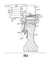
- FIG. 3schematically illustrates a side view of a rotor blade 210 in an installed configuration within an exemplary gas turbine engine, such as the gas turbine engine 20 of FIG. 1 .
- the rotor blade 210is a rotor blade including a flowpath body 212 protruding radially outward into the primary flowpath, and a platform 214 supporting the flowpath body 212 .
- the platform 214is connected to a rotor disk 220 via a fir tree interface 222 at a root 216 of the rotor blade 210 .
Landscapes
- Engineering & Computer Science (AREA)
- Mechanical Engineering (AREA)
- General Engineering & Computer Science (AREA)
- Manufacturing & Machinery (AREA)
- Chemical & Material Sciences (AREA)
- Materials Engineering (AREA)
- Physics & Mathematics (AREA)
- Thermal Sciences (AREA)
- Architecture (AREA)
- Turbine Rotor Nozzle Sealing (AREA)
Abstract
Description
Claims (17)
Priority Applications (2)
| Application Number | Priority Date | Filing Date | Title |
|---|---|---|---|
| US15/045,644US10221694B2 (en) | 2016-02-17 | 2016-02-17 | Gas turbine engine component having vascular engineered lattice structure |
| EP17156353.9AEP3208424A1 (en) | 2016-02-17 | 2017-02-15 | Gas turbine engine component having vascular engineered lattice structure |
Applications Claiming Priority (1)
| Application Number | Priority Date | Filing Date | Title |
|---|---|---|---|
| US15/045,644US10221694B2 (en) | 2016-02-17 | 2016-02-17 | Gas turbine engine component having vascular engineered lattice structure |
Publications (2)
| Publication Number | Publication Date |
|---|---|
| US20170234143A1 US20170234143A1 (en) | 2017-08-17 |
| US10221694B2true US10221694B2 (en) | 2019-03-05 |
Family
ID=58046594
Family Applications (1)
| Application Number | Title | Priority Date | Filing Date |
|---|---|---|---|
| US15/045,644Active2037-03-05US10221694B2 (en) | 2016-02-17 | 2016-02-17 | Gas turbine engine component having vascular engineered lattice structure |
Country Status (2)
| Country | Link |
|---|---|
| US (1) | US10221694B2 (en) |
| EP (1) | EP3208424A1 (en) |
Cited By (10)
| Publication number | Priority date | Publication date | Assignee | Title |
|---|---|---|---|---|
| US20210404456A1 (en)* | 2018-10-02 | 2021-12-30 | Vilter Manufacturing Llc | 3D-Printed Oil Separation for Reciprocating Compressors |
| US11492908B2 (en)* | 2020-01-22 | 2022-11-08 | General Electric Company | Turbine rotor blade root with hollow mount with lattice support structure by additive manufacture |
| US11542844B2 (en) | 2019-09-20 | 2023-01-03 | Raytheon Technologies Corporation | Integrated lubricating fluid filtering and metering device |
| US20230078480A1 (en)* | 2021-09-10 | 2023-03-16 | Hamilton Sundstrand Corporation | Turbomachinery housing with variable lattice densities |
| US11773746B2 (en) | 2021-09-10 | 2023-10-03 | Hamilton Sundstrand Corporation | Turbomachinery rotor shroud with variable lattice densities |
| US11802488B2 (en) | 2021-09-10 | 2023-10-31 | Hamilton Sundstrand Corporation | Turbomachinery seal plate with variable lattice densities |
| US20240141805A1 (en)* | 2022-10-28 | 2024-05-02 | Raytheon Technologies Corporation | Gas turbine engine support structure with internal lattice |
| US11994141B2 (en) | 2021-09-10 | 2024-05-28 | Hamilton Sundstrand Corporation | Turbomachinery shaft with variable lattice densities |
| US12018582B2 (en)* | 2020-10-01 | 2024-06-25 | Safran Aircraft Engines | Turbine blade for an aircraft turbine engine, comprising a platform provided with a channel for primary flow rejection towards a purge cavity |
| US20250188842A1 (en)* | 2022-02-25 | 2025-06-12 | Safran Aircraft Engines | Gas turbine engine blading comprising a blade and a platform which has an internal flow-intake and flow-ejection canal |
Families Citing this family (10)
| Publication number | Priority date | Publication date | Assignee | Title |
|---|---|---|---|---|
| US10634143B2 (en) | 2015-12-23 | 2020-04-28 | Emerson Climate Technologies, Inc. | Thermal and sound optimized lattice-cored additive manufactured compressor components |
| US10982672B2 (en) | 2015-12-23 | 2021-04-20 | Emerson Climate Technologies, Inc. | High-strength light-weight lattice-cored additive manufactured compressor components |
| US10557464B2 (en) | 2015-12-23 | 2020-02-11 | Emerson Climate Technologies, Inc. | Lattice-cored additive manufactured compressor components with fluid delivery features |
| US20180056100A1 (en) | 2016-08-31 | 2018-03-01 | Emerson Process Management Regulator Technologies Tulsa, Llc | Method for Manufacturing a Flame Arrestor |
| US9987508B2 (en)* | 2016-08-31 | 2018-06-05 | Emerson Process Management Regulator Technologies Tulsa, Llc | Hybrid composite flame cell |
| US11156100B2 (en)* | 2018-12-04 | 2021-10-26 | Raytheon Technologies Corporation | Composite fan blade |
| FR3092137B1 (en)* | 2019-01-30 | 2021-02-12 | Safran Aircraft Engines | Turbomachine stator sector with high stress areas |
| US11326516B2 (en)* | 2019-08-15 | 2022-05-10 | Pratt & Whitney Canada Corp. | Removal of contaminants from air for use in aircraft engines |
| DE102020201448A1 (en) | 2020-02-06 | 2021-08-12 | Siemens Aktiengesellschaft | Additively manufactured turbine blade with anti-twist device and adjustment process |
| CN112943378B (en)* | 2021-02-04 | 2022-06-28 | 大连理工大学 | Turbine blade branch net type cooling structure |
Citations (94)
| Publication number | Priority date | Publication date | Assignee | Title |
|---|---|---|---|---|
| US3584972A (en) | 1966-02-09 | 1971-06-15 | Gen Motors Corp | Laminated porous metal |
| US3864199A (en) | 1973-07-26 | 1975-02-04 | Gen Motors Corp | Angular discharge porous sheet |
| US3900629A (en) | 1973-09-14 | 1975-08-19 | Bendix Corp | Porous laminate and method of manufacture |
| US4004056A (en) | 1975-07-24 | 1977-01-18 | General Motors Corporation | Porous laminated sheet |
| US4091146A (en) | 1975-10-01 | 1978-05-23 | General Electric Company | Flexible, low porosity airfoil skin |
| US4168348A (en) | 1974-12-13 | 1979-09-18 | Rolls-Royce Limited | Perforated laminated material |
| US4269032A (en) | 1979-06-13 | 1981-05-26 | General Motors Corporation | Waffle pattern porous material |
| US4292376A (en) | 1978-10-28 | 1981-09-29 | Rolls-Royce Limited | Porous metal sheet laminate |
| US4302940A (en) | 1979-06-13 | 1981-12-01 | General Motors Corporation | Patterned porous laminated material |
| US4359181A (en) | 1978-05-25 | 1982-11-16 | John Chisholm | Process for making a high heat transfer surface composed of perforated or expanded metal |
| US4407632A (en)* | 1981-06-26 | 1983-10-04 | United Technologies Corporation | Airfoil pedestaled trailing edge region cooling configuration |
| US4440834A (en) | 1980-05-28 | 1984-04-03 | Societe Nationale D'etude Et De Construction De Moteurs D'aviation, S.N.E.C.M.A. | Process for the manufacture of turbine blades cooled by means of a porous body and product obtained by the process |
| US4751962A (en) | 1986-02-10 | 1988-06-21 | General Motors Corporation | Temperature responsive laminated porous metal panel |
| EP0475658A1 (en) | 1990-09-06 | 1992-03-18 | General Electric Company | Turbine blade airfoil with serial impingement cooling through internal cavity-forming ribs |
| US5193611A (en) | 1989-05-04 | 1993-03-16 | The Secretary Of State For Trade And Industry In Her Britannic Majesty's Government Of The United Kingdom Of Great Britain And Northern Ireland | Heat exchangers |
| US5197852A (en)* | 1990-05-31 | 1993-03-30 | General Electric Company | Nozzle band overhang cooling |
| US5353867A (en) | 1992-03-31 | 1994-10-11 | Akzo Nobel Nv | Heat exchanger, a method of manufacturing same, and applications |
| US5370499A (en) | 1992-02-03 | 1994-12-06 | General Electric Company | Film cooling of turbine airfoil wall using mesh cooling hole arrangement |
| GB2284825A (en) | 1993-11-11 | 1995-06-21 | Mtu Muenchen Gmbh | Body with dense outer shell and porous core |
| US5545003A (en) | 1992-02-18 | 1996-08-13 | Allison Engine Company, Inc | Single-cast, high-temperature thin wall gas turbine component |
| US5607778A (en) | 1995-07-20 | 1997-03-04 | Purolator Products Company | Method of manufacturing a porous metal mat |
| US5660523A (en) | 1992-02-03 | 1997-08-26 | General Electric Company | Turbine blade squealer tip peripheral end wall with cooling passage arrangement |
| US5752801A (en) | 1997-02-20 | 1998-05-19 | Westinghouse Electric Corporation | Apparatus for cooling a gas turbine airfoil and method of making same |
| US5960863A (en) | 1998-01-07 | 1999-10-05 | Hua; Hsu Mei | Dissipating device for computer chips |
| US5975841A (en) | 1997-10-03 | 1999-11-02 | Thermal Corp. | Heat pipe cooling for turbine stators |
| US6126396A (en) | 1998-12-09 | 2000-10-03 | General Electric Company | AFT flowing serpentine airfoil cooling circuit with side wall impingement cooling chambers |
| US6167952B1 (en) | 1998-03-03 | 2001-01-02 | Hamilton Sundstrand Corporation | Cooling apparatus and method of assembling same |
| US6235370B1 (en) | 1999-03-03 | 2001-05-22 | Siemens Westinghouse Power Corporation | High temperature erosion resistant, abradable thermal barrier composite coating |
| US6397922B1 (en) | 2000-05-24 | 2002-06-04 | Massachusetts Institute Of Technology | Molds for casting with customized internal structure to collapse upon cooling and to facilitate control of heat transfer |
| US6412541B2 (en) | 2000-05-17 | 2002-07-02 | Alstom Power N.V. | Process for producing a thermally loaded casting |
| US6508623B1 (en) | 2000-03-07 | 2003-01-21 | Mitsubishi Heavy Industries, Ltd. | Gas turbine segmental ring |
| WO2003006883A1 (en) | 2001-07-13 | 2003-01-23 | Siemens Aktiengesellschaft | Coolable segment for a turbomachinery and combustion turbine |
| US6511762B1 (en) | 2000-11-06 | 2003-01-28 | General Electric Company | Multi-layer thermal barrier coating with transpiration cooling |
| US6617003B1 (en) | 2000-11-06 | 2003-09-09 | General Electric Company | Directly cooled thermal barrier coating system |
| DE10261071A1 (en) | 2002-12-24 | 2004-07-08 | Rolls-Royce Deutschland Ltd & Co Kg | Combustion chamber wall element for gas turbine has outer cover plate, porous center layer and inner cover plate interconnected in one piece, and may be interconnected by one or more diffusion welding processes |
| US6761956B2 (en) | 2001-12-20 | 2004-07-13 | General Electric Company | Ventilated thermal barrier coating |
| US20050045306A1 (en) | 2003-07-22 | 2005-03-03 | Petervary Miklos Paul | Transpiration cooling system |
| US6955523B2 (en) | 2003-08-08 | 2005-10-18 | Siemens Westinghouse Power Corporation | Cooling system for a turbine vane |
| US20060099074A1 (en) | 2004-11-06 | 2006-05-11 | Rolls-Royce Plc | Component having a film cooling arrangement |
| US7048986B2 (en) | 2003-06-12 | 2006-05-23 | Northrop Grumman Corporation | End gaps of filled honeycomb |
| US7063131B2 (en) | 2001-07-12 | 2006-06-20 | Nuvera Fuel Cells, Inc. | Perforated fin heat exchangers and catalytic support |
| US7070853B2 (en) | 2002-01-15 | 2006-07-04 | Siemens Aktiengesellschaft | Layer system comprising a substrate, and an outer porous layer |
| US20060251515A1 (en) | 2005-05-05 | 2006-11-09 | Landis Kenneth K | Airfoil with a porous fiber metal layer |
| US7141812B2 (en) | 2002-06-05 | 2006-11-28 | Mikro Systems, Inc. | Devices, methods, and systems involving castings |
| EP1726785A2 (en) | 2005-05-23 | 2006-11-29 | United Technologies Corporation | Turbine airfoil platform cooling circuit |
| US7144220B2 (en) | 2004-07-30 | 2006-12-05 | United Technologies Corporation | Investment casting |
| US20060285975A1 (en) | 2005-05-05 | 2006-12-21 | Landis Kenneth K | Airfoil having porous metal filled cavities |
| US7153464B2 (en) | 2003-12-01 | 2006-12-26 | General Electric Company | Method of making porous ceramic matrix composites |
| WO2007014005A1 (en) | 2005-07-22 | 2007-02-01 | Siemens Power Generation, Inc. | Cmc with multiple matrix phases separated by diffusion barrier |
| US20070031252A1 (en) | 2005-08-02 | 2007-02-08 | Rolls-Royce Plc | Component comprising a multiplicity of cooling passages |
| US7204089B2 (en) | 2003-09-04 | 2007-04-17 | Rolls-Royce Deutschland Ltd & Co Kg | Arrangement for the cooling of thermally highly loaded components |
| EP0896127B1 (en) | 1997-08-07 | 2007-07-04 | United Technologies Corporation | Airfoil cooling |
| US20070214759A1 (en) | 2004-07-29 | 2007-09-20 | Merkel Gregory A | Narrow pore size distribution aluminum titanate body and method for making same |
| US20070243069A1 (en) | 2004-09-22 | 2007-10-18 | Rolls-Royce Plc | Aerofoil and a method of manufacturing an aerofoil |
| US20070275210A1 (en) | 2003-11-14 | 2007-11-29 | Siemens Aktiengesellschaft | High-Temperature Layered System for Dissipating Heat and Method for Producing Said System |
| US7402335B2 (en) | 2003-07-09 | 2008-07-22 | Siemens Aktiengesellschaft | Layer structure and method for producing such a layer structure |
| US20080254276A1 (en) | 2007-04-10 | 2008-10-16 | Siemens Power Generation, Inc. | System for applying a continuous surface layer on porous substructures of turbine airfoils |
| US20090011919A1 (en) | 2006-03-17 | 2009-01-08 | Ngk Insulators, Ltd. | Process for producing honeycomb structure |
| US7540710B2 (en) | 2003-10-27 | 2009-06-02 | Siemens Aktiengesellschaft | Turbine blade for use in a gas turbine |
| US7597533B1 (en) | 2007-01-26 | 2009-10-06 | Florida Turbine Technologies, Inc. | BOAS with multi-metering diffusion cooling |
| US20100025001A1 (en) | 2007-06-25 | 2010-02-04 | Ching-Pang Lee | Methods for fabricating gas turbine components using an integrated disposable core and shell die |
| US7658590B1 (en) | 2005-09-30 | 2010-02-09 | Florida Turbine Technologies, Inc. | Turbine airfoil with micro-tubes embedded with a TBC |
| US7717677B1 (en) | 2007-01-31 | 2010-05-18 | Florida Turbine Technologies, Inc. | Multi-metering and diffusion transpiration cooled airfoil |
| EP2199725A1 (en) | 2008-12-16 | 2010-06-23 | Siemens Aktiengesellschaft | Multi-impingement-surface for cooling a wall |
| US7775766B2 (en) | 2003-12-20 | 2010-08-17 | Mtu Aero Engines Gmbh | Gas turbine component |
| US7785098B1 (en) | 2001-06-05 | 2010-08-31 | Mikro Systems, Inc. | Systems for large area micro mechanical systems |
| US7810552B2 (en) | 2006-12-20 | 2010-10-12 | The Boeing Company | Method of making a heat exchanger |
| US20100284798A1 (en) | 2009-05-05 | 2010-11-11 | Siemens Energy, Inc. | Turbine Airfoil With Dual Wall Formed from Inner and Outer Layers Separated by a Compliant Structure |
| US20100291401A1 (en) | 2009-05-15 | 2010-11-18 | Board Of Regents, The University Of Texas System | Reticulated mesh arrays and dissimilar array monoliths by additive layered manufacturing using electron and laser beam melting |
| US7866372B2 (en) | 2006-12-20 | 2011-01-11 | The Boeing Company | Method of making a heat exchanger core component |
| US7866377B2 (en) | 2006-12-20 | 2011-01-11 | The Boeing Company | Method of using minimal surfaces and minimal skeletons to make heat exchanger components |
| WO2011069015A2 (en) | 2009-12-02 | 2011-06-09 | The Regents Of The University Of Colorado, A Body Corporate | Microchannel expanded heat exchanger |
| US20110180245A1 (en) | 2006-03-23 | 2011-07-28 | Mitsuru Obana | Heat exchanger |
| WO2011133359A1 (en) | 2010-04-22 | 2011-10-27 | Siemens Energy, Inc. | Discretely defined porous wall structure for transpirational cooling |
| US20110265406A1 (en) | 2010-04-29 | 2011-11-03 | Morrison Jay A | Gusset with fibers oriented to strengthen a cmc wall intersection anisotropically |
| US20110268580A1 (en) | 2008-11-05 | 2011-11-03 | Roderich Bryk | Axially segmented guide vane mount for a gas turbine |
| US8052389B2 (en) | 2004-08-25 | 2011-11-08 | Rolls-Royce Plc | Internally cooled airfoils with load carrying members |
| US8061146B2 (en)* | 2004-09-20 | 2011-11-22 | United Technologies Corporation | Heat transfer augmentation in a compact heat exchanger pedestal array |
| US20110293434A1 (en) | 2010-06-01 | 2011-12-01 | Ching-Pang Lee | Method of casting a component having interior passageways |
| US20120006518A1 (en) | 2010-07-08 | 2012-01-12 | Ching-Pang Lee | Mesh cooled conduit for conveying combustion gases |
| US20120034075A1 (en) | 2010-08-09 | 2012-02-09 | Johan Hsu | Cooling arrangement for a turbine component |
| US8167573B2 (en) | 2008-09-19 | 2012-05-01 | Siemens Energy, Inc. | Gas turbine airfoil |
| US8257809B2 (en) | 2007-03-08 | 2012-09-04 | Siemens Energy, Inc. | CMC wall structure with integral cooling channels |
| US20120237786A1 (en) | 2011-03-17 | 2012-09-20 | Morrison Jay A | Process for making a wall with a porous element for component cooling |
| US20120243970A1 (en) | 2009-12-17 | 2012-09-27 | Anders Hellgren | Arrangement and method for closed flow cooling of a gas turbine engine component |
| US8327911B2 (en) | 2009-08-09 | 2012-12-11 | Rolls-Royce Corporation | Method for forming a cast article |
| US20130001837A1 (en) | 2009-09-28 | 2013-01-03 | Goehler Jens | Turbine blade and method for its production |
| WO2013013995A1 (en) | 2011-07-22 | 2013-01-31 | Siemens Aktiengesellschaft | Cooling device and method for the production thereof as well as use of the device |
| US8714926B2 (en)* | 2010-09-17 | 2014-05-06 | Siemens Energy, Inc. | Turbine component cooling channel mesh with intersection chambers |
| WO2015026430A1 (en) | 2013-08-20 | 2015-02-26 | United Technologies Corporation | Ducting platform cover plate |
| WO2015057310A2 (en) | 2013-09-17 | 2015-04-23 | United Technologies Corporation | Platform cooling core for a gas turbine engine rotor blade |
| US20150218962A1 (en) | 2014-02-06 | 2015-08-06 | General Electric Company | Micro channel and methods of manufacturing a micro channel |
| EP2947274A1 (en) | 2014-05-22 | 2015-11-25 | United Technologies Corporation | Turbulating cooling structures |
| US20150345304A1 (en) | 2012-12-28 | 2015-12-03 | United Technologies Corporation | Gas turbine engine component having vascular engineered lattice structure |
- 2016
- 2016-02-17USUS15/045,644patent/US10221694B2/enactiveActive
- 2017
- 2017-02-15EPEP17156353.9Apatent/EP3208424A1/ennot_activeWithdrawn
Patent Citations (104)
| Publication number | Priority date | Publication date | Assignee | Title |
|---|---|---|---|---|
| US3584972A (en) | 1966-02-09 | 1971-06-15 | Gen Motors Corp | Laminated porous metal |
| US3864199A (en) | 1973-07-26 | 1975-02-04 | Gen Motors Corp | Angular discharge porous sheet |
| US3900629A (en) | 1973-09-14 | 1975-08-19 | Bendix Corp | Porous laminate and method of manufacture |
| US4168348A (en) | 1974-12-13 | 1979-09-18 | Rolls-Royce Limited | Perforated laminated material |
| US4004056A (en) | 1975-07-24 | 1977-01-18 | General Motors Corporation | Porous laminated sheet |
| US4091146A (en) | 1975-10-01 | 1978-05-23 | General Electric Company | Flexible, low porosity airfoil skin |
| US4359181A (en) | 1978-05-25 | 1982-11-16 | John Chisholm | Process for making a high heat transfer surface composed of perforated or expanded metal |
| US4292376A (en) | 1978-10-28 | 1981-09-29 | Rolls-Royce Limited | Porous metal sheet laminate |
| US4269032A (en) | 1979-06-13 | 1981-05-26 | General Motors Corporation | Waffle pattern porous material |
| US4302940A (en) | 1979-06-13 | 1981-12-01 | General Motors Corporation | Patterned porous laminated material |
| US4440834A (en) | 1980-05-28 | 1984-04-03 | Societe Nationale D'etude Et De Construction De Moteurs D'aviation, S.N.E.C.M.A. | Process for the manufacture of turbine blades cooled by means of a porous body and product obtained by the process |
| US4407632A (en)* | 1981-06-26 | 1983-10-04 | United Technologies Corporation | Airfoil pedestaled trailing edge region cooling configuration |
| US4751962A (en) | 1986-02-10 | 1988-06-21 | General Motors Corporation | Temperature responsive laminated porous metal panel |
| US5193611A (en) | 1989-05-04 | 1993-03-16 | The Secretary Of State For Trade And Industry In Her Britannic Majesty's Government Of The United Kingdom Of Great Britain And Northern Ireland | Heat exchangers |
| US5197852A (en)* | 1990-05-31 | 1993-03-30 | General Electric Company | Nozzle band overhang cooling |
| EP0475658A1 (en) | 1990-09-06 | 1992-03-18 | General Electric Company | Turbine blade airfoil with serial impingement cooling through internal cavity-forming ribs |
| US5370499A (en) | 1992-02-03 | 1994-12-06 | General Electric Company | Film cooling of turbine airfoil wall using mesh cooling hole arrangement |
| US5660523A (en) | 1992-02-03 | 1997-08-26 | General Electric Company | Turbine blade squealer tip peripheral end wall with cooling passage arrangement |
| US5545003A (en) | 1992-02-18 | 1996-08-13 | Allison Engine Company, Inc | Single-cast, high-temperature thin wall gas turbine component |
| US5353867A (en) | 1992-03-31 | 1994-10-11 | Akzo Nobel Nv | Heat exchanger, a method of manufacturing same, and applications |
| GB2284825A (en) | 1993-11-11 | 1995-06-21 | Mtu Muenchen Gmbh | Body with dense outer shell and porous core |
| US5607778A (en) | 1995-07-20 | 1997-03-04 | Purolator Products Company | Method of manufacturing a porous metal mat |
| US5752801A (en) | 1997-02-20 | 1998-05-19 | Westinghouse Electric Corporation | Apparatus for cooling a gas turbine airfoil and method of making same |
| EP0896127B1 (en) | 1997-08-07 | 2007-07-04 | United Technologies Corporation | Airfoil cooling |
| US5975841A (en) | 1997-10-03 | 1999-11-02 | Thermal Corp. | Heat pipe cooling for turbine stators |
| US5960863A (en) | 1998-01-07 | 1999-10-05 | Hua; Hsu Mei | Dissipating device for computer chips |
| US6167952B1 (en) | 1998-03-03 | 2001-01-02 | Hamilton Sundstrand Corporation | Cooling apparatus and method of assembling same |
| US6126396A (en) | 1998-12-09 | 2000-10-03 | General Electric Company | AFT flowing serpentine airfoil cooling circuit with side wall impingement cooling chambers |
| US6235370B1 (en) | 1999-03-03 | 2001-05-22 | Siemens Westinghouse Power Corporation | High temperature erosion resistant, abradable thermal barrier composite coating |
| US6508623B1 (en) | 2000-03-07 | 2003-01-21 | Mitsubishi Heavy Industries, Ltd. | Gas turbine segmental ring |
| US6412541B2 (en) | 2000-05-17 | 2002-07-02 | Alstom Power N.V. | Process for producing a thermally loaded casting |
| US6629559B2 (en) | 2000-05-24 | 2003-10-07 | Massachusetts Institute Of Technology | Molds for casting with customized internal structure to collapse upon cooling and to facilitate control of heat transfer |
| US6397922B1 (en) | 2000-05-24 | 2002-06-04 | Massachusetts Institute Of Technology | Molds for casting with customized internal structure to collapse upon cooling and to facilitate control of heat transfer |
| US6599568B2 (en) | 2000-11-06 | 2003-07-29 | General Electric Company | Method for cooling engine components using multi-layer barrier coating |
| US6617003B1 (en) | 2000-11-06 | 2003-09-09 | General Electric Company | Directly cooled thermal barrier coating system |
| US6511762B1 (en) | 2000-11-06 | 2003-01-28 | General Electric Company | Multi-layer thermal barrier coating with transpiration cooling |
| US7785098B1 (en) | 2001-06-05 | 2010-08-31 | Mikro Systems, Inc. | Systems for large area micro mechanical systems |
| US7063131B2 (en) | 2001-07-12 | 2006-06-20 | Nuvera Fuel Cells, Inc. | Perforated fin heat exchangers and catalytic support |
| WO2003006883A1 (en) | 2001-07-13 | 2003-01-23 | Siemens Aktiengesellschaft | Coolable segment for a turbomachinery and combustion turbine |
| US6761956B2 (en) | 2001-12-20 | 2004-07-13 | General Electric Company | Ventilated thermal barrier coating |
| US7070853B2 (en) | 2002-01-15 | 2006-07-04 | Siemens Aktiengesellschaft | Layer system comprising a substrate, and an outer porous layer |
| US7141812B2 (en) | 2002-06-05 | 2006-11-28 | Mikro Systems, Inc. | Devices, methods, and systems involving castings |
| DE10261071A1 (en) | 2002-12-24 | 2004-07-08 | Rolls-Royce Deutschland Ltd & Co Kg | Combustion chamber wall element for gas turbine has outer cover plate, porous center layer and inner cover plate interconnected in one piece, and may be interconnected by one or more diffusion welding processes |
| US7048986B2 (en) | 2003-06-12 | 2006-05-23 | Northrop Grumman Corporation | End gaps of filled honeycomb |
| US7402335B2 (en) | 2003-07-09 | 2008-07-22 | Siemens Aktiengesellschaft | Layer structure and method for producing such a layer structure |
| US20050045306A1 (en) | 2003-07-22 | 2005-03-03 | Petervary Miklos Paul | Transpiration cooling system |
| US6955523B2 (en) | 2003-08-08 | 2005-10-18 | Siemens Westinghouse Power Corporation | Cooling system for a turbine vane |
| US7204089B2 (en) | 2003-09-04 | 2007-04-17 | Rolls-Royce Deutschland Ltd & Co Kg | Arrangement for the cooling of thermally highly loaded components |
| US7540710B2 (en) | 2003-10-27 | 2009-06-02 | Siemens Aktiengesellschaft | Turbine blade for use in a gas turbine |
| US20070275210A1 (en) | 2003-11-14 | 2007-11-29 | Siemens Aktiengesellschaft | High-Temperature Layered System for Dissipating Heat and Method for Producing Said System |
| US7670675B2 (en) | 2003-11-14 | 2010-03-02 | Siemens Aktiengesellschaft | High-temperature layered system for dissipating heat and method for producing said system |
| US7153464B2 (en) | 2003-12-01 | 2006-12-26 | General Electric Company | Method of making porous ceramic matrix composites |
| US7775766B2 (en) | 2003-12-20 | 2010-08-17 | Mtu Aero Engines Gmbh | Gas turbine component |
| US7294164B2 (en) | 2004-07-29 | 2007-11-13 | Corning Incorporated | Narrow pore size distribution aluminum titanate body and method for making same |
| US20070214759A1 (en) | 2004-07-29 | 2007-09-20 | Merkel Gregory A | Narrow pore size distribution aluminum titanate body and method for making same |
| US7144220B2 (en) | 2004-07-30 | 2006-12-05 | United Technologies Corporation | Investment casting |
| US8052389B2 (en) | 2004-08-25 | 2011-11-08 | Rolls-Royce Plc | Internally cooled airfoils with load carrying members |
| US8061146B2 (en)* | 2004-09-20 | 2011-11-22 | United Technologies Corporation | Heat transfer augmentation in a compact heat exchanger pedestal array |
| US20070243069A1 (en) | 2004-09-22 | 2007-10-18 | Rolls-Royce Plc | Aerofoil and a method of manufacturing an aerofoil |
| US20060099074A1 (en) | 2004-11-06 | 2006-05-11 | Rolls-Royce Plc | Component having a film cooling arrangement |
| US20060251515A1 (en) | 2005-05-05 | 2006-11-09 | Landis Kenneth K | Airfoil with a porous fiber metal layer |
| US7500828B2 (en) | 2005-05-05 | 2009-03-10 | Florida Turbine Technologies, Inc. | Airfoil having porous metal filled cavities |
| US20060285975A1 (en) | 2005-05-05 | 2006-12-21 | Landis Kenneth K | Airfoil having porous metal filled cavities |
| US7255536B2 (en)* | 2005-05-23 | 2007-08-14 | United Technologies Corporation | Turbine airfoil platform cooling circuit |
| EP1726785A2 (en) | 2005-05-23 | 2006-11-29 | United Technologies Corporation | Turbine airfoil platform cooling circuit |
| WO2007014005A1 (en) | 2005-07-22 | 2007-02-01 | Siemens Power Generation, Inc. | Cmc with multiple matrix phases separated by diffusion barrier |
| US20070031252A1 (en) | 2005-08-02 | 2007-02-08 | Rolls-Royce Plc | Component comprising a multiplicity of cooling passages |
| US7658590B1 (en) | 2005-09-30 | 2010-02-09 | Florida Turbine Technologies, Inc. | Turbine airfoil with micro-tubes embedded with a TBC |
| US20090011919A1 (en) | 2006-03-17 | 2009-01-08 | Ngk Insulators, Ltd. | Process for producing honeycomb structure |
| US20110180245A1 (en) | 2006-03-23 | 2011-07-28 | Mitsuru Obana | Heat exchanger |
| US7866377B2 (en) | 2006-12-20 | 2011-01-11 | The Boeing Company | Method of using minimal surfaces and minimal skeletons to make heat exchanger components |
| US7810552B2 (en) | 2006-12-20 | 2010-10-12 | The Boeing Company | Method of making a heat exchanger |
| US7866372B2 (en) | 2006-12-20 | 2011-01-11 | The Boeing Company | Method of making a heat exchanger core component |
| US7597533B1 (en) | 2007-01-26 | 2009-10-06 | Florida Turbine Technologies, Inc. | BOAS with multi-metering diffusion cooling |
| US7717677B1 (en) | 2007-01-31 | 2010-05-18 | Florida Turbine Technologies, Inc. | Multi-metering and diffusion transpiration cooled airfoil |
| US8257809B2 (en) | 2007-03-08 | 2012-09-04 | Siemens Energy, Inc. | CMC wall structure with integral cooling channels |
| US20080254276A1 (en) | 2007-04-10 | 2008-10-16 | Siemens Power Generation, Inc. | System for applying a continuous surface layer on porous substructures of turbine airfoils |
| US7968144B2 (en) | 2007-04-10 | 2011-06-28 | Siemens Energy, Inc. | System for applying a continuous surface layer on porous substructures of turbine airfoils |
| US20100025001A1 (en) | 2007-06-25 | 2010-02-04 | Ching-Pang Lee | Methods for fabricating gas turbine components using an integrated disposable core and shell die |
| US8167573B2 (en) | 2008-09-19 | 2012-05-01 | Siemens Energy, Inc. | Gas turbine airfoil |
| US20110268580A1 (en) | 2008-11-05 | 2011-11-03 | Roderich Bryk | Axially segmented guide vane mount for a gas turbine |
| EP2199725A1 (en) | 2008-12-16 | 2010-06-23 | Siemens Aktiengesellschaft | Multi-impingement-surface for cooling a wall |
| US20100284798A1 (en) | 2009-05-05 | 2010-11-11 | Siemens Energy, Inc. | Turbine Airfoil With Dual Wall Formed from Inner and Outer Layers Separated by a Compliant Structure |
| US20100291401A1 (en) | 2009-05-15 | 2010-11-18 | Board Of Regents, The University Of Texas System | Reticulated mesh arrays and dissimilar array monoliths by additive layered manufacturing using electron and laser beam melting |
| US8327911B2 (en) | 2009-08-09 | 2012-12-11 | Rolls-Royce Corporation | Method for forming a cast article |
| US20130001837A1 (en) | 2009-09-28 | 2013-01-03 | Goehler Jens | Turbine blade and method for its production |
| WO2011069015A2 (en) | 2009-12-02 | 2011-06-09 | The Regents Of The University Of Colorado, A Body Corporate | Microchannel expanded heat exchanger |
| US20120291991A1 (en) | 2009-12-02 | 2012-11-22 | The Regents Of The University Of Colorado, A Body Corporate | Microchannel expanded heat exchanger |
| US20120243970A1 (en) | 2009-12-17 | 2012-09-27 | Anders Hellgren | Arrangement and method for closed flow cooling of a gas turbine engine component |
| WO2011133359A1 (en) | 2010-04-22 | 2011-10-27 | Siemens Energy, Inc. | Discretely defined porous wall structure for transpirational cooling |
| US20110262695A1 (en) | 2010-04-22 | 2011-10-27 | Ching-Pang Lee | Discreetly Defined Porous Wall Structure for Transpirational Cooling |
| US20110265406A1 (en) | 2010-04-29 | 2011-11-03 | Morrison Jay A | Gusset with fibers oriented to strengthen a cmc wall intersection anisotropically |
| US20110293434A1 (en) | 2010-06-01 | 2011-12-01 | Ching-Pang Lee | Method of casting a component having interior passageways |
| US20120006518A1 (en) | 2010-07-08 | 2012-01-12 | Ching-Pang Lee | Mesh cooled conduit for conveying combustion gases |
| US20120034075A1 (en) | 2010-08-09 | 2012-02-09 | Johan Hsu | Cooling arrangement for a turbine component |
| US8714926B2 (en)* | 2010-09-17 | 2014-05-06 | Siemens Energy, Inc. | Turbine component cooling channel mesh with intersection chambers |
| US8793871B2 (en)* | 2011-03-17 | 2014-08-05 | Siemens Energy, Inc. | Process for making a wall with a porous element for component cooling |
| US20120237786A1 (en) | 2011-03-17 | 2012-09-20 | Morrison Jay A | Process for making a wall with a porous element for component cooling |
| WO2013013995A1 (en) | 2011-07-22 | 2013-01-31 | Siemens Aktiengesellschaft | Cooling device and method for the production thereof as well as use of the device |
| US20150345304A1 (en) | 2012-12-28 | 2015-12-03 | United Technologies Corporation | Gas turbine engine component having vascular engineered lattice structure |
| WO2015026430A1 (en) | 2013-08-20 | 2015-02-26 | United Technologies Corporation | Ducting platform cover plate |
| WO2015057310A2 (en) | 2013-09-17 | 2015-04-23 | United Technologies Corporation | Platform cooling core for a gas turbine engine rotor blade |
| US20150218962A1 (en) | 2014-02-06 | 2015-08-06 | General Electric Company | Micro channel and methods of manufacturing a micro channel |
| EP2947274A1 (en) | 2014-05-22 | 2015-11-25 | United Technologies Corporation | Turbulating cooling structures |
Non-Patent Citations (7)
| Title |
|---|
| European Search Report for Application No. 17156353.9 dated Jun. 19, 2017. |
| International Preliminary Report on Patentability for PCT Application for PCT/US2013/0141054, dated Jul. 9, 2015. |
| International Preliminary Report on Patentability for PCT Application No. PCT/US2013/032202, dated Jul. 9, 2015. |
| International Preliminary Report on Patentablity for PCT Application No. PCT/US2013/032003, dated Jul. 9, 2015. |
| International Search Report and Written Opinion of the International Searching Authority for International application No. PCT/US2013/032003 dated Dec. 17, 2013. |
| International Search Report and Written Opinion of the International Searching Authority for International application No. PCT/US2013/032202 dated Jan. 27, 2014. |
| International Search Report and Written Opinion of the International Searching Authority for International application No. PCT/US2013/041054 dated Sep. 4, 2013. |
Cited By (15)
| Publication number | Priority date | Publication date | Assignee | Title |
|---|---|---|---|---|
| US11859603B2 (en)* | 2018-10-02 | 2024-01-02 | Copeland Industrial Lp | 3D-printed oil separation for reciprocating compressors |
| US20210404456A1 (en)* | 2018-10-02 | 2021-12-30 | Vilter Manufacturing Llc | 3D-Printed Oil Separation for Reciprocating Compressors |
| US11542844B2 (en) | 2019-09-20 | 2023-01-03 | Raytheon Technologies Corporation | Integrated lubricating fluid filtering and metering device |
| US11492908B2 (en)* | 2020-01-22 | 2022-11-08 | General Electric Company | Turbine rotor blade root with hollow mount with lattice support structure by additive manufacture |
| US12018582B2 (en)* | 2020-10-01 | 2024-06-25 | Safran Aircraft Engines | Turbine blade for an aircraft turbine engine, comprising a platform provided with a channel for primary flow rejection towards a purge cavity |
| US11802488B2 (en) | 2021-09-10 | 2023-10-31 | Hamilton Sundstrand Corporation | Turbomachinery seal plate with variable lattice densities |
| US11773746B2 (en) | 2021-09-10 | 2023-10-03 | Hamilton Sundstrand Corporation | Turbomachinery rotor shroud with variable lattice densities |
| US11994141B2 (en) | 2021-09-10 | 2024-05-28 | Hamilton Sundstrand Corporation | Turbomachinery shaft with variable lattice densities |
| US20230078480A1 (en)* | 2021-09-10 | 2023-03-16 | Hamilton Sundstrand Corporation | Turbomachinery housing with variable lattice densities |
| US20240301892A1 (en)* | 2021-09-10 | 2024-09-12 | Hamilton Sundstrand Corporation | Turbomachinery housing with variable lattice densities |
| US12188357B2 (en) | 2021-09-10 | 2025-01-07 | Hamilton Sundstrand Corporation | Turbomachinery seal plate with variable lattice densities |
| US20250188842A1 (en)* | 2022-02-25 | 2025-06-12 | Safran Aircraft Engines | Gas turbine engine blading comprising a blade and a platform which has an internal flow-intake and flow-ejection canal |
| US20240141805A1 (en)* | 2022-10-28 | 2024-05-02 | Raytheon Technologies Corporation | Gas turbine engine support structure with internal lattice |
| US12055062B2 (en)* | 2022-10-28 | 2024-08-06 | Rtx Corporation | Gas turbine engine support structure with internal lattice |
| US12398662B2 (en) | 2022-10-28 | 2025-08-26 | Rtx Corporation | Gas turbine engine support structure with internal lattice |
Also Published As
| Publication number | Publication date |
|---|---|
| EP3208424A1 (en) | 2017-08-23 |
| US20170234143A1 (en) | 2017-08-17 |
Similar Documents
| Publication | Publication Date | Title |
|---|---|---|
| US10221694B2 (en) | Gas turbine engine component having vascular engineered lattice structure | |
| US10662781B2 (en) | Gas turbine engine component having vascular engineered lattice structure | |
| US10731473B2 (en) | Gas turbine engine component having engineered vascular structure | |
| EP3179042B1 (en) | Gas turbine engine component having engineered vascular structure | |
| US10301947B2 (en) | Gas turbine engine component cooling circuit | |
| US20170051619A1 (en) | Cmc nozzles with split endwalls for gas turbine engines | |
| US10094287B2 (en) | Gas turbine engine component with vascular cooling scheme | |
| US10472970B2 (en) | Gas turbine engine component having contoured rib end | |
| US20170363007A1 (en) | Isothermalized cooling of gas turbine engine components | |
| EP3477058B1 (en) | Airfoil cooling circuit | |
| US20160169002A1 (en) | Airfoil trailing edge tip cooling | |
| US10619489B2 (en) | Airfoil having end wall contoured pedestals | |
| US11248481B2 (en) | Turbine vane having dual source cooling | |
| EP3170980B1 (en) | Components for gas turbine engines with lattice cooling structure and corresponding method for producing |
Legal Events
| Date | Code | Title | Description |
|---|---|---|---|
| AS | Assignment | Owner name:UNITED TECHNOLOGIES CORPORATION, CONNECTICUT Free format text:ASSIGNMENT OF ASSIGNORS INTEREST;ASSIGNOR:SNYDER, DANIEL A.;REEL/FRAME:037753/0083 Effective date:20160209 | |
| STCF | Information on status: patent grant | Free format text:PATENTED CASE | |
| AS | Assignment | Owner name:RAYTHEON TECHNOLOGIES CORPORATION, MASSACHUSETTS Free format text:CHANGE OF NAME;ASSIGNOR:UNITED TECHNOLOGIES CORPORATION;REEL/FRAME:054062/0001 Effective date:20200403 | |
| AS | Assignment | Owner name:RAYTHEON TECHNOLOGIES CORPORATION, CONNECTICUT Free format text:CORRECTIVE ASSIGNMENT TO CORRECT THE AND REMOVE PATENT APPLICATION NUMBER 11886281 AND ADD PATENT APPLICATION NUMBER 14846874. TO CORRECT THE RECEIVING PARTY ADDRESS PREVIOUSLY RECORDED AT REEL: 054062 FRAME: 0001. ASSIGNOR(S) HEREBY CONFIRMS THE CHANGE OF ADDRESS;ASSIGNOR:UNITED TECHNOLOGIES CORPORATION;REEL/FRAME:055659/0001 Effective date:20200403 | |
| CC | Certificate of correction | ||
| MAFP | Maintenance fee payment | Free format text:PAYMENT OF MAINTENANCE FEE, 4TH YEAR, LARGE ENTITY (ORIGINAL EVENT CODE: M1551); ENTITY STATUS OF PATENT OWNER: LARGE ENTITY Year of fee payment:4 | |
| AS | Assignment | Owner name:RTX CORPORATION, CONNECTICUT Free format text:CHANGE OF NAME;ASSIGNOR:RAYTHEON TECHNOLOGIES CORPORATION;REEL/FRAME:064714/0001 Effective date:20230714 |