US10220308B2 - Games controller and trigger therefor - Google Patents
Games controller and trigger thereforDownload PDFInfo
- Publication number
- US10220308B2 US10220308B2US15/362,134US201615362134AUS10220308B2US 10220308 B2US10220308 B2US 10220308B2US 201615362134 AUS201615362134 AUS 201615362134AUS 10220308 B2US10220308 B2US 10220308B2
- Authority
- US
- United States
- Prior art keywords
- detent
- trigger
- trigger mechanism
- trigger body
- controller
- Prior art date
- Legal status (The legal status is an assumption and is not a legal conclusion. Google has not performed a legal analysis and makes no representation as to the accuracy of the status listed.)
- Active
Links
- 230000007246mechanismEffects0.000claimsabstractdescription105
- 238000004590computer programMethods0.000claimsabstractdescription6
- 210000003811fingerAnatomy0.000claimsdescription8
- 230000036961partial effectEffects0.000claimsdescription3
- 210000003813thumbAnatomy0.000claimsdescription3
- 210000004247handAnatomy0.000claimsdescription2
- 230000001419dependent effectEffects0.000description5
- 238000006073displacement reactionMethods0.000description5
- 230000000977initiatory effectEffects0.000description5
- 230000000994depressogenic effectEffects0.000description4
- 230000002829reductive effectEffects0.000description4
- 230000008901benefitEffects0.000description3
- 230000000881depressing effectEffects0.000description3
- 210000004936left thumbAnatomy0.000description3
- 230000000670limiting effectEffects0.000description3
- 238000000034methodMethods0.000description3
- 230000005355Hall effectEffects0.000description2
- 230000002730additional effectEffects0.000description2
- 238000004891communicationMethods0.000description2
- 238000010304firingMethods0.000description2
- 230000004044responseEffects0.000description2
- 210000004935right thumbAnatomy0.000description2
- 238000004088simulationMethods0.000description2
- 208000012514Cumulative Trauma diseaseDiseases0.000description1
- 206010038584Repetitive strain injuryDiseases0.000description1
- 230000001133accelerationEffects0.000description1
- 230000009471actionEffects0.000description1
- 230000001010compromised effectEffects0.000description1
- 230000003247decreasing effectEffects0.000description1
- 230000007407health benefitEffects0.000description1
- 238000004519manufacturing processMethods0.000description1
- 230000036316preloadEffects0.000description1
- 238000011084recoveryMethods0.000description1
- 230000004043responsivenessEffects0.000description1
- 238000010079rubber tappingMethods0.000description1
- 238000000926separation methodMethods0.000description1
Images


Classifications
- A—HUMAN NECESSITIES
- A63—SPORTS; GAMES; AMUSEMENTS
- A63F—CARD, BOARD, OR ROULETTE GAMES; INDOOR GAMES USING SMALL MOVING PLAYING BODIES; VIDEO GAMES; GAMES NOT OTHERWISE PROVIDED FOR
- A63F13/00—Video games, i.e. games using an electronically generated display having two or more dimensions
- A63F13/20—Input arrangements for video game devices
- A63F13/24—Constructional details thereof, e.g. game controllers with detachable joystick handles
- A—HUMAN NECESSITIES
- A63—SPORTS; GAMES; AMUSEMENTS
- A63F—CARD, BOARD, OR ROULETTE GAMES; INDOOR GAMES USING SMALL MOVING PLAYING BODIES; VIDEO GAMES; GAMES NOT OTHERWISE PROVIDED FOR
- A63F13/00—Video games, i.e. games using an electronically generated display having two or more dimensions
- A63F13/20—Input arrangements for video game devices
- A63F13/22—Setup operations, e.g. calibration, key configuration or button assignment
- H—ELECTRICITY
- H01—ELECTRIC ELEMENTS
- H01H—ELECTRIC SWITCHES; RELAYS; SELECTORS; EMERGENCY PROTECTIVE DEVICES
- H01H21/00—Switches operated by an operating part in the form of a pivotable member acted upon directly by a solid body, e.g. by a hand
- H01H21/02—Details
- H01H21/18—Movable parts; Contacts mounted thereon
- H01H21/22—Operating parts, e.g. handle
- H01H21/24—Operating parts, e.g. handle biased to return to normal position upon removal of operating force
- H—ELECTRICITY
- H01—ELECTRIC ELEMENTS
- H01H—ELECTRIC SWITCHES; RELAYS; SELECTORS; EMERGENCY PROTECTIVE DEVICES
- H01H9/00—Details of switching devices, not covered by groups H01H1/00 - H01H7/00
- H01H9/02—Bases, casings, or covers
- H01H9/0214—Hand-held casings
- H—ELECTRICITY
- H01—ELECTRIC ELEMENTS
- H01H—ELECTRIC SWITCHES; RELAYS; SELECTORS; EMERGENCY PROTECTIVE DEVICES
- H01H11/00—Apparatus or processes specially adapted for the manufacture of electric switches
- H01H11/0006—Apparatus or processes specially adapted for the manufacture of electric switches for converting electric switches
- H01H11/0018—Apparatus or processes specially adapted for the manufacture of electric switches for converting electric switches for allowing different operating parts
- H01H2011/0025—Apparatus or processes specially adapted for the manufacture of electric switches for converting electric switches for allowing different operating parts with provisions for allowing different orientation of the operating part, e.g. turning knob can be mounted in different positions
- H—ELECTRICITY
- H01—ELECTRIC ELEMENTS
- H01H—ELECTRIC SWITCHES; RELAYS; SELECTORS; EMERGENCY PROTECTIVE DEVICES
- H01H2221/00—Actuators
- H01H2221/008—Actuators other then push button
- H01H2221/016—Lever; Rocker
- H—ELECTRICITY
- H01—ELECTRIC ELEMENTS
- H01H—ELECTRIC SWITCHES; RELAYS; SELECTORS; EMERGENCY PROTECTIVE DEVICES
- H01H2221/00—Actuators
- H01H2221/024—Transmission element
- H01H2221/026—Guiding or lubricating nylon
- H01H2221/028—Telescopic guiding
- H—ELECTRICITY
- H01—ELECTRIC ELEMENTS
- H01H—ELECTRIC SWITCHES; RELAYS; SELECTORS; EMERGENCY PROTECTIVE DEVICES
- H01H2221/00—Actuators
- H01H2221/024—Transmission element
- H01H2221/03—Stoppers for on or off position
- H—ELECTRICITY
- H01—ELECTRIC ELEMENTS
- H01H—ELECTRIC SWITCHES; RELAYS; SELECTORS; EMERGENCY PROTECTIVE DEVICES
- H01H2221/00—Actuators
- H01H2221/032—Actuators adjustable
- H—ELECTRICITY
- H01—ELECTRIC ELEMENTS
- H01H—ELECTRIC SWITCHES; RELAYS; SELECTORS; EMERGENCY PROTECTIVE DEVICES
- H01H2221/00—Actuators
- H01H2221/05—Force concentrator; Actuating dimple
Definitions
- the inventionrelates to controllers for controlling the play of computerized games and to a trigger mechanism for a games controller. More particularly, but not exclusively, the invention relates to an adjustable actuator system, such as a trigger button, of a game controller for a gaming console and to a method of adjusting the range of travel of an actuator.
- an adjustable actuator systemsuch as a trigger button
- gaming consolesThere are many different types of gaming consoles currently available for operating a video game. For example, Microsoft®, Sony® and Nintendo® manufacture the Xbox®, PlayStation® and Wii® gaming consoles, respectively.
- the gaming consolestypically include a game controller so that a user can control the operation of the video game.
- Some known game controllersinclude a form of actuator system for the operation of control of the functions of the video games.
- Actuators, buttons or other depressible or manually operable devicesare typically used for controlling discrete actions such as the firing of a weapon or an attack command. It is known to provide a button or actuator which is intended to be operable by the index finger of a user; such buttons are commonly known as triggers.
- the strength of a commandis increased or decreased dependent upon how frequently the trigger is depressed. As such, depressing the trigger the whole distance is unnecessary and excessive for the command or operation required.
- controllerparticularly for gaming applications, that is more responsive or has less scope for allowing unnecessary over-movement by the user of the controller. It is also desirable to provide a trigger mechanism which can be readily adjusted dependent upon the game being controlled to alter the degree of travel of the trigger mechanism.
- Games controllersmay comprise a haptic feedback system such as a vibrating or rumble motor (an off-centered or eccentric weight attached to the rotational shaft of the motor that causes the motor to wobble or vibrate).
- a haptic feedback systemmay be mounted or disposed with the trigger body or chassis. It is an object of the present invention to provide an adjustable trigger mechanism which can accommodate a haptic feedback system.
- the present inventionseeks to improve upon or at least mitigate some of the problems associated with controllers of the prior art by providing a game controller, which includes an adjustable trigger system that has a mechanism to allow the end user to control or recalibrate the maximum and/or minimum trigger positions.
- the adjustable trigger system of the present inventionnow provides users with the option to customize the trigger settings to suit the individual game at the time of operation.
- the trigger systemincludes adjustments for the amount that the trigger is depressed before there is no more motion available to be made by the operator. This removes any unnecessary distance travelled by the trigger.
- the present inventionprovides a method of controlling the amount of available motion of a trigger system dependent upon the gaming circumstances.
- a trigger mechanism for a games controller for controlling electronic gamescomprising:
- a trigger bodyhaving a plurality of walls defining an internal chamber, the plurality of walls including a base wall and an orifice defined in the base wall;
- a detentdetachably mounted on the trigger body, the detent at least partially received in the orifice and wherein the detent is rotatable with respect to the trigger body;
- the detentcomprising at least one abutment surface, eccentrically arranged with respect to the rotational axis of the detent.
- the detentcomprises a push fitting for securing the detent to the trigger body.
- the detentis rotatable between a first position and a second position.
- the detentis stowed within the interior chamber of the trigger body.
- the detentcomprises a pair of oppositely disposed trunnions receivable in a partial cylinder provided by a receiver disposed within the interior chamber.
- the detentcomprises a pair of opposing surfaces.
- the detentis rotatable about an axis which extends through the base wall.
- the detentrotates about an axis substantially perpendicular to the plane of the base wall.
- the detentrotates about an axis extending substantially radially from an outer surface of the base wall.
- the detentis toollessly detachable from the trigger body.
- the at least one abutment surfaceis rotatable from a first position and a second position, the abutment surface being disposed in closer proximity to the rotational axis of the detent in the second position than in the first position.
- a trigger mechanismcomprises a face plate detachably mounted to the trigger body and wherein the detent is disposed behind the face plate.
- an apparatus for supplying user inputs to a computer program, such as a game program, for controlling the game programcomprising at least one depressible trigger mechanism, the trigger mechanism comprising a trigger body having a detent for manual adjustment of the depressible range of the trigger mechanism;
- the trigger bodycomprising a plurality of walls, including a base wall, the plurality of walls defining an interior chamber of the trigger body;
- the base wallcomprising an orifice for receiving at least in part the detent, the detent being detachably mounted to the trigger body and being rotatable with respect to the trigger body, the detent comprising at least one abutment surface eccentrically arranged with respect to the rotational axis of the detent.
- the detentis rotatable between a first position and a second position, the trigger mechanism being depressible through a first range when the detent is in the first position and through a second range when the detent is in the second position, the second range being shorter than the first range.
- the apparatuscomprises a casing wherein rotation of the detent through 180 degrees rotates a first one of the abutment surfaces from a position facing towards the casing to a position facing away from the casing.
- the detentcomprises a pair of opposed abutment surfaces.
- the apparatusis a hand held controller for a games console comprising an outer case, and a plurality of controls are located on a front and a top of the controller; the controller being shaped to be held in both hands of a user such that the user's thumbs are positioned to operate controls located on the front of the controller and the user's index fingers are positioned to operate controls located on the top of the controller.
- a trigger mechanism for a games controller for controlling electronic gamescomprising:
- a trigger bodyhaving a plurality of walls including a front wall, the plurality of walls defining an interior chamber of the trigger body, the front wall comprising an inner surface and an outer surface;
- an actuatorcomprising a first component mounted on the inner surface of the front wall
- a boreextending from the outer surface of the front wall to the interior chamber and defining a bore within the first component coupled to a second component coupled to the first component and a screw thread for adjusting the position of the second component with respect to the first component.
- the second componentcomprises an external screw thread and is rotatably mounted within the bore.
- the second componentcomprises a first end forming an abutment surface.
- the first componentcomprises an external thread and the second component comprises an internal thread which receives the external thread of the first component and the bore provides access to a screw drive enabling torque to be applied to the second component.
- the second componentis in communication with a transducer, and wherein adjustment of the position of the second component with respect to the first component affects an electrical characteristic of the transducer.
- the second componentcomprises an abutment surface for abutment with a transducer.
- the transduceris a pressure sensor.
- the second componentcomprises a magnet for actuating a magnetic sensor.
- the second componentis coupled to a potentiometer so as to adjust an electrical characteristic of the potentiometer.
- the trigger mechanismfurther comprises a face plate detachably mounted to the trigger body, the face plate concealing the orifice in the front wall.
- an apparatus for supplying user inputs to a computer program, such as a game program, for controlling the game programcomprising at least one depressible trigger mechanism.
- the apparatusfurther comprises the trigger mechanism.
- FIG. 1is a schematic illustration from above of the front of a games console controller according to the present invention
- FIGS. 2 and 3are perspective views from below of the rear panel of a games console controller according to a first embodiment
- FIG. 4is an internal view of a trigger mechanism according to a first embodiment
- FIG. 5is a perspective view from below of a trigger mechanism according to a first embodiment
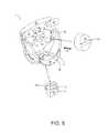
- FIG. 6is an exploded view of a trigger mechanism according to a first embodiment
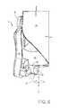
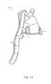
- FIG. 7is a side view of a trigger mechanism according to a first embodiment in which a stop mechanism is in a second condition
- FIG. 8is a side view of a trigger mechanism according to a first embodiment in which a stop mechanism is in the first condition
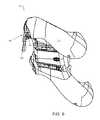
- FIG. 9is a perspective view from below of the rear panel of a games console controller according to a second embodiment.
- FIGS. 10 and 11are perspective views from below of a trigger mechanism according to the second embodiment.
- FIG. 12is an internal view of the trigger mechanism of FIGS. 10 and 11 .
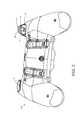
- FIGS. 1 and 2there is shown a controller 1 according to an embodiment of the present invention.
- FIG. 1shows the controls which are mounted on the front and
- FIG. 2shows the controls mounted on the top of the controller 1 .
- the front of the controller 1is provided with left and right analogue thumb sticks 2 , 3 which normally control movement and are intended to be operated by the user's left and right thumbs respectively.
- There are four buttons 4located on a forward-right portion of the controller 1 , which normally control additional actions and are intended to be operated by the user's right thumb.
- There is a direction pad 5located on a forward-left portion of the front of the controller 1 .
- the direction pad 5is intended to be operated by the user's left thumb, typically either as an alternative to the left thumb stick 2 or to provide additional actions.
- the left and right triggers 6 , 7are typically operated by a user's index fingers.
- the left and right bumpers 8 , 9may also be operated by a user's index fingers.
- FIG. 2illustrates a back of the controller 1 .
- Two paddle levers 11 A, 11 Bare mounted to the back of the controller 1 .
- the paddle levers 11 A, 11 Bare configured to replicate the function of one or more of the controls provided upon the front of the controller 1 .
- the paddle levers 11 A, 11 Bare mounted to a housing 12 by a mechanical fixing.
- the housing 12defines a pair of handles H 1 , H 2 which a user may grasp when operating the controller 1 .
- the paddle levers 11 A, 11 Bare configured to be operated by a middle finger of an operator which is wrapped around the handles H 1 , H 2 .
- FIG. 3illustrates a back panel 14 of the controller; the back panel 14 forms a part of the body or housing 12 of the controller 1 .
- the housing 12comprises a pair of apertures A in a top edge thereof.
- the aperturesmay be defined entirely within the back panel 14 or in part in the back panel 14 .
- An actuator, in the form of a trigger mechanism 6extends through each aperture A; one of the trigger mechanisms has been omitted from FIG. 3 for illustrative purposes.
- FIG. 3illustrates a left trigger mechanism 6 extending through one of the apertures A.
- FIGS. 4 to 6illustrate a trigger mechanism 6 for mounting in the apertures A of the housing 12 .
- the Figuresillustrate a left handed trigger mechanism; it will be appreciated that the right handed trigger mechanism is substantially the same in structure albeit a mirror image of that shown in FIGS. 4 to 6 .
- the left and right trigger mechanisms 6 , 7will be described by reference to the left trigger mechanism 6 .
- the trigger mechanism 6is movable through a predefined range of motion with respect to the housing 12 .
- the trigger mechanism 6comprises a trigger body 18 which may be pivotally mounted to the housing 12 ; in the illustrated embodiment the trigger body is mounted to the back panel 14 .
- the trigger mechanism 6comprises a pair of trunnions 22 for pivotally mounting the trigger body 18 to the housing 12 .
- the trigger mechanism 6comprises a sensor, not shown.
- the sensormay comprise a displacement transducer.
- the sensormay be analogue or digital in nature and arranged to measure a parameter indicative of the position of the trigger body 18 with respect to the housing 12 so as to sense or detect the position of the trigger body 18 with respect to the housing 12 .
- the sensormay take the form of: a potentiometer; a magnetic sensor; a Hall effect sensor; or a force or pressure sensitive switch or pad.
- the sensoris coupled to control electronics on a printed circuit board.
- the trigger mechanism 6comprises an interchangeable face plate 20 .
- the face plate 20is mounted to the trigger body 18 by a mechanical fixing such as a snap or bayonet style fitting.
- the trigger mechanism 6comprises a hair trigger mechanism for adjusting the start position or rest position of the trigger body 18 with respect to the back panel 14 .
- the trigger body 18comprises a shaft 30 extending from an inner face of the trigger body 18 .
- An orifice or bore 32extends through the shaft 30 from a front surface of the trigger body 18 to the interior of the trigger body 18 .
- the face plate 20when mounted to the trigger body 18 , conceals or covers the orifice 32 .
- the shaft 30comprises a pair of parallel keys 31 which mate with keyways in a cap 24 .
- the cap 24comprises an orifice or blind hole (not shown) for receiving the shaft 30 .
- the shaft 30may comprise one or more keys 31 or keyways or may comprise a spline. The keys 31 prevent rotation of the cap 24 when mounted upon the shaft 30 .
- a screw(not shown) is mounted into the bore 32 of the shaft 30 .
- the bore 32may comprise an internal screw thread.
- the screwmay be a self-tapping screw and may cut into the side wall of the bore 32 .
- the screwis a grub screw.
- the screwcan be adjusted to bear against an interior face of the cap 24 . In this way the position of the cap 24 , with respect to the inner face of the trigger body 18 , can be adjusted.
- the cap 24is translationally or slideably mounted upon the shaft 30 .
- the pressure sensitive switchis disposed such that the cap 24 cannot be unintentionally dislodged from the shaft 30 .
- the cap 24 and shaft 30may comprise an end stop which prevents the cap detaching from the shaft 30 .
- the cylindrical wall of the cap 24may comprise a bore extending therethrough.
- a second screwmay be received in the bore and partially extend into the interior of the cap 24 .
- a channelmay extend longitudinally along the shaft 30 . The channel may be closed at a first end distal from the inner face to which the shaft 30 is mounted. The second screw may be received in the channel thereby preventing rotation of the cap 24 with respect to the shaft 30 .
- the closed end of the channelforms an end stop preventing separation of the cap 24 from the shaft 30 .
- the cap 24comprises a projection 25 in the form of a rib which defines a contact surface which bears against the pressure sensitive switch.
- the cap 24 and shaft 30form a telescopic arrangement which can be extended and retracted so as to adjust the distance between the contact surface and the inner face of the trigger body 18 .
- the trigger mechanism 6comprises a resilient biasing mechanism.
- the resilient biasing mechanismmay take the form of a spring mounted between the trigger mechanism 6 and the controller housing 12 .
- the springbiases the trigger body 18 to a start or rest position.
- the resilient biasing mechanismmay be incorporated, or integral, with the pressure sensitive switch and arranged such that when the pressure sensitive switch returns to its unbiased or relaxed condition the trigger body 18 is returned to the start or rest position.
- the hair trigger mechanismmay be adjusted such that the cap 24 bears against the pressure sensitive switch and at least partially depresses or activates the pressure sensitive switch. In this way the trigger mechanism applies preload (an adjustable degree of pressure or force) to the pressure sensitive switch. In applications which require a preset magnitude of pressure or force to be applied to the pressure sensitive switch in order to initiate a command instruction, the degree of movement of the trigger body 18 necessary to initiate the command instruction is reduced. In this way the latency of the trigger mechanism 6 is reduced.
- the start or rest position of a sliding contact or wiper with respect to a resistive element, with which it is in electrical contact,is adjusted.
- a magnetic sensorsuch as a Hall effect sensor
- a magnetic sensorcan be mounted or integrally formed with the cap 24 .
- the location of the cap 24 with respect to the magnetic sensorcan be adjusted so as to reduce the latency in the trigger movement.
- the trigger mechanism 6comprises an adjustable stop mechanism 16 .
- the adjustable stop mechanism 16provides an adjustable end stop for limiting the range of motion of the trigger body 18 .
- the adjustable stop mechanism 16defines the maximum displacement or depression of the trigger body 18 with respect to the back panel 14 .
- the adjustable stop mechanism 16allows manual adjustment of the depressible range of the trigger mechanism 6 .
- the trigger body 18comprises a base wall 19 .
- the base wall 19comprises an aperture A 1 .
- the adjustable stop mechanism 16comprises a detent 17 and a rotational mount 28 .
- the rotational mount 28comprises a snap or push fitting including two opposed barbs.
- the detent 17extends or projects downwardly from the base wall 19 of the trigger body 18 .
- the detent 17comprises a pair of opposed surfaces F 1 , F 2 each of which may arrest the travel of the trigger mechanism 6 .
- the detent 17is disposed eccentrically or off-center.
- the detent 17is rotatable between a first, stowed, position shown in FIG. 8 and a second, deployed, position shown in FIG. 7 .
- the range of motion or degree of travel of the trigger mechanism 6can be adjusted by rotating the detent 17 between the first and second positions.
- the second surface F 2faces or opposes the back panel 14 .
- the trigger mechanism 6is depressed sufficiently the second surface F 2 is brought into contact with a portion of the back panel 14 thereby arresting the motion of the trigger mechanism 6 .
- the trigger mechanism 6is moveable through a range of travel ‘y’.
- the first surface F 1faces or opposes the back panel 14 .
- the trigger mechanism 6is depressed sufficiently the first surface F 1 is brought into contact with a portion of the back panel 14 thereby arresting the motion of the trigger mechanism 6 .
- the trigger mechanism 6is moveable through a range of travel ‘x’.
- the range of travel ‘y’is greater than the range of travel ‘x’.
- the detent 17is rotatable about an axis extending substantially radially or perpendicularly from the base wall 19 of the trigger body 18 , as shown in FIG. 5 .
- the detent 17is detachable; this may allow a greater or larger range of travel of the trigger mechanism 6 .
- FIGS. 9 to 12there is shown an alternative embodiment of the present invention.
- like numeralshave, where possible, been used to denote like parts, albeit with the addition of the prefix “100” to indicate that these features belong to the second embodiment.
- the alternative embodimentshares many common features with the first embodiment and therefore only the differences from the embodiment illustrated in FIGS. 1 to 8 will be described in any greater detail.
- the controller 101 of the second embodimentcomprises an elongated face plate 120 .
- the face plate 120is detachably mounted to a trigger body 118 .
- the trigger mechanism 106comprises an adjustable stop mechanism 116 .
- the adjustable stop mechanism 116provides an adjustable end stop for limiting the range of motion of the trigger body 118 .
- the adjustable stop mechanism 116defines the maximum displacement or depression of the trigger body 118 with respect to the back panel 114 .
- the adjustable stop mechanism 116allows manual adjustment of the depressible range of the trigger mechanism 106 .
- the trigger body 118comprises a base wall 119 .
- the base wall 119comprises a cutaway or slot S 1 .
- the adjustable stop mechanism 116comprises an elongated detent 117 and a rotational mount 128 in the form of a pair of second trunnions 142 .
- the second trunnions 142are locatable in a receiver 140 in the form of a partial cylinder.
- the rotational mount 128comprises a snap or push fitting for holding the detent 117 in the receiver 140 .
- the detent 117is rotatable between a retracted or stowed position, in which the detent 117 lies substantially within the interior of the trigger body 118 , and a deployed position in which the detent 117 extends or projects downwardly from the base wall 119 of the trigger body 118 .
- the detent 117comprises a contact surface which arrests the travel of the trigger mechanism 106 .
- the detent 117is disposed eccentrically or off-center.
- the detent 117optionally comprises a retainer 144 , which may take the form of a snap or push fitting, for retaining the detent 117 in the stowed position.
- One advantage of the present inventionis that it allows adjustments to be made to the trigger response; such adjustment could be customized to suit both the nature of the video game that is in use at the time of operation, and the skill of the operator. For example, in combat-style games involving a shooting function, it is often the case that after reaching or passing the command initiation point, no further commands are initiated. In such games further depression of the trigger mechanism 6 , 106 , and hence movement of the displacement transducer or sensor, serves no useful purpose. Therefore the adjustable stop mechanism 16 , 116 , which controls the degree of trigger depression, allows the operator to restrict the amount of travel available to the trigger body 18 , 118 to one of the predefined degrees of travel provided by the adjustable stop mechanism 16 , 116 . The adjustable stop mechanism 16 , 116 , when employing face F 1 or face F 2 , impedes the movement of the trigger body 18 , 118 by striking the housing 12 .
- the faces F 1 and F 2could find application in a variety of other video game genres but for the simplicity of this disclosure, reference is made to combat style games.
- the trigger buttons 6 , 7are employed for throttle control command function and/or a braking control command function.
- the degree of depression of the trigger body 18 , 118is detected by the displacement transducer.
- the degree of depression of the trigger body 18 , 118is converted into a signal, which signal directly relates to a command to be executed by the video game, for example the amount of acceleration or braking to be applied.
- it may be desirable to be able to fully depress the trigger body 18 , 118for example when full depression corresponds to maximum throttle or maximum braking.
- Restricting travel of the trigger body 18 , 118would restrict the throttle control command function where the degree of travel of the trigger body 18 , 118 is proportional to the speed of the vehicle of the simulation.
- the face F 1could be configured to allow full trigger depression.
- a further advantage of the present inventionis that it minimizes the amount of motion an operator's finger must travel, therefore minimizing the recovery time after trigger initiation contacts have been made. This allows the operator to rapidly commence command prompt repeatedly, or to operate different commands more quickly. As the movement that is required to operate commands by depressing the trigger body 18 , 118 is reduced to only that which is required, the risks of any related repetitive strain injury acquired due to the repeated movement of the finger when operating the trigger function would be greatly reduced thereby providing a health benefit to users.
- the present inventionprovides a readily adjustable device to restrict the range of movement of the trigger body 18 , 118 to one of a plurality of predefined ranges.
- a further advantage of this embodimentis that the ergonomic design of the controller is not compromised.
- adjustable stop mechanism 16 , 116can be removed from the trigger body 18 , 118 .
- a replacement adjustable stop mechanism 16 , 116can be inserted and secured. The replacement may provide additional or alternative predefined ranges of motion of the trigger body 18 , 118 .
- the adjustable stop mechanism 16 , 116may comprise faces which are game specific; that is to say, tailored to suit a particular game.
- the cap 24may be omitted.
- a screw(not shown) may be mounted within the bore 32 of the shaft 30 .
- a first end of the screwmay form an abutment surface which acts upon a transducer such as a pressure sensor.
- the cap 24may comprise an internal screw thread and the shaft 30 may comprise an external screw thread matingly received in the internal screw thread.
- An inner face of the end wall of the cap 24may comprise a screw drive such as a hex drive or torx drive or other suitable arrangement for application of torque to the cap 24 .
- the cap 24 or the screw or bothform a second part of a linear actuator, the shaft forming a first part of a linear actuator, the position of the second part with respect to the first part being manually adjustable so as to alter the linear dimension of the linear actuator.
- the linear actuatoris in communication with a transducer or sensor which determines the position of the depressible trigger mechanism with respect to the housing of the controller.
Landscapes
- Engineering & Computer Science (AREA)
- Multimedia (AREA)
- Human Computer Interaction (AREA)
- Position Input By Displaying (AREA)
- Mechanical Control Devices (AREA)
- Input From Keyboards Or The Like (AREA)
Abstract
Description
Claims (18)
Priority Applications (2)
| Application Number | Priority Date | Filing Date | Title |
|---|---|---|---|
| US15/362,134US10220308B2 (en) | 2015-11-27 | 2016-11-28 | Games controller and trigger therefor |
| US16/289,825US10967252B2 (en) | 2015-11-27 | 2019-03-01 | Games controller and trigger therefor |
Applications Claiming Priority (2)
| Application Number | Priority Date | Filing Date | Title |
|---|---|---|---|
| US201562260394P | 2015-11-27 | 2015-11-27 | |
| US15/362,134US10220308B2 (en) | 2015-11-27 | 2016-11-28 | Games controller and trigger therefor |
Related Child Applications (1)
| Application Number | Title | Priority Date | Filing Date |
|---|---|---|---|
| US16/289,825DivisionUS10967252B2 (en) | 2015-11-27 | 2019-03-01 | Games controller and trigger therefor |
Publications (2)
| Publication Number | Publication Date |
|---|---|
| US20170151494A1 US20170151494A1 (en) | 2017-06-01 |
| US10220308B2true US10220308B2 (en) | 2019-03-05 |
Family
ID=58763994
Family Applications (2)
| Application Number | Title | Priority Date | Filing Date |
|---|---|---|---|
| US15/362,134ActiveUS10220308B2 (en) | 2015-11-27 | 2016-11-28 | Games controller and trigger therefor |
| US16/289,825Active2037-02-09US10967252B2 (en) | 2015-11-27 | 2019-03-01 | Games controller and trigger therefor |
Family Applications After (1)
| Application Number | Title | Priority Date | Filing Date |
|---|---|---|---|
| US16/289,825Active2037-02-09US10967252B2 (en) | 2015-11-27 | 2019-03-01 | Games controller and trigger therefor |
Country Status (5)
| Country | Link |
|---|---|
| US (2) | US10220308B2 (en) |
| EP (1) | EP3380207B1 (en) |
| CN (1) | CN108472542B (en) |
| ES (1) | ES2839214T3 (en) |
| WO (1) | WO2017089820A2 (en) |
Cited By (6)
| Publication number | Priority date | Publication date | Assignee | Title |
|---|---|---|---|---|
| US11344809B2 (en)* | 2019-05-23 | 2022-05-31 | Nintendo Co., Ltd. | Game system, game system control method, computer-readable non-transitory storage medium having game program stored therein, and game apparatus |
| US11504612B2 (en)* | 2017-06-12 | 2022-11-22 | Performance Designed Products Llc | Video game controller |
| US11547931B2 (en)* | 2017-10-17 | 2023-01-10 | Sony Interactive Entertainment Inc. | Input apparatus and method |
| US12194375B2 (en) | 2017-01-25 | 2025-01-14 | Kieran S. Lyden | Game controller |
| US12201896B2 (en) | 2021-05-14 | 2025-01-21 | Shenzhen Jinyang Huichuang Technology Company, Ltd. | Game controller and game console |
| US12263399B2 (en) | 2022-10-17 | 2025-04-01 | Ironburg Inventions Limited | Optical user input device |
Families Citing this family (59)
| Publication number | Priority date | Publication date | Assignee | Title |
|---|---|---|---|---|
| WO2015004261A2 (en) | 2013-07-10 | 2015-01-15 | Ironburg Inventions Ltd | Games controller and trigger therefor |
| EP3074101B1 (en) | 2013-11-29 | 2019-08-14 | Ironburg Inventions | Games controller |
| WO2015078987A2 (en) | 2013-11-29 | 2015-06-04 | Ironburg Inventions | Controller for a games console |
| ES2733633T3 (en) | 2014-01-22 | 2019-12-02 | Ironburg Inventions Ltd | Game Controller |
| CN106457038B (en) | 2014-02-05 | 2019-12-31 | 铁堡发明有限公司 | Controller for game host and tool and method thereof |
| CN106794379B (en) | 2014-05-12 | 2020-11-24 | 铁堡发明有限公司 | Game Controller |
| WO2016110586A1 (en) | 2015-01-09 | 2016-07-14 | Ironburg Inventions Ltd | Controller for a games console |
| EP3848102B1 (en) | 2015-09-23 | 2025-06-11 | Ironburg Inventions Limited | Games controller |
| US10427036B2 (en) | 2015-09-24 | 2019-10-01 | Ironburg Inventions Limited | Games controller |
| WO2017060501A1 (en) | 2015-10-09 | 2017-04-13 | Ironburg Inventions Ltd | Games controller |
| ES2839214T3 (en) | 2015-11-27 | 2021-07-05 | Ironburg Inventions Ltd | Game controller and trigger for it |
| JP7083226B2 (en)* | 2016-06-10 | 2022-06-10 | 任天堂株式会社 | Game controller |
| JP6782567B2 (en) | 2016-06-10 | 2020-11-11 | 任天堂株式会社 | Game controller |
| JP6893763B2 (en) | 2016-06-10 | 2021-06-23 | 任天堂株式会社 | Game controller |
| JP6576432B2 (en) | 2016-06-10 | 2019-09-18 | 任天堂株式会社 | Game controller |
| EP3254739B1 (en) | 2016-06-10 | 2020-03-25 | Nintendo Co., Ltd. | Game controller |
| JP6677580B2 (en) | 2016-06-10 | 2020-04-08 | 任天堂株式会社 | Game controller |
| WO2017216571A1 (en) | 2016-06-14 | 2017-12-21 | Ironburg Inventions Limited | Games controller |
| WO2018029450A1 (en) | 2016-08-11 | 2018-02-15 | Ironburg Inventions Limited | Input apparatus for a computer |
| USD819641S1 (en)* | 2016-08-30 | 2018-06-05 | Nintendo Co., Ltd. | Controller for computer |
| WO2018078414A1 (en)* | 2016-10-24 | 2018-05-03 | Staragilis Limited | All in one mobile game controller |
| EP3595788B1 (en) | 2017-03-15 | 2021-09-15 | Ironburg Inventions Limited | Input apparatus for a games console |
| US10183217B2 (en)* | 2017-04-13 | 2019-01-22 | Facebook Technologies, Llc | Hand-held controller using segmented capacitive touch trigger |
| US10537795B2 (en) | 2017-04-26 | 2020-01-21 | Facebook Technologies, Llc | Hand-held controller using LED tracking ring |
| USD831648S1 (en)* | 2017-06-08 | 2018-10-23 | Razer (Asia-Pacific) Pte. Ltd. | Game controller |
| US11103775B2 (en) | 2017-06-12 | 2021-08-31 | Ironburg Inventions Limited | Input apparatus for a games console |
| US10912990B2 (en) | 2017-12-29 | 2021-02-09 | Facebook Technologies, Llc | Hand-held controller using sensors for hand disambiguation |
| USD881283S1 (en) | 2018-09-05 | 2020-04-14 | Ironburg Inventions Limited | Game controller |
| USD889549S1 (en) | 2018-09-05 | 2020-07-07 | Ironburg Inventions Limited | Game controller |
| USD881125S1 (en) | 2018-09-05 | 2020-04-14 | Ironburg Inventions Limited | Game controller motor set |
| USD889550S1 (en) | 2018-09-05 | 2020-07-07 | Ironburg Inventions Limited | Game controller |
| USD881282S1 (en) | 2018-09-05 | 2020-04-14 | Ironburg Inventions Limited | Game controller |
| USD916196S1 (en)* | 2019-01-08 | 2021-04-13 | Jiarui Zhu | Button |
| CN112206506B (en)* | 2019-07-11 | 2025-07-15 | 深圳市壹位堂科技有限公司 | Trigger button and game handle |
| JP7213777B2 (en) | 2019-09-09 | 2023-01-27 | 双葉電子工業株式会社 | radio control transmitter |
| CN111330262B (en)* | 2020-02-27 | 2022-09-23 | 歌尔科技有限公司 | Trigger device and interactive terminal with same |
| USD935460S1 (en)* | 2020-03-31 | 2021-11-09 | Jiarui Zhu | Game controller |
| US12420208B2 (en) | 2020-06-19 | 2025-09-23 | Ironburg Inventions Limited | Input apparatus for a games console |
| USD983269S1 (en) | 2020-06-19 | 2023-04-11 | Ironburg Inventions Limited | Input apparatus for a games console |
| USD956873S1 (en)* | 2020-07-27 | 2022-07-05 | Shenzhen Saitake Electronic Co., Ltd | Game controller |
| USD958253S1 (en)* | 2020-08-11 | 2022-07-19 | Daoyou Wang | Game controller |
| CN112109643B (en)* | 2020-09-14 | 2022-08-30 | 东风汽车有限公司 | Automotive interior component and car |
| USD972037S1 (en)* | 2020-11-13 | 2022-12-06 | Junzhi Wang | Game control pad |
| USD964463S1 (en)* | 2020-12-08 | 2022-09-20 | XiaoHua Luo | Game controller |
| EP4274668A1 (en)* | 2021-01-11 | 2023-11-15 | Ironburg Inventions Limited | Input apparatus for a games console |
| CA201150S (en)* | 2021-02-08 | 2022-10-19 | Collective Minds Gaming Co Ltd | Adapter for a video game controller |
| JP2022170086A (en)* | 2021-04-28 | 2022-11-10 | 双葉電子工業株式会社 | radio control transmitter |
| CN113274739B (en)* | 2021-04-29 | 2023-05-23 | 维沃移动通信有限公司 | Wireless earphone charging box and electronic equipment |
| JP1716778S (en)* | 2021-08-16 | 2022-06-07 | Game console controller | |
| USD967900S1 (en)* | 2021-08-20 | 2022-10-25 | Sen Wang | Gamepad |
| US20230140183A1 (en)* | 2021-11-02 | 2023-05-04 | Panda Hardware LLC | Game controller with adjustable trigger throw length |
| USD1030893S1 (en)* | 2022-03-23 | 2024-06-11 | Jiating Ke | Game controller accessory |
| US20250153040A1 (en)* | 2022-05-05 | 2025-05-15 | Razer (Asia-Pacific) Pte. Ltd. | A Game Controller |
| JP1738104S (en)* | 2022-08-05 | 2023-03-02 | Electronic device controller operation stick | |
| JPWO2024095732A1 (en)* | 2022-10-31 | 2024-05-10 | ||
| SE546236C2 (en)* | 2022-11-11 | 2024-07-23 | Gaim Immersive Tech Group Ab | Triggering mechanism for a weapon |
| USD1040917S1 (en)* | 2022-11-16 | 2024-09-03 | Jiating Ke | Game controller accessory |
| USD1043836S1 (en)* | 2022-11-16 | 2024-09-24 | Jiating Ke | Game controller accessory |
| USD1090709S1 (en)* | 2022-12-09 | 2025-08-26 | Jiarui Zhu | Buttons for game controller |
Citations (79)
| Publication number | Priority date | Publication date | Assignee | Title |
|---|---|---|---|---|
| US4032728A (en) | 1974-12-20 | 1977-06-28 | Olympia Werke Ag | Push button switch |
| US4786768A (en) | 1987-08-20 | 1988-11-22 | Interlock | Manual cursor actuator for electronic keyboards |
| GB2244546A (en) | 1990-05-10 | 1991-12-04 | Primax Electronics Ltd | Computer input device |
| US5430262A (en) | 1992-09-09 | 1995-07-04 | Matsushita Electric Industrial Co., Ltd. | Multiple switch arrangement including membrane dome contacts and multi-directional tilt actuator |
| US5451053A (en) | 1994-09-09 | 1995-09-19 | Garrido; Fernando P. | Reconfigurable video game controller |
| JPH1020951A (en) | 1996-07-02 | 1998-01-23 | Sega Enterp Ltd | Multi-stage trigger device |
| US5773769A (en) | 1994-11-23 | 1998-06-30 | Raymond; Christopher W. | Twin lever key with horizontal finger pads for code transmission |
| US5841372A (en) | 1995-09-06 | 1998-11-24 | Kabushiki Kaisha Sega Enterprises, Ltd. | Operation information input device |
| US5874906A (en) | 1997-09-22 | 1999-02-23 | Wilnel, Inc. | Data entry system |
| US5989123A (en) | 1994-05-20 | 1999-11-23 | Sega Enterprises, Ltd. | Steering wheel control apparatus for a television game machine |
| US6053814A (en)* | 1997-12-04 | 2000-04-25 | Logitech, Inc. | System and method for automatically adjusting game controller sensitivity to player inputs |
| US6203432B1 (en) | 1999-05-11 | 2001-03-20 | Madcatz, Inc. | System for adjusting the response characteristic of an electronic game input device |
| JP2001084077A (en) | 1999-09-10 | 2001-03-30 | Hosiden Corp | Uniaxial type input device |
| US20010003713A1 (en) | 1998-07-20 | 2001-06-14 | Willner Michael A. | Hand held gaming and data entry system |
| US6251015B1 (en) | 1999-03-29 | 2001-06-26 | Micron Electronics, Inc. | Game unit controller with handlebars |
| US20010025778A1 (en) | 2000-03-31 | 2001-10-04 | Atsushi Ono | Switch for game controller |
| US20020052237A1 (en) | 2000-07-21 | 2002-05-02 | Magill Christopher L. | Operating device with pendulum joystick |
| WO2002034345A2 (en) | 2000-10-25 | 2002-05-02 | Eleven Engineering Incorporated | Wireless game control system |
| EP1208883A2 (en) | 2000-11-22 | 2002-05-29 | Universal Electronics, Inc. | Game controller |
| US20020128064A1 (en) | 2001-03-06 | 2002-09-12 | Sobota John F. | Game controller |
| US6512511B2 (en) | 1998-07-20 | 2003-01-28 | Alphagrip, Inc. | Hand grippable combined keyboard and game controller system |
| US20030067111A1 (en) | 2001-10-09 | 2003-04-10 | Logitech Europe S.A. | Game controller lap attachment device |
| WO2003046822A1 (en) | 2001-11-30 | 2003-06-05 | Ziad Badarneh | Manoeuvring device for control of user functions in an electronic appliance endowed with a display |
| US6752719B2 (en) | 1996-03-05 | 2004-06-22 | Sega Enterprises, Ltd. | Controller and expansion unit for controller |
| US20040259059A1 (en) | 2003-02-14 | 2004-12-23 | Honda Motor Co., Ltd. | Interactive driving simulator, and methods of using same |
| US6853308B1 (en) | 2000-08-03 | 2005-02-08 | Matsushita Electric Industrial Co., Ltd. | Multi-sided remote control device |
| US20050083297A1 (en) | 2003-10-17 | 2005-04-21 | Duncan Thomas M. | Ergonomically designed computer gaming device |
| US20050124416A1 (en)* | 2003-11-14 | 2005-06-09 | Michael Hammond | Adjustable tension analog stick for a video game pad |
| US20050215321A1 (en) | 2004-03-29 | 2005-09-29 | Saied Hussaini | Video game controller with integrated trackball control device |
| US20050230230A1 (en) | 2004-04-14 | 2005-10-20 | Ssd Company Limited | Video game controller and game apparatus |
| US20050255918A1 (en)* | 2004-05-11 | 2005-11-17 | Riggs Andrew J | Game controller with sensitivity adjustment |
| US20050255915A1 (en) | 2004-05-11 | 2005-11-17 | Riggs Andrew J | Game controller with interchangeable controls |
| US20060025217A1 (en) | 2004-03-29 | 2006-02-02 | Saied Hussaini | Ergonomically cofigurable video game controller |
| US20060116204A1 (en) | 2004-11-17 | 2006-06-01 | Ultra Electronics Measurement Systems, Inc., A Corporation Of The State Of Delaware | Handheld controller for vehicles |
| EP1852162A1 (en) | 2006-05-02 | 2007-11-07 | Sony Computer Entertainment Inc. | Operating device and game controller |
| US20080261695A1 (en) | 2007-04-19 | 2008-10-23 | Adam Wesley Coe | Game controller |
| US7510477B2 (en) | 2003-12-11 | 2009-03-31 | Argentar Eric J | Control apparatus for use with a computer or video game system |
| US20090088250A1 (en) | 2007-07-29 | 2009-04-02 | E.B. Carlson Marketing, Inc. | Video game device with interchangeable body, interchangeable controller, and methods of use |
| US20090258705A1 (en) | 2008-04-15 | 2009-10-15 | Lee Guinchard | Music video game with guitar controller having auxiliary palm input |
| US20100073283A1 (en) | 2008-09-19 | 2010-03-25 | Robert Enright | Controller with user-selectable discrete button emulation |
| US20100267454A1 (en) | 2009-04-21 | 2010-10-21 | Amir Navid | Connector for video game controller, and video game controller including the same |
| US20100304865A1 (en) | 2009-05-28 | 2010-12-02 | Harmonix Music Systems, Inc. | Simulated Guitar Controller with Split Strum Bar |
| US7859514B1 (en) | 2005-07-19 | 2010-12-28 | Young Park | Multi-functional user interface for electronic devices |
| US20110256930A1 (en) | 2010-04-19 | 2011-10-20 | Guillemot Corporation | Directional game controller |
| US20110281649A1 (en) | 2010-05-12 | 2011-11-17 | Guillemot Corporation | Steering column game controller |
| GB2481633A (en) | 2010-07-01 | 2012-01-04 | Simon David Burgess | Games console controller with buttons on underside |
| WO2012036710A1 (en) | 2010-09-17 | 2012-03-22 | Apple Inc. | Device with foldable cover and user interface for the device |
| US20120088582A1 (en) | 2010-10-08 | 2012-04-12 | Primax Electronics Ltd. | Separable game controller |
| US20120142418A1 (en)* | 2010-09-03 | 2012-06-07 | Hiroaki Muramatsu | Directional pad keystroke adjustment mechanism |
| US20120142419A1 (en) | 2010-09-03 | 2012-06-07 | Hiroaki Muramatsu | Directional Pad Rotating Mechanism |
| EP2479636A2 (en) | 2011-01-25 | 2012-07-25 | Sony Computer Entertainment Inc. | Portable electronic device with rear touch panel |
| US20120260220A1 (en) | 2011-04-06 | 2012-10-11 | Research In Motion Limited | Portable electronic device having gesture recognition and a method for controlling the same |
| CN202528096U (en) | 2012-03-30 | 2012-11-14 | 苏细调 | Internal hexagon wrench |
| US20120299244A1 (en) | 2011-05-26 | 2012-11-29 | Rice Patrick G | Multi-target dart game |
| US20120322553A1 (en) | 2011-06-17 | 2012-12-20 | Ironburg Inventions Ltd. | Controller for video game console |
| US20120322555A1 (en) | 2011-06-17 | 2012-12-20 | Ironburg Inventions Ltd. | Game controller |
| EP2440438B1 (en) | 2009-06-11 | 2013-04-03 | Siemens Aktiengesellschaft | Control device and method for the operation thereof |
| US20130150155A1 (en) | 2000-02-22 | 2013-06-13 | Creative Kingdoms, Llc | Computer-readable storage medium storing program instructions for a wireless computer gaming system |
| US20130147610A1 (en) | 2011-12-09 | 2013-06-13 | Microsoft Corporation | Multi-stage variable resistance trigger |
| CN203077157U (en) | 2012-08-20 | 2013-07-24 | 任锋 | Internal hexagonal wrench embedded with strong magnet |
| US20130196770A1 (en) | 2000-02-22 | 2013-08-01 | Creative Kingdoms, Llc | Customizable toy for playing a wireless interactive game having both physical and virtual elements |
| EP2698185A1 (en) | 2012-04-20 | 2014-02-19 | Nintendo Co., Ltd. | Game controller |
| US8777620B1 (en) | 2006-08-15 | 2014-07-15 | Triggermaster, Inc. | Firearm trigger pull training system and methods |
| US20140274397A1 (en) | 2013-03-13 | 2014-09-18 | Visual Music Systems, Inc. | Platform for finger controls |
| WO2014187923A1 (en) | 2013-05-22 | 2014-11-27 | Ironburg Inventions Ltd | Controller for a games console |
| WO2015004261A2 (en) | 2013-07-10 | 2015-01-15 | Ironburg Inventions Ltd | Games controller and trigger therefor |
| WO2015110553A1 (en) | 2014-01-22 | 2015-07-30 | Ironburg Inventions | Games controller |
| US20150234479A1 (en) | 2014-02-18 | 2015-08-20 | Lenovo (Singapore) Pte, Ltd. | Selectively arrangeable, multi-mode input controller |
| US20150238855A1 (en)* | 2012-09-26 | 2015-08-27 | Razer (Asia-Pacific) Pte. Ltd. | Game controller |
| US20160082349A1 (en) | 2014-05-12 | 2016-03-24 | Ironburg Inventions Ltd. | Games Controller |
| US20160320858A1 (en)* | 2015-04-29 | 2016-11-03 | Playrapid | Command button with adjustable travel for a command input device |
| US20160325177A1 (en)* | 2014-11-30 | 2016-11-10 | T Antonio | Trigger attachment and method for videogame controllers |
| US20160351362A1 (en)* | 2015-05-27 | 2016-12-01 | Microsoft Technology Licensing, Llc | Hair trigger travel stop with on-demand switching |
| US20160346682A1 (en) | 2014-02-05 | 2016-12-01 | Ironburg Inventions | Controller for a games console, tool and a method therefor |
| US20170001107A1 (en) | 2013-11-29 | 2017-01-05 | Ironburg Inventions Ltd. | Controller For A Games Console |
| US20170087456A1 (en) | 2015-09-24 | 2017-03-30 | Ironburg Inventions Ltd. | Games Controller |
| US20170151494A1 (en) | 2015-11-27 | 2017-06-01 | Ironburg Inventions Ltd. | Games Controller and Trigger Therefor |
| US20170157509A1 (en) | 2013-11-29 | 2017-06-08 | Ironburg Inventions Ltd. | Games Controller |
| US9804691B1 (en) | 2012-04-09 | 2017-10-31 | Performance Designed Products Llc | Interchangeable input mechanisms for control devices |
Family Cites Families (7)
| Publication number | Priority date | Publication date | Assignee | Title |
|---|---|---|---|---|
| US3309484A (en)* | 1965-12-27 | 1967-03-14 | Skil Corp | Trigger actuated switch device |
| JP2007036619A (en)* | 2005-07-26 | 2007-02-08 | Biibaruunzu:Kk | Holding unit for mobile operation unit |
| CN201055682Y (en)* | 2007-07-02 | 2008-05-07 | 吴维萍 | Body-building equipment game control device |
| JP2011503744A (en)* | 2007-11-15 | 2011-01-27 | エルゴワークス インターナショナル, エルエルシー. | Mouse with power source |
| US20120244944A1 (en)* | 2009-05-19 | 2012-09-27 | David Kotkin | Game Controller Accessory |
| US20140018173A1 (en)* | 2012-07-10 | 2014-01-16 | Ouya, Inc. | Video game controller with integrated touchpad |
| CN104667525B (en)* | 2013-11-29 | 2020-08-04 | 艾朗博格发明有限公司 | Game controller |
- 2016
- 2016-11-25ESES16804879Tpatent/ES2839214T3/enactiveActive
- 2016-11-25EPEP16804879.1Apatent/EP3380207B1/enactiveActive
- 2016-11-25WOPCT/GB2016/053712patent/WO2017089820A2/ennot_activeCeased
- 2016-11-25CNCN201680079086.9Apatent/CN108472542B/ennot_activeExpired - Fee Related
- 2016-11-28USUS15/362,134patent/US10220308B2/enactiveActive
- 2019
- 2019-03-01USUS16/289,825patent/US10967252B2/enactiveActive
Patent Citations (87)
| Publication number | Priority date | Publication date | Assignee | Title |
|---|---|---|---|---|
| US4032728A (en) | 1974-12-20 | 1977-06-28 | Olympia Werke Ag | Push button switch |
| US4786768A (en) | 1987-08-20 | 1988-11-22 | Interlock | Manual cursor actuator for electronic keyboards |
| GB2244546A (en) | 1990-05-10 | 1991-12-04 | Primax Electronics Ltd | Computer input device |
| US5430262A (en) | 1992-09-09 | 1995-07-04 | Matsushita Electric Industrial Co., Ltd. | Multiple switch arrangement including membrane dome contacts and multi-directional tilt actuator |
| US5989123A (en) | 1994-05-20 | 1999-11-23 | Sega Enterprises, Ltd. | Steering wheel control apparatus for a television game machine |
| US5451053A (en) | 1994-09-09 | 1995-09-19 | Garrido; Fernando P. | Reconfigurable video game controller |
| US5773769A (en) | 1994-11-23 | 1998-06-30 | Raymond; Christopher W. | Twin lever key with horizontal finger pads for code transmission |
| US5841372A (en) | 1995-09-06 | 1998-11-24 | Kabushiki Kaisha Sega Enterprises, Ltd. | Operation information input device |
| US6752719B2 (en) | 1996-03-05 | 2004-06-22 | Sega Enterprises, Ltd. | Controller and expansion unit for controller |
| JPH1020951A (en) | 1996-07-02 | 1998-01-23 | Sega Enterp Ltd | Multi-stage trigger device |
| US5874906A (en) | 1997-09-22 | 1999-02-23 | Wilnel, Inc. | Data entry system |
| US6053814A (en)* | 1997-12-04 | 2000-04-25 | Logitech, Inc. | System and method for automatically adjusting game controller sensitivity to player inputs |
| US6512511B2 (en) | 1998-07-20 | 2003-01-28 | Alphagrip, Inc. | Hand grippable combined keyboard and game controller system |
| US20010003713A1 (en) | 1998-07-20 | 2001-06-14 | Willner Michael A. | Hand held gaming and data entry system |
| US6760013B2 (en) | 1998-07-20 | 2004-07-06 | Alphagrip, Inc. | Hand held gaming and data entry system |
| US6251015B1 (en) | 1999-03-29 | 2001-06-26 | Micron Electronics, Inc. | Game unit controller with handlebars |
| US6203432B1 (en) | 1999-05-11 | 2001-03-20 | Madcatz, Inc. | System for adjusting the response characteristic of an electronic game input device |
| JP2001084077A (en) | 1999-09-10 | 2001-03-30 | Hosiden Corp | Uniaxial type input device |
| US20130150155A1 (en) | 2000-02-22 | 2013-06-13 | Creative Kingdoms, Llc | Computer-readable storage medium storing program instructions for a wireless computer gaming system |
| US20130196770A1 (en) | 2000-02-22 | 2013-08-01 | Creative Kingdoms, Llc | Customizable toy for playing a wireless interactive game having both physical and virtual elements |
| US20010025778A1 (en) | 2000-03-31 | 2001-10-04 | Atsushi Ono | Switch for game controller |
| US20020052237A1 (en) | 2000-07-21 | 2002-05-02 | Magill Christopher L. | Operating device with pendulum joystick |
| US6853308B1 (en) | 2000-08-03 | 2005-02-08 | Matsushita Electric Industrial Co., Ltd. | Multi-sided remote control device |
| WO2002034345A2 (en) | 2000-10-25 | 2002-05-02 | Eleven Engineering Incorporated | Wireless game control system |
| EP1208883A2 (en) | 2000-11-22 | 2002-05-29 | Universal Electronics, Inc. | Game controller |
| US20020128064A1 (en) | 2001-03-06 | 2002-09-12 | Sobota John F. | Game controller |
| US20030067111A1 (en) | 2001-10-09 | 2003-04-10 | Logitech Europe S.A. | Game controller lap attachment device |
| WO2003046822A1 (en) | 2001-11-30 | 2003-06-05 | Ziad Badarneh | Manoeuvring device for control of user functions in an electronic appliance endowed with a display |
| US20040259059A1 (en) | 2003-02-14 | 2004-12-23 | Honda Motor Co., Ltd. | Interactive driving simulator, and methods of using same |
| US20050083297A1 (en) | 2003-10-17 | 2005-04-21 | Duncan Thomas M. | Ergonomically designed computer gaming device |
| US20050124416A1 (en)* | 2003-11-14 | 2005-06-09 | Michael Hammond | Adjustable tension analog stick for a video game pad |
| US7510477B2 (en) | 2003-12-11 | 2009-03-31 | Argentar Eric J | Control apparatus for use with a computer or video game system |
| US20050215321A1 (en) | 2004-03-29 | 2005-09-29 | Saied Hussaini | Video game controller with integrated trackball control device |
| US20060025217A1 (en) | 2004-03-29 | 2006-02-02 | Saied Hussaini | Ergonomically cofigurable video game controller |
| US20050230230A1 (en) | 2004-04-14 | 2005-10-20 | Ssd Company Limited | Video game controller and game apparatus |
| US20050255918A1 (en)* | 2004-05-11 | 2005-11-17 | Riggs Andrew J | Game controller with sensitivity adjustment |
| US20050255915A1 (en) | 2004-05-11 | 2005-11-17 | Riggs Andrew J | Game controller with interchangeable controls |
| US7758424B2 (en) | 2004-05-11 | 2010-07-20 | Mattel, Inc. | Game controller with interchangeable controls |
| US20060116204A1 (en) | 2004-11-17 | 2006-06-01 | Ultra Electronics Measurement Systems, Inc., A Corporation Of The State Of Delaware | Handheld controller for vehicles |
| US7859514B1 (en) | 2005-07-19 | 2010-12-28 | Young Park | Multi-functional user interface for electronic devices |
| US20070281787A1 (en) | 2006-05-02 | 2007-12-06 | Tetsu Numata | Operating device and game controller |
| EP1852162A1 (en) | 2006-05-02 | 2007-11-07 | Sony Computer Entertainment Inc. | Operating device and game controller |
| US8777620B1 (en) | 2006-08-15 | 2014-07-15 | Triggermaster, Inc. | Firearm trigger pull training system and methods |
| WO2008131249A1 (en) | 2007-04-19 | 2008-10-30 | Coe Adam W | Game controller |
| US20080261695A1 (en) | 2007-04-19 | 2008-10-23 | Adam Wesley Coe | Game controller |
| US20090088250A1 (en) | 2007-07-29 | 2009-04-02 | E.B. Carlson Marketing, Inc. | Video game device with interchangeable body, interchangeable controller, and methods of use |
| US20090258705A1 (en) | 2008-04-15 | 2009-10-15 | Lee Guinchard | Music video game with guitar controller having auxiliary palm input |
| US20100073283A1 (en) | 2008-09-19 | 2010-03-25 | Robert Enright | Controller with user-selectable discrete button emulation |
| US20100267454A1 (en) | 2009-04-21 | 2010-10-21 | Amir Navid | Connector for video game controller, and video game controller including the same |
| US20100304865A1 (en) | 2009-05-28 | 2010-12-02 | Harmonix Music Systems, Inc. | Simulated Guitar Controller with Split Strum Bar |
| EP2440438B1 (en) | 2009-06-11 | 2013-04-03 | Siemens Aktiengesellschaft | Control device and method for the operation thereof |
| US20110256930A1 (en) | 2010-04-19 | 2011-10-20 | Guillemot Corporation | Directional game controller |
| US20110281649A1 (en) | 2010-05-12 | 2011-11-17 | Guillemot Corporation | Steering column game controller |
| GB2481633A (en) | 2010-07-01 | 2012-01-04 | Simon David Burgess | Games console controller with buttons on underside |
| US20120142419A1 (en) | 2010-09-03 | 2012-06-07 | Hiroaki Muramatsu | Directional Pad Rotating Mechanism |
| US20120142418A1 (en)* | 2010-09-03 | 2012-06-07 | Hiroaki Muramatsu | Directional pad keystroke adjustment mechanism |
| WO2012036710A1 (en) | 2010-09-17 | 2012-03-22 | Apple Inc. | Device with foldable cover and user interface for the device |
| US20120088582A1 (en) | 2010-10-08 | 2012-04-12 | Primax Electronics Ltd. | Separable game controller |
| EP2479636A2 (en) | 2011-01-25 | 2012-07-25 | Sony Computer Entertainment Inc. | Portable electronic device with rear touch panel |
| US20120260220A1 (en) | 2011-04-06 | 2012-10-11 | Research In Motion Limited | Portable electronic device having gesture recognition and a method for controlling the same |
| US20120299244A1 (en) | 2011-05-26 | 2012-11-29 | Rice Patrick G | Multi-target dart game |
| US20120322555A1 (en) | 2011-06-17 | 2012-12-20 | Ironburg Inventions Ltd. | Game controller |
| US20120322553A1 (en) | 2011-06-17 | 2012-12-20 | Ironburg Inventions Ltd. | Controller for video game console |
| US8641525B2 (en) | 2011-06-17 | 2014-02-04 | Ironburg Inventions Ltd. | Controller for video game console |
| US9089770B2 (en) | 2011-06-17 | 2015-07-28 | Ironburg Inventions Ltd. | Controller for video game console |
| US20130147610A1 (en) | 2011-12-09 | 2013-06-13 | Microsoft Corporation | Multi-stage variable resistance trigger |
| CN202528096U (en) | 2012-03-30 | 2012-11-14 | 苏细调 | Internal hexagon wrench |
| US9804691B1 (en) | 2012-04-09 | 2017-10-31 | Performance Designed Products Llc | Interchangeable input mechanisms for control devices |
| EP2698185A1 (en) | 2012-04-20 | 2014-02-19 | Nintendo Co., Ltd. | Game controller |
| CN203077157U (en) | 2012-08-20 | 2013-07-24 | 任锋 | Internal hexagonal wrench embedded with strong magnet |
| US20150238855A1 (en)* | 2012-09-26 | 2015-08-27 | Razer (Asia-Pacific) Pte. Ltd. | Game controller |
| US20140274397A1 (en) | 2013-03-13 | 2014-09-18 | Visual Music Systems, Inc. | Platform for finger controls |
| WO2014187923A1 (en) | 2013-05-22 | 2014-11-27 | Ironburg Inventions Ltd | Controller for a games console |
| WO2015004261A2 (en) | 2013-07-10 | 2015-01-15 | Ironburg Inventions Ltd | Games controller and trigger therefor |
| US20160193529A1 (en) | 2013-07-10 | 2016-07-07 | Ironburg Inventions Ltd. | Games Controller and Trigger Therefor |
| US20170157509A1 (en) | 2013-11-29 | 2017-06-08 | Ironburg Inventions Ltd. | Games Controller |
| US20170001107A1 (en) | 2013-11-29 | 2017-01-05 | Ironburg Inventions Ltd. | Controller For A Games Console |
| WO2015110553A1 (en) | 2014-01-22 | 2015-07-30 | Ironburg Inventions | Games controller |
| US20170001108A1 (en) | 2014-01-22 | 2017-01-05 | Ironburg Inventions Ltd. | Games controller |
| US20160346682A1 (en) | 2014-02-05 | 2016-12-01 | Ironburg Inventions | Controller for a games console, tool and a method therefor |
| US20150234479A1 (en) | 2014-02-18 | 2015-08-20 | Lenovo (Singapore) Pte, Ltd. | Selectively arrangeable, multi-mode input controller |
| US20160082349A1 (en) | 2014-05-12 | 2016-03-24 | Ironburg Inventions Ltd. | Games Controller |
| US20160325177A1 (en)* | 2014-11-30 | 2016-11-10 | T Antonio | Trigger attachment and method for videogame controllers |
| US20160320858A1 (en)* | 2015-04-29 | 2016-11-03 | Playrapid | Command button with adjustable travel for a command input device |
| US20160351362A1 (en)* | 2015-05-27 | 2016-12-01 | Microsoft Technology Licensing, Llc | Hair trigger travel stop with on-demand switching |
| US20170087456A1 (en) | 2015-09-24 | 2017-03-30 | Ironburg Inventions Ltd. | Games Controller |
| US20170151494A1 (en) | 2015-11-27 | 2017-06-01 | Ironburg Inventions Ltd. | Games Controller and Trigger Therefor |
Non-Patent Citations (20)
| Title |
|---|
| "Rapid Fire Mod for Wireless Xbox 360 Controller," forum on xbox-scene.com, (2008). |
| "Thrustmaster USB game controller roundup," dansdata.com/tmsticks.htm (2002). |
| Burns, "Review: Scuf Xbox 360 Controller," Xboxer360.com (2010). |
| Coles, Olin, "Thrustmaster Run-N-Drive PC/PS3 Wireless Gamepad" BenchmarkReviews.com (2009). |
| Combined Search and Examination Report, GB1011078.1 (dated 2011). |
| Corrected Petition for Inter Partes Review of U.S. Pat. No. 8,641,525, Under 37 C.F.R. § 42.100, filed by Valve Corporation, Case IPR2016-00948 (2016). |
| Corrected Petition for Inter Partes Review of U.S. Pat. No. 9,089,770, Under 37 C.F.R. § 42.100, filed by Valve Corporation, Case IPR2016-00949 (2016). |
| International Search Report, PCT/EP2014/060587 (dated 2014). |
| International Search Report, PCT/EP2014/075851 (dated 2015). |
| International Search Report, PCT/EP2014/075861 (dated 2015). |
| International Search Report, PCT/EP2015/051290 (dated 2015). |
| International Search Report, PCT/EP2015/052448 (dated 2015). |
| International Search Report, PCT/EP2015/058096 (dated 2015). |
| Office Action, U.S. Appl. No. 14/736,771 (dated 2015). |
| Office Action, U.S. Appl. No. 14/805,597 (dated 2015). |
| Office Action, U.S. Appl. No. 14/805,641 (dated 2015). |
| Office Action, U.S. Appl. No. 14/832,211 (dated 2015). |
| World Intellectual Property Office, International Search Report, PCT/GB2016/053712 (dated Feb. 27, 2017). |
| Written Opinion of the International Searching Authority, PCT/EP2015/058096 (dated 2015). |
| Xbox 360 Wireless Controller Tour, published on May 13, 2005 at http://www.ign.com/articles/2005/05/13/xbox-360-wireless-controller-tour. |
Cited By (8)
| Publication number | Priority date | Publication date | Assignee | Title |
|---|---|---|---|---|
| US12194375B2 (en) | 2017-01-25 | 2025-01-14 | Kieran S. Lyden | Game controller |
| US11504612B2 (en)* | 2017-06-12 | 2022-11-22 | Performance Designed Products Llc | Video game controller |
| US11547931B2 (en)* | 2017-10-17 | 2023-01-10 | Sony Interactive Entertainment Inc. | Input apparatus and method |
| US11344809B2 (en)* | 2019-05-23 | 2022-05-31 | Nintendo Co., Ltd. | Game system, game system control method, computer-readable non-transitory storage medium having game program stored therein, and game apparatus |
| US11559742B2 (en) | 2019-05-23 | 2023-01-24 | Nintendo Co., Ltd. | Computer-readable non-transitory storage medium having game program stored therein, game system, game apparatus control method, and game apparatus |
| US11712625B2 (en) | 2019-05-23 | 2023-08-01 | Nintendo Co., Ltd. | Game system, game system control method, computer-readable non-transitory storage medium having game program stored therein, and game apparatus |
| US12201896B2 (en) | 2021-05-14 | 2025-01-21 | Shenzhen Jinyang Huichuang Technology Company, Ltd. | Game controller and game console |
| US12263399B2 (en) | 2022-10-17 | 2025-04-01 | Ironburg Inventions Limited | Optical user input device |
Also Published As
| Publication number | Publication date |
|---|---|
| US10967252B2 (en) | 2021-04-06 |
| WO2017089820A2 (en) | 2017-06-01 |
| EP3380207A2 (en) | 2018-10-03 |
| CN108472542A (en) | 2018-08-31 |
| WO2017089820A3 (en) | 2017-07-13 |
| US20190255431A1 (en) | 2019-08-22 |
| US20170151494A1 (en) | 2017-06-01 |
| CN108472542B (en) | 2021-07-06 |
| EP3380207B1 (en) | 2020-10-28 |
| ES2839214T3 (en) | 2021-07-05 |
Similar Documents
| Publication | Publication Date | Title |
|---|---|---|
| US10967252B2 (en) | Games controller and trigger therefor | |
| EP3019257B1 (en) | Games controller and trigger therefor | |
| US10857454B2 (en) | Games controller | |
| US20220001275A1 (en) | Games controller | |
| US9308450B2 (en) | Game controller | |
| CN104667525B (en) | Game controller |
Legal Events
| Date | Code | Title | Description |
|---|---|---|---|
| AS | Assignment | Owner name:IRONBURG INVENTIONS LTD., UNITED KINGDOM Free format text:ASSIGNMENT OF ASSIGNORS INTEREST;ASSIGNORS:IRONMONGER, DUNCAN;JEFFREY, CARL S.;REEL/FRAME:040432/0723 Effective date:20151127 | |
| AS | Assignment | Owner name:TRIANGLE CAPITAL CORPORATION, NORTH CAROLINA Free format text:SECURITY INTEREST;ASSIGNOR:IRONBURG INVENTIONS LIMITED;REEL/FRAME:040878/0527 Effective date:20161207 | |
| AS | Assignment | Owner name:TRIANGLE CAPITAL CORPORATION, AS AGENT, NORTH CAROLINA Free format text:SECURITY INTEREST;ASSIGNOR:IRONBURG INVENTIONS LIMITED;REEL/FRAME:040884/0057 Effective date:20161207 Owner name:TRIANGLE CAPITAL CORPORATION, AS AGENT, NORTH CARO Free format text:SECURITY INTEREST;ASSIGNOR:IRONBURG INVENTIONS LIMITED;REEL/FRAME:040884/0057 Effective date:20161207 | |
| STCF | Information on status: patent grant | Free format text:PATENTED CASE | |
| AS | Assignment | Owner name:IRONBURG INVENTIONS LIMITED, UNITED KINGDOM Free format text:RELEASE BY SECURED PARTY;ASSIGNOR:BSP AGENCY LLC;REEL/FRAME:051569/0397 Effective date:20191219 | |
| FEPP | Fee payment procedure | Free format text:SURCHARGE FOR LATE PAYMENT, LARGE ENTITY (ORIGINAL EVENT CODE: M1554); ENTITY STATUS OF PATENT OWNER: LARGE ENTITY | |
| MAFP | Maintenance fee payment | Free format text:PAYMENT OF MAINTENANCE FEE, 4TH YEAR, LARGE ENTITY (ORIGINAL EVENT CODE: M1551); ENTITY STATUS OF PATENT OWNER: LARGE ENTITY Year of fee payment:4 |