US10219973B2 - System and method utilizing vacuum for promoting the healing of sprains - Google Patents
System and method utilizing vacuum for promoting the healing of sprainsDownload PDFInfo
- Publication number
- US10219973B2 US10219973B2US14/204,878US201414204878AUS10219973B2US 10219973 B2US10219973 B2US 10219973B2US 201414204878 AUS201414204878 AUS 201414204878AUS 10219973 B2US10219973 B2US 10219973B2
- Authority
- US
- United States
- Prior art keywords
- manifold
- intact skin
- vacuum
- sleeve
- aperture
- Prior art date
- Legal status (The legal status is an assumption and is not a legal conclusion. Google has not performed a legal analysis and makes no representation as to the accuracy of the status listed.)
- Active, expires
Links
- 238000000034methodMethods0.000titleclaimsabstractdescription21
- 230000001737promoting effectEffects0.000titleclaimsabstractdescription13
- 208000010040Sprains and StrainsDiseases0.000titleabstractdescription41
- 230000035876healingEffects0.000titledescription17
- 239000012530fluidSubstances0.000claimsabstractdescription49
- 230000008878couplingEffects0.000claimsabstractdescription23
- 238000010168coupling processMethods0.000claimsabstractdescription23
- 238000005859coupling reactionMethods0.000claimsabstractdescription23
- 230000010412perfusionEffects0.000claimsabstractdescription17
- 239000011148porous materialSubstances0.000claimsabstractdescription10
- 239000000463materialSubstances0.000claimsdescription47
- 239000006260foamSubstances0.000claimsdescription11
- 239000000853adhesiveSubstances0.000claimsdescription8
- 230000001070adhesive effectEffects0.000claimsdescription8
- 238000004891communicationMethods0.000claimsdescription7
- 238000007789sealingMethods0.000claimsdescription4
- 239000013536elastomeric materialSubstances0.000claimsdescription3
- 239000002390adhesive tapeSubstances0.000claimsdescription2
- 239000002210silicon-based materialSubstances0.000claimsdescription2
- 206010024453Ligament sprainDiseases0.000abstractdescription26
- 210000001519tissueAnatomy0.000description105
- 210000003491skinAnatomy0.000description91
- 210000003414extremityAnatomy0.000description27
- 208000014674injuryDiseases0.000description27
- 238000002560therapeutic procedureMethods0.000description26
- 208000027418Wounds and injuryDiseases0.000description24
- 230000006378damageEffects0.000description24
- 238000011282treatmentMethods0.000description19
- 208000002193PainDiseases0.000description18
- 210000003423ankleAnatomy0.000description17
- 210000002683footAnatomy0.000description13
- 230000006837decompressionEffects0.000description12
- 210000003041ligamentAnatomy0.000description12
- 239000003566sealing materialSubstances0.000description11
- 206010042674SwellingDiseases0.000description10
- 210000002615epidermisAnatomy0.000description10
- 230000008961swellingEffects0.000description10
- 210000003205muscleAnatomy0.000description9
- 230000004054inflammatory processEffects0.000description8
- 230000001225therapeutic effectEffects0.000description8
- 206010030113OedemaDiseases0.000description7
- 230000008901benefitEffects0.000description7
- 230000017531blood circulationEffects0.000description7
- 230000006835compressionEffects0.000description7
- 238000007906compressionMethods0.000description7
- 206010061218InflammationDiseases0.000description6
- 230000000845anti-microbial effectEffects0.000description6
- 210000000544articulatio talocruralisAnatomy0.000description6
- 210000004027cellAnatomy0.000description6
- 230000006870functionEffects0.000description6
- 235000019645odorNutrition0.000description6
- 239000003610charcoalSubstances0.000description5
- 239000002131composite materialSubstances0.000description5
- 206010052428WoundDiseases0.000description4
- 230000000694effectsEffects0.000description4
- 239000006261foam materialSubstances0.000description4
- 239000007788liquidSubstances0.000description4
- 230000033001locomotionEffects0.000description4
- 210000002751lymphAnatomy0.000description4
- 230000037081physical activityEffects0.000description4
- 239000000126substanceSubstances0.000description4
- 238000001356surgical procedureMethods0.000description4
- 208000024891symptomDiseases0.000description4
- 230000008733traumaEffects0.000description4
- XUIMIQQOPSSXEZ-UHFFFAOYSA-NSiliconChemical compound[Si]XUIMIQQOPSSXEZ-UHFFFAOYSA-N0.000description3
- 239000003522acrylic cementSubstances0.000description3
- 239000008280bloodSubstances0.000description3
- 210000004369bloodAnatomy0.000description3
- 239000003795chemical substances by applicationSubstances0.000description3
- 230000007423decreaseEffects0.000description3
- 210000000416exudates and transudateAnatomy0.000description3
- 230000002209hydrophobic effectEffects0.000description3
- 210000003127kneeAnatomy0.000description3
- 229920001296polysiloxanePolymers0.000description3
- 230000002035prolonged effectEffects0.000description3
- 239000010703siliconSubstances0.000description3
- 229910052710siliconInorganic materials0.000description3
- 238000007920subcutaneous administrationMethods0.000description3
- 230000002459sustained effectEffects0.000description3
- 208000034656ContusionsDiseases0.000description2
- NTYJJOPFIAHURM-UHFFFAOYSA-NHistamineChemical compoundNCCC1=CN=CN1NTYJJOPFIAHURM-UHFFFAOYSA-N0.000description2
- 241000209094OryzaSpecies0.000description2
- 235000007164Oryza sativaNutrition0.000description2
- BQCADISMDOOEFD-UHFFFAOYSA-NSilverChemical compound[Ag]BQCADISMDOOEFD-UHFFFAOYSA-N0.000description2
- 206010040880Skin irritationDiseases0.000description2
- 230000002159abnormal effectEffects0.000description2
- 238000009825accumulationMethods0.000description2
- 230000004075alterationEffects0.000description2
- 210000000988bone and boneAnatomy0.000description2
- 230000007547defectEffects0.000description2
- 239000013013elastic materialSubstances0.000description2
- 239000000499gelSubstances0.000description2
- 239000000416hydrocolloidSubstances0.000description2
- 239000000017hydrogelSubstances0.000description2
- 210000002414legAnatomy0.000description2
- -1organogelSubstances0.000description2
- 206010033675panniculitisDiseases0.000description2
- 230000037361pathwayEffects0.000description2
- 230000035699permeabilityEffects0.000description2
- 239000004814polyurethaneSubstances0.000description2
- 229920002635polyurethanePolymers0.000description2
- 239000004800polyvinyl chlorideSubstances0.000description2
- 230000008569processEffects0.000description2
- 238000012545processingMethods0.000description2
- 230000009467reductionEffects0.000description2
- 230000008439repair processEffects0.000description2
- 235000009566riceNutrition0.000description2
- QZAYGJVTTNCVMB-UHFFFAOYSA-NserotoninChemical compoundC1=C(O)C=C2C(CCN)=CNC2=C1QZAYGJVTTNCVMB-UHFFFAOYSA-N0.000description2
- 230000011664signalingEffects0.000description2
- 229910052709silverInorganic materials0.000description2
- 239000004332silverSubstances0.000description2
- 230000036556skin irritationEffects0.000description2
- 231100000475skin irritationToxicity0.000description2
- 210000004304subcutaneous tissueAnatomy0.000description2
- 239000004753textileSubstances0.000description2
- 230000002792vascularEffects0.000description2
- 241001247482AmsoniaSpecies0.000description1
- 101800004538BradykininProteins0.000description1
- 206010016228FasciitisDiseases0.000description1
- 206010017533Fungal infectionDiseases0.000description1
- QXZGBUJJYSLZLT-UHFFFAOYSA-NH-Arg-Pro-Pro-Gly-Phe-Ser-Pro-Phe-Arg-OHNatural productsNC(N)=NCCCC(N)C(=O)N1CCCC1C(=O)N1C(C(=O)NCC(=O)NC(CC=2C=CC=CC=2)C(=O)NC(CO)C(=O)N2C(CCC2)C(=O)NC(CC=2C=CC=CC=2)C(=O)NC(CCCN=C(N)N)C(O)=O)CCC1QXZGBUJJYSLZLT-UHFFFAOYSA-N0.000description1
- 206010060820Joint injuryDiseases0.000description1
- 102100035792Kininogen-1Human genes0.000description1
- 208000016593Knee injuryDiseases0.000description1
- 208000031888MycosesDiseases0.000description1
- 239000004677NylonSubstances0.000description1
- 239000004721Polyphenylene oxideSubstances0.000description1
- 229920005830Polyurethane FoamPolymers0.000description1
- 239000004372Polyvinyl alcoholSubstances0.000description1
- 239000004820Pressure-sensitive adhesiveSubstances0.000description1
- 208000031074ReinjuryDiseases0.000description1
- 238000010521absorption reactionMethods0.000description1
- 230000001154acute effectEffects0.000description1
- 208000038016acute inflammationDiseases0.000description1
- 230000006022acute inflammationEffects0.000description1
- 239000000654additiveSubstances0.000description1
- 230000000996additive effectEffects0.000description1
- 210000000577adipose tissueAnatomy0.000description1
- 210000003484anatomyAnatomy0.000description1
- 230000009286beneficial effectEffects0.000description1
- 210000001601blood-air barrierAnatomy0.000description1
- QXZGBUJJYSLZLT-FDISYFBBSA-NbradykininChemical compoundNC(=N)NCCC[C@H](N)C(=O)N1CCC[C@H]1C(=O)N1[C@H](C(=O)NCC(=O)N[C@@H](CC=2C=CC=CC=2)C(=O)N[C@@H](CO)C(=O)N2[C@@H](CCC2)C(=O)N[C@@H](CC=2C=CC=CC=2)C(=O)N[C@@H](CCCNC(N)=N)C(O)=O)CCC1QXZGBUJJYSLZLT-FDISYFBBSA-N0.000description1
- 210000000845cartilageAnatomy0.000description1
- 230000001413cellular effectEffects0.000description1
- 238000012412chemical couplingMethods0.000description1
- 230000004087circulationEffects0.000description1
- 239000011248coating agentSubstances0.000description1
- 238000000576coating methodMethods0.000description1
- 210000002808connective tissueAnatomy0.000description1
- 230000009519contusionEffects0.000description1
- 238000001816coolingMethods0.000description1
- 210000004207dermisAnatomy0.000description1
- 230000003467diminishing effectEffects0.000description1
- 230000009977dual effectEffects0.000description1
- 230000002500effect on skinEffects0.000description1
- 210000002310elbow jointAnatomy0.000description1
- 230000008030eliminationEffects0.000description1
- 238000003379elimination reactionMethods0.000description1
- 230000002255enzymatic effectEffects0.000description1
- 238000001704evaporationMethods0.000description1
- 230000008020evaporationEffects0.000description1
- 238000001125extrusionMethods0.000description1
- 210000002082fibulaAnatomy0.000description1
- 230000005714functional activityEffects0.000description1
- 229960001340histamineDrugs0.000description1
- 230000002706hydrostatic effectEffects0.000description1
- 208000015181infectious diseaseDiseases0.000description1
- 210000000629knee jointAnatomy0.000description1
- 239000000314lubricantSubstances0.000description1
- 230000003692lymphatic flowEffects0.000description1
- 230000002879macerating effectEffects0.000description1
- 238000002803macerationMethods0.000description1
- 238000007726management methodMethods0.000description1
- 230000007246mechanismEffects0.000description1
- 229920002529medical grade siliconePolymers0.000description1
- 239000000155meltSubstances0.000description1
- 229910052751metalInorganic materials0.000description1
- 239000002184metalSubstances0.000description1
- 150000002739metalsChemical class0.000description1
- 230000004048modificationEffects0.000description1
- 238000012986modificationMethods0.000description1
- 238000000465mouldingMethods0.000description1
- 230000004118muscle contractionEffects0.000description1
- 230000001537neural effectEffects0.000description1
- 229920001778nylonPolymers0.000description1
- 230000002853ongoing effectEffects0.000description1
- 239000006072pasteSubstances0.000description1
- 229920003023plasticPolymers0.000description1
- 239000004033plasticSubstances0.000description1
- 229920000728polyesterPolymers0.000description1
- 229920000570polyetherPolymers0.000description1
- 229920000642polymerPolymers0.000description1
- 239000011496polyurethane foamSubstances0.000description1
- 229920002451polyvinyl alcoholPolymers0.000description1
- 229920000915polyvinyl chloridePolymers0.000description1
- 150000003180prostaglandinsChemical class0.000description1
- 230000004044responseEffects0.000description1
- 229940076279serotoninDrugs0.000description1
- 238000006467substitution reactionMethods0.000description1
- 239000000758substrateSubstances0.000description1
- 210000004243sweatAnatomy0.000description1
- 210000002435tendonAnatomy0.000description1
- 229920002725thermoplastic elastomerPolymers0.000description1
- 210000002303tibiaAnatomy0.000description1
- 238000012546transferMethods0.000description1
- 230000007704transitionEffects0.000description1
- 238000002834transmittanceMethods0.000description1
- 230000000472traumatic effectEffects0.000description1
- 238000011144upstream manufacturingMethods0.000description1
- 239000012855volatile organic compoundSubstances0.000description1
- 239000002699waste materialSubstances0.000description1
- 210000003857wrist jointAnatomy0.000description1
Images


Classifications
- A—HUMAN NECESSITIES
- A61—MEDICAL OR VETERINARY SCIENCE; HYGIENE
- A61H—PHYSICAL THERAPY APPARATUS, e.g. DEVICES FOR LOCATING OR STIMULATING REFLEX POINTS IN THE BODY; ARTIFICIAL RESPIRATION; MASSAGE; BATHING DEVICES FOR SPECIAL THERAPEUTIC OR HYGIENIC PURPOSES OR SPECIFIC PARTS OF THE BODY
- A61H9/00—Pneumatic or hydraulic massage
- A61H9/005—Pneumatic massage
- A61H9/0078—Pneumatic massage with intermittent or alternately inflated bladders or cuffs
- A61H9/0092—Cuffs therefor
- A—HUMAN NECESSITIES
- A61—MEDICAL OR VETERINARY SCIENCE; HYGIENE
- A61H—PHYSICAL THERAPY APPARATUS, e.g. DEVICES FOR LOCATING OR STIMULATING REFLEX POINTS IN THE BODY; ARTIFICIAL RESPIRATION; MASSAGE; BATHING DEVICES FOR SPECIAL THERAPEUTIC OR HYGIENIC PURPOSES OR SPECIFIC PARTS OF THE BODY
- A61H9/00—Pneumatic or hydraulic massage
- A61H9/005—Pneumatic massage
- A61H9/0057—Suction
- A—HUMAN NECESSITIES
- A61—MEDICAL OR VETERINARY SCIENCE; HYGIENE
- A61H—PHYSICAL THERAPY APPARATUS, e.g. DEVICES FOR LOCATING OR STIMULATING REFLEX POINTS IN THE BODY; ARTIFICIAL RESPIRATION; MASSAGE; BATHING DEVICES FOR SPECIAL THERAPEUTIC OR HYGIENIC PURPOSES OR SPECIFIC PARTS OF THE BODY
- A61H2201/00—Characteristics of apparatus not provided for in the preceding codes
- A61H2201/16—Physical interface with patient
- A61H2201/1602—Physical interface with patient kind of interface, e.g. head rest, knee support or lumbar support
- A61H2201/1635—Hand or arm, e.g. handle
- A—HUMAN NECESSITIES
- A61—MEDICAL OR VETERINARY SCIENCE; HYGIENE
- A61H—PHYSICAL THERAPY APPARATUS, e.g. DEVICES FOR LOCATING OR STIMULATING REFLEX POINTS IN THE BODY; ARTIFICIAL RESPIRATION; MASSAGE; BATHING DEVICES FOR SPECIAL THERAPEUTIC OR HYGIENIC PURPOSES OR SPECIFIC PARTS OF THE BODY
- A61H2201/00—Characteristics of apparatus not provided for in the preceding codes
- A61H2201/16—Physical interface with patient
- A61H2201/1602—Physical interface with patient kind of interface, e.g. head rest, knee support or lumbar support
- A61H2201/164—Feet or leg, e.g. pedal
- A—HUMAN NECESSITIES
- A61—MEDICAL OR VETERINARY SCIENCE; HYGIENE
- A61H—PHYSICAL THERAPY APPARATUS, e.g. DEVICES FOR LOCATING OR STIMULATING REFLEX POINTS IN THE BODY; ARTIFICIAL RESPIRATION; MASSAGE; BATHING DEVICES FOR SPECIAL THERAPEUTIC OR HYGIENIC PURPOSES OR SPECIFIC PARTS OF THE BODY
- A61H2201/00—Characteristics of apparatus not provided for in the preceding codes
- A61H2201/16—Physical interface with patient
- A61H2201/1602—Physical interface with patient kind of interface, e.g. head rest, knee support or lumbar support
- A61H2201/165—Wearable interfaces
- A—HUMAN NECESSITIES
- A61—MEDICAL OR VETERINARY SCIENCE; HYGIENE
- A61H—PHYSICAL THERAPY APPARATUS, e.g. DEVICES FOR LOCATING OR STIMULATING REFLEX POINTS IN THE BODY; ARTIFICIAL RESPIRATION; MASSAGE; BATHING DEVICES FOR SPECIAL THERAPEUTIC OR HYGIENIC PURPOSES OR SPECIFIC PARTS OF THE BODY
- A61H2201/00—Characteristics of apparatus not provided for in the preceding codes
- A61H2201/16—Physical interface with patient
- A61H2201/1683—Surface of interface
- A61H2201/169—Physical characteristics of the surface, e.g. material, relief, texture or indicia
- A61H2201/1697—Breathability of the material
- A—HUMAN NECESSITIES
- A61—MEDICAL OR VETERINARY SCIENCE; HYGIENE
- A61H—PHYSICAL THERAPY APPARATUS, e.g. DEVICES FOR LOCATING OR STIMULATING REFLEX POINTS IN THE BODY; ARTIFICIAL RESPIRATION; MASSAGE; BATHING DEVICES FOR SPECIAL THERAPEUTIC OR HYGIENIC PURPOSES OR SPECIFIC PARTS OF THE BODY
- A61H2205/00—Devices for specific parts of the body
- A61H2205/06—Arms
- A61H2205/065—Hands
- A—HUMAN NECESSITIES
- A61—MEDICAL OR VETERINARY SCIENCE; HYGIENE
- A61H—PHYSICAL THERAPY APPARATUS, e.g. DEVICES FOR LOCATING OR STIMULATING REFLEX POINTS IN THE BODY; ARTIFICIAL RESPIRATION; MASSAGE; BATHING DEVICES FOR SPECIAL THERAPEUTIC OR HYGIENIC PURPOSES OR SPECIFIC PARTS OF THE BODY
- A61H2205/00—Devices for specific parts of the body
- A61H2205/10—Leg
- A61H2205/102—Knee
- A—HUMAN NECESSITIES
- A61—MEDICAL OR VETERINARY SCIENCE; HYGIENE
- A61H—PHYSICAL THERAPY APPARATUS, e.g. DEVICES FOR LOCATING OR STIMULATING REFLEX POINTS IN THE BODY; ARTIFICIAL RESPIRATION; MASSAGE; BATHING DEVICES FOR SPECIAL THERAPEUTIC OR HYGIENIC PURPOSES OR SPECIFIC PARTS OF THE BODY
- A61H2205/00—Devices for specific parts of the body
- A61H2205/10—Leg
- A61H2205/106—Leg for the lower legs
- A—HUMAN NECESSITIES
- A61—MEDICAL OR VETERINARY SCIENCE; HYGIENE
- A61H—PHYSICAL THERAPY APPARATUS, e.g. DEVICES FOR LOCATING OR STIMULATING REFLEX POINTS IN THE BODY; ARTIFICIAL RESPIRATION; MASSAGE; BATHING DEVICES FOR SPECIAL THERAPEUTIC OR HYGIENIC PURPOSES OR SPECIFIC PARTS OF THE BODY
- A61H2205/00—Devices for specific parts of the body
- A61H2205/12—Feet
- A—HUMAN NECESSITIES
- A61—MEDICAL OR VETERINARY SCIENCE; HYGIENE
- A61H—PHYSICAL THERAPY APPARATUS, e.g. DEVICES FOR LOCATING OR STIMULATING REFLEX POINTS IN THE BODY; ARTIFICIAL RESPIRATION; MASSAGE; BATHING DEVICES FOR SPECIAL THERAPEUTIC OR HYGIENIC PURPOSES OR SPECIFIC PARTS OF THE BODY
- A61H2209/00—Devices for avoiding blood stagnation, e.g. Deep Vein Thrombosis [DVT] devices
- A61M1/0088—
- A—HUMAN NECESSITIES
- A61—MEDICAL OR VETERINARY SCIENCE; HYGIENE
- A61M—DEVICES FOR INTRODUCING MEDIA INTO, OR ONTO, THE BODY; DEVICES FOR TRANSDUCING BODY MEDIA OR FOR TAKING MEDIA FROM THE BODY; DEVICES FOR PRODUCING OR ENDING SLEEP OR STUPOR
- A61M1/00—Suction or pumping devices for medical purposes; Devices for carrying-off, for treatment of, or for carrying-over, body-liquids; Drainage systems
- A61M1/08—Cupping glasses, i.e. for enhancing blood circulation
- A—HUMAN NECESSITIES
- A61—MEDICAL OR VETERINARY SCIENCE; HYGIENE
- A61M—DEVICES FOR INTRODUCING MEDIA INTO, OR ONTO, THE BODY; DEVICES FOR TRANSDUCING BODY MEDIA OR FOR TAKING MEDIA FROM THE BODY; DEVICES FOR PRODUCING OR ENDING SLEEP OR STUPOR
- A61M1/00—Suction or pumping devices for medical purposes; Devices for carrying-off, for treatment of, or for carrying-over, body-liquids; Drainage systems
- A61M1/90—Negative pressure wound therapy devices, i.e. devices for applying suction to a wound to promote healing, e.g. including a vacuum dressing
- A61M1/91—Suction aspects of the dressing
- A61M1/915—Constructional details of the pressure distribution manifold
- A—HUMAN NECESSITIES
- A61—MEDICAL OR VETERINARY SCIENCE; HYGIENE
- A61M—DEVICES FOR INTRODUCING MEDIA INTO, OR ONTO, THE BODY; DEVICES FOR TRANSDUCING BODY MEDIA OR FOR TAKING MEDIA FROM THE BODY; DEVICES FOR PRODUCING OR ENDING SLEEP OR STUPOR
- A61M1/00—Suction or pumping devices for medical purposes; Devices for carrying-off, for treatment of, or for carrying-over, body-liquids; Drainage systems
- A61M1/90—Negative pressure wound therapy devices, i.e. devices for applying suction to a wound to promote healing, e.g. including a vacuum dressing
- A61M1/91—Suction aspects of the dressing
- A61M1/917—Suction aspects of the dressing specially adapted for covering whole body parts
Definitions
- a sprainis an injury resulting from the wrenching or twisting of a ligament or muscle of a joint, such as a knee or ankle, characterized by clinical symptoms including swelling, bruising or contusions, pain, and disablement of the joint.
- a sprainmay further be characterized by edema which is an abnormal accumulation of fluid in cells, tissues, or cavities of the body resulting in swelling.
- Strainsare sprains caused by exertion or an acute trauma event. These trauma events can include, for example, an abnormal muscle contraction, a high amount of specifically applied tension, or forced stretching of the muscle of the ligament. These injuries can be extremely debilitating, especially to professional and amateur athletes who can no longer participate in physical activities.
- the affected areamost commonly extremities such as the foot, ankle and knee, suffer from reduced range of motion.
- high ankle sprainsinvolve injury to the ligament above the ankle that joins together the tibia and fibula, or syndesmotic ligament. Regardless of the type of strain or sprain, a single injury has been shown to place the affected extremity at significantly greater risk of re-injury even after the first injury has healed.
- An exemplary embodiment of an apparatus for promoting perfusion at a tissue site containing a sprain by applying vacuum to intact skin extending over or surrounding the tissue sitecomprises a manifold formed from a porous material having an open cell structure and configured to be disposed proximate the intact skin for distributing vacuum to the intact skin, and a sleeve formed from a semi-permeable material adapted to cover the manifold and form a chamber containing the manifold to seal the manifold within the chamber between the sleeve and the intact skin.
- the apparatusmay further comprises a fluid coupling member adapted to receive vacuum from a vacuum source which is fluidly coupled to the manifold.
- the manifoldmay also be adapted to wick fluid away from the intact skin into the fluid coupling member.
- the sleevemay be an elastomeric material adapted to seal the manifold sufficiently within the chamber to attain a desired vacuum.
- the apparatusmay further comprise a comfort layer disposed in the chamber between the intact skin and the manifold.
- the fluid coupling membermay comprise a housing defining an interior space adapted to be in fluid communication with the manifold.
- An exemplary embodiment of a method for applying vacuum to the intact skin of a tissue sitecomprises disposing a manifold proximate the intact skin of the tissue site wherein the manifold is formed from a porous material, enclosing the manifold with a sleeve formed from a semi-permeable material that seals the manifold within a chamber between the sleeve and the intact skin, and fluidly coupling the manifold to a vacuum source so that the manifold distributes vacuum to the intact skin of the tissue site.
- the dressingcomprises a manifold formed from a porous material having flow channels and configured to be disposed proximate the intact skin for distributing vacuum to the intact skin, and a sleeve formed from a semi-permeable material and adapted to cover the manifold and form a chamber containing the manifold to seal the manifold within the chamber between the sleeve and the intact skin.
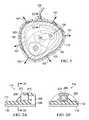
- FIG. 2Ais an exploded, partial cross-sectional view of the connector disposed on the sleeve as illustrated in FIG. 2 ;
- FIG. 2Bis an exploded, cross-sectional view of the connector disposed on the sleeve of FIG. 2A taken along the line 2 B- 2 B;
- FIG. 3is a side view of the system and contain the device of FIG. 1 fitted with in a walking boot according to another illustrative embodiment
- an exemplary embodiment of a therapy system 100comprises a dressing 102 for applying vacuum to intact skin over or surrounding a tissue site such as, for example, tissue site 104 above the ankle portion of a foot 103 , a vacuum source 106 for providing the vacuum, and a conduit 108 fluidly coupling the vacuum source 106 to the dressing 102 .
- the dressing 102forms a chamber 101 with the intact skin around the tissue site 104 .
- the dressing 102extends around and seals the ankle portion of the foot 103 that has been sprained.
- the dressing 102is adapted to apply vacuum to the intact skin such as, for example, the epidermis 103 extending over or surrounding the tissue site 104 .
- the dressing 102forms a space such as, for example, the chamber 101 , between the epidermis 103 and a portion of the dressing 102 that functions like a decompression chamber to pull the skin outwardly or distally as illustrated by arrows 107 rather than compressing the tissue site for a sustained period of time.
- the intact skinmay include an open wound such as, for example, an incision 109 resulting from surgery to repair a fractured bone associated with the sprain or strain.
- the therapy system 100may further comprise a regulator or controller 120 that may be electrically coupled to the vacuum source 106 by electrical coupling 122 to control the airflow being delivered by the vacuum source 106 to the dressing 102 to achieve the desired vacuum therapy.
- the therapy system 100may also include a thermal control system 126 fluidly coupled by a conduit 128 to the conduit 108 through a valve 127 .
- the valve 127is electrically coupled to the controller 120 by an electrical coupling 129 .
- the thermal control system 126is electrically coupled by an electrical coupling 121 to the controller 120 to regulate the temperature of the air being delivered to the dressing 102 in order to achieve the desired thermal therapy in conjunction with the desired vacuum therapy.
- the controller 120may be programmed to motivate the valve 127 to deliver negative and positive pressure alternately or simultaneously to the dressing 102 through the conduit 108 .
- Reduced pressure and “vacuum”generally refer to a pressure less than a local ambient pressure, such as the ambient pressure in a local environment external to a sealed therapeutic environment provided by the dressing 102 .
- the local ambient pressuremay also be the atmospheric pressure in a patient's vicinity.
- the pressuremay be less than a hydrostatic pressure associated with tissue at the tissue site. Unless otherwise indicated, values of pressure stated herein are gauge pressures.
- references to increases in reduced pressuretypically refer to a decrease in absolute pressure, while decreases in reduced pressure typically refer to an increase in absolute pressure.
- a thermal control systemsuch as the thermal control system 126
- the controller 120may be used to increase or decrease the temperature of the airflow provided by the thermal control system 126 alternatively with the vacuum provided by the vacuum source 106 .
- the thermal control system 126may be used in conjunction with other components of the controller 120 such as sensors, processing units, alarm indicators, memory, databases, software, display devices, or user interfaces that further facilitate instillation therapy.
- the controller 120may be operable to provide vacuum and thermal control simultaneously or in an alternating cycle.
- the manifold 110may take many forms and may come in many sizes, shapes, or thicknesses depending on a variety of factors, such as the type of treatment being provided or the nature and size of the intact skin at the tissue site 104 .
- the size and shape of the manifold 110may be adapted to the contours of the extremities located at the joint that was sprained.
- the manifold 110is a first exemplary embodiment of a manifold for distributing vacuum that is formed from open-cell foam tape wrapped circumferentially around the tissue site 104 such as, for example, Kineseo® tape (available from a company bearing the same name and widely known) wrapped to a thickness of greater than approximately 2.0 mm.
- the manifold 110may be a single piece of the same foam material described above that is formed in the shape of an open-toe sock and simply pulled over the a tissue site of the affected extremity of the body.
- a manifoldis a substance or structure adapted to distribute vacuum to or remove fluids from a tissue site, or both.
- a manifoldmay also facilitate delivering fluids to a tissue site, if the fluid path is reversed or a secondary fluid path is provided, for example, when the therapy system 100 is used to supply temperature controlled airflow from the thermal control system 126 to regulate the temperature of the intact skin at the tissue site 104 to promote healing or the evaporation of fluids forming at the tissue site 104 .
- a manifoldmay include flow channels or pathways that distribute fluids provided to and removed from a tissue site around the manifold.
- the manifold 110may also include a comfort layer (not shown) positioned adjacent the intact skin.
- the comfort layermay be coupled, for example by a heat bond or any other technique, to the manifold 110 , or may be an integral component of the manifold 110 .
- the comfort layermay be employed to provide additional comfort for the patient rather than disposing the manifold 110 in direct contact with the intact skin of the patient.
- the comfort layermay be any material that helps prevent skin irritation without significantly impeding airflow between the manifold 110 and the epidermis 103 .
- the comfort layermay also be any material that wicks liquids such as bodily sweat away from the intact skin to prevent maceration.
- One exemplary embodiment of the comfort layeris a woven material or a polyester knit textile substrate.
- Another exemplary embodiment of the comfort layeris a material known as InterDryTM textile material available from Milliken Chemical located in Spartanburg, S.C.
- the comfort layermay also include antimicrobial substances or lubricants.
- the sleeve 112is molded as a single component in a generally tubular shape formed from the sealing material described above that is stretched over the affected limb and pulled over the manifold 110 to the tissue site 104 .
- the sleeve 112may be formed from a composite material formed from the sealing material described above and an adhesive material that is wrapped around the manifold 110 .
- the sleeve 112 and the manifold 110may be a composite structure formed as a single piece of material shaped to wrap around a limb to cover the tissue site 104 .
- the first lumen 441may be fluidly coupled to the conduit 108 to provide vacuum to the first flow passage 421 of the delivery manifold 415 and the second lumen 451 may be fluidly coupled to the conduit 128 to provide positive pressure to the second flow passage 431 of the delivery manifold 415 .
- the vacuum and positive pressuremay each be delivered alternately to both the first lumen 441 and the second lumen 451 as described above, or simultaneously to provide a larger surface area of airflow to the manifold 110 .
- a transition region 429may be provided between the delivery tube 425 and the delivery manifold 415 .
- the delivery manifold 415may be adhesively connected to the delivery tube 425 , connected using other means, such as fusing or insert molding, or alternatively may be integrally connected by co-extrusion.
- the delivery tube 425delivers vacuum and/or positive pressure to the delivery manifold 415 for distribution by the manifold 110 proximate to the intact skin of the tissue site 104 .
- the walls 417further include a plurality of apertures 445 through the walls 417 that communicate with the first and second flow passages 421 , 431 .
- the apertures 445allow vacuum and/or positive pressure delivered to the flow passages 421 , 431 to be delivered to the manifold 110 for distribution to the intact skin surrounding the tissue site 104 .
- the apertures 445may be selectively positioned along the length of the delivery manifold 415 to preferentially direct the delivery of vacuum and/or positive pressure more uniformly to the manifold 110 .
- the delivery tube 425preferably includes a first lumen 461 having at least one outlet fluidly connected to the first flow passage 421 to deliver vacuum to the first flow passage 421 and through the apertures 445 to the manifold 110 .
- a second lumen 463may also be provided that has at least one outlet fluidly coupled to the second flow passage 431 deliver positive pressure to the second flow passage 431 and through the apertures 445 to the manifold 110 .
- the delivery system 411may include multiple lumens and flow passages for providing vacuum and/or positive pressure to the manifold 110 as required by the therapy treatments. While the end of the walls 417 opposite the end attached to delivery tube 425 may be open as illustrated, it has been found that capping the end of the walls 417 may improve the performance and reliability of the fluid delivery function.
- the second walls 471 , 473include protrusions 477 , 478 , respectively.
- the protrusion 474touches protrusion 477 when a force is applied to the delivery tube 425 in a direction indicated by arrows 476 such that the portion of the first wall 470 and the second wall 471 that do not have protrusions 474 and 477 do not touch one another.
- the protrusion 475touches protrusion 478 when a force is applied to the delivery tube 425 in a direction indicated by arrows 476 such that the portion of the first wall 472 and the second wall 473 that do not have protrusions 475 and 478 do not touch one another.
- the lumens 466 , 468may be prevented from collapsing in this manner.
- the dressing 102provides a sealed therapeutic environment proximate to the intact skin surrounding a tissue site and substantially isolated from the external, ambient environment outside the sleeve 112 .
- the dressing 102is shown before applying a vacuum to the manifold 110 as illustrated by the open spaces within the chamber 101 at either ends of the dressing 102 between the intact skin and the sleeve 112 .
- the vacuum source 106applies a vacuum to the chamber 101
- the sleeve 112collapses slightly against the intact skin surrounding the tissue site 104 until the vacuum removes most of the air from the chamber 101 as shown in FIG. 2 .
- the sleeve 112initially collapses against the intact skin surrounding the tissue site 104 and provides a certain amount of stiffening that functions like a splint to stabilize the tissue site 104 and the joint itself as described above.
- SOCrest, ice, compression and elevation
- RICErest, ice, compression and elevation
- This series of treatmentsis designed to treat the causes of the aforementioned clinical symptoms. Rest takes pressure off of the affected area, allowing the damaged ligament or muscle to repair without additional injury. Ice is normally prescribed to be applied immediately after the injury, 10-20 minutes at a time 3-4 times a day to help reduce swelling and pain due to inflammation. Compression, along with ice, is the main form of treatment that is typically implemented by using elastic material in the form of a wrap or garment. The elastic material applies a positive mechanical force to the affected area to control the swelling.
- the compressionshould be applied such that the force being applied reduces in the direction of the heart, which pushes excess fluid up the blood stream in order to be recycled. Elevation of the affected extremity above the heart also helps to minimize the swelling. This form of standard of care is adequate for treating many sprains and strains. After a period of anywhere from 10 days to 24 weeks for minor injuries, patients report a reduction in pain and return to motion. For major injuries, however, patients report a reduction in pain after one year, two years, and even more time. Even after these lengthy time periods, an equally significant number of patients still report pain and no return to motion.
- a therapy that can both manage symptoms and accelerate healingis desirable for treating sprains and strains.
- the dressing 102applies the vacuum to the intact skin extending over or surrounding the tissue site 104 that effectively splints and stabilizes the ankle joint of the foot 103 , while at the same time provides vacuum or a vacuum to the intact skin which pulls the tissue site 104 outwardly toward the sleeve 112 .
- This pulling force adjacent the intact skin coupled with the immobilization of the jointstimulates the blood flow (perfusion) and lymphatic flow at the tissue site 104 to accelerate healing of the damaged ligament and/or muscle in contrast to current SOC procedures defined by the RICE treatments that only temporarily treat the systems of sprains and strains as such treatments only temporarily reduce inflammation by icing and may actually constrict blood flow and lymph flow by compression.
- This pulling forceallows the damaged tissue to be properly supplied and evacuated with blood flow and lymph flow, thereby promoting perfusion in the subcutaneous portions of the tissue site 104 and reducing edema to accelerate healing.
- Utilization of the dressing 102 to pull on the intact skinfurther enhances skin perfusion which significantly reduces the amount of time necessary to heal a sprain compared to the current standard of care.
- the decompression treatment described hereinprovides the dual advantage of managing pain by reducing swelling and inflammation, but also accelerating healing by increasing blood flow and lymph flow.
- volunteers with minor sprain injurieshave reported a total elimination of pain allowing them to return to ongoing activities after decompression treatments of only three hours. They were able to return to their activities without suffering any pain during or after such activities
- the current standard of carerequires a treatment period of anywhere from 10 days to 24 weeks for minor injuries in order to reduce the pain.
- the dressing 102can be comfortably worn by a patient for most of the day to further accelerate healing if desired.
- the dressing 102may be light and flexible, wearing the dressing 102 does not restrict patient mobility nearly as much as current compression bandages and the combination ice and compression systems.
- volunteers with severe ankle sprains who were using a walking boot for several monthshave reported that the pain relief was the same as using an ice treatment without being confined, and that the decompression treatment allowed them to walk around without pain even without the boot.
- One volunteercould not place full weight on his ankle without pain, but was able to do so after receiving the decompression treatment.
- Another volunteer after having a TKA surgeryexperienced serious swelling even several weeks after surgery.
- the sleeve 112may be molded as a single component in a generally tubular shape formed from the sealing material described above that is stretched over the affected extremity and pulled over the manifold 110 to the tissue site 104 .
- the sleeve 112may be formed from an adhesive tape formed from the sealing material described above that is wrapped around the manifold 110 .
- the sleeve 112 and the manifold 110may be a composite structure formed as a single piece of material shaped to wrap around a limb to cover the intact skin extending over or surrounding the tissue site 104 .
- the sleeve 112 and the manifold 110may be a composite structure formed as a single piece of material that is shaped to have a two dimensional profile having a distal portion and a proximal portion including a flexible portion between the distal and proximal portions.
- the distal and proximal portionsmay be wrapped around a limb on either side of a joint wherein the flexible portion of the dressing allows articulation of the joint.
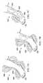
- FIGS. 6A and 6Ba perspective view of a second exemplary embodiment of a dressing 602 is shown for applying vacuum to the intact skin extending or surrounding a tissue site such as, for example, the tissue site 104 on both the distal side and proximal side of the ankle of the foot 103 that allows for articulation of the ankle.
- the dressing 602may operate in substantially the same way as a component of the therapy system 100 as described above and may include components substantially similar to those described above as indicated by the similar numbering scheme preceded by the century number 6.
- the dressing 602also forms a chamber 101 with the intact skin extending over and/or surrounding that portion of the tissue site 104 that has been sprained.
- the dressing 602comprises a manifold layer 610 adapted to contact the intact skin surrounding the tissue site 104 , and a sleeve layer 612 for enclosing the manifold layer 610 over the intact skin to form the chamber and provide an airtight seal.
- the dressing 602further comprises a comfort layer 620 to provide low tack adhesion to the epidermis 103 and an airtight seal.
- the dressing 602further comprises a fluid coupling member such as, for example, the connector 114 for fluidly coupling the conduit 108 to the manifold layer 610 through an aperture 611 extending through the sleeve layer 612 .
- proximal dressing portion 640may still provide splinting to the upper ankle portion of the limb on the proximal side of the ankle joint
- distal dressing portion 630may still provide splinting to the foot portion of the limb on the distal side of the ankle joint.
- the methodcomprises disposing a manifold formed from an open cell, porous material circumferentially around the intact skin of the tissue site, enclosing the manifold within a sleeve formed from a semi-permeable material that seals the manifold within a sealed space between the sleeve and the intact skin, and fluidly coupling the manifold to a vacuum source so that the manifold distributes vacuum to the intact skin of the tissue site.
Landscapes
- Health & Medical Sciences (AREA)
- Epidemiology (AREA)
- Pain & Pain Management (AREA)
- Physical Education & Sports Medicine (AREA)
- Rehabilitation Therapy (AREA)
- Life Sciences & Earth Sciences (AREA)
- Animal Behavior & Ethology (AREA)
- General Health & Medical Sciences (AREA)
- Public Health (AREA)
- Veterinary Medicine (AREA)
- Media Introduction/Drainage Providing Device (AREA)
- Surgical Instruments (AREA)
Abstract
Description
Claims (31)
Priority Applications (3)
| Application Number | Priority Date | Filing Date | Title |
|---|---|---|---|
| US14/204,878US10219973B2 (en) | 2013-03-12 | 2014-03-11 | System and method utilizing vacuum for promoting the healing of sprains |
| US16/251,414US11672725B2 (en) | 2013-03-12 | 2019-01-18 | System and method utilizing vacuum for promoting the healing of sprains |
| US18/142,496US20230263696A1 (en) | 2013-03-12 | 2023-05-02 | System And Method Utilizing Vacuum For Promoting The Healing Of Sprains |
Applications Claiming Priority (2)
| Application Number | Priority Date | Filing Date | Title |
|---|---|---|---|
| US201361778042P | 2013-03-12 | 2013-03-12 | |
| US14/204,878US10219973B2 (en) | 2013-03-12 | 2014-03-11 | System and method utilizing vacuum for promoting the healing of sprains |
Related Child Applications (1)
| Application Number | Title | Priority Date | Filing Date |
|---|---|---|---|
| US16/251,414ContinuationUS11672725B2 (en) | 2013-03-12 | 2019-01-18 | System and method utilizing vacuum for promoting the healing of sprains |
Publications (2)
| Publication Number | Publication Date |
|---|---|
| US20140276288A1 US20140276288A1 (en) | 2014-09-18 |
| US10219973B2true US10219973B2 (en) | 2019-03-05 |
Family
ID=50686109
Family Applications (3)
| Application Number | Title | Priority Date | Filing Date |
|---|---|---|---|
| US14/204,878Active2036-01-03US10219973B2 (en) | 2013-03-12 | 2014-03-11 | System and method utilizing vacuum for promoting the healing of sprains |
| US16/251,414Active2037-06-06US11672725B2 (en) | 2013-03-12 | 2019-01-18 | System and method utilizing vacuum for promoting the healing of sprains |
| US18/142,496PendingUS20230263696A1 (en) | 2013-03-12 | 2023-05-02 | System And Method Utilizing Vacuum For Promoting The Healing Of Sprains |
Family Applications After (2)
| Application Number | Title | Priority Date | Filing Date |
|---|---|---|---|
| US16/251,414Active2037-06-06US11672725B2 (en) | 2013-03-12 | 2019-01-18 | System and method utilizing vacuum for promoting the healing of sprains |
| US18/142,496PendingUS20230263696A1 (en) | 2013-03-12 | 2023-05-02 | System And Method Utilizing Vacuum For Promoting The Healing Of Sprains |
Country Status (4)
| Country | Link |
|---|---|
| US (3) | US10219973B2 (en) |
| EP (2) | EP2968054B1 (en) |
| ES (1) | ES2817834T3 (en) |
| WO (1) | WO2014150433A1 (en) |
Families Citing this family (39)
| Publication number | Priority date | Publication date | Assignee | Title |
|---|---|---|---|---|
| US20150257968A1 (en)* | 2014-03-11 | 2015-09-17 | Carl E. VAUSE | Soft conformal compression devices and methods |
| US20170056239A1 (en)* | 2015-06-08 | 2017-03-02 | Rolf LANGELAND | Post-Operative Medical Recovery Device |
| US10973413B2 (en)* | 2015-10-07 | 2021-04-13 | Fiomet Ventures, Inc. | Advanced compression garments and systems |
| TWI629072B (en)* | 2017-01-13 | 2018-07-11 | 廈門聖慈醫療器材有限公司 | Suction disc |
| JP7204685B2 (en)* | 2017-06-07 | 2023-01-16 | スリーエム イノベイティブ プロパティズ カンパニー | A composite dressing that promotes granulation formation and reduces maceration in negative pressure therapy |
| EP3643287B1 (en)* | 2017-06-19 | 2025-07-02 | Quan, Chengxian | Physiotherapy instrument for human body facet joint inflammation |
| US10960129B2 (en) | 2017-08-25 | 2021-03-30 | AZ Solutions LLC | System and method for patient skin treatment and irrigation |
| US11918549B2 (en) | 2017-08-25 | 2024-03-05 | AZ Solutions LLC | System and method for wound treatment and irrigation |
| US11110021B2 (en) | 2017-09-29 | 2021-09-07 | Otivio As | Medical pressure therapy device and components thereof |
| US10940075B2 (en) | 2017-09-29 | 2021-03-09 | Otivio As | Medical pressure therapy device and components thereof |
| US11259985B2 (en) | 2017-09-29 | 2022-03-01 | Otivio As | Medical pressure therapy device and components thereof |
| USD900996S1 (en) | 2017-10-16 | 2020-11-03 | Otivio As | Pressure chamber |
| AU2018355151B2 (en)* | 2017-10-23 | 2024-09-19 | Solventum Intellectual Properties Company | Area management of tissue sites on articulating joints |
| US20190117495A1 (en)* | 2017-10-24 | 2019-04-25 | Guozhu ZHANG | Air absorbing and discharging massager |
| USD866787S1 (en)* | 2018-06-14 | 2019-11-12 | Shenzhen Fit King Health Tech. Co., Ltd | Leg massager |
| USD866788S1 (en)* | 2018-06-14 | 2019-11-12 | Shenzhen Fit King Health Tech. Co., Ltd | Leg massager |
| EP3829515A1 (en)* | 2018-08-01 | 2021-06-09 | KCI Licensing, Inc. | Soft-tissue treatment with negative pressure |
| USD889634S1 (en) | 2018-08-10 | 2020-07-07 | Otivio As | Pressure control unit |
| EP3946502A1 (en) | 2019-03-29 | 2022-02-09 | KCI Licensing, Inc. | Dressing with integrated pump and releasably coupled pump actuator |
| US11931312B2 (en) | 2019-03-29 | 2024-03-19 | Hill-Rom Services, Inc. | User interface for a patient support apparatus with integrated patient therapy device |
| WO2020205449A1 (en)* | 2019-03-29 | 2020-10-08 | Kci Licensing, Inc. | Negative-pressure treatment with area stabilization |
| US11974964B2 (en)* | 2019-03-29 | 2024-05-07 | Hill-Rom Services, Inc. | Patient support apparatus with integrated patient therapy device |
| WO2020205445A1 (en)* | 2019-03-29 | 2020-10-08 | Kci Licensing, Inc. | Negative-pressure treatment with area stabilization |
| US11305052B2 (en)* | 2019-04-07 | 2022-04-19 | Steven Simpson | Suction-based medical dressing and method of dermal irrigation |
| BR112021022115A2 (en)* | 2019-05-07 | 2022-01-04 | Aroa Biosurgery Ltd | negative pressure wound dressing |
| CN113811272B (en)* | 2019-05-13 | 2023-04-28 | 凯希特许有限公司 | Dressing with strategic shapes allowing enhanced articulation |
| CN110279570B (en)* | 2019-06-29 | 2021-02-02 | 吉林大学 | An air pressure wave therapy instrument leg cover connecting device |
| US20220257850A1 (en)* | 2019-07-30 | 2022-08-18 | Kci Licensing, Inc. | Negative-Pressure Dressing For Foot Treatment |
| EP4051201B1 (en)* | 2019-11-01 | 2024-05-29 | KCI Manufacturing Unlimited Company | Decompression therapy treatment system |
| US12274636B2 (en)* | 2019-11-01 | 2025-04-15 | Kci Manufacturing Unlimited Company | Decompression therapy treatment system |
| US11833290B2 (en) | 2019-11-01 | 2023-12-05 | Kci Licensing, Inc. | Dressing design incorporating formed 3D textile for the delivery of therapeutic negative pressure and compressive forces to a treatment site |
| WO2021165820A1 (en)* | 2020-02-17 | 2021-08-26 | Kci Licensing, Inc. | Extremity dressing with collapsible cuff for negative pressure wound therapy |
| US20230256156A1 (en)* | 2020-08-14 | 2023-08-17 | Kci Manufacturing Unlimited Company | Decompression wrap |
| WO2022149016A1 (en)* | 2021-01-05 | 2022-07-14 | Kci Manufacturing Unlimited Company | Reusable sealing material for decompression therapy treatment system |
| US12005025B2 (en)* | 2021-02-08 | 2024-06-11 | Zachary Wood Lyon | System and method of applied contrasting therapy to pelvic regions and human distal anatomy |
| US11844918B2 (en)* | 2021-04-25 | 2023-12-19 | Tri.O Medical Device Ltd | Apparatus for use with a pressure-regulating device |
| CN113679523B (en)* | 2021-08-12 | 2023-09-05 | 武汉岩硕科技有限公司 | Fracture external fixation high molecular splint with negative pressure wound surface treatment function |
| USD987832S1 (en)* | 2022-01-03 | 2023-05-30 | Therabody, Inc. | Pneumatic compression device |
| USD1041015S1 (en)* | 2022-02-01 | 2024-09-03 | Therabody, Inc. | Pneumatic compression device |
Citations (140)
| Publication number | Priority date | Publication date | Assignee | Title |
|---|---|---|---|---|
| US1355846A (en) | 1920-02-06 | 1920-10-19 | David A Rannells | Medical appliance |
| US2547758A (en) | 1949-01-05 | 1951-04-03 | Wilmer B Keeling | Instrument for treating the male urethra |
| US2632443A (en) | 1949-04-18 | 1953-03-24 | Eleanor P Lesher | Surgical dressing |
| GB692578A (en) | 1949-09-13 | 1953-06-10 | Minnesota Mining & Mfg | Improvements in or relating to drape sheets for surgical use |
| US2682873A (en) | 1952-07-30 | 1954-07-06 | Johnson & Johnson | General purpose protective dressing |
| US2910763A (en) | 1955-08-17 | 1959-11-03 | Du Pont | Felt-like products |
| US2969057A (en) | 1957-11-04 | 1961-01-24 | Brady Co W H | Nematodic swab |
| US3066672A (en) | 1960-09-27 | 1962-12-04 | Jr William H Crosby | Method and apparatus for serial sampling of intestinal juice |
| US3367332A (en) | 1965-08-27 | 1968-02-06 | Gen Electric | Product and process for establishing a sterile area of skin |
| US3520300A (en) | 1967-03-15 | 1970-07-14 | Amp Inc | Surgical sponge and suction device |
| US3568675A (en) | 1968-08-30 | 1971-03-09 | Clyde B Harvey | Fistula and penetrating wound dressing |
| US3648692A (en) | 1970-12-07 | 1972-03-14 | Parke Davis & Co | Medical-surgical dressing for burns and the like |
| US3682180A (en) | 1970-06-08 | 1972-08-08 | Coilform Co Inc | Drain clip for surgical drain |
| US3826254A (en) | 1973-02-26 | 1974-07-30 | Verco Ind | Needle or catheter retaining appliance |
| DE2640413A1 (en) | 1976-09-08 | 1978-03-09 | Wolf Gmbh Richard | CATHETER MONITORING DEVICE |
| US4080970A (en) | 1976-11-17 | 1978-03-28 | Miller Thomas J | Post-operative combination dressing and internal drain tube with external shield and tube connector |
| US4096853A (en) | 1975-06-21 | 1978-06-27 | Hoechst Aktiengesellschaft | Device for the introduction of contrast medium into an anus praeter |
| US4139004A (en) | 1977-02-17 | 1979-02-13 | Gonzalez Jr Harry | Bandage apparatus for treating burns |
| US4165748A (en) | 1977-11-07 | 1979-08-28 | Johnson Melissa C | Catheter tube holder |
| US4184510A (en) | 1977-03-15 | 1980-01-22 | Fibra-Sonics, Inc. | Valued device for controlling vacuum in surgery |
| WO1980002182A1 (en) | 1979-04-06 | 1980-10-16 | J Moss | Portable suction device for collecting fluids from a closed wound |
| US4233969A (en) | 1976-11-11 | 1980-11-18 | Lock Peter M | Wound dressing materials |
| US4245630A (en) | 1976-10-08 | 1981-01-20 | T. J. Smith & Nephew, Ltd. | Tearable composite strip of materials |
| US4256109A (en) | 1978-07-10 | 1981-03-17 | Nichols Robert L | Shut off valve for medical suction apparatus |
| US4261363A (en) | 1979-11-09 | 1981-04-14 | C. R. Bard, Inc. | Retention clips for body fluid drains |
| US4275721A (en) | 1978-11-28 | 1981-06-30 | Landstingens Inkopscentral Lic, Ekonomisk Forening | Vein catheter bandage |
| US4284079A (en) | 1979-06-28 | 1981-08-18 | Adair Edwin Lloyd | Method for applying a male incontinence device |
| US4297995A (en) | 1980-06-03 | 1981-11-03 | Key Pharmaceuticals, Inc. | Bandage containing attachment post |
| US4333468A (en) | 1980-08-18 | 1982-06-08 | Geist Robert W | Mesentery tube holder apparatus |
| US4373519A (en) | 1981-06-26 | 1983-02-15 | Minnesota Mining And Manufacturing Company | Composite wound dressing |
| US4382441A (en) | 1978-12-06 | 1983-05-10 | Svedman Paul | Device for treating tissues, for example skin |
| US4392858A (en) | 1981-07-16 | 1983-07-12 | Sherwood Medical Company | Wound drainage device |
| US4392853A (en) | 1981-03-16 | 1983-07-12 | Rudolph Muto | Sterile assembly for protecting and fastening an indwelling device |
| US4419097A (en) | 1981-07-31 | 1983-12-06 | Rexar Industries, Inc. | Attachment for catheter tube |
| EP0100148A1 (en) | 1982-07-06 | 1984-02-08 | Dow Corning Limited | Medical-surgical dressing and a process for the production thereof |
| US4465485A (en) | 1981-03-06 | 1984-08-14 | Becton, Dickinson And Company | Suction canister with unitary shut-off valve and filter features |
| EP0117632A2 (en) | 1983-01-27 | 1984-09-05 | Johnson & Johnson Products Inc. | Adhesive film dressing |
| US4475909A (en) | 1982-05-06 | 1984-10-09 | Eisenberg Melvin I | Male urinary device and method for applying the device |
| US4480638A (en) | 1980-03-11 | 1984-11-06 | Eduard Schmid | Cushion for holding an element of grafted skin |
| US4525166A (en) | 1981-11-21 | 1985-06-25 | Intermedicat Gmbh | Rolled flexible medical suction drainage device |
| US4525374A (en) | 1984-02-27 | 1985-06-25 | Manresa, Inc. | Treating hydrophobic filters to render them hydrophilic |
| US4540412A (en) | 1983-07-14 | 1985-09-10 | The Kendall Company | Device for moist heat therapy |
| US4543100A (en) | 1983-11-01 | 1985-09-24 | Brodsky Stuart A | Catheter and drain tube retainer |
| US4548202A (en) | 1983-06-20 | 1985-10-22 | Ethicon, Inc. | Mesh tissue fasteners |
| US4551139A (en) | 1982-02-08 | 1985-11-05 | Marion Laboratories, Inc. | Method and apparatus for burn wound treatment |
| EP0161865A2 (en) | 1984-05-03 | 1985-11-21 | Smith and Nephew Associated Companies p.l.c. | Adhesive wound dressing |
| US4569348A (en) | 1980-02-22 | 1986-02-11 | Velcro Usa Inc. | Catheter tube holder strap |
| AU550575B2 (en) | 1981-08-07 | 1986-03-27 | Richard Christian Wright | Wound drainage device |
| US4605399A (en) | 1984-12-04 | 1986-08-12 | Complex, Inc. | Transdermal infusion device |
| US4608041A (en) | 1981-10-14 | 1986-08-26 | Frese Nielsen | Device for treatment of wounds in body tissue of patients by exposure to jets of gas |
| US4640688A (en) | 1985-08-23 | 1987-02-03 | Mentor Corporation | Urine collection catheter |
| US4655754A (en) | 1984-11-09 | 1987-04-07 | Stryker Corporation | Vacuum wound drainage system and lipids baffle therefor |
| US4657003A (en)* | 1983-10-03 | 1987-04-14 | Cramer Products, Inc. | Immobilizer device |
| US4664662A (en) | 1984-08-02 | 1987-05-12 | Smith And Nephew Associated Companies Plc | Wound dressing |
| WO1987004626A1 (en) | 1986-01-31 | 1987-08-13 | Osmond, Roger, L., W. | Suction system for wound and gastro-intestinal drainage |
| US4710165A (en) | 1985-09-16 | 1987-12-01 | Mcneil Charles B | Wearable, variable rate suction/collection device |
| US4733659A (en) | 1986-01-17 | 1988-03-29 | Seton Company | Foam bandage |
| GB2195255A (en) | 1986-09-30 | 1988-04-07 | Vacutec Uk Limited | Method and apparatus for vacuum treatment of an epidermal surface |
| US4743232A (en) | 1986-10-06 | 1988-05-10 | The Clinipad Corporation | Package assembly for plastic film bandage |
| GB2197789A (en) | 1986-11-28 | 1988-06-02 | Smiths Industries Plc | Anti-foaming disinfectants used in surgical suction apparatus |
| US4758220A (en) | 1985-09-26 | 1988-07-19 | Alcon Laboratories, Inc. | Surgical cassette proximity sensing and latching apparatus |
| US4787888A (en) | 1987-06-01 | 1988-11-29 | University Of Connecticut | Disposable piezoelectric polymer bandage for percutaneous delivery of drugs and method for such percutaneous delivery (a) |
| US4826494A (en) | 1984-11-09 | 1989-05-02 | Stryker Corporation | Vacuum wound drainage system |
| US4838883A (en) | 1986-03-07 | 1989-06-13 | Nissho Corporation | Urine-collecting device |
| US4840187A (en) | 1986-09-11 | 1989-06-20 | Bard Limited | Sheath applicator |
| US4863449A (en) | 1987-07-06 | 1989-09-05 | Hollister Incorporated | Adhesive-lined elastic condom cathether |
| US4872450A (en) | 1984-08-17 | 1989-10-10 | Austad Eric D | Wound dressing and method of forming same |
| US4878901A (en) | 1986-10-10 | 1989-11-07 | Sachse Hans Ernst | Condom catheter, a urethral catheter for the prevention of ascending infections |
| GB2220357A (en) | 1988-05-28 | 1990-01-10 | Smiths Industries Plc | Medico-surgical containers |
| US4897081A (en) | 1984-05-25 | 1990-01-30 | Thermedics Inc. | Percutaneous access device |
| US4906240A (en) | 1988-02-01 | 1990-03-06 | Matrix Medica, Inc. | Adhesive-faced porous absorbent sheet and method of making same |
| US4906233A (en) | 1986-05-29 | 1990-03-06 | Terumo Kabushiki Kaisha | Method of securing a catheter body to a human skin surface |
| US4919654A (en) | 1988-08-03 | 1990-04-24 | Kalt Medical Corporation | IV clamp with membrane |
| CA2005436A1 (en) | 1988-12-13 | 1990-06-13 | Glenda G. Kalt | Transparent tracheostomy tube dressing |
| US4941882A (en) | 1987-03-14 | 1990-07-17 | Smith And Nephew Associated Companies, P.L.C. | Adhesive dressing for retaining a cannula on the skin |
| US4953565A (en) | 1986-11-26 | 1990-09-04 | Shunro Tachibana | Endermic application kits for external medicines |
| WO1990010424A1 (en) | 1989-03-16 | 1990-09-20 | Smith & Nephew Plc | Absorbent devices and precursors therefor |
| US4969880A (en) | 1989-04-03 | 1990-11-13 | Zamierowski David S | Wound dressing and treatment method |
| US4985019A (en) | 1988-03-11 | 1991-01-15 | Michelson Gary K | X-ray marker |
| GB2235877A (en) | 1989-09-18 | 1991-03-20 | Antonio Talluri | Closed wound suction apparatus |
| US5037397A (en) | 1985-05-03 | 1991-08-06 | Medical Distributors, Inc. | Universal clamp |
| US5086170A (en) | 1989-01-16 | 1992-02-04 | Roussel Uclaf | Process for the preparation of azabicyclo compounds |
| US5092858A (en) | 1990-03-20 | 1992-03-03 | Becton, Dickinson And Company | Liquid gelling agent distributor device |
| US5100396A (en) | 1989-04-03 | 1992-03-31 | Zamierowski David S | Fluidic connection system and method |
| JPH04129536A (en) | 1990-09-19 | 1992-04-30 | Terumo Corp | Balance device |
| US5134994A (en) | 1990-02-12 | 1992-08-04 | Say Sam L | Field aspirator in a soft pack with externally mounted container |
| US5149331A (en) | 1991-05-03 | 1992-09-22 | Ariel Ferdman | Method and device for wound closure |
| US5167613A (en) | 1992-03-23 | 1992-12-01 | The Kendall Company | Composite vented wound dressing |
| US5176663A (en) | 1987-12-02 | 1993-01-05 | Pal Svedman | Dressing having pad with compressibility limiting elements |
| WO1993009727A1 (en) | 1991-11-14 | 1993-05-27 | Wake Forest University | Method and apparatus for treating tissue damage |
| US5215522A (en) | 1984-07-23 | 1993-06-01 | Ballard Medical Products | Single use medical aspirating device and method |
| US5232453A (en) | 1989-07-14 | 1993-08-03 | E. R. Squibb & Sons, Inc. | Catheter holder |
| US5261893A (en) | 1989-04-03 | 1993-11-16 | Zamierowski David S | Fastening system and method |
| US5278100A (en) | 1991-11-08 | 1994-01-11 | Micron Technology, Inc. | Chemical vapor deposition technique for depositing titanium silicide on semiconductor wafers |
| US5279550A (en) | 1991-12-19 | 1994-01-18 | Gish Biomedical, Inc. | Orthopedic autotransfusion system |
| US5298015A (en) | 1989-07-11 | 1994-03-29 | Nippon Zeon Co., Ltd. | Wound dressing having a porous structure |
| US5342376A (en) | 1993-05-03 | 1994-08-30 | Dermagraphics, Inc. | Inserting device for a barbed tissue connector |
| US5344415A (en) | 1993-06-15 | 1994-09-06 | Deroyal Industries, Inc. | Sterile system for dressing vascular access site |
| DE4306478A1 (en) | 1993-03-02 | 1994-09-08 | Wolfgang Dr Wagner | Drainage device, in particular pleural drainage device, and drainage method |
| WO1994020041A1 (en) | 1993-03-09 | 1994-09-15 | Wake Forest University | Wound treatment employing reduced pressure |
| US5358494A (en) | 1989-07-11 | 1994-10-25 | Svedman Paul | Irrigation dressing |
| US5399152A (en)* | 1990-09-13 | 1995-03-21 | Habermeyer; Peter | Apparatus for treating fractures in extremities |
| US5437622A (en) | 1992-04-29 | 1995-08-01 | Laboratoire Hydrex (Sa) | Transparent adhesive dressing with reinforced starter cuts |
| US5437651A (en) | 1993-09-01 | 1995-08-01 | Research Medical, Inc. | Medical suction apparatus |
| DE29504378U1 (en) | 1995-03-15 | 1995-09-14 | MTG Medizinisch, technische Gerätebau GmbH, 66299 Friedrichsthal | Electronically controlled low-vacuum pump for chest and wound drainage |
| WO1996005873A1 (en) | 1994-08-22 | 1996-02-29 | Kinetic Concepts Inc. | Wound drainage equipment |
| US5527293A (en) | 1989-04-03 | 1996-06-18 | Kinetic Concepts, Inc. | Fastening system and method |
| US5549584A (en) | 1994-02-14 | 1996-08-27 | The Kendall Company | Apparatus for removing fluid from a wound |
| US5556375A (en) | 1994-06-16 | 1996-09-17 | Hercules Incorporated | Wound dressing having a fenestrated base layer |
| US5607388A (en) | 1994-06-16 | 1997-03-04 | Hercules Incorporated | Multi-purpose wound dressing |
| WO1997018007A1 (en) | 1995-11-14 | 1997-05-22 | Kci Medical Limited | Portable wound treatment apparatus |
| US5749100A (en)* | 1996-10-07 | 1998-05-12 | Rosenberg; Iris | Open toe sock |
| WO1999013793A1 (en) | 1997-09-12 | 1999-03-25 | Kci Medical Limited | Surgical drape and suction head for wound treatment |
| US6071267A (en) | 1998-02-06 | 2000-06-06 | Kinetic Concepts, Inc. | Medical patient fluid management interface system and method |
| US6135116A (en) | 1997-07-28 | 2000-10-24 | Kci Licensing, Inc. | Therapeutic method for treating ulcers |
| US6241747B1 (en) | 1993-05-03 | 2001-06-05 | Quill Medical, Inc. | Barbed Bodily tissue connector |
| US6287316B1 (en) | 1999-03-26 | 2001-09-11 | Ethicon, Inc. | Knitted surgical mesh |
| US20020077661A1 (en) | 2000-12-20 | 2002-06-20 | Vahid Saadat | Multi-barbed device for retaining tissue in apposition and methods of use |
| US20020115951A1 (en) | 2001-02-22 | 2002-08-22 | Core Products International, Inc. | Ankle brace providing upper and lower ankle adjustment |
| US20020120185A1 (en) | 2000-05-26 | 2002-08-29 | Kci Licensing, Inc. | System for combined transcutaneous blood gas monitoring and vacuum assisted wound closure |
| US20020143286A1 (en) | 2001-03-05 | 2002-10-03 | Kci Licensing, Inc. | Vacuum assisted wound treatment apparatus and infection identification system and method |
| US20020169399A1 (en)* | 2001-05-10 | 2002-11-14 | Rastegar Jahangir S. | External counterpulsation cardiac assist device |
| US6488643B1 (en) | 1998-10-08 | 2002-12-03 | Kci Licensing, Inc. | Wound healing foot wrap |
| US6493568B1 (en) | 1994-07-19 | 2002-12-10 | Kci Licensing, Inc. | Patient interface system |
| AU755496B2 (en) | 1997-09-12 | 2002-12-12 | Kci Licensing, Inc. | Surgical drape and suction head for wound treatment |
| US20050203452A1 (en)* | 2004-03-09 | 2005-09-15 | Weston Richard S. | Enclosure-based reduced pressure treatment system |
| US20050261615A1 (en)* | 2004-05-21 | 2005-11-24 | Richard Scott Weston | Hypobaric chamber treatment system |
| US20060079852A1 (en) | 2002-12-31 | 2006-04-13 | Bubb Stephen K | Externally-applied patient interface system and method |
| US7074200B1 (en)* | 2000-12-08 | 2006-07-11 | Lewis Michael P | External pulsation unit cuff |
| US20060287621A1 (en)* | 2005-06-17 | 2006-12-21 | Prospex Medical, Inc. | Medical compression devices and methods |
| US20070218101A1 (en)* | 2006-03-14 | 2007-09-20 | Johnson Royce W | System and method for percutaneously administering reduced pressure treatment using a flowable manifold |
| JP4129536B2 (en) | 2000-02-24 | 2008-08-06 | ヴェネテック インターナショナル,インコーポレイテッド | Highly compatible catheter anchoring system |
| DE102008009455A1 (en) | 2008-02-16 | 2009-08-20 | Schreiber, Hans, Dr. Dr. | Blood flow-conditioned ulcer i.e. diabetic ulcer, treatment system for leg of smoker, has sole area and lining with defined resilient, where system produces intermittent lower pressure in tissue over shoe in connection with oxygenated blood |
| US7611476B2 (en)* | 2004-03-03 | 2009-11-03 | Taranow Warren S | Vacuum-sealed orthotic, prosthetic, and other body worn devices |
| US20090299257A1 (en)* | 2008-05-30 | 2009-12-03 | Justin Alexander Long | Reduced-pressure surgical wound treatment systems and methods |
| US20110295168A1 (en)* | 2006-01-17 | 2011-12-01 | Theranova, Llc | Method and apparatus for negative pressure therapy |
| US20120046626A1 (en) | 2007-02-09 | 2012-02-23 | Sanders T Blane | Apparatus and method for administering reduced pressure treatment to a tissue site |
| US20120203144A1 (en) | 2011-02-07 | 2012-08-09 | Kci Licensing, Inc. | Methods and systems for treating a hoof on an ungulate mammal |
| US8663198B2 (en)* | 2009-04-17 | 2014-03-04 | Kalypto Medical, Inc. | Negative pressure wound therapy device |
| US20140107550A1 (en)* | 2012-10-11 | 2014-04-17 | Molly J. Paulson | Pressurized liquid cast |
Family Cites Families (25)
| Publication number | Priority date | Publication date | Assignee | Title |
|---|---|---|---|---|
| JP2003530959A (en)* | 2000-04-20 | 2003-10-21 | ザ、ボード、オブ、トラスティーズ、オブ、ザ、リーランド、スタンフォード、ジュニア、ユニバーシティ | Method and apparatus for cooling a body core |
| JP4213591B2 (en) | 2001-11-23 | 2009-01-21 | コロプラスト アクティーゼルスカブ | Pharmaceutical material for wound |
| EP1509176B1 (en)* | 2002-05-23 | 2006-08-23 | Otto Bock HealthCare, LP | Pulsating pressure chamber in a prosthetic limb |
| US7846141B2 (en) | 2002-09-03 | 2010-12-07 | Bluesky Medical Group Incorporated | Reduced pressure treatment system |
| GB0224986D0 (en) | 2002-10-28 | 2002-12-04 | Smith & Nephew | Apparatus |
| GB0230344D0 (en)* | 2002-12-31 | 2003-02-05 | Filtvedt Marius | Device for applying a pulsating pressure to a local region of the body and applications thereof |
| GB0325120D0 (en) | 2003-10-28 | 2003-12-03 | Smith & Nephew | Apparatus with actives |
| GB0325126D0 (en) | 2003-10-28 | 2003-12-03 | Smith & Nephew | Apparatus with heat |
| US7909805B2 (en) | 2004-04-05 | 2011-03-22 | Bluesky Medical Group Incorporated | Flexible reduced pressure treatment appliance |
| US8529548B2 (en) | 2004-04-27 | 2013-09-10 | Smith & Nephew Plc | Wound treatment apparatus and method |
| US7896823B2 (en)* | 2006-01-17 | 2011-03-01 | Theranova, Llc | Method and apparatus for treating wound using negative pressure therapy |
| DE202006007877U1 (en) | 2006-01-25 | 2006-07-27 | Riesinger, Birgit | Prefabricated wound dressing with superabsorber |
| GB0623196D0 (en) | 2006-11-21 | 2006-12-27 | Smith & Nephew | Dressing |
| US8226586B2 (en)* | 2007-02-22 | 2012-07-24 | Stryker Corporation | Negative pressure, compression therapy device |
| EP2214612B1 (en) | 2007-11-21 | 2019-05-01 | Smith & Nephew PLC | Wound dressing |
| ES2715605T3 (en) | 2007-11-21 | 2019-06-05 | Smith & Nephew | Wound dressing |
| US20090177184A1 (en)* | 2008-01-09 | 2009-07-09 | Christensen Scott A | Method and apparatus for improving venous access |
| US8021347B2 (en) | 2008-07-21 | 2011-09-20 | Tyco Healthcare Group Lp | Thin film wound dressing |
| US8007481B2 (en) | 2008-07-17 | 2011-08-30 | Tyco Healthcare Group Lp | Subatmospheric pressure mechanism for wound therapy system |
| US8251979B2 (en) | 2009-05-11 | 2012-08-28 | Tyco Healthcare Group Lp | Orientation independent canister for a negative pressure wound therapy device |
| US8216198B2 (en) | 2009-01-09 | 2012-07-10 | Tyco Healthcare Group Lp | Canister for receiving wound exudate in a negative pressure therapy system |
| GB201006986D0 (en) | 2010-04-27 | 2010-06-09 | Smith & Nephew | Wound dressing |
| US9107990B2 (en)* | 2011-02-14 | 2015-08-18 | Kci Licensing, Inc. | Reduced-pressure dressings, systems, and methods for use with linear wounds |
| AU2012335000B2 (en) | 2011-11-11 | 2017-10-05 | Kci Licensing, Inc. | Dressings and systems for treating a wound on a patients limb employing liquid control |
| DE202012101202U1 (en) | 2012-04-03 | 2012-04-27 | Eva-Maria Tiersch | Device for heel release |
- 2014
- 2014-03-11ESES14722818Tpatent/ES2817834T3/enactiveActive
- 2014-03-11WOPCT/US2014/023249patent/WO2014150433A1/enactiveApplication Filing
- 2014-03-11USUS14/204,878patent/US10219973B2/enactiveActive
- 2014-03-11EPEP14722818.3Apatent/EP2968054B1/enactiveActive
- 2014-03-11EPEP20183809.1Apatent/EP3741347B1/enactiveActive
- 2019
- 2019-01-18USUS16/251,414patent/US11672725B2/enactiveActive
- 2023
- 2023-05-02USUS18/142,496patent/US20230263696A1/enactivePending
Patent Citations (151)
| Publication number | Priority date | Publication date | Assignee | Title |
|---|---|---|---|---|
| US1355846A (en) | 1920-02-06 | 1920-10-19 | David A Rannells | Medical appliance |
| US2547758A (en) | 1949-01-05 | 1951-04-03 | Wilmer B Keeling | Instrument for treating the male urethra |
| US2632443A (en) | 1949-04-18 | 1953-03-24 | Eleanor P Lesher | Surgical dressing |
| GB692578A (en) | 1949-09-13 | 1953-06-10 | Minnesota Mining & Mfg | Improvements in or relating to drape sheets for surgical use |
| US2682873A (en) | 1952-07-30 | 1954-07-06 | Johnson & Johnson | General purpose protective dressing |
| US2910763A (en) | 1955-08-17 | 1959-11-03 | Du Pont | Felt-like products |
| US2969057A (en) | 1957-11-04 | 1961-01-24 | Brady Co W H | Nematodic swab |
| US3066672A (en) | 1960-09-27 | 1962-12-04 | Jr William H Crosby | Method and apparatus for serial sampling of intestinal juice |
| US3367332A (en) | 1965-08-27 | 1968-02-06 | Gen Electric | Product and process for establishing a sterile area of skin |
| US3520300A (en) | 1967-03-15 | 1970-07-14 | Amp Inc | Surgical sponge and suction device |
| US3568675A (en) | 1968-08-30 | 1971-03-09 | Clyde B Harvey | Fistula and penetrating wound dressing |
| US3682180A (en) | 1970-06-08 | 1972-08-08 | Coilform Co Inc | Drain clip for surgical drain |
| US3648692A (en) | 1970-12-07 | 1972-03-14 | Parke Davis & Co | Medical-surgical dressing for burns and the like |
| US3826254A (en) | 1973-02-26 | 1974-07-30 | Verco Ind | Needle or catheter retaining appliance |
| US4096853A (en) | 1975-06-21 | 1978-06-27 | Hoechst Aktiengesellschaft | Device for the introduction of contrast medium into an anus praeter |
| DE2640413A1 (en) | 1976-09-08 | 1978-03-09 | Wolf Gmbh Richard | CATHETER MONITORING DEVICE |
| US4245630A (en) | 1976-10-08 | 1981-01-20 | T. J. Smith & Nephew, Ltd. | Tearable composite strip of materials |
| US4233969A (en) | 1976-11-11 | 1980-11-18 | Lock Peter M | Wound dressing materials |
| US4080970A (en) | 1976-11-17 | 1978-03-28 | Miller Thomas J | Post-operative combination dressing and internal drain tube with external shield and tube connector |
| US4139004A (en) | 1977-02-17 | 1979-02-13 | Gonzalez Jr Harry | Bandage apparatus for treating burns |
| US4184510A (en) | 1977-03-15 | 1980-01-22 | Fibra-Sonics, Inc. | Valued device for controlling vacuum in surgery |
| US4165748A (en) | 1977-11-07 | 1979-08-28 | Johnson Melissa C | Catheter tube holder |
| US4256109A (en) | 1978-07-10 | 1981-03-17 | Nichols Robert L | Shut off valve for medical suction apparatus |
| US4275721A (en) | 1978-11-28 | 1981-06-30 | Landstingens Inkopscentral Lic, Ekonomisk Forening | Vein catheter bandage |
| US4382441A (en) | 1978-12-06 | 1983-05-10 | Svedman Paul | Device for treating tissues, for example skin |
| WO1980002182A1 (en) | 1979-04-06 | 1980-10-16 | J Moss | Portable suction device for collecting fluids from a closed wound |
| US4284079A (en) | 1979-06-28 | 1981-08-18 | Adair Edwin Lloyd | Method for applying a male incontinence device |
| US4261363A (en) | 1979-11-09 | 1981-04-14 | C. R. Bard, Inc. | Retention clips for body fluid drains |
| US4569348A (en) | 1980-02-22 | 1986-02-11 | Velcro Usa Inc. | Catheter tube holder strap |
| US4480638A (en) | 1980-03-11 | 1984-11-06 | Eduard Schmid | Cushion for holding an element of grafted skin |
| US4297995A (en) | 1980-06-03 | 1981-11-03 | Key Pharmaceuticals, Inc. | Bandage containing attachment post |
| US4333468A (en) | 1980-08-18 | 1982-06-08 | Geist Robert W | Mesentery tube holder apparatus |
| US4465485A (en) | 1981-03-06 | 1984-08-14 | Becton, Dickinson And Company | Suction canister with unitary shut-off valve and filter features |
| US4392853A (en) | 1981-03-16 | 1983-07-12 | Rudolph Muto | Sterile assembly for protecting and fastening an indwelling device |
| US4373519A (en) | 1981-06-26 | 1983-02-15 | Minnesota Mining And Manufacturing Company | Composite wound dressing |
| US4392858A (en) | 1981-07-16 | 1983-07-12 | Sherwood Medical Company | Wound drainage device |
| US4419097A (en) | 1981-07-31 | 1983-12-06 | Rexar Industries, Inc. | Attachment for catheter tube |
| AU550575B2 (en) | 1981-08-07 | 1986-03-27 | Richard Christian Wright | Wound drainage device |
| US4608041A (en) | 1981-10-14 | 1986-08-26 | Frese Nielsen | Device for treatment of wounds in body tissue of patients by exposure to jets of gas |
| US4525166A (en) | 1981-11-21 | 1985-06-25 | Intermedicat Gmbh | Rolled flexible medical suction drainage device |
| US4551139A (en) | 1982-02-08 | 1985-11-05 | Marion Laboratories, Inc. | Method and apparatus for burn wound treatment |
| US4475909A (en) | 1982-05-06 | 1984-10-09 | Eisenberg Melvin I | Male urinary device and method for applying the device |
| EP0100148A1 (en) | 1982-07-06 | 1984-02-08 | Dow Corning Limited | Medical-surgical dressing and a process for the production thereof |
| EP0117632A2 (en) | 1983-01-27 | 1984-09-05 | Johnson & Johnson Products Inc. | Adhesive film dressing |
| US4548202A (en) | 1983-06-20 | 1985-10-22 | Ethicon, Inc. | Mesh tissue fasteners |
| US4540412A (en) | 1983-07-14 | 1985-09-10 | The Kendall Company | Device for moist heat therapy |
| US4657003A (en)* | 1983-10-03 | 1987-04-14 | Cramer Products, Inc. | Immobilizer device |
| US4543100A (en) | 1983-11-01 | 1985-09-24 | Brodsky Stuart A | Catheter and drain tube retainer |
| US4525374A (en) | 1984-02-27 | 1985-06-25 | Manresa, Inc. | Treating hydrophobic filters to render them hydrophilic |
| EP0161865A2 (en) | 1984-05-03 | 1985-11-21 | Smith and Nephew Associated Companies p.l.c. | Adhesive wound dressing |
| US4897081A (en) | 1984-05-25 | 1990-01-30 | Thermedics Inc. | Percutaneous access device |
| US5215522A (en) | 1984-07-23 | 1993-06-01 | Ballard Medical Products | Single use medical aspirating device and method |
| US4664662A (en) | 1984-08-02 | 1987-05-12 | Smith And Nephew Associated Companies Plc | Wound dressing |
| US4872450A (en) | 1984-08-17 | 1989-10-10 | Austad Eric D | Wound dressing and method of forming same |
| US4826494A (en) | 1984-11-09 | 1989-05-02 | Stryker Corporation | Vacuum wound drainage system |
| US4655754A (en) | 1984-11-09 | 1987-04-07 | Stryker Corporation | Vacuum wound drainage system and lipids baffle therefor |
| US4605399A (en) | 1984-12-04 | 1986-08-12 | Complex, Inc. | Transdermal infusion device |
| US5037397A (en) | 1985-05-03 | 1991-08-06 | Medical Distributors, Inc. | Universal clamp |
| US4640688A (en) | 1985-08-23 | 1987-02-03 | Mentor Corporation | Urine collection catheter |
| US4710165A (en) | 1985-09-16 | 1987-12-01 | Mcneil Charles B | Wearable, variable rate suction/collection device |
| US4758220A (en) | 1985-09-26 | 1988-07-19 | Alcon Laboratories, Inc. | Surgical cassette proximity sensing and latching apparatus |
| US4733659A (en) | 1986-01-17 | 1988-03-29 | Seton Company | Foam bandage |
| WO1987004626A1 (en) | 1986-01-31 | 1987-08-13 | Osmond, Roger, L., W. | Suction system for wound and gastro-intestinal drainage |
| US4838883A (en) | 1986-03-07 | 1989-06-13 | Nissho Corporation | Urine-collecting device |
| US4906233A (en) | 1986-05-29 | 1990-03-06 | Terumo Kabushiki Kaisha | Method of securing a catheter body to a human skin surface |
| US4840187A (en) | 1986-09-11 | 1989-06-20 | Bard Limited | Sheath applicator |
| GB2195255A (en) | 1986-09-30 | 1988-04-07 | Vacutec Uk Limited | Method and apparatus for vacuum treatment of an epidermal surface |
| US4743232A (en) | 1986-10-06 | 1988-05-10 | The Clinipad Corporation | Package assembly for plastic film bandage |
| US4878901A (en) | 1986-10-10 | 1989-11-07 | Sachse Hans Ernst | Condom catheter, a urethral catheter for the prevention of ascending infections |
| US4953565A (en) | 1986-11-26 | 1990-09-04 | Shunro Tachibana | Endermic application kits for external medicines |
| GB2197789A (en) | 1986-11-28 | 1988-06-02 | Smiths Industries Plc | Anti-foaming disinfectants used in surgical suction apparatus |
| US4941882A (en) | 1987-03-14 | 1990-07-17 | Smith And Nephew Associated Companies, P.L.C. | Adhesive dressing for retaining a cannula on the skin |
| US4787888A (en) | 1987-06-01 | 1988-11-29 | University Of Connecticut | Disposable piezoelectric polymer bandage for percutaneous delivery of drugs and method for such percutaneous delivery (a) |
| US4863449A (en) | 1987-07-06 | 1989-09-05 | Hollister Incorporated | Adhesive-lined elastic condom cathether |
| US5176663A (en) | 1987-12-02 | 1993-01-05 | Pal Svedman | Dressing having pad with compressibility limiting elements |
| US4906240A (en) | 1988-02-01 | 1990-03-06 | Matrix Medica, Inc. | Adhesive-faced porous absorbent sheet and method of making same |
| US4985019A (en) | 1988-03-11 | 1991-01-15 | Michelson Gary K | X-ray marker |
| GB2220357A (en) | 1988-05-28 | 1990-01-10 | Smiths Industries Plc | Medico-surgical containers |
| EP0358302A2 (en) | 1988-05-28 | 1990-03-14 | Smiths Industries Public Limited Company | Medico-surgical suction container |
| US4919654A (en) | 1988-08-03 | 1990-04-24 | Kalt Medical Corporation | IV clamp with membrane |
| CA2005436A1 (en) | 1988-12-13 | 1990-06-13 | Glenda G. Kalt | Transparent tracheostomy tube dressing |
| US5086170A (en) | 1989-01-16 | 1992-02-04 | Roussel Uclaf | Process for the preparation of azabicyclo compounds |
| WO1990010424A1 (en) | 1989-03-16 | 1990-09-20 | Smith & Nephew Plc | Absorbent devices and precursors therefor |
| US4969880A (en) | 1989-04-03 | 1990-11-13 | Zamierowski David S | Wound dressing and treatment method |
| US5100396A (en) | 1989-04-03 | 1992-03-31 | Zamierowski David S | Fluidic connection system and method |
| US5527293A (en) | 1989-04-03 | 1996-06-18 | Kinetic Concepts, Inc. | Fastening system and method |
| US5261893A (en) | 1989-04-03 | 1993-11-16 | Zamierowski David S | Fastening system and method |
| US5358494A (en) | 1989-07-11 | 1994-10-25 | Svedman Paul | Irrigation dressing |
| US5298015A (en) | 1989-07-11 | 1994-03-29 | Nippon Zeon Co., Ltd. | Wound dressing having a porous structure |
| US5232453A (en) | 1989-07-14 | 1993-08-03 | E. R. Squibb & Sons, Inc. | Catheter holder |
| GB2235877A (en) | 1989-09-18 | 1991-03-20 | Antonio Talluri | Closed wound suction apparatus |
| US5134994A (en) | 1990-02-12 | 1992-08-04 | Say Sam L | Field aspirator in a soft pack with externally mounted container |
| US5092858A (en) | 1990-03-20 | 1992-03-03 | Becton, Dickinson And Company | Liquid gelling agent distributor device |
| US5399152A (en)* | 1990-09-13 | 1995-03-21 | Habermeyer; Peter | Apparatus for treating fractures in extremities |
| JPH04129536A (en) | 1990-09-19 | 1992-04-30 | Terumo Corp | Balance device |
| US5149331A (en) | 1991-05-03 | 1992-09-22 | Ariel Ferdman | Method and device for wound closure |
| US5278100A (en) | 1991-11-08 | 1994-01-11 | Micron Technology, Inc. | Chemical vapor deposition technique for depositing titanium silicide on semiconductor wafers |
| WO1993009727A1 (en) | 1991-11-14 | 1993-05-27 | Wake Forest University | Method and apparatus for treating tissue damage |
| US5645081A (en) | 1991-11-14 | 1997-07-08 | Wake Forest University | Method of treating tissue damage and apparatus for same |
| US5636643A (en) | 1991-11-14 | 1997-06-10 | Wake Forest University | Wound treatment employing reduced pressure |
| US5279550A (en) | 1991-12-19 | 1994-01-18 | Gish Biomedical, Inc. | Orthopedic autotransfusion system |
| US5167613A (en) | 1992-03-23 | 1992-12-01 | The Kendall Company | Composite vented wound dressing |
| US5437622A (en) | 1992-04-29 | 1995-08-01 | Laboratoire Hydrex (Sa) | Transparent adhesive dressing with reinforced starter cuts |
| DE4306478A1 (en) | 1993-03-02 | 1994-09-08 | Wolfgang Dr Wagner | Drainage device, in particular pleural drainage device, and drainage method |
| WO1994020041A1 (en) | 1993-03-09 | 1994-09-15 | Wake Forest University | Wound treatment employing reduced pressure |
| US5342376A (en) | 1993-05-03 | 1994-08-30 | Dermagraphics, Inc. | Inserting device for a barbed tissue connector |
| US6241747B1 (en) | 1993-05-03 | 2001-06-05 | Quill Medical, Inc. | Barbed Bodily tissue connector |
| US5344415A (en) | 1993-06-15 | 1994-09-06 | Deroyal Industries, Inc. | Sterile system for dressing vascular access site |
| US5437651A (en) | 1993-09-01 | 1995-08-01 | Research Medical, Inc. | Medical suction apparatus |
| US5549584A (en) | 1994-02-14 | 1996-08-27 | The Kendall Company | Apparatus for removing fluid from a wound |
| US5607388A (en) | 1994-06-16 | 1997-03-04 | Hercules Incorporated | Multi-purpose wound dressing |
| US5556375A (en) | 1994-06-16 | 1996-09-17 | Hercules Incorporated | Wound dressing having a fenestrated base layer |
| US6493568B1 (en) | 1994-07-19 | 2002-12-10 | Kci Licensing, Inc. | Patient interface system |
| WO1996005873A1 (en) | 1994-08-22 | 1996-02-29 | Kinetic Concepts Inc. | Wound drainage equipment |
| DE29504378U1 (en) | 1995-03-15 | 1995-09-14 | MTG Medizinisch, technische Gerätebau GmbH, 66299 Friedrichsthal | Electronically controlled low-vacuum pump for chest and wound drainage |
| WO1997018007A1 (en) | 1995-11-14 | 1997-05-22 | Kci Medical Limited | Portable wound treatment apparatus |
| US5749100A (en)* | 1996-10-07 | 1998-05-12 | Rosenberg; Iris | Open toe sock |
| US6135116A (en) | 1997-07-28 | 2000-10-24 | Kci Licensing, Inc. | Therapeutic method for treating ulcers |
| AU745271B2 (en) | 1997-09-12 | 2002-03-14 | Kci Licensing, Inc. | Surgical drape and suction head for wound treatment |
| GB2329127B (en) | 1997-09-12 | 2000-08-16 | Kci Medical Ltd | Surgical drape and suction head for wound treatment |
| GB2333965A (en) | 1997-09-12 | 1999-08-11 | Kci Medical Ltd | Surgical drape |
| US6345623B1 (en) | 1997-09-12 | 2002-02-12 | Keith Patrick Heaton | Surgical drape and suction head for wound treatment |
| WO1999013793A1 (en) | 1997-09-12 | 1999-03-25 | Kci Medical Limited | Surgical drape and suction head for wound treatment |
| US6814079B2 (en) | 1997-09-12 | 2004-11-09 | Kci Licensing, Inc. | Surgical drape and suction head for wound treatment |
| EP1018967B1 (en) | 1997-09-12 | 2004-08-18 | KCI Licensing, Inc. | Suction head for wound treatment and combination with a surgical drape |
| US6553998B2 (en) | 1997-09-12 | 2003-04-29 | Kci Licensing, Inc. | Surgical drape and suction head for wound treatment |
| AU755496B2 (en) | 1997-09-12 | 2002-12-12 | Kci Licensing, Inc. | Surgical drape and suction head for wound treatment |
| US6071267A (en) | 1998-02-06 | 2000-06-06 | Kinetic Concepts, Inc. | Medical patient fluid management interface system and method |
| US6488643B1 (en) | 1998-10-08 | 2002-12-03 | Kci Licensing, Inc. | Wound healing foot wrap |
| US6287316B1 (en) | 1999-03-26 | 2001-09-11 | Ethicon, Inc. | Knitted surgical mesh |
| JP4129536B2 (en) | 2000-02-24 | 2008-08-06 | ヴェネテック インターナショナル,インコーポレイテッド | Highly compatible catheter anchoring system |
| US20020120185A1 (en) | 2000-05-26 | 2002-08-29 | Kci Licensing, Inc. | System for combined transcutaneous blood gas monitoring and vacuum assisted wound closure |
| US7074200B1 (en)* | 2000-12-08 | 2006-07-11 | Lewis Michael P | External pulsation unit cuff |
| US20020077661A1 (en) | 2000-12-20 | 2002-06-20 | Vahid Saadat | Multi-barbed device for retaining tissue in apposition and methods of use |
| US20020115951A1 (en) | 2001-02-22 | 2002-08-22 | Core Products International, Inc. | Ankle brace providing upper and lower ankle adjustment |
| US20020143286A1 (en) | 2001-03-05 | 2002-10-03 | Kci Licensing, Inc. | Vacuum assisted wound treatment apparatus and infection identification system and method |
| US20020169399A1 (en)* | 2001-05-10 | 2002-11-14 | Rastegar Jahangir S. | External counterpulsation cardiac assist device |
| US20060079852A1 (en) | 2002-12-31 | 2006-04-13 | Bubb Stephen K | Externally-applied patient interface system and method |
| US7611476B2 (en)* | 2004-03-03 | 2009-11-03 | Taranow Warren S | Vacuum-sealed orthotic, prosthetic, and other body worn devices |
| US20050203452A1 (en)* | 2004-03-09 | 2005-09-15 | Weston Richard S. | Enclosure-based reduced pressure treatment system |
| US20050261615A1 (en)* | 2004-05-21 | 2005-11-24 | Richard Scott Weston | Hypobaric chamber treatment system |
| US20060287621A1 (en)* | 2005-06-17 | 2006-12-21 | Prospex Medical, Inc. | Medical compression devices and methods |
| US20110295168A1 (en)* | 2006-01-17 | 2011-12-01 | Theranova, Llc | Method and apparatus for negative pressure therapy |
| US20070218101A1 (en)* | 2006-03-14 | 2007-09-20 | Johnson Royce W | System and method for percutaneously administering reduced pressure treatment using a flowable manifold |
| US20120046626A1 (en) | 2007-02-09 | 2012-02-23 | Sanders T Blane | Apparatus and method for administering reduced pressure treatment to a tissue site |
| DE102008009455A1 (en) | 2008-02-16 | 2009-08-20 | Schreiber, Hans, Dr. Dr. | Blood flow-conditioned ulcer i.e. diabetic ulcer, treatment system for leg of smoker, has sole area and lining with defined resilient, where system produces intermittent lower pressure in tissue over shoe in connection with oxygenated blood |
| US20090299257A1 (en)* | 2008-05-30 | 2009-12-03 | Justin Alexander Long | Reduced-pressure surgical wound treatment systems and methods |
| EP2319550A1 (en) | 2008-05-30 | 2011-05-11 | KCI Licensing, Inc. | Dressing assemblies for wound treatment using reduced pressure |
| US8663198B2 (en)* | 2009-04-17 | 2014-03-04 | Kalypto Medical, Inc. | Negative pressure wound therapy device |
| US20120203144A1 (en) | 2011-02-07 | 2012-08-09 | Kci Licensing, Inc. | Methods and systems for treating a hoof on an ungulate mammal |
| US20140107550A1 (en)* | 2012-10-11 | 2014-04-17 | Molly J. Paulson | Pressurized liquid cast |
Non-Patent Citations (40)
| Title |
|---|
| A.A. Safronov, Dissertation Abstract, Vacuum Therapy of Trophic Ulcers of the Lower Leg with Simultaneous Autoplasty of the Skin (Central Scientific Research Institute of Traumatology and Orthopedics, Moscow, U.S.S.R. 1967) (copy and certified translation). |
| Arnljots, Björn et al.: "Irrigation Treatment in Split-Thickness Skin Grafting of Intractable Leg Ulcers", Scand J. Plast Reconstr. Surg., vol. 19, 1985, pp. 211-213. |
| C.E. Tennant, "The Use of Hypermia in the Postoperative Treatment of Lesions of the Extremities and Thorax," Journal of the American Medical Association 64 (1915), pp. 1548-1549. |
| Chariker, Mark E., M.D., et al; "Effective Management of incisional and cutaneous fistulae with closed suction wound drainage"; Contemporary Surgery, vol. 34, Jun. 1989, pp. 59-63. |
| Chinn, Steven D. et al.: "Closed Wound Suction Drainage", The Journal of Foot Surgery, vol. 24, No. 1, 1985, pp. 76-81. |
| D.E. Tribble, "An Improved Sump Drain-Irrigation Device of Simple Construction," Archives of Surgery 105 (1972) pp. 511-513. |
| Dattilo, Philip P. Jr., et al; "Medical Textiles: Application of an Absorbable Barbed Bi-directional Surgical Suture"; Journal of Textile and Apparel, Technology and Management, vol. 2, Issue 2, Spring 2002, pp. 1-5. |
| Davydov, Yu. A., et al; "Bacteriological and Cytological Assessment of Vacuum Therapy for Purulent Wounds"; Vestnik Khirurgi, Oct. 1988, pp. 48-52, and 8 page English translation thereof. |
| Davydov, Yu. A., et al; "Concepts for the Clinical-Biological Management of the Wound Process in the Treatment of Purulent Wounds by Means of Vacuum Therapy"; Vestnik Khirurgi, Jul. 7, 1980, pp. 132-136, and 8 page English translation thereof. |
| Davydov, Yu. A., et al; "Vacuum Therapy in the Treatment of Purulent Lactation Mastitis"; Vestnik Khirurgi, May 14, 1986, pp. 66-70, and 9 page English translation thereof. |
| Egnell Minor, Instruction Book, First Edition, 300 7502, Feb. 1975, pp. 24. |
| Egnell Minor: Addition to the Users Manual Concerning Overflow Protection—Concerns all Egnell Pumps, Feb. 3, 1983, p. 1. |
| F.E. Johnson, "An Improved Technique for Skin Graft Placement Using a Suction Drain," Surgery, Gynecology, and Obstetrics 159 (1984), pp. 584-585. |
| G. {hacek over (Z)}ivadinovic, V. Ðukic, {hacek over (Z)}. Maksimović, Ð. Radak, and P. Pe{hacek over (s)}ka, "Vacuum Therapy in the Treatment of Peripheral Blood Vessels," Timok Medical Journal 11 (1986), pp. 161-164 (copy and certified translation). |
| George V. Letsou, MD., et al; "Stimulation of Adenylate Cyclase Activity in Cultured Endothelial Cells Subjected to Cyclic Stretch"; Journal of Cardiovascular Surgery, vol. 31, 1990, pp. 634-639. |
| International Search Report and Written Opinion for corresponding PCT/US2014/023249 dated Jul. 4, 2014. |
| International Search Report for PCT International Application PCT/GB95/01983; dated Nov. 23, 1995. |
| James H. Blackburn, II, MD, et al; "Negative-Pressure Dressings as a Bolster for Skin Grafts"; Annals of Plastic Surgery, vol. 40, No. 5, May 1998, pp. 453-457. |
| John Masters; "Reliable, Inexpensive and Simple Suction Dressings"; Letters to the Editor, British Journal of Plastic Surgery, 1998, vol. 51 (3), p. 267; Elsevier Science/The British Association of Plastic Surgeons, UK. |
| K.F. Jeter, T.E. Tintle, and M. Chariker, "Managing Draining Wounds and Fistulae: New and Established Methods," Chronic Wound Care, edited by D. Krasner (Health Management Publications, Inc., King of Prussia, PA 1990), pp. 240-246. |
| Kostyuchenok, B.M., et al; "Vacuum Treatment in the Surgical Management of Purulent Wounds"; Vestnik Khirurgi, Sep. 1986, pp. 18-21 and 6 page English translation thereof. |
| Louis C. Argenta, MD and Michael J. Morykwas, PhD; "Vacuum-Assisted Closure: A New Method for Wound Control and Treatment: Animal Studies & Basic Foundation"; Annals of Plastic Surgery, vol. 38, No. 6, Jun. 1997; pp. 553-562. |
| M. Schein, R. Saadia, J.R. Jamieson, and G.A.G. Decker, "The ‘Sandwich Technique’ in the Management of the Open Abdomen," British Journal of Surgery 73 (1986), pp. 369-370. |
| N. A. Bagautdinov, "Variant of External Vacuum Aspiration in the Treatment of Purulent Diseases of the Soft Tissues," Current Problems in Modern Clinical Surgery: Interdepartmental Collection, edited by V. Ye Volkov et al. (Chuvashia State University, Cheboksary, U.S.S.R. 1986);pp. 94-96 (copy and certified translation). |
| Orringer, Jay, et al; "Management of Wounds in Patients with Complex Enterocutaneous Fistulas"; Surgery, Gynecology & Obstetrics, Jul. 1987, vol. 165, pp. 79-80. |
| PCT International Examination and Search Report, PCT International Application PCT/GB96/02802; dated Jan. 15, 1998 & Apr. 29, 1997. |
| PCT International Search Report for PCT International Application PCT/GB98/02713; dated Jan. 8, 1999. |
| PCT Written Opinion, PCT International Application PCT/GB96/02802; dated Sep. 3, 1997. |
| PCT Written Opinion; PCT International Application PCT/GB98/02713; dated Jun. 8, 1999. |
| S.E. Greer, et al "The Use of Subatmospheric Pressure Dressing Therapy to Close Lymphocutaneous Fistulas of the Groin" British Journal of Plastic Surgery (2000), vol. 53, pp. 484-487. |
| Selections from W. Meyer and V. Schmieden, Bier's Hyperemic Treatment in Surgery, Medicine, and the Specialties: A Manual of Its Practical Application, (W.B. Saunders Co., Philadelphia, PA 1909), pp. 17-25, 44-64, 90-96, 167-170, and 210-211. |
| Susan Mendez-Eastmen, RN; "When Wounds Won't Heal" RN Jan. 1998, vol. 61 (1); Medical Economics Company, Inc., Montvale, NJ, USA; pp. 20-24. |
| Svedman, P. et al.: "A Dressing System Providing Fluid Supply and Suction Drainage Used for Continuous or Intermittent Irrigation", Annals of Plastic Surgery, vol. 17, No. 2, Aug. 1986, pp. 125-133. |
| Svedman, P.: "A Dressing Allowing Continuous Treatment of a Biosurface", IRCS Medical Science: Biomedical Technology, Clinical Medicine, Surgery and Transplantation, vol. 7, 1979, p. 221. |
| Svedman, P.: "Irrigation Treatment of Leg Ulcers", The Lancet, Sep. 3, 1983, pp. 532-534. |
| V.A. Kuznetsov & N.A. Bagautdinov, "Vacuum and Vacuum-Sorption Treatment of Open Septic Wounds," in II All-Union Conference on Wounds and Wound Infections: Presentation Abstracts, edited by B.M. Kostyuchenok et al. (Moscow, U.S.S.R. Oct. 28-29, 1986) pp. 91-92 ("Bagautdinov II"). |
| V.A. Solovev et al., Guidelines, The Method of Treatment of Immature External Fistulas in the Upper Gastrointestinal Tract, editor-in-chief Prov. V.I. Parahonyak (S.M. Kirov Gorky State Medical Institute, Gorky, U.S.S.R. 1987) ("Solovev Guidelines"). |
| V.A. Solovev, Dissertation Abstract, Treatment and Prevention of Suture Failures after Gastric Resection (S.M. Kirov Gorky State Medical Institute, Gorky, U.S.S.R. 1988) ("Solovev Abstract"). |
| V.A.C.® Therapy Clinical Guidelines: A Reference Source for Clinicians (Jul. 2007). |
| Yusupov. Yu. N., et al; "Active Wound Drainage", Vestnik Khirurgi, vol. 138, Issue 4, 1987, and 7 page English translation thereof. |
Also Published As
| Publication number | Publication date |
|---|---|
| EP2968054A1 (en) | 2016-01-20 |
| EP3741347A1 (en) | 2020-11-25 |
| US11672725B2 (en) | 2023-06-13 |
| ES2817834T3 (en) | 2021-04-08 |
| US20190151188A1 (en) | 2019-05-23 |
| EP2968054B1 (en) | 2020-07-22 |
| US20230263696A1 (en) | 2023-08-24 |
| EP3741347B1 (en) | 2024-07-10 |
| US20140276288A1 (en) | 2014-09-18 |
| WO2014150433A1 (en) | 2014-09-25 |
Similar Documents
| Publication | Publication Date | Title |
|---|---|---|
| US20230263696A1 (en) | System And Method Utilizing Vacuum For Promoting The Healing Of Sprains | |
| US11344666B2 (en) | Negative-pressure treatment with area stabilization | |
| JP7596293B2 (en) | Negative Pressure Therapy with Area Stabilization | |
| CN102159258B (en) | Restricted entry depressurization system and method | |
| CN102046119B (en) | Superabsorbent Pressure Relief Wound Dressings and Systems | |
| US9681993B2 (en) | Solutions for bridging and pressure concentration reduction at wound sites | |
| TW201014579A (en) | Laminar dressings, systems, and methods for applying reduced pressure at a tissue site | |
| US20180344534A1 (en) | Negative Pressure Wound Treatment System and Method | |
| US11766363B2 (en) | Wound drain with fluid management | |
| HK1158558B (en) | Limited-access, reduced-pressure systems and methods |
Legal Events
| Date | Code | Title | Description |
|---|---|---|---|
| AS | Assignment | Owner name:KCI LICENSING, INC., TEXAS Free format text:ASSIGNMENT OF ASSIGNORS INTEREST;ASSIGNORS:RANDOLPH, LARRY TAB;LOCKE, CHRISTOPHER BRIAN;SEDDON, JAMES;AND OTHERS;SIGNING DATES FROM 20140108 TO 20140312;REEL/FRAME:032432/0421 | |
| AS | Assignment | Owner name:WILMINGTON TRUST, NATIONAL ASSOCIATION, AS COLLATERAL AGENT, MINNESOTA Free format text:SECOND LIEN SECURITY AGREEMENT;ASSIGNORS:KCI USA, INC.;LIFECELL CORPORATION;KCI LICENSING, INC.;REEL/FRAME:040098/0268 Effective date:20160920 Owner name:WILMINGTON TRUST, NATIONAL ASSOCIATION, AS COLLATE Free format text:SECOND LIEN SECURITY AGREEMENT;ASSIGNORS:KCI USA, INC.;LIFECELL CORPORATION;KCI LICENSING, INC.;REEL/FRAME:040098/0268 Effective date:20160920 | |
| AS | Assignment | Owner name:WILMINGTON TRUST, NATIONAL ASSOCIATION, AS COLLATERAL AGENT, MINNESOTA Free format text:LIMITED THIRD LIEN INTELLECTUAL PROPERTY SECURITY AGREEMENT;ASSIGNORS:KCI USA, INC.;LIFECELL CORPORATION;KCI LICENSING, INC.;REEL/FRAME:040291/0237 Effective date:20161006 Owner name:WILMINGTON TRUST, NATIONAL ASSOCIATION, AS COLLATE Free format text:LIMITED THIRD LIEN INTELLECTUAL PROPERTY SECURITY AGREEMENT;ASSIGNORS:KCI USA, INC.;LIFECELL CORPORATION;KCI LICENSING, INC.;REEL/FRAME:040291/0237 Effective date:20161006 | |
| AS | Assignment | Owner name:KCI USA, INC., TEXAS Free format text:RELEASE OF SECURITY INTEREST REEL/FRAME 040098/0268;ASSIGNOR:WILMINGTON TRUST;REEL/FRAME:041666/0320 Effective date:20170203 | |
| STCF | Information on status: patent grant | Free format text:PATENTED CASE | |
| AS | Assignment | Owner name:KCI USA, INC., TEXAS Free format text:RELEASE OF SECURITY INTEREST IN PATENTS;ASSIGNOR:WILMINGTON TRUST, NATIONAL ASSOCIATION;REEL/FRAME:050966/0547 Effective date:20191011 Owner name:KCI LICENSING, INC., TEXAS Free format text:RELEASE OF SECURITY INTEREST IN PATENTS;ASSIGNOR:WILMINGTON TRUST, NATIONAL ASSOCIATION;REEL/FRAME:050966/0547 Effective date:20191011 | |
| MAFP | Maintenance fee payment | Free format text:PAYMENT OF MAINTENANCE FEE, 4TH YEAR, LARGE ENTITY (ORIGINAL EVENT CODE: M1551); ENTITY STATUS OF PATENT OWNER: LARGE ENTITY Year of fee payment:4 | |
| AS | Assignment | Owner name:3M INNOVATIVE PROPERTIES COMPANY, MINNESOTA Free format text:ASSIGNMENT OF ASSIGNORS INTEREST;ASSIGNOR:KCI LICENSING, INC.;REEL/FRAME:064718/0544 Effective date:20230824 | |
| AS | Assignment | Owner name:SOLVENTUM INTELLECTUAL PROPERTIES COMPANY, MINNESOTA Free format text:ASSIGNMENT OF ASSIGNORS INTEREST;ASSIGNOR:3M INNOVATIVE PROPERTIES COMPANY;REEL/FRAME:066445/0336 Effective date:20240201 |