US10217532B2 - Systems and methods for merging and compressing compact tori - Google Patents
Systems and methods for merging and compressing compact toriDownload PDFInfo
- Publication number
- US10217532B2 US10217532B2US15/483,984US201715483984AUS10217532B2US 10217532 B2US10217532 B2US 10217532B2US 201715483984 AUS201715483984 AUS 201715483984AUS 10217532 B2US10217532 B2US 10217532B2
- Authority
- US
- United States
- Prior art keywords
- compression
- sections
- acceleration
- formation
- compact
- Prior art date
- Legal status (The legal status is an assumption and is not a legal conclusion. Google has not performed a legal analysis and makes no representation as to the accuracy of the status listed.)
- Active, expires
Links
- 238000000034methodMethods0.000titleabstractdescription29
- 230000006835compressionEffects0.000claimsabstractdescription173
- 238000007906compressionMethods0.000claimsabstractdescription173
- 230000001133accelerationEffects0.000claimsabstractdescription95
- 230000015572biosynthetic processEffects0.000claimsdescription86
- 210000002381plasmaAnatomy0.000description24
- 230000004927fusionEffects0.000description12
- 239000004020conductorSubstances0.000description8
- 230000004907fluxEffects0.000description8
- 238000002474experimental methodMethods0.000description6
- 230000008569processEffects0.000description6
- 230000008901benefitEffects0.000description5
- 239000002184metalSubstances0.000description5
- 239000002243precursorSubstances0.000description5
- 238000013519translationMethods0.000description4
- 230000009471actionEffects0.000description3
- 239000000919ceramicSubstances0.000description3
- 230000008878couplingEffects0.000description3
- 238000010168coupling processMethods0.000description3
- 238000005859coupling reactionMethods0.000description3
- 238000010438heat treatmentMethods0.000description3
- 238000011065in-situ storageMethods0.000description3
- 239000011810insulating materialSubstances0.000description3
- 238000004519manufacturing processMethods0.000description3
- 238000012986modificationMethods0.000description3
- 230000004048modificationEffects0.000description3
- 239000002245particleSubstances0.000description3
- 230000009467reductionEffects0.000description3
- 238000011160researchMethods0.000description3
- 238000000926separation methodMethods0.000description3
- 239000007858starting materialSubstances0.000description3
- 230000003068static effectEffects0.000description3
- 238000012993chemical processingMethods0.000description2
- 238000012824chemical productionMethods0.000description2
- 238000010276constructionMethods0.000description2
- 238000005516engineering processMethods0.000description2
- 230000002349favourable effectEffects0.000description2
- 230000006870functionEffects0.000description2
- 239000000463materialSubstances0.000description2
- 230000037361pathwayEffects0.000description2
- 238000002601radiographyMethods0.000description2
- 238000005067remediationMethods0.000description2
- 238000003325tomographyMethods0.000description2
- 238000012546transferMethods0.000description2
- 230000007704transitionEffects0.000description2
- 239000002699waste materialSubstances0.000description2
- 238000013459approachMethods0.000description1
- 239000003990capacitorSubstances0.000description1
- 150000001875compoundsChemical class0.000description1
- 230000003247decreasing effectEffects0.000description1
- 230000007812deficiencyEffects0.000description1
- 230000001419dependent effectEffects0.000description1
- 238000013461designMethods0.000description1
- 230000000694effectsEffects0.000description1
- 238000000605extractionMethods0.000description1
- 238000010304firingMethods0.000description1
- 239000012530fluidSubstances0.000description1
- 239000000446fuelSubstances0.000description1
- 230000006872improvementEffects0.000description1
- 238000002347injectionMethods0.000description1
- 239000007924injectionSubstances0.000description1
- 230000000670limiting effectEffects0.000description1
- 238000012423maintenanceMethods0.000description1
- 230000007935neutral effectEffects0.000description1
- 230000036961partial effectEffects0.000description1
- 230000002829reductive effectEffects0.000description1
- 238000006467substitution reactionMethods0.000description1
- 230000001360synchronised effectEffects0.000description1
- 230000001052transient effectEffects0.000description1
- 238000001926trapping methodMethods0.000description1
Images


Classifications
- G—PHYSICS
- G21—NUCLEAR PHYSICS; NUCLEAR ENGINEERING
- G21B—FUSION REACTORS
- G21B1/00—Thermonuclear fusion reactors
- G21B1/03—Thermonuclear fusion reactors with inertial plasma confinement
- G—PHYSICS
- G21—NUCLEAR PHYSICS; NUCLEAR ENGINEERING
- G21B—FUSION REACTORS
- G21B1/00—Thermonuclear fusion reactors
- G21B1/05—Thermonuclear fusion reactors with magnetic or electric plasma confinement
- G21B1/052—Thermonuclear fusion reactors with magnetic or electric plasma confinement reversed field configuration
- G—PHYSICS
- G21—NUCLEAR PHYSICS; NUCLEAR ENGINEERING
- G21B—FUSION REACTORS
- G21B3/00—Low temperature nuclear fusion reactors, e.g. alleged cold fusion reactors
- G21B3/006—Fusion by impact, e.g. cluster/beam interaction, ion beam collisions, impact on a target
- H—ELECTRICITY
- H05—ELECTRIC TECHNIQUES NOT OTHERWISE PROVIDED FOR
- H05H—PLASMA TECHNIQUE; PRODUCTION OF ACCELERATED ELECTRICALLY-CHARGED PARTICLES OR OF NEUTRONS; PRODUCTION OR ACCELERATION OF NEUTRAL MOLECULAR OR ATOMIC BEAMS
- H05H1/00—Generating plasma; Handling plasma
- H05H1/54—Plasma accelerators
- H—ELECTRICITY
- H05—ELECTRIC TECHNIQUES NOT OTHERWISE PROVIDED FOR
- H05H—PLASMA TECHNIQUE; PRODUCTION OF ACCELERATED ELECTRICALLY-CHARGED PARTICLES OR OF NEUTRONS; PRODUCTION OR ACCELERATION OF NEUTRAL MOLECULAR OR ATOMIC BEAMS
- H05H1/00—Generating plasma; Handling plasma
- H05H1/02—Arrangements for confining plasma by electric or magnetic fields; Arrangements for heating plasma
- H05H1/16—Arrangements for confining plasma by electric or magnetic fields; Arrangements for heating plasma using externally-applied electric and magnetic fields
- Y—GENERAL TAGGING OF NEW TECHNOLOGICAL DEVELOPMENTS; GENERAL TAGGING OF CROSS-SECTIONAL TECHNOLOGIES SPANNING OVER SEVERAL SECTIONS OF THE IPC; TECHNICAL SUBJECTS COVERED BY FORMER USPC CROSS-REFERENCE ART COLLECTIONS [XRACs] AND DIGESTS
- Y02—TECHNOLOGIES OR APPLICATIONS FOR MITIGATION OR ADAPTATION AGAINST CLIMATE CHANGE
- Y02E—REDUCTION OF GREENHOUSE GAS [GHG] EMISSIONS, RELATED TO ENERGY GENERATION, TRANSMISSION OR DISTRIBUTION
- Y02E30/00—Energy generation of nuclear origin
- Y02E30/10—Nuclear fusion reactors
- Y02E30/122—
Definitions
- the embodiments described hereinrelate generally to pulsed plasma systems and, more particularly, to systems and methods that facilitate merging and compressing compact tori with superior stability as well as significantly reduced losses and increased efficiency.
- the Field Reversed Configurationbelongs to the class of magnetic plasma confinement topologies known as compact toroids. It exhibits predominantly poloidal magnetic fields and possesses zero or small self-generated toroidal fields (see M. Tuszewski, Nucl. Fusion 28, 2033 (1988)).
- the attractions of such a configurationare its simple geometry for ease of construction and maintenance, a natural unrestricted divertor for facilitating energy extraction and ash removal, and very high average (or external) ⁇ ( ⁇ is the ratio of the average plasma pressure to the average magnetic field pressure inside the FRC), i.e., high power density.
- the ⁇ metricis also a very good measure of magnetic efficiency.
- a high average ⁇ valuee.g. close to 1, represents efficient use of the deployed magnetic energy and is henceforth essential for the most economic operation.
- High average ⁇is also critically enabling the use of aneutronic fuels such as D-He 3 and p-B 11 .
- the traditional method of forming an FRCuses the field-reversed ⁇ -pinch technology, producing hot, high-density plasmas (see A. L. Hoffman and J. T. Slough, Nucl. Fusion 33, 27 (1993)).
- a variation on thisis the translation-trapping method in which the plasma created in a theta-pinch “source” is more-or-less immediately ejected out of the formation region and into a confinement chamber.
- the translating plasmoidis then trapped between two strong mirrors at the ends of the confinement chamber (see, for instance, H. Himura, S. Okada, S. Sugimoto, and S. Goto, Phys. Plasmas 2, 191 (1995)).
- FRCshave proved to be extremely robust, resilient to dynamic formation, translation, and violent capture events. Moreover, they show a tendency to assume a preferred plasma state (see e.g. H. Y. Guo, A. L. Hoffman, K. E. Miller, and L. C. Steinhauer, Phys. Rev. Lett. 92, 245001 (2004)).
- FRCsconsist of a torus of closed field lines inside a separatrix, and of an annular edge layer on the open field lines just outside the separatrix. The edge layer coalesces into jets beyond the FRC length, providing a natural divertor.
- the FRC topologycoincides with that of a Field-Reversed-Mirror plasma.
- the FRC plasmacan have an internal ⁇ of about 10.
- the inherent low internal magnetic fieldprovides for a certain indigenous kinetic particle population, i.e. particles with large larmor radii, comparable to the FRC minor radius. It is these strong kinetic effects that appear to at least partially contribute to the gross stability of past and present FRCs, such as those produced in the recent collision-merging experiments.
- the collision-merging techniqueproposed long ago (see e.g. D. R. Wells, Phys. Fluids 9, 1010 (1966)) has been significantly developed further: two separate theta-pinches at opposite ends of a confinement chamber simultaneously generate two plasmoids (e.g., two compact tori) and accelerate the plasmoids toward each other at high speed; they then collide at the center of the confinement chamber and merge to form a compound FRC.
- the conventional collision-merging methodwas shown to produce stable, long-lived, high-flux, high temperature FRCs (see e.g. M. Binderbauer, H. Y. Guo, M.
- the precursor system described in Bystritskiifeatured simultaneous compression and acceleration of compact tori within the same stage by using active fast magnetic coils. Five such stages were deployed on either side of a central compression chamber before magnetically compressing the merged compact tori. While the precursor experiment achieved respectable performance, it exhibited the following deficiencies: (1) Simultaneous compression and acceleration led to inefficient use of driver energy deployed for magnetic compression due to a timing mismatch; (2) Temperature and density decreased as plasma expanded during transit between sections; (3) Abrupt transitions between adjacent sections led to large losses due to plasma-wall contact and generation of shockwaves.
- pulsed fusion concepts in the medium density regimewill have to address adequate transport timescales, efficient drivers, rep-rate capability and appropriate final target conditions. While the precursor system has successfully achieved stable single discharges at encouraging target conditions, the collective losses between formation and final target parameters (presently about 90% of the energy, flux, and particles) as well as the coupling efficiency between driver and plasma (at present around 10-15%) need to be substantially improved.
- the present embodiments provided hereinare directed to systems and methods that facilitate merging and compressing compact tori with superior stability as well as a significant reduction of translation and compression losses and an increase in coupling efficiency between drivers and plasma.
- Such systems and methodsprovide a pathway to a whole variety of applications including compact neutron sources (for medical isotope production, nuclear waste remediation, materials research, neutron radiography and tomography), compact photon sources (for chemical production and processing), mass separation and enrichment systems, and reactor cores for fusion for the future generation of energy and for fusion propulsion systems.
- the systems and methods described hereinare based on the application of successive, axially symmetric acceleration and adiabatic compression stages to accelerate and heat two compact tori towards each other and ultimately collide and fast magnetically compress the compact tori within a central compression chamber.
- a system for merging and compressing compact toricomprises a staged symmetric sequence of compact tori formation, axial acceleration by fast active magnetic coils, passive adiabatic compression by way of a conically constricting flux conserver, and ultimately merging of the compact tori and final fast magnetic compression in a central compression chamber.
- the intermediate steps of sufficient axial acceleration followed by adiabatic compressioncan be repeated multiple times to achieve adequate target conditions before merging and final compression. In this way, a reactor can be realized by adding further sections to the system.
- the formation and accelerations stages or sections and the central compression chamberare preferably cylindrically shaped with walls formed of non-conducting or insulating material such as, e.g., a ceramic.
- the compressions stages or sectionsare preferably trunco-conically shaped with walls formed from conducting material such as, e.g., a metal.
- the formation sections, the acceleration sections, and the compression chamberinclude modular pulsed power systems that drive fast active magnetic coils.
- the slow or DC magnetic coil systems located throughout and along the axis of the systemprovide an axial magnetic guide field to center the compact tori appropriately as it translates through the section toward the mid-plane of the central compression chamber.
- the systems and methods described hereindeploy FRCs, amongst the highest beta plasmas known in magnetic confinement, to provide the starting configuration. Further passive and active compression builds on this highly efficient magnetic topology.
- the process of using axial acceleration via active fast magnet sections followed by adiabatic compression in simple flux conserving conic sectionsprovides for the most efficient transfer of energy with the least complex pulsed power circuitry.
- these basic building blockscan be sequenced to take additional advantage of the inherently favorable compressional scaling, i.e. ⁇ p ⁇ R 4 .
- systemis configured to deploy spheromaks instead of FRC starter plasmas.
- the systemcomprises a staged asymmetric sequence from a single side of the central compression chamber comprising compact tori formation, axial acceleration by fast active magnetic coils, passive adiabatic compression by way of a conically constricting flux conserver, and ultimately merging of the compact tori and final fast magnetic compression in the central compression chamber.
- asymmetric systemwould include a mirror or bounce cone positioned adjacent the other side of the central compression.
- the systemcomprises a thin cylindrical shell or liner comprised of conductive material such as, e.g., a metal, for fast liner compression within the central compression chamber.
- conductive materialsuch as, e.g., a metal
- FIG. 1illustrates a basic layout of a system for forming, accelerating, adiabatically compressing, merging and finally magnetically compressing compact tori.
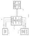
- FIG. 2illustrates a schematic of the components of a pulsed power system for the formation and acceleration sections.
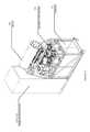
- FIG. 3illustrates an isometric view of an individual pulsed power formation and acceleration skid.
- FIG. 4illustrates an isometric view of a formation and acceleration tube assembly.
- FIG. 5illustrates a basic layout of an alternate embodiment of an asymmetric system for forming, accelerating, adiabatically compressing, merging and finally magnetically compressing compact tori.
- FIG. 6illustrates a detailed view of the system shown in FIG. 1 modified to include a shell or liner positioned within the central compression chamber for fast liner compression within the central compression chamber.
- the present embodiments provided hereinare directed to systems and methods that facilitate merging and compressing compact tori with superior stability as well as a significant reduction of translation and compression losses and an increase in coupling efficiency between drivers and plasma.
- Such systems and methodsprovide a pathway to a whole variety of applications including compact neutron sources (for medical isotope production, nuclear waste remediation, materials research, neutron radiography and tomography), compact photon sources (for chemical production and processing), mass separation and enrichment systems, and reactor cores for fusion for the future generation of energy and for fusion propulsion systems.
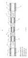
- FIG. 1illustrates the basic layout of a system 10 for forming, accelerating, adiabatically compressing, merging and finally magnetically compressing the compact tori.
- the systemcomprises a staged symmetric sequence of compact tori formation in formation sections 12 N and 12 S, axial acceleration through sections 12 N, 12 S, 16 N and 16 S by fast active magnetic coils 32 N, 32 S, 36 N and 36 S, passive adiabatic compression by way of a conically constricting flux conserver in sections 14 N, 14 S, 18 N and 18 S, and ultimately merging of the compact tori and final fast magnetic compression in a central compression chamber 20 by fast active magnetic coils 40 .
- the intermediate steps of sufficient axial acceleration followed by adiabatic compressioncan be repeated multiple times to achieve adequate target conditions before merging and final compression. In this way, a reactor can be realized by adding further sections to the depicted system.
- the formation and accelerations stages or sections 12 N, 12 S, 16 N and 16 S and the central compression chamber 20are preferably cylindrically shaped with walls formed of non-conducting or insulating material such as, e.g., a ceramic.
- the compressions stages or sections 14 N, 14 S, 18 N and 18 Sare preferably trunco-conically shaped with walls formed from conducting material such as, e.g., a metal.
- the formation sections 12 N and 12 S, the acceleration sections 16 N and 16 S, and the compression chamber 20include modular pulsed power systems that drive fast active magnetic coils 32 N, 32 S, 36 N, 36 S and 40 .
- the slow passive magnetic coil systems 30located throughout and along the axis of the system provide an axial magnetic guide field to center the compact tori appropriately.
- the systems and methods described hereindeploy FRCs, amongst the highest beta plasmas known in magnetic confinement, to provide the starting configuration. Further passive and active compression builds on this highly efficient magnetic topology.
- the process of using axial acceleration via active fast magnet sections followed by adiabatic compression in simple flux conserving conic sectionsprovides for the most efficient transfer of energy with the least complex pulsed power circuitry.
- these basic building blockscan be sequenced to take additional advantage of the inherently favorable compressional scaling, i.e. ⁇ p ⁇ R 4 .
- systemis configured to deploy spheromaks instead of FRC starter plasmas.
- the systemcomprises a staged asymmetric sequence from a single side of the central compression chamber comprising compact tori formation, axial acceleration by fast active magnetic coils, passive adiabatic compression by way of a conically constricting flux conserver, and ultimately merging of the compact tori and final fast magnetic compression in the central compression chamber.
- asymmetric systemwould include a mirror or bounce cone.
- the systemcomprising a thin cylindrical shell or liner comprised of conductive material such as, e.g., a metal, for fast liner compression within the central compression chamber.
- conductive materialsuch as, e.g., a metal
- a system 10 for merging and compressing compact tori plasmaincludes a central compression chamber 20 and a pair of north and south diametrically opposed compact tori formation sections 12 N and 12 S.
- the first and second formation sections 12 N and 12 Sinclude a modularized formation and acceleration systems 120 (discuss below in detail with regard to see FIGS. 2-4 ) for generating first and second compact plasma tori and axially accelerating and translating the compact tori towards a mid-plane of the compression chamber 20 .
- the system 10further includes a first pair of north and south diametrically opposed compression sections 14 N and 14 S coupled on a first end to an exit end of the north and south formation sections 12 N and 12 S.
- the north and south compression sections 14 N and 14 Sbeing configured to adiabatically compress the compact tori as the compact tori traverse the north and south compression sections 14 N and 14 S towards the mid-plane of the compression chamber 20 .
- the system 10further includes a pair of north and south diametrically opposed acceleration sections 16 N and 16 S coupled on a first end to a second end of the first pair of north and south compression sections 14 N and 14 S.
- the north and south acceleration section 16 N and 16 Sinclude modularized acceleration systems (discussed below with regard to FIGS. 2-4 ) for axially accelerating and translating the compact tori towards the mid-plane of the compression chamber 20 .
- the system 10further includes a second pair of north and south diametrically opposed compression sections 18 N and 18 S coupled on a first end to a second end of the north and south acceleration sections 16 N and 16 S and on a second end to first and second diametrically opposed ends of the compression chamber, the second pair of north and south compression sections 18 N and 18 S being configured to adiabatically compress the compact tori as the compact tori traverse the second pair of north and south compression sections 18 N and 18 S towards the mid-plane of the compression chamber 20 .
- the compression chamberincludes a modularized compression systems configured to magnetically compress the compact tori upon collision and merger thereof.
- the north and south acceleration sections 16 N and 16 S and the compression chamber 20are cylindrically shaped.
- the diameter of the north and south acceleration sections 16 N and 16 Sis smaller than the diameter of the north and south formation sections 12 N and 12 S, while the diameter of the compression chamber 20 is than the diameter of the north and south acceleration sections 16 N and 16 S.
- the first and second pairs of north and south compression sections 14 N, 14 S, 18 N and 18 Sare truncated conically shaped with their diameter being larger on a first end than on a second end enabling a transition in the overall diameter of the system 10 from the formation sections 12 N and 12 S to the acceleration sections 16 N and 16 S to the compression chamber 20 .
- the north and south formation sections 12 N and 12 S, the first pair of north and south compression sections 14 N and 14 S, the north and south acceleration sections 16 N and 16 S, and the second pair of north and south compression sections 18 N and 18 Sare axially symmetric.
- first and second sets of a plurality of active magnetic coils 32 N and 32are disposed about and axially along the north and south formation sections 12 N and 12 S
- third and fourth sets of a plurality of active magnetic coils 36 N and 36 Sare disposed about and axially along the north and south acceleration sections 16 N and 16 S
- a fifth set of a plurality of active magnetic coils 40are disposed about and axially along the compression chamber 20 .
- the compression sections 14 N, 14 S, 18 N and 18 Sare preferably formed from conducting material such as, e.g., a metal, while the central compression chamber 20 and the formation and acceleration sections are 12 N, 12 S, 16 N and 16 S are preferably formed from non-conducting or insulating material such as, e.g., a ceramic.
- a plurality of DC magnetic coils 30are disposed about and axially along the central compression chamber 20 and the formation, compression and acceleration sections 12 N, 12 S, 14 N, 14 S, 16 N, 16 S, 18 N and 18 S to form a bias or DC guide field within and extending axially through the central compression chamber and the formation, compression and acceleration sections.
- Triggering control and switch systems 120are configured to enable a staged symmetric sequence of compact tori formation by active magnetic coils 32 N and 32 S in the north and south formation sections 12 N and 12 S, axial acceleration by active magnetic coils 36 N and 36 S in the north and south acceleration sections 16 N and 16 S, and compression by active magnetic coils 40 in the compression chamber 20 .
- the triggering control and switch systems 120are configured to synchronize compact tori formation and acceleration in the north and south formation sections 12 N and 12 S, compact tori acceleration in the north and south acceleration sections 16 N and 16 S, and compact tori merge and compression in the compression chamber 20 .
- FIGS. 2-4there is individual pulsed power system 120 corresponding to and powering individual ones of the first, second, third, fourth and fifth sets of the plurality of active magnets 32 N, 32 S, 36 N, 36 S and 40 of the formation sections 12 N and 12 S, the acceleration sections 16 N and 16 S, and the compression chamber 20 .
- the pulse power system 120operates on a modified theta-pinch principle to form the compact tori.
- FIGS. 2 through 4illustrate the main building blocks and arrangement of the pulsed power systems 120 .
- Each skid 122is composed of capacitors 121 , inductors 123 , fast high current switches 125 and associated trigger 124 and dump circuitry 126 . Coordinated operation of these components is achieved via a state-of-the-art trigger and control system 124 and 126 that allows synchronized timing between the pulsed power systems 120 on each of the formation sections 12 N and 12 S, the acceleration sections 16 N and 16 S, and compression chamber 20 , and minimizes switching jitter to tens of nanoseconds.
- a DC guide fieldis generated by the passive coils 30 within and axially extending through the compression chamber 20 , the formation sections 12 N and 12 S, the acceleration sections 16 N and 16 S, and the compression sections 14 N, 14 S, 18 N and 18 S.
- Compact toriare then formed and accelerated in a staged symmetric sequence within the formation sections 12 N and 12 S and the acceleration sections 16 N and 16 S towards a mid-plane of the central chamber 20 , passively adiabatically compressed within the compression sections 14 N, 14 S, 18 N and 18 S, and merged and magnetically compressed within the central chamber 20 .
- the compact toriare formed and accelerated by powering active magnetic coils 32 N and 32 S extending about and axially along the formation sections 12 N and 12 S, further accelerated by powering active magnetic coils 35 N and 36 S extending about and axially along the acceleration sections 16 N and 16 S, and compressed by powering active magnetic coils 40 extending about and axially along the compression chamber 20 .
- the steps of forming, accelerating and compressing the compact torifurther comprises synchronously firing diametrically opposed pairs of active magnetic coils 32 N and 32 S, and 36 N and 36 S positioned about and along the formation 12 N and 12 S and acceleration sections 16 N and 16 S, and a set of active magnetic coils 40 positioned about and along the compression chamber 20 .
- the compact toriare compressed as the compact tori translate through the conically constricting flux conservers of the compression stages 14 N, 14 S, 18 N and 18 S.
- the system 100comprises a staged asymmetric sequence from a single side of the central compression chamber 20 .
- the system 100includes a single compact toroid formation section 12 S, a first compression section 14 S coupled on a first end to an exit end of the formation section 12 S, an acceleration section 16 N coupled on a first end to a second end of the compression section 14 S, a second compression section 18 S coupled on a first end to a second end of the acceleration section 16 S and on a second end to a first end of the compression chamber 20 .
- a mirror or bounce cone 50is positioned adjacent the other end of the central compression 20 .
- a first compact toroidis formed and accelerated in a staged sequence within the formation section 12 S and then accelerated in one or more acceleration stages 16 S towards a mid-plane of the central chamber 20 to collide and merge with a second compact toroid.
- the first compact toroidis passively adiabatically compressed within one or more compression stages 14 S and 18 S, and then magnetically compressed as a merged compact toroid with the second compact toroid within the central chamber 20 .
- the second compact toroidin formed and accelerated in a staged sequence within the formation section 12 S and the one or more acceleration stages 16 S towards a mid-plane of the central chamber 20 , passively adiabatically compressed within the one or more compression stages, and then biased back toward the mid-plane of the central chamber 20 as it passes through the central chamber 20 with a mirror or bounce cone 50 positioned adjacent an end of the central chamber 20 .
- FIG. 6an alternative embodiment of a system 200 for merging and compressing compact tori plasma is illustrated in a partial detail view showing the compression chamber 20 with diametrically opposed compression section 18 N and 18 S coupled to opposing sides of the chamber 20 .
- the system 200further comprise a cylindrical shell or liner 60 positioned within the central compression chamber 20 for fast liner compression.
Landscapes
- Physics & Mathematics (AREA)
- Engineering & Computer Science (AREA)
- Plasma & Fusion (AREA)
- General Engineering & Computer Science (AREA)
- High Energy & Nuclear Physics (AREA)
- Spectroscopy & Molecular Physics (AREA)
- Optics & Photonics (AREA)
- Plasma Technology (AREA)
- Compressors, Vaccum Pumps And Other Relevant Systems (AREA)
- Characterised By The Charging Evacuation (AREA)
- Combustion Methods Of Internal-Combustion Engines (AREA)
- Basic Packing Technique (AREA)
- Processing Of Solid Wastes (AREA)
- Electrical Discharge Machining, Electrochemical Machining, And Combined Machining (AREA)
- Shovels (AREA)
- Alarm Systems (AREA)
- Emergency Alarm Devices (AREA)
- Reduction Or Emphasis Of Bandwidth Of Signals (AREA)
- Filling Or Discharging Of Gas Storage Vessels (AREA)
- Applications Or Details Of Rotary Compressors (AREA)
- Devices Affording Protection Of Roads Or Walls For Sound Insulation (AREA)
Abstract
Description
The subject application is a continuation of PCT Patent Application No. PCT/US15/55172, filed Oct. 12, 2015, which claims priority to U.S. Provisional Patent Application No. 62/064,346, filed on Oct. 15, 2014, and U.S. Provisional Patent Application No. 62/063,382, filed on Oct. 13, 2014, all of which are incorporated by reference herein in their entirety for all purposes.
The embodiments described herein relate generally to pulsed plasma systems and, more particularly, to systems and methods that facilitate merging and compressing compact tori with superior stability as well as significantly reduced losses and increased efficiency.
The Field Reversed Configuration (FRC) belongs to the class of magnetic plasma confinement topologies known as compact toroids. It exhibits predominantly poloidal magnetic fields and possesses zero or small self-generated toroidal fields (see M. Tuszewski, Nucl. Fusion 28, 2033 (1988)). The attractions of such a configuration are its simple geometry for ease of construction and maintenance, a natural unrestricted divertor for facilitating energy extraction and ash removal, and very high average (or external) β (β is the ratio of the average plasma pressure to the average magnetic field pressure inside the FRC), i.e., high power density. The β metric is also a very good measure of magnetic efficiency. A high average β value, e.g. close to 1, represents efficient use of the deployed magnetic energy and is henceforth essential for the most economic operation. High average β is also critically enabling the use of aneutronic fuels such as D-He3and p-B11.
The traditional method of forming an FRC uses the field-reversed θ-pinch technology, producing hot, high-density plasmas (see A. L. Hoffman and J. T. Slough, Nucl. Fusion 33, 27 (1993)). A variation on this is the translation-trapping method in which the plasma created in a theta-pinch “source” is more-or-less immediately ejected out of the formation region and into a confinement chamber. The translating plasmoid is then trapped between two strong mirrors at the ends of the confinement chamber (see, for instance, H. Himura, S. Okada, S. Sugimoto, and S. Goto, Phys.Plasmas 2, 191 (1995)). Once in the confinement chamber, various heating and current drive methods may be applied such as beam injection (neutral or neutralized), rotating magnetic fields, RF or ohmic heating, etc. This separation of source and confinement functions offers key engineering advantages for potential future fusion reactors. FRCs have proved to be extremely robust, resilient to dynamic formation, translation, and violent capture events. Moreover, they show a tendency to assume a preferred plasma state (see e.g. H. Y. Guo, A. L. Hoffman, K. E. Miller, and L. C. Steinhauer, Phys. Rev. Lett. 92, 245001 (2004)). Significant progress has been made in the last decade developing other FRC formation methods: merging spheromaks with oppositely-directed helicities (see e.g. Y. Ono, M. Inomoto, Y. Ueda, T. Matsuyama, and T. Okazaki, Nucl. Fusion 39, 2001 (1999)) and by driving current with rotating magnetic fields (RMF) (see e.g. I. R. Jones, Phys. Plasmas 6, 1950 (1999)), which also provides additional stability.
FRCs consist of a torus of closed field lines inside a separatrix, and of an annular edge layer on the open field lines just outside the separatrix. The edge layer coalesces into jets beyond the FRC length, providing a natural divertor. The FRC topology coincides with that of a Field-Reversed-Mirror plasma. However, a significant difference is that the FRC plasma can have an internal β of about 10. The inherent low internal magnetic field provides for a certain indigenous kinetic particle population, i.e. particles with large larmor radii, comparable to the FRC minor radius. It is these strong kinetic effects that appear to at least partially contribute to the gross stability of past and present FRCs, such as those produced in the recent collision-merging experiments.
The collision-merging technique, proposed long ago (see e.g. D. R. Wells, Phys.Fluids 9, 1010 (1966)) has been significantly developed further: two separate theta-pinches at opposite ends of a confinement chamber simultaneously generate two plasmoids (e.g., two compact tori) and accelerate the plasmoids toward each other at high speed; they then collide at the center of the confinement chamber and merge to form a compound FRC. In the construction and successful operation of one of the largest FRC experiments to date, the conventional collision-merging method was shown to produce stable, long-lived, high-flux, high temperature FRCs (see e.g. M. Binderbauer, H. Y. Guo, M. Tuszewski et al., Phys. Rev. Lett. 105, 045003 (2010), which is incorporated herein by reference). In a related experiment, the same team of researchers combined the collision-merging technique with simultaneous axial acceleration and radial compression to produce a high density transient plasma in a central compression chamber (see V. Bystritskii, M. Anderson, M. Binderbauer et al., Paper P1-1, IEEE PPPS 2013, San Francisco, Calif. (hereinafter “Bystritskii”), which is incorporated herein by reference). This latter experiment reported in Bystritskii utilized a multitude of acceleration and compression stages before final collisional merging and represents a precursor concept to the system subject to this patent application.
In contrast to the embodiments described here, the precursor system described in Bystritskii featured simultaneous compression and acceleration of compact tori within the same stage by using active fast magnetic coils. Five such stages were deployed on either side of a central compression chamber before magnetically compressing the merged compact tori. While the precursor experiment achieved respectable performance, it exhibited the following deficiencies: (1) Simultaneous compression and acceleration led to inefficient use of driver energy deployed for magnetic compression due to a timing mismatch; (2) Temperature and density decreased as plasma expanded during transit between sections; (3) Abrupt transitions between adjacent sections led to large losses due to plasma-wall contact and generation of shockwaves.
Aside from the fundamental challenge of stability, pulsed fusion concepts in the medium density regime will have to address adequate transport timescales, efficient drivers, rep-rate capability and appropriate final target conditions. While the precursor system has successfully achieved stable single discharges at encouraging target conditions, the collective losses between formation and final target parameters (presently about 90% of the energy, flux, and particles) as well as the coupling efficiency between driver and plasma (at present around 10-15%) need to be substantially improved.
In light of the foregoing, it is, therefore, desirable to provide improved systems and methods for pulsed fusion concepts that facilitate a significant reduction of translation and compression losses and an increase in driver efficiency.
The present embodiments provided herein are directed to systems and methods that facilitate merging and compressing compact tori with superior stability as well as a significant reduction of translation and compression losses and an increase in coupling efficiency between drivers and plasma. Such systems and methods provide a pathway to a whole variety of applications including compact neutron sources (for medical isotope production, nuclear waste remediation, materials research, neutron radiography and tomography), compact photon sources (for chemical production and processing), mass separation and enrichment systems, and reactor cores for fusion for the future generation of energy and for fusion propulsion systems.
The systems and methods described herein are based on the application of successive, axially symmetric acceleration and adiabatic compression stages to accelerate and heat two compact tori towards each other and ultimately collide and fast magnetically compress the compact tori within a central compression chamber.
In certain embodiments, a system for merging and compressing compact tori comprises a staged symmetric sequence of compact tori formation, axial acceleration by fast active magnetic coils, passive adiabatic compression by way of a conically constricting flux conserver, and ultimately merging of the compact tori and final fast magnetic compression in a central compression chamber. The intermediate steps of sufficient axial acceleration followed by adiabatic compression can be repeated multiple times to achieve adequate target conditions before merging and final compression. In this way, a reactor can be realized by adding further sections to the system.
The formation and accelerations stages or sections and the central compression chamber are preferably cylindrically shaped with walls formed of non-conducting or insulating material such as, e.g., a ceramic. The compressions stages or sections are preferably trunco-conically shaped with walls formed from conducting material such as, e.g., a metal.
Aside from a magnetic bias field (DC guide field) supplied by slow coils, the formation sections, the acceleration sections, and the compression chamber include modular pulsed power systems that drive fast active magnetic coils. The pulsed power systems enable compact tori to be formed in-situ within the formation sections and accelerated and injected (=static formation) into the first compression sections, accelerated in the acceleration sections and injected into the next compression sections, and so on, and then be magnetically compressed in the compression chamber. The slow or DC magnetic coil systems located throughout and along the axis of the system provide an axial magnetic guide field to center the compact tori appropriately as it translates through the section toward the mid-plane of the central compression chamber.
Alternatively, the modular pulsed power systems of the formation sections can also drive the fast active magnetic coils in a way such that compact tori are formed and accelerated simultaneously (=dynamic formation).
The systems and methods described herein deploy FRCs, amongst the highest beta plasmas known in magnetic confinement, to provide the starting configuration. Further passive and active compression builds on this highly efficient magnetic topology. The process of using axial acceleration via active fast magnet sections followed by adiabatic compression in simple flux conserving conic sections provides for the most efficient transfer of energy with the least complex pulsed power circuitry. Furthermore, these basic building blocks can be sequenced to take additional advantage of the inherently favorable compressional scaling, i.e. Δp∝R4.
In another embodiment, the system is configured to deploy spheromaks instead of FRC starter plasmas.
In another embodiment, the system comprises a staged asymmetric sequence from a single side of the central compression chamber comprising compact tori formation, axial acceleration by fast active magnetic coils, passive adiabatic compression by way of a conically constricting flux conserver, and ultimately merging of the compact tori and final fast magnetic compression in the central compression chamber. Such an asymmetric system would include a mirror or bounce cone positioned adjacent the other side of the central compression.
In yet another embodiment, the system comprises a thin cylindrical shell or liner comprised of conductive material such as, e.g., a metal, for fast liner compression within the central compression chamber.
Other systems, methods, features and advantages of the example embodiments will be or will become apparent to one with skill in the art upon examination of the following figures and detailed description.
The accompanying drawings, which are included as part of the present specification, illustrate the presently preferred embodiment and, together with the general description given above and the detailed description of the preferred embodiment given below, serve to explain and teach the principles of the present invention.
It should be noted that the figures are not necessarily drawn to scale and that elements of similar structures or functions are generally represented by like reference numerals for illustrative purposes throughout the figures. It also should be noted that the figures are only intended to facilitate the description of the various embodiments described herein. The figures do not necessarily describe every aspect of the teachings disclosed herein and do not limit the scope of the claims.
The present embodiments provided herein are directed to systems and methods that facilitate merging and compressing compact tori with superior stability as well as a significant reduction of translation and compression losses and an increase in coupling efficiency between drivers and plasma. Such systems and methods provide a pathway to a whole variety of applications including compact neutron sources (for medical isotope production, nuclear waste remediation, materials research, neutron radiography and tomography), compact photon sources (for chemical production and processing), mass separation and enrichment systems, and reactor cores for fusion for the future generation of energy and for fusion propulsion systems.
The systems and methods described herein are based on the application of successive, axially symmetric acceleration and adiabatic compression stages to accelerate and heat two compact tori towards each other and ultimately collide and fast magnetically compress the compact tori within a central compression chamber.FIG. 1 illustrates the basic layout of asystem 10 for forming, accelerating, adiabatically compressing, merging and finally magnetically compressing the compact tori.
As depicted, the system comprises a staged symmetric sequence of compact tori formation information sections 12N and12S, axial acceleration throughsections magnetic coils sections central compression chamber 20 by fast activemagnetic coils 40. As illustrated, the intermediate steps of sufficient axial acceleration followed by adiabatic compression can be repeated multiple times to achieve adequate target conditions before merging and final compression. In this way, a reactor can be realized by adding further sections to the depicted system.
As depicted the formation and accelerations stages orsections central compression chamber 20 are preferably cylindrically shaped with walls formed of non-conducting or insulating material such as, e.g., a ceramic. The compressions stages orsections
Aside from a magnetic bias field (DC guide field) supplied by slowpassive coils 30, theformation sections 12N and12S, theacceleration sections compression chamber 20 include modular pulsed power systems that drive fast activemagnetic coils formation sections 12N and12S and accelerated and injected (=static formation) into thefirst compression sections 14N and14S, accelerated in theacceleration sections next compression sections compression chamber 20. The slow passivemagnetic coil systems 30 located throughout and along the axis of the system provide an axial magnetic guide field to center the compact tori appropriately.
Alternatively, the modular pulsed power systems of the formation sections can also drive the fast magnetic coils in a way such that compact tori are formed and accelerated simultaneously (=dynamic formation).
The systems and methods described herein deploy FRCs, amongst the highest beta plasmas known in magnetic confinement, to provide the starting configuration. Further passive and active compression builds on this highly efficient magnetic topology. The process of using axial acceleration via active fast magnet sections followed by adiabatic compression in simple flux conserving conic sections provides for the most efficient transfer of energy with the least complex pulsed power circuitry. Furthermore, these basic building blocks can be sequenced to take additional advantage of the inherently favorable compressional scaling, i.e. Δp∝R4.
Based on experimental and theoretical research to date, a precursor experiment as describe by Bystritskii, using FRC starter plasmas has achieved densities of about 1017cm−3at 1 keV. The embodiments proposed herein are estimated to reach densities of about 1018cm−3at 1 keV, while adding further stages and appropriate upgrades to the central chamber and fast magnetic coils can yield ultimate densities of about 1018cm−3at full Lawson conditions.
In another embodiment, the system is configured to deploy spheromaks instead of FRC starter plasmas.
In another embodiment, the system comprises a staged asymmetric sequence from a single side of the central compression chamber comprising compact tori formation, axial acceleration by fast active magnetic coils, passive adiabatic compression by way of a conically constricting flux conserver, and ultimately merging of the compact tori and final fast magnetic compression in the central compression chamber. Such an asymmetric system would include a mirror or bounce cone.
In yet another embodiment, the system comprising a thin cylindrical shell or liner comprised of conductive material such as, e.g., a metal, for fast liner compression within the central compression chamber.
Fusion concepts today are focused on either steady state or ultra-short pulsed regimes. Both approaches require large capital investment: in steady state magnetic fusion, high expense arises from large superconducting magnets and auxiliary heating/current drive technologies; inertial regimes are dominated by high driver cost due to large energy delivery over nanosecond timescales. The embodiments advanced herein are characterized by compact size and sub-millisecond time scales. This leads to a regime that has relaxed peak power requirements and attractive intermediate time scales.
Turning in detail to the drawings, as depicted inFIG. 1 , asystem 10 for merging and compressing compact tori plasma includes acentral compression chamber 20 and a pair of north and south diametrically opposed compacttori formation sections 12N and12S. The first andsecond formation sections 12N and12S include a modularized formation and acceleration systems120 (discuss below in detail with regard to seeFIGS. 2-4 ) for generating first and second compact plasma tori and axially accelerating and translating the compact tori towards a mid-plane of thecompression chamber 20.
As depicted, thesystem 10 further includes a first pair of north and south diametricallyopposed compression sections 14N and14S coupled on a first end to an exit end of the north andsouth formation sections 12N and12S. The north andsouth compression sections 14N and14S being configured to adiabatically compress the compact tori as the compact tori traverse the north andsouth compression sections 14N and14S towards the mid-plane of thecompression chamber 20.
As depicted, thesystem 10 further includes a pair of north and south diametricallyopposed acceleration sections south compression sections 14N and14S. The north andsouth acceleration section FIGS. 2-4 ) for axially accelerating and translating the compact tori towards the mid-plane of thecompression chamber 20.
As further depicted, thesystem 10 further includes a second pair of north and south diametricallyopposed compression sections south acceleration sections south compression sections south compression sections compression chamber 20.
The compression chamber includes a modularized compression systems configured to magnetically compress the compact tori upon collision and merger thereof.
As depicted the north andsouth formation sections 12N and12S, the north andsouth acceleration sections compression chamber 20 are cylindrically shaped. The diameter of the north andsouth acceleration sections south formation sections 12N and12S, while the diameter of thecompression chamber 20 is than the diameter of the north andsouth acceleration sections
The first and second pairs of north andsouth compression sections system 10 from theformation sections 12N and12S to theacceleration sections compression chamber 20. As depicted, the north andsouth formation sections 12N and12S, the first pair of north andsouth compression sections 14N and14S, the north andsouth acceleration sections south compression sections
As depicted, first and second sets of a plurality of activemagnetic coils 32N and32 are disposed about and axially along the north andsouth formation sections 12N and12S, third and fourth sets of a plurality of activemagnetic coils south acceleration sections magnetic coils 40 are disposed about and axially along thecompression chamber 20.
Thecompression sections central compression chamber 20 and the formation and acceleration sections are12N,12S,16N and16S are preferably formed from non-conducting or insulating material such as, e.g., a ceramic.
As depicted, a plurality of DCmagnetic coils 30 are disposed about and axially along thecentral compression chamber 20 and the formation, compression andacceleration sections
Triggering control andswitch systems 120, shown inFIGS. 2-4 , are configured to enable a staged symmetric sequence of compact tori formation by activemagnetic coils south formation sections 12N and12S, axial acceleration by activemagnetic coils south acceleration sections magnetic coils 40 in thecompression chamber 20. The triggering control andswitch systems 120 are configured to synchronize compact tori formation and acceleration in the north andsouth formation sections 12N and12S, compact tori acceleration in the north andsouth acceleration sections compression chamber 20.
Turning toFIGS. 2-4 , there is individualpulsed power system 120 corresponding to and powering individual ones of the first, second, third, fourth and fifth sets of the plurality ofactive magnets formation sections 12N and12S, theacceleration sections compression chamber 20. In the formation sections, thepulse power system 120 operates on a modified theta-pinch principle to form the compact tori.FIGS. 2 through 4 illustrate the main building blocks and arrangement of thepulsed power systems 120. Thepulsed power system 120 is composed of a modular pulsed power arrangement that consists of individual units (=skids)122 that each energize a sub-set ofcoils 132 of a strap assembly130 (=straps) that wrap around thesection tubes 140. Eachskid 122 is composed ofcapacitors 121,inductors 123, fast highcurrent switches 125 and associatedtrigger 124 and dumpcircuitry 126. Coordinated operation of these components is achieved via a state-of-the-art trigger andcontrol system pulsed power systems 120 on each of theformation sections 12N and12S, theacceleration sections compression chamber 20, and minimizes switching jitter to tens of nanoseconds. The advantage of this modular design is its flexible operation. In theformation sections 12N and12S, FRCs can be formed in-situ and then accelerated and injected (=static formation) or formed and accelerated at the same time (=dynamic formation).
In operation, a DC guide field is generated by the passive coils30 within and axially extending through thecompression chamber 20, theformation sections 12N and12S, theacceleration sections compression sections formation sections 12N and12S and theacceleration sections central chamber 20, passively adiabatically compressed within thecompression sections central chamber 20. These steps of forming, accelerating and compressing compact tori results in the compact tori colliding and merging within thecentral chamber 20.
The compact tori are formed and accelerated by powering activemagnetic coils formation sections 12N and12S, further accelerated by powering activemagnetic coils 35N and36S extending about and axially along theacceleration sections magnetic coils 40 extending about and axially along thecompression chamber 20. The steps of forming, accelerating and compressing the compact tori further comprises synchronously firing diametrically opposed pairs of activemagnetic coils formation 12N and12S andacceleration sections magnetic coils 40 positioned about and along thecompression chamber 20.
As the compact tori are accelerated towards the mid-plane of thecompression chamber 20, the compact tori are compressed as the compact tori translate through the conically constricting flux conservers of the compression stages14N,14S,18N and18S.
Turning toFIG. 5 , an alternative embodiment of asystem 100 for merging and compressing compact tori plasma is illustrated. As depicted, thesystem 100 comprises a staged asymmetric sequence from a single side of thecentral compression chamber 20. Thesystem 100 includes a single compact toroid formation section12S, a first compression section14S coupled on a first end to an exit end of the formation section12S, anacceleration section 16N coupled on a first end to a second end of the compression section14S, asecond compression section 18S coupled on a first end to a second end of theacceleration section 16S and on a second end to a first end of thecompression chamber 20. A mirror or bouncecone 50 is positioned adjacent the other end of thecentral compression 20.
In operation, a first compact toroid is formed and accelerated in a staged sequence within the formation section12S and then accelerated in one or more acceleration stages16S towards a mid-plane of thecentral chamber 20 to collide and merge with a second compact toroid. The first compact toroid is passively adiabatically compressed within one ormore compression stages 14S and18S, and then magnetically compressed as a merged compact toroid with the second compact toroid within thecentral chamber 20.
The second compact toroid in formed and accelerated in a staged sequence within the formation section12S and the one or more acceleration stages16S towards a mid-plane of thecentral chamber 20, passively adiabatically compressed within the one or more compression stages, and then biased back toward the mid-plane of thecentral chamber 20 as it passes through thecentral chamber 20 with a mirror or bouncecone 50 positioned adjacent an end of thecentral chamber 20.
Turning toFIG. 6 , an alternative embodiment of asystem 200 for merging and compressing compact tori plasma is illustrated in a partial detail view showing thecompression chamber 20 with diametricallyopposed compression section chamber 20. Thesystem 200 further comprise a cylindrical shell orliner 60 positioned within thecentral compression chamber 20 for fast liner compression.
While the invention is susceptible to various modifications, and alternative forms, specific examples thereof have been shown in the drawings and are herein described in detail. It should be understood, however, that the invention is not to be limited to the particular forms or methods disclosed, but to the contrary, the invention is to cover all modifications, equivalents and alternatives falling within the spirit and scope of the appended claims.
In the description above, for purposes of explanation only, specific nomenclature is set forth to provide a thorough understanding of the present disclosure. However, it will be apparent to one skilled in the art that these specific details are not required to practice the teachings of the present disclosure.
The various features of the representative examples and the dependent claims may be combined in ways that are not specifically and explicitly enumerated in order to provide additional useful embodiments of the present teachings. It is also expressly noted that all value ranges or indications of groups of entities disclose every possible intermediate value or intermediate entity for the purpose of original disclosure, as well as for the purpose of restricting the claimed subject matter.
Systems and methods for merging and compressing compact tori have been disclosed. It is understood that the embodiments described herein are for the purpose of elucidation and should not be considered limiting the subject matter of the disclosure. Various modifications, uses, substitutions, combinations, improvements, methods of productions without departing from the scope or spirit of the present invention would be evident to a person skilled in the art. For example, the reader is to understand that the specific ordering and combination of process actions described herein is merely illustrative, unless otherwise stated, and the invention can be performed using different or additional process actions, or a different combination or ordering of process actions. As another example, each feature of one embodiment can be mixed and matched with other features shown in other embodiments. Features and processes known to those of ordinary skill may similarly be incorporated as desired. Additionally and obviously, features may be added or subtracted as desired. Accordingly, the invention is not to be restricted except in light of the attached claims and their equivalents.
Claims (25)
1. A system for merging and compressing compact tori plasma comprising
a compression chamber,
first and second formation sections, the first and second formation sections being diametrically opposed and comprising modularized formation and acceleration systems for generating first and second plasma compact tori and axially accelerating the compact tori and translating the compact tori towards a mid-plane of the compression chamber,
first and second compression sections coupled on a first end to an exit end of the first and second formation sections, the first and second compression sections being diametrically opposed and configured to adiabatically compress the compact tori as the compact tori traverse the first and second compression sections towards the mid-plane of the compression chamber,
first and second acceleration sections coupled on a first end to a second end of the first and second compression sections, the first and second acceleration sections being diametrically opposed and comprising modularized acceleration systems for axially accelerating the compact tori and translating the compact tori towards the mid-plane of the compression chamber, and
third and fourth compression sections coupled on a first end to a second end of the first and second acceleration sections and on a second end to first and second diametrically opposed ends of the compression chamber, the third and fourth compression sections being diametrically opposed and configured to adiabatically compress the compact tori as the compact tori traverse the third and fourth compression sections towards the mid-plane of the compression chamber.
2. The system ofclaim 1 , wherein the compression chamber is configured to magnetically compressing the compact tori upon collision and merger thereof.
3. The system ofclaim 1 , wherein the compression chamber comprises a modularized acceleration system for magnetically compressing the compact tori upon collision and merger thereof.
4. The system ofclaim 1 , wherein the first and second formation sections, the first and second acceleration sections and the compression chamber are cylindrically shaped, the diameter of the first and second acceleration sections being smaller than the diameter of the first and second formation sections and the diameter of the compression chamber being than the diameter of the first and second acceleration sections.
5. The system ofclaim 1 , wherein the first, second, third and fourth compression sections are truncated conically shaped with the diameter of the first, second, third and fourth compression section being larger on first end than on the second end.
6. The system ofclaim 1 , wherein the first and second formation sections, the first and second compression sections, the first and second acceleration sections and the third and fourth compression sections are axially symmetric.
7. The system ofclaim 1 , wherein a plurality of active magnetic coils are disposed about and axially along the first and second formation sections, the first and second acceleration sections, and the compression chamber.
8. The system ofclaim 1 , further comprising triggering control and switch systems configured to enable a staged symmetric sequence of compact tori formation in the first and second formation sections and axial acceleration by active magnetic coils in the first and second acceleration sections.
9. The system ofclaim 8 , wherein the triggering control and switch systems are configured to synchronize the compact tori formation and acceleration in the first and second formation sections and synchronize the compact tori acceleration in the first and second acceleration sections.
10. The system ofclaim 9 , wherein the triggering control and switch systems are further configured to synchronize the magnetic compression with the compact tori formation and acceleration in the first and second formation sections and the compact tori acceleration in the first and second acceleration sections.
11. The systems ofclaim 7 further comprising a plurality of DC magnetic coils disposed about and axially along the compression chamber and the formation, compression and acceleration sections to form a bias or DC guide field within and extending axially through the compression chamber and the formation, compression and acceleration sections.
12. The system ofclaim 1 further comprising a cylindrical shell or liner positioned within the compression chamber for fast liner compression.
13. A system for merging and compressing compact tori plasma comprising
a compression chamber,
a formation section, the formation section comprising modularized formation and acceleration sections for generating a compact toroid and axially accelerating the compact toroid and translating the compact toroid towards a mid-plane of the compression chamber,
a first compression section coupled on a first end to an exit end of the formation section, the first compression section being configured to adiabatically compress the compact toroid as the compact toroid traverses the first compression section towards the mid-plane of the compression chamber,
an acceleration section coupled on a first end to a second end of the first compression section, the acceleration section comprising modularized acceleration systems for axially accelerating the compact toroid and translating the compact toroid towards the mid-plane of the compression chamber,
a second compression section coupled on a first end to a second end of the acceleration section and on a second end to a first end of the compression chamber, the second compression section being configured to adiabatically compress the compact toroid as the compact toroid traverses the second compression section towards the mid-plane of the compression chamber.
14. The system ofclaim 13 , wherein the compression chamber is configured to magnetically compress the compact toroid.
15. The system ofclaim 13 , wherein the formation section, the acceleration section and the compression chamber are cylindrically shaped, the diameter of the acceleration section being smaller than the diameter of the formation section and the diameter of the compression chamber being smaller than the diameter of the acceleration section.
16. The system ofclaim 13 , wherein the first and second compression sections are trunco-conically shaped with the diameter of the first and second compression sections being larger on the first end than on the second end.
17. The system ofclaim 13 , wherein the formation section, the first and second compression sections, the acceleration section, and the compression chamber are axially aligned.
18. The system ofclaim 13 , wherein a plurality of active magnetic coils are disposed about and axially along the formation section, the acceleration section, and the compression chamber.
19. The system ofclaim 13 , further comprising triggering control and switch systems configured to enable a staged sequence of compact toroid formation and axial acceleration by active magnetic coils.
20. The system ofclaim 19 , wherein the triggering control and switch systems are further configured to enable magnetic compression of the compact toroid by active magnetic coils in a staged sequence following the staged sequence of compact toroid formation and axial acceleration by active magnetic coils.
21. The system ofclaim 19 , wherein the triggering control and switch systems are configured to synchronize the compact toroid formation and acceleration in the formation section and synchronize the compact toroid acceleration in the acceleration section with the positioning of a second compact toroid at the mid-plane of the compression chamber.
22. The system ofclaim 20 , wherein the triggering control and switch systems are further configured to synchronize the compression of the compact toroid and the second compact toroid with the compact toroid formation and acceleration in the formation section, the compact toroid acceleration in the acceleration section and the positioning of the second compact toroid at the mid-plane of the compression chamber.
23. The systems ofclaim 18 further comprising a plurality of DC magnetic coils disposed about and axially along the compression chamber and the formation, compression and acceleration sections to form a bias or DC guide field within and extending axially through the compression chamber and the formation, compression and acceleration sections.
24. The system ofclaim 13 further comprising a cylindrical shell or liner positioned within the compression chamber for fast liner compression.
25. The system ofclaim 13 further comprising one of a mirror and a bounce cone coupled to a second end of the compression chamber.
Priority Applications (4)
| Application Number | Priority Date | Filing Date | Title |
|---|---|---|---|
| US15/483,984US10217532B2 (en) | 2014-10-13 | 2017-04-10 | Systems and methods for merging and compressing compact tori |
| US16/277,441US10665351B2 (en) | 2014-10-13 | 2019-02-15 | Systems and methods for merging and compressing compact tori |
| US16/862,044US11200990B2 (en) | 2014-10-13 | 2020-04-29 | Systems and methods for merging and compressing compact tori |
| US17/549,426US11901087B2 (en) | 2014-10-13 | 2021-12-13 | Systems and methods for merging and compressing compact tori |
Applications Claiming Priority (4)
| Application Number | Priority Date | Filing Date | Title |
|---|---|---|---|
| US201462063382P | 2014-10-13 | 2014-10-13 | |
| US201462064346P | 2014-10-15 | 2014-10-15 | |
| PCT/US2015/055172WO2016061001A2 (en) | 2014-10-13 | 2015-10-12 | Systems and methods for merging and compressing compact tori |
| US15/483,984US10217532B2 (en) | 2014-10-13 | 2017-04-10 | Systems and methods for merging and compressing compact tori |
Related Parent Applications (2)
| Application Number | Title | Priority Date | Filing Date |
|---|---|---|---|
| PCT/US2015/055172ContinuationWO2016061001A2 (en) | 2014-10-13 | 2015-10-12 | Systems and methods for merging and compressing compact tori |
| PCT/US2015/055175ContinuationWO2016069249A1 (en) | 2014-10-29 | 2015-10-12 | Systems and methods for estimating a two-dimensional position of a receiver |
Related Child Applications (1)
| Application Number | Title | Priority Date | Filing Date |
|---|---|---|---|
| US16/277,441ContinuationUS10665351B2 (en) | 2014-10-13 | 2019-02-15 | Systems and methods for merging and compressing compact tori |
Publications (2)
| Publication Number | Publication Date |
|---|---|
| US20170337991A1 US20170337991A1 (en) | 2017-11-23 |
| US10217532B2true US10217532B2 (en) | 2019-02-26 |
Family
ID=55747541
Family Applications (4)
| Application Number | Title | Priority Date | Filing Date |
|---|---|---|---|
| US15/483,984Active2035-10-16US10217532B2 (en) | 2014-10-13 | 2017-04-10 | Systems and methods for merging and compressing compact tori |
| US16/277,441ActiveUS10665351B2 (en) | 2014-10-13 | 2019-02-15 | Systems and methods for merging and compressing compact tori |
| US16/862,044ActiveUS11200990B2 (en) | 2014-10-13 | 2020-04-29 | Systems and methods for merging and compressing compact tori |
| US17/549,426Active2035-12-07US11901087B2 (en) | 2014-10-13 | 2021-12-13 | Systems and methods for merging and compressing compact tori |
Family Applications After (3)
| Application Number | Title | Priority Date | Filing Date |
|---|---|---|---|
| US16/277,441ActiveUS10665351B2 (en) | 2014-10-13 | 2019-02-15 | Systems and methods for merging and compressing compact tori |
| US16/862,044ActiveUS11200990B2 (en) | 2014-10-13 | 2020-04-29 | Systems and methods for merging and compressing compact tori |
| US17/549,426Active2035-12-07US11901087B2 (en) | 2014-10-13 | 2021-12-13 | Systems and methods for merging and compressing compact tori |
Country Status (31)
| Country | Link |
|---|---|
| US (4) | US10217532B2 (en) |
| EP (2) | EP3187028B1 (en) |
| JP (1) | JP6611802B2 (en) |
| KR (1) | KR102519865B1 (en) |
| CN (2) | CN107006111B (en) |
| AR (1) | AR102255A1 (en) |
| AU (2) | AU2015333832B2 (en) |
| BR (1) | BR112017007750B1 (en) |
| CA (1) | CA2964298C (en) |
| CL (2) | CL2017000898A1 (en) |
| CY (2) | CY1122559T1 (en) |
| DK (2) | DK3187028T3 (en) |
| EA (1) | EA034349B1 (en) |
| ES (2) | ES2772770T3 (en) |
| HR (2) | HRP20200026T1 (en) |
| HU (2) | HUE047712T2 (en) |
| IL (2) | IL251314B (en) |
| LT (2) | LT3187028T (en) |
| MX (2) | MX369531B (en) |
| MY (1) | MY182756A (en) |
| PE (1) | PE20170757A1 (en) |
| PL (2) | PL3633683T3 (en) |
| PT (2) | PT3187028T (en) |
| RS (2) | RS62122B1 (en) |
| SA (1) | SA517381256B1 (en) |
| SG (2) | SG10201906591WA (en) |
| SI (2) | SI3633683T1 (en) |
| SM (2) | SMT202000082T1 (en) |
| UA (1) | UA121318C2 (en) |
| WO (1) | WO2016061001A2 (en) |
| ZA (1) | ZA201702207B (en) |
Cited By (9)
| Publication number | Priority date | Publication date | Assignee | Title |
|---|---|---|---|---|
| US10665351B2 (en)* | 2014-10-13 | 2020-05-26 | Tae Technologies, Inc. | Systems and methods for merging and compressing compact tori |
| US10790064B2 (en)* | 2013-09-24 | 2020-09-29 | Tae Technologies, Inc. | Systems and methods for forming and maintaining a high performance FRC |
| US11049619B1 (en)* | 2019-12-23 | 2021-06-29 | Lockheed Martin Corporation | Plasma creation and heating via magnetic reconnection in an encapsulated linear ring cusp |
| US20210282255A1 (en)* | 2018-05-01 | 2021-09-09 | Sunbeam Technologies, Llc | Method and Apparatus for Torsional Magnetic Reconnection |
| US11337294B2 (en) | 2014-10-30 | 2022-05-17 | Tae Technologies, Inc. | Systems and methods for forming and maintaining a high performance FRC |
| US11399425B2 (en)* | 2019-05-28 | 2022-07-26 | General Fusion Inc. | System and method for generating and accelerating magnetized plasma |
| US11404174B2 (en)* | 2018-02-28 | 2022-08-02 | General Fusion Inc. | System and method for generating plasma and sustaining plasma magnetic field |
| US20220400546A1 (en)* | 2020-01-13 | 2022-12-15 | Tae Technologies, Inc. | System and methods for forming and maintaining high energy and temperature frc plasma via spheromak merging and neutral beam injection |
| US11615896B2 (en) | 2015-11-13 | 2023-03-28 | Tae Technologies, Inc. | Systems and methods for radial and axial stability control of an FRC plasma |
Families Citing this family (10)
| Publication number | Priority date | Publication date | Assignee | Title |
|---|---|---|---|---|
| RS61313B1 (en)* | 2015-05-12 | 2021-02-26 | Tae Technologies Inc | Systems and methods for reducing undesired eddy currents |
| EP3542600A1 (en)* | 2016-11-15 | 2019-09-25 | TAE Technologies, Inc. | Systems and methods for improved sustainment of a high performance frc and high harmonic fast wave electron heating in a high performance frc |
| US10415552B2 (en)* | 2017-02-07 | 2019-09-17 | The Boeing Company | Injection system and method for injecting a cylindrical array of liquid jets |
| DE102018204585A1 (en) | 2017-03-31 | 2018-10-04 | centrotherm international AG | Plasma generator, plasma treatment apparatus and method for pulsed supply of electrical power |
| US11744002B2 (en)* | 2017-09-12 | 2023-08-29 | University Of New Hampshire | System of converging plasma pistons |
| RU188484U1 (en)* | 2018-07-30 | 2019-04-16 | Акционерное общество "Концерн воздушно-космической обороны "Алмаз - Антей" | PLASMA ACCELERATOR WITH MAGNETIC SHUTTER |
| WO2020076727A1 (en) | 2018-10-07 | 2020-04-16 | Horne Tanner L | Nuclear fusion reactor with toroidal superconducting magnetic coils implementing inertial electrostatic heating |
| CN110223796B (en)* | 2019-06-10 | 2020-11-10 | 中国科学院近代物理研究所 | Isotope production equipment |
| CN110337170B (en)* | 2019-07-11 | 2021-06-22 | 哈尔滨工业大学 | A high-density plasma jet generator based on current-driven technology inverse field configuration |
| WO2022271654A1 (en)* | 2021-06-21 | 2022-12-29 | Board Of Regents, The University Of Texas System | Particle-assisted wakefield electron acceleration devices |
Citations (129)
| Publication number | Priority date | Publication date | Assignee | Title |
|---|---|---|---|---|
| US3015618A (en) | 1958-06-30 | 1962-01-02 | Thomas H Stix | Apparatus for heating a plasma |
| US3036963A (en) | 1960-01-25 | 1962-05-29 | Nicholas C Christofilos | Method and apparatus for injecting and trapping electrons in a magnetic field |
| US3052617A (en) | 1959-06-23 | 1962-09-04 | Richard F Post | Stellarator injector |
| US3071525A (en) | 1958-08-19 | 1963-01-01 | Nicholas C Christofilos | Method and apparatus for producing thermonuclear reactions |
| US3120470A (en) | 1954-04-13 | 1964-02-04 | Donald H Imhoff | Method of producing neutrons |
| US3132996A (en) | 1962-12-10 | 1964-05-12 | William R Baker | Contra-rotating plasma system |
| US3170841A (en) | 1954-07-14 | 1965-02-23 | Richard F Post | Pyrotron thermonuclear reactor and process |
| US3182213A (en) | 1961-06-01 | 1965-05-04 | Avco Corp | Magnetohydrodynamic generator |
| US3258402A (en) | 1960-02-26 | 1966-06-28 | Itt | Electric discharge device for producing interactions between nuclei |
| US3386883A (en) | 1966-05-13 | 1968-06-04 | Itt | Method and apparatus for producing nuclear-fusion reactions |
| US3527977A (en) | 1968-06-03 | 1970-09-08 | Atomic Energy Commission | Moving electrons as an aid to initiating reactions in thermonuclear devices |
| US3530036A (en) | 1967-12-15 | 1970-09-22 | Itt | Apparatus for generating fusion reactions |
| US3530497A (en) | 1968-04-24 | 1970-09-22 | Itt | Apparatus for generating fusion reactions |
| US3577317A (en) | 1969-05-01 | 1971-05-04 | Atomic Energy Commission | Controlled fusion reactor |
| US3621310A (en) | 1969-05-30 | 1971-11-16 | Hitachi Ltd | Duct for magnetohydrodynamic thermal to electrical energy conversion apparatus |
| US3663362A (en) | 1970-12-22 | 1972-05-16 | Atomic Energy Commission | Controlled fusion reactor |
| US3664921A (en) | 1969-10-16 | 1972-05-23 | Atomic Energy Commission | Proton e-layer astron for producing controlled fusion reactions |
| US3668065A (en) | 1970-09-15 | 1972-06-06 | Atomic Energy Commission | Apparatus for the conversion of high temperature plasma energy into electrical energy |
| US3859164A (en) | 1970-05-21 | 1975-01-07 | Nowak Karl Ing | Method and device for obtaining controlled nuclear fusion by means of artificial plasma |
| GB1387098A (en) | 1972-05-29 | 1975-03-12 | Euratom | Apparatus for producing controlled nuclear fusions |
| FR2270733A1 (en) | 1974-02-08 | 1975-12-05 | Thomson Csf | Magnetic field vehicle detector unit - receiver detects changes produced in an emitted magnetic field |
| US4010396A (en) | 1973-11-26 | 1977-03-01 | Kreidl Chemico Physical K.G. | Direct acting plasma accelerator |
| US4054846A (en) | 1975-04-02 | 1977-10-18 | Bell Telephone Laboratories, Incorporated | Transverse-excitation laser with preionization |
| US4057462A (en) | 1975-02-26 | 1977-11-08 | The United States Of America As Represented By The United States Energy Research And Development Administration | Radio frequency sustained ion energy |
| US4065351A (en) | 1976-03-25 | 1977-12-27 | The United States Of America As Represented By The United States Energy Research And Development Administration | Particle beam injection system |
| US4098643A (en) | 1974-07-09 | 1978-07-04 | The United States Of America As Represented By The United States Department Of Energy | Dual-function magnetic structure for toroidal plasma devices |
| US4166760A (en) | 1977-10-04 | 1979-09-04 | The United States Of America As Represented By The United States Department Of Energy | Plasma confinement apparatus using solenoidal and mirror coils |
| US4182650A (en) | 1973-05-17 | 1980-01-08 | Fischer Albert G | Pulsed nuclear fusion reactor |
| US4189346A (en) | 1978-03-16 | 1980-02-19 | Jarnagin William S | Operationally confined nuclear fusion system |
| US4202725A (en) | 1978-03-08 | 1980-05-13 | Jarnagin William S | Converging beam fusion system |
| US4233537A (en) | 1972-09-18 | 1980-11-11 | Rudolf Limpaecher | Multicusp plasma containment apparatus |
| US4246067A (en) | 1978-08-30 | 1981-01-20 | Linlor William I | Thermonuclear fusion system |
| US4267488A (en) | 1979-01-05 | 1981-05-12 | Trisops, Inc. | Containment of plasmas at thermonuclear temperatures |
| US4274919A (en) | 1977-11-14 | 1981-06-23 | General Atomic Company | Systems for merging of toroidal plasmas |
| US4303467A (en) | 1977-11-11 | 1981-12-01 | Branson International Plasma Corporation | Process and gas for treatment of semiconductor devices |
| US4314879A (en) | 1979-03-22 | 1982-02-09 | The United States Of America As Represented By The United States Department Of Energy | Production of field-reversed mirror plasma with a coaxial plasma gun |
| US4317057A (en) | 1980-06-16 | 1982-02-23 | Bazarov Georgy P | Channel of series-type magnetohydrodynamic generator |
| US4347621A (en) | 1977-10-25 | 1982-08-31 | Environmental Institute Of Michigan | Trochoidal nuclear fusion reactor |
| US4350927A (en) | 1980-05-23 | 1982-09-21 | The United States Of America As Represented By The United States Department Of Energy | Means for the focusing and acceleration of parallel beams of charged particles |
| US4371808A (en) | 1979-12-07 | 1983-02-01 | Iwatsu Electric Co., Ltd. | One-gun two-beam cathode ray tube |
| US4390494A (en) | 1980-04-07 | 1983-06-28 | Energy Profiles, Inc. | Directed beam fusion reaction with ion spin alignment |
| US4397810A (en) | 1979-03-16 | 1983-08-09 | Energy Profiles, Inc. | Compressed beam directed particle nuclear energy generator |
| US4416845A (en) | 1979-08-02 | 1983-11-22 | Energy Profiles, Inc. | Control for orbiting charged particles |
| US4434130A (en) | 1980-11-03 | 1984-02-28 | Energy Profiles, Inc. | Electron space charge channeling for focusing ion beams |
| US4483737A (en) | 1983-01-31 | 1984-11-20 | University Of Cincinnati | Method and apparatus for plasma etching a substrate |
| US4543231A (en) | 1981-12-14 | 1985-09-24 | Ga Technologies Inc. | Multiple pinch method and apparatus for producing average magnetic well in plasma confinement |
| US4543465A (en) | 1982-08-30 | 1985-09-24 | Hitachi, Ltd. | Microwave plasma source having improved switching operation from plasma ignition phase to normal ion extraction phase |
| US4548782A (en) | 1980-03-27 | 1985-10-22 | The United States Of America As Represented By The Secretary Of The Navy | Tokamak plasma heating with intense, pulsed ion beams |
| US4560528A (en) | 1982-04-12 | 1985-12-24 | Ga Technologies Inc. | Method and apparatus for producing average magnetic well in a reversed field pinch |
| US4584160A (en) | 1981-09-30 | 1986-04-22 | Tokyo Shibaura Denki Kabushiki Kaisha | Plasma devices |
| US4584473A (en) | 1982-09-29 | 1986-04-22 | Tokyo Shibaura Denki Kabushiki Kaisha | Beam direct converter |
| US4601871A (en) | 1983-05-17 | 1986-07-22 | The United States Of America As Represented By The United States Department Of Energy | Steady state compact toroidal plasma production |
| US4615755A (en) | 1985-08-07 | 1986-10-07 | The Perkin-Elmer Corporation | Wafer cooling and temperature control for a plasma etching system |
| US4618470A (en) | 1982-12-01 | 1986-10-21 | Austin N. Stanton | Magnetic confinement nuclear energy generator |
| US4630939A (en) | 1985-11-15 | 1986-12-23 | The Dow Chemical Company | Temperature measuring apparatus |
| US4639348A (en) | 1984-11-13 | 1987-01-27 | Jarnagin William S | Recyclotron III, a recirculating plasma fusion system |
| US4650631A (en) | 1984-05-14 | 1987-03-17 | The University Of Iowa Research Foundation | Injection, containment and heating device for fusion plasmas |
| US4687616A (en) | 1986-01-15 | 1987-08-18 | The United States Of America As Represented By The United States Department Of Energy | Method and apparatus for preventing cyclotron breakdown in partially evacuated waveguide |
| US4826646A (en) | 1985-10-29 | 1989-05-02 | Energy/Matter Conversion Corporation, Inc. | Method and apparatus for controlling charged particles |
| US4853173A (en) | 1985-11-27 | 1989-08-01 | Rolf Stenbacka | Method of producing fusion reactions and apparatus for a fusion reactor |
| US4894199A (en) | 1986-06-11 | 1990-01-16 | Norman Rostoker | Beam fusion device and method |
| US4904441A (en) | 1987-10-23 | 1990-02-27 | Forskningscenter Riso | Method of forming a pellet of condensed gas and a pellet injector for injecting the same into a reactor |
| US5015432A (en) | 1973-10-24 | 1991-05-14 | Koloc Paul M | Method and apparatus for generating and utilizing a compound plasma configuration |
| US5041760A (en) | 1973-10-24 | 1991-08-20 | Koloc Paul M | Method and apparatus for generating and utilizing a compound plasma configuration |
| US5122662A (en) | 1990-10-16 | 1992-06-16 | Schlumberger Technology Corporation | Circular induction accelerator for borehole logging |
| US5160694A (en) | 1990-01-22 | 1992-11-03 | Werner Steudtner | Fusion reactor |
| US5160695A (en) | 1990-02-08 | 1992-11-03 | Qed, Inc. | Method and apparatus for creating and controlling nuclear fusion reactions |
| US5206516A (en) | 1991-04-29 | 1993-04-27 | International Business Machines Corporation | Low energy, steered ion beam deposition system having high current at low pressure |
| US5207760A (en) | 1991-07-23 | 1993-05-04 | Trw Inc. | Multi-megawatt pulsed inductive thruster |
| US5339336A (en) | 1993-02-17 | 1994-08-16 | Cornell Research Foundation, Inc. | High current ion ring accelerator |
| US5355399A (en) | 1992-02-28 | 1994-10-11 | Ruxam, Inc. | Portable X-ray source and method for radiography |
| US5420425A (en) | 1994-05-27 | 1995-05-30 | Finnigan Corporation | Ion trap mass spectrometer system and method |
| US5422481A (en) | 1993-05-26 | 1995-06-06 | Louvet; Pierre | Device for isotope separation by ion cyclotron resonance |
| US5473165A (en) | 1993-11-16 | 1995-12-05 | Stinnett; Regan W. | Method and apparatus for altering material |
| US5483077A (en) | 1990-08-29 | 1996-01-09 | Nissin Electric Co., Ltd. | System and method for magnetic scanning, accelerating, and implanting of an ion beam |
| RU2056649C1 (en) | 1992-10-29 | 1996-03-20 | Сергей Николаевич Столбов | Controlled thermonuclear fusion process and controlled thermonuclear reactor implementing it |
| US5502354A (en) | 1992-07-31 | 1996-03-26 | Correa; Paulo N. | Direct current energized pulse generator utilizing autogenous cyclical pulsed abnormal glow discharges |
| US5537005A (en) | 1994-05-13 | 1996-07-16 | Hughes Aircraft | High-current, low-pressure plasma-cathode electron gun |
| US5557172A (en) | 1993-12-21 | 1996-09-17 | Sumitomo Heavy Industries, Ltd. | Plasma beam generating method and apparatus which can generate a high-power plasma beam |
| US5656519A (en) | 1995-02-14 | 1997-08-12 | Nec Corporation | Method for manufacturing salicide semiconductor device |
| US5747800A (en) | 1995-12-13 | 1998-05-05 | Hitachi, Ltd. | Three-dimensional quadrupole mass spectrometer |
| US5764715A (en) | 1996-02-20 | 1998-06-09 | Sandia Corporation | Method and apparatus for transmutation of atomic nuclei |
| US5811201A (en) | 1996-08-16 | 1998-09-22 | Southern California Edison Company | Power generation system utilizing turbine and fuel cell |
| US5846329A (en) | 1996-02-23 | 1998-12-08 | Tokyo Ohka Kogyo Co., Ltd. | Plasma processing apparatus |
| US5923716A (en) | 1996-11-07 | 1999-07-13 | Meacham; G. B. Kirby | Plasma extrusion dynamo and methods related thereto |
| US6000360A (en) | 1996-07-03 | 1999-12-14 | Tokyo Electron Limited | Plasma processing apparatus |
| US6084356A (en) | 1997-06-03 | 2000-07-04 | Hitachi, Ltd. | Plasma processing apparatus with a dielectric body in the waveguide |
| US6245190B1 (en) | 1997-03-26 | 2001-06-12 | Hitachi, Ltd. | Plasma processing system and plasma processing method |
| US6248251B1 (en) | 1999-02-19 | 2001-06-19 | Tokyo Electron Limited | Apparatus and method for electrostatically shielding an inductively coupled RF plasma source and facilitating ignition of a plasma |
| US6255648B1 (en) | 1998-10-16 | 2001-07-03 | Applied Automation, Inc. | Programmed electron flux |
| US20010006093A1 (en) | 1999-12-07 | 2001-07-05 | Toshihiro Tabuchi | Surface treatment apparatus |
| US6271529B1 (en) | 1997-12-01 | 2001-08-07 | Ebara Corporation | Ion implantation with charge neutralization |
| US6322706B1 (en) | 1999-07-14 | 2001-11-27 | Archimedes Technology Group, Inc. | Radial plasma mass filter |
| US6335535B1 (en) | 1998-06-26 | 2002-01-01 | Nissin Electric Co., Ltd | Method for implanting negative hydrogen ion and implanting apparatus |
| US6345537B1 (en) | 1998-06-25 | 2002-02-12 | Schlumberger Technology Corporation | Devices for determining the flow characteristics of a multi-phase fluid |
| US6390019B1 (en) | 1998-06-11 | 2002-05-21 | Applied Materials, Inc. | Chamber having improved process monitoring window |
| US6396213B1 (en) | 1995-09-25 | 2002-05-28 | Paul M. Koloc | Apparatus for generating a compound plasma configuration with multiple helical conductor elements |
| US6408052B1 (en) | 2000-04-06 | 2002-06-18 | Mcgeoch Malcolm W. | Z-pinch plasma X-ray source using surface discharge preionization |
| US6452168B1 (en) | 1999-09-15 | 2002-09-17 | Ut-Battelle, Llc | Apparatus and methods for continuous beam fourier transform mass spectrometry |
| US6488807B1 (en) | 1991-06-27 | 2002-12-03 | Applied Materials, Inc. | Magnetic confinement in a plasma reactor having an RF bias electrode |
| US6593539B1 (en) | 2000-02-25 | 2003-07-15 | George Miley | Apparatus and methods for controlling charged particles |
| US6593570B2 (en) | 2000-05-24 | 2003-07-15 | Agilent Technologies, Inc. | Ion optic components for mass spectrometers |
| US6611106B2 (en) | 2001-03-19 | 2003-08-26 | The Regents Of The University Of California | Controlled fusion in a field reversed configuration and direct energy conversion |
| US6628740B2 (en) | 1997-10-17 | 2003-09-30 | The Regents Of The University Of California | Controlled fusion in a field reversed configuration and direct energy conversion |
| US6632324B2 (en) | 1995-07-19 | 2003-10-14 | Silicon Genesis Corporation | System for the plasma treatment of large area substrates |
| US20030197129A1 (en) | 2001-12-31 | 2003-10-23 | Applied Materials, Inc. | Ion sources for ion implantation apparatus |
| US6664740B2 (en) | 2001-02-01 | 2003-12-16 | The Regents Of The University Of California | Formation of a field reversed configuration for magnetic and electrostatic confinement of plasma |
| US6755086B2 (en) | 1999-06-17 | 2004-06-29 | Schlumberger Technology Corporation | Flow meter for multi-phase mixtures |
| US20040213368A1 (en) | 1995-09-11 | 2004-10-28 | Norman Rostoker | Fusion reactor that produces net power from the p-b11 reaction |
| US6894446B2 (en) | 1997-10-17 | 2005-05-17 | The Regents Of The University Of California | Controlled fusion in a field reversed configuration and direct energy conversion |
| US20060198485A1 (en) | 2005-03-07 | 2006-09-07 | Michl Binderbauer | Plasma electric generation and propulsion system |
| US7115887B1 (en) | 2005-03-15 | 2006-10-03 | The United States Of America As Represented By The United States Department Of Energy | Method for generating extreme ultraviolet with mather-type plasma accelerators for use in Extreme Ultraviolet Lithography |
| US20070026161A1 (en)* | 2003-09-12 | 2007-02-01 | Applied Process Technologies, Inc. | Magnetic mirror plasma source and method using same |
| US20080226011A1 (en) | 2005-10-04 | 2008-09-18 | Barnes Daniel C | Plasma Centrifuge Heat Engine Beam Fusion Reactor |
| CN101320599A (en) | 2007-06-06 | 2008-12-10 | 高晓达 | Beam current continuous injection method through limit cycle helical sector injection section |
| US20110026657A1 (en)* | 2009-02-04 | 2011-02-03 | Michel Georges Laberge | Systems and methods for compressing plasma |
| US20110142185A1 (en)* | 2009-12-16 | 2011-06-16 | Woodruff Scientific, Inc. | Device for compressing a compact toroidal plasma for use as a neutron source and fusion reactor |
| US8031824B2 (en) | 2005-03-07 | 2011-10-04 | Regents Of The University Of California | Inductive plasma source for plasma electric generation system |
| EP2389048A2 (en) | 2005-03-07 | 2011-11-23 | The Regents of The University of California | Plasma electric generation system |
| US20110293056A1 (en) | 2009-02-12 | 2011-12-01 | Msnw, Llc | Method and apparatus for the generation, heating and/or compression of plasmoids and/or recovery of energy therefrom |
| US20120155591A1 (en)* | 2010-03-18 | 2012-06-21 | Brent Freeze | Method and apparatus for compressing plasma to a high energy state |
| WO2014114986A1 (en) | 2013-01-25 | 2014-07-31 | L Ferreira Jr Moacir | Multiphase nuclear fusion reactor |
| US20150187443A1 (en)* | 2011-11-14 | 2015-07-02 | The Regents Of The University Of California | Systems and methods for forming and maintaining a high performance frc |
| US9082516B2 (en)* | 2011-11-07 | 2015-07-14 | Msnw Llc | Apparatus, systems and methods for fusion based power generation and engine thrust generation |
| US20150216028A1 (en) | 2012-08-29 | 2015-07-30 | General Fusion, Inc. | Apparatus for accelerating and compressing plasma |
| US20160098058A1 (en) | 2013-02-11 | 2016-04-07 | The Regents Of The University Of California | Fractional turn coil winding |
| US20160276044A1 (en) | 2013-09-24 | 2016-09-22 | Tri Alpha Energy, Inc. | Systems and methods for forming and maintaining a high performance frc |
| US9591740B2 (en) | 2013-03-08 | 2017-03-07 | Tri Alpha Energy, Inc. | Negative ion-based neutral beam injector |
| US20170359886A1 (en) | 2014-10-30 | 2017-12-14 | Tri Alpha Energy, Inc. | Systems and methods for forming and maintaining a high performance frc |
Family Cites Families (35)
| Publication number | Priority date | Publication date | Assignee | Title |
|---|---|---|---|---|
| US4068147A (en)* | 1975-11-06 | 1978-01-10 | Wells Daniel R | Method and apparatus for heating and compressing plasma |
| US4125431A (en) | 1977-06-16 | 1978-11-14 | The United States Of America As Represented By The United States Department Of Energy | Tandem mirror plasma confinement apparatus |
| US4354998A (en) | 1979-09-17 | 1982-10-19 | General Atomic Company | Method and apparatus for removing ions trapped in a thermal barrier region in a tandem mirror fusion reactor |
| US4363776A (en) | 1980-07-30 | 1982-12-14 | The United States Of America As Represented By The United States Department Of Energy | Method and apparatus for the formation of a spheromak plasma |
| USH235H (en) | 1983-09-26 | 1987-03-03 | The United States Of America As Represented By The United States Department Of Energy | In-situ determination of energy species yields of intense particle beams |
| US4734247A (en) | 1985-08-28 | 1988-03-29 | Ga Technologies Inc. | Helical shaping method and apparatus to produce large translational transform in pinch plasma magnetic confinement |
| JP2533552B2 (en) | 1987-07-16 | 1996-09-11 | 三菱電機株式会社 | Plasma experimental device |
| IL89519A (en) | 1989-03-07 | 1992-08-18 | Israel Atomic Energy Comm | Topological plasma confinement method and plasma confinement device |
| JP2509729B2 (en) | 1990-04-02 | 1996-06-26 | 株式会社東芝 | Beam energy controller for fusion device |
| US6572935B1 (en) | 1999-03-13 | 2003-06-03 | The Regents Of The University Of California | Optically transparent, scratch-resistant, diamond-like carbon coatings |
| GB0109173D0 (en) | 2001-04-12 | 2001-05-30 | Fosroc International Ltd | Cementitious compositions and a method of their use |
| US7040598B2 (en) | 2003-05-14 | 2006-05-09 | Cardinal Health 303, Inc. | Self-sealing male connector |
| US6922649B2 (en) | 2003-11-25 | 2005-07-26 | International Business Machines Corporation | Multiple on-chip test runs and repairs for memories |
| US9299461B2 (en)* | 2008-06-13 | 2016-03-29 | Arcata Systems | Single pass, heavy ion systems for large-scale neutron source applications |
| US8017261B2 (en)* | 2009-06-26 | 2011-09-13 | Global Energy Science, LLC (California) | Electrochemical cells utilizing Taylor Vortex Flows |
| US20140114986A1 (en)* | 2009-08-11 | 2014-04-24 | Pearl.com LLC | Method and apparatus for implicit topic extraction used in an online consultation system |
| GB201009768D0 (en) | 2010-06-11 | 2010-07-21 | Tokamak Solutions Uk Ltd | Compact fusion reactor |
| CA2858967A1 (en)* | 2011-11-09 | 2013-05-16 | Brent FREEZE | Method and apparatus for compressing plasma to a high energy state |
| US9767925B2 (en) | 2012-03-23 | 2017-09-19 | The Trustees Of Princeton University | Method, apparatus, and system to reduce neutron production in small clean fusion reactors |
| US10811159B2 (en) | 2012-05-10 | 2020-10-20 | The Trustees Of Princeton University | Fueling method for small, steady-state, aneutronic FRC fusion reactors |
| JP2013137024A (en)* | 2013-01-30 | 2013-07-11 | Elwing Llc | Thruster, system therefor, and propulsion generating method |
| FR3004012B1 (en)* | 2013-03-27 | 2016-07-29 | Ecole Polytech | LASER EURISTIC DEVICE IMPLEMENTING LASER PULP PRODUCTION EQUIPMENT AND CORRESPONDING HEURISTIC METHOD |
| US9754686B2 (en) | 2013-08-20 | 2017-09-05 | University Of Washington Through Its Center For Commercialization | Plasma confinement system and methods for use |
| EP2846422A1 (en)* | 2013-09-09 | 2015-03-11 | Ecole Polytechnique | Free-Electron Laser driven by fibre based laser feeding a Laser Plasma Accelerator |
| US9839113B2 (en)* | 2014-03-14 | 2017-12-05 | The Regents Of The University Of California | Solid media wakefield accelerators |
| ES2891303T3 (en) | 2014-04-14 | 2022-01-27 | Stanford Res Inst Int | Portable high-throughput microfluidic electroactive polymer actuators and nucleic acid analysis system |
| EP3183944B1 (en)* | 2014-08-19 | 2018-10-03 | General Fusion, Inc. | System and method for controlling plasma magnetic field |
| WO2016049768A1 (en) | 2014-10-01 | 2016-04-07 | Zheng xian-jun | Neutron source based on a counter-balancing plasma beam configuration |
| KR102519865B1 (en)* | 2014-10-13 | 2023-04-07 | 티에이이 테크놀로지스, 인크. | Systems and methods for merging and compressing compact tori |
| US20180047461A1 (en) | 2015-02-24 | 2018-02-15 | The Trustees Of Princeton University | System and method for small, clean, steady-state fusion reactors |
| RS61313B1 (en)* | 2015-05-12 | 2021-02-26 | Tae Technologies Inc | Systems and methods for reducing undesired eddy currents |
| RS62629B1 (en)* | 2015-11-13 | 2021-12-31 | Tae Technologies Inc | Systems and methods for frc plasma position stability |
| MX2019004956A (en)* | 2016-10-28 | 2019-06-24 | Tae Tech Inc | Systems and methods for improved sustainment of a high performance frc elevated energies utilizing neutral beam injectors with tunable beam energies. |
| EP3542600A1 (en)* | 2016-11-15 | 2019-09-25 | TAE Technologies, Inc. | Systems and methods for improved sustainment of a high performance frc and high harmonic fast wave electron heating in a high performance frc |
| WO2020051380A1 (en)* | 2018-09-05 | 2020-03-12 | Tae Technologies, Inc. | Systems and methods for electrostatic accelerator driven neutron generation for a liquid-phase based transmutation |
- 2015
- 2015-10-12KRKR1020177012927Apatent/KR102519865B1/enactiveActive
- 2015-10-12PEPE2017000597Apatent/PE20170757A1/enunknown
- 2015-10-12RSRS20210881Apatent/RS62122B1/enunknown
- 2015-10-12EPEP15851349.9Apatent/EP3187028B1/enactiveActive
- 2015-10-12HRHRP20200026TTpatent/HRP20200026T1/enunknown
- 2015-10-12HUHUE15851349Apatent/HUE047712T2/enunknown
- 2015-10-12CNCN201580055517.3Apatent/CN107006111B/enactiveActive
- 2015-10-12CACA2964298Apatent/CA2964298C/enactiveActive
- 2015-10-12SGSG10201906591WApatent/SG10201906591WA/enunknown
- 2015-10-12HRHRP20211230TTpatent/HRP20211230T1/enunknown
- 2015-10-12LTLTEP15851349.9Tpatent/LT3187028T/enunknown
- 2015-10-12MYMYPI2017701222Apatent/MY182756A/enunknown
- 2015-10-12ESES15851349Tpatent/ES2772770T3/enactiveActive
- 2015-10-12AUAU2015333832Apatent/AU2015333832B2/enactiveActive
- 2015-10-12SGSG11201702830UApatent/SG11201702830UA/enunknown
- 2015-10-12MXMX2017004924Apatent/MX369531B/enactiveIP Right Grant
- 2015-10-12PTPT158513499Tpatent/PT3187028T/enunknown
- 2015-10-12ESES19210201Tpatent/ES2887930T3/enactiveActive
- 2015-10-12PLPL19210201Tpatent/PL3633683T3/enunknown
- 2015-10-12EAEA201790840Apatent/EA034349B1/enunknown
- 2015-10-12UAUAA201704601Apatent/UA121318C2/enunknown
- 2015-10-12SMSM20200082Tpatent/SMT202000082T1/enunknown
- 2015-10-12DKDK15851349.9Tpatent/DK3187028T3/enactive
- 2015-10-12JPJP2017519485Apatent/JP6611802B2/enactiveActive
- 2015-10-12CNCN202010558888.6Apatent/CN111683446B/enactiveActive
- 2015-10-12PTPT192102010Tpatent/PT3633683T/enunknown
- 2015-10-12LTLTEP19210201.0Tpatent/LT3633683T/enunknown
- 2015-10-12RSRS20200050Apatent/RS60005B1/enunknown
- 2015-10-12DKDK19210201.0Tpatent/DK3633683T3/enactive
- 2015-10-12MXMX2019013367Apatent/MX387752B/enunknown
- 2015-10-12EPEP19210201.0Apatent/EP3633683B1/enactiveActive
- 2015-10-12SISI201531676Tpatent/SI3633683T1/enunknown
- 2015-10-12WOPCT/US2015/055172patent/WO2016061001A2/enactiveApplication Filing
- 2015-10-12SISI201531084Tpatent/SI3187028T1/enunknown
- 2015-10-12PLPL15851349Tpatent/PL3187028T3/enunknown
- 2015-10-12SMSM20210438Tpatent/SMT202100438T1/enunknown
- 2015-10-12HUHUE19210201Apatent/HUE055365T2/enunknown
- 2015-10-12BRBR112017007750-7Apatent/BR112017007750B1/enactiveIP Right Grant
- 2015-10-13ARARP150103306Apatent/AR102255A1/enactiveIP Right Grant
- 2017
- 2017-03-21ILIL251314Apatent/IL251314B/enunknown
- 2017-03-29ZAZA2017/02207Apatent/ZA201702207B/enunknown
- 2017-04-05SASA517381256Apatent/SA517381256B1/enunknown
- 2017-04-10USUS15/483,984patent/US10217532B2/enactiveActive
- 2017-04-11CLCL2017000898Apatent/CL2017000898A1/enunknown
- 2018
- 2018-10-18CLCL2018002980Apatent/CL2018002980A1/enunknown
- 2019
- 2019-02-15USUS16/277,441patent/US10665351B2/enactiveActive
- 2020
- 2020-02-03CYCY20201100092Tpatent/CY1122559T1/enunknown
- 2020-04-29USUS16/862,044patent/US11200990B2/enactiveActive
- 2021
- 2021-02-22AUAU2021201138Apatent/AU2021201138B2/enactiveActive
- 2021-07-27CYCY20211100675Tpatent/CY1124373T1/enunknown
- 2021-09-29ILIL286787Apatent/IL286787B/enunknown
- 2021-12-13USUS17/549,426patent/US11901087B2/enactiveActive
Patent Citations (169)
| Publication number | Priority date | Publication date | Assignee | Title |
|---|---|---|---|---|
| US3120470A (en) | 1954-04-13 | 1964-02-04 | Donald H Imhoff | Method of producing neutrons |
| US3170841A (en) | 1954-07-14 | 1965-02-23 | Richard F Post | Pyrotron thermonuclear reactor and process |
| US3015618A (en) | 1958-06-30 | 1962-01-02 | Thomas H Stix | Apparatus for heating a plasma |
| US3071525A (en) | 1958-08-19 | 1963-01-01 | Nicholas C Christofilos | Method and apparatus for producing thermonuclear reactions |
| US3052617A (en) | 1959-06-23 | 1962-09-04 | Richard F Post | Stellarator injector |
| US3036963A (en) | 1960-01-25 | 1962-05-29 | Nicholas C Christofilos | Method and apparatus for injecting and trapping electrons in a magnetic field |
| US3258402A (en) | 1960-02-26 | 1966-06-28 | Itt | Electric discharge device for producing interactions between nuclei |
| US3182213A (en) | 1961-06-01 | 1965-05-04 | Avco Corp | Magnetohydrodynamic generator |
| US3132996A (en) | 1962-12-10 | 1964-05-12 | William R Baker | Contra-rotating plasma system |
| US3386883A (en) | 1966-05-13 | 1968-06-04 | Itt | Method and apparatus for producing nuclear-fusion reactions |
| US3530036A (en) | 1967-12-15 | 1970-09-22 | Itt | Apparatus for generating fusion reactions |
| US3530497A (en) | 1968-04-24 | 1970-09-22 | Itt | Apparatus for generating fusion reactions |
| US3527977A (en) | 1968-06-03 | 1970-09-08 | Atomic Energy Commission | Moving electrons as an aid to initiating reactions in thermonuclear devices |
| US3577317A (en) | 1969-05-01 | 1971-05-04 | Atomic Energy Commission | Controlled fusion reactor |
| US3621310A (en) | 1969-05-30 | 1971-11-16 | Hitachi Ltd | Duct for magnetohydrodynamic thermal to electrical energy conversion apparatus |
| US3664921A (en) | 1969-10-16 | 1972-05-23 | Atomic Energy Commission | Proton e-layer astron for producing controlled fusion reactions |
| US3859164A (en) | 1970-05-21 | 1975-01-07 | Nowak Karl Ing | Method and device for obtaining controlled nuclear fusion by means of artificial plasma |
| US3668065A (en) | 1970-09-15 | 1972-06-06 | Atomic Energy Commission | Apparatus for the conversion of high temperature plasma energy into electrical energy |
| US3663362A (en) | 1970-12-22 | 1972-05-16 | Atomic Energy Commission | Controlled fusion reactor |
| GB1387098A (en) | 1972-05-29 | 1975-03-12 | Euratom | Apparatus for producing controlled nuclear fusions |
| US4233537A (en) | 1972-09-18 | 1980-11-11 | Rudolf Limpaecher | Multicusp plasma containment apparatus |
| US4182650A (en) | 1973-05-17 | 1980-01-08 | Fischer Albert G | Pulsed nuclear fusion reactor |
| US5015432A (en) | 1973-10-24 | 1991-05-14 | Koloc Paul M | Method and apparatus for generating and utilizing a compound plasma configuration |
| US5041760A (en) | 1973-10-24 | 1991-08-20 | Koloc Paul M | Method and apparatus for generating and utilizing a compound plasma configuration |
| US4010396A (en) | 1973-11-26 | 1977-03-01 | Kreidl Chemico Physical K.G. | Direct acting plasma accelerator |
| FR2270733A1 (en) | 1974-02-08 | 1975-12-05 | Thomson Csf | Magnetic field vehicle detector unit - receiver detects changes produced in an emitted magnetic field |
| US4098643A (en) | 1974-07-09 | 1978-07-04 | The United States Of America As Represented By The United States Department Of Energy | Dual-function magnetic structure for toroidal plasma devices |
| US4057462A (en) | 1975-02-26 | 1977-11-08 | The United States Of America As Represented By The United States Energy Research And Development Administration | Radio frequency sustained ion energy |
| US4054846A (en) | 1975-04-02 | 1977-10-18 | Bell Telephone Laboratories, Incorporated | Transverse-excitation laser with preionization |
| US4065351A (en) | 1976-03-25 | 1977-12-27 | The United States Of America As Represented By The United States Energy Research And Development Administration | Particle beam injection system |
| US4166760A (en) | 1977-10-04 | 1979-09-04 | The United States Of America As Represented By The United States Department Of Energy | Plasma confinement apparatus using solenoidal and mirror coils |
| US4347621A (en) | 1977-10-25 | 1982-08-31 | Environmental Institute Of Michigan | Trochoidal nuclear fusion reactor |
| US4303467A (en) | 1977-11-11 | 1981-12-01 | Branson International Plasma Corporation | Process and gas for treatment of semiconductor devices |
| US4274919A (en) | 1977-11-14 | 1981-06-23 | General Atomic Company | Systems for merging of toroidal plasmas |
| US4202725A (en) | 1978-03-08 | 1980-05-13 | Jarnagin William S | Converging beam fusion system |
| US4189346A (en) | 1978-03-16 | 1980-02-19 | Jarnagin William S | Operationally confined nuclear fusion system |
| US4246067A (en) | 1978-08-30 | 1981-01-20 | Linlor William I | Thermonuclear fusion system |
| US4267488A (en) | 1979-01-05 | 1981-05-12 | Trisops, Inc. | Containment of plasmas at thermonuclear temperatures |
| US4397810A (en) | 1979-03-16 | 1983-08-09 | Energy Profiles, Inc. | Compressed beam directed particle nuclear energy generator |
| US4314879A (en) | 1979-03-22 | 1982-02-09 | The United States Of America As Represented By The United States Department Of Energy | Production of field-reversed mirror plasma with a coaxial plasma gun |
| US4416845A (en) | 1979-08-02 | 1983-11-22 | Energy Profiles, Inc. | Control for orbiting charged particles |
| US4371808A (en) | 1979-12-07 | 1983-02-01 | Iwatsu Electric Co., Ltd. | One-gun two-beam cathode ray tube |
| US4548782A (en) | 1980-03-27 | 1985-10-22 | The United States Of America As Represented By The Secretary Of The Navy | Tokamak plasma heating with intense, pulsed ion beams |
| US4390494A (en) | 1980-04-07 | 1983-06-28 | Energy Profiles, Inc. | Directed beam fusion reaction with ion spin alignment |
| US4350927A (en) | 1980-05-23 | 1982-09-21 | The United States Of America As Represented By The United States Department Of Energy | Means for the focusing and acceleration of parallel beams of charged particles |
| US4317057A (en) | 1980-06-16 | 1982-02-23 | Bazarov Georgy P | Channel of series-type magnetohydrodynamic generator |
| US4434130A (en) | 1980-11-03 | 1984-02-28 | Energy Profiles, Inc. | Electron space charge channeling for focusing ion beams |
| US4584160A (en) | 1981-09-30 | 1986-04-22 | Tokyo Shibaura Denki Kabushiki Kaisha | Plasma devices |
| US4543231A (en) | 1981-12-14 | 1985-09-24 | Ga Technologies Inc. | Multiple pinch method and apparatus for producing average magnetic well in plasma confinement |
| US4560528A (en) | 1982-04-12 | 1985-12-24 | Ga Technologies Inc. | Method and apparatus for producing average magnetic well in a reversed field pinch |
| US4543465A (en) | 1982-08-30 | 1985-09-24 | Hitachi, Ltd. | Microwave plasma source having improved switching operation from plasma ignition phase to normal ion extraction phase |
| US4584473A (en) | 1982-09-29 | 1986-04-22 | Tokyo Shibaura Denki Kabushiki Kaisha | Beam direct converter |
| US4618470A (en) | 1982-12-01 | 1986-10-21 | Austin N. Stanton | Magnetic confinement nuclear energy generator |
| US4483737A (en) | 1983-01-31 | 1984-11-20 | University Of Cincinnati | Method and apparatus for plasma etching a substrate |
| US4483737B1 (en) | 1983-01-31 | 1991-07-30 | Sematech Inc | |
| US4601871A (en) | 1983-05-17 | 1986-07-22 | The United States Of America As Represented By The United States Department Of Energy | Steady state compact toroidal plasma production |
| US4650631A (en) | 1984-05-14 | 1987-03-17 | The University Of Iowa Research Foundation | Injection, containment and heating device for fusion plasmas |
| US4639348A (en) | 1984-11-13 | 1987-01-27 | Jarnagin William S | Recyclotron III, a recirculating plasma fusion system |
| US4615755A (en) | 1985-08-07 | 1986-10-07 | The Perkin-Elmer Corporation | Wafer cooling and temperature control for a plasma etching system |
| US4826646A (en) | 1985-10-29 | 1989-05-02 | Energy/Matter Conversion Corporation, Inc. | Method and apparatus for controlling charged particles |
| US4630939A (en) | 1985-11-15 | 1986-12-23 | The Dow Chemical Company | Temperature measuring apparatus |
| US4853173A (en) | 1985-11-27 | 1989-08-01 | Rolf Stenbacka | Method of producing fusion reactions and apparatus for a fusion reactor |
| US4687616A (en) | 1986-01-15 | 1987-08-18 | The United States Of America As Represented By The United States Department Of Energy | Method and apparatus for preventing cyclotron breakdown in partially evacuated waveguide |
| US4894199A (en) | 1986-06-11 | 1990-01-16 | Norman Rostoker | Beam fusion device and method |
| US4904441A (en) | 1987-10-23 | 1990-02-27 | Forskningscenter Riso | Method of forming a pellet of condensed gas and a pellet injector for injecting the same into a reactor |
| US5160694A (en) | 1990-01-22 | 1992-11-03 | Werner Steudtner | Fusion reactor |
| US5160695A (en) | 1990-02-08 | 1992-11-03 | Qed, Inc. | Method and apparatus for creating and controlling nuclear fusion reactions |
| US5483077A (en) | 1990-08-29 | 1996-01-09 | Nissin Electric Co., Ltd. | System and method for magnetic scanning, accelerating, and implanting of an ion beam |
| US5122662A (en) | 1990-10-16 | 1992-06-16 | Schlumberger Technology Corporation | Circular induction accelerator for borehole logging |
| US5206516A (en) | 1991-04-29 | 1993-04-27 | International Business Machines Corporation | Low energy, steered ion beam deposition system having high current at low pressure |
| US6488807B1 (en) | 1991-06-27 | 2002-12-03 | Applied Materials, Inc. | Magnetic confinement in a plasma reactor having an RF bias electrode |
| US5207760A (en) | 1991-07-23 | 1993-05-04 | Trw Inc. | Multi-megawatt pulsed inductive thruster |
| US5355399A (en) | 1992-02-28 | 1994-10-11 | Ruxam, Inc. | Portable X-ray source and method for radiography |
| US5502354A (en) | 1992-07-31 | 1996-03-26 | Correa; Paulo N. | Direct current energized pulse generator utilizing autogenous cyclical pulsed abnormal glow discharges |
| RU2056649C1 (en) | 1992-10-29 | 1996-03-20 | Сергей Николаевич Столбов | Controlled thermonuclear fusion process and controlled thermonuclear reactor implementing it |
| US5339336A (en) | 1993-02-17 | 1994-08-16 | Cornell Research Foundation, Inc. | High current ion ring accelerator |
| US5422481A (en) | 1993-05-26 | 1995-06-06 | Louvet; Pierre | Device for isotope separation by ion cyclotron resonance |
| US5473165A (en) | 1993-11-16 | 1995-12-05 | Stinnett; Regan W. | Method and apparatus for altering material |
| US5557172A (en) | 1993-12-21 | 1996-09-17 | Sumitomo Heavy Industries, Ltd. | Plasma beam generating method and apparatus which can generate a high-power plasma beam |
| US5677597A (en) | 1993-12-21 | 1997-10-14 | Sumitomo Heavy Industries, Ltd. | Electron flow accelerating method and apparatus which can generate a high-power beam |
| US5537005A (en) | 1994-05-13 | 1996-07-16 | Hughes Aircraft | High-current, low-pressure plasma-cathode electron gun |
| US5420425A (en) | 1994-05-27 | 1995-05-30 | Finnigan Corporation | Ion trap mass spectrometer system and method |
| US5656519A (en) | 1995-02-14 | 1997-08-12 | Nec Corporation | Method for manufacturing salicide semiconductor device |
| US6632324B2 (en) | 1995-07-19 | 2003-10-14 | Silicon Genesis Corporation | System for the plasma treatment of large area substrates |
| US20040213368A1 (en) | 1995-09-11 | 2004-10-28 | Norman Rostoker | Fusion reactor that produces net power from the p-b11 reaction |
| US6396213B1 (en) | 1995-09-25 | 2002-05-28 | Paul M. Koloc | Apparatus for generating a compound plasma configuration with multiple helical conductor elements |
| US6477216B2 (en) | 1995-09-25 | 2002-11-05 | Paul M. Koloc | Compound plasma configuration, and method and apparatus for generating a compound plasma configuration |
| US5747800A (en) | 1995-12-13 | 1998-05-05 | Hitachi, Ltd. | Three-dimensional quadrupole mass spectrometer |
| US5764715A (en) | 1996-02-20 | 1998-06-09 | Sandia Corporation | Method and apparatus for transmutation of atomic nuclei |
| US5848110A (en) | 1996-02-20 | 1998-12-08 | Sandia Corporation | Method and apparatus for transmutation of atomic nuclei |
| US5846329A (en) | 1996-02-23 | 1998-12-08 | Tokyo Ohka Kogyo Co., Ltd. | Plasma processing apparatus |
| US6000360A (en) | 1996-07-03 | 1999-12-14 | Tokyo Electron Limited | Plasma processing apparatus |
| US5811201A (en) | 1996-08-16 | 1998-09-22 | Southern California Edison Company | Power generation system utilizing turbine and fuel cell |
| US5923716A (en) | 1996-11-07 | 1999-07-13 | Meacham; G. B. Kirby | Plasma extrusion dynamo and methods related thereto |
| US6245190B1 (en) | 1997-03-26 | 2001-06-12 | Hitachi, Ltd. | Plasma processing system and plasma processing method |
| US6084356A (en) | 1997-06-03 | 2000-07-04 | Hitachi, Ltd. | Plasma processing apparatus with a dielectric body in the waveguide |
| US6628740B2 (en) | 1997-10-17 | 2003-09-30 | The Regents Of The University Of California | Controlled fusion in a field reversed configuration and direct energy conversion |
| US6888907B2 (en) | 1997-10-17 | 2005-05-03 | The Regents Of The University Of California | Controlled fusion in a field reversed configuration and direct energy conversion |
| US6894446B2 (en) | 1997-10-17 | 2005-05-17 | The Regents Of The University Of California | Controlled fusion in a field reversed configuration and direct energy conversion |
| US6271529B1 (en) | 1997-12-01 | 2001-08-07 | Ebara Corporation | Ion implantation with charge neutralization |
| US6390019B1 (en) | 1998-06-11 | 2002-05-21 | Applied Materials, Inc. | Chamber having improved process monitoring window |
| US6712927B1 (en) | 1998-06-11 | 2004-03-30 | Applied Materials Inc. | Chamber having process monitoring window |
| US6345537B1 (en) | 1998-06-25 | 2002-02-12 | Schlumberger Technology Corporation | Devices for determining the flow characteristics of a multi-phase fluid |
| US6335535B1 (en) | 1998-06-26 | 2002-01-01 | Nissin Electric Co., Ltd | Method for implanting negative hydrogen ion and implanting apparatus |
| US6255648B1 (en) | 1998-10-16 | 2001-07-03 | Applied Automation, Inc. | Programmed electron flux |
| US6248251B1 (en) | 1999-02-19 | 2001-06-19 | Tokyo Electron Limited | Apparatus and method for electrostatically shielding an inductively coupled RF plasma source and facilitating ignition of a plasma |
| US6755086B2 (en) | 1999-06-17 | 2004-06-29 | Schlumberger Technology Corporation | Flow meter for multi-phase mixtures |
| US6322706B1 (en) | 1999-07-14 | 2001-11-27 | Archimedes Technology Group, Inc. | Radial plasma mass filter |
| US6452168B1 (en) | 1999-09-15 | 2002-09-17 | Ut-Battelle, Llc | Apparatus and methods for continuous beam fourier transform mass spectrometry |
| US20010006093A1 (en) | 1999-12-07 | 2001-07-05 | Toshihiro Tabuchi | Surface treatment apparatus |
| US6593539B1 (en) | 2000-02-25 | 2003-07-15 | George Miley | Apparatus and methods for controlling charged particles |
| US6408052B1 (en) | 2000-04-06 | 2002-06-18 | Mcgeoch Malcolm W. | Z-pinch plasma X-ray source using surface discharge preionization |
| US6593570B2 (en) | 2000-05-24 | 2003-07-15 | Agilent Technologies, Inc. | Ion optic components for mass spectrometers |
| US7129656B2 (en) | 2001-02-01 | 2006-10-31 | The Regents Of The University Of California | Apparatus for magnetic and electrostatic confinement of plasma |
| US7613271B2 (en) | 2001-02-01 | 2009-11-03 | The Regents Of The University Of California | Formation of a field reversed configuration for magnetic and electrostatic confinement of plasma |
| US20030230240A1 (en) | 2001-02-01 | 2003-12-18 | The Regents Of The University Of California | Magnetic and electrostatic confinement of plasma with tuning of electrostatic field |
| US9672943B2 (en) | 2001-02-01 | 2017-06-06 | The Regents Of The University Of California | Apparatus for magnetic and electrostatic confinement of plasma |
| US9386676B2 (en) | 2001-02-01 | 2016-07-05 | The Regents Of The University Of California | Apparatus for magnetic and electrostatic confinement of plasma |
| US6664740B2 (en) | 2001-02-01 | 2003-12-16 | The Regents Of The University Of California | Formation of a field reversed configuration for magnetic and electrostatic confinement of plasma |
| US6891911B2 (en) | 2001-02-01 | 2005-05-10 | The Regents Of The University Of California | Formation of a field reversed configuration for magnetic and electrostatic confinement of plasma |
| US9370086B2 (en) | 2001-02-01 | 2016-06-14 | The Regents Of The University Of California | Formation of a field reversed configuration for magnetic and electrostatic confinement of plasma |
| US6995515B2 (en) | 2001-02-01 | 2006-02-07 | The Regents Of The University Of California | Formation of a field reversed configuration for magnetic and electrostatic confinement of plasma |
| US9265137B2 (en) | 2001-02-01 | 2016-02-16 | The Regents Of The University Of California | Formation of a field reversed configuration for magnetic and electrostatic confinement of plasma |
| US7015646B2 (en) | 2001-02-01 | 2006-03-21 | Regents Of The University Of California | Magnetic and electrostatic confinement of plasma with tuning of electrostatic field |
| US7026763B2 (en) | 2001-02-01 | 2006-04-11 | The Regents Of The University Of California | Apparatus for magnetic and electrostatic confinement of plasma |
| US8461762B2 (en) | 2001-02-01 | 2013-06-11 | The Regents Of The University Of California | Apparatus for magnetic and electrostatic confinement of plasma |
| US20030230241A1 (en) | 2001-02-01 | 2003-12-18 | The Regents Of The University Of California | Apparatus for magnetic and electrostatic confinement of plasma |
| US7119491B2 (en) | 2001-02-01 | 2006-10-10 | The Regents Of The University Of California | Magnetic and electrostatic confinement of plasma with tuning of electrostatic field |
| US7126284B2 (en) | 2001-02-01 | 2006-10-24 | The Regents Of The University Of California | Formation of a field reversed configuration for magnetic and electrostatic confinement of plasma |
| US7569995B2 (en) | 2001-02-01 | 2009-08-04 | The Regents Of The University Of California | Apparatus for magnetic and electrostatic confinement of plasma |
| US7477718B2 (en) | 2001-02-01 | 2009-01-13 | The Regents Of The University Of California | Formation of a field reversed configuration for magnetic and electrostatic confinement of plasma |
| US7180242B2 (en) | 2001-02-01 | 2007-02-20 | The Regents Of The University Of California | Formation of a field reversed configuration for magnetic and electrostatic confinement of plasma |
| US7439678B2 (en) | 2001-02-01 | 2008-10-21 | The Regents Of The University Of California | Magnetic and electrostatic confinement of plasma with tuning of electrostatic field |
| US7391160B2 (en) | 2001-03-19 | 2008-06-24 | Regents Of The University Of California | Controlled fusion in a field reversed configuration and direct energy conversion |
| US7719199B2 (en) | 2001-03-19 | 2010-05-18 | The Regents Of The University Of California | Controlled fusion in a field reversed configuration and direct energy conversion |
| US7232985B2 (en) | 2001-03-19 | 2007-06-19 | Regents Of The University Of California | Controlled fusion in a field reversed configuration and direct energy conversion |
| US7459654B2 (en) | 2001-03-19 | 2008-12-02 | The Regents Of The University Of California | Controlled fusion in a field reversed configuration and direct energy conversion |
| US6852942B2 (en) | 2001-03-19 | 2005-02-08 | The Regents Of The University Of California | Controlled fusion in a field reversed configuration and direct energy conversion |
| US7002148B2 (en) | 2001-03-19 | 2006-02-21 | The Regents Of The University Of California | Controlled fusion in a field reversed configuration and direct energy conversion |
| US6611106B2 (en) | 2001-03-19 | 2003-08-26 | The Regents Of The University Of California | Controlled fusion in a field reversed configuration and direct energy conversion |
| US6850011B2 (en) | 2001-03-19 | 2005-02-01 | The Regents Of The University Of California | Controlled fusion in a field reversed configuration and direct energy conversion |
| US20030197129A1 (en) | 2001-12-31 | 2003-10-23 | Applied Materials, Inc. | Ion sources for ion implantation apparatus |
| US20070026161A1 (en)* | 2003-09-12 | 2007-02-01 | Applied Process Technologies, Inc. | Magnetic mirror plasma source and method using same |
| EP2389048A2 (en) | 2005-03-07 | 2011-11-23 | The Regents of The University of California | Plasma electric generation system |
| US20170236599A1 (en) | 2005-03-07 | 2017-08-17 | The Regents Of The University Of California | Inductive plasma source and plasma containment |
| US20060198485A1 (en) | 2005-03-07 | 2006-09-07 | Michl Binderbauer | Plasma electric generation and propulsion system |
| US8031824B2 (en) | 2005-03-07 | 2011-10-04 | Regents Of The University Of California | Inductive plasma source for plasma electric generation system |
| US7115887B1 (en) | 2005-03-15 | 2006-10-03 | The United States Of America As Represented By The United States Department Of Energy | Method for generating extreme ultraviolet with mather-type plasma accelerators for use in Extreme Ultraviolet Lithography |
| US20080226011A1 (en) | 2005-10-04 | 2008-09-18 | Barnes Daniel C | Plasma Centrifuge Heat Engine Beam Fusion Reactor |
| CN101320599A (en) | 2007-06-06 | 2008-12-10 | 高晓达 | Beam current continuous injection method through limit cycle helical sector injection section |
| US20110026657A1 (en)* | 2009-02-04 | 2011-02-03 | Michel Georges Laberge | Systems and methods for compressing plasma |
| US9424955B2 (en)* | 2009-02-04 | 2016-08-23 | General Fusion Inc. | Systems and methods for compressing plasma |
| US9741457B2 (en)* | 2009-02-12 | 2017-08-22 | Msnw, Llc | Method and apparatus for the generation, heating and/or compression of plasmoids and/or recovery of energy therefrom |
| US20110293056A1 (en) | 2009-02-12 | 2011-12-01 | Msnw, Llc | Method and apparatus for the generation, heating and/or compression of plasmoids and/or recovery of energy therefrom |
| US20110142185A1 (en)* | 2009-12-16 | 2011-06-16 | Woodruff Scientific, Inc. | Device for compressing a compact toroidal plasma for use as a neutron source and fusion reactor |
| US9025717B2 (en)* | 2010-03-18 | 2015-05-05 | Brent Freeze | Method and apparatus for compressing plasma to a high energy state |
| US20120155591A1 (en)* | 2010-03-18 | 2012-06-21 | Brent Freeze | Method and apparatus for compressing plasma to a high energy state |
| US9412474B2 (en)* | 2010-03-18 | 2016-08-09 | Brent Freeze | Method and apparatus for compressing plasma to a high energy state |
| US9524802B2 (en)* | 2011-11-07 | 2016-12-20 | Msnw Llc | Apparatus and methods for fusion based power generation and engine thrust generation |
| US9082516B2 (en)* | 2011-11-07 | 2015-07-14 | Msnw Llc | Apparatus, systems and methods for fusion based power generation and engine thrust generation |
| US20150187443A1 (en)* | 2011-11-14 | 2015-07-02 | The Regents Of The University Of California | Systems and methods for forming and maintaining a high performance frc |
| US9596745B2 (en)* | 2012-08-29 | 2017-03-14 | General Fusion Inc. | Apparatus for accelerating and compressing plasma |
| US20150216028A1 (en) | 2012-08-29 | 2015-07-30 | General Fusion, Inc. | Apparatus for accelerating and compressing plasma |
| WO2014114986A1 (en) | 2013-01-25 | 2014-07-31 | L Ferreira Jr Moacir | Multiphase nuclear fusion reactor |
| US20160098058A1 (en) | 2013-02-11 | 2016-04-07 | The Regents Of The University Of California | Fractional turn coil winding |
| US9591740B2 (en) | 2013-03-08 | 2017-03-07 | Tri Alpha Energy, Inc. | Negative ion-based neutral beam injector |
| US20170135194A1 (en) | 2013-03-08 | 2017-05-11 | Tri Alpha Energy, Inc. | Negative ion-based neutral beam injector |
| US20160276044A1 (en) | 2013-09-24 | 2016-09-22 | Tri Alpha Energy, Inc. | Systems and methods for forming and maintaining a high performance frc |
| US20170359886A1 (en) | 2014-10-30 | 2017-12-14 | Tri Alpha Energy, Inc. | Systems and methods for forming and maintaining a high performance frc |
Non-Patent Citations (112)
| Title |
|---|
| "A White Paper on FRC Development", Apr. 1998, retrieved from http://depts.washington.edu/rppl/programs/wpr98.pdf, pp. 1-26. |
| "Laval nozzle", 1992, Academic Press Dictionary of Science and Technology, retrieved from http://www.credoreference.com/entry/3122475/. |
| "Summary", Plasma Science-Advancing Knowledge in the National Interest, National Research Counsel of the National Academies, 2007, The National Academies Press, Washington, D.C., pp. 1-5. |
| "Welcome to Colliding Beam Fusion", retrieved from http://fusion.ps.uci.edu/beam/introb.html on Oct. 11, 2000, pp. 1-3. |
| "Summary", Plasma Science—Advancing Knowledge in the National Interest, National Research Counsel of the National Academies, 2007, The National Academies Press, Washington, D.C., pp. 1-5. |
| Anderson, M., et al., "Plasma and Ion Beam Injection into an FRC", Plasma Physics Reports, 2005, vol. 31, No. 10, pp. 809-817. |
| Arsenin, V.V., et al., "Suppression of plasma instabilities by the feedback method", Soviet Physics Uspekhi, 1977, vol. 20, No. 9, pp. 736-745. |
| Artsimovich, L.A., "Controlled Thermonuclear Reactions", English Edition, 1964, Gordon and Breach, Science Publishers, Inc., New York, pp. 1-9. |
| Asai, T., et al., "End Loss Measurement of Neutral-Beam-Injected Field-Reversed Configuration Plasma", J. Plasma Fusion Res. SERIES, vol. 5, 2002, pp. 220-224. |
| Avanzini, P.G., "Feasibility of Fusion Power Generation by Accelerated Ion Beams", ICENES, Jun. 30-Jul. 4, 1986, Geneva, Italy, pp. 305-309. |
| Becker, H.W., et al., "Low-Energy Cross Sections for 11B(p,3α)", Z. Physics A-Atomic Nuclei, 1987, vol. 217, No. 3, pp. 341-355. |
| Becker, H.W., et al., "Low-Energy Cross Sections for 11B(p,3α)", Z. Physics A—Atomic Nuclei, 1987, vol. 217, No. 3, pp. 341-355. |
| Binderbauer, M.W., et al., "Dynamic Formation of a Hot Field Reversed Configuration with Improved Confinement by Supersonic Merging of Two Colliding High-β Compact Toroids", Phys. Rev. Lett., 2010, vol. 105, No. 4, pp. 045003-1-045003-4. |
| Binderbauer, M.W., et al., "Turbulent transport in magnetic confinement: how to avoid it", Journal of Plasma Physics, 1996, vol. 56, No. 3, pp. 451-465. |
| Bohm, D., "Quantum Theory", 1951, Dover Publications, Inc., New York, Chapter 12-Applications to Simple Systems, The Classical Limit and the WKB Approximation, pp. 277-283. |
| Bohm, D., "Quantum Theory", 1951, Dover Publications, Inc., New York, Chapter 12—Applications to Simple Systems, The Classical Limit and the WKB Approximation, pp. 277-283. |
| Bystritskii, V., et al., "Generation and Transport of a Low-Energy Intense Ion Beam", IEEE Transactions on Plasma Science, 2004, vol. 32, No. 5, pp. 1986-1992. |
| Bystritskii, V., et al., "Study of Dense FRCs Formation and Their Transport With Multistage Compression", IEEE 2013 IEEE Pulsed Power and Plasma Science Conference (PPPS 2013)-San Francisco, CA, USA, Jun. 2013, 1 page. |
| Bystritskii, V., et al., "Study of Dense FRCs Formation and Their Transport With Multistage Compression", IEEE 2013 IEEE Pulsed Power and Plasma Science Conference (PPPS 2013)—San Francisco, CA, USA, Jun. 2013, 1 page. |
| Carlson, A., "Annotated Bibliography of p-B11 Fusion", 1998, retrieved from http://www.ipp.mpg.de/˜Arthur.carlson/p-B11-bib.html, pp. 1-4. |
| Carlson, A., "Fundamental Limitations on Plasma Fusion Systems Not in Thermodynamic Equilibrium", 1997 , retrieved from http://www.ipp.mpg.de/˜Arthur.Carlson/rider.html, pp. 1-3. |
| Carlson, A., "Home Page of Dr. A. Carlson", 2000, retrieved from http://www/rzg/mpg.de/˜awc/home.html, pp. 1-2. |
| Carlson, A., "Re: Boron/Proton colliding beam reactor?", 1997, retrieved from http://groups.google.com/groups?q=rostok...opuo.fsf%40s4awc.aug.ipp-garching.mpg.de, pp. 1-3. |
| Carlson, A., "Re: Lithium Fission-why not?," 2000, retrieved from http://groups.google.com/groups?q=rostok...v35u.fsi%40suawc.aug.ipp-garching.mpg.de, pp. 1-2. |
| Carlson, A., "Re: Lithium Fission—why not?," 2000, retrieved from http://groups.google.com/groups?q=rostok...v35u.fsi%40suawc.aug.ipp-garching.mpg.de, pp. 1-2. |
| Chao, A.W., et al., Handbook of Accelerator Physics and Engineering, 2nd Printing, 1998, World Scientific, Chapter 2, pp. 53, 119-120. |
| Cohen, S.A., et al., "Formation of Collisionless High-β Plasmas by Odd-Parity Rotating Magnetic Fields", Physical Review Letters, 2007, vol. 98, pp. 125002-1-145002-4. |
| Cohen, S.A., et al., "Ion Heating in the Field-Reversed Configuration by Rotating Magnetic Fields near the Ion-Cyclotron Resonance", Physical Review Letters, 2000, vol. 85, No. 24, pp. 5114-5117. |
| Cohen, S.A., et al., "RMFo-Formed Collisionless High-β Plasmas: Yesterday, Today and Tomorrow", AIP Conference Proceedings, vol. 1154, 2009, pp. 165-166. |
| Cox, JR., L/T., et al., "Thermonuclear Reaction Listing With Cross-Section Data for Four Advanced Reactions", Fusion Technology, 1990, vol. 18, No. 2, pp. 325-339. |
| Davis, H.A., et al., "Generation of Field-Reversing E Layers with Millisecond Lifetimes", Physical Review Letters, 1976, vol. 37, No. 9, pp. 542-545. |
| Dawson, J.M., "Advanced Fuels for CTR", Four Workshops in Alternate Concepts in Controlled Fusion, EPRI ER-429-SR, Special Report, Part B: Extended Summaries, 1977, pp. 143-147. |
| Dawson, J.M., "Alternate Concepts in Controlled Fusion", EPRI ER-429-SR, Special Report, Part C: CTR Using the p-11 B Reaction, 1977, pp. ii-30. |
| Dobrott, D., "Alternate Fuels in Fusion Reactors", Nuclear Technology/Fusion, 1983, vol. 4, pp. 339-347. |
| Dolan, T.J, "Fusion Research", 1982, vol. II-Experiments, Pergamon Press, New York, pp. 277-309. |
| Dolan, T.J, "Fusion Research", 1982, vol. II—Experiments, Pergamon Press, New York, pp. 277-309. |
| EP, 15851349.9 Extended Search Report, dated May 2, 2018. |
| Feldbacher, R., et al., "Basic Cross Section Data for Aneutronic Reactor", Nuclear Instruments and Methods in Physics Research A271, 1988, pp. 55-64. |
| Finn, J.M., et al., "Field-Reversed Configurations With a Component of Energetic Particles", Nuclear Fusion, 1982, vol. 22, No. 11, pp. 1443-1518. |
| Goldston, R.J., et al., "Fusion Alternatives", Science, 1997, vol. 278, No. 5346, pp. 2031-2037. |
| Gota, H., et al., A Well-Confined Field-Reversed Configuration Plasma Formed by Dynamic Merging of Two Colliding Compact Toroids in C-2″, ICC and CT Workshops, Aug. 16, 2011, retrieved from http://www.iccworkshops.org/icc2011/uploads/241/icc2011_gota_talk_8_16_11.pdf, pp. 1-19. |
| Guo, H. Y., et al., "Flux Conversion and Evidence of Relaxation in a High-β Plasma Formed by High-Speed Injection into a Mirror Confinement Structure", Phys. Rev. Lett., 2004, vol. 92, No. 24, pp. 245001-1-245001-4. |
| Guo, H. Y., et al., "Formation of a long-lived hot field reversed configuration by dynamically merging two colliding high-β compact toroids", Physics of Plasmas, 2011, vol. 18, pp. 056110-1-056110-10. |
| Heidbrink, W.W., "Measurements of classical deceleration of beam ions in the DIII-D tokamak", Phys. Fluids B. 1990, vol. 2, No. 1, pp. 4-5. |
| Heidbrink, W.W., et al., "Comparison of Experimental and Theoretical Fast Ion Slowing-Down Times in DIII-D", Nuclear Fusion, 1988, vol. 28, No. 1, pp. 1897-1901. |
| Heidbrink, W.W., et al., "The Behaviour of Fast Ions in Tokamak Experiments", Nuclear Fusion, 1994, vol. 34, No. 4, pp. 535-618. |
| Heidbrink, W.W., et al., "The diffusion of fast ions in Ohmic TFTR discharges", Phys. Fluids B, 1991, vol. 3, No. 11, pp. 3167-3170. |
| Himura, H., et al., "Rethermalization of a field-reversed configuration plasma in translation experiments", Phys. Plasmas, 1995, vol. 2, No. 1, pp. 191-197. |
| Hoffman, A.L., et al., "Field Reversed Configuration Lifetime Scaling Based on Measurements From the Large s Experiment", Nucl. Fusion, 1993, vol. 33. No. 1. pp. 27-38. |
| Howard, S., et al., "Development of Merged Compact Toroids for Use as a Magnetized Target Fusion Plasma", J. Fusion Energ., 2009, vol. 28, pp. 156-161. |
| Iwanenko, D., et al., "On the Maximal Energy Attainable in a Betatron", Physical Review, 1944, vol. 65, Nos. 11 and 12, p. 343. |
| Jeffries, C.D., "A Direct Determination of the Magnetic Moment of the Protons in Units of the Nuclear Magneton", Physical Review, 1951, vol. 81, No. 6, pp. 1040-1055. |
| Jones, I. R., "A review of rotating magnetic field current drive and the operation of the rotamak as a field-reversed configuration (Rotamak-FRC) and a spherical tokamak (Rotamak-ST)", Physics of Plasmas, 1999, vol. 6, No. 5, pp. 1950-1957. |
| Kalinowsky, H., "Deceleration of antiprotons from MeV to keV energies", Hyperfine Interactions, 1993, vol. 76, pp. 73-80. |
| Lampe, M., et al., "Comments on the Colliding Beam Fusion Reactor Proposed by Rostoker, Binderbauer and Monkhorst for Use with the p-11 B Fusion Reaction", Naval Research Lab., Plasma Physics Division, Oct. 30, 1998, pp. 1-37. |
| Lawson, J.D., "Some Criteria for a Power Producing Thermonuclear Reactor", Proc. Phys. Soc. B70, 1957, pp. 6-10. |
| Lifschitz, A.F., et al., "Calculations of tangential neutral beam injection current drive efficiency for present moderate flux FRCs", Nucl. Fusion, 2004, vol. 44, pp. 1015-1026. |
| Majeski, R., et al., "Enhanced Energy Confinement and Performance in a Low-Recycling Tokamak", Physical Review Letters, 2006, vol. 97, pp. 075002-1-075002-4. |
| Miley, G.H., et al., "A possible route to small, flexible fusion units", Energy, vol. 4, pp. 163-170. |
| Miley, G.H., et al., "On design and development issues for the FRC and related alternate confinement concepts", Fusion Engineering and Design, 2000, vol. 48, pp. 327-337. |
| Nagata, M., et al., "Behavior of Compact Toroid Injected into the External Magnetic Field", Nuclear Fusion, 2001, vol. 41, No. 11, pp. 1687-1694. |
| Naitou, H., et al., "Kinetic Effects on the Convective Plasma Diffusion and the Heat Transport", Journal of the Physical Society of Japan, 1979, vol. 46, No. 1, pp. 258-264. |
| Nevins, W.M., "Feasibility of a Colliding Beam Fusion Reactor", Science, 1998, vol. 281, No. 5375, p. 307. |
| Okada, S., et al., "Experiments on additional heating of FRC plasmas", Nucl. Fusion, 2001, vol. 41, No. 5, pp. 625-629. |
| Ono, Y., et al., "New relaxation of merging spheromaks to a field reversed configuration", Nucl. Fusion, 1999, vol. 39, No. 11Y, pp. 2001-2008. |
| Phelps, D.A., et al., "Observations of the stable equilibrium and classical diffusion of field reversing relativistic electron coils", The Physics of Fluids, 1974, vol. 17, No. 12, pp. 2226-2235. |
| Post, R.F., "Nuclear Fusion", McGraw-Hill Encyclopedia of Science & Technology, 6th Edition, 1987, pp. 142-153. |
| Raman, R., "Fuelling Requirements for Advanced Tokamak operation", 32nd EPS Conference on Plasma Phys. Tarragona, 2005, pp. 1-4. |
| Rider, T.H., "A general critique of inertial-electrostatic confinement fusion systems", Physics Plasmas, 1995, vol. 2, No. 6, pp. 1853-1872. |
| Rider, T.H., "Fundamental limitations on plasma fusion systems not in thermodynamic equilibrium", Physics Plasmas, 1997, vol. 4, No. 4, pp. 1039-1046. |
| Robinson, JR., C.A., "Army Pushes New Weapons Effort", Aviation Week & Space Technology, 1978, vol. 109, pp. 42-53. |
| Rosenbluth, M.N., et al., "Fokker-Planck Equation for an Inverse-Square Force", The Physical Review, 1957, vol. 107, No. 1, pp. 1-6. |
| Rostoker, N., "Advanced Fusion Energy and Future Energy Mix Scenarios", Abstracts with Programs, 1999 Annual Meeting & Exposition, Oct. 25-28, 1999, Denver, CO. |
| Rostoker, N., "Colliding Beam Fusion Reactor", 12th International Conference on High-Power Particle Beams, Proceedings-vol. 1, Jun. 7-12, 1997, Haifa, Israel. |
| Rostoker, N., "Large Orbit Magnetic Confinement Systems for Advanced Fusion Fuels", Final Technical Report, U.S. Dept. of Commerce, National Technical Information Service, Apr. 1, 1990-Feb. 29, 1992, pp. i-80. |
| Rostoker, N., "Colliding Beam Fusion Reactor", 12th International Conference on High-Power Particle Beams, Proceedings—vol. 1, Jun. 7-12, 1997, Haifa, Israel. |
| Rostoker, N., et al., "Alternative Fusion Concepts", Current Trends in International Fusion Research, edited by Panarella, Plenum Press, New York, 1997, Chapter 32, pp. 489-495. |
| Rostoker, N., et al., "Classical Scattering in a High Beta Self-Collider/FRC", AIP Conference Proceedings 311, 1994, Physics of High Energy Particles in Toroidal Systems, Irvine, CA 1993, pp. 168-185. |
| Rostoker, N., et al., "Colliding Beam Fusion Reactor", Science, 1997, vol. 278, No. 5342, pp. 1419-1422. |
| Rostoker, N., et al., "Fusion Reactors Based on Colliding Beams in a Field Reversed Configuration Plasma", Comments on Plasma Physics and Controlled Fusion, 1997, vol. 18, No. 1, pp. 11-23. |
| Rostoker, N., et al., "Large Orbit Confinement for Aneutronic Systems", Non-Linear and Relativistic Effects in Plasmids, editor V. Stefan, 1992, American Institute of Physics, New York, pp. 116-135. |
| Rostoker, N., et al., "Magnetic Fusion with High Energy Self-Colliding Ion Beams", Physical Review Letters, 1993, vol. 70, No. 12, pp. 1818-1821. |
| Rostoker, N., et al., "Self-Colliding Beams as an Alternative Fusion System for D-He3 Reactors", Current Trends in International Fusion Research, edited by Panarella, Plenum Press, New York, 1997, Chapter 4, pp. 33-41. |
| Rostoker, N., et al., "Self-Colliding Beams as an Alternative Fusion System", 10th International Conference on High Power Particle Beams, San Diego, CA, Jun. 20-24, 1994, pp. 195-201. |
| Rostoker, N., et al., "Self-Colliding Systems for Aneutronic Fusion", Comments on Plasma Physics and Controlled Fusion, 1992, vol. 15, No. 2, pp. 105-120. |
| Ruggiero, A.G., "Proton-Boron Colliding Beams for Nuclear Fusion", Proceedings of ICONE 8, 8th International Conference on Nuclear Engineering, Apr. 2-6, 2000, Baltimore, MD, pp. 1-11. |
| SG, 11201702830U Written Opinion, dated May 28, 2018. |
| Shishlov, A.V., et al., "Long time implosion experiments with double gas puffs", Physics of Plasmas, 2000, vol. 7, No. 4, pp. 1252-1262. |
| Smirnov, A., et al., "Neutral Beam Dump Utilizing Cathodic ARC Titanium Evaporation", Fusion Science and Technology, vol. 59, No. 1, 2010, pp. 271-273. |
| Smirnov, A., et al., "Neutral beam dump with cathodic arc titanium gettering", Rev. Sci. Instr., 2011, vol. 82, pp. 033509-1-033509-6. |
| Song, Y., et al., "Electron trapping and acceleration in a modified elongated betatron", Phys. Fluids B, 1992, vol. 4, No. 11, pp. 3771-3780. |
| Speth, E., et al., "Overview of RF Source Development at IPP", CCNB-Meeting at Padua, Jun. 5-6, 2003, pp. 1-29. |
| Steinhauer, L.C., et al., "FRC 2001: A White Paper on FRC Development in the Next Five Years", Fusion Technology, 1996, vol. 30, No. 1, pp. 116-127. |
| Tandem Energy Corporation Presentation, Dec. 12, 1997, Washington, D.C., pp. 1-47. |
| Tomita, Y., et al., "Direct Energy Conversion System for D-3He Fusion", 7th International Conference on Emerging Nuclear Energy Systems, ICENES '93, 1994, pp. 522.526. |
| Tuszewski, M., "Field Reversed Configurations", Nuclear Fusion, 1988, vol. 28, No. 11, pp. 2033-2092. |
| Tuszewski, M., "Status of the Field-Reversed Configuration as an Alternate Confinement Concept", Fusion Technology, 1989, vol. 15, No. 11, pp. 1148-1153. |
| Tuszewski, M., et al. "Combined FRC and mirror plasma studies in the C-2 device", Fusion Science and Technology, 2011, vol. 59, No. 1, pp. 23-26. |
| Vinyar, I., et al., "Pellett Injectors Developed at PELIN for JET, TAE, and HL-2A", Fusion Engineering and Design, 2011, vol. 86, pp. 2208-2211. |
| Ware, A.A., et al., "Electrostatic Plugging of Open-Ended Magnetic Containment Systems", Nuclear Fusion, 1969, vol. 9, No. 4, pp. 353-361. |
| Watanabe, T., et al., "Computation of Neutral Gas Flow Generation From a CT Neutralization Fuel-Injector", Plasma and Fusion Research: Regular Articles, 2012, vol. 7, pp. 2405042-1-2405042-4. |
| Weaver, T., et al., "Exotic CTR Fuels for Direct Conversion-Utilizing Fusion Reactors", Talk before the AEC CTR Staff, Mar. 16, 1973, AEC/Germantown. |
| Weaver, T., et al., "Exotic CTR Fuels: Non-Thermal Effects and Laser Fusion Applications", 1973 Annual Meeting of the American Physical Society Division of Plasma Physics, Oct. 31-Nov. 3, 1973, Philadelphia, PA, pp. 1-12. |
| Weaver, T., et al., "Fusion Microexplosions, Exotic Fusion Fuels, Direct Conversion: Advanced Technology Options for CTR", Annual Meeting of the Committee on Advance Development and the Fusion Task Force of the Edison Electric Institute, Apr. 27, 1973, Los Alamos Scientific Laboratory, CA. |
| Wells, D. R., "Injection and Trapping of Plasma Vortex Structures", Phys. Fluids, 1966, vol. 9, No. 5, pp. 1010-1021. |
| Wessel, F.J., et al., "Colliding Beam Fusion Reactor Space Propulsion System", AIP Conference Proceedings 504, 2000, pp. 1425-1430. |
| Wessel, F.J., et al., "D-T Beam Fusion Reactor", Journal of Fusion Energy, 1998, vol. 17, No. 3, pp. 209-211. |
| WO, PCT/US2015/055172, Third Pary Observation, dated May 16, 2016. |
| WO, PCT/US2015/55172 ISR and Written Opinion, dated May 6, 2016. |
| Wong, H.V., et al., "Stability of annular equilibrium of energetic large orbit ion beam", Phys. Fluids B, 1991, vol. 3, No. 11, pp. 2973-2986. |
| Woodruff, S., et al., "Adiabatic Compression of a Doublet Field Reversed Configuration (FRC)", J. Fusion Energ., 2008, vol. 27, pp. 128-133. |
| Zweben, S.J., et al., "Radial Diffusion Coefficient for Counter-Passing MeV Ions in the TFTR Tokamak", Nuclear Fusion, 1991, vol. 31, No. 12, pp. 2219-2245. |
Cited By (15)
| Publication number | Priority date | Publication date | Assignee | Title |
|---|---|---|---|---|
| US10790064B2 (en)* | 2013-09-24 | 2020-09-29 | Tae Technologies, Inc. | Systems and methods for forming and maintaining a high performance FRC |
| US11373763B2 (en)* | 2013-09-24 | 2022-06-28 | Tae Technologies, Inc. | Systems and methods for forming and maintaining a high performance FRC |
| US10665351B2 (en)* | 2014-10-13 | 2020-05-26 | Tae Technologies, Inc. | Systems and methods for merging and compressing compact tori |
| US11901087B2 (en)* | 2014-10-13 | 2024-02-13 | Tae Technologies, Inc. | Systems and methods for merging and compressing compact tori |
| US11200990B2 (en)* | 2014-10-13 | 2021-12-14 | Tae Technologies, Inc. | Systems and methods for merging and compressing compact tori |
| US20220208400A1 (en)* | 2014-10-13 | 2022-06-30 | Tae Technologies, Inc. | Systems and methods for merging and compressing compact tori |
| US11337294B2 (en) | 2014-10-30 | 2022-05-17 | Tae Technologies, Inc. | Systems and methods for forming and maintaining a high performance FRC |
| US11615896B2 (en) | 2015-11-13 | 2023-03-28 | Tae Technologies, Inc. | Systems and methods for radial and axial stability control of an FRC plasma |
| US11404174B2 (en)* | 2018-02-28 | 2022-08-02 | General Fusion Inc. | System and method for generating plasma and sustaining plasma magnetic field |
| US20210282255A1 (en)* | 2018-05-01 | 2021-09-09 | Sunbeam Technologies, Llc | Method and Apparatus for Torsional Magnetic Reconnection |
| US11930582B2 (en)* | 2018-05-01 | 2024-03-12 | Sunbeam Technologies, Llc | Method and apparatus for torsional magnetic reconnection |
| US11399425B2 (en)* | 2019-05-28 | 2022-07-26 | General Fusion Inc. | System and method for generating and accelerating magnetized plasma |
| US11049619B1 (en)* | 2019-12-23 | 2021-06-29 | Lockheed Martin Corporation | Plasma creation and heating via magnetic reconnection in an encapsulated linear ring cusp |
| US20220400546A1 (en)* | 2020-01-13 | 2022-12-15 | Tae Technologies, Inc. | System and methods for forming and maintaining high energy and temperature frc plasma via spheromak merging and neutral beam injection |
| US12432840B2 (en)* | 2020-01-13 | 2025-09-30 | Tae Technologies, Inc. | System and methods for forming and maintaining high energy and temperature FRC plasma via spheromak merging and neutral beam injection |
Also Published As
Similar Documents
| Publication | Publication Date | Title |
|---|---|---|
| US11901087B2 (en) | Systems and methods for merging and compressing compact tori | |
| KR102276959B1 (en) | Systems and methods for forming and maintaining a high performance frc | |
| KR102443312B1 (en) | Systems and methods for forming and maintaining a high performance frc | |
| JP2025137643A (en) | System and method for forming and sustaining high energy, high temperature FRC plasma via spheromak fusion and neutral beam injection | |
| NZ730975B2 (en) | Systems and methods for merging and compressing compact tori | |
| NZ761886A (en) | Tyre conveyor for transport means | |
| NZ761886B2 (en) | Systems and methods for load balancing across media server instances | |
| HK40028983B (en) | Systems and methods for merging and compressing compact tori | |
| HK40028983A (en) | Systems and methods for merging and compressing compact tori | |
| HK1241647B (en) | Systems and methods for merging and compressing compact tori | |
| HK1241647A1 (en) | Systems and methods for merging and compressing compact tori | |
| EA041092B1 (en) | METHOD FOR MERGING AND COMPRESSING COMPACT TOROIDS | |
| Kalmus | Options for Machines and Experiments in the Future | |
| Weiland et al. | New e $^{+} $ e $^{-} $ Accelerators | |
| Miley | 1995 Edward Teller Lecture Patience and Optimism |
Legal Events
| Date | Code | Title | Description |
|---|---|---|---|
| AS | Assignment | Owner name:TRI ALPHA ENERGY, INC., CALIFORNIA Free format text:ASSIGNMENT OF ASSIGNORS INTEREST;ASSIGNORS:BINDERBAUER, MICHL W.;BYSTRITSKII, VITALY;TAJIMA, TOSHIKI;REEL/FRAME:042028/0696 Effective date:20151012 | |
| AS | Assignment | Owner name:TAE TECHNOLOGIES, INC., CALIFORNIA Free format text:CHANGE OF NAME;ASSIGNOR:TRI ALPHA ENERGY, INC.;REEL/FRAME:044344/0632 Effective date:20171030 | |
| STCF | Information on status: patent grant | Free format text:PATENTED CASE | |
| MAFP | Maintenance fee payment | Free format text:PAYMENT OF MAINTENANCE FEE, 4TH YR, SMALL ENTITY (ORIGINAL EVENT CODE: M2551); ENTITY STATUS OF PATENT OWNER: SMALL ENTITY Year of fee payment:4 | |
| FEPP | Fee payment procedure | Free format text:ENTITY STATUS SET TO UNDISCOUNTED (ORIGINAL EVENT CODE: BIG.); ENTITY STATUS OF PATENT OWNER: LARGE ENTITY |