US10215926B2 - Multi-fiber fiber optic connection system with flexible, insertable pins - Google Patents
Multi-fiber fiber optic connection system with flexible, insertable pinsDownload PDFInfo
- Publication number
- US10215926B2 US10215926B2US13/715,176US201213715176AUS10215926B2US 10215926 B2US10215926 B2US 10215926B2US 201213715176 AUS201213715176 AUS 201213715176AUS 10215926 B2US10215926 B2US 10215926B2
- Authority
- US
- United States
- Prior art keywords
- ferrule
- fiber optic
- pin
- flexible
- optic connector
- Prior art date
- Legal status (The legal status is an assumption and is not a legal conclusion. Google has not performed a legal analysis and makes no representation as to the accuracy of the status listed.)
- Expired - Fee Related, expires
Links
Images


Classifications
- G—PHYSICS
- G02—OPTICS
- G02B—OPTICAL ELEMENTS, SYSTEMS OR APPARATUS
- G02B6/00—Light guides; Structural details of arrangements comprising light guides and other optical elements, e.g. couplings
- G02B6/24—Coupling light guides
- G02B6/36—Mechanical coupling means
- G02B6/38—Mechanical coupling means having fibre to fibre mating means
- G02B6/3807—Dismountable connectors, i.e. comprising plugs
- G02B6/3873—Connectors using guide surfaces for aligning ferrule ends, e.g. tubes, sleeves, V-grooves, rods, pins, balls
- G02B6/3885—Multicore or multichannel optical connectors, i.e. one single ferrule containing more than one fibre, e.g. ribbon type
- G—PHYSICS
- G02—OPTICS
- G02B—OPTICAL ELEMENTS, SYSTEMS OR APPARATUS
- G02B6/00—Light guides; Structural details of arrangements comprising light guides and other optical elements, e.g. couplings
- G02B6/24—Coupling light guides
- G02B6/36—Mechanical coupling means
- G02B6/38—Mechanical coupling means having fibre to fibre mating means
- G02B6/3807—Dismountable connectors, i.e. comprising plugs
- G02B6/381—Dismountable connectors, i.e. comprising plugs of the ferrule type, e.g. fibre ends embedded in ferrules, connecting a pair of fibres
- G02B6/3825—Dismountable connectors, i.e. comprising plugs of the ferrule type, e.g. fibre ends embedded in ferrules, connecting a pair of fibres with an intermediate part, e.g. adapter, receptacle, linking two plugs
- G—PHYSICS
- G02—OPTICS
- G02B—OPTICAL ELEMENTS, SYSTEMS OR APPARATUS
- G02B6/00—Light guides; Structural details of arrangements comprising light guides and other optical elements, e.g. couplings
- G02B6/24—Coupling light guides
- G02B6/36—Mechanical coupling means
- G02B6/38—Mechanical coupling means having fibre to fibre mating means
- G02B6/3807—Dismountable connectors, i.e. comprising plugs
- G02B6/389—Dismountable connectors, i.e. comprising plugs characterised by the method of fastening connecting plugs and sockets, e.g. screw- or nut-lock, snap-in, bayonet type
- G02B6/3893—Push-pull type, e.g. snap-in, push-on
- Y—GENERAL TAGGING OF NEW TECHNOLOGICAL DEVELOPMENTS; GENERAL TAGGING OF CROSS-SECTIONAL TECHNOLOGIES SPANNING OVER SEVERAL SECTIONS OF THE IPC; TECHNICAL SUBJECTS COVERED BY FORMER USPC CROSS-REFERENCE ART COLLECTIONS [XRACs] AND DIGESTS
- Y10—TECHNICAL SUBJECTS COVERED BY FORMER USPC
- Y10T—TECHNICAL SUBJECTS COVERED BY FORMER US CLASSIFICATION
- Y10T29/00—Metal working
- Y10T29/49—Method of mechanical manufacture
- Y10T29/49826—Assembling or joining
Definitions
- a fiber optic connectoris typically used to terminate an end of an optical fiber.
- a multi-fiber fiber optic connectoris typically used to terminate multiple ends of multiple optical fibers.
- Such fiber optic connectorsmay include a ferrule (e.g., an MT ferrule).
- ferrulescan be made of plastic, metal, ceramic, or a combination of plastic, metal, and/or ceramic.
- the ferruleholds the end or the ends of the optical fiber or the optical fibers and may be bonded to the optical fiber or the optical fibers (e.g., using epoxy).
- Such fiber optic connectorsposition the end or the ends of the optical fiber or the optical fibers relative to another fiber optic component (e.g., another fiber optic connector) in order to establish an optical signal connection with losses below a specified limit.
- Certain of the multi-fiber fiber optic connectorsposition the ends of the multiple optical fibers in a row (i.e., a row of the fiber ends).
- Two of the multi-fiber fiber optic connectorscan be connected together using a multi-fiber fiber optic adapter (e.g., an MPO fiber optic adapter).
- the multi-fiber fiber optic adapterreceives and holds the two multi-fiber fiber optic connectors which can each terminate an end of a fiber optic cable.
- One approach to aligning a first and a second of the two multi-fiber fiber optic connectors to each otheris by using a pin-in-hole approach.
- the first multi-fiber fiber optic connectoris inserted into the multi-fiber fiber optic adapter
- the second multi-fiber fiber optic connectoris inserted into the multi-fiber fiber optic adapter such that the row of the fiber ends of the first multi-fiber fiber optic connector faces a corresponding row of the fiber ends of the second multi-fiber fiber optic connector.
- a pair of metal pins, residing along the row of the fiber ends of the first multi-fiber fiber optic connectorextends outward in a direction parallel to the optical fibers of the first multi-fiber fiber optic connector. The metal pins are located and held in a first ferrule of the first multi-fiber fiber optic connector.
- the pair of the metal pinsis inserted into a corresponding pair of holes residing along the corresponding row of the fiber ends of the second multi-fiber fiber optic connector and thereby positions the two multi-fiber fiber optic connectors relative to each other.
- Fiber optic cables which have two, four, eight, or twelve of the optical fibersare typically terminated using multi-fiber fiber optic connectors which configure the ends of the optical fibers into a single row configuration (e.g., a single row of two, four, eight or twelve fiber ends).
- Fiber optic cables which have 24 of the optical fibersare typically terminated in a double row configuration (e.g., two rows, with each of the rows having twelve fiber ends).
- Other fiber optic cablesmay be terminated in a configuration with three or more rows of fiber ends.
- a pair of the metal pinswith one of the metal pins at each end of the single, double, or multiple row configurations, aligns the two multi-fiber fiber optic connectors relative to each other.
- An aspect of the present disclosurerelates to providing a flexible pin in a male fiber optic connector.
- the flexible pinmay be flexible both in bending and radially or may be flexible either in bending or radially to accommodate variations in fiber optic ferrules of the male fiber optic connector and a female fiber optic connector.
- the flexibilitymay accommodate angular errors of the male and/or the female fiber optic connectors.
- the flexibilitymay accommodate diametral errors of the flexible pin of the male fiber optic connector and/or diametral errors in a pin hole of the female fiber optic connector.
- the flexibility of the flexible pinis sufficient that a connector spring or spring clamp can mate mating faces of the male and the female fiber optic connectors with one or more errors present.
- Another aspect of the present disclosurerelates to a removable pin that includes a latch.
- the removable pincan be installed and removed from a multi-fiber fiber optic connector without disassembling a ferrule from a connector housing of the multi-fiber fiber optic connector.
- the fiber optic connection systemincludes a first fiber optic connector and a second fiber optic connector.
- the first fiber optic connectorincludes a first ferrule with a first mating face.
- the first ferruleis adapted to hold a first set of optical fibers with ends of the first set of optical fibers terminating at the first mating face of the first ferrule.
- the first ferruleincludes at least one flexible pin that extends outwardly away from the first ferrule in a first direction that is away from the first mating face of the first ferrule.
- the second fiber optic connectorincludes a second ferrule with a second mating face.
- the second ferruleis adapted to hold a second set of optical fibers with ends of the second set of optical fibers terminating at the second mating face of the second ferrule.
- the second ferruleincludes at least one pin hole that is adapted to receive the flexible pin of the first ferrule of the first fiber optic connector.
- the first ferruleis adapted to position the first set of optical fibers along a first row.
- the flexible pin of the first ferrulemay be positioned along the first row.
- the second ferrulemay be adapted to position the second set of optical fibers along a second row.
- the pin hole of the second ferrulemay be positioned along the second row.
- the at least one flexible pinincludes a pair of the flexible pins, and the at least one pin hole includes a pair of the pin holes.
- the first ferruleis adapted to position the first set of optical fibers along a first row.
- the pair of the flexible pins of the first ferrulemay be positioned along the first row with the flexible pins on opposite ends of the first row.
- the second ferrulemay be adapted to position the second set of optical fibers along a second row, and the pair of the pin holes of the second ferrule may be positioned along the second row with the pin holes on opposite ends of the second row.
- the first ferrulefurther includes a pin hole
- the second ferrulefurther includes a flexible pin.
- the pin hole of the first ferrulemay be adapted to receive the flexible pin of the second ferrule.
- the first ferrulemay be adapted to position the first set of optical fibers along a first row.
- the flexible pin and the pin hole of the first ferrulemay be positioned along the first row on opposite ends of the first row.
- the second ferrulemay be adapted to position the second set of optical fibers along a second row.
- the pin hole and the flexible pin of the second ferrulemay be positioned along the second row on opposite ends of the second row.
- At least one of the first and the second fiber optic connectorsare interconnectable with an MPO fiber optic connector.
- the at least one of the first and the second fiber optic connectorsmay be interconnectable with the MPO fiber optic connector via an MPO fiber optic adapter.
- the at least one flexible pinmay be removable from the first ferrule by pulling in the first direction on a portion of the flexible pin that extends outwardly away from the first ferrule.
- the first fiber optic connectormay include a housing that houses at least a portion of the first ferrule, and the at least one flexible pin may be removable from the first ferrule without removing the first ferrule from the housing of the first fiber optic connector.
- the first ferrulemay include a pin hole, and the flexible pin may be insertable into the pin hole of the first ferrule by pushing the flexible pin into the pin hole of the first ferrule in a second direction generally opposite the first direction.
- the first fiber optic connectorincludes a housing that houses at least a portion of the first ferrule, and the at least one flexible pin is installable into the first ferrule without removing the first ferrule from the housing of the first fiber optic connector.
- the fiber optic connection systemmay further include a set of flexible pins.
- Each of the flexible pins of the set of flexible pinsmay include a mating portion that potentially interfaces with a mating portion of the pin hole of the second ferrule.
- the mating portions of the flexible pins of the set of flexible pinsmay vary in size.
- the flexible pin of the first ferrulemay be selected from the set of flexible pins to match the size of the mating portion of the flexible pin of the first ferrule with a size of the mating portion of the pin hole of the second ferrule.
- the multi-fiber ferruleincludes a ferrule body and a flexible pin.
- the ferrule bodymay extend between a first end and a second end.
- the first end of the ferrule bodyincludes a mating face that is adapted to terminate ends of the optical fibers.
- the first end of the ferrule bodyalso includes a pin hole.
- the flexible pinextends between a first end and a second end.
- the flexible pinis mounted within the pin hole of the ferrule body.
- the flexible pinhas a retention feature for retaining the flexible pin within the pin hole, and the first end of the flexible pin extends outwardly away from the first end of the ferrule body.
- the fiber optic connection systemincludes a first fiber optic connector and a second fiber optic connector.
- the first fiber optic connectorincludes a first ferrule with a first mating face.
- the first ferruleis adapted to hold a first set of optical fibers with ends of the first set of optical fibers terminating at the first mating face of the first ferrule.
- the first ferruleincludes at least one plastic pin extending outwardly away from the first ferrule in a first direction away from the first mating face of the first ferrule.
- the second fiber optic connectorincludes a second ferrule with a second mating face.
- the second ferruleis adapted to hold a second set of optical fibers with ends of the second set of optical fibers terminating at the second mating face of the second ferrule.
- the second ferruleincludes at least one pin hole adapted to receive the plastic pin of the first ferrule of the first fiber optic connector.
- the plastic pindeforms to accommodate imperfect geometry in at least one of the first fiber optic connector and the second fiber optic connector under a mating force of less than about 15 Newtons and thereby accommodate mating of the first and the second mating faces.
- Still another aspect of the present disclosurerelates to a method of connecting a first fiber optic connector to a second fiber optic connector.
- the methodincludes: providing the first and the second fiber optic connectors; inserting a flexible pin of the first fiber optic connector into a pin hole of the second fiber optic connector; mating mating faces of the first and the second fiber optic connectors together with a mating force of less than about 15 Newtons; and bending the flexible pin about an angle greater than 0.05 degree with the mating force.
- Yet another aspect of the present disclosurerelates to a method of connecting a first fiber optic connector to a second fiber optic connector.
- the methodincludes: providing the first and the second fiber optic connectors; inserting a flexible pin of the first fiber optic connector into a pin hole of the second fiber optic connector; mating mating faces of the first and the second fiber optic connectors together with a mating force of less than about 15 Newtons; and bending the flexible pin about a distance greater than 0.01 millimeter with the mating force.
- Still another aspect of the present disclosurerelates to a method of mating a mating face of a first fiber optic ferrule to a mating face of a second fiber optic ferrule.
- the mating face of at least one of the first and the second fiber optic ferrulesincludes an angular imperfection.
- the methodincludes: providing the first and the second fiber optic ferrules; inserting a flexible pin of the first fiber optic ferrule into a pin hole of the second fiber optic ferrule; mating the mating faces of the first and the second fiber optic ferrules together with a mating force of less than about 15 Newtons; and bending the flexible pin to accommodate the angular imperfection of 0.5 degree or less.
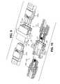
- FIG. 1is a partial perspective cross-sectional view of a fiber optic connector assembly according to the principles of the present disclosure, including a fiber optic adapter, a male fiber optic connector shown with an imperfect male ferrule, and a female fiber optic connector shown with an imperfect female ferrule;
- FIG. 2is a partial cross-sectional plan view of the fiber optic connector assembly of FIG. 1 , shown with the imperfect ferrules;
- FIG. 3is a partial perspective cross-sectional view of a fiber optic connector assembly including a fiber optic adapter, a male fiber optic connector shown with a perfect or near perfect male ferrule, and a female fiber optic connector shown with a perfect or near perfect female ferrule;
- FIG. 4is an enlarged portion of FIG. 3 ;
- FIG. 5is the partial perspective cross-sectional view of FIG. 3 , but with at least one imperfect fiber optic ferrule;
- FIG. 6is an enlarged portion of FIG. 5 ;
- FIG. 7is a perspective view of the fiber optic connector assembly of FIG. 3 shown in a connected configuration
- FIG. 8is the perspective view of FIG. 7 but with the fiber optic connector assembly cross-sectioned
- FIG. 9is a partial perspective view of the fiber optic connector assembly of FIG. 3 shown in a disconnected configuration
- FIG. 10is the perspective view of FIG. 9 but with the fiber optic connector assembly cross-sectioned;
- FIG. 11is a plan view of the male ferrule of FIG. 5 of the male fiber optic connector of FIG. 3 ;
- FIG. 12is a plan view of the female ferrule of FIG. 5 of the female fiber optic connector of FIG. 3 ;
- FIG. 13is a side view of an assembly of the male ferrule of FIG. 11 connected with the imperfect female ferrule of FIG. 12 ;
- FIG. 14is a cross-sectional plan view of the assembly of FIG. 13 as called out at FIG. 13 ;
- FIG. 15is a cross-sectional plan view of the assembly of FIG. 13 similar to FIG. 14 but with mating faces of the ferrules mated together thereby creating an interference between pins of the male ferrule and pin holes of the female ferrule;
- FIG. 16is a cross-sectional view of the assembly of FIG. 13 as called out at FIG. 13 ;
- FIG. 17is an enlarged portion of FIG. 12 ;
- FIG. 18is a perspective view of a pin assembly of the male ferrule of FIG. 3 ;
- FIG. 19is a plan view of the pin assembly of FIG. 18 ;
- FIG. 20is a perspective view of the male ferrule of FIG. 1 but shown as perfect or near perfect;
- FIG. 21is the perspective view of FIG. 20 but with the male ferrule cross-sectioned
- FIG. 22is a top plan view of the male ferrule of FIG. 20 ;
- FIG. 23is the top plan view of FIG. 22 but with the male ferrule cross-sectioned;
- FIG. 24is an enlarged portion of FIG. 23 ;
- FIG. 25is the cross-sectional view of FIG. 23 but with pins of the male ferrule partially removed and a pin-stop added;
- FIG. 26is an enlarged portion of FIG. 25 ;
- FIG. 27is a bottom plan view of the male ferrule of FIG. 20 ;
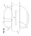
- FIG. 28is a side view of the male ferrule of FIG. 20 ;
- FIG. 29is the side view of FIG. 28 but with the male ferrule cross-sectioned as called out at FIG. 27 ;
- FIG. 30is a front view of the male ferrule of FIG. 20 ;
- FIG. 31is a rear view of the male ferrule of FIG. 20 ;
- FIG. 32is a perspective cross-sectional view of the male ferrule of FIG. 20 ;
- FIG. 33is a perspective cross-sectional view of a ferrule body of the male ferrule of FIG. 20 and/or a ferrule body of an alternative female ferrule;
- FIG. 34is a cross-sectional top plan view of the ferrule body of FIG. 33 ;
- FIG. 35is an enlarged portion of FIG. 34 ;
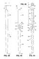
- FIG. 36is a top plan view of the pin of FIG. 25 ;
- FIG. 37is an enlarged portion of FIG. 36 ;
- FIG. 38is a perspective view of the pin of FIG. 25 ;
- FIG. 39is the top plan view of FIG. 36 but with the pin bent as in FIGS. 1 and 2 ;
- FIG. 40is the top plan view of FIG. 36 but with the pin compressed as in FIGS. 25 and 26 ;
- FIG. 41is a cross-sectional top plan view of the pin of FIG. 25 but with an internal void included;
- FIG. 42is a front view of the pin of FIG. 41 ;
- FIG. 43is a perspective view of another fiber optic connector assembly according to the principles of the present disclosure, including a clamp spring, a male fiber optic connector, and a female fiber optic connector; and
- FIG. 44is a cross-sectional perspective view of the fiber optic connector assembly of FIG. 43 .
- a fiber optic connector assembly 100 , 500includes at least one fiber optic ferrule 220 that is tolerant of imperfect ferrule geometry when establishing an optical connection between two fiber optic connectors 200 .
- the fiber optic connector assembly 100includes a fiber optic adapter 130 , a male fiber optic connector 200 M , and a female fiber optic connector 200 F .
- the fiber optic connector assembly 500includes a clamp spring 530 , a male fiber optic connector 200 MB , and a female fiber optic connector 200 FB .
- the male fiber optic connectors 200 M , 200 MB and the female fiber optic connectors 200 F , 200 FBare multi-fiber fiber optic connectors that include 12 optical fibers 210 (see FIGS. 32, 43, and 44 ).
- the fiber optic connectors 200 , 200 F , 200 FB , 200 M , 200 MBmay include more than or fewer than 12 of the optical fibers 210 .
- the depicted fiber optic adapter 130 , the depicted male fiber optic connector 200 M , and the depicted female fiber optic connector 200 Fare of the “MPO” style known in the art of fiber optic connection systems and are generally interconnectable and interchangeable with other gender appropriate “MPO” style fiber optic connectors 1200 and fiber optic adapters 130 (see FIGS. 3-10 ).
- the depicted male fiber optic connectors 200 M , 200 MB and the depicted female fiber optic connectors 200 F , 200 FBare or include “MT” style fiber optic ferrules 220 , known in the art of fiber optic connection systems and are generally interconnectable and interchangeable with other gender appropriate “MT” style fiber optic ferrules 220 , 1220 .
- the at least one fiber optic ferrule 220is tolerant of imperfect mating geometry when two of the fiber optic ferrules 220 , 1220 are mated together.
- the imperfect mating geometrycan include imperfect spatial relationships between a mating face and pins and/or pin holes of the fiber optic ferrules 220 , 1220 .
- the imperfect mating geometrycan include imperfect spatial relationships between corresponding pins and pin holes of the fiber optic ferrules 220 , 1220 .
- the multi-fiber fiber optic ferrules 220 , 1220typically include a ferrule body 250 , 1250 with a mating face 260 (see FIGS. 11, 12, 20, 32, and 33 ).
- the ferrule body 250 , 1250may be made of a plastic such as polyphenylene sulfide.
- the ferrule body 250 , 1250may be glass reinforced, may include glass filled nodules, and/or may include a flexural modulus of about 1,000,000 psi.
- the mating face 260is part of the mating geometry.
- the mating face 260terminates ends 212 of the optical fibers 210 that are held by the respective ferrule body 250 , 1250 (see FIG. 32 ).
- the ends 212are flush with the mating face 260 , and, in other embodiments, the ends 212 protrude slightly from the mating face 260 . In still other embodiments, the ends 212 are recessed slightly in the mating face 260 . In preferred embodiments, the ends 212 of the corresponding optical fibers 210 that are optically connected make physical contact with each other.
- one or more molecular interactionsoccur between mating surfaces of the ends 212 of the corresponding optical fibers 210 upon a certain mating pressure being applied in abutting the corresponding ends 212 against each other.
- the molecular interactions and/or other processes that occur between the abutted corresponding ends 212improves light (i.e., photonic) transmission across the abutted ends 212 .
- the improved light transmissionmay occur because of a minimization of changes in the index of refraction that would otherwise occur at the ends 212 , index matching, compressive stresses, reduced reflection, etc., alone or in combination.
- the improved light transmissionmay occur because of other phenomena, alone or in combination, that occur at the ends 212 when they are compressed together. However, upon reaching a certain pressure, the ends 212 are susceptible to structural failure. It is therefore desired that the abutting contact pressure at the ends 212 be high enough to result in the improved light transmission but be low enough to avoid the structural failure.
- the mating faces 260 of the two ferrules 220 , 1220are mated together with the optical fibers 210 of the two ferrules 220 , 1220 respectively aligned (see FIGS. 5 and 44 ).
- the mating faces 260are typically planar and mate with each other at a mating plane P (see FIGS. 2, 4, and 44 ). In embodiments with slightly protruding ends 212 of the optical fibers 210 , the ends 212 respectively contact each other generally at the mating plane P.
- a pair of pins 300 , 1300can be inserted into a pair of pin holes 302 , 1302 with the pair of the pins 300 , 1300 extending across the mating plane P.
- the pins 300 , 1300 and the pin holes 302 , 1302are part of the mating geometry. For example, as illustrated at FIG. 4 , a pair of the pins 1300 is inserted into a pair of the pin holes 1302 across the mating plane P.
- the pin 300 of the at least one fiber optic ferrule 220is a flexible pin, as will be described in detail below.
- the pin 300may accommodate the imperfect mating geometry by deforming, as will be described in detail below. By deforming along its length, the pin 300 can accommodate an imperfect relationship between the mating face 260 and the pins 300 and/or the pin holes 302 . By radially deforming, the pin 300 can accommodate an imperfect relationship between the pin 300 and the pin hole 302 . By radially deforming, the pin 300 and the pin hole 302 can have an interference fit with each other.
- the interference fitcan allow the pin 300 to move within the pin hole 302 (e.g., of the female ferrule 220 F ) by the application of a force that is small enough not to interfere with the connecting and disconnecting of the fiber optic ferrules 220 , 1220 and/or the connecting and disconnecting of the fiber optic connectors 200 , 1200 .
- the pin 300includes a latch 330 to attach the pin 300 to the pin hole 302 (e.g., of the male ferrule 220 M ).
- the fiber optic connector assembly 100is illustrated with the male fiber optic connector 200 M including an imperfect male ferrule 220 ′ M and the female fiber optic connector 200 F including an imperfect female ferrule 220 ′ F .
- the imperfections of the imperfect male ferrule 220 ′ M and the imperfect female ferrule 220 ′ Fare similar to an imperfect male ferrule 1220 ′ M , illustrated at FIG. 11 , and an imperfect female ferrule 1220 ′ F , illustrated at FIG. 12 .
- Even with imperfect geometry, the mating face 260 of the imperfect male ferrule 220 ′ M and the mating face 260 of the imperfect female ferrule 220 ′ Fmate at the mating plane P (schematically illustrated at FIG.
- a spring 270included in each of the male fiber optic connector 200 M and the female fiber optic connector 200 F , applies a sufficient spring force F 1 and F 2 , respectively, that acts as a mating force and thereby mates the mating faces 260 together.
- the spring forces F 1 and/or F 2are sufficient to deform the pin 300 , if necessary, as the mating faces 260 are moved toward each other.
- the imperfect male ferrule 220 ′ M and the imperfect female ferrule 220 ′ Fhave imperfections, the imperfections may be less than a predetermined tolerance as will be further described below.
- a perfect or near perfect embodiment of a male ferrule 220 Mis illustrated at FIGS. 20-32 .
- the spring force F 1 , F 2ranges from about 7.8 Newtons to about 11.8 Newtons.
- the spring force F 1 , F 2ranges from about 7.5 Newtons to about 12 Newtons.
- a force couplemay develop that results in a moment being applied to one or both of the ferrules 220 ′ M , 1220 ′ M , 220 M , 1220 M , 220 ′ F , 1220 ′ F , 220 F , 1220 F .
- Ferrule imperfectionsinclude angular imperfections between the pin holes 302 , 1302 and the pins 300 , 1300 and the mating face 260 , as illustrated at FIGS. 11 and 12 .
- the pin 300is adapted to accommodate such imperfections. As illustrated at FIGS. 1 and 2 , the pins 300 can flex and thereby allow the pair of the mating faces 260 to mate even if this mating causes the pin holes 302 , 1302 of the female ferrule 220 F , 220 FB , 1220 F to become non-collinear with the pin holes 302 , 1302 of the male ferrule 220 M , 220 MB , 1220 M .
- Ferrule imperfectionsmay also include imperfections in the pin holes 302 , 1302 (e.g. oversized, undersized, and irregularly sized holes).
- the pin 300may be adapted to accommodate such imperfections.
- the pin 300may include an internal void 360 that gives the pin 300 radial flexibility.
- the pin 300may be made of a material that gives the pin 300 radial flexibility.
- the pin 300may be made of plastic, poly sulfanate, polyphenylene sulfide, hard engineered plastic, polycarbonate, carbon reinforced plastic, and/or plastic including nano particles.
- the pin 300is substantially made of a material with a modulus of elasticity of less than 5,000,000 pounds per square inch.
- the pin 300is made of a material with corrosion and/or chemical resistance.
- the pin 300may have other features (e.g., slits, undulations, slots, radial holes, etc.) that give the pin 300 radial flexibility.
- the materials and the features that give the pin 300 radial flexibilitymay be used alone or in combination.
- the materials and the features that give the pin 300 radial flexibilitymay also give and/or contribute to bending flexibility of the pin 300 .
- the materials and the features that give the pin 300 bending flexibilitymay also give and/or contribute to radial flexibility of the pin 300 .
- the pin hole 302is oversized (e.g.
- the pin 300may expand to snugly fit the pin hole 302 .
- the pin 300may compress to snugly fit the pin hole 302 .
- the pin 300may be designed to accommodate pin holes 302 with a predetermined range of sizes (e.g., a hole tolerance). In accommodating the pin holes 302 with the largest size in the range (e.g., at a minimum material condition), the pin 300 should snugly fit in the pin hole 302 . In accommodating the pin holes 302 with the smallest size in the range (e.g., at a maximum material condition), the pin 300 should slip within the pin hole 302 under a force small enough not to interfere with the proper mating of the pair of the mating faces 260 . To achieve such a small sliding force, the pin 300 and/or the pin hole 302 may include a low coefficient of friction. The low coefficient of friction may be achieved by proper surface finish, surface treatment, material selection, etc.
- the pin holes 1302 of the ferrule body 1250 of a female ferrule 1220 Fare larger in size than the pin holes 1302 of the ferrule body 1250 of a male ferrule 1220 M (see FIGS. 3-6 ). This allows the pin 1300 to have a tighter fit (e.g., a press fit) with the pin hole 1302 of the ferrule body 1250 of the male ferrule 1220 M and a looser fit (e.g., a slip fit) with the pin hole 1302 of the ferrule body 1250 of the female ferrule 1220 F .
- a tighter fite.g., a press fit
- a looser fite.g., a slip fit
- the tight fit with the pin hole 1302 of the ferrule body 1250 of the male ferrule 1220 Mkeeps the pin 1300 fixed to the male ferrule 1220 M
- the slip fit with the pin hole 1302 of the ferrule body 1250 of the female ferrule 1220 Fkeeps the pin 1300 from getting stuck in the female ferrule 1220 F and allows relative sliding between the pin hole 1302 and the pin 1300 which is needed to allow the pair of mating faces 260 to be moved together (i.e., mated) by the mating force.
- the pin hole 302can be the same pin hole 302 in both the male ferrule 220 M , 220 MB and the female ferrule 220 F , 220 FB .
- the radial flexibility of the pin 300allows the pin 300 to fit tightly (i.e., snugly) in pin holes 302 of different sizes without generating excessively loose or excessively tight fits.
- the latch 330keeps the pin 300 with the male ferrule 220 M , 220 MB up to a predetermined minimum pull-out force (e.g., 19.6 Newtons).
- the ferrule body 1250 of the female ferrule 220 F(see FIGS. 1 and 2 ) is replaced with the ferrule body 250 (see FIGS. 43 and 44 ).
- the ferrule body 250 of the female ferrule 220 FB(see FIGS. 43 and 44 ) is replaced with the ferrule body 1250 (see FIGS. 1 and 2 ).
- the male ferrule 220 M , 220 MBis interconnectable and/or intermateable with a conventional female ferrule 1220 F (see FIGS. 3-10 ).
- the female ferrule 220 F , 220 FBis interconnectable and/or intermateable with a conventional male ferrule 1220 M (see FIGS. 3 and 4 ).
- the pin 300is installable into the conventional ferrule body 1250 (see FIGS. 3 and 4 ).
- the pin 300can retrofit conventional male ferrules 1220 M and provide existing fiber optic connector assemblies with at least some of the benefits mentioned herein.
- the latch 330may act as a barb when the pin 300 is inserted into the pin hole 1302 of the conventional ferrule body 1250 .
- the pin 300may include multiple latches 330 or barbs and include multiple rows of latches 330 or barbs.
- the latch 330 or barbmay grip the pin hole 1302 of the conventional ferrule body 1250 .
- the latch 330 or barbmay engage an existing feature of a pin hole of a conventional ferrule body.
- the conventional male ferrule 1220 Mretrofitted with the pin 300 , is interconnectable and/or intermateable with the female ferrule 220 F , 220 FB and/or the conventional female ferrule 1220 F .
- the fiber optic connector assembly 500is illustrated with the male fiber optic connector 200 MB and the female fiber optic connector 200 FB assembled together with the spring clamp 530 .
- imperfections of the male ferrule 220 M and/or the female ferrule 220 FBwithin a predetermined limit (i.e., a design tolerance), will not prevent the mating face 260 of the male ferrule 220 M and the mating face 260 of the female ferrule 220 FB from mating at the mating plane P when opposing spring forces F 1A , F 2A , F 1B , F 2B from the spring clamp 530 are applied across the assembled fiber optic connectors 200 MB and 200 FB .
- the opposing spring forces F 1A , F 2A , F 1B , F 2B that the spring clamp 530 appliesare sufficient spring forces F 1A , F 2A , F 1B , F 2B that act as mating forces and thereby mate the mating faces 260 together.
- the opposing spring forces F 1A , F 2A , F 1B , F 2Bare sufficient to deform the pin 300 as the mating faces 260 are urged and moved toward each other.
- the male ferrule 220 M and the female ferrule 220 FBmay have imperfections, the imperfections may be less than a predetermined tolerance.
- each pair of the opposing spring forces F 1A , F 1B and F 2A , F 2B togetherrange from about 7.8 Newtons to about 11.8 Newtons. In certain embodiments, each pair of the opposing spring forces F 1A , F 1B and F 2A , F 2B together range from about 7.5 Newtons to about 12 Newtons.
- a first spring force set F 1 of the opposing spring forces F 1A , F 2A , F 1B , F 2Bmay be distributed and shared between a pair of fingers 540 , 542 that act on the male fiber optic connector 200 MB . In the depicted example, spring force F 1A is generated by the finger 542 , and spring force F 1B is generated by the finger 540 .
- a second spring force set F 2 of the opposing spring forces F 1A , F 2A , F 1B , F 2Bmay be distributed and shared between a pair of fingers 550 , 552 that act on the female fiber optic connector 200 FB .
- spring force F 2Ais generated by the finger 552
- spring force F 2Bis generated by the finger 550 .
- the fiber optic connector assembly 1100includes the fiber optic adapter 130 , a male fiber optic connector 1200 M , and a female fiber optic connector 1200 F .
- the fiber optic connector assembly 1100does not have flexible pins.
- the fiber optic connector assembly 1100includes conventional pins 1300 .
- the conventional pins 1300are typically made of steel or stainless steel.
- the pins 1300are inflexible, rigid, substantially rigid, etc.
- the conventional pins 1300are substantially inflexible when under the load of the spring forces F 1 , F 2 , F 1A , F 2A , F 1B , F 2B .
- the fiber optic connector assembly 1100includes a perfect or near perfect example of the male ferrule 1220 M and a perfect or near perfect example of the female ferrule 1220 F that are mated at the mating plane P.
- FIGS. 5 and 6illustrate a pair of mating faces 260 that are not fully mated even though the male fiber optic connector 1200 M and the female fiber optic connector 1200 F are connected together by the fiber optic adapter 130 .
- FIGS. 5 and 6illustrate the male ferrule 1220 M as the imperfect male ferrule 1220 ′ M and the female ferrule 1220 F as the imperfect female ferrule 1220 ′ F .
- the pins 1300 of the imperfect male ferrule 1220 ′ Mare inserted into the pin holes 1302 of the imperfect female ferrule 1220 ′ F .
- the mating faces 260are constrained at their imperfect angular orientations as the mating faces 260 are moved toward each other.
- Portions 1240 of the imperfect ferrules 1220 ′ M and 1220 ′ Fcontact each other before the mating faces 260 reach or fully reach the mating plane P.
- the springs 270apply the spring force F 1 , F 2 to the respective imperfect ferrules 1220 ′ M and 1220 ′ F as a mating force but are unable to mate the mating faces 260 and are unable to substantially deform the pins 1300 .
- the pins 300 of the imperfect male ferrule 220 ′ Mare inserted into the pin holes 302 of the imperfect female ferrule 220 ′ F .
- the mating faces 260are not rigidly constrained at their imperfect angular orientations as the mating faces 260 are moved toward each other.
- Portions 240 of the imperfect ferrules 220 ′ M and 220 ′ Fcontact each other before the mating faces 260 reach or fully reach the mating plane P.
- the springs 270apply the spring force F 1 , F 2 to the respective imperfect ferrules 220 ′ M and 220 ′ F as a mating force and are able to mate the mating faces 260 and are able to substantially deform the pins 300 .
- the spring clamp 530is able to similarly mate the mating faces 260 and is able to substantially deform the pins 300 .
- the aforementioned force couplemay be developed by compressive forces at the portions 240 , 1240 of the ferrules 220 ′ M , 220 ′ F , 1220 ′ M , 1220 ′ F , 220 M , 220 F , 1220 M , 1220 F , and the mating forces (e.g., the spring forces F 1 and/or F 2 ).
- the portions 240 , 1240may include the ends 212 of the corresponding optical fibers 210 .
- the pins 300may reduce a magnitude of the force couple and thereby the compressive forces at the portions 240 , 1240 .
- the pins 300may reduce the magnitude of the force couple and thereby may reduce the compressive forces at certain of the ends 212 of the corresponding optical fibers 210 .
- the pins 300may reduce the magnitude of the force couple and thereby may improve uniform compressive loading among the ends 212 of the corresponding optical fibers 210 .
- FIG. 11illustrates an angle ⁇ M of the imperfect male ferrule 1220 ′ M
- FIG. 12illustrates an angle ⁇ F of the imperfect female ferrule 1220 ′ F
- the angles ⁇ M , ⁇ Fschematically illustrate an angular error between the mating faces 260 and the pins 1300 and the pin holes 1302 , respectively.
- the angles ⁇ M , ⁇ Fmay be limited by a specified tolerance of the ferrules 1220 M and 1220 F , respectively.
- the angles ⁇ M , ⁇ Fmay include errors introduced during molding of the ferrules 1220 M and 1220 F , respectively.
- the angles ⁇ M , ⁇ Fmay include errors introduced during polishing the mating faces 260 of the ferrules 1220 M and 1220 F , respectively.
- the angles ⁇ M , ⁇ Fmay include errors introduced by the pin holes 1302 of the ferrules 1220 M and 1220 F , respectively.
- the angles ⁇ M , ⁇ Fmay be oriented differently than what is shown at FIGS. 11 and 12 , respectively.
- the specified tolerance of the angles ⁇ M , ⁇ Fmay be 0.1 degree, 0.2 degree, 0.5 degree, or some other value.
- FIG. 13shows the imperfect male ferrule 1220 ′ M and the imperfect female ferrule 1220 ′ F assembled.
- FIGS. 14 and 16are cross-sectional views of FIG. 13 that illustrate the contacting portions 1240 .
- the ferrules 1220 M and 1220 Fmay undergo processing on the same or similar equipment, they may include the same or similar imperfections. This may lead to substantially doubling the effect of the imperfections at the assembly level.
- the angles ⁇ M , ⁇ Fmay each be about 0.1 degree, and an angle , illustrated at FIG. 16 , may therefore be about 0.2 degree.
- an example corresponding projected distance L 2 from the end 212 of one of the optical fibers 210 to the mating plane Pmay be 0.008 millimeter (see FIG.
- a corresponding gap G at the assembly levelmay be 0.016 millimeter (see FIG. 16 ).
- the example distance L 2 and the gap Gare taken at the end 212 of the one of the optical fibers 210 that is a farthest distance L 1 from the contacting portions 1240 .
- the contacting portions 1240are at sides of the ferrules 1220 ′ M , 1220 ′ F . In ferrules with recesses adjacent the pin holes 1302 , contacting portions may form that are spaced away from the sides of the ferrules 1220 ′ M , 1220 ′ F .
- the imperfect male ferrule 1220 ′ M and the imperfect female ferrule 1220 ′ Feach have similar imperfections.
- the imperfect male ferrule 1220 ′ M and the imperfect female ferrule 1220 ′ Fmay each have dissimilar imperfections.
- the imperfect male ferrule 1220 ′ Mmay be mated to a perfect or near perfect female ferrule 1220 F .
- the imperfect female ferrule 1220 ′ Fmay be mated to a perfect or near perfect male ferrule 1220 M .
- the example fiber optic connector assembly 100illustrated at FIGS.
- the imperfect male ferrule 220 ′ M and the imperfect female ferrule 220 ′ Feach have similar imperfections.
- the imperfect male ferrule 220 ′ M and the imperfect female ferrule 220 ′ Fmay each have dissimilar imperfections.
- the imperfect male ferrule 220 ′ Mmay be mated to a perfect or near perfect female ferrule 220 F .
- the imperfect female ferrule 220 ′ Fmay be mated to a perfect or near perfect male ferrule 220 M .
- the pins 300can accommodate the mating of various ferrules with various combinations of imperfection, including those listed above.
- FIG. 15illustrates forcing the imperfect male ferrule 1220 ′ M and the imperfect female ferrule 1220 ′ F together along the pins 1300 .
- the pins 1300interfere with the pin holes 1302 and may thereby damage (e.g., permanently deform, wear, etc.) the pin holes 1302 .
- excessive forcing loadsmay be transmitted to the contacting portions 1240 and thereby damage the mating faces 260 adjacent the contacting portions 1240 .
- the imperfect female ferrule 1220 ′ Fmay shift relative to the imperfect male ferrule 1220 ′ M and thereby compromise or ruin the fiber alignment.
- FIG. 15illustrates forcing the imperfect male ferrule 1220 ′ M and the imperfect female ferrule 1220 ′ F together along the pins 1300 .
- the imperfect female ferrule 1220 ′ Fmay shift upward relative to the imperfect male ferrule 1220 ′ M .
- corresponding fiber holes 1230By shifting upward, corresponding fiber holes 1230 , and thereby the corresponding optical fibers 210 of the imperfect male ferrule 1220 ′ M and the imperfect female ferrule 1220 ′ F may become misaligned at the mating faces 260 (i.e., at the corresponding ends 212 ).
- the pin holes 302 , 1302may not necessarily be rigid or substantially rigid and may deform under the load of the pin 300 , 1300 . The deformation may be elastic, plastic, and/or a combination of elastic and plastic.
- FIGS. 18 and 19illustrate a pin assembly 1290 that includes two of the pins 1300 and a clip 1310 .
- the clip 1310joins the two pins 1300 .
- the clip 1310may further stiffen the pins 1300 by adding a constrained end condition to the pins 1300 .
- the clip 1310may also serve as a spring push of the spring 270 either separately or as part of the pin assembly 1290 (see FIGS. 3 and 5 ).
- the clip 1310occupies a length along the male fiber optic connector 1200 M and the female fiber optic connector 1200 F and may result in added overall length to the connectors 1200 M , 1200 F .
- the male ferrule 220 Mcan be used in the male fiber optic connectors 200 M with a connector housing 280 (see FIGS. 1 and 2 ) and in the male fiber optic connector 200 MB , without a connector housing (see FIGS. 43 and 44 ), and the female ferrule 220 F , 220 FB can be used in the female fiber optic connectors 200 F with the connector housing 280 (see FIGS. 1 and 2 ) and in the female fiber optic connector 200 FB , without a connector housing (see FIGS. 43 and 44 ).
- the connector housings 280When used with the connector housings 280 and the fiber optic adapter 130 , the connector housings 280 form a cavity 110 in which the mated ferrules 220 M and 220 F or 220 FB can float.
- shoulders 284 of the connector housing 280retain shoulders 256 , 1256 of the ferrule bodies 250 , 1250 , which are loaded by the spring 270 , when the fiber optic connectors 200 M , 200 F are not both installed together in the fiber optic adapter 130 .
- the mating faces 260mate and lift the shoulders 256 , 1256 of the ferrule bodies 250 , 1250 off of the shoulders 284 of the connector housing 280 as the springs 270 are compressed and thereby allow the mated ferrules 220 M and 220 F or 220 FB to float.
- a spaceis formed between distal ends 282 of the connector housings 280 upon installing both of the fiber optic connectors 200 M , 200 F together in the fiber optic adapter 130 . This floating substantially structurally decouples the mated ferrules 220 M and 220 F or 220 FB from the fiber optic connectors 200 M , 200 F .
- the male ferrule 220 Mincludes the ferrule body 250 and a pair of the pins 300 .
- the ferrule body 250extends from a first end 252 to a second end 254 (see FIG. 33 ) and includes the mating face 260 at the first end 252 .
- the ferrule body 250further includes a pair of the pin holes 302 that extend from the first end 252 to the second end 254 .
- the pin holes 302mount the pins 300 .
- serving as the female ferrule 220 FBsee FIGS.
- the pair of the pin holes 302may receive the pins 300 of the male ferrule 220 M .
- the female fiber optic connector 200 Fwith the connector housing 280 (see FIGS. 1 and 2 ), and the female fiber optic connector 200 FB , without a connector housing (see FIGS. 43 and 44 ), can use either the ferrule body 250 or the ferrule body 1250 .
- the ferrule body 250 and the ferrule body 1250include fiber holes 230 that extend to and through the mating face 260 .
- the fiber holes 230each hold one of the optical fibers 210 .
- the pin holes 302include an edge portion 372 , a first pin holding portion 374 , a catch 376 , and a second pin holding portion 378 .
- the first pin holding portion 374may define a diameter D 1
- the second pin holding portion 378may define a diameter D 2 .
- the diameter D 2is larger than the diameter D 1 .
- An example dimension for the diameter D 1is 0.7 millimeter
- an example dimension for the diameter D 2is 0.75 millimeter.
- the catch 376can be positioned between the first pin holding portion 374 and the second pin holding portion 378 .
- the catch 376can be defined between the diameter D 1 and the diameter D 2 .
- the catch 376can define an angle ⁇ F relative to the first pin holding portion 374 , and an example dimension for the angle ⁇ F is about 69 degrees. As depicted, the angle ⁇ F is an acute angle.
- the mating face 260defines an angle ⁇ at the first end 252 of the ferrule body 250 .
- the angle ⁇is defined relative to a normal of a lengthwise direction of the pin hole 302 and therefore a normal of a lengthwise direction of the pin 300 .
- the angle ⁇is about 8 degrees. In other embodiments, the angle ⁇ is about 0 degrees (i.e., normal to the lengthwise directions of the pin 300 and/or the pin hole 302 ).
- the spring forces F 1 and/or F 2can cause a lateral component of the mating forces to develop that urges a lateral movement between the mated ferrule bodies 250 .
- other mating forcescan cause the lateral component of the mating forces to develop that urges the lateral movement between the mated ferrule bodies 250 .
- the lateral movementmay cause the abutted corresponding ends 212 to laterally move relative to each other and therefore degrade or disturb the optical connection (e.g., because of misalignment).
- the optical fibers 210may range from about 125 ⁇ m to about 250 ⁇ m in diameter in certain embodiments, a lateral movement of about 10 ⁇ m or so can significantly affect the optical connection.
- This lateral movementcan be avoided or reduced or minimized to acceptable levels by the pin 300 fitting snugly within the pin hole 302 as describe herein.
- This lateral movementcan also be avoided or reduced or minimized to acceptable levels by using a sufficiently low mating force.
- the sufficiently low mating forcemay still be sufficient to establish sufficient contact across the abutted corresponding ends 212 by using the pin 300 with sufficient flexibility to accommodate various imperfect geometries, as illustrated by the examples herein.
- FIGS. 36-42further illustrate the pin 300 .
- the pin 300extends from a first end 312 to a second end 314 .
- the pin 300includes a first portion 350 adjacent the first end 312 , and a second portion 358 adjacent the second end 314 .
- a held portion 354 of the pin 300is illustrated as being held by the first pin holding portion 374 , and the first portion 350 is illustrated extending beyond the ferrule body 250 when the pin 300 is assembled to the ferrule body 250 .
- the first portion 350extends beyond the first end 252 of the ferrule body 250 by a distance L 5 .
- An example dimension for the distance L 5is 2.75 millimeters.
- a protruding portion 352 of the pin 300is adjacent the held portion 354 and the first portion 350 .
- the protruding portion 352is adjacent the edge portion 372 of the pin hole 302 when the pin 300 is assembled to the ferrule body 250 .
- a latching portion 356 of the pin 300is positioned between the held portion 354 and the second portion 358 .
- the latching portion 356includes the latch 330 , mentioned above.
- the latching portion 356extends between a first end 332 and a second end 334 .
- a void 336may extend between a first end 338 and a second end 340 and through the latching portion 356 and define a first flexure 346 and a second flexure 348 .
- the first and the second flexures 346 , 348are positioned opposite each other. As depicted at FIGS.
- the first and the second flexures 346 , 348allow the latch 330 to be compressed within a diameter D P of the held portion 354 and/or the first portion 350 of the pin 300 .
- the diameter D Pcan be about 0.7 millimeter. In certain embodiments, the diameter D P can range between 0.697 millimeter and 0.699 millimeter.
- the latch 330includes a latching surface 342 that interfaces with the catch 376 of the pin hole 302 (see FIGS. 21, 23-26, 29, 32, and 37 ).
- the latching surface 342defines an angle ⁇ P with the held portion 354 and/or the first portion 350 of the pin 300 . As depicted, an example angle for the angle ⁇ P is 111 degrees.
- a taper 344is provided on the latch 330 .
- the taper 344defines an angle ⁇ across a centerline of the pin 300 (see FIG. 36 ).
- an example angle for the angle ⁇is 11 degrees.
- the taper 344 and/or the latching surface 342define a diameter D R about the centerline of the pin 300 .
- an example dimension for the diameter D Ris 0.78 millimeter.
- the second portion 358 of the pin 300is positioned between the latching portion 356 and the second end 314 of the pin 300 .
- the second portion 358includes a taper 359 .
- the taper 359defines an angle ⁇ across the centerline of the pin 300 (see FIG. 36 ).
- an example angle for the angle ⁇is about 2 degrees.
- the second portion 358defines a diameter D T at the second end 314 of the pin 300 about the centerline of the pin 300 .
- an example dimension for the diameter D Tis 0.4 millimeter.
- annular interface 380is formed between the second portion 358 of the pin 300 and the second pin holding portion 378 of the pin hole 302 .
- the annular interface 380is an annular clearance.
- the annular interface 380may include an annular clearance portion, an interference portion, a slip fit portion, a contacting portion, etc.
- the annular interface 380may vary along the lengthwise direction of the pin 300 .
- the annular interface 380at least in part, may determine or influence the stiffness (i.e., the flexibility) of the pin 300 when installed in the ferrule body 250 .
- the annular interface 380may influence the stiffness of the pin 300 when installed in the ferrule body 250 to be variable and/or non-linear.
- the internal void 360opens outwardly through the first end 312 of the pin 360 at a diameter D 3 .
- the void 360may reside entirely within the pin 360 or be plugged at the outward opening.
- the diameter D 3is about 0.4 millimeter and is centered about the centerline of the pin 300 .
- the internal void 360extends within the pin 300 a length of L 4 from the first end 312 of the pin 360 .
- the length L 4is about 3.5 millimeters.
- the internal void 360defines an angle ⁇ across the centerline of the pin 300 (see FIG. 41 ).
- an example angle for the angle ⁇is about 4 degrees.
- the internal void 360may determine or influence the stiffness (i.e., the flexibility) of the pin 300 .
- the internal void 360also may determine or influence the radial flexibility of the pin 300 , at least in the first portion 350 , the protruding portion 352 , and the held portion 354 of the pin 300 .
- FIG. 39illustrates the pin 300 flexed similar to the flexing of the pin 300 , under load, at FIGS. 1 and 2 .
- a deformation angle ⁇is defined at or near the first end 312 of the pin 360 .
- the deformation angle ⁇may range from about 0.12 degree to about 0.24 degree.
- a deformation length L 3defined at or near the first end 312 of the pin 360 .
- the deformation length L 3may range from about 0.022 millimeter to about 0.045 millimeter.
- a plate 310may be positioned adjacent the second end 254 of the ferrule body 250 .
- the plate 310extends between a first face 312 and a second face 314 .
- the first face 312may abut the second end 254 of the ferrule body 250 and serve as a pin stop for the pins 300 .
- the second end 314 of the pin 300may abut or be positioned adjacent the first face 312 of the plate 310 .
- the spring 270may push against the second face 314 of the plate 310 .
- the plate 310may also serve as a spring push plate.
- the plate 310is substantially thinner than the clip 1310 , illustrated at FIGS. 1 and 2 .
- the plate 310may therefore allow the overall length of the fiber optic connectors 200 , 200 F , 200 M to be reduced in comparison to the overall length of connectors 200 , 200 F , 200 M that use the clip 1310 .
- the pin 300can be grouped in a pin set of multiple pins 300 .
- the first portion 350 and/or the protruding portion 352 of each of the pins 300 of the pin setcan be sized slightly differently to accommodate (i.e., match) a variety of sizes of the first pin holding portion 374 of the ferrule body 250 of the female fiber optic connectors 200 F , 200 FB and/or the pin holes 1302 of the female ferrule 220 F , 1220 F that may potentially be encountered due to manufacturing variations, design variation, and/or wear.
- the pins 300 from the pin set which best match the particular female fiber optic connector 200 F , 200 FB , 1200 Fare selected and installed into the male fiber optic connector 200 M , 200 MB , 1200 M .
- the pins 300can be color coded to indicate the size of the pin 300 .
Landscapes
- Physics & Mathematics (AREA)
- General Physics & Mathematics (AREA)
- Optics & Photonics (AREA)
- Mechanical Coupling Of Light Guides (AREA)
Abstract
Description

Claims (24)
Priority Applications (2)
| Application Number | Priority Date | Filing Date | Title |
|---|---|---|---|
| US13/715,176US10215926B2 (en) | 2011-12-14 | 2012-12-14 | Multi-fiber fiber optic connection system with flexible, insertable pins |
| US16/245,667US11009665B2 (en) | 2011-12-14 | 2019-01-11 | Multi-fiber fiber optic connection system with flexible, insertable pins |
Applications Claiming Priority (2)
| Application Number | Priority Date | Filing Date | Title |
|---|---|---|---|
| US201161570654P | 2011-12-14 | 2011-12-14 | |
| US13/715,176US10215926B2 (en) | 2011-12-14 | 2012-12-14 | Multi-fiber fiber optic connection system with flexible, insertable pins |
Related Child Applications (1)
| Application Number | Title | Priority Date | Filing Date |
|---|---|---|---|
| US16/245,667ContinuationUS11009665B2 (en) | 2011-12-14 | 2019-01-11 | Multi-fiber fiber optic connection system with flexible, insertable pins |
Publications (2)
| Publication Number | Publication Date |
|---|---|
| US20130170797A1 US20130170797A1 (en) | 2013-07-04 |
| US10215926B2true US10215926B2 (en) | 2019-02-26 |
Family
ID=48694864
Family Applications (2)
| Application Number | Title | Priority Date | Filing Date |
|---|---|---|---|
| US13/715,176Expired - Fee RelatedUS10215926B2 (en) | 2011-12-14 | 2012-12-14 | Multi-fiber fiber optic connection system with flexible, insertable pins |
| US16/245,667Active2033-01-05US11009665B2 (en) | 2011-12-14 | 2019-01-11 | Multi-fiber fiber optic connection system with flexible, insertable pins |
Family Applications After (1)
| Application Number | Title | Priority Date | Filing Date |
|---|---|---|---|
| US16/245,667Active2033-01-05US11009665B2 (en) | 2011-12-14 | 2019-01-11 | Multi-fiber fiber optic connection system with flexible, insertable pins |
Country Status (1)
| Country | Link |
|---|---|
| US (2) | US10215926B2 (en) |
Cited By (9)
| Publication number | Priority date | Publication date | Assignee | Title |
|---|---|---|---|---|
| US10564367B1 (en)* | 2018-10-18 | 2020-02-18 | Benchmark Electronics, Inc. | MT connector assembly and method therefor |
| US10942316B1 (en)* | 2019-10-31 | 2021-03-09 | Alliance Fiber Optic Products, Inc. | FAU connectors and assemblies employing pin-to-pin alignment |
| WO2021055532A1 (en)* | 2019-09-17 | 2021-03-25 | US Conec, Ltd | Ferrule push |
| US11009667B2 (en) | 2016-03-10 | 2021-05-18 | Corning Optical Communications LLC | Ferrule-based fiber optic connectors with ferrule retraction balancing |
| US11009665B2 (en) | 2011-12-14 | 2021-05-18 | Commscope Technologies Llc | Multi-fiber fiber optic connection system with flexible, insertable pins |
| US20220206233A1 (en)* | 2019-05-22 | 2022-06-30 | Nippon Telegraph And Telephone Corporation | Waveguide Connection Structure, Waveguide Chip, Connector, and Method of Manufacturing Waveguide Connection Component, and Waveguide Connecting Method |
| US11474307B2 (en) | 2020-04-15 | 2022-10-18 | Corning Research & Development Corporation | Interconnect system and methods of installing the same |
| US11506846B2 (en)* | 2016-11-04 | 2022-11-22 | Chaozhou Three-Circle (Group) Co., Ltd. | Guide pin and manufacturing method therefor |
| US12210196B2 (en) | 2019-12-13 | 2025-01-28 | Us Conec Ltd. | Cover for a fiber optic ferrule and ferrule push |
Families Citing this family (48)
| Publication number | Priority date | Publication date | Assignee | Title |
|---|---|---|---|---|
| US9417418B2 (en) | 2011-09-12 | 2016-08-16 | Commscope Technologies Llc | Flexible lensed optical interconnect device for signal distribution |
| US9753229B2 (en) | 2012-09-28 | 2017-09-05 | Commscope Connectivity Uk Limited | Manufacture and testing of fiber optic cassette |
| NZ706687A (en) | 2012-09-28 | 2017-09-29 | Adc Telecommunications Inc | Fiber optic cassette |
| US9223094B2 (en) | 2012-10-05 | 2015-12-29 | Tyco Electronics Nederland Bv | Flexible optical circuit, cassettes, and methods |
| US10031296B2 (en)* | 2013-07-03 | 2018-07-24 | Nexans | Reversible polarity MPO fiber optic connector with a removable key |
| US9482823B1 (en)* | 2013-12-09 | 2016-11-01 | Alliance Fiber Optics Products, Inc. | Fiber attenuator based on MPO loopback assembly having angled ferrules |
| US9876266B2 (en)* | 2014-09-30 | 2018-01-23 | Te Connectivity Corporation | Contactless connector |
| WO2016053851A1 (en)* | 2014-10-01 | 2016-04-07 | Corning Optical Communications LLC | Fiber optic connector and pin change method for the same |
| WO2016087449A1 (en) | 2014-12-01 | 2016-06-09 | Commscope Asia Holdings B.V. | Multi-fiber optic connector with pivotally-aligned ferrule |
| US9684139B2 (en) | 2015-05-29 | 2017-06-20 | Senko Advanced Components, Inc. | Optical fiber connector with changeable gender |
| EP3311207A4 (en)* | 2015-06-19 | 2019-02-20 | Commscope Technologies LLC | Fiber optic connector ferrule with improved alignment mechanism |
| CN108351473B (en)* | 2015-10-12 | 2020-09-08 | 3M创新有限公司 | Sleeves, Alignment Frames and Connectors |
| CA3016774A1 (en)* | 2016-03-16 | 2017-09-21 | Nexans | Reversible polarity mpo fiber optic connector with a removable key |
| US9726830B1 (en) | 2016-06-28 | 2017-08-08 | Senko Advanced Components, Inc. | Connector and adapter system for two-fiber mechanical transfer type ferrule |
| WO2018046677A1 (en) | 2016-09-08 | 2018-03-15 | CommScope Connectivity Belgium BVBA | Telecommunications distribution elements |
| CN110249248B (en)* | 2017-01-30 | 2021-07-27 | 扇港元器件股份有限公司 | Optical connectors with reversible polarity |
| US10444444B2 (en) | 2017-01-30 | 2019-10-15 | Senko Advanced Components, Inc. | Remote release tab connector assembly |
| WO2018165002A1 (en)* | 2017-03-07 | 2018-09-13 | Corning Optical Communications LLC | Receptacle bodies for optical chips and optical connections incorporating the same |
| US10718910B2 (en) | 2017-05-03 | 2020-07-21 | Senko Advanced Components, Inc | Field terminated ruggedized fiber optic connector system |
| US12001064B2 (en) | 2017-07-14 | 2024-06-04 | Senko Advanced Components, Inc. | Small form factor fiber optic connector with multi-purpose boot |
| US10281669B2 (en) | 2017-07-14 | 2019-05-07 | Senko Advance Components, Inc. | Ultra-small form factor optical connectors |
| US10718911B2 (en) | 2017-08-24 | 2020-07-21 | Senko Advanced Components, Inc. | Ultra-small form factor optical connectors using a push-pull boot receptacle release |
| US11822133B2 (en) | 2017-07-14 | 2023-11-21 | Senko Advanced Components, Inc. | Ultra-small form factor optical connector and adapter |
| US11409068B2 (en) | 2017-10-02 | 2022-08-09 | Commscope Technologies Llc | Fiber optic circuit and preparation method |
| US11002923B2 (en) | 2017-11-21 | 2021-05-11 | Senko Advanced Components, Inc. | Fiber optic connector with cable boot release having a two-piece clip assembly |
| US11016250B2 (en)* | 2017-12-19 | 2021-05-25 | Us Conec, Ltd. | Mini duplex connector with push-pull polarity mechanism, carrier, and rail-receiving crimp body |
| WO2019183070A2 (en) | 2018-03-19 | 2019-09-26 | Senko Advanced Components, Inc. | Removal tool for removing a plural of micro optical connectors from an adapter interface |
| EP3776038B1 (en) | 2018-03-28 | 2024-07-03 | Senko Advanced Components Inc. | Small form factor fiber optic connector with multi-purpose boot |
| US11041993B2 (en) | 2018-04-19 | 2021-06-22 | Senko Advanced Components, Inc. | Fiber optic adapter with removable insert for polarity change and removal tool for the same |
| CN112088327A (en) | 2018-07-15 | 2020-12-15 | 扇港元器件股份有限公司 | Subminiature Optical Connectors and Adapters |
| US11073664B2 (en) | 2018-08-13 | 2021-07-27 | Senko Advanced Components, Inc. | Cable boot assembly for releasing fiber optic connector from a receptacle |
| WO2020055440A1 (en) | 2018-09-12 | 2020-03-19 | Senko Advanced Componetns, Inc. | Lc type connector with clip-on push/pull tab for releasing connector from a receptacle using a cable boot |
| US10921531B2 (en) | 2018-09-12 | 2021-02-16 | Senko Advanced Components, Inc. | LC type connector with push/pull assembly for releasing connector from a receptacle using a cable boot |
| US10921530B2 (en) | 2018-09-12 | 2021-02-16 | Senko Advanced Components, Inc. | LC type connector with push/pull assembly for releasing connector from a receptacle using a cable boot |
| US11806831B2 (en) | 2018-11-21 | 2023-11-07 | Senko Advanced Components, Inc. | Fixture and method for polishing fiber optic connector ferrules |
| US11175464B2 (en) | 2018-11-25 | 2021-11-16 | Senko Advanced Components, Inc. | Open ended spring body for use in an optical fiber connector |
| WO2020150395A1 (en)* | 2019-01-18 | 2020-07-23 | Commscope Technologies Llc | Multi-fiber assembly for a ferrule-less fiber optic connector |
| US11579379B2 (en) | 2019-03-28 | 2023-02-14 | Senko Advanced Components, Inc. | Fiber optic adapter assembly |
| US12038613B2 (en) | 2019-03-28 | 2024-07-16 | Senko Advanced Components, Inc. | Behind-the-wall optical connector and assembly of the same |
| US11340406B2 (en) | 2019-04-19 | 2022-05-24 | Senko Advanced Components, Inc. | Small form factor fiber optic connector with resilient latching mechanism for securing within a hook-less receptacle |
| WO2020252355A1 (en) | 2019-06-13 | 2020-12-17 | Senko Advanced Components, Inc | Lever actuated latch arm for releasing a fiber optic connector from a receptacle port and method of use |
| CN114600018B (en) | 2019-07-23 | 2024-04-09 | 扇港元器件有限公司 | Ultra-small receptacle for receiving a fiber optic connector opposite a ferrule assembly |
| US11353664B1 (en) | 2019-08-21 | 2022-06-07 | Senko Advanced Components, Inc. | Fiber optic connector |
| WO2021097304A1 (en) | 2019-11-13 | 2021-05-20 | Senko Advanced Components, Inc. | Fiber optic connector |
| US12339511B2 (en) | 2020-03-31 | 2025-06-24 | Commscope Technologies Llc | Fiber optic cable management systems and methods |
| WO2022046624A1 (en)* | 2020-08-28 | 2022-03-03 | Commscope Technologies Llc | Multi-fiber semi-permanent splicing systems |
| CN116360039B (en)* | 2023-02-21 | 2024-06-14 | 宁波莱塔思光学科技有限公司 | Core-inserted type optical fiber connector |
| WO2025054268A1 (en)* | 2023-09-05 | 2025-03-13 | Senko Advanced Components, Inc. | Very small form factor fiber optic connector and adapter |
Citations (44)
| Publication number | Priority date | Publication date | Assignee | Title |
|---|---|---|---|---|
| US5408558A (en) | 1993-10-21 | 1995-04-18 | Litecom, Inc. | Connecting system with cleaved fiber and crimp termination |
| US5420954A (en) | 1993-05-24 | 1995-05-30 | Photonics Research Incorporated | Parallel optical interconnect |
| JPH07318761A (en) | 1994-05-23 | 1995-12-08 | Furukawa Electric Co Ltd:The | Multi-fiber optical connector |
| US5596662A (en) | 1994-03-03 | 1997-01-21 | France Telecom | Multichannel optical connection method for optical fibers |
| US5611010A (en)* | 1994-08-18 | 1997-03-11 | The Furukawa Electric Co., Ltd. | Guide pin insertion member for inserting guide pins into an optical fiber connector |
| US5778123A (en) | 1996-03-12 | 1998-07-07 | Minnesota Mining And Manufacturing Company | Alignment assembly for multifiber or single fiber optical cable connector |
| US5920670A (en) | 1996-06-07 | 1999-07-06 | 3M Innovative Properties Company | Multiple alignment connector ferrule |
| US5923803A (en) | 1997-07-28 | 1999-07-13 | Molex Incorporated | Method of fabricating a fiber optic connector ferrule |
| US6146024A (en) | 1997-11-28 | 2000-11-14 | Infineon Technologies Ag | Connector body |
| US6357933B1 (en) | 1999-03-30 | 2002-03-19 | Lucent Technologies Inc. | Quick connect optical fiber ferrule connector |
| US20020050716A1 (en)* | 2000-11-01 | 2002-05-02 | Cresswell William L. | Quick connect/disconnect coupling |
| US6425692B1 (en)* | 1997-10-23 | 2002-07-30 | Fujikura, Ltd. | Connecting structure for optical connector |
| US20020114589A1 (en) | 1996-03-12 | 2002-08-22 | 3M Innovative Properties Company | Optical connector assembly using partial large diameter alignment features |
| WO2002088810A1 (en) | 2001-05-01 | 2002-11-07 | Corona Optical Systems, Inc. | Alignment apertures in an optically transparent substrate |
| US20020186932A1 (en) | 2001-06-11 | 2002-12-12 | Barnes Brandon A. | Fiber optic connector and an associated pin retainer |
| US20030012516A1 (en)* | 2001-07-13 | 2003-01-16 | Ngk Insulators, Ltd. | Method of manufacturing two-dimensional optical connector component |
| US6520686B1 (en) | 2000-11-09 | 2003-02-18 | Teradyne, Inc. | Methods and apparatus for forming a fiber optic connection |
| US20030091297A1 (en) | 2001-11-12 | 2003-05-15 | Hung Ngo V. | Fiber optic connector and method of making the same |
| US20030098045A1 (en)* | 2001-11-29 | 2003-05-29 | 3M Innovative Properties Company | Article and process for cleaning optical surfaces |
| US20030161584A1 (en) | 2002-02-28 | 2003-08-28 | Kenichiro Ohtsuka | Optical connector ferrule, optical connector and making method for them |
| US6619855B2 (en)* | 2001-06-29 | 2003-09-16 | Xanoptix, Inc. | Post-formation feature optimization |
| CN1451982A (en) | 2002-04-19 | 2003-10-29 | 富士康(昆山)电脑接插件有限公司 | Multi-optical fibre contact pin |
| US6702479B2 (en)* | 2001-02-13 | 2004-03-09 | U-Conn Technology Inc. | Optical fiber connector assembled before grinding |
| US6910812B2 (en) | 2001-05-15 | 2005-06-28 | Peregrine Semiconductor Corporation | Small-scale optoelectronic package |
| US20050286833A1 (en)* | 2001-08-23 | 2005-12-29 | Anne Kramer | Universal adapter |
| US20060013538A1 (en) | 2004-07-19 | 2006-01-19 | Hodge Malcolm H | Ferrule with tilt correction |
| US7296935B1 (en)* | 2007-02-09 | 2007-11-20 | Us Conec, Ltd. | Ferrule adapter and ferrule adapter assembly |
| US20090052844A1 (en) | 2004-10-11 | 2009-02-26 | Van Der Steen Hendrikus Petrus | Fiber optical connector |
| US20110262075A1 (en) | 2010-04-26 | 2011-10-27 | Beatty John W | Guide pin for aligning ferrules with enhanced alignment feature |
| US20120014649A1 (en) | 2010-07-15 | 2012-01-19 | Tyco Electronics Nederland B.V. | Method and apparatus for aligning optical transports in a ferrule |
| US20120201499A1 (en) | 2011-02-09 | 2012-08-09 | Tyco Electronics Nederland Bv | Ferrule with alignment pin channels |
| US20120257860A1 (en) | 2011-04-05 | 2012-10-11 | Nanoprecision Products, Inc. | Optical fiber connector ferrule having open fiber clamping grooves |
| US20120328244A1 (en) | 2011-06-17 | 2012-12-27 | Sumitomo Electric Industries, Ltd. | Optical connector, optical connecting structure and method of manufacturing optical connector |
| US20130266268A1 (en) | 2012-04-05 | 2013-10-10 | Nanoprecision Products, Inc. | Ferrule for optical fiber connector having a compliant structure for clamping alignment pins |
| JP2014077919A (en) | 2012-10-11 | 2014-05-01 | Nippon Telegr & Teleph Corp <Ntt> | Coated optical fiber switching unit and method thereof |
| US20150168655A1 (en) | 2012-08-31 | 2015-06-18 | Corning Optical Communication Llc | Cable assemblies, optical connector assemblies, and optical connector subassemblies employing a unitary alignment pin and cover |
| US20150198773A1 (en) | 2010-01-14 | 2015-07-16 | Fujikura Ltd. | Optical connector and optical connector ferrule |
| US9274287B2 (en) | 2014-05-13 | 2016-03-01 | Senko Advanced Components, Inc. | Optical fiber connector and ferrule |
| US20160187591A1 (en) | 2013-09-12 | 2016-06-30 | Corning Optical Communications LLC | Optical plug having a translating cover and a complimentary receptacle |
| US9417406B2 (en) | 2012-08-31 | 2016-08-16 | Corning Cable Systems Llc | Cable assemblies and optical connector assemblies employing a unitary alignment pin and translating element |
| US20160252682A1 (en) | 2013-11-04 | 2016-09-01 | Tyco Elctronics Raychem Bvba | Fiber optic connector having an optical fiber that is axially moveable within a ferrule |
| US20170307828A1 (en) | 2014-12-01 | 2017-10-26 | Commscope Asia Holdings B.V. | Hybrid electrical optical connector with spring-loaded electrical contacts at a contact face |
| US20170343741A1 (en) | 2014-12-19 | 2017-11-30 | Adc Telecommunications (Shanghai) Distribution Co., Ltd. | Hardened fiber optic connector with pre-compressed spring |
| US20170363816A1 (en) | 2014-12-01 | 2017-12-21 | Commscope Asia Holdings B.V. | Multi-fiber optic connector with pivotally-aligned ferrule |
Family Cites Families (7)
| Publication number | Priority date | Publication date | Assignee | Title |
|---|---|---|---|---|
| US6318902B1 (en) | 1996-03-12 | 2001-11-20 | 3M Innovative Properties Company | Optical connector assembly using partial large diameter alignment features |
| USH2141H1 (en) | 2001-04-06 | 2006-01-03 | Tyco Electronics Corporation | Multifiber ferrule |
| US20100291794A1 (en)* | 2009-04-14 | 2010-11-18 | Molex Incorporated | Sata to ipass cable connector |
| US8016491B2 (en) | 2009-08-18 | 2011-09-13 | Fujikura Ltd. | Optical ferrule |
| US10215926B2 (en) | 2011-12-14 | 2019-02-26 | Commscope Technologies Llc | Multi-fiber fiber optic connection system with flexible, insertable pins |
| US9720182B2 (en) | 2015-04-23 | 2017-08-01 | US Conec, Ltd | Fiber optic ferrule with improved ability to achieve ferrule mating plane contact |
| EP3311207A4 (en) | 2015-06-19 | 2019-02-20 | Commscope Technologies LLC | Fiber optic connector ferrule with improved alignment mechanism |
- 2012
- 2012-12-14USUS13/715,176patent/US10215926B2/ennot_activeExpired - Fee Related
- 2019
- 2019-01-11USUS16/245,667patent/US11009665B2/enactiveActive
Patent Citations (52)
| Publication number | Priority date | Publication date | Assignee | Title |
|---|---|---|---|---|
| US5420954A (en) | 1993-05-24 | 1995-05-30 | Photonics Research Incorporated | Parallel optical interconnect |
| US5408558A (en) | 1993-10-21 | 1995-04-18 | Litecom, Inc. | Connecting system with cleaved fiber and crimp termination |
| US5596662A (en) | 1994-03-03 | 1997-01-21 | France Telecom | Multichannel optical connection method for optical fibers |
| JPH07318761A (en) | 1994-05-23 | 1995-12-08 | Furukawa Electric Co Ltd:The | Multi-fiber optical connector |
| US5611010A (en)* | 1994-08-18 | 1997-03-11 | The Furukawa Electric Co., Ltd. | Guide pin insertion member for inserting guide pins into an optical fiber connector |
| US20020114589A1 (en) | 1996-03-12 | 2002-08-22 | 3M Innovative Properties Company | Optical connector assembly using partial large diameter alignment features |
| US5778123A (en) | 1996-03-12 | 1998-07-07 | Minnesota Mining And Manufacturing Company | Alignment assembly for multifiber or single fiber optical cable connector |
| US5845028A (en) | 1996-03-12 | 1998-12-01 | Minnesota Mining And Manufacturing Company | Alignment assembly for multifiber or single fiber optical cable connector |
| US6805493B2 (en) | 1996-03-12 | 2004-10-19 | 3M Innovative Properties Company | Optical connector assembly using partial large diameter alignment features |
| US5920670A (en) | 1996-06-07 | 1999-07-06 | 3M Innovative Properties Company | Multiple alignment connector ferrule |
| US5923803A (en) | 1997-07-28 | 1999-07-13 | Molex Incorporated | Method of fabricating a fiber optic connector ferrule |
| US6755574B2 (en)* | 1997-10-23 | 2004-06-29 | Fujikura Ltd. And Nippon Telegraph And Telephone Corporation | Optical connector |
| US6425692B1 (en)* | 1997-10-23 | 2002-07-30 | Fujikura, Ltd. | Connecting structure for optical connector |
| US20020150347A1 (en)* | 1997-10-23 | 2002-10-17 | Kuninhiko Fujiwara | Optical connector |
| US6146024A (en) | 1997-11-28 | 2000-11-14 | Infineon Technologies Ag | Connector body |
| US6357933B1 (en) | 1999-03-30 | 2002-03-19 | Lucent Technologies Inc. | Quick connect optical fiber ferrule connector |
| US20020050716A1 (en)* | 2000-11-01 | 2002-05-02 | Cresswell William L. | Quick connect/disconnect coupling |
| US6520686B1 (en) | 2000-11-09 | 2003-02-18 | Teradyne, Inc. | Methods and apparatus for forming a fiber optic connection |
| US6702479B2 (en)* | 2001-02-13 | 2004-03-09 | U-Conn Technology Inc. | Optical fiber connector assembled before grinding |
| WO2002088810A1 (en) | 2001-05-01 | 2002-11-07 | Corona Optical Systems, Inc. | Alignment apertures in an optically transparent substrate |
| US6910812B2 (en) | 2001-05-15 | 2005-06-28 | Peregrine Semiconductor Corporation | Small-scale optoelectronic package |
| US20020186932A1 (en) | 2001-06-11 | 2002-12-12 | Barnes Brandon A. | Fiber optic connector and an associated pin retainer |
| US6619855B2 (en)* | 2001-06-29 | 2003-09-16 | Xanoptix, Inc. | Post-formation feature optimization |
| US20030012516A1 (en)* | 2001-07-13 | 2003-01-16 | Ngk Insulators, Ltd. | Method of manufacturing two-dimensional optical connector component |
| US20050286833A1 (en)* | 2001-08-23 | 2005-12-29 | Anne Kramer | Universal adapter |
| US20030091297A1 (en) | 2001-11-12 | 2003-05-15 | Hung Ngo V. | Fiber optic connector and method of making the same |
| US20030098045A1 (en)* | 2001-11-29 | 2003-05-29 | 3M Innovative Properties Company | Article and process for cleaning optical surfaces |
| US20030161584A1 (en) | 2002-02-28 | 2003-08-28 | Kenichiro Ohtsuka | Optical connector ferrule, optical connector and making method for them |
| CN1451982A (en) | 2002-04-19 | 2003-10-29 | 富士康(昆山)电脑接插件有限公司 | Multi-optical fibre contact pin |
| US20060013538A1 (en) | 2004-07-19 | 2006-01-19 | Hodge Malcolm H | Ferrule with tilt correction |
| US20090052844A1 (en) | 2004-10-11 | 2009-02-26 | Van Der Steen Hendrikus Petrus | Fiber optical connector |
| US7296935B1 (en)* | 2007-02-09 | 2007-11-20 | Us Conec, Ltd. | Ferrule adapter and ferrule adapter assembly |
| US20150198773A1 (en) | 2010-01-14 | 2015-07-16 | Fujikura Ltd. | Optical connector and optical connector ferrule |
| US20110262075A1 (en) | 2010-04-26 | 2011-10-27 | Beatty John W | Guide pin for aligning ferrules with enhanced alignment feature |
| US8768125B2 (en) | 2010-04-26 | 2014-07-01 | Corning Cable Systems Llc | Guide pin for aligning ferrules with enhanced alignment feature |
| US20120014649A1 (en) | 2010-07-15 | 2012-01-19 | Tyco Electronics Nederland B.V. | Method and apparatus for aligning optical transports in a ferrule |
| US20120201499A1 (en) | 2011-02-09 | 2012-08-09 | Tyco Electronics Nederland Bv | Ferrule with alignment pin channels |
| US8585300B2 (en) | 2011-02-09 | 2013-11-19 | Tyco Electronics Nederland Bv | Ferrule with alignment pin channels |
| US20120257860A1 (en) | 2011-04-05 | 2012-10-11 | Nanoprecision Products, Inc. | Optical fiber connector ferrule having open fiber clamping grooves |
| US20120328244A1 (en) | 2011-06-17 | 2012-12-27 | Sumitomo Electric Industries, Ltd. | Optical connector, optical connecting structure and method of manufacturing optical connector |
| US20130266268A1 (en) | 2012-04-05 | 2013-10-10 | Nanoprecision Products, Inc. | Ferrule for optical fiber connector having a compliant structure for clamping alignment pins |
| US20150168655A1 (en) | 2012-08-31 | 2015-06-18 | Corning Optical Communication Llc | Cable assemblies, optical connector assemblies, and optical connector subassemblies employing a unitary alignment pin and cover |
| US9417406B2 (en) | 2012-08-31 | 2016-08-16 | Corning Cable Systems Llc | Cable assemblies and optical connector assemblies employing a unitary alignment pin and translating element |
| JP2014077919A (en) | 2012-10-11 | 2014-05-01 | Nippon Telegr & Teleph Corp <Ntt> | Coated optical fiber switching unit and method thereof |
| US20160187591A1 (en) | 2013-09-12 | 2016-06-30 | Corning Optical Communications LLC | Optical plug having a translating cover and a complimentary receptacle |
| US20160252682A1 (en) | 2013-11-04 | 2016-09-01 | Tyco Elctronics Raychem Bvba | Fiber optic connector having an optical fiber that is axially moveable within a ferrule |
| US9829646B2 (en) | 2013-11-04 | 2017-11-28 | CommScope Connectivity Belgium BVBA | Fiber optic connector having an optical fiber that is axially moveable within a ferrule |
| US9274287B2 (en) | 2014-05-13 | 2016-03-01 | Senko Advanced Components, Inc. | Optical fiber connector and ferrule |
| US9470852B2 (en) | 2014-05-13 | 2016-10-18 | Senko Advanced Components, Inc. | Optical fiber connector and ferrule |
| US20170307828A1 (en) | 2014-12-01 | 2017-10-26 | Commscope Asia Holdings B.V. | Hybrid electrical optical connector with spring-loaded electrical contacts at a contact face |
| US20170363816A1 (en) | 2014-12-01 | 2017-12-21 | Commscope Asia Holdings B.V. | Multi-fiber optic connector with pivotally-aligned ferrule |
| US20170343741A1 (en) | 2014-12-19 | 2017-11-30 | Adc Telecommunications (Shanghai) Distribution Co., Ltd. | Hardened fiber optic connector with pre-compressed spring |
Non-Patent Citations (2)
| Title |
|---|
| Ryton® PPS (PolyPhenylene Sulfide) Specifications, http://www.boedeker.com/ryton_p.htm, 2 pages (Copyright 2011). |
| Satake, T. et al., "MPO-type single-mode multi-fiber connector: Low-loss and high-return-loss intermateability of APC-MPO connectors," Optical Fiber Technology, vol. 17, pp. 17-30 (2011). |
Cited By (17)
| Publication number | Priority date | Publication date | Assignee | Title |
|---|---|---|---|---|
| US11009665B2 (en) | 2011-12-14 | 2021-05-18 | Commscope Technologies Llc | Multi-fiber fiber optic connection system with flexible, insertable pins |
| US11487064B2 (en) | 2016-03-10 | 2022-11-01 | Corning Optical Communications LLC | Fiber optic connectors having a ferrule insertion stop |
| US11719894B2 (en) | 2016-03-10 | 2023-08-08 | Corning Optical Communications LLC | Ferrule-based fiber optic connectors with ferrule retraction balancing |
| US11009667B2 (en) | 2016-03-10 | 2021-05-18 | Corning Optical Communications LLC | Ferrule-based fiber optic connectors with ferrule retraction balancing |
| US11555969B2 (en)* | 2016-03-10 | 2023-01-17 | Corning Optical Communications LLC | Ferrule-based fiber optic connectors with ferrule retraction balancing |
| US11506846B2 (en)* | 2016-11-04 | 2022-11-22 | Chaozhou Three-Circle (Group) Co., Ltd. | Guide pin and manufacturing method therefor |
| US10564367B1 (en)* | 2018-10-18 | 2020-02-18 | Benchmark Electronics, Inc. | MT connector assembly and method therefor |
| US20220206233A1 (en)* | 2019-05-22 | 2022-06-30 | Nippon Telegraph And Telephone Corporation | Waveguide Connection Structure, Waveguide Chip, Connector, and Method of Manufacturing Waveguide Connection Component, and Waveguide Connecting Method |
| US11747577B2 (en)* | 2019-05-22 | 2023-09-05 | Nippon Telegraph And Telephone Corporation | Waveguide connection structure, waveguide chip, connector, and method of manufacturing waveguide connection component, and waveguide connecting method |
| US11280966B2 (en) | 2019-09-17 | 2022-03-22 | Us Conec, Ltd. | Ferrule push |
| WO2021055532A1 (en)* | 2019-09-17 | 2021-03-25 | US Conec, Ltd | Ferrule push |
| US12061364B2 (en) | 2019-09-17 | 2024-08-13 | Us Conec Ltd. | Ferrule push |
| US10942316B1 (en)* | 2019-10-31 | 2021-03-09 | Alliance Fiber Optic Products, Inc. | FAU connectors and assemblies employing pin-to-pin alignment |
| US12210196B2 (en) | 2019-12-13 | 2025-01-28 | Us Conec Ltd. | Cover for a fiber optic ferrule and ferrule push |
| US11474307B2 (en) | 2020-04-15 | 2022-10-18 | Corning Research & Development Corporation | Interconnect system and methods of installing the same |
| US11774684B2 (en) | 2020-04-15 | 2023-10-03 | Corning Research & Development Corporation | Interconnect system and methods of installing the same |
| US12174434B2 (en) | 2020-04-15 | 2024-12-24 | Corning Research & Development Corporation | Interconnect system and methods of installing the same |
Also Published As
| Publication number | Publication date |
|---|---|
| US20130170797A1 (en) | 2013-07-04 |
| US20190235174A1 (en) | 2019-08-01 |
| US11009665B2 (en) | 2021-05-18 |
Similar Documents
| Publication | Publication Date | Title |
|---|---|---|
| US11009665B2 (en) | Multi-fiber fiber optic connection system with flexible, insertable pins | |
| US11073663B2 (en) | Connector for multiple core optical fiber | |
| US8672560B2 (en) | Hermaphroditic optical fiber ferrule | |
| US9470852B2 (en) | Optical fiber connector and ferrule | |
| US9823424B2 (en) | Ferrule assembly for a fiber optic connector | |
| US9535222B2 (en) | Optical connector | |
| US9606300B2 (en) | Adapter and optical connector coupling system | |
| US9279942B2 (en) | Ferrule for optical fiber connector having a compliant structure for clamping alignment pins | |
| CN103308989B (en) | Multi-fiber connector with ferrule float | |
| US8768125B2 (en) | Guide pin for aligning ferrules with enhanced alignment feature | |
| US9256033B2 (en) | Cylindrical optical ferrule alignment apparatus | |
| US20180275353A1 (en) | Optical ferrules | |
| US20230213707A1 (en) | Male plug optical connectors configured for mating with dissimilar connector | |
| US20170184800A1 (en) | Ferrule for multi-fiber optical connector | |
| US20140178006A1 (en) | Fiber optic connectors having a rotatable ferrule holder and methods for making the same | |
| US12085765B2 (en) | Pushable MPO connector | |
| AU648222B2 (en) | Optical connector | |
| US9182554B2 (en) | Optical connector having improved guide pin retention | |
| US20250035857A1 (en) | Male plug optical connectors for use with a conversion adapter for mating with dissimilar connector | |
| CN102445734B (en) | Optical fiber coupling connector |
Legal Events
| Date | Code | Title | Description |
|---|---|---|---|
| AS | Assignment | Owner name:ADC TELECOMMUNICATIONS, INC., PENNSYLVANIA Free format text:ASSIGNMENT OF ASSIGNORS INTEREST;ASSIGNOR:OTT, MICHAEL JAMES;REEL/FRAME:036185/0287 Effective date:20150714 | |
| AS | Assignment | Owner name:TYCO ELECTRONICS SERVICES GMBH, SWITZERLAND Free format text:ASSIGNMENT OF ASSIGNORS INTEREST;ASSIGNORS:ADC TELECOMMUNICATIONS, INC.;TE CONNECTIVITY SOLUTIONS GMBH;REEL/FRAME:036908/0443 Effective date:20150825 | |
| AS | Assignment | Owner name:COMMSCOPE EMEA LIMITED, IRELAND Free format text:ASSIGNMENT OF ASSIGNORS INTEREST;ASSIGNOR:TYCO ELECTRONICS SERVICES GMBH;REEL/FRAME:036956/0001 Effective date:20150828 | |
| AS | Assignment | Owner name:COMMSCOPE TECHNOLOGIES LLC, NORTH CAROLINA Free format text:ASSIGNMENT OF ASSIGNORS INTEREST;ASSIGNOR:COMMSCOPE EMEA LIMITED;REEL/FRAME:037012/0001 Effective date:20150828 | |
| AS | Assignment | Owner name:JPMORGAN CHASE BANK, N.A., AS COLLATERAL AGENT, ILLINOIS Free format text:PATENT SECURITY AGREEMENT (TERM);ASSIGNOR:COMMSCOPE TECHNOLOGIES LLC;REEL/FRAME:037513/0709 Effective date:20151220 Owner name:JPMORGAN CHASE BANK, N.A., AS COLLATERAL AGENT, ILLINOIS Free format text:PATENT SECURITY AGREEMENT (ABL);ASSIGNOR:COMMSCOPE TECHNOLOGIES LLC;REEL/FRAME:037514/0196 Effective date:20151220 Owner name:JPMORGAN CHASE BANK, N.A., AS COLLATERAL AGENT, IL Free format text:PATENT SECURITY AGREEMENT (ABL);ASSIGNOR:COMMSCOPE TECHNOLOGIES LLC;REEL/FRAME:037514/0196 Effective date:20151220 Owner name:JPMORGAN CHASE BANK, N.A., AS COLLATERAL AGENT, IL Free format text:PATENT SECURITY AGREEMENT (TERM);ASSIGNOR:COMMSCOPE TECHNOLOGIES LLC;REEL/FRAME:037513/0709 Effective date:20151220 | |
| STCF | Information on status: patent grant | Free format text:PATENTED CASE | |
| AS | Assignment | Owner name:ALLEN TELECOM LLC, ILLINOIS Free format text:RELEASE BY SECURED PARTY;ASSIGNOR:JPMORGAN CHASE BANK, N.A.;REEL/FRAME:048840/0001 Effective date:20190404 Owner name:ANDREW LLC, NORTH CAROLINA Free format text:RELEASE BY SECURED PARTY;ASSIGNOR:JPMORGAN CHASE BANK, N.A.;REEL/FRAME:048840/0001 Effective date:20190404 Owner name:REDWOOD SYSTEMS, INC., NORTH CAROLINA Free format text:RELEASE BY SECURED PARTY;ASSIGNOR:JPMORGAN CHASE BANK, N.A.;REEL/FRAME:048840/0001 Effective date:20190404 Owner name:COMMSCOPE TECHNOLOGIES LLC, NORTH CAROLINA Free format text:RELEASE BY SECURED PARTY;ASSIGNOR:JPMORGAN CHASE BANK, N.A.;REEL/FRAME:048840/0001 Effective date:20190404 Owner name:COMMSCOPE, INC. OF NORTH CAROLINA, NORTH CAROLINA Free format text:RELEASE BY SECURED PARTY;ASSIGNOR:JPMORGAN CHASE BANK, N.A.;REEL/FRAME:048840/0001 Effective date:20190404 Owner name:ANDREW LLC, NORTH CAROLINA Free format text:RELEASE BY SECURED PARTY;ASSIGNOR:JPMORGAN CHASE BANK, N.A.;REEL/FRAME:049260/0001 Effective date:20190404 Owner name:COMMSCOPE, INC. OF NORTH CAROLINA, NORTH CAROLINA Free format text:RELEASE BY SECURED PARTY;ASSIGNOR:JPMORGAN CHASE BANK, N.A.;REEL/FRAME:049260/0001 Effective date:20190404 Owner name:COMMSCOPE TECHNOLOGIES LLC, NORTH CAROLINA Free format text:RELEASE BY SECURED PARTY;ASSIGNOR:JPMORGAN CHASE BANK, N.A.;REEL/FRAME:049260/0001 Effective date:20190404 Owner name:ALLEN TELECOM LLC, ILLINOIS Free format text:RELEASE BY SECURED PARTY;ASSIGNOR:JPMORGAN CHASE BANK, N.A.;REEL/FRAME:049260/0001 Effective date:20190404 Owner name:REDWOOD SYSTEMS, INC., NORTH CAROLINA Free format text:RELEASE BY SECURED PARTY;ASSIGNOR:JPMORGAN CHASE BANK, N.A.;REEL/FRAME:049260/0001 Effective date:20190404 | |
| AS | Assignment | Owner name:JPMORGAN CHASE BANK, N.A., NEW YORK Free format text:TERM LOAN SECURITY AGREEMENT;ASSIGNORS:COMMSCOPE, INC. OF NORTH CAROLINA;COMMSCOPE TECHNOLOGIES LLC;ARRIS ENTERPRISES LLC;AND OTHERS;REEL/FRAME:049905/0504 Effective date:20190404 Owner name:JPMORGAN CHASE BANK, N.A., NEW YORK Free format text:ABL SECURITY AGREEMENT;ASSIGNORS:COMMSCOPE, INC. OF NORTH CAROLINA;COMMSCOPE TECHNOLOGIES LLC;ARRIS ENTERPRISES LLC;AND OTHERS;REEL/FRAME:049892/0396 Effective date:20190404 Owner name:WILMINGTON TRUST, NATIONAL ASSOCIATION, AS COLLATE Free format text:PATENT SECURITY AGREEMENT;ASSIGNOR:COMMSCOPE TECHNOLOGIES LLC;REEL/FRAME:049892/0051 Effective date:20190404 Owner name:WILMINGTON TRUST, NATIONAL ASSOCIATION, AS COLLATERAL AGENT, CONNECTICUT Free format text:PATENT SECURITY AGREEMENT;ASSIGNOR:COMMSCOPE TECHNOLOGIES LLC;REEL/FRAME:049892/0051 Effective date:20190404 | |
| AS | Assignment | Owner name:WILMINGTON TRUST, DELAWARE Free format text:SECURITY INTEREST;ASSIGNORS:ARRIS SOLUTIONS, INC.;ARRIS ENTERPRISES LLC;COMMSCOPE TECHNOLOGIES LLC;AND OTHERS;REEL/FRAME:060752/0001 Effective date:20211115 | |
| FEPP | Fee payment procedure | Free format text:MAINTENANCE FEE REMINDER MAILED (ORIGINAL EVENT CODE: REM.); ENTITY STATUS OF PATENT OWNER: LARGE ENTITY | |
| LAPS | Lapse for failure to pay maintenance fees | Free format text:PATENT EXPIRED FOR FAILURE TO PAY MAINTENANCE FEES (ORIGINAL EVENT CODE: EXP.); ENTITY STATUS OF PATENT OWNER: LARGE ENTITY | |
| STCH | Information on status: patent discontinuation | Free format text:PATENT EXPIRED DUE TO NONPAYMENT OF MAINTENANCE FEES UNDER 37 CFR 1.362 | |
| FP | Lapsed due to failure to pay maintenance fee | Effective date:20230226 | |
| AS | Assignment | Owner name:RUCKUS WIRELESS, LLC (F/K/A RUCKUS WIRELESS, INC.), NORTH CAROLINA Free format text:RELEASE OF SECURITY INTEREST AT REEL/FRAME 049905/0504;ASSIGNOR:JPMORGAN CHASE BANK, N.A., AS COLLATERAL AGENT;REEL/FRAME:071477/0255 Effective date:20241217 Owner name:COMMSCOPE TECHNOLOGIES LLC, NORTH CAROLINA Free format text:RELEASE OF SECURITY INTEREST AT REEL/FRAME 049905/0504;ASSIGNOR:JPMORGAN CHASE BANK, N.A., AS COLLATERAL AGENT;REEL/FRAME:071477/0255 Effective date:20241217 Owner name:COMMSCOPE, INC. OF NORTH CAROLINA, NORTH CAROLINA Free format text:RELEASE OF SECURITY INTEREST AT REEL/FRAME 049905/0504;ASSIGNOR:JPMORGAN CHASE BANK, N.A., AS COLLATERAL AGENT;REEL/FRAME:071477/0255 Effective date:20241217 Owner name:ARRIS SOLUTIONS, INC., NORTH CAROLINA Free format text:RELEASE OF SECURITY INTEREST AT REEL/FRAME 049905/0504;ASSIGNOR:JPMORGAN CHASE BANK, N.A., AS COLLATERAL AGENT;REEL/FRAME:071477/0255 Effective date:20241217 Owner name:ARRIS TECHNOLOGY, INC., NORTH CAROLINA Free format text:RELEASE OF SECURITY INTEREST AT REEL/FRAME 049905/0504;ASSIGNOR:JPMORGAN CHASE BANK, N.A., AS COLLATERAL AGENT;REEL/FRAME:071477/0255 Effective date:20241217 Owner name:ARRIS ENTERPRISES LLC (F/K/A ARRIS ENTERPRISES, INC.), NORTH CAROLINA Free format text:RELEASE OF SECURITY INTEREST AT REEL/FRAME 049905/0504;ASSIGNOR:JPMORGAN CHASE BANK, N.A., AS COLLATERAL AGENT;REEL/FRAME:071477/0255 Effective date:20241217 |