US10215376B2 - Light fixture having fixed angular position and lamp module for light fixtures - Google Patents
Light fixture having fixed angular position and lamp module for light fixturesDownload PDFInfo
- Publication number
- US10215376B2 US10215376B2US14/689,423US201514689423AUS10215376B2US 10215376 B2US10215376 B2US 10215376B2US 201514689423 AUS201514689423 AUS 201514689423AUS 10215376 B2US10215376 B2US 10215376B2
- Authority
- US
- United States
- Prior art keywords
- bracket
- light
- housing
- wall
- bottom member
- Prior art date
- Legal status (The legal status is an assumption and is not a legal conclusion. Google has not performed a legal analysis and makes no representation as to the accuracy of the status listed.)
- Active
Links
Images


Classifications
- F—MECHANICAL ENGINEERING; LIGHTING; HEATING; WEAPONS; BLASTING
- F21—LIGHTING
- F21V—FUNCTIONAL FEATURES OR DETAILS OF LIGHTING DEVICES OR SYSTEMS THEREOF; STRUCTURAL COMBINATIONS OF LIGHTING DEVICES WITH OTHER ARTICLES, NOT OTHERWISE PROVIDED FOR
- F21V19/00—Fastening of light sources or lamp holders
- F21V19/001—Fastening of light sources or lamp holders the light sources being semiconductors devices, e.g. LEDs
- F21V19/0015—Fastening arrangements intended to retain light sources
- F21V19/002—Fastening arrangements intended to retain light sources the fastening means engaging the encapsulation or the packaging of the semiconductor device
- F—MECHANICAL ENGINEERING; LIGHTING; HEATING; WEAPONS; BLASTING
- F21—LIGHTING
- F21S—NON-PORTABLE LIGHTING DEVICES; SYSTEMS THEREOF; VEHICLE LIGHTING DEVICES SPECIALLY ADAPTED FOR VEHICLE EXTERIORS
- F21S2/00—Systems of lighting devices, not provided for in main groups F21S4/00 - F21S10/00 or F21S19/00, e.g. of modular construction
- F21S2/005—Systems of lighting devices, not provided for in main groups F21S4/00 - F21S10/00 or F21S19/00, e.g. of modular construction of modular construction
- F—MECHANICAL ENGINEERING; LIGHTING; HEATING; WEAPONS; BLASTING
- F21—LIGHTING
- F21S—NON-PORTABLE LIGHTING DEVICES; SYSTEMS THEREOF; VEHICLE LIGHTING DEVICES SPECIALLY ADAPTED FOR VEHICLE EXTERIORS
- F21S8/00—Lighting devices intended for fixed installation
- F21S8/08—Lighting devices intended for fixed installation with a standard
- F21S8/085—Lighting devices intended for fixed installation with a standard of high-built type, e.g. street light
- F21S8/086—Lighting devices intended for fixed installation with a standard of high-built type, e.g. street light with lighting device attached sideways of the standard, e.g. for roads and highways
- F—MECHANICAL ENGINEERING; LIGHTING; HEATING; WEAPONS; BLASTING
- F21—LIGHTING
- F21S—NON-PORTABLE LIGHTING DEVICES; SYSTEMS THEREOF; VEHICLE LIGHTING DEVICES SPECIALLY ADAPTED FOR VEHICLE EXTERIORS
- F21S8/00—Lighting devices intended for fixed installation
- F21S8/08—Lighting devices intended for fixed installation with a standard
- F21S8/085—Lighting devices intended for fixed installation with a standard of high-built type, e.g. street light
- F21S8/088—Lighting devices intended for fixed installation with a standard of high-built type, e.g. street light with lighting device mounted on top of the standard, e.g. for pedestrian zones
- F—MECHANICAL ENGINEERING; LIGHTING; HEATING; WEAPONS; BLASTING
- F21—LIGHTING
- F21V—FUNCTIONAL FEATURES OR DETAILS OF LIGHTING DEVICES OR SYSTEMS THEREOF; STRUCTURAL COMBINATIONS OF LIGHTING DEVICES WITH OTHER ARTICLES, NOT OTHERWISE PROVIDED FOR
- F21V11/00—Screens not covered by groups F21V1/00, F21V3/00, F21V7/00 or F21V9/00
- F21V11/16—Screens not covered by groups F21V1/00, F21V3/00, F21V7/00 or F21V9/00 using sheets without apertures, e.g. fixed
- F—MECHANICAL ENGINEERING; LIGHTING; HEATING; WEAPONS; BLASTING
- F21—LIGHTING
- F21V—FUNCTIONAL FEATURES OR DETAILS OF LIGHTING DEVICES OR SYSTEMS THEREOF; STRUCTURAL COMBINATIONS OF LIGHTING DEVICES WITH OTHER ARTICLES, NOT OTHERWISE PROVIDED FOR
- F21V13/00—Producing particular characteristics or distribution of the light emitted by means of a combination of elements specified in two or more of main groups F21V1/00 - F21V11/00
- F21V13/12—Combinations of only three kinds of elements
- F—MECHANICAL ENGINEERING; LIGHTING; HEATING; WEAPONS; BLASTING
- F21—LIGHTING
- F21V—FUNCTIONAL FEATURES OR DETAILS OF LIGHTING DEVICES OR SYSTEMS THEREOF; STRUCTURAL COMBINATIONS OF LIGHTING DEVICES WITH OTHER ARTICLES, NOT OTHERWISE PROVIDED FOR
- F21V5/00—Refractors for light sources
- F21V5/04—Refractors for light sources of lens shape
- F21V5/048—Refractors for light sources of lens shape the lens being a simple lens adapted to cooperate with a point-like source for emitting mainly in one direction and having an axis coincident with the main light transmission direction, e.g. convergent or divergent lenses, plano-concave or plano-convex lenses
- F—MECHANICAL ENGINEERING; LIGHTING; HEATING; WEAPONS; BLASTING
- F21—LIGHTING
- F21V—FUNCTIONAL FEATURES OR DETAILS OF LIGHTING DEVICES OR SYSTEMS THEREOF; STRUCTURAL COMBINATIONS OF LIGHTING DEVICES WITH OTHER ARTICLES, NOT OTHERWISE PROVIDED FOR
- F21V7/00—Reflectors for light sources
- F21V7/0066—Reflectors for light sources specially adapted to cooperate with point like light sources; specially adapted to cooperate with light sources the shape of which is unspecified
- F—MECHANICAL ENGINEERING; LIGHTING; HEATING; WEAPONS; BLASTING
- F21—LIGHTING
- F21K—NON-ELECTRIC LIGHT SOURCES USING LUMINESCENCE; LIGHT SOURCES USING ELECTROCHEMILUMINESCENCE; LIGHT SOURCES USING CHARGES OF COMBUSTIBLE MATERIAL; LIGHT SOURCES USING SEMICONDUCTOR DEVICES AS LIGHT-GENERATING ELEMENTS; LIGHT SOURCES NOT OTHERWISE PROVIDED FOR
- F21K9/00—Light sources using semiconductor devices as light-generating elements, e.g. using light-emitting diodes [LED] or lasers
- F21K9/20—Light sources comprising attachment means
- F—MECHANICAL ENGINEERING; LIGHTING; HEATING; WEAPONS; BLASTING
- F21—LIGHTING
- F21V—FUNCTIONAL FEATURES OR DETAILS OF LIGHTING DEVICES OR SYSTEMS THEREOF; STRUCTURAL COMBINATIONS OF LIGHTING DEVICES WITH OTHER ARTICLES, NOT OTHERWISE PROVIDED FOR
- F21V7/00—Reflectors for light sources
- F21V7/0091—Reflectors for light sources using total internal reflection
- F—MECHANICAL ENGINEERING; LIGHTING; HEATING; WEAPONS; BLASTING
- F21—LIGHTING
- F21W—INDEXING SCHEME ASSOCIATED WITH SUBCLASSES F21K, F21L, F21S and F21V, RELATING TO USES OR APPLICATIONS OF LIGHTING DEVICES OR SYSTEMS
- F21W2131/00—Use or application of lighting devices or systems not provided for in codes F21W2102/00-F21W2121/00
- F21W2131/10—Outdoor lighting
- F21W2131/103—Outdoor lighting of streets or roads
- F—MECHANICAL ENGINEERING; LIGHTING; HEATING; WEAPONS; BLASTING
- F21—LIGHTING
- F21Y—INDEXING SCHEME ASSOCIATED WITH SUBCLASSES F21K, F21L, F21S and F21V, RELATING TO THE FORM OR THE KIND OF THE LIGHT SOURCES OR OF THE COLOUR OF THE LIGHT EMITTED
- F21Y2103/00—Elongate light sources, e.g. fluorescent tubes
- F21Y2103/10—Elongate light sources, e.g. fluorescent tubes comprising a linear array of point-like light-generating elements
- F—MECHANICAL ENGINEERING; LIGHTING; HEATING; WEAPONS; BLASTING
- F21—LIGHTING
- F21Y—INDEXING SCHEME ASSOCIATED WITH SUBCLASSES F21K, F21L, F21S and F21V, RELATING TO THE FORM OR THE KIND OF THE LIGHT SOURCES OR OF THE COLOUR OF THE LIGHT EMITTED
- F21Y2107/00—Light sources with three-dimensionally disposed light-generating elements
- F21Y2107/60—Light sources with three-dimensionally disposed light-generating elements on stacked substrates
- F—MECHANICAL ENGINEERING; LIGHTING; HEATING; WEAPONS; BLASTING
- F21—LIGHTING
- F21Y—INDEXING SCHEME ASSOCIATED WITH SUBCLASSES F21K, F21L, F21S and F21V, RELATING TO THE FORM OR THE KIND OF THE LIGHT SOURCES OR OF THE COLOUR OF THE LIGHT EMITTED
- F21Y2115/00—Light-generating elements of semiconductor light sources
- F21Y2115/10—Light-emitting diodes [LED]
Definitions
- Exemplary embodimentsrelate to light fixtures, for example external light fixtures designed to illuminate streets, paths, parking lots, or other areas.
- Light fixturesor luminaires, are used with electric light sources to provide aesthetic and functional housing in both interior and exterior applications.
- One type of light fixtureis a street lamp, generally used for exterior lighting of roads, walkways, parks, parking lots, or other large areas requiring a significant amount of lighting. Street lamps typically include a light fixture attached to pole or post to provide an elevated lighting position.
- lighting applicationsincluding street lamps have trended towards the use of light emitting diodes (LEDs) as a light source in place of conventional incandescent and fluorescent lamps.
- LEDslight emitting diodes
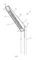
- FIG. 1is a perspective view of an exemplary light fixture mounted to the side of a pole;
- FIG. 2is a top view of the light fixture of FIG. 1 ;
- FIG. 3is a front elevation of the light fixture of FIG. 1 ;
- FIG. 4is a side view of the light fixture of FIG. 1 ;
- FIG. 5is a rear view of the light fixture of FIG. 1 ;
- FIG. 6is a bottom view of the light fixture of FIG. 1 ;
- FIG. 7is a top perspective view of the light fixture of FIG. 1 ;
- FIG. 8Ais a bottom perspective view of the light fixture of FIG. 1 ;
- FIG. 8Bis a bottom, perspective view of the light fixture of FIG. 1 with an outer lens
- FIG. 9is a side view of the light fixture of FIG. 1 with exemplary dimensional representations of the length of the top, the height from the base to the tip, the horizontal length, and the height of the base;
- FIG. 10is a perspective view of the light fixture of FIG. 1 with an exemplary dimensional representation of the width of the top;
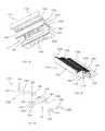
- FIG. 11is an exploded, perspective view of an exemplary lamp unit and a first and second bracket
- FIG. 12is a bottom, perspective view of the lamp unit of FIG. 11 connected to the second bracket;
- FIG. 13is a top, perspective view of the lamp unit and the first and second brackets of FIG. 12 ;
- FIG. 14is a side view of the lamp unit and the first and second brackets of FIG. 12 ;
- FIG. 15is a side, sectional view of the exemplary light housing of FIG. 1 ;
- FIG. 16is a partial, enlarged view of the light housing of FIG. 15 taken about the area labeled 16 ;
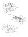
- FIG. 17is an exploded, perspective view of another exemplary lamp unit and exemplary first and second brackets
- FIG. 18is a bottom, perspective view of the lamp unit of FIG. 17 connected to the second bracket;
- FIG. 19is a top, perspective view of the lamp unit and the first and second brackets of FIG. 18 ;
- FIG. 20is a side view of the lamp unit and the first and second brackets of FIG. 18 ;
- FIG. 21is a partial, enlarged sectional view of a series of lamp units in an exemplary housing.
- a light fixture assembly 10is connected to a support, for example a pole 12 extending vertically from the ground (not shown).
- the supportmay be any stable structure, such as a wall or a beam.
- the light fixture assembly 10includes a housing 14 having a cavity for retaining one or more compartmentalized, recessed lamp units 16 .
- the housing 14extends from the pole 12 and includes a first end adjacent and connected to the pole 12 and a second end distal to the pole 12 .
- the housing 14extends obliquely from the pole 12 , outwardly and away from the ground and emits light downwardly.
- the housing 14 and the lamp units 16prevent light from being emitted in a direction parallel to the ground and/or above the light fixture relative to the ground.
- the housing 14includes a top 18 , a first side 20 , and a second side 22 .
- the first and second sides 20 , 22extend from the top 18 toward the ground.
- a chamfered edgeconnects the first and second sides 20 , 22 with the top 18 .
- the first and second sides 20 , 22taper from a first height at a base 24 adjacent the pole to a second height at a tip 26 at the opposite end.
- the first and second sides 20 , 22have a bottom edge with a first section having a first angle of inclination relative to the post 12 and a second section having a second angle of inclination relative to the post greater than the first angle.
- the housing 14includes a first end cap 28 and a second end cap 30 bordering the lamp units 16 .
- An outer diffuser or lens 32can be connected to the housing 14 as shown in FIG. 8B .
- FIGS. 9-10illustrate an exemplary embodiment of the housing 14 configured to provide an angled transition from the pole 12 while preventing light from being emitted parallel to the ground and/or upward relative to the ground.
- the housing 14has a top 18 with length A, an overall height B measured from the bottom of the base 24 to the top of the tip 26 , an overall horizontal length C from the first end to the second end, a height D of the base 24 , and the top 18 has a width E.
- the top width Eis configured to be substantially the width of the pole 12 . In an exemplary embodiment the top width E is approximately 4.0-5.0 inches.
- the housing 14has different dimensions as indicated in table 1 where K 4 represents an exemplary 4 inch wide luminaire and K 5 represents an exemplary 5 inch wide luminaire:
- a cavity within the housing 14receives one or more modular lamp units 16 .
- the light fixture assembly 10 illustrated in FIGS. 11-14includes a first bracket 34 A, an LED board 36 , a conductor grommet 38 , one or more optics 40 , a gasket 42 , and a reflector 44 .
- the first bracket 34 Ais configured to connect to a similar or identical second bracket 34 B, for example through a mechanical connection such as a mating fit, an interference fit, or a snap fit.
- One or more mechanical fasteners 46may be used to hold the first bracket 34 A to the second bracket 34 B and to secure one or more of the other elements in the lamp unit 16 .
- brackets 34 A, 34 Bmate to form a stair-like pattern where each additional bracket is spaced outwardly and above the previous bracket. In this way, a single lamp unit 16 may be manufactured and adapted for use with various sized light housings 14 .
- similar parts on the brackets 34 A, 34 Bare described and labeled only once. As necessary, similar parts of the brackets 34 A, 34 B are designated with the same number with either an A or a B designation.
- the bracket 34 Aincludes a wall 48 , a bottom member 50 extending from the wall 48 in a first direction and a top member 52 extending from the wall 48 in the second direction, giving the bracket 34 A an approximately Z-shaped configuration.
- the bottom and top members 50 , 52are substantially rectangular plates.
- the bracket 34 Ais made from a rigid material, for example aluminum or other suitable metal, polymer, or composite material.
- the bracket 34 Amay be formed through machining, extrusions, molding, or other suitable processes.
- the wall 48 of the bracket 34 Aextends between the bottom member 50 and the top member 52 .
- the wall 48may be substantially vertical, orthogonal to the ground, or the wall 48 may have an angle of inclination relative to a vertical axis, for example between 0 and 10 degrees in either direction.
- the wall 48has a front surface and a rear surface. The size, shape, and configuration of the wall 48 can be changed depending on the housing 12 , the light source (not shown), and other design and utility considerations.
- the bottom member 50extends obliquely from the bottom of the wall 48 in a first direction. In the exemplary embodiment shown, the bottom member 50 extends at an acute angle relative to the rear surface of the wall.
- the bottom member 50has a first section with a first angle of inclination to the wall 48 and a second section with a second angle of inclination greater than the first angle of inclination relative to the wall 48 .
- a first projection 54extends from the bottom member 50 towards the top member 52 continuously along the width of the bottom member 50 .
- the height, shape, length, and position of the first projection 54may vary according to the needs of the light source and the housing 14 and on the various types of required connections.
- the bottom member 50includes one or more light apertures 58 for receiving a light source and/or an optic 40 associated with a light source.
- the bottom member 50also includes one or more fastener apertures 60 for receiving a mechanical fastener 46 .
- the exemplary embodiment shown in FIGS. 11-14depicts two light apertures 58 and two fastener apertures 60 .
- the size, shape, and configuration of the bottom member 50may vary according to the light source, the housing 14 , and other design and utility considerations.
- the top member 52extends obliquely from the top of the wall 48 in the second direction. In the exemplary embodiment shown, the top member 52 extends at an acute angle relative to the front surface of the wall.
- One or more heat fins 62extend from the top surface of the top member 52 to dissipate heat generated by the light source.
- a set of tines 64also extend from the top surface of the top member 52 bounding a channel.
- the top member 52includes a conductor aperture 68 to receive the conductor grommet 38 and one or more fastener openings 69 to receive a mechanical fastener 46 .
- the conductor aperture 68allows conductors to pass through the top member 52 and connect to the LED board 36 .
- the conductor grommet 38protects the conductor passing through the bracket 34 A from wear.
- the conductor grommet 38may be made from a suitable polymer or elastomer material, for example silicone.
- a second projection 70extends from the top member 52 in the direction of the bottom member 50 .
- the second projection 70is configured to mate with the groove 56 and/or the first projection 54 of the bottom member 50 to form a connection with an identical or similarly configured bracket 34 B.
- the LED board 36contains a printed circuit board (PCB) 71 and one or more light sources (not shown), for example LED light sources.
- the PCB 71 and the light sourceare included in the exemplary light source assembly, although other light emitting configurations may be used.
- a conductor connection port 72extends from the PCB 71 for receiving an electrical conductor (not shown), electrically connecting the LED board 36 to a power source, such as a driver (not shown).
- the PCB 71includes one or more traces or pathways extending from the connection port 72 to the light sources.
- One or more slots 74are provided that allow the LED board 36 to be easily positioned and retained relative to the gasket 42 .
- the LED board 36includes one or more apertures or slots 76 to receive a mechanical fastener 46 .
- the various sizes and shapes of the LED board 36 as well as the various light sources, materials, and other configurations used in connection with the LED board 36would be understood by one of ordinary skill in the art when viewing this disclosure.
- the bracket 34 A and the housing 14are utilized with other light sources, for instance, other solid state, electrical filament, fluorescent, plasma, or gas light sources.
- An optic 40is connected to the LED board 36 , for example through a set of pins and an adhesive.
- the optic 40encloses the light source and directs and/or diffuses light emitted therefrom.
- the optic 40is made from a polymer material, for example polycarbonate or polymethyl methacrylate.
- the optic 40is a total internal reflection lens. Different types of optics 40 may be utilized depending on the lights source, the desired emitted light, and other design and utility considerations. Two optics 40 are shown in the exemplary embodiment, although more or less may be utilized depending on the number of light sources and the desired light output.
- the gasket 42has an outer flange 78 that receives at least a portion of the LED board 36 and one or more apertures 80 to receive at least a portion of the optic 40 .
- the gasket 42is selectively configured to include other protrusions, flanges, and openings depending on the configuration of the lamp unit 16 .
- the gasket 42may be made from a material suitable to receive and protect the LED board 36 , for example a polymer or an elastomer such as silicone.
- the reflector 44connects to the bracket 34 A and at least partially surrounds the light source and directs light emitted therefrom.
- the reflector 44has a top surface 82 , a bottom surface 84 , and base 86 at a first end.
- a first arm 88 and a second arm 90extend from the base 86 to a second end, giving the reflector 44 a substantially U-shaped configuration surrounding an opening.
- the first and second arms 88 , 90taper to a point in the direction of the second end, both along their width and height. The taper along the width increases the size of the opening from the top surface 82 to the bottom surface 84 .
- the bottom surface 84is substantially planar and extends substantially parallel to the ground when positioned in the housing 14 .
- the top surface 82has a first section with a first angle of inclination and a second section with a second angle of inclination greater than the first section.
- the reflector 44includes one or more apertures 92 for receiving a mechanical fastener 46 to connect the reflector 44 to the bracket 34 A.
- one or more brackets 34may be combined in a housing 14 to form separate lamp units 16 .
- the gasket 42is placed around the LED board 36 so the optic 40 extends at least partially through the gasket 42 .
- the LED board 36 and gasket 42are placed on the top surface of the bottom member 50 of the first bracket 34 A with the optics 40 extending through the light apertures 58 .
- the reflector 44is placed on the bottom surface of the bottom member 50 of the first bracket 34 A.
- the second bracket 34 Bis positioned adjacent the first bracket 34 A so that the top member 52 of the second bracket 34 B is positioned over the bottom member 50 of the first bracket 34 A.
- the first and second projections 54 , 70are mated so that the second projection 70 extends into the groove 56 adjacent the first projection 54 .
- the first and second projections 54 , 70may be in contact with one another.
- the silicone conductor grommet 38is positioned in the conductor aperture 68 of the top member 52 and the PCB conductor port 72 extends at least partially into the silicone conductor grommet 38 .
- the fasteners 46are inserted through the top member 52 of the second bracket 34 B, the gasket 42 , the bottom member 50 of the first bracket 34 A, and into the reflector 44 .
- a plurality of lamp units 16which include one or more brackets 34 , are connected together in the housing 14 and the housing 14 is connected to a post 12 , for example by one or more mechanical fasteners.
- the brackets 34are connected together sequentially in a stair-like fashion, with each subsequent bracket 34 connected with the previous one.
- Lamp units 16 having identical or similar brackets 34may be utilized in making the connection.
- the brackets 34are not identical but have a common mating feature, for example the first and second protrusions 54 , 70 and the aligned fastener openings 60 , 69 . Other suitable mating features may be used as would be understood by one of ordinary skill in the art.
- the lamp units 16extend along the housing 14 , at an angle from the post 12 and upwards away from the ground.
- the lamp units 16 and the housing 14prevent light from being emitted out of the housing 14 parallel to the ground and above the housing 14 relative to the ground.
- the lightmay be prevented from being emitted parallel to the ground in the front of the housing 14 , from the sides of the housing 14 , or a combination of both.
- the reflector 44 , optic 40 , and brackets 34 A, 34 Bcombine to prevent light from being emitted parallel to the ground in front of the housing 14 and from the side of the housing 14 , while the lamp units 16 are recessed in the housing 14 to prevent light from being emitted above the housing 14 .
- the housing 14may also assist in preventing light from being emitted parallel to the ground from the side of the housing 14 .
- FIG. 16depicts the path of some light emitted from the housing 14 in accordance with various exemplary embodiments.
- Arrows 94 and 96represent the bounded area of light that is emitted from the light source that can leave the housing due to the configuration of the brackets 34 A- 34 C.
- Arrow 98represents light that is directed from the optic 40 . Instead of being emitted from the housing 14 parallel to the ground, the light represented by arrow 98 strikes the bracket 34 C and is directed downward towards the ground.
- Arrows 94 , 96 , 98represent only a portion of the light emitted from the light source as would be understood by one of ordinary skill in the art.
- FIGS. 17-20show another exemplary embodiment of a first bracket 134 A, a second bracket 134 B, an LED board 136 , a conductor grommet 138 , one or more optics 140 , a gasket 142 , and a reflector 144 .
- the first bracket 134 Ais configured to connect to a similar or identical second bracket 134 B, for example through a mechanical connection such as a mating fit, an interference fit, or a snap fit.
- One or more mechanical fasteners 146may be used to hold the first bracket 134 A to the second bracket 134 B and to secure one or more of the other elements in the lamp unit.
- the brackets 134 A, 134 Bmate to form a stair-like pattern where each additional bracket is spaced outwardly and above the previous bracket.
- the bracket 134 Aincludes a wall 148 , a bottom member 150 extending from the wall 148 in a first direction and a top member 152 extending from the wall 148 in a second direction, giving the bracket 134 A an approximately Z-shaped configuration.
- the bottom and top members 150 , 152are substantially rectangular plates.
- the bracket 134 Ais made from a rigid material, for example aluminum or other suitable metal, polymer, or composite material.
- the bracket 134 Amay be formed through machining, extrusions, molding, or other suitable processes.
- the wall 148 of the bracket 134 Aextends between the bottom member 150 and the top member 152 .
- the wall 148may be substantially vertical, orthogonal to the ground, or the wall 148 may have an angle of inclination relative to a vertical axis, for example between 0 and 10 degrees in either direction.
- the wall 148has a front surface and a rear surface. The size, shape, and configuration of the wall 148 can be changed depending on the housing 12 , the light source (not shown), and other design and utility considerations.
- the bottom member 150extends obliquely from the bottom of the wall 148 in the first direction. In the exemplary embodiment shown, the bottom member 150 extends at an acute angle relative to the rear surface of the wall 148 .
- the bottom member 150has a first section with a first angle of inclination to the wall 148 and a second section with a second angle of inclination greater than the first angle of inclination relative to the wall 148 .
- a first projection 154extends from the bottom member 150 towards the top member 152 continuously along the width of the bottom member 150 . In alternative embodiments, the height, shape, length, and position of the first projection 154 may vary according to the needs of the light source and the housing 14 and on the various types of required connections.
- a groove 156is bound on one side by the first projection 54 and on the other side by the wall 148 .
- the groove 156has a substantially rounded bottom.
- the bottom member 150includes one or more light apertures 158 for receiving a light source and/or an optic 140 associated with a light source.
- the bottom member 150also includes one or more fastener apertures 160 for receiving a mechanical fastener 146 .
- the exemplary embodiment shown in FIGS. 17-20depicts four light apertures 158 and four fastener apertures 160 .
- the size, shape, and configuration of the bottom member 150may vary according to the light source, the housing 14 , and other design and utility considerations.
- the top member 152extends obliquely from the top of the wall 48 in the second direction. In the exemplary embodiment shown, the top member 152 extends at an acute angle relative to the front surface of the wall. One or more heat fins 62 extend from the top member 152 to dissipate heat generated by the light source.
- the top member 152includes a conductor aperture to receive the conductor grommet 138 and one or more fastener openings to receive a mechanical fastener 146 .
- the conductor apertureallows conductors to pass through the top member 152 and connect to the LED board 136 .
- the conductor grommet 138protects the conductor passing through the bracket 134 A from wear.
- a second projection 170extends from the top member 152 in the direction of the bottom member 150 .
- the second projection 170is configured to mate with the groove 156 and/or the first projection 154 of the bottom member 150 to form a connection with an identical or similarly configured bracket 134 B.
- the second projectionincludes a rounded portion 172 that extends below the top member 152 and an upper portion 174 that extends above the top member 152 .
- a face or outer surface of the upper portion 174is positioned in contact with or substantially adjacent to a surface of the wall 148 .
- the top of the upper portion 174has a first angled surface and a rear section of the top member 152 has a second angled surface.
- first and second angled surfacesare aligned and have a consistent slope.
- a second groove 164can be formed in the upper portion 174 .
- two or more brackets 134 A-Care combined in a housing 114 to form separate lamp units.
- the LED board 136 and gasket 142are placed on the top surface of the bottom member 150 of the first bracket 134 A with the optics 140 extending through the light apertures 158 .
- the reflector 144is placed on the bottom surface of the bottom member 150 of the first bracket 134 A.
- the second bracket 134 Bis positioned adjacent the first bracket 134 A so that the top member 152 of the second bracket 134 B is positioned over the bottom member 150 of the first bracket 134 A.
- the first and second projections 154 , 170are mated so that the second projection 170 extends into the groove 156 adjacent the first projection 154 .
- the first and second projections 154 , 170may be in contact with one another.
- the fasteners 146are inserted through the top member 152 of the second bracket 134 B, the gasket 142 , the bottom member 150 of the first bracket 134 A, and into the reflector 144 .
- a backing member 115can also be connected to the brackets 134 A-C.
- One or more fasteners 116are inserted through the backing member 115 and connected to the brackets 134 A-C, for example by being inserted into the second slot 164 .
- the second slotcan include threads for engaging the fasteners 116 , or self-taping fasteners can be used.
- the backing member 115can provide rigidity and support the bracket assembly.
- the lamp unitsextend along the housing 114 , at an angle and upwards away from the ground.
- the lamp units and the housing 114prevent light from being emitted out of the housing 114 parallel to the ground and above the housing 114 relative to the ground.
- the lightmay be prevented from being emitted parallel to the ground in the front of the housing 114 , from the sides of the housing 114 , or a combination of both.
- the reflector 144 , optic 140 , and brackets 134 A, 134 Bcombine to prevent light from being emitted parallel to the ground in front of the housing 114 and from the side of the housing 114 , while the lamp units are recessed in the housing 114 to prevent light from being emitted above the housing 114 .
- the housing 114may also assist in preventing light from being emitted parallel to the ground from the side of the housing 114 .
- the terms “front,” “rear,” “upper,” “lower,” “upwardly,” “downwardly,” and other orientational descriptorsare intended to facilitate the description of the exemplary embodiments of the present invention, and are not intended to limit the structure of the exemplary embodiments of the present invention to any particular position or orientation.
- Terms of degree, such as “substantially” or “approximately”are understood by those of ordinary skill to refer to reasonable ranges outside of the given value, for example, general tolerances associated with manufacturing, assembly, and use of the described embodiments.
Landscapes
- Engineering & Computer Science (AREA)
- General Engineering & Computer Science (AREA)
- Non-Portable Lighting Devices Or Systems Thereof (AREA)
- Fastening Of Light Sources Or Lamp Holders (AREA)
- Arrangement Of Elements, Cooling, Sealing, Or The Like Of Lighting Devices (AREA)
Abstract
Description
| TABLE 1 | ||||
| K4 | RATIO TO A | K5 | RATIO TO A | |
| A | 34.084 | 41.084 | ||
| B | 13.7 | 0.40 | 16.106 | 0.39 |
| C | 33.24 | 0.98 | 40.031 | 0.97 |
| D | 6.03 | 0.18 | 6.864 | 0.17 |
Claims (15)
Priority Applications (12)
| Application Number | Priority Date | Filing Date | Title |
|---|---|---|---|
| US14/689,423US10215376B2 (en) | 2014-05-13 | 2015-04-17 | Light fixture having fixed angular position and lamp module for light fixtures |
| AU2015259411AAU2015259411B2 (en) | 2014-05-13 | 2015-05-12 | Light fixture having fixed angular position and lamp module for light fixtures |
| EP15792109.9AEP3143324B1 (en) | 2014-05-13 | 2015-05-12 | Light fixture having fixed angular position and lamp module for light fixtures |
| MX2016014889AMX366387B (en) | 2014-05-13 | 2015-05-12 | Light fixture having fixed angular position and lamp module for light fixtures. |
| CA2948622ACA2948622C (en) | 2014-05-13 | 2015-05-12 | Light fixture having fixed angular position and lamp module for light fixtures |
| PCT/US2015/030316WO2015175495A1 (en) | 2014-05-13 | 2015-05-12 | Light fixture having fixed angular position and lamp module for light fixtures |
| MX2019007994AMX395095B (en) | 2014-05-13 | 2015-05-12 | LIGHTING ACCESSORY THAT HAS A FIXED ANGULAR POSITION AND LAMP MODULE FOR LIGHTING ACCESSORIES. |
| US29/564,385USD822254S1 (en) | 2015-04-17 | 2016-05-12 | Light fixture |
| US29/650,058USD869044S1 (en) | 2015-04-17 | 2018-06-04 | Light fixture |
| US16/284,657US10920963B2 (en) | 2014-05-13 | 2019-02-25 | Light fixture having fixed angular position and lamp module for light fixtures |
| US29/711,193USD891669S1 (en) | 2015-04-17 | 2019-10-29 | Light fixture |
| AU2021201290AAU2021201290B2 (en) | 2014-05-13 | 2021-02-26 | Light fixture having fixed angular position and lamp module for light fixtures |
Applications Claiming Priority (2)
| Application Number | Priority Date | Filing Date | Title |
|---|---|---|---|
| US201461992477P | 2014-05-13 | 2014-05-13 | |
| US14/689,423US10215376B2 (en) | 2014-05-13 | 2015-04-17 | Light fixture having fixed angular position and lamp module for light fixtures |
Related Child Applications (2)
| Application Number | Title | Priority Date | Filing Date |
|---|---|---|---|
| US29/564,385ContinuationUSD822254S1 (en) | 2015-04-17 | 2016-05-12 | Light fixture |
| US16/284,657ContinuationUS10920963B2 (en) | 2014-05-13 | 2019-02-25 | Light fixture having fixed angular position and lamp module for light fixtures |
Publications (2)
| Publication Number | Publication Date |
|---|---|
| US20150330609A1 US20150330609A1 (en) | 2015-11-19 |
| US10215376B2true US10215376B2 (en) | 2019-02-26 |
Family
ID=54480534
Family Applications (2)
| Application Number | Title | Priority Date | Filing Date |
|---|---|---|---|
| US14/689,423ActiveUS10215376B2 (en) | 2014-05-13 | 2015-04-17 | Light fixture having fixed angular position and lamp module for light fixtures |
| US16/284,657ActiveUS10920963B2 (en) | 2014-05-13 | 2019-02-25 | Light fixture having fixed angular position and lamp module for light fixtures |
Family Applications After (1)
| Application Number | Title | Priority Date | Filing Date |
|---|---|---|---|
| US16/284,657ActiveUS10920963B2 (en) | 2014-05-13 | 2019-02-25 | Light fixture having fixed angular position and lamp module for light fixtures |
Country Status (6)
| Country | Link |
|---|---|
| US (2) | US10215376B2 (en) |
| EP (1) | EP3143324B1 (en) |
| AU (2) | AU2015259411B2 (en) |
| CA (1) | CA2948622C (en) |
| MX (2) | MX395095B (en) |
| WO (1) | WO2015175495A1 (en) |
Families Citing this family (7)
| Publication number | Priority date | Publication date | Assignee | Title |
|---|---|---|---|---|
| US10215376B2 (en) | 2014-05-13 | 2019-02-26 | Hubbell Incorporated | Light fixture having fixed angular position and lamp module for light fixtures |
| USD774243S1 (en) | 2015-04-10 | 2016-12-13 | Hubbell Incorporated | Lighting fixture |
| USD822254S1 (en) | 2015-04-17 | 2018-07-03 | Hubbell Incorporated | Light fixture |
| CA3011967A1 (en) | 2016-01-19 | 2017-07-27 | Hubbell Incorporated | Light fixture with shielded optic |
| US10422510B2 (en) | 2016-01-19 | 2019-09-24 | Hubbell Incorporated | Light fixture with pivotable optic |
| USD870947S1 (en)* | 2017-11-01 | 2019-12-24 | Hangzhou Amplesun Solar Technology Co., Ltd. | Solar lamp |
| BE1026261B1 (en)* | 2018-05-08 | 2019-12-10 | Schreder Sa | DOWNSTREAM LIGHTING DEVICE AND FLOOR LAMP COMPRISING A MAST LIGHTING MODULE PROVIDED WITH SAME |
Citations (34)
| Publication number | Priority date | Publication date | Assignee | Title |
|---|---|---|---|---|
| US2336016A (en) | 1941-11-12 | 1943-12-07 | Transit Advertisers Inc | Advertising device |
| US2496513A (en) | 1946-08-07 | 1950-02-07 | Ernest O Anders | Combination lighting and display fixture |
| US2800574A (en) | 1953-06-29 | 1957-07-23 | Compco Corp | Mounting for electric lighting fixtures |
| US2914657A (en) | 1957-05-02 | 1959-11-24 | Guardian Light Company | Outdoor lighting fixtures |
| US3264465A (en) | 1963-09-03 | 1966-08-02 | Gen Electric | Luminaire |
| JPH06243703A (en) | 1993-02-15 | 1994-09-02 | Stanley Electric Co Ltd | Vehicle signal light |
| USD465593S1 (en) | 2001-11-05 | 2002-11-12 | Tsu-Kang Chang | Solar lamp |
| EP1332957A2 (en) | 2002-01-31 | 2003-08-06 | Honda Giken Kogyo Kabushiki Kaisha | Vehicle taillight |
| USD493009S1 (en) | 2003-07-09 | 2004-07-13 | Luen Yick Electrical Mfg. Co., Ltd. | Shelf light |
| US20050237760A1 (en) | 2004-04-22 | 2005-10-27 | Koito Manufacturing Co., Ltd. | Vehicular lamp |
| USD566876S1 (en) | 2005-04-15 | 2008-04-15 | Spi Lighting | Lighting fixture |
| US20090103288A1 (en) | 2007-10-17 | 2009-04-23 | Boyer John D | Roadway luminaire and methods of use |
| US20090323343A1 (en)* | 2008-06-30 | 2009-12-31 | Pei-Choa Wang | Lamp base improvement of a street lamp |
| USD608040S1 (en) | 2008-11-21 | 2010-01-12 | Rab Lighting, Inc. | LED light fixture |
| CN202118667U (en) | 2010-12-30 | 2012-01-18 | 北京朗波尔光电股份有限公司 | LED light fixture used for low position lighting |
| US20120026728A1 (en)* | 2011-05-13 | 2012-02-02 | Xiaomei Lou | Led roadway luminaire |
| USD672078S1 (en) | 2012-05-01 | 2012-12-04 | Foxsemicon Integrated Technology, Inc. | Illumination device |
| US20130003379A1 (en)* | 2010-10-04 | 2013-01-03 | De Silva Niranjan B | Led light system |
| USD677419S1 (en) | 2010-12-22 | 2013-03-05 | Groupe Adeo | Solar lighting fixture |
| US20130083534A1 (en)* | 2011-09-29 | 2013-04-04 | Foxsemicon Integrated Technology, Inc. | Light-emitting diode lamp |
| US20130301267A1 (en)* | 2012-05-08 | 2013-11-14 | Caleb Timothy Badley | Systems, Methods, and Devices for Providing Rotatable Light Modules and Hinged Mount in a Luminaire |
| US20130322074A1 (en) | 2012-06-01 | 2013-12-05 | RAB Lighting Inc. | Light fixture with selectable emitter and reflector configuration |
| US20140078715A1 (en)* | 2012-09-14 | 2014-03-20 | Cree, Inc. | High efficiency lighting device including one or more solid state light emitters, and method of lighting |
| USD707381S1 (en) | 2013-07-30 | 2014-06-17 | Lighting Science Group Corporation | Roadway lamp |
| US20140168991A1 (en)* | 2012-12-14 | 2014-06-19 | Jong-Chen KIM | Led lamp |
| US8858028B2 (en)* | 2011-09-03 | 2014-10-14 | New Technology Bank Co., Ltd. | LED lighting apparatus |
| US20140334148A1 (en)* | 2011-12-06 | 2014-11-13 | Seoul Semiconducstor Co., Ltd. | Backlight module, method for driving same and display device using same |
| US20140347856A1 (en) | 2011-12-23 | 2014-11-27 | Koninklijke Philips N.V. | Outdoor luminaire |
| USD729968S1 (en) | 2013-06-19 | 2015-05-19 | Hei Technology International Gmbh | Outdoor lighting fixture |
| USD732223S1 (en) | 2014-05-13 | 2015-06-16 | Hubbell Incorporated | Light fixture |
| US20150330609A1 (en) | 2014-05-13 | 2015-11-19 | Hubbell Incorporated | Light fixture having fixed angular position and lamp module for light fixtures |
| US9200759B2 (en)* | 2011-04-15 | 2015-12-01 | Cooper Crouse-Hinds Gmbh | Lamp having indirect light emission |
| USD757322S1 (en) | 2014-12-09 | 2016-05-24 | Hubbardton Forge Llc | Lamp |
| USD768904S1 (en) | 2015-04-10 | 2016-10-11 | Hubbell Incorporated | Lighting fixture |
Family Cites Families (1)
| Publication number | Priority date | Publication date | Assignee | Title |
|---|---|---|---|---|
| USD822254S1 (en) | 2015-04-17 | 2018-07-03 | Hubbell Incorporated | Light fixture |
- 2015
- 2015-04-17USUS14/689,423patent/US10215376B2/enactiveActive
- 2015-05-12MXMX2019007994Apatent/MX395095B/enunknown
- 2015-05-12AUAU2015259411Apatent/AU2015259411B2/enactiveActive
- 2015-05-12CACA2948622Apatent/CA2948622C/enactiveActive
- 2015-05-12EPEP15792109.9Apatent/EP3143324B1/enactiveActive
- 2015-05-12MXMX2016014889Apatent/MX366387B/enactiveIP Right Grant
- 2015-05-12WOPCT/US2015/030316patent/WO2015175495A1/enactiveApplication Filing
- 2019
- 2019-02-25USUS16/284,657patent/US10920963B2/enactiveActive
- 2021
- 2021-02-26AUAU2021201290Apatent/AU2021201290B2/enactiveActive
Patent Citations (34)
| Publication number | Priority date | Publication date | Assignee | Title |
|---|---|---|---|---|
| US2336016A (en) | 1941-11-12 | 1943-12-07 | Transit Advertisers Inc | Advertising device |
| US2496513A (en) | 1946-08-07 | 1950-02-07 | Ernest O Anders | Combination lighting and display fixture |
| US2800574A (en) | 1953-06-29 | 1957-07-23 | Compco Corp | Mounting for electric lighting fixtures |
| US2914657A (en) | 1957-05-02 | 1959-11-24 | Guardian Light Company | Outdoor lighting fixtures |
| US3264465A (en) | 1963-09-03 | 1966-08-02 | Gen Electric | Luminaire |
| JPH06243703A (en) | 1993-02-15 | 1994-09-02 | Stanley Electric Co Ltd | Vehicle signal light |
| USD465593S1 (en) | 2001-11-05 | 2002-11-12 | Tsu-Kang Chang | Solar lamp |
| EP1332957A2 (en) | 2002-01-31 | 2003-08-06 | Honda Giken Kogyo Kabushiki Kaisha | Vehicle taillight |
| USD493009S1 (en) | 2003-07-09 | 2004-07-13 | Luen Yick Electrical Mfg. Co., Ltd. | Shelf light |
| US20050237760A1 (en) | 2004-04-22 | 2005-10-27 | Koito Manufacturing Co., Ltd. | Vehicular lamp |
| USD566876S1 (en) | 2005-04-15 | 2008-04-15 | Spi Lighting | Lighting fixture |
| US20090103288A1 (en) | 2007-10-17 | 2009-04-23 | Boyer John D | Roadway luminaire and methods of use |
| US20090323343A1 (en)* | 2008-06-30 | 2009-12-31 | Pei-Choa Wang | Lamp base improvement of a street lamp |
| USD608040S1 (en) | 2008-11-21 | 2010-01-12 | Rab Lighting, Inc. | LED light fixture |
| US20130003379A1 (en)* | 2010-10-04 | 2013-01-03 | De Silva Niranjan B | Led light system |
| USD677419S1 (en) | 2010-12-22 | 2013-03-05 | Groupe Adeo | Solar lighting fixture |
| CN202118667U (en) | 2010-12-30 | 2012-01-18 | 北京朗波尔光电股份有限公司 | LED light fixture used for low position lighting |
| US9200759B2 (en)* | 2011-04-15 | 2015-12-01 | Cooper Crouse-Hinds Gmbh | Lamp having indirect light emission |
| US20120026728A1 (en)* | 2011-05-13 | 2012-02-02 | Xiaomei Lou | Led roadway luminaire |
| US8858028B2 (en)* | 2011-09-03 | 2014-10-14 | New Technology Bank Co., Ltd. | LED lighting apparatus |
| US20130083534A1 (en)* | 2011-09-29 | 2013-04-04 | Foxsemicon Integrated Technology, Inc. | Light-emitting diode lamp |
| US20140334148A1 (en)* | 2011-12-06 | 2014-11-13 | Seoul Semiconducstor Co., Ltd. | Backlight module, method for driving same and display device using same |
| US20140347856A1 (en) | 2011-12-23 | 2014-11-27 | Koninklijke Philips N.V. | Outdoor luminaire |
| USD672078S1 (en) | 2012-05-01 | 2012-12-04 | Foxsemicon Integrated Technology, Inc. | Illumination device |
| US20130301267A1 (en)* | 2012-05-08 | 2013-11-14 | Caleb Timothy Badley | Systems, Methods, and Devices for Providing Rotatable Light Modules and Hinged Mount in a Luminaire |
| US20130322074A1 (en) | 2012-06-01 | 2013-12-05 | RAB Lighting Inc. | Light fixture with selectable emitter and reflector configuration |
| US20140078715A1 (en)* | 2012-09-14 | 2014-03-20 | Cree, Inc. | High efficiency lighting device including one or more solid state light emitters, and method of lighting |
| US20140168991A1 (en)* | 2012-12-14 | 2014-06-19 | Jong-Chen KIM | Led lamp |
| USD729968S1 (en) | 2013-06-19 | 2015-05-19 | Hei Technology International Gmbh | Outdoor lighting fixture |
| USD707381S1 (en) | 2013-07-30 | 2014-06-17 | Lighting Science Group Corporation | Roadway lamp |
| USD732223S1 (en) | 2014-05-13 | 2015-06-16 | Hubbell Incorporated | Light fixture |
| US20150330609A1 (en) | 2014-05-13 | 2015-11-19 | Hubbell Incorporated | Light fixture having fixed angular position and lamp module for light fixtures |
| USD757322S1 (en) | 2014-12-09 | 2016-05-24 | Hubbardton Forge Llc | Lamp |
| USD768904S1 (en) | 2015-04-10 | 2016-10-11 | Hubbell Incorporated | Lighting fixture |
Non-Patent Citations (3)
| Title |
|---|
| European Patent Appl. No. 15792109.9 extended European Search Report dated Oct. 6, 2017 (8 pages). |
| Hess "Pasadena Streetlight" Brochure from www.hess.eu/dldfile/Hess_PASADENA_Kat_EN.pdf. Oct. 2011. (12 pages). |
| PCT/US2015/030316 International Search Report and Written Opinion dated Sep. 17, 2015. |
Also Published As
| Publication number | Publication date |
|---|---|
| EP3143324A4 (en) | 2017-11-08 |
| US20190186715A1 (en) | 2019-06-20 |
| AU2021201290A2 (en) | 2021-05-06 |
| AU2021201290B2 (en) | 2022-09-15 |
| CA2948622C (en) | 2022-11-29 |
| US20150330609A1 (en) | 2015-11-19 |
| US10920963B2 (en) | 2021-02-16 |
| AU2021201290A1 (en) | 2021-03-18 |
| MX2019007994A (en) | 2019-09-13 |
| MX395095B (en) | 2025-03-24 |
| EP3143324A1 (en) | 2017-03-22 |
| MX366387B (en) | 2019-07-08 |
| CA2948622A1 (en) | 2015-11-19 |
| MX2016014889A (en) | 2017-04-06 |
| AU2015259411A1 (en) | 2016-11-24 |
| EP3143324B1 (en) | 2019-06-19 |
| AU2015259411B2 (en) | 2020-11-26 |
| WO2015175495A1 (en) | 2015-11-19 |
Similar Documents
| Publication | Publication Date | Title |
|---|---|---|
| US10920963B2 (en) | Light fixture having fixed angular position and lamp module for light fixtures | |
| JP6940633B2 (en) | LED-based light source with sloping outer wall | |
| US10488032B2 (en) | Area luminaire with heat fins | |
| US9234649B2 (en) | Luminaires and lighting structures | |
| US7753564B2 (en) | Lampshade and illumination lamp having the same | |
| RU2585251C2 (en) | Light-emitting diode electric lamp with light-diffusing optical structure | |
| US20140268747A1 (en) | Standardized troffer fixture | |
| MX2010010567A (en) | Lighting apparatus using light emitting diode. | |
| US20150124449A1 (en) | Led light fixtures with arrangement for electrical connection | |
| US10151453B2 (en) | Directional accent luminaire | |
| US20140218933A1 (en) | Detachable lamp | |
| CN204403966U (en) | Ligthing paraphernalia and secondary light source unit | |
| US20120243254A1 (en) | Lighting Module | |
| US20150062894A1 (en) | Hybrid Driving Light | |
| US9109761B2 (en) | Lamp mounting base and light emitting diode lamp incorporating the same | |
| CN102278637A (en) | Large-angle light-emitting diode (LED) illuminating lamp | |
| CN202274377U (en) | Structure of LED lamps |
Legal Events
| Date | Code | Title | Description |
|---|---|---|---|
| AS | Assignment | Owner name:HUBBELL INCORPORATED, CONNECTICUT Free format text:ASSIGNMENT OF ASSIGNORS INTEREST;ASSIGNORS:AHRARI, ARMIN;NANKIL, ROBERT;REEL/FRAME:035510/0365 Effective date:20150427 | |
| STCF | Information on status: patent grant | Free format text:PATENTED CASE | |
| AS | Assignment | Owner name:HUBBELL LIGHTING, INC., CONNECTICUT Free format text:NUNC PRO TUNC ASSIGNMENT;ASSIGNOR:HUBBELL INCORPORATED;REEL/FRAME:058838/0162 Effective date:20220112 | |
| AS | Assignment | Owner name:ALLY BANK, AS COLLATERAL AGENT, NEW YORK Free format text:SECURITY AGREEMENT;ASSIGNORS:HUBBELL LIGHTING, INC.;LITECONTROL CORPORATION;CURRENT LIGHTING SOLUTIONS, LLC;AND OTHERS;REEL/FRAME:058982/0844 Effective date:20220201 | |
| AS | Assignment | Owner name:ATLANTIC PARK STRATEGIC CAPITAL FUND, L.P., AS COLLATERAL AGENT, NEW YORK Free format text:SECURITY INTEREST;ASSIGNORS:HUBBELL LIGHTING, INC.;LITECONTROL CORPORATION;CURRENT LIGHTING SOLUTIONS, LLC;AND OTHERS;REEL/FRAME:059034/0469 Effective date:20220201 | |
| FEPP | Fee payment procedure | Free format text:SURCHARGE FOR LATE PAYMENT, LARGE ENTITY (ORIGINAL EVENT CODE: M1554); ENTITY STATUS OF PATENT OWNER: LARGE ENTITY | |
| MAFP | Maintenance fee payment | Free format text:PAYMENT OF MAINTENANCE FEE, 4TH YEAR, LARGE ENTITY (ORIGINAL EVENT CODE: M1551); ENTITY STATUS OF PATENT OWNER: LARGE ENTITY Year of fee payment:4 | |
| AS | Assignment | Owner name:ALLY BANK, AS COLLATERAL AGENT, NEW YORK Free format text:CORRECTIVE ASSIGNMENT TO CORRECT THE PATENT NUMBER 10841994 TO PATENT NUMBER 11570872 PREVIOUSLY RECORDED ON REEL 058982 FRAME 0844. ASSIGNOR(S) HEREBY CONFIRMS THE SECURITY AGREEMENT;ASSIGNORS:HUBBELL LIGHTING, INC.;LITECONTROL CORPORATION;CURRENT LIGHTING SOLUTIONS, LLC;AND OTHERS;REEL/FRAME:066355/0455 Effective date:20220201 | |
| AS | Assignment | Owner name:ATLANTIC PARK STRATEGIC CAPITAL FUND, L.P., AS COLLATERAL AGENT, NEW YORK Free format text:CORRECTIVE ASSIGNMENT TO CORRECT THE PATENT NUMBER PREVIOUSLY RECORDED AT REEL: 059034 FRAME: 0469. ASSIGNOR(S) HEREBY CONFIRMS THE SECURITY INTEREST;ASSIGNORS:HUBBELL LIGHTING, INC.;LITECONTROL CORPORATION;CURRENT LIGHTING SOLUTIONS, LLC;AND OTHERS;REEL/FRAME:066372/0590 Effective date:20220201 |