US10215344B2 - Light emitting panel assemblies and light guides therefor - Google Patents
Light emitting panel assemblies and light guides thereforDownload PDFInfo
- Publication number
- US10215344B2 US10215344B2US14/382,716US201214382716AUS10215344B2US 10215344 B2US10215344 B2US 10215344B2US 201214382716 AUS201214382716 AUS 201214382716AUS 10215344 B2US10215344 B2US 10215344B2
- Authority
- US
- United States
- Prior art keywords
- light
- emitting panel
- light emitting
- panel assembly
- flutes
- Prior art date
- Legal status (The legal status is an assumption and is not a legal conclusion. Google has not performed a legal analysis and makes no representation as to the accuracy of the status listed.)
- Active, expires
Links
Images


Classifications
- F—MECHANICAL ENGINEERING; LIGHTING; HEATING; WEAPONS; BLASTING
- F21—LIGHTING
- F21K—NON-ELECTRIC LIGHT SOURCES USING LUMINESCENCE; LIGHT SOURCES USING ELECTROCHEMILUMINESCENCE; LIGHT SOURCES USING CHARGES OF COMBUSTIBLE MATERIAL; LIGHT SOURCES USING SEMICONDUCTOR DEVICES AS LIGHT-GENERATING ELEMENTS; LIGHT SOURCES NOT OTHERWISE PROVIDED FOR
- F21K9/00—Light sources using semiconductor devices as light-generating elements, e.g. using light-emitting diodes [LED] or lasers
- F21K9/60—Optical arrangements integrated in the light source, e.g. for improving the colour rendering index or the light extraction
- F21K9/61—Optical arrangements integrated in the light source, e.g. for improving the colour rendering index or the light extraction using light guides
- G—PHYSICS
- G02—OPTICS
- G02B—OPTICAL ELEMENTS, SYSTEMS OR APPARATUS
- G02B6/00—Light guides; Structural details of arrangements comprising light guides and other optical elements, e.g. couplings
- G02B6/0001—Light guides; Structural details of arrangements comprising light guides and other optical elements, e.g. couplings specially adapted for lighting devices or systems
- G02B6/0011—Light guides; Structural details of arrangements comprising light guides and other optical elements, e.g. couplings specially adapted for lighting devices or systems the light guides being planar or of plate-like form
- G02B6/0013—Means for improving the coupling-in of light from the light source into the light guide
- G02B6/0015—Means for improving the coupling-in of light from the light source into the light guide provided on the surface of the light guide or in the bulk of it
- G02B6/0016—Grooves, prisms, gratings, scattering particles or rough surfaces
- G—PHYSICS
- G02—OPTICS
- G02B—OPTICAL ELEMENTS, SYSTEMS OR APPARATUS
- G02B6/00—Light guides; Structural details of arrangements comprising light guides and other optical elements, e.g. couplings
- G02B6/0001—Light guides; Structural details of arrangements comprising light guides and other optical elements, e.g. couplings specially adapted for lighting devices or systems
- G02B6/0011—Light guides; Structural details of arrangements comprising light guides and other optical elements, e.g. couplings specially adapted for lighting devices or systems the light guides being planar or of plate-like form
- G02B6/0013—Means for improving the coupling-in of light from the light source into the light guide
- G02B6/0023—Means for improving the coupling-in of light from the light source into the light guide provided by one optical element, or plurality thereof, placed between the light guide and the light source, or around the light source
- G02B6/003—Lens or lenticular sheet or layer
- F—MECHANICAL ENGINEERING; LIGHTING; HEATING; WEAPONS; BLASTING
- F21—LIGHTING
- F21V—FUNCTIONAL FEATURES OR DETAILS OF LIGHTING DEVICES OR SYSTEMS THEREOF; STRUCTURAL COMBINATIONS OF LIGHTING DEVICES WITH OTHER ARTICLES, NOT OTHERWISE PROVIDED FOR
- F21V2200/00—Use of light guides, e.g. fibre optic devices, in lighting devices or systems
- F21V2200/20—Use of light guides, e.g. fibre optic devices, in lighting devices or systems of light guides of a generally planar shape
- F—MECHANICAL ENGINEERING; LIGHTING; HEATING; WEAPONS; BLASTING
- F21—LIGHTING
- F21Y—INDEXING SCHEME ASSOCIATED WITH SUBCLASSES F21K, F21L, F21S and F21V, RELATING TO THE FORM OR THE KIND OF THE LIGHT SOURCES OR OF THE COLOUR OF THE LIGHT EMITTED
- F21Y2103/00—Elongate light sources, e.g. fluorescent tubes
- F21Y2103/10—Elongate light sources, e.g. fluorescent tubes comprising a linear array of point-like light-generating elements
- F—MECHANICAL ENGINEERING; LIGHTING; HEATING; WEAPONS; BLASTING
- F21—LIGHTING
- F21Y—INDEXING SCHEME ASSOCIATED WITH SUBCLASSES F21K, F21L, F21S and F21V, RELATING TO THE FORM OR THE KIND OF THE LIGHT SOURCES OR OF THE COLOUR OF THE LIGHT EMITTED
- F21Y2115/00—Light-generating elements of semiconductor light sources
- F21Y2115/10—Light-emitting diodes [LED]
- G—PHYSICS
- G02—OPTICS
- G02B—OPTICAL ELEMENTS, SYSTEMS OR APPARATUS
- G02B6/00—Light guides; Structural details of arrangements comprising light guides and other optical elements, e.g. couplings
- G02B6/0001—Light guides; Structural details of arrangements comprising light guides and other optical elements, e.g. couplings specially adapted for lighting devices or systems
- G02B6/0011—Light guides; Structural details of arrangements comprising light guides and other optical elements, e.g. couplings specially adapted for lighting devices or systems the light guides being planar or of plate-like form
- G02B6/0013—Means for improving the coupling-in of light from the light source into the light guide
- G02B6/0015—Means for improving the coupling-in of light from the light source into the light guide provided on the surface of the light guide or in the bulk of it
- G02B6/002—Means for improving the coupling-in of light from the light source into the light guide provided on the surface of the light guide or in the bulk of it by shaping at least a portion of the light guide, e.g. with collimating, focussing or diverging surfaces
- G—PHYSICS
- G02—OPTICS
- G02B—OPTICAL ELEMENTS, SYSTEMS OR APPARATUS
- G02B6/00—Light guides; Structural details of arrangements comprising light guides and other optical elements, e.g. couplings
- G02B6/0001—Light guides; Structural details of arrangements comprising light guides and other optical elements, e.g. couplings specially adapted for lighting devices or systems
- G02B6/0011—Light guides; Structural details of arrangements comprising light guides and other optical elements, e.g. couplings specially adapted for lighting devices or systems the light guides being planar or of plate-like form
- G02B6/0013—Means for improving the coupling-in of light from the light source into the light guide
- G02B6/0023—Means for improving the coupling-in of light from the light source into the light guide provided by one optical element, or plurality thereof, placed between the light guide and the light source, or around the light source
- G02B6/0028—Light guide, e.g. taper
- G—PHYSICS
- G02—OPTICS
- G02B—OPTICAL ELEMENTS, SYSTEMS OR APPARATUS
- G02B6/00—Light guides; Structural details of arrangements comprising light guides and other optical elements, e.g. couplings
- G02B6/0001—Light guides; Structural details of arrangements comprising light guides and other optical elements, e.g. couplings specially adapted for lighting devices or systems
- G02B6/0011—Light guides; Structural details of arrangements comprising light guides and other optical elements, e.g. couplings specially adapted for lighting devices or systems the light guides being planar or of plate-like form
- G02B6/0066—Light guides; Structural details of arrangements comprising light guides and other optical elements, e.g. couplings specially adapted for lighting devices or systems the light guides being planar or of plate-like form characterised by the light source being coupled to the light guide
- G02B6/0068—Arrangements of plural sources, e.g. multi-colour light sources
- G—PHYSICS
- G02—OPTICS
- G02B—OPTICAL ELEMENTS, SYSTEMS OR APPARATUS
- G02B6/00—Light guides; Structural details of arrangements comprising light guides and other optical elements, e.g. couplings
- G02B6/0001—Light guides; Structural details of arrangements comprising light guides and other optical elements, e.g. couplings specially adapted for lighting devices or systems
- G02B6/0011—Light guides; Structural details of arrangements comprising light guides and other optical elements, e.g. couplings specially adapted for lighting devices or systems the light guides being planar or of plate-like form
- G02B6/0066—Light guides; Structural details of arrangements comprising light guides and other optical elements, e.g. couplings specially adapted for lighting devices or systems the light guides being planar or of plate-like form characterised by the light source being coupled to the light guide
- G02B6/0073—Light emitting diode [LED]
Definitions
- This inventionrelates to light emitting panel assemblies, and in particular light emitting panel assemblies with light guides.
- the light emitting panel assembliesmay for example be a luminaire.
- Light emitting panel assembliesuse light guides to transmit light from point light sources such as light emitting diodes (LEDs) through a transition area to an emission area where the light is extracted. Light travels through the light guide by way of total internal reflection until it is extracted. In known light guides light is internally reflected through the guide in an uninterrupted linear path in the plane perpendicular to the normal of the flat sides of the light guide. In known light guides, when the light is extracted by extraction elements the light can appear to the viewer as undesirable visible lines of light emanating from the light sources. The visual definition of these lines can vary depending on the type of extraction elements used, the distance between the extraction elements and the light source(s), and the width or thickness of the light guide. Light emitting panel assemblies and light guides that reduce or eliminate these visible lines of light and emit light which is more visually homogenous across the emitting surface are desirable.
- LEDslight emitting diodes
- a light emitting panel assemblyincludes: a light source; a transition area including a first major side and a second major side, wherein at least one of the first major side and the second major side includes a plurality of vertically extending flutes, wherein the flutes extend at least a portion of the height of the transition area; and an emission area in optical communication with the transition area, the emission area including light extraction elements.
- the first major side and the second major sidemay have flutes.
- the flutesmay span substantially the height of the transition area.
- the flutesmay have a horizontal cross-section pattern selected from the group consisting of sinusoidal, zig-zagged, rectangular, convex semicircular, and concave semicircular, and combinations thereof.
- the flutesmay be adjacent each other or spaced apart.
- the assemblymay have a plurality of light sources.
- the flutes of the first major side and the flutes of the second major sidemay be configured in mirror image relation to each other or offset in relation to each other.
- the width of the flutesmay be equal to or less than the pitch of the light sources.
- the transition areamay be a solid core and a first film comprising the flutes, the first film bonded to a first side of the core to define the first major side.
- the transition areamay include a second film comprising the flutes, the second film bonded to a second side of the core to define the second major side.
- the transition areamay be a hollow core with vertically extending ribs or ridges disposed along interior surfaces of the first and second major surfaces.
- the emission areahas a first major side and a second major side, and at least one of the first major side and the second major side of the emission area may have a plurality of vertically extending flutes, wherein the flutes extend at least a portion of the height of the emission area.
- the flutes of the transition areamay be continuous with the flutes of the emission area. In some embodiments, the flutes may be absent in the transition area and located only in the emission area.
- the transition areamay include a non-straight path between the light source and the emission area, whereby substantially all light from the light source internally reflects off at least one of the major sides of the transition area before entering the emission area.
- the non-straight pathmay include a curved portion and may be defined by an angle ⁇ between a plane of a surface of the transition area that initially receives light from light source and a plane of an interface of the transition area and the emission area, wherein the angle ⁇ is in the range of about 30 degrees to 90 degrees.
- the non-straight pathmay have an “S-curve”.
- a radius of an outer side of the curved portionis substantially equal to or greater than a critical radius of the outer side of the curved portion.
- the radius of the outer side of the curved portionmay be greater than or equal to 1.0 cm.
- the inner side and the outer side of the curved portionmay be concentric or non-concentric.
- the inner side of the curved portionmay have a greater curvature than an inner side of the curved portion that would result in a concentric curved portion, or the inner side of the curved portion may begin at a point above a point where the outer side of the curved portion begins.
- the thickness of the curved portionmay increase in a direction away from the light source.
- the assemblymay include at least two light sources and a Y-shaped transition area, wherein each of the two arms of the Y-shaped transition area includes a non-straight path between the light source and the emission area, whereby substantially all light from each light source internally reflects off of at least a fluted side of the transition area before entering the emission area.
- the non-straight pathmay include a curved portion and may be defined by an angle ⁇ between a plane of a surface of the transition area that initially receives light from light source and a plane of an interface of the transition area and the emission area, wherein the angle ⁇ is in the range of about 30 degrees to 90 degrees.
- the inner side and an outer side of each of the curved portionsmay be concentric or non-concentric.
- the inner side of the curved portionmay have a greater curvature than an inner side of the curved portion that would result in a concentric curved portion, or the inner side of the curved portion may begin at a point above a point where the outer side of the curved portion begins.
- a thickness of the curved portionmay increase in a direction away from the light source. Individual light elements of a first one of the light sources may be in staggered configuration with individual light elements of the second one of the light sources.
- the assemblymay have a transition area having a “V-shaped” light receiving surface in optical communication with the light source.
- Each inner and outer side of the “V-shaped” light receiving surfacemay be convex.
- the assemblymay have flutes that are continuous or non-continuous in their vertical extent. Where the flutes are non-continuous, each flute may include at least two fluted segments and at least one non-fluted segment therebetween, wherein the non-fluted segment comprises a stepped thickening of the light guide.
- the light source of the assembliesmay be an LED.
- the inventionin another aspect, relates to a luminaire that includes a light emitting panel assembly described herein.
- FIGS. 1A to 1Care top, front, and side views respectively of a light emitting panel assembly according to an embodiment of the invention
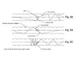
- FIGS. 2A to 2Care partial top schematic views of a light guide according to an embodiment of the invention.
- FIGS. 3A and 3Bare partial top and front schematic views respectively of a light guide according to an embodiment of the invention showing the paths of exemplary light rays from a single light source;
- FIGS. 4A and 4Bare partial top and front schematic views respectively of a light guide according to an embodiment of the invention showing the paths of exemplary light rays from multiple light sources;
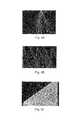
- FIGS. 5A and 5Bare exemplary simulated light ray traces produced by one light source and multiple light sources, respectively, of light emitting panel assemblies according to embodiments of the invention.
- FIG. 5 Cis a partial perspective schematic view of the light emitting panel assembly of FIG. 5B ;
- FIGS. 6A to 6Care partial top, front and side schematic views respectively of a prior art light guide showing the paths of exemplary light rays from a single light source (the vertical lines spanning FIGS. 6A and 6B , and the horizontal lines spanning FIGS. 6B and 6C , are for reference to corresponding points between the figures and do not represent any structure element of the light guide);
- FIGS. 7A and 7Bare partial top and front schematic views respectively of a prior art light guide showing the paths of exemplary light rays from multiple light sources;
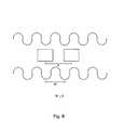
- FIG. 8is a partial top schematic view of a light emitting panel assembly according to an embodiment of the invention.
- FIG. 9is a top view of a light emitting panel assembly according to an embodiment of the invention.
- FIG. 10is a top view of a light emitting panel assembly according to an embodiment of the invention.
- FIG. 11is a top view of a light emitting panel assembly according to an embodiment of the invention.
- FIG. 12is a top view of a light emitting panel assembly according to an embodiment of the invention.
- FIG. 13is a top view of a light emitting panel assembly according to an embodiment of the invention.
- FIG. 14is a top view of a light emitting panel assembly according to an embodiment of the invention.
- FIG. 15is a top view of a light emitting panel assembly according to an embodiment of the invention.
- FIG. 16is a top view of a light emitting panel assembly according to an embodiment of the invention.
- FIGS. 17A to 17Care top, front, and side views respectively of a light emitting panel assembly according to an embodiment of the invention.
- FIG. 18A to 18Eare front, horizontal cross section (along plane A-A in 18 A), side, and first detail (area D in 18 A) and second detail (area E in 18 A) views respectively of a light emitting panel assembly according to an embodiment of the invention;
- FIG. 19is a top view of a light emitting panel assembly according to an embodiment of the invention.
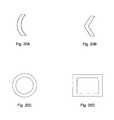
- FIGS. 20A to 20Dare top views of light guides according to various embodiments of the invention.
- FIG. 21is a side view of a light emitting panel assembly according to an embodiment of the invention.
- FIG. 22is a partial side view of the light emitting panel assembly shown in FIG. 21 ;
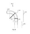
- FIG. 23is a partial side view of a light emitting panel assembly according to an embodiment of the invention.
- FIG. 24A to 24 Dare side views of simulated light ray traces within a light emitting panel assemblies according to various embodiments of the invention.
- FIG. 25is a partial side view of a light emitting panel assembly according to an embodiment of the invention.
- FIG. 26is a partial side view of a light emitting panel assembly according to an embodiment of the invention.
- FIG. 27is a side view of simulated light ray traces within a light emitting panel assembly according to an embodiment of the invention.
- FIG. 28is a partial side view of a light emitting panel assembly according to an embodiment of the invention.
- FIG. 29is a side view of a light emitting panel assembly according to an embodiment of the invention.
- FIG. 30is a top view of a light emitting panel assembly according to the embodiment of the invention shown in FIG. 29 ;
- FIG. 31is a partial side view of simulated light ray traces within a light emitting panel assembly according to an embodiment of the invention.
- FIG. 32is a side view of a light emitting panel assembly according to an embodiment of the invention.
- FIG. 33is a partial side view of simulated light ray traces within a light emitting panel assembly according to an embodiment of the invention.
- FIG. 34is a side view of a light emitting panel assembly according to an embodiment of the invention.
- FIGS. 35A and 35Bare front and side views of a light emitting panel assembly according to an embodiment of the invention.
- the term “horizontal” as used in this specificationis a relative term that refers to an orientation generally perpendicular to the overall direction of light travelling through the light emitting panel assembly.
- the term “vertical” as used in this specificationis a relative term that refers to an orientation generally parallel to the overall direction of light travelling through the light emitting panel assembly.
- the term “upper” and “above” as used in this specificationrefers to a position within the light emitting panel assembly relatively closer to the light source.
- the term “lower” and “below” as used in this specificationrefers to a position within the light emitting panel assembly relatively farther from the light source.
- the light emitting panel assemblies of the inventionare particularly advantageous for use as luminaires or as a component of luminaires, but as would be understood by persons of skill in the art may be used in other applications.
- FIGS. 1A to 1Cshow a light emitting panel assembly 100 according to an embodiment of the invention.
- Light emitting panel assembly 100includes a light guide 102 .
- Light guide 102is constructed of a solid core material with a high refractive index, such as polymethyl methacrylate (PMMA), polycarbonate (PC), or the like.
- PMMApolymethyl methacrylate
- PCpolycarbonate
- Light guide 102includes a transition area 104 and an emission area 106 .
- Transition area 104is integrally formed and in optical communication with emission area 106 .
- transition area 104may be coupled to and in optical communication with emission area 106 , and these two areas made be constructed of the same or different material with similar refractive indices.
- a bridging area(not shown) constructed of the same or different material with a similar refractive index may be provided between the transition area and emission area. Light travels within the transition area, bridging area, and at least part of the emission area, by way of total internal reflection.
- the bridging areamay serve to provide spacing between the transition area and emission area to allow design or structural elements of the luminaire to obscure the transition area from view while ensuring that light from the emission area is not blocked by the same design or structural elements.
- An array of light sources 108is located adjacent an upper region of transition area 104 .
- Light sources 108are evenly spaced apart along the length of transition area 104 .
- the spaces between light sources 108may be in the range of about 2.5 mm to 50 mm, or about 5.0 mm to 10 mm.
- light sources 108are located at an upper surface of transition area 104 opposite a lower surface of transition area 104 joining emission area 106 to maximize horizontal diffusion of light prior to the light entering emission area 106 .
- light sources 108may be positioned in other locations adjacent to, within, or in otherwise optical communication with, transition area 104 .
- Light sources 108are light emitting diodes (LEDs). In other embodiments, light sources 108 may be another suitable point source of light, such as a laser diode, a fibre optic transmitting light from a remote source, and the like.
- LEDslight emitting diodes
- light sources 108may be another suitable point source of light, such as a laser diode, a fibre optic transmitting light from a remote source, and the like.
- Transition area 104has opposing major sides 110 , 110 ′.
- Major sides 110 , 110 ′have corresponding parallel corrugations or flutes 112 , 112 ′ that vertically span transition area 104 .
- the vertical orientation of the flutesprovides total internal reflection of light along the vertical plane and prevents unintended extraction or loss of light.
- flutes 112 , 112 ′may span only a portion of the height of transition area 104 .
- Flutes 112 , 112 ′are sinusoidal in horizontal cross-section, as can be seen in FIG. 1A .
- FIGS. 2A to 2Cillustrate example embodiments of the invention showing the paths of exemplary light rays emitted from an LED light source as the light rays are reflected by flutes.
- FIGS. 3A, 3B, 4A, and 4B on the one hand, and FIGS. 6A, 6B, 6C, 7A and 7B on the other handillustrate by way of example the difference between the paths of exemplary light rays from one or more LED light sources in a transition area according to example embodiments of the invention ( FIGS. 3A, 3B, 4A, and 4B ) and light rays from an LED light source in a transition area of a conventional light guide ( FIGS. 6A, 6B, 6C, 7A and 7B ). As shown in FIGS.
- light rays in a transition area of a conventional light guidetravel in uninterrupted linear paths due to the successive constant angles at which individual light rays are incident on the flat major sides of the transition area (as shown in FIGS. 6A and 7A ).
- the resulting extracted lightappears as undesirable visible bands or lines of light emanating from the light sources.
- the paths of light rays in the transition area of light guides according to example embodiments of the inventionbend at various angles due to the successive various angles at which the light rays are incident on the flutes (as shown in FIGS. 3A and 4A ).
- FIGS. 5A and 5Bshow optically simulated light ray traces in light emitting panel assemblies according to example embodiments of the invention.
- FIG. 5Cshows the light sources, transition area, and emission area of the light emitting panel assembly from which the light ray traces of FIG. 5B were derived.
- each fluteand the spacing if any between adjacent flutes, can vary depending on the application. As shown in FIG. 8 , in some example embodiments the width W of each individual flute is less than or equal to the pitch P (center to center distance) of the light sources. In other embodiments, width W may be greater than pitch P.
- FIGS. 9 to 13show exemplary shapes of flutes in the embodiments illustrated in FIGS. 9 to 13 (shown without the light sources) wherein the flutes are zig-zag/triangular, rectangular, concave semicircular, convex semicircular, and polygonal, in horizontal cross-section, respectively.
- Other embodimentsmay have a combination of flutes of one or more of the foregoing shapes and/or any other shapes and patterns that cause variation in the successive angles at which individual light rays are incident on the major sides of the transition area.
- the flutesare aligned in a mirror image manner with each other.
- Other embodimentsmay have flutes which are offset from each other, for example by 25% or 50%.
- FIG. 14shows an embodiment similar to the embodiment shown in FIGS. 1A to 1C except that the flutes are offset by 50%.
- Other embodimentsmay have flutes disposed only along one of the major sides, as in the example embodiment shown in FIG. 15 .
- Still other embodimentsmay have flutes that are spaced apart and offset, as in the example embodiment shown in FIG. 16 .
- the dimensions of the flutes shown in FIGS. 1 to 4 and 9 to 16are on a macro scale, on the order of millimeters or centimeters. In other embodiments, the dimensions of the flutes may be on a micro scale, on the order of micrometers or nanometers; in some embodiments the shapes and patterns of these micro scale flutes may, for example, be analogous to the shapes and patterns of the macro scale flutes described herein.
- the light transition areamay have a hollow core, with horizontal diffusion of light achieved by vertically extending reflective ribs, ridges or the like disposed on the interior of the major sides of the transition area.
- the major sides of the emission areamay also have vertical flutes, as shown in the example embodiments in FIGS. 17A to 17C and 18A to 18E .
- light emitting panel assembly 200includes a light guide 202 , transition area 204 , emission area 206 , light sources 208 , transition area major sides 210 , 210 ′, transition area flutes 212 , 212 ′, and extraction elements 214 , which correspond in function and structure to equivalent structures of light emitting panel assembly 100 described above.
- Light emitting panel assembly 200also includes emission area major sides 216 , 216 ′ and emission area vertical flutes 218 , 218 ′.
- Emission area major sides 216 , 216 ′ and emission area vertical flutes 218 , 218 ′ flutesmay be continuous with transition area major sides 210 , 210 ′ and transition area flutes 212 , 212 ′ for further horizontal diffusion of light rays internally reflecting down the light guide before extraction at extraction elements 214 .
- FIGS. 18A to 18Eshow a light emitting panel assembly 300 similar to light emitting panel assembly 200 including a light guide 302 , transition area 304 , emission area 306 , light sources (not shown), transition area major sides 310 , 310 ′, transition area flutes 312 , 312 ′, extraction elements 314 , emission area major sides 316 , 316 ′ and emission area vertical flutes 318 , 318 ′, all of which correspond in function and structure to equivalent structures of light emitting panel assembly 200 described above.
- extraction elements 314are disposed on one major side (major side 316 ) of light emitting panel assembly 300 . In other embodiments, extraction elements may be disposed on both major sides. Also in this embodiment, extraction elements 314 increase in density, size and/or depth in the direction away from the light sources to compensate for the decreasing amount of light remaining in light guide 302 .
- the transition areamay comprise one or more films, on which flutes are provided, bonded to a core with flat sides.
- light emitting panel assembly 400includes a light guide 402 , transition area 404 , emission area 406 , and light sources 408 .
- Transition area 404includes films 411 , 411 ′ with flutes 412 , 412 ′ which are bonded onto the flat major sides of the core of transition area 404 .
- Films 411 , 411 ′may have a similar refractive index as the core and may for example be constructed of polyethylene terephthalate (PET), polymethyl methacrylate (PMMA), polycarbonate (PC), or the like.
- PETpolyethylene terephthalate
- PMMApolymethyl methacrylate
- PCpolycarbonate
- the filmmay be bonded to the core by any known optical adhesive such as UV curing optical adhesives and the like.
- the light emitting panel assembliesmay have a non-linear horizontal cross-section.
- the horizontal cross-section of the light emitting panelmay be curved or bent, for example as illustrated in FIGS. 20A and 20B respectively.
- the horizontal cross-section of the light emitting panelmay be any closed shape such as a circle or a polygon, for example as illustrated in FIGS. 20C and 20D respectively.
- FIG. 21shows a light emitting panel assembly 500 according to another embodiment of the invention.
- Light emitting panel assembly 500includes a light guide 502 , transition area 504 , emission area 506 , light source 508 , and opposing major sides 510 , 510 ′ with corresponding corrugations or flutes 512 , 512 ′.
- the features of light emitting panel assembly 500correspond in function and structure to equivalent structures of light emitting panel assembly 100 described above except that transition area 504 comprises a curved portion 520 and linear portion 522 .
- curved portion 520 and linear portion 522define a non-straight path between light source 508 and the interface of transition area 504 and emission area 506 .
- the inventorshave determined that this non-straight path further enhances horizontal diffusion of light in transition area 504 .
- curved portion 520 and linear portion 522are configured to ensure that substantially all light rays (exemplified by the stippled lines) from light source 508 reflect off of at least one of opposing, fluted, major sides 510 , 510 ′ before entering emission area 506 .
- the non-straight pathprevents any light from light source 508 from directly entering emission area 506 without first being horizontally diffused by total internal reflection off of the fluted sides of transition area 504 .
- the curved portion 520thereby further minimizes undesirable visible bands or lines of light emanating from emission area 506 .
- the non-straight pathmay be an “S”-curve.
- the non-straight pathmay in part be defined by an angle ⁇ between the plane of the surface of transition area 504 that initially receives light from light source 508 and the plane of the interface of transition area 504 and emission area 506 .
- angle ⁇is approximately 90 degrees.
- angle ⁇may be 30 to 90 degrees, or 60 to 90 degrees, or 75 to 90 degrees.
- the angle ⁇may be greater than 90 degrees, or greater than 180 degrees as illustrated for example in FIG. 28 .
- Curved portion 520forms a substantially smooth curve.
- the curved portionmay be defined by two joined linear sections. In other embodiments, the curved portion may be defined by more than two joined linear sections. Curved portion 520 and linear portion 522 together form transition area 504 . In other embodiments, an additional linear portion may be formed between curved portion 520 and emission area 506 . In other embodiments, linear portions may be absent and the curved portion may form substantially all of transition area 504 .
- Linear portion 522provides distance between light source 508 and curved portion 520 to allow light from light source 508 to spread sufficiently before reflecting off of the fluted sides of transition area 504 .
- the length of linear portion 522is dependent on the spacing between the individual sources 508 and the length/radii of curved portion 520 . The larger the length/radii of curved portion 520 the shorter linear portion 522 needs to be as light traveling through transition area 504 will experience multiple reflections off of flutes 512 , 512 ′ which will disperse and horizontally diffuse the light.
- closer spacing between individual light sources 508also allows curved portion 520 to be shortened as less horizontal diffusion would be required in this situation. Consequently, increasing the radius/length of curved portion 520 and/or shortening the spacing between individual light sources 508 will allow linear portion 522 to be shorter and in some embodiments be absent altogether.
- FIG. 23shows a light emitting panel assembly 600 according to another embodiment of the invention.
- Light emitting panel assembly 600is similar to light emitting panel assembly 500 except transition area 604 additionally includes a linear portion 624 between curved portion 620 and emission area 606 .
- linear portion 622 and/or linear portion 624may be absent.
- the radius of the curved portion of the transition areamay be substantially equal to or greater than the critical radius, i.e., the radius necessary to meet the critical angle requirement to maintain total internal reflection at the curved portion.
- the thickness T of the curved portionranges from 1.0 mm to 10 mm, or 2.0 mm to 8.0 mm, and radius R at the outer side of the curved portion is greater than or equal to 1.0 cm, greater than or equal to 2.0 cm, greater than or equal to 4.0 cm, greater than or equal to 6.0 cm, or greater than or equal to 10 cm.
- FIGS. 24A to 24Dillustrate embodiments of the invention with progressively larger radii of the curved portion, showing a progressive reduction in the amount of light lost at the curved portion.
- FIG. 25shows a light emitting panel assembly 700 according to another embodiment of the invention.
- Light emitting panel assembly 700is similar to light emitting panel assembly 600 except that curved portion 720 is non-concentric due to the inner side of the curved portion having a greater curvature than an inner side of a concentric curved portion.
- the thickness of the curved portiongradually increases further from light source 708 , i.e., thickness T1 at the beginning of curved portion 720 is less than the thickness T2 at the end of curved portion 720 .
- FIG. 26shows a light emitting panel assembly 800 according to another embodiment of the invention.
- Light emitting panel assembly 800is similar to light emitting panel assembly 700 except that non-concentricity of curved portion 820 is due to the inner side of curved portion 820 beginning at a point P1 before the beginning point P2 of the outer side of curved portion 820 . Similar to light emitting panel assembly 700 , the thickness of curved portion 820 gradually increases away from light source 808 .
- FIG. 27illustrates simulated light ray traces of an embodiment of the invention with a curved portion with increasing thickness, similar to assemblies 700 and 800 , showing little or no light lost at the curved portion.
- FIG. 28shows a light emitting panel assembly 900 according to another embodiment of the invention.
- Light emitting panel assembly 900is similar to light emitting panel assembly 500 except that instead of a linear portion 522 , curved portion 920 extends the entire length of transition area 904 and angle ⁇ is greater than 180 degrees.
- transition area 904includes (a) linear portion(s) before and/or after curved portion 920 .
- the inner and outer sides of curved portion 920may be non-concentric, with increasing thickness of curved portion 920 away from light source 908 and toward emission area 906 .
- FIG. 29shows a light emitting panel assembly 1000 according to another embodiment of the invention.
- Light emitting panel assembly 1000is similar to light emitting panel assembly 500 except it has a transition area 1004 that combines two mirror image curved portions 1020 , 1020 ′, in a Y-shaped configuration, with corresponding light sources 1008 , 1008 ′.
- Light emitting panel assembly 1000includes flutes 1012 on major sides 1020 , 1022 , and flutes 1012 ′ on major sides 1020 ′, 1022 ′.
- Light dispersed in transition area 1004is directed to a unitary emission area 1006 where light is emitted from extraction elements 1014 .
- FIG. 1shows a light emitting panel assembly 1000 according to another embodiment of the invention.
- Light emitting panel assembly 1000is similar to light emitting panel assembly 500 except it has a transition area 1004 that combines two mirror image curved portions 1020 , 1020 ′, in a Y-shaped configuration, with corresponding light sources 1008 , 1008 ′
- FIG. 30is a top view of light emitting panel assembly 1000 , showing how individual light elements of corresponding light sources 1008 , 1008 ′ are staggered to enhance the visual uniformity of light emitted from light emitting panel assembly 1000 .
- individual light elements of corresponding light sources 1008 , 1008 ′may be aligned instead of staggered.
- FIG. 31shows optically simulated light ray traces in a light emitting panel assembly according to example embodiments of the invention similar to light emitting panel assembly 1000 .
- emission area 1006may, at least in part, be formed from two panels instead of a unitary panel.
- the inner and outer sides of curved portions 1020 and 1020 ′may be non-concentric, with increasing thickness of the curved portions in the direction away from light source 1008 .
- linear portions 1022 , 1022 ′may be absent and/or located both above and below curved portions 1020 , 1020 ′.
- flutes 1012 , 1012 ′may extend beyond transition area 1004 into emission area 1006 .
- the regions of emission area 1006 with flutes 1012 , 1012 ′ extending theretomay or may not also have extraction elements.
- FIG. 32shows a light emitting panel assembly 1100 according to another embodiment of the invention.
- Light emitting panel assembly 1100includes a light guide 1102 , transition area 1104 , emission area 1106 , light source 1108 , opposing major sides 1110 , 1110 ′ with corresponding corrugations or flutes 1112 , 1112 ′, and extraction elements 1114 .
- Light guide 1102narrows in the direction away from light source 1108 to aid in extraction of light at emission area 1106 .
- flutes 1112 , 1112 ′may extend beyond transition area 1104 into emission area 1106 .
- the light guidehas generally parallel major sides.
- Upper outer surfaces 1125 , 1125 ′may also be convex to ensure substantially total internal reflection. In other embodiments, the receiving surfaces and/or the upper outer surfaces may have flat sides; for example, as shown in FIG.
- FIG. 33shows optically simulated light ray traces in a light emitting panel assembly according to example embodiments of the invention similar to light emitting panel assembly 1100 .
- light emitting panel assemblies of the inventionmay comprise, instead of a transition area where the flutes are formed as part of a solid core, a transition area comprising one or more films on which flutes are provided and bonded to the core.
- light emitting panel assemblies of the inventionmay comprise a hollow core, with horizontal diffusion of light achieved by vertically extending reflective ribs, ridges or the like disposed on the interior of the major sides of the transition area.
- the vertical span of the individual flutes in the transition areais continuous. In some embodiments the vertical span of the individual flutes in the transition area may be non-continuous.
- light emitting panel assembly 1300 shown in FIG. 35Ahas individual flutes in transition area 1304 may be separated by one or more non-fluted segments 1350 into a plurality of flute segments 1352 as shown in light guide 1302 in FIG. 35A .
- light loss at non-fluted segments 1350may be minimized or eliminated by increasing the thickness of light guide 1302 , for example in a stepped manner by steps 1354 at each non-fluted segment 1350 .
- the thickness of light glide 1302may be constant.
- such region of the emission areamay or may not have extraction elements.
- lightmay be extracted by a narrowing of the thickness of the emission area in the direction away from the light source.
- the transition areamay not have flutes, i.e., only the emission area may have flutes.
- extraction elementsmay be absent from the emission area.
- lightmay be extracted by a narrowing of the thickness of the emission area in the direction away from the light source.
Landscapes
- Physics & Mathematics (AREA)
- Optics & Photonics (AREA)
- General Physics & Mathematics (AREA)
- Engineering & Computer Science (AREA)
- Microelectronics & Electronic Packaging (AREA)
- General Engineering & Computer Science (AREA)
- Planar Illumination Modules (AREA)
Abstract
Description
Claims (23)
Priority Applications (1)
| Application Number | Priority Date | Filing Date | Title |
|---|---|---|---|
| US14/382,716US10215344B2 (en) | 2012-03-05 | 2012-10-04 | Light emitting panel assemblies and light guides therefor |
Applications Claiming Priority (3)
| Application Number | Priority Date | Filing Date | Title |
|---|---|---|---|
| US201261606739P | 2012-03-05 | 2012-03-05 | |
| US14/382,716US10215344B2 (en) | 2012-03-05 | 2012-10-04 | Light emitting panel assemblies and light guides therefor |
| PCT/CA2012/050700WO2013131167A1 (en) | 2012-03-05 | 2012-10-04 | Light emitting panel assemblies and light guides therefor |
Publications (2)
| Publication Number | Publication Date |
|---|---|
| US20150016141A1 US20150016141A1 (en) | 2015-01-15 |
| US10215344B2true US10215344B2 (en) | 2019-02-26 |
Family
ID=49115816
Family Applications (1)
| Application Number | Title | Priority Date | Filing Date |
|---|---|---|---|
| US14/382,716Active2034-05-22US10215344B2 (en) | 2012-03-05 | 2012-10-04 | Light emitting panel assemblies and light guides therefor |
Country Status (5)
| Country | Link |
|---|---|
| US (1) | US10215344B2 (en) |
| EP (1) | EP2823216B1 (en) |
| DK (1) | DK2823216T3 (en) |
| ES (1) | ES2914924T3 (en) |
| WO (1) | WO2013131167A1 (en) |
Cited By (3)
| Publication number | Priority date | Publication date | Assignee | Title |
|---|---|---|---|---|
| US11280453B2 (en)* | 2018-09-17 | 2022-03-22 | Lmpg Inc. | Wedge-shaped light guides for luminaries and luminaire assemblies incorporating same |
| EP3978795A1 (en) | 2020-10-01 | 2022-04-06 | LMPG Inc. dba Fluxwerx Illumination | Narrow aperture luminaires and light guides therefor |
| EP4417865A1 (en) | 2023-02-15 | 2024-08-21 | LMPG Inc. | Narrow aperture luminaires and light guides therefor |
Families Citing this family (3)
| Publication number | Priority date | Publication date | Assignee | Title |
|---|---|---|---|---|
| JP6002071B2 (en)* | 2013-03-26 | 2016-10-05 | 株式会社東芝 | Illumination device and light guide member |
| US20190041050A1 (en) | 2017-08-01 | 2019-02-07 | Technical Consumer Products, Inc. | Edge-lit light fixture having capabilities for a secondary service |
| EP3795895A1 (en)* | 2019-09-20 | 2021-03-24 | ewo GmbH | Modular light extraction unit for producing uniform luminance |
Citations (37)
| Publication number | Priority date | Publication date | Assignee | Title |
|---|---|---|---|---|
| US5005108A (en) | 1989-02-10 | 1991-04-02 | Lumitex, Inc. | Thin panel illuminator |
| US5165187A (en) | 1987-01-30 | 1992-11-24 | Fiber Sense & Signals Inc. | Edge illuminated sign panel |
| EP0751340A2 (en) | 1995-06-27 | 1997-01-02 | Lumitex, Inc. | Light emitting panel assemblies |
| US5915855A (en) | 1996-09-27 | 1999-06-29 | Meitaku System Co., Ltd | Bar light source for an edge light panel and an illumination sign device using the same |
| EP0965789A2 (en) | 1998-06-15 | 1999-12-22 | Brian Edward Richardson | Beam divergence and shape controlling module for projected light |
| US6030089A (en) | 1993-11-04 | 2000-02-29 | Lumitex, Inc. | Light distribution system including an area light emitting portion contained in a flexible holder |
| US6033092A (en) | 1996-02-23 | 2000-03-07 | Simon; Jerome J. | Refractive-reflective lighting jacket with fluted segments and surrounding a lineal bulb light source in a longitudinal direction |
| US6109757A (en) | 1997-05-08 | 2000-08-29 | Stephens; Owen | Case light assembly system |
| US6142652A (en) | 1998-06-15 | 2000-11-07 | Richardson; Brian Edward | Color filter module for projected light |
| US6502961B1 (en) | 2000-11-20 | 2003-01-07 | Brian Edward Richardson | Conical lens array to control projected light beam color, divergence, and shape |
| US20030076669A1 (en)* | 2001-10-22 | 2003-04-24 | Kabushiki Kaisha Advanced Display | Surface light source device and liquid crystal display device using it |
| US6565233B1 (en) | 1999-08-17 | 2003-05-20 | Brian Edward Richardson | Color, size and distribution module for projected light |
| KR20040017341A (en) | 2001-07-19 | 2004-02-26 | 솔리드 스테이트 옵토 리미티드 | Light redirecting films and film systems |
| US6712481B2 (en) | 1995-06-27 | 2004-03-30 | Solid State Opto Limited | Light emitting panel assemblies |
| US20040183774A1 (en)* | 1999-03-12 | 2004-09-23 | Seiji Manabe | Surface lighting device and portable terminal using the same |
| US6827456B2 (en) | 1999-02-23 | 2004-12-07 | Solid State Opto Limited | Transreflectors, transreflector systems and displays and methods of making transreflectors |
| KR20050044695A (en) | 2001-12-05 | 2005-05-12 | 솔리드 스테이트 옵토 리미티드 | Transreflectors, transreflector systems and displays and methods of making transreflectors |
| US6924945B1 (en) | 2003-10-28 | 2005-08-02 | Brian Edward Richardson | Compact light collection system with improved efficiency and reduced size |
| US20050259939A1 (en)* | 2004-04-30 | 2005-11-24 | Kari Rinko | Ultra thin lighting element |
| US6974232B1 (en) | 2003-10-14 | 2005-12-13 | Brian Edward Richardson | Compact lighting system with improved light transmission and color filters |
| US20060001037A1 (en)* | 2004-06-30 | 2006-01-05 | Schardt Craig R | Phosphor based illumination system having a plurality of light guides and a display using same |
| US7128459B2 (en)* | 2001-11-12 | 2006-10-31 | Nidec Copal Corporation | Light-guide plate and method for manufacturing the same |
| EP1794639A2 (en) | 2004-09-30 | 2007-06-13 | Solid State Opto Limited | Light redirecting films and film systems |
| KR20070085643A (en) | 2004-11-04 | 2007-08-27 | 솔리드 스테이트 옵토 리미티드 | Curved long wedge within optical film |
| US20070203267A1 (en) | 2006-02-28 | 2007-08-30 | 3M Innovative Properties Company | Optical display with fluted optical plate |
| CN101490604A (en) | 2005-03-08 | 2009-07-22 | 发光装置公司 | Light emitting devices for liquid crystal displays |
| US7667238B2 (en) | 2003-04-15 | 2010-02-23 | Luminus Devices, Inc. | Light emitting devices for liquid crystal displays |
| US20100118519A1 (en)* | 2008-11-07 | 2010-05-13 | Sang-Min Yi | Light guiding plate, and backlight assembly and display device having the same |
| US20100142223A1 (en)* | 2008-12-10 | 2010-06-10 | James Rowland Suckling | Backlight and display |
| US7780329B2 (en) | 1995-06-27 | 2010-08-24 | Rambus International Ltd. | Light emitting panel assemblies |
| US7959341B2 (en) | 2006-07-20 | 2011-06-14 | Rambus International Ltd. | LED color management and display systems |
| US8029708B2 (en) | 1999-02-23 | 2011-10-04 | Rambus International Ltd. | Methods of cutting or forming cavities in a substrate for use in making optical films, components or wave guides |
| US20110255276A1 (en)* | 2010-04-19 | 2011-10-20 | Coward Mark T | Lighting assembly |
| US20110286237A1 (en)* | 2008-12-16 | 2011-11-24 | Omron Corporation | Surface light source device |
| US20110292318A1 (en)* | 2010-05-27 | 2011-12-01 | Panasonic Liquid Crystal Display Co., Ltd. | Liquid crystal display device |
| US8248560B2 (en)* | 2008-04-18 | 2012-08-21 | Pixtronix, Inc. | Light guides and backlight systems incorporating prismatic structures and light redirectors |
| US20130250618A1 (en)* | 2007-10-09 | 2013-09-26 | Flex Lighting Ii, Llc | Light emitting device with light mixing within a film |
Family Cites Families (3)
| Publication number | Priority date | Publication date | Assignee | Title |
|---|---|---|---|---|
| JP4442767B2 (en)* | 2005-02-28 | 2010-03-31 | 株式会社エンプラス | Light guide plate, surface light source device including the light guide plate, and display device including the surface light source device |
| US7540646B2 (en)* | 2006-01-31 | 2009-06-02 | Konica Minolta Opto, Inc. | Light guide element, light guide unit, backlight apparatus and light source apparatus |
| JP5018692B2 (en)* | 2008-08-18 | 2012-09-05 | オムロン株式会社 | Surface light source device |
- 2012
- 2012-10-04USUS14/382,716patent/US10215344B2/enactiveActive
- 2012-10-04DKDK12870407.9Tpatent/DK2823216T3/enactive
- 2012-10-04WOPCT/CA2012/050700patent/WO2013131167A1/enactiveApplication Filing
- 2012-10-04ESES12870407Tpatent/ES2914924T3/enactiveActive
- 2012-10-04EPEP12870407.9Apatent/EP2823216B1/enactiveActive
Patent Citations (106)
| Publication number | Priority date | Publication date | Assignee | Title |
|---|---|---|---|---|
| US5165187A (en) | 1987-01-30 | 1992-11-24 | Fiber Sense & Signals Inc. | Edge illuminated sign panel |
| US5005108A (en) | 1989-02-10 | 1991-04-02 | Lumitex, Inc. | Thin panel illuminator |
| US6030089A (en) | 1993-11-04 | 2000-02-29 | Lumitex, Inc. | Light distribution system including an area light emitting portion contained in a flexible holder |
| US7434973B2 (en) | 1995-06-27 | 2008-10-14 | Solid State Opto Limited | Light emitting panel assemblies |
| US7434974B2 (en) | 1995-06-27 | 2008-10-14 | Solid State Opto Limited | Light emitting panel assemblies |
| US5876107A (en) | 1995-06-27 | 1999-03-02 | Lumitex, Inc. | Light emitting panel assemblies |
| US7354184B2 (en) | 1995-06-27 | 2008-04-08 | Solid State Opto Limited | Light emitting panel assemblies |
| US5921652A (en) | 1995-06-27 | 1999-07-13 | Lumitex, Inc. | Light emitting panel assemblies |
| US7226196B2 (en) | 1995-06-27 | 2007-06-05 | Solid State Opto Limited | Light emitting panel assemblies |
| US5613751A (en) | 1995-06-27 | 1997-03-25 | Lumitex, Inc. | Light emitting panel assemblies |
| US7357553B2 (en) | 1995-06-27 | 2008-04-15 | Solid State Opto Limited | Light emitting panel assemblies |
| US7195389B2 (en) | 1995-06-27 | 2007-03-27 | Solid State Opto Limited | Light emitting panel assemblies |
| US6079838A (en) | 1995-06-27 | 2000-06-27 | Lumitex, Inc. | Light emitting panel assemblies |
| US7165873B2 (en) | 1995-06-27 | 2007-01-23 | Solid State Opto Limited | Light emitting panel assemblies |
| US7160015B2 (en) | 1995-06-27 | 2007-01-09 | Solid State Opto Limited | Light emitting panel assemblies |
| US7963687B2 (en) | 1995-06-27 | 2011-06-21 | Rambus International Ltd. | Light emitting panel assemblies |
| US7798695B2 (en) | 1995-06-27 | 2010-09-21 | Rambus International Ltd. | Light emitting panel assemblies |
| EP0751340A2 (en) | 1995-06-27 | 1997-01-02 | Lumitex, Inc. | Light emitting panel assemblies |
| US7374305B2 (en) | 1995-06-27 | 2008-05-20 | Solid State Opto Limited | Light emitting panel assemblies |
| US7736043B2 (en) | 1995-06-27 | 2010-06-15 | Rambus International Ltd. | Light emitting panel assemblies |
| US6712481B2 (en) | 1995-06-27 | 2004-03-30 | Solid State Opto Limited | Light emitting panel assemblies |
| US5618096A (en) | 1995-06-27 | 1997-04-08 | Lumitex, Inc. | Light emitting panel assemblies |
| US7780329B2 (en) | 1995-06-27 | 2010-08-24 | Rambus International Ltd. | Light emitting panel assemblies |
| US7513672B2 (en) | 1995-06-27 | 2009-04-07 | Solid State Opto Limited | Light emitting panel assemblies |
| US7384177B2 (en) | 1995-06-27 | 2008-06-10 | Solid State Opto Limited | Light emitting panel assemblies |
| US7404661B2 (en) | 1995-06-27 | 2008-07-29 | Solid State Opto Limited | Light emitting panel assemblies |
| US7537370B2 (en) | 1995-06-27 | 2009-05-26 | Solid State Opto Limited | Light emitting panel assemblies |
| US7524101B2 (en) | 1995-06-27 | 2009-04-28 | Solid State Opto Limited | Light emitting panel assemblies |
| US7563012B2 (en) | 1995-06-27 | 2009-07-21 | Solid State Opto Limited | Light emitting panel assemblies |
| US7467887B2 (en) | 1995-06-27 | 2008-12-23 | Solid State Opto Limited | Light emitting panel assemblies |
| US7322730B2 (en) | 1995-06-27 | 2008-01-29 | Solid State Opto Limited | Light emitting panel assemblies |
| US6749312B2 (en) | 1995-06-27 | 2004-06-15 | Solid State Opto Limited | Light emitting panel assemblies |
| US7404660B2 (en) | 1995-06-27 | 2008-07-29 | Solid State Opto Limited | Light emitting panel assemblies |
| US7004611B2 (en) | 1995-06-27 | 2006-02-28 | Solid State Opto Limited | Light emitting panel assemblies |
| US6033092A (en) | 1996-02-23 | 2000-03-07 | Simon; Jerome J. | Refractive-reflective lighting jacket with fluted segments and surrounding a lineal bulb light source in a longitudinal direction |
| US5915855A (en) | 1996-09-27 | 1999-06-29 | Meitaku System Co., Ltd | Bar light source for an edge light panel and an illumination sign device using the same |
| US6109757A (en) | 1997-05-08 | 2000-08-29 | Stephens; Owen | Case light assembly system |
| JP4272752B2 (en) | 1998-06-15 | 2009-06-03 | ブライアン・エドワード・リチャードソン | Color filter module for projection light |
| JP4272751B2 (en) | 1998-06-15 | 2009-06-03 | ブライアン・エドワード・リチャードソン | Beam divergence and shaping control module for projection light |
| EP0965788B1 (en) | 1998-06-15 | 2004-02-11 | Brian Edward Richardson | Color filter module for projected light |
| US6142652A (en) | 1998-06-15 | 2000-11-07 | Richardson; Brian Edward | Color filter module for projected light |
| US6048081A (en) | 1998-06-15 | 2000-04-11 | Richardson; Brian Edward | Beam divergence and shape controlling module for projected light |
| EP0965789A2 (en) | 1998-06-15 | 1999-12-22 | Brian Edward Richardson | Beam divergence and shape controlling module for projected light |
| JP2010056095A (en) | 1999-02-23 | 2010-03-11 | Solid State Opto Ltd | Light-emitting panel assembly |
| US7364341B2 (en) | 1999-02-23 | 2008-04-29 | Solid State Opto Limited | Light redirecting films including non-interlockable optical elements |
| US6827456B2 (en) | 1999-02-23 | 2004-12-07 | Solid State Opto Limited | Transreflectors, transreflector systems and displays and methods of making transreflectors |
| US8029708B2 (en) | 1999-02-23 | 2011-10-04 | Rambus International Ltd. | Methods of cutting or forming cavities in a substrate for use in making optical films, components or wave guides |
| JP4448252B2 (en) | 1999-02-23 | 2010-04-07 | ソリッド ステート オプト リミテッド | Luminous panel assembly |
| US7875218B2 (en) | 1999-02-23 | 2011-01-25 | Rambus International Ltd. | Methods of making transreflectors |
| US7810982B2 (en) | 1999-02-23 | 2010-10-12 | Rambus International Ltd. | Edge-lit optical system having optical elements on two surfaces |
| TWI246576B (en) | 1999-02-23 | 2006-01-01 | Solid State Opto Ltd | Light emitting panel assembly |
| EP1163473B1 (en) | 1999-02-23 | 2010-09-29 | Rambus International Ltd | Light emitting panel assemblies |
| US6752505B2 (en) | 1999-02-23 | 2004-06-22 | Solid State Opto Limited | Light redirecting films and film systems |
| US7364342B2 (en) | 1999-02-23 | 2008-04-29 | Solid State Opto Limited | Light redirecting films pattern of variable optical elements |
| TWI225543B (en) | 1999-02-23 | 2004-12-21 | Solid State Opto Ltd | Light emitting panel assemblies |
| US7712932B2 (en) | 1999-02-23 | 2010-05-11 | Rambus International Ltd. | Light redirecting films having optical elements with curved surfaces |
| JP2010056094A (en) | 1999-02-23 | 2010-03-11 | Solid State Opto Ltd | Light-emitting panel assembly |
| US7497599B2 (en) | 1999-02-23 | 2009-03-03 | Solid State Opto Limited | Transreflectors, transreflector systems and displays and methods of making transreflectors |
| KR100729886B1 (en) | 1999-02-23 | 2007-06-22 | 솔리드 스테이트 옵토 리미티드 | Light emitting panel assemblies |
| US7090389B2 (en) | 1999-02-23 | 2006-08-15 | Solid State Opto Limited | Method of selecting a light redirecting film |
| US20040183774A1 (en)* | 1999-03-12 | 2004-09-23 | Seiji Manabe | Surface lighting device and portable terminal using the same |
| US6565233B1 (en) | 1999-08-17 | 2003-05-20 | Brian Edward Richardson | Color, size and distribution module for projected light |
| US6502961B1 (en) | 2000-11-20 | 2003-01-07 | Brian Edward Richardson | Conical lens array to control projected light beam color, divergence, and shape |
| CN1952701A (en) | 2001-07-19 | 2007-04-25 | 固态奥普托有限公司 | Light redirecting films and film systems |
| CN100432717C (en) | 2001-07-19 | 2008-11-12 | 固态奥普托有限公司 | Light redirecting films and film systems |
| KR100961043B1 (en) | 2001-07-19 | 2010-06-01 | 솔리드 스테이트 옵토 리미티드 | Light redirecting film and light redirecting film system |
| TWI243920B (en) | 2001-07-19 | 2005-11-21 | Solid State Opto Ltd | Light redirecting films and film systems |
| KR20040017341A (en) | 2001-07-19 | 2004-02-26 | 솔리드 스테이트 옵토 리미티드 | Light redirecting films and film systems |
| JP4349902B2 (en) | 2001-07-19 | 2009-10-21 | ソリッド・ステート・オプト・リミテッド | Light redirecting film and light redirecting film system |
| EP1415110B1 (en) | 2001-07-19 | 2014-10-01 | Rambus International Ltd | Light redirecting films and film systems |
| US20030076669A1 (en)* | 2001-10-22 | 2003-04-24 | Kabushiki Kaisha Advanced Display | Surface light source device and liquid crystal display device using it |
| US7128459B2 (en)* | 2001-11-12 | 2006-10-31 | Nidec Copal Corporation | Light-guide plate and method for manufacturing the same |
| TWI266845B (en) | 2001-12-05 | 2006-11-21 | Global Lighting Technologies I | Transreflectors, transreflector systems and displays and methods of making transreflectors |
| KR20050044695A (en) | 2001-12-05 | 2005-05-12 | 솔리드 스테이트 옵토 리미티드 | Transreflectors, transreflector systems and displays and methods of making transreflectors |
| JP4378172B2 (en) | 2001-12-05 | 2009-12-02 | ソリッド・ステート・オプト・リミテッド | Transreflector, transreflector system and display, and method of manufacturing a transreflector |
| EP2244005A1 (en) | 2001-12-05 | 2010-10-27 | Rambus International Ltd | Transreflector system |
| KR100989695B1 (en) | 2001-12-05 | 2010-10-26 | 솔리드 스테이트 옵토 리미티드 | Transreflectors, transreflector systems and displays and methods of making transreflectors |
| JP2009152207A (en) | 2001-12-05 | 2009-07-09 | Solid State Opto Ltd | Light emitting panel assembly |
| KR20100084704A (en) | 2001-12-05 | 2010-07-27 | 솔리드 스테이트 옵토 리미티드 | Transreflectors, transreflector systems and displays and methods of making transreflectors |
| EP1451502B1 (en) | 2001-12-05 | 2010-05-26 | Rambus International Ltd | Transreflectors, transreflector systems and displays and methods of making transreflectors |
| US7667238B2 (en) | 2003-04-15 | 2010-02-23 | Luminus Devices, Inc. | Light emitting devices for liquid crystal displays |
| TWI333535B (en) | 2003-06-23 | 2010-11-21 | Rambus Int Ltd | Light emitting panel assemblies |
| US6974232B1 (en) | 2003-10-14 | 2005-12-13 | Brian Edward Richardson | Compact lighting system with improved light transmission and color filters |
| US6924945B1 (en) | 2003-10-28 | 2005-08-02 | Brian Edward Richardson | Compact light collection system with improved efficiency and reduced size |
| US20050259939A1 (en)* | 2004-04-30 | 2005-11-24 | Kari Rinko | Ultra thin lighting element |
| US20060001037A1 (en)* | 2004-06-30 | 2006-01-05 | Schardt Craig R | Phosphor based illumination system having a plurality of light guides and a display using same |
| KR20070061901A (en) | 2004-09-30 | 2007-06-14 | 솔리드 스테이트 옵토 리미티드 | Light redirecting film and film system |
| TWI362467B (en) | 2004-09-30 | 2012-04-21 | Rambus Int Ltd | Light redirecting films and film systems |
| JP2008515026A (en) | 2004-09-30 | 2008-05-08 | ソリッド・ステート・オプト・リミテッド | Light redirecting film and film system |
| CN101164006A (en) | 2004-09-30 | 2008-04-16 | 上海向隆电子科技有限公司 | Light redirecting films and film systems |
| EP1794639A2 (en) | 2004-09-30 | 2007-06-13 | Solid State Opto Limited | Light redirecting films and film systems |
| JP2008519311A (en) | 2004-11-04 | 2008-06-05 | ソリッド・ステート・オプト・リミテッド | Long curved wedges in optical films |
| US7367705B2 (en) | 2004-11-04 | 2008-05-06 | Solid State Opto Limited | Long curved wedges in an optical film |
| CN101151582A (en) | 2004-11-04 | 2008-03-26 | 上海向隆电子科技有限公司 | Long Curved Optical Wedges on Optical Films |
| KR20070085643A (en) | 2004-11-04 | 2007-08-27 | 솔리드 스테이트 옵토 리미티드 | Curved long wedge within optical film |
| KR100979826B1 (en) | 2005-03-08 | 2010-09-07 | 루미너스 디바이시즈, 아이엔씨. | Light emitting device for liquid crystal display |
| CN101490604A (en) | 2005-03-08 | 2009-07-22 | 发光装置公司 | Light emitting devices for liquid crystal displays |
| US20070203267A1 (en) | 2006-02-28 | 2007-08-30 | 3M Innovative Properties Company | Optical display with fluted optical plate |
| US7959341B2 (en) | 2006-07-20 | 2011-06-14 | Rambus International Ltd. | LED color management and display systems |
| US20130250618A1 (en)* | 2007-10-09 | 2013-09-26 | Flex Lighting Ii, Llc | Light emitting device with light mixing within a film |
| US8248560B2 (en)* | 2008-04-18 | 2012-08-21 | Pixtronix, Inc. | Light guides and backlight systems incorporating prismatic structures and light redirectors |
| US20100118519A1 (en)* | 2008-11-07 | 2010-05-13 | Sang-Min Yi | Light guiding plate, and backlight assembly and display device having the same |
| US20100142223A1 (en)* | 2008-12-10 | 2010-06-10 | James Rowland Suckling | Backlight and display |
| US20110286237A1 (en)* | 2008-12-16 | 2011-11-24 | Omron Corporation | Surface light source device |
| US20110255276A1 (en)* | 2010-04-19 | 2011-10-20 | Coward Mark T | Lighting assembly |
| US20110292318A1 (en)* | 2010-05-27 | 2011-12-01 | Panasonic Liquid Crystal Display Co., Ltd. | Liquid crystal display device |
Cited By (4)
| Publication number | Priority date | Publication date | Assignee | Title |
|---|---|---|---|---|
| US11280453B2 (en)* | 2018-09-17 | 2022-03-22 | Lmpg Inc. | Wedge-shaped light guides for luminaries and luminaire assemblies incorporating same |
| EP3978795A1 (en) | 2020-10-01 | 2022-04-06 | LMPG Inc. dba Fluxwerx Illumination | Narrow aperture luminaires and light guides therefor |
| US11624866B2 (en)* | 2020-10-01 | 2023-04-11 | Lmpg Inc. | Narrow aperture luminaires and light guides therefor |
| EP4417865A1 (en) | 2023-02-15 | 2024-08-21 | LMPG Inc. | Narrow aperture luminaires and light guides therefor |
Also Published As
| Publication number | Publication date |
|---|---|
| EP2823216A1 (en) | 2015-01-14 |
| ES2914924T3 (en) | 2022-06-17 |
| EP2823216A4 (en) | 2015-11-11 |
| DK2823216T3 (en) | 2022-06-07 |
| EP2823216B1 (en) | 2022-04-27 |
| WO2013131167A1 (en) | 2013-09-12 |
| US20150016141A1 (en) | 2015-01-15 |
Similar Documents
| Publication | Publication Date | Title |
|---|---|---|
| US9753210B2 (en) | Optical waveguide body | |
| US8292467B2 (en) | Illumination device comprising a light guide | |
| US10215344B2 (en) | Light emitting panel assemblies and light guides therefor | |
| EP2137561B1 (en) | Improved light guide and light-output device | |
| US20160139323A1 (en) | Flat light guide | |
| US11041985B2 (en) | Lightguides with asymmetric light extracting structures | |
| US20060109681A1 (en) | Prism sheet and backlight unit employing the same | |
| JP6074628B2 (en) | Light guide plate | |
| US9310546B2 (en) | Backlight unit and display device having the same | |
| US20130176727A1 (en) | Segmented spotlight having narrow beam size and high lumen output | |
| TW201736772A (en) | Projection lens and lamp structure | |
| JP6078939B2 (en) | Panel member and optical device | |
| KR101235349B1 (en) | Lens for light emitting diode, back light unit and display device including the same | |
| JP4945414B2 (en) | Optical adjusting member, and illumination device and liquid crystal display device including the same | |
| JP2009128764A (en) | Optical adjusting member, and illumination device and liquid crystal display device including the same | |
| KR20160103605A (en) | Light source unit and display device including the same |
Legal Events
| Date | Code | Title | Description |
|---|---|---|---|
| AS | Assignment | Owner name:FLUXWERX ILLUMINATION INC., CANADA Free format text:ASSIGNMENT OF ASSIGNORS INTEREST;ASSIGNORS:SANTORO, SCOTT;BERMAN, TIMOTHY EDWARD;REEL/FRAME:037519/0427 Effective date:20160118 | |
| AS | Assignment | Owner name:NATIONAL BANK OF CANADA, CANADA Free format text:SECURITY INTEREST;ASSIGNOR:FLUXWERX ILLUMINATION INC.;REEL/FRAME:038161/0508 Effective date:20160310 Owner name:NATIONAL BANK OF CANADA, CANADA Free format text:SECURITY INTEREST;ASSIGNOR:FLUXWERX ILLUMINATION INC.;REEL/FRAME:038161/0332 Effective date:20160310 | |
| AS | Assignment | Owner name:FLUXWERX ILLUMINATION INC., CANADA Free format text:RELEASE BY SECURED PARTY;ASSIGNOR:NATIONAL BANK OF CANADA;REEL/FRAME:042788/0905 Effective date:20170619 | |
| AS | Assignment | Owner name:NATIONAL BANK OF CANADA, AS COLLATERAL AGENT, CANADA Free format text:SECURITY INTEREST (SUBORDINATED);ASSIGNOR:FLUXWERX ILLUMINATION INC.;REEL/FRAME:043814/0759 Effective date:20170901 Owner name:NATIONAL BANK OF CANADA, AS SECURED PARTY, CANADA Free format text:SECURITY INTEREST (SENIOR);ASSIGNOR:FLUXWERX ILLUMINATION INC.;REEL/FRAME:043812/0415 Effective date:20170901 Owner name:NATIONAL BANK OF CANADA, AS COLLATERAL AGENT, CANA Free format text:SECURITY INTEREST (SUBORDINATED);ASSIGNOR:FLUXWERX ILLUMINATION INC.;REEL/FRAME:043814/0759 Effective date:20170901 | |
| FEPP | Fee payment procedure | Free format text:ENTITY STATUS SET TO UNDISCOUNTED (ORIGINAL EVENT CODE: BIG.); ENTITY STATUS OF PATENT OWNER: LARGE ENTITY | |
| STCF | Information on status: patent grant | Free format text:PATENTED CASE | |
| AS | Assignment | Owner name:LUMENPULSE GROUP INC., CANADA Free format text:MERGER AND CHANGE OF NAME;ASSIGNORS:LUMENPULSE GROUP INC.;FLUXWERX ILLUMINATION INC.;LUMENPULSE GROUP INC.;REEL/FRAME:051331/0459 Effective date:20190701 | |
| AS | Assignment | Owner name:LUMENPULSE GROUP INC./GROUPE LUMENPULSE INC., CANA Free format text:CORRECTIVE ASSIGNMENT TO CORRECT THE ONE OF THE ASSIGNORS NEWLY MERGED ENTITY DATA AND NEWLY MERGED ENTITY'S NAME PREVIOUSLY RECORDED AT REEL: 051331 FRAME: 0459. ASSIGNOR(S) HEREBY CONFIRMS THE ASSIGNMENT;ASSIGNORS:LUMENPULSE GROUP INC./GROUPE LUMENPULSE INC.;FLUXWERX ILLUMINATION INC.;REEL/FRAME:051412/0549 Effective date:20190701 Owner name:LUMENPULSE GROUP INC./GROUPE LUMENPULSE INC., CANADA Free format text:CORRECTIVE ASSIGNMENT TO CORRECT THE ONE OF THE ASSIGNORS NEWLY MERGED ENTITY DATA AND NEWLY MERGED ENTITY'S NAME PREVIOUSLY RECORDED AT REEL: 051331 FRAME: 0459. ASSIGNOR(S) HEREBY CONFIRMS THE ASSIGNMENT;ASSIGNORS:LUMENPULSE GROUP INC./GROUPE LUMENPULSE INC.;FLUXWERX ILLUMINATION INC.;REEL/FRAME:051412/0549 Effective date:20190701 | |
| AS | Assignment | Owner name:LUMENPULSE GROUP INC., CANADA Free format text:MERGER AND CHANGE OF NAME;ASSIGNORS:LUMENPULSE GROUP INC.;FLUXWERX ILLUMINATION INC.;REEL/FRAME:056541/0261 Effective date:20190701 Owner name:LUMENPULSE GROUP INC., CANADA Free format text:MERGER AND CHANGE OF NAME;ASSIGNORS:LUMENPULSE GROUP INC.;FLUXWERX ILLUMINATION INC.;LUMENPULSE GROUP INC.;REEL/FRAME:056541/0261 Effective date:20190701 | |
| AS | Assignment | Owner name:LUMENPULSE GROUP INC. DBA FLUXWERX ILLUMINATION, CANADA Free format text:STATEMENT OF REGISTRATION;ASSIGNOR:LUMENPULSE GROUP INC./GROUPE LUMENPULSE INC.;REEL/FRAME:056634/0261 Effective date:20200214 | |
| AS | Assignment | Owner name:LMPG INC. DBA FLUXWERX ILLUMINATION, CANADA Free format text:CHANGE OF NAME;ASSIGNOR:LUMENPULSE GROUP INC. DBA FLUXWERX ILLUMINATION;REEL/FRAME:056676/0487 Effective date:20210503 | |
| AS | Assignment | Owner name:NATIONAL BANK OF CANADA, CANADA Free format text:SECURITY INTEREST;ASSIGNOR:LMPG INC.;REEL/FRAME:058300/0601 Effective date:20211129 | |
| AS | Assignment | Owner name:LMPG INC., CANADA Free format text:CHANGE OF PROPRIETORSHIP REGISTRATION;ASSIGNOR:LMPG INC. DBA FLUXWERX ILLUMINATION;REEL/FRAME:061466/0621 Effective date:20210514 | |
| MAFP | Maintenance fee payment | Free format text:PAYMENT OF MAINTENANCE FEE, 4TH YEAR, LARGE ENTITY (ORIGINAL EVENT CODE: M1551); ENTITY STATUS OF PATENT OWNER: LARGE ENTITY Year of fee payment:4 | |
| AS | Assignment | Owner name:ROYNAT CAPITAL INC., CANADA Free format text:SECURITY INTEREST;ASSIGNORS:LMPG INC.;LUMENPULSE LIGHTING CORP.;STERNBERG LANTERNS, INC.;AND OTHERS;REEL/FRAME:064009/0205 Effective date:20230608 |