US10213237B2 - Periprosthetic extension plate - Google Patents
Periprosthetic extension plateDownload PDFInfo
- Publication number
- US10213237B2 US10213237B2US14/506,078US201414506078AUS10213237B2US 10213237 B2US10213237 B2US 10213237B2US 201414506078 AUS201414506078 AUS 201414506078AUS 10213237 B2US10213237 B2US 10213237B2
- Authority
- US
- United States
- Prior art keywords
- extension plate
- plate
- wall
- longitudinal axis
- attachment portion
- Prior art date
- Legal status (The legal status is an assumption and is not a legal conclusion. Google has not performed a legal analysis and makes no representation as to the accuracy of the status listed.)
- Active, expires
Links
Images


Classifications
- A—HUMAN NECESSITIES
- A61—MEDICAL OR VETERINARY SCIENCE; HYGIENE
- A61B—DIAGNOSIS; SURGERY; IDENTIFICATION
- A61B17/00—Surgical instruments, devices or methods
- A61B17/56—Surgical instruments or methods for treatment of bones or joints; Devices specially adapted therefor
- A61B17/58—Surgical instruments or methods for treatment of bones or joints; Devices specially adapted therefor for osteosynthesis, e.g. bone plates, screws or setting implements
- A61B17/68—Internal fixation devices, including fasteners and spinal fixators, even if a part thereof projects from the skin
- A61B17/80—Cortical plates, i.e. bone plates; Instruments for holding or positioning cortical plates, or for compressing bones attached to cortical plates
- A61B17/8033—Cortical plates, i.e. bone plates; Instruments for holding or positioning cortical plates, or for compressing bones attached to cortical plates having indirect contact with screw heads, or having contact with screw heads maintained with the aid of additional components, e.g. nuts, wedges or head covers
- A—HUMAN NECESSITIES
- A61—MEDICAL OR VETERINARY SCIENCE; HYGIENE
- A61B—DIAGNOSIS; SURGERY; IDENTIFICATION
- A61B17/00—Surgical instruments, devices or methods
- A61B17/56—Surgical instruments or methods for treatment of bones or joints; Devices specially adapted therefor
- A61B17/58—Surgical instruments or methods for treatment of bones or joints; Devices specially adapted therefor for osteosynthesis, e.g. bone plates, screws or setting implements
- A61B17/68—Internal fixation devices, including fasteners and spinal fixators, even if a part thereof projects from the skin
- A61B17/80—Cortical plates, i.e. bone plates; Instruments for holding or positioning cortical plates, or for compressing bones attached to cortical plates
- A61B17/8004—Cortical plates, i.e. bone plates; Instruments for holding or positioning cortical plates, or for compressing bones attached to cortical plates with means for distracting or compressing the bone or bones
- A61B17/8014—Cortical plates, i.e. bone plates; Instruments for holding or positioning cortical plates, or for compressing bones attached to cortical plates with means for distracting or compressing the bone or bones the extension or compression force being caused by interaction of the plate hole and the screws
Definitions
- the present inventionrelates generally to attachment devices for bone plates, and in particular relates to such devices for treating periprosthetic fractures via the insertion of fixation screws therethrough and into bone.
- Bone plates for osteosynthesis or arthrodesisare often fixed to bone substantially parallel to a longitudinal bone axis using screws or other fixation elements. Such bone plates are firmly fixed to the bone to prevent bone parts or fragments from moving relative to each other.
- peri-implant fracturesincluding periprosthetic fractures, for example.
- Periprosthetic fracturesare fractures around a joint or other prosthesis, whereas peri-implant fractures more generally denote fractures around any type of implant.
- a prosthetic devicee.g., with a ball joint and a stem
- a prosthetic devicepartially extends into a medullary canal of the fractured bone
- the surgeongenerally has to keep in mind that the fixation elements repairing the fracture must not intrude into the medullary canal where the prosthetic device has been inserted.
- an attachment devicecan be used which is adapted to accommodate the bone plate.
- U.S. Pat. No. 4,973,332 and U.S. Patent Application Publication No. 2010/0262194discloses periprosthetic repair systems comprising a long bone plate and an attachment device.
- the long bone plates shownare configured to hold fracture parts of the long bone together to promote healing of the fractured bone, for example.
- the attachment devicesare adapted to be arranged on the long bone plates. Specifically, the attachment devices form a partial overlay which fits over and accommodates the long bone plate.
- attachment devicesalso include finger-like structures or wings that are inclined with respect to a central portion of the attachment devices and are adapted to extend around at least a portion of the femur.
- each winghas a hole for receiving a screw which is screwed into the femur.
- this attachmentoffers a high stability so that the bone fragments of the fractured long bone can effectively consolidate.
- the screws for anchoring the attachment deviceare preferably anchored in the outer hard layer of the bone. That is, they preferably should not penetrate into the medullary canal of the bone.
- the attachment device of the repair system disclosed in U.S. Patent Application Publication No. 2010/0262194further includes receiving holes that are aligned to receive fixation elements that do not pass through a longitudinal axis of the medullary canal.
- aligning the receiving holesrequires fixing the attachment device to the long bone plate with a fixation element or, in the alternative, clumsily sliding the attachment device over the plate prior to fixation of the attachment device to the plate to an appropriate position of the receiving holes and in which the long bone plate and the attachment device are aligned for attachment to each other.
- a fixation systemmay include an elongate plate which may include an inner wall.
- the inner wallmay have a longitudinal axis.
- the fixation systemmay include an extension plate that may have first and second attachment portions that may be offset from one another.
- An engagement portionmay extend outwardly from the first attachment portion.
- the engagement portionmay be couplable to the inner wall of the elongate plate.
- the second attachment portionmay define an aperture through which a fastener may be received.
- the second attachment portion of the extension platemay be revolvable about the longitudinal axis of the inner wall when the engagement portion of the first attachment portion of the extension plate is coupled to and movable about the inner wall.
- the inner wall of the elongate platemay define an aperture that may extend through a thickness of the elongate plate.
- first and second attachment portions of the extension platemay be fixed relative to each other. In this manner, when the first attachment portion is movable about the inner wall of the elongate plate, the second portion may be revolvable about an arc.
- the fixation systemmay include a fastener that may be received at least partially within the engagement portion of the first attachment portion of the extension plate.
- the fastenermay prevent movement of the first attachment portion of the extension plate about the longitudinal axis of the inner wall of the elongate plate.
- the first attachment portion of the extension platePrior to insertion of the fastener, the first attachment portion of the extension plate may be freely rotatable.
- the longitudinal axis of the inner wall of the elongate platemay be collinear with a longitudinal axis of an aperture defined by the first attachment portion of the extension plate while in other arrangements, the longitudinal axes of the inner wall and the aperture defined by the first attachment portion may be offset from each other. In this manner, the compression acting on the fastener may be greatest within a plane defined by longitudinal axes of the inner wall and the aperture defined by the first attachment portion.
- the fixation systemmay include a first fastener that may be received within the aperture of the second attachment portion of the extension plate.
- a second fastenermay be received at least partially within the engagement portion of the first attachment portion of the extension plate.
- the aperture of the second attachment portion of the extension platemay have a longitudinal axis.
- the longitudinal axis of the inner wall of the elongate plate and the longitudinal axis of the aperture of the second attachment portion of the extension platemay lie along the same plane, in some such arrangements, may form an acute angle with each other.
- the aperture of the second attachment portion of the extension platemay have a longitudinal axis.
- the longitudinal axis of the inner wall of the elongate plate and the longitudinal axis of the aperture of the second attachment portion of the extension platemay be skew relative to each other.
- the elongate platemay include a side surface. In some such arrangements, revolution of the second attachment portion of the extension plate about the longitudinal axis of the inner wall may be bounded by the side surface.
- the elongate platemay include top and bottom surfaces and may have a thickness between such top and bottom surfaces.
- the second attachment portion of the extension platemay extend at least partially below the top surface of the elongate plate. In some such arrangements, the second attachment portion of the extension plate may extend at least partially below the bottom surface of the elongate plate.
- the elongate platemay include a second inner wall that may have a longitudinal axis.
- the fixation systemmay include a second extension plate.
- the second extension platemay have first and second attachment portions. An engagement portion of the first attachment portion may be coupled to the second inner wall of the elongate plate.
- the second attachment portionmay have an aperture through which a fastener may be received.
- the second attachment portion of the second extension platemay be revolvable about the longitudinal axis of the second inner wall when the engagement portion of the first attachment portion of the second extension plate is coupled to and movable about the second inner wall.
- the inner wall and the second inner wall of the elongate platemay be directly adjacent to each other.
- the extension plate and the second extension platemay both be movable relative to the elongate plate such that a longitudinal axis of the aperture of the second attachment portion of the extension plate is movable to lie along the same plane as a longitudinal axis of the second aperture of the second attachment portion of the second extension plate.
- the fixation systemmay include a first fastener that may be received within the aperture of the second attachment portion of the extension plate.
- a second fastenermay be received within the aperture of the second attachment portion of the second extension plate. In this manner, the extension plate and the second extension plate may be rotated such that longitudinal axes defined by the first and second fasteners received within the apertures of the respective second attachment portions lie along parallel planes.
- the aperture of the second attachment portion of the extension plate and the aperture of the second attachment portion of the second extension platemay each have a longitudinal axis.
- the longitudinal axis of the aperture of the second attachment portion of the extension platemay intersect with the longitudinal axis of the inner wall of the elongate plate to define a first acute angle.
- the longitudinal axis of the aperture of the second attachment portion of the extension platemay intersect with the longitudinal axis of the second inner wall of the plate to define a second acute angle.
- the first and the second acute anglesmay be different.
- an extension plate for at least partial receipt within an elongate platemay have at least one inner wall that may define an aperture.
- Such an extension platemay include a body.
- the extension platemay further include a plug segment and may include a receiving segment.
- the plug segmentmay extend from the body for receipt within the extension plate.
- the plug segmentmay have a surface that may be compressible against and that may be rotatable within the inner wall of the aperture of the elongate plate.
- the receiving segmentmay have at least one inner surface that may define an aperture for receiving a fastener.
- Such an inner surfacemay have a longitudinal axis. Upon rotation of the plug segment, the longitudinal axis of the inner surface of the receiving segment may move along an arc.
- the plug segmentmay include a plurality of circumferentially spaced apart teeth. These teeth may contact the inner wall of the elongate plate during compression of the plug segment against the inner wall of the elongate plate.
- the inner wall of the elongate platemay be threaded.
- the plug segmentmay include at least one lip for engagement with the threaded inner wall of the elongate plate.
- the plug segmentmay include three circumferentially spaced-apart legs. Such legs may be deflectable. In some such arrangements, the legs may be compressible against the inner wall of the elongate plate.
- a lipmay protrude from a bottom edge of at least one of the spaced-apart legs of the plug segment.
- one end of circumferentially spaced-apart ends of any lip protruding from the plug segmentmay be rounded.
- the surface of the plug segmentmay include an upper portion and a lower portion extending from the upper portion.
- the upper portion of the plug segmentmay define a larger perimeter than the lower portion of the plug segment.
- the upper and lower portions of the plug segmentmay be compressible against corresponding upper and lower portions of the inner wall of the elongate plate.
- the upper portion of the inner wall of the elongate platemay define a larger perimeter than the lower portion of the inner wall of the elongate plate.
- the plug segmentmay be adapted to receive a fastener.
- each of the upper and lower portions of the plug segmentmay be generally cylindrical in shape and may define respective apertures each having a longitudinal axis.
- the longitudinal axes of the upper and lower portions of the plug segmentmay be collinear.
- the longitudinal axis of the upper portionmay be parallel to and offset from the longitudinal axis of the lower portion. In this manner, when the plug segment is received within the inner wall of the elongate plate and a fastener is received in the plug segment, the compression acting on the fastener may be greatest within a plane defined by the parallel and offset longitudinal axes of the upper and lower portions of the plug segment.
- the inner wall of the plug segmentmay define a longitudinal axis. In some such arrangements, the longitudinal axes of the inner wall of the plug segment and the inner surface of the receiving segment may be nonparallel.
- the thicknesses of both the plug segment and the receiving segmentmay be greater than the thickness of the body.
- an osteosynthesis of a bone part or fragmentmay be performed.
- a first fastenermay be received into a first portion of an extension plate to attach the extension plate to an elongate plate.
- a second fastenermay be received into a second portion of the extension plate and into a bone part or fragment.
- the first portion of the extension platemay be rotatable such that the second portion of the extension plate may be moveable relative to the elongate plate.
- the second portion of the extension platemay be revolvable about a longitudinal axis of the first portion of the extension plate.
- the second fastenerwhen received in the second portion of the extension plate, may be positioned such that the second fastener does not contact an intramedullary implant in the respective bone part or fragment upon its insertion into the respective bone part or fragment.
- first and second portions of the extension platemay be fixed relative to each other such that when the first portion is rotated, the second portion is movable about an arc.
- a third fastenermay be inserted into a first portion of a second extension plate to attach the second extension plate to the elongate plate.
- a fourth fastenermay be inserted into a second portion of the second extension plate and into the respective bone part or another bone part.
- the first portion of the second extension platemay be rotatable such that the second portion of the second extension may be movable relative to the elongate plate.
- the second portion of the second extension platemay be revolvable about a longitudinal axis of the first portion of the second extension plate.
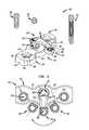
- FIG. 1is an exploded perspective cutaway view of a fixation system, including a plate, an extension plate and optional blind or fixation fasteners, in accordance with an embodiment
- FIG. 2is an assembled plan cutaway view of the plate and extension plate of FIG. 1 , the extension plate being shown in full in one possible location and shown partially in two other possible locations;
- FIG. 3is a plan view of a fixation system including the fixation system of FIG. 1 , in which two additional extension plates are attached to the plate as well as to a bone by fasteners; and
- FIG. 4is a cross-sectional view of the fixation system of FIG. 3 along lines 4 - 4 .
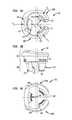
- FIGS. 5A-5Care bottom plan, elevation, and top plan views, respectively, of an attachment portion of the extension plate of FIG. 1 ;
- FIGS. 6A-6Care bottom plan, elevation, and top plan cutaway views, respectively, of the extension plate of FIG. 1 .
- fixation system 100may include a fixation device 110 and a set of fasteners 120 , 130 , 135 .
- Fixation device 110may include a main plate 140 , which may be but is not limited to being elongated, and an extension plate 150 .
- Main plate 140may include a plurality of inner walls 142 separated from each other and extending through a thickness of main plate 140 to define apertures through plate 140 .
- each inner wall 142may include an upper section 146 and a lower section 148 .
- Upper section 146may have a larger circumference than lower section 148 of inner wall 142 .
- upper section 146may be unthreaded and lower section 148 may be threaded.
- Inner wall 142may include a step 149 at a transition between upper section 146 and lower section 148 , in which step 149 may be a chamfer between upper and lower sections 146 , 148 .
- Main plate 140may include top and bottom surfaces 143 , 144 that may be spaced apart to define the thickness of main plate 140 .
- Side surfaces 145may extend between top and bottom surfaces 143 , 144 and may define one or more grooves or concave contours 147 .
- Main plate 140may be but is not limited to being made of titanium and its alloys, steel and its alloys including high strength steel, silver, and gold.
- a first attachment portion 152which may be but is not limited to being a plug segment, of extension plate 150 may be inserted within and attached to inner wall 142 of main plate 140 .
- Extension plate 150may include a second attachment portion 154 which may be attached to and thereby spaced a fixed distance from first attachment portion 152 by body 155 of extension plate 150 .
- Body 155may have a narrow profile relative to the first and second attachment portions 152 , 154 .
- First attachment portion 152may be rotatable about a longitudinal axis of inner wall 142 passing through main plate 140 such that second attachment portion 154 , which may be but is not limited to being a receiving segment, may be revolvable about the longitudinal axis of inner wall 142 .
- Extension plate 150may be but is not limited to being made of titanium and its alloys, steel and its alloys including high strength steel, silver, and gold.
- fastener 120may be inserted into second attachment portion 154 for attachment with another object, such as bone.
- fastener 120may be locking screws, although fastener 120 may also be compression screws or other types of fasteners.
- first attachment portion 152is inserted within and attached to inner wall 142 of main plate 140 , rotation of first attachment portion 152 may allow relative adjustment of second attachment portion 154 to a predetermined position along an arc.
- fixation device 110may be placed into various configurations such that fastener 130 may be placed in different predetermined positions based on the needs of a user of the fixation system 100 .
- First attachment portion 152 of extension plate 150may be attached to main plate 140 by insertion of one of optional fasteners 130 or 135 into an inner part 153 defining an aperture of first attachment portion 152 .
- fastener 130is a blind locking screw and fastener 135 is a locking screw longer than the blind locking screw that, when inserted into fixation device 110 , may extend beyond bottom surface 144 of main plate 140 . Insertion of either of fastener 130 and fastener 135 into inner part 153 may expand first attachment portion 152 such that first attachment portion 152 compresses into inner wall 142 of main plate 140 . In this manner, first attachment portion 152 may be fixed in position in inner wall 142 and may not be rotatable.
- second attachment portion 154 of extension plate 150may be revolved such that extension plate 150 contacts a side surface 145 of main plate 150 .
- second attachment portion 154may contact one location along side surface 145 when second attachment portion 154 is revolved in a first direction and may contact another location along side surface 145 when second attachment portion 154 is revolved in a second direction opposite the first direction. In this manner, an arc of revolution of extension plate 150 may be bound by side surface 145 .
- second attachment portion 154 of extension plate 150may have a convex contour such that a part of second attachment portion 154 fits within one or more of grooves 147 of side surface 145 of main plate 140 .
- a pair of grooves 147 along side surface 145 of main plate 140may be spaced apart such that part of second attachment portion 154 of extension plate 150 may fit within one of the pair of grooves 147 when second attachment portion 154 is revolved in a first direction and fit within the other of the pair of grooves 147 when second attachment portion 154 is revolved in a second direction opposite the first direction.
- fixation device 110may include a plurality of extension plates 150 .
- Fasteners 120which may be of various sizes, may be inserted into second attachment portions 154 of the plurality of extension plates 150 .
- second attachment portions 154may be adjacent to opposing side surfaces 145 of main plate 140 and may be revolved to a predetermined location about a longitudinal axis of respective inner walls 142 of main plate 140 , in the manner described previously herein with respect to FIGS. 1 and 2 .
- Respective second attachment portions 154 of the plurality of extension plates 150may include inner surfaces 156 defining apertures extending through a thickness of the second attachment portions 154 .
- fasteners 120When inserted into inner surfaces 156 , fasteners 120 , may extend into bone 90 to attach fixation device 110 to bone 90 and to lock second attachment portions 154 into position. As shown, second attachment portions 154 may be spaced a fixed distance from first attachment portions 152 of respective extension plates 150 such that fasteners 120 , when inserted in second attachment portions 154 may not intersect with a central region of bone 90 and moreover, may not intersect with a prosthesis 75 that may be inserted within bone 90 . As in the example shown, prosthesis 75 may be an intramedullary nail extending longitudinally through medullary canal 91 in a central region of bone 50 .
- second attachment portion 154 of first extension plate 150 of the plurality of extension plates 150may be revolved about the longitudinal axis of first inner wall 142 of the plurality of inner walls 142 by rotating first attachment portion 152 of first extension plate 150 in one direction while second attachment portion 154 of second extension plate 150 of the plurality of extension plates 150 may be revolved about the longitudinal axis of second inner wall 142 of the plurality of inner walls 142 by rotating first attachment portion 152 of second extension plate 150 in a second direction opposite the first direction.
- longitudinal axes of inner surfaces 156 of second attachment portions 154may lie in parallel planes, and in some instances (not shown), the longitudinal axes of inner surfaces 156 of adjacent second attachment portions 154 may be parallel. Having the longitudinal axes of inner surface 156 of attachment portions 154 and inner walls 142 in the same plane, as in the example shown, through the use of extension plate 150 which may be visible to a surgeon, may provide a visual guideline for the surgeon during insertion of fasteners 120 , 130 , 135 .
- first attachment portion 152includes an upper portion 157 , a lower portion 158 extending from the upper portion 157 , and an intermediate portion 159 at a transition between upper and lower portions 157 , 158 .
- First attachment portion 152may be in the form of two arms 160 A, 160 B each including parts of upper portion 157 , lower portion 158 , and intermediate portion 159 in which a gap is defined between arms 160 A, 160 B.
- Arms 160 A, 160 Bmay be symmetrical and may be cantilevered within a plane transverse to a longitudinal axis of inner part 153 of first attachment portion 152 .
- each of arms 160 A, 160 Bmay have a thin lateral profile to enhance their flexibility and reduce energy losses during deformation of either or both of arms 160 A, 160 B and internal threads 165 upon insertion of a fastener.
- upper portion 157may define a larger perimeter along its entire length than lower portion 158 .
- Upper and lower portions 157 , 158 of first attachment portion 152may have generally cylindrical or conical shapes.
- Upper portion 157may include a plurality of, and in example shown three, sets of teeth 161 circumferentially spaced about its external circumference.
- Upper portion 157may include an internal thread 165 , which may be conical, on internal bosses 163 of upper portion 157 .
- internal thread 165may be split into three parts.
- internal thread 165may include a sharp edge 166 at a beginning of thread 165 and may include a rounded edge 167 at an end of thread 165 .
- Lower portion 158may include three circumferentially spaced apart legs 171 , 172 , 173 .
- Legs 172 , 173may be on arms 160 A, 160 B, respectively, and may be symmetrical.
- Leg 171may be nearest to body 155 of extension plate 150 of the three legs 171 - 173 .
- Leg 171may include middle lip 175 protruding outwardly along a bottom edge of leg 171
- legs 172 , 173may include outer lips 176 , 177 , respectively, protruding outwardly along their bottom edges.
- outer lips 176 , 177may be rounded.
- teeth 161may define an outer circumference of upper portion 157 of first attachment portion 152 of extension plate 150 that is substantially similar to the circumference of upper section 146 of inner wall 142 of main plate 140 .
- upper portion 157 of first attachment portion 152may be slightly compressed against upper section 146 of inner wall 142 of main plate 140 .
- Each of legs 171 - 173 of lower portion 158 of extension plate 150may be flexible such that legs 171 - 173 deflect upon their insertion into lower section 148 of inner wall 142 of main plate 140 .
- first attachment portion 152 of extension plate 150may be held within inner wall 142 of main plate 140 with sufficient force such that extension plate 150 may be manipulated by a user, including by rotation about the longitudinal axis of inner wall 142 , without backing out of inner wall 142 .
- a longitudinal axis of upper portion 157may be parallel to and offset from a longitudinal axis of lower portion 158 of first attachment portion 152 within a plane passing through first and second attachment portions 152 , 154 of extension plate 150 .
- a fastenersuch as fasteners 130 or 135
- the forces acting on upper portion 157may be greater than forces acting on lower portion 158 of first attachment portion 152 .
- second attachment portion 154 of extension plate 150may include upper part 181 that may be unthreaded, lower part 182 that may be threaded, and middle part 183 that may be chamfered. In this manner, second attachment portion 154 may receive a fastener, such as fastener 120 , which may be a locking screw as described previously herein.
- a fastenersuch as fastener 120
- the longitudinal axis of inner surface 156 of second attachment portion 154may be in the same plane as the longitudinal axis of inner part 153 of first attachment portion 152 .
- the longitudinal axes of inner surface 156 and inner part 153may intersect.
- main plate 140may be fastened to a bone by fasteners, which may be but are not limited to being locking screws as shown, compression screws, or other appropriate fixation members.
- fastenerswhich may be but are not limited to being locking screws as shown, compression screws, or other appropriate fixation members.
- first attachment portion 152 of extension plate 150may be pressed, such as by snapping, into an aperture defined by one of the plurality of inner walls 142 of main plate 140 .
- First attachment portion 152may be rotated about the longitudinal axis of inner wall 142 of main plate 140 such that second attachment portion 154 is revolved along an arc about the longitudinal axis of inner wall 142 .
- Fastener 130 or 135then may be inserted, and as shown threaded, into inner part 153 of first attachment portion 152 to lock relative rotation and translation between extension plate 150 and main plate 140 .
- Fastener 120then may be inserted, and as shown threaded, into inner surface 156 of second attachment portion 154 to attach second attachment portion 154 to another object, such as bone as shown in FIGS. 3 and 4 .
- the order of insertion of fastener 130 and fastener 120may be reversed in some arrangements.
- the main platemay be a bone plate for attachment to either of or both a diaphysis and epiphysis of a trabecular bone, such as a femur, tibia, humerus, or radius.
- the inner walls of the main platemay be placed in various locations and may include at least one series of three or more inner walls that may or may not be aligned along an axis through centers of the inner walls.
- fasteners 130 , 135may be rivets which may be used to attach the first attachment portion of the extension plate to the main plate.
- an extension platesuch as extension plate 150
- each of the additional attachment portionsmay have an inner surface for receiving a fastener that may attach the respective additional attachment portions to another object or objects, such as but not limited to one or more bones.
- the fixation devicemay include a second extension plate that may be attached to a first extension plate, extending from a main plate, such as main plate 140 .
- the first extension platemay include a first attachment portion similar to the first attachment portion of extension plate 150 , as described previously herein, and a second attachment portion that may include an inner surface similar to the inner walls of main plate 140 , as described previously herein.
- second extension platemay have first and second attachment portions similar to extension plate 150 , as described previously herein.
- first attachment portion of the second extension platemay be rotatable about a longitudinal axis of the inner surface of the second attachment portion of the first extension plate such that the second attachment portion of the second extension plate may be revolvable about the longitudinal axis of the inner surface of the second attachment portion of the first extension plate.
Landscapes
- Health & Medical Sciences (AREA)
- Orthopedic Medicine & Surgery (AREA)
- Surgery (AREA)
- Life Sciences & Earth Sciences (AREA)
- Heart & Thoracic Surgery (AREA)
- Nuclear Medicine, Radiotherapy & Molecular Imaging (AREA)
- Engineering & Computer Science (AREA)
- Biomedical Technology (AREA)
- Neurology (AREA)
- Medical Informatics (AREA)
- Molecular Biology (AREA)
- Animal Behavior & Ethology (AREA)
- General Health & Medical Sciences (AREA)
- Public Health (AREA)
- Veterinary Medicine (AREA)
- Surgical Instruments (AREA)
Abstract
Description
Claims (28)
Priority Applications (4)
| Application Number | Priority Date | Filing Date | Title |
|---|---|---|---|
| US14/506,078US10213237B2 (en) | 2014-10-03 | 2014-10-03 | Periprosthetic extension plate |
| AU2015234347AAU2015234347B2 (en) | 2014-10-03 | 2015-10-01 | Periprosthetic extension plate |
| EP15002833.0AEP3001966B1 (en) | 2014-10-03 | 2015-10-02 | Periprosthetic extension plate |
| JP2015196425AJP6651322B2 (en) | 2014-10-03 | 2015-10-02 | Artificial joint extension plate |
Applications Claiming Priority (1)
| Application Number | Priority Date | Filing Date | Title |
|---|---|---|---|
| US14/506,078US10213237B2 (en) | 2014-10-03 | 2014-10-03 | Periprosthetic extension plate |
Publications (2)
| Publication Number | Publication Date |
|---|---|
| US20160095636A1 US20160095636A1 (en) | 2016-04-07 |
| US10213237B2true US10213237B2 (en) | 2019-02-26 |
Family
ID=54260605
Family Applications (1)
| Application Number | Title | Priority Date | Filing Date |
|---|---|---|---|
| US14/506,078Active2037-11-16US10213237B2 (en) | 2014-10-03 | 2014-10-03 | Periprosthetic extension plate |
Country Status (4)
| Country | Link |
|---|---|
| US (1) | US10213237B2 (en) |
| EP (1) | EP3001966B1 (en) |
| JP (1) | JP6651322B2 (en) |
| AU (1) | AU2015234347B2 (en) |
Cited By (3)
| Publication number | Priority date | Publication date | Assignee | Title |
|---|---|---|---|---|
| US11179181B2 (en) | 2018-06-15 | 2021-11-23 | Stryker European Operations Holdings Llc | Trochanter plates |
| US11452554B2 (en)* | 2014-07-16 | 2022-09-27 | The Regents Of The University Of Colorado | System and method for fastening of two or more interacting elements |
| US20230380876A1 (en)* | 2016-11-14 | 2023-11-30 | Biedermann Technologies Gmbh & Co. Kg | Modular bone plate and member of such a modular bone plate |
Families Citing this family (8)
| Publication number | Priority date | Publication date | Assignee | Title |
|---|---|---|---|---|
| US12201332B2 (en)* | 2013-12-09 | 2025-01-21 | Acumed Llc | Bone plate with movable joint |
| US9615931B2 (en)* | 2015-03-20 | 2017-04-11 | Globus Medical, Inc. | Surgical plate systems |
| US10136931B1 (en)* | 2015-12-21 | 2018-11-27 | Edward Diao | Bone fixation device and method |
| US10251685B2 (en)* | 2016-03-17 | 2019-04-09 | Stryker European Holdings I, Llc | Floating locking insert |
| US10206724B2 (en)* | 2017-04-28 | 2019-02-19 | Seth K. WILLIAMS | Intramedullary rod plate system |
| US11202664B2 (en)* | 2018-12-17 | 2021-12-21 | Nextremity Solutions, Inc. | Compression force magnifier |
| EP4342398A3 (en) | 2020-05-19 | 2024-05-29 | Smith & Nephew, Inc. | Periprosthetic bone plate |
| US11628002B2 (en) | 2020-08-25 | 2023-04-18 | DePuy Synthes Products, Inc. | Bone plating system clamp sizing instrument and installation instrument |
Citations (113)
| Publication number | Priority date | Publication date | Assignee | Title |
|---|---|---|---|---|
| WO1982001645A1 (en) | 1980-11-14 | 1982-05-27 | Rahmanzadeh Rahim | Device for holding the parts of the joint of a human shoulder |
| US4388921A (en) | 1980-05-28 | 1983-06-21 | Institut Straumann Ag | Device comprising a plate and screws for fastening a plate to a bone |
| SU1130332A1 (en) | 1983-01-26 | 1984-12-23 | Киевский Медицинский Институт Им.Акад.А.А.Богомольца | Apparatus for compression osteosynthesis |
| SU1223901A1 (en) | 1983-10-19 | 1986-04-15 | Новокузнецкий Государственный Ордена Трудового Красного Знамени Институт Усовершенствования Врачей | Apparatus for osteosynthesis |
| US4973332A (en) | 1988-09-12 | 1990-11-27 | Hospital For Joint Diseases | Attachment for femur sliding screw plate |
| SU1634260A1 (en) | 1987-06-19 | 1991-03-15 | Московский медицинский стоматологический институт им.Н.А.Семашко | Appliance for osteosynthesis of the intertrochanteric space |
| US5015248A (en) | 1990-06-11 | 1991-05-14 | New York Society For The Relief Of The Ruptured & Crippled, Maintaining The Hospital For Special Surgery | Bone fracture fixation device |
| US5053036A (en) | 1987-11-03 | 1991-10-01 | Synthes (U.S.A.) | Point contact bone compression plate |
| US5066296A (en) | 1989-02-02 | 1991-11-19 | Pfizer Hopsital Products Group, Inc. | Apparatus for treating a fracture |
| FR2674118A1 (en) | 1991-03-19 | 1992-09-25 | Benoit Girard Cie Sa | Device for spinal osteosynthesis |
| US5151103A (en) | 1987-11-03 | 1992-09-29 | Synthes (U.S.A.) | Point contact bone compression plate |
| WO1994007040A1 (en) | 1992-09-18 | 1994-03-31 | Kuehl Hans | Device for joining at least two elements |
| US5486176A (en) | 1991-03-27 | 1996-01-23 | Smith & Nephew Richards, Inc. | Angled bone fixation apparatus |
| US5531745A (en) | 1993-03-11 | 1996-07-02 | Danek Medical, Inc. | System for stabilizing the spine and reducing spondylolisthesis |
| US5531554A (en) | 1993-11-05 | 1996-07-02 | Jbs S.A. | Self-retaining means for fasteners particularly screws |
| FR2739151A1 (en) | 1995-09-22 | 1997-03-28 | Numedic | Fixing screw for bone implants |
| FR2744011A1 (en) | 1996-01-25 | 1997-08-01 | Richard Rossin | Spinal osteosynthesis device |
| US5681313A (en) | 1995-02-06 | 1997-10-28 | Karl Leibinger Medizintechnik Gmbh & Co. Kg | Device for the extension of bones |
| WO1999009903A1 (en) | 1997-08-27 | 1999-03-04 | Synthes Ag Chur | Locking ring with bayonet for plate osteosynthesis |
| US5951558A (en) | 1998-04-22 | 1999-09-14 | Fiz; Daniel | Bone fixation device |
| US5954722A (en) | 1997-07-29 | 1999-09-21 | Depuy Acromed, Inc. | Polyaxial locking plate |
| US5976141A (en) | 1995-02-23 | 1999-11-02 | Synthes (U.S.A.) | Threaded insert for bone plate screw hole |
| US6017345A (en) | 1997-05-09 | 2000-01-25 | Spinal Innovations, L.L.C. | Spinal fixation plate |
| FR2790198A1 (en) | 1999-02-26 | 2000-09-01 | Numedic | Osteosynthesis plate anchor for bone has sleeve fitting around screw thread to adjustably fit in opening in plate |
| US6129728A (en) | 1998-02-18 | 2000-10-10 | Walter Lorenz Surgical, Inc. | Method and apparatus for mandibular osteosynthesis |
| FR2792185A1 (en) | 1999-04-19 | 2000-10-20 | Numedic | Bone fixation plate fixing screw has rounded head on screw and rounded recess in bone fixing plate to accommodate angular fixing of screw |
| US6193721B1 (en) | 1997-02-11 | 2001-02-27 | Gary K. Michelson | Multi-lock anterior cervical plating system |
| USD440311S1 (en) | 1997-02-11 | 2001-04-10 | Gary K. Michelson | Anterior cervical plate |
| US6221073B1 (en) | 1999-08-20 | 2001-04-24 | Kinetikos Medical, Inc. | Wrist fusion apparatus and method |
| US6235003B1 (en) | 1999-10-12 | 2001-05-22 | Edward D. Dysarz | Inclined plane latching device for a spring needle cannula and a spring needle |
| US6235033B1 (en) | 2000-04-19 | 2001-05-22 | Synthes (Usa) | Bone fixation assembly |
| US6258089B1 (en) | 1998-05-19 | 2001-07-10 | Alphatec Manufacturing, Inc. | Anterior cervical plate and fixation system |
| DE10039767A1 (en) | 2000-01-20 | 2001-07-26 | Impag Gmbh Medizintechnik | Fastening system for mounting shelf on support comprises sleeve around head of screw, outer surfaces of sleeve and bore in component being shaped like part of surface of and screw being inserted at angle and then tipped to compress sleeve |
| US6331179B1 (en) | 2000-01-06 | 2001-12-18 | Spinal Concepts, Inc. | System and method for stabilizing the human spine with a bone plate |
| US20020058939A1 (en) | 1997-08-04 | 2002-05-16 | Spinal Concepts, Inc. | System and method for stabilizing the human spine with a bone plate |
| US6503250B2 (en) | 2000-11-28 | 2003-01-07 | Kamaljit S. Paul | Bone support assembly |
| US6520965B2 (en) | 2001-05-23 | 2003-02-18 | Alan Chervitz | Apparatus and method for orthopedic fixation |
| US6533786B1 (en) | 1999-10-13 | 2003-03-18 | Sdgi Holdings, Inc. | Anterior cervical plating system |
| US6533789B1 (en) | 2000-04-04 | 2003-03-18 | Synthes (Usa) | Device for rotational stabilization of bone segments |
| US6572622B1 (en) | 1999-10-18 | 2003-06-03 | Bernd Schäfer | Bone plate |
| US6602256B1 (en) | 1999-10-11 | 2003-08-05 | Cross Medical Products, Inc. | Bone stabilization plate with a secured-locking mechanism for cervical fixation |
| US20030187440A1 (en) | 2002-03-12 | 2003-10-02 | Marc Richelsoph | Bone plate and screw retaining mechanism |
| US6645209B2 (en) | 2000-04-04 | 2003-11-11 | Synthes (Usa) | Device for rotational stabilization of bone segments |
| US6652530B2 (en) | 2001-09-19 | 2003-11-25 | The University Of Hong Kong | Fixation device |
| US6652525B1 (en) | 1998-04-30 | 2003-11-25 | Sofamor S.N.C. | Anterior implant for the spine |
| US6663632B1 (en) | 1998-05-19 | 2003-12-16 | Synthes (U.S.A.) | Osteosynthetic implant with an embedded hinge joint |
| US6669700B1 (en) | 1997-05-15 | 2003-12-30 | Sdgi Holdings, Inc. | Anterior cervical plating system |
| US6679883B2 (en) | 2001-10-31 | 2004-01-20 | Ortho Development Corporation | Cervical plate for stabilizing the human spine |
| US20040030339A1 (en) | 2001-04-20 | 2004-02-12 | Wack Michael A. | Dual locking plate and associated method |
| FR2844702A1 (en) | 2002-09-24 | 2004-03-26 | Numedic | Device for fixing synthetic bone plate on bone comprises threaded rod passing through non-circular hole housing plate collar to be screwed into bone, constricted collar having non-circular external profile engaging hole |
| US6730091B1 (en) | 1999-05-03 | 2004-05-04 | Medartis Ag | Blockable bone plate |
| US20040102776A1 (en) | 2002-11-19 | 2004-05-27 | Huebner Randall J. | Bone plates with reference marks |
| US6755831B2 (en) | 2001-11-30 | 2004-06-29 | Regents Of The University Of Minnesota | Wrist surgery devices and techniques |
| US20040127896A1 (en) | 2002-10-28 | 2004-07-01 | Alan Lombardo | Bone plate assembly provided with screw locking mechanisms |
| US20050015131A1 (en) | 2003-06-16 | 2005-01-20 | Fourcault Eric Stephane | Device destined to be coupled to at least one support, and in particular a surgical implant destined to be coupled to a bone |
| US20050027296A1 (en) | 2002-06-24 | 2005-02-03 | Jeffrey Thramann | Cervical plate with backout protection |
| US20050043736A1 (en) | 2001-12-24 | 2005-02-24 | Claude Mathieu | Device for osteosynthesis |
| US20050049594A1 (en) | 2001-04-20 | 2005-03-03 | Wack Michael A. | Dual locking plate and associated method |
| US20050049595A1 (en) | 2003-09-03 | 2005-03-03 | Suh Sean S. | Track-plate carriage system |
| US6890335B2 (en) | 2001-08-24 | 2005-05-10 | Zimmer Spine, Inc. | Bone fixation device |
| US6929646B2 (en) | 2001-04-04 | 2005-08-16 | Integra Signature Technologies, Inc. | Implantable bone fracture reduction apparatus having a polymeric applicator |
| US20050240187A1 (en)* | 2004-04-22 | 2005-10-27 | Huebner Randall J | Expanded fixation of bones |
| US6984234B2 (en) | 2003-04-21 | 2006-01-10 | Rsb Spine Llc | Bone plate stabilization system and method for its use |
| US7001388B2 (en) | 2004-01-23 | 2006-02-21 | Hand Innovations, Llc | System for stabilization of fractures of convex articular bone surfaces including subchondral support structure |
| US20070043366A1 (en) | 2003-04-03 | 2007-02-22 | Medartis Ag | Housing for a locking element and locking element |
| US7195633B2 (en) | 2004-01-08 | 2007-03-27 | Robert J. Medoff | Fracture fixation system |
| US7229443B2 (en) | 1998-07-20 | 2007-06-12 | Biedermann Motech Gmbh | Fastening assembly with improved handling properties |
| US7303564B2 (en) | 2002-02-01 | 2007-12-04 | Spinal Concepts, Inc. | Spinal plate extender system and method |
| US20080103501A1 (en) | 2006-08-11 | 2008-05-01 | Ralph Christopher R | Angled Washer Polyaxial Connection for Dynamic Spine Prosthesis |
| US20080306550A1 (en) | 2007-06-07 | 2008-12-11 | Matityahu Amir M | Spine repair assembly |
| US20090076554A1 (en) | 2007-07-19 | 2009-03-19 | Acumed Llc | Insertion tool for bone plates |
| US20090192549A1 (en) | 2008-01-30 | 2009-07-30 | Ebi, Llc | Bone plating system |
| US20090248087A1 (en) | 2008-03-03 | 2009-10-01 | Orthohelix Surgical Designs, Inc. | Variable axis locking mechanism for use in orthopedic implants |
| US20090275987A1 (en) | 2008-05-02 | 2009-11-05 | Thomas James Graham | Bone plate extender and extension system for bone restoration and methods of use thereof |
| US20100179552A1 (en)* | 2006-12-22 | 2010-07-15 | Dietmar Wolter | Repositioning and fixation system for bone fragments |
| US7758620B2 (en) | 2002-09-24 | 2010-07-20 | Stryker Trauma Sa | Device for connecting a screw to a support plate |
| US7771458B2 (en) | 2001-10-23 | 2010-08-10 | Biedermann Motech Gmbh | Bone fixing device |
| US7780710B2 (en) | 2004-01-23 | 2010-08-24 | Depuy Products, Inc. | System for stabilization of fractures of convex articular bone surfaces including subchondral support structure |
| US20100262194A1 (en) | 2007-11-13 | 2010-10-14 | Synthes Gmbh | Periprosthetic Fracture Repair |
| US7833254B2 (en) | 2005-03-11 | 2010-11-16 | Orthofix International B.V. | Device for the ostheosynthesis of proximal humerus fractures |
| US7942913B2 (en) | 2004-04-08 | 2011-05-17 | Ebi, Llc | Bone fixation device |
| US8147530B2 (en) | 2006-03-07 | 2012-04-03 | Orthohelix Surgical Designs, Inc. | Variable axis locking mechanism for use in orthopedic implants |
| US8172885B2 (en) | 2003-02-05 | 2012-05-08 | Pioneer Surgical Technology, Inc. | Bone plate system |
| US8221421B2 (en) | 2001-02-23 | 2012-07-17 | Synthes Usa, Llc | Sternum fixation device |
| US20120226321A1 (en) | 2011-03-03 | 2012-09-06 | Eduardo Gonzalez-Hernandez | Modular and non-modular cortical buttress device |
| US8287575B2 (en) | 2006-11-09 | 2012-10-16 | Stryker Trauma Gmbh | Polyaxial locking mechanism |
| US20130041375A1 (en) | 2011-03-04 | 2013-02-14 | Johann Fierlbeck | Modular Hook Plate Assembly |
| US20130060251A1 (en) | 2011-08-31 | 2013-03-07 | University Of Maryland, Baltimore | Proximal humerus greater tuberosity hook-arm clip |
| US8398636B2 (en) | 2007-04-19 | 2013-03-19 | Stryker Trauma Gmbh | Hip fracture device with barrel and end cap for load control |
| US8444680B2 (en) | 2009-11-09 | 2013-05-21 | Arthrex, Inc. | Polyaxial bushing for locking plate |
| US8486116B2 (en) | 2010-01-08 | 2013-07-16 | Biomet Manufacturing Ring Corporation | Variable angle locking screw |
| US20130211461A1 (en) | 2012-02-13 | 2013-08-15 | Stryker Trauma Sa | Attachment device for a bone plate |
| US8518042B2 (en) | 2010-10-19 | 2013-08-27 | Biomet Manufacturing, Llc | Orthopedic plate assembly for a distal radius having re-contouring features and method for using same |
| US8579898B2 (en) | 2010-03-08 | 2013-11-12 | Memometal Technologies | Adjustable-angle radius plate |
| US8668723B2 (en) | 2011-07-19 | 2014-03-11 | Neurostructures, Inc. | Anterior cervical plate |
| US8728129B2 (en) | 2011-01-07 | 2014-05-20 | Biomet Manufacturing, Llc | Variable angled locking screw |
| US8734494B2 (en) | 2007-04-19 | 2014-05-27 | Stryker Trauma Gmbh | Hip fracture device with static locking mechanism allowing compression |
| US8784458B1 (en)* | 2008-10-10 | 2014-07-22 | Greatbatch Medical S.A. | Polyaxial insert for surgical screws |
| US20140243907A1 (en) | 2013-02-27 | 2014-08-28 | Biomet C.V. | Periprosthetic Fracture Repair System Including Discrete Stabilized Crimp Lugs for Cerclage Cable and Tool Therefor |
| US8906070B2 (en) | 2005-10-25 | 2014-12-09 | Robert J. Medoff | Bone fixation device and method |
| US20140367268A1 (en) | 2011-12-07 | 2014-12-18 | C/O Showa Denko K.K. | Jig for manufacturing capacitor element and method for manufacturing capacitor element |
| US8961573B2 (en) | 2010-10-05 | 2015-02-24 | Toby Orthopaedics, Inc. | System and method for facilitating repair and reattachment of comminuted bone portions |
| US8998904B2 (en) | 2012-07-17 | 2015-04-07 | Fastforward Surgical Inc. | Winged tether plate and method of use for reducing angular bone deformity |
| US9084636B2 (en) | 2011-01-10 | 2015-07-21 | Spine Craft, LLC | Surgical plate system and method |
| USD735861S1 (en) | 2014-03-10 | 2015-08-04 | Embark Enterprises Inc. | Quadruped stifle stabilization assembly |
| US9131968B2 (en) | 2013-02-27 | 2015-09-15 | Biomet C.V. | Periprosthetic plating system including plate with system for retaining tension on a cable |
| US9138267B2 (en) | 2013-02-27 | 2015-09-22 | Biomet C.V. | Periprosthetic plating system with compressive plate and transverse bridge plate |
| US9138244B2 (en) | 2013-02-27 | 2015-09-22 | Biomet C.V. | Dynamic compression plate |
| US20150305877A1 (en) | 2014-01-03 | 2015-10-29 | Tornier, Inc. | Reverse shoulder systems and methods |
| US9254154B2 (en) | 2011-03-03 | 2016-02-09 | Toby Orthopaedic, Inc. | Anterior lesser tuberosity fixed angle fixation device and method of use associated therewith |
| US20160038199A1 (en)* | 2014-08-08 | 2016-02-11 | Stryker European Holdings I, Llc | Cable plugs for bone plates |
| US9333014B2 (en) | 2013-03-15 | 2016-05-10 | Eduardo Gonzalez-Hernandez | Bone fixation and reduction apparatus and method for fixation and reduction of a distal bone fracture and malunion |
| US9522066B2 (en) | 2011-02-16 | 2016-12-20 | Genesis Medical Devices Llc | Periprosthetic fracture management enhancements |
Family Cites Families (2)
| Publication number | Priority date | Publication date | Assignee | Title |
|---|---|---|---|---|
| JP4321132B2 (en)* | 2003-06-20 | 2009-08-26 | セイコーエプソン株式会社 | Battery remaining amount detection device and detection method |
| EP2323573B1 (en)* | 2008-09-18 | 2012-01-18 | Synthes GmbH | Anterior transpedicular screw-and-plate system |
- 2014
- 2014-10-03USUS14/506,078patent/US10213237B2/enactiveActive
- 2015
- 2015-10-01AUAU2015234347Apatent/AU2015234347B2/enactiveActive
- 2015-10-02JPJP2015196425Apatent/JP6651322B2/enactiveActive
- 2015-10-02EPEP15002833.0Apatent/EP3001966B1/enactiveActive
Patent Citations (173)
| Publication number | Priority date | Publication date | Assignee | Title |
|---|---|---|---|---|
| US4388921A (en) | 1980-05-28 | 1983-06-21 | Institut Straumann Ag | Device comprising a plate and screws for fastening a plate to a bone |
| WO1982001645A1 (en) | 1980-11-14 | 1982-05-27 | Rahmanzadeh Rahim | Device for holding the parts of the joint of a human shoulder |
| SU1130332A1 (en) | 1983-01-26 | 1984-12-23 | Киевский Медицинский Институт Им.Акад.А.А.Богомольца | Apparatus for compression osteosynthesis |
| SU1223901A1 (en) | 1983-10-19 | 1986-04-15 | Новокузнецкий Государственный Ордена Трудового Красного Знамени Институт Усовершенствования Врачей | Apparatus for osteosynthesis |
| SU1634260A1 (en) | 1987-06-19 | 1991-03-15 | Московский медицинский стоматологический институт им.Н.А.Семашко | Appliance for osteosynthesis of the intertrochanteric space |
| US5151103A (en) | 1987-11-03 | 1992-09-29 | Synthes (U.S.A.) | Point contact bone compression plate |
| US5053036A (en) | 1987-11-03 | 1991-10-01 | Synthes (U.S.A.) | Point contact bone compression plate |
| US4973332A (en) | 1988-09-12 | 1990-11-27 | Hospital For Joint Diseases | Attachment for femur sliding screw plate |
| US5066296A (en) | 1989-02-02 | 1991-11-19 | Pfizer Hopsital Products Group, Inc. | Apparatus for treating a fracture |
| US5015248A (en) | 1990-06-11 | 1991-05-14 | New York Society For The Relief Of The Ruptured & Crippled, Maintaining The Hospital For Special Surgery | Bone fracture fixation device |
| FR2674118A1 (en) | 1991-03-19 | 1992-09-25 | Benoit Girard Cie Sa | Device for spinal osteosynthesis |
| US5486176A (en) | 1991-03-27 | 1996-01-23 | Smith & Nephew Richards, Inc. | Angled bone fixation apparatus |
| WO1994007040A1 (en) | 1992-09-18 | 1994-03-31 | Kuehl Hans | Device for joining at least two elements |
| US5531745A (en) | 1993-03-11 | 1996-07-02 | Danek Medical, Inc. | System for stabilizing the spine and reducing spondylolisthesis |
| US5531554A (en) | 1993-11-05 | 1996-07-02 | Jbs S.A. | Self-retaining means for fasteners particularly screws |
| US5681313A (en) | 1995-02-06 | 1997-10-28 | Karl Leibinger Medizintechnik Gmbh & Co. Kg | Device for the extension of bones |
| US5976141A (en) | 1995-02-23 | 1999-11-02 | Synthes (U.S.A.) | Threaded insert for bone plate screw hole |
| FR2739151A1 (en) | 1995-09-22 | 1997-03-28 | Numedic | Fixing screw for bone implants |
| FR2744011A1 (en) | 1996-01-25 | 1997-08-01 | Richard Rossin | Spinal osteosynthesis device |
| US7074221B2 (en) | 1997-02-11 | 2006-07-11 | Sdgi Holdings, Inc. | Anterior cervical plate system |
| US6527776B1 (en) | 1997-02-11 | 2003-03-04 | Gary K. Michelson | Locking element for locking at least two bone screws to an orthopedic device |
| US6616666B1 (en) | 1997-02-11 | 2003-09-09 | Gary K. Michelson | Apparatus for compressing a spinal disc space disposed between two adjacent vertebral bodies of a cervical spine |
| US6592586B1 (en) | 1997-02-11 | 2003-07-15 | Gary K. Michelson | Single-lock anterior cervical plating system |
| US6712818B1 (en) | 1997-02-11 | 2004-03-30 | Gary K. Michelson | Method for connecting adjacent vertebral bodies of a human spine with a plating system |
| US6969390B2 (en) | 1997-02-11 | 2005-11-29 | Michelson Gary K | Anterior cervical plating system and bone screw |
| US6916320B2 (en) | 1997-02-11 | 2005-07-12 | Gary K. Michelson | Anterior cervical plate system |
| US6193721B1 (en) | 1997-02-11 | 2001-02-27 | Gary K. Michelson | Multi-lock anterior cervical plating system |
| USD440311S1 (en) | 1997-02-11 | 2001-04-10 | Gary K. Michelson | Anterior cervical plate |
| US6926718B1 (en) | 1997-02-11 | 2005-08-09 | Gary K. Michelson | Multilock anterior cervical plating system |
| US20050187552A1 (en) | 1997-02-11 | 2005-08-25 | Michelson Gary K. | Multilock anterior cervical plating system |
| US7137984B2 (en) | 1997-02-11 | 2006-11-21 | Warsaw Orthopedic, Inc. | Single-lock anterior cervical plate and method |
| US6936050B2 (en) | 1997-02-11 | 2005-08-30 | Gary K. Michelson | Multilock anterior cervical plating system |
| US7704255B2 (en) | 1997-02-11 | 2010-04-27 | Warsaw Orthopedic, Inc. | Threadless multi-lock anterior cervical plating system |
| US6620163B1 (en) | 1997-02-11 | 2003-09-16 | Gary K. Michelson | Anterior cervical plating system and bone screw |
| US20130204300A1 (en) | 1997-02-11 | 2013-08-08 | Warsaw Orthopedic, Inc. | Single-lock anterior cervical plate |
| US7625381B2 (en) | 1997-02-11 | 2009-12-01 | Warsaw Orthopedic, Inc. | System and method for stabilizing a portion of the spine |
| US6936051B2 (en) | 1997-02-11 | 2005-08-30 | Gary K. Michelson | Multilock anterior cervical plating system |
| US6398783B1 (en) | 1997-02-11 | 2002-06-04 | Sulzer Spine-Tech Inc. | Multi-lock anterior cervical plate |
| US6416528B1 (en) | 1997-02-11 | 2002-07-09 | Gary K. Michelson | Anterior cervical plating system, instrumentation, and method of installation |
| US6428542B1 (en) | 1997-02-11 | 2002-08-06 | Gary K. Michelson | Single-lock anterior cervical plate |
| US6454771B1 (en) | 1997-02-11 | 2002-09-24 | Gary K. Michelson | Anterior cervical plating system |
| US6273889B1 (en) | 1997-05-09 | 2001-08-14 | Spinal Innovations, Llc | Method of fixing a spine with a fixation plate |
| US6017345A (en) | 1997-05-09 | 2000-01-25 | Spinal Innovations, L.L.C. | Spinal fixation plate |
| US6669700B1 (en) | 1997-05-15 | 2003-12-30 | Sdgi Holdings, Inc. | Anterior cervical plating system |
| US5954722A (en) | 1997-07-29 | 1999-09-21 | Depuy Acromed, Inc. | Polyaxial locking plate |
| US6454769B2 (en) | 1997-08-04 | 2002-09-24 | Spinal Concepts, Inc. | System and method for stabilizing the human spine with a bone plate |
| US20020058939A1 (en) | 1997-08-04 | 2002-05-16 | Spinal Concepts, Inc. | System and method for stabilizing the human spine with a bone plate |
| WO1999009903A1 (en) | 1997-08-27 | 1999-03-04 | Synthes Ag Chur | Locking ring with bayonet for plate osteosynthesis |
| USD449692S1 (en) | 1998-02-11 | 2001-10-23 | Gary K. Michelson | Anterior cervical plate |
| US6129728A (en) | 1998-02-18 | 2000-10-10 | Walter Lorenz Surgical, Inc. | Method and apparatus for mandibular osteosynthesis |
| US5951558A (en) | 1998-04-22 | 1999-09-14 | Fiz; Daniel | Bone fixation device |
| US6652525B1 (en) | 1998-04-30 | 2003-11-25 | Sofamor S.N.C. | Anterior implant for the spine |
| US6626907B2 (en) | 1998-05-19 | 2003-09-30 | Alphatec Manufacturing, Inc. | Anterior cervical plate and fixation system |
| US6258089B1 (en) | 1998-05-19 | 2001-07-10 | Alphatec Manufacturing, Inc. | Anterior cervical plate and fixation system |
| US6663632B1 (en) | 1998-05-19 | 2003-12-16 | Synthes (U.S.A.) | Osteosynthetic implant with an embedded hinge joint |
| US7887569B2 (en) | 1998-05-19 | 2011-02-15 | Synthes Usa, Llc | Osteosynthetic implant with an embedded hinge joint |
| US20110112584A1 (en) | 1998-05-19 | 2011-05-12 | Robert Frigg | Osteosynthetic Implant With An Embedded Hinge Joint |
| US20160310181A1 (en) | 1998-05-19 | 2016-10-27 | DePuy Synthes Products, Inc. | Osteosynthetic Implant With An Embedded Hinge Joint |
| US7229443B2 (en) | 1998-07-20 | 2007-06-12 | Biedermann Motech Gmbh | Fastening assembly with improved handling properties |
| US8388665B2 (en) | 1998-07-20 | 2013-03-05 | Biedermann Technologies Gmbh & Co. Kg | Fastening assembly |
| FR2790198A1 (en) | 1999-02-26 | 2000-09-01 | Numedic | Osteosynthesis plate anchor for bone has sleeve fitting around screw thread to adjustably fit in opening in plate |
| FR2792185A1 (en) | 1999-04-19 | 2000-10-20 | Numedic | Bone fixation plate fixing screw has rounded head on screw and rounded recess in bone fixing plate to accommodate angular fixing of screw |
| US6730091B1 (en) | 1999-05-03 | 2004-05-04 | Medartis Ag | Blockable bone plate |
| US6221073B1 (en) | 1999-08-20 | 2001-04-24 | Kinetikos Medical, Inc. | Wrist fusion apparatus and method |
| US6602256B1 (en) | 1999-10-11 | 2003-08-05 | Cross Medical Products, Inc. | Bone stabilization plate with a secured-locking mechanism for cervical fixation |
| US6235003B1 (en) | 1999-10-12 | 2001-05-22 | Edward D. Dysarz | Inclined plane latching device for a spring needle cannula and a spring needle |
| US6533786B1 (en) | 1999-10-13 | 2003-03-18 | Sdgi Holdings, Inc. | Anterior cervical plating system |
| US6572622B1 (en) | 1999-10-18 | 2003-06-03 | Bernd Schäfer | Bone plate |
| US6331179B1 (en) | 2000-01-06 | 2001-12-18 | Spinal Concepts, Inc. | System and method for stabilizing the human spine with a bone plate |
| DE10039767A1 (en) | 2000-01-20 | 2001-07-26 | Impag Gmbh Medizintechnik | Fastening system for mounting shelf on support comprises sleeve around head of screw, outer surfaces of sleeve and bore in component being shaped like part of surface of and screw being inserted at angle and then tipped to compress sleeve |
| US6533789B1 (en) | 2000-04-04 | 2003-03-18 | Synthes (Usa) | Device for rotational stabilization of bone segments |
| US6645209B2 (en) | 2000-04-04 | 2003-11-11 | Synthes (Usa) | Device for rotational stabilization of bone segments |
| US6235033B1 (en) | 2000-04-19 | 2001-05-22 | Synthes (Usa) | Bone fixation assembly |
| US6575975B2 (en) | 2000-04-19 | 2003-06-10 | Synthes (U.S.A.) | Bone fixation method |
| US6890334B2 (en) | 2000-04-19 | 2005-05-10 | Synthes (U.S.A.) | Bone fixation assembly |
| US6503250B2 (en) | 2000-11-28 | 2003-01-07 | Kamaljit S. Paul | Bone support assembly |
| US8221421B2 (en) | 2001-02-23 | 2012-07-17 | Synthes Usa, Llc | Sternum fixation device |
| US6929646B2 (en) | 2001-04-04 | 2005-08-16 | Integra Signature Technologies, Inc. | Implantable bone fracture reduction apparatus having a polymeric applicator |
| US20040030339A1 (en) | 2001-04-20 | 2004-02-12 | Wack Michael A. | Dual locking plate and associated method |
| US20050049594A1 (en) | 2001-04-20 | 2005-03-03 | Wack Michael A. | Dual locking plate and associated method |
| US6520965B2 (en) | 2001-05-23 | 2003-02-18 | Alan Chervitz | Apparatus and method for orthopedic fixation |
| US6890335B2 (en) | 2001-08-24 | 2005-05-10 | Zimmer Spine, Inc. | Bone fixation device |
| US6652530B2 (en) | 2001-09-19 | 2003-11-25 | The University Of Hong Kong | Fixation device |
| US7771458B2 (en) | 2001-10-23 | 2010-08-10 | Biedermann Motech Gmbh | Bone fixing device |
| US6679883B2 (en) | 2001-10-31 | 2004-01-20 | Ortho Development Corporation | Cervical plate for stabilizing the human spine |
| US6755831B2 (en) | 2001-11-30 | 2004-06-29 | Regents Of The University Of Minnesota | Wrist surgery devices and techniques |
| US8486118B2 (en) | 2001-12-24 | 2013-07-16 | DePuy Synthes Products, LLC | Device for osteosynthesis |
| US8226692B2 (en) | 2001-12-24 | 2012-07-24 | Synthes Usa, Llc | Device for osteosynthesis |
| US7794482B2 (en) | 2001-12-24 | 2010-09-14 | Synthes Usa, Llc | Device for osteosynthesis |
| US20050043736A1 (en) | 2001-12-24 | 2005-02-24 | Claude Mathieu | Device for osteosynthesis |
| US7682379B2 (en) | 2001-12-24 | 2010-03-23 | Synthes Usa, Llc | Device for osteosynthesis |
| US8216283B2 (en) | 2001-12-24 | 2012-07-10 | Synthes Usa, Llc | Device for osteosynthesis |
| US20130274813A1 (en) | 2001-12-24 | 2013-10-17 | DePuy Synthes Products, LLC | Device for osteosynthesis |
| US7303564B2 (en) | 2002-02-01 | 2007-12-04 | Spinal Concepts, Inc. | Spinal plate extender system and method |
| US8500737B2 (en) | 2002-03-12 | 2013-08-06 | Aesculap Implant Systems, Llc | Bone plate and screw retaining mechanism |
| US20040097935A1 (en) | 2002-03-12 | 2004-05-20 | Marc Richelsoph | Bone plate and screw retaining mechanism |
| US6695846B2 (en) | 2002-03-12 | 2004-02-24 | Spinal Innovations, Llc | Bone plate and screw retaining mechanism |
| US7972366B2 (en) | 2002-03-12 | 2011-07-05 | Aesculap Implant Systems, Llc | Bone plate and screw retaining mechanism |
| US20030187440A1 (en) | 2002-03-12 | 2003-10-02 | Marc Richelsoph | Bone plate and screw retaining mechanism |
| US20050027296A1 (en) | 2002-06-24 | 2005-02-03 | Jeffrey Thramann | Cervical plate with backout protection |
| US7175623B2 (en) | 2002-06-24 | 2007-02-13 | Lanx, Llc | Cervical plate with backout protection |
| US9308033B2 (en) | 2002-07-22 | 2016-04-12 | Acumed Llc | Adjustable bone plates |
| FR2844702A1 (en) | 2002-09-24 | 2004-03-26 | Numedic | Device for fixing synthetic bone plate on bone comprises threaded rod passing through non-circular hole housing plate collar to be screwed into bone, constricted collar having non-circular external profile engaging hole |
| US7758620B2 (en) | 2002-09-24 | 2010-07-20 | Stryker Trauma Sa | Device for connecting a screw to a support plate |
| US9241749B2 (en) | 2002-10-28 | 2016-01-26 | Blackstone Medical, Inc. | Bone plate assembly provided with screw locking mechanisms |
| US8439957B2 (en) | 2002-10-28 | 2013-05-14 | Blackstone Medical, Inc. | Bone plate assembly provided with screw locking mechanisms |
| US7273481B2 (en) | 2002-10-28 | 2007-09-25 | Blackstone Medical, Inc. | Bone plate assembly provided with screw locking mechanisms |
| US20040127896A1 (en) | 2002-10-28 | 2004-07-01 | Alan Lombardo | Bone plate assembly provided with screw locking mechanisms |
| US20130345760A1 (en) | 2002-10-28 | 2013-12-26 | Blackstone Medical, Inc. | Bone plate assembly provided with screw locking mechanisms |
| US8075602B2 (en) | 2002-10-28 | 2011-12-13 | Blackstone Medical, Inc. | Bone plate assembly provided with screw locking mechanisms |
| US7090676B2 (en) | 2002-11-19 | 2006-08-15 | Acumed Llc | Adjustable bone plates |
| US7704251B2 (en) | 2002-11-19 | 2010-04-27 | Acumed Llc | Adjustable bone plates |
| US7326212B2 (en) | 2002-11-19 | 2008-02-05 | Acumed Llc | Bone plates with reference marks |
| US20040102776A1 (en) | 2002-11-19 | 2004-05-27 | Huebner Randall J. | Bone plates with reference marks |
| US8172885B2 (en) | 2003-02-05 | 2012-05-08 | Pioneer Surgical Technology, Inc. | Bone plate system |
| US20070043366A1 (en) | 2003-04-03 | 2007-02-22 | Medartis Ag | Housing for a locking element and locking element |
| US9155577B2 (en) | 2003-04-03 | 2015-10-13 | Medartis Ag | Housing for a locking element and locking element |
| US6984234B2 (en) | 2003-04-21 | 2006-01-10 | Rsb Spine Llc | Bone plate stabilization system and method for its use |
| US20050015131A1 (en) | 2003-06-16 | 2005-01-20 | Fourcault Eric Stephane | Device destined to be coupled to at least one support, and in particular a surgical implant destined to be coupled to a bone |
| US20050049595A1 (en) | 2003-09-03 | 2005-03-03 | Suh Sean S. | Track-plate carriage system |
| US7195633B2 (en) | 2004-01-08 | 2007-03-27 | Robert J. Medoff | Fracture fixation system |
| US7780710B2 (en) | 2004-01-23 | 2010-08-24 | Depuy Products, Inc. | System for stabilization of fractures of convex articular bone surfaces including subchondral support structure |
| US7001388B2 (en) | 2004-01-23 | 2006-02-21 | Hand Innovations, Llc | System for stabilization of fractures of convex articular bone surfaces including subchondral support structure |
| US7942913B2 (en) | 2004-04-08 | 2011-05-17 | Ebi, Llc | Bone fixation device |
| US8828064B2 (en) | 2004-04-08 | 2014-09-09 | Ebi, Llc | Bone fixation device |
| US20140228895A1 (en) | 2004-04-08 | 2014-08-14 | Ebi, Llc | Bone fixation device |
| US8177819B2 (en) | 2004-04-22 | 2012-05-15 | Acumed Llc | Expanded fixation of bones |
| US20050240187A1 (en)* | 2004-04-22 | 2005-10-27 | Huebner Randall J | Expanded fixation of bones |
| US8337534B2 (en) | 2005-03-11 | 2012-12-25 | Orthofix S.R.L. | Device for the ostheosynthesis of proximal humerus fractures |
| US7833254B2 (en) | 2005-03-11 | 2010-11-16 | Orthofix International B.V. | Device for the ostheosynthesis of proximal humerus fractures |
| US8906070B2 (en) | 2005-10-25 | 2014-12-09 | Robert J. Medoff | Bone fixation device and method |
| US8147530B2 (en) | 2006-03-07 | 2012-04-03 | Orthohelix Surgical Designs, Inc. | Variable axis locking mechanism for use in orthopedic implants |
| US20080103501A1 (en) | 2006-08-11 | 2008-05-01 | Ralph Christopher R | Angled Washer Polyaxial Connection for Dynamic Spine Prosthesis |
| US8287575B2 (en) | 2006-11-09 | 2012-10-16 | Stryker Trauma Gmbh | Polyaxial locking mechanism |
| US20100179552A1 (en)* | 2006-12-22 | 2010-07-15 | Dietmar Wolter | Repositioning and fixation system for bone fragments |
| US20140148861A1 (en) | 2007-04-19 | 2014-05-29 | Stryker Trauma Gmbh | Hip fracture device with static locking mechanism allowing compression |
| US8398636B2 (en) | 2007-04-19 | 2013-03-19 | Stryker Trauma Gmbh | Hip fracture device with barrel and end cap for load control |
| US8734494B2 (en) | 2007-04-19 | 2014-05-27 | Stryker Trauma Gmbh | Hip fracture device with static locking mechanism allowing compression |
| US20080306550A1 (en) | 2007-06-07 | 2008-12-11 | Matityahu Amir M | Spine repair assembly |
| US20090076554A1 (en) | 2007-07-19 | 2009-03-19 | Acumed Llc | Insertion tool for bone plates |
| US20100262194A1 (en) | 2007-11-13 | 2010-10-14 | Synthes Gmbh | Periprosthetic Fracture Repair |
| US20090192549A1 (en) | 2008-01-30 | 2009-07-30 | Ebi, Llc | Bone plating system |
| US20090248087A1 (en) | 2008-03-03 | 2009-10-01 | Orthohelix Surgical Designs, Inc. | Variable axis locking mechanism for use in orthopedic implants |
| US8652179B2 (en) | 2008-05-02 | 2014-02-18 | The Cleveland Clinic Foundation | Bone plate extender and extension system for bone restoration and methods of use thereof |
| US20090275987A1 (en) | 2008-05-02 | 2009-11-05 | Thomas James Graham | Bone plate extender and extension system for bone restoration and methods of use thereof |
| US8784458B1 (en)* | 2008-10-10 | 2014-07-22 | Greatbatch Medical S.A. | Polyaxial insert for surgical screws |
| US8444680B2 (en) | 2009-11-09 | 2013-05-21 | Arthrex, Inc. | Polyaxial bushing for locking plate |
| US20130304132A1 (en) | 2010-01-08 | 2013-11-14 | Biomet Manufacturing, Llc | Variable angle locking screw |
| US8486116B2 (en) | 2010-01-08 | 2013-07-16 | Biomet Manufacturing Ring Corporation | Variable angle locking screw |
| US8579898B2 (en) | 2010-03-08 | 2013-11-12 | Memometal Technologies | Adjustable-angle radius plate |
| US8961573B2 (en) | 2010-10-05 | 2015-02-24 | Toby Orthopaedics, Inc. | System and method for facilitating repair and reattachment of comminuted bone portions |
| US8518042B2 (en) | 2010-10-19 | 2013-08-27 | Biomet Manufacturing, Llc | Orthopedic plate assembly for a distal radius having re-contouring features and method for using same |
| US20140222084A1 (en) | 2011-01-07 | 2014-08-07 | Biomet Manufacturing, Llc | Variable angled locking screw |
| US8728129B2 (en) | 2011-01-07 | 2014-05-20 | Biomet Manufacturing, Llc | Variable angled locking screw |
| US9084636B2 (en) | 2011-01-10 | 2015-07-21 | Spine Craft, LLC | Surgical plate system and method |
| US9522066B2 (en) | 2011-02-16 | 2016-12-20 | Genesis Medical Devices Llc | Periprosthetic fracture management enhancements |
| US20120226321A1 (en) | 2011-03-03 | 2012-09-06 | Eduardo Gonzalez-Hernandez | Modular and non-modular cortical buttress device |
| US9254154B2 (en) | 2011-03-03 | 2016-02-09 | Toby Orthopaedic, Inc. | Anterior lesser tuberosity fixed angle fixation device and method of use associated therewith |
| US9072557B2 (en) | 2011-03-04 | 2015-07-07 | DePuy Synthes Products, Inc. | Modular hook plate assembly |
| US20130041375A1 (en) | 2011-03-04 | 2013-02-14 | Johann Fierlbeck | Modular Hook Plate Assembly |
| US8668723B2 (en) | 2011-07-19 | 2014-03-11 | Neurostructures, Inc. | Anterior cervical plate |
| US20130060251A1 (en) | 2011-08-31 | 2013-03-07 | University Of Maryland, Baltimore | Proximal humerus greater tuberosity hook-arm clip |
| US20140367268A1 (en) | 2011-12-07 | 2014-12-18 | C/O Showa Denko K.K. | Jig for manufacturing capacitor element and method for manufacturing capacitor element |
| US20130211461A1 (en) | 2012-02-13 | 2013-08-15 | Stryker Trauma Sa | Attachment device for a bone plate |
| US8998904B2 (en) | 2012-07-17 | 2015-04-07 | Fastforward Surgical Inc. | Winged tether plate and method of use for reducing angular bone deformity |
| US9138244B2 (en) | 2013-02-27 | 2015-09-22 | Biomet C.V. | Dynamic compression plate |
| US9138267B2 (en) | 2013-02-27 | 2015-09-22 | Biomet C.V. | Periprosthetic plating system with compressive plate and transverse bridge plate |
| US9131968B2 (en) | 2013-02-27 | 2015-09-15 | Biomet C.V. | Periprosthetic plating system including plate with system for retaining tension on a cable |
| US20140243907A1 (en) | 2013-02-27 | 2014-08-28 | Biomet C.V. | Periprosthetic Fracture Repair System Including Discrete Stabilized Crimp Lugs for Cerclage Cable and Tool Therefor |
| US9333014B2 (en) | 2013-03-15 | 2016-05-10 | Eduardo Gonzalez-Hernandez | Bone fixation and reduction apparatus and method for fixation and reduction of a distal bone fracture and malunion |
| US20150305877A1 (en) | 2014-01-03 | 2015-10-29 | Tornier, Inc. | Reverse shoulder systems and methods |
| USD735861S1 (en) | 2014-03-10 | 2015-08-04 | Embark Enterprises Inc. | Quadruped stifle stabilization assembly |
| US20160038199A1 (en)* | 2014-08-08 | 2016-02-11 | Stryker European Holdings I, Llc | Cable plugs for bone plates |
Non-Patent Citations (2)
| Title |
|---|
| Extended European Search Report for Application No. 15002833 dated Mar. 4, 2016. |
| Extended European Search Report for Application No. 17000134, dated Aug. 21, 2017. |
Cited By (4)
| Publication number | Priority date | Publication date | Assignee | Title |
|---|---|---|---|---|
| US11452554B2 (en)* | 2014-07-16 | 2022-09-27 | The Regents Of The University Of Colorado | System and method for fastening of two or more interacting elements |
| US20230380876A1 (en)* | 2016-11-14 | 2023-11-30 | Biedermann Technologies Gmbh & Co. Kg | Modular bone plate and member of such a modular bone plate |
| US12207851B2 (en)* | 2016-11-14 | 2025-01-28 | Biedermann Technologies Gmbh & Co. Kg | Modular bone plate and member of such a modular bone plate |
| US11179181B2 (en) | 2018-06-15 | 2021-11-23 | Stryker European Operations Holdings Llc | Trochanter plates |
Also Published As
| Publication number | Publication date |
|---|---|
| JP6651322B2 (en) | 2020-02-19 |
| JP2016073629A (en) | 2016-05-12 |
| EP3001966A1 (en) | 2016-04-06 |
| EP3001966B1 (en) | 2018-11-21 |
| US20160095636A1 (en) | 2016-04-07 |
| AU2015234347B2 (en) | 2020-06-11 |
| AU2015234347A1 (en) | 2016-04-21 |
Similar Documents
| Publication | Publication Date | Title |
|---|---|---|
| US10213237B2 (en) | Periprosthetic extension plate | |
| US12256965B2 (en) | Wrist stabilization systems | |
| US12004790B2 (en) | Volar distal radius stabilization system | |
| US20220096135A1 (en) | Proximal humeral stabilization system | |
| US20220096101A1 (en) | Proximal humeral stabilization system | |
| US11076898B2 (en) | Proximal humeral stabilization system | |
| US10828067B2 (en) | Compressive distal humerus plating system | |
| KR102183272B1 (en) | Bone fixation system | |
| CN106488750A (en) | metacarpal neck plate | |
| US12408958B2 (en) | Distal radius stabilization system | |
| US20140214098A1 (en) | Modular lag screw | |
| CN105848598B (en) | Intramedullary Devices for Midshaft Clavicle Fractures | |
| US20190201064A1 (en) | Bone fixation with a plate and a coupler connected by flexible members | |
| US20240325061A1 (en) | Volar distal radius stabilization system |
Legal Events
| Date | Code | Title | Description |
|---|---|---|---|
| AS | Assignment | Owner name:STRYKER TRAUMA SA, SWITZERLAND Free format text:ASSIGNMENT OF ASSIGNORS INTEREST;ASSIGNOR:WIEDERKEHR, ANDREAS;REEL/FRAME:034095/0893 Effective date:20141027 | |
| AS | Assignment | Owner name:STRYKER EUROPEAN HOLDINGS I, LLC, MICHIGAN Free format text:ASSIGNMENT OF ASSIGNORS INTEREST;ASSIGNOR:STRYKER TRAUMA SA;REEL/FRAME:036736/0601 Effective date:20150929 | |
| STCF | Information on status: patent grant | Free format text:PATENTED CASE | |
| AS | Assignment | Owner name:STRYKER EUROPEAN HOLDINGS III, LLC, DELAWARE Free format text:NUNC PRO TUNC ASSIGNMENT;ASSIGNOR:STRYKER EUROPEAN HOLDINGS I, LLC;REEL/FRAME:056969/0771 Effective date:20210219 Owner name:STRYKER EUROPEAN OPERATIONS HOLDINGS LLC, MICHIGAN Free format text:CHANGE OF NAME;ASSIGNOR:STRYKER EUROPEAN HOLDINGS III, LLC;REEL/FRAME:056969/0893 Effective date:20190226 | |
| MAFP | Maintenance fee payment | Free format text:PAYMENT OF MAINTENANCE FEE, 4TH YEAR, LARGE ENTITY (ORIGINAL EVENT CODE: M1551); ENTITY STATUS OF PATENT OWNER: LARGE ENTITY Year of fee payment:4 | |
| AS | Assignment | Owner name:STRYKER EUROPEAN OPERATIONS HOLDINGS LLC, MICHIGAN Free format text:CHANGE OF ADDRESS;ASSIGNOR:STRYKER EUROPEAN OPERATIONS HOLDINGS LLC;REEL/FRAME:069730/0754 Effective date:20241217 |