US10213236B2 - Orthopedic compression plate and method of surgery - Google Patents
Orthopedic compression plate and method of surgeryDownload PDFInfo
- Publication number
- US10213236B2 US10213236B2US15/445,242US201715445242AUS10213236B2US 10213236 B2US10213236 B2US 10213236B2US 201715445242 AUS201715445242 AUS 201715445242AUS 10213236 B2US10213236 B2US 10213236B2
- Authority
- US
- United States
- Prior art keywords
- plate
- screw
- plane
- top surface
- screw hole
- Prior art date
- Legal status (The legal status is an assumption and is not a legal conclusion. Google has not performed a legal analysis and makes no representation as to the accuracy of the status listed.)
- Active
Links
- 230000006835compressionEffects0.000titleabstractdescription96
- 238000007906compressionMethods0.000titleabstractdescription96
- 230000000399orthopedic effectEffects0.000titleabstractdescription14
- 238000000034methodMethods0.000titledescription24
- 238000001356surgical procedureMethods0.000titledescription15
- 210000000988bone and boneAnatomy0.000claimsdescription64
- 238000003780insertionMethods0.000claimsdescription12
- 230000037431insertionEffects0.000claimsdescription12
- 230000002093peripheral effectEffects0.000abstractdescription5
- 210000002683footAnatomy0.000description15
- 210000001872metatarsal boneAnatomy0.000description15
- 210000001503jointAnatomy0.000description12
- 238000012937correctionMethods0.000description10
- 230000007935neutral effectEffects0.000description10
- 230000004927fusionEffects0.000description9
- 210000000452mid-footAnatomy0.000description8
- 230000008901benefitEffects0.000description7
- 210000001255halluxAnatomy0.000description7
- 241001227561ValgusSpecies0.000description6
- 239000012634fragmentSubstances0.000description6
- 210000003811fingerAnatomy0.000description5
- 210000003813thumbAnatomy0.000description5
- 238000013461designMethods0.000description4
- 210000004744fore-footAnatomy0.000description4
- 208000014674injuryDiseases0.000description4
- 210000003371toeAnatomy0.000description4
- 210000000707wristAnatomy0.000description4
- 206010006585BunionDiseases0.000description3
- 208000027418Wounds and injuryDiseases0.000description3
- 210000003423ankleAnatomy0.000description3
- 210000000459calcaneusAnatomy0.000description3
- 150000001875compoundsChemical class0.000description3
- 210000000548hind-footAnatomy0.000description3
- 210000004872soft tissueAnatomy0.000description3
- 239000007787solidSubstances0.000description3
- 210000004233talusAnatomy0.000description3
- 210000003484anatomyAnatomy0.000description2
- 238000005452bendingMethods0.000description2
- 230000006378damageEffects0.000description2
- 238000002594fluoroscopyMethods0.000description2
- 239000007943implantSubstances0.000description2
- 210000003041ligamentAnatomy0.000description2
- 210000000878metatarsophalangeal jointAnatomy0.000description2
- 210000003205muscleAnatomy0.000description2
- 230000006641stabilisationEffects0.000description2
- 238000011105stabilizationMethods0.000description2
- 238000011477surgical interventionMethods0.000description2
- 230000008733traumaEffects0.000description2
- 206010010356Congenital anomalyDiseases0.000description1
- 229910001069Ti alloyInorganic materials0.000description1
- RTAQQCXQSZGOHL-UHFFFAOYSA-NTitaniumChemical compound[Ti]RTAQQCXQSZGOHL-UHFFFAOYSA-N0.000description1
- 241000826860TrapeziumSpecies0.000description1
- 238000013459approachMethods0.000description1
- 206010003246arthritisDiseases0.000description1
- 210000000549articulatio subtalarisAnatomy0.000description1
- 210000000544articulatio talocruralisAnatomy0.000description1
- 239000000560biocompatible materialSubstances0.000description1
- 210000004204blood vesselAnatomy0.000description1
- 230000037396body weightEffects0.000description1
- 230000001054cortical effectEffects0.000description1
- 230000007547defectEffects0.000description1
- 230000001419dependent effectEffects0.000description1
- 238000011161developmentMethods0.000description1
- 238000005553drillingMethods0.000description1
- 230000005489elastic deformationEffects0.000description1
- 210000003195fasciaAnatomy0.000description1
- 210000002082fibulaAnatomy0.000description1
- 210000001906first metatarsal boneAnatomy0.000description1
- 210000004247handAnatomy0.000description1
- 230000035876healingEffects0.000description1
- 210000000474heelAnatomy0.000description1
- 230000002401inhibitory effectEffects0.000description1
- 230000005764inhibitory processEffects0.000description1
- 210000000859intermediate cuneiformAnatomy0.000description1
- 230000007794irritationEffects0.000description1
- 230000007257malfunctionEffects0.000description1
- 239000000463materialSubstances0.000description1
- 230000013011matingEffects0.000description1
- 229910052751metalInorganic materials0.000description1
- 239000002184metalSubstances0.000description1
- 210000000450navicular boneAnatomy0.000description1
- 210000005036nerveAnatomy0.000description1
- 238000007500overflow downdraw methodMethods0.000description1
- 229940023569palmateDrugs0.000description1
- 230000002980postoperative effectEffects0.000description1
- 238000004321preservationMethods0.000description1
- 206010039073rheumatoid arthritisDiseases0.000description1
- 238000010079rubber tappingMethods0.000description1
- 210000001203second metatarsal boneAnatomy0.000description1
- 230000035939shockEffects0.000description1
- 230000000087stabilizing effectEffects0.000description1
- 239000010935stainless steelSubstances0.000description1
- 229910001220stainless steelInorganic materials0.000description1
- 210000001137tarsal boneAnatomy0.000description1
- 210000002435tendonAnatomy0.000description1
- 210000002303tibiaAnatomy0.000description1
- 210000001519tissueAnatomy0.000description1
- 239000010936titaniumSubstances0.000description1
- 229910052719titaniumInorganic materials0.000description1
- 238000013519translationMethods0.000description1
- 210000000623ulnaAnatomy0.000description1
- 210000003857wrist jointAnatomy0.000description1
Images


Classifications
- A—HUMAN NECESSITIES
- A61—MEDICAL OR VETERINARY SCIENCE; HYGIENE
- A61B—DIAGNOSIS; SURGERY; IDENTIFICATION
- A61B17/00—Surgical instruments, devices or methods
- A61B17/56—Surgical instruments or methods for treatment of bones or joints; Devices specially adapted therefor
- A61B17/58—Surgical instruments or methods for treatment of bones or joints; Devices specially adapted therefor for osteosynthesis, e.g. bone plates, screws or setting implements
- A61B17/68—Internal fixation devices, including fasteners and spinal fixators, even if a part thereof projects from the skin
- A61B17/80—Cortical plates, i.e. bone plates; Instruments for holding or positioning cortical plates, or for compressing bones attached to cortical plates
- A61B17/8004—Cortical plates, i.e. bone plates; Instruments for holding or positioning cortical plates, or for compressing bones attached to cortical plates with means for distracting or compressing the bone or bones
- A61B17/8014—Cortical plates, i.e. bone plates; Instruments for holding or positioning cortical plates, or for compressing bones attached to cortical plates with means for distracting or compressing the bone or bones the extension or compression force being caused by interaction of the plate hole and the screws
- A—HUMAN NECESSITIES
- A61—MEDICAL OR VETERINARY SCIENCE; HYGIENE
- A61B—DIAGNOSIS; SURGERY; IDENTIFICATION
- A61B17/00—Surgical instruments, devices or methods
- A61B17/56—Surgical instruments or methods for treatment of bones or joints; Devices specially adapted therefor
- A61B17/58—Surgical instruments or methods for treatment of bones or joints; Devices specially adapted therefor for osteosynthesis, e.g. bone plates, screws or setting implements
- A61B17/68—Internal fixation devices, including fasteners and spinal fixators, even if a part thereof projects from the skin
- A61B17/80—Cortical plates, i.e. bone plates; Instruments for holding or positioning cortical plates, or for compressing bones attached to cortical plates
- A61B17/8052—Cortical plates, i.e. bone plates; Instruments for holding or positioning cortical plates, or for compressing bones attached to cortical plates immobilised relative to screws by interlocking form of the heads and plate holes, e.g. conical or threaded
- A61B17/8057—Cortical plates, i.e. bone plates; Instruments for holding or positioning cortical plates, or for compressing bones attached to cortical plates immobilised relative to screws by interlocking form of the heads and plate holes, e.g. conical or threaded the interlocking form comprising a thread
- A—HUMAN NECESSITIES
- A61—MEDICAL OR VETERINARY SCIENCE; HYGIENE
- A61B—DIAGNOSIS; SURGERY; IDENTIFICATION
- A61B17/00—Surgical instruments, devices or methods
- A61B17/56—Surgical instruments or methods for treatment of bones or joints; Devices specially adapted therefor
- A61B17/58—Surgical instruments or methods for treatment of bones or joints; Devices specially adapted therefor for osteosynthesis, e.g. bone plates, screws or setting implements
- A61B17/68—Internal fixation devices, including fasteners and spinal fixators, even if a part thereof projects from the skin
- A61B17/80—Cortical plates, i.e. bone plates; Instruments for holding or positioning cortical plates, or for compressing bones attached to cortical plates
- A61B17/8061—Cortical plates, i.e. bone plates; Instruments for holding or positioning cortical plates, or for compressing bones attached to cortical plates specially adapted for particular bones
- A—HUMAN NECESSITIES
- A61—MEDICAL OR VETERINARY SCIENCE; HYGIENE
- A61B—DIAGNOSIS; SURGERY; IDENTIFICATION
- A61B17/00—Surgical instruments, devices or methods
- A61B17/56—Surgical instruments or methods for treatment of bones or joints; Devices specially adapted therefor
- A61B17/58—Surgical instruments or methods for treatment of bones or joints; Devices specially adapted therefor for osteosynthesis, e.g. bone plates, screws or setting implements
- A61B17/68—Internal fixation devices, including fasteners and spinal fixators, even if a part thereof projects from the skin
- A61B17/84—Fasteners therefor or fasteners being internal fixation devices
- A61B17/86—Pins or screws or threaded wires; nuts therefor
- A61B17/8605—Heads, i.e. proximal ends projecting from bone
- A—HUMAN NECESSITIES
- A61—MEDICAL OR VETERINARY SCIENCE; HYGIENE
- A61B—DIAGNOSIS; SURGERY; IDENTIFICATION
- A61B17/00—Surgical instruments, devices or methods
- A61B17/56—Surgical instruments or methods for treatment of bones or joints; Devices specially adapted therefor
- A61B17/58—Surgical instruments or methods for treatment of bones or joints; Devices specially adapted therefor for osteosynthesis, e.g. bone plates, screws or setting implements
- A61B17/68—Internal fixation devices, including fasteners and spinal fixators, even if a part thereof projects from the skin
- A61B17/80—Cortical plates, i.e. bone plates; Instruments for holding or positioning cortical plates, or for compressing bones attached to cortical plates
- A61B17/8095—Wedge osteotomy devices
Definitions
- the present inventionrelates to an orthopedic plate, which is configured to increase compression at a bone interface, in particular to stabilize bones or bone fragments relative to each other such as to cause fusion.
- Specific embodiments and methods of fixationare presented for fixation of the bones of the foot including, for example, stabilization of a fracture, dislocation or reconstruction of a deformity such as use in osteotomies and bunionectomies.
- the inventionalso applies to fusion procedures in other areas of the body, including the wrist or hand.
- the platehas a compression structure located generally peripherally to the mass of the plate, which receives a screw that acts as an inter-fragmentary screw while the plate augments the stabilization and compression that is achieved by the screw.
- the plateis provided with an elongated structure or body that allows the plate to be fixed to the bone fragments while the compression is achieved using the screw.
- the inventionrelates to a system of plates for use in lapidus procedures and to a method of correction of bunions using the present invention.
- the feet and the handsboth include numerous bones and joints that cooperate together to define quintessential human movement. They are sophisticated, delicate and altogether elegant in function and design. Together the foot and ankle have over 25 bones and 33 joints along with more than 100 named muscles, tendons, and ligaments and a network of blood vessels, nerves, all residing beneath a relatively slim covering of soft tissue and skin. Structurally, the foot has three main anatomical regions: the forefoot, the midfoot, and the hindfoot. These parts work together with the ankle, to provide the body with support, balance, and mobility. A structural flaw or malfunction in any one part can result in the development of problems, which are manifested in other areas of the body. The hand forms a cognate to the foot with 27 bones within the hand and wrist.
- the carpalsconnect with the five metacarpals to form the palm of the hand, which terminate in the rays (i.e., the thumb and fingers) formed by the phalanges.
- the three phalanges in each fingerare separated by two joints, called interphalangeal joints (IP joints).
- IP jointsinterphalangeal joints
- the one closest to the MCP joint (knuckle)is called the proximal IP joint (PIP joint).
- PIP jointproximal IP joint
- DIP jointdistal IP joint
- the thumbonly has one IP joint between the two thumb phalanges.
- the IP joints of the digitsalso work like hinges when you bend and straighten your fingers and thumb.
- the forefootincludes the five toes (which are also known as the “phalanges”) and their connecting long bones (or “metatarsals”).
- Several small bones togethercomprise a phalanx or toe.
- Four of the five toeshave three phalanx bones respectively connected by two joints.
- the big toe(or “hallux”) has two phalanx bones distal and proximal with a joint in between called the interphalangeal joint.
- the big toearticulates with the head of the first metatarsal at the first metatarsophalangeal joint (the “MTP” joint) and there are two tiny, round bones called sesamoids on the plantar side of the metatarsal head.
- the phalangesare connected to the metatarsals at the ball of the foot.
- the forefootbalances pressure on the ball of the foot and bears a substantial amount of the body weight.
- the first metatarsalforms a joint at the mid-foot with the cuneiform. This joint is referred to as the MTC joint or metatarsocuneiform joint.
- the first metarsalIn the native position, the first metarsal is relatively parallel to the second metatarsal. When bunions are formed, the first metatarsal becomes displaced at an angle relative to the second metatarsal, and often in response, the big toe subluxates.
- the bones of the midfoot from medial to lateralare the 1 st through 3 rd cuneiform, the cuboid, and the crescent shaped navicular bone posterior to the cuneiforms, which also forms a joint with the talus that forms the basis for the ankle joint at the hinged intersection of the tibia, the fibula, and the foot.
- the five tarsal bones of the midfootact together form a lateral arch and a longitudinal arch, which help to absorb shock.
- the plantar fascia(arch ligament) underlays the bones of the midfoot and along with muscles, forms a connection between the forefoot and the hindfoot.
- Surgical interventionthat includes surgical sectioning of bone or an “osteotomy” is often used to restructure the bones as a treatment for such conditions, for example, the bunionectomy.
- the present inventionis likewise useful for conditions of the hand that result from prior trauma, surgical intervention or defects from birth or that develop with age (such as rheumatoid arthritis).
- Examples of some of the other procedures with which the present invention could be usedinclude hallus valgus and hallus rigidus corrections, as well as lapidus surgeries.
- Other applications, which could use the present inventioninclude first and fifth metatarsal chevrons, translational osteotomies, closing wedge osteotomies, pediatric femoral osteotomies, metacarpal and calcaneal rotational osteotomies, intrarticular osteotomies and hand and wrist realignment osteotomies.
- Specific surgical techniquesare discussed for the use of an embodiment of the invention designed for use in bunionectomies specifically involving the MTP and MTC joints.
- Typical surgical treatment of the foot or handre-establishes a normal anatomy while the fractured bones mend.
- fusion of a jointmay be necessary, for example, where arthritis arises in a patient due to use injuries, poor bone or prior unsuccessful surgeries.
- One current surgical treatment of these conditionsrequires that pins, wires and/or screws be inserted to stabilize the bones and joints and hold them in place until healing is complete.
- a pin or interfragmentary screwmay be introduced medially into the internal cuneiform and through the base of the first and/or second metatarsal bone.
- the present inventioncombines the advantages of the prior art screw/pin fusion methods with the advantages of a plate, and allows the surgeon the option of using an inter-fragmentary or fusion compression screw in a procedure that also incorporates a plate and thus provides the advantages for stress shielding and force loading or balancing that permits earlier weight bearing.
- Templatesare provided which facilitate the operative procedure, including alignment holes for the positioning of guide wires which can remain in position during placement of the plate, counter-boring the surgical site to accommodate the compression screw housing and placement of the “inter-fragmentary” or compression screw.
- the plateincludes elongated wire and/or screw holes that allow for the compression and attendant relative bone movement during the surgery by the engagement of the compression screw.
- the compression screw or screwsare placed in the plate so as to minimize the possibility of interference with the guide wires and plate screws.
- the openings in the plate for the compression screwsare provided in a peripheral, and/or distal portion of the plate, and further for some applications are displaced from and do not lie on the long axis of the plate body, but are offset from by means of a longitudinal curve in a extended or tail portion of the plate which receives the screw or by providing a peripheral tab that curves inward so as to wrap the axis. This allows a placement of the compression screw that exerts a force on a diagonal to the long axis of the plate (i.e. a compound force relative to the plate).
- a compression housing or “pocket”which projects below the bone-facing surface of the plate, which includes a slotted opening for the compression screw.
- the screwcan be angled with a single degree of freedom (i.e. linearly) with respect to the axis of the compression screw hole in the housing.
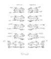
- a surgical trayis provided with a series of plates that include a varying degree of offset to accommodate the correction for a varying degree of anatomical deformity in a lapidus procedure.
- this systemprovides for a left and right set of plates, each set optionally including a first plate that has a compression slot rather than a shrouded compression housing, a “neutral” plate having a compression housing and a 3.5° offset between the posterior and anterior end of the plate, a 4° plate that has a total offset of 7.5°, a 8° plate that has a total offset of 11.5° (all angles being expressed at +/ ⁇ 0.5°) and a medial column plate that is designed to provide for additional fixation of the first ray.
- the systemmay also include a non-pocket plate that has a double tabbed end and an opposing tri-lobed end with the intermediate lobe including a compression slot
- the systemmay include a medial column plate that has a series of threaded medial tabs for locking screws and at one end a lobe that has a terminal compression slots to achieve compression toward the other end of the plate, and the other end of the plate has a middle compression slot which acts to achieve compression towards the middle of the plate.
- an orthopedic platethat achieves improved compression through the use of a screw that is situated with its axis obliquely to the spine of the plate (i.e. to the longitudinal axis in the plane of the plate taken at the opening of the compression opening of the plate).
- the term “spine” of the plateis used to mean a line or curve that is generally medial to the mass of the plate, taking into account that the plates of the invention are somewhat more long than wide, but are amorphous in profile, and have end sections that are may be asymmetrically lobed or tabbed with semi-circular conjoined tabs including screw holes that can have internal threads for locking screws.
- the compression screwis received in a housing or pocket which includes an opening in the top surface of the plate and a shroud which extends from the bottom surface of the plate so as to define a pocket on the bottom of the plate that captures the screw at a variable orientation.
- the housingextends through the plate to accommodate the entire diameter of the head of the screw (i.e. so that the head of the screw does not project significantly or at all beyond the top of the plate when the screw is fully implanted within the plate).
- the screw headdoes not project beyond the top surface of the plate when the screw is fully seated in the housing.
- topit is meant herein the exterior facing surface, which is opposite through the thickness of the plate from the bone-facing surface, of the plate when the plate is in position on the bone.
- the openingis elongated or is a slot, which allows the screw to be placed at a linear variable angle (that is a restricted portion of the conical angulation) relative to the housing, where the amount of angulation is about +/ ⁇ 12°, preferably +/ ⁇ 10°, and more preferably +1-6° of linear freedom relative to the axis of the housing.
- an application specific configurationis illustrated as a MTP plate, which is intended to span the MTP joint.
- the plate outlinehas (again “consists essentially of”) a first end with two lateral tabs on either side of a middle tab, and a second end with two lateral tabs and no intermediate tab. Each of these tabs is provided with a threaded screw hole that receives a threaded locking screw.
- the end with the two tabsalso includes a compression housing as previously described that accepts a screw which extends toward the first end of the plate with its axis at an oblique angle of about 5° to about 40°, more preferably about 10° to about 30°, and most preferably about 15° to about 25° with respect to the longitudinal axis of the plate.
- the platehas an angle of up to about 10° (and preferably about 5°) for dorsiflexion and an angle up to about 10° for valgus.
- the bottom surface of the plateis radiused. This allows the plate to be in snug contact with the bone.
- This plateis also provided in a second version which differs from the first in that the second end does include three tabs similar to the first end, an the compression housing is located at at an oblique angle of about 5° to about 40°, more preferably about 10° to about 30°, and most preferably about 15° to about 25° to the lateral side of the plate and intermediate along the longitudinal axis to the tabs, and further houses a screw hole that defines an axis at an angle of about 55°, / ⁇ about 15°, preferably about 10°, and most preferably about 5° to a line perpendicular to the plate surface at a point along the plate longitudinal axis.
- the compression housingis similar in concept to the previously described compression housing, but in this case, has a round footprint describing at least a portion of a circle, and preferably is substantially a portion of a circle, with a leading edge that is linear.
- the housinghas an internal recess that houses the compression screw and which has a narrowed opening, that is smaller than an associated screw head so as to capture and retain the screw, but which allow for conical rotation in the compression housing.
- a third embodiment of the plateis intended for use in lapidus procedures which are also used to correct bunions, but by realigning the metatarsal relative to the rear joint with the cuneiform.
- Lapidus procedures in accordance with the present inventionhave several advantages over past procedures, including earlier post operative weight bearing, inhibition of elastic deformation, preservation of the function of the MTP joint, realignment of the big toe, better outcomes in the event of mal-union or non-union, and better rear-foot alignment.
- the platehas an even more complex footprint with the posterior end (i.e. toward the heel end of the plate) of the plate including a double tabbed end with each tab including a threaded locking screw hole, and where the inferior tab proceeds (i.e, is rearwards of) the superior tab in the posterior direction.
- the anterior end of the plateincludes a tri-lobed outline in which the central lobe and the superior lobe or tab include internally threaded locking screw holes, and the third lobe or tab which is less distinct than the other two lobes and is curved inward and downward toward the bone-facing surface.
- the plateis provided with slot or slots in opposition to the compression pocket, and the template is provided with guide wire holes spaced appropriately to account for the compression achieved with the screw, the guide wires move in the slots in the plate to account for the compression achieved by the compression screw.
- the guide wirescan be removed, the posterior screws are implanted, and the wound can be closed.
- the plate and template systemallow the security of the guide wire used for the interfragmentary compression, and the screws allow for multiplanar fixation, while inhibiting the possibility of screw interference.
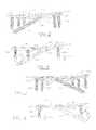
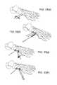
- FIG. 5is a first side view of the plate shown in FIG. 1 ;
- FIG. 6is a first cross-sectional view of the plate shown in FIG. 2 , taken along line 6 - 6 ;
- FIG. 7is a side view taken from the other side of the plate shown in FIG. 1 ;
- FIG. 8is a second cross-sectional view of the plate shown in FIG. 2 , taken along line 6 - 6 and looking in the opposite direction from FIG. 6 ;
- FIG. 9is a left end view of the plate shown in FIG. 1 ;
- FIG. 10is a right end view of the plate shown in FIG. 1 ;
- FIG. 11is a top view of a second version of the embodiment of the plate shown in FIG. 1 ;
- FIG. 12is a first side view of the plate shown in FIG. 11 ;
- FIG. 13is a cross-section of the plate shown in FIG. 11 taken along line 13 - 13 ;
- FIG. 14is a bottom view of the plate shown in FIG. 11 ;
- FIG. 15is a cross-section of the plate shown in FIG. 11 taken at line 15 - 15 ;
- FIG. 16is a top view of a left version of the embodiment of the plate shown in FIG. 11 ;
- FIG. 17is a detail in cross section of the plate shown in FIG. 11 ;
- FIG. 19is a first side view of the orthopedic plate of FIG. 18 ;
- FIG. 20is a bottom view of the orthopedic plate of FIG. 18 ;
- FIG. 21is a first end view of the plate of FIG. 18 ;
- FIG. 22is a second end view of the plate shown in FIG. 18 ;
- FIG. 23is an end and bottom view of the plate of FIG. 18 which illustrates the compression screw opening
- FIG. 25is a first side view of the orthopedic plate assembly of FIG. 24 ;
- FIG. 26is a top view of the orthopedic plate assembly of FIG. 24 ;
- FIG. 27is a first end view of the plate assembly of FIG. 24 ;
- FIG. 28is a second end view of the plate assembly shown in FIG. 24 ;
- FIG. 30is a side view of a non-locking screw that can be used with the invention.
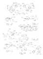
- FIG. 33( a )-33( l )illustrates a method of performing a surgery using the plates and instruments in accordance with the invention.
- FIG. 34is an alternative embodiment of the MTC plate of FIG. 18 .
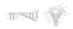
- FIGS. 1-10show a first version of plate for use in the MTP joint, the junction of the head of the first metatarsal and the proximal phalange of the first ray (i.e. the great toe) at the first metatarsophalangeal joint.
- the plate used in fixation (i.e. for fusion) of the bones of the first MTP jointand is thus termed an MTP plate.
- the plate 110has a first end 112 which is tri-lobed, or has three rounds tabs 113 , of just appropriate size to form mounting rings for threaded locking holes 114 which receive the locking screws having an externally threaded locking head.
- the tabsinclude a rounded portion for example large enough to accommodate an opening for a screw hole, and contiguous material that holds the rounded projection to the general plate body.
- the tabsare longitudinally offset from each other, and angled inward toward the medial axis of the plate to improve the purchase in the plate, and inhibit backout.
- the other end 118 of the plate 110includes two laterally and longitudinally offset tabs 115 which are also just of appropriate size to form mounting rings for threaded locking holes 114 which receive threaded locking screws 130 .
- the second end 118 of the plateincludes a compression housing similar 116 .
- the compression housing 116includes an opening 120 in the top surface 122 of the plate.
- the opening 120is ovoid, with a width that wide enough to accept the compression screw 132 that is received in the opening 120 .
- the compression screwis of slightly greater diameter and of greater length than the locking screws.
- the opening 120angles into the top surface 122 of the plate 110 so as to form a groove 124 that accommodates and guides the screw 132 and a mating driver as the screw is screwed into the bone below the plate.
- the term “shroud” as used hereinmeans that the housing creates a “pocket” of enclosed space for the compression screw head, which is closed to the bone surface and in which the structure that defines the enclosed space is connected at each side to the bottom of the plate. This reinforces the housing structure, helps to create additional compression and closes the housing from the possibility of tissue interference or in-growth.
- the “housing”comprises a more complete structure than a flat solid rib which projects from the bottom surface of the plate and includes a screw hole (threaded or not).
- the shroud 126includes a lower opening 129 which is circular, and which is large enough to allow the major diameter of the screw to pass through, but which is smaller than the diameter of the rounded portion 134 of the head of the screw 132 .
- the compression housing 126accepts a screw 132 which extends toward the first end 112 of the plate with its axis at an oblique angle of about 5° to about 40°, more preferably about 10° to about 30°, and most preferably about 15° to about 25° with respect to the longitudinal spine of the plate. Further, the plate has an angle of up to about 10° (and preferably about 5°) for dorsiflexion and an angle up to about 10° for valgus. The bottom surface of the plate is radiused at a constant curve.
- FIGS. 11-17illustrate a second embodiment, i.e. the MPT plate 310 , of the present invention.
- both the first and the second ends 312 , 318includes three tabs 313 , 315 and locking holes 314 within each tab.
- the plate 310continues to have the same angles for dorsiflexion and for valgus.
- the geometry of the opposite end of the platemirrors the first end, with the exception that the second end further includes a tab 317 for a compression shroud 316 which extends from the bottom surface of the plate and intermediate to the second tab and has a screw housing that extends from the bottom of the plate at an angle of about 55°+/ ⁇ about 10°, preferably about 8°, and most preferably about 5° relative to the screw hole axis of the terminal most screw hole.
- the housinghas a cylindrical configuration, which intersects the plate at a linear edge.
- the housinghas a narrowed opening that acts to capture a screw housed in the housing but which allows conical rotation in the housing.
- the inside wall of the housingnarrows at an angle of 40° relative to the axis of the housing.
- the housing 316has a narrowed opening that acts to capture a screw housed in the housing but which allows conical rotation in the housing.
- the inside wall of the housingnarrows at an angle of 40° relative to the axis of the housing.
- the shroud 316includes a lower opening 329 which is circular, and which is large enough to allow the major diameter of the screw to pass through, but which is smaller than the diameter of the rounded portion 234 of the head of the screw 232 .
- FIG. 16shows right plate MPT plate 410 which is a mirror image of the left MPT plate shown in FIG. 10 .
- both the first and the second ends 412 , 418includes three tabs and locking holes 414 within each tab and the second end also includes a tab 417 for a compression shroud 416 which extends from the bottom surface of the plate.
- the platecontinues to have the same angles for dorsiflexion and for valgus.
- the geometry of the opposite end of the platemirrors the first end, with the exception that the second end further includes a fourth tab intermediate to the second tab and has a screw housing that extends from the bottom of the plate at an angle of about 55°+/ ⁇ about 10°, preferably about 8°, and most preferably about 5° relative to the screw hole axis of the terminal most screw hole.
- the housinghas a cylindrical configuration, which intersects the plate at a linear edge.
- FIGS. 18-28illustrate a third embodiment of the invention which is a lapidus plate and assembly designed for use in lapidus procedures.
- This plate 510has a first end 512 and a second end 518 , where the first end includes two tabs 515 , each having internally threaded locking screw holes 514 .
- a second end 518has three conjoined tabs or lobes 515 two of which include internally threaded locking screw holes 514 .
- the third lobeincludes a compression housing 516 that projects into the plate so as to provide a seat for a compression screw and a structure that will also contribute to this compression in the bone.
- this compression housingis a peripheral compression housing that is not located on the spine or longitudinal axis of the plate, and the screw located in this housing does not act to apply a force substantially solely in the direction of the longitudinal axis or along the spine of the plate, but rather acts so as to apply a compound force that is directed in a diagonal direction across the body of the plate.
- the opening of the housingis elongated or slotted in the direction transverse to the axis of the slot so as to define linear angulation in the slot hole for the compression screw.
- the platealso includes at least one slot 520 having a long axis, which is aligned with the direction of compression imposed by the compression screw.
- the slotreceives a guide wire and allows it to remain in place stabilizing the bone fragments as the compression screw is tightened and a first bone segment is compressed against a second bone fragment.
- the platemay include an additional guide wire hole 524 located in the vicinity of the compression housing. It is noted that the guide wire holes are smaller than the screw holes, and have a diameter that is slightly (i.e. between about 3 and 10% larger in diameter than, and preferably greater than about 3 and 7% larger than the diameter of a guide wire where the slotted version is from 1.5 to 3 times the diameter in length.) Alternatively as shown in FIG.
- the slotted guide wire holecould be a slotted screw hole or compression hole 521 with a similar ratio of length to width (i.e. providing for a length that corresponds to the amount of compression that is achieved and is about 1-5 millimeters.)
- FIGS. 24-28illustrate the plate 510 including plate screws 526 and compression screw 528 . These views illustrate how the invention provides for the compression screw with a minimized concern for interference with the plate screws.
- FIG. 30illustrates a threaded locking screw 600 , that can be used with the invention, while FIG. 31 illustrates a compression screw 610 , and FIG. 32 illustrates a variable locking screw assembly 620 that can be used with the present invention.
- the screw 600could include external screw threads 602 that mate with internal threads in the locking screw hole at a pre-selected angle, in some instances, the screw axis is perpendicular to a tangent at the top of the screw hole so that the screw axis angles slightly toward the bottom of the plate.
- other methods of causing lockingcould be employed, such as a variable locking assembly 622 .
- the screw 610 used in the compression housinghas a rounded rear shoulder 612 (such as a hemisphere, or a torroid), which allows for play in the convexly rounded recess in the compression housing. The compression is caused when the compression screw engages the bone and pulls the plate into that bone as it engages a downwardly sloping shoulder on the compression slot, and the locking screw or screws act on their respective bone segment.
- the plateis formed of a biocompatible material, and preferably a metal such as surgical grade stainless steel, titanium or a titanium alloy.
- the platehas a thickness of between about 1.0 and 2.0 millimeters, more preferably between about 1.2 and 1.5 millimeters, and most preferably between about 1.25 and 1.40 millimeters.
- the compression housingextends a depth below the bottom surface of the plate from about 1.4 to about 3 mm, preferably from about 175 to about 2.25 mm, and has a width of from about 3.5 to about 5.5, preferably from about 4 to about 5 mm, and a length of from about 3.0 to about 8.0, mm preferably from about 5.0 to about 7.0 mm.
- the opening in the upper surface of the plate for the compression openingis from about 8 to about 15 mm in width, and from about 10 to about 18 mm in length.
- the lower openingis about 2.5 to about 2.9 mm in diameter with a recess width of from about 2.5 to about 4.5 mm.
- the locking screw holesinclude a flat annular recess surrounding the threaded area that is about 0.4 to about 0.6 mm in width.
- the universal platei.e. the tab-like plate
- the axis of the compression screwforms an angle of from about 35° to about 45° to a longitudinal axis on the bottom of the plate.
- the plateincludes a continuous outer edge, which is defined between the top and the bottom surface.
- the platecan include a small through hole sized to receive a K-wire or other similar guide wire.
- a k-wireplaced in the plantar portion of the bones from medial to lateral across the joint, temporarily fix the joint in the desired position.
- Assemble the template that corresponds to the chosen plate with the countersink guideby snapping the template into the guide.
- the systemfurther allows the plates to accommodate all of non-locking, fixed-angle locking and variable-angle locking screws for fixation without compromise.
- the compression screwcan be a partially threaded or fully threaded cannulated or solid screw. All of these can be provided in the surgical tray or caddy and thus are made available at the time of surgery.
- Step 2Temporarily fix the joint in the desired orientation using the provided k-wires.
- Recommended wire placementis through the dorsal aspect of the joint, directed into the plantar-lateral aspect of the cuneiform and into the intermediate cuneiform or second metatarsal if desired.
- FIG. 33( a )Temporarily fix the joint in the desired orientation using the provided k-wires.
- Step 3Select the plate template.
- the plate and templatesare side specific and designed so that the pocket is on the plantar-medial aspect of the joint and a template is provided at each offset corresponding to the appropriate degree of correction: i.e. neutral (0° of correction), 4° past neutral, and 8° past neutral. Note that the neutral template has a slight bend to fit the natural angle of the joint. The 4° and 8° designations reflect the amount of bend past neutral and do not necessarily correspond to the total IM correction angle.
- Step 4Insert a 1.4 mm k-wire through each k-wire hole in the template.
- the templatesinclude raised nubs which surround the guide wire holes in order to provide for parallel placement of the guides wires relative to each other, and an alignment that is desired relative to the foot. Take care to keep the wires parallel during insertion as they will later facilitate plate placement. FIG. 33( b ) .
- Step 6With the k-wires still in place, slide the template off the bone. Then slide the corresponding plate over the wires and position into the prepared pocket. FIG. 33( e ) . The proximal k-wire should pass through the k-wire slot in the plate.
- Step 7Using the fixed drill guide and the 2.4 mm drill bit, drill a pilot hole for the most distal screw.
- FIG. 33( f )Take care to not move the plate after drilling for a locking screw in order to maintain the proper pilot hole alignment and prevent locking screw cross-threading.
- the threaded screw holes in the plateare compatible with a variety of screw options; 3.5 mm non-locking or fixed-angle locking screws (magenta) and 4.0 mm non-locking screws (teal) are included in the Set. Depending on surgeon preference, a combination of screw types can be used.
- Step 8Determine the screw length required using the provided depth gage.
- Step 10With the driver, insert the selected screw into the hole and drive the screw.
- Step 11follows the same technique for the remaining distal screw hole.
- Step 12Select the 1.4 mm pocket wire guide and place the nose into the plate pocket, aligning the solid line on the guide with the dashed line on the plate.
- Step 13With the guide fully seated in the plate pocket, insert a 1.4 mm guide wire through the guide at the desired trajectory.
- FIG. 33( g )The recess within the pocket wire guide is slotted to allow for 12° of planar angulation within the slot of the compression housing. Verify wire placement with fluoroscopy to ensure trajectory and screw purchase will be adequate.
- Step 14Remove the pocket wire guide and use the provided pocket depth gauge to measure over the wire and determine the required screw length. Keep in mind that a shorter screw may be required based on compression generation. FIG. 33( h ) .
- Step 15Use the cannulated drill bit to drill over the wire for the 4.0 mm pocket screw.
- Step 16Remove the 1.4 mm guide wire from the pocket in order to insert a partially threaded solid screw. Leave any other provisional fixation in place to maintain proper alignment.
- FIG. 33( i )If a cannulated screw is used the pocket guide wire may be left in place during initial screw insertion to further maintain joint alignment.
- Step 17Using the driver, insert the appropriate length partially threaded screw through the pocket until almost fully seated in the pocket.
- FIG. 33( j )Using the driver, insert the appropriate length partially threaded screw through the pocket until almost fully seated in the pocket.
- Step 18Remove any provisional fixation wires and fully tighten the pocket screw.
- the proximal k-wiremay remain in place during screw insertion to maintain plate alignment; the slot will allow plate translation during pocket screw insertion.
- Step 19Remove all remaining wires. Drill and insert the proximal screws using the technique described in Steps 8-10 above. Fully tighten all screws.
- FIG. 33( k )Verify final plate and screw placement with fluoroscopy to ensure correct joint.
- FIG. 33( l )Verify final plate and screw placement with fluoroscopy to ensure correct joint.
Landscapes
- Health & Medical Sciences (AREA)
- Orthopedic Medicine & Surgery (AREA)
- Surgery (AREA)
- Life Sciences & Earth Sciences (AREA)
- Heart & Thoracic Surgery (AREA)
- Nuclear Medicine, Radiotherapy & Molecular Imaging (AREA)
- Engineering & Computer Science (AREA)
- Biomedical Technology (AREA)
- Neurology (AREA)
- Medical Informatics (AREA)
- Molecular Biology (AREA)
- Animal Behavior & Ethology (AREA)
- General Health & Medical Sciences (AREA)
- Public Health (AREA)
- Veterinary Medicine (AREA)
- Surgical Instruments (AREA)
Abstract
Description
Claims (20)
Priority Applications (4)
| Application Number | Priority Date | Filing Date | Title |
|---|---|---|---|
| US15/445,242US10213236B2 (en) | 2011-12-28 | 2017-02-28 | Orthopedic compression plate and method of surgery |
| US16/251,891US11317952B2 (en) | 2011-12-28 | 2019-01-18 | Orthopedic compression plate and method of surgery |
| US17/233,828US20210236182A1 (en) | 2011-12-28 | 2021-04-19 | Orthopedic compression plate and method of surgery |
| US17/714,308US12016600B2 (en) | 2011-12-28 | 2022-04-06 | Orthopedic compression plate and method of surgery |
Applications Claiming Priority (5)
| Application Number | Priority Date | Filing Date | Title |
|---|---|---|---|
| US201161580680P | 2011-12-28 | 2011-12-28 | |
| US13/372,902US9005255B2 (en) | 2011-02-15 | 2012-02-14 | Orthopedic compression plate |
| US13/728,532US9060822B2 (en) | 2011-12-28 | 2012-12-27 | Orthopedic compression plate and method of surgery |
| US14/713,401US20150272639A1 (en) | 2011-12-28 | 2015-05-15 | Orthopedic compression plate and method of surgery |
| US15/445,242US10213236B2 (en) | 2011-12-28 | 2017-02-28 | Orthopedic compression plate and method of surgery |
Related Parent Applications (1)
| Application Number | Title | Priority Date | Filing Date |
|---|---|---|---|
| US14/713,401ContinuationUS20150272639A1 (en) | 2011-12-28 | 2015-05-15 | Orthopedic compression plate and method of surgery |
Related Child Applications (1)
| Application Number | Title | Priority Date | Filing Date |
|---|---|---|---|
| US16/251,891ContinuationUS11317952B2 (en) | 2011-12-28 | 2019-01-18 | Orthopedic compression plate and method of surgery |
Publications (2)
| Publication Number | Publication Date |
|---|---|
| US20170238978A1 US20170238978A1 (en) | 2017-08-24 |
| US10213236B2true US10213236B2 (en) | 2019-02-26 |
Family
ID=48695485
Family Applications (6)
| Application Number | Title | Priority Date | Filing Date |
|---|---|---|---|
| US13/728,532Active2032-02-21US9060822B2 (en) | 2011-12-28 | 2012-12-27 | Orthopedic compression plate and method of surgery |
| US14/713,401AbandonedUS20150272639A1 (en) | 2011-12-28 | 2015-05-15 | Orthopedic compression plate and method of surgery |
| US15/445,242ActiveUS10213236B2 (en) | 2011-12-28 | 2017-02-28 | Orthopedic compression plate and method of surgery |
| US16/251,891Active2032-12-09US11317952B2 (en) | 2011-12-28 | 2019-01-18 | Orthopedic compression plate and method of surgery |
| US17/233,828AbandonedUS20210236182A1 (en) | 2011-12-28 | 2021-04-19 | Orthopedic compression plate and method of surgery |
| US17/714,308Active2032-06-07US12016600B2 (en) | 2011-12-28 | 2022-04-06 | Orthopedic compression plate and method of surgery |
Family Applications Before (2)
| Application Number | Title | Priority Date | Filing Date |
|---|---|---|---|
| US13/728,532Active2032-02-21US9060822B2 (en) | 2011-12-28 | 2012-12-27 | Orthopedic compression plate and method of surgery |
| US14/713,401AbandonedUS20150272639A1 (en) | 2011-12-28 | 2015-05-15 | Orthopedic compression plate and method of surgery |
Family Applications After (3)
| Application Number | Title | Priority Date | Filing Date |
|---|---|---|---|
| US16/251,891Active2032-12-09US11317952B2 (en) | 2011-12-28 | 2019-01-18 | Orthopedic compression plate and method of surgery |
| US17/233,828AbandonedUS20210236182A1 (en) | 2011-12-28 | 2021-04-19 | Orthopedic compression plate and method of surgery |
| US17/714,308Active2032-06-07US12016600B2 (en) | 2011-12-28 | 2022-04-06 | Orthopedic compression plate and method of surgery |
Country Status (3)
| Country | Link |
|---|---|
| US (6) | US9060822B2 (en) |
| EP (2) | EP3189802B1 (en) |
| WO (1) | WO2013101979A1 (en) |
Cited By (3)
| Publication number | Priority date | Publication date | Assignee | Title |
|---|---|---|---|---|
| US10610273B2 (en)* | 2016-11-07 | 2020-04-07 | In2Bones Usa, Llc | Bone plate with transverse screw |
| US11020148B2 (en) | 2019-08-07 | 2021-06-01 | Crossroads Extremity Systems, Llc | Bunion correction system and method |
| US12403009B2 (en) | 2019-06-12 | 2025-09-02 | United States Government As Represented By The Department Of Veterans Affairs | Femoral head arthroplasty system |
Families Citing this family (118)
| Publication number | Priority date | Publication date | Assignee | Title |
|---|---|---|---|---|
| US7905904B2 (en) | 2006-02-03 | 2011-03-15 | Biomet Sports Medicine, Llc | Soft tissue repair device and associated methods |
| US8118836B2 (en) | 2004-11-05 | 2012-02-21 | Biomet Sports Medicine, Llc | Method and apparatus for coupling soft tissue to a bone |
| US7749250B2 (en) | 2006-02-03 | 2010-07-06 | Biomet Sports Medicine, Llc | Soft tissue repair assembly and associated method |
| US8303604B2 (en) | 2004-11-05 | 2012-11-06 | Biomet Sports Medicine, Llc | Soft tissue repair device and method |
| US8361113B2 (en) | 2006-02-03 | 2013-01-29 | Biomet Sports Medicine, Llc | Method and apparatus for coupling soft tissue to a bone |
| US8128658B2 (en) | 2004-11-05 | 2012-03-06 | Biomet Sports Medicine, Llc | Method and apparatus for coupling soft tissue to bone |
| US8088130B2 (en) | 2006-02-03 | 2012-01-03 | Biomet Sports Medicine, Llc | Method and apparatus for coupling soft tissue to a bone |
| US7909851B2 (en) | 2006-02-03 | 2011-03-22 | Biomet Sports Medicine, Llc | Soft tissue repair device and associated methods |
| US8298262B2 (en) | 2006-02-03 | 2012-10-30 | Biomet Sports Medicine, Llc | Method for tissue fixation |
| US9017381B2 (en) | 2007-04-10 | 2015-04-28 | Biomet Sports Medicine, Llc | Adjustable knotless loops |
| US8801783B2 (en) | 2006-09-29 | 2014-08-12 | Biomet Sports Medicine, Llc | Prosthetic ligament system for knee joint |
| US8652171B2 (en) | 2006-02-03 | 2014-02-18 | Biomet Sports Medicine, Llc | Method and apparatus for soft tissue fixation |
| US8562645B2 (en) | 2006-09-29 | 2013-10-22 | Biomet Sports Medicine, Llc | Method and apparatus for forming a self-locking adjustable loop |
| US10517587B2 (en) | 2006-02-03 | 2019-12-31 | Biomet Sports Medicine, Llc | Method and apparatus for forming a self-locking adjustable loop |
| US9468433B2 (en) | 2006-02-03 | 2016-10-18 | Biomet Sports Medicine, Llc | Method and apparatus for forming a self-locking adjustable loop |
| US11311287B2 (en) | 2006-02-03 | 2022-04-26 | Biomet Sports Medicine, Llc | Method for tissue fixation |
| US11259792B2 (en) | 2006-02-03 | 2022-03-01 | Biomet Sports Medicine, Llc | Method and apparatus for coupling anatomical features |
| US9078644B2 (en) | 2006-09-29 | 2015-07-14 | Biomet Sports Medicine, Llc | Fracture fixation device |
| US8968364B2 (en) | 2006-02-03 | 2015-03-03 | Biomet Sports Medicine, Llc | Method and apparatus for fixation of an ACL graft |
| US8562647B2 (en) | 2006-09-29 | 2013-10-22 | Biomet Sports Medicine, Llc | Method and apparatus for securing soft tissue to bone |
| US8672969B2 (en) | 2006-09-29 | 2014-03-18 | Biomet Sports Medicine, Llc | Fracture fixation device |
| US11259794B2 (en) | 2006-09-29 | 2022-03-01 | Biomet Sports Medicine, Llc | Method for implanting soft tissue |
| US12245759B2 (en) | 2008-08-22 | 2025-03-11 | Biomet Sports Medicine, Llc | Method and apparatus for coupling soft tissue to bone |
| US12419632B2 (en) | 2008-08-22 | 2025-09-23 | Biomet Sports Medicine, Llc | Method and apparatus for coupling anatomical features |
| US12096928B2 (en) | 2009-05-29 | 2024-09-24 | Biomet Sports Medicine, Llc | Method and apparatus for coupling soft tissue to a bone |
| US9161796B2 (en) | 2010-12-18 | 2015-10-20 | The Brigham And Women's Hospital, Inc. | Medical devices for use during ankle fusion surgery |
| US12329373B2 (en) | 2011-05-02 | 2025-06-17 | Biomet Sports Medicine, Llc | Method and apparatus for soft tissue fixation |
| US9357991B2 (en) | 2011-11-03 | 2016-06-07 | Biomet Sports Medicine, Llc | Method and apparatus for stitching tendons |
| US9381013B2 (en) | 2011-11-10 | 2016-07-05 | Biomet Sports Medicine, Llc | Method for coupling soft tissue to a bone |
| KR20140119797A (en) | 2012-03-01 | 2014-10-10 | 솔라나 서지컬, 엘엘씨 | Surgical staple for insertion into bones |
| US9907588B2 (en)* | 2012-09-06 | 2018-03-06 | Orthohelix Surgical Designs, Inc. | Orthopedic dual pocket compression plate and method of surgery |
| EP4252686A3 (en) | 2012-12-28 | 2023-12-27 | Paragon 28, Inc. | Alignment guide apparatus |
| US9918827B2 (en)* | 2013-03-14 | 2018-03-20 | Biomet Sports Medicine, Llc | Scaffold for spring ligament repair |
| US9545276B2 (en) | 2013-03-15 | 2017-01-17 | Aristotech Industries Gmbh | Fixation device and method of use for a lapidus-type plantar hallux valgus procedure |
| US10610368B2 (en) | 2018-05-26 | 2020-04-07 | Acumed Llc | Ankle fusion system with expandable spacer |
| WO2015105880A1 (en)* | 2014-01-07 | 2015-07-16 | Nextremity Solutions, Inc. | Resection guides, implants and methods |
| US10653464B2 (en)* | 2014-02-12 | 2020-05-19 | Life Spine, Inc. | Foot bone plate providing fixation and compression |
| EP2957247A1 (en)* | 2014-04-22 | 2015-12-23 | Stryker European Holdings I, LLC | Plates with countersinks |
| US20150335365A1 (en)* | 2014-05-24 | 2015-11-26 | Neutin Orthopedics, LLC | Fixation device for a mau-type osteotomy procedure |
| US10321942B2 (en) | 2014-06-17 | 2019-06-18 | Life Spine, Inc. | Compression screw systems for compressing bones of the extremities |
| US9743965B2 (en)* | 2014-06-20 | 2017-08-29 | DePuy Synthes Products, Inc. | Medial column fusion plates |
| US20160015426A1 (en) | 2014-07-15 | 2016-01-21 | Treace Medical Concepts, Inc. | Bone positioning and cutting system and method |
| AU2014321174B2 (en)* | 2014-09-11 | 2017-06-29 | Wright Medical Technology, Inc. | Medial-plantar plate for medial column arthrodesis |
| CN105640634A (en)* | 2014-11-13 | 2016-06-08 | 无锡市闻泰百得医疗器械有限公司 | Locking bone plate structure |
| CN105726110B (en)* | 2014-12-12 | 2020-01-17 | 上海斯地德商务咨询中心 | First metatarsal distal osteotomy plate |
| US9687250B2 (en) | 2015-01-07 | 2017-06-27 | Treace Medical Concepts, Inc. | Bone cutting guide systems and methods |
| US10245088B2 (en) | 2015-01-07 | 2019-04-02 | Treace Medical Concepts, Inc. | Bone plating system and method |
| WO2016115172A1 (en) | 2015-01-13 | 2016-07-21 | University Of Washington | Devices and methods for metatarsophalangeal arthroplasty procedures |
| US10898211B2 (en) | 2015-01-14 | 2021-01-26 | Crossroads Extremity Systems, Llc | Opening and closing wedge osteotomy guide and method |
| US10292713B2 (en) | 2015-01-28 | 2019-05-21 | First Ray, LLC | Freeform tri-planar osteotomy guide and method |
| WO2016134160A1 (en) | 2015-02-18 | 2016-08-25 | Treace Medical Concepts, Inc. | Bone plating kit for foot and ankle applications |
| WO2016134154A1 (en) | 2015-02-18 | 2016-08-25 | Treace Medical Concepts, Inc. | Pivotable bone cutting guide useful for bone realignment and compression techniques |
| US10376268B2 (en) | 2015-02-19 | 2019-08-13 | First Ray, LLC | Indexed tri-planar osteotomy guide and method |
| US10653467B2 (en) | 2015-05-06 | 2020-05-19 | Treace Medical Concepts, Inc. | Intra-osseous plate system and method |
| US10376367B2 (en) | 2015-07-02 | 2019-08-13 | First Ray, LLC | Orthopedic fasteners, instruments and methods |
| US9622805B2 (en) | 2015-08-14 | 2017-04-18 | Treace Medical Concepts, Inc. | Bone positioning and preparing guide systems and methods |
| EP4483824A3 (en) | 2015-07-14 | 2025-03-05 | Treace Medical Concepts, Inc. | Bone positioning guide |
| US10849663B2 (en) | 2015-07-14 | 2020-12-01 | Treace Medical Concepts, Inc. | Bone cutting guide systems and methods |
| EP4494582A3 (en)* | 2015-08-14 | 2025-04-16 | Treace Medical Concepts, Inc. | Tarsal-metatarsal joint procedure utilizing fulcrum |
| WO2017031020A1 (en) | 2015-08-14 | 2017-02-23 | Treace Medical Concepts, Inc. | Tarsal-metatarsal joint procedure utilizing fulcrum |
| CN105030315A (en)* | 2015-08-24 | 2015-11-11 | 苏州市康力骨科器械有限公司 | Steel plate for locking foot bone in multidirectional mode |
| US10039559B2 (en) | 2015-09-02 | 2018-08-07 | Wright Medical Technology, Inc. | Method and cut guide for biplanar wedge osteotomy |
| CA2998481C (en) | 2015-09-18 | 2024-05-14 | Treace Medical Concepts, Inc. | Joint spacer systems and methods |
| US10702290B2 (en) | 2015-11-02 | 2020-07-07 | First Ray, LLC | Orthopedic fastener, retainer, and guide |
| CN105596073B (en)* | 2016-02-01 | 2019-08-06 | 郑明辉 | Intervertebral fixation device and intervertebral fixation system |
| FR3052047B1 (en) | 2016-06-02 | 2021-12-17 | Neosteo | IMPLANTABLE MEDICAL DEVICE FOR THE SOLIDARIZATION OF SEPARATED BONE PARTS WITH A VIEW OF THEIR FUSION |
| AU2017274445B2 (en)* | 2016-06-02 | 2022-06-16 | In2Bones Usa, Llc | Plantar bone fusion plate |
| US10512470B1 (en) | 2016-08-26 | 2019-12-24 | Treace Medical Concepts, Inc. | Osteotomy procedure for correcting bone misalignment |
| EP3528716B1 (en) | 2016-10-24 | 2024-02-14 | Paragon 28, Inc. | Osteotomy systems |
| US10524808B1 (en) | 2016-11-11 | 2020-01-07 | Treace Medical Concepts, Inc. | Devices and techniques for performing an osteotomy procedure on a first metatarsal to correct a bone misalignment |
| CN106691634B (en)* | 2016-11-18 | 2018-05-15 | 徐永清 | A kind of wrist joint prosthese with titanium alloy lockplate |
| US10939939B1 (en) | 2017-02-26 | 2021-03-09 | Treace Medical Concepts, Inc. | Fulcrum for tarsal-metatarsal joint procedure |
| ES2993743T3 (en) | 2017-02-27 | 2025-01-08 | Paragon 28 Inc | Targeting instruments and systems |
| EP3585287B1 (en) | 2017-02-27 | 2024-11-13 | Paragon 28, Inc. | Intramedullary nail fixation systems |
| US10918431B2 (en) | 2017-03-30 | 2021-02-16 | Paragon 28, Inc. | Bone fixation system, assembly, implants, devices, alignment guides, and methods of use |
| US10709566B2 (en) | 2017-05-04 | 2020-07-14 | Wright Medical Technology, Inc. | Implant and method for ankle syndesmosis treatment |
| USD822832S1 (en) | 2017-06-28 | 2018-07-10 | Paragon 28, Inc. | Bone plate |
| EP3651699B1 (en)* | 2017-07-11 | 2025-09-17 | Paragon 28, Inc. | Bone fixation system, assembly, implants, devices and insertion guides |
| WO2019022712A1 (en) | 2017-07-25 | 2019-01-31 | University Of Washington | Devices and methods for metatarsophalangeal arthroplasty procedures |
| US10881436B2 (en) | 2017-10-27 | 2021-01-05 | Wright Medical Technology, Inc. | Implant with intramedullary portion and offset extramedullary portion |
| ES2971443T3 (en)* | 2017-12-08 | 2024-06-05 | Paragon 28 Inc | Bone fixation and implant set |
| WO2019152784A2 (en)* | 2018-02-05 | 2019-08-08 | Bespa Global, Llc | Implants and methods for treating charcot foot and other conditions |
| WO2019185104A1 (en) | 2018-03-28 | 2019-10-03 | Elkhawaga Ahmed Mohamed Abou Elainen | The gear dynamic compression plates |
| US11596443B2 (en) | 2018-07-11 | 2023-03-07 | Treace Medical Concepts, Inc. | Compressor-distractor for angularly realigning bone portions |
| US11583323B2 (en) | 2018-07-12 | 2023-02-21 | Treace Medical Concepts, Inc. | Multi-diameter bone pin for installing and aligning bone fixation plate while minimizing bone damage |
| US11571312B1 (en)* | 2018-08-12 | 2023-02-07 | Paragon Advanced Technologies, Inc. | Process, kit, and implant for correction of a bone injury |
| EP3923842A4 (en) | 2019-02-13 | 2022-11-23 | Paragon 28, Inc. | IMPLANTS, ALIGNMENT GUIDES, SYSTEMS AND METHODS OF USE |
| US11607250B2 (en) | 2019-02-13 | 2023-03-21 | Treace Medical Concepts, Inc. | Tarsal-metatarsal joint procedure utilizing compressor-distractor and instrument providing sliding surface |
| AU2020228309B2 (en) | 2019-02-28 | 2025-10-02 | Paragon 28, Inc. | Fusion systems, instruments, bone plates and methods of use |
| WO2020206087A1 (en) | 2019-04-04 | 2020-10-08 | Wright Medical Technology, Inc. | Surgical system and methods for stabilization and fixation of fractures, joints, and reconstructions |
| EP3968872A4 (en) | 2019-05-13 | 2023-04-19 | Wright Medical Technology, Inc. | Surgical tools and methods of use |
| WO2021021640A1 (en) | 2019-07-26 | 2021-02-04 | Crossroads Extremity Systems, Llc | Bone repositioning guide system and procedure |
| CA3146564A1 (en) | 2019-08-07 | 2021-02-11 | Jason May | Bi-planar instrument for bone cutting and joint realignment procedure |
| US11889998B1 (en) | 2019-09-12 | 2024-02-06 | Treace Medical Concepts, Inc. | Surgical pin positioning lock |
| US11986251B2 (en) | 2019-09-13 | 2024-05-21 | Treace Medical Concepts, Inc. | Patient-specific osteotomy instrumentation |
| US11890039B1 (en) | 2019-09-13 | 2024-02-06 | Treace Medical Concepts, Inc. | Multi-diameter K-wire for orthopedic applications |
| EP4027922A4 (en) | 2019-09-13 | 2023-10-04 | MIOS Marketing LLC, DBA RedPoint Medical 3D | Patient-specific surgical methods and instrumentation |
| US11517358B2 (en)* | 2019-10-02 | 2022-12-06 | Arthrex, Inc. | Interfragmentary guide and plate system |
| US12295589B2 (en) | 2019-12-12 | 2025-05-13 | Relja Innovations, Llc | Method, surgical apparatus, and surgical implant for minimally invasive surgical procedures |
| USD977645S1 (en)* | 2020-01-08 | 2023-02-07 | Ortho Solutions Holdings Limited | Orthopedic plate |
| USD977646S1 (en)* | 2020-01-08 | 2023-02-07 | Ortho Solutions Holdings Limited | Orthopedic plate |
| WO2021155269A1 (en) | 2020-01-31 | 2021-08-05 | Treace Medical Concepts, Inc. | Metatarsophalangeal joint preparation and metatarsal realignment for fusion |
| JP7639014B2 (en)* | 2020-02-19 | 2025-03-04 | クロスローズ エクストリミティ システムズ リミテッド ライアビリティ カンパニー | Systems and methods for lapidus bunion repair |
| CA3116453A1 (en) | 2020-05-04 | 2021-11-04 | Laboratoires Bodycad Inc. | Osteotomy plate and method for performing an osteotomy procedure using the same |
| AU2021275140A1 (en) | 2020-05-19 | 2023-02-02 | Treace Medical Concepts, Inc. | Devices and techniques for treating metatarsus adductus |
| US12161371B2 (en) | 2021-01-18 | 2024-12-10 | Treace Medical Concepts, Inc. | Contoured bone plate with locking screw for bone compression, particularly across a tarsometatarsal joint |
| US12310603B2 (en) | 2021-02-18 | 2025-05-27 | Treace Medical Concepts, Inc. | System and technique for metatarsal realignment with reduced incision length |
| AU2022276540A1 (en) | 2021-05-20 | 2023-11-30 | Treace Medical Concepts, Inc. | Cut guide with integrated joint realignment features |
| US12256969B2 (en) | 2021-06-17 | 2025-03-25 | Wright Medical Technology, Inc. | Minimally invasive surgery osteotomy fragment shifter, stabilizer, and targeter |
| US11883075B2 (en) | 2021-11-08 | 2024-01-30 | Relja Innovations, Llc | Device and surgical technique for foot surgery |
| USD1075012S1 (en) | 2022-02-23 | 2025-05-13 | Treace Medical Concepts, Inc. | Metatarsal lateral release instrument |
| USD1057155S1 (en) | 2022-02-23 | 2025-01-07 | Treace Medical Concepts, Inc. | Lesser metatarsal cut guide with parallel cut faces |
| USD1011524S1 (en) | 2022-02-23 | 2024-01-16 | Treace Medical Concepts, Inc. | Compressor-distractor for the foot |
| USD1051382S1 (en) | 2022-02-23 | 2024-11-12 | Treace Medical Concepts, Inc. | Lesser metatarsal cut guide |
| USD1079011S1 (en) | 2022-02-23 | 2025-06-10 | Treace Medical Concepts, Inc. | Metatarsal cut guide with parallel cut faces |
| USD1068077S1 (en) | 2023-02-08 | 2025-03-25 | Treace Medical Concepts, Inc. | Orthopedic rasp for preparing an intercuneiform joint |
| USD1068078S1 (en) | 2023-02-08 | 2025-03-25 | Treace Medical Concepts, Inc. | Handle for an orthopedic instrument |
| WO2024187200A1 (en)* | 2023-03-08 | 2024-09-12 | Castellano Bradley David | Small bone internal fixation system for orthopedic surgery |
Citations (35)
| Publication number | Priority date | Publication date | Assignee | Title |
|---|---|---|---|---|
| US3489143A (en) | 1967-12-15 | 1970-01-13 | William X Halloran | Convertible hip pin |
| US4493317A (en) | 1980-11-20 | 1985-01-15 | Synthes Ltd. (U.S.A.) | Surgical compression plate and drill guide |
| US5534027A (en)* | 1993-06-21 | 1996-07-09 | Zimmer, Inc. | Method for providing a barrier to the advancement of wear debris in an orthopaedic implant assembly |
| US5591169A (en) | 1994-06-14 | 1997-01-07 | Benoist; Louis | Device and method for positioning and holding bone fragments in place |
| WO1997008999A1 (en) | 1995-09-08 | 1997-03-13 | Depuy Ace Medical Company | Internal bone fracture fixator |
| US5667510A (en) | 1995-08-03 | 1997-09-16 | Combs; C. Robert | Joint fixation system and method |
| US5693055A (en)* | 1995-01-03 | 1997-12-02 | Zahiri; Christopher A. | Odd angle internal bone fixation device |
| US20020045896A1 (en) | 1997-02-11 | 2002-04-18 | Michelson Gary K. | Anterior cervical plating system, instrumentation, and method of installation |
| US20030060827A1 (en) | 2001-09-26 | 2003-03-27 | Coughln Michael John | Plate for fixing the bones of a joint, in particular a metatarso-phalangeal joint |
| US20040143266A1 (en) | 2000-10-25 | 2004-07-22 | Jeffrey Kozak | Anterior lumbar plate and method |
| US20050171544A1 (en) | 2004-02-02 | 2005-08-04 | Acumed Llc | Bone plate with toothed aperture |
| US7128744B2 (en) | 1999-09-13 | 2006-10-31 | Synthes (Usa) | Bone plating system |
| US20070173843A1 (en) | 2005-12-22 | 2007-07-26 | Matityahu Amir M | Drug delivering bone plate and method and targeting device for use therewith |
| US20080015593A1 (en) | 2005-03-24 | 2008-01-17 | Joachim Pfefferle | Bone plate |
| US20090036931A1 (en)* | 2007-08-04 | 2009-02-05 | Normed Medizin-Technik Vertriebs-Gmbh | Foot surgery bone plate, and system comprising bone plate and insertion aid |
| US20090076554A1 (en) | 2007-07-19 | 2009-03-19 | Acumed Llc | Insertion tool for bone plates |
| US20090210010A1 (en) | 2008-02-19 | 2009-08-20 | Orthohelix Surgical Designs, Inc. | Orthopedic plate for use in the MTP joint |
| US20090210011A1 (en) | 2008-02-19 | 2009-08-20 | Orthohelix Surgical Designs, Inc. | Orthopedic plate for use in the midfoot |
| US7648508B2 (en) | 2004-11-30 | 2010-01-19 | Stryker Trauma S.A. | Bone plating implants, instruments and methods |
| US7717945B2 (en) | 2002-07-22 | 2010-05-18 | Acumed Llc | Orthopedic systems |
| US20100125300A1 (en) | 2008-11-19 | 2010-05-20 | Amei Technologies, Inc. | Fixation plate for use in the lapidus approach |
| US20100274293A1 (en) | 2009-04-28 | 2010-10-28 | Osteomed L.P. | Bone Plate with a Transfixation Screw Hole |
| US20110009866A1 (en) | 2009-07-09 | 2011-01-13 | Orthohelix Surgical Designs, Inc. | Osteotomy plate, plate driver and method for their use |
| US20110098757A1 (en) | 2009-10-28 | 2011-04-28 | Craig Schelling | Compression plate kit and methods for repairing bone discontinuities |
| US20110295324A1 (en) | 2010-03-19 | 2011-12-01 | Brian Donley | Tabbed compression plate and method of use |
| US8182484B2 (en) | 2008-04-21 | 2012-05-22 | Depuy Products, Inc. | Orthopaedic trauma hip screw assembly |
| US8187276B1 (en) | 2006-09-26 | 2012-05-29 | Zahiri Christopher A | Odd angle internal bone fixation device for use in a transverse fracture of a humerus |
| US8231625B2 (en) | 2008-09-03 | 2012-07-31 | The Cleveland Clinic Foundation | Modular bone fixation device for treatment of fractures and related methods |
| US20120303033A1 (en) | 2011-02-01 | 2012-11-29 | Nextremity Solutions, Llc | Bone defect repair device and method |
| US8556946B2 (en) | 2008-10-02 | 2013-10-15 | Memometal Technologies | Orthopedic implant in the form of a plate to be fixed between two bone parts |
| US20140148859A1 (en) | 2012-11-27 | 2014-05-29 | Solana Surgical, Llc | Orthopedic fusion plate and compression screw |
| US8740915B2 (en) | 2010-04-27 | 2014-06-03 | DePuy Synthes Products, LLC | Bone fixation systems and methods of use |
| US8852246B2 (en) | 2008-07-01 | 2014-10-07 | Swemac Innovation Ab | Device for internal fixation of the bone fragments in a radius fracture |
| US9005255B2 (en)* | 2011-02-15 | 2015-04-14 | Orthohelix Surgical Designs, Inc. | Orthopedic compression plate |
| US9907588B2 (en)* | 2012-09-06 | 2018-03-06 | Orthohelix Surgical Designs, Inc. | Orthopedic dual pocket compression plate and method of surgery |
Family Cites Families (6)
| Publication number | Priority date | Publication date | Assignee | Title |
|---|---|---|---|---|
| US5607428A (en)* | 1995-05-01 | 1997-03-04 | Lin; Kwan C. | Orthopedic fixation device having a double-threaded screw |
| US7052499B2 (en)* | 1998-02-18 | 2006-05-30 | Walter Lorenz Surgical, Inc. | Method and apparatus for bone fracture fixation |
| US7316687B2 (en)* | 2001-08-24 | 2008-01-08 | Zimmer Technology, Inc. | Blade plate and instruments |
| US7951176B2 (en)* | 2003-05-30 | 2011-05-31 | Synthes Usa, Llc | Bone plate |
| US7799061B2 (en)* | 2005-01-28 | 2010-09-21 | Orthohelix Surgical Designs, Inc. | Orthopedic plate |
| WO2011119815A2 (en)* | 2010-03-26 | 2011-09-29 | The General Hospital Corporation | System and methods for in vivo adjustable bone plate |
- 2012
- 2012-12-27USUS13/728,532patent/US9060822B2/enactiveActive
- 2012-12-28EPEP17158160.6Apatent/EP3189802B1/enactiveActive
- 2012-12-28WOPCT/US2012/071911patent/WO2013101979A1/enactiveApplication Filing
- 2012-12-28EPEP12862889.8Apatent/EP2797531B1/enactiveActive
- 2015
- 2015-05-15USUS14/713,401patent/US20150272639A1/ennot_activeAbandoned
- 2017
- 2017-02-28USUS15/445,242patent/US10213236B2/enactiveActive
- 2019
- 2019-01-18USUS16/251,891patent/US11317952B2/enactiveActive
- 2021
- 2021-04-19USUS17/233,828patent/US20210236182A1/ennot_activeAbandoned
- 2022
- 2022-04-06USUS17/714,308patent/US12016600B2/enactiveActive
Patent Citations (37)
| Publication number | Priority date | Publication date | Assignee | Title |
|---|---|---|---|---|
| US3489143A (en) | 1967-12-15 | 1970-01-13 | William X Halloran | Convertible hip pin |
| US4493317A (en) | 1980-11-20 | 1985-01-15 | Synthes Ltd. (U.S.A.) | Surgical compression plate and drill guide |
| US5534027A (en)* | 1993-06-21 | 1996-07-09 | Zimmer, Inc. | Method for providing a barrier to the advancement of wear debris in an orthopaedic implant assembly |
| US5591169A (en) | 1994-06-14 | 1997-01-07 | Benoist; Louis | Device and method for positioning and holding bone fragments in place |
| US5693055A (en)* | 1995-01-03 | 1997-12-02 | Zahiri; Christopher A. | Odd angle internal bone fixation device |
| US5667510A (en) | 1995-08-03 | 1997-09-16 | Combs; C. Robert | Joint fixation system and method |
| WO1997008999A1 (en) | 1995-09-08 | 1997-03-13 | Depuy Ace Medical Company | Internal bone fracture fixator |
| US20020045896A1 (en) | 1997-02-11 | 2002-04-18 | Michelson Gary K. | Anterior cervical plating system, instrumentation, and method of installation |
| US7128744B2 (en) | 1999-09-13 | 2006-10-31 | Synthes (Usa) | Bone plating system |
| US20040143266A1 (en) | 2000-10-25 | 2004-07-22 | Jeffrey Kozak | Anterior lumbar plate and method |
| US8617224B2 (en) | 2000-10-25 | 2013-12-31 | Warsaw Orthopedic, Inc. | Anterior lumbar plate and method |
| US20030060827A1 (en) | 2001-09-26 | 2003-03-27 | Coughln Michael John | Plate for fixing the bones of a joint, in particular a metatarso-phalangeal joint |
| US7717945B2 (en) | 2002-07-22 | 2010-05-18 | Acumed Llc | Orthopedic systems |
| US20050171544A1 (en) | 2004-02-02 | 2005-08-04 | Acumed Llc | Bone plate with toothed aperture |
| US7648508B2 (en) | 2004-11-30 | 2010-01-19 | Stryker Trauma S.A. | Bone plating implants, instruments and methods |
| US20080015593A1 (en) | 2005-03-24 | 2008-01-17 | Joachim Pfefferle | Bone plate |
| US20070173843A1 (en) | 2005-12-22 | 2007-07-26 | Matityahu Amir M | Drug delivering bone plate and method and targeting device for use therewith |
| US8187276B1 (en) | 2006-09-26 | 2012-05-29 | Zahiri Christopher A | Odd angle internal bone fixation device for use in a transverse fracture of a humerus |
| US20090076554A1 (en) | 2007-07-19 | 2009-03-19 | Acumed Llc | Insertion tool for bone plates |
| US20090036931A1 (en)* | 2007-08-04 | 2009-02-05 | Normed Medizin-Technik Vertriebs-Gmbh | Foot surgery bone plate, and system comprising bone plate and insertion aid |
| US20090210010A1 (en) | 2008-02-19 | 2009-08-20 | Orthohelix Surgical Designs, Inc. | Orthopedic plate for use in the MTP joint |
| US20090210011A1 (en) | 2008-02-19 | 2009-08-20 | Orthohelix Surgical Designs, Inc. | Orthopedic plate for use in the midfoot |
| US8182484B2 (en) | 2008-04-21 | 2012-05-22 | Depuy Products, Inc. | Orthopaedic trauma hip screw assembly |
| US8852246B2 (en) | 2008-07-01 | 2014-10-07 | Swemac Innovation Ab | Device for internal fixation of the bone fragments in a radius fracture |
| US8231625B2 (en) | 2008-09-03 | 2012-07-31 | The Cleveland Clinic Foundation | Modular bone fixation device for treatment of fractures and related methods |
| US8556946B2 (en) | 2008-10-02 | 2013-10-15 | Memometal Technologies | Orthopedic implant in the form of a plate to be fixed between two bone parts |
| US20100125300A1 (en) | 2008-11-19 | 2010-05-20 | Amei Technologies, Inc. | Fixation plate for use in the lapidus approach |
| US20100274293A1 (en) | 2009-04-28 | 2010-10-28 | Osteomed L.P. | Bone Plate with a Transfixation Screw Hole |
| US20110009866A1 (en) | 2009-07-09 | 2011-01-13 | Orthohelix Surgical Designs, Inc. | Osteotomy plate, plate driver and method for their use |
| US20110098757A1 (en) | 2009-10-28 | 2011-04-28 | Craig Schelling | Compression plate kit and methods for repairing bone discontinuities |
| US20110295324A1 (en) | 2010-03-19 | 2011-12-01 | Brian Donley | Tabbed compression plate and method of use |
| US8740915B2 (en) | 2010-04-27 | 2014-06-03 | DePuy Synthes Products, LLC | Bone fixation systems and methods of use |
| US20120303033A1 (en) | 2011-02-01 | 2012-11-29 | Nextremity Solutions, Llc | Bone defect repair device and method |
| US8858602B2 (en) | 2011-02-01 | 2014-10-14 | Nextremity Solutions, Inc. | Bone defect repair device and method |
| US9005255B2 (en)* | 2011-02-15 | 2015-04-14 | Orthohelix Surgical Designs, Inc. | Orthopedic compression plate |
| US9907588B2 (en)* | 2012-09-06 | 2018-03-06 | Orthohelix Surgical Designs, Inc. | Orthopedic dual pocket compression plate and method of surgery |
| US20140148859A1 (en) | 2012-11-27 | 2014-05-29 | Solana Surgical, Llc | Orthopedic fusion plate and compression screw |
Non-Patent Citations (3)
| Title |
|---|
| European Search Report issued for European patent application No. 12862889.8, dated Nov. 23, 2015, 8 pages. |
| Extended European Search Report issued for European patent application No. 17158160.6, dated Apr. 12, 2017, 8 pages. |
| Supplementary European Search Report issued for European patent application No. 12746929, dated Nov. 12, 2015, 3 pages. |
Cited By (7)
| Publication number | Priority date | Publication date | Assignee | Title |
|---|---|---|---|---|
| US10610273B2 (en)* | 2016-11-07 | 2020-04-07 | In2Bones Usa, Llc | Bone plate with transverse screw |
| US11452550B2 (en)* | 2016-11-07 | 2022-09-27 | In2Bones Usa, Llc | Bone plate with transverse screw |
| US20230016528A1 (en)* | 2016-11-07 | 2023-01-19 | In2Bones Usa, Llc | Bone plate with transverse screw |
| US12121273B2 (en)* | 2016-11-07 | 2024-10-22 | In2Bones Usa, Llc | Bone plate with transverse screw |
| US12403009B2 (en) | 2019-06-12 | 2025-09-02 | United States Government As Represented By The Department Of Veterans Affairs | Femoral head arthroplasty system |
| US11020148B2 (en) | 2019-08-07 | 2021-06-01 | Crossroads Extremity Systems, Llc | Bunion correction system and method |
| US12402915B2 (en) | 2019-08-07 | 2025-09-02 | Crossroads Extremity Systems, Llc | Bunion correction system and method |
Also Published As
| Publication number | Publication date |
|---|---|
| US20170238978A1 (en) | 2017-08-24 |
| EP3189802B1 (en) | 2022-05-25 |
| EP2797531B1 (en) | 2017-04-19 |
| US20220226029A1 (en) | 2022-07-21 |
| WO2013101979A1 (en) | 2013-07-04 |
| US20190150994A1 (en) | 2019-05-23 |
| US9060822B2 (en) | 2015-06-23 |
| US20210236182A1 (en) | 2021-08-05 |
| EP2797531A4 (en) | 2015-12-23 |
| US20130172942A1 (en) | 2013-07-04 |
| US11317952B2 (en) | 2022-05-03 |
| EP2797531A1 (en) | 2014-11-05 |
| US20150272639A1 (en) | 2015-10-01 |
| US12016600B2 (en) | 2024-06-25 |
| EP3189802A1 (en) | 2017-07-12 |
Similar Documents
| Publication | Publication Date | Title |
|---|---|---|
| US12016600B2 (en) | Orthopedic compression plate and method of surgery | |
| US11864803B2 (en) | Osteotomy plate, plate driver and method for their use | |
| US9005255B2 (en) | Orthopedic compression plate | |
| US8257406B2 (en) | Orthopedic plate for use on a single ray in the midfoot | |
| US9545276B2 (en) | Fixation device and method of use for a lapidus-type plantar hallux valgus procedure | |
| US8257403B2 (en) | Orthopedic plate for use in the midfoot | |
| US20090210010A1 (en) | Orthopedic plate for use in the MTP joint |
Legal Events
| Date | Code | Title | Description |
|---|---|---|---|
| AS | Assignment | Owner name:MIDCAP FUNDING IV TRUST, AS AGENT, MARYLAND Free format text:SECURITY INTEREST;ASSIGNORS:WRIGHT MEDICAL GROUP N.V.;WRIGHT MEDICAL GROUP, INC.;BIOMIMETIC THERAPEUTICS CANADA, INC.;AND OTHERS;REEL/FRAME:046291/0001 Effective date:20180507 | |
| STCF | Information on status: patent grant | Free format text:PATENTED CASE | |
| AS | Assignment | Owner name:TROOPER HOLDINGS INC., MINNESOTA Free format text:RELEASE BY SECURED PARTY;ASSIGNOR:MIDCAP FUNDING IV TRUST;REEL/FRAME:054480/0001 Effective date:20201112 Owner name:BIOMIMETIC THERAPEUTICS USA, INC., TENNESSEE Free format text:RELEASE BY SECURED PARTY;ASSIGNOR:MIDCAP FUNDING IV TRUST;REEL/FRAME:054480/0001 Effective date:20201112 Owner name:ORTHOHELIX SURGICAL DESIGNS, INC., MINNESOTA Free format text:RELEASE BY SECURED PARTY;ASSIGNOR:MIDCAP FUNDING IV TRUST;REEL/FRAME:054480/0001 Effective date:20201112 Owner name:ORTHOPRO, L.L.C., TENNESSEE Free format text:RELEASE BY SECURED PARTY;ASSIGNOR:MIDCAP FUNDING IV TRUST;REEL/FRAME:054480/0001 Effective date:20201112 Owner name:WRIGHT MEDICAL TECHNOLOGY, INC., TENNESSEE Free format text:RELEASE BY SECURED PARTY;ASSIGNOR:MIDCAP FUNDING IV TRUST;REEL/FRAME:054480/0001 Effective date:20201112 Owner name:BIOMIMETIC THERAPEUTICS CANADA, INC., TENNESSEE Free format text:RELEASE BY SECURED PARTY;ASSIGNOR:MIDCAP FUNDING IV TRUST;REEL/FRAME:054480/0001 Effective date:20201112 Owner name:WRIGHT MEDICAL GROUP, INC., TENNESSEE Free format text:RELEASE BY SECURED PARTY;ASSIGNOR:MIDCAP FUNDING IV TRUST;REEL/FRAME:054480/0001 Effective date:20201112 Owner name:BIOMIMETIC THERAPEUTICS, LLC, TENNESSEE Free format text:RELEASE BY SECURED PARTY;ASSIGNOR:MIDCAP FUNDING IV TRUST;REEL/FRAME:054480/0001 Effective date:20201112 Owner name:WHITE BOX ORTHOPEDICS, LLC, TENNESSEE Free format text:RELEASE BY SECURED PARTY;ASSIGNOR:MIDCAP FUNDING IV TRUST;REEL/FRAME:054480/0001 Effective date:20201112 Owner name:SOLANA SURGICAL, LLC, TENNESSEE Free format text:RELEASE BY SECURED PARTY;ASSIGNOR:MIDCAP FUNDING IV TRUST;REEL/FRAME:054480/0001 Effective date:20201112 Owner name:TORNIER US HOLDINGS, INC., MINNESOTA Free format text:RELEASE BY SECURED PARTY;ASSIGNOR:MIDCAP FUNDING IV TRUST;REEL/FRAME:054480/0001 Effective date:20201112 Owner name:TORNIER, INC., MINNESOTA Free format text:RELEASE BY SECURED PARTY;ASSIGNOR:MIDCAP FUNDING IV TRUST;REEL/FRAME:054480/0001 Effective date:20201112 Owner name:INBONE TECHNOLOGIES, INC., TENNESSEE Free format text:RELEASE BY SECURED PARTY;ASSIGNOR:MIDCAP FUNDING IV TRUST;REEL/FRAME:054480/0001 Effective date:20201112 Owner name:WRIGHT MEDICAL CAPITAL, INC., TENNESSEE Free format text:RELEASE BY SECURED PARTY;ASSIGNOR:MIDCAP FUNDING IV TRUST;REEL/FRAME:054480/0001 Effective date:20201112 Owner name:WRIGHT MEDICAL GROUP INTELLECTUAL PROPERTY, INC., TENNESSEE Free format text:RELEASE BY SECURED PARTY;ASSIGNOR:MIDCAP FUNDING IV TRUST;REEL/FRAME:054480/0001 Effective date:20201112 Owner name:WRIGHT MEDICAL GROUP N.V., NETHERLANDS Free format text:RELEASE BY SECURED PARTY;ASSIGNOR:MIDCAP FUNDING IV TRUST;REEL/FRAME:054480/0001 Effective date:20201112 | |
| MAFP | Maintenance fee payment | Free format text:PAYMENT OF MAINTENANCE FEE, 4TH YEAR, LARGE ENTITY (ORIGINAL EVENT CODE: M1551); ENTITY STATUS OF PATENT OWNER: LARGE ENTITY Year of fee payment:4 | |
| AS | Assignment | Owner name:STRYKER CORPORATION, MICHIGAN Free format text:NUNC PRO TUNC ASSIGNMENT;ASSIGNOR:ORTHOHELIX SURGICAL DESIGNS, INC.;REEL/FRAME:070793/0972 Effective date:20241205 |