US10209429B2 - Luminaire with selectable luminous intensity pattern - Google Patents
Luminaire with selectable luminous intensity patternDownload PDFInfo
- Publication number
- US10209429B2 US10209429B2US14/472,064US201414472064AUS10209429B2US 10209429 B2US10209429 B2US 10209429B2US 201414472064 AUS201414472064 AUS 201414472064AUS 10209429 B2US10209429 B2US 10209429B2
- Authority
- US
- United States
- Prior art keywords
- luminaire
- light
- waveguides
- luminous intensity
- waveguide
- Prior art date
- Legal status (The legal status is an assumption and is not a legal conclusion. Google has not performed a legal analysis and makes no representation as to the accuracy of the status listed.)
- Active, expires
Links
Images


Classifications
- G—PHYSICS
- G02—OPTICS
- G02B—OPTICAL ELEMENTS, SYSTEMS OR APPARATUS
- G02B6/00—Light guides; Structural details of arrangements comprising light guides and other optical elements, e.g. couplings
- G02B6/0001—Light guides; Structural details of arrangements comprising light guides and other optical elements, e.g. couplings specially adapted for lighting devices or systems
- G02B6/0011—Light guides; Structural details of arrangements comprising light guides and other optical elements, e.g. couplings specially adapted for lighting devices or systems the light guides being planar or of plate-like form
- G02B6/0066—Light guides; Structural details of arrangements comprising light guides and other optical elements, e.g. couplings specially adapted for lighting devices or systems the light guides being planar or of plate-like form characterised by the light source being coupled to the light guide
- G02B6/0073—Light emitting diode [LED]
- G—PHYSICS
- G02—OPTICS
- G02B—OPTICAL ELEMENTS, SYSTEMS OR APPARATUS
- G02B6/00—Light guides; Structural details of arrangements comprising light guides and other optical elements, e.g. couplings
- G02B6/0001—Light guides; Structural details of arrangements comprising light guides and other optical elements, e.g. couplings specially adapted for lighting devices or systems
- G02B6/0011—Light guides; Structural details of arrangements comprising light guides and other optical elements, e.g. couplings specially adapted for lighting devices or systems the light guides being planar or of plate-like form
- G02B6/0013—Means for improving the coupling-in of light from the light source into the light guide
- G02B6/0015—Means for improving the coupling-in of light from the light source into the light guide provided on the surface of the light guide or in the bulk of it
- G02B6/002—Means for improving the coupling-in of light from the light source into the light guide provided on the surface of the light guide or in the bulk of it by shaping at least a portion of the light guide, e.g. with collimating, focussing or diverging surfaces
- G02B6/0021—Means for improving the coupling-in of light from the light source into the light guide provided on the surface of the light guide or in the bulk of it by shaping at least a portion of the light guide, e.g. with collimating, focussing or diverging surfaces for housing at least a part of the light source, e.g. by forming holes or recesses
- G—PHYSICS
- G02—OPTICS
- G02B—OPTICAL ELEMENTS, SYSTEMS OR APPARATUS
- G02B6/00—Light guides; Structural details of arrangements comprising light guides and other optical elements, e.g. couplings
- G02B6/0001—Light guides; Structural details of arrangements comprising light guides and other optical elements, e.g. couplings specially adapted for lighting devices or systems
- G02B6/0011—Light guides; Structural details of arrangements comprising light guides and other optical elements, e.g. couplings specially adapted for lighting devices or systems the light guides being planar or of plate-like form
- G02B6/0033—Means for improving the coupling-out of light from the light guide
- G02B6/0035—Means for improving the coupling-out of light from the light guide provided on the surface of the light guide or in the bulk of it
- G02B6/0045—Means for improving the coupling-out of light from the light guide provided on the surface of the light guide or in the bulk of it by shaping at least a portion of the light guide
- G—PHYSICS
- G02—OPTICS
- G02B—OPTICAL ELEMENTS, SYSTEMS OR APPARATUS
- G02B6/00—Light guides; Structural details of arrangements comprising light guides and other optical elements, e.g. couplings
- G02B6/0001—Light guides; Structural details of arrangements comprising light guides and other optical elements, e.g. couplings specially adapted for lighting devices or systems
- G02B6/0011—Light guides; Structural details of arrangements comprising light guides and other optical elements, e.g. couplings specially adapted for lighting devices or systems the light guides being planar or of plate-like form
- G02B6/0033—Means for improving the coupling-out of light from the light guide
- G02B6/005—Means for improving the coupling-out of light from the light guide provided by one optical element, or plurality thereof, placed on the light output side of the light guide
- G02B6/0053—Prismatic sheet or layer; Brightness enhancement element, sheet or layer
- G—PHYSICS
- G02—OPTICS
- G02B—OPTICAL ELEMENTS, SYSTEMS OR APPARATUS
- G02B6/00—Light guides; Structural details of arrangements comprising light guides and other optical elements, e.g. couplings
- G02B6/0001—Light guides; Structural details of arrangements comprising light guides and other optical elements, e.g. couplings specially adapted for lighting devices or systems
- G02B6/0011—Light guides; Structural details of arrangements comprising light guides and other optical elements, e.g. couplings specially adapted for lighting devices or systems the light guides being planar or of plate-like form
- G02B6/0075—Arrangements of multiple light guides
- G02B6/0078—Side-by-side arrangements, e.g. for large area displays
- H05B33/0845—
- F—MECHANICAL ENGINEERING; LIGHTING; HEATING; WEAPONS; BLASTING
- F21—LIGHTING
- F21Y—INDEXING SCHEME ASSOCIATED WITH SUBCLASSES F21K, F21L, F21S and F21V, RELATING TO THE FORM OR THE KIND OF THE LIGHT SOURCES OR OF THE COLOUR OF THE LIGHT EMITTED
- F21Y2113/00—Combination of light sources
- F21Y2113/10—Combination of light sources of different colours
- F21Y2113/13—Combination of light sources of different colours comprising an assembly of point-like light sources
- F—MECHANICAL ENGINEERING; LIGHTING; HEATING; WEAPONS; BLASTING
- F21—LIGHTING
- F21Y—INDEXING SCHEME ASSOCIATED WITH SUBCLASSES F21K, F21L, F21S and F21V, RELATING TO THE FORM OR THE KIND OF THE LIGHT SOURCES OR OF THE COLOUR OF THE LIGHT EMITTED
- F21Y2115/00—Light-generating elements of semiconductor light sources
- F21Y2115/10—Light-emitting diodes [LED]
- G—PHYSICS
- G02—OPTICS
- G02B—OPTICAL ELEMENTS, SYSTEMS OR APPARATUS
- G02B6/00—Light guides; Structural details of arrangements comprising light guides and other optical elements, e.g. couplings
- G02B6/0001—Light guides; Structural details of arrangements comprising light guides and other optical elements, e.g. couplings specially adapted for lighting devices or systems
- G02B6/0011—Light guides; Structural details of arrangements comprising light guides and other optical elements, e.g. couplings specially adapted for lighting devices or systems the light guides being planar or of plate-like form
- G02B6/0033—Means for improving the coupling-out of light from the light guide
- G02B6/0035—Means for improving the coupling-out of light from the light guide provided on the surface of the light guide or in the bulk of it
- G02B6/0036—2-D arrangement of prisms, protrusions, indentations or roughened surfaces
- G—PHYSICS
- G02—OPTICS
- G02B—OPTICAL ELEMENTS, SYSTEMS OR APPARATUS
- G02B6/00—Light guides; Structural details of arrangements comprising light guides and other optical elements, e.g. couplings
- G02B6/0001—Light guides; Structural details of arrangements comprising light guides and other optical elements, e.g. couplings specially adapted for lighting devices or systems
- G02B6/0011—Light guides; Structural details of arrangements comprising light guides and other optical elements, e.g. couplings specially adapted for lighting devices or systems the light guides being planar or of plate-like form
- G02B6/0066—Light guides; Structural details of arrangements comprising light guides and other optical elements, e.g. couplings specially adapted for lighting devices or systems the light guides being planar or of plate-like form characterised by the light source being coupled to the light guide
- G02B6/0068—Arrangements of plural sources, e.g. multi-colour light sources
- H—ELECTRICITY
- H05—ELECTRIC TECHNIQUES NOT OTHERWISE PROVIDED FOR
- H05B—ELECTRIC HEATING; ELECTRIC LIGHT SOURCES NOT OTHERWISE PROVIDED FOR; CIRCUIT ARRANGEMENTS FOR ELECTRIC LIGHT SOURCES, IN GENERAL
- H05B45/00—Circuit arrangements for operating light-emitting diodes [LED]
- H05B45/10—Controlling the intensity of the light
- H05B45/12—Controlling the intensity of the light using optical feedback
Definitions
- the present applicationclaims the benefit of U.S. Provisional Patent Application No. 61/922,017, filed Dec. 30, 2013, entitled “Optical Waveguide Bodies and Luminaires Utilizing Same” and U.S. Provisional Patent Application No. 62/020,866, filed Jul. 3, 2014, entitled “Luminaires Utilizing Edge Coupling”.
- the present applicationfurther comprises a continuation-in-part of U.S. patent application Ser. No. 13/839,949, filed Mar. 15, 2013, entitled “Optical Waveguide and Lamp Including Same”, and further comprises a continuation-in-part of U.S. patent application Ser. No. 13/840,563, filed Mar. 15, 2013, entitled “Optical Waveguide and Luminaire Incorporating Same”, and further comprises a continuation-in-part of U.S.
- the present subject matterrelates to lighting devices, and more particularly, to a luminaire incorporating waveguides for general illumination.
- An optical waveguidemixes and directs light emitted by one or more light sources, such as one or more light emitting diodes (LEDs).
- a typical optical waveguideincludes three main components: one or more coupling elements, one or more distribution elements, and one or more extraction elements.
- the coupling component(s)direct light into the distribution element(s), and condition the light to interact with the subsequent components.
- the one or more distribution elementscontrol how light flows through the waveguide and is dependent on the waveguide geometry and material.
- the extraction element(s)determine how light is removed by controlling where and in what direction the light exits the waveguide.
- the primary considerationsare: maximizing the efficiency of light transfer from the source into the waveguide; controlling the location of light injected into the waveguide; and controlling the angular distribution of the light in the coupling optic.
- One way of controlling the spatial and angular spread of injected lightis by fitting each source with a dedicated lens. These lenses can be disposed with an air gap between the lens and the coupling optic, or may be manufactured from the same piece of material that defines the waveguide's distribution element(s).
- Discrete coupling opticsallow numerous advantages such as higher efficiency coupling, controlled overlap of light flux from the sources, and angular control of how the injected light interacts with the remaining elements of the waveguide.
- Discrete coupling opticsuse refraction, total internal reflection, and surface or volume scattering to control the distribution of light injected into the waveguide.
- the simplest exampleis a fiber-optic cable, which is designed to transport light from one end of the cable to another with minimal loss in between. To achieve this, fiber optic cables are only gradually curved and sharp bends in the waveguide are avoided. In accordance with well-known principles of total internal reflectance light traveling through a waveguide is reflected back into the waveguide from an outer surface thereof, provided that the incident light does not exceed a critical angle with respect to the surface.
- the light rayscontinue to travel through the waveguide until such rays strike an index interface surface at a particular angle less than an angle measured with respect to a line normal to the surface point at which the light rays are incident (or, equivalently, until the light rays exceed an angle measured with respect to a line tangent to the surface point at which the light rays are incident) and the light rays escape.
- the lightIn order for an extraction element to remove light from the waveguide, the light must first contact the feature comprising the element.
- the waveguide surfacesBy appropriately shaping the waveguide surfaces, one can control the flow of light across the extraction feature(s) and thus influence both the position from which light is emitted and the angular distribution of the emitted light.
- the design of the coupling and distribution surfaces, in combination with the spacing (distribution), shape, and other characteristic(s) of the extraction featuresprovide control over the appearance of the waveguide (luminance), its resulting distribution of emitted light (illuminance), and system optical efficiency.
- Hulse U.S. Pat. No. 5,812,714discloses a waveguide bend element configured to change a direction of travel of light from a first direction to a second direction.
- the waveguide bend elementincludes a collector element that collects light emitted from a light source and directs the light into an input face of the waveguide bend element.
- Light entering the bend elementis reflected internally along an outer surface and exits the element at an output face.
- the outer surfacecomprises beveled angular surfaces or a curved surface oriented such that most of the light entering the bend element is internally reflected until the light reaches the output face
- a light emitting panel assemblythat comprises a transparent light emitting panel having a light input surface, a light transition area, and one or more light sources.
- Light sourcesare preferably embedded or bonded in the light transition area to eliminate any air gaps, thus reducing light loss and maximizing the emitted light.
- the light transition areamay include reflective and/or refractive surfaces around and behind each light source to reflect and/or refract and focus the light more efficiently through the light transition area into the light input surface of the light-emitting panel.
- a pattern of light extracting deformitiesmay be provided on one or both sides of the panel members.
- a variable pattern of deformitiesmay break up the light rays such that the internal angle of reflection of a portion of the light rays will be great enough to cause the light rays either to be emitted out of the panel or reflected back through the panel and emitted out of the other side.
- Simon U.S. Pat. No. 5,897,201discloses various embodiments of architectural lighting that is distributed from contained radially collimated light.
- a quasi-point sourcedevelops light that is collimated in a radially outward direction and exit means of distribution optics direct the collimated light out of the optics.
- Kelly et al. U.S. Pat. No. 8,430,548discloses light fixtures that use a variety of light sources, such as an incandescent bulb, a fluorescent tube and multiple LEDs.
- a volumetric diffusercontrols the spatial luminance uniformity and angular spread of light from the light fixture.
- the volumetric diffuserincludes one or more regions of volumetric light scattering particles.
- the volumetric diffusermay be used in conjunction with a waveguide to extract light.
- Dau et al U.S. Pat. No. 8,506,112discloses illumination, devices having multiple light emitting elements, such as LEDs disposed in a row.
- a collimating optical elementreceives light developed by the LEDs and a light guide directs the collimated light from the optical element to an optical extractor, which extracts the light.
- A.L.P. Lighting Components, Inc. of Niles, Ill.manufactures a waveguide having a wedge shape with a thick end, a narrow end, and two main faces therebetween. Pyramid-shaped extraction features are formed on both main faces.
- the wedge waveguideis used as an exit sign such that the thick end of the sign is positioned adjacent a ceiling and the narrow end extends downwardly. Light enters the waveguide at the thick end and is directed down and away from the waveguide by the pyramid-shaped extraction features.
- Low-profile LED-based luminaireshave recently been developed (e.g., General Electric's ET series panel troffers) that utilize a string of LED components directed into the edge of a waveguiding element (an “edge-lit” approach).
- edge-litan approach
- luminairestypically suffer from Fow efficiency due to losses inherent in coupling light emitted from a predominantly Lambertian emitting source such as a LED component into the narrow edge of a waveguide plane.
- the light direction deviceincludes a plurality of opposing collimators disposed about a plurality of LEDs on one side of the device. Each collimator collimates light developed by the LEDs and directs the collimated light through output surfaces of the collimators toward angled reflectors disposed on a second side opposite the first side of the device. The collimated light reflects off the reflectors out of and out of the device from the one side perpendicular thereto.
- the collimatorsare integral with a waveguide having reflective surfaces disposed on a second side of the waveguide, and the collimated light is directed toward the reflective surfaces. The light incident on the reflective surfaces is directed from the one side of the device, as in the one embodiment.
- U.S. Pat. No. 8,410,726discloses a lamp for use in an Edison-type screw-in connector.
- the lampincludes a plurality of LED modules oriented radially within a base.
- each LED modulehas a wedge shape. LEDs located near the base of the module emit light into a light guiding and extracting wedge. Surface extraction features are introduced into the wedge to extract light. A user can operate the light with different combinations of modules to generate a desired light output from the lamp.
- U.S. Pat. No. 8,547,022discloses a lighting control system having a primary high intensity discharge light source and a secondary LED light source. Power is routed to either the primary or the secondary light source by a common power source.
- the apparatusincludes a slab waveguide that receives light from a light source positioned adjacent a side surface thereof and an array of microprisms attached to a face of the waveguide. Each microprism has a side surface tilted at an angle from the direction normal to the surface of the waveguide. Light emitted from the microprisms is substantially perpendicular to the slab waveguide.
- Zimmerman et al. U.S. Pat. No. 5,598,281discloses a backlight assembly for electro-optical displays.
- Light emitted from a light source disposed within a reflectortravels through an array of apertures and is collimated by an array of tapered optical elements aligned with the array of apertures.
- Microlensesmay be disposed adjacent the optical elements to further collimate the light.
- the surfaces of the optical elementsare planar or parabolic in shape.
- Zimmerman et al. U.S. Pat. No. 5,428,468teaches an optical illumination system for applications that require substantially collimated light.
- the systemcomprises a waveguide that receives light at an edge thereof.
- An array of microprismsis attached to one face of the waveguide.
- Each microprismhas at least two sidewalls tilted at an angle from the normal of the surface of the waveguide.
- An array of microlensesmay be disposed atop the array of microprisms to further collimate the light.
- the systemincludes a waveguide that receives light at an edge thereof and an array of lenticular microprisms attached to one face of the waveguide.
- Each microprismhas a light input surface optically coupled to the waveguide and a light output surface opposite the input surface.
- the light input surfaceincludes a number of tapered grooves perpendicular to the length of the lenticular microprism.
- the systemalso includes an array of microlenses to further collimate the light.
- an illumination systemincluding a light source adjacent to or housed within a reflector.
- a light-directing assembly having at least one microprism carried on a base wallis positioned adjacent the light source opposite the reflector.
- the microprismmay be polyhedronal, curvilinear, and polyhedronal curvilinear.
- a lens arraymay be disposed on the other side of the base wall.
- U.S. Pat. No. 5,761,355discloses a light directing optical structure comprising a waveguide having a multiplicity of prisms attached thereto. Light redirected by the prisms is constrained to a range of angles.
- the side face(s) of the prismsmay be planar or curved.
- An array of lensesmay be used to spread the light output of the prisms to a wider distribution angle.
- a luminairecomprises at least one waveguide having a first region that emits a first luminous intensity pattern and a second region that emits a second luminous intensity pattern different from the first luminous intensity pattern.
- the luminairefurther includes a plurality of LED elements and circuitry to control the plurality of LED elements to cause the luminaire to produce a selected one of a plurality of luminous intensity patterns.
- a luminaireincludes a plurality of waveguides each having a light emission surface and a plurality of extraction features.
- the plurality of light extraction featuresare disposed on the light emission surfaces of the waveguides.
- the extraction features on at least one of the light emission surfaceshave a different light extraction characteristic than the extraction features on at least another of the light emission surfaces.
- the luminairefurther comprises a plurality of LEDs associated with the plurality of waveguides and circuitry adapted to apply electrical power to at least some of the LEDs of the plurality of LEDs to cause the luminaire to produce a selected one of a plurality of luminous intensity patterns.
- a luminairecomprises multiple waveguides each having two light emission surfaces and a light coupling feature and wherein the waveguides have substantially identical shapes.
- a mounting apparatusmaintains the multiple waveguides in a side-by-side array wherein each waveguide is disposed adjacent at least one other waveguide.
- An optical isolation memberis disposed between adjacent waveguides.
- Extraction featuresare disposed on each light emission surface of the waveguides.
- the extraction featurescomprise protrusions and are carried by associated substrate portions and disposed between an associated light emission surface and the associated substrate portion.
- the protrusions associated with one of the light emission surfaceshas a first light extraction characteristic and the protrusions associated with another of the light emission surfaces has a second light extraction characteristic different than the first light extraction characteristic.
- LEDsare optically coupled to an optical coupling feature of each waveguide. Circuitry is adapted to apply electrical power to at least some of the LEDs to cause the luminaire to produce a selected one of a number of luminous intensity patterns.
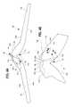
- FIG. 1is an isometric view of an embodiment of a luminaire shown from below;
- FIG. 2is an enlarged fragmentary view of the luminaire of FIG. 1 ;
- FIG. 3is a first sectional isometric views of the luminaire of FIG. 1 ;
- FIG. 4is a second sectional isometric view.
- FIG. 3Ais a plan view of the luminaire of FIG. 1 with central portions broken away to show LED elements or modules therein;
- FIG. 4Ais a side elevational view of one of the waveguides of FIG. 1 ;
- FIG. 4Bis a fragmentary enlarged side elevational view illustrating the waveguide of FIG. 4A in greater detail;
- FIG. 5is an enlarged fragmentary elevational view of one of the waveguides of FIG. 1 ;
- FIG. 6is a fragmentary isometric view of the light extraction features of FIG. 5 disposed on a substrate;
- FIG. 7is an enlarged fragmentary side elevational view of the light extraction features and substrate of FIG. 6 ;
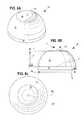
- FIGS. 8A-8Care isometric, plan, and side elevational views, respectively, of a further embodiment of a light extraction feature
- FIGS. 9A and 9Bare side elevational and plan views, respectively, of a further embodiment of an extraction feature before application to a waveguide;
- FIGS. 10A-10Care side elevational, plan, and further side elevational views, respectively, of the extraction features of FIGS. 9A and 9B after application to a waveguide;
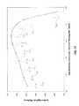
- FIG. 11is a graph illustrating system efficiency and light illumination distribution as a function of extraction feature height
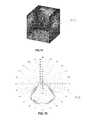
- FIGS. 12, 14, 16, and 18are isometric views illustrating different light illumination distributions developed by the luminaire of FIG. 1 in response to application of differing electrical power parameters to the LEDs thereof;
- FIGS. 13, 15, 17, and 19are graphs illustrating the illumination distributions of FIGS. 12, 14, 16, and 18 , respectively;
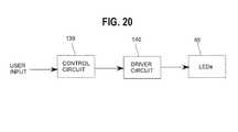
- FIG. 20is a block diagram of circuits for operating the LEDs of the luminaire of FIG. 1 ;
- FIG. 21is an enlarged fragmentary side elevational view of the waveguide of FIG. 1 with light extraction features applied thereto in which the indices of refraction of the light extraction features and the waveguide are approximately the same;
- FIG. 22is an enlarged fragmentary side elevational view of the waveguide of FIG. 1 with light extraction features applied thereto in which the indices of refraction of the light extraction features and the waveguide are different.
- FIG. 23is a view similar to F 5 showing a portion of a waveguide with different regions where the extraction features a of different heights.
- a luminaire 40includes a plurality of waveguides 42 a , 42 b , . . . , 42 N that are, in the illustrated embodiment, assembled together in fixed relationship by a frame or other holding or mounting apparatus 44 . While these figures illustrate a specific waveguide geometry and coupling approach, the overall concept of the invention may also be achieved using a variety of waveguide geometries and coupling approaches, including standard state-of-the-art flat (planar) waveguides with edge or center coupling.
- the multiple waveguides 42 a , 42 b , . . . , 42 Nare maintained in a side-by-side array wherein each waveguide 42 is disposed adjacent at least one other waveguide 42 .
- optional optical isolation members in the form of reflective barriers 50 a , 50 b , . . . , 50 N ⁇ 1may be disposed between some or all adjacent waveguides 42 .
- Each reflective barrier 50may comprise a specular or white reflective member or film that extends partially or completely between adjacent waveguides 42 so that the adjacent waveguides are partially or fully optically isolated, respectively, with respect to one another. Further reflective barriers 50 may be disposed between outer waveguides 42 a , 42 N and the mounting apparatus 44 , if desired.
- each waveguide 42may have any suitable shape, and the shapes of the waveguides may be different from one another or substantially identical.
- a first subset less than all of the waveguides 42may be substantially identical to one another, and some or all of the remaining waveguides 42 comprising a second subset may be different than the waveguides of the first subset.
- the waveguides of the second subsetmay be substantially identical to each other or some or all may be different from one another.
- Any combination of substantially identical and/or different waveguides 42is contemplated.
- nine waveguides 42are illustrated in the FIGS., a different number of waveguides could be used.
- each waveguide 42includes an input portion 58 having a light coupling feature in the form of a cavity 60 disposed between two outwardly extending arm portions 62 , 64 .
- One or more LED elements or modules 65are disposed in or adjacent each cavity 60 .
- the arm portions 62 , 64are preferably mirror images of one another about an axis of symmetry 66 coincident with a center line of the light coupling cavity 60 .
- each arm portion 62 , 64is tapered, and the arm portions 62 , 64 are disposed at an included angle therebetween.
- each waveguide 42may have the shape and size (including dimensions), for example, as shown in International Application No. PCT/US14/13937, filed Jan. 30, 2014, entitled “Optical Waveguide Bodies and Luminaires Utilizing Same”, incorporated by reference herein.
- the included angleis equal to about 160 degrees such that each waveguide disposed with an angle of about 10 degrees relative to horizontal.
- the luminairemay include more than one waveguide and may utilize interior-lit coupling, multiple-edge coupling, or a combination thereof.
- One example of multiple-edge couplingis described in co-pending U.S. patent application Ser. No. 14/472,035, filed Aug.
- the type of couplingmay influence the angular and spatial distribution of light within the waveguide, which in turn, can influence the efficiency of extraction, the illuminance, and the luminance.
- Each LED element or module 65may be a single white or other color LED chip or other bare component, or each may comprise multiple LEDs either mounted, separately or together on a single substrate or package to form a module including, for example, at least one phosphor-coated LED either alone or in combination with at least one color LED, such as a green LED, a yellow LED, a red LED, etc.
- each LED element or module 65 or a plurality of such elements or modulesmay include one or more blue shifted yellow LEDs and one or more red LEDs.
- the LEDsmay be disposed in different configurations and/or layouts as desired. Different color temperatures and appearances could be produced using other LED combinations, as is known in the art.
- the luminairemay include LEDs 65 of the same type of phosphor-converted white LED, or any combination of the same or different types of LEDs discussed herein.
- a luminairemay include a plurality of groups of LEDs 65 , where each group may include LEDs 65 having different colors and/or color temperatures.
- the groups of LEDs 65may be separated by dividers, as described in U.S. patent application Ser. No. 14/472,035, filed Aug. 28, 2014, entitled “Luminaire Utilizing Multiple Edge Coupling”, incorporated herein by reference, wherein the LEDs 65 are disposed within the coupling cavity.
- the light sourcecomprises any LED, for example, an MT-G LED incorporating TrueWhite® LED technology or as disclosed in U.S. patent application Ser. No. 13/649,067, filed Oct.
- each LED element or module 65may comprise one or more LEDs disposed vertically within the coupling cavity.
- the LED element(s) or module(s) 65preferably have a Lambertian or near-Lambertian light distribution, although each may have a directional emission distribution (e.g., a side emitting distribution), as necessary or desirable. More generally, any lambertian, symmetric, wide angle, preferential-sided, or asymmetric beam pattern LED(s) may be used as the light source.
- the input portion 58includes two control sections 68 , 70 that are preferably, although not necessarily, mirror images of one another about the axis of symmetry 66 .
- Each control section 68 , 70includes at least one control surface 72 , 74 , respectively.
- FIG. 4Bwhich illustrates the control section 68 in greater detail, first and second opposed control surfaces 72 a , 72 b are disposed in spaced relationship with respect to the light coupling cavity 60 .
- the control section 70includes corresponding opposed control surfaces 74 a , 74 b and the control surfaces 72 a , 74 a together define a curved V-shaped surface 75 . If desired, the V-shaped surface 75 may have a specular or other reflective coating or member disposed thereon.
- the light coupling cavity 60is defined by first, second, third, and fourth surfaces 80 a - 80 d .
- the surfaces 80 a - 80 d and the control surfaces 72 , 74are designed to cause light developed by the one or more LED elements or modules 65 disposed in or adjacent the light coupling cavity 60 to be redirected into two groups or sets of light rays each of which travels within a range of ray angles through each arm portion 62 , 64 .
- the primarily lambertian distribution of light developed by the LED elements or modules 65is incident on the surfaces 80 a - 80 d defining the cavity 60 , and light incident on the second and third surfaces 80 b , 80 c travels through the input portion 58 and strikes the curved V-shaped surface 75 .
- the control surfaces 72 a , 74 aredirect the light by TIR (and/or specular reflection if the coating or member 76 is present) into the arm portions 62 , 64 as first sets of ray groups 91 a , 91 b that bounce due to total internal reflection between first and second surfaces 62 a , 62 b of the arm portion 62 and first and second surfaces 64 a , 64 b of the arm portion 64 , respectively.
- the light rays of the groups 91 a , 91 bcontinue to travel through the arm portions 62 , 64 , respectively, until such rays strike an index interface surface at a particular angle less than an angle measured with respect to a line normal to the surface point at which the light ray is incident or, equivalently, until the light rays exceed an angle measured with respect to a line tangent to the surface point at which the light ray is incident, and the light rays escape.
- Light incident on the first and fourth surfaces 80 a , 80 d of the cavity 60travels through the input portion 58 without striking the curved V-shaped surface 75 .
- at least some of the light incident on the surfaces 80 a , 80 dis further incident on the second control surfaces 72 b , 74 b and such surfaces are curved in a manner that causes the light to be redirected into second sets of ray groups 92 a , 92 b .
- This lightalso bounces between the first surfaces 62 a , 64 a and the second surfaces 64 a , 64 b until such rays escape the arm portions 62 , 64 .
- the ray groups 91 a , 91 b , 92 a , and 92 bhave narrow ray angle distributions (i.e., the ray groups are substantially or fully collimated).
- the control surfaces 72 , 74may be partially or fully parabolic in shape and centered on the LED elements or modules 65 .
- One or more extraction features 93FIGS.
- any or all of the surfaces 62 a , 62 b , 64 a , 64 bcause the light to exit the waveguide 42 in a controlled fashion such that light is directed out of the first and/or second surfaces 62 a , 62 b , 64 a , 64 b , as noted in greater detail hereinafter. Because the light rays are at least substantially collimated they experience minimal spreading as they propagate through the arm portions 62 , 64 . This results in highly controlled beams that can be either extracted in a collimated fashion, or spread into a wide distribution, as also described in greater detail hereinbelow.
- a light reflective backplane member 100may be disposed above the waveguides 42 .
- the backplane member 100may comprise a part of the frame or other holding or mounting apparatus 44 or may be separate therefrom.
- the member 100may include a surface 102 adjacent the surfaces 62 h , 64 b that has a white or specular reflective coating or other member secured or otherwise applied thereto. Light exiting the surfaces 62 b , 64 b of one of the waveguides 42 a , 42 b , . . . , 42 N is reflected off the surface 102 and re-directed downward through the same waveguide 42 (and/or any of the other waveguides 42 ) so that the light contributes to the luminous intensity distribution of the luminaire.
- each waveguide 42includes a plurality of light extraction features 93 disposed on light emission surfaces comprising the surfaces 62 a , 64 a .
- one or more waveguides of the luminairemay include one or more light emission surfaces including light extraction features thereon.
- the plurality of light extraction features 93comprises an array 110 of regularly-spaced features 112 , although it should be noted that the light extraction features may be irregularly spaced or some may be regularly spaced and others irregularly spaced, etc.
- the light extraction features 93are disposed in a hexagonal array and are disposed on a substrate 114 , which may be a planar member, such as a film, a plate, a block or material, or the like. Further in the illustrated embodiment, the light extraction features 93 comprise protrusions carried by a film wherein the protrusions are disposed between the film and the light emission surfaces 62 a , 64 a.
- the substrate 114 having features 93 disposed thereonmay be fabricated using one of a variety of techniques typically applied to the formation of micro-optical films, including gray-scale lithography, micro-replication, injection/compression molding, reactive ion etching, chemical embossing, or drum roll transfer. Other methods of fabrication include dispensing an acrylic-based UV resin or silicone material on a carrier film that is subsequently cured to form extraction features.
- the extraction features 93may be disposed on the waveguide 42 without a substrate 114 .
- the extraction features 93may be fabricated directly on the first surfaces 62 a , 64 a of the waveguide 42 by means of an intermediate patterning layer as described in U.S. Pat. No. 8,564,004, issued Oct. 22, 2013, entitled “Complex Primary Optics with Intermediate Elements” by Tarsa et al., incorporated by reference herein.
- the extraction features 93are optically joined to the waveguide 42 without the need for the substrate 114 .
- the patterning layermay be used with any method such as molding, injection molding, compression molding, dispensing, stencil printing, three-dimensional printing, photolithography, deposition, or the like.
- the patterning layeris formed on the first surfaces 62 a , 64 a of the waveguide 42 and includes holes or openings where the waveguide 42 is exposed.
- the openings of the patterning layercorrespond to locations where the extraction features 93 are to be formed on the waveguide 42 .
- a moldis then placed over the patterning layer and first surfaces 62 a , 64 a of the waveguide 42 .
- the moldincludes voids that are aligned with the openings of the patterning layer to define cavities.
- the cavitiesare filled with the material of the extraction features.
- the material of the extraction featuresis applied to the openings of the patterning layer prior to placement of the mold on the patterning layer.
- the material of the extraction featureis then at least partially cured and the mold is removed.
- the material of the patterning layermay comprise polyvinyl alcohol, a poly(methyl methacrylate) (PMMA) one or more photoresist materials, or other suitable materials.
- the patterning layermay be removed by a water rinse, heat, vaporization, machining, developers and solvents, chemical etching/solvent, plasma etching, or any method that does not interfere with the material of the waveguide 42 and/or extraction features 93 .
- the waveguide 42 , the extraction features 93 , and/or the substrate 114may be bonded to one another through one or more supplemental layers such as an adhesive layer or pressure-sensitive adhesive film.
- the light extraction features 93may be of the same material as the substrate 114 and/or the waveguide 42 , or the materials of the features 93 , the substrate 114 , and/or the waveguide 42 may be different.
- the material(s) of the features 93 and the substrate 114 , as well as the waveguides 42preferably comprise optical grade materials that exhibit TIR characteristics including, but not limited to, one or more of acrylic, air, polycarbonate, molded silicone, glass, and/or cyclic olefin copolymers, and combinations thereof, possibly in a layered arrangement, to achieve a desired effect and/or appearance.
- the features 93are all solid or some or all have one or more voids or discrete bodies of differing materials therein. Still further, the features 93 are preferably (although not necessarily) of substantially the same size (except, perhaps height extending from the substrate 114 ) and preferably (but not necessarily) have substantially the same shape.
- FIGS. 11-17Examples of illuminance distributions 95 A- 95 K produced by each waveguide 42 are shown in FIGS. 11-17 .
- the illuminance distributions 95 A- 95 Kare dependent upon the particular geometry and arrangement of extraction features 93 .
- the features 93may have a truncated hemispherical shape, although other shapes and/or sizes are possible.
- the base diameter db of the extraction feature 93may be approximately twice a height H.
- the height Hmay vary in turn to vary the desired illuminance distribution as described below.
- a wide range of geometriescould be used for the various waveguides to produce a wide variety of patterns. For example, the geometries illustrated in FIGS.
- FIGS. 8A-8CAnother geometry which is particularly useful for a range of lighting applications includes a roughly “bullet shaped” profile as illustrated in FIGS. 8A-8C , consisting of a truncated curved surface 94 such as a truncated hemisphere with an adjacent cylindrical or conical base 96 .
- This particular geometryprovides a high degree of directionality as well as a range of possible illuminance distributions that may be realized by changing the height at which the curved surface is truncated.
- the height A of the hemispherical portion 94affects the distribution of the light illumination of each waveguide 42 while the height C of the base 96 affects the percentage of light emitted downwardly relative to upward emitted light.
- a bonding feature 98 having a central planar portion 99may be formed atop the truncated hemispherical portion 94 .
- the bonding feature 98facilitates fabrication by enabling the bond between the feature 93 and the waveguide surfaces 62 a , 64 a to be free of air pocket(s) that may otherwise form.
- the bonding feature 98 of each extraction featureis bonded, laminated, or otherwise optically coupled to the light emission surfaces 62 a , 64 a such that the bonding feature 98 is embedded in the interposing adhering layer and results in a planar bond between the extraction feature 93 and the waveguide surfaces 62 a , 64 a , as depicted in FIG. 5 .
- Example dimensions of one embodiment of the feature 93are provided in Table 1.
- At least one of the waveguides 42has a first set of features 93 disposed thereon that are all substantially of the same first height H 1 wherein at least one other waveguide 42 has a second set of features 93 disposed thereon that are all substantially of the same second height H 2 different than the first height H 1 .
- the features 93 a of the surface 62 a or a first region of waveguide 42may have a different height than the features 93 b of the surface 64 a or a second region of the same waveguide 42 (see FIG. 23 ). More particularly, referring to FIG.
- the heights of the features 93 associated with each waveguide 42preferably are in a range between about 10 ⁇ m and about 590 ⁇ m, and more preferably are in a range between about 100 ⁇ m and about 570 ⁇ m, and most preferably are in a range between about 279 ⁇ m and about 550 ⁇ m.
- the center-to-center spacings of the features 93vary across with the waveguide 42
- the center-to-center spacingspreferably are in a range between about 1.2 mm and about 20 mm, and more preferably are in a range between about 1.2 mm and about 10 mm, and most preferably are in a range between about 1.25 mm and about 5 mm.
- the center-to-center spacings of the features 93may range from about 1.2 mm to about 2 mm, preferably about 1.25 mm.
- the maximum side-to-side dimensions of the features 93e.g., the diameter d b in FIG. 7 ) associated with each waveguide 42 preferably are in a range between about 0.1 micron and about 10 mm, and more preferably are in a range between about 1 micron and about 5 mm, and most preferably are in a range between about 10 microns and about 2 mm.
- the minimum distances between adjacent features 93preferably are in a range between about 0.1 microns and about 20 mm, and more preferably are in a range between about 1 micron and about 5 mm, and most preferably are in a range between about 10 microns and about 1 mm.
- Each extraction feature 116includes a body 118 having a curved shape that extends between an aperture 120 adjacent the first surfaces 62 a , 64 a ( FIG. 5 ) of the waveguide 42 and a base 122 opposite the aperture 120 .
- the aperture 120 and the base 122may be parallel or disposed at an angle relative to one another, as may be desired for a specialized asymmetric distribution.
- the body 118is undercut relative to the first surfaces 62 a , 64 a of the waveguide 54 .
- the body 118may include planar surfaces, curved surfaces, planar surfaces approximating one or more curved surfaces, or a combination thereof.
- the cross sectional outer profile of the body 118may be symmetric in nature (e.g., as in the case of a hemisphere) or asymmetric (e.g., as in the case of an ellipse or other combination of shapes when viewed from above or below).
- the extraction features 116 and/or waveguide 42may be acrylic, including an acrylic UV-curable resin, silicone, polycarbonate, glass, or other suitable material(s) and combinations thereof, possibly in a layered arrangement, to achieve a desired effect.
- the body 118may include a first portion 124 adjacent the aperture 120 and a second portion 126 adjacent the base 122 .
- the first portion 124may be designed to redirect incident light downward through total internal reflection (TIR).
- TIRtotal internal reflection
- a shape of the extraction feature 116may be determined by iteratively plotting the points defining an outer surface of the shape using a differential or quasi-differential equation.
- One iterative processincludes the steps of defining a start point at coordinates r, h, calculating a slope necessary to achieve total internal reflection for all light rays entering the extraction feature, and, based on the calculated slope, further calculating the necessary incremental radial step ⁇ r that corresponds to a predetermined incremental height change ⁇ h, moving to a new point r+ ⁇ r and h+ ⁇ h, and repeating the calculation and moving steps until the desired total height is reached.
- the outer surfaces 124 , 132may be designed using geometric and/or differential equation (s) in combination with other curved, planar, and/or piecewise linear surfaces.
- Equations 1 and 2are entered into an optimization routine such as Solver by Microsoft Excel®.
- a profile of the extraction feature 116is defined by calculating a series of slopes dh/dR at incremental points 202 a , 202 b , . . . , 202 N along an outer surface 128 of the first portion 124 of the extraction feature 116 .
- the outer surface 128is then rotated about a central axis 200 to define the extraction feature 116 .
- Equation 1the sharpest angle of ⁇ ray of light striking a given point, for example, 202 d on the outer surface 128 is determined.
- the sharpest angle ⁇is defined by a light ray 204 entering the aperture 120 at an edge 206 thereof opposite to the point 202 d , and is measured relative to a surface normal 208 of the aperture 120 .
- the angle ⁇is calculated based on the coordinates of the point 202 d relative to the entry of the light ray 204 into the extraction feature 116 at the edge 206 of the aperture 120 .
- the point 202 dhas a y-coordinate value h relative to the respective waveguide surface 62 a , 64 a and an x-coordinate value R o +R, where R o is a distance from the edge 206 to the central axis 200 (i.e., an aperture radius) and R is a distance from the central axis 200 to the point 202 d.
- Equation 2the slope dh/dR at the point 202 d along the outer surface 128 is then calculated. Equation 2 ensures that the resultant incident angle ⁇ relative to a surface normal 210 at point 202 d exceeds the critical angle ⁇ relative to the surface normal 210 . As shown in FIG. 10C , the angle is the angle complementary to the critical angle ⁇ . In the illustrated example, the resultant incident angle ⁇ of the light ray 204 is approximately the same as or greater than the critical angle ⁇ such that the light ray 204 is totally internally reflected by the outer surface 128 of the extraction feature 116 and emitted through the base 122 thereof.
- the angle ⁇is calculated using Equation 1 for the next point 202 e having incremental changes ⁇ h, ⁇ R along the x- and y-coordinates h, R.
- the slope dh/dR for the point 202 eis then determined using Equation 2, and the process is repeated until a known parameter is satisfied, for example, once the height distance h reaches the height M ( FIG. 10A ) of the first portion 124 , or in some cases the total height M+N ( FIG. 10A ), of the extraction feature 116 .
- the incremental change ⁇ hmay range from about 1 nm to about 1 ⁇ m, or may be a fraction, such as 1/50 th , of the total height M+N ( FIG. 10A ) of the extraction feature 116 .
- Equation 2may be implemented with a conditional check to specify an upper limit for the slope dh/dR.
- the upper limitmay be used in lieu of the calculated slope as desired.
- the upper limitmay be specified as angle ⁇ , defined by an outer surface 132 of the second portion 126 relative to the base 122 .
- the optimization routinemay determine the aperture radius R o for a preferred area ratio (i.e., ratio of aperture area to base area) subject to user defined conditions, such as the total height M+N ( FIG. 10A ), the critical angle ⁇ (based on the relative indices of refraction), and the desired smallest angle defined by the sharpest angle ⁇ of a light ray 212 that strikes the point 204 N on the outer surface 132 at the base 122 of the extraction feature 116 .
- Other user defined conditionsmay be specified as desired.
- the outer surfaces 124 , 132 designed in accordance with the description aboveresults in extraction of over 95% of light out of the first surfaces 62 a , 64 a of the waveguide 42 .
- the shape, size, or density of extraction features 116may be varied across the surfaces 62 a , 64 a of the waveguide 42 in either a regular or irregular fashion to produce a desired illuminance distribution.
- a plurality of substrates 114 a , 114 b or films having differently shaped extraction features 93 a , 93 b respectively,may be bonded to the waveguide 42 to produce an asymmetric illumination distribution as shown in FIG. 24 .
- the aperture diameters d a , the base diameters d b , and the heights H of the extraction features 93 , 116may all be the same or different, and may be varied over the surface(s) 62 a , 64 a of the waveguide 42 to provide varying illumination patterns, as desired. Further, it may be desirable to fabricate varying degrees of roughness, or specific optical features, such as a second set or array of geometric features, on an outer surface 130 ( FIG. 7 ) of the member 114 in order to further provide control over the luminance and illuminance distributions. In other embodiments, the extraction features 93 , 116 may be shaped to extract the luminance from both of the first and second surfaces 62 a , 62 b , 64 a , and 64 b.
- a second outer surface 132 of the second portion 126has a conical shape that forms an angle ⁇ with the base 122 .
- the angle ⁇may range from 1 degree to 90 degrees, preferably from 60 degrees to 90 degrees.
- FIGS. 10A and 10Billustrate the extraction feature 84 of FIGS. 9A and 9B as disposed on the first surface of the waveguide.
- Example dimensions of the extraction feature of FIGS. 9A, 9B, 10A, and 10Bare provided below.
- a luminaire having a plurality of extraction features 116 of FIGS. 10A and 10Bextracts approximately 97% of light traveling through the waveguide 42 from the first surfaces 62 a , 64 a such that approximately 3% of the light traveling through the waveguide 42 is emitted from the second surface 62 b , 64 b .
- FIG. 9AH3 33 ⁇ m J 5 ⁇ m K 53.26 ⁇ m L 16.716 ⁇ m B 70 degrees
- FIG. 10AM 13.95 ⁇ m N 14.050 ⁇ m P 53.26 ⁇ m Q 26.716 ⁇ m ⁇ 70 degrees
- the extraction features 93 , 116may have an asymmetric shape.
- the first portion 124 of the extraction feature 116may be hemispherical and the base 122 may be elliptical such that the feature 116 appears as a truncated hemisphere when viewed from any cross-section, but appears as an ellipse or elongated circle when viewed from the top or bottom.
- Such asymmetric geometrywould result in an asymmetric illuminance pattern such that may be desired for certain applications, such as roadway lighting.
- the extraction features 93 , 116 having an asymmetric cross-section along the height Hmay direct light into particular directions or quadrants below the luminaire.
- Extraction features 93 , 116 with segmented cross-sections and top or bottom profiles consisting of a combination of curved surfaces and linear surfacesmay be used for specific lighting applications requiring a very unique and defined illuminance distribution (e.g., stage lighting, architectural or cove lighting).
- extraction features having a generally conic shapemay produce more collimated light beams in specific directions (e.g., for direct/indirect pendant lighting, downlighting, etc.).
- the waveguide 42is shaped such that the second surfaces 62 b , 64 b are relatively planar and the first surfaces 62 a , 64 a taper outwardly from the coupling cavity 60 toward an outer edge (not shown).
- the apertures 120 of the extraction features 93 , 116may be optically joined to the first surfaces 62 a , 64 a while the bases 122 of the extraction features 93 , 116 are parallel to the second surfaces 62 b , 64 b .
- the extractor height Hwould range from relatively small adjacent the coupling cavity 60 to relatively large adjacent the outer edge (not shown).
- the apertures 120 and the bases 122would be disposed at angle relative to one another.
- a luminaire including at least one waveguide 42 that has features 93 disposed thereonproduces a luminous intensity pattern or distribution that varies with feature height (the luminous flux distributions shown in the FIG. assume that the features 93 of all of the waveguides are all of substantially the same diameter).
- the luminous intensity patternvaries from a “wall-wash” distribution (i.e., a distribution having a significant side-to-side illumination component) at feature heights of about 279 micrometers, to a general or “near-lambertian” distribution at a feature height of about 427 micrometers, to a task lighting or “spotlight” distribution at a feature height of about 550 micrometers.
- the luminous flux variancesresult from variations in optical coupling surface area and extractor aperture area between the features 93 and the waveguide 42 as the cross-sectional dimensions of the interface between features 93 and the waveguide vary with feature (truncation) height.
- the luminaire 40includes three waveguides 42 a , 42 d , 42 g including features 93 disposed thereon having heights of about 279 micrometers, three waveguides 42 b , 42 e , 42 h including features 93 disposed thereon having heights of about 427 micrometers, and the remaining three waveguides 42 c , 42 f , 42 i including features 93 disposed thereon having heights of about 550 micrometers.
- a control circuit 139 and a driver circuit 140are responsive to a user or other input (which may be a fixed or variable signal) and varies a parameter of electrical power (for, example, drive current) to each of the LED elements or modules 65 a - 65 i to obtain a desired or commanded illumination distribution.
- full or partial drive currentmay be delivered by the circuits 139 , 140 to the LED elements or modules 65 a , 65 d , and 65 g and no drive current may be supplied to the remaining LED elements or modules 65 b , 65 c , 65 e , 65 f , 65 h , and 65 i so that the luminaire 40 develops the wall-wash luminous intensity pattern or distribution ( FIGS. 12 and 13 ) at a light intensity dependent upon the magnitude of the drive current.
- full or partial drive currentmay be supplied to either the LED elements or modules 65 b , 65 e , 65 h or the LED elements or modules 65 c , 65 f , 65 i and no drive current supplied to the remaining LED elements or modules 65 a , 65 d , 65 g to cause the luminaire 40 to develop the near-lambertian luminous intensity pattern ( FIGS. 14 and 15 ) or spot luminous intensity pattern ( FIGS. 16 and 17 ), respectively.
- the intensity of the lightis determined by the magnitude of the supplied drive current.
- Combined luminous flux distributionsare obtained by providing drive currents to the LEDs 65 associated with combinations of the waveguides 42 .
- a first group of LEDs 65 associated with waveguides 42 a , 42 d , 42 gmay have a first color and/or color temperature
- a second group of LEDs 65 associated with waveguides 42 b , 42 e , 42 hmay have a second color and/or color temperature
- a third group of LEDs 65 associated with waveguides 42 c , 42 f , 42 imay have a third color and/or color temperature such that variation in drive currents to the LEDs 65 results in different color distributions.
- a combined wall-wash and lambertian luminous intensity pattern or distributionmay be obtained by providing drive currents of desired magnitudes to the LED elements or modules 65 a , 65 d , 65 g and 65 b , 65 e , 65 h and no drive current to the remaining LED elements or modules 65 c , 65 f , 65 i .
- a combined wall-wash and spot luminous intensity pattern or distributionmay be obtained by supplying drive currents to the LED elements or modules 65 a , 65 d , 65 g and 65 c , 65 f , 65 i and no drive current to the LED elements or modules 65 b , 65 e , 65 h and a combined lambertian and spot distribution may be obtained by supplying drive currents to the LED elements or modules 65 b , 65 e , 65 h and 65 c , 65 f , 65 i and no drive current to the LED elements or modules 65 a , 65 d , 65 g . Still further, a combined wall-wash, lambertian and spot luminous intensity pattern or distribution (seen in FIGS.
- the magnitudes of the drive currents supplied to the LED elements or modules 65 associated with the waveguides 42determine the intensities of the distributions developed by such waveguides 42 .
- full drive current magnitudes supplied by the circuits 139 , 140 to the LED elements or modules 65 a , 65 d , 65 g and one-half drive current supplied to the remaining LED elements or modules 65 b , 65 c , 65 e , 65 f , 65 h , and 65 iresults in a relatively high intensity wall-wash luminous flux distribution and lesser intensity lambertian and spot luminous flux distributions combined with the wall-wash distribution. An infinite range of combinations is possible, as should be evident.
- the waveguides 42 a , 42 d , 42 gmay all be of a first overall shape
- the waveguides 42 b , 42 e , 42 hmay all be of a second overall shape the same or different than the first overall shape
- the waveguides 42 c , 42 f , 42 imay be of a third overall shape the same or different than one or both of the first and second overall shapes.
- the features 93 on the waveguides 42 a , 42 d , 42 gmay all have a fourth shape
- the features 93 on the waveguides 42 b , 42 e , 42 hmay all have a fifth shape the same or different than the fourth shape
- the features 93 on the waveguides 42 c , 42 f , 42 imay have a sixth shape the same or different than one or both of the fourth and fifth overall shapes.
- the LED elements or modules 65 a , 65 d , 65 gmay emit the same first color or first plurality of colors
- the LED elements or modules 65 b , 65 e , 65 hmay emit the same second color or second plurality of colors the same or different than the first color or first plurality of colors
- the LED elements or modules 65 c , 65 f , 65 imay emit the same third color or third plurality of colors the same or different than the first and/or second color or first and/or second plurality of colors.
- all or some of the overall shapes of the waveguides 42 , all or some of the shapes, sizes, and/or arrangements of features 93 on one or more of the substrates 114 , and/or all or some of the LED element or module colors or plurality of colorsmay be the same or different to obtain varying combinations of light luminous flux distributions and/or colors.
- different light illumination parametersmay be obtained for each light luminous flux distribution, such as illumination shape, color, intensity and/or the like and/or more or fewer than three distributions can be obtained by adding or omitting waveguides 42 , reducing or increasing drive current to one or more LED elements or modules or pluralities of such elements or modules, as appropriate, etc.
- one or more parameters of electric power delivered to individual LEDs elements or modulesmay be controlled by a user via the circuits 139 , 140 in turn to control one or more luminaire optical parameters including, but not limited to, luminance distribution and/or color, color saturation, and/or color temperature.
- any of the embodiments disclosed hereinmay include a power circuit having a buck regulator, a boost regulator, a buck-boost regulator, a SEPIC power supply, or the like, and may comprise a driver circuit as disclosed in U.S. patent application Ser. No. 14/291,829, filed May 30, 2014, entitled “High Efficiency Driver Circuit with Fast Response” by Hu et al. or U.S. patent application Ser. No. 14/292,001, filed May 30, 2014, entitled “SEPIC Driver Circuit with Low input Current Ripple” by Flu et al. incorporated by reference herein.
- the circuitmay further be used with light control circuitry that controls color temperature of any of the embodiments disclosed herein in accordance with user input such as disclosed in U.S. patent application Ser. No. 14/292,286, filed May 30, 2014, entitled “Lighting Fixture Providing Variable CCT” by Pope et al. incorporated by reference herein.
- any of the embodiments disclosed hereinmay include one or more communication components forming a part of the light control circuitry, such as an RF antenna that senses RF energy.
- the communication componentsmay be included, for example, to allow the luminaire to communicate with other luminaires and/or with an external wireless controller, such as disclosed in U.S. patent application Ser. No. 13/782,040, filed Mar. 1, 2013, entitled “Lighting Fixture for Distributed Control” or U.S. provisional application No. 61/932,058, filed Jan. 27, 2014, entitled “Enhanced Network Lighting” both owned by the assignee of the present application and the disclosures of which are incorporated by reference herein.
- control circuitryincludes at least one of a network component, an RF component, a control component, and a sensor.
- the sensorsuch as a knob-shaped sensor, may provide an indication of ambient lighting levels thereto and/or occupancy within the room or illuminated area. Such sensor may be integrated into the light control circuitry.
- one or more light distributionscan be developed by a luminaire by providing one or more sets of waveguides of differing optical characteristic(s) and controlling one or more parameters of electrical power to LEDs associated with such sets of waveguides.
- a luminaire or lighting fixtureprovides an adjustable illuminance, luminance, and/or luminous flux distribution and/or color, color saturation, or color temperature.
- a luminaire fixturehaving a range of possible luminous flux distributions including a wall-wash setting (e.g., for highlighting artwork), a general or lambertian setting for general illuminance, and a collimated or spotlight setting for task lighting.
- the various settingscould be adjusted via the control circuit 139 using a wall switch or wired/wireless data transfer from a mobile device or network. This enables a new class of task specific lighting adjustments for a single lighting system, allowing a user to tailor illuminance to suit both the workspace and the task at hand.
- Dynamic or adjustable illuminance systemscan also provide safety benefits, with specific lighting conditions designated for emergency conditions, and can also provide energy savings, with light more efficiently distributed into areas critical for the task at hand. Different illuminance areas may overlap.
- the adjustable/dynamic luminance aspect of the embodiments disclosed hereincould be used to tailor and/or minimize glare for specific tasks and/or situations, as well as provide aesthetic opportunities, such as having the luminaire display an image that also provides illumination for the room.
- a luminairemay provide colored areas of light and/or one or more images, including effects such as clouds moving across a blue illuminated ceiling.
- Other applicationscould enhance advertising or branding by having the luminaire display messages while providing illuminance, either in an adjustable (e.g., via wall switch or network) or dynamic (continuously changing) manner.
- the embodiments disclosed hereinmay be used for general lighting, energy efficient lighting, task-specific lighting, emergency lighting, advertising, and other applications.
- at least some of the luminairespreferably require a total luminaire output of at least about 100 lumens or greater, and, in some embodiments, a total luminaire output of at least about 3,000 lumens, and, in other embodiments, a total lumen output of about 10,000 lumens to about 20,000 lumens.
- a total lumen output of up to 10,000 lumensmay be desired in some industrial and business lighting applications such as warehouse lighting.
- the luminaires disclosed hereinpreferably have a color temperature of between about 2500 degrees Kelvin and about 6200 degrees Kelvin, and, in some embodiments, between about 2500 degrees Kelvin and about 5000 degrees Kelvin, and, in other embodiments, between 2700 and 3500 degrees Kelvin. Also, at least some of the luminaires disclosed herein preferably exhibit an efficacy of at least about 80 lumens per watt, and more preferably at least about 100 lumens per watt, and most preferably at least about 120 lumens per watt. Further, in some of the luminaires described herein, the waveguide or waveguides exhibit an optical efficiency of at least about 80 percent, preferably, at least about 90 percent, and most preferably, at least about 95 percent.
- At least some of the luminaires disclosed hereinpreferably exhibit an overall efficiency (i.e., light extracted out of the waveguide divided by light injected into the waveguide) of at least about 70 percent, preferably, at least about 80 percent, and most preferably, at least about 90 percent.
- a color rendition index (CRI) of at least about 80is preferably attained by at least some of the luminaires disclosed herein, with a CRI of at least about 88 being more preferable, and at least about 90 being most preferable.
- Some luminairesexhibit a CRI of at least about 90 while maintaining a relatively high efficiency. Any desired form factor and particular output light distribution, such as a butterfly light distribution, could be achieved, including up and down light distributions or up only or down only distributions, etc.
- Fresnel lensesare generally planar in nature, and are therefore not well suited to re-directing high-angle light emitted by the source, leading to a loss in optical efficiency.
- lightis coupled into the optic, where primarily TIR is used for re-direction and collimation. This coupling allows the full range of angular emission from the source, including high-angle light, to be re-directed and collimated, resulting in higher optical efficiency in a more compact form factor.
- a waveguide having a high efficiency in a compact form factoris described in U.S. patent application Ser. No. 13/839,949, filed Mar. 15, 2013, entitled “Optical Waveguide and Lamp Including Same”.
- the distribution and direction of light within the waveguideis better known, and hence, light is controlled and extracted in a more controlled fashion.
- lightbounces back and forth through the waveguide.
- lightis extracted as much as possible over one pass through the waveguide to minimize losses.
Landscapes
- Physics & Mathematics (AREA)
- General Physics & Mathematics (AREA)
- Optics & Photonics (AREA)
- Engineering & Computer Science (AREA)
- Microelectronics & Electronic Packaging (AREA)
- Non-Portable Lighting Devices Or Systems Thereof (AREA)
- Planar Illumination Modules (AREA)
Abstract
Description
The present application claims the benefit of U.S. Provisional Patent Application No. 61/922,017, filed Dec. 30, 2013, entitled “Optical Waveguide Bodies and Luminaires Utilizing Same” and U.S. Provisional Patent Application No. 62/020,866, filed Jul. 3, 2014, entitled “Luminaires Utilizing Edge Coupling”. The present application further comprises a continuation-in-part of U.S. patent application Ser. No. 13/839,949, filed Mar. 15, 2013, entitled “Optical Waveguide and Lamp Including Same”, and further comprises a continuation-in-part of U.S. patent application Ser. No. 13/840,563, filed Mar. 15, 2013, entitled “Optical Waveguide and Luminaire Incorporating Same”, and further comprises a continuation-in-part of U.S. patent application Ser. No. 13/938,877, filed Jul. 10, 2013, entitled “Optical Waveguide and Luminaire Incorporating Same”, and further comprises a continuation-in-part of U.S. patent application Ser. No. 14/101,086, filed Dec. 9, 2013, entitled “Optical Waveguides and Luminaires Incorporating Same”, and further comprises a continuation-in-part of U.S. patent application Ser. No. 14/101,132, filed Dec. 9, 2013, entitled. “Waveguide Bodies Including Redirection Features and Methods of Producing Same”, and further comprises a continuation-in-part of U.S. patent application Ser. No. 14/101,147, filed Dec. 9, 2013, entitled “Luminaires Using Waveguide Bodies and Optical Elements”, and further comprises a continuation-in-part of U.S. patent application Ser. No. 14/101,129, filed Dec. 9, 2013, entitled “Simplified Low Profile Module With Light Guide For Pendant, Surface Mount, Wall Mount and Stand Alone Luminaires”, and further comprises a continuation-in-part of U.S. patent application Ser. No. 14/101,051, filed Dec. 9, 2013, entitled “Optical Waveguide and Lamp including Same”, and further comprises a continuation-in-part of International Application No. PCT/US14/13937, filed Jan. 30, 2014, entitled “Optical Waveguide Bodies and Luminaires Utilizing Same”, and further comprises a continuation-in-part of International Application No. PCT/US14/13931, filed Jan. 30, 2014, entitled “Optical Waveguides and Luminaires Incorporating Same”, all owned by the assignee of the present application, and the disclosures of which are incorporated by reference herein. This patent application incorporates by reference co-pending U.S. patent application Ser. No. 14/472,078, entitled “Waveguide Having Unidirectional Illuminance”, filed Aug. 28, 2014, and U.S. patent application Ser. No. 14/472,035, entitled “Luminaires Utilizing Edge Coupling”, filed Aug. 28, 2014, both owned by the assignee of the present application.
Not applicable
Not applicable
The present subject matter relates to lighting devices, and more particularly, to a luminaire incorporating waveguides for general illumination.
An optical waveguide mixes and directs light emitted by one or more light sources, such as one or more light emitting diodes (LEDs). A typical optical waveguide includes three main components: one or more coupling elements, one or more distribution elements, and one or more extraction elements. The coupling component(s) direct light into the distribution element(s), and condition the light to interact with the subsequent components. The one or more distribution elements control how light flows through the waveguide and is dependent on the waveguide geometry and material. The extraction element(s) determine how light is removed by controlling where and in what direction the light exits the waveguide.
When designing a coupling optic, the primary considerations are: maximizing the efficiency of light transfer from the source into the waveguide; controlling the location of light injected into the waveguide; and controlling the angular distribution of the light in the coupling optic. One way of controlling the spatial and angular spread of injected light is by fitting each source with a dedicated lens. These lenses can be disposed with an air gap between the lens and the coupling optic, or may be manufactured from the same piece of material that defines the waveguide's distribution element(s). Discrete coupling optics allow numerous advantages such as higher efficiency coupling, controlled overlap of light flux from the sources, and angular control of how the injected light interacts with the remaining elements of the waveguide. Discrete coupling optics use refraction, total internal reflection, and surface or volume scattering to control the distribution of light injected into the waveguide.
After light has been coupled into the waveguide, it must be guided and conditioned to the locations of extraction. The simplest example is a fiber-optic cable, which is designed to transport light from one end of the cable to another with minimal loss in between. To achieve this, fiber optic cables are only gradually curved and sharp bends in the waveguide are avoided. In accordance with well-known principles of total internal reflectance light traveling through a waveguide is reflected back into the waveguide from an outer surface thereof, provided that the incident light does not exceed a critical angle with respect to the surface. Specifically, the light rays continue to travel through the waveguide until such rays strike an index interface surface at a particular angle less than an angle measured with respect to a line normal to the surface point at which the light rays are incident (or, equivalently, until the light rays exceed an angle measured with respect to a line tangent to the surface point at which the light rays are incident) and the light rays escape.
In order for an extraction element to remove light from the waveguide, the light must first contact the feature comprising the element. By appropriately shaping the waveguide surfaces, one can control the flow of light across the extraction feature(s) and thus influence both the position from which light is emitted and the angular distribution of the emitted light. Specifically, the design of the coupling and distribution surfaces, in combination with the spacing (distribution), shape, and other characteristic(s) of the extraction features provide control over the appearance of the waveguide (luminance), its resulting distribution of emitted light (illuminance), and system optical efficiency.
Hulse U.S. Pat. No. 5,812,714 discloses a waveguide bend element configured to change a direction of travel of light from a first direction to a second direction. The waveguide bend element includes a collector element that collects light emitted from a light source and directs the light into an input face of the waveguide bend element. Light entering the bend element is reflected internally along an outer surface and exits the element at an output face. The outer surface comprises beveled angular surfaces or a curved surface oriented such that most of the light entering the bend element is internally reflected until the light reaches the output face
Parker et al. U.S. Pat. No. 5,613,751 discloses a light emitting panel assembly that comprises a transparent light emitting panel having a light input surface, a light transition area, and one or more light sources. Light sources are preferably embedded or bonded in the light transition area to eliminate any air gaps, thus reducing light loss and maximizing the emitted light. The light transition area may include reflective and/or refractive surfaces around and behind each light source to reflect and/or refract and focus the light more efficiently through the light transition area into the light input surface of the light-emitting panel. A pattern of light extracting deformities, or any change in the shape or geometry of the panel surface, and/or coating that causes a portion of the light to be emitted, may be provided on one or both sides of the panel members. A variable pattern of deformities may break up the light rays such that the internal angle of reflection of a portion of the light rays will be great enough to cause the light rays either to be emitted out of the panel or reflected back through the panel and emitted out of the other side.
Shipman, U.S. Pat. No. 3,532,871 discloses a combination running light reflector having two light sources, each of which, when illuminated, develops light that is directed onto a polished surface of a projection. The light is reflected onto a cone-shaped reflector. The light is transversely reflected into a main body and impinges on prisms that direct the light out of the main body.
Simon U.S. Pat. No. 5,897,201 discloses various embodiments of architectural lighting that is distributed from contained radially collimated light. A quasi-point source develops light that is collimated in a radially outward direction and exit means of distribution optics direct the collimated light out of the optics.
Kelly et al. U.S. Pat. No. 8,430,548 discloses light fixtures that use a variety of light sources, such as an incandescent bulb, a fluorescent tube and multiple LEDs. A volumetric diffuser controls the spatial luminance uniformity and angular spread of light from the light fixture. The volumetric diffuser includes one or more regions of volumetric light scattering particles. The volumetric diffuser may be used in conjunction with a waveguide to extract light.
Dau et al U.S. Pat. No. 8,506,112 discloses illumination, devices having multiple light emitting elements, such as LEDs disposed in a row. A collimating optical element receives light developed by the LEDs and a light guide directs the collimated light from the optical element to an optical extractor, which extracts the light.
A.L.P. Lighting Components, Inc. of Niles, Ill., manufactures a waveguide having a wedge shape with a thick end, a narrow end, and two main faces therebetween. Pyramid-shaped extraction features are formed on both main faces. The wedge waveguide is used as an exit sign such that the thick end of the sign is positioned adjacent a ceiling and the narrow end extends downwardly. Light enters the waveguide at the thick end and is directed down and away from the waveguide by the pyramid-shaped extraction features.
Low-profile LED-based luminaires have recently been developed (e.g., General Electric's ET series panel troffers) that utilize a string of LED components directed into the edge of a waveguiding element (an “edge-lit” approach). However, such luminaires typically suffer from Fow efficiency due to losses inherent in coupling light emitted from a predominantly Lambertian emitting source such as a LED component into the narrow edge of a waveguide plane.
Smith U.S. Pat. Nos. 7,083,313 and 7,520,650 disclose a light direction device for use with LEDs. In one embodiment, the light direction device includes a plurality of opposing collimators disposed about a plurality of LEDs on one side of the device. Each collimator collimates light developed by the LEDs and directs the collimated light through output surfaces of the collimators toward angled reflectors disposed on a second side opposite the first side of the device. The collimated light reflects off the reflectors out of and out of the device from the one side perpendicular thereto. In another embodiment, the collimators are integral with a waveguide having reflective surfaces disposed on a second side of the waveguide, and the collimated light is directed toward the reflective surfaces. The light incident on the reflective surfaces is directed from the one side of the device, as in the one embodiment.
Dau et al. U.S. Pat. No. 8,410,726 discloses a lamp for use in an Edison-type screw-in connector. The lamp includes a plurality of LED modules oriented radially within a base. In one embodiment, each LED module has a wedge shape. LEDs located near the base of the module emit light into a light guiding and extracting wedge. Surface extraction features are introduced into the wedge to extract light. A user can operate the light with different combinations of modules to generate a desired light output from the lamp.
Summerford et al. U.S. Pat. No. 8,547,022 discloses a lighting control system having a primary high intensity discharge light source and a secondary LED light source. Power is routed to either the primary or the secondary light source by a common power source.
Beeson et al. U.S. Pat. No. 5,396,350 teaches a backlighting apparatus used for flat panel electronic displays. The apparatus includes a slab waveguide that receives light from a light source positioned adjacent a side surface thereof and an array of microprisms attached to a face of the waveguide. Each microprism has a side surface tilted at an angle from the direction normal to the surface of the waveguide. Light emitted from the microprisms is substantially perpendicular to the slab waveguide.
Zimmerman et al. U.S. Pat. No. 5,598,281 discloses a backlight assembly for electro-optical displays. Light emitted from a light source disposed within a reflector travels through an array of apertures and is collimated by an array of tapered optical elements aligned with the array of apertures. Microlenses may be disposed adjacent the optical elements to further collimate the light. The surfaces of the optical elements are planar or parabolic in shape.
Zimmerman et al. U.S. Pat. No. 5,428,468 teaches an optical illumination system for applications that require substantially collimated light. The system comprises a waveguide that receives light at an edge thereof. An array of microprisms is attached to one face of the waveguide. Each microprism has at least two sidewalls tilted at an angle from the normal of the surface of the waveguide. An array of microlenses may be disposed atop the array of microprisms to further collimate the light.
Steiner et al. U.S. Pat. No. 5,949,933 discloses an optical illumination system for collimating light. The system includes a waveguide that receives light at an edge thereof and an array of lenticular microprisms attached to one face of the waveguide. Each microprism has a light input surface optically coupled to the waveguide and a light output surface opposite the input surface. The light input surface includes a number of tapered grooves perpendicular to the length of the lenticular microprism. The system also includes an array of microlenses to further collimate the light.
Hou et al. U.S. Pat. No. 5,839,823 teaches an illumination system including a light source adjacent to or housed within a reflector. A light-directing assembly having at least one microprism carried on a base wall is positioned adjacent the light source opposite the reflector. The microprism may be polyhedronal, curvilinear, and polyhedronal curvilinear. A lens array may be disposed on the other side of the base wall.
Kuper et al. U.S. Pat. No. 5,761,355 discloses a light directing optical structure comprising a waveguide having a multiplicity of prisms attached thereto. Light redirected by the prisms is constrained to a range of angles. The side face(s) of the prisms may be planar or curved. An array of lenses may be used to spread the light output of the prisms to a wider distribution angle.
According to one aspect, a luminaire comprises at least one waveguide having a first region that emits a first luminous intensity pattern and a second region that emits a second luminous intensity pattern different from the first luminous intensity pattern. The luminaire further includes a plurality of LED elements and circuitry to control the plurality of LED elements to cause the luminaire to produce a selected one of a plurality of luminous intensity patterns.
According to another aspect, a luminaire includes a plurality of waveguides each having a light emission surface and a plurality of extraction features. The plurality of light extraction features are disposed on the light emission surfaces of the waveguides. The extraction features on at least one of the light emission surfaces have a different light extraction characteristic than the extraction features on at least another of the light emission surfaces. The luminaire further comprises a plurality of LEDs associated with the plurality of waveguides and circuitry adapted to apply electrical power to at least some of the LEDs of the plurality of LEDs to cause the luminaire to produce a selected one of a plurality of luminous intensity patterns.
According to yet another aspect, a luminaire comprises multiple waveguides each having two light emission surfaces and a light coupling feature and wherein the waveguides have substantially identical shapes. A mounting apparatus maintains the multiple waveguides in a side-by-side array wherein each waveguide is disposed adjacent at least one other waveguide. An optical isolation member is disposed between adjacent waveguides. Extraction features are disposed on each light emission surface of the waveguides. The extraction features comprise protrusions and are carried by associated substrate portions and disposed between an associated light emission surface and the associated substrate portion. The protrusions associated with one of the light emission surfaces has a first light extraction characteristic and the protrusions associated with another of the light emission surfaces has a second light extraction characteristic different than the first light extraction characteristic. LEDs are optically coupled to an optical coupling feature of each waveguide. Circuitry is adapted to apply electrical power to at least some of the LEDs to cause the luminaire to produce a selected one of a number of luminous intensity patterns.
Other aspects and advantages will become apparent upon consideration of the following detailed description and the attached drawings wherein like numerals designate like structures throughout the specification.
Referring toFIGS. 1-4 , aluminaire 40 includes a plurality ofwaveguides apparatus 44. While these figures illustrate a specific waveguide geometry and coupling approach, the overall concept of the invention may also be achieved using a variety of waveguide geometries and coupling approaches, including standard state-of-the-art flat (planar) waveguides with edge or center coupling.
In the specific illustrated embodiment, themultiple waveguides waveguide 42 is disposed adjacent at least oneother waveguide 42. If desired, optional optical isolation members in the form ofreflective barriers FIG. 2 ) may be disposed between some or alladjacent waveguides 42. Eachreflective barrier 50 may comprise a specular or white reflective member or film that extends partially or completely betweenadjacent waveguides 42 so that the adjacent waveguides are partially or fully optically isolated, respectively, with respect to one another. Furtherreflective barriers 50 may be disposed betweenouter waveguides 42a,42N and the mountingapparatus 44, if desired.
Referring also toFIG. 4A , eachwaveguide 42 may have any suitable shape, and the shapes of the waveguides may be different from one another or substantially identical. For example, a first subset less than all of thewaveguides 42 may be substantially identical to one another, and some or all of the remainingwaveguides 42 comprising a second subset may be different than the waveguides of the first subset. In this latter case, the waveguides of the second subset may be substantially identical to each other or some or all may be different from one another. Any combination of substantially identical and/ordifferent waveguides 42 is contemplated. Also, although ninewaveguides 42 are illustrated in the FIGS., a different number of waveguides could be used.
In the illustrated embodiment thewaveguides 42 are all substantially identical to one another, with the exceptions noted hereinafter. As seen inFIG. 4A , eachwaveguide 42 includes aninput portion 58 having a light coupling feature in the form of acavity 60 disposed between two outwardly extendingarm portions modules 65 are disposed in or adjacent eachcavity 60. Thearm portions symmetry 66 coincident with a center line of thelight coupling cavity 60. Also preferably, eacharm portion arm portions arm portions waveguide 42 may have the shape and size (including dimensions), for example, as shown in International Application No. PCT/US14/13937, filed Jan. 30, 2014, entitled “Optical Waveguide Bodies and Luminaires Utilizing Same”, incorporated by reference herein. In the illustrated embodiment the included angle is equal to about 160 degrees such that each waveguide disposed with an angle of about 10 degrees relative to horizontal. In alternative embodiments, the luminaire may include more than one waveguide and may utilize interior-lit coupling, multiple-edge coupling, or a combination thereof. One example of multiple-edge coupling is described in co-pending U.S. patent application Ser. No. 14/472,035, filed Aug. 28, 2014, entitled “Luminaire Utilizing Multiple Edge Coupling”, incorporated herein by reference. The type of coupling may influence the angular and spatial distribution of light within the waveguide, which in turn, can influence the efficiency of extraction, the illuminance, and the luminance.
Each LED element ormodule 65 may be a single white or other color LED chip or other bare component, or each may comprise multiple LEDs either mounted, separately or together on a single substrate or package to form a module including, for example, at least one phosphor-coated LED either alone or in combination with at least one color LED, such as a green LED, a yellow LED, a red LED, etc. In those cases where a soft white illumination with improved color rendering is to be produced, each LED element ormodule 65 or a plurality of such elements or modules may include one or more blue shifted yellow LEDs and one or more red LEDs. The LEDs may be disposed in different configurations and/or layouts as desired. Different color temperatures and appearances could be produced using other LED combinations, as is known in the art. The luminaire may includeLEDs 65 of the same type of phosphor-converted white LED, or any combination of the same or different types of LEDs discussed herein. In some embodiments, a luminaire may include a plurality of groups ofLEDs 65, where each group may includeLEDs 65 having different colors and/or color temperatures. The groups ofLEDs 65 may be separated by dividers, as described in U.S. patent application Ser. No. 14/472,035, filed Aug. 28, 2014, entitled “Luminaire Utilizing Multiple Edge Coupling”, incorporated herein by reference, wherein theLEDs 65 are disposed within the coupling cavity. Such dividers facilitate the mixing of light betweenadjacent LEDs 65, limit the angle of incidence of light incident oncoupling surfaces 80a-80ddefining acoupling cavity 60 of thewaveguide 42, and reduce interaction and light absorption betweenLED components 65. In embodiments having LEDs of the same or similar color, dividers may not be necessary or desired. Further, in one embodiment, the light source comprises any LED, for example, an MT-G LED incorporating TrueWhite® LED technology or as disclosed in U.S. patent application Ser. No. 13/649,067, filed Oct. 10, 2012, entitled “LED Package with Multiple Element Light Source and Encapsulant Having Planar Surfaces” by Lowes et al., the disclosure of which is hereby incorporated by reference herein, as developed and manufactured by Cree, Inc., the assignee of the present application. If desirable, a side emitting LED disclosed in U.S. Pat. No. 8,541,795, the disclosure of which is incorporated by reference herein, may be utilized inside the waveguide body. In some embodiments, each LED element ormodule 65 may comprise one or more LEDs disposed vertically within the coupling cavity. In any of the embodiments disclosed herein the LED element(s) or module(s)65 preferably have a Lambertian or near-Lambertian light distribution, although each may have a directional emission distribution (e.g., a side emitting distribution), as necessary or desirable. More generally, any lambertian, symmetric, wide angle, preferential-sided, or asymmetric beam pattern LED(s) may be used as the light source.
Theinput portion 58 includes twocontrol sections symmetry 66. Eachcontrol section FIG. 4B , which illustrates thecontrol section 68 in greater detail, first and second opposedcontrol surfaces light coupling cavity 60. Thecontrol section 70 includes corresponding opposedcontrol surfaces surface 75. If desired, the V-shapedsurface 75 may have a specular or other reflective coating or member disposed thereon. Thelight coupling cavity 60 is defined by first, second, third, andfourth surfaces 80a-80d. Thesurfaces 80a-80dand the control surfaces72,74 are designed to cause light developed by the one or more LED elements ormodules 65 disposed in or adjacent thelight coupling cavity 60 to be redirected into two groups or sets of light rays each of which travels within a range of ray angles through eacharm portion
Specifically, and with reference toFIGS. 4A and 4B , the primarily lambertian distribution of light developed by the LED elements ormodules 65 is incident on thesurfaces 80a-80ddefining thecavity 60, and light incident on the second andthird surfaces input portion 58 and strikes the curved V-shapedsurface 75. The control surfaces72a,74aredirect the light by TIR (and/or specular reflection if the coating or member76 is present) into thearm portions ray groups second surfaces arm portion 62 and first andsecond surfaces arm portion 64, respectively. According to well-known TIR principles, the light rays of thegroups arm portions
Light incident on the first andfourth surfaces cavity 60 travels through theinput portion 58 without striking the curved V-shapedsurface 75. In the embodiment ofFIGS. 4A and 4B , at least some of the light incident on thesurfaces second control surfaces ray groups first surfaces second surfaces arm portions ray groups modules 65. One or more extraction features93 (FIGS. 5-10 ) disposed on any or all of thesurfaces waveguide 42 in a controlled fashion such that light is directed out of the first and/orsecond surfaces arm portions
If desired, a light reflective backplane member100 (FIG. 3 ) may be disposed above thewaveguides 42. Thebackplane member 100 may comprise a part of the frame or other holding or mountingapparatus 44 or may be separate therefrom. Themember 100 may include asurface 102 adjacent thesurfaces 62h,64bthat has a white or specular reflective coating or other member secured or otherwise applied thereto. Light exiting thesurfaces waveguides surface 102 and re-directed downward through the same waveguide42 (and/or any of the other waveguides42) so that the light contributes to the luminous intensity distribution of the luminaire.
With reference toFIG. 5 , in the illustrated embodiment, eachwaveguide 42 includes a plurality of light extraction features93 disposed on light emission surfaces comprising thesurfaces FIG. 6 , the plurality of light extraction features93 comprises anarray 110 of regularly-spacedfeatures 112, although it should be noted that the light extraction features may be irregularly spaced or some may be regularly spaced and others irregularly spaced, etc. In the illustrated embodiment, the light extraction features93 are disposed in a hexagonal array and are disposed on asubstrate 114, which may be a planar member, such as a film, a plate, a block or material, or the like. Further in the illustrated embodiment, the light extraction features93 comprise protrusions carried by a film wherein the protrusions are disposed between the film and the light emission surfaces62a,64a.
Thesubstrate 114 havingfeatures 93 disposed thereon may be fabricated using one of a variety of techniques typically applied to the formation of micro-optical films, including gray-scale lithography, micro-replication, injection/compression molding, reactive ion etching, chemical embossing, or drum roll transfer. Other methods of fabrication include dispensing an acrylic-based UV resin or silicone material on a carrier film that is subsequently cured to form extraction features.
In some embodiments, the extraction features93 may be disposed on thewaveguide 42 without asubstrate 114. For example, the extraction features93 may be fabricated directly on thefirst surfaces waveguide 42 by means of an intermediate patterning layer as described in U.S. Pat. No. 8,564,004, issued Oct. 22, 2013, entitled “Complex Primary Optics with Intermediate Elements” by Tarsa et al., incorporated by reference herein. Using this method of manufacture, the extraction features93 are optically joined to thewaveguide 42 without the need for thesubstrate 114. The patterning layer may be used with any method such as molding, injection molding, compression molding, dispensing, stencil printing, three-dimensional printing, photolithography, deposition, or the like. Specifically, the patterning layer is formed on thefirst surfaces waveguide 42 and includes holes or openings where thewaveguide 42 is exposed. The openings of the patterning layer correspond to locations where the extraction features93 are to be formed on thewaveguide 42. In some embodiments, a mold is then placed over the patterning layer andfirst surfaces waveguide 42. The mold includes voids that are aligned with the openings of the patterning layer to define cavities. The cavities are filled with the material of the extraction features. In other embodiments, the material of the extraction features is applied to the openings of the patterning layer prior to placement of the mold on the patterning layer. In either case, the material of the extraction feature is then at least partially cured and the mold is removed. The material of the patterning layer may comprise polyvinyl alcohol, a poly(methyl methacrylate) (PMMA) one or more photoresist materials, or other suitable materials. The patterning layer may be removed by a water rinse, heat, vaporization, machining, developers and solvents, chemical etching/solvent, plasma etching, or any method that does not interfere with the material of thewaveguide 42 and/or extraction features93. Alternatively, thewaveguide 42, the extraction features93, and/or thesubstrate 114 may be bonded to one another through one or more supplemental layers such as an adhesive layer or pressure-sensitive adhesive film.
The light extraction features93 may be of the same material as thesubstrate 114 and/or thewaveguide 42, or the materials of thefeatures 93, thesubstrate 114, and/or thewaveguide 42 may be different. In any event, the material(s) of thefeatures 93 and thesubstrate 114, as well as thewaveguides 42, preferably comprise optical grade materials that exhibit TIR characteristics including, but not limited to, one or more of acrylic, air, polycarbonate, molded silicone, glass, and/or cyclic olefin copolymers, and combinations thereof, possibly in a layered arrangement, to achieve a desired effect and/or appearance. Preferably, although not necessarily, thefeatures 93 are all solid or some or all have one or more voids or discrete bodies of differing materials therein. Still further, thefeatures 93 are preferably (although not necessarily) of substantially the same size (except, perhaps height extending from the substrate114) and preferably (but not necessarily) have substantially the same shape.
Examples of illuminance distributions95A-95K produced by eachwaveguide 42 are shown inFIGS. 11-17 . The illuminance distributions95A-95K are dependent upon the particular geometry and arrangement of extraction features93. Thefeatures 93 may have a truncated hemispherical shape, although other shapes and/or sizes are possible. Referring toFIG. 7 , the base diameter db of theextraction feature 93 may be approximately twice a height H. The height H may vary in turn to vary the desired illuminance distribution as described below. Further, a wide range of geometries could be used for the various waveguides to produce a wide variety of patterns. For example, the geometries illustrated inFIGS. 8A-8C, 9A, 9B, and 10A-10C are particularly useful in extracting light out of thefirst surfaces waveguide 42, thereby minimizing the amount of light emitted from thesecond surfaces reflective backplane member 100. Further, additional embodiments may utilize geometries, spacings, methods of manufacture, and any other details related to the extraction features as described in U.S. patent application Ser. No. 14/472,078, entitled “Waveguide Having Unidirectional Illuminance”, filed Aug. 28, 2014, the disclosure of which is incorporated by reference herein.
Another geometry which is particularly useful for a range of lighting applications includes a roughly “bullet shaped” profile as illustrated inFIGS. 8A-8C , consisting of a truncatedcurved surface 94 such as a truncated hemisphere with an adjacent cylindrical orconical base 96. This particular geometry provides a high degree of directionality as well as a range of possible illuminance distributions that may be realized by changing the height at which the curved surface is truncated. The height A of thehemispherical portion 94 affects the distribution of the light illumination of eachwaveguide 42 while the height C of thebase 96 affects the percentage of light emitted downwardly relative to upward emitted light. If desired, abonding feature 98 having a centralplanar portion 99 may be formed atop the truncatedhemispherical portion 94. In some embodiments, thebonding feature 98 facilitates fabrication by enabling the bond between thefeature 93 and the waveguide surfaces62a,64ato be free of air pocket(s) that may otherwise form. Thebonding feature 98 of each extraction feature is bonded, laminated, or otherwise optically coupled to the light emission surfaces62a,64asuch that thebonding feature 98 is embedded in the interposing adhering layer and results in a planar bond between theextraction feature 93 and the waveguide surfaces62a,64a, as depicted inFIG. 5 . Example dimensions of one embodiment of thefeature 93 are provided in Table 1.
| TABLE 1 | |
| A | 0.025 mm |
| B | 0.415 mm |
| C | 0.085 mm |
| D | 1.0 mm |
| E | 0.050 mm |
| F | 0.510 mm radius of curvature |
| G | 89 degrees |
In this regard, it is generally contemplated that at least one of thewaveguides 42 has a first set offeatures 93 disposed thereon that are all substantially of the same first height H1 wherein at least oneother waveguide 42 has a second set offeatures 93 disposed thereon that are all substantially of the same second height H2 different than the first height H1. However, it is possible to have at least onewaveguide 42 havingfeatures 93 disposed thereon of differing heights. For example, the features93aof thesurface 62aor a first region ofwaveguide 42 may have a different height than thefeatures 93bof thesurface 64aor a second region of the same waveguide42 (seeFIG. 23 ). More particularly, referring toFIG. 7 , the heights of thefeatures 93 associated with eachwaveguide 42 preferably are in a range between about 10 μm and about 590 μm, and more preferably are in a range between about 100 μm and about 570 μm, and most preferably are in a range between about 279 μm and about 550 μm. Further, in embodiments where the center-to-center spacings of thefeatures 93 vary across with thewaveguide 42, the center-to-center spacings preferably are in a range between about 1.2 mm and about 20 mm, and more preferably are in a range between about 1.2 mm and about 10 mm, and most preferably are in a range between about 1.25 mm and about 5 mm. In embodiments where the center-to-center spacings of thefeatures 93 have uniform spacing across with thewaveguide 42, the center-to-center spacings may range from about 1.2 mm to about 2 mm, preferably about 1.25 mm. Still further, the maximum side-to-side dimensions of the features93 (e.g., the diameter dbinFIG. 7 ) associated with eachwaveguide 42 preferably are in a range between about 0.1 micron and about 10 mm, and more preferably are in a range between about 1 micron and about 5 mm, and most preferably are in a range between about 10 microns and about 2 mm. Still further, the minimum distances betweenadjacent features 93 preferably are in a range between about 0.1 microns and about 20 mm, and more preferably are in a range between about 1 micron and about 5 mm, and most preferably are in a range between about 10 microns and about 1 mm.
Further example extraction features116 are illustrated inFIGS. 9A, 9B, 10A , and10C. Eachextraction feature 116 includes abody 118 having a curved shape that extends between anaperture 120 adjacent thefirst surfaces FIG. 5 ) of thewaveguide 42 and a base122 opposite theaperture 120. Theaperture 120 and the base122 may be parallel or disposed at an angle relative to one another, as may be desired for a specialized asymmetric distribution. As in the embodiment shown inFIG. 5 , thebody 118 is undercut relative to thefirst surfaces body 118 may include planar surfaces, curved surfaces, planar surfaces approximating one or more curved surfaces, or a combination thereof. The cross sectional outer profile of thebody 118 may be symmetric in nature (e.g., as in the case of a hemisphere) or asymmetric (e.g., as in the case of an ellipse or other combination of shapes when viewed from above or below). The extraction features116 and/orwaveguide 42 may be acrylic, including an acrylic UV-curable resin, silicone, polycarbonate, glass, or other suitable material(s) and combinations thereof, possibly in a layered arrangement, to achieve a desired effect.
Thebody 118 may include afirst portion 124 adjacent theaperture 120 and asecond portion 126 adjacent thebase 122. In some embodiments, thefirst portion 124 may be designed to redirect incident light downward through total internal reflection (TIR). A shape of theextraction feature 116 may be determined by iteratively plotting the points defining an outer surface of the shape using a differential or quasi-differential equation. One iterative process includes the steps of defining a start point at coordinates r, h, calculating a slope necessary to achieve total internal reflection for all light rays entering the extraction feature, and, based on the calculated slope, further calculating the necessary incremental radial step Δr that corresponds to a predetermined incremental height change Δh, moving to a new point r+Δr and h+Δh, and repeating the calculation and moving steps until the desired total height is reached. In other embodiments, theouter surfaces
An example of the foregoing iterative process includes the use ofEquations 1 and 2 below that are entered into an optimization routine such as Solver by Microsoft Excel®. Generally, a profile of theextraction feature 116 is defined by calculating a series of slopes dh/dR at incremental points202a,202b, . . . ,202N along anouter surface 128 of thefirst portion 124 of theextraction feature 116. Theouter surface 128 is then rotated about acentral axis 200 to define theextraction feature 116.
InEquation 1, the sharpest angle of φ ray of light striking a given point, for example,202don theouter surface 128 is determined. As seen inFIG. 10C , the sharpest angle φ is defined by alight ray 204 entering theaperture 120 at anedge 206 thereof opposite to thepoint 202d, and is measured relative to a surface normal208 of theaperture 120. The angle φ is calculated based on the coordinates of thepoint 202drelative to the entry of thelight ray 204 into theextraction feature 116 at theedge 206 of theaperture 120. Specifically, thepoint 202dhas a y-coordinate value h relative to therespective waveguide surface edge 206 to the central axis200 (i.e., an aperture radius) and R is a distance from thecentral axis 200 to thepoint 202d.
Using Equation 2, the slope dh/dR at thepoint 202dalong theouter surface 128 is then calculated. Equation 2 ensures that the resultant incident angle δ relative to a surface normal210 atpoint 202dexceeds the critical angle θ relative to the surface normal210. As shown inFIG. 10C , the angle is the angle complementary to the critical angle θ. In the illustrated example, the resultant incident angle δ of thelight ray 204 is approximately the same as or greater than the critical angle θ such that thelight ray 204 is totally internally reflected by theouter surface 128 of theextraction feature 116 and emitted through thebase 122 thereof.
Once the slope dh/dR for thepoint 202dis calculated, the angle φ is calculated usingEquation 1 for the next point202ehaving incremental changes Δh, ΔR along the x- and y-coordinates h, R. The slope dh/dR for the point202eis then determined using Equation 2, and the process is repeated until a known parameter is satisfied, for example, once the height distance h reaches the height M (FIG. 10A ) of thefirst portion 124, or in some cases the total height M+N (FIG. 10A ), of theextraction feature 116. The incremental change Δh may range from about 1 nm to about 1 μm, or may be a fraction, such as 1/50th, of the total height M+N (FIG. 10A ) of theextraction feature 116.
In some embodiments, Equation 2 may be implemented with a conditional check to specify an upper limit for the slope dh/dR. The upper limit may be used in lieu of the calculated slope as desired. For example, referring toFIG. 10C , the upper limit may be specified as angle β, defined by anouter surface 132 of thesecond portion 126 relative to thebase 122. Once the calculated slope dh/dR ofpoints 202 along theouter surface 128 of thefirst portion 124 reaches the upper limit of angle β, each slope dh/dR for thesubsequent points 202 along theouter surface 132 of thesecond portion 126 are constant and equal to β so as to form the conical shape.
In some embodiments, the optimization routine may determine the aperture radius Rofor a preferred area ratio (i.e., ratio of aperture area to base area) subject to user defined conditions, such as the total height M+N (FIG. 10A ), the critical angle θ (based on the relative indices of refraction), and the desired smallest angle defined by the sharpest angle φ of alight ray 212 that strikes the point204N on theouter surface 132 at thebase 122 of theextraction feature 116. Other user defined conditions may be specified as desired. In one embodiment, theouter surfaces first surfaces waveguide 42.
The shape, size, or density of extraction features116 may be varied across thesurfaces waveguide 42 in either a regular or irregular fashion to produce a desired illuminance distribution. For example, a plurality of substrates114a,114bor films having differently shaped extraction features93a,93brespectively, may be bonded to thewaveguide 42 to produce an asymmetric illumination distribution as shown inFIG. 24 . The aperture diameters da, the base diameters db, and the heights H of the extraction features93,116 may all be the same or different, and may be varied over the surface(s)62a,64aof thewaveguide 42 to provide varying illumination patterns, as desired. Further, it may be desirable to fabricate varying degrees of roughness, or specific optical features, such as a second set or array of geometric features, on an outer surface130 (FIG. 7 ) of themember 114 in order to further provide control over the luminance and illuminance distributions. In other embodiments, the extraction features93,116 may be shaped to extract the luminance from both of the first andsecond surfaces
A secondouter surface 132 of thesecond portion 126 has a conical shape that forms an angle β with thebase 122. The angle β may range from 1 degree to 90 degrees, preferably from 60 degrees to 90 degrees.
| TABLE 2 | |||
| FIG. 9A | |||
| H3 | 33 μm | ||
| J | 5 μm | ||
| K | 53.26 μm | ||
| L | 16.716 | ||
| B | |||
| 70 degrees | |||
| FIG. 10A | |||
| M | 13.95 μm | ||
| N | 14.050 μm | ||
| P | 53.26 μm | ||
| Q | 26.716 μm | ||
| β | 70 degrees | ||
In still further embodiments, the extraction features93,116 may have an asymmetric shape. For example, thefirst portion 124 of theextraction feature 116 may be hemispherical and the base122 may be elliptical such that thefeature 116 appears as a truncated hemisphere when viewed from any cross-section, but appears as an ellipse or elongated circle when viewed from the top or bottom. Such asymmetric geometry would result in an asymmetric illuminance pattern such that may be desired for certain applications, such as roadway lighting. Further, the extraction features93,116 having an asymmetric cross-section along the height H may direct light into particular directions or quadrants below the luminaire. Extraction features93,116 with segmented cross-sections and top or bottom profiles consisting of a combination of curved surfaces and linear surfaces (such as an extractor that appears as a truncated hemisphere from the side, but appears as a star-shape or faceted shape from above) may be used for specific lighting applications requiring a very unique and defined illuminance distribution (e.g., stage lighting, architectural or cove lighting). Still further, extraction features having a generally conic shape (symmetric or asymmetric, truncated or not) may produce more collimated light beams in specific directions (e.g., for direct/indirect pendant lighting, downlighting, etc.).
In a further embodiment, thewaveguide 42 is shaped such that thesecond surfaces first surfaces coupling cavity 60 toward an outer edge (not shown). Theapertures 120 of the extraction features93,116 may be optically joined to thefirst surfaces bases 122 of the extraction features93,116 are parallel to thesecond surfaces coupling cavity 60 to relatively large adjacent the outer edge (not shown). Further, theapertures 120 and thebases 122 would be disposed at angle relative to one another.
As seen inFIG. 11 , a luminaire including at least onewaveguide 42 that has features93 disposed thereon produces a luminous intensity pattern or distribution that varies with feature height (the luminous flux distributions shown in the FIG. assume that thefeatures 93 of all of the waveguides are all of substantially the same diameter). As seen in the FIG., the luminous intensity pattern varies from a “wall-wash” distribution (i.e., a distribution having a significant side-to-side illumination component) at feature heights of about 279 micrometers, to a general or “near-lambertian” distribution at a feature height of about 427 micrometers, to a task lighting or “spotlight” distribution at a feature height of about 550 micrometers. Generally, the luminous flux variances result from variations in optical coupling surface area and extractor aperture area between thefeatures 93 and thewaveguide 42 as the cross-sectional dimensions of the interface betweenfeatures 93 and the waveguide vary with feature (truncation) height.
By providingwaveguides 42 with different feature heights in a single luminaire and controlling the electrical power supplied to each set ofLEDs 65 associated with eachwaveguide 42, one can achieve a single luminous intensity patterns or a combination of luminous intensity patterns. In the illustrated example, and with reference toFIGS. 3 and 4 , theluminaire 40 includes threewaveguides g including features 93 disposed thereon having heights of about 279 micrometers, threewaveguides waveguides modules 65a-65i(FIG. 3A ) are associated with and disposed incavities 60a-60iof thewaveguides 42a-42i, respectively. Referring toFIG. 20 , acontrol circuit 139 and adriver circuit 140 are responsive to a user or other input (which may be a fixed or variable signal) and varies a parameter of electrical power (for, example, drive current) to each of the LED elements ormodules 65a-65ito obtain a desired or commanded illumination distribution. Thus, for example, full or partial drive current may be delivered by thecircuits modules modules luminaire 40 develops the wall-wash luminous intensity pattern or distribution (FIGS. 12 and 13 ) at a light intensity dependent upon the magnitude of the drive current. Similarly, full or partial drive current may be supplied to either the LED elements ormodules modules modules luminaire 40 to develop the near-lambertian luminous intensity pattern (FIGS. 14 and 15 ) or spot luminous intensity pattern (FIGS. 16 and 17 ), respectively. Again, the intensity of the light is determined by the magnitude of the supplied drive current. Combined luminous flux distributions are obtained by providing drive currents to theLEDs 65 associated with combinations of thewaveguides 42. Further, in one embodiment, a first group ofLEDs 65 associated withwaveguides LEDs 65 associated withwaveguides LEDs 65 associated withwaveguides LEDs 65 results in different color distributions. Thus, for example, a combined wall-wash and lambertian luminous intensity pattern or distribution may be obtained by providing drive currents of desired magnitudes to the LED elements ormodules modules modules modules modules modules FIGS. 18 and 19 ) may be obtained by supplying drive currents to all of the LED elements ormodules 65a-65i. The magnitudes of the drive currents supplied to the LED elements ormodules 65 associated with thewaveguides 42 determine the intensities of the distributions developed bysuch waveguides 42. Thus, for example, full drive current magnitudes supplied by thecircuits modules modules
Other parameters relative to theluminaire 40 could be varied to obtain other effects. For example, thewaveguides waveguides waveguides waveguides features 93 on thewaveguides features 93 on thewaveguides modules modules modules waveguides 42, all or some of the shapes, sizes, and/or arrangements offeatures 93 on one or more of thesubstrates 114, and/or all or some of the LED element or module colors or plurality of colors may be the same or different to obtain varying combinations of light luminous flux distributions and/or colors. Thus, different light illumination parameters may be obtained for each light luminous flux distribution, such as illumination shape, color, intensity and/or the like and/or more or fewer than three distributions can be obtained by adding or omittingwaveguides 42, reducing or increasing drive current to one or more LED elements or modules or pluralities of such elements or modules, as appropriate, etc. In fact, one or more parameters of electric power delivered to individual LEDs elements or modules may be controlled by a user via thecircuits
Any of the embodiments disclosed herein may include a power circuit having a buck regulator, a boost regulator, a buck-boost regulator, a SEPIC power supply, or the like, and may comprise a driver circuit as disclosed in U.S. patent application Ser. No. 14/291,829, filed May 30, 2014, entitled “High Efficiency Driver Circuit with Fast Response” by Hu et al. or U.S. patent application Ser. No. 14/292,001, filed May 30, 2014, entitled “SEPIC Driver Circuit with Low input Current Ripple” by Flu et al. incorporated by reference herein. The circuit may further be used with light control circuitry that controls color temperature of any of the embodiments disclosed herein in accordance with user input such as disclosed in U.S. patent application Ser. No. 14/292,286, filed May 30, 2014, entitled “Lighting Fixture Providing Variable CCT” by Pope et al. incorporated by reference herein.
Further, any of the embodiments disclosed herein may include one or more communication components forming a part of the light control circuitry, such as an RF antenna that senses RF energy. The communication components may be included, for example, to allow the luminaire to communicate with other luminaires and/or with an external wireless controller, such as disclosed in U.S. patent application Ser. No. 13/782,040, filed Mar. 1, 2013, entitled “Lighting Fixture for Distributed Control” or U.S. provisional application No. 61/932,058, filed Jan. 27, 2014, entitled “Enhanced Network Lighting” both owned by the assignee of the present application and the disclosures of which are incorporated by reference herein. More generally, the control circuitry includes at least one of a network component, an RF component, a control component, and a sensor. The sensor, such as a knob-shaped sensor, may provide an indication of ambient lighting levels thereto and/or occupancy within the room or illuminated area. Such sensor may be integrated into the light control circuitry.
In summary, one or more light distributions can be developed by a luminaire by providing one or more sets of waveguides of differing optical characteristic(s) and controlling one or more parameters of electrical power to LEDs associated with such sets of waveguides.
In accordance with one aspect, a luminaire or lighting fixture provides an adjustable illuminance, luminance, and/or luminous flux distribution and/or color, color saturation, or color temperature. For example, a luminaire fixture having a range of possible luminous flux distributions including a wall-wash setting (e.g., for highlighting artwork), a general or lambertian setting for general illuminance, and a collimated or spotlight setting for task lighting. The various settings (or combinations of settings) could be adjusted via thecontrol circuit 139 using a wall switch or wired/wireless data transfer from a mobile device or network. This enables a new class of task specific lighting adjustments for a single lighting system, allowing a user to tailor illuminance to suit both the workspace and the task at hand. This flexibility may be used in combination with other luminaire adjustments known in the art such as dimming, color/hue variation, motion detection, etc. For example, combining dynamic illuminance as disclosed herein with motion detection could allow task-specific lighting to follow an occupant through a room/building, or allow parkway lights to follow pedestrians, thereby providing illumination where it is needed most. Dynamic or adjustable illuminance systems can also provide safety benefits, with specific lighting conditions designated for emergency conditions, and can also provide energy savings, with light more efficiently distributed into areas critical for the task at hand. Different illuminance areas may overlap.
The adjustable/dynamic luminance aspect of the embodiments disclosed herein could be used to tailor and/or minimize glare for specific tasks and/or situations, as well as provide aesthetic opportunities, such as having the luminaire display an image that also provides illumination for the room. Alternatively or in addition, a luminaire may provide colored areas of light and/or one or more images, including effects such as clouds moving across a blue illuminated ceiling. Other applications could enhance advertising or branding by having the luminaire display messages while providing illuminance, either in an adjustable (e.g., via wall switch or network) or dynamic (continuously changing) manner.
The embodiments disclosed herein may be used for general lighting, energy efficient lighting, task-specific lighting, emergency lighting, advertising, and other applications. For general lighting, at least some of the luminaires preferably require a total luminaire output of at least about 100 lumens or greater, and, in some embodiments, a total luminaire output of at least about 3,000 lumens, and, in other embodiments, a total lumen output of about 10,000 lumens to about 20,000 lumens. For example, a total lumen output of up to 10,000 lumens may be desired in some industrial and business lighting applications such as warehouse lighting. Further, the luminaires disclosed herein preferably have a color temperature of between about 2500 degrees Kelvin and about 6200 degrees Kelvin, and, in some embodiments, between about 2500 degrees Kelvin and about 5000 degrees Kelvin, and, in other embodiments, between 2700 and 3500 degrees Kelvin. Also, at least some of the luminaires disclosed herein preferably exhibit an efficacy of at least about 80 lumens per watt, and more preferably at least about 100 lumens per watt, and most preferably at least about 120 lumens per watt. Further, in some of the luminaires described herein, the waveguide or waveguides exhibit an optical efficiency of at least about 80 percent, preferably, at least about 90 percent, and most preferably, at least about 95 percent. Further, at least some of the luminaires disclosed herein preferably exhibit an overall efficiency (i.e., light extracted out of the waveguide divided by light injected into the waveguide) of at least about 70 percent, preferably, at least about 80 percent, and most preferably, at least about 90 percent. A color rendition index (CRI) of at least about 80 is preferably attained by at least some of the luminaires disclosed herein, with a CRI of at least about 88 being more preferable, and at least about 90 being most preferable. Some luminaires exhibit a CRI of at least about 90 while maintaining a relatively high efficiency. Any desired form factor and particular output light distribution, such as a butterfly light distribution, could be achieved, including up and down light distributions or up only or down only distributions, etc.
When one uses a relatively small light source which emits into a broad (e.g., Lambertian) angular distribution (common for LED-based light sources), the conservation of etendue, as generally understood in the art, requires an optical system having a large emission area to achieve a narrow (collimated) angular light distribution. In the case of parabolic reflectors, a large optic is thus generally required to achieve high levels of collimation. In order to achieve a large emission area in a more compact design, the prior art has relied on the use of Fresnel lenses, which utilize refractive optical surfaces to direct and collimate the light. Fresnel lenses, however, are generally planar in nature, and are therefore not well suited to re-directing high-angle light emitted by the source, leading to a loss in optical efficiency. In contrast, in the embodiments described herein, light is coupled into the optic, where primarily TIR is used for re-direction and collimation. This coupling allows the full range of angular emission from the source, including high-angle light, to be re-directed and collimated, resulting in higher optical efficiency in a more compact form factor. One example of a waveguide having a high efficiency in a compact form factor is described in U.S. patent application Ser. No. 13/839,949, filed Mar. 15, 2013, entitled “Optical Waveguide and Lamp Including Same”.
In at least some of the present embodiments the distribution and direction of light within the waveguide is better known, and hence, light is controlled and extracted in a more controlled fashion. In standard optical waveguides, light bounces back and forth through the waveguide. In the present embodiments, light is extracted as much as possible over one pass through the waveguide to minimize losses.
In some embodiments, one may wish to control the light rays such that at least some of the rays are collimated, but in the same or other embodiments, one may also wish to control other or all of the light rays to increase the angular dispersion thereof so that such light is not collimated. In some embodiments, one might wish to collimate to narrow ranges, while in other cases, one might wish to undertake the opposite.
All references, including publications, patent applications, and patents, cited herein are hereby incorporated by reference to the same extent as if each reference were individually and specifically indicated to be incorporated by reference and were set forth in its entirety herein.
The use of the terms “a” and “an” and “the” and similar references in the context of describing the invention (especially in the context of the following claims) are to be construed to cover both the singular and the plural, unless otherwise indicated herein or clearly contradicted by context. Recitation of ranges of values herein are merely intended to serve as a shorthand method of referring individually to each separate value falling within the range, unless otherwise indicated herein, and each separate value is incorporated into the specification as if it were individually recited herein. All methods described herein can be performed in any suitable order unless otherwise indicated herein or otherwise clearly contradicted by context. The use of any and all examples, or exemplary language (e.g., “such as”) provided herein, is intended merely to better illuminate the disclosure and does not pose a limitation on the scope of the disclosure unless otherwise claimed. No language in the specification should be construed as indicating any non-claimed element as essential to the practice of the disclosure.
Numerous modifications to the present disclosure will be apparent to those skilled in the art in view of the foregoing description. It should be understood that the illustrated embodiments are exemplary only, and should not be taken as limiting the scope of the disclosure.
Claims (39)
1. A luminaire, comprising:
a first waveguide having a first region with a first light extraction feature that emits a first luminous intensity pattern and a second region with a second light extraction feature that emits a second luminous intensity pattern different from the first luminous intensity pattern, the first light extraction feature being different from the second light extraction feature;
a second waveguide having a third region with a third light extraction feature that emits a third luminous intensity pattern and a fourth region with a fourth light extraction feature that emits a fourth luminous intensity pattern different from the third luminous intensity pattern, the third light extraction feature being different from the fourth light extraction feature, and a combination of the first light extraction feature and the second light extraction feature being different than a combination of the third light extraction feature and the fourth light extraction feature;
a plurality of LED elements comprising a first LED element and a second LED element for emitting light to the first waveguide and a third LED element and a fourth LED element for emitting light to the second waveguide; and
circuitry to control at least one parameter of electrical power delivered to at least one of the first LED element, the second LED element, the third LED element and the fourth LED element to cause the luminaire to produce a selected one of a plurality of luminous intensity patterns, the first waveguide and the second waveguide being supported in a mounting apparatus to provide a light fixture where the light emitted from the first waveguide and the second waveguide is controllable to obtain a commanded illumination pattern.
2. The luminaire ofclaim 1 , wherein the plurality of LED elements includes LED elements having the same color.
3. The luminaire ofclaim 1 , wherein the plurality of LED elements includes LED elements having different color temperatures.
4. The luminaire ofclaim 1 , further comprising a plurality of sets of LED elements, wherein each set of LED elements is associated with one of the luminous intensity patterns.
5. The luminaire ofclaim 1 , wherein the first waveguide includes a light emission surface and the first light extraction feature and the second light extraction feature are disposed adjacent the light emission surface.
6. The luminaire ofclaim 5 , further comprising a substrate arranged such that the first light extraction feature and the second light extraction feature are disposed between the substrate and the light emission surface.
7. The luminaire ofclaim 5 , wherein the first light extraction feature and the second light extraction feature comprise protrusions.
8. The luminaire ofclaim 7 , further comprising a first plurality of protrusions having a first height that are associated with the first region, and a second plurality of protrusions having a second height different than the first height that are associated with the second region.
9. The luminaire ofclaim 7 , wherein the first waveguide comprises a plurality of first waveguides and the second waveguide comprises a plurality of second waveguides, and further comprising a plurality of third waveguides wherein each of the plurality of first waveguides includes protrusions having a first shape, each of the plurality of second waveguides includes protrusions of a second shape different than the first shape, and each of the plurality of third waveguides includes protrusions of a third shape different than the first and second shapes.
10. The luminaire ofclaim 9 , wherein a first set of LED elements, a second set of LED elements, and a third set of LED elements are associated with the plurality of first waveguides, the plurality of second waveguides, and the plurality of third waveguides, respectively.
11. The luminaire ofclaim 10 , wherein the circuit applies electrical power to the first, second, and third groups of LED elements to cause the luminaire to develop one of first, second, and third luminous intensity patterns, respectively.
12. The luminaire ofclaim 11 , wherein the first luminous intensity pattern comprises a wall wash pattern.
13. The luminaire ofclaim 11 , wherein the second luminous intensity pattern comprises a lambertian pattern.
14. The luminaire ofclaim 11 , wherein the third luminous intensity pattern comprises a spot pattern.
15. The luminaire ofclaim 1 , wherein the at least one waveguide exhibits an optical efficiency of at least about 90%.
16. The luminaire ofclaim 1 , wherein the at least one waveguide exhibits an optical efficiency of at least about 95%.
17. A luminaire, comprising:
a plurality of waveguides each having a light emission surface including a plurality of extraction features;
the plurality of extraction features on at least one of the light emission surfaces having a first light extraction characteristic and the plurality of extraction features on at least another one of the light emission surfaces having a second light extraction characteristic where the plurality of extraction features on the at least one of the light emission surfaces is different than the light extraction characteristic of the plurality of extraction features on the at least another one of the light emission surfaces such that the luminous intensity pattern emitted by the at least one of the light emission surfaces is different than the luminous intensity pattern emitted by the at least another one of the light emission surfaces regardless of the spatial orientation of the plurality of waveguides;
a plurality of LED elements associated with the plurality of waveguides; and
circuitry controlling at least one parameter of electrical power delivered to at least some of the LED elements of the plurality of LED elements to cause the luminaire to produce a selected one of a plurality of luminous intensity patterns, the plurality of waveguides being supported in a mounting apparatus to provide a light fixture where the light emitted from the plurality of waveguides is controllable to obtain the selected one of a plurality of luminous intensity patterns wherein the selected one of a plurality of luminous intensity patterns includes at least one of a wall-wash luminous intensity pattern, a near-lambertian luminous intensity pattern, and a spot-light luminous intensity pattern.
18. The luminaire ofclaim 17 , wherein the plurality of extraction features is carried by at least one substrate.
19. The luminaire ofclaim 18 , wherein the plurality of extraction features is carried by multiple substrates each disposed on an associated one of the emission surfaces.
20. The luminaire ofclaim 19 , wherein extraction features are disposed between each substrate and the associated light emission surfaces, and wherein a shape of extraction features carried by one of the substrates is different than a shape of extraction features carried by another of the substrates.
21. The luminaire ofclaim 19 , wherein the plurality of waveguides includes a first plurality of waveguides, a second plurality of waveguides and a third plurality of waveguides wherein each of the first plurality of waveguides includes extraction features comprising protrusions having a first shape, each of the second plurality of waveguides includes extraction features comprising protrusions of a second shape different than the first shape, and each of the third plurality of waveguides includes extraction features comprising protrusions of a third shape different than the first and second shapes.
22. The luminaire ofclaim 21 , wherein first, second, and third sets of LED elements are associated with the first, second, and third plurality of waveguides, and wherein the circuit applies electrical power to at least one of the first, second, and third sets of LED elements in dependence upon a selection signal to cause the luminaire to develop one of first, second, and third luminous intensity patterns.
23. The luminaire ofclaim 22 , wherein the first luminous intensity pattern comprises a wall wash pattern.
24. The luminaire ofclaim 22 , wherein the second luminous intensity pattern comprises a lambertian pattern.
25. The luminaire ofclaim 22 , wherein the third luminous intensity pattern comprises a spot pattern.
26. The luminaire ofclaim 17 , wherein the luminaire exhibits an overall efficiency of at least about 90%.
27. A luminaire, comprising:
multiple waveguides each having at least two light emission surfaces and a light coupling feature, wherein the waveguides have substantially identical shapes;
a mounting apparatus that maintains the multiple waveguides in a side-by-side array wherein each waveguide is disposed adjacent at least one other waveguide; an optical isolation member disposed between adjacent waveguides;
extraction features disposed on each light emission surface of the waveguides, the extraction features comprising protrusions and disposed on an associated light emission surface, wherein the protrusions associated with one of the light emission surfaces has a first light extraction characteristic and the protrusions associated with another of the light emission surfaces has a second light extraction characteristic different than the first light extraction characteristic;
LED elements optically coupled to an optical coupling feature of each waveguide; and
circuitry adapted to apply electrical power to at least some of the LED elements to cause the luminaire to produce a selected one of a number of luminous intensity patterns.
28. The luminaire ofclaim 27 , wherein the protrusions all have a substantially identical truncated partially spherical shape.
29. The luminaire ofclaim 28 , wherein the protrusions are equally spaced from one another.
30. The luminaire ofclaim 29 , wherein the multiple waveguides include first, second, and third groups of waveguides wherein each light emission surface of the first group of waveguides is associated with protrusions having a first height, each light emission surface of the second group of waveguides is associated with protrusions of a second height different than the first height, and each light emission surface of the third group of waveguides is associated with protrusions of a third height different than the first and second heights.
31. The luminaire ofclaim 29 , wherein the first height is between about 170 μm and about 350 μm, the second height is between about 350 μm and about 475 μm, and the third height is between about 475 μm and about 580 μm.
32. The luminaire ofclaim 31 , wherein the first height is about 280 μm, the second height is about 430 μm, and the third height is about 550 μm.
33. The luminaire ofclaim 31 , wherein the protrusions are carried by an associated substrate portion, and wherein each of the protrusions has a circular base where the protrusion intersects the substrate portion and partial spherical side walls extending between the circular base and a planar top surface.
34. The luminaire ofclaim 33 , wherein each circular base has a diameter between about 0.1 μm and about 10 mm.
35. The luminaire ofclaim 34 , wherein each circular base has a diameter of about 1 mm.
36. The luminaire ofclaim 35 , wherein the protrusions are disposed in rows on each substrate portion and each protrusion is spaced from an adjacent protrusion in a same row by a center-to-center spacing distance between about 1.2 mm and about 20 mm.
37. The luminaire ofclaim 36 , wherein the protrusions are disposed in rows on each substrate portion and each protrusion is spaced from an adjacent protrusion in a same row by a center-to-center spacing distance of about 1.25 mm.
38. The luminaire ofclaim 27 , wherein the LED elements comprise LED chips.
39. A luminaire, comprising:
a plurality of waveguides each having a light emission surface;
a plurality of extraction features disposed on the light emission surfaces of the waveguides, wherein the extraction features on at least one of the light emission surfaces have a different light extraction characteristic than the extraction features on at least another of the light emission surfaces, wherein the plurality of extraction features is carried by multiple substrates each disposed on an associated one of the emission surfaces and wherein the plurality of waveguides includes a first plurality of waveguides, a second plurality of waveguides and a third plurality of waveguides wherein each of the first plurality of waveguides includes extraction features comprising protrusions having a first shape, each of the second plurality of waveguides includes extraction features comprising protrusions of a second shape different than the first shape, and each of the third plurality of waveguides includes extraction features comprising protrusions of a third shape different than the first and second shapes;
a plurality of LED elements associated with the plurality of waveguides; and
circuitry controlling at least one parameter of electrical power delivered to at least some of the LED elements of the plurality of LED elements to cause the luminaire to produce a selected one of a plurality of luminous intensity patterns, the plurality of waveguides being supported in a mounting apparatus to provide a light fixture where the light emitted from the plurality of waveguides is controllable to obtain the selected one of a plurality of luminous intensity patterns wherein the selected one of a plurality of luminous intensity patterns includes at least one of a wall-wash luminous intensity pattern, a near-lambertian luminous intensity pattern, and a spot-light luminous intensity pattern.
Priority Applications (11)
| Application Number | Priority Date | Filing Date | Title |
|---|---|---|---|
| US14/472,064US10209429B2 (en) | 2013-03-15 | 2014-08-28 | Luminaire with selectable luminous intensity pattern |
| PCT/US2014/072860WO2015089517A1 (en) | 2013-12-09 | 2014-12-30 | Luminaires utilizing edge coupling |
| EP14869050.6AEP3111138B1 (en) | 2013-12-30 | 2014-12-30 | Luminaires utilizing edge coupling |
| PCT/US2015/032040WO2016003550A2 (en) | 2014-07-03 | 2015-05-21 | Waveguide having unidirectional illuminance |
| DE112015003119.7TDE112015003119T5 (en) | 2014-07-03 | 2015-05-21 | Luminaire with selectable light intensity pattern |
| PCT/US2015/032050WO2016003551A1 (en) | 2014-07-03 | 2015-05-21 | Luminaire with selectable luminous intensity pattern |
| DE112015003118.9TDE112015003118T5 (en) | 2014-07-03 | 2015-05-21 | Waveguide with unidirectional illumination |
| US14/801,476US20150316703A1 (en) | 2013-03-15 | 2015-07-16 | Dual edge coupler |
| US14/839,557US9798072B2 (en) | 2013-03-15 | 2015-08-28 | Optical element and method of forming an optical element |
| US15/277,670US10422939B2 (en) | 2013-03-15 | 2016-09-27 | Waveguide having unidrectional illuminance |
| US15/476,052US10168467B2 (en) | 2013-03-15 | 2017-03-31 | Luminaires utilizing edge coupling |
Applications Claiming Priority (13)
| Application Number | Priority Date | Filing Date | Title |
|---|---|---|---|
| US13/840,563US10436969B2 (en) | 2013-01-30 | 2013-03-15 | Optical waveguide and luminaire incorporating same |
| US13/839,949US9581751B2 (en) | 2013-01-30 | 2013-03-15 | Optical waveguide and lamp including same |
| US13/938,877US9389367B2 (en) | 2013-01-30 | 2013-07-10 | Optical waveguide and luminaire incorporating same |
| US14/101,132US9442243B2 (en) | 2013-01-30 | 2013-12-09 | Waveguide bodies including redirection features and methods of producing same |
| US14/101,147US9869432B2 (en) | 2013-01-30 | 2013-12-09 | Luminaires using waveguide bodies and optical elements |
| US14/101,086US9690029B2 (en) | 2013-01-30 | 2013-12-09 | Optical waveguides and luminaires incorporating same |
| US14/101,129US10234616B2 (en) | 2013-01-30 | 2013-12-09 | Simplified low profile module with light guide for pendant, surface mount, wall mount and stand alone luminaires |
| US14/101,051US9366396B2 (en) | 2013-01-30 | 2013-12-09 | Optical waveguide and lamp including same |
| US201361922017P | 2013-12-30 | 2013-12-30 | |
| PCT/US2014/013937WO2014120971A1 (en) | 2013-01-30 | 2014-01-30 | Optical waveguide bodies and luminaires utilizing same |
| PCT/US2014/013931WO2014120968A1 (en) | 2013-01-30 | 2014-01-30 | Optical waveguides and luminaires incorporating same |
| US201462020866P | 2014-07-03 | 2014-07-03 | |
| US14/472,064US10209429B2 (en) | 2013-03-15 | 2014-08-28 | Luminaire with selectable luminous intensity pattern |
Related Parent Applications (4)
| Application Number | Title | Priority Date | Filing Date |
|---|---|---|---|
| US13/839,949Continuation-In-PartUS9581751B2 (en) | 2013-01-30 | 2013-03-15 | Optical waveguide and lamp including same |
| US14/472,035Continuation-In-PartUS9645303B2 (en) | 2013-03-15 | 2014-08-28 | Luminaires utilizing edge coupling |
| US14/472,078Continuation-In-PartUS20150049511A1 (en) | 2013-03-15 | 2014-08-28 | Waveguide Having Unidirectional Illuminance |
| US15/277,670Continuation-In-PartUS10422939B2 (en) | 2013-03-15 | 2016-09-27 | Waveguide having unidrectional illuminance |
Related Child Applications (3)
| Application Number | Title | Priority Date | Filing Date |
|---|---|---|---|
| PCT/US2014/013931Continuation-In-PartWO2014120968A1 (en) | 2013-01-30 | 2014-01-30 | Optical waveguides and luminaires incorporating same |
| PCT/US2014/030017Continuation-In-PartWO2014145283A1 (en) | 2013-03-15 | 2014-03-15 | Optical waveguide body |
| US14/472,035Continuation-In-PartUS9645303B2 (en) | 2013-03-15 | 2014-08-28 | Luminaires utilizing edge coupling |
Publications (2)
| Publication Number | Publication Date |
|---|---|
| US20150055371A1 US20150055371A1 (en) | 2015-02-26 |
| US10209429B2true US10209429B2 (en) | 2019-02-19 |
Family
ID=52480237
Family Applications (1)
| Application Number | Title | Priority Date | Filing Date |
|---|---|---|---|
| US14/472,064Active2035-02-26US10209429B2 (en) | 2013-03-15 | 2014-08-28 | Luminaire with selectable luminous intensity pattern |
Country Status (1)
| Country | Link |
|---|---|
| US (1) | US10209429B2 (en) |
Cited By (6)
| Publication number | Priority date | Publication date | Assignee | Title |
|---|---|---|---|---|
| US20190101686A1 (en)* | 2014-11-07 | 2019-04-04 | Quarkstar Llc | Stack Lighter Luminaire |
| US10310274B1 (en)* | 2018-05-29 | 2019-06-04 | Disney Enterprises, Inc. | Stacked wave guide system providing depth and animation |
| US20190317269A1 (en)* | 2014-06-02 | 2019-10-17 | Lg Innotek Co., Ltd. | Lighting device having diffuser with array of 3d elements |
| US20230161127A1 (en)* | 2020-04-15 | 2023-05-25 | CommScope Connectivity Belgium BV | Device and method for sealing cables in telecommunications enclosures |
| US12372219B2 (en)* | 2014-05-30 | 2025-07-29 | Cree Lighting Usa Llc | LED luminaire with a cavity, finned interior, and a curved outer wall extending from a surface on which the light source is mounted |
| US20250298180A1 (en)* | 2022-05-12 | 2025-09-25 | Signify Holding B.V. | Fixating a light guide without compromising the optical function |
Families Citing this family (29)
| Publication number | Priority date | Publication date | Assignee | Title |
|---|---|---|---|---|
| US10422944B2 (en) | 2013-01-30 | 2019-09-24 | Ideal Industries Lighting Llc | Multi-stage optical waveguide for a luminaire |
| US11408572B2 (en) | 2014-03-15 | 2022-08-09 | Ideal Industries Lighting Llc | Luminaires utilizing optical waveguide |
| US9519095B2 (en) | 2013-01-30 | 2016-12-13 | Cree, Inc. | Optical waveguides |
| US10317608B2 (en) | 2014-03-15 | 2019-06-11 | Cree, Inc. | Luminaires utilizing optical waveguide |
| US9709725B2 (en) | 2013-03-15 | 2017-07-18 | Cree, Inc. | Luminaire utilizing waveguide |
| US9952372B2 (en) | 2013-03-15 | 2018-04-24 | Cree, Inc. | Luminaire utilizing waveguide |
| US9835317B2 (en) | 2014-03-15 | 2017-12-05 | Cree, Inc. | Luminaire utilizing waveguide |
| US9366396B2 (en) | 2013-01-30 | 2016-06-14 | Cree, Inc. | Optical waveguide and lamp including same |
| US9625638B2 (en) | 2013-03-15 | 2017-04-18 | Cree, Inc. | Optical waveguide body |
| US9581750B2 (en)* | 2013-03-15 | 2017-02-28 | Cree, Inc. | Outdoor and/or enclosed structure LED luminaire |
| US10209429B2 (en) | 2013-03-15 | 2019-02-19 | Cree, Inc. | Luminaire with selectable luminous intensity pattern |
| US9366799B2 (en) | 2013-03-15 | 2016-06-14 | Cree, Inc. | Optical waveguide bodies and luminaires utilizing same |
| US10379278B2 (en) | 2013-03-15 | 2019-08-13 | Ideal Industries Lighting Llc | Outdoor and/or enclosed structure LED luminaire outdoor and/or enclosed structure LED luminaire having outward illumination |
| US9568662B2 (en) | 2013-03-15 | 2017-02-14 | Cree, Inc. | Optical waveguide body |
| US9798072B2 (en) | 2013-03-15 | 2017-10-24 | Cree, Inc. | Optical element and method of forming an optical element |
| US9651740B2 (en) | 2014-01-09 | 2017-05-16 | Cree, Inc. | Extraction film for optical waveguide and method of producing same |
| WO2015123702A2 (en)* | 2014-03-15 | 2015-08-20 | Cree, Inc. | Luminaire utilizing waveguide |
| US10935211B2 (en) | 2014-05-30 | 2021-03-02 | Ideal Industries Lighting Llc | LED luminaire with a smooth outer dome and a cavity with a ridged inner surface |
| DE102015114310A1 (en)* | 2015-08-28 | 2017-03-02 | Itz Innovations- Und Technologiezentrum Gmbh | Optical element |
| US10253948B1 (en) | 2017-03-27 | 2019-04-09 | EcoSense Lighting, Inc. | Lighting systems having multiple edge-lit lightguide panels |
| US11585515B2 (en) | 2016-01-28 | 2023-02-21 | Korrus, Inc. | Lighting controller for emulating progression of ambient sunlight |
| US12385623B2 (en) | 2016-01-28 | 2025-08-12 | Korrus, Inc. | Beam-shaping lighting systems |
| US11635188B2 (en) | 2017-03-27 | 2023-04-25 | Korrus, Inc. | Lighting systems generating visible-light emissions for dynamically emulating sky colors |
| US11719882B2 (en) | 2016-05-06 | 2023-08-08 | Ideal Industries Lighting Llc | Waveguide-based light sources with dynamic beam shaping |
| US10416377B2 (en) | 2016-05-06 | 2019-09-17 | Cree, Inc. | Luminaire with controllable light emission |
| EP3282179B1 (en) | 2016-08-11 | 2020-04-08 | ABL IP Holding LLC | Luminaires with transition zones for glare control |
| US20180231198A1 (en)* | 2017-02-12 | 2018-08-16 | Huizhou Light Engine Limited | Troffer lighting systems and methods for installing the same |
| KR102785601B1 (en)* | 2018-12-26 | 2025-03-26 | 엘지이노텍 주식회사 | Lighting module, lighting apparatus and manufacturing method thereof |
| TWI761275B (en)* | 2021-08-05 | 2022-04-11 | 坦德科技股份有限公司 | Vehicle signal lamp structure and vehicle daytime running lamp |
Citations (614)
| Publication number | Priority date | Publication date | Assignee | Title |
|---|---|---|---|---|
| US615108A (en) | 1898-11-29 | de segundo | ||
| US766515A (en) | 1904-01-26 | 1904-08-02 | Elmer C Northrup | Elevator. |
| US2043951A (en) | 1932-06-07 | 1936-06-09 | Budd Wheel Co | Vehicle wheel |
| US2992587A (en) | 1958-04-11 | 1961-07-18 | American Optical Corp | Fiber optical devices |
| US3372740A (en) | 1966-01-12 | 1968-03-12 | Westinghouse Electric Corp | Lighting luminaire which is liquid cooled |
| US3532871A (en)* | 1968-05-20 | 1970-10-06 | Ford Motor Co | Combination running light-reflector |
| US4146297A (en) | 1978-01-16 | 1979-03-27 | Bell Telephone Laboratories, Incorporated | Tunable optical waveguide directional coupler filter |
| US4441787A (en) | 1981-04-29 | 1984-04-10 | Cooper Industries, Inc. | Fiber optic cable and method of manufacture |
| US4714983A (en) | 1985-06-10 | 1987-12-22 | Motorola, Inc. | Uniform emission backlight |
| USD298861S (en) | 1986-02-03 | 1988-12-06 | Manville Corporation | Area light |
| US4914553A (en) | 1984-07-26 | 1990-04-03 | Sharp Kabushiki Kaisha | Lighting device |
| US4954930A (en) | 1988-09-27 | 1990-09-04 | Alps Electric Co., Ltd. | Illumination light guide |
| US4977486A (en) | 1989-04-25 | 1990-12-11 | Alps Electric Co., Ltd. | Illuminating display device |
| US5005108A (en) | 1989-02-10 | 1991-04-02 | Lumitex, Inc. | Thin panel illuminator |
| US5009483A (en) | 1989-04-12 | 1991-04-23 | Rockwell Iii Marshall A | Optical waveguide display system |
| US5026161A (en) | 1989-11-17 | 1991-06-25 | Allied-Signal Inc. | Fiber-optic gyroscope with reduced bias drift error caused by optical back reflections |
| US5040098A (en) | 1989-04-13 | 1991-08-13 | Fujitsu Limited | Backlight for an electronic display |
| US5047761A (en) | 1989-02-16 | 1991-09-10 | Vdo Adolf Schindling Ag | Pointer illuminated instrument |
| US5061404A (en) | 1989-12-26 | 1991-10-29 | Allied-Signal Inc. | Electro-optical materials and light modulator devices containing same |
| US5097258A (en) | 1989-10-25 | 1992-03-17 | Stanley Electric Co., Ltd. | Multicolor display lamp |
| US5113472A (en) | 1991-05-28 | 1992-05-12 | Allied-Signal Inc. | Optical waveguides of aluminum garnet |
| US5113177A (en) | 1988-10-04 | 1992-05-12 | Allied-Signal Inc. | Apparatus for a display system |
| US5171080A (en) | 1991-05-28 | 1992-12-15 | Allied-Signal Inc. | Method of reducing light leakage from internally illuminated panels |
| US5175787A (en) | 1991-05-28 | 1992-12-29 | Allied-Signal Inc. | Birefringent optical waveguides of aluminum garnet |
| US5186865A (en) | 1989-12-26 | 1993-02-16 | Allied-Signal Inc. | Electro-optical materials and light modulator devices containing same |
| US5245689A (en) | 1991-05-28 | 1993-09-14 | Allied-Signal Inc. | Magneto-optical waveguides of aluminum garnet |
| US5253317A (en) | 1991-11-21 | 1993-10-12 | Cooper Industries, Inc. | Non-halogenated plenum cable |
| US5295019A (en) | 1992-01-17 | 1994-03-15 | Allied-Signal Inc. | Method and apparatus for color separation with an optical slab and roof prism |
| US5309544A (en) | 1992-03-31 | 1994-05-03 | Minnesota Mining And Manufacturing Company | Light pipe having optimized cross-section |
| US5359687A (en) | 1993-08-23 | 1994-10-25 | Alliedsignal Inc. | Polymer microstructures which facilitate fiber optic to waveguide coupling |
| US5359691A (en) | 1992-10-08 | 1994-10-25 | Briteview Technologies | Backlighting system with a multi-reflection light injection system and using microprisms |
| US5396350A (en) | 1993-11-05 | 1995-03-07 | Alliedsignal Inc. | Backlighting apparatus employing an array of microprisms |
| US5398179A (en) | 1992-08-03 | 1995-03-14 | Innovative Industries Of Tampa, Inc. | Compact fluorescent hard wire adaptor for recessed cans |
| US5400224A (en) | 1993-01-08 | 1995-03-21 | Precision Lamp, Inc. | Lighting panel |
| US5428468A (en) | 1993-11-05 | 1995-06-27 | Alliedsignal Inc. | Illumination system employing an array of microprisms |
| US5461547A (en) | 1993-07-20 | 1995-10-24 | Precision Lamp, Inc. | Flat panel display lighting system |
| US5462700A (en) | 1993-11-08 | 1995-10-31 | Alliedsignal Inc. | Process for making an array of tapered photopolymerized waveguides |
| US5481385A (en) | 1993-07-01 | 1996-01-02 | Alliedsignal Inc. | Direct view display device with array of tapered waveguide on viewer side |
| US5506924A (en) | 1994-08-23 | 1996-04-09 | Inoue Denki Co., Inc. | Light guiding plate |
| US5521725A (en) | 1993-11-05 | 1996-05-28 | Alliedsignal Inc. | Illumination system employing an array of microprisms |
| US5521726A (en) | 1994-08-26 | 1996-05-28 | Alliedsignal Inc. | Polarizer with an array of tapered waveguides |
| US5528720A (en) | 1992-03-23 | 1996-06-18 | Minnesota Mining And Manufacturing Co. | Tapered multilayer luminaire devices |
| US5537304A (en) | 1994-11-10 | 1996-07-16 | Dal Partnership | Lighting fixture canopy |
| WO1996021884A1 (en) | 1995-01-12 | 1996-07-18 | Alliedsignal Inc. | Display screen device with array of tapered waveguides |
| US5541039A (en) | 1989-12-26 | 1996-07-30 | Alliedsignal Inc. | Method for forming optically active waveguides |
| US5548670A (en) | 1992-11-27 | 1996-08-20 | Koike; Yasuhiro | Light-scattering light-guiding device |
| US5553092A (en) | 1994-05-17 | 1996-09-03 | Alliedsignal Inc. | Solid state laser with integral optical diffuser plate to homogenize optical pumping |
| US5555160A (en) | 1991-06-27 | 1996-09-10 | Nissen Chemitec Co., Ltd. | Light-guiding panel for surface lighting and a surface lighting body |
| US5555329A (en) | 1993-11-05 | 1996-09-10 | Alliesignal Inc. | Light directing optical structure |
| US5572411A (en) | 1993-05-07 | 1996-11-05 | Enplas Corporation | Surface light source device |
| US5577492A (en) | 1992-04-16 | 1996-11-26 | Tir Technologies, Inc. | Collimating TIR lens with focusing filter lens |
| US5584556A (en) | 1991-11-28 | 1996-12-17 | Enplas Corporation | Surface light source device |
| US5598281A (en) | 1993-11-19 | 1997-01-28 | Alliedsignal Inc. | Backlight assembly for improved illumination employing tapered optical elements |
| US5598280A (en) | 1993-03-23 | 1997-01-28 | Dai Nippon Printing Co., Ltd. | Film lens and a surface light source using the same |
| US5613751A (en) | 1995-06-27 | 1997-03-25 | Lumitex, Inc. | Light emitting panel assemblies |
| US5613770A (en) | 1994-05-16 | 1997-03-25 | Lite Corporation | Apparatus for securing component panels in a lighting fixture |
| US5624202A (en) | 1995-10-19 | 1997-04-29 | Ledalite Architectural Products, Inc. | Integral joint and mounting assembly for suspended linear structures |
| US5657408A (en) | 1994-12-23 | 1997-08-12 | Alliedsignal Inc. | Optical device comprising a plurality of units having at least two geometrically-differentiated tapered optical waveguides therein |
| US5658066A (en) | 1995-07-20 | 1997-08-19 | Linear Lighting Corp. | Joining system for sectional lighting assembly |
| US5659410A (en) | 1993-12-28 | 1997-08-19 | Enplas Corporation | Surface light source device and liquid crystal display |
| US5676453A (en) | 1992-04-16 | 1997-10-14 | Tir Technologies, Inc. | Collimating TIR lens devices employing fluorescent light sources |
| US5676457A (en) | 1993-01-21 | 1997-10-14 | Simon; Jerome H. | Lineal light distribution |
| US5677702A (en) | 1993-12-27 | 1997-10-14 | Inoue Denki Co. Inc | Display unit incorporating light guiding plate |
| US5685634A (en) | 1996-08-22 | 1997-11-11 | Display Solutions, Inc. | Lens assembly for matrix lamp displays |
| US5696865A (en) | 1995-02-17 | 1997-12-09 | Alliedsignal Inc. | Optical waveguide having two or more refractive indices and method of manufacturing same |
| US5702176A (en) | 1994-12-12 | 1997-12-30 | Jji Lighting Group, Inc. | Modular connector device |
| US5727107A (en) | 1995-08-03 | 1998-03-10 | Nitto Denko Corporation | Light guide plate, surface light source device, polarized light source device and liquid crystal display |
| US5735590A (en) | 1994-03-02 | 1998-04-07 | Tosoh Corporation | Backlighting device with a transparent sheet having straight ridges |
| US5748828A (en) | 1993-11-10 | 1998-05-05 | Alliedsignal Inc. | Color separating backlight |
| US5769522A (en) | 1991-09-09 | 1998-06-23 | Enplas Corporation | Surface light source device |
| US5771039A (en) | 1994-06-06 | 1998-06-23 | Ditzik; Richard J. | Direct view display device integration techniques |
| JPH10173870A (en) | 1996-12-13 | 1998-06-26 | Rohm Co Ltd | Linear light source device, light transmission member used for it, and image reader provided with the linear light source using the light transmission member |
| US5777857A (en) | 1995-10-16 | 1998-07-07 | Cooper Industries, Inc. | Energy efficient lighting system |
| US5806955A (en) | 1992-04-16 | 1998-09-15 | Tir Technologies, Inc. | TIR lens for waveguide injection |
| US5812714A (en) | 1997-01-30 | 1998-09-22 | Cooper Industries, Inc. | Optical waveguide elements for a distributed lighting system |
| US5818555A (en) | 1993-11-05 | 1998-10-06 | Enplas Corporation | Surface light source device |
| US5839823A (en) | 1996-03-26 | 1998-11-24 | Alliedsignal Inc. | Back-coupled illumination system with light recycling |
| US5850498A (en) | 1997-04-08 | 1998-12-15 | Alliedsignal Inc. | Low stress optical waveguide having conformal cladding and fixture for precision optical interconnects |
| US5854872A (en) | 1996-10-08 | 1998-12-29 | Clio Technologies, Inc. | Divergent angle rotator system and method for collimating light beams |
| US5863113A (en) | 1993-06-22 | 1999-01-26 | Mitsubishi Rayon Co., Ltd. | Plane light source unit |
| WO1999004531A1 (en) | 1997-07-18 | 1999-01-28 | Apple Computer, Inc. | Method and apparatus for fast elliptical encryption with direct embedding |
| US5872883A (en) | 1995-11-28 | 1999-02-16 | Mitsubishi Gas Chemical Company, Inc. | Curved optical waveguide and method of manufacturing the same |
| US5897201A (en) | 1993-01-21 | 1999-04-27 | Simon; Jerome H. | Architectural lighting distributed from contained radially collimated light |
| US5914759A (en) | 1996-02-07 | 1999-06-22 | Nitto Jushi Kogyo Kabushiki Kaisha | Surface light source device, liquid crystal display and asymmetric prism sheet |
| US5914760A (en) | 1996-06-21 | 1999-06-22 | Casio Computer Co., Ltd. | Surface light source device and liquid crystal display device using the same |
| US5949933A (en) | 1998-03-03 | 1999-09-07 | Alliedsignal Inc. | Lenticular illumination system |
| US5961198A (en) | 1996-02-02 | 1999-10-05 | Hitachi, Ltd. | Liquid crystal display device and method of manufacturing backlighting light guide panel therefor |
| US5967637A (en) | 1994-08-29 | 1999-10-19 | Enplas Corporation | Tapered light guide plate for surface light source device and method of making by injection molding via supplementary cavity |
| US5974214A (en) | 1997-04-08 | 1999-10-26 | Alliedsignal Inc. | Raised rib waveguide ribbon for precision optical interconnects |
| US5999685A (en) | 1997-02-07 | 1999-12-07 | Sanyo Electric Co., Ltd. | Light guide plate and surface light source using the light guide plate |
| US5999281A (en) | 1997-02-28 | 1999-12-07 | Polaroid Corporation | Holographic projection screen combining an elliptical holographic diffuser and a cylindrical light-collimator |
| US5997148A (en) | 1997-06-04 | 1999-12-07 | Enplas Corporation | Surface light source device of side light type |
| US6002079A (en) | 1997-01-24 | 1999-12-14 | Shin; Haeng Chul | Luminous decorative device |
| US6002829A (en) | 1992-03-23 | 1999-12-14 | Minnesota Mining And Manufacturing Company | Luminaire device |
| US6007209A (en) | 1997-03-19 | 1999-12-28 | Teledyne Industries, Inc. | Light source for backlighting |
| US6043951A (en) | 1996-09-02 | 2000-03-28 | Samsung Electronics Co., Ltd. | Method, apparatus, and magnetic disk for optimizing off-track position of a magnetoresistive head |
| JP2000147264A (en) | 1998-11-05 | 2000-05-26 | Mitsubishi Chemicals Corp | Light control sheet and surface light source device using the same |
| US6097549A (en) | 1997-08-12 | 2000-08-01 | Breault Research Organization, Inc. | Bireflective lens element |
| US6134092A (en) | 1998-04-08 | 2000-10-17 | Teledyne Lighting And Display Products, Inc. | Illumination device for non-emissive displays |
| US6139176A (en) | 1998-07-02 | 2000-10-31 | Federal-Mogul World Wide, Inc. | Optical waveguide structure with raised or embedded waveguides |
| US6139163A (en) | 1998-06-05 | 2000-10-31 | Citizen Electronics Co., Ltd. | Planar light source unit |
| DE20014114U1 (en) | 2000-08-11 | 2000-11-16 | Karl Jungbecker GmbH & Co, 57462 Olpe | Illuminating or lighting device with Fresnel optics |
| US6151089A (en) | 1998-01-20 | 2000-11-21 | Sony Corporation | Reflection type display with light waveguide with inclined and planar surface sections |
| US6155693A (en) | 1996-05-20 | 2000-12-05 | Zumtobel Staff Gmbh | Lighting fitting with a basic unit as support for at least one lamp |
| US6155692A (en) | 1997-10-15 | 2000-12-05 | Enplas Corporation | Surface light source device of side light type |
| US6161939A (en) | 1999-05-05 | 2000-12-19 | Semperlux Ag | Interior lighting fixture |
| US6167182A (en) | 1996-10-25 | 2000-12-26 | Omron Corporation | Surface light source device and liquid crystal display device, portable telephone and information terminal employing the surface light source device |
| US6164790A (en) | 1998-12-17 | 2000-12-26 | Lg. Philips Lcd Co., Ltd. | Back light unit for a liquid crystal display device |
| US6164791A (en) | 1999-01-07 | 2000-12-26 | Industrial Technology Research Institute | Backlight source device |
| WO2001002772A1 (en) | 1999-07-01 | 2001-01-11 | 3M Innovative Properties Company | Display assembly having a front light guide |
| US6185357B1 (en) | 1998-09-10 | 2001-02-06 | Honeywell International Inc. | Illumination system using edge-illuminated hollow waveguide and lenticular optical structures |
| US6206535B1 (en) | 1999-11-30 | 2001-03-27 | Hayashi Telempu Co., Ltd. | Planar lighting device and method of making light guides used therein |
| US6231200B1 (en) | 1995-10-13 | 2001-05-15 | Omron Corporation | Surface light source device, elements therefor and apparatus using the same |
| US6232592B1 (en) | 1998-07-10 | 2001-05-15 | Canon Kabushiki Kaisha | Light guide member, illumination device, and image reading apparatus using them |
| US6241363B1 (en) | 2000-02-04 | 2001-06-05 | Ching-Chuan Lee | Colored light mixing device |
| US6257737B1 (en) | 1999-05-20 | 2001-07-10 | Philips Electronics Na | Low-profile luminaire having a reflector for mixing light from a multi-color linear array of LEDs |
| US6259854B1 (en) | 1997-05-29 | 2001-07-10 | Kuraray Co., Ltd. | Lightguide |
| DE20107425U1 (en) | 2001-04-30 | 2001-07-19 | Karl Jungbecker Gmbh & Co | Glare-free lighting |
| US20010019479A1 (en) | 1997-05-13 | 2001-09-06 | Koki Nakabayashi | Illuminating system |
| US6304693B1 (en) | 1999-12-02 | 2001-10-16 | Fiberstars Incorporated | Efficient arrangement for coupling light between light source and light guide |
| US6310704B1 (en) | 1995-06-02 | 2001-10-30 | Trw Inc. | Communication apparatus for transmitting and receiving signals over a fiber-optic waveguide using different frequency bands of light |
| US6318880B1 (en) | 2000-03-14 | 2001-11-20 | The Regents Of The University Of California | Portable lamp with dynamically controlled lighting distribution |
| US6379016B1 (en) | 2000-02-16 | 2002-04-30 | 3M Innovative Properties Company | Light guide with extraction structures |
| DE10047101A1 (en) | 2000-09-21 | 2002-05-16 | Karl Jungbecker Gmbh & Co | High frequency screening housing for electronics is in form of hinged box section |
| US6400086B1 (en) | 1998-04-29 | 2002-06-04 | Zumtobel Staff Gmbh. | Light guiding device for an oblong light source |
| US6421103B2 (en) | 1999-12-28 | 2002-07-16 | Fuji Photo Film Co., Ltd. | Liquid-crystal display apparatus including a backlight section using collimating plate |
| US6443594B1 (en) | 2000-03-31 | 2002-09-03 | Koninklijke Philips Electronics N.V. | One-piece lens arrays for collimating and focusing light and led light generators using same |
| US6461007B2 (en) | 2001-01-31 | 2002-10-08 | Mineba Co., Ltd. | Spread illuminating apparatus |
| US6473554B1 (en) | 1996-12-12 | 2002-10-29 | Teledyne Lighting And Display Products, Inc. | Lighting apparatus having low profile |
| US6480307B1 (en) | 1919-07-02 | 2002-11-12 | Keun-Chang Yang | Plane light source unit and method for manufacturing holographic light-guide used for the same |
| US20020172039A1 (en) | 2001-05-16 | 2002-11-21 | Ben-Zion Inditsky | Ultra-thin backlight |
| US6485157B2 (en) | 2000-03-31 | 2002-11-26 | Enplas Corporation | Light guide plate, surface light source device and liquid crystal display |
| US6508563B2 (en) | 1996-01-16 | 2003-01-21 | Solid State Opto Limited | Light emitting panel assemblies for use in automotive applications and the like |
| US20030034985A1 (en) | 2001-08-14 | 2003-02-20 | Needham Riddle George Herbert | Color display device |
| US6523986B1 (en) | 1999-03-16 | 2003-02-25 | Friedeman Hoffmann | Light signaling device for floors |
| US6536921B1 (en) | 1993-01-21 | 2003-03-25 | Jerome H. Simon | Architectural lighting distributed from contained radially collimated light and compact efficient luminaires |
| US6541720B2 (en) | 1998-12-30 | 2003-04-01 | Zumtobel Staff Gmbh | Electrical connecting device for contacting conductor wires |
| WO2003031869A1 (en) | 2001-10-04 | 2003-04-17 | Mitsubishi Rayon Co., Ltd. | Area light source and lightguide used therefor |
| JP3093080U (en) | 2002-09-27 | 2003-04-18 | 三和企業股▲ふん▼有限公司 | Direct backlight module structure |
| US6554451B1 (en) | 1999-08-27 | 2003-04-29 | Lumileds Lighting U.S., Llc | Luminaire, optical element and method of illuminating an object |
| US6568819B1 (en) | 1998-07-17 | 2003-05-27 | Enplas Corporation | Guide plate, surface light source device of side light type and liquid crystal display |
| US6582103B1 (en) | 1996-12-12 | 2003-06-24 | Teledyne Lighting And Display Products, Inc. | Lighting apparatus |
| US6585356B1 (en) | 1999-08-25 | 2003-07-01 | Enplas Corporation | Light guide plate, surface light source device of side light type and liquid crystal display |
| US6598998B2 (en) | 2001-05-04 | 2003-07-29 | Lumileds Lighting, U.S., Llc | Side emitting light emitting device |
| DE10203106A1 (en) | 2002-01-25 | 2003-07-31 | Karl Jungbecker Gmbh & Co | Optical system, to gather solar energy, has linear Fresnel's lens focused at absorber, together with angled mirror assembly to bundle light towards absorber and increase solar density from all sun positions |
| US20030146688A1 (en) | 2002-02-04 | 2003-08-07 | Nidec Copal Corporation | Surface emitting device |
| US6612723B2 (en) | 1999-11-30 | 2003-09-02 | Reflexite Corporation | Luminaire system |
| US6616290B2 (en) | 2001-05-30 | 2003-09-09 | Enplas Corporation | Light guide plate, surface light source device and liquid crystal display |
| US6629764B1 (en) | 1999-03-30 | 2003-10-07 | West Electric Co., Ltd. | Illuminator and LCD device comprising the illuminator |
| US6633722B1 (en) | 1998-04-30 | 2003-10-14 | Nippon Zeon Co., Ltd. | Light guide plate with alicyclic resin |
| US6634772B2 (en) | 2000-09-28 | 2003-10-21 | Canlyte Inc. | Linear fixture suspension system |
| US6637924B2 (en) | 2000-11-15 | 2003-10-28 | Teledyne Lighting And Display Products, Inc. | Strip lighting apparatus and method |
| US6652109B2 (en) | 2000-12-14 | 2003-11-25 | Alps Electric Co., Ltd. | Surface light emission device, method of manufacturing the same, and liquid crystal display device |
| US6659628B2 (en) | 2000-09-14 | 2003-12-09 | Juan Cordero Gomez Del Campo | Enhancements for a suspension, coupling and alignment system and passage for electrical energy cables for fluorescent luminaires |
| US6678021B2 (en) | 2000-08-17 | 2004-01-13 | Enplas Corporation | Light guide plate, surface light source device and liquid crystal display |
| US6676284B1 (en) | 1998-09-04 | 2004-01-13 | Wynne Willson Gottelier Limited | Apparatus and method for providing a linear effect |
| US20040008952A1 (en) | 2000-12-29 | 2004-01-15 | Hans Kragl | Coupling device for optically coupling an optical waveguide to an elecro-optical element |
| WO2004005983A1 (en) | 2002-07-08 | 2004-01-15 | Koninklijke Philips Electronics N.V. | Foil display with two light guides |
| US6679621B2 (en) | 2002-06-24 | 2004-01-20 | Lumileds Lighting U.S., Llc | Side emitting LED and lens |
| US6712481B2 (en) | 1995-06-27 | 2004-03-30 | Solid State Opto Limited | Light emitting panel assemblies |
| US6724543B1 (en) | 2002-10-23 | 2004-04-20 | Visteon Global Technologies, Inc. | Light collection assembly having mixed conic shapes for use with various light emitting sources |
| US6724529B2 (en) | 2002-04-17 | 2004-04-20 | Howard Sinkoff | Reflection-type projection screens |
| US6727965B1 (en) | 1999-07-07 | 2004-04-27 | Matsushita Electric Industrial Co., Ltd. | Semitransparent liquid crystal display device |
| US20040080938A1 (en) | 2001-12-14 | 2004-04-29 | Digital Optics International Corporation | Uniform illumination system |
| US6752505B2 (en) | 1999-02-23 | 2004-06-22 | Solid State Opto Limited | Light redirecting films and film systems |
| US6755556B2 (en) | 2002-02-21 | 2004-06-29 | Valeo Vision | Indicator light comprising an optical piece fulfilling an indicating function autonomously |
| US6755546B2 (en) | 2000-08-01 | 2004-06-29 | Enplas Corporation | Light guide plate, surface light source device and display |
| US6758582B1 (en) | 2003-03-19 | 2004-07-06 | Elumina Technology Incorporation | LED lighting device |
| US20040135933A1 (en) | 2002-12-20 | 2004-07-15 | Charles Leu | Light guide plate and method for fabricating the same |
| DE10302564A1 (en) | 2003-01-22 | 2004-07-29 | Karl Jungbecker Gmbh & Co | Glass or plastic plate reducing lamp glare to meet working regulations, has optically-active structure on one side and partially-transparent mirror coating on other side |
| US20040146241A1 (en) | 2003-01-29 | 2004-07-29 | Institut National D'optique | Light coupling between a light source and an optical waveguide |
| DE10302563A1 (en) | 2003-01-22 | 2004-07-29 | Karl Jungbecker Gmbh & Co | Device for deblinding an illuminating device is made from a thermoplastic material produced by hot embossing or injection molding |
| US6775460B2 (en) | 1998-07-07 | 2004-08-10 | Honeywell International Inc. | Optical array and collimated light distribution |
| JP2004227934A (en) | 2003-01-23 | 2004-08-12 | Nichia Chem Ind Ltd | Light guide plate for surface light emitting device and surface light emitting device |
| US6796676B2 (en) | 2002-12-12 | 2004-09-28 | Hubbell Incorporated | Lighting fixture end cap |
| US6802628B2 (en) | 2002-10-18 | 2004-10-12 | Heng Huang Kuo | Vertically downward type back-light module |
| US6802626B2 (en) | 2002-05-31 | 2004-10-12 | Lighting World Inc. | Track lighting system including lamp clips with separate locking and connection means |
| US20040213003A1 (en) | 2003-04-23 | 2004-10-28 | Bruce Lauderdale | Suspended ceiling lighting system incorporating T-bar component |
| US20040240217A1 (en) | 2003-05-30 | 2004-12-02 | Guide Corporation | AFS for LED headlamp |
| US6840656B2 (en) | 2003-02-27 | 2005-01-11 | Heng Sheng Kuo | Light guiding plate for backlight module |
| US6845212B2 (en) | 1999-10-08 | 2005-01-18 | 3M Innovative Properties Company | Optical element having programmed optical structures |
| US20050024744A1 (en) | 2003-07-29 | 2005-02-03 | Light Prescriptions Innovators, Llc | Circumferentially emitting luminaires and lens-elements formed by transverse-axis profile-sweeps |
| US6876408B2 (en) | 2000-02-14 | 2005-04-05 | Fuji Photo Film Co., Ltd. | Collimating plate, lighting apparatus and liquid crystal display apparatus |
| US6894740B2 (en) | 2001-12-21 | 2005-05-17 | Enplas Corporation | Surface light source device and liquid crystal display |
| US6896381B2 (en) | 2002-10-11 | 2005-05-24 | Light Prescriptions Innovators, Llc | Compact folded-optics illumination lens |
| US20050111235A1 (en) | 2003-11-21 | 2005-05-26 | Nobuyuki Suzuki | Vehicle lamp and method of use |
| US20050140848A1 (en)* | 2003-12-29 | 2005-06-30 | Lg. Philips Lcd Co., Ltd. | Backlight unit in display device and liquid crystal display device therewith |
| US6924943B2 (en) | 2002-12-02 | 2005-08-02 | Light Prescriptions Innovators, Llc | Asymmetric TIR lenses producing off-axis beams |
| US20050201103A1 (en) | 2004-03-12 | 2005-09-15 | Honeywell International Inc. | Luminaires with batwing light distribution |
| US20050210643A1 (en) | 2002-10-04 | 2005-09-29 | Lumitex, Inc. | Transparent light emitting members and method of manufacture |
| US6971758B2 (en) | 2001-03-16 | 2005-12-06 | Toyoda Gosei Co., Ltd. | Illumination device |
| US6974241B2 (en) | 2002-11-29 | 2005-12-13 | Fujitsu Limited | Light-guiding plate, lighting device and display device |
| US20050286251A1 (en) | 2004-06-28 | 2005-12-29 | Whelen Engineering Company, Inc. | Side-emitting collimator |
| US20060002146A1 (en) | 2004-07-01 | 2006-01-05 | Nec Lcd Technologies, Ltd. | Backlight unit and liquid crystal display device using the same |
| US6992335B2 (en) | 2000-07-04 | 2006-01-31 | Enplas Corporation | Guide plate, surface light source device and liquid crystal display |
| US7008097B1 (en) | 2003-02-25 | 2006-03-07 | Ilight Technologies, Inc. | Illumination device for simulating neon or fluorescent lighting including a waveguide and a scattering cap |
| US7010212B2 (en) | 2002-05-28 | 2006-03-07 | 3M Innovative Properties Company | Multifunctional optical assembly |
| US7021805B2 (en) | 2002-07-04 | 2006-04-04 | Koito Manufacturing Co., Ltd. | Vehicle lamp |
| US20060072203A1 (en) | 2004-10-01 | 2006-04-06 | Eastman Kodak Company | Turning film using array of roof prism structures |
| US7025482B2 (en) | 2002-11-08 | 2006-04-11 | Alps Electric Co., Ltd. | Light guide member and illuminating device |
| US20060076568A1 (en) | 2004-10-12 | 2006-04-13 | Cree, Inc. | Side-emitting optical coupling device |
| US7046905B1 (en) | 1999-10-08 | 2006-05-16 | 3M Innovative Properties Company | Blacklight with structured surfaces |
| US7046318B2 (en) | 2002-11-29 | 2006-05-16 | Hon Hai Precision Ind. Co., Ltd. | Polarized light source system comprising meshing prism plates and liquid crystal display using the same |
| JP2006131444A (en) | 2004-11-04 | 2006-05-25 | Shin Etsu Chem Co Ltd | Optical fiber preform for optical component, method for manufacturing the same, and optical fiber |
| US7052157B1 (en) | 2003-04-26 | 2006-05-30 | Lau Kenneth H | Multi-function luminaire |
| US7063430B2 (en) | 2001-01-20 | 2006-06-20 | Koninklijke Philips Electronics N.V. | Colored lighting device |
| US20060147151A1 (en) | 2004-12-30 | 2006-07-06 | Mario Wanninger | Lighting device comprising a plurality of semiconductor light sources |
| US7085460B2 (en) | 2002-12-20 | 2006-08-01 | Hon Hai Precision Ind. Co., Ltd. | Light guide plate with diffusion dots having scattering particles and surface light source unit incorporating the light guide plate |
| US7090370B2 (en) | 2001-06-08 | 2006-08-15 | Advanced Leds Limited | Exterior luminaire |
| JP2006221922A (en) | 2005-02-09 | 2006-08-24 | Mitsubishi Rayon Co Ltd | LED surface light source device |
| US20060187651A1 (en) | 2005-02-18 | 2006-08-24 | Samsung Electro-Mechanics Co., Ltd. | Direct-illumination backlight apparatus having transparent plate acting as light guide plate |
| US7097341B2 (en) | 2002-12-27 | 2006-08-29 | Hon Hai Precision Ind. Co., Ltd. | Light guide plate and surface light source |
| US7106528B2 (en) | 2001-12-04 | 2006-09-12 | Riken | Method and apparatus for manufacturing large double-sided curved Fresnel lens |
| US7111969B2 (en) | 2002-10-22 | 2006-09-26 | Schefenacker Vision Systems Germany Gmbh | Vehicle lamp |
| US7118253B1 (en) | 2001-05-19 | 2006-10-10 | Simon Jerome H | Evenly distributed illumination from radial light producing luminaires and their components |
| US7131764B2 (en) | 2004-06-07 | 2006-11-07 | Nano Precision Corporation | Backlight apparatus |
| US20060262521A1 (en) | 2005-05-23 | 2006-11-23 | Color Kinetics Incorporated | Methods and apparatus for providing lighting via a grid system of a suspended ceiling |
| US7160010B1 (en) | 2005-11-15 | 2007-01-09 | Visteon Global Technologies, Inc. | Light manifold for automotive light module |
| US7168841B2 (en) | 2004-07-07 | 2007-01-30 | Epistar Corporation | Backlight module having independent light source |
| US7175330B1 (en) | 2005-12-02 | 2007-02-13 | Radiant Opto-Electronics Corporation | Light mixing backlight module |
| US7178941B2 (en) | 2003-05-05 | 2007-02-20 | Color Kinetics Incorporated | Lighting methods and systems |
| US7179946B2 (en) | 2003-01-07 | 2007-02-20 | Lanxess Deutschland Gmbh | Copper complexes and their use |
| US7182480B2 (en) | 2003-03-05 | 2007-02-27 | Tir Systems Ltd. | System and method for manipulating illumination created by an array of light emitting devices |
| US7192174B2 (en) | 2002-04-01 | 2007-03-20 | Hunatech Co., Ltd. | Light guiding panel formed with minute recesses by a sand blasting process and a backlight unit using the same |
| US7195374B2 (en) | 2004-03-12 | 2007-03-27 | Honeywell International, Inc. | Luminaires for artificial lighting |
| US20070081780A1 (en) | 2003-09-11 | 2007-04-12 | Koninklijke Philips Electronics, N.V. | Lamp system |
| US7204634B2 (en) | 2004-12-24 | 2007-04-17 | Coretronic Corporation | Backlight module |
| US20070086179A1 (en) | 2005-10-14 | 2007-04-19 | Radiant Opto-Electronics Corporation | Light mixing plate and direct backlight module |
| US7218830B2 (en) | 2004-06-14 | 2007-05-15 | Keiji Iimura | Surface illuminator using point light source |
| JP2007123130A (en) | 2005-10-28 | 2007-05-17 | Citizen Electronics Co Ltd | Backlight unit and display device provided with same |
| US7223004B2 (en) | 2003-04-18 | 2007-05-29 | Hon Hai Precision Ind. Co., Ltd. | Light guide plate with narrowed center and surface light source device incorporating same |
| US7222995B1 (en) | 2006-01-19 | 2007-05-29 | Bayco Products, Ltd. | Unitary reflector and lens combination for a light emitting device |
| US20070121340A1 (en) | 2005-11-25 | 2007-05-31 | Sony Corporation | Light guide plate, backlight unit and method of manufacturing the same, and liquid crystal display |
| US20070139905A1 (en) | 2005-12-15 | 2007-06-21 | Siemens Vdo Automotive Coporation | Compensation free illumination of instrument cluster display |
| US20070139965A1 (en)* | 2005-11-18 | 2007-06-21 | Hon Hai Precision Industry Co., Ltd. | Light guide plate and backlight module using the same |
| US7246931B2 (en) | 2004-12-15 | 2007-07-24 | Epistar Corporation | LED light source |
| US20070189033A1 (en) | 2006-02-14 | 2007-08-16 | Citizen Electronics Co., Ltd. | Light guide plate |
| US7258467B2 (en) | 2004-03-12 | 2007-08-21 | Honeywell International, Inc. | Low profile direct/indirect luminaires |
| US7265800B2 (en) | 2001-09-26 | 2007-09-04 | Koninklijke Philips Electronics N.V. | Micro-structured illumination system for providing polarized light |
| DE102006009325A1 (en) | 2006-03-01 | 2007-09-06 | Karl Jungbecker Gmbh & Co | Arrangement for avoidance of blinding effect caused by lighting device, comprises truncated cones on top of transparent panel |
| DE102006011296A1 (en) | 2006-03-11 | 2007-09-13 | Karl Jungbecker Gmbh & Co | Optical system for directing light, has laminar extending plate with two surfaces, where one of two surfaces is provided with optically effective microstructure having micro units tilted in symmetric axis related to surface-normal of plate |
| US7273299B2 (en) | 2005-01-26 | 2007-09-25 | Pelka & Associates | Cylindrical irradiance-mapping lens and its applications to LED shelf-lighting |
| DE102006013343A1 (en) | 2006-03-23 | 2007-09-27 | Karl Jungbecker Gmbh & Co | Directional optical system for one or more light-sources, uses optically active components fabricated from linear structured optical plates |
| US20070223247A1 (en) | 2006-03-24 | 2007-09-27 | Junwon Lee | Illumination apparatus and film |
| US20070245607A1 (en) | 2006-04-24 | 2007-10-25 | Awai George K | System and methods for illuminating panels |
| US20070253058A1 (en) | 2006-05-01 | 2007-11-01 | Bright View Technologies, Inc. | Brightness enhancement structures including optical microstructures to provide elliptical diffusion patterns and methods of fabricating and operating the same |
| US7292767B2 (en) | 2003-10-31 | 2007-11-06 | Hon Hai Precision Industry Co., Ltd. | Light guide plate and back light system using same |
| US20070274654A1 (en) | 2004-08-23 | 2007-11-29 | Molex Incorporated | System and Tapered Waveguide for Improving Light Coupling Efficiency Between Optical Fibers and Integrated Planar Waveguides and Method of Manufacturing Same |
| US20070279933A1 (en)* | 2006-06-02 | 2007-12-06 | Tzeng-Ke Shiau | Edge-type backlight module and manufacturing method thereof |
| US20080002399A1 (en) | 2006-06-29 | 2008-01-03 | Russell George Villard | Modular led lighting fixture |
| US7322733B2 (en) | 2005-11-09 | 2008-01-29 | Applied Research Laboratories, National Center For High-Performance Computing | Light guide plate having micro-reflectors |
| US20080030650A1 (en)* | 2006-06-30 | 2008-02-07 | Kabushiki Kaisha Toshiba | Illumination apparatus and liquid crystal display apparatus |
| US20080037284A1 (en) | 2006-04-21 | 2008-02-14 | Rudisill Charles A | Lightguide tile modules and modular lighting system |
| US20080094853A1 (en) | 2006-10-20 | 2008-04-24 | Pixtronix, Inc. | Light guides and backlight systems incorporating light redirectors at varying densities |
| US7369918B2 (en) | 2004-07-15 | 2008-05-06 | Rodger Cosgrove | System and apparatus for generating mailers on demand |
| US20080137695A1 (en) | 2006-12-06 | 2008-06-12 | Makoto Takahashi | Optical semiconductor device and optical waveguide |
| US7393124B1 (en) | 2005-05-04 | 2008-07-01 | Kenneth Riley Williams | Architectural mast-mounted support system |
| US7400809B2 (en) | 2004-12-10 | 2008-07-15 | General Electric Company | Optical waveguide devices and method of making the same |
| US7399108B2 (en) | 2004-10-19 | 2008-07-15 | Omron Corporation | Light emitting source and a light emitting source array |
| US20080186273A1 (en) | 2005-08-24 | 2008-08-07 | Koninklijke Philips Electronics, N.V. | Illumination Module |
| US20080192458A1 (en) | 2007-02-12 | 2008-08-14 | Intematix Corporation | Light emitting diode lighting system |
| US20080199143A1 (en) | 2006-01-06 | 2008-08-21 | Turner Mark A | Optical waveguide |
| US20080211990A1 (en)* | 2007-01-23 | 2008-09-04 | Mitsubishi Electric Corporation | Surface light source device and display apparatus |
| US7422357B1 (en) | 2007-05-18 | 2008-09-09 | Hon Hai Precision Industry Co., Ltd. | Optical plate and backlight module using the same |
| US20080232135A1 (en) | 2006-05-31 | 2008-09-25 | 3M Innovative Properties Company | Light guide |
| US20080266879A1 (en) | 2007-04-27 | 2008-10-30 | Hon Hai Precision Industry Co., Ltd. | Optical plate and backlight module using the same |
| US20080266901A1 (en) | 2007-04-27 | 2008-10-30 | Hon Hai Precision Industry Co., Ltd. | Optical plate and backlight module using the same |
| US20080285310A1 (en)* | 2007-05-16 | 2008-11-20 | Aylward Peter T | Elongated illuminators configuration for lcd displays |
| US20080285304A1 (en)* | 2007-05-18 | 2008-11-20 | Rankin Jr Charles M | Light extraction film system |
| US7455416B2 (en) | 2006-11-17 | 2008-11-25 | Ichia Technologies, Inc. | Light guide structure and keypad having the same |
| US7458714B2 (en) | 2007-04-30 | 2008-12-02 | Hon Hai Precision Industry Co., Ltd. | Optical plate and backlight module using the same |
| US7465074B2 (en) | 2004-07-20 | 2008-12-16 | Osram Opto Semiconductors Gmbh | Optical element |
| WO2008152561A1 (en) | 2007-06-14 | 2008-12-18 | Koninklijke Philips Electronics N.V. | Led-based luminaire with adjustable beam shape |
| WO2009012484A1 (en) | 2007-07-19 | 2009-01-22 | University Of Cincinnati | Nearly index-matched luminescent glass-phosphor composites for photonic applications |
| US20090027893A1 (en) | 2007-07-23 | 2009-01-29 | Hon Hai Precision Industry Co., Ltd. | Optical plate and backlight module using the same |
| US7486854B2 (en) | 2006-01-24 | 2009-02-03 | Uni-Pixel Displays, Inc. | Optical microstructures for light extraction and control |
| US7488093B1 (en) | 2007-12-27 | 2009-02-10 | Fu Zhun Precision Industry (Shen Zhen) Co., Ltd. | LED lamp with a cover and a heat sink |
| US20090091948A1 (en) | 2007-10-09 | 2009-04-09 | Foxsemicon Integrated Technology, Inc. | Light source module |
| US7520650B2 (en) | 2004-06-28 | 2009-04-21 | Whelen Engineering Company, Inc. | Side-emitting collimator |
| US20090103293A1 (en) | 2007-10-17 | 2009-04-23 | Xicato, Inc. | Illumination Device with Light Emitting Diodes and Moveable Light Adjustment Member |
| US7534013B1 (en) | 2003-01-16 | 2009-05-19 | Simon Jerome H | Illuminating devices using small PT sources including LEDs |
| US20090175050A1 (en) | 2006-05-18 | 2009-07-09 | Marttila Charles A | Process for making light guides with extraction structures and light guides produced thereby |
| US7559672B1 (en) | 2007-06-01 | 2009-07-14 | Inteled Corporation | Linear illumination lens with Fresnel facets |
| US7566148B2 (en) | 2004-11-24 | 2009-07-28 | Samsung Electronics Co., Ltd. | Side light-emitting device, backlight unit having the side light-emitting device, and liquid crystal display apparatus employing the backlight unit |
| US7566159B2 (en) | 2007-05-31 | 2009-07-28 | Avago Technologies Ecbu Ip (Singapore) Pte. Ltd. | Side-emitting LED package with improved heat dissipation |
| US20090196071A1 (en) | 2006-02-01 | 2009-08-06 | Tir Technology Lp | Lighting system for creating an illuminated surface |
| US7581854B2 (en) | 2006-02-10 | 2009-09-01 | The Flewelling Ford Family Trust | Light emitting and receiving device |
| US20090257242A1 (en) | 2008-04-09 | 2009-10-15 | Mark Wendman | Light-emitting devices and related methods |
| US7614764B2 (en) | 2005-12-08 | 2009-11-10 | Group Dekko, Inc. | Method and apparatus for joining linear light fixtures using radially oriented keyholes |
| US7626655B2 (en) | 1998-06-12 | 2009-12-01 | Enplas Corporation | Surface light source device of side light type, liquid crystal display and guide plate |
| US20090297090A1 (en) | 2005-09-30 | 2009-12-03 | Osram Opto Semiconductors Gmbh | Illumination Unit Comprising Luminescence Diode Chip and Optical Waveguide, Method for Producing an Illumination Unit and LCD Display |
| US7628508B2 (en) | 2006-10-03 | 2009-12-08 | Stanley Electric Co., Ltd. | Illuminating device |
| US20090310367A1 (en) | 2008-06-17 | 2009-12-17 | Shih-Yuan Kuo | Composite light guide structure |
| US20090309494A1 (en) | 2008-06-13 | 2009-12-17 | Element Labs, Inc. | Alignment Angle Method and Apparatus for a Display |
| US7635193B2 (en) | 2007-04-27 | 2009-12-22 | Hon Hai Precision Industry Co., Ltd. | Optical plate and backlight module using the same |
| US7635205B2 (en) | 2007-07-24 | 2009-12-22 | Fu Zhun Precision Industry (Shen Zhen) Co., Ltd. | LED lamp with heat dissipation device |
| US20090316414A1 (en) | 2008-06-18 | 2009-12-24 | Fu Zhun Precision Industry (Shen Zhen) Co., Ltd. | Led lamp |
| US7639918B2 (en) | 2008-05-05 | 2009-12-29 | Visteon Global Technologies, Inc. | Manifold-type lightguide with reduced thickness |
| US7641363B1 (en) | 2008-06-16 | 2010-01-05 | Li-Hong Technological Co., Ltd. | LED streetlight structure |
| US20100008628A1 (en) | 2008-07-10 | 2010-01-14 | Yosi Shani | Slim waveguide coupling apparatus and method |
| US20100008088A1 (en) | 2008-07-10 | 2010-01-14 | Koito Manufacturing Co., Ltd. | Lamp |
| US7648256B2 (en) | 2005-10-14 | 2010-01-19 | Kabushiki Kaisha Toshiba | Lighting system having lenses for light sources emitting rays at different wavelengths |
| US7654687B2 (en) | 2006-12-06 | 2010-02-02 | Chi Lin Technology Co., Ltd. | Light mixer and backlight module having the same |
| US20100027257A1 (en) | 2007-02-12 | 2010-02-04 | Koninklijke Philips Electronics N.V. | Lighting device comprising at least one led |
| US7663804B2 (en) | 2007-05-08 | 2010-02-16 | Hon Hai Precision Industry Co., Ltd. | Optical plate and backlight module using the same |
| US20100046219A1 (en) | 2007-04-12 | 2010-02-25 | Koninklijke Philips Electronics N.V. | Light guide and light-output device |
| US20100053959A1 (en) | 2007-04-16 | 2010-03-04 | Koninklijke Philips Electronics N.V. | Optical arrangement |
| US7674018B2 (en) | 2006-02-27 | 2010-03-09 | Illumination Management Solutions Inc. | LED device for wide beam generation |
| US20100073911A1 (en)* | 2008-09-19 | 2010-03-25 | Shingo Ohkawa | Planar light source device and display device |
| US20100073597A1 (en) | 2008-09-24 | 2010-03-25 | Koninklijke Philips Electronics N.V. | Thin edge backlight with leds optically coupled to the back surface |
| US20100079980A1 (en) | 2008-10-01 | 2010-04-01 | Mitsubishi Electric Corporation | Planar light source device and display apparatus incorporating same |
| US20100079843A1 (en) | 2008-08-22 | 2010-04-01 | Derichs Kevin J | Normally emitting pixel architecture for frustrated total internal reflection displays |
| US7696531B2 (en) | 2005-03-10 | 2010-04-13 | Kabushiki Kaisha Toshiba | Semiconductor device and manufacturing method thereof |
| US7695165B2 (en) | 2007-06-28 | 2010-04-13 | Hon Hai Precision Industry Co., Ltd. | Optical plate and backlight module using the same |
| US7703950B2 (en) | 2007-11-21 | 2010-04-27 | C-R Control Systems, Inc. | Side-emitting lens for LED lamp |
| US7703945B2 (en) | 2006-06-27 | 2010-04-27 | Cree, Inc. | Efficient emitting LED package and method for efficiently emitting light |
| US7710663B2 (en) | 2008-03-10 | 2010-05-04 | A.L.P. Lighting & Ceiling Products, Inc. | Prismatic lens and reflector/refractor device for lighting fixtures having enhanced performance characteristics |
| US20100110673A1 (en) | 2006-10-16 | 2010-05-06 | Koninklijke Philips Electronics N.V. | Luminaire with leds |
| US20100110679A1 (en) | 2008-11-04 | 2010-05-06 | Advanced Optoelectronic Technology Inc. | Light emitting diode light module and optical engine thereof |
| US20100118531A1 (en) | 2007-04-05 | 2010-05-13 | Koninklijke Philips Electronics N.V. | Light-beam shaper |
| US7722224B1 (en) | 2006-12-15 | 2010-05-25 | Fusion Optix, Inc. | Illuminating device incorporating a high clarity scattering layer |
| US7722241B2 (en) | 2007-04-26 | 2010-05-25 | Hon Hai Precision Industry Co., Ltd. | Optical plate and backlight module using the same |
| US7724321B2 (en) | 2004-09-24 | 2010-05-25 | Epistar Corporation | Liquid crystal display |
| US20100128483A1 (en) | 2008-11-25 | 2010-05-27 | Cooper Technologies Company | Led luminaire |
| US20100133422A1 (en) | 2008-12-03 | 2010-06-03 | Industrial Technology Research Institute | Light concentrating module |
| US7730967B2 (en) | 2004-06-22 | 2010-06-08 | Baker Hughes Incorporated | Drilling wellbores with optimal physical drill string conditions |
| US7736019B2 (en) | 2006-10-10 | 2010-06-15 | Yanchers Corporation | Lighting system |
| US20100157577A1 (en) | 2006-11-20 | 2010-06-24 | Sharp Kabushiki Kaisha | Backlight and display |
| US7750982B2 (en) | 2008-03-19 | 2010-07-06 | 3M Innovative Properties Company | Autostereoscopic display with fresnel lens element and double sided prism film adjacent a backlight having a light transmission surface with left and right eye light sources at opposing ends modulated at a rate of at least 90 hz |
| US7753551B2 (en) | 2000-09-28 | 2010-07-13 | Canlyte Inc. | Linear fixture assembly |
| US7760290B2 (en) | 2005-04-08 | 2010-07-20 | Bong Sup Kang | Multi-reflecting device and backlight unit and display device having multi-reflecting architecture |
| US7758227B1 (en) | 2004-11-17 | 2010-07-20 | Fusion Optix, Inc. | Light fixture with curved light scattering region comprising ellipsoidal domains |
| US7762705B2 (en) | 2005-12-15 | 2010-07-27 | Mitsubishi Electric Corporation | Surface light source device and display device using the same |
| US7766515B2 (en) | 2005-04-20 | 2010-08-03 | Dragonfish Technologies, Llc | Light source with non-imaging optical distribution apparatus |
| US7771087B2 (en) | 2006-09-30 | 2010-08-10 | Ruud Lighting, Inc. | LED light fixture with uninterruptible power supply |
| US7776236B2 (en) | 2003-07-25 | 2010-08-17 | General Electric Company | Index contrast enhanced optical waveguides and fabrication methods |
| US7775697B2 (en) | 2008-03-10 | 2010-08-17 | Koito Manufacturing Co., Ltd. | Vehicular lamp |
| US20100208460A1 (en) | 2009-02-19 | 2010-08-19 | Cooper Technologies Company | Luminaire with led illumination core |
| US7784954B1 (en) | 2006-07-25 | 2010-08-31 | Fusion Optix, Inc. | Polarization sensitive light homogenizer |
| US20100220497A1 (en) | 2009-01-14 | 2010-09-02 | Ngai Peter Y Y | Luminaire having floating luminous light source |
| US20100220484A1 (en) | 2008-07-10 | 2010-09-02 | Oree Inc. | Slim waveguide coupling apparatus and method |
| US20100231143A1 (en) | 2003-06-23 | 2010-09-16 | Advanced Optical Technologies, Llc | Optical integrating cavity lighting system using multiple led light sources with a control circuit |
| US20100238671A1 (en) | 2009-03-18 | 2010-09-23 | Koninklijke Philips Electronics N.V. | Led luminaire |
| US20100238645A1 (en) | 2007-10-01 | 2010-09-23 | Lighting Science Group Corporation | Multi-cavity led array rgb collimation optic |
| US20100246158A1 (en) | 2007-05-10 | 2010-09-30 | Koninklijke Philips Electronics N.V. | Lighting device |
| US7806581B2 (en) | 2007-12-10 | 2010-10-05 | Kun Dian Photoelectric Enterprise Co. | Lighting lamp |
| US20100253881A1 (en)* | 2009-04-01 | 2010-10-07 | Jaejung Han | Backlight unit and liquid crystal display using the same |
| US20100254129A1 (en) | 2006-04-18 | 2010-10-07 | Cree, Inc. | Saturated yellow phosphor converted led and blue converted red led |
| US7810949B2 (en) | 2007-07-12 | 2010-10-12 | Hon Hai Precision Industry Co., Ltd. | Optical plate and backlight module using the same |
| US7810968B1 (en) | 2009-05-15 | 2010-10-12 | Koninklijke Philips Electronics N.V. | LED unit for installation in a post-top luminaire |
| US7810960B1 (en) | 2007-11-13 | 2010-10-12 | Inteltech Corporation | Light fixture assembly having improved heat dissipation capabilities |
| US7813131B2 (en) | 2008-04-17 | 2010-10-12 | Aeon Lighting Technology Inc. | Modular outdoor LED power supply |
| US7821982B2 (en) | 2002-12-17 | 2010-10-26 | Ntt Docomo, Inc. | Packet communications taking into account channel quality and buffered data amount |
| US7826698B1 (en) | 2007-12-19 | 2010-11-02 | Oree, Inc. | Elimination of stitch artifacts in a planar illumination area |
| US20100302218A1 (en) | 2009-05-29 | 2010-12-02 | Qualcomm Mems Technologies, Inc. | Illumination devices and methods of fabrication thereof |
| US20100302783A1 (en) | 2009-05-28 | 2010-12-02 | Chakrakodi Vishnu Shastry | Led street light lens |
| US20100302135A1 (en) | 2007-11-19 | 2010-12-02 | Honeywell International Inc. | Backlight systems for liquid crystal displays |
| US20100301360A1 (en) | 2009-06-02 | 2010-12-02 | Van De Ven Antony P | Lighting devices with discrete lumiphor-bearing regions on remote surfaces thereof |
| US7845826B2 (en) | 2008-01-15 | 2010-12-07 | Skc Haas Display Films Co., Ltd. | Multilayered integrated backlight illumination assembly |
| US7850357B2 (en) | 2007-07-19 | 2010-12-14 | Samsung Electronics Co., Ltd. | Optical guide bar, line light source device, surface light illumination device, and display apparatus |
| US20100315833A1 (en) | 2008-01-30 | 2010-12-16 | Digital Optics International Llc | Thin illumination system |
| US20100320904A1 (en) | 2009-05-13 | 2010-12-23 | Oree Inc. | LED-Based Replacement Lamps for Incandescent Fixtures |
| US7857487B2 (en) | 2008-11-14 | 2010-12-28 | Pixon Technologies Corp. | Miniaturized linear light source sub-module for various format main modules |
| US7857619B2 (en) | 2005-02-26 | 2010-12-28 | Yongqian Liu | LED curing light having fresnel lenses |
| US20100328936A1 (en) | 2009-06-30 | 2010-12-30 | Apple Inc. | Multicolor light emitting diodes |
| US7866871B2 (en) | 2006-01-13 | 2011-01-11 | Avery Dennison Corporation | Light enhancing structures with a plurality of arrays of elongate features |
| US20110007505A1 (en) | 2009-07-13 | 2011-01-13 | Pei-Choa Wang | Light source module and led street lamp using the same |
| US20110013420A1 (en) | 2009-05-01 | 2011-01-20 | Zane Coleman | Light emitting devices and applications thereof |
| US20110013397A1 (en) | 2009-03-18 | 2011-01-20 | Koninklijke Philips Electronics N.V. | Led luminaire |
| US20110013421A1 (en)* | 2009-07-14 | 2011-01-20 | Keetae Um | Backlight unit |
| US20110037388A1 (en) | 2008-04-30 | 2011-02-17 | Zhejiang Manelux Lighting Co., Ltd. | White light emission diode and white light emission diode lamp |
| US20110044582A1 (en) | 2009-08-21 | 2011-02-24 | Microsoft Corporation | Efficient collimation of light with optical wedge |
| US20110044022A1 (en) | 2009-08-20 | 2011-02-24 | Illumitex, Inc. | System and method for a phosphor coated lens |
| US20110051457A1 (en) | 2009-08-28 | 2011-03-03 | Chih-Ming Chen | Ceiling mount led lamp |
| US20110058372A1 (en) | 2010-08-27 | 2011-03-10 | Quarkstar, Llc | Solid State Bidirectional Light Sheet for General Illumination |
| US7905646B2 (en) | 2007-01-09 | 2011-03-15 | Hitachi Displays, Ltd. | Lighting unit and display equipment provided therewith |
| US20110063838A1 (en) | 2010-11-01 | 2011-03-17 | Quarkstar, Llc | Solid State Bidirectional Light Sheet Having Vertical Orientation |
| US20110063830A1 (en) | 2004-05-05 | 2011-03-17 | Rensselaer Polytechnic Institute | Lighting source using solid state emitter and phosphor materials |
| US20110063855A1 (en) | 2008-05-30 | 2011-03-17 | Koninklijke Philips Electronics N.V. | Round illumination device |
| US20110069843A1 (en) | 2006-12-05 | 2011-03-24 | Searete Llc, A Limited Liability Corporation | Selective audio/sound aspects |
| US7914193B2 (en) | 2008-02-15 | 2011-03-29 | Lunera Lighting, Inc. | LED light fixture |
| US7914192B2 (en) | 2004-08-31 | 2011-03-29 | Fusion Optix, Inc. | Enhanced light diffusing sheet |
| US7929816B2 (en) | 2007-12-19 | 2011-04-19 | Oree, Inc. | Waveguide sheet containing in-coupling, propagation, and out-coupling regions |
| US7934851B1 (en) | 2008-08-19 | 2011-05-03 | Koninklijke Philips Electronics N.V. | Vertical luminaire |
| US20110122616A1 (en) | 2008-06-06 | 2011-05-26 | Hochstein Peter A | Integral heat sink and housing light emitting diode assembly |
| US7967477B2 (en) | 2007-09-06 | 2011-06-28 | Philips Lumileds Lighting Company Llc | Compact optical system and lenses for producing uniform collimated light |
| US7969531B1 (en) | 2007-03-08 | 2011-06-28 | Jabil Circuit, Inc. | Integrated multi-function light guide for LCD backlighting |
| US20110163681A1 (en) | 2011-02-22 | 2011-07-07 | Quarkstar, Llc | Solid State Lamp Using Modular Light Emitting Elements |
| US20110163683A1 (en) | 2011-02-22 | 2011-07-07 | Quarkstar, Llc | Solid State Lamp Using Light Emitting Strips |
| US7976204B2 (en) | 2006-06-13 | 2011-07-12 | Wavien, Inc. | Illumination system and method for recycling light to increase the brightness of the light source |
| US20110170289A1 (en) | 2010-01-11 | 2011-07-14 | General Electric Company | Compact light-mixing led light engine and white led lamp with narrow beam and high cri using same |
| US20110180818A1 (en) | 2010-08-27 | 2011-07-28 | Quarkstar, Llc | Solid State Light Sheet Using Thin LEDs For General Illumination |
| US7991257B1 (en) | 2007-05-16 | 2011-08-02 | Fusion Optix, Inc. | Method of manufacturing an optical composite |
| US20110187273A1 (en) | 2010-01-30 | 2011-08-04 | Koninklijke Philips Electronics N.V. | Lighting control system for a plurality of luminaires |
| US20110195532A1 (en) | 2010-08-27 | 2011-08-11 | Quarkstar, Llc | Solid State Light Sheet for General Illumination |
| US20110193106A1 (en) | 2010-08-27 | 2011-08-11 | Quarkstar, Llc | Solid State Light Sheet for General Illumination Having Metal Interconnector Through Layer for Connecting Dies in Series |
| US7997784B2 (en) | 2009-05-12 | 2011-08-16 | Global Lighting Technologies (Taiwan) Inc. | Light guide apparatus of backlight module |
| US20110199769A1 (en) | 2010-02-17 | 2011-08-18 | Eric Bretschneider | Lighting unit with heat-dissipating chimney |
| US8002450B2 (en) | 2008-10-06 | 2011-08-23 | Rambus Inc. | Cavity reflector light injection for flat panel displays |
| US20110210861A1 (en) | 2009-11-30 | 2011-09-01 | Radionic Hi-Tech, Inc. | Energy saving exit sign retrofit lighting system using light emitting diodes |
| US20110228527A1 (en) | 2007-08-10 | 2011-09-22 | Koninklijke Philips Electronics N.V. | Lighting device |
| US20110233568A1 (en) | 2008-12-18 | 2011-09-29 | Set Co., Ltd. | Led street lamp |
| US8033706B1 (en) | 2004-09-09 | 2011-10-11 | Fusion Optix, Inc. | Lightguide comprising a low refractive index region |
| US20110249467A1 (en) | 2008-12-18 | 2011-10-13 | Koninklijke Philips Electronics N.V. | Light emitting device creating decorative light effects in a luminaire |
| US20110248287A1 (en) | 2010-04-09 | 2011-10-13 | Cree, Inc. | High reflective substrate of light emitting devices with improved light outpput |
| US8038308B2 (en) | 2003-06-27 | 2011-10-18 | Koninklijke Philips Electronics N.V. | Luminous body |
| WO2011130648A2 (en) | 2010-04-16 | 2011-10-20 | Solais Lighting, Inc. | Miniature cellular structure for retrofit led lamp secondary optics |
| US20110261570A1 (en) | 2010-04-22 | 2011-10-27 | Hidetaka Okada | Lighting fixture unit |
| US8047673B2 (en) | 2007-04-10 | 2011-11-01 | Philips Electronics Ltd | Light control device exhibiting batwing luminous intensity distributions in upper and lower hemispheres |
| US8047696B2 (en) | 2006-10-16 | 2011-11-01 | Koninklijke Philips Electronics N.V. | Luminaire arrangement with cover layer |
| US8052316B2 (en) | 2006-07-26 | 2011-11-08 | Samsung Electronics Co., Ltd. | Lighting device and display device employing the same |
| US20110273079A1 (en) | 2006-01-20 | 2011-11-10 | Paul Pickard | Lighting Devices Having Remote Lumiphors that are Excited by Lumiphor-Converted Semiconductor Excitation Sources |
| US20110273882A1 (en) | 2010-05-10 | 2011-11-10 | Cree, Inc. | Optical element for a light source and lighting system using same |
| US8057056B2 (en) | 2008-08-09 | 2011-11-15 | Tsinghua University | Light guide plates and backlight module |
| US8061877B2 (en) | 2008-03-28 | 2011-11-22 | Hon Hai Precision Industry Co., Ltd. | Prism sheet having parallelogram microstructures |
| US8067884B2 (en) | 2006-08-03 | 2011-11-29 | Intematrix Corporation | LED lighting arrangement including a substantially spherical optical component having a surface partially coated with a light emitting phosphor |
| US8070345B2 (en) | 2008-12-12 | 2011-12-06 | Tsinghua University | Light guide plates and backlight module |
| US20110299807A1 (en) | 2010-06-07 | 2011-12-08 | General Electric Company | Optical sensors and methods of making the same |
| US8075157B2 (en) | 2009-07-10 | 2011-12-13 | Fu Zhun Precision Industry (Shen Zhen) Co., Ltd. | LED module |
| US20110305018A1 (en) | 2003-01-24 | 2011-12-15 | Fraen Corporation S.R.L. | Multiple optical assembly for a led lighting device, and led lighting device comprising such an optical assembly |
| US20110305027A1 (en) | 2010-06-09 | 2011-12-15 | Richard Ham | Induction streetlight |
| US20110317436A1 (en) | 2010-06-24 | 2011-12-29 | Thermoking Technology International | Outdoor light unit with angle adjustability |
| US8087807B2 (en) | 2009-06-05 | 2012-01-03 | Fu Zhun Precision Industry (Shen Zhen) Co., Ltd. | LED lamp |
| US20120008338A1 (en) | 2009-03-31 | 2012-01-12 | Kuraray Co., Ltd. | Light emitter |
| US8096671B1 (en) | 2009-04-06 | 2012-01-17 | Nmera, Llc | Light emitting diode illumination system |
| US8096681B2 (en) | 2008-12-24 | 2012-01-17 | Fu Zhun Precision Industry (Shen Zhen) Co., Ltd. | LED lamp |
| US20120014128A1 (en) | 2010-07-15 | 2012-01-19 | Yu-Yuan Lin | Illumination apparatus |
| US20120020108A1 (en) | 2010-07-22 | 2012-01-26 | Hon Hai Precision Industry Co., Ltd. | Led lighting device |
| US20120026728A1 (en) | 2011-05-13 | 2012-02-02 | Xiaomei Lou | Led roadway luminaire |
| US20120026828A1 (en) | 2009-07-07 | 2012-02-02 | Kongsberg Seatex As | Control device for positioning an instrumented cable towed in water |
| US20120033445A1 (en) | 2009-04-24 | 2012-02-09 | Koninklijke Philips Electronics N.V. | Luminaire with functionality-enhancing structure |
| US8113704B2 (en) | 2008-05-27 | 2012-02-14 | Lg Electronics Inc. | Backlight unit having light guide plates |
| US20120039073A1 (en) | 2010-08-12 | 2012-02-16 | Cree, Inc. | Luminaire with distributed led sources |
| US20120051041A1 (en) | 2010-08-31 | 2012-03-01 | Cree, Inc. | Troffer-Style Fixture |
| US8129731B2 (en) | 2006-10-16 | 2012-03-06 | Koninklijke Philips Electronics N.V. | Light emitting diode lighting device |
| US8128272B2 (en) | 2005-06-07 | 2012-03-06 | Oree, Inc. | Illumination apparatus |
| US20120057325A1 (en) | 2009-04-21 | 2012-03-08 | Koninklijke Philips Electronics N.V. | Illumination device with a phosphor |
| US20120069595A1 (en) | 2010-09-22 | 2012-03-22 | Anthony Catalano | Linear illumination devices |
| US20120069575A1 (en) | 2010-09-20 | 2012-03-22 | Luxingtek, Ltd. | Light converting optical structure and lighting device utilizing the same |
| US20120068615A1 (en) | 2009-08-20 | 2012-03-22 | Illumitex, Inc. | System and Method for Color Mixing Lens Array |
| US20120069579A1 (en) | 2010-09-20 | 2012-03-22 | Luxingtek, Ltd. | Direct-lit light guiding structure, direct-lit light guiding panel and lighting device |
| US20120075873A1 (en) | 2008-04-01 | 2012-03-29 | Cooper James M | Interlocking system for hanging decorative lights and fixtures |
| US8152339B2 (en) | 2007-05-01 | 2012-04-10 | Morgan Solar Inc. | Illumination device |
| US8152352B2 (en) | 2009-01-02 | 2012-04-10 | Rambus International Ltd. | Optic system for light guide with controlled output |
| US20120113676A1 (en) | 2009-07-09 | 2012-05-10 | Koninklijke Philips Electronics N.V. | Free form lighting module |
| US20120114284A1 (en) | 2009-07-20 | 2012-05-10 | Ender David A | lightguide having multiple reflectors |
| US8177408B1 (en) | 2008-02-15 | 2012-05-15 | Fusion Optix, Inc. | Light filtering directional control element and light fixture incorporating the same |
| US20120120651A1 (en) | 2010-11-16 | 2012-05-17 | John Patrick Peck | Led luminaire utilizing an extended and non-metallic enclosure |
| US8186847B2 (en) | 2009-04-30 | 2012-05-29 | Wanjiong Lin | LED lighting assembly |
| US20120140461A1 (en) | 2010-12-06 | 2012-06-07 | Cree, Inc. | Troffer-style optical assembly |
| US20120147624A1 (en) | 2010-06-11 | 2012-06-14 | Intematix Corporation | Led-based lamps |
| US20120152490A1 (en) | 2010-12-20 | 2012-06-21 | Xiangyu Wen | Fastening type heat-dissipation structure |
| US20120161009A1 (en) | 2009-01-23 | 2012-06-28 | Qualcomm Mems Technologies, Inc. | Integrated light emitting and light detecting device |
| US8212263B2 (en) | 2009-04-03 | 2012-07-03 | Koninklijke Philips Electronics N.V. | Backlight including semiconductior light emitting devices |
| US20120170316A1 (en) | 2010-12-31 | 2012-07-05 | Global Lighting Technologies Inc. | Light guide panel and fabricating method thereof |
| US20120170266A1 (en) | 2011-01-04 | 2012-07-05 | GE Lighting Solutions, LLC | Edge-lit modular ceiling tile light fixtures |
| US20120170318A1 (en) | 2009-05-12 | 2012-07-05 | Global Lighting Technologies Inc. | Light guide apparatus for a backlight module |
| US8220955B2 (en) | 2010-09-16 | 2012-07-17 | Lg Innotek Co., Ltd. | Lighting device |
| US8220980B2 (en) | 2008-09-23 | 2012-07-17 | Tyco Electronics Corporation | Socket assembly for light-emitting devices |
| US20120182767A1 (en)* | 2009-09-14 | 2012-07-19 | Unipixel Displays, Inc. | Light-extraction graphics film |
| US8226287B2 (en) | 2009-05-14 | 2012-07-24 | Coretronic Corporation | Light guide plate and backlight module |
| US20120188774A1 (en) | 2011-01-24 | 2012-07-26 | Hidetaka Okada | Lighting unit |
| US8231258B2 (en) | 2010-04-10 | 2012-07-31 | Lg Innotek Co., Ltd. | Lighting module and lighting apparatus including the same |
| US8231259B2 (en) | 2008-03-14 | 2012-07-31 | Zumtobel Lighting Gmbh | Luminaire having separate lamps for direct lighting and indirect lighting |
| US8231256B1 (en) | 2007-02-12 | 2012-07-31 | Fusion Optix, Inc. | Light fixture comprising a multi-functional non-imaging optical component |
| US8246187B2 (en) | 2009-12-01 | 2012-08-21 | Samsung Electronics Co., Ltd. | Display device using diffusive light guide plate |
| US8246197B2 (en) | 2008-12-05 | 2012-08-21 | Hon Hai Precision Industry Co., Ltd. | Lens, lens array having same and light source module having same |
| US20120212957A1 (en) | 2010-04-10 | 2012-08-23 | Lg Innotek Co., Ltd. | Lighting apparatus |
| US8258524B2 (en) | 2010-01-26 | 2012-09-04 | Sharp Kabushiki Kaisha | Light emitting diode device |
| US20120230019A1 (en) | 2011-03-09 | 2012-09-13 | Lunera Lighting Inc. | Removable optical component for luminaire |
| US8272770B2 (en) | 2009-01-02 | 2012-09-25 | Rambus International Ltd. | TIR switched flat panel display |
| US8272756B1 (en) | 2008-03-10 | 2012-09-25 | Cooper Technologies Company | LED-based lighting system and method |
| US20120243259A1 (en)* | 2011-03-25 | 2012-09-27 | Unipixel Displays, Inc. | Interleaved lighting system for 2d-3d display |
| US20120242930A1 (en) | 2011-03-24 | 2012-09-27 | Ryu Hohan | Backlight unit and display device having the same |
| US20120250296A1 (en) | 2011-02-28 | 2012-10-04 | Min-Hao Michael Lu | System and method for illuminating a space with increased application efficiency |
| US8283354B2 (en) | 2004-09-02 | 2012-10-09 | Vertex Pharmaceuticals Incorporated | Quinazolines useful as modulators of ion channels |
| US8282853B2 (en) | 2008-09-30 | 2012-10-09 | Tdk Corporation | NiMnZn based ferrite |
| US8283853B2 (en) | 2010-03-31 | 2012-10-09 | General Electric Company | Light-emitting device and article |
| US8282261B2 (en) | 2009-06-01 | 2012-10-09 | Apple, Inc. | White point adjustment for multicolor keyboard backlight |
| US20120257383A1 (en) | 2011-04-08 | 2012-10-11 | Lunera Lighting Inc. | Light well providing wide angle up lighting in a led luminaire |
| US8287152B2 (en) | 2008-03-24 | 2012-10-16 | Amoluxe Co., Ltd. | Lighting apparatus using light emitting diode |
| US8292467B2 (en) | 2008-05-30 | 2012-10-23 | Koninklijke Philips Electronics N.V. | Illumination device comprising a light guide |
| US8297801B2 (en) | 2004-07-16 | 2012-10-30 | Osram Sylvania Inc. | Light emitting diode disc optic with heat sink housing |
| US8297818B2 (en) | 2009-06-11 | 2012-10-30 | Rambus International Ltd. | Optical system with reflectors and light pipes |
| US8310158B2 (en) | 2009-09-23 | 2012-11-13 | Ecofit Lighting, LLC | LED light engine apparatus |
| US20120287654A1 (en) | 2009-12-25 | 2012-11-15 | Shenzhen Bang-Bell Electronics Co., Ltd | Led streetlamp installation seat and led streetlamp |
| US20120287619A1 (en) | 2011-05-09 | 2012-11-15 | Cree, Inc. | High efficiency led lamp |
| US20120287668A1 (en)* | 2011-05-13 | 2012-11-15 | Rambus Inc. | Lighting assembly |
| US20120287677A1 (en) | 2009-12-08 | 2012-11-15 | 3M Innovative Properties Company | Optical constructions incorporating a light guide and low refractive index films |
| US8319130B2 (en) | 2008-03-05 | 2012-11-27 | Global Lighting Technologies (Taiwan) Inc. | Light emitting key structure |
| US8317363B2 (en) | 2009-09-25 | 2012-11-27 | Fu Zhun Precision Industry (Shen Zhen) Co., Ltd. | LED lamp |
| US8317366B2 (en) | 2005-04-29 | 2012-11-27 | Eveready Battery Company, Inc. | Light distributor |
| US20120298181A1 (en) | 2008-05-16 | 2012-11-29 | Emcore Corporation | Concentrating photovoltaic solar panel |
| US20120307496A1 (en) | 2011-05-26 | 2012-12-06 | Phillips Iii William E | Led lighting apparatus with reflectors |
| US8328403B1 (en) | 2012-03-21 | 2012-12-11 | Morgan Solar Inc. | Light guide illumination devices |
| US20120320626A1 (en) | 2011-06-14 | 2012-12-20 | Osram Sylvania Inc. | Edge-lit light fixture incorporating a downlight and having a uniform external appearance |
| US20120326614A1 (en) | 2011-06-27 | 2012-12-27 | Toshiba Lighting & Technology Corporation | Luminaire |
| US20130003409A1 (en) | 2010-03-18 | 2013-01-03 | Koninklijke Philips Electronics, N.V. | light mixing module, and a luminaire comprising such a light mixing module |
| US20130003363A1 (en) | 2011-07-01 | 2013-01-03 | Cree, Inc. | Reverse total internal reflection features in linear profile for lighting applications |
| US8348446B2 (en) | 2008-09-26 | 2013-01-08 | Sony Corporation | Area light source device and display device |
| US20130010464A1 (en) | 2011-07-07 | 2013-01-10 | BritePointe, Inc. | High intensity lighting fixture |
| US8353606B2 (en) | 2010-07-02 | 2013-01-15 | Jinsung Cnc Co. Ltd. | Streetlight |
| US20130028557A1 (en) | 2011-07-27 | 2013-01-31 | National Tsing Hua University | Practical silicon photonic multi-function integrated-optic chip for fiber sensor applications |
| US8369678B2 (en) | 2006-02-10 | 2013-02-05 | Rpc Photonics, Inc. | Optical devices for guiding illumination |
| US8371735B2 (en) | 2010-04-14 | 2013-02-12 | Entire Technology Co., Ltd. | Multi-layer light guide apparatus |
| US20130039090A1 (en) | 2011-08-08 | 2013-02-14 | Wilson Dau | Illumination Devices Including Multiple Light Emitting Elements |
| US20130039050A1 (en) | 2011-08-08 | 2013-02-14 | Quarkstar, Llc | Solid-State Luminaire |
| US20130037838A1 (en) | 2011-08-08 | 2013-02-14 | Quarkstar Llc | Method and Apparatus for Coupling Light-Emitting Elements with Light-Converting Material |
| US20130038219A1 (en) | 2011-08-08 | 2013-02-14 | Wilson Dau | Dimmable Lighting Devices and Methods for Dimming Same |
| US20130044480A1 (en) | 2010-04-23 | 2013-02-21 | Opto Design Inc. | Surface illumination fixture and surface illumination device |
| US8382387B1 (en) | 2011-01-21 | 2013-02-26 | Shaun C. Sandoval | Cobra head streetlight fixture surveillance system |
| US8388173B2 (en) | 2008-05-09 | 2013-03-05 | The Sloan Company, Inc. | Low profile extrusion |
| US8398262B2 (en) | 2008-05-09 | 2013-03-19 | The Sloan Company, Inc. | Low profile extrusion |
| US8408737B2 (en) | 2010-03-10 | 2013-04-02 | Cooper Technologies Company | Light emitting diode sign lighter |
| US8412010B2 (en) | 2007-09-10 | 2013-04-02 | Banyan Energy, Inc. | Compact optics for concentration and illumination systems |
| US8419224B2 (en) | 2010-11-24 | 2013-04-16 | Optotech Corporatipn | Light-emitting diode streetlight structure |
| US8430548B1 (en) | 2004-11-17 | 2013-04-30 | Fusion Optix, Inc. | Enhanced light fixture with volumetric light scattering |
| US8430536B1 (en) | 2012-10-01 | 2013-04-30 | Zumtobel Lighting Inc. | LED lighting system including TIR optic |
| US8432628B2 (en) | 2010-04-30 | 2013-04-30 | Coretronic Corporation | Optical film |
| US20130107518A1 (en) | 2011-11-01 | 2013-05-02 | Lsi Industries, Inc. | Luminaires and lighting structures |
| US20130107528A1 (en) | 2011-11-01 | 2013-05-02 | Lsi Industries, Inc. | Luminaires and lighting structures |
| US20130107527A1 (en) | 2011-11-01 | 2013-05-02 | Lsi Industries, Inc. | Luminaires and lighting structures |
| US8434892B2 (en) | 2011-03-30 | 2013-05-07 | Varroccorp Holding Bv | Collimator assembly |
| US8434914B2 (en) | 2009-12-11 | 2013-05-07 | Osram Sylvania Inc. | Lens generating a batwing-shaped beam distribution, and method therefor |
| US8434893B2 (en) | 2007-10-17 | 2013-05-07 | Lsi Industries, Inc. | Luminaire and methods of use |
| US20130128593A1 (en) | 2011-11-22 | 2013-05-23 | Hon Hai Precision Industry Co., Ltd. | Portable electronic device |
| US8449142B1 (en) | 2009-10-14 | 2013-05-28 | C-M Glo, Llc | Reinforced housing structure for a lighted sign or lighting fixture |
| WO2013078463A1 (en) | 2011-11-23 | 2013-05-30 | Quarkstar Llc | Light-emitting devices providing asymmetrical propagation of light |
| US8454218B2 (en) | 2010-05-20 | 2013-06-04 | Young Lighting Technology Inc. | Illuminating apparatus |
| US20130141937A1 (en)* | 2010-08-10 | 2013-06-06 | Sharp Kabushiki Kaisha | Light-controlling element, display device and illumination device |
| WO2013082537A1 (en) | 2011-12-01 | 2013-06-06 | Quarkstar Llc | Solid-state lighting device and method of manufacturing same |
| US8469559B2 (en) | 2011-03-28 | 2013-06-25 | Target Brands, Inc. | Edge-lit lighting product |
| US8475010B2 (en) | 2008-05-30 | 2013-07-02 | Koninklijke Philips Electronics N.V. | Illumination device comprising a collimator |
| US20130170210A1 (en) | 2011-12-30 | 2013-07-04 | Cree, Inc. | Led fixture with heat pipe |
| US8482186B2 (en) | 2010-05-03 | 2013-07-09 | Young Lighting Technology Inc. | Lighting device |
| US20130208461A1 (en) | 2006-08-04 | 2013-08-15 | Vode Lighting Llc | Modular lighting system |
| US20130208495A1 (en) | 2011-08-08 | 2013-08-15 | Quarkstar Llc | Illumination Devices including Multiple Light Emitting Elements |
| US8511868B2 (en) | 2007-04-02 | 2013-08-20 | Cree, Inc. | Remote ballast housing with airflow channel |
| US20130215612A1 (en) | 2012-02-22 | 2013-08-22 | Koninklijke Philips Electronics N.V. | Optical System for LEDs for Control of Stray Light |
| US20130223057A1 (en) | 2010-09-27 | 2013-08-29 | Zumtobel Lighting Gmbh | Arrangement for Directed Light Emission |
| US20130229810A1 (en) | 2012-03-05 | 2013-09-05 | Seoul Semiconductor Co., Ltd. | Illumination lens for short-throw lighting |
| US8534896B2 (en) | 2009-07-10 | 2013-09-17 | Koninklijke Philips N.V. | Free form lighting module |
| US8534901B2 (en) | 2010-09-13 | 2013-09-17 | Teledyne Reynolds, Inc. | Collimating waveguide apparatus and method |
| US20130250584A1 (en) | 2012-03-22 | 2013-09-26 | Leotek Electronics Corporation | Light emitting device |
| US8564004B2 (en) | 2011-11-29 | 2013-10-22 | Cree, Inc. | Complex primary optics with intermediate elements |
| US20130279198A1 (en) | 2012-04-20 | 2013-10-24 | Lextar Electronics Corp. | Light module and light guide device thereof |
| US8567986B2 (en) | 2011-03-21 | 2013-10-29 | Component Hardware Group, Inc. | Self-contained LED tubular luminaire |
| US20130294059A1 (en) | 2012-05-04 | 2013-11-07 | Leviton Manufacturing Company, Inc. | Led light fixture |
| US20130300310A1 (en) | 2012-05-08 | 2013-11-14 | Yuequan Hu | Light emitting diode driver with isolated control circuits |
| US8593070B2 (en) | 2009-07-29 | 2013-11-26 | General Electric Company | Three-phase LED power supply |
| US8591072B2 (en) | 2011-11-16 | 2013-11-26 | Oree, Inc. | Illumination apparatus confining light by total internal reflection and methods of forming the same |
| US8591090B2 (en) | 2010-02-06 | 2013-11-26 | Hon Hai Precision Industry Co., Ltd. | Backlight module and light guide plate thereof |
| US20130317784A1 (en) | 2012-05-22 | 2013-11-28 | Jiandong Huang | Method for the Design of Uniform Waveguide Light Extraction |
| US8598778B2 (en) | 2007-07-19 | 2013-12-03 | Quarkstar Llc | Light emitting device having a specific dimension of phosphor layer |
| US20130322116A1 (en) | 2011-02-22 | 2013-12-05 | Koninklijke Philips N.V. | Light collimator and lighting unit comprising such light collimator |
| USD695431S1 (en) | 2013-03-15 | 2013-12-10 | Cree, Inc. | Lamp |
| US20130328073A1 (en) | 2012-06-11 | 2013-12-12 | Cree, Inc. | Led package with multiple element light source and encapsulant having planar surfaces |
| US20130343079A1 (en) | 2012-06-20 | 2013-12-26 | Energy Focus, Inc. | Elongated LED Lighting Arrangement |
| US20130343045A1 (en) | 2012-06-22 | 2013-12-26 | Pervaiz Lodhie | LED Light Module |
| US20130343055A1 (en) | 2011-03-16 | 2013-12-26 | Osram Gmbh | Lighting apparatus |
| US8616746B2 (en) | 2008-11-18 | 2013-12-31 | Nittoh Kogaku K.K. | Optical element and light-emitting device |
| US8632214B1 (en) | 2009-11-12 | 2014-01-21 | Cooper Technologies Company | Light modules with uninterrupted arrays of LEDs |
| US8641219B1 (en) | 2010-06-17 | 2014-02-04 | Rockwell Collins, Inc. | High efficiency rear lit waveguide |
| US20140036510A1 (en) | 2012-08-02 | 2014-02-06 | Fraen Corporation | Low profile multi-lens tir |
| US20140043850A1 (en) | 2012-08-13 | 2014-02-13 | 3M Innovative Properties Company | Lighting devices with patterned printing of diffractive extraction features |
| US20140071687A1 (en) | 2012-09-12 | 2014-03-13 | Jerold Alan Tickner | Light-Emitting Diode Wave Guide Down Light Retrofit Fixtures |
| USD702377S1 (en) | 2013-03-15 | 2014-04-08 | Cree, Inc. | Portion of a lamp |
| US8696173B2 (en) | 2011-06-08 | 2014-04-15 | GE Lighting Solutions, LLC | Low profile lamp using TIR lens |
| US8740440B2 (en) | 2011-08-25 | 2014-06-03 | Hayashi Engineering Inc. | Planar lighting device |
| US20140168955A1 (en) | 2012-12-14 | 2014-06-19 | David Gershaw | Led module for light distribution |
| US20140211502A1 (en) | 2013-01-30 | 2014-07-31 | Cree, Inc. | Optical waveguides and luminaires incorporating same |
| US20140211462A1 (en) | 2013-01-30 | 2014-07-31 | Cree, Inc. | Luminaires using waveguide bodies and optical elements |
| US20140211497A1 (en) | 2013-01-30 | 2014-07-31 | Cree, Inc. | Optical Waveguide and Lamp Including Same |
| US20140211457A1 (en) | 2013-01-30 | 2014-07-31 | Cree, Inc. | Simplified low profile module witih light guide for pendant, surface mount, wall mount and stand alone luminaires |
| US20140211503A1 (en) | 2013-01-30 | 2014-07-31 | Cree, Inc. | Waveguide bodies including redirection features and methods of producing same |
| US20140212090A1 (en) | 2013-01-30 | 2014-07-31 | Cree, Inc. | Optical Waveguides |
| US20140211496A1 (en) | 2013-01-30 | 2014-07-31 | Cree, Inc. | Consolidated troffer |
| US20140211504A1 (en) | 2013-01-30 | 2014-07-31 | Cree, Inc. | Optical waveguide assembly and light engine including same |
| WO2014120968A1 (en) | 2013-01-30 | 2014-08-07 | Cree, Inc. | Optical waveguides and luminaires incorporating same |
| US8833996B2 (en) | 2012-09-13 | 2014-09-16 | Quarkstar Llc | Illumination systems providing direct and indirect illumination |
| US8833999B2 (en) | 2011-12-23 | 2014-09-16 | Wistron Corporation | Electronic device having a flexible screen, a backlight module and a light guide plate |
| US20140268762A1 (en) | 2013-03-15 | 2014-09-18 | Cree, Inc. | Multi-Layer Polymeric Lens and Unitary Optic Member for LED Light Fixtures and Method of Manufacture |
| US20140268879A1 (en)* | 2013-03-14 | 2014-09-18 | Panasonic Corporation | Transparent waveguide diffuser for lighting and methods of manufacturing transparent waveguide diffuser |
| WO2014145283A1 (en) | 2013-03-15 | 2014-09-18 | Cree, Inc. | Optical waveguide body |
| US20140268761A1 (en) | 2009-10-30 | 2014-09-18 | Cree, Inc. | One-Piece Multi-Lens Optical Member and Method of Manufacture |
| US20140268875A1 (en) | 2013-03-15 | 2014-09-18 | Cree, Inc. | Shaped Optical Waveguide Bodies |
| US20140270672A1 (en) | 2013-03-15 | 2014-09-18 | Cree, Inc. | Optical waveguide body |
| US20140286052A1 (en)* | 2011-10-20 | 2014-09-25 | Rambus Delaware Llc | Modular light-emitting panel assembly |
| US8864360B2 (en) | 2011-05-06 | 2014-10-21 | Rambus Delaware Llc | Lighting assembly |
| US8870430B2 (en) | 2009-04-22 | 2014-10-28 | Fujikura Ltd. | Display apparatus and lighting window |
| US8870431B2 (en) | 2010-12-31 | 2014-10-28 | Industrial Technology Research Institute | Light mixing module |
| US8882323B2 (en) | 2009-08-12 | 2014-11-11 | 3M Innovative Properties Company | Lightguide |
| US20140334126A1 (en) | 2012-09-13 | 2014-11-13 | Quarkstar Llc | Light-emitting device with total internal reflection (tir) extractor |
| US20140347885A1 (en) | 2013-03-15 | 2014-11-27 | Cree, Inc. | Optical Waveguide Bodies and Luminaires Utilizing Same |
| US20140355297A1 (en) | 2013-03-15 | 2014-12-04 | Cree, Inc. | Optical components for luminaire |
| US20140355302A1 (en) | 2013-03-15 | 2014-12-04 | Cree, Inc. | Outdoor and/or Enclosed Structure LED Luminaire for General Illumination Applications, Such as Parking Lots and Structures |
| US8905569B2 (en) | 2010-10-15 | 2014-12-09 | Set Industries Corporation | Method and apparatus for lighting |
| US8917962B1 (en) | 2009-06-24 | 2014-12-23 | Flex Lighting Ii, Llc | Method of manufacturing a light input coupler and lightguide |
| US8950919B2 (en) | 2013-04-26 | 2015-02-10 | Hon Hai Precision Industry Co., Ltd. | Optical element and backlight module incorporating the same |
| US20150049511A1 (en) | 2013-03-15 | 2015-02-19 | Cree, Inc. | Waveguide Having Unidirectional Illuminance |
| US8960969B2 (en) | 2012-09-28 | 2015-02-24 | Lsi Corporation | Semiconductor structure with waveguide |
| US20150055369A1 (en) | 2013-03-15 | 2015-02-26 | Cree, Inc. | Luminaires utilizing edge coupling |
| US20150055371A1 (en) | 2013-03-15 | 2015-02-26 | Cree, Inc. | Luminaire with Selectable Luminous Intensity Pattern |
| WO2015028328A2 (en) | 2013-08-30 | 2015-03-05 | Koninklijke Philips N.V. | Dual function luminaire |
| US8975827B2 (en) | 2012-07-01 | 2015-03-10 | Cree, Inc. | Lighting fixture for distributed control |
| US20150109820A1 (en) | 2013-03-15 | 2015-04-23 | Cree, Inc. | Outdoor and/or Enclosed Structure LED Luminaire |
| US9046225B2 (en) | 2013-08-16 | 2015-06-02 | General Electric Company | Lighting system with improved illumination distribution |
| US20150160396A1 (en) | 2013-03-15 | 2015-06-11 | Cree, Inc. | Luminaire Utilizing Waveguide |
| US20150177439A1 (en) | 2013-03-15 | 2015-06-25 | Cree, Inc. | Optical Waveguide Bodies and Luminaires Utilizing Same |
| US20150192742A1 (en) | 2014-01-09 | 2015-07-09 | Cree, Inc. | Extraction Film for Optical Waveguide and Method of Producing Same |
| US20150198760A1 (en) | 2013-03-15 | 2015-07-16 | Cree, Inc. | Outdoor and/or Enclosed Structure LED Luminaire |
| US20150204491A1 (en) | 2014-01-21 | 2015-07-23 | Cree, Inc. | Lighting Device Utilizing a Double Fresnel Lens |
| US20150260905A1 (en) | 2013-01-30 | 2015-09-17 | Cree, Inc. | Multi-Stage Optical Waveguide for a Luminaire |
| US20170205552A1 (en) | 2014-02-10 | 2017-07-20 | Saint-Gobain Glass France | Luminous glazing assembly |
- 2014
- 2014-08-28USUS14/472,064patent/US10209429B2/enactiveActive
Patent Citations (732)
| Publication number | Priority date | Publication date | Assignee | Title |
|---|---|---|---|---|
| US615108A (en) | 1898-11-29 | de segundo | ||
| US766515A (en) | 1904-01-26 | 1904-08-02 | Elmer C Northrup | Elevator. |
| US6480307B1 (en) | 1919-07-02 | 2002-11-12 | Keun-Chang Yang | Plane light source unit and method for manufacturing holographic light-guide used for the same |
| US2043951A (en) | 1932-06-07 | 1936-06-09 | Budd Wheel Co | Vehicle wheel |
| US2992587A (en) | 1958-04-11 | 1961-07-18 | American Optical Corp | Fiber optical devices |
| US3372740A (en) | 1966-01-12 | 1968-03-12 | Westinghouse Electric Corp | Lighting luminaire which is liquid cooled |
| US3532871A (en)* | 1968-05-20 | 1970-10-06 | Ford Motor Co | Combination running light-reflector |
| US4146297A (en) | 1978-01-16 | 1979-03-27 | Bell Telephone Laboratories, Incorporated | Tunable optical waveguide directional coupler filter |
| US4441787A (en) | 1981-04-29 | 1984-04-10 | Cooper Industries, Inc. | Fiber optic cable and method of manufacture |
| US4914553A (en) | 1984-07-26 | 1990-04-03 | Sharp Kabushiki Kaisha | Lighting device |
| US4714983A (en) | 1985-06-10 | 1987-12-22 | Motorola, Inc. | Uniform emission backlight |
| USD298861S (en) | 1986-02-03 | 1988-12-06 | Manville Corporation | Area light |
| US4954930A (en) | 1988-09-27 | 1990-09-04 | Alps Electric Co., Ltd. | Illumination light guide |
| US5113177A (en) | 1988-10-04 | 1992-05-12 | Allied-Signal Inc. | Apparatus for a display system |
| US5005108A (en) | 1989-02-10 | 1991-04-02 | Lumitex, Inc. | Thin panel illuminator |
| US5047761A (en) | 1989-02-16 | 1991-09-10 | Vdo Adolf Schindling Ag | Pointer illuminated instrument |
| US5009483A (en) | 1989-04-12 | 1991-04-23 | Rockwell Iii Marshall A | Optical waveguide display system |
| US5040098A (en) | 1989-04-13 | 1991-08-13 | Fujitsu Limited | Backlight for an electronic display |
| US4977486A (en) | 1989-04-25 | 1990-12-11 | Alps Electric Co., Ltd. | Illuminating display device |
| US5097258A (en) | 1989-10-25 | 1992-03-17 | Stanley Electric Co., Ltd. | Multicolor display lamp |
| US5026161A (en) | 1989-11-17 | 1991-06-25 | Allied-Signal Inc. | Fiber-optic gyroscope with reduced bias drift error caused by optical back reflections |
| US5061404A (en) | 1989-12-26 | 1991-10-29 | Allied-Signal Inc. | Electro-optical materials and light modulator devices containing same |
| US5186865A (en) | 1989-12-26 | 1993-02-16 | Allied-Signal Inc. | Electro-optical materials and light modulator devices containing same |
| US5541039A (en) | 1989-12-26 | 1996-07-30 | Alliedsignal Inc. | Method for forming optically active waveguides |
| US5113472A (en) | 1991-05-28 | 1992-05-12 | Allied-Signal Inc. | Optical waveguides of aluminum garnet |
| US5171080A (en) | 1991-05-28 | 1992-12-15 | Allied-Signal Inc. | Method of reducing light leakage from internally illuminated panels |
| US5175787A (en) | 1991-05-28 | 1992-12-29 | Allied-Signal Inc. | Birefringent optical waveguides of aluminum garnet |
| US5245689A (en) | 1991-05-28 | 1993-09-14 | Allied-Signal Inc. | Magneto-optical waveguides of aluminum garnet |
| US5555160A (en) | 1991-06-27 | 1996-09-10 | Nissen Chemitec Co., Ltd. | Light-guiding panel for surface lighting and a surface lighting body |
| US5769522A (en) | 1991-09-09 | 1998-06-23 | Enplas Corporation | Surface light source device |
| US5253317A (en) | 1991-11-21 | 1993-10-12 | Cooper Industries, Inc. | Non-halogenated plenum cable |
| US5584556A (en) | 1991-11-28 | 1996-12-17 | Enplas Corporation | Surface light source device |
| US5718497A (en) | 1991-11-28 | 1998-02-17 | Enplas Corporation | Surface light source device |
| US5295019A (en) | 1992-01-17 | 1994-03-15 | Allied-Signal Inc. | Method and apparatus for color separation with an optical slab and roof prism |
| US6671452B2 (en) | 1992-03-23 | 2003-12-30 | 3M Innovative Properties Company | Luminaire device |
| US20020061178A1 (en) | 1992-03-23 | 2002-05-23 | Roland Winston | Luminaire device |
| US6044196A (en) | 1992-03-23 | 2000-03-28 | Minnesota Mining & Manufacturing, Co. | Luminaire device |
| US6002829A (en) | 1992-03-23 | 1999-12-14 | Minnesota Mining And Manufacturing Company | Luminaire device |
| US5528720A (en) | 1992-03-23 | 1996-06-18 | Minnesota Mining And Manufacturing Co. | Tapered multilayer luminaire devices |
| US7209628B2 (en) | 1992-03-23 | 2007-04-24 | 3M Innovative Properties Company | Luminaire device |
| US5309544A (en) | 1992-03-31 | 1994-05-03 | Minnesota Mining And Manufacturing Company | Light pipe having optimized cross-section |
| US5577492A (en) | 1992-04-16 | 1996-11-26 | Tir Technologies, Inc. | Collimating TIR lens with focusing filter lens |
| US5676453A (en) | 1992-04-16 | 1997-10-14 | Tir Technologies, Inc. | Collimating TIR lens devices employing fluorescent light sources |
| US5806955A (en) | 1992-04-16 | 1998-09-15 | Tir Technologies, Inc. | TIR lens for waveguide injection |
| US5398179A (en) | 1992-08-03 | 1995-03-14 | Innovative Industries Of Tampa, Inc. | Compact fluorescent hard wire adaptor for recessed cans |
| US5359691A (en) | 1992-10-08 | 1994-10-25 | Briteview Technologies | Backlighting system with a multi-reflection light injection system and using microprisms |
| US5548670A (en) | 1992-11-27 | 1996-08-20 | Koike; Yasuhiro | Light-scattering light-guiding device |
| US5400224A (en) | 1993-01-08 | 1995-03-21 | Precision Lamp, Inc. | Lighting panel |
| US5897201A (en) | 1993-01-21 | 1999-04-27 | Simon; Jerome H. | Architectural lighting distributed from contained radially collimated light |
| US6536921B1 (en) | 1993-01-21 | 2003-03-25 | Jerome H. Simon | Architectural lighting distributed from contained radially collimated light and compact efficient luminaires |
| US5676457A (en) | 1993-01-21 | 1997-10-14 | Simon; Jerome H. | Lineal light distribution |
| US5598280A (en) | 1993-03-23 | 1997-01-28 | Dai Nippon Printing Co., Ltd. | Film lens and a surface light source using the same |
| US5572411A (en) | 1993-05-07 | 1996-11-05 | Enplas Corporation | Surface light source device |
| US5863113A (en) | 1993-06-22 | 1999-01-26 | Mitsubishi Rayon Co., Ltd. | Plane light source unit |
| US5481385A (en) | 1993-07-01 | 1996-01-02 | Alliedsignal Inc. | Direct view display device with array of tapered waveguide on viewer side |
| US5461547A (en) | 1993-07-20 | 1995-10-24 | Precision Lamp, Inc. | Flat panel display lighting system |
| US5359687A (en) | 1993-08-23 | 1994-10-25 | Alliedsignal Inc. | Polymer microstructures which facilitate fiber optic to waveguide coupling |
| US5555329A (en) | 1993-11-05 | 1996-09-10 | Alliesignal Inc. | Light directing optical structure |
| US5396350A (en) | 1993-11-05 | 1995-03-07 | Alliedsignal Inc. | Backlighting apparatus employing an array of microprisms |
| US5428468A (en) | 1993-11-05 | 1995-06-27 | Alliedsignal Inc. | Illumination system employing an array of microprisms |
| US5521725A (en) | 1993-11-05 | 1996-05-28 | Alliedsignal Inc. | Illumination system employing an array of microprisms |
| US5818555A (en) | 1993-11-05 | 1998-10-06 | Enplas Corporation | Surface light source device |
| US5555109A (en) | 1993-11-05 | 1996-09-10 | Alliedsignal Inc. | Illumination system employing an array of microprisms |
| US5761355A (en) | 1993-11-05 | 1998-06-02 | Alliedsignal Inc. | Light directing optical structure |
| US5462700A (en) | 1993-11-08 | 1995-10-31 | Alliedsignal Inc. | Process for making an array of tapered photopolymerized waveguides |
| US5748828A (en) | 1993-11-10 | 1998-05-05 | Alliedsignal Inc. | Color separating backlight |
| US5598281A (en) | 1993-11-19 | 1997-01-28 | Alliedsignal Inc. | Backlight assembly for improved illumination employing tapered optical elements |
| US5677702A (en) | 1993-12-27 | 1997-10-14 | Inoue Denki Co. Inc | Display unit incorporating light guiding plate |
| US5659410A (en) | 1993-12-28 | 1997-08-19 | Enplas Corporation | Surface light source device and liquid crystal display |
| US5739931A (en) | 1994-01-11 | 1998-04-14 | Alliedsignal Inc. | Illumination system employing an array of microprisms |
| US5735590A (en) | 1994-03-02 | 1998-04-07 | Tosoh Corporation | Backlighting device with a transparent sheet having straight ridges |
| US5613770A (en) | 1994-05-16 | 1997-03-25 | Lite Corporation | Apparatus for securing component panels in a lighting fixture |
| US5553092A (en) | 1994-05-17 | 1996-09-03 | Alliedsignal Inc. | Solid state laser with integral optical diffuser plate to homogenize optical pumping |
| US5771039A (en) | 1994-06-06 | 1998-06-23 | Ditzik; Richard J. | Direct view display device integration techniques |
| US5506924A (en) | 1994-08-23 | 1996-04-09 | Inoue Denki Co., Inc. | Light guiding plate |
| US5521726A (en) | 1994-08-26 | 1996-05-28 | Alliedsignal Inc. | Polarizer with an array of tapered waveguides |
| US5967637A (en) | 1994-08-29 | 1999-10-19 | Enplas Corporation | Tapered light guide plate for surface light source device and method of making by injection molding via supplementary cavity |
| US5537304A (en) | 1994-11-10 | 1996-07-16 | Dal Partnership | Lighting fixture canopy |
| US5702176A (en) | 1994-12-12 | 1997-12-30 | Jji Lighting Group, Inc. | Modular connector device |
| US5657408A (en) | 1994-12-23 | 1997-08-12 | Alliedsignal Inc. | Optical device comprising a plurality of units having at least two geometrically-differentiated tapered optical waveguides therein |
| WO1996021122A1 (en) | 1995-01-03 | 1996-07-11 | Alliedsignal Inc. | Illumination system employing an array of microprisms |
| WO1996021884A1 (en) | 1995-01-12 | 1996-07-18 | Alliedsignal Inc. | Display screen device with array of tapered waveguides |
| US5696865A (en) | 1995-02-17 | 1997-12-09 | Alliedsignal Inc. | Optical waveguide having two or more refractive indices and method of manufacturing same |
| US6310704B1 (en) | 1995-06-02 | 2001-10-30 | Trw Inc. | Communication apparatus for transmitting and receiving signals over a fiber-optic waveguide using different frequency bands of light |
| US7703967B2 (en) | 1995-06-27 | 2010-04-27 | Rambus International Ltd. | Light emitting panel assemblies |
| US7160015B2 (en) | 1995-06-27 | 2007-01-09 | Solid State Opto Limited | Light emitting panel assemblies |
| US6079838A (en) | 1995-06-27 | 2000-06-27 | Lumitex, Inc. | Light emitting panel assemblies |
| US7513672B2 (en) | 1995-06-27 | 2009-04-07 | Solid State Opto Limited | Light emitting panel assemblies |
| US5613751A (en) | 1995-06-27 | 1997-03-25 | Lumitex, Inc. | Light emitting panel assemblies |
| US7798695B2 (en) | 1995-06-27 | 2010-09-21 | Rambus International Ltd. | Light emitting panel assemblies |
| US7404660B2 (en) | 1995-06-27 | 2008-07-29 | Solid State Opto Limited | Light emitting panel assemblies |
| US6712481B2 (en) | 1995-06-27 | 2004-03-30 | Solid State Opto Limited | Light emitting panel assemblies |
| US5658066A (en) | 1995-07-20 | 1997-08-19 | Linear Lighting Corp. | Joining system for sectional lighting assembly |
| US5727107A (en) | 1995-08-03 | 1998-03-10 | Nitto Denko Corporation | Light guide plate, surface light source device, polarized light source device and liquid crystal display |
| US6231200B1 (en) | 1995-10-13 | 2001-05-15 | Omron Corporation | Surface light source device, elements therefor and apparatus using the same |
| US5777857A (en) | 1995-10-16 | 1998-07-07 | Cooper Industries, Inc. | Energy efficient lighting system |
| US5624202A (en) | 1995-10-19 | 1997-04-29 | Ledalite Architectural Products, Inc. | Integral joint and mounting assembly for suspended linear structures |
| US5872883A (en) | 1995-11-28 | 1999-02-16 | Mitsubishi Gas Chemical Company, Inc. | Curved optical waveguide and method of manufacturing the same |
| US6508563B2 (en) | 1996-01-16 | 2003-01-21 | Solid State Opto Limited | Light emitting panel assemblies for use in automotive applications and the like |
| US5961198A (en) | 1996-02-02 | 1999-10-05 | Hitachi, Ltd. | Liquid crystal display device and method of manufacturing backlighting light guide panel therefor |
| US5914759A (en) | 1996-02-07 | 1999-06-22 | Nitto Jushi Kogyo Kabushiki Kaisha | Surface light source device, liquid crystal display and asymmetric prism sheet |
| US5839823A (en) | 1996-03-26 | 1998-11-24 | Alliedsignal Inc. | Back-coupled illumination system with light recycling |
| US6155693A (en) | 1996-05-20 | 2000-12-05 | Zumtobel Staff Gmbh | Lighting fitting with a basic unit as support for at least one lamp |
| US5914760A (en) | 1996-06-21 | 1999-06-22 | Casio Computer Co., Ltd. | Surface light source device and liquid crystal display device using the same |
| US5685634A (en) | 1996-08-22 | 1997-11-11 | Display Solutions, Inc. | Lens assembly for matrix lamp displays |
| US6043951A (en) | 1996-09-02 | 2000-03-28 | Samsung Electronics Co., Ltd. | Method, apparatus, and magnetic disk for optimizing off-track position of a magnetoresistive head |
| US5854872A (en) | 1996-10-08 | 1998-12-29 | Clio Technologies, Inc. | Divergent angle rotator system and method for collimating light beams |
| US6167182A (en) | 1996-10-25 | 2000-12-26 | Omron Corporation | Surface light source device and liquid crystal display device, portable telephone and information terminal employing the surface light source device |
| US6647199B1 (en) | 1996-12-12 | 2003-11-11 | Teledyne Lighting And Display Products, Inc. | Lighting apparatus having low profile |
| US6473554B1 (en) | 1996-12-12 | 2002-10-29 | Teledyne Lighting And Display Products, Inc. | Lighting apparatus having low profile |
| US6582103B1 (en) | 1996-12-12 | 2003-06-24 | Teledyne Lighting And Display Products, Inc. | Lighting apparatus |
| JPH10173870A (en) | 1996-12-13 | 1998-06-26 | Rohm Co Ltd | Linear light source device, light transmission member used for it, and image reader provided with the linear light source using the light transmission member |
| US6002079A (en) | 1997-01-24 | 1999-12-14 | Shin; Haeng Chul | Luminous decorative device |
| US5812714A (en) | 1997-01-30 | 1998-09-22 | Cooper Industries, Inc. | Optical waveguide elements for a distributed lighting system |
| US5999685A (en) | 1997-02-07 | 1999-12-07 | Sanyo Electric Co., Ltd. | Light guide plate and surface light source using the light guide plate |
| US5999281A (en) | 1997-02-28 | 1999-12-07 | Polaroid Corporation | Holographic projection screen combining an elliptical holographic diffuser and a cylindrical light-collimator |
| US6007209A (en) | 1997-03-19 | 1999-12-28 | Teledyne Industries, Inc. | Light source for backlighting |
| US5850498A (en) | 1997-04-08 | 1998-12-15 | Alliedsignal Inc. | Low stress optical waveguide having conformal cladding and fixture for precision optical interconnects |
| US5974214A (en) | 1997-04-08 | 1999-10-26 | Alliedsignal Inc. | Raised rib waveguide ribbon for precision optical interconnects |
| US6379017B2 (en) | 1997-05-13 | 2002-04-30 | Matsushita Electric Industrial Co., Ltd. | Illuminating system |
| US20010019479A1 (en) | 1997-05-13 | 2001-09-06 | Koki Nakabayashi | Illuminating system |
| US6259854B1 (en) | 1997-05-29 | 2001-07-10 | Kuraray Co., Ltd. | Lightguide |
| US5997148A (en) | 1997-06-04 | 1999-12-07 | Enplas Corporation | Surface light source device of side light type |
| WO1999004531A1 (en) | 1997-07-18 | 1999-01-28 | Apple Computer, Inc. | Method and apparatus for fast elliptical encryption with direct embedding |
| US6097549A (en) | 1997-08-12 | 2000-08-01 | Breault Research Organization, Inc. | Bireflective lens element |
| US6155692A (en) | 1997-10-15 | 2000-12-05 | Enplas Corporation | Surface light source device of side light type |
| US6151089A (en) | 1998-01-20 | 2000-11-21 | Sony Corporation | Reflection type display with light waveguide with inclined and planar surface sections |
| US5949933A (en) | 1998-03-03 | 1999-09-07 | Alliedsignal Inc. | Lenticular illumination system |
| US6134092A (en) | 1998-04-08 | 2000-10-17 | Teledyne Lighting And Display Products, Inc. | Illumination device for non-emissive displays |
| US6400086B1 (en) | 1998-04-29 | 2002-06-04 | Zumtobel Staff Gmbh. | Light guiding device for an oblong light source |
| US6633722B1 (en) | 1998-04-30 | 2003-10-14 | Nippon Zeon Co., Ltd. | Light guide plate with alicyclic resin |
| US6139163A (en) | 1998-06-05 | 2000-10-31 | Citizen Electronics Co., Ltd. | Planar light source unit |
| US7626655B2 (en) | 1998-06-12 | 2009-12-01 | Enplas Corporation | Surface light source device of side light type, liquid crystal display and guide plate |
| US6139176A (en) | 1998-07-02 | 2000-10-31 | Federal-Mogul World Wide, Inc. | Optical waveguide structure with raised or embedded waveguides |
| US6775460B2 (en) | 1998-07-07 | 2004-08-10 | Honeywell International Inc. | Optical array and collimated light distribution |
| US6232592B1 (en) | 1998-07-10 | 2001-05-15 | Canon Kabushiki Kaisha | Light guide member, illumination device, and image reading apparatus using them |
| US6568819B1 (en) | 1998-07-17 | 2003-05-27 | Enplas Corporation | Guide plate, surface light source device of side light type and liquid crystal display |
| US6676284B1 (en) | 1998-09-04 | 2004-01-13 | Wynne Willson Gottelier Limited | Apparatus and method for providing a linear effect |
| US6185357B1 (en) | 1998-09-10 | 2001-02-06 | Honeywell International Inc. | Illumination system using edge-illuminated hollow waveguide and lenticular optical structures |
| JP2000147264A (en) | 1998-11-05 | 2000-05-26 | Mitsubishi Chemicals Corp | Light control sheet and surface light source device using the same |
| US6164790A (en) | 1998-12-17 | 2000-12-26 | Lg. Philips Lcd Co., Ltd. | Back light unit for a liquid crystal display device |
| US6541720B2 (en) | 1998-12-30 | 2003-04-01 | Zumtobel Staff Gmbh | Electrical connecting device for contacting conductor wires |
| US6164791A (en) | 1999-01-07 | 2000-12-26 | Industrial Technology Research Institute | Backlight source device |
| US8092068B2 (en) | 1999-02-23 | 2012-01-10 | Rambus International Ltd. | Light redirecting films and film systems |
| US7914196B2 (en) | 1999-02-23 | 2011-03-29 | Rambus International Ltd. | Light redirecting film systems having pattern of variable optical elements |
| US7090389B2 (en) | 1999-02-23 | 2006-08-15 | Solid State Opto Limited | Method of selecting a light redirecting film |
| US7364342B2 (en) | 1999-02-23 | 2008-04-29 | Solid State Opto Limited | Light redirecting films pattern of variable optical elements |
| US6752505B2 (en) | 1999-02-23 | 2004-06-22 | Solid State Opto Limited | Light redirecting films and film systems |
| US6523986B1 (en) | 1999-03-16 | 2003-02-25 | Friedeman Hoffmann | Light signaling device for floors |
| US6629764B1 (en) | 1999-03-30 | 2003-10-07 | West Electric Co., Ltd. | Illuminator and LCD device comprising the illuminator |
| US6161939A (en) | 1999-05-05 | 2000-12-19 | Semperlux Ag | Interior lighting fixture |
| US6257737B1 (en) | 1999-05-20 | 2001-07-10 | Philips Electronics Na | Low-profile luminaire having a reflector for mixing light from a multi-color linear array of LEDs |
| WO2001002772A1 (en) | 1999-07-01 | 2001-01-11 | 3M Innovative Properties Company | Display assembly having a front light guide |
| US6727965B1 (en) | 1999-07-07 | 2004-04-27 | Matsushita Electric Industrial Co., Ltd. | Semitransparent liquid crystal display device |
| US6585356B1 (en) | 1999-08-25 | 2003-07-01 | Enplas Corporation | Light guide plate, surface light source device of side light type and liquid crystal display |
| US6554451B1 (en) | 1999-08-27 | 2003-04-29 | Lumileds Lighting U.S., Llc | Luminaire, optical element and method of illuminating an object |
| US6845212B2 (en) | 1999-10-08 | 2005-01-18 | 3M Innovative Properties Company | Optical element having programmed optical structures |
| US7046905B1 (en) | 1999-10-08 | 2006-05-16 | 3M Innovative Properties Company | Blacklight with structured surfaces |
| US6612723B2 (en) | 1999-11-30 | 2003-09-02 | Reflexite Corporation | Luminaire system |
| US6206535B1 (en) | 1999-11-30 | 2001-03-27 | Hayashi Telempu Co., Ltd. | Planar lighting device and method of making light guides used therein |
| US6304693B1 (en) | 1999-12-02 | 2001-10-16 | Fiberstars Incorporated | Efficient arrangement for coupling light between light source and light guide |
| US6421103B2 (en) | 1999-12-28 | 2002-07-16 | Fuji Photo Film Co., Ltd. | Liquid-crystal display apparatus including a backlight section using collimating plate |
| US6241363B1 (en) | 2000-02-04 | 2001-06-05 | Ching-Chuan Lee | Colored light mixing device |
| US6876408B2 (en) | 2000-02-14 | 2005-04-05 | Fuji Photo Film Co., Ltd. | Collimating plate, lighting apparatus and liquid crystal display apparatus |
| US6379016B1 (en) | 2000-02-16 | 2002-04-30 | 3M Innovative Properties Company | Light guide with extraction structures |
| US6318880B1 (en) | 2000-03-14 | 2001-11-20 | The Regents Of The University Of California | Portable lamp with dynamically controlled lighting distribution |
| US6443594B1 (en) | 2000-03-31 | 2002-09-03 | Koninklijke Philips Electronics N.V. | One-piece lens arrays for collimating and focusing light and led light generators using same |
| US6485157B2 (en) | 2000-03-31 | 2002-11-26 | Enplas Corporation | Light guide plate, surface light source device and liquid crystal display |
| US6992335B2 (en) | 2000-07-04 | 2006-01-31 | Enplas Corporation | Guide plate, surface light source device and liquid crystal display |
| US6755546B2 (en) | 2000-08-01 | 2004-06-29 | Enplas Corporation | Light guide plate, surface light source device and display |
| DE20014114U1 (en) | 2000-08-11 | 2000-11-16 | Karl Jungbecker GmbH & Co, 57462 Olpe | Illuminating or lighting device with Fresnel optics |
| US6678021B2 (en) | 2000-08-17 | 2004-01-13 | Enplas Corporation | Light guide plate, surface light source device and liquid crystal display |
| US6659628B2 (en) | 2000-09-14 | 2003-12-09 | Juan Cordero Gomez Del Campo | Enhancements for a suspension, coupling and alignment system and passage for electrical energy cables for fluorescent luminaires |
| DE10047101A1 (en) | 2000-09-21 | 2002-05-16 | Karl Jungbecker Gmbh & Co | High frequency screening housing for electronics is in form of hinged box section |
| US7753551B2 (en) | 2000-09-28 | 2010-07-13 | Canlyte Inc. | Linear fixture assembly |
| US6634772B2 (en) | 2000-09-28 | 2003-10-21 | Canlyte Inc. | Linear fixture suspension system |
| US6637924B2 (en) | 2000-11-15 | 2003-10-28 | Teledyne Lighting And Display Products, Inc. | Strip lighting apparatus and method |
| US6652109B2 (en) | 2000-12-14 | 2003-11-25 | Alps Electric Co., Ltd. | Surface light emission device, method of manufacturing the same, and liquid crystal display device |
| US20040008952A1 (en) | 2000-12-29 | 2004-01-15 | Hans Kragl | Coupling device for optically coupling an optical waveguide to an elecro-optical element |
| US7063430B2 (en) | 2001-01-20 | 2006-06-20 | Koninklijke Philips Electronics N.V. | Colored lighting device |
| US6461007B2 (en) | 2001-01-31 | 2002-10-08 | Mineba Co., Ltd. | Spread illuminating apparatus |
| US6971758B2 (en) | 2001-03-16 | 2005-12-06 | Toyoda Gosei Co., Ltd. | Illumination device |
| DE20107425U1 (en) | 2001-04-30 | 2001-07-19 | Karl Jungbecker Gmbh & Co | Glare-free lighting |
| US6598998B2 (en) | 2001-05-04 | 2003-07-29 | Lumileds Lighting, U.S., Llc | Side emitting light emitting device |
| US20020172039A1 (en) | 2001-05-16 | 2002-11-21 | Ben-Zion Inditsky | Ultra-thin backlight |
| US7118253B1 (en) | 2001-05-19 | 2006-10-10 | Simon Jerome H | Evenly distributed illumination from radial light producing luminaires and their components |
| US6616290B2 (en) | 2001-05-30 | 2003-09-09 | Enplas Corporation | Light guide plate, surface light source device and liquid crystal display |
| US7090370B2 (en) | 2001-06-08 | 2006-08-15 | Advanced Leds Limited | Exterior luminaire |
| US20030034985A1 (en) | 2001-08-14 | 2003-02-20 | Needham Riddle George Herbert | Color display device |
| US7265800B2 (en) | 2001-09-26 | 2007-09-04 | Koninklijke Philips Electronics N.V. | Micro-structured illumination system for providing polarized light |
| WO2003031869A1 (en) | 2001-10-04 | 2003-04-17 | Mitsubishi Rayon Co., Ltd. | Area light source and lightguide used therefor |
| US7736045B2 (en) | 2001-10-04 | 2010-06-15 | Mitsubishi Rayon Co., Ltd. | Area light source and lightguide used therefore |
| US7106528B2 (en) | 2001-12-04 | 2006-09-12 | Riken | Method and apparatus for manufacturing large double-sided curved Fresnel lens |
| US7072096B2 (en) | 2001-12-14 | 2006-07-04 | Digital Optics International, Corporation | Uniform illumination system |
| US20040080938A1 (en) | 2001-12-14 | 2004-04-29 | Digital Optics International Corporation | Uniform illumination system |
| US6894740B2 (en) | 2001-12-21 | 2005-05-17 | Enplas Corporation | Surface light source device and liquid crystal display |
| DE10203106A1 (en) | 2002-01-25 | 2003-07-31 | Karl Jungbecker Gmbh & Co | Optical system, to gather solar energy, has linear Fresnel's lens focused at absorber, together with angled mirror assembly to bundle light towards absorber and increase solar density from all sun positions |
| US20030146688A1 (en) | 2002-02-04 | 2003-08-07 | Nidec Copal Corporation | Surface emitting device |
| US6755556B2 (en) | 2002-02-21 | 2004-06-29 | Valeo Vision | Indicator light comprising an optical piece fulfilling an indicating function autonomously |
| US7192174B2 (en) | 2002-04-01 | 2007-03-20 | Hunatech Co., Ltd. | Light guiding panel formed with minute recesses by a sand blasting process and a backlight unit using the same |
| US6724529B2 (en) | 2002-04-17 | 2004-04-20 | Howard Sinkoff | Reflection-type projection screens |
| US7010212B2 (en) | 2002-05-28 | 2006-03-07 | 3M Innovative Properties Company | Multifunctional optical assembly |
| US6802626B2 (en) | 2002-05-31 | 2004-10-12 | Lighting World Inc. | Track lighting system including lamp clips with separate locking and connection means |
| US6679621B2 (en) | 2002-06-24 | 2004-01-20 | Lumileds Lighting U.S., Llc | Side emitting LED and lens |
| US7021805B2 (en) | 2002-07-04 | 2006-04-04 | Koito Manufacturing Co., Ltd. | Vehicle lamp |
| WO2004005983A1 (en) | 2002-07-08 | 2004-01-15 | Koninklijke Philips Electronics N.V. | Foil display with two light guides |
| JP3093080U (en) | 2002-09-27 | 2003-04-18 | 三和企業股▲ふん▼有限公司 | Direct backlight module structure |
| US20050210643A1 (en) | 2002-10-04 | 2005-09-29 | Lumitex, Inc. | Transparent light emitting members and method of manufacture |
| US6896381B2 (en) | 2002-10-11 | 2005-05-24 | Light Prescriptions Innovators, Llc | Compact folded-optics illumination lens |
| US7152985B2 (en) | 2002-10-11 | 2006-12-26 | Light Prescriptions Innovators, Llc | Compact folded-optics illumination lens |
| US6802628B2 (en) | 2002-10-18 | 2004-10-12 | Heng Huang Kuo | Vertically downward type back-light module |
| US7111969B2 (en) | 2002-10-22 | 2006-09-26 | Schefenacker Vision Systems Germany Gmbh | Vehicle lamp |
| US6724543B1 (en) | 2002-10-23 | 2004-04-20 | Visteon Global Technologies, Inc. | Light collection assembly having mixed conic shapes for use with various light emitting sources |
| US7025482B2 (en) | 2002-11-08 | 2006-04-11 | Alps Electric Co., Ltd. | Light guide member and illuminating device |
| US6974241B2 (en) | 2002-11-29 | 2005-12-13 | Fujitsu Limited | Light-guiding plate, lighting device and display device |
| US7046318B2 (en) | 2002-11-29 | 2006-05-16 | Hon Hai Precision Ind. Co., Ltd. | Polarized light source system comprising meshing prism plates and liquid crystal display using the same |
| US6924943B2 (en) | 2002-12-02 | 2005-08-02 | Light Prescriptions Innovators, Llc | Asymmetric TIR lenses producing off-axis beams |
| US6796676B2 (en) | 2002-12-12 | 2004-09-28 | Hubbell Incorporated | Lighting fixture end cap |
| US7821982B2 (en) | 2002-12-17 | 2010-10-26 | Ntt Docomo, Inc. | Packet communications taking into account channel quality and buffered data amount |
| US7085460B2 (en) | 2002-12-20 | 2006-08-01 | Hon Hai Precision Ind. Co., Ltd. | Light guide plate with diffusion dots having scattering particles and surface light source unit incorporating the light guide plate |
| US20040135933A1 (en) | 2002-12-20 | 2004-07-15 | Charles Leu | Light guide plate and method for fabricating the same |
| US7097341B2 (en) | 2002-12-27 | 2006-08-29 | Hon Hai Precision Ind. Co., Ltd. | Light guide plate and surface light source |
| US7179946B2 (en) | 2003-01-07 | 2007-02-20 | Lanxess Deutschland Gmbh | Copper complexes and their use |
| US7534013B1 (en) | 2003-01-16 | 2009-05-19 | Simon Jerome H | Illuminating devices using small PT sources including LEDs |
| DE10302563A1 (en) | 2003-01-22 | 2004-07-29 | Karl Jungbecker Gmbh & Co | Device for deblinding an illuminating device is made from a thermoplastic material produced by hot embossing or injection molding |
| DE10302564A1 (en) | 2003-01-22 | 2004-07-29 | Karl Jungbecker Gmbh & Co | Glass or plastic plate reducing lamp glare to meet working regulations, has optically-active structure on one side and partially-transparent mirror coating on other side |
| JP2004227934A (en) | 2003-01-23 | 2004-08-12 | Nichia Chem Ind Ltd | Light guide plate for surface light emitting device and surface light emitting device |
| US20110305018A1 (en) | 2003-01-24 | 2011-12-15 | Fraen Corporation S.R.L. | Multiple optical assembly for a led lighting device, and led lighting device comprising such an optical assembly |
| US20040146241A1 (en) | 2003-01-29 | 2004-07-29 | Institut National D'optique | Light coupling between a light source and an optical waveguide |
| US7008097B1 (en) | 2003-02-25 | 2006-03-07 | Ilight Technologies, Inc. | Illumination device for simulating neon or fluorescent lighting including a waveguide and a scattering cap |
| US6840656B2 (en) | 2003-02-27 | 2005-01-11 | Heng Sheng Kuo | Light guiding plate for backlight module |
| US7182480B2 (en) | 2003-03-05 | 2007-02-27 | Tir Systems Ltd. | System and method for manipulating illumination created by an array of light emitting devices |
| US6758582B1 (en) | 2003-03-19 | 2004-07-06 | Elumina Technology Incorporation | LED lighting device |
| US7223004B2 (en) | 2003-04-18 | 2007-05-29 | Hon Hai Precision Ind. Co., Ltd. | Light guide plate with narrowed center and surface light source device incorporating same |
| US20040213003A1 (en) | 2003-04-23 | 2004-10-28 | Bruce Lauderdale | Suspended ceiling lighting system incorporating T-bar component |
| US7052157B1 (en) | 2003-04-26 | 2006-05-30 | Lau Kenneth H | Multi-function luminaire |
| US7178941B2 (en) | 2003-05-05 | 2007-02-20 | Color Kinetics Incorporated | Lighting methods and systems |
| US20040240217A1 (en) | 2003-05-30 | 2004-12-02 | Guide Corporation | AFS for LED headlamp |
| US20100231143A1 (en) | 2003-06-23 | 2010-09-16 | Advanced Optical Technologies, Llc | Optical integrating cavity lighting system using multiple led light sources with a control circuit |
| US8038308B2 (en) | 2003-06-27 | 2011-10-18 | Koninklijke Philips Electronics N.V. | Luminous body |
| US7776236B2 (en) | 2003-07-25 | 2010-08-17 | General Electric Company | Index contrast enhanced optical waveguides and fabrication methods |
| US20050024744A1 (en) | 2003-07-29 | 2005-02-03 | Light Prescriptions Innovators, Llc | Circumferentially emitting luminaires and lens-elements formed by transverse-axis profile-sweeps |
| US20070081780A1 (en) | 2003-09-11 | 2007-04-12 | Koninklijke Philips Electronics, N.V. | Lamp system |
| US7292767B2 (en) | 2003-10-31 | 2007-11-06 | Hon Hai Precision Industry Co., Ltd. | Light guide plate and back light system using same |
| US20050111235A1 (en) | 2003-11-21 | 2005-05-26 | Nobuyuki Suzuki | Vehicle lamp and method of use |
| US7290906B2 (en) | 2003-11-21 | 2007-11-06 | Stanley Electric Co., Ltd. | Vehicle lamp and method of use |
| US20050140848A1 (en)* | 2003-12-29 | 2005-06-30 | Lg. Philips Lcd Co., Ltd. | Backlight unit in display device and liquid crystal display device therewith |
| US7195374B2 (en) | 2004-03-12 | 2007-03-27 | Honeywell International, Inc. | Luminaires for artificial lighting |
| US20050201103A1 (en) | 2004-03-12 | 2005-09-15 | Honeywell International Inc. | Luminaires with batwing light distribution |
| US7258467B2 (en) | 2004-03-12 | 2007-08-21 | Honeywell International, Inc. | Low profile direct/indirect luminaires |
| US20110063830A1 (en) | 2004-05-05 | 2011-03-17 | Rensselaer Polytechnic Institute | Lighting source using solid state emitter and phosphor materials |
| US7131764B2 (en) | 2004-06-07 | 2006-11-07 | Nano Precision Corporation | Backlight apparatus |
| US7218830B2 (en) | 2004-06-14 | 2007-05-15 | Keiji Iimura | Surface illuminator using point light source |
| US7730967B2 (en) | 2004-06-22 | 2010-06-08 | Baker Hughes Incorporated | Drilling wellbores with optimal physical drill string conditions |
| US7520650B2 (en) | 2004-06-28 | 2009-04-21 | Whelen Engineering Company, Inc. | Side-emitting collimator |
| US7083313B2 (en) | 2004-06-28 | 2006-08-01 | Whelen Engineering Company, Inc. | Side-emitting collimator |
| US20050286251A1 (en) | 2004-06-28 | 2005-12-29 | Whelen Engineering Company, Inc. | Side-emitting collimator |
| US20060002146A1 (en) | 2004-07-01 | 2006-01-05 | Nec Lcd Technologies, Ltd. | Backlight unit and liquid crystal display device using the same |
| US7168841B2 (en) | 2004-07-07 | 2007-01-30 | Epistar Corporation | Backlight module having independent light source |
| US7369918B2 (en) | 2004-07-15 | 2008-05-06 | Rodger Cosgrove | System and apparatus for generating mailers on demand |
| US8297801B2 (en) | 2004-07-16 | 2012-10-30 | Osram Sylvania Inc. | Light emitting diode disc optic with heat sink housing |
| US7465074B2 (en) | 2004-07-20 | 2008-12-16 | Osram Opto Semiconductors Gmbh | Optical element |
| US20070274654A1 (en) | 2004-08-23 | 2007-11-29 | Molex Incorporated | System and Tapered Waveguide for Improving Light Coupling Efficiency Between Optical Fibers and Integrated Planar Waveguides and Method of Manufacturing Same |
| US7914192B2 (en) | 2004-08-31 | 2011-03-29 | Fusion Optix, Inc. | Enhanced light diffusing sheet |
| US8283354B2 (en) | 2004-09-02 | 2012-10-09 | Vertex Pharmaceuticals Incorporated | Quinazolines useful as modulators of ion channels |
| US8033706B1 (en) | 2004-09-09 | 2011-10-11 | Fusion Optix, Inc. | Lightguide comprising a low refractive index region |
| US7724321B2 (en) | 2004-09-24 | 2010-05-25 | Epistar Corporation | Liquid crystal display |
| US8724052B2 (en) | 2004-09-24 | 2014-05-13 | Epistar Corporation | Light-spreading device |
| US8054409B2 (en) | 2004-09-24 | 2011-11-08 | Epistar Corporation | Liquid crystal display |
| US20060072203A1 (en) | 2004-10-01 | 2006-04-06 | Eastman Kodak Company | Turning film using array of roof prism structures |
| US20060076568A1 (en) | 2004-10-12 | 2006-04-13 | Cree, Inc. | Side-emitting optical coupling device |
| US8541795B2 (en) | 2004-10-12 | 2013-09-24 | Cree, Inc. | Side-emitting optical coupling device |
| US7399108B2 (en) | 2004-10-19 | 2008-07-15 | Omron Corporation | Light emitting source and a light emitting source array |
| JP2006131444A (en) | 2004-11-04 | 2006-05-25 | Shin Etsu Chem Co Ltd | Optical fiber preform for optical component, method for manufacturing the same, and optical fiber |
| US8430548B1 (en) | 2004-11-17 | 2013-04-30 | Fusion Optix, Inc. | Enhanced light fixture with volumetric light scattering |
| US7758227B1 (en) | 2004-11-17 | 2010-07-20 | Fusion Optix, Inc. | Light fixture with curved light scattering region comprising ellipsoidal domains |
| US7566148B2 (en) | 2004-11-24 | 2009-07-28 | Samsung Electronics Co., Ltd. | Side light-emitting device, backlight unit having the side light-emitting device, and liquid crystal display apparatus employing the backlight unit |
| US7400809B2 (en) | 2004-12-10 | 2008-07-15 | General Electric Company | Optical waveguide devices and method of making the same |
| US7246931B2 (en) | 2004-12-15 | 2007-07-24 | Epistar Corporation | LED light source |
| US7204634B2 (en) | 2004-12-24 | 2007-04-17 | Coretronic Corporation | Backlight module |
| US7407303B2 (en) | 2004-12-30 | 2008-08-05 | Osram Opto Semiconductors Gmbh | Lighting device comprising a plurality of semiconductor light sources |
| US20060147151A1 (en) | 2004-12-30 | 2006-07-06 | Mario Wanninger | Lighting device comprising a plurality of semiconductor light sources |
| US7273299B2 (en) | 2005-01-26 | 2007-09-25 | Pelka & Associates | Cylindrical irradiance-mapping lens and its applications to LED shelf-lighting |
| JP2006221922A (en) | 2005-02-09 | 2006-08-24 | Mitsubishi Rayon Co Ltd | LED surface light source device |
| US20060187651A1 (en) | 2005-02-18 | 2006-08-24 | Samsung Electro-Mechanics Co., Ltd. | Direct-illumination backlight apparatus having transparent plate acting as light guide plate |
| US7857619B2 (en) | 2005-02-26 | 2010-12-28 | Yongqian Liu | LED curing light having fresnel lenses |
| US7696531B2 (en) | 2005-03-10 | 2010-04-13 | Kabushiki Kaisha Toshiba | Semiconductor device and manufacturing method thereof |
| US7760290B2 (en) | 2005-04-08 | 2010-07-20 | Bong Sup Kang | Multi-reflecting device and backlight unit and display device having multi-reflecting architecture |
| US7766515B2 (en) | 2005-04-20 | 2010-08-03 | Dragonfish Technologies, Llc | Light source with non-imaging optical distribution apparatus |
| US8317366B2 (en) | 2005-04-29 | 2012-11-27 | Eveready Battery Company, Inc. | Light distributor |
| US7393124B1 (en) | 2005-05-04 | 2008-07-01 | Kenneth Riley Williams | Architectural mast-mounted support system |
| US20060262521A1 (en) | 2005-05-23 | 2006-11-23 | Color Kinetics Incorporated | Methods and apparatus for providing lighting via a grid system of a suspended ceiling |
| US8128272B2 (en) | 2005-06-07 | 2012-03-06 | Oree, Inc. | Illumination apparatus |
| US20080186273A1 (en) | 2005-08-24 | 2008-08-07 | Koninklijke Philips Electronics, N.V. | Illumination Module |
| US8331746B2 (en) | 2005-09-30 | 2012-12-11 | Osram Opto Semiconductors Gmbh | Illumination unit comprising luminescence diode chip and optical waveguide, method for producing an illumination unit and LCD display |
| US20090297090A1 (en) | 2005-09-30 | 2009-12-03 | Osram Opto Semiconductors Gmbh | Illumination Unit Comprising Luminescence Diode Chip and Optical Waveguide, Method for Producing an Illumination Unit and LCD Display |
| US20070086179A1 (en) | 2005-10-14 | 2007-04-19 | Radiant Opto-Electronics Corporation | Light mixing plate and direct backlight module |
| US7648256B2 (en) | 2005-10-14 | 2010-01-19 | Kabushiki Kaisha Toshiba | Lighting system having lenses for light sources emitting rays at different wavelengths |
| JP2007123130A (en) | 2005-10-28 | 2007-05-17 | Citizen Electronics Co Ltd | Backlight unit and display device provided with same |
| US7322733B2 (en) | 2005-11-09 | 2008-01-29 | Applied Research Laboratories, National Center For High-Performance Computing | Light guide plate having micro-reflectors |
| US7160010B1 (en) | 2005-11-15 | 2007-01-09 | Visteon Global Technologies, Inc. | Light manifold for automotive light module |
| US20070139965A1 (en)* | 2005-11-18 | 2007-06-21 | Hon Hai Precision Industry Co., Ltd. | Light guide plate and backlight module using the same |
| US20070121340A1 (en) | 2005-11-25 | 2007-05-31 | Sony Corporation | Light guide plate, backlight unit and method of manufacturing the same, and liquid crystal display |
| US7780306B2 (en) | 2005-11-25 | 2010-08-24 | Sony Corporation | Light guide plate, backlight unit and method of manufacturing the same, and liquid crystal display |
| US7175330B1 (en) | 2005-12-02 | 2007-02-13 | Radiant Opto-Electronics Corporation | Light mixing backlight module |
| US7614764B2 (en) | 2005-12-08 | 2009-11-10 | Group Dekko, Inc. | Method and apparatus for joining linear light fixtures using radially oriented keyholes |
| US20070139905A1 (en) | 2005-12-15 | 2007-06-21 | Siemens Vdo Automotive Coporation | Compensation free illumination of instrument cluster display |
| US7762705B2 (en) | 2005-12-15 | 2010-07-27 | Mitsubishi Electric Corporation | Surface light source device and display device using the same |
| US20080199143A1 (en) | 2006-01-06 | 2008-08-21 | Turner Mark A | Optical waveguide |
| US7866871B2 (en) | 2006-01-13 | 2011-01-11 | Avery Dennison Corporation | Light enhancing structures with a plurality of arrays of elongate features |
| US7222995B1 (en) | 2006-01-19 | 2007-05-29 | Bayco Products, Ltd. | Unitary reflector and lens combination for a light emitting device |
| US20110273079A1 (en) | 2006-01-20 | 2011-11-10 | Paul Pickard | Lighting Devices Having Remote Lumiphors that are Excited by Lumiphor-Converted Semiconductor Excitation Sources |
| US7486854B2 (en) | 2006-01-24 | 2009-02-03 | Uni-Pixel Displays, Inc. | Optical microstructures for light extraction and control |
| US8218920B2 (en) | 2006-01-24 | 2012-07-10 | Rambus Inc. | Optical microstructures for light extraction and control |
| US20090196071A1 (en) | 2006-02-01 | 2009-08-06 | Tir Technology Lp | Lighting system for creating an illuminated surface |
| US7909496B2 (en) | 2006-02-01 | 2011-03-22 | Koninklijke Philips Electronics N.V. | Lighting system for creating an illuminated surface |
| US7581854B2 (en) | 2006-02-10 | 2009-09-01 | The Flewelling Ford Family Trust | Light emitting and receiving device |
| US8369678B2 (en) | 2006-02-10 | 2013-02-05 | Rpc Photonics, Inc. | Optical devices for guiding illumination |
| US20070189033A1 (en) | 2006-02-14 | 2007-08-16 | Citizen Electronics Co., Ltd. | Light guide plate |
| US7674018B2 (en) | 2006-02-27 | 2010-03-09 | Illumination Management Solutions Inc. | LED device for wide beam generation |
| US20130229804A1 (en) | 2006-02-27 | 2013-09-05 | Ronald G. Holder | LED Device for Wide Beam Generation |
| DE102006009325A1 (en) | 2006-03-01 | 2007-09-06 | Karl Jungbecker Gmbh & Co | Arrangement for avoidance of blinding effect caused by lighting device, comprises truncated cones on top of transparent panel |
| DE102006011296A1 (en) | 2006-03-11 | 2007-09-13 | Karl Jungbecker Gmbh & Co | Optical system for directing light, has laminar extending plate with two surfaces, where one of two surfaces is provided with optically effective microstructure having micro units tilted in symmetric axis related to surface-normal of plate |
| DE102006013343A1 (en) | 2006-03-23 | 2007-09-27 | Karl Jungbecker Gmbh & Co | Directional optical system for one or more light-sources, uses optically active components fabricated from linear structured optical plates |
| US20070223247A1 (en) | 2006-03-24 | 2007-09-27 | Junwon Lee | Illumination apparatus and film |
| US20100254129A1 (en) | 2006-04-18 | 2010-10-07 | Cree, Inc. | Saturated yellow phosphor converted led and blue converted red led |
| US20080037284A1 (en) | 2006-04-21 | 2008-02-14 | Rudisill Charles A | Lightguide tile modules and modular lighting system |
| US20070245607A1 (en) | 2006-04-24 | 2007-10-25 | Awai George K | System and methods for illuminating panels |
| US20070253058A1 (en) | 2006-05-01 | 2007-11-01 | Bright View Technologies, Inc. | Brightness enhancement structures including optical microstructures to provide elliptical diffusion patterns and methods of fabricating and operating the same |
| US20090175050A1 (en) | 2006-05-18 | 2009-07-09 | Marttila Charles A | Process for making light guides with extraction structures and light guides produced thereby |
| US20080232135A1 (en) | 2006-05-31 | 2008-09-25 | 3M Innovative Properties Company | Light guide |
| US20070279933A1 (en)* | 2006-06-02 | 2007-12-06 | Tzeng-Ke Shiau | Edge-type backlight module and manufacturing method thereof |
| US8388190B2 (en) | 2006-06-13 | 2013-03-05 | Wavien, Inc. | Illumination system and method for recycling light to increase the brightness of the light source |
| US7976204B2 (en) | 2006-06-13 | 2011-07-12 | Wavien, Inc. | Illumination system and method for recycling light to increase the brightness of the light source |
| US7703945B2 (en) | 2006-06-27 | 2010-04-27 | Cree, Inc. | Efficient emitting LED package and method for efficiently emitting light |
| US20080002399A1 (en) | 2006-06-29 | 2008-01-03 | Russell George Villard | Modular led lighting fixture |
| US20080030650A1 (en)* | 2006-06-30 | 2008-02-07 | Kabushiki Kaisha Toshiba | Illumination apparatus and liquid crystal display apparatus |
| US7784954B1 (en) | 2006-07-25 | 2010-08-31 | Fusion Optix, Inc. | Polarization sensitive light homogenizer |
| US8033674B1 (en) | 2006-07-25 | 2011-10-11 | Fusion Optix, Inc. | Optical components and light emitting devices comprising asymmetric scattering domains |
| US8052316B2 (en) | 2006-07-26 | 2011-11-08 | Samsung Electronics Co., Ltd. | Lighting device and display device employing the same |
| US8067884B2 (en) | 2006-08-03 | 2011-11-29 | Intematrix Corporation | LED lighting arrangement including a substantially spherical optical component having a surface partially coated with a light emitting phosphor |
| US20130208461A1 (en) | 2006-08-04 | 2013-08-15 | Vode Lighting Llc | Modular lighting system |
| US7771087B2 (en) | 2006-09-30 | 2010-08-10 | Ruud Lighting, Inc. | LED light fixture with uninterruptible power supply |
| US7628508B2 (en) | 2006-10-03 | 2009-12-08 | Stanley Electric Co., Ltd. | Illuminating device |
| US7736019B2 (en) | 2006-10-10 | 2010-06-15 | Yanchers Corporation | Lighting system |
| US20100110673A1 (en) | 2006-10-16 | 2010-05-06 | Koninklijke Philips Electronics N.V. | Luminaire with leds |
| US8047696B2 (en) | 2006-10-16 | 2011-11-01 | Koninklijke Philips Electronics N.V. | Luminaire arrangement with cover layer |
| US8129731B2 (en) | 2006-10-16 | 2012-03-06 | Koninklijke Philips Electronics N.V. | Light emitting diode lighting device |
| US20080094853A1 (en) | 2006-10-20 | 2008-04-24 | Pixtronix, Inc. | Light guides and backlight systems incorporating light redirectors at varying densities |
| US7455416B2 (en) | 2006-11-17 | 2008-11-25 | Ichia Technologies, Inc. | Light guide structure and keypad having the same |
| US20100157577A1 (en) | 2006-11-20 | 2010-06-24 | Sharp Kabushiki Kaisha | Backlight and display |
| US20110069843A1 (en) | 2006-12-05 | 2011-03-24 | Searete Llc, A Limited Liability Corporation | Selective audio/sound aspects |
| US20080137695A1 (en) | 2006-12-06 | 2008-06-12 | Makoto Takahashi | Optical semiconductor device and optical waveguide |
| US7654687B2 (en) | 2006-12-06 | 2010-02-02 | Chi Lin Technology Co., Ltd. | Light mixer and backlight module having the same |
| US7722224B1 (en) | 2006-12-15 | 2010-05-25 | Fusion Optix, Inc. | Illuminating device incorporating a high clarity scattering layer |
| US7905646B2 (en) | 2007-01-09 | 2011-03-15 | Hitachi Displays, Ltd. | Lighting unit and display equipment provided therewith |
| US20080211990A1 (en)* | 2007-01-23 | 2008-09-04 | Mitsubishi Electric Corporation | Surface light source device and display apparatus |
| US20100027257A1 (en) | 2007-02-12 | 2010-02-04 | Koninklijke Philips Electronics N.V. | Lighting device comprising at least one led |
| US20080192458A1 (en) | 2007-02-12 | 2008-08-14 | Intematix Corporation | Light emitting diode lighting system |
| US8231256B1 (en) | 2007-02-12 | 2012-07-31 | Fusion Optix, Inc. | Light fixture comprising a multi-functional non-imaging optical component |
| US7969531B1 (en) | 2007-03-08 | 2011-06-28 | Jabil Circuit, Inc. | Integrated multi-function light guide for LCD backlighting |
| US8511868B2 (en) | 2007-04-02 | 2013-08-20 | Cree, Inc. | Remote ballast housing with airflow channel |
| US20100118531A1 (en) | 2007-04-05 | 2010-05-13 | Koninklijke Philips Electronics N.V. | Light-beam shaper |
| US8047673B2 (en) | 2007-04-10 | 2011-11-01 | Philips Electronics Ltd | Light control device exhibiting batwing luminous intensity distributions in upper and lower hemispheres |
| US20100046219A1 (en) | 2007-04-12 | 2010-02-25 | Koninklijke Philips Electronics N.V. | Light guide and light-output device |
| US8770821B2 (en) | 2007-04-16 | 2014-07-08 | Koninklijke Philips N.V. | Optical arrangement with a light transmitting layer arranged to cover a portion of light entry surface of light guide and to transmit light diffusively |
| US20100053959A1 (en) | 2007-04-16 | 2010-03-04 | Koninklijke Philips Electronics N.V. | Optical arrangement |
| US7722241B2 (en) | 2007-04-26 | 2010-05-25 | Hon Hai Precision Industry Co., Ltd. | Optical plate and backlight module using the same |
| US20080266879A1 (en) | 2007-04-27 | 2008-10-30 | Hon Hai Precision Industry Co., Ltd. | Optical plate and backlight module using the same |
| US20080266901A1 (en) | 2007-04-27 | 2008-10-30 | Hon Hai Precision Industry Co., Ltd. | Optical plate and backlight module using the same |
| US7635193B2 (en) | 2007-04-27 | 2009-12-22 | Hon Hai Precision Industry Co., Ltd. | Optical plate and backlight module using the same |
| US7458714B2 (en) | 2007-04-30 | 2008-12-02 | Hon Hai Precision Industry Co., Ltd. | Optical plate and backlight module using the same |
| US8152339B2 (en) | 2007-05-01 | 2012-04-10 | Morgan Solar Inc. | Illumination device |
| US7663804B2 (en) | 2007-05-08 | 2010-02-16 | Hon Hai Precision Industry Co., Ltd. | Optical plate and backlight module using the same |
| US20100246158A1 (en) | 2007-05-10 | 2010-09-30 | Koninklijke Philips Electronics N.V. | Lighting device |
| US8277106B2 (en) | 2007-05-10 | 2012-10-02 | Koninklijke Philips Electronics N.V. | Lighting device |
| US8249408B2 (en) | 2007-05-16 | 2012-08-21 | Fusion Optix, Inc. | Method of manufacturing an optical composite |
| US20080285310A1 (en)* | 2007-05-16 | 2008-11-20 | Aylward Peter T | Elongated illuminators configuration for lcd displays |
| US7991257B1 (en) | 2007-05-16 | 2011-08-02 | Fusion Optix, Inc. | Method of manufacturing an optical composite |
| US20080285304A1 (en)* | 2007-05-18 | 2008-11-20 | Rankin Jr Charles M | Light extraction film system |
| US7422357B1 (en) | 2007-05-18 | 2008-09-09 | Hon Hai Precision Industry Co., Ltd. | Optical plate and backlight module using the same |
| US7566159B2 (en) | 2007-05-31 | 2009-07-28 | Avago Technologies Ecbu Ip (Singapore) Pte. Ltd. | Side-emitting LED package with improved heat dissipation |
| US7559672B1 (en) | 2007-06-01 | 2009-07-14 | Inteled Corporation | Linear illumination lens with Fresnel facets |
| WO2008152561A1 (en) | 2007-06-14 | 2008-12-18 | Koninklijke Philips Electronics N.V. | Led-based luminaire with adjustable beam shape |
| US7695165B2 (en) | 2007-06-28 | 2010-04-13 | Hon Hai Precision Industry Co., Ltd. | Optical plate and backlight module using the same |
| US7810949B2 (en) | 2007-07-12 | 2010-10-12 | Hon Hai Precision Industry Co., Ltd. | Optical plate and backlight module using the same |
| US8598778B2 (en) | 2007-07-19 | 2013-12-03 | Quarkstar Llc | Light emitting device having a specific dimension of phosphor layer |
| US7850357B2 (en) | 2007-07-19 | 2010-12-14 | Samsung Electronics Co., Ltd. | Optical guide bar, line light source device, surface light illumination device, and display apparatus |
| WO2009012484A1 (en) | 2007-07-19 | 2009-01-22 | University Of Cincinnati | Nearly index-matched luminescent glass-phosphor composites for photonic applications |
| US7654719B2 (en) | 2007-07-23 | 2010-02-02 | Hon Hai Precision Industry Co., Ltd. | Optical plate and backlight module using the same |
| US20090027893A1 (en) | 2007-07-23 | 2009-01-29 | Hon Hai Precision Industry Co., Ltd. | Optical plate and backlight module using the same |
| US7635205B2 (en) | 2007-07-24 | 2009-12-22 | Fu Zhun Precision Industry (Shen Zhen) Co., Ltd. | LED lamp with heat dissipation device |
| US20110228527A1 (en) | 2007-08-10 | 2011-09-22 | Koninklijke Philips Electronics N.V. | Lighting device |
| US7967477B2 (en) | 2007-09-06 | 2011-06-28 | Philips Lumileds Lighting Company Llc | Compact optical system and lenses for producing uniform collimated light |
| US8412010B2 (en) | 2007-09-10 | 2013-04-02 | Banyan Energy, Inc. | Compact optics for concentration and illumination systems |
| US20100238645A1 (en) | 2007-10-01 | 2010-09-23 | Lighting Science Group Corporation | Multi-cavity led array rgb collimation optic |
| US20090091948A1 (en) | 2007-10-09 | 2009-04-09 | Foxsemicon Integrated Technology, Inc. | Light source module |
| US20090103293A1 (en) | 2007-10-17 | 2009-04-23 | Xicato, Inc. | Illumination Device with Light Emitting Diodes and Moveable Light Adjustment Member |
| US20140029257A1 (en) | 2007-10-17 | 2014-01-30 | Lsi Industries, Inc. | Roadway luminaire and methods of use |
| US8567983B2 (en) | 2007-10-17 | 2013-10-29 | Lsi Industries, Inc. | Roadway luminaire and methods of use |
| US8434893B2 (en) | 2007-10-17 | 2013-05-07 | Lsi Industries, Inc. | Luminaire and methods of use |
| US7810960B1 (en) | 2007-11-13 | 2010-10-12 | Inteltech Corporation | Light fixture assembly having improved heat dissipation capabilities |
| US20100302135A1 (en) | 2007-11-19 | 2010-12-02 | Honeywell International Inc. | Backlight systems for liquid crystal displays |
| US7703950B2 (en) | 2007-11-21 | 2010-04-27 | C-R Control Systems, Inc. | Side-emitting lens for LED lamp |
| US7806581B2 (en) | 2007-12-10 | 2010-10-05 | Kun Dian Photoelectric Enterprise Co. | Lighting lamp |
| US7826698B1 (en) | 2007-12-19 | 2010-11-02 | Oree, Inc. | Elimination of stitch artifacts in a planar illumination area |
| US20130003348A1 (en) | 2007-12-19 | 2013-01-03 | Noam Meir | Waveguide sheet containing in-coupling, propagation, and out-coupling regions |
| US8182128B2 (en) | 2007-12-19 | 2012-05-22 | Oree, Inc. | Planar white illumination apparatus |
| US7907804B2 (en) | 2007-12-19 | 2011-03-15 | Oree, Inc. | Elimination of stitch artifacts in a planar illumination area |
| US8172447B2 (en) | 2007-12-19 | 2012-05-08 | Oree, Inc. | Discrete lighting elements and planar assembly thereof |
| US8064743B2 (en) | 2007-12-19 | 2011-11-22 | Oree, Inc. | Discrete light guide-based planar illumination area |
| US7929816B2 (en) | 2007-12-19 | 2011-04-19 | Oree, Inc. | Waveguide sheet containing in-coupling, propagation, and out-coupling regions |
| US7488093B1 (en) | 2007-12-27 | 2009-02-10 | Fu Zhun Precision Industry (Shen Zhen) Co., Ltd. | LED lamp with a cover and a heat sink |
| US7845826B2 (en) | 2008-01-15 | 2010-12-07 | Skc Haas Display Films Co., Ltd. | Multilayered integrated backlight illumination assembly |
| US20100315833A1 (en) | 2008-01-30 | 2010-12-16 | Digital Optics International Llc | Thin illumination system |
| US8348489B2 (en) | 2008-01-30 | 2013-01-08 | Qualcomm Mems Technologies, Inc. | Thin illumination system |
| US7914193B2 (en) | 2008-02-15 | 2011-03-29 | Lunera Lighting, Inc. | LED light fixture |
| US8177408B1 (en) | 2008-02-15 | 2012-05-15 | Fusion Optix, Inc. | Light filtering directional control element and light fixture incorporating the same |
| US8319130B2 (en) | 2008-03-05 | 2012-11-27 | Global Lighting Technologies (Taiwan) Inc. | Light emitting key structure |
| US8272756B1 (en) | 2008-03-10 | 2012-09-25 | Cooper Technologies Company | LED-based lighting system and method |
| US7775697B2 (en) | 2008-03-10 | 2010-08-17 | Koito Manufacturing Co., Ltd. | Vehicular lamp |
| US7710663B2 (en) | 2008-03-10 | 2010-05-04 | A.L.P. Lighting & Ceiling Products, Inc. | Prismatic lens and reflector/refractor device for lighting fixtures having enhanced performance characteristics |
| US8231259B2 (en) | 2008-03-14 | 2012-07-31 | Zumtobel Lighting Gmbh | Luminaire having separate lamps for direct lighting and indirect lighting |
| US7750982B2 (en) | 2008-03-19 | 2010-07-06 | 3M Innovative Properties Company | Autostereoscopic display with fresnel lens element and double sided prism film adjacent a backlight having a light transmission surface with left and right eye light sources at opposing ends modulated at a rate of at least 90 hz |
| US8287152B2 (en) | 2008-03-24 | 2012-10-16 | Amoluxe Co., Ltd. | Lighting apparatus using light emitting diode |
| US8061877B2 (en) | 2008-03-28 | 2011-11-22 | Hon Hai Precision Industry Co., Ltd. | Prism sheet having parallelogram microstructures |
| US20120075873A1 (en) | 2008-04-01 | 2012-03-29 | Cooper James M | Interlocking system for hanging decorative lights and fixtures |
| US20090257242A1 (en) | 2008-04-09 | 2009-10-15 | Mark Wendman | Light-emitting devices and related methods |
| US7813131B2 (en) | 2008-04-17 | 2010-10-12 | Aeon Lighting Technology Inc. | Modular outdoor LED power supply |
| US20110037388A1 (en) | 2008-04-30 | 2011-02-17 | Zhejiang Manelux Lighting Co., Ltd. | White light emission diode and white light emission diode lamp |
| US7639918B2 (en) | 2008-05-05 | 2009-12-29 | Visteon Global Technologies, Inc. | Manifold-type lightguide with reduced thickness |
| US8388173B2 (en) | 2008-05-09 | 2013-03-05 | The Sloan Company, Inc. | Low profile extrusion |
| US8398262B2 (en) | 2008-05-09 | 2013-03-19 | The Sloan Company, Inc. | Low profile extrusion |
| US20120298181A1 (en) | 2008-05-16 | 2012-11-29 | Emcore Corporation | Concentrating photovoltaic solar panel |
| US8113704B2 (en) | 2008-05-27 | 2012-02-14 | Lg Electronics Inc. | Backlight unit having light guide plates |
| US8475010B2 (en) | 2008-05-30 | 2013-07-02 | Koninklijke Philips Electronics N.V. | Illumination device comprising a collimator |
| US8434913B2 (en) | 2008-05-30 | 2013-05-07 | Koninklijke Philips Electronics N.V. | Round illumination device |
| US8292467B2 (en) | 2008-05-30 | 2012-10-23 | Koninklijke Philips Electronics N.V. | Illumination device comprising a light guide |
| US20110063855A1 (en) | 2008-05-30 | 2011-03-17 | Koninklijke Philips Electronics N.V. | Round illumination device |
| US20110122616A1 (en) | 2008-06-06 | 2011-05-26 | Hochstein Peter A | Integral heat sink and housing light emitting diode assembly |
| US20090309494A1 (en) | 2008-06-13 | 2009-12-17 | Element Labs, Inc. | Alignment Angle Method and Apparatus for a Display |
| US7641363B1 (en) | 2008-06-16 | 2010-01-05 | Li-Hong Technological Co., Ltd. | LED streetlight structure |
| US20090310367A1 (en) | 2008-06-17 | 2009-12-17 | Shih-Yuan Kuo | Composite light guide structure |
| US20090316414A1 (en) | 2008-06-18 | 2009-12-24 | Fu Zhun Precision Industry (Shen Zhen) Co., Ltd. | Led lamp |
| US20100220484A1 (en) | 2008-07-10 | 2010-09-02 | Oree Inc. | Slim waveguide coupling apparatus and method |
| US20100008088A1 (en) | 2008-07-10 | 2010-01-14 | Koito Manufacturing Co., Ltd. | Lamp |
| US20150049507A1 (en) | 2008-07-10 | 2015-02-19 | Yosi Shani | Slim waveguide coupling apparatus and method |
| US8301002B2 (en) | 2008-07-10 | 2012-10-30 | Oree, Inc. | Slim waveguide coupling apparatus and method |
| US8297786B2 (en) | 2008-07-10 | 2012-10-30 | Oree, Inc. | Slim waveguide coupling apparatus and method |
| US8851712B2 (en) | 2008-07-10 | 2014-10-07 | Oree, Inc. | Slim waveguide coupling apparatus and method |
| US20100008628A1 (en) | 2008-07-10 | 2010-01-14 | Yosi Shani | Slim waveguide coupling apparatus and method |
| US8057056B2 (en) | 2008-08-09 | 2011-11-15 | Tsinghua University | Light guide plates and backlight module |
| US7934851B1 (en) | 2008-08-19 | 2011-05-03 | Koninklijke Philips Electronics N.V. | Vertical luminaire |
| US20100079843A1 (en) | 2008-08-22 | 2010-04-01 | Derichs Kevin J | Normally emitting pixel architecture for frustrated total internal reflection displays |
| US20100073911A1 (en)* | 2008-09-19 | 2010-03-25 | Shingo Ohkawa | Planar light source device and display device |
| US8220980B2 (en) | 2008-09-23 | 2012-07-17 | Tyco Electronics Corporation | Socket assembly for light-emitting devices |
| US8755005B2 (en) | 2008-09-24 | 2014-06-17 | Koninklijke Philips N.V. | Thin edge backlight with LEDS optically coupled to the back surface |
| US20100073597A1 (en) | 2008-09-24 | 2010-03-25 | Koninklijke Philips Electronics N.V. | Thin edge backlight with leds optically coupled to the back surface |
| US8348446B2 (en) | 2008-09-26 | 2013-01-08 | Sony Corporation | Area light source device and display device |
| US8282853B2 (en) | 2008-09-30 | 2012-10-09 | Tdk Corporation | NiMnZn based ferrite |
| US20100079980A1 (en) | 2008-10-01 | 2010-04-01 | Mitsubishi Electric Corporation | Planar light source device and display apparatus incorporating same |
| US8162524B2 (en) | 2008-10-06 | 2012-04-24 | Rambus Inc. | Cavity reflector light injection for flat panel displays |
| US20110280043A1 (en) | 2008-10-06 | 2011-11-17 | Van Ostrand Daniel K | Cavity reflector light injection for flat panel displays |
| US8002450B2 (en) | 2008-10-06 | 2011-08-23 | Rambus Inc. | Cavity reflector light injection for flat panel displays |
| US20100110679A1 (en) | 2008-11-04 | 2010-05-06 | Advanced Optoelectronic Technology Inc. | Light emitting diode light module and optical engine thereof |
| US7857487B2 (en) | 2008-11-14 | 2010-12-28 | Pixon Technologies Corp. | Miniaturized linear light source sub-module for various format main modules |
| US8616746B2 (en) | 2008-11-18 | 2013-12-31 | Nittoh Kogaku K.K. | Optical element and light-emitting device |
| US20100128483A1 (en) | 2008-11-25 | 2010-05-27 | Cooper Technologies Company | Led luminaire |
| US20100133422A1 (en) | 2008-12-03 | 2010-06-03 | Industrial Technology Research Institute | Light concentrating module |
| US8246197B2 (en) | 2008-12-05 | 2012-08-21 | Hon Hai Precision Industry Co., Ltd. | Lens, lens array having same and light source module having same |
| US8070345B2 (en) | 2008-12-12 | 2011-12-06 | Tsinghua University | Light guide plates and backlight module |
| US20110233568A1 (en) | 2008-12-18 | 2011-09-29 | Set Co., Ltd. | Led street lamp |
| US20110249467A1 (en) | 2008-12-18 | 2011-10-13 | Koninklijke Philips Electronics N.V. | Light emitting device creating decorative light effects in a luminaire |
| US8096681B2 (en) | 2008-12-24 | 2012-01-17 | Fu Zhun Precision Industry (Shen Zhen) Co., Ltd. | LED lamp |
| US8152352B2 (en) | 2009-01-02 | 2012-04-10 | Rambus International Ltd. | Optic system for light guide with controlled output |
| US8272770B2 (en) | 2009-01-02 | 2012-09-25 | Rambus International Ltd. | TIR switched flat panel display |
| US20100220497A1 (en) | 2009-01-14 | 2010-09-02 | Ngai Peter Y Y | Luminaire having floating luminous light source |
| US20120161009A1 (en) | 2009-01-23 | 2012-06-28 | Qualcomm Mems Technologies, Inc. | Integrated light emitting and light detecting device |
| US20100208460A1 (en) | 2009-02-19 | 2010-08-19 | Cooper Technologies Company | Luminaire with led illumination core |
| US20110013397A1 (en) | 2009-03-18 | 2011-01-20 | Koninklijke Philips Electronics N.V. | Led luminaire |
| US8376582B2 (en) | 2009-03-18 | 2013-02-19 | Koninklijke Philips Electronics N.V. | LED luminaire |
| US20100238671A1 (en) | 2009-03-18 | 2010-09-23 | Koninklijke Philips Electronics N.V. | Led luminaire |
| US20120008338A1 (en) | 2009-03-31 | 2012-01-12 | Kuraray Co., Ltd. | Light emitter |
| US20100253881A1 (en)* | 2009-04-01 | 2010-10-07 | Jaejung Han | Backlight unit and liquid crystal display using the same |
| US8212263B2 (en) | 2009-04-03 | 2012-07-03 | Koninklijke Philips Electronics N.V. | Backlight including semiconductior light emitting devices |
| US8096671B1 (en) | 2009-04-06 | 2012-01-17 | Nmera, Llc | Light emitting diode illumination system |
| US20120057325A1 (en) | 2009-04-21 | 2012-03-08 | Koninklijke Philips Electronics N.V. | Illumination device with a phosphor |
| US8870430B2 (en) | 2009-04-22 | 2014-10-28 | Fujikura Ltd. | Display apparatus and lighting window |
| US20120033445A1 (en) | 2009-04-24 | 2012-02-09 | Koninklijke Philips Electronics N.V. | Luminaire with functionality-enhancing structure |
| US8186847B2 (en) | 2009-04-30 | 2012-05-29 | Wanjiong Lin | LED lighting assembly |
| US20110013420A1 (en) | 2009-05-01 | 2011-01-20 | Zane Coleman | Light emitting devices and applications thereof |
| US7997784B2 (en) | 2009-05-12 | 2011-08-16 | Global Lighting Technologies (Taiwan) Inc. | Light guide apparatus of backlight module |
| US20120170318A1 (en) | 2009-05-12 | 2012-07-05 | Global Lighting Technologies Inc. | Light guide apparatus for a backlight module |
| US8328406B2 (en) | 2009-05-13 | 2012-12-11 | Oree, Inc. | Low-profile illumination device |
| US20100320904A1 (en) | 2009-05-13 | 2010-12-23 | Oree Inc. | LED-Based Replacement Lamps for Incandescent Fixtures |
| US8226287B2 (en) | 2009-05-14 | 2012-07-24 | Coretronic Corporation | Light guide plate and backlight module |
| US7810968B1 (en) | 2009-05-15 | 2010-10-12 | Koninklijke Philips Electronics N.V. | LED unit for installation in a post-top luminaire |
| US20100302783A1 (en) | 2009-05-28 | 2010-12-02 | Chakrakodi Vishnu Shastry | Led street light lens |
| US20100302218A1 (en) | 2009-05-29 | 2010-12-02 | Qualcomm Mems Technologies, Inc. | Illumination devices and methods of fabrication thereof |
| US20100302616A1 (en) | 2009-05-29 | 2010-12-02 | Qualcomm Mems Technologies, Inc. | Illumination devices and methods of fabrication thereof |
| US20100302803A1 (en) | 2009-05-29 | 2010-12-02 | Qualcomm Mems Technologies, Inc. | Illumination devices and methods of fabrication thereof |
| US8282261B2 (en) | 2009-06-01 | 2012-10-09 | Apple, Inc. | White point adjustment for multicolor keyboard backlight |
| US20100301360A1 (en) | 2009-06-02 | 2010-12-02 | Van De Ven Antony P | Lighting devices with discrete lumiphor-bearing regions on remote surfaces thereof |
| US8087807B2 (en) | 2009-06-05 | 2012-01-03 | Fu Zhun Precision Industry (Shen Zhen) Co., Ltd. | LED lamp |
| US8297818B2 (en) | 2009-06-11 | 2012-10-30 | Rambus International Ltd. | Optical system with reflectors and light pipes |
| US8917962B1 (en) | 2009-06-24 | 2014-12-23 | Flex Lighting Ii, Llc | Method of manufacturing a light input coupler and lightguide |
| US20100328936A1 (en) | 2009-06-30 | 2010-12-30 | Apple Inc. | Multicolor light emitting diodes |
| US20120026828A1 (en) | 2009-07-07 | 2012-02-02 | Kongsberg Seatex As | Control device for positioning an instrumented cable towed in water |
| US20120113676A1 (en) | 2009-07-09 | 2012-05-10 | Koninklijke Philips Electronics N.V. | Free form lighting module |
| US20130336001A1 (en) | 2009-07-10 | 2013-12-19 | Koninklijke Philips N.V. | Free form lighting module |
| US8534896B2 (en) | 2009-07-10 | 2013-09-17 | Koninklijke Philips N.V. | Free form lighting module |
| US8075157B2 (en) | 2009-07-10 | 2011-12-13 | Fu Zhun Precision Industry (Shen Zhen) Co., Ltd. | LED module |
| US20110007505A1 (en) | 2009-07-13 | 2011-01-13 | Pei-Choa Wang | Light source module and led street lamp using the same |
| US20110013421A1 (en)* | 2009-07-14 | 2011-01-20 | Keetae Um | Backlight unit |
| US20120114284A1 (en) | 2009-07-20 | 2012-05-10 | Ender David A | lightguide having multiple reflectors |
| US8593070B2 (en) | 2009-07-29 | 2013-11-26 | General Electric Company | Three-phase LED power supply |
| US8882323B2 (en) | 2009-08-12 | 2014-11-11 | 3M Innovative Properties Company | Lightguide |
| US8449128B2 (en) | 2009-08-20 | 2013-05-28 | Illumitex, Inc. | System and method for a lens and phosphor layer |
| US20120068615A1 (en) | 2009-08-20 | 2012-03-22 | Illumitex, Inc. | System and Method for Color Mixing Lens Array |
| US8585253B2 (en) | 2009-08-20 | 2013-11-19 | Illumitex, Inc. | System and method for color mixing lens array |
| US20110044022A1 (en) | 2009-08-20 | 2011-02-24 | Illumitex, Inc. | System and method for a phosphor coated lens |
| US7970246B2 (en) | 2009-08-21 | 2011-06-28 | Microsoft Corporation | Efficient collimation of light with optical wedge |
| US20110044582A1 (en) | 2009-08-21 | 2011-02-24 | Microsoft Corporation | Efficient collimation of light with optical wedge |
| US8351744B2 (en) | 2009-08-21 | 2013-01-08 | Microsoft Corporation | Efficient collimation of light with optical wedge |
| US8189973B2 (en) | 2009-08-21 | 2012-05-29 | Microsoft Corporation | Efficient collimation of light with optical wedge |
| US20110051457A1 (en) | 2009-08-28 | 2011-03-03 | Chih-Ming Chen | Ceiling mount led lamp |
| US20120182767A1 (en)* | 2009-09-14 | 2012-07-19 | Unipixel Displays, Inc. | Light-extraction graphics film |
| US20130033867A1 (en) | 2009-09-23 | 2013-02-07 | EcoFit Lightning, LLC | LED Light Engine Apparatus |
| US8310158B2 (en) | 2009-09-23 | 2012-11-13 | Ecofit Lighting, LLC | LED light engine apparatus |
| US8618735B2 (en) | 2009-09-23 | 2013-12-31 | Ecofit Lighting, LLC | LED light engine apparatus |
| US8317363B2 (en) | 2009-09-25 | 2012-11-27 | Fu Zhun Precision Industry (Shen Zhen) Co., Ltd. | LED lamp |
| US8449142B1 (en) | 2009-10-14 | 2013-05-28 | C-M Glo, Llc | Reinforced housing structure for a lighted sign or lighting fixture |
| US20140268761A1 (en) | 2009-10-30 | 2014-09-18 | Cree, Inc. | One-Piece Multi-Lens Optical Member and Method of Manufacture |
| US8632214B1 (en) | 2009-11-12 | 2014-01-21 | Cooper Technologies Company | Light modules with uninterrupted arrays of LEDs |
| US20110210861A1 (en) | 2009-11-30 | 2011-09-01 | Radionic Hi-Tech, Inc. | Energy saving exit sign retrofit lighting system using light emitting diodes |
| US8246187B2 (en) | 2009-12-01 | 2012-08-21 | Samsung Electronics Co., Ltd. | Display device using diffusive light guide plate |
| US20120287677A1 (en) | 2009-12-08 | 2012-11-15 | 3M Innovative Properties Company | Optical constructions incorporating a light guide and low refractive index films |
| US8434914B2 (en) | 2009-12-11 | 2013-05-07 | Osram Sylvania Inc. | Lens generating a batwing-shaped beam distribution, and method therefor |
| US20120287654A1 (en) | 2009-12-25 | 2012-11-15 | Shenzhen Bang-Bell Electronics Co., Ltd | Led streetlamp installation seat and led streetlamp |
| US20110170289A1 (en) | 2010-01-11 | 2011-07-14 | General Electric Company | Compact light-mixing led light engine and white led lamp with narrow beam and high cri using same |
| US8258524B2 (en) | 2010-01-26 | 2012-09-04 | Sharp Kabushiki Kaisha | Light emitting diode device |
| US8547022B2 (en) | 2010-01-30 | 2013-10-01 | Koninklijke Philips N.V. | Lighting control system for a plurality of luminaires |
| US20110187273A1 (en) | 2010-01-30 | 2011-08-04 | Koninklijke Philips Electronics N.V. | Lighting control system for a plurality of luminaires |
| US8591090B2 (en) | 2010-02-06 | 2013-11-26 | Hon Hai Precision Industry Co., Ltd. | Backlight module and light guide plate thereof |
| US20110199769A1 (en) | 2010-02-17 | 2011-08-18 | Eric Bretschneider | Lighting unit with heat-dissipating chimney |
| US8408737B2 (en) | 2010-03-10 | 2013-04-02 | Cooper Technologies Company | Light emitting diode sign lighter |
| US9097824B2 (en) | 2010-03-18 | 2015-08-04 | Koninklijke Philips N.V. | Light mixing module, and a luminaire comprising such a light mixing module |
| US20130003409A1 (en) | 2010-03-18 | 2013-01-03 | Koninklijke Philips Electronics, N.V. | light mixing module, and a luminaire comprising such a light mixing module |
| US8283853B2 (en) | 2010-03-31 | 2012-10-09 | General Electric Company | Light-emitting device and article |
| US20110248287A1 (en) | 2010-04-09 | 2011-10-13 | Cree, Inc. | High reflective substrate of light emitting devices with improved light outpput |
| US8231258B2 (en) | 2010-04-10 | 2012-07-31 | Lg Innotek Co., Ltd. | Lighting module and lighting apparatus including the same |
| US20120212957A1 (en) | 2010-04-10 | 2012-08-23 | Lg Innotek Co., Ltd. | Lighting apparatus |
| US8382354B2 (en) | 2010-04-10 | 2013-02-26 | Lg Innotek Co., Ltd. | Lighting module and lighting apparatus including the same |
| US8371735B2 (en) | 2010-04-14 | 2013-02-12 | Entire Technology Co., Ltd. | Multi-layer light guide apparatus |
| WO2011130648A2 (en) | 2010-04-16 | 2011-10-20 | Solais Lighting, Inc. | Miniature cellular structure for retrofit led lamp secondary optics |
| US8702281B2 (en) | 2010-04-22 | 2014-04-22 | Stanley Electric Co., Ltd. | Lighting fixture unit |
| US20110261570A1 (en) | 2010-04-22 | 2011-10-27 | Hidetaka Okada | Lighting fixture unit |
| US20130044480A1 (en) | 2010-04-23 | 2013-02-21 | Opto Design Inc. | Surface illumination fixture and surface illumination device |
| US8432628B2 (en) | 2010-04-30 | 2013-04-30 | Coretronic Corporation | Optical film |
| US8482186B2 (en) | 2010-05-03 | 2013-07-09 | Young Lighting Technology Inc. | Lighting device |
| US20110273882A1 (en) | 2010-05-10 | 2011-11-10 | Cree, Inc. | Optical element for a light source and lighting system using same |
| US8454218B2 (en) | 2010-05-20 | 2013-06-04 | Young Lighting Technology Inc. | Illuminating apparatus |
| US20110299807A1 (en) | 2010-06-07 | 2011-12-08 | General Electric Company | Optical sensors and methods of making the same |
| US20110305027A1 (en) | 2010-06-09 | 2011-12-15 | Richard Ham | Induction streetlight |
| US20120147624A1 (en) | 2010-06-11 | 2012-06-14 | Intematix Corporation | Led-based lamps |
| US8641219B1 (en) | 2010-06-17 | 2014-02-04 | Rockwell Collins, Inc. | High efficiency rear lit waveguide |
| US20110317436A1 (en) | 2010-06-24 | 2011-12-29 | Thermoking Technology International | Outdoor light unit with angle adjustability |
| US8353606B2 (en) | 2010-07-02 | 2013-01-15 | Jinsung Cnc Co. Ltd. | Streetlight |
| US20120014128A1 (en) | 2010-07-15 | 2012-01-19 | Yu-Yuan Lin | Illumination apparatus |
| US20120020108A1 (en) | 2010-07-22 | 2012-01-26 | Hon Hai Precision Industry Co., Ltd. | Led lighting device |
| US20130141937A1 (en)* | 2010-08-10 | 2013-06-06 | Sharp Kabushiki Kaisha | Light-controlling element, display device and illumination device |
| US20120039073A1 (en) | 2010-08-12 | 2012-02-16 | Cree, Inc. | Luminaire with distributed led sources |
| US8198109B2 (en) | 2010-08-27 | 2012-06-12 | Quarkstar Llc | Manufacturing methods for solid state light sheet or strip with LEDs connected in series for general illumination |
| US20110193114A1 (en) | 2010-08-27 | 2011-08-11 | Quarkstar, Llc | Manufacturing Methods for Solid State Light Sheet or Strip with LEDs Connected in Series for General Illumination |
| US20110198632A1 (en) | 2010-08-27 | 2011-08-18 | Quarkstar, Llc | Solid State Light Strips Containing LED Dies in Series |
| US20110198631A1 (en) | 2010-08-27 | 2011-08-18 | Quarkstar, Llc | Solid State Light Sheet or Strip Having Cavities Formed in Bottom Substrate |
| US8344397B2 (en) | 2010-08-27 | 2013-01-01 | Quarkstar Llc | Solid state light sheet having wide support substrate and narrow strips enclosing LED dies in series |
| US20110058372A1 (en) | 2010-08-27 | 2011-03-10 | Quarkstar, Llc | Solid State Bidirectional Light Sheet for General Illumination |
| US20110193105A1 (en) | 2010-08-27 | 2011-08-11 | Quarkstar, Llc | Solid State Light Sheet for General Illumination Having Substrates for Creating Series Connection of Dies |
| US8338842B2 (en) | 2010-08-27 | 2012-12-25 | Quarkstar Llc | Solid state light sheet or strip having cavities formed in top substrate |
| US8338839B2 (en) | 2010-08-27 | 2012-12-25 | Quarkstar Llc | Solid state light sheet for general illumination having substrates for creating series connection of dies |
| US8338199B2 (en) | 2010-08-27 | 2012-12-25 | Quarkstar Llc | Solid state light sheet for general illumination |
| US20120268931A1 (en) | 2010-08-27 | 2012-10-25 | Quarkstar Llc | Solid State Bidirectional Light Sheet for General Illumination |
| US20110195532A1 (en) | 2010-08-27 | 2011-08-11 | Quarkstar, Llc | Solid State Light Sheet for General Illumination |
| US8338841B2 (en) | 2010-08-27 | 2012-12-25 | Quarkstar Llc | Solid state light strips containing LED dies in series |
| US20120268932A1 (en) | 2010-08-27 | 2012-10-25 | Quarkstar Llc | Solid State Bidirectional Light Sheet for General Illumination |
| US20130214300A1 (en) | 2010-08-27 | 2013-08-22 | Quarkstar Llc | Solid State Light Sheet Having Wide Support Substrate and Narrow Strips Enclosing LED Dies in Series |
| US8210716B2 (en) | 2010-08-27 | 2012-07-03 | Quarkstar Llc | Solid state bidirectional light sheet for general illumination |
| US20110204390A1 (en) | 2010-08-27 | 2011-08-25 | Quarkstar, Llc | Solid State Light Sheet Having Wide Support Substrate and Narrow Strips Enclosing LED Dies In Series |
| US20110204391A1 (en) | 2010-08-27 | 2011-08-25 | Quarkstar, Llc | Solid State Light Sheet or Strip Having Cavities Formed in Top Substrate |
| US20110193106A1 (en) | 2010-08-27 | 2011-08-11 | Quarkstar, Llc | Solid State Light Sheet for General Illumination Having Metal Interconnector Through Layer for Connecting Dies in Series |
| US8242518B2 (en) | 2010-08-27 | 2012-08-14 | Quarkstar Llc | Solid state light sheet for general illumination having metal interconnector through layer for connecting dies in series |
| US20110180818A1 (en) | 2010-08-27 | 2011-07-28 | Quarkstar, Llc | Solid State Light Sheet Using Thin LEDs For General Illumination |
| US8338840B2 (en) | 2010-08-27 | 2012-12-25 | Quarkstar Llc | Solid state light sheet or strip having cavities formed in bottom substrate |
| US8461602B2 (en) | 2010-08-27 | 2013-06-11 | Quarkstar Llc | Solid state light sheet using thin LEDs for general illumination |
| US20120051041A1 (en) | 2010-08-31 | 2012-03-01 | Cree, Inc. | Troffer-Style Fixture |
| US8534901B2 (en) | 2010-09-13 | 2013-09-17 | Teledyne Reynolds, Inc. | Collimating waveguide apparatus and method |
| US8398259B2 (en) | 2010-09-16 | 2013-03-19 | Lg Innotek Co., Ltd. | Lighting device |
| US8220955B2 (en) | 2010-09-16 | 2012-07-17 | Lg Innotek Co., Ltd. | Lighting device |
| US20120069575A1 (en) | 2010-09-20 | 2012-03-22 | Luxingtek, Ltd. | Light converting optical structure and lighting device utilizing the same |
| US20120069579A1 (en) | 2010-09-20 | 2012-03-22 | Luxingtek, Ltd. | Direct-lit light guiding structure, direct-lit light guiding panel and lighting device |
| US20120069595A1 (en) | 2010-09-22 | 2012-03-22 | Anthony Catalano | Linear illumination devices |
| US20130223057A1 (en) | 2010-09-27 | 2013-08-29 | Zumtobel Lighting Gmbh | Arrangement for Directed Light Emission |
| US8905569B2 (en) | 2010-10-15 | 2014-12-09 | Set Industries Corporation | Method and apparatus for lighting |
| US8192051B2 (en) | 2010-11-01 | 2012-06-05 | Quarkstar Llc | Bidirectional LED light sheet |
| US20120250319A1 (en) | 2010-11-01 | 2012-10-04 | Quarkstar Llc | Solid State Bidirectional Light Sheet Having Vertical Orientation |
| US8414154B2 (en) | 2010-11-01 | 2013-04-09 | Quarkstar Llc | Solid state bidirectional light sheet having vertical orientation |
| US20140003041A1 (en) | 2010-11-01 | 2014-01-02 | Quarkstar Llc | Solid state bidirectional light sheet having vertical orientation |
| US20110063838A1 (en) | 2010-11-01 | 2011-03-17 | Quarkstar, Llc | Solid State Bidirectional Light Sheet Having Vertical Orientation |
| US20120120651A1 (en) | 2010-11-16 | 2012-05-17 | John Patrick Peck | Led luminaire utilizing an extended and non-metallic enclosure |
| US8419224B2 (en) | 2010-11-24 | 2013-04-16 | Optotech Corporatipn | Light-emitting diode streetlight structure |
| US20120140461A1 (en) | 2010-12-06 | 2012-06-07 | Cree, Inc. | Troffer-style optical assembly |
| US20120152490A1 (en) | 2010-12-20 | 2012-06-21 | Xiangyu Wen | Fastening type heat-dissipation structure |
| US8870431B2 (en) | 2010-12-31 | 2014-10-28 | Industrial Technology Research Institute | Light mixing module |
| US20120170316A1 (en) | 2010-12-31 | 2012-07-05 | Global Lighting Technologies Inc. | Light guide panel and fabricating method thereof |
| US20120170266A1 (en) | 2011-01-04 | 2012-07-05 | GE Lighting Solutions, LLC | Edge-lit modular ceiling tile light fixtures |
| US8382387B1 (en) | 2011-01-21 | 2013-02-26 | Shaun C. Sandoval | Cobra head streetlight fixture surveillance system |
| US20120188774A1 (en) | 2011-01-24 | 2012-07-26 | Hidetaka Okada | Lighting unit |
| US20130322116A1 (en) | 2011-02-22 | 2013-12-05 | Koninklijke Philips N.V. | Light collimator and lighting unit comprising such light collimator |
| US8410726B2 (en) | 2011-02-22 | 2013-04-02 | Quarkstar Llc | Solid state lamp using modular light emitting elements |
| US20110163681A1 (en) | 2011-02-22 | 2011-07-07 | Quarkstar, Llc | Solid State Lamp Using Modular Light Emitting Elements |
| US20130077298A1 (en) | 2011-02-22 | 2013-03-28 | Quarkstar Llc | Solid State Lamp Using Light Emitting Strips |
| US8314566B2 (en) | 2011-02-22 | 2012-11-20 | Quarkstar Llc | Solid state lamp using light emitting strips |
| US20110163683A1 (en) | 2011-02-22 | 2011-07-07 | Quarkstar, Llc | Solid State Lamp Using Light Emitting Strips |
| US20120250296A1 (en) | 2011-02-28 | 2012-10-04 | Min-Hao Michael Lu | System and method for illuminating a space with increased application efficiency |
| US20120230019A1 (en) | 2011-03-09 | 2012-09-13 | Lunera Lighting Inc. | Removable optical component for luminaire |
| US8608351B2 (en) | 2011-03-09 | 2013-12-17 | Lunera Lighting, Inc. | Removable optical component for luminaire |
| US20130343055A1 (en) | 2011-03-16 | 2013-12-26 | Osram Gmbh | Lighting apparatus |
| US8567986B2 (en) | 2011-03-21 | 2013-10-29 | Component Hardware Group, Inc. | Self-contained LED tubular luminaire |
| US20120242930A1 (en) | 2011-03-24 | 2012-09-27 | Ryu Hohan | Backlight unit and display device having the same |
| US8780299B2 (en) | 2011-03-24 | 2014-07-15 | Samsung Display Co., Ltd. | Backlight unit and display device having the same |
| US20120243259A1 (en)* | 2011-03-25 | 2012-09-27 | Unipixel Displays, Inc. | Interleaved lighting system for 2d-3d display |
| US8469559B2 (en) | 2011-03-28 | 2013-06-25 | Target Brands, Inc. | Edge-lit lighting product |
| US8434892B2 (en) | 2011-03-30 | 2013-05-07 | Varroccorp Holding Bv | Collimator assembly |
| US20120257383A1 (en) | 2011-04-08 | 2012-10-11 | Lunera Lighting Inc. | Light well providing wide angle up lighting in a led luminaire |
| US8915611B2 (en) | 2011-04-08 | 2014-12-23 | Lunera Lighting, Inc. | Light well providing wide angle up lighting in an LED luminaire |
| US8864360B2 (en) | 2011-05-06 | 2014-10-21 | Rambus Delaware Llc | Lighting assembly |
| US20120287619A1 (en) | 2011-05-09 | 2012-11-15 | Cree, Inc. | High efficiency led lamp |
| US8485684B2 (en) | 2011-05-13 | 2013-07-16 | GE Lighting Solutions, LLC | LED roadway luminaire |
| US20130294063A1 (en) | 2011-05-13 | 2013-11-07 | GE Lighting Solutions, LLC | Led roadway luminaire |
| US20120287668A1 (en)* | 2011-05-13 | 2012-11-15 | Rambus Inc. | Lighting assembly |
| US20120026728A1 (en) | 2011-05-13 | 2012-02-02 | Xiaomei Lou | Led roadway luminaire |
| US20120307496A1 (en) | 2011-05-26 | 2012-12-06 | Phillips Iii William E | Led lighting apparatus with reflectors |
| US8696173B2 (en) | 2011-06-08 | 2014-04-15 | GE Lighting Solutions, LLC | Low profile lamp using TIR lens |
| US20120320626A1 (en) | 2011-06-14 | 2012-12-20 | Osram Sylvania Inc. | Edge-lit light fixture incorporating a downlight and having a uniform external appearance |
| US20120326614A1 (en) | 2011-06-27 | 2012-12-27 | Toshiba Lighting & Technology Corporation | Luminaire |
| US20130003363A1 (en) | 2011-07-01 | 2013-01-03 | Cree, Inc. | Reverse total internal reflection features in linear profile for lighting applications |
| US20130010464A1 (en) | 2011-07-07 | 2013-01-10 | BritePointe, Inc. | High intensity lighting fixture |
| US20130028557A1 (en) | 2011-07-27 | 2013-01-31 | National Tsing Hua University | Practical silicon photonic multi-function integrated-optic chip for fiber sensor applications |
| US20130039050A1 (en) | 2011-08-08 | 2013-02-14 | Quarkstar, Llc | Solid-State Luminaire |
| US20130201715A1 (en) | 2011-08-08 | 2013-08-08 | Quarkstar Llc | Illumination devices including multiple light emitting elements |
| US8506112B1 (en) | 2011-08-08 | 2013-08-13 | Quarkstar Llc | Illumination devices including multiple light emitting elements |
| US20130208495A1 (en) | 2011-08-08 | 2013-08-15 | Quarkstar Llc | Illumination Devices including Multiple Light Emitting Elements |
| US8573823B2 (en) | 2011-08-08 | 2013-11-05 | Quarkstar Llc | Solid-state luminaire |
| US20130039090A1 (en) | 2011-08-08 | 2013-02-14 | Wilson Dau | Illumination Devices Including Multiple Light Emitting Elements |
| US20130038219A1 (en) | 2011-08-08 | 2013-02-14 | Wilson Dau | Dimmable Lighting Devices and Methods for Dimming Same |
| US8602586B1 (en) | 2011-08-08 | 2013-12-10 | Quarkstar Llc | Illumination devices including multiple light emitting elements |
| US9081125B2 (en) | 2011-08-08 | 2015-07-14 | Quarkstar Llc | Illumination devices including multiple light emitting elements |
| US20130037838A1 (en) | 2011-08-08 | 2013-02-14 | Quarkstar Llc | Method and Apparatus for Coupling Light-Emitting Elements with Light-Converting Material |
| US8740440B2 (en) | 2011-08-25 | 2014-06-03 | Hayashi Engineering Inc. | Planar lighting device |
| US20140286052A1 (en)* | 2011-10-20 | 2014-09-25 | Rambus Delaware Llc | Modular light-emitting panel assembly |
| US20130107528A1 (en) | 2011-11-01 | 2013-05-02 | Lsi Industries, Inc. | Luminaires and lighting structures |
| US20130107527A1 (en) | 2011-11-01 | 2013-05-02 | Lsi Industries, Inc. | Luminaires and lighting structures |
| US20130107518A1 (en) | 2011-11-01 | 2013-05-02 | Lsi Industries, Inc. | Luminaires and lighting structures |
| US8840276B2 (en) | 2011-11-16 | 2014-09-23 | Oree, Inc. | Illumination apparatus confining light by total internal reflection and methods of forming the same |
| US8591072B2 (en) | 2011-11-16 | 2013-11-26 | Oree, Inc. | Illumination apparatus confining light by total internal reflection and methods of forming the same |
| US20130128593A1 (en) | 2011-11-22 | 2013-05-23 | Hon Hai Precision Industry Co., Ltd. | Portable electronic device |
| WO2013078463A1 (en) | 2011-11-23 | 2013-05-30 | Quarkstar Llc | Light-emitting devices providing asymmetrical propagation of light |
| US20150003059A1 (en) | 2011-11-23 | 2015-01-01 | Quarkstar Llc | Light-Emitting Devices Providing Asymmetrical Propagation of Light |
| US8564004B2 (en) | 2011-11-29 | 2013-10-22 | Cree, Inc. | Complex primary optics with intermediate elements |
| WO2013082537A1 (en) | 2011-12-01 | 2013-06-06 | Quarkstar Llc | Solid-state lighting device and method of manufacturing same |
| US8833999B2 (en) | 2011-12-23 | 2014-09-16 | Wistron Corporation | Electronic device having a flexible screen, a backlight module and a light guide plate |
| US20130170210A1 (en) | 2011-12-30 | 2013-07-04 | Cree, Inc. | Led fixture with heat pipe |
| US20130215612A1 (en) | 2012-02-22 | 2013-08-22 | Koninklijke Philips Electronics N.V. | Optical System for LEDs for Control of Stray Light |
| US20130229810A1 (en) | 2012-03-05 | 2013-09-05 | Seoul Semiconductor Co., Ltd. | Illumination lens for short-throw lighting |
| US8657479B2 (en) | 2012-03-21 | 2014-02-25 | Morgan Solar Inc. | Light guide illumination devices |
| US8328403B1 (en) | 2012-03-21 | 2012-12-11 | Morgan Solar Inc. | Light guide illumination devices |
| US20130250584A1 (en) | 2012-03-22 | 2013-09-26 | Leotek Electronics Corporation | Light emitting device |
| US20130279198A1 (en) | 2012-04-20 | 2013-10-24 | Lextar Electronics Corp. | Light module and light guide device thereof |
| US20130294059A1 (en) | 2012-05-04 | 2013-11-07 | Leviton Manufacturing Company, Inc. | Led light fixture |
| US20130300310A1 (en) | 2012-05-08 | 2013-11-14 | Yuequan Hu | Light emitting diode driver with isolated control circuits |
| US20130317784A1 (en) | 2012-05-22 | 2013-11-28 | Jiandong Huang | Method for the Design of Uniform Waveguide Light Extraction |
| US20130328073A1 (en) | 2012-06-11 | 2013-12-12 | Cree, Inc. | Led package with multiple element light source and encapsulant having planar surfaces |
| US20130343079A1 (en) | 2012-06-20 | 2013-12-26 | Energy Focus, Inc. | Elongated LED Lighting Arrangement |
| US20130343045A1 (en) | 2012-06-22 | 2013-12-26 | Pervaiz Lodhie | LED Light Module |
| US8975827B2 (en) | 2012-07-01 | 2015-03-10 | Cree, Inc. | Lighting fixture for distributed control |
| US20140036510A1 (en) | 2012-08-02 | 2014-02-06 | Fraen Corporation | Low profile multi-lens tir |
| US20140043850A1 (en) | 2012-08-13 | 2014-02-13 | 3M Innovative Properties Company | Lighting devices with patterned printing of diffractive extraction features |
| US20140071687A1 (en) | 2012-09-12 | 2014-03-13 | Jerold Alan Tickner | Light-Emitting Diode Wave Guide Down Light Retrofit Fixtures |
| US20140334126A1 (en) | 2012-09-13 | 2014-11-13 | Quarkstar Llc | Light-emitting device with total internal reflection (tir) extractor |
| US8833996B2 (en) | 2012-09-13 | 2014-09-16 | Quarkstar Llc | Illumination systems providing direct and indirect illumination |
| US8960969B2 (en) | 2012-09-28 | 2015-02-24 | Lsi Corporation | Semiconductor structure with waveguide |
| US8430536B1 (en) | 2012-10-01 | 2013-04-30 | Zumtobel Lighting Inc. | LED lighting system including TIR optic |
| US20140168955A1 (en) | 2012-12-14 | 2014-06-19 | David Gershaw | Led module for light distribution |
| WO2014120672A3 (en) | 2013-01-30 | 2014-09-25 | Cree, Inc. | Optical waveguides |
| US20140211496A1 (en) | 2013-01-30 | 2014-07-31 | Cree, Inc. | Consolidated troffer |
| US20140211502A1 (en) | 2013-01-30 | 2014-07-31 | Cree, Inc. | Optical waveguides and luminaires incorporating same |
| US20150260905A1 (en) | 2013-01-30 | 2015-09-17 | Cree, Inc. | Multi-Stage Optical Waveguide for a Luminaire |
| US20140211462A1 (en) | 2013-01-30 | 2014-07-31 | Cree, Inc. | Luminaires using waveguide bodies and optical elements |
| US20140211497A1 (en) | 2013-01-30 | 2014-07-31 | Cree, Inc. | Optical Waveguide and Lamp Including Same |
| WO2014120672A2 (en) | 2013-01-30 | 2014-08-07 | Cree, Inc. | Optical waveguides |
| WO2014120968A1 (en) | 2013-01-30 | 2014-08-07 | Cree, Inc. | Optical waveguides and luminaires incorporating same |
| US20140211476A1 (en) | 2013-01-30 | 2014-07-31 | Cree, Inc. | Optical Waveguide and Lamp Including Same |
| US20140211495A1 (en) | 2013-01-30 | 2014-07-31 | Cree, Inc. | Optical Waveguide and Luminaire Incorporating Same |
| US20140211504A1 (en) | 2013-01-30 | 2014-07-31 | Cree, Inc. | Optical waveguide assembly and light engine including same |
| US20140211508A1 (en) | 2013-01-30 | 2014-07-31 | Cree, Inc. | Optical waveguide and luminaire incorporating same |
| US20140211457A1 (en) | 2013-01-30 | 2014-07-31 | Cree, Inc. | Simplified low profile module witih light guide for pendant, surface mount, wall mount and stand alone luminaires |
| US20140211503A1 (en) | 2013-01-30 | 2014-07-31 | Cree, Inc. | Waveguide bodies including redirection features and methods of producing same |
| US20140212090A1 (en) | 2013-01-30 | 2014-07-31 | Cree, Inc. | Optical Waveguides |
| US20140268879A1 (en)* | 2013-03-14 | 2014-09-18 | Panasonic Corporation | Transparent waveguide diffuser for lighting and methods of manufacturing transparent waveguide diffuser |
| US20150055369A1 (en) | 2013-03-15 | 2015-02-26 | Cree, Inc. | Luminaires utilizing edge coupling |
| WO2014145283A1 (en) | 2013-03-15 | 2014-09-18 | Cree, Inc. | Optical waveguide body |
| US20140347885A1 (en) | 2013-03-15 | 2014-11-27 | Cree, Inc. | Optical Waveguide Bodies and Luminaires Utilizing Same |
| US20140268875A1 (en) | 2013-03-15 | 2014-09-18 | Cree, Inc. | Shaped Optical Waveguide Bodies |
| US20150049511A1 (en) | 2013-03-15 | 2015-02-19 | Cree, Inc. | Waveguide Having Unidirectional Illuminance |
| US20140268762A1 (en) | 2013-03-15 | 2014-09-18 | Cree, Inc. | Multi-Layer Polymeric Lens and Unitary Optic Member for LED Light Fixtures and Method of Manufacture |
| US20140355297A1 (en) | 2013-03-15 | 2014-12-04 | Cree, Inc. | Optical components for luminaire |
| US20140355302A1 (en) | 2013-03-15 | 2014-12-04 | Cree, Inc. | Outdoor and/or Enclosed Structure LED Luminaire for General Illumination Applications, Such as Parking Lots and Structures |
| US20150055371A1 (en) | 2013-03-15 | 2015-02-26 | Cree, Inc. | Luminaire with Selectable Luminous Intensity Pattern |
| USD695431S1 (en) | 2013-03-15 | 2013-12-10 | Cree, Inc. | Lamp |
| US20140270672A1 (en) | 2013-03-15 | 2014-09-18 | Cree, Inc. | Optical waveguide body |
| US20150109820A1 (en) | 2013-03-15 | 2015-04-23 | Cree, Inc. | Outdoor and/or Enclosed Structure LED Luminaire |
| USD702377S1 (en) | 2013-03-15 | 2014-04-08 | Cree, Inc. | Portion of a lamp |
| US20150160396A1 (en) | 2013-03-15 | 2015-06-11 | Cree, Inc. | Luminaire Utilizing Waveguide |
| US20150177439A1 (en) | 2013-03-15 | 2015-06-25 | Cree, Inc. | Optical Waveguide Bodies and Luminaires Utilizing Same |
| US20150198760A1 (en) | 2013-03-15 | 2015-07-16 | Cree, Inc. | Outdoor and/or Enclosed Structure LED Luminaire |
| US8950919B2 (en) | 2013-04-26 | 2015-02-10 | Hon Hai Precision Industry Co., Ltd. | Optical element and backlight module incorporating the same |
| US9046225B2 (en) | 2013-08-16 | 2015-06-02 | General Electric Company | Lighting system with improved illumination distribution |
| WO2015028328A2 (en) | 2013-08-30 | 2015-03-05 | Koninklijke Philips N.V. | Dual function luminaire |
| US20150192742A1 (en) | 2014-01-09 | 2015-07-09 | Cree, Inc. | Extraction Film for Optical Waveguide and Method of Producing Same |
| US20150204491A1 (en) | 2014-01-21 | 2015-07-23 | Cree, Inc. | Lighting Device Utilizing a Double Fresnel Lens |
| US20170205552A1 (en) | 2014-02-10 | 2017-07-20 | Saint-Gobain Glass France | Luminous glazing assembly |
Non-Patent Citations (57)
| Title |
|---|
| Drain, Kieran, "Transformations in Lighting: 2011 DOE Solid-State Lighting R&D Workshop, Panel 3: Novel Lighting Concepts for Large Interior Spaces," PowerPoint presentation printed Nov. 2013 (23 pages). |
| European Extended Search Report dated May 19, 2015 for EP Application No. 14192325.0, Applicant, Cree, Inc. (5 pages). |
| Final Office action dated Jun. 11, 2015, for U.S. Appl. No. 13/938,877, Applicant, Cree, Inc. (40 pages). |
| Final Office action dated Jun. 2, 2015, for U.S. Appl. No. 13/841,622, Applicant, Cree, Inc. (58 pages). |
| Iijima et al., "Document Scanner Using Polymer Waveguides With a Microlens Array," Optical Engineering, vol. 41, Issue 11, pp. 2743-2748, Oct. 28, 2002 (4 pages). |
| International Search Report and Written Opinion dated Jan. 11, 2016, for International Application No. PCT/US2015/032040, Applicant, Cree, Inc., (16 pages). |
| International Search Report and Written Opinion dated Jul. 24, 2014, for International Application No. PCT/US2014/28887, Applicant, Cree, Inc. (15 pages). |
| International Search Report and Written Opinion dated Jul. 28, 2014, for International Application No. PCT/US2014/28938, Applicant, Cree, Inc. (19 pages). |
| International Search Report and Written Opinion dated Mar. 25, 2015, for International Application No. PCT/US2014/072860, Applicant, Cree, Inc. (14 pages). |
| International Search Report and Written Opinion for International Application No. PCT/US14/30017, dated Aug. 1, 2014, Applicant, Cree, Inc., (21 pages). |
| International Search Report and Written Opinion for International Application No. PCT/US15/32050, Applicant, Cree, Inc., dated Oct. 19, 2015 (19 pages). |
| International Search Report and Written Opinion for International Application No. PCT/US2014/013408, dated Jul. 17, 2014, Applicant, Cree, Inc. (21 pages). |
| International Search Report and Written Opinion for International Application No. PCT/US2014/013840, dated Jul. 28, 2014, Applicant, Cree, Inc. (17 pages). |
| International Search Report and Written Opinion for International Application No. PCT/US2014/072848, dated Mar. 25, 2015, Applicant, Cree, Inc., (17 pages). |
| International Search Report and Written Opinion for International Application No. PCT/US2015/020601, dated Jul. 31, 2015, Applicant, Cree, Inc. (23 pages). |
| Invitation to Pay Additional Fees for International Application No. PCT/US2014/013408, dated May 8, 2014, Applicant, Cree, Inc. (2 pages). |
| Invitation to Pay Additional Fees for International Application No. PCT/US2014/013840, dated May 8, 2014, Applicant, Cree, Inc. (2 pages). |
| Invitation to Pay Additional Fees for International Application No. PCT/US2015/020601 dated Jun. 5, 2015, Applicant, Cree, Inc. (2 pages). |
| Invitation to Pay Additional Fees for International Application No. PCT/US2015/032011 dated Aug. 6, 2015, Applicant, Cree, Inc. (2 pages). |
| Invitation to Pay Additional Fees for International Application No. PCT/US2015/032040 dated Aug. 6, 2015, Applicant, Cree, Inc. (2 pages). |
| IPRP for International Application No. PCT/US2014/013400, dated Sep. 24, 2015, Applicant, Cree, Inc., (14 pages). |
| IPRP for International Application No. PCT/US2014/013408, dated Aug. 13, 2015, Applicant, Cree, Inc., (15 pages). |
| IPRP for International Application No. PCT/US2014/013840, dated Aug. 13, 2015, Applicant, Cree, Inc. (10 pages). |
| IPRP for International Application No. PCT/US2014/013854, dated Aug. 13, 2015, Applicant, Cree, Inc., (9 pages). |
| IPRP for International Application No. PCT/US2014/013891, dated Aug. 13, 2015, Applicant, Cree, Inc., (8 pages). |
| IPRP for International Application No. PCT/US2014/013931, dated Aug. 13, 2015, Applicant, Cree, Inc., (15 pages). |
| IPRP for International Application No. PCT/US2014/013934, dated Aug. 13, 2015, Applicant, Cree, Inc., (11 pages). |
| IPRP for International Application No. PCT/US2014/028887, dated Sep. 24, 2015, Applicant, Cree, Inc., (9 pages). |
| IPRP for International Application No. PCT/US2014/028938, dated Sep. 24, 2015, Applicant, Cree, Inc., (12 pages). |
| Ji et al., "Electrically Controllable Microlens Array Fabricated by Anisotropic Phase Separation From Liquid-Crystal and Polymer Composite Materials," vol. 28, No. 13, Optics Letters, pp. 1147-1149, Jul. 1, 2003 (4 pages). |
| Non-final Office action dated Apr. 1, 2015, for U.S. Appl. No. 13/841,074, Applicant, Cree, Inc. (57 pages). |
| Non-final Office action dated Apr. 30, 2015, for U.S. Appl. No. 14/101,132, Applicant, Cree, Inc. (21 pages). |
| Non-final Office action dated Aug. 12, 2015, for U.S. Appl. No. 14/577,730, Applicant, Cree, Inc. (52 pages). |
| Non-final Office action dated Aug. 31, 2015, for U.S. Appl. No. 14/292,778, Applicant, Cree, Inc. (49 pages). |
| Non-final Office action dated Feb. 27, 2015, for U.S. Appl. No. 14/292,778, Applicant, Cree, Inc. (10 pages). |
| Non-final Office action dated Jul. 31, 2015, for U.S. Appl. No. 14/015,801, Applicant, Cree, Inc. (48 pages). |
| Non-final Office action dated Jun. 10, 2015, for U.S. Appl. No. 13/842,521, Applicant, Cree, Inc. (53 pages). |
| Non-final Office action dated Jun. 30, 2015, for U.S. Appl. No. 14/583,415, Applicant, Cree, Inc. (216 pages). |
| Non-final Office action dated Mar. 24, 2015, for U.S. Appl. No. 13/840,563, Applicant, Cree, Inc. (36 pages). |
| Non-final Office action dated May 20, 2015, for U.S. Appl. No. 14/101,051, Applicant, Cree, Inc. (17 pages). |
| Non-final Office action dated Sep. 4, 2015, for U.S. Appl. No. 14/101,132, Applicant, Cree, Inc. (48 pages). |
| U.S. Appl. No. 13/657,421, filed Oct. 22, 2012 (38 pages). |
| U.S. Appl. No. 14/291,829, filed May 30, 2014, Inventors, Yuan et al. (65 pages). |
| U.S. Appl. No. 14/292,001, filed May 30, 2014, Inventors, Hu et al. (38 pages). |
| U.S. Appl. No. 14/292,286, filed May 30, 2014, Inventors, McBryde et al. (103 pages). |
| U.S. Appl. No. 14/462,322, filed Aug. 18, 2014, Inventors, Castillo et al. (31 pages). |
| U.S. Appl. No. 14/472,078, filed Aug. 28, 2014, Inventors, Tarsa et al. (60 pages). |
| U.S. Appl. No. 14/618,819, filed Feb. 10, 2015, Inventors, Bendtsen et al. (37 pages). |
| U.S. Appl. No. 14/618,884, filed Feb. 10, 2015, Inventors, Castillo et al. (56 pages). |
| U.S. Appl. No. 14/801,476, filed Jul. 16, 2015, Inventors, de Sugny et al. (38 pages). |
| U.S. Appl. No. 14/839,557, filed Aug. 28, 2015, Inventors, Wilcenski et al. (63 pages). |
| U.S. Appl. No. 15/450,578, Office Action, dated Aug. 9, 2018. |
| U.S. Appl. No. 61/932,058, filed Jan. 27, 2014, Inventors, Carrigan et al. (203 pages). |
| U.S. Appl. No. 62/088,375, filed Dec. 5, 2014, Inventors, Hussell et al. (51 pages). |
| USPTO Office action dated Nov. 13, 2015, for U.S. Appl. No. 13/841,622 Applicant, Cree, Inc. (7 pages). |
| Web page at http://www.fusionoptix.com/lighting/components/array-optics.htm, printed May 9, 2013 (2 pages). |
| Web page at http://www.oluce.com/en/lamps/table/colombo-281-detail, printed Nov. 19, 2013 (2 pages). |
Cited By (9)
| Publication number | Priority date | Publication date | Assignee | Title |
|---|---|---|---|---|
| US12372219B2 (en)* | 2014-05-30 | 2025-07-29 | Cree Lighting Usa Llc | LED luminaire with a cavity, finned interior, and a curved outer wall extending from a surface on which the light source is mounted |
| US20190317269A1 (en)* | 2014-06-02 | 2019-10-17 | Lg Innotek Co., Ltd. | Lighting device having diffuser with array of 3d elements |
| US10935199B2 (en)* | 2014-06-02 | 2021-03-02 | Lg Innotek Co., Ltd. | Lighting device having non-planar diffuser with array of 3D elements |
| US20190101686A1 (en)* | 2014-11-07 | 2019-04-04 | Quarkstar Llc | Stack Lighter Luminaire |
| US10545276B2 (en)* | 2014-11-07 | 2020-01-28 | Quarkstar Llc | Stack lighter luminaire |
| US10551547B2 (en) | 2014-11-07 | 2020-02-04 | Quarkstar Llc | Troffer luminaire |
| US10310274B1 (en)* | 2018-05-29 | 2019-06-04 | Disney Enterprises, Inc. | Stacked wave guide system providing depth and animation |
| US20230161127A1 (en)* | 2020-04-15 | 2023-05-25 | CommScope Connectivity Belgium BV | Device and method for sealing cables in telecommunications enclosures |
| US20250298180A1 (en)* | 2022-05-12 | 2025-09-25 | Signify Holding B.V. | Fixating a light guide without compromising the optical function |
Also Published As
| Publication number | Publication date |
|---|---|
| US20150055371A1 (en) | 2015-02-26 |
Similar Documents
| Publication | Publication Date | Title |
|---|---|---|
| US10209429B2 (en) | Luminaire with selectable luminous intensity pattern | |
| US10422939B2 (en) | Waveguide having unidrectional illuminance | |
| US11644157B2 (en) | Luminaires using waveguide bodies and optical elements | |
| US11169313B2 (en) | Optical waveguide bodies and luminaires utilizing same | |
| US10168467B2 (en) | Luminaires utilizing edge coupling | |
| CN104777554B (en) | Extraction film for optical waveguide and method for manufacturing the same | |
| US9442243B2 (en) | Waveguide bodies including redirection features and methods of producing same | |
| US11536894B2 (en) | Modular waveguides and fixtures utilizing same | |
| US10317608B2 (en) | Luminaires utilizing optical waveguide | |
| US9690029B2 (en) | Optical waveguides and luminaires incorporating same | |
| EP2951499B1 (en) | Optical waveguide bodies | |
| US20200003947A1 (en) | Multi-stage optical waveguide for a luminaire | |
| WO2015089517A1 (en) | Luminaires utilizing edge coupling | |
| CN105121947A (en) | Lighting device comprising a plurality of light emitting elements | |
| US20150316703A1 (en) | Dual edge coupler | |
| WO2016003551A1 (en) | Luminaire with selectable luminous intensity pattern | |
| WO2016003550A2 (en) | Waveguide having unidirectional illuminance | |
| CN111947069B (en) | Luminophores using waveguides |
Legal Events
| Date | Code | Title | Description |
|---|---|---|---|
| AS | Assignment | Owner name:CREE, INC., NORTH CAROLINA Free format text:ASSIGNMENT OF ASSIGNORS INTEREST;ASSIGNORS:DE VEN, ANTONY P. VAN;TARSA, ERIC J.;KELLER, BERND P.;AND OTHERS;SIGNING DATES FROM 20150810 TO 20150817;REEL/FRAME:036351/0377 | |
| STCF | Information on status: patent grant | Free format text:PATENTED CASE | |
| AS | Assignment | Owner name:IDEAL INDUSTRIES LIGHTING LLC, ILLINOIS Free format text:ASSIGNMENT OF ASSIGNORS INTEREST;ASSIGNOR:CREE, INC.;REEL/FRAME:049224/0001 Effective date:20190513 | |
| CC | Certificate of correction | ||
| MAFP | Maintenance fee payment | Free format text:PAYMENT OF MAINTENANCE FEE, 4TH YEAR, LARGE ENTITY (ORIGINAL EVENT CODE: M1551); ENTITY STATUS OF PATENT OWNER: LARGE ENTITY Year of fee payment:4 | |
| AS | Assignment | Owner name:FGI WORLDWIDE LLC, NEW YORK Free format text:SECURITY INTEREST;ASSIGNOR:IDEAL INDUSTRIES LIGHTING LLC;REEL/FRAME:064897/0413 Effective date:20230908 |