US10209044B2 - Shot shells with performance-enhancing absorbers - Google Patents
Shot shells with performance-enhancing absorbersDownload PDFInfo
- Publication number
- US10209044B2 US10209044B2US15/895,318US201815895318AUS10209044B2US 10209044 B2US10209044 B2US 10209044B2US 201815895318 AUS201815895318 AUS 201815895318AUS 10209044 B2US10209044 B2US 10209044B2
- Authority
- US
- United States
- Prior art keywords
- shot
- absorber
- psi
- bar
- shell
- Prior art date
- Legal status (The legal status is an assumption and is not a legal conclusion. Google has not performed a legal analysis and makes no representation as to the accuracy of the status listed.)
- Expired - Fee Related
Links
- 239000006096absorbing agentSubstances0.000titleclaimsabstractdescription194
- 239000008188pelletSubstances0.000claimsabstractdescription113
- 239000003380propellantSubstances0.000claimsdescription26
- 239000000463materialSubstances0.000claimsdescription17
- 229920001971elastomerPolymers0.000claimsdescription8
- 238000002485combustion reactionMethods0.000claimsdescription6
- 239000007799corkSubstances0.000claimsdescription5
- 239000005060rubberSubstances0.000claimsdescription5
- 230000004044responseEffects0.000claimsdescription3
- 239000012858resilient materialSubstances0.000claimsdescription2
- 238000010276constructionMethods0.000claims1
- 238000000034methodMethods0.000abstractdescription18
- 238000010304firingMethods0.000abstractdescription10
- 230000008569processEffects0.000abstractdescription3
- 238000003780insertionMethods0.000description11
- 230000037431insertionEffects0.000description11
- -1feltSubstances0.000description8
- 230000006870functionEffects0.000description7
- 239000002245particleSubstances0.000description6
- 239000000843powderSubstances0.000description6
- 239000007787solidSubstances0.000description5
- 239000004793PolystyreneSubstances0.000description4
- 239000006260foamSubstances0.000description4
- 239000007788liquidSubstances0.000description4
- 229920002223polystyrenePolymers0.000description4
- VOPWNXZWBYDODV-UHFFFAOYSA-NChlorodifluoromethaneChemical compoundFC(F)ClVOPWNXZWBYDODV-UHFFFAOYSA-N0.000description3
- 239000004698PolyethyleneSubstances0.000description3
- 239000004743PolypropyleneSubstances0.000description3
- 239000004676acrylonitrile butadiene styreneSubstances0.000description3
- 239000011111cardboardSubstances0.000description3
- 239000000806elastomerSubstances0.000description3
- 239000004794expanded polystyreneSubstances0.000description3
- 230000035515penetrationEffects0.000description3
- 229920000573polyethylenePolymers0.000description3
- 229920001155polypropylenePolymers0.000description3
- 239000004814polyurethaneSubstances0.000description3
- 229920002635polyurethanePolymers0.000description3
- 241000271566AvesSpecies0.000description2
- XEEYBQQBJWHFJM-UHFFFAOYSA-NIronChemical compound[Fe]XEEYBQQBJWHFJM-UHFFFAOYSA-N0.000description2
- PXHVJJICTQNCMI-UHFFFAOYSA-NNickelChemical compound[Ni]PXHVJJICTQNCMI-UHFFFAOYSA-N0.000description2
- 229920006328StyrofoamPolymers0.000description2
- 229910001080W alloyInorganic materials0.000description2
- 230000009471actionEffects0.000description2
- 238000013459approachMethods0.000description2
- 238000002474experimental methodMethods0.000description2
- 239000012634fragmentSubstances0.000description2
- 230000014509gene expressionEffects0.000description2
- 230000001788irregularEffects0.000description2
- 229910052751metalInorganic materials0.000description2
- 239000002184metalSubstances0.000description2
- 150000002739metalsChemical class0.000description2
- 239000000203mixtureSubstances0.000description2
- 230000009467reductionEffects0.000description2
- 239000008261styrofoamSubstances0.000description2
- 241000272517AnseriformesSpecies0.000description1
- RYGMFSIKBFXOCR-UHFFFAOYSA-NCopperChemical compound[Cu]RYGMFSIKBFXOCR-UHFFFAOYSA-N0.000description1
- 229910000640Fe alloyInorganic materials0.000description1
- 229910000990Ni alloyInorganic materials0.000description1
- 229910000831SteelInorganic materials0.000description1
- ATJFFYVFTNAWJD-UHFFFAOYSA-NTinChemical compound[Sn]ATJFFYVFTNAWJD-UHFFFAOYSA-N0.000description1
- 238000010521absorption reactionMethods0.000description1
- 229910045601alloyInorganic materials0.000description1
- 239000000956alloySubstances0.000description1
- 230000005540biological transmissionEffects0.000description1
- 229910052797bismuthInorganic materials0.000description1
- JCXGWMGPZLAOME-UHFFFAOYSA-Nbismuth atomChemical compound[Bi]JCXGWMGPZLAOME-UHFFFAOYSA-N0.000description1
- 229910052802copperInorganic materials0.000description1
- 239000010949copperSubstances0.000description1
- 238000009826distributionMethods0.000description1
- 230000000694effectsEffects0.000description1
- 230000005489elastic deformationEffects0.000description1
- 239000008187granular materialSubstances0.000description1
- 239000003721gunpowderSubstances0.000description1
- 230000006872improvementEffects0.000description1
- 238000010348incorporationMethods0.000description1
- 238000004519manufacturing processMethods0.000description1
- 238000005259measurementMethods0.000description1
- 231100000252nontoxicToxicity0.000description1
- 230000003000nontoxic effectEffects0.000description1
- 230000008520organizationEffects0.000description1
- 238000012856packingMethods0.000description1
- 235000012771pancakesNutrition0.000description1
- 239000000123paperSubstances0.000description1
- 238000005192partitionMethods0.000description1
- 229920003023plasticPolymers0.000description1
- 239000004033plasticSubstances0.000description1
- 230000037452primingEffects0.000description1
- 238000007789sealingMethods0.000description1
- 239000011343solid materialSubstances0.000description1
- 239000010959steelSubstances0.000description1
- 229910052718tinInorganic materials0.000description1
- WFKWXMTUELFFGS-UHFFFAOYSA-NtungstenChemical compound[W]WFKWXMTUELFFGS-UHFFFAOYSA-N0.000description1
- 229910052721tungstenInorganic materials0.000description1
- 239000010937tungstenSubstances0.000description1
Images


Classifications
- F—MECHANICAL ENGINEERING; LIGHTING; HEATING; WEAPONS; BLASTING
- F42—AMMUNITION; BLASTING
- F42B—EXPLOSIVE CHARGES, e.g. FOR BLASTING, FIREWORKS, AMMUNITION
- F42B7/00—Shotgun ammunition
- F42B7/02—Cartridges, i.e. cases with propellant charge and missile
- F42B7/04—Cartridges, i.e. cases with propellant charge and missile of pellet type
- F—MECHANICAL ENGINEERING; LIGHTING; HEATING; WEAPONS; BLASTING
- F42—AMMUNITION; BLASTING
- F42B—EXPLOSIVE CHARGES, e.g. FOR BLASTING, FIREWORKS, AMMUNITION
- F42B33/00—Manufacture of ammunition; Dismantling of ammunition; Apparatus therefor
- F42B33/001—Devices or processes for assembling ammunition, cartridges or cartridge elements from parts
- F—MECHANICAL ENGINEERING; LIGHTING; HEATING; WEAPONS; BLASTING
- F42—AMMUNITION; BLASTING
- F42B—EXPLOSIVE CHARGES, e.g. FOR BLASTING, FIREWORKS, AMMUNITION
- F42B7/00—Shotgun ammunition
- F42B7/02—Cartridges, i.e. cases with propellant charge and missile
- F42B7/08—Wads, i.e. projectile or shot carrying devices, therefor
Definitions
- the present disclosureis directed generally to firearms ammunition, and more particularly to shot shells that include a performance-enhancing absorber between the shot wad and the shot pellet(s).
- ANSI/SAAMI standard Z299.2:1992sets forth the maximum average chamber pressure for various firearms, including shot guns.
- SAAMIrefers to the Small Arms and Ammunition Manufacturers' Institute, which is an organization that develops firearms and ammunition standards, coordinates technical data, and promotes firearms safety.
- shot shellsare designed so that when the shot shell is fired, such as by a shot gun, the pressure generated within the shot gun's chamber does not exceed the maximum chamber pressure.
- Table 1presents SAAMI pressure specifications for a variety of gauges of shot shells.
- a conventional approach to balancing velocity and pressureis to utilize slower burning propellants that will generate a lower maximum chamber pressure.
- a drawback of this approachis that the slower burning propellants often are more difficult to ignite, and therefore may result in shot shells that do not fire reliably.
- the present disclosureis directed to shot shells with performance-enhancing absorbers that are positioned between the shot wad and the shot payload.
- the absorberis configured to reduce the pressure within a firearm's chamber when the shot shell is fired, such as by absorbing some of the energy that is generated during the firing process and which otherwise would generate pressure within the chamber.
- the absorberalso is concurrently configured to enable a shot shell to generate shot payload velocities that are greater than the velocities that would be achieved if the absorber was not present, typically at a lower internal chamber pressure.
- the absorbermay be sufficiently resilient to impart at least a portion of the absorbed energy to the shot pellets after the absorber and shot pellets leave the shot shell during firing of the shot shell.
- the absorberhas a Young's Modulus of less than 2,000 psi (137.9 bar). In some embodiments, the absorber has a compressive strength of at least 100 psi (6.895 bar) and/or less than 10,000 psi (689.5 bar). In some embodiments, the absorber has a tensile strength of at least 145 psi (10 bar) and/or less than 10,000 psi (689.5 bar). In some embodiments, the absorber covers at least half, at least 75%, or even all of the interior (shot pellet/payload-facing) face or surface of the shot wad. In some embodiments, the absorber further extends into the region of the shot shell containing the shot pellets, and in some embodiments may be intermixed with shot pellets within this region.
- the absorberis formed from at least one of cork, rubber, an elastomer, felt, cardboard, expanded polystyrene, acrylonitrile butadiene styrene (ABS), and a synthetic foam, such as of polyurethane, polystyrene, polyethylene or polypropylene.
- the absorbertakes the form of at least one ball, layer, disc, mat, or block, and in some embodiments, the absorber takes the form of a plurality of balls, layers, discs, mats, blocks, particles, fragments, granules, or pieces.
- the absorberis inserted into the shot shell's casing, or payload region after the shot wad and before the shot pellets. In some embodiments, the absorber is inserted into the shot cup, and/or into contact with the pellet-facing region or surface of the wad, before insertion of the shot payload into the shot wad and/or shot shell casing. In some embodiments, the absorber is inserted as a liquid into the shot wad and cured to form a solid therein. In some embodiments, the absorber is formed and/or shaped before insertion into the shot wad and/or payload region of the shot shell.
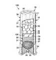
- FIG. 1is a schematic, partially broken away illustration of a conventional shot shell.
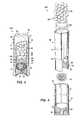
- FIG. 2is an exploded elevation view of a conventional shot shell.
- FIG. 3is a schematic, partially broken away illustration of a shot shell containing an absorber according to the present disclosure.
- FIG. 4is an exploded elevation view of a shot shell containing an absorber according to the present disclosure.
- FIG. 5is a schematic illustration of a portion of another shot shell containing an absorber according to the present disclosure.
- FIG. 6is a schematic illustration of a portion of another shot shell containing an absorber according to the present disclosure.
- FIG. 7is a schematic illustration of a portion of another shot shell containing an absorber according to the present disclosure.
- FIG. 8is a schematic illustration of a portion of another shot shell containing an absorber according to the present disclosure.
- FIG. 9is a schematic illustration of a portion of another shot shell containing an absorber according to the present disclosure.
- FIG. 10is a schematic illustration of a portion of another shot shell containing an absorber according to the present disclosure.
- Shot shell 10is shown including a head, or head portion, 24 , a shot shell case, or casing, 17 , and a mouth region 36 .
- Shot shell 10further includes an ignition device 32 , such as primer, or priming mixture, 25 , which is located behind a propellant, or powder, 22 , which also may be referred to as the charge 22 of the shot shell.
- Propellant 22 and primer 25are located behind a partition 31 , namely, a wad 20 , which serves to segregate the propellant and the primer from the shot shell's payload 38 .
- Powder 22additionally or alternatively may be referred to as smokeless powder or gun powder.
- Wad 20additionally or alternatively may be referred to as a shot wad 20 , and it may take a variety of suitable shapes and sizes.
- Casing 17 and head 24additionally or alternatively may be referred to as forming a housing 18 of the shot shell.
- housing 18(and/or casing 17 ) may be described as defining an internal chamber, or internal compartment, 19 of the shot shell.
- propellant 22 , wad 20 , and payload 38are inserted into the internal compartment, such as through mouth region 36 .
- mouth region 36is sealed or otherwise closed, such as via any suitable closure 35 .
- the region of the casing distal head 24may be folded, crimped, or otherwise used to close mouth region 36 .
- Payload 38additionally or alternatively may be referred to as a shot charge, or shot load, 38 .
- Payload 38typically will include a plurality of shot pellets 30 .
- the region of shot shell 10 , casing 17 , and/or wad 20 that contains payload 38may be referred to as the payload region 39 thereof.
- the payload region 39 of the shot wadcontains only shot pellets 30 , with a pellet-facing surface of the wad, and/or of the wad's shot cup 26 , directly engaging at least some of the shot pellets.
- shot cup 26may additionally or alternatively be referred to as a wad cup and/or as an end region of the wad that generally faces away from the head and/or toward the payload region.
- the initial impulse, or impact force, generated by the combustion of the shell's chargeis conveyed through the wad directly to the pellets.
- the greatest pressure within the shot gun's chamberis experienced in, or proximate, the shot cup, where these forces are first imparted to the shot pellets.
- the region of the shot gun's barrel that is most likely to be damaged or failis the region of the barrel that surrounds the shot cup region of a shot shell as the shot shell is being fired.
- Wad 20typically defines a pellet-facing surface 29 that extends and/or faces generally toward mouth region 36 and away from head 24 (when the wad is positioned properly within an assembled shot shell).
- Wad 20may include at least one gas seal, or gas seal region, 27 , and at least one deformable region 28 , between the shot cup and the propellant.
- Gas seal region 27is configured to engage the inner surface of the shot gun's chamber and barrel to restrict the passage of gasses, which are produced when the shot shell is fired (i.e., when the charge is ignited), along the shot gun's barrel. By doing so, the gasses are forced to propel the wad, and the payload of shot pellets 30 contained therein, from the chamber and along and out of the shot gun's barrel.
- Deformable region 28is designed to crumple, collapse, or otherwise non-elastically deform in response to the setback, or firing, forces that are generated when the shot shell is fired and the combustion of the propellant rapidly urges the wad and payload from being stationary to travelling down the barrel of the shot gun at high speeds.
- wad 20includes and/or defines a shot cup, or shot cup region, 26 , which has a generally concave configuration and defines region of the pellet-facing surface that is closest to head 24 .
- shot cupit is meant that the wad defines a concave portion of the payload region that generally faces, or opens, toward mouth region 36 .
- the specific size and geometric shape of the shot cup, when present,may vary, and the concave configuration of FIG. 1 is not required to all embodiments.
- shots cup region, 26has a generally concave configuration and defines region of the pellet-facing surface that is closest to head 24 .
- shot cupit is meant that the wad defines a concave portion of the payload region that generally faces, or opens, toward mouth region 36 .
- the specific size and geometric shape of the shot cup, when present,may vary, and the concave configuration of FIG. 1 is not required to all embodiments.
- FIG. 1may vary, and the concave configuration of FIG. 1 is not required to all embodiments.
- shot wad 20may include one or more sidewalls 21 that extend from the shot cup and around the payload region 39 of the wad and/or shot shell.
- the sidewallscontain the plurality of shot pellets within the assembled shot shell, and when the shot shell is fired, the sidewalls are intended to protect the inner surface of the shot gun's barrel from being contacted, and thus potentially damaged, by the shot pellets as the wad and plurality of shot pellets travel down the barrel.
- the wadincludes a plurality of sidewall sections that are joined together proximate the shot cup region of the wad and which are not secured together proximate the forward/mouth region of the shot cup.
- such a configurationenables the sidewall regions to flare away from each other after the wad exits the shot gun's barrel after the shot shell is fired, with this flaring increasing the wind resistance of the wad and slowing the wad, thereby separating it from the plurality of shot pellets and reducing the distance that it travels from the shot gun.
- a shot shellmay include as few as a single shot pellet 30 , which perhaps more appropriately may be referred to as a shot slug, and as many as dozens or hundreds of individual shot pellets 30 .
- the number of shot pellets 30 in any particular shot shellwill be defined by such factors as the size and geometry of the shot pellets, the size and shape of the shell's casing and/or wad, the available volume in the casing to be filled by shot pellets 30 , etc.
- a double ought 00 buckshot shelltypically contains nine shot pellets having diameters of approximately 0.3 inches (0.762 cm), while shot shells that are intended for use in hunting birds, and especially smaller birds, tend to contain many more shot pellets.
- Shot pellets 30may be formed from a variety of suitable materials and may have a variety of shapes.
- suitable materials for shot pelletsinclude lead, tin, bismuth, steel, copper, tungsten, alloys of tungsten with one or more other metals, alloys of tungsten, nickel, and iron, alloys and/or combinations of the preceding metals, etc., although lead often will not be used in applications where it is desirable or required to utilize non-toxic materials, such as for waterfowl hunting.
- Illustrative, non-exclusive examples of shot pellet shapesinclude spheres, spheroids, tear drops, belted spheres, pancake shapes, irregular shapes, etc.
- shot pellet loading patternsi.e., distributions and locations of the two or more different types of shot pellet morphologies within a single shot shell. These loading patterns may be utilized to improve the packing density of shot pellets within the shell, to impact general pattern uniformity, and/or to impact shot pattern diameters.
- shot pellets, shot pellet compositions, methods of manufacturing shot pellets, shot shell components, and/or shot shell configurationsare disclosed in U.S. Pat. Nos.
- the combustion of the primer and propellantWhen a shot shell is fired, the combustion of the primer and propellant generates pressure within the shot gun's chamber, and this generated pressure forces the shot wad and the shot payload away from the propellant, typically along and out of the barrel of the shot gun (or other firearm).
- the pressure within the shot gun's chamber during this processmay be significant, with such factors as the amount and type of propellant contributing to the generated pressure. Relative increases in this pressure typically correlate to increased velocity of the shot payload as it exits the barrel of the shot gun, but too much pressure may damage the shot gun.
- this damagemay range from scoring and/or marring of the inner surface of the shot gun's barrel to rupturing, exploding, or other piercing and/or shattering of the shot gun's barrel.
- Shot shell 10 and its componentshave been schematically illustrated in FIGS. 1 and 2 and are not intended to require a specific shape, size, or quantity of the components thereof.
- the length and diameter of the overall shot shell 10 and its casing 17 , the amount of primer 25 and propellant 22 , the shape, size, and configuration of wad 20 , the type, shape, size, and/or number of shot pellets 30 , etc.all may vary within the scope of the present disclosure.
- referenceshave been and will continue to be made to shot guns as the firearms in which shot shells are used, but shot shells according to the present disclosure may be used with any firearm that is sized or otherwise configured to receive and fire a shot shell.
- shot shell 100is schematically illustrated and is generally indicated at 100 .
- shot shell 100may include the same components, subcomponents, materials, variants, dimensions, etc., as conventional shot shell 10 . Accordingly, the previously described components of shot shell 10 that may be present in shot shell 100 are not described again in connection with FIGS. 3 and 4 .
- elements that serve a similar, or at least substantially similar, purposeare labeled with like numbers in FIGS. 1-10 , and these elements may not be discussed in detail herein with reference to each of FIGS. 1-10 . Similarly, all elements may not be labeled in each of FIGS.
- shot shell 100includes an absorber 120 that is within the payload region of the shot shell, such as being at least partially or even completely within the shot cup, being within a portion of the payload region that otherwise would be occupied by shot pellets in a conventional shot shell (such as shot shell 10 ), and/or being inserted into the shot shell after insertion of the wad and before insertion of the plurality of shot pellets.
- absorber 120is present within shot cup 26 of wad 20 and thereby separates the portion of the pellet-facing surface 29 defined by the shot cup from the plurality of shot pellets 30 .
- absorber 120is schematically illustrated in dashed lines to provide a graphical depiction that the absorber may take a variety of shapes, sizes, and forms without departing from the scope of the present disclosure. Illustrative, non-exclusive examples of such absorbers are described, illustrated, and/or incorporated in more detail herein.
- absorber 120is configured to absorb some of the energy that is/are produced during firing of the shot shell and which otherwise would be converted into pressure and/or forces within the shot gun's chamber. This absorption of some of the initial energy generated when the shot shell is fired has the effect of reducing the pressure within the chamber, as compared to the pressure that would be generated in the chamber if the shot shell did not include absorber 120 . Accordingly, shot shell 100 may (but is not required to) utilize a type and/or quantity of propellant and/or primer that otherwise would generate, when the shot shell is fired, a pressure within the chamber that exceeds a maximum chamber pressure, such as a predetermined maximum pressure, a rated or recommended maximum pressure, a SAAMI or other industry standard, etc.
- a maximum chamber pressuresuch as a predetermined maximum pressure, a rated or recommended maximum pressure, a SAAMI or other industry standard, etc.
- shot shell 100may (but is not required to) utilize faster burning, easily lit, propellants that generate higher pellet velocities (such as due to the generation of a greater amount of gas and/or due to a quicker generation of gas during combustion of the propellant), with the presence of absorber 120 preventing the propellants from generating chamber pressures that exceed a corresponding maximum (rated) chamber pressure.
- the predetermined maximum pressures and/or chamber pressure limits expressed hereinmay be referred to as maximum rated pressures, maximum average pressures, and/or maximum chamber pressures, and the pressure generated during the firing of a particular shot shell may be referred to as the actual pressure, actual chamber pressure, actual maximum average pressure, etc.
- absorber 120optionally may be configured to release, or impart, some of the absorbed energy to the shot pellets after the wad, absorber, and shot pellets have been propelled out of the shot gun's chamber.
- the absorbermay be described as reducing the initial (peak) pressure generated within the shot gun's chamber by absorbing some of the energy produced therein, and thereafter imparting at least a portion of the energy to the shot pellets by exerting forces thereupon.
- the absorbermay be sufficiently resilient to deform while absorbing energy as the shot shell is fired, and thereafter transmit some of the absorbed energy to the shot pellets as the absorber returns to, or at least toward, its pre-firing configuration and/or after the absorber reaches it elastic deformation limit.
- the absorberoptionally may be configured to utilize the absorbed energy to fragment or break into particles, such as to convert a solid absorber 120 into particulate or powder, including particulate and/or powder that has a smaller average cross-sectional area than shot pellets 30 , that has an average cross-sectional area that is less than 50%, less than 75%, less than 90%, or even less than 95% of the cross-sectional area of the shot pellets.
- Absorber 120additionally or alternatively may be referred to herein as a/an energy —————— , —————— material, ——————— region, energy-absorbing ————— , energy-distributing ——————— , setback energy absorbing —————— , force-absorbing —————— , setback force-absorbing ————— , pressure-reducing ———————— , energy-absorbing frangible ——————— , and/or energy-absorbing-and-returning —————— , with “ ——————— ” being “absorber,” “insert,” “structure,” and/or “material.”
- Absorber 120may be, and typically is, formed from a different material than the wad or shot pellets, and absorber 120 is separately formed from the wad. It is within the scope of the present disclosure that absorber 120 may be inserted into wad 20 prior to or after insertion of the wad into casing 17 of shot shell 100 . It also is within the scope of the present disclosure that absorber 120 may be attached to wad 20 within payload region 39 thereof, such as by being coupled or otherwise attached to the shot cup of the wad, although it is also within the scope of the present disclosure that the absorber may be in contact with the wad, such as the shot cup thereof, without being attached thereto.
- the absorbermay be formed or otherwise fabricated and thereafter inserted (as one or more solid components) into the wad, however, it is also within the scope of the present disclosure that the absorber may be inserted into the wad as a liquid that is thereafter cured or otherwise solidified into a solid component.
- Absorber 120may be formed of any suitable material(s), shape(s), and/or number of components/pieces to provide the desired pressure reduction during firing of a shot shell 100 .
- suitable materials for absorber 120include one or more of cork, elastomers, styrofoam, expanded polystyrene, acrylonitrile butadiene styrene (ABS), rubber, felt, cardboard, compressed paper or card stock, synthetic foams, such as which may be formed from polyurethane, polystyrene, polyethylene, and/or polypropylene.
- absorber 120may be formed from a material that is different from the material(s) used to form the shot pellets and the wad of a shot shell 100 , such as a non-metallic, non-plastic material.
- suitable shapes for absorber 120include one or more sphere/ball, spheroid, ovoid, ellipsoid, hemisphere, block, disc, mat, layer, and/or regular or irregular pellets/particles/pieces (such as crumbled cork, rubber, styrofoam, etc.).
- absorber 120may cover at least 25% of the internal (pellet-facing) surface of the wad's shot cup, and in some embodiments may cover at least 50%, at least 75%, at least 90%, at least 95%, at least 97%, at least 99%, 40-75%, 60-90%, 80-95%, 85-97%, 90-98%, 95-99%, or even all of the internal (pellet-facing) surface of the wad's shot cup. In some embodiments, at least a portion of absorber 120 may (but is not required to) extend into the region of the wad where the shot pellets are housed and/or may be intermixed with or otherwise extend between adjacent shot pellets within the payload region of the shot shell.
- absorber 120may have a cross-sectional area (measured transverse to the long axis of shot shell 100 after proper insertion of the absorber into the shot shell's wad) that is at least 75%, at least 80%, at least 85%, at least 90%, at least 95%, or at least 98% of the internal cross-sectional area of the wad measured in the same plane.
- a cross-sectional areameasured transverse to the long axis of shot shell 100 after proper insertion of the absorber into the shot shell's wad
- absorber 120may have a cross-sectional area (measured transverse to the long axis of shot shell 100 after proper insertion of the absorber into the shot shell's wad) that is at least 75%, at least 80%, at least 85%, at least 90%, at least 95%, or at least 98% of the internal cross-sectional area of the wad measured in the same plane.
- absorber 120has a diameter, measured transverse to the long axis of the shot shell after proper insertion of the absorber into the wad thereof, that is less than the diameter of the wad, and optionally at least 0.01 inches (0.025 cm) smaller, at least 0.02 inches (0.051 cm) smaller, at least 0.03 inches (0.076 cm) smaller, at least 0.05 inches (0.127 cm) smaller, at least 0.08 inches (0.203 cm) smaller, at least 0.09 inches (0.229 cm) smaller, at least 0.1 inches (0.254 cm) smaller, 0.2 inches (0.508 cm) smaller, 0.3 inches (0.762 cm) smaller, 0.01-0.15 inches (0.025-0.038 cm) smaller, 0.03-0.12 inches (0.076-0.305 cm) smaller, 0.05-0.11 inches (0.127-00.279 cm) smaller, 0.06-0.1 inches (0.154-0.254 cm) smaller, and/or 0.07-0.09 inches (0.178-0.229 cm) smaller.
- an absorber 120 in the form of a 14 mm ballhas proven effective
- an absorber in the form of a 16 mm ballhas proven effective, although other shapes and/or sizes of absorbers (including larger and/or smaller sizes) may be used without departing from the scope of the present disclosure.
- properties of absorber 120include at least one of (and optionally, at least two of, at least three of, at least four of, or all of) the following:
- FIGS. 5-10schematically depict illustrative, non-exclusive examples of portions of shot shells 100 that include an absorber 120 according to the present disclosure. Although the complete shot shell 100 is not shown in FIGS. 5-10 , it is within the scope of the present disclosure that shot shell 100 of FIGS. 5-10 may include any of the components, features, variants, shapes, etc. that are described, illustrated, and/or incorporated herein with respect to shot shell 100 of FIGS. 2 and 4 .
- absorber 120takes the form of a sphere, or optionally a spheroid, that is positioned in wad 20 generally between shot cup 26 and pellets 30 .
- absorber 120may be dropped or otherwise inserted into the wad prior to or after insertion of the wad into casing 17 and prior to insertion of shot pellets 30 into the wad.
- the spheremay have a diameter that is less than the internal (transverse) diameter of the shot shell's wad, such that the sphere does not simultaneously engage opposed internal sidewalls of the wad.
- the spheremay be described as having a diameter that is approximately the inner diameter of the wad, but less (and optionally only slightly less) than the inner diameter of the wad.
- a spherical (or otherwise shaped) absorbermay have a diameter (or other cross-sectional area) that is as large as the inner diameter (or other cross-sectional area) of the wad and/or casing.
- such a spherical (or otherwise shaped absorber)may have a diameter that is much smaller than the inner diameter of the wad, and in some embodiments may be sufficiently smaller than the inner diameter of the wad to permit a plurality of absorber spheres to be inserted into the wad, such as between the shot cup and the shot pellets, such as shown in FIG. 10 .
- absorber 120takes the form of a hemisphere that is positioned in the wad generally between the shot cup and the shot pellets
- absorber 120takes the form of a plurality of layers that are positioned in the wad generally between the shot cup and the shot pellets.
- FIG. 7four layers are schematically illustrated, but it is within the scope of the present disclosure that fewer or more layers may be used, and that the corresponding layers may or may not be secured together.
- absorber 120takes the form of a plurality of pieces, or particles, such as may collectively form a layer, or absorber region, generally between the shot cup and the shot pellets. The depth of this region may vary within the scope of the present disclosure.
- absorber 120may extend into the payload region of the shot shell, such as to extend between adjacent shot pellets and/or between one or more shot pellets and an inner sidewall of the wad.
- Such an absorber 120 that extends into the payload region of shot shell 100is illustrated in dashed lines in FIGS. 8 and 10 .
- FIG. 9schematically illustrates an absorber 120 that is shaped to conform to and/or match the shape of the shot cup of wad 20 . In such an embodiment, the wad may be shaped or otherwise formed prior to insertion into the wad.
- the absorbermay be poured, injected, or otherwise inserted into the wad as a liquid that conforms to the shape of the shot cup and/or other portion of the shot wad proximate the absorber and thereafter is cured or otherwise hardens to form a solid component having this shape.
- Shot shells 100 with an absorber 120additionally or alternatively may experience reduced imprinting, puncturing, and/or other penetration of the lower region of the wad by the shot pellets during firing of the shot shell, as compared to a corresponding shot shell that does not include absorber 120 but otherwise has the same components as shot shell 100 .
- This reduced imprinting/penetration, such as in the lower third, or even half, of the wad (relative to the head region of the shell)means that fewer shot pellets are embedded into the wad than (on average) would be embedded therein if the shot shell did not include absorber 120 .
- This reduction in the penetration of the wad by shot pellets when the shot shell is firedreduces the likelihood that shot pellets will penetrate through the wad and contact the shot gun's barrel, which in turn may reduce or even eliminate scoring of the shot gun's barrel when shot shells 100 are fired therein.
- shot shells 100 using an absorber 120 according to the present disclosurehave improved the pellet velocity produced by a conventional 10-gauge shot shell from 1,300 feet per second (fps) (396.2 meters per second (m/s)) at the SAAMI maximum chamber pressure limit of 11,000 pounds per square inch (psi) (758.4 bar) to 1,500 fps (457.2 m/s) at a chamber pressure below 11,000 psi (758.4 bar).
- the term “and/or” placed between a first entity and a second entitymeans one of (1) the first entity, (2) the second entity, and (3) the first entity and the second entity.
- Multiple entities listed with “and/or”should be construed in the same manner, i.e., “one or more” of the entities so conjoined.
- Other entitiesmay optionally be present other than the entities specifically identified by the “and/or” clause, whether related or unrelated to those entities specifically identified.
- a reference to “A and/or B,” when used in conjunction with open-ended language such as “comprising”may refer, in one embodiment, to A only (optionally including entities other than B); in another embodiment, to B only (optionally including entities other than A); in yet another embodiment, to both A and B (optionally including other entities).
- These entitiesmay refer to elements, actions, structures, steps, operations, values, and the like.
- the phrase “at least one,” in reference to a list of one or more entitiesshould be understood to mean at least one entity selected from any one or more of the entity in the list of entities, but not necessarily including at least one of each and every entity specifically listed within the list of entities and not excluding any combinations of entities in the list of entities.
- This definitionalso allows that entities may optionally be present other than the entities specifically identified within the list of entities to which the phrase “at least one” refers, whether related or unrelated to those entities specifically identified.
- “at least one of A and B”may refer, in one embodiment, to at least one, optionally including more than one, A, with no B present (and optionally including entities other than B); in another embodiment, to at least one, optionally including more than one, B, with no A present (and optionally including entities other than A); in yet another embodiment, to at least one, optionally including more than one, A, and at least one, optionally including more than one, B (and optionally including other entities).
- each of the expressions “at least one of A, B and C,” “at least one of A, B, or C,” “one or more of A, B, and C,” “one or more of A, B, or C” and “A, B, and/or C”may mean A alone, B alone, C alone, A and B together, A and C together, B and C together, A, B and C together, and optionally any of the above in combination with at least one other entity.
- adaptedand “configured” mean that the element, component, or other subject matter is designed and/or intended to perform a given function.
- the use of the terms “adapted” and “configured”should not be construed to mean that a given element, component, or other subject matter is simply “capable of” performing a given function but that the element, component, and/or other subject matter is specifically selected, created, implemented, utilized, programmed, and/or designed for the purpose of performing the function.
- elements, components, and/or other recited subject matter that is recited as being adapted to perform a particular functionmay additionally or alternatively be described as being configured to perform that function, and vice versa.
- shot shells 100 and methods according to the present disclosureare presented in the following enumerated paragraphs. It is within the scope of the present disclosure that an individual step of a method recited herein, including in the following enumerated paragraphs, may additionally or alternatively be referred to as a “step for” performing the recited action.
- a shot shellcomprising:
- a housingcontaining a charge and defining an internal chamber
- a force-absorbing absorberwithin the internal chamber and extending generally between the pellet-facing surface of the wad cup and the plurality of shot pellets.
- A6The shot shell of any of paragraphs A1-A5, wherein the absorber is configured to absorb a portion of setback forces that are generated when the shot shell is fired and to at least delay transmission of the forces to the plurality of shot pellets.
- A7The shot shell of any of paragraphs A1-A6, wherein the absorber is configured to absorb a portion of the energy produced when the shot shell is fired and thereby prevent generation of pressure from this portion of the energy within a shot gun's chamber when the shot shell is fired.
- A8The shot shell of any of paragraphs A1-A7, wherein the absorber is formed from a resilient material that is configured to absorb setback forces generated when the shot shell is fired and to impart at least a portion of the setback forces to the plurality of shot pellets as the absorber and the plurality of shot pellets travel after the shot shell is fired.
- A9The shot shell of any of paragraphs A1-A7, wherein the absorber is formed from a frangible material that is configured to absorb setback forces generated when the shot shell is fired and to break into particulate as the absorber and the plurality of shot pellets travel after the shot shell is fired.
- A17The shot shell of any of paragraphs A1-A9, wherein the absorber is molded to conform to the shape of the pellet-facing surface of the shot cup.
- A19The shot shell of any of paragraphs A1-A18, wherein the shot wad has an inner cross-sectional area measured transverse to the long axis of the shot shell, and further wherein the absorber has an outer cross-sectional area that is at least 50% of the inner cross-sectional area of the shot wad.
- A20The shot shell of any of paragraphs A1-A19, wherein the shot wad has an inner cross-sectional area measured transverse to the long axis of the shot shell, and further wherein the absorber has an outer cross-sectional area that is at least 75% of the inner cross-sectional area of the shot wad.
- A21The shot shell of any of paragraphs A1-A20, wherein the shot wad has an inner cross-sectional area measured transverse to the long axis of the shot shell, and further wherein the absorber has an outer cross-sectional area that is at least 90% of the inner cross-sectional area of the shot wad.
- A22The shot shell of any of paragraphs A1-A21, wherein the shot wad has an inner cross-sectional area measured transverse to the long axis of the shot shell, and further wherein the absorber has an outer cross-sectional area that is at least 95% of the inner cross-sectional area of the shot wad.
- A26The shot shell of any of paragraphs A1-A25, wherein the absorber covers the entire pellet-facing surface of the shot cup.
- A27The shot shell of any of paragraphs A1-A26, wherein the absorber further extends into a payload region of the shot shell that contains the plurality of shot pellets, with the absorber being intermixed with at least a portion of the shot pellets.
- A29The shot shell of any of paragraphs A1-A28, wherein the absorber has a compressive strength that is at least 100 psi (6.9 bar) and which is less than 10,000 psi (689.5 bar).
- A35The shot shell of any of paragraphs A1-A30, wherein the absorber includes, and optionally is formed from, expanded polystyrene.
- A36The shot shell of any of paragraphs A1-A30, wherein the absorber includes, and optionally is formed from, polystyrene.
- A37The shot shell of any of paragraphs A1-A30 wherein the absorber includes, and optionally is formed from, acrylonitrile butadiene styrene (ABS).
- ABSacrylonitrile butadiene styrene
- A38The shot shell of any of paragraphs A1-A30, wherein the absorber includes, and optionally is formed from, a synthetic foam, such as synthetic foam of polyurethane, polystyrene, polyethylene or polypropylene.
- a synthetic foamsuch as synthetic foam of polyurethane, polystyrene, polyethylene or polypropylene.
- A40The shot shell of any of paragraphs A1-A39, wherein the absorber has a Young's Modulus of less than 500,000 psi (34,474 bar), and optionally less than 250,000 psi (17,237 bar), and optionally less than 150,000 psi (10,342 bar), and optionally less than 100,000 psi (6,895 bar), and optionally less than 75,000 psi (5,171 bar), and optionally less than 50,000 psi (3,447 bar), and optionally less than 25,000 psi (1,724 bar), and optionally less than 10,000 psi (689 bar), and optionally less than 5,000 psi (345 bar), and optionally less than 2,500 psi (172 bar), and optionally less than 2,000 psi (138 bar), and optionally less than 1,500 psi (103 bar), and optionally in the range of 500-2,000 psi (34-138 bar), and optionally in the range of 1,000-3,000 ps
- A41The shot shell of any of paragraphs A1-A40, wherein the absorber has a specific Young's Modulus of at least 1.45 psi/(g/cc) (0.10 bar/(g/cc)), and optionally at least 5 psi/(g/cc) (0.34 bar/(g/cc)), and optionally at least 10 psi/(g/cc) (0.69 bar/(g/cc)), and optionally at least 25 psi/(g/cc) (1.7 bar/(g/cc)), and optionally at least 50 psi/(g/cc) (3.5 bar/(g/cc)), and optionally at least 75 psi/(g/cc) (5.2 bar/(g/cc)), and optionally at least 100 psi/(g/cc) (6.9 bar/(g/cc)), and optionally at least 150 psi/(g/cc) (10.3 bar/(g/
- A42The shot shell of any of paragraphs A1-A41, wherein the absorber has a specific Young's Modulus of less than 300 psi/(g/cc) (20.7 bar/(g/cc)), and optionally less than 290 psi/(g/cc) (20.0 bar/(g/cc)), and optionally less than 250 psi/(g/cc) (17.2 bar/(g/cc)), and optionally less than 200 psi/(g/cc) (13.8 bar/(g/cc)), and optionally less than 150 psi/(g/cc) (10.3 bar/(g/cc)), and optionally less than 100 psi/(g/cc) (6.9 bar/(g/cc)), and optionally less than 75 psi/(g/cc) (5.2 bar/(g/cc)), and optionally less than 50 psi/(g/cc) (3.5 bar/(g/cc)
- A43The shot shell of any of paragraphs A1-A42, wherein the absorber has a compressive strength of at least 100 psi (6.9 bar), and optionally at least 250 psi (17.2 bar), and optionally at least 500 psi (34.5 bar), and optionally at least 1,000 psi (69.0 bar), and optionally at least 2,500 psi (172 bar), and optionally at least 5,000 psi (345 bar), and optionally at least 7,500 psi (517 bar), and optionally at least 10,000 psi (689 bar).
- the absorberhas a compressive strength of at least 100 psi (6.9 bar), and optionally at least 250 psi (17.2 bar), and optionally at least 500 psi (34.5 bar), and optionally at least 1,000 psi (69.0 bar), and optionally at least 2,500 psi (172 bar), and optionally at least 5,000 psi (345 bar), and optionally at least 7,500 psi (517
- A44The shot shell of any of paragraphs A1-A43, wherein the absorber has a compressive strength of less than 10,000 psi (689 bar), and optionally less than 7,500 psi (517 bar), and optionally less than 5,000 psi (345 bar), and optionally less than 2,500 psi (172 bar), and optionally less than 1,000 psi (69.0 bar), and optionally less than 500 psi (34.5 bar), and optionally less than 250 psi (17.2 bar), and optionally less than 150 psi (10.3 bar).
- the absorberhas a compressive strength of less than 10,000 psi (689 bar), and optionally less than 7,500 psi (517 bar), and optionally less than 5,000 psi (345 bar), and optionally less than 2,500 psi (172 bar), and optionally less than 1,000 psi (69.0 bar), and optionally less than 500 psi (34.5 bar), and optionally less than 250 psi (17.2 bar),
- A45The shot shell of any of paragraphs A1-A44, wherein the absorber has a specific compressive strength of at least 14.5 psi/(g/cc) (1.0 bar/(g/cc)), and optionally at least 25 psi/(g/cc) (1.7 bar/(g/cc)), and optionally at least 50 psi/(g/cc) (3.4 bar/(g/cc)), and optionally at least 75 psi/(g/cc) (5.2 bar/(g/cc)), and optionally at least 100 psi/(g/cc) (6.9 bar/(g/cc)), and optionally at least 150 psi/(g/cc) (10.3 bar/(g/cc)), and optionally at least 250 psi/(g/cc) (17.2 bar/(g/cc)), and optionally at least 500 psi/(g/cc) (34.5 bar/(g/cc)), and optional
- A46The shot shell of any of paragraphs A1-A45, wherein the absorber has a specific compressive strength of less than 1,500 psi/(g/cc) (103 bar/(g/cc)), and optionally less than 1,450 psi/(g/cc) (100 bar/(g/cc)), and optionally less than 1,400 psi/(g/cc) (96.5 bar/(g/cc)), and optionally less than 1,250 psi/(g/cc) (86.2 bar/(g/cc)), and optionally less than 1,000 psi/(g/cc) (68.9 bar/(g/cc)), and optionally less than 750 psi/(g/cc) (51.7 bar/(g/cc)), and optionally less than 500 psi/(g/cc) (34.5 bar/(g/cc)), and optionally less than 250 psi/(g/cc) (17.2 bar/(g/c
- A47The shot shell of any of paragraphs A1-A46, wherein the absorber has a tensile strength of at least 125 psi (8.6 bar), and optionally at least 145 psi (10.0 bar), and optionally at least 150 psi (10.3 bar), and optionally at least 175 psi (12.1 bar), and optionally at last 200 psi (13.8 bar), and optionally at least 250 psi (17.2 bar), and optionally at least 500 psi (34.5 bar), and optionally at least 750 psi (51.7 bar), and optionally at least 1,000 psi (68.9 bar), and optionally at least 2,500 psi (172 bar), and optionally at least 5,000 psi (345 bar), and optionally at least 7,500 psi (571 bar).
- A48The shot shell of any of paragraphs A1-A47, wherein the absorber has a tensile strength of less than 10,000 psi (690 bar), and optionally less than 9,000 psi (621 bar), and optionally less than 7,500 psi (517 bar), and optionally less than 5,000 psi (345 bar), and optionally less than 2,500 psi (172 bar), and optionally less than 1,500 psi (103 bar), and optionally less than 1,000 psi (68.9 bar), and optionally less than 750 psi (51.7 bar), and optionally less than 500 psi (34.5 bar), and optionally less than 300 psi (20.7 bar), and optionally less than 250 psi (17.2 bar), and optionally less than 200 psi (13.8 bar), and optionally less than 175 psi (12.1 bar), and optionally less than 150 psi (10.3 bar).
- the improvementcomprising an energy absorber between the shot cup and the plurality of shot pellets.
- a method for assembling a shot shellcomprising:
Landscapes
- Engineering & Computer Science (AREA)
- General Engineering & Computer Science (AREA)
- Manufacturing & Machinery (AREA)
- Aiming, Guidance, Guns With A Light Source, Armor, Camouflage, And Targets (AREA)
- Vibration Dampers (AREA)
- Powder Metallurgy (AREA)
Abstract
Description
| TABLE 1 |
| SAAMI Shot Gun Pressure Specifications |
| (piezoelectric measurements) |
| Maximum Average | Maximum Average | |
| Cartridge | Pressure (psi) | Pressure (bar) |
| 10 gauge | 11,000 (all) | 758.4 (all) |
| 12 gauge | 11,500 (all but 3½ | 792.9 (all but 8.9 |
| inch mag) | cm mag) | |
| 12 gauge 3½″ mag | 14,000 | 965.3 |
| 16 gauge | 11,500 (all) | 792.9 (all) |
| 20 gauge | 12,000 (all) | 827.4 (all) |
| 28 gauge | 12,500 (all) | 861.8 (all) |
| .410 Bore 2½″ | 12,500 | 861.8 |
| .410 Bore 3″ | 13,500 | 930.8 |
- a Young's Modulus of less than 500,000 psi (34,474 bar), less than 250,000 psi (17,237 bar), less than 150,000 psi (10,342 bar), less than 100,000 psi (6,895 bar), less than 75,000 psi (5,171 bar), less than 50,000 psi (3,447 bar), less than 25,000 psi (1,724 bar), less than 10,000 psi (689 bar), less than 5,000 psi (345 bar), less than 2,500 psi (172 bar), less than 2,000 psi (138 bar), less than 1,500 psi (103 bar), in the range of 500-2,000 psi (34-138 bar), in the range of 1,000-3,000 psi (69-207 bar), in the range of 1,500-5,000 psi (103-345 bar), and/or in the range of 5,000-20,000 psi (345-1379 bar), etc.;
- a specific Young's Modulus of at least 1.45 psi/(g/cc) (0.10 bar/(g/cc)), at least 5 psi/(g/cc) (0.34 bar/(g/cc)), at least 10 psi/(g/cc) (0.69 bar/(g/cc)), at least 25 psi/(g/cc) (1.7 bar/(g/cc)), at least 50 psi/(g/cc) (3.5 bar/(g/cc)), at least 75 psi/(g/cc) (5.2 bar/(g/cc)), at least 100 psi/(g/cc) (6.9 bar/(g/cc)), at least 150 psi/(g/cc) (10.3 bar/(g/cc)), at least 200 psi/(g/cc) (13.8 bar/(g/cc)), at least 250 psi/(g/cc) (17.2 bar/(g/cc)), less than 300 psi/(g/cc) (20.7 bar/(g/cc)), less than 290 psi/(g/cc) (20.0 bar/(g/cc)), less than 250 psi/(g/cc) (17.2 bar/(g/cc)), less than 200 psi/(g/cc) (13.8 bar/(g/cc)), less than 150 psi/(g/cc) (10.3 bar/(g/cc)), less than 100 psi/(g/cc) (6.9 bar/(g/cc)), less than 75 psi/(g/cc) (5.2 bar/(g/cc)), less than 50 psi/(g/cc) (3.5 bar/(g/cc)), less than 25 psi/(g/cc) (1.7 bar/(g/cc)), less than 10 psi/(g/cc) (0.69 bar/(g/cc)), and/or less than 5 psi/(g/cc) (0.34 bar/(g/cc));
- a compressive strength of at least 100 psi (6.9 bar), at least 250 psi (17.2 bar), at least 500 psi (34.5 bar), at least 1,000 psi (69.0 bar), at least 2,500 psi (172 bar), at least 5,000 psi (345 bar), at least 7,500 psi (517), at least 10,000 psi (689 bar), less than 10,000 psi (689 bar), less than 7,500 psi (517 bar), less than 5,000 psi (345 bar), less than 2,500 psi (172 bar), less than 1,000 psi (69.0 bar), less than 500 psi (34.5 bar), less than 250 psi (17.2 bar), and/or less than 150 psi (10.3 bar);
- a specific compressive strength of at least 14.5 psi/(g/cc) (1.0 bar/(g/cc)), at least 25 psi/(g/cc) (1.7 bar/(g/cc)), at least 50 psi/(g/cc) (3.4 bar/(g/cc)), at least 75 psi/(g/cc) (5.2 bar/(g/cc)), at least 100 psi/(g/cc) (6.9 bar/(g/cc)), at least 150 psi/(g/cc) (10.3 bar/(g/cc)), at least 250 psi/(g/cc) (17.2 bar/(g/cc)), at least 500 psi/(g/cc) (34.5 bar/(g/cc)), at least 750 psi/(g/cc) (51.7 bar/(g/cc)), at least 1,000 psi/(g/cc) (68.9 bar/(g/cc)), at least 1,250 psi/(g/cc) (86.2 bar/(g/cc)), less than 1,500 psi/(g/cc) (103 bar/(g/cc)), less than 1,450 psi/(g/cc) (100 bar/(g/cc)), less than 1,400 psi/(g/cc) (96.5 bar/(g/cc)), less than 1,250 psi/(g/cc) (86.2 bar/(g/cc)), less than 1,000 psi/(g/cc) (68.9 bar/(g/cc)), less than 750 psi/(g/cc) (51.7 bar/(g/cc)), less than 500 psi/(g/cc) (34.5 bar/(g/cc)), less than 250 psi/(g/cc) (17.2 bar/(g/cc)), less than 150 psi/(g/cc) (10.3 bar/(g/cc)), less than 100 psi/(g/cc) (6.9 bar/(g/cc)), less than 75 psi/(g/cc) (5.2 bar/(g/cc)), less than 50 psi/(g/cc) (3.4 bar/(g/cc)), and/or less than 25 psi/(g/cc) (1.7 bar/(g/cc)); and/or
- a tensile strength of at least 125 psi (8.6 bar), at least 145 psi (10.0 bar), at least 150 psi (10.3 bar), at least 175 psi (12.1 bar), at last 200 psi (13.8 bar), at least 250 psi (17.2 bar), at least 500 psi (34.5 bar), at least 750 psi (51.7 bar), at least 1,000 psi (68.9 bar), at least 2,500 psi (172 bar), at least 5,000 psi (345 bar), at least 7,500 psi (571 bar), less than 10,000 psi (690 bar), less than 9,000 psi (621 bar), less than 7,500 psi (517 bar), less than 5,000 psi (345 bar), less than 2,500 psi (172 bar), less than 1,500 psi (103 bar), less than 1,000 psi (68.9 bar), less than 750 psi (51.7 bar), less than 500 psi (34.5 bar), less than 300 psi (20.7 bar), less than 250 psi (17.2 bar), less than 200 psi (13.8 bar), less than 175 psi (12.1 bar), and/or less than 150 psi (10.3 bar).
Claims (20)
Priority Applications (1)
| Application Number | Priority Date | Filing Date | Title |
|---|---|---|---|
| US15/895,318US10209044B2 (en) | 2011-12-08 | 2018-02-13 | Shot shells with performance-enhancing absorbers |
Applications Claiming Priority (5)
| Application Number | Priority Date | Filing Date | Title |
|---|---|---|---|
| US201161568591P | 2011-12-08 | 2011-12-08 | |
| US13/707,430US9046328B2 (en) | 2011-12-08 | 2012-12-06 | Shot shells with performance-enhancing absorbers |
| US14/722,719US9677860B2 (en) | 2011-12-08 | 2015-05-27 | Shot shells with performance-enhancing absorbers |
| US15/619,937US9897424B2 (en) | 2011-12-08 | 2017-06-12 | Shot shells with performance-enhancing absorbers |
| US15/895,318US10209044B2 (en) | 2011-12-08 | 2018-02-13 | Shot shells with performance-enhancing absorbers |
Related Parent Applications (1)
| Application Number | Title | Priority Date | Filing Date |
|---|---|---|---|
| US15/619,937DivisionUS9897424B2 (en) | 2011-12-08 | 2017-06-12 | Shot shells with performance-enhancing absorbers |
Publications (2)
| Publication Number | Publication Date |
|---|---|
| US20180172412A1 US20180172412A1 (en) | 2018-06-21 |
| US10209044B2true US10209044B2 (en) | 2019-02-19 |
Family
ID=48570817
Family Applications (4)
| Application Number | Title | Priority Date | Filing Date |
|---|---|---|---|
| US13/707,430Expired - Fee RelatedUS9046328B2 (en) | 2011-12-08 | 2012-12-06 | Shot shells with performance-enhancing absorbers |
| US14/722,719ActiveUS9677860B2 (en) | 2011-12-08 | 2015-05-27 | Shot shells with performance-enhancing absorbers |
| US15/619,937Expired - Fee RelatedUS9897424B2 (en) | 2011-12-08 | 2017-06-12 | Shot shells with performance-enhancing absorbers |
| US15/895,318Expired - Fee RelatedUS10209044B2 (en) | 2011-12-08 | 2018-02-13 | Shot shells with performance-enhancing absorbers |
Family Applications Before (3)
| Application Number | Title | Priority Date | Filing Date |
|---|---|---|---|
| US13/707,430Expired - Fee RelatedUS9046328B2 (en) | 2011-12-08 | 2012-12-06 | Shot shells with performance-enhancing absorbers |
| US14/722,719ActiveUS9677860B2 (en) | 2011-12-08 | 2015-05-27 | Shot shells with performance-enhancing absorbers |
| US15/619,937Expired - Fee RelatedUS9897424B2 (en) | 2011-12-08 | 2017-06-12 | Shot shells with performance-enhancing absorbers |
Country Status (2)
| Country | Link |
|---|---|
| US (4) | US9046328B2 (en) |
| WO (1) | WO2013130158A1 (en) |
Families Citing this family (17)
| Publication number | Priority date | Publication date | Assignee | Title |
|---|---|---|---|---|
| US9046328B2 (en)* | 2011-12-08 | 2015-06-02 | Environ-Metal, Inc. | Shot shells with performance-enhancing absorbers |
| US9250048B2 (en) | 2013-04-01 | 2016-02-02 | Olin Corporation | Shotshell with reduced dispersion of projectiles |
| US9778002B2 (en)* | 2013-12-20 | 2017-10-03 | Ra Brands, L.L.C. | Shot cup wad |
| USD727424S1 (en)* | 2014-04-14 | 2015-04-21 | Lawrence A. Skinn | Card holder |
| US9879957B2 (en) | 2015-10-15 | 2018-01-30 | Vista Outdoor Operations Llc | Shotshell having wad with enhanced fin deployment |
| US10422611B1 (en) | 2015-10-15 | 2019-09-24 | Vista Outdoor Operations Llc | Shotshell having wad with enhanced fin deployment |
| USD809622S1 (en)* | 2016-01-28 | 2018-02-06 | Vista Outdoor Operations Llc | Shotgun wad |
| USD810226S1 (en) | 2016-02-04 | 2018-02-13 | Vista Outdoor Operations Llc | Shotgun wad |
| US10766633B2 (en)* | 2018-02-12 | 2020-09-08 | RPX Technologies, Inc. | Tacticle unmanned aerial vehicle |
| USD1017756S1 (en) | 2018-02-23 | 2024-03-12 | Federal Cartridge Company | Shotgun wad |
| US11379788B1 (en) | 2018-10-09 | 2022-07-05 | Fida, Llc | Multilayered method and apparatus to facilitate the accurate calculation of freight density, area, and classification and provide recommendations to optimize shipping efficiency |
| US12243001B1 (en) | 2018-10-09 | 2025-03-04 | Fida, Llc | Multilayered method and apparatus to facilitate the accurate calculation of freight density, area, and classification and provide recommendations to optimize shipping efficiency |
| US10837744B1 (en)* | 2019-05-07 | 2020-11-17 | Donald McIntosh | Shot shell system and method |
| WO2021263093A1 (en)* | 2020-06-25 | 2021-12-30 | Federal Cartridge Company | Bismuth-based firearm projectiles, firearm cartridges including the same, and related methods |
| US11674782B1 (en)* | 2020-08-28 | 2023-06-13 | The United States Of America As Represented By The Secretary Of The Army | Piston actuated extended range projectile with segmented slip band |
| US11402188B1 (en)* | 2020-08-28 | 2022-08-02 | The United States Of America As Represented By The Secretary Of The Army | Pyrotechnic delayed extended range shotgun munition |
| US12181263B2 (en)* | 2022-01-17 | 2024-12-31 | Seismic Ammunition, Inc. | Firearm projectile |
Citations (123)
| Publication number | Priority date | Publication date | Assignee | Title |
|---|---|---|---|---|
| US12545A (en) | 1855-03-20 | Improved shot-cartridge | ||
| US34806A (en) | 1862-03-25 | Bern l | ||
| US1583559A (en) | 1925-11-02 | 1926-05-04 | Christian H Kenneweg | Shotgun cartridge |
| US1847617A (en) | 1928-02-11 | 1932-03-01 | Hirsch Kupfer & Messingwerke | Hard alloy |
| US1872107A (en)* | 1927-01-09 | 1932-08-16 | Bond Mfg Corp | Gun wad |
| US2119876A (en) | 1936-12-24 | 1938-06-07 | Remington Arms Co Inc | Shot |
| US2183359A (en) | 1938-06-24 | 1939-12-12 | Gen Electric Co Ltd | Method of manufacture of heavy metallic material |
| US2559275A (en) | 1947-07-03 | 1951-07-03 | Remington Arms Co Inc | Cellular plastic wad |
| US2582124A (en)* | 1945-09-15 | 1952-01-08 | Olin Ind Inc | Ammunition |
| US2582125A (en)* | 1947-09-29 | 1952-01-08 | Olin Ind Inc | Ammunition |
| GB731237A (en) | 1952-12-30 | 1955-06-01 | Josef Jacobs | Improvements in or relating to the manufacture of cast iron or steel shot |
| CA521944A (en) | 1956-02-21 | J. Stutzman Milo | Process for making shot | |
| US2919471A (en) | 1958-04-24 | 1960-01-05 | Olin Mathieson | Metal fabrication |
| US2995090A (en) | 1954-07-02 | 1961-08-08 | Remington Arms Co Inc | Gallery bullet |
| US3059578A (en) | 1956-08-29 | 1962-10-23 | Edward N Hegge | Projectile for multimissile ammunition |
| US3092026A (en) | 1962-09-18 | 1963-06-04 | Olin Mathieson | Shot load |
| US3093073A (en) | 1959-08-31 | 1963-06-11 | Harry A Lockwood | Shell for guns |
| US3123003A (en) | 1962-01-03 | 1964-03-03 | lange | |
| US3270669A (en) | 1964-06-16 | 1966-09-06 | Canadian Ind | Shotshells |
| US3372021A (en) | 1964-06-19 | 1968-03-05 | Union Carbide Corp | Tungsten addition agent |
| US3422761A (en) | 1965-09-24 | 1969-01-21 | Imp Metal Ind Kynoch Ltd | Shotgun cartridges |
| US3491690A (en) | 1968-01-10 | 1970-01-27 | Verran Lane Knight | Water boosted shotshell |
| US3550531A (en)* | 1968-05-17 | 1970-12-29 | Joseph H Carter | Shotgun shell |
| US3623849A (en) | 1969-08-25 | 1971-11-30 | Int Nickel Co | Sintered refractory articles of manufacture |
| US3656433A (en) | 1969-10-13 | 1972-04-18 | Us Army | Method for reducing shot dispersion |
| US3756155A (en) | 1970-12-28 | 1973-09-04 | D Smith | Shot gun shells |
| US3785801A (en) | 1968-03-01 | 1974-01-15 | Int Nickel Co | Consolidated composite materials by powder metallurgy |
| US3888636A (en) | 1971-02-01 | 1975-06-10 | Us Health | High density, high ductility, high strength tungsten-nickel-iron alloy & process of making therefor |
| US3890145A (en) | 1969-10-28 | 1975-06-17 | Onera (Off Nat Aerospatiale) | Processes for the manufacture of tungsten-based alloys and in the corresponding materials |
| US3953194A (en) | 1975-06-20 | 1976-04-27 | Allegheny Ludlum Industries, Inc. | Process for reclaiming cemented metal carbide |
| US3979234A (en) | 1975-09-18 | 1976-09-07 | The United States Of America As Represented By The United States Energy Research And Development Administration | Process for fabricating articles of tungsten-nickel-iron alloy |
| US3996865A (en) | 1974-07-12 | 1976-12-14 | Vernon Thomas Dwyer | Shotshell with seed capsule |
| US4027594A (en) | 1976-06-21 | 1977-06-07 | Olin Corporation | Disintegrating lead shot |
| JPS5268800A (en) | 1975-12-03 | 1977-06-07 | Tatsuhiro Katagiri | Canister used for shotgun and method of producing same |
| US4035115A (en) | 1975-01-14 | 1977-07-12 | Sundstrand Corporation | Vane pump |
| US4035116A (en) | 1976-09-10 | 1977-07-12 | Arthur D. Little, Inc. | Process and apparatus for forming essentially spherical pellets directly from a melt |
| US4103621A (en) | 1976-07-19 | 1978-08-01 | Fackler David G | Wad column for shotshells |
| US4138249A (en) | 1978-05-26 | 1979-02-06 | Cabot Corporation | Process for recovering valuable metals from superalloy scrap |
| US4274940A (en) | 1975-08-13 | 1981-06-23 | Societe Metallurgique Le Nickel -S.L.N. | Process for making ferro-nickel shot for electroplating and shot made thereby |
| US4338126A (en) | 1980-06-09 | 1982-07-06 | Gte Products Corporation | Recovery of tungsten from heavy metal alloys |
| US4383853A (en) | 1981-02-18 | 1983-05-17 | William J. McCollough | Corrosion-resistant Fe-Cr-uranium238 pellet and method for making the same |
| JPS596305A (en) | 1982-06-30 | 1984-01-13 | Tanaka Kikinzoku Kogyo Kk | Method for producing metal particles |
| US4428295A (en) | 1982-05-03 | 1984-01-31 | Olin Corporation | High density shot |
| US4488959A (en) | 1981-09-21 | 1984-12-18 | Agar Gordon E | Scheelite flotation process |
| GB2149067A (en) | 1983-11-04 | 1985-06-05 | Wimet Ltd | Pellets and shot and their manufacture |
| US4627356A (en) | 1985-06-11 | 1986-12-09 | Louis Buczkowski | Two-piece booster shot shell wad |
| FR2584808A2 (en)* | 1985-07-09 | 1987-01-16 | Piegay Marcel | Wad for cartridges of hunting guns or other firearms |
| US4733613A (en) | 1986-06-27 | 1988-03-29 | Olin Corporation | Adjustable volume shot wad structure and method of assembling the same |
| US4760793A (en) | 1987-01-09 | 1988-08-02 | E. I. Du Pont De Nemours And Company | Multi-range shot shell |
| US4762559A (en) | 1987-07-30 | 1988-08-09 | Teledyne Industries, Incorporated | High density tungsten-nickel-iron-cobalt alloys having improved hardness and method for making same |
| US4780981A (en) | 1982-09-27 | 1988-11-01 | Hayward Andrew C | High density materials and products |
| US4784690A (en) | 1985-10-11 | 1988-11-15 | Gte Products Corporation | Low density tungsten alloy article and method for producing same |
| WO1988009476A1 (en) | 1987-05-21 | 1988-12-01 | Sprintvale Limited | Training projectile of plastics material |
| US4815388A (en) | 1986-11-11 | 1989-03-28 | Olin Corporation | Shot charge and wad structure for a combat shotgun |
| JPH01142002A (en) | 1987-11-27 | 1989-06-02 | Kawasaki Steel Corp | Alloy steel powder for powder metallurgy |
| US4864934A (en) | 1988-12-12 | 1989-09-12 | Olin Corporation | Industrial shotshell having a load-stabilizing assembly |
| US4881465A (en) | 1988-09-01 | 1989-11-21 | Hooper Robert C | Non-toxic shot pellets for shotguns and method |
| US4897117A (en) | 1986-03-25 | 1990-01-30 | Teledyne Industries, Inc. | Hardened penetrators |
| US4931252A (en) | 1987-06-23 | 1990-06-05 | Cime Bocuze | Process for reducing the disparities in mechanical values of tungsten-nickel-iron alloys |
| US4940404A (en) | 1989-04-13 | 1990-07-10 | Westinghouse Electric Corp. | Method of making a high velocity armor penetrator |
| US4949645A (en) | 1982-09-27 | 1990-08-21 | Royal Ordnance Speciality Metals Ltd. | High density materials and products |
| US4949644A (en) | 1989-06-23 | 1990-08-21 | Brown John E | Non-toxic shot and shot shell containing same |
| US4960563A (en) | 1987-10-23 | 1990-10-02 | Cime Bocuze | Heavy tungsten-nickel-iron alloys with very high mechanical characteristics |
| US4961383A (en) | 1981-06-26 | 1990-10-09 | The United States Of America As Represented By The Secretary Of The Navy | Composite tungsten-steel armor penetrators |
| US4990195A (en) | 1989-01-03 | 1991-02-05 | Gte Products Corporation | Process for producing tungsten heavy alloys |
| US5069869A (en) | 1988-06-22 | 1991-12-03 | Cime Bocuze | Process for direct shaping and optimization of the mechanical characteristics of penetrating projectiles of high-density tungsten alloy |
| US5088415A (en) | 1990-10-31 | 1992-02-18 | Safety Shot Limited Partnership | Environmentally improved shot |
| FR2672619A1 (en) | 1985-11-07 | 1992-08-14 | Fraunhofer Ges Forschung | COMPOSITE TUNGSTEN MATERIAL AND PROCESS FOR PREPARING THE SAME. |
| US5264022A (en) | 1992-05-05 | 1993-11-23 | Teledyne Industries, Inc. | Composite shot |
| US5279787A (en) | 1992-04-29 | 1994-01-18 | Oltrogge Victor C | High density projectile and method of making same from a mixture of low density and high density metal powders |
| US5399187A (en) | 1993-09-23 | 1995-03-21 | Olin Corporation | Lead-free bullett |
| US5527376A (en) | 1994-10-18 | 1996-06-18 | Teledyne Industries, Inc. | Composite shot |
| US5616642A (en) | 1995-04-14 | 1997-04-01 | West; Harley L. | Lead-free frangible ammunition |
| US5713981A (en) | 1992-05-05 | 1998-02-03 | Teledyne Industries, Inc. | Composite shot |
| US5719352A (en) | 1993-04-22 | 1998-02-17 | The Kent Cartridge Manufacturing Co. Limited | Low toxicity shot pellets |
| US5740516A (en) | 1996-12-31 | 1998-04-14 | Remington Arms Company, Inc. | Firearm bolt |
| US5760331A (en) | 1994-07-06 | 1998-06-02 | Lockheed Martin Energy Research Corp. | Non-lead, environmentally safe projectiles and method of making same |
| US5786416A (en) | 1993-09-06 | 1998-07-28 | John C. Gardner | High specific gravity material |
| US5820707A (en) | 1995-03-17 | 1998-10-13 | Teledyne Industries, Inc. | Composite article, alloy and method |
| US5831188A (en) | 1992-05-05 | 1998-11-03 | Teledyne Industries, Inc. | Composite shots and methods of making |
| US5847313A (en) | 1997-01-30 | 1998-12-08 | Cove Corporation | Projectile for ammunition cartridge |
| US5868879A (en) | 1994-03-17 | 1999-02-09 | Teledyne Industries, Inc. | Composite article, alloy and method |
| US5877437A (en) | 1992-04-29 | 1999-03-02 | Oltrogge; Victor C. | High density projectile |
| US5905936A (en) | 1997-08-06 | 1999-05-18 | Teledyne Wah Chang | Method and apparatus for shaping spheres and process for sintering |
| US5913256A (en) | 1993-07-06 | 1999-06-15 | Lockheed Martin Energy Systems, Inc. | Non-lead environmentally safe projectiles and explosive container |
| US5917143A (en) | 1997-08-08 | 1999-06-29 | Remington Arms Company, Inc. | Frangible powdered iron projectiles |
| US5922978A (en) | 1998-03-27 | 1999-07-13 | Omg Americas, Inc. | Method of preparing pressable powders of a transition metal carbide, iron group metal or mixtures thereof |
| US5950064A (en) | 1997-01-17 | 1999-09-07 | Olin Corporation | Lead-free shot formed by liquid phase bonding |
| US6048379A (en) | 1996-06-28 | 2000-04-11 | Ideas To Market, L.P. | High density composite material |
| WO2000037878A1 (en) | 1998-12-23 | 2000-06-29 | Beal Harold F | Small bore frangible ammunition projectile |
| US6090178A (en) | 1998-04-22 | 2000-07-18 | Sinterfire, Inc. | Frangible metal bullets, ammunition and method of making such articles |
| US6101949A (en) | 1997-05-23 | 2000-08-15 | Societe Nationale Des Poudres Et Explosifs | Non-toxic composite projectiles having a biodegradable polymeric matrix for hunting or shooting cartridges |
| US6136105A (en) | 1998-06-12 | 2000-10-24 | Lockheed Martin Corporation | Process for imparting high strength, ductility, and toughness to tungsten heavy alloy (WHA) materials |
| US6202561B1 (en) | 1999-06-25 | 2001-03-20 | Federal Cartridge Company | Shotshell having pellets of different densities in stratified layers |
| US6258316B1 (en) | 1999-01-29 | 2001-07-10 | Olin Corporation | Steel ballistic shot and production method |
| US6260484B1 (en) | 1999-05-17 | 2001-07-17 | Chris L. Billings | Shotgun cartridge and shotshell wad |
| US6270549B1 (en) | 1998-09-04 | 2001-08-07 | Darryl Dean Amick | Ductile, high-density, non-toxic shot and other articles and method for producing same |
| US6367388B1 (en) | 2001-01-09 | 2002-04-09 | Chris Lee Billings | Ammunition cartridge with differently packed shotshell wad projectile chambers |
| US6371029B1 (en) | 2000-01-26 | 2002-04-16 | Harold F. Beal | Powder-based disc for gun ammunition having a projectile which includes a frangible powder-based core disposed within a metallic jacket |
| US6415719B1 (en) | 1999-03-16 | 2002-07-09 | Muninord Di Zanoletti Walter | Shot cartridge with double pattern |
| WO2002068898A1 (en) | 2001-01-09 | 2002-09-06 | Amick Darryl D | Tungsten-containing articles and methods for forming the same |
| US6447715B1 (en) | 2000-01-14 | 2002-09-10 | Darryl D. Amick | Methods for producing medium-density articles from high-density tungsten alloys |
| US6457417B1 (en) | 1997-04-16 | 2002-10-01 | Doris Nebel Beal Inter Vivos Patent Trust | Method for the manufacture of a frangible nonsintered powder-based projectile for use in gun ammunition and product obtained thereby |
| US20020152915A1 (en) | 2001-04-23 | 2002-10-24 | Vaughn Norman L. | Non-lead hollow point bullett |
| US20020189485A1 (en) | 2000-06-09 | 2002-12-19 | E. Wendell Diller | Shotgun shell flight path indicator |
| US6551376B1 (en) | 1997-03-14 | 2003-04-22 | Doris Nebel Beal Inter Vivos Patent Trust | Method for developing and sustaining uniform distribution of a plurality of metal powders of different densities in a mixture of such metal powders |
| US6581523B2 (en) | 2000-01-26 | 2003-06-24 | Doris Nebel Beal Intervivos Patent Trust | Powder-based disc having solid outer skin for use in a multi-component ammunition projectile |
| US6591730B2 (en) | 2001-05-15 | 2003-07-15 | Doris Nebel Beal Intervivos Patent Trust | Cap for a multi-component ammunition projectile and method |
| US6749802B2 (en) | 2002-01-30 | 2004-06-15 | Darryl D. Amick | Pressing process for tungsten articles |
| US6931993B1 (en) | 2003-12-10 | 2005-08-23 | The United States Of America As Represented By The Secretary Of The Army | System and method for a flameless tracer / marker for ammunition housing multiple projectiles utilizing chemlucent chemicals |
| US20060118211A1 (en) | 2001-10-16 | 2006-06-08 | International Non-Toxic Composites | Composite material containing tungsten and bronze |
| US7059233B2 (en) | 2002-10-31 | 2006-06-13 | Amick Darryl D | Tungsten-containing articles and methods for forming the same |
| US7267794B2 (en) | 1998-09-04 | 2007-09-11 | Amick Darryl D | Ductile medium-and high-density, non-toxic shot and other articles and method for producing the same |
| US7383776B2 (en) | 2003-04-11 | 2008-06-10 | Amick Darryl D | System and method for processing ferrotungsten and other tungsten alloys, articles formed therefrom and methods for detecting the same |
| US7640861B2 (en) | 1998-09-04 | 2010-01-05 | Amick Darryl D | Ductile medium- and high-density, non-toxic shot and other articles and method for producing the same |
| US20100175575A1 (en) | 2009-01-14 | 2010-07-15 | Amick Family Revocable Living Trust | Multi-range shotshells with multimodal patterning properties and methods for producing the same |
| US7765933B2 (en) | 2007-11-06 | 2010-08-03 | Alliant Techsystems Inc. | Shotshell with shot pellets having multiple shapes |
| US20100281744A1 (en) | 2005-01-25 | 2010-11-11 | Meyer Stephen W | Short magnum shotshell cartridge and firing assembly |
| US20110203477A1 (en) | 2010-02-09 | 2011-08-25 | Amick Family Revocable Living Trust | Firearm projectiles and cartridges and methods of manufacturing the same |
| US9046328B2 (en) | 2011-12-08 | 2015-06-02 | Environ-Metal, Inc. | Shot shells with performance-enhancing absorbers |
| US9046332B2 (en) | 2013-01-10 | 2015-06-02 | Vista Outdoor Operations Llc | Projectile assembly with stabilization/obturation enhancement |
| US9115961B2 (en) | 2012-07-19 | 2015-08-25 | Amick Family Revocable Living Trust | Corrosion-inhibited projectiles, and shot shells including the same |
| US9207050B2 (en) | 2013-06-28 | 2015-12-08 | Michael Clifford Sorensen | Shot shell payloads that include a plurality of large projectiles and shot shells including the same |
Family Cites Families (1)
| Publication number | Priority date | Publication date | Assignee | Title |
|---|---|---|---|---|
| WO1986005871A1 (en) | 1985-03-27 | 1986-10-09 | Scientific Cartridge Developments Limited | Shotgun cartridge |
- 2012
- 2012-12-06USUS13/707,430patent/US9046328B2/ennot_activeExpired - Fee Related
- 2012-12-07WOPCT/US2012/068391patent/WO2013130158A1/enactiveApplication Filing
- 2015
- 2015-05-27USUS14/722,719patent/US9677860B2/enactiveActive
- 2017
- 2017-06-12USUS15/619,937patent/US9897424B2/ennot_activeExpired - Fee Related
- 2018
- 2018-02-13USUS15/895,318patent/US10209044B2/ennot_activeExpired - Fee Related
Patent Citations (132)
| Publication number | Priority date | Publication date | Assignee | Title |
|---|---|---|---|---|
| CA521944A (en) | 1956-02-21 | J. Stutzman Milo | Process for making shot | |
| US34806A (en) | 1862-03-25 | Bern l | ||
| US12545A (en) | 1855-03-20 | Improved shot-cartridge | ||
| US1583559A (en) | 1925-11-02 | 1926-05-04 | Christian H Kenneweg | Shotgun cartridge |
| US1872107A (en)* | 1927-01-09 | 1932-08-16 | Bond Mfg Corp | Gun wad |
| US1847617A (en) | 1928-02-11 | 1932-03-01 | Hirsch Kupfer & Messingwerke | Hard alloy |
| US2119876A (en) | 1936-12-24 | 1938-06-07 | Remington Arms Co Inc | Shot |
| US2183359A (en) | 1938-06-24 | 1939-12-12 | Gen Electric Co Ltd | Method of manufacture of heavy metallic material |
| US2582124A (en)* | 1945-09-15 | 1952-01-08 | Olin Ind Inc | Ammunition |
| US2559275A (en) | 1947-07-03 | 1951-07-03 | Remington Arms Co Inc | Cellular plastic wad |
| US2582125A (en)* | 1947-09-29 | 1952-01-08 | Olin Ind Inc | Ammunition |
| GB731237A (en) | 1952-12-30 | 1955-06-01 | Josef Jacobs | Improvements in or relating to the manufacture of cast iron or steel shot |
| US2995090A (en) | 1954-07-02 | 1961-08-08 | Remington Arms Co Inc | Gallery bullet |
| US3059578A (en) | 1956-08-29 | 1962-10-23 | Edward N Hegge | Projectile for multimissile ammunition |
| US2919471A (en) | 1958-04-24 | 1960-01-05 | Olin Mathieson | Metal fabrication |
| US3093073A (en) | 1959-08-31 | 1963-06-11 | Harry A Lockwood | Shell for guns |
| US3123003A (en) | 1962-01-03 | 1964-03-03 | lange | |
| US3092026A (en) | 1962-09-18 | 1963-06-04 | Olin Mathieson | Shot load |
| US3270669A (en) | 1964-06-16 | 1966-09-06 | Canadian Ind | Shotshells |
| US3372021A (en) | 1964-06-19 | 1968-03-05 | Union Carbide Corp | Tungsten addition agent |
| US3422761A (en) | 1965-09-24 | 1969-01-21 | Imp Metal Ind Kynoch Ltd | Shotgun cartridges |
| US3491690A (en) | 1968-01-10 | 1970-01-27 | Verran Lane Knight | Water boosted shotshell |
| US3785801A (en) | 1968-03-01 | 1974-01-15 | Int Nickel Co | Consolidated composite materials by powder metallurgy |
| US3550531A (en)* | 1968-05-17 | 1970-12-29 | Joseph H Carter | Shotgun shell |
| US3623849A (en) | 1969-08-25 | 1971-11-30 | Int Nickel Co | Sintered refractory articles of manufacture |
| US3656433A (en) | 1969-10-13 | 1972-04-18 | Us Army | Method for reducing shot dispersion |
| US3890145A (en) | 1969-10-28 | 1975-06-17 | Onera (Off Nat Aerospatiale) | Processes for the manufacture of tungsten-based alloys and in the corresponding materials |
| US3756155A (en) | 1970-12-28 | 1973-09-04 | D Smith | Shot gun shells |
| US3888636A (en) | 1971-02-01 | 1975-06-10 | Us Health | High density, high ductility, high strength tungsten-nickel-iron alloy & process of making therefor |
| US3996865A (en) | 1974-07-12 | 1976-12-14 | Vernon Thomas Dwyer | Shotshell with seed capsule |
| US4035115A (en) | 1975-01-14 | 1977-07-12 | Sundstrand Corporation | Vane pump |
| US3953194A (en) | 1975-06-20 | 1976-04-27 | Allegheny Ludlum Industries, Inc. | Process for reclaiming cemented metal carbide |
| US4274940A (en) | 1975-08-13 | 1981-06-23 | Societe Metallurgique Le Nickel -S.L.N. | Process for making ferro-nickel shot for electroplating and shot made thereby |
| US3979234A (en) | 1975-09-18 | 1976-09-07 | The United States Of America As Represented By The United States Energy Research And Development Administration | Process for fabricating articles of tungsten-nickel-iron alloy |
| JPS5268800A (en) | 1975-12-03 | 1977-06-07 | Tatsuhiro Katagiri | Canister used for shotgun and method of producing same |
| US4027594A (en) | 1976-06-21 | 1977-06-07 | Olin Corporation | Disintegrating lead shot |
| US4103621A (en) | 1976-07-19 | 1978-08-01 | Fackler David G | Wad column for shotshells |
| US4035116A (en) | 1976-09-10 | 1977-07-12 | Arthur D. Little, Inc. | Process and apparatus for forming essentially spherical pellets directly from a melt |
| US4138249A (en) | 1978-05-26 | 1979-02-06 | Cabot Corporation | Process for recovering valuable metals from superalloy scrap |
| US4338126A (en) | 1980-06-09 | 1982-07-06 | Gte Products Corporation | Recovery of tungsten from heavy metal alloys |
| US4383853A (en) | 1981-02-18 | 1983-05-17 | William J. McCollough | Corrosion-resistant Fe-Cr-uranium238 pellet and method for making the same |
| US4961383A (en) | 1981-06-26 | 1990-10-09 | The United States Of America As Represented By The Secretary Of The Navy | Composite tungsten-steel armor penetrators |
| US4488959A (en) | 1981-09-21 | 1984-12-18 | Agar Gordon E | Scheelite flotation process |
| US4428295A (en) | 1982-05-03 | 1984-01-31 | Olin Corporation | High density shot |
| JPS596305A (en) | 1982-06-30 | 1984-01-13 | Tanaka Kikinzoku Kogyo Kk | Method for producing metal particles |
| US4780981A (en) | 1982-09-27 | 1988-11-01 | Hayward Andrew C | High density materials and products |
| US4949645A (en) | 1982-09-27 | 1990-08-21 | Royal Ordnance Speciality Metals Ltd. | High density materials and products |
| GB2149067A (en) | 1983-11-04 | 1985-06-05 | Wimet Ltd | Pellets and shot and their manufacture |
| US4627356A (en) | 1985-06-11 | 1986-12-09 | Louis Buczkowski | Two-piece booster shot shell wad |
| FR2584808A2 (en)* | 1985-07-09 | 1987-01-16 | Piegay Marcel | Wad for cartridges of hunting guns or other firearms |
| US4784690A (en) | 1985-10-11 | 1988-11-15 | Gte Products Corporation | Low density tungsten alloy article and method for producing same |
| FR2672619A1 (en) | 1985-11-07 | 1992-08-14 | Fraunhofer Ges Forschung | COMPOSITE TUNGSTEN MATERIAL AND PROCESS FOR PREPARING THE SAME. |
| US4897117A (en) | 1986-03-25 | 1990-01-30 | Teledyne Industries, Inc. | Hardened penetrators |
| US4733613A (en) | 1986-06-27 | 1988-03-29 | Olin Corporation | Adjustable volume shot wad structure and method of assembling the same |
| US4815388A (en) | 1986-11-11 | 1989-03-28 | Olin Corporation | Shot charge and wad structure for a combat shotgun |
| US4760793A (en) | 1987-01-09 | 1988-08-02 | E. I. Du Pont De Nemours And Company | Multi-range shot shell |
| WO1988009476A1 (en) | 1987-05-21 | 1988-12-01 | Sprintvale Limited | Training projectile of plastics material |
| US4931252A (en) | 1987-06-23 | 1990-06-05 | Cime Bocuze | Process for reducing the disparities in mechanical values of tungsten-nickel-iron alloys |
| US4762559A (en) | 1987-07-30 | 1988-08-09 | Teledyne Industries, Incorporated | High density tungsten-nickel-iron-cobalt alloys having improved hardness and method for making same |
| US4960563A (en) | 1987-10-23 | 1990-10-02 | Cime Bocuze | Heavy tungsten-nickel-iron alloys with very high mechanical characteristics |
| JPH01142002A (en) | 1987-11-27 | 1989-06-02 | Kawasaki Steel Corp | Alloy steel powder for powder metallurgy |
| US5069869A (en) | 1988-06-22 | 1991-12-03 | Cime Bocuze | Process for direct shaping and optimization of the mechanical characteristics of penetrating projectiles of high-density tungsten alloy |
| US4881465A (en) | 1988-09-01 | 1989-11-21 | Hooper Robert C | Non-toxic shot pellets for shotguns and method |
| US4864934A (en) | 1988-12-12 | 1989-09-12 | Olin Corporation | Industrial shotshell having a load-stabilizing assembly |
| US4990195A (en) | 1989-01-03 | 1991-02-05 | Gte Products Corporation | Process for producing tungsten heavy alloys |
| US4940404A (en) | 1989-04-13 | 1990-07-10 | Westinghouse Electric Corp. | Method of making a high velocity armor penetrator |
| US4949644A (en) | 1989-06-23 | 1990-08-21 | Brown John E | Non-toxic shot and shot shell containing same |
| US5088415A (en) | 1990-10-31 | 1992-02-18 | Safety Shot Limited Partnership | Environmentally improved shot |
| US5279787A (en) | 1992-04-29 | 1994-01-18 | Oltrogge Victor C | High density projectile and method of making same from a mixture of low density and high density metal powders |
| US5877437A (en) | 1992-04-29 | 1999-03-02 | Oltrogge; Victor C. | High density projectile |
| US5264022A (en) | 1992-05-05 | 1993-11-23 | Teledyne Industries, Inc. | Composite shot |
| US5713981A (en) | 1992-05-05 | 1998-02-03 | Teledyne Industries, Inc. | Composite shot |
| US5831188A (en) | 1992-05-05 | 1998-11-03 | Teledyne Industries, Inc. | Composite shots and methods of making |
| US5719352A (en) | 1993-04-22 | 1998-02-17 | The Kent Cartridge Manufacturing Co. Limited | Low toxicity shot pellets |
| US5913256A (en) | 1993-07-06 | 1999-06-15 | Lockheed Martin Energy Systems, Inc. | Non-lead environmentally safe projectiles and explosive container |
| US5786416A (en) | 1993-09-06 | 1998-07-28 | John C. Gardner | High specific gravity material |
| US5399187A (en) | 1993-09-23 | 1995-03-21 | Olin Corporation | Lead-free bullett |
| US5814759A (en) | 1993-09-23 | 1998-09-29 | Olin Corporation | Lead-free shot |
| US5868879A (en) | 1994-03-17 | 1999-02-09 | Teledyne Industries, Inc. | Composite article, alloy and method |
| US5760331A (en) | 1994-07-06 | 1998-06-02 | Lockheed Martin Energy Research Corp. | Non-lead, environmentally safe projectiles and method of making same |
| US5963776A (en) | 1994-07-06 | 1999-10-05 | Martin Marietta Energy Systems, Inc. | Non-lead environmentally safe projectiles and method of making same |
| US5527376A (en) | 1994-10-18 | 1996-06-18 | Teledyne Industries, Inc. | Composite shot |
| US5820707A (en) | 1995-03-17 | 1998-10-13 | Teledyne Industries, Inc. | Composite article, alloy and method |
| US5616642A (en) | 1995-04-14 | 1997-04-01 | West; Harley L. | Lead-free frangible ammunition |
| US6048379A (en) | 1996-06-28 | 2000-04-11 | Ideas To Market, L.P. | High density composite material |
| US5740516A (en) | 1996-12-31 | 1998-04-14 | Remington Arms Company, Inc. | Firearm bolt |
| US5950064A (en) | 1997-01-17 | 1999-09-07 | Olin Corporation | Lead-free shot formed by liquid phase bonding |
| US5847313A (en) | 1997-01-30 | 1998-12-08 | Cove Corporation | Projectile for ammunition cartridge |
| US6551376B1 (en) | 1997-03-14 | 2003-04-22 | Doris Nebel Beal Inter Vivos Patent Trust | Method for developing and sustaining uniform distribution of a plurality of metal powders of different densities in a mixture of such metal powders |
| US6457417B1 (en) | 1997-04-16 | 2002-10-01 | Doris Nebel Beal Inter Vivos Patent Trust | Method for the manufacture of a frangible nonsintered powder-based projectile for use in gun ammunition and product obtained thereby |
| US6101949A (en) | 1997-05-23 | 2000-08-15 | Societe Nationale Des Poudres Et Explosifs | Non-toxic composite projectiles having a biodegradable polymeric matrix for hunting or shooting cartridges |
| US5905936A (en) | 1997-08-06 | 1999-05-18 | Teledyne Wah Chang | Method and apparatus for shaping spheres and process for sintering |
| US5917143A (en) | 1997-08-08 | 1999-06-29 | Remington Arms Company, Inc. | Frangible powdered iron projectiles |
| US5922978A (en) | 1998-03-27 | 1999-07-13 | Omg Americas, Inc. | Method of preparing pressable powders of a transition metal carbide, iron group metal or mixtures thereof |
| US6090178A (en) | 1998-04-22 | 2000-07-18 | Sinterfire, Inc. | Frangible metal bullets, ammunition and method of making such articles |
| US6136105A (en) | 1998-06-12 | 2000-10-24 | Lockheed Martin Corporation | Process for imparting high strength, ductility, and toughness to tungsten heavy alloy (WHA) materials |
| US7640861B2 (en) | 1998-09-04 | 2010-01-05 | Amick Darryl D | Ductile medium- and high-density, non-toxic shot and other articles and method for producing the same |
| US6270549B1 (en) | 1998-09-04 | 2001-08-07 | Darryl Dean Amick | Ductile, high-density, non-toxic shot and other articles and method for producing same |
| US7267794B2 (en) | 1998-09-04 | 2007-09-11 | Amick Darryl D | Ductile medium-and high-density, non-toxic shot and other articles and method for producing the same |
| WO2000037878A1 (en) | 1998-12-23 | 2000-06-29 | Beal Harold F | Small bore frangible ammunition projectile |
| US6258316B1 (en) | 1999-01-29 | 2001-07-10 | Olin Corporation | Steel ballistic shot and production method |
| US6415719B1 (en) | 1999-03-16 | 2002-07-09 | Muninord Di Zanoletti Walter | Shot cartridge with double pattern |
| US6260484B1 (en) | 1999-05-17 | 2001-07-17 | Chris L. Billings | Shotgun cartridge and shotshell wad |
| US6202561B1 (en) | 1999-06-25 | 2001-03-20 | Federal Cartridge Company | Shotshell having pellets of different densities in stratified layers |
| US6447715B1 (en) | 2000-01-14 | 2002-09-10 | Darryl D. Amick | Methods for producing medium-density articles from high-density tungsten alloys |
| US6371029B1 (en) | 2000-01-26 | 2002-04-16 | Harold F. Beal | Powder-based disc for gun ammunition having a projectile which includes a frangible powder-based core disposed within a metallic jacket |
| US6581523B2 (en) | 2000-01-26 | 2003-06-24 | Doris Nebel Beal Intervivos Patent Trust | Powder-based disc having solid outer skin for use in a multi-component ammunition projectile |
| US20020189485A1 (en) | 2000-06-09 | 2002-12-19 | E. Wendell Diller | Shotgun shell flight path indicator |
| US6539873B2 (en)* | 2000-06-09 | 2003-04-01 | E. Wendell Diller | Shotgun shell flight path indicator |
| US7217389B2 (en) | 2001-01-09 | 2007-05-15 | Amick Darryl D | Tungsten-containing articles and methods for forming the same |
| WO2002068898A1 (en) | 2001-01-09 | 2002-09-06 | Amick Darryl D | Tungsten-containing articles and methods for forming the same |
| US20050008522A1 (en) | 2001-01-09 | 2005-01-13 | Amick Darryl D. | Tungsten-containing articles and methods for forming the same |
| US6367388B1 (en) | 2001-01-09 | 2002-04-09 | Chris Lee Billings | Ammunition cartridge with differently packed shotshell wad projectile chambers |
| US20020152915A1 (en) | 2001-04-23 | 2002-10-24 | Vaughn Norman L. | Non-lead hollow point bullett |
| US6591730B2 (en) | 2001-05-15 | 2003-07-15 | Doris Nebel Beal Intervivos Patent Trust | Cap for a multi-component ammunition projectile and method |
| US7232473B2 (en) | 2001-10-16 | 2007-06-19 | International Non-Toxic Composite | Composite material containing tungsten and bronze |
| US20060118211A1 (en) | 2001-10-16 | 2006-06-08 | International Non-Toxic Composites | Composite material containing tungsten and bronze |
| US6749802B2 (en) | 2002-01-30 | 2004-06-15 | Darryl D. Amick | Pressing process for tungsten articles |
| US7059233B2 (en) | 2002-10-31 | 2006-06-13 | Amick Darryl D | Tungsten-containing articles and methods for forming the same |
| US7383776B2 (en) | 2003-04-11 | 2008-06-10 | Amick Darryl D | System and method for processing ferrotungsten and other tungsten alloys, articles formed therefrom and methods for detecting the same |
| US6931993B1 (en) | 2003-12-10 | 2005-08-23 | The United States Of America As Represented By The Secretary Of The Army | System and method for a flameless tracer / marker for ammunition housing multiple projectiles utilizing chemlucent chemicals |
| US20100281744A1 (en) | 2005-01-25 | 2010-11-11 | Meyer Stephen W | Short magnum shotshell cartridge and firing assembly |
| US20100294158A1 (en) | 2007-11-06 | 2010-11-25 | Alliant Techsystems Inc. | Shotshell with Shot Pellets Having Multiple Shapes |
| US7765933B2 (en) | 2007-11-06 | 2010-08-03 | Alliant Techsystems Inc. | Shotshell with shot pellets having multiple shapes |
| US20100175575A1 (en) | 2009-01-14 | 2010-07-15 | Amick Family Revocable Living Trust | Multi-range shotshells with multimodal patterning properties and methods for producing the same |
| US20110203477A1 (en) | 2010-02-09 | 2011-08-25 | Amick Family Revocable Living Trust | Firearm projectiles and cartridges and methods of manufacturing the same |
| US9046328B2 (en) | 2011-12-08 | 2015-06-02 | Environ-Metal, Inc. | Shot shells with performance-enhancing absorbers |
| US9677860B2 (en) | 2011-12-08 | 2017-06-13 | Environ-Metal, Inc. | Shot shells with performance-enhancing absorbers |
| US9897424B2 (en)* | 2011-12-08 | 2018-02-20 | Environ-Metal, Inc. | Shot shells with performance-enhancing absorbers |
| US9115961B2 (en) | 2012-07-19 | 2015-08-25 | Amick Family Revocable Living Trust | Corrosion-inhibited projectiles, and shot shells including the same |
| US9046332B2 (en) | 2013-01-10 | 2015-06-02 | Vista Outdoor Operations Llc | Projectile assembly with stabilization/obturation enhancement |
| US9207050B2 (en) | 2013-06-28 | 2015-12-08 | Michael Clifford Sorensen | Shot shell payloads that include a plurality of large projectiles and shot shells including the same |
Non-Patent Citations (1)
| Title |
|---|
| S.P. Silvia, et al., Cork: Properties, Capabilities and Applications; International Materials Reviews, 2005. vol. 50, No. 6. |
Also Published As
| Publication number | Publication date |
|---|---|
| US20150268015A1 (en) | 2015-09-24 |
| US20170284779A1 (en) | 2017-10-05 |
| US9897424B2 (en) | 2018-02-20 |
| US9046328B2 (en) | 2015-06-02 |
| US20180172412A1 (en) | 2018-06-21 |
| US20130145951A1 (en) | 2013-06-13 |
| US9677860B2 (en) | 2017-06-13 |
| WO2013130158A1 (en) | 2013-09-06 |
Similar Documents
| Publication | Publication Date | Title |
|---|---|---|
| US10209044B2 (en) | Shot shells with performance-enhancing absorbers | |
| US8276519B2 (en) | Wad-less cartridges and method of manufacturing the same | |
| US8671841B2 (en) | Kinetic munition or projectile with controlled, non-lethal effects | |
| AU2007307315B2 (en) | Non-lethal ammunition | |
| US5353712A (en) | Marking pellet gun and rigid, fracturable pellet therefor | |
| US20100175575A1 (en) | Multi-range shotshells with multimodal patterning properties and methods for producing the same | |
| KR101660887B1 (en) | Bullet | |
| US20110185936A1 (en) | Shotshell with combination load for personal defense | |
| US10527394B2 (en) | Kinetic and/or incapacitating projectile having high energy absorption | |
| US7814820B2 (en) | Method and apparatus for manufacturing wad-less ammunition | |
| US9207050B2 (en) | Shot shell payloads that include a plurality of large projectiles and shot shells including the same | |
| US10222185B2 (en) | Shotshell with reduced dispersion of projectiles | |
| US10578408B2 (en) | Ballistic barrel cleaning shell | |
| US20130087063A1 (en) | Cartridge and bullet | |
| RU2208759C2 (en) | Fragmentation-cluster projective | |
| JP3977846B2 (en) | Ammunition for empty packaging | |
| EP2972062A2 (en) | Shotshell with reduced dispersion of projectiles | |
| CN211651398U (en) | Gun-shot primary-secondary type detonation bomb | |
| JP3681317B2 (en) | Ammunition for empty packaging | |
| JP4740655B2 (en) | Empty package | |
| CN110645845B (en) | Air-explosion grenade | |
| RU6231U1 (en) | CARTRIDGE FOR SMOOTHING WEAPONS | |
| CN211651399U (en) | Pellet interlocking type anti-riot kinetic energy pellet | |
| JP6707965B2 (en) | Ammunition container | |
| JP3168445U (en) | Blowback model gun detonator, blowback model gun |
Legal Events
| Date | Code | Title | Description |
|---|---|---|---|
| AS | Assignment | Owner name:ENVIRON-METAL, INC., OREGON Free format text:ASSIGNMENT OF ASSIGNORS INTEREST;ASSIGNORS:NAUMAN, RALPH;SORENSEN, MICHAEL CLIFFORD;SIGNING DATES FROM 20121204 TO 20121206;REEL/FRAME:044912/0369 | |
| FEPP | Fee payment procedure | Free format text:ENTITY STATUS SET TO UNDISCOUNTED (ORIGINAL EVENT CODE: BIG.); ENTITY STATUS OF PATENT OWNER: LARGE ENTITY Free format text:ENTITY STATUS SET TO UNDISCOUNTED (ORIGINAL EVENT CODE: BIG.); ENTITY STATUS OF PATENT OWNER: SMALL ENTITY | |
| FEPP | Fee payment procedure | Free format text:ENTITY STATUS SET TO SMALL (ORIGINAL EVENT CODE: SMAL); ENTITY STATUS OF PATENT OWNER: LARGE ENTITY Free format text:ENTITY STATUS SET TO SMALL (ORIGINAL EVENT CODE: SMAL); ENTITY STATUS OF PATENT OWNER: SMALL ENTITY | |
| STCF | Information on status: patent grant | Free format text:PATENTED CASE | |
| AS | Assignment | Owner name:FEDERAL CARTRIDGE COMPANY, MINNESOTA Free format text:ASSIGNMENT OF ASSIGNORS INTEREST;ASSIGNORS:ENVIRON-METAL, INC.;HEVI-SHOT EXPORTING, INC.;REEL/FRAME:055684/0869 Effective date:20210131 | |
| AS | Assignment | Owner name:CAPITAL ONE, NATIONAL ASSOCIATION, AS ADMINISTRATIVE AGENT, MARYLAND Free format text:ABL INTELLECTUAL PROPERTY SECURITY AGREEMENT;ASSIGNORS:AMMUNITION OPERATIONS LLC;BEE STINGER, LLC;BELL SPORTS, INC.;AND OTHERS;REEL/FRAME:056033/0349 Effective date:20210331 | |
| FEPP | Fee payment procedure | Free format text:ENTITY STATUS SET TO UNDISCOUNTED (ORIGINAL EVENT CODE: BIG.); ENTITY STATUS OF PATENT OWNER: LARGE ENTITY | |
| AS | Assignment | Owner name:JPMORGAN CHASE BANK, N.A., AS THE ADMINISTRATIVE AGENT, ILLINOIS Free format text:SECURITY INTEREST;ASSIGNORS:AMMUNITION OPERATIONS LLC;BEE STINGER, LLC;BELL SPORTS, INC.;AND OTHERS;REEL/FRAME:061521/0747 Effective date:20220805 | |
| FEPP | Fee payment procedure | Free format text:MAINTENANCE FEE REMINDER MAILED (ORIGINAL EVENT CODE: REM.); ENTITY STATUS OF PATENT OWNER: LARGE ENTITY | |
| LAPS | Lapse for failure to pay maintenance fees | Free format text:PATENT EXPIRED FOR FAILURE TO PAY MAINTENANCE FEES (ORIGINAL EVENT CODE: EXP.); ENTITY STATUS OF PATENT OWNER: LARGE ENTITY | |
| STCH | Information on status: patent discontinuation | Free format text:PATENT EXPIRED DUE TO NONPAYMENT OF MAINTENANCE FEES UNDER 37 CFR 1.362 | |
| FP | Lapsed due to failure to pay maintenance fee | Effective date:20230219 | |
| AS | Assignment | Owner name:SIMMS FISHING PRODUCTS LLC, MONTANA Free format text:TERMINATION AND RELEASE OF TERM LOAN INTELLECTUAL PROPERTY SECURITY AGREEMENT;ASSIGNOR:JPMORGAN CHASE BANK, N.A., AS ADMINISTRATIVE AGENT;REEL/FRAME:066959/0001 Effective date:20240306 Owner name:FOX HEAD, INC., CALIFORNIA Free format text:TERMINATION AND RELEASE OF TERM LOAN INTELLECTUAL PROPERTY SECURITY AGREEMENT;ASSIGNOR:JPMORGAN CHASE BANK, N.A., AS ADMINISTRATIVE AGENT;REEL/FRAME:066959/0001 Effective date:20240306 Owner name:WAWGD NEWCO, LLC, CALIFORNIA Free format text:TERMINATION AND RELEASE OF TERM LOAN INTELLECTUAL PROPERTY SECURITY AGREEMENT;ASSIGNOR:JPMORGAN CHASE BANK, N.A., AS ADMINISTRATIVE AGENT;REEL/FRAME:066959/0001 Effective date:20240306 Owner name:VISTA OUTDOOR OPERATIONS LLC, MINNESOTA Free format text:TERMINATION AND RELEASE OF TERM LOAN INTELLECTUAL PROPERTY SECURITY AGREEMENT;ASSIGNOR:JPMORGAN CHASE BANK, N.A., AS ADMINISTRATIVE AGENT;REEL/FRAME:066959/0001 Effective date:20240306 Owner name:STONE GLACIER, INC., MONTANA Free format text:TERMINATION AND RELEASE OF TERM LOAN INTELLECTUAL PROPERTY SECURITY AGREEMENT;ASSIGNOR:JPMORGAN CHASE BANK, N.A., AS ADMINISTRATIVE AGENT;REEL/FRAME:066959/0001 Effective date:20240306 Owner name:MILLETT INDUSTRIES, INC., KANSAS Free format text:TERMINATION AND RELEASE OF TERM LOAN INTELLECTUAL PROPERTY SECURITY AGREEMENT;ASSIGNOR:JPMORGAN CHASE BANK, N.A., AS ADMINISTRATIVE AGENT;REEL/FRAME:066959/0001 Effective date:20240306 Owner name:MICHAELS OF OREGON CO., KANSAS Free format text:TERMINATION AND RELEASE OF TERM LOAN INTELLECTUAL PROPERTY SECURITY AGREEMENT;ASSIGNOR:JPMORGAN CHASE BANK, N.A., AS ADMINISTRATIVE AGENT;REEL/FRAME:066959/0001 Effective date:20240306 Owner name:LOGAN OUTDOOR PRODUCTS, LLC, UTAH Free format text:TERMINATION AND RELEASE OF TERM LOAN INTELLECTUAL PROPERTY SECURITY AGREEMENT;ASSIGNOR:JPMORGAN CHASE BANK, N.A., AS ADMINISTRATIVE AGENT;REEL/FRAME:066959/0001 Effective date:20240306 Owner name:GOLD TIP, LLC, MISSISSIPPI Free format text:TERMINATION AND RELEASE OF TERM LOAN INTELLECTUAL PROPERTY SECURITY AGREEMENT;ASSIGNOR:JPMORGAN CHASE BANK, N.A., AS ADMINISTRATIVE AGENT;REEL/FRAME:066959/0001 Effective date:20240306 Owner name:FEDERAL CARTRIDGE COMPANY, MINNESOTA Free format text:TERMINATION AND RELEASE OF TERM LOAN INTELLECTUAL PROPERTY SECURITY AGREEMENT;ASSIGNOR:JPMORGAN CHASE BANK, N.A., AS ADMINISTRATIVE AGENT;REEL/FRAME:066959/0001 Effective date:20240306 Owner name:EAGLE INDUSTRIES UNLIMITED, INC., VIRGINIA Free format text:TERMINATION AND RELEASE OF TERM LOAN INTELLECTUAL PROPERTY SECURITY AGREEMENT;ASSIGNOR:JPMORGAN CHASE BANK, N.A., AS ADMINISTRATIVE AGENT;REEL/FRAME:066959/0001 Effective date:20240306 Owner name:CAMELBAK PRODUCTS, LLC, CALIFORNIA Free format text:TERMINATION AND RELEASE OF TERM LOAN INTELLECTUAL PROPERTY SECURITY AGREEMENT;ASSIGNOR:JPMORGAN CHASE BANK, N.A., AS ADMINISTRATIVE AGENT;REEL/FRAME:066959/0001 Effective date:20240306 Owner name:C PREME LIMITED LLC, CALIFORNIA Free format text:TERMINATION AND RELEASE OF TERM LOAN INTELLECTUAL PROPERTY SECURITY AGREEMENT;ASSIGNOR:JPMORGAN CHASE BANK, N.A., AS ADMINISTRATIVE AGENT;REEL/FRAME:066959/0001 Effective date:20240306 Owner name:BUSHNELL INC., KANSAS Free format text:TERMINATION AND RELEASE OF TERM LOAN INTELLECTUAL PROPERTY SECURITY AGREEMENT;ASSIGNOR:JPMORGAN CHASE BANK, N.A., AS ADMINISTRATIVE AGENT;REEL/FRAME:066959/0001 Effective date:20240306 Owner name:BUSHNELL HOLDINGS, INC., KANSAS Free format text:TERMINATION AND RELEASE OF TERM LOAN INTELLECTUAL PROPERTY SECURITY AGREEMENT;ASSIGNOR:JPMORGAN CHASE BANK, N.A., AS ADMINISTRATIVE AGENT;REEL/FRAME:066959/0001 Effective date:20240306 Owner name:BELL SPORTS, INC., CALIFORNIA Free format text:TERMINATION AND RELEASE OF TERM LOAN INTELLECTUAL PROPERTY SECURITY AGREEMENT;ASSIGNOR:JPMORGAN CHASE BANK, N.A., AS ADMINISTRATIVE AGENT;REEL/FRAME:066959/0001 Effective date:20240306 Owner name:AMMUNITION OPERATIONS LLC, MINNESOTA Free format text:TERMINATION AND RELEASE OF TERM LOAN INTELLECTUAL PROPERTY SECURITY AGREEMENT;ASSIGNOR:JPMORGAN CHASE BANK, N.A., AS ADMINISTRATIVE AGENT;REEL/FRAME:066959/0001 Effective date:20240306 | |
| AS | Assignment | Owner name:VISTA OUTDOOR OPERATIONS LLC, MINNESOTA Free format text:RELEASE BY SECURED PARTY;ASSIGNOR:CAPITAL ONE, NATIONAL ASSOCIATION;REEL/FRAME:069460/0001 Effective date:20241127 Owner name:STONEY POINT PRODUCTS, INC., MONTANA Free format text:RELEASE BY SECURED PARTY;ASSIGNOR:CAPITAL ONE, NATIONAL ASSOCIATION;REEL/FRAME:069460/0001 Effective date:20241127 Owner name:MILLETT INDUSTRIES, INC., MONTANA Free format text:RELEASE BY SECURED PARTY;ASSIGNOR:CAPITAL ONE, NATIONAL ASSOCIATION;REEL/FRAME:069460/0001 Effective date:20241127 Owner name:MICHAELS OF OREGON CO., MONTANA Free format text:RELEASE BY SECURED PARTY;ASSIGNOR:CAPITAL ONE, NATIONAL ASSOCIATION;REEL/FRAME:069460/0001 Effective date:20241127 Owner name:LOGAN OUTDOOR PRODUCTS, LLC, UTAH Free format text:RELEASE BY SECURED PARTY;ASSIGNOR:CAPITAL ONE, NATIONAL ASSOCIATION;REEL/FRAME:069460/0001 Effective date:20241127 Owner name:GOLD TIP, LLC, MONTANA Free format text:RELEASE BY SECURED PARTY;ASSIGNOR:CAPITAL ONE, NATIONAL ASSOCIATION;REEL/FRAME:069460/0001 Effective date:20241127 Owner name:FEDERAL CARTRIDGE COMPANY, MINNESOTA Free format text:RELEASE BY SECURED PARTY;ASSIGNOR:CAPITAL ONE, NATIONAL ASSOCIATION;REEL/FRAME:069460/0001 Effective date:20241127 Owner name:EAGLE INDUSTRIES UNLIMITED, INC., VIRGINIA Free format text:RELEASE BY SECURED PARTY;ASSIGNOR:CAPITAL ONE, NATIONAL ASSOCIATION;REEL/FRAME:069460/0001 Effective date:20241127 Owner name:CAMELBAK PRODUCTS, LLC, CALIFORNIA Free format text:RELEASE BY SECURED PARTY;ASSIGNOR:CAPITAL ONE, NATIONAL ASSOCIATION;REEL/FRAME:069460/0001 Effective date:20241127 Owner name:C PREME LIMITED LLC, CALIFORNIA Free format text:RELEASE BY SECURED PARTY;ASSIGNOR:CAPITAL ONE, NATIONAL ASSOCIATION;REEL/FRAME:069460/0001 Effective date:20241127 Owner name:BUSHNELL HOLDINGS, INC., MONTANA Free format text:RELEASE BY SECURED PARTY;ASSIGNOR:CAPITAL ONE, NATIONAL ASSOCIATION;REEL/FRAME:069460/0001 Effective date:20241127 Owner name:BUSHNELL INC., MONTANA Free format text:RELEASE BY SECURED PARTY;ASSIGNOR:CAPITAL ONE, NATIONAL ASSOCIATION;REEL/FRAME:069460/0001 Effective date:20241127 Owner name:BELL SPORTS, INC., CALIFORNIA Free format text:RELEASE BY SECURED PARTY;ASSIGNOR:CAPITAL ONE, NATIONAL ASSOCIATION;REEL/FRAME:069460/0001 Effective date:20241127 Owner name:BEE STINGER, LLC, MONTANA Free format text:RELEASE BY SECURED PARTY;ASSIGNOR:CAPITAL ONE, NATIONAL ASSOCIATION;REEL/FRAME:069460/0001 Effective date:20241127 Owner name:AMMUNITION OPERATIONS LLC, MINNESOTA Free format text:RELEASE BY SECURED PARTY;ASSIGNOR:CAPITAL ONE, NATIONAL ASSOCIATION;REEL/FRAME:069460/0001 Effective date:20241127 |