US10209026B2 - Crossbow with pulleys that rotate around stationary axes - Google Patents
Crossbow with pulleys that rotate around stationary axesDownload PDFInfo
- Publication number
- US10209026B2 US10209026B2US15/782,259US201715782259AUS10209026B2US 10209026 B2US10209026 B2US 10209026B2US 201715782259 AUS201715782259 AUS 201715782259AUS 10209026 B2US10209026 B2US 10209026B2
- Authority
- US
- United States
- Prior art keywords
- string
- crossbow
- configuration
- draw string
- journals
- Prior art date
- Legal status (The legal status is an assumption and is not a legal conclusion. Google has not performed a legal analysis and makes no representation as to the accuracy of the status listed.)
- Active
Links
Images


Classifications
- F—MECHANICAL ENGINEERING; LIGHTING; HEATING; WEAPONS; BLASTING
- F41—WEAPONS
- F41B—WEAPONS FOR PROJECTING MISSILES WITHOUT USE OF EXPLOSIVE OR COMBUSTIBLE PROPELLANT CHARGE; WEAPONS NOT OTHERWISE PROVIDED FOR
- F41B5/00—Bows; Crossbows
- F41B5/10—Compound bows
- F41B5/105—Cams or pulleys for compound bows
- F—MECHANICAL ENGINEERING; LIGHTING; HEATING; WEAPONS; BLASTING
- F41—WEAPONS
- F41B—WEAPONS FOR PROJECTING MISSILES WITHOUT USE OF EXPLOSIVE OR COMBUSTIBLE PROPELLANT CHARGE; WEAPONS NOT OTHERWISE PROVIDED FOR
- F41B5/00—Bows; Crossbows
- F41B5/06—Quivers
- F41B5/066—Quivers mounted on the bow or crossbow
- F—MECHANICAL ENGINEERING; LIGHTING; HEATING; WEAPONS; BLASTING
- F41—WEAPONS
- F41B—WEAPONS FOR PROJECTING MISSILES WITHOUT USE OF EXPLOSIVE OR COMBUSTIBLE PROPELLANT CHARGE; WEAPONS NOT OTHERWISE PROVIDED FOR
- F41B5/00—Bows; Crossbows
- F41B5/10—Compound bows
- F—MECHANICAL ENGINEERING; LIGHTING; HEATING; WEAPONS; BLASTING
- F41—WEAPONS
- F41B—WEAPONS FOR PROJECTING MISSILES WITHOUT USE OF EXPLOSIVE OR COMBUSTIBLE PROPELLANT CHARGE; WEAPONS NOT OTHERWISE PROVIDED FOR
- F41B5/00—Bows; Crossbows
- F41B5/12—Crossbows
- F41B5/123—Compound crossbows
- F—MECHANICAL ENGINEERING; LIGHTING; HEATING; WEAPONS; BLASTING
- F41—WEAPONS
- F41B—WEAPONS FOR PROJECTING MISSILES WITHOUT USE OF EXPLOSIVE OR COMBUSTIBLE PROPELLANT CHARGE; WEAPONS NOT OTHERWISE PROVIDED FOR
- F41B5/00—Bows; Crossbows
- F41B5/14—Details of bows; Accessories for arc shooting
- F41B5/1403—Details of bows
- F41B5/1411—Bow-strings
- F—MECHANICAL ENGINEERING; LIGHTING; HEATING; WEAPONS; BLASTING
- F41—WEAPONS
- F41B—WEAPONS FOR PROJECTING MISSILES WITHOUT USE OF EXPLOSIVE OR COMBUSTIBLE PROPELLANT CHARGE; WEAPONS NOT OTHERWISE PROVIDED FOR
- F41B5/00—Bows; Crossbows
- F41B5/14—Details of bows; Accessories for arc shooting
- F41B5/1403—Details of bows
- F41B5/143—Arrow rests or guides
- F—MECHANICAL ENGINEERING; LIGHTING; HEATING; WEAPONS; BLASTING
- F41—WEAPONS
- F41B—WEAPONS FOR PROJECTING MISSILES WITHOUT USE OF EXPLOSIVE OR COMBUSTIBLE PROPELLANT CHARGE; WEAPONS NOT OTHERWISE PROVIDED FOR
- F41B5/00—Bows; Crossbows
- F41B5/14—Details of bows; Accessories for arc shooting
- F41B5/1442—Accessories for arc or bow shooting
- F41B5/1469—Bow-string drawing or releasing devices
Definitions
- the present disclosureis directed to a crossbow with pulleys that rotate around stationary axes that are fixed relative to the center rail and the riser. Power cables connect the limbs to the pulleys such that as the crossbow is drawn from the released configuration to the drawn configuration the power cables wrap onto the respective power cable take-up journals. Only the draw string crosses the center rail.
- Bowshave been used for many years as a weapon for hunting and target shooting. More advanced bows include cams that increase the mechanical advantage associated with the draw of the bowstring. The cams are configured to yield a decrease, in draw force near full draw. Such cams preferably use power cables that load the bow limbs. Power cables can also be used to synchronize rotation of the cams, such as disclosed in U.S. Pat. No. 7,305,979 (Yehle).
- the draw stringcan be positioned on the down-range side of the string guides so that the draw string, unrolls between the string guides toward the user as the bow is drawn, such as illustrated in U.S. Pat. No. 7,836,871 (Kempf) and U.S. Pat. No. 7,328,693 (Kempf).
- One drawback of this configurationis that the power cables can limit the rotation of the cams to about 270 degrees.
- the diameter of the pulleysneeds to be increased. Increasing the size of the pulleys results in a larger and less usable bow.
- FIGS. 1-3illustrate a string guide system for a bow that includes power cables 20 A, 20 B (“20”) attached to respective string guides 22 A, 22 B (“22”) at first attachment points 24 A, 24 B (“24”).
- the second ends 26 A 26 B (“26”) of the power cables 20are attached to the axles 28 A, 28 B (“28”) of the opposite string guides 22 .
- Draw string 30engages down-range edges 46 A, 46 B of string guides 22 and is attached at draw string attachment points 44 A, 44 B (“44”)
- the string guides 22counter-rotate toward each other about 270 degrees.
- the draw string 30unwinds between the string guides 22 from opposing cam journals 48 A, 48 B (“48”) in what is referred to as a reverse draw configuration.
- the power cables 20are wrapped around respective power cable take-up journal, of the string guides 22 , which in turn bends the limbs toward each other to store the energy needed for the bow to fire the arrow.
- the present disclosureis directed to a crossbow with pulleys rotatably attached to the center rail or the riser.
- Power cablesconnect the limbs to the pulleys such that only the draw string translates between a released configuration and a drawn configuration the power cables wrap onto power cable take-up journals on the pulleys.
- the crossbowincludes a frame with a riser and a center rail.
- First and second flexible limbsare attached to the riser.
- a draw stringis received in string guide journals in first and second cams rotatably attached to the frame.
- the draw stringunwinds from the string guide journals as it translates between a released, configuration and a drawn configuration.
- the first and second camsinclude at least first and second power cable take-up journals, respectively.
- At least first and second power cablesare attached to the first and second limbs and received in, the first and second power cable take-up journals, respectively.
- the crossbowis drawn from the released configuration to the drawn configuration the first and second power cables wrap onto the respective first and second power cable take-up journals.
- the first and second camscan be mounted to the riser or the center rail.
- the first and second axes around which the first and second cams rotateare ⁇ stationary with respect to the frame.
- the separation between first and second axesis preferably less than about 5 inches, and more preferably less than about 4 inches.
- the first and second camspreferably rotate between about 270 degrees to about 330 degrees when the crossbow is drawn from the released configuration to the drawn configuration. In another embodiment, the first and second cams rotate between about 300 degrees to about 360 degrees when the crossbow is drawn from the released configuration to the drawn configuration. In yet another embodiment, the first and second, cams rotate more than about 360 degrees when the crossbow is drawn from the released configuration to the drawn configuration.
- the first and second power cablesdo not cross over the center rail.
- the draw string in the drawn configurationpreferably has an included angle of less than about 15 degrees.
- the crossbowincludes a string carrier that slides along the center rail to engage with the draw string in the released configuration and to a retracted position that locates the draw string in the drawn configuration.
- a retaining mechanismretains the string carrier in the retracted position and the draw string in the drawn configuration.
- a triggerreleases the draw string from the string carrier to fire the crossbow when the string carrier is in the retracted position.
- the string carrieris captured by the center rail during movement of the string carrier between the release configuration and the drawn configuration.
- the string carrieris preferably constrained to, move in a single degree of freedom along the center rail between the release configuration and the drawn configuration.
- the retaining mechanismis a cocking mechanism that moves the string carrier along, the center rail to the retracted position and the draw string to the drawn configuration.
- at least one cocking rope configured to engage with the string carrieris used to retract the string carrier and the draw string to the drawn configuration.
- the present disclosureis also directed to a crossbow including a frame with a riser and a center rail. First and second flexible limbs are attached to the riser.
- a first camis mounted to the frame and is rotatable around a first axis.
- the first camincludes a first draw string journal having a first plane of rotation perpendicular to the first axis, and at least one, first power cable take-up journal.
- a second camis mounted to the frame and is rotatable around a second axis.
- the second camincludes a second draw string journal having a second plane of rotation perpendicular to the second axis, and at least one second power cable take-up journal.
- a draw stringis received in the first and second string guide journals and secured to the first and second cams.
- the draw stringunwinds from the first and second string guide journals as it translates from a released configuration to a drawn configuration.
- first and second power cablesare attached to the first and second limbs and received in the first and second power cable take-up journals, respectively.
- the crossbowis drawn from the released configuration to the drawn configuration the first and second power cables wrap onto the respective first and second power cable take-up journals.
- the present disclosureis also directed to a crossbow including a frame with a riser and a center rail. First and second flexible limbs are attached to the riser.
- a first camis mounted to the frame and is rotatable around a first axis.
- the first camincludes a first draw string journal having a first plane of rotation perpendicular to the first axis, a first upper power cable take-up journal extending in a direction perpendicular to the first plane of rotation of the first draw string journal, and a first lower power cable take-up journal extending in an opposite direction perpendicular to the first plane of rotation.
- a second camis mounted to the frame and is rotatable around a second axis.
- the second canincludes a second draw string journal having a second plane of rotation perpendicular to the second axis, a second upper power cable take-up journal extending in a direction perpendicular to the second plane of rotation of the second draw string journal, and a second lower power cable take-up journal extending in an opposite direction perpendicular to the second plane of rotation.
- a draw stringis received in the first and second string guide journals and secured to the first and second cams. The draw string unwinds from the first and second string guide journals as it translates from a released configuration to a drawn configuration.
- First upper and lower power cablesare attached to the first limb and received in the upper and lower power cable take-up journals on the first cam.
- Second upper and lower power cablesare attached to the second limb and received in the upper and lower power cable take-up journals on the second cam. The first and second power cables do not cross over the center rail.
- the upper and lower power cableswrap onto the respective upper and lower power cable take-up journals and, are displaced along the first and second axes away from the first and second planes of rotation of the first and second draw string journals.
- the present disclosureis also directed to a method of assembling a crossbow.
- the methodincludes providing a frame with a riser and a center rail. At least first and second flexible limbs are attached to the riser.
- a draw stringis located in string guide journals on first and second cams rotatably attached to the frame, such that the draw string unwinds from the string guide journals as it translates between a released configuration and a drawn configuration.
- At least first and second power cablesare attached to the first and second limbs, and the first and, second cams, respectively, such that as the crossbow is drawn from the released configuration to the drawn configuration the first and second power cables wrap onto first and second power cable take-up journals on the first and second cams, respectively.
- FIG. 1is a bottom view of a prior art string guide system for a bow in a released configuration.
- FIG. 2is a bottom view of the string guide system of FIG. 1 in a drawn configuration.
- FIG. 4is a bottom view of a string guide system for a bow with a helical take-up journal in accordance with an embodiment of the present disclosure.
- FIG. 5is a bottom view of the string guide system of FIG. 4 in a drawn configuration.
- FIG. 6is a perspective view of the string guide system of FIG. 4 in a drawn configuration.
- FIG. 7is an enlarged view of the left string guide of the string guide system of FIG. 4 .
- FIG. 9Ais an enlarged view of a power cable take-up journal sized to receive two full wraps of the power cable in accordance with an embodiment of the present disclosure.
- FIG. 9Bis an enlarged view of a power cable take-up journal and draw string journal sized to receive two full wraps of the power cable and draw string in accordance with an embodiment of the present disclosure.
- FIG. 9Cis an enlarged view of an elongated power cable take-up journal in accordance with an embodiment of the present disclosure.
- FIG. 10is a schematic illustration of a bow with a string guide system in accordance with an embodiment of the present disclosure.
- FIG. 11is a schematic illustration of an alternate bow with a string guide system in accordance with an embodiment of the present disclosure.
- FIG. 12is a schematic illustration of an alternate dual-cam bow with a string guide system in accordance with an embodiment of the present disclosure.
- FIGS. 13A and 13Bare top and side views of a crossbow with helical power cable journals in accordance with an embodiment of the present disclosure.
- FIG. 14Ais an enlarged top view of the crossbow of FIG. 13A .
- FIG. 14Bis an enlarged bottom view of the crossbow of FIG. 13A .
- FIG. 14Cillustrates an arrow rest in accordance with an embodiment of the present disclosure.
- FIGS. 14D and 14Eillustrate the cocking handle for the crossbow of FIG. 13A .
- FIGS. 14F and 14Gillustrate the quiver for the crossbow of FIG. 13A .
- FIG. 15is a front view of the crossbow of FIG. 13A .
- FIGS. 16A and 16Bare top and bottom views of cams with helical power cable journals in accordance with an embodiment, of the present disclosure.
- FIGS. 17A and 17Bare opposite side view of a trigger assembly in accordance with an embodiment of the present disclosure.
- FIG. 17Cis a side view of the trigger of FIG. 17A with a bolt engaged with the draw string in accordance with an embodiment of the present disclosure.
- FIG. 17Dis a perspective view of a low friction interface at a rear edge of a string catch in accordance with an embodiment of the present disclosure.
- FIGS. 18A and 18Billustrate operation of the trigger mechanism in accordance with an embodiment of the present disclosure.
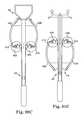
- FIGS. 19 and 20illustrate a cocking mechanism for a crossbow in accordance with an embodiment of the present disclosure.
- FIGS. 21A and 21Billustrate a crossbow in a release configuration in accordance with an embodiment, of the present disclosure.
- FIGS. 22A and 22Billustrate the cams of the crossbow of FIGS. 21A and 21B in the release configuration.
- FIGS. 23A and 23Billustrate the crossbow of FIGS. 21A and 21B in a drawn configuration in accordance with an embodiment of the present disclosure.
- FIGS. 24A, 24B, and 24Cillustrate the cams of the crossbow of FIGS. 23A and 23B in the drawn configuration.
- FIGS. 25A and 25Billustrate an alternate trigger assembly in accordance with an embodiment of the present disclosure.
- FIG. 25Cis a front view of an alternate string carrier for the crossbow in accordance with an embodiment of the present disclosure.
- FIGS. 26A and 26Billustrate an alternate cocking handle in accordance with an embodiment of the present disclosure.
- FIGS. 27A-27Dillustrate an alternate tunable arrow rest for a crossbow in accordance with an embodiment of the present disclosure.
- FIGS. 28A-28Fillustrate alternate cocking systems for a crossbow in accordance with an embodiment of the present disclosure.
- FIG. 29illustrates capture of the string carrier in the center rail illustrated in FIG. 13B .
- FIGS. 30A through 30Cillustrate an alternate crossbow in which the pulleys rotate around axes in a fixed relationship relative to the center rail and the riser in, accordance with an embodiment of the present disclosure.
- FIGS. 31A through 31Cillustrate a variation of the crossbow of FIG. 30A with limbs swept forward in accordance with an embodiment of the present disclosure.
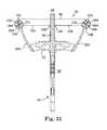
- FIG. 32illustrates an alternate crossbow in which the pulleys rotate around axes attached to the riser in accordance with an embodiment of the present disclosure.
- FIG. 4illustrates a string guide system 90 for a bow with a reverse draw configuration 92 in accordance with an embodiment of the present disclosure.
- Power cables 102 A, 102 B (“ 102 ”)are attached to respective string guides 104 A, 104 B (“ 104 ”) at first attachment points 106 A, 106 B (“ 106 ”).
- Second ends 108 A, 108 B (“ 108 ”) of the power cables 102are attached to axles 110 A, 110 B (“ 110 ”) of the opposite string guides 104 .
- the power cables 102wrap around power cable take-ups 112 A, 112 B (“ 112 ”) located on the respective cam assembles 104 when in the released configuration 116 of FIG. 4 .
- the draw string 114is located adjacent down-range side 94 of the string guide system 70 when in the released configuration 116 .
- the distance between the axles 110may be in the range of less than about 16 inches to less than about 10 inches.
- the distance between the axles 110may be in the range of about between about 6 inches to about 8 inches, and more preferably about 4 inches to about 8 inches. In one embodiment, the distance between the axles 110 in the drawn configuration 118 is less than about 6 inches and alternatively, less, than about 4 inches.
- the draw string 114translates from the down-range side 94 toward the up-range side 96 and unwinds between the first and second string guides 104 in a drawn configuration 118 .
- the string guides 104counter-rotate toward each other in directions 120 more than 360 degrees as the draw string 114 unwinds between the string guides 104 from opposing cam journals 130 A, 130 B (“ 130 ”).
- the string guides 104each include one or more grooves, channels or journals located between two flanges around at least a portion of its circumference that guides a flexible member, such as a rope, string, belt, chain, and the like.
- the string guidescan be cams or pulleys with a variety of round and non-round shapes.
- the axis of rotationcan be located, concentrically or eccentrically relative to the string guides.
- the power cables and draw stringscan be any elongated flexible member, such as woven and non-woven filaments of synthetic or natural materials, cables, belts, chains, and the like.
- the power cables 102are wrapped onto cams 126 A, 126 B (“ 126 ”) with helical journals 122 A, 122 B (“ 122 ”), preferably located at the respective axles 110 .
- the helical journals 122take up excess slack in the power cables 102 resulting from the string guides 104 moving toward each other in direction 124 as the axles 110 move toward each other.
- the helical journals 122serve to displace the power cables 102 away from the string guides 104 , so the first attachment points 106 do not contact the power cables 102 while the bow is being drawn (see FIGS. 7 and 8 ).
- rotation of the string guides 104is limited only by the length of the draw string journals 130 A, 103 B (“ 130 ”).
- the draw string journals 130can also be helically in nature, wrapping around the axles 110 more than 360 degrees.
- the power stroke 132is extended.
- the power stroke 132can be increased by at least 25%, and preferably by 40% or more, without changing the diameter of the string guides 104 .
- the power stroke 132can be in the range of about 8 inches to about 20 inches.
- the present disclosurepermits crossbows that generate kinetic energy of greater than 70 ft.-lbs. of energy with a power stroke of about 8 inches to about 15 inches. In another embodiment, the present disclosure permits a crossbow that generates kinetic energy of greater than 125 ft.-lbs. of energy with a power stroke of about 10 inches to about 15 inches.
- the geometric profiles of the draw string journals 130 and the helical journals 122contribute to let-off at full draw.
- a more detailed discussion of cams suitable for use in bowsis provided in U.S. Pat. No. 7,305,979 (Yehle), which is hereby incorporated by reference.
- FIGS. 7 and 8are enlarged views of the string guides 104 A, 104 B, respectively, with, the draw string 114 in the drawn configuration 118 .
- the helical journals 122have a length corresponding generally to one full wrap of the power cables 102 .
- the axes of rotation 146 A, 146 B (“ 146 ”) of the first and second helical journals 122preferably extend, generally perpendicular to a plane of rotation of the first and second string guides 104 .
- the helical journals 122displace the power cables 102 away from the draw string 114 as the bow is drawn from the released configuration 116 to the drawn configuration 118 .
- Height 140 of the helical journals 122raises the power cables 102 above top surface 142 of the string guides 104 .
- the resulting gap 144permits the first attachment points 106 and the power cable take-ups 112 to pass freely under the power cables 102 .
- the length of the helical journals 122can be increased or decreased to optimize draw force versus draw distance for the bow and let-off.
- the axes of rotation 146 of the helical journals 122are preferably co-linear with axes 110 of rotation for the string guides 104 .
- FIG. 9Aillustrates an alternate string guide 200 in accordance with an embodiment of the present disclosure.
- Power cable take-ups 202have helical journals 204 that permit the power cables 102 to wrap around about two full turns or about 720 degrees.
- the extended power cable take-up 202increases the gap 206 between the power cables 102 and top surface 208 of the string guide 200 and provides excess capacity to accommodate more than 360 degrees of rotation of the string guides 200 .
- FIG. 9Billustrates an alternate string guide 250 in accordance with an embodiment of the present disclosure.
- the draw string journals 252 and the power cable journals 254are both helical structures designed so that, the draw string 114 and the power cables 102 can wrap two, full turns around the string guide 250 .
- FIG. 9Cillustrates an alternate string guide 270 with a smooth power cable take-up 272 in accordance with an embodiment of the present disclosure.
- the power cable take-up 272has a surface 274 with a height 276 at least twice a diameter 278 of the power cable 102 .
- the surface 274has a height 276 at least three times the diameter 278 of the power cable 102 .
- Biasing force 280such as from a cable guard located on the bow shifts the power cables 102 along the surface 274 away from top surface 282 of the string, guide 270 when in the drawn configuration 284 .
- FIG. 10is a schematic illustration of bow 150 with a string guide system 152 in accordance with an embodiment of the present disclosure.
- Bow limbs 154 A, 154 B (“ 154 ”)extend oppositely from riser 156 .
- String guides 158 A, 158 B (“ 158 ”)are rotatably mounted, typically eccentrically, on respective limbs 154 A, 154 B on respective axles 160 A, 160 B (“ 160 ”) in a reverse draw configuration 174 .
- Draw string 162is received in respective draw string journals (see e.g., FIGS. 7 and 8 ) and secured at each end to the string guides 158 at locations 164 A, 164 B.
- the draw string 162is located adjacent the down-range side 178 of the bow 150 .
- the draw string 162unwinds from the draw string journals toward the up-range side 180 of the bow 150 , thereby rotating the string guides 158 in direction 166 .
- First power cable 168 Ais secured, to the first string guide 158 A at first attachment, point 170 A and engages with a power cable take-up with a helical journal 172 A (see FIGS. 7 and 8 ) as the bow 150 is drawn. As the string guide 158 A rotates in the direction 166 , the power cable 168 A is taken up by the cam 172 A. The other end of the first power cable 168 A is secured to the axle 160 B.
- Second power cable 168 Bis secured to the second string guide 158 B at first attachment point 170 B and engages with a power cable take-up with a helical journal 172 B (see FIGS. 7 and 8 ) as the bow 150 is drawn. As the string guide 158 B rotates, the power cable 168 B is taken up by the cam 172 B. The other end of the second power cable 168 B is secured to the axle 160 A. Alternatively, the other ends of the first and second power cables 168 can be attached to the riser 156 or an extension thereof, such as the pylons 32 illustrated in commonly assigned U.S. Pat. No. 8,899,217 (Islas) and U.S. Pat. No.
- FIG. 11is a schematic illustration of a crossbow 300 with a reverse draw configuration 302 in accordance with an embodiment of the present disclosure.
- the crossbow 300includes a center portion 304 with down-range side 306 and up-range side 308 .
- the center portion 304includes riser 310 .
- First and second flexible limbs 312 A, 312 B (“ 312 ”)are attached to the riser 310 and extend from opposite sides of the center portion 304 .
- Draw string 314extends between first and second string guides 316 A, 316 B (“ 316 ”).
- the string guide 316 Ais substantially as shown in FIGS. 4-8
- the string guide 316 Bis a conventional pulley.
- the first string guide 316 Ais mounted to the first bow limb 312 A sand is rotatable around a first axis 318 A.
- the first string guide 316 Aincludes a first draw string journal 320 A and a first power cable take-up journal 322 A, both of which are oriented generally perpendicular to the first axis 318 A. (See e.g., FIG. 8 ).
- the first power cable take-up journal 322 Aincludes a width measured along the first axis 318 A that is at least twice a width of power cable 324 .
- the second string guide 316 Bis mounted to the second bow limb 312 A and rotatable around a second, axis 318 B.
- the second string guide 316 Bincludes a second draw string journal 320 B oriented generally perpendicular to the second axis 318 B.
- the draw string 314is received in the first and second draw string journals 320 A, 320 B and is secured to the first string guide 316 A at first attachment point 324 .
- the draw stringextends adjacent to the down-range side 306 to the second string guide 316 B, wraps around the second string guide 316 B, and is attached at the first axis 318 A.
- Power cable 324is attached to the string guide 3164 at attachment point 326 . See FIG. 4 . Opposite end of the power cable 324 is attached to the axis 318 B. In the illustrated embodiment, power cable wraps 324 onto the first power cable take-up journal 322 A and translates along the first power cable take-up journal 322 A away from the first draw string journal 320 A as the bow 300 is drawn from the released configuration 328 to the drawn configuration (see FIGS. 5-8 ).
- FIG. 12is a schematic illustration of a dual-cam crossbow 350 with a reverse draw configuration 352 in accordance with an embodiment of the present disclosure.
- the crossbow 350includes a center portion 354 with down-range side 356 and up-range side 358 .
- First and second flexible limbs 362 A, 362 B (“ 362 ”)are attached to riser 360 and extend from opposite sides of the center portion 354 .
- Draw string 364extends between first and second string guides 366 A, 366 B (“ 366 ”). In the illustrated embodiment, the string guides 366 are substantially as shown in FIGS. 4-8 .
- the draw string 364is received in the draw string journals 370 and is secured to the string guides 316 at first and second attachment points 375 A, 375 B (“ 325 ”).
- Power cables 374are attached to the string guides 316 at attachment points 376 A. 376 B (“ 376 ”). See FIG. 4 . Opposite ends 380 A, 380 B (“ 380 ”) of the power cables 374 are attached to anchors 378 A, 378 B (“ 378 ”) on the center portion 354 . The power cables 374 preferably do not cross over the center support 354 .
- power cableswrap 374 onto the power cable take-up journal 372 and translates along the power cable take-up journals 372 away from the draw string journals 370 as the bow 350 is drawn from the released configuration 378 to, the drawn configuration (see FIGS. 5-8 ).
- the string guides disclosed hereincan be used with a variety of bows and crossbows, including those disclosed in commonly assigned U.S. patent application Ser. No. 13/799,518, entitled Energy Storage Device for a Bow, filed Mar. 13, 2013 and Ser. No. 14/071,723, entitled DeCocking Mechanism for a Bow, filed Nov. 5, 2013, both of which are hereby incorporated by reference.
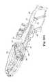
- FIGS. 13A and 13Billustrate an alternate crossbow 400 in accordance with an embodiment of the present disclosure.
- the crossbow 400includes a center rail 402 with a riser 404 mounted at the distal end 406 and a stock 408 located at the proximal end 410 .
- the arrow 416is suspended above the rail 402 before firing.
- the central rail 402 and the riser 404may be a unitary structure, such as, for example, a molded carbon fiber component.
- the stock 408includes a scope mount 412 with a tactical, picatinny, or weaver mounting rail.
- Scope 414preferably includes a reticle with gradations corresponding to the ballistic drop of bolts 416 of particular weight.
- the riser 404includes a pair of limbs 420 A, 420 B (“ 420 ”) extending rearward toward the proximal end 410 .
- the limbs 420have a generally concave shape directed toward the center rail 402 .
- the terms “bolt” and “arrow”are both used for the projectiles launch by crossbows and are used interchangeable herein.
- Various arrows and nooksare disclosed in commonly assigned U.S. patent Ser. No. 15/673,784 entitled Arrow Assembly for a Crossbow and Methods of Using Same, filed Aug. 10, 2017, which is hereby incorporated by reference.
- Draw string 501is retracted to the drawn configuration 405 shown in FIGS. 13A and 13B using string carrier 480 .
- the string carrier 480slides along the center rail 402 toward the riser 404 to engage the draw string 501 while it is in a released configuration (see e.g., FIG. 21A ). That is, the string carrier 480 is captured by the center rail 402 and moves in a single degree of freedom along a Y-axis. The engagement of the string carrier 480 with the rail 402 (see e.g., FIG.
- the string carrier 480substantially prevents the string carrier 480 from moving in the other five degrees of freedom (X-axis, Z-axis, pitch, roll, or yaw) relative to the center rail 402 and the riser 404 .
- “captured”refers to a string carrier that cannot be removed from the center rail without disassembling the crossbow or the string carrier.
- tension forces 409 A, 409 B on the draw string 501 on opposite sides of the string carrier 480are substantially the same, resulting in increased accuracy.
- tension force 409 Ais the same as tension force 409 B within less, than about 1.0%, and more preferably less than about 0.5%, and most preferably less than about 0.1%. Consequently, cocking and firing the crossbow 400 is highly repeatable. To the extent that manufacturing variability creates inaccuracy in the crossbow 400 , any such inaccuracy are likewise highly repeatable, which can be compensated for with appropriate windage and elevation adjustments in the scope 414 (See FIG. 13B ).
- the repeatability provided by the present string carrier 480results in a highly accurate crossbow 400 at distances beyond the capabilities of prior art crossbows.
- a cocking mechanism 484retracts the string carrier 480 to the retracted position illustrated in FIG. 13B .
- the crossbow 400includes a positive stop (e.g., the stock 408 ) for the string carrier 480 that prevents the draw string 501 from being retracted beyond the drawn configuration 405 .
- the distance 407 between the cam axlesmay be in the range of about between about 6 inches to about 8 inches, and more preferably about 4 inches to about 8 inches. In one embodiment, the distance 407 between the axles in the drawn configuration 405 is less than about 6 inches, and alternatively, less than about 4 inches.
- the included angle 403is the angle defined by the draw string 501 on either side of the string carrier 480 when in the drawing configuration 405 .
- the included angle 403is preferably less than about 25 degrees, and more preferably less than about 20 degrees.
- the included angle 403is typically between about 15 degrees to about 25 degrees.
- the present string carrier 480includes a catch 502 (see e.g., FIG. 17A ) that engages a narrow segment of the draw string 501 that permits the present small included angle 403 .
- the small included angle 403 that results from the narrow separation 407does not provide sufficient space to accommodate conventional cocking mechanisms, such as cocking ropes and cocking sleds disclosed in U.S. Pat. No. 6,095,128 (Bednar); U.S. Pat. No. 6,874,491 (Bednar); U.S. Pat. No. 8,573,192 (Bednar et, al.); U.S. Pat. No. 9,335,115 (Bednar et al.); and 2015/0013654 (Bednar et al.), which are hereby incorporated by reference. It will be appreciated that the cocking systems disclosed herein are applicable to any type of crossbow, including recurved crossbows that do not include cams or conventional compound crossbows with power cables that crossover.
- the pivots 432provide a flexure point for the limbs 420 when the crossbow 400 is in the drawn configuration.
- the maximum diameter 441 of the cams 440is preferably less than about 2.6 inches.
- the cams 440preferably have a maximum diameter of less than about 4.0 inches, and more preferably less than about 3.5 inches.
- a highly compact crossbow with an included angle of less than about 25 degreespreferably has cams with a maximum diameter of less than about 3.0 inches.
- the axle mounts 442are attached to the limbs 420 offset a distance 446 from the proximal ends 444 A, 444 B (“ 444 ”) of the limbs 420 . Due to their concave shape, greatest width 448 of the limbs 420 (in both the drawn configuration and the release configuration) preferably occurs at a location between the axle mounts 442 and the pivots 432 , not at the proximal ends 444 .
- the offset 446 of the axle mounts 442maximizes the speed of the limbs 420 , minimizes limb vibration, and maximizes energy transfer to the bolts 416 .
- the offset 446is similar to hitting a baseball with a baseball bat at a location offset from the tip of the bat, commonly referred to as the “sweet spot”.
- the size of the offset 446is determined empirically for each type of limb. In the illustrated embodiment, the offset 446 is about 1.5 to about 4 inches, and more preferably about 2 to about 3 inches.
- Tunable arrow rest 490is positioned just behind the pocket 426 .
- a pair of supports 492are secured near opposite sides of the bolt 416 by fasteners 494 .
- the supports 492preferably slide in the plane of the limbs 420 .
- the separation 496 between the supports 492can be adjusted to raise or lower front end of the bolt 416 relative to the draw string 501 .
- the separation 496 between the supports 492can be adjusted to raise or lower front end of the bolt 416 relative to the draw string 501 .
- the separation 496 between the supports 492the curved profile of the front end of the bolt 416 is lowered relative to the string carrier 480 (see FIG. 17A ).
- the separation 496the curved profile of the bolt 416 is raised.
- FIG. 14Billustrates the bottom of the riser 404 .
- Rail 450 on the riser 404is used as the attachment point for accessories, such as quiver 452 for holding bolts 416 and cocking handle 454 that engages with pins 570 to rotate the drive shaft 564 (see FIG. 18A ).
- FIG. 14Dillustrates the cocking handle 454 in greater detail.
- Distal end 700is configured to engage with drive shaft 564 and pins 570 illustrated in FIG. 18A .
- Center recess 702receives the drive shaft 564 and the undercuts 704 engage with, the pins 570 when the system is under tension. Consequently, when cocking or uncocking the crossbow 400 the tension in the system locks the pins 570 into the undercuts 704 .
- the cocking handle 454can be rotated a few degrees and disengaged from the drive shaft 564 .
- the distal end 700includes stem 706 that extends into hollow handle 708 .
- Pins 710permit the stem 706 to rotate a few degrees around pin 712 in either direction within the hollow handle 708 .
- torque assembly 714is located in hollow handle 708 that resists rotation of the stem 706 until a pre-set torque is reached Once that torque threshold is exceeded, the stem 706 breaks free of block 716 and rotates within the hollow handle 708 , generating an audible noise and snapping sensation that signal to the user that the crossbow 400 is fully cocked.
- FIGS. 14F and 14Gillustrate a mounting system 730 for the quiver 452 and the cocking handle 454 .
- Quiver spine 732includes a pair of mounting posts 734 spaced to engage with openings 736 in the mounting bracket 738 .
- Magazine catch 740slides within mounting bracket 738 .
- Spring 742biases the magazine catch 740 in direction 744 .
- Openings 746 in the magazine catch 740engage with undercuts 748 on the mounting posts 734 under pressure from the spring 742 .
- the userpresses the handle 750 in direction 752 until the openings 746 in the magazine catch 740 are aligned with the openings 736 in the mounting bracket 738 . Once aligned, the mounting posts 734 can be removed from the mounting bracket 738 .
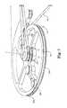
- FIG. 15is a front view of the crossbow 400 with the draw string or the power cables removed, to better illustrate the cams 440 having upper and lower helical journals 460 A, 460 B above and below draw string journal 464 .
- FIG. 21Aseparate power cables 610 A, 610 B are operatively engaged with each of the helical journals 460 A, 460 B, and minimizing torque on the cams 440 .
- the draw string journal 464defines plane 466 that passes through the bolt 416 .
- the helical journals 460 A, 460 Bmove the power cables 610 A, 610 B in directions 468 A, 468 B, respectively, away from the plane 466 as the bow 400 is drawn.
- FIGS. 16A and 16Bare upper and lower perspective views of the cams 440 with the power cables and draw string removed.
- Recess 470contains draw string mount 472 located generally in the plane 466 of the draw string journal 464 .
- Power cable attachment 462 A and pivot post 463 Acorrespond to helical journal 460 A.
- power cable attachment 462 B and pivot post 463 Bcorresponds to the helical journal 460 B.
- the pivot pots 463serve to take-up a portion of the power cables 610 and redirect the power cables 610 onto the helical journals 460 .
- FIGS. 17A through 17Dillustrate string carrier 480 for the crossbow 400 in accordance with an embodiment of the present disclosure.
- the string carrier 480slides along axis 482 of the center rail 402 to the location 483 (see FIG. 21A ) to capture the draw string 501 .
- the cocking mechanism 484(see FIGS. 18A and 18B ) is used to return the string carrier 480 back to the position illustrated in FIGS. 17A and 17B at the proximal end 410 of the crossbow 400 and into engagement with trigger 558 .
- recess 512 on sear 514engages low friction device 513 at rear edge of the catch 502 at interface 533 to retain the catch 502 in the closed position 504 .
- the sear 514is biased in direction 516 by a sear biasing force applied by spring 511 to engage with and retain the catch 502 in the closed position 504 .
- FIG. 17Dillustrates the string carrier 480 with the sear 514 removed for clarity.
- the low friction device 513is a roller pin 523 mounted in rear portion of the catch 520 .
- the roller pin 523has a diameter corresponding generally to the diameter of the recess 512 .
- the roller pin 523is preferably supported by ball bearings 525 to reduce friction between the catch 502 and the recess 512 when firing the crossbow 400 .
- a force necessary to overcome the friction at the interface 533 to release the catch 502is preferably less than about 1 pound, substantially reducing the trigger pull weight.
- the positions of the roller pin 523 and the ball bearings 525can be reversed so that the sear 514 engages directly on the ball bearings 525 .
- a force necessary to overcome the friction at the interface 533 to release the catch 502is preferably less than the biasing force applied, to the sear 514 by the spring 511 . This feature causes the sear 514 to return fully to the cocked position 524 in the event the trigger 558 is partially depressed, but then released before the catch 502 releases the draw string 501 .
- FIG. 17Cillustrates the string carrier 480 with the catch 502 removed for clarity.
- Nock 417 of the bolt 416is engaged with the dry fire lockout 542 and rotated it in the direction 546 .
- Distal end 544 of the dry fire lockout 542is now in disengaged position 547 relative to the sear 514 .
- the crossbow 400can be fired.
- the nock 417is a clip-on version that flexes to form a snap-fit engagement with the draw string 501 .
- FIGS. 18A and 18Billustrate the relationship between the string carrier 480 , the cocking mechanism 484 , and the trigger assembly 550 that form string control assembly 551 .
- the trigger assembly 550is mounted in the stock 408 , separate from the string carrier 480 . Only when the string carrier 480 is fully retracted into the stock 408 is the trigger pawl 552 positioned adjacent to the sear 514 .
- the safety button 530is moved in direction 532 to a free position 553 where the extension 515 is disengaged from the shoulder 520 .
- the trigger 558is depressed the sear 514 rotating in direction 517 to a de-cocked position 557 and the catch 502 moves to the open position 505 to release the draw string 501 .
- the sear 514is in a de-cocked position 557 and the safety 522 is in the free position 553 .
- the catch 502retains the sear 514 in the de-cocked position 557 even though the spring 511 biases it toward the cocked position 524 .
- the sear 514retains the dry fire lockout 542 in the disengaged position 547 even though the spring 540 biases it toward the lockout position 541 .
- the extension 515 on the sear 514is located in recess 521 on the safety 522 .
- the spring 540biases dry fire lockout 542 to the lockout position 541 so the distal end 544 engages the sear 514 to prevent the catch 502 from releasing the draw string 501 (See FIG. 18A ) until an arrow is inserted into the string carrier 480 .
- a pair of pawls 572 A, 572 B (“ 572 ”)include teeth 574 (see FIG. 20 ) that are biased into engage with the gear teeth 568 .
- the pawls 572are preferably offset 1 ⁇ 2 the gear tooth 568 spacing so that when the teeth 574 of one pawl 572 are disengaged from the gear teeth 568 , the teeth 574 on the other pawl 572 are positioned to engage the gear teeth 568 . Consequently, during winding of the spool 560 , the teeth 574 on one of the pawls 572 are always positioned to engage with the gear teeth 568 on the spool. If the user inadvertently released the cocking handle 454 when the crossbow 400 is under tension, one of the pawls 572 is always in position to arrest rotation of the spool 560 .
- the userpresses the release 576 to disengage the pawls 572 from the spool 560 and proceeds to rotate the cocking handle 454 to move the string carrier 480 in either direction 482 along the rail 402 to cock or de-cocking the crossbow 400 .
- the crossbow 400can be cocked without depressing the release 576 , but the pawls 572 will make a clicking sound as they advance over the gear teeth 568 .
- FIGS. 21A and 21Billustrate the crossbow 400 in the released configuration 600 .
- Draw string 501is located adjacent down-range side 602 of the cams 440 in a reverse draw configuration 604 .
- the draw string 501is adjacent stops 606 attached to power cable bracket 608 .
- Upper power cables 610 Aare attached to the power cable bracket 608 at upper attachment points 612 A and to power cable attachments 462 A on the cams 440 (see also FIG. 22A ).
- Lower power cables 610 Eare attached to the power cable bracket 608 at lower attachment points 612 B and to the power cable attachments 462 B on the cams 440 (see also FIG. 22B ).
- the attachment points 612are static relative to the riser 404 , rather than dynamic attachment points on the opposite limbs or opposite cams.
- “static attachment point”refers to a cabling system in which power cables are attached to a fixed point relative to the riser, and not attached to the opposite limb or opposite cam.
- the upper and lower attachment points 612 A. 612 B on, the power cable bracket 608maintains gap 614 between the upper and lower power cables 610 A, 610 B greater than the gap at the axes of the cams 440 . Consequently, the power cables 610 A, 610 B angle toward each other near the cams 440 .
- FIGS. 22A and 22Bare upper and lower perspective views of the cams 440 with the cables 510 , 610 A, and 610 B in the released configuration 600 .
- the cams 440are preferably symmetrical so only one of the cams 440 is illustrated.
- Upper power cables 610 Aare attached to power cable attachments 462 A, wrap around the upper pivots 463 A and then return toward the bow 400 to attach to the power cable bracket 608 (see FIG. 21A ).
- the draw cable 501is attached to the draw string mount 472 and then wraps almost completely around the cam 440 in, the draw string journal 464 to the down range side 602 .
- FIGS. 23A and 23Billustrate the crossbow 400 in the drawn configuration 620 .
- Draw string 501extends from the down-range side 602 of the cams 440 in a reverse draw configuration 604 .
- the power cables 610 A, 610 Bmove away from the cams 440 as they wrap onto the upper and lower helical journals 460 A, 460 B.
- the power cables 610 A, 610 Bare generally parallel (compare the angled relationship in the released configuration 600 illustrated in FIG. 21B ).
- the resulting gap 622permits the power cable attachments 462 and pivot 463 to pass under the power cables 610 without contacting them (see also, FIGS.
- FIGS. 24A and 24Bare upper and lower perspective views of the cams 440 with the cables 510 , 610 A, and 610 B in the drawn configuration 620 .
- the upper power cables 610 Awraps around the upper pivots 463 A and then onto the upper helical journal 460 A, before returning to the power cable bracket 608 (see FIG. 23A ).
- the lower power cables 610 Bwraps around the lower pivots 463 B and then onto the lower journal 460 B, before returning to the power cable bracket 608 (see FIG. 23A ).
- the draw cable 501is attached to the draw string mount 472 unwraps almost completely from the draw string journal 464 of the cam 440 to the down range side 602 .
- the draw string journal 464rotates between about 270 degrees and about 330 degrees, and more preferably from about 300 degrees to about 360 degrees, when the crossbow 400 is drawn from the released configuration 600 to the drawn configuration 620 . In another embodiment, the draw string journal 464 rotates more than 360 degrees (see FIG. 9A ).
- FIGS. 25A and 25Billustrate an alternate string carrier 480 A for the crossbow 400 in accordance with an embodiment of the present disclosure.
- the string carrier 480 Ais similar to the assembly illustrated in FIGS. 17A-17C , so the same reference numbers are used where applicable.
- FIG. 25Aillustrates the catch 502 is illustrated in a closed position 504 .
- the catch 502is biased by spring 510 to rotate in direction 506 and retained in open position 505 (see FIG. 18B ). Absent an external force, the catch 502 automatically releases the draw string 501 (See FIG. 17A ).
- recess 512 on sear 514engages with low friction device 513 on the catch 502 to retain the catch 502 in the closed position 504 .
- the sear 514is biased by spring 519 to retain the catch 502 in the closed position 504 .
- the safety 522operates, as discussed in connection with FIGS. 17A-17C .
- the rear portions or arms on the clip-on nock 417extends past the draw string 501 (so a portion of the nock 417 is behind the draw sting 501 ) and engages with the portion 543 A on the dry fire lockout 542 A, causing the dry fire lockout 542 A to rotate in direction 546 A so that the distal end. 544 A is disengaged from the sear 514 .
- the portion 543 Ais a protrusion or finger on the dry fire lockout 542 A. Only when a bolt 416 is frilly engaged with the draw string 501 will the dry fire lockout 542 A permit the sear 514 to release the catch 502 .
- the portion 543 A on the dry fire lockout 542 Ais positioned behind the draw string location 501 A.
- the phrase “behind the draw string”refers to a region between a draw string and a proximal end of a crossbow. Conventional flat or half-moon nocks do not extend far enough rearward to reach the portion 543 A of the dry fire lockout 542 A, reducing the chance that non-approved arrows can be launched by the crossbow 400 .
- Upper roller 652is located near the entrance of the arrow capture recess 650 .
- the upper roller 652is configured to rotate in the direction of travel of the arrow 416 as it is launched. That is, the axis of rotation of the upper roller 652 is perpendicular to a longitudinal axis of the arrow 416 .
- the upper roller 652is displaced within the slot in a direction generally perpendicular to the arrow 416 , while spring 654 biases the upper roller 652 in direction 656 against the arrow 416 .
- the arrow capture recess 650extends rearward past the fingers 500 on catch 502 .
- the string carrier 480 Aincludes lower angled surfaces 658 A, 658 B (“ 658 ”) and upper angled surfaces 660 A, 660 B (“ 660 ”) configured to engage the arrow 416 around the perimeter of the rear portion.
- the clip-on nock 417must be fully engaged with the draw string 510 A near the rear of the arrow capture recess 650 to disengage the dry fire lock out 542 A.
- the rear portion 419 of the arrow 416is fully engaged with the arrow capture recess 650 , surrounded by the rigid structure of the string carrier 480 A.
- the lower angled surfaces 658do not support the arrow 416 in the arrow capture recess 650 unless the clip-on neck 417 is used.
- the upper angled surfaces 660prevent the nock 417 from rising upward when the crossbow 400 is fired, but the arrow 417 tends to slide downward off the lower angled surfaces 658 unless the clip-on nock 417 is fully engaged with the draw string 510 A.
- prior art crossbowstypically include a leaf spring or other biasing structure to retain the arrow against the rail. These devices tend to break and are subject to tampering, which can compromise accuracy.
- FIG. 26Aillustrates an alternate the cocking handle 720 with an integral, clutch to prevent excessive torque on the cocking mechanism 484 and tension on the flexible tension member 585 in accordance with an embodiment of the present disclosure.
- distal end 700is configured to engage with drive shaft 564 and pins 570 .
- Center recess 702receives the drive, shaft 564 and the undercuts 704 engage with the pins 570 when, the system is under tension. Consequently, when cocking or uncocking the crossbow 400 the tension in the system locks the pins 570 into the undercuts 704 .
- the cocking handle 454can be rotated a few degrees and disengaged from the drive shaft 564 .
- FIG. 26Bis an exploded view of the cocking handle 720 of FIG. 26A .
- Distal end 700contains a torque control mechanism 722 .
- Coupling 724 that engages with the drive shaft 564is contained between a pair of opposing friction washers 726 and a pair of opposing notched washers 728 within head 729 .
- Pins 730couple the notched washers 728 .
- One or more spring washers 732such as for example Belleville washers, conical spring washers, and the like, maintain a compressive load on the coupling 724 to control the torque applied to the drive shaft 564 .
- the magnitude of the compressive load applied to the couplingestablishes a pre-set maximum torque that can be, applied to the drive shaft 564 .
- the maximum torque or break-away torque at which the coupling 724 slips relative to the cocking handle 720preferably corresponds to about 110% to about 150% of the force on the flexible tension member 585 during cocking of the crossbow
- the drive shaft 564is three discrete pieces 565 A, 565 B, 565 C connected by torque control mechanisms located in housings 567 A, 567 B.
- a torque control mechanism 722 generally as illustrated in FIG. 26Bmay be used.
- FIGS. 27A-27Cillustrates an alternate tunable arrow rest 750 in accordance with an embodiment of the present disclosure.
- the tunable arrow rest 750includes housing 760 that is positioned just behind the pocket 426 .
- a pair of spring loaded support rollers 752are rotatable secured in slots 754 by pins 756 .
- the support rollers 752rotate, freely around the pins 756 . When compressed, the support rollers 752 can be independently displaced in directions 758 .
- Springs 764bias the pins 756 and the support rollers 752 to the tops of the slots.
- arrow rest 750is mounted to distal end 776 of the center rail 402 by fasteners 762 .
- Each of the support rollers 752is biased to the tops of the slots 754 by the springs 764 .
- Rotating member 766is provided at the interface between the support rollers 752 and the springs 764 to reduce friction and permit the support rollers 752 to turn freely.
- the housing 760includes enlarged openings 768 with diameters larger than the diameters of the fasteners 762 . Consequently, the position of the arrow rest 750 can be adjusted (i.e., tuned) in at three degrees of freedom—the Y-direction 770 , the Z-direction 772 , and roll 774 relative to the center rail 402 .
- FIG. 27Dillustrates an arrow 412 with arrowhead 428 positioned on the support rollers 752 and the various degrees of freedom 770 , 772 , 774 available for tuning the arrow rest 750 .
- FIGS. 28A-28Eillustrate alternate cocking systems 800 in accordance with an embodiment of the present disclosure in which the cocking mechanism 484 located in the stock 408 and the flexible tension member 585 are not required.
- the string carrier 480when not engaged with the draw string 501 slides freely back and forth along the rail between the released configuration and the drawn configuration.
- At least one cocking rope engagement mechanism 802is attached to the string carrier 480 .
- a pair of pulleys 804are pivotally attached to opposite sides of the string carrier 480 brackets 806 and pivot pins 808 .
- a variety of conventional cocking ropes 810can releasably engage with the pulleys 804 .
- the hooks found on conventional cocking ropesare not required.
- the cocking rope 810can be a single discrete segment of rope or two discrete segments of rope. In the illustrated embodiment, two discrete cocking ropes 810 are each attached to opposite sides of the stock 408 at anchors 816 and wrap around the pulleys 804 to provide the user with mechanical advantage when cocking the bow 400 .
- the cocking ropes 810retract into handles 812 for convenient storage.
- protrusions 826 on handles 812can optionally contain a spring-loaded spool that automatically retracts the cocking ropes 810 when not in use, such as disclosed in U.S. Pat. No. 8,573,192 (Bednar et al.).
- a retraction mechanism for storing the cocking ropes when not in useare attached to the stock 408 at the location of the anchors 816 such as disclosed in U.S. Pat. No. 6,874,491 (Bednar).
- a cocking rope retraction system with a spool and crank handlecan be attached to the stock 408 , such as illustrated in U.S. Pat. No. 7,174,884 (the '884 Kempf Patent”).
- the userslides the string carrier 480 forward along, the rail into engagement with the draw string 501 .
- the catch 502(see e.g., FIG. 25A ) on the string carrier 480 engages the draw string 501 as discussed herein.
- the userpulls the handles 812 until the string carrier 480 is retained in the retracted position 814 by retaining mechanism 817 .
- the retaining mechanism 817retains the string carrier 480 in the retracted position 814 independent of the cocking ropes 810 . That is, once the string carrier 480 is in the retracted position 814 the retaining mechanism 817 the cocking ropes 810 can be removed and stored.
- the retaining mechanism 817is hook 818 attached to the stock configured to couple with pin 819 on the string carrier 480 .
- Release lever 820moves the hook 818 in direction 822 to disengage it from the pin 819 on the string carrier 480 .
- the force 824 applied to the string carrier 480 by the draw stringprevent the hook 818 from inadvertently disengaging from the pin 819 on the string carrier 480 .
- the string carrier 480can be secured to either the draw string 501 in the release configuration 600 or to the hook 818 in the retracted configuration 814 without the draw string 501 attached.
- FIG. 28Fillustrates an alternate embodiment where the cocking rope 810 is a single segment that wraps around the stock 408 rather than requiring anchors 816 .
- the opposite ends of the cocking rope 810then wrap around the cocking rope engagement mechanisms on opposite sides of the string carrier 480 .
- the userpulls the handles 812 toward the proximal end of the crossbow 400 to manually retract the string carrier 480 to the retracted position and the draw siring to the drawing configuration.
- extensions 830 on the string carrier 480are engaged with undercuts 832 in the rail 402 . Consequently, the string carrier 480 is captured by the rail 402 and can only move back and forth along the rail 402 (Y-axis), but cannot move in the Z-axis or X axis direction, or in pitch 834 , roll 836 , or yaw 838 , relative to the bowstring 501 .
- the extension 830are located on the exterior surface of the rail 402 and the string carrier 480 wraps around the rail 402 to engage the undercuts 832 .
- the extensions 830are retractable so the string carrier 480 can be removed from the rail 402 . With the extensions 830 in the extended position illustrated in FIG. 29 the string carrier 480 is captured by the rail 402 .
- tension forces on the draw string 501 on opposite sides of the string carrier 480are substantially the same, within less than about 1.0%, and more preferably less than about 0.5%, and most preferably less than about 0.1%. Consequently, cocking and firing the crossbow 400 is highly repeatable.
- any such inaccuracyare likewise highly repeatable, which can be compensated for with appropriate windage and elevation adjustments in the scope 414 (See FIG. 13B ).
- the repeatability provided by the present cocking systems 484 , 800results in a highly accurate crossbow 400 at distances beyond the capabilities of prior art crossbows.
- the cocking systems 484 , 800 in combination with windage and elevation adjustmentspermits groupings of three arrows in a three-inch diameter target at about 100 yards, and groupings of three arrows in a two-inch diameter target at about 50 yards.
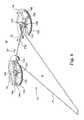
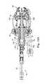
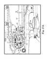
- FIGS. 30A and 30Billustrate an alternate crossbow 900 in accordance with an embodiment of the present disclosure.
- FIG. 30Aillustrates the crossbow 900 in the released configuration 600 and
- FIG. 30Billustrates the drawn configuration 405 .
- the crossbow 900includes a center rail 402 with a riser 404 mounted at the distal end 406 and a stock 408 located at the proximal end 410 .
- the center rail 402 and riser 404may be referred to herein as the frame 904 .
- the riser 404includes a pair of limbs 420 A, 420 B (“ 420 ”) extending rearward toward the proximal end 410 .
- Cams 440 A, 440 Bare attached to the frame 904 , rather than the limbs 420 .
- the cams 440are attached to the center rail 402 by axle mounts 442 A, 442 B.
- the cams 440rotate around axes 443 A, 443 B (“ 443 ”) on respective axle mounts 442 A, 442 B, but otherwise do not move relative to the frame 904 .
- the locations of axes 443are fixed relative to the center rail 402 and the riser 404 , even as the limbs 420 and the draw string 501 move.
- the stationary cams 440 and cam axles 442also eliminates any inaccuracy introduced by moving the cams 440 with the limbs 420 when firing a conventional crossbow.
- Draw string 501is engaged with draw string journals 464 (see e.g., FIG. 15 ) in a reverse draw configuration. Ends of the draw string 501 are preferably attached to the cams 440 at draw string mounts 472 .
- the present crossbow 900can also be configured in a non-reverse draw configuration.
- Power cables 610 A, 610 Bare attached to the limbs 420 A, 420 B, respectively. Opposite ends of the power cables 610 are attached to the power cable attachments 462 on the cams 440 .
- the cams 440include power cable journals 460 A, 460 B that receive respective power cables 610 A, 610 B as the draw string 510 is moved from the released configuration 600 to the drawn configuration 405 .
- each limb 420includes upper and lower power cables 610 that engaged with upper and lower power cable journals 460 on the cams 440 (see e.g., FIG. 15 ).
- the power cable journals 460are the upper and lower helical journals 460 A, 460 B located above and below draw string journal 464 illustrated in FIG. 15 .
- the helical journals 460 A, 460 Bpreferably move the power cables 610 A, 610 B in directions 468 A. 468 B, respectively, away from the plane 466 as the bow 400 is drawn (see e.g., FIG. 15 ).
- Draw string 501is preferably retracted to the drawn configuration 405 shown in FIG. 30B using the string carrier 480 .
- the string carrier 480slides along the center rail 402 toward the riser 404 to engage the draw string 501 while it is in a released configuration 600 .
- the string carrier 480is preferably captured by the center rail.
- the cocking mechanism 484(see e.g., FIGS. 18A and 18B ) retracts the string carrier 480 to the retracted position illustrated in FIG. 30B .
- any of the alternate cocking systems 800may be used, with the present crossbow 900 , such as those illustrated in FIGS. 28A-28E .
- Foot stirrup 411permits the user to secure the crossbow 900 while using the alternate cocking systems 800
- the stationary axes 443preferably have a fixed separation 902 of between about 3 inches to about 8 inches, and more preferably, about 4 inches.
- the drawn configuration 405 illustrated in FIG. 30Bresults in small included angle 403 of the draw string 501 .
- the included angle 403is preferably less than about 15 degrees, and more preferably less than about 10 degrees.
- the power strokeis preferably about 12 inches to about 16 inches.
- the draw string 501is close to the rail 402 .
- the draw string 501in entirely contained within the rail 402 in the drawn configuration 405 .
- the draw string 501is substantially surrounded by a string guard and/or the center rail 402 when in the drawn configuration 405 . Consequently, the user is shielded from the entire string path traversed by the draw string 501 between, the drawn configuration 405 and the release configuration 600 .
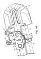
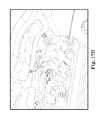
- FIG. 30Cillustrates an alternate version of the crossbow 900 with limb tips 421 A, 421 B (“ 421 ”) that overlap with cams 440 A, 440 B, respectively, in accordance with an embodiment of the present disclosure.
- the overlap of the limb tips 421 with the cams 440is best seen from the top or rear of the crossbow 900 .
- the limb 420 Ais a pair of upper and lower limbs (see e.g., FIG. 15 ) with a pair of limb tips 421 A that are positioned above and below the cam 440 A when in the drawn configuration 405 .
- the limb 420 Bincludes a pair of upper and lower limbs with a pair of limb tips 421 B that are positioned above and below the cam 440 B when in the drawn configuration 405 .
- Configuring the limb tips 421 to overlap the cams 440permits the crossbow 900 to be more compact in the drawn configuration 405 .
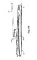
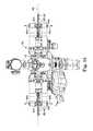
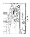
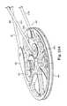
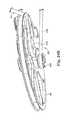
- FIGS. 31A and 31Billustrate an alternate crossbow 910 with forward swept limbs 420 in accordance with an embodiment of the present disclosure.
- the crossbow 910is substantially the same as the crossbow 900 , except that the riser 404 is located closer to the proximal end 410 and the limbs 420 extending forward toward the distal end 406 .
- a variation of the foot stirrup 411is also illustrated.
- the draw string 501is arranged in a reverse draw configuration, with the released configuration illustrated in FIG. 31A and the drawn configuration illustrated in FIG. 31B .
- FIG. 31Cillustrates an alternate version of the crossbow 910 with limb tips 421 A, 421 B (“ 421 ”) that overlap with cams 440 A, 440 B, respectively, in accordance with an embodiment of the present disclosure.
- the overlap of the limb tips 421 with the cams 440is best seen from the top or rear of the crossbow 900 .
- Overlap or overlappingrefers to the limb tip being located above and/or below the cams 440 within the outside perimeter of the cams 440 .
- the limb 420 Ais a pair of upper and lower limbs (see e.g., FIG. 15 ) with a pair of limb tips 421 A that are positioned above and below the cam 440 A when in the drawn configuration 405 .
- the limb 420 Bincludes a pair of upper and lower limbs with a pair of limb tips 421 B that are positioned above and below the cam 440 B when in the drawn configuration 405 .
- Configuring the limb tips 421 to overlap the cams 440permits the crossbow 900 to be more compact in the drawn configuration 405 .
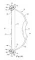
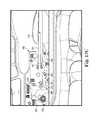
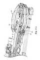
- FIG. 32illustrates another alternate crossbow 920 with the cams 440 attached to the riser 404 in accordance with an embodiment of the present disclosure.
- the crossbow 920is substantially the same as the crossbow 900 except that the limbs 420 extending forward toward the distal end 406 .
- the riser 404extends along the center rail 402 to provide attachment locations for both the limbs 420 and the cams 440 .
- the cams 440are attached to the riser 404 closer to the distal end 406 and rotate around axes 443 .
- the axle mounts 442are machined directly into the riser 404 .
- the axial mounts 442are discrete components attached to the riser 404 .
- Center portions 922 of the riser 404have a width 924 greater than the draw string 501 when in the drawn configuration 405 as illustrated in FIG. 32 .
- String guard 926 extending over the top of the crossbow 920is optionally added to partially or fully enclose the draw string 501 .
- the string carrier 480may also move within the string guard 926 . Consequently, the entire string path traversed by the draw string 501 between the drawn configuration 405 and the release configuration 600 is optionally isolated from the user.
Landscapes
- Engineering & Computer Science (AREA)
- General Engineering & Computer Science (AREA)
- Surgical Instruments (AREA)
- Transmission Devices (AREA)
Abstract
Description
Claims (25)
Priority Applications (6)
| Application Number | Priority Date | Filing Date | Title |
|---|---|---|---|
| US15/782,259US10209026B2 (en) | 2013-12-16 | 2017-10-12 | Crossbow with pulleys that rotate around stationary axes |
| US16/237,062US20190137212A1 (en) | 2013-12-16 | 2018-12-31 | Crossbow with Pulleys that Rotate Around Stationary Axes |
| US17/199,000US20210222987A1 (en) | 2015-10-22 | 2021-03-11 | Crossbow with pulleys attached to a frame |
| CA3171268ACA3171268A1 (en) | 2015-10-22 | 2021-03-12 | Crossbow with pulleys attached to frame |
| US17/579,254US20220205755A1 (en) | 2013-12-16 | 2022-01-19 | Crossbow with Pulleys that Rotate Around Stationary Axes |
| US19/031,824US20250244097A1 (en) | 2017-01-03 | 2025-01-18 | Crossbow with pulleys attached to a frame |
Applications Claiming Priority (7)
| Application Number | Priority Date | Filing Date | Title |
|---|---|---|---|
| US14/107,058US9354015B2 (en) | 2013-12-16 | 2013-12-16 | String guide system for a bow |
| US201562244932P | 2015-10-22 | 2015-10-22 | |
| US15/098,537US9494379B2 (en) | 2013-12-16 | 2016-04-14 | Crossbow |
| US15/294,993US9879936B2 (en) | 2013-12-16 | 2016-10-17 | String guide for a bow |
| US201762441618P | 2017-01-03 | 2017-01-03 | |
| US15/433,769US10126088B2 (en) | 2013-12-16 | 2017-02-15 | Crossbow |
| US15/782,259US10209026B2 (en) | 2013-12-16 | 2017-10-12 | Crossbow with pulleys that rotate around stationary axes |
Related Parent Applications (1)
| Application Number | Title | Priority Date | Filing Date |
|---|---|---|---|
| US15/433,769Continuation-In-PartUS10126088B2 (en) | 2013-12-16 | 2017-02-15 | Crossbow |
Related Child Applications (1)
| Application Number | Title | Priority Date | Filing Date |
|---|---|---|---|
| US16/237,062ContinuationUS20190137212A1 (en) | 2013-12-16 | 2018-12-31 | Crossbow with Pulleys that Rotate Around Stationary Axes |
Publications (2)
| Publication Number | Publication Date |
|---|---|
| US20180051954A1 US20180051954A1 (en) | 2018-02-22 |
| US10209026B2true US10209026B2 (en) | 2019-02-19 |
Family
ID=61191530
Family Applications (1)
| Application Number | Title | Priority Date | Filing Date |
|---|---|---|---|
| US15/782,259ActiveUS10209026B2 (en) | 2013-12-16 | 2017-10-12 | Crossbow with pulleys that rotate around stationary axes |
Country Status (1)
| Country | Link |
|---|---|
| US (1) | US10209026B2 (en) |
Cited By (13)
| Publication number | Priority date | Publication date | Assignee | Title |
|---|---|---|---|---|
| US10520274B2 (en)* | 2017-07-05 | 2019-12-31 | Hunter's Manufacturing Co., Inc. | Crossbow assembly |
| US20200011634A1 (en)* | 2018-07-03 | 2020-01-09 | Crosman Corporation | Crossbow |
| US10533822B1 (en)* | 2019-01-22 | 2020-01-14 | Sergey Popov | Vertical crossbow |
| US10969192B1 (en)* | 2019-05-14 | 2021-04-06 | Barnett Outdoors, Llc | Crossbow with crossing cable system |
| US10989492B1 (en)* | 2019-05-10 | 2021-04-27 | Archery Innovators, Llc | Archery cam shaft with integrated cable track |
| US11181336B2 (en) | 2019-09-19 | 2021-11-23 | Krysse As | Archery bow operable to change tension |
| US11221191B2 (en) | 2020-05-08 | 2022-01-11 | Hunter's Manufacturing Company, Inc. | Crossbow with winch |
| US11226167B2 (en) | 2019-01-15 | 2022-01-18 | Krysse As | Tension amplifying assembly and method for archery bows |
| US11320230B2 (en) | 2019-09-19 | 2022-05-03 | Krysse As | Archery device having a motion generator operable for different levels of tension |
| US11402172B2 (en)* | 2020-10-27 | 2022-08-02 | Poe Lang Enterprise Co., Ltd. | Crossbow |
| US11499792B1 (en)* | 2019-06-20 | 2022-11-15 | Archery Innovators, Llc | Projectile launching device with self-timing and without cam lean |
| US11598601B2 (en) | 2021-06-09 | 2023-03-07 | Grace Engineering Corp. | Archery bow cam and related method of use |
| US11808543B2 (en) | 2020-12-07 | 2023-11-07 | Ravin Crossbows, Llc | Crossover crossbow |
Families Citing this family (13)
| Publication number | Priority date | Publication date | Assignee | Title |
|---|---|---|---|---|
| US12188740B2 (en) | 2013-12-16 | 2025-01-07 | Ravin Crossbows, Llc | Silent cocking system for a crossbow |
| US10712118B2 (en) | 2013-12-16 | 2020-07-14 | Ravin Crossbows, Llc | Crossbow |
| US10175023B2 (en) | 2013-12-16 | 2019-01-08 | Ravin Crossbows, Llc | Cocking system for a crossbow |
| US10126088B2 (en) | 2013-12-16 | 2018-11-13 | Ravin Crossbows, Llc | Crossbow |
| US10254073B2 (en) | 2013-12-16 | 2019-04-09 | Ravin Crossbows, Llc | Crossbow |
| US10254075B2 (en) | 2013-12-16 | 2019-04-09 | Ravin Crossbows, Llc | Reduced length crossbow |
| US10962322B2 (en) | 2013-12-16 | 2021-03-30 | Ravin Crossbows, Llc | Bow string cam arrangement for a compound bow |
| US10139205B2 (en) | 2017-02-15 | 2018-11-27 | Ravin Crossbows, Llc | High impact strength nock assembly |
| US10480893B2 (en)* | 2017-03-24 | 2019-11-19 | Mcp Ip, Llc | Crossbow with stock overlap |
| EP3969831A2 (en)* | 2019-05-17 | 2022-03-23 | Ravin Crossbows, LLC | Crossbow |
| US11428495B2 (en)* | 2020-10-13 | 2022-08-30 | Limin' Innovations LLC | Device and systems for a semi-automatic crossbow |
| WO2022204551A1 (en)* | 2021-03-25 | 2022-09-29 | Ravin Crossbows, Llc | Crossbow utilizing cams |
| CN217403258U (en)* | 2022-03-28 | 2022-09-09 | 潍坊赵氏弓弩有限公司 | Crossbow head assembly structure of crossbow |
Citations (269)
| Publication number | Priority date | Publication date | Assignee | Title |
|---|---|---|---|---|
| US213976A (en) | 1879-04-08 | Improvement in spring-guns | ||
| US214791A (en) | 1879-04-29 | Improvement in cross-bows | ||
| US369153A (en) | 1887-08-30 | Spring-gun | ||
| US437605A (en) | 1890-09-30 | George w | ||
| US785050A (en) | 1903-11-16 | 1905-03-14 | Samuel L Saunders | Bow-gun. |
| US1985079A (en) | 1932-02-10 | 1934-12-18 | Claude C Conklin | Toy magazine gun |
| US2092361A (en) | 1937-02-18 | 1937-09-07 | Moses S Shirn | Dart gun |
| US2278585A (en) | 1939-01-17 | 1942-04-07 | Fides Gmbh | Telephone system |
| US2375607A (en) | 1944-01-18 | 1945-05-08 | Rodney L Wulfert | Toy rocket projecting gun |
| US2520713A (en) | 1946-06-11 | 1950-08-29 | Charles A Diehr | Shoulder bow |
| US2542777A (en) | 1946-04-22 | 1951-02-20 | Burl C Loew | Pellet projecting toy gun |
| US2818849A (en) | 1954-10-04 | 1958-01-07 | Edward F Connors Jr | Spear gun |
| US2918050A (en) | 1957-08-16 | 1959-12-22 | Francis R Kopman | Repeating cross bow |
| US3043287A (en) | 1960-03-14 | 1962-07-10 | Raymond L Nelson | Crossbow cocking device |
| US3427016A (en) | 1967-03-17 | 1969-02-11 | Harold D Harris | Ratchet clamp vernier |
| US3670711A (en) | 1971-02-22 | 1972-06-20 | Max Firestone | Crossbow cocking device |
| US4030473A (en) | 1975-06-25 | 1977-06-21 | Brunswick Corporation | Crossbow trigger |
| US4054118A (en) | 1976-01-26 | 1977-10-18 | Mckee Arnold D | Compound bow with torque eliminators and tension cable deflectors |
| US4064862A (en) | 1976-03-31 | 1977-12-27 | Victor United, Inc. | Compound bow |
| US4072254A (en) | 1976-07-07 | 1978-02-07 | P.C. Cox (Mastic Appliances) Limited | Dispensing guns |
| US4078538A (en) | 1976-11-17 | 1978-03-14 | Shepley Paul E | Two wheel compound archery bow |
| US4079723A (en) | 1976-08-09 | 1978-03-21 | Darlington Rex F | Compound bow |
| US4187826A (en) | 1977-04-15 | 1980-02-12 | Killian Gerald I | Folding limb compound archery bow |
| US4192281A (en) | 1977-06-10 | 1980-03-11 | King Fred V | Crossbow with trigger locking device |
| US4241715A (en) | 1978-11-17 | 1980-12-30 | Jennings Compound Bow, Inc. | Compound bow with adjustable eccentric wheel |
| US4261320A (en) | 1978-07-24 | 1981-04-14 | Barna Alex J | Compound bow |
| US4287867A (en) | 1980-02-25 | 1981-09-08 | Victor United, Inc. | Compound bow |
| US4338910A (en) | 1980-03-27 | 1982-07-13 | Darlington Rex F | Compound bow with center tension pulley |
| US4340025A (en) | 1980-01-28 | 1982-07-20 | Caldwell Joseph M | Pulley for compound archery bow |
| US4388914A (en) | 1981-06-08 | 1983-06-21 | Cesin Louie P | Crossbow with coil spring force developing means for projecting an article |
| US4479480A (en) | 1982-09-29 | 1984-10-30 | Holt Zedoc A | Crossbow trigger mechanism |
| US4515142A (en) | 1983-01-31 | 1985-05-07 | Indian Industries, Inc. | Compound bow and eccentric wheel assemblies therefor |
| US4541401A (en) | 1980-01-28 | 1985-09-17 | Caldwell Joseph M | Compound archery bow |
| US4545358A (en) | 1982-12-17 | 1985-10-08 | B & P Barnett Limited | Crossbow |
| US4565182A (en) | 1982-12-21 | 1986-01-21 | B & P Barnett Limited | Crossbow with rotatable magazine having open-sided channels |
| US4587944A (en) | 1982-12-17 | 1986-05-13 | B & P Barnett Limited | Crossbow stock |
| US4593675A (en) | 1983-09-28 | 1986-06-10 | Shimon Waiser | Cross bows |
| US4603676A (en) | 1984-04-17 | 1986-08-05 | Luoma Eugene H | Bow drawback mechanism |
| US4649890A (en) | 1984-06-08 | 1987-03-17 | Powers John E A | Compound bow with planar components |
| US4649891A (en) | 1985-09-20 | 1987-03-17 | Bozek John W | Cross bow |
| US4693228A (en) | 1986-02-13 | 1987-09-15 | Kidde Recreation Products, Inc. | Crossbow trigger mechanism |
| US4697571A (en) | 1983-09-28 | 1987-10-06 | Shimon Waiser | Cross bows |
| US4719897A (en) | 1986-04-24 | 1988-01-19 | Jacques Gaudreau | Cocking mechanism for crossbow |
| US4722318A (en) | 1986-10-29 | 1988-02-02 | Yankey Robert L | Crossbow bolt stabilizer |
| US4756296A (en) | 1985-04-29 | 1988-07-12 | Darlington Rex F | High energy compound bow |
| US4766874A (en) | 1987-05-11 | 1988-08-30 | Nishioka Jim Z | Shooting crossbow |
| US4796598A (en) | 1987-03-06 | 1989-01-10 | Jones Robert L | Retractable arrow launch ramp with compound crossbow |
| US4827894A (en) | 1985-06-01 | 1989-05-09 | Werner Schallberger | Crossbow |
| US4877008A (en) | 1984-04-17 | 1989-10-31 | Troubridge William C | Crossbow trigger mechanism |
| US4917071A (en)* | 1985-09-20 | 1990-04-17 | Bozek John W | Mechanical projector with variable leverage device |
| US4942861A (en) | 1985-09-20 | 1990-07-24 | Bozek John W | Cross bow with improved cocking mechanism |
| US5024206A (en) | 1988-12-16 | 1991-06-18 | Lester Wayne L | Compound archery bow |
| US5067731A (en) | 1990-05-25 | 1991-11-26 | Bickel Wayne J | Nock adapter |
| US5085200A (en) | 1991-01-09 | 1992-02-04 | Horton Manufacturing Company Inc. | Self-actuating, dry-fire prevention safety device for a crossbow |
| US5115795A (en) | 1990-08-16 | 1992-05-26 | Farris William M | Crossbow cocking device |
| US5119797A (en) | 1987-07-31 | 1992-06-09 | Anderson Jeffrey R | Archery device and arrow |
| US5134552A (en) | 1991-07-25 | 1992-07-28 | Progenics Corporation | Acceleration activated energizing device |
| US5174268A (en) | 1991-06-20 | 1992-12-29 | Martin Archery, Inc. | Compound archery bow |
| US5205267A (en) | 1990-07-20 | 1993-04-27 | Richard Burdick | Overdraw assembly for an archery bow |
| US5211155A (en) | 1992-02-21 | 1993-05-18 | Zamojski Marek R | Eccentric pulley mechanism for compound archery bow |
| US5220906A (en) | 1991-01-08 | 1993-06-22 | Horton Manufacturing Company Inc. | Device to draw the bowstring of a crossbow |
| US5224463A (en) | 1992-03-16 | 1993-07-06 | Flatiron Development, Inc. | Bowstring release assembly |
| USD337145S (en) | 1991-01-09 | 1993-07-06 | Horton Manufacturing Company Inc. | Stock for a crossbow |
| US5243956A (en) | 1992-03-30 | 1993-09-14 | Barnett International, Inc. | Crossbow cocking device |
| US5256124A (en) | 1991-03-13 | 1993-10-26 | Hughes Paul G | Body exerciser using distributed frictional brake means and central acting biasing means |
| US5265584A (en) | 1991-01-08 | 1993-11-30 | Horton Manufacturing Company Inc. | Quiver |
| US5301651A (en) | 1992-08-20 | 1994-04-12 | Paul E. Shepley, Jr. | Three way wheel for compound archery bow |
| US5307787A (en) | 1992-03-10 | 1994-05-03 | Paul E. Shepley, Jr. | Compound bow having offset cable anchor |
| US5368006A (en) | 1992-04-28 | 1994-11-29 | Bear Archery, Inc. | Dual-feed single-cam compound bow |
| US5388564A (en) | 1994-01-05 | 1995-02-14 | Islas; John J. | Compound bow |
| US5445139A (en) | 1994-02-07 | 1995-08-29 | Barnett International, Inc. | Hydraulic/pneumatic boost system for archery bow and crossbow |
| US5495843A (en) | 1981-02-23 | 1996-03-05 | Browning | Compound archery bow |
| US5505185A (en) | 1995-01-13 | 1996-04-09 | Miller; Larry | Single cam compound bow |
| US5522373A (en) | 1994-01-07 | 1996-06-04 | Barnett International Limited | Cross bow |
| US5596976A (en) | 1996-02-05 | 1997-01-28 | Waiser; Shimon | Trigger device for crossbows, with automatically activated safely means |
| US5598829A (en) | 1995-06-07 | 1997-02-04 | Hunter's Manufacturing Company | Crossbow dry fire prevention device |
| US5630405A (en) | 1993-09-15 | 1997-05-20 | Nizov; Sergei N. | Shooting bow with springback compensation |
| US5649520A (en) | 1995-01-25 | 1997-07-22 | Hunter's Manufacturing Co | Crossbow trigger mechanism |
| US5660159A (en) | 1991-11-18 | 1997-08-26 | Clayton; Richard A. | Airgun with rotary actuator |
| US5671723A (en) | 1997-01-03 | 1997-09-30 | Jerry A. Goff | Archery drawlock |
| US5678528A (en) | 1995-06-07 | 1997-10-21 | Hadley; Claude | Bow with barrel arrangement |
| US5678529A (en) | 1981-02-23 | 1997-10-21 | Browning | Compound archery bow |
| US5687703A (en) | 1996-04-04 | 1997-11-18 | Vyprachticky; Emil | Compound archery bow with bilateral cable cams |
| US5697355A (en) | 1994-12-12 | 1997-12-16 | Schaffer; John P. | Cable adjuster and limb pocket assembly for compound bow |
| US5749348A (en) | 1996-02-26 | 1998-05-12 | Oviedo-Reyes; Alfonso | Separating stock hydraulic crossbow |
| US5765536A (en) | 1994-01-31 | 1998-06-16 | Scott; John William | Bowstring release device |
| US5782229A (en) | 1995-08-14 | 1998-07-21 | Evans; John D. | Single cam compound bow with interchangeable cams for varying draw length |
| US5823172A (en) | 1995-09-25 | 1998-10-20 | Suggitt; Jack A. | Crossbow bow string drawing device |
| US5884614A (en) | 1997-09-19 | 1999-03-23 | Container Specialties, Inc. | Crossbow with improved trigger mechanism |
| US5890480A (en) | 1992-04-28 | 1999-04-06 | Bear Archery, Inc. | Dual-feed single-cam compound bow |
| US5902199A (en) | 1998-01-13 | 1999-05-11 | Adams, Jr.; Charles C. | Archery arrow tuning method and apparatus |
| US5921227A (en) | 1995-12-14 | 1999-07-13 | Indian Industries, Inc. | Compound archery bow |
| US5934265A (en) | 1996-02-20 | 1999-08-10 | Darlington; Rex F. | Single-cam compound archery bow |
| US5960778A (en) | 1995-06-07 | 1999-10-05 | Browning | Compound archery bow |
| US5975067A (en) | 1997-05-16 | 1999-11-02 | Strother; Kevin D. | Efficient power cam for a compound bow |
| US5987724A (en) | 1997-03-07 | 1999-11-23 | Kleman; John | Crossbow bolt cap and fletching nock device and method |
| US6073351A (en) | 1995-10-18 | 2000-06-13 | Barnett; Bernard Thomas | Sight mounting for weapons such as crossbows |
| US6095128A (en) | 1998-01-08 | 2000-08-01 | Tenpoint Crossbow Technologies | Crossbow bowstring drawing mechanisms |
| US6155243A (en) | 2000-01-24 | 2000-12-05 | Gallops, Jr.; Henry M. | Crossbow having a no let-off cam |
| US6205990B1 (en) | 2000-07-24 | 2001-03-27 | Daniel K. Adkins | Dry-fire prevention mechanism for crossbows |
| US6267108B1 (en) | 2000-02-11 | 2001-07-31 | Mathew A. McPherson | Single cam crossbow having level nocking point travel |
| US6286496B1 (en) | 1998-01-08 | 2001-09-11 | William J. Bednar | Crossbow bowstring drawing mechanism |
| US6360735B1 (en) | 2000-11-01 | 2002-03-26 | Browning | Eccentric for archery bow with let-off adjustment module |
| US6415780B1 (en) | 1999-11-26 | 2002-07-09 | Robert Gene Proctor | Bearing system for compound archery bow |
| US6425386B1 (en) | 2000-07-24 | 2002-07-30 | Daniel K. Adkins | Bowstring release system for crossbows |
| US6470870B1 (en) | 2000-11-22 | 2002-10-29 | John G. Schaar | Synchronous compound bow with non-coplanar actuators and interchangeable leveraging components |
| US6474324B1 (en) | 2000-11-17 | 2002-11-05 | Martin Archery, Inc. | Archery bows, archery bow cam assemblies, and archery bow anchors |
| US6571785B1 (en) | 2001-10-16 | 2003-06-03 | Horton Manufacturing Company Inc. | System for positioning bow limbs relative to the riser of a crossbow |
| US6651641B1 (en) | 2001-07-06 | 2003-11-25 | Horton Manufacturing Company Inc. | Silencer for a crossbow |
| US6705304B1 (en) | 2002-04-23 | 2004-03-16 | Adam Cuthbert Pauluhn | Crossbow cocking mechanism |
| US6712057B2 (en) | 2001-09-27 | 2004-03-30 | Albert A. Andrews | Archery bow assembly |
| US6736123B1 (en) | 2003-03-04 | 2004-05-18 | Gregory E. Summers | Crossbow trigger |
| US6763819B2 (en) | 2001-06-15 | 2004-07-20 | Tru-Fire Corporation | Bow string release |
| US6776148B1 (en) | 2003-10-10 | 2004-08-17 | John J. Islas | Bowstring cam arrangement for compound bow |
| US6786214B2 (en) | 2002-09-27 | 2004-09-07 | Albert A. Andrews | Bow actuating system |
| US6792931B1 (en) | 2003-11-12 | 2004-09-21 | John G. Schaar | Means of increasing mechanical advantage in asynchronous compound bows |
| US6792930B1 (en) | 2003-10-10 | 2004-09-21 | Precision Shooting Equipment, Inc. | Single-cam split-harness compound bow |
| US6799566B1 (en) | 2000-05-30 | 2004-10-05 | Ermanno Malucelli | Automatic cocking device in a crossbow for hunting and archery |
| US6802304B1 (en) | 2004-01-20 | 2004-10-12 | Chu-Wei Chang | Trigger assembly with a safety device for a crossbow |
| US20050022799A1 (en) | 2003-01-15 | 2005-02-03 | Tenpoint Crossbow Technologies | Crossbow rope cocking device |
| US6874492B1 (en) | 2001-01-09 | 2005-04-05 | New-Matics Licensing, Llc | Compressed gas-powered gun simulating the recoil of a conventional firearm |
| US6901921B1 (en) | 2004-01-30 | 2005-06-07 | Barnett International | Crossbow with inset foot claw |
| US6913007B2 (en) | 1997-01-09 | 2005-07-05 | William J. Bednar | Crossbow bowstring drawing mechanism |
| US6990970B1 (en) | 2003-08-27 | 2006-01-31 | Darlington Rex F | Compound archery bow |
| US7017568B1 (en) | 2003-05-06 | 2006-03-28 | Douglas Lane Smith | Pneumatic cocking device |
| US7021784B2 (en) | 2003-01-23 | 2006-04-04 | Dicarlo Joseph L | Archers flame illuminated arrow nock |
| US20060086346A1 (en) | 2004-10-26 | 2006-04-27 | Middleton Derrick J | Crossbow cocking and stringing device |
| US7047958B1 (en) | 2003-09-03 | 2006-05-23 | Colley David E | Compact archery compound bow with improved efficiency features |
| US20070028907A1 (en) | 2005-07-20 | 2007-02-08 | Hunter's Manufacturing Company, Inc. (Dba Tenpoint Crossbow Technologies) | Crossbow grip guard |
| US7174884B2 (en) | 2005-01-05 | 2007-02-13 | Kempf James J | Trigger assembly |
| US20070044782A1 (en)* | 2005-08-30 | 2007-03-01 | Gregory Norkus | Compound archery bow with extended inverted stroke |
| US7204242B2 (en) | 2002-04-12 | 2007-04-17 | Marcin Dziekan | Tiller, bow and trigger mechanism for a crossbow, and a crossbow |
| US7305979B1 (en) | 2005-03-18 | 2007-12-11 | Yehle Craig T | Dual-cam archery bow with simultaneous power cable take-up and let-out |
| US7328693B2 (en) | 2004-09-16 | 2008-02-12 | Kempf James J | Reverse draw technology archery |
| US7363921B2 (en) | 2005-01-05 | 2008-04-29 | J & S R.D.T. Archery | Crossbow |
| US20080251058A1 (en) | 2007-04-13 | 2008-10-16 | Colley David E | Compact Crossbow with Improved Efficiency |
| US7441555B1 (en) | 2005-09-30 | 2008-10-28 | Larson Archery Company | Synchronized compound archery bow |
| US7506643B2 (en) | 2006-06-30 | 2009-03-24 | Larry Holmberg | Crossbow device mount |
| US20090078243A1 (en) | 2007-09-26 | 2009-03-26 | Hunter's Manufacturing, Inc. | Trigger assembly for an archery device |
| USD589578S1 (en) | 2008-04-18 | 2009-03-31 | Horton Manufacturing Company, Inc. | Stock of a crossbow |
| USD590907S1 (en) | 2006-04-28 | 2009-04-21 | Barnett Outdoors, Llc | Crossbow stock |
| US20090178657A1 (en) | 2004-12-29 | 2009-07-16 | Hunter's Manufacturing Company, Inc., D/B/A Tenpoint Crosssbow Technologies | Vibration Dampening Arrow Retention Spring |
| US20090194086A1 (en) | 2008-01-17 | 2009-08-06 | Kempf James J | Shooting bow |
| US20090223500A1 (en) | 2008-03-10 | 2009-09-10 | Stanziale Pasquale | Device for launching a projectile or a launch object in general |
| US7588022B2 (en) | 2006-09-13 | 2009-09-15 | Poe Lang Enterprises Co., Ltd. | Trigger assembly with a safety device for a crossbow |
| US20090277435A1 (en) | 2008-05-09 | 2009-11-12 | Eastman Outdoors Inc. | Cocking Winch Apparatus For A Crossbow, Crossbow System Including The Cocking Winch Apparatus, And Method Of Using Same |
| US7624725B1 (en) | 2007-09-04 | 2009-12-01 | Horton Archery, Llc | Crossbow cocking system |
| US7624724B2 (en) | 2005-10-05 | 2009-12-01 | Tenpoint Crossbow Technologies | Multi-position draw weight crossbow |
| US7637256B2 (en) | 2006-02-21 | 2009-12-29 | Lee Seul-Ki | Compound bow |
| US20100031945A1 (en) | 2008-08-07 | 2010-02-11 | Hunter's Manufacturing Company, Inc., dba TenPoint Crossbow Technologies | Unloading Bolt |
| US7677233B2 (en) | 2005-06-14 | 2010-03-16 | Tenpoint Crossbow Technologies | Crossbow support rod |
| US7699045B1 (en) | 2008-01-10 | 2010-04-20 | Precision Shooting Equipment, Inc. | Compound bow with high limb preload |
| US7708001B2 (en) | 2006-03-22 | 2010-05-04 | Kempf James J | Bow |
| US7721721B1 (en) | 2006-09-28 | 2010-05-25 | Precision Shooting Equipment, Inc. | Reversible and adjustable module system for archery bow |
| US20100154768A1 (en) | 2005-07-20 | 2010-06-24 | Hunter's Manufacturing Company, Inc. D/B/A Tenpoint Crossbow Technologies | Crossbow Grip Guard |
| US7743760B2 (en) | 2004-10-18 | 2010-06-29 | Woodland Dennis R | Reverse energy bow |
| US7748370B1 (en) | 2007-09-25 | 2010-07-06 | Horton Archery, Llc | Method of cocking a crossbow having increased performance |
| US20100170488A1 (en) | 2009-01-07 | 2010-07-08 | Precision Shooting Equipment, Inc. | Compact Winding Mechanism for Crossbow |
| US20100170487A1 (en) | 2009-01-07 | 2010-07-08 | Precision Shooting Equipment, Inc. | Release Assembly for Crossbow |
| US7753041B2 (en) | 2006-11-10 | 2010-07-13 | Tsuyoshi Ogawa | Crossbow |
| US7770567B1 (en) | 2007-06-14 | 2010-08-10 | Extreme Technologies, Inc. | Safety trigger for a crossbow |
| US20100206284A1 (en) | 2007-10-16 | 2010-08-19 | Sergey Olegovich Popov | Cam with separated peripheral surfaces |
| US7784452B1 (en) | 2005-09-15 | 2010-08-31 | Precision Shooting Equipment, Inc. | Archery bow system |
| US7784453B1 (en) | 2007-10-31 | 2010-08-31 | Extreme Technologies, Inc. | Draw mechanism for a crossbow |
| US7810480B2 (en) | 2009-01-07 | 2010-10-12 | Precision Shooting Equipment, Inc. | Crossbow accessory for lower receiver of rifle and related method |
| US7814894B2 (en) | 2007-11-02 | 2010-10-19 | Gaetan Giroux | Anti dry-fire device for crossbows |
| US20100269807A1 (en) | 2007-01-23 | 2010-10-28 | Kempf James J | Crossbow cocking assembly |
| US7823572B2 (en) | 2007-10-22 | 2010-11-02 | Anderson Jeffrey R | Crossbow having elongated draw length |
| US20100282227A1 (en) | 2009-05-08 | 2010-11-11 | Chester Vanek | Breechloading toy/sporting ring airfoil launcher and projectile therefor |
| US7832387B1 (en) | 2006-11-01 | 2010-11-16 | Extreme Technologies, Inc. | Center-pivot limbs for an archery bow |
| US7832386B2 (en) | 2006-12-01 | 2010-11-16 | Hunter's Manufacturing Company, Inc. | Narrow crossbow with large power stroke |
| US7836871B2 (en) | 2007-01-17 | 2010-11-23 | Kempf James J | Powerstroke crossbow |
| US20110030666A1 (en) | 2009-08-04 | 2011-02-10 | Rex Franklin Darlington | Compound archery crossbow |
| US20110041820A1 (en) | 2008-03-10 | 2011-02-24 | Stanziale Pasquale | Device for launching a projectile or a launch object in general |
| US7938108B2 (en) | 2007-04-20 | 2011-05-10 | Sergey Olegovich Popov | Reverse crossbow |
| US7971582B1 (en) | 2008-03-07 | 2011-07-05 | Larson Archery Company | Pulley assembly and axle for compound bows |
| US7997258B2 (en) | 2009-01-07 | 2011-08-16 | Precision Shooting Equipment, Inc. | Crossbow stock having lower floating rail |
| US20110203561A1 (en) | 2006-12-01 | 2011-08-25 | Hunter's Manufacturing Company, Inc. D/B/A Tenpoint Crossbow Technologies | Narrow Crossbow With Large Power Stroke |
| US20110218063A1 (en) | 2010-03-04 | 2011-09-08 | Hunt C Timothy | Light-emitting components for arrows |
| US8016703B1 (en) | 2009-08-25 | 2011-09-13 | Precision Shooting Equipment, Inc. | Arrow shaft insert |
| US8020543B2 (en) | 2007-01-18 | 2011-09-20 | Falcon Outdoors, Llc | Crossbow dry fire arrestor |
| US20110232619A1 (en) | 2009-11-05 | 2011-09-29 | Hunter's Manufacturing Company, Inc., D/B/A Tenpoint Crossbow Technologies | Portable Cocking Device |
| US8037876B1 (en) | 2009-07-29 | 2011-10-18 | Extreme Technologies, Inc. | Pulley-and-cable power cable tensioning mechanism for a compound archery bow |
| US8042530B2 (en) | 2006-04-28 | 2011-10-25 | Barnett Outdoors, Llc | Crossbow with removable prod |
| WO2011141771A1 (en) | 2010-05-12 | 2011-11-17 | Nec Plus Ultra S.R.L. | Device for launching a projectile or a launch object in general |
| WO2011158062A1 (en) | 2010-06-15 | 2011-12-22 | Nec Plus Ultra S.R.L. | Device for launching a projectile or a launch object in general |
| US20110308508A1 (en) | 2010-06-18 | 2011-12-22 | Islas John J | Bowstring Cam Arrangement for Compound Long Bow or Crossbow |
| US8082910B1 (en) | 2008-02-29 | 2011-12-27 | Extreme Technologies, Inc. | Pulley assembly for a compound archery bow |
| US8091540B2 (en) | 2007-09-07 | 2012-01-10 | Kodabow, Inc. | Crossbow |
| US20120006311A1 (en) | 2010-01-08 | 2012-01-12 | Hunter's Manufacturing Company, Inc., d/b/a as TenPoint Crossbow Technologies | Barrel Cable Suppressor |
| US8136514B2 (en)* | 2007-07-31 | 2012-03-20 | Jrh Industries, Llc | Device for propelling a projectile |
| US8181638B1 (en) | 2010-01-20 | 2012-05-22 | Yehle Craig T | Eccentric power cable let-out mechanism for a compound archery bow |
| US20120125302A1 (en) | 2010-11-18 | 2012-05-24 | Stanziale Pasquale | Device for firing a projectile or another object to be fired |
| US8387603B2 (en) | 2009-04-13 | 2013-03-05 | Rex F. Darlington | Compound archery bow with intermediate cable pulleys |
| US8459244B2 (en) | 2009-02-27 | 2013-06-11 | Extreme Technologies, Inc. | Center-bearing limbs for an archery bow |
| US8469013B1 (en) | 2011-01-06 | 2013-06-25 | Extreme Technologies, Inc. | Cable take-up or let-out mechanism for a compound archery bow |
| US8522761B1 (en) | 2012-01-24 | 2013-09-03 | Man Kung Enterprise Co., Ltd. | Trigger assembly |
| US8522762B2 (en) | 2008-07-03 | 2013-09-03 | Mcp Ip, Llc | Compound bow |
| US8578918B1 (en) | 2013-03-01 | 2013-11-12 | John J. Islas | Crossbow with bowstring redirection |
| US8627811B1 (en) | 2011-05-27 | 2014-01-14 | Rex F. Darlington | Compound archery crossbow |
| US8635994B1 (en) | 2009-10-19 | 2014-01-28 | BowTech, Inc. | Multilayer composite limbs for an archery bow |
| US8662061B1 (en) | 2012-01-27 | 2014-03-04 | Rex F. Darlington | Crossbow with improved bolt retaining spring |
| US8671923B2 (en) | 2010-06-15 | 2014-03-18 | Jerry Goff | Stock and trigger assembly for crossbow |
| US8689771B2 (en) | 2011-06-30 | 2014-04-08 | GM Global Technology Operations LLC | Shape memory alloy-based device for controlling or monitoring pressure in a system |
| US8701642B2 (en) | 2012-02-17 | 2014-04-22 | Eastman Outdoors, Inc. | Crossbow |
| US8752535B2 (en) | 2010-12-14 | 2014-06-17 | Archery America, L.L.C. | Device for decocking a crossbow |
| US20140187362A1 (en) | 2013-01-03 | 2014-07-03 | Out Rage, Llc | Metal Or Reinforced Lighted Nocks |
| US8826894B1 (en) | 2011-08-18 | 2014-09-09 | Rex Darlington | Compound archery bow |
| US8833349B2 (en) | 2010-02-17 | 2014-09-16 | Kyung Sin Park | Small-scale compound bow |
| US8845464B1 (en) | 2012-08-17 | 2014-09-30 | BowTech, Inc. | Method for reducing the size of a grouping pattern for a set of multiple bolts shot by a crossbow |
| US8851056B2 (en) | 2011-05-25 | 2014-10-07 | Mcp Ip, Llc | Dual inverted limb |
| US8857420B2 (en) | 2011-10-21 | 2014-10-14 | Archery America, L.L.C. | Crossbow with arrow retainer |
| US8899218B2 (en) | 2012-09-19 | 2014-12-02 | James J. Kempf | Shooting bow |
| US8931465B1 (en) | 2011-11-21 | 2015-01-13 | Camx Outdoors Inc. | Crossbow |
| US20150013654A1 (en) | 2013-07-15 | 2015-01-15 | Hunter's Manufacturing Company, Inc. D/B/A Tenpoint Crossbow Technologies | Connectable two piece bowstring engaging mechanism for crossbow |
| US8950385B1 (en) | 2014-05-27 | 2015-02-10 | Bahram Khoshnood | Crossbow with a crank cocking and release mechanism |
| US8978634B2 (en) | 2012-05-02 | 2015-03-17 | Rex F. Darlington | Crossbow with improved rail and arrow slot |
| US8985091B2 (en) | 2012-12-28 | 2015-03-24 | Jiaozuo Sanlida Recreation Equipment Co., Ltd. | Double linkage triggering system used for crossbow |
| US8997728B2 (en)* | 2007-09-16 | 2015-04-07 | Sergey Olegovich Popov | Double bow system |
| US9004053B1 (en) | 2013-03-05 | 2015-04-14 | Jeffrey R. Anderson | String release for a crossbow |
| US9010308B1 (en) | 2012-01-06 | 2015-04-21 | BowTech, Inc. | Trigger mechanism for a crossbow |
| US9022013B2 (en) | 2011-05-25 | 2015-05-05 | Mcp Ip, Llc | Bullpup crossbow |
| US20150209821A1 (en) | 2012-08-03 | 2015-07-30 | Pdap, Llc | Dispensing and aspirating system including a syringe holding and actuation device |
| US9097485B2 (en) | 2012-03-23 | 2015-08-04 | 2360216 Ontario Inc. | Trigger assembly |
| US20150233664A1 (en)* | 2014-02-06 | 2015-08-20 | Mcp Ip, Llc | High Let-Off Crossbow |
| US9140513B2 (en) | 2013-12-02 | 2015-09-22 | PT Archery | Compact compound bow |
| US20150285582A1 (en) | 2014-04-07 | 2015-10-08 | Poe Lang Enterprise Co., Ltd. | Crossbow with take-up cables higher than let-off cable |
| US20150285581A1 (en) | 2014-04-07 | 2015-10-08 | Poe Lang Enterprise Co., Ltd. | Bow with take-up cables anchored to riser |
| US9212862B2 (en) | 2012-02-17 | 2015-12-15 | Eastman Outdoors, Inc. | Crossbow |
| US9234719B1 (en) | 2014-09-25 | 2016-01-12 | James J. Kempf | Shooting bow with pulleys |
| US9243861B1 (en) | 2014-09-25 | 2016-01-26 | James J. Kempf | Shooting bow with pulleys |
| US9255753B2 (en) | 2013-03-13 | 2016-02-09 | Ravin Crossbows, Llc | Energy storage device for a bow |
| US9255756B1 (en) | 2014-08-28 | 2016-02-09 | Yue Wu | Multifunctional crossbow |
| US9255754B1 (en) | 2014-01-02 | 2016-02-09 | James J. Kempf | Crossbow lock mechanism |
| US9255755B1 (en) | 2014-12-23 | 2016-02-09 | Barnett Outdoors, Llc | Crossbow arrow retainer |
| US20160045675A1 (en) | 2013-03-14 | 2016-02-18 | Norton Healthcare Limited | Dispensing mechanism for a medical device |
| US9285195B1 (en) | 2014-12-24 | 2016-03-15 | Easton Technical Products, Inc. | Compressible archery nock |
| US9297604B1 (en)* | 2014-04-02 | 2016-03-29 | Bear Archery, Inc. | Crossbow cam system |
| US9303944B2 (en) | 2010-12-14 | 2016-04-05 | Archery America, L.L.C. | Crossbow with integrated decocking device |
| US9335115B2 (en) | 2011-02-16 | 2016-05-10 | Hunter's Manufacturing Co., Inc. | Integrated cocking device |
| US9341434B2 (en) | 2013-08-09 | 2016-05-17 | Mcp Ip, Llc | Crossbow cocking crank |
| US9341430B2 (en) | 2012-09-10 | 2016-05-17 | Mcp Ip. Llc | Self-aligning crossbow interface |
| US9347731B1 (en) | 2015-06-04 | 2016-05-24 | Poe Lang Enterprise Co., Ltd. | Crossbow device |
| US9354018B2 (en) | 2014-03-13 | 2016-05-31 | Mcp Ip, Llc | Crossbow with a release mechanism |
| US9354015B2 (en) | 2013-12-16 | 2016-05-31 | Ravin Crossbows, Llc | String guide system for a bow |
| US9360268B2 (en) | 2013-11-22 | 2016-06-07 | Mcp Ip, Llc | Crossbow with a release mechanism |
| US9377267B1 (en) | 2014-12-03 | 2016-06-28 | James J. Kempf | Shooting bow with transitional modules |
| US9383159B2 (en) | 2013-03-13 | 2016-07-05 | Ravin Crossbows, Llc | De-cocking mechanism for a bow |
| US9389041B2 (en) | 2013-03-06 | 2016-07-12 | Gennady NOVIKOV | Spiral elastic element for a shooting device |
| US9404705B2 (en) | 2012-10-14 | 2016-08-02 | Bennie Kennedy | Rotary cam release trigger device for a crossbow |
| US9404701B2 (en) | 2012-03-23 | 2016-08-02 | Mats Lipowski | Trigger assembly |
| US20160223285A1 (en) | 2013-12-16 | 2016-08-04 | Ravin Crossbows, Llc | Crossbow |
| US9417029B1 (en) | 2015-08-06 | 2016-08-16 | Poe Lang Enterprise Co., Ltd. | Arrow shaft pressing device for crossbow |
| US9423203B2 (en) | 2012-09-10 | 2016-08-23 | Mcp Ip, Llc | Crossbow cocking device |
| US9434334B2 (en) | 2010-10-29 | 2016-09-06 | Sabic Global Technologies B.V. | Reinforced plastic energy absorber system and methods of making the same |
| US9435605B2 (en) | 2012-12-06 | 2016-09-06 | Mcp Ip, Llc | Safety trigger mechanism for a crossbow |
| US9453699B1 (en) | 2013-01-03 | 2016-09-27 | Barnett Outdoors, Llc | Crossbow with retractable support lever |
| US20160290757A1 (en) | 2015-04-01 | 2016-10-06 | Bahram Khoshnood | Crossbow having improved barrel and arrow |
| US9464861B1 (en) | 2015-08-18 | 2016-10-11 | Bear Archery, Inc. | Crossbow assembly |
| US9476665B2 (en) | 2013-03-15 | 2016-10-25 | Mcp Ip, Llc | Crossbow cabling arrangement |
| US9500433B2 (en) | 2014-11-13 | 2016-11-22 | Mcp Ip, Llc | Crossbow with variable cable displacement |
| US9506715B2 (en) | 2014-10-23 | 2016-11-29 | Bear Archery, Inc. | Crossbow trigger assembly |
| US9523549B1 (en) | 2015-04-23 | 2016-12-20 | Bear Archery, Inc. | Crossbow trigger mechanism |
| US9546851B2 (en) | 2014-04-29 | 2017-01-17 | Jae Woo Kim | Lighted arrow nock |
| US9551544B1 (en) | 2014-01-02 | 2017-01-24 | James J. Kempf | Crossbow lock mechanism |
| US20170131058A1 (en) | 2015-11-11 | 2017-05-11 | Mcp Ip, Llc | Crossbow Trigger with Roller Sear |
| US20170160044A1 (en) | 2015-12-02 | 2017-06-08 | Bahram Khoshnood | Disarm mechanism for a crossbow trigger |
| US9829268B1 (en) | 2017-05-24 | 2017-11-28 | Archery Innovators, Llc | Projectile launching device with self-timing and without cam lean |
| US10048036B1 (en) | 2017-05-24 | 2018-08-14 | Archery Innovators, Llc | Projectile launching device with self-timing and without cam lean |
- 2017
- 2017-10-12USUS15/782,259patent/US10209026B2/enactiveActive
Patent Citations (305)
| Publication number | Priority date | Publication date | Assignee | Title |
|---|---|---|---|---|
| US213976A (en) | 1879-04-08 | Improvement in spring-guns | ||
| US214791A (en) | 1879-04-29 | Improvement in cross-bows | ||
| US369153A (en) | 1887-08-30 | Spring-gun | ||
| US437605A (en) | 1890-09-30 | George w | ||
| US785050A (en) | 1903-11-16 | 1905-03-14 | Samuel L Saunders | Bow-gun. |
| US1985079A (en) | 1932-02-10 | 1934-12-18 | Claude C Conklin | Toy magazine gun |
| US2092361A (en) | 1937-02-18 | 1937-09-07 | Moses S Shirn | Dart gun |
| US2278585A (en) | 1939-01-17 | 1942-04-07 | Fides Gmbh | Telephone system |
| US2375607A (en) | 1944-01-18 | 1945-05-08 | Rodney L Wulfert | Toy rocket projecting gun |
| US2542777A (en) | 1946-04-22 | 1951-02-20 | Burl C Loew | Pellet projecting toy gun |
| US2520713A (en) | 1946-06-11 | 1950-08-29 | Charles A Diehr | Shoulder bow |
| US2818849A (en) | 1954-10-04 | 1958-01-07 | Edward F Connors Jr | Spear gun |
| US2918050A (en) | 1957-08-16 | 1959-12-22 | Francis R Kopman | Repeating cross bow |
| US3043287A (en) | 1960-03-14 | 1962-07-10 | Raymond L Nelson | Crossbow cocking device |
| US3427016A (en) | 1967-03-17 | 1969-02-11 | Harold D Harris | Ratchet clamp vernier |
| US3670711A (en) | 1971-02-22 | 1972-06-20 | Max Firestone | Crossbow cocking device |
| US4030473A (en) | 1975-06-25 | 1977-06-21 | Brunswick Corporation | Crossbow trigger |
| US4054118A (en) | 1976-01-26 | 1977-10-18 | Mckee Arnold D | Compound bow with torque eliminators and tension cable deflectors |
| US4064862A (en) | 1976-03-31 | 1977-12-27 | Victor United, Inc. | Compound bow |
| US4072254A (en) | 1976-07-07 | 1978-02-07 | P.C. Cox (Mastic Appliances) Limited | Dispensing guns |
| US4079723A (en) | 1976-08-09 | 1978-03-21 | Darlington Rex F | Compound bow |
| US4078538A (en) | 1976-11-17 | 1978-03-14 | Shepley Paul E | Two wheel compound archery bow |
| US4187826A (en) | 1977-04-15 | 1980-02-12 | Killian Gerald I | Folding limb compound archery bow |
| US4192281A (en) | 1977-06-10 | 1980-03-11 | King Fred V | Crossbow with trigger locking device |
| US4261320A (en) | 1978-07-24 | 1981-04-14 | Barna Alex J | Compound bow |
| US4241715A (en) | 1978-11-17 | 1980-12-30 | Jennings Compound Bow, Inc. | Compound bow with adjustable eccentric wheel |
| US4340025A (en) | 1980-01-28 | 1982-07-20 | Caldwell Joseph M | Pulley for compound archery bow |
| US4541401A (en) | 1980-01-28 | 1985-09-17 | Caldwell Joseph M | Compound archery bow |
| US4287867A (en) | 1980-02-25 | 1981-09-08 | Victor United, Inc. | Compound bow |
| US4338910A (en) | 1980-03-27 | 1982-07-13 | Darlington Rex F | Compound bow with center tension pulley |
| US5678529A (en) | 1981-02-23 | 1997-10-21 | Browning | Compound archery bow |
| US5495843A (en) | 1981-02-23 | 1996-03-05 | Browning | Compound archery bow |
| US4388914A (en) | 1981-06-08 | 1983-06-21 | Cesin Louie P | Crossbow with coil spring force developing means for projecting an article |
| US4479480A (en) | 1982-09-29 | 1984-10-30 | Holt Zedoc A | Crossbow trigger mechanism |
| US4545358A (en) | 1982-12-17 | 1985-10-08 | B & P Barnett Limited | Crossbow |
| US4587944A (en) | 1982-12-17 | 1986-05-13 | B & P Barnett Limited | Crossbow stock |
| US4565182A (en) | 1982-12-21 | 1986-01-21 | B & P Barnett Limited | Crossbow with rotatable magazine having open-sided channels |
| US4515142A (en) | 1983-01-31 | 1985-05-07 | Indian Industries, Inc. | Compound bow and eccentric wheel assemblies therefor |
| US4593675A (en) | 1983-09-28 | 1986-06-10 | Shimon Waiser | Cross bows |
| US4697571A (en) | 1983-09-28 | 1987-10-06 | Shimon Waiser | Cross bows |
| US4603676A (en) | 1984-04-17 | 1986-08-05 | Luoma Eugene H | Bow drawback mechanism |
| US4877008A (en) | 1984-04-17 | 1989-10-31 | Troubridge William C | Crossbow trigger mechanism |
| US4649890A (en) | 1984-06-08 | 1987-03-17 | Powers John E A | Compound bow with planar components |
| US4756296A (en) | 1985-04-29 | 1988-07-12 | Darlington Rex F | High energy compound bow |
| US4827894A (en) | 1985-06-01 | 1989-05-09 | Werner Schallberger | Crossbow |
| US4649891A (en) | 1985-09-20 | 1987-03-17 | Bozek John W | Cross bow |
| US4917071A (en)* | 1985-09-20 | 1990-04-17 | Bozek John W | Mechanical projector with variable leverage device |
| US4942861A (en) | 1985-09-20 | 1990-07-24 | Bozek John W | Cross bow with improved cocking mechanism |
| US4693228A (en) | 1986-02-13 | 1987-09-15 | Kidde Recreation Products, Inc. | Crossbow trigger mechanism |
| US4719897A (en) | 1986-04-24 | 1988-01-19 | Jacques Gaudreau | Cocking mechanism for crossbow |
| US4722318A (en) | 1986-10-29 | 1988-02-02 | Yankey Robert L | Crossbow bolt stabilizer |
| US4796598A (en) | 1987-03-06 | 1989-01-10 | Jones Robert L | Retractable arrow launch ramp with compound crossbow |
| US4766874A (en) | 1987-05-11 | 1988-08-30 | Nishioka Jim Z | Shooting crossbow |
| US5119797A (en) | 1987-07-31 | 1992-06-09 | Anderson Jeffrey R | Archery device and arrow |
| US5024206A (en) | 1988-12-16 | 1991-06-18 | Lester Wayne L | Compound archery bow |
| US5067731A (en) | 1990-05-25 | 1991-11-26 | Bickel Wayne J | Nock adapter |
| US5205267A (en) | 1990-07-20 | 1993-04-27 | Richard Burdick | Overdraw assembly for an archery bow |
| US5115795A (en) | 1990-08-16 | 1992-05-26 | Farris William M | Crossbow cocking device |
| US5220906A (en) | 1991-01-08 | 1993-06-22 | Horton Manufacturing Company Inc. | Device to draw the bowstring of a crossbow |
| US5265584A (en) | 1991-01-08 | 1993-11-30 | Horton Manufacturing Company Inc. | Quiver |
| USD337145S (en) | 1991-01-09 | 1993-07-06 | Horton Manufacturing Company Inc. | Stock for a crossbow |
| US5085200A (en) | 1991-01-09 | 1992-02-04 | Horton Manufacturing Company Inc. | Self-actuating, dry-fire prevention safety device for a crossbow |
| US5256124A (en) | 1991-03-13 | 1993-10-26 | Hughes Paul G | Body exerciser using distributed frictional brake means and central acting biasing means |
| US5174268A (en) | 1991-06-20 | 1992-12-29 | Martin Archery, Inc. | Compound archery bow |
| US5134552A (en) | 1991-07-25 | 1992-07-28 | Progenics Corporation | Acceleration activated energizing device |
| US5660159A (en) | 1991-11-18 | 1997-08-26 | Clayton; Richard A. | Airgun with rotary actuator |
| US5211155A (en) | 1992-02-21 | 1993-05-18 | Zamojski Marek R | Eccentric pulley mechanism for compound archery bow |
| US5307787A (en) | 1992-03-10 | 1994-05-03 | Paul E. Shepley, Jr. | Compound bow having offset cable anchor |
| US5224463A (en) | 1992-03-16 | 1993-07-06 | Flatiron Development, Inc. | Bowstring release assembly |
| US5243956A (en) | 1992-03-30 | 1993-09-14 | Barnett International, Inc. | Crossbow cocking device |
| US5890480A (en) | 1992-04-28 | 1999-04-06 | Bear Archery, Inc. | Dual-feed single-cam compound bow |
| US5368006A (en) | 1992-04-28 | 1994-11-29 | Bear Archery, Inc. | Dual-feed single-cam compound bow |
| US5301651A (en) | 1992-08-20 | 1994-04-12 | Paul E. Shepley, Jr. | Three way wheel for compound archery bow |
| US5630405A (en) | 1993-09-15 | 1997-05-20 | Nizov; Sergei N. | Shooting bow with springback compensation |
| US5388564A (en) | 1994-01-05 | 1995-02-14 | Islas; John J. | Compound bow |
| US5522373A (en) | 1994-01-07 | 1996-06-04 | Barnett International Limited | Cross bow |
| US5765536A (en) | 1994-01-31 | 1998-06-16 | Scott; John William | Bowstring release device |
| US5445139A (en) | 1994-02-07 | 1995-08-29 | Barnett International, Inc. | Hydraulic/pneumatic boost system for archery bow and crossbow |
| US5697355A (en) | 1994-12-12 | 1997-12-16 | Schaffer; John P. | Cable adjuster and limb pocket assembly for compound bow |
| US5505185A (en) | 1995-01-13 | 1996-04-09 | Miller; Larry | Single cam compound bow |
| US5649520A (en) | 1995-01-25 | 1997-07-22 | Hunter's Manufacturing Co | Crossbow trigger mechanism |
| US5598829A (en) | 1995-06-07 | 1997-02-04 | Hunter's Manufacturing Company | Crossbow dry fire prevention device |
| US5678528A (en) | 1995-06-07 | 1997-10-21 | Hadley; Claude | Bow with barrel arrangement |
| US6112732A (en) | 1995-06-07 | 2000-09-05 | Browning | Compound archery bow |
| US5960778A (en) | 1995-06-07 | 1999-10-05 | Browning | Compound archery bow |
| US5782229A (en) | 1995-08-14 | 1998-07-21 | Evans; John D. | Single cam compound bow with interchangeable cams for varying draw length |
| US5823172A (en) | 1995-09-25 | 1998-10-20 | Suggitt; Jack A. | Crossbow bow string drawing device |
| US6073351A (en) | 1995-10-18 | 2000-06-13 | Barnett; Bernard Thomas | Sight mounting for weapons such as crossbows |
| US5921227A (en) | 1995-12-14 | 1999-07-13 | Indian Industries, Inc. | Compound archery bow |
| US5596976A (en) | 1996-02-05 | 1997-01-28 | Waiser; Shimon | Trigger device for crossbows, with automatically activated safely means |
| US5934265A (en) | 1996-02-20 | 1999-08-10 | Darlington; Rex F. | Single-cam compound archery bow |
| US5749348A (en) | 1996-02-26 | 1998-05-12 | Oviedo-Reyes; Alfonso | Separating stock hydraulic crossbow |
| US5687703A (en) | 1996-04-04 | 1997-11-18 | Vyprachticky; Emil | Compound archery bow with bilateral cable cams |
| US5671723A (en) | 1997-01-03 | 1997-09-30 | Jerry A. Goff | Archery drawlock |
| US6913007B2 (en) | 1997-01-09 | 2005-07-05 | William J. Bednar | Crossbow bowstring drawing mechanism |
| US5987724A (en) | 1997-03-07 | 1999-11-23 | Kleman; John | Crossbow bolt cap and fletching nock device and method |
| US5975067A (en) | 1997-05-16 | 1999-11-02 | Strother; Kevin D. | Efficient power cam for a compound bow |
| US5884614A (en) | 1997-09-19 | 1999-03-23 | Container Specialties, Inc. | Crossbow with improved trigger mechanism |
| US6286496B1 (en) | 1998-01-08 | 2001-09-11 | William J. Bednar | Crossbow bowstring drawing mechanism |
| US6095128A (en) | 1998-01-08 | 2000-08-01 | Tenpoint Crossbow Technologies | Crossbow bowstring drawing mechanisms |
| US5902199A (en) | 1998-01-13 | 1999-05-11 | Adams, Jr.; Charles C. | Archery arrow tuning method and apparatus |
| US6415780B1 (en) | 1999-11-26 | 2002-07-09 | Robert Gene Proctor | Bearing system for compound archery bow |
| US6155243A (en) | 2000-01-24 | 2000-12-05 | Gallops, Jr.; Henry M. | Crossbow having a no let-off cam |
| US6460528B1 (en) | 2000-01-24 | 2002-10-08 | Bear Archery, L.L.C. | Crossbow having a no let-off cam |
| US6267108B1 (en) | 2000-02-11 | 2001-07-31 | Mathew A. McPherson | Single cam crossbow having level nocking point travel |
| US6799566B1 (en) | 2000-05-30 | 2004-10-05 | Ermanno Malucelli | Automatic cocking device in a crossbow for hunting and archery |
| US6205990B1 (en) | 2000-07-24 | 2001-03-27 | Daniel K. Adkins | Dry-fire prevention mechanism for crossbows |
| US6425386B1 (en) | 2000-07-24 | 2002-07-30 | Daniel K. Adkins | Bowstring release system for crossbows |
| US6360735B1 (en) | 2000-11-01 | 2002-03-26 | Browning | Eccentric for archery bow with let-off adjustment module |
| US6474324B1 (en) | 2000-11-17 | 2002-11-05 | Martin Archery, Inc. | Archery bows, archery bow cam assemblies, and archery bow anchors |
| US6470870B1 (en) | 2000-11-22 | 2002-10-29 | John G. Schaar | Synchronous compound bow with non-coplanar actuators and interchangeable leveraging components |
| US6874492B1 (en) | 2001-01-09 | 2005-04-05 | New-Matics Licensing, Llc | Compressed gas-powered gun simulating the recoil of a conventional firearm |
| US6763819B2 (en) | 2001-06-15 | 2004-07-20 | Tru-Fire Corporation | Bow string release |
| US6651641B1 (en) | 2001-07-06 | 2003-11-25 | Horton Manufacturing Company Inc. | Silencer for a crossbow |
| US6712057B2 (en) | 2001-09-27 | 2004-03-30 | Albert A. Andrews | Archery bow assembly |
| US6571785B1 (en) | 2001-10-16 | 2003-06-03 | Horton Manufacturing Company Inc. | System for positioning bow limbs relative to the riser of a crossbow |
| US7204242B2 (en) | 2002-04-12 | 2007-04-17 | Marcin Dziekan | Tiller, bow and trigger mechanism for a crossbow, and a crossbow |
| US6705304B1 (en) | 2002-04-23 | 2004-03-16 | Adam Cuthbert Pauluhn | Crossbow cocking mechanism |
| US6786214B2 (en) | 2002-09-27 | 2004-09-07 | Albert A. Andrews | Bow actuating system |
| US20050022799A1 (en) | 2003-01-15 | 2005-02-03 | Tenpoint Crossbow Technologies | Crossbow rope cocking device |
| US6874491B2 (en) | 2003-01-15 | 2005-04-05 | William Bednar | Crossbow rope cocking device |
| US7021784B2 (en) | 2003-01-23 | 2006-04-04 | Dicarlo Joseph L | Archers flame illuminated arrow nock |
| US6736123B1 (en) | 2003-03-04 | 2004-05-18 | Gregory E. Summers | Crossbow trigger |
| US7017568B1 (en) | 2003-05-06 | 2006-03-28 | Douglas Lane Smith | Pneumatic cocking device |
| US6990970B1 (en) | 2003-08-27 | 2006-01-31 | Darlington Rex F | Compound archery bow |
| US7047958B1 (en) | 2003-09-03 | 2006-05-23 | Colley David E | Compact archery compound bow with improved efficiency features |
| US6776148B1 (en) | 2003-10-10 | 2004-08-17 | John J. Islas | Bowstring cam arrangement for compound bow |
| US6792930B1 (en) | 2003-10-10 | 2004-09-21 | Precision Shooting Equipment, Inc. | Single-cam split-harness compound bow |
| US6792931B1 (en) | 2003-11-12 | 2004-09-21 | John G. Schaar | Means of increasing mechanical advantage in asynchronous compound bows |
| US6802304B1 (en) | 2004-01-20 | 2004-10-12 | Chu-Wei Chang | Trigger assembly with a safety device for a crossbow |
| US6901921B1 (en) | 2004-01-30 | 2005-06-07 | Barnett International | Crossbow with inset foot claw |
| US7328693B2 (en) | 2004-09-16 | 2008-02-12 | Kempf James J | Reverse draw technology archery |
| US7743760B2 (en) | 2004-10-18 | 2010-06-29 | Woodland Dennis R | Reverse energy bow |
| US20060086346A1 (en) | 2004-10-26 | 2006-04-27 | Middleton Derrick J | Crossbow cocking and stringing device |
| US20090178657A1 (en) | 2004-12-29 | 2009-07-16 | Hunter's Manufacturing Company, Inc., D/B/A Tenpoint Crosssbow Technologies | Vibration Dampening Arrow Retention Spring |
| US7174884B2 (en) | 2005-01-05 | 2007-02-13 | Kempf James J | Trigger assembly |
| US7363921B2 (en) | 2005-01-05 | 2008-04-29 | J & S R.D.T. Archery | Crossbow |
| US7770568B1 (en) | 2005-03-18 | 2010-08-10 | Yehle Craig T | Dual-cam archery bow with simultaneous power cable take-up and let-out |
| US7305979B1 (en) | 2005-03-18 | 2007-12-11 | Yehle Craig T | Dual-cam archery bow with simultaneous power cable take-up and let-out |
| US7677233B2 (en) | 2005-06-14 | 2010-03-16 | Tenpoint Crossbow Technologies | Crossbow support rod |
| US20100154768A1 (en) | 2005-07-20 | 2010-06-24 | Hunter's Manufacturing Company, Inc. D/B/A Tenpoint Crossbow Technologies | Crossbow Grip Guard |
| US20100012108A1 (en) | 2005-07-20 | 2010-01-21 | Hunter's Manufacturing Company, Inc. D/B/A Tenpoint Crossbow Technologies | Crossbow Grip Guard |
| US20100186728A1 (en) | 2005-07-20 | 2010-07-29 | Hunter's Manufacturing Company, Inc., D/B/A Tenpoint Crossbow Technologies | Crossbow Angled Grip |
| US20070028907A1 (en) | 2005-07-20 | 2007-02-08 | Hunter's Manufacturing Company, Inc. (Dba Tenpoint Crossbow Technologies) | Crossbow grip guard |
| US20070044782A1 (en)* | 2005-08-30 | 2007-03-01 | Gregory Norkus | Compound archery bow with extended inverted stroke |
| US7578289B2 (en) | 2005-08-30 | 2009-08-25 | Gregory Norkus | Compound archery bow with extended inverted stroke |
| US7784452B1 (en) | 2005-09-15 | 2010-08-31 | Precision Shooting Equipment, Inc. | Archery bow system |
| US7832388B1 (en) | 2005-09-15 | 2010-11-16 | Precision Shooting Equipment, Inc. | Archery bow system |
| US7918218B1 (en) | 2005-09-15 | 2011-04-05 | Precision Shooting Equipment, Inc. | Archery bow system |
| US7980236B1 (en) | 2005-09-15 | 2011-07-19 | Precision Shooting Equipment, Inc. | Archery bow system |
| US7441555B1 (en) | 2005-09-30 | 2008-10-28 | Larson Archery Company | Synchronized compound archery bow |
| US7624724B2 (en) | 2005-10-05 | 2009-12-01 | Tenpoint Crossbow Technologies | Multi-position draw weight crossbow |
| US8033275B2 (en) | 2005-10-05 | 2011-10-11 | Hunter's Manufacturing Company, Inc. | Multi-position draw weight crossbow |
| US8434463B2 (en) | 2005-10-05 | 2013-05-07 | Hunters Manufacturing Company, Inc. | Multi-position draw weight crossbow |
| US7637256B2 (en) | 2006-02-21 | 2009-12-29 | Lee Seul-Ki | Compound bow |
| US7708001B2 (en) | 2006-03-22 | 2010-05-04 | Kempf James J | Bow |
| USD590907S1 (en) | 2006-04-28 | 2009-04-21 | Barnett Outdoors, Llc | Crossbow stock |
| US8042530B2 (en) | 2006-04-28 | 2011-10-25 | Barnett Outdoors, Llc | Crossbow with removable prod |
| US7506643B2 (en) | 2006-06-30 | 2009-03-24 | Larry Holmberg | Crossbow device mount |
| US7588022B2 (en) | 2006-09-13 | 2009-09-15 | Poe Lang Enterprises Co., Ltd. | Trigger assembly with a safety device for a crossbow |
| US7721721B1 (en) | 2006-09-28 | 2010-05-25 | Precision Shooting Equipment, Inc. | Reversible and adjustable module system for archery bow |
| US7832387B1 (en) | 2006-11-01 | 2010-11-16 | Extreme Technologies, Inc. | Center-pivot limbs for an archery bow |
| US7753041B2 (en) | 2006-11-10 | 2010-07-13 | Tsuyoshi Ogawa | Crossbow |
| US8479719B2 (en) | 2006-12-01 | 2013-07-09 | Hunter's Manufacturing Company, Inc. | Narrow crossbow with large power stroke |
| US8469012B2 (en) | 2006-12-01 | 2013-06-25 | Hunter's Manufacturing Company, Inc. | Narrow crossbow with large power stroke |
| US8439025B2 (en) | 2006-12-01 | 2013-05-14 | Hunter's Manufacturing Company | Narrow crossbow with large power stroke |
| US20110203561A1 (en) | 2006-12-01 | 2011-08-25 | Hunter's Manufacturing Company, Inc. D/B/A Tenpoint Crossbow Technologies | Narrow Crossbow With Large Power Stroke |
| US8794225B2 (en) | 2006-12-01 | 2014-08-05 | Hunter's Manufacturing Co., Inc. | Narrow crossbow with large power stroke |
| US8763595B1 (en) | 2006-12-01 | 2014-07-01 | Hunter's Manufacturing Co. Inc. | Narrow crossbow with large power stroke |
| US8191541B2 (en) | 2006-12-01 | 2012-06-05 | Hunter's Manufacturing Company, Inc. | Narrow crossbow with large power stroke |
| US20120080021A1 (en) | 2006-12-01 | 2012-04-05 | Hunter's Manufacturing Company, Inc., D/B/A Tenpoint Crossbow Technologies | Narrow crossbow with large power stroke |
| US7832386B2 (en) | 2006-12-01 | 2010-11-16 | Hunter's Manufacturing Company, Inc. | Narrow crossbow with large power stroke |
| US7836871B2 (en) | 2007-01-17 | 2010-11-23 | Kempf James J | Powerstroke crossbow |
| US8020543B2 (en) | 2007-01-18 | 2011-09-20 | Falcon Outdoors, Llc | Crossbow dry fire arrestor |
| US8104461B2 (en) | 2007-01-23 | 2012-01-31 | Kempf James J | Crossbow cocking assembly |
| US20100269807A1 (en) | 2007-01-23 | 2010-10-28 | Kempf James J | Crossbow cocking assembly |
| US20080251058A1 (en) | 2007-04-13 | 2008-10-16 | Colley David E | Compact Crossbow with Improved Efficiency |
| US7891348B2 (en) | 2007-04-13 | 2011-02-22 | Colley David E | Compact crossbow with improved efficiency |
| US7938108B2 (en) | 2007-04-20 | 2011-05-10 | Sergey Olegovich Popov | Reverse crossbow |
| US7770567B1 (en) | 2007-06-14 | 2010-08-10 | Extreme Technologies, Inc. | Safety trigger for a crossbow |
| US8136514B2 (en)* | 2007-07-31 | 2012-03-20 | Jrh Industries, Llc | Device for propelling a projectile |
| US7624725B1 (en) | 2007-09-04 | 2009-12-01 | Horton Archery, Llc | Crossbow cocking system |
| US8091540B2 (en) | 2007-09-07 | 2012-01-10 | Kodabow, Inc. | Crossbow |
| US8997728B2 (en)* | 2007-09-16 | 2015-04-07 | Sergey Olegovich Popov | Double bow system |
| US7748370B1 (en) | 2007-09-25 | 2010-07-06 | Horton Archery, Llc | Method of cocking a crossbow having increased performance |
| US20090078243A1 (en) | 2007-09-26 | 2009-03-26 | Hunter's Manufacturing, Inc. | Trigger assembly for an archery device |
| US20100206284A1 (en) | 2007-10-16 | 2010-08-19 | Sergey Olegovich Popov | Cam with separated peripheral surfaces |
| US7823572B2 (en) | 2007-10-22 | 2010-11-02 | Anderson Jeffrey R | Crossbow having elongated draw length |
| US7784453B1 (en) | 2007-10-31 | 2010-08-31 | Extreme Technologies, Inc. | Draw mechanism for a crossbow |
| US7814894B2 (en) | 2007-11-02 | 2010-10-19 | Gaetan Giroux | Anti dry-fire device for crossbows |
| US7891349B1 (en) | 2008-01-10 | 2011-02-22 | Precision Shooting Equipment, Inc. | Compound bow with high limb preload |
| US7699045B1 (en) | 2008-01-10 | 2010-04-20 | Precision Shooting Equipment, Inc. | Compound bow with high limb preload |
| US20110253118A1 (en) | 2008-01-17 | 2011-10-20 | Kempf James J | Shooting bow |
| US20090194086A1 (en) | 2008-01-17 | 2009-08-06 | Kempf James J | Shooting bow |
| US8082910B1 (en) | 2008-02-29 | 2011-12-27 | Extreme Technologies, Inc. | Pulley assembly for a compound archery bow |
| US7971582B1 (en) | 2008-03-07 | 2011-07-05 | Larson Archery Company | Pulley assembly and axle for compound bows |
| US20110041820A1 (en) | 2008-03-10 | 2011-02-24 | Stanziale Pasquale | Device for launching a projectile or a launch object in general |
| US20090223500A1 (en) | 2008-03-10 | 2009-09-10 | Stanziale Pasquale | Device for launching a projectile or a launch object in general |
| USD589578S1 (en) | 2008-04-18 | 2009-03-31 | Horton Manufacturing Company, Inc. | Stock of a crossbow |
| US20090277435A1 (en) | 2008-05-09 | 2009-11-12 | Eastman Outdoors Inc. | Cocking Winch Apparatus For A Crossbow, Crossbow System Including The Cocking Winch Apparatus, And Method Of Using Same |
| US8443790B2 (en) | 2008-05-09 | 2013-05-21 | Eastman Outdoors, Inc. | Cocking winch apparatus for a crossbow, crossbow system including the cocking winch apparatus, and method of using same |
| US8522762B2 (en) | 2008-07-03 | 2013-09-03 | Mcp Ip, Llc | Compound bow |
| US8919332B2 (en) | 2008-07-03 | 2014-12-30 | Mcp Ip, Llc | Compound bow |
| US20100031945A1 (en) | 2008-08-07 | 2010-02-11 | Hunter's Manufacturing Company, Inc., dba TenPoint Crossbow Technologies | Unloading Bolt |
| US20100170487A1 (en) | 2009-01-07 | 2010-07-08 | Precision Shooting Equipment, Inc. | Release Assembly for Crossbow |
| US8453631B1 (en) | 2009-01-07 | 2013-06-04 | Precision Shooting Equipment, Inc | Release assembly for crossbow |
| US7810480B2 (en) | 2009-01-07 | 2010-10-12 | Precision Shooting Equipment, Inc. | Crossbow accessory for lower receiver of rifle and related method |
| US7997258B2 (en) | 2009-01-07 | 2011-08-16 | Precision Shooting Equipment, Inc. | Crossbow stock having lower floating rail |
| US20100170488A1 (en) | 2009-01-07 | 2010-07-08 | Precision Shooting Equipment, Inc. | Compact Winding Mechanism for Crossbow |
| US8240299B2 (en) | 2009-01-07 | 2012-08-14 | Precision Shooting Equipment, Inc. | Release assembly for crossbow |
| US8459244B2 (en) | 2009-02-27 | 2013-06-11 | Extreme Technologies, Inc. | Center-bearing limbs for an archery bow |
| US8387603B2 (en) | 2009-04-13 | 2013-03-05 | Rex F. Darlington | Compound archery bow with intermediate cable pulleys |
| US20100282227A1 (en) | 2009-05-08 | 2010-11-11 | Chester Vanek | Breechloading toy/sporting ring airfoil launcher and projectile therefor |
| US8037876B1 (en) | 2009-07-29 | 2011-10-18 | Extreme Technologies, Inc. | Pulley-and-cable power cable tensioning mechanism for a compound archery bow |
| US20110030666A1 (en) | 2009-08-04 | 2011-02-10 | Rex Franklin Darlington | Compound archery crossbow |
| US8016703B1 (en) | 2009-08-25 | 2011-09-13 | Precision Shooting Equipment, Inc. | Arrow shaft insert |
| US8635994B1 (en) | 2009-10-19 | 2014-01-28 | BowTech, Inc. | Multilayer composite limbs for an archery bow |
| US20110232619A1 (en) | 2009-11-05 | 2011-09-29 | Hunter's Manufacturing Company, Inc., D/B/A Tenpoint Crossbow Technologies | Portable Cocking Device |
| US8573192B2 (en) | 2009-11-05 | 2013-11-05 | Hunter's Manufacturing Company, Inc. | Portable cocking device |
| US20120006311A1 (en) | 2010-01-08 | 2012-01-12 | Hunter's Manufacturing Company, Inc., d/b/a as TenPoint Crossbow Technologies | Barrel Cable Suppressor |
| US8181638B1 (en) | 2010-01-20 | 2012-05-22 | Yehle Craig T | Eccentric power cable let-out mechanism for a compound archery bow |
| US8833349B2 (en) | 2010-02-17 | 2014-09-16 | Kyung Sin Park | Small-scale compound bow |
| US20110218063A1 (en) | 2010-03-04 | 2011-09-08 | Hunt C Timothy | Light-emitting components for arrows |
| WO2011141771A1 (en) | 2010-05-12 | 2011-11-17 | Nec Plus Ultra S.R.L. | Device for launching a projectile or a launch object in general |
| WO2011158062A1 (en) | 2010-06-15 | 2011-12-22 | Nec Plus Ultra S.R.L. | Device for launching a projectile or a launch object in general |
| US8671923B2 (en) | 2010-06-15 | 2014-03-18 | Jerry Goff | Stock and trigger assembly for crossbow |
| US8651095B2 (en) | 2010-06-18 | 2014-02-18 | John J. Islas | Bowstring cam arrangement for compound crossbow |
| US8899217B2 (en) | 2010-06-18 | 2014-12-02 | Field Logic, Inc. | Bowstring cam arrangement for compound long bow or crossbow |
| US20110308508A1 (en) | 2010-06-18 | 2011-12-22 | Islas John J | Bowstring Cam Arrangement for Compound Long Bow or Crossbow |
| US9434334B2 (en) | 2010-10-29 | 2016-09-06 | Sabic Global Technologies B.V. | Reinforced plastic energy absorber system and methods of making the same |
| US20120125302A1 (en) | 2010-11-18 | 2012-05-24 | Stanziale Pasquale | Device for firing a projectile or another object to be fired |
| US9303944B2 (en) | 2010-12-14 | 2016-04-05 | Archery America, L.L.C. | Crossbow with integrated decocking device |
| US8752535B2 (en) | 2010-12-14 | 2014-06-17 | Archery America, L.L.C. | Device for decocking a crossbow |
| US8739769B1 (en) | 2011-01-06 | 2014-06-03 | BowTech, Inc. | Cable take-up or let-out mechanism for a compound archery bow |
| US8469013B1 (en) | 2011-01-06 | 2013-06-25 | Extreme Technologies, Inc. | Cable take-up or let-out mechanism for a compound archery bow |
| US9335115B2 (en) | 2011-02-16 | 2016-05-10 | Hunter's Manufacturing Co., Inc. | Integrated cocking device |
| US9022013B2 (en) | 2011-05-25 | 2015-05-05 | Mcp Ip, Llc | Bullpup crossbow |
| US9658025B2 (en) | 2011-05-25 | 2017-05-23 | Mcp Ip, Llc | Bullpup crossbow |
| US8851056B2 (en) | 2011-05-25 | 2014-10-07 | Mcp Ip, Llc | Dual inverted limb |
| US8627811B1 (en) | 2011-05-27 | 2014-01-14 | Rex F. Darlington | Compound archery crossbow |
| US8689771B2 (en) | 2011-06-30 | 2014-04-08 | GM Global Technology Operations LLC | Shape memory alloy-based device for controlling or monitoring pressure in a system |
| US8826894B1 (en) | 2011-08-18 | 2014-09-09 | Rex Darlington | Compound archery bow |
| US8857420B2 (en) | 2011-10-21 | 2014-10-14 | Archery America, L.L.C. | Crossbow with arrow retainer |
| US8931465B1 (en) | 2011-11-21 | 2015-01-13 | Camx Outdoors Inc. | Crossbow |
| US9010308B1 (en) | 2012-01-06 | 2015-04-21 | BowTech, Inc. | Trigger mechanism for a crossbow |
| US9140516B1 (en) | 2012-01-06 | 2015-09-22 | BowTech, Inc. | Trigger mechanism for a crossbow |
| US8522761B1 (en) | 2012-01-24 | 2013-09-03 | Man Kung Enterprise Co., Ltd. | Trigger assembly |
| US8662061B1 (en) | 2012-01-27 | 2014-03-04 | Rex F. Darlington | Crossbow with improved bolt retaining spring |
| US9528789B2 (en) | 2012-02-17 | 2016-12-27 | Eastman Outdoors, Inc. | Crossbow |
| US9212862B2 (en) | 2012-02-17 | 2015-12-15 | Eastman Outdoors, Inc. | Crossbow |
| US8701642B2 (en) | 2012-02-17 | 2014-04-22 | Eastman Outdoors, Inc. | Crossbow |
| US9404701B2 (en) | 2012-03-23 | 2016-08-02 | Mats Lipowski | Trigger assembly |
| US9097485B2 (en) | 2012-03-23 | 2015-08-04 | 2360216 Ontario Inc. | Trigger assembly |
| US8978634B2 (en) | 2012-05-02 | 2015-03-17 | Rex F. Darlington | Crossbow with improved rail and arrow slot |
| US20150209821A1 (en) | 2012-08-03 | 2015-07-30 | Pdap, Llc | Dispensing and aspirating system including a syringe holding and actuation device |
| US8845464B1 (en) | 2012-08-17 | 2014-09-30 | BowTech, Inc. | Method for reducing the size of a grouping pattern for a set of multiple bolts shot by a crossbow |
| US9423203B2 (en) | 2012-09-10 | 2016-08-23 | Mcp Ip, Llc | Crossbow cocking device |
| US9341430B2 (en) | 2012-09-10 | 2016-05-17 | Mcp Ip. Llc | Self-aligning crossbow interface |
| US8899218B2 (en) | 2012-09-19 | 2014-12-02 | James J. Kempf | Shooting bow |
| US9404705B2 (en) | 2012-10-14 | 2016-08-02 | Bennie Kennedy | Rotary cam release trigger device for a crossbow |
| US9435605B2 (en) | 2012-12-06 | 2016-09-06 | Mcp Ip, Llc | Safety trigger mechanism for a crossbow |
| US8985091B2 (en) | 2012-12-28 | 2015-03-24 | Jiaozuo Sanlida Recreation Equipment Co., Ltd. | Double linkage triggering system used for crossbow |
| US9453699B1 (en) | 2013-01-03 | 2016-09-27 | Barnett Outdoors, Llc | Crossbow with retractable support lever |
| US20140187362A1 (en) | 2013-01-03 | 2014-07-03 | Out Rage, Llc | Metal Or Reinforced Lighted Nocks |
| US8578918B1 (en) | 2013-03-01 | 2013-11-12 | John J. Islas | Crossbow with bowstring redirection |
| US9004053B1 (en) | 2013-03-05 | 2015-04-14 | Jeffrey R. Anderson | String release for a crossbow |
| US9389041B2 (en) | 2013-03-06 | 2016-07-12 | Gennady NOVIKOV | Spiral elastic element for a shooting device |
| US9383159B2 (en) | 2013-03-13 | 2016-07-05 | Ravin Crossbows, Llc | De-cocking mechanism for a bow |
| US9255753B2 (en) | 2013-03-13 | 2016-02-09 | Ravin Crossbows, Llc | Energy storage device for a bow |
| US20160045675A1 (en) | 2013-03-14 | 2016-02-18 | Norton Healthcare Limited | Dispensing mechanism for a medical device |
| US9476665B2 (en) | 2013-03-15 | 2016-10-25 | Mcp Ip, Llc | Crossbow cabling arrangement |
| US20150013654A1 (en) | 2013-07-15 | 2015-01-15 | Hunter's Manufacturing Company, Inc. D/B/A Tenpoint Crossbow Technologies | Connectable two piece bowstring engaging mechanism for crossbow |
| US9341434B2 (en) | 2013-08-09 | 2016-05-17 | Mcp Ip, Llc | Crossbow cocking crank |
| US9360268B2 (en) | 2013-11-22 | 2016-06-07 | Mcp Ip, Llc | Crossbow with a release mechanism |
| US9354016B2 (en) | 2013-12-02 | 2016-05-31 | P.T. Archery Llc | Compact compound bow |
| US9140513B2 (en) | 2013-12-02 | 2015-09-22 | PT Archery | Compact compound bow |
| US9354015B2 (en) | 2013-12-16 | 2016-05-31 | Ravin Crossbows, Llc | String guide system for a bow |
| US20160223285A1 (en) | 2013-12-16 | 2016-08-04 | Ravin Crossbows, Llc | Crossbow |
| US9255754B1 (en) | 2014-01-02 | 2016-02-09 | James J. Kempf | Crossbow lock mechanism |
| US9551544B1 (en) | 2014-01-02 | 2017-01-24 | James J. Kempf | Crossbow lock mechanism |
| US20150233664A1 (en)* | 2014-02-06 | 2015-08-20 | Mcp Ip, Llc | High Let-Off Crossbow |
| US20160273869A1 (en) | 2014-03-13 | 2016-09-22 | Mcp Ip, Llc | Crossbow with a Release Mechanism |
| US9354018B2 (en) | 2014-03-13 | 2016-05-31 | Mcp Ip, Llc | Crossbow with a release mechanism |
| US9297604B1 (en)* | 2014-04-02 | 2016-03-29 | Bear Archery, Inc. | Crossbow cam system |
| US20150285582A1 (en) | 2014-04-07 | 2015-10-08 | Poe Lang Enterprise Co., Ltd. | Crossbow with take-up cables higher than let-off cable |
| US20150285581A1 (en) | 2014-04-07 | 2015-10-08 | Poe Lang Enterprise Co., Ltd. | Bow with take-up cables anchored to riser |
| US9546851B2 (en) | 2014-04-29 | 2017-01-17 | Jae Woo Kim | Lighted arrow nock |
| US8950385B1 (en) | 2014-05-27 | 2015-02-10 | Bahram Khoshnood | Crossbow with a crank cocking and release mechanism |
| US9255756B1 (en) | 2014-08-28 | 2016-02-09 | Yue Wu | Multifunctional crossbow |
| US9234719B1 (en) | 2014-09-25 | 2016-01-12 | James J. Kempf | Shooting bow with pulleys |
| US9243861B1 (en) | 2014-09-25 | 2016-01-26 | James J. Kempf | Shooting bow with pulleys |
| US9506715B2 (en) | 2014-10-23 | 2016-11-29 | Bear Archery, Inc. | Crossbow trigger assembly |
| US9500433B2 (en) | 2014-11-13 | 2016-11-22 | Mcp Ip, Llc | Crossbow with variable cable displacement |
| US9377267B1 (en) | 2014-12-03 | 2016-06-28 | James J. Kempf | Shooting bow with transitional modules |
| US9255755B1 (en) | 2014-12-23 | 2016-02-09 | Barnett Outdoors, Llc | Crossbow arrow retainer |
| US9285195B1 (en) | 2014-12-24 | 2016-03-15 | Easton Technical Products, Inc. | Compressible archery nock |
| US20160290757A1 (en) | 2015-04-01 | 2016-10-06 | Bahram Khoshnood | Crossbow having improved barrel and arrow |
| US9523549B1 (en) | 2015-04-23 | 2016-12-20 | Bear Archery, Inc. | Crossbow trigger mechanism |
| US9347731B1 (en) | 2015-06-04 | 2016-05-24 | Poe Lang Enterprise Co., Ltd. | Crossbow device |
| US9417029B1 (en) | 2015-08-06 | 2016-08-16 | Poe Lang Enterprise Co., Ltd. | Arrow shaft pressing device for crossbow |
| US9464861B1 (en) | 2015-08-18 | 2016-10-11 | Bear Archery, Inc. | Crossbow assembly |
| US20170131058A1 (en) | 2015-11-11 | 2017-05-11 | Mcp Ip, Llc | Crossbow Trigger with Roller Sear |
| US20170160044A1 (en) | 2015-12-02 | 2017-06-08 | Bahram Khoshnood | Disarm mechanism for a crossbow trigger |
| US9829268B1 (en) | 2017-05-24 | 2017-11-28 | Archery Innovators, Llc | Projectile launching device with self-timing and without cam lean |
| US10048036B1 (en) | 2017-05-24 | 2018-08-14 | Archery Innovators, Llc | Projectile launching device with self-timing and without cam lean |
Non-Patent Citations (23)
| Title |
|---|
| Bowtech 2008 Owner's Manual (12 pages). |
| Bowtech model Constitution photos (6 pages). |
| U.S. Appl. No. 13/799,518, filed Mar. 13, 2013, Energy Storage Device for a Bow, now U.S. Pat. No. 9,255,753, dated Feb. 9, 2016. |
| U.S. Appl. No. 14/071,723, filed Nov. 5, 2013, De-Cocking Mechanism for a Bow, now U.S. Pat. No. 9,383,159, dated Jul. 5, 2016. |
| U.S. Appl. No. 14/071,723, filed Nov. 5, 2013, De-Cocking Mechism for a Bow, now U.S. Pat. No. 9,383,159, dated Jul. 5, 2016. |
| U.S. Appl. No. 14/107,058, filed Dec. 16, 2013, String Guide System for a Bow, now U.S. Pat. No. 9,354,015, dated May 31, 2016. |
| U.S. Appl. No. 15/098,537, filed Apr. 14, 2016, Crossbow, now U.S. Pat. No. 9,494,379, dated Nov. 15, 2016. |
| U.S. Appl. No. 15/098,557, filed Apr. 14, 2016, String Control System for a Crossbow, now U.S. Pat. No. 9,494,380, dated Nov. 15, 2016. |
| U.S. Appl. No. 15/098,568, filed Apr. 14, 2016, Reduced Friction Trigger for a Crossbow, now U.S. Pat. No. 9,557,134, dated Jan. 31, 2017. |
| U.S. Appl. No. 15/098,577, filed Apr. 14, 2016, Anti-Dry Fire System for a Crossbow. |
| U.S. Appl. No. 15/171,391, filed Jun. 2, 2016, Cocking Mechanism for a Crossbow. |
| U.S. Appl. No. 15/294,993, filed Oct. 17, 2016, String Guide for a Bow. |
| U.S. Appl. No. 15/395,705, filed Dec. 30, 2016, Torque Control System for Cocking a Crossbow. |
| U.S. Appl. No. 15/395,794, filed Dec. 30, 2016, Cocking System for a Crossbow. |
| U.S. Appl. No. 15/395,835, filed Dec. 30, 2016, Crossbow. |
| U.S. Appl. No. 15/433,769, filed Feb. 15, 2017, Crossbow. |
| U.S. Appl. No. 15/673,784, filed Aug. 10, 2017, Arrow Assembly for a Crossbow and Methods of Using Same. |
| U.S. Appl. No. 15/782,238, filed Oct. 12, 2017, Cocking System for a Crossbow. |
| U.S. Appl. No. 15/782,259, filed Oct. 12, 2017, Crossbow with Pulleys that Rotate Around Fixed Axes. |
| U.S. Appl. No. 15/821,372, filed Nov. 22, 2017, Bow. |
| U.S. Appl. No. 15/909,872, filed Mar. 1, 2018, Reduced Length Crossbow. |
| U.S. Appl. No. 61/820,792, filed May 8, 2013, Cocking Mechanism for a Bow. |
| U.S. Appl. No. 62/244,932, filed Oct. 22, 2015, String Guide for a Bow. |
Cited By (23)
| Publication number | Priority date | Publication date | Assignee | Title |
|---|---|---|---|---|
| US10520274B2 (en)* | 2017-07-05 | 2019-12-31 | Hunter's Manufacturing Co., Inc. | Crossbow assembly |
| US20200011634A1 (en)* | 2018-07-03 | 2020-01-09 | Crosman Corporation | Crossbow |
| US11098973B2 (en)* | 2018-07-03 | 2021-08-24 | Crosman Corporation | Crossbow |
| US11609061B2 (en)* | 2018-07-03 | 2023-03-21 | Crosman Corporation | Crossbow |
| US20220026170A1 (en)* | 2018-07-03 | 2022-01-27 | Crosman Corporation | Crossbow |
| US11802749B2 (en) | 2019-01-15 | 2023-10-31 | Krysse As | Motorized archery bow and method |
| US11226167B2 (en) | 2019-01-15 | 2022-01-18 | Krysse As | Tension amplifying assembly and method for archery bows |
| US10533822B1 (en)* | 2019-01-22 | 2020-01-14 | Sergey Popov | Vertical crossbow |
| US10989492B1 (en)* | 2019-05-10 | 2021-04-27 | Archery Innovators, Llc | Archery cam shaft with integrated cable track |
| US10969192B1 (en)* | 2019-05-14 | 2021-04-06 | Barnett Outdoors, Llc | Crossbow with crossing cable system |
| US11499792B1 (en)* | 2019-06-20 | 2022-11-15 | Archery Innovators, Llc | Projectile launching device with self-timing and without cam lean |
| US11320230B2 (en) | 2019-09-19 | 2022-05-03 | Krysse As | Archery device having a motion generator operable for different levels of tension |
| US11181336B2 (en) | 2019-09-19 | 2021-11-23 | Krysse As | Archery bow operable to change tension |
| US11236964B2 (en)* | 2020-05-08 | 2022-02-01 | Hunter's Manufacturing Company, Inc. | Crossbow with de-cocking mechanism |
| US20220138018A1 (en)* | 2020-05-08 | 2022-05-05 | Hunter's Manufacturing Company, Inc. D/B/A Tenpoint Crossbow Technologies | Crossbow de-cocking mechanism |
| US11236963B2 (en)* | 2020-05-08 | 2022-02-01 | Hunter's Manufacturing Company, Inc. | Crossbow with cocking mechanism |
| US11221191B2 (en) | 2020-05-08 | 2022-01-11 | Hunter's Manufacturing Company, Inc. | Crossbow with winch |
| US11913752B2 (en)* | 2020-05-08 | 2024-02-27 | Hunter's Manufacturing Company, Inc. | Crossbow de-cocking mechanism |
| US12320613B2 (en)* | 2020-05-08 | 2025-06-03 | Hunter's Manufacturing Company, Inc. | Crossbow de-cocking method |
| US11402172B2 (en)* | 2020-10-27 | 2022-08-02 | Poe Lang Enterprise Co., Ltd. | Crossbow |
| US11808543B2 (en) | 2020-12-07 | 2023-11-07 | Ravin Crossbows, Llc | Crossover crossbow |
| US12259211B2 (en) | 2020-12-07 | 2025-03-25 | Ravin Crossbows, Llc | Crossover crossbow |
| US11598601B2 (en) | 2021-06-09 | 2023-03-07 | Grace Engineering Corp. | Archery bow cam and related method of use |
Also Published As
| Publication number | Publication date |
|---|---|
| US20180051954A1 (en) | 2018-02-22 |
Similar Documents
| Publication | Publication Date | Title |
|---|---|---|
| US10209026B2 (en) | Crossbow with pulleys that rotate around stationary axes | |
| US11085728B2 (en) | Crossbow with cabling system | |
| US20220205755A1 (en) | Crossbow with Pulleys that Rotate Around Stationary Axes | |
| US10077965B2 (en) | Cocking system for a crossbow | |
| US10126088B2 (en) | Crossbow | |
| US10082359B2 (en) | Torque control system for cocking a crossbow | |
| US9494379B2 (en) | Crossbow | |
| US20210270560A1 (en) | Bow string cam arrangement for a compound bow | |
| US9494380B1 (en) | String control system for a crossbow | |
| US11408705B2 (en) | Reduced length crossbow | |
| US10175023B2 (en) | Cocking system for a crossbow | |
| US9879936B2 (en) | String guide for a bow | |
| US11982508B2 (en) | Crossbow and crossbow string guide power journals | |
| US20180321011A1 (en) | Silent Cocking System for a Crossbow | |
| US20180051955A1 (en) | Arrow Assembly for a Crossbow and Method of Using Same | |
| US20230204320A1 (en) | Crossbow | |
| US20250102264A1 (en) | Crossbow with draw string stop | |
| US20220373290A1 (en) | Reduced length crossbow | |
| US20250102262A1 (en) | Crossbow with trigger assembly |
Legal Events
| Date | Code | Title | Description |
|---|---|---|---|
| AS | Assignment | Owner name:RAVIN CROSSBOWS, LLC, WISCONSIN Free format text:ASSIGNMENT OF ASSIGNORS INTEREST;ASSIGNOR:YEHLE, CRAIG;REEL/FRAME:043851/0805 Effective date:20171009 | |
| FEPP | Fee payment procedure | Free format text:ENTITY STATUS SET TO UNDISCOUNTED (ORIGINAL EVENT CODE: BIG.); ENTITY STATUS OF PATENT OWNER: LARGE ENTITY | |
| FEPP | Fee payment procedure | Free format text:ENTITY STATUS SET TO SMALL (ORIGINAL EVENT CODE: SMAL); ENTITY STATUS OF PATENT OWNER: LARGE ENTITY | |
| AS | Assignment | Owner name:COMPASS GROUP DIVERSIFIED HOLDINGS LLC, CONNECTICUT Free format text:SECURITY INTEREST;ASSIGNOR:RAVIN CROSSBOWS, LLC;REEL/FRAME:046776/0457 Effective date:20180904 Owner name:COMPASS GROUP DIVERSIFIED HOLDINGS LLC, CONNECTICU Free format text:SECURITY INTEREST;ASSIGNOR:RAVIN CROSSBOWS, LLC;REEL/FRAME:046776/0457 Effective date:20180904 | |
| FEPP | Fee payment procedure | Free format text:ENTITY STATUS SET TO UNDISCOUNTED (ORIGINAL EVENT CODE: BIG.); ENTITY STATUS OF PATENT OWNER: LARGE ENTITY | |
| STCF | Information on status: patent grant | Free format text:PATENTED CASE | |
| AS | Assignment | Owner name:COMPASS GROUP DIVERSIFIED HOLDINGS LLC, CONNECTICUT Free format text:INTELLECTUAL PROPERTY SECURITY AGREEMENT;ASSIGNOR:RAVIN CROSSBOWS, LLC;REEL/FRAME:051970/0452 Effective date:20180904 | |
| MAFP | Maintenance fee payment | Free format text:PAYMENT OF MAINTENANCE FEE, 4TH YEAR, LARGE ENTITY (ORIGINAL EVENT CODE: M1551); ENTITY STATUS OF PATENT OWNER: LARGE ENTITY Year of fee payment:4 |