US10206787B2 - Composite vertebral spacers and instrument - Google Patents
Composite vertebral spacers and instrumentDownload PDFInfo
- Publication number
- US10206787B2 US10206787B2US15/001,339US201615001339AUS10206787B2US 10206787 B2US10206787 B2US 10206787B2US 201615001339 AUS201615001339 AUS 201615001339AUS 10206787 B2US10206787 B2US 10206787B2
- Authority
- US
- United States
- Prior art keywords
- intervertebral fusion
- cage
- leading portion
- fusion cage
- support members
- Prior art date
- Legal status (The legal status is an assumption and is not a legal conclusion. Google has not performed a legal analysis and makes no representation as to the accuracy of the status listed.)
- Active, expires
Links
Images


Classifications
- A—HUMAN NECESSITIES
- A61—MEDICAL OR VETERINARY SCIENCE; HYGIENE
- A61F—FILTERS IMPLANTABLE INTO BLOOD VESSELS; PROSTHESES; DEVICES PROVIDING PATENCY TO, OR PREVENTING COLLAPSING OF, TUBULAR STRUCTURES OF THE BODY, e.g. STENTS; ORTHOPAEDIC, NURSING OR CONTRACEPTIVE DEVICES; FOMENTATION; TREATMENT OR PROTECTION OF EYES OR EARS; BANDAGES, DRESSINGS OR ABSORBENT PADS; FIRST-AID KITS
- A61F2/00—Filters implantable into blood vessels; Prostheses, i.e. artificial substitutes or replacements for parts of the body; Appliances for connecting them with the body; Devices providing patency to, or preventing collapsing of, tubular structures of the body, e.g. stents
- A61F2/02—Prostheses implantable into the body
- A61F2/30—Joints
- A61F2/44—Joints for the spine, e.g. vertebrae, spinal discs
- A61F2/4455—Joints for the spine, e.g. vertebrae, spinal discs for the fusion of spinal bodies, e.g. intervertebral fusion of adjacent spinal bodies, e.g. fusion cages
- A—HUMAN NECESSITIES
- A61—MEDICAL OR VETERINARY SCIENCE; HYGIENE
- A61F—FILTERS IMPLANTABLE INTO BLOOD VESSELS; PROSTHESES; DEVICES PROVIDING PATENCY TO, OR PREVENTING COLLAPSING OF, TUBULAR STRUCTURES OF THE BODY, e.g. STENTS; ORTHOPAEDIC, NURSING OR CONTRACEPTIVE DEVICES; FOMENTATION; TREATMENT OR PROTECTION OF EYES OR EARS; BANDAGES, DRESSINGS OR ABSORBENT PADS; FIRST-AID KITS
- A61F2/00—Filters implantable into blood vessels; Prostheses, i.e. artificial substitutes or replacements for parts of the body; Appliances for connecting them with the body; Devices providing patency to, or preventing collapsing of, tubular structures of the body, e.g. stents
- A61F2/02—Prostheses implantable into the body
- A61F2/30—Joints
- A61F2/44—Joints for the spine, e.g. vertebrae, spinal discs
- A61F2/442—Intervertebral or spinal discs, e.g. resilient
- A—HUMAN NECESSITIES
- A61—MEDICAL OR VETERINARY SCIENCE; HYGIENE
- A61F—FILTERS IMPLANTABLE INTO BLOOD VESSELS; PROSTHESES; DEVICES PROVIDING PATENCY TO, OR PREVENTING COLLAPSING OF, TUBULAR STRUCTURES OF THE BODY, e.g. STENTS; ORTHOPAEDIC, NURSING OR CONTRACEPTIVE DEVICES; FOMENTATION; TREATMENT OR PROTECTION OF EYES OR EARS; BANDAGES, DRESSINGS OR ABSORBENT PADS; FIRST-AID KITS
- A61F2/00—Filters implantable into blood vessels; Prostheses, i.e. artificial substitutes or replacements for parts of the body; Appliances for connecting them with the body; Devices providing patency to, or preventing collapsing of, tubular structures of the body, e.g. stents
- A61F2/02—Prostheses implantable into the body
- A61F2/30—Joints
- A61F2/44—Joints for the spine, e.g. vertebrae, spinal discs
- A61F2/4455—Joints for the spine, e.g. vertebrae, spinal discs for the fusion of spinal bodies, e.g. intervertebral fusion of adjacent spinal bodies, e.g. fusion cages
- A61F2/447—Joints for the spine, e.g. vertebrae, spinal discs for the fusion of spinal bodies, e.g. intervertebral fusion of adjacent spinal bodies, e.g. fusion cages substantially parallelepipedal, e.g. having a rectangular or trapezoidal cross-section
- A—HUMAN NECESSITIES
- A61—MEDICAL OR VETERINARY SCIENCE; HYGIENE
- A61F—FILTERS IMPLANTABLE INTO BLOOD VESSELS; PROSTHESES; DEVICES PROVIDING PATENCY TO, OR PREVENTING COLLAPSING OF, TUBULAR STRUCTURES OF THE BODY, e.g. STENTS; ORTHOPAEDIC, NURSING OR CONTRACEPTIVE DEVICES; FOMENTATION; TREATMENT OR PROTECTION OF EYES OR EARS; BANDAGES, DRESSINGS OR ABSORBENT PADS; FIRST-AID KITS
- A61F2/00—Filters implantable into blood vessels; Prostheses, i.e. artificial substitutes or replacements for parts of the body; Appliances for connecting them with the body; Devices providing patency to, or preventing collapsing of, tubular structures of the body, e.g. stents
- A61F2/02—Prostheses implantable into the body
- A61F2/30—Joints
- A61F2/46—Special tools for implanting artificial joints
- A61F2/4603—Special tools for implanting artificial joints for insertion or extraction of endoprosthetic joints or of accessories thereof
- A61F2/4611—Special tools for implanting artificial joints for insertion or extraction of endoprosthetic joints or of accessories thereof of spinal prostheses
- A—HUMAN NECESSITIES
- A61—MEDICAL OR VETERINARY SCIENCE; HYGIENE
- A61F—FILTERS IMPLANTABLE INTO BLOOD VESSELS; PROSTHESES; DEVICES PROVIDING PATENCY TO, OR PREVENTING COLLAPSING OF, TUBULAR STRUCTURES OF THE BODY, e.g. STENTS; ORTHOPAEDIC, NURSING OR CONTRACEPTIVE DEVICES; FOMENTATION; TREATMENT OR PROTECTION OF EYES OR EARS; BANDAGES, DRESSINGS OR ABSORBENT PADS; FIRST-AID KITS
- A61F2/00—Filters implantable into blood vessels; Prostheses, i.e. artificial substitutes or replacements for parts of the body; Appliances for connecting them with the body; Devices providing patency to, or preventing collapsing of, tubular structures of the body, e.g. stents
- A61F2/02—Prostheses implantable into the body
- A61F2/28—Bones
- A61F2002/2817—Bone stimulation by chemical reactions or by osteogenic or biological products for enhancing ossification, e.g. by bone morphogenetic or morphogenic proteins [BMP] or by transforming growth factors [TGF]
- A—HUMAN NECESSITIES
- A61—MEDICAL OR VETERINARY SCIENCE; HYGIENE
- A61F—FILTERS IMPLANTABLE INTO BLOOD VESSELS; PROSTHESES; DEVICES PROVIDING PATENCY TO, OR PREVENTING COLLAPSING OF, TUBULAR STRUCTURES OF THE BODY, e.g. STENTS; ORTHOPAEDIC, NURSING OR CONTRACEPTIVE DEVICES; FOMENTATION; TREATMENT OR PROTECTION OF EYES OR EARS; BANDAGES, DRESSINGS OR ABSORBENT PADS; FIRST-AID KITS
- A61F2/00—Filters implantable into blood vessels; Prostheses, i.e. artificial substitutes or replacements for parts of the body; Appliances for connecting them with the body; Devices providing patency to, or preventing collapsing of, tubular structures of the body, e.g. stents
- A61F2/02—Prostheses implantable into the body
- A61F2/28—Bones
- A61F2002/2835—Bone graft implants for filling a bony defect or an endoprosthesis cavity, e.g. by synthetic material or biological material
- A—HUMAN NECESSITIES
- A61—MEDICAL OR VETERINARY SCIENCE; HYGIENE
- A61F—FILTERS IMPLANTABLE INTO BLOOD VESSELS; PROSTHESES; DEVICES PROVIDING PATENCY TO, OR PREVENTING COLLAPSING OF, TUBULAR STRUCTURES OF THE BODY, e.g. STENTS; ORTHOPAEDIC, NURSING OR CONTRACEPTIVE DEVICES; FOMENTATION; TREATMENT OR PROTECTION OF EYES OR EARS; BANDAGES, DRESSINGS OR ABSORBENT PADS; FIRST-AID KITS
- A61F2/00—Filters implantable into blood vessels; Prostheses, i.e. artificial substitutes or replacements for parts of the body; Appliances for connecting them with the body; Devices providing patency to, or preventing collapsing of, tubular structures of the body, e.g. stents
- A61F2/02—Prostheses implantable into the body
- A61F2/30—Joints
- A61F2002/30001—Additional features of subject-matter classified in A61F2/28, A61F2/30 and subgroups thereof
- A61F2002/30003—Material related properties of the prosthesis or of a coating on the prosthesis
- A61F2002/3006—Properties of materials and coating materials
- A61F2002/30062—(bio)absorbable, biodegradable, bioerodable, (bio)resorbable, resorptive
- A—HUMAN NECESSITIES
- A61—MEDICAL OR VETERINARY SCIENCE; HYGIENE
- A61F—FILTERS IMPLANTABLE INTO BLOOD VESSELS; PROSTHESES; DEVICES PROVIDING PATENCY TO, OR PREVENTING COLLAPSING OF, TUBULAR STRUCTURES OF THE BODY, e.g. STENTS; ORTHOPAEDIC, NURSING OR CONTRACEPTIVE DEVICES; FOMENTATION; TREATMENT OR PROTECTION OF EYES OR EARS; BANDAGES, DRESSINGS OR ABSORBENT PADS; FIRST-AID KITS
- A61F2/00—Filters implantable into blood vessels; Prostheses, i.e. artificial substitutes or replacements for parts of the body; Appliances for connecting them with the body; Devices providing patency to, or preventing collapsing of, tubular structures of the body, e.g. stents
- A61F2/02—Prostheses implantable into the body
- A61F2/30—Joints
- A61F2002/30001—Additional features of subject-matter classified in A61F2/28, A61F2/30 and subgroups thereof
- A61F2002/30108—Shapes
- A61F2002/3011—Cross-sections or two-dimensional shapes
- A61F2002/30112—Rounded shapes, e.g. with rounded corners
- A61F2002/30131—Rounded shapes, e.g. with rounded corners horseshoe- or crescent- or C-shaped or U-shaped
- A—HUMAN NECESSITIES
- A61—MEDICAL OR VETERINARY SCIENCE; HYGIENE
- A61F—FILTERS IMPLANTABLE INTO BLOOD VESSELS; PROSTHESES; DEVICES PROVIDING PATENCY TO, OR PREVENTING COLLAPSING OF, TUBULAR STRUCTURES OF THE BODY, e.g. STENTS; ORTHOPAEDIC, NURSING OR CONTRACEPTIVE DEVICES; FOMENTATION; TREATMENT OR PROTECTION OF EYES OR EARS; BANDAGES, DRESSINGS OR ABSORBENT PADS; FIRST-AID KITS
- A61F2/00—Filters implantable into blood vessels; Prostheses, i.e. artificial substitutes or replacements for parts of the body; Appliances for connecting them with the body; Devices providing patency to, or preventing collapsing of, tubular structures of the body, e.g. stents
- A61F2/02—Prostheses implantable into the body
- A61F2/30—Joints
- A61F2002/30001—Additional features of subject-matter classified in A61F2/28, A61F2/30 and subgroups thereof
- A61F2002/30108—Shapes
- A61F2002/3011—Cross-sections or two-dimensional shapes
- A61F2002/30159—Concave polygonal shapes
- A61F2002/30166—H-shaped or I-shaped
- A—HUMAN NECESSITIES
- A61—MEDICAL OR VETERINARY SCIENCE; HYGIENE
- A61F—FILTERS IMPLANTABLE INTO BLOOD VESSELS; PROSTHESES; DEVICES PROVIDING PATENCY TO, OR PREVENTING COLLAPSING OF, TUBULAR STRUCTURES OF THE BODY, e.g. STENTS; ORTHOPAEDIC, NURSING OR CONTRACEPTIVE DEVICES; FOMENTATION; TREATMENT OR PROTECTION OF EYES OR EARS; BANDAGES, DRESSINGS OR ABSORBENT PADS; FIRST-AID KITS
- A61F2/00—Filters implantable into blood vessels; Prostheses, i.e. artificial substitutes or replacements for parts of the body; Appliances for connecting them with the body; Devices providing patency to, or preventing collapsing of, tubular structures of the body, e.g. stents
- A61F2/02—Prostheses implantable into the body
- A61F2/30—Joints
- A61F2002/30001—Additional features of subject-matter classified in A61F2/28, A61F2/30 and subgroups thereof
- A61F2002/30316—The prosthesis having different structural features at different locations within the same prosthesis; Connections between prosthetic parts; Special structural features of bone or joint prostheses not otherwise provided for
- A61F2002/30329—Connections or couplings between prosthetic parts, e.g. between modular parts; Connecting elements
- A61F2002/30433—Connections or couplings between prosthetic parts, e.g. between modular parts; Connecting elements using additional screws, bolts, dowels, rivets or washers e.g. connecting screws
- A—HUMAN NECESSITIES
- A61—MEDICAL OR VETERINARY SCIENCE; HYGIENE
- A61F—FILTERS IMPLANTABLE INTO BLOOD VESSELS; PROSTHESES; DEVICES PROVIDING PATENCY TO, OR PREVENTING COLLAPSING OF, TUBULAR STRUCTURES OF THE BODY, e.g. STENTS; ORTHOPAEDIC, NURSING OR CONTRACEPTIVE DEVICES; FOMENTATION; TREATMENT OR PROTECTION OF EYES OR EARS; BANDAGES, DRESSINGS OR ABSORBENT PADS; FIRST-AID KITS
- A61F2/00—Filters implantable into blood vessels; Prostheses, i.e. artificial substitutes or replacements for parts of the body; Appliances for connecting them with the body; Devices providing patency to, or preventing collapsing of, tubular structures of the body, e.g. stents
- A61F2/02—Prostheses implantable into the body
- A61F2/30—Joints
- A61F2002/30001—Additional features of subject-matter classified in A61F2/28, A61F2/30 and subgroups thereof
- A61F2002/30316—The prosthesis having different structural features at different locations within the same prosthesis; Connections between prosthetic parts; Special structural features of bone or joint prostheses not otherwise provided for
- A61F2002/30329—Connections or couplings between prosthetic parts, e.g. between modular parts; Connecting elements
- A61F2002/30471—Connections or couplings between prosthetic parts, e.g. between modular parts; Connecting elements connected by a hinged linkage mechanism, e.g. of the single-bar or multi-bar linkage type
- A—HUMAN NECESSITIES
- A61—MEDICAL OR VETERINARY SCIENCE; HYGIENE
- A61F—FILTERS IMPLANTABLE INTO BLOOD VESSELS; PROSTHESES; DEVICES PROVIDING PATENCY TO, OR PREVENTING COLLAPSING OF, TUBULAR STRUCTURES OF THE BODY, e.g. STENTS; ORTHOPAEDIC, NURSING OR CONTRACEPTIVE DEVICES; FOMENTATION; TREATMENT OR PROTECTION OF EYES OR EARS; BANDAGES, DRESSINGS OR ABSORBENT PADS; FIRST-AID KITS
- A61F2/00—Filters implantable into blood vessels; Prostheses, i.e. artificial substitutes or replacements for parts of the body; Appliances for connecting them with the body; Devices providing patency to, or preventing collapsing of, tubular structures of the body, e.g. stents
- A61F2/02—Prostheses implantable into the body
- A61F2/30—Joints
- A61F2002/30001—Additional features of subject-matter classified in A61F2/28, A61F2/30 and subgroups thereof
- A61F2002/30316—The prosthesis having different structural features at different locations within the same prosthesis; Connections between prosthetic parts; Special structural features of bone or joint prostheses not otherwise provided for
- A61F2002/30535—Special structural features of bone or joint prostheses not otherwise provided for
- A61F2002/30579—Special structural features of bone or joint prostheses not otherwise provided for with mechanically expandable devices, e.g. fixation devices
- A—HUMAN NECESSITIES
- A61—MEDICAL OR VETERINARY SCIENCE; HYGIENE
- A61F—FILTERS IMPLANTABLE INTO BLOOD VESSELS; PROSTHESES; DEVICES PROVIDING PATENCY TO, OR PREVENTING COLLAPSING OF, TUBULAR STRUCTURES OF THE BODY, e.g. STENTS; ORTHOPAEDIC, NURSING OR CONTRACEPTIVE DEVICES; FOMENTATION; TREATMENT OR PROTECTION OF EYES OR EARS; BANDAGES, DRESSINGS OR ABSORBENT PADS; FIRST-AID KITS
- A61F2/00—Filters implantable into blood vessels; Prostheses, i.e. artificial substitutes or replacements for parts of the body; Appliances for connecting them with the body; Devices providing patency to, or preventing collapsing of, tubular structures of the body, e.g. stents
- A61F2/02—Prostheses implantable into the body
- A61F2/30—Joints
- A61F2002/30001—Additional features of subject-matter classified in A61F2/28, A61F2/30 and subgroups thereof
- A61F2002/30667—Features concerning an interaction with the environment or a particular use of the prosthesis
- A61F2002/30672—Features concerning an interaction with the environment or a particular use of the prosthesis temporary
- A—HUMAN NECESSITIES
- A61—MEDICAL OR VETERINARY SCIENCE; HYGIENE
- A61F—FILTERS IMPLANTABLE INTO BLOOD VESSELS; PROSTHESES; DEVICES PROVIDING PATENCY TO, OR PREVENTING COLLAPSING OF, TUBULAR STRUCTURES OF THE BODY, e.g. STENTS; ORTHOPAEDIC, NURSING OR CONTRACEPTIVE DEVICES; FOMENTATION; TREATMENT OR PROTECTION OF EYES OR EARS; BANDAGES, DRESSINGS OR ABSORBENT PADS; FIRST-AID KITS
- A61F2/00—Filters implantable into blood vessels; Prostheses, i.e. artificial substitutes or replacements for parts of the body; Appliances for connecting them with the body; Devices providing patency to, or preventing collapsing of, tubular structures of the body, e.g. stents
- A61F2/02—Prostheses implantable into the body
- A61F2/30—Joints
- A61F2/30767—Special external or bone-contacting surface, e.g. coating for improving bone ingrowth
- A61F2/30771—Special external or bone-contacting surface, e.g. coating for improving bone ingrowth applied in original prostheses, e.g. holes or grooves
- A61F2002/30772—Apertures or holes, e.g. of circular cross section
- A—HUMAN NECESSITIES
- A61—MEDICAL OR VETERINARY SCIENCE; HYGIENE
- A61F—FILTERS IMPLANTABLE INTO BLOOD VESSELS; PROSTHESES; DEVICES PROVIDING PATENCY TO, OR PREVENTING COLLAPSING OF, TUBULAR STRUCTURES OF THE BODY, e.g. STENTS; ORTHOPAEDIC, NURSING OR CONTRACEPTIVE DEVICES; FOMENTATION; TREATMENT OR PROTECTION OF EYES OR EARS; BANDAGES, DRESSINGS OR ABSORBENT PADS; FIRST-AID KITS
- A61F2/00—Filters implantable into blood vessels; Prostheses, i.e. artificial substitutes or replacements for parts of the body; Appliances for connecting them with the body; Devices providing patency to, or preventing collapsing of, tubular structures of the body, e.g. stents
- A61F2/02—Prostheses implantable into the body
- A61F2/30—Joints
- A61F2/30767—Special external or bone-contacting surface, e.g. coating for improving bone ingrowth
- A61F2/30771—Special external or bone-contacting surface, e.g. coating for improving bone ingrowth applied in original prostheses, e.g. holes or grooves
- A61F2002/3082—Grooves
- A—HUMAN NECESSITIES
- A61—MEDICAL OR VETERINARY SCIENCE; HYGIENE
- A61F—FILTERS IMPLANTABLE INTO BLOOD VESSELS; PROSTHESES; DEVICES PROVIDING PATENCY TO, OR PREVENTING COLLAPSING OF, TUBULAR STRUCTURES OF THE BODY, e.g. STENTS; ORTHOPAEDIC, NURSING OR CONTRACEPTIVE DEVICES; FOMENTATION; TREATMENT OR PROTECTION OF EYES OR EARS; BANDAGES, DRESSINGS OR ABSORBENT PADS; FIRST-AID KITS
- A61F2/00—Filters implantable into blood vessels; Prostheses, i.e. artificial substitutes or replacements for parts of the body; Appliances for connecting them with the body; Devices providing patency to, or preventing collapsing of, tubular structures of the body, e.g. stents
- A61F2/02—Prostheses implantable into the body
- A61F2/30—Joints
- A61F2/30767—Special external or bone-contacting surface, e.g. coating for improving bone ingrowth
- A61F2/30771—Special external or bone-contacting surface, e.g. coating for improving bone ingrowth applied in original prostheses, e.g. holes or grooves
- A61F2002/30841—Sharp anchoring protrusions for impaction into the bone, e.g. sharp pins, spikes
- A—HUMAN NECESSITIES
- A61—MEDICAL OR VETERINARY SCIENCE; HYGIENE
- A61F—FILTERS IMPLANTABLE INTO BLOOD VESSELS; PROSTHESES; DEVICES PROVIDING PATENCY TO, OR PREVENTING COLLAPSING OF, TUBULAR STRUCTURES OF THE BODY, e.g. STENTS; ORTHOPAEDIC, NURSING OR CONTRACEPTIVE DEVICES; FOMENTATION; TREATMENT OR PROTECTION OF EYES OR EARS; BANDAGES, DRESSINGS OR ABSORBENT PADS; FIRST-AID KITS
- A61F2/00—Filters implantable into blood vessels; Prostheses, i.e. artificial substitutes or replacements for parts of the body; Appliances for connecting them with the body; Devices providing patency to, or preventing collapsing of, tubular structures of the body, e.g. stents
- A61F2/02—Prostheses implantable into the body
- A61F2/30—Joints
- A61F2/30767—Special external or bone-contacting surface, e.g. coating for improving bone ingrowth
- A61F2/30771—Special external or bone-contacting surface, e.g. coating for improving bone ingrowth applied in original prostheses, e.g. holes or grooves
- A61F2002/30904—Special external or bone-contacting surface, e.g. coating for improving bone ingrowth applied in original prostheses, e.g. holes or grooves serrated profile, i.e. saw-toothed
- A—HUMAN NECESSITIES
- A61—MEDICAL OR VETERINARY SCIENCE; HYGIENE
- A61F—FILTERS IMPLANTABLE INTO BLOOD VESSELS; PROSTHESES; DEVICES PROVIDING PATENCY TO, OR PREVENTING COLLAPSING OF, TUBULAR STRUCTURES OF THE BODY, e.g. STENTS; ORTHOPAEDIC, NURSING OR CONTRACEPTIVE DEVICES; FOMENTATION; TREATMENT OR PROTECTION OF EYES OR EARS; BANDAGES, DRESSINGS OR ABSORBENT PADS; FIRST-AID KITS
- A61F2/00—Filters implantable into blood vessels; Prostheses, i.e. artificial substitutes or replacements for parts of the body; Appliances for connecting them with the body; Devices providing patency to, or preventing collapsing of, tubular structures of the body, e.g. stents
- A61F2/02—Prostheses implantable into the body
- A61F2/30—Joints
- A61F2/46—Special tools for implanting artificial joints
- A61F2/4603—Special tools for implanting artificial joints for insertion or extraction of endoprosthetic joints or of accessories thereof
- A61F2002/4625—Special tools for implanting artificial joints for insertion or extraction of endoprosthetic joints or of accessories thereof with relative movement between parts of the instrument during use
- A61F2002/4627—Special tools for implanting artificial joints for insertion or extraction of endoprosthetic joints or of accessories thereof with relative movement between parts of the instrument during use with linear motion along or rotating motion about the instrument axis or the implantation direction, e.g. telescopic, along a guiding rod, screwing inside the instrument
- A—HUMAN NECESSITIES
- A61—MEDICAL OR VETERINARY SCIENCE; HYGIENE
- A61F—FILTERS IMPLANTABLE INTO BLOOD VESSELS; PROSTHESES; DEVICES PROVIDING PATENCY TO, OR PREVENTING COLLAPSING OF, TUBULAR STRUCTURES OF THE BODY, e.g. STENTS; ORTHOPAEDIC, NURSING OR CONTRACEPTIVE DEVICES; FOMENTATION; TREATMENT OR PROTECTION OF EYES OR EARS; BANDAGES, DRESSINGS OR ABSORBENT PADS; FIRST-AID KITS
- A61F2/00—Filters implantable into blood vessels; Prostheses, i.e. artificial substitutes or replacements for parts of the body; Appliances for connecting them with the body; Devices providing patency to, or preventing collapsing of, tubular structures of the body, e.g. stents
- A61F2/02—Prostheses implantable into the body
- A61F2/30—Joints
- A61F2/46—Special tools for implanting artificial joints
- A61F2/4603—Special tools for implanting artificial joints for insertion or extraction of endoprosthetic joints or of accessories thereof
- A61F2002/4629—Special tools for implanting artificial joints for insertion or extraction of endoprosthetic joints or of accessories thereof connected to the endoprosthesis or implant via a threaded connection
- A—HUMAN NECESSITIES
- A61—MEDICAL OR VETERINARY SCIENCE; HYGIENE
- A61F—FILTERS IMPLANTABLE INTO BLOOD VESSELS; PROSTHESES; DEVICES PROVIDING PATENCY TO, OR PREVENTING COLLAPSING OF, TUBULAR STRUCTURES OF THE BODY, e.g. STENTS; ORTHOPAEDIC, NURSING OR CONTRACEPTIVE DEVICES; FOMENTATION; TREATMENT OR PROTECTION OF EYES OR EARS; BANDAGES, DRESSINGS OR ABSORBENT PADS; FIRST-AID KITS
- A61F2210/00—Particular material properties of prostheses classified in groups A61F2/00 - A61F2/26 or A61F2/82 or A61F9/00 or A61F11/00 or subgroups thereof
- A61F2210/0004—Particular material properties of prostheses classified in groups A61F2/00 - A61F2/26 or A61F2/82 or A61F9/00 or A61F11/00 or subgroups thereof bioabsorbable
- A—HUMAN NECESSITIES
- A61—MEDICAL OR VETERINARY SCIENCE; HYGIENE
- A61F—FILTERS IMPLANTABLE INTO BLOOD VESSELS; PROSTHESES; DEVICES PROVIDING PATENCY TO, OR PREVENTING COLLAPSING OF, TUBULAR STRUCTURES OF THE BODY, e.g. STENTS; ORTHOPAEDIC, NURSING OR CONTRACEPTIVE DEVICES; FOMENTATION; TREATMENT OR PROTECTION OF EYES OR EARS; BANDAGES, DRESSINGS OR ABSORBENT PADS; FIRST-AID KITS
- A61F2220/00—Fixations or connections for prostheses classified in groups A61F2/00 - A61F2/26 or A61F2/82 or A61F9/00 or A61F11/00 or subgroups thereof
- A61F2220/0025—Connections or couplings between prosthetic parts, e.g. between modular parts; Connecting elements
- A61F2220/0041—Connections or couplings between prosthetic parts, e.g. between modular parts; Connecting elements using additional screws, bolts, dowels or rivets, e.g. connecting screws
- A—HUMAN NECESSITIES
- A61—MEDICAL OR VETERINARY SCIENCE; HYGIENE
- A61F—FILTERS IMPLANTABLE INTO BLOOD VESSELS; PROSTHESES; DEVICES PROVIDING PATENCY TO, OR PREVENTING COLLAPSING OF, TUBULAR STRUCTURES OF THE BODY, e.g. STENTS; ORTHOPAEDIC, NURSING OR CONTRACEPTIVE DEVICES; FOMENTATION; TREATMENT OR PROTECTION OF EYES OR EARS; BANDAGES, DRESSINGS OR ABSORBENT PADS; FIRST-AID KITS
- A61F2220/00—Fixations or connections for prostheses classified in groups A61F2/00 - A61F2/26 or A61F2/82 or A61F9/00 or A61F11/00 or subgroups thereof
- A61F2220/0025—Connections or couplings between prosthetic parts, e.g. between modular parts; Connecting elements
- A61F2220/0091—Connections or couplings between prosthetic parts, e.g. between modular parts; Connecting elements connected by a hinged linkage mechanism, e.g. of the single-bar or multi-bar linkage type
- A—HUMAN NECESSITIES
- A61—MEDICAL OR VETERINARY SCIENCE; HYGIENE
- A61F—FILTERS IMPLANTABLE INTO BLOOD VESSELS; PROSTHESES; DEVICES PROVIDING PATENCY TO, OR PREVENTING COLLAPSING OF, TUBULAR STRUCTURES OF THE BODY, e.g. STENTS; ORTHOPAEDIC, NURSING OR CONTRACEPTIVE DEVICES; FOMENTATION; TREATMENT OR PROTECTION OF EYES OR EARS; BANDAGES, DRESSINGS OR ABSORBENT PADS; FIRST-AID KITS
- A61F2230/00—Geometry of prostheses classified in groups A61F2/00 - A61F2/26 or A61F2/82 or A61F9/00 or A61F11/00 or subgroups thereof
- A61F2230/0002—Two-dimensional shapes, e.g. cross-sections
- A61F2230/0004—Rounded shapes, e.g. with rounded corners
- A61F2230/0013—Horseshoe-shaped, e.g. crescent-shaped, C-shaped, U-shaped
- A—HUMAN NECESSITIES
- A61—MEDICAL OR VETERINARY SCIENCE; HYGIENE
- A61F—FILTERS IMPLANTABLE INTO BLOOD VESSELS; PROSTHESES; DEVICES PROVIDING PATENCY TO, OR PREVENTING COLLAPSING OF, TUBULAR STRUCTURES OF THE BODY, e.g. STENTS; ORTHOPAEDIC, NURSING OR CONTRACEPTIVE DEVICES; FOMENTATION; TREATMENT OR PROTECTION OF EYES OR EARS; BANDAGES, DRESSINGS OR ABSORBENT PADS; FIRST-AID KITS
- A61F2230/00—Geometry of prostheses classified in groups A61F2/00 - A61F2/26 or A61F2/82 or A61F9/00 or A61F11/00 or subgroups thereof
- A61F2230/0002—Two-dimensional shapes, e.g. cross-sections
- A61F2230/0028—Shapes in the form of latin or greek characters
- A—HUMAN NECESSITIES
- A61—MEDICAL OR VETERINARY SCIENCE; HYGIENE
- A61F—FILTERS IMPLANTABLE INTO BLOOD VESSELS; PROSTHESES; DEVICES PROVIDING PATENCY TO, OR PREVENTING COLLAPSING OF, TUBULAR STRUCTURES OF THE BODY, e.g. STENTS; ORTHOPAEDIC, NURSING OR CONTRACEPTIVE DEVICES; FOMENTATION; TREATMENT OR PROTECTION OF EYES OR EARS; BANDAGES, DRESSINGS OR ABSORBENT PADS; FIRST-AID KITS
- A61F2250/00—Special features of prostheses classified in groups A61F2/00 - A61F2/26 or A61F2/82 or A61F9/00 or A61F11/00 or subgroups thereof
- A61F2250/0058—Additional features; Implant or prostheses properties not otherwise provided for
- A61F2250/0059—Additional features; Implant or prostheses properties not otherwise provided for temporary
- A—HUMAN NECESSITIES
- A61—MEDICAL OR VETERINARY SCIENCE; HYGIENE
- A61F—FILTERS IMPLANTABLE INTO BLOOD VESSELS; PROSTHESES; DEVICES PROVIDING PATENCY TO, OR PREVENTING COLLAPSING OF, TUBULAR STRUCTURES OF THE BODY, e.g. STENTS; ORTHOPAEDIC, NURSING OR CONTRACEPTIVE DEVICES; FOMENTATION; TREATMENT OR PROTECTION OF EYES OR EARS; BANDAGES, DRESSINGS OR ABSORBENT PADS; FIRST-AID KITS
- A61F2310/00—Prostheses classified in A61F2/28 or A61F2/30 - A61F2/44 being constructed from or coated with a particular material
- A61F2310/00005—The prosthesis being constructed from a particular material
- A61F2310/00011—Metals or alloys
- A—HUMAN NECESSITIES
- A61—MEDICAL OR VETERINARY SCIENCE; HYGIENE
- A61F—FILTERS IMPLANTABLE INTO BLOOD VESSELS; PROSTHESES; DEVICES PROVIDING PATENCY TO, OR PREVENTING COLLAPSING OF, TUBULAR STRUCTURES OF THE BODY, e.g. STENTS; ORTHOPAEDIC, NURSING OR CONTRACEPTIVE DEVICES; FOMENTATION; TREATMENT OR PROTECTION OF EYES OR EARS; BANDAGES, DRESSINGS OR ABSORBENT PADS; FIRST-AID KITS
- A61F2310/00—Prostheses classified in A61F2/28 or A61F2/30 - A61F2/44 being constructed from or coated with a particular material
- A61F2310/00005—The prosthesis being constructed from a particular material
- A61F2310/00179—Ceramics or ceramic-like structures
- A—HUMAN NECESSITIES
- A61—MEDICAL OR VETERINARY SCIENCE; HYGIENE
- A61F—FILTERS IMPLANTABLE INTO BLOOD VESSELS; PROSTHESES; DEVICES PROVIDING PATENCY TO, OR PREVENTING COLLAPSING OF, TUBULAR STRUCTURES OF THE BODY, e.g. STENTS; ORTHOPAEDIC, NURSING OR CONTRACEPTIVE DEVICES; FOMENTATION; TREATMENT OR PROTECTION OF EYES OR EARS; BANDAGES, DRESSINGS OR ABSORBENT PADS; FIRST-AID KITS
- A61F2310/00—Prostheses classified in A61F2/28 or A61F2/30 - A61F2/44 being constructed from or coated with a particular material
- A61F2310/00005—The prosthesis being constructed from a particular material
- A61F2310/00359—Bone or bony tissue
Definitions
- the natural intervertebral disccontains a jelly-like nucleus pulposus surrounded by a fibrous annulus fibrosis. Under an axial load, the nucleus pulposus compresses and radially transfers that load to the annulus fibrosis.
- the laminated nature of the annulus fibrosisprovides it with a high tensile strength and so allows it to expand radially in response to this transferred load.
- ECMextracellular matrix
- proteoglycanscontain sulfated functional groups that retain water, thereby providing the nucleus pulposus with its cushioning qualities.
- These nucleus pulposus cellsmay also secrete small amounts of cytokines as well as matrix metalloproteinases (MMPs). These cytokines and MMPs help regulate the metabolism of the nucleus pulposus cells.
- MMPsmatrix metalloproteinases
- DDDdegenerative disc disease
- mechanical instabilities in other portions of the spineIn these instances, increased loads and pressures on the nucleus pulposus cause the cells within the disc (or invading macrophages) to emit larger than normal amounts of the above-mentioned cytokines.
- genetic factors or apoptosiscan also cause the cells within the nucleus pulposus to emit toxic amounts of these cytokines and MMPs.
- the pumping action of the discmay malfunction (due to, for example, a decrease in the proteoglycan concentration within the nucleus pulposus), thereby retarding the flow of nutrients into the disc as well as the flow of waste products out of the disc.
- This reduced capacity to eliminate wastemay result in the accumulation of high levels of proinflammatory cytokines and/or MMPs that may cause nerve irritation and pain.
- cytokines and MMPs present in the nucleus pulposusbegin to degrade the extracellular matrix.
- the MMPs(as mediated by the cytokines) begin cleaving the water-retaining portions of the proteoglycans, thereby reducing their water-retaining capabilities.
- This degradationleads to a less flexible nucleus pulposus, and so changes the loading pattern within the disc, thereby possibly causing delamination of the annulus fibrosis.
- These changescause more mechanical instability, thereby causing the cells to emit even more cytokines, typically thereby upregulating MMPs.
- the discbegins to bulge (“a herniated disc”), and then ultimately ruptures, causing the nucleus pulposus to contact the spinal cord and produce pain.
- fusion devicesOne proposed method of managing these problems is to remove the problematic disc and replace it with a porous device that restores disc height and allows for bone growth therethrough for the fusion of the adjacent vertebrae. These devices are commonly called “fusion devices”.
- Design of intervertebral fusion devicesare generally either box-like (i.e., Smith-Robinson style) or threaded cylinders (i.e., Cloward style).
- Smith-Robinson style implantshave the advantage of better contact area to the endplates, but rely on a coarse surface texture or teeth to prevent migration once implanted. Insertion then requires over distraction of the disc space to slide the implant in or to provide a smoother implant, which can migrate post-op.
- Brantigandiscloses an improved surgical method for eliminating spinal back pain caused by ruptured or degenerated vertebral discs by spanning the disc space between adjacent vertebrae with rigid fusion devices, or “cages”, having surfaces facilitating bone ingrowth and bottomed on prepared sites of the vertebrae to integrate the implant with the vertebrae and to provide a permanent weight supporting strut maintaining the disc space.
- CFRPinjection-molded carbon fiber reinforced PEEK
- CFRPinjection-molded carbon fiber reinforced PEEK
- these cagesare difficult to insert because of the interference fit produced between the textured, toothed upper and lower surfaces of the implant and the bony endplates. Simply, the presence of teeth extending from the upper and lower surfaces of the cage make its insertion difficult.
- the reinforced PEEK materialis brittle and so is prone to breakage when applying impact or torque loads to the implant to overcome tooth-induced resistance during insertion and final positioning of the implant.
- Titaniumhas the disadvantage of being radiopaque (which can interfere with fusion assessment on x-ray) while also having a high modulus of elasticity (which can stress shield the bone graft).
- Injection molded CFRPis very brittle and prone to fracture during insertion.
- Unfilled PEEKis much less brittle but also weaker than carbon-filled PEEK, requiring thicker-walled designs (diminishing space for bone graft). Both PEEK and carbon-filled PEEK are radiolucent.
- Boyddiscloses a modular intervertebral spacer formed from assembled bone-derived components.
- Boyddiscloses an assembly of vertical planks with cylindrical cross pins.
- Boyddoes not disclose the use of non-allograft materials of construction, any companion instrumentation for insertion of the device, nor a method of placing the device first into the disc space and then filling it with a biologic material Allograft bone is very brittle, and so it is difficult to securely join such pieces together.
- MuhanaU.S. Pat. No. 6,824,565
- the disclosed inserterwraps around the exterior of the implant and partially into grooves on the implant.
- the disclosed implantis derived from bone and is not hollow.
- the insertion technique disclosed by Muhanarequires a cutting tool to prepare a channel for the implant.
- US2005/0209696discloses an intervertebral implant system for intervertebral implantation, wherein the system includes a frame having a peripheral wall defining a space therein, and a settable material introducible into the space of the frame.
- the settable materialis a biocompatible load bearing material including and not limited to bone, composites, polymers of bone growth material, collagen, and insoluble collagen derivatives.
- the settable materialis injectable into the space defined by the frame.
- the settable materialmay have an initial fluid condition wherein the fluid settable material cures to a hardened condition.
- Linfurther includes the steps of accessing the disc space between adjacent intervertebral discs; removing disc material from the disc space; distracting the disc space; preparing the end plates of the adjacent intervertebral discs; inserting the peripheral wall of the frame into the disc space between the adjacent intervertebral discs; and injecting settable material into the space defines by the peripheral wall of the frame and between the adjacent intervertebral discs.
- the methodmay further include the step of connecting each free end of the peripheral wall to one another.
- the methodfurther includes the steps of inserting a plurality of frames into the disc space between the adjacent intervertebral discs, wherein each frame defines a space; and injecting settable material into at least one of the spaces defined by the frames.
- a fusion cagecan now be placed into the disc space in an empty condition (i.e., without pre-packed morselized bone graft) and then filled with injectable bone graft in a minimally invasive manner.
- This procedurenow allows the surgeon to fill the interior of the cage with an insertion instrument during cage insertion in order to create a more secure mating condition with the implant without adding to the overall size of the implant.
- the insertercan now occupy space along the length of the cage, it can also be used to ease entry of the cage into the disc space.
- the insertercan be provided with a height that is just slightly taller than the cage and with smooth upper and lower surfaces.
- the smooth surfaces of the inserterextend to be just proud of the cage teeth, they help distract the disc space during insertion and greatly reduce insertion-generated friction to improve the ease with which the cage is inserted.
- the inserteris removed after the cage has been inserted into the disc space, the adjacent boney endplates of the patient will collapse upon the cage, and the aggressive teeth of the cage will engage the bone and effectively prevent migration of the implant. Therefore, the cage and inserter of the present invention overcome the prior art problems associated with conventional toothed and smooth cages by not only allowing for easy insertion, but also providing a firm, migration-resistant grip.
- this inventionimproves the ease of insertion and placement of an intervertebral spacer, eliminates damage to the spacer during insertion and placement, resists implant migration, and maintains maximum volume for bone graft within the spacer and surrounding disc space.
- an intervertebral fusion cagecomprising:
- a method of inserting a fusion cagecomprising the steps of:
- FIGS. 1A-1Dare different views of a first intervertebral cage of the present invention.
- FIGS. 2A-2Bare cross sections of a cage of the present invention having an inserter housed therewithin.
- FIG. 2Cis a perspective view of an inserter of the present invention.
- FIG. 3Ais a perspective view of a second embodiment of a cage of the present invention.
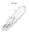
- FIGS. 3B-3Care exploded perspective views of a first cage-inserter assembly of the present invention.
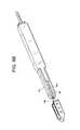
- FIG. 3Dis an assembled perspective view of the first cage-inserter assembly of the present invention.
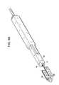
- FIG. 4Ais a perspective view of a third embodiment of a cage of the present invention.
- FIGS. 4B-4Care exploded perspective views of a second cage-inserter assembly of the present invention.
- FIG. 4Dis an assembled perspective view of the second cage-inserter assembly of the present invention.
- FIG. 5Ais a perspective view of a fourth embodiment of a cage of the present invention.
- FIGS. 5B-5Care exploded perspective views of a third cage-inserter assembly of the present invention.
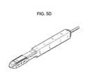
- FIG. 5Dis an assembled perspective view of the third cage-inserter assembly of the present invention.
- FIGS. 6A-6Care various views of a fourth cage-inserter assembly of the present invention.
- FIG. 6Dis a perspective view of a leading end component of the present invention.
- FIG. 6Eis a plan view of a fifth cage-inserter assembly of the present invention.
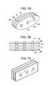
- FIGS. 7A-7Care various views of a planked cage of the present invention.
- FIG. 7Dis a perspective view of a planked cage-inserter assembly of the present invention.
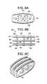
- FIGS. 8A and 8Bare views of a planked cage of the present invention.
- FIG. 8Cis a perspective view of a planked cage-inserter assembly of the present invention.
- FIG. 9Ais a cross section of a banana cage-inserter assembly of the present invention.
- FIG. 9Bis a top view of a banana cage-inserter assembly of the present invention.
- FIGS. 10A-10Bare top views of banana cage-inserter assemblies of the present invention.
- the present inventionrelates to a spinal interbody spacer that is easy to insert, fracture resistant, migration resistant, and fillable with a flowable biologic material after insertion.
- an intervertebral fusion cagecomprising:
- each of the upper and lower surfaces of the cagethere is provided a plurality of teeth 21 .
- these teethbite into the adjacent vertebral bodies and thereby resist migration of the cage.
- Each of the support membersfurther comprises a side surface 23 extending between its upper and lower surfaces, each side surface having at least one transverse hole 25 therethrough.
- the transverse holeallows bone growth therethrough, thereby further securing the cage within the intervertebral space.
- the front surface of the leading end of the cageis tapered. This tapered nose 27 can distract the disc space during its insertion into the disc space, thereby providing for ease of insertion.
- the back surface of the leading end of the cageforms a recess 29 for reception of a rod.
- the recessis a throughhole.
- the throughholemay be threaded.
- coupling of the back surface of the leading end of the cage with the threaded distal end 33 of the rod 32allows the surgeon to use the rod as an inserter and insert the cage in a minimally invasive manner.
- the back surface of the leading end of the cageforms a concave recess for reception of a rod.
- the concave recessis a simple design choice that provides the needed coupling with the rod and allows the rod to have a substantially rectangular cross-section.
- the back surface of the leading endforms a threaded recess for threadable reception of a rod.
- the ends of the leading end and the support membersare integrally connected.
- the back surfaces of the support members of the cageare used as stabilizers whereby a forward force upon these back surfaces carefully counterbalances the backward force used to withdraw the rod from the cage. This forward force keeps the cage in the disc space during withdrawal of the rod.
- the back surfacesare configured to stably receive the laterally-spaced extensions that extend from the distal face of the cannula and provide the biasing forward force.
- the back surface of each support memberhas a concave recess providing such stability.
- the back surface of each support membermay be flat.
- the “U” shaped implant of FIG. 1Ais coupled with the metal inserter 35 of FIG. 2C so that the metal inserter occupies the interior space of the cage, as shown in FIGS. 2A-2B .
- the smooth upper 37 and lower 39 surfaces of the metal inserterare just proud of the level of the tooth peaks of the cage.
- These smooth upper and lower surfaces of the metal insertershould therefore be the only part of the assembly that contacts the adjacent vertebral bodies. Therefore, when the implant is inserted, the entire insertion load is borne by the metallic inserter, thereby reducing the chances of damaging the implant.
- the contact surfacesare smooth, the insertion will be carried out under low friction, thereby increasing the ease of insertion.
- the cageis then held in place by the extension components 40 of the inserter while the rod component 32 (which is slidably received in annulus 31 ) is uncoupled from the cage and retracted out of the annulus 31 .
- Annulus 31is then retracted to a position just outside out of the cage, thereby allowing the adjacent bone to contact the cage.
- the empty cageis then filled with flowable bone graft by introducing bone graft through the annulus 31 .
- an assemblycomprising:
- a method of inserting a fusion cagecomprising the steps of:
- an intervertebral fusion cagecomprising:
- the leading endhas an arcuate shape.
- the leading endhas a beveled nose 77 defined by converging upper and lower surfaces. This beveled nose facilitates cage insertion.
- the upper and lower surfaces of the support membersare adapted for gripping the opposing vertebral endplates.
- these surfacescontain outwardly extending teeth 79 that provide stability to the cage.
- each support memberhas a throughhole 80 extending therethrough and each cross-member has a throughhole 81 extending therethrough.
- the cross membersprovide for substantial containment of the injectable bone graft paste and add stiffness to the construct. These holes are adapted for encouraging bone growth therethrough.
- the cagepreferably has a substantially rectangular cross-section.
- an inserter rodcan anchor into the back surface of the leading end of the cage.
- an intervertebral fusion cagecomprising:
- FIGS. 3B and 3Care exploded versions of the cage and inserter assembly, as viewed from the distal and proximal perspectives.
- the cageis the cage shown in FIG. 3A .
- the back surface of the leading end of the cageincludes a throughhole 81 adapted for reception of a rod. These holes allow the inserter rod to pass through to the leading end of the cage.
- the inserter of FIGS. 3B and 3Cincludes two components and comprises:
- an apparatus for inserting a fusion cage having a leading end and a trailing endcomprising:
- an assemblycomprising:
- FIG. 3Dshows the assembled version of this cage and inserter assembly.
- the assembly of FIG. 3Dis first constructed.
- the arms of the inner rodextend over the cross-members of the cage so that its beveled nose is flush (here, coplanar) with the beveled nose of the cage.
- the arms of the outer annulus component of the inserterbear against the respective proximal end surfaces of the cage.
- the distal end of the cageis delivered into the disc space, with the beveled nose of the cage providing distraction of the disc space.
- the assemblyis then moved distally so that the entire cage is within the disc space.
- the outer annulus of the inserteris held in place as the inner rod component is withdrawn.
- each arm of the inserterThe bearing of the distal end surface of each arm of the inserter against the proximal end surfaces of the cage during inner rod withdrawal insures that the cage remains in place. Once the inner rod is completely withdrawn, the outer annulus is then moved proximally away from the cage and removed from the patient.
- FIG. 4Ain a second preferred embodiment, there is provided an intervertebral fusion cage substantially similar to that of FIG. 3A , except that there is a single cross-member 131 connecting the supporting members and it is located in the proximal end portion 135 of the cage.
- the throughhole 137 of the cross-memberis somewhat larger than that of FIG. 3A (and is adapted for reception of a threaded rod).
- injectable graft materialis delivered through this throughhole 137 .
- FIGS. 4B and 4Care exploded versions of the cage and inserter assembly, as viewed from the distal and proximal perspectives.
- the cageis the cage of FIG. 4A .
- the inserter assemblyis substantially similar to that of FIGS. 3B and 3C , except that the inner rod 141 also has a longitudinal throughhole, and a threaded rod 145 is slidably received within the longitudinal throughhole of the inner rod.
- the distal end 147 of the threaded rodhas a threadform 149 thereon that is adapted to mate with a threadform 149 within the hole 151 in the back surface 153 of the leading end 155 of the cage.
- the coupling of the threaded rod with the threaded hole on the back surface of the leading end of the cageprovides stability for the cage during its insertion into the disc space.
- FIGS. 4B and 4CThe assembled version of FIGS. 4B and 4C is shown in 4 D.
- the threaded distal end of the rodpasses through the throughhole of the cross-member of the cage and is received in the threaded hole on the back surface of the leading end of the cage.
- the coupling of these threadformsprovides stability to the cage during insertion.
- the threaded rodis disengaged from the threaded hole of the cage.
- both the threaded rod and the inner rodare simultaneously removed from the disc space, as the outer annulus component of the inserter remains bearing against the proximal ends of the cage to insure that the cage remains in place.
- the outer annulusis removed.
- FIG. 5Ain a third preferred embodiment, there is provided an intervertebral fusion cage substantially similar to that of FIG. 4A , except that there is no cross-member.
- FIGS. 5B and 5Care exploded versions of the cage and inserter assembly, as viewed from the distal and proximal and distal perspectives.
- the cageis the cage of FIG. 5A .
- the inserter assemblyis substantially similar to that of FIGS. 4B and 4C , except that the arms 161 of the inner rod 163 are substantially shorter.
- the short arm and lack of cross-memberallow the inner rod to bear substantially against the back surface 165 of the leading end 167 of the cage, thereby providing enhanced strength to the assembled design during insertion.
- FIGS. 5B and 5CThe assembled version of FIGS. 5B and 5C is shown in 5 D.
- the assembled versionis used in a manner substantially similar to that of the assembled version shown in 4 D.
- hingesare provided between each end of the leading portion of the cage and each of the support members. These hinges allow the cage to be spread after insertion in order to increase the effective surface area (i.e., footprint) covered by the implant. Increasing the footprint beneficially improves the stability of the construct.
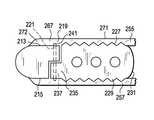
- an intervertebral fusion cagecomprising:
- an intervertebral fusion cagecomprising:
- Each support memberhas a bump 245 extending medially from its inside surface 247 . As will be explained later in more detail, these bumps facilitate the splaying of the support members to increase the footprint of the cage.
- the insertion instrument of the present inventioncomprises three components;
- the cylindrical rodis adapted to fit within the open recess formed between the two support members.
- the rodcomprises an enlarged head 259 having an annular recess 261 therebehind, a distal threaded portion 263 and an intermediate portion 265 .
- the annular recesscorresponds in shape and dimension to the bumps 245 situated on the inside surfaces of the support members.
- the distal threaded portionis adapted to be threadably received in the recess of the C-shaped leading portion of the cage, thereby securing the instrument to the cage.
- the intermediate portion of the rodis housed within the interior space of the cage.
- the threaded portionis unthreaded to free the rod for proximal movement in respect of the cage.
- the hinged support membersare forced to pivot outwards to increase the footprint of the cage. The closer these bumps are situated to the arcuate leading end of the cage, the greater the splay of the support members.
- the cylindrical rodis the first instrument component to be removed from the disc space.
- the front ends 267 of the upper 255 and lower 257 railsare adapted to fit within the upper and lower grooves provided on the C-shaped leading portion of the cage, while the posterior portion of the rail is adapted to bear against the upper and lower surfaces of the cylindrical rod.
- Each railhas a thickness T that allows the rail to extend beyond the respective upper and lower surfaces of both the C-shaped leading portion and the support members of the cage.
- the outer surfaces 271 of the railsare smooth. Because the smooth rails extend beyond the upper and lower surfaces of the cage, they provide a smooth insertion of the cage-instrument assembly into the disc space.
- the front end of each railmay be provided with a taper 272 that essentially extends from the taper of the front nose of the C-shaped leading portion of the cage.
- the railsare the second instrument component to be removed from the disc space.
- an intervertebral fusion cagecomprising,
- the pair of laterally disposed cage holdersare disposed upon each side of the cylindrical rod.
- Each cage holderhas a front end 273 adapted to bear against the back surface of each support member portion of the cage. These front ends prevent the cage from moving back when the cylindrical rod and the rails are removed.
- the cage holdersare the third and last instrument component to be removed from the disc space.
- an intervertebral fusion cagecomprising:
- each support memberhas a triangular cross-section.
- This configurationallows the proximal ends of the support members to extend inward to produce a narrowing at the proximal end.
- the inserter that fits within the inner space of the cagehas a corresponding triangular shape.
- the greater width of the distal end of the inserterpushes the proximal ends of the support members outward, thereby expanding the cross-section of the cage.
- the enlarged footprint of this expanded designbeneficially provides stabilization of the construct. It also beneficially moves the struts towards the more dense bone on the periphery of the endplates.
- an implant 301 for promoting bone fusion between adjacent vertebral bodiessaid implant having an exterior surface 303 , a longitudinal axis and comprising an assembly of components, the components comprising:
- FIGS. 7A and 7Balso have d) a third strut 306 spaced from said first strut, said second strut having a third bone-engaging portion 308 , an opposite fourth bone-engaging portion, said second strut in cooperation with said first strut defining an internal space.
- FIG. 7Cprovides a cage having substantial similarity to the cage of FIGS. 7A and 7B , except that it has a rectangular profile.
- the cage of FIG. 7Cis constructed from parallel spaced planks made of woven carbon-fiber PEEK laminates spaced apart and held together by titanium pins (or “struts”). The spaces between the planks allow a metal instrument to mate with and attach to the pin component of the implant.
- the metallic insertion instrument (or “inserter”) 319mates to the pins between the PEEK planks to form an assembly that can be easily inserted into and manipulated within the disc space.
- the inserterhas smooth upper 321 and lower 323 surfaces that extend beyond the teeth 325 of the implant to provide for an easy insertion.
- the inserteralso has a bulleted nose 327 to provide distraction.
- the implantis inserted into the disc space in an orientation that allows the planks to be substantially perpendicular to the patient's vertebral endplates.
- the pins 317are mainly in compression between the inserter components, the inserter will carry the majority of the insertion load. To the extent the pins 317 carry any impaction force, the pins are advantageously made of a high strength, ductile metal such as titanium, and are preferably a titanium alloy, and so can bear such loads. The metallic nature of the pins allows for forceful manipulation of the assembly during insertion into the disc space. At the same time, selection of a somewhat flexible polymer such as PEEK for the material of construction of the laminate components avoids the stress shielding issues associated with purely titanium cage designs. Selection of the woven carbon fiber (as opposed to chopped carbon fiber) will enhance the strength of the PEEK composite.
- FIG. 7Cshows a cage made of three parallel planks held together by three titanium-based pins. However, in other embodiments, only two planks may be used to construct the cage. Likewise, more than three planks may also be used to construct the cage.
- the struts 305 , 311can have domed upper and lower surfaces in order to conform to the shape of the vertebral endplates.
- the upper and lower surfaces of the strutsare flat (as in FIG. 7C ) and the inserter instrument is provided with a bullet nose 327 that extends distal of the implant (as in FIG. 7D ).
- the strutshave additional side holes (not shown), wherein those side holes are not engaged by a cross-pin. The presence of these holes will enhance bone ingrowth through the struts.
- the upper and lower surfaces of the strutshave a plurality of fine teeth 325 extending therefrom to resist implant migration.
- an intervertebral fusion cagecomprising:
- the fusion cageincludes smooth retractable rails positioned on the top and bottom of the cage.
- the upper and lower surface of the cagehas teeth 419 that extend outward to grip the adjacent vertebral bodies.
- the railsalso extend past the respective teeth of each of the upper and lower surfaces.
- the smooth railsare the only part of the cage that contacts the adjacent vertebral bodies, and so only a moderate insertion force is required to insert the cage into the disc space.
- FIG. 9Bonce the cage is set in place, the rails are proximally retracted by the surgeon (while the back end of the cage is still held by the inserter 421 ), the adjacent boney endplates of the patient collapse upon the cage, and the aggressive teeth of the cage will engage the bone and effectively prevent migration of the implant. Therefore, the cage and inserter of the present invention overcome the prior art problems associated with conventional toothed and smooth cages by not only allowing for easy insertion but also providing a firm, migration-resistant grip.
- the railsare rigid. Such rigid rails may be conveniently used with substantially straight cages. In some embodiments, the rails are flexible. Such flexible rails may be conveniently used with curved cages such as banana cages.
- the railcomprises an outer tube having a smooth outer surface and an inner rod.
- the tube and rodWhen assembled, the tube and rod have a height that allows the to extend outward past the upper and lower teeth of the cage.
- the tube-rod assemblyeases insertion load.
- the rodWhen the cage has been inserted, the rod is withdrawn and the tube collapses under the force of the tensioning load of the functional spinal unit.
- the adjacent boney endplates of the patientcollapse upon the cage, and the aggressive teeth of the cage will engage the bone and effectively prevent migration of the implant.
- the railscan be molded onto the cage as a fast dissolving polymer. During insertion, the smooth rails ease insertion. Once the cage is set in place, the rails dissolve, thereby allowing the adjacent boney endplates of the patient to collapse upon the cage.
- a single smooth cablemay act as both an upper and lower rail by wrapping around an end of the cage. During insertion, the smooth rails ease insertion. At this time, tensioning of the cable may serve to hold the cage on the inserter.
- the surgeonpulls a single end of the cable in order to remove the whole cable from the cage.
- the cableis coated with a smoothing polymer such as Teflon in order to reduce friction.
- an intervertebral fusion cagehaving:
- FIG. 10Bthere is provided an intervertebral fusion cage having substantial similarity to that of FIG. 10A , except that its leading side surface also has a throughhole 469 adapted for slidable reception of a rail.
- the inserter of the present inventioncan be made out of any material commonly used in medical instruments. If the inserter is designed to be reusable, then it is preferred that all of its components be made of stainless steel. If the device is designed to be disposable, then it is preferred that at least some of the components be made of plastic. Preferably, at least one component of the inserter is sterilized. More preferably, each component is sterilized.
- the intervertebral fusion cage of the present inventionmay be manufactured from any biocompatible material commonly used in interbody fusion procedures.
- the cageis made from a composite comprising 40-99% polyarylethyl ketone PAEK, and 1-60% carbon fiber.
- a cageis radiolucent.
- the polyarylethyl ketone PAEKis selected from the group consisting of polyetherether ketone PEEK, polyether ketone ketone PEKK, polyether ketone ether ketone ketone PEKEKK, and polyether ketone PEK.
- cageis made from woven, long carbon fiber laminates.
- the PAEK and carbon fiberare homogeneously mixed.
- the compositeconsists essentially of PAEK and carbon fiber.
- the compositecomprises 60-80 wt % PAEK and 20-40 wt % carbon fiber, more preferably 65-75 wt % PAEK and 25-35 wt % carbon fiber.
- the cageis made from materials used in carbon fibers cages marketed by DePuy Spine, Raynham, Mass., USA.
- the compositeis PEEK-OPTIMATM, available from Invibio of Greenville, N.C.
- the cageis made from a metal such as titanium alloy, such as Ti-6Al-4. In other embodiments, the cage is made from an allograft material. In some embodiments, the cage is made from ceramic, preferably a ceramic that can be at least partially resorbed, such as HA or TCP. In other embodiments, the ceramic comprises an oxide such as either alumina or zirconia. In some embodiments, the cage is made from a polymer, preferably a polymer that can be at least partially resorbed, such as PLA or PLG.
- the cageis provided in a sterile form.
- the cage implant of the present inventiondistracts the disc space during insertion. It is easy to insert and optimizes clinical performance once in place because it resists migration and subsidence, has an appropriate stiffness for load sharing, is preferably radiolucent and has a shape that is able to contain injected graft material such as growth factors.
- the cageis robust over a wide variation of surgical technique because it will not break even when large forces are applied thereto.
- the cage of the present inventionis compatible with the broad use of injectable paste-like bone grafting materials, such as BMP-containing pastes because it is designed to be inserted empty and then filled with graft in-situ. With the availability of these injectable pastes, cages will no longer require large, contiguous internal volumes to accept morselized/granular bone graft. Spaces can be smaller and more numerous.
- the cage of the present inventionallows an insertion instrument to occupy the internal volume of the cage so as to minimize the overall size of the inserted cage as well as to bear insertion loads.
- the insertercan also possess smooth upper and lower surfaces to reduce friction and thereby increase the ease of insertion.
- the cage of the present inventionwill not experience large loads during insertion.
Landscapes
- Health & Medical Sciences (AREA)
- Engineering & Computer Science (AREA)
- Biomedical Technology (AREA)
- Orthopedic Medicine & Surgery (AREA)
- Neurology (AREA)
- Transplantation (AREA)
- Oral & Maxillofacial Surgery (AREA)
- Cardiology (AREA)
- Heart & Thoracic Surgery (AREA)
- Vascular Medicine (AREA)
- Life Sciences & Earth Sciences (AREA)
- Animal Behavior & Ethology (AREA)
- General Health & Medical Sciences (AREA)
- Public Health (AREA)
- Veterinary Medicine (AREA)
- Physical Education & Sports Medicine (AREA)
- Prostheses (AREA)
Abstract
Description
This application is a continuation of U.S. patent application Ser. No. 14/698,179 filed Apr. 28, 2015, which is a divisional of U.S. patent application Ser. No. 11/615,077, filed Dec. 22, 2006, the disclosure of each of which is incorporated herein by reference.
The natural intervertebral disc contains a jelly-like nucleus pulposus surrounded by a fibrous annulus fibrosis. Under an axial load, the nucleus pulposus compresses and radially transfers that load to the annulus fibrosis. The laminated nature of the annulus fibrosis provides it with a high tensile strength and so allows it to expand radially in response to this transferred load.
In a healthy intervertebral disc, cells within the nucleus pulposus produce an extracellular matrix (ECM) containing a high percentage of proteoglycans. These proteoglycans contain sulfated functional groups that retain water, thereby providing the nucleus pulposus with its cushioning qualities. These nucleus pulposus cells may also secrete small amounts of cytokines as well as matrix metalloproteinases (MMPs). These cytokines and MMPs help regulate the metabolism of the nucleus pulposus cells.
In some instances of degenerative disc disease (DDD), gradual degeneration of the intervertebral disc is caused by mechanical instabilities in other portions of the spine. In these instances, increased loads and pressures on the nucleus pulposus cause the cells within the disc (or invading macrophages) to emit larger than normal amounts of the above-mentioned cytokines. In other instances of DDD, genetic factors or apoptosis can also cause the cells within the nucleus pulposus to emit toxic amounts of these cytokines and MMPs. In some instances, the pumping action of the disc may malfunction (due to, for example, a decrease in the proteoglycan concentration within the nucleus pulposus), thereby retarding the flow of nutrients into the disc as well as the flow of waste products out of the disc. This reduced capacity to eliminate waste may result in the accumulation of high levels of proinflammatory cytokines and/or MMPs that may cause nerve irritation and pain.
As DDD progresses, toxic levels of the cytokines and MMPs present in the nucleus pulposus begin to degrade the extracellular matrix. In particular, the MMPs (as mediated by the cytokines) begin cleaving the water-retaining portions of the proteoglycans, thereby reducing their water-retaining capabilities. This degradation leads to a less flexible nucleus pulposus, and so changes the loading pattern within the disc, thereby possibly causing delamination of the annulus fibrosis. These changes cause more mechanical instability, thereby causing the cells to emit even more cytokines, typically thereby upregulating MMPs. As this destructive cascade continues and DDD further progresses, the disc begins to bulge (“a herniated disc”), and then ultimately ruptures, causing the nucleus pulposus to contact the spinal cord and produce pain.
One proposed method of managing these problems is to remove the problematic disc and replace it with a porous device that restores disc height and allows for bone growth therethrough for the fusion of the adjacent vertebrae. These devices are commonly called “fusion devices”.
Designs of intervertebral fusion devices are generally either box-like (i.e., Smith-Robinson style) or threaded cylinders (i.e., Cloward style). Smith-Robinson style implants have the advantage of better contact area to the endplates, but rely on a coarse surface texture or teeth to prevent migration once implanted. Insertion then requires over distraction of the disc space to slide the implant in or to provide a smoother implant, which can migrate post-op.
One such box-like design is the Brantigan cage. U.S. Pat. No. 4,743,256 (“Brantigan”) discloses an improved surgical method for eliminating spinal back pain caused by ruptured or degenerated vertebral discs by spanning the disc space between adjacent vertebrae with rigid fusion devices, or “cages”, having surfaces facilitating bone ingrowth and bottomed on prepared sites of the vertebrae to integrate the implant with the vertebrae and to provide a permanent weight supporting strut maintaining the disc space.
One commercial box-like design is the injection-molded carbon fiber reinforced PEEK (CFRP) cage made by DePuy Spine. However, these cages are difficult to insert because of the interference fit produced between the textured, toothed upper and lower surfaces of the implant and the bony endplates. Simply, the presence of teeth extending from the upper and lower surfaces of the cage make its insertion difficult. In addition, the reinforced PEEK material is brittle and so is prone to breakage when applying impact or torque loads to the implant to overcome tooth-induced resistance during insertion and final positioning of the implant.
Current interbody devices are made from single materials (e.g., machined titanium, or molded and/or machined PEEK). Titanium has the disadvantage of being radiopaque (which can interfere with fusion assessment on x-ray) while also having a high modulus of elasticity (which can stress shield the bone graft). Injection molded CFRP is very brittle and prone to fracture during insertion. Unfilled PEEK is much less brittle but also weaker than carbon-filled PEEK, requiring thicker-walled designs (diminishing space for bone graft). Both PEEK and carbon-filled PEEK are radiolucent.
U.S. Pat. No. 6,761,738 (“Boyd”) discloses a modular intervertebral spacer formed from assembled bone-derived components. In particular, Boyd discloses an assembly of vertical planks with cylindrical cross pins. However, Boyd does not disclose the use of non-allograft materials of construction, any companion instrumentation for insertion of the device, nor a method of placing the device first into the disc space and then filling it with a biologic material Allograft bone is very brittle, and so it is difficult to securely join such pieces together.
U.S. Pat. No. 6,413,278 and U.S. Pat. No. 6,835,208 (“Marchosky”) disclose an I-beam shaped implant whose top and bottom surface flex under anatomic loads. There is no interior space to this implant, and Marchosky teaches that two such implants need be implanted in a single disc space. Although a syringe for injecting bone graft around the implant is disclosed, a mating inserter instrument for placing the implant is not disclosed.
U.S. Pat. No. 6,824,565 (“Muhana”) discloses implant and instrument designs wherein some of the implant embodiments have planked designs and a mating inserter instrument. However, the disclosed inserter wraps around the exterior of the implant and partially into grooves on the implant. The disclosed implant is derived from bone and is not hollow. The insertion technique disclosed by Muhana requires a cutting tool to prepare a channel for the implant.
US2005/0209696 (Lin) discloses an intervertebral implant system for intervertebral implantation, wherein the system includes a frame having a peripheral wall defining a space therein, and a settable material introducible into the space of the frame. The settable material is a biocompatible load bearing material including and not limited to bone, composites, polymers of bone growth material, collagen, and insoluble collagen derivatives. The settable material is injectable into the space defined by the frame. The settable material may have an initial fluid condition wherein the fluid settable material cures to a hardened condition. Lin further includes the steps of accessing the disc space between adjacent intervertebral discs; removing disc material from the disc space; distracting the disc space; preparing the end plates of the adjacent intervertebral discs; inserting the peripheral wall of the frame into the disc space between the adjacent intervertebral discs; and injecting settable material into the space defines by the peripheral wall of the frame and between the adjacent intervertebral discs. Lin teaches that the method may further include the step of connecting each free end of the peripheral wall to one another. Lin teaches that the method further includes the steps of inserting a plurality of frames into the disc space between the adjacent intervertebral discs, wherein each frame defines a space; and injecting settable material into at least one of the spaces defined by the frames.
In summary, the insertion of both smooth and toothed intervertebral cages has proven to be problematic. Whereas toothed cages are difficult to insert, cages with smooth upper and lower surfaces have demonstrated undesirable migration.
With the availability of an injectable bone graft material, it is appreciated by the present inventor that a fusion cage can now be placed into the disc space in an empty condition (i.e., without pre-packed morselized bone graft) and then filled with injectable bone graft in a minimally invasive manner. This procedure now allows the surgeon to fill the interior of the cage with an insertion instrument during cage insertion in order to create a more secure mating condition with the implant without adding to the overall size of the implant.
Moreover, under such conditions, because the inserter can now occupy space along the length of the cage, it can also be used to ease entry of the cage into the disc space. In particular, the inserter can be provided with a height that is just slightly taller than the cage and with smooth upper and lower surfaces. When the smooth surfaces of the inserter extend to be just proud of the cage teeth, they help distract the disc space during insertion and greatly reduce insertion-generated friction to improve the ease with which the cage is inserted. When the inserter is removed after the cage has been inserted into the disc space, the adjacent boney endplates of the patient will collapse upon the cage, and the aggressive teeth of the cage will engage the bone and effectively prevent migration of the implant. Therefore, the cage and inserter of the present invention overcome the prior art problems associated with conventional toothed and smooth cages by not only allowing for easy insertion, but also providing a firm, migration-resistant grip.
Therefore, this invention improves the ease of insertion and placement of an intervertebral spacer, eliminates damage to the spacer during insertion and placement, resists implant migration, and maintains maximum volume for bone graft within the spacer and surrounding disc space.
Therefore, in accordance with the present invention, there is provided an intervertebral fusion cage, comprising:
- a) a leading end having a right and left ends, a front surface and a back surface, the back surface being adapted for reception of a rod,
- b) first and second support members extending backwards from the right and left ends and terminating in a respective back surface, each member having an upper and lower surface adapted for bearing against and gripping adjacent vertebral bodies,
- c) an open trailing end formed by the back surfaces of the support members.
Also in accordance with the present invention, there is provided a method of inserting a fusion cage, comprising the steps of:
- a) providing an intervertebral fusion cage having an interior space,
- b) providing an inserter rod having a distal end and an intermediate portion,
- c) coupling a distal end of a rod to the cage so that the intermediate portion of the cage occupies interior space of the cage,
- d) inserting the cage into an intervertebral space,
- e) withdrawing the rod from the cage, and
- f) adding a flowable graft material to the interior space of the cage.
The present invention relates to a spinal interbody spacer that is easy to insert, fracture resistant, migration resistant, and fillable with a flowable biologic material after insertion.
Now referring toFIGS. 1A-1D , there is provided an intervertebral fusion cage, comprising:
- a) a
leading end 1 having a right3 and left5 ends, afront surface 7 and aback surface 9, the back surface being adapted for reception of a rod, - b) first11 and second13 support members extending backwards from the right and left ends, each member having an upper15 and lower17 surface adapted for bearing against and gripping adjacent vertebral bodies and a
proximal surface 18, and - c) an open trailing
end 19 formed between the back surfaces of the support members.
- a) a
Upon each of the upper and lower surfaces of the cage, there is provided a plurality ofteeth 21. When the cage is inserted and the inserter is removed, these teeth bite into the adjacent vertebral bodies and thereby resist migration of the cage.
Each of the support members further comprises aside surface 23 extending between its upper and lower surfaces, each side surface having at least onetransverse hole 25 therethrough. The transverse hole allows bone growth therethrough, thereby further securing the cage within the intervertebral space.
In some embodiments, the front surface of the leading end of the cage is tapered. Thistapered nose 27 can distract the disc space during its insertion into the disc space, thereby providing for ease of insertion.
Also shown inFIG. 1D , the back surface of the leading end of the cage forms arecess 29 for reception of a rod. InFIGS. 1A-1D , the recess is a throughhole. The throughhole may be threaded. As shown inFIG. 2A , coupling of the back surface of the leading end of the cage with the threadeddistal end 33 of therod 32 allows the surgeon to use the rod as an inserter and insert the cage in a minimally invasive manner. In some embodiments (and as shown inFIGS. 1A-1D ), the back surface of the leading end of the cage forms a concave recess for reception of a rod. The concave recess is a simple design choice that provides the needed coupling with the rod and allows the rod to have a substantially rectangular cross-section.
In other embodiments, the back surface of the leading end forms a threaded recess for threadable reception of a rod.
As shown, the ends of the leading end and the support members are integrally connected.
In preferred embodiments, the back surfaces of the support members of the cage are used as stabilizers whereby a forward force upon these back surfaces carefully counterbalances the backward force used to withdraw the rod from the cage. This forward force keeps the cage in the disc space during withdrawal of the rod. Preferably then, the back surfaces are configured to stably receive the laterally-spaced extensions that extend from the distal face of the cannula and provide the biasing forward force. In some embodiments thereof, the back surface of each support member has a concave recess providing such stability. However, in other embodiments, the back surface of each support member may be flat.
In use, the “U” shaped implant ofFIG. 1A is coupled with themetal inserter 35 ofFIG. 2C so that the metal inserter occupies the interior space of the cage, as shown inFIGS. 2A-2B . Since the inserter is slightly taller than the cage, the smooth upper37 and lower39 surfaces of the metal inserter are just proud of the level of the tooth peaks of the cage. These smooth upper and lower surfaces of the metal inserter should therefore be the only part of the assembly that contacts the adjacent vertebral bodies. Therefore, when the implant is inserted, the entire insertion load is borne by the metallic inserter, thereby reducing the chances of damaging the implant. Moreover, since the contact surfaces are smooth, the insertion will be carried out under low friction, thereby increasing the ease of insertion. The cage is then held in place by theextension components 40 of the inserter while the rod component32 (which is slidably received in annulus31) is uncoupled from the cage and retracted out of theannulus 31.Annulus 31 is then retracted to a position just outside out of the cage, thereby allowing the adjacent bone to contact the cage. The empty cage is then filled with flowable bone graft by introducing bone graft through theannulus 31.
Therefore, in accordance with the present invention, there is provided an assembly comprising:
- a) an intervertebral fusion cage having an interior space, and
- b) a rod adapted to insert the cage into an intervertebral space, the rod having a distal end and an intermediate portion,
wherein the distal end of the rod is connected to the cage, and wherein the intermediate portion of the rod is housed within the interior space of the cage.
Also in accordance with the present invention, there is provided a method of inserting a fusion cage, comprising the steps of:
- a) providing an intervertebral fusion cage having a leading end having a back surface and a trailing end,
- b) coupling a distal end of an inserter having a slidable rod therein to the back surface of the leading end of the cage,
- c) inserting the cage into an intervertebral space,
- d) withdrawing the rod from the cage.
Now referring toFIG. 3A , in a first preferred embodiment, there is provided an intervertebral fusion cage, comprising:
- a) a
leading end 51 having a right53 and left55 ends, afront surface 57 and aback surface 59, the back surface being adapted for reception of a rod, - b) first61 and second63 support members extending backwards from the right and left ends, each member having an upper65 and lower67 surface adapted for bearing against and gripping adjacent vertebral bodies, and proximal end surfaces69,
- c) an open trailing
end 71 formed between the proximal end surfaces, and - d) a first73 and second75 elongate cross-members, each extending from the first support member to the second support member.
- a) a
Preferably, as shown, the leading end has an arcuate shape. Also preferably, the leading end has abeveled nose 77 defined by converging upper and lower surfaces. This beveled nose facilitates cage insertion.
Preferably, the upper and lower surfaces of the support members are adapted for gripping the opposing vertebral endplates. Preferably, these surfaces contain outwardly extendingteeth 79 that provide stability to the cage.
Preferably, each support member has a throughhole80 extending therethrough and each cross-member has a throughhole81 extending therethrough. The cross members provide for substantial containment of the injectable bone graft paste and add stiffness to the construct. These holes are adapted for encouraging bone growth therethrough.
As shown, the cage preferably has a substantially rectangular cross-section.
In this embodiment, an inserter rod can anchor into the back surface of the leading end of the cage.
Therefore, in accordance with the present invention, there is provided an intervertebral fusion cage, comprising:
- a) a leading end having a right and left ends, a front surface and a back surface,
- b) first and second support members extending backwards from the right and left ends and terminating in a respective back surface, each member having an upper and lower surface adapted for bearing against and gripping adjacent vertebral bodies,
- c) an open trailing end formed by the back surfaces of the support members, and
- d) a strut connecting the first and second support members, the strut being located between the leading end and the open trailing end of the cage, the strut having a back surface being adapted for reception of an inserter rod.
The cage is the cage shown inFIG. 3A . As seen onFIG. 3C , the back surface of the leading end of the cage includes a throughhole81 adapted for reception of a rod. These holes allow the inserter rod to pass through to the leading end of the cage.
The inserter ofFIGS. 3B and 3C includes two components and comprises:
- a) an
outer annulus 85 having alongitudinal throughhole 87, aproximal end portion 89 and adistal end portion 91, the distal end portion including adistal end surface 93 having anupper surface 95, alower surface 97 and a pair oflateral surfaces 99, each lateral surface having first andsecond arms 101 extending distally therefrom, each arm having adistal end surface 105 respectively adapted for bearing against a proximal end surface of the cage, - b) an
inner rod 111 slidable within the longitudinal throughhole of the annulus and having adistal end surface 113, upper115 and lower117 surfaces, and upper119 and lower121 arms extending from the distal end surface, each arm including a beveleddistal end 123 adapted to be coplanar with the beveled nose of the cage, each arm having a width W adapted for slidable reception between the support members of the cage.
- a) an
Therefore, in accordance with the present invention, there is provided an apparatus for inserting a fusion cage having a leading end and a trailing end, comprising:
- a) a cannula having a bore therethrough, a distal end face and at least two extensions extending distally from the distal end face, each extensions having a distal end adapted for bearing against the trailing end of the cage, and
- b) a rod slidably received within the bore of the cannula, the rod having a distal end adapted for bearing against the leading end of the cage.
Also in accordance with the present invention, there is provided an assembly comprising:
- a) an intervertebral fusion cage having a leading end and a trailing end, and
- b) an inserter comprising:
- i) a cannula having a bore therethrough, a distal end face and at least two extensions extending distally from the distal end face, each extension having a distal end bearing against the trailing end of the cage, and
- ii) a rod slidably received within the bore of the cannula, the rod having a distal end bearing against the leading end of the cage
Lastly,FIG. 3D shows the assembled version of this cage and inserter assembly.
In use, the assembly ofFIG. 3D is first constructed. In this assembled state, the arms of the inner rod extend over the cross-members of the cage so that its beveled nose is flush (here, coplanar) with the beveled nose of the cage. The arms of the outer annulus component of the inserter bear against the respective proximal end surfaces of the cage. Next, the distal end of the cage is delivered into the disc space, with the beveled nose of the cage providing distraction of the disc space. The assembly is then moved distally so that the entire cage is within the disc space. Next, the outer annulus of the inserter is held in place as the inner rod component is withdrawn. The bearing of the distal end surface of each arm of the inserter against the proximal end surfaces of the cage during inner rod withdrawal insures that the cage remains in place. Once the inner rod is completely withdrawn, the outer annulus is then moved proximally away from the cage and removed from the patient.
Now referring toFIG. 4A , in a second preferred embodiment, there is provided an intervertebral fusion cage substantially similar to that ofFIG. 3A , except that there is asingle cross-member 131 connecting the supporting members and it is located in the proximal end portion135 of the cage. In addition, thethroughhole 137 of the cross-member is somewhat larger than that ofFIG. 3A (and is adapted for reception of a threaded rod). In some embodiments, injectable graft material is delivered through thisthroughhole 137.
The assembled version ofFIGS. 4B and 4C is shown in4D. Although not shown inFIG. 4D , the threaded distal end of the rod passes through the throughhole of the cross-member of the cage and is received in the threaded hole on the back surface of the leading end of the cage. The coupling of these threadforms provides stability to the cage during insertion. After the cage has been inserted, the threaded rod is disengaged from the threaded hole of the cage. Next, both the threaded rod and the inner rod are simultaneously removed from the disc space, as the outer annulus component of the inserter remains bearing against the proximal ends of the cage to insure that the cage remains in place. Lastly, the outer annulus is removed.
It has further been appreciated that if only the threaded inner rod is removed, then there exists a channel in the insertion instrument through which injectable bone graft material can be injected.
Now referring toFIG. 5A , in a third preferred embodiment, there is provided an intervertebral fusion cage substantially similar to that ofFIG. 4A , except that there is no cross-member.
The assembled version ofFIGS. 5B and 5C is shown in5D. The assembled version is used in a manner substantially similar to that of the assembled version shown in4D.
In some embodiments, hinges are provided between each end of the leading portion of the cage and each of the support members. These hinges allow the cage to be spread after insertion in order to increase the effective surface area (i.e., footprint) covered by the implant. Increasing the footprint beneficially improves the stability of the construct.
Now referring toFIGS. 6A-6D , there is provided an intervertebral fusion cage, comprising:
- a) a C-shaped leading
portion 201 having a first203 and second205 ends extending backwards, afront surface 207 and aback surface 209, the back surface having arecess 211 therein adapted for reception of a rod, anupper surface 213 and alower surface 215, each of the upper and lower surfaces having agroove 217 extending from the front surface to the back surface for reception of arail pivot hole 221 provided in each of the first and second ends that extends from the upper surface to the lower surface, - b) first223 and second225 support members extending proximally from the first and second ends of the C-shaped leading end, each support member having:
- i. an upper227 and lower229 surface adapted for bearing against and gripping adjacent vertebral bodies,
- ii. a
back surface 231, the back surfaces forming an open trailing end therebetween, - iii. a
front end 235 having apivot hole 237 which extends from the upper surface to the lower surface,
- c) first239 and second241 pivot pins respectfully provided in the pivot holes to pivotally connect each end of the C-shaped leading end and the front end of each support member.
- a) a C-shaped leading
Therefore, in accordance with the present invention, there is provided an intervertebral fusion cage, comprising:
- a) a leading portion having a first and second ends extending backwards, a front surface and a back surface, an upper surface and a lower surface, and a pivot hole provided in each of the ends which extends from the upper surface to the lower surface,
- b) first and second support members, each support member having:
- i. an upper and lower surface adapted for bearing against and gripping adjacent vertebral bodies,
- ii. a back surface, the back surfaces forming an open trailing end therebetween,
- iii. a front end having a pivot hole which extends from the upper surface of the support member to the lower surface of the support member, and
- c) first and second pivot pins respectfully provided in the pivot holes to pivotally connect each end of the leading end and the front end of each support member.
Each support member has abump 245 extending medially from itsinside surface 247. As will be explained later in more detail, these bumps facilitate the splaying of the support members to increase the footprint of the cage.
The insertion instrument of the present invention comprises three components;
- a) a centrally-disposed
cylindrical rod 251, - b) a pair of laterally disposed
cage holders 253, and - c) upper255 and lower257 rails.
- a) a centrally-disposed
The cylindrical rod is adapted to fit within the open recess formed between the two support members. The rod comprises anenlarged head 259 having anannular recess 261 therebehind, a distal threadedportion 263 and anintermediate portion 265. The annular recess corresponds in shape and dimension to thebumps 245 situated on the inside surfaces of the support members. The distal threaded portion is adapted to be threadably received in the recess of the C-shaped leading portion of the cage, thereby securing the instrument to the cage. The intermediate portion of the rod is housed within the interior space of the cage.
In use, after cage insertion, the threaded portion is unthreaded to free the rod for proximal movement in respect of the cage. When the head of the cylindrical rod is moved backward so as to be removed from the cage, the hinged support members are forced to pivot outwards to increase the footprint of the cage. The closer these bumps are situated to the arcuate leading end of the cage, the greater the splay of the support members. The cylindrical rod is the first instrument component to be removed from the disc space.
The front ends267 of the upper255 and lower257 rails are adapted to fit within the upper and lower grooves provided on the C-shaped leading portion of the cage, while the posterior portion of the rail is adapted to bear against the upper and lower surfaces of the cylindrical rod. Each rail has a thickness T that allows the rail to extend beyond the respective upper and lower surfaces of both the C-shaped leading portion and the support members of the cage. Further, theouter surfaces 271 of the rails are smooth. Because the smooth rails extend beyond the upper and lower surfaces of the cage, they provide a smooth insertion of the cage-instrument assembly into the disc space. For additional ease of insertion, the front end of each rail may be provided with ataper 272 that essentially extends from the taper of the front nose of the C-shaped leading portion of the cage. The rails are the second instrument component to be removed from the disc space.
Therefore, in accordance with the present invention, there is provided an intervertebral fusion cage comprising,
- a) a leading end and a trailing end,
- b) first and second longitudinal support members extending between each end, each member having an upper and lower surface adapted for bearing against and gripping adjacent vertebral bodies, each upper and lower surface having a longitudinal groove therein, and
- c) a plurality of rails, each rail having a smooth outer surface and each rail received in a respective groove of the support member and extending out of the respective groove.
The pair of laterally disposed cage holders are disposed upon each side of the cylindrical rod. Each cage holder has afront end 273 adapted to bear against the back surface of each support member portion of the cage. These front ends prevent the cage from moving back when the cylindrical rod and the rails are removed. The cage holders are the third and last instrument component to be removed from the disc space.
Now referring toFIG. 6E , there is provided an intervertebral fusion cage, comprising:
- a) a leading end having a right and left ends, a front surface and a back surface, the back surface being adapted for reception of a rod,
- b) first and
second support members 281, each member having adistal end 283 and widenedproximal end 285, and an upper and lower surface adapted for bearing against and gripping adjacent vertebral bodies, - c) an open trailing end formed between the proximal ends, and
- d) first and second hinges respectfully provided between each end of the leading end and the distal end of each support member.
As seen inFIG. 6E , each support member has a triangular cross-section. This configuration allows the proximal ends of the support members to extend inward to produce a narrowing at the proximal end. In addition, the inserter that fits within the inner space of the cage has a corresponding triangular shape. Thus, upon retraction of the inserter from the cage, the greater width of the distal end of the inserter pushes the proximal ends of the support members outward, thereby expanding the cross-section of the cage. The enlarged footprint of this expanded design beneficially provides stabilization of the construct. It also beneficially moves the struts towards the more dense bone on the periphery of the endplates.
Now referring toFIGS. 7A-7B , there is provided an implant301 for promoting bone fusion between adjacent vertebral bodies, said implant having anexterior surface 303, a longitudinal axis and comprising an assembly of components, the components comprising:
- a) a
first strut 305 having a first bone-engagingportion 307, an opposite second bone-engagingportion 309, - b) a
second strut 311 spaced from said first strut, said second strut having a third bone-engagingportion 313, an opposite fourth bone-engaging portion, said second strut in cooperation with said first strut defining an internal space, - wherein the first strut and the second strut each include an aperture opening into the internal space;
- c) an
elongate cross-member 317 extending from the first strut to the second strut and including a first end engaged within the first aperture of the first strut and a second end engaged within the aperture of the second strut; - wherein the elongate cross-member is made of a metal.
- a) a
As shown,FIGS. 7A and 7B also have d) athird strut 306 spaced from said first strut, said second strut having a third bone-engagingportion 308, an opposite fourth bone-engaging portion, said second strut in cooperation with said first strut defining an internal space.
In preferred embodiments, the cage ofFIG. 7C is constructed from parallel spaced planks made of woven carbon-fiber PEEK laminates spaced apart and held together by titanium pins (or “struts”). The spaces between the planks allow a metal instrument to mate with and attach to the pin component of the implant.
Now referring toFIG. 7D , the metallic insertion instrument (or “inserter”)319 mates to the pins between the PEEK planks to form an assembly that can be easily inserted into and manipulated within the disc space. The inserter has smooth upper321 and lower323 surfaces that extend beyond theteeth 325 of the implant to provide for an easy insertion. The inserter also has abulleted nose 327 to provide distraction. The implant is inserted into the disc space in an orientation that allows the planks to be substantially perpendicular to the patient's vertebral endplates.
The composite nature of this implant in conjunction with the mating condition of the inserter instrument will also allow for very forceful manipulation of the implant during insertion without damaging the implant. In essence, the PEEK laminates are not loaded by the insertion force.
Since thepins 317 are mainly in compression between the inserter components, the inserter will carry the majority of the insertion load. To the extent thepins 317 carry any impaction force, the pins are advantageously made of a high strength, ductile metal such as titanium, and are preferably a titanium alloy, and so can bear such loads. The metallic nature of the pins allows for forceful manipulation of the assembly during insertion into the disc space. At the same time, selection of a somewhat flexible polymer such as PEEK for the material of construction of the laminate components avoids the stress shielding issues associated with purely titanium cage designs. Selection of the woven carbon fiber (as opposed to chopped carbon fiber) will enhance the strength of the PEEK composite.
In some embodiments, as inFIG. 7A , thestruts FIG. 7C ) and the inserter instrument is provided with abullet nose 327 that extends distal of the implant (as inFIG. 7D ).
In some embodiments, the struts have additional side holes (not shown), wherein those side holes are not engaged by a cross-pin. The presence of these holes will enhance bone ingrowth through the struts.
In some embodiments, the upper and lower surfaces of the struts have a plurality offine teeth 325 extending therefrom to resist implant migration.
Now referring toFIGS. 8A-8C , there is provided an intervertebral fusion cage, comprising:
- a) a
first strut 351 having first353 and second355 sides, an upper bone-engagingportion 357, and a lower bone-engagingportion 359, - b) a
second strut 361 having first363 and second365 sides, said second strut having an upper bone-engagingportion 367, a lower bone-engaging portion, the first side of the second strut opposed to the first side of the first strut thereby defining a first internal space, - c) a
third strut 371 having first373 and second375 sides, said third strut having an upper bone-engagingportion 377, a lower bone-engaging portion, the second side of the second strut opposed to the second side of the third strut thereby defining a second internal space, - wherein the first strut, second strut and third strut each include a plurality of apertures extending between the respective first and second sides thereof;
- wherein the first strut, second strut and third strut each include a
first opening 383 adapted for bone growth extending between the respective first and second sides thereof; - d) a first
elongate cross-member 385 extending from the first strut to the third strut and including afirst end 387 engaged within a first aperture of the first strut and asecond end 389 engaged within a first aperture of the third strut, and anintermediate portion 391 engaged within a first aperture of the second strut
- a) a
In some embodiments, the fusion cage includes smooth retractable rails positioned on the top and bottom of the cage. Now referring toFIGS. 9A and 9B , there is provided an intervertebral fusion cage comprising:
- a) a
leading end 401 and a trailingend 403, - b) first405 and second407 longitudinal support members extending between each end, each member having an upper409 and a lower411 surface adapted for bearing against and gripping adjacent vertebral bodies, each upper and lower surface having a
longitudinal groove 413 therein, and - c) a
rail 415 having a smoothouter surface 416 and received in a respective groove and extending out of the respective groove.
- a) a
As shown inFIG. 9A , the upper and lower surface of the cage hasteeth 419 that extend outward to grip the adjacent vertebral bodies. The rails also extend past the respective teeth of each of the upper and lower surfaces. During insertion of this cage, the smooth rails are the only part of the cage that contacts the adjacent vertebral bodies, and so only a moderate insertion force is required to insert the cage into the disc space. Now referring toFIG. 9B , once the cage is set in place, the rails are proximally retracted by the surgeon (while the back end of the cage is still held by the inserter421), the adjacent boney endplates of the patient collapse upon the cage, and the aggressive teeth of the cage will engage the bone and effectively prevent migration of the implant. Therefore, the cage and inserter of the present invention overcome the prior art problems associated with conventional toothed and smooth cages by not only allowing for easy insertion but also providing a firm, migration-resistant grip.
In some embodiments, the rails are rigid. Such rigid rails may be conveniently used with substantially straight cages. In some embodiments, the rails are flexible. Such flexible rails may be conveniently used with curved cages such as banana cages.
In some embodiments (not shown), the rail comprises an outer tube having a smooth outer surface and an inner rod. When assembled, the tube and rod have a height that allows the to extend outward past the upper and lower teeth of the cage. During insertion, the tube-rod assembly eases insertion load. When the cage has been inserted, the rod is withdrawn and the tube collapses under the force of the tensioning load of the functional spinal unit. Thus, the adjacent boney endplates of the patient collapse upon the cage, and the aggressive teeth of the cage will engage the bone and effectively prevent migration of the implant.
In some embodiments (not shown), the rails can be molded onto the cage as a fast dissolving polymer. During insertion, the smooth rails ease insertion. Once the cage is set in place, the rails dissolve, thereby allowing the adjacent boney endplates of the patient to collapse upon the cage.
In some embodiments, a single smooth cable may act as both an upper and lower rail by wrapping around an end of the cage. During insertion, the smooth rails ease insertion. At this time, tensioning of the cable may serve to hold the cage on the inserter.
Once the cage is set in place, the surgeon pulls a single end of the cable in order to remove the whole cable from the cage. In some embodiments, the cable is coated with a smoothing polymer such as Teflon in order to reduce friction.
The recognition that inserter designs can now occupy the interior volume of the cage has special application in the field of intervertebral fusion cages having a banana shape. In these banana cages, the cage can be made to attach to an inserter at the midpoint of the cage, which is the strongest portion of the cage.
Now referring toFIG. 10A , there is provided an intervertebral fusion cage having:
- a) a convex
anterior surface 451 and aconcave posterior surface 453, - b) an upper
bone engaging surface 455 and a lower bone engaging surface (not shown), - c) leading459 and trailing461 side surfaces,
- d) a
strut 463 connecting the convex anterior surface and the concave posterior surface and thereby forming leading464 and trailing466 spaces,
wherein the strut has a threadedrecess opening 465 onto the trailing space for reception of a threaded distal end of an inserter and,
wherein the trailing side surface has athroughhole 467 therethrough for slidable reception of the inserter.
- a) a convex
Now referring toFIG. 10B , there is provided an intervertebral fusion cage having substantial similarity to that ofFIG. 10A , except that its leading side surface also has a throughhole469 adapted for slidable reception of a rail.
Typically, the inserter of the present invention can be made out of any material commonly used in medical instruments. If the inserter is designed to be reusable, then it is preferred that all of its components be made of stainless steel. If the device is designed to be disposable, then it is preferred that at least some of the components be made of plastic. Preferably, at least one component of the inserter is sterilized. More preferably, each component is sterilized.
The intervertebral fusion cage of the present invention may be manufactured from any biocompatible material commonly used in interbody fusion procedures. In some embodiments, the cage is made from a composite comprising 40-99% polyarylethyl ketone PAEK, and 1-60% carbon fiber. Such a cage is radiolucent. Preferably, the polyarylethyl ketone PAEK is selected from the group consisting of polyetherether ketone PEEK, polyether ketone ketone PEKK, polyether ketone ether ketone ketone PEKEKK, and polyether ketone PEK. Preferably, cage is made from woven, long carbon fiber laminates. Preferably, the PAEK and carbon fiber are homogeneously mixed. Preferably, the composite consists essentially of PAEK and carbon fiber. Preferably, the composite comprises 60-80 wt % PAEK and 20-40 wt % carbon fiber, more preferably 65-75 wt % PAEK and 25-35 wt % carbon fiber. In some embodiments, the cage is made from materials used in carbon fibers cages marketed by DePuy Spine, Raynham, Mass., USA. In some embodiments, the composite is PEEK-OPTIMA™, available from Invibio of Greenville, N.C.
In other embodiments, the cage is made from a metal such as titanium alloy, such as Ti-6Al-4. In other embodiments, the cage is made from an allograft material. In some embodiments, the cage is made from ceramic, preferably a ceramic that can be at least partially resorbed, such as HA or TCP. In other embodiments, the ceramic comprises an oxide such as either alumina or zirconia. In some embodiments, the cage is made from a polymer, preferably a polymer that can be at least partially resorbed, such as PLA or PLG.
In preferred embodiments, the cage is provided in a sterile form.
In summary, the cage implant of the present invention distracts the disc space during insertion. It is easy to insert and optimizes clinical performance once in place because it resists migration and subsidence, has an appropriate stiffness for load sharing, is preferably radiolucent and has a shape that is able to contain injected graft material such as growth factors. In addition, the cage is robust over a wide variation of surgical technique because it will not break even when large forces are applied thereto.
The cage of the present invention is compatible with the broad use of injectable paste-like bone grafting materials, such as BMP-containing pastes because it is designed to be inserted empty and then filled with graft in-situ. With the availability of these injectable pastes, cages will no longer require large, contiguous internal volumes to accept morselized/granular bone graft. Spaces can be smaller and more numerous.
The cage of the present invention allows an insertion instrument to occupy the internal volume of the cage so as to minimize the overall size of the inserted cage as well as to bear insertion loads. The inserter can also possess smooth upper and lower surfaces to reduce friction and thereby increase the ease of insertion. The cage of the present invention will not experience large loads during insertion.
Claims (20)
1. An intervertebral fusion cage expandable from a first position to an expanded position, the intervertebral fusion cage comprising:
a) a leading portion having first and second ends, a front surface and a back surface opposite the front surface in a rearward direction, and an upper surface and a lower surface opposite the upper surface;
b) a first support member having a first connected end that is pivotally coupled to the first end of the leading portion, and a first opposed end that is opposite the first connected end, wherein the first support member extends from the first connected end to the first opposed end, the first support member having an upper surface and a lower surface configured to bear against and grip respective adjacent vertebral bodies; and
c) a second support member having a second connected end that is pivotally coupled to the second end of the leading portion, and a second opposed end that is opposite the first connected end, wherein the second support member extends from the second connected end to the second opposed end, the second support member having an upper surface and a lower surface configured to bear against and grip the respective adjacent vertebral bodies, wherein the first and second support members are oriented parallel to each other when the intervertebral fusion cage is in the first position,
wherein when the intervertebral fusion cage is in the first position, the first and second opposed ends define a space therebetween that is configured to receive an elongate member when the elongate member is attached to the leading portion, and
wherein the first and second support members are configured to pivot outwards about the respective first and second ends to increase a footprint of the cage, whereby the first and second support members flare away from each other as they extend away from the leading portion, such that no portion of either of the first and second support members is spaced from the leading portion in a forward direction that is opposite the rearward direction.
2. The intervertebral fusion cage as recited inclaim 1 , wherein the first and second support members define the space therebetween from the respective first and second connected ends to the respective first and second opposed ends, the space sized to receive the elongate member when the elongate member is attached to the leading portion.
3. The intervertebral fusion cage as recited inclaim 1 , wherein the first and second support members are configured to pivot with respect to the leading portion about respective pivot axes, and the footprint is defined along a plane that is normal to the pivot axes.
4. The intervertebral fusion cage as recited inclaim 1 , wherein the first and second support members are spaced from each other along a first direction, the upper and lower surfaces of each of the first and second support members are spaced from each other along a second direction perpendicular to the first direction, and the footprint is defined along a plane that includes the first direction and a third direction that is perpendicular to each of the first and second directions, wherein the third direction includes the rearward direction and the forward direction.
5. The intervertebral fusion cage as recited inclaim 1 , wherein each of the first and second support members comprise teeth at their respective upper and lower surfaces.
6. The intervertebral fusion cage recited inclaim 1 , wherein when the intervertebral fusion cage is in the first position, 1) the first and second support members extend in a proximal direction from the leading portion to the respective first and second outer portions, respectively, and the space extends in a distal direction opposite the proximal direction from a first location between the first and second opposed ends to a second location between the first and second connected ends.
7. An intervertebral fusion system comprising:
an intervertebral fusion cage that is expandable from a first position to an expanded position, the intervertebral fusion cage including:
a leading portion;
a first support member that extends from the leading portion in a first direction when the intervertebral fusion cage is in the first position, wherein the first support member is pivotally coupled to the leading portion, and the first support member defines a first inner side and a first outer side opposite the first inner side; and
a second support member that extends from the leading portion in the first direction when the intervertebral fusion cage is in the first position, wherein the second support member is pivotally coupled to the leading portion, and the second support member defines a second inner side and a second outer side that is opposite the second inner side, the second inner side facing the first inner side when the intervertebral fusion cage is in the first position; and
an actuator member configured to attach to the leading portion at a distal end of the actuator member when the intervertebral fusion cage is in the first position, such that the actuator member extends in a second direction toward the distal end at a location between the first and second outer sides, wherein the second direction is opposite the first direction,
wherein when the distal end of the actuator member is attached to the leading portion as the intervertebral fusion cage is in the first position, movement of the actuator member in the first direction causes the distal end of the actuator member to bear against the leading portion so as to cause the intervertebral fusion cage to move from the first position to the expanded position, whereby the first and second support members pivot with respect to the leading portion away from each other such that the first and second support members flare away from each other as they extend away from the leading portion, and no part of either of the first and second support members extends past the leading portion in the second direction.
8. The intervertebral fusion system as recited inclaim 7 , wherein the actuator member comprises an elongate member that extends from an instrument component in the second direction, and the instrument component bears against the intervertebral fusion cage in the second direction, such that movement of the elongate member in the first direction as the elongate member bears against the leading portion in the first direction causes the intervertebral fusion cage to move from the first position to the expanded position.
9. The intervertebral fusion system as recited inclaim 8 , wherein the elongate member is removably attachable to the leading portion at a location between the first and second ends.
10. The intervertebral fusion system as recited inclaim 7 , wherein the actuator member is removably attachable to the leading portion at a location between the first and second ends.
11. The intervertebral fusion system as recited inclaim 7 , wherein the actuator member is removably received in a recess of the leading portion when the intervertebral fusion cage is in the first position and the portion of the actuator member is straddled by the first and second support members.
12. The intervertebral fusion system as recited inclaim 7 , wherein each of the leading portion, the first support member, and the second support member defines a respective upper surface and a lower surface that are configured to bear against respective adjacent vertebral bodies.
13. The intervertebral fusion system as recited inclaim 12 , wherein the first and second support members are spaced from each other along a perpendicular direction that is perpendicular to the first direction, the upper and lower surfaces are spaced from each other along a third direction that is perpendicular to both the first direction and the perpendicular direction, and the first and second support members are pivotable with respect to the leading portion about respective pivot axes that are oriented along the third direction.
14. An intervertebral fusion system comprising:
a) an intervertebral fusion cage that is expandable from a first position to an expanded position, the intervertebral fusion cage including:
i. a leading portion;
ii. a first support member that is pivotally coupled to the leading portion, wherein the first support member extends from the leading portion in a proximal direction when the intervertebral fusion cage is in the first position; and
iii. a second support member that is pivotally coupled to the leading portion, wherein the second support member extends from the leading portion in the proximal direction when the intervertebral fusion cage is in the first position; and
b) an insertion instrument including:
i. an instrument component that is capable of bearing against the intervertebral fusion cage; and
ii. an elongate member that extends out from the instrument component in a distal direction to a distal end of the elongate member that is configured to attach to the leading portion, wherein the distal direction is opposite the proximal direction,
wherein when the intervertebral fusion cage is in the first position and the elongate member is disposed between respective opposed outer sides of the first and second support members, movement of the elongate member relative to the instrument component in the proximal direction causes the instrument component to bear against the intervertebral fusion cage in the distal direction, thereby causing the intervertebral fusion cage to move from the first position to the expanded position, whereby the first and second support members pivot about the leading portion away from each other to a position such that no portion of either of the first and second support members extends from the leading portion in the distal direction.
15. The intervertebral fusion system as recited inclaim 14 , wherein the first and second support members straddle a portion of the elongate member when the intervertebral fusion cage is in the first position.
16. The intervertebral fusion system as recited inclaim 15 , wherein the support members are parallel to each other when the intervertebral fusion is in the first position.
17. The intervertebral fusion system as recited inclaim 15 , wherein the leading portion has first and second ends, a front surface and a back surface opposite the front surface, and an upper surface and a lower surface each configured to bear against adjacent respective vertebral bodies.
18. The intervertebral fusion system as recited inclaim 17 , wherein the elongate member extends into the back surface so as to attach to the leading portion.
19. The intervertebral fusion system as recited inclaim 17 , wherein the distal end of the elongate member is configured to attach to the leading portion at a location midway between the first and second ends.
20. The intervertebral fusion system as recited inclaim 14 , wherein the distal end of the elongate member is attached to the leading portion.
Priority Applications (3)
| Application Number | Priority Date | Filing Date | Title |
|---|---|---|---|
| US15/001,339US10206787B2 (en) | 2006-12-22 | 2016-01-20 | Composite vertebral spacers and instrument |
| US16/242,043US11020237B2 (en) | 2006-12-22 | 2019-01-08 | Composite vertebral spacers and instrument |
| US17/307,000US20210251773A1 (en) | 2006-12-22 | 2021-05-04 | Composite Vertebral Spacers and Instrument |
Applications Claiming Priority (3)
| Application Number | Priority Date | Filing Date | Title |
|---|---|---|---|
| US11/615,077US9039768B2 (en) | 2006-12-22 | 2006-12-22 | Composite vertebral spacers and instrument |
| US14/698,179US9265621B2 (en) | 2006-12-22 | 2015-04-28 | Composite vertebral spacers and instrument |
| US15/001,339US10206787B2 (en) | 2006-12-22 | 2016-01-20 | Composite vertebral spacers and instrument |
Related Parent Applications (1)
| Application Number | Title | Priority Date | Filing Date |
|---|---|---|---|
| US14/698,179ContinuationUS9265621B2 (en) | 2006-12-22 | 2015-04-28 | Composite vertebral spacers and instrument |
Related Child Applications (1)
| Application Number | Title | Priority Date | Filing Date |
|---|---|---|---|
| US16/242,043ContinuationUS11020237B2 (en) | 2006-12-22 | 2019-01-08 | Composite vertebral spacers and instrument |
Publications (2)
| Publication Number | Publication Date |
|---|---|
| US20160128846A1 US20160128846A1 (en) | 2016-05-12 |
| US10206787B2true US10206787B2 (en) | 2019-02-19 |
Family
ID=39544044
Family Applications (5)
| Application Number | Title | Priority Date | Filing Date |
|---|---|---|---|
| US11/615,077Active2031-04-05US9039768B2 (en) | 2006-12-22 | 2006-12-22 | Composite vertebral spacers and instrument |
| US14/698,179ActiveUS9265621B2 (en) | 2006-12-22 | 2015-04-28 | Composite vertebral spacers and instrument |
| US15/001,339Active2027-04-28US10206787B2 (en) | 2006-12-22 | 2016-01-20 | Composite vertebral spacers and instrument |
| US16/242,043Active2027-01-09US11020237B2 (en) | 2006-12-22 | 2019-01-08 | Composite vertebral spacers and instrument |
| US17/307,000PendingUS20210251773A1 (en) | 2006-12-22 | 2021-05-04 | Composite Vertebral Spacers and Instrument |
Family Applications Before (2)
| Application Number | Title | Priority Date | Filing Date |
|---|---|---|---|
| US11/615,077Active2031-04-05US9039768B2 (en) | 2006-12-22 | 2006-12-22 | Composite vertebral spacers and instrument |
| US14/698,179ActiveUS9265621B2 (en) | 2006-12-22 | 2015-04-28 | Composite vertebral spacers and instrument |
Family Applications After (2)
| Application Number | Title | Priority Date | Filing Date |
|---|---|---|---|
| US16/242,043Active2027-01-09US11020237B2 (en) | 2006-12-22 | 2019-01-08 | Composite vertebral spacers and instrument |
| US17/307,000PendingUS20210251773A1 (en) | 2006-12-22 | 2021-05-04 | Composite Vertebral Spacers and Instrument |
Country Status (4)
| Country | Link |
|---|---|
| US (5) | US9039768B2 (en) |
| EP (1) | EP2124834B1 (en) |
| AU (1) | AU2007336858B2 (en) |
| WO (1) | WO2008079953A2 (en) |
Cited By (19)
| Publication number | Priority date | Publication date | Assignee | Title |
|---|---|---|---|---|
| USD896384S1 (en)* | 2019-06-07 | 2020-09-15 | GetSet Surgical SA | Spinal fusion cage |
| USD911525S1 (en)* | 2019-06-21 | 2021-02-23 | Providence Medical Technology, Inc. | Spinal cage |
| USRE48501E1 (en) | 2012-10-23 | 2021-04-06 | Providence Medical Technology, Inc. | Cage spinal implant |
| US11058466B2 (en) | 2014-05-28 | 2021-07-13 | Providence Medical Technology, Inc. | Lateral mass fixation system |
| US11058553B2 (en) | 2008-06-06 | 2021-07-13 | Providence Medical Technology, Inc. | Spinal facet cage implant |
| US11065039B2 (en) | 2016-06-28 | 2021-07-20 | Providence Medical Technology, Inc. | Spinal implant and methods of using the same |
| US11141144B2 (en) | 2008-06-06 | 2021-10-12 | Providence Medical Technology, Inc. | Facet joint implants and delivery tools |
| USD933230S1 (en)* | 2019-04-15 | 2021-10-12 | Providence Medical Technology, Inc. | Cervical cage |
| US11224521B2 (en) | 2008-06-06 | 2022-01-18 | Providence Medical Technology, Inc. | Cervical distraction/implant delivery device |
| USD945621S1 (en) | 2020-02-27 | 2022-03-08 | Providence Medical Technology, Inc. | Spinal cage |
| US11272964B2 (en) | 2008-06-06 | 2022-03-15 | Providence Medical Technology, Inc. | Vertebral joint implants and delivery tools |
| US11285010B2 (en) | 2006-12-29 | 2022-03-29 | Providence Medical Technology, Inc. | Cervical distraction method |
| US11311314B2 (en) | 2018-07-31 | 2022-04-26 | GetSet Surgical SA | Spinal surgery systems and methods |
| US11559408B2 (en) | 2008-01-09 | 2023-01-24 | Providence Medical Technology, Inc. | Methods and apparatus for accessing and treating the facet joint |
| US11648128B2 (en) | 2018-01-04 | 2023-05-16 | Providence Medical Technology, Inc. | Facet screw and delivery device |
| US11871968B2 (en) | 2017-05-19 | 2024-01-16 | Providence Medical Technology, Inc. | Spinal fixation access and delivery system |
| US12004781B2 (en) | 2014-05-27 | 2024-06-11 | Providence Medical Technology, Inc. | Lateral mass fixation implant |
| US12144513B2 (en) | 2018-09-21 | 2024-11-19 | Providence Medical Technology, Inc. | Vertebral joint access and decortication devices and methods of using |
| USD1098431S1 (en) | 2023-02-27 | 2025-10-14 | Providence Medical Technology, Inc. | Spinal cage |
Families Citing this family (159)
| Publication number | Priority date | Publication date | Assignee | Title |
|---|---|---|---|---|
| US6793678B2 (en) | 2002-06-27 | 2004-09-21 | Depuy Acromed, Inc. | Prosthetic intervertebral motion disc having dampening |
| US8246683B2 (en)* | 2005-03-24 | 2012-08-21 | Cardinal Spine, Llc | Spinal implant |
| US8226718B2 (en)* | 2005-03-24 | 2012-07-24 | Cardinal Spine, Llc | Spinal implant and method of using spinal implant |
| US8361149B2 (en)* | 2005-03-24 | 2013-01-29 | Cardinal Spine, Llc | Wedge-like spinal implant |
| US8673006B2 (en)* | 2005-03-24 | 2014-03-18 | Igip, Llc | Spinal implant |
| US7465313B2 (en)* | 2005-09-26 | 2008-12-16 | Depuy Spine, Inc. | Red light implant for treating degenerative disc disease |
| US8262713B2 (en) | 2005-09-26 | 2012-09-11 | Depuy Spine, Inc. | Red light implant for treating osteoporosis |
| US8500778B2 (en)* | 2006-02-01 | 2013-08-06 | DePuy Synthes Products, LLC | Interspinous process spacer |
| WO2008070863A2 (en) | 2006-12-07 | 2008-06-12 | Interventional Spine, Inc. | Intervertebral implant |
| US9039768B2 (en) | 2006-12-22 | 2015-05-26 | Medos International Sarl | Composite vertebral spacers and instrument |
| US8123811B2 (en)* | 2007-04-27 | 2012-02-28 | Atlas Spine, Inc. | Cervical implant |
| US8900307B2 (en) | 2007-06-26 | 2014-12-02 | DePuy Synthes Products, LLC | Highly lordosed fusion cage |
| EP2237748B1 (en) | 2008-01-17 | 2012-09-05 | Synthes GmbH | An expandable intervertebral implant |
| WO2009100400A1 (en)* | 2008-02-06 | 2009-08-13 | Nuvasive, Inc. | Systems and methods for spinal fusion |
| US8088163B1 (en) | 2008-02-06 | 2012-01-03 | Kleiner Jeffrey B | Tools and methods for spinal fusion |
| US20090248092A1 (en) | 2008-03-26 | 2009-10-01 | Jonathan Bellas | Posterior Intervertebral Disc Inserter and Expansion Techniques |
| US8936641B2 (en) | 2008-04-05 | 2015-01-20 | DePuy Synthes Products, LLC | Expandable intervertebral implant |
| US20210378834A1 (en) | 2008-05-22 | 2021-12-09 | Spinal Surgical Strategies, Inc., A Nevada Corporation D/B/A Kleiner Device Labs | Spinal fusion cage system with inserter |
| US8425610B2 (en)* | 2008-09-16 | 2013-04-23 | Alphatec Spine, Inc. | Interbody spacer |
| USD853560S1 (en) | 2008-10-09 | 2019-07-09 | Nuvasive, Inc. | Spinal implant insertion device |
| US8147554B2 (en)* | 2008-10-13 | 2012-04-03 | Globus Medical, Inc. | Intervertebral spacer |
| US8366748B2 (en) | 2008-12-05 | 2013-02-05 | Kleiner Jeffrey | Apparatus and method of spinal implant and fusion |
| US8864654B2 (en) | 2010-04-20 | 2014-10-21 | Jeffrey B. Kleiner | Method and apparatus for performing retro peritoneal dissection |
| US9717403B2 (en) | 2008-12-05 | 2017-08-01 | Jeffrey B. Kleiner | Method and apparatus for performing retro peritoneal dissection |
| US9247943B1 (en) | 2009-02-06 | 2016-02-02 | Kleiner Intellectual Property, Llc | Devices and methods for preparing an intervertebral workspace |
| USD656610S1 (en) | 2009-02-06 | 2012-03-27 | Kleiner Jeffrey B | Spinal distraction instrument |
| US8349015B2 (en)* | 2009-02-11 | 2013-01-08 | Howmedica Osteonics Corp. | Intervertebral implant with integrated fixation |
| US9526620B2 (en) | 2009-03-30 | 2016-12-27 | DePuy Synthes Products, Inc. | Zero profile spinal fusion cage |
| EP2835113B1 (en) | 2009-08-10 | 2016-05-25 | Howmedica Osteonics Corp. | Intervertebral implant with integrated fixation |
| US10973656B2 (en) | 2009-09-18 | 2021-04-13 | Spinal Surgical Strategies, Inc. | Bone graft delivery system and method for using same |
| USD750249S1 (en) | 2014-10-20 | 2016-02-23 | Spinal Surgical Strategies, Llc | Expandable fusion cage |
| US10245159B1 (en) | 2009-09-18 | 2019-04-02 | Spinal Surgical Strategies, Llc | Bone graft delivery system and method for using same |
| US8685031B2 (en) | 2009-09-18 | 2014-04-01 | Spinal Surgical Strategies, Llc | Bone graft delivery system |
| USD723682S1 (en) | 2013-05-03 | 2015-03-03 | Spinal Surgical Strategies, Llc | Bone graft delivery tool |
| US9173694B2 (en) | 2009-09-18 | 2015-11-03 | Spinal Surgical Strategies, Llc | Fusion cage with combined biological delivery system |
| US9629729B2 (en) | 2009-09-18 | 2017-04-25 | Spinal Surgical Strategies, Llc | Biological delivery system with adaptable fusion cage interface |
| US20170238984A1 (en) | 2009-09-18 | 2017-08-24 | Spinal Surgical Strategies, Llc | Bone graft delivery device with positioning handle |
| US8906028B2 (en) | 2009-09-18 | 2014-12-09 | Spinal Surgical Strategies, Llc | Bone graft delivery device and method of using the same |
| US9186193B2 (en) | 2009-09-18 | 2015-11-17 | Spinal Surgical Strategies, Llc | Fusion cage with combined biological delivery system |
| US9060877B2 (en) | 2009-09-18 | 2015-06-23 | Spinal Surgical Strategies, Llc | Fusion cage with combined biological delivery system |
| US9801732B2 (en)* | 2009-10-30 | 2017-10-31 | Spinefrontier, Inc | System and method for an intervertebral implant assembly |
| EP2496187B1 (en) | 2009-11-03 | 2016-12-21 | Howmedica Osteonics Corp. | Intervertebral implant with integrated fixation |
| US9028553B2 (en) | 2009-11-05 | 2015-05-12 | DePuy Synthes Products, Inc. | Self-pivoting spinal implant and associated instrumentation |
| US9168138B2 (en) | 2009-12-09 | 2015-10-27 | DePuy Synthes Products, Inc. | Aspirating implants and method of bony regeneration |
| US9393129B2 (en) | 2009-12-10 | 2016-07-19 | DePuy Synthes Products, Inc. | Bellows-like expandable interbody fusion cage |
| US9480511B2 (en) | 2009-12-17 | 2016-11-01 | Engage Medical Holdings, Llc | Blade fixation for ankle fusion and arthroplasty |
| US9421109B2 (en) | 2010-01-13 | 2016-08-23 | Jcbd, Llc | Systems and methods of fusing a sacroiliac joint |
| US9381045B2 (en) | 2010-01-13 | 2016-07-05 | Jcbd, Llc | Sacroiliac joint implant and sacroiliac joint instrument for fusing a sacroiliac joint |
| WO2014015309A1 (en) | 2012-07-20 | 2014-01-23 | Jcbd, Llc | Orthopedic anchoring system and methods |
| CA3002234C (en) | 2010-01-13 | 2020-07-28 | Jcbd, Llc | Sacroiliac joint fixation fusion system |
| US9333090B2 (en) | 2010-01-13 | 2016-05-10 | Jcbd, Llc | Systems for and methods of fusing a sacroiliac joint |
| EP2547292B1 (en)* | 2010-03-16 | 2019-04-24 | Pinnacle Spine Group, LLC | Ntervertebral implants and graft delivery systems |
| US8979860B2 (en) | 2010-06-24 | 2015-03-17 | DePuy Synthes Products. LLC | Enhanced cage insertion device |
| US9907560B2 (en) | 2010-06-24 | 2018-03-06 | DePuy Synthes Products, Inc. | Flexible vertebral body shavers |
| WO2012012327A1 (en)* | 2010-07-20 | 2012-01-26 | X-Spine Systems, Inc. | Composite orthopedic implant having a low friction material substrate with primary frictional features and secondary frictional features |
| US12409039B2 (en)* | 2010-07-27 | 2025-09-09 | Tenon Medical, Inc. | Systems for sacroiliac joint stabilization |
| US12115077B2 (en)* | 2010-07-27 | 2024-10-15 | Tenon Medical, Inc. | Systems, apparatus and methods for stabilizing sacroiliac joints |
| US9480576B2 (en) | 2010-08-27 | 2016-11-01 | Thompson Mis | Methods and systems for interbody implant and bone graft delivery |
| US20120071981A1 (en)* | 2010-08-27 | 2012-03-22 | Farley Daniel K | Methods and Systems for Interbody Implant and Bone Graft Delivery |
| US8852282B2 (en) | 2010-08-27 | 2014-10-07 | Daniel K. Farley | Methods and systems for interbody implant and bone graft delivery |
| AU2011305680B2 (en)* | 2010-09-20 | 2014-09-11 | Jeffrey Kleiner | Fusion cage with combined biological delivery system |
| US20120078372A1 (en) | 2010-09-23 | 2012-03-29 | Thomas Gamache | Novel implant inserter having a laterally-extending dovetail engagement feature |
| US20120078373A1 (en) | 2010-09-23 | 2012-03-29 | Thomas Gamache | Stand alone intervertebral fusion device |
| US11529241B2 (en) | 2010-09-23 | 2022-12-20 | DePuy Synthes Products, Inc. | Fusion cage with in-line single piece fixation |
| US9044284B2 (en)* | 2010-09-29 | 2015-06-02 | Spinal Generations, Llc | Intervertebral insert system |
| KR101877806B1 (en) | 2010-10-05 | 2018-07-12 | 모건 피. 로리오 | Minimally invasive intervertebral systems and methods |
| DE102010041959A1 (en) | 2010-10-05 | 2012-04-05 | Aces Gmbh | Medical implant |
| US9402732B2 (en) | 2010-10-11 | 2016-08-02 | DePuy Synthes Products, Inc. | Expandable interspinous process spacer implant |
| US9220535B2 (en) | 2010-10-26 | 2015-12-29 | Christian Röbling | Process for introducing a stabilizing element into a vertebral column |
| ES2564289T3 (en)* | 2010-10-26 | 2016-03-21 | Christian Röbling | Intervertebral disc prosthesis |
| EP2651341B1 (en) | 2010-12-16 | 2017-01-04 | Engage Medical Holdings, LLC | Arthroplasty systems and methods |
| EP2720628B1 (en) | 2011-06-17 | 2021-08-11 | Jcbd, Llc | Sacroiliac joint implant system |
| US9132021B2 (en) | 2011-10-07 | 2015-09-15 | Pioneer Surgical Technology, Inc. | Intervertebral implant |
| US9615856B2 (en) | 2011-11-01 | 2017-04-11 | Imds Llc | Sacroiliac fusion cage |
| US9254130B2 (en) | 2011-11-01 | 2016-02-09 | Hyun Bae | Blade anchor systems for bone fusion |
| US9380932B1 (en) | 2011-11-02 | 2016-07-05 | Pinnacle Spine Group, Llc | Retractor devices for minimally invasive access to the spine |
| US8795167B2 (en) | 2011-11-15 | 2014-08-05 | Baxano Surgical, Inc. | Spinal therapy lateral approach access instruments |
| WO2013119445A1 (en)* | 2012-02-06 | 2013-08-15 | Jeffrey Kleiner | Fusion cage with combined biological delivery system |
| DE102012203256A1 (en) | 2012-03-01 | 2013-09-05 | Aces Gmbh | Implant structure for supporting spine in inter vertebral space, has anterior support element and posterior support element that are connected with adjusting mechanism where support elements are spaced apart at a distance |
| US9271836B2 (en) | 2012-03-06 | 2016-03-01 | DePuy Synthes Products, Inc. | Nubbed plate |
| US10238382B2 (en) | 2012-03-26 | 2019-03-26 | Engage Medical Holdings, Llc | Blade anchor for foot and ankle |
| US10182921B2 (en) | 2012-11-09 | 2019-01-22 | DePuy Synthes Products, Inc. | Interbody device with opening to allow packing graft and other biologics |
| EP2928418A4 (en) | 2012-12-07 | 2016-12-21 | Providence Medical Tech Inc | Apparatus and method for bone screw deployment |
| US10022245B2 (en) | 2012-12-17 | 2018-07-17 | DePuy Synthes Products, Inc. | Polyaxial articulating instrument |
| US9717601B2 (en) | 2013-02-28 | 2017-08-01 | DePuy Synthes Products, Inc. | Expandable intervertebral implant, system, kit and method |
| US9522070B2 (en) | 2013-03-07 | 2016-12-20 | Interventional Spine, Inc. | Intervertebral implant |
| US8900312B2 (en) | 2013-03-12 | 2014-12-02 | Spine Wave, Inc. | Expandable interbody fusion device with graft chambers |
| US8864830B2 (en) | 2013-03-12 | 2014-10-21 | Spine Wave, Inc. | Apparatus and methods for inserting an interbody fusion device |
| US8828019B1 (en) | 2013-03-13 | 2014-09-09 | Spine Wave, Inc. | Inserter for expanding an expandable interbody fusion device |
| WO2014159739A1 (en) | 2013-03-14 | 2014-10-02 | Pinnacle Spine Group, Llc | Interbody implants and graft delivery systems |
| US9119732B2 (en) | 2013-03-15 | 2015-09-01 | Orthocision, Inc. | Method and implant system for sacroiliac joint fixation and fusion |
| US9700356B2 (en) | 2013-07-30 | 2017-07-11 | Jcbd, Llc | Systems for and methods of fusing a sacroiliac joint |
| US10245087B2 (en) | 2013-03-15 | 2019-04-02 | Jcbd, Llc | Systems and methods for fusing a sacroiliac joint and anchoring an orthopedic appliance |
| WO2014146018A1 (en) | 2013-03-15 | 2014-09-18 | Jcbd, Llc | Systems and methods for fusing a sacroiliac joint and anchoring an orthopedic appliance |
| US9717539B2 (en) | 2013-07-30 | 2017-08-01 | Jcbd, Llc | Implants, systems, and methods for fusing a sacroiliac joint |
| US9826986B2 (en) | 2013-07-30 | 2017-11-28 | Jcbd, Llc | Systems for and methods of preparing a sacroiliac joint for fusion |
| US9993506B1 (en)* | 2013-03-16 | 2018-06-12 | BioDlogics, Inc. | Methods for the treatment of degenerative disc diseases by human birth tissue material composition |
| US20140288654A1 (en)* | 2013-03-22 | 2014-09-25 | Jeffrey Allen Guyer | Interbody spacer |
| US20140379085A1 (en)* | 2013-06-20 | 2014-12-25 | Institute for Musculoskeletal Science and Education, Ltd. | Reverse cage intervertebral fusion implants |
| JP6514697B2 (en)* | 2013-08-07 | 2019-05-15 | グローバス メディカル インコーポレイティッド | Extensible fixing device and installation method thereof |
| WO2015081240A1 (en) | 2013-11-27 | 2015-06-04 | Coalign Innovations, Inc. | Structurally supporting insert for spinal fusion cage |
| US20150250610A1 (en) | 2014-03-04 | 2015-09-10 | DePuy Synthes Products, LLC | Post-Operative Bone Grown Stimulant Introduction Method |
| US9445921B2 (en) | 2014-03-06 | 2016-09-20 | Spine Wave, Inc. | Device for expanding and supporting body tissue |
| US9439783B2 (en) | 2014-03-06 | 2016-09-13 | Spine Wave, Inc. | Inserter for expanding body tissue |
| US11065132B2 (en) | 2014-03-06 | 2021-07-20 | Spine Wave, Inc. | Method of expanding a space between opposing tissue surfaces |
| US9265623B2 (en) | 2014-03-06 | 2016-02-23 | Spine Wave, Inc. | Method of expanding a spinal interbody fusion device |
| US9107766B1 (en) | 2014-03-06 | 2015-08-18 | Spine Wave, Inc. | Expandable spinal interbody fusion device and inserter |
| US9566169B2 (en)* | 2014-03-13 | 2017-02-14 | DePuy Synthes Products, Inc. | ACIS allograft designs |
| US9801546B2 (en) | 2014-05-27 | 2017-10-31 | Jcbd, Llc | Systems for and methods of diagnosing and treating a sacroiliac joint disorder |
| AU2016200195B2 (en) | 2015-01-14 | 2020-07-02 | Vb Spine Us Opco Llc | Spinal implant with fluid delivery capabilities |
| AU2016200179B2 (en) | 2015-01-14 | 2020-09-17 | Stryker European Operations Holdings Llc | Spinal implant with porous and solid surfaces |
| WO2016137983A1 (en) | 2015-02-24 | 2016-09-01 | X-Spine Systems, Inc. | Modular interspinous fixation system with threaded component |
| US11426290B2 (en) | 2015-03-06 | 2022-08-30 | DePuy Synthes Products, Inc. | Expandable intervertebral implant, system, kit and method |
| US10149710B2 (en) | 2015-05-11 | 2018-12-11 | Providence Medical Technology, Inc. | Bone screw and implant delivery device |
| CA2930123A1 (en) | 2015-05-18 | 2016-11-18 | Stryker European Holdings I, Llc | Partially resorbable implants and methods |
| US9913727B2 (en) | 2015-07-02 | 2018-03-13 | Medos International Sarl | Expandable implant |
| CN108289689A (en) | 2015-10-13 | 2018-07-17 | 普罗维登斯医疗技术公司 | Joint of vertebral column implantation material conveying device and system |
| USD797290S1 (en) | 2015-10-19 | 2017-09-12 | Spinal Surgical Strategies, Llc | Bone graft delivery tool |
| US10383740B2 (en)* | 2016-04-29 | 2019-08-20 | Vivex Biomedical, Inc. | Bone growth enhancing implant |
| US10292825B2 (en)* | 2016-06-27 | 2019-05-21 | Globus Medical, Inc. | Intervertebral spacer with chamfered edges |
| US10292834B2 (en)* | 2016-06-27 | 2019-05-21 | Globus Medical, Inc. | Intervertebral spacer with chamfered edges |
| EP3474784A2 (en) | 2016-06-28 | 2019-05-01 | Eit Emerging Implant Technologies GmbH | Expandable and angularly adjustable intervertebral cages with articulating joint |
| US11510788B2 (en) | 2016-06-28 | 2022-11-29 | Eit Emerging Implant Technologies Gmbh | Expandable, angularly adjustable intervertebral cages |
| USD887552S1 (en) | 2016-07-01 | 2020-06-16 | Providence Medical Technology, Inc. | Cervical cage |
| US10390955B2 (en) | 2016-09-22 | 2019-08-27 | Engage Medical Holdings, Llc | Bone implants |
| WO2018112324A2 (en)* | 2016-12-16 | 2018-06-21 | Advance Research System, Llc | Interbody implant with concave profiled nose |
| US11540928B2 (en) | 2017-03-03 | 2023-01-03 | Engage Uni Llc | Unicompartmental knee arthroplasty |
| US10456272B2 (en) | 2017-03-03 | 2019-10-29 | Engage Uni Llc | Unicompartmental knee arthroplasty |
| US10398563B2 (en) | 2017-05-08 | 2019-09-03 | Medos International Sarl | Expandable cage |
| USD816844S1 (en) | 2017-06-29 | 2018-05-01 | American Medical Ortho Systems LLC | Lumbar interbody implant |
| US10940016B2 (en) | 2017-07-05 | 2021-03-09 | Medos International Sarl | Expandable intervertebral fusion cage |
| US10966843B2 (en) | 2017-07-18 | 2021-04-06 | DePuy Synthes Products, Inc. | Implant inserters and related methods |
| US11045331B2 (en) | 2017-08-14 | 2021-06-29 | DePuy Synthes Products, Inc. | Intervertebral implant inserters and related methods |
| USD841167S1 (en) | 2017-08-16 | 2019-02-19 | American Medical Ortho Systems LLC | Lumbar interbody implant |
| WO2019051260A1 (en)* | 2017-09-08 | 2019-03-14 | Pioneer Surgical Technology, Inc. | Intervertebral implants, instruments, and methods |
| US10603055B2 (en) | 2017-09-15 | 2020-03-31 | Jcbd, Llc | Systems for and methods of preparing and fusing a sacroiliac joint |
| EP3459502B1 (en) | 2017-09-20 | 2024-05-22 | Stryker European Operations Holdings LLC | Spinal implants |
| USD907771S1 (en) | 2017-10-09 | 2021-01-12 | Pioneer Surgical Technology, Inc. | Intervertebral implant |
| US10893953B2 (en)* | 2018-01-29 | 2021-01-19 | Seth Neubardt | Side pocket spinal fusion cage |
| DE102018201399B3 (en)* | 2018-01-30 | 2019-06-13 | Premiere Medical Gmbh | Cage positioning system as well as cage and positioning instrument for such a cage positioning system |
| US11446156B2 (en) | 2018-10-25 | 2022-09-20 | Medos International Sarl | Expandable intervertebral implant, inserter instrument, and related methods |
| US11166821B2 (en)* | 2018-11-19 | 2021-11-09 | John Anthony Sazy | Implants and implantation techniques for sacroiliac joint fusion |
| US11684482B2 (en)* | 2018-12-20 | 2023-06-27 | Additive Implants, Inc. | Spondylolisthesis system and methods |
| US11857420B2 (en)* | 2019-03-19 | 2024-01-02 | Brad MULLIN | Sacroiliac joint fusion implants and methods |
| CN109730816A (en)* | 2019-03-19 | 2019-05-10 | 卿培东 | an intervertebral fusion device |
| US11678906B2 (en) | 2019-09-09 | 2023-06-20 | Amplify Surgical, Inc. | Multi-portal surgical systems, cannulas, and related technologies |
| US11464648B2 (en) | 2019-09-09 | 2022-10-11 | Amplify Surgical, Inc. | Multi-portal surgical systems |
| US11737888B1 (en)* | 2019-09-19 | 2023-08-29 | Advance Research System, Llc | Spinal fusion implant system and method |
| US11154402B1 (en) | 2019-10-04 | 2021-10-26 | Pain TEQ, LLC | Instrumentation for fusing a sacroiliac joint |
| US11058550B2 (en) | 2019-10-04 | 2021-07-13 | Pain TEQ, LLC | Allograft implant for fusing a sacroiliac joint |
| EP4037618A4 (en)* | 2019-10-04 | 2023-12-13 | PTL Opco LLC | Allograft implant for fusing a sacroiliac joint |
| KR102370651B1 (en)* | 2020-02-06 | 2022-03-04 | 주식회사 지비에스커먼웰스 | Structure of porous spinal implant |
| US11426286B2 (en) | 2020-03-06 | 2022-08-30 | Eit Emerging Implant Technologies Gmbh | Expandable intervertebral implant |
| US11850160B2 (en) | 2021-03-26 | 2023-12-26 | Medos International Sarl | Expandable lordotic intervertebral fusion cage |
| US11752009B2 (en) | 2021-04-06 | 2023-09-12 | Medos International Sarl | Expandable intervertebral fusion cage |
| US12090064B2 (en) | 2022-03-01 | 2024-09-17 | Medos International Sarl | Stabilization members for expandable intervertebral implants, and related systems and methods |
| US11931053B2 (en) | 2022-08-04 | 2024-03-19 | PTL Opco, LLC | Single-use joint decorticator apparatus |
| US11950770B1 (en) | 2022-12-01 | 2024-04-09 | Amplify Surgical, Inc. | Multi-portal split cannulas, endoscopic hemostatic dispensers and surgical tools |
| CN119367112A (en)* | 2024-10-30 | 2025-01-28 | 上海三友医疗器械股份有限公司 | Fusion cage holder |
Citations (457)
| Publication number | Priority date | Publication date | Assignee | Title |
|---|---|---|---|---|
| US1636636A (en) | 1927-01-20 | 1927-07-19 | William S Humble | Surgical instrument |
| US1677337A (en) | 1924-09-27 | 1928-07-17 | Thomas E Grove | Antrum drill |
| US2304703A (en) | 1939-09-27 | 1942-12-08 | Winslow Foster | Screw driver |
| US4105034A (en) | 1977-06-10 | 1978-08-08 | Ethicon, Inc. | Poly(alkylene oxalate) absorbable coating for sutures |
| US4130639A (en) | 1977-09-28 | 1978-12-19 | Ethicon, Inc. | Absorbable pharmaceutical compositions based on isomorphic copolyoxalates |
| US4140678A (en) | 1977-06-13 | 1979-02-20 | Ethicon, Inc. | Synthetic absorbable surgical devices of poly(alkylene oxalates) |
| US4141087A (en) | 1977-01-19 | 1979-02-27 | Ethicon, Inc. | Isomorphic copolyoxalates and sutures thereof |
| US4205399A (en) | 1977-06-13 | 1980-06-03 | Ethicon, Inc. | Synthetic absorbable surgical devices of poly(alkylene oxalates) |
| US4208511A (en) | 1977-01-19 | 1980-06-17 | Ethicon, Inc. | Isomorphic copolyoxalates and sutures thereof |
| US4743256A (en) | 1985-10-04 | 1988-05-10 | Brantigan John W | Surgical prosthetic implant facilitating vertebral interbody fusion and method |
| GB2220729A (en) | 1988-07-15 | 1990-01-17 | Bristol Myers Co | Angle drive device |
| US4904261A (en) | 1987-08-06 | 1990-02-27 | A. W. Showell (Surgicraft) Limited | Spinal implants |
| US4955908A (en) | 1987-07-09 | 1990-09-11 | Sulzer Brothers Limited | Metallic intervertebral prosthesis |
| US5041113A (en) | 1989-07-20 | 1991-08-20 | Lutz Biedermann | Stabilization member for stabilizing bones |
| US5123926A (en) | 1991-02-22 | 1992-06-23 | Madhavan Pisharodi | Artificial spinal prosthesis |
| US5147361A (en) | 1989-11-29 | 1992-09-15 | Asahi Kogaku Kogyo Kabushiki Kaisha | Vertebral connecting plate |
| US5209751A (en) | 1992-02-19 | 1993-05-11 | Danek Medical, Inc. | Spinal fixation system |
| US5306308A (en) | 1989-10-23 | 1994-04-26 | Ulrich Gross | Intervertebral implant |
| US5352231A (en) | 1992-11-23 | 1994-10-04 | Danek Medical, Inc. | Nut starter wrench for orthopedic fixation system |
| US5391170A (en) | 1991-12-13 | 1995-02-21 | David A. McGuire | Angled surgical screw driver and methods of arthroscopic ligament reconstruction |
| US5395372A (en) | 1993-09-07 | 1995-03-07 | Danek Medical, Inc. | Spinal strut graft holding staple |
| US5397364A (en) | 1993-10-12 | 1995-03-14 | Danek Medical, Inc. | Anterior interbody fusion device |
| US5443514A (en) | 1993-10-01 | 1995-08-22 | Acromed Corporation | Method for using spinal implants |
| US5443515A (en) | 1994-01-26 | 1995-08-22 | Implex Corporation | Vertebral body prosthetic implant with slidably positionable stabilizing member |
| US5464929A (en) | 1995-03-06 | 1995-11-07 | Ethicon, Inc. | Absorbable polyoxaesters |
| US5464407A (en) | 1991-02-19 | 1995-11-07 | Mcguire; David A. | Flexible surgical screwdriver and methods of arthroscopic ligament reconstruction |
| US5499986A (en) | 1994-01-07 | 1996-03-19 | Smith & Nephew Richards Inc. | Quick release handle apparatus for removing and inserting intramedullary nails |
| US5529580A (en) | 1987-10-30 | 1996-06-25 | Olympus Optical Co., Ltd. | Surgical resecting tool |
| US5534031A (en) | 1992-01-28 | 1996-07-09 | Asahi Kogaku Kogyo Kabushiki Kaisha | Prosthesis for spanning a space formed upon removal of an intervertebral disk |
| US5578034A (en) | 1995-06-07 | 1996-11-26 | Danek Medical, Inc. | Apparatus for preventing screw backout in a bone plate fixation system |
| US5591166A (en) | 1995-03-27 | 1997-01-07 | Smith & Nephew Richards, Inc. | Multi angle bone bolt |
| US5595751A (en) | 1995-03-06 | 1997-01-21 | Ethicon, Inc. | Absorbable polyoxaesters containing amines and/or amido groups |
| US5597579A (en) | 1995-03-06 | 1997-01-28 | Ethicon, Inc. | Blends of absorbable polyoxaamides |
| US5601553A (en) | 1994-10-03 | 1997-02-11 | Synthes (U.S.A.) | Locking plate and bone screw |
| US5607687A (en) | 1995-03-06 | 1997-03-04 | Ethicon, Inc. | Polymer blends containing absorbable polyoxaesters |
| US5609636A (en) | 1994-05-23 | 1997-03-11 | Spine-Tech, Inc. | Spinal implant |
| US5618552A (en) | 1995-03-06 | 1997-04-08 | Ethicon, Inc. | Absorbable polyoxaesters |
| US5620458A (en) | 1994-03-16 | 1997-04-15 | United States Surgical Corporation | Surgical instruments useful for endoscopic spinal procedures |
| US5620698A (en) | 1995-03-06 | 1997-04-15 | Ethicon, Inc. | Blends of absorbable polyoxaesters containing amines and/or amido groups |
| US5645598A (en) | 1996-01-16 | 1997-07-08 | Smith & Nephew, Inc. | Spinal fusion device with porous material |
| US5662655A (en) | 1992-07-24 | 1997-09-02 | Laboureau; Jacques Philippe | Osteosynthesis plate-staple |
| US5676666A (en) | 1994-08-23 | 1997-10-14 | Spinetech, Inc. | Cervical spine stabilization system |
| US5698213A (en) | 1995-03-06 | 1997-12-16 | Ethicon, Inc. | Hydrogels of absorbable polyoxaesters |
| US5700583A (en) | 1995-03-06 | 1997-12-23 | Ethicon, Inc. | Hydrogels of absorbable polyoxaesters containing amines or amido groups |
| US5713899A (en) | 1995-04-27 | 1998-02-03 | Societe Jbs Sa | Cervical cage designed for the performance of intersomatic arthrodesis |
| WO1998004217A1 (en) | 1996-07-26 | 1998-02-05 | Heinrich Ulrich | Implant for bonding two adjacent vertebrae of the vertebral column |
| US5716415A (en) | 1993-10-01 | 1998-02-10 | Acromed Corporation | Spinal implant |
| US5755796A (en) | 1996-06-06 | 1998-05-26 | Ibo; Ivo | Prosthesis of the cervical intervertebralis disk |
| US5779707A (en) | 1992-11-13 | 1998-07-14 | Bertholet; Maurice | Link piece for bony elements |
| US5785713A (en) | 1995-04-25 | 1998-07-28 | Jobe; Richard P. | Surgical fixation apparatus |
| US5788698A (en) | 1993-04-19 | 1998-08-04 | Savornin; Claude | Osteosynthesis clip and ancillary material for its emplacement |
| WO1998034568A1 (en) | 1997-02-12 | 1998-08-13 | Li Medical Technologies, Inc. | Intervertebral spacer and tool and method for emplacement thereof |
| US5797912A (en) | 1995-09-22 | 1998-08-25 | Terray Corporation | Washer for use with a bone screw |
| US5797918A (en) | 1991-12-13 | 1998-08-25 | David A. McGuire | Flexible surgical screwdriver and methods of arthroscopic ligament reconstruction |
| US5800440A (en) | 1997-03-18 | 1998-09-01 | Johnson & Johnson Professional, Inc. | Device for inserting a surgical pin |
| US5800435A (en) | 1996-10-09 | 1998-09-01 | Techsys, Llc | Modular spinal plate for use with modular polyaxial locking pedicle screws |
| US5859150A (en) | 1995-03-06 | 1999-01-12 | Ethicon, Inc. | Prepolymers of absorbable polyoxaesters |
| US5888223A (en) | 1995-12-08 | 1999-03-30 | Bray, Jr.; Robert S. | Anterior stabilization device |
| US5904689A (en) | 1996-10-18 | 1999-05-18 | Jonjic; Leo | Surgical angled screwdriver |
| US5913860A (en) | 1998-02-27 | 1999-06-22 | Synthes (Usa) | Surgical nail inserter |
| DE19710392C1 (en) | 1997-03-13 | 1999-07-01 | Haehnel Michael | Slipped disc implant comprises an extensible, hinged or wound body |
| WO1999038463A2 (en) | 1998-01-28 | 1999-08-05 | Sdgi Holdings, Inc. | Methods and instruments for interbody fusion |
| WO1999052473A1 (en) | 1998-04-15 | 1999-10-21 | Stone Kevin R | Osteotomy wedge device, kit and methods for realignment of a varus angulated knee |
| US6049026A (en) | 1996-07-03 | 2000-04-11 | The Cleveland Clinic Foundation | Apparatus and methods for preparing an implantable graft |
| US6056749A (en) | 1999-03-15 | 2000-05-02 | Spineology, Inc. | Method and device for fixing and correcting spondylolisthesis anteriorly |
| US6066175A (en) | 1993-02-16 | 2000-05-23 | Henderson; Fraser C. | Fusion stabilization chamber |
| US6086593A (en) | 1998-06-30 | 2000-07-11 | Bonutti; Peter M. | Method and apparatus for use in operating on a bone |
| US6093205A (en) | 1997-06-25 | 2000-07-25 | Bridport-Gundry Plc C/O Pearsalls Implants | Surgical implant |
| US6099531A (en) | 1998-08-20 | 2000-08-08 | Bonutti; Peter M. | Changing relationship between bones |
| US6106557A (en) | 1998-07-23 | 2000-08-22 | Howmedica Gmbh | Reconstruction system for vertebra |
| US6117174A (en) | 1998-09-16 | 2000-09-12 | Nolan; Wesley A. | Spinal implant device |
| US6120503A (en) | 1994-03-28 | 2000-09-19 | Michelson; Gary Karlin | Apparatus instrumentation, and method for spinal fixation |
| US6126689A (en) | 1998-06-15 | 2000-10-03 | Expanding Concepts, L.L.C. | Collapsible and expandable interbody fusion device |
| US6139550A (en) | 1997-02-11 | 2000-10-31 | Michelson; Gary K. | Skeletal plating system |
| US6156037A (en) | 1998-10-28 | 2000-12-05 | Sdgi Holdings, Inc. | Anterior lateral spine cage-plate fixation device and technique |
| US6159244A (en) | 1999-07-30 | 2000-12-12 | Suddaby; Loubert | Expandable variable angle intervertebral fusion implant |
| US6159211A (en) | 1998-10-22 | 2000-12-12 | Depuy Acromed, Inc. | Stackable cage system for corpectomy/vertebrectomy |
| US6174311B1 (en) | 1998-10-28 | 2001-01-16 | Sdgi Holdings, Inc. | Interbody fusion grafts and instrumentation |
| US6179875B1 (en) | 1998-06-17 | 2001-01-30 | Ulrich Gmbh & Co. Kg | Implant for fusing lumbar vertebrae and method of using same |
| WO2001008864A1 (en) | 1999-07-29 | 2001-02-08 | Materials Innovation, Inc. | Hydraulic powder press |
| US6190414B1 (en) | 1996-10-31 | 2001-02-20 | Surgical Dynamics Inc. | Apparatus for fusion of adjacent bone structures |
| US6193757B1 (en) | 1998-10-29 | 2001-02-27 | Sdgi Holdings, Inc. | Expandable intervertebral spacers |
| US6200306B1 (en) | 1999-05-26 | 2001-03-13 | Sulzer Carbomedics Inc. | Bend clip for flexible rotator |
| US6224602B1 (en) | 1999-10-11 | 2001-05-01 | Interpore Cross International | Bone stabilization plate with a secured-locking mechanism for cervical fixation |
| US6231610B1 (en) | 1999-08-25 | 2001-05-15 | Allegiance Corporation | Anterior cervical column support device |
| US6235059B1 (en) | 1996-04-03 | 2001-05-22 | Scient'x (Societe A Responsabilite Limitee) | Intersomatic setting and fusion system |
| US20010031968A1 (en) | 1999-08-26 | 2001-10-18 | Dorchak John D. | Devices and methods for implanting fusion cages |
| US6306170B2 (en) | 1997-04-25 | 2001-10-23 | Tegementa, L.L.C. | Threaded fusion cage anchoring device and method |
| US6330845B1 (en) | 2000-05-17 | 2001-12-18 | Bristol-Myers Squibb | Wrench for an implant |
| US6336928B1 (en) | 1996-10-18 | 2002-01-08 | Depuy France | Device for securing at least two vertebrae |
| US6342074B1 (en) | 1999-04-30 | 2002-01-29 | Nathan S. Simpson | Anterior lumbar interbody fusion implant and method for fusing adjacent vertebrae |
| US6342055B1 (en) | 1999-04-29 | 2002-01-29 | Theken Surgical Llc | Bone fixation system |
| WO2002013732A2 (en) | 2000-08-11 | 2002-02-21 | Orthopedic Designs, Inc. | Apparatus and method for fusing opposing spinal vertebrae |
| US20020029082A1 (en) | 2000-08-29 | 2002-03-07 | Muhanna Nabil L. | Vertebral spacer and method of use |
| US20020029044A1 (en) | 2000-09-07 | 2002-03-07 | Leonid Monassevitch | Staples for bone fixation |
| US6368351B1 (en) | 2001-03-27 | 2002-04-09 | Bradley J. Glenn | Intervertebral space implant for use in spinal fusion procedures |
| US6375462B2 (en) | 2000-02-04 | 2002-04-23 | Degussa Ag. | Screwdriver for intra-oral implantation |
| US6387130B1 (en) | 1999-04-16 | 2002-05-14 | Nuvasive, Inc. | Segmented linked intervertebral implant systems |
| US6406478B1 (en) | 2001-05-24 | 2002-06-18 | Robert W. H. Kuo | Bone reinforcement plate for use on the spine |
| US6413278B1 (en) | 1998-03-30 | 2002-07-02 | J. Alexander Marchosky | Prosthetic system |
| US20020099376A1 (en) | 2001-01-23 | 2002-07-25 | Michelson Gary K. | Interbody spinal implant with trailing end adapted to receive bone screws |
| US6428575B2 (en) | 2000-01-06 | 2002-08-06 | Ja Kyo Koo | Prosthetic cage for spine |
| US6432106B1 (en) | 1999-11-24 | 2002-08-13 | Depuy Acromed, Inc. | Anterior lumbar interbody fusion cage with locking plate |
| US6447544B1 (en) | 1995-06-07 | 2002-09-10 | Gary Karlin Michelson | Lordotic interbody spinal fusion implants |
| US6454769B2 (en) | 1997-08-04 | 2002-09-24 | Spinal Concepts, Inc. | System and method for stabilizing the human spine with a bone plate |
| US20020138146A1 (en) | 2000-04-18 | 2002-09-26 | Jackson Roger P. | Anterior expandable spinal fusion cage system |
| US20020143328A1 (en) | 2001-03-29 | 2002-10-03 | Endius Incorporated | Apparatus for retaining bone portions in a desired spatial relationship |
| US6461359B1 (en) | 1999-11-10 | 2002-10-08 | Clifford Tribus | Spine stabilization device |
| US20020156475A1 (en) | 1999-10-30 | 2002-10-24 | Aesculap Ag & Co. Kg | Surgical connecting element for fixing adjacently arranged bone plates |
| US6488710B2 (en) | 1999-07-02 | 2002-12-03 | Petrus Besselink | Reinforced expandable cage and method of deploying |
| US20030004576A1 (en) | 2001-06-28 | 2003-01-02 | Thalgott John S. | Modular anatomic fusion device |
| WO2003003951A1 (en) | 2001-07-02 | 2003-01-16 | Surgicraft Limited | Collapsible and expandable instrument for insertion in a dorsal vertebra |
| US6508818B2 (en) | 1998-08-21 | 2003-01-21 | Synthes (U.S.A.) | Bone anchoring assembly with a snap-in ballhead |
| WO2003005938A1 (en) | 2001-07-12 | 2003-01-23 | Osteotech, Inc. | Intervertebral impant with movement resistant structure |
| WO2003005939A2 (en) | 2001-07-13 | 2003-01-23 | Ldr Medical | Vertebral cage device with modular fixation |
| US20030028197A1 (en) | 2000-07-06 | 2003-02-06 | Hanson David A. | Bone implants and methods |
| US20030045940A1 (en) | 2001-08-24 | 2003-03-06 | Robert Eberlein | Artificial intervertebral disc |
| US20030050645A1 (en) | 2002-10-30 | 2003-03-13 | Parker Brad A. | Acetabular cup impactor |
| US20030083748A1 (en) | 2001-10-30 | 2003-05-01 | Lee Chong Suh | Intervertebral fusion cage |
| US6558387B2 (en) | 2001-01-30 | 2003-05-06 | Fastemetix, Llc | Porous interbody fusion device having integrated polyaxial locking interference screws |
| US6558423B1 (en) | 1999-05-05 | 2003-05-06 | Gary K. Michelson | Interbody spinal fusion implants with multi-lock for locking opposed screws |
| US6562073B2 (en) | 2001-02-06 | 2003-05-13 | Sdgi Holding, Inc. | Spinal bone implant |
| US6565570B2 (en) | 2001-03-14 | 2003-05-20 | Electro-Biology, Inc. | Bone plate and retractor assembly |
| US20030100949A1 (en) | 2000-04-19 | 2003-05-29 | Michelson Gary K. | Expandable threaded arcuate interbody spinal fusion implant with cylindrical configuration during insertion |
| US6572619B2 (en) | 2001-02-23 | 2003-06-03 | Albert N. Santilli | Cage plate for spinal fusion and method of operation |
| US6579290B1 (en) | 1997-11-29 | 2003-06-17 | Surgicraft Limited | Surgical implant and surgical fixing screw |
| US20030125739A1 (en) | 2001-12-12 | 2003-07-03 | Bagga Charanpreet S. | Bioactive spinal implants and method of manufacture thereof |
| US20030130739A1 (en) | 2001-10-17 | 2003-07-10 | Medicinelodge, Inc. | Adjustable bone fusion implant and method |
| US6602257B1 (en) | 2002-06-24 | 2003-08-05 | Jeffrey J. Thramann | Cervical plate |
| US20030153975A1 (en) | 2002-02-12 | 2003-08-14 | Byrd John Abbott | Vertebral Interbody cage with translatable locking screw |
| US20030158555A1 (en) | 2002-02-15 | 2003-08-21 | Roy Sanders | Surgical screw and tool for its insertion |
| WO2003070128A1 (en) | 2002-02-19 | 2003-08-28 | Synthes Ag Chur | Intervertebral implant |
| US20030187506A1 (en) | 2002-03-27 | 2003-10-02 | Raymond Ross | Modular disc prosthesis |
| US20030187440A1 (en) | 2002-03-12 | 2003-10-02 | Marc Richelsoph | Bone plate and screw retaining mechanism |
| US6629998B1 (en) | 2000-08-23 | 2003-10-07 | Chih-I Lin | Intervertebral retrieval device |
| US20030195632A1 (en) | 2001-02-06 | 2003-10-16 | Foley Kevin T. | Spinal implant with attached ligament |
| WO2003090650A1 (en) | 2002-04-25 | 2003-11-06 | Blackstone Medical, Inc. | Artificial intervertebral disc |
| US20030225409A1 (en) | 2002-02-01 | 2003-12-04 | Freid James M. | Spinal plate extender system and method |
| US6682563B2 (en) | 2002-03-04 | 2004-01-27 | Michael S. Scharf | Spinal fixation device |
| US20040034430A1 (en) | 2002-06-14 | 2004-02-19 | Falahee Mark H. | Anatomic vertebral cage |
| US6730127B2 (en) | 2000-07-10 | 2004-05-04 | Gary K. Michelson | Flanged interbody spinal fusion implants |
| US6730125B1 (en) | 2000-02-02 | 2004-05-04 | Chih-I Lin | Spinal fixation and retrieval device having side pieces |
| US6733531B1 (en) | 2000-10-20 | 2004-05-11 | Sdgi Holdings, Inc. | Anchoring devices and implants for intervertebral disc augmentation |
| US20040092929A1 (en) | 2002-09-27 | 2004-05-13 | Zindrick Michael R. | Spinal plate with means to secure a graft |
| US6736850B2 (en) | 2001-12-28 | 2004-05-18 | Spinal Concepts, Inc. | Vertebral pseudo arthrosis device and method |
| US6743257B2 (en) | 2000-12-19 | 2004-06-01 | Cortek, Inc. | Dynamic implanted intervertebral spacer |
| US6745255B2 (en) | 2002-05-09 | 2004-06-01 | W-Link Systems Inc. | Small memory device with drivers on device |
| US20040106996A1 (en) | 1997-08-26 | 2004-06-03 | Mingyan Liu | Spinal implant and cutting tool preparation accessory for mounting the implant |
| US20040111089A1 (en) | 2002-12-04 | 2004-06-10 | Stevens Peter M. | Bone alignment implant and method of use |
| US20040127990A1 (en) | 2002-12-31 | 2004-07-01 | Bartish, Charles M. | Novel banana cage |
| US20040127902A1 (en) | 2002-09-12 | 2004-07-01 | Showa Ika Kohgyo Co., Ltd. | Vertebra body plate for vertebral column fixing system |
| US6761738B1 (en) | 2000-09-19 | 2004-07-13 | Sdgi Holdings, Inc. | Reinforced molded implant formed of cortical bone |
| US20040138662A1 (en) | 2002-10-30 | 2004-07-15 | Landry Michael E. | Spinal stabilization systems and methods |
| US6770096B2 (en) | 1999-07-01 | 2004-08-03 | Spinevision S.A. | Interbody spinal stabilization cage and spinal stabilization method |
| US20040153065A1 (en) | 2003-02-03 | 2004-08-05 | Lim Roy K. | Expanding interbody implant and articulating inserter and method |
| US6773437B2 (en) | 1999-04-23 | 2004-08-10 | Sdgi Holdings, Inc. | Shape memory alloy staple |
| US6776781B1 (en) | 2000-09-28 | 2004-08-17 | Farihan Renno | Spinal-column buttress plate assembly and method for attachment |
| WO2004069106A1 (en) | 2003-02-06 | 2004-08-19 | Synthes Ag Chur | Intervertebral implant |
| US20040167625A1 (en) | 1999-01-27 | 2004-08-26 | Disc-O-Tech Orthopedic Technologies Inc. | Spacer filler |
| US20040193269A1 (en) | 2003-03-31 | 2004-09-30 | Depuy Acromed, Inc. | Anterior lumbar interbody fusion cage with locking plate |
| US20040199253A1 (en) | 2003-04-07 | 2004-10-07 | Cervitech, Inc. | Cervical intervertebral disk prosthesis |
| US6805714B2 (en) | 2001-04-02 | 2004-10-19 | Ulrich Gmbh & Co. Kg | Anchorable vertebral implant |
| US20040210219A1 (en) | 2003-04-21 | 2004-10-21 | Bray Robert S. | Bone plate stabilization system and method for its use |
| US6808537B2 (en) | 2000-07-07 | 2004-10-26 | Gary Karlin Michelson | Expandable implant with interlocking walls |
| US6824564B2 (en) | 1997-04-25 | 2004-11-30 | Stryker France, Sas | Two-part intersomatic implant |
| US6824565B2 (en) | 2000-09-08 | 2004-11-30 | Nabil L. Muhanna | System and methods for inserting a vertebral spacer |
| US20040254644A1 (en) | 2002-10-21 | 2004-12-16 | Taylor Brett Allison | Intervertebral disk prosthesis |
| US20040260286A1 (en) | 1999-10-08 | 2004-12-23 | Ferree Bret A. | Intradiscal devices with anti-extrusion keels |
| US6835208B2 (en) | 1998-03-30 | 2004-12-28 | J. Alexander Marchosky | Prosthetic system |
| US6837905B1 (en) | 2002-09-26 | 2005-01-04 | Daniel M. Lieberman | Spinal vertebral fusion implant and method |
| US20050021144A1 (en) | 2003-07-23 | 2005-01-27 | Malberg Marc I. | Expandable spinal implant |
| US6849093B2 (en) | 2001-03-09 | 2005-02-01 | Gary K. Michelson | Expansion constraining member adapted for use with an expandable interbody spinal fusion implant and method for use thereof |
| US20050033433A1 (en) | 1999-05-05 | 2005-02-10 | Michelson Gary K. | Implant having upper and lower extended members and method for use thereof |
| US20050038513A1 (en) | 1999-05-05 | 2005-02-17 | Michelson Gary K. | Apparatus for inserting nested interbody spinal fusion implants |
| US20050043800A1 (en) | 2003-07-31 | 2005-02-24 | Paul David C. | Prosthetic spinal disc replacement |
| WO2005020861A1 (en) | 2003-09-02 | 2005-03-10 | Hfsc Company | Multipiece allograft implant |
| US20050065608A1 (en) | 2000-02-04 | 2005-03-24 | Michelson Gary K. | Expandable threaded arcuate interbody spinal fusion implant with lordotic configuration during insertion |
| US20050071006A1 (en) | 2003-09-30 | 2005-03-31 | Kirschman David Louis | Spinal fusion system and method for fusing spinal bones |
| US20050071008A1 (en) | 2003-09-30 | 2005-03-31 | Kirschman David Louis | Spinal fusion system and method for fusing spinal bones |
| US20050085913A1 (en) | 2003-03-31 | 2005-04-21 | Robert Fraser | Spinal fixation plate |
| US20050096657A1 (en) | 2002-02-26 | 2005-05-05 | Alex Autericque | Osteosynthesis or arthrodesis material comprising a bony plate |
| US6890355B2 (en) | 2001-04-02 | 2005-05-10 | Gary K. Michelson | Artificial contoured spinal fusion implants made of a material other than bone |
| US6890335B2 (en) | 2001-08-24 | 2005-05-10 | Zimmer Spine, Inc. | Bone fixation device |
| US20050101960A1 (en) | 2001-04-03 | 2005-05-12 | Vincent Fiere | Stabilised interbody fusion system for vertebrae |
| US20050143749A1 (en) | 2003-12-31 | 2005-06-30 | Depuy Spine, Inc. | Inserter instrument and implant clip |
| US20050149192A1 (en) | 2003-11-20 | 2005-07-07 | St. Francis Medical Technologies, Inc. | Intervertebral body fusion cage with keels and implantation method |
| US20050149193A1 (en) | 2003-11-20 | 2005-07-07 | St. Francis Medical Technology, Inc. | Intervertebral body fusion cage with keels and implantation methods |
| US20050154391A1 (en) | 2003-12-30 | 2005-07-14 | Thomas Doherty | Bone anchor assemblies |
| US20050159813A1 (en) | 2004-01-15 | 2005-07-21 | Molz Fred J.Iv | Spinal implant construct and method for implantation |
| US20050177245A1 (en) | 2004-02-05 | 2005-08-11 | Leatherbury Neil C. | Absorbable orthopedic implants |
| US20050177240A1 (en) | 2004-02-06 | 2005-08-11 | Jason Blain | Vertebral facet joint prosthesis and method of fixation |
| US20050182416A1 (en) | 2004-02-13 | 2005-08-18 | Roy Lim | Spacer with height and angle adjustments for spacing vertebral members |
| US6945973B2 (en) | 2003-05-01 | 2005-09-20 | Nuvasive, Inc. | Slidable bone plate system |
| US20050209696A1 (en) | 2004-01-16 | 2005-09-22 | Jo-Wen Lin | Implant frames for use with settable materials and related methods of use |
| US20050251260A1 (en) | 2002-08-15 | 2005-11-10 | David Gerber | Controlled artificial intervertebral disc implant |
| US20050261768A1 (en) | 2004-05-21 | 2005-11-24 | Trieu Hai H | Interspinous spacer |
| US6974480B2 (en) | 2001-05-03 | 2005-12-13 | Synthes (Usa) | Intervertebral implant for transforaminal posterior lumbar interbody fusion procedure |
| US6974479B2 (en) | 2002-12-10 | 2005-12-13 | Sdgi Holdings, Inc. | System and method for blocking and/or retaining a prosthetic spinal implant |
| US20050278036A1 (en) | 2004-06-09 | 2005-12-15 | Ceravic | Method for restoration of human or animal bone anatomy, and expansible prosthetic implant allowing implementation of this method |
| US20050277938A1 (en) | 2004-05-27 | 2005-12-15 | Depuy Spine, Inc. | Tri-joint implant methods |
| US20060025860A1 (en) | 2004-06-21 | 2006-02-02 | Kung-Chia Li | Body augmenter capable of being planted through a pedicle for vertebral body reconstruction |
| US20060030851A1 (en) | 2003-04-21 | 2006-02-09 | Rsb Spine Llc | Implant subsidence control |
| US20060058801A1 (en) | 2003-03-28 | 2006-03-16 | Andre Schlienger | Locking screw |
| US7044971B2 (en) | 2002-08-30 | 2006-05-16 | Loubert Suddaby | Lordotic fusion implant |
| WO2006058281A2 (en) | 2004-11-23 | 2006-06-01 | Glenn Bradley J | Minimally invasive spinal disc stabilizer and insertion tool |
| US20060129424A1 (en) | 2000-06-28 | 2006-06-15 | Ning-Ping Chan | Cross language advertising |
| US7063491B2 (en) | 2003-06-11 | 2006-06-20 | French Douglas R | Reverse barb system for screws and nails |
| US20060142858A1 (en) | 2004-12-16 | 2006-06-29 | Dennis Colleran | Expandable implants for spinal disc replacement |
| US20060142863A1 (en) | 2003-03-31 | 2006-06-29 | Robert Fraser | Method and apparatus for implant stability |
| US20060142765A9 (en) | 2001-10-15 | 2006-06-29 | Dixon Robert A | Vertebral implant for bone fixation or interbody use |
| US7070598B2 (en) | 2002-06-25 | 2006-07-04 | Sdgi Holdings, Inc. | Minimally invasive expanding spacer and method |
| US20060152863A1 (en) | 2005-01-10 | 2006-07-13 | Hitachi Global Storage Technologies | Magnetic sensor having a Ru/Si based seedlayer providing improved free layer biasing |
| US7087055B2 (en) | 2002-06-25 | 2006-08-08 | Sdgi Holdings, Inc. | Minimally invasive expanding spacer and method |
| US20060178745A1 (en) | 2005-02-10 | 2006-08-10 | Depuy Spine, Inc. | Intervertebral prosthetic disc |
| WO2006084057A1 (en) | 2005-02-03 | 2006-08-10 | Warsaw Orthopedic, Inc. | Spinal plating and intervertebral support systems and methods |
| US20060211952A1 (en) | 2005-03-18 | 2006-09-21 | Wilson-Cook Medical Inc. | Wire guides having novel outer surface areas and reservoirs for enhancing hydrophilic properties and delivering therapeutic agents |
| US20060229609A1 (en) | 2005-03-18 | 2006-10-12 | Chao-Jan Wang | Microadjustment spinal joint fixture |
| US20060229729A1 (en) | 2003-08-05 | 2006-10-12 | Gordon Charles R | Expandable intervertebral implant for use with instrument |
| US20060235409A1 (en) | 2005-03-17 | 2006-10-19 | Jason Blain | Flanged interbody fusion device |
| US20060235535A1 (en) | 1999-10-08 | 2006-10-19 | Ferree Bret A | Artificial disc and joint replacements with modular cushioning components |
| US20060241597A1 (en) | 2004-12-13 | 2006-10-26 | St. Francis Medical Technologies, Inc. | Inter-cervical facet joint implant with locking screw system |
| US20060241761A1 (en) | 2005-04-08 | 2006-10-26 | G&L Consulting | Spine implant insertion device and method |
| US7135043B2 (en) | 2002-08-20 | 2006-11-14 | Showa Ika Kohgyo Co., Ltd. | Intervertebral cage |
| US7135024B2 (en) | 1999-09-03 | 2006-11-14 | Cookgas, L.L.C. | Lumbar spine fixation device |
| US20060259147A1 (en) | 2003-01-17 | 2006-11-16 | Manoj Krishna | Articulating spinal disc prosthesis |
| US20060265068A1 (en) | 2005-05-17 | 2006-11-23 | Schwab Frank J | Intervertebral implant |
| US20060293753A1 (en) | 2002-08-19 | 2006-12-28 | Lanx, Llc | Corrective artificial disc |
| WO2007003785A1 (en) | 2005-07-01 | 2007-01-11 | Spinevision | Instrument for moving a vertebra |
| US20070049941A1 (en) | 2005-08-25 | 2007-03-01 | Lanx, Llc | Plate with stabilization |
| US20070067035A1 (en) | 2005-09-16 | 2007-03-22 | Falahee Mark H | Steerable interbody fusion cage |
| US20070073398A1 (en) | 2005-09-27 | 2007-03-29 | Fabian Henry F | Spine surgery method and implant |
| US20070106384A1 (en) | 2003-04-21 | 2007-05-10 | Rsb Spine Llc | Implant subsidence control |
| US20070129804A1 (en) | 2005-12-07 | 2007-06-07 | Zimmer Spine, Inc. | Transforaminal lumbar interbody fusion spacers |
| FR2894130A1 (en) | 2005-12-05 | 2007-06-08 | Spineart Sa Sa | CAGES OF CONTENTION AND INTERSOMATIC FUSION OF VERTEBRATES |
| US7232463B2 (en) | 2002-10-23 | 2007-06-19 | U.S. Spinal Technologies, Llc | Intervertebral cage designs |
| US7238206B2 (en) | 2003-10-17 | 2007-07-03 | Co-Ligne Ag | Fusion implant |
| US20070162138A1 (en) | 2005-12-12 | 2007-07-12 | Sdgi Holdings, Inc. | Vertebral implant and insertion tool |
| US20070198016A1 (en) | 2006-02-21 | 2007-08-23 | Osteomed, L.P. | Compression stabilizing spacers |
| WO2007098288A2 (en) | 2006-02-27 | 2007-08-30 | Synthes (U.S.A.) | Intervertebral implant with fixation geometry |
| US20070213737A1 (en) | 2006-03-08 | 2007-09-13 | Seaspine, Inc. | Insertion tool for an intervertebral spacer providing multiple angles of insertion |
| US20070213820A1 (en) | 2003-04-23 | 2007-09-13 | Sepitec Foundation | Spondylodesis Device |
| US7276081B1 (en) | 1995-10-16 | 2007-10-02 | Warsaw Orthopedic, Inc. | Bone grafts |
| US20070233253A1 (en) | 2003-04-21 | 2007-10-04 | Bray Robert S | Lateral mount implant device |
| US20070233118A1 (en) | 2006-03-02 | 2007-10-04 | The Cleveland Clinic Foundation | Cervical fusion apparatus and method for use |
| US20070233261A1 (en) | 2006-03-28 | 2007-10-04 | Depuy Spine, Inc. | Artificial Disc Replacement Using Posterior Approach |
| US20070233263A1 (en) | 2006-03-31 | 2007-10-04 | Sdgi Holdings, Inc. | Intervertebral implants with radial teeth and methods of use |
| US20070250167A1 (en) | 2003-04-21 | 2007-10-25 | Rsb Spine Llc | Spine implants |
| WO2007118856A1 (en) | 2006-04-19 | 2007-10-25 | Medtech Composites Gmbh | Surgical implant for the back |
| US7288095B2 (en) | 2004-08-12 | 2007-10-30 | Atlas Spine, Inc. | Bone plate with screw lock |
| US7288094B2 (en) | 2005-06-10 | 2007-10-30 | Sdgi Holdings, Inc. | System and method for retaining screws relative to a vertebral plate |
| US7288114B2 (en) | 2001-02-27 | 2007-10-30 | Co-Ligne Ag | Medical implant |
| US20070255416A1 (en) | 2006-05-01 | 2007-11-01 | Sdgi Holdings, Inc. | Intervertebral implants with covered inner chamber and methods of use |
| US20070265631A1 (en) | 2003-02-03 | 2007-11-15 | Biomedical Enterprises, Inc. | System and method for force, displacement, and rate control of shaped memory material implants |
| US20070270965A1 (en) | 2006-04-28 | 2007-11-22 | Joe Ferguson | Orthopedic support locating or centering feature and method |
| US20070270957A1 (en) | 2006-04-13 | 2007-11-22 | Sdgi Holdings, Inc. | Vertebral implants having predetermined angular correction and methods of use |
| US20070276490A1 (en) | 2006-05-15 | 2007-11-29 | Mateyka Richard J | Dynamic Spinal Plate Implant and Method of Use |
| US20070282449A1 (en) | 2006-04-12 | 2007-12-06 | Spinalmotion, Inc. | Posterior spinal device and method |
| US7306605B2 (en) | 2003-10-02 | 2007-12-11 | Zimmer Spine, Inc. | Anterior cervical plate |
| US7309358B2 (en) | 2002-03-21 | 2007-12-18 | Warsaw Orthopedic, Inc. | Vertebral body and disc space replacement devices |
| US7311734B2 (en) | 1995-10-16 | 2007-12-25 | Warsaw Orthopedic, Inc. | Intervertebral spacers |
| US7316714B2 (en) | 2003-08-05 | 2008-01-08 | Flexuspine, Inc. | Artificial functional spinal unit assemblies |
| US20080015694A1 (en) | 2006-01-13 | 2008-01-17 | Clifford Tribus | Spine reduction and stabilization device |
| US7323011B2 (en) | 2002-10-18 | 2008-01-29 | Musculoskeletal Transplant Foundation | Cortical and cancellous allograft cervical fusion block |
| US20080027550A1 (en) | 2004-03-05 | 2008-01-31 | Cervitech, Inc. | Cervical Intervertebral Disc Prosthesis Comprising An Anti-Dislocation Device And Instruments |
| US20080033440A1 (en) | 2005-04-12 | 2008-02-07 | Moskowitz Ahmnon D | Bi-directional fixating transvertebral body screws and posterior cervical and lumbar interarticulating joint calibrated stapling devices for spinal fusion |
| US7332209B2 (en) | 2003-09-29 | 2008-02-19 | Fujifilm Corporation | Laminated structure formed of thin plates |
| US20080051897A1 (en) | 2006-03-28 | 2008-02-28 | Depuy Spine, Inc. | Methods and instrumentation for disc replacement |
| US20080051890A1 (en) | 2006-08-11 | 2008-02-28 | Warsaw Orthopedic, Inc. | Intervertebral Implants with Attachable Flanges and Methods of Use |
| US7338525B2 (en) | 2002-04-30 | 2008-03-04 | Ferree Bret A | Methods and apparatus for preventing the migration of intradiscal devices |
| US7341587B2 (en) | 2003-11-20 | 2008-03-11 | Warsaw Orthopedic, Inc. | Methods and devices for inserting and engaging vertebral implants in minimally invasive procedures |
| US7341590B2 (en) | 2001-03-27 | 2008-03-11 | Nuvasive, Inc. | Hinged anterior thoracic/lumbar plate |
| US20080065219A1 (en) | 2006-09-08 | 2008-03-13 | Justin Dye | Offset radius lordosis |
| US20080077247A1 (en) | 2006-09-22 | 2008-03-27 | Alphatec Spine, Inc. | Spinal spacer |
| US20080082173A1 (en) | 2006-09-13 | 2008-04-03 | Delurio Robert J | Allograft intervertebral implant and method of manufacturing the same |
| US7361193B2 (en) | 1999-10-21 | 2008-04-22 | Warsaw Orthopedic, Inc. | Devices and techniques for a posterior lateral disc space approach |
| US20080097436A1 (en) | 2006-04-21 | 2008-04-24 | Culbert Brad S | Method and apparatus for spinal fixation |
| US20080103597A1 (en) | 2004-12-28 | 2008-05-01 | Beat Lechmann | Intervertebral Prosthesis |
| US20080103598A1 (en) | 2006-09-15 | 2008-05-01 | Trudeau Jeffrey L | System and Method for Sizing, Inserting and Securing Artificial Disc in Intervertebral Space |
| US20080109005A1 (en) | 2006-08-10 | 2008-05-08 | Trudeau Jeffrey L | System and Methods for Inserting a Spinal Disc Device Into an Intervertebral Space |
| US20080125865A1 (en) | 2006-09-21 | 2008-05-29 | Abdelgany Mahmoud F | Articulating interbody spacer, vertebral body replacement |
| US20080133014A1 (en) | 2006-12-05 | 2008-06-05 | G&L Consulting, Llc | Artificial intervertebral disc assembly and method for assembly within spine |
| US20080133012A1 (en) | 2006-11-16 | 2008-06-05 | Mcguckin James F | Spinal implant and method of use |
| US20080132958A1 (en) | 2006-11-30 | 2008-06-05 | Normed Medizin-Technik Vertriebs Gmbh | Orthopedic compression screw |
| US20080132949A1 (en) | 2005-12-29 | 2008-06-05 | Joseph Aferzon | Apparatus and method for anterior intervertebral spinal fixation and fusion |
| US20080161925A1 (en) | 2006-10-04 | 2008-07-03 | Seaspine, Inc. | Articulating spinal implant |
| US20080167666A1 (en) | 2005-05-12 | 2008-07-10 | Vincent Fiere | Vertebral Osteosynthesis Equipment |
| US20080177307A1 (en) | 2005-04-12 | 2008-07-24 | Moskowitz Ahmnon D | Bi-directional fixating/locking transvertebral body screw/intervertebral cage stand-alone constructs and posterior cervical and lumbar interarticulating joint stapling guns and devices for spinal fusion |
| US20080183293A1 (en) | 2007-11-12 | 2008-07-31 | John Parry | Orthopaedic Implants and Protheses |
| US20080183294A1 (en) | 2005-04-19 | 2008-07-31 | Ali Adl | Hinged Artificial Spinal Disk Drive |
| US20080221694A1 (en) | 2006-03-22 | 2008-09-11 | Warnick David R | Pivotable Interbody Spacer System and Method |
| US20080221690A1 (en) | 2007-03-10 | 2008-09-11 | Christopher Chaput | Artificial disc with post and modular collar |
| US20080243136A1 (en) | 2003-11-24 | 2008-10-02 | Stryker Trauma Gmbh | Screwdriver for bone screws |
| US20080249569A1 (en) | 2007-04-03 | 2008-10-09 | Warsaw Orthopedic, Inc. | Implant Face Plates |
| US20080249625A1 (en) | 2007-04-03 | 2008-10-09 | Warsaw Orthopedic, Inc. | Composite Interbody Spacer |
| US20080249575A1 (en) | 2007-04-03 | 2008-10-09 | Warsaw Orthopedic, Inc. | Anchor Member Locking Features |
| US7435262B2 (en) | 2001-04-02 | 2008-10-14 | Warsaw Orthopedic, Inc. | Contoured cortical bone implants |
| US20080255620A1 (en) | 2007-03-30 | 2008-10-16 | Strauss Kevin R | Anterior Vertebral Plate With Spike Fixation |
| US7438715B2 (en) | 2005-01-06 | 2008-10-21 | Spinal Llc | Spinal implant kit |
| US20080269806A1 (en) | 2007-04-24 | 2008-10-30 | Jeffrey Zhang | Prostheses for locking an artificial disc in an intervertebral disc space |
| US20080281425A1 (en) | 2007-02-21 | 2008-11-13 | John Thalgott | Orthopaedic Implants and Prostheses |
| US7452370B2 (en) | 2005-04-29 | 2008-11-18 | Warsaw Orthopedic, Inc | Apparatus for retaining a bone anchor in a bone plate and method for use thereof |
| US20080300634A1 (en) | 2007-05-31 | 2008-12-04 | Wayne Gray | Spinal interbody system and method |
| US20080300601A1 (en) | 2007-05-31 | 2008-12-04 | Fabian Henry F | Spine surgery method and instrumentation |
| WO2008149223A2 (en) | 2007-06-08 | 2008-12-11 | Ldr Medical | Intersomatic cage, intervertebral prosthesis, anchoring device and implantation instruments |
| US20080306596A1 (en) | 2007-06-06 | 2008-12-11 | Jones Robert J | Interbody fusion device and associated methods |
| US20080306598A1 (en) | 2007-04-02 | 2008-12-11 | Eric Hansen | Spinal implant with biologic sponge |
| US20080312698A1 (en) | 2007-06-14 | 2008-12-18 | Bergeron Brian J | Device and system for stabilizing movement between bony tissue and method for implanting |
| US20080312742A1 (en) | 2007-06-12 | 2008-12-18 | Dennis Lee Abernathie | Anterior Spinal Fusion and Fixation Cage with Integrated Plate and Method of Use |
| US20090012529A1 (en) | 2007-07-02 | 2009-01-08 | Jason Blain | Device and method for delivery of multiple heterogenous orthopedic implants |
| US20090030520A1 (en) | 2007-07-26 | 2009-01-29 | Lutz Biedermann | Fixation device for bones |
| US20090030421A1 (en) | 2007-07-23 | 2009-01-29 | Depuy Spine, Inc. | Implant engagement method and device |
| US7491237B2 (en) | 2004-03-26 | 2009-02-17 | Synthes Usa, Llc | Allograft implant |
| WO2009025841A1 (en) | 2007-08-20 | 2009-02-26 | Nuvasive, Inc. | Surgical fixation system and related methods |
| US20090088849A1 (en) | 2007-09-27 | 2009-04-02 | Warsaw Orthopedic, Inc. | Intervertebral Implant |
| US20090099610A1 (en) | 2007-10-12 | 2009-04-16 | Donald Johnson | Methods of stabilizing the sacroiliac joint |
| US20090099554A1 (en) | 2006-06-20 | 2009-04-16 | Forster David C | Elongate Flexible Torque Instruments And Methods Of Use |
| US20090105831A1 (en) | 2007-10-19 | 2009-04-23 | Jones Robert J | Locking mechanisms and associated methods |
| US20090105771A1 (en) | 2006-05-18 | 2009-04-23 | Wei Lei | Multi-Axial Expandable Pedicle Screw and an Expansion Method Thereof |
| US20090105774A1 (en) | 2007-10-23 | 2009-04-23 | K2M, Inc. | Rod insertion instrument and method of use |
| US7527641B2 (en) | 2005-03-11 | 2009-05-05 | Synthes Usa, Llc | Translational hinged door plate system |
| US20090125028A1 (en) | 2007-11-14 | 2009-05-14 | Jacques Teisen | Hybrid bone fixation element and methods of using the same |
| US20090132054A1 (en) | 2004-12-22 | 2009-05-21 | Ldr Medical | Intervertebral Disc Prosthesis |
| US20090131988A1 (en) | 2007-11-09 | 2009-05-21 | Stryker Spine | Cervical plate with a feedback device for selective association with bone screw blocking mechanism |
| WO2009064644A1 (en) | 2007-11-16 | 2009-05-22 | Synthes(U.S.A.) | Low profile intervertebral implant |
| CN201244104Y (en) | 2008-06-27 | 2009-05-27 | 常州奥斯迈医疗器械有限公司 | Intervertebral fusion device for locking anterior lumbar interbody |
| US20090143859A1 (en) | 2007-11-30 | 2009-06-04 | Mcclellan Iii John W | Maximum support tlif implant |
| US20090164020A1 (en) | 2007-11-28 | 2009-06-25 | Pioneer Surgical Technology, Inc. | Device for Securing an Implant to Tissue |
| US20090182428A1 (en) | 2008-01-16 | 2009-07-16 | Custom Spine, Inc. | Flanged interbody device |
| US20090182430A1 (en) | 2008-01-16 | 2009-07-16 | Aesculap Implant Systems, Inc. | Dynamic interbody |
| WO2009091775A2 (en) | 2008-01-17 | 2009-07-23 | Warsaw Orthopedic, Inc. | Intervertebral cage and vertebral fusion device |
| US20090192616A1 (en) | 2008-01-30 | 2009-07-30 | Zielinski Steven C | Artificial spinal disk |
| US20090192613A1 (en) | 2008-01-16 | 2009-07-30 | Aesculap Implant Systems, Inc. | Standalone dynamic interbody |
| US20090192614A1 (en) | 2008-01-25 | 2009-07-30 | Aesculap Ag | Intervertebral implant |
| US20090192615A1 (en) | 2008-01-25 | 2009-07-30 | Aesculap Implant Systems, Inc. | Hydrostatic interbody |
| US20090192549A1 (en) | 2008-01-30 | 2009-07-30 | Ebi, Llc | Bone plating system |
| US20090198287A1 (en) | 2008-02-04 | 2009-08-06 | Mark Hsien Nien Chiu | Bone fixation device and method of use thereof |
| US20090198245A1 (en) | 2008-02-04 | 2009-08-06 | Phan Christopher U | Tools and methods for insertion and removal of medical implants |
| US20090198339A1 (en) | 2008-02-06 | 2009-08-06 | Nuvasive, Inc. | Systems and methods for spinal fusion |
| US20090210062A1 (en) | 2008-02-20 | 2009-08-20 | John Thalgott | Orthopaedic Implants and Prostheses |
| GB2457673A (en) | 2008-02-20 | 2009-08-26 | Surgicraft Ltd | Spinal implant |
| US20090224023A1 (en) | 2005-04-12 | 2009-09-10 | Moskowitz Ahmnon D | Posterior cervical and lumbar interarticulating joint staples, stapling guns, and devices for spinal fusion |
| US20090234364A1 (en) | 2008-03-03 | 2009-09-17 | David Crook | Surgical positioning assembly and associated spinal implant device and surgical methods |
| US7601171B2 (en) | 2003-10-23 | 2009-10-13 | Trans1 Inc. | Spinal motion preservation assemblies |
| US20090265007A1 (en) | 2007-11-12 | 2009-10-22 | Dennis Colleran | Vertebral interbody compression implant |
| US7608062B2 (en) | 2003-07-15 | 2009-10-27 | Spinal Generations, Llc | Method and device for delivering medicine to bone |
| WO2009136009A1 (en) | 2008-05-05 | 2009-11-12 | Maurice Bertholet | Intervertebral prosthetic device |
| US20090287251A1 (en) | 2008-05-13 | 2009-11-19 | Stryker Spine | Composite spinal rod |
| US20090306779A1 (en) | 2008-06-05 | 2009-12-10 | Alphatec Spine, Inc. | Modular anterior locking interbody cage |
| US20090326589A1 (en) | 2008-06-26 | 2009-12-31 | Lemoine Jeremy J | Hinged plate for dynamic stabilization |
| US20090326580A1 (en) | 2008-06-25 | 2009-12-31 | Anderson Mark E | Spinal fixation device |
| US20090326543A1 (en) | 2008-06-30 | 2009-12-31 | Fabian Jr Henry F | Spine surgery method and extractor |
| US7641665B2 (en) | 2003-03-06 | 2010-01-05 | Spinecore, Inc. | Instrumentation and methods for use in implementing a cervical disc replacement device |
| US20100004747A1 (en) | 2008-07-07 | 2010-01-07 | Jin-Fu Lin | Trans-Vertebral and Intra-Vertebral Plate and Fusion Cage Device for Spinal Interbody Fusion and Method of Operation |
| US20100016901A1 (en) | 2005-06-16 | 2010-01-21 | Robinson James C | Bone screw retaining system |
| US20100016973A1 (en) | 2008-07-18 | 2010-01-21 | Spinalmotion, Inc. | Posterior Prosthetic Intervertebral Disc |
| US20100023128A1 (en) | 2008-07-23 | 2010-01-28 | Malberg Marc I | Modular nucleus pulposus prosthesis |
| US20100036496A1 (en) | 2008-08-06 | 2010-02-11 | Warsaw Orthopedic, Inc. | V-Shaped Staple for Spinal Prosthesis |
| US7662182B2 (en) | 2003-03-06 | 2010-02-16 | Spinecore, Inc. | Instrumentation and methods for use in implanting a cervical disc replacement device |
| US20100042159A1 (en) | 2008-07-17 | 2010-02-18 | Alphatec Spine, Inc. | Bone plate assembly |
| US20100057206A1 (en) | 2008-09-02 | 2010-03-04 | Duffield William E | Intervertebral fusion implant |
| US7674279B2 (en) | 2006-10-13 | 2010-03-09 | Spinal U.S.A. | Bone plate |
| WO2010028045A1 (en) | 2008-09-02 | 2010-03-11 | Synthes Usa, Llc | Intervertebral implant with blades for connecting to adjacent vertebral bodies |
| US20100069969A1 (en) | 2008-09-15 | 2010-03-18 | Ampuero Eduardo A | Low Profile Screw and Washer System for Bone Plating |
| US20100070037A1 (en) | 2006-11-29 | 2010-03-18 | John Parry | Orthopaedic implants and prostheses |
| WO2010033786A2 (en) | 2008-09-18 | 2010-03-25 | Synthes Usa, Llc | Anterior transpedicular screw-and-plate system |
| US20100087925A1 (en) | 2008-10-08 | 2010-04-08 | K2M, Inc. | Spinal interbody spacer |
| US7704255B2 (en) | 1997-02-11 | 2010-04-27 | Warsaw Orthopedic, Inc. | Threadless multi-lock anterior cervical plating system |
| US20100106249A1 (en) | 2008-10-23 | 2010-04-29 | Aesculap Implant Systems Inc. | Dynamic interbody with motion control mechanisms |
| WO2010054208A1 (en) | 2008-11-07 | 2010-05-14 | Synthes Usa, Llc | Vertebral interbody spacer and coupled plate assembly |
| US7726002B2 (en) | 2001-12-05 | 2010-06-01 | Osteotech, Inc. | Processes for making spinal intervertebral implant, interconnections for such implant |
| US20100145457A1 (en) | 2000-08-28 | 2010-06-10 | Felt Jeffrey C | Method and system for mammalian joint resurfacing |
| US20100185292A1 (en) | 2009-01-22 | 2010-07-22 | Stephen Hochschuler | Apparatus and method for stabilizing adjacent bone portions |
| US20100185289A1 (en) | 2009-01-20 | 2010-07-22 | Incite Innovation Llc | Interbody fusion device and method of operation |
| US20100204739A1 (en) | 2009-02-11 | 2010-08-12 | IMDS, Inc. | Intervertebral implant with integrated fixation |
| WO2010092893A1 (en) | 2009-02-10 | 2010-08-19 | 学校法人自治医科大学 | Surgical operation system for lumbar interbody fusion and device for keeping lumbar interbody space to be used in surgical operation for lumbar interbody fusion |
| US20100217325A1 (en) | 2008-11-03 | 2010-08-26 | Hochschuler Stephen H | Expandable spinal support device with attachable members and methods of use |
| US20100217393A1 (en) | 2009-02-20 | 2010-08-26 | Theofilos Charles S | Interbody fusion system with intervertebral implant retention assembly |
| WO2010099239A2 (en) | 2009-02-24 | 2010-09-02 | Flex Technology, Inc. | Flexible screw |
| US20100249935A1 (en) | 2009-03-30 | 2010-09-30 | Slivka Michael A | Zero Profile Spinal Fusion Cage |
| US20100249937A1 (en) | 2009-03-27 | 2010-09-30 | Spinal Elements, Inc. | Flanged interbody fusion device |
| US7815643B2 (en) | 2000-08-14 | 2010-10-19 | Spine Wave, Inc. | Transverse cavity device and method |
| WO2010121028A2 (en) | 2009-04-15 | 2010-10-21 | Synthes Usa, Llc | Arcuate fixation member |
| US20100286777A1 (en) | 2009-05-08 | 2010-11-11 | Stryker Spine | Stand alone anterior cage |
| US20100286781A1 (en) | 2008-09-04 | 2010-11-11 | Bullard Dennis E | Anterior cervical instrumentation systems, methods and devices |
| US20100286783A1 (en) | 2008-01-17 | 2010-11-11 | Synthes Usa, Llc | Expandable intervertebral implant and associated method of manufacturing the same |
| US20100292737A1 (en) | 2009-05-15 | 2010-11-18 | Sean Suh | Orthopedic Plate Blocking Assembly |
| US20100292696A1 (en) | 2005-06-06 | 2010-11-18 | Christophe Chantelot | Device for Securing to a Support, Assembling Piece for this Device, and Method for Securing a Device to a Support |
| US7846210B2 (en) | 2007-01-16 | 2010-12-07 | Perez-Cruet Miguelangelo J | Minimally invasive interbody device assembly |
| US20100312345A1 (en) | 2009-06-04 | 2010-12-09 | Duffield William E | Intervertebral fusion implant |
| US7871441B2 (en) | 2006-04-28 | 2011-01-18 | Concept Matrix, Llc | Cervical fixation device |
| US20110015745A1 (en) | 2009-07-14 | 2011-01-20 | Bucci Kara A | Combined Spinal Interbody and Plate Assemblies |
| US20110015675A1 (en) | 2009-07-16 | 2011-01-20 | Howmedica Osteonics Corp. | Suture anchor implantation instrumentation system |
| US7875062B2 (en) | 2006-03-07 | 2011-01-25 | Warsaw Orthopedic, Inc. | Methods and devices for retaining bone plate anchors |
| US7883531B2 (en) | 2005-07-06 | 2011-02-08 | Stryker Spine | Multi-axial bone plate system |
| US7887591B2 (en) | 2002-12-17 | 2011-02-15 | Synthes Usa, Llc | Intervertebral implant comprising joint parts that are mounted to form a universal joint |
| US7887595B1 (en) | 2005-12-05 | 2011-02-15 | Nuvasive, Inc. | Methods and apparatus for spinal fusion |
| US7909877B2 (en) | 2002-10-31 | 2011-03-22 | Zimmer Spine, Inc. | Spinal disc implant with complimentary members between vertebral engaging plates |
| US20110082550A1 (en) | 2009-10-07 | 2011-04-07 | Yeh An-Shih | Intervertebral fixation device |
| US20110082555A1 (en) | 2003-08-15 | 2011-04-07 | Martz Erik O | Transforaminal Lumbar Interbody Fusion (TLIF) Implant, Surgical Procedure and Instruments for Insertion of Spinal Implant in a Spinal Disc Space |
| US20110098747A1 (en) | 2009-04-15 | 2011-04-28 | Synthes Usa, Llc | Arcuate fixation member |
| US20110106159A1 (en) | 2008-06-05 | 2011-05-05 | Seaspine, Inc. | Spinal fixation plate assembly |
| WO2011080535A1 (en) | 2009-12-31 | 2011-07-07 | Lrd Medical | Anchoring device, intervertebral implant and implantation instrument |
| US20110184415A1 (en) | 2010-01-26 | 2011-07-28 | Westmark Medical, Llc | Bone screw retention mechanism |
| US20110190892A1 (en) | 2010-02-01 | 2011-08-04 | X-Spine Systems, Inc. | Spinal implant co-insertion system and method |
| US8002808B2 (en) | 2002-11-22 | 2011-08-23 | Warsaw Orthopedic, Inc. | Variable angle adaptive plate |
| US20110208311A1 (en) | 2007-11-28 | 2011-08-25 | Janowski Brian P | Device For Securing An Impalnt To Tissue |
| US20110213421A1 (en) | 2004-04-19 | 2011-09-01 | Lawrence Binder | Bone Fixation Plate |
| US20110230971A1 (en) | 2009-04-15 | 2011-09-22 | Synthes Usa, Llc | Arcuate fixation member |
| US20110251689A1 (en) | 2010-04-08 | 2011-10-13 | Seifert Jody L | Intervertebral Implant |
| US20110319998A1 (en) | 2010-06-24 | 2011-12-29 | O'neil Michael J | Universal Trial for Lateral Cages |
| US20120041559A1 (en) | 2010-08-11 | 2012-02-16 | Warsaw Orthopedic, Inc | Interbody spinal implants with extravertebral support plates |
| US20120078371A1 (en) | 2010-09-23 | 2012-03-29 | Thomas Gamache | Fusion cage with in-line single piece fixation |
| US20120078372A1 (en) | 2010-09-23 | 2012-03-29 | Thomas Gamache | Novel implant inserter having a laterally-extending dovetail engagement feature |
| US20120078373A1 (en) | 2010-09-23 | 2012-03-29 | Thomas Gamache | Stand alone intervertebral fusion device |
| US20120083889A1 (en) | 2010-10-05 | 2012-04-05 | Alphatec Spine, Inc. | Intervertebral device and methods of use |
| WO2012056119A1 (en) | 2010-10-29 | 2012-05-03 | Kasios | Cervical cage and plate system |
| US20120150303A1 (en) | 2007-11-19 | 2012-06-14 | Linares Medical Devices, Llc | Spine support implant including inter vertebral insertable fluid ballastable insert and inter-vertebral web retaining harnesses |
| US20120158143A1 (en) | 2010-12-20 | 2012-06-21 | Shapiro Gary S | ALIF Spinal Cage |
| US8206423B2 (en) | 2004-08-11 | 2012-06-26 | NLT-Spine Ltd. | Devices for introduction into a body via a substantially straight conduit to form a predefined curved configuration, and methods employing such devices |
| US20120197401A1 (en) | 2011-01-27 | 2012-08-02 | Warsaw Orthopedic, Inc. | Interbody spinal implants with modular add-on devices |
| US20120203230A1 (en) | 2011-02-04 | 2012-08-09 | Adams Kenneth M | Curved bur |
| US20120226319A1 (en) | 2011-03-03 | 2012-09-06 | Warsaw Orthropedic, Inc. | Interbody device and plate for spinal stabilization and instruments for positioning same |
| US20120253406A1 (en) | 2009-11-03 | 2012-10-04 | Howmedica Osteonics Corp. | Intervertebral implant with integrated fixation |
| US8337559B2 (en) | 2005-04-21 | 2012-12-25 | Globus Medical, Inc. | Expandable vertebral prosthesis |
| US8336559B2 (en) | 2007-06-01 | 2012-12-25 | Klix Hair, Inc. | Hair extension system |
| WO2013018062A1 (en) | 2011-08-02 | 2013-02-07 | Nlt Spine Ltd. | Bone screw with deflectable portion |
| US20130060337A1 (en) | 2011-09-06 | 2013-03-07 | Samuel Petersheim | Spinal Plate |
| US20130073044A1 (en) | 2011-09-16 | 2013-03-21 | Thomas Gamache | Removable, bone-securing cover plate for intervertebral fusion cage |
| US8460387B2 (en) | 2010-06-04 | 2013-06-11 | Spartan Cage, LLC | Intervertebral implant and face plate combination |
| US8460385B1 (en) | 2008-03-27 | 2013-06-11 | Spinelogik, Inc. | Fusion member for insertion between vertebral bodies |
| US20130166027A1 (en) | 2011-12-22 | 2013-06-27 | Jonathan Bellas | Lateral Cage with Integrated Plate |
| US8491658B1 (en) | 2009-07-12 | 2013-07-23 | Mohammad Etminan | Interbody fusion implant and related methods |
| US8500783B2 (en) | 2008-04-30 | 2013-08-06 | Atlas Spine, Inc. | Dynamic cervical plate with spacer |
| US20130238095A1 (en) | 2012-03-06 | 2013-09-12 | Nicholas Pavento | Nubbed Plate |
| US8551175B1 (en) | 2008-03-27 | 2013-10-08 | Spinelogik, Inc. | Method and apparatus for retaining a fusion member while delivering the fusion member between two vertebral bodies |
| US8562651B2 (en) | 2011-03-30 | 2013-10-22 | Warsaw Orthopedic, Inc. | Sacroiliac terminal anchor device and method |
| US20130310939A1 (en) | 2005-09-27 | 2013-11-21 | Henry F. Fabian | Spine surgery method and implant |
| US20130325071A1 (en) | 2012-05-30 | 2013-12-05 | Marcin Niemiec | Aligning Vertebral Bodies |
| US20130345813A1 (en) | 2012-06-22 | 2013-12-26 | Sheryl Frank | Dual Anchor Lateral Vertebral Body Fixation Plates |
| US8617245B2 (en) | 2009-09-17 | 2013-12-31 | DePuy Synthes Products, LLC | Intervertebral implant having extendable bone fixation members |
| US8628578B2 (en) | 2011-12-19 | 2014-01-14 | Warsaw Orthopedic, Inc. | Expandable interbody implant and methods of use |
| US8641765B2 (en) | 2009-08-12 | 2014-02-04 | Nabil L. Muhanna | Posterior spinal implant system |
| US20140039623A1 (en) | 2012-08-03 | 2014-02-06 | Andrew Iott | Stabilizing Joints |
| US20140067069A1 (en) | 2012-08-30 | 2014-03-06 | Interventional Spine, Inc. | Artificial disc |
| US8690928B1 (en) | 2013-07-23 | 2014-04-08 | Lanx, Inc. | Fusion plate with directional holes and implant system employing the same |
| US20140107786A1 (en) | 2012-10-11 | 2014-04-17 | Rhausler, Inc. | Fusion cage implant with lattice structure |
| US20140114415A1 (en) | 2012-10-19 | 2014-04-24 | Jeffrey Tyber | Orthopedic Systems for Spine and Tracking Control |
| US20140135930A1 (en) | 2012-11-09 | 2014-05-15 | Bacem Georges | Interbody Device With Opening to Allow Packing Graft and Other Biologies |
| US8747443B2 (en) | 2009-10-21 | 2014-06-10 | International Spinal Innovations, Llc | Spinal plate with compression locking |
| US20140172103A1 (en) | 2012-12-17 | 2014-06-19 | Michael J. O'Neil | Polyaxial Intervertebral Cage |
| US20140364917A1 (en) | 2010-01-22 | 2014-12-11 | Frontier Medical Devices, Inc. | Apparatus and method for stabilizing adjacent bone portions |
| US8956416B2 (en) | 2009-04-27 | 2015-02-17 | Medicrea International | Vertebral osteosynthetis equipment |
| US9138330B2 (en) | 2008-10-13 | 2015-09-22 | Globus Medical, Inc. | Intervertebral spacer |
| US9265621B2 (en)* | 2006-12-22 | 2016-02-23 | Medos International Sarl | Composite vertebral spacers and instrument |
| US9289311B1 (en) | 2015-06-12 | 2016-03-22 | Amendia, Inc. | Artificial disc with shunt enhanced magnetic fields |
| US20160213487A1 (en) | 2015-01-27 | 2016-07-28 | K2M, Inc. | Spinal implant |
| US9402738B2 (en) | 2013-02-14 | 2016-08-02 | Globus Medical, Inc. | Devices and methods for correcting vertebral misalignment |
Family Cites Families (51)
| Publication number | Priority date | Publication date | Assignee | Title |
|---|---|---|---|---|
| US20050165483A1 (en) | 2004-01-27 | 2005-07-28 | Ray Eddie F.Iii | Bone grafts |
| EP1905392B1 (en) | 1997-03-07 | 2011-05-18 | Kyphon SÀRL | System for percutaneous bone and spinal stabilization, fixation and repair |
| US20070282443A1 (en) | 1997-03-07 | 2007-12-06 | Disc-O-Tech Medical Technologies Ltd. | Expandable element |
| AU2002366381A1 (en) | 2001-12-18 | 2003-06-30 | Ebi, L.P. | Spinal implants |
| US7572276B2 (en) | 2002-05-06 | 2009-08-11 | Warsaw Orthopedic, Inc. | Minimally invasive instruments and methods for inserting implants |
| US7320686B2 (en) | 2002-10-09 | 2008-01-22 | Depuy Acromed, Inc. | Device for distracting vertebrae and delivering a flowable material into a disc space |
| US7204852B2 (en) | 2002-12-13 | 2007-04-17 | Spine Solutions, Inc. | Intervertebral implant, insertion tool and method of inserting same |
| US7192447B2 (en) | 2002-12-19 | 2007-03-20 | Synthes (Usa) | Intervertebral implant |
| AU2004212942A1 (en) | 2003-02-14 | 2004-09-02 | Depuy Spine, Inc. | In-situ formed intervertebral fusion device |
| IL155146A0 (en) | 2003-03-30 | 2003-10-31 | Expandis Ltd | Minimally invasive distraction device and method |
| ATE423532T1 (en) | 2003-07-22 | 2009-03-15 | Synthes Gmbh | INTERVERBEL IMPLANT WITH TEMPORARY BLOCKING AGENTS |
| WO2005009299A1 (en) | 2003-07-25 | 2005-02-03 | Impliant Ltd. | Elastomeric spinal disc nucleus replacement |
| US7766914B2 (en) | 2003-09-10 | 2010-08-03 | Warsaw Orthopedic, Inc. | Adjustable drill guide |
| US7513900B2 (en) | 2003-09-29 | 2009-04-07 | Boston Scientific Scimed, Inc. | Apparatus and methods for reducing compression bone fractures using high strength ribbed members |
| US8372152B2 (en) | 2003-09-30 | 2013-02-12 | X-Spine Systems, Inc. | Spinal fusion system utilizing an implant plate having at least one integral lock and ratchet lock |
| US20060036241A1 (en) | 2004-08-11 | 2006-02-16 | Tzony Siegal | Spinal surgery system and method |
| US8070813B2 (en) | 2005-09-26 | 2011-12-06 | Coalign Innovations, Inc. | Selectively expanding spine cage, hydraulically controllable in three dimensions for vertebral body replacement |
| US8377133B2 (en) | 2006-09-15 | 2013-02-19 | Pioneer Surgical Technology, Inc. | Systems and methods for sizing, inserting and securing an implant in intervertebral space |
| US20080140085A1 (en) | 2006-12-11 | 2008-06-12 | G&L Consulting, Llc | Steerable spine implant insertion device and method |
| US20080234822A1 (en) | 2007-01-26 | 2008-09-25 | Tutogen Medical, U.S., Inc. | Method and Apparatus for Stabilization and Fusion of Adjacent Bone Segments |
| US9138328B2 (en) | 2007-03-29 | 2015-09-22 | Life Spine, Inc. | Radially expandable spinal interbody device and implantation tool |
| FR2917287B1 (en) | 2007-06-15 | 2010-09-03 | Ldr Medical | INTERVERTEBRAL PROSTHESIS |
| WO2009019669A1 (en) | 2007-08-09 | 2009-02-12 | Nonlinear Technologies Ltd. | Device and method for spinous process distraction |
| US8685099B2 (en) | 2007-08-14 | 2014-04-01 | Warsaw Orthopedic, Inc. | Multiple component osteoimplant |
| US8231676B2 (en) | 2007-09-17 | 2012-07-31 | Pioneer Surgical Technology, Inc. | Motion preserving artificial intervertebral disc device |
| US20090248092A1 (en) | 2008-03-26 | 2009-10-01 | Jonathan Bellas | Posterior Intervertebral Disc Inserter and Expansion Techniques |
| EP2271289A4 (en) | 2008-03-28 | 2013-01-09 | K2M Inc | Expandable cage with locking device |
| US20090259316A1 (en) | 2008-04-15 | 2009-10-15 | Ginn Richard S | Spacer Devices and Systems for the Treatment of Spinal Stenosis and Methods for Using the Same |
| US20090270873A1 (en) | 2008-04-24 | 2009-10-29 | Fabian Henry F | Spine surgery method and inserter |
| US8328812B2 (en) | 2008-07-27 | 2012-12-11 | NLT-Spine Ltd. | Tool and corresponding method for removal of material from within a body |
| CA2731351A1 (en) | 2008-07-27 | 2010-02-04 | Nonlinear Technologies Ltd. | Tool and corresponding method for removal of material from within a body |
| CN102281829A (en) | 2008-11-19 | 2011-12-14 | 安杜奥斯皮迪克公司 | Intramedullary repair system for bone fractures |
| US9066816B2 (en) | 2009-01-21 | 2015-06-30 | Warsaw Orthopedic, Inc. | Spinal nucleus replacement implants |
| US8123809B2 (en) | 2009-04-16 | 2012-02-28 | Warsaw Orthopedic, Inc. | Deployment system and method for an expandable vertebral implant |
| US8870961B2 (en) | 2009-11-09 | 2014-10-28 | Centinal Spine, Inc. | Spinal implant configured for midline insertion |
| US9393129B2 (en) | 2009-12-10 | 2016-07-19 | DePuy Synthes Products, Inc. | Bellows-like expandable interbody fusion cage |
| JP5774028B2 (en) | 2010-02-16 | 2015-09-02 | エヌエルティー スパイン エルティーディー. | Medical device locking mechanism |
| US8535380B2 (en) | 2010-05-13 | 2013-09-17 | Stout Medical Group, L.P. | Fixation device and method |
| US8828084B2 (en) | 2010-06-08 | 2014-09-09 | Kamran Aflatoon | Dynamic interbody cage anchor system |
| US8366559B2 (en) | 2010-06-23 | 2013-02-05 | Lenkbar, Llc | Cannulated flexible drive shaft |
| BR112013002765A2 (en) | 2010-07-15 | 2017-09-19 | Nlt Spine Ltd | deflectable implant, system and methods for implantation |
| CN103096843A (en) | 2010-07-21 | 2013-05-08 | Nlt脊椎有限公司 | Spinal surgery implants and delivery system |
| WO2012088238A2 (en) | 2010-12-21 | 2012-06-28 | Synthes Usa, Llc | Intervertebral implants, systems, and methods of use |
| US8425604B2 (en) | 2011-01-20 | 2013-04-23 | Warsaw Orthopedic, Inc. | Spinal implant with attachable bone securing component |
| CN103648415A (en) | 2011-05-12 | 2014-03-19 | Nlt脊椎有限公司 | Tissue disruption device and corresponding methods |
| EP2535021B1 (en) | 2011-06-14 | 2015-10-14 | Biedermann Technologies GmbH & Co. KG | Intervertebral implant |
| CN104582639A (en) | 2012-05-29 | 2015-04-29 | Nlt-脊椎有限公司 | Laterally deflectable implant |
| US9283091B2 (en) | 2013-10-07 | 2016-03-15 | Warsaw Orthopedic, Inc. | Spinal implant system and method |
| US8932358B1 (en) | 2013-10-07 | 2015-01-13 | Daniel Nehls | Anterior intervertebral spacer and integrated plate assembly and methods of use |
| WO2016063283A1 (en) | 2014-10-21 | 2016-04-28 | Nlt Spine Ltd. | Adjustable implant |
| US9867718B2 (en) | 2014-10-22 | 2018-01-16 | DePuy Synthes Products, Inc. | Intervertebral implants, systems, and methods of use |
- 2006
- 2006-12-22USUS11/615,077patent/US9039768B2/enactiveActive
- 2007
- 2007-12-20EPEP07855287.4Apatent/EP2124834B1/enactiveActive
- 2007-12-20AUAU2007336858Apatent/AU2007336858B2/enactiveActive
- 2007-12-20WOPCT/US2007/088335patent/WO2008079953A2/enactiveApplication Filing
- 2015
- 2015-04-28USUS14/698,179patent/US9265621B2/enactiveActive
- 2016
- 2016-01-20USUS15/001,339patent/US10206787B2/enactiveActive
- 2019
- 2019-01-08USUS16/242,043patent/US11020237B2/enactiveActive
- 2021
- 2021-05-04USUS17/307,000patent/US20210251773A1/enactivePending
Patent Citations (579)
| Publication number | Priority date | Publication date | Assignee | Title |
|---|---|---|---|---|
| US1677337A (en) | 1924-09-27 | 1928-07-17 | Thomas E Grove | Antrum drill |
| US1636636A (en) | 1927-01-20 | 1927-07-19 | William S Humble | Surgical instrument |
| US2304703A (en) | 1939-09-27 | 1942-12-08 | Winslow Foster | Screw driver |
| US4208511A (en) | 1977-01-19 | 1980-06-17 | Ethicon, Inc. | Isomorphic copolyoxalates and sutures thereof |
| US4141087A (en) | 1977-01-19 | 1979-02-27 | Ethicon, Inc. | Isomorphic copolyoxalates and sutures thereof |
| US4105034A (en) | 1977-06-10 | 1978-08-08 | Ethicon, Inc. | Poly(alkylene oxalate) absorbable coating for sutures |
| US4140678A (en) | 1977-06-13 | 1979-02-20 | Ethicon, Inc. | Synthetic absorbable surgical devices of poly(alkylene oxalates) |
| US4205399A (en) | 1977-06-13 | 1980-06-03 | Ethicon, Inc. | Synthetic absorbable surgical devices of poly(alkylene oxalates) |
| US4130639A (en) | 1977-09-28 | 1978-12-19 | Ethicon, Inc. | Absorbable pharmaceutical compositions based on isomorphic copolyoxalates |
| US4743256A (en) | 1985-10-04 | 1988-05-10 | Brantigan John W | Surgical prosthetic implant facilitating vertebral interbody fusion and method |
| US4955908A (en) | 1987-07-09 | 1990-09-11 | Sulzer Brothers Limited | Metallic intervertebral prosthesis |
| US4904261A (en) | 1987-08-06 | 1990-02-27 | A. W. Showell (Surgicraft) Limited | Spinal implants |
| US5529580A (en) | 1987-10-30 | 1996-06-25 | Olympus Optical Co., Ltd. | Surgical resecting tool |
| GB2220729A (en) | 1988-07-15 | 1990-01-17 | Bristol Myers Co | Angle drive device |
| US5041113A (en) | 1989-07-20 | 1991-08-20 | Lutz Biedermann | Stabilization member for stabilizing bones |
| US5306308A (en) | 1989-10-23 | 1994-04-26 | Ulrich Gross | Intervertebral implant |
| US5147361A (en) | 1989-11-29 | 1992-09-15 | Asahi Kogaku Kogyo Kabushiki Kaisha | Vertebral connecting plate |
| US5464407A (en) | 1991-02-19 | 1995-11-07 | Mcguire; David A. | Flexible surgical screwdriver and methods of arthroscopic ligament reconstruction |
| US5123926A (en) | 1991-02-22 | 1992-06-23 | Madhavan Pisharodi | Artificial spinal prosthesis |
| US5391170A (en) | 1991-12-13 | 1995-02-21 | David A. McGuire | Angled surgical screw driver and methods of arthroscopic ligament reconstruction |
| US5797918A (en) | 1991-12-13 | 1998-08-25 | David A. McGuire | Flexible surgical screwdriver and methods of arthroscopic ligament reconstruction |
| US5776196A (en) | 1992-01-28 | 1998-07-07 | Asahi Kogaku Kogyo Kabushiki Kaisha | Prosthesis for spanning a space formed upon removal of an intervertebral disk |
| US5534031A (en) | 1992-01-28 | 1996-07-09 | Asahi Kogaku Kogyo Kabushiki Kaisha | Prosthesis for spanning a space formed upon removal of an intervertebral disk |
| US5209751A (en) | 1992-02-19 | 1993-05-11 | Danek Medical, Inc. | Spinal fixation system |
| US5662655A (en) | 1992-07-24 | 1997-09-02 | Laboureau; Jacques Philippe | Osteosynthesis plate-staple |
| US5779707A (en) | 1992-11-13 | 1998-07-14 | Bertholet; Maurice | Link piece for bony elements |
| US5352231A (en) | 1992-11-23 | 1994-10-04 | Danek Medical, Inc. | Nut starter wrench for orthopedic fixation system |
| US6066175A (en) | 1993-02-16 | 2000-05-23 | Henderson; Fraser C. | Fusion stabilization chamber |
| US5788698A (en) | 1993-04-19 | 1998-08-04 | Savornin; Claude | Osteosynthesis clip and ancillary material for its emplacement |
| US5395372A (en) | 1993-09-07 | 1995-03-07 | Danek Medical, Inc. | Spinal strut graft holding staple |
| US5443514A (en) | 1993-10-01 | 1995-08-22 | Acromed Corporation | Method for using spinal implants |
| US5716415A (en) | 1993-10-01 | 1998-02-10 | Acromed Corporation | Spinal implant |
| US5397364A (en) | 1993-10-12 | 1995-03-14 | Danek Medical, Inc. | Anterior interbody fusion device |
| US5499986A (en) | 1994-01-07 | 1996-03-19 | Smith & Nephew Richards Inc. | Quick release handle apparatus for removing and inserting intramedullary nails |
| US5443515A (en) | 1994-01-26 | 1995-08-22 | Implex Corporation | Vertebral body prosthetic implant with slidably positionable stabilizing member |
| US5620458A (en) | 1994-03-16 | 1997-04-15 | United States Surgical Corporation | Surgical instruments useful for endoscopic spinal procedures |
| US7255698B2 (en) | 1994-03-28 | 2007-08-14 | Warsaw Orthopedic, Inc. | Apparatus and method for anterior spinal stabilization |
| US6120503A (en) | 1994-03-28 | 2000-09-19 | Michelson; Gary Karlin | Apparatus instrumentation, and method for spinal fixation |
| US6364880B1 (en) | 1994-03-28 | 2002-04-02 | Gary Karlin Michelson | Spinal implant with bone screws |
| US20020095155A1 (en) | 1994-03-28 | 2002-07-18 | Michelson Gary Karlin | Spinal implant containing bone morphogenetic protein |
| US20120209331A1 (en) | 1994-03-28 | 2012-08-16 | Michelson Gary K | Device and method for locking a screw with a bendable plate portion |
| US5609636A (en) | 1994-05-23 | 1997-03-11 | Spine-Tech, Inc. | Spinal implant |
| US5676666A (en) | 1994-08-23 | 1997-10-14 | Spinetech, Inc. | Cervical spine stabilization system |
| US5601553A (en) | 1994-10-03 | 1997-02-11 | Synthes (U.S.A.) | Locking plate and bone screw |
| US5698213A (en) | 1995-03-06 | 1997-12-16 | Ethicon, Inc. | Hydrogels of absorbable polyoxaesters |
| US5597579A (en) | 1995-03-06 | 1997-01-28 | Ethicon, Inc. | Blends of absorbable polyoxaamides |
| US5859150A (en) | 1995-03-06 | 1999-01-12 | Ethicon, Inc. | Prepolymers of absorbable polyoxaesters |
| US5618552A (en) | 1995-03-06 | 1997-04-08 | Ethicon, Inc. | Absorbable polyoxaesters |
| US5464929A (en) | 1995-03-06 | 1995-11-07 | Ethicon, Inc. | Absorbable polyoxaesters |
| US5700583A (en) | 1995-03-06 | 1997-12-23 | Ethicon, Inc. | Hydrogels of absorbable polyoxaesters containing amines or amido groups |
| US5648088A (en) | 1995-03-06 | 1997-07-15 | Ethicon, Inc. | Blends of absorbable polyoxaesters containing amines and/or amide groups |
| US5607687A (en) | 1995-03-06 | 1997-03-04 | Ethicon, Inc. | Polymer blends containing absorbable polyoxaesters |
| US5620698A (en) | 1995-03-06 | 1997-04-15 | Ethicon, Inc. | Blends of absorbable polyoxaesters containing amines and/or amido groups |
| US5645850A (en) | 1995-03-06 | 1997-07-08 | Ethicon, Inc. | Blending containing absorbable polyoxaamides |
| US5595751A (en) | 1995-03-06 | 1997-01-21 | Ethicon, Inc. | Absorbable polyoxaesters containing amines and/or amido groups |
| US6206922B1 (en) | 1995-03-27 | 2001-03-27 | Sdgi Holdings, Inc. | Methods and instruments for interbody fusion |
| US6471724B2 (en) | 1995-03-27 | 2002-10-29 | Sdgi Holdings, Inc. | Methods and instruments for interbody fusion |
| US5591166A (en) | 1995-03-27 | 1997-01-07 | Smith & Nephew Richards, Inc. | Multi angle bone bolt |
| US5785713A (en) | 1995-04-25 | 1998-07-28 | Jobe; Richard P. | Surgical fixation apparatus |
| US5713899A (en) | 1995-04-27 | 1998-02-03 | Societe Jbs Sa | Cervical cage designed for the performance of intersomatic arthrodesis |
| US5578034A (en) | 1995-06-07 | 1996-11-26 | Danek Medical, Inc. | Apparatus for preventing screw backout in a bone plate fixation system |
| US6447544B1 (en) | 1995-06-07 | 2002-09-10 | Gary Karlin Michelson | Lordotic interbody spinal fusion implants |
| US5797912A (en) | 1995-09-22 | 1998-08-25 | Terray Corporation | Washer for use with a bone screw |
| US7311734B2 (en) | 1995-10-16 | 2007-12-25 | Warsaw Orthopedic, Inc. | Intervertebral spacers |
| US7276081B1 (en) | 1995-10-16 | 2007-10-02 | Warsaw Orthopedic, Inc. | Bone grafts |
| US5888223A (en) | 1995-12-08 | 1999-03-30 | Bray, Jr.; Robert S. | Anterior stabilization device |
| US5645598A (en) | 1996-01-16 | 1997-07-08 | Smith & Nephew, Inc. | Spinal fusion device with porous material |
| US6235059B1 (en) | 1996-04-03 | 2001-05-22 | Scient'x (Societe A Responsabilite Limitee) | Intersomatic setting and fusion system |
| US5755796A (en) | 1996-06-06 | 1998-05-26 | Ibo; Ivo | Prosthesis of the cervical intervertebralis disk |
| US6049026A (en) | 1996-07-03 | 2000-04-11 | The Cleveland Clinic Foundation | Apparatus and methods for preparing an implantable graft |
| WO1998004217A1 (en) | 1996-07-26 | 1998-02-05 | Heinrich Ulrich | Implant for bonding two adjacent vertebrae of the vertebral column |
| US5800435A (en) | 1996-10-09 | 1998-09-01 | Techsys, Llc | Modular spinal plate for use with modular polyaxial locking pedicle screws |
| US5904689A (en) | 1996-10-18 | 1999-05-18 | Jonjic; Leo | Surgical angled screwdriver |
| US6336928B1 (en) | 1996-10-18 | 2002-01-08 | Depuy France | Device for securing at least two vertebrae |
| US6190414B1 (en) | 1996-10-31 | 2001-02-20 | Surgical Dynamics Inc. | Apparatus for fusion of adjacent bone structures |
| US6139550A (en) | 1997-02-11 | 2000-10-31 | Michelson; Gary K. | Skeletal plating system |
| US7704255B2 (en) | 1997-02-11 | 2010-04-27 | Warsaw Orthopedic, Inc. | Threadless multi-lock anterior cervical plating system |
| WO1998034568A1 (en) | 1997-02-12 | 1998-08-13 | Li Medical Technologies, Inc. | Intervertebral spacer and tool and method for emplacement thereof |
| US6039761A (en)* | 1997-02-12 | 2000-03-21 | Li Medical Technologies, Inc. | Intervertebral spacer and tool and method for emplacement thereof |
| DE19710392C1 (en) | 1997-03-13 | 1999-07-01 | Haehnel Michael | Slipped disc implant comprises an extensible, hinged or wound body |
| US5800440A (en) | 1997-03-18 | 1998-09-01 | Johnson & Johnson Professional, Inc. | Device for inserting a surgical pin |
| US6824564B2 (en) | 1997-04-25 | 2004-11-30 | Stryker France, Sas | Two-part intersomatic implant |
| US6306170B2 (en) | 1997-04-25 | 2001-10-23 | Tegementa, L.L.C. | Threaded fusion cage anchoring device and method |
| US7056341B2 (en)* | 1997-04-25 | 2006-06-06 | Stryker France | Two part intersomatic implant |
| US6093205A (en) | 1997-06-25 | 2000-07-25 | Bridport-Gundry Plc C/O Pearsalls Implants | Surgical implant |
| US8007523B2 (en) | 1997-08-04 | 2011-08-30 | Zimmer Spine, Inc. | System and method for stabilizing the human spine with a bone plate |
| US6454769B2 (en) | 1997-08-04 | 2002-09-24 | Spinal Concepts, Inc. | System and method for stabilizing the human spine with a bone plate |
| US20040106996A1 (en) | 1997-08-26 | 2004-06-03 | Mingyan Liu | Spinal implant and cutting tool preparation accessory for mounting the implant |
| US6579290B1 (en) | 1997-11-29 | 2003-06-17 | Surgicraft Limited | Surgical implant and surgical fixing screw |
| WO1999038463A2 (en) | 1998-01-28 | 1999-08-05 | Sdgi Holdings, Inc. | Methods and instruments for interbody fusion |
| US5913860A (en) | 1998-02-27 | 1999-06-22 | Synthes (Usa) | Surgical nail inserter |
| US6413278B1 (en) | 1998-03-30 | 2002-07-02 | J. Alexander Marchosky | Prosthetic system |
| US6835208B2 (en) | 1998-03-30 | 2004-12-28 | J. Alexander Marchosky | Prosthetic system |
| WO1999052473A1 (en) | 1998-04-15 | 1999-10-21 | Stone Kevin R | Osteotomy wedge device, kit and methods for realignment of a varus angulated knee |
| US6126689A (en) | 1998-06-15 | 2000-10-03 | Expanding Concepts, L.L.C. | Collapsible and expandable interbody fusion device |
| US6179875B1 (en) | 1998-06-17 | 2001-01-30 | Ulrich Gmbh & Co. Kg | Implant for fusing lumbar vertebrae and method of using same |
| US6086593A (en) | 1998-06-30 | 2000-07-11 | Bonutti; Peter M. | Method and apparatus for use in operating on a bone |
| US6106557A (en) | 1998-07-23 | 2000-08-22 | Howmedica Gmbh | Reconstruction system for vertebra |
| US6409766B1 (en) | 1998-07-30 | 2002-06-25 | Expanding Concepts, Llc | Collapsible and expandable interbody fusion device |
| US20040153072A1 (en) | 1998-08-20 | 2004-08-05 | Bonutti Peter M. | Spinal spacer |
| US7001385B2 (en) | 1998-08-20 | 2006-02-21 | Bonutti Ip, Llc | Joint spacer with compartment for orthobiologic material |
| US6099531A (en) | 1998-08-20 | 2000-08-08 | Bonutti; Peter M. | Changing relationship between bones |
| US6423063B1 (en) | 1998-08-20 | 2002-07-23 | Peter M. Bonutti | Changing relationship between bones |
| US6508818B2 (en) | 1998-08-21 | 2003-01-21 | Synthes (U.S.A.) | Bone anchoring assembly with a snap-in ballhead |
| US6117174A (en) | 1998-09-16 | 2000-09-12 | Nolan; Wesley A. | Spinal implant device |
| US6159211A (en) | 1998-10-22 | 2000-12-12 | Depuy Acromed, Inc. | Stackable cage system for corpectomy/vertebrectomy |
| US6174311B1 (en) | 1998-10-28 | 2001-01-16 | Sdgi Holdings, Inc. | Interbody fusion grafts and instrumentation |
| US6156037A (en) | 1998-10-28 | 2000-12-05 | Sdgi Holdings, Inc. | Anterior lateral spine cage-plate fixation device and technique |
| US7993403B2 (en) | 1998-10-29 | 2011-08-09 | Warsaw Orthopedic, Inc. | Expandable intervertebral spacers |
| US6833006B2 (en) | 1998-10-29 | 2004-12-21 | Sdgi Holdings, Inc. | Expandable intervertebral spacers |
| US6193757B1 (en) | 1998-10-29 | 2001-02-27 | Sdgi Holdings, Inc. | Expandable intervertebral spacers |
| US6395031B1 (en) | 1998-10-29 | 2002-05-28 | Sdgi Holdings, Inc. | Expandable intervertebral spacers |
| EP1459711B1 (en) | 1998-10-29 | 2007-07-04 | Warsaw Orthopedic, Inc. | Expandable intervertebral spacers |
| US20050113920A1 (en) | 1998-10-29 | 2005-05-26 | Kevin Foley | Expandable intervertebral spacers |
| US7655042B2 (en) | 1998-10-29 | 2010-02-02 | Warsaw Orthopedic, Inc. | Expandable intervertebral spacers |
| US20020151976A1 (en) | 1998-10-29 | 2002-10-17 | Kevin Foley | Expandable intervertebral spacers |
| US20050143827A1 (en) | 1999-01-27 | 2005-06-30 | Disco-O-Tech Medical Technologies Ltd. | Expandable intervertebral spacer |
| US20040167625A1 (en) | 1999-01-27 | 2004-08-26 | Disc-O-Tech Orthopedic Technologies Inc. | Spacer filler |
| US6056749A (en) | 1999-03-15 | 2000-05-02 | Spineology, Inc. | Method and device for fixing and correcting spondylolisthesis anteriorly |
| US6387130B1 (en) | 1999-04-16 | 2002-05-14 | Nuvasive, Inc. | Segmented linked intervertebral implant systems |
| EP1683490A2 (en) | 1999-04-23 | 2006-07-26 | SDGI Holdings, Inc. | Spinal staple |
| US6773437B2 (en) | 1999-04-23 | 2004-08-10 | Sdgi Holdings, Inc. | Shape memory alloy staple |
| US6342055B1 (en) | 1999-04-29 | 2002-01-29 | Theken Surgical Llc | Bone fixation system |
| US6342074B1 (en) | 1999-04-30 | 2002-01-29 | Nathan S. Simpson | Anterior lumbar interbody fusion implant and method for fusing adjacent vertebrae |
| US20050033433A1 (en) | 1999-05-05 | 2005-02-10 | Michelson Gary K. | Implant having upper and lower extended members and method for use thereof |
| US7041135B2 (en) | 1999-05-05 | 2006-05-09 | Sdgi Holdings, Inc. | Interbody spinal fusion implants with single-lock for locking opposed screws |
| US20050038513A1 (en) | 1999-05-05 | 2005-02-17 | Michelson Gary K. | Apparatus for inserting nested interbody spinal fusion implants |
| US7033394B2 (en) | 1999-05-05 | 2006-04-25 | Sdgi Holdings, Inc. | Interbody spinal fusion implants with end cap for locking vertebral body penetrating members |
| US6558423B1 (en) | 1999-05-05 | 2003-05-06 | Gary K. Michelson | Interbody spinal fusion implants with multi-lock for locking opposed screws |
| US6200306B1 (en) | 1999-05-26 | 2001-03-13 | Sulzer Carbomedics Inc. | Bend clip for flexible rotator |
| US6770096B2 (en) | 1999-07-01 | 2004-08-03 | Spinevision S.A. | Interbody spinal stabilization cage and spinal stabilization method |
| US6488710B2 (en) | 1999-07-02 | 2002-12-03 | Petrus Besselink | Reinforced expandable cage and method of deploying |
| WO2001008864A1 (en) | 1999-07-29 | 2001-02-08 | Materials Innovation, Inc. | Hydraulic powder press |
| US6159244A (en) | 1999-07-30 | 2000-12-12 | Suddaby; Loubert | Expandable variable angle intervertebral fusion implant |
| US6231610B1 (en) | 1999-08-25 | 2001-05-15 | Allegiance Corporation | Anterior cervical column support device |
| US20010031968A1 (en) | 1999-08-26 | 2001-10-18 | Dorchak John D. | Devices and methods for implanting fusion cages |
| US7135024B2 (en) | 1999-09-03 | 2006-11-14 | Cookgas, L.L.C. | Lumbar spine fixation device |
| US20040260286A1 (en) | 1999-10-08 | 2004-12-23 | Ferree Bret A. | Intradiscal devices with anti-extrusion keels |
| US20060235535A1 (en) | 1999-10-08 | 2006-10-19 | Ferree Bret A | Artificial disc and joint replacements with modular cushioning components |
| US6224602B1 (en) | 1999-10-11 | 2001-05-01 | Interpore Cross International | Bone stabilization plate with a secured-locking mechanism for cervical fixation |
| US7361193B2 (en) | 1999-10-21 | 2008-04-22 | Warsaw Orthopedic, Inc. | Devices and techniques for a posterior lateral disc space approach |
| US20020156475A1 (en) | 1999-10-30 | 2002-10-24 | Aesculap Ag & Co. Kg | Surgical connecting element for fixing adjacently arranged bone plates |
| US6461359B1 (en) | 1999-11-10 | 2002-10-08 | Clifford Tribus | Spine stabilization device |
| US6432106B1 (en) | 1999-11-24 | 2002-08-13 | Depuy Acromed, Inc. | Anterior lumbar interbody fusion cage with locking plate |
| US6428575B2 (en) | 2000-01-06 | 2002-08-06 | Ja Kyo Koo | Prosthetic cage for spine |
| US6730125B1 (en) | 2000-02-02 | 2004-05-04 | Chih-I Lin | Spinal fixation and retrieval device having side pieces |
| US20050065608A1 (en) | 2000-02-04 | 2005-03-24 | Michelson Gary K. | Expandable threaded arcuate interbody spinal fusion implant with lordotic configuration during insertion |
| US6375462B2 (en) | 2000-02-04 | 2002-04-23 | Degussa Ag. | Screwdriver for intra-oral implantation |
| US20020138146A1 (en) | 2000-04-18 | 2002-09-26 | Jackson Roger P. | Anterior expandable spinal fusion cage system |
| US20030100949A1 (en) | 2000-04-19 | 2003-05-29 | Michelson Gary K. | Expandable threaded arcuate interbody spinal fusion implant with cylindrical configuration during insertion |
| US6330845B1 (en) | 2000-05-17 | 2001-12-18 | Bristol-Myers Squibb | Wrench for an implant |
| US20060129424A1 (en) | 2000-06-28 | 2006-06-15 | Ning-Ping Chan | Cross language advertising |
| US20030028197A1 (en) | 2000-07-06 | 2003-02-06 | Hanson David A. | Bone implants and methods |
| US6808537B2 (en) | 2000-07-07 | 2004-10-26 | Gary Karlin Michelson | Expandable implant with interlocking walls |
| US6730127B2 (en) | 2000-07-10 | 2004-05-04 | Gary K. Michelson | Flanged interbody spinal fusion implants |
| US20070106388A1 (en) | 2000-07-10 | 2007-05-10 | Sdgi Holdings, Inc. | Flanged interbody spinal fusion implants |
| US7163561B2 (en) | 2000-07-10 | 2007-01-16 | Warsaw Orthopedic, Inc. | Flanged interbody spinal fusion implants |
| US6447546B1 (en) | 2000-08-11 | 2002-09-10 | Dale G. Bramlet | Apparatus and method for fusing opposing spinal vertebrae |
| WO2002013732A2 (en) | 2000-08-11 | 2002-02-21 | Orthopedic Designs, Inc. | Apparatus and method for fusing opposing spinal vertebrae |
| US7815643B2 (en) | 2000-08-14 | 2010-10-19 | Spine Wave, Inc. | Transverse cavity device and method |
| US6629998B1 (en) | 2000-08-23 | 2003-10-07 | Chih-I Lin | Intervertebral retrieval device |
| US20100145457A1 (en) | 2000-08-28 | 2010-06-10 | Felt Jeffrey C | Method and system for mammalian joint resurfacing |
| US20020029082A1 (en) | 2000-08-29 | 2002-03-07 | Muhanna Nabil L. | Vertebral spacer and method of use |
| US20020029044A1 (en) | 2000-09-07 | 2002-03-07 | Leonid Monassevitch | Staples for bone fixation |
| US6824565B2 (en) | 2000-09-08 | 2004-11-30 | Nabil L. Muhanna | System and methods for inserting a vertebral spacer |
| US6761738B1 (en) | 2000-09-19 | 2004-07-13 | Sdgi Holdings, Inc. | Reinforced molded implant formed of cortical bone |
| US6776781B1 (en) | 2000-09-28 | 2004-08-17 | Farihan Renno | Spinal-column buttress plate assembly and method for attachment |
| US6733531B1 (en) | 2000-10-20 | 2004-05-11 | Sdgi Holdings, Inc. | Anchoring devices and implants for intervertebral disc augmentation |
| US6743257B2 (en) | 2000-12-19 | 2004-06-01 | Cortek, Inc. | Dynamic implanted intervertebral spacer |
| US20110009966A1 (en) | 2001-01-23 | 2011-01-13 | Michelson Gary K | Implant with openings adapted to receive bone screws |
| US20060079961A1 (en) | 2001-01-23 | 2006-04-13 | Michelson Gary K | Implant with trailing end adapted to receive bone screws |
| US20020099376A1 (en) | 2001-01-23 | 2002-07-25 | Michelson Gary K. | Interbody spinal implant with trailing end adapted to receive bone screws |
| US7794502B2 (en) | 2001-01-23 | 2010-09-14 | Warsaw Orthopedic, Inc. | Implant with openings adapted to receive bone screws |
| US6972019B2 (en) | 2001-01-23 | 2005-12-06 | Michelson Gary K | Interbody spinal implant with trailing end adapted to receive bone screws |
| US20090062921A1 (en) | 2001-01-23 | 2009-03-05 | Michelson Gary K | Implant with openings adapted to receive bone screws |
| US6558387B2 (en) | 2001-01-30 | 2003-05-06 | Fastemetix, Llc | Porous interbody fusion device having integrated polyaxial locking interference screws |
| US20040024464A1 (en) | 2001-01-30 | 2004-02-05 | Errico Thomas J. | Porous interbody fusion device having integrated polyaxial locking interference screws |
| US20030195632A1 (en) | 2001-02-06 | 2003-10-16 | Foley Kevin T. | Spinal implant with attached ligament |
| US6562073B2 (en) | 2001-02-06 | 2003-05-13 | Sdgi Holding, Inc. | Spinal bone implant |
| US7354452B2 (en) | 2001-02-06 | 2008-04-08 | Warsaw Orthopedic, Inc. | Spinal bone implant |
| US6572619B2 (en) | 2001-02-23 | 2003-06-03 | Albert N. Santilli | Cage plate for spinal fusion and method of operation |
| US7288114B2 (en) | 2001-02-27 | 2007-10-30 | Co-Ligne Ag | Medical implant |
| US6849093B2 (en) | 2001-03-09 | 2005-02-01 | Gary K. Michelson | Expansion constraining member adapted for use with an expandable interbody spinal fusion implant and method for use thereof |
| US7326248B2 (en) | 2001-03-09 | 2008-02-05 | Warsaw Orthopedic, Inc. | Expandable interbody spinal fusion implant with expansion constraining member and method for use thereof |
| US6565570B2 (en) | 2001-03-14 | 2003-05-20 | Electro-Biology, Inc. | Bone plate and retractor assembly |
| US7341590B2 (en) | 2001-03-27 | 2008-03-11 | Nuvasive, Inc. | Hinged anterior thoracic/lumbar plate |
| US6368351B1 (en) | 2001-03-27 | 2002-04-09 | Bradley J. Glenn | Intervertebral space implant for use in spinal fusion procedures |
| US20020143328A1 (en) | 2001-03-29 | 2002-10-03 | Endius Incorporated | Apparatus for retaining bone portions in a desired spatial relationship |
| US6890355B2 (en) | 2001-04-02 | 2005-05-10 | Gary K. Michelson | Artificial contoured spinal fusion implants made of a material other than bone |
| US6805714B2 (en) | 2001-04-02 | 2004-10-19 | Ulrich Gmbh & Co. Kg | Anchorable vertebral implant |
| US7435262B2 (en) | 2001-04-02 | 2008-10-14 | Warsaw Orthopedic, Inc. | Contoured cortical bone implants |
| US7172627B2 (en) | 2001-04-03 | 2007-02-06 | Scient'x | Stabilized interbody fusion system for vertebrae |
| US20050101960A1 (en) | 2001-04-03 | 2005-05-12 | Vincent Fiere | Stabilised interbody fusion system for vertebrae |
| US6974480B2 (en) | 2001-05-03 | 2005-12-13 | Synthes (Usa) | Intervertebral implant for transforaminal posterior lumbar interbody fusion procedure |
| US6406478B1 (en) | 2001-05-24 | 2002-06-18 | Robert W. H. Kuo | Bone reinforcement plate for use on the spine |
| US20030004576A1 (en) | 2001-06-28 | 2003-01-02 | Thalgott John S. | Modular anatomic fusion device |
| WO2003003951A1 (en) | 2001-07-02 | 2003-01-16 | Surgicraft Limited | Collapsible and expandable instrument for insertion in a dorsal vertebra |
| WO2003005938A1 (en) | 2001-07-12 | 2003-01-23 | Osteotech, Inc. | Intervertebral impant with movement resistant structure |
| US20040249377A1 (en) | 2001-07-12 | 2004-12-09 | Kaes David R. | Intervertebral implant with movement resistant structure |
| WO2003005939A2 (en) | 2001-07-13 | 2003-01-23 | Ldr Medical | Vertebral cage device with modular fixation |
| US7594931B2 (en) | 2001-07-13 | 2009-09-29 | Ldr Medical | Vertebral cage device with modular fixation |
| US20040199254A1 (en) | 2001-07-13 | 2004-10-07 | Christian Louis | Vertebral cage device with modular fixation |
| US6890335B2 (en) | 2001-08-24 | 2005-05-10 | Zimmer Spine, Inc. | Bone fixation device |
| US20030045940A1 (en) | 2001-08-24 | 2003-03-06 | Robert Eberlein | Artificial intervertebral disc |
| US20060142765A9 (en) | 2001-10-15 | 2006-06-29 | Dixon Robert A | Vertebral implant for bone fixation or interbody use |
| US20030130739A1 (en) | 2001-10-17 | 2003-07-10 | Medicinelodge, Inc. | Adjustable bone fusion implant and method |
| US20030083748A1 (en) | 2001-10-30 | 2003-05-01 | Lee Chong Suh | Intervertebral fusion cage |
| US7726002B2 (en) | 2001-12-05 | 2010-06-01 | Osteotech, Inc. | Processes for making spinal intervertebral implant, interconnections for such implant |
| US7238203B2 (en) | 2001-12-12 | 2007-07-03 | Vita Special Purpose Corporation | Bioactive spinal implants and method of manufacture thereof |
| US20030125739A1 (en) | 2001-12-12 | 2003-07-03 | Bagga Charanpreet S. | Bioactive spinal implants and method of manufacture thereof |
| US20070293948A1 (en) | 2001-12-12 | 2007-12-20 | Vita Special Purpose Corporation | Bioactive Spinal Implants and Method of Manufacture Thereof |
| US7112223B2 (en) | 2001-12-28 | 2006-09-26 | Abbott Spine Inc. | Pseudo arthrosis device |
| US6736850B2 (en) | 2001-12-28 | 2004-05-18 | Spinal Concepts, Inc. | Vertebral pseudo arthrosis device and method |
| US20030225409A1 (en) | 2002-02-01 | 2003-12-04 | Freid James M. | Spinal plate extender system and method |
| US7077864B2 (en) | 2002-02-12 | 2006-07-18 | Cross Medical Products, Inc. | Vertebral interbody cage with translatable locking screw |
| US20030153975A1 (en) | 2002-02-12 | 2003-08-14 | Byrd John Abbott | Vertebral Interbody cage with translatable locking screw |
| US20030158555A1 (en) | 2002-02-15 | 2003-08-21 | Roy Sanders | Surgical screw and tool for its insertion |
| US20070219635A1 (en) | 2002-02-19 | 2007-09-20 | Claude Mathieu | Intervertebral implant |
| US7232464B2 (en) | 2002-02-19 | 2007-06-19 | Synthes (Usa) | Intervertebral implant |
| US7875076B2 (en) | 2002-02-19 | 2011-01-25 | Synthes Usa, Llc | Intervertebral implant |
| WO2003070128A1 (en) | 2002-02-19 | 2003-08-28 | Synthes Ag Chur | Intervertebral implant |
| US7618456B2 (en) | 2002-02-19 | 2009-11-17 | Synthes Usa, Llc | Intervertebral implant |
| US20050096657A1 (en) | 2002-02-26 | 2005-05-05 | Alex Autericque | Osteosynthesis or arthrodesis material comprising a bony plate |
| US6682563B2 (en) | 2002-03-04 | 2004-01-27 | Michael S. Scharf | Spinal fixation device |
| US6695846B2 (en) | 2002-03-12 | 2004-02-24 | Spinal Innovations, Llc | Bone plate and screw retaining mechanism |
| US20030187440A1 (en) | 2002-03-12 | 2003-10-02 | Marc Richelsoph | Bone plate and screw retaining mechanism |
| US7309358B2 (en) | 2002-03-21 | 2007-12-18 | Warsaw Orthopedic, Inc. | Vertebral body and disc space replacement devices |
| US20030187506A1 (en) | 2002-03-27 | 2003-10-02 | Raymond Ross | Modular disc prosthesis |
| WO2003090650A1 (en) | 2002-04-25 | 2003-11-06 | Blackstone Medical, Inc. | Artificial intervertebral disc |
| US7338525B2 (en) | 2002-04-30 | 2008-03-04 | Ferree Bret A | Methods and apparatus for preventing the migration of intradiscal devices |
| US6745255B2 (en) | 2002-05-09 | 2004-06-01 | W-Link Systems Inc. | Small memory device with drivers on device |
| US20040034430A1 (en) | 2002-06-14 | 2004-02-19 | Falahee Mark H. | Anatomic vertebral cage |
| US6602257B1 (en) | 2002-06-24 | 2003-08-05 | Jeffrey J. Thramann | Cervical plate |
| US7087055B2 (en) | 2002-06-25 | 2006-08-08 | Sdgi Holdings, Inc. | Minimally invasive expanding spacer and method |
| US7070598B2 (en) | 2002-06-25 | 2006-07-04 | Sdgi Holdings, Inc. | Minimally invasive expanding spacer and method |
| US20050251260A1 (en) | 2002-08-15 | 2005-11-10 | David Gerber | Controlled artificial intervertebral disc implant |
| US20060293753A1 (en) | 2002-08-19 | 2006-12-28 | Lanx, Llc | Corrective artificial disc |
| US7135043B2 (en) | 2002-08-20 | 2006-11-14 | Showa Ika Kohgyo Co., Ltd. | Intervertebral cage |
| US7044971B2 (en) | 2002-08-30 | 2006-05-16 | Loubert Suddaby | Lordotic fusion implant |
| US20040127902A1 (en) | 2002-09-12 | 2004-07-01 | Showa Ika Kohgyo Co., Ltd. | Vertebra body plate for vertebral column fixing system |
| US6837905B1 (en) | 2002-09-26 | 2005-01-04 | Daniel M. Lieberman | Spinal vertebral fusion implant and method |
| US20040092929A1 (en) | 2002-09-27 | 2004-05-13 | Zindrick Michael R. | Spinal plate with means to secure a graft |
| US7323011B2 (en) | 2002-10-18 | 2008-01-29 | Musculoskeletal Transplant Foundation | Cortical and cancellous allograft cervical fusion block |
| US20040254644A1 (en) | 2002-10-21 | 2004-12-16 | Taylor Brett Allison | Intervertebral disk prosthesis |
| US7232463B2 (en) | 2002-10-23 | 2007-06-19 | U.S. Spinal Technologies, Llc | Intervertebral cage designs |
| US20090030519A1 (en) | 2002-10-23 | 2009-01-29 | Falahee Mark H | Intervertebral cage designs |
| US20030050645A1 (en) | 2002-10-30 | 2003-03-13 | Parker Brad A. | Acetabular cup impactor |
| US20040138662A1 (en) | 2002-10-30 | 2004-07-15 | Landry Michael E. | Spinal stabilization systems and methods |
| US7909877B2 (en) | 2002-10-31 | 2011-03-22 | Zimmer Spine, Inc. | Spinal disc implant with complimentary members between vertebral engaging plates |
| US8002808B2 (en) | 2002-11-22 | 2011-08-23 | Warsaw Orthopedic, Inc. | Variable angle adaptive plate |
| US20040111089A1 (en) | 2002-12-04 | 2004-06-10 | Stevens Peter M. | Bone alignment implant and method of use |
| US6974479B2 (en) | 2002-12-10 | 2005-12-13 | Sdgi Holdings, Inc. | System and method for blocking and/or retaining a prosthetic spinal implant |
| US7887591B2 (en) | 2002-12-17 | 2011-02-15 | Synthes Usa, Llc | Intervertebral implant comprising joint parts that are mounted to form a universal joint |
| US20040127990A1 (en) | 2002-12-31 | 2004-07-01 | Bartish, Charles M. | Novel banana cage |
| US20060259147A1 (en) | 2003-01-17 | 2006-11-16 | Manoj Krishna | Articulating spinal disc prosthesis |
| US20040153065A1 (en) | 2003-02-03 | 2004-08-05 | Lim Roy K. | Expanding interbody implant and articulating inserter and method |
| US20070265631A1 (en) | 2003-02-03 | 2007-11-15 | Biomedical Enterprises, Inc. | System and method for force, displacement, and rate control of shaped memory material implants |
| WO2004069106A1 (en) | 2003-02-06 | 2004-08-19 | Synthes Ag Chur | Intervertebral implant |
| US20090210064A1 (en) | 2003-02-06 | 2009-08-20 | Beat Lechmann | Intervertebral implant |
| US20060085071A1 (en) | 2003-02-06 | 2006-04-20 | Beat Lechmann | Intervertebral implant |
| US7862616B2 (en) | 2003-02-06 | 2011-01-04 | Synthes Usa, Llc | Intervertebral implant |
| US7641665B2 (en) | 2003-03-06 | 2010-01-05 | Spinecore, Inc. | Instrumentation and methods for use in implementing a cervical disc replacement device |
| US7662182B2 (en) | 2003-03-06 | 2010-02-16 | Spinecore, Inc. | Instrumentation and methods for use in implanting a cervical disc replacement device |
| US20060058801A1 (en) | 2003-03-28 | 2006-03-16 | Andre Schlienger | Locking screw |
| US7112222B2 (en) | 2003-03-31 | 2006-09-26 | Depuy Spine, Inc. | Anterior lumbar interbody fusion cage with locking plate |
| US20040193269A1 (en) | 2003-03-31 | 2004-09-30 | Depuy Acromed, Inc. | Anterior lumbar interbody fusion cage with locking plate |
| US20050085913A1 (en) | 2003-03-31 | 2005-04-21 | Robert Fraser | Spinal fixation plate |
| US20060142863A1 (en) | 2003-03-31 | 2006-06-29 | Robert Fraser | Method and apparatus for implant stability |
| US20040199253A1 (en) | 2003-04-07 | 2004-10-07 | Cervitech, Inc. | Cervical intervertebral disk prosthesis |
| US20070250167A1 (en) | 2003-04-21 | 2007-10-25 | Rsb Spine Llc | Spine implants |
| US6984234B2 (en) | 2003-04-21 | 2006-01-10 | Rsb Spine Llc | Bone plate stabilization system and method for its use |
| US20040210219A1 (en) | 2003-04-21 | 2004-10-21 | Bray Robert S. | Bone plate stabilization system and method for its use |
| US20070106384A1 (en) | 2003-04-21 | 2007-05-10 | Rsb Spine Llc | Implant subsidence control |
| US20060030851A1 (en) | 2003-04-21 | 2006-02-09 | Rsb Spine Llc | Implant subsidence control |
| US20070233253A1 (en) | 2003-04-21 | 2007-10-04 | Bray Robert S | Lateral mount implant device |
| US8613772B2 (en) | 2003-04-21 | 2013-12-24 | Rsb Spine Llc | Lateral mount implant device |
| US9278009B2 (en) | 2003-04-21 | 2016-03-08 | Rsb Spine Llc | Spine implants |
| US7628816B2 (en) | 2003-04-23 | 2009-12-08 | Friedrich Magerl | Spondylodesis device |
| US20070213820A1 (en) | 2003-04-23 | 2007-09-13 | Sepitec Foundation | Spondylodesis Device |
| US6945973B2 (en) | 2003-05-01 | 2005-09-20 | Nuvasive, Inc. | Slidable bone plate system |
| US7063491B2 (en) | 2003-06-11 | 2006-06-20 | French Douglas R | Reverse barb system for screws and nails |
| US7608062B2 (en) | 2003-07-15 | 2009-10-27 | Spinal Generations, Llc | Method and device for delivering medicine to bone |
| US20050021144A1 (en) | 2003-07-23 | 2005-01-27 | Malberg Marc I. | Expandable spinal implant |
| EP1506753B1 (en) | 2003-07-23 | 2009-09-09 | Ebi, Llc | Expandable spinal implant |
| US7318839B2 (en) | 2003-07-23 | 2008-01-15 | Ebi, L.P. | Expandable spinal implant |
| US20050043800A1 (en) | 2003-07-31 | 2005-02-24 | Paul David C. | Prosthetic spinal disc replacement |
| US20060229729A1 (en) | 2003-08-05 | 2006-10-12 | Gordon Charles R | Expandable intervertebral implant for use with instrument |
| US7316714B2 (en) | 2003-08-05 | 2008-01-08 | Flexuspine, Inc. | Artificial functional spinal unit assemblies |
| US20110082555A1 (en) | 2003-08-15 | 2011-04-07 | Martz Erik O | Transforaminal Lumbar Interbody Fusion (TLIF) Implant, Surgical Procedure and Instruments for Insertion of Spinal Implant in a Spinal Disc Space |
| WO2005020861A1 (en) | 2003-09-02 | 2005-03-10 | Hfsc Company | Multipiece allograft implant |
| US7226482B2 (en) | 2003-09-02 | 2007-06-05 | Synthes (U.S.A.) | Multipiece allograft implant |
| US7601173B2 (en) | 2003-09-02 | 2009-10-13 | Synthes Usa, Llc | Multipiece allograft implant |
| US7332209B2 (en) | 2003-09-29 | 2008-02-19 | Fujifilm Corporation | Laminated structure formed of thin plates |
| US20050071006A1 (en) | 2003-09-30 | 2005-03-31 | Kirschman David Louis | Spinal fusion system and method for fusing spinal bones |
| US20050071008A1 (en) | 2003-09-30 | 2005-03-31 | Kirschman David Louis | Spinal fusion system and method for fusing spinal bones |
| US7306605B2 (en) | 2003-10-02 | 2007-12-11 | Zimmer Spine, Inc. | Anterior cervical plate |
| US7238206B2 (en) | 2003-10-17 | 2007-07-03 | Co-Ligne Ag | Fusion implant |
| US7601171B2 (en) | 2003-10-23 | 2009-10-13 | Trans1 Inc. | Spinal motion preservation assemblies |
| US20050149192A1 (en) | 2003-11-20 | 2005-07-07 | St. Francis Medical Technologies, Inc. | Intervertebral body fusion cage with keels and implantation method |
| US20050149193A1 (en) | 2003-11-20 | 2005-07-07 | St. Francis Medical Technology, Inc. | Intervertebral body fusion cage with keels and implantation methods |
| US7341587B2 (en) | 2003-11-20 | 2008-03-11 | Warsaw Orthopedic, Inc. | Methods and devices for inserting and engaging vertebral implants in minimally invasive procedures |
| US20080243136A1 (en) | 2003-11-24 | 2008-10-02 | Stryker Trauma Gmbh | Screwdriver for bone screws |
| US20050154391A1 (en) | 2003-12-30 | 2005-07-14 | Thomas Doherty | Bone anchor assemblies |
| US20050143749A1 (en) | 2003-12-31 | 2005-06-30 | Depuy Spine, Inc. | Inserter instrument and implant clip |
| US20050159813A1 (en) | 2004-01-15 | 2005-07-21 | Molz Fred J.Iv | Spinal implant construct and method for implantation |
| US20100030334A1 (en) | 2004-01-15 | 2010-02-04 | Molz Iv Fred J | Spinal implant construct and method for implantation |
| US20050209696A1 (en) | 2004-01-16 | 2005-09-22 | Jo-Wen Lin | Implant frames for use with settable materials and related methods of use |
| US20050177245A1 (en) | 2004-02-05 | 2005-08-11 | Leatherbury Neil C. | Absorbable orthopedic implants |
| US20050177240A1 (en) | 2004-02-06 | 2005-08-11 | Jason Blain | Vertebral facet joint prosthesis and method of fixation |
| US20050182416A1 (en) | 2004-02-13 | 2005-08-18 | Roy Lim | Spacer with height and angle adjustments for spacing vertebral members |
| US20080027550A1 (en) | 2004-03-05 | 2008-01-31 | Cervitech, Inc. | Cervical Intervertebral Disc Prosthesis Comprising An Anti-Dislocation Device And Instruments |
| US7491237B2 (en) | 2004-03-26 | 2009-02-17 | Synthes Usa, Llc | Allograft implant |
| US20110213421A1 (en) | 2004-04-19 | 2011-09-01 | Lawrence Binder | Bone Fixation Plate |
| US20050261768A1 (en) | 2004-05-21 | 2005-11-24 | Trieu Hai H | Interspinous spacer |
| US20050277938A1 (en) | 2004-05-27 | 2005-12-15 | Depuy Spine, Inc. | Tri-joint implant methods |
| US20050278036A1 (en) | 2004-06-09 | 2005-12-15 | Ceravic | Method for restoration of human or animal bone anatomy, and expansible prosthetic implant allowing implementation of this method |
| US7846206B2 (en) | 2004-06-09 | 2010-12-07 | Vexim Sas | Methods and apparatuses for bone restoration |
| US20060025860A1 (en) | 2004-06-21 | 2006-02-02 | Kung-Chia Li | Body augmenter capable of being planted through a pedicle for vertebral body reconstruction |
| US8206423B2 (en) | 2004-08-11 | 2012-06-26 | NLT-Spine Ltd. | Devices for introduction into a body via a substantially straight conduit to form a predefined curved configuration, and methods employing such devices |
| US8906098B2 (en) | 2004-08-11 | 2014-12-09 | Nlt Spine Ltd. | Devices for introduction into a body via a substantially straight conduit to form a predefined curved configuration, and methods employing such devices |
| US8900235B2 (en) | 2004-08-11 | 2014-12-02 | Nlt Spine Ltd. | Devices for introduction into a body via a substantially straight conduit to form a predefined curved configuration, and methods employing such devices |
| US8597330B2 (en) | 2004-08-11 | 2013-12-03 | Nlt Spine Ltd. | Devices for introduction into a body via a substantially straight conduit to form a predefined curved configuration, and methods employing such devices |
| US8486109B2 (en) | 2004-08-11 | 2013-07-16 | Nlt Spine Ltd. | Devices for introduction into a body via a substantially straight conduit to form a predefined curved configuration, and methods employing such devices |
| US7288095B2 (en) | 2004-08-12 | 2007-10-30 | Atlas Spine, Inc. | Bone plate with screw lock |
| WO2006058281A2 (en) | 2004-11-23 | 2006-06-01 | Glenn Bradley J | Minimally invasive spinal disc stabilizer and insertion tool |
| WO2006058281A3 (en) | 2004-11-23 | 2006-10-05 | Bradley J Glenn | Minimally invasive spinal disc stabilizer and insertion tool |
| US20070299521A1 (en) | 2004-11-23 | 2007-12-27 | Glenn Bradley J | Minimally invasive spinal disc stabilizer and insertion tool |
| US20060247650A1 (en) | 2004-12-13 | 2006-11-02 | St. Francis Medical Technologies, Inc. | Inter-cervical facet joint fusion implant |
| US20060241597A1 (en) | 2004-12-13 | 2006-10-26 | St. Francis Medical Technologies, Inc. | Inter-cervical facet joint implant with locking screw system |
| US20060142858A1 (en) | 2004-12-16 | 2006-06-29 | Dennis Colleran | Expandable implants for spinal disc replacement |
| US20090132054A1 (en) | 2004-12-22 | 2009-05-21 | Ldr Medical | Intervertebral Disc Prosthesis |
| US20080103597A1 (en) | 2004-12-28 | 2008-05-01 | Beat Lechmann | Intervertebral Prosthesis |
| US7438715B2 (en) | 2005-01-06 | 2008-10-21 | Spinal Llc | Spinal implant kit |
| US20060152863A1 (en) | 2005-01-10 | 2006-07-13 | Hitachi Global Storage Technologies | Magnetic sensor having a Ru/Si based seedlayer providing improved free layer biasing |
| WO2006084057A1 (en) | 2005-02-03 | 2006-08-10 | Warsaw Orthopedic, Inc. | Spinal plating and intervertebral support systems and methods |
| US20060178745A1 (en) | 2005-02-10 | 2006-08-10 | Depuy Spine, Inc. | Intervertebral prosthetic disc |
| US7527641B2 (en) | 2005-03-11 | 2009-05-05 | Synthes Usa, Llc | Translational hinged door plate system |
| US20070055252A1 (en) | 2005-03-17 | 2007-03-08 | Jason Blain | Flanged interbody fusion device with oblong fastener apertures |
| US8496691B2 (en) | 2005-03-17 | 2013-07-30 | Spinal Elements, Inc. | Side-biased orthopedic fastener retention |
| US20060235518A1 (en) | 2005-03-17 | 2006-10-19 | Jason Blain | Flanged interbody fusion device with fastener insert and retaining ring |
| US8496708B2 (en) | 2005-03-17 | 2013-07-30 | Spinal Elements, Inc. | Flanged interbody fusion device with hinge |
| US9265546B2 (en) | 2005-03-17 | 2016-02-23 | Spinal Elements, Inc. | Side-biased orthopedic fastener retention |
| US20060235411A1 (en) | 2005-03-17 | 2006-10-19 | Jason Blain | Orthopedic expansion fastener |
| US20060235403A1 (en) | 2005-03-17 | 2006-10-19 | Jason Blain | Flanged interbody fusion device with locking plate |
| US20060235409A1 (en) | 2005-03-17 | 2006-10-19 | Jason Blain | Flanged interbody fusion device |
| US20060211952A1 (en) | 2005-03-18 | 2006-09-21 | Wilson-Cook Medical Inc. | Wire guides having novel outer surface areas and reservoirs for enhancing hydrophilic properties and delivering therapeutic agents |
| US20060229609A1 (en) | 2005-03-18 | 2006-10-12 | Chao-Jan Wang | Microadjustment spinal joint fixture |
| US20060241761A1 (en) | 2005-04-08 | 2006-10-26 | G&L Consulting | Spine implant insertion device and method |
| US20090224023A1 (en) | 2005-04-12 | 2009-09-10 | Moskowitz Ahmnon D | Posterior cervical and lumbar interarticulating joint staples, stapling guns, and devices for spinal fusion |
| US9005293B2 (en) | 2005-04-12 | 2015-04-14 | Ahmnon D. Moskowitz | Bi-directional fixating transvertebral body screws and posterior cervical and lumbar interarticulating joint calibrated stapling devices for spinal fusion |
| US20080177307A1 (en) | 2005-04-12 | 2008-07-24 | Moskowitz Ahmnon D | Bi-directional fixating/locking transvertebral body screw/intervertebral cage stand-alone constructs and posterior cervical and lumbar interarticulating joint stapling guns and devices for spinal fusion |
| US20080033440A1 (en) | 2005-04-12 | 2008-02-07 | Moskowitz Ahmnon D | Bi-directional fixating transvertebral body screws and posterior cervical and lumbar interarticulating joint calibrated stapling devices for spinal fusion |
| US20080183294A1 (en) | 2005-04-19 | 2008-07-31 | Ali Adl | Hinged Artificial Spinal Disk Drive |
| US8357200B2 (en) | 2005-04-19 | 2013-01-22 | Ali Adl | Hinged artificial spinal disk device |
| US8337559B2 (en) | 2005-04-21 | 2012-12-25 | Globus Medical, Inc. | Expandable vertebral prosthesis |
| US7452370B2 (en) | 2005-04-29 | 2008-11-18 | Warsaw Orthopedic, Inc | Apparatus for retaining a bone anchor in a bone plate and method for use thereof |
| US20080167666A1 (en) | 2005-05-12 | 2008-07-10 | Vincent Fiere | Vertebral Osteosynthesis Equipment |
| US8323342B2 (en) | 2005-05-17 | 2012-12-04 | Schwab Frank J | Intervertebral implant |
| US20060265068A1 (en) | 2005-05-17 | 2006-11-23 | Schwab Frank J | Intervertebral implant |
| US20100292696A1 (en) | 2005-06-06 | 2010-11-18 | Christophe Chantelot | Device for Securing to a Support, Assembling Piece for this Device, and Method for Securing a Device to a Support |
| US7288094B2 (en) | 2005-06-10 | 2007-10-30 | Sdgi Holdings, Inc. | System and method for retaining screws relative to a vertebral plate |
| US20100016901A1 (en) | 2005-06-16 | 2010-01-21 | Robinson James C | Bone screw retaining system |
| WO2007003785A1 (en) | 2005-07-01 | 2007-01-11 | Spinevision | Instrument for moving a vertebra |
| US7883531B2 (en) | 2005-07-06 | 2011-02-08 | Stryker Spine | Multi-axial bone plate system |
| US20070049941A1 (en) | 2005-08-25 | 2007-03-01 | Lanx, Llc | Plate with stabilization |
| US20070067035A1 (en) | 2005-09-16 | 2007-03-22 | Falahee Mark H | Steerable interbody fusion cage |
| US20070073398A1 (en) | 2005-09-27 | 2007-03-29 | Fabian Henry F | Spine surgery method and implant |
| US20130310939A1 (en) | 2005-09-27 | 2013-11-21 | Henry F. Fabian | Spine surgery method and implant |
| EP1774926B1 (en) | 2005-10-12 | 2010-06-02 | RSB Spine, LLC | Fusion Implant with subsidence control |
| US20080294262A1 (en) | 2005-12-05 | 2008-11-27 | Jerome Levieux | Cages for Setting and Intersomatically Fusing Vertebrae |
| FR2894130A1 (en) | 2005-12-05 | 2007-06-08 | Spineart Sa Sa | CAGES OF CONTENTION AND INTERSOMATIC FUSION OF VERTEBRATES |
| US7887595B1 (en) | 2005-12-05 | 2011-02-15 | Nuvasive, Inc. | Methods and apparatus for spinal fusion |
| US20070129804A1 (en) | 2005-12-07 | 2007-06-07 | Zimmer Spine, Inc. | Transforaminal lumbar interbody fusion spacers |
| US20070162138A1 (en) | 2005-12-12 | 2007-07-12 | Sdgi Holdings, Inc. | Vertebral implant and insertion tool |
| US7594932B2 (en) | 2005-12-29 | 2009-09-29 | International Spinal Innovations, Llc | Apparatus for anterior intervertebral spinal fixation and fusion |
| US20080132949A1 (en) | 2005-12-29 | 2008-06-05 | Joseph Aferzon | Apparatus and method for anterior intervertebral spinal fixation and fusion |
| US20080015694A1 (en) | 2006-01-13 | 2008-01-17 | Clifford Tribus | Spine reduction and stabilization device |
| US20070198016A1 (en) | 2006-02-21 | 2007-08-23 | Osteomed, L.P. | Compression stabilizing spacers |
| US20100305704A1 (en) | 2006-02-27 | 2010-12-02 | Synthes Gmbh | Intervertebral implant with fixation geometry |
| WO2007098288A2 (en) | 2006-02-27 | 2007-08-30 | Synthes (U.S.A.) | Intervertebral implant with fixation geometry |
| US20070233118A1 (en) | 2006-03-02 | 2007-10-04 | The Cleveland Clinic Foundation | Cervical fusion apparatus and method for use |
| US7875062B2 (en) | 2006-03-07 | 2011-01-25 | Warsaw Orthopedic, Inc. | Methods and devices for retaining bone plate anchors |
| US20070213737A1 (en) | 2006-03-08 | 2007-09-13 | Seaspine, Inc. | Insertion tool for an intervertebral spacer providing multiple angles of insertion |
| US20080221694A1 (en) | 2006-03-22 | 2008-09-11 | Warnick David R | Pivotable Interbody Spacer System and Method |
| US20070233261A1 (en) | 2006-03-28 | 2007-10-04 | Depuy Spine, Inc. | Artificial Disc Replacement Using Posterior Approach |
| US20080051897A1 (en) | 2006-03-28 | 2008-02-28 | Depuy Spine, Inc. | Methods and instrumentation for disc replacement |
| US20070233263A1 (en) | 2006-03-31 | 2007-10-04 | Sdgi Holdings, Inc. | Intervertebral implants with radial teeth and methods of use |
| US20070282449A1 (en) | 2006-04-12 | 2007-12-06 | Spinalmotion, Inc. | Posterior spinal device and method |
| US20070270957A1 (en) | 2006-04-13 | 2007-11-22 | Sdgi Holdings, Inc. | Vertebral implants having predetermined angular correction and methods of use |
| WO2007118856A1 (en) | 2006-04-19 | 2007-10-25 | Medtech Composites Gmbh | Surgical implant for the back |
| EP1847240B1 (en) | 2006-04-21 | 2011-11-16 | RSB Spine, LLC | Spine implants |
| US20080097436A1 (en) | 2006-04-21 | 2008-04-24 | Culbert Brad S | Method and apparatus for spinal fixation |
| US7871441B2 (en) | 2006-04-28 | 2011-01-18 | Concept Matrix, Llc | Cervical fixation device |
| US20110009908A1 (en) | 2006-04-28 | 2011-01-13 | Joe Ferguson | Orthopedic support locating or centering feature and method |
| US20070270965A1 (en) | 2006-04-28 | 2007-11-22 | Joe Ferguson | Orthopedic support locating or centering feature and method |
| US7815681B2 (en) | 2006-04-28 | 2010-10-19 | Warsaw Orthopedic, Inc. | Orthopedic support locating or centering feature and method |
| US20070255416A1 (en) | 2006-05-01 | 2007-11-01 | Sdgi Holdings, Inc. | Intervertebral implants with covered inner chamber and methods of use |
| US7658766B2 (en) | 2006-05-01 | 2010-02-09 | Warsaw Orthopedic, Inc. | Intervertebral implants with covered inner chamber and methods of use |
| US20070276490A1 (en) | 2006-05-15 | 2007-11-29 | Mateyka Richard J | Dynamic Spinal Plate Implant and Method of Use |
| US20090105771A1 (en) | 2006-05-18 | 2009-04-23 | Wei Lei | Multi-Axial Expandable Pedicle Screw and an Expansion Method Thereof |
| US20090099554A1 (en) | 2006-06-20 | 2009-04-16 | Forster David C | Elongate Flexible Torque Instruments And Methods Of Use |
| US20080109005A1 (en) | 2006-08-10 | 2008-05-08 | Trudeau Jeffrey L | System and Methods for Inserting a Spinal Disc Device Into an Intervertebral Space |
| US20080051890A1 (en) | 2006-08-11 | 2008-02-28 | Warsaw Orthopedic, Inc. | Intervertebral Implants with Attachable Flanges and Methods of Use |
| US20080065219A1 (en) | 2006-09-08 | 2008-03-13 | Justin Dye | Offset radius lordosis |
| US20080082173A1 (en) | 2006-09-13 | 2008-04-03 | Delurio Robert J | Allograft intervertebral implant and method of manufacturing the same |
| US20080103598A1 (en) | 2006-09-15 | 2008-05-01 | Trudeau Jeffrey L | System and Method for Sizing, Inserting and Securing Artificial Disc in Intervertebral Space |
| US20080125865A1 (en) | 2006-09-21 | 2008-05-29 | Abdelgany Mahmoud F | Articulating interbody spacer, vertebral body replacement |
| US20080077247A1 (en) | 2006-09-22 | 2008-03-27 | Alphatec Spine, Inc. | Spinal spacer |
| US20110202136A1 (en) | 2006-10-04 | 2011-08-18 | Seaspine, Inc. | Articulating spinal implant |
| US20080161925A1 (en) | 2006-10-04 | 2008-07-03 | Seaspine, Inc. | Articulating spinal implant |
| US7674279B2 (en) | 2006-10-13 | 2010-03-09 | Spinal U.S.A. | Bone plate |
| US20080133012A1 (en) | 2006-11-16 | 2008-06-05 | Mcguckin James F | Spinal implant and method of use |
| US20100070037A1 (en) | 2006-11-29 | 2010-03-18 | John Parry | Orthopaedic implants and prostheses |
| US20080132958A1 (en) | 2006-11-30 | 2008-06-05 | Normed Medizin-Technik Vertriebs Gmbh | Orthopedic compression screw |
| US20080133014A1 (en) | 2006-12-05 | 2008-06-05 | G&L Consulting, Llc | Artificial intervertebral disc assembly and method for assembly within spine |
| US9265621B2 (en)* | 2006-12-22 | 2016-02-23 | Medos International Sarl | Composite vertebral spacers and instrument |
| US20160128846A1 (en) | 2006-12-22 | 2016-05-12 | Medos International Sarl | Composite Vertebral Spacers and Instrument |
| US7846210B2 (en) | 2007-01-16 | 2010-12-07 | Perez-Cruet Miguelangelo J | Minimally invasive interbody device assembly |
| US20080281425A1 (en) | 2007-02-21 | 2008-11-13 | John Thalgott | Orthopaedic Implants and Prostheses |
| US20080221690A1 (en) | 2007-03-10 | 2008-09-11 | Christopher Chaput | Artificial disc with post and modular collar |
| US20080255620A1 (en) | 2007-03-30 | 2008-10-16 | Strauss Kevin R | Anterior Vertebral Plate With Spike Fixation |
| US20080306598A1 (en) | 2007-04-02 | 2008-12-11 | Eric Hansen | Spinal implant with biologic sponge |
| US20080249569A1 (en) | 2007-04-03 | 2008-10-09 | Warsaw Orthopedic, Inc. | Implant Face Plates |
| US20080249575A1 (en) | 2007-04-03 | 2008-10-09 | Warsaw Orthopedic, Inc. | Anchor Member Locking Features |
| US20080249625A1 (en) | 2007-04-03 | 2008-10-09 | Warsaw Orthopedic, Inc. | Composite Interbody Spacer |
| US20080269806A1 (en) | 2007-04-24 | 2008-10-30 | Jeffrey Zhang | Prostheses for locking an artificial disc in an intervertebral disc space |
| US20080300634A1 (en) | 2007-05-31 | 2008-12-04 | Wayne Gray | Spinal interbody system and method |
| US20080300601A1 (en) | 2007-05-31 | 2008-12-04 | Fabian Henry F | Spine surgery method and instrumentation |
| US8216312B2 (en) | 2007-05-31 | 2012-07-10 | Zimmer Spine, Inc. | Spinal interbody system and method |
| US8336559B2 (en) | 2007-06-01 | 2012-12-25 | Klix Hair, Inc. | Hair extension system |
| US20080306596A1 (en) | 2007-06-06 | 2008-12-11 | Jones Robert J | Interbody fusion device and associated methods |
| US20090105830A1 (en) | 2007-06-06 | 2009-04-23 | Jones Robert J | Interbody fusion device, integral retention device, and associated methods |
| WO2008149223A2 (en) | 2007-06-08 | 2008-12-11 | Ldr Medical | Intersomatic cage, intervertebral prosthesis, anchoring device and implantation instruments |
| US8343219B2 (en) | 2007-06-08 | 2013-01-01 | Ldr Medical | Intersomatic cage, intervertebral prosthesis, anchoring device and implantation instruments |
| US20080312742A1 (en) | 2007-06-12 | 2008-12-18 | Dennis Lee Abernathie | Anterior Spinal Fusion and Fixation Cage with Integrated Plate and Method of Use |
| US20080312698A1 (en) | 2007-06-14 | 2008-12-18 | Bergeron Brian J | Device and system for stabilizing movement between bony tissue and method for implanting |
| US20090012529A1 (en) | 2007-07-02 | 2009-01-08 | Jason Blain | Device and method for delivery of multiple heterogenous orthopedic implants |
| US20090030421A1 (en) | 2007-07-23 | 2009-01-29 | Depuy Spine, Inc. | Implant engagement method and device |
| US20090030520A1 (en) | 2007-07-26 | 2009-01-29 | Lutz Biedermann | Fixation device for bones |
| WO2009025841A1 (en) | 2007-08-20 | 2009-02-26 | Nuvasive, Inc. | Surgical fixation system and related methods |
| US20090088849A1 (en) | 2007-09-27 | 2009-04-02 | Warsaw Orthopedic, Inc. | Intervertebral Implant |
| US20090099610A1 (en) | 2007-10-12 | 2009-04-16 | Donald Johnson | Methods of stabilizing the sacroiliac joint |
| US20090105831A1 (en) | 2007-10-19 | 2009-04-23 | Jones Robert J | Locking mechanisms and associated methods |
| US20090105774A1 (en) | 2007-10-23 | 2009-04-23 | K2M, Inc. | Rod insertion instrument and method of use |
| US20090131988A1 (en) | 2007-11-09 | 2009-05-21 | Stryker Spine | Cervical plate with a feedback device for selective association with bone screw blocking mechanism |
| US20080183293A1 (en) | 2007-11-12 | 2008-07-31 | John Parry | Orthopaedic Implants and Protheses |
| US20090265007A1 (en) | 2007-11-12 | 2009-10-22 | Dennis Colleran | Vertebral interbody compression implant |
| US20090125028A1 (en) | 2007-11-14 | 2009-05-14 | Jacques Teisen | Hybrid bone fixation element and methods of using the same |
| US9005295B2 (en) | 2007-11-16 | 2015-04-14 | DePuy Synthes Products, LLC | Low profile intervertebral implant |
| WO2009064644A1 (en) | 2007-11-16 | 2009-05-22 | Synthes(U.S.A.) | Low profile intervertebral implant |
| US8758439B2 (en) | 2007-11-19 | 2014-06-24 | Linares Medical Devices, Llc | Spine support implant including inter vertebral insertable fluid ballastable insert and inter-vertebral web retaining harnesses |
| US20120150303A1 (en) | 2007-11-19 | 2012-06-14 | Linares Medical Devices, Llc | Spine support implant including inter vertebral insertable fluid ballastable insert and inter-vertebral web retaining harnesses |
| US20090164020A1 (en) | 2007-11-28 | 2009-06-25 | Pioneer Surgical Technology, Inc. | Device for Securing an Implant to Tissue |
| US20110208311A1 (en) | 2007-11-28 | 2011-08-25 | Janowski Brian P | Device For Securing An Impalnt To Tissue |
| US20090143859A1 (en) | 2007-11-30 | 2009-06-04 | Mcclellan Iii John W | Maximum support tlif implant |
| US20090182428A1 (en) | 2008-01-16 | 2009-07-16 | Custom Spine, Inc. | Flanged interbody device |
| US20090192613A1 (en) | 2008-01-16 | 2009-07-30 | Aesculap Implant Systems, Inc. | Standalone dynamic interbody |
| US20090182430A1 (en) | 2008-01-16 | 2009-07-16 | Aesculap Implant Systems, Inc. | Dynamic interbody |
| US20100286783A1 (en) | 2008-01-17 | 2010-11-11 | Synthes Usa, Llc | Expandable intervertebral implant and associated method of manufacturing the same |
| WO2009091775A2 (en) | 2008-01-17 | 2009-07-23 | Warsaw Orthopedic, Inc. | Intervertebral cage and vertebral fusion device |
| US20090192615A1 (en) | 2008-01-25 | 2009-07-30 | Aesculap Implant Systems, Inc. | Hydrostatic interbody |
| US20090192614A1 (en) | 2008-01-25 | 2009-07-30 | Aesculap Ag | Intervertebral implant |
| US20090192616A1 (en) | 2008-01-30 | 2009-07-30 | Zielinski Steven C | Artificial spinal disk |
| US20090192549A1 (en) | 2008-01-30 | 2009-07-30 | Ebi, Llc | Bone plating system |
| US20090198287A1 (en) | 2008-02-04 | 2009-08-06 | Mark Hsien Nien Chiu | Bone fixation device and method of use thereof |
| US20090198245A1 (en) | 2008-02-04 | 2009-08-06 | Phan Christopher U | Tools and methods for insertion and removal of medical implants |
| US20090198339A1 (en) | 2008-02-06 | 2009-08-06 | Nuvasive, Inc. | Systems and methods for spinal fusion |
| GB2457673A (en) | 2008-02-20 | 2009-08-26 | Surgicraft Ltd | Spinal implant |
| US20090210062A1 (en) | 2008-02-20 | 2009-08-20 | John Thalgott | Orthopaedic Implants and Prostheses |
| US20090234364A1 (en) | 2008-03-03 | 2009-09-17 | David Crook | Surgical positioning assembly and associated spinal implant device and surgical methods |
| US8551175B1 (en) | 2008-03-27 | 2013-10-08 | Spinelogik, Inc. | Method and apparatus for retaining a fusion member while delivering the fusion member between two vertebral bodies |
| US8460385B1 (en) | 2008-03-27 | 2013-06-11 | Spinelogik, Inc. | Fusion member for insertion between vertebral bodies |
| US8500783B2 (en) | 2008-04-30 | 2013-08-06 | Atlas Spine, Inc. | Dynamic cervical plate with spacer |
| US8470044B2 (en) | 2008-05-05 | 2013-06-25 | Maurice Bertholet | Intervertebral prosthetic device |
| WO2009136009A1 (en) | 2008-05-05 | 2009-11-12 | Maurice Bertholet | Intervertebral prosthetic device |
| US20090287251A1 (en) | 2008-05-13 | 2009-11-19 | Stryker Spine | Composite spinal rod |
| US20090306779A1 (en) | 2008-06-05 | 2009-12-10 | Alphatec Spine, Inc. | Modular anterior locking interbody cage |
| US20110106159A1 (en) | 2008-06-05 | 2011-05-05 | Seaspine, Inc. | Spinal fixation plate assembly |
| US20090326580A1 (en) | 2008-06-25 | 2009-12-31 | Anderson Mark E | Spinal fixation device |
| US20090326589A1 (en) | 2008-06-26 | 2009-12-31 | Lemoine Jeremy J | Hinged plate for dynamic stabilization |
| CN201244104Y (en) | 2008-06-27 | 2009-05-27 | 常州奥斯迈医疗器械有限公司 | Intervertebral fusion device for locking anterior lumbar interbody |
| US20090326543A1 (en) | 2008-06-30 | 2009-12-31 | Fabian Jr Henry F | Spine surgery method and extractor |
| US20100004747A1 (en) | 2008-07-07 | 2010-01-07 | Jin-Fu Lin | Trans-Vertebral and Intra-Vertebral Plate and Fusion Cage Device for Spinal Interbody Fusion and Method of Operation |
| US20100042159A1 (en) | 2008-07-17 | 2010-02-18 | Alphatec Spine, Inc. | Bone plate assembly |
| US20100016973A1 (en) | 2008-07-18 | 2010-01-21 | Spinalmotion, Inc. | Posterior Prosthetic Intervertebral Disc |
| US20100023128A1 (en) | 2008-07-23 | 2010-01-28 | Malberg Marc I | Modular nucleus pulposus prosthesis |
| US20100036496A1 (en) | 2008-08-06 | 2010-02-11 | Warsaw Orthopedic, Inc. | V-Shaped Staple for Spinal Prosthesis |
| WO2010028045A1 (en) | 2008-09-02 | 2010-03-11 | Synthes Usa, Llc | Intervertebral implant with blades for connecting to adjacent vertebral bodies |
| US20140142705A1 (en) | 2008-09-02 | 2014-05-22 | William E. Duffield | Intervertebral Fusion Implant |
| US20100057206A1 (en) | 2008-09-02 | 2010-03-04 | Duffield William E | Intervertebral fusion implant |
| US20100286781A1 (en) | 2008-09-04 | 2010-11-11 | Bullard Dennis E | Anterior cervical instrumentation systems, methods and devices |
| US20100069969A1 (en) | 2008-09-15 | 2010-03-18 | Ampuero Eduardo A | Low Profile Screw and Washer System for Bone Plating |
| WO2010033786A2 (en) | 2008-09-18 | 2010-03-25 | Synthes Usa, Llc | Anterior transpedicular screw-and-plate system |
| US20100087925A1 (en) | 2008-10-08 | 2010-04-08 | K2M, Inc. | Spinal interbody spacer |
| US9138330B2 (en) | 2008-10-13 | 2015-09-22 | Globus Medical, Inc. | Intervertebral spacer |
| US20100106249A1 (en) | 2008-10-23 | 2010-04-29 | Aesculap Implant Systems Inc. | Dynamic interbody with motion control mechanisms |
| US20100217325A1 (en) | 2008-11-03 | 2010-08-26 | Hochschuler Stephen H | Expandable spinal support device with attachable members and methods of use |
| US9192419B2 (en) | 2008-11-07 | 2015-11-24 | DePuy Synthes Products, Inc. | Zero-profile interbody spacer and coupled plate assembly |
| US20160324662A1 (en) | 2008-11-07 | 2016-11-10 | DePuy Synthes Products, Inc. | Zero-Profile Interbody Spacer and Coupled Plate Assembly |
| WO2010054208A1 (en) | 2008-11-07 | 2010-05-14 | Synthes Usa, Llc | Vertebral interbody spacer and coupled plate assembly |
| US20100145459A1 (en) | 2008-11-07 | 2010-06-10 | Mcdonough William P | Zero-profile interbody spacer and coupled plate assembly |
| US20100145460A1 (en) | 2008-11-07 | 2010-06-10 | Mcdonough William P | Zero-profile interbody spacer and coupled plate assembly |
| US20100185289A1 (en) | 2009-01-20 | 2010-07-22 | Incite Innovation Llc | Interbody fusion device and method of operation |
| US20100185292A1 (en) | 2009-01-22 | 2010-07-22 | Stephen Hochschuler | Apparatus and method for stabilizing adjacent bone portions |
| WO2010092893A1 (en) | 2009-02-10 | 2010-08-19 | 学校法人自治医科大学 | Surgical operation system for lumbar interbody fusion and device for keeping lumbar interbody space to be used in surgical operation for lumbar interbody fusion |
| US20100204739A1 (en) | 2009-02-11 | 2010-08-12 | IMDS, Inc. | Intervertebral implant with integrated fixation |
| US8821555B2 (en) | 2009-02-11 | 2014-09-02 | Howmedica Osteonics Corp. | Intervertebral implant with integrated fixation |
| US8349015B2 (en) | 2009-02-11 | 2013-01-08 | Howmedica Osteonics Corp. | Intervertebral implant with integrated fixation |
| US8187329B2 (en) | 2009-02-20 | 2012-05-29 | Spartan Cage Holding, Llc | Interbody fusion system with intervertebral implant retention assembly |
| US20100217393A1 (en) | 2009-02-20 | 2010-08-26 | Theofilos Charles S | Interbody fusion system with intervertebral implant retention assembly |
| US20110144703A1 (en) | 2009-02-24 | 2011-06-16 | Krause William R | Flexible Screw |
| WO2010099239A2 (en) | 2009-02-24 | 2010-09-02 | Flex Technology, Inc. | Flexible screw |
| US20100249937A1 (en) | 2009-03-27 | 2010-09-30 | Spinal Elements, Inc. | Flanged interbody fusion device |
| US20100249935A1 (en) | 2009-03-30 | 2010-09-30 | Slivka Michael A | Zero Profile Spinal Fusion Cage |
| US20110230971A1 (en) | 2009-04-15 | 2011-09-22 | Synthes Usa, Llc | Arcuate fixation member |
| US20110098747A1 (en) | 2009-04-15 | 2011-04-28 | Synthes Usa, Llc | Arcuate fixation member |
| WO2010121028A2 (en) | 2009-04-15 | 2010-10-21 | Synthes Usa, Llc | Arcuate fixation member |
| US8956416B2 (en) | 2009-04-27 | 2015-02-17 | Medicrea International | Vertebral osteosynthetis equipment |
| US20100286777A1 (en) | 2009-05-08 | 2010-11-11 | Stryker Spine | Stand alone anterior cage |
| US20100292737A1 (en) | 2009-05-15 | 2010-11-18 | Sean Suh | Orthopedic Plate Blocking Assembly |
| US20100312345A1 (en) | 2009-06-04 | 2010-12-09 | Duffield William E | Intervertebral fusion implant |
| US8491658B1 (en) | 2009-07-12 | 2013-07-23 | Mohammad Etminan | Interbody fusion implant and related methods |
| US20110015745A1 (en) | 2009-07-14 | 2011-01-20 | Bucci Kara A | Combined Spinal Interbody and Plate Assemblies |
| WO2011008864A1 (en) | 2009-07-14 | 2011-01-20 | Life Spine, Inc. | Combined interbody and plate assemblies |
| US20110015675A1 (en) | 2009-07-16 | 2011-01-20 | Howmedica Osteonics Corp. | Suture anchor implantation instrumentation system |
| US8641765B2 (en) | 2009-08-12 | 2014-02-04 | Nabil L. Muhanna | Posterior spinal implant system |
| US8617245B2 (en) | 2009-09-17 | 2013-12-31 | DePuy Synthes Products, LLC | Intervertebral implant having extendable bone fixation members |
| US8932359B2 (en) | 2009-09-17 | 2015-01-13 | Expanding Concepts, Llc | Intervertebral implant having extendable bone fixation members |
| US20110082550A1 (en) | 2009-10-07 | 2011-04-07 | Yeh An-Shih | Intervertebral fixation device |
| US8747443B2 (en) | 2009-10-21 | 2014-06-10 | International Spinal Innovations, Llc | Spinal plate with compression locking |
| US20120253406A1 (en) | 2009-11-03 | 2012-10-04 | Howmedica Osteonics Corp. | Intervertebral implant with integrated fixation |
| WO2011080535A1 (en) | 2009-12-31 | 2011-07-07 | Lrd Medical | Anchoring device, intervertebral implant and implantation instrument |
| US20140364917A1 (en) | 2010-01-22 | 2014-12-11 | Frontier Medical Devices, Inc. | Apparatus and method for stabilizing adjacent bone portions |
| US20110184415A1 (en) | 2010-01-26 | 2011-07-28 | Westmark Medical, Llc | Bone screw retention mechanism |
| US20110190892A1 (en) | 2010-02-01 | 2011-08-04 | X-Spine Systems, Inc. | Spinal implant co-insertion system and method |
| US20110251689A1 (en) | 2010-04-08 | 2011-10-13 | Seifert Jody L | Intervertebral Implant |
| US8460387B2 (en) | 2010-06-04 | 2013-06-11 | Spartan Cage, LLC | Intervertebral implant and face plate combination |
| US20110319998A1 (en) | 2010-06-24 | 2011-12-29 | O'neil Michael J | Universal Trial for Lateral Cages |
| US20130268080A1 (en) | 2010-08-11 | 2013-10-10 | Warsaw Orthopedic, Inc. | Interbody spinal implants with extravertebral support plates |
| US20120041559A1 (en) | 2010-08-11 | 2012-02-16 | Warsaw Orthopedic, Inc | Interbody spinal implants with extravertebral support plates |
| US8480747B2 (en) | 2010-08-11 | 2013-07-09 | Warsaw Orthopedic, Inc. | Interbody spinal implants with extravertebral support plates |
| US20150297356A1 (en) | 2010-09-23 | 2015-10-22 | DePuy Synthes Products, Inc. | Stand Alone Intervertebral Fusion Device |
| US20120078371A1 (en) | 2010-09-23 | 2012-03-29 | Thomas Gamache | Fusion cage with in-line single piece fixation |
| US20120150301A1 (en) | 2010-09-23 | 2012-06-14 | Thomas Gamache | Novel Implant Inserter Having a Laterally-Extending Dovetail Engagement Feature |
| US20120078373A1 (en) | 2010-09-23 | 2012-03-29 | Thomas Gamache | Stand alone intervertebral fusion device |
| US20120078372A1 (en) | 2010-09-23 | 2012-03-29 | Thomas Gamache | Novel implant inserter having a laterally-extending dovetail engagement feature |
| US20150313721A1 (en) | 2010-09-23 | 2015-11-05 | DePuy Synthes Products, Inc. | Stand Alone Intervertebral Fusion Device |
| US20120083889A1 (en) | 2010-10-05 | 2012-04-05 | Alphatec Spine, Inc. | Intervertebral device and methods of use |
| WO2012056119A1 (en) | 2010-10-29 | 2012-05-03 | Kasios | Cervical cage and plate system |
| US20120158143A1 (en) | 2010-12-20 | 2012-06-21 | Shapiro Gary S | ALIF Spinal Cage |
| US20120197401A1 (en) | 2011-01-27 | 2012-08-02 | Warsaw Orthopedic, Inc. | Interbody spinal implants with modular add-on devices |
| US20120203230A1 (en) | 2011-02-04 | 2012-08-09 | Adams Kenneth M | Curved bur |
| US20140156009A1 (en) | 2011-03-03 | 2014-06-05 | Warsaw Orthropedic, Inc. | Interbody device and plate for spinal stabilization and instruments for positioning same |
| US8454694B2 (en) | 2011-03-03 | 2013-06-04 | Warsaw Orthopedic, Inc. | Interbody device and plate for spinal stabilization and instruments for positioning same |
| US20120226319A1 (en) | 2011-03-03 | 2012-09-06 | Warsaw Orthropedic, Inc. | Interbody device and plate for spinal stabilization and instruments for positioning same |
| US8690948B2 (en) | 2011-03-03 | 2014-04-08 | Warsaw Orthopedic, Inc. | Interbody device and plate for spinal stabilization and instruments for positioning same |
| US8562651B2 (en) | 2011-03-30 | 2013-10-22 | Warsaw Orthopedic, Inc. | Sacroiliac terminal anchor device and method |
| WO2013018062A1 (en) | 2011-08-02 | 2013-02-07 | Nlt Spine Ltd. | Bone screw with deflectable portion |
| US20130060337A1 (en) | 2011-09-06 | 2013-03-07 | Samuel Petersheim | Spinal Plate |
| US9248028B2 (en) | 2011-09-16 | 2016-02-02 | DePuy Synthes Products, Inc. | Removable, bone-securing cover plate for intervertebral fusion cage |
| US20130073044A1 (en) | 2011-09-16 | 2013-03-21 | Thomas Gamache | Removable, bone-securing cover plate for intervertebral fusion cage |
| US8628578B2 (en) | 2011-12-19 | 2014-01-14 | Warsaw Orthopedic, Inc. | Expandable interbody implant and methods of use |
| US20130166027A1 (en) | 2011-12-22 | 2013-06-27 | Jonathan Bellas | Lateral Cage with Integrated Plate |
| WO2013096192A1 (en) | 2011-12-22 | 2013-06-27 | Depuy Spine, Inc. | Lateral fusion cage with integrated plate |
| US20150374511A1 (en) | 2012-03-06 | 2015-12-31 | DePuy Synthes Products, Inc. | Nubbed Plate |
| US20130238095A1 (en) | 2012-03-06 | 2013-09-12 | Nicholas Pavento | Nubbed Plate |
| US20130325071A1 (en) | 2012-05-30 | 2013-12-05 | Marcin Niemiec | Aligning Vertebral Bodies |
| US20130345813A1 (en) | 2012-06-22 | 2013-12-26 | Sheryl Frank | Dual Anchor Lateral Vertebral Body Fixation Plates |
| WO2013191979A1 (en) | 2012-06-22 | 2013-12-27 | DePuy Synthes Products, LLC | Dual anchor lateral vertebral body fixation plates |
| US20140039623A1 (en) | 2012-08-03 | 2014-02-06 | Andrew Iott | Stabilizing Joints |
| US20140067069A1 (en) | 2012-08-30 | 2014-03-06 | Interventional Spine, Inc. | Artificial disc |
| US20140107786A1 (en) | 2012-10-11 | 2014-04-17 | Rhausler, Inc. | Fusion cage implant with lattice structure |
| US20140114415A1 (en) | 2012-10-19 | 2014-04-24 | Jeffrey Tyber | Orthopedic Systems for Spine and Tracking Control |
| US20140135930A1 (en) | 2012-11-09 | 2014-05-15 | Bacem Georges | Interbody Device With Opening to Allow Packing Graft and Other Biologies |
| US20140172103A1 (en) | 2012-12-17 | 2014-06-19 | Michael J. O'Neil | Polyaxial Intervertebral Cage |
| US9402738B2 (en) | 2013-02-14 | 2016-08-02 | Globus Medical, Inc. | Devices and methods for correcting vertebral misalignment |
| US8690928B1 (en) | 2013-07-23 | 2014-04-08 | Lanx, Inc. | Fusion plate with directional holes and implant system employing the same |
| US20160213487A1 (en) | 2015-01-27 | 2016-07-28 | K2M, Inc. | Spinal implant |
| US9289311B1 (en) | 2015-06-12 | 2016-03-22 | Amendia, Inc. | Artificial disc with shunt enhanced magnetic fields |
Non-Patent Citations (18)
| Title |
|---|
| Allcock in the Encyclopedia of Polymer Science, vol. 13, pp. 31-41, Wiley Intersciences, John Wiley & Sons, 1988. |
| Cain, "New Stand-Alone Anterior Lumbar Interbody Fusion Device: Bioemechanical Comparison with Established Fixation Techniques", Spine, vol. 30, No. 23, pp. 2631-2636, 2005, Lippincott Williams & Wilkins Inc. |
| European Examination Report dated Mar. 19, 2014 for EP07855287.4. |
| Examination Report dated Mar. 22, 2012 for AU2007336858. |
| Gercek, "Subsidence of Stand-Alone Cervical Cages in Anterior Interbody Fusion: Warning", Eur Spine J., vol. 12, pp. 513-516, 2003, Springer-Verlag. |
| Heller in Handbook of Biodegradable Polymers, edited by Domb, et al, Hardwood Academic Press, pp. 99-118 (1997). |
| Humphries, "Anterior Fusion of the Lumbar Spine Using an Internal Fixative Device", Surgical Forum, vol. IX, pp. 770-773, American College of Surgeons, 1959, Chicago Illinois. |
| Journal of Biomaterials Research, vol. 22, pp. 993-1009, 1988 by Cohn and Younes. |
| Kandziora,"Biomechanical Comparison of Cervical Spine Interbody Fusion Cages", Spine, vol. 26, No. 17, pp. 1850-1857, 2001, Lippincott Williams & Wilkins, Inc. |
| Kemnitzer and Kohn, in the Handbook of Biodegradable Polymers, edited by Domb, et. al., Hardwood Academic Press, pp. 251-272 (1997). |
| Oxland, "A Comparative Biomechanical Investigation of Anterior Lumbar Interbody Cages: Central and Bilateral Approaches", The Journal of Bone and Joint Surgery, pp. 383-393, vol. 82A, No. 3, Mar. 2000. |
| Pavlov, "Good Outcome and Restoration of Lordosis After Anterior Lumbar Interbody Fusion With Additional Posterior Fixation", Spine, vol. 29, No. 17, pp. 1893-1900, 2004, Lippincott Williams & Wilkins. |
| Pederson, "Thermal Assembly of a Biomimetic Mineral/Collagen Composite", Biomaterials, 2003, vol. 2, pp. 4881-4890, Elsevier. |
| Polymer Preprints (ACS Division of Polymer Chemistry), vol. 30(1), p. 498, 1989 by Cohn (e.g. PEO/PLA). |
| Samandouras, "A New Anterior Cervical Instrumentation System Combining an Intradiscal Cage With an Integrated Plate", Spine, vol. 26, No. 10, pp. 1188-1192, 2001, Lippincott Williams and Watkins, Inc. |
| Schmiedberg, Isoloation and characterization of metallic wear debris from a dynamic intervertebral disc prosthesis, J. Biomed. Mater. Res., vol. 28 Issue 11, 1277-1288, Nov. 1994. |
| Search Report dated Jan. 20, 2012 for EP07855287. |
| Vandorpe, et al in the Handbook of Biodegradable Polymers. edited by Domb, et al, Hardwood Academic Press, pp. 161-182 (1997). |
Cited By (24)
| Publication number | Priority date | Publication date | Assignee | Title |
|---|---|---|---|---|
| US11285010B2 (en) | 2006-12-29 | 2022-03-29 | Providence Medical Technology, Inc. | Cervical distraction method |
| US11559408B2 (en) | 2008-01-09 | 2023-01-24 | Providence Medical Technology, Inc. | Methods and apparatus for accessing and treating the facet joint |
| US11890038B2 (en) | 2008-06-06 | 2024-02-06 | Providence Medical Technology, Inc. | Vertebral joint implants and delivery tools |
| US11344339B2 (en) | 2008-06-06 | 2022-05-31 | Providence Medical Technology, Inc. | Vertebral joint implants and delivery tools |
| US11058553B2 (en) | 2008-06-06 | 2021-07-13 | Providence Medical Technology, Inc. | Spinal facet cage implant |
| US12409044B2 (en) | 2008-06-06 | 2025-09-09 | Providence Medical Technology, Inc. | Cervical distraction/implant delivery device |
| US11141144B2 (en) | 2008-06-06 | 2021-10-12 | Providence Medical Technology, Inc. | Facet joint implants and delivery tools |
| US11272964B2 (en) | 2008-06-06 | 2022-03-15 | Providence Medical Technology, Inc. | Vertebral joint implants and delivery tools |
| US11224521B2 (en) | 2008-06-06 | 2022-01-18 | Providence Medical Technology, Inc. | Cervical distraction/implant delivery device |
| USRE48501E1 (en) | 2012-10-23 | 2021-04-06 | Providence Medical Technology, Inc. | Cage spinal implant |
| US12004781B2 (en) | 2014-05-27 | 2024-06-11 | Providence Medical Technology, Inc. | Lateral mass fixation implant |
| US11058466B2 (en) | 2014-05-28 | 2021-07-13 | Providence Medical Technology, Inc. | Lateral mass fixation system |
| US11065039B2 (en) | 2016-06-28 | 2021-07-20 | Providence Medical Technology, Inc. | Spinal implant and methods of using the same |
| US11871968B2 (en) | 2017-05-19 | 2024-01-16 | Providence Medical Technology, Inc. | Spinal fixation access and delivery system |
| US11813172B2 (en) | 2018-01-04 | 2023-11-14 | Providence Medical Technology, Inc. | Facet screw and delivery device |
| US11648128B2 (en) | 2018-01-04 | 2023-05-16 | Providence Medical Technology, Inc. | Facet screw and delivery device |
| US11311314B2 (en) | 2018-07-31 | 2022-04-26 | GetSet Surgical SA | Spinal surgery systems and methods |
| US12144513B2 (en) | 2018-09-21 | 2024-11-19 | Providence Medical Technology, Inc. | Vertebral joint access and decortication devices and methods of using |
| USD933230S1 (en)* | 2019-04-15 | 2021-10-12 | Providence Medical Technology, Inc. | Cervical cage |
| USD896384S1 (en)* | 2019-06-07 | 2020-09-15 | GetSet Surgical SA | Spinal fusion cage |
| USD911525S1 (en)* | 2019-06-21 | 2021-02-23 | Providence Medical Technology, Inc. | Spinal cage |
| USD945621S1 (en) | 2020-02-27 | 2022-03-08 | Providence Medical Technology, Inc. | Spinal cage |
| USD1098431S1 (en) | 2023-02-27 | 2025-10-14 | Providence Medical Technology, Inc. | Spinal cage |
| USD1098433S1 (en) | 2023-12-28 | 2025-10-14 | Providence Medical Technology, Inc. | Spinal cage |
Also Published As
| Publication number | Publication date |
|---|---|
| US20190133786A1 (en) | 2019-05-09 |
| US20210251773A1 (en) | 2021-08-19 |
| AU2007336858A1 (en) | 2008-07-03 |
| US20160128846A1 (en) | 2016-05-12 |
| EP2124834A4 (en) | 2012-02-29 |
| US9265621B2 (en) | 2016-02-23 |
| AU2007336858B2 (en) | 2013-09-12 |
| WO2008079953A3 (en) | 2008-10-09 |
| US11020237B2 (en) | 2021-06-01 |
| WO2008079953A2 (en) | 2008-07-03 |
| US9039768B2 (en) | 2015-05-26 |
| US20080154377A1 (en) | 2008-06-26 |
| US20150230937A1 (en) | 2015-08-20 |
| EP2124834B1 (en) | 2018-08-08 |
| EP2124834A2 (en) | 2009-12-02 |
Similar Documents
| Publication | Publication Date | Title |
|---|---|---|
| US20210251773A1 (en) | Composite Vertebral Spacers and Instrument | |
| US11872139B2 (en) | Enhanced cage insertion assembly | |
| US12390344B2 (en) | Distributing graft material from an expandable cage | |
| US20240299185A1 (en) | Methods of stabilizing an intervertebral scaffolding system | |
| JP2004209249A (en) | Banana shape cage | |
| CN116831789A (en) | Posterior implantation integrated lumbar vertebra fusion device | |
| HK40013750A (en) | A bone graft distribution system | |
| HK1216139B (en) | A bone graft distribution system |
Legal Events
| Date | Code | Title | Description |
|---|---|---|---|
| STCF | Information on status: patent grant | Free format text:PATENTED CASE | |
| MAFP | Maintenance fee payment | Free format text:PAYMENT OF MAINTENANCE FEE, 4TH YEAR, LARGE ENTITY (ORIGINAL EVENT CODE: M1551); ENTITY STATUS OF PATENT OWNER: LARGE ENTITY Year of fee payment:4 |