US10205307B2 - Power line maintenance monitoring - Google Patents
Power line maintenance monitoringDownload PDFInfo
- Publication number
- US10205307B2 US10205307B2US13/545,087US201213545087AUS10205307B2US 10205307 B2US10205307 B2US 10205307B2US 201213545087 AUS201213545087 AUS 201213545087AUS 10205307 B2US10205307 B2US 10205307B2
- Authority
- US
- United States
- Prior art keywords
- sag
- transceiver
- conductor
- span
- distance
- Prior art date
- Legal status (The legal status is an assumption and is not a legal conclusion. Google has not performed a legal analysis and makes no representation as to the accuracy of the status listed.)
- Expired - Fee Related, expires
Links
Images


Classifications
- H—ELECTRICITY
- H02—GENERATION; CONVERSION OR DISTRIBUTION OF ELECTRIC POWER
- H02G—INSTALLATION OF ELECTRIC CABLES OR LINES, OR OF COMBINED OPTICAL AND ELECTRIC CABLES OR LINES
- H02G1/00—Methods or apparatus specially adapted for installing, maintaining, repairing or dismantling electric cables or lines
- H02G1/02—Methods or apparatus specially adapted for installing, maintaining, repairing or dismantling electric cables or lines for overhead lines or cables
- H—ELECTRICITY
- H02—GENERATION; CONVERSION OR DISTRIBUTION OF ELECTRIC POWER
- H02J—CIRCUIT ARRANGEMENTS OR SYSTEMS FOR SUPPLYING OR DISTRIBUTING ELECTRIC POWER; SYSTEMS FOR STORING ELECTRIC ENERGY
- H02J13/00—Circuit arrangements for providing remote indication of network conditions, e.g. an instantaneous record of the open or closed condition of each circuitbreaker in the network; Circuit arrangements for providing remote control of switching means in a power distribution network, e.g. switching in and out of current consumers by using a pulse code signal carried by the network
- H02J13/00002—Circuit arrangements for providing remote indication of network conditions, e.g. an instantaneous record of the open or closed condition of each circuitbreaker in the network; Circuit arrangements for providing remote control of switching means in a power distribution network, e.g. switching in and out of current consumers by using a pulse code signal carried by the network characterised by monitoring
- H—ELECTRICITY
- H02—GENERATION; CONVERSION OR DISTRIBUTION OF ELECTRIC POWER
- H02J—CIRCUIT ARRANGEMENTS OR SYSTEMS FOR SUPPLYING OR DISTRIBUTING ELECTRIC POWER; SYSTEMS FOR STORING ELECTRIC ENERGY
- H02J13/00—Circuit arrangements for providing remote indication of network conditions, e.g. an instantaneous record of the open or closed condition of each circuitbreaker in the network; Circuit arrangements for providing remote control of switching means in a power distribution network, e.g. switching in and out of current consumers by using a pulse code signal carried by the network
- H02J13/00006—Circuit arrangements for providing remote indication of network conditions, e.g. an instantaneous record of the open or closed condition of each circuitbreaker in the network; Circuit arrangements for providing remote control of switching means in a power distribution network, e.g. switching in and out of current consumers by using a pulse code signal carried by the network characterised by information or instructions transport means between the monitoring, controlling or managing units and monitored, controlled or operated power network element or electrical equipment
- H02J13/00016—Circuit arrangements for providing remote indication of network conditions, e.g. an instantaneous record of the open or closed condition of each circuitbreaker in the network; Circuit arrangements for providing remote control of switching means in a power distribution network, e.g. switching in and out of current consumers by using a pulse code signal carried by the network characterised by information or instructions transport means between the monitoring, controlling or managing units and monitored, controlled or operated power network element or electrical equipment using a wired telecommunication network or a data transmission bus
- H02J13/00017—Circuit arrangements for providing remote indication of network conditions, e.g. an instantaneous record of the open or closed condition of each circuitbreaker in the network; Circuit arrangements for providing remote control of switching means in a power distribution network, e.g. switching in and out of current consumers by using a pulse code signal carried by the network characterised by information or instructions transport means between the monitoring, controlling or managing units and monitored, controlled or operated power network element or electrical equipment using a wired telecommunication network or a data transmission bus using optical fiber
- H—ELECTRICITY
- H02—GENERATION; CONVERSION OR DISTRIBUTION OF ELECTRIC POWER
- H02J—CIRCUIT ARRANGEMENTS OR SYSTEMS FOR SUPPLYING OR DISTRIBUTING ELECTRIC POWER; SYSTEMS FOR STORING ELECTRIC ENERGY
- H02J13/00—Circuit arrangements for providing remote indication of network conditions, e.g. an instantaneous record of the open or closed condition of each circuitbreaker in the network; Circuit arrangements for providing remote control of switching means in a power distribution network, e.g. switching in and out of current consumers by using a pulse code signal carried by the network
- H02J13/00006—Circuit arrangements for providing remote indication of network conditions, e.g. an instantaneous record of the open or closed condition of each circuitbreaker in the network; Circuit arrangements for providing remote control of switching means in a power distribution network, e.g. switching in and out of current consumers by using a pulse code signal carried by the network characterised by information or instructions transport means between the monitoring, controlling or managing units and monitored, controlled or operated power network element or electrical equipment
- H02J13/00022—Circuit arrangements for providing remote indication of network conditions, e.g. an instantaneous record of the open or closed condition of each circuitbreaker in the network; Circuit arrangements for providing remote control of switching means in a power distribution network, e.g. switching in and out of current consumers by using a pulse code signal carried by the network characterised by information or instructions transport means between the monitoring, controlling or managing units and monitored, controlled or operated power network element or electrical equipment using wireless data transmission
- H02J13/0006—
- G—PHYSICS
- G01—MEASURING; TESTING
- G01C—MEASURING DISTANCES, LEVELS OR BEARINGS; SURVEYING; NAVIGATION; GYROSCOPIC INSTRUMENTS; PHOTOGRAMMETRY OR VIDEOGRAMMETRY
- G01C9/00—Measuring inclination, e.g. by clinometers, by levels
- G—PHYSICS
- G01—MEASURING; TESTING
- G01R—MEASURING ELECTRIC VARIABLES; MEASURING MAGNETIC VARIABLES
- G01R15/00—Details of measuring arrangements of the types provided for in groups G01R17/00 - G01R29/00, G01R33/00 - G01R33/26 or G01R35/00
- G01R15/14—Adaptations providing voltage or current isolation, e.g. for high-voltage or high-current networks
- G01R15/142—Arrangements for simultaneous measurements of several parameters employing techniques covered by groups G01R15/14 - G01R15/26
- H—ELECTRICITY
- H02—GENERATION; CONVERSION OR DISTRIBUTION OF ELECTRIC POWER
- H02J—CIRCUIT ARRANGEMENTS OR SYSTEMS FOR SUPPLYING OR DISTRIBUTING ELECTRIC POWER; SYSTEMS FOR STORING ELECTRIC ENERGY
- H02J13/00—Circuit arrangements for providing remote indication of network conditions, e.g. an instantaneous record of the open or closed condition of each circuitbreaker in the network; Circuit arrangements for providing remote control of switching means in a power distribution network, e.g. switching in and out of current consumers by using a pulse code signal carried by the network
- H02J13/00032—Systems characterised by the controlled or operated power network elements or equipment, the power network elements or equipment not otherwise provided for
- H02J13/00034—Systems characterised by the controlled or operated power network elements or equipment, the power network elements or equipment not otherwise provided for the elements or equipment being or involving an electric power substation
- Y—GENERAL TAGGING OF NEW TECHNOLOGICAL DEVELOPMENTS; GENERAL TAGGING OF CROSS-SECTIONAL TECHNOLOGIES SPANNING OVER SEVERAL SECTIONS OF THE IPC; TECHNICAL SUBJECTS COVERED BY FORMER USPC CROSS-REFERENCE ART COLLECTIONS [XRACs] AND DIGESTS
- Y02—TECHNOLOGIES OR APPLICATIONS FOR MITIGATION OR ADAPTATION AGAINST CLIMATE CHANGE
- Y02E—REDUCTION OF GREENHOUSE GAS [GHG] EMISSIONS, RELATED TO ENERGY GENERATION, TRANSMISSION OR DISTRIBUTION
- Y02E60/00—Enabling technologies; Technologies with a potential or indirect contribution to GHG emissions mitigation
- Y02E60/727—
- Y02E60/74—
- Y—GENERAL TAGGING OF NEW TECHNOLOGICAL DEVELOPMENTS; GENERAL TAGGING OF CROSS-SECTIONAL TECHNOLOGIES SPANNING OVER SEVERAL SECTIONS OF THE IPC; TECHNICAL SUBJECTS COVERED BY FORMER USPC CROSS-REFERENCE ART COLLECTIONS [XRACs] AND DIGESTS
- Y04—INFORMATION OR COMMUNICATION TECHNOLOGIES HAVING AN IMPACT ON OTHER TECHNOLOGY AREAS
- Y04S—SYSTEMS INTEGRATING TECHNOLOGIES RELATED TO POWER NETWORK OPERATION, COMMUNICATION OR INFORMATION TECHNOLOGIES FOR IMPROVING THE ELECTRICAL POWER GENERATION, TRANSMISSION, DISTRIBUTION, MANAGEMENT OR USAGE, i.e. SMART GRIDS
- Y04S10/00—Systems supporting electrical power generation, transmission or distribution
- Y04S10/26—
- Y—GENERAL TAGGING OF NEW TECHNOLOGICAL DEVELOPMENTS; GENERAL TAGGING OF CROSS-SECTIONAL TECHNOLOGIES SPANNING OVER SEVERAL SECTIONS OF THE IPC; TECHNICAL SUBJECTS COVERED BY FORMER USPC CROSS-REFERENCE ART COLLECTIONS [XRACs] AND DIGESTS
- Y04—INFORMATION OR COMMUNICATION TECHNOLOGIES HAVING AN IMPACT ON OTHER TECHNOLOGY AREAS
- Y04S—SYSTEMS INTEGRATING TECHNOLOGIES RELATED TO POWER NETWORK OPERATION, COMMUNICATION OR INFORMATION TECHNOLOGIES FOR IMPROVING THE ELECTRICAL POWER GENERATION, TRANSMISSION, DISTRIBUTION, MANAGEMENT OR USAGE, i.e. SMART GRIDS
- Y04S10/00—Systems supporting electrical power generation, transmission or distribution
- Y04S10/30—State monitoring, e.g. fault, temperature monitoring, insulator monitoring, corona discharge
Definitions
- a power lineis a system of many components. These components include conductors, splices, dead-ends, insulators, and structures. Power line monitoring and inspection has conventionally been done manually on a scheduled basis. This requires a utility company crew with equipment to visit each structure on the power line to visually inspect the components. Additionally, some utility companies use a helicopter to “fly” the power line and perform a visual and thermal inspection. Generally a utility company will determine an inspection schedule, attempting to balance cost of the inspection verses cost of repairing the failure and service interruption. With conventional power line monitoring and inspection, however, potential component failure points may go undetected, especially if the inspections occur when the power line is lightly loaded. Accordingly, conventional power line monitoring and inspection is time consuming, expensive, prone to inaccuracy, and components can fail between extended inspection cycles.
- Monitoringmay be provided. First, data may be received comprising a current location of a point on a span of conductor or a current angle of a section of the span of conductor. Next, a sag may be calculated of the span of conductor based upon the current location of the point on the span of conductor and the current angle of the section of the span of conductor. An alert may then be provided when the calculated sag is outside of a predetermined range for the span.
- FIG. 1shows an operating environment
- FIG. 2shows a power line monitor
- FIG. 3shows an operating environment for the power line monitor
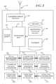
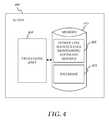
- FIG. 4shows a SCADA system
- FIG. 5is a flow chart of a method for providing maintenance monitoring
- FIG. 6shows an operating environment
- FIG. 7shows an operating environment
- Electric power linesare systems of many components. These components comprise, but are not limited to, conductors, conductor splices, conductor dead-ends, insulators, strings of insulators (i.e., insulator strings,) insulator string supports, structures, and structure grounds. Utility companies may manually inspect these components on a scheduled basis. These manual inspections are time consuming, expensive, prone to inaccuracy, and components may fail between extended manual inspection cycles.
- a real-time power line maintenance monitoring systemmay provide a utility company with information on the status of a power line, the interpretation of this information, and display of this information in a manner that may allow the utility company to optimize the operation and maintenance of the power line. This may allow for increased power line reliability as the utility company may be able to determine if the power line is approaching its clearance limit or if a monitored component is failing.
- Embodiments of the inventionmay allow “continuous” monitoring of power line components. This continuous monitoring may reduce inspection expenses over conventional manual processes and provide earlier indication of potential component failure.
- FIG. 1shows an operating environment 100 used to transmit or deliver electrical power.
- operating environment 100may include a structure 102 , a power line monitor 105 , a conductor 110 , an insulator string 115 , an insulator string support 120 , a conductor splice 125 , and a structure ground 130 .
- Structure 102may support conductor 110 . While structure 102 is shown in FIG. 1 as a galvanized steel lattice tower, structure 102 may comprise any structure configured to support conductor 110 such as a steel pole structure, a wooden pole structure, or a structure made of any material configured in any way.
- Conductor 110may comprise any type conductor used to transmit electric power such as, but not limited to, Aluminum Conductor Steel Reinforced (ACSR).
- Conductor splice 125may comprise any component configured to splice conductor 110 .
- Insulator string 115may comprise any component configured to insulate conductor 110 from structure 102 .
- Insulator string support 120many comprise any component configured to attach insulator string 115 to structure 102 .
- Structure ground 130may comprise any component that grounds structure 102 to the Earth, for example, a grounding rod(s) and a connector.
- FIG. 2shows power line monitor 105 in more detail.
- power line monitor 105may include a processing unit 210 and a memory 215 .
- Memory 215may include a monitoring software module 220 and a database 225 .
- monitoring software module 220may perform processes for providing maintenance monitoring including, but not limited to, one or more of the stages of a method 500 as described below in greater detail with respect to FIG. 5 .
- Power line monitor 105may also include a communications package 230 that may include and antenna 235 and may be connected to processing unit 210 .
- Communications package 230may transmit status data collected from power line monitor 105 and may receive other data including control data.
- Communications package 230may communicate over a network (not shown).
- the networkmay comprise, for example, a local area network (LAN) or a wide area network (WAN).
- LANlocal area network
- WANwide area network
- a network interface located at power line monitor 105may be used to interconnect any other processor on the network.
- power line monitor 105may include an internal or external modem (not shown) or other means for establishing communications over the WAN.
- data sent over the networkmay be encrypted to insure data security by using encryption/decryption techniques.
- a wireless communications systemmay be utilized as the network.
- Wirelessmay be defined as radio transmission via the airwaves.
- various other communication techniquescan be used to provide wireless transmission, including infrared line of sight, cellular, microwave, satellite, packet radio, and spread spectrum radio.
- power line monitor 105may communicate across a wireless interface such as, for example, a cellular interface (e.g., general packet radio system (GPRS), enhanced data rates for global evolution (EDGE), global system for mobile communications (GSM)), a wireless local area network interface (e.g., WLAN, IEEE 802), a bluetooth interface, WiFi, WiMax, another RF communication interface, and/or an optical interface.
- GPRSgeneral packet radio system
- EDGEenhanced data rates for global evolution
- GSMglobal system for mobile communications
- WLANwireless local area network interface
- Power line monitor 105may communicate with a plurality of status transducers.
- the status transducersmay include, but are not limited to, a splice temperature transducer 230 , a conductor temperature transducer 235 , a dead-end temperature transducer 240 , a conductor motion transducer 245 , a conductor vibration transducer 250 , a support vibration transducer 255 , a structure vibration transducer 260 , a structure ground transducer 265 , and an insulator breakdown transducer 270 , an ambient air temperature transducer (not shown), all of which may collect and communicate status data to processing unit 210 .
- the status transducersmay communicate with processing unit 210 in any way.
- the status transducersmay communicate with processing unit 210 either over a wire or wirelessly, directly or through the network, for example.
- the status transducers and power line monitor 105may be read wirelessly by a fixed wing aircraft or helicopter.
- the plurality of status transducersmay be programmed with limits such that they can make a determination when measured data exceeds those limits and transmit a warning. Embodiments of the invention may download and change these limits remotely through the network. Embodiments of the invention may also include a base/weather station (not shown). The base/weather station may receive raw data from sensors (e.g., status transducers.) Then a processor in the base/weather station may be programmed to make a determination that there is an alert condition and transmit an alert in response.
- All elements within power line monitor 105may be supplied with power from a power supply 275 . Because power line monitor 105 may be in close proximity to a power line (e.g., coupled to the power line,) power supply 275 may scavenge power from the power line using a current transformer (CT,) for example. Power supply 275 may also be a solar power supply.
- CTcurrent transformer
- FIG. 3shows an operating environment 300 for power line monitor 105 consistent with embodiments of the invention.
- a power line 305(e.g., including conductor 110 ) may connect a first substation 310 and a second substation 315 .
- Power line 305may be tens or even hundreds of miles long.
- RUS BULLETIN 1724E-200“DESIGN MANUAL FOR HIGH VOLTAGE TRANSMISSION LINES”, published by the Electric Staff Division, Rural Utilities Service, U.S. Department of Agriculture shows how power lines may be designed.
- Sensor devices 105may be placed on power line 305 .
- Sensor devices 105 in environment 300may include any one or more of a combination of the status transducers shown in FIG. 2 .
- Each of the sensor devices 105may collect status data at a location (e.g., structure) where the sensor device is located on power line 305 . After collection, each of the sensor devices 105 may transmit its collected status data to a central station 320 .
- the received status datamay be fed into a supervisory control and data acquisition (SCADA) system 400 as shown in more detail in FIG. 4 .
- SCADAsupervisory control and data acquisition
- FIG. 4shows SCADA system 400 in more detail.
- SCADA system 400may include a processing unit 410 and a memory 415 .
- Memory 415may include a power line maintenance monitoring software module 420 and a database 425 .
- power line maintenance monitoring software module 420may perform, for example, processes for providing maintenance monitoring including, for example, any one or more of the stages of method 500 as described in greater detail below with respect to FIG. 5 .
- FIG. 5is a flow chart setting forth the general stages involved in a method 500 consistent with embodiments of the invention for providing maintenance monitoring.
- Method 500may be implemented using power line monitor 105 , SCADA system 400 , or a combination of both power line monitor 105 and SCADA system 400 . Ways to implement the stages of method 500 will be described in greater detail below.
- Method 500may begin at starting block 505 and proceed to stage 510 where power line monitor 105 may collect a plurality of status data respectively corresponding to a plurality of components on a power line.
- the plurality of componentsmay comprise, but are not limited to, a conductor dead-end, structure 102 , conductor 110 , insulator string 115 , insulator string support 120 , conductor splice 125 , and structure ground 130 .
- Conductor temperature transducer 235may be placed at or near conductor 110 , may be configured to measure the temperature of conductor 110 , and send the measured conductor temperature reading back to power line monitor 105 .
- Splice temperature transducer 230may be placed at or near conductor splice 125 , be configured to measure the temperature of conductor splice 125 , and send the measured splice temperature reading back to power line monitor 105 .
- Dead-end temperature transducer 240may be placed at or near a conductor dead-end (not shown), be configured to measure the temperature of the conductor dead-end, and send the measured dead-end temperature reading back to power line monitor 105 .
- Conductor motion transducer 245may comprise, for example, an accelerometer and may be placed on conductor 110 , for example, at or near mid-span. Conductor motion transducer 245 may be configured to measure the motion (e.g., movement profile) of conductor 110 and send the measured motion measurements back to power line monitor 105 . The motion measurements may be used to determine if conductor 110 is in a “galloping” state. Conductor galloping is described in RUS BULLETIN 1724E-200, “DESIGN MANUAL FOR HIGH VOLTAGE TRANSMISSION LINES”, published by the Electric Staff Division, Rural Utilities Service, U.S. Department of Agriculture and is incorporated herein by reference.
- Conductor vibration transducer 250may be placed on conductor 110 .
- Conductor vibration transducer 250may be configured to measure the vibration of conductor 110 and send the vibration measurements (e.g., vibration profile) back to power line monitor 105 .
- the vibration measurementsmay be used to determine if conductor 110 is experiencing excessive Aeolian vibration (e.g., torsional conductor movement and string vibration) which can lead to conductor fatigue failures.
- Aeolian vibrationis described in RUS BULLETIN 1724E-200, “DESIGN MANUAL FOR HIGH VOLTAGE TRANSMISSION LINES”, published by the Electric Staff Division, Rural Utilities Service, U.S. Department of Agriculture and is incorporated herein by reference.
- Support vibration transducer 255may be placed at or near insulator string support 120 , be configured to measure vibration of insulator string support 120 , and send the measured vibration reading (e.g., vibration profile) of insulator string support 120 back to power line monitor 105 . Moreover, support vibration transducer 255 may be configured to “ping” insulator string support 120 with a mechanical energy wave and measure the reflection of the mechanical energy wave in insulator string support 120 as the measured vibration reading.
- Structure vibration transducer 260may be placed on or near structure 102 , be configured to measure vibration of structure 102 , and send the measured vibration reading (e.g., vibration profile) back to power line monitor 105 . Moreover, structure vibration transducer 260 may be configured to “ping” structure 102 with a mechanical energy wave and measure the reflection of the mechanical energy wave in structure 102 as the measured vibration reading.
- Structure ground transducer 265may be configured to “megger” structure ground 130 .
- structure ground transducer 265may be configured measure a ground impedance of structure ground 130 at structure 102 .
- Structure ground transducer 265may send the measured ground impedance reading back to power line monitor 105 .
- Insulator electromagnetic transducer 270may be placed on or near insulator string 115 , be configured to measure an electromagnetic profile of insulator string 115 , and send the measured electromagnetic profile back to power line monitor 105 .
- FIG. 6shows an operating environment 600 .
- operating environment 600may include a first structure 605 , a second structure 610 , a ground 615 , and a span of conductor in a first position 620 above ground 615 .
- Operating environment 600may include a plurality of sag transceivers comprising, for example, a first sag transceiver 625 , a second sag transceiver 630 , and a third sag transceiver 635 .
- the plurality of sag transceiversmay be included in the plurality of status transducers of FIG. 2 .
- First sag transceiver 625may be disposed on first structure 605 and second sag transceiver 630 may be disposed on second structure 610 .
- Third sag transceiver 635may be disposed on the span of conductor, for example, substantially in the middle or at substantially the low point of sag of the span of conductor.
- Power line monitor 105may be disposed, for example, on either of first structure 605 or second structure 610 .
- First sag transceiver 625 and second sag transceiver 630may be disposed a first distance 640 apart, first sag transceiver 625 and third sag transceiver 635 may be disposed a second distance 645 apart, and second sag transceiver 630 and third sag transceiver 635 may be disposed a third distance 650 apart.
- the amount of sagincreases or decreases in the span of conductor, the distance between the span of conductor and ground 615 changes.
- the amount of sagmay increase or decrease in the span of conductor for any number of reasons including, for example, a change in ambient temperature, a changes in the temperature of the conductor, icing in the conductor, etc.
- the amount of sagmay increase in the span.
- the conductormay move from first position 620 to a second position 655 .
- This change in the conductor's positionmay cause third sag transceiver 635 to move to a third sag transceiver second positions 660 . Consequently, first sag transceiver 625 and third sag transceiver 635 may now be disposed a fourth distance 665 apart and second sag transceiver 630 and third sag transceiver 635 may now be disposed a fifth distance 670 apart.
- first sag transceiver 625may send a signal to third sag transceiver 635 .
- This signalmay include a time-stamp indicating the time when the signal left first sag transceiver 625 .
- Third sag transceiver 635may note the time that the signal was received from first sag transceiver 625 .
- third sag transceiver 635may calculate the time it took for the signal to travel from first sag transceiver 625 to third sag transceiver 635 .
- Third sag transceiver 635may calculate the distance by knowing the speed of the signal and the amount of time it took the signal to get to third sag transceiver 635 . This same process may be used between any of the plurality of sag transceivers to calculate first distance 640 , second distance 645 , third distance 650 , fourth distance 665 , and fifth distance 670 .
- this calculated distancemay be communicated (e.g., over the network) amongst the plurality of sag transceivers, to power line monitor 105 , and to SCADA system 400 .
- any of the plurality of sag transceivers, power line monitor 105 , or SCADA system 400can calculate a location of a point on the span of conductor associated with third sag transceiver 635 .
- mathematical processesincluding, for example, triangulation and the side-side-side theorem of geometry may be used.
- Embodiments of the inventionmay be calibrated a baseline data.
- the baseline datamay include a distance (e.g., clearance) between ground 615 for a given location of the point on the span of conductor associated with third sag transceiver 635 .
- the baseline datamay be used to recalculate the clearance between ground 615 and the span of conductor. If this clearance is too small as compared to a predetermined value, embodiments of the invention may provide an alert. Safety codes may be considered when setting this predetermined value.
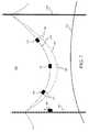
- FIG. 7shows an operating environment 700 .
- operating environment 700may include one or more inclinometers (e.g., a first inclinometer 705 , a second inclinometer 710 , and a third inclinometer 715 ) rather than the plurality of sag transceivers of FIG. 6 .
- the inclinometers, power line monitor 105 , or SCADA system 400may communicate data amongst each other over, for example, the network.
- the one or more inclinometersmay be included in the plurality of status transducers of FIG. 2 .
- any one of the inclinometerscan provide an angle of a section of the span of conductor associated with the inclinometer.
- Embodiments of the inventionmay be calibrated with baseline data.
- the baseline datamay include a distance (e.g., clearance) between ground 615 and a low point of sag on the span of conductor for a given angle indicated by any of the inclinometers.
- the ground clearance distance between ground 615 and a low point of sag on the span of conductormay be recalculated.
- This recalculationmay be performed, for example, by the inclinometers, power line monitor 105 , or SCADA system 400 . If this clearance is too small as compared to a predetermined value, embodiments of the invention may provide an alert. Safety codes may be considered when setting this predetermined value.
- method 500may advance to stage 520 where power line monitor 105 (or SCADA 400 ) may analyze the collected plurality of status data to determine when a one of the collected plurality of status data is outside of a normal operation range for a one of the plurality of components corresponding to the one of the collected plurality of status data. Consistent with embodiments of the invention, the collected plurality of status data may be trended and interpreted.
- Thismay include, but is not limited to, providing: i) trending of component data; ii) heuristic algorithms specific to each monitored component type, which may interpret real-time and trended data to determine if the component is degrading; and iii) comparison of algorithm outputs to alarm set points to determine estimation of effects of conditions on remaining component life.
- conductor splices and conductor dead-endsmay deteriorate over time and may eventually fail. As they approach their failure point, they become hotter and hotter. Consequently, the temperature of conductor splice 125 and/or the conductor deadened may be compared to the temperature of conductor 110 . If the temperature of conductor splice 125 and/or the temperature of the conductor deadened is greater than the temperature of conductor 110 by a predetermined amount, then the temperature of conductor splice 125 and/or the temperature of the conductor deadened may be considered to be out side of the normal operation range for conductor splice 125 and/or the conductor deadened.
- conductor 110may be prone to “galloping.”
- Conductor galloping(sometimes called dancing), is a phenomenon where power line conductors move with large amplitudes. Galloping usually occurs when an unsteady, high or gusty wind blows over a conductor covered by a layer of ice deposited by freezing rain, mist, or sleet.
- the coatingmay vary from a very thin glaze on one side to a solid three-inch cover giving the conductor an irregularly shaped profile. Consequently, this ice covering may give the conductor a slightly out-of-round, elliptical, or quasi-airfoil shape. Wind blowing over this irregularly shaped profile results in aerodynamic lift that causes the conductor to gallop.
- the windcan be anything between 5 to 45 miles-per-hour at an angle to the power line of 10 to 90 degrees.
- the windmay be unsteady in velocity or direction. Consequently, the movement profile of conductor 110 may be periodically analyzed by conductor motion transducer 245 , power line monitor 105 , or SCADA 400 to see if the motion of conductor 110 is consistent with the galloping conductor phenomenon.
- conductor 110may be prone to damage through Aeolian vibration.
- Aeolian vibrationis a high-frequency low-amplitude oscillation generated by a low velocity, comparatively steady wind blowing across a conductor. This steady wind creates air vortices or eddies on the lee side of the conductor. These vortices or eddies will detach at regular intervals from the top and bottom area of the conductor (i.e., “vortex shedding”) creating a force on the conductor that is alternately impressed from above and below.
- the frequency of the forcesi.e., expected excitation frequency
- a frequency of a resonant vibration mode for a conductor spani.e., natural frequency of the power line
- the frequency of resonant vibrationdepends mainly on conductor size and wind velocity and is generally between 5 and 100 Hz for wind speeds within the range of 0 to 15 miles per hour.
- the peak-to-peak vibration amplitudeswill cause alternating bending stresses great enough to produce fatigue failure in the conductor strands at the attachment points to the power line structure.
- Tensioned conductors in long spansare particularly subject to vibration fatigue. This vibration is generally more severe in flat open terrain where steady winds are more often encountered.
- the vibration profile of conductor 110may be periodically analyzed by conductor vibration transducer 250 , power line monitor 105 , or SCADA 400 to see if the vibration of conductor 110 is greater than acceptable levels or significantly different than a vibration profile taken at a previous time (e.g., when the power line including structure 102 was first constructed).
- Insulator string 115may be connected to structure 102 on insulator string support 120 .
- Insulator string support 120may weaken and loosen due to vibration. Damage to insulator string support 120 may be detectable through vibration or excessive motion. Consequently, the vibration profile of insulator string support 120 may be periodically analyzed by support vibration transducer 255 , power line monitor 105 , or SCADA 400 to see if the vibration of insulator string support 120 is greater than acceptable levels or significantly different than a vibration profile taken at a previous time (e.g., when the power line including structure 102 was first constructed).
- Power line structuresmay be made of concrete, wood, or steel. Regardless of the material, power line structures may deteriorate, for example, by rot, rust, corrode, or the bolts of a lattice structure may loosen. A level of deterioration can be determined by how structure 102 vibrates. Consequently, the vibration profile of structure 102 may be periodically analyzed by structure vibration transducer 260 , power line monitor 105 , or SCADA 400 to see if the vibration of structure 102 is greater than acceptable levels or significantly different than a vibration profile taken at a previous time (e.g., when the power line including structure 102 was first constructed).
- Structure 102may be grounded through structure ground 130 .
- Structure ground 130may comprise a ground rod or a series of ground rods being driven into the earth near structure 102 .
- the ground rod or a series of ground rodsare connect to structure 102 by a wire. While an impedance of structure ground 130 may have been checked and found acceptable (e.g., between 20 ohms and 40 ohms) when structure 102 was built, the grounding of structure 102 may deteriorate over time.
- the impedance of structure ground 130may be periodically analyzed by structure ground transducer 265 , power line monitor 105 , or SCADA 400 to see if the impedance of structure ground 130 is greater than a predetermined acceptable level or significantly different than an impedance of structure ground 130 taken at a previous time (e.g., when the power line including structure 102 was first constructed).
- Insulator stringse.g., insulator string 115
- Mechanical failuresmay be the result of physical damage to the “bells” or “core” of insulator string 115 .
- Electrical failuresmay be the result of contamination and tracking that can be detected via corona or electromagnetic disruptions (e.g., like static on an AM radio). Accordingly, embodiments of the invention may use devices that measure corona or partial discharge that may detect insulator tracking.
- the electromagnetic profile of insulator string 115may be periodically analyzed by insulator electromagnetic transducer 270 , power line monitor 105 , or SCADA 400 to see if the corona or electromagnetic disruptions of insulator string 115 is greater than acceptable levels or significantly different than an electromagnetic profile taken at a previous time (e.g., when the power line including structure 102 was first constructed).
- step 520method 500 may continue to stage 530 where power line monitor 105 (or SCADA 400 ) may display results of the collected data analysis.
- the resultsmay indicate that the one of the collected plurality of status data is outside of the normal operation range for the one of the plurality of components corresponding to the one of the collected plurality of status data as described above. For example, if embodiments of the invention show that sag is increasing beyond that expected for the electrical load on the conductor and that the weather conditions are present for ice, then the analysis may indicate that ice loading conditions may be present on the power line causing the sag.
- the analysismay indicate that some other condition is present that is causing the excessive sag.
- the displaymay show a profile of a given span of conductor. On this profile, two horizontal lines may respectively indicate an upper safe limit and a lower safe limit of the sag.
- Embodiment of the present inventionmay, for example, be implemented using a memory, a processing unit, and other components. Any suitable combination of hardware, software, and/or firmware may be used to implement the memory, processing unit, or other components.
- the processing unitmay implement program modules.
- program modulesmay include routines, programs, components, data structures, and other types of structures that perform particular tasks or implement particular abstract data types.
- embodiments of the inventionmay be practiced with other computer system configurations, including hand-held devices, multiprocessor systems, microprocessor-based or programmable consumer electronics, minicomputers, mainframe computers, and the like.
- Embodiments of the inventionmay also be practiced in distributed computing environments where tasks are performed by remote processing devices that are linked through a communications network.
- program modulesmay be located in both local and remote memory storage devices.
- embodiments of the inventionmay be practiced in an electrical circuit comprising discrete electronic elements, packaged or integrated electronic chips containing logic gates, a circuit utilizing a microprocessor, or on a single chip containing electronic elements or microprocessors.
- Embodiments of the inventionmay also be practiced using other technologies capable of performing logical operations such as, for example, AND, OR, and NOT, including but not limited to mechanical, optical, fluidic, and quantum technologies.
- embodiments of the inventionmay be practiced within a general purpose computer or in any other circuits or systems.
- Embodiments of the inventionmay be implemented as a computer process (method), a computing system, or as an article of manufacture, such as a computer program product or computer readable media.
- the computer program productmay be a computer storage media readable by a computer system and encoding a computer program of instructions for executing a computer process.
- the computer program productmay also be a propagated signal on a carrier readable by a computing system and encoding a computer program of instructions for executing a computer process.
- the present inventionmay be embodied in hardware and/or in software (including firmware, resident software, micro-code, etc.).
- embodiments of the present inventionmay take the form of a computer program product on a computer-usable or computer-readable storage medium having computer-usable or computer-readable program code embodied in the medium for use by or in connection with an instruction execution system.
- a computer-usable or computer-readable mediummay be any medium that can contain, store, communicate, propagate, or transport the program for use by or in connection with the instruction execution system, apparatus, or device.
- the computer-usable or computer-readable mediummay be, for example but not limited to, an electronic, magnetic, optical, electromagnetic, infrared, or semiconductor system, apparatus, device, or propagation medium. More specific examples (a non-exhaustive list) of the computer-readable medium would include the following: an electrical connection having one or more wires, a portable computer diskette, a random access memory (RAM), a read-only memory (ROM), an erasable programmable read-only memory (EPROM or Flash memory), an optical fiber, and a portable compact disc read-only memory (CD-ROM).
- RAMrandom access memory
- ROMread-only memory
- EPROM or Flash memoryerasable programmable read-only memory
- CD-ROMportable compact disc read-only memory
- the computer-usable or computer-readable mediumcould even be paper or another suitable medium upon which the program is printed, as the program can be electronically captured, via, for instance, optical scanning of the paper or other medium, then compiled, interpreted, or otherwise processed in a suitable manner, if necessary, and then stored in a computer memory.
- Embodiments of the present inventionare described above with reference to block diagrams and/or operational illustrations of methods, systems, and computer program products according to embodiments of the invention. It is to be understood that the functions/acts noted in the blocks may occur out of the order noted in the operational illustrations. For example, two blocks shown in succession may in fact be executed substantially concurrently or the blocks may sometimes be executed in the reverse order, depending upon the functionality/acts involved.
Landscapes
- Engineering & Computer Science (AREA)
- Power Engineering (AREA)
- Computer Networks & Wireless Communication (AREA)
- Remote Monitoring And Control Of Power-Distribution Networks (AREA)
Abstract
Description
Claims (14)
Priority Applications (4)
| Application Number | Priority Date | Filing Date | Title |
|---|---|---|---|
| US13/545,087US10205307B2 (en) | 2010-03-23 | 2012-07-10 | Power line maintenance monitoring |
| CA2878674ACA2878674C (en) | 2012-07-10 | 2013-07-10 | Power line maintenance monitoring |
| EP13741938.8AEP2873127B1 (en) | 2012-07-10 | 2013-07-10 | Power line maintenance monitoring |
| PCT/US2013/049908WO2014011760A1 (en) | 2012-07-10 | 2013-07-10 | Power line maintenance monitoring |
Applications Claiming Priority (2)
| Application Number | Priority Date | Filing Date | Title |
|---|---|---|---|
| US12/729,319US20110238374A1 (en) | 2010-03-23 | 2010-03-23 | Power Line Maintenance Monitoring |
| US13/545,087US10205307B2 (en) | 2010-03-23 | 2012-07-10 | Power line maintenance monitoring |
Related Parent Applications (1)
| Application Number | Title | Priority Date | Filing Date |
|---|---|---|---|
| US12/729,319Continuation-In-PartUS20110238374A1 (en) | 2010-03-23 | 2010-03-23 | Power Line Maintenance Monitoring |
Publications (2)
| Publication Number | Publication Date |
|---|---|
| US20120278011A1 US20120278011A1 (en) | 2012-11-01 |
| US10205307B2true US10205307B2 (en) | 2019-02-12 |
Family
ID=47068602
Family Applications (1)
| Application Number | Title | Priority Date | Filing Date |
|---|---|---|---|
| US13/545,087Expired - Fee RelatedUS10205307B2 (en) | 2010-03-23 | 2012-07-10 | Power line maintenance monitoring |
Country Status (1)
| Country | Link |
|---|---|
| US (1) | US10205307B2 (en) |
Cited By (3)
| Publication number | Priority date | Publication date | Assignee | Title |
|---|---|---|---|---|
| US11237078B2 (en)* | 2018-12-13 | 2022-02-01 | Sicame | Monitoring system of wind-induced motion or vibration in at least one overhead cable, in particular a conductor aerial cable of a transmission or distribution |
| US11443155B2 (en)* | 2018-01-19 | 2022-09-13 | Lindsey Manufacturing Company | Insulator leakage current detector and method of detecting insulator leakage current |
| US20230288276A1 (en)* | 2022-03-10 | 2023-09-14 | Dalian University Of Technology | Quasi-static calculation method for lateral unbalanced force of transmission lines |
Families Citing this family (23)
| Publication number | Priority date | Publication date | Assignee | Title |
|---|---|---|---|---|
| CA2742854C (en) | 2008-11-06 | 2017-01-24 | Southwire Company | Real-time power line rating |
| US20110238374A1 (en)* | 2010-03-23 | 2011-09-29 | Mark Lancaster | Power Line Maintenance Monitoring |
| US20130054162A1 (en) | 2011-08-31 | 2013-02-28 | Tollgrade Communications, Inc. | Methods and apparatus for determining conditions of power lines |
| BR112014019973A2 (en)* | 2012-02-14 | 2017-06-13 | Tollgrade Communications Inc | transmission line management system |
| WO2014011760A1 (en)* | 2012-07-10 | 2014-01-16 | Mark Lancaster | Power line maintenance monitoring |
| US20140136140A1 (en)* | 2012-11-13 | 2014-05-15 | Elwha Llc | Systems and methods for detecting overhead line motion |
| US20140163884A1 (en)* | 2012-12-10 | 2014-06-12 | Universite De Liege | Method and system for the determination of wind speeds and incident radiation parameters of overhead power lines |
| CN103078790B (en)* | 2012-12-29 | 2015-11-25 | 银江股份有限公司 | For the intelligent gateway of power transmission line on-line detecting system |
| US9412254B1 (en)* | 2013-03-15 | 2016-08-09 | Jeffrey N. Weiss | Downed item detector |
| US9972989B2 (en) | 2014-03-31 | 2018-05-15 | Aclara Technologies Llc | Optical voltage sensing for underground medium voltage wires |
| EP3186646B1 (en) | 2014-08-29 | 2021-10-20 | Aclara Technologies LLC | Power extraction for a medium voltage sensor using a capacitive voltage divider |
| CN104596453A (en)* | 2015-01-20 | 2015-05-06 | 电子科技大学 | System for measuring sag of overhead transmission line |
| CN106803659A (en)* | 2015-11-26 | 2017-06-06 | 江苏天南电力器材有限公司 | One kind has monitoring function pre-hinged catenarian cable cleat |
| WO2017180668A1 (en)* | 2016-04-11 | 2017-10-19 | Lindsey Manufacturing Co. | Dropped conductor sensor |
| US10978863B2 (en)* | 2019-01-15 | 2021-04-13 | Schweitzer Engineering Laboratories, Inc. | Power line sag monitoring device |
| NO345597B1 (en)* | 2019-09-17 | 2021-05-03 | Comrod As | System for monitoring a power distribution network and method of building such system |
| NO345714B1 (en) | 2019-11-27 | 2021-06-28 | Comrod As | Rope robot and method for mounting an object to a power line |
| CN112525083B (en)* | 2020-11-30 | 2022-04-01 | 广东电网有限责任公司 | Power line sag detection device |
| CN113591342B (en)* | 2021-06-28 | 2024-02-27 | 国网天津市电力公司电力科学研究院 | Method for analyzing galloping characteristics of 10kV overhead insulated line |
| WO2023004534A1 (en)* | 2021-07-26 | 2023-02-02 | 大连理工大学 | Lattice tower structure displacement reconstruction method based on improved vibration mode superposition |
| FR3149555A1 (en)* | 2023-06-07 | 2024-12-13 | 4Nrj | System and method for controlling a catenary boom |
| CN116911134A (en)* | 2023-07-20 | 2023-10-20 | 云南电网有限责任公司楚雄供电局 | Solving method of high-voltage transmission line conductor galloping trajectory equation |
| WO2025165970A1 (en)* | 2024-01-30 | 2025-08-07 | Preformed Line Products Company | Remote line monitoring system and method |
Citations (101)
| Publication number | Priority date | Publication date | Assignee | Title |
|---|---|---|---|---|
| US3771356A (en) | 1972-03-14 | 1973-11-13 | Saskatchewan Power Corp | Vibration measuring assemblies for energized and non-energized power line vibration measurements |
| US4384289A (en) | 1981-01-23 | 1983-05-17 | General Electric Company | Transponder unit for measuring temperature and current on live transmission lines |
| US4420752A (en) | 1978-03-20 | 1983-12-13 | Murray W. Davis | Real-time parameter sensor-transmitter |
| EP0223507A2 (en) | 1985-11-05 | 1987-05-27 | Niagara Mohawk Power Corporation | Transmission line sensor apparatus |
| US4689752A (en) | 1983-04-13 | 1987-08-25 | Niagara Mohawk Power Corporation | System and apparatus for monitoring and control of a bulk electric power delivery system |
| US4728887A (en) | 1984-06-22 | 1988-03-01 | Davis Murray W | System for rating electric power transmission lines and equipment |
| US4777381A (en) | 1983-04-13 | 1988-10-11 | Fernandes Roosevelt A | Electrical power line and substation monitoring apparatus and systems |
| US4786862A (en) | 1986-06-09 | 1988-11-22 | Niagara Mohawk Power Corporation | Watchdog circuit for transmission line sensor module |
| US4794327A (en) | 1983-04-13 | 1988-12-27 | Fernandes Roosevelt A | Electrical parameter sensing module for mounting on and removal from an energized high voltage power conductor |
| US4796027A (en) | 1983-04-13 | 1989-01-03 | Niagara Mohawk Power Corporation | Apparatus for data transmission from multiple sources on a single channel |
| US4806855A (en) | 1984-06-22 | 1989-02-21 | Davis Murray W | System for rating electric power transmission lines and equipment |
| US4821138A (en) | 1986-05-23 | 1989-04-11 | Sumitomo Electric Industries, Ltd. | Monitoring device for overhead power transmission system |
| US4827272A (en) | 1984-06-04 | 1989-05-02 | Davis Murray W | Overhead power line clamp and antenna |
| US4829298A (en) | 1983-04-13 | 1989-05-09 | Fernandes Roosevelt A | Electrical power line monitoring systems, including harmonic value measurements and relaying communications |
| US4886980A (en) | 1985-11-05 | 1989-12-12 | Niagara Mohawk Power Corporation | Transmission line sensor apparatus operable with near zero current line conditions |
| US4891576A (en) | 1988-08-22 | 1990-01-02 | The United States Of America As Represented By The Secretary Of The Interior | Ground-based transmission line conductor motion sensor |
| US4894785A (en) | 1987-09-18 | 1990-01-16 | Fernandes Roosevelt A | High voltage conductor mounted line powered monitoring system |
| US4904996A (en) | 1988-01-19 | 1990-02-27 | Fernandes Roosevelt A | Line-mounted, movable, power line monitoring system |
| US5006846A (en) | 1987-11-12 | 1991-04-09 | Granville J Michael | Power transmission line monitoring system |
| US5029101A (en) | 1987-09-18 | 1991-07-02 | Fernandes Roosevelt A | High voltage conductor mounted line powered monitoring system |
| US5107447A (en) | 1988-05-16 | 1992-04-21 | Hitachi, Ltd. | Abnormality diagnosing system and method for a high voltage power apparatus |
| US5121644A (en) | 1990-02-14 | 1992-06-16 | Stc Plc | Deploying cables in pipelines |
| US5140257A (en) | 1984-06-22 | 1992-08-18 | Davis Murray W | System for rating electric power transmission lines and equipment |
| US5214595A (en) | 1988-05-16 | 1993-05-25 | Hitachi, Ltd. | Abnormality diagnosing system and method for a high voltage power apparatus |
| US5235681A (en) | 1988-06-22 | 1993-08-10 | Hitachi, Ltd. | Image filing system for protecting partial regions of image data of a document |
| US5235861A (en) | 1991-05-03 | 1993-08-17 | Seppa Tapani O | Power transmission line monitoring system |
| US5341088A (en) | 1984-06-22 | 1994-08-23 | Davis Murray W | System for rating electric power transmission lines and equipment |
| US5397983A (en) | 1993-01-22 | 1995-03-14 | Consolidated Edison Company Of New York, Inc. | Vibration based deenergized cable detector and method |
| WO1995029553A1 (en) | 1994-04-25 | 1995-11-02 | Foster-Miller Inc. | Self-powered powerline sensor |
| WO1995035478A1 (en) | 1994-06-20 | 1995-12-28 | Hafslund Nycomed A.S | Apparatus for monitoring overhead electric lines |
| US5517864A (en) | 1994-05-31 | 1996-05-21 | Seppa; Tapani O. | Power transmission line tension monitoring system |
| US5559430A (en) | 1994-07-27 | 1996-09-24 | Seppa; Tapani O. | Net radiation sensor |
| US5565783A (en) | 1994-09-29 | 1996-10-15 | Pacific Gas And Electric Company | Fault sensor device with radio transceiver |
| WO1998020468A1 (en) | 1996-11-01 | 1998-05-14 | Foster-Miller, Inc. | Modular core, self-powered powerline sensor |
| US5821463A (en) | 1996-06-14 | 1998-10-13 | The Whitaker Corporation | Mechanical connector splice for cable |
| US5859596A (en) | 1996-08-30 | 1999-01-12 | Csi Technology, Inc. | Switchyard equipment monitoring system and communications network therefor |
| US5918288A (en) | 1997-03-11 | 1999-06-29 | Seppa; Tapani O | Transmission line load cell protection system |
| US5933355A (en) | 1995-05-04 | 1999-08-03 | Deb; Anjan Kumar | Object oriented expert power line ampacity system |
| US6097298A (en)* | 1998-02-13 | 2000-08-01 | Ecsi Corporation | Apparatus and method of monitoring a power transmission line |
| WO2000062317A1 (en) | 1999-04-08 | 2000-10-19 | Doble Engineering Company | Monitoring leakage currents from high-voltage devices |
| US6205867B1 (en) | 1998-10-07 | 2001-03-27 | American Electric Power, Inc. | Power line sag monitor |
| WO2002037925A2 (en) | 2000-10-10 | 2002-05-16 | Sempra Fiber Links | Methods and systems for installing cable and conduit in pipelines |
| WO2002093279A2 (en) | 2001-03-28 | 2002-11-21 | Westinghouse Electric Company Llc | Predictive maintenance display system |
| US20030014199A1 (en) | 2001-07-12 | 2003-01-16 | Patrick Toomey | System and methods for detecting fault in structure |
| US6677743B1 (en) | 1999-03-05 | 2004-01-13 | Foster-Miller, Inc. | High voltage powerline sensor with a plurality of voltage sensing devices |
| EP1385013A1 (en) | 2002-07-22 | 2004-01-28 | General Electric Company | Multifunction intelligent electronic device and method |
| US6727604B2 (en) | 1998-12-04 | 2004-04-27 | Hydro-Quebec | Switching apparatus and method for a segment of an electric power line |
| WO2004038891A2 (en) | 2002-10-07 | 2004-05-06 | Protura As | System and device for monitoring an overhead power line |
| US6776572B2 (en) | 2001-07-18 | 2004-08-17 | Ferag Ag | Method and device for stacking flat articles |
| US6799080B1 (en) | 2003-06-12 | 2004-09-28 | The Boc Group, Inc. | Configurable PLC and SCADA-based control system |
| US20050058081A1 (en)* | 2003-09-16 | 2005-03-17 | Elliott Brig Barnum | Systems and methods for measuring the distance between devices |
| US6873746B2 (en) | 2001-08-02 | 2005-03-29 | Electric Power Research Institute, Inc. | Apparatus and method for monitoring a cable |
| WO2005059491A2 (en) | 2003-12-11 | 2005-06-30 | Joslyn Hi-Voltage Corp. | Transmission/distribution line fault indicator with remote polling and current sensing and reporting capability |
| US7066524B2 (en) | 2000-08-14 | 2006-06-27 | Agri-Cover, Inc. | Tonneau cover with turn knob for rear bar locks |
| WO2006085804A1 (en) | 2005-02-14 | 2006-08-17 | Abb Research Ltd | Line inspection |
| US7103511B2 (en) | 1998-10-14 | 2006-09-05 | Statsignal Ipc, Llc | Wireless communication networks for providing remote monitoring of devices |
| EP1703428A2 (en) | 2005-03-18 | 2006-09-20 | ABB PATENT GmbH | System and method for process data simulation |
| US7136725B1 (en) | 2001-06-21 | 2006-11-14 | Paciorek Ronald R | Load shed notification method, product, and apparatus |
| US20060265175A1 (en) | 2005-05-09 | 2006-11-23 | Manuchehr Shimohamadi | Low-cost multi-span conductor temperature measurement system |
| US20070038396A1 (en) | 2001-12-21 | 2007-02-15 | Abb Schweiz Ag | Parameter estimation for and use of a thermal model of a power line |
| US7188997B2 (en) | 2005-01-21 | 2007-03-13 | Eaton Corporation | Apparatus and method for detecting hot spots in an electric power conductor |
| WO2007031435A1 (en) | 2005-09-16 | 2007-03-22 | Universite De Liege | Device, system and method for real-time monitoring of overhead power lines |
| US7274186B2 (en) | 2004-01-16 | 2007-09-25 | Fieldmetrics, Inc | Temperature compensated and self-calibrated current sensor |
| US7282944B2 (en) | 2003-07-25 | 2007-10-16 | Power Measurement, Ltd. | Body capacitance electric field powered device for high voltage lines |
| WO2007134022A2 (en) | 2006-05-11 | 2007-11-22 | Underground Systems, Inc. | A power line temperature and sag monitor system |
| US7310948B2 (en) | 2002-10-09 | 2007-12-25 | Manucheher Shirmohamadi | De-icer for suspended overhead lines |
| WO2007149668A2 (en) | 2006-06-20 | 2007-12-27 | Battelle Energy Alliance, Llc | Methods, apparatus, and systems for monitoring transmission systems |
| US7336202B2 (en) | 2001-04-17 | 2008-02-26 | Sanyo Electric Co., Ltd. | Temperature monitoring device |
| US20080077336A1 (en) | 2006-09-25 | 2008-03-27 | Roosevelt Fernandes | Power line universal monitor |
| US20080156524A1 (en)* | 2006-12-28 | 2008-07-03 | 3M Innovative Properties Company | Overhead electrical power transmission line |
| US20080189061A1 (en) | 2007-02-05 | 2008-08-07 | Abb Research Ltd. | Real-time power-line sag monitoring using time-synchronized power system measurements |
| WO2008097458A1 (en) | 2007-02-05 | 2008-08-14 | Abb Research Ltd. | Power-line sag calculation by way of power-system state estimation |
| US7430932B2 (en) | 2002-10-31 | 2008-10-07 | Boris Iosifovitch Mekhanoshin | Device for telemonitoring the state of aerial power lines(variants) |
| US20090015239A1 (en) | 2007-03-01 | 2009-01-15 | Georgiou George E | Transmission Line Sensor |
| US7504819B2 (en) | 2004-07-21 | 2009-03-17 | Underground Systems, Inc. | Dynamic line rating system with real-time tracking of conductor creep to establish the maximum allowable conductor loading as limited by clearance |
| US20090115426A1 (en) | 2007-11-02 | 2009-05-07 | Cooper Technologies Company | Faulted circuit indicator apparatus with transmission line state display and method of use thereof |
| WO2009058955A1 (en) | 2007-11-02 | 2009-05-07 | Cooper Technologies Company | Faulted circuit indicator apparatus with transmission line state display and method of use thereof |
| US7575371B1 (en) | 2004-11-11 | 2009-08-18 | Fieldmetrics, Inc | Temperature sensor and extensometer |
| US20090284249A1 (en) | 2006-09-08 | 2009-11-19 | Syracuse Steven J | Sensor, Method and System of Monitoring Transmission Lines |
| US7641387B2 (en) | 2007-05-08 | 2010-01-05 | Underground Systems, Inc. | Power line temperature and sag monitor system |
| US20100017153A1 (en) | 2006-05-18 | 2010-01-21 | Ldic Gmbh | Method and Device for Determining the Electrical Loadability of Overhead Lines by Means of Temperature Measurement |
| US7672794B2 (en) | 2003-06-24 | 2010-03-02 | Expro Meters, Inc. | System and method for operating a flow process |
| US20100085036A1 (en) | 2007-11-02 | 2010-04-08 | Cooper Technologies Company | Overhead Communicating Device |
| WO2010042442A1 (en) | 2008-10-08 | 2010-04-15 | Cooper Technologies Company | Overhead communicating device |
| US7705747B2 (en) | 2005-08-18 | 2010-04-27 | Terahop Networks, Inc. | Sensor networks for monitoring pipelines and power lines |
| US20100114392A1 (en) | 2008-11-06 | 2010-05-06 | Mark Lancaster | Real-Time Power Line Rating |
| US7733094B2 (en) | 2004-11-01 | 2010-06-08 | Underground Systems, Inc. | Electrical instrument platform for mounting on and removal from an energized high voltage power conductor |
| WO2010127145A1 (en) | 2009-04-30 | 2010-11-04 | Underground Systems, Inc. | Overhead power line monitor |
| US7902854B2 (en) | 2003-07-25 | 2011-03-08 | Power Measurement, Ltd. | Body capacitance electric field powered device for high voltage lines |
| US20110080283A1 (en) | 2006-05-19 | 2011-04-07 | Schweitzer Iii Edmund O | Fault detection using phase comparison |
| WO2011042906A1 (en) | 2009-10-11 | 2011-04-14 | Moshe Henig | Loads management and outages detection for smart grid |
| US7930141B2 (en) | 2007-11-02 | 2011-04-19 | Cooper Technologies Company | Communicating faulted circuit indicator apparatus and method of use thereof |
| US7987071B1 (en) | 2007-07-30 | 2011-07-26 | Raytheon BBN Technologies, Corp. | Remote passive detection of failed power lines and estimation of power line current and power flow |
| US20110196536A1 (en) | 2010-02-10 | 2011-08-11 | Electric Power Research Institute, Inc. | Line inspection robot and system |
| US20110196535A1 (en) | 2010-02-10 | 2011-08-11 | Electric Power Research Institute, Inc. | Line inspection robot and system |
| US20110218790A1 (en) | 2008-11-08 | 2011-09-08 | Ajgaonkar Mahesh U | System and method for determining characteristics of power cables using distributed temperature sensing systems |
| EP2369718A2 (en) | 2010-03-23 | 2011-09-28 | Southwire Company | Power line maintenance monitoring |
| WO2011119065A2 (en) | 2010-03-24 | 2011-09-29 | Vladimir Aleksandrovitch Shkaptsov | Remote monitoring device for disposal conductor condition of the overhead transmission line |
| US20120299603A1 (en) | 2011-05-25 | 2012-11-29 | Electric Power Research Institute, Inc. | On-line monitoring system of insulation losses for underground power cables |
| US20130022078A1 (en) | 2011-07-21 | 2013-01-24 | Electric Power Research Institute, Inc. | Overhead Conductor Sensor |
| US20130054162A1 (en) | 2011-08-31 | 2013-02-28 | Tollgrade Communications, Inc. | Methods and apparatus for determining conditions of power lines |
- 2012
- 2012-07-10USUS13/545,087patent/US10205307B2/ennot_activeExpired - Fee Related
Patent Citations (125)
| Publication number | Priority date | Publication date | Assignee | Title |
|---|---|---|---|---|
| US3771356A (en) | 1972-03-14 | 1973-11-13 | Saskatchewan Power Corp | Vibration measuring assemblies for energized and non-energized power line vibration measurements |
| US4420752A (en) | 1978-03-20 | 1983-12-13 | Murray W. Davis | Real-time parameter sensor-transmitter |
| US4384289A (en) | 1981-01-23 | 1983-05-17 | General Electric Company | Transponder unit for measuring temperature and current on live transmission lines |
| US4794327A (en) | 1983-04-13 | 1988-12-27 | Fernandes Roosevelt A | Electrical parameter sensing module for mounting on and removal from an energized high voltage power conductor |
| US4689752A (en) | 1983-04-13 | 1987-08-25 | Niagara Mohawk Power Corporation | System and apparatus for monitoring and control of a bulk electric power delivery system |
| US4777381A (en) | 1983-04-13 | 1988-10-11 | Fernandes Roosevelt A | Electrical power line and substation monitoring apparatus and systems |
| US4796027A (en) | 1983-04-13 | 1989-01-03 | Niagara Mohawk Power Corporation | Apparatus for data transmission from multiple sources on a single channel |
| US4808917A (en) | 1983-04-13 | 1989-02-28 | Niagara Mohawk Power Corporation | Transmission line sensor apparatus operable with near zero current line conditions |
| US4829298A (en) | 1983-04-13 | 1989-05-09 | Fernandes Roosevelt A | Electrical power line monitoring systems, including harmonic value measurements and relaying communications |
| US4827272A (en) | 1984-06-04 | 1989-05-02 | Davis Murray W | Overhead power line clamp and antenna |
| US4728887A (en) | 1984-06-22 | 1988-03-01 | Davis Murray W | System for rating electric power transmission lines and equipment |
| US5140257A (en) | 1984-06-22 | 1992-08-18 | Davis Murray W | System for rating electric power transmission lines and equipment |
| US4806855A (en) | 1984-06-22 | 1989-02-21 | Davis Murray W | System for rating electric power transmission lines and equipment |
| US5341088A (en) | 1984-06-22 | 1994-08-23 | Davis Murray W | System for rating electric power transmission lines and equipment |
| EP0223507A2 (en) | 1985-11-05 | 1987-05-27 | Niagara Mohawk Power Corporation | Transmission line sensor apparatus |
| US4886980A (en) | 1985-11-05 | 1989-12-12 | Niagara Mohawk Power Corporation | Transmission line sensor apparatus operable with near zero current line conditions |
| US4821138A (en) | 1986-05-23 | 1989-04-11 | Sumitomo Electric Industries, Ltd. | Monitoring device for overhead power transmission system |
| US4786862A (en) | 1986-06-09 | 1988-11-22 | Niagara Mohawk Power Corporation | Watchdog circuit for transmission line sensor module |
| US4894785A (en) | 1987-09-18 | 1990-01-16 | Fernandes Roosevelt A | High voltage conductor mounted line powered monitoring system |
| US5029101A (en) | 1987-09-18 | 1991-07-02 | Fernandes Roosevelt A | High voltage conductor mounted line powered monitoring system |
| US5006846A (en) | 1987-11-12 | 1991-04-09 | Granville J Michael | Power transmission line monitoring system |
| US4904996A (en) | 1988-01-19 | 1990-02-27 | Fernandes Roosevelt A | Line-mounted, movable, power line monitoring system |
| US5107447A (en) | 1988-05-16 | 1992-04-21 | Hitachi, Ltd. | Abnormality diagnosing system and method for a high voltage power apparatus |
| US5214595A (en) | 1988-05-16 | 1993-05-25 | Hitachi, Ltd. | Abnormality diagnosing system and method for a high voltage power apparatus |
| US5235681A (en) | 1988-06-22 | 1993-08-10 | Hitachi, Ltd. | Image filing system for protecting partial regions of image data of a document |
| US4891576A (en) | 1988-08-22 | 1990-01-02 | The United States Of America As Represented By The Secretary Of The Interior | Ground-based transmission line conductor motion sensor |
| US5121644A (en) | 1990-02-14 | 1992-06-16 | Stc Plc | Deploying cables in pipelines |
| US5235861A (en) | 1991-05-03 | 1993-08-17 | Seppa Tapani O | Power transmission line monitoring system |
| US5397983A (en) | 1993-01-22 | 1995-03-14 | Consolidated Edison Company Of New York, Inc. | Vibration based deenergized cable detector and method |
| US5892430A (en) | 1994-04-25 | 1999-04-06 | Foster-Miller, Inc. | Self-powered powerline sensor |
| WO1995029553A1 (en) | 1994-04-25 | 1995-11-02 | Foster-Miller Inc. | Self-powered powerline sensor |
| US5517864A (en) | 1994-05-31 | 1996-05-21 | Seppa; Tapani O. | Power transmission line tension monitoring system |
| WO1995035478A1 (en) | 1994-06-20 | 1995-12-28 | Hafslund Nycomed A.S | Apparatus for monitoring overhead electric lines |
| US5559430A (en) | 1994-07-27 | 1996-09-24 | Seppa; Tapani O. | Net radiation sensor |
| US5565783A (en) | 1994-09-29 | 1996-10-15 | Pacific Gas And Electric Company | Fault sensor device with radio transceiver |
| US5933355A (en) | 1995-05-04 | 1999-08-03 | Deb; Anjan Kumar | Object oriented expert power line ampacity system |
| US5821463A (en) | 1996-06-14 | 1998-10-13 | The Whitaker Corporation | Mechanical connector splice for cable |
| US5859596A (en) | 1996-08-30 | 1999-01-12 | Csi Technology, Inc. | Switchyard equipment monitoring system and communications network therefor |
| WO1998020468A1 (en) | 1996-11-01 | 1998-05-14 | Foster-Miller, Inc. | Modular core, self-powered powerline sensor |
| US5918288A (en) | 1997-03-11 | 1999-06-29 | Seppa; Tapani O | Transmission line load cell protection system |
| US6097298A (en)* | 1998-02-13 | 2000-08-01 | Ecsi Corporation | Apparatus and method of monitoring a power transmission line |
| US6229451B1 (en) | 1998-02-13 | 2001-05-08 | Linesoft Corporation | Apparatus and method of monitoring a power transmission line |
| US6523424B1 (en)* | 1998-10-07 | 2003-02-25 | Ray M. Hayes | Power line sag monitor |
| US6205867B1 (en) | 1998-10-07 | 2001-03-27 | American Electric Power, Inc. | Power line sag monitor |
| US7103511B2 (en) | 1998-10-14 | 2006-09-05 | Statsignal Ipc, Llc | Wireless communication networks for providing remote monitoring of devices |
| US6727604B2 (en) | 1998-12-04 | 2004-04-27 | Hydro-Quebec | Switching apparatus and method for a segment of an electric power line |
| US6677743B1 (en) | 1999-03-05 | 2004-01-13 | Foster-Miller, Inc. | High voltage powerline sensor with a plurality of voltage sensing devices |
| US6633169B1 (en) | 1999-04-08 | 2003-10-14 | Doble Engineering Company | Monitoring leakage currents from high-voltage devices |
| WO2000062317A1 (en) | 1999-04-08 | 2000-10-19 | Doble Engineering Company | Monitoring leakage currents from high-voltage devices |
| US7066524B2 (en) | 2000-08-14 | 2006-06-27 | Agri-Cover, Inc. | Tonneau cover with turn knob for rear bar locks |
| WO2002037925A2 (en) | 2000-10-10 | 2002-05-16 | Sempra Fiber Links | Methods and systems for installing cable and conduit in pipelines |
| WO2002093279A2 (en) | 2001-03-28 | 2002-11-21 | Westinghouse Electric Company Llc | Predictive maintenance display system |
| US6735549B2 (en) | 2001-03-28 | 2004-05-11 | Westinghouse Electric Co. Llc | Predictive maintenance display system |
| US7336202B2 (en) | 2001-04-17 | 2008-02-26 | Sanyo Electric Co., Ltd. | Temperature monitoring device |
| US7136725B1 (en) | 2001-06-21 | 2006-11-14 | Paciorek Ronald R | Load shed notification method, product, and apparatus |
| US20030014199A1 (en) | 2001-07-12 | 2003-01-16 | Patrick Toomey | System and methods for detecting fault in structure |
| US6776572B2 (en) | 2001-07-18 | 2004-08-17 | Ferag Ag | Method and device for stacking flat articles |
| US6873746B2 (en) | 2001-08-02 | 2005-03-29 | Electric Power Research Institute, Inc. | Apparatus and method for monitoring a cable |
| US20070038396A1 (en) | 2001-12-21 | 2007-02-15 | Abb Schweiz Ag | Parameter estimation for and use of a thermal model of a power line |
| EP1385013A1 (en) | 2002-07-22 | 2004-01-28 | General Electric Company | Multifunction intelligent electronic device and method |
| US7369045B2 (en) | 2002-10-07 | 2008-05-06 | Roger Hansen | Monitoring system and device for an electric power line network |
| WO2004038891A2 (en) | 2002-10-07 | 2004-05-06 | Protura As | System and device for monitoring an overhead power line |
| US7310948B2 (en) | 2002-10-09 | 2007-12-25 | Manucheher Shirmohamadi | De-icer for suspended overhead lines |
| US7430932B2 (en) | 2002-10-31 | 2008-10-07 | Boris Iosifovitch Mekhanoshin | Device for telemonitoring the state of aerial power lines(variants) |
| US6799080B1 (en) | 2003-06-12 | 2004-09-28 | The Boc Group, Inc. | Configurable PLC and SCADA-based control system |
| US7672794B2 (en) | 2003-06-24 | 2010-03-02 | Expro Meters, Inc. | System and method for operating a flow process |
| US7282944B2 (en) | 2003-07-25 | 2007-10-16 | Power Measurement, Ltd. | Body capacitance electric field powered device for high voltage lines |
| US7902854B2 (en) | 2003-07-25 | 2011-03-08 | Power Measurement, Ltd. | Body capacitance electric field powered device for high voltage lines |
| US20050058081A1 (en)* | 2003-09-16 | 2005-03-17 | Elliott Brig Barnum | Systems and methods for measuring the distance between devices |
| WO2005059491A2 (en) | 2003-12-11 | 2005-06-30 | Joslyn Hi-Voltage Corp. | Transmission/distribution line fault indicator with remote polling and current sensing and reporting capability |
| US7279885B2 (en) | 2004-01-16 | 2007-10-09 | Field Metrics, Inc | Temperature compensated current sensor using reference magnetic field |
| US7279884B2 (en) | 2004-01-16 | 2007-10-09 | Field Metrics, Inc | Temperature compensated and self-calibrated current sensor using reference magnetic field |
| US7274186B2 (en) | 2004-01-16 | 2007-09-25 | Fieldmetrics, Inc | Temperature compensated and self-calibrated current sensor |
| US7504819B2 (en) | 2004-07-21 | 2009-03-17 | Underground Systems, Inc. | Dynamic line rating system with real-time tracking of conductor creep to establish the maximum allowable conductor loading as limited by clearance |
| US7733094B2 (en) | 2004-11-01 | 2010-06-08 | Underground Systems, Inc. | Electrical instrument platform for mounting on and removal from an energized high voltage power conductor |
| US7575371B1 (en) | 2004-11-11 | 2009-08-18 | Fieldmetrics, Inc | Temperature sensor and extensometer |
| US7845848B2 (en) | 2004-11-11 | 2010-12-07 | Fieldmetrics, Inc. | Temperature sensor and extensometer for electrical power cables |
| US7845847B2 (en) | 2004-11-11 | 2010-12-07 | Fieldmetrics, Inc. | Temperature sensor and extensometer for electrical power cables |
| US7188997B2 (en) | 2005-01-21 | 2007-03-13 | Eaton Corporation | Apparatus and method for detecting hot spots in an electric power conductor |
| WO2006085804A1 (en) | 2005-02-14 | 2006-08-17 | Abb Research Ltd | Line inspection |
| EP1703428A2 (en) | 2005-03-18 | 2006-09-20 | ABB PATENT GmbH | System and method for process data simulation |
| US20060265175A1 (en) | 2005-05-09 | 2006-11-23 | Manuchehr Shimohamadi | Low-cost multi-span conductor temperature measurement system |
| US7705747B2 (en) | 2005-08-18 | 2010-04-27 | Terahop Networks, Inc. | Sensor networks for monitoring pipelines and power lines |
| WO2007031435A1 (en) | 2005-09-16 | 2007-03-22 | Universite De Liege | Device, system and method for real-time monitoring of overhead power lines |
| US20090243876A1 (en) | 2005-09-16 | 2009-10-01 | Jean-Louis Lilien | Device, system and method for real-time monitoring of overhead power lines |
| WO2007134022A2 (en) | 2006-05-11 | 2007-11-22 | Underground Systems, Inc. | A power line temperature and sag monitor system |
| US20100017153A1 (en) | 2006-05-18 | 2010-01-21 | Ldic Gmbh | Method and Device for Determining the Electrical Loadability of Overhead Lines by Means of Temperature Measurement |
| US20110080283A1 (en) | 2006-05-19 | 2011-04-07 | Schweitzer Iii Edmund O | Fault detection using phase comparison |
| WO2007149668A2 (en) | 2006-06-20 | 2007-12-27 | Battelle Energy Alliance, Llc | Methods, apparatus, and systems for monitoring transmission systems |
| US20100033345A1 (en) | 2006-06-20 | 2010-02-11 | Battelle Energy Alliance, Llc | Methods, apparatus, and systems for monitoring transmission systems |
| US7786894B2 (en) | 2006-06-20 | 2010-08-31 | Battelle Energy Alliance, Llc | Methods, apparatus, and systems for monitoring transmission systems |
| US20090284249A1 (en) | 2006-09-08 | 2009-11-19 | Syracuse Steven J | Sensor, Method and System of Monitoring Transmission Lines |
| US20080077336A1 (en) | 2006-09-25 | 2008-03-27 | Roosevelt Fernandes | Power line universal monitor |
| US20080156524A1 (en)* | 2006-12-28 | 2008-07-03 | 3M Innovative Properties Company | Overhead electrical power transmission line |
| WO2008097458A1 (en) | 2007-02-05 | 2008-08-14 | Abb Research Ltd. | Power-line sag calculation by way of power-system state estimation |
| US7620517B2 (en) | 2007-02-05 | 2009-11-17 | Abb Research Ltd. | Real-time power-line sag monitoring using time-synchronized power system measurements |
| US7494271B2 (en) | 2007-02-05 | 2009-02-24 | Abb Research Ltd. | Power-line sag calculation by way of power-system state estimation |
| US20080189061A1 (en) | 2007-02-05 | 2008-08-07 | Abb Research Ltd. | Real-time power-line sag monitoring using time-synchronized power system measurements |
| US20090015239A1 (en) | 2007-03-01 | 2009-01-15 | Georgiou George E | Transmission Line Sensor |
| US7641387B2 (en) | 2007-05-08 | 2010-01-05 | Underground Systems, Inc. | Power line temperature and sag monitor system |
| US7987071B1 (en) | 2007-07-30 | 2011-07-26 | Raytheon BBN Technologies, Corp. | Remote passive detection of failed power lines and estimation of power line current and power flow |
| US7930141B2 (en) | 2007-11-02 | 2011-04-19 | Cooper Technologies Company | Communicating faulted circuit indicator apparatus and method of use thereof |
| US20100085036A1 (en) | 2007-11-02 | 2010-04-08 | Cooper Technologies Company | Overhead Communicating Device |
| US20090115426A1 (en) | 2007-11-02 | 2009-05-07 | Cooper Technologies Company | Faulted circuit indicator apparatus with transmission line state display and method of use thereof |
| WO2009058955A1 (en) | 2007-11-02 | 2009-05-07 | Cooper Technologies Company | Faulted circuit indicator apparatus with transmission line state display and method of use thereof |
| WO2010042442A1 (en) | 2008-10-08 | 2010-04-15 | Cooper Technologies Company | Overhead communicating device |
| US20100114392A1 (en) | 2008-11-06 | 2010-05-06 | Mark Lancaster | Real-Time Power Line Rating |
| US8744790B2 (en) | 2008-11-06 | 2014-06-03 | Southwire Company | Real-time power line rating |
| WO2010054072A1 (en) | 2008-11-06 | 2010-05-14 | Mark Lancaster | Real-time power line rating |
| US8386198B2 (en) | 2008-11-06 | 2013-02-26 | Southwire Company | Real-time power line rating |
| US20110218790A1 (en) | 2008-11-08 | 2011-09-08 | Ajgaonkar Mahesh U | System and method for determining characteristics of power cables using distributed temperature sensing systems |
| WO2010127145A1 (en) | 2009-04-30 | 2010-11-04 | Underground Systems, Inc. | Overhead power line monitor |
| WO2011042906A1 (en) | 2009-10-11 | 2011-04-14 | Moshe Henig | Loads management and outages detection for smart grid |
| US20120197558A1 (en) | 2009-10-11 | 2012-08-02 | Moshe Henig | Loads management and outages detection for smart grid |
| US20110196535A1 (en) | 2010-02-10 | 2011-08-11 | Electric Power Research Institute, Inc. | Line inspection robot and system |
| WO2011100404A1 (en) | 2010-02-10 | 2011-08-18 | Electric Power Research Institute, Inc. | Line inspection robot and system |
| WO2011100409A1 (en) | 2010-02-10 | 2011-08-18 | Electric Power Research Institute, Inc. | Line inspection robot and system |
| US20110196536A1 (en) | 2010-02-10 | 2011-08-11 | Electric Power Research Institute, Inc. | Line inspection robot and system |
| EP2369718A2 (en) | 2010-03-23 | 2011-09-28 | Southwire Company | Power line maintenance monitoring |
| US20110238374A1 (en) | 2010-03-23 | 2011-09-29 | Mark Lancaster | Power Line Maintenance Monitoring |
| WO2011119065A2 (en) | 2010-03-24 | 2011-09-29 | Vladimir Aleksandrovitch Shkaptsov | Remote monitoring device for disposal conductor condition of the overhead transmission line |
| US20120299603A1 (en) | 2011-05-25 | 2012-11-29 | Electric Power Research Institute, Inc. | On-line monitoring system of insulation losses for underground power cables |
| WO2012162486A2 (en) | 2011-05-25 | 2012-11-29 | Electric Power Research Institute, Inc. | On-line monitoring system of insulation losses for underground power cables |
| US20130022078A1 (en) | 2011-07-21 | 2013-01-24 | Electric Power Research Institute, Inc. | Overhead Conductor Sensor |
| US20130054162A1 (en) | 2011-08-31 | 2013-02-28 | Tollgrade Communications, Inc. | Methods and apparatus for determining conditions of power lines |
Non-Patent Citations (55)
| Title |
|---|
| "ComEd: Energized for the Future," Commonwealth Edison pamphlet, 10 pgs., date unknown. |
| "Guide for Partial-Discharge Test Procedure," Publication T-24-380, Revised Dec. 1980, Insulated Cable Engineers Association, Inc., 6 pgs., author unknown. |
| A. Akbar et al., "Insulator Pollution Monitoring," Electra No. 152, Feb. 1994, pp. 78-89. |
| A. Vlastós et al., "Outdoor Leakage Current Monitoring of Silicone Composite Insulators in Coastal Service Conditions," IEEE Transactions on Power Delivery, vol. 11, No. 2, Apr. 1996, pp. 1066-1070. |
| AEIC CS5-94, Specifications for Cross-Linked Polyethylene Insulated Shielded Power Cables Rated 5 Through 46 Kv, 10th Edition, Association of Edison Illuminating Companies, Mar. 1, 1994, author unknown, pp. 24, 25, 33, & 34. |
| Alfred Roller et al., "Fortified with Fiber Optics," Siemens Telecommunication Cables, Neustadt, Technology, 3 pgs., date unknown. |
| Cable Design-partial article, pp. 2-10, author, publication, & date unknown. |
| Cable Design—partial article, pp. 2-10, author, publication, & date unknown. |
| Canadian Office Action dated Mar. 30, 2017 cited in Application No. 2,735,353, 8 pgs. |
| Copending U.S. Appl. No. 13/776,956, filed Feb. 26, 2013 entitled "Real-Time Power Line Rating". |
| Cram, Professor, "Non-Right Triangles Study Sheet," Aug. 13, 2007, College-Cram Trigonometry, pp. 1-2.* |
| D.A. Douglass, "Radial and Axial Temperature Gradients in Bare Stranded Conductor," IEEE Power Engineering Review, Apr. 1986, PER 6/Issue 4, pp. 1-7. |
| Doble brochure, IDD, Intelligent Diagnostic Device, Jun. 2013, 2 pgs. |
| EP Communication dated Mar. 24, 2017 cited in Application No. 13 741 938.8, 6 pgs. |
| EP Extended Search Report dated Aug. 29, 2017 cited in Application No. 11159356.2, 7 pgs. |
| Fierro-Chavez et al, "Online leakage current monitoring of 400 kV insulator strings in polluted areas," IEEE (1996), 5 pgs. |
| G.P. Van Der Wijk et al., "An Intelligent HV Power Cable System," CIGRE 1996: 15/21/33-11, 6 pgs., publication unknown. |
| G.R. Kirikera et al., "Initial evaluation of an active/passive structural neural system for health monitoring of composite materials," Institute of Physics, Smart Materials & Structures, 2006, pp. 1275-1286. |
| Gary Schmidt et al., "Advances in Fiber Optic Distributed Temperature Sensing for Underground Transmission Cables," presented to the Cable Systems Sub-Committee C of the IEEE PES Insulated Conductors Committee, St. Petersburg, FL, Nov. 1999, 6 pgs. |
| Gene Sanders, "Fo Conductor: Temp Sensing," Problem Solving Report Question No. 1058607.002, Jan. 19, 2000, pp. 1-18. |
| Ichiro Matsubara et al., "Total Monitoring System for the Reihoku Thermal Power Transmission Line of the Kyushu Electric Power Company," 7 pgs, publication & date unknown. |
| International Search Report dated Mar. 9, 2010 cited in Application No. PCT/US2009/063390. |
| International Search Report dated Oct. 11, 2013 cited in Application No. PCT/us2013/049908. |
| J. Lundquist et al., "New Method for Measurement of the Resistive Leakage Currents of Metal-Oxide Surge Arresters in Service," IEEE 1989, pp. 1-9. |
| J.F. Minambres et al., "Radial Temperature Distribution in ACSR Conductors Applying Finite Elements," Power Delivery, IEEE Transactions on vol. 14, Issue 2, Apr. 1999, pp. 473-480. |
| Jay A. Williams et al., "Increasing Cable Rating by Distributed Fiber Optic Temperature Monitoring and Ampacity Analysis," Transmission and Distribution Conference, IEEE vol. 1, Apr. 1999, 7 pgs. |
| K.T. Yoon, "Controlling and Monitoring Singapore's Underground Grid," PowerGrid Ltd., Singapore, ISSN 0895-0156, Oct. 1999, pp. 23-29. |
| Mexican Office Action dated Feb. 11, 2014 cited in Application No. MX/a/2011/003141, 10 pgs. |
| Mexican Office Action dated Feb. 15, 2013 cited in Application No. MX/a/2011/004874, 4 pgs. |
| Mexican Office Action dated Jun. 12, 2013 cited in Application No. MX/a/2011/003141, 5 pgs. |
| Mexican Office Action dated Sep. 24, 2012 cited in Application No. MX/a/2011/004874, 6 pgs. |
| Mike Mahoney, Nerac citation, Nerac, Inc., Electrical Cables; Power Delivery; Power Distribution Patents, Mar. 23, 2013, pp. 1-15. |
| Murray W. Davis, "A New Thermal Rating Approach: The Real Time Thermal Rating System for Strategic Overhead Conductor Transmission Lines, Part I, General Description and Justification of the Real Time Thermal Rating System," IEEE Transactions on Power Apparatus and Systems, vol. PAS-96, No. 3, May/Jun. 1977, pp. 803-809. |
| O. Nigol et al., "Characteristics of ACSR Conductors at High Temperatures and Stresses," IEEE Transactions on Power Apparatus and Systems, vol. PAS-100, No. 2, Feb. 1981, pp. 485-493. |
| RUS Bulletin 1724E-200, Design Manual for High Voltage Transmission Lines, Electric Staff Division, Rural Utilities Service, U.S. Department of Agriculture, Revised May 2005, 314 pgs. |
| RUS-Bulleting 1724E-200, "Design manual for high voltage transmission lines," (2009), 322 pgs. |
| Stephen D. Foss et al., "Significance of the Conductor Radial Temperature Gradient within a Dynamic Line Rating Methodology," IEEE Power Delivery, vol. 2, Issue 2, 1986, 7 pgs. |
| Todd Hudson, "Fine-tuned for cable TV Introducing an optical power meter ideally suited for analog measurements," Communications Test Equipment, Siemens Industrial Automation, Products, 1 pg., date unknown. |
| Tom Rodenbaugh et al., "Temperature sensors maximize underground cable power transfer," Electric Light & Power, Dec. 1, 1998, Technology, 2 pgs. |
| Transmission & Distribution World, "Oncor Seeks Stimulus Funds for Real-Time Dynamic Transmission Line Rating Technology Study," Aug. 27, 2009, Business Wire, 2 pgs., http://www:tdworld.com/test_monitor_control/highlights/oncor-transmission-line-rating-funds-0809/index.html. |
| U.S. Department of Energy, "Sensing and Measurement," (2007), 26 pgs. |
| U.S. Final Office Action dated Jan. 11, 2018 cited in U.S. Appl. No. 12/729,319, 26 pgs. |
| U.S. Final Office Action dated Jul. 1, 2016 cited in U.S. Appl. No. 12/729,319, 23 pgs. |
| U.S. Final Office Action dated Mar. 27, 2014 cited in U.S. Appl. No. 12/729,319, 38 pgs. |
| U.S. Final Office Action dated May 14, 2012 cited in U.S. Appl. No. 12/729,319, 27 pgs. |
| U.S. Office Action dated Aug. 29, 2014 cited in U.S. Appl. No. 12/729,319, 21 pgs. |
| U.S. Office Action dated Jul. 30, 2013 cited in U.S. Appl. No. 12/729,319, 39 pgs. |
| U.S. Office Action dated Jul. 6, 2011 cited in U.S. Appl. No. 12/729,319, 19 pgs. |
| U.S. Office Action dated Jun. 13, 2012 cited in U.S. Appl. No. 12/612,728, 21 pgs. |
| U.S. Office Action dated Jun. 30, 2017 cited in U.S. Appl. No. 12/729,319, 36 pgs. |
| U.S. Office Action dated May 13, 2013 cited in U.S. Appl. No. 13/776,956, 19 pgs. |
| U.S. Office Action dated May 22, 2015 cited in U.S. Appl. No. 12/729,319, 18 pgs. |
| U.S. Office Action dated Nov. 5, 2015 cited in U.S. Appl. No. 12/729,319, 20 pgs. |
| Wang et al., Oak Ridge National Laboratory, ORNL/TM-2008/156, "Integrity of ACSR Full tension single0stage splice connector at higher operation temperature," (2008), 191 pgs. |
| Whapham et al., "Use of factor-formed dead-ends on high temperature conductors," Transmission and distribution conference and exhibition IEEE PES (2006), 5 pgs. |
Cited By (4)
| Publication number | Priority date | Publication date | Assignee | Title |
|---|---|---|---|---|
| US11443155B2 (en)* | 2018-01-19 | 2022-09-13 | Lindsey Manufacturing Company | Insulator leakage current detector and method of detecting insulator leakage current |
| US11237078B2 (en)* | 2018-12-13 | 2022-02-01 | Sicame | Monitoring system of wind-induced motion or vibration in at least one overhead cable, in particular a conductor aerial cable of a transmission or distribution |
| US20230288276A1 (en)* | 2022-03-10 | 2023-09-14 | Dalian University Of Technology | Quasi-static calculation method for lateral unbalanced force of transmission lines |
| US11953398B2 (en)* | 2022-03-10 | 2024-04-09 | Dalian University Of Technology | Quasi-static calculation method for lateral unbalanced force of transmission lines |
Also Published As
| Publication number | Publication date |
|---|---|
| US20120278011A1 (en) | 2012-11-01 |
Similar Documents
| Publication | Publication Date | Title |
|---|---|---|
| US10205307B2 (en) | Power line maintenance monitoring | |
| CA2735353C (en) | Power line maintenance monitoring | |
| JP7523755B2 (en) | System and method for power line monitoring | |
| Cloet et al. | Uprating Transmission Lines through the use of an innovative real-time monitoring system | |
| US10209291B2 (en) | System and method for condition monitoring of electricity transmission structures | |
| Swain et al. | Sensor technologies for transmission and distribution systems: A review of the latest developments | |
| US9158036B2 (en) | Method and system for monitoring power transmission line of power grid | |
| US9377498B2 (en) | Fault prediction in electronic transmission networks | |
| CN102042885B (en) | A state monitoring device for transmission line tower line system | |
| US20170227677A1 (en) | Method and System for Measuring/Detecting Ice or Snow Atmospheric Accretion on Overhead Power Lines | |
| CA2878674C (en) | Power line maintenance monitoring | |
| CN101614602A (en) | Transmission line monitoring method and device | |
| US20130066600A1 (en) | Method and apparatus for real-time line rating of a transmission line | |
| CN118294758B (en) | Power transmission line abnormal state monitoring and analyzing method and system based on optical sensing and traveling wave technology | |
| CN104155568A (en) | Method for accurately positioning lightning conductor, struck by lightning, of power transmission line | |
| Hlalele et al. | Real time monitoring of high voltage transmission line conductor sag: The state-of-the-art | |
| EP3249766B1 (en) | Method and system for measuring/detecting ice or snow atmospheric accretion on overhead power lines | |
| WO2022268276A1 (en) | Detecting lightning strikes on a wind turbine with improved reliability | |
| Zhao et al. | A structural health monitoring system of the overhead transmission line conductor | |
| CN106706086A (en) | Ultra-high voltage transmission line on-line monitoring system | |
| Moschas et al. | High accuracy measurement of deflections of an electricity transmission line tower | |
| Quaia et al. | Subtransmission overhead lines mechanical monitoring for fast detection of damaging events | |
| RU2710208C1 (en) | "intelligent" remote strut and method of monitoring overhead lines | |
| Farzaneh et al. | Systems for Monitoring and Predicting Ice Accretion and Shedding | |
| CN118823951A (en) | Transmission line icing warning method, device, electronic equipment and storage medium |
Legal Events
| Date | Code | Title | Description |
|---|---|---|---|
| AS | Assignment | Owner name:SOUTHWIRE COMPANY, GEORGIA Free format text:ASSIGNMENT OF ASSIGNORS INTEREST;ASSIGNOR:LANCASTER, MARK;REEL/FRAME:028663/0023 Effective date:20120622 | |
| AS | Assignment | Owner name:BANK OF AMERICA, N.A., AS COLLATERAL AGENT, NORTH CAROLINA Free format text:SECURITY AGREEMENT;ASSIGNORS:SOUTHWIRE COMPANY, LLC;COLEMAN CABLE, INC.;TECHNOLOGY RESEARCH CORPORATION;REEL/FRAME:032251/0277 Effective date:20140211 Owner name:BANK OF AMERICA, N.A., AS COLLATERAL AGENT, NORTH Free format text:SECURITY AGREEMENT;ASSIGNORS:SOUTHWIRE COMPANY, LLC;COLEMAN CABLE, INC.;TECHNOLOGY RESEARCH CORPORATION;REEL/FRAME:032251/0277 Effective date:20140211 | |
| AS | Assignment | Owner name:WELLS FARGO BANK, NATIONAL ASSOCIATION, AS COLLATERAL AGENT, GEORGIA Free format text:GRANT OF SECURITY INTEREST IN PATENT RIGHTS;ASSIGNORS:SOUTHWIRE COMPANY, LLC;COLEMAN CABLE, INC.;TECHNOLOGY RESEARCH CORPORATION;REEL/FRAME:032308/0469 Effective date:20140211 Owner name:WELLS FARGO BANK, NATIONAL ASSOCIATION, AS COLLATE Free format text:GRANT OF SECURITY INTEREST IN PATENT RIGHTS;ASSIGNORS:SOUTHWIRE COMPANY, LLC;COLEMAN CABLE, INC.;TECHNOLOGY RESEARCH CORPORATION;REEL/FRAME:032308/0469 Effective date:20140211 | |
| AS | Assignment | Owner name:SOUTHWIRE COMPANY, LLC, GEORGIA Free format text:CONVERSION;ASSIGNOR:SOUTHWIRE COMPANY;REEL/FRAME:033244/0969 Effective date:20140205 | |
| STCF | Information on status: patent grant | Free format text:PATENTED CASE | |
| AS | Assignment | Owner name:BANK OF AMERICA, N.A., NORTH CAROLINA Free format text:SECURITY INTEREST;ASSIGNORS:SOUTHWIRE COMPANY, LLC;SUMNER MANUFACTURING COMPANY, LLC;COLEMAN CABLE, LLC;AND OTHERS;REEL/FRAME:049522/0643 Effective date:20190507 Owner name:WELLS FARGO BANK, GEORGIA Free format text:SECURITY INTEREST;ASSIGNORS:SOUTHWIRE COMPANY, LLC;COLEMAN CABLE, LLC;TECHNOLOGY RESEARCH, LLC;AND OTHERS;REEL/FRAME:049522/0836 Effective date:20190507 | |
| FEPP | Fee payment procedure | Free format text:MAINTENANCE FEE REMINDER MAILED (ORIGINAL EVENT CODE: REM.); ENTITY STATUS OF PATENT OWNER: LARGE ENTITY | |
| LAPS | Lapse for failure to pay maintenance fees | Free format text:PATENT EXPIRED FOR FAILURE TO PAY MAINTENANCE FEES (ORIGINAL EVENT CODE: EXP.); ENTITY STATUS OF PATENT OWNER: LARGE ENTITY | |
| STCH | Information on status: patent discontinuation | Free format text:PATENT EXPIRED DUE TO NONPAYMENT OF MAINTENANCE FEES UNDER 37 CFR 1.362 | |
| FP | Lapsed due to failure to pay maintenance fee | Effective date:20230212 | |
| AS | Assignment | Owner name:WIIP, INC., CANADA Free format text:TERMINATION AND RELEASE OF INTELLECTUAL PROPERTY SECURITY AGREEMENTS;ASSIGNOR:BANK OF AMERICA, N.A., AS AGENT;REEL/FRAME:069235/0104 Effective date:20241022 Owner name:OBI PARTNERS, LLC, GEORGIA Free format text:TERMINATION AND RELEASE OF INTELLECTUAL PROPERTY SECURITY AGREEMENTS;ASSIGNOR:BANK OF AMERICA, N.A., AS AGENT;REEL/FRAME:069235/0104 Effective date:20241022 Owner name:TOPAZ LIGHTING COMPANY LLC, GEORGIA Free format text:TERMINATION AND RELEASE OF INTELLECTUAL PROPERTY SECURITY AGREEMENTS;ASSIGNOR:BANK OF AMERICA, N.A., AS AGENT;REEL/FRAME:069235/0104 Effective date:20241022 Owner name:UNITED COPPER INDUSTRIES, LLC, DELAWARE Free format text:TERMINATION AND RELEASE OF INTELLECTUAL PROPERTY SECURITY AGREEMENTS;ASSIGNOR:BANK OF AMERICA, N.A., AS AGENT;REEL/FRAME:069235/0104 Effective date:20241022 Owner name:TAPPAN WIRE & CABLE, LLC, NEW YORK Free format text:TERMINATION AND RELEASE OF INTELLECTUAL PROPERTY SECURITY AGREEMENTS;ASSIGNOR:BANK OF AMERICA, N.A., AS AGENT;REEL/FRAME:069235/0104 Effective date:20241022 Owner name:WATTEREDGE, LLC, OHIO Free format text:TERMINATION AND RELEASE OF INTELLECTUAL PROPERTY SECURITY AGREEMENTS;ASSIGNOR:BANK OF AMERICA, N.A., AS AGENT;REEL/FRAME:069235/0104 Effective date:20241022 Owner name:NOVINIUM, LLC, GEORGIA Free format text:TERMINATION AND RELEASE OF INTELLECTUAL PROPERTY SECURITY AGREEMENTS;ASSIGNOR:BANK OF AMERICA, N.A., AS AGENT;REEL/FRAME:069235/0104 Effective date:20241022 Owner name:MADISON ELECTRIC PRODUCTS, LLC, OHIO Free format text:TERMINATION AND RELEASE OF INTELLECTUAL PROPERTY SECURITY AGREEMENTS;ASSIGNOR:BANK OF AMERICA, N.A., AS AGENT;REEL/FRAME:069235/0104 Effective date:20241022 Owner name:SUMNER MANUFACTURING COMPANY, LLC, DELAWARE Free format text:TERMINATION AND RELEASE OF INTELLECTUAL PROPERTY SECURITY AGREEMENTS;ASSIGNOR:BANK OF AMERICA, N.A., AS AGENT;REEL/FRAME:069235/0104 Effective date:20241022 Owner name:TECHNOLOGY RESEARCH, LLC (F/K/A TECHNOLOGY RESEARCH CORPORATION), FLORIDA Free format text:TERMINATION AND RELEASE OF INTELLECTUAL PROPERTY SECURITY AGREEMENTS;ASSIGNOR:BANK OF AMERICA, N.A., AS AGENT;REEL/FRAME:069235/0104 Effective date:20241022 Owner name:COLEMAN CABLE, LLC (F/K/A COLEMAN CABLE, INC.), ILLINOIS Free format text:TERMINATION AND RELEASE OF INTELLECTUAL PROPERTY SECURITY AGREEMENTS;ASSIGNOR:BANK OF AMERICA, N.A., AS AGENT;REEL/FRAME:069235/0104 Effective date:20241022 Owner name:SOUTHWIRE COMPANY, LLC, GEORGIA Free format text:TERMINATION AND RELEASE OF INTELLECTUAL PROPERTY SECURITY AGREEMENTS;ASSIGNOR:BANK OF AMERICA, N.A., AS AGENT;REEL/FRAME:069235/0104 Effective date:20241022 | |
| AS | Assignment | Owner name:SOUTHWIRE COMPANY, LLC, GEORGIA Free format text:RELEASE BY SECURED PARTY;ASSIGNOR:WELLS FARGO BANK, NATIONAL ASSOCIATION;REEL/FRAME:072299/0141 Effective date:20250730 Owner name:COLEMAN CABLE, LLC, GEORGIA Free format text:RELEASE BY SECURED PARTY;ASSIGNOR:WELLS FARGO BANK, NATIONAL ASSOCIATION;REEL/FRAME:072299/0141 Effective date:20250730 Owner name:TECHNOLOGY RESEARCH, LLC, GEORGIA Free format text:RELEASE BY SECURED PARTY;ASSIGNOR:WELLS FARGO BANK, NATIONAL ASSOCIATION;REEL/FRAME:072299/0141 Effective date:20250730 Owner name:SUMNER MANUFACTURING COMPANY, LLC, GEORGIA Free format text:RELEASE BY SECURED PARTY;ASSIGNOR:WELLS FARGO BANK, NATIONAL ASSOCIATION;REEL/FRAME:072299/0141 Effective date:20250730 Owner name:MADISON ELECTRIC PRODUCTS, LLC, GEORGIA Free format text:RELEASE BY SECURED PARTY;ASSIGNOR:WELLS FARGO BANK, NATIONAL ASSOCIATION;REEL/FRAME:072299/0141 Effective date:20250730 Owner name:NOVINIUM, LLC, GEORGIA Free format text:RELEASE BY SECURED PARTY;ASSIGNOR:WELLS FARGO BANK, NATIONAL ASSOCIATION;REEL/FRAME:072299/0141 Effective date:20250730 Owner name:NOVINIUM HOLDINGS, INC., GEORGIA Free format text:RELEASE BY SECURED PARTY;ASSIGNOR:WELLS FARGO BANK, NATIONAL ASSOCIATION;REEL/FRAME:072299/0141 Effective date:20250730 Owner name:WATTEREDGE, LLC, GEORGIA Free format text:RELEASE BY SECURED PARTY;ASSIGNOR:WELLS FARGO BANK, NATIONAL ASSOCIATION;REEL/FRAME:072299/0141 Effective date:20250730 Owner name:TAPPAN WIRE & CABLE, LLC, GEORGIA Free format text:RELEASE BY SECURED PARTY;ASSIGNOR:WELLS FARGO BANK, NATIONAL ASSOCIATION;REEL/FRAME:072299/0141 Effective date:20250730 Owner name:UNITED COPPER INDUSTRIES, LLC, GEORGIA Free format text:RELEASE BY SECURED PARTY;ASSIGNOR:WELLS FARGO BANK, NATIONAL ASSOCIATION;REEL/FRAME:072299/0141 Effective date:20250730 Owner name:TOPAZ LIGHTING COMPANY LLC, GEORGIA Free format text:RELEASE BY SECURED PARTY;ASSIGNOR:WELLS FARGO BANK, NATIONAL ASSOCIATION;REEL/FRAME:072299/0141 Effective date:20250730 Owner name:OBI PARTNERS, LLC, GEORGIA Free format text:RELEASE BY SECURED PARTY;ASSIGNOR:WELLS FARGO BANK, NATIONAL ASSOCIATION;REEL/FRAME:072299/0141 Effective date:20250730 Owner name:WIIP, INC., GEORGIA Free format text:RELEASE BY SECURED PARTY;ASSIGNOR:WELLS FARGO BANK, NATIONAL ASSOCIATION;REEL/FRAME:072299/0141 Effective date:20250730 |