US10203315B2 - Systems for measuring properties of water in a water distribution system - Google Patents
Systems for measuring properties of water in a water distribution systemDownload PDFInfo
- Publication number
- US10203315B2 US10203315B2US15/347,849US201615347849AUS10203315B2US 10203315 B2US10203315 B2US 10203315B2US 201615347849 AUS201615347849 AUS 201615347849AUS 10203315 B2US10203315 B2US 10203315B2
- Authority
- US
- United States
- Prior art keywords
- water
- sensor
- data
- client
- port
- Prior art date
- Legal status (The legal status is an assumption and is not a legal conclusion. Google has not performed a legal analysis and makes no representation as to the accuracy of the status listed.)
- Active
Links
Images


Classifications
- G—PHYSICS
- G01—MEASURING; TESTING
- G01N—INVESTIGATING OR ANALYSING MATERIALS BY DETERMINING THEIR CHEMICAL OR PHYSICAL PROPERTIES
- G01N33/00—Investigating or analysing materials by specific methods not covered by groups G01N1/00 - G01N31/00
- G01N33/18—Water
- F—MECHANICAL ENGINEERING; LIGHTING; HEATING; WEAPONS; BLASTING
- F17—STORING OR DISTRIBUTING GASES OR LIQUIDS
- F17D—PIPE-LINE SYSTEMS; PIPE-LINES
- F17D5/00—Protection or supervision of installations
- E—FIXED CONSTRUCTIONS
- E03—WATER SUPPLY; SEWERAGE
- E03B—INSTALLATIONS OR METHODS FOR OBTAINING, COLLECTING, OR DISTRIBUTING WATER
- E03B7/00—Water main or service pipe systems
- E03B7/07—Arrangement of devices, e.g. filters, flow controls, measuring devices, siphons or valves, in the pipe systems
- E03B7/071—Arrangement of safety devices in domestic pipe systems, e.g. devices for automatic shut-off
- E—FIXED CONSTRUCTIONS
- E03—WATER SUPPLY; SEWERAGE
- E03F—SEWERS; CESSPOOLS
- E03F3/00—Sewer pipe-line systems
- E03F3/04—Pipes or fittings specially adapted to sewers
- G—PHYSICS
- G01—MEASURING; TESTING
- G01F—MEASURING VOLUME, VOLUME FLOW, MASS FLOW OR LIQUID LEVEL; METERING BY VOLUME
- G01F15/00—Details of, or accessories for, apparatus of groups G01F1/00 - G01F13/00 insofar as such details or appliances are not adapted to particular types of such apparatus
- G01F15/06—Indicating or recording devices
- G01F15/061—Indicating or recording devices for remote indication
- G01F15/063—Indicating or recording devices for remote indication using electrical means
- G—PHYSICS
- G01—MEASURING; TESTING
- G01M—TESTING STATIC OR DYNAMIC BALANCE OF MACHINES OR STRUCTURES; TESTING OF STRUCTURES OR APPARATUS, NOT OTHERWISE PROVIDED FOR
- G01M3/00—Investigating fluid-tightness of structures
- G—PHYSICS
- G01—MEASURING; TESTING
- G01M—TESTING STATIC OR DYNAMIC BALANCE OF MACHINES OR STRUCTURES; TESTING OF STRUCTURES OR APPARATUS, NOT OTHERWISE PROVIDED FOR
- G01M3/00—Investigating fluid-tightness of structures
- G01M3/02—Investigating fluid-tightness of structures by using fluid or vacuum
- G01M3/04—Investigating fluid-tightness of structures by using fluid or vacuum by detecting the presence of fluid at the leakage point
- G01M3/24—Investigating fluid-tightness of structures by using fluid or vacuum by detecting the presence of fluid at the leakage point using infrasonic, sonic, or ultrasonic vibrations
- G01M3/243—Investigating fluid-tightness of structures by using fluid or vacuum by detecting the presence of fluid at the leakage point using infrasonic, sonic, or ultrasonic vibrations for pipes
- G—PHYSICS
- G05—CONTROLLING; REGULATING
- G05B—CONTROL OR REGULATING SYSTEMS IN GENERAL; FUNCTIONAL ELEMENTS OF SUCH SYSTEMS; MONITORING OR TESTING ARRANGEMENTS FOR SUCH SYSTEMS OR ELEMENTS
- G05B15/00—Systems controlled by a computer
- G05B15/02—Systems controlled by a computer electric
- G—PHYSICS
- G06—COMPUTING OR CALCULATING; COUNTING
- G06F—ELECTRIC DIGITAL DATA PROCESSING
- G06F3/00—Input arrangements for transferring data to be processed into a form capable of being handled by the computer; Output arrangements for transferring data from processing unit to output unit, e.g. interface arrangements
- G06F3/01—Input arrangements or combined input and output arrangements for interaction between user and computer
- G06F3/048—Interaction techniques based on graphical user interfaces [GUI]
- G06F3/0484—Interaction techniques based on graphical user interfaces [GUI] for the control of specific functions or operations, e.g. selecting or manipulating an object, an image or a displayed text element, setting a parameter value or selecting a range
- G—PHYSICS
- G06—COMPUTING OR CALCULATING; COUNTING
- G06Q—INFORMATION AND COMMUNICATION TECHNOLOGY [ICT] SPECIALLY ADAPTED FOR ADMINISTRATIVE, COMMERCIAL, FINANCIAL, MANAGERIAL OR SUPERVISORY PURPOSES; SYSTEMS OR METHODS SPECIALLY ADAPTED FOR ADMINISTRATIVE, COMMERCIAL, FINANCIAL, MANAGERIAL OR SUPERVISORY PURPOSES, NOT OTHERWISE PROVIDED FOR
- G06Q50/00—Information and communication technology [ICT] specially adapted for implementation of business processes of specific business sectors, e.g. utilities or tourism
- G06Q50/06—Energy or water supply
- G—PHYSICS
- G08—SIGNALLING
- G08B—SIGNALLING OR CALLING SYSTEMS; ORDER TELEGRAPHS; ALARM SYSTEMS
- G08B21/00—Alarms responsive to a single specified undesired or abnormal condition and not otherwise provided for
- G08B21/18—Status alarms
- H—ELECTRICITY
- H04—ELECTRIC COMMUNICATION TECHNIQUE
- H04Q—SELECTING
- H04Q9/00—Arrangements in telecontrol or telemetry systems for selectively calling a substation from a main station, in which substation desired apparatus is selected for applying a control signal thereto or for obtaining measured values therefrom
- Y—GENERAL TAGGING OF NEW TECHNOLOGICAL DEVELOPMENTS; GENERAL TAGGING OF CROSS-SECTIONAL TECHNOLOGIES SPANNING OVER SEVERAL SECTIONS OF THE IPC; TECHNICAL SUBJECTS COVERED BY FORMER USPC CROSS-REFERENCE ART COLLECTIONS [XRACs] AND DIGESTS
- Y10—TECHNICAL SUBJECTS COVERED BY FORMER USPC
- Y10T—TECHNICAL SUBJECTS COVERED BY FORMER US CLASSIFICATION
- Y10T137/00—Fluid handling
- Y10T137/6851—With casing, support, protector or static constructional installations
- Y10T137/6966—Static constructional installations
- Y10T137/6991—Ground supporting enclosure
- Y10T137/7025—Pipe line transport
Definitions
- the present disclosuregenerally relates to water distribution systems, and more particularly relates to measuring properties of water in a water distribution system and managing the measurement data.
- Water utility companiesprovide water to customers through a network of water pipes.
- This network of pipescan be referred to as a water distribution system.
- a non-transitory web applicationis stored on a computer-readable medium, wherein the web application comprises web site logic, browser interface logic, an application programming interface, and a database.
- the web site logicis configured to maintain a web site having at least one web page.
- the browser interface logicis configured to enable a remote device to access the at least one web page.
- the application programming interfaceis configured to interface with the remote device to enable the remote device to access the web application.
- the databaseis configured to store water data related to a plurality of water measurements.
- the web site logicis further configured to receive a data request from the remote device, search the database in response to the data request to obtain at least one water measurement, and send the at least one water measurement to the remote device.
- an analysis systemcomprising a plurality of water sensors connected at various points to a water distribution system, each of the plurality of water sensors configured to measure a property of water.
- the analysis systemalso includes a computer server configured to communicate with the plurality of water sensors via a network and receive water measurement data from the plurality of water sensors.
- the computer servercomprises a processor, a database configured to store the water measurement data, and a system health monitoring module configured to evaluate the health of the water distribution system to obtain health data.
- the analysis systemfurther includes at least one client device configured to communicate with the computer server via the network and receive the health data from the computer server.
- a water sensing assemblycomprises a valve box securely mountable on an underground water pipe.
- the water sensing assemblyalso includes a sensor mounted inside the valve box, wherein the sensor is configured to sense a property of water within the underground water pipe.
- a top sectionconnected to the valve box.
- An electrical communication deviceis mounted at a top portion of the adjustable top section such that the electrical communication device is positioned at or near the surface of the ground.
- a service saddleis also provided, wherein the service saddle comprises a lower channel alignable with a bore in a water pipe.
- the service saddlealso includes a main port having an interior volume opened to the lower channel and a secondary port having an interior volume opened to the lower channel.
- the service saddlefurther includes a first valve moveably mounted in the main port for controlling water flow through the main port and a second valve moveably mounted in the secondary port for controlling water flow through the secondary port.
- the water sensing assemblyis mountable on a water pipe and comprises a sensor, a generator, and a turbine coupled to the turbine and positionable through a bore in the water pipe into water flow within the water pipe.
- the present disclosurealso describes a method of sensing a property of water within a water distribution system.
- the methodcomprises a step of periodically sampling water within a water distribution system according to a sampling rate such that multiple water samples are obtained during each of at least one predefined logging interval.
- the methodalso includes the steps of measuring a property of the water for each of the multiple water samples and storing a maximum of two values of the measured property for each predefined logging interval, wherein the two values include a highest value measured and a lowest value measured.
- FIG. 1Ais a block diagram illustrating a system for measuring properties of water in a water distribution system and managing the measurement data, according to various embodiments of the present disclosure.
- FIG. 1Bis a block diagram illustrating a system for measuring properties of water and managing the measurement data, according to various embodiments of the present disclosure.
- FIG. 1Cis a block diagram illustrating the server shown in FIG. 1B , according to various embodiments of the present disclosure.
- FIG. 2is a cutaway side view of a water sensing assembly, according to various embodiments of the present disclosure.
- FIG. 3Ais perspective detail view of the shape of a vertical axis turbine, according to various embodiments of the present disclosure.
- FIG. 3Bis a perspective view of a second water sensing assembly, according to various embodiments of the present disclosure.
- FIG. 3Cis cutaway side view of the second water sensing assembly of FIG. 3B , according to various embodiments of the present disclosure.
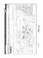
- FIG. 4is a diagram of a third water sensing assembly installed on a pipe, according to various embodiments of the present disclosure.
- FIG. 5is front cross-sectional view of the third water sensing assembly of FIG. 4 , according to various embodiments of the present disclosure.
- FIG. 6is a partial cross-sectional side view of the third water sensing assembly of FIG. 4 , according to various embodiments of the present disclosure.
- FIG. 7is an exploded view of a communication assembly of the third water sensing assembly of FIG. 4 , according to various embodiments of the present disclosure.
- FIG. 8is a cutaway side view of a water sensing assembly of FIG. 3B in a multi-port service saddle, according to various embodiments of the present disclosure.
- FIG. 9is a cutaway side view of the second water sensing assembly of FIG. 3B in the multi-port service saddle of FIG. 8 in a power generation mode, according to various embodiments of the present disclosure.
- FIG. 10is a chart showing sampling rate, log rate, and upload rate, according to various embodiments of the present disclosure.
- FIG. 11is a screen view of a user interface for enabling a user to sign in with a server, according to various embodiments of the present disclosure.
- FIG. 12is a screen view of a user interface showing a map of the locations of installed sensors, according to various embodiments of the present disclosure.
- FIG. 13is a screen view of a user interface showing the map of FIG. 12 with information about a sensing device superimposed, according to various embodiments of the present disclosure.
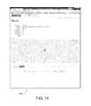
- FIG. 14is a screen view of a user interface showing further details of a sensing device, according to various embodiments of the present disclosure.
- FIG. 15is a screen view of a user interface for enabling a user to edit parameters of a sensing device, according to various embodiments of the present disclosure.
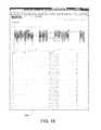
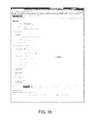
- FIG. 16is a screen view of a user interface showing a graph and a table of measurements logged by a sensing device, according to various embodiments of the present disclosure.
- FIG. 17is a screen view of a user interface for enabling a user to edit measurements, according to various embodiments of the present disclosure.
- FIG. 18is a screen view of a user interface for enabling a user to edit user information, according to various embodiments of the present disclosure.
- the present disclosuredescribes systems and methods for measuring properties of water within a water distribution system at multiple locations throughout the water distribution system.
- the present disclosurealso describes sensors that may be installed in the water distribution system for one or more clients (e.g., water utility companies).
- the sensorsmay be configured to generate energy from the water itself to power its internal circuitry.
- the sensorsmay be tapped into the side of a pipe or installed at any location in the system.
- the water property measurementsmay be logged in the sensors and periodically uploaded to a server using a wireless communication network. Measurements may also be uploaded on demand in some embodiments.
- the serverwhich may be a web server, maintains the measurements in a database. Clients may access the measurements to view the readings during various time periods. Also, the clients may request a substantially real-time measurement.
- FIG. 1Ais a block diagram illustrating an embodiment of a system 100 for managing data related to properties of water in a water distribution system.
- the system 100comprises a sensing device 102 , a web application 104 , and a client system 106 .
- the system 100includes a single sensing device 102 and a single client system 106 .
- the system 100may include any number of sensing devices 102 installed in various locations in the water distribution system.
- the system 100may include any number of client systems 106 for any number of clients.
- the multiple client systems 106may be connected to the web application 104 through a communication network.
- multiple sensing devices 102may be used to monitor water properties at various locations within one or more water distribution systems for multiple clients, and the clients can access their respective sensor readings through the web application 104 .
- the sensing device 102 of the current embodimentcomprises, among other things, a sensor 110 (e.g., a pressure sensor), a battery 112 , and an antenna 114 .
- the sensing device 102may include any suitable type of sensor 110 for sensing various characteristics of water within a water distribution system.
- the sensor 110may be a pressure sensor for measuring water pressure at a particular location in the water distribution system, a flow rate sensor for measuring the rate that water is flowing through the particular location of the water distribution system, a chlorine sensor for measuring the chlorine content of the water at the location, or other types of sensors.
- the battery 112may include any suitable type of battery or batteries for providing power to the sensor 110 and other electronics of the sensing device 102 .
- the sensing device 102may include a power generation device that harvests energy from the flow of water.
- the power generation devicemay be configured to recharge the battery 112 , supplement the power of the battery 112 , or even replace the battery 112 .
- the antenna 114is configured to wirelessly transmit properties of water that are sensed by the sensing device 102 to the web application 104 .
- the sensor datamay be transmitted over any suitable type of wireless network 116 , such as, for example, a cellular network, radio frequency (RF) channels, Wi-Fi, Bluetooth, etc.
- a receiver on the wireless network 116is configured to convert the sensor data signals to allow transmission over a data network 118 using any suitable protocol, such as the Hypertext Transfer Protocol (http), Transmission Control Protocol (TCP), Internet Protocol (IP), or other communication protocol.
- the data network 118may include a wide area network (WAN), such as the Internet, and/or may include local area networks (LANs).
- WANwide area network
- LANslocal area networks
- the web application 104 as shown in FIG. 1Amay be configured on a server, such as a web server, or a group of servers.
- the web application 104may be associated with a data management company that provides a service to its clients for managing the clients' sensor data.
- multiple clientse.g., water distribution companies
- the clientscan customize how the water properties for the pipes in their system are to be sensed. They can also customize how the information about the sensor data can be accessed. They can also customize how they will be contacted if the sensor data reveals a warning or critical condition.
- FIG. 1Aonly one client system 106 is shown, but it should be understood that multiple client systems 106 may be configured in the system 100 to access the server on which the web application 104 is running.
- FIG. 1Bis a block diagram illustrating an embodiment of a system 150 for measuring properties of water and managing the measurement data.
- the system 150includes a plurality of sensing devices 152 that are distributed throughout an area and are installed to be in contact with water within a water distribution system.
- the sensing devices 152are installed and put into service to allow them to take measurements of the water at their particular location and wirelessly communicate the measurement data to a cell tower 154 or other wireless communication device for receiving wireless signals, such as a Wi-Fi or Bluetooth receiver.
- multiple cell towers 154 or receiversmay be incorporated in the system 150 .
- the system 150 of FIG. 1Balso includes a network 156 , which enables communication from a wireless communication protocol, or other communication channel protocol, to a data network protocol.
- the network 156enables the measurement data received by the cell tower 154 to be transmitted to a server 160 .
- the server 160may be one or more computer systems for managing the measurements of water properties.
- the server 160may be a web server for providing a web site for clients to access if authorized.
- the system 150also includes client devices 162 , which may include desktop computers, wired or wireless laptop devices, smart phones, or other computer system.
- the client devices 162may include computer systems for any number of clients. Also, it should be known that any number of client devices 162 may be used for each client.
- FIG. 1Cis a block diagram of an embodiment of the server 160 shown in FIG. 1B .
- the server 160comprises a processor 170 , a memory 172 , an interface 174 , and the database 122 .
- the database 122may be separate from the server 160 .
- the processor 170is configured to control the operations of the server 160 .
- the server 160may execute certain functions that may be stored in software and/or firmware and execute functions that may be configured in hardware.
- the memory 172in some embodiments, may comprise the web application 104 and the API 126 .
- the interface 174in some embodiments, may comprise the browser interface 124 .
- the interface 174may be a network interface for interfacing with the client devices 162 via the network 156 .
- the web application 104may comprise at least a web site 120 , a database 122 , a browser interface 124 , and an Application Programming Interface (API) 126 .
- the web application 104 , database 122 , browser interface 124 , and API 126may be contained within the server 160 .
- the web site 120provides various web pages and screen views (as explained below) to a user on the client system 106 or client devices 162 .
- the database 122is configured to store the data retrieved from the sensing devices 102 , 152 .
- the database 122may be arranged to securely separate the data for one client from another. In some embodiments, multiple databases 122 may be used.
- the browser interface 124enables a user on the client system 106 to access the web site 120 and obtain sensor data formatted in an organized way, as described below.
- the API 126provides an interface for the client system 106 to access the web application 104 .
- the web application 104with the web site 120 , browser interface 124 , database 122 , and API 126 , may be configured in one package, such as in a single server (e.g., server 160 ).
- the web site 120can take requests from authorized clients, search the database 122 , and send information back to the clients.
- the clientsmay wish to request a certain reading at a certain time and date.
- the log in the database 122 that is closest to that time and datecan be retrieved from the database 122 and sent to the SCADA system.
- the web site 120may be configured to include two different types of retrieval techniques for the clients' use.
- the first techniqueis a simple Read, while the second technique is referred to ReadX.
- Readthe client may make requests for data, and in response the data log is retrieved and sent back to the client. In this case, the data is merely read from the database 122 and remains in the database 122 without any change to the data entry.
- a ReadX commandallows a client to request data. Again, the data is retrieved and sent to the client. In this case, however, the web application 104 checks to ensure that the client has indeed received the data. For example, the API 126 may request for an acknowledgement from the client that the records were received successfully. When the client system 106 receives the data successfully and stores this data in its own database, it sends an acknowledgement (ACK) receipt back to the web application 104 . When the API 126 receives this ACK receipt signal, the web application 104 erases that data from the database 122 .
- ACKacknowledgement
- ReadX commandfor example, is for security. Certain clients may not want their data to be stored on another database that does not belong to them. This may also be beneficial for the data management company that owns the server 160 or web application 104 , because the owner may be released from any liability associated with the other party's information. In this respect, the client can be able to hide or manage their proprietary data any way they see fit.
- the client system 106 or client device 162may include any suitable communication device capable of transmitting and receiving http or other data transmissions.
- the client system 106 or client device 162may be a personal computer, laptop computer, tablet computer, or other computer systems.
- the client system 106 or client device 162may also include portable electronic communication devices, such as cell phones, smart phones, or other mobile devices that may utilize a cellular network, data network, or other types of networks.
- the client system 106 or client device 162may include its own database for storing sensor data retrieved from the web application 104 .
- the client system 106 or client device 162may be a Supervisory Control and Data Acquisition (SCADA) system.
- SCADASupervisory Control and Data Acquisition
- the client system 106 or client device 162may also be configured to contain a user interface that allows a user to see web pages of the web application 104 , as described below with respect to FIG. 11-18 .
- the system 100may be a multi-tenant system for managing sensors for multiple clients.
- the system 100may be configured to show only the sensor devices for each particular client when a client signs in. Thus, each client is only able to see their own sensors and not the sensor of other clients.
- a master devicemay be connected in the system 150 to allow a user to access information for all the sensors.
- the master devicemay be the server 160 that run the web application 104 or may be computer system connected directly to the server 160 . In some respects, the master device may be operated by a city or county government for monitoring the water distribution systems in their jurisdictions.
- the system 100gives clients an inexpensive product that can be employed relatively easily on the part of the client.
- the system 100allows a client (e.g., water utility company) to sign up with a service that provides a combination of water monitoring functions all in one package.
- a cliente.g., water utility company
- the server 160 associated with the web application 104may be configured with a system health monitoring module 180 .
- the system health monitoring module 180may be configured in software, hardware, and/or firmware.
- the system health monitoring module 180may be configured to evaluate the health of the water distribution system using an empirical method of analyzing many data points.
- the system health monitoring module 180may be neural network for determining whether values are within a normal range.
- the data pointsmay be evaluated based on their location in the water distribution system and based on the time of day when the measurements were taken.
- the system health monitoring module 180may use statistical analysis to determine if certain points are abnormal or unhealthy with respect to baseline data points established for a normal or healthy system.
- the system health monitoring module 180may use the Mahalanobis-Taguchi System (MTS) for determining the health of the system.
- MTSMahalanobis-Taguchi System
- the MTSuses pattern recognition to analyze multi-variate data.
- the system health monitoring module 180can analyze values with respect to norms based on the MTS model. Not only does the MTS model diagnose the norms, but it can also include a predictive method for analyzing patterns in multivariate cases.
- the system health monitoring module 180may analyze both location-dependent and time-dependent data. For example, a water flow rate at 4:00 pm at a certain location in the water distribution system may have a certain normal range based on multiple measurements taken at this time. When values are outside of this range, the system health monitoring module 180 can instruct the interface 174 to provide an alert to the client. In some embodiments, the system health monitoring module 180 may process data stored in the database 122 from multiple sensors and consider all the parameters when diagnosing health.
- the server 160is also configured to read data in real time, perform hydraulic simulation in real-time, and recommend a pump power level in real-time.
- the server 160may also read data, perform hydraulic simulation, and control the pump power level.
- the server 160may also be configured to detect leaks in the main when the pressure matrix is abnormal.
- FIG. 2is a cutaway side view of a water sensing assembly 200 , according to various embodiments of the present disclosure.
- the water sensing assemblyincludes a housing 210 enclosing a battery pack 220 , a generator 230 , a pressure sensor 240 , and measurement and communication electronics 250 .
- An antenna 260is mounted to the exterior of the housing 210 .
- Extending from a lower end of the housing 210is a turbine 270 .
- the turbine 270is a vertical axis turbine in the current embodiment, and is coupled to the generator 230 by a turbine shaft 275 extending through a sealed shaft bore 277 and a seal partition 279 to connect with a generator shaft 235 of the generator 230 .
- the turbine 270is may be indirectly coupled to the generator, such as with magnets, so that the turbine 270 may be fully separated from a sealed interior of the housing 21 .
- the pressure sensor 240is mounted within the housing 210 such that the pressure sensor 240 extends through the seal partition 275 to partially expose pressure sensor 240 to fluid flow along the lower end of the housing 210 , which may travel around turbine 270 into the lower interior of housing 210 .
- the pressure sensor 240communicates fluid pressure readings to measurement and communications electronics 250 , which may process, store, and/or communicate the date through antenna connection 260 .
- the measurement and communications electronics 250 , pressure sensor 240 , and antenna 260are powered by battery pack 220 , which is recharged by generator 230 .
- the water sensing assembly 200is a self-contained, removable sensing unit that may be tapped into a fluid pipe or other valve through a tap or bore.
- the turbine 270is situated such that the turbine 270 is within the fluid path of the fluid passing through the fluid pipe.
- the fluid flowthereby turns the turbine 270 , turning the generator shaft 235 , causing the generator 230 to generate a current to recharge batter pack 220 .
- the presence of the turbine 270 and generator 230 attached to the battery pack 220allows the battery pack 220 to last longer, giving the water sensing assembly 200 a longer life to detect sensing data.
- the pressure sensor 240may be replaced by various other sensors in various embodiments, such as chlorine or flow sensors.
- FIG. 3Ais detail view of the shape of a vertical axis turbine 370 .
- the vertical axis turbine 370includes two wings 372 a,b , each wing having a curved profile and extending in opposite spirals on either side of a central turbine axis 374 .
- fluidflows in against vertical axis turbine 370 in a direction 376 orthogonal to the central turbine axis 374 , fluid pushes wings 372 a,b such that the vertical axis turbine 370 spins about central turbine axis 374 .
- FIG. 3Bis a perspective view of a second water sensing assembly 300 , according to various embodiments of the present disclosure.
- the water sensing assembly 300includes a housing 310 , a mounting bracket 320 , mounting bracket fasteners 325 , power wires 330 , and a turbine 340 .
- the housing 310is coupled to the mounting bracket 320 , and power wires 330 extend through a wiring bore 322 defined in the mounting bracket 320 into housing 310 .
- FIG. 3Cis another cutaway side view of the second water sensing assembly 300 of FIG. 3B , according to various embodiments of the present disclosure.
- a generator 350is mounted within the housing 310 similarly to generator 230 .
- the turbine 340extends from a lower end of the housing 310 similarly to turbine 270 .
- the turbine 340is a vertical axis turbine in the current embodiment, and is coupled to the generator 340 by a turbine shaft 345 extending through a sealed shaft bore 347 and a seal partition 349 to connect with a generator shaft 355 of the generator 350 .
- a side bore 380is defined in the housing 310 below seal partition 349 so that fluid may flow around turbine 340 to side bore 380 .
- the turbine 340is may be indirectly coupled to the generator, such as with magnets, so that the turbine 340 may be fully separated from a sealed interior of the housing 310 .
- the power wires 330may be directly connected to the generator to power sensing, communication, process, data storage, and other electronic equipment.
- a pressure sensor or other sensormay be mounted within the housing 310 similarly to pressure sensor 240 within housing 210 .
- the mounting bracket 320may mount the water sensing assembly 300 on any sort of sensing, tapping, or boring equipment.
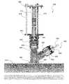
- FIG. 4is a diagram of the water sensing assembly 400 of FIG. 2 installed on a pipe, with various partial cross-sectional views of parts of the water sensing assembly 400 and the surrounding environment, according to various embodiments of the present disclosure.
- the water sensing assembly 400is buried underground in the current embodiment such that it extends from a pipe 410 to a ground surface 420 , such as a road.
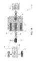
- FIG. 5is front cross-sectional view of the water sensing assembly 400 of FIG. 4 , according to various embodiments of the present disclosure.
- the water sensing assembly 400includes a valve box 1 mounted over pipe 4 .
- a saddle 15connects ball valve 6 to the pipe 4 , and a reducer 5 couples a pressure sensor 7 to the ball valve 6 .
- Wiring 11runs up through the valve box 1 to a communication assembly 17 .
- the communication assembly 17may contain processing, data storage, and power equipment in various embodiments to store, communicate, and receive orders based on data received from the pressure sensor 7 .
- the communication assembly 17is connected by a wire 14 to an antenna 2 mounted on an iron cap 18 , the iron cap 18 itself mounted on an adjustable top 3 .
- the adjustable top 3connects to the valve box 1 , forming an enclosure extending from ground surface 420 to the top of pipe 410 to protect the enclosed equipment.
- the adjustable top 3can be adjusted telescopically to vary the overall height of the water sensing assembly 400 , based on the depth of the pipe below ground level.
- Other sensorsmay be used with water sensing assembly, such as chlorine or flow sensors.
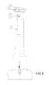
- FIG. 6is a partially cutaway side view of the water sensing assembly 400 of FIG. 4 , according to various embodiments of the present disclosure.
- the communication assembly 17is mounted to the iron cap 18 by a hanging bracket 16 .
- the communication assembly 17is configured to receive measurement signals from the and transmit the signals from antenna 2 of the sensor assembly.
- the signalsare transmitted to the web application 104 via the cellular network 116 or 154 .
- the antenna 2may be configured for Global System for Mobile (GSM) communication using a cellular network, Code Division Multiple Access (CDMA) communication, or can be used with other types of communication networks and protocols.
- the communication device 17may include a plug-in for Wi-Fi, Bluetooth, or other short range communication.
- FIG. 7is an exploded view of the water sensing assembly 400 of FIG. 4 , according to various embodiments of the present disclosure.
- the water assembly 400includes two flat washers 8 , lock washer 9 , two hex nuts 10 , hanging bracket 16 , machine screw 12 , and jam nut 13 , the combination of which mounts communication assembly 17 to iron cap 18 .
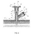
- FIG. 8is a cutaway side view of a water sensing assembly 300 mounted in a multi-port service saddle 800 on a pipe 810 , according to various embodiments of the present disclosure.
- the multi-port service saddle 800includes a main port 820 and a secondary port 830 .
- a ball valve 840is mounted in main port 820 and a ball valve 850 is mounted in secondary port 830 .
- Ball valve 840includes a ball bore 842 and ball valve 850 includes a ball bore 852 , each of which may be turned to open and close main port 820 and secondary port 830 , respectively.
- the ball valve 840is closed and the ball valve 850 is open.
- a lower end 860 of the multi-port service saddle 800defines a lower opening 862 , which is aligned with a bore 812 in the pipe 810 .
- the multi-port service saddle 800is mounted to the pipe exterior with the ball valve 840 open and the ball valve 850 closed.
- a tapping machineis mounted to main port 820 and is pushed down through main port 820 to form bore 812 .
- the tapping machineis then pulled out of ball valve 840 into a pre-insertion position and ball valve 840 is closed.
- Water sensing assembly 300may then be mounted to multi-port service saddle as shown in FIG. 8 .
- water sensing assembly 300is mounted to a port bracket 890 coupled to main port 820 . Insertion screws 870 extend between mounting bracket 320 and port bracket 890 , with turbine 340 and housing 310 pre-inserted into main port 820 .
- a sensor cap 880is shown coupled to secondary port 830 and including a sensor 882 .
- Sensor 882can be any sensor for fluid data collection, such as a pressure sensor, chlorine sensor, or flow sensor. While the water sensing assembly 300 is mounted outside ball valve 840 , fluid may flow into multi-port service saddle 800 to secondary port 830 where the fluid may be sensed by sensor 882 .
- FIG. 9is a cutaway side view of the second water sensing assembly 300 in a power generation mode, according to various embodiments of the present disclosure.
- ball valve 840is opened and insertion screws 870 are tightened to pull mounting bracket 320 towards port bracket 890 .
- mounting bracket fasteners 325fasten mounting bracket 320 to port bracket 890 .
- water sensing assembly 300may be inserted to various degrees within main port 820 such that turbine 340 may be partially presented at varying depths to fluid flow within pipe 810 , which may lessen the speed at which turbine 340 turns, generating less power and allowing for a customizable level of power generation based on known fluid flow and power needs.
- Moving mounting bracket 320 towards port bracket 890inserts housing 310 and turbine 340 into main port 820 such that turbine 340 extends down through lower opening 862 bore 812 into fluid flow within pipe 810 , thereby turning turbine 340 and generating current to power various equipment or recharge batteries.
- fluid flowmay pass up through side bore 380 so that sensor 882 may continue to sense fluid conditions within pipe 810 .
- Turbine 340may be removed from the fluid path within pipe 810 by use of insertion screws 870 to move mounting bracket 320 away from port bracket 890 . This may be necessary if, for instance, a pig is sent down the pipe 810 to clean the system and it is desired to prevent damage to turbine 340 .
- FIG. 10is a chart showing an exemplary sampling rate, log rate, and upload rate related to sensing water properties.
- the sensing assemblymay be configured to remain in a sleep mode until it is configured to wake up and take a sample reading.
- the sampling ratemay include sampling once every 15 seconds.
- the log ratemay be set, for example, at about once every 15 minutes.
- the processing device of the sensor assemblymay be configured to store only the samples that are the highest value and the lowest value. Measurements in between the high value and low value during that log interval may be discarded. When a new high or new low value is sampled, it replaces the old value. In this sense, only two values are stored during each log interval.
- the processing devicestores the high and low value for that interval in memory. Therefore, at the log rate (e.g., once every 15 minutes), two values are stored or logged.
- the sensor assemblyrepeats the logging at the log rate until it is time for uploading as determined by the upload rate. In one example, the upload rate may be about once per day. This is the rate at which the sensor assembly uploads the log information via the antenna 114 to the server 160 .
- the sensor datadoes not consume much memory within the sensor assembly, only the high and low values for each log interval.
- the upload ratemay be set to upload not very often (e.g., once a day), which can conserve battery life versus uploading after every reading.
- the sensor and communication device 17may be in a sleep mode and then wake up only to sense and upload data. For example, with these rate settings, a battery may last about seven years or longer.
- the sampling rate and log ratemay be set to the same rate.
- a clientmay request such a set-up if they wish to view the data in more detail and have access to the data at any time.
- the cellular modemmay be placed in a low-power mode and listen for a signal, such as an SMS message from the client. In this way, the client can get a substantially real-time measurement.
- the sensor assemblyis waken up, regardless of the sampling rate times, and takes a reading.
- the communication devicesends the newly taken reading, or, in some embodiments, may send the high and low readings of a current logging interval, to the web application 104 .
- the web site 120can then communicate that data directly to the client, via e-mail, SMS, or other communication channel.
- this strategymay increase the battery usage compared with normal operations. This may cut the battery life to about two years.
- the clientmay be given options to choose between different types of plans for receiving sensor data. For example, the client may wish to have access to data under normal operations, with the uploaded data being available the following day.
- the second optionmay be the substantially real-time plan.
- the processing devicemay analyze the data to see if it falls within a normal range of values. If so, then nothing needs to be done, except store the values if they are highs or lows for the period. Otherwise, if the values are not within normal range, the communication device sends an alert to the web site 120 .
- the modemis waken from sleep mode and instructed to transmit the details of the out-of-range measurement.
- the web site 120may be configured to check the reading with the client's settings to find out what type of notification they wish to receive when such a condition occurs. The web site 120 may then send an SMS message, e-mail, or other type of message to inform the client of the condition.
- FIGS. 11-18show examples of various screen views of web pages that may be displayed on a user interface, such as the user interface of the client system 106 .
- the web pagesmay be part of the web site 120 shown in FIG. 1 that allows a client to access the data stored in the database 122 .
- the web pagesare designed to provide an organized and easy to understand display for the users.
- FIG. 11is an example of a screen view of a web page that may be displayed on a user interface 1100 for enabling a user to sign up to receive a service for viewing water property data.
- a new usersigns up or registers with the web server.
- the web servermay include the one or more web servers that are configured to run the web application 104 shown in FIG. 1 .
- the user interface 1100may be displayed on a screen, display, monitor, or other visual indication device of the client system 106 .
- the user interface 1100allows a user to sign up using an e-mail address, password, first name, last name, and mobile phone number.
- the sign up user interface 1100includes an entry window for a “service contract number.”
- the service contract numberis a number that is set up for a particular client that has a service contract with the company that manages the web application 104 shown in FIG. 1 .
- a clientmay allow its associates or employees to also sign up to gain access under the respective service contract number.
- the user interface 1100also includes entry windows for time zone, street address, city, state, and zip code. This can be the information for the location of the client (e.g., water distribution company).
- the user interface 1100includes four selectable boxes that allow the new user to set up the types of ways that the user may be contacted if a warning condition or critical condition occurs.
- the usermay choose to receive a text message (e.g., a Short Message Service (SMS)) message or other type of electronic message on a portable electronic device.
- SMSShort Message Service
- the usermay also choose to receive an e-mail message for warning or critical conditions.
- a warning conditionmay be a condition that if untreated may lead to problems with the water distribution system
- a critical conditionmay be a condition that indicates a more severe problem, such as pipe that has burst.
- One method for initiating a new contractmay include the following.
- the data managing companyprovides a service contract number to a new client. They also send the client a URL and instructions on how to set up an account.
- the URL and instructionsare contained in an e-mail that is sent to the client.
- a contact persone.g., a boss
- He or shemay also send the URL and instructions to other in the company so that they too can set up a profile.
- the additional profileswill include the personal information for the other people (e.g., employees) and will also include the same service contract number for that company.
- Each individual in the companycan therefore choose the types of notifications they receive when a warning condition or critical condition is sensed.
- FIG. 12is an example of a screen view of a web page that may be displayed on a user interface 1200 showing a map of sensing device locations.
- the mapmay be any suitable map of an area where a client's sensing devices are installed. Sensors may be installed in any part of the water distribution system, such as on main pipes, secondary pipes, neighborhood pipes, residential pipes, etc.
- the mapmay be provided by Google Maps or other online mapping service.
- icons 1202are configured to display the locations of the sensor devices 102 . As shown in this figure, five icons are displayed, representing five different sensor devices 102 . It should be understood that the map may show any number of icons 1202 , depending on how many sensor devices are installed and placed in service. The icons 1202 can each include a number for distinguishing one sensor from another. If a user selects one of the icons, such as by hovering a mouse icon over an icon 1202 , clicking an icon 1202 , tapping an icon 1202 on a touch-sensitive screen, or by other entry methods, the web site 120 may be configured to bring up a new page, such as the page described with respect to FIG. 13 .
- the icons 1202can be displayed in different ways to indicate various conditions of the sensor. For example, if the sensor senses a warning condition, the icon 1202 may be displayed in a different way from a normal condition. In one embodiment, the icons 1202 may be green if they measurements are within a normal range, but may be changed to yellow or red if the measurements indicate a warning or critical condition. Other than changing color to indicate condition, the icons 1202 can also be displayed in other ways, such as by changing the size or shape of the icon 1202 , or by flashing the icon 1202 , or other means of distinguishing an abnormal condition from a normal one.
- the user interface 1200may be configured to show different types of sensors. For example, if a client has any combination of pressure sensors, flow rate sensors, chlorine sensors, etc., each type of sensor may be displayed differently. As an example, the different types may be distinguished by using different colors (e.g., blue, green, black, etc.) for the icons. The different sensors may also be shown with icons of different shapes (e.g., circle, square, triangle, etc.).
- FIG. 13is an example of a screen view of a web page that may be displayed on a user interface 1300 showing a map of sensing locations with information about a sensing device superimposed.
- the information for the selected sensoris displayed in a box 1302 , representing a device condition window.
- the informationmay include a current reading for that sensor.
- the sensing deviceis a pressure sensor
- the readingmay give a value in units of pounds per square inch (psi).
- the illustrated exampleshows a current pressure of 40.0 psi.
- the box 1302may display “Chlorine Content” with the reading.
- the numbersmay be highlighted in a particular way to draw attention to it. For example, the number may appear in yellow if the reading is within a warning level and may appear in red if it is within a critical condition. Also, green may be a color used to indicate that the reading is normal.
- the box 1302may also include a phone number of the device 102 , which may be the cellular number used to communicate the data to the cellular network 116 .
- the box 1302may also include an address of the device 102 .
- the superimposed box 1302may also include a first link to “Device” and a second link to “Measurements.”
- the first linkallows a user to navigate to another web page, such as the web page described with respect to FIG. 14 .
- the second linkallows the user to navigate to yet another web page, such as the web page described with respect to FIG. 16 .
- FIG. 14is an example of a screen view of a web page that may be displayed on a user interface 1400 showing further details of a sensing device.
- this web pagemay be displayed when the user selects the “Devices” link shown in FIG. 13 or when the user navigates to the page by some other route.
- the user interface 1400shows more details of the particular sensing device highlighted at an earlier time.
- the device informationmay include the phone number, a description of its location, latitude and longitude information, high warning level, critical high level, low warning level, and critical low level.
- the informationmay also include a reading of a particular property (e.g., pressure).
- the measurement valuee.g., pressure
- the measurement valuemay be highlighted in any suitable way if the value is outside of the range indicated by the high and low warning levels or outside the range indicated by the high and low critical condition levels.
- the high warning level, critically high level, low warning level, and critically low levelmay be set by the client, having an understanding of the nature of the various pipes throughout the water distribution system.
- a high warning level of 110.0 psiis a level that the client knows may be an indication of a problem that should likely be investigated.
- a critically high level of 150.0 psiis likely an indication that a pipe is about to burst.
- a low warning level of 40.0 psimay indicate a small leak in the pipe, and a critically low level of 30.0 psi may indicate a larger leak that likely needs to be attended to immediately.
- the clientmay need to notify its customers of a “boil” notice that water may be engraphed with contaminates.
- a “status” outputmay also be displayed. If status is normal, the output may be blank, but if the status is a warning or critical, the status indication may be changed to show such conditions. For example, the status may change to a different color, may blink, or may include some other type of highlighting feature. In one embodiment, for a warning, the status output may be displayed yellow, and for a critical condition, the status output may be displayed red.
- FIG. 15is an example of a screen view of a web page that may be displayed on a user interface 1500 for enabling a user to edit parameters of a sensing device.
- the usercan change the description, which may include location information of the device.
- the usercan also change the latitude and longitude information, and the high and low warning and critical condition levels.
- the usercan click on the “update device” button.
- the phone number boxmay not be available to the client but may only be available for users of the management company.
- FIG. 16is an example of a screen view of a web page that may be displayed on a user interface 1600 showing a graph and data points representing measurements by a sensing device.
- This web pageshows measurement data from one sensor over certain time periods. The user may select time periods of 1 day, 2 days, 5 days, 1 week, 2 weeks, 1 month, 6 months, 1 year, or all.
- the graph section of the web pageshows the high and low points for each day.
- the data point sectionshows the reading (e.g., pressure), notes (if any), and the time when the measurement was taken.
- This web pagealso gives the user an option to edit or annotate a particular record by pressing the “edit” button on the same line as the record.
- the data points in the graph and in the tablemay be highlighted in any suitable way to indicate when a measurement is outside a range of normal limits.
- the date points or measurement readingsmay be given a different color, size, shape, or other distinctive feature to indicate abnormal conditions.
- FIG. 17is an example of a screen view of a web page that may be displayed on a user interface 1700 for enabling a user to edit measurements.
- the web site 120navigates the user to the user interface 1700 .
- the usercan enter a note that is saved with the particular data record.
- the userwishes to annotate a low pressure reading that occurred when the client was aware that a pipe was broken.
- the userenters a message, such as “Main Pipe was broken.”
- the userselects the “update measurement” button.
- the “destroy” buttonmay not be available or may be available to a limited extent. The purpose of the destroy button is to remove the particular sensor from the system and/or ignore any readings or communications from the sensor.
- FIG. 18is an example of a screen view of a web page that may be displayed on a user interface 1800 for enabling a user to edit user information.
- the user interface 1800 in this exampleis similar to the user sign-up page shown in FIG. 11 .
- a usercan access this page using the “Edit Profile” link on any of the user interfaces shown in FIGS. 12-18 .
- the usercan edit any information, such as e-mail, address, password, or other personal information.
- the usercan also edit the ways that the user will receive warnings from the system 100 . For example, if the user decides that he or she wants to receive both an SMS message and an e-mail when there is a critical condition, the user can check the appropriate boxes.
- the server 160may be part of the utility company (e.g., water utility company) and provide communication with other users via the communication network.
- the servermay be part of a company responsible for managing the utility measurement data.
- the communication network in these embodimentsmay be a local area network (LAN), wide area network (WAN), such as the Internet, or any other suitable data communication networks.
- the communication networkmay also include other types of networks, such as plain old telephone service (POTS), cellular systems, satellite systems, etc.
- POTSplain old telephone service
- the server 160may detect extreme events and provide an alarm in response.
- the alarmmay be in the form of an automated e-mail, a pop-up window, an interrupt signal or indication on a computer of the client device 162 , SMS, or other suitable message signifying an urgent event.
- the client system 106may include a computer system used by the utility provider.
- the utility provider systemmay be a client of the data management company that manages the utility measurement data and/or provides monitoring services regarding the status of the utility infrastructure.
- the client systemtherefore, may be able to receive and review status updates regarding the infrastructure. Alarms may be provided to the client system, which may then be acknowledged and confirmed.
- the client systemmay also receive historic data and manage the client's accounts and usage information. In some embodiments, information may be provided to the client system in a read-only manner.
- the sensing devices 152 and client devices 162may communicate with the server 160 by a cellular service, via cellular towers and/or satellites.
- the wireless communication between the devicesmay be active during some periods of time (when two respective devices are linked) and may be inactive during other periods of time (when the devices are not linked and/or are in sleep mode).
- any of the sensing devices 152may be connected to the network 156 through wired connections.
- the water mainsmay include transmission mains, which may include water pipes having an inside diameter of at least twelve inches.
- the water mainsalso include distribution mains, which may include smaller pipes having an inside diameter of less than twelve inches.
- the transmission mainshaving a greater size, may be configured to allow a greater amount of water flow in comparison with the distribution mains.
- the transmission mainsmay be located nearer to the utility source and the distribution mains may be located farther from the utility provider. In some systems, distribution mains may be located along secondary roads or residential roads.
- the cellular network 116may include relay devices (e.g., using ISM frequency transmission) for relaying radio signals from the cell towers 154 to the data network 156 .
- the network 156in some embodiments may also include the cellular network 116 , a satellite network, a radio network, a LAN, a WAN, or any other suitable network.
- the sensing devices 152may comprise printed circuit board with the components of a sensor interface, processing device, and communication device incorporated on the printed circuit board.
- multiple printed circuit boardsmay be used with the components of the sensor interface, processing device, and communication device incorporated on the boards in any suitable configuration.
- standoffsmay be used as needed.
- Connectorsmay be used to couple the processing device with the sensor interface and communication device.
- the sensor assemblymay include any combination of sensors for detecting various parameters that may be analyzed.
- the sensor assemblymay include one or more piezoelectric sensors, acoustic sensors, acoustic transducers, hydrophones, pressure sensors, pressure transducers, temperature sensors, accelerometers, flow sensors, chlorine sensors, leak detectors, vibration sensors, or other types of sensors.
- the power supply of the sensor assemblymay contain one or more batteries, solar-powered devices, electrical power line couplers, or other power sources. When external power is received, additional connectors or ports may be added through the walls of the enclosure. When batteries are used, the power supply may also include a battery capacity detection module for detecting the capacity of the one or more batteries. In some embodiments, the power may be partially or completely supplied by the energy harvesting device housed on the sensor assembly itself.
- a sensor interfacemay be incorporated in the sensor assembly.
- the sensor interfacemay be configured to acquire the acoustic, pressure, and/or temperature data from the sensor assembly.
- the sensor interfacemay include amplification circuitry for amplifying the sensed signals.
- the sensor interfacemay also include summing devices, low pass filters, high pass filters, and other circuitry for preparing the signals for the processing device.
- the sensor assemblymay also include a processing device configured to log the measurement information and save it in memory until a designated upload time or when requested by a client.
- the communication device of the sensor assemblymay include a modem, such as a cellular or ISM-enabled modem to provide network access to the communication device. Also, the communication device may include a tuning module, such as a GPS timing receiver, for providing an accurate timing reference and for synchronizing timing signals with other elements of the cellular network 116 .
- the communication devicemay be configured to transmit and receive RF signals (e.g., ISM frequency signals), cellular signals, GPS signals, etc., via the antenna 114 .
- the processing device housed in the sensor assemblymay include a processor, a sensor data handling device, a power assembly, a communication module, a time/sleep module, a data processing module, a health status detecting module, and a storage module.
- the processormay comprise one or more of a microcontroller unit (MCU), a digital signal processor (DSP), and other processing elements.
- the sensor data handling deviceconnects with the sensor interface and handles the sensor data to allow processing of the signals by the processor.
- the power assemblymay comprise a power source, which may be separate from the power supply. In some embodiments, however, the power assembly may be connected to the power supply. The power assembly may also be configured to control the voltage and current levels to provide constant power to the processor. In some embodiments, the processor may be provided with about 3.3 volts DC.
- the communication moduleconnects with the communication device and receives and/or sends signals for communication through the communication device. In some embodiments, the communication device may include a GPS device for receiving timing samples for synchronization purposes. The timing samples may be forwarded to the communication module to allow the processing device to be synchronized with other devices. The timing samples may also be used to wake up the processing device when needed or sleep when inactive.
- the processing devicealso includes a time/sleep module for providing timing signals to the processor and may include a crystal oscillator.
- the time/sleep modulealso controls sleep modes in order to minimize battery usage when the sensor assembly is not in use.
- the processormay include an MCU that operates continually and a DSP that sleeps when not in use. Since the DSP normally uses more power, it is allowed to sleep in order to conserve battery power.
- the time/sleep modulemay be configured to wake various components of the processor at designated times in order that sensor data stored during a previous time may be transmitted to the host.
- the time/sleep modulemay wake the sensor assembly at a certain time during the day, enable the sensor assembly to analyze and record the measurements, return to a sleep mode according to the sampling rate, and repeat the analysis every 15 seconds or so for about 15 minutes.
- the communication devicesends the data to the server 160 and the time/sleep module returns the device to a sleep mode until the next designated time.
- the time/sleep modulemay be configured to wake up the processor in the event that a warning or critical condition has been detected.
- the storage module of the sensor assemblymay include flash memory, read-only memory (ROM), random access memory (RAM), or other types of memory.
- Pressure sensorsmay be used in particular to measure an absolute pressure value. Also, pressure sensors may be used as a burst sensor. In this respect, the sensor may measure a high-speed pressure transient profile. Both the pressure change value and absolute pressure value may be useful for different applications.
- the sensor(s)may measure voltage signals or frequency measurements. Temperature sensors may also be used for measuring the temperature of the pipe. The sensed waveform signals are supplied to the processing device, which may process the signals at the point of measurement. In other embodiments, the signals may be transmitted to the host for processing.
- the functions of the sensor assemblymay be configured in software or firmware and the functions performed by the processor.
- the processormay include a DSP, microcontroller, or other types of processing units.
- the signalsmay be communicated to the server 160 where processing may occur.
- the real time processingmay be performed by a DSP, for example.
- conditional languagesuch as, among others, “can,” “could,” “might,” or “may,” unless specifically stated otherwise, or otherwise understood within the context as used, is generally intended to convey that certain embodiments include, while other embodiments do not include, certain features, elements and/or steps. Thus, such conditional language is not generally intended to imply that features, elements and/or steps are in any way required for one or more particular embodiments or that one or more particular embodiments necessarily include logic for deciding, with or without user input or prompting, whether these features, elements and/or steps are included or are to be performed in any particular embodiment.
Landscapes
- Engineering & Computer Science (AREA)
- Health & Medical Sciences (AREA)
- Life Sciences & Earth Sciences (AREA)
- Chemical & Material Sciences (AREA)
- Biochemistry (AREA)
- Medicinal Chemistry (AREA)
- Physics & Mathematics (AREA)
- Analytical Chemistry (AREA)
- Food Science & Technology (AREA)
- General Health & Medical Sciences (AREA)
- General Physics & Mathematics (AREA)
- Immunology (AREA)
- Pathology (AREA)
- Mechanical Engineering (AREA)
- General Engineering & Computer Science (AREA)
- Arrangements For Transmission Of Measured Signals (AREA)
- Measuring And Recording Apparatus For Diagnosis (AREA)
Abstract
Description
This application is a divisional of U.S. application Ser. No. 14/209,257, filed Mar. 13, 2014, which issued into U.S. Pat. No. 10,101,311 on Oct. 16, 2018, which claims the benefit of U.S. Provisional Application No. 61/794,616, filed Mar. 15, 2013, both of which are hereby specifically incorporated by reference herein in their entireties.
The present disclosure generally relates to water distribution systems, and more particularly relates to measuring properties of water in a water distribution system and managing the measurement data.
Water utility companies provide water to customers through a network of water pipes. This network of pipes can be referred to as a water distribution system.
The present disclosure provides systems and methods for measuring properties of water in a water distribution system. In various embodiments, a non-transitory web application is stored on a computer-readable medium, wherein the web application comprises web site logic, browser interface logic, an application programming interface, and a database. The web site logic is configured to maintain a web site having at least one web page. The browser interface logic is configured to enable a remote device to access the at least one web page. The application programming interface is configured to interface with the remote device to enable the remote device to access the web application. The database is configured to store water data related to a plurality of water measurements. The web site logic is further configured to receive a data request from the remote device, search the database in response to the data request to obtain at least one water measurement, and send the at least one water measurement to the remote device.
In addition, according to various embodiments of the present disclosure, an analysis system is provided. The analysis system comprises a plurality of water sensors connected at various points to a water distribution system, each of the plurality of water sensors configured to measure a property of water. The analysis system also includes a computer server configured to communicate with the plurality of water sensors via a network and receive water measurement data from the plurality of water sensors. The computer server comprises a processor, a database configured to store the water measurement data, and a system health monitoring module configured to evaluate the health of the water distribution system to obtain health data. The analysis system further includes at least one client device configured to communicate with the computer server via the network and receive the health data from the computer server.
In addition, in various embodiments, a water sensing assembly is disclosed. The water sensing assembly comprises a valve box securely mountable on an underground water pipe. The water sensing assembly also includes a sensor mounted inside the valve box, wherein the sensor is configured to sense a property of water within the underground water pipe. Also included is a top section connected to the valve box. An electrical communication device is mounted at a top portion of the adjustable top section such that the electrical communication device is positioned at or near the surface of the ground.
A service saddle is also provided, wherein the service saddle comprises a lower channel alignable with a bore in a water pipe. The service saddle also includes a main port having an interior volume opened to the lower channel and a secondary port having an interior volume opened to the lower channel. The service saddle further includes a first valve moveably mounted in the main port for controlling water flow through the main port and a second valve moveably mounted in the secondary port for controlling water flow through the secondary port.
In addition, in various embodiments, another water sensing assembly is disclosed. The water sensing assembly is mountable on a water pipe and comprises a sensor, a generator, and a turbine coupled to the turbine and positionable through a bore in the water pipe into water flow within the water pipe.
The present disclosure also describes a method of sensing a property of water within a water distribution system. The method comprises a step of periodically sampling water within a water distribution system according to a sampling rate such that multiple water samples are obtained during each of at least one predefined logging interval. The method also includes the steps of measuring a property of the water for each of the multiple water samples and storing a maximum of two values of the measured property for each predefined logging interval, wherein the two values include a highest value measured and a lowest value measured.
Various implementations described in the present disclosure may include additional systems, methods, features, and advantages, which may not necessarily be expressly disclosed herein but will be apparent to one of ordinary skill in the art upon examination of the following detailed description and accompanying drawings. It is intended that all such systems, methods, features, and advantages be included within the present disclosure and protected by the accompanying claims.
The features and components of the following figures are illustrated to emphasize the general principles of the present disclosure. Corresponding features and components throughout the figures may be designated by matching reference characters for the sake of consistency and clarity.
The present disclosure describes systems and methods for measuring properties of water within a water distribution system at multiple locations throughout the water distribution system. The present disclosure also describes sensors that may be installed in the water distribution system for one or more clients (e.g., water utility companies). The sensors may be configured to generate energy from the water itself to power its internal circuitry. The sensors may be tapped into the side of a pipe or installed at any location in the system.
The water property measurements may be logged in the sensors and periodically uploaded to a server using a wireless communication network. Measurements may also be uploaded on demand in some embodiments. The server, which may be a web server, maintains the measurements in a database. Clients may access the measurements to view the readings during various time periods. Also, the clients may request a substantially real-time measurement.
Thesensing device 102 of the current embodiment comprises, among other things, a sensor110 (e.g., a pressure sensor), abattery 112, and anantenna 114. Thesensing device 102 may include any suitable type ofsensor 110 for sensing various characteristics of water within a water distribution system. For example, thesensor 110 may be a pressure sensor for measuring water pressure at a particular location in the water distribution system, a flow rate sensor for measuring the rate that water is flowing through the particular location of the water distribution system, a chlorine sensor for measuring the chlorine content of the water at the location, or other types of sensors.
Thebattery 112 may include any suitable type of battery or batteries for providing power to thesensor 110 and other electronics of thesensing device 102. In some embodiments, thesensing device 102 may include a power generation device that harvests energy from the flow of water. The power generation device may be configured to recharge thebattery 112, supplement the power of thebattery 112, or even replace thebattery 112.
Theantenna 114 is configured to wirelessly transmit properties of water that are sensed by thesensing device 102 to theweb application 104. The sensor data may be transmitted over any suitable type ofwireless network 116, such as, for example, a cellular network, radio frequency (RF) channels, Wi-Fi, Bluetooth, etc. A receiver on thewireless network 116 is configured to convert the sensor data signals to allow transmission over adata network 118 using any suitable protocol, such as the Hypertext Transfer Protocol (http), Transmission Control Protocol (TCP), Internet Protocol (IP), or other communication protocol. Thedata network 118 may include a wide area network (WAN), such as the Internet, and/or may include local area networks (LANs).
Theweb application 104 as shown inFIG. 1A may be configured on a server, such as a web server, or a group of servers. Theweb application 104 may be associated with a data management company that provides a service to its clients for managing the clients' sensor data. For example, multiple clients (e.g., water distribution companies) may wish to have the data management company monitor the sensor data and then make the data available to the clients as desired. As explained in more detail below, the clients can customize how the water properties for the pipes in their system are to be sensed. They can also customize how the information about the sensor data can be accessed. They can also customize how they will be contacted if the sensor data reveals a warning or critical condition. InFIG. 1A , only oneclient system 106 is shown, but it should be understood thatmultiple client systems 106 may be configured in thesystem 100 to access the server on which theweb application 104 is running.
Thesystem 150 ofFIG. 1B also includes anetwork 156, which enables communication from a wireless communication protocol, or other communication channel protocol, to a data network protocol. Thenetwork 156 enables the measurement data received by thecell tower 154 to be transmitted to aserver 160. Theserver 160 may be one or more computer systems for managing the measurements of water properties. Theserver 160 may be a web server for providing a web site for clients to access if authorized. Thesystem 150 also includesclient devices 162, which may include desktop computers, wired or wireless laptop devices, smart phones, or other computer system. Theclient devices 162 may include computer systems for any number of clients. Also, it should be known that any number ofclient devices 162 may be used for each client.
Theweb application 104, according to the embodiment shown inFIG. 1A , may comprise at least aweb site 120, adatabase 122, abrowser interface 124, and an Application Programming Interface (API)126. As shown inFIG. 1C , theweb application 104,database 122,browser interface 124, andAPI 126 may be contained within theserver 160. Theweb site 120 provides various web pages and screen views (as explained below) to a user on theclient system 106 orclient devices 162. Thedatabase 122 is configured to store the data retrieved from thesensing devices database 122 may be arranged to securely separate the data for one client from another. In some embodiments,multiple databases 122 may be used. Thebrowser interface 124 enables a user on theclient system 106 to access theweb site 120 and obtain sensor data formatted in an organized way, as described below. TheAPI 126 provides an interface for theclient system 106 to access theweb application 104. Theweb application 104, with theweb site 120,browser interface 124,database 122, andAPI 126, may be configured in one package, such as in a single server (e.g., server160).
Theweb site 120 can take requests from authorized clients, search thedatabase 122, and send information back to the clients. In some embodiments, the clients may wish to request a certain reading at a certain time and date. The log in thedatabase 122 that is closest to that time and date can be retrieved from thedatabase 122 and sent to the SCADA system.
Furthermore, theweb site 120 may be configured to include two different types of retrieval techniques for the clients' use. The first technique is a simple Read, while the second technique is referred to ReadX. With Read, the client may make requests for data, and in response the data log is retrieved and sent back to the client. In this case, the data is merely read from thedatabase 122 and remains in thedatabase 122 without any change to the data entry.
However, a ReadX command allows a client to request data. Again, the data is retrieved and sent to the client. In this case, however, theweb application 104 checks to ensure that the client has indeed received the data. For example, theAPI 126 may request for an acknowledgement from the client that the records were received successfully. When theclient system 106 receives the data successfully and stores this data in its own database, it sends an acknowledgement (ACK) receipt back to theweb application 104. When theAPI 126 receives this ACK receipt signal, theweb application 104 erases that data from thedatabase 122.
One benefit of the ReadX command, for example, is for security. Certain clients may not want their data to be stored on another database that does not belong to them. This may also be beneficial for the data management company that owns theserver 160 orweb application 104, because the owner may be released from any liability associated with the other party's information. In this respect, the client can be able to hide or manage their proprietary data any way they see fit.
Theclient system 106 orclient device 162 may include any suitable communication device capable of transmitting and receiving http or other data transmissions. For example, theclient system 106 orclient device 162 may be a personal computer, laptop computer, tablet computer, or other computer systems. Theclient system 106 orclient device 162 may also include portable electronic communication devices, such as cell phones, smart phones, or other mobile devices that may utilize a cellular network, data network, or other types of networks. Theclient system 106 orclient device 162 may include its own database for storing sensor data retrieved from theweb application 104. Theclient system 106 orclient device 162 may be a Supervisory Control and Data Acquisition (SCADA) system. Theclient system 106 orclient device 162 may also be configured to contain a user interface that allows a user to see web pages of theweb application 104, as described below with respect toFIG. 11-18 .
Thesystem 100 may be a multi-tenant system for managing sensors for multiple clients. Thesystem 100 may be configured to show only the sensor devices for each particular client when a client signs in. Thus, each client is only able to see their own sensors and not the sensor of other clients. However, a master device may be connected in thesystem 150 to allow a user to access information for all the sensors. The master device may be theserver 160 that run theweb application 104 or may be computer system connected directly to theserver 160. In some respects, the master device may be operated by a city or county government for monitoring the water distribution systems in their jurisdictions.
Thesystem 100 gives clients an inexpensive product that can be employed relatively easily on the part of the client. Thesystem 100 allows a client (e.g., water utility company) to sign up with a service that provides a combination of water monitoring functions all in one package.
Theserver 160 associated with theweb application 104 may be configured with a systemhealth monitoring module 180. The systemhealth monitoring module 180 may be configured in software, hardware, and/or firmware. The systemhealth monitoring module 180 may be configured to evaluate the health of the water distribution system using an empirical method of analyzing many data points. The systemhealth monitoring module 180 may be neural network for determining whether values are within a normal range. In some embodiments, the data points may be evaluated based on their location in the water distribution system and based on the time of day when the measurements were taken. The systemhealth monitoring module 180 may use statistical analysis to determine if certain points are abnormal or unhealthy with respect to baseline data points established for a normal or healthy system.
In some embodiments, the systemhealth monitoring module 180 may use the Mahalanobis-Taguchi System (MTS) for determining the health of the system. The MTS, for example, uses pattern recognition to analyze multi-variate data. The systemhealth monitoring module 180 can analyze values with respect to norms based on the MTS model. Not only does the MTS model diagnose the norms, but it can also include a predictive method for analyzing patterns in multivariate cases.
The systemhealth monitoring module 180 may analyze both location-dependent and time-dependent data. For example, a water flow rate at 4:00 pm at a certain location in the water distribution system may have a certain normal range based on multiple measurements taken at this time. When values are outside of this range, the systemhealth monitoring module 180 can instruct theinterface 174 to provide an alert to the client. In some embodiments, the systemhealth monitoring module 180 may process data stored in thedatabase 122 from multiple sensors and consider all the parameters when diagnosing health.
Theserver 160 is also configured to read data in real time, perform hydraulic simulation in real-time, and recommend a pump power level in real-time. Theserver 160 may also read data, perform hydraulic simulation, and control the pump power level. Theserver 160 may also be configured to detect leaks in the main when the pressure matrix is abnormal.
Thepressure sensor 240 is mounted within thehousing 210 such that thepressure sensor 240 extends through theseal partition 275 to partially exposepressure sensor 240 to fluid flow along the lower end of thehousing 210, which may travel aroundturbine 270 into the lower interior ofhousing 210. Thepressure sensor 240 communicates fluid pressure readings to measurement andcommunications electronics 250, which may process, store, and/or communicate the date throughantenna connection 260. The measurement andcommunications electronics 250,pressure sensor 240, andantenna 260 are powered bybattery pack 220, which is recharged bygenerator 230.
In operation, thewater sensing assembly 200 is a self-contained, removable sensing unit that may be tapped into a fluid pipe or other valve through a tap or bore. Theturbine 270 is situated such that theturbine 270 is within the fluid path of the fluid passing through the fluid pipe. The fluid flow thereby turns theturbine 270, turning thegenerator shaft 235, causing thegenerator 230 to generate a current to rechargebatter pack 220. The presence of theturbine 270 andgenerator 230 attached to thebattery pack 220 allows thebattery pack 220 to last longer, giving the water sensing assembly200 a longer life to detect sensing data. Thepressure sensor 240 may be replaced by various other sensors in various embodiments, such as chlorine or flow sensors.
To form bore812 in thepipe 810 without leakage from the pipe, themulti-port service saddle 800 is mounted to the pipe exterior with theball valve 840 open and theball valve 850 closed. A tapping machine is mounted tomain port 820 and is pushed down throughmain port 820 to formbore 812. The tapping machine is then pulled out ofball valve 840 into a pre-insertion position andball valve 840 is closed.Water sensing assembly 300 may then be mounted to multi-port service saddle as shown inFIG. 8 .
As shown inFIG. 8 ,water sensing assembly 300 is mounted to aport bracket 890 coupled tomain port 820. Insertion screws870 extend between mountingbracket 320 andport bracket 890, withturbine 340 andhousing 310 pre-inserted intomain port 820. Asensor cap 880 is shown coupled tosecondary port 830 and including asensor 882.Sensor 882 can be any sensor for fluid data collection, such as a pressure sensor, chlorine sensor, or flow sensor. While thewater sensing assembly 300 is mounted outsideball valve 840, fluid may flow intomulti-port service saddle 800 tosecondary port 830 where the fluid may be sensed bysensor 882.
One benefit of these three rates is that the sensor data does not consume much memory within the sensor assembly, only the high and low values for each log interval. Also, the upload rate may be set to upload not very often (e.g., once a day), which can conserve battery life versus uploading after every reading. Thus, the sensor andcommunication device 17 may be in a sleep mode and then wake up only to sense and upload data. For example, with these rate settings, a battery may last about seven years or longer.
In some embodiments, the sampling rate and log rate may be set to the same rate. A client may request such a set-up if they wish to view the data in more detail and have access to the data at any time. The cellular modem may be placed in a low-power mode and listen for a signal, such as an SMS message from the client. In this way, the client can get a substantially real-time measurement. When requested in this manner, the sensor assembly is waken up, regardless of the sampling rate times, and takes a reading. The communication device sends the newly taken reading, or, in some embodiments, may send the high and low readings of a current logging interval, to theweb application 104. Theweb site 120 can then communicate that data directly to the client, via e-mail, SMS, or other communication channel. Of course, this strategy may increase the battery usage compared with normal operations. This may cut the battery life to about two years.
The client may be given options to choose between different types of plans for receiving sensor data. For example, the client may wish to have access to data under normal operations, with the uploaded data being available the following day. The second option may be the substantially real-time plan.
Another feature of the sensor assembly is that when sample data is measured, the processing device may analyze the data to see if it falls within a normal range of values. If so, then nothing needs to be done, except store the values if they are highs or lows for the period. Otherwise, if the values are not within normal range, the communication device sends an alert to theweb site 120. In this case, the modem is waken from sleep mode and instructed to transmit the details of the out-of-range measurement. In response to receiving this alert, theweb site 120 may be configured to check the reading with the client's settings to find out what type of notification they wish to receive when such a condition occurs. Theweb site 120 may then send an SMS message, e-mail, or other type of message to inform the client of the condition.
Also, the sign upuser interface 1100 includes an entry window for a “service contract number.” The service contract number is a number that is set up for a particular client that has a service contract with the company that manages theweb application 104 shown inFIG. 1 . A client may allow its associates or employees to also sign up to gain access under the respective service contract number.
Theuser interface 1100 also includes entry windows for time zone, street address, city, state, and zip code. This can be the information for the location of the client (e.g., water distribution company).
In addition, theuser interface 1100 includes four selectable boxes that allow the new user to set up the types of ways that the user may be contacted if a warning condition or critical condition occurs. For example, the user may choose to receive a text message (e.g., a Short Message Service (SMS)) message or other type of electronic message on a portable electronic device. The user may also choose to receive an e-mail message for warning or critical conditions. For example, a warning condition may be a condition that if untreated may lead to problems with the water distribution system, while a critical condition may be a condition that indicates a more severe problem, such as pipe that has burst.
One method for initiating a new contract according to one implementation may include the following. The data managing company provides a service contract number to a new client. They also send the client a URL and instructions on how to set up an account. The URL and instructions are contained in an e-mail that is sent to the client. A contact person (e.g., a boss) at the client's company may set up a profile for himself or herself. He or she may also send the URL and instructions to other in the company so that they too can set up a profile. The additional profiles will include the personal information for the other people (e.g., employees) and will also include the same service contract number for that company. Each individual in the company can therefore choose the types of notifications they receive when a warning condition or critical condition is sensed.
Superimposed on this map areicons 1202, which are configured to display the locations of thesensor devices 102. As shown in this figure, five icons are displayed, representing fivedifferent sensor devices 102. It should be understood that the map may show any number oficons 1202, depending on how many sensor devices are installed and placed in service. Theicons 1202 can each include a number for distinguishing one sensor from another. If a user selects one of the icons, such as by hovering a mouse icon over anicon 1202, clicking anicon 1202, tapping anicon 1202 on a touch-sensitive screen, or by other entry methods, theweb site 120 may be configured to bring up a new page, such as the page described with respect toFIG. 13 .
Theicons 1202 can be displayed in different ways to indicate various conditions of the sensor. For example, if the sensor senses a warning condition, theicon 1202 may be displayed in a different way from a normal condition. In one embodiment, theicons 1202 may be green if they measurements are within a normal range, but may be changed to yellow or red if the measurements indicate a warning or critical condition. Other than changing color to indicate condition, theicons 1202 can also be displayed in other ways, such as by changing the size or shape of theicon 1202, or by flashing theicon 1202, or other means of distinguishing an abnormal condition from a normal one.
Theuser interface 1200 may be configured to show different types of sensors. For example, if a client has any combination of pressure sensors, flow rate sensors, chlorine sensors, etc., each type of sensor may be displayed differently. As an example, the different types may be distinguished by using different colors (e.g., blue, green, black, etc.) for the icons. The different sensors may also be shown with icons of different shapes (e.g., circle, square, triangle, etc.).
If the reading (e.g., pressure) is out of a normal range, then the numbers may be highlighted in a particular way to draw attention to it. For example, the number may appear in yellow if the reading is within a warning level and may appear in red if it is within a critical condition. Also, green may be a color used to indicate that the reading is normal.
Thebox 1302 may also include a phone number of thedevice 102, which may be the cellular number used to communicate the data to thecellular network 116. Thebox 1302 may also include an address of thedevice 102.
The superimposedbox 1302 may also include a first link to “Device” and a second link to “Measurements.” The first link allows a user to navigate to another web page, such as the web page described with respect toFIG. 14 . The second link allows the user to navigate to yet another web page, such as the web page described with respect toFIG. 16 .
The high warning level, critically high level, low warning level, and critically low level may be set by the client, having an understanding of the nature of the various pipes throughout the water distribution system. For example, a high warning level of 110.0 psi is a level that the client knows may be an indication of a problem that should likely be investigated. A critically high level of 150.0 psi is likely an indication that a pipe is about to burst. A low warning level of 40.0 psi may indicate a small leak in the pipe, and a critically low level of 30.0 psi may indicate a larger leak that likely needs to be attended to immediately. Also, when a critically low level occurs in a pressure reading, the client may need to notify its customers of a “boil” notice that water may be engraphed with contaminates.
A “status” output may also be displayed. If status is normal, the output may be blank, but if the status is a warning or critical, the status indication may be changed to show such conditions. For example, the status may change to a different color, may blink, or may include some other type of highlighting feature. In one embodiment, for a warning, the status output may be displayed yellow, and for a critical condition, the status output may be displayed red.
The data points in the graph and in the table may be highlighted in any suitable way to indicate when a measurement is outside a range of normal limits. For example, the date points or measurement readings may be given a different color, size, shape, or other distinctive feature to indicate abnormal conditions.
Theserver 160 may be part of the utility company (e.g., water utility company) and provide communication with other users via the communication network. In some embodiments, the server may be part of a company responsible for managing the utility measurement data. The communication network in these embodiments may be a local area network (LAN), wide area network (WAN), such as the Internet, or any other suitable data communication networks. The communication network may also include other types of networks, such as plain old telephone service (POTS), cellular systems, satellite systems, etc.
Theserver 160 may detect extreme events and provide an alarm in response. The alarm may be in the form of an automated e-mail, a pop-up window, an interrupt signal or indication on a computer of theclient device 162, SMS, or other suitable message signifying an urgent event.
Theclient system 106 may include a computer system used by the utility provider. In this respect, the utility provider system may be a client of the data management company that manages the utility measurement data and/or provides monitoring services regarding the status of the utility infrastructure. The client system, therefore, may be able to receive and review status updates regarding the infrastructure. Alarms may be provided to the client system, which may then be acknowledged and confirmed. The client system may also receive historic data and manage the client's accounts and usage information. In some embodiments, information may be provided to the client system in a read-only manner.
Thesensing devices 152 andclient devices 162 may communicate with theserver 160 by a cellular service, via cellular towers and/or satellites. The wireless communication between the devices may be active during some periods of time (when two respective devices are linked) and may be inactive during other periods of time (when the devices are not linked and/or are in sleep mode). Alternatively, any of thesensing devices 152 may be connected to thenetwork 156 through wired connections.
The water mains may include transmission mains, which may include water pipes having an inside diameter of at least twelve inches. The water mains also include distribution mains, which may include smaller pipes having an inside diameter of less than twelve inches. The transmission mains, having a greater size, may be configured to allow a greater amount of water flow in comparison with the distribution mains. The transmission mains may be located nearer to the utility source and the distribution mains may be located farther from the utility provider. In some systems, distribution mains may be located along secondary roads or residential roads.
Thecellular network 116 may include relay devices (e.g., using ISM frequency transmission) for relaying radio signals from the cell towers154 to thedata network 156. Thenetwork 156 in some embodiments may also include thecellular network 116, a satellite network, a radio network, a LAN, a WAN, or any other suitable network.
In some embodiments, thesensing devices 152 may comprise printed circuit board with the components of a sensor interface, processing device, and communication device incorporated on the printed circuit board. In other embodiments, multiple printed circuit boards may be used with the components of the sensor interface, processing device, and communication device incorporated on the boards in any suitable configuration. When the electrical components are disposed on multiple boards, standoffs may be used as needed. Connectors may be used to couple the processing device with the sensor interface and communication device.
The sensor assembly may include any combination of sensors for detecting various parameters that may be analyzed. For example, the sensor assembly may include one or more piezoelectric sensors, acoustic sensors, acoustic transducers, hydrophones, pressure sensors, pressure transducers, temperature sensors, accelerometers, flow sensors, chlorine sensors, leak detectors, vibration sensors, or other types of sensors.
The power supply of the sensor assembly may contain one or more batteries, solar-powered devices, electrical power line couplers, or other power sources. When external power is received, additional connectors or ports may be added through the walls of the enclosure. When batteries are used, the power supply may also include a battery capacity detection module for detecting the capacity of the one or more batteries. In some embodiments, the power may be partially or completely supplied by the energy harvesting device housed on the sensor assembly itself.
A sensor interface may be incorporated in the sensor assembly. The sensor interface may be configured to acquire the acoustic, pressure, and/or temperature data from the sensor assembly. In addition, the sensor interface may include amplification circuitry for amplifying the sensed signals. The sensor interface may also include summing devices, low pass filters, high pass filters, and other circuitry for preparing the signals for the processing device. The sensor assembly may also include a processing device configured to log the measurement information and save it in memory until a designated upload time or when requested by a client.
The communication device of the sensor assembly may include a modem, such as a cellular or ISM-enabled modem to provide network access to the communication device. Also, the communication device may include a tuning module, such as a GPS timing receiver, for providing an accurate timing reference and for synchronizing timing signals with other elements of thecellular network 116. The communication device may be configured to transmit and receive RF signals (e.g., ISM frequency signals), cellular signals, GPS signals, etc., via theantenna 114.
The processing device housed in the sensor assembly may include a processor, a sensor data handling device, a power assembly, a communication module, a time/sleep module, a data processing module, a health status detecting module, and a storage module. The processor may comprise one or more of a microcontroller unit (MCU), a digital signal processor (DSP), and other processing elements.
The sensor data handling device connects with the sensor interface and handles the sensor data to allow processing of the signals by the processor. The power assembly may comprise a power source, which may be separate from the power supply. In some embodiments, however, the power assembly may be connected to the power supply. The power assembly may also be configured to control the voltage and current levels to provide constant power to the processor. In some embodiments, the processor may be provided with about 3.3 volts DC. The communication module connects with the communication device and receives and/or sends signals for communication through the communication device. In some embodiments, the communication device may include a GPS device for receiving timing samples for synchronization purposes. The timing samples may be forwarded to the communication module to allow the processing device to be synchronized with other devices. The timing samples may also be used to wake up the processing device when needed or sleep when inactive.
The processing device also includes a time/sleep module for providing timing signals to the processor and may include a crystal oscillator. The time/sleep module also controls sleep modes in order to minimize battery usage when the sensor assembly is not in use. For example, the processor may include an MCU that operates continually and a DSP that sleeps when not in use. Since the DSP normally uses more power, it is allowed to sleep in order to conserve battery power.
The time/sleep module may be configured to wake various components of the processor at designated times in order that sensor data stored during a previous time may be transmitted to the host. In some embodiments, the time/sleep module may wake the sensor assembly at a certain time during the day, enable the sensor assembly to analyze and record the measurements, return to a sleep mode according to the sampling rate, and repeat the analysis every 15 seconds or so for about 15 minutes. At the end of log period, the communication device sends the data to theserver 160 and the time/sleep module returns the device to a sleep mode until the next designated time. Separate from the regular sensing schedule, the time/sleep module may be configured to wake up the processor in the event that a warning or critical condition has been detected.
The storage module of the sensor assembly may include flash memory, read-only memory (ROM), random access memory (RAM), or other types of memory.
Pressure sensors may be used in particular to measure an absolute pressure value. Also, pressure sensors may be used as a burst sensor. In this respect, the sensor may measure a high-speed pressure transient profile. Both the pressure change value and absolute pressure value may be useful for different applications. The sensor(s) may measure voltage signals or frequency measurements. Temperature sensors may also be used for measuring the temperature of the pipe. The sensed waveform signals are supplied to the processing device, which may process the signals at the point of measurement. In other embodiments, the signals may be transmitted to the host for processing.
It should be noted that the functions of the sensor assembly may be configured in software or firmware and the functions performed by the processor. The processor, as mentioned above, may include a DSP, microcontroller, or other types of processing units. In some embodiments, the signals may be communicated to theserver 160 where processing may occur. The real time processing may be performed by a DSP, for example.
One should note that conditional language, such as, among others, “can,” “could,” “might,” or “may,” unless specifically stated otherwise, or otherwise understood within the context as used, is generally intended to convey that certain embodiments include, while other embodiments do not include, certain features, elements and/or steps. Thus, such conditional language is not generally intended to imply that features, elements and/or steps are in any way required for one or more particular embodiments or that one or more particular embodiments necessarily include logic for deciding, with or without user input or prompting, whether these features, elements and/or steps are included or are to be performed in any particular embodiment.
It should be emphasized that the above-described embodiments are merely possible examples of implementations, merely set forth for a clear understanding of the principles of the present disclosure. Any process descriptions or blocks in flow diagrams should be understood as representing modules, segments, or portions of code which include one or more executable instructions for implementing specific logical functions or steps in the process, and alternate implementations are included in which functions may not be included or executed at all, may be executed out of order from that shown or discussed, including substantially concurrently or in reverse order, depending on the functionality involved, as would be understood by those reasonably skilled in the art of the present disclosure. Many variations and modifications may be made to the above-described embodiment(s) without departing substantially from the spirit and principles of the present disclosure. Further, the scope of the present disclosure is intended to cover any and all combinations and sub-combinations of all elements, features, and aspects discussed above. All such modifications and variations are intended to be included herein within the scope of the present disclosure, and all possible claims to individual aspects or combinations of elements or steps are intended to be supported by the present disclosure.
Claims (3)
1. A service saddle comprising:
a lower channel alignable with a bore in a water pipe;
a main port having an interior volume opened to the lower channel;
a secondary port having an interior volume opened to the lower channel;
a first valve moveably mounted in the main port for controlling water flow through the main port;
a second valve moveably mounted in the secondary port for controlling water flow through the secondary port; and
a first sensor mounted in the main port, wherein the first sensor is a water sensing assembly mounted to the main port by a port bracket, and wherein the water sensing assembly comprises an energy harvesting device moveable between a retracted position within the main port when not in use and an extended position protruding from the main port when in use, the energy harvesting device including a turbine.
2. The service saddle ofclaim 1 , wherein each of the first valve and the second valve is a ball valve including a bore formed therethrough such that turning the ball valve opens or closes the respective port.
3. The service saddle ofclaim 1 , further comprising a second sensor mounted in the secondary port.
Priority Applications (1)
| Application Number | Priority Date | Filing Date | Title |
|---|---|---|---|
| US15/347,849US10203315B2 (en) | 2013-03-15 | 2016-11-10 | Systems for measuring properties of water in a water distribution system |
Applications Claiming Priority (3)
| Application Number | Priority Date | Filing Date | Title |
|---|---|---|---|
| US201361794616P | 2013-03-15 | 2013-03-15 | |
| US14/209,257US10180414B2 (en) | 2013-03-15 | 2014-03-13 | Systems for measuring properties of water in a water distribution system |
| US15/347,849US10203315B2 (en) | 2013-03-15 | 2016-11-10 | Systems for measuring properties of water in a water distribution system |
Related Parent Applications (1)
| Application Number | Title | Priority Date | Filing Date |
|---|---|---|---|
| US14/209,257DivisionUS10180414B2 (en) | 2013-03-15 | 2014-03-13 | Systems for measuring properties of water in a water distribution system |
Publications (2)
| Publication Number | Publication Date |
|---|---|
| US20170059543A1 US20170059543A1 (en) | 2017-03-02 |
| US10203315B2true US10203315B2 (en) | 2019-02-12 |
Family
ID=51531715
Family Applications (6)
| Application Number | Title | Priority Date | Filing Date |
|---|---|---|---|
| US14/209,257Active2036-01-03US10180414B2 (en) | 2013-03-15 | 2014-03-13 | Systems for measuring properties of water in a water distribution system |
| US15/347,849ActiveUS10203315B2 (en) | 2013-03-15 | 2016-11-10 | Systems for measuring properties of water in a water distribution system |
| US16/118,907AbandonedUS20180372707A1 (en) | 2013-03-15 | 2018-08-31 | Systems for measuring properties of water in a water distribution system |
| US16/118,914ActiveUS11255835B2 (en) | 2013-03-15 | 2018-08-31 | Systems for measuring properties of water in a water distribution system |
| US16/118,664ActiveUS11307190B2 (en) | 2013-03-15 | 2018-08-31 | Systems for measuring properties of water in a water distribution system |
| US17/572,722Active2035-02-25US12253507B2 (en) | 2013-03-15 | 2022-01-11 | Systems for measuring properties of water in a water distribution system |
Family Applications Before (1)
| Application Number | Title | Priority Date | Filing Date |
|---|---|---|---|
| US14/209,257Active2036-01-03US10180414B2 (en) | 2013-03-15 | 2014-03-13 | Systems for measuring properties of water in a water distribution system |
Family Applications After (4)
| Application Number | Title | Priority Date | Filing Date |
|---|---|---|---|
| US16/118,907AbandonedUS20180372707A1 (en) | 2013-03-15 | 2018-08-31 | Systems for measuring properties of water in a water distribution system |
| US16/118,914ActiveUS11255835B2 (en) | 2013-03-15 | 2018-08-31 | Systems for measuring properties of water in a water distribution system |
| US16/118,664ActiveUS11307190B2 (en) | 2013-03-15 | 2018-08-31 | Systems for measuring properties of water in a water distribution system |
| US17/572,722Active2035-02-25US12253507B2 (en) | 2013-03-15 | 2022-01-11 | Systems for measuring properties of water in a water distribution system |
Country Status (6)
| Country | Link |
|---|---|
| US (6) | US10180414B2 (en) |
| EP (2) | EP2972139A4 (en) |
| AU (4) | AU2014235054B2 (en) |
| CA (3) | CA3128758A1 (en) |
| MX (2) | MX353378B (en) |
| WO (1) | WO2014151384A1 (en) |
Cited By (5)
| Publication number | Priority date | Publication date | Assignee | Title |
|---|---|---|---|---|
| US20190011072A1 (en)* | 2017-07-05 | 2019-01-10 | Postberg + Co. GmbH | Retractable fitting having a stopcock |
| US10262518B2 (en) | 2008-10-27 | 2019-04-16 | Mueller International Llc | Method of disseminating monitoring information relating to contamination and corrosion within an infrastructure |
| US11041839B2 (en) | 2015-06-05 | 2021-06-22 | Mueller International, Llc | Distribution system monitoring |
| US11255835B2 (en) | 2013-03-15 | 2022-02-22 | Mueller International, Llc | Systems for measuring properties of water in a water distribution system |
| US11725366B2 (en) | 2020-07-16 | 2023-08-15 | Mueller International, Llc | Remote-operated flushing system |
Families Citing this family (27)
| Publication number | Priority date | Publication date | Assignee | Title |
|---|---|---|---|---|
| EP2433440B1 (en) | 2009-05-22 | 2018-07-25 | Mueller International, LLC | Infrastructure monitoring devices, systems, and methods |
| RU2635016C2 (en)* | 2013-07-02 | 2017-11-08 | Бейкер Хьюз Инкорпорейтед | Intra-tube projectile with wireless data transmission system |
| US10039240B2 (en) | 2013-08-14 | 2018-08-07 | Richard Alan Darnold | Device for monitoring and controlling water flow |
| USD808421S1 (en)* | 2015-07-07 | 2018-01-23 | Google Llc | Display screen or portion thereof with a transitional graphical user interface component for identifying current location |
| CN105137770B (en)* | 2015-07-23 | 2017-12-05 | 江苏大学 | A kind of aquaculture remote monitoring system and its control method based on Web |
| WO2017175136A1 (en) | 2016-04-05 | 2017-10-12 | Aquarius Spectrum Ltd. | Systems and methods for monitoring pressure transients and pipe bursts |
| CN106820390A (en)* | 2017-02-23 | 2017-06-13 | 福建强闽信息科技有限公司 | The water quality monitoring intelligent helmet and application method of display screen down-drawable retraction |
| US10311726B2 (en)* | 2017-07-21 | 2019-06-04 | Toyota Research Institute, Inc. | Systems and methods for a parallel autonomy interface |
| US20190064024A1 (en)* | 2017-08-30 | 2019-02-28 | Steven Linn Wolf | Water pressure alarm system |
| CN108846232A (en)* | 2018-06-28 | 2018-11-20 | 上海交通大学 | A kind of urban water supply booster confining method |
| CN109187391A (en)* | 2018-09-17 | 2019-01-11 | 安徽水韵环境检测有限公司 | A kind of detection method and its monitoring system of urban groundwater |
| CN109267612B (en)* | 2018-11-13 | 2024-03-26 | 株洲珠华智慧水务科技有限公司 | BIM-based water delivery pipe network pressure management system |
| US11313748B2 (en) | 2019-01-18 | 2022-04-26 | Mueller International, Llc | Pressure monitor housing with cap-engaging projection |
| US11067464B2 (en)* | 2019-01-18 | 2021-07-20 | Mueller International, Llc | Wet barrel hydrant with pressure monitoring and leak detection |
| NL2022456B1 (en)* | 2019-01-25 | 2020-08-18 | Pipelife Nederland Bv | Service saddle |
| WO2020153840A1 (en)* | 2019-01-25 | 2020-07-30 | Pipelife Nederland B.V. | Service saddle |
| CN110514798A (en)* | 2019-07-19 | 2019-11-29 | 东莞市鸿图节能科技有限公司 | A kind of environment-protecting intelligent control system and method |
| CN110865924B (en)* | 2019-11-29 | 2023-05-16 | 国网四川省电力公司信息通信公司 | Health degree diagnosis method and health diagnosis framework for internal server of power information system |
| US12181320B2 (en)* | 2020-04-15 | 2024-12-31 | Johnson Controls Technology Company | Flow control assembly with user interface features |
| AU2021104890B4 (en)* | 2020-12-18 | 2025-03-13 | OzGreen Energy Pty Ltd | System and method for monitoring water quality |
| US11698319B2 (en) | 2021-04-20 | 2023-07-11 | Kupferle, Llc | Sampling meter resetter and pressure transmitter combination |
| US12411121B2 (en)* | 2021-06-28 | 2025-09-09 | International Business Machines Corporation | Predictive alerting and cutoff of hazardous water flow |
| US20230266294A1 (en)* | 2022-02-18 | 2023-08-24 | David James SCOTT | Systems and methods for monitoring water quality in a building |
| CN115371755A (en)* | 2022-08-31 | 2022-11-22 | 江花集团有限公司 | Wireless intelligent remote water meter and monitoring method and device thereof |
| CN115899585A (en)* | 2022-09-27 | 2023-04-04 | 深圳前海运通水务有限公司 | A system for detecting the environmental structure of the water surface and the water surface in the pipeline at the same time |
| EP4425116A1 (en)* | 2023-03-03 | 2024-09-04 | Biase Celano | Control system |
| US12241563B1 (en) | 2024-06-04 | 2025-03-04 | Craig L Jones | Water supply monitoring and control system |
Citations (308)
| Publication number | Priority date | Publication date | Assignee | Title |
|---|---|---|---|---|
| US1788618A (en) | 1929-11-06 | 1931-01-13 | Berkey E Cover | Signal system |
| US3705385A (en) | 1969-12-10 | 1972-12-05 | Northern Illinois Gas Co | Remote meter reading system |
| US4093997A (en) | 1976-09-17 | 1978-06-06 | General Electric Company | Portable programmer for time-of-day metering register system and method of using same |
| US4120031A (en) | 1976-07-19 | 1978-10-10 | Energy Conservation Systems, Inc. | Utility usage monitoring systems |
| US4282413A (en) | 1979-07-02 | 1981-08-04 | Grunau Company, Inc. | Liquid flow indicator |
| US4291375A (en) | 1979-03-30 | 1981-09-22 | Westinghouse Electric Corp. | Portable programmer-reader unit for programmable time registering electric energy meters |
| US4388690A (en) | 1979-10-11 | 1983-06-14 | Ael Microtel Limited | Automatic meter reading transponder |
| US4414633A (en) | 1980-11-17 | 1983-11-08 | British Gas Corporation | Data processing and recording apparatus |
| US4442492A (en) | 1979-08-21 | 1984-04-10 | Karlsson Bjoern G E | Device for central reading and registration of customers' power consumption |
| US4465970A (en) | 1981-02-26 | 1984-08-14 | General Electric Company | Method and apparatus for multiple rate metering of electrical energy |
| US4516213A (en) | 1982-02-01 | 1985-05-07 | E. Grant Deans | Multiple rate metering system |
| US4542469A (en) | 1982-08-12 | 1985-09-17 | Duncan Electric Company, Inc. | Programmable demand register with two way communication through an optical port and external reading devices associated therewith |
| US4591988A (en) | 1983-07-13 | 1986-05-27 | Control Energy Corporation | Energy cost allocation method and system |
| US4705060A (en) | 1986-08-01 | 1987-11-10 | Stephen Goulbourne | Detecting leaks in plumbing systems |
| US4707852A (en) | 1981-10-09 | 1987-11-17 | Systems And Support, Incorporated | Utility usage data and event data acquisition system |
| JPS62295674A (en) | 1986-06-16 | 1987-12-23 | 松下電工株式会社 | Disasters preventing monitor control system |
| US4727900A (en) | 1986-12-11 | 1988-03-01 | Dooling Joseph S | Tamper-proof hydrant cover |
| US4792946A (en) | 1987-04-07 | 1988-12-20 | Spectrum Electronics, Inc. | Wireless local area network for use in neighborhoods |
| US4803632A (en) | 1986-05-09 | 1989-02-07 | Utility Systems Corporation | Intelligent utility meter system |
| US4833618A (en) | 1986-02-20 | 1989-05-23 | Net Laboratories, Inc. | System for automatically reading utility meters from a remote location |
| US4868566A (en) | 1988-05-03 | 1989-09-19 | Badger Meter, Inc. | Flexible piezoelectric switch activated metering pulse generators |
| US4881070A (en) | 1985-06-21 | 1989-11-14 | Energy Innovations, Inc. | Meter reading methods and apparatus |
| US4940976A (en) | 1988-02-05 | 1990-07-10 | Utilicom Inc. | Automated remote water meter readout system |
| US4945344A (en) | 1986-11-24 | 1990-07-31 | Farrell Jonathon E | Fluid flow sensor having light reflective slider |
| US4989830A (en) | 1990-01-26 | 1991-02-05 | Ratnik Industries, Inc. | Motorized hydrant |
| US5056107A (en) | 1990-02-15 | 1991-10-08 | Iris Systems Inc. | Radio communication network for remote data generating stations |
| US5075792A (en) | 1989-03-20 | 1991-12-24 | Hewlett-Packard Company | Low power optical transceiver for portable computing devices |
| US5079715A (en) | 1987-12-28 | 1992-01-07 | Krishnan Venkataraman | Electronic data recorder for electric energy metering |
| US5121344A (en) | 1989-07-03 | 1992-06-09 | The United States Of America As Represented By The Secretary Of The Interior | Method of locating underground mines fires |
| US5239575A (en) | 1991-07-09 | 1993-08-24 | Schlumberger Industries, Inc. | Telephone dial-inbound data acquisition system with demand reading capability |
| JPH05253316A (en) | 1992-03-12 | 1993-10-05 | Senju Sprinkler Kk | Extinguishing equipment |
| US5298894A (en) | 1992-06-17 | 1994-03-29 | Badger Meter, Inc. | Utility meter transponder/antenna assembly for underground installations |
| US5327925A (en)* | 1993-12-14 | 1994-07-12 | Ortel Thomas L | Valve service box and method of making |
| JPH06223279A (en) | 1993-01-26 | 1994-08-12 | Nohmi Bosai Ltd | Tunnel disaster preventing equipment |
| JPH06300606A (en) | 1993-04-15 | 1994-10-28 | Matsushita Electric Ind Co Ltd | Flow rate measuring device |
| US5381136A (en) | 1993-03-19 | 1995-01-10 | Northern Illinois Gas Company | Remote data collection and monitoring system for distribution line |
| JPH07116285A (en) | 1993-10-26 | 1995-05-09 | Nohmi Bosai Ltd | Sprinkler fire extinguishing system |
| US5434911A (en) | 1993-06-04 | 1995-07-18 | M & Fc Holding Company, Inc. | Call in-bound remote reading and data collection system |
| US5438329A (en) | 1993-06-04 | 1995-08-01 | M & Fc Holding Company, Inc. | Duplex bi-directional multi-mode remote instrument reading and telemetry system |
| JPH07231363A (en) | 1994-02-18 | 1995-08-29 | Toyo Puropan Gas Kk | Emergency call network system |
| US5451938A (en) | 1993-10-22 | 1995-09-19 | Schlumberger Industries, Inc. | RF meter reading system |
| US5459459A (en) | 1992-12-28 | 1995-10-17 | General Electric Company | Method and apparatus for transmitting data from an energy meter |
| US5481259A (en) | 1994-05-02 | 1996-01-02 | Motorola, Inc. | Method for reading a plurality of remote meters |
| US5493287A (en) | 1994-03-07 | 1996-02-20 | Motorola, Inc. | Method of remotely reading a group of meters |
| JPH08128079A (en) | 1994-10-31 | 1996-05-21 | Fuji Electric Co Ltd | Method of estimating pollutant diffusion state in water distribution network and method of displaying estimation result |
| US5525898A (en) | 1994-12-16 | 1996-06-11 | General Electric Company | Programmable multi-channel load profile recorder and method of recording electrical energy metering quantities therein |
| US5553094A (en) | 1990-02-15 | 1996-09-03 | Iris Systems, Inc. | Radio communication network for remote data generating stations |
| US5588462A (en) | 1986-06-16 | 1996-12-31 | Agf Manufacturing, Inc. | Valve and sensor arrangement |
| US5590179A (en) | 1993-02-12 | 1996-12-31 | Ekstrom Industries, Inc. | Remote automatic meter reading apparatus |
| US5594740A (en) | 1993-08-27 | 1997-01-14 | Axion Logistics Corporation | Wireless communications application specific enabling method and apparatus |
| US5617084A (en) | 1993-09-10 | 1997-04-01 | Sears; Lawrence M. | Apparatus for communicating utility usage-related information from a utility usage location to a utility usage registering device |
| GB2305333A (en) | 1993-02-12 | 1997-04-02 | Ekstroem Ind Inc | Remote electric power reader apparatus |
| US5631554A (en) | 1993-03-26 | 1997-05-20 | Schlumberger Industries, Inc. | Electronic metering device including automatic service sensing |
| US5646863A (en) | 1994-03-22 | 1997-07-08 | Morton; Stephen G. | Method and apparatus for detecting and classifying contaminants in water |
| US5654692A (en) | 1996-05-24 | 1997-08-05 | Baxter, Jr.; John F. | Tracking buoy |
| US5673252A (en) | 1990-02-15 | 1997-09-30 | Itron, Inc. | Communications protocol for remote data generating stations |
| US5708195A (en) | 1995-07-06 | 1998-01-13 | Hitachi, Ltd. | Pipeline breakage sensing system and sensing method |
| US5714931A (en) | 1994-05-16 | 1998-02-03 | Petite; Thomas D. | Personalized security system |
| WO1998010299A1 (en) | 1996-09-06 | 1998-03-12 | Innovatec Corporation | Electronic electric meter for networked meter reading |
| US5748104A (en) | 1996-07-11 | 1998-05-05 | Qualcomm Incorporated | Wireless remote telemetry system |
| US5751797A (en) | 1990-04-13 | 1998-05-12 | Badger Meter, Inc. | Automatic meter reading system with multitasking control |
| CN1185838A (en) | 1996-07-22 | 1998-06-24 | 施鲁博格工业公司 | Electrical Meter with Automatic Maintenance Sensing Device |
| US5801643A (en) | 1996-06-20 | 1998-09-01 | Northrop Grumman Corporation | Remote utility meter reading system |
| US5815086A (en) | 1994-10-20 | 1998-09-29 | Ies Technologies, Inc. | Automated appliance control system |
| US5852658A (en) | 1997-06-12 | 1998-12-22 | Knight; Nelson E. | Remote meter reading system |
| JPH1146254A (en) | 1997-07-25 | 1999-02-16 | Toshiba Corp | Building group monitoring system |
| US5877703A (en) | 1997-08-12 | 1999-03-02 | Badger Meter, Inc. | Utility meter transmitter assembly for subsurface installations |
| US5892758A (en) | 1996-07-11 | 1999-04-06 | Qualcomm Incorporated | Concentrated subscriber wireless remote telemetry system |
| US5907491A (en) | 1996-08-23 | 1999-05-25 | Csi Technology, Inc. | Wireless machine monitoring and communication system |
| US5924051A (en) | 1994-12-16 | 1999-07-13 | General Electric Company | Demand meter having load profile recording capabilities |
| US5926103A (en) | 1994-05-16 | 1999-07-20 | Petite; T. David | Personalized security system |
| US5926531A (en) | 1997-02-14 | 1999-07-20 | Statsignal Systems, Inc. | Transmitter for accessing pay-type telephones |
| US5940009A (en) | 1997-09-08 | 1999-08-17 | Abb Power T&D Company Inc. | Apparatus and method to detect tampering with an electronic utility meter |
| US5971011A (en) | 1998-02-21 | 1999-10-26 | Price; Stephen Jeffrey | Water shut-off valve and leak detection system |
| US5994892A (en) | 1996-07-31 | 1999-11-30 | Sacramento Municipal Utility District | Integrated circuit design automatic utility meter: apparatus & method |
| US5993739A (en) | 1997-10-29 | 1999-11-30 | Chaircare | Continuous washing system |
| US6006212A (en) | 1997-09-17 | 1999-12-21 | Itron, Inc. | Time-of-use and demand metering in conditions of power outage with a mobile node |
| US6028522A (en) | 1998-10-14 | 2000-02-22 | Statsignal Systems, Inc. | System for monitoring the light level around an ATM |
| US6031455A (en) | 1998-02-09 | 2000-02-29 | Motorola, Inc. | Method and apparatus for monitoring environmental conditions in a communication system |
| US6044062A (en) | 1996-12-06 | 2000-03-28 | Communique, Llc | Wireless network system and method for providing same |
| US6058374A (en) | 1996-06-20 | 2000-05-02 | Northrop Grumman Corporation | Inventorying method and system for monitoring items using tags |
| US6060994A (en) | 1999-01-20 | 2000-05-09 | Tempa Communication Inc. | Method for controlling united home security system |
| US6078269A (en) | 1997-11-10 | 2000-06-20 | Safenight Technology Inc. | Battery-powered, RF-interconnected detector sensor system |
| US6081204A (en) | 1997-05-30 | 2000-06-27 | General Electric Company | Automated communication of electricity meter data |
| JP2000285356A (en) | 1999-03-31 | 2000-10-13 | Osaka Gas Co Ltd | Automatic metring method, device and system, and recording medium recorded with automatic metering program |
| US6163276A (en) | 1999-05-17 | 2000-12-19 | Cellnet Data Systems, Inc. | System for remote data collection |
| US6195018B1 (en) | 1996-02-07 | 2001-02-27 | Cellnet Data Systems, Inc. | Metering system |
| US6194902B1 (en) | 1996-02-27 | 2001-02-27 | John T. Kuo | Pipe testing apparatus and method using electrical or electromagnetic pulses transmitted into the pipe |
| US6218953B1 (en) | 1998-10-14 | 2001-04-17 | Statsignal Systems, Inc. | System and method for monitoring the light level around an ATM |
| US6233327B1 (en) | 1997-02-14 | 2001-05-15 | Statsignal Systems, Inc. | Multi-function general purpose transceiver |
| US6246677B1 (en) | 1996-09-06 | 2001-06-12 | Innovatec Communications, Llc | Automatic meter reading data communication system |
| US20010010032A1 (en) | 1998-10-27 | 2001-07-26 | Ehlers Gregory A. | Energy management and building automation system |
| JP2001200952A (en)* | 2000-01-13 | 2001-07-27 | Asahi Organic Chem Ind Co Ltd | Saddled three-way valve |
| US20010013488A1 (en) | 1998-03-30 | 2001-08-16 | Masao Fukunaga | Water quality meter and water quality monitoring system |
| US6288641B1 (en) | 1999-09-15 | 2001-09-11 | Nokia Corporation | Assembly, and associated method, for remotely monitoring a surveillance area |
| US20010024163A1 (en) | 1998-06-22 | 2001-09-27 | Petite Thomas D. | System and method for accessing residential monitoring devices |
| US6317051B1 (en) | 1998-08-03 | 2001-11-13 | Jeffrey D. Cohen | Water flow monitoring system determining the presence of leaks and stopping flow in water pipes |
| US20010048030A1 (en) | 2000-01-07 | 2001-12-06 | Sharood John N. | Retrofit damper system |
| US6333975B1 (en) | 1998-03-03 | 2001-12-25 | Itron, Inc. | Method and system for reading intelligent utility meters |
| US20020002425A1 (en) | 1999-11-30 | 2002-01-03 | Dossey James F. | Computer controlled irrigation and environment management system |
| US20020013679A1 (en) | 1998-10-14 | 2002-01-31 | Petite Thomas D. | System and method for monitoring the light level in a lighted area |
| US20020019725A1 (en) | 1998-10-14 | 2002-02-14 | Statsignal Systems, Inc. | Wireless communication networks for providing remote monitoring of devices |
| US20020031101A1 (en) | 2000-11-01 | 2002-03-14 | Petite Thomas D. | System and methods for interconnecting remote devices in an automated monitoring system |
| US20020043969A1 (en) | 2000-04-25 | 2002-04-18 | Duncan Paul G. | System and method for distributed monitoring using remote sensors |
| US6392538B1 (en) | 1995-11-13 | 2002-05-21 | Charles J. Shere | Advanced services interactive security system |
| US20020062392A1 (en) | 2000-06-19 | 2002-05-23 | Sanyo Electric Co., Ltd. | Communication between networks based on different protocols |
| US20020067717A1 (en) | 2000-08-18 | 2002-06-06 | Raschke Steven K. | Autonomous local area distributed network |
| US20020073183A1 (en) | 2000-12-13 | 2002-06-13 | Yoon Sang Chul | Apparatus and method for remotely controlling household appliances |
| US20020089802A1 (en) | 2001-01-09 | 2002-07-11 | Beckwith Robert W. | Distribution line fault detector and communications module |
| US6424270B1 (en) | 1998-10-30 | 2002-07-23 | Schlumberger Resource Management Services, Inc. | Utility meter interface unit |
| US6430268B1 (en) | 1997-09-20 | 2002-08-06 | Statsignal Systems, Inc. | Systems for requesting service of a vending machine |
| US20020105346A1 (en) | 2001-01-12 | 2002-08-08 | Banks Rodney H. | Low cost, on-line corrosion monitor and smart corrosion probe |
| US6437692B1 (en) | 1998-06-22 | 2002-08-20 | Statsignal Systems, Inc. | System and method for monitoring and controlling remote devices |
| US6453247B1 (en) | 2000-01-14 | 2002-09-17 | National Research Council Of Canada | PC multimedia-based leak detection system for water transmission and distribution pipes |
| US20020130768A1 (en) | 2001-03-14 | 2002-09-19 | Hongyuan Che | Low voltage power line carrier communications at fundamental working frequency |
| US20020130069A1 (en) | 2001-03-16 | 2002-09-19 | Moskoff Harold I. | Water quality monitoring and transmission system and method |
| US6456197B1 (en) | 1998-03-25 | 2002-09-24 | Fmc Technologies, Inc. | Oil-in-water detector buoy arrangement |
| US20020149487A1 (en) | 2001-03-02 | 2002-10-17 | Harvey Haines | In-ground pipeline monitoring |
| US6470903B2 (en) | 1998-05-05 | 2002-10-29 | Mark Reyman | Enhanced and remote meter reading with vibration actuated valve |
| US20020169643A1 (en) | 2001-05-11 | 2002-11-14 | Statsignal Systems, Inc. | System and method for remotely processing reservations |
| JP2002352361A (en) | 2001-05-29 | 2002-12-06 | Tokyo Business Service Co Ltd | Building management method and building management system |
| US6493377B2 (en) | 2000-12-06 | 2002-12-10 | Linex Technologies, Inc. | Distributed network, spread-spectrum system |
| US20020190956A1 (en) | 2001-05-02 | 2002-12-19 | Universal Electronics Inc. | Universal remote control with display and printer |
| US20030009515A1 (en) | 2001-05-02 | 2003-01-09 | Lee Sang Kyun | System and method for networking home appliances through multinetwork structure |
| US20030018776A1 (en) | 2001-07-20 | 2003-01-23 | Lg Electronics Inc. | System and method for controlling home appliances |
| US20030018733A1 (en) | 2001-07-20 | 2003-01-23 | Lg Electronics, Inc. | System and method for controlling home appliances |
| US6512463B1 (en) | 1999-03-30 | 2003-01-28 | American Meter Co. | Bi-directional protocol |
| US20030036810A1 (en) | 2001-08-15 | 2003-02-20 | Petite Thomas D. | System and method for controlling generation over an integrated wireless network |
| US6528957B1 (en) | 1999-09-08 | 2003-03-04 | Lutron Electronics, Co., Inc. | Power/energy management control system |
| US20030046377A1 (en) | 2000-12-27 | 2003-03-06 | Wolfgang Daum | Method and apparatus for appliance service diagnostics |
| US6538577B1 (en) | 1997-09-05 | 2003-03-25 | Silver Springs Networks, Inc. | Electronic electric meter for networked meter reading |
| US20030074109A1 (en) | 2001-10-12 | 2003-04-17 | Jeong Jong Min | Automatic control system using power line communication method |
| US6560543B2 (en) | 1998-12-17 | 2003-05-06 | Perlorica, Inc. | Method for monitoring a public water treatment system |
| US6564159B1 (en) | 1999-06-30 | 2003-05-13 | General Electric Company | Methods and apparatus for defining meter data calculations in an electronic electricity meter |
| US20030093484A1 (en) | 2001-10-30 | 2003-05-15 | Petite Thomas D. | System and method for tansmitting pollution information over an integrated wireless network |
| US6577961B1 (en) | 1996-10-22 | 2003-06-10 | Abb Automation Inc. | Energy meter having programmable functions |
| US20030107485A1 (en) | 2001-12-07 | 2003-06-12 | Michael Zoratti | Fire hydrant anti-tamper device |
| US6618578B1 (en) | 1997-02-14 | 2003-09-09 | Statsignal Systems, Inc | System and method for communicating with a remote communication unit via the public switched telephone network (PSTN) |
| US20030174070A1 (en) | 2002-03-13 | 2003-09-18 | Garrod J. Kelly | Wireless supervisory control and data acquisition |
| US6624750B1 (en) | 1998-10-06 | 2003-09-23 | Interlogix, Inc. | Wireless home fire and security alarm system |
| US6628207B1 (en) | 1997-12-24 | 2003-09-30 | Elster Electricity, Llc | Method and apparatus for detecting and reporting a power outage |
| US6628764B1 (en) | 1997-02-14 | 2003-09-30 | Statsignal Systems, Inc. | System for requesting service of a vending machine |
| US6633781B1 (en) | 2002-03-20 | 2003-10-14 | Lg Electronics Inc. | Home appliance networking system and method for controlling the same |
| US6657552B2 (en) | 2001-05-04 | 2003-12-02 | Invensys Metering Systems-North America Inc. | System and method for communicating and control of automated meter reading |
| US6675071B1 (en) | 1999-01-08 | 2004-01-06 | Siemens Transmission & Distribution. Llc | Power quality utility metering system having waveform capture |
| US20040006513A1 (en) | 1998-12-17 | 2004-01-08 | Wolfe Thomas D. | Anti-terrorism water quality monitoring system |
| US6677861B1 (en) | 1999-09-30 | 2004-01-13 | In-Situ, Inc. | Monitoring system |
| US6675834B1 (en)* | 2002-02-11 | 2004-01-13 | Hung-Lin Lai | Structure for switching flow of fluid in a fluid-conveying system |
| US20040010561A1 (en) | 2002-07-11 | 2004-01-15 | Lg Electronics Inc. | System for remotely controlling home appliances and method for operating the same |
| US20040054747A1 (en) | 2002-09-12 | 2004-03-18 | International Business Machines Corporation | Pervasive home network appliance |
| US6710721B1 (en) | 1999-10-16 | 2004-03-23 | Datamatic Inc. | Radio frequency automated meter reading device |
| US20040064217A1 (en) | 2000-12-07 | 2004-04-01 | John Addink | Recording and processing utility commodity usage |
| US6747557B1 (en) | 1999-03-18 | 2004-06-08 | Statsignal Systems, Inc. | System and method for signaling a weather alert condition to a residential environment |
| US20040129312A1 (en) | 2003-01-03 | 2004-07-08 | Joseph Cuzzo | Water system tampering sensing device |
| US20040139210A1 (en) | 2002-12-06 | 2004-07-15 | Lg Electronics Inc. | Home network system and method for operating the same |
| US20040138840A1 (en) | 1998-12-17 | 2004-07-15 | Wolfe Thomas D. | Method for remote monitoring of water treatment systems |
| US20040158333A1 (en) | 2001-05-30 | 2004-08-12 | Sam-Chul Ha | Network control system for home appliances |
| US20040154965A1 (en) | 2002-11-25 | 2004-08-12 | Baum Marc M. | Wet and dry weather water flows disinfection system |
| US20040159149A1 (en) | 2002-12-23 | 2004-08-19 | The Charles Stark Draper Laboratory, Inc. | Sensor apparatus and method of using same |
| US20040183687A1 (en) | 1999-03-18 | 2004-09-23 | Petite Thomas D. | System and method for signaling a weather alert condition to a residential environment |
| US20040199340A1 (en) | 2003-01-13 | 2004-10-07 | Kersey Alan D. | Apparatus and method using an array of ultrasonic sensors for determining the velocity of a fluid within a pipe |
| US20040212510A1 (en) | 2003-04-23 | 2004-10-28 | Baker Hughes Incorporated | Apparatus and methods for remote monitoring of flow conduits |
| US6836737B2 (en) | 2000-08-09 | 2004-12-28 | Statsignal Systems, Inc. | Systems and methods for providing remote monitoring of consumption for a utility meter |
| US20050009192A1 (en) | 2003-07-11 | 2005-01-13 | Page Daniel V. | Remote monitoring system for water |
| US6847300B2 (en) | 2001-02-02 | 2005-01-25 | Motorola, Inc. | Electric power meter including a temperature sensor and controller |
| US20050084418A1 (en) | 2003-10-20 | 2005-04-21 | Hill David E. | Freeze resistant buoy system |
| US20050096753A1 (en) | 2003-11-04 | 2005-05-05 | Universal Electronics Inc. | Home appliance control system and methods in a networked environment |
| US6891838B1 (en) | 1998-06-22 | 2005-05-10 | Statsignal Ipc, Llc | System and method for monitoring and controlling residential devices |
| US20050104747A1 (en) | 2003-09-18 | 2005-05-19 | Bojan Silic | Multi-purpose wireless communication device |
| US20050120778A1 (en) | 2003-07-14 | 2005-06-09 | Brian Von Herzen | Distributed sensor array for fluid contaminant monitoring |
| US6914893B2 (en) | 1998-06-22 | 2005-07-05 | Statsignal Ipc, Llc | System and method for monitoring and controlling remote devices |
| US20050159823A1 (en) | 2003-11-04 | 2005-07-21 | Universal Electronics Inc. | System and methods for home appliance identification and control in a networked environment |
| US6931445B2 (en) | 2003-02-18 | 2005-08-16 | Statsignal Systems, Inc. | User interface for monitoring remote devices |
| US20050195775A1 (en) | 2004-03-03 | 2005-09-08 | Petite Thomas D. | System and method for monitoring remote devices with a dual-mode wireless communication protocol |
| US20050195768A1 (en) | 2004-03-03 | 2005-09-08 | Petite Thomas D. | Method for communicating in dual-modes |
| US20050203647A1 (en) | 2004-03-15 | 2005-09-15 | Landry Kenneth D. | Appliance communication system and method |
| US20050201379A1 (en) | 2004-01-16 | 2005-09-15 | Song Zhang | Methods for aggregating cells transported in a bonded group |
| US6946972B2 (en) | 2001-01-25 | 2005-09-20 | Smartsynch, Inc. | Systems and methods for wirelessly transmitting data from a utility meter |
| US6954814B1 (en) | 1999-06-10 | 2005-10-11 | Amron Technologies Inc. | Method and system for monitoring and transmitting utility status via universal communications interface |
| US20050247114A1 (en) | 2004-05-07 | 2005-11-10 | Sensicore, Inc. | Multi-sensor system for fluid monitoring with selective exposure of sensors |
| US20050251367A1 (en) | 2004-05-07 | 2005-11-10 | Sensicore, Inc. | Fluid monitoring systems and methods with data communication to interested parties |
| US6972677B2 (en) | 2002-08-27 | 2005-12-06 | Coulthard John J | Monitoring system |
| US6978210B1 (en) | 2000-10-26 | 2005-12-20 | Conocophillips Company | Method for automated management of hydrocarbon gathering systems |
| US6980079B1 (en) | 1999-07-13 | 2005-12-27 | Matsushita Electric Industrial Co., Ltd. | Control network system of household electric appliance |
| US20060031040A1 (en) | 2004-08-03 | 2006-02-09 | Wolfe Thomas D | System for real-time contaminant detection in a water distribution system |
| US20060028355A1 (en) | 1999-10-16 | 2006-02-09 | Tim Patterson | Automated meter reader having peak product delivery rate generator |
| US20060041655A1 (en) | 2004-05-06 | 2006-02-23 | Marty Holloway | Bi-directional remote control for remotely controllable apparatus |
| US20060046664A1 (en) | 2004-08-26 | 2006-03-02 | Massachusetts Institute Of Technology | Parasitic mobility in dynamically distributed sensor networks |
| US7009530B2 (en) | 2001-09-13 | 2006-03-07 | M&Fc Holding, Llc | Modular wireless fixed network for wide-area metering data collection and meter module apparatus |
| US7008239B1 (en) | 2004-11-12 | 2006-03-07 | Ted Ju | Socket mounted on printed circuit board |
| US20060059977A1 (en) | 2004-09-23 | 2006-03-23 | Lawrence Kates | System and method for utility metering and leak detection |
| US7020701B1 (en) | 1999-10-06 | 2006-03-28 | Sensoria Corporation | Method for collecting and processing data using internetworked wireless integrated network sensors (WINS) |
| US7042368B2 (en) | 1999-10-16 | 2006-05-09 | Datamatic, Ltd | Automated meter reader device having optical sensor with automatic gain control |
| US20060098576A1 (en) | 1996-12-06 | 2006-05-11 | Brownrigg Edwin B | Wireless network system and method for providing same |
| US20060122736A1 (en)* | 2003-04-25 | 2006-06-08 | George Alexanian | Irrigation controller water management with temperature budgeting |
| US7061924B1 (en) | 2001-05-24 | 2006-06-13 | Intel Corporation | Methods and apparatus for remote metering |
| US7072945B1 (en) | 2000-06-30 | 2006-07-04 | Nokia Corporation | Network and method for controlling appliances |
| US7079810B2 (en) | 1997-02-14 | 2006-07-18 | Statsignal Ipc, Llc | System and method for communicating with a remote communication unit via the public switched telephone network (PSTN) |
| US20060158347A1 (en) | 1999-10-16 | 2006-07-20 | Roche Thomas W | Automated meter reader having time synchronization circuit |
| US7089125B2 (en) | 2003-10-27 | 2006-08-08 | Itron, Inc. | Distributed asset optimization (DAO) system and method |
| US7088239B2 (en) | 2004-03-02 | 2006-08-08 | Vann Basinger | Method and apparatus for all-purpose, automatic remote utility meter reading, utility shut off, and hazard warning and correction |
| US20060174707A1 (en) | 2005-02-09 | 2006-08-10 | Zhang Jack K | Intelligent valve control methods and systems |
| US20060181414A1 (en) | 2003-10-24 | 2006-08-17 | Symbol Technologies, Inc. | Radio frequency identification (RFID) based sensor networks |
| US20060197345A1 (en)* | 2005-01-28 | 2006-09-07 | Hidetoshi Kuroki | Plant facility |
| US20060201550A1 (en) | 2005-03-14 | 2006-09-14 | Blyth Peter C | Polymeric fire hydrant |
| US20060218266A1 (en) | 2002-03-27 | 2006-09-28 | Kabushiki Kaisha Toshiba | Centralized plant-monitoring controller and method |
| US7124184B2 (en) | 2004-04-19 | 2006-10-17 | Lg Electronics Inc. | Home networking system having alive and connection termination messages and method for operating same |
| JP2006285645A (en) | 2005-03-31 | 2006-10-19 | Sogo Keibi Hosho Co Ltd | Security system, security device, and security method |
| US20060248961A1 (en) | 2005-02-04 | 2006-11-09 | Yosi Shachar | Flow sensor and fire detection system utilizing same |
| US7137550B1 (en) | 1997-02-14 | 2006-11-21 | Statsignal Ipc, Llc | Transmitter for accessing automated financial transaction machines |
| US7142107B2 (en) | 2004-05-27 | 2006-11-28 | Lawrence Kates | Wireless sensor unit |
| US20060272830A1 (en) | 2002-09-23 | 2006-12-07 | R. Giovanni Fima | Systems and methods for monitoring and controlling water consumption |
| US20060273896A1 (en) | 2005-06-06 | 2006-12-07 | Lawrence Kates | System and method for variable threshold sensor |
| US20070035315A1 (en) | 2001-06-22 | 2007-02-15 | Hilleary Thomas N | Methods and systems for automated pipeline testing |
| DE202006017758U1 (en) | 2006-11-22 | 2007-02-22 | Judo Wasseraufbereitung Gmbh | Connection interface for connecting water treatment system at pipeline of e.g. domestic water supply mains, has channels connecting pipeline of mains with water treatment system, and flow meter analyzer and closing unit arranged in channels |
| US20070059986A1 (en) | 2005-09-13 | 2007-03-15 | Daniel Rockwell | Monitoring electrical assets for fault and efficiency correction |
| US20070063866A1 (en) | 2005-06-02 | 2007-03-22 | Andisa Technologies, Inc. | Remote meter monitoring and control system |
| US20070090059A1 (en) | 2005-07-22 | 2007-04-26 | Plummer Robert J | Remote water quality monitoring systems and techniques |
| US7263073B2 (en) | 1999-03-18 | 2007-08-28 | Statsignal Ipc, Llc | Systems and methods for enabling a mobile user to notify an automated monitoring system of an emergency situation |
| US20070219728A1 (en) | 2005-11-16 | 2007-09-20 | Sensicore, Inc. | System and methods for fluid quality sensing, data sharing and data visualization |
| US7292143B2 (en) | 2005-05-20 | 2007-11-06 | Drake David A | Remote sensing and communication system |
| US7301456B2 (en) | 2004-02-25 | 2007-11-27 | Lg Electronics Inc. | Wireless terminal-interoperable home network system and method controlling the same |
| US20070293990A1 (en)* | 2003-04-25 | 2007-12-20 | George Alexanain | Irrigation water conservation with temperature budgeting and time of use technology |
| US20070298779A1 (en) | 2006-06-26 | 2007-12-27 | Microsoft Corporation | Platform for enterprise wireless network management applications |
| US20080030319A1 (en) | 2005-09-20 | 2008-02-07 | Vulano Group, Inc. | Self-configuring emergency event alarm network |
| US7342504B2 (en) | 2002-03-05 | 2008-03-11 | Aeromesh Corporation | Monitoring system and method |
| EP1901253A1 (en) | 2006-09-18 | 2008-03-19 | Siemens Building Technologies Fire & Security Products GmbH & Co. oHG | Method for radio transmission in a hazard warning system |
| US7353280B2 (en) | 2000-03-17 | 2008-04-01 | Aol Llc, A Delaware Limited Liability Company | Home-networking |
| US7356614B2 (en) | 2001-09-17 | 2008-04-08 | Lg Electronics, Inc. | Method for detecting and regulating identifier overlap on power line communication network, electronic appliance connected to subnet of power line communication network, and communication module used in electronic appliance |
| US7363031B1 (en) | 1999-10-13 | 2008-04-22 | Indesit Company S.P.A. | System for monitoring and controlling a set of household appliances |
| US20080095403A1 (en) | 2006-10-24 | 2008-04-24 | Tdx Llc | Electronic traffic monitor |
| US20080109090A1 (en) | 2006-11-03 | 2008-05-08 | Air Products And Chemicals, Inc. | System And Method For Process Monitoring |
| US20080136191A1 (en) | 2003-10-09 | 2008-06-12 | Baarman David W | Miniature hydro-power generation system |
| US20080155064A1 (en)* | 2002-03-05 | 2008-06-26 | Aeromesh Corporation | Monitoring system and method |
| US20080149180A1 (en)* | 2006-12-21 | 2008-06-26 | Parris Earl H | Method of associating a water utility service line to a customer service line |
| WO2008087911A1 (en) | 2007-01-16 | 2008-07-24 | Kabushiki Kaisha Toshiba | Remote monitoring/diagnosing system |
| US20080186898A1 (en) | 2005-01-25 | 2008-08-07 | Sipco, Llc | Wireless Network Protocol System And Methods |
| US20080195329A1 (en) | 2003-08-20 | 2008-08-14 | Dennis Scott Prince | Method for detecting and monitoring emissions |
| US7417557B2 (en) | 2003-05-07 | 2008-08-26 | Itron, Inc. | Applications for a low cost receiver in an automatic meter reading system |
| JP2008198044A (en) | 2007-02-15 | 2008-08-28 | Nec Infrontia Corp | Indoor abnormality detection method and device, and program therefor and storage medium |
| US7423985B1 (en) | 2004-06-03 | 2008-09-09 | Jason Lester Hill | System for large area telemetry data collection networks |
| US7443313B2 (en)* | 2005-03-04 | 2008-10-28 | Hunt Technologies, Inc. | Water utility meter transceiver |
| US7444401B1 (en) | 2002-11-18 | 2008-10-28 | Arkion Systems Llc | Method and apparatus for inexpensively monitoring and controlling remotely distributed appliances |
| US7453373B2 (en) | 2004-10-29 | 2008-11-18 | Itron, Inc. | Integrated meter module and utility metering system |
| US20080291054A1 (en) | 2007-05-21 | 2008-11-27 | Eric Groft | Parking system employing rem techniques |
| US20080289402A1 (en) | 2005-11-14 | 2008-11-27 | Sudhir Chowdhury | Method for Monitoring Water Quality |
| US7478108B2 (en) | 1999-12-06 | 2009-01-13 | Micro Strain, Inc. | Data collection using sensing units and separate control units with all power derived from the control units |
| US7480501B2 (en) | 2001-10-24 | 2009-01-20 | Statsignal Ipc, Llc | System and method for transmitting an emergency message over an integrated wireless network |
| WO2009012254A1 (en) | 2007-07-17 | 2009-01-22 | Badger Meter, Inc. | Apparatus and method for measuring water quality in a water distribution system |
| US7497957B2 (en) | 2005-01-21 | 2009-03-03 | Bernard Frank | System, method and apparatus for end-to-end control of water quality |
| US20090066524A1 (en) | 2006-09-07 | 2009-03-12 | Atsushi Yukawa | Water leakage monitoring system |
| US20090084734A1 (en) | 2007-09-27 | 2009-04-02 | Yencho Stephen A | Ultraviolet water purification system |
| US7526539B1 (en) | 2000-01-04 | 2009-04-28 | Pni Corporation | Method and apparatus for a distributed home-automation-control (HAC) window |
| US20090121860A1 (en) | 1999-09-01 | 2009-05-14 | Nettalon Security Systems, Inc. | Method and apparatus for remotely monitoring a site |
| US20090123340A1 (en) | 2007-05-04 | 2009-05-14 | H2Observe, Llc | Water quality monitoring device and method |
| US20090157521A1 (en) | 2007-01-23 | 2009-06-18 | Andrew Moren | Systems and methods for a web based inspection compliance registry and communication tool |
| US7550746B2 (en) | 2006-06-01 | 2009-06-23 | Ecolab Inc. | UV fluorometric sensor and method for using the same |
| US20090260697A1 (en) | 2008-04-21 | 2009-10-22 | Emerson Process Management Regulator Technologies, Inc. | Valve Body with Dual Sense Mechanism |
| US20090271045A1 (en)* | 2008-04-24 | 2009-10-29 | Telsco Industries, Inc. | Irrigation flow converter, monitoring system and intelligent water management system |
| US20090301571A1 (en) | 2008-06-04 | 2009-12-10 | Jack Ruhs | Fire hydrant security cap closure system |
| US20090309755A1 (en) | 2006-05-04 | 2009-12-17 | Capstone Mobile Techologies Llc | System and method for remotely monitoring and controlling a water meter |
| CA2634759A1 (en) | 2008-06-27 | 2009-12-27 | George Lampropoulos | Intelligent online water quality monitoring system using sensor and non-sensor data fusion |
| US7650425B2 (en) | 1999-03-18 | 2010-01-19 | Sipco, Llc | System and method for controlling communication between a host computer and communication devices associated with remote devices in an automated monitoring system |
| US20100039984A1 (en) | 1996-12-06 | 2010-02-18 | Brownrigg Edwin B | Systems and methods for facilitating wireless network communication, satellite-based wireless network systems, and aircraft-based wireless network systems, and related methods |
| WO2010051287A1 (en) | 2008-10-27 | 2010-05-06 | Mueller International, Inc. | Infrastructure monitoring system and method |
| US7767093B2 (en) | 2005-01-21 | 2010-08-03 | Bernard Frank | Method for end-to-end control of water quality |
| US20100193430A1 (en) | 1999-12-16 | 2010-08-05 | Robert Whiteman | Systems and methods for treating oil, fat and grease in collection systems |
| US20100214120A1 (en) | 2009-02-24 | 2010-08-26 | Means Stephen R | Well test system |
| US20100295672A1 (en) | 2009-05-22 | 2010-11-25 | Mueller International, Inc. | Infrastructure monitoring devices, systems, and methods |
| US20100332149A1 (en) | 1998-12-17 | 2010-12-30 | Hach Company | Method and system for remote monitoring of fluid quality and treatment |
| US7870080B2 (en) | 1998-05-29 | 2011-01-11 | Budike Jr Lothar E S | Multi-utility energy control and facility automation control system with dashboard having a plurality of interface gateways |
| US7880641B2 (en) | 2006-12-21 | 2011-02-01 | Parris Earl H | Configurable smart utility meter box |
| US20110044276A1 (en) | 2005-04-22 | 2011-02-24 | Axiometric, Llc | System and Method for Routing in a Wireless Mesh Network |
| US20110059462A1 (en) | 2006-02-21 | 2011-03-10 | University Of South Florida | Automated particulate concentration system |
| US7920983B1 (en) | 2010-03-04 | 2011-04-05 | TaKaDu Ltd. | System and method for monitoring resources in a water utility network |
| US20110093123A1 (en)* | 2003-04-25 | 2011-04-21 | George Alexanian | Irrigation water conservation with automated water budgeting and time of use technology |
| US20110125412A1 (en) | 1998-12-17 | 2011-05-26 | Hach Company | Remote monitoring of carbon nanotube sensor |
| US20110132484A1 (en) | 2004-07-23 | 2011-06-09 | Teach William O | Valve Assemblies Including Electrically Actuated Valves |
| US7980317B1 (en)* | 2007-03-15 | 2011-07-19 | F.C. Patents | Smart monitor for fire hydrants |
| US20110178644A1 (en) | 2008-09-30 | 2011-07-21 | Picton Holdings Limited | Water management system |
| US20110190947A1 (en)* | 2008-04-24 | 2011-08-04 | Telsco Industries, Inc. | Irrigation flow converter, monitoring system and intelligent water management system |
| US20110257788A1 (en) | 2007-08-01 | 2011-10-20 | Wiemers Reginald A | Mobile station and methods for diagnosing and modeling site specific full-scale effluent treatment facility requirements |
| US20110307203A1 (en) | 2010-06-10 | 2011-12-15 | Hach Company | Predictive and internet-based sampler control |
| US20110308638A1 (en) | 2010-06-16 | 2011-12-22 | Mueller International, Llc | Infrastructure monitoring devices, systems, and methods |
| US8082945B1 (en)* | 2008-10-02 | 2011-12-27 | E-Z Innovations, L.L.C. | Top operating telescoping adjustable valve box and valve stem assembly |
| US8109131B2 (en) | 2001-03-09 | 2012-02-07 | Arad Measuring Technologies Ltd. | Meter register transmitting flow rate warning |
| US20120038170A1 (en)* | 2009-04-28 | 2012-02-16 | Stuart Alex J | Wind Energy Generating and Storing System |
| US20120106518A1 (en) | 2005-04-22 | 2012-05-03 | Axiometric, Llc | Wireless Communication System and Related Methods |
| US20120132445A1 (en) | 2010-11-23 | 2012-05-31 | Tsi Flowmeters Ltd. | Water usage data acquisition, processing and presentation for fire appliances |
| US8249042B2 (en) | 2001-04-18 | 2012-08-21 | Trilliant Networks, Inc. | Wireless mesh network |
| US20120271686A1 (en) | 2008-05-27 | 2012-10-25 | Lawrence Silverman | Method and system for the more efficient utilization and conservation of energy and water resources |
| US20120298208A1 (en) | 2011-05-27 | 2012-11-29 | Environmental Enhancement and Technologies, USA Inc. | Systems and methods for controlling flushing apparatus and related interfaces |
| US20120298381A1 (en) | 2011-01-27 | 2012-11-29 | Jeremy Taylor | Self-testing and self-calibrating fire sprinkler system, method of installation and method of use |
| US8351409B2 (en) | 2005-04-22 | 2013-01-08 | Axiometric, Llc | Timing synchronization in wireless mesh networks |
| US20130041601A1 (en) | 2011-08-12 | 2013-02-14 | Mueller International, Llc | Leak detector |
| US20130036800A1 (en) | 2011-08-08 | 2013-02-14 | Kam Controls, Inc. | Apparatus and method for maintaining consistent fluid velocity and homogeneity in a pipeline |
| US20130118239A1 (en) | 2011-10-19 | 2013-05-16 | Siemens Aktiengeselleschaft | Remote Water Quality Monitoring |
| US8615374B1 (en) | 2006-06-09 | 2013-12-24 | Rockwell Automation Technologies, Inc. | Modular, configurable, intelligent sensor system |
| US20130341934A1 (en)* | 2009-08-24 | 2013-12-26 | Eiji Kawanishi | Hybrid power generator coupled to gravity power generator using balance which has pressure load device |
| US20140026644A1 (en) | 2009-06-11 | 2014-01-30 | University Of Washington | Sensing Events Affecting Liquid Flow in a Liquid Distribution System |
| US20140278246A1 (en) | 2013-03-15 | 2014-09-18 | Mueller International, Llc | Systems for measuring properties of water in a water distribution system |
| US20140262998A1 (en) | 2013-03-15 | 2014-09-18 | Chris Wagner | Water System |
| AU2014259545B2 (en) | 2008-10-27 | 2015-08-06 | Mueller International Llc | Infrastructure monitoring system and method |
| US20150308627A1 (en) | 2012-11-30 | 2015-10-29 | Imperial Innovations Limited | A device, method and system for monitoring a network of fluid-carrying conduits |
| CN204828756U (en)* | 2015-08-19 | 2015-12-02 | 浙江万得凯铜业有限公司 | External screw thread pair ball valve |
| AU2015202223B2 (en) | 2009-05-22 | 2016-05-26 | Mueller International, Llc | Infrastructure monitoring devices, systems, and methods |
| WO2016197096A1 (en) | 2015-06-05 | 2016-12-08 | Mueller International, Llc | Distribution system monitoring |
| US9604858B2 (en) | 2011-07-15 | 2017-03-28 | Deka Products Limited Partnership | Water vapor distillation apparatus, method and system |
Family Cites Families (132)
| Publication number | Priority date | Publication date | Assignee | Title |
|---|---|---|---|---|
| US3128998A (en)* | 1964-04-14 | Scroll type full face continuous miner | ||
| US1661265A (en)* | 1925-11-20 | 1928-03-06 | Olbricht Heinrich Max | Condensing apparatus |
| US1901772A (en)* | 1931-07-22 | 1933-03-14 | Allis Chalmers Mfg Co | Fluid pressure servo-motor for tilting propeller blades |
| US2099479A (en) | 1936-05-22 | 1937-11-16 | Heinkel John | Curb box for service pipe shut-offs in water systems |
| US2336450A (en)* | 1941-01-16 | 1943-12-07 | Charles R Voorhess | Turbine regulator |
| US2524031A (en)* | 1945-10-01 | 1950-10-03 | Jan J Arps | Apparatus for logging wells |
| US2828762A (en) | 1955-06-27 | 1958-04-01 | Erie Meter Systems Inc | Pit box access cover and tool for removing same |
| DE1016529B (en) | 1956-07-02 | 1957-09-26 | P W Lenzen G M B H | Method and device for treating rolled iron strips in a pickling drum |
| US3077937A (en)* | 1956-12-07 | 1963-02-19 | Tiraspolsky Wladimir | Drilling turbine |
| US2931383A (en) | 1957-02-13 | 1960-04-05 | Handley Brown Heater Company | Curb box having locating magnet therein |
| US3047079A (en)* | 1959-01-05 | 1962-07-31 | Jersey Prod Res Co | Floating shaft turbo-drill |
| US3084515A (en)* | 1960-07-20 | 1963-04-09 | Sun Oil Co | Underground storage of fluids |
| SE311127B (en)* | 1964-12-23 | 1969-05-27 | Nydqvist & Holm Ab | |
| US3391735A (en) | 1966-11-21 | 1968-07-09 | Otis Eng Co | Means for drilling, completing, producing and treating submarine wells |
| US3537471A (en)* | 1968-08-07 | 1970-11-03 | Robert R Houle | Curb box and installations thereof |
| DE1909999A1 (en)* | 1968-08-30 | 1970-07-02 | Hitachi Ltd | Control device for a water turbine |
| US4039784A (en) | 1976-01-30 | 1977-08-02 | Honeywell Inc. | Digital minimum/maximum vector crt display |
| US4149676A (en)* | 1977-04-25 | 1979-04-17 | Wieck Gregory J | Extractors |
| DE3025926A1 (en) | 1980-07-09 | 1982-02-04 | Robert Bosch Gmbh, 7000 Stuttgart | COMBINED INTERNAL COMBUSTION ENGINE WITH AT LEAST ONE MAIN COMBUSTION CHAMBER AND ITS COMBINED COMBUSTION CHAMBER |
| US4491186A (en)* | 1982-11-16 | 1985-01-01 | Smith International, Inc. | Automatic drilling process and apparatus |
| US4520516A (en)* | 1983-09-23 | 1985-06-04 | Parsons Natan E | Ultrasonic flow-control system |
| US4674279A (en)* | 1984-09-12 | 1987-06-23 | Acres International Corporation | Control system for run-of-river hydroelectric plant |
| US4631967A (en) | 1985-05-17 | 1986-12-30 | Welker Engineering Company | Automatic insertion device |
| JPH0646161Y2 (en) | 1986-06-19 | 1994-11-24 | 篠原電機株式会社 | Free rack for control panel |
| US5006240A (en) | 1990-02-06 | 1991-04-09 | Aqua Systems Division Of Chem-Free, Inc. | Water-treatment system |
| DE4016529C1 (en) | 1990-05-22 | 1991-11-07 | Turbo-Werk Messtechnik Gmbh, 5000 Koeln, De | Flowmeter for open duct - has flow sensor movable across channel to supply computer with flow speeds measured at several points |
| US5095705A (en)* | 1991-04-12 | 1992-03-17 | Oliver Daly | Process for producing energy from water flowing down a borehole and recovery same |
| DE4124154C2 (en)* | 1991-07-20 | 1995-11-02 | Oeko Patent Finanz Ag | Sanitary fitting |
| JP3452381B2 (en) | 1993-07-19 | 2003-09-29 | 蛇の目ミシン工業株式会社 | Bath water heat purifier |
| US5757357A (en) | 1994-06-30 | 1998-05-26 | Moore Products Co. | Method and system for displaying digital data with zoom capability |
| US5839508A (en) | 1995-02-09 | 1998-11-24 | Baker Hughes Incorporated | Downhole apparatus for generating electrical power in a well |
| US5634488A (en) | 1996-05-20 | 1997-06-03 | C.P. Test Services-Valvco, Inc. | Modular valve service box |
| US5901738A (en) | 1997-10-20 | 1999-05-11 | Miller; Wayne Edwin | Portable fire hydrant |
| US6036401A (en) | 1998-04-29 | 2000-03-14 | Morina; John | Roadway access device and method of using same |
| US6356205B1 (en) | 1998-11-30 | 2002-03-12 | General Electric | Monitoring, diagnostic, and reporting system and process |
| US9056783B2 (en)* | 1998-12-17 | 2015-06-16 | Hach Company | System for monitoring discharges into a waste water collection system |
| US8958917B2 (en) | 1998-12-17 | 2015-02-17 | Hach Company | Method and system for remote monitoring of fluid quality and treatment |
| US6598056B1 (en)* | 1999-02-12 | 2003-07-22 | Honeywell International Inc. | Remotely accessible building information system |
| US8044793B2 (en) | 2001-03-01 | 2011-10-25 | Fisher-Rosemount Systems, Inc. | Integrated device alerts in a process control system |
| US7034660B2 (en) | 1999-02-26 | 2006-04-25 | Sri International | Sensor devices for structural health monitoring |
| CA2314573C (en) | 2000-01-13 | 2009-09-29 | Z.I. Probes, Inc. | System for acquiring data from a facility and method |
| JP2001254662A (en)* | 2000-03-09 | 2001-09-21 | Tanaka Yorio | Pumped storage power generating system combined with hydraulic high pressure air impeller motor |
| US6876100B2 (en) | 2000-05-17 | 2005-04-05 | Kabushiki Kaisha Sankyo Seiki Seisakusho | Small power generating device and water faucet device |
| US7330796B2 (en) | 2000-06-05 | 2008-02-12 | Aqua Conserve, Inc. | Methods and apparatus for using water use signatures and water pressure in improving water use efficiency |
| US6963808B1 (en) | 2000-06-05 | 2005-11-08 | Aqua Conserve, Inc. | Methods and apparatus for using water use signatures in improving water use efficiency |
| JP2002014000A (en) | 2000-06-30 | 2002-01-18 | Toho Gas Co Ltd | Self-recording pressure gauge |
| US6830061B2 (en) | 2001-04-27 | 2004-12-14 | Fisher Controls International Llc | Intelligent regulator with input/output capabilities |
| US6579445B2 (en) | 2001-06-01 | 2003-06-17 | Sartorius Ag | System for the production of laboratory grade ultrapure water |
| US20090125241A1 (en) | 2001-10-26 | 2009-05-14 | Innovative American Technology, Inc. | Real time water analysis system for metals, chemicals, radiological and biological materials (cbrnme) within water |
| JP2003172243A (en)* | 2001-12-06 | 2003-06-20 | Toshiba Eng Co Ltd | Small hydroelectric power equipment |
| IL147506A (en) | 2002-01-08 | 2008-11-26 | Optimus Water Technologies Ltd | Water supply system |
| WO2003067021A2 (en) | 2002-02-06 | 2003-08-14 | In-Situ, Inc. | Multi-parameter monitoring tool assembly |
| US7891246B2 (en)* | 2002-11-12 | 2011-02-22 | Itron, Inc. | Tracking vibrations in a pipeline network |
| AU2003292935A1 (en) | 2002-12-31 | 2004-07-22 | Telaura Inc. | System and method for real-time detection and remote monitoring of pathogens |
| TW200500552A (en) | 2003-03-28 | 2005-01-01 | Toto Ltd | Water supply apparatus |
| GB2401406A (en)* | 2003-05-08 | 2004-11-10 | James Freel Stevenson | Hydroelectric power generator with underground turbine hall fed from bore hole |
| JP4069010B2 (en)* | 2003-05-14 | 2008-03-26 | 株式会社日立産機システム | Air conditioning equipment and energy recovery device mounting method |
| CN2630512Y (en)* | 2003-06-07 | 2004-08-04 | 谢晓林 | Automatic air making-up device of central hole for water turbine |
| CN100491718C (en)* | 2003-06-07 | 2009-05-27 | 谢晓林 | An automatic air supply device for the center hole of a water turbine |
| EP1646864B1 (en) | 2003-07-18 | 2018-11-07 | Rosemount Inc. | Process diagnostics |
| US7219553B1 (en) | 2003-09-11 | 2007-05-22 | Loren Worthington | Dynamic transient pressure detection system |
| US7252431B1 (en)* | 2003-10-28 | 2007-08-07 | Caramanna A Gregory | Water temperature monitoring apparatus |
| US6998724B2 (en) | 2004-02-18 | 2006-02-14 | Fmc Technologies, Inc. | Power generation system |
| US6970808B2 (en) | 2004-04-29 | 2005-11-29 | Kingsley E. Abhulimen | Realtime computer assisted leak detection/location reporting and inventory loss monitoring system of pipeline network systems |
| US20050251366A1 (en)* | 2004-05-07 | 2005-11-10 | Sensicore, Inc. | Monitoring systems and methods for fluid testing |
| US7042352B2 (en) | 2004-05-27 | 2006-05-09 | Lawrence Kates | Wireless repeater for sensor system |
| JP4634207B2 (en) | 2005-04-12 | 2011-02-16 | 富士通株式会社 | Disaster prevention information management system |
| US7424399B2 (en)* | 2005-06-10 | 2008-09-09 | Ge Analytical Instruments, Inc. | Systems and methods for fluid quality sensing, data sharing and data visualization |
| US20070052540A1 (en) | 2005-09-06 | 2007-03-08 | Rockwell Automation Technologies, Inc. | Sensor fusion for RFID accuracy |
| US8457798B2 (en)* | 2006-03-14 | 2013-06-04 | Jamie Hackett | Long-range radio frequency receiver-controller module and wireless control system comprising same |
| US8279080B2 (en)* | 2006-06-08 | 2012-10-02 | Fairfax County Water Authority | Systems and methods for remote utility metering and meter monitoring |
| US8299937B2 (en)* | 2006-08-07 | 2012-10-30 | Agency For Science, Technology And Research | Self-powered in-pipe fluid meter and piping network comprising a plurality of such fluid meters |
| US20080109175A1 (en) | 2006-08-30 | 2008-05-08 | Sensicore, Inc. | Systems and methods for dynamic monitoring of fluid movement in a fluid distribution network using controlled concentration pulses of additives |
| US7421902B2 (en) | 2006-10-13 | 2008-09-09 | Smartire Systems, Inc. | Fluid pressure sensing method and apparatus |
| US7310590B1 (en) | 2006-11-15 | 2007-12-18 | Computer Associates Think, Inc. | Time series anomaly detection using multiple statistical models |
| JP2008128079A (en) | 2006-11-20 | 2008-06-05 | Mitsubishi Heavy Ind Ltd | Moisture separator and straightening mechanism of manifold |
| US7688198B2 (en) | 2006-11-29 | 2010-03-30 | Honeywell International Inc. | Apparatus and method for monitoring hazardous materials in a processing or other environment |
| US7523016B1 (en) | 2006-12-29 | 2009-04-21 | Google Inc. | Detecting anomalies |
| US20090099701A1 (en)* | 2007-10-12 | 2009-04-16 | Rain Bird Corporation | Remote Access to Irrigation Control Systems |
| US9297150B2 (en) | 2007-10-24 | 2016-03-29 | Michael Edward Klicpera | Water use monitoring apparatus and water damage prevention system |
| AU2008350784A1 (en)* | 2008-02-14 | 2009-08-20 | Vinidex Pty Limited | Pivot irrigator drive system |
| WO2009132425A1 (en) | 2008-04-29 | 2009-11-05 | Jamie Hackett | Wireless control system using variable power dual modulation transceivers |
| US20090281677A1 (en) | 2008-05-12 | 2009-11-12 | Energy And Power Solutions, Inc. | Systems and methods for assessing and optimizing energy use and environmental impact |
| GB2460891A (en) | 2008-06-17 | 2009-12-23 | Philip John Campbell | Apparatus and method for characterising fluid flow through a pipe |
| WO2010099348A1 (en) | 2009-02-25 | 2010-09-02 | Aquacue, Inc. | Systems and methods of interaction with water usage information |
| US7959411B2 (en) | 2009-04-07 | 2011-06-14 | Northwest Pipe Company | In-pipe hydro-electric power system and turbine |
| US9104189B2 (en) | 2009-07-01 | 2015-08-11 | Mario E. Berges Gonzalez | Methods and apparatuses for monitoring energy consumption and related operations |
| NO20092663A (en)* | 2009-07-14 | 2010-11-22 | Dynavec As | Method and device for counteracting wear around a guide vane |
| US9749792B2 (en) | 2009-08-11 | 2017-08-29 | Michael Edward Klicpera | Water use monitoring apparatus |
| GB2507184B (en) | 2010-03-04 | 2014-08-13 | Takadu Ltd | System and method for monitoring resources in a water utility network |
| KR100993248B1 (en) | 2010-04-19 | 2010-11-10 | 주식회사 엔디에스 | Measuring system for water quality using smart phone |
| CN101871834A (en)* | 2010-04-23 | 2010-10-27 | 北京中科通视科技有限公司 | Wireless remote water leakage detection device and system |
| US8988236B2 (en) | 2010-05-27 | 2015-03-24 | University Of Southern California | System and method for failure prediction for rod pump artificial lift systems |
| FR2962831A1 (en) | 2010-07-16 | 2012-01-20 | Act750 | METHOD OF ESTIMATING ATTRITION RISK |
| US8423637B2 (en) | 2010-08-06 | 2013-04-16 | Silver Spring Networks, Inc. | System, method and program for detecting anomalous events in a utility network |
| US9624652B2 (en) | 2010-08-25 | 2017-04-18 | Mueller International, Llc | System for contaminant isolation and flushing |
| JP2012099071A (en) | 2010-11-05 | 2012-05-24 | Yokogawa Electric Corp | Plant analysis system |
| CA2817725C (en)* | 2010-11-16 | 2018-11-20 | Tetra Technologies, Inc. | Rapid deployment frac water transfer system |
| WO2012069688A1 (en)* | 2010-11-23 | 2012-05-31 | Sakari Laitinen-Vellonen | System for monitoring water quality |
| CN102095837A (en)* | 2010-12-15 | 2011-06-15 | 山西太钢不锈钢股份有限公司 | Method for field calibration of online water-quality analyzing instrument for sewage treatment |
| US10489038B2 (en) | 2011-01-08 | 2019-11-26 | Michael Edward Klicpera | Remote apparatus for displaying, monitoring and controlling shower, bath or faucet water parameters |
| US8583386B2 (en) | 2011-01-18 | 2013-11-12 | TaKaDu Ltd. | System and method for identifying likely geographical locations of anomalies in a water utility network |
| WO2012099588A1 (en) | 2011-01-20 | 2012-07-26 | Galtronics Telemetry, Inc. | System, method, and computer program product for detecting and monitoring utility consumption |
| US8692668B2 (en)* | 2011-02-11 | 2014-04-08 | Amrita Vishwa Vidyapeetham | Network based system for predicting landslides and providing early warnings |
| KR101209201B1 (en)* | 2011-06-20 | 2012-12-06 | 주식회사 조흥밸브앤파이프 | Water distribution management system capable of detecting water leak |
| US20130170417A1 (en) | 2011-09-06 | 2013-07-04 | Evan A. Thomas | Distributed low-power monitoring system |
| US9077183B2 (en)* | 2011-09-06 | 2015-07-07 | Portland State University | Distributed low-power wireless monitoring |
| US9145904B2 (en) | 2011-10-17 | 2015-09-29 | Emerson Process Management Regulator Technologies, Inc. | Pilot operated fluid regulators having a reset apparatus and related methods |
| US8341106B1 (en) | 2011-12-07 | 2012-12-25 | TaKaDu Ltd. | System and method for identifying related events in a resource network monitoring system |
| WO2013090407A2 (en) | 2011-12-12 | 2013-06-20 | Step Ahead Innovations, Inc. | Aquatic environment monitoring and dosing systems and apparatuses, and methods and software relating thereto |
| US9053519B2 (en) | 2012-02-13 | 2015-06-09 | TaKaDu Ltd. | System and method for analyzing GIS data to improve operation and monitoring of water distribution networks |
| JP2013200031A (en)* | 2012-02-21 | 2013-10-03 | Kurimoto Ltd | Soft seal gate valve |
| US10242414B2 (en) | 2012-06-12 | 2019-03-26 | TaKaDu Ltd. | Method for locating a leak in a fluid network |
| DE102013100960A1 (en)* | 2012-09-11 | 2014-04-10 | Ipek International Gmbh | System and method for video data transmission in pipelines |
| US9775307B2 (en) | 2013-02-11 | 2017-10-03 | Creative Sensor Technology, Inc. | Methods and systems for improved irrigation sensor and control communication |
| GB2513094B (en)* | 2013-02-14 | 2019-03-13 | Syrinix Ltd | Pipeline pressure transient event monitoring unit and method |
| EP2778296B1 (en) | 2013-03-11 | 2018-04-25 | Grundfos Holding A/S | Pump system |
| EP2971892B1 (en) | 2013-03-15 | 2021-09-22 | RPM Industries, LLC | Valve assembly for machine fluid operations |
| US9777457B2 (en) | 2013-09-04 | 2017-10-03 | Harold Edmund Mosley | Water service monitor assembly |
| US9157332B2 (en) | 2014-01-10 | 2015-10-13 | Ibrahim Hanna | Hydrodynamic energy generation system with energy recovery and levering subsystem |
| JP6300606B2 (en) | 2014-04-02 | 2018-03-28 | オリンパス株式会社 | Microscope system |
| FR3024260B1 (en) | 2014-07-25 | 2016-07-29 | Suez Environnement | METHOD FOR DETECTING ANOMALIES IN A DISTRIBUTION NETWORK, ESPECIALLY DRINKING WATER |
| US9583386B2 (en) | 2014-10-25 | 2017-02-28 | Lam Research Corporation | Interlevel conductor pre-fill utilizing selective barrier deposition |
| US10402044B2 (en) | 2014-10-28 | 2019-09-03 | Apana Inc. | Systems and methods for resource consumption analytics |
| US10271728B2 (en) | 2015-01-26 | 2019-04-30 | Northeastern University | Ultrasonic network for wearable devices |
| GB201501935D0 (en)* | 2015-02-05 | 2015-03-25 | Tooms Moore Consulting Ltd And Trow Consulting Ltd | Water flow analysis |
| US9760097B2 (en) | 2015-06-03 | 2017-09-12 | Emerson Process Management Regulator Technologies, Inc. | Adjustable deadband control system |
| US10837858B2 (en) | 2015-11-09 | 2020-11-17 | The King Abdulaziz City For Science And Technology | Method and system for providing a time-based schedule for monitoring one or more properties of an asset using a plurality of mobile sensor nodes in a wireless sensor network |
| MX2015017297A (en) | 2015-12-18 | 2017-06-14 | Alicia GONZÁLEZ HERNÁNDEZ Norma | Remote controlled electrically independent irrigation system. |
| US9822519B2 (en) | 2016-03-08 | 2017-11-21 | David R. Hall | Intelligent dispensing toilet bidet system |
| US20170370893A1 (en)* | 2016-06-28 | 2017-12-28 | Smart Water Services, LLC | Universal multi-parameter remote water monitoring system |
| US11725366B2 (en) | 2020-07-16 | 2023-08-15 | Mueller International, Llc | Remote-operated flushing system |
- 2014
- 2014-03-13WOPCT/US2014/025617patent/WO2014151384A1/enactiveApplication Filing
- 2014-03-13MXMX2015011793Apatent/MX353378B/enactiveIP Right Grant
- 2014-03-13AUAU2014235054Apatent/AU2014235054B2/enactiveActive
- 2014-03-13MXMX2017010920Apatent/MX368046B/enunknown
- 2014-03-13CACA3128758Apatent/CA3128758A1/enactivePending
- 2014-03-13EPEP14771115.4Apatent/EP2972139A4/ennot_activeCeased
- 2014-03-13CACA3115584Apatent/CA3115584C/enactiveActive
- 2014-03-13USUS14/209,257patent/US10180414B2/enactiveActive
- 2014-03-13CACA2900965Apatent/CA2900965C/enactiveActive
- 2014-03-13EPEP23155054.2Apatent/EP4215884B1/enactiveActive
- 2016
- 2016-11-10USUS15/347,849patent/US10203315B2/enactiveActive
- 2018
- 2018-01-18AUAU2018200410Apatent/AU2018200410B2/enactiveActive
- 2018-08-31USUS16/118,907patent/US20180372707A1/ennot_activeAbandoned
- 2018-08-31USUS16/118,914patent/US11255835B2/enactiveActive
- 2018-08-31USUS16/118,664patent/US11307190B2/enactiveActive
- 2018-10-25AUAU2018253559Apatent/AU2018253559B2/enactiveActive
- 2020
- 2020-10-21AUAU2020257082Apatent/AU2020257082B2/enactiveActive
- 2022
- 2022-01-11USUS17/572,722patent/US12253507B2/enactiveActive
Patent Citations (374)
| Publication number | Priority date | Publication date | Assignee | Title |
|---|---|---|---|---|
| US1788618A (en) | 1929-11-06 | 1931-01-13 | Berkey E Cover | Signal system |
| US3705385A (en) | 1969-12-10 | 1972-12-05 | Northern Illinois Gas Co | Remote meter reading system |
| US4120031A (en) | 1976-07-19 | 1978-10-10 | Energy Conservation Systems, Inc. | Utility usage monitoring systems |
| US4093997A (en) | 1976-09-17 | 1978-06-06 | General Electric Company | Portable programmer for time-of-day metering register system and method of using same |
| US4291375A (en) | 1979-03-30 | 1981-09-22 | Westinghouse Electric Corp. | Portable programmer-reader unit for programmable time registering electric energy meters |
| US4282413A (en) | 1979-07-02 | 1981-08-04 | Grunau Company, Inc. | Liquid flow indicator |
| US4442492A (en) | 1979-08-21 | 1984-04-10 | Karlsson Bjoern G E | Device for central reading and registration of customers' power consumption |
| US4388690A (en) | 1979-10-11 | 1983-06-14 | Ael Microtel Limited | Automatic meter reading transponder |
| US4414633A (en) | 1980-11-17 | 1983-11-08 | British Gas Corporation | Data processing and recording apparatus |
| US4465970A (en) | 1981-02-26 | 1984-08-14 | General Electric Company | Method and apparatus for multiple rate metering of electrical energy |
| US4707852A (en) | 1981-10-09 | 1987-11-17 | Systems And Support, Incorporated | Utility usage data and event data acquisition system |
| US4516213A (en) | 1982-02-01 | 1985-05-07 | E. Grant Deans | Multiple rate metering system |
| US4542469A (en) | 1982-08-12 | 1985-09-17 | Duncan Electric Company, Inc. | Programmable demand register with two way communication through an optical port and external reading devices associated therewith |
| US4591988A (en) | 1983-07-13 | 1986-05-27 | Control Energy Corporation | Energy cost allocation method and system |
| US4881070A (en) | 1985-06-21 | 1989-11-14 | Energy Innovations, Inc. | Meter reading methods and apparatus |
| US4833618A (en) | 1986-02-20 | 1989-05-23 | Net Laboratories, Inc. | System for automatically reading utility meters from a remote location |
| US4803632A (en) | 1986-05-09 | 1989-02-07 | Utility Systems Corporation | Intelligent utility meter system |
| JPS62295674A (en) | 1986-06-16 | 1987-12-23 | 松下電工株式会社 | Disasters preventing monitor control system |
| US5588462A (en) | 1986-06-16 | 1996-12-31 | Agf Manufacturing, Inc. | Valve and sensor arrangement |
| US4705060A (en) | 1986-08-01 | 1987-11-10 | Stephen Goulbourne | Detecting leaks in plumbing systems |
| US4945344A (en) | 1986-11-24 | 1990-07-31 | Farrell Jonathon E | Fluid flow sensor having light reflective slider |
| US4727900A (en) | 1986-12-11 | 1988-03-01 | Dooling Joseph S | Tamper-proof hydrant cover |
| US4792946A (en) | 1987-04-07 | 1988-12-20 | Spectrum Electronics, Inc. | Wireless local area network for use in neighborhoods |
| US5079715A (en) | 1987-12-28 | 1992-01-07 | Krishnan Venkataraman | Electronic data recorder for electric energy metering |
| US4940976A (en) | 1988-02-05 | 1990-07-10 | Utilicom Inc. | Automated remote water meter readout system |
| US4868566A (en) | 1988-05-03 | 1989-09-19 | Badger Meter, Inc. | Flexible piezoelectric switch activated metering pulse generators |
| US5075792A (en) | 1989-03-20 | 1991-12-24 | Hewlett-Packard Company | Low power optical transceiver for portable computing devices |
| US5121344A (en) | 1989-07-03 | 1992-06-09 | The United States Of America As Represented By The Secretary Of The Interior | Method of locating underground mines fires |
| US4989830A (en) | 1990-01-26 | 1991-02-05 | Ratnik Industries, Inc. | Motorized hydrant |
| US5673252A (en) | 1990-02-15 | 1997-09-30 | Itron, Inc. | Communications protocol for remote data generating stations |
| US6172616B1 (en) | 1990-02-15 | 2001-01-09 | Itron, Inc. | Wide area communications network for remote data generating stations |
| US6653945B2 (en) | 1990-02-15 | 2003-11-25 | Itron, Inc. | Radio communication network for collecting data from utility meters |
| US5553094A (en) | 1990-02-15 | 1996-09-03 | Iris Systems, Inc. | Radio communication network for remote data generating stations |
| US6373399B1 (en) | 1990-02-15 | 2002-04-16 | Itron, Inc. | Wide area communications network for remote data generating stations |
| US5963146A (en) | 1990-02-15 | 1999-10-05 | Itron, Inc. | Wide area communications network for remote data generating stations |
| US5056107A (en) | 1990-02-15 | 1991-10-08 | Iris Systems Inc. | Radio communication network for remote data generating stations |
| US5751797A (en) | 1990-04-13 | 1998-05-12 | Badger Meter, Inc. | Automatic meter reading system with multitasking control |
| US5239575A (en) | 1991-07-09 | 1993-08-24 | Schlumberger Industries, Inc. | Telephone dial-inbound data acquisition system with demand reading capability |
| JPH05253316A (en) | 1992-03-12 | 1993-10-05 | Senju Sprinkler Kk | Extinguishing equipment |
| US5298894A (en) | 1992-06-17 | 1994-03-29 | Badger Meter, Inc. | Utility meter transponder/antenna assembly for underground installations |
| US5459459A (en) | 1992-12-28 | 1995-10-17 | General Electric Company | Method and apparatus for transmitting data from an energy meter |
| JPH06223279A (en) | 1993-01-26 | 1994-08-12 | Nohmi Bosai Ltd | Tunnel disaster preventing equipment |
| GB2305333A (en) | 1993-02-12 | 1997-04-02 | Ekstroem Ind Inc | Remote electric power reader apparatus |
| US5590179A (en) | 1993-02-12 | 1996-12-31 | Ekstrom Industries, Inc. | Remote automatic meter reading apparatus |
| US5381136A (en) | 1993-03-19 | 1995-01-10 | Northern Illinois Gas Company | Remote data collection and monitoring system for distribution line |
| US5631554A (en) | 1993-03-26 | 1997-05-20 | Schlumberger Industries, Inc. | Electronic metering device including automatic service sensing |
| JPH06300606A (en) | 1993-04-15 | 1994-10-28 | Matsushita Electric Ind Co Ltd | Flow rate measuring device |
| US5438329A (en) | 1993-06-04 | 1995-08-01 | M & Fc Holding Company, Inc. | Duplex bi-directional multi-mode remote instrument reading and telemetry system |
| US5434911A (en) | 1993-06-04 | 1995-07-18 | M & Fc Holding Company, Inc. | Call in-bound remote reading and data collection system |
| US5594740A (en) | 1993-08-27 | 1997-01-14 | Axion Logistics Corporation | Wireless communications application specific enabling method and apparatus |
| US5617084A (en) | 1993-09-10 | 1997-04-01 | Sears; Lawrence M. | Apparatus for communicating utility usage-related information from a utility usage location to a utility usage registering device |
| US5451938A (en) | 1993-10-22 | 1995-09-19 | Schlumberger Industries, Inc. | RF meter reading system |
| JPH07116285A (en) | 1993-10-26 | 1995-05-09 | Nohmi Bosai Ltd | Sprinkler fire extinguishing system |
| US5327925A (en)* | 1993-12-14 | 1994-07-12 | Ortel Thomas L | Valve service box and method of making |
| JPH07231363A (en) | 1994-02-18 | 1995-08-29 | Toyo Puropan Gas Kk | Emergency call network system |
| US5493287A (en) | 1994-03-07 | 1996-02-20 | Motorola, Inc. | Method of remotely reading a group of meters |
| US5646863A (en) | 1994-03-22 | 1997-07-08 | Morton; Stephen G. | Method and apparatus for detecting and classifying contaminants in water |
| US5481259A (en) | 1994-05-02 | 1996-01-02 | Motorola, Inc. | Method for reading a plurality of remote meters |
| US5926103A (en) | 1994-05-16 | 1999-07-20 | Petite; T. David | Personalized security system |
| US5714931A (en) | 1994-05-16 | 1998-02-03 | Petite; Thomas D. | Personalized security system |
| US5815086A (en) | 1994-10-20 | 1998-09-29 | Ies Technologies, Inc. | Automated appliance control system |
| JPH08128079A (en) | 1994-10-31 | 1996-05-21 | Fuji Electric Co Ltd | Method of estimating pollutant diffusion state in water distribution network and method of displaying estimation result |
| US5924051A (en) | 1994-12-16 | 1999-07-13 | General Electric Company | Demand meter having load profile recording capabilities |
| US5525898A (en) | 1994-12-16 | 1996-06-11 | General Electric Company | Programmable multi-channel load profile recorder and method of recording electrical energy metering quantities therein |
| US5708195A (en) | 1995-07-06 | 1998-01-13 | Hitachi, Ltd. | Pipeline breakage sensing system and sensing method |
| US6392538B1 (en) | 1995-11-13 | 2002-05-21 | Charles J. Shere | Advanced services interactive security system |
| US6195018B1 (en) | 1996-02-07 | 2001-02-27 | Cellnet Data Systems, Inc. | Metering system |
| US6194902B1 (en) | 1996-02-27 | 2001-02-27 | John T. Kuo | Pipe testing apparatus and method using electrical or electromagnetic pulses transmitted into the pipe |
| US5654692A (en) | 1996-05-24 | 1997-08-05 | Baxter, Jr.; John F. | Tracking buoy |
| US6058374A (en) | 1996-06-20 | 2000-05-02 | Northrop Grumman Corporation | Inventorying method and system for monitoring items using tags |
| US5801643A (en) | 1996-06-20 | 1998-09-01 | Northrop Grumman Corporation | Remote utility meter reading system |
| US5892758A (en) | 1996-07-11 | 1999-04-06 | Qualcomm Incorporated | Concentrated subscriber wireless remote telemetry system |
| US5748104A (en) | 1996-07-11 | 1998-05-05 | Qualcomm Incorporated | Wireless remote telemetry system |
| CN1185838A (en) | 1996-07-22 | 1998-06-24 | 施鲁博格工业公司 | Electrical Meter with Automatic Maintenance Sensing Device |
| US5994892A (en) | 1996-07-31 | 1999-11-30 | Sacramento Municipal Utility District | Integrated circuit design automatic utility meter: apparatus & method |
| US5907491A (en) | 1996-08-23 | 1999-05-25 | Csi Technology, Inc. | Wireless machine monitoring and communication system |
| US6246677B1 (en) | 1996-09-06 | 2001-06-12 | Innovatec Communications, Llc | Automatic meter reading data communication system |
| WO1998010394A1 (en) | 1996-09-06 | 1998-03-12 | Innovatec Corporation | Automatic meter reading data communication system |
| WO1998010299A1 (en) | 1996-09-06 | 1998-03-12 | Innovatec Corporation | Electronic electric meter for networked meter reading |
| US6577961B1 (en) | 1996-10-22 | 2003-06-10 | Abb Automation Inc. | Energy meter having programmable functions |
| US20100039984A1 (en) | 1996-12-06 | 2010-02-18 | Brownrigg Edwin B | Systems and methods for facilitating wireless network communication, satellite-based wireless network systems, and aircraft-based wireless network systems, and related methods |
| US7054271B2 (en) | 1996-12-06 | 2006-05-30 | Ipco, Llc | Wireless network system and method for providing same |
| US20100017465A1 (en) | 1996-12-06 | 2010-01-21 | Brownrigg Edwin B | Wireless network system and method for providing same |
| US20060098576A1 (en) | 1996-12-06 | 2006-05-11 | Brownrigg Edwin B | Wireless network system and method for providing same |
| US6249516B1 (en) | 1996-12-06 | 2001-06-19 | Edwin B. Brownrigg | Wireless network gateway and method for providing same |
| US6044062A (en) | 1996-12-06 | 2000-03-28 | Communique, Llc | Wireless network system and method for providing same |
| US20090068947A1 (en) | 1997-02-14 | 2009-03-12 | Petite Thomas D | Multi-function general purpose transceivers & devices |
| US6628764B1 (en) | 1997-02-14 | 2003-09-30 | Statsignal Systems, Inc. | System for requesting service of a vending machine |
| US7397907B2 (en) | 1997-02-14 | 2008-07-08 | Sipco, Llc | Multi-function general purpose transceiver |
| US7079810B2 (en) | 1997-02-14 | 2006-07-18 | Statsignal Ipc, Llc | System and method for communicating with a remote communication unit via the public switched telephone network (PSTN) |
| US7137550B1 (en) | 1997-02-14 | 2006-11-21 | Statsignal Ipc, Llc | Transmitter for accessing automated financial transaction machines |
| US6618578B1 (en) | 1997-02-14 | 2003-09-09 | Statsignal Systems, Inc | System and method for communicating with a remote communication unit via the public switched telephone network (PSTN) |
| US6233327B1 (en) | 1997-02-14 | 2001-05-15 | Statsignal Systems, Inc. | Multi-function general purpose transceiver |
| US5926531A (en) | 1997-02-14 | 1999-07-20 | Statsignal Systems, Inc. | Transmitter for accessing pay-type telephones |
| US6081204A (en) | 1997-05-30 | 2000-06-27 | General Electric Company | Automated communication of electricity meter data |
| US5852658A (en) | 1997-06-12 | 1998-12-22 | Knight; Nelson E. | Remote meter reading system |
| JPH1146254A (en) | 1997-07-25 | 1999-02-16 | Toshiba Corp | Building group monitoring system |
| US5877703A (en) | 1997-08-12 | 1999-03-02 | Badger Meter, Inc. | Utility meter transmitter assembly for subsurface installations |
| US6538577B1 (en) | 1997-09-05 | 2003-03-25 | Silver Springs Networks, Inc. | Electronic electric meter for networked meter reading |
| US5940009A (en) | 1997-09-08 | 1999-08-17 | Abb Power T&D Company Inc. | Apparatus and method to detect tampering with an electronic utility meter |
| US6006212A (en) | 1997-09-17 | 1999-12-21 | Itron, Inc. | Time-of-use and demand metering in conditions of power outage with a mobile node |
| US6430268B1 (en) | 1997-09-20 | 2002-08-06 | Statsignal Systems, Inc. | Systems for requesting service of a vending machine |
| US5993739A (en) | 1997-10-29 | 1999-11-30 | Chaircare | Continuous washing system |
| US6078269A (en) | 1997-11-10 | 2000-06-20 | Safenight Technology Inc. | Battery-powered, RF-interconnected detector sensor system |
| US6628207B1 (en) | 1997-12-24 | 2003-09-30 | Elster Electricity, Llc | Method and apparatus for detecting and reporting a power outage |
| US6031455A (en) | 1998-02-09 | 2000-02-29 | Motorola, Inc. | Method and apparatus for monitoring environmental conditions in a communication system |
| US5971011A (en) | 1998-02-21 | 1999-10-26 | Price; Stephen Jeffrey | Water shut-off valve and leak detection system |
| US6333975B1 (en) | 1998-03-03 | 2001-12-25 | Itron, Inc. | Method and system for reading intelligent utility meters |
| US6456197B1 (en) | 1998-03-25 | 2002-09-24 | Fmc Technologies, Inc. | Oil-in-water detector buoy arrangement |
| US20010013488A1 (en) | 1998-03-30 | 2001-08-16 | Masao Fukunaga | Water quality meter and water quality monitoring system |
| US6470903B2 (en) | 1998-05-05 | 2002-10-29 | Mark Reyman | Enhanced and remote meter reading with vibration actuated valve |
| US7870080B2 (en) | 1998-05-29 | 2011-01-11 | Budike Jr Lothar E S | Multi-utility energy control and facility automation control system with dashboard having a plurality of interface gateways |
| US7697492B2 (en) | 1998-06-22 | 2010-04-13 | Sipco, Llc | Systems and methods for monitoring and controlling remote devices |
| US20090243840A1 (en) | 1998-06-22 | 2009-10-01 | Sipco, Llc | Systems and methods for monitoring and controlling remote devices |
| US20010024163A1 (en) | 1998-06-22 | 2001-09-27 | Petite Thomas D. | System and method for accessing residential monitoring devices |
| US7468661B2 (en) | 1998-06-22 | 2008-12-23 | Hunt Technologies, Inc. | System and method for monitoring and controlling remote devices |
| US7295128B2 (en) | 1998-06-22 | 2007-11-13 | Sipco, Llc | Smoke detection methods, devices, and systems |
| US6437692B1 (en) | 1998-06-22 | 2002-08-20 | Statsignal Systems, Inc. | System and method for monitoring and controlling remote devices |
| US6891838B1 (en) | 1998-06-22 | 2005-05-10 | Statsignal Ipc, Llc | System and method for monitoring and controlling residential devices |
| US7053767B2 (en) | 1998-06-22 | 2006-05-30 | Statsignal Systems, Inc. | System and method for monitoring and controlling remote devices |
| US6914893B2 (en) | 1998-06-22 | 2005-07-05 | Statsignal Ipc, Llc | System and method for monitoring and controlling remote devices |
| US6914533B2 (en) | 1998-06-22 | 2005-07-05 | Statsignal Ipc Llc | System and method for accessing residential monitoring devices |
| US20100194582A1 (en) | 1998-06-22 | 2010-08-05 | Petite Thomas D | Systems and methods for monitoring and controlling remote devices |
| US20050201397A1 (en) | 1998-06-22 | 2005-09-15 | Statsignal Ipc, Llc | Systems and methods for monitoring conditions |
| US6317051B1 (en) | 1998-08-03 | 2001-11-13 | Jeffrey D. Cohen | Water flow monitoring system determining the presence of leaks and stopping flow in water pipes |
| US6624750B1 (en) | 1998-10-06 | 2003-09-23 | Interlogix, Inc. | Wireless home fire and security alarm system |
| US20020013679A1 (en) | 1998-10-14 | 2002-01-31 | Petite Thomas D. | System and method for monitoring the light level in a lighted area |
| US6028522A (en) | 1998-10-14 | 2000-02-22 | Statsignal Systems, Inc. | System for monitoring the light level around an ATM |
| US7103511B2 (en) | 1998-10-14 | 2006-09-05 | Statsignal Ipc, Llc | Wireless communication networks for providing remote monitoring of devices |
| US6218953B1 (en) | 1998-10-14 | 2001-04-17 | Statsignal Systems, Inc. | System and method for monitoring the light level around an ATM |
| US20020019725A1 (en) | 1998-10-14 | 2002-02-14 | Statsignal Systems, Inc. | Wireless communication networks for providing remote monitoring of devices |
| US20010010032A1 (en) | 1998-10-27 | 2001-07-26 | Ehlers Gregory A. | Energy management and building automation system |
| US6424270B1 (en) | 1998-10-30 | 2002-07-23 | Schlumberger Resource Management Services, Inc. | Utility meter interface unit |
| US20110125412A1 (en) | 1998-12-17 | 2011-05-26 | Hach Company | Remote monitoring of carbon nanotube sensor |
| US20040138840A1 (en) | 1998-12-17 | 2004-07-15 | Wolfe Thomas D. | Method for remote monitoring of water treatment systems |
| US6560543B2 (en) | 1998-12-17 | 2003-05-06 | Perlorica, Inc. | Method for monitoring a public water treatment system |
| US20040006513A1 (en) | 1998-12-17 | 2004-01-08 | Wolfe Thomas D. | Anti-terrorism water quality monitoring system |
| US6954701B2 (en) | 1998-12-17 | 2005-10-11 | Watereye, Inc. | Method for remote monitoring of water treatment systems |
| US20100332149A1 (en) | 1998-12-17 | 2010-12-30 | Hach Company | Method and system for remote monitoring of fluid quality and treatment |
| US6675071B1 (en) | 1999-01-08 | 2004-01-06 | Siemens Transmission & Distribution. Llc | Power quality utility metering system having waveform capture |
| US6060994A (en) | 1999-01-20 | 2000-05-09 | Tempa Communication Inc. | Method for controlling united home security system |
| US20100312881A1 (en) | 1999-03-18 | 2010-12-09 | James Davis | Systems and methods for controlling communication between a host computer and communication devices |
| US7263073B2 (en) | 1999-03-18 | 2007-08-28 | Statsignal Ipc, Llc | Systems and methods for enabling a mobile user to notify an automated monitoring system of an emergency situation |
| US20040183687A1 (en) | 1999-03-18 | 2004-09-23 | Petite Thomas D. | System and method for signaling a weather alert condition to a residential environment |
| US6747557B1 (en) | 1999-03-18 | 2004-06-08 | Statsignal Systems, Inc. | System and method for signaling a weather alert condition to a residential environment |
| US7650425B2 (en) | 1999-03-18 | 2010-01-19 | Sipco, Llc | System and method for controlling communication between a host computer and communication devices associated with remote devices in an automated monitoring system |
| US6512463B1 (en) | 1999-03-30 | 2003-01-28 | American Meter Co. | Bi-directional protocol |
| JP2000285356A (en) | 1999-03-31 | 2000-10-13 | Osaka Gas Co Ltd | Automatic metring method, device and system, and recording medium recorded with automatic metering program |
| US6163276A (en) | 1999-05-17 | 2000-12-19 | Cellnet Data Systems, Inc. | System for remote data collection |
| US6954814B1 (en) | 1999-06-10 | 2005-10-11 | Amron Technologies Inc. | Method and system for monitoring and transmitting utility status via universal communications interface |
| US6564159B1 (en) | 1999-06-30 | 2003-05-13 | General Electric Company | Methods and apparatus for defining meter data calculations in an electronic electricity meter |
| US6980079B1 (en) | 1999-07-13 | 2005-12-27 | Matsushita Electric Industrial Co., Ltd. | Control network system of household electric appliance |
| US20090121860A1 (en) | 1999-09-01 | 2009-05-14 | Nettalon Security Systems, Inc. | Method and apparatus for remotely monitoring a site |
| US6528957B1 (en) | 1999-09-08 | 2003-03-04 | Lutron Electronics, Co., Inc. | Power/energy management control system |
| US6288641B1 (en) | 1999-09-15 | 2001-09-11 | Nokia Corporation | Assembly, and associated method, for remotely monitoring a surveillance area |
| US6677861B1 (en) | 1999-09-30 | 2004-01-13 | In-Situ, Inc. | Monitoring system |
| US7020701B1 (en) | 1999-10-06 | 2006-03-28 | Sensoria Corporation | Method for collecting and processing data using internetworked wireless integrated network sensors (WINS) |
| US7363031B1 (en) | 1999-10-13 | 2008-04-22 | Indesit Company S.P.A. | System for monitoring and controlling a set of household appliances |
| US20060028355A1 (en) | 1999-10-16 | 2006-02-09 | Tim Patterson | Automated meter reader having peak product delivery rate generator |
| US6798352B2 (en) | 1999-10-16 | 2004-09-28 | Datamatic, Inc. | Optical sensor for utility meter |
| US20060158347A1 (en) | 1999-10-16 | 2006-07-20 | Roche Thomas W | Automated meter reader having time synchronization circuit |
| US7042368B2 (en) | 1999-10-16 | 2006-05-09 | Datamatic, Ltd | Automated meter reader device having optical sensor with automatic gain control |
| US7315257B2 (en) | 1999-10-16 | 2008-01-01 | Datamatic, Ltd. | Automated meter reader having high product delivery rate alert generator |
| US7248181B2 (en) | 1999-10-16 | 2007-07-24 | Datamatic, Inc. | Automated meter reading system |
| US6710721B1 (en) | 1999-10-16 | 2004-03-23 | Datamatic Inc. | Radio frequency automated meter reading device |
| US20020002425A1 (en) | 1999-11-30 | 2002-01-03 | Dossey James F. | Computer controlled irrigation and environment management system |
| US7478108B2 (en) | 1999-12-06 | 2009-01-13 | Micro Strain, Inc. | Data collection using sensing units and separate control units with all power derived from the control units |
| US20100193430A1 (en) | 1999-12-16 | 2010-08-05 | Robert Whiteman | Systems and methods for treating oil, fat and grease in collection systems |
| US7526539B1 (en) | 2000-01-04 | 2009-04-28 | Pni Corporation | Method and apparatus for a distributed home-automation-control (HAC) window |
| US20010048030A1 (en) | 2000-01-07 | 2001-12-06 | Sharood John N. | Retrofit damper system |
| JP2001200952A (en)* | 2000-01-13 | 2001-07-27 | Asahi Organic Chem Ind Co Ltd | Saddled three-way valve |
| US6453247B1 (en) | 2000-01-14 | 2002-09-17 | National Research Council Of Canada | PC multimedia-based leak detection system for water transmission and distribution pipes |
| US7353280B2 (en) | 2000-03-17 | 2008-04-01 | Aol Llc, A Delaware Limited Liability Company | Home-networking |
| US20020043969A1 (en) | 2000-04-25 | 2002-04-18 | Duncan Paul G. | System and method for distributed monitoring using remote sensors |
| US20020062392A1 (en) | 2000-06-19 | 2002-05-23 | Sanyo Electric Co., Ltd. | Communication between networks based on different protocols |
| US7072945B1 (en) | 2000-06-30 | 2006-07-04 | Nokia Corporation | Network and method for controlling appliances |
| US6836737B2 (en) | 2000-08-09 | 2004-12-28 | Statsignal Systems, Inc. | Systems and methods for providing remote monitoring of consumption for a utility meter |
| US20020067717A1 (en) | 2000-08-18 | 2002-06-06 | Raschke Steven K. | Autonomous local area distributed network |
| US6978210B1 (en) | 2000-10-26 | 2005-12-20 | Conocophillips Company | Method for automated management of hydrocarbon gathering systems |
| US20020031101A1 (en) | 2000-11-01 | 2002-03-14 | Petite Thomas D. | System and methods for interconnecting remote devices in an automated monitoring system |
| US6493377B2 (en) | 2000-12-06 | 2002-12-10 | Linex Technologies, Inc. | Distributed network, spread-spectrum system |
| US20040064217A1 (en) | 2000-12-07 | 2004-04-01 | John Addink | Recording and processing utility commodity usage |
| US20020073183A1 (en) | 2000-12-13 | 2002-06-13 | Yoon Sang Chul | Apparatus and method for remotely controlling household appliances |
| US20030046377A1 (en) | 2000-12-27 | 2003-03-06 | Wolfgang Daum | Method and apparatus for appliance service diagnostics |
| US20020089802A1 (en) | 2001-01-09 | 2002-07-11 | Beckwith Robert W. | Distribution line fault detector and communications module |
| US20020105346A1 (en) | 2001-01-12 | 2002-08-08 | Banks Rodney H. | Low cost, on-line corrosion monitor and smart corrosion probe |
| US6946972B2 (en) | 2001-01-25 | 2005-09-20 | Smartsynch, Inc. | Systems and methods for wirelessly transmitting data from a utility meter |
| US6847300B2 (en) | 2001-02-02 | 2005-01-25 | Motorola, Inc. | Electric power meter including a temperature sensor and controller |
| US20020149487A1 (en) | 2001-03-02 | 2002-10-17 | Harvey Haines | In-ground pipeline monitoring |
| US8109131B2 (en) | 2001-03-09 | 2012-02-07 | Arad Measuring Technologies Ltd. | Meter register transmitting flow rate warning |
| US20020130768A1 (en) | 2001-03-14 | 2002-09-19 | Hongyuan Che | Low voltage power line carrier communications at fundamental working frequency |
| US20020130069A1 (en) | 2001-03-16 | 2002-09-19 | Moskoff Harold I. | Water quality monitoring and transmission system and method |
| US8249042B2 (en) | 2001-04-18 | 2012-08-21 | Trilliant Networks, Inc. | Wireless mesh network |
| US20030009515A1 (en) | 2001-05-02 | 2003-01-09 | Lee Sang Kyun | System and method for networking home appliances through multinetwork structure |
| US20020190956A1 (en) | 2001-05-02 | 2002-12-19 | Universal Electronics Inc. | Universal remote control with display and printer |
| US6657552B2 (en) | 2001-05-04 | 2003-12-02 | Invensys Metering Systems-North America Inc. | System and method for communicating and control of automated meter reading |
| US20020169643A1 (en) | 2001-05-11 | 2002-11-14 | Statsignal Systems, Inc. | System and method for remotely processing reservations |
| US7061924B1 (en) | 2001-05-24 | 2006-06-13 | Intel Corporation | Methods and apparatus for remote metering |
| JP2002352361A (en) | 2001-05-29 | 2002-12-06 | Tokyo Business Service Co Ltd | Building management method and building management system |
| US20040158333A1 (en) | 2001-05-30 | 2004-08-12 | Sam-Chul Ha | Network control system for home appliances |
| US20070035315A1 (en) | 2001-06-22 | 2007-02-15 | Hilleary Thomas N | Methods and systems for automated pipeline testing |
| US7256704B2 (en) | 2001-07-20 | 2007-08-14 | Lg Electronics Inc. | System and method for controlling home appliances |
| US20030018776A1 (en) | 2001-07-20 | 2003-01-23 | Lg Electronics Inc. | System and method for controlling home appliances |
| US20030018733A1 (en) | 2001-07-20 | 2003-01-23 | Lg Electronics, Inc. | System and method for controlling home appliances |
| US20030036810A1 (en) | 2001-08-15 | 2003-02-20 | Petite Thomas D. | System and method for controlling generation over an integrated wireless network |
| US7012546B1 (en) | 2001-09-13 | 2006-03-14 | M&Fc Holding, Llc | Modular wireless fixed network for wide-area metering data collection and meter module apparatus |
| US7009530B2 (en) | 2001-09-13 | 2006-03-07 | M&Fc Holding, Llc | Modular wireless fixed network for wide-area metering data collection and meter module apparatus |
| US7356614B2 (en) | 2001-09-17 | 2008-04-08 | Lg Electronics, Inc. | Method for detecting and regulating identifier overlap on power line communication network, electronic appliance connected to subnet of power line communication network, and communication module used in electronic appliance |
| US20030074109A1 (en) | 2001-10-12 | 2003-04-17 | Jeong Jong Min | Automatic control system using power line communication method |
| US7480501B2 (en) | 2001-10-24 | 2009-01-20 | Statsignal Ipc, Llc | System and method for transmitting an emergency message over an integrated wireless network |
| US20090215424A1 (en) | 2001-10-24 | 2009-08-27 | Sipco, Llc. | System and method for transmitting an emergency message over an integrated wireless network |
| US7424527B2 (en) | 2001-10-30 | 2008-09-09 | Sipco, Llc | System and method for transmitting pollution information over an integrated wireless network |
| US20030093484A1 (en) | 2001-10-30 | 2003-05-15 | Petite Thomas D. | System and method for tansmitting pollution information over an integrated wireless network |
| US7739378B2 (en) | 2001-10-30 | 2010-06-15 | Sipco, Llc | System and method for transmitting pollution information over an integrated wireless network |
| US20100250054A1 (en) | 2001-10-30 | 2010-09-30 | Sipco, Llc | System And Method For Transmitting Pollution Information Over An Integrated Wireless Network |
| US6816072B2 (en) | 2001-12-07 | 2004-11-09 | Michael Zoratti | Fire hydrant anti-tamper device |
| US20030107485A1 (en) | 2001-12-07 | 2003-06-12 | Michael Zoratti | Fire hydrant anti-tamper device |
| US6675834B1 (en)* | 2002-02-11 | 2004-01-13 | Hung-Lin Lai | Structure for switching flow of fluid in a fluid-conveying system |
| US7342504B2 (en) | 2002-03-05 | 2008-03-11 | Aeromesh Corporation | Monitoring system and method |
| US20080155064A1 (en)* | 2002-03-05 | 2008-06-26 | Aeromesh Corporation | Monitoring system and method |
| US20030174070A1 (en) | 2002-03-13 | 2003-09-18 | Garrod J. Kelly | Wireless supervisory control and data acquisition |
| US6633781B1 (en) | 2002-03-20 | 2003-10-14 | Lg Electronics Inc. | Home appliance networking system and method for controlling the same |
| US20060218266A1 (en) | 2002-03-27 | 2006-09-28 | Kabushiki Kaisha Toshiba | Centralized plant-monitoring controller and method |
| US20040010561A1 (en) | 2002-07-11 | 2004-01-15 | Lg Electronics Inc. | System for remotely controlling home appliances and method for operating the same |
| US6972677B2 (en) | 2002-08-27 | 2005-12-06 | Coulthard John J | Monitoring system |
| US20040054747A1 (en) | 2002-09-12 | 2004-03-18 | International Business Machines Corporation | Pervasive home network appliance |
| US20060272830A1 (en) | 2002-09-23 | 2006-12-07 | R. Giovanni Fima | Systems and methods for monitoring and controlling water consumption |
| US20090040057A1 (en) | 2002-11-18 | 2009-02-12 | Arkion Systems Llc | Method and Apparatus for Inexpensively Monitoring and Controlling Remotely Distributed Appliances |
| US20090287966A1 (en) | 2002-11-18 | 2009-11-19 | Seyamak Keyghobad | Method and apparatus for inexpensively monitoring and controlling remotely distributed appliances |
| US8407333B2 (en) | 2002-11-18 | 2013-03-26 | Mueller International, Llc | Method and apparatus for inexpensively monitoring and controlling remotely distributed appliances |
| US20120191868A1 (en) | 2002-11-18 | 2012-07-26 | Mueller International, Llc | Method and apparatus for inexpensively monitoring and controlling remotely distributed appliances |
| US7444401B1 (en) | 2002-11-18 | 2008-10-28 | Arkion Systems Llc | Method and apparatus for inexpensively monitoring and controlling remotely distributed appliances |
| US7792946B2 (en) | 2002-11-18 | 2010-09-07 | Mueller International, Inc. | Method and apparatus for inexpensively monitoring and controlling remotely distributed appliances |
| US20120311170A1 (en) | 2002-11-18 | 2012-12-06 | Muller International, LLC | Method and apparatus for inexpensively monitoring and controlling remotely distributed appliances |
| US8140667B2 (en) | 2002-11-18 | 2012-03-20 | Mueller International, Llc | Method and apparatus for inexpensively monitoring and controlling remotely distributed appliances |
| US7752309B2 (en) | 2002-11-18 | 2010-07-06 | Mueller International, Inc. | Method and apparatus for inexpensively monitoring and controlling remotely distributed appliances |
| US8549131B2 (en) | 2002-11-18 | 2013-10-01 | Mueller International, Llc | Method and apparatus for inexpensively monitoring and controlling remotely distributed appliances |
| US7783738B2 (en) | 2002-11-18 | 2010-08-24 | Mueller International, Inc. | Method and apparatus for inexpensively monitoring and controlling remotely distributed appliances |
| US20090287838A1 (en) | 2002-11-18 | 2009-11-19 | Seyamak Keyghobad | Method and apparatus for inexpensively monitoring and controlling remotely distributed appliances |
| US20090319853A1 (en) | 2002-11-18 | 2009-12-24 | Seyamak Keyghobad | Method and apparatus for inexpensively monitoring and controlling remotely distributed appliances |
| US20040154965A1 (en) | 2002-11-25 | 2004-08-12 | Baum Marc M. | Wet and dry weather water flows disinfection system |
| US20040139210A1 (en) | 2002-12-06 | 2004-07-15 | Lg Electronics Inc. | Home network system and method for operating the same |
| US20040159149A1 (en) | 2002-12-23 | 2004-08-19 | The Charles Stark Draper Laboratory, Inc. | Sensor apparatus and method of using same |
| US20040129312A1 (en) | 2003-01-03 | 2004-07-08 | Joseph Cuzzo | Water system tampering sensing device |
| US20040199340A1 (en) | 2003-01-13 | 2004-10-07 | Kersey Alan D. | Apparatus and method using an array of ultrasonic sensors for determining the velocity of a fluid within a pipe |
| US6931445B2 (en) | 2003-02-18 | 2005-08-16 | Statsignal Systems, Inc. | User interface for monitoring remote devices |
| US20040212510A1 (en) | 2003-04-23 | 2004-10-28 | Baker Hughes Incorporated | Apparatus and methods for remote monitoring of flow conduits |
| US20070293990A1 (en)* | 2003-04-25 | 2007-12-20 | George Alexanain | Irrigation water conservation with temperature budgeting and time of use technology |
| US20110093123A1 (en)* | 2003-04-25 | 2011-04-21 | George Alexanian | Irrigation water conservation with automated water budgeting and time of use technology |
| US20060122736A1 (en)* | 2003-04-25 | 2006-06-08 | George Alexanian | Irrigation controller water management with temperature budgeting |
| US7417557B2 (en) | 2003-05-07 | 2008-08-26 | Itron, Inc. | Applications for a low cost receiver in an automatic meter reading system |
| US20050009192A1 (en) | 2003-07-11 | 2005-01-13 | Page Daniel V. | Remote monitoring system for water |
| US20050120778A1 (en) | 2003-07-14 | 2005-06-09 | Brian Von Herzen | Distributed sensor array for fluid contaminant monitoring |
| US20080195329A1 (en) | 2003-08-20 | 2008-08-14 | Dennis Scott Prince | Method for detecting and monitoring emissions |
| US20050104747A1 (en) | 2003-09-18 | 2005-05-19 | Bojan Silic | Multi-purpose wireless communication device |
| US20110233935A1 (en) | 2003-10-09 | 2011-09-29 | Access Business Group International Llc | Miniature hydro-power generation system |
| US20080136191A1 (en) | 2003-10-09 | 2008-06-12 | Baarman David W | Miniature hydro-power generation system |
| US20050084418A1 (en) | 2003-10-20 | 2005-04-21 | Hill David E. | Freeze resistant buoy system |
| US20060181414A1 (en) | 2003-10-24 | 2006-08-17 | Symbol Technologies, Inc. | Radio frequency identification (RFID) based sensor networks |
| US7089125B2 (en) | 2003-10-27 | 2006-08-08 | Itron, Inc. | Distributed asset optimization (DAO) system and method |
| US20050096753A1 (en) | 2003-11-04 | 2005-05-05 | Universal Electronics Inc. | Home appliance control system and methods in a networked environment |
| US20050159823A1 (en) | 2003-11-04 | 2005-07-21 | Universal Electronics Inc. | System and methods for home appliance identification and control in a networked environment |
| US20050201379A1 (en) | 2004-01-16 | 2005-09-15 | Song Zhang | Methods for aggregating cells transported in a bonded group |
| US7301456B2 (en) | 2004-02-25 | 2007-11-27 | Lg Electronics Inc. | Wireless terminal-interoperable home network system and method controlling the same |
| US7088239B2 (en) | 2004-03-02 | 2006-08-08 | Vann Basinger | Method and apparatus for all-purpose, automatic remote utility meter reading, utility shut off, and hazard warning and correction |
| US20050195768A1 (en) | 2004-03-03 | 2005-09-08 | Petite Thomas D. | Method for communicating in dual-modes |
| US7756086B2 (en) | 2004-03-03 | 2010-07-13 | Sipco, Llc | Method for communicating in dual-modes |
| US20100265909A1 (en) | 2004-03-03 | 2010-10-21 | Sipco, Llc | Dual-mode communication devices, methods, & systems |
| US20050195775A1 (en) | 2004-03-03 | 2005-09-08 | Petite Thomas D. | System and method for monitoring remote devices with a dual-mode wireless communication protocol |
| US7117051B2 (en) | 2004-03-15 | 2006-10-03 | Tmio, Llc | Appliance communication system and method |
| US20050203647A1 (en) | 2004-03-15 | 2005-09-15 | Landry Kenneth D. | Appliance communication system and method |
| US7124184B2 (en) | 2004-04-19 | 2006-10-17 | Lg Electronics Inc. | Home networking system having alive and connection termination messages and method for operating same |
| US20060041655A1 (en) | 2004-05-06 | 2006-02-23 | Marty Holloway | Bi-directional remote control for remotely controllable apparatus |
| US20050247114A1 (en) | 2004-05-07 | 2005-11-10 | Sensicore, Inc. | Multi-sensor system for fluid monitoring with selective exposure of sensors |
| US20050251367A1 (en) | 2004-05-07 | 2005-11-10 | Sensicore, Inc. | Fluid monitoring systems and methods with data communication to interested parties |
| US7142107B2 (en) | 2004-05-27 | 2006-11-28 | Lawrence Kates | Wireless sensor unit |
| US7423985B1 (en) | 2004-06-03 | 2008-09-09 | Jason Lester Hill | System for large area telemetry data collection networks |
| US20110132484A1 (en) | 2004-07-23 | 2011-06-09 | Teach William O | Valve Assemblies Including Electrically Actuated Valves |
| US20060031040A1 (en) | 2004-08-03 | 2006-02-09 | Wolfe Thomas D | System for real-time contaminant detection in a water distribution system |
| US20060046664A1 (en) | 2004-08-26 | 2006-03-02 | Massachusetts Institute Of Technology | Parasitic mobility in dynamically distributed sensor networks |
| US20060059977A1 (en) | 2004-09-23 | 2006-03-23 | Lawrence Kates | System and method for utility metering and leak detection |
| US7453373B2 (en) | 2004-10-29 | 2008-11-18 | Itron, Inc. | Integrated meter module and utility metering system |
| US7008239B1 (en) | 2004-11-12 | 2006-03-07 | Ted Ju | Socket mounted on printed circuit board |
| US7767093B2 (en) | 2005-01-21 | 2010-08-03 | Bernard Frank | Method for end-to-end control of water quality |
| US7497957B2 (en) | 2005-01-21 | 2009-03-03 | Bernard Frank | System, method and apparatus for end-to-end control of water quality |
| US20080186898A1 (en) | 2005-01-25 | 2008-08-07 | Sipco, Llc | Wireless Network Protocol System And Methods |
| US20060197345A1 (en)* | 2005-01-28 | 2006-09-07 | Hidetoshi Kuroki | Plant facility |
| US20060248961A1 (en) | 2005-02-04 | 2006-11-09 | Yosi Shachar | Flow sensor and fire detection system utilizing same |
| US20060174707A1 (en) | 2005-02-09 | 2006-08-10 | Zhang Jack K | Intelligent valve control methods and systems |
| US7443313B2 (en)* | 2005-03-04 | 2008-10-28 | Hunt Technologies, Inc. | Water utility meter transceiver |
| US20060201550A1 (en) | 2005-03-14 | 2006-09-14 | Blyth Peter C | Polymeric fire hydrant |
| JP2006285645A (en) | 2005-03-31 | 2006-10-19 | Sogo Keibi Hosho Co Ltd | Security system, security device, and security method |
| US8351409B2 (en) | 2005-04-22 | 2013-01-08 | Axiometric, Llc | Timing synchronization in wireless mesh networks |
| US20110044276A1 (en) | 2005-04-22 | 2011-02-24 | Axiometric, Llc | System and Method for Routing in a Wireless Mesh Network |
| US20120106518A1 (en) | 2005-04-22 | 2012-05-03 | Axiometric, Llc | Wireless Communication System and Related Methods |
| US7292143B2 (en) | 2005-05-20 | 2007-11-06 | Drake David A | Remote sensing and communication system |
| US20070063866A1 (en) | 2005-06-02 | 2007-03-22 | Andisa Technologies, Inc. | Remote meter monitoring and control system |
| US20060273896A1 (en) | 2005-06-06 | 2006-12-07 | Lawrence Kates | System and method for variable threshold sensor |
| US20070090059A1 (en) | 2005-07-22 | 2007-04-26 | Plummer Robert J | Remote water quality monitoring systems and techniques |
| US20070059986A1 (en) | 2005-09-13 | 2007-03-15 | Daniel Rockwell | Monitoring electrical assets for fault and efficiency correction |
| US20080030319A1 (en) | 2005-09-20 | 2008-02-07 | Vulano Group, Inc. | Self-configuring emergency event alarm network |
| US20080289402A1 (en) | 2005-11-14 | 2008-11-27 | Sudhir Chowdhury | Method for Monitoring Water Quality |
| US20070219728A1 (en) | 2005-11-16 | 2007-09-20 | Sensicore, Inc. | System and methods for fluid quality sensing, data sharing and data visualization |
| US20110059462A1 (en) | 2006-02-21 | 2011-03-10 | University Of South Florida | Automated particulate concentration system |
| US20090309755A1 (en) | 2006-05-04 | 2009-12-17 | Capstone Mobile Techologies Llc | System and method for remotely monitoring and controlling a water meter |
| US7550746B2 (en) | 2006-06-01 | 2009-06-23 | Ecolab Inc. | UV fluorometric sensor and method for using the same |
| US8615374B1 (en) | 2006-06-09 | 2013-12-24 | Rockwell Automation Technologies, Inc. | Modular, configurable, intelligent sensor system |
| US20070298779A1 (en) | 2006-06-26 | 2007-12-27 | Microsoft Corporation | Platform for enterprise wireless network management applications |
| US20090066524A1 (en) | 2006-09-07 | 2009-03-12 | Atsushi Yukawa | Water leakage monitoring system |
| EP1901253A1 (en) | 2006-09-18 | 2008-03-19 | Siemens Building Technologies Fire & Security Products GmbH & Co. oHG | Method for radio transmission in a hazard warning system |
| US20080095403A1 (en) | 2006-10-24 | 2008-04-24 | Tdx Llc | Electronic traffic monitor |
| US20080109090A1 (en) | 2006-11-03 | 2008-05-08 | Air Products And Chemicals, Inc. | System And Method For Process Monitoring |
| DE202006017758U1 (en) | 2006-11-22 | 2007-02-22 | Judo Wasseraufbereitung Gmbh | Connection interface for connecting water treatment system at pipeline of e.g. domestic water supply mains, has channels connecting pipeline of mains with water treatment system, and flow meter analyzer and closing unit arranged in channels |
| US7880641B2 (en) | 2006-12-21 | 2011-02-01 | Parris Earl H | Configurable smart utility meter box |
| US20080149180A1 (en)* | 2006-12-21 | 2008-06-26 | Parris Earl H | Method of associating a water utility service line to a customer service line |
| WO2008087911A1 (en) | 2007-01-16 | 2008-07-24 | Kabushiki Kaisha Toshiba | Remote monitoring/diagnosing system |
| US20090157521A1 (en) | 2007-01-23 | 2009-06-18 | Andrew Moren | Systems and methods for a web based inspection compliance registry and communication tool |
| JP2008198044A (en) | 2007-02-15 | 2008-08-28 | Nec Infrontia Corp | Indoor abnormality detection method and device, and program therefor and storage medium |
| US7980317B1 (en)* | 2007-03-15 | 2011-07-19 | F.C. Patents | Smart monitor for fire hydrants |
| US20090123340A1 (en) | 2007-05-04 | 2009-05-14 | H2Observe, Llc | Water quality monitoring device and method |
| US20080291054A1 (en) | 2007-05-21 | 2008-11-27 | Eric Groft | Parking system employing rem techniques |
| US20100105146A1 (en) | 2007-07-17 | 2010-04-29 | Meeusen Richard A | Apparatus and Method for Measuring Water Quality in a Water Distribution System |
| US20110030482A1 (en) | 2007-07-17 | 2011-02-10 | Meeusen Richard A | Apparatus and Method for Measuring Water Quality in a Water Meter Data Collection System |
| WO2009012254A1 (en) | 2007-07-17 | 2009-01-22 | Badger Meter, Inc. | Apparatus and method for measuring water quality in a water distribution system |
| US20110257788A1 (en) | 2007-08-01 | 2011-10-20 | Wiemers Reginald A | Mobile station and methods for diagnosing and modeling site specific full-scale effluent treatment facility requirements |
| US20090084734A1 (en) | 2007-09-27 | 2009-04-02 | Yencho Stephen A | Ultraviolet water purification system |
| US20090260697A1 (en) | 2008-04-21 | 2009-10-22 | Emerson Process Management Regulator Technologies, Inc. | Valve Body with Dual Sense Mechanism |
| US20110190947A1 (en)* | 2008-04-24 | 2011-08-04 | Telsco Industries, Inc. | Irrigation flow converter, monitoring system and intelligent water management system |
| US20090271045A1 (en)* | 2008-04-24 | 2009-10-29 | Telsco Industries, Inc. | Irrigation flow converter, monitoring system and intelligent water management system |
| US20120271686A1 (en) | 2008-05-27 | 2012-10-25 | Lawrence Silverman | Method and system for the more efficient utilization and conservation of energy and water resources |
| US20090301571A1 (en) | 2008-06-04 | 2009-12-10 | Jack Ruhs | Fire hydrant security cap closure system |
| CA2634759A1 (en) | 2008-06-27 | 2009-12-27 | George Lampropoulos | Intelligent online water quality monitoring system using sensor and non-sensor data fusion |
| US20110178644A1 (en) | 2008-09-30 | 2011-07-21 | Picton Holdings Limited | Water management system |
| US8082945B1 (en)* | 2008-10-02 | 2011-12-27 | E-Z Innovations, L.L.C. | Top operating telescoping adjustable valve box and valve stem assembly |
| US20160049067A1 (en) | 2008-10-27 | 2016-02-18 | Mueller International, Llc | Infrastructure monitoring system and method |
| JP2012507090A (en) | 2008-10-27 | 2012-03-22 | ミューラー インターナショナル エルエルシー | Infrastructure monitoring system and method |
| US9202362B2 (en) | 2008-10-27 | 2015-12-01 | Mueller International, Llc | Infrastructure monitoring system and method |
| AU2014259545B2 (en) | 2008-10-27 | 2015-08-06 | Mueller International Llc | Infrastructure monitoring system and method |
| US9934670B2 (en) | 2008-10-27 | 2018-04-03 | Mueller International, Llc | Infrastructure monitoring system and method |
| WO2010051287A1 (en) | 2008-10-27 | 2010-05-06 | Mueller International, Inc. | Infrastructure monitoring system and method |
| CA2741843C (en) | 2008-10-27 | 2018-05-08 | Mueller International, Llc | Infrastructure monitoring system and method |
| AU2009308949A1 (en) | 2008-10-27 | 2010-05-06 | Mueller International Llc | Infrastructure monitoring system and method |
| US20100156632A1 (en) | 2008-10-27 | 2010-06-24 | Mueller International, Inc. | Infrastructure monitoring system and method |
| US20180174424A1 (en) | 2008-10-27 | 2018-06-21 | Mueller International, Llc | Infrastructure monitoring system and method |
| US20100214120A1 (en) | 2009-02-24 | 2010-08-26 | Means Stephen R | Well test system |
| US20120038170A1 (en)* | 2009-04-28 | 2012-02-16 | Stuart Alex J | Wind Energy Generating and Storing System |
| AU2010249499B2 (en) | 2009-05-22 | 2015-01-29 | Mueller International Llc | Infrastructure monitoring devices, systems, and methods |
| US20100295672A1 (en) | 2009-05-22 | 2010-11-25 | Mueller International, Inc. | Infrastructure monitoring devices, systems, and methods |
| AU2015202223B2 (en) | 2009-05-22 | 2016-05-26 | Mueller International, Llc | Infrastructure monitoring devices, systems, and methods |
| WO2010135587A1 (en) | 2009-05-22 | 2010-11-25 | Mueller International, Inc. | Infrastructure monitoring devices, systems, and methods |
| US20140340238A1 (en) | 2009-05-22 | 2014-11-20 | Mueller International, Llc | Infrastructure monitoring devices, systems, and methods |
| JP2012527706A (en) | 2009-05-22 | 2012-11-08 | ミューラー インターナショナル インコーポレイテッド | Infrastructure monitoring apparatus, system, and method |
| US8823509B2 (en) | 2009-05-22 | 2014-09-02 | Mueller International, Llc | Infrastructure monitoring devices, systems, and methods |
| US20140026644A1 (en) | 2009-06-11 | 2014-01-30 | University Of Washington | Sensing Events Affecting Liquid Flow in a Liquid Distribution System |
| US20130341934A1 (en)* | 2009-08-24 | 2013-12-26 | Eiji Kawanishi | Hybrid power generator coupled to gravity power generator using balance which has pressure load device |
| US7920983B1 (en) | 2010-03-04 | 2011-04-05 | TaKaDu Ltd. | System and method for monitoring resources in a water utility network |
| US20110215945A1 (en) | 2010-03-04 | 2011-09-08 | TaKaDu Ltd. | System and method for monitoring resources in a water utility network |
| US20110307203A1 (en) | 2010-06-10 | 2011-12-15 | Hach Company | Predictive and internet-based sampler control |
| US20110308638A1 (en) | 2010-06-16 | 2011-12-22 | Mueller International, Llc | Infrastructure monitoring devices, systems, and methods |
| US20120132445A1 (en) | 2010-11-23 | 2012-05-31 | Tsi Flowmeters Ltd. | Water usage data acquisition, processing and presentation for fire appliances |
| US20120298381A1 (en) | 2011-01-27 | 2012-11-29 | Jeremy Taylor | Self-testing and self-calibrating fire sprinkler system, method of installation and method of use |
| US20120298208A1 (en) | 2011-05-27 | 2012-11-29 | Environmental Enhancement and Technologies, USA Inc. | Systems and methods for controlling flushing apparatus and related interfaces |
| US9604858B2 (en) | 2011-07-15 | 2017-03-28 | Deka Products Limited Partnership | Water vapor distillation apparatus, method and system |
| US20130036800A1 (en) | 2011-08-08 | 2013-02-14 | Kam Controls, Inc. | Apparatus and method for maintaining consistent fluid velocity and homogeneity in a pipeline |
| US20130041601A1 (en) | 2011-08-12 | 2013-02-14 | Mueller International, Llc | Leak detector |
| US20130118239A1 (en) | 2011-10-19 | 2013-05-16 | Siemens Aktiengeselleschaft | Remote Water Quality Monitoring |
| US20150308627A1 (en) | 2012-11-30 | 2015-10-29 | Imperial Innovations Limited | A device, method and system for monitoring a network of fluid-carrying conduits |
| AU2014235054A1 (en) | 2013-03-15 | 2015-09-24 | Mueller International, Llc | Systems for measuring properties of water in a water distribution system |
| WO2014151384A1 (en) | 2013-03-15 | 2014-09-25 | Mueller International, Llc | Systems for measuring properties of water in a water distribution system |
| US20140262998A1 (en) | 2013-03-15 | 2014-09-18 | Chris Wagner | Water System |
| US20140278246A1 (en) | 2013-03-15 | 2014-09-18 | Mueller International, Llc | Systems for measuring properties of water in a water distribution system |
| WO2016197096A1 (en) | 2015-06-05 | 2016-12-08 | Mueller International, Llc | Distribution system monitoring |
| US20160356755A1 (en) | 2015-06-05 | 2016-12-08 | Mueller International, Llc | Distribution system monitoring |
| CN204828756U (en)* | 2015-08-19 | 2015-12-02 | 浙江万得凯铜业有限公司 | External screw thread pair ball valve |
Non-Patent Citations (172)
| Title |
|---|
| "In Brief," Land Mobile Radio News, Jan. 16, 1998. vol. 52, No. 3, p. 1. [Accessed Dec. 29, 2011-ProQuest] http://proquest.umi.com/pqdweb?did=25435781&sid=1&Fmt=3&clientId=31810&RQT=309&VName%20=PQD, 3 pgs. |
| "Landis & Gyr Utilities: Service Partnership Helps Utilities Use Available Resources More Effectively," www.landisgyr.com/utilities/e/fr_press1_e_htm (archived Feb. 6, 1998) http://web.archive.org/web/19980206060801, 5 pgs. |
| "In Brief," Land Mobile Radio News, Jan. 16, 1998. vol. 52, No. 3, p. 1. [Accessed Dec. 29, 2011—ProQuest] http://proquest.umi.com/pqdweb?did=25435781&sid=1&Fmt=3&clientId=31810&RQT=309&VName%20=PQD, 3 pgs. |
| 34 Stoianov, et al.; Article entitled: "Sensor Networks for Monitoring Water Supply and Sewer Systems: Lessons from Boston", Water Distribution Systems Analysis Symposium 2006; , Aug. 27-30, 2006, 17 pgs. |
| AMCO; "Pit Water-Meter Transponder (PWT)"; AMCO Automated Systems, LLC; PDB-14611; Sep. 2002; 2 pgs. |
| AMCO; "Short-Range Programmer (SRP) VRT"; AMCO Automated Systems, LLC; PDB-14555.1; Sep. 2002; 2 pgs. |
| AMCO; Remote Water-Meter Transponder (RWT); AMCO Automated Systems, LLC; PDB-14610; Sep. 2002; 2 pgs. |
| ANSI; "Protocol Specification for ANSI Type 2 Optical Port", American National Standard, ANSI C.12.18-2006, 11 pgs. |
| Article entitled: "Datamatic, Badger Connect for AMR Solutions", http://www.datamatic.com/badger_partnership.html; accessed on Jul. 27, 2012, 1 pg. |
| Article entitled: "OET Exhibits List", https://apps.fcc.gov/oetcf/eas/reports/ViewExhibitReport.cfm?mode=Exhibits&RequestTimeout=500&calledFromFrame=N&application_id=194044&fcc_id=; Feb. 20, 2001, 2 pgs. |
| Article entitled: "Remote Meter Reading", http://www.meter.co.uk/RMR.html; accessed on Jul. 30, 2012, 2 pgs. |
| Clark, Kenneth A.; Applicant-Initiated Interview Summary for U.S. Appl. No. 14/209,257, filed Mar. 13, 2014, dated Jul. 19, 2017, 7 pgs. |
| Clark, Kenneth A.; Examination Report for Australian application No. 2018200410, filed Mar. 13, 2014, dated Jun. 28, 2018, 4 pgs. |
| Clark, Kenneth A.; Extended European Search Report for serial No. 14771115.4, filed Mar. 13, 2014, dated Sep. 14, 2016, 8 pages. |
| Clark, Kenneth A.; Final Office Action for U.S. Appl. No. 14/209,257, filed Mar. 13, 2014, dated Jun. 28, 2017, 41 pgs. |
| Clark, Kenneth A.; International Preliminary Report on Patentability for PCT/US2014/025617, filed Mar. 13, 2014, dated Sep. 24, 2015, 12 pgs. |
| Clark, Kenneth A.; International Search Report and Written Opinion for serial No. PCT/US2014/025617, filed Mar. 13, 2014, dated Aug. 27, 2014, 48 pgs. |
| Clark, Kenneth A.; Issue Notification for U.S. Appl. No. 14/209,257, filed Mar. 13, 2014, dated Sep. 26, 2018, 1 pg. |
| Clark, Kenneth A.; Non-final Office Action for U.S. Appl. No. 14/209,257, filed Mar. 13, 2014, dated Feb. 22, 2017, 95 pgs. |
| Clark, Kenneth A.; Non-Final Office Action for U.S. Appl. No. 14/209,257, filed Mar. 13, 2014, dated Oct. 16, 2017, 33 pgs. |
| Clark, Kenneth A.; Notice of Allowance for U.S. Appl. No. 14/209,257, filed Mar. 13, 2014, dated Jun. 27, 2018, 26 pgs. |
| Clark, Kenneth A.; Office Action for Australian Application No. 2014235054, filed Mar. 13, 2014, dated Jun. 2, 2017, 3 pgs. |
| Clark, Kenneth A.; Office Action for Mexico Application No. MX/a/2015/011793, filed Mar. 13, 2014, dated Feb. 20, 2017, 7 pgs. |
| Clark, Kenneth A.; Office Action for Mexico Application No. MX/a/2015/011793, filed Mar. 13, 2014, dated Jun. 20, 2017, 8 pgs. |
| Clark, Kenneth A.; Restriction Requirement for U.S. Appl. No. 14/209,257, filed Mar. 13, 2014, dated Oct. 4, 2016, 7 pgs. |
| Clark, Kenneth A.; U.S. Provisional Patent Application entitled: Systems for Measuring Properties of Water in a Water Distribution System , U.S. Appl. No. 61/794,616, filed Mar. 15, 2013; 49 pgs. |
| De Almeida et al. "Advanced Monitoring Technologies for the Evaluation of Demand-Side Management Programs," IEEE Transactions on Power Systems, Aug. 1994. vol. 9, No. 3. [Accessed Dec. 29, 2011] http://ieeexplore.ieee.org/xpls/abs_all.jsp?arnumber=336086, 7 pgs. |
| Dolezilek. "Microprocessor Based Relay Information Improves the Power System," Rural Electric Power Conference, May 1999. p. B5/1-B5/9. [Accessed Dec. 29, 2011] http://ieeexplore.ieee.org/xpls/abs_all.jsp?arnumber=768685, 9 pgs. |
| English Translation: Von Roll Hydro-Hyrdojournal,VonRoll Hydroalert-Provides a Warning in the Event of Any Tampering with the Water Supply, p. 3, Nov. 2008. |
| English Translation: Von Roll Hydro—Hyrdojournal,VonRoll Hydroalert—Provides a Warning in the Event of Any Tampering with the Water Supply, p. 3, Nov. 2008. |
| English Translation: Vonroll Hydro-Hyrdojournal, Technology with a Future for Shut-off Systems-p. 4, VonRoll Hydro (shop) GmbH-New Concepts for Apprentice Training-p. 12, May 2008. |
| English Translation: Vonroll Hydro—Hyrdojournal, Technology with a Future for Shut-off Systems—p. 4, VonRoll Hydro (shop) GmbH—New Concepts for Apprentice Training—p. 12, May 2008. |
| European Search Report for serial No. EP2433440, filed Nov. 18, 2011, dated Nov. 28, 2012, 6 pgs. |
| Federal Communications Commission; "Understanding the FCC Regulations for Low-Power, Non-Licensed Transmitters", Office of Engineering and Technology; Oct. 1993; 34 pgs. |
| Gehami et al. "Electronic Control System I Salient Feature in Substation," Transmission & Distrubition, Mar. 1991. vol. 43, No. 3, p. 48. [Accessed Dec. 29, 2011-ProQuest], 4 pgs. |
| Gehami et al. "Electronic Control System I Salient Feature in Substation," Transmission & Distrubition, Mar. 1991. vol. 43, No. 3, p. 48. [Accessed Dec. 29, 2011—ProQuest], 4 pgs. |
| General Electric; "GEH-5081 kV Meter Product Manual", Nov. 1997, 137 pgs. |
| General Electric; "kV RSX-R5232/RS485 Communications Options: Instructions Manual"; Mar. 1999, 33 pgs. |
| General Electric; "kV RSX—R5232/RS485 Communications Options: Instructions Manual"; Mar. 1999, 33 pgs. |
| Gifford, Paul; Final Office Action for U.S. Appl. No. 15/171,722, filed Jun. 2, 2016, dated Mar. 30, 2018, 15 pgs. |
| Gifford, Paul; International Search Report and Written Opinion for PCT Application No. PCT/US16/36007, filed May 6, 2016, dated Jun. 6, 2016, 12 pgs. |
| Gifford, Paul; Non-Final Office Action for U.S. Appl. No. 15/171,722, filed Jun. 2, 2016, dated Aug. 29, 2018, 16 pgs. |
| Gifford, Paul; Non-Final Office Action for U.S. Appl. No. 15/171,722, filed Jun. 2, 2016, dated Nov. 17, 2017, 90 pgs. |
| Gifford, Paul; Non-Final Office Action for U.S. Appl. No. 15/171,722, filed Jun. 2, 2016, dated Oct. 16, 2017, 76 pgs. |
| Gifford, Paul; Notification Concerning International Preliminary Report on Patentability for PCT Application No. PCT/US16/36007, filed Jun. 6, 2016, dated Dec. 14, 2017, 9 pgs. |
| Gifford, Paul; U.S. Provisional Patent Application entitled: Distribution System Monitoring having U.S. Appl. No. 62/171,897, filed Jun. 5, 2015, 42 pgs. |
| Horlent. "New Metering and Reading Techniques Based on a Modular Design Concept," 10th International Conference on Electricity Distribution, May 1989. vol. 5, p. 455-459. [Accessed Dec. 29, 2011-IEEExplore], 5 pgs. |
| Horlent. "New Metering and Reading Techniques Based on a Modular Design Concept," 10th International Conference on Electricity Distribution, May 1989. vol. 5, p. 455-459. [Accessed Dec. 29, 2011—IEEExplore], 5 pgs. |
| Huang, et al.; "The Mahalanobis-Taguchi system-Neural network algorithm for data mining in dynamic environments", Extern Systems with Appklications (online), 2009 [retrieved on Aug. 13, 2014], vol. 36, pp. 5475-5480. |
| Huang, et al.; "The Mahalanobis-Taguchi system—Neural network algorithm for data mining in dynamic environments", Extern Systems with Appklications (online), 2009 [retrieved on Aug. 13, 2014], vol. 36, pp. 5475-5480. |
| Hyland, Gregory E.; Applicant Initiated Interview Summary for U.S. Appl. No. 12/606,957, filed Oct. 27, 2009, dated Feb. 18, 2014, 4 pgs. |
| Hyland, Gregory E.; Australian Examination Report for serial No. 2014259545, filed Oct. 27, 2009, dated Jun. 10, 2015; 2 pgs. |
| Hyland, Gregory E.; Australian Patent Examination report for serial No. 2010249499, filed Nov. 17, 2011, dated Jun. 16, 2014, 5 pgs. |
| Hyland, Gregory E.; Australian Patent Examination report for serial No. 2010249499, filed Nov. 17, 2011, dated Nov. 21, 2014, 5 pgs. |
| Hyland, Gregory E.; Australian Patent Examination report for serial No. 2015202223, filed May 20, 2010, dated Nov. 4, 2015, 4 pgs. |
| Hyland, Gregory E.; Canadian Office Action for Serial No. 2,741,843, filed Oct. 27, 2009, dated Apr. 25, 2017, 7 pgs. |
| Hyland, Gregory E.; Canadian Office Action for serial No. 2,741,843, filed Oct. 27, 2009, dated Dec. 8, 2015, 5 pgs. |
| Hyland, Gregory E.; Canadian Office Action for serial No. 2,741,843, filed Oct. 27, 2009, dated Jul. 22, 2016, 5 pgs. |
| Hyland, Gregory E.; Decision of Rejection for Japanese serial No. 2011-533427, filed Oct. 27, 2009, dated Sep. 16, 2014, 4 pgs. |
| Hyland, Gregory E.; European Search Report for serial No. 10778423.3, filed Nov. 18, 2011, dated Apr. 10, 2017, 6 pgs. |
| Hyland, Gregory E.; Final Office Action for U.S. Appl. No. 12/606,957, filed Oct. 27, 2009, dated Apr. 10, 2013, 80 pgs. |
| Hyland, Gregory E.; Final Office Action for U.S. Appl. No. 12/606,957, filed Oct. 27, 2009, dated Dec. 17, 2013, 54 pgs. |
| Hyland, Gregory E.; Final Office Action for U.S. Appl. No. 12/606,957, filed Oct. 27, 2009, dated Sep. 22, 2014, 49 pgs. |
| Hyland, Gregory E.; Final Office Action for U.S. Appl. No. 12/784,300, filed May 20, 2010, dated Feb. 11, 2014; 44 pgs. |
| Hyland, Gregory E.; Final Office Action for U.S. Appl. No. 12/784,300, filed May 20, 2010, dated May 29, 2013, 71 pgs. |
| Hyland, Gregory E.; Final Office Action for U.S. Appl. No. 14/450,452, filed Aug. 4, 2014, dated Aug. 23, 2016, 41 pgs. |
| Hyland, Gregory E.; Final Office Action for U.S. Appl. No. 14/928,725, filed Oct. 30, 2015, dated Jul. 18, 2017, 51 pgs. |
| Hyland, Gregory E.; Issue Notification for U.S. Appl. No. 12/606,957, filed Oct. 27, 2009, dated Nov. 11, 2015, 1 pg. |
| Hyland, Gregory E.; Issue Notification for U.S. Appl. No. 12/784,300, filed May 20, 2010, dated Aug. 13, 2014. 1 pg. |
| Hyland, Gregory E.; Issue Notification for U.S. Appl. No. 14/928,725, filed Oct. 30, 2015, dated Mar. 14, 2018, 1 pg. |
| Hyland, Gregory E.; Japanese Office Action for serial No. 2011-533427, filed Oct. 27, 2009, dated Feb. 4, 2014, 50 pgs. |
| Hyland, Gregory E.; Mexico Final Office Action for serial No. MX/a/2011/012383, filed May 20, 2010, dated Jan. 9, 2014, 9 pgs. |
| Hyland, Gregory E.; Mexico Office Action for serial No. MX/a/2011/012383, filed May 20, 2010, dated May 9, 2013, 8 pgs. |
| Hyland, Gregory E.; Mexico Office Action for serial No. MX/a/2011/012383, filed May 20, 2010, dated Oct. 8, 2012, 3 pgs. |
| Hyland, Gregory E.; Mexico Office Action for serial No. MX/a/2011/012383, filed May 20, 2010, dated Sep. 3, 2013, 10 pgs. |
| Hyland, Gregory E.; Non-Final Office Action for U.S. Appl. No. 12/606,957, filed Oct. 27, 2009, dated Apr. 16, 2015, 47 pgs. |
| Hyland, Gregory E.; Non-Final Office Action for U.S. Appl. No. 12/606,957, filed Oct. 27, 2009, dated Apr. 8, 2014, 43 pgs. |
| Hyland, Gregory E.; Non-Final Office Action for U.S. Appl. No. 12/606,957, filed Oct. 27, 2009, dated Oct. 18, 2012; 44 pgs. |
| Hyland, Gregory E.; Non-Final Office Action for U.S. Appl. No. 12/606,957, filed Oct. 27, 2009, dated Sep. 6, 2013; 53 pgs. |
| Hyland, Gregory E.; Non-Final Office Action for U.S. Appl. No. 12/784,300, filed May 20, 2010, dated Sep. 10, 2012, 35 pgs. |
| Hyland, Gregory E.; Non-Final Office Action for U.S. Appl. No. 12/784,300, filed May 20, 2010, dated Sep. 24, 2013; 37 pgs. |
| Hyland, Gregory E.; Non-Final Office Action for U.S. Appl. No. 14/450,452, filed Aug. 4, 2014, dated Feb. 17, 2016, 98 pgs. |
| Hyland, Gregory E.; Non-final Office Action for U.S. Appl. No. 14/450,452, filed Aug. 4, 2014, dated Feb. 2, 2017, 40 pgs. |
| Hyland, Gregory E.; Non-final Office Action for U.S. Appl. No. 14/928,725, filed Oct. 30, 2015, dated Jan. 25, 2017, 137 pgs. |
| Hyland, Gregory E.; Non-Final Office Action for U.S. Appl. No. 15/895,062, filed Feb. 13, 2018, dated Oct. 25, 2018, 72 pgs. |
| Hyland, Gregory E.; Notice of Allowability for U.S. Appl. No. 14/450,452, filed Aug. 4, 2014, dated Jul. 18, 2017, 6 pgs. |
| Hyland, Gregory E.; Notice of Allowance for U.S. Appl. No. 12/606,957, filed Oct. 27, 2009, dated Jul. 27, 2015, 19 pgs. |
| Hyland, Gregory E.; Notice of Allowance for U.S. Appl. No. 12/784,300, filed May 20, 2010, dated Apr. 23, 2014, 20 pgs. |
| Hyland, Gregory E.; Notice of Allowance for U.S. Appl. No. 14/450,452, filed Aug. 4, 2014, dated Jun. 15, 2017, 17 pgs. |
| Hyland, Gregory E.; Notice of Allowance for U.S. Appl. No. 14/928,725, filed Oct. 30, 2015, dated Nov. 30, 2017, 22 pgs. |
| Hyland, Gregory E.; Office Action for Canadian application No. 2,772,545, filed May 10, 2010, dated Jul. 27, 2016, 4 pgs. |
| Hyland, Gregory E.; Office Action for Canadian patent application No. 2,772,545, filed May 20, 2010, dated Jun. 22, 2017, 3 pgs. |
| Hyland, Gregory E.; Supplemental Notice of Allowability for U.S. Appl. No. 12/606,957, filed Oct. 27, 2009, dated Oct. 13, 2015, 4 pgs. |
| Hyland, Gregory E.; Supplemental Notice of Allowability for U.S. Appl. No. 12/784,300, filed May 20, 2010, dated Aug. 1, 2014, 4 pgs. |
| Hyland, Gregory E.; Supplemental Notice of Allowance for U.S. Appl. No. 14/928,725, filed Oct. 30, 2015, dated Dec. 28, 2017, 6 pgs. |
| Hyland, Gregory E.; Supplemental Notice of Allowance for U.S. Appl. No. 14/928,725, filed Oct. 30, 2015, dated Feb. 27, 2018, 6 pgs. |
| Hyland, Gregory E.;Japanese Office Action for serial No. 2011-533427, filed Oct. 27, 2009, dated Apr. 30, 2013, 15 pgs. |
| Hyland, Gregory; Australian Patent Examination Report for serial No. 2009308949, filed Oct. 27, 2009, dated Nov. 12, 2013, 3 pgs. |
| Hyland, Gregory; Corrected Notice of Allowability for U.S. Appl. No. 14/450,452, filed Aug. 4, 2014, dated Sep. 26, 2017, 4 pgs. |
| Hyland, Gregory; Decision of Rejection for Japanese serial No. 2012-512048, filed May 20, 2010, dated Apr. 22, 2014, 10 pgs. |
| Hyland, Gregory; International Search Report for serial No. PCT/US2009/062247, filed on Oct. 27, 2009, dated Dec. 18, 2009, 2 pgs. |
| Hyland, Gregory; Issue Notification for U.S. Appl. No. 14/450,452, filed Aug. 4, 2014, dated Oct. 4, 2017, 1 pg. |
| Hyland, Gregory; Japanese Office Action for serial No. 2012-512048, filed May 20, 2010, dated Oct. 22, 2013, 51 pgs. |
| Hyland, Gregory; Mexico Office Action for serial No. MX/a/2011/004330, filed Apr. 25, 2011, dated Jul. 18, 2013, 6 pgs. |
| Hyland, Gregory; Mexico Office Action for serial No. MX/a/2011/004330, filed Apr. 25, 2011, dated Oct. 3, 2013, 6 pgs. |
| Hyland, Gregory; Mexico Office Action for serial No. MX/a/2012/015236, filed Dec. 19, 2012, dated Dec. 3, 2013, received by foreign associate on Jan. 9, 2014, 4 pgs. |
| Hyland, Gregory; Mexico Office Action for serial No. MX/a/2012/015236, filed Dec. 19, 2012, dated Jun. 13, 2013, 4 pgs. |
| Hyland, Gregory; Mexico Office Action for serial No. MX/a/2012/015236, filed Dec. 19, 2012, dated Oct. 3, 2013, 8 pgs. |
| Hyland, Gregory;Mexico Office Action for serial No. MX/a/2011/004330, filed Apr. 25, 2011, dated Mar. 21, 2013, 7 pgs. |
| Hyland; European Examination Report for serial No. EP09824079.9, filed Oct. 27, 2009, dated Nov. 13, 2015; 6 pgs. |
| Hyland; European Search Report for serial No. EP09824079.9, filed Oct. 27, 2009, dated May 8, 2012; 38 pages. |
| Hyland; International Preliminary Report on Patentability for serial No. PCT/US2010/035666, filed May 20, 2010, dated Nov. 22, 2011, 6 pgs. |
| Hyland; International Preliminary Report on Patentability for U.S. Patent Application No. PCT/US2009/062247, filed Oct. 27, 2009, dated May 3, 2011, 7 pgs. |
| Hyland; International Search Report and Written Opinion for serial No. PCT/US2010/035666, filed May 20, 2010, dated Jul. 16, 2010, 7 pgs. |
| Hyland; U.S. Provisional Patent Application entitled: Water Supply Infrastructure Monitoring System and Method, raving U.S. Appl. No. 61/108,770, filed Oct. 27, 2008, 11 pgs. |
| Hyland; U.S. Provisional Patent Application entitled: Water Supply Infrastructure Monitoring System and Method, raving U.S. Appl. No. 61/180,600, filed May 22, 2009, 14 pgs. |
| Keyghobad, Seyamak, Issue Notification for U.S. Appl. No. 13/590,954, filed Aug. 21, 2012, dated Sep. 11, 2013, 1 pg. |
| Keyghobad, Seyamak; Certificate of Correction for U.S. Appl. No. 10/298,300, filed Nov. 18, 2002; dated Mar. 31, 2009; 1 page. |
| Keyghobad, Seyamak; Examiner Interview Summary Record for U.S. Appl. No. 10/298,300, filed Nov. 18, 2002; dated Feb. 5, 2008; 2 pages. |
| Keyghobad, Seyamak; Examiner Interview Summary Record for U.S. Appl. No. 12/243,452, filed Oct. 1, 2008; dated Dec. 7, 2009; 3 pages. |
| Keyghobad, Seyamak; Issue Notification for U.S. Appl. No. 10/298,300, filed Nov. 18, 2002, dated Oct. 8, 2008; 1 pg. |
| Keyghobad, Seyamak; Issue Notification for U.S. Appl. No. 12/243,452, filed Oct. 1, 2008 dated Jun. 16, 2010; 1 pg. |
| Keyghobad, Seyamak; Issue Notification for U.S. Appl. No. 12/490,867, filed Jun. 24, 2009, dated Feb. 29, 2012; 1 pg. |
| Keyghobad, Seyamak; Issue Notification for U.S. Appl. No. 12/490,925, filed Jun. 24, 2009; dated Aug. 18, 2010; 1 pg. |
| Keyghobad, Seyamak; Issue Notification for U.S. Appl. No. 12/490,957, filed Jun. 24, 2009; dated Aug. 4, 2010; 1 pg. |
| Keyghobad, Seyamak; Issue Notification for U.S. Appl. No. 13/372,408, filed Feb. 13, 2012, dated Mar. 6, 2013, 1 pg. |
| Keyghobad, Seyamak; Non Final Rejection for U.S. Appl. No. 12/490,867, filed Jun. 24, 2009, dated Mar. 21, 2011; 9 pgs. |
| Keyghobad, Seyamak; Non Final Rejection for U.S. Appl. No. 12/490,867, filed Jun. 24, 2009, dated Oct. 4, 2010; 13 pgs. |
| Keyghobad, Seyamak; Non-final office action for U.S. Appl. No. 12/490,925, filed Jun. 24, 2009; dated Dec. 23, 2009; 17 pgs. |
| Keyghobad, Seyamak; Non-final Office Action for U.S. Appl. No. 13/372,408, filed Feb. 23, 2012; dated May 25, 2012; 17 pgs. |
| Keyghobad, Seyamak; Non-Final Office Action for U.S. Appl. No. 13/590,954, filed Aug. 21, 2012, dated Dec. 13, 2012; 39 pgs. |
| Keyghobad, Seyamak; Non-Final Rejection for U.S. Appl. No. 10/298,300, filed Nov. 18, 2002; dated May 18, 2006; 13 pages. |
| Keyghobad, Seyamak; Non-Final Rejection for U.S. Appl. No. 10/298,300, filed Nov. 18, 2002; dated Oct. 26, 2007; 35 pages. |
| Keyghobad, Seyamak; Non-Final Rejection for U.S. Appl. No. 12/243,452, filed Oct. 1, 2008; dated Sep. 14, 2009; 8 pages. |
| Keyghobad, Seyamak; Notice of Allowance for U.S. Appl. No. 10/298,300, filed Nov. 18, 2002; dated Jul. 14, 2008; 4 pages. |
| Keyghobad, Seyamak; Notice of Allowance for U.S. Appl. No. 12/243,452, filed Oct. 1, 2008; dated Mar. 22, 2010; 8 pages. |
| Keyghobad, Seyamak; Notice of Allowance for U.S. Appl. No. 12/490,867, filed Jun. 24, 2006, dated Sep. 7, 2011; 6 pgs. |
| Keyghobad, Seyamak; Notice of Allowance for U.S. Appl. No. 12/490,867, filed Jun. 24, 2009, dated Nov. 2, 2011; 17 pgs. |
| Keyghobad, Seyamak; Notice of Allowance for U.S. Appl. No. 12/490,925, filed Jun. 24, 2009, dated Aug. 2, 2010, 8 pgs. |
| Keyghobad, Seyamak; Notice of Allowance for U.S. Appl. No. 12/490,925, filed Jun. 24, 2009; dated Jul. 19, 2010; 8 pages. |
| Keyghobad, Seyamak; Notice of Allowance for U.S. Appl. No. 12/490,925, filed Jun. 24, 2009; dated Jun. 28, 2010; 10 pgs. |
| Keyghobad, Seyamak; Notice of Allowance for U.S. Appl. No. 12/490,957, filed Jun. 24, 2009; dated Jun. 24, 2010; 10 pgs. |
| Keyghobad, Seyamak; Notice of Allowance for U.S. Appl. No. 13/372,408, filed Feb. 13, 2012, dated Jul. 27, 2012; 11 pgs. |
| Keyghobad, Seyamak; Notice of Allowance for U.S. Appl. No. 13/372,408, filed Feb. 13, 2012; dated Nov. 1, 2012; 18 pgs. |
| Keyghobad, Seyamak; Notice of Allowance for U.S. Appl. No. 13/590,954, filed Aug. 21, 2012, dated Jul. 9, 2013, 21 pgs. |
| Keyghobad, Seyamak; Notice of Allowance for U.S. Appl. No. 13/590,954, filed Aug. 21, 2012, dated Mar. 21, 2013, 22 pgs. |
| Keyghobad, Seyamak; Requirement for Restriction/ Election for U.S. Appl. No. 10/298,300, filed Nov. 18, 2002; dated Feb. 27, 2006; 17 pages. |
| Keyghobad, Seyamak; Requirement for Restriction/ Election for U.S. Appl. No. 10/298,300, filed Nov. 18, 2002; dated Feb. 9, 2006; 11 pages. |
| Keyghobad, Seyamak; Supplemental Notice of Allowance for U.S. Appl. No. 13/372,408, filed Feb. 13, 2012; dated Aug. 2, 2012; 7 pgs. |
| Keyghobad,Seyamak; Non-Final Rejection for U.S. Appl. No. 12/243,452, filed Oct. 1, 2008; dated May 1, 2009; 5 pages. |
| Keyghobad,Seyamak; Non-Final Rejection for U.S. Appl. No. 12/490,957, filed Jun. 24, 2009; dated Dec. 23, 2009; 8 pgs. |
| Keyghobad,Seyamak; Non-Final Rejection or U.S. Appl. No. 10/298,300, filed Nov. 18, 2002; dated Jun. 6, 2007; 32 pages. |
| Orfield; "Badger® ORION® System Helps Lemmon, South Dakota Reduce Read Time, Billing Cycles", Badger Connect Publication, 2004, 2 pgs. |
| Palau, et al.; Article entitled: "Using Multivariate Principal Component Analysis of Injected Water Flows to Detect Anomalous Behaviors in a Water Supply System. A Case Study", Water Science and Technology: Water Supply, vol. 4, No. 3, Jun. 30, 2004, 12 pgs. |
| Patterson, Tim; Request for Ex Parte Reexamination under U.S. Appl. No. 90/012,449, filed Aug. 23, 2012; 51 pgs. |
| Patterson, Tim; Request for Ex Parte Reexamination under U.S. Appl. No. 90/012,468, filed Sep. 6, 2012; 52 pgs. |
| Perelman, et al.; Article entitled: "Event Detection in Water Distribution Systems from Multivariate Water Quality Time Series", Environmental Science & Technology, vol. 46, No. 15, Aug. 7, 2012, 8 pgs. |
| Radix Corporation; "Automatic Meter Reading", 2 pgs. |
| RFM; "HX 2000 Datasheet: 916.5 MHz: Hybrid Transmitter", RF Monolithics, Inc., Dallas, TX, USA, 1998; 2 pgs. |
| Semtech; "TN1200.4, Calculating Radiated Power and Field Strength for Conducted Power Measurements", Semtech Corporation, Camarillo, CA, 2007, 9 pgs. |
| Splitz, David; International Search Report and Written Opinion for serial No. PCT/US11/58260, filed Oct. 28, 2011, dated Feb. 7, 2012, 8 pgs. |
| Tamarkin. "Automated Meter Reading", Sep.-Oct. 1992, vol. 50, No. 5/ [Accessed Dec. 29, 2011] http://www.usclcorp.com/news/Automatic, 7 pgs. |
| Trace; "Pit Water-Meter Transponder"; User Guide; Jan. 2003 16 pgs. |
| Trace; "Pit Water—Meter Transponder"; User Guide; Jan. 2003 16 pgs. |
| Transparent Technologies; "Model M1A: Utility Radio Transmitter; M1A Operating Instructions"; 7 pgs. |
| US 10,101,311, 10/2018, Clark et al. (withdrawn) |
| Von Roll Hydro-Hydrojournal, pp. 1-16, Nov. 2008. |
| Von Roll Hydro—Hydrojournal, pp. 1-16, Nov. 2008. |
| Vonroll Hydro-Hydrojournal, pp. 1-16, May 2008. |
| Vonroll Hydro—Hydrojournal, pp. 1-16, May 2008. |
| Wikipedia entry for Water turbine (https://en.wikipedia.org/wiki/Water_turbine).* |
| Young et al. "Real-Time Intranet-Controlled Virtual Instrument Multiple-Circuit Power Monitoring," IEEE Transactions on Instrumentation and Measurement, Jun. 2000. vol. 49, No. 3, p. 570. [Accessed Dec. 29, 2011] http://ieeexplore.ieee.org/xpls/abs_all, 6 pgs. |
Cited By (9)
| Publication number | Priority date | Publication date | Assignee | Title |
|---|---|---|---|---|
| US10262518B2 (en) | 2008-10-27 | 2019-04-16 | Mueller International Llc | Method of disseminating monitoring information relating to contamination and corrosion within an infrastructure |
| US11255835B2 (en) | 2013-03-15 | 2022-02-22 | Mueller International, Llc | Systems for measuring properties of water in a water distribution system |
| US11307190B2 (en) | 2013-03-15 | 2022-04-19 | Mueller International, Llc | Systems for measuring properties of water in a water distribution system |
| US12253507B2 (en) | 2013-03-15 | 2025-03-18 | Mueller International, Llc | Systems for measuring properties of water in a water distribution system |
| US11041839B2 (en) | 2015-06-05 | 2021-06-22 | Mueller International, Llc | Distribution system monitoring |
| US20190011072A1 (en)* | 2017-07-05 | 2019-01-10 | Postberg + Co. GmbH | Retractable fitting having a stopcock |
| US10859196B2 (en)* | 2017-07-05 | 2020-12-08 | Postberg + Co. GmbH | Retractable fitting having a stopcock |
| US11725366B2 (en) | 2020-07-16 | 2023-08-15 | Mueller International, Llc | Remote-operated flushing system |
| US12385233B2 (en) | 2020-07-16 | 2025-08-12 | Mueller International, Llc | Fluid flushing system |
Also Published As
| Publication number | Publication date |
|---|---|
| MX368046B (en) | 2019-09-17 |
| AU2018200410A1 (en) | 2018-02-08 |
| MX353378B (en) | 2018-01-10 |
| US20140278246A1 (en) | 2014-09-18 |
| EP4215884B1 (en) | 2025-07-16 |
| US20170059543A1 (en) | 2017-03-02 |
| AU2018253559A1 (en) | 2018-11-22 |
| US10180414B2 (en) | 2019-01-15 |
| US12253507B2 (en) | 2025-03-18 |
| EP2972139A1 (en) | 2016-01-20 |
| US20180372707A1 (en) | 2018-12-27 |
| AU2018253559B2 (en) | 2020-07-23 |
| AU2020257082A1 (en) | 2020-11-19 |
| AU2018200410B2 (en) | 2018-09-20 |
| US20180372706A1 (en) | 2018-12-27 |
| US20220128538A1 (en) | 2022-04-28 |
| AU2014235054B2 (en) | 2017-11-02 |
| AU2014235054A1 (en) | 2015-09-24 |
| WO2014151384A1 (en) | 2014-09-25 |
| CA2900965C (en) | 2021-09-07 |
| US11255835B2 (en) | 2022-02-22 |
| AU2020257082B2 (en) | 2022-06-02 |
| US11307190B2 (en) | 2022-04-19 |
| EP2972139A4 (en) | 2016-10-12 |
| CA3115584A1 (en) | 2014-09-25 |
| CA3128758A1 (en) | 2014-09-25 |
| EP4215884A1 (en) | 2023-07-26 |
| CA2900965A1 (en) | 2014-09-25 |
| US20180372708A1 (en) | 2018-12-27 |
| CA3115584C (en) | 2023-09-19 |
| MX2015011793A (en) | 2016-01-08 |
Similar Documents
| Publication | Publication Date | Title |
|---|---|---|
| US12253507B2 (en) | Systems for measuring properties of water in a water distribution system | |
| US11513503B2 (en) | Monitoring and controlling industrial equipment | |
| US11549837B2 (en) | Water meter and leak detection system | |
| CN108952685B (en) | Horizontal directional drilling area network and method | |
| CN106369288B (en) | Water supply network leakage loss monitoring system | |
| CN203066091U (en) | Monitoring system of foundation pit dewatering and pumping test | |
| CN105492874A (en) | A device, method and system for monitoring a network of fluid-carrying conduits | |
| CN201141297Y (en) | A water injection well data acquisition and analysis system and data acquisition terminal | |
| CN101788551A (en) | Expressway slide slope disease automatic monitoring system | |
| CN109831495A (en) | A kind of intelligent radio methane monitoring device, system and method based on NB-IoT | |
| CN105320017A (en) | Integrated underground water monitoring system | |
| RU2513600C1 (en) | Integrated system of continuous supervision | |
| TW201317948A (en) | Slope displacement monitoring and early warning system | |
| CN109587650A (en) | A kind of group of pump Internet of things system based on wechat small routine | |
| CN203298925U (en) | GPS-supported wireless pipe network pressure measuring apparatus | |
| AU2014202604B2 (en) | Wirelessly networked fluid monitoring method, system and apparatus | |
| CN203965870U (en) | Integral type Groundwater Monitoring system | |
| CN107770485A (en) | A kind of leakage point real-time monitoring system | |
| CN105137208A (en) | Split type oil product static electricity online monitor and monitoring method thereof | |
| HK40001271B (en) | Horizontal directional drilling area network and methods | |
| US20160323817A1 (en) | Soil monitor and system therefor | |
| RO126001A2 (en) | Multimedia platform for monitoring the floodable areas named cityprotect |
Legal Events
| Date | Code | Title | Description |
|---|---|---|---|
| STCF | Information on status: patent grant | Free format text:PATENTED CASE | |
| MAFP | Maintenance fee payment | Free format text:PAYMENT OF MAINTENANCE FEE, 4TH YEAR, LARGE ENTITY (ORIGINAL EVENT CODE: M1551); ENTITY STATUS OF PATENT OWNER: LARGE ENTITY Year of fee payment:4 | |
| CC | Certificate of correction |