US10198947B2 - Emitter programmer and verification system - Google Patents
Emitter programmer and verification systemDownload PDFInfo
- Publication number
- US10198947B2 US10198947B2US15/254,683US201615254683AUS10198947B2US 10198947 B2US10198947 B2US 10198947B2US 201615254683 AUS201615254683 AUS 201615254683AUS 10198947 B2US10198947 B2US 10198947B2
- Authority
- US
- United States
- Prior art keywords
- emitter
- microprocessor
- portable computing
- computing device
- support structure
- Prior art date
- Legal status (The legal status is an assumption and is not a legal conclusion. Google has not performed a legal analysis and makes no representation as to the accuracy of the status listed.)
- Active, expires
Links
Images


Classifications
- G—PHYSICS
- G08—SIGNALLING
- G08G—TRAFFIC CONTROL SYSTEMS
- G08G1/00—Traffic control systems for road vehicles
- G08G1/07—Controlling traffic signals
- G08G1/087—Override of traffic control, e.g. by signal transmitted by an emergency vehicle
- G—PHYSICS
- G08—SIGNALLING
- G08C—TRANSMISSION SYSTEMS FOR MEASURED VALUES, CONTROL OR SIMILAR SIGNALS
- G08C23/00—Non-electrical signal transmission systems, e.g. optical systems
- G08C23/04—Non-electrical signal transmission systems, e.g. optical systems using light waves, e.g. infrared
- G—PHYSICS
- G08—SIGNALLING
- G08C—TRANSMISSION SYSTEMS FOR MEASURED VALUES, CONTROL OR SIMILAR SIGNALS
- G08C2201/00—Transmission systems of control signals via wireless link
- G08C2201/20—Binding and programming of remote control devices
Definitions
- the disclosureis generally directed to configuring infrared emitters for traffic control preemption systems.
- Traffic signalshave long been used to regulate the flow of traffic at intersections. Generally, traffic signals have relied on timers or vehicle sensors to determine when to change traffic signal lights, thereby signaling alternating directions of traffic to stop, and others to proceed.
- Emergency vehiclessuch as police cars, fire trucks and ambulances generally have the right to cross an intersection against a traffic signal.
- Emergency vehicleshave in the past typically depended on horns, sirens and flashing lights to alert other drivers approaching the intersection that an emergency vehicle intends to cross the intersection.
- due to hearing impairment, air conditioning, audio systems and other distractionsoften the driver of a vehicle approaching an intersection will not be aware of a warning being emitted by an approaching emergency vehicle.
- Traffic control preemption systemsassist authorized vehicles (police, fire and other public safety or transit vehicles) through signalized intersections by making preemption requests to the intersection controllers that control the traffic lights at the intersections.
- the intersection controllermay respond to the preemption request from the vehicle by changing the intersection lights to green in the direction of travel of the approaching vehicle.
- This systemimproves the response time of public safety personnel, while reducing dangerous situations at intersections when an emergency vehicle is trying to cross on a red light.
- speed and schedule efficiencycan be improved for transit vehicles.
- a traffic control preemption systemthat have equipment installed at certain traffic signals and on authorized vehicles.
- One such system in use todayis the OPTICOM® system.
- This systemutilizes a high power strobe tube (emitter), located in or on the emergency vehicle, that generates light pulses at a predetermined rate, typically 10 Hz or 14 Hz.
- a receiverwhich includes a photodetector and associated electronics, is typically mounted on the mast arm located at the intersection and produces a series of voltage pulses, the number of which are proportional to the intensity of light pulses received from the emitter.
- the emittergenerates sufficient radiant power to be detected from over 2500 feet away.
- the conventional strobe tube emittergenerates broad spectrum light.
- an optical filteris used on the detector to restrict its sensitivity to light only in the near infrared (IR) spectrum. This minimizes interference from other sources of light.
- Intensity levelsare associated with each intersection approach to determine when a detected vehicle is within range of the intersection. Vehicles with valid security codes and a sufficient intensity level are reviewed with other detected vehicles to determine the highest priority vehicle. Vehicles of equivalent priority are selected in a first come, first served manner. A preemption request is issued to the controller for the approach direction with the highest priority vehicle.
- the emitter on a vehiclemay be configurable so that it is associated with a vehicle class, vehicle identifier, and a government agency, for example.
- the emittermay encode this information in the light pulses for processing by the intersection equipment.
- the intersection equipmentmay use this information in prioritizing preemption requests and logging preemption data.
- the OpticomTM 794H LED emitter from Global Traffic Technologies, LLCis an example of an emitter that generates pulses of infrared light that encode preemption requests.
- the 794H LED emitteris also configurable via an infrared interface and a handheld infrared remote coding unit.
- a device for configuring an infrared (IR) emitterincludes a support structure and a microprocessor attached to the support structure.
- An interface circuitis also attached to the support structure and is configured to provide communications between the microprocessor and a portable computing device.
- a memorywhich is attached to the support structure, is coupled to the microprocessor and is configured with instructions. Execution of the instructions by the microprocessor cause the microprocessor to communicate with an application executing on the portable computing device and initiate transmission of configuration data to the IR emitter.
- a transmitteris attached to the support structure and is coupled to the microprocessor. The transmitter is configured to transmit the configuration data to the IR emitter.
- a method of configuring an IR emitterincludes establishing communication between a programming device and an application executing on a portable computing device, receiving by the programming device, configuration data from the application, and transmitting the configuration data from the programming device to the IR emitter.
- FIG. 1shows a system in which an IR emitter is configured by a programming device that is controlled by a portable computing device;
- FIG. 2shows an implementation of a programming device having a wireless interface for communicating with an application on a portable computing device
- FIG. 3shows an implementation of a programming device having a wire interface for connecting the programming device to a portable computing device
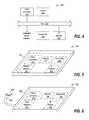
- FIG. 4shows an implementation of a programming device having an IR receiver for receiving an IR light signal from the emitter and providing data from the signal to the microprocessor for verification;
- FIG. 5shows a programming device in which the components are attached to a support structure, and the programming device has a wireless interface for connecting to a portable computing device;
- FIG. 6shows a programming device in which the components are attached to a support structure, and the programming device has a wire interface for connecting to a portable computing device;
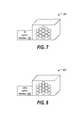
- FIG. 7shows an IR emitter having an IR communications interface
- FIG. 8shows an alternative IR emitter having a radio communications interface
- FIG. 9is a flowchart of a process for configuring and verifying the configuration of an IR emitter.
- Configuring emittershas been found to present a number of challenges. For some emitters, physical access to the emitters is required for cable connections, and accessing the emitters may be cumbersome. For example, an emitter may be disposed on the roof of a fire engine and enclosed within a structure containing other emergency lighting apparatus. A ladder, tools, and cables may be required to access the emitter in the aforementioned scenario.
- the infrared (IR) configuration interface and handheld unit for some emittersalleviates some challenges of configuring emitters. However, a good line of sight is needed between the handheld unit and the emitter, and bright sunlight may interfere with the IR communications.
- This disclosuredescribes devices and methods for configuring an IR emitter.
- the ease with which IR emitters may be configured, tested, or updated with new firmwareis important to the user experience with the emitter. Many users may be inconvenienced in having to procure and place a ladder, and climb the ladder with a notebook computer or other equipment to configure or test an IR emitter. These and other inconveniences associated with configuring or testing an IR emitter are eliminated with the disclosed devices and methods.
- a device for configuring an IR emitterincludes a support structure and a microprocessor attached to the support structure.
- An interface circuitis attached to the support structure, and the interface circuit is configured to provide communications between the microprocessor and a portable computing device, such as a smart phone, tablet computer, notebook computer or other similar devices.
- a memoryis also attached to the support structure and is coupled to the microprocessor. The memory is configured with instructions, and execution of the instructions by the microprocessor causes the microprocessor to communicate with an application executing on the portable computing device, and to initiate transmission of configuration data received from the application to the IR emitter.
- a transmitteris attached to the support structure, coupled to the microprocessor, and configured to transmit the configuration data to the IR emitter.
- the support structuremay include a circuit board on which the circuit components are mounted and a case to which the circuit board is attached and in which the circuit board is enclosed.
- the support structuremay be structured similar to a dongle, for example.
- FIG. 1shows a system 100 in which an IR emitter 102 is configured by a programming device 104 that is controlled by a portable computing device 106 .
- the portable computing deviceexecutes an application program that provides a user interface 108 through which a user may enter and view data for configuring or testing operation of the IR emitter 102 .
- Configuration datais communicated from the portable computing device to the programming device, and from the programming device to the IR emitter.
- the configuration datamay include the class of vehicle with which the IR emitter is associated, a vehicle identifier of the vehicle to which the IR emitter is assigned and installed, an agency identifier of the entity to which the vehicle belongs, and the model and/or serial number of the IR emitter.
- Diagnostic datawhich is generated by the IR emitter in response to a command entered at the portable computing device, is transmitted from the IR emitter and received by the programming device, and then communicated from the programming device to the portable computing device for display via the user interface. Diagnostic data may include logged error data, a count of the number of times the number of on-off cycles of the LEDs of the IR emitter (flash count), an a number of hours of operations.
- the programming device 104may communicate with the portable computing device 106 via a wireless or a wired connection.
- Wireless communicationsmay be by Bluetooth or a wireless network connection, for example.
- a wired connectionmay include a cable that connects to a USB or micro-USB port (not shown) of the portable computing device.
- the IR emitter 102includes a wireless interface (not shown) for wirelessly communicating with the programming device 104 and for interfacing with control circuitry (not shown) of the IR emitter.
- the wireless communication between the programming device 104 and the IR emittermay be by Bluetooth, wireless network, cellular communications, IR signaling or other wireless medium.
- the portable computing device 106may be a multi-purpose computing device such as a smart phone, tablet computer, or notebook computer, for example.
- the portable computing deviceexecutes an application program that provides the user interface 108 and establishes communications with the programming device 104 and provides configuration data and/or diagnostic commands to the programming device.
- FIG. 2shows an implementation of a programming device 200 having a wireless interface 202 for communicating with an application on a portable computing device.
- the programming devicefurther includes a micro-processor 204 , a memory arrangement 206 , and a transmitter 208 , all inter-coupled via bus 210 .
- the wireless interfacemay be a network interface controller that includes a radio signal transceiver and antenna for connecting to a radio signal-based network such as one based on the IEEE 802.11 standard or Bluetooth standard, for example.
- the transmitter 208is configured to wirelessly transmit data and/or commands to the IR emitter.
- the transmittermay be a network interface controller that connects to a radio signal-based network such as one based on the IEEE 802.11 standard or Bluetooth standard, or may provide IR light signaling, for example.
- the transmittermay be part of a transceiver (not shown) for connecting and communicating with the IR emitter via an IEEE 802.11 network or a cellular communications network, thereby providing long-range transmission of configuration data and receipt of diagnostic data.
- Microprocessor 204may be any type of processor capable of executing program instructions and suitable for implementation requirements.
- the memory arrangement 206may include a hierarchy of memory components ranging from cache memory to retentive storage.
- the retentive storagemay be flash memory for storing executable program code.
- the memory arrangement 206may be configured with instructions that are executable by the microprocessor 204 for transmitting configuration data to the IR emitter.
- the configuration datamay be provided to the programming device via the portable computing device 106 ( FIG. 1 ).
- the memory arrangementmay be further configured with program code that is executable by the portable computing device for providing the user interface 108 and interacting with the programming device. Further still, the memory arrangement may be configured with program code that is executable by the portable computing device for receiving diagnostic data from the IR emitter and forwarding the diagnostic data to the application on the portable computing device.
- the bus 210may include multiple buses for communicating data, address and control signals between the connected components.
- FIG. 3shows an implementation of a programming device 300 having a wire interface 302 for connecting the programming device to a portable computing device.
- the wire interface 302may implement a micro-USB or USB connection, for example.
- FIG. 4shows an implementation of a programming device 400 having an IR receiver 402 for receiving an IR light signal from the emitter and providing data from the signal to the microprocessor for verification.
- the IR receiverincludes circuitry for detecting an IR light signal, decoding the IR light signal into electrical signals, and communicating data represented in the electrical signals to the microprocessor.
- the IR receiver 402may be used in supporting diagnostic operations on the IR emitter.
- the memory arrangement 206may be configured with instructions that are executable by the microprocessor for initiating transmission of a request or command to the IR emitter for diagnostic data.
- the request or commandmay have been first received by the programming device 400 from the portable computing device 106 ( FIG. 1 ) via the computing device interface.
- the microprocessorinputs the diagnostic data, as decoded by the IR receiver 402 , and communicates the diagnostic data to the application executing on the portable computing device.
- FIG. 5shows a programming device 500 in which the components are attached to a support structure 502 , and the programming device has a wireless interface for connecting to a portable computing device.
- the support structure 502may include a circuit board on which the wireless interface 202 , microprocessor 204 , memory 206 , transmitter 208 , and IR receiver 402 are mounted and communicatively interconnected.
- the circuit boardmay be attached to a housing or case that encloses the circuit board and attached components.
- Other implementationsmay have multiple ones of the components constructed as a system on a chip (SOC).
- SOCsystem on a chip
- FIG. 6shows a programming device 600 in which the components are attached to a support structure 602 , and the programming device has a wire interface 302 for connecting to a portable computing device.
- the support structure 602may include a circuit board on which the wire interface 302 , microprocessor 204 , memory 206 , transmitter 208 , and IR receiver 402 are mounted and communicatively interconnected.
- the circuit boardmay be attached to a housing or case that encloses the circuit board and attached components.
- Other implementationsmay have multiple ones of the components constructed as a system on a chip (SOC).
- SOCsystem on a chip
- the wire interface 302is coupled to the cable 604 and connector 606 , and the cable may be either permanently attached or detachable from the support structure.
- the connectoris configured to mechanically and electrically connect to a data port on the portable computing device.
- the connector and cablemay be micro-USB compatible, or compatible with another similar interface.
- FIG. 7shows an IR emitter 700 having an IR communications interface 702 through which the emitter can be configured via IR signaling.
- the IR communications interfaceincludes an IR light detector and circuitry for converting the IR signal into an electrical signal for input to control circuitry of the IR emitter.
- FIG. 8shows an alternative IR emitter 800 having a radio communications interface 802 through which the emitter can be configured via radio signaling specified in the IEEE 802.11 standard or the Bluetooth standard, or in a cellular network, for example.
- the radio communications interfaceincludes an antenna and circuitry for converting the radio signal into an electrical signal for input to control circuitry of the IR emitter.
- FIG. 9is a flowchart of a process for configuring and verifying the configuration of an IR emitter.
- the programming deviceis connected to the portable computing device. It will be appreciated that for a programming device having a wireless interface to the portable computing device, no physical connection need be made.
- communicationis established between the programming device and the portable computing device according to the protocol of the interface.
- the programming devicestores program code that is executable by the portable computing device. The program code may be loaded by the portable computing device and executed to provide an application program and user interface for configuring and/or testing the IR emitter. In an alternative implementation, the program code may be stored as an available application on the portable computing device.
- configuration datais received from the portable computing device by the programming device.
- the configuration datamay be entered, specified, or referenced via the user interface of the application executing on the portable computing device.
- the configuration datamay include commands and data.
- the commandsmay direct the IR emitter to perform configuration of its local registers or memory or direct the IR emitter to perform diagnostic functions.
- the configuration datais transmitted from the programming device to the IR emitter. Depending on the implementation, the configuration data may be transmitted via radio signal or an IR light signal.
- the programming devicereceives a verification command from the application on the portable computing device.
- the verification commandis for obtaining diagnostic and configuration information from the IR emitter.
- the diagnostic informationmay include logged error data, a count of the number of times the number of on-off cycles of the LEDs of the IR emitter (flash count), and a number of hours of operation.
- the configuration information read-back from the IR emittermay include the class of vehicle with which the IR emitter is associated, a vehicle identifier of the vehicle to which the IR emitter is assigned and installed, an agency identifier of the entity to which the vehicle belongs, and the model and/or serial number of the IR emitter.
- the verification commandis transmitted from the programming device to the IR emitter.
- the commandmay be encoded in a radio signal or an IR light signal and transmitted accordingly, depending on the implementation.
- output from the IR emitteris captured and converted by the programming device into electrical signals that represent the diagnostic data.
- the outputmay be an IR light signal and/or a radio signal, depending on the implementation of the IR emitter and programming device.
- the diagnostic datais communicated from the programming device to the application on the portable computing device at block 916 .
- the applicationmay then display the diagnostic data on the portable computing device for review by a user.
Landscapes
- Physics & Mathematics (AREA)
- General Physics & Mathematics (AREA)
- Business, Economics & Management (AREA)
- Emergency Management (AREA)
- Selective Calling Equipment (AREA)
- Optical Communication System (AREA)
- Telephone Function (AREA)
Abstract
Description
Claims (18)
Priority Applications (6)
| Application Number | Priority Date | Filing Date | Title |
|---|---|---|---|
| US15/254,683US10198947B2 (en) | 2016-09-01 | 2016-09-01 | Emitter programmer and verification system |
| ES17768283TES2817428T3 (en) | 2016-09-01 | 2017-08-28 | Issuer Scheduler and Verification System |
| EP17768283.8AEP3507782B1 (en) | 2016-09-01 | 2017-08-28 | Emitter programmer and verification system |
| CA3035521ACA3035521C (en) | 2016-09-01 | 2017-08-28 | Emitter programmer and verification system |
| PCT/US2017/048881WO2018044784A1 (en) | 2016-09-01 | 2017-08-28 | Emitter programmer and verification system |
| AU2017321292AAU2017321292B2 (en) | 2016-09-01 | 2017-08-28 | Emitter programmer and verification system |
Applications Claiming Priority (1)
| Application Number | Priority Date | Filing Date | Title |
|---|---|---|---|
| US15/254,683US10198947B2 (en) | 2016-09-01 | 2016-09-01 | Emitter programmer and verification system |
Publications (2)
| Publication Number | Publication Date |
|---|---|
| US20180061229A1 US20180061229A1 (en) | 2018-03-01 |
| US10198947B2true US10198947B2 (en) | 2019-02-05 |
Family
ID=59887369
Family Applications (1)
| Application Number | Title | Priority Date | Filing Date |
|---|---|---|---|
| US15/254,683Active2036-09-30US10198947B2 (en) | 2016-09-01 | 2016-09-01 | Emitter programmer and verification system |
Country Status (6)
| Country | Link |
|---|---|
| US (1) | US10198947B2 (en) |
| EP (1) | EP3507782B1 (en) |
| AU (1) | AU2017321292B2 (en) |
| CA (1) | CA3035521C (en) |
| ES (1) | ES2817428T3 (en) |
| WO (1) | WO2018044784A1 (en) |
Cited By (1)
| Publication number | Priority date | Publication date | Assignee | Title |
|---|---|---|---|---|
| US11594127B1 (en) | 2018-02-09 | 2023-02-28 | Applied Information, Inc. | Systems, methods, and devices for communication between traffic controller systems and mobile transmitters and receivers |
Citations (23)
| Publication number | Priority date | Publication date | Assignee | Title |
|---|---|---|---|---|
| US5014052A (en) | 1983-04-21 | 1991-05-07 | Bourse Trading Company, Ltd. | Traffic signal control for emergency vehicles |
| US5027260A (en) | 1989-09-06 | 1991-06-25 | Whelen Technologies, Inc. | Vehicular lightbar assembly |
| US5172113A (en) | 1991-10-24 | 1992-12-15 | Minnesota Mining And Manufacturing Company | System and method for transmitting data in an optical traffic preemption system |
| US5187476A (en) | 1991-06-25 | 1993-02-16 | Minnesota Mining And Manufacturing Company | Optical traffic preemption detector circuitry |
| US5237663A (en)* | 1991-03-26 | 1993-08-17 | Hewlett-Packard Company | Low cost diagnostic/configuration interface |
| US5661374A (en) | 1994-12-14 | 1997-08-26 | Astronics Corporation | LED light strip with brightness/current draw control circuitry |
| US5826965A (en) | 1996-08-21 | 1998-10-27 | Whelen Engineering Company, Inc. | Modular light bar |
| US5988839A (en) | 1998-08-17 | 1999-11-23 | Whelen Engineering Company, Inc. | Rear facing light bar |
| US6064319A (en) | 1998-10-22 | 2000-05-16 | Matta; David M. | Method and system for regulating switching of a traffic light |
| US6299337B1 (en) | 1999-03-04 | 2001-10-09 | Osram Opto Semiconductors Gmbh & Co. Ohg | Flexible multiple led module, in particular for a luminaire housing of a motor vehicle |
| US6326903B1 (en) | 2000-01-26 | 2001-12-04 | Dave Gross | Emergency vehicle traffic signal pre-emption and collision avoidance system |
| US6682210B1 (en) | 2002-01-11 | 2004-01-27 | Whelen Engineering Company, Inc. | Tip-up light bar assembly |
| US20040174712A1 (en) | 2003-03-06 | 2004-09-09 | Seiichiro Yagi | Vehicular headlamp |
| US6863424B2 (en) | 2002-08-07 | 2005-03-08 | Whelen Engineering Company, Inc. | Light bar with integrated warning illumination and lens support structure |
| US20060273926A1 (en) | 2005-06-01 | 2006-12-07 | 3M Innovative Properties Company | Multimode traffic priority/preemption vehicle arrangement |
| US20080003993A1 (en)* | 2006-06-29 | 2008-01-03 | X10 Ltd. | Icon mobile phone remote with favorite channel selection |
| US7411174B2 (en) | 2004-10-12 | 2008-08-12 | Eash Brandon A | Sensor-controlled LED array apparatus and method |
| US7429917B2 (en) | 2006-02-27 | 2008-09-30 | Whelen Engineering Company, Inc. | LED aviation warning light with fault detection |
| US7808401B1 (en) | 2008-01-11 | 2010-10-05 | Global Traffic Technologies, Llc | Light emitters for optical traffic control systems |
| US20110298581A1 (en)* | 2010-06-08 | 2011-12-08 | Wei Hsu | Universal remote controller |
| US20120218126A1 (en) | 2011-02-24 | 2012-08-30 | Douglas Gordon Roberts | Systems and Method for Controlling Preemption of a Traffic Signal |
| US20140200760A1 (en) | 2011-05-27 | 2014-07-17 | Augmentation Industries Gmbh | Method for vehicle communication by means of a vehicle-implemented vehicle diagnostic system, vehicle diagnostic interface, interace module, user communication terminal, data connection system, and diagnostic and control network for a plurality of vehicles |
| US20140327778A1 (en)* | 2010-10-18 | 2014-11-06 | Zonar Systems, Inc. | Method and apparatus for an automated fuel authorization program for fuel terminals using a camera as part of the authorization process |
- 2016
- 2016-09-01USUS15/254,683patent/US10198947B2/enactiveActive
- 2017
- 2017-08-28EPEP17768283.8Apatent/EP3507782B1/enactiveActive
- 2017-08-28CACA3035521Apatent/CA3035521C/enactiveActive
- 2017-08-28AUAU2017321292Apatent/AU2017321292B2/enactiveActive
- 2017-08-28ESES17768283Tpatent/ES2817428T3/enactiveActive
- 2017-08-28WOPCT/US2017/048881patent/WO2018044784A1/ennot_activeCeased
Patent Citations (23)
| Publication number | Priority date | Publication date | Assignee | Title |
|---|---|---|---|---|
| US5014052A (en) | 1983-04-21 | 1991-05-07 | Bourse Trading Company, Ltd. | Traffic signal control for emergency vehicles |
| US5027260A (en) | 1989-09-06 | 1991-06-25 | Whelen Technologies, Inc. | Vehicular lightbar assembly |
| US5237663A (en)* | 1991-03-26 | 1993-08-17 | Hewlett-Packard Company | Low cost diagnostic/configuration interface |
| US5187476A (en) | 1991-06-25 | 1993-02-16 | Minnesota Mining And Manufacturing Company | Optical traffic preemption detector circuitry |
| US5172113A (en) | 1991-10-24 | 1992-12-15 | Minnesota Mining And Manufacturing Company | System and method for transmitting data in an optical traffic preemption system |
| US5661374A (en) | 1994-12-14 | 1997-08-26 | Astronics Corporation | LED light strip with brightness/current draw control circuitry |
| US5826965A (en) | 1996-08-21 | 1998-10-27 | Whelen Engineering Company, Inc. | Modular light bar |
| US5988839A (en) | 1998-08-17 | 1999-11-23 | Whelen Engineering Company, Inc. | Rear facing light bar |
| US6064319A (en) | 1998-10-22 | 2000-05-16 | Matta; David M. | Method and system for regulating switching of a traffic light |
| US6299337B1 (en) | 1999-03-04 | 2001-10-09 | Osram Opto Semiconductors Gmbh & Co. Ohg | Flexible multiple led module, in particular for a luminaire housing of a motor vehicle |
| US6326903B1 (en) | 2000-01-26 | 2001-12-04 | Dave Gross | Emergency vehicle traffic signal pre-emption and collision avoidance system |
| US6682210B1 (en) | 2002-01-11 | 2004-01-27 | Whelen Engineering Company, Inc. | Tip-up light bar assembly |
| US6863424B2 (en) | 2002-08-07 | 2005-03-08 | Whelen Engineering Company, Inc. | Light bar with integrated warning illumination and lens support structure |
| US20040174712A1 (en) | 2003-03-06 | 2004-09-09 | Seiichiro Yagi | Vehicular headlamp |
| US7411174B2 (en) | 2004-10-12 | 2008-08-12 | Eash Brandon A | Sensor-controlled LED array apparatus and method |
| US20060273926A1 (en) | 2005-06-01 | 2006-12-07 | 3M Innovative Properties Company | Multimode traffic priority/preemption vehicle arrangement |
| US7429917B2 (en) | 2006-02-27 | 2008-09-30 | Whelen Engineering Company, Inc. | LED aviation warning light with fault detection |
| US20080003993A1 (en)* | 2006-06-29 | 2008-01-03 | X10 Ltd. | Icon mobile phone remote with favorite channel selection |
| US7808401B1 (en) | 2008-01-11 | 2010-10-05 | Global Traffic Technologies, Llc | Light emitters for optical traffic control systems |
| US20110298581A1 (en)* | 2010-06-08 | 2011-12-08 | Wei Hsu | Universal remote controller |
| US20140327778A1 (en)* | 2010-10-18 | 2014-11-06 | Zonar Systems, Inc. | Method and apparatus for an automated fuel authorization program for fuel terminals using a camera as part of the authorization process |
| US20120218126A1 (en) | 2011-02-24 | 2012-08-30 | Douglas Gordon Roberts | Systems and Method for Controlling Preemption of a Traffic Signal |
| US20140200760A1 (en) | 2011-05-27 | 2014-07-17 | Augmentation Industries Gmbh | Method for vehicle communication by means of a vehicle-implemented vehicle diagnostic system, vehicle diagnostic interface, interace module, user communication terminal, data connection system, and diagnostic and control network for a plurality of vehicles |
Non-Patent Citations (1)
| Title |
|---|
| International Search Report and Written Opinion dated Dec. 4, 2017, for corresponding International Patent Application PCT/US2017/048881. |
Cited By (2)
| Publication number | Priority date | Publication date | Assignee | Title |
|---|---|---|---|---|
| US11594127B1 (en) | 2018-02-09 | 2023-02-28 | Applied Information, Inc. | Systems, methods, and devices for communication between traffic controller systems and mobile transmitters and receivers |
| US11854389B1 (en) | 2018-02-09 | 2023-12-26 | Applied Information, Inc. | Systems, methods, and devices for communication between traffic controller systems and mobile transmitters and receivers |
Also Published As
| Publication number | Publication date |
|---|---|
| CA3035521A1 (en) | 2018-03-08 |
| EP3507782B1 (en) | 2020-07-22 |
| AU2017321292A1 (en) | 2019-04-18 |
| ES2817428T3 (en) | 2021-04-07 |
| CA3035521C (en) | 2019-09-24 |
| WO2018044784A1 (en) | 2018-03-08 |
| US20180061229A1 (en) | 2018-03-01 |
| EP3507782A1 (en) | 2019-07-10 |
| AU2017321292B2 (en) | 2019-10-31 |
Similar Documents
| Publication | Publication Date | Title |
|---|---|---|
| US9478131B2 (en) | Prioritization of traffic signal preemption requests received from multiple sources over different communication mediums | |
| US8054202B1 (en) | Traffic preemption system and related methods | |
| US8884783B2 (en) | Systems and method for controlling preemption of a traffic signal | |
| US7573399B2 (en) | Multimode traffic priority/preemption vehicle arrangement | |
| US11030895B1 (en) | Incident-based traffic signal preemption and priority | |
| CN105751960A (en) | Methods And Systems For Visual Communication Of Vehicle Drive Information By Using Light Set | |
| US20210049904A1 (en) | Traffic management system | |
| US20170316685A1 (en) | Vehicle accident management system and method for operating same | |
| US20160019729A1 (en) | System and method for the access to information contained in motor vehicles | |
| US20220050475A1 (en) | Autonomous vehicle signaling system | |
| CN109598883A (en) | Lamp leads fire evacuation system and its control method | |
| CN106920411A (en) | It is a kind of automatic with the method and device during car by intersection | |
| US20230410574A1 (en) | Self-diagnosis apparatus and self-diagnosis system | |
| CA3035521C (en) | Emitter programmer and verification system | |
| KR102420342B1 (en) | Traffic flow control apparatus for controling mixed traffic flow with automated vehicles and method using the same | |
| CN104383697A (en) | Electronic building block and electronic building block group | |
| EP2646994B1 (en) | Vehicle communications | |
| US12365493B2 (en) | Lighting device and lighting system | |
| JP6132194B2 (en) | Tunnel warning system and tunnel warning transmission system | |
| KR102106450B1 (en) | A method for Traffic Signal Notification System Using Traffic Lights Capable of Wireless Communications | |
| AU2023248110A1 (en) | DSRC Cap Lamp | |
| JP2017092879A (en) | Optical beacon | |
| KR20200131051A (en) | Traffic signaling information service system linked with mobile platform | |
| KR20180085514A (en) | System and method for controlling temperature of cabin | |
| HK1125732B (en) | Multimode traffic priority/preemption vehicle arrangement |
Legal Events
| Date | Code | Title | Description |
|---|---|---|---|
| AS | Assignment | Owner name:GLOBAL TRAFFIC TECHNOLOGIES, LLC, MINNESOTA Free format text:ASSIGNMENT OF ASSIGNORS INTEREST;ASSIGNORS:MEYER, CHARLES B.;EICHHORST, KEVIN;HALL, TIMOTHY J.;SIGNING DATES FROM 20160728 TO 20160913;REEL/FRAME:040095/0435 | |
| STCF | Information on status: patent grant | Free format text:PATENTED CASE | |
| MAFP | Maintenance fee payment | Free format text:PAYMENT OF MAINTENANCE FEE, 4TH YEAR, LARGE ENTITY (ORIGINAL EVENT CODE: M1551); ENTITY STATUS OF PATENT OWNER: LARGE ENTITY Year of fee payment:4 | |
| AS | Assignment | Owner name:COMERICA BANK, MICHIGAN Free format text:SECURITY INTEREST;ASSIGNOR:GLOBAL TRAFFIC TECHNOLOGIES, LLC;REEL/FRAME:064183/0966 Effective date:20230706 | |
| AS | Assignment | Owner name:EXPORT DEVELOPMENT CANADA, CANADA Free format text:SECURITY INTEREST;ASSIGNOR:GLOBAL TRAFFIC TECHNOLOGIES, LLC;REEL/FRAME:066861/0273 Effective date:20240301 | |
| AS | Assignment | Owner name:MIOVISION TECHNOLOGIES US, LLC, DELAWARE Free format text:CHANGE OF NAME;ASSIGNOR:GLOBAL TRAFFIC TECHNOLOGIES, LLC;REEL/FRAME:070446/0609 Effective date:20241227 | |
| AS | Assignment | Owner name:MIOVISION TECHNOLOGIES US, LLC, DELAWARE Free format text:CORRECTIVE ASSIGNMENT TO CORRECT THE STREET ADDRESS AND ZIP CODE PREVIOUSLY RECORDED ON REEL 70446 FRAME 609. ASSIGNOR(S) HEREBY CONFIRMS THE CHANGE OF NAME;ASSIGNOR:GLOBAL TRAFFIC TECHNOLOGIES, LLC;REEL/FRAME:071129/0664 Effective date:20241227 |