US10198024B2 - Ergonomic gear shift grip adjuster - Google Patents
Ergonomic gear shift grip adjusterDownload PDFInfo
- Publication number
- US10198024B2 US10198024B2US15/394,210US201615394210AUS10198024B2US 10198024 B2US10198024 B2US 10198024B2US 201615394210 AUS201615394210 AUS 201615394210AUS 10198024 B2US10198024 B2US 10198024B2
- Authority
- US
- United States
- Prior art keywords
- bracket
- extension
- handle
- lever
- adapter
- Prior art date
- Legal status (The legal status is an assumption and is not a legal conclusion. Google has not performed a legal analysis and makes no representation as to the accuracy of the status listed.)
- Active - Reinstated
Links
Images


Classifications
- G—PHYSICS
- G05—CONTROLLING; REGULATING
- G05G—CONTROL DEVICES OR SYSTEMS INSOFAR AS CHARACTERISED BY MECHANICAL FEATURES ONLY
- G05G1/00—Controlling members, e.g. knobs or handles; Assemblies or arrangements thereof; Indicating position of controlling members
- G05G1/54—Controlling members specially adapted for actuation by auxiliary operating members or extensions; Operating members or extensions therefor (pedal extensions)
- B—PERFORMING OPERATIONS; TRANSPORTING
- B60—VEHICLES IN GENERAL
- B60K—ARRANGEMENT OR MOUNTING OF PROPULSION UNITS OR OF TRANSMISSIONS IN VEHICLES; ARRANGEMENT OR MOUNTING OF PLURAL DIVERSE PRIME-MOVERS IN VEHICLES; AUXILIARY DRIVES FOR VEHICLES; INSTRUMENTATION OR DASHBOARDS FOR VEHICLES; ARRANGEMENTS IN CONNECTION WITH COOLING, AIR INTAKE, GAS EXHAUST OR FUEL SUPPLY OF PROPULSION UNITS IN VEHICLES
- B60K20/00—Arrangement or mounting of change-speed gearing control devices in vehicles
- B60K20/02—Arrangement or mounting of change-speed gearing control devices in vehicles of initiating means
- B60K20/04—Arrangement or mounting of change-speed gearing control devices in vehicles of initiating means floor mounted
- B—PERFORMING OPERATIONS; TRANSPORTING
- B60—VEHICLES IN GENERAL
- B60K—ARRANGEMENT OR MOUNTING OF PROPULSION UNITS OR OF TRANSMISSIONS IN VEHICLES; ARRANGEMENT OR MOUNTING OF PLURAL DIVERSE PRIME-MOVERS IN VEHICLES; AUXILIARY DRIVES FOR VEHICLES; INSTRUMENTATION OR DASHBOARDS FOR VEHICLES; ARRANGEMENTS IN CONNECTION WITH COOLING, AIR INTAKE, GAS EXHAUST OR FUEL SUPPLY OF PROPULSION UNITS IN VEHICLES
- B60K26/00—Arrangement or mounting of propulsion-unit control devices in vehicles
- F—MECHANICAL ENGINEERING; LIGHTING; HEATING; WEAPONS; BLASTING
- F16—ENGINEERING ELEMENTS AND UNITS; GENERAL MEASURES FOR PRODUCING AND MAINTAINING EFFECTIVE FUNCTIONING OF MACHINES OR INSTALLATIONS; THERMAL INSULATION IN GENERAL
- F16H—GEARING
- F16H59/00—Control inputs to control units of change-speed- or reversing-gearings for conveying rotary motion
- F16H59/02—Selector apparatus
- F16H59/0278—Constructional features of the selector lever, e.g. grip parts, mounting or manufacturing
Definitions
- the present applicationis generally directed to ergonomically adjustable structures for motor vehicles and other manually-operated levers, and more particularly, to an attachable/detachable and ergonomically adjustable grip to facilitate operation of a gear shift tower of a truck, a tractor-trailer, or other heavy equipment.
- Modern tractor trailer transmissionstypically include 18 gear settings. Control of the transmission is accomplished by moving a shift tower through positions arranged in an H-shaped pattern. A selected gear ratio is engaged when the tower is pushed or pulled into a position at an end of a leg of the H-shaped pattern. A hydraulic switch located on the tower allows the driver to select whether the positions on the H-shaped pattern correspond to low, high, or overdrive combinations.
- a large number of gear selectionsallows a driver to operate the vehicle efficiently, to navigate inclines and declines, and to quickly decelerate or accelerate in emergency situations.
- To make effective use of the gear selectionan operator must be able to rapidly move the tower among the gear selections and to easily access the switch.
- Shifting gearsplaces significant, repetitive strain on muscles and tendons that control motions of the driver's wrist and elbow that can lead to injury.
- Operating a manual transmissionrequires that the driver apply force to the tower to assure that the transmission is firmly engaged in the desired gear.
- gear shiftinginvolves moving the tower through the same H-shaped pattern over and over again.
- the location and angle of the towermay not be ideal for a particular driver, given the location of the seat, the height and arm-length of the driver and the fact that the driver must also work foot pedals simultaneously with the gear shifter.
- driverssometimes suffer from repetitive motion injuries to the wrist and elbow. These injuries include wrist flexor tendinopathy (golfer's elbow), which is an inflammation of the tendon of the wrist flexor muscle.
- Orthopedistsrecommend that people who perform tasks that require the same motion repeatedly make an effort to rest the limb performing the repetitive task. For truck drivers, gear shifting is a constant activity and, unless the driver pulls off the road (which costs time and money) there is no opportunity to rest. To the extent a repetitive motion cannot be avoided, orthopedists recommend adjustment of the range of motion to reduce overuse of particular tendons.
- switchesthat allow the driver to select low, high, and overdrive gear combinations and/or to select intermediate (split) gears.
- the switchesare positioned near enough to the grip so that the driver can quickly change from low to high to overdrive while at the same time moving the tower. Operation of the switches must be done simultaneously with motion of the tower to smoothly transition between gears.
- the bottom end of the towerengages the transmission located along the center-line of the truck below the floor of the cab.
- the distance the top of the tower must travel through the H-shaped pattern discussed above in order to engage gearsdepends on the design of the transmission and on the height of the tower. These dimensions are fixed for a particular truck. Moreover, trucks made by different manufacturers, and even trucks made by the same manufacturer, but with different transmissions, may have different distances through which the tower most be moved. In many cases, drivers working for companies that employ a fleet of trucks (e.g., Federal Express, United Parcel Service, etc.) may be assigned to a variety of trucks. As a result, the distance a driver must reach through to shift gears may change from trip to trip, depending on which truck he or she is assigned.
- Trucksare usually provided with seat adjustments that allow the driver to position the height of the seat, the distance of the seat from the controls, and the angle of the seat.
- many truckshave adjustable steering columns and fuel, brake, and clutch pedals to allow the driver to comfortably operate the vehicle.
- the gear shift towerlacks such ergonomic adjustments. Instead, the location of the gear shift and the distance through which the tower must be pushed or pulled is determined by the overall shape of the cab and the design of the transmission.
- the angle of the tower grip with respect to the driver's wristis fixed by the design of the vehicle and cannot be adjusted to accommodate the shape of a drivers hand or the driver's range of comfortable motion. As a result, drivers are unable to make ergonomic adjustments to the tower grip.
- the grip on the towerdoes not provide a variety of surfaces to allow the driver to vary the position of his or her wrist, elbow, and shoulder when shifting gears.
- an ergonomic adapter for a transmission towercomprising: a tower mounting bracket, the bracket removably coupled to a tower of the transmission and adapted to be positioned at a selected position along the height of the transmission tower and at a selected angular position about an axis of the tower; an extension bracket rotatably coupled with the tower mounting bracket about an extension axis and adapted to be fixed to the tower mounting bracket at a selected angular position about the extension axis; and a handle rotatably coupled to the extension bracket about a handle axis and adapted to be fixed to the handle at a selected angular position about the handle axis.
- the handle of the adapterfurther comprises a plurality of gripping surfaces, wherein each gripping surface is sized to accommodate an operator's hand.
- the gripping surfacescomprise two parallel portions, and the handle further comprising a safety bar where the safety bar extends between the parallel portions.
- the handlefurther comprises a mounting plate connected with at least a first one of the gripping surfaces, wherein the gripping surfaces and the plate form a loop.
- a safety barextends from a second one of the gripping surfaces to the plate.
- the handlecomprises a single, cylindrical gripping surface.
- the adapterincludes a bushing positioned between an interior surface of the mounting bracket and an exterior surface of the tower.
- the exterior surface of the toweris cylindrical.
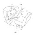
- FIG. 1shows the interior of a cab of a vehicle equipped with a device according to an embodiment of the present invention.
- FIG. 2shows a view of an embodiment of the present invention attached to a shift tower.
- FIG. 3Ashows an engagement clamp of the embodiment shown in FIG. 2
- FIG. 3Bshows a bracket of the embodiment shown in FIG. 2 .
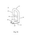
- FIG. 3Cshows a handle of the embodiment shown in FIG. 2
- FIG. 4Ashows the engagement clamp of FIG. 3A connected with a gear shift tower.
- FIG. 4Bshows an alternative embodiment of an engagement clamp in an open position.
- FIG. 4Cshows the embodiment of the engagement clamp of FIG. 4B in the closed position.
- FIG. 5shows a handle according to a further embodiment of the present invention.
- FIG. 6shows a handle according to yet another embodiment of the present invention.
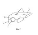
- FIG. 7shows a clamp including a bushing according to a further embodiment of the present invention.
- An attachable/detachable and ergonomically adjustable grip for the gear shift tower of a motor vehicle or other manual lever assembly and the method of making such an adjustable grip according to embodiments of the present inventionare provided.
- FIG. 1depicts the interior of the cab of a motor vehicle 100 .
- the vehiclemay be a tractor-trailer, a delivery truck, an automobile, a piece of heavy equipment (e.g., front loader), or the like.
- a driver's seat 102is positioned behind the steering wheel 103 .
- the seatmay include a track engagement 114 with the floor 118 of the vehicle cab.
- the seatmay also include a height adjustment 116 .
- the track 114 and height adjustment 116allow the driver to comfortably position himself with respect to control mechanisms, including the steering wheel 103 , clutch pedal 104 , brake pedal 106 , and throttle 108 .
- Extending up from the floor 118is the gear shift tower 112 .
- Mounted on the gear shift tower 112is an adjustable grip 1 according to an embodiment of the invention.
- a switch 116that allows the driver to select low, high, and overdrive gear settings.
- FIG. 2is a detailed view of the adjustable grip 1 shown in FIG. 1 according to one embodiment of the invention.
- the grip 1is fixed to the tower 112 .
- Switch 116is mounted near the top of the tower 112 .
- a clamp 2mounts the grip to the tower 112 .
- a extension bracket 4is connected with the clamp 2 .
- the bracket 4has two surfaces arranged at a right angle to one another.
- Handle 6is connected with the extension bracket 4 .
- the tower 112has a round cross section.
- the engagement between the clamp 2 and tower 112can be positioned about the tower axis 8 along the height of the tower 112 .
- the engagement between the clamp 2 and extension bracket 4can be adjusted about an extension axis 10 .
- the engagement between the handle 6 and bracket 4can be adjusted about a handle axis 12 .
- the height of the adapter 1 on the tower 112 , as well as the position of the handle 6 with respect to the tower 112is adjusted so that the operator can comfortably move the tower 112 through its range of operation while also allowing the operator to conveniently reach the switch 116 .
- FIG. 3Ashows a detailed view of a clamp 2 according to an embodiment of the invention.
- the clampis formed from an engagement portion 22 and an opposing portion 20 .
- Through holes 24 in the opposing portion 20allow mounting bolts (not shown) to extend through the opposing portion.
- the boltsengage with threaded holes 26 in the engagement portion 22 .
- Arcuate surfaces 21 on the opposing portion 20 and engagement portion 22are shaped to closely match the surface of the tower 112 so that when the bolts pull the opposing portion 20 and the engagement portion 22 together the clamp 2 is fixed at a selected position on the tower 112 .
- FIG. 4shows a view of clamp 2 connected with tower 112 .
- Engaging portion 22includes two threaded holes 28 to connect with the bracket 4 .
- clamp 2is connected with tower 112 by way of a latch mechanism such as an over-center latch.
- FIGS. 4B and 4Cshow a view of such an embodiment.
- FIG. 4Bshows a clamp 200 formed from an engagement portion 222 (including holes 229 defined therein) and an opposing portion 220 connected by clamp hinge 224 .
- Latch 228is connected to the opposing portion 220 by a latch hinge 230 .
- a hasp 226is connected to the latch 228 by a hasp hinge 232 .
- a receiving notch 234is formed in the engagement portion 222 on a side opposite the side connected with hinge 224 .
- FIG. 4Cshows the clamp 200 in the closed configuration.
- clamp 200can connect the adapter 1 to the tower 112 in the same manner as that shown in FIG. 4A with respect to clamp 2 .
- Opposing portion 220is rotated about hinge 224 to abut engaging portion 222 (including holes 229 ) with the shaft of the tower 112 positioned in the opening.
- An edge of hasp 226engages with notch 234 .
- Latch 228is rotated about latch hinge 230 to abut a side of opposing portion 220 .
- Rotation of the latch 228 about the latch hinge 230pulls hasp 226 against notch 234 , thereby pulling opposing portion 220 toward engaging portion 222 .
- the positions of hinges 224 , 230 , and 232are selected so that latch 228 forms an over-center engagement to hold clamp 200 in the closed arrangement shown in FIG. 4C to fix the adapter 1 to the tower 112 .
- Clamp 200allows the adapter 1 to be connected with the tower 112 without the need for tools. This arrangement also allows the device to be easily removed from the tower 112 by moving latch 228 away from opposing portion 220 . Thus, a driver that uses multiple vehicles can conveniently remove the adapter 1 from one vehicle and install it in another.
- Bracket 4is shown in FIG. 3B .
- bracket 4has a clamp engaging portion 40 arranged perpendicularly with a handle engaging portion 42 .
- the clamp engaging portionhas a through hole 44 and an arcuate slot 46 .
- the handle engaging portion 42has two threaded holes 47 , 48 and a slotted hole 49 .
- Bracket 3 bis connected with the engagement portion 22 of clamp 2 by bolts extending through hole 44 and through slot 46 and into threaded holes 28 on the engagement portion 22 .
- Arcuate slot 46allows the bracket 4 to be positioned at a selected angle about the extension axis 10 (as shown in FIG. 2 ) so that, when the device is fully assembled, the handle 6 is in a position that is comfortable for the driver.
- FIG. 3Cshows a detailed view of a handle 6 according to an embodiment of the invention.
- the handle 6has side grips 60 connected by top grip 62 .
- Side grips 60are connected with plate 64 .
- boltsextend through holes 68 and engage with holes 47 and 49 or with holes 48 and 49 .
- holes 68are slotted, because hole 49 is slotted, and because holes 68 can engage one or the other of holes 47 and 48 , handle 6 can be positioned at a selected angular position about handle axis 12 (as shown in FIG. 2 ).
- a through hole 69is located in the plate 64 , and aligns with slot 49 when assembled.
- Safety bar 66extends between side grips 60 of handle 6 .
- the safety bar 66prevents the driver from inadvertently extending his hand through the handle 6 . This minimizes the risk that the driver's hand is lodged inside the handle 6 , which would create a dangerous situation when driving.
- FIG. 5shows an alternative embodiment of the invention.
- safety bar 67extends from top grip 62 to plate 64 .
- safety bar 67partially blocks the opening of handle 6 , thereby reducing the risk that the driver can become entangled with the handle 6 while driving.
- the device 1in operation the device 1 is positioned on tower 112 so that handle 6 is positioned near the top of tower 112 with bracket 4 extending generally toward the driver.
- handle 6is displaced from tower 112 toward the driver, thus reducing the maximum distance the driver must extend his or her arm to reach the farthest gear selection. This feature reduced the stress on the driver's shoulder and upper back muscles. It also allows the driver to more easily reach this gear setting without having to move out of the seat.
- the clamp 2 , bracket 4 and handle 6can be positioned at selected angles of tower axis 8 , extension axis 10 , and handle axis 12 so that the location of the side grips 60 and top grip 62 can be comfortably grasped by the driver.
- the driverhas the option to grasp the handle on any of the side or top grips 60 , 62 allowing the driver change the range of motion of his or her wrist, elbow, and shoulder and reduce the impact of repeated gear shifting motions.
- FIG. 6shows another alternative configuration of the handle according to another embodiment of the invention.
- handle 7has a cylindrical grip 70 .
- the grip 70extends from plate 74 .
- Slotted holes 78are formed in plate 74 .
- Handle 7can be affixed to bracket 4 in the same manner as handle 6 , as discussed above.
- FIG. 7shows an alternative configuration of the clamp 22 according to a further embodiment of the invention.
- bushing 25Positioned within the arcuate surfaces 21 of the opposing portion 20 and engaging portion 22 is bushing 25 .
- the thickness of bushing 25is selected so that the device 1 can be affixed to towers 112 of differing diameter.
- Bushing 25can also be shaped to conform to the shape of a tower that is not cylindrical.
- Components of the device 1can be constructed from materials that have adequate mechanical strength to communicate forces from the driver's hand to the tower 112 to operate the vehicle transmission. These materials include metals and metal alloys, polymers, composite materials, for example, carbon fiber composites, and combinations thereof.
Landscapes
- Engineering & Computer Science (AREA)
- Mechanical Engineering (AREA)
- Chemical & Material Sciences (AREA)
- Combustion & Propulsion (AREA)
- Transportation (AREA)
- General Engineering & Computer Science (AREA)
- Physics & Mathematics (AREA)
- General Physics & Mathematics (AREA)
- Automation & Control Theory (AREA)
- Mechanical Control Devices (AREA)
- Arrangement Or Mounting Of Control Devices For Change-Speed Gearing (AREA)
Abstract
Description
Claims (10)
Priority Applications (2)
| Application Number | Priority Date | Filing Date | Title |
|---|---|---|---|
| US15/394,210US10198024B2 (en) | 2016-12-29 | 2016-12-29 | Ergonomic gear shift grip adjuster |
| PCT/US2017/069005WO2018126168A2 (en) | 2016-12-29 | 2017-12-29 | Ergonomic grip |
Applications Claiming Priority (1)
| Application Number | Priority Date | Filing Date | Title |
|---|---|---|---|
| US15/394,210US10198024B2 (en) | 2016-12-29 | 2016-12-29 | Ergonomic gear shift grip adjuster |
Publications (2)
| Publication Number | Publication Date |
|---|---|
| US20180188766A1 US20180188766A1 (en) | 2018-07-05 |
| US10198024B2true US10198024B2 (en) | 2019-02-05 |
Family
ID=61581716
Family Applications (1)
| Application Number | Title | Priority Date | Filing Date |
|---|---|---|---|
| US15/394,210Active - ReinstatedUS10198024B2 (en) | 2016-12-29 | 2016-12-29 | Ergonomic gear shift grip adjuster |
Country Status (2)
| Country | Link |
|---|---|
| US (1) | US10198024B2 (en) |
| WO (1) | WO2018126168A2 (en) |
Cited By (2)
| Publication number | Priority date | Publication date | Assignee | Title |
|---|---|---|---|---|
| US10704673B1 (en)* | 2019-10-01 | 2020-07-07 | Midwest Truck & Auto Parts, Inc. | Transmission with configurable shifter |
| RU236718U1 (en)* | 2025-05-15 | 2025-08-18 | Федеральное государственное бюджетное образовательное учреждение высшего образования "Юго-Западный государственный университет" | ADJUSTABLE CAR GEAR SHIFT LEVER |
Families Citing this family (5)
| Publication number | Priority date | Publication date | Assignee | Title |
|---|---|---|---|---|
| US10967977B2 (en) | 2018-07-06 | 2021-04-06 | Hamilton Sunstrand Corporation | Aircraft air supply and contaminant detection system |
| US11441672B2 (en)* | 2019-10-29 | 2022-09-13 | Lokar, Inc. | Adjustable shift lever mount |
| CN115234643B (en)* | 2022-07-21 | 2023-08-01 | 广州市柏格迪电子科技有限公司 | Automobile crystal gear handle with adjustable holding angle |
| CN116164096A (en)* | 2023-02-22 | 2023-05-26 | 江苏徐工工程机械研究院有限公司 | Control box, design method thereof and engineering machinery |
| US12194976B1 (en)* | 2023-09-11 | 2025-01-14 | Robert F Trepanier | Safety parking brake system for campers and all tow trailers |
Citations (43)
| Publication number | Priority date | Publication date | Assignee | Title |
|---|---|---|---|---|
| US1155916A (en) | 1914-10-03 | 1915-10-05 | Barton Fisk Grout | Extension-arm. |
| US1232449A (en) | 1916-11-21 | 1917-07-03 | Fred T Hughes | Gear-shifting lever for automobiles. |
| US1256244A (en) | 1917-09-06 | 1918-02-12 | Gustaf A E Mellin | Gear-shifting lever. |
| US1262425A (en) | 1917-10-02 | 1918-04-09 | Charles F Young | Automobile-transmission-lever extension. |
| US1283852A (en) | 1918-04-24 | 1918-11-05 | Gustaf A E Mellin | Adjustable gear-shift lever for automobiles and the like. |
| US1285351A (en) | 1917-03-06 | 1918-11-19 | Jackson G Parsons | Controlling-lever for automobiles. |
| US1301475A (en) | 1918-09-11 | 1919-04-22 | Gustaf A E Mellin | Adjustable gear-shift lever for automobiles and the like. |
| US1409447A (en) | 1920-02-07 | 1922-03-14 | Frederick T Hughes | Extension for brake levers |
| US1545462A (en) | 1924-07-02 | 1925-07-07 | American Pulley Co | Belt-shifter attachment for shaft hangers |
| US2108745A (en) | 1936-10-15 | 1938-02-15 | Dodd Victor John | Adjustable control lever |
| US2185024A (en) | 1938-09-20 | 1939-12-26 | Eddy Nelson | Extension for gear-shift levers |
| US2561632A (en) | 1950-11-10 | 1951-07-24 | Albert J Nejezchleb | Shifting lever stabilizer |
| US2630342A (en)* | 1948-06-22 | 1953-03-03 | Emil Greiner Company | Universally adaptable frame |
| US3456525A (en) | 1967-03-01 | 1969-07-22 | Albert H Oldham | Steering handle extension for outboard motor |
| US4197764A (en) | 1977-04-11 | 1980-04-15 | Auernhammer Marcus J | Detachable handle assembly |
| US4515029A (en) | 1982-11-08 | 1985-05-07 | Eaton Corporation | Compound variable mechanical advantage shifting mechanism |
| US4535648A (en) | 1983-07-05 | 1985-08-20 | Stelzer Jack C | Control handle extension |
| US4624206A (en) | 1985-04-09 | 1986-11-25 | Frye Richard D | Foldable auxilliary steering arm for trolling motors |
| US4811921A (en) | 1987-06-22 | 1989-03-14 | Whitaker Charles N | Cyclic control stick |
| US4916969A (en) | 1985-12-11 | 1990-04-17 | Peter Henning | Electric trolling motor steering handle |
| US5040432A (en) | 1989-12-28 | 1991-08-20 | Carlstedt Paul A | Control handle extension |
| US5094124A (en)* | 1991-06-03 | 1992-03-10 | Western States Import Company, Inc. | Handlebars for stationary exercise bicycle |
| US5131116A (en) | 1991-07-29 | 1992-07-21 | Shirley Bowdler | Extension handle for a seat adjustment lever |
| US5133568A (en)* | 1991-09-19 | 1992-07-28 | Balterman Alisa M | U-lock connector for bicycle handlebar |
| US5145210A (en)* | 1987-01-09 | 1992-09-08 | Lennon Dan C | Bicycle, handlebar and adapter system |
| DE29616622U1 (en)* | 1996-07-18 | 1996-11-28 | Lai, Yung-Hsin, Hwatan Hsiang, Changhua | Auxiliary handlebars for a racing bike |
| US5669322A (en) | 1995-04-05 | 1997-09-23 | Huzjak; George P. | Trolling motor extension handle bracket |
| US6029535A (en) | 1998-09-10 | 2000-02-29 | Volvo Trucks North America, Inc. | Highway tractor gear shift |
| US6058797A (en) | 1998-11-24 | 2000-05-09 | Teleflex Incorporated | Clip-on shifter knob |
| US6186027B1 (en)* | 2000-02-23 | 2001-02-13 | Peter M. Nielsen | Handlebar stem assembly for bicycle fork |
| US6202504B1 (en) | 1999-04-02 | 2001-03-20 | Edmund P. Burkle | Extension handle for emergency or safety brake lever |
| US6234501B1 (en) | 1970-02-23 | 2001-05-22 | Chih-Liang Chen | Foldable scooter with head tube assembly, brake and suspension |
| US6318209B1 (en) | 1999-03-25 | 2001-11-20 | Hyundai Motor Company | Shift lever position adjustment device for an automotive vehicle |
| US20020170144A1 (en) | 2001-05-15 | 2002-11-21 | Agate Donald Lee | Gear shift lever handle construction |
| US6662680B2 (en)* | 2000-05-17 | 2003-12-16 | Peter Rocket | Device and method for attaching a supplemental set of handlebars to a bicycle |
| US6736357B2 (en)* | 2000-06-12 | 2004-05-18 | Frederick W. Venn | Wrist support |
| US7000497B1 (en) | 2002-04-22 | 2006-02-21 | Harry Edward Campbell | Selectively positionable gearshift and method |
| US20060107780A1 (en) | 2004-11-23 | 2006-05-25 | Beiermann Bradley S | Gear shifter pen assembly |
| US8065774B2 (en) | 2006-10-26 | 2011-11-29 | Margco International, Llc | Paint brush with detachable head |
| US8677851B2 (en) | 2007-10-30 | 2014-03-25 | Steering Solutions Ip Holding Corporation | Energy absorbing shift lever assembly with reusable latching mechanism |
| US8984987B2 (en) | 2013-03-01 | 2015-03-24 | Wesley C. JOHNSON | Adaptor for turn signal lever |
| GB2524939A (en) | 2014-01-29 | 2015-10-14 | Jonathan Martin Michaelis | Sliding and tilting bracket |
| US9352183B2 (en)* | 2013-09-05 | 2016-05-31 | Michael Scott Quinn | Bicycle-mounted exercise apparatus |
- 2016
- 2016-12-29USUS15/394,210patent/US10198024B2/enactiveActive - Reinstated
- 2017
- 2017-12-29WOPCT/US2017/069005patent/WO2018126168A2/ennot_activeCeased
Patent Citations (43)
| Publication number | Priority date | Publication date | Assignee | Title |
|---|---|---|---|---|
| US1155916A (en) | 1914-10-03 | 1915-10-05 | Barton Fisk Grout | Extension-arm. |
| US1232449A (en) | 1916-11-21 | 1917-07-03 | Fred T Hughes | Gear-shifting lever for automobiles. |
| US1285351A (en) | 1917-03-06 | 1918-11-19 | Jackson G Parsons | Controlling-lever for automobiles. |
| US1256244A (en) | 1917-09-06 | 1918-02-12 | Gustaf A E Mellin | Gear-shifting lever. |
| US1262425A (en) | 1917-10-02 | 1918-04-09 | Charles F Young | Automobile-transmission-lever extension. |
| US1283852A (en) | 1918-04-24 | 1918-11-05 | Gustaf A E Mellin | Adjustable gear-shift lever for automobiles and the like. |
| US1301475A (en) | 1918-09-11 | 1919-04-22 | Gustaf A E Mellin | Adjustable gear-shift lever for automobiles and the like. |
| US1409447A (en) | 1920-02-07 | 1922-03-14 | Frederick T Hughes | Extension for brake levers |
| US1545462A (en) | 1924-07-02 | 1925-07-07 | American Pulley Co | Belt-shifter attachment for shaft hangers |
| US2108745A (en) | 1936-10-15 | 1938-02-15 | Dodd Victor John | Adjustable control lever |
| US2185024A (en) | 1938-09-20 | 1939-12-26 | Eddy Nelson | Extension for gear-shift levers |
| US2630342A (en)* | 1948-06-22 | 1953-03-03 | Emil Greiner Company | Universally adaptable frame |
| US2561632A (en) | 1950-11-10 | 1951-07-24 | Albert J Nejezchleb | Shifting lever stabilizer |
| US3456525A (en) | 1967-03-01 | 1969-07-22 | Albert H Oldham | Steering handle extension for outboard motor |
| US6234501B1 (en) | 1970-02-23 | 2001-05-22 | Chih-Liang Chen | Foldable scooter with head tube assembly, brake and suspension |
| US4197764A (en) | 1977-04-11 | 1980-04-15 | Auernhammer Marcus J | Detachable handle assembly |
| US4515029A (en) | 1982-11-08 | 1985-05-07 | Eaton Corporation | Compound variable mechanical advantage shifting mechanism |
| US4535648A (en) | 1983-07-05 | 1985-08-20 | Stelzer Jack C | Control handle extension |
| US4624206A (en) | 1985-04-09 | 1986-11-25 | Frye Richard D | Foldable auxilliary steering arm for trolling motors |
| US4916969A (en) | 1985-12-11 | 1990-04-17 | Peter Henning | Electric trolling motor steering handle |
| US5145210A (en)* | 1987-01-09 | 1992-09-08 | Lennon Dan C | Bicycle, handlebar and adapter system |
| US4811921A (en) | 1987-06-22 | 1989-03-14 | Whitaker Charles N | Cyclic control stick |
| US5040432A (en) | 1989-12-28 | 1991-08-20 | Carlstedt Paul A | Control handle extension |
| US5094124A (en)* | 1991-06-03 | 1992-03-10 | Western States Import Company, Inc. | Handlebars for stationary exercise bicycle |
| US5131116A (en) | 1991-07-29 | 1992-07-21 | Shirley Bowdler | Extension handle for a seat adjustment lever |
| US5133568A (en)* | 1991-09-19 | 1992-07-28 | Balterman Alisa M | U-lock connector for bicycle handlebar |
| US5669322A (en) | 1995-04-05 | 1997-09-23 | Huzjak; George P. | Trolling motor extension handle bracket |
| DE29616622U1 (en)* | 1996-07-18 | 1996-11-28 | Lai, Yung-Hsin, Hwatan Hsiang, Changhua | Auxiliary handlebars for a racing bike |
| US6029535A (en) | 1998-09-10 | 2000-02-29 | Volvo Trucks North America, Inc. | Highway tractor gear shift |
| US6058797A (en) | 1998-11-24 | 2000-05-09 | Teleflex Incorporated | Clip-on shifter knob |
| US6318209B1 (en) | 1999-03-25 | 2001-11-20 | Hyundai Motor Company | Shift lever position adjustment device for an automotive vehicle |
| US6202504B1 (en) | 1999-04-02 | 2001-03-20 | Edmund P. Burkle | Extension handle for emergency or safety brake lever |
| US6186027B1 (en)* | 2000-02-23 | 2001-02-13 | Peter M. Nielsen | Handlebar stem assembly for bicycle fork |
| US6662680B2 (en)* | 2000-05-17 | 2003-12-16 | Peter Rocket | Device and method for attaching a supplemental set of handlebars to a bicycle |
| US6736357B2 (en)* | 2000-06-12 | 2004-05-18 | Frederick W. Venn | Wrist support |
| US20020170144A1 (en) | 2001-05-15 | 2002-11-21 | Agate Donald Lee | Gear shift lever handle construction |
| US7000497B1 (en) | 2002-04-22 | 2006-02-21 | Harry Edward Campbell | Selectively positionable gearshift and method |
| US20060107780A1 (en) | 2004-11-23 | 2006-05-25 | Beiermann Bradley S | Gear shifter pen assembly |
| US8065774B2 (en) | 2006-10-26 | 2011-11-29 | Margco International, Llc | Paint brush with detachable head |
| US8677851B2 (en) | 2007-10-30 | 2014-03-25 | Steering Solutions Ip Holding Corporation | Energy absorbing shift lever assembly with reusable latching mechanism |
| US8984987B2 (en) | 2013-03-01 | 2015-03-24 | Wesley C. JOHNSON | Adaptor for turn signal lever |
| US9352183B2 (en)* | 2013-09-05 | 2016-05-31 | Michael Scott Quinn | Bicycle-mounted exercise apparatus |
| GB2524939A (en) | 2014-01-29 | 2015-10-14 | Jonathan Martin Michaelis | Sliding and tilting bracket |
Non-Patent Citations (1)
| Title |
|---|
| International Search Report and Written Opinion dated Jun. 21, 2018 for International Application No. PCT/US2017/069005, filed Dec. 29, 2017. |
Cited By (2)
| Publication number | Priority date | Publication date | Assignee | Title |
|---|---|---|---|---|
| US10704673B1 (en)* | 2019-10-01 | 2020-07-07 | Midwest Truck & Auto Parts, Inc. | Transmission with configurable shifter |
| RU236718U1 (en)* | 2025-05-15 | 2025-08-18 | Федеральное государственное бюджетное образовательное учреждение высшего образования "Юго-Западный государственный университет" | ADJUSTABLE CAR GEAR SHIFT LEVER |
Also Published As
| Publication number | Publication date |
|---|---|
| WO2018126168A3 (en) | 2018-08-02 |
| US20180188766A1 (en) | 2018-07-05 |
| WO2018126168A2 (en) | 2018-07-05 |
Similar Documents
| Publication | Publication Date | Title |
|---|---|---|
| US10198024B2 (en) | Ergonomic gear shift grip adjuster | |
| EP1623918B1 (en) | Adjusting device for gear change | |
| DE2941345A1 (en) | Adjustable pedals assembly for car - incorporates support plate adjusted to suit size of driver | |
| US6955404B1 (en) | Sequential remote dumping control for power buggies | |
| DE3333258C2 (en) | Brake-accelerator manual control device for the operation of a motor vehicle by handicapped drivers | |
| DE102005046318B4 (en) | Manual control unit; Method for operating the brake and accelerator pedal | |
| DE102017001835B4 (en) | Additional device for brake levers on two-wheeled vehicles with and without engine assistance to automatically change the height position of the saddle | |
| DE10029752C1 (en) | Parking brake | |
| DE102020207238B4 (en) | pick-up device and vehicle | |
| DE4304250C1 (en) | Gear selector for automatic road vehicle gearbox - has selector shaft adjusted by electric motor via intermediary of four link gear | |
| DE60204136T2 (en) | LOCKING A CONTROL DEVICE WITH AN ADJUSTMENT RIM | |
| EP0835201A1 (en) | Brake-actuating device | |
| DE60002493T2 (en) | DEVICE FOR DRIVING A CARD WITH THE HANDS FOR PERSONS WITH LEG DISABILITIES AND A KART EQUIPPED WITH THIS | |
| DE19746223C2 (en) | Hand control device for foot pedals in a motor vehicle | |
| DE102019009040A1 (en) | vehicle | |
| US2677976A (en) | Dual control brake attachment for automobiles | |
| DE102020102054A1 (en) | Brake operating device for a vehicle and vehicle with the brake operating device | |
| EP2364903B1 (en) | Method for starting the drive motor of a vehicle | |
| DE10360280A1 (en) | Gear switching device for use with steering wheel of commercial vehicle, has ring encircling entire circumference of wheel and arranged coaxially with reference to central axis of wheel, where ring has radius smaller than wheel rim | |
| EP2308729B1 (en) | Vehicle, in particular electric vehicle, with an electrically actuated parking brake | |
| RU230388U1 (en) | Device for manual control of a car with an automatic transmission | |
| DE1480333A1 (en) | Device for manual operation of a motor vehicle | |
| DE19948675B4 (en) | Device for closing and opening a lockable cover part, in particular a vehicle cover part for a trunk lining | |
| DE102004050067A1 (en) | Handheld terminal for a motor vehicle | |
| WO2006108925A1 (en) | Arrangement for mounting driving control device to vehicle |
Legal Events
| Date | Code | Title | Description |
|---|---|---|---|
| STCF | Information on status: patent grant | Free format text:PATENTED CASE | |
| FEPP | Fee payment procedure | Free format text:MAINTENANCE FEE REMINDER MAILED (ORIGINAL EVENT CODE: REM.); ENTITY STATUS OF PATENT OWNER: SMALL ENTITY | |
| LAPS | Lapse for failure to pay maintenance fees | Free format text:PATENT EXPIRED FOR FAILURE TO PAY MAINTENANCE FEES (ORIGINAL EVENT CODE: EXP.); ENTITY STATUS OF PATENT OWNER: SMALL ENTITY | |
| STCH | Information on status: patent discontinuation | Free format text:PATENT EXPIRED DUE TO NONPAYMENT OF MAINTENANCE FEES UNDER 37 CFR 1.362 | |
| FP | Lapsed due to failure to pay maintenance fee | Effective date:20230205 | |
| FEPP | Fee payment procedure | Free format text:PETITION FOR DELAYED MAINTENANCE FEE PAYMENT, MORE THAN 2 YEARS (ORIGINAL EVENT CODE: M2560); ENTITY STATUS OF PATENT OWNER: SMALL ENTITY | |
| MAFP | Maintenance fee payment | Free format text:PAYMENT OF MAINTENANCE FEE, 4TH YR, SMALL ENTITY (ORIGINAL EVENT CODE: M2551); ENTITY STATUS OF PATENT OWNER: SMALL ENTITY Year of fee payment:4 | |
| FEPP | Fee payment procedure | Free format text:PETITION RELATED TO MAINTENANCE FEES FILED (ORIGINAL EVENT CODE: PMFP); ENTITY STATUS OF PATENT OWNER: SMALL ENTITY | |
| FEPP | Fee payment procedure | Free format text:PETITION RELATED TO MAINTENANCE FEES DISMISSED (ORIGINAL EVENT CODE: PMFS); ENTITY STATUS OF PATENT OWNER: SMALL ENTITY | |
| REFU | Refund | Free format text:REFUND - PETITION FOR DELAYED MAINTENANCE FEE PAYMENT, MORE THAN 2 YEARS (ORIGINAL EVENT CODE: R2560); ENTITY STATUS OF PATENT OWNER: SMALL ENTITY | |
| FEPP | Fee payment procedure | Free format text:PETITION RELATED TO MAINTENANCE FEES FILED (ORIGINAL EVENT CODE: PMFP); ENTITY STATUS OF PATENT OWNER: SMALL ENTITY | |
| FEPP | Fee payment procedure | Free format text:PETITION RELATED TO MAINTENANCE FEES GRANTED (ORIGINAL EVENT CODE: PMFG); ENTITY STATUS OF PATENT OWNER: SMALL ENTITY | |
| STCF | Information on status: patent grant | Free format text:PATENTED CASE |