US10197979B2 - Determining occupancy with user provided information - Google Patents
Determining occupancy with user provided informationDownload PDFInfo
- Publication number
- US10197979B2 US10197979B2US14/291,789US201414291789AUS10197979B2US 10197979 B2US10197979 B2US 10197979B2US 201414291789 AUS201414291789 AUS 201414291789AUS 10197979 B2US10197979 B2US 10197979B2
- Authority
- US
- United States
- Prior art keywords
- predictive schedule
- user
- sensor
- occupancy
- information
- Prior art date
- Legal status (The legal status is an assumption and is not a legal conclusion. Google has not performed a legal analysis and makes no representation as to the accuracy of the status listed.)
- Active, expires
Links
Images


Classifications
- G—PHYSICS
- G05—CONTROLLING; REGULATING
- G05B—CONTROL OR REGULATING SYSTEMS IN GENERAL; FUNCTIONAL ELEMENTS OF SUCH SYSTEMS; MONITORING OR TESTING ARRANGEMENTS FOR SUCH SYSTEMS OR ELEMENTS
- G05B15/00—Systems controlled by a computer
- G05B15/02—Systems controlled by a computer electric
- G—PHYSICS
- G06—COMPUTING OR CALCULATING; COUNTING
- G06N—COMPUTING ARRANGEMENTS BASED ON SPECIFIC COMPUTATIONAL MODELS
- G06N5/00—Computing arrangements using knowledge-based models
- G06N5/04—Inference or reasoning models
- G—PHYSICS
- G05—CONTROLLING; REGULATING
- G05B—CONTROL OR REGULATING SYSTEMS IN GENERAL; FUNCTIONAL ELEMENTS OF SUCH SYSTEMS; MONITORING OR TESTING ARRANGEMENTS FOR SUCH SYSTEMS OR ELEMENTS
- G05B2219/00—Program-control systems
- G05B2219/20—Pc systems
- G05B2219/26—Pc applications
- G05B2219/2642—Domotique, domestic, home control, automation, smart house
Definitions
- a furnace of a building operating at a level high enough to make residents comfortable when there are no occupants in the homecan be costly and wasteful.
- keeping lights on when they are not in usealso wastes resources and is an additional cost to homeowners and/or building management.
- residents in a homeoften turn down the lights and/or lower the temperature in their homes when they leave for an extended amount of time to save costs. For example, if a homeowner takes a week-long vacation, the homeowner often manually adjusts the thermostat to keep the home at a temperature that will prevent the house from freezing or overheating while the homeowner is away. But, such a temperature may not necessarily be a temperature that is comfortable for the homeowner. Thus, when the homeowner returns, the homeowner readjusts the thermostat to return the house to a comfortable temperature.
- a method for determining occupancy with user provided informationincludes using at least one sensor to detect occupancy in a building over time, determining a predictive schedule based on the occupancy detected with the at least one sensor, and requesting information relevant to the predictive schedule from a user.
- the methodmay include making a hypothesis about a detail relevant to the predictive schedule. Any appropriate level of analysis of information already obtained from the sensors may be used to make the hypothesis. In other example, the method includes identifying missing information that affects the predictive schedule.
- requesting the informationmay include sending a question to a device associated with the user, asking a question of the user about missing data relevant to the predictive schedule, asking a question of the user about ascertained data relevant to the predictive schedule associated with an unreliable confidence score, requesting data about a period of time where no occupancy is detected, requesting the information about the number of occupants with location tracking mobile devices, requesting the information to determine whether the at least one sensor has a blind spot, requesting the user to confirm an accuracy of the hypothesis, requesting other types of information, or combinations thereof.
- informationis received from the user.
- the predictive schedulemay be changed based on the information from the user.
- a confidence scoreis changed about ascertained data relevant to the predictive schedule based on the information from the user.
- the methodmay include making a recommendation to the user based on the information received from the user. For example, the method may make a recommendation to install another sensor in response to information that identifies a blind spot.
- a computing deviceconfigured for determining occupancy with user provided information.
- the computing deviceincludes a processor, memory in electronic communication with the processor, and instructions stored in the memory.
- the instructionsare executable by the processor to use at least one sensor to detect occupancy in a building over time, determine a predictive schedule based on the occupancy detected with the at least one sensor, and request information relevant to the predictive schedule from a user.
- a computer program productfor determining occupancy with user provided information.
- the computer-program productincludes a non-transitory computer-readable medium having instructions thereon.
- the instructionsare executable by a processor to use at least one sensor to detect occupancy in a building over time, determine a predictive schedule based on the occupancy detected with the at least one sensor, make a hypothesis about a detail affecting the predictive schedule, request information from a user to confirm the hypothesis, or combinations thereof.
- FIG. 1is a block diagram of an example of an environment in which the present systems and methods may be implemented
- FIG. 2is a block diagram of an example of a control unit of the environment shown in FIG. 1 ;
- FIG. 3is a block diagram of an example of an hypothesis module of the control unit of FIG. 2 ;
- FIG. 4is a block diagram of an example of a requesting module of the control unit of FIG. 2 ;
- FIG. 5is a block diagram of an example of a response module of the control unit of FIG. 2 ;
- FIG. 6is a flow diagram illustrating an example of a method for determining occupancy with user provided information
- FIG. 7is a flow diagram illustrating an example of a method for determining occupancy with user provided information
- FIG. 8is a flow diagram illustrating an example of a method for determining occupancy with user provided information
- FIG. 9is a flow diagram illustrating an example of a method for determining occupancy with user provided information
- FIG. 10is a flow diagram illustrating an example of a method for determining occupancy with user provided information
- FIG. 11is a block diagram of a computer system suitable for implementing the present systems and methods of FIG. 1 .
- the systems and methods described hereinrelate to home automation, home security and related security systems and automation for use in commercial and business settings. More specifically, the systems and methods described herein relate to an improved arrangement for determining occupancy in a building with user provided information.
- the principles described hereinuse occupancy sensors to predict a schedule of when the building is occupied. The parameters in the building are adjusted based in part on the schedule.
- the information provided by the occupancy sensorscan be supplemented with information from the user.
- the user provided informationcan be received through requests sent from a control panel asking the user specific questions that pertain to a hypothesis made by the system, missing information relevant to the predictive schedule, information that the system is unsure how to interpret, other types of information, or combinations thereof. Based on the information provided by the occupancy sensors, the system can generate specific questions to assist the system in making the predictive schedule.
- moduleincludes a combination of hardware and programmed instructions that are necessary for performing the designated function of the module.
- Components of the modulesmay be located on the same physical device or some of the components may be located at remote locations that are in communication with the other components of the module.
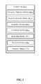
- FIG. 1is a block diagram depicting one embodiment of an environment 100 in which the present systems and methods may be implemented.
- the environment 100includes a control unit 102 - a that is in communication with at least one occupancy sensor 104 , a door sensor 106 , and a mobile device 108 .
- the control unit 102 - ais also in communication with a security system 110 , lighting 112 , and a climate control 114 .
- a wireless networkis utilized to communicate between the control unit 102 - a , the occupancy sensors 104 , the door sensor 106 , and the mobile device 108 .
- networksinclude, but are not limited to, local area networks (LAN), wide area networks (WAN), virtual private networks (VPN), wireless networks (using 802.11, for example), and/or cellular networks (using 3G and/or LTE, for example), Bluetooth networks, z-wave networks, ZigBee networks, other types of networks, or combinations thereof.
- the control unit 102 - amay control at least a part of the security and/or automation system.
- other sensors and/or actuatorsmay send information to the control unit 102 - a where the signals are processed.
- sensorsmay include, for example, a camera sensor, audio sensor, forced entry sensor, shock sensor, proximity sensor, boundary sensor, appliance sensor, light fixture sensor, temperature sensor, light beam sensor, three-dimensional (3-D) sensor, motion sensor, smoke sensor, glass break sensor, door sensor, window sensor, carbon monoxide sensor, accelerometer, global positioning system (GPS) sensor, Wi-Fi positioning system sensor, capacitance sensor, radio frequency sensor, near-field sensor, heartbeat sensor, breathing sensor, oxygen sensor, carbon dioxide sensor, brain wave sensor, movement sensor, voice sensor, other types of sensors, or combinations thereof.
- actuatorsmay include, but are not limited to, automated door locks, climate control adjustors, lighting adjusters, sensors activation mechanisms, other types of actuators, or combinations thereof.
- the control unit 102 - amay make decisions based on the communications from the occupancy sensor 104 and the door sensor 106 . For example, based on the information sent from the occupancy sensor 104 and the door sensor 106 to the control unit 102 - a , the control unit 102 - a may make a decision to activate an alarm, adjust a climate control setting, open or close a window, lock or unlock a door, control a security parameter, manage energy consumption, check the status of a door, locate a person or item, control lighting, control cameras, receive notifications regarding a current status or anomaly associated with a building, perform another task, or combinations thereof. In some cases, a decision may be decided at one of the local sensors, and the local sensors may or may not notify the control unit 102 - a of the decision and/or resulting action.
- control unit 102 - aincludes a user interface where the occupant can interact with the control unit 102 - a .
- the occupantcan manually give instructions to the control unit 102 - a to adjust a building parameter, install an occupancy sensor 104 , or perform another system task.
- the control unit 102 - amay determine whether the building is occupied or unoccupied.
- the occupancy sensor 104communicates with the control unit 102 - a to determine the occupancy state of the building. Any appropriate type or types of occupancy sensors may be used in accordance with the principles described in the present disclosure. A non-exhaustive list of occupancy sensor types may include microphones, motion detectors, video cameras, mobile devices, location devices, infrared devices, temperature devices, touch input devices, other types of devices, or combinations thereof.
- a single occupancy sensor 104is used to determine whether the entire building is occupied. However, in other examples, multiple occupancy sensors 104 are distributed throughout the building to determine whether the building is occupied. In some cases, multiple different types of occupancy sensors 104 are used to increase the accuracy of occupancy detection.
- control unit 102 - amay determine that the building is not occupied when the motion detector does not detect the presence of an occupant within the building. On the other hand, the control unit 102 - a may determine that there is an occupant within the building when the motion detector is triggered.
- the door sensor 106 or a window sensormay indicate to the control unit 102 - a when an event occurs that may indicate a change in occupancy. For example, a probability exists that the building's occupancy state will change when a door to the exterior of the building is open allowing occupants to enter and/or leave the building.
- the control unit 102 - ais aware that the occupancy of the building may have changed.
- the control unit 102 - amay associate a time stamp with the opening and/or closing of the door. The control unit 102 - a may make an assumption that occupancy will be consistent until the occurrence of another door type event.
- a motion detector(or another type of occupancy sensor) may detect the presence of an occupant. As a result, the control unit 102 - a may determine that the building will be occupied until the occurrence of another door type event. Likewise, if the motion detector (or another type of occupancy sensor) does not detect an occupant, the control unit 102 - a may determine that no occupants are within the building and determine that the building will be unoccupied until a subsequent door type event.
- the subsequent door type eventmay be of the same type of event as the initial door type event.
- the initial door type event and the subsequent door type eventmay both be opening the front door to a home.
- the initial door type eventis opening a front door
- the subsequent door type eventis the opening of a back door.
- the initial door type eventmay be opening a door
- the subsequent door type eventmay be the opening of a window, the opening of a garage door, another type of event that may indicate a potential change in occupancy, or combinations thereof. While these examples have been described with reference to specific types of events, any appropriate type of event may be used for either of the initial door type event and the subsequent door type event that can indicate a potential change in occupancy.
- control unit 102 - adetermines that there is occupancy or no occupancy after a predetermined time threshold lapses from the occurrence of the door type event. In other examples, the control unit 102 - a calculates an increased confidence that there is no occupancy within the building as more time passes from the occurrence of the door type event.
- the control unit 102 - a or another type of processing devicemay generate a schedule based on the data collected from the occupancy sensor 104 .
- the occupancy sensors 104 in a household of a single individual who leaves his or her home around 7:45 a.m. and returns home around 5:15 p.m.may have fairly consistent occupancy patterns Monday through Friday.
- the occupancy sensorsmay fail to detect the presence of the individual during the time period that starts around 7:45 a.m. and ends around 5:15 p.m.
- the control unit 102 - amay predict that the household will be unoccupied during this time period.
- the control unit 102 - amay determine that the home will be unoccupied until about 5:15 p.m.
- Such a generated schedulemay vary from day to day.
- the control unit 102 - amay have the capability to determine patterns for each day of the week to account for different schedules on different days of the week.
- the control unit 102 - amay have a capability to recognize weekly patterns, monthly patterns, annual patterns, patterns exhibited over less than a week, patterns exhibited over less than a day, other patterns, or combinations thereof.
- the occupancy sensorsmay be positioned throughout an entire building. In other examples, the occupancy sensors are positioned just within areas that are highly indicative of occupancy throughout the entire building.
- the predictive schedulemay be used, at least in part, to make adjustments to parameters of the building. For example, if the control unit 102 - a receives notice that a door type event has occurred, the control unit 102 - a can consult the predictive schedule. If the door type event coincides with a predicted transition into an unoccupied state, the control unit 102 - a may determine that the building is not occupied. In some examples, the control unit 102 - a may continue to monitor the building with occupancy sensors 104 for a predetermined grace period before making the determination that the building is unoccupied.
- the control unit 102 - amay send commands to various control devices throughout the building to adjust parameters to conserve building resources while the building is unoccupied. For example, the control unit 102 - a may communicate with lighting 112 and a climate control 114 to reduce energy consumption. Similarly, the control unit 102 - a may automatically arm the security system 110 in response to determining that the building is unoccupied. In some examples, appliances like a washing machine may be turned on based on the determination that the building is in an unoccupied state, while other devices, like a television or a radio, may be turned off.
- any appropriate parameter adjustmentmay be made including adjustments to security parameters, climate parameters, lighting parameters, cleaning parameters, energy consumption parameters, computer parameters, television parameters, door parameters, window parameters, blind parameters, fan parameters, appliance parameters, water parameters, network parameters, other types of parameters, or combinations thereof.
- the control unit 102 - amakes the predictive schedule based on just the information from the occupancy sensor 104 .
- information from the occupancy sensor 104may reveal very clear occupancy patterns with easily identified transitions from one state of occupancy to the next.
- the occupancy sensor 104may not have all of the information that the control unit 102 - a desires to make a predictive schedule with a high degree of confidence. Further, some of the information from the occupancy sensor 104 may appear to be contradictory. As a result, the control unit 102 - a may seek user input about those details relevant to the predictive schedule that are missing, vague, inconsistent, or that otherwise appear to be unreliable.
- control unit 102 - amay be in communication with a location tracking device of the occupant's mobile device 108 and the control unit 102 - a may receive communications from the mobile device 108 indicating that the mobile device 108 is away from the building.
- the control unit 102 - amay make the assumption, based on the communications from the mobile device 108 , that the occupant is also away from the building.
- the control unit 102 - amay send a question to the occupant asking whether he or she is currently at the building.
- Another appropriate type of questionmay be a question asking the occupant if there is another occupant living in the home.
- Yet another appropriate questionmay involve asking if another person uses the occupant's mobile device.
- the control unit 102 - amay ask the occupant if there is another person living in the building.
- FIG. 2is a block diagram illustrating one example of a control unit 102 - b .
- the control unit 102 - bhas an occupancy deduction module 200 - a , a predictive schedule module 202 - a , a hypothesis module 204 - a , a confidence module 206 - a , a requesting module 208 - a , a receiving module 210 - a , and a response module 212 - a.
- the occupancy deduction module 200 - amay be used to deduce whether a building is occupied or not. For example, if the occupancy sensor 104 detects the presence of a person, the occupancy deduction module 200 - a may deduce that the building is currently in an occupied state. On the other hand, if the occupancy sensor 104 does not detect the presence of an occupant, the occupancy deduction module 200 - a may deduce that the building is in an unoccupied state. However, in either state, the occupancy deduction module 200 - a may have varying degrees of confidence about the deduced state.
- the predictive schedulehas just an occupied state and an unoccupied state.
- the predictive scheduleincludes additional occupancy states that give more detail about the occupant's behavior, such as an “on the way to work” state, an “at work” state, a “heading home from work” state, another type of state, or combinations thereof.
- the additional occupancy statesmay help the control module understand when the building is likely to be reoccupied.
- the hypothesis module 204 - amay construct any appropriate hypothesis about whether the building is occupied or a hypothesis about a detail that would help the predictive schedule module 202 - a determine if the building is occupied or not. For example, if an occupancy sensor 104 detects music, but there is no other indication that an occupant is in the building, the hypothesis module 204 - a may construct a hypothesis that the occupant left a radio playing before leaving the home. In another example, the hypothesis module 204 - a may construct a hypothesis that the occupant is away from the building based on communications from the mobile device despite movements detected from the occupancy sensor 104 that may be attributable to curtains blowing in the breeze from an open window.
- the requesting module 208 - asends a request to the mobile device 108 .
- the occupantmay respond to the request through a user interface incorporated into the mobile device 108 .
- the requestis emailed to the user or displayed in a display incorporated into the control unit 102 - a . While the examples above have been described with reference to specific mechanisms that the requesting module 208 - a can use to deliver a request for information to the occupant, the requesting module 208 - a may use any appropriate mechanism to send the request to the occupant.
- the response module 212 - aresponses to the received information.
- the response module 212 - adetermines the meaning of the information in the response. In those examples where a predetermined answer was provided and selected, the response module 212 - a determines which of the answers was selected. In other examples, the response module 212 - a may perform a key word analysis in a free text formatted answer. However, any appropriate mechanism may be implemented to determine the meaning of the information in the answer.
- the response module 212 - aresponses to the meaning of the information in the answer.
- the response module 212 - amay send a communication to the predictive schedule module 202 - a indicating either the hypothesis can be treated as fact or confirming to the predictive schedule module 202 - a that the hypothesis is accurate.
- changes to the predictive schedulemay result based on the information received from the occupant.
- the response module 212 - amay determine that no action is appropriate.
- FIG. 3is a block diagram illustrating an example of a hypothesis module 204 - b .
- the hypothesis module 204 - bhas a predictive schedule analyzer module 300 , a blind spot module 302 , and a hypothesis construction module 304 .
- the predictive schedule analyzer module 300analyzes the predictive schedule or the information to be relied upon to construct the predictive schedule. Such an analysis may look at the information that is relied upon to construct the predictive schedule. For example, the analysis may determine the readings from the occupancy sensors and make a determination as to whether that information is reliable for being used in the predictive schedule. In some examples, such information indicates that the building is occupied, but such indicators are not reliable and therefore a low confidence is associated with such information.
- the blind spot module 302identifies if the occupancy sensors 104 are capable of detecting an adequate amount of information to make the predictive schedule. For example, the blind spot module 302 may analyze information to determine whether occupancy sensors 104 are appropriately positioned throughout the building. Such an analysis may cause the blind spot module 302 to consider whether additional occupancy sensors are desirable for detecting occupancy. For example, if there is no occupancy sensor 104 positioned in a room of a home and no other occupancy sensors in the building would be able to detect the presence of an individual in that home, than the room may be part of a blind spot to the occupancy detection system. An analysis of the occupancy sensors may reveal that the sensors' ability to detect the occupant's presence disappears from time to time. Such a failure to detect the occupant's presence may occur when the occupant enters the blind spot. Based on the analysis, the blind spot module 302 may identify patterns indicative of a blind spot.
- the hypothesis construction module 304constructs the hypothesis.
- the hypothesiscan be based on the analysis of the blind spot module 302 , the predictive schedule analyzer module 300 , another module, or combinations thereof.
- An example of a hypothesismay include identifying a location where a blind spot exists.
- Another example of a hypothesismay involve determining that the building is occupied based on data that suggests the building could be occupied, but is not conclusive.
- Another example of a hypothesiscould be predicting the time that the building will transition from one occupancy state to another.
- the confirmation module 400may cause a request to be made that seeks to confirm whether a hypothesis generated by the hypothesis module 204 is accurate.
- the confirmation module 400may formulate a question that restates the hypothesis in a question format.
- a requestmay include “yes” or “no” predetermined answers that can be selected by the recipient of the request.
- the sensor coverage module 402may format requests for information about the location of the occupancy sensors. For example, the request may include asking whether an occupancy sensor is located in a particular room. In another example, the request may involve asking if the occupant is located within a specific room when the occupant has disappeared from the occupancy sensors. In yet another example, a request may ask where the occupant was at a specific time. Such questions may be aimed at determining the adequacy of the occupancy sensors coverage.
- the time period data module 404may make requests for information about time periods where no reliable data for determining occupancy exists. For example, if a time period exists where no occupancy is detected, but no door type event has occurred that could indicate that an occupant left the building, then the request could be directed to finding out the location of where the occupant was during that time. In another example, the request could be directed at determining the location of the occupant when the occupancy sensors and other types of indicators are sending conflicting details about occupancy.
- the location tracking module 406may include requests that deal with determining how many mobile devices are available to determine occupancy. For example, a request may involve asking how many occupants use a mobile device that have location tracking mechanisms that the control unit 102 can use to determine occupancy. Another type of request may include asking how often the occupant is with his or her mobile device to determine how reliable the mobile device's location can be associated with the occupant's location. For example, if the mobile device is often left behind when the occupant leaves his or her home, the control unit 102 can associate a lower confidence with data indicating the occupant's location based on the mobile device's location tracking mechanism.
- FIG. 5is a block diagram illustrating one example of a response module 212 - b .
- the response module 212 - bincludes a predictive schedule modifying module 500 , a confidence score modifying module 502 , and a suggestion module 504 .
- the suggestion module 504can make suggestions to the occupant based on the user's response. For example, if the answer from the occupant indicates that there is likely a blind spot in the occupancy detection system, then the suggestion module 504 can send a message to the occupant suggesting that another occupancy sensor be installed to cover the blind spot.
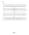
- FIG. 6is a flow diagram illustrating one embodiment of a method 600 for determining occupancy with user provided information.
- the method 600includes using 602 at least one sensor to detect occupancy in a building over time, determining 604 a predictive schedule based on the occupancy detected with the at least one sensor, and requesting 606 information relevant to the predictive schedule from a user.
- Such a method 600may be implemented with a control unit 102 shown in FIGS. 1 and/or 2 .
- method 600may be performed generally by the environment 100 shown in FIG. 1 .
- occupancy sensorsare used to determine whether the building is occupied or unoccupied.
- An occupancy sensormay be any appropriate type of sensor that is capable of determining whether an occupant is present within the building.
- a motion detector, video camera, microphone, thermometer, door sensor, window sensor, another type of sensor, or combinations thereofmay be used to detect the presence of an occupant.
- the predictive scheduleis determined based on the occupancy patterns detected in the building over time. Such a schedule predicts when the building will be occupied and/or unoccupied.
- FIG. 7is a flow diagram illustrating one embodiment of a method 700 for determining occupancy with user provided information.
- the method 700includes using 702 at least one sensor to detect occupancy in a building over time, determining 704 a predictive schedule based on the occupancy detected with the at least one sensor, making 706 a hypothesis about a detail affecting the predictive schedule, and requesting 708 information from a user to confirm the hypothesis.
- Such a method 700may be implemented with a control unit 102 shown in FIGS. 1 and/or 2 .
- method 700may be performed generally by the environment 100 shown in FIG. 1 .
- a hypothesisis formed that can serve as the basis of a question to be asked of the user.
- Such a hypothesismay be based on desirable, but missing, information for making the predictive schedule, based on confidence scores relating to the accuracy of information for making the predictive schedule, based on occupancy sensor data that is indicative of a gap in occupancy sensor coverage, based on communications from a mobile device, based on user input, based on historical occupancy patterns, based on other types of information, or combinations thereof.
- FIG. 8is a flow diagram illustrating one embodiment of a method 800 for determining occupancy with user provided information.
- the method 800includes using 802 at least one sensor to detect occupancy in a building over time, determining 804 a predictive schedule based on the occupancy detected with the at least one sensor, asking 806 a question of the user about ascertained data relevant to the predictive schedule associated with an unreliable confidence score, receiving 808 an answer from the user, and changing 810 the confidence score based on the information from the user.
- Such a method 800may be implemented with a control unit 102 shown in FIGS. 1 and/or 2 . In other examples, method 800 may be performed generally by the environment 100 shown in FIG. 1 .
- a questionis asked of the user about data that has been ascertained by the occupancy detection system.
- the ascertained datahas a low confidence score.
- Data with low confidence scoresmay be deemed too unreliable to be used to create the predictive schedule.
- data with low confidence scoresmay be used to create the predictive schedule, although the system has a preference to use data with higher confidence scores.
- Such a questionis sent to the user in any appropriate manner, such as sending the question to the user's mobile device.
- an answer from the useris received, and at block 810 the confidence score of the relevant information is changed based on the user's response. For example, if the user confirms the accuracy of the data, the confidence score associated with that data may increase. Similarly, if the user denies the accuracy of the data, the confidence score may accordingly decrease.
- FIG. 9is a flow diagram illustrating one embodiment of a method 900 for determining occupancy with user provided information.
- the method 900includes using 902 at least one sensor to detect occupancy in a building over time, determining 904 a predictive schedule based on the occupancy detected with the at least one sensor, requesting 906 information to determine whether the at least one sensor has a blind spot, and suggesting 908 to install another sensor in response to identifying the blind spot.
- Such a method 900may be implemented with a control unit 102 shown in FIGS. 1 and/or 2 .
- method 900may be performed generally by the environment 100 shown in FIG. 1 .
- a suggestionis made to install another sensor in response to identifying a blind spot. For example, if a blind spot is identified in a particular room within the building, the recommendation may be to install an occupancy sensor in that room. Likewise, if just a portion of a specific room is part of a blind spot, the suggestion may include recommending a second occupancy sensor in that room that will cover the area blind to the occupancy sensors. Other suggestions may include recommending that a particular type of occupancy sensor be replaced within another occupancy sensor type, that a specific occupancy sensor be replaced, that a certain occupancy sensor be programmed to operate differently, another type of suggestion, or combinations thereof.
- FIG. 10is a flow diagram illustrating one embodiment of a method 1000 for determining occupancy with user provided information.
- the method 1000includes using 1002 at least one sensor to detect occupancy in a building over time, determining 1004 a predictive schedule based on the occupancy detected with the at least one sensor, asking 1006 a question of the user about missing data relevant to the predictive schedule, receiving 1008 an answer from the user, and changing 1010 the predictive schedule based on the information from the user.
- Such a method 1000may be implemented with a control unit 102 shown in FIGS. 1 and/or 2 .
- method 1000may be performed generally by the environment 100 shown in FIG. 1 .
- a questionis asked of the user about data that is missing and is relevant to the predictive schedule.
- Such missing datamay include data that is desirable to generate the predictive schedule, but was not collected.
- Such datamay not be sent to the appropriate module for creating or modifying the predictive schedule due to inconsistent data or other factors rendering the data less reliable than desired.
- no data relevant to a portion of the predictive schedulewas ever collected.
- an answer to the questionis received.
- Such an answermay be a selected predetermined answer, a free text formatted answer, another type of answer, or combinations thereof.
- the answermay be sent over a mobile device, a speech command, a button input, another mechanism, or combinations thereof.
- a changeis made to the predictive schedule based on the information from the user. For example, if the answer to the question indicates that some information previously believed to be unreliable is accurate data, the predictive schedule may be changed to rely on such information.
- a question asking if the user is often home during that periodmay be sent to the user.
- the usermay indicate in a reply that the user is often home during that period.
- the predictive schedulemay be changed from an unknown predictive state to an occupied predicted state.
- FIG. 11depicts a block diagram of a controller 1100 suitable for implementing the present systems and methods.
- the controller 1100may be an example of the control unit 102 - a in FIG. 1 .
- controller 1100includes a bus 1105 which interconnects major subsystems of controller 1100 , such as a central processor 1110 , a system memory 1115 (typically RAM, but which may also include ROM, flash RAM, or the like), an input/output controller 1120 , an external audio device, such as a speaker system 1125 via an audio output interface 1130 , an external device, such as a display screen 1135 via display adapter 1140 , an input device 1145 (e.g., remote control device interfaced with an input controller 1150 ), multiple USB devices 1165 (interfaced with a USB controller 1170 ), one or more cellular radios 1190 , and a storage interface 1180 . Also included are at least one sensor 1155 connected to bus 1105 through a sensor controller 1160 and a network interface 1185
- an occupancy deduction module 200 - bmay be used to implement the present systems and methods may be stored within the system memory 1115 .
- These modulesmay be an example of the modules illustrated in FIG. 2 .
- Applications resident with controller 1100are generally stored on and accessed via a non-transitory computer readable medium, such as a hard disk drive (e.g., fixed disk 1175 ) or other storage medium. Additionally, applications can be in the form of electronic signals modulated in accordance with the application and data communication technology when accessed via network interface 1185 .
- Storage interface 1180can connect to a standard computer readable medium for storage and/or retrieval of information, such as a fixed disk drive 1175 .
- Fixed disk drive 1175may be a part of controller 1100 or may be separate and accessed through other interface systems.
- Network interface 1185may provide a direct connection to a remote server via a direct network link to the Internet via a POP (point of presence).
- Network interface 1185may provide such connection using wireless techniques, including digital cellular telephone connection, Cellular Digital Packet Data (CDPD) connection, digital satellite data connection, or the like.
- CDPDCellular Digital Packet Data
- controller 1100may be iOS®, ANDROID®, MS-DOS®, MS-WINDOWS®, OS/2®, UNIX®, LINUX®, or another known operating system.
- a signalcan be directly transmitted from a first block to a second block, or a signal can be modified (e.g., amplified, attenuated, delayed, latched, buffered, inverted, filtered, or otherwise modified) between the blocks.
- a signalcan be directly transmitted from a first block to a second block, or a signal can be modified (e.g., amplified, attenuated, delayed, latched, buffered, inverted, filtered, or otherwise modified) between the blocks.
- a signal input at a second blockcan be conceptualized as a second signal derived from a first signal output from a first block due to physical limitations of the circuitry involved (e.g., there will inevitably be some attenuation and delay). Therefore, as used herein, a second signal derived from a first signal includes the first signal or any modifications to the first signal, whether due to circuit limitations or due to passage through other circuit elements which do not change the informational and/or final functional aspect of the first signal.
- the terms “a” or “an,” as used in the specification and claims,are to be construed as meaning “at least one of”
- the words “including” and “having,” as used in the specification and claimsare interchangeable with and have the same meaning as the word “comprising.”
- the term “based on” as used in the specification and the claimsis to be construed as meaning “based at least upon.”
Landscapes
- Engineering & Computer Science (AREA)
- General Engineering & Computer Science (AREA)
- Physics & Mathematics (AREA)
- General Physics & Mathematics (AREA)
- Theoretical Computer Science (AREA)
- Automation & Control Theory (AREA)
- Software Systems (AREA)
- Computational Linguistics (AREA)
- Data Mining & Analysis (AREA)
- Evolutionary Computation (AREA)
- Computing Systems (AREA)
- Mathematical Physics (AREA)
- Artificial Intelligence (AREA)
- Management, Administration, Business Operations System, And Electronic Commerce (AREA)
- Telephonic Communication Services (AREA)
- Fuzzy Systems (AREA)
- Alarm Systems (AREA)
Abstract
Description
Claims (17)
Priority Applications (5)
| Application Number | Priority Date | Filing Date | Title |
|---|---|---|---|
| US14/291,789US10197979B2 (en) | 2014-05-30 | 2014-05-30 | Determining occupancy with user provided information |
| CA2946891ACA2946891A1 (en) | 2014-05-07 | 2015-05-07 | Controlling a building system based on real time events |
| EP15788885.0AEP3140702A4 (en) | 2014-05-07 | 2015-05-07 | Controlling a building system based on real time events |
| PCT/US2015/029670WO2015171882A1 (en) | 2014-05-07 | 2015-05-07 | Controlling a building system based on real time events |
| US16/248,447US11635737B1 (en) | 2014-05-30 | 2019-01-15 | Determining occupancy with user provided information |
Applications Claiming Priority (1)
| Application Number | Priority Date | Filing Date | Title |
|---|---|---|---|
| US14/291,789US10197979B2 (en) | 2014-05-30 | 2014-05-30 | Determining occupancy with user provided information |
Related Child Applications (1)
| Application Number | Title | Priority Date | Filing Date |
|---|---|---|---|
| US16/248,447ContinuationUS11635737B1 (en) | 2014-05-30 | 2019-01-15 | Determining occupancy with user provided information |
Publications (2)
| Publication Number | Publication Date |
|---|---|
| US20150347916A1 US20150347916A1 (en) | 2015-12-03 |
| US10197979B2true US10197979B2 (en) | 2019-02-05 |
Family
ID=54702199
Family Applications (2)
| Application Number | Title | Priority Date | Filing Date |
|---|---|---|---|
| US14/291,789Active2036-02-02US10197979B2 (en) | 2014-05-07 | 2014-05-30 | Determining occupancy with user provided information |
| US16/248,447Active2035-03-04US11635737B1 (en) | 2014-05-30 | 2019-01-15 | Determining occupancy with user provided information |
Family Applications After (1)
| Application Number | Title | Priority Date | Filing Date |
|---|---|---|---|
| US16/248,447Active2035-03-04US11635737B1 (en) | 2014-05-30 | 2019-01-15 | Determining occupancy with user provided information |
Country Status (1)
| Country | Link |
|---|---|
| US (2) | US10197979B2 (en) |
Cited By (3)
| Publication number | Priority date | Publication date | Assignee | Title |
|---|---|---|---|---|
| US10824957B2 (en)* | 2013-11-21 | 2020-11-03 | Panasonic Intellectual Property Management Co., Ltd. | In-home-presence probability calculation method, server apparatus, and in-home-presence probability calculation system |
| US20220042696A1 (en)* | 2019-12-31 | 2022-02-10 | Lennox Industries Inc. | Error correction for predictive schedules for a thermostat |
| US11416878B2 (en) | 2019-12-10 | 2022-08-16 | At&T Intellectual Property I, L.P. | Detection of usage of a physical environment |
Families Citing this family (17)
| Publication number | Priority date | Publication date | Assignee | Title |
|---|---|---|---|---|
| US9903606B2 (en) | 2014-04-29 | 2018-02-27 | Vivint, Inc. | Controlling parameters in a building |
| US11099533B2 (en)* | 2014-05-07 | 2021-08-24 | Vivint, Inc. | Controlling a building system based on real time events |
| US10197979B2 (en) | 2014-05-30 | 2019-02-05 | Vivint, Inc. | Determining occupancy with user provided information |
| US10359746B2 (en)* | 2016-04-12 | 2019-07-23 | SILVAIR Sp. z o.o. | System and method for space-driven building automation and control including actor nodes subscribed to a set of addresses including addresses that are representative of spaces within a building to be controlled |
| EP4502965A3 (en) | 2016-11-23 | 2025-04-09 | Alarm.com Incorporated | Detection of authorized user presence and handling of unauthenticated monitoring system commands |
| US10650652B1 (en)* | 2017-03-30 | 2020-05-12 | Alarm.Com Incorporated | Integrated security for multiple access control systems |
| US20180330599A1 (en)* | 2017-05-10 | 2018-11-15 | Katerra, Inc. | Method and apparatus for real property monitoring and control system |
| US20180330597A1 (en)* | 2017-05-10 | 2018-11-15 | Katerra, Inc. | Method and apparatus for real property alarm system |
| US11048218B2 (en)* | 2017-05-10 | 2021-06-29 | Katerra, Inc. | Method and apparatus for controlling devices in a real property monitoring and control system |
| US10713922B1 (en) | 2017-05-10 | 2020-07-14 | Katerra, Inc. | Method and apparatus for exchanging messages with users of a real property monitoring and control system |
| US11086283B2 (en)* | 2017-05-10 | 2021-08-10 | Katerra, Inc. | Method and apparatus for real property monitoring and control system |
| EP3441951B1 (en) | 2017-08-08 | 2020-03-18 | Carrier Corporation | Door lock with display unit |
| US10382284B1 (en) | 2018-03-02 | 2019-08-13 | SILVAIR Sp. z o.o. | System and method for commissioning mesh network-capable devices within a building automation and control system |
| US11680423B2 (en) | 2019-05-01 | 2023-06-20 | Vbc Tracy Llc | Electromechanical locking apparatus and method and apparatus for controlling the same in a real property monitoring and control system |
| US12380517B2 (en) | 2020-08-18 | 2025-08-05 | Tyco Fire & Security Gmbh | Building system with a recommendation interface |
| US12287105B2 (en) | 2021-07-13 | 2025-04-29 | SILVAIR Sp. z o.o. | Networked sensors integrated with heating, ventilation, and air conditioning (HVAC) systems |
| US20230111459A1 (en) | 2021-10-13 | 2023-04-13 | Johnson Controls Tyco IP Holdings LLP | Building system for building equipment with external model integration |
Citations (91)
| Publication number | Priority date | Publication date | Assignee | Title |
|---|---|---|---|---|
| US4174064A (en) | 1977-12-27 | 1979-11-13 | Teleci, Inc. | Energy control system providing selective control of remote zone heating or cooling from a central location |
| US5344068A (en) | 1993-04-16 | 1994-09-06 | Staefa Control System, Inc. | Dynamically controlled environmental control system |
| US5668446A (en) | 1995-01-17 | 1997-09-16 | Negawatt Technologies Inc. | Energy management control system for fluorescent lighting |
| US5699243A (en) | 1995-02-02 | 1997-12-16 | Hubbell Incorporated | Motion sensing system with adaptive timing for controlling lighting fixtures |
| US5909378A (en) | 1997-04-09 | 1999-06-01 | De Milleville; Hugues | Control apparatus and method for maximizing energy saving in operation of HVAC equipment and the like |
| US5924486A (en) | 1997-10-29 | 1999-07-20 | Tecom, Inc. | Environmental condition control and energy management system and method |
| US5973594A (en) | 1995-03-29 | 1999-10-26 | Hubbell Incorporated | Multiple optical designs for a multifunction sensor |
| US6108614A (en) | 1993-01-22 | 2000-08-22 | Diablo Research Corporation | System and method for serial communication between a central unit and a plurality of remote units |
| US6263260B1 (en) | 1996-05-21 | 2001-07-17 | Hts High Technology Systems Ag | Home and building automation system |
| US6377858B1 (en) | 1997-10-02 | 2002-04-23 | Lucent Technologies Inc. | System and method for recording and controlling on/off events of devices of a dwelling |
| US20020134849A1 (en) | 2001-03-02 | 2002-09-26 | Disser James R. | Method and apparatus for reducing energy consumption in heating, ventilating, and air conditioning of unoccupied building zones |
| US20070032225A1 (en) | 2005-08-03 | 2007-02-08 | Konicek Jeffrey C | Realtime, location-based cell phone enhancements, uses, and applications |
| US20080079569A1 (en) | 2006-09-29 | 2008-04-03 | Edward George Axelsen | Real-Time Room Occupancy Monitoring System |
| GB2448896A (en) | 2007-05-02 | 2008-11-05 | Montford University De | Energy management system |
| US7469550B2 (en) | 2004-01-08 | 2008-12-30 | Robertshaw Controls Company | System and method for controlling appliances and thermostat for use therewith |
| WO2009036764A2 (en) | 2007-09-20 | 2009-03-26 | Danfoss A/S | Distance regulated energy consuming devices |
| US20100025483A1 (en) | 2008-07-31 | 2010-02-04 | Michael Hoeynck | Sensor-Based Occupancy and Behavior Prediction Method for Intelligently Controlling Energy Consumption Within a Building |
| US7761186B2 (en) | 2008-01-28 | 2010-07-20 | Tlc Integration, Llc | Automated lighting and building control system |
| US7765033B2 (en) | 2007-06-22 | 2010-07-27 | Dsa, Inc. | Intelligent device control system |
| US7918406B2 (en) | 2008-07-22 | 2011-04-05 | Howard Rosen | Override of nonoccupancy status in a thermostat device based upon analysis of recent patterns of occupancy |
| US20110181412A1 (en) | 2010-01-22 | 2011-07-28 | Assa Abloy Hospitality, Inc. | Energy management and security in multi-unit facilities |
| US20110253796A1 (en) | 2010-04-14 | 2011-10-20 | Posa John G | Zone-based hvac system |
| US8066558B2 (en) | 2004-11-24 | 2011-11-29 | Honeywell International Inc. | Demand control ventilation sensor failure |
| US8086352B1 (en) | 2007-10-04 | 2011-12-27 | Scott Elliott | Predictive efficient residential energy controls |
| US20120025717A1 (en) | 2009-04-09 | 2012-02-02 | Koninklijke Philips Electronics N.V. | Intelligent lighting control system |
| US8111131B2 (en) | 2008-08-15 | 2012-02-07 | Abl Ip Holding, Llc | Occupancy sensors programmed to determine loss of lamp life as lamp is used |
| US20120066168A1 (en) | 2010-09-14 | 2012-03-15 | Nest Labs, Inc. | Occupancy pattern detection, estimation and prediction |
| US20120086568A1 (en) | 2010-10-06 | 2012-04-12 | Microsoft Corporation | Inferring Building Metadata From Distributed Sensors |
| US20120085831A1 (en) | 2010-10-07 | 2012-04-12 | Energy Eye, Inc. | Systems and methods for controlling the temperature of a room based on occupancy |
| US8180492B2 (en) | 2008-07-14 | 2012-05-15 | Ecofactor, Inc. | System and method for using a networked electronic device as an occupancy sensor for an energy management system |
| US8195313B1 (en) | 2010-11-19 | 2012-06-05 | Nest Labs, Inc. | Thermostat user interface |
| US20120143357A1 (en) | 2010-11-04 | 2012-06-07 | Digital Lumens, Inc. | Method, apparatus, and system for occupancy sensing |
| US20120143810A1 (en) | 2010-09-02 | 2012-06-07 | Anker Berg-Sonne | Rules engine with database triggering |
| US20120165993A1 (en)* | 2010-10-28 | 2012-06-28 | University Of Virginia Patent Foundation | Self-Programming Thermostat System, Method and Computer Program Product |
| US8214061B2 (en) | 2006-05-26 | 2012-07-03 | Abl Ip Holding Llc | Distributed intelligence automated lighting systems and methods |
| US8219251B2 (en)* | 2003-12-02 | 2012-07-10 | Honeywell International Inc. | Interview programming for an HVAC controller |
| US20120186774A1 (en) | 2010-11-19 | 2012-07-26 | Nest Labs, Inc. | Control unit with automatic setback capability |
| US20120259469A1 (en) | 2009-12-16 | 2012-10-11 | John Ward | Hvac control system and method |
| WO2012142477A2 (en) | 2011-04-15 | 2012-10-18 | Egs Electrical Group, Llc | Self-adjusting thermostat for floor warming control systems and other applications |
| US20120265501A1 (en) | 2011-04-12 | 2012-10-18 | Goldstein Rhys | Generation of occupant activities based on recorded occupant behavior |
| US20120271460A1 (en) | 2011-04-22 | 2012-10-25 | Rognli Roger W | Universal demand-response remote control for ductless split system |
| US20120299728A1 (en) | 2011-05-23 | 2012-11-29 | Crestron Electronics, Inc. | Occupancy Sensor with Stored Occupancy Schedule |
| US20120310376A1 (en)* | 2011-06-02 | 2012-12-06 | Microsoft Corporation | Occupancy prediction using historical occupancy patterns |
| US8335842B2 (en) | 2004-03-16 | 2012-12-18 | Icontrol Networks, Inc. | Premises management networking |
| US8350697B2 (en) | 2009-05-18 | 2013-01-08 | Alarm.Com Incorporated | Remote device control and energy monitoring by analyzing data and applying rules |
| US20130030600A1 (en) | 2011-07-27 | 2013-01-31 | Honeywell International Inc. | Systems and methods for managing a programmable thermostat |
| US8386082B2 (en) | 2003-11-23 | 2013-02-26 | Alertme.Com Ltd. | Utilizing cell phone location for occupancy determination and home energy control |
| US20130060360A1 (en) | 2011-09-02 | 2013-03-07 | Kabushiki Kaisha Toshiba | Control server and control method |
| US8412654B2 (en) | 2008-10-08 | 2013-04-02 | Rey Montalvo | Method and system for fully automated energy curtailment |
| US8457796B2 (en) | 2009-03-11 | 2013-06-04 | Deepinder Singh Thind | Predictive conditioning in occupancy zones |
| US8458102B2 (en) | 2006-11-22 | 2013-06-04 | Aol Inc. | User behavior-based remotely-triggered automated actions |
| US8457793B2 (en) | 2008-09-10 | 2013-06-04 | Enlighted, Inc. | Intelligent lighting management and building control system |
| US20130151012A1 (en) | 2011-12-12 | 2013-06-13 | Honeywell International Inc. | System and method for optimal load and source scheduling in context aware homes |
| US8478447B2 (en) | 2010-11-19 | 2013-07-02 | Nest Labs, Inc. | Computational load distribution in a climate control system having plural sensing microsystems |
| US20130173064A1 (en)* | 2011-10-21 | 2013-07-04 | Nest Labs, Inc. | User-friendly, network connected learning thermostat and related systems and methods |
| US8511577B2 (en) | 2011-02-24 | 2013-08-20 | Nest Labs, Inc. | Thermostat with power stealing delay interval at transitions between power stealing states |
| US8511576B2 (en) | 2011-02-24 | 2013-08-20 | Nest Labs, Inc. | Power management in energy buffered building control unit |
| US8523083B2 (en) | 2011-02-24 | 2013-09-03 | Nest Labs, Inc. | Thermostat with self-configuring connections to facilitate do-it-yourself installation |
| US8538596B2 (en) | 2010-12-20 | 2013-09-17 | Redwood Systems, Inc. | Light timeout optimization |
| US20130245837A1 (en) | 2012-03-19 | 2013-09-19 | Wojciech Maciej Grohman | System for controlling HVAC and lighting functionality |
| US8543244B2 (en) | 2008-12-19 | 2013-09-24 | Oliver Joe Keeling | Heating and cooling control methods and systems |
| US8544285B2 (en) | 2010-11-19 | 2013-10-01 | Nest Labs, Inc. | HVAC controller with user-friendly installation features facilitating both do-it-yourself and professional installation scenarios |
| KR20130107838A (en) | 2012-03-23 | 2013-10-02 | 영남대학교 산학협력단 | Heating and cooling unit and method for managing heating and cooling of the same |
| US8554376B1 (en) | 2012-09-30 | 2013-10-08 | Nest Labs, Inc | Intelligent controller for an environmental control system |
| US20130268124A1 (en) | 2012-04-05 | 2013-10-10 | Yoky Matsuoka | Distribution of call-home events over time to ameliorate high communications and computation peaks in intelligent control system |
| US20130268125A1 (en) | 2012-04-05 | 2013-10-10 | Yoky Matsuoka | Continuous intelligent-control-system update using information requests directed to user devices |
| US8556188B2 (en) | 2010-05-26 | 2013-10-15 | Ecofactor, Inc. | System and method for using a mobile electronic device to optimize an energy management system |
| US20130292481A1 (en) | 2012-05-07 | 2013-11-07 | Nest Labs, Inc. | Building control unit method and controls |
| US20130325189A1 (en) | 2012-06-04 | 2013-12-05 | Azbil Corporation | Need identifying device, air-conditioning controlling system, need identifying method, and air-conditioning controlling method |
| US8620841B1 (en)* | 2012-08-31 | 2013-12-31 | Nest Labs, Inc. | Dynamic distributed-sensor thermostat network for forecasting external events |
| US8627127B2 (en) | 2011-02-24 | 2014-01-07 | Nest Labs, Inc. | Power-preserving communications architecture with long-polling persistent cloud channel for wireless network-connected thermostat |
| US8622314B2 (en) | 2011-10-21 | 2014-01-07 | Nest Labs, Inc. | Smart-home device that self-qualifies for away-state functionality |
| US20140012821A1 (en) | 2011-03-17 | 2014-01-09 | Koninklijke Philips N.V. | Reliable profiling for monitoring systems |
| US8630740B2 (en) | 2011-10-21 | 2014-01-14 | Nest Labs, Inc. | Automated control-schedule acquisition within an intelligent controller |
| US8630741B1 (en) | 2012-09-30 | 2014-01-14 | Nest Labs, Inc. | Automated presence detection and presence-related control within an intelligent controller |
| US20140052300A1 (en) | 2010-12-31 | 2014-02-20 | Nest Labs, Inc. | Inhibiting deleterious control coupling in an enclosure having multiple hvac regions |
| WO2014033189A1 (en) | 2012-08-28 | 2014-03-06 | Katholieke Universiteit Leuven | Control of thermally activated building systems |
| US20140098596A1 (en) | 2012-10-09 | 2014-04-10 | Nvidia Corporation | 8-transistor dual-ported static random access memory |
| US20140107846A1 (en) | 2012-10-12 | 2014-04-17 | Telefonaktiebolaget L M Ericsson (Publ) | Method for synergistic occupancy sensing in commercial real estates |
| KR20140047851A (en) | 2012-10-15 | 2014-04-23 | (주)홈시큐넷 | Building automation system |
| US20140239817A1 (en) | 2013-02-25 | 2014-08-28 | Leviton Manufacturing Company, Inc. | System and Method for Occupancy Sensing with Enhanced Functionality |
| US8850348B2 (en)* | 2010-12-31 | 2014-09-30 | Google Inc. | Dynamic device-associated feedback indicative of responsible device usage |
| US20150070181A1 (en) | 2013-09-12 | 2015-03-12 | Google Inc. | Detector unit with multiple integrated sensing systems and visually pleasing housing |
| US20150285527A1 (en) | 2014-04-04 | 2015-10-08 | Samsung Electronics Co., Ltd. | Method and apparatus for controlling energy in hvac system |
| US20150297778A1 (en) | 2014-04-18 | 2015-10-22 | Thomas A. Conroy | Method and system of sensor feedback for a scent diffusion device |
| US20150309484A1 (en) | 2014-04-24 | 2015-10-29 | Vivint, Inc. | Managing home automation system based on behavior |
| US20150308706A1 (en) | 2014-04-29 | 2015-10-29 | Vivint, Inc. | Controlling parameters in a building |
| US20150323915A1 (en) | 2014-05-07 | 2015-11-12 | Vivint, Inc. | Controlling a building system based on real time events |
| US20150347916A1 (en) | 2014-05-30 | 2015-12-03 | Vivint, Inc. | Determining occupancy with user provided information |
| US20160004237A1 (en) | 2012-01-16 | 2016-01-07 | Enlighted, Inc. | Building control system |
| US20170153613A1 (en) | 2013-02-06 | 2017-06-01 | Tendril Networks, Inc. | Dynamically adaptive personalized smart energy profiles |
Family Cites Families (8)
| Publication number | Priority date | Publication date | Assignee | Title |
|---|---|---|---|---|
| US6759954B1 (en) | 1997-10-15 | 2004-07-06 | Hubbell Incorporated | Multi-dimensional vector-based occupancy sensor and method of operating same |
| JP5103778B2 (en)* | 2006-04-17 | 2012-12-19 | ダイキン工業株式会社 | Air conditioning system |
| AU2009225446B2 (en) | 2008-03-20 | 2014-02-13 | Signify Holding B.V. | Illumination device and fixture |
| US9799205B2 (en) | 2013-07-15 | 2017-10-24 | Oneevent Technologies, Inc. | Owner controlled evacuation system with notification and route guidance provided by a user device |
| US8509954B2 (en) | 2009-08-21 | 2013-08-13 | Allure Energy, Inc. | Energy management system and method |
| GB201005320D0 (en) | 2010-03-30 | 2010-05-12 | Telepure Ltd | Improvements in controllers, particularly controllers for use in heating, ventilation and air conditioning systems |
| US8547036B2 (en) | 2011-11-20 | 2013-10-01 | Available For Licensing | Solid state light system with broadband optical communication capability |
| US10557637B2 (en) | 2014-01-20 | 2020-02-11 | Emerson Electric Co. | Facilitating scheduling of comfort controllers |
- 2014
- 2014-05-30USUS14/291,789patent/US10197979B2/enactiveActive
- 2019
- 2019-01-15USUS16/248,447patent/US11635737B1/enactiveActive
Patent Citations (111)
| Publication number | Priority date | Publication date | Assignee | Title |
|---|---|---|---|---|
| US4174064A (en) | 1977-12-27 | 1979-11-13 | Teleci, Inc. | Energy control system providing selective control of remote zone heating or cooling from a central location |
| US6108614A (en) | 1993-01-22 | 2000-08-22 | Diablo Research Corporation | System and method for serial communication between a central unit and a plurality of remote units |
| US5344068A (en) | 1993-04-16 | 1994-09-06 | Staefa Control System, Inc. | Dynamically controlled environmental control system |
| US5668446A (en) | 1995-01-17 | 1997-09-16 | Negawatt Technologies Inc. | Energy management control system for fluorescent lighting |
| US5962989A (en) | 1995-01-17 | 1999-10-05 | Negawatt Technologies Inc. | Energy management control system |
| US5699243A (en) | 1995-02-02 | 1997-12-16 | Hubbell Incorporated | Motion sensing system with adaptive timing for controlling lighting fixtures |
| US5973594A (en) | 1995-03-29 | 1999-10-26 | Hubbell Incorporated | Multiple optical designs for a multifunction sensor |
| US6263260B1 (en) | 1996-05-21 | 2001-07-17 | Hts High Technology Systems Ag | Home and building automation system |
| US5909378A (en) | 1997-04-09 | 1999-06-01 | De Milleville; Hugues | Control apparatus and method for maximizing energy saving in operation of HVAC equipment and the like |
| US6377858B1 (en) | 1997-10-02 | 2002-04-23 | Lucent Technologies Inc. | System and method for recording and controlling on/off events of devices of a dwelling |
| US6216956B1 (en) | 1997-10-29 | 2001-04-17 | Tocom, Inc. | Environmental condition control and energy management system and method |
| US5924486A (en) | 1997-10-29 | 1999-07-20 | Tecom, Inc. | Environmental condition control and energy management system and method |
| US20020134849A1 (en) | 2001-03-02 | 2002-09-26 | Disser James R. | Method and apparatus for reducing energy consumption in heating, ventilating, and air conditioning of unoccupied building zones |
| US8386082B2 (en) | 2003-11-23 | 2013-02-26 | Alertme.Com Ltd. | Utilizing cell phone location for occupancy determination and home energy control |
| US8600562B2 (en) | 2003-11-27 | 2013-12-03 | Alertme.Com Ltd | Household energy management sytem |
| US8219251B2 (en)* | 2003-12-02 | 2012-07-10 | Honeywell International Inc. | Interview programming for an HVAC controller |
| US7469550B2 (en) | 2004-01-08 | 2008-12-30 | Robertshaw Controls Company | System and method for controlling appliances and thermostat for use therewith |
| US8335842B2 (en) | 2004-03-16 | 2012-12-18 | Icontrol Networks, Inc. | Premises management networking |
| US8066558B2 (en) | 2004-11-24 | 2011-11-29 | Honeywell International Inc. | Demand control ventilation sensor failure |
| US20070032225A1 (en) | 2005-08-03 | 2007-02-08 | Konicek Jeffrey C | Realtime, location-based cell phone enhancements, uses, and applications |
| US8214061B2 (en) | 2006-05-26 | 2012-07-03 | Abl Ip Holding Llc | Distributed intelligence automated lighting systems and methods |
| US20080079569A1 (en) | 2006-09-29 | 2008-04-03 | Edward George Axelsen | Real-Time Room Occupancy Monitoring System |
| US8458102B2 (en) | 2006-11-22 | 2013-06-04 | Aol Inc. | User behavior-based remotely-triggered automated actions |
| GB2448896A (en) | 2007-05-02 | 2008-11-05 | Montford University De | Energy management system |
| US7765033B2 (en) | 2007-06-22 | 2010-07-27 | Dsa, Inc. | Intelligent device control system |
| WO2009036764A2 (en) | 2007-09-20 | 2009-03-26 | Danfoss A/S | Distance regulated energy consuming devices |
| US8086352B1 (en) | 2007-10-04 | 2011-12-27 | Scott Elliott | Predictive efficient residential energy controls |
| US20120072030A1 (en) | 2007-10-04 | 2012-03-22 | Mountainlogic, Inc. | System and method of predictive occupancy room conditioning |
| US7761186B2 (en) | 2008-01-28 | 2010-07-20 | Tlc Integration, Llc | Automated lighting and building control system |
| US8180492B2 (en) | 2008-07-14 | 2012-05-15 | Ecofactor, Inc. | System and method for using a networked electronic device as an occupancy sensor for an energy management system |
| US7918406B2 (en) | 2008-07-22 | 2011-04-05 | Howard Rosen | Override of nonoccupancy status in a thermostat device based upon analysis of recent patterns of occupancy |
| US20100025483A1 (en) | 2008-07-31 | 2010-02-04 | Michael Hoeynck | Sensor-Based Occupancy and Behavior Prediction Method for Intelligently Controlling Energy Consumption Within a Building |
| US8111131B2 (en) | 2008-08-15 | 2012-02-07 | Abl Ip Holding, Llc | Occupancy sensors programmed to determine loss of lamp life as lamp is used |
| US8410896B2 (en) | 2008-08-15 | 2013-04-02 | Abl Ip Holding, Llc | Occupancy sensors programmed to determine loss of lamp life as lamp is used |
| US8237540B2 (en) | 2008-08-15 | 2012-08-07 | Abl Ip Holding, Llc | Occupancy sensors programmed to determine loss of lamp life as lamp is used |
| US8457793B2 (en) | 2008-09-10 | 2013-06-04 | Enlighted, Inc. | Intelligent lighting management and building control system |
| US8412654B2 (en) | 2008-10-08 | 2013-04-02 | Rey Montalvo | Method and system for fully automated energy curtailment |
| US8543244B2 (en) | 2008-12-19 | 2013-09-24 | Oliver Joe Keeling | Heating and cooling control methods and systems |
| US8457796B2 (en) | 2009-03-11 | 2013-06-04 | Deepinder Singh Thind | Predictive conditioning in occupancy zones |
| US20120025717A1 (en) | 2009-04-09 | 2012-02-02 | Koninklijke Philips Electronics N.V. | Intelligent lighting control system |
| US8350697B2 (en) | 2009-05-18 | 2013-01-08 | Alarm.Com Incorporated | Remote device control and energy monitoring by analyzing data and applying rules |
| US20120259469A1 (en) | 2009-12-16 | 2012-10-11 | John Ward | Hvac control system and method |
| US20110181412A1 (en) | 2010-01-22 | 2011-07-28 | Assa Abloy Hospitality, Inc. | Energy management and security in multi-unit facilities |
| US20110253796A1 (en) | 2010-04-14 | 2011-10-20 | Posa John G | Zone-based hvac system |
| US8556188B2 (en) | 2010-05-26 | 2013-10-15 | Ecofactor, Inc. | System and method for using a mobile electronic device to optimize an energy management system |
| US20120150788A1 (en) | 2010-09-02 | 2012-06-14 | Pepperdash Technology Corporation | Automated facilities management system |
| US20120143356A1 (en) | 2010-09-02 | 2012-06-07 | Pepperdash Technology Corporation | Automated facilities management system |
| US20120143810A1 (en) | 2010-09-02 | 2012-06-07 | Anker Berg-Sonne | Rules engine with database triggering |
| US8510255B2 (en)* | 2010-09-14 | 2013-08-13 | Nest Labs, Inc. | Occupancy pattern detection, estimation and prediction |
| US9245229B2 (en) | 2010-09-14 | 2016-01-26 | Google Inc. | Occupancy pattern detection, estimation and prediction |
| US20130297555A1 (en)* | 2010-09-14 | 2013-11-07 | Nest Labs, Inc. | Occupancy pattern detection, estimation and prediction |
| US20120066168A1 (en) | 2010-09-14 | 2012-03-15 | Nest Labs, Inc. | Occupancy pattern detection, estimation and prediction |
| US20120086568A1 (en) | 2010-10-06 | 2012-04-12 | Microsoft Corporation | Inferring Building Metadata From Distributed Sensors |
| US20120085831A1 (en) | 2010-10-07 | 2012-04-12 | Energy Eye, Inc. | Systems and methods for controlling the temperature of a room based on occupancy |
| US20120165993A1 (en)* | 2010-10-28 | 2012-06-28 | University Of Virginia Patent Foundation | Self-Programming Thermostat System, Method and Computer Program Product |
| US20120143357A1 (en) | 2010-11-04 | 2012-06-07 | Digital Lumens, Inc. | Method, apparatus, and system for occupancy sensing |
| US8560128B2 (en) | 2010-11-19 | 2013-10-15 | Nest Labs, Inc. | Adjusting proximity thresholds for activating a device user interface |
| US8195313B1 (en) | 2010-11-19 | 2012-06-05 | Nest Labs, Inc. | Thermostat user interface |
| US20140005837A1 (en) | 2010-11-19 | 2014-01-02 | Nest Labs, Inc. | Thermostat user interface |
| US8478447B2 (en) | 2010-11-19 | 2013-07-02 | Nest Labs, Inc. | Computational load distribution in a climate control system having plural sensing microsystems |
| US20120186774A1 (en) | 2010-11-19 | 2012-07-26 | Nest Labs, Inc. | Control unit with automatic setback capability |
| US8489243B2 (en) | 2010-11-19 | 2013-07-16 | Nest Labs, Inc. | Thermostat user interface |
| US8280536B1 (en) | 2010-11-19 | 2012-10-02 | Nest Labs, Inc. | Thermostat user interface |
| US8544285B2 (en) | 2010-11-19 | 2013-10-01 | Nest Labs, Inc. | HVAC controller with user-friendly installation features facilitating both do-it-yourself and professional installation scenarios |
| US8538596B2 (en) | 2010-12-20 | 2013-09-17 | Redwood Systems, Inc. | Light timeout optimization |
| US8850348B2 (en)* | 2010-12-31 | 2014-09-30 | Google Inc. | Dynamic device-associated feedback indicative of responsible device usage |
| US20140052300A1 (en) | 2010-12-31 | 2014-02-20 | Nest Labs, Inc. | Inhibiting deleterious control coupling in an enclosure having multiple hvac regions |
| US8523083B2 (en) | 2011-02-24 | 2013-09-03 | Nest Labs, Inc. | Thermostat with self-configuring connections to facilitate do-it-yourself installation |
| US8627127B2 (en) | 2011-02-24 | 2014-01-07 | Nest Labs, Inc. | Power-preserving communications architecture with long-polling persistent cloud channel for wireless network-connected thermostat |
| US8511576B2 (en) | 2011-02-24 | 2013-08-20 | Nest Labs, Inc. | Power management in energy buffered building control unit |
| US8511577B2 (en) | 2011-02-24 | 2013-08-20 | Nest Labs, Inc. | Thermostat with power stealing delay interval at transitions between power stealing states |
| US20140012821A1 (en) | 2011-03-17 | 2014-01-09 | Koninklijke Philips N.V. | Reliable profiling for monitoring systems |
| US20120265501A1 (en) | 2011-04-12 | 2012-10-18 | Goldstein Rhys | Generation of occupant activities based on recorded occupant behavior |
| US20120261481A1 (en) | 2011-04-15 | 2012-10-18 | Egs Electrical Group, Llc | Self-Adjusting Thermostat for Floor Warming Control Systems and Other Applications |
| WO2012142477A3 (en) | 2011-04-15 | 2013-08-01 | Egs Electrical Group, Llc | Self-adjusting thermostat for floor warming control systems and other applications |
| WO2012142477A2 (en) | 2011-04-15 | 2012-10-18 | Egs Electrical Group, Llc | Self-adjusting thermostat for floor warming control systems and other applications |
| US20120271460A1 (en) | 2011-04-22 | 2012-10-25 | Rognli Roger W | Universal demand-response remote control for ductless split system |
| US20120299728A1 (en) | 2011-05-23 | 2012-11-29 | Crestron Electronics, Inc. | Occupancy Sensor with Stored Occupancy Schedule |
| US20120310376A1 (en)* | 2011-06-02 | 2012-12-06 | Microsoft Corporation | Occupancy prediction using historical occupancy patterns |
| US20130030600A1 (en) | 2011-07-27 | 2013-01-31 | Honeywell International Inc. | Systems and methods for managing a programmable thermostat |
| US20130060360A1 (en) | 2011-09-02 | 2013-03-07 | Kabushiki Kaisha Toshiba | Control server and control method |
| US8532827B2 (en) | 2011-10-21 | 2013-09-10 | Nest Labs, Inc. | Prospective determination of processor wake-up conditions in energy buffered HVAC control unit |
| US8558179B2 (en) | 2011-10-21 | 2013-10-15 | Nest Labs, Inc. | Integrating sensing systems into thermostat housing in manners facilitating compact and visually pleasing physical characteristics thereof |
| US20130173064A1 (en)* | 2011-10-21 | 2013-07-04 | Nest Labs, Inc. | User-friendly, network connected learning thermostat and related systems and methods |
| US8630740B2 (en) | 2011-10-21 | 2014-01-14 | Nest Labs, Inc. | Automated control-schedule acquisition within an intelligent controller |
| US8622314B2 (en) | 2011-10-21 | 2014-01-07 | Nest Labs, Inc. | Smart-home device that self-qualifies for away-state functionality |
| US20130151012A1 (en) | 2011-12-12 | 2013-06-13 | Honeywell International Inc. | System and method for optimal load and source scheduling in context aware homes |
| US20160004237A1 (en) | 2012-01-16 | 2016-01-07 | Enlighted, Inc. | Building control system |
| US20130245837A1 (en) | 2012-03-19 | 2013-09-19 | Wojciech Maciej Grohman | System for controlling HVAC and lighting functionality |
| KR20130107838A (en) | 2012-03-23 | 2013-10-02 | 영남대학교 산학협력단 | Heating and cooling unit and method for managing heating and cooling of the same |
| US20130268125A1 (en) | 2012-04-05 | 2013-10-10 | Yoky Matsuoka | Continuous intelligent-control-system update using information requests directed to user devices |
| US20130268124A1 (en) | 2012-04-05 | 2013-10-10 | Yoky Matsuoka | Distribution of call-home events over time to ameliorate high communications and computation peaks in intelligent control system |
| US20130292481A1 (en) | 2012-05-07 | 2013-11-07 | Nest Labs, Inc. | Building control unit method and controls |
| US20130325189A1 (en) | 2012-06-04 | 2013-12-05 | Azbil Corporation | Need identifying device, air-conditioning controlling system, need identifying method, and air-conditioning controlling method |
| WO2014033189A1 (en) | 2012-08-28 | 2014-03-06 | Katholieke Universiteit Leuven | Control of thermally activated building systems |
| US8620841B1 (en)* | 2012-08-31 | 2013-12-31 | Nest Labs, Inc. | Dynamic distributed-sensor thermostat network for forecasting external events |
| US8630741B1 (en) | 2012-09-30 | 2014-01-14 | Nest Labs, Inc. | Automated presence detection and presence-related control within an intelligent controller |
| US8554376B1 (en) | 2012-09-30 | 2013-10-08 | Nest Labs, Inc | Intelligent controller for an environmental control system |
| US20140098596A1 (en) | 2012-10-09 | 2014-04-10 | Nvidia Corporation | 8-transistor dual-ported static random access memory |
| US20140107846A1 (en) | 2012-10-12 | 2014-04-17 | Telefonaktiebolaget L M Ericsson (Publ) | Method for synergistic occupancy sensing in commercial real estates |
| KR20140047851A (en) | 2012-10-15 | 2014-04-23 | (주)홈시큐넷 | Building automation system |
| US20170153613A1 (en) | 2013-02-06 | 2017-06-01 | Tendril Networks, Inc. | Dynamically adaptive personalized smart energy profiles |
| US20150264777A1 (en) | 2013-02-25 | 2015-09-17 | Leviton Manufacturing Co., Inc. | System and method for occupancy sensing with enhanced functionality |
| US20140239817A1 (en) | 2013-02-25 | 2014-08-28 | Leviton Manufacturing Company, Inc. | System and Method for Occupancy Sensing with Enhanced Functionality |
| US20150070181A1 (en) | 2013-09-12 | 2015-03-12 | Google Inc. | Detector unit with multiple integrated sensing systems and visually pleasing housing |
| US20150285527A1 (en) | 2014-04-04 | 2015-10-08 | Samsung Electronics Co., Ltd. | Method and apparatus for controlling energy in hvac system |
| US20150297778A1 (en) | 2014-04-18 | 2015-10-22 | Thomas A. Conroy | Method and system of sensor feedback for a scent diffusion device |
| US20150309484A1 (en) | 2014-04-24 | 2015-10-29 | Vivint, Inc. | Managing home automation system based on behavior |
| US20150308706A1 (en) | 2014-04-29 | 2015-10-29 | Vivint, Inc. | Controlling parameters in a building |
| US20150323915A1 (en) | 2014-05-07 | 2015-11-12 | Vivint, Inc. | Controlling a building system based on real time events |
| US20150347916A1 (en) | 2014-05-30 | 2015-12-03 | Vivint, Inc. | Determining occupancy with user provided information |
Non-Patent Citations (25)
| Title |
|---|
| Allure Energy, Eversense, www.allure-energy.com/mainpage.html, accessed on Apr. 2, 2014, 7 pages. |
| Ecobee Inc., Ecobee, http://www.ecobee.com/, accessed on Apr. 2, 2014, 5 pages. |
| English Machine Translation for KR1020130107838. Oct. 2, 2013. |
| English Machine Translation for KR1020140047851, Apr. 23, 2014. |
| Erickson et al., Observe: Occupancy-Based System for Efficient Reduction of HVAC Energy, University of California Merced, Electrical Engineering and Computer Science, 2011, 12 pages. |
| Erickson et al., Occupancy Based Demand Response HVAC Control Strategy, University of California Merced, 2010, 6 pages. |
| Gao et al., Spot: A Smart Personlaized Office Thermal Control System, School of Computer Science, University of Waterloow, Waterloo, Ontario, May 24, 2013, 10 pages. |
| Gupta et al., Adding GPS-Control to Traditional Thermostats: An Exploration of Potential Energy Savings and Design Challenges, Massachusetts Institute of Technology, 2009, Abstract only, 6 pages. |
| Gupta et al., Adding GPS-Control to Traditional Thermostats:An Exploration of Potential Energy Savings and Design Challenges, Massachusetts Institute of Technology, Cambridge, 2009, 18 pages. |
| International Search Report and Written Opinion of the International Searching Authority for PCT/US2015/026932, dated Jul. 15, 2015. |
| International Search Report and Written Opinion of the International Searching Authority for PCT/US2015/029670, dated Sep. 3, 2015. |
| Kleiminger et al., Predicting household occupancy for smart heating control: A comparative performance analysis of state-of-the-art approaches, Institute for Pervasive Computing, ETCH Zurich and Wireless Sensor Networks Lab, TU Darmstadt, 2013, pp. 1-26. |
| Koehler et al., UbiComp '13 Proceedings of the 2013 ACM international joint conference on Pervasive and ubiquitous computing, New York, 2013, Abstract only, 1 page. |
| Lee et al., Occupancy Prediction Algorithms for Thermostat Control Systems Using Mobile Devices, IEEE Transactions on Smart Grid 4.3: 1332-40, IEEE, Sep. 2013. Abstract only, 3 pages. |
| Lu et al., The Smart Thermostat: Using Occupancy Sensors to Save Energy in Homes, Department of Computer Science, University of Virginia and School of Architecture, University of Virginia, Nov. 5, 2011, 14 pages. |
| Mamidi et al., Improving Building Energy Efficiency with a Network of Sensing, Learning and Prediction Agents, Information Sciences Institute, University of Southern California, 2012, 8 pages. |
| Mamidi et al., Smart Sensing, Estimation, and Prediction for Efficient Building Energy Management, Information Sciences Institute, University of Southern California, 2011, 10 pages. |
| Nest Labs, Inc., Nest Thermostat, https://nest.com/thermostat/life-with-nest-thermostat/, accessed on Apr. 2, 2014, 15 pages. |
| Scott et al., Home Heating Using GPS-Based Arrival Prediction, Microsoft Research, Feb. 24, 2010, 6 pages. |
| Scott et al., PreHeat: Controlling Home Heating Using Occupancy Prediction, Proceeding, UbiComp '11 Proceedings of the 13th international conference on Ubiquitous computing, Sep. 21, 2011, 10 pages. |
| Supplementary European Search Report for EP Application No. 15786321, dated Nov. 10, 2017 (3 pp.). |
| Tado Inc., Tado, The Heating App, http://www.tado.com/de-en/, accessed on Feb. 14, 2014, 8 pages. |
| Vazquez et al., Impact of user habits in smart home control, IEEE 16th Conference on Emerging Technologies & Factory Automation (ETFA), Sep. 2011, Abstract only, 2 pages. |
| Wooley et al., Occupancy Sensing Adaptive Thermostat Controls: A Market Review and Observations from Multiple Field Installations in University Residence Halls, 2012 ACEEE Summer Study on Energy Efficiency in Buildings, 2012, pp. 298-311. |
| Yang et al., Development of multi-agent system for building energy and comfort management based on occupant behaviors, Energy and Buildings 56: 1-7. Elsevier Sequoia S.A., Jan. 2013, Abstract only, 3 pages. |
Cited By (6)
| Publication number | Priority date | Publication date | Assignee | Title |
|---|---|---|---|---|
| US10824957B2 (en)* | 2013-11-21 | 2020-11-03 | Panasonic Intellectual Property Management Co., Ltd. | In-home-presence probability calculation method, server apparatus, and in-home-presence probability calculation system |
| US11416878B2 (en) | 2019-12-10 | 2022-08-16 | At&T Intellectual Property I, L.P. | Detection of usage of a physical environment |
| US11620664B2 (en) | 2019-12-10 | 2023-04-04 | At&T Intellectual Property I, L.P. | Detection of usage of a physical environment |
| US11861632B2 (en) | 2019-12-10 | 2024-01-02 | At&T Intellectual Property I, L.P. | Detection of usage of a physical environment |
| US20220042696A1 (en)* | 2019-12-31 | 2022-02-10 | Lennox Industries Inc. | Error correction for predictive schedules for a thermostat |
| US11644204B2 (en)* | 2019-12-31 | 2023-05-09 | Lennox Industries Inc. | Error correction for predictive schedules for a thermostat |
Also Published As
| Publication number | Publication date |
|---|---|
| US20150347916A1 (en) | 2015-12-03 |
| US11635737B1 (en) | 2023-04-25 |
Similar Documents
| Publication | Publication Date | Title |
|---|---|---|
| US11635737B1 (en) | Determining occupancy with user provided information | |
| US10901379B2 (en) | Controlling parameters in a building | |
| US11099533B2 (en) | Controlling a building system based on real time events | |
| US20190243314A1 (en) | Managing home automation system based on behavior and user input | |
| US10223904B2 (en) | Automatic security system mode selection | |
| US10339773B2 (en) | Home security system with automatic context-sensitive transition to different modes | |
| US10481561B2 (en) | Managing home automation system based on behavior | |
| US20160187368A1 (en) | Systems and methods of detecting failure of an opening sensor | |
| CA2946891A1 (en) | Controlling a building system based on real time events | |
| US20250306551A1 (en) | Selecting a Level of Autonomy | |
| EP3188147A1 (en) | Adaptive exit arm times based on real time events and historical data in a home security system | |
| US10303137B2 (en) | Structure modes for controlling various systems in closed environments | |
| CA2965329C (en) | Managing home automation system based on behavior and user input |
Legal Events
| Date | Code | Title | Description |
|---|---|---|---|
| AS | Assignment | Owner name:VIVINT, INC., UTAH Free format text:ASSIGNMENT OF ASSIGNORS INTEREST;ASSIGNORS:WARREN, JEREMY B.;LYMAN, JEFFERSON;BUNKER, BRANDON;AND OTHERS;SIGNING DATES FROM 20140313 TO 20140513;REEL/FRAME:032998/0180 | |
| AS | Assignment | Owner name:WILMINGTON TRUST, NATIONAL ASSOCIATION, DELAWARE Free format text:SECURITY INTEREST;ASSIGNOR:VIVINT, INC.;REEL/FRAME:038275/0377 Effective date:20160328 | |
| AS | Assignment | Owner name:BANK OF AMERICA, N.A., AS ADMINISTRATIVE AGENT, NORTH CAROLINA Free format text:SECURITY AGREEMENT;ASSIGNOR:VIVINT, INC.;REEL/FRAME:038402/0356 Effective date:20160411 Owner name:BANK OF AMERICA, N.A., AS ADMINISTRATIVE AGENT, NO Free format text:SECURITY AGREEMENT;ASSIGNOR:VIVINT, INC.;REEL/FRAME:038402/0356 Effective date:20160411 | |
| AS | Assignment | Owner name:BANK OF AMERICA, N.A., NORTH CAROLINA Free format text:SECURITY AGREEMENT;ASSIGNOR:VIVINT, INC.;REEL/FRAME:047029/0304 Effective date:20180906 | |
| STCF | Information on status: patent grant | Free format text:PATENTED CASE | |
| AS | Assignment | Owner name:WILMINGTON TRUST, NATIONAL ASSOCIATION, DELAWARE Free format text:SECURITY AGREEMENT;ASSIGNOR:VIVINT, INC.;REEL/FRAME:049283/0566 Effective date:20190510 | |
| AS | Assignment | Owner name:VIVINT, INC., UTAH Free format text:RELEASE BY SECURED PARTY;ASSIGNOR:BANK OF AMERICA, N.A.;REEL/FRAME:056832/0725 Effective date:20210709 | |
| MAFP | Maintenance fee payment | Free format text:PAYMENT OF MAINTENANCE FEE, 4TH YEAR, LARGE ENTITY (ORIGINAL EVENT CODE: M1551); ENTITY STATUS OF PATENT OWNER: LARGE ENTITY Year of fee payment:4 | |
| AS | Assignment | Owner name:VIVINT LLC (F/K/A VIVINT, INC.), UTAH Free format text:RELEASE (REEL 047029/ FRAME 0304);ASSIGNOR:BANK OF AMERICA, N.A.;REEL/FRAME:069289/0468 Effective date:20241030 | |
| AS | Assignment | Owner name:VIVINT, INC., UTAH Free format text:TERMINATION AND RELEASE OF SECURITY INTEREST IN PATENTS RECORDED AT REEL 038275, FRAME 0377;ASSIGNOR:WILMINGTON TRUST, NATIONAL ASSOCIATION, AS COLLATERAL AGENT;REEL/FRAME:069334/0010 Effective date:20241108 Owner name:VIVINT, INC., UTAH Free format text:TERMINATION AND RELEASE OF SECURITY INTEREST IN PATENTS RECORDED AT REEL 049283, FRAME 0566;ASSIGNOR:WILMINGTON TRUST, NATIONAL ASSOCIATION, AS COLLATERAL AGENT;REEL/FRAME:069334/0137 Effective date:20241108 | |
| AS | Assignment | Owner name:DEUTSCHE BANK TRUST COMPANY AMERICAS, AS PRIORITY COLLATERAL TRUSTEE, NEW JERSEY Free format text:AFTER-ACQUIRED INTELLECTUAL PROPERTY SECURITY AGREEMENT;ASSIGNORS:VIVINT LLC;SMART HOME PROS, INC.;VIVINT AMIGO, INC.;REEL/FRAME:070349/0816 Effective date:20241220 |