US10197671B2 - Virtual radar configuration for 2D array - Google Patents
Virtual radar configuration for 2D arrayDownload PDFInfo
- Publication number
- US10197671B2 US10197671B2US15/871,175US201815871175AUS10197671B2US 10197671 B2US10197671 B2US 10197671B2US 201815871175 AUS201815871175 AUS 201815871175AUS 10197671 B2US10197671 B2US 10197671B2
- Authority
- US
- United States
- Prior art keywords
- antennas
- receive
- array
- virtual
- sensing system
- Prior art date
- Legal status (The legal status is an assumption and is not a legal conclusion. Google has not performed a legal analysis and makes no representation as to the accuracy of the status listed.)
- Active
Links
Images


Classifications
- G—PHYSICS
- G01—MEASURING; TESTING
- G01S—RADIO DIRECTION-FINDING; RADIO NAVIGATION; DETERMINING DISTANCE OR VELOCITY BY USE OF RADIO WAVES; LOCATING OR PRESENCE-DETECTING BY USE OF THE REFLECTION OR RERADIATION OF RADIO WAVES; ANALOGOUS ARRANGEMENTS USING OTHER WAVES
- G01S13/00—Systems using the reflection or reradiation of radio waves, e.g. radar systems; Analogous systems using reflection or reradiation of waves whose nature or wavelength is irrelevant or unspecified
- G01S13/02—Systems using reflection of radio waves, e.g. primary radar systems; Analogous systems
- G01S13/06—Systems determining position data of a target
- G01S13/42—Simultaneous measurement of distance and other co-ordinates
- G—PHYSICS
- G01—MEASURING; TESTING
- G01S—RADIO DIRECTION-FINDING; RADIO NAVIGATION; DETERMINING DISTANCE OR VELOCITY BY USE OF RADIO WAVES; LOCATING OR PRESENCE-DETECTING BY USE OF THE REFLECTION OR RERADIATION OF RADIO WAVES; ANALOGOUS ARRANGEMENTS USING OTHER WAVES
- G01S13/00—Systems using the reflection or reradiation of radio waves, e.g. radar systems; Analogous systems using reflection or reradiation of waves whose nature or wavelength is irrelevant or unspecified
- G01S13/88—Radar or analogous systems specially adapted for specific applications
- G01S13/93—Radar or analogous systems specially adapted for specific applications for anti-collision purposes
- G01S13/931—Radar or analogous systems specially adapted for specific applications for anti-collision purposes of land vehicles
- G—PHYSICS
- G01—MEASURING; TESTING
- G01S—RADIO DIRECTION-FINDING; RADIO NAVIGATION; DETERMINING DISTANCE OR VELOCITY BY USE OF RADIO WAVES; LOCATING OR PRESENCE-DETECTING BY USE OF THE REFLECTION OR RERADIATION OF RADIO WAVES; ANALOGOUS ARRANGEMENTS USING OTHER WAVES
- G01S7/00—Details of systems according to groups G01S13/00, G01S15/00, G01S17/00
- G01S7/02—Details of systems according to groups G01S13/00, G01S15/00, G01S17/00 of systems according to group G01S13/00
- G01S7/03—Details of HF subsystems specially adapted therefor, e.g. common to transmitter and receiver
- G01S7/032—Constructional details for solid-state radar subsystems
- G—PHYSICS
- G01—MEASURING; TESTING
- G01S—RADIO DIRECTION-FINDING; RADIO NAVIGATION; DETERMINING DISTANCE OR VELOCITY BY USE OF RADIO WAVES; LOCATING OR PRESENCE-DETECTING BY USE OF THE REFLECTION OR RERADIATION OF RADIO WAVES; ANALOGOUS ARRANGEMENTS USING OTHER WAVES
- G01S7/00—Details of systems according to groups G01S13/00, G01S15/00, G01S17/00
- G01S7/02—Details of systems according to groups G01S13/00, G01S15/00, G01S17/00 of systems according to group G01S13/00
- G01S7/28—Details of pulse systems
- G01S7/282—Transmitters
- H—ELECTRICITY
- H01—ELECTRIC ELEMENTS
- H01Q—ANTENNAS, i.e. RADIO AERIALS
- H01Q1/00—Details of, or arrangements associated with, antennas
- H01Q1/27—Adaptation for use in or on movable bodies
- H01Q1/32—Adaptation for use in or on road or rail vehicles
- H01Q1/3208—Adaptation for use in or on road or rail vehicles characterised by the application wherein the antenna is used
- H01Q1/3233—Adaptation for use in or on road or rail vehicles characterised by the application wherein the antenna is used particular used as part of a sensor or in a security system, e.g. for automotive radar, navigation systems
- H—ELECTRICITY
- H01—ELECTRIC ELEMENTS
- H01Q—ANTENNAS, i.e. RADIO AERIALS
- H01Q21/00—Antenna arrays or systems
- H01Q21/06—Arrays of individually energised antenna units similarly polarised and spaced apart
- H01Q21/061—Two dimensional planar arrays
- H—ELECTRICITY
- H01—ELECTRIC ELEMENTS
- H01Q—ANTENNAS, i.e. RADIO AERIALS
- H01Q21/00—Antenna arrays or systems
- H01Q21/06—Arrays of individually energised antenna units similarly polarised and spaced apart
- H01Q21/08—Arrays of individually energised antenna units similarly polarised and spaced apart the units being spaced along or adjacent to a rectilinear path
- H—ELECTRICITY
- H01—ELECTRIC ELEMENTS
- H01Q—ANTENNAS, i.e. RADIO AERIALS
- H01Q21/00—Antenna arrays or systems
- H01Q21/28—Combinations of substantially independent non-interacting antenna units or systems
- G—PHYSICS
- G01—MEASURING; TESTING
- G01S—RADIO DIRECTION-FINDING; RADIO NAVIGATION; DETERMINING DISTANCE OR VELOCITY BY USE OF RADIO WAVES; LOCATING OR PRESENCE-DETECTING BY USE OF THE REFLECTION OR RERADIATION OF RADIO WAVES; ANALOGOUS ARRANGEMENTS USING OTHER WAVES
- G01S13/00—Systems using the reflection or reradiation of radio waves, e.g. radar systems; Analogous systems using reflection or reradiation of waves whose nature or wavelength is irrelevant or unspecified
- G01S13/88—Radar or analogous systems specially adapted for specific applications
- G01S13/93—Radar or analogous systems specially adapted for specific applications for anti-collision purposes
- G01S13/931—Radar or analogous systems specially adapted for specific applications for anti-collision purposes of land vehicles
- G01S2013/9321—Velocity regulation, e.g. cruise control
- G—PHYSICS
- G01—MEASURING; TESTING
- G01S—RADIO DIRECTION-FINDING; RADIO NAVIGATION; DETERMINING DISTANCE OR VELOCITY BY USE OF RADIO WAVES; LOCATING OR PRESENCE-DETECTING BY USE OF THE REFLECTION OR RERADIATION OF RADIO WAVES; ANALOGOUS ARRANGEMENTS USING OTHER WAVES
- G01S13/00—Systems using the reflection or reradiation of radio waves, e.g. radar systems; Analogous systems using reflection or reradiation of waves whose nature or wavelength is irrelevant or unspecified
- G01S13/88—Radar or analogous systems specially adapted for specific applications
- G01S13/93—Radar or analogous systems specially adapted for specific applications for anti-collision purposes
- G01S13/931—Radar or analogous systems specially adapted for specific applications for anti-collision purposes of land vehicles
- G01S2013/9327—Sensor installation details
- G01S2013/93271—Sensor installation details in the front of the vehicles
- G—PHYSICS
- G01—MEASURING; TESTING
- G01S—RADIO DIRECTION-FINDING; RADIO NAVIGATION; DETERMINING DISTANCE OR VELOCITY BY USE OF RADIO WAVES; LOCATING OR PRESENCE-DETECTING BY USE OF THE REFLECTION OR RERADIATION OF RADIO WAVES; ANALOGOUS ARRANGEMENTS USING OTHER WAVES
- G01S13/00—Systems using the reflection or reradiation of radio waves, e.g. radar systems; Analogous systems using reflection or reradiation of waves whose nature or wavelength is irrelevant or unspecified
- G01S13/88—Radar or analogous systems specially adapted for specific applications
- G01S13/93—Radar or analogous systems specially adapted for specific applications for anti-collision purposes
- G01S13/931—Radar or analogous systems specially adapted for specific applications for anti-collision purposes of land vehicles
- G01S2013/9327—Sensor installation details
- G01S2013/93272—Sensor installation details in the back of the vehicles
- G—PHYSICS
- G01—MEASURING; TESTING
- G01S—RADIO DIRECTION-FINDING; RADIO NAVIGATION; DETERMINING DISTANCE OR VELOCITY BY USE OF RADIO WAVES; LOCATING OR PRESENCE-DETECTING BY USE OF THE REFLECTION OR RERADIATION OF RADIO WAVES; ANALOGOUS ARRANGEMENTS USING OTHER WAVES
- G01S13/00—Systems using the reflection or reradiation of radio waves, e.g. radar systems; Analogous systems using reflection or reradiation of waves whose nature or wavelength is irrelevant or unspecified
- G01S13/88—Radar or analogous systems specially adapted for specific applications
- G01S13/93—Radar or analogous systems specially adapted for specific applications for anti-collision purposes
- G01S13/931—Radar or analogous systems specially adapted for specific applications for anti-collision purposes of land vehicles
- G01S2013/9327—Sensor installation details
- G01S2013/93275—Sensor installation details in the bumper area
- G01S2013/9375—
- G01S2013/9378—
- G01S2013/9389—
Definitions
- the present inventionis directed to radar systems, and in particular to radar systems for vehicles.
- a radartypically transmits a signal and listens for the reflection of the signal from objects in the environment. By comparing the transmitted radio signals with the received radio signals, a radar system can determine the distance to an object. Using Doppler processing, the velocity of an object can be determined. Using various transmitter and receiver combinations, the location (angle) of an object can also be determined.
- the present inventionprovides multiple-input, multiple-output (MIMO) virtual array methods and a system for achieving better performance in a radar system in determining the angles of an object/target.
- MIMO antenna techniquesoffer the potential for substantial improvements in azimuth and elevation angle accuracy and resolution.
- Automotive radar with MIMO technologyis now entering the market place with modest improvements in angle capability, primarily in the azimuth angle dimension, with less capability in the elevation angle dimension.
- substantially better capability in both azimuth and elevationwill be required to detect and determine the angles of closely spaced objects and to image individual objects.
- improved MIMO antenna configurationsare needed to provide the required resolution in azimuth and elevation within the constraints of the physical antenna size and performance/cost of the radio frequency (RF) and digital signal processing components.
- Improved MIMO antenna configurationsare disclosed herein.
- a radar sensing system for a vehicle in accordance with an embodiment of the present inventionincludes a plurality of transmitters, a plurality of receivers, and a plurality of receive antennas and transmit antennas.
- the plurality of transmittersis configured for installation and use on a vehicle, and operable to transmit radio signals.
- the plurality of receiversis configured for installation and use on the vehicle, and operable to receive radio signals that include transmitted radio signals reflected from objects in the environment.
- a selected antenna configurationprovides a quantity of receive antennas and transmit antennas for a desired two-dimensional angle capability for a given board size.
- a radar sensing system for a vehicle in accordance with an embodiment of the present inventionincludes a plurality of transmitters and a plurality of receivers, and a plurality of receive and transmit antennas arranged according to MIMO antenna topologies that comprise transmit and receive antennas with uniform spacing of virtual phase centers as well as sparse array configurations with non-uniform spacing of the virtual phase centers in both horizontal and vertical dimensions.
- a radar sensing system for a vehicle in accordance with an embodiment of the present inventionincludes a plurality of transmitters and a plurality of receivers, and a plurality of receive and transmit antennas arranged according to MIMO antenna topologies that provide a virtual receive sub-array with antennas spaced by half a wavelength ( ⁇ /2) while using transmit and receive antennas spaced by greater than ⁇ /2 through the uniform spacing of the transmit antennas by an integer multiple of ⁇ /2 and uniform spacing of the receive antennas by a different integer multiple of ⁇ /2.
- a radar sensing system for a vehicle in accordance with an embodiment of the present inventionincludes a plurality of transmitters and a plurality of receivers, and a plurality of receive antennas and transmit antennas in an MIMO antenna configuration comprising one of: (i) a MIMO configuration with a minimum quantity of antennas and minimum antenna board size for a desired 2D angle capability; (ii) a MIMO configuration comprising TX antenna and/or RX antenna spacing substantially greater than half a wavelength ( ⁇ /2) and compatible with wide field of view (FOV), wherein selected TX antenna and/or RX antenna sizes are selected for enhanced detection range while still yielding a virtual uniform linear array (ULA) of ⁇ /2 spacing with no grating lobes; (iii) a MIMO configuration comprising TX antenna and/or RX antenna spacing substantially greater than ⁇ /2 that yields a virtual receive array with uniform phase center spacing of less than the TX or RX phase center spacing, but greater than ⁇ /2, yet with the capability to suppress resulting grating
- FIG. 1is a plan view of an automobile equipped with a radar system in accordance with the present invention
- FIG. 2A and FIG. 2Bare block diagrams of radar systems in accordance with the present invention.
- FIG. 3is a block diagram illustrating a radar system with a plurality of transmitters and transmit antennas and a plurality of receivers and receive antennas in accordance with the present invention
- FIG. 4illustrates capabilities of a radar system with multiple transmitters and transmit antennas and multiple receivers and receive antennas
- FIG. 5Ais a diagram illustrating a two dimensional (2D) MIMO configuration in accordance with an aspect of the present invention
- FIG. 5Bis a diagram illustrating a 2D virtual receive array synthesized by the MIMO configuration of FIG. 5A ;
- FIG. 6Ais a diagram illustrating 2D MIMO configuration in accordance with another aspect of the present invention.
- FIG. 6Bis a diagram illustrating a 2D virtual receive array synthesized by the MIMO configuration of FIG. 6A in accordance with an aspect of the present invention
- FIG. 7Ais a diagram illustrating a 2D MIMO configuration in accordance with another aspect of the present invention.
- FIG. 7Bis a diagram illustrating a 2D virtual receive array synthesized by the MIMO configuration of FIG. 7A in accordance with an aspect of the present invention
- FIG. 8is a diagram illustrating an example antenna comprised of multiple radiating elements in accordance with the present invention.
- FIG. 9Ais a diagram illustrating a 2D MIMO configuration in accordance with another aspect of the present invention.
- FIG. 9Bis a diagram illustrating a 2D virtual receive array synthesized by the MIMO configuration of FIG. 9A in accordance with an aspect of the present invention
- FIG. 10Ais a diagram illustrating a 2D MIMO configuration in accordance with an aspect of the present invention.
- FIG. 10Bis a diagram illustrating a 2D virtual receive array synthesized by the MIMO configuration of FIG. 10A in accordance with an aspect of the present invention
- FIG. 11Ais a diagram illustrating a 2D MIMO configuration in accordance with an aspect of the present invention.
- FIG. 11Bis a diagram illustrating a 2D virtual receive array synthesized by the MIMO configuration of FIG. 11A in accordance with an aspect of the present invention
- FIG. 12Ais a diagram illustrating a 2D MIMO configuration in accordance with an aspect of the present invention.
- FIG. 12Bis a diagram illustrating a 2D virtual receive array synthesized by the MIMO configuration of FIG. 12A in accordance with an aspect of the present invention
- FIG. 13Ais a diagram illustrating a 2D MIMO configuration in accordance with an aspect of the present invention.
- FIG. 13Bis a diagram illustrating a 2D virtual receive array synthesized by the MIMO configuration of FIG. 13A in accordance with an aspect of the present invention
- FIG. 14Ais a diagram illustrating a 2D MIMO configuration in accordance with an aspect of the present invention.
- FIG. 14Bis a diagram illustrating a 2D virtual receive array synthesized by the MIMO configuration of FIG. 14A in accordance with an aspect of the present invention
- FIG. 15Ais a diagram illustrating a 2D MIMO configuration in accordance with an aspect of the present invention.
- FIG. 15Bis a diagram illustrating a 2D virtual receive array synthesized by the MIMO configuration of FIG. 15A in accordance with an aspect of the present invention
- FIG. 16Ais a diagram illustrating a 2D MIMO configuration in accordance with an aspect of the present invention.
- FIG. 16Bis a diagram illustrating a 2D virtual receive array synthesized by the MIMO configuration of FIG. 16A in accordance with an aspect of the present invention.
- Exemplary embodiments of the present inventionaccomplish better two-dimensional (2D) angle capability over the current state of the art via exemplary multiple input, multiple output (MIMO) antenna topologies in accordance with the present invention.
- Improvement in angle capabilityincludes better angle resolution for more reliable detection of multiple closely spaced objects as well as better quality imaging for contour detection and identification of individual objects.
- Angle resolutionis known to scale linearly with the length of the MIMO virtual receiver array, which in turn depends on the number of transmit and receive antennas and their spatial distribution.
- the present inventionprovides methods and a system for achieving better 2D angle performance in a radar system where a MIMO antenna configuration provides an efficient quantity of antennas and antenna board size for a given level of two-dimensional angle capability.
- the exemplary MIMO antenna topologiesare scalable in the size and spacing of the TX and RX antennas, as well as the number of antennas, and the resulting 2D angle capability.
- FIG. 1illustrates an exemplary radar system 100 configured for use in a vehicle 150 .
- a vehicle 150may be an automobile, truck, or bus, etc.
- the radar system 100may comprise one or more transmitters and one or more receivers 104 a - 104 d that interface with a control & processing module 102 and an indicator 106 .
- modules 104 a - 104 dcan be complete radar sensors, each with one or multiple transmitters and one or multiple receivers and their own individual control & processing module.
- FIG. 1illustrates receivers/transmitters 104 a - 104 d placed to acquire and provide data for object detection and adaptive cruise control.
- the radar system 100(providing such object detection and adaptive cruise control or the like) may be part of an Advanced Driver Assistance System (ADAS) for the automobile 150 .
- ADASAdvanced Driver Assistance System
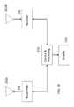
- FIG. 2Aillustrates an exemplary radar system 200 with an antenna 202 that is time-shared between a transmitter 206 and a receiver 208 via a duplexer 204 .
- output from the receiver 208is received by a control and processing module 210 that processes the output from the receiver 208 to produce display data for the display 212 .
- the control and processing module 210is also operable to produce a radar data output that is provided to other control units.
- the control and processing module 210is also operable to control the transmitter 206 .
- FIG. 2Billustrates an alternative exemplary radar system 250 with a pair of antennas 202 a , 202 b , a separate antenna 202 a for the transmitter 206 and another antenna 202 b for the receiver 208 .
- Radars with a single transmitter/antenna and a single receiver/antennacan determine distance to a target/object but cannot determine a direction or an angle of an object from the radar sensor or system (unless the transmit antenna or receive antenna is mechanically scanned).
- To achieve angular informationeither multiple transmitters/antennas or multiple receivers/antennas or both are needed. The larger the number of transmitters and receivers (with corresponding antennas), the better the resolution possible.
- a system with multiple transmitters and multiple receiversis also called a multiple input, multiple output or MIMO system.
- a quantity of virtual receivers/antennas(a quantity of physical transmitters times a quantity of physical receivers equals a quantity of virtual receivers/antennas).
- An exemplary MIMO radar systemis illustrated in FIG. 3 with multiple transmitters 306 connected to multiple transmit antennas 304 and multiple receivers 308 connected to multiple receive antennas 302 .
- Using multiple antennasallows a radar system 300 to determine the angle of objects/targets in the environment. Depending on the geometry of the antenna system 300 , different angles (e.g., with respect to the horizontal or vertical) can be determined.
- the radar system 300may be connected to a network via an Ethernet connection or other types of network connections 314 .
- the radar system 300includes memory 310 , 312 to store software used for processing the received radio signals to determine range, velocity, and location of objects/targets in the environment. Memory may also be used to store information about objects/targets in the environment.
- the radar sensing system of the present inventionmay utilize aspects of the radar systems described in U.S. Pat. Nos. 9,753,121; 9,599,702; 9,575,160; 9,689,967; 9,772,397; 9,806,914; 9,791,564; 9,846,228, and/or 9,791,551, and/or U.S. patent applications, Ser. No. 15/492,159, filed Apr. 20, 2017, now U.S. Pat. No. 9,945,935, Ser. No. 15/496,038, filed Apr. 25, 2017, Ser. No. 15/496,039, filed Apr. 25, 2017, now U.S. Pat. No. 9,954955, Ser. No. 15/598,664, filed May 18, 2017, and/or Ser. No. 15/689,273, filed Aug. 29, 2017, and/or U.S. provisional application Ser. No. 62/528,789, filed Jul. 5, 2017, which are all hereby incorporated by reference herein in their entireties.
- each transmitter signalis rendered distinguishable from every other transmitter by using appropriate differences in the modulation, for example, different digital code sequences.
- Each receivercorrelates with each transmitter signal, producing a number of correlated outputs equal to the product of the number of receivers with the number of transmitters. The outputs are deemed to have been produced by a number of virtual receivers, which can exceed the number of physical receivers. In general, if there are N transmitters (T ⁇ N) and M receivers (R ⁇ M), there will be N ⁇ M virtual receivers, one for each transmitter-receiver pair.
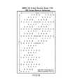
- FIG. 4illustrates a MIMO antenna configuration with three transmitters/antennas: Tx 1 , Tx 2 , and Tx 3 ( 410 ) and three receivers/antennas: Rx 1 , Rx 2 , Rx 3 ( 420 ).
- Each of the three receivers/antennasreceives and processes the signals from each of the three transmitters/antennas resulting in nine virtual receivers/antennas: Vrx 1 , Vrx 2 , Vrx 3 , Vrx 4 , Vrx 5 , Vrx 6 , Vrx 7 , and Vrx 9 ( 430 ).
- the spatial distribution of the virtual receive antennasis given by the spatial convolution of the positions of the transmit and receive antennas.
- a preferred radar system of the present inventionthere are 1-8 transmitters and 4-8 receivers, or more preferably 4-8 transmitters and 8-16 receivers, and most preferably 16 or more transmitters and 16-64 or more receivers.
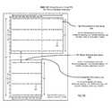
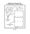
- FIG. 5Aillustrates an exemplary MIMO antenna configuration 500 that is most efficient in terms of a number of antennas and an antenna board size for a given level of 2D angle capability.
- the multiple-input, multiple-output (MIMO) configuration illustrated in FIG. 5Aincorporates 3 transmit antenna elements 510 and N receive antenna elements 520 , 530 .
- the antenna elements 510 , 520 , 530are placed in a manner that minimizes the physical size of an antenna board needed to synthesize virtual uniform linear receive arrays in both the horizontal and vertical dimensions, with a length equal to twice a physical length of the corresponding receive arrays.
- N Xequals the number receive antennas
- ⁇ Xequals the spacing between the receive antennas in the corresponding uniform linear receive array.
- an exemplary horizontal linear array 520 of receive antenna elementsis arranged along one edge of an antenna board
- an exemplary vertical linear array 530 of receive antenna elementsis arranged along an adjacent edge of the antenna board.
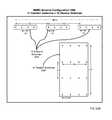
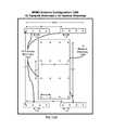
- the MIMO virtual array 540 formed by the antenna configuration of FIG. 5Ais illustrated in FIG. 5B .
- Two uniform virtual linear receive arrays 550 , 560are synthesized, one disposed horizontally ( 550 ) with 2N H virtual antennas spaced by ⁇ H and one disposed vertically ( 560 ) with 2N V virtual antennas spaced by ⁇ V , the number of virtual receive antennas being twice the number of antennas in the corresponding real receive array of FIG. 5A .
- MIMO configurations in accordance with the present inventionmay be arranged that provide 2D angle capability with aperture doubling in both the horizontal and vertical dimensions with only 3 transmit antennas and with placement of the transmit and receive antennas in a manner that minimizes the physical size of the antenna board for the given level of 2D angle capability.
- the MIMO configuration and virtual receiver arrays illustrated in FIGS. 5A and 5Bprovide 2D angle capability via two uniform linear arrays.
- the two linear arrayscan be processed independently or combined coherently to form a composite antenna response prior to detection and/or angle measurement.
- the virtual receiver arrayis rather sparse with inherent tradeoffs in 2D angle performance compared to a fully filled 2D array (e.g., with respect to detection of multiple objects at different azimuth or elevation angles or imaging of a single distributed object).
- FIG. 5Aillustrates an exemplary antenna 810 consisting of three linear arrays of radiators that are arranged as vertical columns of radiators 820 . Each of the three vertical columns of radiators consist of three individual radiators 830 connected by feed lines 840 . The three vertical columns of radiators are combined into a single antenna port using a three-way power combiner 850 .
- the phase center 860 of the example antennais indicated by the symbol “X”.
- each of the various transmit and receive antennascan be of different size and incorporate a different number and/or configuration of radiators.
- the size of the individual transmit and receive antennaswill constrain the minimum spacing between their phase centers (for example, ⁇ H and ⁇ V in FIG. 5 ) to be used in the MIMO configuration.
- the MIMO antennascan be implemented using well known antenna structures and fabrication techniques, including multi-layer printed circuit board antennas with, for example, microstrip feed lines and patch radiators, substrate integrated waveguide (SIW) feed lines and SIW slotted radiators, coplanar waveguide feed lines with SIW slotted radiators, or suitable combinations thereof. Other common types of feed and radiator structures can be used as well.
- the antenna illustrated in FIG. 8would typically be recognized to represent patch radiators 830 connected by microstrip feed lines 840 .
- the number of antennas in the arraycan be reduced by spacing the individual antennas by a distance greater than ⁇ /2 (where ⁇ is wavelength of the transmitted radio signal) with the inherent penalty of grating lobes (multiple ambiguous replicas of the mainlobe and/or large radiation side lobes produced by antenna arrays when element spacing is too large).
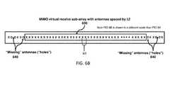
- FIG. 6Aillustrates an exemplary MIMO antenna configuration 600 using a linear array of transmit antennas 610 and a linear array of receive antennas 620 with uniform spacing substantially greater than ⁇ /2, yet producing a virtual receive sub-array 630 (illustrated in FIG. 6B ) with antennas spaced ⁇ /2 apart.
- this style of MIMO antenna configurationsynthesizes a longer virtual receiver array compared to MIMO configurations with transmit and/or receive antennas spaced by ⁇ /2.
- larger higher-gain antennascan be incorporated compared to MIMO configurations with antennas spaced by ⁇ /2.
- Benefits of this exemplary style of MIMO configuration that incorporates larger higher-gain antennas in a manner that produces a longer virtual receive array with ⁇ /2 spacingcan include enhanced detection range and improved angle capability without introducing grating lobes.
- the enabling innovation that synthesizes a MIMO virtual receive sub-array with antennas spaced ⁇ /2 while using transmit and receive antennas spaced by greater than ⁇ /2is uniform spacing of the transmit antennas by an integer multiple of ⁇ /2 and uniform spacing of the receive antennas by a different integer multiple of ⁇ /2.
- the resulting MIMO virtual receive arraymay produce a few antennas at either end with a non-uniform spacing greater than ⁇ /2. These antennas with non-uniform spacing can either be discarded or the “holes” ( 640 ) in the virtual array can be filled to further extend the length of the uniform virtual linear array 630 .
- a number of different known techniquescan be used to fill the holes. These techniques, which include linear prediction methods, fill the resulting holes produced through the non-uniform spacings and extend the length of the portion of the virtual receive sub-array with uniform spacing of virtual antennas via array interpolation techniques.
- the length of the resulting virtual receive array 630scales with the number of transmit and receive antennas incorporated, N TX and N RX respectively, and their respective spacings, (N ⁇ /2) and (N+/ ⁇ K) ⁇ /2, respectively.
- the antennascan be oriented for a desired direction of 1D angle capability (e.g., either horizontally or vertically) or two sets of transmit and receive antennas can be used for 2D angle capability (e.g., one set with horizontal orientation and another set with vertical orientation).
- FIGS. 7A and 7Billustrate another MIMO configuration in accordance with the present invention.
- This particular MIMO configurationcombines the MIMO configurations of FIGS. 5A and 5B and FIGS. 6A and 6B in a manner to further improve 2D angle capability.
- This exemplary MIMO configurationsynthesizes a MIMO virtual receive array 750 composed of several virtual sub-arrays, as illustrated in FIG. 7B .
- Attributes of this exemplary MIMO configurationinclude a more fully filled (less sparse) 2D virtual receive array ( 780 ) compared to the MIMO configuration of FIGS. 5A and 5B , aperture doubling in both the horizontal dimension and vertical dimension (virtual receive antennas 760 and 770 , respectively) in a manner that minimizes the physical size of the antenna board for a given level of 2D angle capability and a virtual receive sub-array 790 with antennas spaced by ⁇ /2 while using transmit and/or receive antennas spaced by greater than ⁇ /2 ( 740 and 720 , respectively).
- the various sub-arrays illustrated in FIG. 7Bcan be processed independently for target detection and angle measurement, combined coherently to form a composite antenna response prior to detection and/or angle measurement, or various combinations of the sub-arrays can be processed independently or combined coherently.
- the diversity of virtual receive arrays illustrated in FIG. 7Bimprove 2D angle capability in a synergistic manner compared to the MIMO configurations illustrated in FIGS. 5A and 5B and FIGS. 6A and 6B .
- the benefit of the more fully filled (less sparse) 2D virtual receive array ( 780 ) shown in FIG. 7B compared to the 2D array of FIG. 5B ( 550 + 560 )includes improved 2D angle resolution capability with respect to multi-target discrimination (detection of multiple objects at different azimuth or elevation angles) and also with respect to imaging a single distributed object. Further, if the spacings of the transmit antennas and/or receive antennas used to synthesize the 2D virtual receive array are greater than ⁇ /2 (as may be desired to produce a narrow beam), the antennas in the 2D virtual array will likewise be spaced by greater than ⁇ /2 resulting in grating lobes. For the MIMO configuration of FIGS.
- the 1D virtual receive sub-array 790 with ⁇ /2 spacingmitigates the horizontal grating lobes of the 2D virtual receive subarray 780 and can also be used in a similar manner to improve upon the horizontal resolution and accuracy of the 2D array (see FIG. 7B ).
- the 1D virtual receive array 760can be used in a similar manner to further improve upon the horizontal resolution and accuracy.
- the 1D horizontal virtual sub-array 790 with ⁇ /2 spacing of FIG. 7Bcan be oriented vertically if desired by orienting the transmit antennas 740 of FIG. 7A vertically.
- another set of transmit antennas similar to 740 , but oriented verticallycan be added to the MIMO configuration of FIG. 7A to produce a 1D vertical virtual sub-array similar to 790 but oriented vertically.
- the receive antennas RX 1 through RX Ncould instead be transmit antennas and the transmit antennas TX 1 through TX 3 could instead be receive antennas.
- the virtual receive arrayis determined by the relative location of the transmit antennas to each other and the relative location of the receive antennas to each other but not the relative location of the transmit antennas to the receive antennas.
- the position of the set of transmit antennas relative to the position of the set of receive antennascan be adapted as needed to tailor the antenna board dimensions without affecting the resulting MIMO virtual receive array.
- the set of three transmit antennas 510can be relocated relative to the set of N receive antennas ( 520 + 530 ) without affecting the MIMO virtual receive array 540 .
- the MIMO virtual receive arrayrepresents the far field response of the MIMO antenna layout.
- the far field response of the MIMO antenna layoutis not affected by the relative position of the set of transmit antennas to the set of receive antennas, the near field response is affected and can be determined using ray tracing techniques for the specific layout of the transmit antennas and receive antennas.
- the 2D MIMO configurations as depicted hereindo not necessarily provide symmetrical angle capability in the horizontal and vertical directions. Depending on the application, it may be appropriate to provide asymmetrical angle capability, for example, better angle capability in the horizontal direction compared to the vertical direction.
- angle capability in a given directioncan be adapted by the variable parameters illustrated and/or by suitable orientation of the sets of transmit antennas and receive antennas.
- FIGS. 9 through 16illustrate additional exemplary 2D MIMO configurations with a specific number of transmit (TX) and receive (RX) antennas configured for different horizontal and vertical angle capabilities.
- An exemplary quantity of TX and RX antennascan vary from 12 TX ⁇ 16 RX antennas to 24 TX ⁇ 32 RX antennas with a corresponding quantity of virtual receive (Vrx) antennas from 192 to 768.
- Vrxvirtual receive
- the vertical angle capabilitycan be tailored based on the vertical spacing parameter ⁇ V.
- the above exemplary MIMO antenna configurationsinclude eight exemplary configurations to yield a desired outcome.
- the quantity of TX, RX, and Vrx antennasinvolve tradeoffs in angle resolution versus the requirements imposed on the physical size of the antenna board as well as the requirements imposed on the radio frequency (RF) and digital signal processing components and the resulting cost implications.
- RFradio frequency
- Radar horizontal and vertical angle resolutiondetermine the capability to distinguish (discriminate) multiple closely spaced objects and to image a single distributed object.
- Horizontal and vertical angle resolutionare proportional to the azimuth and elevation beamwidths of the (virtual) receive array and can be further improved via angle super-resolution processing techniques.
- the 2D MIMO configurations here-incan yield azimuth and elevation beamwidths from 5.0 to 1.5 deg. while incorporating from 3 TX ⁇ 8 RX (24 Vrx) antennas to 12 TX ⁇ 16 RX (192 Vrx) antennas.
- the corresponding physical size of the antenna boardwould vary from about 40 mm ⁇ 40 mm to 100 mm ⁇ 100 mm.
- the number of antennasis within the emerging capabilities of low-cost, single chip RFCMOS MMICs now being developed.
- Automotive radar with azimuth and elevation beamwidth less than 1.5 deg.can be accomplished with 2D MIMO configurations here-in incorporating additional antennas, for example up to 24 TX ⁇ 32 RX (768 Vrx), at the expense of increased physical size of the antenna board and increased cost of the supporting RF, analog and digital chipset (e.g., the need for multiple RFCMOS MMICs).
- Angle resolution for the purposes of target imagingis typically on the order of the antenna beamwidth. Using super-resolution signal processing, angle resolution can be improved to on the order of one-half to one-third of the beamwidth. For adequate imaging capability for automotive radar, it is estimated that angle resolution on the order of one to two degrees is needed. For a given angle resolution metric, the radar image quality (object contour quality) will depend on the distribution of radar signal scattering in position and strength along the contour of the object.
- embodiments of the present inventionprovide adequate accuracy and resolution capabilities necessary to support a variety of convenience and safety functions including full speed range adaptive cruise control, forward and side collision warning and avoidance, and automated parking as well as emerging autonomous driving functions including traffic jam pilot and highway pilot up to fully autonomous operation.
- the exemplary embodimentsincorporate MIMO configurations with uniform spacing of the virtual phase centers as well as sparse array MIMO configurations with non-uniform spacing of the virtual phase centers in both the horizontal and vertical dimensions.
Landscapes
- Engineering & Computer Science (AREA)
- Radar, Positioning & Navigation (AREA)
- Remote Sensing (AREA)
- Physics & Mathematics (AREA)
- Computer Networks & Wireless Communication (AREA)
- General Physics & Mathematics (AREA)
- Electromagnetism (AREA)
- Computer Security & Cryptography (AREA)
- Radar Systems Or Details Thereof (AREA)
- Variable-Direction Aerials And Aerial Arrays (AREA)
Abstract
Description
Claims (23)
Priority Applications (1)
| Application Number | Priority Date | Filing Date | Title |
|---|---|---|---|
| US15/871,175US10197671B2 (en) | 2016-09-16 | 2018-01-15 | Virtual radar configuration for 2D array |
Applications Claiming Priority (3)
| Application Number | Priority Date | Filing Date | Title |
|---|---|---|---|
| US201662395583P | 2016-09-16 | 2016-09-16 | |
| US15/705,627US9869762B1 (en) | 2016-09-16 | 2017-09-15 | Virtual radar configuration for 2D array |
| US15/871,175US10197671B2 (en) | 2016-09-16 | 2018-01-15 | Virtual radar configuration for 2D array |
Related Parent Applications (1)
| Application Number | Title | Priority Date | Filing Date |
|---|---|---|---|
| US15/705,627ContinuationUS9869762B1 (en) | 2016-09-16 | 2017-09-15 | Virtual radar configuration for 2D array |
Publications (2)
| Publication Number | Publication Date |
|---|---|
| US20180149736A1 US20180149736A1 (en) | 2018-05-31 |
| US10197671B2true US10197671B2 (en) | 2019-02-05 |
Family
ID=60935528
Family Applications (2)
| Application Number | Title | Priority Date | Filing Date |
|---|---|---|---|
| US15/705,627ActiveUS9869762B1 (en) | 2016-09-16 | 2017-09-15 | Virtual radar configuration for 2D array |
| US15/871,175ActiveUS10197671B2 (en) | 2016-09-16 | 2018-01-15 | Virtual radar configuration for 2D array |
Family Applications Before (1)
| Application Number | Title | Priority Date | Filing Date |
|---|---|---|---|
| US15/705,627ActiveUS9869762B1 (en) | 2016-09-16 | 2017-09-15 | Virtual radar configuration for 2D array |
Country Status (2)
| Country | Link |
|---|---|
| US (2) | US9869762B1 (en) |
| WO (1) | WO2018051288A1 (en) |
Cited By (4)
| Publication number | Priority date | Publication date | Assignee | Title |
|---|---|---|---|---|
| US11532869B2 (en)* | 2017-04-27 | 2022-12-20 | Sony Corporation | Radar antenna array for three-dimensional imaging |
| US20240053469A1 (en)* | 2019-12-26 | 2024-02-15 | Samsung Electronics Co., Ltd. | Method and device to process radar signal |
| US12332376B2 (en) | 2020-01-13 | 2025-06-17 | Uhnder, Inc. | Method and system for multi-chip operation of radar systems |
| US12429555B2 (en) | 2019-03-12 | 2025-09-30 | Robert Bosch Gmbh | Multi-chip synchronization for digital radars |
Families Citing this family (122)
| Publication number | Priority date | Publication date | Assignee | Title |
|---|---|---|---|---|
| US9846228B2 (en) | 2016-04-07 | 2017-12-19 | Uhnder, Inc. | Software defined automotive radar systems |
| WO2017175190A1 (en) | 2016-04-07 | 2017-10-12 | Uhnder, Inc. | Adaptive transmission and interference cancellation for mimo radar |
| US10261179B2 (en) | 2016-04-07 | 2019-04-16 | Uhnder, Inc. | Software defined automotive radar |
| US9791551B1 (en) | 2016-04-25 | 2017-10-17 | Uhnder, Inc. | Vehicular radar system with self-interference cancellation |
| US10573959B2 (en) | 2016-04-25 | 2020-02-25 | Uhnder, Inc. | Vehicle radar system using shaped antenna patterns |
| US9791564B1 (en) | 2016-04-25 | 2017-10-17 | Uhnder, Inc. | Adaptive filtering for FMCW interference mitigation in PMCW radar systems |
| EP3449272B1 (en) | 2016-04-25 | 2022-11-02 | Uhnder, Inc. | Vehicle radar system with a shared radar and communication system, and method for managing such a system in a vehicle |
| CN109073741B (en) | 2016-04-25 | 2019-07-02 | 乌恩德股份有限公司 | Radar sensing system for vehicle and method for mitigating its interference |
| WO2017187304A2 (en) | 2016-04-25 | 2017-11-02 | Uhnder, Inc. | Digital frequency modulated continuous wave radar using handcrafted constant envelope modulation |
| US9806914B1 (en) | 2016-04-25 | 2017-10-31 | Uhnder, Inc. | Successive signal interference mitigation |
| US9753121B1 (en) | 2016-06-20 | 2017-09-05 | Uhnder, Inc. | Power control for improved near-far performance of radar systems |
| WO2018051288A1 (en)* | 2016-09-16 | 2018-03-22 | Uhnder, Inc. | Virtual radar configuration for 2d array |
| DE102017200273A1 (en)* | 2017-01-10 | 2018-07-12 | Audi Ag | Radar arrangement for a motor vehicle and motor vehicle |
| IL250253B (en) | 2017-01-24 | 2021-10-31 | Arbe Robotics Ltd | Method for separating targets and clutter from noise in radar signals |
| IL250381A0 (en)* | 2017-01-31 | 2017-03-30 | Arbe Robotics Ltd | A compact radar switch/mimo array antenna with high azimuth and elevation angular resolution |
| US11454697B2 (en) | 2017-02-10 | 2022-09-27 | Uhnder, Inc. | Increasing performance of a receive pipeline of a radar with memory optimization |
| WO2018146530A1 (en) | 2017-02-10 | 2018-08-16 | Uhnder, Inc. | Reduced complexity fft-based correlation for automotive radar |
| US10866306B2 (en) | 2017-02-10 | 2020-12-15 | Uhnder, Inc. | Increasing performance of a receive pipeline of a radar with memory optimization |
| JP6924046B2 (en)* | 2017-03-08 | 2021-08-25 | 株式会社デンソーテン | Radar device and elevation estimation method |
| WO2019005870A1 (en)* | 2017-06-26 | 2019-01-03 | Echodyne Corp | Antenna array that includes analog beam-steering transmit antenna and analog beam-steering receive antenna arranged orthogonally to the transmit antenna, and related subsystem, system, and method |
| US10613212B2 (en) | 2017-08-14 | 2020-04-07 | Oculii Corp. | Systems and methods for doppler-enhanced radar tracking |
| US11101572B2 (en) | 2017-09-07 | 2021-08-24 | Echodyne Corp. | Antenna array having a different beam-steering resolution in one dimension than in another dimension |
| WO2019075421A2 (en) | 2017-10-13 | 2019-04-18 | Echodyne Corp | Beam-steering antenna |
| US11105890B2 (en) | 2017-12-14 | 2021-08-31 | Uhnder, Inc. | Frequency modulated signal cancellation in variable power mode for radar applications |
| JP6911778B2 (en)* | 2018-01-24 | 2021-07-28 | 株式会社デンソー | Radar device |
| US12386029B2 (en) | 2018-01-29 | 2025-08-12 | Robert Bosch Gmbh | Millimeter wave automotive radar systems |
| US10564277B2 (en) | 2018-01-30 | 2020-02-18 | Oculii Corp. | Systems and methods for interpolated virtual aperature radar tracking |
| US10048366B1 (en) | 2018-01-30 | 2018-08-14 | Oculii Corp | Systems and methods for virtual aperature radar tracking |
| KR102516365B1 (en)* | 2018-05-25 | 2023-03-31 | 삼성전자주식회사 | Method and apparatus for controlling radar of vehicle |
| CN108732567B (en)* | 2018-05-25 | 2023-11-14 | 中国人民解放军国防科技大学 | Array element distribution structure for near-field multi-transmit and multi-receive array radar imaging and the array |
| IT201800006797A1 (en)* | 2018-06-29 | 2019-12-29 | GROUND-BASED SYNTHETIC OPENING RADAR (GBSAR) WITH MULTIPLE TRANSMISSION AND RECEPTION ANTENNAS (MIMO) AND EFFICIENT USE OF THE COMPRESSIVE SENSING (CS) PROCESSING TECHNIQUE. | |
| IL260696A (en) | 2018-07-19 | 2019-01-31 | Arbe Robotics Ltd | Apparatus and method of rf built in self-test (rfbist) in a radar system |
| IL260695A (en) | 2018-07-19 | 2019-01-31 | Arbe Robotics Ltd | Apparatus and method of eliminating settling time delays in a radar system |
| IL260694A (en) | 2018-07-19 | 2019-01-31 | Arbe Robotics Ltd | Apparatus and method of two-stage signal processing in a radar system |
| JP7248970B2 (en)* | 2018-08-01 | 2023-03-30 | 株式会社デンソー | Direction-of-arrival estimation device and direction-of-arrival estimation method |
| IL261636A (en) | 2018-09-05 | 2018-10-31 | Arbe Robotics Ltd | Skewed mimo antenna array for use in automotive imaging radar |
| DE102018121987A1 (en) | 2018-09-10 | 2020-03-12 | Infineon Technologies Ag | Frequency modulated continuous wave radar system |
| DE102019125973A1 (en) | 2018-09-28 | 2020-04-02 | Panasonic Intellectual Property Management Co., Ltd. | Radar device |
| US10386462B1 (en)* | 2018-10-02 | 2019-08-20 | Oculii Corp. | Systems and methods for stereo radar tracking |
| EP3825718A4 (en)* | 2018-10-25 | 2022-04-13 | Bitsensing Inc. | RADAR DEVICE AND ANTENNA DEVICE FOR RADAR DEVICE |
| KR102276975B1 (en)* | 2018-10-25 | 2021-07-13 | 주식회사 비트센싱 | Radar and antenna built in radar |
| US11474225B2 (en) | 2018-11-09 | 2022-10-18 | Uhnder, Inc. | Pulse digital mimo radar system |
| WO2020118582A1 (en) | 2018-12-12 | 2020-06-18 | 华为技术有限公司 | Signal processing method, radar system, and vehicle |
| JP7224174B2 (en)* | 2018-12-26 | 2023-02-17 | ルネサスエレクトロニクス株式会社 | Electronic device and radar control method |
| US12044794B2 (en) | 2019-02-26 | 2024-07-23 | Magna Electronics Inc. | Vehicular radar system with automatic sensor alignment |
| JP7573926B2 (en)* | 2019-03-20 | 2024-10-28 | パナソニックオートモーティブシステムズ株式会社 | Radar device and transmitting/receiving array antenna |
| JP7228791B2 (en)* | 2019-03-20 | 2023-02-27 | パナソニックIpマネジメント株式会社 | radar equipment |
| US11515624B2 (en)* | 2019-03-29 | 2022-11-29 | GM Global Technology Operations LLC | Integrated cavity backed slot array antenna system |
| US11262434B2 (en)* | 2019-04-01 | 2022-03-01 | GM Global Technology Operations LLC | Antenna array design and processing to eliminate false detections in a radar system |
| DE102019002662A1 (en)* | 2019-04-10 | 2020-10-15 | Friedrich-Alexander-Universität Erlangen-Nürnberg | Procedure for evaluating radar systems |
| IL266846B2 (en)* | 2019-05-23 | 2023-09-01 | Qualcomm Inc | Hybrid multiple-input multiple-output (mimo) radar system |
| DE102019114876B4 (en)* | 2019-06-03 | 2022-07-14 | Audi Ag | Radar antenna arrangement for a vehicle, comprising at least one vehicle component, and vehicle |
| US11181614B2 (en)* | 2019-06-06 | 2021-11-23 | GM Global Technology Operations LLC | Antenna array tilt and processing to eliminate false detections in a radar system |
| US11360210B2 (en)* | 2019-07-02 | 2022-06-14 | Intel Corporation | Multi-mode multi-input multi-output (MIMO) radar sensors |
| RU2725757C1 (en)* | 2019-07-16 | 2020-07-06 | Федеральное государственное автономное образовательное учреждение высшего образования "Национальный исследовательский университет "Московский институт электронной техники" | Radar ranging method using digital antenna arrays (daa) and device for implementation thereof |
| JP7369852B2 (en)* | 2019-07-22 | 2023-10-26 | 華為技術有限公司 | Radar systems and vehicles |
| WO2021014686A1 (en)* | 2019-07-24 | 2021-01-28 | ソニー株式会社 | Radar device, processing device, calculation method, and calculation program |
| TWI726791B (en)* | 2019-08-14 | 2021-05-01 | 創未來科技股份有限公司 | Signal divider, signal distribution system, and method thereof |
| DE102019213208B3 (en)* | 2019-09-02 | 2020-09-24 | Audi Ag | Roof antenna with embedded mmWave antenna |
| CN110596646B (en)* | 2019-09-30 | 2024-07-12 | 南京慧尔视智能科技有限公司 | Layout and method for improving radar angular resolution based on MIMO system |
| EP4059090A4 (en)* | 2019-11-11 | 2023-11-29 | Metawave Corporation | TWO-DIMENSIONAL RADAR FOR MILLIMETER WAVE APPLICATIONS |
| WO2021194577A1 (en) | 2019-12-13 | 2021-09-30 | Oculii Corp. | Systems and methods for virtual doppler and/or aperture enhancement |
| US11994578B2 (en) | 2019-12-13 | 2024-05-28 | Oculli Corp. | Systems and methods for virtual doppler and/or aperture enhancement |
| WO2021127172A1 (en) | 2019-12-20 | 2021-06-24 | Oculii Corp. | Systems and methods for phase-modulated radar detection |
| JP2023510174A (en)* | 2019-12-31 | 2023-03-13 | バヤー イメージング リミテッド | Systems and methods for shaping beams produced by antenna arrays |
| EP3862773A1 (en) | 2020-02-04 | 2021-08-11 | Aptiv Technologies Limited | Radar device |
| EP3862771A1 (en)* | 2020-02-04 | 2021-08-11 | Aptiv Technologies Limited | Radar device |
| EP3862772A1 (en)* | 2020-02-04 | 2021-08-11 | Aptiv Technologies Limited | Radar device |
| US20210239788A1 (en)* | 2020-02-05 | 2021-08-05 | Alps Alpine Co., Ltd. | Radar with virtual planar array (vpa) antenna |
| US12300897B2 (en) | 2020-02-11 | 2025-05-13 | Telefonaktiebolaget Lm Ericsson (Publ) | Antenna arrangement having unequally many physical antenna elements for transmission and reception |
| JP2021139762A (en)* | 2020-03-05 | 2021-09-16 | 株式会社東芝 | Radar device and transmission / reception method |
| US11448722B2 (en)* | 2020-03-26 | 2022-09-20 | Intel Corporation | Apparatus, system and method of communicating radar signals |
| US11860270B2 (en) | 2020-04-01 | 2024-01-02 | The Board Of Trustees Of The University Of Alabama | Sparse linear array approach in automotive radars using matrix completion |
| CN111505597B (en)* | 2020-04-24 | 2023-04-14 | 南京市德赛西威汽车电子有限公司 | Method for eliminating radar beam forming grating lobe and antenna |
| WO2021219427A1 (en)* | 2020-04-27 | 2021-11-04 | Signify Holding B.V. | Horticulture system and method |
| US11280879B2 (en) | 2020-06-16 | 2022-03-22 | Oculii Corp. | System and method for radar interference mitigation |
| US11639992B2 (en)* | 2020-06-25 | 2023-05-02 | Intel Corporation | Apparatus, system and method of generating radar information based on an amplitude phase estimation calculation |
| JP2023536150A (en)* | 2020-07-29 | 2023-08-23 | ニューラル プロパルション システムズ,インコーポレイテッド | Multi-frequency radar array system and sensor fusion for viewing around corners during autonomous driving |
| US11644565B2 (en) | 2020-10-13 | 2023-05-09 | Aptiv Technologies Limited | Radar system with sparse primary array and dense auxiliary array |
| US11619705B2 (en) | 2020-10-20 | 2023-04-04 | Aptiv Technologies Limited | Radar system with modified orthogonal linear antenna subarrays |
| IL278587A (en) | 2020-11-09 | 2022-06-01 | Arbe Robotics Ltd | Estimating an efficient direction of arrival using a low degree approximation |
| US11841420B2 (en) | 2020-11-16 | 2023-12-12 | Oculii Corp. | System and method for radar-based localization and/or mapping |
| US20240012101A1 (en)* | 2020-11-18 | 2024-01-11 | Atcodi Co., Ltd | Asymmetric wide-angle radar module |
| EP4012438A1 (en) | 2020-12-10 | 2022-06-15 | Aptiv Technologies Limited | Radar device |
| EP4016127A1 (en) | 2020-12-16 | 2022-06-22 | Provizio Limited | Multiple input multiple steered output (mimso) radar |
| US11740328B2 (en)* | 2020-12-16 | 2023-08-29 | DC-001, Inc. | Methods and systems for processing radar signals |
| WO2022139844A1 (en)* | 2020-12-24 | 2022-06-30 | Intel Corporation | Radar apparatus, system, and method |
| KR102288673B1 (en)* | 2020-12-28 | 2021-08-12 | 주식회사 비트센싱 | Radar having antennas arranged in horizontal and vertical intervals |
| CN114690170A (en)* | 2020-12-30 | 2022-07-01 | 杭州海康威视数字技术股份有限公司 | Target detection method and device and electronic equipment |
| WO2022157733A2 (en)* | 2021-01-22 | 2022-07-28 | Uhnder, Inc. | Sparse antenna arrays for automotive radar |
| US12153157B2 (en) | 2021-01-27 | 2024-11-26 | Aptiv Technologies AG | Radar system with paired one-dimensional and two-dimensional antenna arrays |
| CN112924938B (en)* | 2021-01-28 | 2024-04-19 | 电子科技大学成都学院 | 12 Send out 16 millimeter wave 4D formation of image radar microstrip antenna array that receive |
| US11714180B2 (en) | 2021-01-29 | 2023-08-01 | Aptiv Technologies Limited | Radar system to detect angles in bistatic and monostatic scenarios |
| CN112834988B (en)* | 2021-02-08 | 2023-02-17 | 上海保隆汽车科技股份有限公司 | Vehicle-mounted MIMO radar antenna layout structure |
| US11808846B2 (en) | 2021-02-12 | 2023-11-07 | Aptiv Technologies Limited | Angle-finding process for sparse uniform arrays |
| EP4301626A4 (en) | 2021-03-01 | 2024-10-02 | Magna Mirrors Of America, Inc. | INTERIOR REARVIEW MIRROR ASSEMBLY WITH DRIVER MONITORING SYSTEM |
| US20240219552A1 (en) | 2021-04-30 | 2024-07-04 | Provizio Limited | Mimo radar using a frequency scanning antenna |
| US12194992B2 (en) | 2021-07-01 | 2025-01-14 | Magna Electronics Inc. | Vehicular automatic emergency braking system with cross-path threat determination |
| JP7569138B2 (en)* | 2021-07-12 | 2024-10-17 | パナソニックオートモーティブシステムズ株式会社 | Radar Equipment |
| JP7532321B2 (en)* | 2021-08-31 | 2024-08-13 | 株式会社東芝 | Radar device and method |
| US12007476B2 (en) | 2021-09-13 | 2024-06-11 | Magna Electronics Inc. | Method for detecting objects via a vehicular sensing system |
| US12122324B2 (en) | 2021-09-17 | 2024-10-22 | Magna Mirrors Of America, Inc. | Vehicular power door sensing and operating system |
| US12366653B2 (en) | 2021-10-26 | 2025-07-22 | Magna Electronics Inc. | Radar-based vehicular exterior mirror collision avoidance system |
| JP7547306B2 (en)* | 2021-11-18 | 2024-09-09 | 京セラ株式会社 | Electronic device, electronic device control method, and program |
| KR102858815B1 (en)* | 2021-11-19 | 2025-09-12 | 주식회사 에이치엘클레무브 | Radar control apparatus and method |
| IL289661A (en)* | 2022-01-06 | 2023-08-01 | Arbe Robotics Ltd | Extended virtual array in an automotive mimo radar |
| US12216227B2 (en) | 2022-01-19 | 2025-02-04 | Aptiv Technologies AG | Radar system with sequential two-dimensional angle estimation |
| CN114512786A (en)* | 2022-02-09 | 2022-05-17 | 惠州市德赛西威智能交通技术研究院有限公司 | Antenna arrangement method, radar for improving angular resolution |
| US12345809B2 (en)* | 2022-04-20 | 2025-07-01 | Magna Electronics Inc. | Vehicular radar sensor with antenna that provides improved blind-spot detection |
| US12286102B2 (en) | 2022-04-27 | 2025-04-29 | Magna Electronics Inc. | Vehicular driving assist system with collision avoidance |
| US11561299B1 (en) | 2022-06-03 | 2023-01-24 | Oculii Corp. | System and method for multi-waveform radar tracking |
| US12420707B2 (en) | 2022-06-24 | 2025-09-23 | Magna Electronics Inc. | Vehicular control system with cross traffic alert and collision avoidance |
| US20240130637A1 (en)* | 2022-10-18 | 2024-04-25 | Rutgers, The State University Of New Jersey | Monitoring vital signs of multiple persons via single phased-mimo radar |
| DE102022131461A1 (en)* | 2022-11-29 | 2024-05-29 | Valeo Schalter Und Sensoren Gmbh | Antenna device for a radar device having at least two antenna arrangements, radar device, driver assistance system, vehicle and method for operating a radar device |
| JP2024101259A (en)* | 2023-01-17 | 2024-07-29 | 株式会社東芝 | Antenna Device |
| US12392879B2 (en) | 2023-02-28 | 2025-08-19 | Aptiv Technologies AG | Radar system to universally detect direction-of-arrival or direction-of-departure angles in direct-path and multipath reflection conditions |
| DE102023113029A1 (en) | 2023-05-17 | 2024-11-21 | Deutsches Zentrum für Luft- und Raumfahrt e.V. | Synthetic aperture radar method |
| GB2635040A (en) | 2023-10-23 | 2025-04-30 | Portable Multimedia Ltd | Operation modes for an in-vehicle security system |
| GB2630829B (en)* | 2023-10-23 | 2025-08-27 | Portable Multimedia Ltd | Security System |
| GB2634896A (en) | 2023-10-23 | 2025-04-30 | Portable Multimedia Ltd | Vehicle security device |
| CN120109536A (en)* | 2023-12-06 | 2025-06-06 | 上海华为技术有限公司 | Antenna arrays, radars, electronics and vehicles |
| EP4628924A1 (en)* | 2024-04-02 | 2025-10-08 | Aptiv Technologies AG | Radar behind license plate |
Citations (247)
| Publication number | Priority date | Publication date | Assignee | Title |
|---|---|---|---|---|
| US1882128A (en) | 1927-06-01 | 1932-10-11 | Edward W Fearing | Radiofrequency amplification system |
| US3374478A (en) | 1966-12-07 | 1968-03-19 | Spectronics Inc | Radar signaliing system with reduced clutter effect |
| US3735398A (en) | 1971-05-20 | 1973-05-22 | Sperry Rand Corp | Base band short range pre-collision sensor for actuation of vehicle safety apparatus |
| US3750169A (en) | 1972-03-13 | 1973-07-31 | Sperry Rand Corp | Vehicular safety system |
| US3896434A (en) | 1973-03-06 | 1975-07-22 | Thomson Csf | Pulse type radar system |
| US4078234A (en) | 1975-04-25 | 1978-03-07 | The United States Of America As Represented By The Secretary Of The Army | Continuous wave correlation radar system |
| US4176351A (en) | 1978-08-18 | 1979-11-27 | Raytheon Company | Method of operating a continuous wave radar |
| US4566010A (en) | 1982-04-28 | 1986-01-21 | Raytheon Company | Processing arrangement for pulse compression radar |
| US4882668A (en) | 1987-12-10 | 1989-11-21 | General Dynamics Corp., Pomona Division | Adaptive matched filter |
| US4939685A (en) | 1986-06-05 | 1990-07-03 | Hughes Aircraft Company | Normalized frequency domain LMS adaptive filter |
| US5001486A (en) | 1989-08-04 | 1991-03-19 | Siemens-Albis | Radar system for determining the position of two or more objects |
| US5034906A (en) | 1990-03-30 | 1991-07-23 | Microwave Logic | Pseudorandom Binary Sequence delay systems |
| US5087918A (en) | 1990-04-02 | 1992-02-11 | Delco Electronics Corporation | FMCW/2FD implementation for vehicle near obstacle detection system |
| US5151702A (en) | 1991-07-22 | 1992-09-29 | General Electric Company | Complementary-sequence pulse radar with matched filtering following doppler filtering |
| US5175710A (en) | 1990-12-14 | 1992-12-29 | Hutson William H | Multi-dimensional data processing and display |
| US5218619A (en) | 1990-12-17 | 1993-06-08 | Ericsson Ge Mobile Communications Holding, Inc. | CDMA subtractive demodulation |
| US5272663A (en) | 1992-05-05 | 1993-12-21 | The Board Of Trustees Of The University Of Illinois | Apparatus and method for wide bandwidth adaptive filtering |
| US5280288A (en) | 1992-08-14 | 1994-01-18 | Vorad Safety Systems, Inc. | Interference avoidance system for vehicular radar system |
| US5302956A (en) | 1992-08-14 | 1994-04-12 | Vorad Safety Systems, Inc. | Multi-frequency, multi-target vehicular radar system using digital signal processing |
| US5341141A (en) | 1993-03-09 | 1994-08-23 | Hughes Missile Systems Company | Three dimensional imaging radar |
| US5345470A (en) | 1993-03-31 | 1994-09-06 | Alexander Richard O | Methods of minimizing the interference between many multiple FMCW radars |
| US5379322A (en) | 1992-01-07 | 1995-01-03 | Sanyo Electric Co., Ltd. | Baseband signal generator for digital modulator |
| US5497162A (en) | 1995-01-09 | 1996-03-05 | Northrop Grumman Corporation | Radar signal selection based upon antenna bearing |
| US5508706A (en) | 1991-09-30 | 1996-04-16 | Trw Inc. | Radar signal processor |
| EP0725480A1 (en) | 1995-02-01 | 1996-08-07 | Nec Corporation | Adaptively controlled filter |
| US5657021A (en) | 1994-06-30 | 1997-08-12 | Ehsani Engineering Enterprises, Inc. | System and method for radar-vision for vehicles in traffic |
| US5657023A (en) | 1996-05-02 | 1997-08-12 | Hughes Electronics | Self-phase up of array antennas with non-uniform element mutual coupling and arbitrary lattice orientation |
| FR2751086A1 (en) | 1986-08-01 | 1998-01-16 | Thomson Csf | Mutual interference eliminating method for radar groups transmitting and receiving signals |
| US5712640A (en) | 1994-11-28 | 1998-01-27 | Honda Giken Kogyo Kabushiki Kaisha | Radar module for radar system on motor vehicle |
| US5724041A (en) | 1994-11-24 | 1998-03-03 | The Furukawa Electric Co., Ltd. | Spread spectrum radar device using pseudorandom noise signal for detection of an object |
| US5892477A (en) | 1996-11-13 | 1999-04-06 | Trw Inc. | Anti-jam FM/CW radar |
| US5917430A (en) | 1995-08-28 | 1999-06-29 | The Safety Warning System, L.C. | Radar based highway safety warning system |
| US5920285A (en) | 1996-06-06 | 1999-07-06 | University Of Bristol | Post-reception focusing in remote detection systems |
| US5931893A (en) | 1997-11-11 | 1999-08-03 | Ericsson, Inc. | Efficient correlation over a sliding window |
| US5959571A (en) | 1996-04-22 | 1999-09-28 | The Furukawa Electric Co., Ltd. | Radar device |
| US5970400A (en) | 1996-04-30 | 1999-10-19 | Magellan Corporation | Adjusting the timing and synchronization of a radio's oscillator with a signal from an SATPS satellite |
| US6067314A (en) | 1996-07-10 | 2000-05-23 | Kabushiki Kaisha Toshiba | Direct spread spectrum signal receiving apparatus and synchronism acquisition circuit |
| US6069581A (en) | 1998-02-20 | 2000-05-30 | Amerigon | High performance vehicle radar system |
| US6121872A (en) | 1989-04-15 | 2000-09-19 | Bayerische Motoren Werke Ag | Object sensing device for motor vehicles |
| US6121918A (en) | 1996-10-17 | 2000-09-19 | Celsiustech Electronics Ab | Procedure for the elimination of interference in a radar unit of the FMCW type |
| US6151366A (en) | 1998-04-17 | 2000-11-21 | Advanced Microdevices, Inc. | Method and apparatus for modulating signals |
| US6163252A (en) | 1999-04-07 | 2000-12-19 | Mitsubishi Denki Kabushiki Kaisha | Device for detecting obstacles, for use in vehicles |
| US6184829B1 (en) | 1999-01-08 | 2001-02-06 | Trueposition, Inc. | Calibration for wireless location system |
| US20010002919A1 (en) | 1998-02-17 | 2001-06-07 | Essam Sourour | Flexible sliding correlator for direct sequence spread spectrum systems |
| US6288672B1 (en) | 1998-09-14 | 2001-09-11 | Kabushiki Kaisha Toyota Chuo Kenkyusho | Holographic radar |
| US6307622B1 (en) | 1999-02-17 | 2001-10-23 | Infineon Technologies North America Corp. | Correlation based optical ranging and proximity detector |
| US20020004692A1 (en) | 1994-05-31 | 2002-01-10 | Winged Systems Corporation | High accuracy, high integrity scene mapped navigation |
| US20020044082A1 (en) | 2000-08-16 | 2002-04-18 | Woodington Walter Gordon | Radar detection method and apparatus |
| US6400308B1 (en) | 1998-02-20 | 2002-06-04 | Amerigon Inc. | High performance vehicle radar system |
| US6411250B1 (en) | 1997-09-01 | 2002-06-25 | Cambridge Consultants Limited | Electromagnetic sensor system |
| US6417796B1 (en) | 1998-09-16 | 2002-07-09 | Mph Industries, Inc. | Doppler-based traffic radar system |
| US6424289B2 (en) | 2000-06-01 | 2002-07-23 | Mitsubishi Denki Kabushiki Kaisha | Obstacle detection device and obstacle detection system |
| US20020118522A1 (en) | 2001-02-28 | 2002-08-29 | Siliconware Precision Industries Co., Ltd. | Ball grid array package with interdigitated power ring and ground ring |
| US20020130811A1 (en) | 2001-02-22 | 2002-09-19 | Klaus Voigtlaender | Method of detecting interference conditions of a radar device and a radar device |
| US20020147534A1 (en) | 2000-08-16 | 2002-10-10 | Delcheccolo Michael Joseph | Near object detection system |
| US20020155811A1 (en) | 2001-04-18 | 2002-10-24 | Jerry Prismantas | System and method for adapting RF transmissions to mitigate the effects of certain interferences |
| US20030011519A1 (en) | 2000-08-16 | 2003-01-16 | Caroline Breglia | Slot antenna element for an array antenna |
| US20030058166A1 (en) | 2001-09-17 | 2003-03-27 | Nec Corporation | Apparatus and method for calibrating array antenna |
| US20030102997A1 (en) | 2000-02-13 | 2003-06-05 | Hexagon System Engineering Ltd. | Vehicle communication network |
| US6583753B1 (en) | 2002-04-03 | 2003-06-24 | Delphi Technologies, Inc. | Vehicle back-up and parking aid radar system |
| US6614387B1 (en) | 1998-09-29 | 2003-09-02 | Qinetiq Limited | Proximity measuring apparatus |
| US6624784B1 (en) | 1998-07-13 | 2003-09-23 | Ntt Mobile Communications Network, Inc. | Adaptive array antenna |
| US20030235244A1 (en) | 2002-06-24 | 2003-12-25 | Pessoa Lucio F. C. | Method and apparatus for performing adaptive filtering |
| US6674908B1 (en) | 2002-05-04 | 2004-01-06 | Edward Lasar Aronov | Method of compression of binary data with a random number generator |
| US20040012516A1 (en) | 2002-07-16 | 2004-01-22 | Schiffmann Jan K. | Tracking system and method employing multiple overlapping sensors |
| US20040015529A1 (en) | 2002-07-16 | 2004-01-22 | Tellabs Operations, Inc. | Selective-partial-update proportionate normalized least-mean-square adaptive filtering for network echo cancellation |
| US6714956B1 (en) | 2000-07-24 | 2004-03-30 | Via Technologies, Inc. | Hardware accelerator for normal least-mean-square algorithm-based coefficient adaptation |
| US20040066323A1 (en) | 2000-12-01 | 2004-04-08 | Karl-Heinz Richter | Pulse radar method, pulse radar sensor and corresponding system |
| US6747595B2 (en) | 2002-01-21 | 2004-06-08 | Nec Corporation | Array antenna calibration apparatus and array antenna calibration method |
| US20040138802A1 (en) | 2003-01-10 | 2004-07-15 | Hitachi, Ltd. | Vehiclar travel control device |
| US6768391B1 (en) | 2000-06-22 | 2004-07-27 | Ericsson Inc. | Class-B biased gilbert cells and quadrature modulators |
| US20050069162A1 (en) | 2003-09-23 | 2005-03-31 | Simon Haykin | Binaural adaptive hearing aid |
| US20050156780A1 (en) | 2004-01-16 | 2005-07-21 | Ghz Tr Corporation | Methods and apparatus for automotive radar sensors |
| US20050201457A1 (en) | 2004-03-10 | 2005-09-15 | Allred Daniel J. | Distributed arithmetic adaptive filter and method |
| US20050225476A1 (en) | 2002-09-06 | 2005-10-13 | Juergen Hoetzel | Radar measurement device, especially for a motor vehicle, and method for operating a radar measurement device |
| US6975246B1 (en) | 2003-05-13 | 2005-12-13 | Itt Manufacturing Enterprises, Inc. | Collision avoidance using limited range gated video |
| US20060012511A1 (en) | 2004-07-13 | 2006-01-19 | Fujitsu Limited | Radar apparatus, radar apparatus controlling method |
| US20060036353A1 (en) | 2002-06-18 | 2006-02-16 | A.D.C. Automotive Distance Control Systems Gmbh | Method of suppressing interferences in systems for detecting objects |
| US20060050707A1 (en) | 2004-09-09 | 2006-03-09 | Intel Corporation | Methods and apparatus for multiple bit rate serial communication |
| US20060093078A1 (en) | 2001-11-20 | 2006-05-04 | Michael Lewis | Preamble aided synchronization |
| US20060109170A1 (en) | 2002-11-26 | 2006-05-25 | Klaus Voigtlaender | Method and device for the adaptive regulation of power |
| US20060109931A1 (en) | 2004-11-05 | 2006-05-25 | Ntt Docomo, Inc. | Mobile communication receiver and transmitter |
| US20060114324A1 (en) | 2004-11-16 | 2006-06-01 | Northrop Grumman Corporation | Method and apparatus for collaborative aggregate situation awareness |
| US20060140249A1 (en) | 2003-02-25 | 2006-06-29 | Yokohama Tlo Company, Ltd. | Pulse waveform producing method |
| US20060181448A1 (en) | 2005-02-14 | 2006-08-17 | Denso Corporation | FMCW radar device and method for detecting interference |
| US7119739B1 (en) | 2002-05-14 | 2006-10-10 | Bae Systems Information And Electronic Systems Integration Inc. | Near field to far field DF antenna array calibration technique |
| US20060244653A1 (en) | 2003-07-07 | 2006-11-02 | Szajnowski Wieslaw J | Generations of sequences of waveforms |
| US20060262007A1 (en) | 2004-01-16 | 2006-11-23 | Clariant Technologies, Corp. | Methods and apparatus for automotive radar sensors |
| US20060262009A1 (en) | 2005-05-20 | 2006-11-23 | Denso Corporation | Method of preventing interference between radars and radar system having interference preventing function |
| US20070018886A1 (en) | 2005-04-15 | 2007-01-25 | Denso Corporation | Interference determination method and fmcw radar using the same |
| US20070018884A1 (en) | 2005-07-08 | 2007-01-25 | Raytheon Company | Single transmit multi-receiver modulation radar, multi-modulation receiver and method |
| US20070109175A1 (en) | 2005-06-22 | 2007-05-17 | Matsushita Electric Industrial Co., Ltd. | Spread spectrum radar apparatus |
| US20070120731A1 (en) | 2004-12-15 | 2007-05-31 | Kelly Thomas M Jr | System and method for reducing the effect of a radar interference signal |
| US20070132633A1 (en) | 2004-10-14 | 2007-06-14 | Masaharu Uchino | Small-sized low-power dissipation short-range radar that can arbitrarily change delay time between transmission and reception with high time resolution and method of controlling the same |
| US20070152872A1 (en) | 2005-12-30 | 2007-07-05 | Woodington Walter G | Reducing undesirable coupling of signal(s) between two or more signal paths in a radar system |
| US20070152871A1 (en) | 2006-01-05 | 2007-07-05 | Puglia Kenneth V | Time duplex apparatus and method for radar sensor front-ends |
| US20070152870A1 (en) | 2005-12-30 | 2007-07-05 | Woodington Walter G | Vehicle radar system having multiple operating modes |
| US20070164896A1 (en) | 2005-11-10 | 2007-07-19 | Hitachi, Ltd. | In-vehicle radar device and communication device |
| US20070171122A1 (en) | 2006-01-25 | 2007-07-26 | Fujitsu Ten Limited | Radar apparatus and interference detection method |
| US20070182619A1 (en) | 2004-07-16 | 2007-08-09 | Fujitsu Ten Limited | Monopulse radar apparatus and antenna switch |
| US20070182623A1 (en) | 2006-02-03 | 2007-08-09 | Shuqing Zeng | Method and apparatus for on-vehicle calibration and orientation of object-tracking systems |
| US20070188373A1 (en) | 2006-02-15 | 2007-08-16 | Fujitsu Limited | Search/detection apparatus |
| US20070200747A1 (en) | 2006-02-28 | 2007-08-30 | Hitachi, Ltd. | Radar apparatus and radar system for a vehicle |
| US7289058B2 (en) | 2004-06-21 | 2007-10-30 | Fujitsu Ten Limited | Radar apparatus |
| US7299251B2 (en) | 2000-11-08 | 2007-11-20 | Qinetiq Limited | Adaptive filter |
| US20070279303A1 (en) | 2004-09-13 | 2007-12-06 | Robert Bosch Gmbh | Antenna Structure for Series-Fed Planar Antenna Elements |
| US7338450B2 (en) | 2004-08-27 | 2008-03-04 | General Electric Company | Method and apparatus for performing CW doppler ultrasound utilizing a 2D matrix array |
| US7395084B2 (en) | 2005-01-24 | 2008-07-01 | Sikorsky Aircraft Corporation | Dynamic antenna allocation system |
| US20080208472A1 (en) | 2004-06-25 | 2008-08-28 | Christopher John Morcom | Traffic Safety System |
| US20080272955A1 (en) | 2007-05-04 | 2008-11-06 | Yonak Serdar H | Active radar system |
| US7460055B2 (en) | 2006-06-02 | 2008-12-02 | Panasonic Corporation | Radar apparatus |
| US20090015464A1 (en) | 2005-03-31 | 2009-01-15 | Matsushita Electric Industrial Co., Ltd. | Spread spectrum radar apparatus |
| US20090015459A1 (en) | 2004-05-28 | 2009-01-15 | Michael Mahler | Method for Reducing Interference Signal Influences on a High-Frequency Measurement Device and High-Frequency Measurement Device |
| US20090051581A1 (en) | 2006-12-25 | 2009-02-26 | Fuji Jukogyo Kabushiki Kaisha | Pulse radar, car radar and landing assistance radar |
| US20090073025A1 (en) | 2007-09-13 | 2009-03-19 | Matsushita Electric Industrial Co., Ltd. | Radar apparatus, method for controlling the same, and vehicle including the same |
| US20090079617A1 (en) | 2007-09-26 | 2009-03-26 | Fujitsu Limited | Detection and ranging appartus and detection and ranging method |
| US20090085827A1 (en) | 2007-10-02 | 2009-04-02 | Furukawa Electric Co., Ltd | Antenna installed on radar |
| US20090121918A1 (en) | 2007-11-12 | 2009-05-14 | Denso Corporation | Radar apparatus enabling simplified suppression of interference signal components which result from reception of directly transmitted radar waves from another radar apparatus |
| US7545310B2 (en) | 2007-08-17 | 2009-06-09 | Mitsubishi Electric Corporation | In-vehicle mount radar device |
| US7545321B2 (en) | 2005-05-19 | 2009-06-09 | Fujitsu Limited | Array antenna calibration apparatus and method |
| US7564400B2 (en) | 2007-09-19 | 2009-07-21 | Panasonic Corporation | Spread spectrum radar apparatus |
| US7567204B2 (en) | 2007-03-20 | 2009-07-28 | Denso Corporation | Method for determining noise floor level and radar using the same |
| US20090212998A1 (en) | 2005-10-24 | 2009-08-27 | Mitsubishi Electric Corporation | Object Detection |
| US20090237293A1 (en) | 2008-03-21 | 2009-09-24 | Denso Corporation | Recognition system for vehicle |
| US7609198B2 (en) | 2007-05-21 | 2009-10-27 | Spatial Digital Systems, Inc. | Apparatus and method for radar imaging by measuring spatial frequency components |
| US20090267822A1 (en) | 2008-04-28 | 2009-10-29 | Hitachi, Ltd. | Mobile radar and planar antenna |
| US20090289831A1 (en) | 2006-10-27 | 2009-11-26 | Mitsubishi Electric Corporation | Radar device |
| US20090295623A1 (en) | 2008-06-03 | 2009-12-03 | Saab Ab | Radar receiver and a method for processing radar returns |
| US7663533B2 (en) | 2004-01-29 | 2010-02-16 | Robert Bosch Gmbh | Radar system for motor vehicles |
| US20100116365A1 (en) | 2008-11-11 | 2010-05-13 | Mccarty Michael Wildie | Remotely readable valve position indicators |
| US7728762B2 (en) | 2007-03-20 | 2010-06-01 | Denso Corporation | Method for detecting interference in radar system and radar using the same |
| US20100156690A1 (en) | 2008-12-22 | 2010-06-24 | Electronics And Telecommunications Research Institute | Digital direct conversion receiving apparatus and method |
| US20100198513A1 (en) | 2009-02-03 | 2010-08-05 | Gm Global Technology Operations, Inc. | Combined Vehicle-to-Vehicle Communication and Object Detection Sensing |
| US7791528B2 (en) | 2008-11-24 | 2010-09-07 | Autoliv Asp, Inc. | Method and apparatus for radar signal processing |
| US20100277359A1 (en) | 2009-05-01 | 2010-11-04 | Denso Corporation | Vehicle radar apparatus having variable output power controlled based on speed of vehicle |
| US7847731B2 (en) | 2007-08-23 | 2010-12-07 | Universitat Karlsruhe | Method for the operation of an antenna group having a plurality of transmitters and a plurality of receivers and associated apparatus |
| US7855677B2 (en) | 2006-04-04 | 2010-12-21 | Panasonic Corporation | Code generation apparatus |
| US20110006944A1 (en) | 2009-06-19 | 2011-01-13 | U.S. Government As Represented By The Secretary Of The Army | Computationally efficent radar processing method and sytem for sar and gmti on a slow moving platform |
| US20110032138A1 (en) | 2007-12-19 | 2011-02-10 | Robert Bosch Gmbh | Method for operating an electrical device and electrical device |
| US20110074620A1 (en) | 2008-07-02 | 2011-03-31 | Adc Automotive Distance Control Systems Gmbh | Radar System With Elevation Measuring Capability |
| US20110187600A1 (en) | 2010-01-29 | 2011-08-04 | Tc License Ltd. | System and method for measurement of distance to a tag by a modulated backscatter rfid reader |
| US20110196568A1 (en) | 2010-02-11 | 2011-08-11 | Gm Global Technology Operations, Inc. | Vehicle safety systems and methods |
| US8019352B2 (en) | 2004-07-23 | 2011-09-13 | Wireless Valley Communications, Inc. | System, method, and apparatus for determining and using the position of wireless devices or infrastructure for wireless network enhancements |
| US20110248796A1 (en) | 2010-04-09 | 2011-10-13 | Raytheon Company | Rf feed network for modular active aperture electronically steered arrays |
| US8049663B2 (en) | 2008-05-21 | 2011-11-01 | Raytheon Company | Hardware compensating pulse compression filter system and method |
| US8059026B1 (en) | 2006-03-01 | 2011-11-15 | The United States Of America As Represented By The Secretary Of The Air Force | Interference avoiding transform domain radar |
| US20110279307A1 (en) | 2010-05-14 | 2011-11-17 | Massachusetts Institute Of Technology | High Duty Cycle Radar with Near/Far Pulse Compression Interference Mitigation |
| US20110279303A1 (en) | 2010-05-13 | 2011-11-17 | The United States Of America As Represented By The Secretary Of The Navy | Active-radar-assisted passive composite imagery for aiding navigation or detecting threats |
| US20110285576A1 (en) | 2007-01-25 | 2011-11-24 | Lynam Niall R | Forward facing sensing system for a vehicle |
| US20110292971A1 (en) | 2010-05-28 | 2011-12-01 | Ronny Hadani | Communications method employing orthonormal time-frequency shifting and spectral shaping |
| US20110291874A1 (en) | 2010-06-01 | 2011-12-01 | De Mersseman Bernard | Vehicle radar system and method for detecting objects |
| US20110291875A1 (en) | 2010-05-27 | 2011-12-01 | Mitsubishi Electric Corporation | Automotive radar with radio-frequency interference avoidance |
| US20110298653A1 (en) | 2010-06-04 | 2011-12-08 | Denso Corporation | Method and device for detecting azimuth |
| US20120001791A1 (en) | 2009-04-06 | 2012-01-05 | Conti Temic Microelectronic Gmbh | Radar System Having Arrangements and Methods for the Decoupling of Transmitting and Receiving Signals and for the Suppression of Interference Radiation |
| US20120050093A1 (en) | 2009-03-02 | 2012-03-01 | Stefan Heilmann | Radar sensor having a blindness detection device |
| US20120105268A1 (en) | 2009-02-20 | 2012-05-03 | Nederlandse Organisatie Voor Toegepast-Natuurwetenschappelijk Onderzoek Tno | Method of Detecting a Scatterer in a Structure, a Radar System and a Computer Program Product |
| US20120112957A1 (en) | 2010-11-09 | 2012-05-10 | U.S. Government As Represented By The Secretary Of The Army | Multidirectional target detecting system and method |
| US20120133547A1 (en) | 2010-11-29 | 2012-05-31 | Freescale Semiconductor, Inc. | Automotive Radar System and Method for Using Same |
| US20120173246A1 (en) | 2010-12-31 | 2012-07-05 | Korea Electronics Technology Institute | Variable order short-term predictor |
| US20120257643A1 (en) | 2011-04-08 | 2012-10-11 | the Communications Research Centre of Canada | Method and system for wireless data communication |
| US8330650B2 (en) | 2010-05-07 | 2012-12-11 | The United States Of America, As Represented By The Secretary Of The Army | Radar system and antenna with delay lines and method thereof |
| US20120319900A1 (en) | 2010-02-08 | 2012-12-20 | Telefonaktiebolaget Lm Ericsson(Publ) | Antenna with adjustable beam characteristics |
| US20130016761A1 (en) | 2011-07-15 | 2013-01-17 | Renesas Mobile Corporation | Transmitter with a Variable Sampling Rate |
| US20130021196A1 (en) | 2011-07-22 | 2013-01-24 | Armin Himmelstoss | Fmcw radar system and interference recognition method for fmcw radar systems |
| US20130027240A1 (en) | 2010-03-05 | 2013-01-31 | Sazzadur Chowdhury | Radar system and method of manufacturing same |
| US20130069818A1 (en) | 2011-09-20 | 2013-03-21 | Fujitsu Limited | System and method for detection and ranging |
| EP2374217B1 (en) | 2008-12-09 | 2013-04-10 | Telefonaktiebolaget L M Ericsson (PUBL) | Cross-coupling interference cancellation in multiple receive branches with independent demodulation signals |
| US20130102254A1 (en) | 2010-05-27 | 2013-04-25 | Ubiquam Ltd. | Method and system of interference cancelation in collocated transceivers configurations |
| US20130113653A1 (en) | 2010-07-16 | 2013-05-09 | Panasonic Corporation | Radar device |
| US20130135140A1 (en) | 2010-09-02 | 2013-05-30 | Panasonic Corporation | Radar device |
| US20130169485A1 (en) | 2011-12-28 | 2013-07-04 | Hrl Labroratories, Llc | Coded aperture beam analysis method and apparatus |
| US20130176154A1 (en) | 2012-01-09 | 2013-07-11 | International Business Machines Corporation | Off-line gain calibration in a time-interleaved analog-to-digital converter |
| US20130214961A1 (en) | 2012-02-22 | 2013-08-22 | Toyota Motor Engineering & Manufacturing North America, Inc. | Hybrid radar integrated into single package |
| US20130229301A1 (en) | 2007-12-25 | 2013-09-05 | Honda Elesys Co., Ltd. | Electronic scanning type radar device, estimation method of direction of reception wave, and program estimating direction of reception wave |
| US8532159B2 (en) | 2007-08-30 | 2013-09-10 | Toyota Jidosha Kabushiki Kaisha | Transmitter, receiver, wireless communication system, and communication method |
| US20130244710A1 (en) | 2012-03-09 | 2013-09-19 | U.S. Army Research Laboratory ATTN: RDRL-LOC-1 | Method and System for Removal of Noise in Signal |
| US20130314271A1 (en) | 2012-05-25 | 2013-11-28 | Brandt Braswell | Vehicle-borne radar systems with continuous-time, sigma delta analog-to-digital converters, and methods of their operation |
| US20130321196A1 (en) | 2010-12-29 | 2013-12-05 | Robert Bosch Gmbh | Radar sensor for motor vehicles |
| US20140022108A1 (en) | 2012-07-23 | 2014-01-23 | Motorola Mobility Llc | Inter-vehicle alert system with nagable video look ahead |
| US20140028491A1 (en) | 2012-07-27 | 2014-01-30 | Honeywell International Inc. | Method of system compensation to reduce the effects of self interference in frequency modulated continuous wave altimeter systems |
| US20140035774A1 (en) | 2012-08-01 | 2014-02-06 | Audi Ag | Radar sensor for a motor vehicle, motor vehicle and communication method |
| US20140070985A1 (en) | 2012-09-10 | 2014-03-13 | Honeywell Interntional Inc. | Systems and methods for combined frequency-modulation continuous-wave and pulse-compression transmission operation |
| US20140085128A1 (en) | 2011-06-01 | 2014-03-27 | Panasonic Corporation | Radar device |
| US8686894B2 (en) | 2010-08-09 | 2014-04-01 | Panasonic Corporation | Radar imaging apparatus, imaging method, and program thereof |
| US8694306B1 (en) | 2012-05-04 | 2014-04-08 | Kaonyx Labs LLC | Systems and methods for source signal separation |
| US20140111372A1 (en) | 2012-10-22 | 2014-04-24 | Saab-Sensis Corporation | Sensor system and method for determining target location using sparsity-based processing |
| US20140159948A1 (en) | 2012-12-07 | 2014-06-12 | Fujitsu Ten Limited | Radar apparatus and signal processing method |
| US20140220903A1 (en) | 2013-02-04 | 2014-08-07 | Gary D. Schulz | Operation of radio devices for long-range high-speed wireless communication |
| US20140253345A1 (en) | 2000-09-08 | 2014-09-11 | Intelligent Technologies International, Inc. | Travel information sensing and communication method and system |
| US20140285373A1 (en) | 2013-03-19 | 2014-09-25 | Honda Elesys Co., Ltd. | On-board radar apparatus |
| US20140327566A1 (en) | 2012-05-09 | 2014-11-06 | Stmicroelectronics S.R.L. | Method and devices for processing radar signals |
| US20140348253A1 (en) | 2011-02-01 | 2014-11-27 | Research In Motion Limited | Mixed rank downlink multi-user interference alignment scheme |
| US20150002329A1 (en) | 2013-06-27 | 2015-01-01 | GM Global Technology Operations LLC | Multiple transmission methods for improving the operation of automotive radar systems |
| US20150002357A1 (en) | 2013-02-04 | 2015-01-01 | John R. Sanford | Dual receiver/transmitter radio devices with choke |
| EP2821808A1 (en) | 2012-03-02 | 2015-01-07 | Tokyo Keiki Inc. | Radar apparatus and radar signal processing method |
| US20150035662A1 (en) | 2013-07-31 | 2015-02-05 | Elwha, Llc | Systems and methods for adaptive vehicle sensing systems |
| US20150061922A1 (en) | 2013-02-22 | 2015-03-05 | Panasonic Corporation | Radar apparatus |
| US20150103745A1 (en) | 2012-06-21 | 2015-04-16 | CBF Networks, Inc. | Intelligent backhaul radio with co-band zero division duplexing |
| US20150198709A1 (en) | 2013-08-29 | 2015-07-16 | Panasonic Intellectual Property Management Co., Ltd. | Radar system and target detection method |
| US20150204966A1 (en) | 2013-06-13 | 2015-07-23 | Panasonic Corporation | Radar apparatus |
| US20150204971A1 (en) | 2014-01-22 | 2015-07-23 | Fujitsu Ten Limited | Radar apparatus |
| US20150226848A1 (en) | 2014-02-11 | 2015-08-13 | Electronics And Telecommunications Research Institute | Method and apparatus for detecting target using radar |
| US20150234045A1 (en) | 2014-02-20 | 2015-08-20 | Mobileye Vision Technologies Ltd. | Navigation based on radar-cued visual imaging |
| US9121943B2 (en) | 2011-05-23 | 2015-09-01 | Sony Corporation | Beam forming device and method |
| US20150247924A1 (en) | 2014-02-28 | 2015-09-03 | Panasonic Corporation | Radar apparatus |
| US20150253419A1 (en)* | 2014-03-05 | 2015-09-10 | Delphi Technologies, Inc. | Mimo antenna with improved grating lobe characteristics |
| US20150255867A1 (en) | 2012-11-23 | 2015-09-10 | Furukawa Electric Co., Ltd. | Array antenna device |
| US20150301172A1 (en) | 2012-11-08 | 2015-10-22 | Valeo Schalter Und Sensoren Gmbh | Method for operating a radar sensor of a motor vehicle, driver assistance device and motor vehicle |
| US20150323660A1 (en) | 2014-05-12 | 2015-11-12 | Autoliv Asp, Inc. | Radar system and method for determining range, relative velocity and bearing of an object using continuous-wave and chirp signals |
| WO2015175078A2 (en) | 2014-02-24 | 2015-11-19 | Massachusetts Institute Of Technology | Object tracking via radio reflections |
| US20150331090A1 (en) | 2013-07-05 | 2015-11-19 | Mando Corporation | Frequency modulated continuous wave radar device, and object detection method using continuous wave thereof |
| WO2015185058A1 (en) | 2014-06-05 | 2015-12-10 | Conti Temic Microelectronic Gmbh | Radar system with optimized storage of temporary data |
| US20160003939A1 (en) | 2014-07-03 | 2016-01-07 | GM Global Technology Operations LLC | Vehicle radar control |
| US9239378B2 (en) | 2010-10-07 | 2016-01-19 | Panasonic Intellectual Property Management Co., Ltd. | Radar device |
| US20160018511A1 (en) | 2014-07-17 | 2016-01-21 | Texas Instruments Incorporated | Distributed Radar Signal Processing in a Radar System |
| US20160033632A1 (en) | 2014-03-05 | 2016-02-04 | Delphi Technologies, Inc. | Mimo antenna with elevation detection |
| US20160033631A1 (en) | 2014-07-29 | 2016-02-04 | Delphi Technologies, Inc. | Radar data compression system and method |
| US20160041260A1 (en) | 2014-08-05 | 2016-02-11 | Panasonic Intellectual Property Management Co., Ltd. | Radar apparatus and object sensing method |
| US20160061935A1 (en) | 2014-08-28 | 2016-03-03 | Google Inc. | Methods and Systems for Vehicle Radar Coordination and Interference Reduction |
| WO2016030656A1 (en) | 2014-08-28 | 2016-03-03 | Aveillant Limited | Radar system and associated apparatus and methods |
| US9282945B2 (en) | 2009-04-14 | 2016-03-15 | Maui Imaging, Inc. | Calibration of ultrasound probes |
| US20160084941A1 (en) | 2014-09-19 | 2016-03-24 | Delphi Technologies, Inc. | Radar system with phase based multi-target detection |
| US20160084943A1 (en) | 2014-09-19 | 2016-03-24 | Delphi Technologies, Inc. | Radar System For Automated Vehicle With Phase Change Based Target Catagorization |
| US20160091595A1 (en)* | 2014-09-29 | 2016-03-31 | Delphi Technologies, Inc. | Radar system and method for virtual antenna signals |
| US20160124086A1 (en) | 2014-10-30 | 2016-05-05 | Nxp, B.V. | Radar ambiguity resolving detector |
| US9335402B2 (en) | 2012-06-21 | 2016-05-10 | Furuno Electric Co., Ltd. | Apparatus and method for detecting target object |
| US20160139254A1 (en) | 2014-11-13 | 2016-05-19 | The Boeing Company | Short-Range Point Defense Radar |
| US20160146931A1 (en) | 2014-11-21 | 2016-05-26 | Texas Instruments Incorporated | Techniques for high arrival angle resolution using multiple nano-radars |
| US20160154103A1 (en) | 2014-11-28 | 2016-06-02 | Fujitsu Ten Limited | Radar device and signal processing method |
| US20160238694A1 (en) | 2015-02-16 | 2016-08-18 | Panasonic Intellectual Property Management Co., Ltd. | Radar device |
| US20170010361A1 (en) | 2014-03-05 | 2017-01-12 | Sony Corporation | Receiving device and receiving method |
| US20170023661A1 (en) | 2015-07-20 | 2017-01-26 | Brain Corporation | Apparatus and methods for detection of objects using broadband signals |
| US9568600B2 (en) | 2014-03-05 | 2017-02-14 | Delphi Technologies, Inc. | MIMO antenna with elevation detection |
| US9575160B1 (en) | 2016-04-25 | 2017-02-21 | Uhnder, Inc. | Vehicular radar sensing system utilizing high rate true random number generator |
| US9599702B1 (en) | 2016-04-25 | 2017-03-21 | Uhnder, Inc. | On-demand multi-scan micro doppler for vehicle |
| US9689967B1 (en) | 2016-04-07 | 2017-06-27 | Uhnder, Inc. | Adaptive transmission and interference cancellation for MIMO radar |
| US9753121B1 (en) | 2016-06-20 | 2017-09-05 | Uhnder, Inc. | Power control for improved near-far performance of radar systems |
| US9772397B1 (en) | 2016-04-25 | 2017-09-26 | Uhnder, Inc. | PMCW-PMCW interference mitigation |
| US20170293025A1 (en) | 2016-04-07 | 2017-10-12 | Uhnder, Inc. | Software defined automotive radar systems |
| US9791551B1 (en) | 2016-04-25 | 2017-10-17 | Uhnder, Inc. | Vehicular radar system with self-interference cancellation |
| US9791564B1 (en) | 2016-04-25 | 2017-10-17 | Uhnder, Inc. | Adaptive filtering for FMCW interference mitigation in PMCW radar systems |
| US20170309997A1 (en) | 2016-04-25 | 2017-10-26 | Uhnder, Inc. | Vehicle radar system using shaped antenna patterns |
| US20170307728A1 (en) | 2016-04-25 | 2017-10-26 | Uhnder, Inc. | Digital frequency modulated continuous wave radar using handcrafted constant envelope modulation |
| US20170310758A1 (en) | 2016-04-25 | 2017-10-26 | Uhnder, Inc. | Vehicle radar system with a shared radar and communication system |
| US9806914B1 (en) | 2016-04-25 | 2017-10-31 | Uhnder, Inc. | Successive signal interference mitigation |
| WO2017187330A1 (en) | 2016-04-25 | 2017-11-02 | Uhnder, Inc. | Software defined automotive radar |
| US9869762B1 (en)* | 2016-09-16 | 2018-01-16 | Uhnder, Inc. | Virtual radar configuration for 2D array |
Family Cites Families (1)
| Publication number | Priority date | Publication date | Assignee | Title |
|---|---|---|---|---|
| KR101477909B1 (en)* | 2013-06-03 | 2014-12-30 | 주식회사 만도 | Radar apparatus and antenna apparatus |
- 2017
- 2017-09-15WOPCT/IB2017/055608patent/WO2018051288A1/ennot_activeCeased
- 2017-09-15USUS15/705,627patent/US9869762B1/enactiveActive
- 2018
- 2018-01-15USUS15/871,175patent/US10197671B2/enactiveActive
Patent Citations (269)
| Publication number | Priority date | Publication date | Assignee | Title |
|---|---|---|---|---|
| US1882128A (en) | 1927-06-01 | 1932-10-11 | Edward W Fearing | Radiofrequency amplification system |
| US3374478A (en) | 1966-12-07 | 1968-03-19 | Spectronics Inc | Radar signaliing system with reduced clutter effect |
| US3735398A (en) | 1971-05-20 | 1973-05-22 | Sperry Rand Corp | Base band short range pre-collision sensor for actuation of vehicle safety apparatus |
| US3750169A (en) | 1972-03-13 | 1973-07-31 | Sperry Rand Corp | Vehicular safety system |
| US3896434A (en) | 1973-03-06 | 1975-07-22 | Thomson Csf | Pulse type radar system |
| US4078234A (en) | 1975-04-25 | 1978-03-07 | The United States Of America As Represented By The Secretary Of The Army | Continuous wave correlation radar system |
| US4176351A (en) | 1978-08-18 | 1979-11-27 | Raytheon Company | Method of operating a continuous wave radar |
| US4566010A (en) | 1982-04-28 | 1986-01-21 | Raytheon Company | Processing arrangement for pulse compression radar |
| US4939685A (en) | 1986-06-05 | 1990-07-03 | Hughes Aircraft Company | Normalized frequency domain LMS adaptive filter |
| FR2751086A1 (en) | 1986-08-01 | 1998-01-16 | Thomson Csf | Mutual interference eliminating method for radar groups transmitting and receiving signals |
| US4882668A (en) | 1987-12-10 | 1989-11-21 | General Dynamics Corp., Pomona Division | Adaptive matched filter |
| US6121872A (en) | 1989-04-15 | 2000-09-19 | Bayerische Motoren Werke Ag | Object sensing device for motor vehicles |
| US5001486A (en) | 1989-08-04 | 1991-03-19 | Siemens-Albis | Radar system for determining the position of two or more objects |
| US5034906A (en) | 1990-03-30 | 1991-07-23 | Microwave Logic | Pseudorandom Binary Sequence delay systems |
| US5087918A (en) | 1990-04-02 | 1992-02-11 | Delco Electronics Corporation | FMCW/2FD implementation for vehicle near obstacle detection system |
| US5175710A (en) | 1990-12-14 | 1992-12-29 | Hutson William H | Multi-dimensional data processing and display |
| US5218619A (en) | 1990-12-17 | 1993-06-08 | Ericsson Ge Mobile Communications Holding, Inc. | CDMA subtractive demodulation |
| US5151702A (en) | 1991-07-22 | 1992-09-29 | General Electric Company | Complementary-sequence pulse radar with matched filtering following doppler filtering |
| US5508706A (en) | 1991-09-30 | 1996-04-16 | Trw Inc. | Radar signal processor |
| US5379322A (en) | 1992-01-07 | 1995-01-03 | Sanyo Electric Co., Ltd. | Baseband signal generator for digital modulator |
| US5272663A (en) | 1992-05-05 | 1993-12-21 | The Board Of Trustees Of The University Of Illinois | Apparatus and method for wide bandwidth adaptive filtering |
| US5280288A (en) | 1992-08-14 | 1994-01-18 | Vorad Safety Systems, Inc. | Interference avoidance system for vehicular radar system |
| US5302956A (en) | 1992-08-14 | 1994-04-12 | Vorad Safety Systems, Inc. | Multi-frequency, multi-target vehicular radar system using digital signal processing |
| US5341141A (en) | 1993-03-09 | 1994-08-23 | Hughes Missile Systems Company | Three dimensional imaging radar |
| US5345470A (en) | 1993-03-31 | 1994-09-06 | Alexander Richard O | Methods of minimizing the interference between many multiple FMCW radars |
| US6347264B2 (en) | 1994-05-31 | 2002-02-12 | Winged Systems Corporation | High accuracy, high integrity scene mapped navigation |
| US20020004692A1 (en) | 1994-05-31 | 2002-01-10 | Winged Systems Corporation | High accuracy, high integrity scene mapped navigation |
| US5657021A (en) | 1994-06-30 | 1997-08-12 | Ehsani Engineering Enterprises, Inc. | System and method for radar-vision for vehicles in traffic |
| US5724041A (en) | 1994-11-24 | 1998-03-03 | The Furukawa Electric Co., Ltd. | Spread spectrum radar device using pseudorandom noise signal for detection of an object |
| US5712640A (en) | 1994-11-28 | 1998-01-27 | Honda Giken Kogyo Kabushiki Kaisha | Radar module for radar system on motor vehicle |
| US5497162A (en) | 1995-01-09 | 1996-03-05 | Northrop Grumman Corporation | Radar signal selection based upon antenna bearing |
| EP0725480A1 (en) | 1995-02-01 | 1996-08-07 | Nec Corporation | Adaptively controlled filter |
| US5917430A (en) | 1995-08-28 | 1999-06-29 | The Safety Warning System, L.C. | Radar based highway safety warning system |
| US5959571A (en) | 1996-04-22 | 1999-09-28 | The Furukawa Electric Co., Ltd. | Radar device |
| US5970400A (en) | 1996-04-30 | 1999-10-19 | Magellan Corporation | Adjusting the timing and synchronization of a radio's oscillator with a signal from an SATPS satellite |
| US5657023A (en) | 1996-05-02 | 1997-08-12 | Hughes Electronics | Self-phase up of array antennas with non-uniform element mutual coupling and arbitrary lattice orientation |
| US5920285A (en) | 1996-06-06 | 1999-07-06 | University Of Bristol | Post-reception focusing in remote detection systems |
| US6067314A (en) | 1996-07-10 | 2000-05-23 | Kabushiki Kaisha Toshiba | Direct spread spectrum signal receiving apparatus and synchronism acquisition circuit |
| US6191726B1 (en) | 1996-10-17 | 2001-02-20 | Celsiustech Electronics Ab | Procedure for the elimination of interference in a radar unit of the FMCW type |
| US6121918A (en) | 1996-10-17 | 2000-09-19 | Celsiustech Electronics Ab | Procedure for the elimination of interference in a radar unit of the FMCW type |
| US5892477A (en) | 1996-11-13 | 1999-04-06 | Trw Inc. | Anti-jam FM/CW radar |
| US6411250B1 (en) | 1997-09-01 | 2002-06-25 | Cambridge Consultants Limited | Electromagnetic sensor system |
| US5931893A (en) | 1997-11-11 | 1999-08-03 | Ericsson, Inc. | Efficient correlation over a sliding window |
| US20010002919A1 (en) | 1998-02-17 | 2001-06-07 | Essam Sourour | Flexible sliding correlator for direct sequence spread spectrum systems |
| US6400308B1 (en) | 1998-02-20 | 2002-06-04 | Amerigon Inc. | High performance vehicle radar system |
| US6069581A (en) | 1998-02-20 | 2000-05-30 | Amerigon | High performance vehicle radar system |
| US6151366A (en) | 1998-04-17 | 2000-11-21 | Advanced Microdevices, Inc. | Method and apparatus for modulating signals |
| US6624784B1 (en) | 1998-07-13 | 2003-09-23 | Ntt Mobile Communications Network, Inc. | Adaptive array antenna |
| US6288672B1 (en) | 1998-09-14 | 2001-09-11 | Kabushiki Kaisha Toyota Chuo Kenkyusho | Holographic radar |
| US6417796B1 (en) | 1998-09-16 | 2002-07-09 | Mph Industries, Inc. | Doppler-based traffic radar system |
| US6614387B1 (en) | 1998-09-29 | 2003-09-02 | Qinetiq Limited | Proximity measuring apparatus |
| US6184829B1 (en) | 1999-01-08 | 2001-02-06 | Trueposition, Inc. | Calibration for wireless location system |
| US6307622B1 (en) | 1999-02-17 | 2001-10-23 | Infineon Technologies North America Corp. | Correlation based optical ranging and proximity detector |
| US6163252A (en) | 1999-04-07 | 2000-12-19 | Mitsubishi Denki Kabushiki Kaisha | Device for detecting obstacles, for use in vehicles |
| US20030102997A1 (en) | 2000-02-13 | 2003-06-05 | Hexagon System Engineering Ltd. | Vehicle communication network |
| US6424289B2 (en) | 2000-06-01 | 2002-07-23 | Mitsubishi Denki Kabushiki Kaisha | Obstacle detection device and obstacle detection system |
| US6768391B1 (en) | 2000-06-22 | 2004-07-27 | Ericsson Inc. | Class-B biased gilbert cells and quadrature modulators |
| US6714956B1 (en) | 2000-07-24 | 2004-03-30 | Via Technologies, Inc. | Hardware accelerator for normal least-mean-square algorithm-based coefficient adaptation |
| US20020044082A1 (en) | 2000-08-16 | 2002-04-18 | Woodington Walter Gordon | Radar detection method and apparatus |
| US20020075178A1 (en) | 2000-08-16 | 2002-06-20 | Woodington Walter Gordon | Radar transmitter circuitry and techniques |
| US20020147534A1 (en) | 2000-08-16 | 2002-10-10 | Delcheccolo Michael Joseph | Near object detection system |
| US20030001772A1 (en) | 2000-08-16 | 2003-01-02 | Woodington Walter Gordon | Radar detection method and apparatus |
| US20030011519A1 (en) | 2000-08-16 | 2003-01-16 | Caroline Breglia | Slot antenna element for an array antenna |
| US20140253345A1 (en) | 2000-09-08 | 2014-09-11 | Intelligent Technologies International, Inc. | Travel information sensing and communication method and system |
| US7299251B2 (en) | 2000-11-08 | 2007-11-20 | Qinetiq Limited | Adaptive filter |
| US20040066323A1 (en) | 2000-12-01 | 2004-04-08 | Karl-Heinz Richter | Pulse radar method, pulse radar sensor and corresponding system |
| US20020130811A1 (en) | 2001-02-22 | 2002-09-19 | Klaus Voigtlaender | Method of detecting interference conditions of a radar device and a radar device |
| US20020118522A1 (en) | 2001-02-28 | 2002-08-29 | Siliconware Precision Industries Co., Ltd. | Ball grid array package with interdigitated power ring and ground ring |
| US20020155811A1 (en) | 2001-04-18 | 2002-10-24 | Jerry Prismantas | System and method for adapting RF transmissions to mitigate the effects of certain interferences |
| US20030058166A1 (en) | 2001-09-17 | 2003-03-27 | Nec Corporation | Apparatus and method for calibrating array antenna |
| US20060093078A1 (en) | 2001-11-20 | 2006-05-04 | Michael Lewis | Preamble aided synchronization |
| US6747595B2 (en) | 2002-01-21 | 2004-06-08 | Nec Corporation | Array antenna calibration apparatus and array antenna calibration method |
| US6583753B1 (en) | 2002-04-03 | 2003-06-24 | Delphi Technologies, Inc. | Vehicle back-up and parking aid radar system |
| US6674908B1 (en) | 2002-05-04 | 2004-01-06 | Edward Lasar Aronov | Method of compression of binary data with a random number generator |
| US7119739B1 (en) | 2002-05-14 | 2006-10-10 | Bae Systems Information And Electronic Systems Integration Inc. | Near field to far field DF antenna array calibration technique |
| US20060036353A1 (en) | 2002-06-18 | 2006-02-16 | A.D.C. Automotive Distance Control Systems Gmbh | Method of suppressing interferences in systems for detecting objects |
| US20030235244A1 (en) | 2002-06-24 | 2003-12-25 | Pessoa Lucio F. C. | Method and apparatus for performing adaptive filtering |
| US20040015529A1 (en) | 2002-07-16 | 2004-01-22 | Tellabs Operations, Inc. | Selective-partial-update proportionate normalized least-mean-square adaptive filtering for network echo cancellation |
| US20040012516A1 (en) | 2002-07-16 | 2004-01-22 | Schiffmann Jan K. | Tracking system and method employing multiple overlapping sensors |
| US20050225476A1 (en) | 2002-09-06 | 2005-10-13 | Juergen Hoetzel | Radar measurement device, especially for a motor vehicle, and method for operating a radar measurement device |
| US20060109170A1 (en) | 2002-11-26 | 2006-05-25 | Klaus Voigtlaender | Method and device for the adaptive regulation of power |
| US20040138802A1 (en) | 2003-01-10 | 2004-07-15 | Hitachi, Ltd. | Vehiclar travel control device |
| US20060140249A1 (en) | 2003-02-25 | 2006-06-29 | Yokohama Tlo Company, Ltd. | Pulse waveform producing method |
| US6975246B1 (en) | 2003-05-13 | 2005-12-13 | Itt Manufacturing Enterprises, Inc. | Collision avoidance using limited range gated video |
| US20060244653A1 (en) | 2003-07-07 | 2006-11-02 | Szajnowski Wieslaw J | Generations of sequences of waveforms |
| US20050069162A1 (en) | 2003-09-23 | 2005-03-31 | Simon Haykin | Binaural adaptive hearing aid |
| US20050156780A1 (en) | 2004-01-16 | 2005-07-21 | Ghz Tr Corporation | Methods and apparatus for automotive radar sensors |
| US20060262007A1 (en) | 2004-01-16 | 2006-11-23 | Clariant Technologies, Corp. | Methods and apparatus for automotive radar sensors |
| US7663533B2 (en) | 2004-01-29 | 2010-02-16 | Robert Bosch Gmbh | Radar system for motor vehicles |
| US20050201457A1 (en) | 2004-03-10 | 2005-09-15 | Allred Daniel J. | Distributed arithmetic adaptive filter and method |
| US20090015459A1 (en) | 2004-05-28 | 2009-01-15 | Michael Mahler | Method for Reducing Interference Signal Influences on a High-Frequency Measurement Device and High-Frequency Measurement Device |
| US7289058B2 (en) | 2004-06-21 | 2007-10-30 | Fujitsu Ten Limited | Radar apparatus |
| US20080208472A1 (en) | 2004-06-25 | 2008-08-28 | Christopher John Morcom | Traffic Safety System |
| US20060012511A1 (en) | 2004-07-13 | 2006-01-19 | Fujitsu Limited | Radar apparatus, radar apparatus controlling method |
| US20070182619A1 (en) | 2004-07-16 | 2007-08-09 | Fujitsu Ten Limited | Monopulse radar apparatus and antenna switch |
| US8019352B2 (en) | 2004-07-23 | 2011-09-13 | Wireless Valley Communications, Inc. | System, method, and apparatus for determining and using the position of wireless devices or infrastructure for wireless network enhancements |
| US7338450B2 (en) | 2004-08-27 | 2008-03-04 | General Electric Company | Method and apparatus for performing CW doppler ultrasound utilizing a 2D matrix array |
| US20060050707A1 (en) | 2004-09-09 | 2006-03-09 | Intel Corporation | Methods and apparatus for multiple bit rate serial communication |
| US20070279303A1 (en) | 2004-09-13 | 2007-12-06 | Robert Bosch Gmbh | Antenna Structure for Series-Fed Planar Antenna Elements |
| US20070132633A1 (en) | 2004-10-14 | 2007-06-14 | Masaharu Uchino | Small-sized low-power dissipation short-range radar that can arbitrarily change delay time between transmission and reception with high time resolution and method of controlling the same |
| US20060109931A1 (en) | 2004-11-05 | 2006-05-25 | Ntt Docomo, Inc. | Mobile communication receiver and transmitter |
| US20060114324A1 (en) | 2004-11-16 | 2006-06-01 | Northrop Grumman Corporation | Method and apparatus for collaborative aggregate situation awareness |
| US20070120731A1 (en) | 2004-12-15 | 2007-05-31 | Kelly Thomas M Jr | System and method for reducing the effect of a radar interference signal |
| US7395084B2 (en) | 2005-01-24 | 2008-07-01 | Sikorsky Aircraft Corporation | Dynamic antenna allocation system |
| US20060181448A1 (en) | 2005-02-14 | 2006-08-17 | Denso Corporation | FMCW radar device and method for detecting interference |
| US7642952B2 (en) | 2005-03-31 | 2010-01-05 | Panasonic Corporation | Spread spectrum radar apparatus |
| US20090015464A1 (en) | 2005-03-31 | 2009-01-15 | Matsushita Electric Industrial Co., Ltd. | Spread spectrum radar apparatus |
| US20070018886A1 (en) | 2005-04-15 | 2007-01-25 | Denso Corporation | Interference determination method and fmcw radar using the same |
| US7545321B2 (en) | 2005-05-19 | 2009-06-09 | Fujitsu Limited | Array antenna calibration apparatus and method |
| US20060262009A1 (en) | 2005-05-20 | 2006-11-23 | Denso Corporation | Method of preventing interference between radars and radar system having interference preventing function |
| US20070109175A1 (en) | 2005-06-22 | 2007-05-17 | Matsushita Electric Industrial Co., Ltd. | Spread spectrum radar apparatus |
| US20070018884A1 (en) | 2005-07-08 | 2007-01-25 | Raytheon Company | Single transmit multi-receiver modulation radar, multi-modulation receiver and method |
| US8154436B2 (en) | 2005-10-24 | 2012-04-10 | Mitsubishi Electric Information Technology Centre Europe B.V. | Object detection |
| US20090212998A1 (en) | 2005-10-24 | 2009-08-27 | Mitsubishi Electric Corporation | Object Detection |
| US20070164896A1 (en) | 2005-11-10 | 2007-07-19 | Hitachi, Ltd. | In-vehicle radar device and communication device |
| US20070152872A1 (en) | 2005-12-30 | 2007-07-05 | Woodington Walter G | Reducing undesirable coupling of signal(s) between two or more signal paths in a radar system |
| US20070152870A1 (en) | 2005-12-30 | 2007-07-05 | Woodington Walter G | Vehicle radar system having multiple operating modes |
| US20070152871A1 (en) | 2006-01-05 | 2007-07-05 | Puglia Kenneth V | Time duplex apparatus and method for radar sensor front-ends |
| US20070171122A1 (en) | 2006-01-25 | 2007-07-26 | Fujitsu Ten Limited | Radar apparatus and interference detection method |
| US20070182623A1 (en) | 2006-02-03 | 2007-08-09 | Shuqing Zeng | Method and apparatus for on-vehicle calibration and orientation of object-tracking systems |
| US20070188373A1 (en) | 2006-02-15 | 2007-08-16 | Fujitsu Limited | Search/detection apparatus |
| US20070200747A1 (en) | 2006-02-28 | 2007-08-30 | Hitachi, Ltd. | Radar apparatus and radar system for a vehicle |
| US8059026B1 (en) | 2006-03-01 | 2011-11-15 | The United States Of America As Represented By The Secretary Of The Air Force | Interference avoiding transform domain radar |
| US7855677B2 (en) | 2006-04-04 | 2010-12-21 | Panasonic Corporation | Code generation apparatus |
| US7460055B2 (en) | 2006-06-02 | 2008-12-02 | Panasonic Corporation | Radar apparatus |
| US20090289831A1 (en) | 2006-10-27 | 2009-11-26 | Mitsubishi Electric Corporation | Radar device |
| US20090051581A1 (en) | 2006-12-25 | 2009-02-26 | Fuji Jukogyo Kabushiki Kaisha | Pulse radar, car radar and landing assistance radar |
| US20110285576A1 (en) | 2007-01-25 | 2011-11-24 | Lynam Niall R | Forward facing sensing system for a vehicle |
| US7728762B2 (en) | 2007-03-20 | 2010-06-01 | Denso Corporation | Method for detecting interference in radar system and radar using the same |
| US7567204B2 (en) | 2007-03-20 | 2009-07-28 | Denso Corporation | Method for determining noise floor level and radar using the same |
| US20080272955A1 (en) | 2007-05-04 | 2008-11-06 | Yonak Serdar H | Active radar system |
| US7609198B2 (en) | 2007-05-21 | 2009-10-27 | Spatial Digital Systems, Inc. | Apparatus and method for radar imaging by measuring spatial frequency components |
| US7545310B2 (en) | 2007-08-17 | 2009-06-09 | Mitsubishi Electric Corporation | In-vehicle mount radar device |
| US7847731B2 (en) | 2007-08-23 | 2010-12-07 | Universitat Karlsruhe | Method for the operation of an antenna group having a plurality of transmitters and a plurality of receivers and associated apparatus |
| US8532159B2 (en) | 2007-08-30 | 2013-09-10 | Toyota Jidosha Kabushiki Kaisha | Transmitter, receiver, wireless communication system, and communication method |
| US20090073025A1 (en) | 2007-09-13 | 2009-03-19 | Matsushita Electric Industrial Co., Ltd. | Radar apparatus, method for controlling the same, and vehicle including the same |
| US7564400B2 (en) | 2007-09-19 | 2009-07-21 | Panasonic Corporation | Spread spectrum radar apparatus |
| US20090079617A1 (en) | 2007-09-26 | 2009-03-26 | Fujitsu Limited | Detection and ranging appartus and detection and ranging method |
| US7859450B2 (en) | 2007-09-26 | 2010-12-28 | Fujitsu Limited | Detection and ranging appartus and detection and ranging method |
| US20090085827A1 (en) | 2007-10-02 | 2009-04-02 | Furukawa Electric Co., Ltd | Antenna installed on radar |
| US20090121918A1 (en) | 2007-11-12 | 2009-05-14 | Denso Corporation | Radar apparatus enabling simplified suppression of interference signal components which result from reception of directly transmitted radar waves from another radar apparatus |
| US20110032138A1 (en) | 2007-12-19 | 2011-02-10 | Robert Bosch Gmbh | Method for operating an electrical device and electrical device |
| US20130229301A1 (en) | 2007-12-25 | 2013-09-05 | Honda Elesys Co., Ltd. | Electronic scanning type radar device, estimation method of direction of reception wave, and program estimating direction of reception wave |
| US20090237293A1 (en) | 2008-03-21 | 2009-09-24 | Denso Corporation | Recognition system for vehicle |
| US20090267822A1 (en) | 2008-04-28 | 2009-10-29 | Hitachi, Ltd. | Mobile radar and planar antenna |
| US8049663B2 (en) | 2008-05-21 | 2011-11-01 | Raytheon Company | Hardware compensating pulse compression filter system and method |
| US20090295623A1 (en) | 2008-06-03 | 2009-12-03 | Saab Ab | Radar receiver and a method for processing radar returns |
| US20110074620A1 (en) | 2008-07-02 | 2011-03-31 | Adc Automotive Distance Control Systems Gmbh | Radar System With Elevation Measuring Capability |
| US8390507B2 (en) | 2008-07-02 | 2013-03-05 | Adc Automotive Distance Control Systems Gmbh | Radar system with elevation measuring capability |
| US20100116365A1 (en) | 2008-11-11 | 2010-05-13 | Mccarty Michael Wildie | Remotely readable valve position indicators |
| US7791528B2 (en) | 2008-11-24 | 2010-09-07 | Autoliv Asp, Inc. | Method and apparatus for radar signal processing |
| EP2374217B1 (en) | 2008-12-09 | 2013-04-10 | Telefonaktiebolaget L M Ericsson (PUBL) | Cross-coupling interference cancellation in multiple receive branches with independent demodulation signals |
| US20100156690A1 (en) | 2008-12-22 | 2010-06-24 | Electronics And Telecommunications Research Institute | Digital direct conversion receiving apparatus and method |
| US20100198513A1 (en) | 2009-02-03 | 2010-08-05 | Gm Global Technology Operations, Inc. | Combined Vehicle-to-Vehicle Communication and Object Detection Sensing |
| US20120105268A1 (en) | 2009-02-20 | 2012-05-03 | Nederlandse Organisatie Voor Toegepast-Natuurwetenschappelijk Onderzoek Tno | Method of Detecting a Scatterer in a Structure, a Radar System and a Computer Program Product |
| US20120050093A1 (en) | 2009-03-02 | 2012-03-01 | Stefan Heilmann | Radar sensor having a blindness detection device |
| US20120001791A1 (en) | 2009-04-06 | 2012-01-05 | Conti Temic Microelectronic Gmbh | Radar System Having Arrangements and Methods for the Decoupling of Transmitting and Receiving Signals and for the Suppression of Interference Radiation |
| US9282945B2 (en) | 2009-04-14 | 2016-03-15 | Maui Imaging, Inc. | Calibration of ultrasound probes |
| US20100277359A1 (en) | 2009-05-01 | 2010-11-04 | Denso Corporation | Vehicle radar apparatus having variable output power controlled based on speed of vehicle |
| US20110006944A1 (en) | 2009-06-19 | 2011-01-13 | U.S. Government As Represented By The Secretary Of The Army | Computationally efficent radar processing method and sytem for sar and gmti on a slow moving platform |
| US20110187600A1 (en) | 2010-01-29 | 2011-08-04 | Tc License Ltd. | System and method for measurement of distance to a tag by a modulated backscatter rfid reader |
| US20120319900A1 (en) | 2010-02-08 | 2012-12-20 | Telefonaktiebolaget Lm Ericsson(Publ) | Antenna with adjustable beam characteristics |
| US20110196568A1 (en) | 2010-02-11 | 2011-08-11 | Gm Global Technology Operations, Inc. | Vehicle safety systems and methods |
| US20130027240A1 (en) | 2010-03-05 | 2013-01-31 | Sazzadur Chowdhury | Radar system and method of manufacturing same |
| US20110248796A1 (en) | 2010-04-09 | 2011-10-13 | Raytheon Company | Rf feed network for modular active aperture electronically steered arrays |
| US8330650B2 (en) | 2010-05-07 | 2012-12-11 | The United States Of America, As Represented By The Secretary Of The Army | Radar system and antenna with delay lines and method thereof |
| US20110279303A1 (en) | 2010-05-13 | 2011-11-17 | The United States Of America As Represented By The Secretary Of The Navy | Active-radar-assisted passive composite imagery for aiding navigation or detecting threats |
| US8102306B2 (en) | 2010-05-13 | 2012-01-24 | The United States Of America As Represented By The Secretary Of The Navy | Active-radar-assisted passive composite imagery for aiding navigation or detecting threats |
| US20110279307A1 (en) | 2010-05-14 | 2011-11-17 | Massachusetts Institute Of Technology | High Duty Cycle Radar with Near/Far Pulse Compression Interference Mitigation |
| US20130102254A1 (en) | 2010-05-27 | 2013-04-25 | Ubiquam Ltd. | Method and system of interference cancelation in collocated transceivers configurations |
| US20110291875A1 (en) | 2010-05-27 | 2011-12-01 | Mitsubishi Electric Corporation | Automotive radar with radio-frequency interference avoidance |
| US8471760B2 (en) | 2010-05-27 | 2013-06-25 | Mitsubishi Electric Corporation | Automotive radar with radio-frequency interference avoidance |
| US20110292971A1 (en) | 2010-05-28 | 2011-12-01 | Ronny Hadani | Communications method employing orthonormal time-frequency shifting and spectral shaping |
| US8547988B2 (en) | 2010-05-28 | 2013-10-01 | Ronny Hadani | Communications method employing orthonormal time-frequency shifting and spectral shaping |
| US20110291874A1 (en) | 2010-06-01 | 2011-12-01 | De Mersseman Bernard | Vehicle radar system and method for detecting objects |
| US20110298653A1 (en) | 2010-06-04 | 2011-12-08 | Denso Corporation | Method and device for detecting azimuth |
| US20130113653A1 (en) | 2010-07-16 | 2013-05-09 | Panasonic Corporation | Radar device |
| US8686894B2 (en) | 2010-08-09 | 2014-04-01 | Panasonic Corporation | Radar imaging apparatus, imaging method, and program thereof |
| US20130135140A1 (en) | 2010-09-02 | 2013-05-30 | Panasonic Corporation | Radar device |
| US9239378B2 (en) | 2010-10-07 | 2016-01-19 | Panasonic Intellectual Property Management Co., Ltd. | Radar device |
| US20120112957A1 (en) | 2010-11-09 | 2012-05-10 | U.S. Government As Represented By The Secretary Of The Army | Multidirectional target detecting system and method |
| US20120133547A1 (en) | 2010-11-29 | 2012-05-31 | Freescale Semiconductor, Inc. | Automotive Radar System and Method for Using Same |
| US20130321196A1 (en) | 2010-12-29 | 2013-12-05 | Robert Bosch Gmbh | Radar sensor for motor vehicles |
| US20120173246A1 (en) | 2010-12-31 | 2012-07-05 | Korea Electronics Technology Institute | Variable order short-term predictor |
| US20140348253A1 (en) | 2011-02-01 | 2014-11-27 | Research In Motion Limited | Mixed rank downlink multi-user interference alignment scheme |
| US20120257643A1 (en) | 2011-04-08 | 2012-10-11 | the Communications Research Centre of Canada | Method and system for wireless data communication |
| US9121943B2 (en) | 2011-05-23 | 2015-09-01 | Sony Corporation | Beam forming device and method |
| US20140085128A1 (en) | 2011-06-01 | 2014-03-27 | Panasonic Corporation | Radar device |
| US20130016761A1 (en) | 2011-07-15 | 2013-01-17 | Renesas Mobile Corporation | Transmitter with a Variable Sampling Rate |
| US20130021196A1 (en) | 2011-07-22 | 2013-01-24 | Armin Himmelstoss | Fmcw radar system and interference recognition method for fmcw radar systems |
| US20130069818A1 (en) | 2011-09-20 | 2013-03-21 | Fujitsu Limited | System and method for detection and ranging |
| US20130169485A1 (en) | 2011-12-28 | 2013-07-04 | Hrl Labroratories, Llc | Coded aperture beam analysis method and apparatus |
| US20130176154A1 (en) | 2012-01-09 | 2013-07-11 | International Business Machines Corporation | Off-line gain calibration in a time-interleaved analog-to-digital converter |
| US20130214961A1 (en) | 2012-02-22 | 2013-08-22 | Toyota Motor Engineering & Manufacturing North America, Inc. | Hybrid radar integrated into single package |
| EP2821808A1 (en) | 2012-03-02 | 2015-01-07 | Tokyo Keiki Inc. | Radar apparatus and radar signal processing method |
| US20130244710A1 (en) | 2012-03-09 | 2013-09-19 | U.S. Army Research Laboratory ATTN: RDRL-LOC-1 | Method and System for Removal of Noise in Signal |
| US8694306B1 (en) | 2012-05-04 | 2014-04-08 | Kaonyx Labs LLC | Systems and methods for source signal separation |
| US9239379B2 (en) | 2012-05-09 | 2016-01-19 | Stmicroelectronics S.R.L. | Method and devices for processing radar signals |
| US20140327566A1 (en) | 2012-05-09 | 2014-11-06 | Stmicroelectronics S.R.L. | Method and devices for processing radar signals |
| US20130314271A1 (en) | 2012-05-25 | 2013-11-28 | Brandt Braswell | Vehicle-borne radar systems with continuous-time, sigma delta analog-to-digital converters, and methods of their operation |
| US20150103745A1 (en) | 2012-06-21 | 2015-04-16 | CBF Networks, Inc. | Intelligent backhaul radio with co-band zero division duplexing |
| US9335402B2 (en) | 2012-06-21 | 2016-05-10 | Furuno Electric Co., Ltd. | Apparatus and method for detecting target object |
| US20140022108A1 (en) | 2012-07-23 | 2014-01-23 | Motorola Mobility Llc | Inter-vehicle alert system with nagable video look ahead |
| US20140028491A1 (en) | 2012-07-27 | 2014-01-30 | Honeywell International Inc. | Method of system compensation to reduce the effects of self interference in frequency modulated continuous wave altimeter systems |
| US20140035774A1 (en) | 2012-08-01 | 2014-02-06 | Audi Ag | Radar sensor for a motor vehicle, motor vehicle and communication method |
| US20140070985A1 (en) | 2012-09-10 | 2014-03-13 | Honeywell Interntional Inc. | Systems and methods for combined frequency-modulation continuous-wave and pulse-compression transmission operation |
| US20140111372A1 (en) | 2012-10-22 | 2014-04-24 | Saab-Sensis Corporation | Sensor system and method for determining target location using sparsity-based processing |
| US20150301172A1 (en) | 2012-11-08 | 2015-10-22 | Valeo Schalter Und Sensoren Gmbh | Method for operating a radar sensor of a motor vehicle, driver assistance device and motor vehicle |
| US20150255867A1 (en) | 2012-11-23 | 2015-09-10 | Furukawa Electric Co., Ltd. | Array antenna device |
| US20140159948A1 (en) | 2012-12-07 | 2014-06-12 | Fujitsu Ten Limited | Radar apparatus and signal processing method |
| US20140220903A1 (en) | 2013-02-04 | 2014-08-07 | Gary D. Schulz | Operation of radio devices for long-range high-speed wireless communication |
| US20150002357A1 (en) | 2013-02-04 | 2015-01-01 | John R. Sanford | Dual receiver/transmitter radio devices with choke |
| US20150061922A1 (en) | 2013-02-22 | 2015-03-05 | Panasonic Corporation | Radar apparatus |
| US20140285373A1 (en) | 2013-03-19 | 2014-09-25 | Honda Elesys Co., Ltd. | On-board radar apparatus |
| US20150204966A1 (en) | 2013-06-13 | 2015-07-23 | Panasonic Corporation | Radar apparatus |
| US20150002329A1 (en) | 2013-06-27 | 2015-01-01 | GM Global Technology Operations LLC | Multiple transmission methods for improving the operation of automotive radar systems |
| US20150331090A1 (en) | 2013-07-05 | 2015-11-19 | Mando Corporation | Frequency modulated continuous wave radar device, and object detection method using continuous wave thereof |
| US20150035662A1 (en) | 2013-07-31 | 2015-02-05 | Elwha, Llc | Systems and methods for adaptive vehicle sensing systems |
| US20150198709A1 (en) | 2013-08-29 | 2015-07-16 | Panasonic Intellectual Property Management Co., Ltd. | Radar system and target detection method |
| US20150204971A1 (en) | 2014-01-22 | 2015-07-23 | Fujitsu Ten Limited | Radar apparatus |
| US20150226848A1 (en) | 2014-02-11 | 2015-08-13 | Electronics And Telecommunications Research Institute | Method and apparatus for detecting target using radar |
| US20150234045A1 (en) | 2014-02-20 | 2015-08-20 | Mobileye Vision Technologies Ltd. | Navigation based on radar-cued visual imaging |
| WO2015175078A2 (en) | 2014-02-24 | 2015-11-19 | Massachusetts Institute Of Technology | Object tracking via radio reflections |
| US20170074980A1 (en) | 2014-02-24 | 2017-03-16 | Massachusetts Institute Of Technology | Object tracking via radio reflections |
| US20150247924A1 (en) | 2014-02-28 | 2015-09-03 | Panasonic Corporation | Radar apparatus |
| US20150253419A1 (en)* | 2014-03-05 | 2015-09-10 | Delphi Technologies, Inc. | Mimo antenna with improved grating lobe characteristics |
| US9541639B2 (en) | 2014-03-05 | 2017-01-10 | Delphi Technologies, Inc. | MIMO antenna with elevation detection |
| US20170010361A1 (en) | 2014-03-05 | 2017-01-12 | Sony Corporation | Receiving device and receiving method |
| US20160033632A1 (en) | 2014-03-05 | 2016-02-04 | Delphi Technologies, Inc. | Mimo antenna with elevation detection |
| US9568600B2 (en) | 2014-03-05 | 2017-02-14 | Delphi Technologies, Inc. | MIMO antenna with elevation detection |
| US20150323660A1 (en) | 2014-05-12 | 2015-11-12 | Autoliv Asp, Inc. | Radar system and method for determining range, relative velocity and bearing of an object using continuous-wave and chirp signals |
| US20170153316A1 (en) | 2014-06-05 | 2017-06-01 | Conti Temic Microelectronic Gmbh | Radar system with optimized storage of temporary data |
| WO2015185058A1 (en) | 2014-06-05 | 2015-12-10 | Conti Temic Microelectronic Gmbh | Radar system with optimized storage of temporary data |
| US20160003939A1 (en) | 2014-07-03 | 2016-01-07 | GM Global Technology Operations LLC | Vehicle radar control |
| WO2016011407A1 (en) | 2014-07-17 | 2016-01-21 | Texas Instruments Incorporated | Distributed radar signal processing in a radar system |
| US20160018511A1 (en) | 2014-07-17 | 2016-01-21 | Texas Instruments Incorporated | Distributed Radar Signal Processing in a Radar System |
| US20160033631A1 (en) | 2014-07-29 | 2016-02-04 | Delphi Technologies, Inc. | Radar data compression system and method |
| US20160041260A1 (en) | 2014-08-05 | 2016-02-11 | Panasonic Intellectual Property Management Co., Ltd. | Radar apparatus and object sensing method |
| WO2016030656A1 (en) | 2014-08-28 | 2016-03-03 | Aveillant Limited | Radar system and associated apparatus and methods |
| US20160061935A1 (en) | 2014-08-28 | 2016-03-03 | Google Inc. | Methods and Systems for Vehicle Radar Coordination and Interference Reduction |
| US20160084943A1 (en) | 2014-09-19 | 2016-03-24 | Delphi Technologies, Inc. | Radar System For Automated Vehicle With Phase Change Based Target Catagorization |
| US20160084941A1 (en) | 2014-09-19 | 2016-03-24 | Delphi Technologies, Inc. | Radar system with phase based multi-target detection |
| US20160091595A1 (en)* | 2014-09-29 | 2016-03-31 | Delphi Technologies, Inc. | Radar system and method for virtual antenna signals |
| US20160124086A1 (en) | 2014-10-30 | 2016-05-05 | Nxp, B.V. | Radar ambiguity resolving detector |
| US20160139254A1 (en) | 2014-11-13 | 2016-05-19 | The Boeing Company | Short-Range Point Defense Radar |
| US20160146931A1 (en) | 2014-11-21 | 2016-05-26 | Texas Instruments Incorporated | Techniques for high arrival angle resolution using multiple nano-radars |
| US20160154103A1 (en) | 2014-11-28 | 2016-06-02 | Fujitsu Ten Limited | Radar device and signal processing method |
| US20160238694A1 (en) | 2015-02-16 | 2016-08-18 | Panasonic Intellectual Property Management Co., Ltd. | Radar device |
| US20170023661A1 (en) | 2015-07-20 | 2017-01-26 | Brain Corporation | Apparatus and methods for detection of objects using broadband signals |
| US20170293027A1 (en) | 2016-04-07 | 2017-10-12 | Uhnder, Inc. | Adaptive transmission and interference cancellation for mimo radar |
| US20170293025A1 (en) | 2016-04-07 | 2017-10-12 | Uhnder, Inc. | Software defined automotive radar systems |
| US9689967B1 (en) | 2016-04-07 | 2017-06-27 | Uhnder, Inc. | Adaptive transmission and interference cancellation for MIMO radar |
| US9846228B2 (en) | 2016-04-07 | 2017-12-19 | Uhnder, Inc. | Software defined automotive radar systems |
| US20170310758A1 (en) | 2016-04-25 | 2017-10-26 | Uhnder, Inc. | Vehicle radar system with a shared radar and communication system |
| US20170309997A1 (en) | 2016-04-25 | 2017-10-26 | Uhnder, Inc. | Vehicle radar system using shaped antenna patterns |
| US9772397B1 (en) | 2016-04-25 | 2017-09-26 | Uhnder, Inc. | PMCW-PMCW interference mitigation |
| US9753132B1 (en) | 2016-04-25 | 2017-09-05 | Uhnder, Inc. | On-demand multi-scan micro doppler for vehicle |
| US9575160B1 (en) | 2016-04-25 | 2017-02-21 | Uhnder, Inc. | Vehicular radar sensing system utilizing high rate true random number generator |
| US9791551B1 (en) | 2016-04-25 | 2017-10-17 | Uhnder, Inc. | Vehicular radar system with self-interference cancellation |
| US9791564B1 (en) | 2016-04-25 | 2017-10-17 | Uhnder, Inc. | Adaptive filtering for FMCW interference mitigation in PMCW radar systems |
| US9720073B1 (en) | 2016-04-25 | 2017-08-01 | Uhnder, Inc. | Vehicular radar sensing system utilizing high rate true random number generator |
| US20170307728A1 (en) | 2016-04-25 | 2017-10-26 | Uhnder, Inc. | Digital frequency modulated continuous wave radar using handcrafted constant envelope modulation |
| US9599702B1 (en) | 2016-04-25 | 2017-03-21 | Uhnder, Inc. | On-demand multi-scan micro doppler for vehicle |
| US9806914B1 (en) | 2016-04-25 | 2017-10-31 | Uhnder, Inc. | Successive signal interference mitigation |
| WO2017187330A1 (en) | 2016-04-25 | 2017-11-02 | Uhnder, Inc. | Software defined automotive radar |
| US20170336495A1 (en) | 2016-04-25 | 2017-11-23 | Uhnder, Inc. | Vehicular radar sensing system utilizing high rate true random number generator |
| US9829567B1 (en) | 2016-06-20 | 2017-11-28 | Uhnder, Inc. | Power control for improved near-far performance of radar systems |
| US9753121B1 (en) | 2016-06-20 | 2017-09-05 | Uhnder, Inc. | Power control for improved near-far performance of radar systems |
| US9869762B1 (en)* | 2016-09-16 | 2018-01-16 | Uhnder, Inc. | Virtual radar configuration for 2D array |
Non-Patent Citations (4)
| Title |
|---|
| Chambers et al., An article entitled "Real-Time Vehicle Mounted Multistatic Ground Penetrating Radar Imaging System for Buried Object Detection," Lawrence Livermore National Laboratory Reports (LLNL-TR-615452), Feb. 4, 2013; Retrieved from the Internet from https://e-reports-ext.llnl.gov/pdf/711892.pdf. |
| Fraser, "Design and simulation of a coded sequence ground penetrating radar," In: Diss. University of British Columbia, Dec. 3, 2015. |
| International Search Report and Written Opinion of the International Searching Authority from corresponding Patent Cooperation Treaty (PCT) Application No. PCT/IB2017/55608, dated Jan. 26, 2018. |
| Zhou et al., "Linear extractors for extracting randomness from noisy sources," In: Information Theory Proceedings (ISIT), 2011 IEEE International Symposium on Oct. 3, 2011. |
Cited By (6)
| Publication number | Priority date | Publication date | Assignee | Title |
|---|---|---|---|---|
| US11532869B2 (en)* | 2017-04-27 | 2022-12-20 | Sony Corporation | Radar antenna array for three-dimensional imaging |
| US12429555B2 (en) | 2019-03-12 | 2025-09-30 | Robert Bosch Gmbh | Multi-chip synchronization for digital radars |
| US20240053469A1 (en)* | 2019-12-26 | 2024-02-15 | Samsung Electronics Co., Ltd. | Method and device to process radar signal |
| US12326500B2 (en)* | 2019-12-26 | 2025-06-10 | Samsung Electronics Co., Ltd. | Method and device to process radar signal |
| US12332376B2 (en) | 2020-01-13 | 2025-06-17 | Uhnder, Inc. | Method and system for multi-chip operation of radar systems |
| US12386030B2 (en) | 2020-01-13 | 2025-08-12 | Robert Bosch Gmbh | Method and system for antenna array calibration for cross-coupling and gain/phase variations in radar systems |
Also Published As
| Publication number | Publication date |
|---|---|
| WO2018051288A1 (en) | 2018-03-22 |
| US20180149736A1 (en) | 2018-05-31 |
| US9869762B1 (en) | 2018-01-16 |
Similar Documents
| Publication | Publication Date | Title |
|---|---|---|
| US10197671B2 (en) | Virtual radar configuration for 2D array | |
| US10573959B2 (en) | Vehicle radar system using shaped antenna patterns | |
| US11422254B2 (en) | Radar sensor apparatus for vehicle, object detecting method, and antenna apparatus therefor | |
| JP7688632B2 (en) | Two-dimensional radar for millimeter wave applications. | |
| CN105929370B (en) | Digital beamforming-based resolution of grating lobe detection | |
| JP6481020B2 (en) | Modular planar multi-sector 90 degree FOV radar antenna architecture | |
| US20140070994A1 (en) | 3d short range detection with phased array radar | |
| JP2009265007A (en) | Mobile radar and planar antenna | |
| US7864099B2 (en) | Low cost short range radar | |
| US11349202B2 (en) | Antenna device and radar including the same | |
| US12374791B2 (en) | Stripline feed distribution network with embedded resistor plane for millimeter wave applications | |
| Li et al. | Novel 4D 79 GHz radar concept for object detection and active safety applications | |
| CN117256078A (en) | Vehicle radar sensor unit with improved vertical resolution | |
| CN111180905B (en) | Array antenna arrangement and automobile | |
| WO2017187341A1 (en) | Vehicle radar system using shaped antenna patterns | |
| CN110620297B (en) | Multi-mode radar antenna | |
| CN119381781A (en) | A sparse antenna array for vehicle-mounted 4D millimeter-wave radar and its design method | |
| US11251542B2 (en) | Antenna array for a radar sensor | |
| US12388193B2 (en) | Antenna device and radar device with the same | |
| JP2008111750A (en) | Mobile radar and radar antenna | |
| EP4535563A1 (en) | Electronic device | |
| KR101458700B1 (en) | Radar Apparatus for a Vehicle and Radar Antenna for the Radar Apparatus | |
| Nikishov et al. | mmWave Antenna Array Unit for Imaging Radar | |
| CN120476318A (en) | Antenna device for radar system, driver assistance system, vehicle and method for operating radar system | |
| CN116195138A (en) | Radar system, antenna array for a radar system, vehicle and method for operating a radar system |
Legal Events
| Date | Code | Title | Description |
|---|---|---|---|
| FEPP | Fee payment procedure | Free format text:ENTITY STATUS SET TO UNDISCOUNTED (ORIGINAL EVENT CODE: BIG.); ENTITY STATUS OF PATENT OWNER: SMALL ENTITY | |
| FEPP | Fee payment procedure | Free format text:ENTITY STATUS SET TO SMALL (ORIGINAL EVENT CODE: SMAL); ENTITY STATUS OF PATENT OWNER: SMALL ENTITY | |
| STCF | Information on status: patent grant | Free format text:PATENTED CASE | |
| AS | Assignment | Owner name:WILMINGTON TRUST, NATIONAL ASSOCIATION, AS AGENT, DELAWARE Free format text:SECURITY INTEREST;ASSIGNOR:UHNDER, INC.;REEL/FRAME:057602/0451 Effective date:20210923 | |
| MAFP | Maintenance fee payment | Free format text:PAYMENT OF MAINTENANCE FEE, 4TH YR, SMALL ENTITY (ORIGINAL EVENT CODE: M2551); ENTITY STATUS OF PATENT OWNER: SMALL ENTITY Year of fee payment:4 | |
| AS | Assignment | Owner name:ROBERT BOSCH GMBH, GERMANY Free format text:RELEASE BY SECURED PARTY;ASSIGNOR:WILMINGTON TRUST, NATIONAL ASSOCIATION;REEL/FRAME:071432/0739 Effective date:20250514 Owner name:ROBERT BOSCH GMBH, GERMANY Free format text:SECURED PARTY BILL OF SALE AND PATENT ASSIGNMENT;ASSIGNORS:CELTIC JEWEL, L.L.C.;WILMINGTON TRUST, NATIONAL ASSOCIATION;REEL/FRAME:071432/0703 Effective date:20250514 | |
| FEPP | Fee payment procedure | Free format text:ENTITY STATUS SET TO UNDISCOUNTED (ORIGINAL EVENT CODE: BIG.); ENTITY STATUS OF PATENT OWNER: LARGE ENTITY |