US10194955B2 - Method of placing an implant between bone portions - Google Patents
Method of placing an implant between bone portionsDownload PDFInfo
- Publication number
- US10194955B2 US10194955B2US15/245,664US201615245664AUS10194955B2US 10194955 B2US10194955 B2US 10194955B2US 201615245664 AUS201615245664 AUS 201615245664AUS 10194955 B2US10194955 B2US 10194955B2
- Authority
- US
- United States
- Prior art keywords
- implant
- flexible member
- trial
- kit
- bone
- Prior art date
- Legal status (The legal status is an assumption and is not a legal conclusion. Google has not performed a legal analysis and makes no representation as to the accuracy of the status listed.)
- Active, expires
Links
Images


Classifications
- A—HUMAN NECESSITIES
- A61—MEDICAL OR VETERINARY SCIENCE; HYGIENE
- A61B—DIAGNOSIS; SURGERY; IDENTIFICATION
- A61B17/00—Surgical instruments, devices or methods
- A61B17/56—Surgical instruments or methods for treatment of bones or joints; Devices specially adapted therefor
- A61B17/58—Surgical instruments or methods for treatment of bones or joints; Devices specially adapted therefor for osteosynthesis, e.g. bone plates, screws or setting implements
- A61B17/68—Internal fixation devices, including fasteners and spinal fixators, even if a part thereof projects from the skin
- A61B17/70—Spinal positioners or stabilisers, e.g. stabilisers comprising fluid filler in an implant
- A61B17/7062—Devices acting on, attached to, or simulating the effect of, vertebral processes, vertebral facets or ribs ; Tools for such devices
- A61B17/7064—Devices acting on, attached to, or simulating the effect of, vertebral facets; Tools therefor
- A—HUMAN NECESSITIES
- A61—MEDICAL OR VETERINARY SCIENCE; HYGIENE
- A61B—DIAGNOSIS; SURGERY; IDENTIFICATION
- A61B17/00—Surgical instruments, devices or methods
- A61B17/16—Instruments for performing osteoclasis; Drills or chisels for bones; Trepans
- A61B17/1642—Instruments for performing osteoclasis; Drills or chisels for bones; Trepans for producing a curved bore
- A—HUMAN NECESSITIES
- A61—MEDICAL OR VETERINARY SCIENCE; HYGIENE
- A61B—DIAGNOSIS; SURGERY; IDENTIFICATION
- A61B17/00—Surgical instruments, devices or methods
- A61B17/16—Instruments for performing osteoclasis; Drills or chisels for bones; Trepans
- A61B17/1662—Instruments for performing osteoclasis; Drills or chisels for bones; Trepans for particular parts of the body
- A61B17/1671—Instruments for performing osteoclasis; Drills or chisels for bones; Trepans for particular parts of the body for the spine
- A—HUMAN NECESSITIES
- A61—MEDICAL OR VETERINARY SCIENCE; HYGIENE
- A61B—DIAGNOSIS; SURGERY; IDENTIFICATION
- A61B17/00—Surgical instruments, devices or methods
- A61B17/56—Surgical instruments or methods for treatment of bones or joints; Devices specially adapted therefor
- A61B17/58—Surgical instruments or methods for treatment of bones or joints; Devices specially adapted therefor for osteosynthesis, e.g. bone plates, screws or setting implements
- A61B17/68—Internal fixation devices, including fasteners and spinal fixators, even if a part thereof projects from the skin
- A61B17/70—Spinal positioners or stabilisers, e.g. stabilisers comprising fluid filler in an implant
- A61B17/7053—Spinal positioners or stabilisers, e.g. stabilisers comprising fluid filler in an implant with parts attached to bones or to each other by flexible wires, straps, sutures or cables
- A—HUMAN NECESSITIES
- A61—MEDICAL OR VETERINARY SCIENCE; HYGIENE
- A61B—DIAGNOSIS; SURGERY; IDENTIFICATION
- A61B17/00—Surgical instruments, devices or methods
- A61B17/56—Surgical instruments or methods for treatment of bones or joints; Devices specially adapted therefor
- A61B17/58—Surgical instruments or methods for treatment of bones or joints; Devices specially adapted therefor for osteosynthesis, e.g. bone plates, screws or setting implements
- A61B17/68—Internal fixation devices, including fasteners and spinal fixators, even if a part thereof projects from the skin
- A61B17/82—Internal fixation devices, including fasteners and spinal fixators, even if a part thereof projects from the skin for bone cerclage
- A—HUMAN NECESSITIES
- A61—MEDICAL OR VETERINARY SCIENCE; HYGIENE
- A61B—DIAGNOSIS; SURGERY; IDENTIFICATION
- A61B17/00—Surgical instruments, devices or methods
- A61B17/16—Instruments for performing osteoclasis; Drills or chisels for bones; Trepans
- A61B17/1604—Chisels; Rongeurs; Punches; Stamps
Definitions
- Some embodiments described hereinrelate generally to methods and devices for facilitating the insertion of an implant between bone portions.
- Some embodiments described hereinrelate generally to methods and implants for fusing bone, for example, fusing vertebrae by securing the articular processes of the vertebrae.
- Other embodiments described hereinrelate to augmentation and restoration of vertebral facet joints affected by degeneration and the surgical method and devices for implanting these devices in the spine
- One source of back and spine painis related to degeneration of the facets of the spine or facet arthritis.
- Bony contact or grinding of degenerated facet joint surfacescan play a role in some pain syndromes. While many technological advances have focused on the intervertebral disc and artificial replacement or repair of the intervertebral disc, little advancement in facet repair has been made. Facet joint and disc degeneration frequently occur together. Thus, a need exists to address the clinical concerns raised by degenerative facet joints.
- first bone portionis the articular process of a first vertebrae and the second bone portion is an articular process of a second vertebra.
- prosthesise.g., an allograft, metallic implant, etc.
- Injuries and/or surgical procedure on and/or effecting other bonescan also result in the desire to fixate and/or stabilize a bone until the bone, or bone portions, can fuse, for example, to stabilize a sternum after heart surgery, to stabilize a rib after a break, etc.
- Current procedures to fixate and/or stabilize adjacent vertebrae and/or other bonescan be slow and/or complex.
- a method of placing an implant between a first bone portion and a second bone portioncan include the step of forming a lumen in a first bone portion.
- the methodcan include the step of forming a lumen in a second bone portion.
- the methodcan include the step of inserting a trial implant between the first bone portion and the second bone portion.
- the methodcan include the step of inserting a portion of a flexible member through the lumen in the first bone portion, through the trial implant, and through the lumen in the second bone portion.
- the methodcan include the step of withdrawing the trial implant and the flexible member from between the first and second bone portions.
- the methodcan include the step of coupling an implant with the flexible member.
- the methodcan include the step of advancing the implant between the first and second bone portions.
- the first bone portionis a first articular process and the second bone portion is a second articular process.
- the methodcan include the step of tying ends of the flexible member together.
- the step of coupling an implant with the flexible membercan include the step of passing the flexible member through a hole in the implant.
- the step of coupling an implant with the flexible membercan include the step of passing the flexible member through a slot extending from the edge of the implant.
- the implantcomprises an allograft.
- the methodcan include the step of sizing the implant to fit into the joint space between the first bone portion and the second bone portion.
- the step of forming a lumen in a first bone portioncan include drilling a hole.
- the step of withdrawing the flexible member from between the first and second bone portioncan include bringing the flexible member out at a joint line.
- the methodcan include the step of inserting the trial implant between the first bone portion and the second bone portion before forming a lumen in the first bone portion and forming a lumen in the second bone portion.
- the step of advancing the implant between the first and second bone portionscan include applying tension to both ends of the flexible member.
- the methodcan include the step of inserting a flexible retention member through the first bone portion, the implant, and the second bone portion and using the flexible retention member to secure the first bone portions and the second bone portions.
- the flexible retention membercomprises a ratchet.
- a method of placing an implant in a spine facet jointcan include the step of drilling a hole across the facet joint.
- the methodcan include the step of inserting a trial implant in the joint space.
- the methodcan include the step of passing a flexible member through the hole and across the facet joint.
- the methodcan include the step of withdrawing the flexible member out of the facet joint at a joint line by withdrawing the trial implant.
- the methodcan include the step of coupling an implant with the flexible member.
- the methodcan include the step of pulling the ends of the flexible member to reduce implant into the joint space.
- implantcomprises an allograft.
- the methodcan include the step of sizing the implant to fit into the joint space.
- an implant for placement between a first bone portion and a second bone portionis provided.
- the implantcan include a body that is sized to fit in the facet joint of a spine.
- the bodyformed from artificial materials, allograft or a combination thereof.
- the implantcan include the body having a slot extending from an edge of the body to a hole. In some embodiments, the slot and the hole are configured to slidingly accept a flexible member.
- a kit for placement of an implant between two bone portionscan include a trial member with an opening configured to engage a flexible member.
- the kitcan include a drill configured to form an opening between two bone portions.
- the drillis configured to drill a hole when the trial member inserted between the two bone portions.
- the kitcan include an implant with an opening configured to engage the flexible member.
- the kitcan include a flexible member.
- the kitcan include a flexible fastening band through with fastener.
- the implantcomprises an allograft.
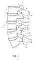
- FIG. 1is a lateral elevational view of a portion of the vertebral column.
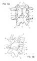
- FIG. 2Ais a schematic superior view of an isolated thoracic vertebra.
- FIG. 2Bare schematic side view of an isolated thoracic vertebra.
- FIG. 3Ais a schematic posterior elevational view of a portion of the vertebral column.
- FIG. 3Bis a posterior-oblique elevational view of a portion of the vertebral column.
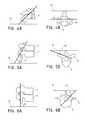
- FIG. 4Ais a schematic side view of a facet joint in the cervical vertebrae.
- FIG. 4Bis a schematic superior view of a facet joint in the cervical vertebrae.
- FIG. 5Ais a schematic side view of a facet joint in the thoracic vertebrae.
- FIG. 5Bis a schematic superior view of a facet joint in the thoracic vertebrae.
- FIG. 6Ais a schematic side view of a facet joint in the lumbar vertebrae.
- FIG. 6Bis a schematic superior view of a facet joint in the lumbar vertebrae.
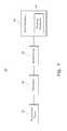
- FIG. 7is a block diagram of a flexible fastening band according to an embodiment.
- FIGS. 8-10are posterior perspective views of a portion of the vertebral column depicting a method of stabilizing a vertebra using a flexible fastening band according to an embodiment.
- FIG. 11is a flow chart illustrating a method of inserting an implant between two bone portions.
- FIG. 12is a flow chart illustrating a method of inserting an implant into a facet joint.
- FIG. 13is a schematic view of one embodiment of a trial member having a trial implant deployed in a facet joint.
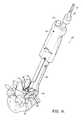
- FIG. 14is a schematic view of one embodiment of a tool guided over the trial member of FIG. 13 .
- FIGS. 15A-15Bare posterior perspective views of a portion of the vertebral column depicting a method of using the tool of FIG. 14 to drill through the facet joint.
- FIGS. 16A-16Bare posterior perspective views of a portion of the vertebral column depicting a method of passing a flexible member through the facet joint.
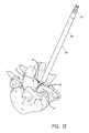
- FIG. 17is a posterior perspective view of a portion of the vertebral column depicting a method of pulling the flexible member of FIGS. 16A-16B out of the facet joint using the trial member.
- FIG. 18is a posterior perspective view of a portion of the vertebral column depicting a method of disassembling the trial member.
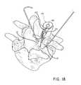
- FIG. 19is a posterior perspective view of a portion of the vertebral column depicting a method of loading an implant onto the flexible member.
- FIGS. 20A-20Bare posterior perspective views of a portion of the vertebral column depicting a method of pulling the implant of FIG. 19 into the facet joint by making the flexible member taut.
- FIG. 21is a posterior perspective view of a portion of the vertebral column depicting a method of cinching the facet joint closed using a flexible fastening band.
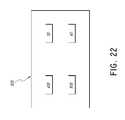
- FIG. 22is a block diagram of a kit according to an embodiment.
- an implantis intended to mean a single implant or a combination of implants.
- a substancecan include any biologic and/or chemical substance, including, but not limited to, medicine, adhesives, etc. While exemplary references are made with respect to vertebra, in some embodiments another bone or portions of bones can be involved. While specific reference may be made to a specific vertebra and/or subset and/or grouping of vertebrae, it is understood that any vertebra and/or subset and/or grouping, or combination of vertebrae can be used.
- the vertebral column 2comprises a series of alternating vertebrae 4 and fibrous discs 6 that provide axial support and movement to the upper portions of the body.
- the vertebral column 2typically comprises thirty-three vertebrae 4 , with seven cervical (C1-C7), twelve thoracic (T1-T12), five lumbar (L1-15), five fused sacral (S1-S5) and four fused coccygeal vertebrae.
- FIGS. 2A and 2Bdepict a typical thoracic vertebra.
- Each vertebraincludes an anterior body 8 with a posterior arch 10 .
- the posterior arch 10comprises two pedicles 12 and two laminae 14 that join posteriorly to form a spinous process 16 .
- a transverse 18 , superior 20 and inferior articular process 22Projecting from each side of the posterior arch 10 is a transverse 18 , superior 20 and inferior articular process 22 .
- the facets 24 , 26 of the superior 20 and inferior articular processes 22form facet joints 28 with the articular processes of the adjacent vertebrae (see FIGS. 3A and 3B ).
- the facet jointsare true synovial joints with cartilaginous surfaces and a joint capsule.
- the orientation of the facet jointsvary, depending on the level of the vertebral column.
- the facet jointsare parallel to the transverse plane.
- FIGS. 4A to 6Bdepict examples of the orientations of the facet joints at different levels of the vertebral column.
- the facetsare oriented at a 45-degree angle to the transverse plane 30 and parallel to the frontal plane 32 , respectively. This orientation allows the facet joints of the cervical vertebrae to flex, extend, lateral flex and rotate.
- FIGS. 5A and 5Bdepict examples of the thoracic vertebrae, where the facets are oriented at a 60-degree angle to the transverse plane 30 and a 20-degree angle to the frontal plane 32 , respectively. This orientation is capable of providing lateral flexion and rotation, but only limited flexion and extension.
- FIGS. 6A and 6Billustrate examples of the lumbar region, where the facet joints are oriented at 90-degree angles to the transverse plane 30 and a 45-degree angle to the frontal plane 32 , respectively.
- the lumbar vertebraeare capable of flexion, extension and lateral flexion, but little, if any, rotation because of the 90-degree orientation of the facet joints in the transverse plane.
- the actual range of motion along the vertebral columncan vary considerably with each individual vertebra.
- the facet jointsIn addition to guiding movement of the vertebrae, the facet joints also contribute to the load-bearing ability of the vertebral column.
- the facet jointsmay also play a role in resisting shear stresses between the vertebrae. Over time, these forces acting on the facet joints can cause degeneration and arthritis.
- a flexible fastening bandcan be used to stabilize and/or fixate a first vertebra to a second vertebra to reduce the pain, to reduce further degradation of a spine, or of a specific vertebra of a spine, and/or until the first vertebra and the second vertebra have fused.
- FIG. 7depicts a block diagram of a flexible fastening band (“band”) 140 .
- Band 140includes a flexible elongate body including a proximal end portion 142 , a first portion 144 , a second portion 146 , and a distal end portion 148 that includes a fastening mechanism 150 (alternatively referred to herein as a fastener).
- band 140can include a third portion (not shown in FIG. 7 ). In some embodiments, band 140 can include a spacer (not shown in FIG. 7 ). In some embodiments, the fastening mechanism can be separate from the distal end portion.
- Band 140can be configured to stabilize a first vertebra (not shown in FIG. 7 ) and/or a second vertebra (not shown in FIG. 7 ). Specifically, band 140 can be configured to stabilize the first vertebra and/or second vertebra by securing an articular process of the first vertebra to an articular process of a second vertebra.
- band 140can be configured to stabilize the first vertebra and/or a second vertebra by securing an articular process of the first vertebra to an articular process of a second vertebra by securing a facet of the articular process of the first vertebra with a facet of the articular process of the second vertebra.
- band 140can be removed from the vertebra, e.g. by cutting, breaking, or otherwise releasing band 140 . In this manner, should a band fail, a replacement band can be inserted. Similarly, should the band be deemed ineffective for a particular patient, the band can be removed and an alternate treatment can be chosen without incurring permanent fusion of the vertebra.
- band 140can be monolithically formed or separately formed.
- Band 140can include any biocompatible material, e.g., stainless steel, titanium, PEEK, nylon, etc.
- Proximal end portion 142is configured to pass through a lumen formed through a vertebra and a lumen formed through an adjacent vertebra, and to pass through fastening mechanism 150 of the distal end portion 148 .
- proximal end portion 142can be shaped to incrcase the case of inserting proximal end portion 142 into fastening mechanism 150 , e.g., proximal end portion 142 can be tapered, rounded, and/or angled, etc., to reduce at least a portion of a cross-sectional area of proximal end portion 142 .
- First portion 144can extend for a length between proximal end portion 142 and second portion 146 , and can have a substantially uniform shape.
- the first portion 144can have, for example, a substantially cuboidal shape, or a substantially cylindrical shape.
- the length of first portion 144can be more than twice the length of second portion 146 .
- the cross-sectional area of the first portion 144can be smaller than the cross-sectional area of the second portion 146 .
- the cross-sectional area of first portion 144can be less than a cross-sectional area of a lumen defined by the fastening mechanism 150 .
- First portion 144can include a gear rack (not shown in FIG.
- the gear rackcan be configured to allow first portion 144 to travel through fastening mechanism 150 in only one direction.
- First portion 144can be monolithically formed with second portion 146 . In some other embodiments, the first portion can be separately formed from the second portion.
- First portion 144can be configured to be slideably disposed in a lumen of second portion 146 .
- Second portion 146can have a length between first portion 144 and distal end portion 148 , and can include a substantially uniform shape. In embodiments including the third portion, second portion 146 can have a length between first portion 144 and the third portion. Second portion 146 can have, for example, a substantially cuboidal shape or a substantially cylindrical shape. First portion 144 and second portion 146 can have the same or different shapes, e.g., first portion 144 and second portion 146 can both be substantially cuboidal (see, e.g., band 240 in FIG.
- first portion 144 and second portion 146can both be substantially cylindrical, first portion 144 can be substantially cuboidal while second portion 146 can be substantially cylindrical, or first portion 144 can be substantially cylindrical while second portion 146 can be substantially cuboidal (not shown).
- the length of second portion 146can be less than half the length of first portion 144 .
- the cross-sectional area of the second portion 146can be greater than the cross-sectional area of the first portion 144 .
- the cross-sectional area of second portion 146can be greater than a cross-sectional area of a lumen defined by the fastening mechanism 150 .
- Second portion 146can include a gear rack (not shown in FIG. 7 ) configured to engage the ratchet of the fastening mechanism 150 .
- the gear rackcan be configured to allow second portion 146 to travel through fastening mechanism 150 in only one direction.
- Second portion 146can be monolithically formed with first portion 144 . In some embodiments, the second portion can be separately formed from the first portion. Second portion 146 can define a lumen configured to slideably accept first portion 144 .
- Distal end portion 148includes a fastening mechanism 150 configured to accept at least a portion of proximal end portion 142 , first portion 144 , and/or second portion 146 .
- distal end portion 148 , second portion 146 , first portion 144 , and proximal end portion 142can be monolithically formed.
- Fastening mechanism 150includes a lumen (not shown in FIG. 7 ) configured to accept at least a portion of proximal end portion 142 , a portion of first portion 142 , and/or a portion of second portion 146 .
- the cross-sectional area of the lumen of fastening mechanism 150is smaller than the cross-sectional area of second portion 146 . In this manner, second portion 146 can be prevented from advancing through fastening mechanism 150 .
- distal end portion 148 , second portion 146 , first portion 144 , and proximal end portion 142can be formed separately from the other(s) of distal end portion 148 , second portion 146 , first portion 144 , and proximal end portion 142 .
- distal end portion 148 , first portion 144 , and proximal end portion 142can be monolithically formed together, while second portion 146 can be separately formed.
- band 140can include an initial second portion 146 configured to be replaced and/or covered with a replacement second portion 146 .
- initial second portion 146can be monolithically formed with first portion 144 and replacement second portion 146 can be slideably disposed over initial second portion 146 .
- initial second portion 146can be separately formed from first portion 144 , can be removed from band 140 , and replacement second portion 146 can be slideably disposed over first portion 144 .
- initial second portion 146can be separately or monolithically formed from first portion 144 , and replacement second portion 146 can be slideably disposed over first portion 144 and initial second portion 146 .
- initial second portion 146 and replacement second portion 146can have the same shape, e.g., initial second portion 146 can include a substantially cylindrical shape and replacement second portion 146 can include a substantially cylindrical shape. In some embodiments, initial second portion 146 and replacement second portion 146 can have different shapes, e.g., initial second portion 146 can include a substantially cuboidal shape and replacement second portion 146 can include a substantially cylindrical shape.
- the shape of first portion 144 and the shape of second portion 146can be determined based on the shape of an artificial lumen formed through an articular process of a vertebra.
- the shape of the artificial lumenis cuboidal
- the shape of the first portion 144 and the shape of the second portion 146can be cuboidal to allow the first portion 144 and the second portion 146 to slideably advance through the artificial lumen.
- the shape of the artificial lumenis cylindrical
- the shape of the first portion 144 and the shape of the second portion 146can be either cuboidal or cylindrical.
- the shape of the first portion 144can be cuboidal to allow the first portion 144 to advance easily through the artificial lumen, while the shape of the second portion 146 can be cylindrical to allow the second portion 146 to fit more tightly within the artificial lumen as compared to a cuboidal shape.
- the shape of the first portion 144 and the shape of the second portion 146can be determined based on characteristics of the bone or bone portion against which the first portion 144 and the second portion 146 may contact.
- first portion 144 and/or second portion 146can be substantially cuboidal
- edges of the first portion 144 and/or the second portion 146can be rounded, partially rounded, and/or otherwise shaped to compliment the shape of a bone or bone portion, and/or to reduce digging or grinding into the bone or bone portion. In this manner, use of band 140 may cause little or no damage to the bone or bone portions contacted by band 140 .
- band 140can include a third portion (not shown in FIG. 7 ).
- the third portioncan have a length between second portion 146 and distal end portion 150 , and can have a substantially uniform shape.
- the third portioncan have, for example, a substantially cuboidal shape or a substantially cylindrical shape.
- the length of the third portioncan be less than half the length of first portion 144 .
- the third portioncan be monolithically formed with first portion 144 and/or the second portion 146 .
- the first portioncan be separately formed from the second portion and/or the first portion.
- first portion 144 , second portion 146 , and the third portioncan be a substantially uniform shape
- any one of first portion 144 , second portion 146 , and the third portioncan include a transition portion to transition band 140 from a first substantially uniform shape to a second substantially uniform shape.
- first portion 144 and the third portioncan be substantially cuboidal and second portion 146 can be substantially cylindrical.
- second portion 146can include an angled, conical, or other shaped transition portion.
- FIGS. 8-10show posterior perspective views of a portion of the vertebral column during a method for stabilizing adjacent vertebrae using a flexible fastening band (“band”) 240 according to an embodiment.
- a band 240can be used to stabilize a vertebra V 1 and vertebra V 2 via the inferior articular process IAP of vertebra V 1 and the superior articular process SAP2A of vertebra V 2 .
- a flexible fastening band (“band”) 340is used to stabilize a vertebra V 1 and vertebra V 2 via the inferior articular process IAP1B of vertebra V 1 and the superior articular process SAP2B of vertebra V 2 .
- vertebra V 1 and/or vertebra V 2are stabilized using only one of band 240 or band 340 .
- one of band 240 or band 340can be used to stabilize vertebra V 1 and/or vertebra V 2 via one of via the inferior articular process IAP of vertebra V 1 and the superior articular process SAP2A of vertebra V 2 , or, via the inferior articular process IAP1B of vertebra V 1 and the superior articular process SAP2B of vertebra V 2 .
- one of band 240 or band 340can be used to stabilize vertebra V 1 and/or vertebra V 2 via both of the inferior articular process IAP of vertebra V 1 and the superior articular process SAP2A of vertebra V 2 , and, the inferior articular process IAP1B of vertebra V 1 and the superior articular process SAP2B of vertebra V 2 .
- band 240 and band 340can be similar to band 140 described above and can include similar components.
- band 240includes a proximal end portion 242 , a first portion 244 , a second portion 246 , and a distal end portion 248 including a fastening mechanism 250
- band 340includes a proximal end portion (not shown in FIG. 8 ), a first portion, a second portion, and a distal end portion including a fastening mechanism.
- the shapes of first portion 244 , the first portion of band 340 , second portion 246 , and the second portion of band 340can all be cuboidal. As shown in FIG.
- band 240includes a gear rack 247 and gears 264 .
- gears 264can be wedge shaped to allow each of gears 264 to displace the ratchet of fastening mechanism 250 in only one direction.
- gears 264can be other shapes, such as blocks, etc.
- FIG. 11depicts a flow chart illustrating a method 1000 of placing an implant between two bone portions.
- a patientPrior to use of the implant, a patient can be prepared for surgery. Some examples of preparations for surgery are shown and described in U.S. Publication 2011/0040301 (application Ser. No. 12/859,009, filed Aug. 18, 2010) and U.S. Pat. No. 7,846,183 (application Ser. No. 10/865,073, filed Jun. 10, 2004).
- the surgical procedurecan include direct visualization of the vertebra(e) to be stabilized.
- the medical practitionercan perform the operation without the use of fluoroscopy, and, in this manner, may not have to rely on the inaccuracies and/or inconvenience inherent in fluoroscopic procedures.
- This direct visualizationcan be possible due to the small incision necessary for implantation of the band, for example, less than about 25 mm, and due to the case of implanting and deploying the band.
- the surgical procedure usedcan include forming an opening in body tissue. In some embodiments, this opening is substantially equidistant between a first articular process of the first vertebra and a second articular process of the first vertebra.
- a cannula(not shown) can be inserted through the opening and a proximal end of the cannula can be positioned near the lumen of superior articular process SAP2A of vertebra V 2 .
- Step 1002can include forming a lumen across two bone portions.
- a drill or other devicee.g., tissue punch or reamer
- This stepcan involve forming a lumen in superior articular process SAP2A of vertebra V 2 and inferior articular process IAP1A of vertebra V 1 .
- the drillcan be used to form the lumen in a facet of superior articular process SAP2A of vertebra V 2 and form the lumen in a facet of inferior articular process IAP of vertebra V 1 .
- Methods and devices for forming lumens in vertebraare described in U.S. Pat. No. 7,846,183 (application Ser.
- a flexible membersuch as a suture, can be positioned within the cannula and can be advanced through the cannula until the proximal end portion of the flexible member is positioned near the lumen of superior articular process SAP2A of vertebra V 2 .
- Step 1004can include inserting a portion of the flexible member through the lumen and across the two bone portions.
- the flexible membercan be inserted into and through the lumen of the first bone portion.
- the flexible membercan be inserted into and through the lumen of the second bone portion.
- the flexible memberhas two ends. In some embodiments, the first end is threaded consecutively through the first bone portion and through the second bone portion. After the threading, one end of the flexible member extends beyond the first bone portion and the other end of the flexible member extends beyond the second bone portion.
- the two bone portionsare facets.
- the proximal end portion of the flexile membercan be inserted into the lumen of superior articular process SAP2A of vertebra V 2 and through the lumen of inferior articular process IAP1A of vertebra V 1 . After the threading, one end of the flexible member extends beyond the superior articular process and the other end of the flexible member extends beyond the inferior articular process.
- Step 1006can include coupling a portion of the flexible member extending across to bone portions to the implant. This step may include withdrawing a portion of the flexible member out of the joint. In some embodiments, the flexible member is coupled to a trial implant when the flexible member is withdrawn. This step can include bringing the flexible member out at a joint line. In some embodiments, the bone portions are facets. This step may include withdrawing a portion of the flexible member from the facet joint.
- An implantis coupled to the flexible member. In some embodiments, the implant can be coupled to the flexible member by sliding the implant onto the flexible member.
- the implantcan include an engagement feature extending from the edge of the implant to the center of the implant. The engagement feature may be slot connected to an aperture. The slot may be linear or non-linear. A non-linear slot may prevent accidental disengagement between the implant and the flexible member.
- the flexible memberremains threaded through the lumen in the first bone portion and the lumen of the second bone portion.
- Step 1008can include inserting the implant into the space between the bone portions.
- the implantis inserted into the joint space between facet joints.
- tensionis applied to both ends of flexible member. The tension takes up slack in the flexible member, urging the implant into the joint space. Tension can be applied until the shortest distance of the flexible member is between the first bone portion and the second bone portion.
- the implantcan be positioned such that the aperture of the implant forms a path between the first bone portion and the second bone portion.
- a bandcan inserted into and through the lumen in first bone portion, into and through the aperture in the implant, and into and through the lumen in the second bone portion.
- the band or other retaining membercan be advanced through a fastening mechanism until the two bone portions are stabilized as described in U.S. Patent Publication No. 2012/0221049 (U.S. application Ser. No. 13/403,698, filed Feb. 23, 2012) and U.S. Pat. No. 8,740,949 (U.S. application Ser. No. 13/033,791, filed Feb. 24, 2011).
- the bandcan extend through the implant.
- the flexible membercan be cut to reduce the size the flexible member.
- the ends of the flexible membercan be tied to secure the implant within the joint.
- FIG. 12is a flow chart illustrating a method of placing an implant within a facet joint.
- FIG. 12shows a similar method to FIG. 11 , wherein the first bone portion is a first facet and the second bone portion is a second facet.
- the flexible membercan be extended across the facet joint (or two bone portions) while the lumen is being formed.
- FIGS. 13-21illustrate various method steps wherein the first bone portion is a first facet and the second bone portion is a second facet. As described above, prior the illustrated steps, a patient can be prepared for surgery and access can be provided to the treatment site.
- FIG. 13shows the trial member 500 inserted into the patient.
- a trial implant 502is inserted in the facet joint space between the articular processes 20 , 22 .
- the trial implant 502is inserted after the facet joint has been incised and the articular surfaces prepared.
- the trial implant 502can be used as a reference to size an implant 40 which will be fitted into the joint space.
- the shaft 504extends outward from the facet joint 28 .
- the trial member 500can include a notch 512 on the proximal end of the shaft 504 to secure the trial member 500 to a tool 400 via a retention member.
- the trial implant 502can comprise a disk-like member having an aperture 508 .
- the trial implant 502can have a curved or cupped shape to facilitate positioning between the articular processes 20 , 22 .
- the trial implant 502may have different shapes, sizes and thicknesses for use with different sized vertebra.
- Some embodimentscomprise tools and methods for creating holes or lumens through one or more bone portions such as the articular processes 20 , 22 of the vertebra to facilitate implantation of the implant 40 .
- the holes or lumenshave a curved or non-linear configuration.
- the curved or non-linear configurationallows relatively greater penetration through the thicker portions of the articular process(es) and therefore the articular process(es) may be less likely to fracture during formation of the hole or lumen.
- various instrumentshave been proposed for drilling into and through bone, including for example, the curved drills described in U.S. Pat. Nos.
- the subject tooloffers the benefits of lumen formation through the articular processes within the limited surgical access available about the vertebra.
- the devices described hereinmay utilize one or more curved punch members or curved drills that rotate about an axis that is transverse to the movement plane of the curved punch or curved drill member. Unlike traditional orthopedic procedures that require unimpeded access to the surgical site due to the longitudinally-oriented surgical tools, the curved punch or curved drill members also permit access using a limited space or cavity around the articular processes.
- the terms “lumen-forming” and “lumen formation”refer to the creation of a hole, passageway or indentation generally such as by, for example, piercing, punching, boring, puncturing, or drilling.
- FIG. 14shows the tool 400 coupled to the trial member 500 .
- One embodiment of the tool 400shown in FIG. 14 , comprises a shaft 402 with a proximal handle 404 and a distal arm guide 406 .
- the arm guide 406contains a lumen-forming arm 410 (not shown) that can be moved in the proximal-distal direction by manipulation of a proximal actuator 422 .
- the distal portionalso comprises an opposing target member 408 having a target plate 414 .
- the lumen-forming arm 410comprises a rotating drill bit 412 (not shown) that can be connected to a drill motor by a drill coupler 424 disposed toward the proximal end of the tool 400 .
- a trial member 500 with a trial implant 502can be coupled to the tool 400 .
- the trial member 500can be at least partially supported on the tool 400 by a frame 418 and the proximal handle 404 .
- the trial member 500can be secured to the tool 400 by a retention member, which can be relcased by a relcase button 514 .
- the lumen-forming arm 410can be slideably contained within the shaft 402 and the arm guide 406 .
- the lumen-forming arm 410can be moved between an advanced configuration, and a retracted configuration, by a proximal actuator 422 that moves the lumen-forming arm 410 axially along the shaft 402 of the tool 400 .
- manipulation of the actuator 422causes a longitudinal movement of the lumen-forming arm 410 .
- the lumen-forming arm 410can be straight or curved or a combination of these shapes.
- the lumen-forming arm 410may be stiff, bendable, or partially stiff and partially bendable.
- the lumen-forming arm 410can be sized to be able to pass through the articular processes 20 , 22 of the spine and the resulting hole is sized for a flexible member 30 and/or band 140 , 240 to be inserted.
- the lumen-forming arm 410can have a diameter in the range of about 1 mm to 5 mm, preferably about 2 mm to 4 mm, and most preferably about 3 mm.
- At an end of the rotating drill bit 412can be a drill bit tip 413 (not shown) with a cutting surface for creating the lumen in the facets.
- a target member 408 having a target plate 414can be connected to the frame 418 .
- the target plate 414is in the path of travel of the lumen forming arm 410 and thus the position of the target plate 414 against an articular process 22 can provide indication to the user of where the lumen forming arm 410 will emerge from the articular processes 20 , 22 during the drilling procedure.
- the target member 408can advantageously help the user avoid neural or other structures in and around the articular process 22 by visualizing and understanding the trajectory of the lumen forming arm 410 through the articular processes 20 , 22 .
- the target member 408can provide some stabilization of the articular processes 20 , 22 as the lumen forming arm 410 passes or cuts through the bone.
- the tool 400can further comprise a trial member 500 that can be coupled to the handle 404 .
- the trial member 500can comprise a shaft 504 that is connected by retention member to the tool 400 .
- the retention memberallows the trial member 500 to be detached from and attached to the facet drill tool 400 with case.
- the tool 400can be guided over the shaft 504 until the retention member engages the notch 512 to lock the trial member 500 to the tool 400 .
- the trial member 500has a trial implant 502 at the distal end.
- the trial implant 502can comprise a disk-like member and an aperture 508 that is lined up with the lumen-forming arm 410 to allow the drill bit tip 413 of the lumen-forming arm 410 to penetrate through the bones and through the aperture 508 .
- the trial implant 502can have a curved or cupped shape to facilitate positioning between the articular processes 20 , 22 .
- the trial implant 502may have different shapes, sizes and thicknesses for use with different sized vertebra.
- the tool 400may be used by positioning the anchor portion 426 of an arm guide 406 against one bone portion such as the articular process 20 and positioning the target plate 414 against another bone portion, such as the articular process 22 .
- the tool 400can be rotated axially relative to the trial member 500 to adjust for variations in the native anatomy of the patient.
- the surgeonmay select a particular rotational and/or angular approach to the surgical site, depending upon the particular anatomy of the patient, the extent and location of damage or injury, prior surgery, and other factors known in the art. Additional embodiments and method related to drilling holes in bones can be found in U.S. Patent Publication No. 2011/0040301 (application Ser. No. 12/859,009, filed Aug. 18, 2010).
- the trial member 500can rotate about its longitudinal axis while coupled to the tool 400 to accommodate variations in the shapes and positions of the articular processes 20 , 22 .
- the aperture 508can be sufficiently large to allow the lumen-forming arm 410 to pass through the aperture 508 even when the trial member 500 is at an angle to the lumen-forming arm 410 .
- the tool 400can be used to drill through the facet joint thereby forming a lumen that extends across the facet joint.
- the drill bit tip 413can be extended to cut the lumen in the articular process 20 .
- the lumen-forming arm 410can extend through the aperture 508 in the trial implant 502 . Then the lumen-forming arm 410 can continue to extend to the target plate 414 of the opposing target member 408 to cut a lumen in the articular process 22 . Once the curved hole is formed, the lumen-forming arm 410 can be retracted back through the lumen in the articular processes 20 , 22 .
- the flexible member 30can be passed through the lumen of the first articular process 20 , through the aperture 508 in the trial implant 502 , and through the second articular process 22 .
- the proximal end portion of the flexile member 30can be inserted into the lumen of superior articular process SAP2A of vertebra V 2 , through the aperture 508 in the trial implant 502 , and through the lumen of inferior articular process IAP1A of vertebra V 1 .
- FIG. 16Ashows that the flexible member 30 can be inserted through aperture 508 in the trial implant 502 and the through the lumens of the facets while the tool 400 is in place.
- the lumen-forming arm 410can guide the flexible member 30 through the lumens in the articular processes 20 , 22 .
- the flexible member 30is inserted through the lumens as the drill bit tip cuts the lumen.
- FIG. 16Bshows the flexible member 30 can be inserted through the aperture 508 in the trial implant 502 and the through the lumens of the facets after the tool 400 is removed.
- the flexible member 30can be coupled to a curved needle 32 shown in FIG. 17 or other guiding device to facilitate insertion of the flexible member 30 through the lumens of the facets. In both FIGS.
- the trial member 500remains within the patient and the trial implant 502 remains within the facet joint 28 while the flexible member 30 is threaded through the articular processes 20 , 22 .
- One end of the flexible member 30can extend beyond the first articular process 20 and the other end of the flexible member 30 can extend beyond the second articular process 22 as shown in FIG. 17 .
- FIG. 17shows the trial implant 502 can be withdrawn from the facet joint 28 .
- the flexible member 30is retained within the aperture 508 of the trial implant 502 during this step.
- the shaft 504can be pulled away from the facet joint 28 , thereby withdrawing the trial implant 502 .
- Withdrawing the trial implant 502causes the flexible member 30 to extend outward and beyond the facet joint 28 as shown.
- the flexible member 30has sufficient length to extend through both facets as the trial implant 502 is withdrawn from the facet joint 28 .
- the ends of the flexible member 30are drawn inward, toward the facet joint 28 as the trial implant 502 is withdrawn. As shown, the ends of the flexible member 30 extend beyond the lumens in the articular processes 20 , 22 after the trial implant 502 is withdrawn.
- the trial member 500can be disassembled.
- the trial implant 502is decoupled from the shaft 504 .
- the stem 516 of the trial implant 502can be releasably retained within the shaft 504 during any or all of the previous steps.
- the stem 516can include a slot 518 extending from an edge of the stem 516 to the aperture 508 .
- the slot 518may be linear or non-linear. A non-linear slot may prevent accidental disengagement between the trial implant 502 and the flexible member 30 .
- the trial implant 502can be rotated 90 degrees as shown in FIG. 18 to facilitate removal of the flexible member 30 from the trial implant 502 .
- the flexible member 30can be passed from the aperture 508 through the slot 518 toward the edge of the stem 516 .
- the flexible member 30can be disengaged from the aperture 508 and the slot 518 thereby freeing the flexible member 30 from the trial implant 502 .
- the trial implant 502includes an engagement feature extending from the edge of the trial implant 502 to the aperture 508 .
- the engagement featuremay be a slot, such as slot 518 .
- the engagement featureis formed only after the trial implant 502 is decoupled from the shaft 504 .
- slot 518can be formed only when the stem 516 is in an expanded state in which the two halves of the stem 516 are spaced apart. Other designs are contemplated to permit the flexible member 30 from disengaging from the trial implant 502 .
- FIG. 19shows the implant 40 coupled to the flexible member 30 .
- a portion of the flexible member 30 extending outward and beyond the facet joint 28can be coupled to the implant 40 .
- the implant 40comprises an engagement feature extending from the edge of the implant 40 to an aperture 48 .
- the engagement featuremay be a slot 44 , which may be linear or non-linear. A non-linear slot may prevent accidental disengagement between the implant 40 and the flexible member 30 .
- Other embodimentsare contemplated to engage the flexible member 30 with the implant 40 .
- the flexible member 30can be inserted from the slot 44 to the aperture 48 to couple the implant 40 to the flexible member 30 .
- the implant 40comprises a body with a least two faces, a first face adapted to contact a first bone such as the articular surface of one facet of the facet joint and a second face adapted to contact a second bone such as the articular surface of the other facet.
- the aperture 48can be sized and configured to accept a retaining member, such as the retaining members described in U.S. Pat. No. 7,846,183 (U.S. application Ser. No. 10/865,073, filed Jun. 10, 2004).
- the aperture 48can be sized and configured to accept a band, such as the bands described herein and in U.S. Publication No. 2012/0221060 (U.S. application Ser. No. 13/033,791, filed Feb. 24, 2011).
- the implant 40has a generally circular profile and is sized to fit generally within the joint capsule of the facet joint 28 .
- the implant 40can be, for example, substantially disc shaped.
- the implant 40can have any of a variety of profiles, including but not limited to square, rectangle, elliptical, oval, star, polygon or combination thereof.
- an implant 40 having the desired shapeis selected from an array of implants after radiographic visualization of the articular processes and/or by radio-contract injection into the facet joint to visualize the joint capsule.
- the implant 40has a diameter of about 4 mm to about 30 mm. In another embodiment, the implant 40 has a diameter of about 5 mm to about 25 mm. In still another embodiment, the implant 40 has a diameter of about 10 mm to about 20 mm. In some embodiments, the implant 40 has a cross-sectional area of about 10 mm 2 to about 700 mm 2 . In another embodiment, the implant 40 has a cross-sectional area of about 25 mm 2 to about 500 mm 2 . In still another embodiment, the implant 40 has a cross-sectional area of about 20 mm 2 to about 400 mm 2 , and preferably about 25 mm 2 to about 100 mm 2 .
- the implant 40has a thickness generally equal to about the anatomic spacing between two facets of a facet joint. In some embodiments, the implant 40 generally has a thickness within the range of about 0.5 mm to about 3.0 mm. In some embodiments, the implant 40 has a thickness of about 1 mm to about 2 mm. In some embodiments, the implant 40 has a thickness of about 0.5 mm to about 1.5 mm. In some embodiments, the thickness of the implant 40 is non-uniform within the same implant. For example, the thickness of the implant 40 can be incrcased around the entire outer edge, along at least one and, as illustrated, both faces.
- only a portion of the edge on one face of the implant 40has a thickness that is greater than the thickness of a central region, and, optionally, also thicker than the typical anatomic spacing between two facets of a facet joint.
- An incrcased edge thicknessmay resist lateral displacement of the prosthesis out of the facet joint.
- the implant 40is configured to provide an improved fit with the articular process and/or joint capsule.
- the implant 40can have a bend, angle or curve to generally match the natural shape of an articular facet.
- the implant 40may be rigid with a preformed bend.
- the implant 40may be sufficiently malleable that it will conform post implantation to the unique configuration of the adjacent facet face.
- the implant 40is configured to be implanted between the articular processes and/or within the joint capsule of the facet joint, without securing of the implant to any bony structures. Such embodiments can thus be used without invasion or disruption of the vertebral bone and/or structure, thereby maintaining the integrity of the vertebral bone and/or structure.
- the implant 40can be similar to, and have similar features to the embodiments of the prosthesis shown and described in commonly owned U.S. Pat. No. 7,846,183 (application Ser. No. 10/865,073, filed Jun. 10, 2004), which is incorporated herein by reference in its entirety.
- the implant 40can be implanted and deployed to restore the space between facets of a superior articular process of a first vertebra and an inferior articular process of an adjacent vertebra.
- the implant 40can be deployed to help stabilize adjacent bone portions, such as adjacent facets of a facet joint.
- a porous surfacecan allow bone to grow into or attach to the surface of the implant, thus securing the implant to the bone.
- an adhesive or sealantsuch as a cyanoacrylate, polymethylmethacrylate, or other adhesive known in the art, is used to bond one face of the implant to an articular surface.
- the implantcan include a first side and a second side.
- the first side and/or the second sidecan be, for example, convex, concave, or flat.
- the first side of the implantcan be concave, convex, or flat, and the second side of the implant can be concave, convex, or flat.
- the first sidecan be concave and the second side concave, the first side can be concave and the second side convex, etc.
- the implant 40can be formed of allograft. In some embodiments, at least a portion of the implant 40 can be formed of artificial materials, such as, for example, titanium or PEEK. In some embodiments, the implant 40 can be deployed to deliver and/or relcase a substance. In some embodiments, the substance can have therapeutic properties, for example, a medication. In some embodiments, the substance is an adhesive.
- the implant 40can include the same materials as the flexible band, describe herein. In some embodiments, the implant 40 can incrcase the stability of a vertebra and/or the flexible band, describe herein.
- FIG. 20Ashows the implant 40 being inserted into the facet joint.
- tensioncan be applied to one or both ends of the flexible member 30 .
- the slot 44can be oriented away from the facet joint 28 to prevent accidental disengagement of the flexible member 30 from the implant 40 .
- the tensiontakes up slack in the flexible member 30 , urging the implant 40 into the joint space.
- Tensioncan be applied until the implant 40 is held taut by the flexible member 30 .
- the implant 40can be positioned such that the aperture 48 forms a path between the first bone portion and the second bone portion, as illustrated in FIG. 20B .
- the flexible member 30is secured to maintain the position of the implant 40 .
- the ends of the flexible member 30are secured to each other or to other objects such as anchors, tacks, or bones. In some embodiments, the ends of the flexible member 30 are tied. In some embodiments, the flexible member 30 is removed. In some embodiments, the ends of the flexible member 30 are cut.
- the facet jointcan be stabilized using a band 140 , 240 as described herein.
- the band 140 , 240can follow the path of the flexible member 30 .
- the flexible member 30is removed prior to insertion of the band 140 , 240 .
- the flexible member 30is removed after to insertion of the band 140 , 240 .
- the band 140 , 240can be extended through the lumen of the first facet, the aperture 48 of the implant 40 , and through the lumen in the second facet.
- the proximal end 142 , 242 of the band 140 , 240can be advanced through a fastening mechanism 150 , 250 until the two facets are stabilized.
- FIG. 22illustrates is a block diagram of a kit for inserting an implant into a facet joint according to an embodiment.
- the kit 600can include the tool 400 as described herein.
- the kit 600can include the trial member 500 including the trial implant 502 and the shaft 504 .
- the kit 600can include the flexible member 30 .
- the kitcan include the implant 40 .
- the kitincludes two of the components selected from the group of the tool 400 , the trial member 500 , the flexible member 30 and the implant 40 .
- the kitincludes three of the components selected from the group of the tool 400 , the trial member 500 , the flexible member 30 and the implant 40 .
- the kitincludes all of the following components: the tool 400 , the trial member 500 , the flexible member 30 and the implant 40 .
- the kitincludes multiple implants 40 (e.g., two, three, four, a plurality).
- the kitincludes multiple trial members 500 (e.g., two, three, four, a plurality).
- the kitincludes multiple trial implants 502 (e.g., two, three, four, a plurality).
- a method of placing an implant into a facet joint of the spinecan include the step of forming a hole across the facet joint.
- the methodcan include the step of passing a flexible member through the hole and across the facet joint.
- the methodcan include the step of bringing the flexible member out of the facet joint.
- the methodcan include the step of coupling an implant to the flexible member.
- the methodcan include the step of tightening the flexible member to reduce into the implant into a joint space.
- the methodcan include the step of cutting the flexible member.
- the methodcan include the step of tying cut ends of the flexible member together.
- the flexible memberis a suture.
- the implantincludes a hole for receiving the flexible member.
- the implantincludes a slot for receiving the flexible member.
- the implantincludes allograft or an artificial material.
- the implantis sized to fit into the joint space.
- the step of forming a hole across the facet jointcomprises drilling a hole.
- the step of bringing the flexible member out of the facet jointcomprises bringing the flexible member out at a joint line.
- the methodcan include the step of inserting a trial implant into the joint space before forming a hole across the facet joint.
- the methodcan include the step of withdrawing the trial implant out of the joint space to bring the flexible member out of the facet joint.
- the methodcan include the step of inserting a flexible retention member through the facet joint and the implant and using the flexible retention member to secure the facet joint.
- a method of placing an implant in a spine facet jointcan include the step of drilling a hole across the facet joint.
- the methodcan include the step of removing the drill.
- the methodcan include the step of leaving behind a trial/targeting device in the joint space.
- the methodcan include the step of passing a suture through the hole and across the facet joint.
- the methodcan include the step of bringing the suture out of the facet joint at a joint line by removing the trial/targeting device.
- the methodcan include the step of removing the suture from the trial/targeting device by passing it through a slot in the trial/targeting device.
- the methodcan include the step of placing an implant with a hole and slot over the suture.
- the methodcan include the step of pulling the suture tight to reduce implant into the joint space.
- the implantcomprises artificial material and/or allograft.
- the implantis configured and sized to fit into the joint space.
- a device for placement in a spine facet jointcan include a body that is sized to fit in the facet joint of a spine.
- the bodyis formed from artificial materials, allograft or a combination thereof.
- the bodyhas a hole for receiving a suture or flexible fixation member.
- the bodyhas a slot so that it can be placed over a portion of the suture or flexible fixation member.
- a kit for placement of an implant into a spine facet jointcan include a trial member with an opening.
- the kitcan include a drill configured to form an opening between two bone portions and the trial member inserted between the two bone portions.
- the kitcan include an implant with an opening.
- the kitcan include a flexible member.
- the kitcan include a flexible fastening band through with fastener.
- the implantcomprises an allograft.
- the methods and devices described herein for placing an implant into a joint or between two bone portionsare not limited to fusion applications and/or the fusion devices described herein.
- the methods and devices described herein for placing an implant into a joint or between two bone portionscan be used with fixation devices that utilized flexible fasteners of different configuration and/or fasteners that are not flexible (e.g., rods, screws, and/or clamps) that extend across the joint or between bone portions.
- U.S. Pat. No. 7,846,183 and/or U.S. Pat. No. 8,740,949disclose various devices and methods for the augmentation and restoration of vertebral facet joints.
- implante.g., a disk
- Several embodimentsinvolve the insertion of implant (e.g., a disk) into the facet joint.
- Several embodimentsinclude a hole or slot in the implant and/or a flexible member that can extend across an opening formed in the facet joint and the implant.
- the techniques and devices described herein for advancing a flexible member through the facet joint and then using the flexible member to urge the implant into the facet jointcan be used.
- the methods and devices hereinare not limited to the facet joint but can also be used to insert an implant between to bone portions and/or other joints in the body.
Landscapes
- Health & Medical Sciences (AREA)
- Orthopedic Medicine & Surgery (AREA)
- Life Sciences & Earth Sciences (AREA)
- Surgery (AREA)
- Neurology (AREA)
- Heart & Thoracic Surgery (AREA)
- General Health & Medical Sciences (AREA)
- Biomedical Technology (AREA)
- Nuclear Medicine, Radiotherapy & Molecular Imaging (AREA)
- Medical Informatics (AREA)
- Molecular Biology (AREA)
- Animal Behavior & Ethology (AREA)
- Engineering & Computer Science (AREA)
- Public Health (AREA)
- Veterinary Medicine (AREA)
- Dentistry (AREA)
- Oral & Maxillofacial Surgery (AREA)
- Prostheses (AREA)
- Surgical Instruments (AREA)
Abstract
Description
Claims (15)
Priority Applications (3)
| Application Number | Priority Date | Filing Date | Title |
|---|---|---|---|
| US15/245,664US10194955B2 (en) | 2013-09-27 | 2016-08-24 | Method of placing an implant between bone portions |
| US16/221,903US11517354B2 (en) | 2013-09-27 | 2018-12-17 | Method of placing an implant between bone portions |
| US18/052,361US20230089601A1 (en) | 2013-09-27 | 2022-11-03 | Method of placing an implant between bone portions |
Applications Claiming Priority (3)
| Application Number | Priority Date | Filing Date | Title |
|---|---|---|---|
| US201361883911P | 2013-09-27 | 2013-09-27 | |
| US14/491,820US9456855B2 (en) | 2013-09-27 | 2014-09-19 | Method of placing an implant between bone portions |
| US15/245,664US10194955B2 (en) | 2013-09-27 | 2016-08-24 | Method of placing an implant between bone portions |
Related Parent Applications (1)
| Application Number | Title | Priority Date | Filing Date |
|---|---|---|---|
| US14/491,820DivisionUS9456855B2 (en) | 2013-09-27 | 2014-09-19 | Method of placing an implant between bone portions |
Related Child Applications (1)
| Application Number | Title | Priority Date | Filing Date |
|---|---|---|---|
| US16/221,903DivisionUS11517354B2 (en) | 2013-09-27 | 2018-12-17 | Method of placing an implant between bone portions |
Publications (2)
| Publication Number | Publication Date |
|---|---|
| US20170000527A1 US20170000527A1 (en) | 2017-01-05 |
| US10194955B2true US10194955B2 (en) | 2019-02-05 |
Family
ID=52740879
Family Applications (4)
| Application Number | Title | Priority Date | Filing Date |
|---|---|---|---|
| US14/491,820ActiveUS9456855B2 (en) | 2013-09-27 | 2014-09-19 | Method of placing an implant between bone portions |
| US15/245,664Active2035-01-29US10194955B2 (en) | 2013-09-27 | 2016-08-24 | Method of placing an implant between bone portions |
| US16/221,903Active2034-10-11US11517354B2 (en) | 2013-09-27 | 2018-12-17 | Method of placing an implant between bone portions |
| US18/052,361PendingUS20230089601A1 (en) | 2013-09-27 | 2022-11-03 | Method of placing an implant between bone portions |
Family Applications Before (1)
| Application Number | Title | Priority Date | Filing Date |
|---|---|---|---|
| US14/491,820ActiveUS9456855B2 (en) | 2013-09-27 | 2014-09-19 | Method of placing an implant between bone portions |
Family Applications After (2)
| Application Number | Title | Priority Date | Filing Date |
|---|---|---|---|
| US16/221,903Active2034-10-11US11517354B2 (en) | 2013-09-27 | 2018-12-17 | Method of placing an implant between bone portions |
| US18/052,361PendingUS20230089601A1 (en) | 2013-09-27 | 2022-11-03 | Method of placing an implant between bone portions |
Country Status (1)
| Country | Link |
|---|---|
| US (4) | US9456855B2 (en) |
Cited By (14)
| Publication number | Priority date | Publication date | Assignee | Title |
|---|---|---|---|---|
| US10426524B2 (en) | 2013-03-14 | 2019-10-01 | Spinal Elements, Inc. | Apparatus for spinal fixation and methods of use |
| US10624680B2 (en) | 2013-09-27 | 2020-04-21 | Spinal Elements, Inc. | Device and method for reinforcement of a facet |
| USD884896S1 (en) | 2011-10-26 | 2020-05-19 | Spinal Elements, Inc. | Interbody bone implant |
| US10758361B2 (en) | 2015-01-27 | 2020-09-01 | Spinal Elements, Inc. | Facet joint implant |
| US11272961B2 (en) | 2013-03-14 | 2022-03-15 | Spinal Elements, Inc. | Apparatus for bone stabilization and distraction and methods of use |
| US11284928B2 (en) | 2018-12-17 | 2022-03-29 | Warsaw Orthopedic, Inc. | Surgical implant and method of use |
| US11304733B2 (en) | 2020-02-14 | 2022-04-19 | Spinal Elements, Inc. | Bone tie methods |
| US11457959B2 (en) | 2019-05-22 | 2022-10-04 | Spinal Elements, Inc. | Bone tie and bone tie inserter |
| US11464552B2 (en) | 2019-05-22 | 2022-10-11 | Spinal Elements, Inc. | Bone tie and bone tie inserter |
| US11464551B2 (en) | 2011-02-24 | 2022-10-11 | Spinal Elements, Inc. | Methods and apparatus for stabilizing bone |
| US11478275B2 (en) | 2014-09-17 | 2022-10-25 | Spinal Elements, Inc. | Flexible fastening band connector |
| US11517354B2 (en) | 2013-09-27 | 2022-12-06 | Spinal Elements, Inc. | Method of placing an implant between bone portions |
| US12369952B2 (en) | 2021-12-10 | 2025-07-29 | Spinal Elements, Inc. | Bone tie and portal |
| US12440242B2 (en) | 2024-04-29 | 2025-10-14 | Spinal Elements, Inc. | Flexible fastening band connector |
Families Citing this family (12)
| Publication number | Priority date | Publication date | Assignee | Title |
|---|---|---|---|---|
| US7846183B2 (en) | 2004-02-06 | 2010-12-07 | Spinal Elements, Inc. | Vertebral facet joint prosthesis and method of fixation |
| US9504583B2 (en) | 2004-06-10 | 2016-11-29 | Spinal Elements, Inc. | Implant and method for facet immobilization |
| EP2813190B1 (en) | 2007-02-22 | 2017-04-26 | Spinal Elements, Inc. | Vertebral facet joint drill |
| US8992533B2 (en) | 2007-02-22 | 2015-03-31 | Spinal Elements, Inc. | Vertebral facet joint drill and method of use |
| USD724733S1 (en) | 2011-02-24 | 2015-03-17 | Spinal Elements, Inc. | Interbody bone implant |
| US9271765B2 (en) | 2011-02-24 | 2016-03-01 | Spinal Elements, Inc. | Vertebral facet joint fusion implant and method for fusion |
| USD765853S1 (en) | 2013-03-14 | 2016-09-06 | Spinal Elements, Inc. | Flexible elongate member with a portion configured to receive a bone anchor |
| US9730737B2 (en)* | 2013-03-14 | 2017-08-15 | Atlas Spine, Inc. | Facet fixation with anchor wire |
| US20160106478A1 (en)* | 2014-10-20 | 2016-04-21 | Warsaw Orthopedic, Inc. | Surgical system and method |
| US10918422B2 (en)* | 2017-12-01 | 2021-02-16 | Medicrea International | Method and apparatus for inhibiting proximal junctional failure |
| FR3086159B1 (en)* | 2018-09-21 | 2021-07-23 | Allyon | SOFT TISSUE SPREADING TOOL COVERING LUMBAR VERTEBRA |
| WO2022187793A1 (en)* | 2021-03-01 | 2022-09-09 | Spinal Elements, Inc. | Bone tie methods |
Citations (404)
| Publication number | Priority date | Publication date | Assignee | Title |
|---|---|---|---|---|
| US86016A (en) | 1869-01-19 | Silas j | ||
| US1630239A (en) | 1924-05-09 | 1927-05-24 | Roy S Binkley | Antrum burr |
| US1822280A (en) | 1929-06-26 | 1931-09-08 | John F Ervay | Carpenter's hammer |
| US1822330A (en) | 1930-01-13 | 1931-09-08 | Ainslie George | Suturing instrument |
| US2486303A (en) | 1948-04-29 | 1949-10-25 | Harry Herschel Leiter | Surgical appliance for bone fractures |
| US2706023A (en) | 1952-01-02 | 1955-04-12 | Ronald A Merritt | Gripping device for securing guy wires to a mast |
| US2967282A (en) | 1957-09-30 | 1961-01-03 | Gen Electric | High temperature resistor |
| US3111945A (en) | 1961-01-05 | 1963-11-26 | Solbrig Charles R Von | Bone band and process of applying the same |
| US3149808A (en) | 1963-09-25 | 1964-09-22 | Weckesser Co | Wedge-lock band clamp |
| US3570497A (en) | 1969-01-16 | 1971-03-16 | Gerald M Lemole | Suture apparatus and methods |
| US3867728A (en) | 1971-12-30 | 1975-02-25 | Cutter Lab | Prosthesis for spinal repair |
| US3875595A (en) | 1974-04-15 | 1975-04-08 | Edward C Froning | Intervertebral disc prosthesis and instruments for locating same |
| US3879767A (en) | 1972-01-26 | 1975-04-29 | Cutter Lab | Prosthesis for articulating body structures |
| US4001896A (en) | 1975-06-09 | 1977-01-11 | Zimmer, U.S.A. Inc. | Prosthetic joint for total knee replacement |
| US4037603A (en) | 1975-05-13 | 1977-07-26 | Wendorff Erwin R | Metallic surgical suture |
| JPS535889A (en) | 1976-07-06 | 1978-01-19 | Partridge Anthony John | Orthopedic surgical operation band and bone setting method |
| US4085466A (en) | 1974-11-18 | 1978-04-25 | National Research Development Corporation | Prosthetic joint device |
| US4156296A (en) | 1977-04-08 | 1979-05-29 | Bio-Dynamics, Inc. | Great (large) toe prosthesis and method of implanting |
| US4231121A (en) | 1979-07-05 | 1980-11-04 | Wright Dow Corning | Metacarpal-phalangeal prosthesis |
| USD261935S (en) | 1978-12-18 | 1981-11-17 | Halloran William X | Slotted intramedullary rod |
| US4312337A (en) | 1980-09-08 | 1982-01-26 | Donohue Brian T | Cannula and drill guide apparatus |
| US4323217A (en) | 1980-01-30 | 1982-04-06 | General Electric Company | Motor mounting assembly including extendable band |
| US4349921A (en) | 1980-06-13 | 1982-09-21 | Kuntz J David | Intervertebral disc prosthesis |
| US4502161A (en) | 1981-09-21 | 1985-03-05 | Wall W H | Prosthetic meniscus for the repair of joints |
| USD279502S (en) | 1982-11-26 | 1985-07-02 | Halloran William X | Intramedullary rod having a s-shaped cross section |
| USD279503S (en) | 1982-11-26 | 1985-07-02 | Halloran William X | Grooved intramedullary rod |
| US4535764A (en) | 1983-04-15 | 1985-08-20 | Tayco Developments, Inc. | Surgical bone tie |
| US4573459A (en) | 1983-08-25 | 1986-03-04 | Litton Bruce W | Thumb and finger extension device |
| US4573458A (en) | 1982-08-17 | 1986-03-04 | Zimmer, Inc. | Bone fixation plate |
| US4634445A (en) | 1981-01-30 | 1987-01-06 | Oec Europe Limited | Joint prosthesis |
| US4662371A (en) | 1983-01-26 | 1987-05-05 | Whipple Terry L | Surgical instrument |
| EP0238219A1 (en) | 1986-03-03 | 1987-09-23 | Pfizer Hospital Products Group, Inc. | A sternum closure device |
| US4706659A (en) | 1984-12-05 | 1987-11-17 | Regents Of The University Of Michigan | Flexible connecting shaft for intramedullary reamer |
| US4714469A (en) | 1987-02-26 | 1987-12-22 | Pfizer Hospital Products Group, Inc. | Spinal implant |
| US4722331A (en) | 1985-09-03 | 1988-02-02 | Fox James M | Orthopaedic tool guide |
| US4759766A (en) | 1984-09-04 | 1988-07-26 | Humboldt-Universitaet Zu Berlin | Intervertebral disc endoprosthesis |
| US4759769A (en) | 1987-02-12 | 1988-07-26 | Health & Research Services Inc. | Artificial spinal disc |
| US4772287A (en) | 1987-08-20 | 1988-09-20 | Cedar Surgical, Inc. | Prosthetic disc and method of implanting |
| US4773402A (en) | 1985-09-13 | 1988-09-27 | Isola Implants, Inc. | Dorsal transacral surgical implant |
| US4834757A (en) | 1987-01-22 | 1989-05-30 | Brantigan John W | Prosthetic implant |
| EP0322334A1 (en) | 1987-12-23 | 1989-06-28 | Cremascoli France | Prosthesis implanted between vertebral spinous processes |
| US4863477A (en) | 1987-05-12 | 1989-09-05 | Monson Gary L | Synthetic intervertebral disc prosthesis |
| US4907577A (en) | 1989-04-03 | 1990-03-13 | Wu Shing Sheng | Spinal transpedicle drill jig |
| US4911718A (en) | 1988-06-10 | 1990-03-27 | University Of Medicine & Dentistry Of N.J. | Functional and biocompatible intervertebral disc spacer |
| US4919667A (en) | 1988-12-02 | 1990-04-24 | Stryker Corporation | Implant |
| US4923471A (en) | 1989-10-17 | 1990-05-08 | Timesh, Inc. | Bone fracture reduction and fixation devices with identity tags |
| US4936848A (en) | 1989-09-22 | 1990-06-26 | Bagby George W | Implant for vertebrae |
| US4941466A (en) | 1987-04-13 | 1990-07-17 | Romano Jack W | Curved bore drilling method and apparatus |
| US4959065A (en) | 1989-07-14 | 1990-09-25 | Techmedica, Inc. | Bone plate with positioning member |
| EP0392124A1 (en) | 1987-11-16 | 1990-10-17 | Francis Henri Bréard | Surgical implant for limiting the relative movement of vertebrae |
| US4969909A (en) | 1987-10-27 | 1990-11-13 | Barouk Louis S | Articular prosthetic implant with temporary fixing means |
| US5000165A (en) | 1989-05-15 | 1991-03-19 | Watanabe Robert S | Lumbar spine rod fixation system |
| US5002546A (en) | 1987-04-13 | 1991-03-26 | Romano Jack W | Curved bore drilling apparatus |
| JPH03100154A (en) | 1989-09-13 | 1991-04-25 | Kawasaki Steel Corp | Production of alloying hot dip galvanized steel strip |
| US5015255A (en) | 1989-05-10 | 1991-05-14 | Spine-Tech, Inc. | Spinal stabilization method |
| US5047055A (en) | 1990-12-21 | 1991-09-10 | Pfizer Hospital Products Group, Inc. | Hydrogel intervertebral disc nucleus |
| JPH03240660A (en) | 1990-02-02 | 1991-10-28 | Yazaki Corp | Focusing tool |
| US5071437A (en) | 1989-02-15 | 1991-12-10 | Acromed Corporation | Artificial disc |
| US5092866A (en) | 1989-02-03 | 1992-03-03 | Breard Francis H | Flexible inter-vertebral stabilizer as well as process and apparatus for determining or verifying its tension before installation on the spinal column |
| US5112346A (en) | 1989-06-08 | 1992-05-12 | Richard Wolf Gmbh | Retrograde cutting hook punch |
| US5112013A (en) | 1991-02-25 | 1992-05-12 | Chrysler Corporation | Tie strap structure for electric wiring |
| US5127912A (en) | 1990-10-05 | 1992-07-07 | R. Charles Ray | Sacral implant system |
| US5135188A (en) | 1990-02-06 | 1992-08-04 | Anderson Franklin R | Attachable bundling strap |
| US5147404A (en) | 1987-12-07 | 1992-09-15 | Downey Ernest L | Vertebra prosthesis |
| US5171280A (en) | 1990-04-20 | 1992-12-15 | Sulzer Brothers Limited | Intervertebral prosthesis |
| US5192326A (en) | 1990-12-21 | 1993-03-09 | Pfizer Hospital Products Group, Inc. | Hydrogel bead intervertebral disc nucleus |
| US5192327A (en) | 1991-03-22 | 1993-03-09 | Brantigan John W | Surgical prosthetic implant for vertebrae |
| US5209755A (en) | 1992-06-05 | 1993-05-11 | Stella Abrahan | Dermal exciser |
| DE9304368U1 (en) | 1993-03-18 | 1993-05-13 | AAP GmbH & Co. Betriebs KG, 1000 Berlin | Spinal implant |
| WO1993014721A1 (en) | 1992-01-28 | 1993-08-05 | Salut, Ltd. | Sacral implant system |
| US5258031A (en) | 1992-01-06 | 1993-11-02 | Danek Medical | Intervertebral disk arthroplasty |
| US5282861A (en) | 1992-03-11 | 1994-02-01 | Ultramet | Open cell tantalum structures for cancellous bone implants and cell and tissue receptors |
| US5286249A (en) | 1989-10-31 | 1994-02-15 | Thibodaux Peggy L | Brace for fixation of bone fractures |
| WO1994004088A1 (en) | 1992-08-19 | 1994-03-03 | Surgicraft Limited | Surgical implants, etc |
| US5306275A (en) | 1992-12-31 | 1994-04-26 | Bryan Donald W | Lumbar spine fixation apparatus and method |
| US5306309A (en) | 1992-05-04 | 1994-04-26 | Calcitek, Inc. | Spinal disk implant and implantation kit |
| US5306308A (en) | 1989-10-23 | 1994-04-26 | Ulrich Gross | Intervertebral implant |
| US5330479A (en) | 1993-03-11 | 1994-07-19 | Whitmore Henry B | Reciprocating bone punch |
| EP0610837A1 (en) | 1993-02-09 | 1994-08-17 | Acromed Corporation | Spine disc |
| US5360431A (en) | 1990-04-26 | 1994-11-01 | Cross Medical Products | Transpedicular screw system and method of use |
| FR2704745A1 (en) | 1993-05-07 | 1994-11-10 | Erpios | Device for connecting the ends of a ligament for osteosynthesis, in particular for vertebral osteosynthesis. |
| US5368596A (en) | 1992-03-18 | 1994-11-29 | Burkhart; Stephen S. | Augmented awl for creating channels in human bone tissue |
| US5370697A (en) | 1992-04-21 | 1994-12-06 | Sulzer Medizinaltechnik Ag | Artificial intervertebral disk member |
| US5372598A (en) | 1987-05-14 | 1994-12-13 | Howmedica Gmbh | Small bone plate for cranial or facial fractures or the like |
| US5400784A (en) | 1993-10-15 | 1995-03-28 | Case Western Reserve University | Slowly penetrating inter-fascicular nerve cuff electrode and method of using |
| US5401269A (en) | 1992-03-13 | 1995-03-28 | Waldemar Link Gmbh & Co. | Intervertebral disc endoprosthesis |
| US5413576A (en) | 1993-02-10 | 1995-05-09 | Rivard; Charles-Hilaire | Apparatus for treating spinal disorder |
| US5415661A (en) | 1993-03-24 | 1995-05-16 | University Of Miami | Implantable spinal assist device |
| US5425773A (en) | 1992-01-06 | 1995-06-20 | Danek Medical, Inc. | Intervertebral disk arthroplasty device |
| US5437672A (en) | 1992-11-12 | 1995-08-01 | Alleyne; Neville | Spinal cord protection device |
| US5445639A (en) | 1989-05-10 | 1995-08-29 | Spine-Tech, Inc. | Intervertebral reamer construction |
| US5458642A (en) | 1994-01-18 | 1995-10-17 | Beer; John C. | Synthetic intervertebral disc |
| US5458643A (en) | 1991-03-29 | 1995-10-17 | Kyocera Corporation | Artificial intervertebral disc |
| US5462542A (en) | 1994-01-24 | 1995-10-31 | United States Surgical Corporation | Sternum buckle with serrated strap |
| US5487756A (en) | 1994-12-23 | 1996-01-30 | Simon Fraser University | Implantable cuff having improved closure |
| FR2722980A1 (en) | 1994-07-26 | 1996-02-02 | Samani Jacques | Spinal implant for securing adjacent pair of vertebrae |
| US5491882A (en) | 1993-12-28 | 1996-02-20 | Walston; D. Kenneth | Method of making joint prosthesis having PTFE cushion |
| US5496318A (en) | 1993-01-08 | 1996-03-05 | Advanced Spine Fixation Systems, Inc. | Interspinous segmental spine fixation device |
| US5509918A (en) | 1993-05-11 | 1996-04-23 | David Romano | Method and apparatus for drilling a curved bore in an object |
| US5514180A (en) | 1994-01-14 | 1996-05-07 | Heggeness; Michael H. | Prosthetic intervertebral devices |
| US5527312A (en) | 1994-08-19 | 1996-06-18 | Salut, Ltd. | Facet screw anchor |
| US5527314A (en) | 1993-01-04 | 1996-06-18 | Danek Medical, Inc. | Spinal fixation system |
| US5534028A (en) | 1993-04-20 | 1996-07-09 | Howmedica, Inc. | Hydrogel intervertebral disc nucleus with diminished lateral bulging |
| US5540706A (en) | 1993-01-25 | 1996-07-30 | Aust; Gilbert M. | Surgical instrument |
| US5545229A (en) | 1988-08-18 | 1996-08-13 | University Of Medicine And Dentistry Of Nj | Functional and biocompatible intervertebral disc spacer containing elastomeric material of varying hardness |
| US5549619A (en) | 1991-06-04 | 1996-08-27 | Clinical Product Development Limited | Medical/surgical devices |
| US5556431A (en) | 1992-03-13 | 1996-09-17 | B+E,Uml U+Ee Ttner-Janz; Karin | Intervertebral disc endoprosthesis |
| US5571105A (en) | 1993-07-06 | 1996-11-05 | Gundolf; Ferdinand | Osteosynthesis apparatus for the fixation of bone fragments |
| US5571131A (en) | 1995-06-07 | 1996-11-05 | Smith & Nephew Endoscopy, Inc. | Back biting punch |
| US5571191A (en) | 1995-03-16 | 1996-11-05 | Fitz; William R. | Artificial facet joint |
| US5571189A (en) | 1994-05-20 | 1996-11-05 | Kuslich; Stephen D. | Expandable fabric implant for stabilizing the spinal motion segment |
| US5577995A (en) | 1991-06-13 | 1996-11-26 | Grace L. Walker | Spinal and soft tissue mobilizer |
| US5586989A (en) | 1995-01-27 | 1996-12-24 | Bray, Jr.; Robert | Microsurgical curette |
| US5591165A (en) | 1992-11-09 | 1997-01-07 | Sofamor, S.N.C. | Apparatus and method for spinal fixation and correction of spinal deformities |
| US5603713A (en) | 1991-09-24 | 1997-02-18 | Aust; Gilbert M. | Anterior lumbar/cervical bicortical compression plate |
| US5638700A (en) | 1996-01-11 | 1997-06-17 | Shechter; Jaime | Earring post |
| US5645597A (en) | 1995-12-29 | 1997-07-08 | Krapiva; Pavel I. | Disc replacement method and apparatus |
| US5649947A (en) | 1990-11-09 | 1997-07-22 | Arthrotek, Inc. | Surgical instrument |
| US5653762A (en) | 1994-03-18 | 1997-08-05 | Pisharodi; Madhavan | Method of stabilizing adjacent vertebrae with rotating, lockable, middle-expanded intervertebral disk stabilizer |
| US5674296A (en) | 1994-11-14 | 1997-10-07 | Spinal Dynamics Corporation | Human spinal disc prosthesis |
| US5674295A (en) | 1994-10-17 | 1997-10-07 | Raymedica, Inc. | Prosthetic spinal disc nucleus |
| US5676701A (en) | 1993-01-14 | 1997-10-14 | Smith & Nephew, Inc. | Low wear artificial spinal disc |
| US5683466A (en) | 1996-03-26 | 1997-11-04 | Vitale; Glenn C. | Joint surface replacement system |
| WO1997047246A1 (en) | 1996-06-10 | 1997-12-18 | Influence Medical Technologies Ltd. | Suture insertion device for the treatment of urinary stress incontinence |
| US5702450A (en) | 1993-06-28 | 1997-12-30 | Bisserie; Michel | Intervertebral disk prosthesis |
| US5707373A (en) | 1996-04-26 | 1998-01-13 | Ikonos Corporation | Bone fastener and instrument for insertion thereof |
| US5713542A (en) | 1995-07-11 | 1998-02-03 | Avery Dennison Corporation | Locator tie |
| US5716415A (en) | 1993-10-01 | 1998-02-10 | Acromed Corporation | Spinal implant |
| US5741260A (en) | 1994-02-24 | 1998-04-21 | Pioneer Laboratories, Inc. | Cable system for bone securance |
| US5741261A (en) | 1996-06-25 | 1998-04-21 | Sdgi Holdings, Inc. | Minimally invasive spinal surgical methods and instruments |
| US5766251A (en) | 1992-03-13 | 1998-06-16 | Tomihisa Koshino | Wedge-shaped spacer for correction of deformed extremities |
| USD395138S (en) | 1996-05-20 | 1998-06-16 | Kenji Ohata | Metallic cranial burr hole cover and bone flap fixation plate |
| US5766253A (en) | 1996-01-16 | 1998-06-16 | Surgical Dynamics, Inc. | Spinal fusion device |
| US5772663A (en) | 1994-02-17 | 1998-06-30 | Whiteside; Leo A. | Surgical device for banding bone with cable |
| JPH10179622A (en) | 1996-12-20 | 1998-07-07 | Mizuho Ika Kogyo Kk | Vertebral implant |
| US5797916A (en) | 1996-12-10 | 1998-08-25 | Johnson & Johnson Professional, Inc. | Trochanteric reattachment cerclage device |
| US5824094A (en) | 1997-10-17 | 1998-10-20 | Acromed Corporation | Spinal disc |
| US5824093A (en) | 1994-10-17 | 1998-10-20 | Raymedica, Inc. | Prosthetic spinal disc nucleus |
| WO1998048717A1 (en) | 1997-04-30 | 1998-11-05 | Jean Taylor | Apparatus for interlocking two contiguous, in particular lumbar, vertebrae |
| US5836948A (en) | 1997-01-02 | 1998-11-17 | Saint Francis Medical Technologies, Llc | Spine distraction implant and method |
| US5851208A (en) | 1996-10-15 | 1998-12-22 | Linvatec Corporation | Rotatable surgical burr |
| US5860977A (en) | 1997-01-02 | 1999-01-19 | Saint Francis Medical Technologies, Llc | Spine distraction implant and method |
| US5868745A (en) | 1992-11-12 | 1999-02-09 | Alleyne; Neville | Spinal protection device |
| US5879396A (en) | 1993-12-28 | 1999-03-09 | Walston; D. Kenneth | Joint prosthesis having PTFE cushion |
| US5888203A (en) | 1995-03-09 | 1999-03-30 | Goldberg; Robert | Biaxial ligamentous-restrained prostheses for upper and lower extremity arthroplasties |
| US5893889A (en) | 1997-06-20 | 1999-04-13 | Harrington; Michael | Artificial disc |
| US5895428A (en) | 1996-11-01 | 1999-04-20 | Berry; Don | Load bearing spinal joint implant |
| WO1999023963A1 (en) | 1997-11-10 | 1999-05-20 | Dimso (Distribution Medicale Du Sud-Ouest) | Vertebra implant |
| USRE36221E (en) | 1989-02-03 | 1999-06-01 | Breard; Francis Henri | Flexible inter-vertebral stabilizer as well as process and apparatus for determining or verifying its tension before installation on the spinal column |
| US5918604A (en) | 1997-02-12 | 1999-07-06 | Arthrex, Inc. | Method of loading tendons into the knee |
| EP0928603A1 (en) | 1998-01-12 | 1999-07-14 | Salvatore Sessa | Intervertebral connecting device |
| US5951555A (en) | 1996-03-27 | 1999-09-14 | Rehak; Lubos | Device for the correction of spinal deformities |
| US5964765A (en) | 1998-04-16 | 1999-10-12 | Axya Medical, Inc. | Soft tissue fixation device |
| US5993452A (en) | 1998-08-24 | 1999-11-30 | Biomet Inc. | Cerclage system |
| US5997542A (en) | 1997-11-18 | 1999-12-07 | Biomet, Inc. | Surgical wire assembly and method of use |
| US6014588A (en) | 1998-04-07 | 2000-01-11 | Fitz; William R. | Facet joint pain relief method and apparatus |
| US6019763A (en) | 1996-10-25 | 2000-02-01 | Gunze Limited | Bone joining device |
| US6019792A (en) | 1998-04-23 | 2000-02-01 | Cauthen Research Group, Inc. | Articulating spinal implant |
| US6039763A (en) | 1998-10-27 | 2000-03-21 | Disc Replacement Technologies, Inc. | Articulating spinal disc prosthesis |
| US6048342A (en) | 1997-01-02 | 2000-04-11 | St. Francis Medical Technologies, Inc. | Spine distraction implant |
| US6050998A (en) | 1999-05-21 | 2000-04-18 | Stephen A. Fletcher | Bone fastener |
| US6063121A (en) | 1998-07-29 | 2000-05-16 | Xavier; Ravi | Vertebral body prosthesis |
| US6066325A (en) | 1996-08-27 | 2000-05-23 | Fusion Medical Technologies, Inc. | Fragmented polymeric compositions and methods for their use |
| US6068630A (en) | 1997-01-02 | 2000-05-30 | St. Francis Medical Technologies, Inc. | Spine distraction implant |
| US6080157A (en) | 1995-09-12 | 2000-06-27 | Cg Surgical Limited | Device to stabilize the lamina |
| WO2000038582A1 (en) | 1998-12-23 | 2000-07-06 | Nuvasive, Inc. | Bony tissue resector |
| JP2000210297A (en) | 1999-01-26 | 2000-08-02 | Ishibashi Toru | Steel wire |
| US6099531A (en) | 1998-08-20 | 2000-08-08 | Bonutti; Peter M. | Changing relationship between bones |
| US6102347A (en) | 1997-09-03 | 2000-08-15 | Avery Dennison Corporation | Cable tie |
| US6106558A (en) | 1997-09-15 | 2000-08-22 | Applied Medical Research, Inc. | Neuro decompression device |
| US6113637A (en) | 1998-10-22 | 2000-09-05 | Sofamor Danek Holdings, Inc. | Artificial intervertebral joint permitting translational and rotational motion |
| WO2000053126A1 (en) | 1999-03-10 | 2000-09-14 | Aesculap Ag & Co. Kg | Implant for fixing an articulated joint |
| US6132465A (en) | 1998-06-04 | 2000-10-17 | Raymedica, Inc. | Tapered prosthetic spinal disc nucleus |
| US6132464A (en) | 1994-06-24 | 2000-10-17 | Paulette Fairant | Vertebral joint facets prostheses |
| US6146422A (en) | 1999-01-25 | 2000-11-14 | Lawson; Kevin Jon | Prosthetic nucleus replacement for surgical reconstruction of intervertebral discs and treatment method |
| US6179839B1 (en) | 1999-09-20 | 2001-01-30 | Kinetikos Medical Incorporated | Bone fusion apparatus and method |
| US6200322B1 (en) | 1999-08-13 | 2001-03-13 | Sdgi Holdings, Inc. | Minimal exposure posterior spinal interbody instrumentation and technique |
| USD439340S1 (en) | 2000-01-03 | 2001-03-20 | Gary K. Michelson | End cap for a spinal implant |
| WO2001030248A1 (en) | 1999-10-22 | 2001-05-03 | Reiley Mark A | Facet arthroplasty devices and methods |
| US20010018614A1 (en) | 1999-03-16 | 2001-08-30 | Bianchi John R. | Implants for orthopedic applications |
| US6293949B1 (en) | 2000-03-01 | 2001-09-25 | Sdgi Holdings, Inc. | Superelastic spinal stabilization system and method |
| DE20112123U1 (en) | 2001-07-23 | 2001-09-27 | Aesculap AG & Co. KG, 78532 Tuttlingen | Facet joint implant |
| US6325803B1 (en) | 1998-02-18 | 2001-12-04 | Walter Lorenz Surgical, Inc. | Method and apparatus for mandibular osteosynthesis |
| US20020018799A1 (en) | 2000-06-28 | 2002-02-14 | Myron Spector | Collagen tubes for nerve regeneration |
| US20020019637A1 (en) | 1999-10-21 | 2002-02-14 | George Frey | Devices and techniques for a posterior lateral disc space approach |
| US20020029039A1 (en) | 1997-01-02 | 2002-03-07 | Zucherman James F. | Supplemental spine fixation device and methods |
| US20020040227A1 (en) | 1999-06-04 | 2002-04-04 | Boaz Harari | Bone suturing device |
| US6368350B1 (en) | 1999-03-11 | 2002-04-09 | Sulzer Spine-Tech Inc. | Intervertebral disc prosthesis and method |
| US6368325B1 (en) | 1998-05-27 | 2002-04-09 | Nuvasive, Inc. | Bone blocks and methods for inserting bone blocks into intervertebral spaces |
| US6371958B1 (en) | 2000-03-02 | 2002-04-16 | Ethicon, Inc. | Scaffold fixation device for use in articular cartilage repair |
| US6375573B2 (en) | 1997-12-31 | 2002-04-23 | Jack W. Romano | Method and apparatus for transferring drilling energy to a cutting member |
| US6379386B1 (en) | 1997-09-09 | 2002-04-30 | Stryker Technologies Corporation | Anatomic glenoid shoulder prosthesis together with methods and tools for implanting same |
| EP1201256A2 (en) | 2000-10-28 | 2002-05-02 | DEUTSCHE INSTITUTE FÜR TEXTIL- UND FASERFORSCHUNG STUTTGART Stiftung des öffentlichen Rechts | Bioresorbable nerve guidance channels |
| EP1201202A1 (en) | 1999-07-07 | 2002-05-02 | Tapic International Co., Ltd. | Artificial neural tube |
| US20020065557A1 (en) | 2000-11-29 | 2002-05-30 | Goble E. Marlowe | Facet joint replacement |
| US20020072800A1 (en) | 2000-12-13 | 2002-06-13 | Goble E. Marlowe | Multiple facet joint replacement |
| WO2002045765A2 (en) | 2000-12-08 | 2002-06-13 | Osteotech, Inc. | Biocompatible osteogenic band for repair of spinal disorders |
| US20020077700A1 (en) | 2000-06-12 | 2002-06-20 | Ortho Development Corporation | Intervertebral spacer |
| USD460189S1 (en) | 1999-12-09 | 2002-07-09 | Gary K. Michelson | Trailing end of a spinal implant |
| US6419703B1 (en) | 2001-03-01 | 2002-07-16 | T. Wade Fallin | Prosthesis for the replacement of a posterior element of a vertebra |
| US6419678B1 (en) | 2000-11-28 | 2002-07-16 | Wilson T. Asfora | Curved drill guide system |
| US6436101B1 (en) | 1999-10-13 | 2002-08-20 | James S. Hamada | Rasp for use in spine surgery |
| US6436146B1 (en) | 1997-12-10 | 2002-08-20 | Bioprofile | Implant for treating ailments of a joint or a bone |
| US6436099B1 (en) | 1999-04-23 | 2002-08-20 | Sdgi Holdings, Inc. | Adjustable spinal tether |
| WO2002065954A1 (en) | 2001-02-16 | 2002-08-29 | Queen's University At Kingston | Method and device for treating scoliosis |
| US20020120335A1 (en) | 2001-02-28 | 2002-08-29 | Angelucci Christopher M. | Laminoplasty implants and methods of use |
| US20020123806A1 (en) | 1999-10-22 | 2002-09-05 | Total Facet Technologies, Inc. | Facet arthroplasty devices and methods |
| US6447544B1 (en) | 1995-06-07 | 2002-09-10 | Gary Karlin Michelson | Lordotic interbody spinal fusion implants |
| US6470207B1 (en) | 1999-03-23 | 2002-10-22 | Surgical Navigation Technologies, Inc. | Navigational guidance via computer-assisted fluoroscopic imaging |
| US20020173800A1 (en) | 2001-05-21 | 2002-11-21 | Peter Dreyfuss | Suture passer |
| US20020173813A1 (en) | 2001-04-05 | 2002-11-21 | Peterson Francis C. | Circumferential resecting reamer tool |
| WO2002096300A1 (en) | 2001-05-25 | 2002-12-05 | Hb Medicals Corporation | Nerve anastomosis device |
| US20020198527A1 (en) | 2001-06-21 | 2002-12-26 | Helmut Muckter | Implantable screw for stabilization of a joint or a bone fracture |
| US20030004572A1 (en) | 2001-03-02 | 2003-01-02 | Goble E. Marlowe | Method and apparatus for spine joint replacement |
| US20030028250A1 (en) | 1999-10-22 | 2003-02-06 | Archus Orthopedics, Inc. | Prostheses, systems and methods for replacement of natural facet joints with artifical facet joint surfaces |
| JP2003079649A (en) | 2001-09-12 | 2003-03-18 | Pentax Corp | Atlas fixation spacer |
| US6589244B1 (en) | 1996-02-14 | 2003-07-08 | Walter Lorenz Surgical, Inc. | Bone fastener and instrument for insertion thereof |
| US6600956B2 (en) | 2001-08-21 | 2003-07-29 | Cyberonics, Inc. | Circumneural electrode assembly |
| US6607530B1 (en) | 1999-05-10 | 2003-08-19 | Highgate Orthopedics, Inc. | Systems and methods for spinal fixation |
| USD479331S1 (en) | 2002-11-05 | 2003-09-02 | Zimmer | Orthopedic bone plate |
| US20030176919A1 (en) | 1997-02-12 | 2003-09-18 | Reinhold Schmieding | Transverse fixation technique for ACL reconstruction using bone-tendon-bone graft with loop at end |
| US20030176922A1 (en) | 2002-03-13 | 2003-09-18 | Cross Medical Products, Inc. | Keeled prosthetic nucleus |
| US6626944B1 (en) | 1998-02-20 | 2003-09-30 | Jean Taylor | Interspinous prosthesis |
| US6641614B1 (en) | 1997-05-01 | 2003-11-04 | Spinal Concepts, Inc. | Multi-variable-height fusion device |
| US20030216669A1 (en) | 2001-05-25 | 2003-11-20 | Imaging Therapeutics, Inc. | Methods and compositions for articular repair |
| US6656195B2 (en) | 2000-09-22 | 2003-12-02 | Medtronic Xomed, Inc. | Flexible inner tubular members and rotary tissue cutting instruments having flexible inner tubular members |
| US20030233146A1 (en) | 2002-06-18 | 2003-12-18 | Alexander Grinberg | Intervertebral disc |
| US6669697B1 (en) | 1998-09-25 | 2003-12-30 | Perumala Corporation | Self-retaining bolt for internal spinal stabilizers |
| US6669729B2 (en) | 2002-03-08 | 2003-12-30 | Kingsley Richard Chin | Apparatus and method for the replacement of posterior vertebral elements |
| US20040010318A1 (en) | 2002-05-15 | 2004-01-15 | Ferree Bret A. | Conformable endplates for artificial disc replacement (ADR) devices and other applications |
| US20040024462A1 (en) | 2002-04-12 | 2004-02-05 | Ferree Bret A. | Spacerless artificial disc replacements |
| US20040049271A1 (en) | 2001-08-03 | 2004-03-11 | Lutz Biedermann | Spacer having a variable axial length |
| US6706068B2 (en) | 2002-04-23 | 2004-03-16 | Bret A. Ferree | Artificial disc replacements with natural kinematics |
| US20040059429A1 (en) | 2002-09-20 | 2004-03-25 | Uri Amin | Mechanically attached elastomeric cover for prosthesis |
| JP2004508888A (en) | 2000-09-19 | 2004-03-25 | エスディージーアイ・ホールディングス・インコーポレーテッド | Bone formation fusion device |
| US20040087954A1 (en) | 2002-08-28 | 2004-05-06 | Allen C . Wayne | Systems, methods, and apparatuses for clamping and reclamping an orthopedic surgical cable |
| US6743232B2 (en) | 2001-02-26 | 2004-06-01 | David W. Overaker | Tissue scaffold anchor for cartilage repair |
| US20040116927A1 (en) | 2000-12-01 | 2004-06-17 | Henry Graf | Intervertebral stabilizing device |
| US20040127989A1 (en) | 2002-12-31 | 2004-07-01 | Andrew Dooris | Prosthetic facet joint ligament |
| JP2004181236A (en) | 2002-12-03 | 2004-07-02 | Arthrosurface Inc | Drill guide, bone chisel and articular face implant |
| US6761720B1 (en) | 1999-10-15 | 2004-07-13 | Spine Next | Intervertebral implant |
| US20040143264A1 (en) | 2002-08-23 | 2004-07-22 | Mcafee Paul C. | Metal-backed UHMWPE rod sleeve system preserving spinal motion |
| WO2004071358A1 (en) | 2003-02-06 | 2004-08-26 | Archus Orthopedics Inc. | Facet arthroplasty devices and methods |
| US6783527B2 (en) | 2001-10-30 | 2004-08-31 | Sdgi Holdings, Inc. | Flexible spinal stabilization system and method |
| US20040176844A1 (en) | 2003-03-06 | 2004-09-09 | Rafail Zubok | Cervical disc replacement |
| US6790210B1 (en) | 2000-02-16 | 2004-09-14 | Trans1, Inc. | Methods and apparatus for forming curved axial bores through spinal vertebrae |
| US20040199166A1 (en) | 2003-03-18 | 2004-10-07 | Reinhold Schmieding | ACL reconstruction technique using retrodrill |
| US20040230201A1 (en) | 2003-05-14 | 2004-11-18 | Archus Orthopedics Inc. | Prostheses, tools and methods for replacement of natural facet joints with artifical facet joint surfaces |
| US20040230304A1 (en) | 2003-05-14 | 2004-11-18 | Archus Orthopedics Inc. | Prostheses, tools and methods for replacement of natural facet joints with artifical facet joint surfaces |
| US20050010291A1 (en) | 2003-07-08 | 2005-01-13 | Archus Orthopedics Inc. | Prostheses, tools and methods for replacement of natural facet joints with artificial facet joint surfaces |
| US20050015146A1 (en) | 2001-11-15 | 2005-01-20 | Rene Louis | Posterior vertebral joint prosthesis |
| US20050043797A1 (en) | 2003-07-17 | 2005-02-24 | Lee Casey K. | Facet joint prosthesis |
| US20050049705A1 (en) | 2003-08-29 | 2005-03-03 | Hale Horace Winston | Facet implant |
| US20050055096A1 (en) | 2002-12-31 | 2005-03-10 | Depuy Spine, Inc. | Functional spinal unit prosthetic |
| US20050059972A1 (en) | 2003-09-16 | 2005-03-17 | Spineco, Inc., An Ohio Corporation | Bone anchor prosthesis and system |
| US6902566B2 (en) | 1997-01-02 | 2005-06-07 | St. Francis Medical Technologies, Inc. | Spinal implants, insertion instruments, and methods of use |
| US20050131409A1 (en) | 2003-12-10 | 2005-06-16 | Alan Chervitz | Linked bilateral spinal facet implants and methods of use |
| US20050143818A1 (en) | 2003-05-14 | 2005-06-30 | Hansen Yuan | Prostheses, tools and methods for replacement of natural facet joints with artifical facet joint surfaces |
| US20050159746A1 (en) | 2004-01-21 | 2005-07-21 | Dieter Grob | Cervical facet resurfacing implant |
| US20050197700A1 (en) | 2004-02-18 | 2005-09-08 | Boehm Frank H.Jr. | Facet joint prosthesis and method of replacing a facet joint |
| US20050216017A1 (en) | 2004-03-09 | 2005-09-29 | Louie Fielding | Spinal implant and method for restricting spinal flexion |
| US20050240201A1 (en) | 2001-02-13 | 2005-10-27 | Yeung Jeffrey E | Disc shunt delivery devices |
| US20050256494A1 (en) | 2004-04-29 | 2005-11-17 | Kimberly-Clark Worldwide, Inc. | Easy open diaper |
| US6966930B2 (en) | 2003-10-20 | 2005-11-22 | Impliant Ltd. | Facet prosthesis |
| US6974479B2 (en) | 2002-12-10 | 2005-12-13 | Sdgi Holdings, Inc. | System and method for blocking and/or retaining a prosthetic spinal implant |
| US20060004367A1 (en) | 2004-06-17 | 2006-01-05 | Alamin Todd F | Facet joint fusion devices and methods |
| US20060036323A1 (en) | 2004-08-03 | 2006-02-16 | Carl Alan L | Facet device and method |
| US20060041311A1 (en) | 2004-08-18 | 2006-02-23 | Mcleer Thomas J | Devices and methods for treating facet joints |
| WO2006023980A2 (en) | 2002-12-03 | 2006-03-02 | Arthrosurface, Inc. | System and method for retrograde procedure |
| US7008429B2 (en) | 2004-06-23 | 2006-03-07 | Golobek Donald D | Bio-absorbable bone tie with convex head |
| USD517404S1 (en) | 2004-03-19 | 2006-03-21 | Robert Schluter | Anti-tamper fastener |
| US7013675B2 (en) | 2003-12-04 | 2006-03-21 | Terri Marquez-Pickering | Smooth backed pierced earring |
| US20060085006A1 (en) | 2002-12-03 | 2006-04-20 | Ek Steven W | System and method for retrograde procedure |
| US20060084985A1 (en) | 2004-10-20 | 2006-04-20 | The Board Of Trustees Of The Leland Stanford Junior University | Systems and methods for posterior dynamic stabilization of the spine |
| US20060085072A1 (en) | 2004-04-22 | 2006-04-20 | Archus Orthopedics, Inc. | Implantable orthopedic device component selection instrument and methods |
| US20060111782A1 (en) | 2004-11-22 | 2006-05-25 | Orthopedic Development Corporation | Spinal plug for a minimally invasive facet joint fusion system |
| US7051451B2 (en) | 2004-04-22 | 2006-05-30 | Archus Orthopedics, Inc. | Facet joint prosthesis measurement and implant tools |
| US7101375B2 (en) | 1997-01-02 | 2006-09-05 | St. Francis Medical Technologies, Inc. | Spine distraction implant |
| JP2006230722A (en) | 2005-02-25 | 2006-09-07 | Takiron Co Ltd | Biomaterial for artificial cartilage |
| WO2006096803A2 (en) | 2005-03-08 | 2006-09-14 | Chester Sutterlin Iii | Facet joint stabilization |
| US20060235412A1 (en) | 2005-03-17 | 2006-10-19 | Jason Blain | Side-biased orthopedic fastener retention |
| US20060241601A1 (en) | 2005-04-08 | 2006-10-26 | Trautwein Frank T | Interspinous vertebral and lumbosacral stabilization devices and methods of use |
| US20060241758A1 (en) | 2005-04-20 | 2006-10-26 | Sdgi Holdings, Inc. | Facet spacers |
| JP2006528540A (en) | 2003-05-30 | 2006-12-21 | ウォーソー・オーソペディック・インコーポレーテッド | Spinal graft assembly |
| US20060293691A1 (en) | 2005-06-07 | 2006-12-28 | Avir Mitra | Apparatus and methods for performing cerclage |
| US20070055236A1 (en) | 2005-09-02 | 2007-03-08 | Zimmer Spine, Inc. | Translaminar facet augmentation and flexible spinal stabilization |
| US20070078464A1 (en) | 2005-09-30 | 2007-04-05 | Depuy Products, Inc. | Separator tool for a modular prosthesis |
| US20070100452A1 (en) | 2003-12-02 | 2007-05-03 | Alphatec Spine, Inc. | Vertebral body replacement cage assembly |
| US20070118218A1 (en) | 2005-11-22 | 2007-05-24 | Hooper David M | Facet joint implant and procedure |
| US7223269B2 (en) | 2002-12-02 | 2007-05-29 | Chappuis James L | Facet fusion system |
| US20070123863A1 (en) | 2004-12-13 | 2007-05-31 | St. Francis Medical Technologies, Inc. | Inter-cervical facet implant with multiple direction articulation joint and method for implanting |
| JP2007517627A (en) | 2004-01-15 | 2007-07-05 | ウォーソー・オーソペディック・インコーポレーテッド | Spine structure |
| JP2007190389A (en) | 2006-01-17 | 2007-08-02 | Stryker Trauma Gmbh | Medical device, equipment component, and method for spatially adjusting an aiming device relative to a biological implant |
| JP2007521881A (en) | 2004-02-06 | 2007-08-09 | スパイナル・エレメンツ・インコーポレーテッド | Vertebral facet prosthesis and its fixation method |
| US20070250166A1 (en) | 2006-04-25 | 2007-10-25 | Sdgi Holdings, Inc. | Facet fusion implants and methods of use |
| US20070270812A1 (en) | 2006-04-14 | 2007-11-22 | Sdgi Holdings, Inc. | Fixation plate and method of use |
| US20080009866A1 (en) | 2004-03-09 | 2008-01-10 | Todd Alamin | Methods and systems for constraint of spinous processes with attachment |
| WO2008008522A2 (en) | 2006-07-13 | 2008-01-17 | Highgate Orthopedics, Inc. | Devices and methods for stabilizing a spinal region |
| USD565180S1 (en) | 2004-07-08 | 2008-03-25 | Jung-Yen Liao | Device for bone grafting |
| JP2008510526A (en) | 2004-08-20 | 2008-04-10 | アースロサーフィス・インコーポレーテッド | System and method for retrograde treatment |
| US20080177264A1 (en) | 2006-10-19 | 2008-07-24 | Simpirica Spine, Inc. | Methods and systems for laterally stabilized constraint of spinous processes |
| US20080183211A1 (en) | 2007-01-11 | 2008-07-31 | Lanx, Llc | Spinous process implants and associated methods |
| US20080228225A1 (en) | 2006-11-30 | 2008-09-18 | Paradigm Spine, Llc | Interlaminar-Interspinous Vertebral Stabilization System |
| US20090005873A1 (en) | 2007-06-29 | 2009-01-01 | Michael Andrew Slivka | Spinous Process Spacer Hammock |
| US20090005818A1 (en) | 2007-06-27 | 2009-01-01 | Spinefrontier Inc | Dynamic facet replacement system |
| US20090018662A1 (en) | 2005-08-26 | 2009-01-15 | Abbott Laboratories | Intervertebral implant for the lumbosacral joint |
| US20090024166A1 (en) | 2004-08-03 | 2009-01-22 | Vertech Innovations, Llc. | Facet device and method |
| WO2009021876A2 (en) | 2007-08-10 | 2009-02-19 | Neos Surgery, S.L. | A fixation device for the fixation of bone fragments |
| US20090076617A1 (en) | 2006-01-17 | 2009-03-19 | Ralph James D | Craniotomy Closures |
| US7517358B2 (en) | 2004-11-22 | 2009-04-14 | Orthopedic Development Corporation | Implant device used in minimally invasive facet joint hemi-arthroplasty |
| US20090125066A1 (en) | 2005-02-09 | 2009-05-14 | Gary Kraus | Facet stabilization schemes |
| US20090138048A1 (en) | 2005-09-21 | 2009-05-28 | Abbott Laboratories | Instrument for tensioning a flexible tie |
| US7559940B2 (en) | 2002-12-18 | 2009-07-14 | Smith & Nephew, Inc. | Surgical biting punch |
| US7563286B2 (en) | 2002-08-15 | 2009-07-21 | Synthes Usa, Llc | Controlled artificial intervertebral disc implant |
| US7585300B2 (en) | 2003-12-19 | 2009-09-08 | Spinascope, Inc. | Dissecting high speed burr for spinal surgery |
| US20090264928A1 (en) | 2004-06-10 | 2009-10-22 | Spinal Elements, Inc. | Implant and method for facet immobilization |
| US20090264929A1 (en) | 2006-10-19 | 2009-10-22 | Simpirica Spine, Inc. | Structures and methods for constraining spinal processes with single connector |
| US20090270929A1 (en) | 2008-04-24 | 2009-10-29 | Loubert Suddaby | Facet joint fixation device |
| US20090270918A1 (en) | 2005-04-08 | 2009-10-29 | David Attia | Surgical Intervertebral Implant Forming a Swivel Joint |
| US20090306716A1 (en) | 2006-12-08 | 2009-12-10 | Aesculap Ag | Implant and implant system |
| EP2138122A1 (en) | 2008-06-25 | 2009-12-30 | Abbott Spine | Stabilization system between a sacrum and a lumbar vertebra |
| US20090326589A1 (en) | 2008-06-26 | 2009-12-31 | Lemoine Jeremy J | Hinged plate for dynamic stabilization |
| US20100010548A1 (en) | 2008-07-11 | 2010-01-14 | Elias Humberto Hermida Ochoa | Instruments and Method of Use for Minimally Invasive Spine Surgery in Interspine Space Through Only One Side |
| US20100076503A1 (en) | 2007-02-07 | 2010-03-25 | N.M.B. Medical Applications Ltd | Bone implant |
| US7695472B2 (en) | 2003-03-26 | 2010-04-13 | Swiss Orthopedic Solutions Sa | Locking bone plate |
| US20100131008A1 (en) | 2008-11-25 | 2010-05-27 | Thomas Overes | Visco-elastic facet joint implant |
| WO2010060072A1 (en) | 2008-11-24 | 2010-05-27 | Simpirica Spine, Inc. | Methods and devices for restricting flexion and extension of a spinal segment |
| US20100179553A1 (en) | 2006-01-17 | 2010-07-15 | Ralph James D | Craniotomy Closures and Plugs |
| US20100185241A1 (en) | 2009-01-16 | 2010-07-22 | Malandain Hugues F | Adjustable surgical cables and methods for treating spinal stenosis |
| US20100191286A1 (en) | 2008-10-03 | 2010-07-29 | Butler Jesse P | Facet compression system and related surgical methods |
| JP2010173739A (en) | 2010-03-19 | 2010-08-12 | Mitsubishi Engineering Plastics Corp | Binding band and molded object having hinge structure |
| US20100204700A1 (en) | 2009-02-06 | 2010-08-12 | Falahee Mark H | Percutaneous locking bone fixation system |
| US20100204732A1 (en) | 2007-09-14 | 2010-08-12 | Felix Aschmann | Interspinous spacer |
| US20100234894A1 (en) | 2009-03-10 | 2010-09-16 | Simpirica Spine, Inc. | Surgical tether apparatus and methods of use |
| US7799077B2 (en) | 2002-10-07 | 2010-09-21 | Conformis, Inc. | Minimally invasive joint implant with 3-dimensional geometry matching the articular surfaces |
| US7806895B2 (en) | 2006-05-08 | 2010-10-05 | Device Evolutions Llc | Thoracic closure device and methods |
| WO2010122472A1 (en) | 2009-04-21 | 2010-10-28 | Malan De Villiers | Spinal implant |
| US20100274289A1 (en) | 2009-04-24 | 2010-10-28 | Warsaw Orthopedic, Inc. | Medical implant with tie configured to deliver a therapeutic substance |
| US20100298829A1 (en) | 2009-05-20 | 2010-11-25 | Konrad Schaller | Peri-Prosthetic Fixation Implant and Method |
| US20100318133A1 (en) | 2009-06-11 | 2010-12-16 | Clariance Sas | Device to protect adjacent stages of a spinal segment |
| US7862590B2 (en) | 2005-04-08 | 2011-01-04 | Warsaw Orthopedic, Inc. | Interspinous process spacer |
| WO2011011621A1 (en) | 2009-07-24 | 2011-01-27 | Zyga Technology, Inc. | Systems and methods for facet joint treatment |
| US20110040301A1 (en) | 2007-02-22 | 2011-02-17 | Spinal Elements, Inc. | Vertebral facet joint drill and method of use |
| US20110098816A1 (en) | 2009-10-28 | 2011-04-28 | Warsaw Orthopedic, Inc. | Sacro-iliac joint implant system and method |
| US20110160772A1 (en) | 2009-12-28 | 2011-06-30 | Arcenio Gregory B | Systems and methods for performing spinal fusion |
| US7993370B2 (en) | 2003-09-24 | 2011-08-09 | N Spine, Inc. | Method and apparatus for flexible fixation of a spine |
| USD643121S1 (en) | 2010-05-27 | 2011-08-09 | Ebi, Llc | Orthopedic wrist spanning bone plate |
| US20110245875A1 (en) | 2010-04-05 | 2011-10-06 | Neurosurj Research & Development, LLC | Sublaminar wired screwed device for spinal fusion |
| US8052728B2 (en) | 2007-07-31 | 2011-11-08 | Zimmer Spine, Inc. | Method for stabilizing a facet joint |
| WO2012007941A2 (en) | 2010-07-11 | 2012-01-19 | Mininvasive Ltd. | Circular bone tunneling device |
| US8109971B2 (en) | 2007-10-29 | 2012-02-07 | Horace Winston Hale | Orthopedic fixation mechanism |
| US20120046749A1 (en) | 2009-04-13 | 2012-02-23 | Rlt Healthcare, Llc | Interspinous spacer and facet joint fixation device |
| US8133225B2 (en) | 2006-11-21 | 2012-03-13 | Oliver Pieske | Implant for long bones and treatment method |
| US8163016B2 (en) | 2007-09-17 | 2012-04-24 | Linares Medical Devices, Llc | Artificial ligaments for joint applications and including ligaments crosswise extending ligaments between first and second bones |
| US20120101502A1 (en) | 2007-08-02 | 2012-04-26 | Proactive Orthopedic, Llc | Fixation and alignment device and method used in orthopaedic surgery |
| US8192468B2 (en) | 2005-12-23 | 2012-06-05 | Biedermann Technologies Gmbh & Co. Kg | Dynamic stabilization device for bones or vertebrae |
| US20120150231A1 (en) | 2009-02-02 | 2012-06-14 | Simpirica Spine, Inc. | Sacral tether anchor and methods of use |
| US8246655B2 (en) | 2009-01-09 | 2012-08-21 | Pioneer Surgical Technology, Inc. | Intervertebral implant devices and methods for insertion thereof |
| US20120221048A1 (en) | 2011-02-24 | 2012-08-30 | Spinal Elements, Inc. | Methods and apparatus for stabilizing bone |
| US20120221049A1 (en) | 2011-02-24 | 2012-08-30 | Spinal Elements, Inc. | Vertebral facet joint fusion implant and method for fusion |
| JP2012521221A (en) | 2009-03-19 | 2012-09-13 | フィギュア 8 サージカル インコーポレイテッド | System and method for repairing sternum |
| US20120245586A1 (en) | 2011-03-21 | 2012-09-27 | Oulun Yliopisto | Bone Drill |
| US8292954B2 (en) | 2009-09-11 | 2012-10-23 | Articulinx, Inc. | Disc-based orthopedic devices |
| US20120271354A1 (en) | 2010-01-06 | 2012-10-25 | Implanet, Societe Anonyme | Vertebral attachment device |
| US20120277801A1 (en) | 2011-04-29 | 2012-11-01 | Warsaw Orthopedic, Inc. | Methods and Instruments for Use in Vertebral Treatment |
| US8306307B2 (en) | 2009-03-25 | 2012-11-06 | Fuji Xerox Co., Ltd. | Component assembly inspection method and component assembly inspection apparatus |
| US20120310244A1 (en) | 2007-02-22 | 2012-12-06 | Spinal Elements, Inc. | Method of using a vertebral facet joint drill |
| US20130023878A1 (en) | 2011-07-21 | 2013-01-24 | Zimmer Spine | Fixing device |
| US20130041410A1 (en) | 2011-08-08 | 2013-02-14 | Zimmer Spine, Inc. | Bone anchoring device |
| US20130079778A1 (en) | 2011-09-26 | 2013-03-28 | Atex Technologies, Inc. | Loop |
| US20130123923A1 (en) | 2011-05-10 | 2013-05-16 | Paul Pavlov | Facet interference cage |
| US8486078B2 (en) | 1999-05-10 | 2013-07-16 | Highgate Orthopedics | Systems, devices and apparatuses for bony fixation and disk repair and replacement methods related thereto |
| WO2013138655A1 (en) | 2012-03-14 | 2013-09-19 | Zyga Technology, Inc. | Sacroiliac fusion system |
| US20130253649A1 (en) | 2012-02-17 | 2013-09-26 | Timothy T. DAVIS | Implantable facet fusion devices |
| US20130325065A1 (en) | 2011-02-22 | 2013-12-05 | Simpirica Spine, Inc. | Spinous process cerclage for bone graft containment |
| US20140012318A1 (en) | 2011-09-06 | 2014-01-09 | Atul Goel | Devices and method for treatment of spondylotic disease |
| US20140066758A1 (en) | 2012-08-28 | 2014-03-06 | Warsaw Orthopedic, Inc. | Spinal implant system and methods of use |
| WO2014078541A1 (en) | 2012-11-15 | 2014-05-22 | Zyga Technology, Inc. | Systems and methods for facet joint treatment |
| US8753345B2 (en) | 2008-06-06 | 2014-06-17 | Providence Medical Technology, Inc. | Vertebral joint implants and delivery tools |
| US8784423B2 (en) | 2010-05-17 | 2014-07-22 | Arthrex, Inc. | Tibial cross-pin fixation techniques and instrumentation |
| US20140257397A1 (en) | 2013-03-11 | 2014-09-11 | K2M, Inc. | Flexible fastening system |
| US20140277148A1 (en) | 2013-03-14 | 2014-09-18 | Spinal Elements, Inc. | Apparatus for bone stabilization and distraction and methods of use |
| US20140277149A1 (en) | 2013-03-15 | 2014-09-18 | Warsaw Orthopedic, Inc. | Spinal correction system and method |
| US20140277142A1 (en) | 2013-03-14 | 2014-09-18 | Spinal Elements, Inc. | Apparatus for spinal fixation and methods of use |
| US20140336653A1 (en) | 2013-05-13 | 2014-11-13 | Empire Technology Development Llc | Articulated bone drill and tap |
| US20140378976A1 (en) | 2011-06-29 | 2014-12-25 | Biomet Microfixation, Llc | Locking mechanism to secure ends of an implantable fabric |
| US8961613B2 (en) | 2009-10-07 | 2015-02-24 | Zyga Technology, Inc. | Low friction resurfacing implant |
| US8974456B2 (en) | 2011-05-19 | 2015-03-10 | Dallen Medical, Inc. | Hybrid medical device implant with migration management |
| USD724733S1 (en) | 2011-02-24 | 2015-03-17 | Spinal Elements, Inc. | Interbody bone implant |
| US8979529B2 (en) | 2007-12-10 | 2015-03-17 | Jeffrey R. Marcus | Intermaxillary fixation device and method of using same |
| US20150094766A1 (en) | 2013-09-27 | 2015-04-02 | Spinal Elements, Inc. | Device and method for reinforcement of a facet |
| US20150094767A1 (en) | 2013-09-27 | 2015-04-02 | Spinal Elements, Inc. | Method of placing an implant between bone portions |
| US20150190149A1 (en) | 2014-01-09 | 2015-07-09 | Zyga Technology, Inc. | Undercutting system for use in conjunction with sacroiliac fusion |
| US20150209096A1 (en) | 2012-11-21 | 2015-07-30 | Pioneer Surgical Technology, Inc. | Tensioning instrument |
| US9101410B1 (en) | 2007-10-24 | 2015-08-11 | Robert E. Urrea | Facet joint fusion device and method for using same |
| US20150257770A1 (en) | 2010-01-04 | 2015-09-17 | Zyga Technology, Inc. | Method of cutting tissue |
| USD739935S1 (en) | 2011-10-26 | 2015-09-29 | Spinal Elements, Inc. | Interbody bone implant |
| US9220547B2 (en) | 2009-03-27 | 2015-12-29 | Spinal Elements, Inc. | Flanged interbody fusion device |
| US9233006B2 (en) | 2010-06-15 | 2016-01-12 | Zyga Technology, Inc. | Systems and methods for facet joint treatment |
| WO2016044432A1 (en) | 2014-09-17 | 2016-03-24 | Spinal Elements, Inc. | Flexible fastening band connector |
| US9314277B2 (en) | 2010-06-15 | 2016-04-19 | Zyga Technology, Inc. | Systems and methods for facet joint treatment |
| US20160113692A1 (en) | 2013-07-11 | 2016-04-28 | Stryker Leibinger Gmbh & Co. Kg | Fixation assembly with a flexible elongated member for securing parts of a sternum |
| US20160213481A1 (en) | 2015-01-27 | 2016-07-28 | Spinal Elements, Inc. | Facet joint implant |
| USD765853S1 (en) | 2013-03-14 | 2016-09-06 | Spinal Elements, Inc. | Flexible elongate member with a portion configured to receive a bone anchor |
Family Cites Families (101)
| Publication number | Priority date | Publication date | Assignee | Title |
|---|---|---|---|---|
| US4166292A (en)* | 1977-09-08 | 1979-09-04 | Carbomedics, Inc. | Stress reinforced artificial joint prostheses |
| US4164793A (en) | 1978-04-26 | 1979-08-21 | Swanson Alfred B | Lunate implant |
| US4570618A (en) | 1983-11-23 | 1986-02-18 | Henry Ford Hospital | Intervertebral body wire stabilization |
| US4643178A (en) | 1984-04-23 | 1987-02-17 | Fabco Medical Products, Inc. | Surgical wire and method for the use thereof |
| US4955913A (en) | 1985-03-28 | 1990-09-11 | Robinson Walter C | Surgical tie |
| AU1684788A (en) | 1987-02-20 | 1988-09-14 | Edward M. Farrell | Surgical tying devices |
| GB8716925D0 (en) | 1987-07-17 | 1987-08-26 | Mehdian S M H | Apparatus for treatment of spinal disorders |
| US4880429A (en)* | 1987-07-20 | 1989-11-14 | Stone Kevin R | Prosthetic meniscus |
| US5304178A (en) | 1992-05-29 | 1994-04-19 | Acromed Corporation | Sublaminar wire |
| FR2693364B1 (en) | 1992-07-07 | 1995-06-30 | Erpios Snc | INTERVERTEBRAL PROSTHESIS FOR STABILIZING ROTATORY AND FLEXIBLE-EXTENSION CONSTRAINTS. |
| US5326364A (en) | 1992-12-16 | 1994-07-05 | Wright Medical Technology, Inc. | Trapezial implant |
| US5540703A (en) | 1993-01-06 | 1996-07-30 | Smith & Nephew Richards Inc. | Knotted cable attachment apparatus formed of braided polymeric fibers |
| US5540698A (en) | 1993-04-21 | 1996-07-30 | Amei Technologies Inc. | System and method for securing a medical cable |
| US5496142A (en)* | 1993-07-20 | 1996-03-05 | Applied Materials, Inc. | Slotted conical spring washer |
| US5810854A (en) | 1997-01-24 | 1998-09-22 | Beach; William R. | Method and apparatus for attaching connective tissue to each other or underlying bone |
| US6033438A (en)* | 1997-06-03 | 2000-03-07 | Sdgi Holdings, Inc. | Open intervertebral spacer |
| US6019768A (en) | 1997-11-18 | 2000-02-01 | Ethicon, Inc, | Suture anchor retriever and method for retrieving an implanted suture anchor |
| JP2000201941A (en) | 1999-01-13 | 2000-07-25 | Kyowa Tokei Kogyo Kk | Bone binding band |
| NL1012719C1 (en)* | 1999-07-28 | 2001-01-30 | Veldhuizen Dr Ag | Spine prosthesis. |
| US6475220B1 (en) | 1999-10-15 | 2002-11-05 | Whiteside Biomechanics, Inc. | Spinal cable system |
| EE200200329A (en)* | 1999-12-17 | 2003-10-15 | Cartificial A/S | Prosthesis, method of its installation and kit containing it |
| US6423071B1 (en) | 2000-07-25 | 2002-07-23 | Kevin Jon Lawson | Surgical tool and method for passing pilot-line sutures through spinal vertebrae |
| US20050154463A1 (en)* | 2000-08-30 | 2005-07-14 | Trieu Hal H. | Spinal nucleus replacement implants and methods |
| WO2002047587A2 (en)* | 2000-10-25 | 2002-06-20 | Sdgi Holdings, Inc. | Vertically expanding intervertebral body fusion device |
| US6679914B1 (en)* | 2000-11-14 | 2004-01-20 | Shlomo Gabbay | Implantable orthopedic support apparatus |
| US6468311B2 (en) | 2001-01-22 | 2002-10-22 | Sdgi Holdings, Inc. | Modular interbody fusion implant |
| US6802844B2 (en)* | 2001-03-26 | 2004-10-12 | Nuvasive, Inc | Spinal alignment apparatus and methods |
| WO2003007829A1 (en) | 2001-07-20 | 2003-01-30 | Spinal Concepts, Inc. | Spinal stabilization system and method |
| DK175391B1 (en)* | 2002-02-13 | 2004-09-20 | Danfoss As | Column implant and method of manufacture thereof |
| FR2842724B1 (en) | 2002-07-23 | 2005-05-27 | Spine Next Sa | VERTEBRAL FASTENING SYSTEM |
| US20040070107A1 (en)* | 2002-10-09 | 2004-04-15 | Pragtech, Inc. | Method of making lubricious polyacrylonitrile artificial joint components and resulting product |
| US7004971B2 (en)* | 2002-12-31 | 2006-02-28 | Depuy Acromed, Inc. | Annular nucleus pulposus replacement |
| AU2004232009B2 (en)* | 2003-04-18 | 2009-08-06 | Ascension Orthopedics, Inc. | Interpositional biarticular disk implant |
| WO2005037150A1 (en) | 2003-10-16 | 2005-04-28 | Osteotech, Inc. | System and method for flexible correction of bony motion segment |
| US20050125066A1 (en)* | 2003-12-08 | 2005-06-09 | Innovative Spinal Technologies | Nucleus replacement securing device and method |
| US20050171547A1 (en) | 2004-01-29 | 2005-08-04 | Aram Tony N. | Surgical instrument, and related methods |
| US7281302B2 (en) | 2004-03-18 | 2007-10-16 | Advanced Cable Ties, Inc. | Cable tie |
| AU2005316646B2 (en) | 2004-12-13 | 2011-09-15 | Kyphon Sarl | Inter-facet implant |
| US7776090B2 (en) | 2004-12-13 | 2010-08-17 | Warsaw Orthopedic, Inc. | Inter-cervical facet implant and method |
| US8172877B2 (en) | 2004-12-13 | 2012-05-08 | Kyphon Sarl | Inter-cervical facet implant with surface enhancements |
| US8128660B2 (en) | 2004-12-13 | 2012-03-06 | Kyphon Sarl | Inter-cervical facet joint implant with locking screw system |
| US20070055373A1 (en) | 2005-09-08 | 2007-03-08 | Zimmer Spine, Inc. | Facet replacement/spacing and flexible spinal stabilization |
| FR2890850B1 (en) | 2005-09-20 | 2009-04-17 | Abbott Spine Sa | VERTEBRAL FASTENING SYSTEM |
| US20080183209A1 (en)* | 2005-09-23 | 2008-07-31 | Spinal Kinetics, Inc. | Spinal Stabilization Device |
| US20070135814A1 (en) | 2005-12-12 | 2007-06-14 | Sdgi Holdings, Inc. | Facet spacer |
| WO2007087535A2 (en) | 2006-01-23 | 2007-08-02 | Pioneer Surgical Technology, Inc. | Interlaminar stabilizing system |
| FR2897771B1 (en) | 2006-02-28 | 2008-06-06 | Abbott Spine Sa | INTERVERTEBRAL IMPLANT |
| US20070255414A1 (en) | 2006-05-01 | 2007-11-01 | Sdgi Holdings, Inc. | Intervertebral implants with one or more covers and methods of use |
| JP5210305B2 (en) | 2006-06-16 | 2013-06-12 | アルファテック スパイン, インコーポレイテッド | Spinal screw assembly system, system for implanting spinal screw assembly |
| US8906096B2 (en)* | 2006-08-15 | 2014-12-09 | GMFDelaware 2 LLC | Spinal implant |
| US20080082172A1 (en) | 2006-09-29 | 2008-04-03 | Jackson Roger P | Interspinous process spacer |
| US20080262549A1 (en) | 2006-10-19 | 2008-10-23 | Simpirica Spine, Inc. | Methods and systems for deploying spinous process constraints |
| GB0623801D0 (en) | 2006-11-29 | 2007-01-10 | Surgicraft Ltd | Orthopaedic implants and prosthesis |
| US20080161853A1 (en)* | 2006-12-28 | 2008-07-03 | Depuy Spine, Inc. | Spine stabilization system with dynamic screw |
| US9247968B2 (en) | 2007-01-11 | 2016-02-02 | Lanx, Inc. | Spinous process implants and associated methods |
| US8382801B2 (en) | 2007-01-11 | 2013-02-26 | Lanx, Inc. | Spinous process implants, instruments, and methods |
| US8435268B2 (en) | 2007-01-19 | 2013-05-07 | Reduction Technologies, Inc. | Systems, devices and methods for the correction of spinal deformities |
| US20080177326A1 (en) | 2007-01-19 | 2008-07-24 | Matthew Thompson | Orthosis to correct spinal deformities |
| US7473258B2 (en) | 2007-03-08 | 2009-01-06 | Cardica, Inc. | Surgical stapler |
| US20080255664A1 (en)* | 2007-04-10 | 2008-10-16 | Mdesign International | Percutaneously deliverable orthopedic joint device |
| US8979904B2 (en) | 2007-05-01 | 2015-03-17 | Roger P Jackson | Connecting member with tensioned cord, low profile rigid sleeve and spacer with torsion control |
| US20110060366A1 (en)* | 2007-06-29 | 2011-03-10 | Stephen Heim | Facet Joint Implant and Related Methods |
| US8177810B2 (en) | 2007-07-17 | 2012-05-15 | Anova Corporation | Methods of annulus and ligament reconstruction using flexible devices |
| PL2170192T3 (en) | 2007-07-20 | 2011-07-29 | Synthes Gmbh | Polyaxial bone fixation element |
| WO2009013397A1 (en) | 2007-07-25 | 2009-01-29 | Ros Guillen, Francisco | Vertebral fastening device for a system for correcting the abnormal curvatures of the rachis |
| AU2009205679B2 (en)* | 2008-01-18 | 2013-12-05 | Spinecore, Inc. | Instruments and methods for inserting artificial intervertebral implants |
| WO2009100400A1 (en) | 2008-02-06 | 2009-08-13 | Nuvasive, Inc. | Systems and methods for spinal fusion |
| US20090248082A1 (en) | 2008-03-04 | 2009-10-01 | David Crook | Surgical systems and methods for joint fixation |
| US20090248077A1 (en) | 2008-03-31 | 2009-10-01 | Derrick William Johns | Hybrid dynamic stabilization |
| CN102046106B (en) | 2008-06-02 | 2012-12-26 | 斯恩蒂斯有限公司 | Inflatable interspinous spacer |
| US8267966B2 (en) | 2008-06-06 | 2012-09-18 | Providence Medical Technology, Inc. | Facet joint implants and delivery tools |
| US9408649B2 (en) | 2008-09-11 | 2016-08-09 | Innovasis, Inc. | Radiolucent screw with radiopaque marker |
| EP2339985A4 (en)* | 2008-09-12 | 2013-07-03 | Articulinx Inc | Tether-based orthopedic joint device delivery methods |
| US20100087859A1 (en) | 2008-10-03 | 2010-04-08 | Jackson Jr Darrell | Facet button assembly and related surgical methods |
| US8231626B2 (en) | 2009-05-12 | 2012-07-31 | Synthes Usa, Llc | Self-retaining cable tie |
| US8945225B2 (en) | 2009-07-20 | 2015-02-03 | Warsaw, Orthopedic, Inc. | Prosthetic spinal disc system |
| US8231661B2 (en) | 2009-09-30 | 2012-07-31 | Warsaw Orthopedic | Systems and methods for minimally invasive facet fusion |
| US9028553B2 (en) | 2009-11-05 | 2015-05-12 | DePuy Synthes Products, Inc. | Self-pivoting spinal implant and associated instrumentation |
| US20110301644A1 (en) | 2010-06-08 | 2011-12-08 | Zimmer Spine | Spinal stabilization system |
| US9089372B2 (en) | 2010-07-12 | 2015-07-28 | DePuy Synthes Products, Inc. | Pedicular facet fusion screw with plate |
| US20120041441A1 (en) | 2010-08-10 | 2012-02-16 | Acute Innovations, Llc. | Cable tie system for stabilizing bone |
| US9615861B2 (en) | 2010-09-16 | 2017-04-11 | Mi4Spine, Llc | Minimally invasive vertebral laminar reconstructive plate |
| EP2787929B1 (en) | 2011-12-07 | 2019-05-15 | Smith&Nephew, Inc. | Orthopedic augments having recessed pockets |
| US9198764B2 (en) | 2012-01-31 | 2015-12-01 | Blackstone Medical, Inc. | Intervertebral disc prosthesis and method |
| EP2811927B1 (en)* | 2012-02-07 | 2017-05-10 | MNR Device Corporation | Apparatus for treating a bone fracture |
| EP2830512B1 (en) | 2012-03-28 | 2016-08-03 | Synthes GmbH | Bone fixation member systems |
| US20140018816A1 (en) | 2012-07-12 | 2014-01-16 | Synthes Usa, Llc | Torque transmitting ball joint driver having a rigid fixation mechanism |
| US20140214084A1 (en) | 2013-01-28 | 2014-07-31 | Roger P. Jackson | Polyaxial bone anchor with receiver with spheric edge for friction fit |
| WO2014149244A1 (en) | 2013-02-07 | 2014-09-25 | Houff Louis | Sternum fixation device and method |
| WO2014144479A1 (en) | 2013-03-15 | 2014-09-18 | Biomet Microfixation, Llc | Sternal closure cerclage, plate implant and instrumentation |
| WO2015167920A1 (en) | 2014-04-30 | 2015-11-05 | DePuy Synthes Products, Inc. | Tensioning instrument and related bone fixation systems |
| AU2015267055B2 (en) | 2014-05-27 | 2020-04-02 | Christopher U. Phan | Lateral mass fixation implant |
| US9603646B2 (en) | 2014-05-30 | 2017-03-28 | DePuy Synthes Products, Inc. | Bone fixation assembly |
| FR3050927B1 (en) | 2016-05-03 | 2022-01-07 | Ldr Medical | VERTEBRAL IMPLANT AND INSERT FOR VERTEBRAL IMPLANT |
| US10433978B2 (en) | 2016-05-31 | 2019-10-08 | Bullard Spine, Llc | Systems and methods for adjacent vertebral fixation |
| EP3320868B1 (en) | 2016-11-11 | 2019-05-01 | Stryker European Holdings I, LLC | Implant for bone fixation |
| US10918422B2 (en) | 2017-12-01 | 2021-02-16 | Medicrea International | Method and apparatus for inhibiting proximal junctional failure |
| GB2576187A (en) | 2018-08-08 | 2020-02-12 | Brook Orthopaedics Ltd | A clamp and a cable |
| BR112021022695A2 (en) | 2019-05-22 | 2021-12-28 | Spinal Elements Inc | Bone tethering and bone tethering inserter |
| US11457959B2 (en) | 2019-05-22 | 2022-10-04 | Spinal Elements, Inc. | Bone tie and bone tie inserter |
| WO2021163313A1 (en) | 2020-02-14 | 2021-08-19 | Spinal Elements, Inc. | Bone tie methods |
- 2014
- 2014-09-19USUS14/491,820patent/US9456855B2/enactiveActive
- 2016
- 2016-08-24USUS15/245,664patent/US10194955B2/enactiveActive
- 2018
- 2018-12-17USUS16/221,903patent/US11517354B2/enactiveActive
- 2022
- 2022-11-03USUS18/052,361patent/US20230089601A1/enactivePending
Patent Citations (554)
| Publication number | Priority date | Publication date | Assignee | Title |
|---|---|---|---|---|
| US86016A (en) | 1869-01-19 | Silas j | ||
| US1630239A (en) | 1924-05-09 | 1927-05-24 | Roy S Binkley | Antrum burr |
| US1822280A (en) | 1929-06-26 | 1931-09-08 | John F Ervay | Carpenter's hammer |
| US1822330A (en) | 1930-01-13 | 1931-09-08 | Ainslie George | Suturing instrument |
| US2486303A (en) | 1948-04-29 | 1949-10-25 | Harry Herschel Leiter | Surgical appliance for bone fractures |
| US2706023A (en) | 1952-01-02 | 1955-04-12 | Ronald A Merritt | Gripping device for securing guy wires to a mast |
| US2967282A (en) | 1957-09-30 | 1961-01-03 | Gen Electric | High temperature resistor |
| US3111945A (en) | 1961-01-05 | 1963-11-26 | Solbrig Charles R Von | Bone band and process of applying the same |
| US3149808A (en) | 1963-09-25 | 1964-09-22 | Weckesser Co | Wedge-lock band clamp |
| US3570497A (en) | 1969-01-16 | 1971-03-16 | Gerald M Lemole | Suture apparatus and methods |
| US3867728A (en) | 1971-12-30 | 1975-02-25 | Cutter Lab | Prosthesis for spinal repair |
| US3879767A (en) | 1972-01-26 | 1975-04-29 | Cutter Lab | Prosthesis for articulating body structures |
| US3875595A (en) | 1974-04-15 | 1975-04-08 | Edward C Froning | Intervertebral disc prosthesis and instruments for locating same |
| US4085466A (en) | 1974-11-18 | 1978-04-25 | National Research Development Corporation | Prosthetic joint device |
| US4037603A (en) | 1975-05-13 | 1977-07-26 | Wendorff Erwin R | Metallic surgical suture |
| US4001896A (en) | 1975-06-09 | 1977-01-11 | Zimmer, U.S.A. Inc. | Prosthetic joint for total knee replacement |
| JPS535889A (en) | 1976-07-06 | 1978-01-19 | Partridge Anthony John | Orthopedic surgical operation band and bone setting method |
| US4119091A (en) | 1976-07-06 | 1978-10-10 | Chichester Partridge Limited | Tie for use in bone fracture surgery |
| US4156296A (en) | 1977-04-08 | 1979-05-29 | Bio-Dynamics, Inc. | Great (large) toe prosthesis and method of implanting |
| USD261935S (en) | 1978-12-18 | 1981-11-17 | Halloran William X | Slotted intramedullary rod |
| US4231121A (en) | 1979-07-05 | 1980-11-04 | Wright Dow Corning | Metacarpal-phalangeal prosthesis |
| US4323217A (en) | 1980-01-30 | 1982-04-06 | General Electric Company | Motor mounting assembly including extendable band |
| US4349921A (en) | 1980-06-13 | 1982-09-21 | Kuntz J David | Intervertebral disc prosthesis |
| US4312337A (en) | 1980-09-08 | 1982-01-26 | Donohue Brian T | Cannula and drill guide apparatus |
| US4634445A (en) | 1981-01-30 | 1987-01-06 | Oec Europe Limited | Joint prosthesis |
| US4502161A (en) | 1981-09-21 | 1985-03-05 | Wall W H | Prosthetic meniscus for the repair of joints |
| US4502161B1 (en) | 1981-09-21 | 1989-07-25 | ||
| US4573458A (en) | 1982-08-17 | 1986-03-04 | Zimmer, Inc. | Bone fixation plate |
| USD279503S (en) | 1982-11-26 | 1985-07-02 | Halloran William X | Grooved intramedullary rod |
| USD279502S (en) | 1982-11-26 | 1985-07-02 | Halloran William X | Intramedullary rod having a s-shaped cross section |
| US4662371A (en) | 1983-01-26 | 1987-05-05 | Whipple Terry L | Surgical instrument |
| US4535764A (en) | 1983-04-15 | 1985-08-20 | Tayco Developments, Inc. | Surgical bone tie |
| US4573459A (en) | 1983-08-25 | 1986-03-04 | Litton Bruce W | Thumb and finger extension device |
| US4759766A (en) | 1984-09-04 | 1988-07-26 | Humboldt-Universitaet Zu Berlin | Intervertebral disc endoprosthesis |
| US4706659A (en) | 1984-12-05 | 1987-11-17 | Regents Of The University Of Michigan | Flexible connecting shaft for intramedullary reamer |
| US4722331A (en) | 1985-09-03 | 1988-02-02 | Fox James M | Orthopaedic tool guide |
| US4773402A (en) | 1985-09-13 | 1988-09-27 | Isola Implants, Inc. | Dorsal transacral surgical implant |
| JPS62270147A (en) | 1986-03-03 | 1987-11-24 | デクナテル テクノロジー コーポレイション | sternal closure device |
| EP0238219A1 (en) | 1986-03-03 | 1987-09-23 | Pfizer Hospital Products Group, Inc. | A sternum closure device |
| US4730615A (en) | 1986-03-03 | 1988-03-15 | Pfizer Hospital Products Group, Inc. | Sternum closure device |
| US4834757A (en) | 1987-01-22 | 1989-05-30 | Brantigan John W | Prosthetic implant |
| US4759769A (en) | 1987-02-12 | 1988-07-26 | Health & Research Services Inc. | Artificial spinal disc |
| US4714469A (en) | 1987-02-26 | 1987-12-22 | Pfizer Hospital Products Group, Inc. | Spinal implant |
| US5002546A (en) | 1987-04-13 | 1991-03-26 | Romano Jack W | Curved bore drilling apparatus |
| US4941466A (en) | 1987-04-13 | 1990-07-17 | Romano Jack W | Curved bore drilling method and apparatus |
| US4863477A (en) | 1987-05-12 | 1989-09-05 | Monson Gary L | Synthetic intervertebral disc prosthesis |
| US5372598A (en) | 1987-05-14 | 1994-12-13 | Howmedica Gmbh | Small bone plate for cranial or facial fractures or the like |
| US4772287A (en) | 1987-08-20 | 1988-09-20 | Cedar Surgical, Inc. | Prosthetic disc and method of implanting |
| US4904260A (en) | 1987-08-20 | 1990-02-27 | Cedar Surgical, Inc. | Prosthetic disc containing therapeutic material |
| US4969909A (en) | 1987-10-27 | 1990-11-13 | Barouk Louis S | Articular prosthetic implant with temporary fixing means |
| US5011484A (en) | 1987-11-16 | 1991-04-30 | Breard Francis H | Surgical implant for restricting the relative movement of vertebrae |
| EP0392124A1 (en) | 1987-11-16 | 1990-10-17 | Francis Henri Bréard | Surgical implant for limiting the relative movement of vertebrae |
| US5147404A (en) | 1987-12-07 | 1992-09-15 | Downey Ernest L | Vertebra prosthesis |
| EP0322334A1 (en) | 1987-12-23 | 1989-06-28 | Cremascoli France | Prosthesis implanted between vertebral spinous processes |
| US4911718A (en) | 1988-06-10 | 1990-03-27 | University Of Medicine & Dentistry Of N.J. | Functional and biocompatible intervertebral disc spacer |
| US5545229A (en) | 1988-08-18 | 1996-08-13 | University Of Medicine And Dentistry Of Nj | Functional and biocompatible intervertebral disc spacer containing elastomeric material of varying hardness |
| US4919667A (en) | 1988-12-02 | 1990-04-24 | Stryker Corporation | Implant |
| USRE36221E (en) | 1989-02-03 | 1999-06-01 | Breard; Francis Henri | Flexible inter-vertebral stabilizer as well as process and apparatus for determining or verifying its tension before installation on the spinal column |
| US5092866A (en) | 1989-02-03 | 1992-03-03 | Breard Francis H | Flexible inter-vertebral stabilizer as well as process and apparatus for determining or verifying its tension before installation on the spinal column |
| US5071437A (en) | 1989-02-15 | 1991-12-10 | Acromed Corporation | Artificial disc |
| US4907577A (en) | 1989-04-03 | 1990-03-13 | Wu Shing Sheng | Spinal transpedicle drill jig |
| US5015255A (en) | 1989-05-10 | 1991-05-14 | Spine-Tech, Inc. | Spinal stabilization method |
| US5062845A (en) | 1989-05-10 | 1991-11-05 | Spine-Tech, Inc. | Method of making an intervertebral reamer |
| US5445639A (en) | 1989-05-10 | 1995-08-29 | Spine-Tech, Inc. | Intervertebral reamer construction |
| US5000165A (en) | 1989-05-15 | 1991-03-19 | Watanabe Robert S | Lumbar spine rod fixation system |
| US5112346A (en) | 1989-06-08 | 1992-05-12 | Richard Wolf Gmbh | Retrograde cutting hook punch |
| US4959065A (en) | 1989-07-14 | 1990-09-25 | Techmedica, Inc. | Bone plate with positioning member |
| JPH03100154A (en) | 1989-09-13 | 1991-04-25 | Kawasaki Steel Corp | Production of alloying hot dip galvanized steel strip |
| US4936848A (en) | 1989-09-22 | 1990-06-26 | Bagby George W | Implant for vertebrae |
| US4923471A (en) | 1989-10-17 | 1990-05-08 | Timesh, Inc. | Bone fracture reduction and fixation devices with identity tags |
| US5306308A (en) | 1989-10-23 | 1994-04-26 | Ulrich Gross | Intervertebral implant |
| US5286249A (en) | 1989-10-31 | 1994-02-15 | Thibodaux Peggy L | Brace for fixation of bone fractures |
| JPH03240660A (en) | 1990-02-02 | 1991-10-28 | Yazaki Corp | Focusing tool |
| US5135188A (en) | 1990-02-06 | 1992-08-04 | Anderson Franklin R | Attachable bundling strap |
| US5171280A (en) | 1990-04-20 | 1992-12-15 | Sulzer Brothers Limited | Intervertebral prosthesis |
| US5360431A (en) | 1990-04-26 | 1994-11-01 | Cross Medical Products | Transpedicular screw system and method of use |
| US5127912A (en) | 1990-10-05 | 1992-07-07 | R. Charles Ray | Sacral implant system |
| US5300073A (en) | 1990-10-05 | 1994-04-05 | Salut, Ltd. | Sacral implant system |
| US5649947A (en) | 1990-11-09 | 1997-07-22 | Arthrotek, Inc. | Surgical instrument |
| US5192326A (en) | 1990-12-21 | 1993-03-09 | Pfizer Hospital Products Group, Inc. | Hydrogel bead intervertebral disc nucleus |
| US5047055A (en) | 1990-12-21 | 1991-09-10 | Pfizer Hospital Products Group, Inc. | Hydrogel intervertebral disc nucleus |
| US5112013A (en) | 1991-02-25 | 1992-05-12 | Chrysler Corporation | Tie strap structure for electric wiring |
| US5192327A (en) | 1991-03-22 | 1993-03-09 | Brantigan John W | Surgical prosthetic implant for vertebrae |
| US5458643A (en) | 1991-03-29 | 1995-10-17 | Kyocera Corporation | Artificial intervertebral disc |
| US5549619A (en) | 1991-06-04 | 1996-08-27 | Clinical Product Development Limited | Medical/surgical devices |
| US5577995A (en) | 1991-06-13 | 1996-11-26 | Grace L. Walker | Spinal and soft tissue mobilizer |
| US5603713A (en) | 1991-09-24 | 1997-02-18 | Aust; Gilbert M. | Anterior lumbar/cervical bicortical compression plate |
| US5562738A (en) | 1992-01-06 | 1996-10-08 | Danek Medical, Inc. | Intervertebral disk arthroplasty device |
| US5258031A (en) | 1992-01-06 | 1993-11-02 | Danek Medical | Intervertebral disk arthroplasty |
| US5425773A (en) | 1992-01-06 | 1995-06-20 | Danek Medical, Inc. | Intervertebral disk arthroplasty device |
| WO1993014721A1 (en) | 1992-01-28 | 1993-08-05 | Salut, Ltd. | Sacral implant system |
| US5282861A (en) | 1992-03-11 | 1994-02-01 | Ultramet | Open cell tantalum structures for cancellous bone implants and cell and tissue receptors |
| US5401269A (en) | 1992-03-13 | 1995-03-28 | Waldemar Link Gmbh & Co. | Intervertebral disc endoprosthesis |
| US5556431A (en) | 1992-03-13 | 1996-09-17 | B+E,Uml U+Ee Ttner-Janz; Karin | Intervertebral disc endoprosthesis |
| US5766251A (en) | 1992-03-13 | 1998-06-16 | Tomihisa Koshino | Wedge-shaped spacer for correction of deformed extremities |
| US5368596A (en) | 1992-03-18 | 1994-11-29 | Burkhart; Stephen S. | Augmented awl for creating channels in human bone tissue |
| US5370697A (en) | 1992-04-21 | 1994-12-06 | Sulzer Medizinaltechnik Ag | Artificial intervertebral disk member |
| US5306309A (en) | 1992-05-04 | 1994-04-26 | Calcitek, Inc. | Spinal disk implant and implantation kit |
| US5683464A (en) | 1992-05-04 | 1997-11-04 | Sulzer Calcitek Inc. | Spinal disk implantation kit |
| US5209755A (en) | 1992-06-05 | 1993-05-11 | Stella Abrahan | Dermal exciser |
| US5725582A (en) | 1992-08-19 | 1998-03-10 | Surgicraft Limited | Surgical implants |
| WO1994004088A1 (en) | 1992-08-19 | 1994-03-03 | Surgicraft Limited | Surgical implants, etc |
| US5591165A (en) | 1992-11-09 | 1997-01-07 | Sofamor, S.N.C. | Apparatus and method for spinal fixation and correction of spinal deformities |
| US5437672A (en) | 1992-11-12 | 1995-08-01 | Alleyne; Neville | Spinal cord protection device |
| US5868745A (en) | 1992-11-12 | 1999-02-09 | Alleyne; Neville | Spinal protection device |
| US5306275A (en) | 1992-12-31 | 1994-04-26 | Bryan Donald W | Lumbar spine fixation apparatus and method |
| US5527314A (en) | 1993-01-04 | 1996-06-18 | Danek Medical, Inc. | Spinal fixation system |
| US5496318A (en) | 1993-01-08 | 1996-03-05 | Advanced Spine Fixation Systems, Inc. | Interspinous segmental spine fixation device |
| US5676701A (en) | 1993-01-14 | 1997-10-14 | Smith & Nephew, Inc. | Low wear artificial spinal disc |
| US5540706A (en) | 1993-01-25 | 1996-07-30 | Aust; Gilbert M. | Surgical instrument |
| US5534030A (en) | 1993-02-09 | 1996-07-09 | Acromed Corporation | Spine disc |
| EP0610837A1 (en) | 1993-02-09 | 1994-08-17 | Acromed Corporation | Spine disc |
| US5413576A (en) | 1993-02-10 | 1995-05-09 | Rivard; Charles-Hilaire | Apparatus for treating spinal disorder |
| US5330479A (en) | 1993-03-11 | 1994-07-19 | Whitmore Henry B | Reciprocating bone punch |
| DE9304368U1 (en) | 1993-03-18 | 1993-05-13 | AAP GmbH & Co. Betriebs KG, 1000 Berlin | Spinal implant |
| US5415661A (en) | 1993-03-24 | 1995-05-16 | University Of Miami | Implantable spinal assist device |
| US5534028A (en) | 1993-04-20 | 1996-07-09 | Howmedica, Inc. | Hydrogel intervertebral disc nucleus with diminished lateral bulging |
| FR2704745A1 (en) | 1993-05-07 | 1994-11-10 | Erpios | Device for connecting the ends of a ligament for osteosynthesis, in particular for vertebral osteosynthesis. |
| US5700265A (en) | 1993-05-11 | 1997-12-23 | Romano; Jack W. | Method and apparatus for drilling a curved bore in an object |
| JPH08509918A (en) | 1993-05-11 | 1996-10-22 | ロマノ、ジャック・ダブリュ | Equipment for drilling curved bores |
| US5509918A (en) | 1993-05-11 | 1996-04-23 | David Romano | Method and apparatus for drilling a curved bore in an object |
| US5702450A (en) | 1993-06-28 | 1997-12-30 | Bisserie; Michel | Intervertebral disk prosthesis |
| US5571105A (en) | 1993-07-06 | 1996-11-05 | Gundolf; Ferdinand | Osteosynthesis apparatus for the fixation of bone fragments |
| US5716415A (en) | 1993-10-01 | 1998-02-10 | Acromed Corporation | Spinal implant |
| US5400784A (en) | 1993-10-15 | 1995-03-28 | Case Western Reserve University | Slowly penetrating inter-fascicular nerve cuff electrode and method of using |
| US5491882A (en) | 1993-12-28 | 1996-02-20 | Walston; D. Kenneth | Method of making joint prosthesis having PTFE cushion |
| US5507823A (en) | 1993-12-28 | 1996-04-16 | Walston; D. Kenneth | Joint prosthesis having PTFE cushion |
| US5879396A (en) | 1993-12-28 | 1999-03-09 | Walston; D. Kenneth | Joint prosthesis having PTFE cushion |
| US5514180A (en) | 1994-01-14 | 1996-05-07 | Heggeness; Michael H. | Prosthetic intervertebral devices |
| US5458642A (en) | 1994-01-18 | 1995-10-17 | Beer; John C. | Synthetic intervertebral disc |
| US5462542A (en) | 1994-01-24 | 1995-10-31 | United States Surgical Corporation | Sternum buckle with serrated strap |
| US5772663A (en) | 1994-02-17 | 1998-06-30 | Whiteside; Leo A. | Surgical device for banding bone with cable |
| US5741260A (en) | 1994-02-24 | 1998-04-21 | Pioneer Laboratories, Inc. | Cable system for bone securance |
| US5653762A (en) | 1994-03-18 | 1997-08-05 | Pisharodi; Madhavan | Method of stabilizing adjacent vertebrae with rotating, lockable, middle-expanded intervertebral disk stabilizer |
| US5571189A (en) | 1994-05-20 | 1996-11-05 | Kuslich; Stephen D. | Expandable fabric implant for stabilizing the spinal motion segment |
| US6132464A (en) | 1994-06-24 | 2000-10-17 | Paulette Fairant | Vertebral joint facets prostheses |
| FR2722980A1 (en) | 1994-07-26 | 1996-02-02 | Samani Jacques | Spinal implant for securing adjacent pair of vertebrae |
| US5645599A (en) | 1994-07-26 | 1997-07-08 | Fixano | Interspinal vertebral implant |
| US5527312A (en) | 1994-08-19 | 1996-06-18 | Salut, Ltd. | Facet screw anchor |
| US5824093A (en) | 1994-10-17 | 1998-10-20 | Raymedica, Inc. | Prosthetic spinal disc nucleus |
| US5674295A (en) | 1994-10-17 | 1997-10-07 | Raymedica, Inc. | Prosthetic spinal disc nucleus |
| US5865846A (en) | 1994-11-14 | 1999-02-02 | Bryan; Vincent | Human spinal disc prosthesis |
| US6156067A (en) | 1994-11-14 | 2000-12-05 | Spinal Dynamics Corporation | Human spinal disc prosthesis |
| US6001130A (en) | 1994-11-14 | 1999-12-14 | Bryan; Vincent | Human spinal disc prosthesis with hinges |
| US5674296A (en) | 1994-11-14 | 1997-10-07 | Spinal Dynamics Corporation | Human spinal disc prosthesis |
| US5487756A (en) | 1994-12-23 | 1996-01-30 | Simon Fraser University | Implantable cuff having improved closure |
| US5586989A (en) | 1995-01-27 | 1996-12-24 | Bray, Jr.; Robert | Microsurgical curette |
| US5888203A (en) | 1995-03-09 | 1999-03-30 | Goldberg; Robert | Biaxial ligamentous-restrained prostheses for upper and lower extremity arthroplasties |
| USRE36758E (en) | 1995-03-16 | 2000-06-27 | Fitz; William R. | Artificial facet joint |
| US5571191A (en) | 1995-03-16 | 1996-11-05 | Fitz; William R. | Artificial facet joint |
| US5571131A (en) | 1995-06-07 | 1996-11-05 | Smith & Nephew Endoscopy, Inc. | Back biting punch |
| US6447544B1 (en) | 1995-06-07 | 2002-09-10 | Gary Karlin Michelson | Lordotic interbody spinal fusion implants |
| US5713542A (en) | 1995-07-11 | 1998-02-03 | Avery Dennison Corporation | Locator tie |
| US6080157A (en) | 1995-09-12 | 2000-06-27 | Cg Surgical Limited | Device to stabilize the lamina |
| US5645597A (en) | 1995-12-29 | 1997-07-08 | Krapiva; Pavel I. | Disc replacement method and apparatus |
| US5638700A (en) | 1996-01-11 | 1997-06-17 | Shechter; Jaime | Earring post |
| US5766253A (en) | 1996-01-16 | 1998-06-16 | Surgical Dynamics, Inc. | Spinal fusion device |
| US6589244B1 (en) | 1996-02-14 | 2003-07-08 | Walter Lorenz Surgical, Inc. | Bone fastener and instrument for insertion thereof |
| US5683466A (en) | 1996-03-26 | 1997-11-04 | Vitale; Glenn C. | Joint surface replacement system |
| US5951555A (en) | 1996-03-27 | 1999-09-14 | Rehak; Lubos | Device for the correction of spinal deformities |
| US5707373A (en) | 1996-04-26 | 1998-01-13 | Ikonos Corporation | Bone fastener and instrument for insertion thereof |
| USD395138S (en) | 1996-05-20 | 1998-06-16 | Kenji Ohata | Metallic cranial burr hole cover and bone flap fixation plate |
| WO1997047246A1 (en) | 1996-06-10 | 1997-12-18 | Influence Medical Technologies Ltd. | Suture insertion device for the treatment of urinary stress incontinence |
| US5741261A (en) | 1996-06-25 | 1998-04-21 | Sdgi Holdings, Inc. | Minimally invasive spinal surgical methods and instruments |
| US6066325A (en) | 1996-08-27 | 2000-05-23 | Fusion Medical Technologies, Inc. | Fragmented polymeric compositions and methods for their use |
| US5851208A (en) | 1996-10-15 | 1998-12-22 | Linvatec Corporation | Rotatable surgical burr |
| US6019763A (en) | 1996-10-25 | 2000-02-01 | Gunze Limited | Bone joining device |
| US5895428A (en) | 1996-11-01 | 1999-04-20 | Berry; Don | Load bearing spinal joint implant |
| US5797916A (en) | 1996-12-10 | 1998-08-25 | Johnson & Johnson Professional, Inc. | Trochanteric reattachment cerclage device |
| JPH10179622A (en) | 1996-12-20 | 1998-07-07 | Mizuho Ika Kogyo Kk | Vertebral implant |
| US5876404A (en) | 1997-01-02 | 1999-03-02 | St. Francis Medical Technologies, Llc | Spine distraction implant and method |
| US6048342A (en) | 1997-01-02 | 2000-04-11 | St. Francis Medical Technologies, Inc. | Spine distraction implant |
| US5836948A (en) | 1997-01-02 | 1998-11-17 | Saint Francis Medical Technologies, Llc | Spine distraction implant and method |
| US5860977A (en) | 1997-01-02 | 1999-01-19 | Saint Francis Medical Technologies, Llc | Spine distraction implant and method |
| US6068630A (en) | 1997-01-02 | 2000-05-30 | St. Francis Medical Technologies, Inc. | Spine distraction implant |
| US7101375B2 (en) | 1997-01-02 | 2006-09-05 | St. Francis Medical Technologies, Inc. | Spine distraction implant |
| US20020029039A1 (en) | 1997-01-02 | 2002-03-07 | Zucherman James F. | Supplemental spine fixation device and methods |
| US6902566B2 (en) | 1997-01-02 | 2005-06-07 | St. Francis Medical Technologies, Inc. | Spinal implants, insertion instruments, and methods of use |
| US5918604A (en) | 1997-02-12 | 1999-07-06 | Arthrex, Inc. | Method of loading tendons into the knee |
| US20060116684A1 (en) | 1997-02-12 | 2006-06-01 | Whelan Jeffery M | Method of loading tendons into the knee |
| US20030176919A1 (en) | 1997-02-12 | 2003-09-18 | Reinhold Schmieding | Transverse fixation technique for ACL reconstruction using bone-tendon-bone graft with loop at end |
| US20030120343A1 (en) | 1997-02-12 | 2003-06-26 | Whelan Jeffery M. | Method of loading tendons into the knee |
| US20080058929A1 (en) | 1997-02-12 | 2008-03-06 | Whelan Jeffery M | Method of loading tendons into the knee |
| US20090171360A1 (en) | 1997-02-12 | 2009-07-02 | Whelan Jeffery M | Apparatus for loading tendons into the knee |
| WO1998048717A1 (en) | 1997-04-30 | 1998-11-05 | Jean Taylor | Apparatus for interlocking two contiguous, in particular lumbar, vertebrae |
| US6641614B1 (en) | 1997-05-01 | 2003-11-04 | Spinal Concepts, Inc. | Multi-variable-height fusion device |
| US5893889A (en) | 1997-06-20 | 1999-04-13 | Harrington; Michael | Artificial disc |
| US6102347A (en) | 1997-09-03 | 2000-08-15 | Avery Dennison Corporation | Cable tie |
| US6379386B1 (en) | 1997-09-09 | 2002-04-30 | Stryker Technologies Corporation | Anatomic glenoid shoulder prosthesis together with methods and tools for implanting same |
| US6106558A (en) | 1997-09-15 | 2000-08-22 | Applied Medical Research, Inc. | Neuro decompression device |
| US5824094A (en) | 1997-10-17 | 1998-10-20 | Acromed Corporation | Spinal disc |
| WO1999023963A1 (en) | 1997-11-10 | 1999-05-20 | Dimso (Distribution Medicale Du Sud-Ouest) | Vertebra implant |
| US6572617B1 (en) | 1997-11-10 | 2003-06-03 | Stryker Spine | Vertebra implant |
| US5997542A (en) | 1997-11-18 | 1999-12-07 | Biomet, Inc. | Surgical wire assembly and method of use |
| US6436146B1 (en) | 1997-12-10 | 2002-08-20 | Bioprofile | Implant for treating ailments of a joint or a bone |
| US6375573B2 (en) | 1997-12-31 | 2002-04-23 | Jack W. Romano | Method and apparatus for transferring drilling energy to a cutting member |
| EP0928603A1 (en) | 1998-01-12 | 1999-07-14 | Salvatore Sessa | Intervertebral connecting device |
| US6325803B1 (en) | 1998-02-18 | 2001-12-04 | Walter Lorenz Surgical, Inc. | Method and apparatus for mandibular osteosynthesis |
| US6626944B1 (en) | 1998-02-20 | 2003-09-30 | Jean Taylor | Interspinous prosthesis |
| US6014588A (en) | 1998-04-07 | 2000-01-11 | Fitz; William R. | Facet joint pain relief method and apparatus |
| US5964765A (en) | 1998-04-16 | 1999-10-12 | Axya Medical, Inc. | Soft tissue fixation device |
| US6019792A (en) | 1998-04-23 | 2000-02-01 | Cauthen Research Group, Inc. | Articulating spinal implant |
| US6368325B1 (en) | 1998-05-27 | 2002-04-09 | Nuvasive, Inc. | Bone blocks and methods for inserting bone blocks into intervertebral spaces |
| US6132465A (en) | 1998-06-04 | 2000-10-17 | Raymedica, Inc. | Tapered prosthetic spinal disc nucleus |
| US6063121A (en) | 1998-07-29 | 2000-05-16 | Xavier; Ravi | Vertebral body prosthesis |
| US6099531A (en) | 1998-08-20 | 2000-08-08 | Bonutti; Peter M. | Changing relationship between bones |
| US5993452A (en) | 1998-08-24 | 1999-11-30 | Biomet Inc. | Cerclage system |
| US6669697B1 (en) | 1998-09-25 | 2003-12-30 | Perumala Corporation | Self-retaining bolt for internal spinal stabilizers |
| US20030187454A1 (en) | 1998-10-22 | 2003-10-02 | Gill Steven S. | Artificial intervertebral joint permitting translational and rotational motion |
| US6113637A (en) | 1998-10-22 | 2000-09-05 | Sofamor Danek Holdings, Inc. | Artificial intervertebral joint permitting translational and rotational motion |
| US6039763A (en) | 1998-10-27 | 2000-03-21 | Disc Replacement Technologies, Inc. | Articulating spinal disc prosthesis |
| WO2000038582A1 (en) | 1998-12-23 | 2000-07-06 | Nuvasive, Inc. | Bony tissue resector |
| US6146422A (en) | 1999-01-25 | 2000-11-14 | Lawson; Kevin Jon | Prosthetic nucleus replacement for surgical reconstruction of intervertebral discs and treatment method |
| JP2000210297A (en) | 1999-01-26 | 2000-08-02 | Ishibashi Toru | Steel wire |
| WO2000053126A1 (en) | 1999-03-10 | 2000-09-14 | Aesculap Ag & Co. Kg | Implant for fixing an articulated joint |
| US6368350B1 (en) | 1999-03-11 | 2002-04-09 | Sulzer Spine-Tech Inc. | Intervertebral disc prosthesis and method |
| US20010018614A1 (en) | 1999-03-16 | 2001-08-30 | Bianchi John R. | Implants for orthopedic applications |
| US6470207B1 (en) | 1999-03-23 | 2002-10-22 | Surgical Navigation Technologies, Inc. | Navigational guidance via computer-assisted fluoroscopic imaging |
| US6436099B1 (en) | 1999-04-23 | 2002-08-20 | Sdgi Holdings, Inc. | Adjustable spinal tether |
| US6607530B1 (en) | 1999-05-10 | 2003-08-19 | Highgate Orthopedics, Inc. | Systems and methods for spinal fixation |
| US8486078B2 (en) | 1999-05-10 | 2013-07-16 | Highgate Orthopedics | Systems, devices and apparatuses for bony fixation and disk repair and replacement methods related thereto |
| US6050998A (en) | 1999-05-21 | 2000-04-18 | Stephen A. Fletcher | Bone fastener |
| US20020040227A1 (en) | 1999-06-04 | 2002-04-04 | Boaz Harari | Bone suturing device |
| EP1201202A1 (en) | 1999-07-07 | 2002-05-02 | Tapic International Co., Ltd. | Artificial neural tube |
| US6200322B1 (en) | 1999-08-13 | 2001-03-13 | Sdgi Holdings, Inc. | Minimal exposure posterior spinal interbody instrumentation and technique |
| US6179839B1 (en) | 1999-09-20 | 2001-01-30 | Kinetikos Medical Incorporated | Bone fusion apparatus and method |
| US6436101B1 (en) | 1999-10-13 | 2002-08-20 | James S. Hamada | Rasp for use in spine surgery |
| US6761720B1 (en) | 1999-10-15 | 2004-07-13 | Spine Next | Intervertebral implant |
| US20020019637A1 (en) | 1999-10-21 | 2002-02-14 | George Frey | Devices and techniques for a posterior lateral disc space approach |
| US6764491B2 (en) | 1999-10-21 | 2004-07-20 | Sdgi Holdings, Inc. | Devices and techniques for a posterior lateral disc space approach |
| US20040049281A1 (en) | 1999-10-22 | 2004-03-11 | Archus Orthopedics, Inc. | Facet arthroplasty devices and methods |
| US20040049275A1 (en) | 1999-10-22 | 2004-03-11 | Archus Orthopedics, Inc. | Facet arthroplasty devices and methods |
| US20020123806A1 (en) | 1999-10-22 | 2002-09-05 | Total Facet Technologies, Inc. | Facet arthroplasty devices and methods |
| US20040049278A1 (en) | 1999-10-22 | 2004-03-11 | Archus Orthopedics, Inc. | Facet arthroplasty devices and methods |
| US20040006391A1 (en) | 1999-10-22 | 2004-01-08 | Archus Orthopedics Inc. | Facet arthroplasty devices and methods |
| US20040049277A1 (en) | 1999-10-22 | 2004-03-11 | Archus Orthopedics, Inc. | Facet arthroplasty devices and methods |
| US20040049274A1 (en) | 1999-10-22 | 2004-03-11 | Archus Orthopedics, Inc. | Facet arthroplasty devices and methods |
| WO2001030248A1 (en) | 1999-10-22 | 2001-05-03 | Reiley Mark A | Facet arthroplasty devices and methods |
| US6974478B2 (en) | 1999-10-22 | 2005-12-13 | Archus Orthopedics, Inc. | Prostheses, systems and methods for replacement of natural facet joints with artificial facet joint surfaces |
| US20050251256A1 (en) | 1999-10-22 | 2005-11-10 | Archus Orthopedics, Inc. | Facet arthroplasty devices and methods |
| US20040049273A1 (en) | 1999-10-22 | 2004-03-11 | Archus Orthopedics, Inc. | Facet Arthroplasty devices and methods |
| US20040049272A1 (en) | 1999-10-22 | 2004-03-11 | Archus Orthopedics, Inc. | Facet arthroplasty devices and methods |
| US20030028250A1 (en) | 1999-10-22 | 2003-02-06 | Archus Orthopedics, Inc. | Prostheses, systems and methods for replacement of natural facet joints with artifical facet joint surfaces |
| US20050043799A1 (en) | 1999-10-22 | 2005-02-24 | Archus Orthopedics Inc. | Facet arthroplasty devices and methods |
| US6811567B2 (en) | 1999-10-22 | 2004-11-02 | Archus Orthopedics Inc. | Facet arthroplasty devices and methods |
| US20040049276A1 (en) | 1999-10-22 | 2004-03-11 | Archus Orthopedics, Inc. | Facet arthroplasty devices and methods |
| US6610091B1 (en) | 1999-10-22 | 2003-08-26 | Archus Orthopedics Inc. | Facet arthroplasty devices and methods |
| USD460189S1 (en) | 1999-12-09 | 2002-07-09 | Gary K. Michelson | Trailing end of a spinal implant |
| USD450122S1 (en) | 2000-01-03 | 2001-11-06 | Gary K. Michelson | End cap for a spinal implant |
| USD460188S1 (en) | 2000-01-03 | 2002-07-09 | Gary K. Michelson | End cap for a spinal implant |
| USD439340S1 (en) | 2000-01-03 | 2001-03-20 | Gary K. Michelson | End cap for a spinal implant |
| USD454953S1 (en) | 2000-01-03 | 2002-03-26 | Gary K. Michelson | End cap for a spinal implant |
| USD463560S1 (en) | 2000-01-03 | 2002-09-24 | Gary K. Michelson | End cap for a spinal implant |
| US6790210B1 (en) | 2000-02-16 | 2004-09-14 | Trans1, Inc. | Methods and apparatus for forming curved axial bores through spinal vertebrae |
| US6293949B1 (en) | 2000-03-01 | 2001-09-25 | Sdgi Holdings, Inc. | Superelastic spinal stabilization system and method |
| US6371958B1 (en) | 2000-03-02 | 2002-04-16 | Ethicon, Inc. | Scaffold fixation device for use in articular cartilage repair |
| US6579318B2 (en) | 2000-06-12 | 2003-06-17 | Ortho Development Corporation | Intervertebral spacer |
| US20020077700A1 (en) | 2000-06-12 | 2002-06-20 | Ortho Development Corporation | Intervertebral spacer |
| GB2366736A (en) | 2000-06-28 | 2002-03-20 | Geistlich Soehne Ag | Collagen tubes |
| US20020018799A1 (en) | 2000-06-28 | 2002-02-14 | Myron Spector | Collagen tubes for nerve regeneration |
| JP2004508888A (en) | 2000-09-19 | 2004-03-25 | エスディージーアイ・ホールディングス・インコーポレーテッド | Bone formation fusion device |
| US6656195B2 (en) | 2000-09-22 | 2003-12-02 | Medtronic Xomed, Inc. | Flexible inner tubular members and rotary tissue cutting instruments having flexible inner tubular members |
| US20020086047A1 (en) | 2000-10-28 | 2002-07-04 | Erhard Mueller | Bioresorbable nerve guide rail |
| EP1201256A2 (en) | 2000-10-28 | 2002-05-02 | DEUTSCHE INSTITUTE FÜR TEXTIL- UND FASERFORSCHUNG STUTTGART Stiftung des öffentlichen Rechts | Bioresorbable nerve guidance channels |
| US6419678B1 (en) | 2000-11-28 | 2002-07-16 | Wilson T. Asfora | Curved drill guide system |
| US20020065557A1 (en) | 2000-11-29 | 2002-05-30 | Goble E. Marlowe | Facet joint replacement |
| US20030191532A1 (en) | 2000-11-29 | 2003-10-09 | Goble E. Marlowe | Facet joint replacement |
| US6579319B2 (en) | 2000-11-29 | 2003-06-17 | Medicinelodge, Inc. | Facet joint replacement |
| US20040116927A1 (en) | 2000-12-01 | 2004-06-17 | Henry Graf | Intervertebral stabilizing device |
| US20040215341A1 (en) | 2000-12-08 | 2004-10-28 | Sybert Daryl R | Biocompatible osteogenic band for repair of spinal disorders |
| WO2002045765A2 (en) | 2000-12-08 | 2002-06-13 | Osteotech, Inc. | Biocompatible osteogenic band for repair of spinal disorders |
| US20020072800A1 (en) | 2000-12-13 | 2002-06-13 | Goble E. Marlowe | Multiple facet joint replacement |
| US20120035658A1 (en) | 2000-12-13 | 2012-02-09 | Marlowe Goble E | Multiple Facet Joint Replacement |
| US6565605B2 (en) | 2000-12-13 | 2003-05-20 | Medicinelodge, Inc. | Multiple facet joint replacement |
| US20030204259A1 (en) | 2000-12-13 | 2003-10-30 | Goble E. Marlowe | Multiple facet joint replacement |
| US20050240201A1 (en) | 2001-02-13 | 2005-10-27 | Yeung Jeffrey E | Disc shunt delivery devices |
| CA2437575C (en) | 2001-02-16 | 2009-04-07 | Queen's University At Kingston | Method and device for treating abnormal curvature of the spine |
| US20080287996A1 (en) | 2001-02-16 | 2008-11-20 | Soboleski Donald A | Method and device for treating scoliosis |
| US7371238B2 (en) | 2001-02-16 | 2008-05-13 | Queen's University At Kingston | Method and device for treating scoliosis |
| US20020151895A1 (en) | 2001-02-16 | 2002-10-17 | Soboleski Donald A. | Method and device for treating scoliosis |
| US20060200137A1 (en) | 2001-02-16 | 2006-09-07 | St. Francis Medical Technologies, Inc. | Method and device for treating ailments of the spine |
| WO2002065954A1 (en) | 2001-02-16 | 2002-08-29 | Queen's University At Kingston | Method and device for treating scoliosis |
| US6743232B2 (en) | 2001-02-26 | 2004-06-01 | David W. Overaker | Tissue scaffold anchor for cartilage repair |
| US20020120335A1 (en) | 2001-02-28 | 2002-08-29 | Angelucci Christopher M. | Laminoplasty implants and methods of use |
| US6419703B1 (en) | 2001-03-01 | 2002-07-16 | T. Wade Fallin | Prosthesis for the replacement of a posterior element of a vertebra |
| US20030040797A1 (en) | 2001-03-01 | 2003-02-27 | Fallin T. Wade | Prosthesis for the replacement of a posterior element of a vertebra |
| US20030004572A1 (en) | 2001-03-02 | 2003-01-02 | Goble E. Marlowe | Method and apparatus for spine joint replacement |
| US20020173813A1 (en) | 2001-04-05 | 2002-11-21 | Peterson Francis C. | Circumferential resecting reamer tool |
| US20020173800A1 (en) | 2001-05-21 | 2002-11-21 | Peter Dreyfuss | Suture passer |
| WO2002096300A1 (en) | 2001-05-25 | 2002-12-05 | Hb Medicals Corporation | Nerve anastomosis device |
| US20030216669A1 (en) | 2001-05-25 | 2003-11-20 | Imaging Therapeutics, Inc. | Methods and compositions for articular repair |
| US20020198527A1 (en) | 2001-06-21 | 2002-12-26 | Helmut Muckter | Implantable screw for stabilization of a joint or a bone fracture |
| DE20112123U1 (en) | 2001-07-23 | 2001-09-27 | Aesculap AG & Co. KG, 78532 Tuttlingen | Facet joint implant |
| DE10135771A1 (en) | 2001-07-23 | 2003-02-20 | Aesculap Ag & Co Kg | Vertebral facet joint implant comprises at least one fixing element with surfaces which are in full areal contact with at least one facet |
| US20040049271A1 (en) | 2001-08-03 | 2004-03-11 | Lutz Biedermann | Spacer having a variable axial length |
| US6600956B2 (en) | 2001-08-21 | 2003-07-29 | Cyberonics, Inc. | Circumneural electrode assembly |
| JP2003079649A (en) | 2001-09-12 | 2003-03-18 | Pentax Corp | Atlas fixation spacer |
| US6783527B2 (en) | 2001-10-30 | 2004-08-31 | Sdgi Holdings, Inc. | Flexible spinal stabilization system and method |
| US20050015146A1 (en) | 2001-11-15 | 2005-01-20 | Rene Louis | Posterior vertebral joint prosthesis |
| US6669729B2 (en) | 2002-03-08 | 2003-12-30 | Kingsley Richard Chin | Apparatus and method for the replacement of posterior vertebral elements |
| US6802863B2 (en) | 2002-03-13 | 2004-10-12 | Cross Medical Products, Inc. | Keeled prosthetic nucleus |
| US20030176922A1 (en) | 2002-03-13 | 2003-09-18 | Cross Medical Products, Inc. | Keeled prosthetic nucleus |
| US20040024462A1 (en) | 2002-04-12 | 2004-02-05 | Ferree Bret A. | Spacerless artificial disc replacements |
| US6706068B2 (en) | 2002-04-23 | 2004-03-16 | Bret A. Ferree | Artificial disc replacements with natural kinematics |
| US20040010318A1 (en) | 2002-05-15 | 2004-01-15 | Ferree Bret A. | Conformable endplates for artificial disc replacement (ADR) devices and other applications |
| WO2003101350A1 (en) | 2002-05-30 | 2003-12-11 | Archus Orthopedics Inc. | Prostheses, systems and methods for replacement of natural facet joints with artificial facet joint surfaces |
| US6770095B2 (en) | 2002-06-18 | 2004-08-03 | Depuy Acroned, Inc. | Intervertebral disc |
| US20030233146A1 (en) | 2002-06-18 | 2003-12-18 | Alexander Grinberg | Intervertebral disc |
| US7563286B2 (en) | 2002-08-15 | 2009-07-21 | Synthes Usa, Llc | Controlled artificial intervertebral disc implant |
| US20040143264A1 (en) | 2002-08-23 | 2004-07-22 | Mcafee Paul C. | Metal-backed UHMWPE rod sleeve system preserving spinal motion |
| US20040087954A1 (en) | 2002-08-28 | 2004-05-06 | Allen C . Wayne | Systems, methods, and apparatuses for clamping and reclamping an orthopedic surgical cable |
| US20040059429A1 (en) | 2002-09-20 | 2004-03-25 | Uri Amin | Mechanically attached elastomeric cover for prosthesis |
| US7799077B2 (en) | 2002-10-07 | 2010-09-21 | Conformis, Inc. | Minimally invasive joint implant with 3-dimensional geometry matching the articular surfaces |
| USD479331S1 (en) | 2002-11-05 | 2003-09-02 | Zimmer | Orthopedic bone plate |
| US7223269B2 (en) | 2002-12-02 | 2007-05-29 | Chappuis James L | Facet fusion system |
| WO2006023980A2 (en) | 2002-12-03 | 2006-03-02 | Arthrosurface, Inc. | System and method for retrograde procedure |
| US20060085006A1 (en) | 2002-12-03 | 2006-04-20 | Ek Steven W | System and method for retrograde procedure |
| JP2004181236A (en) | 2002-12-03 | 2004-07-02 | Arthrosurface Inc | Drill guide, bone chisel and articular face implant |
| US6974479B2 (en) | 2002-12-10 | 2005-12-13 | Sdgi Holdings, Inc. | System and method for blocking and/or retaining a prosthetic spinal implant |
| US7559940B2 (en) | 2002-12-18 | 2009-07-14 | Smith & Nephew, Inc. | Surgical biting punch |
| US20050055096A1 (en) | 2002-12-31 | 2005-03-10 | Depuy Spine, Inc. | Functional spinal unit prosthetic |
| US20040127989A1 (en) | 2002-12-31 | 2004-07-01 | Andrew Dooris | Prosthetic facet joint ligament |
| WO2004071358A1 (en) | 2003-02-06 | 2004-08-26 | Archus Orthopedics Inc. | Facet arthroplasty devices and methods |
| US6908484B2 (en) | 2003-03-06 | 2005-06-21 | Spinecore, Inc. | Cervical disc replacement |
| US20040176844A1 (en) | 2003-03-06 | 2004-09-09 | Rafail Zubok | Cervical disc replacement |
| US20040199166A1 (en) | 2003-03-18 | 2004-10-07 | Reinhold Schmieding | ACL reconstruction technique using retrodrill |
| US7695472B2 (en) | 2003-03-26 | 2010-04-13 | Swiss Orthopedic Solutions Sa | Locking bone plate |
| US7608104B2 (en) | 2003-05-14 | 2009-10-27 | Archus Orthopedics, Inc. | Prostheses, tools and methods for replacement of natural facet joints with artifical facet joint surfaces |
| US20060149375A1 (en) | 2003-05-14 | 2006-07-06 | Yuan Hansen A | Prostheses, Tools And Methods For Replacement Of Natural Facet Joints With Artificial Facet Joint Surfaces |
| US20050143818A1 (en) | 2003-05-14 | 2005-06-30 | Hansen Yuan | Prostheses, tools and methods for replacement of natural facet joints with artifical facet joint surfaces |
| US20040230304A1 (en) | 2003-05-14 | 2004-11-18 | Archus Orthopedics Inc. | Prostheses, tools and methods for replacement of natural facet joints with artifical facet joint surfaces |
| US20040230201A1 (en) | 2003-05-14 | 2004-11-18 | Archus Orthopedics Inc. | Prostheses, tools and methods for replacement of natural facet joints with artifical facet joint surfaces |
| JP2006528540A (en) | 2003-05-30 | 2006-12-21 | ウォーソー・オーソペディック・インコーポレーテッド | Spinal graft assembly |
| US20050010291A1 (en) | 2003-07-08 | 2005-01-13 | Archus Orthopedics Inc. | Prostheses, tools and methods for replacement of natural facet joints with artificial facet joint surfaces |
| US7074238B2 (en) | 2003-07-08 | 2006-07-11 | Archus Orthopedics, Inc. | Prostheses, tools and methods for replacement of natural facet joints with artificial facet joint surfaces |
| US20050043797A1 (en) | 2003-07-17 | 2005-02-24 | Lee Casey K. | Facet joint prosthesis |
| US7537611B2 (en) | 2003-07-17 | 2009-05-26 | Lee Casey K | Facet joint prosthesis |
| WO2005020850A2 (en) | 2003-08-29 | 2005-03-10 | Gerraspine A.G. | Facet implant |
| US20050049705A1 (en) | 2003-08-29 | 2005-03-03 | Hale Horace Winston | Facet implant |
| US20070149976A1 (en) | 2003-08-29 | 2007-06-28 | Gerraspine A.G. | Method for resurfacing a lumbar articular facet |
| JP2007503884A (en) | 2003-08-29 | 2007-03-01 | ゲラスパイン アー.ゲー. | Small joint surface implant |
| US20050059972A1 (en) | 2003-09-16 | 2005-03-17 | Spineco, Inc., An Ohio Corporation | Bone anchor prosthesis and system |
| US7993370B2 (en) | 2003-09-24 | 2011-08-09 | N Spine, Inc. | Method and apparatus for flexible fixation of a spine |
| US6966930B2 (en) | 2003-10-20 | 2005-11-22 | Impliant Ltd. | Facet prosthesis |
| US20070100452A1 (en) | 2003-12-02 | 2007-05-03 | Alphatec Spine, Inc. | Vertebral body replacement cage assembly |
| US7013675B2 (en) | 2003-12-04 | 2006-03-21 | Terri Marquez-Pickering | Smooth backed pierced earring |
| US20050131409A1 (en) | 2003-12-10 | 2005-06-16 | Alan Chervitz | Linked bilateral spinal facet implants and methods of use |
| US20050131538A1 (en) | 2003-12-10 | 2005-06-16 | Alan Chervitz | Spinal facet implants with mating articulating bearing surface and methods of use |
| US7585300B2 (en) | 2003-12-19 | 2009-09-08 | Spinascope, Inc. | Dissecting high speed burr for spinal surgery |
| JP2007517627A (en) | 2004-01-15 | 2007-07-05 | ウォーソー・オーソペディック・インコーポレーテッド | Spine structure |
| WO2005072661A1 (en) | 2004-01-21 | 2005-08-11 | Gerraspine A.G. | Cervical facet resurfacing implant |
| US20070179619A1 (en) | 2004-01-21 | 2007-08-02 | Gerraspine A.G. | Method for resurfacing a cervical articular facet |
| US20050159746A1 (en) | 2004-01-21 | 2005-07-21 | Dieter Grob | Cervical facet resurfacing implant |
| JP2007521881A (en) | 2004-02-06 | 2007-08-09 | スパイナル・エレメンツ・インコーポレーテッド | Vertebral facet prosthesis and its fixation method |
| US20150196330A1 (en) | 2004-02-06 | 2015-07-16 | Spinal Elements, Inc. | Vertebral facet joint prosthesis and method of fixation |
| US7846183B2 (en) | 2004-02-06 | 2010-12-07 | Spinal Elements, Inc. | Vertebral facet joint prosthesis and method of fixation |
| US20110313456A1 (en) | 2004-02-06 | 2011-12-22 | Jason Blain | Vertebral facet joint prosthesis and method of fixation |
| US8882804B2 (en) | 2004-02-06 | 2014-11-11 | Spinal Elements, Inc. | Vertebral facet joint prosthesis and method of fixation |
| US9675387B2 (en) | 2004-02-06 | 2017-06-13 | Spinal Elements, Inc. | Vertebral facet joint prosthesis and method of fixation |
| US8998953B2 (en) | 2004-02-06 | 2015-04-07 | Spinal Elements, Inc. | Vertebral facet joint prosthesis and method of fixation |
| US8858597B2 (en) | 2004-02-06 | 2014-10-14 | Spinal Elements, Inc. | Vertebral facet joint prosthesis and method of fixation |
| US8740942B2 (en) | 2004-02-06 | 2014-06-03 | Spinal Elements, Inc. | Vertebral facet joint prosthesis and method of fixation |
| US20170239060A1 (en) | 2004-02-06 | 2017-08-24 | Spinal Elements, Inc. | Vertebral facet joint prosthesis and method of fixation |
| US20150081023A1 (en) | 2004-02-06 | 2015-03-19 | Spinal Elements, Inc. | Vertebral facet joint prosthesis and method of fixation |
| US7998172B2 (en) | 2004-02-06 | 2011-08-16 | Spinal Elements, Inc. | Vertebral facet joint prosthesis and method of fixation |
| US20050197700A1 (en) | 2004-02-18 | 2005-09-08 | Boehm Frank H.Jr. | Facet joint prosthesis and method of replacing a facet joint |
| US20080009866A1 (en) | 2004-03-09 | 2008-01-10 | Todd Alamin | Methods and systems for constraint of spinous processes with attachment |
| US20050216017A1 (en) | 2004-03-09 | 2005-09-29 | Louie Fielding | Spinal implant and method for restricting spinal flexion |
| US8216275B2 (en) | 2004-03-09 | 2012-07-10 | The Board Of Trustees Of The Leland Stanford Junior University | Spinal implant and method for restricting spinal flexion |
| US20090198282A1 (en) | 2004-03-09 | 2009-08-06 | Louis Fielding | Spinal implant and method for restricting spinal flexion |
| US7458981B2 (en) | 2004-03-09 | 2008-12-02 | The Board Of Trustees Of The Leland Stanford Junior University | Spinal implant and method for restricting spinal flexion |
| USD517404S1 (en) | 2004-03-19 | 2006-03-21 | Robert Schluter | Anti-tamper fastener |
| US20060085072A1 (en) | 2004-04-22 | 2006-04-20 | Archus Orthopedics, Inc. | Implantable orthopedic device component selection instrument and methods |
| US7051451B2 (en) | 2004-04-22 | 2006-05-30 | Archus Orthopedics, Inc. | Facet joint prosthesis measurement and implant tools |
| MXPA06012309A (en) | 2004-04-29 | 2007-01-17 | Kimberly Clark Co | Easy open diaper |
| US20050256494A1 (en) | 2004-04-29 | 2005-11-17 | Kimberly-Clark Worldwide, Inc. | Easy open diaper |
| US20090264928A1 (en) | 2004-06-10 | 2009-10-22 | Spinal Elements, Inc. | Implant and method for facet immobilization |
| US7935136B2 (en) | 2004-06-17 | 2011-05-03 | Alamin Todd F | Facet joint fusion devices and methods |
| US20060004367A1 (en) | 2004-06-17 | 2006-01-05 | Alamin Todd F | Facet joint fusion devices and methods |
| US20110172712A1 (en) | 2004-06-17 | 2011-07-14 | Uriel Hiram Chee | Facet joint fusion devices and methods |
| US7008429B2 (en) | 2004-06-23 | 2006-03-07 | Golobek Donald D | Bio-absorbable bone tie with convex head |
| USD565180S1 (en) | 2004-07-08 | 2008-03-25 | Jung-Yen Liao | Device for bone grafting |
| US20090024166A1 (en) | 2004-08-03 | 2009-01-22 | Vertech Innovations, Llc. | Facet device and method |
| US20060036323A1 (en) | 2004-08-03 | 2006-02-16 | Carl Alan L | Facet device and method |
| US20060041311A1 (en) | 2004-08-18 | 2006-02-23 | Mcleer Thomas J | Devices and methods for treating facet joints |
| JP2008510526A (en) | 2004-08-20 | 2008-04-10 | アースロサーフィス・インコーポレーテッド | System and method for retrograde treatment |
| US20060084985A1 (en) | 2004-10-20 | 2006-04-20 | The Board Of Trustees Of The Leland Stanford Junior University | Systems and methods for posterior dynamic stabilization of the spine |
| US20060111782A1 (en) | 2004-11-22 | 2006-05-25 | Orthopedic Development Corporation | Spinal plug for a minimally invasive facet joint fusion system |
| US7517358B2 (en) | 2004-11-22 | 2009-04-14 | Orthopedic Development Corporation | Implant device used in minimally invasive facet joint hemi-arthroplasty |
| US20070123863A1 (en) | 2004-12-13 | 2007-05-31 | St. Francis Medical Technologies, Inc. | Inter-cervical facet implant with multiple direction articulation joint and method for implanting |
| US20090125066A1 (en) | 2005-02-09 | 2009-05-14 | Gary Kraus | Facet stabilization schemes |
| JP2006230722A (en) | 2005-02-25 | 2006-09-07 | Takiron Co Ltd | Biomaterial for artificial cartilage |
| WO2006096803A2 (en) | 2005-03-08 | 2006-09-14 | Chester Sutterlin Iii | Facet joint stabilization |
| US9265546B2 (en) | 2005-03-17 | 2016-02-23 | Spinal Elements, Inc. | Side-biased orthopedic fastener retention |
| US20060235412A1 (en) | 2005-03-17 | 2006-10-19 | Jason Blain | Side-biased orthopedic fastener retention |
| US8496691B2 (en) | 2005-03-17 | 2013-07-30 | Spinal Elements, Inc. | Side-biased orthopedic fastener retention |
| US9936984B2 (en) | 2005-03-17 | 2018-04-10 | Spinal Elements, Inc. | Flanged interbody fusion device with fastener insert and retaining ring |
| US20070055252A1 (en) | 2005-03-17 | 2007-03-08 | Jason Blain | Flanged interbody fusion device with oblong fastener apertures |
| US7862590B2 (en) | 2005-04-08 | 2011-01-04 | Warsaw Orthopedic, Inc. | Interspinous process spacer |
| US20090270918A1 (en) | 2005-04-08 | 2009-10-29 | David Attia | Surgical Intervertebral Implant Forming a Swivel Joint |
| US20060241601A1 (en) | 2005-04-08 | 2006-10-26 | Trautwein Frank T | Interspinous vertebral and lumbosacral stabilization devices and methods of use |
| US20060241758A1 (en) | 2005-04-20 | 2006-10-26 | Sdgi Holdings, Inc. | Facet spacers |
| US20060293691A1 (en) | 2005-06-07 | 2006-12-28 | Avir Mitra | Apparatus and methods for performing cerclage |
| US20090018662A1 (en) | 2005-08-26 | 2009-01-15 | Abbott Laboratories | Intervertebral implant for the lumbosacral joint |
| US20070055236A1 (en) | 2005-09-02 | 2007-03-08 | Zimmer Spine, Inc. | Translaminar facet augmentation and flexible spinal stabilization |
| US20090138048A1 (en) | 2005-09-21 | 2009-05-28 | Abbott Laboratories | Instrument for tensioning a flexible tie |
| US20070078464A1 (en) | 2005-09-30 | 2007-04-05 | Depuy Products, Inc. | Separator tool for a modular prosthesis |
| US20070118218A1 (en) | 2005-11-22 | 2007-05-24 | Hooper David M | Facet joint implant and procedure |
| US8192468B2 (en) | 2005-12-23 | 2012-06-05 | Biedermann Technologies Gmbh & Co. Kg | Dynamic stabilization device for bones or vertebrae |
| JP2007190389A (en) | 2006-01-17 | 2007-08-02 | Stryker Trauma Gmbh | Medical device, equipment component, and method for spatially adjusting an aiming device relative to a biological implant |
| US20090076617A1 (en) | 2006-01-17 | 2009-03-19 | Ralph James D | Craniotomy Closures |
| US8460346B2 (en) | 2006-01-17 | 2013-06-11 | Biodynamics Llc | Craniotomy closures |
| US20100179553A1 (en) | 2006-01-17 | 2010-07-15 | Ralph James D | Craniotomy Closures and Plugs |
| US20070270812A1 (en) | 2006-04-14 | 2007-11-22 | Sdgi Holdings, Inc. | Fixation plate and method of use |
| JP2009533167A (en) | 2006-04-14 | 2009-09-17 | ウォーソー・オーソペディック・インコーポレーテッド | Fixing plate and its use |
| US20070250166A1 (en) | 2006-04-25 | 2007-10-25 | Sdgi Holdings, Inc. | Facet fusion implants and methods of use |
| US7806895B2 (en) | 2006-05-08 | 2010-10-05 | Device Evolutions Llc | Thoracic closure device and methods |
| WO2008008522A2 (en) | 2006-07-13 | 2008-01-17 | Highgate Orthopedics, Inc. | Devices and methods for stabilizing a spinal region |
| US8579903B2 (en) | 2006-07-13 | 2013-11-12 | K2M, Inc. | Devices and methods for stabilizing a spinal region |
| US20090264929A1 (en) | 2006-10-19 | 2009-10-22 | Simpirica Spine, Inc. | Structures and methods for constraining spinal processes with single connector |
| US20110295318A1 (en) | 2006-10-19 | 2011-12-01 | Simpirica Spine, Inc. | Methods and systems for laterally stabilized constraint of spinous processes |
| US20080177264A1 (en) | 2006-10-19 | 2008-07-24 | Simpirica Spine, Inc. | Methods and systems for laterally stabilized constraint of spinous processes |
| US8133225B2 (en) | 2006-11-21 | 2012-03-13 | Oliver Pieske | Implant for long bones and treatment method |
| US20080228225A1 (en) | 2006-11-30 | 2008-09-18 | Paradigm Spine, Llc | Interlaminar-Interspinous Vertebral Stabilization System |
| US20090306716A1 (en) | 2006-12-08 | 2009-12-10 | Aesculap Ag | Implant and implant system |
| US20080183211A1 (en) | 2007-01-11 | 2008-07-31 | Lanx, Llc | Spinous process implants and associated methods |
| US20100076503A1 (en) | 2007-02-07 | 2010-03-25 | N.M.B. Medical Applications Ltd | Bone implant |
| US9743937B2 (en) | 2007-02-22 | 2017-08-29 | Spinal Elements, Inc. | Vertebral facet joint drill and method of use |
| US8652137B2 (en) | 2007-02-22 | 2014-02-18 | Spinal Elements, Inc. | Vertebral facet joint drill and method of use |
| US9517077B2 (en) | 2007-02-22 | 2016-12-13 | Spinal Elements, Inc. | Vertebral facet joint drill and method of use |
| US20150164516A1 (en) | 2007-02-22 | 2015-06-18 | Spinal Elements, Inc. | Vertebral facet joint drill and method of use |
| US9060787B2 (en) | 2007-02-22 | 2015-06-23 | Spinal Elements, Inc. | Method of using a vertebral facet joint drill |
| US8992533B2 (en) | 2007-02-22 | 2015-03-31 | Spinal Elements, Inc. | Vertebral facet joint drill and method of use |
| US20150257773A1 (en) | 2007-02-22 | 2015-09-17 | Spinal Elements, Inc. | Vertebral facet joint drill and method of use |
| US20110040301A1 (en) | 2007-02-22 | 2011-02-17 | Spinal Elements, Inc. | Vertebral facet joint drill and method of use |
| US20120310244A1 (en) | 2007-02-22 | 2012-12-06 | Spinal Elements, Inc. | Method of using a vertebral facet joint drill |
| US20090005818A1 (en) | 2007-06-27 | 2009-01-01 | Spinefrontier Inc | Dynamic facet replacement system |
| US20090005873A1 (en) | 2007-06-29 | 2009-01-01 | Michael Andrew Slivka | Spinous Process Spacer Hammock |
| US8052728B2 (en) | 2007-07-31 | 2011-11-08 | Zimmer Spine, Inc. | Method for stabilizing a facet joint |
| US20120101502A1 (en) | 2007-08-02 | 2012-04-26 | Proactive Orthopedic, Llc | Fixation and alignment device and method used in orthopaedic surgery |
| WO2009021876A2 (en) | 2007-08-10 | 2009-02-19 | Neos Surgery, S.L. | A fixation device for the fixation of bone fragments |
| US20100204732A1 (en) | 2007-09-14 | 2010-08-12 | Felix Aschmann | Interspinous spacer |
| US8163016B2 (en) | 2007-09-17 | 2012-04-24 | Linares Medical Devices, Llc | Artificial ligaments for joint applications and including ligaments crosswise extending ligaments between first and second bones |
| US9101410B1 (en) | 2007-10-24 | 2015-08-11 | Robert E. Urrea | Facet joint fusion device and method for using same |
| US8109971B2 (en) | 2007-10-29 | 2012-02-07 | Horace Winston Hale | Orthopedic fixation mechanism |
| US8979529B2 (en) | 2007-12-10 | 2015-03-17 | Jeffrey R. Marcus | Intermaxillary fixation device and method of using same |
| US20090270929A1 (en) | 2008-04-24 | 2009-10-29 | Loubert Suddaby | Facet joint fixation device |
| US8753345B2 (en) | 2008-06-06 | 2014-06-17 | Providence Medical Technology, Inc. | Vertebral joint implants and delivery tools |
| EP2138122A1 (en) | 2008-06-25 | 2009-12-30 | Abbott Spine | Stabilization system between a sacrum and a lumbar vertebra |
| US20090326589A1 (en) | 2008-06-26 | 2009-12-31 | Lemoine Jeremy J | Hinged plate for dynamic stabilization |
| US20100010548A1 (en) | 2008-07-11 | 2010-01-14 | Elias Humberto Hermida Ochoa | Instruments and Method of Use for Minimally Invasive Spine Surgery in Interspine Space Through Only One Side |
| US20100191286A1 (en) | 2008-10-03 | 2010-07-29 | Butler Jesse P | Facet compression system and related surgical methods |
| WO2010060072A1 (en) | 2008-11-24 | 2010-05-27 | Simpirica Spine, Inc. | Methods and devices for restricting flexion and extension of a spinal segment |
| US20100131008A1 (en) | 2008-11-25 | 2010-05-27 | Thomas Overes | Visco-elastic facet joint implant |
| US8246655B2 (en) | 2009-01-09 | 2012-08-21 | Pioneer Surgical Technology, Inc. | Intervertebral implant devices and methods for insertion thereof |
| US20100185241A1 (en) | 2009-01-16 | 2010-07-22 | Malandain Hugues F | Adjustable surgical cables and methods for treating spinal stenosis |
| US20120150231A1 (en) | 2009-02-02 | 2012-06-14 | Simpirica Spine, Inc. | Sacral tether anchor and methods of use |
| US20100204700A1 (en) | 2009-02-06 | 2010-08-12 | Falahee Mark H | Percutaneous locking bone fixation system |
| US20100234894A1 (en) | 2009-03-10 | 2010-09-16 | Simpirica Spine, Inc. | Surgical tether apparatus and methods of use |
| JP2012521221A (en) | 2009-03-19 | 2012-09-13 | フィギュア 8 サージカル インコーポレイテッド | System and method for repairing sternum |
| US8306307B2 (en) | 2009-03-25 | 2012-11-06 | Fuji Xerox Co., Ltd. | Component assembly inspection method and component assembly inspection apparatus |
| US9220547B2 (en) | 2009-03-27 | 2015-12-29 | Spinal Elements, Inc. | Flanged interbody fusion device |
| US20120046749A1 (en) | 2009-04-13 | 2012-02-23 | Rlt Healthcare, Llc | Interspinous spacer and facet joint fixation device |
| WO2010122472A1 (en) | 2009-04-21 | 2010-10-28 | Malan De Villiers | Spinal implant |
| US20100274289A1 (en) | 2009-04-24 | 2010-10-28 | Warsaw Orthopedic, Inc. | Medical implant with tie configured to deliver a therapeutic substance |
| US20100298829A1 (en) | 2009-05-20 | 2010-11-25 | Konrad Schaller | Peri-Prosthetic Fixation Implant and Method |
| US20100318133A1 (en) | 2009-06-11 | 2010-12-16 | Clariance Sas | Device to protect adjacent stages of a spinal segment |
| US20150164652A1 (en) | 2009-07-24 | 2015-06-18 | Zyga Technology, Inc. | Methods for facet joint treatment |
| US9017389B2 (en) | 2009-07-24 | 2015-04-28 | Zyga Technology, Inc. | Methods for facet joint treatment |
| US8394125B2 (en) | 2009-07-24 | 2013-03-12 | Zyga Technology, Inc. | Systems and methods for facet joint treatment |
| WO2011011621A1 (en) | 2009-07-24 | 2011-01-27 | Zyga Technology, Inc. | Systems and methods for facet joint treatment |
| US20110022089A1 (en) | 2009-07-24 | 2011-01-27 | Zyga Technology, Inc | Systems and methods for facet joint treatment |
| US8292954B2 (en) | 2009-09-11 | 2012-10-23 | Articulinx, Inc. | Disc-based orthopedic devices |
| US8961613B2 (en) | 2009-10-07 | 2015-02-24 | Zyga Technology, Inc. | Low friction resurfacing implant |
| US20110098816A1 (en) | 2009-10-28 | 2011-04-28 | Warsaw Orthopedic, Inc. | Sacro-iliac joint implant system and method |
| US20110160772A1 (en) | 2009-12-28 | 2011-06-30 | Arcenio Gregory B | Systems and methods for performing spinal fusion |
| US9345488B2 (en) | 2010-01-04 | 2016-05-24 | Zyga Technology, Inc. | Method of cutting tissue |
| US20160128838A1 (en) | 2010-01-04 | 2016-05-12 | Zyga Technology, Inc. | Sacroiliac fusion system |
| US20150327872A1 (en) | 2010-01-04 | 2015-11-19 | Zyga Technology, Inc. | Method of performing sacroiliac fusion |
| US9161763B2 (en) | 2010-01-04 | 2015-10-20 | Zyga Technology, Inc. | Sacroiliac fusion system |
| US20150257770A1 (en) | 2010-01-04 | 2015-09-17 | Zyga Technology, Inc. | Method of cutting tissue |
| US20120271354A1 (en) | 2010-01-06 | 2012-10-25 | Implanet, Societe Anonyme | Vertebral attachment device |
| JP2010173739A (en) | 2010-03-19 | 2010-08-12 | Mitsubishi Engineering Plastics Corp | Binding band and molded object having hinge structure |
| US20110245875A1 (en) | 2010-04-05 | 2011-10-06 | Neurosurj Research & Development, LLC | Sublaminar wired screwed device for spinal fusion |
| US8784423B2 (en) | 2010-05-17 | 2014-07-22 | Arthrex, Inc. | Tibial cross-pin fixation techniques and instrumentation |
| USD643121S1 (en) | 2010-05-27 | 2011-08-09 | Ebi, Llc | Orthopedic wrist spanning bone plate |
| US9233006B2 (en) | 2010-06-15 | 2016-01-12 | Zyga Technology, Inc. | Systems and methods for facet joint treatment |
| US20150119988A1 (en) | 2010-06-15 | 2015-04-30 | Zyga Technology, Inc. | System and methods for facet joint treatment |
| US9314277B2 (en) | 2010-06-15 | 2016-04-19 | Zyga Technology, Inc. | Systems and methods for facet joint treatment |
| WO2012007941A2 (en) | 2010-07-11 | 2012-01-19 | Mininvasive Ltd. | Circular bone tunneling device |
| JP2013534451A (en) | 2010-07-11 | 2013-09-05 | ミニンヴェイシヴ リミティッド | Annular bone tunneling device |
| US9149283B2 (en) | 2010-11-03 | 2015-10-06 | Zyga Technology, Inc. | Sacroiliac fusion system |
| US20130325065A1 (en) | 2011-02-22 | 2013-12-05 | Simpirica Spine, Inc. | Spinous process cerclage for bone graft containment |
| USD724733S1 (en) | 2011-02-24 | 2015-03-17 | Spinal Elements, Inc. | Interbody bone implant |
| USD748793S1 (en) | 2011-02-24 | 2016-02-02 | Spinal Elements, Inc. | Interbody bone implant |
| US8740949B2 (en) | 2011-02-24 | 2014-06-03 | Spinal Elements, Inc. | Methods and apparatus for stabilizing bone |
| US9179943B2 (en) | 2011-02-24 | 2015-11-10 | Spinal Elements, Inc. | Methods and apparatus for stabilizing bone |
| US20160128739A1 (en) | 2011-02-24 | 2016-05-12 | Spinal Elements, Inc. | Vertebral facet joint fusion implant and method for fusion |
| US9572602B2 (en) | 2011-02-24 | 2017-02-21 | Spinal Elements, Inc. | Vertebral facet joint fusion implant and method for fusion |
| JP2014513583A (en) | 2011-02-24 | 2014-06-05 | スパイナル・エレメンツ・インコーポレーテッド | Method and apparatus for stabilizing bone |
| US9301786B2 (en) | 2011-02-24 | 2016-04-05 | Spinal Elements, Inc. | Methods and apparatus for stabilizing bone |
| US20180049780A1 (en) | 2011-02-24 | 2018-02-22 | Spinal Elements, Inc. | Methods and apparatus for stabilizing bone |
| US20120221048A1 (en) | 2011-02-24 | 2012-08-30 | Spinal Elements, Inc. | Methods and apparatus for stabilizing bone |
| WO2012116266A1 (en) | 2011-02-24 | 2012-08-30 | Spinal Elements, Inc. | Methods and apparatus for stabilizing bone |
| US9808294B2 (en) | 2011-02-24 | 2017-11-07 | Spinal Elements, Inc. | Methods and apparatus for stabilizing bone |
| US9271765B2 (en) | 2011-02-24 | 2016-03-01 | Spinal Elements, Inc. | Vertebral facet joint fusion implant and method for fusion |
| US20160051294A1 (en) | 2011-02-24 | 2016-02-25 | Spinal Elements, Inc. | Methods and apparatus for stabilizing bone |
| USD777921S1 (en) | 2011-02-24 | 2017-01-31 | Spinal Elements, Inc. | Interbody bone implant |
| US20140228883A1 (en) | 2011-02-24 | 2014-08-14 | Spinal Elements, Inc. | Methods and apparatus for stabilizing bone |
| US20170105767A1 (en) | 2011-02-24 | 2017-04-20 | Spinal Elements, Inc. | Vertebral facet joint fusion implant and method for fusion |
| USD748262S1 (en) | 2011-02-24 | 2016-01-26 | Spinal Elements, Inc. | Interbody bone implant |
| US20120221049A1 (en) | 2011-02-24 | 2012-08-30 | Spinal Elements, Inc. | Vertebral facet joint fusion implant and method for fusion |
| US20120245586A1 (en) | 2011-03-21 | 2012-09-27 | Oulun Yliopisto | Bone Drill |
| US20120277801A1 (en) | 2011-04-29 | 2012-11-01 | Warsaw Orthopedic, Inc. | Methods and Instruments for Use in Vertebral Treatment |
| US20130123923A1 (en) | 2011-05-10 | 2013-05-16 | Paul Pavlov | Facet interference cage |
| US8974456B2 (en) | 2011-05-19 | 2015-03-10 | Dallen Medical, Inc. | Hybrid medical device implant with migration management |
| US20140378976A1 (en) | 2011-06-29 | 2014-12-25 | Biomet Microfixation, Llc | Locking mechanism to secure ends of an implantable fabric |
| US20130023878A1 (en) | 2011-07-21 | 2013-01-24 | Zimmer Spine | Fixing device |
| US20130041410A1 (en) | 2011-08-08 | 2013-02-14 | Zimmer Spine, Inc. | Bone anchoring device |
| WO2013022880A1 (en) | 2011-08-08 | 2013-02-14 | Zimmer Spine, Inc. | Bone anchoring device |
| US20140012318A1 (en) | 2011-09-06 | 2014-01-09 | Atul Goel | Devices and method for treatment of spondylotic disease |
| US20130079778A1 (en) | 2011-09-26 | 2013-03-28 | Atex Technologies, Inc. | Loop |
| USD790062S1 (en) | 2011-10-26 | 2017-06-20 | Spinal Elements, Inc. | Interbody bone implant |
| USD810942S1 (en) | 2011-10-26 | 2018-02-20 | Spinal Elements, Inc. | Interbody bone implant |
| USD765854S1 (en) | 2011-10-26 | 2016-09-06 | Spinal Elements, Inc. | Interbody bone implant |
| USD739935S1 (en) | 2011-10-26 | 2015-09-29 | Spinal Elements, Inc. | Interbody bone implant |
| US20130253649A1 (en) | 2012-02-17 | 2013-09-26 | Timothy T. DAVIS | Implantable facet fusion devices |
| WO2013138655A1 (en) | 2012-03-14 | 2013-09-19 | Zyga Technology, Inc. | Sacroiliac fusion system |
| US20140066758A1 (en) | 2012-08-28 | 2014-03-06 | Warsaw Orthopedic, Inc. | Spinal implant system and methods of use |
| WO2014078541A1 (en) | 2012-11-15 | 2014-05-22 | Zyga Technology, Inc. | Systems and methods for facet joint treatment |
| EP2919717A1 (en) | 2012-11-15 | 2015-09-23 | Zyga Technology, Inc. | Systems and methods for facet joint treatment |
| US20150209096A1 (en) | 2012-11-21 | 2015-07-30 | Pioneer Surgical Technology, Inc. | Tensioning instrument |
| US20140257397A1 (en) | 2013-03-11 | 2014-09-11 | K2M, Inc. | Flexible fastening system |
| US20160324549A1 (en) | 2013-03-14 | 2016-11-10 | Spinal Elements, Inc. | Apparatus for bone stabilization and distraction and methods of use |
| USD765853S1 (en) | 2013-03-14 | 2016-09-06 | Spinal Elements, Inc. | Flexible elongate member with a portion configured to receive a bone anchor |
| US9421044B2 (en) | 2013-03-14 | 2016-08-23 | Spinal Elements, Inc. | Apparatus for bone stabilization and distraction and methods of use |
| US20140277148A1 (en) | 2013-03-14 | 2014-09-18 | Spinal Elements, Inc. | Apparatus for bone stabilization and distraction and methods of use |
| USD780315S1 (en) | 2013-03-14 | 2017-02-28 | Spinal Elements, Inc. | Flexible elongate member with a portion configured to receive a bone anchor |
| US20180085149A1 (en) | 2013-03-14 | 2018-03-29 | Spinal Elements, Inc. | Apparatus for spinal fixation and methods of use |
| USD812754S1 (en) | 2013-03-14 | 2018-03-13 | Spinal Elements, Inc. | Flexible elongate member with a portion configured to receive a bone anchor |
| US20140277142A1 (en) | 2013-03-14 | 2014-09-18 | Spinal Elements, Inc. | Apparatus for spinal fixation and methods of use |
| US9820784B2 (en) | 2013-03-14 | 2017-11-21 | Spinal Elements, Inc. | Apparatus for spinal fixation and methods of use |
| US20140277149A1 (en) | 2013-03-15 | 2014-09-18 | Warsaw Orthopedic, Inc. | Spinal correction system and method |
| US20140336653A1 (en) | 2013-05-13 | 2014-11-13 | Empire Technology Development Llc | Articulated bone drill and tap |
| US20160113692A1 (en) | 2013-07-11 | 2016-04-28 | Stryker Leibinger Gmbh & Co. Kg | Fixation assembly with a flexible elongated member for securing parts of a sternum |
| US20150094766A1 (en) | 2013-09-27 | 2015-04-02 | Spinal Elements, Inc. | Device and method for reinforcement of a facet |
| US9839450B2 (en) | 2013-09-27 | 2017-12-12 | Spinal Elements, Inc. | Device and method for reinforcement of a facet |
| US20150094767A1 (en) | 2013-09-27 | 2015-04-02 | Spinal Elements, Inc. | Method of placing an implant between bone portions |
| US9456855B2 (en) | 2013-09-27 | 2016-10-04 | Spinal Elements, Inc. | Method of placing an implant between bone portions |
| US20180085148A1 (en) | 2013-09-27 | 2018-03-29 | Spinal Elements, Inc. | Device and method for reinforcement of a facet |
| US20150190149A1 (en) | 2014-01-09 | 2015-07-09 | Zyga Technology, Inc. | Undercutting system for use in conjunction with sacroiliac fusion |
| US20170281232A1 (en) | 2014-09-17 | 2017-10-05 | Spinal Elements, Inc. | Flexible fastening band connector |
| WO2016044432A1 (en) | 2014-09-17 | 2016-03-24 | Spinal Elements, Inc. | Flexible fastening band connector |
| US20160213481A1 (en) | 2015-01-27 | 2016-07-28 | Spinal Elements, Inc. | Facet joint implant |
Non-Patent Citations (110)
| Title |
|---|
| 3rd Party Lab Notebook, "Facet Cartilage Repair," dated May 20, 2003 in 2 pages. |
| ArthroTek, "CurvTek® Bone Tunneling System," Surgical Technique, 2000, pp. 6. |
| ArthroTek, "CurvTek® Bone Tunneling System," User's Manual, 2000, pp. 20. |
| Ash, H.E., "Proximal Interphalangeal Joint Dimensions for the Design of a Surface Replacement Prosthesis", School of Engineering, University of Durham, Proceedings of the Institution of Mechanical Engineers Part H Journal of Engineering in Medicine Feb. 1996, vol. 210, No. 2, pp. 95-108. |
| Beaman, MD et al., "Substance P Innervation of Lumbar Spine Facet Joints", Spine, 1993, vol. 18, No. 8, pp. 1044-1049. |
| Butterman, et al., "An Experimental Method for Measuring Force on the Spinal Facet Joint: Description and Application of the Method", Journal of Biomechanical Engineering, Nov. 1991, vol. 113, pp. 375-386. |
| Cruess et al., "The Response of Articular Cartilage to Weight-Bearing Against Metal", The Journal of Bone and Joint Surgery, Aug. 1984, vol. 66-B, No. 4, pp. 592-597. |
| Dalldorf et al., "Rate of Degeneration of Human Acetabular Cartilage after Hemiarthroplasty", The Journal of Bone and Joint Surgery, Jun. 1995, vol. 77. No. 6, pp. 877-882. |
| E-mail from 3rd Party citing U.S. Appl. Nos. 60/721,909; 60/750,005 and 60/749,000, initial e-mail dated May 11, 2009, reply e-mail dated May 18, 2009. |
| Frost, Harold M., "From Wolff's Law to the Utah Paradigm: Insights About Bone Physiology and Its Clinical Applications", The Anatomical Record, 2001, vol. 262, pp. 398-419. |
| International Preliminary Report and Written Opinion in International App No. PCT/US2005/003753, dated Jan. 9, 2007. |
| International Preliminary Report on Patentability and Written Opinion in International Application No. PCT/US2012/026470, dated Sep. 6, 2013. |
| International Preliminary Report on Patentability and Written Opinion in International Application No. PCT/US2012/026472, dated Mar. 12, 2014. |
| International Preliminary Report on Patentability and Written Opinion in International Application No. PCT/US2014/019325, dated Sep. 24, 2015. |
| International Preliminary Report on Patentability and Written Opinion in International Application No. PCT/US2014/056598, dated Apr. 7, 2016. |
| International Preliminary Report on Patentability and Written Opinion in International Application No. PCT/US2015/050441, dated Mar. 30, 2017. |
| International Preliminary Report on Patentability and Written Opinion in International Application No. PCT/US2016/013062, dated Aug. 10, 2017. |
| International Preliminary Report on Patentability in International Application No. PCT/US2004/028094, dated Feb. 25, 2013. |
| International Preliminary Report on Patentability in International Application No. PCT/US2005/000987 filed Jan. 13, 2005, dated Jan. 17, 2006. |
| International Preliminary Report on Patentability in International Application No. PCT/US2008/054607, dated Sep. 3, 2009. |
| International Preliminary Report on Patentability in International Application No. PCT/US2011/047432, dated Feb. 28, 2013. |
| International Search Report and Written Opinion in International Application No. PCT/US2004/028094, dated May 16, 2005. |
| International Search Report and Written Opinion in International Application No. PCT/US2005/003753, dated Dec. 5, 2006. |
| International Search Report and Written Opinion in International Application No. PCT/US2008/054607, dated Jul. 10, 2008. |
| International Search Report and Written Opinion in International Application No. PCT/US2011/047432, dated Dec. 12, 2011. |
| International Search Report and Written Opinion in International Application No. PCT/US2012/026472, dated Jun. 20, 2012. |
| International Search Report and Written Opinion in International Application No. PCT/US2014/019302, dated May 18, 2015. |
| International Search Report and Written Opinion in International Application No. PCT/US2014/019325, dated Jun. 17, 2014. |
| International Search Report and Written Opinion in International Application No. PCT/US2014/056598, dated Dec. 29, 2014. |
| International Search Report and Written Opinion in International Application No. PCT/US2015/050441, dated Dec. 28, 2015. |
| International Search Report and Written Opinion in International Application No. PCT/US2016/013062, dated Mar. 16, 2016. |
| International Search Report in International Application No. PCT/CA2002/000193 filed Feb. 15, 2002, dated Jun. 18, 2002. |
| International Search Report in International Application No. PCT/US2005/000987 filed Jan. 13, 2005, dated May 24, 2005. |
| International Search Report in International Application No. PCT/US2012/026470, dated May 30, 2012. |
| King et al., "Mechanism of Spinal Injury Due to Caudocephalad Acceleration," Symposium on the Lumbar Spine, Orthopedic Clinic of North America, Jan. 1975, vol. 6, pp. 19-31. |
| Kurtz, PhD et al., "Isoelastic Polyaryletheretherketone Implants for Total Joint Replacement", PEEK Biomaterials Handbook, Ch. 14, 2012, pp. 221-226. |
| Meisel et al., "Minimally Invasive Facet Restoration Implant for Chronic Lumbar Zygapophysial Pain: 1-Year Outcomes", Annals of Surgical Innovation and Research (ASIR), 2014, vol. 8, No. 7, pp. 6. |
| Notice of Acceptance in Australian Application No. AU2013237744, dated Apr. 23, 2015. |
| Official Communication in Australian Application No. 2005213459, dated Dec. 11, 2009. |
| Official Communication in Australian Application No. 2005213459, dated Dec. 15, 2010. |
| Official Communication in Australian Application No. 2011226832, dated Oct. 31, 2012. |
| Official Communication in Australian Application No. 2011226832, dated Sep. 4, 2012. |
| Official Communication in Australian Application No. 2011292297, dated Jul. 10, 2013. |
| Official Communication in Australian Application No. 2014241989, dated Aug. 31, 2017. |
| Official Communication in Australian Application No. 2014241994, dated Oct. 30, 2017. |
| Official Communication in Australian Application No. 2014277721, dated Jan. 9, 2017. |
| Official Communication in Australian Application No. 2014277721, dated Sep. 8, 2016. |
| Official Communication in Australian Application No. AU2012222229, dated Aug. 21, 2015. |
| Official Communication in Australian Application No. AU2012222229, dated May 11, 2016. |
| Official Communication in Australian Application No. AU2012222230, dated Aug. 21, 2015. |
| Official Communication in Australian Application No. AU2013237744, dated Sep. 2, 2014. |
| Official Communication in Australian Application No. AU2015205875, dated Apr. 2, 2016. |
| Official Communication in Australian Application No. AU2015205875, dated Jun. 15, 2016. |
| Official Communication in Australian Application No. AU2016231622, dated Dec. 5, 2017. |
| Official Communication in Canadian Application No. 2,555,355, dated Sep. 2, 2011. |
| Official Communication in Canadian Application No. 2,803,783, dated Apr. 5, 2017. |
| Official Communication in Canadian Application No. 2,803,783, dated Aug. 5, 2015. |
| Official Communication in Canadian Application No. 2,803,783, dated Jul. 7, 2016. |
| Official Communication in Canadian Application No. 2,803,783, dated Sep. 29, 2014. |
| Official Communication in Canadian Application No. 2,804,223, dated Jun. 5, 2017. |
| Official Communication in Canadian Application No. 2,804,223, dated Mar. 14, 2018. |
| Official Communication in European Application No. 05712981.9, dated Apr. 6, 2009. |
| Official Communication in European Application No. 05712981.9, dated Jul. 24, 2007. |
| Official Communication in European Application No. 05712981.9, dated Jun. 15, 2010. |
| Official Communication in European Application No. 05712981.9, dated Mar. 10, 2008. |
| Official Communication in European Application No. 08730413.5, dated Feb. 16, 2012. |
| Official Communication in European Application No. 10178979.0, dated Aug. 5, 2013. |
| Official Communication in European Application No. 10178979.0, dated Mar. 14, 2011. |
| Official Communication in European Application No. 10178979.0, dated Nov. 13, 2012. |
| Official Communication in European Application No. 11818586.7, dated Feb. 3, 2017. |
| Official Communication in European Application No. 11818586.7, dated Nov. 6, 2014. |
| Official Communication in European Application No. 12749251.0, dated Jan. 4, 2017. |
| Official Communication in European Application No. 12749251.0, dated May 9, 2017. |
| Official Communication in European Application No. 14175088.5, dated Nov. 18, 2015. |
| Official Communication in European Application No. 14175088.5, dated Sep. 8, 2014. |
| Official Communication in European Application No. 14177951.2, dated Nov. 13, 2014. |
| Official Communication in European Application No. 14774714.1, dated Oct. 21, 2016. |
| Official Communication in European Application No. 14776445.0, dated Nov. 7, 2016. |
| Official Communication in European Application No. 14850082.0, dated Aug. 31, 2016. |
| Official Communication in European Application No. 16180368.9, dated Jan. 11, 2018. |
| Official Communication in European Application No. 16180368.9, dated Mar. 31, 2017. |
| Official Communication in European Application No. EP12749447.4, dated Apr. 4, 2017. |
| Official Communication in European Application No. EP12749447.4, dated Jan. 4, 2017. |
| Official Communication in Japanese Application No. 2006-552309, dated Feb. 15, 2011. |
| Official Communication in Japanese Application No. 2006-552309, dated May 25, 2010. |
| Official Communication in Japanese Application No. 2010-221380, dated Feb. 15, 2011. |
| Official Communication in Japanese Application No. 2012-272106, dated Dec. 3, 2013. |
| Official Communication in Japanese Application No. 2012-272106, dated Feb. 23, 2015. |
| Official Communication in Japanese Application No. 2012-272106, dated May 26, 2014. |
| Official Communication in Japanese Application No. 2012-272106, dated Nov. 2, 2015. |
| Official Communication in Japanese Application No. 2013-524882, dated Mar. 2, 2015. |
| Official Communication in Japanese Application No. 2015-242990, dated Aug. 21, 2017. |
| Official Communication in Japanese Application No. 2015-242990, dated Dec. 12, 2016. |
| Official Communication in Japanese Application No. 2015-242990, dated May 8, 2017. |
| Official Communication in Japanese Application No. 2016-237460, dated Apr. 16, 2018. |
| Official Communication in Japanese Application No. 2016-237460, dated Oct. 23, 2017. |
| Official Communication in Japanese Application No. 2016-246368, dated Oct. 30, 2017. |
| Official Communication in Japanese Application No. JP 2013-555591, dated Jan. 4, 2016. |
| Official Communication in Japanese Application No. JP 2013-555592, dated Aug. 8, 2016. |
| Official Communication in Japanese Application No. JP 2013-555592, dated Dec. 7, 2015. |
| Official Communication in Japanese Application No. JP 2013-555592, dated Jan. 5, 2018. |
| Official Communication in Japanese Application No. JP 2016-500490, dated May 7, 2018. |
| Official Communication in Japanese Application No. JP 2016-500490, dated Nov. 27, 2017. |
| Official Communication in Japanese Application No. JP 2016-500498, dated Jan. 5, 2018. |
| Panjabi, PhD et al., "Articular Facets of the Human Spine: Quantitative Three-Dimensional Anatomy", Spine, 1993, vol. 18, No. 10, pp. 1298-1310. |
| Parteq Innovations, "Facet Joint Implants & Resurfacing Devices," Technology Opportunity Bulletin, Tech ID 1999-012, Queen's University, Ontario Canada. |
| Ravikumar et al., "Internal Fixation Versus Hemiarthroplasty Versus Total Hip Arthroplasty for Displaced Subcapital Fractures of Femur—13 year Results of a Prospective Randomised Study", International Journal of the Care of the Injured (Injury), 2000, vol. 31, pp. 793-797. |
| Schendel et al., "Experimental Measurement of Ligament Force, Facet Force, and Segment Motion in the Human Lumbar Spine", Journal of Biomechanics, 1993, vol. 26, No. 4/5, pp. 427-438. |
| Sharpe Products, "Metal Round Disks", https://web.archive.org/web/20170705214756/https://sharpeproducts.com/store/metal-round-disks, as archived Jul. 5, 2017 in 3 pages. |
| Tanno et al., "Which Portion in a Facet is Specifically Affected by Articular Cartilage Degeneration with Aging in the Human Lumbar Zygapophysial Joint?", Okajimas Folia Anatomica Japonica, May 2003, vol. 80, No. 1, pp. 29-34. |
Cited By (22)
| Publication number | Priority date | Publication date | Assignee | Title |
|---|---|---|---|---|
| US12343048B2 (en) | 2011-02-24 | 2025-07-01 | Spinal Elements, Inc. | Methods and apparatus for stabilizing bone |
| US11464551B2 (en) | 2011-02-24 | 2022-10-11 | Spinal Elements, Inc. | Methods and apparatus for stabilizing bone |
| USD958366S1 (en) | 2011-10-26 | 2022-07-19 | Spinal Elements, Inc. | Interbody bone implant |
| USD884896S1 (en) | 2011-10-26 | 2020-05-19 | Spinal Elements, Inc. | Interbody bone implant |
| USD926982S1 (en) | 2011-10-26 | 2021-08-03 | Spinal Elements, Inc. | Interbody bone implant |
| USD979062S1 (en) | 2011-10-26 | 2023-02-21 | Spinal Elements, Inc. | Interbody bone implant |
| US10426524B2 (en) | 2013-03-14 | 2019-10-01 | Spinal Elements, Inc. | Apparatus for spinal fixation and methods of use |
| US11272961B2 (en) | 2013-03-14 | 2022-03-15 | Spinal Elements, Inc. | Apparatus for bone stabilization and distraction and methods of use |
| US11918258B2 (en) | 2013-09-27 | 2024-03-05 | Spinal Elements, Inc. | Device and method for reinforcement of a facet |
| US11517354B2 (en) | 2013-09-27 | 2022-12-06 | Spinal Elements, Inc. | Method of placing an implant between bone portions |
| US10624680B2 (en) | 2013-09-27 | 2020-04-21 | Spinal Elements, Inc. | Device and method for reinforcement of a facet |
| US11998240B2 (en) | 2014-09-17 | 2024-06-04 | Spinal Elements, Inc. | Flexible fastening band connector |
| US11478275B2 (en) | 2014-09-17 | 2022-10-25 | Spinal Elements, Inc. | Flexible fastening band connector |
| US10758361B2 (en) | 2015-01-27 | 2020-09-01 | Spinal Elements, Inc. | Facet joint implant |
| US11284928B2 (en) | 2018-12-17 | 2022-03-29 | Warsaw Orthopedic, Inc. | Surgical implant and method of use |
| US12207853B2 (en) | 2018-12-17 | 2025-01-28 | Warsaw Orthopedic, Inc. | Surgical implant and method of use |
| US11457959B2 (en) | 2019-05-22 | 2022-10-04 | Spinal Elements, Inc. | Bone tie and bone tie inserter |
| US11464552B2 (en) | 2019-05-22 | 2022-10-11 | Spinal Elements, Inc. | Bone tie and bone tie inserter |
| US11304733B2 (en) | 2020-02-14 | 2022-04-19 | Spinal Elements, Inc. | Bone tie methods |
| US12232778B2 (en) | 2020-02-14 | 2025-02-25 | Spinal Elements, Inc. | Bone tie methods |
| US12369952B2 (en) | 2021-12-10 | 2025-07-29 | Spinal Elements, Inc. | Bone tie and portal |
| US12440242B2 (en) | 2024-04-29 | 2025-10-14 | Spinal Elements, Inc. | Flexible fastening band connector |
Also Published As
| Publication number | Publication date |
|---|---|
| US20230089601A1 (en) | 2023-03-23 |
| US20150094767A1 (en) | 2015-04-02 |
| US11517354B2 (en) | 2022-12-06 |
| US20170000527A1 (en) | 2017-01-05 |
| US9456855B2 (en) | 2016-10-04 |
| US20190142478A1 (en) | 2019-05-16 |
Similar Documents
| Publication | Publication Date | Title |
|---|---|---|
| US20230089601A1 (en) | Method of placing an implant between bone portions | |
| US20220401133A1 (en) | Methods and apparatus for stabilizing bone | |
| US20220211274A1 (en) | Posterior-inferior sacroiliac joint fusion procedure employing an implant having a pair of fixation members connected by a bridge | |
| US9517077B2 (en) | Vertebral facet joint drill and method of use | |
| US9801546B2 (en) | Systems for and methods of diagnosing and treating a sacroiliac joint disorder | |
| JP6431031B2 (en) | Apparatus for spinal fixation and method of use thereof | |
| EP2813190B1 (en) | Vertebral facet joint drill | |
| US9357985B2 (en) | Method for accessing a spinal facet joint | |
| JP2002501784A (en) | Intervertebral body fixation device and method | |
| AU2014277721B2 (en) | Tool and method for forming a lumen |
Legal Events
| Date | Code | Title | Description |
|---|---|---|---|
| AS | Assignment | Owner name:SPINAL ELEMENTS, INC., CALIFORNIA Free format text:ASSIGNMENT OF ASSIGNORS INTEREST;ASSIGNORS:BLAIN, JASON;MARTIN, GREGORY;NEWTON, CHARLES C.;AND OTHERS;SIGNING DATES FROM 20160824 TO 20160907;REEL/FRAME:040133/0290 | |
| AS | Assignment | Owner name:ANTARES CAPITAL LP, AS AGENT, ILLINOIS Free format text:SECURITY INTEREST;ASSIGNOR:SPINAL ELEMENTS, INC.;REEL/FRAME:042247/0572 Effective date:20170413 | |
| AS | Assignment | Owner name:CORTLAND CAPITAL MARKET SERVICES LLC, AS AGENT, IL Free format text:SECURITY INTEREST;ASSIGNOR:SPINAL ELEMENTS, INC.;REEL/FRAME:042369/0295 Effective date:20170413 Owner name:CORTLAND CAPITAL MARKET SERVICES LLC, AS AGENT, ILLINOIS Free format text:SECURITY INTEREST;ASSIGNOR:SPINAL ELEMENTS, INC.;REEL/FRAME:042369/0295 Effective date:20170413 | |
| STCF | Information on status: patent grant | Free format text:PATENTED CASE | |
| CC | Certificate of correction | ||
| AS | Assignment | Owner name:AMENDIA, INC., CALIFORNIA Free format text:MERGER;ASSIGNOR:SPINAL ELEMENTS, INC.;REEL/FRAME:052372/0207 Effective date:20191231 | |
| AS | Assignment | Owner name:SPINAL ELEMENTS, INC., CALIFORNIA Free format text:CHANGE OF NAME;ASSIGNOR:AMENDIA, INC.;REEL/FRAME:052919/0070 Effective date:20191231 | |
| MAFP | Maintenance fee payment | Free format text:PAYMENT OF MAINTENANCE FEE, 4TH YR, SMALL ENTITY (ORIGINAL EVENT CODE: M2551); ENTITY STATUS OF PATENT OWNER: SMALL ENTITY Year of fee payment:4 | |
| AS | Assignment | Owner name:PERCEPTIVE CREDIT HOLDINGS IV, LP, NEW YORK Free format text:SECURITY INTEREST;ASSIGNORS:SPINAL ELEMENTS, INC.;CUSTOM SPINE ACQUISITION, INC.;OMNI ACQUISITION INC.;REEL/FRAME:067596/0295 Effective date:20240531 | |
| AS | Assignment | Owner name:SPINAL ELEMENTS, INC. (F.K.A. AMENDIA, INC.), CALIFORNIA Free format text:RELEASE BY SECURED PARTY;ASSIGNOR:CORTLAND CAPITAL MARKET SERVICES LLC, AS AGENT;REEL/FRAME:067605/0676 Effective date:20240531 Owner name:SPINAL ELEMENTS, INC. (F.K.A. AMENDIA, INC.), CALIFORNIA Free format text:RELEASE BY SECURED PARTY;ASSIGNOR:ANTARES CAPITAL LP, AS ADMINISTRATIVE AGENT;REEL/FRAME:067605/0626 Effective date:20240531 |