US10194032B2 - Method and apparatus for in-ear canal sound suppression - Google Patents
Method and apparatus for in-ear canal sound suppressionDownload PDFInfo
- Publication number
- US10194032B2 US10194032B2US14/943,001US201514943001AUS10194032B2US 10194032 B2US10194032 B2US 10194032B2US 201514943001 AUS201514943001 AUS 201514943001AUS 10194032 B2US10194032 B2US 10194032B2
- Authority
- US
- United States
- Prior art keywords
- communication device
- signal
- voice
- communication
- conference call
- Prior art date
- Legal status (The legal status is an assumption and is not a legal conclusion. Google has not performed a legal analysis and makes no representation as to the accuracy of the status listed.)
- Active
Links
- 238000000034methodMethods0.000titleclaimsabstractdescription36
- 230000001629suppressionEffects0.000titledescription8
- 238000004891communicationMethods0.000claimsabstractdescription139
- 230000000977initiatory effectEffects0.000claimsabstractdescription4
- 210000000613ear canalAnatomy0.000claimsdescription56
- 230000003044adaptive effectEffects0.000claimsdescription51
- 230000000694effectsEffects0.000claimsdescription27
- 230000006870functionEffects0.000claimsdescription14
- 239000003999initiatorSubstances0.000claimsdescription13
- 230000004044responseEffects0.000claimsdescription9
- 238000012546transferMethods0.000claimsdescription7
- 238000010586diagramMethods0.000description9
- 238000005516engineering processMethods0.000description8
- 230000008569processEffects0.000description7
- 230000005236sound signalEffects0.000description7
- 230000006978adaptationEffects0.000description4
- 210000003454tympanic membraneAnatomy0.000description4
- 238000012545processingMethods0.000description3
- 238000007789sealingMethods0.000description3
- 230000002238attenuated effectEffects0.000description2
- 230000008901benefitEffects0.000description2
- 238000004590computer programMethods0.000description2
- 238000001514detection methodMethods0.000description2
- 230000007613environmental effectEffects0.000description2
- 238000001914filtrationMethods0.000description2
- 238000002955isolationMethods0.000description2
- 238000010295mobile communicationMethods0.000description2
- 238000012544monitoring processMethods0.000description2
- 230000000737periodic effectEffects0.000description2
- 238000012360testing methodMethods0.000description2
- 230000002159abnormal effectEffects0.000description1
- 230000009471actionEffects0.000description1
- 230000033228biological regulationEffects0.000description1
- 230000005540biological transmissionEffects0.000description1
- 230000008859changeEffects0.000description1
- 230000001143conditioned effectEffects0.000description1
- 238000012937correctionMethods0.000description1
- 230000007423decreaseEffects0.000description1
- 230000001419dependent effectEffects0.000description1
- 210000000883ear externalAnatomy0.000description1
- 230000008014freezingEffects0.000description1
- 238000007710freezingMethods0.000description1
- 238000004519manufacturing processMethods0.000description1
- 239000000463materialSubstances0.000description1
- 238000012986modificationMethods0.000description1
- 230000004048modificationEffects0.000description1
- 238000011084recoveryMethods0.000description1
- 230000009467reductionEffects0.000description1
- 230000001953sensory effectEffects0.000description1
- 230000003595spectral effectEffects0.000description1
- 210000001260vocal cordAnatomy0.000description1
Images


Classifications
- H—ELECTRICITY
- H04—ELECTRIC COMMUNICATION TECHNIQUE
- H04M—TELEPHONIC COMMUNICATION
- H04M3/00—Automatic or semi-automatic exchanges
- H04M3/42—Systems providing special services or facilities to subscribers
- H04M3/56—Arrangements for connecting several subscribers to a common circuit, i.e. affording conference facilities
- H04M3/568—Arrangements for connecting several subscribers to a common circuit, i.e. affording conference facilities audio processing specific to telephonic conferencing, e.g. spatial distribution, mixing of participants
- H—ELECTRICITY
- H04—ELECTRIC COMMUNICATION TECHNIQUE
- H04R—LOUDSPEAKERS, MICROPHONES, GRAMOPHONE PICK-UPS OR LIKE ACOUSTIC ELECTROMECHANICAL TRANSDUCERS; DEAF-AID SETS; PUBLIC ADDRESS SYSTEMS
- H04R1/00—Details of transducers, loudspeakers or microphones
- H04R1/10—Earpieces; Attachments therefor ; Earphones; Monophonic headphones
- H04R1/1016—Earpieces of the intra-aural type
- H—ELECTRICITY
- H04—ELECTRIC COMMUNICATION TECHNIQUE
- H04R—LOUDSPEAKERS, MICROPHONES, GRAMOPHONE PICK-UPS OR LIKE ACOUSTIC ELECTROMECHANICAL TRANSDUCERS; DEAF-AID SETS; PUBLIC ADDRESS SYSTEMS
- H04R1/00—Details of transducers, loudspeakers or microphones
- H04R1/10—Earpieces; Attachments therefor ; Earphones; Monophonic headphones
- H04R1/1083—Reduction of ambient noise
- H—ELECTRICITY
- H04—ELECTRIC COMMUNICATION TECHNIQUE
- H04R—LOUDSPEAKERS, MICROPHONES, GRAMOPHONE PICK-UPS OR LIKE ACOUSTIC ELECTROMECHANICAL TRANSDUCERS; DEAF-AID SETS; PUBLIC ADDRESS SYSTEMS
- H04R3/00—Circuits for transducers, loudspeakers or microphones
- H04R3/005—Circuits for transducers, loudspeakers or microphones for combining the signals of two or more microphones
- H—ELECTRICITY
- H04—ELECTRIC COMMUNICATION TECHNIQUE
- H04R—LOUDSPEAKERS, MICROPHONES, GRAMOPHONE PICK-UPS OR LIKE ACOUSTIC ELECTROMECHANICAL TRANSDUCERS; DEAF-AID SETS; PUBLIC ADDRESS SYSTEMS
- H04R3/00—Circuits for transducers, loudspeakers or microphones
- H04R3/02—Circuits for transducers, loudspeakers or microphones for preventing acoustic reaction, i.e. acoustic oscillatory feedback
- H—ELECTRICITY
- H04—ELECTRIC COMMUNICATION TECHNIQUE
- H04M—TELEPHONIC COMMUNICATION
- H04M9/00—Arrangements for interconnection not involving centralised switching
- H04M9/08—Two-way loud-speaking telephone systems with means for conditioning the signal, e.g. for suppressing echoes for one or both directions of traffic
- H—ELECTRICITY
- H04—ELECTRIC COMMUNICATION TECHNIQUE
- H04R—LOUDSPEAKERS, MICROPHONES, GRAMOPHONE PICK-UPS OR LIKE ACOUSTIC ELECTROMECHANICAL TRANSDUCERS; DEAF-AID SETS; PUBLIC ADDRESS SYSTEMS
- H04R2201/00—Details of transducers, loudspeakers or microphones covered by H04R1/00 but not provided for in any of its subgroups
- H04R2201/10—Details of earpieces, attachments therefor, earphones or monophonic headphones covered by H04R1/10 but not provided for in any of its subgroups
- H04R2201/107—Monophonic and stereophonic headphones with microphone for two-way hands free communication
- H—ELECTRICITY
- H04—ELECTRIC COMMUNICATION TECHNIQUE
- H04R—LOUDSPEAKERS, MICROPHONES, GRAMOPHONE PICK-UPS OR LIKE ACOUSTIC ELECTROMECHANICAL TRANSDUCERS; DEAF-AID SETS; PUBLIC ADDRESS SYSTEMS
- H04R2410/00—Microphones
- H04R2410/05—Noise reduction with a separate noise microphone
- H—ELECTRICITY
- H04—ELECTRIC COMMUNICATION TECHNIQUE
- H04R—LOUDSPEAKERS, MICROPHONES, GRAMOPHONE PICK-UPS OR LIKE ACOUSTIC ELECTROMECHANICAL TRANSDUCERS; DEAF-AID SETS; PUBLIC ADDRESS SYSTEMS
- H04R2430/00—Signal processing covered by H04R, not provided for in its groups
- H04R2430/01—Aspects of volume control, not necessarily automatic, in sound systems
- H—ELECTRICITY
- H04—ELECTRIC COMMUNICATION TECHNIQUE
- H04R—LOUDSPEAKERS, MICROPHONES, GRAMOPHONE PICK-UPS OR LIKE ACOUSTIC ELECTROMECHANICAL TRANSDUCERS; DEAF-AID SETS; PUBLIC ADDRESS SYSTEMS
- H04R2460/00—Details of hearing devices, i.e. of ear- or headphones covered by H04R1/10 or H04R5/033 but not provided for in any of their subgroups, or of hearing aids covered by H04R25/00 but not provided for in any of its subgroups
- H04R2460/01—Hearing devices using active noise cancellation
- H—ELECTRICITY
- H04—ELECTRIC COMMUNICATION TECHNIQUE
- H04R—LOUDSPEAKERS, MICROPHONES, GRAMOPHONE PICK-UPS OR LIKE ACOUSTIC ELECTROMECHANICAL TRANSDUCERS; DEAF-AID SETS; PUBLIC ADDRESS SYSTEMS
- H04R2460/00—Details of hearing devices, i.e. of ear- or headphones covered by H04R1/10 or H04R5/033 but not provided for in any of their subgroups, or of hearing aids covered by H04R25/00 but not provided for in any of its subgroups
- H04R2460/05—Electronic compensation of the occlusion effect
- H—ELECTRICITY
- H04—ELECTRIC COMMUNICATION TECHNIQUE
- H04R—LOUDSPEAKERS, MICROPHONES, GRAMOPHONE PICK-UPS OR LIKE ACOUSTIC ELECTROMECHANICAL TRANSDUCERS; DEAF-AID SETS; PUBLIC ADDRESS SYSTEMS
- H04R2499/00—Aspects covered by H04R or H04S not otherwise provided for in their subgroups
- H04R2499/10—General applications
- H04R2499/13—Acoustic transducers and sound field adaptation in vehicles
Definitions
- the present inventionpertains to sound reproduction, sound recording, audio communications and hearing protection using earphone devices designed to provide variable acoustical isolation from ambient sounds while being able to audition both environmental and desired audio stimuli.
- the present inventiondescribes a method and device for suppressing echo in an ear-canal when capturing a user's voice when using an ambient sound microphone and an ear canal microphone.
- a headset or earpieceprimarily for voice communications and music listening enjoyment.
- a headset or earpiecegenerally includes a microphone and a speaker for allowing the user to speak and listen.
- An ambient sound microphone mounted on the earpiececan capture ambient sounds in the environment; sounds that can include the user's voice.
- An ear canal microphone mounted internally on the earpiececan capture voice within the ear canal; sounds generated when the user is speaking.
- An earpiece that provides sufficient occlusioncan utilize both the ambient sound microphone and the ear canal microphone to enhance the user's voice.
- An ear canal receiver mounted internal to the ear canalcan loopback sound captured at the ambient sound microphone or the ear canal microphone to allow the user to listen to captured sound. If the earpiece is however not properly sealed within the ear canal, the ambient sounds can leak through into the ear canal and create an echo feedback condition with the ear canal microphone and ear canal receiver. In such cases, the feedback loop can generate an annoying “howling” sound that degrades the quality of the voice communication and listening experience.
- a method of listening to music or other media content during a full duplex communication eventcomprising the steps of delivering audio content to an ear canal of a first user by way of an Ear Canal Receiver (ECR) to produce an acoustic audio content where the audio content includes music or other media content, capturing in the ear canal of the first user by way of an Ear Canal Microphone (ECM) an electronic signal comprising the acoustic audio content and a spoken voice of the first user in the presence of the audio content delivered to the ear canal, suppressing the audio content in the electronic signal while preserving the spoken voice to produce a modified electronic signal, and sending the modified electronic signal to at least one other user so that the audio content is sufficiently inaudible and the spoken voice is audible during the full duplex communication.
- ECREar Canal Receiver
- ECMEar Canal Microphone
- a method of conferencingcomprising the steps of initiating a conference call with two or more people, selecting to suppress the voice communication of at least one person on the conference call where a modified electronic signal is generated with the selected at least one person voice communication being inaudible, and sending the modified electronic signal to at least one other person on the conference call.
- a method of listening to audio contentcomprising the steps of listening to audio content from a transducer coupled to a communication device, engaging in a full duplex voice communication with the communication device where the voice communication and the audio content is output by the transducer, and suppressing the audio content from a transmitted signal from the communication device such that participants receiving the transmitted signal hear a spoken voice of a user of the communication device but the audio content is inaudible.
- FIG. 1is a pictorial diagram of an earpiece in accordance with an exemplary embodiment
- FIG. 2is a block diagram of the earpiece in accordance with an exemplary embodiment
- FIG. 3is a block diagram for an acoustic management module in accordance with an exemplary embodiment
- FIG. 4is a schematic for the acoustic management module of FIG. 3 illustrating a mixing of an external microphone signal with an internal microphone signal as a function of a background noise level and voice activity level in accordance with an exemplary embodiment
- FIG. 5is a more detailed schematic of the acoustic management module of FIG. 3 illustrating a mixing of an external microphone signal with an internal microphone signal based on a background noise level and voice activity level in accordance with an exemplary embodiment
- FIG. 6is a block diagram of a system for generating modified electronic signals in accordance with an exemplary embodiment
- FIG. 7is a schematic of a control unit for controlling adaptation of a first set and second set of filter coefficients of an echo suppressor for in-ear canal echo suppression in accordance with an exemplary embodiment
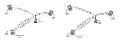
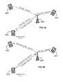
- FIGS. 8 a -8 bare diagrams illustrating a conference call initiated by a user of a communication device in accordance with an exemplary embodiment
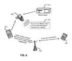
- FIG. 9illustrates that a user can be listening to audio content while in voice communication with a remote communication device in accordance with an exemplary embodiment
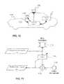
- FIG. 10is an illustration of a system for suppressing a siren or acoustic signal from a communication signal in accordance with an exemplary embodiment
- FIG. 11is a block diagram of the invisible audio system of FIG. 10 for suppressing the siren or acoustic signal in accordance with an exemplary embodiment.
- any specific valuesfor example the sound pressure level change, should be interpreted to be illustrative only and non-limiting. Thus, other examples of the exemplary embodiments could have different values.
- Various embodiments hereinprovide a method and device for automatically mixing audio signals produced by a pair of microphone signals that monitor a first ambient sound field and a second ear canal sound field, to create a third new mixed signal.
- An Ambient Sound Microphone (ASM) and an Ear Canal Microphone (ECM)can be housed in an earpiece that forms a seal in the ear of a user.
- the third mixed signalcan be auditioned by the user with an Ear Canal Receiver (ECR) mounted in the earpiece, which creates a sound pressure in the occluded ear canal of the user.
- ECREar Canal Receiver
- a voice activity detectorcan determine when the user is speaking and control an echo suppressor to suppress associated feedback in the ECR.
- the echo suppressorcan suppress feedback of the spoken voice from the ECR.
- the echo suppressorcan contain two sets of filter coefficients; a first set that adapts when voice is not present and becomes fixed when voice is present, and a second set that adapts when the first set is fixed.
- the voice activity detectorcan discriminate between audible content, such as music, that the user is listening to, and spoken voice generated by the user when engaged in voice communication.
- the third mixed signalcontains primarily the spoken voice captured at the ASM and ECM without echo, and can be transmitted to a remote voice communications system, such as a mobile phone, personal media player, recording device, walkie-talkie radio, etc.
- a remote voice communications systemsuch as a mobile phone, personal media player, recording device, walkie-talkie radio, etc.
- the ASM and ECM signalscan be echo suppressed and subjected to different filters and at optional additional gains. This permits a single earpiece to provide full-duplex voice communication with proper or improper acoustic sealing.
- the characteristic responses of the ASM and ECM filterscan differ based on characteristics of the background noise and the voice activity level.
- the filter responsecan depend on the measured Background Noise Level (BNL).
- a gain of a filtered ASM and a filtered ECM signalcan also depend on the BNL.
- the (BNL)can be calculated using either or both the conditioned ASM and/or ECM signal(s).
- the BNLcan be a slow time weighted average of the level of the ASM and/or ECM signals, and can be weighted using a frequency-weighting system, e.g. to give an A-weighted SPL level (i.e. the high and low frequencies are attenuated before the level of the microphone signals are calculated).
- At least one exemplary embodiment of the inventionis directed to an earpiece for voice operated control.
- earpiece 100depicts an electro-acoustical assembly 113 for an in-the-ear acoustic assembly, as it would typically be placed in the ear canal 131 of a user 135 .
- the earpiece 100can be an in the ear earpiece, behind the ear earpiece, receiver in the ear, open-fit device, or any other suitable earpiece type.
- the earpiece 100can be partially or fully occluded in the ear canal, and is suitable for use with users having healthy or abnormal auditory functioning.
- Earpiece 100includes an Ambient Sound Microphone (ASM) 111 to capture ambient sound, an Ear Canal Receiver (ECR) 125 to deliver audio to an ear canal 131 , and an Ear Canal Microphone (ECM) 123 to assess a sound exposure level within the ear canal 131 .
- the earpiece 100can partially or fully occlude the ear canal 131 to provide various degrees of acoustic isolation.
- the assemblyis designed to be inserted into the user's ear canal 131 , and to form an acoustic seal with the walls 129 of the ear canal at a location 127 between the entrance 117 to the ear canal 131 and the tympanic membrane (or ear drum) 133 .
- Such a sealis typically achieved by means of a soft and compliant housing of assembly 113 .
- Such a sealcreates a closed cavity 131 of approximately 5 cc between the in-ear assembly 113 and the tympanic membrane 133 .
- the ECR (speaker) 125is able to generate a full range frequency response when reproducing sounds for the user.
- This sealalso serves to significantly reduce the sound pressure level at the user's eardrum 133 resulting from the sound field at the entrance to the ear canal 131 .
- This sealis also a basis for a sound isolating performance of the electro-acoustic assembly 113 .
- the ECM 123Located adjacent to the ECR 125 , is the ECM 123 , which is acoustically coupled to the (closed or partially closed) ear canal cavity 131 .
- One of its functionsis that of measuring the sound pressure level in the ear canal cavity 131 as a part of testing the hearing acuity of the user as well as confirming the integrity of the acoustic seal and the working condition of the earpiece 100 .
- the ASM 111can be housed in the assembly 113 to monitor sound pressure at the entrance to the occluded or partially occluded ear canal. All transducers shown can receive or transmit audio signals to a processor 121 that undertakes audio signal processing and provides a transceiver for audio via the wired or wireless communication path 119 .
- the earpiece 100can actively monitor a sound pressure level both inside and outside an ear canal and enhance spatial and timbral sound quality while maintaining supervision to ensure safe sound reproduction levels.
- the earpiece 100in various embodiments can conduct listening tests, filter sounds in the environment, monitor warning sounds in the environment, present notification based on identified warning sounds, maintain constant audio content to ambient sound levels, and filter sound in accordance with a Personalized Hearing Level (PHL).
- PHLPersonalized Hearing Level
- the earpiece 100can measure ambient sounds in the environment received at the ASM 111 .
- Ambient soundscorrespond to sounds within the environment such as the sound of traffic noise, street noise, conversation babble, or any other acoustic sound.
- Ambient soundscan also correspond to industrial sounds present in an industrial setting, such as factory noise, lifting vehicles, automobiles, and robots to name a few.
- the earpiece 100can generate an Ear Canal Transfer Function (ECTF) to model the ear canal 131 using ECR 125 and ECM 123 , as well as an Outer Ear Canal Transfer function (OETF) using ASM 111 .
- ECTFEar Canal Transfer Function
- ECM 123ECM 123
- OETFOuter Ear Canal Transfer function
- the ECR 125can deliver an impulse within the ear canal and generate the ECTF via cross correlation of the impulse with the impulse response of the ear canal.
- the earpiece 100can also determine a sealing profile with the user's ear to compensate for any leakage. It also includes a Sound Pressure Level Dosimeter to estimate sound exposure and recovery times. This permits the earpiece 100 to safely administer and monitor sound exposure to the ear.
- the earpiece 100can include the processor 121 operatively coupled to the ASM 111 , ECR 125 , and ECM 123 via one or more Analog to Digital Converters (ADC) 202 and Digital to Analog Converters (DAC) 203 .
- the processor 121can utilize computing technologies such as a microprocessor, Application Specific Integrated Chip (ASIC), and/or digital signal processor (DSP) with associated storage memory 208 such as Flash, ROM, RAM, SRAM, DRAM or other like technologies for controlling operations of the earpiece device 100 .
- the processor 121can also include a clock to record a time stamp.
- the earpiece 100can include an acoustic management module 201 to mix sounds captured at the ASM 111 and ECM 123 to produce a mixed signal.
- the processor 121can then provide the mixed signal to one or more subsystems, such as a voice recognition system, a voice dictation system, a voice recorder, or any other voice related processor or communication device.
- the acoustic management module 201can be a hardware component implemented by discrete or analog electronic components or a software component. In one arrangement, the functionality of the acoustic management module 201 can be provided by way of software, such as program code, assembly language, or machine language.
- the memory 208can also store program instructions for execution on the processor 121 as well as captured audio processing data and filter coefficient data.
- the memory 208can be off-chip and external to the processor 121 , and include a data buffer to temporarily capture the ambient sound and the internal sound, and a storage memory to save from the data buffer the recent portion of the history in a compressed format responsive to a directive by the processor 121 .
- the data buffercan be a circular buffer that temporarily stores audio sound at a current time point to a previous time point. It should also be noted that the data buffer can in one configuration reside on the processor 121 to provide high speed data access.
- the storage memory 208can be non-volatile memory such as SRAM to store captured or compressed audio data.
- the earpiece 100can include an audio interface 212 operatively coupled to the processor 121 and acoustic management module 201 to receive audio content, for example from a media player, cell phone, or any other communication device, and deliver the audio content to the processor 121 .
- the processor 121responsive to detecting spoken voice from the acoustic management module 201 can adjust the audio content delivered to the ear canal. For instance, the processor 121 (or acoustic management module 201 ) can lower a volume of the audio content responsive to detecting a spoken voice.
- the processor 121by way of the ECM 123 can also actively monitor the sound exposure level inside the ear canal and adjust the audio to within a safe and subjectively optimized listening level range based on voice operating decisions made by the acoustic management module 201 .
- the earpiece 100can further include a transceiver 204 that can support singly or in combination any number of wireless access technologies including without limitation BluetoothTM, Wireless Fidelity (WiFi), Worldwide Interoperability for Microwave Access (WiMAX), and/or other short or long range communication protocols.
- the transceiver 204can also provide support for dynamic downloading over-the-air to the earpiece 100 . It should be noted also that next generation access technologies can also be applied to the present disclosure.
- the location receiver 232can utilize common technology such as a common GPS (Global Positioning System) receiver that can intercept satellite signals and therefrom determine a location fix of the earpiece 100 .
- GPSGlobal Positioning System
- the power supply 210can utilize common power management technologies such as replaceable batteries, supply regulation technologies, and charging system technologies for supplying energy to the components of the earpiece 100 and to facilitate portable applications.
- a motor(not shown) can be a single supply motor driver coupled to the power supply 210 to improve sensory input via haptic vibration.
- the processor 121can direct the motor to vibrate responsive to an action, such as a detection of a warning sound or an incoming voice call.
- the earpiece 100can further represent a single operational device or a family of devices configured in a master-slave arrangement, for example, a mobile device and an earpiece. In the latter embodiment, the components of the earpiece 100 can be reused in different form factors for the master and slave devices.
- FIG. 3is a block diagram of the acoustic management module 201 in accordance with an exemplary embodiment.
- the acoustic management module 201facilitates monitoring, recording and transmission of user-generated voice (speech) to a voice communication system.
- User-generated soundis detected with the ASM 111 that monitors a sound field near the entrance to a user's ear, and with the ECM 123 that monitors a sound field in the user's occluded ear canal.
- a new mixed signal 323is created by filtering and mixing the ASM and ECM microphone signals. The filtering and mixing process is automatically controlled depending on the background noise level of the ambient sound field to enhance intelligibility of the new mixed signal 323 .
- the acoustic management module 201automatically increases the level of the ECM 123 signal relative to the level of the ASM 111 to create the new mixed signal 323 .
- the acoustic management module 201automatically decreases the level of the ECM 123 signal relative to the level of the ASM 111 to create the new mixed signal 323 .
- the ASM 111is configured to capture ambient sound and produce an electronic ambient signal 426
- the ECR 125is configured to pass, process, or play acoustic audio content 402 (e.g., audio content 321 , mixed signal 323 ) to the ear canal
- the ECM 123is configured to capture internal sound in the ear canal and produce an electronic internal signal 410
- the acoustic management module 201is configured to measure a background noise signal from the electronic ambient signal 426 or the electronic internal signal 410 , and mix the electronic ambient signal 426 with the electronic internal signal 410 in a ratio dependent on the background noise signal to produce the mixed signal 323 .
- the acoustic management module 201filters the electronic ambient signal 426 and the electronic internal 410 signal based on a characteristic of the background noise signal using filter coefficients stored in memory or filter coefficients generated algorithmically.
- the acoustic management module 201mixes sounds captured at the ASM 111 and the ECM 123 to produce the mixed signal 323 based on characteristics of the background noise in the environment and a voice activity level.
- the characteristicscan be a background noise level, a spectral profile, or an envelope fluctuation.
- the acoustic management module 201manages echo feedback conditions affecting the voice activity level when the ASM 111 , the ECM 123 , and the ECR 125 are used together in a single earpiece for full-duplex communication, when the user is speaking to generate spoken voice (captured by the ASM 111 and ECM 123 ) and simultaneously listening to audio content (delivered by ECR 125 ).
- the voice captured at the ASM 111includes the background noise from the environment, whereas, the internal voice created in the ear canal 131 captured by the ECM 123 has less noise artifacts, since the noise is blocked due to the occlusion of the earpiece 100 in the ear.
- the background noisecan enter the ear canal if the earpiece 100 is not completely sealed. In this case, when speaking, the user's voice can leak through and cause an echo feedback condition that the acoustic management module 201 mitigates.
- FIG. 4is a schematic 300 of the acoustic management module 201 illustrating a mixing of the electronic ambient signal 426 with the electronic internal signal 410 as a function of a background noise level (BNL) and a voice activity level (VAL) in accordance with an exemplary embodiment.
- the acoustic management module 201includes an Automatic Gain Control (AGC) 302 to measure background noise characteristics.
- the acoustic management module 201also includes a Voice Activity Detector (VAD) 306 .
- the VAD 306can analyze either or both the electronic ambient signal 426 and the electronic internal signal 410 to estimate the VAL.
- the VALcan be a numeric range such as 0 to 10 indicating a degree of voicing.
- a voiced signalcan be predominately periodic due to the periodic vibrations of the vocal cords.
- a highly voiced signale.g., vowel
- a non-voiced signale.g., fricative, plosive, consonant
- the acoustic management module 201includes a first gain (G 1 ) 304 applied to the AGC processed electronic ambient signal 426 .
- a second gain (G 2 ) 308is applied to the VAD processed electronic internal signal 410 .
- the mixed signalis the sum 310 of the G 1 scaled electronic ambient signal and the G 2 scaled electronic internal signal.
- the mixed signal 323can then be transmitted to a second communication device (e.g. second cell phone, voice recorder, etc.) to receive the enhanced voice signal.
- the acoustic management module 201can also play the mixed signal 323 back to the ECR for loopback listening.
- the loopbackallows the user to hear himself or herself when speaking, as though the earpiece 100 and associated occlusion effect were absent.
- the loopbackcan also be mixed with the audio content 321 based on the background noise level, the VAL, and audio content level.
- the acoustic management module 201can also account for an acoustic attenuation level of the earpiece, and account for the audio content level reproduced by the ECR when measuring background noise characteristics. Echo conditions created as a result of the loopback can be mitigated to ensure that the voice activity level is accurate.
- FIG. 5is a more detailed schematic of the acoustic management module 201 illustrating a mixing of an external microphone signal with an internal microphone signal based on a background noise level and voice activity level in accordance with an exemplary embodiment.
- the gain blocks for G 1 and G 2 of FIG. 4are a function of the BNL and the VAL and are shown in greater detail.
- the AGCproduces a BNL that can be used to set a first gain 322 for the processed electronic ambient signal 311 and a second gain 324 for the processed electronic internal signal 312 .
- gain 322is set higher relative to gain 324 so as to amplify the electronic ambient signal 311 in greater proportion than the electronic internal signal 312 .
- gain 322is set lower relative to gain 324 so as to attenuate the electronic ambient signal 311 in greater proportion than the electronic internal signal 312 .
- the VADproduces a VAL that can be used to set a third gain 326 for the processed electronic ambient signal 311 and a fourth gain 328 for the processed electronic internal signal 312 .
- a VALe.g., 0-3
- gain 326 and gain 328are set low so as to attenuate the electronic ambient signal 311 and the electronic internal signal 312 when spoken voice is not detected.
- the VALis high (e.g., 7-10)
- gain 326 and gain 328are set high so as to amplify the electronic ambient signal 311 and the electronic internal signal 312 when spoken voice is detected.
- the gain scaled processed electronic ambient signal 311 and the gain scaled processed electronic internal signal 312are then summed at adder 320 to produce the mixed signal 323 .
- the mixed signal 323can be transmitted to another communication device, or as loopback to allow the user to hear his or her self.
- FIG. 6is an exemplary schematic of an operational unit 600 of the acoustic management module for generating modified electronic signals in accordance with an embodiment.
- the operational unit 600may contain more or less than the number of components shown in the schematic.
- the operational unit 600can include an adaptive filter 610 , an adaptive filter 612 , and a voice decision logic 620 .
- Adaptive filters 610 and 612can be a Least Mean Squares (LMS) or Normalized Least Mean Squares (NLMS) adaptive filter that models an ear canal transfer function (ECTF) between the ECR 125 and the ECM 123 .
- the adaptive filter 610generates the modified electronic signal, e(n) 412 , which is provided as an input to the voice decision logic 620 ; e(n) is also termed the error signal e(n) of the adaptive filter 610 .
- the error signal e(n) 412is used to update the filter H(w) to model the ECTF of an echo path.
- the error signal e(n) 412closely approximates the user's spoken voice signal u(n) 607 when the echo suppressor 610 accurately models the ECTF.
- a first reference signalcan be provided to adaptive filter 610 and a second reference signal can be provided to adaptive filter 612 .
- a reference signalcan be music, media content, or a voice communication signal.
- the error signal e(n) 412 for adaptive filter 610 or e(n) 618 for adaptive filter 612is used to update their respective filters H(w) to model the ECTF in the signal path.
- the error signal e(n) 412 for adaptive filter 610 or e(n) 618 for adaptive filter 612will closely approximate the corresponding acoustic reference signal as output by ECR 125 and received ECM 123 when adaptive filters 610 and 612 accurately model the ECTF.
- the adaptive filter 610minimizes the error between the filtered signal, ⁇ tilde over (y) ⁇ (n), and the electronic internal signal, z(n), in an effort to obtain a transfer function H′ which is a best approximation to the H(w) (i.e., ECTF).
- H(w)represents the transfer function of the ear canal and models the echo response.
- the adaptive filter 610monitors the mixed signal 323 delivered to the ECR 125 and produces an echo estimate ⁇ tilde over (y) ⁇ (n) of an echo y(n) 609 based on the captured electronic internal signal 410 and the mixed signal 323 .
- the adaptive filter 610upon learning the ECTF by an adaptive process, can then suppress the echo y(n) 609 of the acoustic audio content 603 (e.g., output mixed signal 323 ) in the electronic internal signal z(n) 410 . It subtracts the echo estimate ⁇ tilde over (y) ⁇ (n) from the electronic internal signal 410 to produce the modified electronic internal signal e(n) 412 .
- a signal or multiple signalsare suppressed from at least one device.
- a conference callis initiated by the user of a communication device 806 in accordance with an exemplary embodiment.
- Communication device 806is coupled via a network 808 to communication devices 802 and 804 .
- communication device 806opens a channel 1 to communicate with device 802 and a channel 2 to communicate with device 804 .
- device 806receives voice communication from both devices 802 and 804 .
- the reference suppression modeallows the initiator of the conference call to selectively suppress the voice communication of one or more participants and to selectively determine which of the participants each person gets to hear. As shown, two participants are engaged in the call.
- the conference call initiatorpre-selects which caller is suppressed. Referring to FIG. 8 b , the conference call initiator has selected that the user of device 804 will not hear the voice of the user of device 802 .
- the voice communication signal from device 802is the reference signal for suppression.
- the users of devices 804 and 806are in discussion of a business deal. The conference call initiator wants to better understand the implications of the business terms as the dialogue progresses.
- the user of device 802is a business associate of the conference call initiator and provides input or comment that can be relevant to the negotiation.
- the voice communication of the user of device 802is suppressed by communication device 806 such that only the initiator of the conference call is heard by the user of device 804 .
- the suppressed communication signalis sent to the user of device 804 through channel 2 .
- the communication signal sent on channel 1is not modified allowing the business associate to hear the full conversation while commenting to the conference call initiator.
- a usercan be listening to audio content while in voice communication with a user of device 906 in accordance with an exemplary embodiment.
- the user of communication device 906does not hear the audio content in the voice communication.
- An earpiece 902is coupled for receiving audio content from a media player 910 .
- earpiece 902receives the media content directly from media player 910 via a wired or wireless connection.
- earpiece 902can receive the audio content through communication device 904 .
- the audio contentcan be music, media content, or other audio content that the user of earpiece 902 wants to hear.
- Communication device 904is paired with earpiece 902 .
- the audio content provided by media player 910is uninterrupted by a call from the user of communication device 906 .
- the volume of the audio contentcan be automatically adjusted to a predetermined level (defined by the user) that would allow voice communication with the user of device 906 via network 908 . For example, the volume could be lowered for the user to hear that a call is incoming and further adjust the volume if the call is taken.
- the audio contentis the reference signal.
- Earpiece 902suppresses the audio content from a communication signal being sent to the user of device 906 .
- device 904can suppress the audio content from the transmitted communication signal if it has access to the reference signal using the method described hereinbelow.
- the user of device 904can continue to listen to a ball game, hear a news bulletin, or enjoy music while in communication with others and the audio content is not transmitted to those in communication with device 904 .
- a switch 624includes an input 614 coupled to a source 1 , an input 616 coupled to a source 2 , an output 626 , an output 628 , an output 630 and control signals 632 .
- Source 1 and source 2are signals such as music, media content, voice communication, or other audio content.
- Control signalsconfigure switch 624 for providing source 1 , source 2 , or a combination of source 1 and source 2 at each output 626 , 628 , and 630 .
- a user of the systeminitiates a conference call with two other people.
- Source 1is a voice communication from a first caller.
- Source 2is a voice communication from a second caller.
- the conference call initiatorsets up the call on the system so that the first caller does not hear the voice of the second caller.
- the systemconfigures switch 624 such that the first and second caller voice communication is mixed with an electronic ambient signal 426 and is provided as mixed signal 323 to ECR 125 .
- ECR 125provides the acoustic audio content 603 that includes the voices of the first and second callers.
- the call initiatorhears both the callers.
- Switch 624is configured such that output 628 is coupled to source 2 which is the second caller voice communication.
- the second caller voice communicationis the reference signal for adaptive filter 610 .
- the adaptive filter 610upon learning the ECTF by an adaptive process can suppress the second caller voice of the acoustic audio content 603 (e.g., output mixed signal 323 ) in the electronic internal signal 410 (z(n)). It subtracts the second caller estimate ⁇ tilde over (y) ⁇ (n) from the electronic internal signal 410 to produce the modified electronic internal signal e(n) 412 .
- the modified electronic signal 1will include the voice of the initiator of the conference call but not the second caller.
- the modified electronic signal 1is transmitted to the first caller.
- the systemis set up for the second caller to hear the entire conversation.
- Output 630 of switch 624couples to the adaptive filter 612 .
- No reference signalis provided to adaptive filter 612 so nothing in electronic internal signal 410 is suppressed.
- adaptive filter 612can be disabled.
- Modified electronic signal 2is electronic internal signal 410 that includes all of the voice communication. The modified electronic signal 2 is transmitted to the second caller.
- a useris listening to audio content such as music when receiving a call.
- the usercan listen to the audio content while taking the call without the caller hearing the audio content.
- a second modified electronic signal 2is not required so adaptive filter 612 is disabled.
- Source 1couples to a media player or other audio source.
- source 1is music from a media player.
- Source 2is the voice communication signal from a remote caller.
- Control signals 632enable switch 624 for providing source 1 and source 2 at the output 626 .
- the music signal and the voice communication signal at output 626are mixed with the electronic ambient signal 426 forming mixed signal 323 .
- Mixed signal 323is provided to ECR 125 .
- ECR 125outputs acoustic audio content 603 which includes the music and the voice communication from the remote caller.
- Switch 624is configured such that output 628 is coupled to source 1 which is the music signal.
- the music signalis the reference signal for adaptive filter 610 .
- the adaptive filter 610upon learning the ECTF by an adaptive process can suppress the music signal of the acoustic audio content 603 (e.g., output mixed signal 323 ) in the electronic internal signal 410 (z(n)). It subtracts the music signal estimate ⁇ tilde over (y) ⁇ (n) from the electronic internal signal 410 to produce the modified electronic internal signal e(n) 412 .
- the modified electronic signal 1will include the voice of the initiator of the conference call but not the music.
- the modified electronic signal 1is transmitted to the first caller.
- the voice decision logic 620analyzes the modified electronic signal 412 e(n) and the electronic ambient signal 426 to produce a voice activity level 622 , ⁇ .
- the voice activity level ⁇identifies a probability that the user is speaking, for example, when the user is using the earpiece for two way voice communication.
- the voice activity level 622can also indicate a degree of voicing (e.g., periodicity, amplitude), When the user is speaking, voice is captured externally from acoustic ambient signal 424 by the ASM 111 in the ambient environment and also by the ECM 123 in the ear canal.
- the voice decision logic 620provides the voice activity level ⁇ to the acoustic management module 201 as an input parameter for mixing the ASM 111 and ECM 123 signals.
- the acoustic management module 201For instance, at low background noise levels and low voice activity levels, the acoustic management module 201 amplifies the electronic ambient signal 426 from the ASM 111 relative to the electronic internal signal 410 from the ECM 123 in producing the mixed signal 323 . At medium background noise levels and medium voice activity levels, the acoustic management module 201 attenuates low frequencies in the electronic ambient signal 426 and attenuates high frequencies in the electronic internal signal 410 . At high background noise levels and high voice activity levels, the acoustic management module 201 amplifies the electronic internal signal 410 from the ECM 123 relative to the electronic ambient signal 426 from the ASM 111 in producing the mixed signal. The acoustic management module 201 can additionally apply frequency specific filters based on the characteristics of the background noise.
- FIG. 7is a schematic of a control unit 700 for controlling adaptation of a first set ( 736 ) and a second set ( 738 ) of filter coefficients of the adaptive filter 610 for in-ear canal echo suppression in accordance with an exemplary embodiment.
- the description hereinbelowalso applies to adaptive filter 612 .
- the control unit 700illustrates a freezing (fixing) of weights in upon detection of spoken voice.
- the adaptive filter 610resumes weight adaptation when e(n) is low, and freezes weights when e(n) is high signifying presence of spoken voice.
- the ECR 125can pass through ambient sound captured at the ASM 111 , thereby allowing the user to hear environmental ambient sounds.
- the adaptive filter 610models an ECTF and suppresses an echo of the mixed signal 323 that is looped back to the ECR 125 by way of the ASM 111 (see dotted line Loop Back path).
- the suppressorcontinually adapts to model the ECTF.
- the adaptive filter 610produces a modified internal electronic signal e(n) that is low in amplitude level (i.e, low in error). The suppressor adapts the weights to keep the error signal low.
- the suppressorWhen the user speaks, the suppressor however initially produces a high-level e(n) (e.g., the error signal increases). This happens since the speaker's voice is uncorrelated with the audio signal played out the ECR 125 , which disrupts the ECTF modeling ability of adaptive filter 610 .
- the control unit 700upon detecting a rise in e(n), freezes the weights of the adaptive filter 610 to produce a fixed filter H′(w) fixed 738 . Upon detecting the rise in e(n) the control unit adjusts the gain 734 for the ASM signal and the gain 732 for the mixed signal 323 that is looped back to the ECR 125 . The mixed signal 323 fed back to the ECR 125 permits the user to hear themself speak. Although the weights are frozen when the user is speaking, a second filter H′(w) 736 continually adapts the weights for generating a second e(n) that is used to determine presence of spoken voice. That is, the control unit 700 monitors the second error signal e(n) produced by the second filter 736 for monitoring a presence of the spoken voice.
- the first error signal e(n) (in a parallel path) generated by the first filter 738is used as the mixed signal 323 .
- the first error signalcontains primarily the spoken voice since the ECTF model has been fixed due to the weights. That is, the second (adaptive) filter is used to monitor a presence of spoken voice, and the first (fixed) filter is used to generate the mixed signal 323 .
- the control unitUpon detecting a fall of e(n), the control unit restores the gains 734 and 732 and unfreezes the weights of the suppressor, and the first filter H′(w) 738 returns to being an adaptive filter.
- the second filter H′(w) 736remains on stand-by until spoken voice is detected, and at which point, the first filter H′(w) 738 goes fixed, and the second filter H′(w) 736 begins adaptation for producing the e(n) signal that is monitored for voice activity.
- the control unit 700monitors e(n) from the first filter 738 or the second filter 736 for changes in amplitude to determine when spoken voice is detected based on the state of voice activity.
- FIG. 10is an illustration of a system for suppressing a siren or acoustic signal from a communication signal in accordance with an exemplary embodiment.
- an emergency vehiclesuch as a police car, military vehicle, fire truck, or ambulance is a noisy environment.
- the vehiclehas a loud siren or horn that is played periodically in an emergency situation to alert people that the vehicle is approaching.
- the sirenis of sufficient loudness that it penetrates the cabin of the vehicle where it is picked up by a communication device being used.
- the sirencan make the intelligibility of the speech difficult to understand on the receiving end of the communication. For example, an ambulance medical technician is rapidly telling a hospital the condition of a patient while the siren is blaring in the background. Removing the siren from the communication would allow the speech to be heard with clarity and allow concise recognition of the information being provided.
- a system for a vehicle 1002comprises a transducer 1006 for emitting an acoustic signal (e.g. siren), a cabin loudspeaker 1004 , an “invisible audio” (IA) system 1010 , a communication system 1012 , and a microphone 1008 .
- the siren acoustic component detected by cabin microphone 1008is removed by the “Invisible Audio” (IA) system 1010 before the voice communication signal is transmitted to a remote party via communication system 1012 .
- Removing the siren or acoustic signalincreases the intelligibility of the transmitted voice communication signal to a remote party, e.g. an emergency call centre.
- warning signals that can be reproduced with cabin loudspeaker 1004such as voice audio signals from other calling parties or vehicle warning systems, can also be removed (or attenuated) by the IA system 1010 .
- FIG. 11is a block diagram of the invisible audio system of FIG. 10 for suppressing the siren or acoustic signal in accordance with an exemplary embodiment.
- An emergency siren audio signal 1112can be generated either algorithmically using a digital signal processing system, or can be acquired from computer readable memory, and is emitted using acoustic siren transducer 1116 (e.g. a loudspeaker mounted on the outside of the emergency vehicle).
- the emergency siren audio signal 1112is further filtered using filter 1118 and subtracted from the cabin microphone signal 1122 using signal subtraction unit 1120 , to generate a modified microphone signal 1114 .
- filter 1118is a fixed FIR-type digital filter, where the impulse response approximates the acoustic impulse response between the siren transducer 1116 and cabin microphone 1122 .
- filter 1118is an adaptive filter, where the filter coefficients are updated over time to approximate the acoustic impulse response between the siren transducer 1116 and cabin microphone 1122 .
- the adaptive filtercan be updated according to one of many well-known adaptive filter algorithms, such as the normalized least-mean-square algorithm (NLMS) or recursive least-mean-square algorithm.
- NLMSnormalized least-mean-square algorithm
- the modified microphone signal 1114can then be further transmitted to a remote party, such as an emergency caller control centre with better intelligibility and clarity.
- the present embodiments of the inventioncan be realized in hardware, software or a combination of hardware and software. Any kind of computer system or other apparatus adapted for carrying out the methods described herein are suitable.
- a typical combination of hardware and softwarecan be a mobile communications device with a computer program that, when being loaded and executed, can control the mobile communications device such that it carries out the methods described herein.
- Portions of the present method and systemmay also be embedded in a computer program product, which comprises all the features enabling the implementation of the methods described herein and which when loaded in a computer system, is able to carry out these methods.
Landscapes
- Engineering & Computer Science (AREA)
- Signal Processing (AREA)
- Physics & Mathematics (AREA)
- Acoustics & Sound (AREA)
- Health & Medical Sciences (AREA)
- General Health & Medical Sciences (AREA)
- Otolaryngology (AREA)
- Multimedia (AREA)
- Telephone Function (AREA)
- Circuit For Audible Band Transducer (AREA)
Abstract
Description
G1=f(BNL)+f(VAL) andG2=f(BNL)+f(VAL)
Mixed signal=(1−β)*electronic ambient signal+(β)*electronic internal signal
where=(1−β) is an external gain, (β) is an internal gain, and the mixing is performed with 0<β<1.
Claims (20)
Priority Applications (5)
| Application Number | Priority Date | Filing Date | Title |
|---|---|---|---|
| US14/943,001US10194032B2 (en) | 2007-05-04 | 2015-11-16 | Method and apparatus for in-ear canal sound suppression |
| US16/258,015US10812660B2 (en) | 2007-05-04 | 2019-01-25 | Method and apparatus for in-ear canal sound suppression |
| US16/992,861US11489966B2 (en) | 2007-05-04 | 2020-08-13 | Method and apparatus for in-ear canal sound suppression |
| US17/867,682US20230011879A1 (en) | 2007-05-04 | 2022-07-19 | Method and apparatus for in-ear canal sound suppression |
| US18/985,018US20250119499A1 (en) | 2007-05-04 | 2024-12-18 | Method and apparatus for in-ear canal sound suppression |
Applications Claiming Priority (6)
| Application Number | Priority Date | Filing Date | Title |
|---|---|---|---|
| US91627107P | 2007-05-04 | 2007-05-04 | |
| US12/110,773US8577062B2 (en) | 2007-04-27 | 2008-04-28 | Device and method for controlling operation of an earpiece based on voice activity in the presence of audio content |
| US12/115,349US8081780B2 (en) | 2007-05-04 | 2008-05-05 | Method and device for acoustic management control of multiple microphones |
| US12/170,171US8526645B2 (en) | 2007-05-04 | 2008-07-09 | Method and device for in ear canal echo suppression |
| US12/245,316US9191740B2 (en) | 2007-05-04 | 2008-10-03 | Method and apparatus for in-ear canal sound suppression |
| US14/943,001US10194032B2 (en) | 2007-05-04 | 2015-11-16 | Method and apparatus for in-ear canal sound suppression |
Related Parent Applications (1)
| Application Number | Title | Priority Date | Filing Date |
|---|---|---|---|
| US12/245,316ContinuationUS9191740B2 (en) | 2007-05-04 | 2008-10-03 | Method and apparatus for in-ear canal sound suppression |
Related Child Applications (1)
| Application Number | Title | Priority Date | Filing Date |
|---|---|---|---|
| US16/258,015ContinuationUS10812660B2 (en) | 2007-05-04 | 2019-01-25 | Method and apparatus for in-ear canal sound suppression |
Publications (2)
| Publication Number | Publication Date |
|---|---|
| US20160072958A1 US20160072958A1 (en) | 2016-03-10 |
| US10194032B2true US10194032B2 (en) | 2019-01-29 |
Family
ID=66532670
Family Applications (5)
| Application Number | Title | Priority Date | Filing Date |
|---|---|---|---|
| US14/943,001ActiveUS10194032B2 (en) | 2007-05-04 | 2015-11-16 | Method and apparatus for in-ear canal sound suppression |
| US16/258,015Active2028-05-13US10812660B2 (en) | 2007-05-04 | 2019-01-25 | Method and apparatus for in-ear canal sound suppression |
| US16/992,861ActiveUS11489966B2 (en) | 2007-05-04 | 2020-08-13 | Method and apparatus for in-ear canal sound suppression |
| US17/867,682PendingUS20230011879A1 (en) | 2007-05-04 | 2022-07-19 | Method and apparatus for in-ear canal sound suppression |
| US18/985,018PendingUS20250119499A1 (en) | 2007-05-04 | 2024-12-18 | Method and apparatus for in-ear canal sound suppression |
Family Applications After (4)
| Application Number | Title | Priority Date | Filing Date |
|---|---|---|---|
| US16/258,015Active2028-05-13US10812660B2 (en) | 2007-05-04 | 2019-01-25 | Method and apparatus for in-ear canal sound suppression |
| US16/992,861ActiveUS11489966B2 (en) | 2007-05-04 | 2020-08-13 | Method and apparatus for in-ear canal sound suppression |
| US17/867,682PendingUS20230011879A1 (en) | 2007-05-04 | 2022-07-19 | Method and apparatus for in-ear canal sound suppression |
| US18/985,018PendingUS20250119499A1 (en) | 2007-05-04 | 2024-12-18 | Method and apparatus for in-ear canal sound suppression |
Country Status (1)
| Country | Link |
|---|---|
| US (5) | US10194032B2 (en) |
Families Citing this family (5)
| Publication number | Priority date | Publication date | Assignee | Title |
|---|---|---|---|---|
| US10764226B2 (en)* | 2016-01-15 | 2020-09-01 | Staton Techiya, Llc | Message delivery and presentation methods, systems and devices using receptivity |
| US10966010B2 (en)* | 2018-03-15 | 2021-03-30 | Staton Techiya, Llc | Method and device for suppression of microphone squeal and cable noise |
| KR102088216B1 (en)* | 2018-10-31 | 2020-03-12 | 김정근 | Method and device for reducing crosstalk in automatic speech translation system |
| US11563857B2 (en)* | 2019-05-31 | 2023-01-24 | Microsoft Technology Licensing, Llc | Aggregating hardware loopback |
| US11330358B2 (en)* | 2020-08-21 | 2022-05-10 | Bose Corporation | Wearable audio device with inner microphone adaptive noise reduction |
Citations (56)
| Publication number | Priority date | Publication date | Assignee | Title |
|---|---|---|---|---|
| US4809262A (en) | 1987-02-23 | 1989-02-28 | Deutsche Telephonwerke Und Kabelindustrie Ag | Method of making conference call connections in computer-controlled digital telephone exchanges |
| US5131032A (en) | 1989-03-13 | 1992-07-14 | Hitachi, Ltd. | Echo canceller and communication apparatus employing the same |
| US5259033A (en) | 1989-08-30 | 1993-11-02 | Gn Danavox As | Hearing aid having compensation for acoustic feedback |
| US5692059A (en) | 1995-02-24 | 1997-11-25 | Kruger; Frederick M. | Two active element in-the-ear microphone system |
| US5796819A (en) | 1996-07-24 | 1998-08-18 | Ericsson Inc. | Echo canceller for non-linear circuits |
| US5963901A (en) | 1995-12-12 | 1999-10-05 | Nokia Mobile Phones Ltd. | Method and device for voice activity detection and a communication device |
| US5999828A (en) | 1997-03-19 | 1999-12-07 | Qualcomm Incorporated | Multi-user wireless telephone having dual echo cancellers |
| US6021207A (en) | 1997-04-03 | 2000-02-01 | Resound Corporation | Wireless open ear canal earpiece |
| US6081732A (en) | 1995-06-08 | 2000-06-27 | Nokia Telecommunications Oy | Acoustic echo elimination in a digital mobile communications system |
| US6118878A (en) | 1993-06-23 | 2000-09-12 | Noise Cancellation Technologies, Inc. | Variable gain active noise canceling system with improved residual noise sensing |
| US6169912B1 (en) | 1999-03-31 | 2001-01-02 | Pericom Semiconductor Corp. | RF front-end with signal cancellation using receiver signal to eliminate duplexer for a cordless phone |
| US6304648B1 (en) | 1998-12-21 | 2001-10-16 | Lucent Technologies Inc. | Multimedia conference call participant identification system and method |
| US20010046304A1 (en) | 2000-04-24 | 2001-11-29 | Rast Rodger H. | System and method for selective control of acoustic isolation in headsets |
| US6381572B1 (en) | 1998-04-10 | 2002-04-30 | Pioneer Electronic Corporation | Method of modifying feature parameter for speech recognition, method of speech recognition and speech recognition apparatus |
| US6466666B1 (en) | 1997-09-10 | 2002-10-15 | Telefonaktiebolaget Lm Ericsson (Publ) | Method and apparatus for echo estimation and suppression |
| US6570985B1 (en) | 1998-01-09 | 2003-05-27 | Ericsson Inc. | Echo canceler adaptive filter optimization |
| US20030112947A1 (en)* | 2000-05-25 | 2003-06-19 | Alon Cohen | Telecommunications and conference calling device, system and method |
| US6631196B1 (en) | 2000-04-07 | 2003-10-07 | Gn Resound North America Corporation | Method and device for using an ultrasonic carrier to provide wide audio bandwidth transduction |
| US6647368B2 (en) | 2001-03-30 | 2003-11-11 | Think-A-Move, Ltd. | Sensor pair for detecting changes within a human ear and producing a signal corresponding to thought, movement, biological function and/or speech |
| US6728385B2 (en) | 2002-02-28 | 2004-04-27 | Nacre As | Voice detection and discrimination apparatus and method |
| US6738482B1 (en) | 1999-09-27 | 2004-05-18 | Jaber Associates, Llc | Noise suppression system with dual microphone echo cancellation |
| US6754359B1 (en) | 2000-09-01 | 2004-06-22 | Nacre As | Ear terminal with microphone for voice pickup |
| US6760453B1 (en) | 1998-03-30 | 2004-07-06 | Nec Corporation | Portable terminal device for controlling received voice level and transmitted voice level |
| US20040137969A1 (en) | 2002-05-09 | 2004-07-15 | Shary Nassimi | Voice activated wireless phone headset |
| US20040202340A1 (en) | 2003-04-10 | 2004-10-14 | Armstrong Stephen W. | System and method for transmitting audio via a serial data port in a hearing instrument |
| US20050058313A1 (en) | 2003-09-11 | 2005-03-17 | Victorian Thomas A. | External ear canal voice detection |
| US6870807B1 (en) | 2000-05-15 | 2005-03-22 | Avaya Technology Corp. | Method and apparatus for suppressing music on hold |
| US20050069161A1 (en) | 2003-09-30 | 2005-03-31 | Kaltenbach Matt Andrew | Bluetooth enabled hearing aid |
| US20050102133A1 (en) | 2003-09-12 | 2005-05-12 | Canon Kabushiki Kaisha | Voice activated device |
| US7003097B2 (en) | 1999-11-03 | 2006-02-21 | Tellabs Operations, Inc. | Synchronization of echo cancellers in a voice processing system |
| US20060062395A1 (en) | 1995-07-28 | 2006-03-23 | Klayman Arnold I | Acoustic correction apparatus |
| US20060067512A1 (en) | 2004-08-25 | 2006-03-30 | Motorola, Inc. | Speakerphone having improved outbound audio quality |
| US7039195B1 (en) | 2000-09-01 | 2006-05-02 | Nacre As | Ear terminal |
| US20070019803A1 (en) | 2003-05-27 | 2007-01-25 | Koninklijke Philips Electronics N.V. | Loudspeaker-microphone system with echo cancellation system and method for echo cancellation |
| US20070036342A1 (en) | 2005-08-05 | 2007-02-15 | Boillot Marc A | Method and system for operation of a voice activity detector |
| US7236580B1 (en) | 2002-02-20 | 2007-06-26 | Cisco Technology, Inc. | Method and system for conducting a conference call |
| US20070189544A1 (en) | 2005-01-15 | 2007-08-16 | Outland Research, Llc | Ambient sound responsive media player |
| US20070291953A1 (en) | 2006-06-14 | 2007-12-20 | Think-A-Move, Ltd. | Ear sensor assembly for speech processing |
| US20080019539A1 (en) | 2006-07-21 | 2008-01-24 | Motorola, Inc. | Method and system for near-end detection |
| US20080037801A1 (en)* | 2006-08-10 | 2008-02-14 | Cambridge Silicon Radio, Ltd. | Dual microphone noise reduction for headset application |
| US7349353B2 (en) | 2003-12-04 | 2008-03-25 | Intel Corporation | Techniques to reduce echo |
| US7403608B2 (en) | 2002-06-28 | 2008-07-22 | France Telecom | Echo processing devices for single-channel or multichannel communication systems |
| US20090010444A1 (en) | 2007-04-27 | 2009-01-08 | Personics Holdings Inc. | Method and device for personalized voice operated control |
| US20090034748A1 (en) | 2006-04-01 | 2009-02-05 | Alastair Sibbald | Ambient noise-reduction control system |
| US20090147966A1 (en) | 2007-05-04 | 2009-06-11 | Personics Holdings Inc | Method and Apparatus for In-Ear Canal Sound Suppression |
| US7783054B2 (en) | 2000-12-22 | 2010-08-24 | Harman Becker Automotive Systems Gmbh | System for auralizing a loudspeaker in a monitoring room for any type of input signals |
| US7817803B2 (en) | 2006-06-22 | 2010-10-19 | Personics Holdings Inc. | Methods and devices for hearing damage notification and intervention |
| US7986802B2 (en) | 2006-10-25 | 2011-07-26 | Sony Ericsson Mobile Communications Ab | Portable electronic device and personal hands-free accessory with audio disable |
| US8027481B2 (en) | 2006-11-06 | 2011-09-27 | Terry Beard | Personal hearing control system and method |
| US8060366B1 (en) | 2007-07-17 | 2011-11-15 | West Corporation | System, method, and computer-readable medium for verbal control of a conference call |
| US8081780B2 (en) | 2007-05-04 | 2011-12-20 | Personics Holdings Inc. | Method and device for acoustic management control of multiple microphones |
| US20120184337A1 (en) | 2010-07-15 | 2012-07-19 | Burnett Gregory C | Wireless conference call telephone |
| US8275145B2 (en) | 2006-04-25 | 2012-09-25 | Harman International Industries, Incorporated | Vehicle communication system |
| US20130051543A1 (en) | 2011-08-25 | 2013-02-28 | Verizon Patent And Licensing Inc. | Muting and un-muting user devices |
| US8401178B2 (en) | 2008-09-30 | 2013-03-19 | Apple Inc. | Multiple microphone switching and configuration |
| US20140370838A1 (en) | 2012-01-26 | 2014-12-18 | Han Seok Kim | System and method for preventing abuse of emergency calls placed using smartphone |
Family Cites Families (166)
| Publication number | Priority date | Publication date | Assignee | Title |
|---|---|---|---|---|
| US3027481A (en) | 1958-03-31 | 1962-03-27 | Hughes Aircraft Co | Acceleration and vibration resistant lamp |
| US3876843A (en) | 1973-01-02 | 1975-04-08 | Textron Inc | Directional hearing aid with variable directivity |
| US4088849A (en) | 1975-09-30 | 1978-05-09 | Victor Company Of Japan, Limited | Headphone unit incorporating microphones for binaural recording |
| JPS5944639B2 (en) | 1975-12-02 | 1984-10-31 | フジゼロツクス カブシキガイシヤ | Standard pattern update method in voice recognition method |
| US4837832A (en) | 1987-10-20 | 1989-06-06 | Sol Fanshel | Electronic hearing aid with gain control means for eliminating low frequency noise |
| US4947440A (en) | 1988-10-27 | 1990-08-07 | The Grass Valley Group, Inc. | Shaping of automatic audio crossfade |
| DK164349C (en) | 1989-08-22 | 1992-11-02 | Oticon As | HEARING DEVICE WITH BACKUP COMPENSATION |
| US5327506A (en) | 1990-04-05 | 1994-07-05 | Stites Iii George M | Voice transmission system and method for high ambient noise conditions |
| US5208867A (en) | 1990-04-05 | 1993-05-04 | Intelex, Inc. | Voice transmission system and method for high ambient noise conditions |
| WO1992005538A1 (en) | 1990-09-14 | 1992-04-02 | Chris Todter | Noise cancelling systems |
| US5267321A (en) | 1991-11-19 | 1993-11-30 | Edwin Langberg | Active sound absorber |
| US5887070A (en) | 1992-05-08 | 1999-03-23 | Etymotic Research, Inc. | High fidelity insert earphones and methods of making same |
| US5251263A (en) | 1992-05-22 | 1993-10-05 | Andrea Electronics Corporation | Adaptive noise cancellation and speech enhancement system and apparatus therefor |
| US5509102A (en) | 1992-07-01 | 1996-04-16 | Kokusai Electric Co., Ltd. | Voice encoder using a voice activity detector |
| US5317273A (en) | 1992-10-22 | 1994-05-31 | Liberty Mutual | Hearing protection device evaluation apparatus |
| US5524056A (en) | 1993-04-13 | 1996-06-04 | Etymotic Research, Inc. | Hearing aid having plural microphones and a microphone switching system |
| US6553130B1 (en) | 1993-08-11 | 2003-04-22 | Jerome H. Lemelson | Motor vehicle warning and control system and method |
| JP2845130B2 (en)* | 1994-05-13 | 1999-01-13 | 日本電気株式会社 | Communication device |
| JPH0877468A (en) | 1994-09-08 | 1996-03-22 | Ono Denki Kk | Monitor device |
| US5867581A (en) | 1994-10-14 | 1999-02-02 | Matsushita Electric Industrial Co., Ltd. | Hearing aid |
| US5577511A (en) | 1995-03-29 | 1996-11-26 | Etymotic Research, Inc. | Occlusion meter and associated method for measuring the occlusion of an occluding object in the ear canal of a subject |
| US6118877A (en) | 1995-10-12 | 2000-09-12 | Audiologic, Inc. | Hearing aid with in situ testing capability |
| US5903868A (en) | 1995-11-22 | 1999-05-11 | Yuen; Henry C. | Audio recorder with retroactive storage |
| US5694467A (en)* | 1996-05-10 | 1997-12-02 | Hewlett Packard Company | Integrated sound/telephone headset system |
| DE19630109A1 (en) | 1996-07-25 | 1998-01-29 | Siemens Ag | Method for speaker verification using at least one speech signal spoken by a speaker, by a computer |
| FI108909B (en) | 1996-08-13 | 2002-04-15 | Nokia Corp | Earphone element and terminal |
| DE19640140C2 (en) | 1996-09-28 | 1998-10-15 | Bosch Gmbh Robert | Radio receiver with a recording unit for audio data |
| US5946050A (en) | 1996-10-04 | 1999-08-31 | Samsung Electronics Co., Ltd. | Keyword listening device |
| JP3165044B2 (en) | 1996-10-21 | 2001-05-14 | 日本電気株式会社 | Digital hearing aid |
| JPH10162283A (en) | 1996-11-28 | 1998-06-19 | Hitachi Ltd | Road condition monitoring device |
| US5878147A (en) | 1996-12-31 | 1999-03-02 | Etymotic Research, Inc. | Directional microphone assembly |
| US6021325A (en) | 1997-03-10 | 2000-02-01 | Ericsson Inc. | Mobile telephone having continuous recording capability |
| US6056698A (en) | 1997-04-03 | 2000-05-02 | Etymotic Research, Inc. | Apparatus for audibly monitoring the condition in an ear, and method of operation thereof |
| FI104662B (en) | 1997-04-11 | 2000-04-14 | Nokia Mobile Phones Ltd | Antenna arrangement for small radio communication devices |
| US5933510A (en) | 1997-10-02 | 1999-08-03 | Siemens Information And Communication Networks, Inc. | User selectable unidirectional/omnidirectional microphone housing |
| US6163338A (en) | 1997-12-11 | 2000-12-19 | Johnson; Dan | Apparatus and method for recapture of realtime events |
| US6606598B1 (en) | 1998-09-22 | 2003-08-12 | Speechworks International, Inc. | Statistical computing and reporting for interactive speech applications |
| US6400652B1 (en) | 1998-12-04 | 2002-06-04 | At&T Corp. | Recording system having pattern recognition |
| US6359993B2 (en) | 1999-01-15 | 2002-03-19 | Sonic Innovations | Conformal tip for a hearing aid with integrated vent and retrieval cord |
| US6804638B2 (en) | 1999-04-30 | 2004-10-12 | Recent Memory Incorporated | Device and method for selective recall and preservation of events prior to decision to record the events |
| US6920229B2 (en) | 1999-05-10 | 2005-07-19 | Peter V. Boesen | Earpiece with an inertial sensor |
| US6163508A (en) | 1999-05-13 | 2000-12-19 | Ericsson Inc. | Recording method having temporary buffering |
| FI19992351L (en) | 1999-10-29 | 2001-04-30 | Nokia Mobile Phones Ltd | Voice recognition |
| FR2805072B1 (en) | 2000-02-16 | 2002-04-05 | Touchtunes Music Corp | METHOD FOR ADJUSTING THE SOUND VOLUME OF A DIGITAL SOUND RECORDING |
| US7050592B1 (en) | 2000-03-02 | 2006-05-23 | Etymotic Research, Inc. | Hearing test apparatus and method having automatic starting functionality |
| GB2360165A (en) | 2000-03-07 | 2001-09-12 | Central Research Lab Ltd | A method of improving the audibility of sound from a loudspeaker located close to an ear |
| US6661901B1 (en) | 2000-09-01 | 2003-12-09 | Nacre As | Ear terminal with microphone for natural voice rendition |
| US6567524B1 (en) | 2000-09-01 | 2003-05-20 | Nacre As | Noise protection verification device |
| US6748238B1 (en) | 2000-09-25 | 2004-06-08 | Sharper Image Corporation | Hands-free digital recorder system for cellular telephones |
| IL149968A0 (en) | 2002-05-31 | 2002-11-10 | Yaron Mayer | System and method for improved retroactive recording or replay |
| US6687377B2 (en) | 2000-12-20 | 2004-02-03 | Sonomax Hearing Healthcare Inc. | Method and apparatus for determining in situ the acoustic seal provided by an in-ear device |
| US8086287B2 (en) | 2001-01-24 | 2011-12-27 | Alcatel Lucent | System and method for switching between audio sources |
| US20020106091A1 (en) | 2001-02-02 | 2002-08-08 | Furst Claus Erdmann | Microphone unit with internal A/D converter |
| US20020118798A1 (en) | 2001-02-27 | 2002-08-29 | Christopher Langhart | System and method for recording telephone conversations |
| DE10112305B4 (en) | 2001-03-14 | 2004-01-08 | Siemens Ag | Hearing protection and method for operating a noise-emitting device |
| US6671379B2 (en) | 2001-03-30 | 2003-12-30 | Think-A-Move, Ltd. | Ear microphone apparatus and method |
| US7039585B2 (en) | 2001-04-10 | 2006-05-02 | International Business Machines Corporation | Method and system for searching recorded speech and retrieving relevant segments |
| US7409349B2 (en) | 2001-05-04 | 2008-08-05 | Microsoft Corporation | Servers for web enabled speech recognition |
| US7158933B2 (en) | 2001-05-11 | 2007-01-02 | Siemens Corporate Research, Inc. | Multi-channel speech enhancement system and method based on psychoacoustic masking effects |
| US6639987B2 (en) | 2001-12-11 | 2003-10-28 | Motorola, Inc. | Communication device with active equalization and method therefor |
| JP2003204282A (en) | 2002-01-07 | 2003-07-18 | Toshiba Corp | Headset with wireless communication function, communication recording system using the same, and headset system capable of selecting communication control method |
| KR100456020B1 (en) | 2002-02-09 | 2004-11-08 | 삼성전자주식회사 | Method of a recoding media used in AV system |
| US7035091B2 (en) | 2002-02-28 | 2006-04-25 | Accenture Global Services Gmbh | Wearable computer system and modes of operating the system |
| US7209648B2 (en) | 2002-03-04 | 2007-04-24 | Jeff Barber | Multimedia recording system and method |
| US20040203351A1 (en) | 2002-05-15 | 2004-10-14 | Koninklijke Philips Electronics N.V. | Bluetooth control device for mobile communication apparatus |
| EP1385324A1 (en) | 2002-07-22 | 2004-01-28 | Siemens Aktiengesellschaft | A system and method for reducing the effect of background noise |
| US20040037428A1 (en) | 2002-08-22 | 2004-02-26 | Keller James E. | Acoustically auditing supervisory audiometer |
| US7072482B2 (en) | 2002-09-06 | 2006-07-04 | Sonion Nederland B.V. | Microphone with improved sound inlet port |
| DE60239534D1 (en) | 2002-09-11 | 2011-05-05 | Hewlett Packard Development Co | Mobile terminal with bidirectional mode of operation and method for its manufacture |
| US8009966B2 (en)* | 2002-11-01 | 2011-08-30 | Synchro Arts Limited | Methods and apparatus for use in sound replacement with automatic synchronization to images |
| US7892180B2 (en) | 2002-11-18 | 2011-02-22 | Epley Research Llc | Head-stabilized medical apparatus, system and methodology |
| JP4033830B2 (en) | 2002-12-03 | 2008-01-16 | ホシデン株式会社 | Microphone |
| US8086093B2 (en) | 2002-12-05 | 2011-12-27 | At&T Ip I, Lp | DSL video service with memory manager |
| US20040125965A1 (en) | 2002-12-27 | 2004-07-01 | William Alberth | Method and apparatus for providing background audio during a communication session |
| US20040190737A1 (en) | 2003-03-25 | 2004-09-30 | Volker Kuhnel | Method for recording information in a hearing device as well as a hearing device |
| US7406179B2 (en) | 2003-04-01 | 2008-07-29 | Sound Design Technologies, Ltd. | System and method for detecting the insertion or removal of a hearing instrument from the ear canal |
| WO2004112424A1 (en) | 2003-06-06 | 2004-12-23 | Sony Ericsson Mobile Communications Ab | Wind noise reduction for microphone |
| CN1813491A (en) | 2003-06-24 | 2006-08-02 | Gn瑞声达A/S | Binaural hearing aid system with coordinated sound processing |
| US20040264938A1 (en) | 2003-06-27 | 2004-12-30 | Felder Matthew D. | Audio event detection recording apparatus and method |
| US7433714B2 (en) | 2003-06-30 | 2008-10-07 | Microsoft Corporation | Alert mechanism interface |
| US7149693B2 (en) | 2003-07-31 | 2006-12-12 | Sony Corporation | Automated digital voice recorder to personal information manager synchronization |
| US7099821B2 (en) | 2003-09-12 | 2006-08-29 | Softmax, Inc. | Separation of target acoustic signals in a multi-transducer arrangement |
| US20090286515A1 (en) | 2003-09-12 | 2009-11-19 | Core Mobility, Inc. | Messaging systems and methods |
| US20050068171A1 (en) | 2003-09-30 | 2005-03-31 | General Electric Company | Wearable security system and method |
| US7190795B2 (en) | 2003-10-08 | 2007-03-13 | Henry Simon | Hearing adjustment appliance for electronic audio equipment |
| US7688983B2 (en) | 2003-12-05 | 2010-03-30 | 3M Innovative Properties Company | Method and apparatus for objective assessment of in-ear device acoustical performance |
| DE102004011149B3 (en) | 2004-03-08 | 2005-11-10 | Infineon Technologies Ag | Microphone and method of making a microphone |
| US7899194B2 (en) | 2005-10-14 | 2011-03-01 | Boesen Peter V | Dual ear voice communication device |
| US7778434B2 (en) | 2004-05-28 | 2010-08-17 | General Hearing Instrument, Inc. | Self forming in-the-ear hearing aid with conical stent |
| US20050281421A1 (en) | 2004-06-22 | 2005-12-22 | Armstrong Stephen W | First person acoustic environment system and method |
| US7317932B2 (en) | 2004-06-23 | 2008-01-08 | Inventec Appliances Corporation | Portable phone capable of being switched into hearing aid function |
| EP1612660A1 (en) | 2004-06-29 | 2006-01-04 | GMB Tech (Holland) B.V. | Sound recording communication system and method |
| US20080105470A1 (en)* | 2004-08-02 | 2008-05-08 | Koninklijke Philips Electronics, N.V. | Touch Screen Slider for Setting Floating Point Value |
| US7602933B2 (en) | 2004-09-28 | 2009-10-13 | Westone Laboratories, Inc. | Conformable ear piece and method of using and making same |
| EP1643798B1 (en) | 2004-10-01 | 2012-12-05 | AKG Acoustics GmbH | Microphone comprising two pressure-gradient capsules |
| WO2006037156A1 (en) | 2004-10-01 | 2006-04-13 | Hear Works Pty Ltd | Acoustically transparent occlusion reduction system and method |
| US7715577B2 (en) | 2004-10-15 | 2010-05-11 | Mimosa Acoustics, Inc. | System and method for automatically adjusting hearing aid based on acoustic reflectance |
| US8594341B2 (en) | 2004-10-18 | 2013-11-26 | Leigh M. Rothschild | System and method for selectively switching between a plurality of audio channels |
| US7348895B2 (en) | 2004-11-03 | 2008-03-25 | Lagassey Paul J | Advanced automobile accident detection, data recordation and reporting system |
| US8045840B2 (en) | 2004-11-19 | 2011-10-25 | Victor Company Of Japan, Limited | Video-audio recording apparatus and method, and video-audio reproducing apparatus and method |
| US7450730B2 (en) | 2004-12-23 | 2008-11-11 | Phonak Ag | Personal monitoring system for a user and method for monitoring a user |
| US8160261B2 (en) | 2005-01-18 | 2012-04-17 | Sensaphonics, Inc. | Audio monitoring system |
| US7356473B2 (en) | 2005-01-21 | 2008-04-08 | Lawrence Kates | Management and assistance system for the deaf |
| US20060195322A1 (en) | 2005-02-17 | 2006-08-31 | Broussard Scott J | System and method for detecting and storing important information |
| US20060188105A1 (en) | 2005-02-18 | 2006-08-24 | Orval Baskerville | In-ear system and method for testing hearing protection |
| US8102973B2 (en) | 2005-02-22 | 2012-01-24 | Raytheon Bbn Technologies Corp. | Systems and methods for presenting end to end calls and associated information |
| WO2006105105A2 (en) | 2005-03-28 | 2006-10-05 | Sound Id | Personal sound system |
| TWM286532U (en) | 2005-05-17 | 2006-01-21 | Ju-Tzai Hung | Bluetooth modular audio I/O device |
| US7464029B2 (en) | 2005-07-22 | 2008-12-09 | Qualcomm Incorporated | Robust separation of speech signals in a noisy environment |
| US20070036377A1 (en) | 2005-08-03 | 2007-02-15 | Alfred Stirnemann | Method of obtaining a characteristic, and hearing instrument |
| EP1934828A4 (en) | 2005-08-19 | 2008-10-08 | Gracenote Inc | Method and system to control operation of a playback device |
| US7962340B2 (en) | 2005-08-22 | 2011-06-14 | Nuance Communications, Inc. | Methods and apparatus for buffering data for use in accordance with a speech recognition system |
| US8265291B2 (en)* | 2005-11-15 | 2012-09-11 | Active Signal Technologies, Inc. | High sensitivity noise immune stethoscope |
| EP1801803B1 (en) | 2005-12-21 | 2017-06-07 | Advanced Digital Broadcast S.A. | Audio/video device with replay function and method for handling replay function |
| US7756285B2 (en) | 2006-01-30 | 2010-07-13 | Songbird Hearing, Inc. | Hearing aid with tuned microphone cavity |
| ATE506811T1 (en) | 2006-02-06 | 2011-05-15 | Koninkl Philips Electronics Nv | AUDIO-VIDEO SWITCH |
| US7477756B2 (en) | 2006-03-02 | 2009-01-13 | Knowles Electronics, Llc | Isolating deep canal fitting earphone |
| US7903825B1 (en) | 2006-03-03 | 2011-03-08 | Cirrus Logic, Inc. | Personal audio playback device having gain control responsive to environmental sounds |
| US7903826B2 (en) | 2006-03-08 | 2011-03-08 | Sony Ericsson Mobile Communications Ab | Headset with ambient sound |
| ATE495522T1 (en) | 2006-04-27 | 2011-01-15 | Mobiter Dicta Oy | METHOD, SYSTEM AND DEVICE FOR IMPLEMENTING LANGUAGE |
| EP2044804A4 (en) | 2006-07-08 | 2013-12-18 | Personics Holdings Inc | PERSONAL HEARING AID AND METHOD |
| US7574917B2 (en) | 2006-07-13 | 2009-08-18 | Phonak Ag | Method for in-situ measuring of acoustic attenuation and system therefor |
| US7280849B1 (en) | 2006-07-31 | 2007-10-09 | At & T Bls Intellectual Property, Inc. | Voice activated dialing for wireless headsets |
| JP4886851B2 (en) | 2006-08-07 | 2012-02-29 | ヴェーデクス・アクティーセルスカプ | Hearing aid, occlusion effect and direct transmission sound measurement method, and vent size determination method |
| WO2008050583A1 (en) | 2006-10-26 | 2008-05-02 | Panasonic Electric Works Co., Ltd. | Intercom device and wiring system using the same |
| US8014553B2 (en) | 2006-11-07 | 2011-09-06 | Nokia Corporation | Ear-mounted transducer and ear-device |
| US8774433B2 (en) | 2006-11-18 | 2014-07-08 | Personics Holdings, Llc | Method and device for personalized hearing |
| US8160421B2 (en) | 2006-12-18 | 2012-04-17 | Core Wireless Licensing S.A.R.L. | Audio routing for audio-video recording |
| WO2008079112A1 (en) | 2006-12-20 | 2008-07-03 | Thomson Licensing | Embedded audio routing switcher |
| US9135797B2 (en) | 2006-12-28 | 2015-09-15 | International Business Machines Corporation | Audio detection using distributed mobile computing |
| US8150044B2 (en) | 2006-12-31 | 2012-04-03 | Personics Holdings Inc. | Method and device configured for sound signature detection |
| US8140325B2 (en) | 2007-01-04 | 2012-03-20 | International Business Machines Corporation | Systems and methods for intelligent control of microphones for speech recognition applications |
| US20080165988A1 (en) | 2007-01-05 | 2008-07-10 | Terlizzi Jeffrey J | Audio blending |
| US8218784B2 (en) | 2007-01-09 | 2012-07-10 | Tension Labs, Inc. | Digital audio processor device and method |
| US8094838B2 (en)* | 2007-01-15 | 2012-01-10 | Eastman Kodak Company | Voice command of audio emitting device |
| US8917894B2 (en) | 2007-01-22 | 2014-12-23 | Personics Holdings, LLC. | Method and device for acute sound detection and reproduction |
| WO2008095167A2 (en) | 2007-02-01 | 2008-08-07 | Personics Holdings Inc. | Method and device for audio recording |
| GB2441835B (en) | 2007-02-07 | 2008-08-20 | Sonaptic Ltd | Ambient noise reduction system |
| US7920557B2 (en) | 2007-02-15 | 2011-04-05 | Harris Corporation | Apparatus and method for soft media processing within a routing switcher |
| US8160273B2 (en) | 2007-02-26 | 2012-04-17 | Erik Visser | Systems, methods, and apparatus for signal separation using data driven techniques |
| US8949266B2 (en) | 2007-03-07 | 2015-02-03 | Vlingo Corporation | Multiple web-based content category searching in mobile search application |
| US8983081B2 (en) | 2007-04-02 | 2015-03-17 | Plantronics, Inc. | Systems and methods for logging acoustic incidents |
| US8611560B2 (en) | 2007-04-13 | 2013-12-17 | Navisense | Method and device for voice operated control |
| US8625819B2 (en) | 2007-04-13 | 2014-01-07 | Personics Holdings, Inc | Method and device for voice operated control |
| WO2009006418A1 (en) | 2007-06-28 | 2009-01-08 | Personics Holdings Inc. | Method and device for background noise mitigation |
| US20090024234A1 (en) | 2007-07-19 | 2009-01-22 | Archibald Fitzgerald J | Apparatus and method for coupling two independent audio streams |
| WO2009023784A1 (en) | 2007-08-14 | 2009-02-19 | Personics Holdings Inc. | Method and device for linking matrix control of an earpiece ii |
| US8804972B2 (en) | 2007-11-11 | 2014-08-12 | Source Of Sound Ltd | Earplug sealing test |
| US8855343B2 (en) | 2007-11-27 | 2014-10-07 | Personics Holdings, LLC. | Method and device to maintain audio content level reproduction |
| US8498426B2 (en) | 2008-08-18 | 2013-07-30 | Voyetra Turtle Beach, Inc | Headphone system for computer gaming |
| US9202456B2 (en) | 2009-04-23 | 2015-12-01 | Qualcomm Incorporated | Systems, methods, apparatus, and computer-readable media for automatic control of active noise cancellation |
| US8625818B2 (en) | 2009-07-13 | 2014-01-07 | Fairchild Semiconductor Corporation | No pop switch |
| JP5499633B2 (en) | 2009-10-28 | 2014-05-21 | ソニー株式会社 | REPRODUCTION DEVICE, HEADPHONE, AND REPRODUCTION METHOD |
| US8401200B2 (en) | 2009-11-19 | 2013-03-19 | Apple Inc. | Electronic device and headset with speaker seal evaluation capabilities |
| KR20140026229A (en) | 2010-04-22 | 2014-03-05 | 퀄컴 인코포레이티드 | Voice activity detection |
| US9053697B2 (en) | 2010-06-01 | 2015-06-09 | Qualcomm Incorporated | Systems, methods, devices, apparatus, and computer program products for audio equalization |
| US8798278B2 (en) | 2010-09-28 | 2014-08-05 | Bose Corporation | Dynamic gain adjustment based on signal to ambient noise level |
| WO2012097150A1 (en) | 2011-01-12 | 2012-07-19 | Personics Holdings, Inc. | Automotive sound recognition system for enhanced situation awareness |
| US9037458B2 (en) | 2011-02-23 | 2015-05-19 | Qualcomm Incorporated | Systems, methods, apparatus, and computer-readable media for spatially selective audio augmentation |
| US8183997B1 (en) | 2011-11-14 | 2012-05-22 | Google Inc. | Displaying sound indications on a wearable computing system |
| JP6024180B2 (en) | 2012-04-27 | 2016-11-09 | 富士通株式会社 | Speech recognition apparatus, speech recognition method, and program |
| WO2014022359A2 (en) | 2012-07-30 | 2014-02-06 | Personics Holdings, Inc. | Automatic sound pass-through method and system for earphones |
| US20140126736A1 (en) | 2012-11-02 | 2014-05-08 | Daniel M. Gauger, Jr. | Providing Audio and Ambient Sound simultaneously in ANR Headphones |
| KR102091003B1 (en) | 2012-12-10 | 2020-03-19 | 삼성전자 주식회사 | Method and apparatus for providing context aware service using speech recognition |
| CA2913218C (en) | 2013-05-24 | 2022-09-27 | Awe Company Limited | Systems and methods for a shared mixed reality experience |
| US9936297B2 (en) | 2015-11-16 | 2018-04-03 | Tv Ears, Inc. | Headphone audio and ambient sound mixer |
- 2015
- 2015-11-16USUS14/943,001patent/US10194032B2/enactiveActive
- 2019
- 2019-01-25USUS16/258,015patent/US10812660B2/enactiveActive
- 2020
- 2020-08-13USUS16/992,861patent/US11489966B2/enactiveActive
- 2022
- 2022-07-19USUS17/867,682patent/US20230011879A1/enactivePending
- 2024
- 2024-12-18USUS18/985,018patent/US20250119499A1/enactivePending
Patent Citations (60)
| Publication number | Priority date | Publication date | Assignee | Title |
|---|---|---|---|---|
| US4809262A (en) | 1987-02-23 | 1989-02-28 | Deutsche Telephonwerke Und Kabelindustrie Ag | Method of making conference call connections in computer-controlled digital telephone exchanges |
| US5131032A (en) | 1989-03-13 | 1992-07-14 | Hitachi, Ltd. | Echo canceller and communication apparatus employing the same |
| US5259033A (en) | 1989-08-30 | 1993-11-02 | Gn Danavox As | Hearing aid having compensation for acoustic feedback |
| US6118878A (en) | 1993-06-23 | 2000-09-12 | Noise Cancellation Technologies, Inc. | Variable gain active noise canceling system with improved residual noise sensing |
| US5692059A (en) | 1995-02-24 | 1997-11-25 | Kruger; Frederick M. | Two active element in-the-ear microphone system |
| US6081732A (en) | 1995-06-08 | 2000-06-27 | Nokia Telecommunications Oy | Acoustic echo elimination in a digital mobile communications system |
| US20060062395A1 (en) | 1995-07-28 | 2006-03-23 | Klayman Arnold I | Acoustic correction apparatus |
| US5963901A (en) | 1995-12-12 | 1999-10-05 | Nokia Mobile Phones Ltd. | Method and device for voice activity detection and a communication device |
| US5796819A (en) | 1996-07-24 | 1998-08-18 | Ericsson Inc. | Echo canceller for non-linear circuits |
| US5999828A (en) | 1997-03-19 | 1999-12-07 | Qualcomm Incorporated | Multi-user wireless telephone having dual echo cancellers |
| US6021207A (en) | 1997-04-03 | 2000-02-01 | Resound Corporation | Wireless open ear canal earpiece |
| US6466666B1 (en) | 1997-09-10 | 2002-10-15 | Telefonaktiebolaget Lm Ericsson (Publ) | Method and apparatus for echo estimation and suppression |
| US6570985B1 (en) | 1998-01-09 | 2003-05-27 | Ericsson Inc. | Echo canceler adaptive filter optimization |
| US6760453B1 (en) | 1998-03-30 | 2004-07-06 | Nec Corporation | Portable terminal device for controlling received voice level and transmitted voice level |
| US6381572B1 (en) | 1998-04-10 | 2002-04-30 | Pioneer Electronic Corporation | Method of modifying feature parameter for speech recognition, method of speech recognition and speech recognition apparatus |
| US6304648B1 (en) | 1998-12-21 | 2001-10-16 | Lucent Technologies Inc. | Multimedia conference call participant identification system and method |
| US6169912B1 (en) | 1999-03-31 | 2001-01-02 | Pericom Semiconductor Corp. | RF front-end with signal cancellation using receiver signal to eliminate duplexer for a cordless phone |
| US6738482B1 (en) | 1999-09-27 | 2004-05-18 | Jaber Associates, Llc | Noise suppression system with dual microphone echo cancellation |
| US7003097B2 (en) | 1999-11-03 | 2006-02-21 | Tellabs Operations, Inc. | Synchronization of echo cancellers in a voice processing system |
| US6631196B1 (en) | 2000-04-07 | 2003-10-07 | Gn Resound North America Corporation | Method and device for using an ultrasonic carrier to provide wide audio bandwidth transduction |
| US20010046304A1 (en) | 2000-04-24 | 2001-11-29 | Rast Rodger H. | System and method for selective control of acoustic isolation in headsets |
| US6870807B1 (en) | 2000-05-15 | 2005-03-22 | Avaya Technology Corp. | Method and apparatus for suppressing music on hold |
| US20030112947A1 (en)* | 2000-05-25 | 2003-06-19 | Alon Cohen | Telecommunications and conference calling device, system and method |
| US7039195B1 (en) | 2000-09-01 | 2006-05-02 | Nacre As | Ear terminal |
| US6754359B1 (en) | 2000-09-01 | 2004-06-22 | Nacre As | Ear terminal with microphone for voice pickup |
| US7783054B2 (en) | 2000-12-22 | 2010-08-24 | Harman Becker Automotive Systems Gmbh | System for auralizing a loudspeaker in a monitoring room for any type of input signals |
| US6647368B2 (en) | 2001-03-30 | 2003-11-11 | Think-A-Move, Ltd. | Sensor pair for detecting changes within a human ear and producing a signal corresponding to thought, movement, biological function and/or speech |
| US7236580B1 (en) | 2002-02-20 | 2007-06-26 | Cisco Technology, Inc. | Method and system for conducting a conference call |
| US6728385B2 (en) | 2002-02-28 | 2004-04-27 | Nacre As | Voice detection and discrimination apparatus and method |
| US20040137969A1 (en) | 2002-05-09 | 2004-07-15 | Shary Nassimi | Voice activated wireless phone headset |
| US7403608B2 (en) | 2002-06-28 | 2008-07-22 | France Telecom | Echo processing devices for single-channel or multichannel communication systems |
| US20040202340A1 (en) | 2003-04-10 | 2004-10-14 | Armstrong Stephen W. | System and method for transmitting audio via a serial data port in a hearing instrument |
| US20070019803A1 (en) | 2003-05-27 | 2007-01-25 | Koninklijke Philips Electronics N.V. | Loudspeaker-microphone system with echo cancellation system and method for echo cancellation |
| US20050058313A1 (en) | 2003-09-11 | 2005-03-17 | Victorian Thomas A. | External ear canal voice detection |
| US20050102133A1 (en) | 2003-09-12 | 2005-05-12 | Canon Kabushiki Kaisha | Voice activated device |
| US20150288823A1 (en) | 2003-09-18 | 2015-10-08 | Aliphcom | Wireless conference call telephone |
| US8838184B2 (en) | 2003-09-18 | 2014-09-16 | Aliphcom | Wireless conference call telephone |
| US20050069161A1 (en) | 2003-09-30 | 2005-03-31 | Kaltenbach Matt Andrew | Bluetooth enabled hearing aid |
| US7349353B2 (en) | 2003-12-04 | 2008-03-25 | Intel Corporation | Techniques to reduce echo |
| US20060067512A1 (en) | 2004-08-25 | 2006-03-30 | Motorola, Inc. | Speakerphone having improved outbound audio quality |
| US20070189544A1 (en) | 2005-01-15 | 2007-08-16 | Outland Research, Llc | Ambient sound responsive media player |
| US20070036342A1 (en) | 2005-08-05 | 2007-02-15 | Boillot Marc A | Method and system for operation of a voice activity detector |
| US20090034748A1 (en) | 2006-04-01 | 2009-02-05 | Alastair Sibbald | Ambient noise-reduction control system |
| US8275145B2 (en) | 2006-04-25 | 2012-09-25 | Harman International Industries, Incorporated | Vehicle communication system |
| US20070291953A1 (en) | 2006-06-14 | 2007-12-20 | Think-A-Move, Ltd. | Ear sensor assembly for speech processing |
| US7817803B2 (en) | 2006-06-22 | 2010-10-19 | Personics Holdings Inc. | Methods and devices for hearing damage notification and intervention |
| US20080019539A1 (en) | 2006-07-21 | 2008-01-24 | Motorola, Inc. | Method and system for near-end detection |
| US7536006B2 (en) | 2006-07-21 | 2009-05-19 | Motorola, Inc. | Method and system for near-end detection |
| US20080037801A1 (en)* | 2006-08-10 | 2008-02-14 | Cambridge Silicon Radio, Ltd. | Dual microphone noise reduction for headset application |
| US7986802B2 (en) | 2006-10-25 | 2011-07-26 | Sony Ericsson Mobile Communications Ab | Portable electronic device and personal hands-free accessory with audio disable |
| US8027481B2 (en) | 2006-11-06 | 2011-09-27 | Terry Beard | Personal hearing control system and method |
| US20090010444A1 (en) | 2007-04-27 | 2009-01-08 | Personics Holdings Inc. | Method and device for personalized voice operated control |
| US8081780B2 (en) | 2007-05-04 | 2011-12-20 | Personics Holdings Inc. | Method and device for acoustic management control of multiple microphones |
| US20090147966A1 (en) | 2007-05-04 | 2009-06-11 | Personics Holdings Inc | Method and Apparatus for In-Ear Canal Sound Suppression |
| US8060366B1 (en) | 2007-07-17 | 2011-11-15 | West Corporation | System, method, and computer-readable medium for verbal control of a conference call |
| US8380521B1 (en) | 2007-07-17 | 2013-02-19 | West Corporation | System, method and computer-readable medium for verbal control of a conference call |
| US8401178B2 (en) | 2008-09-30 | 2013-03-19 | Apple Inc. | Multiple microphone switching and configuration |
| US20120184337A1 (en) | 2010-07-15 | 2012-07-19 | Burnett Gregory C | Wireless conference call telephone |
| US20130051543A1 (en) | 2011-08-25 | 2013-02-28 | Verizon Patent And Licensing Inc. | Muting and un-muting user devices |
| US20140370838A1 (en) | 2012-01-26 | 2014-12-18 | Han Seok Kim | System and method for preventing abuse of emergency calls placed using smartphone |
Also Published As
| Publication number | Publication date |
|---|---|
| US10812660B2 (en) | 2020-10-20 |
| US20160072958A1 (en) | 2016-03-10 |
| US20250119499A1 (en) | 2025-04-10 |
| US20230011879A1 (en) | 2023-01-12 |
| US20190158672A1 (en) | 2019-05-23 |
| US11489966B2 (en) | 2022-11-01 |
| US20200374404A1 (en) | 2020-11-26 |
Similar Documents
| Publication | Publication Date | Title |
|---|---|---|
| US9191740B2 (en) | Method and apparatus for in-ear canal sound suppression | |
| US11057701B2 (en) | Method and device for in ear canal echo suppression | |
| US11710473B2 (en) | Method and device for acute sound detection and reproduction | |
| US9066167B2 (en) | Method and device for personalized voice operated control | |
| US8315400B2 (en) | Method and device for acoustic management control of multiple microphones | |
| US11489966B2 (en) | Method and apparatus for in-ear canal sound suppression | |
| US8081780B2 (en) | Method and device for acoustic management control of multiple microphones | |
| US9706280B2 (en) | Method and device for voice operated control | |
| US9456268B2 (en) | Method and device for background mitigation | |
| US11683643B2 (en) | Method and device for in ear canal echo suppression | |
| US11856375B2 (en) | Method and device for in-ear echo suppression | |
| WO2008128173A1 (en) | Method and device for voice operated control |
Legal Events
| Date | Code | Title | Description |
|---|---|---|---|
| AS | Assignment | Owner name:PERSONICS HOLDINGS, LLC, FLORIDA Free format text:ASSIGNMENT OF ASSIGNORS INTEREST;ASSIGNOR:PERSONICS HOLDINGS, INC;REEL/FRAME:037183/0643 Effective date:20131219 | |
| AS | Assignment | Owner name:PERSONICS HOLDINGS, LLC, FLORIDA Free format text:ASSIGNMENT OF ASSIGNORS INTEREST;ASSIGNOR:GOLDSTEIN, STEVEN;REEL/FRAME:046617/0524 Effective date:20180730 Owner name:PERSONICS HOLDINGS, INC., FLORIDA Free format text:ASSIGNMENT OF ASSIGNORS INTEREST;ASSIGNOR:GOLDSTEIN, STEVEN;REEL/FRAME:046617/0524 Effective date:20180730 Owner name:PERSONICS HOLDINGS, INC., FLORIDA Free format text:ASSIGNMENT OF ASSIGNORS INTEREST;ASSIGNOR:USHER, JOHN;REEL/FRAME:047282/0609 Effective date:20180716 Owner name:PERSONICS HOLDINGS, LLC, FLORIDA Free format text:ASSIGNMENT OF ASSIGNORS INTEREST;ASSIGNOR:USHER, JOHN;REEL/FRAME:047282/0609 Effective date:20180716 | |
| AS | Assignment | Owner name:PERSONICS HOLDINGS, INC., FLORIDA Free format text:ASSIGNMENT OF ASSIGNORS INTEREST;ASSIGNOR:MCINTOSH, JASON;REEL/FRAME:046937/0484 Effective date:20180817 Owner name:PERSONICS HOLDINGS, LLC, FLORIDA Free format text:ASSIGNMENT OF ASSIGNORS INTEREST;ASSIGNOR:MCINTOSH, JASON;REEL/FRAME:046937/0484 Effective date:20180817 | |
| AS | Assignment | Owner name:PERSONICS HOLDINGS, LLC, FLORIDA Free format text:ASSIGNMENT OF ASSIGNORS INTEREST;ASSIGNOR:USHER, JOHN;REEL/FRAME:047213/0001 Effective date:20180716 Owner name:STATON TECHIYA, LLC, FLORIDA Free format text:ASSIGNMENT OF ASSIGNORS INTEREST;ASSIGNOR:DM STATON FAMILY LIMITED PARTNERSHIP;REEL/FRAME:047213/0128 Effective date:20181008 Owner name:PERSONICS HOLDINGS, INC., FLORIDA Free format text:ASSIGNMENT OF ASSIGNORS INTEREST;ASSIGNOR:USHER, JOHN;REEL/FRAME:047213/0001 Effective date:20180716 Owner name:DM STATON FAMILY LIMITED PARTNERSHIP, FLORIDA Free format text:ASSIGNMENT OF ASSIGNORS INTEREST;ASSIGNORS:PERSONICS HOLDINGS, INC.;PERSONICS HOLDINGS, LLC;REEL/FRAME:047785/0150 Effective date:20181008 | |
| AS | Assignment | Owner name:DM STATON FAMILY LIMITED PARTNERSHIP, FLORIDA Free format text:ASSIGNMENT OF ASSIGNORS INTEREST;ASSIGNORS:PERSONICS HOLDINGS, INC.;PERSONICS HOLDINGS, LLC;REEL/FRAME:047509/0264 Effective date:20181008 | |
| STCF | Information on status: patent grant | Free format text:PATENTED CASE | |
| MAFP | Maintenance fee payment | Free format text:PAYMENT OF MAINTENANCE FEE, 4TH YR, SMALL ENTITY (ORIGINAL EVENT CODE: M2551); ENTITY STATUS OF PATENT OWNER: SMALL ENTITY Year of fee payment:4 | |
| AS | Assignment | Owner name:CASES2TECH, LLC, FLORIDA Free format text:ASSIGNMENT OF ASSIGNORS INTEREST;ASSIGNOR:ST PORTFOLIO HOLDINGS, LLC;REEL/FRAME:067803/0141 Effective date:20240612 Owner name:ST PORTFOLIO HOLDINGS, LLC, FLORIDA Free format text:ASSIGNMENT OF ASSIGNORS INTEREST;ASSIGNOR:STATON TECHIYA, LLC;REEL/FRAME:067803/0129 Effective date:20240612 |