US10193429B2 - Air gap control systems and methods - Google Patents
Air gap control systems and methodsDownload PDFInfo
- Publication number
- US10193429B2 US10193429B2US15/332,627US201615332627AUS10193429B2US 10193429 B2US10193429 B2US 10193429B2US 201615332627 AUS201615332627 AUS 201615332627AUS 10193429 B2US10193429 B2US 10193429B2
- Authority
- US
- United States
- Prior art keywords
- stator
- rotor
- magnet
- air gap
- assembly
- Prior art date
- Legal status (The legal status is an assumption and is not a legal conclusion. Google has not performed a legal analysis and makes no representation as to the accuracy of the status listed.)
- Expired - Fee Related, expires
Links
- 238000000034methodMethods0.000titledescription9
- 230000004907fluxEffects0.000claimsabstractdescription78
- 230000005291magnetic effectEffects0.000claimsabstractdescription52
- 230000033001locomotionEffects0.000claimsabstractdescription43
- 230000004044responseEffects0.000claimsabstractdescription8
- 238000004804windingMethods0.000claimsdescription52
- 230000003247decreasing effectEffects0.000claimsdescription12
- XEEYBQQBJWHFJM-UHFFFAOYSA-NIronChemical group[Fe]XEEYBQQBJWHFJM-UHFFFAOYSA-N0.000description56
- 230000006870functionEffects0.000description25
- 229910052742ironInorganic materials0.000description16
- 230000000712assemblyEffects0.000description13
- 238000000429assemblyMethods0.000description13
- 239000011162core materialSubstances0.000description11
- 230000005294ferromagnetic effectEffects0.000description9
- 238000003491arrayMethods0.000description6
- 230000007423decreaseEffects0.000description6
- 230000000694effectsEffects0.000description6
- 230000008859changeEffects0.000description5
- 239000000463materialSubstances0.000description5
- 230000015654memoryEffects0.000description5
- 239000003302ferromagnetic materialSubstances0.000description4
- 230000007246mechanismEffects0.000description4
- 125000006850spacer groupChemical group0.000description4
- 230000001133accelerationEffects0.000description3
- 238000004891communicationMethods0.000description3
- 230000001276controlling effectEffects0.000description3
- 230000006698inductionEffects0.000description3
- 229910000831SteelInorganic materials0.000description2
- 230000003213activating effectEffects0.000description2
- 238000005452bendingMethods0.000description2
- 230000008901benefitEffects0.000description2
- 238000010276constructionMethods0.000description2
- 238000013461designMethods0.000description2
- 238000006073displacement reactionMethods0.000description2
- 230000003993interactionEffects0.000description2
- 235000000396ironNutrition0.000description2
- 238000005339levitationMethods0.000description2
- 230000005389magnetismEffects0.000description2
- 229910001172neodymium magnetInorganic materials0.000description2
- 230000003287optical effectEffects0.000description2
- 230000001902propagating effectEffects0.000description2
- 239000010959steelSubstances0.000description2
- 230000001360synchronised effectEffects0.000description2
- 238000013519translationMethods0.000description2
- RYGMFSIKBFXOCR-UHFFFAOYSA-NCopperChemical compound[Cu]RYGMFSIKBFXOCR-UHFFFAOYSA-N0.000description1
- 241000208202LinaceaeSpecies0.000description1
- 235000004431Linum usitatissimumNutrition0.000description1
- QJVKUMXDEUEQLH-UHFFFAOYSA-N[B].[Fe].[Nd]Chemical compound[B].[Fe].[Nd]QJVKUMXDEUEQLH-UHFFFAOYSA-N0.000description1
- 230000004913activationEffects0.000description1
- XAGFODPZIPBFFR-UHFFFAOYSA-NaluminiumChemical compound[Al]XAGFODPZIPBFFR-UHFFFAOYSA-N0.000description1
- 229910052782aluminiumInorganic materials0.000description1
- 230000003466anti-cipated effectEffects0.000description1
- 238000013459approachMethods0.000description1
- 229910000963austenitic stainless steelInorganic materials0.000description1
- 230000009286beneficial effectEffects0.000description1
- 230000005540biological transmissionEffects0.000description1
- 238000006243chemical reactionMethods0.000description1
- 230000001010compromised effectEffects0.000description1
- 238000007796conventional methodMethods0.000description1
- 229910052802copperInorganic materials0.000description1
- 239000010949copperSubstances0.000description1
- 230000008878couplingEffects0.000description1
- 238000010168coupling processMethods0.000description1
- 238000005859coupling reactionMethods0.000description1
- 230000001066destructive effectEffects0.000description1
- 238000011161developmentMethods0.000description1
- 230000018109developmental processEffects0.000description1
- 230000005674electromagnetic inductionEffects0.000description1
- 230000005284excitationEffects0.000description1
- -1for exampleSubstances0.000description1
- 230000005484gravityEffects0.000description1
- 238000009434installationMethods0.000description1
- 238000012423maintenanceMethods0.000description1
- 230000013011matingEffects0.000description1
- 239000012528membraneSubstances0.000description1
- 238000012986modificationMethods0.000description1
- 230000004048modificationEffects0.000description1
- 238000012545processingMethods0.000description1
- 230000009467reductionEffects0.000description1
- 230000001105regulatory effectEffects0.000description1
- 230000029058respiratory gaseous exchangeEffects0.000description1
- 238000005096rolling processMethods0.000description1
- 230000011218segmentationEffects0.000description1
- 238000000926separation methodMethods0.000description1
- 239000000725suspensionSubstances0.000description1
Images


Classifications
- H—ELECTRICITY
- H02—GENERATION; CONVERSION OR DISTRIBUTION OF ELECTRIC POWER
- H02K—DYNAMO-ELECTRIC MACHINES
- H02K21/00—Synchronous motors having permanent magnets; Synchronous generators having permanent magnets
- H02K21/02—Details
- H02K21/021—Means for mechanical adjustment of the excitation flux
- H02K21/022—Means for mechanical adjustment of the excitation flux by modifying the relative position between field and armature, e.g. between rotor and stator
- H02K21/025—Means for mechanical adjustment of the excitation flux by modifying the relative position between field and armature, e.g. between rotor and stator by varying the thickness of the air gap between field and armature
- H02K21/026—Axial air gap machines
- H—ELECTRICITY
- H02—GENERATION; CONVERSION OR DISTRIBUTION OF ELECTRIC POWER
- H02K—DYNAMO-ELECTRIC MACHINES
- H02K21/00—Synchronous motors having permanent magnets; Synchronous generators having permanent magnets
- H02K21/12—Synchronous motors having permanent magnets; Synchronous generators having permanent magnets with stationary armatures and rotating magnets
- H02K21/24—Synchronous motors having permanent magnets; Synchronous generators having permanent magnets with stationary armatures and rotating magnets with magnets axially facing the armatures, e.g. hub-type cycle dynamos
- H—ELECTRICITY
- H02—GENERATION; CONVERSION OR DISTRIBUTION OF ELECTRIC POWER
- H02K—DYNAMO-ELECTRIC MACHINES
- H02K41/00—Propulsion systems in which a rigid body is moved along a path due to dynamo-electric interaction between the body and a magnetic field travelling along the path
- H02K41/02—Linear motors; Sectional motors
- H02K41/03—Synchronous motors; Motors moving step by step; Reluctance motors
- H02K41/031—Synchronous motors; Motors moving step by step; Reluctance motors of the permanent magnet type
- H—ELECTRICITY
- H02—GENERATION; CONVERSION OR DISTRIBUTION OF ELECTRIC POWER
- H02K—DYNAMO-ELECTRIC MACHINES
- H02K7/00—Arrangements for handling mechanical energy structurally associated with dynamo-electric machines, e.g. structural association with mechanical driving motors or auxiliary dynamo-electric machines
- H02K7/08—Structural association with bearings
- H02K7/086—Structural association with bearings radially supporting the rotor around a fixed spindle; radially supporting the rotor directly
- H02K7/088—Structural association with bearings radially supporting the rotor around a fixed spindle; radially supporting the rotor directly radially supporting the rotor directly
- H—ELECTRICITY
- H02—GENERATION; CONVERSION OR DISTRIBUTION OF ELECTRIC POWER
- H02K—DYNAMO-ELECTRIC MACHINES
- H02K7/00—Arrangements for handling mechanical energy structurally associated with dynamo-electric machines, e.g. structural association with mechanical driving motors or auxiliary dynamo-electric machines
- H02K7/08—Structural association with bearings
- H02K7/09—Structural association with bearings with magnetic bearings
- H—ELECTRICITY
- H02—GENERATION; CONVERSION OR DISTRIBUTION OF ELECTRIC POWER
- H02P—CONTROL OR REGULATION OF ELECTRIC MOTORS, ELECTRIC GENERATORS OR DYNAMO-ELECTRIC CONVERTERS; CONTROLLING TRANSFORMERS, REACTORS OR CHOKE COILS
- H02P25/00—Arrangements or methods for the control of AC motors characterised by the kind of AC motor or by structural details
- H02P25/02—Arrangements or methods for the control of AC motors characterised by the kind of AC motor or by structural details characterised by the kind of motor
- H02P25/022—Synchronous motors
- H02P25/024—Synchronous motors controlled by supply frequency
- H—ELECTRICITY
- H02—GENERATION; CONVERSION OR DISTRIBUTION OF ELECTRIC POWER
- H02K—DYNAMO-ELECTRIC MACHINES
- H02K2201/00—Specific aspects not provided for in the other groups of this subclass relating to the magnetic circuits
- H02K2201/03—Machines characterised by aspects of the air-gap between rotor and stator
- H—ELECTRICITY
- H02—GENERATION; CONVERSION OR DISTRIBUTION OF ELECTRIC POWER
- H02K—DYNAMO-ELECTRIC MACHINES
- H02K2213/00—Specific aspects, not otherwise provided for and not covered by codes H02K2201/00 - H02K2211/00
- H02K2213/09—Machines characterised by the presence of elements which are subject to variation, e.g. adjustable bearings, reconfigurable windings, variable pitch ventilators
Definitions
- Embodiments described hereinrelate to an air gap control system, and more particularly to an air gap control system for maintaining a minimum gap clearance in electromagnetic machines.
- Typical electromagnetic machinesfunction by exposing electrically conductive windings in a stator to a magnetic field produced by magnets mounted on a turning rotor.
- the size of the air gap between the stator and the rotoris an important design variable, as the electromagnetic efficiency of such machines tends to improve as the air gap size is reduced. Maintaining a constant air gap size is also important, both to avoid a collision between the rotor and the stator and to avoid unwanted currents, flux effects, and other load-related losses caused by eccentricities in the air gap. Consistency in air gap size is typically achieved by ensuring that the machine's stator and rotor (and any supporting structure) are stiff enough to withstand expected outside forces during assembly and operation. Significant violations of air gap size, such as where the air gap is nearly closed or is closed altogether, can be dangerous or destructive to equipment and personnel, particularly if the air gap is compromised during operation of the electromagnetic machine.
- an apparatusin one embodiment, includes a first member that supports a magnetic flux carrying member and a second member that supports a magnetic flux generating member. The second member is disposed for movement relative to the first member.
- An air gap control systemthat includes an air gap control device is coupled to at least one of the first member or the second member. The air gap control system is configured to exert a force on one of the first member and the second member in response to movement of the other of the first member and the second member in a direction that reduces a distance between the first member and the second member to one of maintain a minimum distance between the first member and the second member and substantially center the one of the first member and the second member within a region defined by the other of the first member and the second member.
- the air gap control deviceis separate from a primary magnetic flux circuit formed between the first member and the second member.
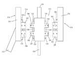
- FIG. 1is a schematic illustration of an air gap control system and a rotor/stator assembly according to an embodiment.
- FIG. 2is schematic illustration of a rotor/stator assembly and an air gap control system, according to an embodiment.
- FIG. 3is a schematic illustration of a portion of a rotor/stator assembly, according to an embodiment.
- FIG. 4is a schematic illustration of a portion of a rotor/stator assembly, according to an embodiment.
- FIG. 5is a schematic illustration of a portion of a rotor/stator assembly having a two-sided rotor, according to an embodiment.
- FIG. 6is a schematic illustration of a portion of a rotor/stator assembly having a one-sided rotor, according to an embodiment.
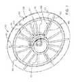
- FIG. 7is a perspective view of a rotor/stator assembly that can be used with an axial flux motor or generator, according to an embodiment.
- FIG. 8is an exploded detail view of a portion of the rotor/stator assembly of FIG. 7 , showing one of the rotors with a portion of an air gap control system mounted thereto.
- FIG. 9is an enlarged view of a portion of the rotor/stator assembly shown in FIG. 7 showing a portion of an air gap control system mounted thereto.
- FIG. 10is a schematic illustration of a section of a portion of the rotor/stator assembly of FIG. 7 with a portion of an air gap control system mounted thereto.
- FIG. 11is a schematic illustration of a portion of the rotor/stator assembly and a portion of an air gap control system shown in FIG. 10 taken at “A” in FIG. 10 .
- FIGS. 12-16are schematic illustrations of the portion of the rotor/stator assembly and air gap control system shown in FIG. 11 .
- FIG. 17is a schematic illustration of a portion of the rotor/stator assembly of FIG. 7 taken at “A” and a portion of an air gap control system, according to an alternative embodiment, coupled thereto.
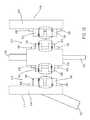
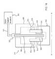
- FIG. 18is a schematic illustration of an axial rotor/stator assembly and a portion of an air gap control system, according to an embodiment.
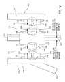
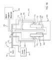
- FIG. 19is a schematic illustration of an axial rotor/stator assembly and a portion of an air gap control system, according to another embodiment.
- FIG. 20is a schematic illustration of a portion of an axial rotor/stator assembly and a portion of an air gap control system, according to another embodiment.
- FIG. 21is an enlarged view of a portion of the air gap control system of FIG. 20 .
- FIG. 22is a schematic illustration of a portion of an axial rotor/stator assembly and a portion of an air gap control system, according to another embodiment.
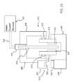
- FIG. 23is a schematic illustration of a portion of an axial rotor/stator assembly and a portion of an air gap control system, according to another embodiment.
- FIG. 24is a schematic illustration of a portion of an axial rotor/stator assembly and a portion of an air gap control system, according to another embodiment.
- FIG. 25is a schematic illustration of a portion of an axial rotor/stator assembly and a portion of an air gap control system, according to another embodiment.
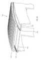
- FIG. 26is an illustration of a portion of a radial rotor/stator assembly and a portion of an air gap control system, according to another embodiment.
- FIG. 27is a schematic illustration of a cup-type radial flux rotor/stator assembly, according to an embodiment.
- FIG. 28is a schematic illustration of the rotor/stator assembly of FIG. 27 with an air gap control system coupled thereto.
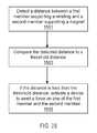
- FIG. 29is a flowchart illustrating a method of controlling an air gap, according to an embodiment.
- an air gap control system as described hereincan be implemented in many applications where maintaining a constant gap is desired for machine performance and/or safe operation of the machine.
- an air gap control systemis described herein that can be used to maintain a clearance between the rotor assembly and stator by making one of the stator structure and the rotor structure relatively soft or compliant and the other of the stator structure and the rotor structure relatively stiff, and by transmitting a force from the stiff member to the compliant member to maintain a minimum gap clearance.
- the stiff memberWhen the stiff member is displaced or deflected, it transmits a force to the compliant member, causing the compliant member to deflect in a similar manner so as to maintain a constant or substantially constant gap size.
- the air gap control systemcan provide a locating stiffness between the rotor and stator, such that the air gap control stiffness becomes the dominant stiffness with respect to the relative motion between the stator and the rotor.
- the air gap control systemcan function similarly to a spring of desired spring constant in that it can be used to produce a desired structural stiffness at a localized point between, for example, a rotor and a stator.
- the air gap control systemprovides localized stiffness between a relatively soft component and a relatively stiff component of a machine or mechanism. Additionally, the stiffness between a relatively soft component and a relatively stiff component of the air gap control system can be distributed over a broader surface area of interaction between the two components if this arrangement proves more adaptable to the dynamic responses of the system components.
- Some embodiments of an air gap control system described hereincan be used to maintain an air gap within a required limit for performance and/or safety, such as in radial, axial, and transverse flux motors or generators, operating in a rotating manner or in a linear manner. Some embodiments of an air gap control system described herein can be useful for reducing the weight and cost of machines utilizing an air gap, and for reducing the required frequency and scope of maintenance over conventional air gap machines.
- Electromagnetic machinessuch as the rotor/stator assemblies described herein, utilize magnetic flux from magnets, such as permanent magnets or electromagnets, to convert mechanical energy to electrical energy or vice versa.
- magnetssuch as permanent magnets or electromagnets
- Various types of electromagnetic machinesare known, including axial flux machines, radial flux machines, and transverse flux machines, in which one component rotates about an axis or translates along an axis, either in a single direction or in two directions, e.g. reciprocating, with respect to another component.
- Such machinestypically include windings to carry electric current through coils that interact with the flux from the magnets through relative movement between the magnets and the windings.
- permanent magnetsfor example, are mounted for movement, e.g.
- an electric motorfor example, current is applied to the windings in the stator, causing the magnets (and therefore the rotor) to move relative to the windings, thus converting electrical energy into mechanical energy.
- a generatorapplication of an external force to the generator's rotor causes the magnets to move relative to the windings, and the resulting generated voltage causes current to flow through the windings—thus converting mechanical energy into electrical energy.
- the rotoris energized by electromagnetic induction produced by electromagnets that cause the rotor to move relative to the windings on the stator, which are connected directly to an AC power source and can create a rotating magnetic field when power is applied.
- An air gap control system as described hereincan be utilized in such electromagnetic machines, to control the air gap or distance between the moving part (e.g., the rotor) and the stationary part (e.g., the stator) to ensure proper operation of the machine.
- An air gap control system as described hereinis separate from the main rotor-stator support feature of such electromagnetic machines, and can operate independently of a main bearing of, for example, a rotor/stator assembly.
- the air gap control systemdoes not bear the load of the rotor/stator assembly; rather the rotor/stator assembly is supported by some other suitable load-bearing component such as, for example, a main bearing assembly of the rotor/stator assembly as described below.
- an electromagnetic machinee.g., a rotor/stator assembly as described herein
- the air gap control systems described hereincan also be used within other machines or mechanisms where there is a need or desire to maintain a specified distance or gap between a stationary component and a component that can move relative to the stationary component.
- An air gap control system as described hereincan also be beneficial for controlling and maintaining an air gap in an iron core stator system. In such systems, where the stator is formed of iron, the stator is attracted to the rotor and therefore a need to control the gap between the rotor and stator can be even greater than in an air core stator system as described herein with reference to specific embodiments.
- an air gap control systemcan be configured similar to a magnetic levitation train suspension system.
- magnetic levitationcan be used to suspend, guide and/or propel a train from magnets.
- Similar magnetic forcescan be used within a machine to control and maintain a gap between the moving component (e.g., rotor) and the stationary component (e.g., stator) of the machine.
- an air gap control devicecan refer to a component of any of the embodiments of an air gap control system described herein.
- an air gap control devicecan include a magnet (e.g. permanent magnet, electromagnet), an auxiliary winding, an air bearing, a guide rail, etc.
- FIG. 1is a schematic illustration of a rotor/stator assembly, according to an embodiment.
- the rotor/stator assemblyis one example embodiment of an electromagnetic machine that can include an air gap control system that can be used to control a gap between a moving component and a stationary component of the electromagnetic machine.
- a rotor/stator assembly 12can include a rotor assembly 28 and a stator 18 .
- the rotor/stator assembly 12can be incorporated within, for example, a machine such as, for example, an electric motor or an electric generator.
- the rotor assembly 28can include one or more rotor portions that move relative to the stator 18 .
- the rotor assembly 28can include a rotor portion that rotates relative to the stator 18 (e.g., with the direction of flux from rotor to stator generally in the axial or radial direction). In some embodiments, the rotor assembly 28 can include a rotor portion that moves in a linear motion relative to the stator 18 .
- the rotor assembly 28(also referred to herein as a “magnet supporting member” or a “member supporting a magnetic flux generating member”) can include or support one or more magnetic flux generating members, such as, for example, magnets (e.g., a magnet pole assembly, or array of magnets) or windings (each not shown in FIG. 1 ).
- the magnetscan include, for example, an array of magnets and can be, for example, permanent magnets, electromagnets or a combination of both.
- the magnetsare electromagnets.
- a windingcan be, for example, as described below for stator 18 .
- the stator 18can include or support, for example, air core types of stators without any ferromagnetic material to support the copper windings or conduct magnetic flux.
- An air core statorcan include an annular array of stator segments (not shown) and one or more conductive windings (not shown) or one or more magnets (not shown).
- Each air core stator segmentcan include a printed circuit board sub-assembly (not shown), or another means known of structurally encapsulating the windings in non-ferromagnetic materials.
- the printed circuit board sub assembliescan be similar to that described in U.S. Pat. No.
- An air gap control system 10can be coupled to the rotor assembly 28 and/or to the stator 18 and can be used to control one or more air gaps defined between the rotor assembly 28 and the stator 18 during operation of the rotor/stator assembly 12 .
- An air gap as referred to hereincan be, for example, a distance between two components such as a distance between a portion of the rotor assembly 28 and a portion of the stator 18 .
- the air gap control system 10can be embodied in a variety of different arrangements that are each configured to maintain a minimum air gap between the rotor assembly 28 and the stator and/or to provide a mechanism to maintain the stator 18 centered within a region defined by the rotor assembly 28 .
- the air gap control system 10can be configured to maintain a minimum distance between the rotor portion of the rotor assembly 28 and the stator 18 .
- the air gap control system 10can be configured to maintain the stator 18 in a centered or substantially centered position between the first rotor portion and the second rotor portion of the rotor assembly 28 .
- the air gap control system 10can also carry the magnetic attraction load of the system to maintain the first rotor portion 14 spaced apart from the second rotor portion 16 .
- the rotor/stator assembly 12can include a stator support structure 52 that couples the stator 18 to a stationary stator hub 21 .
- the stator support structure 52can include one or more stator support members, a stator support clamp, and various other supporting components (the preceding components not shown in FIG. 2 , for simplicity of illustration) depending on the particular embodiment.
- the stator 18 and/or one or more components of the stator support structure 52can be relatively compliant or flexible to allow for the stator 18 to be deflected by a force exerted by the air gap control system 10 , as described in more detail below.
- the rotor/stator assembly 12also includes a rotor support structure 62 that couples the rotor assembly 28 to one or more bearings 20 that are coupled to the stationary stator hub 21 .
- the rotor support structure 62can include, for example, one or more rotor support members (not shown in FIG. 2 ) that can couple the rotor assembly 28 to the bearings 20 .
- the rotor assembly 28can also include an end support portion 53 that can separate the magnetic attraction loading within the system.
- the bearings 20can be, for example, a conventional bearing that can function to establish the general alignment, support (bears the weight of the rotor assembly 18 ), and provide general locating forces for rotor assembly 28 and stator 18 , as well as general rotor dynamic stability of the rotating and stationary parts.
- the bearing 20can be, for example, a hydrodynamic oil film, air, rolling element or magnetic bearing or other type of bearing known in the art.
- the air gap control system 10can function independently of the main bearings 20 and can be used to establish the relative proximity of the rotating and stationary parts, for example, at the air gap between the rotor assembly 28 and the stator 18 .
- the rotor assembly 28includes a first rotor portion 14 and a second rotor portion 16 and the stator 18 can be disposed between the first rotor portion 14 and the second rotor portion 16 .
- the stator 18can be disposed substantially centered between the first rotor portion 14 and the second rotor portion 16 .
- the rotor assembly 28also includes at least one magnet 30 .
- the rotor assembly 28can include a first magnet 30 coupled to or supported by the first rotor portion 14 and a second magnet 31 having an opposite polarity coupled to the second rotor portion 16 .
- the magnets 30 and 31can each include, for example, a magnet assembly or an array of magnets coupled to or supported by the rotor assembly 28 .
- the magnets 30 and 31can direct flux in an axial direction from the magnet poles on magnet 30 supported on the first rotor portion 14 to the magnet poles of magnet 31 supported on the second rotor portion 16 .
- a portion of the air gap control system 10can be disposed between the first rotor portion 14 and the stator 18 or a portion of the stator support structure 52 , such as for example, the stator support clamp or a stator support member.
- a portion of the air gap control system 10can also be disposed between the second rotor portion 16 and the stator 18 or a portion of the stator support structure 52 .
- more than one air gap control system 10can be utilized.
- the air gap control system 10can be disposed as shown in FIG. 2
- a second air gap control system(not shown) can be disposed to control an air gap at another location, such as, for example, at locations 33 , 35 and 37 shown in FIG. 2 .
- the air gap control assembly 10can induce a centering force that acts to move or return the stator 18 to a nominally centered location between the first rotor portion 14 and the second rotor portion 16 .
- air gap control assembly 10can exert a force on stator 18 to cause stator 18 to maintain a nominal location, for example, centered within the rotor assembly 28 between first rotor portion 14 and second rotor portion 16 .
- stator 18undergoes an axial translation relative to the rotor assembly 28 (e.g.
- stator 18can increase and the gap distance on the other side of stator 18 can decrease.
- air gap control system 10can exert a force on stator 18 to re-center stator 18 between first rotor portion 14 and second rotor portion 16 .
- air gap control system 10can exert a moment on stator 18 that restores a uniform gap distance at some or all points between stator 18 and each of the first rotor portion 14 and the second rotor portion 16 .
- an air gap control system 10can be used to transmit a force from the relatively stiff member (e.g., the rotor assembly 28 in this example) to the relatively compliant member (e.g., the stator 18 in this example) so as to maintain a desired air gap between the stator 18 and the rotor assembly 28 .
- the air gap control system 10is an active system that includes a controllable force generating device (e.g., an electromagnet, an air bearing, auxiliary windings) and a system controller 87 (shown in FIG. 2 ) that can vary the applied force to the stator 18 based on input from a sensor 82 , such as, for example, a proximity sensor or a back-emf detecting winding. Examples of such embodiments are described in detail below.
- a controllable force generating devicee.g., an electromagnet, an air bearing, auxiliary windings
- a system controller 87shown in FIG. 2
- a sensor 82such as, for example, a proximity sensor or a back-emf detecting winding. Examples of such embodiments are described in detail below.
- the air gap control system 10can be implemented in many applications where maintaining a constant or substantially constant gap is desired for machine performance and/or safe operation of the machine.
- the air gap control system 10can be used with any machine with arrays of magnets, including radial, axial, and transverse flux motors and generators that operate in a rotating or a linear manner.
- the air gap control system 10can include magnets to produce the force to move the stator 18 and maintain the air gap between the stator 18 and the rotor assembly 28 (e.g., the first rotor portion 14 and the second rotor portion 16 ).
- the magnetscan be, for example, permanent magnets.
- the magnetscan include one or more magnets and can be, for example, an array of magnets or a magnet assembly. In other embodiments, the magnets can be electromagnets as described below for an alternative embodiment.
- a first magnet (not shown) having a polarity in a first directioncan be disposed on the first rotor portion 14 and a second magnet (not shown) having a second polarity opposite the first polarity can be coupled to the stator 18 (or stator support structure 52 ) facing the first magnet.
- the air gap control system 10can include a third magnet (not shown) having a polarity in a third direction disposed on the second rotor portion 16 and a fourth magnet (not shown) having a fourth polarity opposite the third polarity coupled to the stator 18 (or the stator support structure 52 ) facing the third magnet.
- the third magnet and the fourth magnetcan function in the same manner as the first magnet and the second magnet to exert a force on the stator 18 to control the air gap between the stator 18 and the first rotor portion 14 and the second rotor portion 16 .
- An example of such an embodimentis described in more detail below.
- the air gap control system 10can include one or more guide rails (not shown) coupled to the first rotor portion 14 and the second rotor portion 16 .
- the guide railsare also coupled to a relatively stiff stationary outrigger (not shown) coupled to the stator support structure 52 .
- that rotor portioncontacts the guide rail coupled to that rotor and applies a force to that guide rail.
- the force applied to the guide railis then transmitted from the guide rail, through the stationary outrigger and to the stator support structure 52 where it causes the stator support member of the stator support structure 52 to limit or prevent further movement of the rotor portions 14 , 16 and/or stator 18 and/or prevent contact between the rotor portions 14 , 16 and stator 18 , and can act to re-center the stator 18 between first rotor portion 14 and second rotor portion 16 , thereby maintaining the necessary air gap clearance.
- An example of such an embodimentis described in more detail below.
- the air gap control system 10can include a pneumatic system coupled to the stationary outrigger, which can be used to form an air bearing at the guide rails to apply the force needed to re-position (e.g. re-center) the stator 18 without contact for most of the anticipated deflection loads.
- the air gap control systemis a passive system.
- the air bearingscan balance the stiffness.
- the air gap control systemis an active system.
- the air gap control systemcan include a system controller 87 that can be used to control the flow rate of compressed air supplied to the air bearings based on input from a proximity sensor 82 or a mechanical lever, or in response to differential pressure changes caused by changes in the proximity between the air bearing and the mating surface, that are incorporated into the guide rail to control an air supply throttle valve to increase or decrease the air admitted to the air bearing based on the amount of force needed to resist further deflection. Examples of such alternative embodiments are described in more detail below.
- the air gap control system 10can include an alternative embodiment of an active system to maintain the requisite air gap between the rotor assembly 28 and the stator 18 .
- proximity sensors 82can detect a decrease in the air gap distance between the rotor assembly 28 and the stator 18 and a system controller 87 can activate an electromagnet to create or increase a magnetic repulsion force between a rotor extension of the rotor assembly 28 having magnets or magnetic poles mounted thereto and the stationary outrigger.
- the system controllercan be configured to activate an electromagnet to create a magnetic attractive force between the rotor extension and the stationary outrigger.
- the forceis transmitted through the intermediate components to the stator support structure 52 , which can limit or prevent further movement of the rotor assembly 28 and/or stator 18 to prevent contact between the rotor assembly 28 and stator 18 , and can act to re-center stator 18 within the rotor assembly 28 (e.g., between first rotor portion 14 and second rotor portion 16 ) and minimize variation of the air gap.
- the controllerdetermines that the air gap as measured by the proximity sensor has been restored to the desired distance, it deactivates or reduces the current through the electromagnet.
- the guide rails described abovecan optionally provide a mechanical backup in case of failure of the electromagnet. An example of such an embodiment of an air gap control system is described in more detail below.
- the air gap control system 10can utilize repulsive forces of one or more magnets to re-center or re-position the stator 18 in a similar manner as previously described.
- an array of two or more magnetscan be coupled to the stationary outrigger and an array of two or more magnets can be coupled to a rotor extension of the rotor assembly 28 .
- the arrays of magnetscan include a variety of different types, combinations and quantities of magnets.
- the array of magnets on the stationary outrigger and/or the rotor extensioncan be permanent magnets, electromagnets and/or a combination thereof.
- the guide rails described abovecan optionally be included to provide a mechanical backup in case of failure of the magnet system. An example of such an embodiment of an air gap control system is described in more detail below.
- the air gap control system 10can include the use of non-ferromagnetic brackets coupled to the rotor assembly 28 and non-ferromagnetic brackets coupled to the stator 18 , together with annular rows of magnets coupled to the stator 18 to create a null flux ladder circuit.
- the magnetic flux from the annular rows of magnetswill cause current to flow through null flux ladder circuit, which in turn will generate a repulsive magnetic field that pushes annular rows of magnets and the stator to which they are coupled.
- guide railscan be used to provide a backup air gap control system. An example of such an embodiment is described in more detail below.
- the air gap control system 10can include auxiliary windings on or near the outer surfaces of the stator 18 .
- a system controller 87can measure and compare the back-emf of the auxiliary windings to determine if the stator has moved off-center.
- the auxiliary windingscan be, for example, on a different flux path than the primary windings of the stator 18 .
- the system controller 87can then send alternating current to the auxiliary winding (and not the primary winding of the stator 18 ) to generate an attractive force to be exerted on the stator 18 .
- guide railscan optionally be used to provide a backup air gap control system. An example of such an embodiment is described in more detail below.
- the air gap control system 10can include wheels, rollers, or other mechanical force-applying members that are coupled to a portion of the stator support structure 52 in a relatively stiff manner.
- the rotor portioncontacts one or more of the wheels or rollers and applies a force thereto that is transferred to the stator 18 via the stator support structure 52 .
- FIG. 3is a schematic illustration of a portion of another embodiment of a rotor/stator assembly.
- the rotor/stator assembly 112includes a rotor assembly 128 , a stator 118 , a rotor support structure 162 and a stator support structure 152 .
- the rotor assembly 128is disposed for rotational movement relative to the stator 118 .
- the rotor assembly 128can rotate about an axis A-A shown in FIG. 3 .
- the rotor/stator assembly 112is an example of an axial flux machine system.
- the stator 118can include the same features and perform the same functions as described above for stator 18 .
- the stator 118can support a conductive winding (not shown in FIG. 3 ).
- the stator support structure 152includes a stator support clamp 132 , which is coupled to the stator 118 and a stator support member 124 .
- the stator support member 124couples the stator 118 to a stationary stator hub 121 .
- the rotor/stator assembly 112is an example of a system in which the stator 118 is supported on an inboard side of the system. In other words, the stator 118 is coupled to the stator support clamp 132 radially inboard of a portion of the rotor assembly 128 .
- the rotor assembly 128includes a first rotor portion 114 and a second rotor portion 116 , and an end support portion 153 .
- the first rotor portion 114supports a first magnet 130 and the second rotor portion 116 supports a second magnet 131 .
- the magnets 130 and 131can each be the same as or similar to and function the same as or similar to the magnets 30 and 31 described above.
- the stator 118is disposed between the first rotor portion 114 and the second rotor portion 116 .
- the stator 118can be centered or substantially centered between the first rotor portion 114 and the second rotor portion 116 as shown in FIG. 3 .
- the rotor assembly 128is coupled to rotor support structure 162 that includes rotor support members 122 and bearings 120 .
- the bearings 120provide for rotational movement of the rotor assembly 128 relative to the stator 118 .
- An air gapis defined at various locations between the first rotor portion 114 and the stator 118 and the second rotor portion 116 and the stator 118 , and between the magnet 130 and the stator 118 and the magnet 131 and the stator 118 .
- any of the embodiments of an air gap control system(not shown in FIG. 3 ) as described above with respect to FIGS. 1 and 2 and as described herein can be implemented at, for example, any of the air gap locations G indicated in FIG. 3 , to maintain a desired air gap at that location.
- stator support clamp 132 and/or the stator support member 124can be flexible or compliant such that when a force is exerted on the stator support clamp 132 and/or the stator support member 124 by the air gap control system, the stator 118 is moved to a position in which the stator 118 is centered or substantially centered between the first rotor portion 114 and the second rotor portion 116 .
- FIG. 4is a schematic illustration of a portion of another embodiment of a rotor/stator assembly.
- the rotor/stator assembly 212includes a rotor assembly 228 , a stator 218 , a rotor support structure 262 and a stator support structure 252 .
- the rotor assembly 228is disposed for rotational movement relative to the stator 218 .
- the rotor assembly 228can rotate about an axis A-A shown in FIG. 4 .
- the rotor/stator assembly 212is an example of an axial flux machine system.
- the stator 218can include the same features and perform the same functions as described above for stator 18 .
- the stator 218can support a conductive winding (not shown in FIG. 4 ).
- the stator support structure 252includes a stator support clamp 232 , which is coupled to the stator 218 and a stator support member 224 .
- the stator support member 224couples the stator 218 to a stationary stator hub 221 .
- the rotor/stator assembly 212is an example of a system in which the stator 218 is supported on a radially outboard side of the system. In other words, the stator 218 is coupled to the stator support clamp 232 exterior or outboard of the rotor assembly 228 .
- the rotor assembly 228includes a first rotor portion 214 and a second rotor portion 216 , and an end support portion 253 .
- the first rotor portion 214supports a first magnet 230 and the second rotor portion 216 supports a second magnet 231 .
- the magnets 230 and 231can each be the same as or similar to and function the same as or similar to the magnets 30 and 31 described above.
- the stator 218is disposed between the first rotor portion 214 and the second rotor portion 216 .
- the stator 218can be centered or substantially centered between the first rotor portion 214 and the second rotor portion 216 as shown in FIG. 4 .
- the rotor assembly 228is coupled to rotor support structure 262 that includes a rotor support member 222 and a bearing 220 .
- the bearing 220provides for rotational movement of the rotor assembly 228 relative to the stator 218 .
- An air gapis defined at various locations between the first rotor portion 214 and the stator 218 and the second rotor portion 216 and the stator 218 , and between the magnet 230 and the stator 218 and the magnet 231 and the stator 218 .
- any of the embodiments of an air gap control system(not shown in FIG. 4 ) as described above with respect to FIGS. 1 and 2 and as described herein can be implemented at, for example, any of the air gap locations G indicated in FIG. 4 , to maintain a desired air gap at that location.
- stator support clamp 232 and/or the stator support member 224can be relatively flexible or compliant such that when a force is exerted on the stator support clamp 232 and/or the stator support member 224 by the air gap control system, the stator 218 is moved to a position in which the stator 218 is centered or substantially centered between the first rotor portion 214 and the second rotor portion 216 .
- the rotor/stator assembly 112is an example of a system in which the stator 118 is supported on an inboard side of the system or inboard of a portion of the rotor assembly 128
- rotor/stator assembly 212is an example of a system in which the stator is supported on an outboard side of the system or outboard of the rotor assembly 228
- a stator of a rotor/stator assemblycan be supported both on an inboard side and an outboard side.
- FIG. 5is a schematic illustration of a portion of another embodiment of a rotor/stator assembly.
- the rotor/stator assembly 312includes a rotor assembly 328 , a stator 318 , a rotor support structure (not shown) and a stator support structure 352 .
- the rotor assembly 328can be disposed for rotational movement relative to the stator 318 or for linear movement relative to the stator 318 .
- the rotor/stator assembly 312is an axial flux machine system, similar to the embodiments shown in FIG. 3 .
- the rotor/stator assembly 312is a radial flux machine system.
- the rotor assembly 328moves linearly, rather than rotationally, with respect to stator 318 , such as reciprocal movement into and out of the plane of FIG. 5 , perpendicular to axes A-A and B-B, the rotor/stator assembly 312 has a linear machine architecture.
- the stator 318can include the same features and perform the same functions as described above for stator 18 .
- the stator 318can support a conductive winding (not shown in FIG. 5 ).
- the stator support structure 352includes a stator support clamp 332 , which is coupled to the stator 318 and a stator support member 324 .
- the stator support member 324can couple the stator 318 to a stationary stator hub (not shown) as described above for previous embodiments.
- the rotor/stator assembly 312is another example of an inboard mounted stator system (similar to embodiment of FIG. 3 ) in which the stator 318 is supported on an inboard side of the system.
- the rotor assembly 328includes a first rotor portion 314 and a second rotor portion 316 , and an optional end support portion 353 .
- the first rotor portion 314supports a first magnet 330 and the second rotor portion 316 supports a second magnet 331 .
- the magnets 330 and 331can each be the same as or similar to and function the same as or similar to the magnets 30 and 31 described above.
- the stator 318is disposed between the first rotor portion 314 and the second rotor portion 316 .
- the stator 318can be centered or substantially centered between the first rotor portion 314 and the second rotor portion 316 .
- the rotor assembly 328can be coupled to a rotor support structure (not shown) that can include, for example, a rotor support member and a bearing that can provide for rotational movement of the rotor assembly 328 relative to the stator 318 .
- An air gapis defined at various locations between the first rotor portion 314 and the stator 318 and the second rotor portion 316 and the stator 318 , and between the magnet 330 and the stator 318 and the magnet 331 and the stator 318 .
- any of the embodiments of an air gap control system(not shown in FIG. 5 ) as described above with respect to FIGS. 1 and 2 and as described herein can be implemented at, for example, any of the air gap locations G indicated in FIG. 5 , to maintain a desired air gap at that location.
- stator support clamp 332 and/or the stator support member 324can be relatively flexible or compliant such that when a force is exerted on the stator support clamp 332 and/or the stator support member 324 by the air gap control system, the stator 318 is moved to a position in which the stator 318 is centered or substantially centered between the first rotor portion 314 and the second rotor portion 316 .
- FIG. 6is a schematic illustration of a portion of another embodiment of a rotor/stator assembly.
- the rotor/stator assembly 412includes a rotor assembly 428 and a stator 418 .
- the rotor assembly 428includes a single rotor portion 414 that can support a magnet 430 .
- the stator 418includes conductive windings 455 , which are wound around a core portion 457 .
- the core portion 457can be, for example, ferromagnetic.
- the pole face of the magnet 430is separated from windings 455 by an air gap such that the magnetic flux generally flows into, and changes direction in, the stator 418 and the rotor 428 .
- the stator 418can be coupled to a stator support structure (not shown in FIG. 6 ) and can be coupled to a stationary hub (not shown in FIG. 6 ), as described above for previous embodiments.
- the rotor assembly 428can be coupled to a rotor support structure (not shown in FIG. 6 ) that couples the rotor assembly 428 to a bearing (not shown in FIG. 6 ) that provides for movement of the rotor assembly 428 relative to the stator 418 and also bears the primary load of the rotor/stator assembly 412 .
- the rotor/stator assembly 412is an axial flux machine system. If the axis of rotation of rotor assembly 428 is axis A-A in FIG. 6 , the rotor/stator assembly 412 is a radial flux machine system. Alternatively, if the rotor assembly 428 moves linearly, rather than rotationally, with respect to stator 418 , such as reciprocal movement into and out of the plane of FIG. 6 , perpendicular to axes A-A and B-B, the rotor/stator assembly 412 has a linear machine architecture.
- An air gapis defined at various locations between the rotor portion 414 and the stator 418 at which an embodiment of an air gap control system (not shown in FIG. 6 ) as described herein can be implemented.
- an air gap control systemcan be used to control the air gap at locations G indicated in FIG. 6 , to maintain a desired air gap between the rotor assembly 428 and the stator 418 .
- the air gap control systemcan, for example, maintain a minimum gap or distance or a nominal distance between the stator 418 and the rotor portion 414 , rather than centering the stator 418 within the rotor assembly 428 , for example, as described for rotor portion 328 and stator 318 shown in FIG. 5 .
- FIGS. 7-10illustrate an embodiment of an axial rotor/stator assembly.
- the rotor/stator assembly 512includes a rotor assembly 528 , a stator assembly 518 (see, e.g., FIGS. 8 and 9 ), a rotor support structure 562 and a stator support structure 552 .
- the rotor assembly 528is disposed for rotational movement relative to the stator assembly 518 .
- the stator assembly 518can include the same features and perform the same functions as described above for previous embodiments.
- the stator assembly 518can support a conductive winding 555 (see, e.g., the schematic illustration of FIG. 10 ).
- the stator support structure 552includes multiple stator support members 524 and a stator support clamp 532 (see FIG. 10 ), which is coupled to the stator assembly 518 .
- the stator support members 524couple the stator assembly 518 to a stationary stator hub 521 (see FIG. 7 ).
- the rotor support structure 562includes multiple rotor support members 522 coupled to a bearing 520 .
- the bearing 520is attached to a hub 577 extending through a central opening of the stator hub 521 and can function similar to an axle to provide for rotational movement of the rotor assembly 528 relative to the stator assembly 518 .
- the rotor assembly 528includes a first rotor portion 514 , a second rotor portion 516 , and an end support portion 553 (see FIG. 10 ).
- the first rotor portion 514supports a first magnet 530 and the second rotor portion 516 supports a second magnet 531 .
- the magnets 530 and 531can each be the same as or similar to and function the same as or similar to the magnets 30 and 31 described above with respect to FIG. 1 .
- the magnets 530 and 531can be, for example, magnet pole assemblies or an array of magnets, which direct flux in an axial direction from the magnet poles on one rotor portion (e.g., rotor portion 514 ) to the magnet poles of opposite polarity on the other rotor portion (e.g., rotor portion 516 ).
- magnet 530is mounted or supported on a rotor back iron 534 of rotor portion 514 with a pole magnet retainer 536 .
- Magnet 531can be mounted on second rotor portion 516 in a similar manner.
- the first rotor portion 514is coupled to the multiple rotor support members 522 , which is coupled to the bearing 520 .
- the second rotor portion 516can be coupled to the first rotor portion 514 with spacer blocks 526 at an outer diameter portion of rotor/stator assembly 512 , such that the first and second rotor portions 514 and 516 can rotate together, and deflect primarily in an axial direction as a single, structurally rigid subassembly.
- the spacer blocks 526can be coupled to mounting pads 525 with a bolt, screw or other coupling mechanism.
- the end support portion 553can be integrally or monolithically formed with the spacer blocks 526 (in other words, spacer blocks 526 and end support portion 553 are a single component).
- stator assembly 518is disposed between the first segmented rotor portion 514 and the second segmented rotor portion 516 .
- the stator assembly 518can be centered or substantially centered between the first segmented rotor portion 514 and the second segmented rotor portion 516 .
- stator assembly 518can include an annular array of stator segments 559 .
- Each segment 559can include a printed circuit board sub-assembly as described above for stator 18 .
- stator assembly 518is coupled to the stator support clamp 532 , which is coupled to a rim of stationary stator hub 521 via the structural support members 524 .
- Stator hub 521can be coupled to a support structure and/or housing arrangement (not shown), which can further maintain the stator assembly 518 in a fixed or stationary position.
- the stator support clamp 532 and/or the stator support member 524can be relatively flexible or compliant such that when a force is exerted on the stator support clamp 532 and/or the stator support member 524 by the air gap control system 510 (described below), the stator assembly 518 can be moved.
- an air gapcan be defined at various locations between the first rotor portion 514 and the stator assembly 518 and between the second rotor portion 516 and the stator assembly 518 .
- An air gap control system 510can be coupled to the rotor assembly 528 and/or the stator assembly 518 and used to control or maintain a desired gap distance between the rotor portions 514 and 516 and the stator assembly 518 .
- FIG. 8 and 9illustrate a portion of the air gap control system 510 coupled to an inner circumference portion 515 of the rotor portion 514 , which is not to preclude having the air gap control system 510 coupled to an outer circumference feature 517 instead of, or in addition to the inner circumference.
- a second air gap control system(not shown) can optionally be disposed at a radially outer portion 517 of the rotor portion 514 .
- an air gap control system 510can be disposed only at the radially outer portion 517 of rotor portion 514 rather than at the radially inner portion 515 of the rotor portion 514 .
- the air gap control system 510can be mounted to the first rotor back iron of the first rotor portion 514 with one or more air gap control magnet retainers 538 .
- the air gap control assembly 510can be coupled to the second rotor portion 516 in a similar manner.
- the air gap control system 510is also coupled to the stator assembly 518 as shown for example, in the schematic illustration of FIG. 10 .
- the air gap control system 510can induce a centering force that acts to move the stator assembly 518 to a centered or substantially centered location between the first rotor portion 514 and the second rotor portion 516 .
- air gap control assembly 510can exert a force on stator assembly 518 , causing stator assembly 518 to maintain a nominal location, for example, centered between first rotor portion 514 and second rotor portion 516 .
- stator assembly 518undergoes an axial translation relative to first rotor portion 514 and second rotor portion 516 because of an external force (whether temporary or constant) applied to rotor portions 514 and 516 and that moves or deflects rotor portions 514 and 516 in an axial direction
- the gap distance on one side of stator assembly 518increases and the gap distance on the other side of stator assembly 518 decreases.
- air gap control system 510exerts a force on annular stator assembly 518 to re-center annular stator assembly 518 between annular rotor portions 514 and 516 .
- stator assembly 518undergoes an angular deflection relative to rotor portions 514 and 516 (such that in any given section of stator assembly 518 , a gap distance at an inner diameter of stator assembly 518 is different than a gap distance at an outer diameter of stator assembly 518 ) then air gap control system 510 will exert a moment on stator assembly 518 that restores a uniform gap distance between stator assembly 518 and each of first and second rotor portions 514 and 516 .
- the air gap control system 510includes a first magnet assembly 541 coupled to the first rotor portion 514 , a second magnet assembly 543 coupled to the second rotor portion 516 , a third magnet assembly 545 coupled to the stator assembly 518 and a fourth magnet assembly 547 coupled to the stator assembly 518 .
- the first magnet assembly 541can include a magnet 540 mounted with its south facing magnet pole against rotor back iron 534 of rotor portion 514 and a magnet 542 mounted with its north facing magnet pole against the rotor back iron 534 .
- the magnet assembly 543can include a magnet 544 mounted with its south facing magnet pole against the stator support clamp 532 (also referred to as a “stator back iron”), and a magnet 546 mounted with its north facing magnet pole against stator back iron 532 .
- the third magnet assembly 545can include a magnet 540 mounted with its south facing magnet pole against a rotor back iron 535 of rotor portion 516 and a magnet 542 mounted with its north facing magnet pole against the rotor back iron 535 .
- the magnet assembly 547can include a magnet 544 mounted with its south facing magnet pole against the stator back iron 532 and a magnet 546 mounted with its north facing magnet pole against stator back iron 532 .
- Magnets 540 , 542 , 544 and 546can each be held in place with magnet retainers 538 .
- the magnet assemblies 541 , 543 , 545 , and 547are mounted in a circumferential pattern around the entire inner diameter of the inner face of first and second rotor portions 514 and 516 and circumferentially around the entire inner diameter of both faces of stator assembly 518 .
- the rotor back irons 534 and 535can be formed, for example, with a magnetically permeable material, such as iron or steel, and can provide both a return path for flux to pass from one row of magnets 542 to an adjacent row of magnets 540 as well as providing structural rigidity to react the attractive force between rotor portions 514 and 516 as shown by the flux arrows in FIG. 12 , which illustrate the predominant direction of flux.
- a magnetically permeable materialsuch as iron or steel
- Stator clamp ring 532can also be made from a magnetically permeable material, which in the vicinity of magnets 544 and 546 provides a return path for flux to travel from one row of magnets 546 to the adjacent row of magnets 544 as illustrated in FIG. 12 .
- a flux return pathcan be created, for example, with a Halbach array or a horseshoe magnet.
- this embodimentshows north facing magnets disposed above south facing magnets, in alternative embodiments, the south facing magnets can be disposed above the north facing magnets.
- the magnets 540 , 542 , 544 and 546can be, for example, neodymium-iron-boron (NdFeB) permanent magnets. It should be understood, however, that this is just an example of the type of magnet that can be used.
- the air gap control system 510can function similar to a two-sided, passive permanent magnet bearing. Because the opposing magnets are placed in a nearly continuous ring around both the rotor portions 514 , 516 and the stator assembly 518 , the effect of eddy current drag, which would be induced by an alternating magnetic field at a given location due to the relative motion, can be thereby minimized.
- the spacing implemented in this embodimentis such that the discontinuities present can be smoothed out across the air gap control system's rotor-to-stator spacing.
- rectangular shaped magnetscan be used. In applications where this axial magnet-to-magnet dimension is significantly smaller, arc segments or a continuous ring of magnets may be desirable to further reduce drag.
- Magnets 540 and 544are oriented in such a manner that the polarity of axially opposing magnets is in opposite directions.
- Magnets 542 and 546are also oriented in such a manner that the polarity of axially opposing magnets is in opposite directions.
- north pole faces of magnet pairs 540 and 544face each other and south pole faces of magnet pairs 542 and 546 face each other.
- this forcecan increase as magnet pairs are brought closer together by reducing the physical gap between them.
- the repulsive forces on either side of the stator assembly 518are equal and opposite, resulting in no net force on stator assembly 518 .
- FIG. 13shows the rotor/stator assembly 512 after there has been a deflection or movement of either the rotor portion 514 or the rotor portion 516 caused by, for example, fluctuations in torque, speed, or as a result of other inertial dynamics, inherent to or externally applied to the rotor/stator assembly 512 .
- the physical gap or distance between magnets 540 and 542 of rotor portion 516 and magnets 544 and 546 on the right side of stator assembly 518is reduced, resulting in an increase in repulsive force between those magnets.
- FIG. 14illustrates the stator assembly 518 after the stator assembly 518 has returned to an equilibrium position due to removal of the external force causing the initial displacement.
- this “at rest” equilibrium positioncan be biased one way or the other. In other words, it does not have to be equal.
- the “at rest” positionmay be displaced one way or the other, or conversely, the force generating features can be sized differently on each side of the rotor assembly 514 to achieve a desired “at rest” position.
- FIG. 15illustrates the repulsive forces between axial pairs of magnets 540 and 544 and of magnets 542 and 546 counteract angular deflection of stator assembly 518 relative to rotor portions 514 and 516 by reacting against bending moments as shown in FIG. 15 .
- These bending momentscan be, for example, a result of deflection in stator support members 524 or of inertial loading of the rotor/stator assembly 512 .
- the reactive moment applied to stator assembly 518 by air gap control system 510can restore a uniform gap distance between stator assembly 518 and each of the rotor portions 514 and 516 , as shown in FIG. 16 .
- FIG. 16illustrates the stator assembly 518 when the stator assembly 518 has returned to an equilibrium position due to removal of the applied moment causing the initial displacement.
- the angular stiffness of an air gap control system 510i.e. its resistance to angular deflection of stator assembly 518 , can vary with the strength of its magnets, the distance between the magnets in the direction of the air gap, the radial distance of the magnets from the radially inner end of the stator assembly 518 , and the radial separation of the individual magnets of magnet assemblies 541 , 543 , 545 and 547 established by retainers 538 .
- the air gap control system 510can be designed with a desired “track width” or radial location along the rotor portions 514 and 516 and/or stator assembly 518 to achieve the desired angular stiffness relative to its axial stiffness (which does not necessarily depend on radial location).
- the air gap control system 510can maintain the desired gap or distance between two members (e.g., the rotor and the stator) by transmitting a force from the stiffer first member to the compliant second member, where the second member is relatively compliant in the direction of the gap.
- the second memberi.e. stator assembly 518
- the second memberwould be relatively compliant in the radial direction.
- FIG. 17An alternative air gap control system is shown in FIG. 17 .
- an air gap control system 510 ′is coupled to the rotor/stator assembly 512 described above.
- the air gap control system 510 ′can be configured the same as the air gap control system 510 except in this embodiment, the flux return function for magnets 544 and 546 and the flux return function for magnets 542 and 540 can be enabled by inserting a small magnetically permeable material segment 548 directly behind magnets 544 and 546 and retainers 538 , and behind magnets 542 and 540 and retainers 538 to provide an independent flux return path.
- Segments 548may be separately installed in a stator clamp ring 532 and rotor back irons 534 and 535 , which in the vicinity of the air gap control magnets ( 540 , 542 , 544 , 546 ), may be composed of a relatively impermeable material, such as, for example, aluminum, austenitic stainless steel, or plastic.
- FIG. 18is a schematic illustration of an axial rotor/stator assembly 612 according to another embodiment.
- the rotor/stator assembly 612includes a stator support structure 652 that can support one or more stator support members 624 to which a stator clamp ring 632 is coupled.
- Stator clamp ring 632can support an outer circumference of a segmented annular stator 618 along its own inner circumference.
- the segmented stator 618can be configured the same as described for previous embodiments and can support a conductive winding (not shown).
- Rotor/stator assembly 612also includes a rotor support structure 662 , which supports an inner circumference of a first segmented annular rotor portion 614 and an opposing second segmented annular rotor portion 616 .
- Annular rotor portions 614 and 616are positioned on opposite sides of the segmented annular stator 618 and can rotate about an axis A-A relative to the annular stator 618 .
- the first rotor portion 614supports a first magnet 630 and the second rotor portion supports a second magnet 631 .
- the magnets 630 and 631can be configured the same as described for previous embodiments.
- the axial rotor/stator assembly 612further includes one or more stationary outriggers 668 coupled to both sides of the stator clamp ring 632 at spaced locations.
- stator support members 624can be relatively compliant in an axial direction compared to rotor support structure 662 , which is axially rigid or stiff.
- the stiffness of stator support members 624 and rotor support structure 662 in non-axial directionscan be relatively or substantially equal, or at least sufficient to satisfy any structural requirements of the particular application in which axial rotor/stator assembly 612 is used.
- an air gap control system 610includes guide rails 670 coupled to the stationary outrigger 668 and disposed between the stationary outrigger 668 and the first rotor portion 614 , and between the stationary outrigger 668 and the second rotor portion 616 .
- the guide rails 670can be formed with, for example, a material with a low coefficient of friction and robust wear properties. In operation, when an external force causes movement (e.g., an axial deflection) of either annular rotor portion 614 or annular rotor portion 616 , that rotor portion contacts one of the guide rails 670 and thus applies a force to that guide rail 670 .
- stator support members 624can then prevent or limit further movement of, or contact between, the annular rotor portions 614 or 616 and the annular stator 618 and can act to re-center annular stator 618 between first annular rotor portion 614 and second annular rotor portion 616 , thereby maintaining a desired air gap clearance or distance between the stator 618 and the rotor portions 614 and 616 .
- FIG. 19illustrates embodiment of an alternative air gap control system coupled to the rotor/stator assembly 612 .
- an air gap control system 710is an active system that includes a controllable force generating device (in this embodiment, an air bearing) and a controller that varies the applied force to the stator 618 based on input from proximity sensors or mechanical levers that are actuated by contact with the guide rail to position the air bearing air supply throttle valve.
- an air gap control system 710includes a compressed air supply source 754 coupled to the rotor/stator assembly 612 that provides compressed air to an air supply manifold 772 , which feeds the compressed air into channels 774 defined within stationary outrigger 668 .
- the compressed airis then released through an orifice 776 integrated into guide rail 770 , thus forming an air bearing.
- the air supply manifold 772can include one or more orifices (not shown), and can also include a pressure regulating system (not shown).
- a system controller 787is coupled to and/or in communication with the air supply manifold 772 and can control the volume of air released into the channels 774 based on input from a proximity sensor (not shown) or mechanical lever (not shown) that can be used to position the air supply throttle valve (not shown), or respond to pressure changes as the air bearing changes its clearance from 614 or 616 as described below, and increase or decrease flow as needed to position the rotor portion 614 or 616 relative to the stator 618 . In the latter case, where the smaller clearance causes an increased air pressure inside the air bearing chamber formed by guide rail 770 , that increased pressure can be used to actuate the air supply throttle valve to increase air flow to increase the restoring force, and thus, maintain the air gap desired dimension.
- annular stator 618When annular stator 618 is centered between rotors 614 and 616 , the forces applied by the air bearings to each side of annular stator 618 are equal and opposite.
- the proximity sensorcan detect a change corresponding to a change in distance between the rotor portion and the stator, and can communicate the detected change to the system controller 787 that can change the forces exerted by the air bearings.
- the system controller 787can release a higher flow rate of compressed air to the air bearing on the side with the decreased gap or distance between the stator 618 and the rotor portion 614 or 616 such that an increased force is exerted on the adjacent rotor portion, and can release less compressed air to the air bearing on the side with the increased gap or distance between the stator 618 and the rotor portion 614 or 616 such that a decreased force is exerted on the adjacent rotor.
- Guide rails 770can provide a backup, mechanical means for maintaining the desired air gap clearance. For example, if the air bearings fail, guide rails 770 function as shown and described for FIG. 18 .
- the air gap control system 710functions as a passive system rather than an active system.
- the air gap control system 710may not include a system controller 787 and a proximity sensor.
- the forces applied by the air bearings to each side of annular stator 618are equal and opposite.
- an external forcecauses annular rotor portions 614 and 616 to move or deflect, the forces exerted by the air bearings change as the air flow out of the bearing pocket formed by guide rail 770 is restricted. This restriction will increase the air pressure, which will increase the load capacity of the air bearing and enable it to exert a higher force.
- the air bearing on the side with the decreased gapexerts an increased force on the adjacent annular rotor portion ( 614 or 616 ), while the air bearing on the side with the increased gap exerts a decreased force on the adjacent annular rotor portion ( 614 or 616 ).
- the net resultant forceis transmitted through the stationary outrigger 668 and to the stator support member 624 , which can prevent or limit further movement of, or contact between, the annular rotor portions 614 or 616 and the annular stator 618 , thus re-centering annular stator 618 between annular rotor portions 614 and 616 and minimizing variation of the air gap.
- guide rails 770can provide a backup, mechanical means for maintaining the necessary air gap clearance. For example, if the air bearings fail, guide rails 770 function as shown and described for FIG. 18 .
- FIG. 20illustrates embodiment of an alternative air gap control system coupled to the rotor/stator assembly 612 .
- an air gap control system 810is another example of an active system that includes proximity sensors to determine the distance between the rotor portions 614 and 616 and the stator 618 , a controllable force generating device (in this embodiment, electromagnets) and a controller that varies the applied force based on input from the proximity sensors.
- the rotor/stator assembly 612includes rotor extensions 878 incorporated with or coupled to rotor portions 614 and 616 .
- rotor extensions 878may not be included.
- Rotor extensions 878can be formed, for example, of a ferromagnetic material, such as, for example, steel.
- Electromagnet assemblies 880are coupled to the stationary outrigger 668 on each side of the stator 618 .
- the electromagnet assemblies 880can each include a proximity sensor 882 at least partially surrounded by two opposing pole pieces 884 , and a coil 886 for magnetizing pole pieces 884 , as shown in FIG. 21 .
- the electromagnet assemblies 880are disposed on stationary outrigger 668 such that the proximity sensor 882 faces the rotor extensions 878 .
- a system controller 887is coupled to and/or in communication with the electromagnet assemblies 880 .
- a proximity sensor 882detects a decrease in the distance to the rotor extension 878 corresponding to a distance between the rotor portion 614 or 616 and the stator 618 and compare that distance to a stored threshold distance. If the detected distance is less than the stored threshold distance, the system controller 887 can increase the strength of magnetism of the electromagnet assembly 880 such that a magnetic force is exerted on either the stator 618 or the rotor portion 614 or 616 . Specifically, the system controller 887 can activate the coil 886 of the electromagnet assembly 880 , thus magnetizing opposing pole pieces 884 and creating a magnetic attractive force between rotor extension 878 and stationary outrigger 668 .
- stator support structure 652which can prevent or limit further movement of, or contact between, the annular rotor portions 614 or 616 and the annular stator 618 and act to re-center annular stator 618 between annular rotor portions 614 and 616 and minimize variation of the air gap.
- the system controller 887deactivates coil 886 .
- guide rails 870can be included to provide a mechanical backup in case of failure of electromagnet assemblies 880 . Although this embodiment was described as using magnet assemblies 880 having two opposing pole pieces 884 , in alternative embodiments other types of electromagnets can be utilized.
- FIG. 22illustrates embodiment of another alternative air gap control system coupled to the rotor/stator assembly 612 .
- an air gap control system 910includes magnets coupled to the stationary outrigger and to rotor extensions in a similar manner as described above for air gap control system 810 .
- FIG. 22illustrates the use of permanent magnets similar to those described with respect FIGS. 10-17 .
- magnet arrays 988are coupled to the stationary outrigger 668 on each side of the stator 618 .
- the magnet arrays 988can include, for example, two permanent magnets 990 and 992 mounted on a ferromagnetic back iron 994 that are attached to an inward side of stationary outriggers 668 .
- a magnet array 988can include a south pole permanent magnet 990 attached to the back iron 994 in a radial outside position, and a north pole permanent magnet 992 attached to the back iron 994 in a radial inside position.
- permanent magnets 996 and 998are mounted on rotor extensions 978 , directly opposite permanent magnets 990 and 992 , respectively
- Permanent magnets 990 , 992 , 996 , and 998can be mounted such that there is a repulsive force between magnet pairs 990 and 996 and between magnet pairs 992 and 998 , and this force can increase as the magnet pairs are brought closer together.
- the repulsive forces between the magnet pairs on either side of the annular stator 618are equal and opposite, resulting in no net force on the support members 624 .
- annular rotor portions 614 and 616When annular rotor portions 614 and 616 are displaced from the equilibrium position, however, there is an increased repulsive force between the magnet pairs on the side with a decreased air gap (i.e., the distance between the stator 618 and the rotor portion 614 or 616 is decreased) and a decreased repulsive force between the magnet pairs on the side with an increased air gap (i.e., the distance between the stator 618 and the rotor portion 614 or 616 is increased), with a net resultant force that deflects the support members 624 in a direction to re-center annular stator 618 between annular rotor portions 614 and 616 .
- the magnet pairscan be disposed such that when there is increase in the distance between the rotor portions 614 or 616 and the stator 618 a magnetic attractive force is created between the magnet pairs on the side with an increased air gap.
- guide rails 970can optionally be used to provide a backup air gap control system.
- an air gap control systemcan use a combination of permanent magnets and electromagnets rather than only permanent magnets or only electromagnets (as described for air gap control system 910 ).
- one or more electromagnetscan be used on one side of the stator and one or more permanent magnets can be used on the other side of the stator.
- the number of magnets included in magnet arrays 988can also vary.
- FIG. 23illustrates yet another embodiment of an air gap control system coupled to the rotor/stator assembly 612 .
- an air gap control system 1010includes a non-ferromagnetic bracket 1091 attached to stationary outriggers 668 on one axial side of annular stator 618 .
- the bracket 1091is coupled to the side of the stator 618 adjacent the rotor portion 614 .
- the non-ferromagnetic bracket 1091can hold, for example, one two, or another quantity of annular rows of magnets 1093 .
- the annular rows of magnetscan be, for example, a Halbach or other array of magnets or magnets and pole pieces arranged to maximize the flux being passed through the null flux ladder circuit.
- a rim extension 1095 of annular rotor portion 614(or of annular rotor 616 if the non-ferromagnetic brackets 1091 is attached to stationary outriggers 668 on the same side as annular rotor portion 616 ), also made of non-ferromagnetic material, can support a null flux ladder circuit 1097 .
- Null flax ladder circuitsare also known to persons of ordinary skill in the art.
- null flux ladder circuit 1097During operation, as annular rotor portion 614 , and hence null flux ladder circuit 1097 , rotates beneath annular rows of magnets 1093 , no current flows through null flux ladder circuit 1097 as long as annular stator 618 remains in a nominal position (e.g., centered between annular rotor portions 614 and 616 ). If rotor portions 614 and 616 are moved or deflected by an external force, such that annular rows of magnets 1093 are no longer centered over null flux ladder circuit 1097 , the magnetic flux from annular rows of magnets 1093 will cause current to flow through null flux ladder circuit 1097 .
- annular rows of magnets 1093are fixed relative to annular stator 618 , the centering effect created by the interaction of annular rows of magnets 1093 and null flux ladder circuit 1097 serves to keep annular stator 618 centered between annular rotor portions 614 and 616 .
- Guide rails 1070can optionally be used to provide a backup air gap control system in the event that the main system of this embodiment fails, and also to maintain the desired air gap when annular rotor portions 614 and 616 are stopped.
- FIG. 24illustrates an air gap control system according to another embodiment.
- an air gap control system 1110includes auxiliary windings 1185 on or near the outer surfaces of annular stator 618 .
- annular stator 618is formed of printed circuit boards as disclosed, for example, in U.S. Pat. No. 7,109,625 incorporated by reference above, then auxiliary windings 1185 can be included in the outer layers of annular stator 618 , near annular rotor portions 614 and 616 .
- Auxiliary windings 1185can be in a different winding configuration that the primary windings on the stator 618 , and can have a slightly different pole count than the primary windings in annular stator 618 .
- auxiliary windings 1185can employ the same electrical segmentation scheme as the primary windings, so as to reduce complexity, or alternatively auxiliary windings 1185 on each printed circuit board may be electrically segmented.
- a system controller 1187can measure and compare the back-emf of each pair of auxiliary windings 1185 (i.e. the two auxiliary windings 1185 on opposite sides of a single printed circuit board).
- the auxiliary windings 1185can be, for example, on a different flux path than the primary windings of the annular stator 618 . If the measured back-emfs are equal, then annular stator 618 is centered between annular rotor portions 614 and 616 . If the back-emfs are not equal, then the annular stator 618 is off-center.
- the system controller 1187sends alternating current to the auxiliary windings 1185 (and not the primary winding of the annular stator 618 ) on the side of the stator 618 with the relatively lower back-emf (the side of the stator 618 with a greater gap or distance between the rotor portion and the stator 618 ) to generate an attractive force that pulls annular stator 618 toward the rotor on the same side as the auxiliary windings 1185 being energized (i.e., to reduce the gap on that side).
- application of alternating current to the auxiliary winding 1185is discontinued, such that it no longer generates a force between them.
- guide rails 1170may be optionally be used, both as a backup air gap control system, and to control the air gap when annular rotors 614 and 616 are stopped.
- FIG. 25illustrates another embodiment of an air gap control system coupled to the rotor/stator assembly 612 .
- an air gap control system 1210includes wheels or rollers 1281 that are rotatably attached to the stationary outriggers 668 .
- Each wheel or roller 1281can be aligned with its axis A-A in the radial direction relative to rotor/stator assembly 612 .
- annular rotor portions 614 and 616During operation, when an external force causes a deflection or movement of annular rotor portions 614 and 616 , one of rotor portions 614 and 616 contacts one or more of the wheels or rollers 1281 and applies a force thereto.
- That forceis transferred through the outriggers 668 and causes stator support members 624 to move or deflect to re-center annular stator 618 between annular rotor portions 614 and 616 , and thereby maintain the desired air gap clearance between the stator 618 and the rotor portions 614 and 616 .
- FIG. 26is an illustration of a portion of a radial rotor/stator assembly 1312 .
- the radial rotor/stator assembly 1312includes a stator 1318 disposed between a first rotor portion 1314 and a second rotor portion (not shown).
- the stator 1318is coupled to a stator support clamp 1332 which coupled the stator 1318 to stator support members 1324 .
- the rotor portion 1314can also be coupled to a rotor support structure (not shown) as described for previous embodiments.
- An air gap control system 1310is coupled to the stator support clamp 1332 and the first rotor portion 1314 and includes an array of magnets, such as the magnet assemblies described with respect to FIGS. 10-17 .
- a radial rotor/stator systemcan include any of the various configurations of an air gap control system described herein.
- FIGS. 27 and 28are schematic illustrations of an embodiment of a cup-type radial flux rotor/stator assembly.
- a rotor/stator assembly 1412includes a rotor assembly 1428 , a stator 1418 , and a stator support structure 1473 .
- the rotor assembly 1428is disposed for rotational movement relative to the stator 1418 .
- the stator support structure 1473supports the stator 1418 and includes a main bearing 1420 and a stator hub 1421 and can include other support components not shown in FIGS. 27 and 28 .
- the rotor assembly 1428includes a cylindrical portion 1414 and an end support portion 1453 that collectively form a cup shape.
- the cylindrical portion 1414supports a cylindrical array of magnets 1430 .
- the array of magnets 1430can be coupled to a rotor back iron 1435 of the rotor assembly 1428 .
- the array of magnets 1430can be the same as or similar to, and function the same as or similar to, for example, the magnets 30 and 31 described above with respect to FIG. 2 .
- End support portion 1453is coupled to one end of a rotating axle 1475 , which is supported in a bearing 1420 and extends through a central opening of the stator hub 1421 .
- Bearing 1420can be the same as or similar to, and function the same as or similar to, the main bearing 20 and other bearings described herein.
- the bearing 1420can support axle 1475 for rotational movement of the rotor assembly 1428 relative to the stator 1418 .
- a diameter and/or length of the rotor assembly 1428can be configured with a desired mass to achieve a desired stiffness of the rotor assembly 1428 and support structure 1473 that will resist attractive (radial in this depiction) forces between the rotor magnets 1430 and the stator 1418 .
- the stator 1418can include the same features and perform the same functions as described above for previous embodiments.
- the stator 1418includes a plurality of cores, e.g. ferromagnetic cores as described above with reference to FIG. 6 , distributed about the cylindrical outer surface of stator 1418 , around each of which is wound a conductive winding 1455 .
- the rotor/stator support structure 1473can also include, for example, a stator support clamp (not shown) and stator support members (not shown) that can couple the stator 1418 to the stator hub 1421 .
- the stator 1418is disposed within an interior of the cylindrical portion 1414 of rotor assembly 1428 .
- the stator 1418can be centered or substantially centered concentrically within the cylindrical portion 1414 .
- the unsupported end of the rotor assembly 1428can respond to varying electromagnetic forces from the geometry of the rotor assembly 1428 and the stator 1418 by vibrating.
- vibration modes of concernthat can cause either “breathing modes” in which the cylindrical portion of the rotor assembly 1428 begins to deform and become lobed in a radial direction, and/or the rotor assembly 1428 deflects a support membrane at the connection to the main bearing 1420 and the open end of the rotor assembly 1428 becomes closer to the stator 1418 on one side than on the other side of the stator 1418 as the rotor assembly 1428 rotates.
- Adding a contacting or non-contacting, active or passive, air gap control system as described herein at the open end of the cup-type rotor assembly 1428can eliminate or mitigate the effects of vibration to enable greater lengths and diameters for such machines, which is desirable to achieve higher torque and power ratings
- an air gap control system 1410can be coupled to the stator 1418 and/or the rotor assembly 1428 and used to control and/or maintain a desired air gap(s) defined between the stator 1418 and the rotor assembly 1428 .
- the air gap control system 1410can be any of the various configurations for an air gap control system described herein and can be coupled to the rotor/stator assembly 1412 at various locations (other than the location shown in FIG. 28 ).
- the air gap control system 1410can induce a centering force that acts to move the stator 1418 to a centered or substantially centered location within the cylindrical portion 1414 .
- air gap control assembly 1410can exert a force on stator 1418 , causing stator 1418 to maintain a nominal location, for example, centered within cylindrical portion 1414 .
- FIG. 29is a flowchart illustrating a method of controlling an air gap according to an embodiment.
- the methodincludes at 1561 , detecting a distance between a first member supporting a winding and a second member supporting a magnet.
- the second memberis disposed at a non-zero distance from the first member and configured to move relative to the first member.
- the detected distanceis compared to a threshold distance.
- an air gap control device coupled to one of the first member or the second memberis activated such that a force is exerted on one of the first member and the second member and the distance between the first member and the second member is increased.
- the air gap control devicecan be, for example, a separate component from the first flux generating member and the second flux generating member.
- activating the deviceincludes increasing a strength of magnetism of an electromagnet disposed at least partially between a portion of the first member and a portion of the second member is increased such that a magnetic force is exerted on one of the first member and the second member by the electromagnet and the distance between the first member and the second member is increased.
- activating the deviceincludes sending an alternating current to an auxiliary winding coupled to the first member such that an attractive force is generated that causes the first member to be moved toward the second member and the distance between the first member and the second member is increased.
- an air gap control systemcan be implemented at both the inner circumference and the outer circumference of the stator.
- An air gap control systemcan be implemented at a variety of different locations as illustrated and described, for example, with respect to FIGS. 3-6 .
- an air gap control systemcan be implemented to control an air gap in both a two-sided rotor system and a one-sided rotor system (see e.g., FIG. 6 ).
- the air gap control systemcan control and maintain the stator in a centered position between the first rotor portion and the second rotor portion.
- the air gap control systemcan control and maintain the stator at a minimum distance from the rotor.
- Air gap control systems as described hereincan be used in electromagnetic machines of many varieties, including axial, radial, and transverse flux electromagnetic machines, and in machines utilizing axial, radial, or linear motion.
- an air gap control systemmay be used in electromagnetic machines having a stator with a freely suspended outer circumference, a freely suspended inner circumference, or a fixed inner and outer circumference.
- An air gap control system as described hereincan be used in any machine in which a desired gap or distance between a stationary component and a component the moves relative to the stationary component is desired.
- the system controllers 787 , 887 and 1187 described hereincan each include the use of a computer or computers.
- the term computeris intended to be broadly interpreted to include a variety of systems and devices including personal computers, laptop computers, mainframe computers, set top boxes, digital versatile disc (DVD) players, and the like.
- a computercan include for example, processors, memory components for storing data (e.g., read only memory (ROM) and/or random access memory (RAM), other storage devices, various input/output communication devices and/or modules for network interface capabilities, etc.
- ROMread only memory
- RAMrandom access memory
- Various functions of the rotor/stator assemblies and/or air gap control systems described hereincan be performed by software and/or hardware.
- Some embodiments described hereinrelate to a computer storage product with a non-transitory computer-readable medium (also can be referred to as a non-transitory processor-readable medium) having instructions or computer code thereon for performing various computer-implemented operations.
- the computer-readable mediumor processor-readable medium
- the media and computer codemay be those designed and constructed for the specific purpose or purposes.
- non-transitory computer-readable mediainclude, but are not limited to: magnetic storage media such as hard disks, floppy disks, and magnetic tape; optical storage media such as Compact Disc/Digital Video Discs (CD/DVDs), Compact Disc-Read Only Memories (CD-ROMs), and holographic devices; magneto-optical storage media such as optical disks; carrier wave signal processing modules; and hardware devices that are specially configured to store and execute program code, such as Application-Specific Integrated Circuits (ASICs), Programmable Logic Devices (PLDs), Read-Only Memory (ROM) and Random-Access Memory (RAM) devices.
- ASICsApplication-Specific Integrated Circuits
- PLDsProgrammable Logic Devices
- ROMRead-Only Memory
- RAMRandom-Access Memory
- Examples of computer codeinclude, but are not limited to, micro-code or micro-instructions, machine instructions, such as produced by a compiler, code used to produce a web service, and files containing higher-level instructions that are executed by a computer using an interpreter.
- embodimentsmay be implemented using Java, C++, or other programming languages (e.g., object-oriented programming languages) and development tools.
- Additional examples of computer codeinclude, but are not limited to, control signals, encrypted code, and compressed code.
Landscapes
- Engineering & Computer Science (AREA)
- Power Engineering (AREA)
- Physics & Mathematics (AREA)
- Chemical & Material Sciences (AREA)
- Combustion & Propulsion (AREA)
- Electromagnetism (AREA)
- Permanent Magnet Type Synchronous Machine (AREA)
- Linear Motors (AREA)
- Magnetic Bearings And Hydrostatic Bearings (AREA)
- Iron Core Of Rotating Electric Machines (AREA)
- Control Of Position Or Direction (AREA)
- Exposure Of Semiconductors, Excluding Electron Or Ion Beam Exposure (AREA)
- Electric Connection Of Electric Components To Printed Circuits (AREA)
Abstract
Description
Claims (12)
Priority Applications (2)
| Application Number | Priority Date | Filing Date | Title |
|---|---|---|---|
| US15/332,627US10193429B2 (en) | 2010-06-02 | 2016-10-24 | Air gap control systems and methods |
| US16/259,521US20190245421A1 (en) | 2010-06-02 | 2019-01-28 | Air gap control systems and methods |
Applications Claiming Priority (6)
| Application Number | Priority Date | Filing Date | Title |
|---|---|---|---|
| US35085010P | 2010-06-02 | 2010-06-02 | |
| US201161517040P | 2011-04-12 | 2011-04-12 | |
| US13/152,164US9154024B2 (en) | 2010-06-02 | 2011-06-02 | Systems and methods for improved direct drive generators |
| US13/445,206US8362731B2 (en) | 2010-06-02 | 2012-04-12 | Air gap control systems and methods |
| US13/733,457US9479038B2 (en) | 2010-06-02 | 2013-01-03 | Air gap control systems and methods |
| US15/332,627US10193429B2 (en) | 2010-06-02 | 2016-10-24 | Air gap control systems and methods |
Related Parent Applications (1)
| Application Number | Title | Priority Date | Filing Date |
|---|---|---|---|
| US13/733,457ContinuationUS9479038B2 (en) | 2010-06-02 | 2013-01-03 | Air gap control systems and methods |
Related Child Applications (1)
| Application Number | Title | Priority Date | Filing Date |
|---|---|---|---|
| US16/259,521ContinuationUS20190245421A1 (en) | 2010-06-02 | 2019-01-28 | Air gap control systems and methods |
Publications (2)
| Publication Number | Publication Date |
|---|---|
| US20170040878A1 US20170040878A1 (en) | 2017-02-09 |
| US10193429B2true US10193429B2 (en) | 2019-01-29 |
Family
ID=46028156
Family Applications (4)
| Application Number | Title | Priority Date | Filing Date |
|---|---|---|---|
| US13/445,206Expired - Fee RelatedUS8362731B2 (en) | 2010-06-02 | 2012-04-12 | Air gap control systems and methods |
| US13/733,457Expired - Fee RelatedUS9479038B2 (en) | 2010-06-02 | 2013-01-03 | Air gap control systems and methods |
| US15/332,627Expired - Fee RelatedUS10193429B2 (en) | 2010-06-02 | 2016-10-24 | Air gap control systems and methods |
| US16/259,521AbandonedUS20190245421A1 (en) | 2010-06-02 | 2019-01-28 | Air gap control systems and methods |
Family Applications Before (2)
| Application Number | Title | Priority Date | Filing Date |
|---|---|---|---|
| US13/445,206Expired - Fee RelatedUS8362731B2 (en) | 2010-06-02 | 2012-04-12 | Air gap control systems and methods |
| US13/733,457Expired - Fee RelatedUS9479038B2 (en) | 2010-06-02 | 2013-01-03 | Air gap control systems and methods |
Family Applications After (1)
| Application Number | Title | Priority Date | Filing Date |
|---|---|---|---|
| US16/259,521AbandonedUS20190245421A1 (en) | 2010-06-02 | 2019-01-28 | Air gap control systems and methods |
Country Status (6)
| Country | Link |
|---|---|
| US (4) | US8362731B2 (en) |
| EP (1) | EP2697893B1 (en) |
| CN (2) | CN106300851B (en) |
| BR (1) | BR112013026393A2 (en) |
| MX (1) | MX2013011852A (en) |
| WO (1) | WO2012142230A2 (en) |
Cited By (312)
| Publication number | Priority date | Publication date | Assignee | Title |
|---|---|---|---|---|
| US10600673B2 (en)* | 2015-07-07 | 2020-03-24 | Asm Ip Holding B.V. | Magnetic susceptor to baseplate seal |
| US10655221B2 (en) | 2017-02-09 | 2020-05-19 | Asm Ip Holding B.V. | Method for depositing oxide film by thermal ALD and PEALD |
| US10658205B2 (en) | 2017-09-28 | 2020-05-19 | Asm Ip Holdings B.V. | Chemical dispensing apparatus and methods for dispensing a chemical to a reaction chamber |
| US10665452B2 (en) | 2016-05-02 | 2020-05-26 | Asm Ip Holdings B.V. | Source/drain performance through conformal solid state doping |
| US10672636B2 (en) | 2017-08-09 | 2020-06-02 | Asm Ip Holding B.V. | Cassette holder assembly for a substrate cassette and holding member for use in such assembly |
| US10685834B2 (en) | 2017-07-05 | 2020-06-16 | Asm Ip Holdings B.V. | Methods for forming a silicon germanium tin layer and related semiconductor device structures |
| US10683571B2 (en) | 2014-02-25 | 2020-06-16 | Asm Ip Holding B.V. | Gas supply manifold and method of supplying gases to chamber using same |
| US10692741B2 (en) | 2017-08-08 | 2020-06-23 | Asm Ip Holdings B.V. | Radiation shield |
| US10707106B2 (en) | 2011-06-06 | 2020-07-07 | Asm Ip Holding B.V. | High-throughput semiconductor-processing apparatus equipped with multiple dual-chamber modules |
| US10714385B2 (en) | 2016-07-19 | 2020-07-14 | Asm Ip Holding B.V. | Selective deposition of tungsten |
| US10714335B2 (en) | 2017-04-25 | 2020-07-14 | Asm Ip Holding B.V. | Method of depositing thin film and method of manufacturing semiconductor device |
| US10714315B2 (en) | 2012-10-12 | 2020-07-14 | Asm Ip Holdings B.V. | Semiconductor reaction chamber showerhead |
| US10714350B2 (en) | 2016-11-01 | 2020-07-14 | ASM IP Holdings, B.V. | Methods for forming a transition metal niobium nitride film on a substrate by atomic layer deposition and related semiconductor device structures |
| US10720331B2 (en) | 2016-11-01 | 2020-07-21 | ASM IP Holdings, B.V. | Methods for forming a transition metal nitride film on a substrate by atomic layer deposition and related semiconductor device structures |
| US10734244B2 (en) | 2017-11-16 | 2020-08-04 | Asm Ip Holding B.V. | Method of processing a substrate and a device manufactured by the same |
| US10734223B2 (en) | 2017-10-10 | 2020-08-04 | Asm Ip Holding B.V. | Method for depositing a metal chalcogenide on a substrate by cyclical deposition |
| US10734497B2 (en) | 2017-07-18 | 2020-08-04 | Asm Ip Holding B.V. | Methods for forming a semiconductor device structure and related semiconductor device structures |
| US10731249B2 (en) | 2018-02-15 | 2020-08-04 | Asm Ip Holding B.V. | Method of forming a transition metal containing film on a substrate by a cyclical deposition process, a method for supplying a transition metal halide compound to a reaction chamber, and related vapor deposition apparatus |
| US10741385B2 (en) | 2016-07-28 | 2020-08-11 | Asm Ip Holding B.V. | Method and apparatus for filling a gap |
| US10755923B2 (en) | 2018-07-03 | 2020-08-25 | Asm Ip Holding B.V. | Method for depositing silicon-free carbon-containing film as gap-fill layer by pulse plasma-assisted deposition |
| US10755922B2 (en) | 2018-07-03 | 2020-08-25 | Asm Ip Holding B.V. | Method for depositing silicon-free carbon-containing film as gap-fill layer by pulse plasma-assisted deposition |
| US10770336B2 (en) | 2017-08-08 | 2020-09-08 | Asm Ip Holding B.V. | Substrate lift mechanism and reactor including same |
| US10767789B2 (en) | 2018-07-16 | 2020-09-08 | Asm Ip Holding B.V. | Diaphragm valves, valve components, and methods for forming valve components |
| US10784102B2 (en) | 2016-12-22 | 2020-09-22 | Asm Ip Holding B.V. | Method of forming a structure on a substrate |
| US10787741B2 (en) | 2014-08-21 | 2020-09-29 | Asm Ip Holding B.V. | Method and system for in situ formation of gas-phase compounds |
| US10797133B2 (en) | 2018-06-21 | 2020-10-06 | Asm Ip Holding B.V. | Method for depositing a phosphorus doped silicon arsenide film and related semiconductor device structures |
| US10804098B2 (en) | 2009-08-14 | 2020-10-13 | Asm Ip Holding B.V. | Systems and methods for thin-film deposition of metal oxides using excited nitrogen-oxygen species |
| US10811256B2 (en) | 2018-10-16 | 2020-10-20 | Asm Ip Holding B.V. | Method for etching a carbon-containing feature |
| US10818758B2 (en) | 2018-11-16 | 2020-10-27 | Asm Ip Holding B.V. | Methods for forming a metal silicate film on a substrate in a reaction chamber and related semiconductor device structures |
| US10829852B2 (en) | 2018-08-16 | 2020-11-10 | Asm Ip Holding B.V. | Gas distribution device for a wafer processing apparatus |
| US10832903B2 (en) | 2011-10-28 | 2020-11-10 | Asm Ip Holding B.V. | Process feed management for semiconductor substrate processing |
| US10844486B2 (en) | 2009-04-06 | 2020-11-24 | Asm Ip Holding B.V. | Semiconductor processing reactor and components thereof |
| US10847371B2 (en) | 2018-03-27 | 2020-11-24 | Asm Ip Holding B.V. | Method of forming an electrode on a substrate and a semiconductor device structure including an electrode |
| US10847366B2 (en) | 2018-11-16 | 2020-11-24 | Asm Ip Holding B.V. | Methods for depositing a transition metal chalcogenide film on a substrate by a cyclical deposition process |
| US10844484B2 (en) | 2017-09-22 | 2020-11-24 | Asm Ip Holding B.V. | Apparatus for dispensing a vapor phase reactant to a reaction chamber and related methods |
| US10847365B2 (en) | 2018-10-11 | 2020-11-24 | Asm Ip Holding B.V. | Method of forming conformal silicon carbide film by cyclic CVD |
| USD903477S1 (en) | 2018-01-24 | 2020-12-01 | Asm Ip Holdings B.V. | Metal clamp |
| US10851456B2 (en) | 2016-04-21 | 2020-12-01 | Asm Ip Holding B.V. | Deposition of metal borides |
| US10858737B2 (en) | 2014-07-28 | 2020-12-08 | Asm Ip Holding B.V. | Showerhead assembly and components thereof |
| US10867786B2 (en) | 2018-03-30 | 2020-12-15 | Asm Ip Holding B.V. | Substrate processing method |
| US10867788B2 (en) | 2016-12-28 | 2020-12-15 | Asm Ip Holding B.V. | Method of forming a structure on a substrate |
| US10865475B2 (en) | 2016-04-21 | 2020-12-15 | Asm Ip Holding B.V. | Deposition of metal borides and silicides |
| US10872771B2 (en) | 2018-01-16 | 2020-12-22 | Asm Ip Holding B. V. | Method for depositing a material film on a substrate within a reaction chamber by a cyclical deposition process and related device structures |
| US10883175B2 (en) | 2018-08-09 | 2021-01-05 | Asm Ip Holding B.V. | Vertical furnace for processing substrates and a liner for use therein |
| US10892156B2 (en) | 2017-05-08 | 2021-01-12 | Asm Ip Holding B.V. | Methods for forming a silicon nitride film on a substrate and related semiconductor device structures |
| US10896820B2 (en) | 2018-02-14 | 2021-01-19 | Asm Ip Holding B.V. | Method for depositing a ruthenium-containing film on a substrate by a cyclical deposition process |
| US10910262B2 (en) | 2017-11-16 | 2021-02-02 | Asm Ip Holding B.V. | Method of selectively depositing a capping layer structure on a semiconductor device structure |
| US10914004B2 (en) | 2018-06-29 | 2021-02-09 | Asm Ip Holding B.V. | Thin-film deposition method and manufacturing method of semiconductor device |
| US10923344B2 (en) | 2017-10-30 | 2021-02-16 | Asm Ip Holding B.V. | Methods for forming a semiconductor structure and related semiconductor structures |
| US10928731B2 (en) | 2017-09-21 | 2021-02-23 | Asm Ip Holding B.V. | Method of sequential infiltration synthesis treatment of infiltrateable material and structures and devices formed using same |
| US10934619B2 (en) | 2016-11-15 | 2021-03-02 | Asm Ip Holding B.V. | Gas supply unit and substrate processing apparatus including the gas supply unit |
| US10941490B2 (en) | 2014-10-07 | 2021-03-09 | Asm Ip Holding B.V. | Multiple temperature range susceptor, assembly, reactor and system including the susceptor, and methods of using the same |
| US10943771B2 (en) | 2016-10-26 | 2021-03-09 | Asm Ip Holding B.V. | Methods for thermally calibrating reaction chambers |
| USD913980S1 (en) | 2018-02-01 | 2021-03-23 | Asm Ip Holding B.V. | Gas supply plate for semiconductor manufacturing apparatus |
| US10975470B2 (en) | 2018-02-23 | 2021-04-13 | Asm Ip Holding B.V. | Apparatus for detecting or monitoring for a chemical precursor in a high temperature environment |
| US11001925B2 (en) | 2016-12-19 | 2021-05-11 | Asm Ip Holding B.V. | Substrate processing apparatus |
| US11004977B2 (en) | 2017-07-19 | 2021-05-11 | Asm Ip Holding B.V. | Method for depositing a group IV semiconductor and related semiconductor device structures |
| US11015245B2 (en) | 2014-03-19 | 2021-05-25 | Asm Ip Holding B.V. | Gas-phase reactor and system having exhaust plenum and components thereof |
| US11018047B2 (en) | 2018-01-25 | 2021-05-25 | Asm Ip Holding B.V. | Hybrid lift pin |
| US11018002B2 (en) | 2017-07-19 | 2021-05-25 | Asm Ip Holding B.V. | Method for selectively depositing a Group IV semiconductor and related semiconductor device structures |
| US11024523B2 (en) | 2018-09-11 | 2021-06-01 | Asm Ip Holding B.V. | Substrate processing apparatus and method |
| US11022879B2 (en) | 2017-11-24 | 2021-06-01 | Asm Ip Holding B.V. | Method of forming an enhanced unexposed photoresist layer |
| US11031242B2 (en) | 2018-11-07 | 2021-06-08 | Asm Ip Holding B.V. | Methods for depositing a boron doped silicon germanium film |
| USD922229S1 (en) | 2019-06-05 | 2021-06-15 | Asm Ip Holding B.V. | Device for controlling a temperature of a gas supply unit |
| US11049751B2 (en) | 2018-09-14 | 2021-06-29 | Asm Ip Holding B.V. | Cassette supply system to store and handle cassettes and processing apparatus equipped therewith |
| US11053591B2 (en) | 2018-08-06 | 2021-07-06 | Asm Ip Holding B.V. | Multi-port gas injection system and reactor system including same |
| US11056567B2 (en) | 2018-05-11 | 2021-07-06 | Asm Ip Holding B.V. | Method of forming a doped metal carbide film on a substrate and related semiconductor device structures |
| US11056344B2 (en) | 2017-08-30 | 2021-07-06 | Asm Ip Holding B.V. | Layer forming method |
| US11069510B2 (en) | 2017-08-30 | 2021-07-20 | Asm Ip Holding B.V. | Substrate processing apparatus |
| US11081345B2 (en) | 2018-02-06 | 2021-08-03 | Asm Ip Holding B.V. | Method of post-deposition treatment for silicon oxide film |
| US11087997B2 (en) | 2018-10-31 | 2021-08-10 | Asm Ip Holding B.V. | Substrate processing apparatus for processing substrates |
| US11088002B2 (en) | 2018-03-29 | 2021-08-10 | Asm Ip Holding B.V. | Substrate rack and a substrate processing system and method |
| US11094582B2 (en) | 2016-07-08 | 2021-08-17 | Asm Ip Holding B.V. | Selective deposition method to form air gaps |
| US11094546B2 (en) | 2017-10-05 | 2021-08-17 | Asm Ip Holding B.V. | Method for selectively depositing a metallic film on a substrate |
| US11101370B2 (en) | 2016-05-02 | 2021-08-24 | Asm Ip Holding B.V. | Method of forming a germanium oxynitride film |
| US11114283B2 (en) | 2018-03-16 | 2021-09-07 | Asm Ip Holding B.V. | Reactor, system including the reactor, and methods of manufacturing and using same |
| US11114294B2 (en) | 2019-03-08 | 2021-09-07 | Asm Ip Holding B.V. | Structure including SiOC layer and method of forming same |
| USD930782S1 (en) | 2019-08-22 | 2021-09-14 | Asm Ip Holding B.V. | Gas distributor |
| US11127617B2 (en) | 2017-11-27 | 2021-09-21 | Asm Ip Holding B.V. | Storage device for storing wafer cassettes for use with a batch furnace |
| US11127589B2 (en) | 2019-02-01 | 2021-09-21 | Asm Ip Holding B.V. | Method of topology-selective film formation of silicon oxide |
| USD931978S1 (en) | 2019-06-27 | 2021-09-28 | Asm Ip Holding B.V. | Showerhead vacuum transport |
| US11139308B2 (en) | 2015-12-29 | 2021-10-05 | Asm Ip Holding B.V. | Atomic layer deposition of III-V compounds to form V-NAND devices |
| US11139191B2 (en) | 2017-08-09 | 2021-10-05 | Asm Ip Holding B.V. | Storage apparatus for storing cassettes for substrates and processing apparatus equipped therewith |
| US11158513B2 (en) | 2018-12-13 | 2021-10-26 | Asm Ip Holding B.V. | Methods for forming a rhenium-containing film on a substrate by a cyclical deposition process and related semiconductor device structures |
| US11168395B2 (en) | 2018-06-29 | 2021-11-09 | Asm Ip Holding B.V. | Temperature-controlled flange and reactor system including same |
| USD935572S1 (en) | 2019-05-24 | 2021-11-09 | Asm Ip Holding B.V. | Gas channel plate |
| US11171025B2 (en) | 2019-01-22 | 2021-11-09 | Asm Ip Holding B.V. | Substrate processing device |
| US11205585B2 (en) | 2016-07-28 | 2021-12-21 | Asm Ip Holding B.V. | Substrate processing apparatus and method of operating the same |
| US11217444B2 (en) | 2018-11-30 | 2022-01-04 | Asm Ip Holding B.V. | Method for forming an ultraviolet radiation responsive metal oxide-containing film |
| USD940837S1 (en) | 2019-08-22 | 2022-01-11 | Asm Ip Holding B.V. | Electrode |
| US11222772B2 (en) | 2016-12-14 | 2022-01-11 | Asm Ip Holding B.V. | Substrate processing apparatus |
| US11227789B2 (en) | 2019-02-20 | 2022-01-18 | Asm Ip Holding B.V. | Method and apparatus for filling a recess formed within a substrate surface |
| US11227782B2 (en) | 2019-07-31 | 2022-01-18 | Asm Ip Holding B.V. | Vertical batch furnace assembly |
| US11233133B2 (en) | 2015-10-21 | 2022-01-25 | Asm Ip Holding B.V. | NbMC layers |
| US11232963B2 (en) | 2018-10-03 | 2022-01-25 | Asm Ip Holding B.V. | Substrate processing apparatus and method |
| US11230766B2 (en) | 2018-03-29 | 2022-01-25 | Asm Ip Holding B.V. | Substrate processing apparatus and method |
| US11242598B2 (en) | 2015-06-26 | 2022-02-08 | Asm Ip Holding B.V. | Structures including metal carbide material, devices including the structures, and methods of forming same |
| US11251068B2 (en) | 2018-10-19 | 2022-02-15 | Asm Ip Holding B.V. | Substrate processing apparatus and substrate processing method |
| US11251040B2 (en) | 2019-02-20 | 2022-02-15 | Asm Ip Holding B.V. | Cyclical deposition method including treatment step and apparatus for same |
| USD944946S1 (en) | 2019-06-14 | 2022-03-01 | Asm Ip Holding B.V. | Shower plate |
| US11270899B2 (en) | 2018-06-04 | 2022-03-08 | Asm Ip Holding B.V. | Wafer handling chamber with moisture reduction |
| US11274369B2 (en) | 2018-09-11 | 2022-03-15 | Asm Ip Holding B.V. | Thin film deposition method |
| US11282698B2 (en) | 2019-07-19 | 2022-03-22 | Asm Ip Holding B.V. | Method of forming topology-controlled amorphous carbon polymer film |
| US11286558B2 (en) | 2019-08-23 | 2022-03-29 | Asm Ip Holding B.V. | Methods for depositing a molybdenum nitride film on a surface of a substrate by a cyclical deposition process and related semiconductor device structures including a molybdenum nitride film |
| US11286562B2 (en) | 2018-06-08 | 2022-03-29 | Asm Ip Holding B.V. | Gas-phase chemical reactor and method of using same |
| US11289326B2 (en) | 2019-05-07 | 2022-03-29 | Asm Ip Holding B.V. | Method for reforming amorphous carbon polymer film |
| USD947913S1 (en) | 2019-05-17 | 2022-04-05 | Asm Ip Holding B.V. | Susceptor shaft |
| US11295980B2 (en) | 2017-08-30 | 2022-04-05 | Asm Ip Holding B.V. | Methods for depositing a molybdenum metal film over a dielectric surface of a substrate by a cyclical deposition process and related semiconductor device structures |
| USD948463S1 (en) | 2018-10-24 | 2022-04-12 | Asm Ip Holding B.V. | Susceptor for semiconductor substrate supporting apparatus |
| USD949319S1 (en) | 2019-08-22 | 2022-04-19 | Asm Ip Holding B.V. | Exhaust duct |
| US11306395B2 (en) | 2017-06-28 | 2022-04-19 | Asm Ip Holding B.V. | Methods for depositing a transition metal nitride film on a substrate by atomic layer deposition and related deposition apparatus |
| US11315794B2 (en) | 2019-10-21 | 2022-04-26 | Asm Ip Holding B.V. | Apparatus and methods for selectively etching films |
| US11339476B2 (en) | 2019-10-08 | 2022-05-24 | Asm Ip Holding B.V. | Substrate processing device having connection plates, substrate processing method |
| US11342216B2 (en) | 2019-02-20 | 2022-05-24 | Asm Ip Holding B.V. | Cyclical deposition method and apparatus for filling a recess formed within a substrate surface |
| US11345999B2 (en) | 2019-06-06 | 2022-05-31 | Asm Ip Holding B.V. | Method of using a gas-phase reactor system including analyzing exhausted gas |
| US11355338B2 (en) | 2019-05-10 | 2022-06-07 | Asm Ip Holding B.V. | Method of depositing material onto a surface and structure formed according to the method |
| US11361990B2 (en) | 2018-05-28 | 2022-06-14 | Asm Ip Holding B.V. | Substrate processing method and device manufactured by using the same |
| US11374112B2 (en) | 2017-07-19 | 2022-06-28 | Asm Ip Holding B.V. | Method for depositing a group IV semiconductor and related semiconductor device structures |
| US11378337B2 (en) | 2019-03-28 | 2022-07-05 | Asm Ip Holding B.V. | Door opener and substrate processing apparatus provided therewith |
| US11393690B2 (en) | 2018-01-19 | 2022-07-19 | Asm Ip Holding B.V. | Deposition method |
| US11390950B2 (en) | 2017-01-10 | 2022-07-19 | Asm Ip Holding B.V. | Reactor system and method to reduce residue buildup during a film deposition process |
| US11390946B2 (en) | 2019-01-17 | 2022-07-19 | Asm Ip Holding B.V. | Methods of forming a transition metal containing film on a substrate by a cyclical deposition process |
| US11390945B2 (en) | 2019-07-03 | 2022-07-19 | Asm Ip Holding B.V. | Temperature control assembly for substrate processing apparatus and method of using same |
| US11401605B2 (en) | 2019-11-26 | 2022-08-02 | Asm Ip Holding B.V. | Substrate processing apparatus |
| US11410851B2 (en) | 2017-02-15 | 2022-08-09 | Asm Ip Holding B.V. | Methods for forming a metallic film on a substrate by cyclical deposition and related semiconductor device structures |
| US11414760B2 (en) | 2018-10-08 | 2022-08-16 | Asm Ip Holding B.V. | Substrate support unit, thin film deposition apparatus including the same, and substrate processing apparatus including the same |
| US11424119B2 (en) | 2019-03-08 | 2022-08-23 | Asm Ip Holding B.V. | Method for selective deposition of silicon nitride layer and structure including selectively-deposited silicon nitride layer |
| US11430640B2 (en) | 2019-07-30 | 2022-08-30 | Asm Ip Holding B.V. | Substrate processing apparatus |
| US11430674B2 (en) | 2018-08-22 | 2022-08-30 | Asm Ip Holding B.V. | Sensor array, apparatus for dispensing a vapor phase reactant to a reaction chamber and related methods |
| US11437241B2 (en) | 2020-04-08 | 2022-09-06 | Asm Ip Holding B.V. | Apparatus and methods for selectively etching silicon oxide films |
| US11443926B2 (en) | 2019-07-30 | 2022-09-13 | Asm Ip Holding B.V. | Substrate processing apparatus |
| US11447864B2 (en) | 2019-04-19 | 2022-09-20 | Asm Ip Holding B.V. | Layer forming method and apparatus |
| US11447861B2 (en) | 2016-12-15 | 2022-09-20 | Asm Ip Holding B.V. | Sequential infiltration synthesis apparatus and a method of forming a patterned structure |
| USD965044S1 (en) | 2019-08-19 | 2022-09-27 | Asm Ip Holding B.V. | Susceptor shaft |
| US11453943B2 (en) | 2016-05-25 | 2022-09-27 | Asm Ip Holding B.V. | Method for forming carbon-containing silicon/metal oxide or nitride film by ALD using silicon precursor and hydrocarbon precursor |
| USD965524S1 (en) | 2019-08-19 | 2022-10-04 | Asm Ip Holding B.V. | Susceptor support |
| US11469098B2 (en) | 2018-05-08 | 2022-10-11 | Asm Ip Holding B.V. | Methods for depositing an oxide film on a substrate by a cyclical deposition process and related device structures |
| US11473195B2 (en) | 2018-03-01 | 2022-10-18 | Asm Ip Holding B.V. | Semiconductor processing apparatus and a method for processing a substrate |
| US11476109B2 (en) | 2019-06-11 | 2022-10-18 | Asm Ip Holding B.V. | Method of forming an electronic structure using reforming gas, system for performing the method, and structure formed using the method |
| US11482418B2 (en) | 2018-02-20 | 2022-10-25 | Asm Ip Holding B.V. | Substrate processing method and apparatus |
| US11482533B2 (en) | 2019-02-20 | 2022-10-25 | Asm Ip Holding B.V. | Apparatus and methods for plug fill deposition in 3-D NAND applications |
| US11482412B2 (en) | 2018-01-19 | 2022-10-25 | Asm Ip Holding B.V. | Method for depositing a gap-fill layer by plasma-assisted deposition |
| US11488819B2 (en) | 2018-12-04 | 2022-11-01 | Asm Ip Holding B.V. | Method of cleaning substrate processing apparatus |
| US11488854B2 (en) | 2020-03-11 | 2022-11-01 | Asm Ip Holding B.V. | Substrate handling device with adjustable joints |
| US11495459B2 (en) | 2019-09-04 | 2022-11-08 | Asm Ip Holding B.V. | Methods for selective deposition using a sacrificial capping layer |
| US11492703B2 (en) | 2018-06-27 | 2022-11-08 | Asm Ip Holding B.V. | Cyclic deposition methods for forming metal-containing material and films and structures including the metal-containing material |
| US11499226B2 (en) | 2018-11-02 | 2022-11-15 | Asm Ip Holding B.V. | Substrate supporting unit and a substrate processing device including the same |
| US11499222B2 (en) | 2018-06-27 | 2022-11-15 | Asm Ip Holding B.V. | Cyclic deposition methods for forming metal-containing material and films and structures including the metal-containing material |
| US11501968B2 (en) | 2019-11-15 | 2022-11-15 | Asm Ip Holding B.V. | Method for providing a semiconductor device with silicon filled gaps |
| US11515188B2 (en) | 2019-05-16 | 2022-11-29 | Asm Ip Holding B.V. | Wafer boat handling device, vertical batch furnace and method |
| US11515187B2 (en) | 2020-05-01 | 2022-11-29 | Asm Ip Holding B.V. | Fast FOUP swapping with a FOUP handler |
| US11521851B2 (en) | 2020-02-03 | 2022-12-06 | Asm Ip Holding B.V. | Method of forming structures including a vanadium or indium layer |
| US11527403B2 (en) | 2019-12-19 | 2022-12-13 | Asm Ip Holding B.V. | Methods for filling a gap feature on a substrate surface and related semiconductor structures |
| US11527400B2 (en) | 2019-08-23 | 2022-12-13 | Asm Ip Holding B.V. | Method for depositing silicon oxide film having improved quality by peald using bis(diethylamino)silane |
| US11532757B2 (en) | 2016-10-27 | 2022-12-20 | Asm Ip Holding B.V. | Deposition of charge trapping layers |
| US11530483B2 (en) | 2018-06-21 | 2022-12-20 | Asm Ip Holding B.V. | Substrate processing system |
| US11530876B2 (en) | 2020-04-24 | 2022-12-20 | Asm Ip Holding B.V. | Vertical batch furnace assembly comprising a cooling gas supply |
| US20220407386A1 (en)* | 2019-11-21 | 2022-12-22 | Xinjiang Goldwind Science & Technology Co., Ltd. | Device with stator and rotor, and wind generating set |
| US11551912B2 (en) | 2020-01-20 | 2023-01-10 | Asm Ip Holding B.V. | Method of forming thin film and method of modifying surface of thin film |
| US11551925B2 (en) | 2019-04-01 | 2023-01-10 | Asm Ip Holding B.V. | Method for manufacturing a semiconductor device |
| US11557474B2 (en) | 2019-07-29 | 2023-01-17 | Asm Ip Holding B.V. | Methods for selective deposition utilizing n-type dopants and/or alternative dopants to achieve high dopant incorporation |
| USD975665S1 (en) | 2019-05-17 | 2023-01-17 | Asm Ip Holding B.V. | Susceptor shaft |
| US11562901B2 (en) | 2019-09-25 | 2023-01-24 | Asm Ip Holding B.V. | Substrate processing method |
| US11572620B2 (en) | 2018-11-06 | 2023-02-07 | Asm Ip Holding B.V. | Methods for selectively depositing an amorphous silicon film on a substrate |
| US11581186B2 (en) | 2016-12-15 | 2023-02-14 | Asm Ip Holding B.V. | Sequential infiltration synthesis apparatus |
| US11587814B2 (en) | 2019-07-31 | 2023-02-21 | Asm Ip Holding B.V. | Vertical batch furnace assembly |
| US11587815B2 (en) | 2019-07-31 | 2023-02-21 | Asm Ip Holding B.V. | Vertical batch furnace assembly |
| USD979506S1 (en) | 2019-08-22 | 2023-02-28 | Asm Ip Holding B.V. | Insulator |
| US11594450B2 (en) | 2019-08-22 | 2023-02-28 | Asm Ip Holding B.V. | Method for forming a structure with a hole |
| US11594600B2 (en) | 2019-11-05 | 2023-02-28 | Asm Ip Holding B.V. | Structures with doped semiconductor layers and methods and systems for forming same |
| USD980814S1 (en) | 2021-05-11 | 2023-03-14 | Asm Ip Holding B.V. | Gas distributor for substrate processing apparatus |
| USD980813S1 (en) | 2021-05-11 | 2023-03-14 | Asm Ip Holding B.V. | Gas flow control plate for substrate processing apparatus |
| US11605528B2 (en) | 2019-07-09 | 2023-03-14 | Asm Ip Holding B.V. | Plasma device using coaxial waveguide, and substrate treatment method |
| US11610774B2 (en) | 2019-10-02 | 2023-03-21 | Asm Ip Holding B.V. | Methods for forming a topographically selective silicon oxide film by a cyclical plasma-enhanced deposition process |
| US11610775B2 (en) | 2016-07-28 | 2023-03-21 | Asm Ip Holding B.V. | Method and apparatus for filling a gap |
| US11615970B2 (en) | 2019-07-17 | 2023-03-28 | Asm Ip Holding B.V. | Radical assist ignition plasma system and method |
| USD981973S1 (en) | 2021-05-11 | 2023-03-28 | Asm Ip Holding B.V. | Reactor wall for substrate processing apparatus |
| US11626308B2 (en) | 2020-05-13 | 2023-04-11 | Asm Ip Holding B.V. | Laser alignment fixture for a reactor system |
| US11626316B2 (en) | 2019-11-20 | 2023-04-11 | Asm Ip Holding B.V. | Method of depositing carbon-containing material on a surface of a substrate, structure formed using the method, and system for forming the structure |
| US11629407B2 (en) | 2019-02-22 | 2023-04-18 | Asm Ip Holding B.V. | Substrate processing apparatus and method for processing substrates |
| US11629406B2 (en) | 2018-03-09 | 2023-04-18 | Asm Ip Holding B.V. | Semiconductor processing apparatus comprising one or more pyrometers for measuring a temperature of a substrate during transfer of the substrate |
| US11637014B2 (en) | 2019-10-17 | 2023-04-25 | Asm Ip Holding B.V. | Methods for selective deposition of doped semiconductor material |
| US11637011B2 (en) | 2019-10-16 | 2023-04-25 | Asm Ip Holding B.V. | Method of topology-selective film formation of silicon oxide |
| US11639548B2 (en) | 2019-08-21 | 2023-05-02 | Asm Ip Holding B.V. | Film-forming material mixed-gas forming device and film forming device |
| US11639811B2 (en) | 2017-11-27 | 2023-05-02 | Asm Ip Holding B.V. | Apparatus including a clean mini environment |
| US11643724B2 (en) | 2019-07-18 | 2023-05-09 | Asm Ip Holding B.V. | Method of forming structures using a neutral beam |
| US11646205B2 (en) | 2019-10-29 | 2023-05-09 | Asm Ip Holding B.V. | Methods of selectively forming n-type doped material on a surface, systems for selectively forming n-type doped material, and structures formed using same |
| US11646204B2 (en) | 2020-06-24 | 2023-05-09 | Asm Ip Holding B.V. | Method for forming a layer provided with silicon |
| US11646184B2 (en) | 2019-11-29 | 2023-05-09 | Asm Ip Holding B.V. | Substrate processing apparatus |
| US11644758B2 (en) | 2020-07-17 | 2023-05-09 | Asm Ip Holding B.V. | Structures and methods for use in photolithography |
| US11649546B2 (en) | 2016-07-08 | 2023-05-16 | Asm Ip Holding B.V. | Organic reactants for atomic layer deposition |
| US11658029B2 (en) | 2018-12-14 | 2023-05-23 | Asm Ip Holding B.V. | Method of forming a device structure using selective deposition of gallium nitride and system for same |
| US11658030B2 (en) | 2017-03-29 | 2023-05-23 | Asm Ip Holding B.V. | Method for forming doped metal oxide films on a substrate by cyclical deposition and related semiconductor device structures |
| US11658035B2 (en) | 2020-06-30 | 2023-05-23 | Asm Ip Holding B.V. | Substrate processing method |
| US11664267B2 (en) | 2019-07-10 | 2023-05-30 | Asm Ip Holding B.V. | Substrate support assembly and substrate processing device including the same |
| US11664245B2 (en) | 2019-07-16 | 2023-05-30 | Asm Ip Holding B.V. | Substrate processing device |
| US11664199B2 (en) | 2018-10-19 | 2023-05-30 | Asm Ip Holding B.V. | Substrate processing apparatus and substrate processing method |
| US11674220B2 (en) | 2020-07-20 | 2023-06-13 | Asm Ip Holding B.V. | Method for depositing molybdenum layers using an underlayer |
| US11676812B2 (en) | 2016-02-19 | 2023-06-13 | Asm Ip Holding B.V. | Method for forming silicon nitride film selectively on top/bottom portions |
| US11680839B2 (en) | 2019-08-05 | 2023-06-20 | Asm Ip Holding B.V. | Liquid level sensor for a chemical source vessel |
| US11688603B2 (en) | 2019-07-17 | 2023-06-27 | Asm Ip Holding B.V. | Methods of forming silicon germanium structures |
| US11685991B2 (en) | 2018-02-14 | 2023-06-27 | Asm Ip Holding B.V. | Method for depositing a ruthenium-containing film on a substrate by a cyclical deposition process |
| USD990534S1 (en) | 2020-09-11 | 2023-06-27 | Asm Ip Holding B.V. | Weighted lift pin |
| USD990441S1 (en) | 2021-09-07 | 2023-06-27 | Asm Ip Holding B.V. | Gas flow control plate |
| US11705333B2 (en) | 2020-05-21 | 2023-07-18 | Asm Ip Holding B.V. | Structures including multiple carbon layers and methods of forming and using same |
| US11718913B2 (en) | 2018-06-04 | 2023-08-08 | Asm Ip Holding B.V. | Gas distribution system and reactor system including same |
| US11725277B2 (en) | 2011-07-20 | 2023-08-15 | Asm Ip Holding B.V. | Pressure transmitter for a semiconductor processing environment |
| US11725280B2 (en) | 2020-08-26 | 2023-08-15 | Asm Ip Holding B.V. | Method for forming metal silicon oxide and metal silicon oxynitride layers |
| US11735422B2 (en) | 2019-10-10 | 2023-08-22 | Asm Ip Holding B.V. | Method of forming a photoresist underlayer and structure including same |
| US11742198B2 (en) | 2019-03-08 | 2023-08-29 | Asm Ip Holding B.V. | Structure including SiOCN layer and method of forming same |
| US11742189B2 (en) | 2015-03-12 | 2023-08-29 | Asm Ip Holding B.V. | Multi-zone reactor, system including the reactor, and method of using the same |
| US11767589B2 (en) | 2020-05-29 | 2023-09-26 | Asm Ip Holding B.V. | Substrate processing device |
| US11769682B2 (en) | 2017-08-09 | 2023-09-26 | Asm Ip Holding B.V. | Storage apparatus for storing cassettes for substrates and processing apparatus equipped therewith |
| US11776846B2 (en) | 2020-02-07 | 2023-10-03 | Asm Ip Holding B.V. | Methods for depositing gap filling fluids and related systems and devices |
| US11781243B2 (en) | 2020-02-17 | 2023-10-10 | Asm Ip Holding B.V. | Method for depositing low temperature phosphorous-doped silicon |
| US11781221B2 (en) | 2019-05-07 | 2023-10-10 | Asm Ip Holding B.V. | Chemical source vessel with dip tube |
| US11799342B2 (en) | 2020-02-20 | 2023-10-24 | Kohler Co. | Printed circuit board electrical machine |
| US11804364B2 (en) | 2020-05-19 | 2023-10-31 | Asm Ip Holding B.V. | Substrate processing apparatus |
| US11802338B2 (en) | 2017-07-26 | 2023-10-31 | Asm Ip Holding B.V. | Chemical treatment, deposition and/or infiltration apparatus and method for using the same |
| US11814747B2 (en) | 2019-04-24 | 2023-11-14 | Asm Ip Holding B.V. | Gas-phase reactor system-with a reaction chamber, a solid precursor source vessel, a gas distribution system, and a flange assembly |
| US11823876B2 (en) | 2019-09-05 | 2023-11-21 | Asm Ip Holding B.V. | Substrate processing apparatus |
| US11823866B2 (en) | 2020-04-02 | 2023-11-21 | Asm Ip Holding B.V. | Thin film forming method |
| US11821078B2 (en) | 2020-04-15 | 2023-11-21 | Asm Ip Holding B.V. | Method for forming precoat film and method for forming silicon-containing film |
| US11828707B2 (en) | 2020-02-04 | 2023-11-28 | Asm Ip Holding B.V. | Method and apparatus for transmittance measurements of large articles |
| US11830738B2 (en) | 2020-04-03 | 2023-11-28 | Asm Ip Holding B.V. | Method for forming barrier layer and method for manufacturing semiconductor device |
| US11830730B2 (en) | 2017-08-29 | 2023-11-28 | Asm Ip Holding B.V. | Layer forming method and apparatus |
| US11827981B2 (en) | 2020-10-14 | 2023-11-28 | Asm Ip Holding B.V. | Method of depositing material on stepped structure |
| US11840761B2 (en) | 2019-12-04 | 2023-12-12 | Asm Ip Holding B.V. | Substrate processing apparatus |
| US11848200B2 (en) | 2017-05-08 | 2023-12-19 | Asm Ip Holding B.V. | Methods for selectively forming a silicon nitride film on a substrate and related semiconductor device structures |
| US11876356B2 (en) | 2020-03-11 | 2024-01-16 | Asm Ip Holding B.V. | Lockout tagout assembly and system and method of using same |
| US11873557B2 (en) | 2020-10-22 | 2024-01-16 | Asm Ip Holding B.V. | Method of depositing vanadium metal |
| US11887857B2 (en) | 2020-04-24 | 2024-01-30 | Asm Ip Holding B.V. | Methods and systems for depositing a layer comprising vanadium, nitrogen, and a further element |
| US11885013B2 (en) | 2019-12-17 | 2024-01-30 | Asm Ip Holding B.V. | Method of forming vanadium nitride layer and structure including the vanadium nitride layer |
| US11885023B2 (en) | 2018-10-01 | 2024-01-30 | Asm Ip Holding B.V. | Substrate retaining apparatus, system including the apparatus, and method of using same |
| USD1012873S1 (en) | 2020-09-24 | 2024-01-30 | Asm Ip Holding B.V. | Electrode for semiconductor processing apparatus |
| US11885020B2 (en) | 2020-12-22 | 2024-01-30 | Asm Ip Holding B.V. | Transition metal deposition method |
| US11891696B2 (en) | 2020-11-30 | 2024-02-06 | Asm Ip Holding B.V. | Injector configured for arrangement within a reaction chamber of a substrate processing apparatus |
| US11898243B2 (en) | 2020-04-24 | 2024-02-13 | Asm Ip Holding B.V. | Method of forming vanadium nitride-containing layer |
| US11901179B2 (en) | 2020-10-28 | 2024-02-13 | Asm Ip Holding B.V. | Method and device for depositing silicon onto substrates |
| US11915929B2 (en) | 2019-11-26 | 2024-02-27 | Asm Ip Holding B.V. | Methods for selectively forming a target film on a substrate comprising a first dielectric surface and a second metallic surface |
| US11923181B2 (en) | 2019-11-29 | 2024-03-05 | Asm Ip Holding B.V. | Substrate processing apparatus for minimizing the effect of a filling gas during substrate processing |
| US11929251B2 (en) | 2019-12-02 | 2024-03-12 | Asm Ip Holding B.V. | Substrate processing apparatus having electrostatic chuck and substrate processing method |
| US11946137B2 (en) | 2020-12-16 | 2024-04-02 | Asm Ip Holding B.V. | Runout and wobble measurement fixtures |
| US11961741B2 (en) | 2020-03-12 | 2024-04-16 | Asm Ip Holding B.V. | Method for fabricating layer structure having target topological profile |
| US11959168B2 (en) | 2020-04-29 | 2024-04-16 | Asm Ip Holding B.V. | Solid source precursor vessel |
| US11967488B2 (en) | 2013-02-01 | 2024-04-23 | Asm Ip Holding B.V. | Method for treatment of deposition reactor |
| USD1023959S1 (en) | 2021-05-11 | 2024-04-23 | Asm Ip Holding B.V. | Electrode for substrate processing apparatus |
| US11976359B2 (en) | 2020-01-06 | 2024-05-07 | Asm Ip Holding B.V. | Gas supply assembly, components thereof, and reactor system including same |
| US11986868B2 (en) | 2020-02-28 | 2024-05-21 | Asm Ip Holding B.V. | System dedicated for parts cleaning |
| US11987881B2 (en) | 2020-05-22 | 2024-05-21 | Asm Ip Holding B.V. | Apparatus for depositing thin films using hydrogen peroxide |
| US11996289B2 (en) | 2020-04-16 | 2024-05-28 | Asm Ip Holding B.V. | Methods of forming structures including silicon germanium and silicon layers, devices formed using the methods, and systems for performing the methods |
| US11993847B2 (en) | 2020-01-08 | 2024-05-28 | Asm Ip Holding B.V. | Injector |
| US11993843B2 (en) | 2017-08-31 | 2024-05-28 | Asm Ip Holding B.V. | Substrate processing apparatus |
| US11996309B2 (en) | 2019-05-16 | 2024-05-28 | Asm Ip Holding B.V. | Wafer boat handling device, vertical batch furnace and method |
| US11996292B2 (en) | 2019-10-25 | 2024-05-28 | Asm Ip Holding B.V. | Methods for filling a gap feature on a substrate surface and related semiconductor structures |
| US12009241B2 (en) | 2019-10-14 | 2024-06-11 | Asm Ip Holding B.V. | Vertical batch furnace assembly with detector to detect cassette |
| US12009224B2 (en) | 2020-09-29 | 2024-06-11 | Asm Ip Holding B.V. | Apparatus and method for etching metal nitrides |
| US12006572B2 (en) | 2019-10-08 | 2024-06-11 | Asm Ip Holding B.V. | Reactor system including a gas distribution assembly for use with activated species and method of using same |
| US12020934B2 (en) | 2020-07-08 | 2024-06-25 | Asm Ip Holding B.V. | Substrate processing method |
| US12025484B2 (en) | 2018-05-08 | 2024-07-02 | Asm Ip Holding B.V. | Thin film forming method |
| US12027365B2 (en) | 2020-11-24 | 2024-07-02 | Asm Ip Holding B.V. | Methods for filling a gap and related systems and devices |
| US12033885B2 (en) | 2020-01-06 | 2024-07-09 | Asm Ip Holding B.V. | Channeled lift pin |
| US12040199B2 (en) | 2018-11-28 | 2024-07-16 | Asm Ip Holding B.V. | Substrate processing apparatus for processing substrates |
| US12040200B2 (en) | 2017-06-20 | 2024-07-16 | Asm Ip Holding B.V. | Semiconductor processing apparatus and methods for calibrating a semiconductor processing apparatus |
| US12040177B2 (en) | 2020-08-18 | 2024-07-16 | Asm Ip Holding B.V. | Methods for forming a laminate film by cyclical plasma-enhanced deposition processes |
| US12051602B2 (en) | 2020-05-04 | 2024-07-30 | Asm Ip Holding B.V. | Substrate processing system for processing substrates with an electronics module located behind a door in a front wall of the substrate processing system |
| US12051567B2 (en) | 2020-10-07 | 2024-07-30 | Asm Ip Holding B.V. | Gas supply unit and substrate processing apparatus including gas supply unit |
| US12057314B2 (en) | 2020-05-15 | 2024-08-06 | Asm Ip Holding B.V. | Methods for silicon germanium uniformity control using multiple precursors |
| US12074022B2 (en) | 2020-08-27 | 2024-08-27 | Asm Ip Holding B.V. | Method and system for forming patterned structures using multiple patterning process |
| US12087586B2 (en) | 2020-04-15 | 2024-09-10 | Asm Ip Holding B.V. | Method of forming chromium nitride layer and structure including the chromium nitride layer |
| US12106944B2 (en) | 2020-06-02 | 2024-10-01 | Asm Ip Holding B.V. | Rotating substrate support |
| US12107005B2 (en) | 2020-10-06 | 2024-10-01 | Asm Ip Holding B.V. | Deposition method and an apparatus for depositing a silicon-containing material |
| US12112940B2 (en) | 2019-07-19 | 2024-10-08 | Asm Ip Holding B.V. | Method of forming topology-controlled amorphous carbon polymer film |
| US12125700B2 (en) | 2020-01-16 | 2024-10-22 | Asm Ip Holding B.V. | Method of forming high aspect ratio features |
| US12129545B2 (en) | 2020-12-22 | 2024-10-29 | Asm Ip Holding B.V. | Precursor capsule, a vessel and a method |
| US12131885B2 (en) | 2020-12-22 | 2024-10-29 | Asm Ip Holding B.V. | Plasma treatment device having matching box |
| US12148609B2 (en) | 2020-09-16 | 2024-11-19 | Asm Ip Holding B.V. | Silicon oxide deposition method |
| US12154824B2 (en) | 2020-08-14 | 2024-11-26 | Asm Ip Holding B.V. | Substrate processing method |
| US12159788B2 (en) | 2020-12-14 | 2024-12-03 | Asm Ip Holding B.V. | Method of forming structures for threshold voltage control |
| US12169361B2 (en) | 2019-07-30 | 2024-12-17 | Asm Ip Holding B.V. | Substrate processing apparatus and method |
| US12173404B2 (en) | 2020-03-17 | 2024-12-24 | Asm Ip Holding B.V. | Method of depositing epitaxial material, structure formed using the method, and system for performing the method |
| US12195852B2 (en) | 2020-11-23 | 2025-01-14 | Asm Ip Holding B.V. | Substrate processing apparatus with an injector |
| US12211742B2 (en) | 2020-09-10 | 2025-01-28 | Asm Ip Holding B.V. | Methods for depositing gap filling fluid |
| US12209308B2 (en) | 2020-11-12 | 2025-01-28 | Asm Ip Holding B.V. | Reactor and related methods |
| US12217954B2 (en) | 2020-08-25 | 2025-02-04 | Asm Ip Holding B.V. | Method of cleaning a surface |
| US12218269B2 (en) | 2020-02-13 | 2025-02-04 | Asm Ip Holding B.V. | Substrate processing apparatus including light receiving device and calibration method of light receiving device |
| US12217946B2 (en) | 2020-10-15 | 2025-02-04 | Asm Ip Holding B.V. | Method of manufacturing semiconductor device, and substrate treatment apparatus using ether-CAT |
| US12218000B2 (en) | 2020-09-25 | 2025-02-04 | Asm Ip Holding B.V. | Semiconductor processing method |
| USD1060598S1 (en) | 2021-12-03 | 2025-02-04 | Asm Ip Holding B.V. | Split showerhead cover |
| US12221357B2 (en) | 2020-04-24 | 2025-02-11 | Asm Ip Holding B.V. | Methods and apparatus for stabilizing vanadium compounds |
| US12230531B2 (en) | 2018-04-09 | 2025-02-18 | Asm Ip Holding B.V. | Substrate supporting apparatus, substrate processing apparatus including the same, and substrate processing method |
| US12243747B2 (en) | 2020-04-24 | 2025-03-04 | Asm Ip Holding B.V. | Methods of forming structures including vanadium boride and vanadium phosphide layers |
| US12241158B2 (en) | 2020-07-20 | 2025-03-04 | Asm Ip Holding B.V. | Method for forming structures including transition metal layers |
| US12240760B2 (en) | 2016-03-18 | 2025-03-04 | Asm Ip Holding B.V. | Aligned carbon nanotubes |
| US12243742B2 (en) | 2020-04-21 | 2025-03-04 | Asm Ip Holding B.V. | Method for processing a substrate |
| US12243757B2 (en) | 2020-05-21 | 2025-03-04 | Asm Ip Holding B.V. | Flange and apparatus for processing substrates |
| US12247286B2 (en) | 2019-08-09 | 2025-03-11 | Asm Ip Holding B.V. | Heater assembly including cooling apparatus and method of using same |
| US12252785B2 (en) | 2019-06-10 | 2025-03-18 | Asm Ip Holding B.V. | Method for cleaning quartz epitaxial chambers |
| US12255053B2 (en) | 2020-12-10 | 2025-03-18 | Asm Ip Holding B.V. | Methods and systems for depositing a layer |
| US12266524B2 (en) | 2020-06-16 | 2025-04-01 | Asm Ip Holding B.V. | Method for depositing boron containing silicon germanium layers |
| US12272527B2 (en) | 2018-05-09 | 2025-04-08 | Asm Ip Holding B.V. | Apparatus for use with hydrogen radicals and method of using same |
| US12276023B2 (en) | 2017-08-04 | 2025-04-15 | Asm Ip Holding B.V. | Showerhead assembly for distributing a gas within a reaction chamber |
| US12278129B2 (en) | 2020-03-04 | 2025-04-15 | Asm Ip Holding B.V. | Alignment fixture for a reactor system |
| US12288710B2 (en) | 2020-12-18 | 2025-04-29 | Asm Ip Holding B.V. | Wafer processing apparatus with a rotatable table |
| US12322591B2 (en) | 2020-07-27 | 2025-06-03 | Asm Ip Holding B.V. | Thin film deposition process |
| US12378665B2 (en) | 2018-10-26 | 2025-08-05 | Asm Ip Holding B.V. | High temperature coatings for a preclean and etch apparatus and related methods |
| US12406846B2 (en) | 2020-05-26 | 2025-09-02 | Asm Ip Holding B.V. | Method for depositing boron and gallium containing silicon germanium layers |
| US12410515B2 (en) | 2020-01-29 | 2025-09-09 | Asm Ip Holding B.V. | Contaminant trap system for a reactor system |
| US12431334B2 (en) | 2020-02-13 | 2025-09-30 | Asm Ip Holding B.V. | Gas distribution assembly |
| US12428726B2 (en) | 2019-10-08 | 2025-09-30 | Asm Ip Holding B.V. | Gas injection system and reactor system including same |
| US12431354B2 (en) | 2020-07-01 | 2025-09-30 | Asm Ip Holding B.V. | Silicon nitride and silicon oxide deposition methods using fluorine inhibitor |
| US12444599B2 (en) | 2021-12-08 | 2025-10-14 | Asm Ip Holding B.V. | Method for forming an ultraviolet radiation responsive metal oxide-containing film |
Families Citing this family (70)
| Publication number | Priority date | Publication date | Assignee | Title |
|---|---|---|---|---|
| US8700239B2 (en)* | 2007-01-16 | 2014-04-15 | Charles Hampton Perry | Machine for augmentation, storage, and conservation of vehicle motive energy |
| US9154024B2 (en) | 2010-06-02 | 2015-10-06 | Boulder Wind Power, Inc. | Systems and methods for improved direct drive generators |
| WO2012142230A2 (en) | 2011-04-12 | 2012-10-18 | Smith James S | Air gap control systems and methods |
| US9729016B1 (en) | 2012-03-20 | 2017-08-08 | Linear Labs, Inc. | Multi-tunnel electric motor/generator |
| US10284029B2 (en) | 2012-03-20 | 2019-05-07 | Linear Labs, LLC | Brushed electric motor/generator |
| US10263480B2 (en) | 2012-03-20 | 2019-04-16 | Linear Labs, LLC | Brushless electric motor/generator |
| EP2828962B1 (en) | 2012-03-20 | 2021-05-12 | Linear Labs, Inc. | An improved dc electric motor/generator with enhanced permanent magnet flux densities |
| KR20140003851A (en)* | 2012-06-29 | 2014-01-10 | 삼성전기주식회사 | Motor, measure method for distance of air gap between rotor and stator assembly, and control method using the same |
| US8339019B1 (en) | 2012-07-30 | 2012-12-25 | Boulder Wind Power, Inc. | Structure for an electromagnetic machine having compression and tension members |
| US10125814B2 (en)* | 2013-10-24 | 2018-11-13 | Raymond James Walsh | Passive magnetic bearing |
| US20150017016A1 (en)* | 2013-07-10 | 2015-01-15 | Haynie Prince Beall | Direct drive wind turbine |
| EP2953242A1 (en)* | 2014-06-02 | 2015-12-09 | Kone Corporation | Axial flux permanent magnet motor condition monitoring |
| JP7149071B2 (en)* | 2014-07-23 | 2022-10-06 | クリアウォーター ホールディングス,リミテッド | magnetic flux machine |
| DE102014115607A1 (en)* | 2014-10-27 | 2016-04-28 | Trinamic Motion Control Gmbh & Co. Kg | Method and circuit arrangement for stabilizing the position of a rotor relative to a stator in an electric motor |
| SE538502C2 (en)* | 2014-11-17 | 2016-08-16 | Magström Ab C/O Urban Lundin | Arrangement and method for force compensation in electrical machines |
| CN104393373B (en)* | 2014-11-28 | 2016-04-13 | 中国航天时代电子公司 | A kind of waveguide switch with separating-closing type leading rotor |
| CH710643A2 (en)* | 2015-01-22 | 2016-07-29 | Mega Windforce Ip Bv I/O | Wind turbine. |
| US9627941B1 (en)* | 2015-03-05 | 2017-04-18 | Henry Wojdylo | Driver for a turbine generator aided by magnetic levitation |
| DE102015107666A1 (en)* | 2015-05-15 | 2016-11-17 | Universität Kassel | Measuring coil unit and electrical machine with such a measuring coil unit and method for determining operating parameters of an electrical machine |
| GB2538516B (en)* | 2015-05-19 | 2021-09-29 | Time To Act Ltd | Method of construction for permanent magnet generator |
| US10476362B2 (en) | 2015-06-28 | 2019-11-12 | Linear Labs, LLC | Multi-tunnel electric motor/generator segment |
| US10447103B2 (en) | 2015-06-28 | 2019-10-15 | Linear Labs, LLC | Multi-tunnel electric motor/generator |
| KR20180093872A (en) | 2015-08-11 | 2018-08-22 | 제네시스 로보틱스 엘엘피 | Electric machine |
| US11139707B2 (en) | 2015-08-11 | 2021-10-05 | Genesis Robotics And Motion Technologies Canada, Ulc | Axial gap electric machine with permanent magnets arranged between posts |
| CN105226848A (en)* | 2015-09-29 | 2016-01-06 | 北京金风科创风电设备有限公司 | generator and wind generating set |
| US10170953B2 (en) | 2015-10-02 | 2019-01-01 | E-Circuit Motors, Inc. | Planar composite structures and assemblies for axial flux motors and generators |
| US9673684B2 (en) | 2015-10-02 | 2017-06-06 | E-Circuit Motors, Inc. | Structures and methods for thermal management in printed circuit board stators |
| US11121614B2 (en) | 2017-06-05 | 2021-09-14 | E-Circuit Motors, Inc. | Pre-warped rotors for control of magnet-stator gap in axial flux machines |
| US9673688B2 (en) | 2015-10-02 | 2017-06-06 | E-Circuit Motors, Inc. | Apparatus and method for forming a magnet assembly |
| US9859763B2 (en) | 2015-10-02 | 2018-01-02 | E-Circuit Motors, Inc. | Structures and methods for controlling losses in printed circuit boards |
| US9800109B2 (en) | 2015-10-02 | 2017-10-24 | E-Circuit Motors, Inc. | Structures and methods for controlling losses in printed circuit boards |
| US11527933B2 (en) | 2015-10-02 | 2022-12-13 | E-Circuit Motors, Inc. | Stator and rotor design for periodic torque requirements |
| WO2017070403A1 (en) | 2015-10-20 | 2017-04-27 | Linear Labs, Inc. | A circumferential flux electric machine with field weakening mechanisms and methods of use |
| WO2017111842A1 (en)* | 2015-12-26 | 2017-06-29 | Intel Corporation | Adjustable gap structure for mobile devices |
| US11043885B2 (en) | 2016-07-15 | 2021-06-22 | Genesis Robotics And Motion Technologies Canada, Ulc | Rotary actuator |
| JP2019527022A (en) | 2016-09-05 | 2019-09-19 | リニア ラブズ リミテッド ライアビリティ カンパニー | Improved multi-tunnel electric motor / generator |
| EP3703231B1 (en)* | 2016-10-28 | 2021-09-22 | Danfoss Editron Oy | A power electronic converter for controlling a linear electric machine |
| US10218232B2 (en) | 2016-11-17 | 2019-02-26 | General Electric Company | High speed electric machine |
| US10826344B2 (en) | 2016-11-17 | 2020-11-03 | General Electric Company | High speed electric machine with embedded rotor magnets |
| US10826343B2 (en) | 2016-11-17 | 2020-11-03 | General Electric Company | High speed electric machine with radially supported rotor magnets |
| GB2557270B (en) | 2016-12-02 | 2023-01-25 | Time To Act Ltd | Improvements to rotary generators |
| US11831211B2 (en) | 2017-06-05 | 2023-11-28 | E-Circuit Motors, Inc. | Stator and rotor design for periodic torque requirements |
| US11005322B2 (en) | 2017-06-05 | 2021-05-11 | E-Circuit Motors, Inc. | Rotor assemblies for axial flux machines |
| US10385665B2 (en) | 2017-09-20 | 2019-08-20 | Upwing Energy, LLC | Axial gap generator measurement tool |
| EP3688863A1 (en)* | 2017-09-27 | 2020-08-05 | Neapco Intellectual Property Holdings, LLC | Lubricant supported electric motor |
| EP3781790B1 (en) | 2018-04-17 | 2024-08-14 | The Maglev Aero Co. | Systems and methods for vertical takeoff and landing using magnetic levitation |
| US11156128B2 (en) | 2018-08-22 | 2021-10-26 | General Electric Company | Embedded electric machine |
| NL2022078B1 (en) | 2018-11-27 | 2020-06-09 | Atlas Technologies Holding Bv | Improved permanent magnet motor/generator. |
| CN111379702B (en)* | 2018-12-29 | 2021-08-27 | 广东美的暖通设备有限公司 | Magnetic bearing compressor, air conditioner and protective air gap value setting method |
| US10985639B2 (en)* | 2019-03-08 | 2021-04-20 | Regal Beloit America, Inc. | Axial flux electrical motor assembly and methods of assembling the same |
| WO2021003576A1 (en)* | 2019-07-10 | 2021-01-14 | Vibrosystm Inc. | Rotary machine, and method of operation thereof |
| CN110289705A (en)* | 2019-07-29 | 2019-09-27 | 珠海凌达压缩机有限公司 | Motor prevents rotor slope structure, motor and compressor |
| US12155288B2 (en) | 2019-08-14 | 2024-11-26 | Lightyear Ipco B.V. | Electric motor/generator, vehicle and wind turbine |
| NL2023641B1 (en)* | 2019-08-14 | 2021-02-24 | Atlas Technologies Holding Bv | Improved electric motor/generator. |
| WO2021033038A1 (en)* | 2019-08-16 | 2021-02-25 | Ghsp, Inc. | Circular force generator having a self-contained positioning sensor assembly |
| US11277062B2 (en) | 2019-08-19 | 2022-03-15 | Linear Labs, Inc. | System and method for an electric motor/generator with a multi-layer stator/rotor assembly |
| CN110729829B (en)* | 2019-10-23 | 2020-12-04 | 温岭绿能新能源有限公司 | Reluctance adjusting method of generator |
| JP7388934B2 (en)* | 2020-01-24 | 2023-11-29 | 三菱重工業株式会社 | Magnetic geared rotating electric machine |
| US12015320B2 (en) | 2020-05-07 | 2024-06-18 | Agilent Technologies, Inc. | Air gap magnetic coupling with counterbalanced force |
| DE102020209428A1 (en)* | 2020-07-27 | 2022-01-27 | Robert Bosch Gesellschaft mit beschränkter Haftung | Electric motor device and electric motor system with an electric motor device |
| DE102020209433A1 (en)* | 2020-07-27 | 2022-01-27 | Robert Bosch Gesellschaft mit beschränkter Haftung | Electric motor device and electric motor system with an electric motor device |
| CN112187009B (en)* | 2020-08-28 | 2022-01-14 | 瑞声科技(南京)有限公司 | Air gap adjustable linear motor |
| US11894738B2 (en)* | 2020-08-31 | 2024-02-06 | General Electric Company | Turbomachine equipped with an embedded electric machine having a segmented and movable stator |
| MX2023009616A (en) | 2021-02-17 | 2023-08-24 | E Circuit Motors Inc | Planar stator configurations for axial flux machines. |
| CN112910170A (en)* | 2021-03-25 | 2021-06-04 | 广州小鹏汽车科技有限公司 | Motor, motor control method, vehicle and medium |
| US12149154B2 (en) | 2021-07-22 | 2024-11-19 | General Electric Company | Electric machine having a hybrid insulative-conductive manifold |
| CA3227417A1 (en) | 2021-07-30 | 2023-02-02 | E-Circuit Motors, Inc. | Magnetic material filled printed circuit boards and printed circuit board stators |
| US11336130B1 (en) | 2021-08-17 | 2022-05-17 | E-Circuit Motors, Inc. | Low-loss planar winding configurations for an axial flux machine |
| CN118100576A (en)* | 2022-11-28 | 2024-05-28 | 通用汽车环球科技运作有限责任公司 | Adjustable Air Gap Axial Flux Motor |
| CN117937986B (en)* | 2024-03-14 | 2024-05-28 | 天津工业大学 | Fixed air gap six-degree-of-freedom magnetic suspension huge transfer equipment |
Citations (49)
| Publication number | Priority date | Publication date | Assignee | Title |
|---|---|---|---|---|
| US3233950A (en) | 1961-05-30 | 1966-02-08 | Baermann Max | Permanent magnetic bearing |
| GB1129290A (en) | 1965-04-16 | 1968-10-02 | Skinner Prec Ind Inc | Improvements in or relating to transportation systems |
| US3614181A (en) | 1970-07-02 | 1971-10-19 | Us Air Force | Magnetic bearing for combined radial and thrust loads |
| US4055123A (en) | 1974-07-26 | 1977-10-25 | Heidelberg Goetz | Systems for magnetically supporting a vehicle |
| JPS59122361A (en) | 1982-12-27 | 1984-07-14 | Hino Motors Ltd | Automatic air gap adjusting device for retarder |
| US4793263A (en) | 1986-08-01 | 1988-12-27 | The Boeing Company | Integrated linear synchronous unipolar motor with controlled permanent magnet bias |
| US5608196A (en) | 1995-09-08 | 1997-03-04 | The Whitaker Corporation | Normally closed dimmer switch contact assembly separated by rocker actuator interposed insulation plate |
| US5610463A (en) | 1994-02-25 | 1997-03-11 | Seagate Technology, Inc. | Passive magnetic bearings for a spindle motor |
| WO2001094779A1 (en) | 2000-06-06 | 2001-12-13 | Abb Ab | A power generating device |
| US6362554B1 (en) | 1999-07-29 | 2002-03-26 | Encap Motor Corporation | Stator assembly |
| WO2002033254A1 (en) | 2000-10-19 | 2002-04-25 | Energiutvikling As | Windmill |
| US6566783B2 (en) | 2000-03-02 | 2003-05-20 | Motorenfabrik Hatz Gmbh & Co., Kg | Permanent magnet generator having internal stator with adjustable air gap |
| US20030155829A1 (en) | 2002-02-20 | 2003-08-21 | Calnetix | Method and apparatus for providing three axis magnetic bearing having permanent magnets mounted on radial pole stack |
| US20040069901A1 (en) | 2000-05-15 | 2004-04-15 | Nunnally William C. | Aircraft and hybrid with magnetic airfoil suspension and drive |
| US6727630B1 (en) | 2002-07-31 | 2004-04-27 | Wavecrest Laboratories, Llc. | Rotary permanent magnet electric motor with varying air gap between interfacing stator and rotor elements |
| US6781276B1 (en) | 1998-12-15 | 2004-08-24 | Bonus Enegy A/S | Generator for a windmill, stator module for use in such a generator and use of such a generator |
| US6791222B1 (en) | 2002-04-30 | 2004-09-14 | Wavecrest Laboratories, Llc | Rotary electric motor having at least two axially air gaps separating stator and rotor segments |
| US20050200223A1 (en) | 2004-03-10 | 2005-09-15 | Hitachi, Ltd. | Permanent magnet rotating electric machine and electric car using the same |
| EP1607583A1 (en) | 2004-06-04 | 2005-12-21 | General Electric Company | Method and system for operating rotary machines |
| US7004724B2 (en) | 2003-02-03 | 2006-02-28 | General Electric Company | Method and apparatus for wind turbine rotor load control based on shaft radial displacement |
| US7011598B2 (en) | 2000-08-15 | 2006-03-14 | Hansen Transmissions International Nv | Drive assembly for wind turbines |
| EP1684399A2 (en) | 2005-01-24 | 2006-07-26 | Fujitsu General Limited | Stator of an axial air-gap motor and manufacturing method of such a stator |
| US7109625B1 (en) | 2003-02-07 | 2006-09-19 | Jore Lincoln M | Conductor optimized axial field rotary energy device |
| US7180204B2 (en) | 2005-01-07 | 2007-02-20 | General Electric Company | Method and apparatus for wind turbine air gap control |
| US20070052312A1 (en)* | 2005-09-08 | 2007-03-08 | Anatoliy Stanetskiy | Permanent magnetic motor |
| US7205678B2 (en) | 2001-09-13 | 2007-04-17 | Matteo Casazza | Wind power generator |
| WO2007043894A1 (en) | 2005-10-13 | 2007-04-19 | Sway As | Direct-drive generator/motor for a windmill/hydropower plan /vessel where the generator/motor is configured as a hollow profile and a method to assemble such a windmill/hydropower plant |
| US7246991B2 (en) | 2002-09-23 | 2007-07-24 | John Vanden Bosche | Wind turbine blade deflection control system |
| US7456534B2 (en) | 2003-01-27 | 2008-11-25 | Newgen Generator Ab | Rotating electrical machine |
| US20090015020A1 (en) | 2007-07-10 | 2009-01-15 | Siemens Aktiengesellschaft | Wind turbine, method for mounting a wind turbine and method for adjusting an air gap between a rotor and a stator of a generator of a wind turbine |
| KR20090066369A (en) | 2007-12-20 | 2009-06-24 | 두산인프라코어 주식회사 | Linear motor with air gap regulator |
| US7581921B2 (en) | 2006-06-19 | 2009-09-01 | General Electric Company | Methods and apparatus for controlling rotary machines |
| US7656135B2 (en)* | 2007-01-05 | 2010-02-02 | General Electric Company | Method and apparatus for controlling rotary machines |
| US7755244B2 (en) | 2007-05-11 | 2010-07-13 | Uqm Technologies, Inc. | Stator for permanent magnet electric motor using soft magnetic composites |
| WO2010083054A1 (en) | 2009-01-16 | 2010-07-22 | Jore Matthew B | Segmented stator for an axial field device |
| EP2237398A1 (en) | 2009-04-03 | 2010-10-06 | Siemens Aktiengesellschaft | Method and arrangement to adjust an air-gap |
| DE102009017839A1 (en) | 2009-04-17 | 2010-10-21 | Siemens Aktiengesellschaft | Electric machine for use as segment motor i.e. circularly-arranged linear motor, has bearing that is arranged between rotor and stator for receiving attractive force acting between stator and rotor towards shaft axis |
| US7854198B2 (en) | 2006-11-09 | 2010-12-21 | Robert Bosch Gmbh | Direct drive |
| US7888904B2 (en) | 2006-01-26 | 2011-02-15 | The Timken Company | Virtual moving air gap for an axial flux permanent magnet motor with dual stators |
| US8040011B2 (en) | 2006-03-16 | 2011-10-18 | The University Court Of The University Of Edinburgh | Generator and magnetic flux conducting unit |
| US20110291413A1 (en) | 2006-12-20 | 2011-12-01 | Unimodal Systems, LLC | Modular electric generator for variable speed turbines |
| US20110298310A1 (en) | 2010-06-07 | 2011-12-08 | Ross David A | Flexible Rotor Sequentially Actuated Motor/Generator |
| WO2012059109A2 (en) | 2010-11-05 | 2012-05-10 | Vestas Wind Systems A/S | Direct drive segmented generator |
| US8178992B1 (en) | 2010-11-23 | 2012-05-15 | Moshe Meller | Axial flux alternator with air gap maintaining arrangement |
| WO2012092965A1 (en) | 2011-01-05 | 2012-07-12 | Vestas Wind Systems A/S | A wind turbine generator with a stator support structure |
| WO2012092967A1 (en) | 2011-01-05 | 2012-07-12 | Vestas Wind Systems A/S | A direct drive generator |
| WO2012092964A1 (en) | 2011-01-05 | 2012-07-12 | Vestas Wind Systems A/S | A wind turbine generator with movable stator subunits |
| US20120217831A1 (en) | 2010-06-02 | 2012-08-30 | Jore Matthew B | Systems and methods for improved direct drive generators |
| US8362731B2 (en) | 2010-06-02 | 2013-01-29 | Boulder Wind Power, Inc. | Air gap control systems and methods |
Family Cites Families (1)
| Publication number | Priority date | Publication date | Assignee | Title |
|---|---|---|---|---|
| JPS59122361U (en)* | 1983-02-07 | 1984-08-17 | スガツネ工業株式会社 | Hinge for holding closed door |
- 2012
- 2012-04-12WOPCT/US2012/033236patent/WO2012142230A2/enactiveApplication Filing
- 2012-04-12USUS13/445,206patent/US8362731B2/ennot_activeExpired - Fee Related
- 2012-04-12MXMX2013011852Apatent/MX2013011852A/enunknown
- 2012-04-12EPEP12719143.5Apatent/EP2697893B1/ennot_activeNot-in-force
- 2012-04-12CNCN201610860633.9Apatent/CN106300851B/ennot_activeExpired - Fee Related
- 2012-04-12CNCN201280026020.5Apatent/CN103703658B/ennot_activeExpired - Fee Related
- 2012-04-12BRBR112013026393Apatent/BR112013026393A2/ennot_activeIP Right Cessation
- 2013
- 2013-01-03USUS13/733,457patent/US9479038B2/ennot_activeExpired - Fee Related
- 2016
- 2016-10-24USUS15/332,627patent/US10193429B2/ennot_activeExpired - Fee Related
- 2019
- 2019-01-28USUS16/259,521patent/US20190245421A1/ennot_activeAbandoned
Patent Citations (60)
| Publication number | Priority date | Publication date | Assignee | Title |
|---|---|---|---|---|
| US3233950A (en) | 1961-05-30 | 1966-02-08 | Baermann Max | Permanent magnetic bearing |
| GB1129290A (en) | 1965-04-16 | 1968-10-02 | Skinner Prec Ind Inc | Improvements in or relating to transportation systems |
| US3614181A (en) | 1970-07-02 | 1971-10-19 | Us Air Force | Magnetic bearing for combined radial and thrust loads |
| US4055123A (en) | 1974-07-26 | 1977-10-25 | Heidelberg Goetz | Systems for magnetically supporting a vehicle |
| JPS59122361A (en) | 1982-12-27 | 1984-07-14 | Hino Motors Ltd | Automatic air gap adjusting device for retarder |
| US4793263A (en) | 1986-08-01 | 1988-12-27 | The Boeing Company | Integrated linear synchronous unipolar motor with controlled permanent magnet bias |
| US5619083A (en) | 1994-02-25 | 1997-04-08 | Seagate Technology, Inc. | Passive magnetic bearings for a spindle motor |
| US5610463A (en) | 1994-02-25 | 1997-03-11 | Seagate Technology, Inc. | Passive magnetic bearings for a spindle motor |
| US5608196A (en) | 1995-09-08 | 1997-03-04 | The Whitaker Corporation | Normally closed dimmer switch contact assembly separated by rocker actuator interposed insulation plate |
| US6781276B1 (en) | 1998-12-15 | 2004-08-24 | Bonus Enegy A/S | Generator for a windmill, stator module for use in such a generator and use of such a generator |
| US6362554B1 (en) | 1999-07-29 | 2002-03-26 | Encap Motor Corporation | Stator assembly |
| US6566783B2 (en) | 2000-03-02 | 2003-05-20 | Motorenfabrik Hatz Gmbh & Co., Kg | Permanent magnet generator having internal stator with adjustable air gap |
| US7410123B2 (en) | 2000-05-15 | 2008-08-12 | Nunnally William C | Aircraft and hybrid with magnetic airfoil suspension and drive |
| US20040069901A1 (en) | 2000-05-15 | 2004-04-15 | Nunnally William C. | Aircraft and hybrid with magnetic airfoil suspension and drive |
| WO2001094779A1 (en) | 2000-06-06 | 2001-12-13 | Abb Ab | A power generating device |
| US7011598B2 (en) | 2000-08-15 | 2006-03-14 | Hansen Transmissions International Nv | Drive assembly for wind turbines |
| US6911741B2 (en) | 2000-10-19 | 2005-06-28 | Scan Wind Group Ag | Windmill |
| WO2002033254A1 (en) | 2000-10-19 | 2002-04-25 | Energiutvikling As | Windmill |
| US7385306B2 (en) | 2001-09-13 | 2008-06-10 | Matteo Casazza | wind power generator including blade arrangement |
| US7893555B2 (en) | 2001-09-13 | 2011-02-22 | Wilic S.Ar.L. | Wind power current generator |
| US7687932B2 (en) | 2001-09-13 | 2010-03-30 | High Technology Investments B.V. | Wind power generator and bearing structure therefor |
| US7205678B2 (en) | 2001-09-13 | 2007-04-17 | Matteo Casazza | Wind power generator |
| US20030155829A1 (en) | 2002-02-20 | 2003-08-21 | Calnetix | Method and apparatus for providing three axis magnetic bearing having permanent magnets mounted on radial pole stack |
| US6791222B1 (en) | 2002-04-30 | 2004-09-14 | Wavecrest Laboratories, Llc | Rotary electric motor having at least two axially air gaps separating stator and rotor segments |
| US6727630B1 (en) | 2002-07-31 | 2004-04-27 | Wavecrest Laboratories, Llc. | Rotary permanent magnet electric motor with varying air gap between interfacing stator and rotor elements |
| US7246991B2 (en) | 2002-09-23 | 2007-07-24 | John Vanden Bosche | Wind turbine blade deflection control system |
| US7456534B2 (en) | 2003-01-27 | 2008-11-25 | Newgen Generator Ab | Rotating electrical machine |
| US7004724B2 (en) | 2003-02-03 | 2006-02-28 | General Electric Company | Method and apparatus for wind turbine rotor load control based on shaft radial displacement |
| US7109625B1 (en) | 2003-02-07 | 2006-09-19 | Jore Lincoln M | Conductor optimized axial field rotary energy device |
| US20050200223A1 (en) | 2004-03-10 | 2005-09-15 | Hitachi, Ltd. | Permanent magnet rotating electric machine and electric car using the same |
| EP1607583A1 (en) | 2004-06-04 | 2005-12-21 | General Electric Company | Method and system for operating rotary machines |
| US7180204B2 (en) | 2005-01-07 | 2007-02-20 | General Electric Company | Method and apparatus for wind turbine air gap control |
| EP1684399A2 (en) | 2005-01-24 | 2006-07-26 | Fujitsu General Limited | Stator of an axial air-gap motor and manufacturing method of such a stator |
| US20070052312A1 (en)* | 2005-09-08 | 2007-03-08 | Anatoliy Stanetskiy | Permanent magnetic motor |
| US20080292467A1 (en) | 2005-10-13 | 2008-11-27 | Sway As | Direct-Drive Generator/Motor for a Windmill/Hydropower Plant/Vessel Where the Generator/Morot is Configured as a Hollow Profile and a Method to Assemble Such a Windmill/Hydropower Plant |
| WO2007043894A1 (en) | 2005-10-13 | 2007-04-19 | Sway As | Direct-drive generator/motor for a windmill/hydropower plan /vessel where the generator/motor is configured as a hollow profile and a method to assemble such a windmill/hydropower plant |
| US7888904B2 (en) | 2006-01-26 | 2011-02-15 | The Timken Company | Virtual moving air gap for an axial flux permanent magnet motor with dual stators |
| US8040011B2 (en) | 2006-03-16 | 2011-10-18 | The University Court Of The University Of Edinburgh | Generator and magnetic flux conducting unit |
| US7581921B2 (en) | 2006-06-19 | 2009-09-01 | General Electric Company | Methods and apparatus for controlling rotary machines |
| US7854198B2 (en) | 2006-11-09 | 2010-12-21 | Robert Bosch Gmbh | Direct drive |
| US20110291413A1 (en) | 2006-12-20 | 2011-12-01 | Unimodal Systems, LLC | Modular electric generator for variable speed turbines |
| US7656135B2 (en)* | 2007-01-05 | 2010-02-02 | General Electric Company | Method and apparatus for controlling rotary machines |
| US7755244B2 (en) | 2007-05-11 | 2010-07-13 | Uqm Technologies, Inc. | Stator for permanent magnet electric motor using soft magnetic composites |
| US20090015020A1 (en) | 2007-07-10 | 2009-01-15 | Siemens Aktiengesellschaft | Wind turbine, method for mounting a wind turbine and method for adjusting an air gap between a rotor and a stator of a generator of a wind turbine |
| KR20090066369A (en) | 2007-12-20 | 2009-06-24 | 두산인프라코어 주식회사 | Linear motor with air gap regulator |
| WO2010083054A1 (en) | 2009-01-16 | 2010-07-22 | Jore Matthew B | Segmented stator for an axial field device |
| US20100253272A1 (en) | 2009-04-03 | 2010-10-07 | Henrik Stiesdal | Method and Arrangement to Adjust an Air-Gap |
| EP2237398A1 (en) | 2009-04-03 | 2010-10-06 | Siemens Aktiengesellschaft | Method and arrangement to adjust an air-gap |
| DE102009017839A1 (en) | 2009-04-17 | 2010-10-21 | Siemens Aktiengesellschaft | Electric machine for use as segment motor i.e. circularly-arranged linear motor, has bearing that is arranged between rotor and stator for receiving attractive force acting between stator and rotor towards shaft axis |
| US20120217831A1 (en) | 2010-06-02 | 2012-08-30 | Jore Matthew B | Systems and methods for improved direct drive generators |
| US8362731B2 (en) | 2010-06-02 | 2013-01-29 | Boulder Wind Power, Inc. | Air gap control systems and methods |
| US20130119802A1 (en) | 2010-06-02 | 2013-05-16 | Boulder Wind Power, Inc. | Air gap control systems and methods |
| US9479038B2 (en) | 2010-06-02 | 2016-10-25 | Boulder Wind Power, Inc. | Air gap control systems and methods |
| US20110298310A1 (en) | 2010-06-07 | 2011-12-08 | Ross David A | Flexible Rotor Sequentially Actuated Motor/Generator |
| WO2012059109A2 (en) | 2010-11-05 | 2012-05-10 | Vestas Wind Systems A/S | Direct drive segmented generator |
| US8178992B1 (en) | 2010-11-23 | 2012-05-15 | Moshe Meller | Axial flux alternator with air gap maintaining arrangement |
| WO2012092965A1 (en) | 2011-01-05 | 2012-07-12 | Vestas Wind Systems A/S | A wind turbine generator with a stator support structure |
| WO2012092967A1 (en) | 2011-01-05 | 2012-07-12 | Vestas Wind Systems A/S | A direct drive generator |
| WO2012092964A1 (en) | 2011-01-05 | 2012-07-12 | Vestas Wind Systems A/S | A wind turbine generator with movable stator subunits |
| EP2697893B1 (en) | 2011-04-12 | 2016-01-13 | Boulder Wind Power, Inc. | Air gap control systems and methods |
Non-Patent Citations (7)
| Title |
|---|
| Examination Report for European Patent Application No. 12719143.5, dated Mar. 5, 2015. |
| First Office Action issued by the Chinese Patent Office for Application No. 201610860633.9, dated May 16, 2018, 10 pages non-English and 10 pages English translation. |
| International Search Report and Written Opinion for International Application No. PCT/US2012/033236, dated Apr. 9, 2013. |
| Office Action for Chinese Patent Application No. 201280026020, dated Sep. 14, 2015. |
| Office Action for U.S. Appl. No. 13/445,206, dated Aug. 24, 2012. |
| Office Action for U.S. Appl. No. 13/733,457, dated Jun. 30, 2015. |
| Office Action for U.S. Appl. No. 13/733,457, dated Nov. 13, 2015. |
Cited By (388)
| Publication number | Priority date | Publication date | Assignee | Title |
|---|---|---|---|---|
| US10844486B2 (en) | 2009-04-06 | 2020-11-24 | Asm Ip Holding B.V. | Semiconductor processing reactor and components thereof |
| US10804098B2 (en) | 2009-08-14 | 2020-10-13 | Asm Ip Holding B.V. | Systems and methods for thin-film deposition of metal oxides using excited nitrogen-oxygen species |
| US10707106B2 (en) | 2011-06-06 | 2020-07-07 | Asm Ip Holding B.V. | High-throughput semiconductor-processing apparatus equipped with multiple dual-chamber modules |
| US11725277B2 (en) | 2011-07-20 | 2023-08-15 | Asm Ip Holding B.V. | Pressure transmitter for a semiconductor processing environment |
| US10832903B2 (en) | 2011-10-28 | 2020-11-10 | Asm Ip Holding B.V. | Process feed management for semiconductor substrate processing |
| US11501956B2 (en) | 2012-10-12 | 2022-11-15 | Asm Ip Holding B.V. | Semiconductor reaction chamber showerhead |
| US10714315B2 (en) | 2012-10-12 | 2020-07-14 | Asm Ip Holdings B.V. | Semiconductor reaction chamber showerhead |
| US11967488B2 (en) | 2013-02-01 | 2024-04-23 | Asm Ip Holding B.V. | Method for treatment of deposition reactor |
| US10683571B2 (en) | 2014-02-25 | 2020-06-16 | Asm Ip Holding B.V. | Gas supply manifold and method of supplying gases to chamber using same |
| US11015245B2 (en) | 2014-03-19 | 2021-05-25 | Asm Ip Holding B.V. | Gas-phase reactor and system having exhaust plenum and components thereof |
| US10858737B2 (en) | 2014-07-28 | 2020-12-08 | Asm Ip Holding B.V. | Showerhead assembly and components thereof |
| US10787741B2 (en) | 2014-08-21 | 2020-09-29 | Asm Ip Holding B.V. | Method and system for in situ formation of gas-phase compounds |
| US10941490B2 (en) | 2014-10-07 | 2021-03-09 | Asm Ip Holding B.V. | Multiple temperature range susceptor, assembly, reactor and system including the susceptor, and methods of using the same |
| US11795545B2 (en) | 2014-10-07 | 2023-10-24 | Asm Ip Holding B.V. | Multiple temperature range susceptor, assembly, reactor and system including the susceptor, and methods of using the same |
| US11742189B2 (en) | 2015-03-12 | 2023-08-29 | Asm Ip Holding B.V. | Multi-zone reactor, system including the reactor, and method of using the same |
| US11242598B2 (en) | 2015-06-26 | 2022-02-08 | Asm Ip Holding B.V. | Structures including metal carbide material, devices including the structures, and methods of forming same |
| US10600673B2 (en)* | 2015-07-07 | 2020-03-24 | Asm Ip Holding B.V. | Magnetic susceptor to baseplate seal |
| US11233133B2 (en) | 2015-10-21 | 2022-01-25 | Asm Ip Holding B.V. | NbMC layers |
| US11956977B2 (en) | 2015-12-29 | 2024-04-09 | Asm Ip Holding B.V. | Atomic layer deposition of III-V compounds to form V-NAND devices |
| US11139308B2 (en) | 2015-12-29 | 2021-10-05 | Asm Ip Holding B.V. | Atomic layer deposition of III-V compounds to form V-NAND devices |
| US11676812B2 (en) | 2016-02-19 | 2023-06-13 | Asm Ip Holding B.V. | Method for forming silicon nitride film selectively on top/bottom portions |
| US12240760B2 (en) | 2016-03-18 | 2025-03-04 | Asm Ip Holding B.V. | Aligned carbon nanotubes |
| US10851456B2 (en) | 2016-04-21 | 2020-12-01 | Asm Ip Holding B.V. | Deposition of metal borides |
| US10865475B2 (en) | 2016-04-21 | 2020-12-15 | Asm Ip Holding B.V. | Deposition of metal borides and silicides |
| US10665452B2 (en) | 2016-05-02 | 2020-05-26 | Asm Ip Holdings B.V. | Source/drain performance through conformal solid state doping |
| US11101370B2 (en) | 2016-05-02 | 2021-08-24 | Asm Ip Holding B.V. | Method of forming a germanium oxynitride film |
| US11453943B2 (en) | 2016-05-25 | 2022-09-27 | Asm Ip Holding B.V. | Method for forming carbon-containing silicon/metal oxide or nitride film by ALD using silicon precursor and hydrocarbon precursor |
| US11649546B2 (en) | 2016-07-08 | 2023-05-16 | Asm Ip Holding B.V. | Organic reactants for atomic layer deposition |
| US11749562B2 (en) | 2016-07-08 | 2023-09-05 | Asm Ip Holding B.V. | Selective deposition method to form air gaps |
| US11094582B2 (en) | 2016-07-08 | 2021-08-17 | Asm Ip Holding B.V. | Selective deposition method to form air gaps |
| US10714385B2 (en) | 2016-07-19 | 2020-07-14 | Asm Ip Holding B.V. | Selective deposition of tungsten |
| US11205585B2 (en) | 2016-07-28 | 2021-12-21 | Asm Ip Holding B.V. | Substrate processing apparatus and method of operating the same |
| US11694892B2 (en) | 2016-07-28 | 2023-07-04 | Asm Ip Holding B.V. | Method and apparatus for filling a gap |
| US11107676B2 (en) | 2016-07-28 | 2021-08-31 | Asm Ip Holding B.V. | Method and apparatus for filling a gap |
| US10741385B2 (en) | 2016-07-28 | 2020-08-11 | Asm Ip Holding B.V. | Method and apparatus for filling a gap |
| US11610775B2 (en) | 2016-07-28 | 2023-03-21 | Asm Ip Holding B.V. | Method and apparatus for filling a gap |
| US10943771B2 (en) | 2016-10-26 | 2021-03-09 | Asm Ip Holding B.V. | Methods for thermally calibrating reaction chambers |
| US11532757B2 (en) | 2016-10-27 | 2022-12-20 | Asm Ip Holding B.V. | Deposition of charge trapping layers |
| US11810788B2 (en) | 2016-11-01 | 2023-11-07 | Asm Ip Holding B.V. | Methods for forming a transition metal niobium nitride film on a substrate by atomic layer deposition and related semiconductor device structures |
| US10714350B2 (en) | 2016-11-01 | 2020-07-14 | ASM IP Holdings, B.V. | Methods for forming a transition metal niobium nitride film on a substrate by atomic layer deposition and related semiconductor device structures |
| US10720331B2 (en) | 2016-11-01 | 2020-07-21 | ASM IP Holdings, B.V. | Methods for forming a transition metal nitride film on a substrate by atomic layer deposition and related semiconductor device structures |
| US10934619B2 (en) | 2016-11-15 | 2021-03-02 | Asm Ip Holding B.V. | Gas supply unit and substrate processing apparatus including the gas supply unit |
| US11396702B2 (en) | 2016-11-15 | 2022-07-26 | Asm Ip Holding B.V. | Gas supply unit and substrate processing apparatus including the gas supply unit |
| US11222772B2 (en) | 2016-12-14 | 2022-01-11 | Asm Ip Holding B.V. | Substrate processing apparatus |
| US11581186B2 (en) | 2016-12-15 | 2023-02-14 | Asm Ip Holding B.V. | Sequential infiltration synthesis apparatus |
| US11970766B2 (en) | 2016-12-15 | 2024-04-30 | Asm Ip Holding B.V. | Sequential infiltration synthesis apparatus |
| US11447861B2 (en) | 2016-12-15 | 2022-09-20 | Asm Ip Holding B.V. | Sequential infiltration synthesis apparatus and a method of forming a patterned structure |
| US12000042B2 (en) | 2016-12-15 | 2024-06-04 | Asm Ip Holding B.V. | Sequential infiltration synthesis apparatus and a method of forming a patterned structure |
| US11851755B2 (en) | 2016-12-15 | 2023-12-26 | Asm Ip Holding B.V. | Sequential infiltration synthesis apparatus and a method of forming a patterned structure |
| US11001925B2 (en) | 2016-12-19 | 2021-05-11 | Asm Ip Holding B.V. | Substrate processing apparatus |
| US11251035B2 (en) | 2016-12-22 | 2022-02-15 | Asm Ip Holding B.V. | Method of forming a structure on a substrate |
| US10784102B2 (en) | 2016-12-22 | 2020-09-22 | Asm Ip Holding B.V. | Method of forming a structure on a substrate |
| US10867788B2 (en) | 2016-12-28 | 2020-12-15 | Asm Ip Holding B.V. | Method of forming a structure on a substrate |
| US12043899B2 (en) | 2017-01-10 | 2024-07-23 | Asm Ip Holding B.V. | Reactor system and method to reduce residue buildup during a film deposition process |
| US11390950B2 (en) | 2017-01-10 | 2022-07-19 | Asm Ip Holding B.V. | Reactor system and method to reduce residue buildup during a film deposition process |
| US10655221B2 (en) | 2017-02-09 | 2020-05-19 | Asm Ip Holding B.V. | Method for depositing oxide film by thermal ALD and PEALD |
| US11410851B2 (en) | 2017-02-15 | 2022-08-09 | Asm Ip Holding B.V. | Methods for forming a metallic film on a substrate by cyclical deposition and related semiconductor device structures |
| US12106965B2 (en) | 2017-02-15 | 2024-10-01 | Asm Ip Holding B.V. | Methods for forming a metallic film on a substrate by cyclical deposition and related semiconductor device structures |
| US11658030B2 (en) | 2017-03-29 | 2023-05-23 | Asm Ip Holding B.V. | Method for forming doped metal oxide films on a substrate by cyclical deposition and related semiconductor device structures |
| US10714335B2 (en) | 2017-04-25 | 2020-07-14 | Asm Ip Holding B.V. | Method of depositing thin film and method of manufacturing semiconductor device |
| US10950432B2 (en) | 2017-04-25 | 2021-03-16 | Asm Ip Holding B.V. | Method of depositing thin film and method of manufacturing semiconductor device |
| US11848200B2 (en) | 2017-05-08 | 2023-12-19 | Asm Ip Holding B.V. | Methods for selectively forming a silicon nitride film on a substrate and related semiconductor device structures |
| US10892156B2 (en) | 2017-05-08 | 2021-01-12 | Asm Ip Holding B.V. | Methods for forming a silicon nitride film on a substrate and related semiconductor device structures |
| US12040200B2 (en) | 2017-06-20 | 2024-07-16 | Asm Ip Holding B.V. | Semiconductor processing apparatus and methods for calibrating a semiconductor processing apparatus |
| US11976361B2 (en) | 2017-06-28 | 2024-05-07 | Asm Ip Holding B.V. | Methods for depositing a transition metal nitride film on a substrate by atomic layer deposition and related deposition apparatus |
| US11306395B2 (en) | 2017-06-28 | 2022-04-19 | Asm Ip Holding B.V. | Methods for depositing a transition metal nitride film on a substrate by atomic layer deposition and related deposition apparatus |
| US10685834B2 (en) | 2017-07-05 | 2020-06-16 | Asm Ip Holdings B.V. | Methods for forming a silicon germanium tin layer and related semiconductor device structures |
| US11164955B2 (en) | 2017-07-18 | 2021-11-02 | Asm Ip Holding B.V. | Methods for forming a semiconductor device structure and related semiconductor device structures |
| US11695054B2 (en) | 2017-07-18 | 2023-07-04 | Asm Ip Holding B.V. | Methods for forming a semiconductor device structure and related semiconductor device structures |
| US10734497B2 (en) | 2017-07-18 | 2020-08-04 | Asm Ip Holding B.V. | Methods for forming a semiconductor device structure and related semiconductor device structures |
| US12363960B2 (en) | 2017-07-19 | 2025-07-15 | Asm Ip Holding B.V. | Method for depositing a Group IV semiconductor and related semiconductor device structures |
| US11004977B2 (en) | 2017-07-19 | 2021-05-11 | Asm Ip Holding B.V. | Method for depositing a group IV semiconductor and related semiconductor device structures |
| US11374112B2 (en) | 2017-07-19 | 2022-06-28 | Asm Ip Holding B.V. | Method for depositing a group IV semiconductor and related semiconductor device structures |
| US11018002B2 (en) | 2017-07-19 | 2021-05-25 | Asm Ip Holding B.V. | Method for selectively depositing a Group IV semiconductor and related semiconductor device structures |
| US11802338B2 (en) | 2017-07-26 | 2023-10-31 | Asm Ip Holding B.V. | Chemical treatment, deposition and/or infiltration apparatus and method for using the same |
| US12276023B2 (en) | 2017-08-04 | 2025-04-15 | Asm Ip Holding B.V. | Showerhead assembly for distributing a gas within a reaction chamber |
| US11417545B2 (en) | 2017-08-08 | 2022-08-16 | Asm Ip Holding B.V. | Radiation shield |
| US10770336B2 (en) | 2017-08-08 | 2020-09-08 | Asm Ip Holding B.V. | Substrate lift mechanism and reactor including same |
| US10692741B2 (en) | 2017-08-08 | 2020-06-23 | Asm Ip Holdings B.V. | Radiation shield |
| US11587821B2 (en) | 2017-08-08 | 2023-02-21 | Asm Ip Holding B.V. | Substrate lift mechanism and reactor including same |
| US11769682B2 (en) | 2017-08-09 | 2023-09-26 | Asm Ip Holding B.V. | Storage apparatus for storing cassettes for substrates and processing apparatus equipped therewith |
| US11139191B2 (en) | 2017-08-09 | 2021-10-05 | Asm Ip Holding B.V. | Storage apparatus for storing cassettes for substrates and processing apparatus equipped therewith |
| US10672636B2 (en) | 2017-08-09 | 2020-06-02 | Asm Ip Holding B.V. | Cassette holder assembly for a substrate cassette and holding member for use in such assembly |
| US11830730B2 (en) | 2017-08-29 | 2023-11-28 | Asm Ip Holding B.V. | Layer forming method and apparatus |
| US11295980B2 (en) | 2017-08-30 | 2022-04-05 | Asm Ip Holding B.V. | Methods for depositing a molybdenum metal film over a dielectric surface of a substrate by a cyclical deposition process and related semiconductor device structures |
| US11581220B2 (en) | 2017-08-30 | 2023-02-14 | Asm Ip Holding B.V. | Methods for depositing a molybdenum metal film over a dielectric surface of a substrate by a cyclical deposition process and related semiconductor device structures |
| US11069510B2 (en) | 2017-08-30 | 2021-07-20 | Asm Ip Holding B.V. | Substrate processing apparatus |
| US11056344B2 (en) | 2017-08-30 | 2021-07-06 | Asm Ip Holding B.V. | Layer forming method |
| US11993843B2 (en) | 2017-08-31 | 2024-05-28 | Asm Ip Holding B.V. | Substrate processing apparatus |
| US10928731B2 (en) | 2017-09-21 | 2021-02-23 | Asm Ip Holding B.V. | Method of sequential infiltration synthesis treatment of infiltrateable material and structures and devices formed using same |
| US10844484B2 (en) | 2017-09-22 | 2020-11-24 | Asm Ip Holding B.V. | Apparatus for dispensing a vapor phase reactant to a reaction chamber and related methods |
| US11387120B2 (en) | 2017-09-28 | 2022-07-12 | Asm Ip Holding B.V. | Chemical dispensing apparatus and methods for dispensing a chemical to a reaction chamber |
| US10658205B2 (en) | 2017-09-28 | 2020-05-19 | Asm Ip Holdings B.V. | Chemical dispensing apparatus and methods for dispensing a chemical to a reaction chamber |
| US12033861B2 (en) | 2017-10-05 | 2024-07-09 | Asm Ip Holding B.V. | Method for selectively depositing a metallic film on a substrate |
| US11094546B2 (en) | 2017-10-05 | 2021-08-17 | Asm Ip Holding B.V. | Method for selectively depositing a metallic film on a substrate |
| US10734223B2 (en) | 2017-10-10 | 2020-08-04 | Asm Ip Holding B.V. | Method for depositing a metal chalcogenide on a substrate by cyclical deposition |
| US12040184B2 (en) | 2017-10-30 | 2024-07-16 | Asm Ip Holding B.V. | Methods for forming a semiconductor structure and related semiconductor structures |
| US10923344B2 (en) | 2017-10-30 | 2021-02-16 | Asm Ip Holding B.V. | Methods for forming a semiconductor structure and related semiconductor structures |
| US10910262B2 (en) | 2017-11-16 | 2021-02-02 | Asm Ip Holding B.V. | Method of selectively depositing a capping layer structure on a semiconductor device structure |
| US10734244B2 (en) | 2017-11-16 | 2020-08-04 | Asm Ip Holding B.V. | Method of processing a substrate and a device manufactured by the same |
| US11022879B2 (en) | 2017-11-24 | 2021-06-01 | Asm Ip Holding B.V. | Method of forming an enhanced unexposed photoresist layer |
| US11682572B2 (en) | 2017-11-27 | 2023-06-20 | Asm Ip Holdings B.V. | Storage device for storing wafer cassettes for use with a batch furnace |
| US11639811B2 (en) | 2017-11-27 | 2023-05-02 | Asm Ip Holding B.V. | Apparatus including a clean mini environment |
| US11127617B2 (en) | 2017-11-27 | 2021-09-21 | Asm Ip Holding B.V. | Storage device for storing wafer cassettes for use with a batch furnace |
| US10872771B2 (en) | 2018-01-16 | 2020-12-22 | Asm Ip Holding B. V. | Method for depositing a material film on a substrate within a reaction chamber by a cyclical deposition process and related device structures |
| US11501973B2 (en) | 2018-01-16 | 2022-11-15 | Asm Ip Holding B.V. | Method for depositing a material film on a substrate within a reaction chamber by a cyclical deposition process and related device structures |
| US12119228B2 (en) | 2018-01-19 | 2024-10-15 | Asm Ip Holding B.V. | Deposition method |
| US11482412B2 (en) | 2018-01-19 | 2022-10-25 | Asm Ip Holding B.V. | Method for depositing a gap-fill layer by plasma-assisted deposition |
| US11972944B2 (en) | 2018-01-19 | 2024-04-30 | Asm Ip Holding B.V. | Method for depositing a gap-fill layer by plasma-assisted deposition |
| US11393690B2 (en) | 2018-01-19 | 2022-07-19 | Asm Ip Holding B.V. | Deposition method |
| USD903477S1 (en) | 2018-01-24 | 2020-12-01 | Asm Ip Holdings B.V. | Metal clamp |
| US11018047B2 (en) | 2018-01-25 | 2021-05-25 | Asm Ip Holding B.V. | Hybrid lift pin |
| USD913980S1 (en) | 2018-02-01 | 2021-03-23 | Asm Ip Holding B.V. | Gas supply plate for semiconductor manufacturing apparatus |
| US11735414B2 (en) | 2018-02-06 | 2023-08-22 | Asm Ip Holding B.V. | Method of post-deposition treatment for silicon oxide film |
| US11081345B2 (en) | 2018-02-06 | 2021-08-03 | Asm Ip Holding B.V. | Method of post-deposition treatment for silicon oxide film |
| US11387106B2 (en) | 2018-02-14 | 2022-07-12 | Asm Ip Holding B.V. | Method for depositing a ruthenium-containing film on a substrate by a cyclical deposition process |
| US10896820B2 (en) | 2018-02-14 | 2021-01-19 | Asm Ip Holding B.V. | Method for depositing a ruthenium-containing film on a substrate by a cyclical deposition process |
| US11685991B2 (en) | 2018-02-14 | 2023-06-27 | Asm Ip Holding B.V. | Method for depositing a ruthenium-containing film on a substrate by a cyclical deposition process |
| US12173402B2 (en) | 2018-02-15 | 2024-12-24 | Asm Ip Holding B.V. | Method of forming a transition metal containing film on a substrate by a cyclical deposition process, a method for supplying a transition metal halide compound to a reaction chamber, and related vapor deposition apparatus |
| US10731249B2 (en) | 2018-02-15 | 2020-08-04 | Asm Ip Holding B.V. | Method of forming a transition metal containing film on a substrate by a cyclical deposition process, a method for supplying a transition metal halide compound to a reaction chamber, and related vapor deposition apparatus |
| US11482418B2 (en) | 2018-02-20 | 2022-10-25 | Asm Ip Holding B.V. | Substrate processing method and apparatus |
| US10975470B2 (en) | 2018-02-23 | 2021-04-13 | Asm Ip Holding B.V. | Apparatus for detecting or monitoring for a chemical precursor in a high temperature environment |
| US11939673B2 (en) | 2018-02-23 | 2024-03-26 | Asm Ip Holding B.V. | Apparatus for detecting or monitoring for a chemical precursor in a high temperature environment |
| US11473195B2 (en) | 2018-03-01 | 2022-10-18 | Asm Ip Holding B.V. | Semiconductor processing apparatus and a method for processing a substrate |
| US11629406B2 (en) | 2018-03-09 | 2023-04-18 | Asm Ip Holding B.V. | Semiconductor processing apparatus comprising one or more pyrometers for measuring a temperature of a substrate during transfer of the substrate |
| US11114283B2 (en) | 2018-03-16 | 2021-09-07 | Asm Ip Holding B.V. | Reactor, system including the reactor, and methods of manufacturing and using same |
| US11398382B2 (en) | 2018-03-27 | 2022-07-26 | Asm Ip Holding B.V. | Method of forming an electrode on a substrate and a semiconductor device structure including an electrode |
| US12020938B2 (en) | 2018-03-27 | 2024-06-25 | Asm Ip Holding B.V. | Method of forming an electrode on a substrate and a semiconductor device structure including an electrode |
| US10847371B2 (en) | 2018-03-27 | 2020-11-24 | Asm Ip Holding B.V. | Method of forming an electrode on a substrate and a semiconductor device structure including an electrode |
| US11088002B2 (en) | 2018-03-29 | 2021-08-10 | Asm Ip Holding B.V. | Substrate rack and a substrate processing system and method |
| US11230766B2 (en) | 2018-03-29 | 2022-01-25 | Asm Ip Holding B.V. | Substrate processing apparatus and method |
| US10867786B2 (en) | 2018-03-30 | 2020-12-15 | Asm Ip Holding B.V. | Substrate processing method |
| US12230531B2 (en) | 2018-04-09 | 2025-02-18 | Asm Ip Holding B.V. | Substrate supporting apparatus, substrate processing apparatus including the same, and substrate processing method |
| US11469098B2 (en) | 2018-05-08 | 2022-10-11 | Asm Ip Holding B.V. | Methods for depositing an oxide film on a substrate by a cyclical deposition process and related device structures |
| US12025484B2 (en) | 2018-05-08 | 2024-07-02 | Asm Ip Holding B.V. | Thin film forming method |
| US12272527B2 (en) | 2018-05-09 | 2025-04-08 | Asm Ip Holding B.V. | Apparatus for use with hydrogen radicals and method of using same |
| US11056567B2 (en) | 2018-05-11 | 2021-07-06 | Asm Ip Holding B.V. | Method of forming a doped metal carbide film on a substrate and related semiconductor device structures |
| US11361990B2 (en) | 2018-05-28 | 2022-06-14 | Asm Ip Holding B.V. | Substrate processing method and device manufactured by using the same |
| US11908733B2 (en) | 2018-05-28 | 2024-02-20 | Asm Ip Holding B.V. | Substrate processing method and device manufactured by using the same |
| US11837483B2 (en) | 2018-06-04 | 2023-12-05 | Asm Ip Holding B.V. | Wafer handling chamber with moisture reduction |
| US11270899B2 (en) | 2018-06-04 | 2022-03-08 | Asm Ip Holding B.V. | Wafer handling chamber with moisture reduction |
| US11718913B2 (en) | 2018-06-04 | 2023-08-08 | Asm Ip Holding B.V. | Gas distribution system and reactor system including same |
| US11286562B2 (en) | 2018-06-08 | 2022-03-29 | Asm Ip Holding B.V. | Gas-phase chemical reactor and method of using same |
| US10797133B2 (en) | 2018-06-21 | 2020-10-06 | Asm Ip Holding B.V. | Method for depositing a phosphorus doped silicon arsenide film and related semiconductor device structures |
| US11530483B2 (en) | 2018-06-21 | 2022-12-20 | Asm Ip Holding B.V. | Substrate processing system |
| US11296189B2 (en) | 2018-06-21 | 2022-04-05 | Asm Ip Holding B.V. | Method for depositing a phosphorus doped silicon arsenide film and related semiconductor device structures |
| US11952658B2 (en) | 2018-06-27 | 2024-04-09 | Asm Ip Holding B.V. | Cyclic deposition methods for forming metal-containing material and films and structures including the metal-containing material |
| US11492703B2 (en) | 2018-06-27 | 2022-11-08 | Asm Ip Holding B.V. | Cyclic deposition methods for forming metal-containing material and films and structures including the metal-containing material |
| US11814715B2 (en) | 2018-06-27 | 2023-11-14 | Asm Ip Holding B.V. | Cyclic deposition methods for forming metal-containing material and films and structures including the metal-containing material |
| US11499222B2 (en) | 2018-06-27 | 2022-11-15 | Asm Ip Holding B.V. | Cyclic deposition methods for forming metal-containing material and films and structures including the metal-containing material |
| US10914004B2 (en) | 2018-06-29 | 2021-02-09 | Asm Ip Holding B.V. | Thin-film deposition method and manufacturing method of semiconductor device |
| US11168395B2 (en) | 2018-06-29 | 2021-11-09 | Asm Ip Holding B.V. | Temperature-controlled flange and reactor system including same |
| US10755922B2 (en) | 2018-07-03 | 2020-08-25 | Asm Ip Holding B.V. | Method for depositing silicon-free carbon-containing film as gap-fill layer by pulse plasma-assisted deposition |
| US11923190B2 (en) | 2018-07-03 | 2024-03-05 | Asm Ip Holding B.V. | Method for depositing silicon-free carbon-containing film as gap-fill layer by pulse plasma-assisted deposition |
| US11646197B2 (en) | 2018-07-03 | 2023-05-09 | Asm Ip Holding B.V. | Method for depositing silicon-free carbon-containing film as gap-fill layer by pulse plasma-assisted deposition |
| US10755923B2 (en) | 2018-07-03 | 2020-08-25 | Asm Ip Holding B.V. | Method for depositing silicon-free carbon-containing film as gap-fill layer by pulse plasma-assisted deposition |
| US10767789B2 (en) | 2018-07-16 | 2020-09-08 | Asm Ip Holding B.V. | Diaphragm valves, valve components, and methods for forming valve components |
| US11053591B2 (en) | 2018-08-06 | 2021-07-06 | Asm Ip Holding B.V. | Multi-port gas injection system and reactor system including same |
| US10883175B2 (en) | 2018-08-09 | 2021-01-05 | Asm Ip Holding B.V. | Vertical furnace for processing substrates and a liner for use therein |
| US10829852B2 (en) | 2018-08-16 | 2020-11-10 | Asm Ip Holding B.V. | Gas distribution device for a wafer processing apparatus |
| US11430674B2 (en) | 2018-08-22 | 2022-08-30 | Asm Ip Holding B.V. | Sensor array, apparatus for dispensing a vapor phase reactant to a reaction chamber and related methods |
| US11804388B2 (en) | 2018-09-11 | 2023-10-31 | Asm Ip Holding B.V. | Substrate processing apparatus and method |
| US11274369B2 (en) | 2018-09-11 | 2022-03-15 | Asm Ip Holding B.V. | Thin film deposition method |
| US11024523B2 (en) | 2018-09-11 | 2021-06-01 | Asm Ip Holding B.V. | Substrate processing apparatus and method |
| US11049751B2 (en) | 2018-09-14 | 2021-06-29 | Asm Ip Holding B.V. | Cassette supply system to store and handle cassettes and processing apparatus equipped therewith |
| US11885023B2 (en) | 2018-10-01 | 2024-01-30 | Asm Ip Holding B.V. | Substrate retaining apparatus, system including the apparatus, and method of using same |
| US11232963B2 (en) | 2018-10-03 | 2022-01-25 | Asm Ip Holding B.V. | Substrate processing apparatus and method |
| US11414760B2 (en) | 2018-10-08 | 2022-08-16 | Asm Ip Holding B.V. | Substrate support unit, thin film deposition apparatus including the same, and substrate processing apparatus including the same |
| US10847365B2 (en) | 2018-10-11 | 2020-11-24 | Asm Ip Holding B.V. | Method of forming conformal silicon carbide film by cyclic CVD |
| US10811256B2 (en) | 2018-10-16 | 2020-10-20 | Asm Ip Holding B.V. | Method for etching a carbon-containing feature |
| US11664199B2 (en) | 2018-10-19 | 2023-05-30 | Asm Ip Holding B.V. | Substrate processing apparatus and substrate processing method |
| US11251068B2 (en) | 2018-10-19 | 2022-02-15 | Asm Ip Holding B.V. | Substrate processing apparatus and substrate processing method |
| USD948463S1 (en) | 2018-10-24 | 2022-04-12 | Asm Ip Holding B.V. | Susceptor for semiconductor substrate supporting apparatus |
| US12378665B2 (en) | 2018-10-26 | 2025-08-05 | Asm Ip Holding B.V. | High temperature coatings for a preclean and etch apparatus and related methods |
| US11087997B2 (en) | 2018-10-31 | 2021-08-10 | Asm Ip Holding B.V. | Substrate processing apparatus for processing substrates |
| US11735445B2 (en) | 2018-10-31 | 2023-08-22 | Asm Ip Holding B.V. | Substrate processing apparatus for processing substrates |
| US11499226B2 (en) | 2018-11-02 | 2022-11-15 | Asm Ip Holding B.V. | Substrate supporting unit and a substrate processing device including the same |
| US11866823B2 (en) | 2018-11-02 | 2024-01-09 | Asm Ip Holding B.V. | Substrate supporting unit and a substrate processing device including the same |
| US11572620B2 (en) | 2018-11-06 | 2023-02-07 | Asm Ip Holding B.V. | Methods for selectively depositing an amorphous silicon film on a substrate |
| US11031242B2 (en) | 2018-11-07 | 2021-06-08 | Asm Ip Holding B.V. | Methods for depositing a boron doped silicon germanium film |
| US11244825B2 (en) | 2018-11-16 | 2022-02-08 | Asm Ip Holding B.V. | Methods for depositing a transition metal chalcogenide film on a substrate by a cyclical deposition process |
| US10818758B2 (en) | 2018-11-16 | 2020-10-27 | Asm Ip Holding B.V. | Methods for forming a metal silicate film on a substrate in a reaction chamber and related semiconductor device structures |
| US11798999B2 (en) | 2018-11-16 | 2023-10-24 | Asm Ip Holding B.V. | Methods for forming a metal silicate film on a substrate in a reaction chamber and related semiconductor device structures |
| US11411088B2 (en) | 2018-11-16 | 2022-08-09 | Asm Ip Holding B.V. | Methods for forming a metal silicate film on a substrate in a reaction chamber and related semiconductor device structures |
| US10847366B2 (en) | 2018-11-16 | 2020-11-24 | Asm Ip Holding B.V. | Methods for depositing a transition metal chalcogenide film on a substrate by a cyclical deposition process |
| US12040199B2 (en) | 2018-11-28 | 2024-07-16 | Asm Ip Holding B.V. | Substrate processing apparatus for processing substrates |
| US11217444B2 (en) | 2018-11-30 | 2022-01-04 | Asm Ip Holding B.V. | Method for forming an ultraviolet radiation responsive metal oxide-containing film |
| US11488819B2 (en) | 2018-12-04 | 2022-11-01 | Asm Ip Holding B.V. | Method of cleaning substrate processing apparatus |
| US11158513B2 (en) | 2018-12-13 | 2021-10-26 | Asm Ip Holding B.V. | Methods for forming a rhenium-containing film on a substrate by a cyclical deposition process and related semiconductor device structures |
| US11769670B2 (en) | 2018-12-13 | 2023-09-26 | Asm Ip Holding B.V. | Methods for forming a rhenium-containing film on a substrate by a cyclical deposition process and related semiconductor device structures |
| US11658029B2 (en) | 2018-12-14 | 2023-05-23 | Asm Ip Holding B.V. | Method of forming a device structure using selective deposition of gallium nitride and system for same |
| US11959171B2 (en) | 2019-01-17 | 2024-04-16 | Asm Ip Holding B.V. | Methods of forming a transition metal containing film on a substrate by a cyclical deposition process |
| US11390946B2 (en) | 2019-01-17 | 2022-07-19 | Asm Ip Holding B.V. | Methods of forming a transition metal containing film on a substrate by a cyclical deposition process |
| US11171025B2 (en) | 2019-01-22 | 2021-11-09 | Asm Ip Holding B.V. | Substrate processing device |
| US11127589B2 (en) | 2019-02-01 | 2021-09-21 | Asm Ip Holding B.V. | Method of topology-selective film formation of silicon oxide |
| US11251040B2 (en) | 2019-02-20 | 2022-02-15 | Asm Ip Holding B.V. | Cyclical deposition method including treatment step and apparatus for same |
| US11227789B2 (en) | 2019-02-20 | 2022-01-18 | Asm Ip Holding B.V. | Method and apparatus for filling a recess formed within a substrate surface |
| US11342216B2 (en) | 2019-02-20 | 2022-05-24 | Asm Ip Holding B.V. | Cyclical deposition method and apparatus for filling a recess formed within a substrate surface |
| US11615980B2 (en) | 2019-02-20 | 2023-03-28 | Asm Ip Holding B.V. | Method and apparatus for filling a recess formed within a substrate surface |
| US11482533B2 (en) | 2019-02-20 | 2022-10-25 | Asm Ip Holding B.V. | Apparatus and methods for plug fill deposition in 3-D NAND applications |
| US11798834B2 (en) | 2019-02-20 | 2023-10-24 | Asm Ip Holding B.V. | Cyclical deposition method and apparatus for filling a recess formed within a substrate surface |
| US12176243B2 (en) | 2019-02-20 | 2024-12-24 | Asm Ip Holding B.V. | Method and apparatus for filling a recess formed within a substrate surface |
| US12410522B2 (en) | 2019-02-22 | 2025-09-09 | Asm Ip Holding B.V. | Substrate processing apparatus and method for processing substrates |
| US11629407B2 (en) | 2019-02-22 | 2023-04-18 | Asm Ip Holding B.V. | Substrate processing apparatus and method for processing substrates |
| US11742198B2 (en) | 2019-03-08 | 2023-08-29 | Asm Ip Holding B.V. | Structure including SiOCN layer and method of forming same |
| US11114294B2 (en) | 2019-03-08 | 2021-09-07 | Asm Ip Holding B.V. | Structure including SiOC layer and method of forming same |
| US11424119B2 (en) | 2019-03-08 | 2022-08-23 | Asm Ip Holding B.V. | Method for selective deposition of silicon nitride layer and structure including selectively-deposited silicon nitride layer |
| US11901175B2 (en) | 2019-03-08 | 2024-02-13 | Asm Ip Holding B.V. | Method for selective deposition of silicon nitride layer and structure including selectively-deposited silicon nitride layer |
| US11378337B2 (en) | 2019-03-28 | 2022-07-05 | Asm Ip Holding B.V. | Door opener and substrate processing apparatus provided therewith |
| US11551925B2 (en) | 2019-04-01 | 2023-01-10 | Asm Ip Holding B.V. | Method for manufacturing a semiconductor device |
| US11447864B2 (en) | 2019-04-19 | 2022-09-20 | Asm Ip Holding B.V. | Layer forming method and apparatus |
| US11814747B2 (en) | 2019-04-24 | 2023-11-14 | Asm Ip Holding B.V. | Gas-phase reactor system-with a reaction chamber, a solid precursor source vessel, a gas distribution system, and a flange assembly |
| US11289326B2 (en) | 2019-05-07 | 2022-03-29 | Asm Ip Holding B.V. | Method for reforming amorphous carbon polymer film |
| US11781221B2 (en) | 2019-05-07 | 2023-10-10 | Asm Ip Holding B.V. | Chemical source vessel with dip tube |
| US11355338B2 (en) | 2019-05-10 | 2022-06-07 | Asm Ip Holding B.V. | Method of depositing material onto a surface and structure formed according to the method |
| US11515188B2 (en) | 2019-05-16 | 2022-11-29 | Asm Ip Holding B.V. | Wafer boat handling device, vertical batch furnace and method |
| US11996309B2 (en) | 2019-05-16 | 2024-05-28 | Asm Ip Holding B.V. | Wafer boat handling device, vertical batch furnace and method |
| USD975665S1 (en) | 2019-05-17 | 2023-01-17 | Asm Ip Holding B.V. | Susceptor shaft |
| USD947913S1 (en) | 2019-05-17 | 2022-04-05 | Asm Ip Holding B.V. | Susceptor shaft |
| USD935572S1 (en) | 2019-05-24 | 2021-11-09 | Asm Ip Holding B.V. | Gas channel plate |
| USD922229S1 (en) | 2019-06-05 | 2021-06-15 | Asm Ip Holding B.V. | Device for controlling a temperature of a gas supply unit |
| US12195855B2 (en) | 2019-06-06 | 2025-01-14 | Asm Ip Holding B.V. | Gas-phase reactor system including a gas detector |
| US11345999B2 (en) | 2019-06-06 | 2022-05-31 | Asm Ip Holding B.V. | Method of using a gas-phase reactor system including analyzing exhausted gas |
| US11453946B2 (en) | 2019-06-06 | 2022-09-27 | Asm Ip Holding B.V. | Gas-phase reactor system including a gas detector |
| US12252785B2 (en) | 2019-06-10 | 2025-03-18 | Asm Ip Holding B.V. | Method for cleaning quartz epitaxial chambers |
| US11476109B2 (en) | 2019-06-11 | 2022-10-18 | Asm Ip Holding B.V. | Method of forming an electronic structure using reforming gas, system for performing the method, and structure formed using the method |
| US11908684B2 (en) | 2019-06-11 | 2024-02-20 | Asm Ip Holding B.V. | Method of forming an electronic structure using reforming gas, system for performing the method, and structure formed using the method |
| USD944946S1 (en) | 2019-06-14 | 2022-03-01 | Asm Ip Holding B.V. | Shower plate |
| USD931978S1 (en) | 2019-06-27 | 2021-09-28 | Asm Ip Holding B.V. | Showerhead vacuum transport |
| US11746414B2 (en) | 2019-07-03 | 2023-09-05 | Asm Ip Holding B.V. | Temperature control assembly for substrate processing apparatus and method of using same |
| US11390945B2 (en) | 2019-07-03 | 2022-07-19 | Asm Ip Holding B.V. | Temperature control assembly for substrate processing apparatus and method of using same |
| US11605528B2 (en) | 2019-07-09 | 2023-03-14 | Asm Ip Holding B.V. | Plasma device using coaxial waveguide, and substrate treatment method |
| US12107000B2 (en) | 2019-07-10 | 2024-10-01 | Asm Ip Holding B.V. | Substrate support assembly and substrate processing device including the same |
| US11664267B2 (en) | 2019-07-10 | 2023-05-30 | Asm Ip Holding B.V. | Substrate support assembly and substrate processing device including the same |
| US11664245B2 (en) | 2019-07-16 | 2023-05-30 | Asm Ip Holding B.V. | Substrate processing device |
| US11996304B2 (en) | 2019-07-16 | 2024-05-28 | Asm Ip Holding B.V. | Substrate processing device |
| US11615970B2 (en) | 2019-07-17 | 2023-03-28 | Asm Ip Holding B.V. | Radical assist ignition plasma system and method |
| US11688603B2 (en) | 2019-07-17 | 2023-06-27 | Asm Ip Holding B.V. | Methods of forming silicon germanium structures |
| US11643724B2 (en) | 2019-07-18 | 2023-05-09 | Asm Ip Holding B.V. | Method of forming structures using a neutral beam |
| US12129548B2 (en) | 2019-07-18 | 2024-10-29 | Asm Ip Holding B.V. | Method of forming structures using a neutral beam |
| US11282698B2 (en) | 2019-07-19 | 2022-03-22 | Asm Ip Holding B.V. | Method of forming topology-controlled amorphous carbon polymer film |
| US12112940B2 (en) | 2019-07-19 | 2024-10-08 | Asm Ip Holding B.V. | Method of forming topology-controlled amorphous carbon polymer film |
| US11557474B2 (en) | 2019-07-29 | 2023-01-17 | Asm Ip Holding B.V. | Methods for selective deposition utilizing n-type dopants and/or alternative dopants to achieve high dopant incorporation |
| US12169361B2 (en) | 2019-07-30 | 2024-12-17 | Asm Ip Holding B.V. | Substrate processing apparatus and method |
| US11430640B2 (en) | 2019-07-30 | 2022-08-30 | Asm Ip Holding B.V. | Substrate processing apparatus |
| US11443926B2 (en) | 2019-07-30 | 2022-09-13 | Asm Ip Holding B.V. | Substrate processing apparatus |
| US11587814B2 (en) | 2019-07-31 | 2023-02-21 | Asm Ip Holding B.V. | Vertical batch furnace assembly |
| US11227782B2 (en) | 2019-07-31 | 2022-01-18 | Asm Ip Holding B.V. | Vertical batch furnace assembly |
| US11876008B2 (en) | 2019-07-31 | 2024-01-16 | Asm Ip Holding B.V. | Vertical batch furnace assembly |
| US11587815B2 (en) | 2019-07-31 | 2023-02-21 | Asm Ip Holding B.V. | Vertical batch furnace assembly |
| US11680839B2 (en) | 2019-08-05 | 2023-06-20 | Asm Ip Holding B.V. | Liquid level sensor for a chemical source vessel |
| US12247286B2 (en) | 2019-08-09 | 2025-03-11 | Asm Ip Holding B.V. | Heater assembly including cooling apparatus and method of using same |
| USD965524S1 (en) | 2019-08-19 | 2022-10-04 | Asm Ip Holding B.V. | Susceptor support |
| USD965044S1 (en) | 2019-08-19 | 2022-09-27 | Asm Ip Holding B.V. | Susceptor shaft |
| US11639548B2 (en) | 2019-08-21 | 2023-05-02 | Asm Ip Holding B.V. | Film-forming material mixed-gas forming device and film forming device |
| USD930782S1 (en) | 2019-08-22 | 2021-09-14 | Asm Ip Holding B.V. | Gas distributor |
| US11594450B2 (en) | 2019-08-22 | 2023-02-28 | Asm Ip Holding B.V. | Method for forming a structure with a hole |
| USD940837S1 (en) | 2019-08-22 | 2022-01-11 | Asm Ip Holding B.V. | Electrode |
| US12040229B2 (en) | 2019-08-22 | 2024-07-16 | Asm Ip Holding B.V. | Method for forming a structure with a hole |
| USD949319S1 (en) | 2019-08-22 | 2022-04-19 | Asm Ip Holding B.V. | Exhaust duct |
| USD979506S1 (en) | 2019-08-22 | 2023-02-28 | Asm Ip Holding B.V. | Insulator |
| US11527400B2 (en) | 2019-08-23 | 2022-12-13 | Asm Ip Holding B.V. | Method for depositing silicon oxide film having improved quality by peald using bis(diethylamino)silane |
| US12033849B2 (en) | 2019-08-23 | 2024-07-09 | Asm Ip Holding B.V. | Method for depositing silicon oxide film having improved quality by PEALD using bis(diethylamino)silane |
| US11827978B2 (en) | 2019-08-23 | 2023-11-28 | Asm Ip Holding B.V. | Methods for depositing a molybdenum nitride film on a surface of a substrate by a cyclical deposition process and related semiconductor device structures including a molybdenum nitride film |
| US11898242B2 (en) | 2019-08-23 | 2024-02-13 | Asm Ip Holding B.V. | Methods for forming a polycrystalline molybdenum film over a surface of a substrate and related structures including a polycrystalline molybdenum film |
| US11286558B2 (en) | 2019-08-23 | 2022-03-29 | Asm Ip Holding B.V. | Methods for depositing a molybdenum nitride film on a surface of a substrate by a cyclical deposition process and related semiconductor device structures including a molybdenum nitride film |
| US11495459B2 (en) | 2019-09-04 | 2022-11-08 | Asm Ip Holding B.V. | Methods for selective deposition using a sacrificial capping layer |
| US11823876B2 (en) | 2019-09-05 | 2023-11-21 | Asm Ip Holding B.V. | Substrate processing apparatus |
| US11562901B2 (en) | 2019-09-25 | 2023-01-24 | Asm Ip Holding B.V. | Substrate processing method |
| US12230497B2 (en) | 2019-10-02 | 2025-02-18 | Asm Ip Holding B.V. | Methods for forming a topographically selective silicon oxide film by a cyclical plasma-enhanced deposition process |
| US11610774B2 (en) | 2019-10-02 | 2023-03-21 | Asm Ip Holding B.V. | Methods for forming a topographically selective silicon oxide film by a cyclical plasma-enhanced deposition process |
| US12006572B2 (en) | 2019-10-08 | 2024-06-11 | Asm Ip Holding B.V. | Reactor system including a gas distribution assembly for use with activated species and method of using same |
| US12428726B2 (en) | 2019-10-08 | 2025-09-30 | Asm Ip Holding B.V. | Gas injection system and reactor system including same |
| US11339476B2 (en) | 2019-10-08 | 2022-05-24 | Asm Ip Holding B.V. | Substrate processing device having connection plates, substrate processing method |
| US11735422B2 (en) | 2019-10-10 | 2023-08-22 | Asm Ip Holding B.V. | Method of forming a photoresist underlayer and structure including same |
| US12009241B2 (en) | 2019-10-14 | 2024-06-11 | Asm Ip Holding B.V. | Vertical batch furnace assembly with detector to detect cassette |
| US11637011B2 (en) | 2019-10-16 | 2023-04-25 | Asm Ip Holding B.V. | Method of topology-selective film formation of silicon oxide |
| US11637014B2 (en) | 2019-10-17 | 2023-04-25 | Asm Ip Holding B.V. | Methods for selective deposition of doped semiconductor material |
| US11315794B2 (en) | 2019-10-21 | 2022-04-26 | Asm Ip Holding B.V. | Apparatus and methods for selectively etching films |
| US11996292B2 (en) | 2019-10-25 | 2024-05-28 | Asm Ip Holding B.V. | Methods for filling a gap feature on a substrate surface and related semiconductor structures |
| US11646205B2 (en) | 2019-10-29 | 2023-05-09 | Asm Ip Holding B.V. | Methods of selectively forming n-type doped material on a surface, systems for selectively forming n-type doped material, and structures formed using same |
| US12266695B2 (en) | 2019-11-05 | 2025-04-01 | Asm Ip Holding B.V. | Structures with doped semiconductor layers and methods and systems for forming same |
| US11594600B2 (en) | 2019-11-05 | 2023-02-28 | Asm Ip Holding B.V. | Structures with doped semiconductor layers and methods and systems for forming same |
| US11501968B2 (en) | 2019-11-15 | 2022-11-15 | Asm Ip Holding B.V. | Method for providing a semiconductor device with silicon filled gaps |
| US11626316B2 (en) | 2019-11-20 | 2023-04-11 | Asm Ip Holding B.V. | Method of depositing carbon-containing material on a surface of a substrate, structure formed using the method, and system for forming the structure |
| US12003166B2 (en)* | 2019-11-21 | 2024-06-04 | Xinjiang Goldwind Science & Technology Co., Ltd. | Device with stator and rotor, and wind generating set |
| US20220407386A1 (en)* | 2019-11-21 | 2022-12-22 | Xinjiang Goldwind Science & Technology Co., Ltd. | Device with stator and rotor, and wind generating set |
| US11401605B2 (en) | 2019-11-26 | 2022-08-02 | Asm Ip Holding B.V. | Substrate processing apparatus |
| US11915929B2 (en) | 2019-11-26 | 2024-02-27 | Asm Ip Holding B.V. | Methods for selectively forming a target film on a substrate comprising a first dielectric surface and a second metallic surface |
| US11646184B2 (en) | 2019-11-29 | 2023-05-09 | Asm Ip Holding B.V. | Substrate processing apparatus |
| US11923181B2 (en) | 2019-11-29 | 2024-03-05 | Asm Ip Holding B.V. | Substrate processing apparatus for minimizing the effect of a filling gas during substrate processing |
| US11929251B2 (en) | 2019-12-02 | 2024-03-12 | Asm Ip Holding B.V. | Substrate processing apparatus having electrostatic chuck and substrate processing method |
| US11840761B2 (en) | 2019-12-04 | 2023-12-12 | Asm Ip Holding B.V. | Substrate processing apparatus |
| US11885013B2 (en) | 2019-12-17 | 2024-01-30 | Asm Ip Holding B.V. | Method of forming vanadium nitride layer and structure including the vanadium nitride layer |
| US11527403B2 (en) | 2019-12-19 | 2022-12-13 | Asm Ip Holding B.V. | Methods for filling a gap feature on a substrate surface and related semiconductor structures |
| US12119220B2 (en) | 2019-12-19 | 2024-10-15 | Asm Ip Holding B.V. | Methods for filling a gap feature on a substrate surface and related semiconductor structures |
| US12033885B2 (en) | 2020-01-06 | 2024-07-09 | Asm Ip Holding B.V. | Channeled lift pin |
| US11976359B2 (en) | 2020-01-06 | 2024-05-07 | Asm Ip Holding B.V. | Gas supply assembly, components thereof, and reactor system including same |
| US11993847B2 (en) | 2020-01-08 | 2024-05-28 | Asm Ip Holding B.V. | Injector |
| US12125700B2 (en) | 2020-01-16 | 2024-10-22 | Asm Ip Holding B.V. | Method of forming high aspect ratio features |
| US11551912B2 (en) | 2020-01-20 | 2023-01-10 | Asm Ip Holding B.V. | Method of forming thin film and method of modifying surface of thin film |
| US12410515B2 (en) | 2020-01-29 | 2025-09-09 | Asm Ip Holding B.V. | Contaminant trap system for a reactor system |
| US11521851B2 (en) | 2020-02-03 | 2022-12-06 | Asm Ip Holding B.V. | Method of forming structures including a vanadium or indium layer |
| US11828707B2 (en) | 2020-02-04 | 2023-11-28 | Asm Ip Holding B.V. | Method and apparatus for transmittance measurements of large articles |
| US11776846B2 (en) | 2020-02-07 | 2023-10-03 | Asm Ip Holding B.V. | Methods for depositing gap filling fluids and related systems and devices |
| US12431334B2 (en) | 2020-02-13 | 2025-09-30 | Asm Ip Holding B.V. | Gas distribution assembly |
| US12218269B2 (en) | 2020-02-13 | 2025-02-04 | Asm Ip Holding B.V. | Substrate processing apparatus including light receiving device and calibration method of light receiving device |
| US11781243B2 (en) | 2020-02-17 | 2023-10-10 | Asm Ip Holding B.V. | Method for depositing low temperature phosphorous-doped silicon |
| US11799342B2 (en) | 2020-02-20 | 2023-10-24 | Kohler Co. | Printed circuit board electrical machine |
| US11986868B2 (en) | 2020-02-28 | 2024-05-21 | Asm Ip Holding B.V. | System dedicated for parts cleaning |
| US12278129B2 (en) | 2020-03-04 | 2025-04-15 | Asm Ip Holding B.V. | Alignment fixture for a reactor system |
| US11876356B2 (en) | 2020-03-11 | 2024-01-16 | Asm Ip Holding B.V. | Lockout tagout assembly and system and method of using same |
| US11837494B2 (en) | 2020-03-11 | 2023-12-05 | Asm Ip Holding B.V. | Substrate handling device with adjustable joints |
| US11488854B2 (en) | 2020-03-11 | 2022-11-01 | Asm Ip Holding B.V. | Substrate handling device with adjustable joints |
| US11961741B2 (en) | 2020-03-12 | 2024-04-16 | Asm Ip Holding B.V. | Method for fabricating layer structure having target topological profile |
| US12173404B2 (en) | 2020-03-17 | 2024-12-24 | Asm Ip Holding B.V. | Method of depositing epitaxial material, structure formed using the method, and system for performing the method |
| US11823866B2 (en) | 2020-04-02 | 2023-11-21 | Asm Ip Holding B.V. | Thin film forming method |
| US11830738B2 (en) | 2020-04-03 | 2023-11-28 | Asm Ip Holding B.V. | Method for forming barrier layer and method for manufacturing semiconductor device |
| US11437241B2 (en) | 2020-04-08 | 2022-09-06 | Asm Ip Holding B.V. | Apparatus and methods for selectively etching silicon oxide films |
| US11821078B2 (en) | 2020-04-15 | 2023-11-21 | Asm Ip Holding B.V. | Method for forming precoat film and method for forming silicon-containing film |
| US12087586B2 (en) | 2020-04-15 | 2024-09-10 | Asm Ip Holding B.V. | Method of forming chromium nitride layer and structure including the chromium nitride layer |
| US11996289B2 (en) | 2020-04-16 | 2024-05-28 | Asm Ip Holding B.V. | Methods of forming structures including silicon germanium and silicon layers, devices formed using the methods, and systems for performing the methods |
| US12243742B2 (en) | 2020-04-21 | 2025-03-04 | Asm Ip Holding B.V. | Method for processing a substrate |
| US11530876B2 (en) | 2020-04-24 | 2022-12-20 | Asm Ip Holding B.V. | Vertical batch furnace assembly comprising a cooling gas supply |
| US11898243B2 (en) | 2020-04-24 | 2024-02-13 | Asm Ip Holding B.V. | Method of forming vanadium nitride-containing layer |
| US12130084B2 (en) | 2020-04-24 | 2024-10-29 | Asm Ip Holding B.V. | Vertical batch furnace assembly comprising a cooling gas supply |
| US11887857B2 (en) | 2020-04-24 | 2024-01-30 | Asm Ip Holding B.V. | Methods and systems for depositing a layer comprising vanadium, nitrogen, and a further element |
| US12221357B2 (en) | 2020-04-24 | 2025-02-11 | Asm Ip Holding B.V. | Methods and apparatus for stabilizing vanadium compounds |
| US12243747B2 (en) | 2020-04-24 | 2025-03-04 | Asm Ip Holding B.V. | Methods of forming structures including vanadium boride and vanadium phosphide layers |
| US11959168B2 (en) | 2020-04-29 | 2024-04-16 | Asm Ip Holding B.V. | Solid source precursor vessel |
| US11515187B2 (en) | 2020-05-01 | 2022-11-29 | Asm Ip Holding B.V. | Fast FOUP swapping with a FOUP handler |
| US11798830B2 (en) | 2020-05-01 | 2023-10-24 | Asm Ip Holding B.V. | Fast FOUP swapping with a FOUP handler |
| US12051602B2 (en) | 2020-05-04 | 2024-07-30 | Asm Ip Holding B.V. | Substrate processing system for processing substrates with an electronics module located behind a door in a front wall of the substrate processing system |
| US11626308B2 (en) | 2020-05-13 | 2023-04-11 | Asm Ip Holding B.V. | Laser alignment fixture for a reactor system |
| US12057314B2 (en) | 2020-05-15 | 2024-08-06 | Asm Ip Holding B.V. | Methods for silicon germanium uniformity control using multiple precursors |
| US11804364B2 (en) | 2020-05-19 | 2023-10-31 | Asm Ip Holding B.V. | Substrate processing apparatus |
| US12243757B2 (en) | 2020-05-21 | 2025-03-04 | Asm Ip Holding B.V. | Flange and apparatus for processing substrates |
| US11705333B2 (en) | 2020-05-21 | 2023-07-18 | Asm Ip Holding B.V. | Structures including multiple carbon layers and methods of forming and using same |
| US11987881B2 (en) | 2020-05-22 | 2024-05-21 | Asm Ip Holding B.V. | Apparatus for depositing thin films using hydrogen peroxide |
| US12406846B2 (en) | 2020-05-26 | 2025-09-02 | Asm Ip Holding B.V. | Method for depositing boron and gallium containing silicon germanium layers |
| US11767589B2 (en) | 2020-05-29 | 2023-09-26 | Asm Ip Holding B.V. | Substrate processing device |
| US12106944B2 (en) | 2020-06-02 | 2024-10-01 | Asm Ip Holding B.V. | Rotating substrate support |
| US12266524B2 (en) | 2020-06-16 | 2025-04-01 | Asm Ip Holding B.V. | Method for depositing boron containing silicon germanium layers |
| US11646204B2 (en) | 2020-06-24 | 2023-05-09 | Asm Ip Holding B.V. | Method for forming a layer provided with silicon |
| US11658035B2 (en) | 2020-06-30 | 2023-05-23 | Asm Ip Holding B.V. | Substrate processing method |
| US12431354B2 (en) | 2020-07-01 | 2025-09-30 | Asm Ip Holding B.V. | Silicon nitride and silicon oxide deposition methods using fluorine inhibitor |
| US12020934B2 (en) | 2020-07-08 | 2024-06-25 | Asm Ip Holding B.V. | Substrate processing method |
| US11644758B2 (en) | 2020-07-17 | 2023-05-09 | Asm Ip Holding B.V. | Structures and methods for use in photolithography |
| US12055863B2 (en) | 2020-07-17 | 2024-08-06 | Asm Ip Holding B.V. | Structures and methods for use in photolithography |
| US11674220B2 (en) | 2020-07-20 | 2023-06-13 | Asm Ip Holding B.V. | Method for depositing molybdenum layers using an underlayer |
| US12241158B2 (en) | 2020-07-20 | 2025-03-04 | Asm Ip Holding B.V. | Method for forming structures including transition metal layers |
| US12322591B2 (en) | 2020-07-27 | 2025-06-03 | Asm Ip Holding B.V. | Thin film deposition process |
| US12154824B2 (en) | 2020-08-14 | 2024-11-26 | Asm Ip Holding B.V. | Substrate processing method |
| US12040177B2 (en) | 2020-08-18 | 2024-07-16 | Asm Ip Holding B.V. | Methods for forming a laminate film by cyclical plasma-enhanced deposition processes |
| US12217954B2 (en) | 2020-08-25 | 2025-02-04 | Asm Ip Holding B.V. | Method of cleaning a surface |
| US11725280B2 (en) | 2020-08-26 | 2023-08-15 | Asm Ip Holding B.V. | Method for forming metal silicon oxide and metal silicon oxynitride layers |
| US12074022B2 (en) | 2020-08-27 | 2024-08-27 | Asm Ip Holding B.V. | Method and system for forming patterned structures using multiple patterning process |
| US12211742B2 (en) | 2020-09-10 | 2025-01-28 | Asm Ip Holding B.V. | Methods for depositing gap filling fluid |
| USD990534S1 (en) | 2020-09-11 | 2023-06-27 | Asm Ip Holding B.V. | Weighted lift pin |
| US12148609B2 (en) | 2020-09-16 | 2024-11-19 | Asm Ip Holding B.V. | Silicon oxide deposition method |
| USD1012873S1 (en) | 2020-09-24 | 2024-01-30 | Asm Ip Holding B.V. | Electrode for semiconductor processing apparatus |
| US12218000B2 (en) | 2020-09-25 | 2025-02-04 | Asm Ip Holding B.V. | Semiconductor processing method |
| US12009224B2 (en) | 2020-09-29 | 2024-06-11 | Asm Ip Holding B.V. | Apparatus and method for etching metal nitrides |
| US12107005B2 (en) | 2020-10-06 | 2024-10-01 | Asm Ip Holding B.V. | Deposition method and an apparatus for depositing a silicon-containing material |
| US12051567B2 (en) | 2020-10-07 | 2024-07-30 | Asm Ip Holding B.V. | Gas supply unit and substrate processing apparatus including gas supply unit |
| US11827981B2 (en) | 2020-10-14 | 2023-11-28 | Asm Ip Holding B.V. | Method of depositing material on stepped structure |
| US12217946B2 (en) | 2020-10-15 | 2025-02-04 | Asm Ip Holding B.V. | Method of manufacturing semiconductor device, and substrate treatment apparatus using ether-CAT |
| US11873557B2 (en) | 2020-10-22 | 2024-01-16 | Asm Ip Holding B.V. | Method of depositing vanadium metal |
| US11901179B2 (en) | 2020-10-28 | 2024-02-13 | Asm Ip Holding B.V. | Method and device for depositing silicon onto substrates |
| US12209308B2 (en) | 2020-11-12 | 2025-01-28 | Asm Ip Holding B.V. | Reactor and related methods |
| US12195852B2 (en) | 2020-11-23 | 2025-01-14 | Asm Ip Holding B.V. | Substrate processing apparatus with an injector |
| US12027365B2 (en) | 2020-11-24 | 2024-07-02 | Asm Ip Holding B.V. | Methods for filling a gap and related systems and devices |
| US11891696B2 (en) | 2020-11-30 | 2024-02-06 | Asm Ip Holding B.V. | Injector configured for arrangement within a reaction chamber of a substrate processing apparatus |
| US12255053B2 (en) | 2020-12-10 | 2025-03-18 | Asm Ip Holding B.V. | Methods and systems for depositing a layer |
| US12159788B2 (en) | 2020-12-14 | 2024-12-03 | Asm Ip Holding B.V. | Method of forming structures for threshold voltage control |
| US11946137B2 (en) | 2020-12-16 | 2024-04-02 | Asm Ip Holding B.V. | Runout and wobble measurement fixtures |
| US12288710B2 (en) | 2020-12-18 | 2025-04-29 | Asm Ip Holding B.V. | Wafer processing apparatus with a rotatable table |
| US12129545B2 (en) | 2020-12-22 | 2024-10-29 | Asm Ip Holding B.V. | Precursor capsule, a vessel and a method |
| US11885020B2 (en) | 2020-12-22 | 2024-01-30 | Asm Ip Holding B.V. | Transition metal deposition method |
| US12131885B2 (en) | 2020-12-22 | 2024-10-29 | Asm Ip Holding B.V. | Plasma treatment device having matching box |
| US12442082B2 (en) | 2021-05-04 | 2025-10-14 | Asm Ip Holding B.V. | Reactor system comprising a tuning circuit |
| USD980813S1 (en) | 2021-05-11 | 2023-03-14 | Asm Ip Holding B.V. | Gas flow control plate for substrate processing apparatus |
| USD1023959S1 (en) | 2021-05-11 | 2024-04-23 | Asm Ip Holding B.V. | Electrode for substrate processing apparatus |
| USD980814S1 (en) | 2021-05-11 | 2023-03-14 | Asm Ip Holding B.V. | Gas distributor for substrate processing apparatus |
| USD981973S1 (en) | 2021-05-11 | 2023-03-28 | Asm Ip Holding B.V. | Reactor wall for substrate processing apparatus |
| USD990441S1 (en) | 2021-09-07 | 2023-06-27 | Asm Ip Holding B.V. | Gas flow control plate |
| USD1060598S1 (en) | 2021-12-03 | 2025-02-04 | Asm Ip Holding B.V. | Split showerhead cover |
| US12444599B2 (en) | 2021-12-08 | 2025-10-14 | Asm Ip Holding B.V. | Method for forming an ultraviolet radiation responsive metal oxide-containing film |
Also Published As
| Publication number | Publication date |
|---|---|
| BR112013026393A2 (en) | 2016-12-27 |
| US9479038B2 (en) | 2016-10-25 |
| US20170040878A1 (en) | 2017-02-09 |
| EP2697893B1 (en) | 2016-01-13 |
| US20190245421A1 (en) | 2019-08-08 |
| CN106300851B (en) | 2019-12-17 |
| CN106300851A (en) | 2017-01-04 |
| MX2013011852A (en) | 2014-01-31 |
| WO2012142230A3 (en) | 2013-06-06 |
| US20130119802A1 (en) | 2013-05-16 |
| WO2012142230A2 (en) | 2012-10-18 |
| EP2697893A2 (en) | 2014-02-19 |
| CN103703658A (en) | 2014-04-02 |
| CN103703658B (en) | 2016-10-26 |
| US8362731B2 (en) | 2013-01-29 |
| US20120262095A1 (en) | 2012-10-18 |
Similar Documents
| Publication | Publication Date | Title |
|---|---|---|
| US10193429B2 (en) | Air gap control systems and methods | |
| EP0580201B1 (en) | Magnetic bearing back-up | |
| EP1047175B1 (en) | Energy storage flywheel apparatus and journaling details thereof | |
| JP2008537872A (en) | Method for stabilizing a magnetically levitated object | |
| US20100126374A1 (en) | Magnetostatic levitation and propulsion systems for moving objects | |
| US20080246373A1 (en) | Generating electromagnetic forces | |
| CN112865421B (en) | Five-degree-of-freedom single-winding bearingless magnetic suspension motor | |
| US20120299422A1 (en) | Electromagnetic actuator | |
| EP2371613A1 (en) | Magnetostatic levitation and propulsion systems for moving objects | |
| CN110435931B (en) | A magnetic suspension control torque gyro high-speed rotor device | |
| CN102434587A (en) | Permanent magnet passive type axial magnetic suspension bearing with passive damping effect | |
| JP2005240963A (en) | Flywheel type energy storing device | |
| CN102303709B (en) | Large-torque magnetic suspension flywheel | |
| US20250042519A1 (en) | Roll stabilization and related apparatuses | |
| CA2151687A1 (en) | Hybrid magnetic/foil gas bearings | |
| CN112983988A (en) | Composite magnetic suspension bearing and magnetic suspension bearing system | |
| CN115733323B (en) | Five-degree-of-freedom ultrahigh-speed bearingless permanent magnet motor | |
| KR100701550B1 (en) | Bearingless Step Motor | |
| JP6685410B2 (en) | Train and train brake controller | |
| CN109681525A (en) | Magnetic suspension bearing and motor | |
| CN111043156B (en) | Novel structure crossed tooth quadrupole hybrid magnetic bearing | |
| WO2007031758A2 (en) | Radial magnetic bearing with coils on the stator and an axial magnetic field provided by magnets on a rotor disc | |
| CN112065856A (en) | Four-pole internal and external double-rotor hybrid magnetic bearing | |
| CN102075048B (en) | Bearing solutions for segmented motors | |
| CA2944544A1 (en) | Magnetic coupling, coupling assembly, and method |
Legal Events
| Date | Code | Title | Description |
|---|---|---|---|
| AS | Assignment | Owner name:CORE WIND POWER, INC., COLORADO Free format text:ASSIGNMENT OF ASSIGNORS INTEREST;ASSIGNORS:JORE, MATTHEW B.;KVAM, MICHAEL A.;SAMSEL, DAVID;AND OTHERS;SIGNING DATES FROM 20100704 TO 20100920;REEL/FRAME:040139/0849 Owner name:BOULDER WIND POWER, INC., COLORADO Free format text:ASSIGNMENT OF ASSIGNORS INTEREST;ASSIGNORS:SMITH, JAMES S.;BUTTERFIELD, CHARLES PERRY, JR;SULLIVAN, BRIAN J.;SIGNING DATES FROM 20120918 TO 20120921;REEL/FRAME:040139/0887 Owner name:BOULDER WIND POWER, INC., COLORADO Free format text:ASSIGNMENT OF ASSIGNORS INTEREST;ASSIGNORS:JORE, MATTHEW B.;KVAM, MICHAEL A.;SAMSEL, DAVID;AND OTHERS;SIGNING DATES FROM 20120105 TO 20120114;REEL/FRAME:040139/0866 Owner name:BOULDER WIND POWER, INC., COLORADO Free format text:ASSIGNMENT OF ASSIGNORS INTEREST;ASSIGNORS:CORE MOTION, INC.;CORE INNOVATION LLC;JORE, MATTHEW B.;AND OTHERS;REEL/FRAME:040139/0785 Effective date:20120924 Owner name:BOULDER WIND POWER, INC., COLORADO Free format text:CHANGE OF NAME;ASSIGNOR:CORE WIND POWER, INC.;REEL/FRAME:040491/0756 Effective date:20110628 | |
| STCF | Information on status: patent grant | Free format text:PATENTED CASE | |
| AS | Assignment | Owner name:BWP GROUP, VERMONT Free format text:ASSIGNMENT OF ASSIGNORS INTEREST;ASSIGNOR:BOULDER WIND POWER, INC.;REEL/FRAME:050842/0974 Effective date:20191015 | |
| FEPP | Fee payment procedure | Free format text:MAINTENANCE FEE REMINDER MAILED (ORIGINAL EVENT CODE: REM.); ENTITY STATUS OF PATENT OWNER: SMALL ENTITY | |
| LAPS | Lapse for failure to pay maintenance fees | Free format text:PATENT EXPIRED FOR FAILURE TO PAY MAINTENANCE FEES (ORIGINAL EVENT CODE: EXP.); ENTITY STATUS OF PATENT OWNER: SMALL ENTITY | |
| STCH | Information on status: patent discontinuation | Free format text:PATENT EXPIRED DUE TO NONPAYMENT OF MAINTENANCE FEES UNDER 37 CFR 1.362 | |
| FP | Lapsed due to failure to pay maintenance fee | Effective date:20230129 |