US10191756B2 - Hypervisor-agnostic method of configuring a virtual machine - Google Patents
Hypervisor-agnostic method of configuring a virtual machineDownload PDFInfo
- Publication number
- US10191756B2 US10191756B2US14/664,389US201514664389AUS10191756B2US 10191756 B2US10191756 B2US 10191756B2US 201514664389 AUS201514664389 AUS 201514664389AUS 10191756 B2US10191756 B2US 10191756B2
- Authority
- US
- United States
- Prior art keywords
- configuration
- virtual machine
- disk
- operating
- hypervisor
- Prior art date
- Legal status (The legal status is an assumption and is not a legal conclusion. Google has not performed a legal analysis and makes no representation as to the accuracy of the status listed.)
- Active
Links
Images


Classifications
- G—PHYSICS
- G06—COMPUTING OR CALCULATING; COUNTING
- G06F—ELECTRIC DIGITAL DATA PROCESSING
- G06F9/00—Arrangements for program control, e.g. control units
- G06F9/06—Arrangements for program control, e.g. control units using stored programs, i.e. using an internal store of processing equipment to receive or retain programs
- G06F9/44—Arrangements for executing specific programs
- G06F9/455—Emulation; Interpretation; Software simulation, e.g. virtualisation or emulation of application or operating system execution engines
- G06F9/45533—Hypervisors; Virtual machine monitors
- G06F9/45558—Hypervisor-specific management and integration aspects
- G—PHYSICS
- G06—COMPUTING OR CALCULATING; COUNTING
- G06F—ELECTRIC DIGITAL DATA PROCESSING
- G06F11/00—Error detection; Error correction; Monitoring
- G06F11/07—Responding to the occurrence of a fault, e.g. fault tolerance
- G06F11/14—Error detection or correction of the data by redundancy in operation
- G—PHYSICS
- G06—COMPUTING OR CALCULATING; COUNTING
- G06F—ELECTRIC DIGITAL DATA PROCESSING
- G06F3/00—Input arrangements for transferring data to be processed into a form capable of being handled by the computer; Output arrangements for transferring data from processing unit to output unit, e.g. interface arrangements
- G06F3/06—Digital input from, or digital output to, record carriers, e.g. RAID, emulated record carriers or networked record carriers
- G06F3/0601—Interfaces specially adapted for storage systems
- G06F3/0602—Interfaces specially adapted for storage systems specifically adapted to achieve a particular effect
- G06F3/0604—Improving or facilitating administration, e.g. storage management
- G06F3/0605—Improving or facilitating administration, e.g. storage management by facilitating the interaction with a user or administrator
- G—PHYSICS
- G06—COMPUTING OR CALCULATING; COUNTING
- G06F—ELECTRIC DIGITAL DATA PROCESSING
- G06F3/00—Input arrangements for transferring data to be processed into a form capable of being handled by the computer; Output arrangements for transferring data from processing unit to output unit, e.g. interface arrangements
- G06F3/06—Digital input from, or digital output to, record carriers, e.g. RAID, emulated record carriers or networked record carriers
- G06F3/0601—Interfaces specially adapted for storage systems
- G06F3/0602—Interfaces specially adapted for storage systems specifically adapted to achieve a particular effect
- G06F3/0614—Improving the reliability of storage systems
- G06F3/0617—Improving the reliability of storage systems in relation to availability
- G—PHYSICS
- G06—COMPUTING OR CALCULATING; COUNTING
- G06F—ELECTRIC DIGITAL DATA PROCESSING
- G06F3/00—Input arrangements for transferring data to be processed into a form capable of being handled by the computer; Output arrangements for transferring data from processing unit to output unit, e.g. interface arrangements
- G06F3/06—Digital input from, or digital output to, record carriers, e.g. RAID, emulated record carriers or networked record carriers
- G06F3/0601—Interfaces specially adapted for storage systems
- G06F3/0602—Interfaces specially adapted for storage systems specifically adapted to achieve a particular effect
- G06F3/0626—Reducing size or complexity of storage systems
- G—PHYSICS
- G06—COMPUTING OR CALCULATING; COUNTING
- G06F—ELECTRIC DIGITAL DATA PROCESSING
- G06F3/00—Input arrangements for transferring data to be processed into a form capable of being handled by the computer; Output arrangements for transferring data from processing unit to output unit, e.g. interface arrangements
- G06F3/06—Digital input from, or digital output to, record carriers, e.g. RAID, emulated record carriers or networked record carriers
- G06F3/0601—Interfaces specially adapted for storage systems
- G06F3/0628—Interfaces specially adapted for storage systems making use of a particular technique
- G06F3/0646—Horizontal data movement in storage systems, i.e. moving data in between storage devices or systems
- G06F3/0647—Migration mechanisms
- G—PHYSICS
- G06—COMPUTING OR CALCULATING; COUNTING
- G06F—ELECTRIC DIGITAL DATA PROCESSING
- G06F3/00—Input arrangements for transferring data to be processed into a form capable of being handled by the computer; Output arrangements for transferring data from processing unit to output unit, e.g. interface arrangements
- G06F3/06—Digital input from, or digital output to, record carriers, e.g. RAID, emulated record carriers or networked record carriers
- G06F3/0601—Interfaces specially adapted for storage systems
- G06F3/0628—Interfaces specially adapted for storage systems making use of a particular technique
- G06F3/0646—Horizontal data movement in storage systems, i.e. moving data in between storage devices or systems
- G06F3/065—Replication mechanisms
- G—PHYSICS
- G06—COMPUTING OR CALCULATING; COUNTING
- G06F—ELECTRIC DIGITAL DATA PROCESSING
- G06F3/00—Input arrangements for transferring data to be processed into a form capable of being handled by the computer; Output arrangements for transferring data from processing unit to output unit, e.g. interface arrangements
- G06F3/06—Digital input from, or digital output to, record carriers, e.g. RAID, emulated record carriers or networked record carriers
- G06F3/0601—Interfaces specially adapted for storage systems
- G06F3/0628—Interfaces specially adapted for storage systems making use of a particular technique
- G06F3/0662—Virtualisation aspects
- G06F3/0664—Virtualisation aspects at device level, e.g. emulation of a storage device or system
- G—PHYSICS
- G06—COMPUTING OR CALCULATING; COUNTING
- G06F—ELECTRIC DIGITAL DATA PROCESSING
- G06F3/00—Input arrangements for transferring data to be processed into a form capable of being handled by the computer; Output arrangements for transferring data from processing unit to output unit, e.g. interface arrangements
- G06F3/06—Digital input from, or digital output to, record carriers, e.g. RAID, emulated record carriers or networked record carriers
- G06F3/0601—Interfaces specially adapted for storage systems
- G06F3/0628—Interfaces specially adapted for storage systems making use of a particular technique
- G06F3/0662—Virtualisation aspects
- G06F3/0665—Virtualisation aspects at area level, e.g. provisioning of virtual or logical volumes
- G—PHYSICS
- G06—COMPUTING OR CALCULATING; COUNTING
- G06F—ELECTRIC DIGITAL DATA PROCESSING
- G06F3/00—Input arrangements for transferring data to be processed into a form capable of being handled by the computer; Output arrangements for transferring data from processing unit to output unit, e.g. interface arrangements
- G06F3/06—Digital input from, or digital output to, record carriers, e.g. RAID, emulated record carriers or networked record carriers
- G06F3/0601—Interfaces specially adapted for storage systems
- G06F3/0668—Interfaces specially adapted for storage systems adopting a particular infrastructure
- G06F3/067—Distributed or networked storage systems, e.g. storage area networks [SAN], network attached storage [NAS]
- G—PHYSICS
- G06—COMPUTING OR CALCULATING; COUNTING
- G06F—ELECTRIC DIGITAL DATA PROCESSING
- G06F3/00—Input arrangements for transferring data to be processed into a form capable of being handled by the computer; Output arrangements for transferring data from processing unit to output unit, e.g. interface arrangements
- G06F3/06—Digital input from, or digital output to, record carriers, e.g. RAID, emulated record carriers or networked record carriers
- G06F3/0601—Interfaces specially adapted for storage systems
- G06F3/0668—Interfaces specially adapted for storage systems adopting a particular infrastructure
- G06F3/0671—In-line storage system
- G06F3/0683—Plurality of storage devices
- G06F3/0689—Disk arrays, e.g. RAID, JBOD
- G—PHYSICS
- G06—COMPUTING OR CALCULATING; COUNTING
- G06F—ELECTRIC DIGITAL DATA PROCESSING
- G06F9/00—Arrangements for program control, e.g. control units
- G06F9/06—Arrangements for program control, e.g. control units using stored programs, i.e. using an internal store of processing equipment to receive or retain programs
- G06F9/44—Arrangements for executing specific programs
- G06F9/455—Emulation; Interpretation; Software simulation, e.g. virtualisation or emulation of application or operating system execution engines
- G06F9/45533—Hypervisors; Virtual machine monitors
- G—PHYSICS
- G06—COMPUTING OR CALCULATING; COUNTING
- G06F—ELECTRIC DIGITAL DATA PROCESSING
- G06F9/00—Arrangements for program control, e.g. control units
- G06F9/06—Arrangements for program control, e.g. control units using stored programs, i.e. using an internal store of processing equipment to receive or retain programs
- G06F9/46—Multiprogramming arrangements
- G06F9/461—Saving or restoring of program or task context
- G—PHYSICS
- G06—COMPUTING OR CALCULATING; COUNTING
- G06F—ELECTRIC DIGITAL DATA PROCESSING
- G06F9/00—Arrangements for program control, e.g. control units
- G06F9/06—Arrangements for program control, e.g. control units using stored programs, i.e. using an internal store of processing equipment to receive or retain programs
- G06F9/46—Multiprogramming arrangements
- G06F9/48—Program initiating; Program switching, e.g. by interrupt
- G06F9/4806—Task transfer initiation or dispatching
- G06F9/4843—Task transfer initiation or dispatching by program, e.g. task dispatcher, supervisor, operating system
- G06F9/485—Task life-cycle, e.g. stopping, restarting, resuming execution
- G06F9/4856—Task life-cycle, e.g. stopping, restarting, resuming execution resumption being on a different machine, e.g. task migration, virtual machine migration
- H—ELECTRICITY
- H04—ELECTRIC COMMUNICATION TECHNIQUE
- H04L—TRANSMISSION OF DIGITAL INFORMATION, e.g. TELEGRAPHIC COMMUNICATION
- H04L61/00—Network arrangements, protocols or services for addressing or naming
- H04L61/50—Address allocation
- H04L61/5007—Internet protocol [IP] addresses
- H—ELECTRICITY
- H04—ELECTRIC COMMUNICATION TECHNIQUE
- H04L—TRANSMISSION OF DIGITAL INFORMATION, e.g. TELEGRAPHIC COMMUNICATION
- H04L67/00—Network arrangements or protocols for supporting network services or applications
- H04L67/01—Protocols
- H04L67/10—Protocols in which an application is distributed across nodes in the network
- G—PHYSICS
- G06—COMPUTING OR CALCULATING; COUNTING
- G06F—ELECTRIC DIGITAL DATA PROCESSING
- G06F11/00—Error detection; Error correction; Monitoring
- G06F11/07—Responding to the occurrence of a fault, e.g. fault tolerance
- G06F11/14—Error detection or correction of the data by redundancy in operation
- G06F11/1479—Generic software techniques for error detection or fault masking
- G06F11/1482—Generic software techniques for error detection or fault masking by means of middleware or OS functionality
- G06F11/1484—Generic software techniques for error detection or fault masking by means of middleware or OS functionality involving virtual machines
- G—PHYSICS
- G06—COMPUTING OR CALCULATING; COUNTING
- G06F—ELECTRIC DIGITAL DATA PROCESSING
- G06F9/00—Arrangements for program control, e.g. control units
- G06F9/06—Arrangements for program control, e.g. control units using stored programs, i.e. using an internal store of processing equipment to receive or retain programs
- G06F9/44—Arrangements for executing specific programs
- G06F9/455—Emulation; Interpretation; Software simulation, e.g. virtualisation or emulation of application or operating system execution engines
- G06F9/45533—Hypervisors; Virtual machine monitors
- G06F9/45558—Hypervisor-specific management and integration aspects
- G06F2009/4557—Distribution of virtual machine instances; Migration and load balancing
- G—PHYSICS
- G06—COMPUTING OR CALCULATING; COUNTING
- G06F—ELECTRIC DIGITAL DATA PROCESSING
- G06F9/00—Arrangements for program control, e.g. control units
- G06F9/06—Arrangements for program control, e.g. control units using stored programs, i.e. using an internal store of processing equipment to receive or retain programs
- G06F9/44—Arrangements for executing specific programs
- G06F9/455—Emulation; Interpretation; Software simulation, e.g. virtualisation or emulation of application or operating system execution engines
- G06F9/45533—Hypervisors; Virtual machine monitors
- G06F9/45558—Hypervisor-specific management and integration aspects
- G06F2009/45575—Starting, stopping, suspending or resuming virtual machine instances
- G—PHYSICS
- G06—COMPUTING OR CALCULATING; COUNTING
- G06F—ELECTRIC DIGITAL DATA PROCESSING
- G06F9/00—Arrangements for program control, e.g. control units
- G06F9/06—Arrangements for program control, e.g. control units using stored programs, i.e. using an internal store of processing equipment to receive or retain programs
- G06F9/44—Arrangements for executing specific programs
- G06F9/455—Emulation; Interpretation; Software simulation, e.g. virtualisation or emulation of application or operating system execution engines
- G06F9/45533—Hypervisors; Virtual machine monitors
- G06F9/45558—Hypervisor-specific management and integration aspects
- G06F2009/45595—Network integration; Enabling network access in virtual machine instances
- G—PHYSICS
- G06—COMPUTING OR CALCULATING; COUNTING
- G06F—ELECTRIC DIGITAL DATA PROCESSING
- G06F3/00—Input arrangements for transferring data to be processed into a form capable of being handled by the computer; Output arrangements for transferring data from processing unit to output unit, e.g. interface arrangements
- G06F3/06—Digital input from, or digital output to, record carriers, e.g. RAID, emulated record carriers or networked record carriers
- G06F3/0601—Interfaces specially adapted for storage systems
- G06F3/0668—Interfaces specially adapted for storage systems adopting a particular infrastructure
- G06F3/0671—In-line storage system
- G06F3/0673—Single storage device
- H—ELECTRICITY
- H04—ELECTRIC COMMUNICATION TECHNIQUE
- H04L—TRANSMISSION OF DIGITAL INFORMATION, e.g. TELEGRAPHIC COMMUNICATION
- H04L2101/00—Indexing scheme associated with group H04L61/00
- H04L2101/60—Types of network addresses
- H04L2101/618—Details of network addresses
- H04L2101/622—Layer-2 addresses, e.g. medium access control [MAC] addresses
- Y—GENERAL TAGGING OF NEW TECHNOLOGICAL DEVELOPMENTS; GENERAL TAGGING OF CROSS-SECTIONAL TECHNOLOGIES SPANNING OVER SEVERAL SECTIONS OF THE IPC; TECHNICAL SUBJECTS COVERED BY FORMER USPC CROSS-REFERENCE ART COLLECTIONS [XRACs] AND DIGESTS
- Y02—TECHNOLOGIES OR APPLICATIONS FOR MITIGATION OR ADAPTATION AGAINST CLIMATE CHANGE
- Y02D—CLIMATE CHANGE MITIGATION TECHNOLOGIES IN INFORMATION AND COMMUNICATION TECHNOLOGIES [ICT], I.E. INFORMATION AND COMMUNICATION TECHNOLOGIES AIMING AT THE REDUCTION OF THEIR OWN ENERGY USE
- Y02D10/00—Energy efficient computing, e.g. low power processors, power management or thermal management
- Y02D10/24—
- Y02D10/32—
Definitions
- the present disclosurerelates generally to cloud computing, specifically relative to the ability to dynamically adjust computational and storage capacity on demand.
- the compute capacitycan be increased or decreased by adjusting the number of processing units (cores) allocated to a given instance of a processing module (server or node) or by adjusting the overall quantity of processing modules in a system.
- Cloud computing systemssuch as OpenStack abstract the management layer of a cloud and allow clients to implement hypervisor agnostic processing modules.
- Virtualizationenables a single physical machine to run multiple operating systems or operating environments at once. This allows the consolidation of workloads when there is less load, but also the ability to subdivide physical machines, creating additional virtual resources on demand. These additional virtual resources can be configured to have a high degree of uniformity, making the addition of newly-created virtual resources easier to integrate into an existing system.
- WoLWoL allows a networked computer to go into a lower power state when it is not being used, while also allowing external management software to wake up the computer by sending an Ethernet frame with a specific structure, called a “Magic Packet.” The Ethernet controller then alerts the system and the power management circuitry wakes it up.
- Virtualizationallows the migration of computing resources from one host machine to another host machine.
- Existing techniquestypically require the use of shared storage to be able to transfer a virtual machine from one server to the other while it's still running.
- Shared storagecan be inefficient because it can be challenging and expensive to scale in cloud provider environments and may present a single point of failure.
- Other techniquesrequire the virtual machine to be shut down during the entire period of transfer from one server to another. If the virtual machine happens to be very large in size, the transfer time could take very long periods of time to transfer it from one server to another.
- Wake-on-LANallows virtual machines to be awakened under certain circumstances, but the virtual machines must be pre-defined and the use of certain sleep states is less efficient.
- a system and method for remotely managing an operating environmentincluding an information processing device, wherein the information processing device has an associated hypervisor and network connection.
- the methodcomprises receiving a message at the hypervisor via the network connection and determining which operating environment managed by the hypervisor is addressed by the message. In some cases, the addressed operating environment may not yet exist.
- the hypervisoridentifies the type of message and interacts with the addressed operating environment according to the message. Interacting with the addressed operating environment may include creating a new operating environment, waking an existing operating environment, changing or moving an existing operating environment, sleeping an existing operating environment, and destroying an existing operating environment.
- the system and methodallows the movement of a virtual machine with minimal downtime without the use of an expensive shared storage device. It allows for the virtual machine to be moved in either a suspended or shutdown state while being on-line for most of the transfer. In the suspended state, the virtual machine and its memory state are moved to another machine and on resuming of the virtual machine, the virtual machine appears to have never been powered off to the user except for a brief period of network loss.
- there is a method for configuring a virtual machinethere are two storage mechanisms available to the virtual machine: a first storage containing virtual machine operating information, and a second storage including virtual machine configuration information.
- the configuration information in the second storageis used to configure the virtual machine, including changing the information in the operating storage.
- the configuration informationcan pertain to the hypervisor, any logical container within the hypervisor, and any operating environment within one of the logical containers.
- the configuration information from the second storagecan be saved and provided to another virtual machine, and used to configure the second virtual machine in a similar fashion.
- Each virtual machinecan have an independent copy of the second storage, or the storage can be mounted in the first machine, unmounted, and then mounted in the second machine.
- the first hostcontains an active environment, with a disk and memory.
- the diskis snapshotted while the operating environment on the first host is still live, and the snapshot is transferred to the second host.
- a differential update using rsync or a similar mechanismcan be used to transfer just the changes from the snapshot from the first to the second host.
- the contents of the memoryare also transferred.
- This memorycan be transferred as a snapshot after pausing the active environment, or by synchronizing the memory spaces between the two hosts.
- FIG. 1is a schematic view illustrating an embodiment of an information processing system.
- FIG. 2is a schematic view illustrating an embodiment of a cluster of information processing systems as described in FIG. 1 .
- FIG. 3 ais a flow chart illustrating an embodiment of a method for waking a virtual machine using a wake-up message.
- FIG. 3 bis a flow chart illustrating an embodiment of a method for waking a virtual machine using a content message.
- FIG. 3 cis a flow chart illustrating an embodiment of a method for waking and moving a virtual machine using a message.
- FIG. 3 dis a flow chart illustrating an embodiment of a method for instantiating a virtual machine using a message.
- FIG. 3 eis a flow chart illustrating an embodiment of a method for sleeping a virtual machine using a message.
- FIG. 3 fis a flow chart illustrating an embodiment of a method for destroying a virtual machine using a message.
- FIG. 4 ais a flow chart illustrating an embodiment of a method for transferring a virtual machine with minimal downtime.
- FIG. 4 bis a flow chart illustrating an embodiment of a method for transferring a virtual machine, including memory synchronization.
- FIG. 4 cis a flow chart illustrating an embodiment of a method for transferring a virtual machine, including live memory and process migration.
- FIG. 5shows greater detail of a hypervisor according to one embodiment.
- FIG. 6is a schematic view of a virtual machine-hypervisor interface according to one embodiment.
- FIG. 7is a schematic view illustrating communication and storage of a configuration disk.
- FIG. 8is a flow chart illustrating aspects of a method according to one embodiment.
- a system and method for dynamically instantiating a virtual machine (VM) in a cloud computing environment in response to a messageis described.
- VMvirtual machine
- the messagewill be described in terms of a Wake-on-LAN message, various other types of messages are contemplated, including wake on PHY activity, wake on a unicast message, wake on a multicast message, wake on a broadcast message, wake on ARP, and wake on ICMP (such as wake on ping).
- the wake/instantiate messagecan be at a higher level in the stack, such as an HTTP request, XMLRPC request, SOAP, CORBA, AMQP or ZeroMQ message, or any other protocol known in the art.
- HTTP requestXMLRPC request
- SOAPSOAP
- CORBACORBA
- AMQPZeroMQ message
- the description of a message as a Wake-on-LAN (or “WoL”) packet or a “magic packet”is simply one embodiment used for clarity and ease of description.
- a messageis a “wakeup-only message,” and no further processing is needed.
- a messageis an “indicator message,” contains or is sent in a manner that indicates some kind non-overt semantic message.
- a third embodimentis a “content message,” and contains content to be received or processed. It is anticipated that all three types of messages will be used.
- Wake-on-LANis implemented using a specially formatted data-link layer packet (the “magic packet”) containing the MAC address of a destination computer.
- the listening computerwaits for a magic packet addressed to it and then initiates system wake-up.
- the magic packetis a broadcast frame containing anywhere within its payload 6 bytes of all 255 (FF:FF:FF:FF:FF in hexadecimal), followed by sixteen repetitions of the target computer's 48-bit MAC address.
- network cardsinclude logic to scan for the magic packet.
- the packetmay be sent as any network- and transport-layer protocol, although it is typically sent as a UDP datagram to port 7 or 9 , or directly over Ethernet as EtherType 0x0842. It is anticipated that different ports, protocols, and/or EtherTypes can be used to distinguish different types of messages, including, but not limited to wakeup-only and indicator messages.
- a content messagewill typically be sent in the correct protocol associated with the content to be received and/or processed.
- a magic packetrequires that the destination computer MAC address be known, as it needs to be included in the packet. Further, magic packets do not provide delivery confirmation, and are generally subnet-local, unless a subnet-directed broadcast is used.
- Wake-on-LAN support in a virtual machinetypically focuses on states S 1 -S 4 and S 5 .
- states S 1 -S 4the VM must still be resident in memory, just “sleeping.” This uses resources which could be consumed by other VMs—including RAM usage and power draw, including about 60% of the power draw associated with a fully-on but idle VM.
- a VM in state S 5is written out to disk and requires rebooting of the operating system.
- one embodimentdefines a new state G 4 , meaning that the VM does not yet exist—it is either just a disk image ready to be instantiated, or even a series of instructions or a template image.
- the system“wakes” the VM either by rousing it out of memory (relative to states S 1 -S 4 ), booting it from an already-created disk image (relative to state S 5 ), by instantiating a VM from an existing disk image, or by following the instructions or template to create a new VM (corresponding to state G 4 ).
- Thiswill also be referred to as “Instantiate-on-LAN,” or “IoL.”
- networks of VMsare defined, either fully laid out or as templates, and then not created or turned off.
- the VMshave a “waking order” so that the network equipment can auto-scale as traffic goes up and down.
- IoLcan be combined with traditional WoL so that an entire physical box as well as associated VMs can be “woken” with one packet.
- the “live” NICcan be in the physical box that houses the hypervisor. If there are no live VMs on the box, the entire physical box can be put to sleep, resulting in power savings.
- the NICcan listen for the magic packet addressed to its own address or to one of the VM addresses registered with the hypervisor. Upon awakening, the hypervisor can execute pre-provided instructions to automatically instantiate the correct VM.
- messages such as those described abovecan be used in the manner described to send more general administrative messages about various virtual machines, including instructions to transfer, or configure a virtual machine.
- hypervisorsuse different methods of providing their functionality. When instantiating or transferring a VM, there may be differences in the underlying hypervisor that need to be taken into account. Accordingly, hypervisor agnostic methods to persist and backup virtual machine configurations will be described. The methods are suitable for use with any virtualization product that uses configurations where a user desires to customize the virtualization product and pass the customized virtualization product across a cloud and/or hypervisors. In some aspects, the methods are suitable for configuring a virtual machine that does not have network connectivity or any back channel method of reaching into the virtual machine. The methods allow the customized virtualization product to be portable across hypervisors and without vendor lock-in. The methods also do not require the hypervisor to be able to read and write to a guest's file system.
- the methods of the present disclosurestill allow the virtualization product to be properly configured.
- the methodsallow a user to pass pre-configuration data related to the virtualization product and enable the portability of this pre-configuration data outside of the datacenter and cloud providers.
- the methodslessen the reliance on a single hypervisor vendor and do not rely on network access to reach a metadata service on the network. Accordingly, a potential vector of attack is avoided.
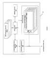
- FIG. 1shows an information processing system 110 configured to host one or more virtual machines.
- An information processing systemis an electronic device capable of processing, executing or otherwise handling information. Examples of information processing systems include a server computer, a personal computer (e.g., a desktop computer or a portable computer such as, for example, a laptop computer), a handheld computer, and/or a variety of other information handling systems known in the art.
- the information processing system 110 shownis representative of, one of, or a portion of, the information processing systems described above.
- the information processing system 110may include any or all of the following: (a) a processor 112 for executing and otherwise processing instructions, (b) a network interface 114 (e.g., circuitry) for communicating between the processor 112 and other devices, those other devices possibly located across the network 105 ; (c) a memory device 116 (e.g., FLASH memory, a random access memory (RAM) device or a read-only memory (ROM) device for storing information (e.g., instructions executed by processor 112 and data operated upon by processor 112 in response to such instructions)).
- the information processing system 110may also include a separate computer-readable medium 118 operably coupled to the processor 112 for storing information and instructions as described further below.
- the information processing system 110may include a plurality of input/output devices 120 a - n which are operably coupled to the processor 112 , for inputting or outputting information, such as a display device 120 a , a print device 120 b , or other electronic circuitry 120 c - n for performing other operations of the information processing system 110 known in the art.
- the computer-readable media and the processor 112are structurally and functionally interrelated with one another as described below in further detail, and the information processing system of the illustrative embodiment is structurally and functionally interrelated with a respective computer-readable medium similar to the manner in which the processor 112 is structurally and functionally interrelated with the computer-readable media 116 and 118 .
- the computer-readable mediamay be implemented using a hard disk drive, a memory device, and/or a variety of other computer-readable media known in the art, and when including functional descriptive material, data structures are created that define structural and functional interrelationships between such data structures and the computer-readable media (and other aspects of the system 100 ). Such interrelationships permit the data structures' functionality to be realized.
- the processor 112reads (e.g., accesses or copies) such functional descriptive material from the network interface 114 , the computer-readable media 118 onto the memory device 116 of the information processing system 110 , and the information processing system 110 (more particularly, the processor 112 ) performs its operations, as described elsewhere herein, in response to such material stored in the memory device of the information processing system 110 .
- the processor 112is capable of reading such functional descriptive material from (or through) the network 105 .
- the information processing system 110includes at least one type of computer-readable media that is non-transitory.
- the information processing system 110includes a hypervisor 130 .
- the hypervisor 130may be implemented in software, as a subsidiary information processing system, or in a tailored electrical circuit or as software instructions to be used in conjunction with a processor to create a hardware-software combination that implements the specific functionality described herein.
- softwaremay include software that is stored on a computer-readable medium, including the computer-readable medium 118 .
- the hypervisormay be included logically “below” a host operating system, as a host itself, as part of a larger host operating system, or as a program or process running “above” or “on top of” a host operating system. Examples of hypervisors include Xenserver, KVM, VMware, Microsoft's Hyper-V, and emulation programs such as QEMU.
- the hypervisor 130includes the functionality to add, remove, and modify a number of logical containers 132 a - n associated with the hypervisor. Zero, one, or many of the logical containers 132 a - n contain associated operating environments 134 a - n .
- the logical containers 132 a - ncan implement various interfaces depending upon the desired characteristics of the operating environment. In one embodiment, a logical container 132 implements a hardware-like interface, such that the associated operating environment 134 appears to be running on or within an information processing system such as the information processing system 110 .
- a logical container 134could implement an interface resembling an x86, x86-64, ARM, or other computer instruction set with appropriate RAM, busses, disks, and network devices.
- a corresponding operating environment 134 for this embodimentcould be an operating system such as Microsoft Windows, Linux, Linux-Android, or Mac OS X.
- a logical container 132implements an operating system-like interface, such that the associated operating environment 134 appears to be running on or within an operating system.
- this type of logical container 132could appear to be a Microsoft Windows, Linux, or Mac OS X operating system.
- Another possible operating systemincludes an Android operating system, which includes significant runtime functionality on top of a lower-level kernel.
- a corresponding operating environment 134could enforce separation between users and processes such that each process or group of processes appeared to have sole access to the resources of the operating system.
- a logical container 132implements a software-defined interface, such a language runtime or logical process that the associated operating environment 134 can use to run and interact with its environment.
- a corresponding operating environment 134would use the built-in threading, processing, and code loading capabilities to load and run code. Adding, removing, or modifying a logical container 132 may or may not also involve adding, removing, or modifying an associated operating environment 134 .
- these operating environmentswill be described in terms of an embodiment as “Virtual Machines,” or “VMs,” but this is simply one implementation among the options listed above.
- a VMhas one or more virtual network interfaces 136 . How the virtual network interface is exposed to the operating environment depends upon the implementation of the operating environment. In an operating environment that mimics a hardware computer, the virtual network interface 136 appears as one or more virtual network interface cards. In an operating environment that appears as an operating system, the virtual network interface 136 appears as a virtual character device or socket. In an operating environment that appears as a language runtime, the virtual network interface appears as a socket, queue, message service, or other appropriate construct.
- the virtual network interfaces (VNIs) 136may be associated with a virtual switch (Vswitch) at either the hypervisor or container level. The VNI 136 logically couples the operating environment 134 to the network, and allows the VMs to send and receive network traffic.
- the physical network interface card 114is also coupled to one or more VMs through a Vswitch.
- each VMincludes identification data for use naming, interacting, or referring to the VM. This can include the Media Access Control (MAC) address, the Internet Protocol (IP) address, and one or more unambiguous names or identifiers.
- MACMedia Access Control
- IPInternet Protocol
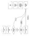
- the network operating environment 200includes multiple information processing systems 210 a - n , each of which correspond to a single information processing system 110 as described relative to FIG. 1 , including a hypervisor 130 , zero or more logical containers 132 and zero or more operating environments 134 .
- the information processing systems 210 a - nare connected via a communication medium 212 , typically implemented using a known network protocol such as Ethernet, Fibre Channel, Infiniband, or IEEE 1394.
- the network operating environment 200will be referred to as a “cluster” or “cloud” of operating environments.
- the clustermay also include a cluster monitor 214 and a network routing element 216 .
- the cluster monitor 214 and network routing element 216may be implemented as hardware, as software running on hardware, or may be implemented completely as software. In one implementation, one or both of the cluster monitor 214 or network routing element 216 is implemented in a logical container 132 using an operating environment 134 as described above. In another embodiment, one or both of the cluster monitor 214 or network routing element 216 is implemented so that the cluster corresponds to a group of physically co-located information processing systems, such as in a rack, row, or group of physical machines.
- the cluster monitor 214provides an interface to the cluster in general, and provides a single point of contact allowing someone outside the system to query and control any one of the information processing systems 210 , the logical containers 132 and the operating environments 134 . In one embodiment, the cluster monitor also provides monitoring and reporting capabilities.
- the network routing element 216allows the information processing systems 210 , the logical containers 132 and the operating environments 134 to be connected together in a network topology.
- the illustrated tree topologyis only one possible topology; the information processing systems and operating environments can be logically arrayed in a ring, in a star, in a graph, or in multiple logical arrangements through the use of vLANs.
- the clusteralso includes a cluster controller 218 .
- the cluster controlleris outside the cluster, and is used to store or provide identifying information associated with the different addressable elements in the cluster—specifically the cluster generally (addressable as the cluster monitor 214 ), the cluster network router (addressable as the network routing element 216 ), each information processing system 210 , and with each information processing system the associated logical containers 132 and operating environments 134 .
- the cluster controller 218is outside the cluster, and is used to store or provide identifying information associated with the different addressable elements in the cluster—specifically the cluster generally (addressable as the cluster monitor 214 ), the cluster network router (addressable as the network routing element 216 ), each information processing system 210 , and with each information processing system the associated logical containers 132 and operating environments 134 .
- the cluster controller 218includes a registry of VM information 219 .
- the registry 219is associated with but not included in the cluster controller 218 .
- the clusteralso includes one or more script processors 220 .
- the script processoris located in the hypervisor, but it is also contemplated to locate a script processor within an active VM or at a cluster level, for example in a piece of machinery associated with a rack or cluster.
- the script processor 220is implemented in a tailored electrical circuit or as software instructions to be used in conjunction with a processor to create a hardware-software combination that implements the specific functionality described herein. To the extent that one embodiment includes computer-executable instructions, those instructions may include software that is stored on a computer-readable medium. Further, one or more embodiments have associated with them a buffer 222 .
- the buffer 222can take the form of data structures, a memory, a computer-readable medium, or an off-script-processor facility.
- a language runtimeas a script processor 220 .
- the language runtimecan be run directly on top of the hypervisor, as a process in an active operating environment, or can be run from a low-power embedded processor.
- the script processor 220takes the form of a series of interoperating but discrete components, some or all of which may be implemented as software programs.
- an interoperating bash shell, gzip program, an rsync program, and a cryptographic accelerator chipare all components that may be used in a script processor 220 .
- the script processor 220is a discrete component, using a small amount of flash and a low power processor, such as a low-power ARM processor.
- This hardware-based script processorcan be embedded on a network interface card, built into the hardware of a rack, or provided as an add-on to the physical chips associated with an information processing system 210 . It is expected that in many embodiments, the script processor 220 will have an integrated battery and will be able to spend an extended period of time without drawing current.
- Various embodimentsalso contemplate the use of an embedded Linux or Linux-Android environment.
- FIGS. 3 a -3 fshow a series of flowcharts detailing the operations involved in waking or instantiating a VM according to one or more embodiments.
- FIGS. 3-7will be discussed with reference to the physical and logical infrastructure described relative to FIGS. 1 and 2 .
- FIG. 3 ashows a first embodiment wherein a VM is made available.
- the VMhas been predefined and preallocated, and is currently in sleep level S 4 or S 5 .
- the identifying information for this VMis stored within one of the cluster controller 218 , the network routing element 216 , the cluster monitor 214 , a hypervisor 130 or in a non-sleeping operating environment 134 .
- a suspended VMmay be powered on automatically when there is a request destined for that VM. Because the VM already has been provisioned, the identifying information for the VM (the MAC address, IP address, and/or any other unique identifiers) are already known.
- a messageis formatted addressing the VM. In a first embodiment, this is a magic packet, or a subnet-directed broadcast. In another embodiment, another message format is used, such as one of the formats described above.
- the network interface card associated with the information processing system 210 hosting the VMreceives the message.
- the messageis evaluated for whether it is a wakeup-only message, an indicator message, or a content message. If the message is a wakeup-only message, processing moves to step 360 . Otherwise, processing moves to step 340 .
- a first script processor 220examines the message. If the message is a content message, then it is put into a buffer 222 and processing moves to step 360 .
- processingmoves to step 350 .
- the received indicator messageis evaluated, any indicated values are retrieved and processed before moving on to step 360 . It may occur that one or more values are placed into a buffer 222 for the VM.
- the hypervisoractivates the logical container 132 associated with the VM.
- the hypervisoracting in concert with the activated logical container 132 , activates the associated operating environment 134 .
- any buffer contentsare evaluated, and processed or forwarded on to the operating environment 134 .
- the processends.
- FIG. 3 bshows a second embodiment wherein a VM is made available.
- the VMhas been predefined and preallocated, and is currently in sleep level S 4 or S 5 .
- stepshave the same number as in FIG. 3 a , the are the same; primary differences are highlighted below.
- a messageis formatted addressing the VM. This is done by going to step 311 .
- any necessary information regarding the location of the VMis looked up, including the MAC address, the IP address, and/or any unique identifiers associated with the VM, by querying the cluster controller 218 or the registry 219 .
- the processthen moves to step 314 , where the content message is formatted according to a protocol known in the art.
- the messageis an HTTP message, it is formatted according to the HTTP standard.
- An SMTP messageis formatted according to the SMTP standard, etc.
- the addressability of the messageis evaluated, and an appropriate wrapper is provided if necessary. For example, in a first embodiment in which the message is a WoL packet, it is put into a subnet directed broadcast. In a second embodiment in which the message is a WoL packet, the WoL packet is put into a routable wrapper or tunnel. In a third embodiment, a standard packet addressed to a VM that is not yet capable of responding is placed into a wrapper that addresses the hypervisor, the cluster monitor, or another associated entity that can receive a message.
- step 318the message is sent using the communication medium 212 .
- step 319the message is received by a receiver and unwrapped if necessary. If further routing is needed, steps 317 - 319 are repeated as necessary. The process then proceeds until step 380 .
- step 382the message is recognized as a content message, and the content message is provided to the VM for appropriate processing and response. The process then goes to step 390 and ends.
- FIG. 3 cshows a third embodiment wherein a VM is made available.
- the VMhas been predefined and preallocated, and is currently in sleep level S 4 or S 5 .
- stepshave the same number as in FIGS. 3 a -3 b , the are the same; only the differences are highlighted below.
- a messageis formatted addressing the VM. This is done by going to step 311 .
- any necessary information regarding the location of the VMis looked up, including the MAC address, the IP address, and/or any unique identifiers associated with the VM, by querying the cluster controller 218 or the registry 219 .
- a set of possible indicatorsis consulted.
- a messageis formatted using an indicator that specifies that the VM is to be transitioned to from information processing system 210 a to information processing system 210 b prior to awakening.
- thisis a magic packet, or a subnet-directed broadcast on a non-standard port, such as 12 , or using a non-standard EtherType.
- another message formatis used, such as one of the formats described above. Steps 317 - 319 are then followed as previously described.
- the network interface card associated with the information processing system 210 hosting the VMreceives the message.
- the messageis evaluated for whether it is a wakeup-only message, an indicator message, or a content message.
- step 360If the message is a wakeup-only message, processing moves to step 360 . Otherwise, processing moves to step 340 .
- a first script processor 220examines the message. If the message is a content message, then it is put into a buffer 222 and processing moves to step 360 . Otherwise, processing moves to step 350 .
- the received indicator messageis evaluated, any indicated values are retrieved and processed before moving on. In this embodiment, processing moves to step 361 , wherein the disk image associated with the VM is transferred via a shared medium or via the network to information processing system 210 b .
- the first script processor 220then moves to step 310 , and generates a wakeup message addressed to the VM as located on the new information processing system 210 b .
- the information processing system 210 athen moves to step 390 and ends. Information processing system 210 b then proceeds with steps 320 - 390 as described relative to FIG. 3 a and ends.
- FIG. 3 dshows a fourth embodiment wherein a VM is made available.
- the VMhas not been predefined and preallocated, and no particularized VM is available but sleeping.
- stepshave the same number as in FIGS. 3 a -3 c , the are the same; only the differences are highlighted below.
- a messageis formatted addressing the VM. This is done by going to step 311 .
- any necessary information regarding the location of the VMis looked up, including the MAC address, the IP address, and/or any unique identifiers associated with the VM.
- a messageis formatted using an indicator that specifies that the VM is to be instantiated prior to awakening. In a first embodiment, this is a magic packet, or a subnet-directed broadcast on a non-standard port, such as 13 , or using a non-standard EtherType. In another embodiment, another message format is used, such as one of the formats described above.
- the indicatoris specialized so as to indicate a particular process or template to use when instantiating the VM.
- one embodimenthas a standardized “object storage” VM, a “compute node” VM, and a “manager VM.”
- the portBy changing the port, the EtherType, or the message content, the type of VM to instantiate is specified.
- one or more script processors 220has been provided with an instantiation script. By changing the port, the EtherType, or the message content, the specific script to use is specified.
- a custom protocolis used to transfer information about the VM to be instantiated, including necessary identifying information such as the MAC address to use, the IP address to use, or any other identifying information to associate with the new VM.
- Steps 317 - 319are then followed as previously described.
- the network interface card associated with the information processing system 210 hosting the VMreceives the message.
- the messageis evaluated for whether it is a wakeup-only message, an indicator message, or a content message. In this embodiment, further processing is always required, so the process moves always to step 340 .
- a first script processor 220examines the message.
- step 350the received indicator message is evaluated, any indicated values are retrieved and processed. This is done by moving to step 351 .
- the instantiation messageis evaluated to determine how the target VM is to be instantiated. As discussed above relative to step 315 , this can be done by specifying a script that gets executed to create a VM, by specifying a template image, or some combination. Accordingly, step 351 identifies the correct script, template, and parameter values from packet indications, packet contents, and pre-shared information.
- step 352the instantiation process is started.
- a templateis loaded, copied, or otherwise made available.
- a scriptis used, the script is loaded and executed. It is expected that the instantiation process may take one or more parameters. To the extent that these parameters are not already provided, the necessary values can be retrieved via the network.
- a logical containeris created using the provided instantiation process.
- an operating environmentis created within the logical container using the provided instantiation process.
- the operating environmentis customized or configured as necessary, completing the instantiation of the VM. The process then moves to step 360 .
- the hypervisoractivates the logical container 132 associated with the VM, if the logical container was not already activated during the instantiation process.
- the hypervisoracting in concert with the activated logical container 132 , activates the associated operating environment 134 , if the operating environment was not already activated during the instantiation process.
- any buffer contentsare evaluated, and processed or forwarded on to the operating environment 134 . Note that the instantiation process may be separate from the contents of the message addressed to the VM; for this purpose the message or part of the message may need to stay in the buffer until the VM is available at step 380 , when VM processes any necessary messages addressed to it.
- the processends.
- FIG. 3 eshows a fifth embodiment wherein a VM is put to sleep.
- the VMis currently active state G 0 .
- stepshave the same number as in FIGS. 3 a -3 d , the are the same; only the differences are highlighted below.
- a messageis formatted addressing the VM. This is done by going to step 311 .
- any necessary information regarding the location of the VMis looked up, including the MAC address, the IP address, and/or any unique identifiers associated with the VM, by querying the cluster controller 218 or the registry 219 .
- a set of possible indicatorsis consulted.
- a messageis formatted using an indicator that specifies that the VM power state is to be changed.
- thisis a magic packet, or a subnet-directed broadcast on a non-standard port, such as 14 , or using a non-standard EtherType.
- another message formatis used, such as one of the formats described above.
- the indicatoris specialized so as to indicate a particular power state (such as S 4 or S 5 ) to use when changing the power state of the VM. Steps 317 - 319 are then followed as previously described.
- the network interface card associated with the information processing system 210 hosting the VMreceives the message.
- step 350the received indicator message is evaluated, any indicated values are retrieved and processed before moving on to step 360 . This is done by moving to step 358 , wherein the hypervisor sends the appropriate messages to send a VM into the specified power mode. This embodiment then moves to step 390 and ends.
- FIG. 3 fshows a sixth embodiment wherein a VM is decommissioned or destroyed.
- the VMis in any power state.
- stepshave the same number as in FIGS. 3 a -3 e , the are the same; only the differences are highlighted below.
- a messageis formatted addressing the VM. This is done by going to step 311 .
- any necessary information regarding the location of the VMis looked up, including the MAC address, the IP address, and/or any unique identifiers associated with the VM, by querying the cluster controller 218 or the registry 219 .
- a set of possible indicatorsis consulted.
- a messageis formatted using an indicator that specifies that a specified VM is to be destroyed. Note that this can be a special case of a power state change indicator. In another embodiment, it is a separate indicator. In a first embodiment, this is a magic packet, or a subnet-directed broadcast on a non-standard port, such as 15 , or using a non-standard EtherType. In another embodiment, another message format is used, such as one of the formats described above. Steps 317 - 319 are then followed as previously described.
- the network interface card associated with the information processing system 210 hosting the VMreceives the message.
- the received indicator messageis evaluated, any indicated values are retrieved and processed before moving on to step 360 . This is done by moving to step 359 , wherein the hypervisor removes the VM from memory and/or from disk. This embodiment then moves to step 390 and ends.
- a “move” instruction for a live VMcould be formatted as “sleep, move, wake.” This move instruction can be associated with a single message, or can also be performed using a sequence of messages.
- one or more script processors 220can delay the action on a particular message to satisfy prerequisites associated with fulfilling the message. For example, an entire rack of servers may be powered down. In response to a single message sent to a VM associated with that rack, the rack can be powered up, an information processing system 210 can be powered up, a VM instantiated, and the message responded to, at the cost of the latency associated with powering on the necessary equipment and instantiating the VM.
- the combination of auto-instantiation, and sleep at a VM, information processing device, and rack/cluster levelallows higher energy savings because entire areas of equipment can be powered down when not in use but dynamically brought up when needed.
- the processes describedcan be used to automatically scale a cluster or cloud computing system both up and down, simply by addressing a system that is desired. If a desired non-existent system is addressed, the cluster transparently brings up the desired system and uses it to respond to the message.
- VMis a particular operating environment 134 within a particular logical container 132 .
- Host Machine Acontains a VM to be moved to Host Machine B.
- the VMis running and live on Host Machine A.
- Host Machine Bis prepared to receive the VM.
- In Host Machine Atakes a snapshot of the VM and starts the process of transferring the primary disk of the snapshot to Host Machine B.
- a snapshotis the defined as the state of a system at a particular point in time.
- a new logical container 132 on Host Machine Bit may not be necessary to create a new logical container 132 on Host Machine B. If Host Machine B is operating, then an existing or new logical container can be defined as the target for the snapshot. Otherwise, a new logical container can be defined as described below. The configuration of the logical container on host B is based off the original configuration on Host Machine A.
- Hypervisor Ahas direct access to the disk and memory images of the running VM
- Host Machine Bhas direct access to the disk and memory images on Host Machine B.
- Hypervisor Acan make a snapshot of the disk and memory of the VM while the VM is running and provide access directly to Hypervisor B so that the appropriate data can be transferred. Because the snapshot is a point of time capture from the VM running, the majority of the data can be copied over to host machine two using the communication medium 212 . An incremental update from the snapshot of disk and data is then provided from Hypervisor A to Hypervisor B after the initial snapshot is complete.
- the VMis powered on (brought into a G 0 state). Under the control of one of the cluster monitor 214 , the network routing element 216 , or the cluster controller 218 , the location of the active VM is updated from Host Machine A to Host Machine B, and the migration process is complete. If the VM was in a sleep state (S 1 -S 5 ), been suspended, the VM can be resumed from the memory state giving the appearance that the VM was never shut down and therefore retaining the uptime of the machine. To the user of the VM, the instance will appear to have been online the entire time with a brief period of network loss.
- FIGS. 4 a -4 cshow a series of flowcharts detailing the operations showing various embodiments of the snapshot and incremental update procedure.
- FIG. 4 ashows a first embodiment wherein a VM is migrated from Host Machine A to Host Machine B.
- the VMhas is currently active (in state G 0 ).
- the identifying information for this VMis stored within one of the cluster controller 218 , the network routing element 216 , the cluster monitor 214 , a hypervisor 130 or in a non-sleeping operating environment 134 .
- a messageis formatted addressing the VM. In a first embodiment, this is a magic packet, or a subnet-directed broadcast. In another embodiment, another message format is used, such as a unicast message, a multicast message, broadcast message, ARP request, or ICMP ping.
- the messagecan be at a higher level in the stack, such as an HTTP request, XMLRPC request, SOAP, CORBA, AMQP or ZeroMQ message, or any other protocol known in the art.
- This messagecontains either content or an indicator identifying the destination for the VM.
- the network interface card associated with the Host Machine Areceives the message.
- the messageis evaluated to determine how to address Host Machine B and the necessary information for the transfer.
- a script processor 220is used to create an initial snapshot the disk and memory associated with the VM. In one embodiment, this is done by snapshotting a logical volume associated with the VM and a memory image and then mounting them to a directory.
- a script processor 220is used to prepare Host Machine B, including allocating and configuring a logical container 132 .
- the snapshotting process on Host Machine A and the preparation of Host Machine Bcan be done by the same script processor, or may be done by multiple script processors in parallel.
- the initial snapshotis transferred from Host Machine A to Host Machine B via the communications medium 212 .
- the transfer of the initial snapshotis performed using the rsync protocol.
- another protocolsuch as FTP, TFTP, SFTP, SCP, or HTTP is used.
- the hypervisor on Host Machine Asuspends the VM.
- the VMis suspended by placing the VM in ACPI power state S 4 or S 5 .
- an incremental snapshotis transferred from Host Machine A to Host Machine B, updating the state of Host Machine B so that it matches the state of Host Machine A.
- the hypervisor on Host Machine Bactivates the VM. In one embodiment, the activation is performed by placing the VM in power state G 0 .
- the clusteris updated to reflect the new location of the VM. In one embodiment, updating information within or associated with one of the cluster controller 218 , the network routing element 216 , the cluster monitor 214 , a hypervisor 130 or in a non-sleeping operating environment 134 .
- the migrationis complete and the process ends.
- FIG. 4 bshows a second embodiment wherein a VM is migrated from Host Machine A to Host Machine B.
- stepshave the same number as in FIG. 4 a , they are the same; primary differences are highlighted below.
- the VM(logical container 132 and operating environment 134 ) are of any type previously described. In one embodiment, steps 410 - 450 are performed as described above.
- the hypervisor on Host Machine Asuspends the VM. In one embodiment, the VM is suspended by using the hypervisor to stop all processing within the VM; the disk and memory contents are briefly frozen in a consistent state without the VM being aware.
- an incremental snapshotis transferred from Host Machine A to Host Machine B, updating the state of Host Machine B so that it matches the state of Host Machine A.
- the memory state of the VM on Host Machine Ais transferred to Host Machine B.
- the hypervisor on Host Machine Bactivates the VM. In one embodiment, the activation is performed by resuming processing of the VM on Host Machine B from the previously-frozen consistent state.
- the clusteris updated to reflect the new location of the VM.
- the migrationis complete and the process ends.
- FIG. 4 cshows a third embodiment wherein a VM is migrated from Host Machine A to Host Machine B.
- stepshave the same number as in FIG. 4 a or 4 b , they are the same; primary differences are highlighted below.
- the VM(logical container 132 and operating environment 134 ) are of any type previously described. In one embodiment, steps 410 - 450 are performed as described above. Instead of going to step 460 , in this embodiment, processing moves to step 462 .
- the operating environment 132 on Host Machine Bis activated.
- a live synchronization protocolis used to synchronize the changes within the VMs running on Host Machine A and Host Machine B.
- this functionalitymay use one or more of the implementation strategies described below.
- thisis done by transferring a first incremental snapshot using the live data from Host Machine A to Host Machine B to minimize the changes between the environments at Host Machine A and Host Machine B.
- the changes to the state of Host Machine Aare logged and the logs provided to Host Machine B.
- Host Machine Breplays the logs to synchronize its state with that of Host Machine A.
- a third implementationinserts a messaging shim in the operating environment of Host Machine A such that the changes are expressed as a series of messages directed to both Host Machine A and Host Machine B.
- the changesare executed simultaneously on both host machines.
- the effective speed of the host machinesis lowered so that synchronization can take place more effectively.
- a NUMA, cache coherency, or snooping protocolis used.
- the operating environment of Host Machine Acould have its effective memory space expanded to include the memory space of Host Machine B, for example by using the virtual memory system to map the virtual memory of Host Machine A to Host Machine B.
- a sixth implementationcould effect live migration of portions of memory by selectively increasing memory pressure on different processes. As those processes are swapped out to memory, they would actually be written to the swap memory of Host Machine B.
- step 463the state of Host Machine B matches or is more advanced than the state of Host Machine A.
- step 490the cluster is updated to reflect the new location of the VM. In one embodiment, this includes updating information within or associated with one of the cluster controller 218 , the network routing element 216 , the cluster monitor 214 , a hypervisor 130 or in a non-sleeping operating environment 134 .
- step 490may include one or more iterations of step 491 , wherein the information regarding a particular port, service, or process occur selectively to reflect the ongoing live migration.
- step 499the migration is complete and the process ends.
- the hypervisor 130may also have access to a script processor 220 .
- FIG. 5shows part of the hypervisor-logical container interface in greater detail.
- Hypervisor 130includes hypervisor-specific configuration options 502 .
- Running on top of the hypervisorare the logical containers 132 a - n .
- Each logical containerhas a set of associated configuration data, the container configurations 504 a - n .
- each operating environment 134 a - nmay also have associated configuration data 506 a - n .
- hypervisor 130may have access to a multi-hypervisor configuration mechanism over hypervisor control connection 508 .
- the hypervisor 130has hardware and software methods, generally made available through software APIs, which allow it programmatic access to and control of logical containers 132 a - n and the associated container configurations 504 a - n .
- This programmatic access and controlis shown via the arrows between hypervisor 130 , logical containers 132 a - n and container configurations 504 a - n .
- Further embodimentsalso give programmatic control and access to the hypervisor configuration 502 , operating environments 134 a - n , and operating environment configuration data 506 a - n . Finally, this control and access may be provided over the hypervisor control connection 508 .
- a logical container 132 and/or an operating environment 134may not have connectivity or may not support the programmatic access described. Further, the disk and/or memory of the logical container may be encrypted for security purposes.
- the methods described belowallow pre-configuration data related to the virtualization product to be provided at instantiation or configuration time to the hypervisor 130 , which is then customized by a script processor 220 to the specific operating environment.
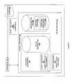
- a hypervisor 130as described above and a single logical container 132 and operating environment 134 (collectively, the “virtual machine 602 ”).
- the hypervisor 130is in communication with a configuration disk 604 and a virtual machine disk 606 .
- One or more script processors 220are available to the hypervisor 130 , the logical container 132 , and the operating environment 134 . In one embodiment, it is advantageous to place a script processor 220 within the logical container 132 or the operating environment 134 so that programmatic access is available within the security context of the container or operating environment.
- a script processor 220 within the logical container 132 or operating environment 134will be said to be running “in” the virtual machine 602 .
- the customized settings of the virtual machine 602are stored within configuration disk 604 .
- the customized settingsinclude one or more of hypervisor-specific configuration options 502 , container configurations 504 , or operating environment configurations 506 .
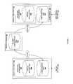
- configuration data corresponding to the configuration disk 604is uploaded to online storage 610 .
- online storage 610is a cloud storage system.
- the online storageis on a different information processing system, perhaps including its own hypervisor 130 , logical containers 132 and operating environments 134 .
- the configuration information corresponding to the configuration disk 604now available as stored configuration disk 614 , is downloaded from the online storage 610 and added to the new instance.
- an additional disk image(e.g., additional VHD) is delivered along with a basic disk image.
- the additional disk imageincludes the configuration information injected by the provisioning system.
- the additional disk image containing the configuration informationis 32 mb or 64 mb in size. However, in other instances, the disk image containing the configuration information is smaller or larger in size.
- the information on the configuration disk 614is mounted by the virtual machine to become configuration disk 624 .
- the information from configuration disk 624is utilized by a script processor 220 to configure networking, set administrator access, inject files to a virtual machine disk, and/or otherwise configure the virtualization product in accordance with the configuration information corresponding to the configuration disk 624 .
- the script processoris running in the virtual machine 622 .
- the format of the configuration information as stored in the cloud and uploaded to the configuration disk 614can be any format, it is advantageous to use a file system format that is readable by a majority of modern operating systems.
- the configuration disk 614 of the instance of the virtualization productcan be written to by the user.
- the usercan store additional configuration information about the instance or applications hosted on the instance.
- the configuration disk 614can be backed up independently of the baseline configuration information initially loaded on the configuration disk.
- the provisioning systemoverwrites any old instance configuration information such that the user can use the application information to quickly customize the instance.
- the modified version of the configuration informationcan be applied to another instance in a similar manner.
- standard configurationssuch as those used for automated creation of instances, can be provisioned or pre-provisioned and made available for use.
- the flowchart 800begins at step 802 where the system uploads a configuration disk to cloud storage and registers the configuration disk with a service provider.
- the systemdownloads, at step 804 , the configuration disk from the cloud storage and adds it to the new instance.
- the systemadds the configuration disk to the hypervisor associated with the new instance.
- an script processor 220 associated with the hypervisorreads the configuration disk and modifies the virtualization product of the hypervisor in accordance with the configuration parameters of the configuration disk. Subsequently, the new instance of the virtualization product will run on the hypervisor with the configuration parameters defined by the configuration disk.
- configuration informationwill be provided through a readable socket.
- configuration informationwill be provided through a memory-mapped area.
- configuration informationwill be provided through a configuration data structure that is available to script processor 220 .
- the configuration informationis provided as an “overlay” over the raw information.
- one implementationuses a RAM, flash, or disk-backed live overlay or union filesystem over another, more generic filesystem.
- the generic filesystemcan be stored or accessed as a read-only filesystem, enhancing security and maintainability.
- the overlaytakes the form of the shadowing of variables, settings, or other information available to the VM.
Landscapes
- Engineering & Computer Science (AREA)
- Theoretical Computer Science (AREA)
- Software Systems (AREA)
- Physics & Mathematics (AREA)
- General Engineering & Computer Science (AREA)
- General Physics & Mathematics (AREA)
- Human Computer Interaction (AREA)
- Computer Networks & Wireless Communication (AREA)
- Signal Processing (AREA)
- Quality & Reliability (AREA)
- Stored Programmes (AREA)
- Power Sources (AREA)
Abstract
Description
- G0 (S0): Working
- G1, or Sleeping, subdivided into the four states S1 through S4:
- S1: All processor caches are flushed, and the CPU(s) stop executing instructions. Power to the CPU(s) and RAM is maintained; devices that do not indicate they must remain on may be powered down.
- S2: CPU powered off
- S3: Commonly referred to as Standby, Sleep, or Suspend to RAM. RAM remains powered.
- S4: Hibernation or Suspend to Disk. All content of main memory is saved to non-volatile memory such as a hard drive, and is powered down.
- G2 (S5), Soft Off: Most systems are powered down, but some components remain powered so the computer can “wake” from input from the keyboard, clock, modem, LAN, or USB device.
- G3, Mechanical Off: The computer's power consumption approaches close to zero, to the point that the power cord can be removed and the system is safe for dis-assembly (typically, only the real-time clock is running off its own small battery).
Claims (17)
Priority Applications (1)
| Application Number | Priority Date | Filing Date | Title |
|---|---|---|---|
| US14/664,389US10191756B2 (en) | 2011-03-08 | 2015-03-20 | Hypervisor-agnostic method of configuring a virtual machine |
Applications Claiming Priority (6)
| Application Number | Priority Date | Filing Date | Title |
|---|---|---|---|
| US201161450166P | 2011-03-08 | 2011-03-08 | |
| US201161479294P | 2011-04-26 | 2011-04-26 | |
| US201161480784P | 2011-04-29 | 2011-04-29 | |
| US13/270,737US9552215B2 (en) | 2011-03-08 | 2011-10-11 | Method and system for transferring a virtual machine |
| US13/270,779US9015709B2 (en) | 2011-03-08 | 2011-10-11 | Hypervisor-agnostic method of configuring a virtual machine |
| US14/664,389US10191756B2 (en) | 2011-03-08 | 2015-03-20 | Hypervisor-agnostic method of configuring a virtual machine |
Related Parent Applications (1)
| Application Number | Title | Priority Date | Filing Date |
|---|---|---|---|
| US13/270,779ContinuationUS9015709B2 (en) | 2011-03-08 | 2011-10-11 | Hypervisor-agnostic method of configuring a virtual machine |
Publications (2)
| Publication Number | Publication Date |
|---|---|
| US20150242228A1 US20150242228A1 (en) | 2015-08-27 |
| US10191756B2true US10191756B2 (en) | 2019-01-29 |
Family
ID=46797075
Family Applications (6)
| Application Number | Title | Priority Date | Filing Date |
|---|---|---|---|
| US13/270,737Active2032-02-26US9552215B2 (en) | 2011-03-08 | 2011-10-11 | Method and system for transferring a virtual machine |
| US13/270,779Expired - Fee RelatedUS9015709B2 (en) | 2011-03-08 | 2011-10-11 | Hypervisor-agnostic method of configuring a virtual machine |
| US13/467,686Active2034-04-03US9268586B2 (en) | 2011-03-08 | 2012-05-09 | Wake-on-LAN and instantiate-on-LAN in a cloud computing system |
| US14/664,389ActiveUS10191756B2 (en) | 2011-03-08 | 2015-03-20 | Hypervisor-agnostic method of configuring a virtual machine |
| US15/048,060Active2032-04-14US10078529B2 (en) | 2011-03-08 | 2016-02-19 | Wake-on-LAN and instantiate-on-LAN in a cloud computing system |
| US15/412,359ActiveUS10157077B2 (en) | 2011-03-08 | 2017-01-23 | Method and system for transferring a virtual machine |
Family Applications Before (3)
| Application Number | Title | Priority Date | Filing Date |
|---|---|---|---|
| US13/270,737Active2032-02-26US9552215B2 (en) | 2011-03-08 | 2011-10-11 | Method and system for transferring a virtual machine |
| US13/270,779Expired - Fee RelatedUS9015709B2 (en) | 2011-03-08 | 2011-10-11 | Hypervisor-agnostic method of configuring a virtual machine |
| US13/467,686Active2034-04-03US9268586B2 (en) | 2011-03-08 | 2012-05-09 | Wake-on-LAN and instantiate-on-LAN in a cloud computing system |
Family Applications After (2)
| Application Number | Title | Priority Date | Filing Date |
|---|---|---|---|
| US15/048,060Active2032-04-14US10078529B2 (en) | 2011-03-08 | 2016-02-19 | Wake-on-LAN and instantiate-on-LAN in a cloud computing system |
| US15/412,359ActiveUS10157077B2 (en) | 2011-03-08 | 2017-01-23 | Method and system for transferring a virtual machine |
Country Status (1)
| Country | Link |
|---|---|
| US (6) | US9552215B2 (en) |
Cited By (3)
| Publication number | Priority date | Publication date | Assignee | Title |
|---|---|---|---|---|
| US20210279088A1 (en)* | 2020-03-05 | 2021-09-09 | Hewlett Packard Enterprise Development Lp | Persistent volume plugin for containers |
| US11409619B2 (en) | 2020-04-29 | 2022-08-09 | The Research Foundation For The State University Of New York | Recovering a virtual machine after failure of post-copy live migration |
| US12346718B2 (en) | 2018-06-01 | 2025-07-01 | The Research Foundation For The State University Of New York | Multi-hypervisor virtual machines that run on multiple co-located hypervisors |
Families Citing this family (211)
| Publication number | Priority date | Publication date | Assignee | Title |
|---|---|---|---|---|
| US7757269B1 (en) | 2006-02-02 | 2010-07-13 | Mcafee, Inc. | Enforcing alignment of approved changes and deployed changes in the software change life-cycle |
| US7895573B1 (en) | 2006-03-27 | 2011-02-22 | Mcafee, Inc. | Execution environment file inventory |
| US8332929B1 (en) | 2007-01-10 | 2012-12-11 | Mcafee, Inc. | Method and apparatus for process enforced configuration management |
| US9424154B2 (en) | 2007-01-10 | 2016-08-23 | Mcafee, Inc. | Method of and system for computer system state checks |
| US7975033B2 (en)* | 2007-10-23 | 2011-07-05 | Virtudatacenter Holdings, L.L.C. | System and method for initializing and maintaining a series of virtual local area networks contained in a clustered computer system |
| US8938800B2 (en) | 2010-07-28 | 2015-01-20 | Mcafee, Inc. | System and method for network level protection against malicious software |
| US8925101B2 (en) | 2010-07-28 | 2014-12-30 | Mcafee, Inc. | System and method for local protection against malicious software |
| CN102404162A (en)* | 2010-09-17 | 2012-04-04 | 鸿富锦精密工业(深圳)有限公司 | Test system and method for network wakeup function of computer |
| US8983536B2 (en) | 2010-10-22 | 2015-03-17 | Google Technology Holdings LLC | Resource management in a multi-operating environment |
| US9112830B2 (en) | 2011-02-23 | 2015-08-18 | Mcafee, Inc. | System and method for interlocking a host and a gateway |
| US9286182B2 (en)* | 2011-06-17 | 2016-03-15 | Microsoft Technology Licensing, Llc | Virtual machine snapshotting and analysis |
| US9594881B2 (en)* | 2011-09-09 | 2017-03-14 | Mcafee, Inc. | System and method for passive threat detection using virtual memory inspection |
| US8713668B2 (en) | 2011-10-17 | 2014-04-29 | Mcafee, Inc. | System and method for redirected firewall discovery in a network environment |
| US20130166504A1 (en)* | 2011-12-27 | 2013-06-27 | RiverMeadow Software, Inc. | Systems and methods for virtual machine migration |
| US9066287B2 (en) | 2012-01-24 | 2015-06-23 | Qualcomm Incorporated | Systems and methods of relay selection and setup |
| US9396041B2 (en)* | 2012-02-01 | 2016-07-19 | Google Technology Holdings LLC | Optimization of resource usage in a multi-environment computing system |
| US9262195B2 (en)* | 2012-02-28 | 2016-02-16 | Red Hat Israel, Ltd. | Manageable external wake of virtual machines |
| US20130238785A1 (en)* | 2012-03-06 | 2013-09-12 | Rackspace Us, Inc. | System and Method for Metadata Discovery and Metadata-Aware Scheduling |
| US8677449B1 (en) | 2012-03-19 | 2014-03-18 | Google Inc. | Exposing data to virtual machines |
| US9311122B2 (en) | 2012-03-26 | 2016-04-12 | Oracle International Corporation | System and method for providing a scalable signaling mechanism for virtual machine migration in a middleware machine environment |
| US9432304B2 (en)* | 2012-03-26 | 2016-08-30 | Oracle International Corporation | System and method for supporting live migration of virtual machines based on an extended host channel adaptor (HCA) model |
| US9110604B2 (en) | 2012-09-28 | 2015-08-18 | Emc Corporation | System and method for full virtual machine backup using storage system functionality |
| US9104331B2 (en) | 2012-09-28 | 2015-08-11 | Emc Corporation | System and method for incremental virtual machine backup using storage system functionality |
| US8739272B1 (en) | 2012-04-02 | 2014-05-27 | Mcafee, Inc. | System and method for interlocking a host and a gateway |
| US9094302B2 (en)* | 2012-04-16 | 2015-07-28 | Dell Products, Lp | System and method to discover virtual machine instantiations and configure network service level agreements |
| US9027024B2 (en)* | 2012-05-09 | 2015-05-05 | Rackspace Us, Inc. | Market-based virtual machine allocation |
| US9164790B2 (en)* | 2012-06-07 | 2015-10-20 | Red Hat Israel, Ltd. | Live virtual machine template creation |
| US9794796B2 (en) | 2012-06-13 | 2017-10-17 | Qualcomm, Incorporation | Systems and methods for simplified store and forward relays |
| US10338940B2 (en)* | 2012-06-27 | 2019-07-02 | International Business Machines Corporation | Adjusting adminstrative access based on workload migration |
| US8910161B2 (en)* | 2012-07-13 | 2014-12-09 | Vmware, Inc. | Scan systems and methods of scanning virtual machines |
| US9510271B2 (en)* | 2012-08-30 | 2016-11-29 | Qualcomm Incorporated | Systems, apparatus, and methods for address format detection |
| KR101438461B1 (en)* | 2012-10-15 | 2014-11-03 | (주) 글루시스 | Cloud stroage system having electric power control switching module |
| US9075789B2 (en) | 2012-12-11 | 2015-07-07 | General Dynamics C4 Systems, Inc. | Methods and apparatus for interleaving priorities of a plurality of virtual processors |
| US8973146B2 (en) | 2012-12-27 | 2015-03-03 | Mcafee, Inc. | Herd based scan avoidance system in a network environment |
| US8972780B2 (en)* | 2013-01-31 | 2015-03-03 | Red Hat Israel, Ltd. | Low-latency fault-tolerant virtual machines |
| US9183062B2 (en) | 2013-02-25 | 2015-11-10 | International Business Machines Corporation | Automated application reconfiguration |
| US9582219B2 (en) | 2013-03-12 | 2017-02-28 | Netapp, Inc. | Technique for rapidly converting between storage representations in a virtualized computing environment |
| US9342341B2 (en)* | 2013-03-14 | 2016-05-17 | Alcatel Lucent | Systems and methods for deploying an application and an agent on a customer server in a selected network |
| US9990221B2 (en) | 2013-03-15 | 2018-06-05 | Oracle International Corporation | System and method for providing an infiniband SR-IOV vSwitch architecture for a high performance cloud computing environment |
| US9430255B1 (en) | 2013-03-15 | 2016-08-30 | Google Inc. | Updating virtual machine generated metadata to a distribution service for sharing and backup |
| CN104079507B (en)* | 2013-03-27 | 2019-04-09 | 联想企业解决方案(新加坡)私人有限公司 | The method and apparatus of synchronous IP information |
| US9081599B2 (en) | 2013-05-28 | 2015-07-14 | Red Hat Israel, Ltd. | Adjusting transfer rate of virtual machine state in virtual machine migration |
| US9274824B2 (en)* | 2013-06-27 | 2016-03-01 | Verizon Patent And Licensing Inc. | Network technology standard operating environment |
| US9454549B1 (en) | 2013-06-28 | 2016-09-27 | Emc Corporation | Metadata reconciliation |
| US9424056B1 (en) | 2013-06-28 | 2016-08-23 | Emc Corporation | Cross site recovery of a VM |
| US9477693B1 (en)* | 2013-06-28 | 2016-10-25 | Emc Corporation | Automated protection of a VBA |
| GB2516842A (en) | 2013-07-31 | 2015-02-11 | Ibm | Deployment of software images with distinct configuration logic |
| US9280372B2 (en) | 2013-08-12 | 2016-03-08 | Amazon Technologies, Inc. | Request processing techniques |
| US10346148B2 (en) | 2013-08-12 | 2019-07-09 | Amazon Technologies, Inc. | Per request computer system instances |
| US9348634B2 (en) | 2013-08-12 | 2016-05-24 | Amazon Technologies, Inc. | Fast-booting application image using variation points in application source code |
| US9705755B1 (en) | 2013-08-14 | 2017-07-11 | Amazon Technologies, Inc. | Application definition deployment with request filters employing base groups |
| US9733964B2 (en)* | 2013-08-27 | 2017-08-15 | Red Hat, Inc. | Live snapshot of a virtual machine |
| US9842032B2 (en)* | 2013-08-27 | 2017-12-12 | Red Hat, Inc. | Memory first live snapshot |
| US9503371B2 (en) | 2013-09-04 | 2016-11-22 | Nicira, Inc. | High availability L3 gateways for logical networks |
| US9577845B2 (en) | 2013-09-04 | 2017-02-21 | Nicira, Inc. | Multiple active L3 gateways for logical networks |
| US9405568B2 (en) | 2013-09-13 | 2016-08-02 | Microsoft Technology Licensing, Llc | Multi-tenant network stack |
| US9483352B2 (en)* | 2013-09-27 | 2016-11-01 | Fisher-Rosemont Systems, Inc. | Process control systems and methods |
| WO2015060857A1 (en) | 2013-10-24 | 2015-04-30 | Mcafee, Inc. | Agent assisted malicious application blocking in a network environment |
| CN104601622B (en) | 2013-10-31 | 2018-04-17 | 国际商业机器公司 | A kind of method and system for disposing cluster |
| CN104636125B (en)* | 2013-11-13 | 2018-03-23 | 联想(北京)有限公司 | A kind of information processing method and device |
| US9225597B2 (en)* | 2014-03-14 | 2015-12-29 | Nicira, Inc. | Managed gateways peering with external router to attract ingress packets |
| US9590901B2 (en) | 2014-03-14 | 2017-03-07 | Nicira, Inc. | Route advertisement by managed gateways |
| US9864622B2 (en)* | 2014-04-24 | 2018-01-09 | International Business Machines Corporation | Administering virtual machines in a distributed computing environment |
| US10542049B2 (en) | 2014-05-09 | 2020-01-21 | Nutanix, Inc. | Mechanism for providing external access to a secured networked virtualization environment |
| US9841991B2 (en)* | 2014-05-12 | 2017-12-12 | Netapp, Inc. | Techniques for virtual machine migration |
| US10216531B2 (en) | 2014-05-12 | 2019-02-26 | Netapp, Inc. | Techniques for virtual machine shifting |
| US20150339069A1 (en)* | 2014-05-22 | 2015-11-26 | Kabushiki Kaisha Toshiba | Memory system and method |
| US9454439B2 (en) | 2014-05-28 | 2016-09-27 | Unitrends, Inc. | Disaster recovery validation |
| US20170199770A1 (en)* | 2014-06-23 | 2017-07-13 | Getclouder Ltd. | Cloud hosting systems featuring scaling and load balancing with containers |
| US9448834B2 (en)* | 2014-06-27 | 2016-09-20 | Unitrends, Inc. | Automated testing of physical servers using a virtual machine |
| US9760443B2 (en)* | 2014-06-28 | 2017-09-12 | Vmware, Inc. | Using a recovery snapshot during live migration |
| US10152343B2 (en)* | 2014-08-13 | 2018-12-11 | Hitachi, Ltd. | Method and apparatus for managing IT infrastructure in cloud environments by migrating pairs of virtual machines |
| US9723009B2 (en) | 2014-09-09 | 2017-08-01 | Oracle International Corporation | System and method for providing for secure network communication in a multi-tenant environment |
| US9600312B2 (en)* | 2014-09-30 | 2017-03-21 | Amazon Technologies, Inc. | Threading as a service |
| US9678773B1 (en) | 2014-09-30 | 2017-06-13 | Amazon Technologies, Inc. | Low latency computational capacity provisioning |
| US9715402B2 (en) | 2014-09-30 | 2017-07-25 | Amazon Technologies, Inc. | Dynamic code deployment and versioning |
| US9830193B1 (en) | 2014-09-30 | 2017-11-28 | Amazon Technologies, Inc. | Automatic management of low latency computational capacity |
| US10048974B1 (en) | 2014-09-30 | 2018-08-14 | Amazon Technologies, Inc. | Message-based computation request scheduling |
| US9323556B2 (en) | 2014-09-30 | 2016-04-26 | Amazon Technologies, Inc. | Programmatic event detection and message generation for requests to execute program code |
| US9146764B1 (en) | 2014-09-30 | 2015-09-29 | Amazon Technologies, Inc. | Processing event messages for user requests to execute program code |
| US9256467B1 (en) | 2014-11-11 | 2016-02-09 | Amazon Technologies, Inc. | System for managing and scheduling containers |
| GB2558163A (en)* | 2014-11-12 | 2018-07-11 | Ibm | Dynamically assigning network addresses |
| US9798567B2 (en) | 2014-11-25 | 2017-10-24 | The Research Foundation For The State University Of New York | Multi-hypervisor virtual machines |
| US9413626B2 (en) | 2014-12-05 | 2016-08-09 | Amazon Technologies, Inc. | Automatic management of resource sizing |
| JP6609918B2 (en)* | 2014-12-17 | 2019-11-27 | 富士通株式会社 | Storage system, storage management device, and storage management program |
| US9971621B1 (en)* | 2015-02-02 | 2018-05-15 | Amazon Technologies, Inc. | Hotpooling virtual machines |
| US9588790B1 (en) | 2015-02-04 | 2017-03-07 | Amazon Technologies, Inc. | Stateful virtual compute system |
| US9733967B2 (en) | 2015-02-04 | 2017-08-15 | Amazon Technologies, Inc. | Security protocols for low latency execution of program code |
| US9146769B1 (en) | 2015-04-02 | 2015-09-29 | Shiva Shankar | Systems and methods for copying a source machine to a target virtual machine |
| US10038628B2 (en) | 2015-04-04 | 2018-07-31 | Nicira, Inc. | Route server mode for dynamic routing between logical and physical networks |
| US9930103B2 (en) | 2015-04-08 | 2018-03-27 | Amazon Technologies, Inc. | Endpoint management system providing an application programming interface proxy service |
| US9785476B2 (en) | 2015-04-08 | 2017-10-10 | Amazon Technologies, Inc. | Endpoint management system and virtual compute system |
| CN104881254B (en)* | 2015-05-27 | 2018-09-07 | 北京百度网讯科技有限公司 | Date storage method and device |
| US9923811B2 (en) | 2015-06-27 | 2018-03-20 | Nicira, Inc. | Logical routers and switches in a multi-datacenter environment |
| US20180210766A1 (en)* | 2015-07-23 | 2018-07-26 | Hewlett Packard Enterprise Development Lp | Migration for cloud management systems |
| JP6319770B2 (en)* | 2015-07-27 | 2018-05-09 | 日本電信電話株式会社 | Container migration system and method |
| CN106548262B (en) | 2015-09-21 | 2020-11-06 | 阿里巴巴集团控股有限公司 | Scheduling method, device and system for resources for processing tasks |
| US10754701B1 (en) | 2015-12-16 | 2020-08-25 | Amazon Technologies, Inc. | Executing user-defined code in response to determining that resources expected to be utilized comply with resource restrictions |
| US9811434B1 (en) | 2015-12-16 | 2017-11-07 | Amazon Technologies, Inc. | Predictive management of on-demand code execution |
| US10261782B2 (en) | 2015-12-18 | 2019-04-16 | Amazon Technologies, Inc. | Software container registry service |
| US9910713B2 (en) | 2015-12-21 | 2018-03-06 | Amazon Technologies, Inc. | Code execution request routing |
| US10067801B1 (en) | 2015-12-21 | 2018-09-04 | Amazon Technologies, Inc. | Acquisition and maintenance of compute capacity |
| US10540165B2 (en) | 2016-02-12 | 2020-01-21 | Nutanix, Inc. | Virtualized file server rolling upgrade |
| US10891145B2 (en) | 2016-03-30 | 2021-01-12 | Amazon Technologies, Inc. | Processing pre-existing data sets at an on demand code execution environment |
| US11132213B1 (en) | 2016-03-30 | 2021-09-28 | Amazon Technologies, Inc. | Dependency-based process of pre-existing data sets at an on demand code execution environment |
| CN107273146B (en)* | 2016-04-08 | 2021-11-19 | 中兴通讯股份有限公司 | Virtual machine upgrading method and device |
| US9817592B1 (en) | 2016-04-27 | 2017-11-14 | Netapp, Inc. | Using an intermediate virtual disk format for virtual disk conversion |
| US10333849B2 (en) | 2016-04-28 | 2019-06-25 | Nicira, Inc. | Automatic configuration of logical routers on edge nodes |
| US10091161B2 (en) | 2016-04-30 | 2018-10-02 | Nicira, Inc. | Assignment of router ID for logical routers |
| US10135837B2 (en) | 2016-05-17 | 2018-11-20 | Amazon Technologies, Inc. | Versatile autoscaling for containers |
| US11218418B2 (en) | 2016-05-20 | 2022-01-04 | Nutanix, Inc. | Scalable leadership election in a multi-processing computing environment |
| US10282229B2 (en) | 2016-06-28 | 2019-05-07 | Amazon Technologies, Inc. | Asynchronous task management in an on-demand network code execution environment |
| US10560320B2 (en) | 2016-06-29 | 2020-02-11 | Nicira, Inc. | Ranking of gateways in cluster |
| US10102040B2 (en) | 2016-06-29 | 2018-10-16 | Amazon Technologies, Inc | Adjusting variable limit on concurrent code executions |
| US10277708B2 (en) | 2016-06-30 | 2019-04-30 | Amazon Technologies, Inc. | On-demand network code execution with cross-account aliases |
| US10460113B2 (en)* | 2016-08-16 | 2019-10-29 | International Business Machines Corporation | Security fix of a container in a virtual machine environment |
| US10884787B1 (en) | 2016-09-23 | 2021-01-05 | Amazon Technologies, Inc. | Execution guarantees in an on-demand network code execution system |
| US11119813B1 (en) | 2016-09-30 | 2021-09-14 | Amazon Technologies, Inc. | Mapreduce implementation using an on-demand network code execution system |
| US10412022B1 (en) | 2016-10-19 | 2019-09-10 | Amazon Technologies, Inc. | On-premises scaling using a versatile scaling service and an application programming interface management service |
| US10409642B1 (en) | 2016-11-22 | 2019-09-10 | Amazon Technologies, Inc. | Customer resource monitoring for versatile scaling service scaling policy recommendations |
| US10728090B2 (en) | 2016-12-02 | 2020-07-28 | Nutanix, Inc. | Configuring network segmentation for a virtualization environment |
| US11562034B2 (en) | 2016-12-02 | 2023-01-24 | Nutanix, Inc. | Transparent referrals for distributed file servers |
| US10824455B2 (en) | 2016-12-02 | 2020-11-03 | Nutanix, Inc. | Virtualized server systems and methods including load balancing for virtualized file servers |
| US11568073B2 (en) | 2016-12-02 | 2023-01-31 | Nutanix, Inc. | Handling permissions for virtualized file servers |
| US11294777B2 (en) | 2016-12-05 | 2022-04-05 | Nutanix, Inc. | Disaster recovery for distributed file servers, including metadata fixers |
| US11288239B2 (en) | 2016-12-06 | 2022-03-29 | Nutanix, Inc. | Cloning virtualized file servers |
| US11281484B2 (en) | 2016-12-06 | 2022-03-22 | Nutanix, Inc. | Virtualized server systems and methods including scaling of file system virtual machines |
| US10425225B1 (en)* | 2016-12-14 | 2019-09-24 | Amazon Technologies, Inc. | Synchronizable hardware security module |
| US10228963B2 (en) | 2016-12-19 | 2019-03-12 | Red Hat, Inc. | Efficient hypervisor reporting |
| US10237123B2 (en) | 2016-12-21 | 2019-03-19 | Nicira, Inc. | Dynamic recovery from a split-brain failure in edge nodes |
| US10616045B2 (en) | 2016-12-22 | 2020-04-07 | Nicira, Inc. | Migration of centralized routing components of logical router |
| CA3054071A1 (en)* | 2017-03-28 | 2018-10-04 | Cloudjumper Corporation | Methods and systems for providing wake-on-demand access to session servers |
| US10909165B2 (en)* | 2017-06-20 | 2021-02-02 | Red Hat, Inc. | Sharing filesystems between containers |
| US11113087B2 (en)* | 2017-07-12 | 2021-09-07 | Amzetta Technologies, Llc | Techniques of discovering VDI systems and synchronizing operation information of VDI systems by sending discovery messages and information messages |
| US10572289B2 (en)* | 2017-08-28 | 2020-02-25 | Red Hat Israel, Ltd. | Guest-initiated announcement of virtual machine migration |
| KR102480415B1 (en) | 2017-11-23 | 2022-12-23 | 삼성전자주식회사 | Electronic device and method for managing computing resources of at least one cloud server that provices cloud services |
| US10564946B1 (en) | 2017-12-13 | 2020-02-18 | Amazon Technologies, Inc. | Dependency handling in an on-demand network code execution system |
| US10353678B1 (en) | 2018-02-05 | 2019-07-16 | Amazon Technologies, Inc. | Detecting code characteristic alterations due to cross-service calls |
| US10831898B1 (en) | 2018-02-05 | 2020-11-10 | Amazon Technologies, Inc. | Detecting privilege escalations in code including cross-service calls |
| US10733085B1 (en) | 2018-02-05 | 2020-08-04 | Amazon Technologies, Inc. | Detecting impedance mismatches due to cross-service calls |
| US10725752B1 (en) | 2018-02-13 | 2020-07-28 | Amazon Technologies, Inc. | Dependency handling in an on-demand network code execution system |
| US10776091B1 (en) | 2018-02-26 | 2020-09-15 | Amazon Technologies, Inc. | Logging endpoint in an on-demand code execution system |
| US10901768B1 (en)* | 2018-03-23 | 2021-01-26 | Amazon Technologies, Inc. | Migrating servers from user networks to a user-selected type of hypervisor at a service provider network |
| US11086826B2 (en) | 2018-04-30 | 2021-08-10 | Nutanix, Inc. | Virtualized server systems and methods including domain joining techniques |
| US10853115B2 (en) | 2018-06-25 | 2020-12-01 | Amazon Technologies, Inc. | Execution of auxiliary functions in an on-demand network code execution system |
| US10649749B1 (en) | 2018-06-26 | 2020-05-12 | Amazon Technologies, Inc. | Cross-environment application of tracing information for improved code execution |
| US11146569B1 (en) | 2018-06-28 | 2021-10-12 | Amazon Technologies, Inc. | Escalation-resistant secure network services using request-scoped authentication information |
| US10949237B2 (en) | 2018-06-29 | 2021-03-16 | Amazon Technologies, Inc. | Operating system customization in an on-demand network code execution system |
| US11194680B2 (en) | 2018-07-20 | 2021-12-07 | Nutanix, Inc. | Two node clusters recovery on a failure |
| US11099870B1 (en) | 2018-07-25 | 2021-08-24 | Amazon Technologies, Inc. | Reducing execution times in an on-demand network code execution system using saved machine states |
| US10901781B2 (en) | 2018-09-13 | 2021-01-26 | Cisco Technology, Inc. | System and method for migrating a live stateful container |
| US11086616B2 (en)* | 2018-09-25 | 2021-08-10 | Vmware, Inc. | Near zero downtime application upgrade |
| US11243953B2 (en) | 2018-09-27 | 2022-02-08 | Amazon Technologies, Inc. | Mapreduce implementation in an on-demand network code execution system and stream data processing system |
| US11099917B2 (en) | 2018-09-27 | 2021-08-24 | Amazon Technologies, Inc. | Efficient state maintenance for execution environments in an on-demand code execution system |
| US11770447B2 (en) | 2018-10-31 | 2023-09-26 | Nutanix, Inc. | Managing high-availability file servers |
| US11943093B1 (en) | 2018-11-20 | 2024-03-26 | Amazon Technologies, Inc. | Network connection recovery after virtual machine transition in an on-demand network code execution system |
| US10884812B2 (en) | 2018-12-13 | 2021-01-05 | Amazon Technologies, Inc. | Performance-based hardware emulation in an on-demand network code execution system |
| US11010188B1 (en) | 2019-02-05 | 2021-05-18 | Amazon Technologies, Inc. | Simulated data object storage using on-demand computation of data objects |
| US12327133B1 (en) | 2019-03-22 | 2025-06-10 | Amazon Technologies, Inc. | Application gateways in an on-demand network code execution system |
| US11861386B1 (en) | 2019-03-22 | 2024-01-02 | Amazon Technologies, Inc. | Application gateways in an on-demand network code execution system |
| CN109992354B (en)* | 2019-04-09 | 2021-02-19 | 腾讯科技(深圳)有限公司 | Container processing method, device, main body server, system and storage medium |
| US11119809B1 (en) | 2019-06-20 | 2021-09-14 | Amazon Technologies, Inc. | Virtualization-based transaction handling in an on-demand network code execution system |
| US11115404B2 (en) | 2019-06-28 | 2021-09-07 | Amazon Technologies, Inc. | Facilitating service connections in serverless code executions |
| US11190609B2 (en) | 2019-06-28 | 2021-11-30 | Amazon Technologies, Inc. | Connection pooling for scalable network services |
| US11159528B2 (en) | 2019-06-28 | 2021-10-26 | Amazon Technologies, Inc. | Authentication to network-services using hosted authentication information |
| US11669365B1 (en) | 2019-08-26 | 2023-06-06 | Amazon Technologies, Inc. | Task pool for managed compute instances |
| US11593137B2 (en) | 2019-08-30 | 2023-02-28 | Nutanix, Inc. | Hypervisor hibernation |
| US11250007B1 (en) | 2019-09-27 | 2022-02-15 | Amazon Technologies, Inc. | On-demand execution of object combination code in output path of object storage service |
| US10996961B2 (en) | 2019-09-27 | 2021-05-04 | Amazon Technologies, Inc. | On-demand indexing of data in input path of object storage service |
| US11394761B1 (en) | 2019-09-27 | 2022-07-19 | Amazon Technologies, Inc. | Execution of user-submitted code on a stream of data |
| US11550944B2 (en) | 2019-09-27 | 2023-01-10 | Amazon Technologies, Inc. | Code execution environment customization system for object storage service |
| US11263220B2 (en) | 2019-09-27 | 2022-03-01 | Amazon Technologies, Inc. | On-demand execution of object transformation code in output path of object storage service |
| US11023416B2 (en) | 2019-09-27 | 2021-06-01 | Amazon Technologies, Inc. | Data access control system for object storage service based on owner-defined code |
| US11055112B2 (en) | 2019-09-27 | 2021-07-06 | Amazon Technologies, Inc. | Inserting executions of owner-specified code into input/output path of object storage service |
| US11360948B2 (en) | 2019-09-27 | 2022-06-14 | Amazon Technologies, Inc. | Inserting owner-specified data processing pipelines into input/output path of object storage service |
| US11386230B2 (en) | 2019-09-27 | 2022-07-12 | Amazon Technologies, Inc. | On-demand code obfuscation of data in input path of object storage service |
| US11106477B2 (en) | 2019-09-27 | 2021-08-31 | Amazon Technologies, Inc. | Execution of owner-specified code during input/output path to object storage service |
| US11416628B2 (en) | 2019-09-27 | 2022-08-16 | Amazon Technologies, Inc. | User-specific data manipulation system for object storage service based on user-submitted code |
| US10908927B1 (en) | 2019-09-27 | 2021-02-02 | Amazon Technologies, Inc. | On-demand execution of object filter code in output path of object storage service |
| US11023311B2 (en) | 2019-09-27 | 2021-06-01 | Amazon Technologies, Inc. | On-demand code execution in input path of data uploaded to storage service in multiple data portions |
| US11656892B1 (en) | 2019-09-27 | 2023-05-23 | Amazon Technologies, Inc. | Sequential execution of user-submitted code and native functions |
| US10942795B1 (en) | 2019-11-27 | 2021-03-09 | Amazon Technologies, Inc. | Serverless call distribution to utilize reserved capacity without inhibiting scaling |
| US11119826B2 (en) | 2019-11-27 | 2021-09-14 | Amazon Technologies, Inc. | Serverless call distribution to implement spillover while avoiding cold starts |
| CN110928728A (en)* | 2019-11-27 | 2020-03-27 | 上海英方软件股份有限公司 | Virtual machine copying and switching method and system based on snapshot |
| US11714682B1 (en) | 2020-03-03 | 2023-08-01 | Amazon Technologies, Inc. | Reclaiming computing resources in an on-demand code execution system |
| US11188391B1 (en) | 2020-03-11 | 2021-11-30 | Amazon Technologies, Inc. | Allocating resources to on-demand code executions under scarcity conditions |
| US11775640B1 (en) | 2020-03-30 | 2023-10-03 | Amazon Technologies, Inc. | Resource utilization-based malicious task detection in an on-demand code execution system |
| US11870679B2 (en) | 2020-04-06 | 2024-01-09 | VMware LLC | Primary datacenter for logical router |
| US11768809B2 (en) | 2020-05-08 | 2023-09-26 | Nutanix, Inc. | Managing incremental snapshots for fast leader node bring-up |
| US11797401B2 (en)* | 2020-06-24 | 2023-10-24 | EMC IP Holding Company LLC | True zero RTO: planned failover |
| CN111786904B (en)* | 2020-07-07 | 2021-07-06 | 上海道客网络科技有限公司 | System and method for realizing container dormancy and awakening |
| US11972266B2 (en) | 2020-10-02 | 2024-04-30 | Nutanix, Inc. | Hibernating and resuming nodes of a computing cluster |
| US12248435B2 (en) | 2021-03-31 | 2025-03-11 | Nutanix, Inc. | File analytics systems and methods |
| US11593270B1 (en) | 2020-11-25 | 2023-02-28 | Amazon Technologies, Inc. | Fast distributed caching using erasure coded object parts |
| US11550713B1 (en) | 2020-11-25 | 2023-01-10 | Amazon Technologies, Inc. | Garbage collection in distributed systems using life cycled storage roots |
| US12131192B2 (en) | 2021-03-18 | 2024-10-29 | Nutanix, Inc. | Scope-based distributed lock infrastructure for virtualized file server |
| US12248434B2 (en) | 2021-03-31 | 2025-03-11 | Nutanix, Inc. | File analytics systems including examples providing metrics adjusted for application operation |
| US12367108B2 (en) | 2021-03-31 | 2025-07-22 | Nutanix, Inc. | File analytics systems and methods including retrieving metadata from file system snapshots |
| US12197398B2 (en) | 2021-03-31 | 2025-01-14 | Nutanix, Inc. | Virtualized file servers and methods to persistently store file system event data |
| US12242455B2 (en) | 2021-03-31 | 2025-03-04 | Nutanix, Inc. | File analytics systems and methods including receiving and processing file system event data in order |
| US11388210B1 (en) | 2021-06-30 | 2022-07-12 | Amazon Technologies, Inc. | Streaming analytics using a serverless compute system |
| US12117972B2 (en) | 2021-08-19 | 2024-10-15 | Nutanix, Inc. | File server managers and systems for managing virtualized file servers |
| US20230066137A1 (en) | 2021-08-19 | 2023-03-02 | Nutanix, Inc. | User interfaces for disaster recovery of distributed file servers |
| US12141041B2 (en)* | 2021-10-05 | 2024-11-12 | Memverge, Inc. | Efficiency and reliability improvement in computing service |
| US12019882B2 (en)* | 2021-11-15 | 2024-06-25 | VMware LLC | Force provisioning virtual objects in degraded stretched clusters |
| US11968280B1 (en) | 2021-11-24 | 2024-04-23 | Amazon Technologies, Inc. | Controlling ingestion of streaming data to serverless function executions |
| US12015603B2 (en) | 2021-12-10 | 2024-06-18 | Amazon Technologies, Inc. | Multi-tenant mode for serverless code execution |
| US12153690B2 (en) | 2022-01-24 | 2024-11-26 | Nutanix, Inc. | Consistent access control lists across file servers for local users in a distributed file server environment |
| US12182264B2 (en) | 2022-03-11 | 2024-12-31 | Nutanix, Inc. | Malicious activity detection, validation, and remediation in virtualized file servers |
| US12189499B2 (en) | 2022-07-29 | 2025-01-07 | Nutanix, Inc. | Self-service restore (SSR) snapshot replication with share-level file system disaster recovery on virtualized file servers |
| US12381878B1 (en) | 2023-06-27 | 2025-08-05 | Amazon Technologies, Inc. | Architecture for selective use of private paths between cloud services |
Citations (39)
| Publication number | Priority date | Publication date | Assignee | Title |
|---|---|---|---|---|
| US6032044A (en) | 1995-08-19 | 2000-02-29 | Nortel Networks Corporation | Cellular communications system with screening of unauthorized services |
| US6446092B1 (en) | 1996-11-01 | 2002-09-03 | Peerdirect Company | Independent distributed database system |
| US6795966B1 (en) | 1998-05-15 | 2004-09-21 | Vmware, Inc. | Mechanism for restoring, porting, replicating and checkpointing computer systems using state extraction |
| US20050138310A1 (en) | 2003-12-17 | 2005-06-23 | Takashi Horiuchi | Backup system and method and program |
| US6917963B1 (en) | 1999-10-05 | 2005-07-12 | Veritas Operating Corporation | Snapshot image for the application state of unshareable and shareable data |
| US20050268298A1 (en) | 2004-05-11 | 2005-12-01 | International Business Machines Corporation | System, method and program to migrate a virtual machine |
| US20060005189A1 (en) | 2004-06-30 | 2006-01-05 | Microsoft Corporation | Systems and methods for voluntary migration of a virtual machine between hosts with common storage connectivity |
| US20060122927A1 (en) | 2004-12-06 | 2006-06-08 | Bernardo Huberman | System and method for allocating resources in a distributed computational system using proportional share auctions |
| US7093086B1 (en) | 2002-03-28 | 2006-08-15 | Veritas Operating Corporation | Disaster recovery and backup using virtual machines |
| US20070094467A1 (en) | 2005-10-20 | 2007-04-26 | Yasuo Yamasaki | Method for rolling back from snapshot with log |
| US20070226320A1 (en) | 2003-10-31 | 2007-09-27 | Yuval Hager | Device, System and Method for Storage and Access of Computer Files |
| US20080052322A1 (en) | 2006-08-17 | 2008-02-28 | Gusciora Paul H | Conflict resolution in database replication through autonomous node qualified folding |
| US20080126547A1 (en) | 2001-09-12 | 2008-05-29 | Vmware | Resource allocation in computers |
| US20080222375A1 (en) | 2007-02-21 | 2008-09-11 | Deutsche Telekom Ag | Method and system for the transparent migration of virtual machines storage |
| US20080256534A1 (en)* | 2007-04-12 | 2008-10-16 | International Business Machines Corporation | Method for improved image-customization by use of embedded metadata |
| US20080320583A1 (en)* | 2007-06-22 | 2008-12-25 | Vipul Sharma | Method for Managing a Virtual Machine |
| US20090037680A1 (en) | 2007-07-31 | 2009-02-05 | Vmware, Inc. | Online virtual machine disk migration |
| US7577722B1 (en) | 2002-04-05 | 2009-08-18 | Vmware, Inc. | Provisioning of computer systems using virtual machines |
| US20090228532A1 (en) | 2008-03-07 | 2009-09-10 | Hitachi, Ltd | Storage System |
| US20090313445A1 (en) | 2008-06-11 | 2009-12-17 | Vmware, Inc. | System and Method for Improving Memory Locality of Virtual Machines |
| US20100082922A1 (en) | 2008-09-30 | 2010-04-01 | Vmware, Inc. | Virtual machine migration using local storage |
| US20100094948A1 (en) | 2008-10-10 | 2010-04-15 | International Business Machines Corporation | Workload migration using on demand remote paging |
| US20100103781A1 (en) | 2008-10-24 | 2010-04-29 | Oracle International Corporation | Time synchronization in cluster systems |
| US20100131649A1 (en) | 2008-11-26 | 2010-05-27 | James Michael Ferris | Systems and methods for embedding a cloud-based resource request in a specification language wrapper |
| US20100217866A1 (en) | 2009-02-24 | 2010-08-26 | Thyagarajan Nandagopal | Load Balancing in a Multiple Server System Hosting an Array of Services |
| EP2239866A1 (en) | 2008-01-30 | 2010-10-13 | Alcatel Lucent | Long-time statistical csi assistant mu-mimo scheduling method, base station and user device |
| US20100306354A1 (en) | 2009-05-28 | 2010-12-02 | Dehaan Michael Paul | Methods and systems for flexible cloud management with power management support |
| US20110047340A1 (en)* | 2009-08-21 | 2011-02-24 | James Robert Olson | Proxy Backup of Virtual Disk Image Files on NAS Devices |
| US20110153697A1 (en) | 2005-09-15 | 2011-06-23 | Computer Assoicates Think, Inc. | Automated Filer Technique for Use in Virtualized Appliances and Applications |
| US8015383B2 (en) | 2007-06-27 | 2011-09-06 | International Business Machines Corporation | System, method and program to manage virtual memory allocated by a virtual machine control program |
| US8073934B1 (en)* | 2008-10-20 | 2011-12-06 | Amazon Technologies, Inc. | Automated load balancing architecture |
| US20120054306A1 (en) | 2010-08-30 | 2012-03-01 | Vmware, Inc. | Error handling methods for virtualized computer systems employing space-optimized block devices |
| US20120084381A1 (en) | 2010-09-30 | 2012-04-05 | Microsoft Corporation | Virtual Desktop Configuration And Operation Techniques |
| US20120209812A1 (en)* | 2011-02-16 | 2012-08-16 | Microsoft Corporation | Incremental virtual machine backup supporting migration |
| US20120272244A1 (en) | 2011-03-28 | 2012-10-25 | International Business Machines Corporation | Virtual machine placement to improve memory utilization |
| US8364639B1 (en) | 2007-10-11 | 2013-01-29 | Parallels IP Holdings GmbH | Method and system for creation, analysis and navigation of virtual snapshots |
| US8438216B2 (en) | 2009-05-20 | 2013-05-07 | Kaseya International Limited | Remote management of virtual machines hosted in a private network |
| US8538919B1 (en) | 2009-05-16 | 2013-09-17 | Eric H. Nielsen | System, method, and computer program for real time remote recovery of virtual computing machines |
| US9547562B1 (en)* | 2010-08-11 | 2017-01-17 | Dell Software Inc. | Boot restore system for rapidly restoring virtual machine backups |
Family Cites Families (7)
| Publication number | Priority date | Publication date | Assignee | Title |
|---|---|---|---|---|
| US6101585A (en)* | 1997-11-04 | 2000-08-08 | Adaptec, Inc. | Mechanism for incremental backup of on-line files |
| US8191063B2 (en)* | 2007-09-30 | 2012-05-29 | Symantex Corporation | Method for migrating a plurality of virtual machines by associating files and state information with a single logical container |
| US8069362B2 (en)* | 2008-02-26 | 2011-11-29 | Sap Ag | Automated electrical power savings in virtualization environments |
| US8327356B2 (en)* | 2008-03-20 | 2012-12-04 | Embotics Corporation | Method and system for supporting Wake-on-LAN in a virtualized environment |
| US8577845B2 (en)* | 2008-06-13 | 2013-11-05 | Symantec Operating Corporation | Remote, granular restore from full virtual machine backup |
| US8566821B2 (en)* | 2008-11-11 | 2013-10-22 | Netapp Inc. | Cloning virtual machines |
| US8924534B2 (en)* | 2009-10-27 | 2014-12-30 | Vmware, Inc. | Resource optimization and monitoring in virtualized infrastructure |
- 2011
- 2011-10-11USUS13/270,737patent/US9552215B2/enactiveActive
- 2011-10-11USUS13/270,779patent/US9015709B2/ennot_activeExpired - Fee Related
- 2012
- 2012-05-09USUS13/467,686patent/US9268586B2/enactiveActive
- 2015
- 2015-03-20USUS14/664,389patent/US10191756B2/enactiveActive
- 2016
- 2016-02-19USUS15/048,060patent/US10078529B2/enactiveActive
- 2017
- 2017-01-23USUS15/412,359patent/US10157077B2/enactiveActive
Patent Citations (40)
| Publication number | Priority date | Publication date | Assignee | Title |
|---|---|---|---|---|
| US6032044A (en) | 1995-08-19 | 2000-02-29 | Nortel Networks Corporation | Cellular communications system with screening of unauthorized services |
| US6446092B1 (en) | 1996-11-01 | 2002-09-03 | Peerdirect Company | Independent distributed database system |
| US6795966B1 (en) | 1998-05-15 | 2004-09-21 | Vmware, Inc. | Mechanism for restoring, porting, replicating and checkpointing computer systems using state extraction |
| US6917963B1 (en) | 1999-10-05 | 2005-07-12 | Veritas Operating Corporation | Snapshot image for the application state of unshareable and shareable data |
| US20080126547A1 (en) | 2001-09-12 | 2008-05-29 | Vmware | Resource allocation in computers |
| US7093086B1 (en) | 2002-03-28 | 2006-08-15 | Veritas Operating Corporation | Disaster recovery and backup using virtual machines |
| US7577722B1 (en) | 2002-04-05 | 2009-08-18 | Vmware, Inc. | Provisioning of computer systems using virtual machines |
| US20070226320A1 (en) | 2003-10-31 | 2007-09-27 | Yuval Hager | Device, System and Method for Storage and Access of Computer Files |
| US20050138310A1 (en) | 2003-12-17 | 2005-06-23 | Takashi Horiuchi | Backup system and method and program |
| US20050268298A1 (en) | 2004-05-11 | 2005-12-01 | International Business Machines Corporation | System, method and program to migrate a virtual machine |
| US20060005189A1 (en) | 2004-06-30 | 2006-01-05 | Microsoft Corporation | Systems and methods for voluntary migration of a virtual machine between hosts with common storage connectivity |
| US20060122927A1 (en) | 2004-12-06 | 2006-06-08 | Bernardo Huberman | System and method for allocating resources in a distributed computational system using proportional share auctions |
| US7634430B2 (en) | 2004-12-06 | 2009-12-15 | Hewlett-Packard Development Company, L.P. | System and method for allocating resources in a distributed computational system using proportional share auctions |
| US20110153697A1 (en) | 2005-09-15 | 2011-06-23 | Computer Assoicates Think, Inc. | Automated Filer Technique for Use in Virtualized Appliances and Applications |
| US20070094467A1 (en) | 2005-10-20 | 2007-04-26 | Yasuo Yamasaki | Method for rolling back from snapshot with log |
| US20080052322A1 (en) | 2006-08-17 | 2008-02-28 | Gusciora Paul H | Conflict resolution in database replication through autonomous node qualified folding |
| US20080222375A1 (en) | 2007-02-21 | 2008-09-11 | Deutsche Telekom Ag | Method and system for the transparent migration of virtual machines storage |
| US20080256534A1 (en)* | 2007-04-12 | 2008-10-16 | International Business Machines Corporation | Method for improved image-customization by use of embedded metadata |
| US20080320583A1 (en)* | 2007-06-22 | 2008-12-25 | Vipul Sharma | Method for Managing a Virtual Machine |
| US8015383B2 (en) | 2007-06-27 | 2011-09-06 | International Business Machines Corporation | System, method and program to manage virtual memory allocated by a virtual machine control program |
| US20090037680A1 (en) | 2007-07-31 | 2009-02-05 | Vmware, Inc. | Online virtual machine disk migration |
| US8364639B1 (en) | 2007-10-11 | 2013-01-29 | Parallels IP Holdings GmbH | Method and system for creation, analysis and navigation of virtual snapshots |
| EP2239866A1 (en) | 2008-01-30 | 2010-10-13 | Alcatel Lucent | Long-time statistical csi assistant mu-mimo scheduling method, base station and user device |
| US20090228532A1 (en) | 2008-03-07 | 2009-09-10 | Hitachi, Ltd | Storage System |
| US20090313445A1 (en) | 2008-06-11 | 2009-12-17 | Vmware, Inc. | System and Method for Improving Memory Locality of Virtual Machines |
| US20100082922A1 (en) | 2008-09-30 | 2010-04-01 | Vmware, Inc. | Virtual machine migration using local storage |
| US20100094948A1 (en) | 2008-10-10 | 2010-04-15 | International Business Machines Corporation | Workload migration using on demand remote paging |
| US8073934B1 (en)* | 2008-10-20 | 2011-12-06 | Amazon Technologies, Inc. | Automated load balancing architecture |
| US20100103781A1 (en) | 2008-10-24 | 2010-04-29 | Oracle International Corporation | Time synchronization in cluster systems |
| US20100131649A1 (en) | 2008-11-26 | 2010-05-27 | James Michael Ferris | Systems and methods for embedding a cloud-based resource request in a specification language wrapper |
| US20100217866A1 (en) | 2009-02-24 | 2010-08-26 | Thyagarajan Nandagopal | Load Balancing in a Multiple Server System Hosting an Array of Services |
| US8538919B1 (en) | 2009-05-16 | 2013-09-17 | Eric H. Nielsen | System, method, and computer program for real time remote recovery of virtual computing machines |
| US8438216B2 (en) | 2009-05-20 | 2013-05-07 | Kaseya International Limited | Remote management of virtual machines hosted in a private network |
| US20100306354A1 (en) | 2009-05-28 | 2010-12-02 | Dehaan Michael Paul | Methods and systems for flexible cloud management with power management support |
| US20110047340A1 (en)* | 2009-08-21 | 2011-02-24 | James Robert Olson | Proxy Backup of Virtual Disk Image Files on NAS Devices |
| US9547562B1 (en)* | 2010-08-11 | 2017-01-17 | Dell Software Inc. | Boot restore system for rapidly restoring virtual machine backups |
| US20120054306A1 (en) | 2010-08-30 | 2012-03-01 | Vmware, Inc. | Error handling methods for virtualized computer systems employing space-optimized block devices |
| US20120084381A1 (en) | 2010-09-30 | 2012-04-05 | Microsoft Corporation | Virtual Desktop Configuration And Operation Techniques |
| US20120209812A1 (en)* | 2011-02-16 | 2012-08-16 | Microsoft Corporation | Incremental virtual machine backup supporting migration |
| US20120272244A1 (en) | 2011-03-28 | 2012-10-25 | International Business Machines Corporation | Virtual machine placement to improve memory utilization |
Non-Patent Citations (31)
| Title |
|---|
| An, Bo, et al., "Automated Negotiation with Decommitment for Dynamic Resource Allocation in Cloud Computing," University of Massachusetts, Amherst, p. 981-988, 2010. |
| Buyya, Rajkumar, et al., "Market-Oriented cloud Computing: Vision, Hype, and Reality for Delivering IT Services as computing Utilities," GRIDS Laboratory, University of Melbourne, Australia, 2008 9 pages. |
| Chun, Brent N., et al., "Market-based Proportional Resources Sharing for Clusters," University of California, Berkeley, 1999, 19 pages. |
| Chun, Brent Nee, "Market-based Cluster Resource Management," dissertation for Ph.D. requirements, University of California, Berkeley, Fall 2001, 191 pages. |
| Clark et al, "Live Migration of Virtual Machine," USENIX Association, NSDI'05: 2nd Symposium on Networked Systems Design & Implementation, p. 273-286, 2005. |
| Cliff, Dave, "Minimal-Intelligence Agents for Bargaining Behaviors in Market-Based Environments," University of Sussex, Brighton, UK, Jun. 1997, 134 pages. |
| Cordeiro et al., "Open Source Cloud Computing Platforms", 2010 Ninth International Conference on Grid and Cloud Computing, Nov. 1, 2010, pp. 366-371. |
| Crago et al., "Heterogeneous Cloud Computing", 2011 IEEE International Conference on Cluster Computing, Sep. 26, 2011, pp. 378-385. |
| European Search Report received in European Application No. 12001564.9, dated Nov. 28, 2012, 5 pages. |
| He, Linli, et al., "Forming Resource-Sharing Coalitions: a Distributed Resource Allocation Mechanism for Self-Interested Agents in Computational Grids," ACM Symposium on Applied Computing, Mar. 13-17, 2005, Santa Fe, NM, 1-58113-964-0/05/0003, p. 84-91. |
| International Search Report and Written Opinion issued for PCT/US2013/029274 dated Jun. 21, 2013, 12 pages. |
| International Search Report and Written Opinion issued for PCT/US2014/012514 dated Jan. 22, 2014, 12 pages. |
| International Search Report and Written Opinion issued for PCT/US2014/012514 dated Jun. 4, 2014, 12 pages. |
| Kurose, James F. et al, "A Microeconomic Approach to Optimal Resource Allocation in Distributed Computer Systems", IEEE Transactions on Computers, May 1989, p. 705-717, vol. 38 No. 5. |
| Kurose, James F., et al., "A Microeconomic Approach to Optimal Resource Allocation in Distributed Computer Systems," IEEE Transactions on Computers, vol. 38, No. 5, May, 1989, p. 705-717. |
| Lai, Kevin, et al., "Tycoon: a Distributed Market-based Resource Allocation System," HP Labs, Feb. 1, 2008, arXiv:cs/0404013v1 [cs.DC] Apr. 5, 2004, 8 pages. |
| Llorente et al., "Cloud Computing for on-Demand Grid Resource Provisioning", High Speed and Large Scale Scientific Computing, IOS Press Jan. 1, 2009, pp. 177-191. |
| Malone, Thomas W., et al., "Enterprise: A Market-Like Task Scheduler for Distributed Computing Environments," Oct. 1983, CISR WP#111, Sloan WP #1537-84, Cambridge, MA, 46 pages. |
| Messer, Alan, et al., "A Market Model for Resource Allocation in Distributed Operating Systems," Systems Architecture Research Center, London, UK, 1995, 12 pages. |
| Miller, Mark S., et al., "Comparative Ecology: A Computational Perspective," The Ecology of Computation (Huberman, ed.), Elsevier Science Publishers/North-Holland, 1988, 34 pages. |
| Miller, Mark S., et al., "Incentive Engineering: for Computational Resource Management," The Ecology of Computation (Huberman, ed.), Elsevier Science Publishers/North-Holland, 1988, 46 pages. |
| Miller, Mark S., et al., "Markets and Computation: Agoric Open Systems;" The Ecology of Computation (Huberman, ed.), Elsevier Science Publishers/North-Holland, 1988, 38 pages. |
| Niyato, Dusit, et al., "Cooperative Virtual Machine Management for Multi-Organization Cloud Computing Environment," Nanyang Technological University, Singapore, 2011, p. 528-537. |
| Stober, Jochen, et al., "Market-Based Pricing in Grids: On Strategic Manipulation and Computational Cost," Karlsruhe Institute of Technology, Universitat Karlsruhe and Albert-Ludwigs-Universitat Freiberg, Germany, 2010, 31 pages. |
| Stonebraker, Michael, et al., "An Economic Paradigm for Query Processing and Data Migration in Mariposa," University of California, Berkeley, 1994, 10 pages. |
| Waldspurger, Carl A., "Spawn: A Distributed Computational Economy", IEEE Transactions on Software Engineering, Feb. 1992, p. 103-117, vol. 18 No. 2. |
| Waldspurger, Carl A., et al., "Spawn: A Distributed Computational Economy," IEEE Transactions on Software Engineering, vol. 18, No. 2, Feb. 1992, p. 103-117. |
| Wang, Tengjiao, et al., "MBA: A market-based Approach to Data Allocation and Dynamic Migration for Cloud Database," Science China, Jan. 2010 vol. 53, No. 1: 1-18. |
| Wellman, Michael P., "A Market-Oriented Programming Environment and Its Application to Distributed Multicommodity flow Problems," Journal of Artificial intelligence Research 1, (1993), Aug. 1993, p. 1-23. |
| Wolski, Rich, et al., "Analyzing Market-based Resource Allocation Strategies for the Computational Grid," University of Tennessee and College of the Holy Cross, Knoxville, 2001, 26 pages. |
| Zhou, Songnian, et al., "Utopia: A Load Sharing Facility for Large, Heterogeneous Distributed Computer Systems," Technical Report CSRI-257, Apr. 1992, Toronto, Canada, 37 pages. |
Cited By (4)
| Publication number | Priority date | Publication date | Assignee | Title |
|---|---|---|---|---|
| US12346718B2 (en) | 2018-06-01 | 2025-07-01 | The Research Foundation For The State University Of New York | Multi-hypervisor virtual machines that run on multiple co-located hypervisors |
| US20210279088A1 (en)* | 2020-03-05 | 2021-09-09 | Hewlett Packard Enterprise Development Lp | Persistent volume plugin for containers |
| US11734041B2 (en)* | 2020-03-05 | 2023-08-22 | Hewlett Packard Enterprise Development Lp | Persistent volume plugin for containers |
| US11409619B2 (en) | 2020-04-29 | 2022-08-09 | The Research Foundation For The State University Of New York | Recovering a virtual machine after failure of post-copy live migration |
Also Published As
| Publication number | Publication date |
|---|---|
| US20150242228A1 (en) | 2015-08-27 |
| US20120233611A1 (en) | 2012-09-13 |
| US20170199755A1 (en) | 2017-07-13 |
| US20120233282A1 (en) | 2012-09-13 |
| US9015709B2 (en) | 2015-04-21 |
| US9552215B2 (en) | 2017-01-24 |
| US9268586B2 (en) | 2016-02-23 |
| US20160246639A1 (en) | 2016-08-25 |
| US10157077B2 (en) | 2018-12-18 |
| US20120233331A1 (en) | 2012-09-13 |
| US10078529B2 (en) | 2018-09-18 |
Similar Documents
| Publication | Publication Date | Title |
|---|---|---|
| US10157077B2 (en) | Method and system for transferring a virtual machine | |
| US11190463B2 (en) | Distributed virtual switch for virtualized computer systems | |
| US10564996B2 (en) | Parentless virtual machine forking | |
| US9176744B2 (en) | Quickly provisioning a virtual machine by identifying a path to a differential file during pre-boot | |
| Zhang et al. | Transparent computing: Spatio-temporal extension on von Neumann architecture for cloud services | |
| US20090150463A1 (en) | Method of migration between virtual machine and physical machine and machine system thereof | |
| WO2022066251A1 (en) | Firmware emulated watchdog timer controlled using native cpu operations | |
| CN114697162A (en) | A kind of IoT gateway implementation method and system based on microkernel architecture | |
| GB2527130A (en) | Deploying software in a computer network | |
| WO2024008066A1 (en) | Cloud computing technology-based server and cloud system | |
| WO2025073258A1 (en) | Hardware management method based on virtualization technology, and hardware management platform | |
| CN120144188A (en) | Start the network interface device of one or more devices |
Legal Events
| Date | Code | Title | Description |
|---|---|---|---|
| AS | Assignment | Owner name:CITIBANK, N.A., AS COLLATERAL AGENT, NEW YORK Free format text:SECURITY AGREEMENT;ASSIGNOR:RACKSPACE US, INC.;REEL/FRAME:040564/0914 Effective date:20161103 | |
| AS | Assignment | Owner name:RACKSPACE US, INC., TEXAS Free format text:ASSIGNMENT OF ASSIGNORS INTEREST;ASSIGNORS:VOCCIO, PAUL;MESSERLI, ANTONY JOEL;REEL/FRAME:041586/0825 Effective date:20110930 Owner name:RACKSPACE US, INC., TEXAS Free format text:ASSIGNMENT OF ASSIGNORS INTEREST;ASSIGNOR:VOCCIO, PAUL;REEL/FRAME:041586/0820 Effective date:20110930 | |
| STCF | Information on status: patent grant | Free format text:PATENTED CASE | |
| AS | Assignment | Owner name:CITIBANK, N.A., AS COLLATERAL AGENT, NEW YORK Free format text:CORRECTIVE ASSIGNMENT TO CORRECT THE DELETE PROPERTY NUMBER PREVIOUSLY RECORDED AT REEL: 40564 FRAME: 914. ASSIGNOR(S) HEREBY CONFIRMS THE ASSIGNMENT;ASSIGNOR:RACKSPACE US, INC.;REEL/FRAME:048658/0637 Effective date:20161103 | |
| MAFP | Maintenance fee payment | Free format text:PAYMENT OF MAINTENANCE FEE, 4TH YEAR, LARGE ENTITY (ORIGINAL EVENT CODE: M1551); ENTITY STATUS OF PATENT OWNER: LARGE ENTITY Year of fee payment:4 | |
| AS | Assignment | Owner name:RACKSPACE US, INC., TEXAS Free format text:RELEASE OF PATENT SECURITIES;ASSIGNOR:CITIBANK, N.A.;REEL/FRAME:066795/0177 Effective date:20240312 Owner name:CITIBANK, N.A., AS COLLATERAL AGENT, NEW YORK Free format text:SECURITY AGREEMENT (FIRST LIEN);ASSIGNOR:RACKSPACE US, INC.;REEL/FRAME:066795/0282 Effective date:20240312 |