US10190851B1 - Windage mechanism - Google Patents
Windage mechanismDownload PDFInfo
- Publication number
- US10190851B1 US10190851B1US15/908,126US201815908126AUS10190851B1US 10190851 B1US10190851 B1US 10190851B1US 201815908126 AUS201815908126 AUS 201815908126AUS 10190851 B1US10190851 B1US 10190851B1
- Authority
- US
- United States
- Prior art keywords
- boss
- knob
- sight
- stem
- frame
- Prior art date
- Legal status (The legal status is an assumption and is not a legal conclusion. Google has not performed a legal analysis and makes no representation as to the accuracy of the status listed.)
- Active
Links
Images


Classifications
- F—MECHANICAL ENGINEERING; LIGHTING; HEATING; WEAPONS; BLASTING
- F41—WEAPONS
- F41G—WEAPON SIGHTS; AIMING
- F41G3/00—Aiming or laying means
- F41G3/08—Aiming or laying means with means for compensating for speed, direction, temperature, pressure, or humidity of the atmosphere
- F—MECHANICAL ENGINEERING; LIGHTING; HEATING; WEAPONS; BLASTING
- F41—WEAPONS
- F41G—WEAPON SIGHTS; AIMING
- F41G1/00—Sighting devices
- F41G1/46—Sighting devices for particular applications
- F41G1/467—Sighting devices for particular applications for bows
Definitions
- This inventionrelates generally to a sight for a firearm, bow or other similar type of weapon or equipment. More particularly, the present invention relates to a windage mechanism for a sight.
- Adjustable sightsfor example, those used in the field of archery, are known to be adjustable to account for many external factors, e.g. the distance to the target, wind, various axis, etc.
- Current sightstypically use one of two types of windage mechanisms, a micro-drive or a macro-drive.
- a first type of windage mechanismis a micro-drive.
- the micro-driveutilizes a threaded screw and knob. As the knob is turned a screw moves the sight pin(s) away from the frame of the sight or closer to it.
- a micro-driveis often beneficial for making minor adjustments or precise adjustments because a partial turn of a knob often equates to a small amount of movement to the sight pin(s).
- micro-drivesare not as advantageous for making larger adjustments, such as when a sight is first attached to a weapon, and adjusted because it requires turning the knob many times which is inefficient and slow.
- a second type of windage mechanismis a macro-drive.
- the macro-driveutilizes a clamp on a bar. When the clamp is loosened, the sight pin(s) may be moved, e.g. by moving the bar through the clamp, away from the frame of the sight or closer to it. When the sight pin(s) are in position, the clamp is tightened to hold the bar at the exact position.
- a macro-driveis often beneficial for making larger adjustments, such as when a sight is first attached to a weapon, and adjusted because the amount the bar is moved is often the same as the amount the sight pin(s) is moved. Further, the sight pin(s) can be moved from one end of movement to the other, or anywhere in between, in an instant. However, macro-drives are not advantageous for making small, precise or repeatable adjustments.
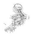
- FIG. 1is a perspective view of a sight apparatus.
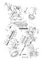
- FIG. 2is an exploded perspective view of the sight apparatus of FIG. 1 .
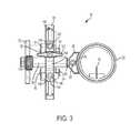
- FIG. 3is a front elevation view of the sight apparatus of FIG. 1 .
- FIG. 4is a rear elevation view of the sight apparatus of FIG. 1 .
- FIG. 5is side elevation view of the sight apparatus of FIG. 1 .
- FIG. 6is another side elevation view of the sight apparatus of FIG. 1 .
- FIG. 7is top plan view of the sight apparatus of FIG. 1 .
- FIG. 8is bottom plan view of the sight apparatus of FIG. 1 .
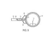
- FIG. 9is a front elevation view of the scope head removed from the sight apparatus of FIG. 1 .
- FIG. 10is a side elevation view of the boss removed from the sight apparatus of FIG. 1 .
- FIG. 11is a side elevation view of the micro-knob removed from the sight apparatus of FIG. 1 .
- FIG. 12is a front cross-sectional view of the sight apparatus taken along the lines 12 - 12 in FIG. 7 .
- the sight apparatus 10has a housing or frame that can include a number of members or portions, as seen in FIG. 2 .
- One portion of the frame as best seen in FIG. 1is a mounting member or bracket 12 which has a variety of mounting holes 14 that permit the sight apparatus 10 to be attached to a variety of firearms, weapons or equipment, in this example a bow, in a variety of positions.
- Another portion of the frame shown in FIG. 2is an adjustable member or portion 16 that is adjustably connected to the mounting member 12 .
- the framecould also be integrally formed or any number of the portions combined or integrally formed, e.g. slide member, block, arm, etc.
- the sight apparatus 10includes a number of correction mechanisms, designed to permit the sight apparatus to be adjusted in a number of ways such that the sight may be very finely calibrated. Some equipment may not need such fine calibration and therefore, may not need as many or any such correction mechanisms.
- One such correction mechanismpermits adjustment to the line of sight through a sight pin 18 attached to a sight mount or scope head 20 vertically, e.g. up or down. This type of adjustment is often referred to as elevation adjustment.
- the embodiment seen in FIG. 2includes the translation of rotation from a dial 22 engaged with or rotatably connected to the frame to linear, e.g. vertical, movement of the sight pin 18 .
- One way to accomplish such translationis through a rack-and-pinion or drum-and-slide mechanism, such as that disclosed in U.S. patent application Ser. No. 14/873,917, owned by the Applicant and which is hereby incorporated by reference herein in its entirety for all purposes.
- the drumcould be a circular or pinion gear 24 connected to the wheel 22 , which pinion gear engages the linear gear bar or rack 26 of a slide member 28 , the slide being connected to the sight pin 18 as discussed further below.
- the engagement between the drum 24 and slide member 28causes the slide, and thereby the sight pin 18 , to move up and down in response to rotation of the drum, e.g. by rotation of the dial or wheel 22 .
- the wheel 22such as that disclosed in U.S. patent application Ser. No. 14/061,216, owned by the Applicant and which is hereby incorporated by reference herein in its entirety for all purposes, is attached to a gear 24 .
- the peg or pin 30 on which the wheel 22 resides and rotates aboutis secured to adjustable member 16 .
- the slide member 28carries the rack gear, linear gear bar or vertical gear 26 , which has a set of bar teeth 32 for engaging the pinion teeth 34 of the pinion gear 24 .
- the slide member 28is engaged with, e.g. slidably held to, a first part of the housing, in FIG. 2 the adjustment member 16 .
- the slide member 28can also have a groove 36 in which at least one fastener or, in the embodiment seen in FIG. 2 , a first or top slide member fastener 38 and a second or bottom slide member fastener 40 , extend.
- the adjustment member 16has a first or top adjustable member hole 42 and a second or bottom adjustable member hole 44 .
- the top slide member fastener 38extends through the top adjustable member hole 42 , a first top washer 46 a top bushing 48 , the groove 36 , a second top washer 50 , a third top washer 52 and into a top nut 54 to hold the slide member 28 to the adjustment member 16 .
- a second or bottom slide member fastener 40extends through the bottom adjustment member hole 44 , a first bottom washer 56 and a bottom bushing 58 , the slot 36 , a second bottom washer 60 and a third bottom washer 62 and into a bottom nut 64 .
- the two bushings 48 , 58are located in a vertical groove 36 formed in the slide member 28 and the washers 46 , 50 , 56 , 60 will sandwich the slide member 28 as seen in FIG. 2 .
- the bushings 48 , 58 and/or the washers 46 , 50 , 56 , 60can be made of a low friction material, such as Teflon, nylon, or other suitable plastic or low friction material.
- a harder material, such as metal, for the third washers 52 , 62protects the washers 50 , 60 from the nuts 54 , 64 .
- the sides of slide member 28 and/or the groove 36could be made from a low friction material in addition or alternatively to the bushings 48 , 58 and/or the washers 46 , 50 , 56 , 60 .
- the scope head or sight mount 20is attached to the slide member 28 such that as the slide member moves up or down in response to the rotation of the dial 22 , the scope head also moves up and down to thereby selectively adjust the sight apparatus 10 .
- the scope head 20has a post or stem 66 which is attached to the scope head by an adapter 68 .
- the stem 68is made from ground stainless steel for strength and to provide smooth movement within the boss 90 .
- other materialscould be used for the stem 66 , e.g. aluminum, without defeating the spirit of the invention.
- the adapter 68has a top adapter hole 70 and a bottom adapter hole 72 for the top adapter fastener 74 and bottom adapter fastener 76 respectively, that secure the adapter to the scope head 20 .
- the adapterhas a third adapter hole 78 that aligns with an side adapter hole 80 in the stem 66 such that a stem fastener 82 secures the stem to the adapter and, thereby, the scope head 20 .
- the scope head 20 and the stem 66could also be attached in a number of known means for attaching such components, e.g. integrally forming, welding, threading, gluing, etc., the use of which would not defeat the spirit of the invention.
- the end of the stem 66 opposite the scope head 20has an end hole 84 .
- a worm gear 86is threaded into the end hole 84 of the stem 66 .
- the stem 66 and worm gear 86fit within a first or boss bore 88 in a windage arm or boss 90 to attach the scope head 20 to the boss.
- the boss bore 88terminates in a wall 98 .
- a collar 92is affixed to the worm gear 86 to divide the worm gear into two parts, a first part 94 that is engaged with the stem 66 and a second part 96 opposite the first part.
- the collar 92abuts the wall 98 of the boss 90 to hold the stem and/or worm gear to the boss and prevent the stem and/or worm gear from being further inserted into the boss bore 88 .
- the second part 96 of the worm gear 86extends out of the boss bore 88 through a smaller wall hole 100 in the wall 98 of the boss 90 .
- a collar washer 102such as a silicone or plastic washer, may be located between the wall 98 and the collar 92 to decrease the friction there-between when the worm gear 86 and, thereby, the collar is rotated.
- a micro-knob 104is attached to the worm gear 86 to form a threaded portion thereof and rotatably attach the micro-knob to the boss 90 , such that the micro-knob may be turned to laterally move the scope head 20 and sight pin 18 . As such, the scope head 20 and sight pin 18 are engaged with the boss 90 and the micro-knob 104 .
- the micro-knob 104 in FIG. 11includes a center hole 106 sized to receive the second part 96 of the worm gear 86 extending through the wall hole 100 in the wall 98 of the boss 90 .
- An edge hole 108 in the curved surface of the micro-knob 104allows a an edge fastener 110 to be threaded into the edge hole to contact the second part 96 of the worm gear 86 and prevent the micro-knob from coming loose from the worm gear.
- the micro-knob 104 and the stem 66could also be attached in a number of known means for attaching such components, e.g. integrally forming, welding, threading, gluing, etc., the use of which would not defeat the spirit of the invention.
- the stem 66 embodiment seen in FIG. 9also includes a notch 112 and a divot 114 .
- the notch 112receives a bar 116 and the divot 114 receives a ball 118 .
- the boss 90has a second or overlapping bore 122 that overlaps the boss bore 88 .
- the intersecting boss bore 88 and overlapping bore 122receive the stem 66 and bar 116 and ball 118 such that the stem cannot be rotated within the boss bore.
- the stem 66 and the bar 116could also be attached in a number of known means for attaching such components, e.g. integrally forming, over-molding, the use of which would not defeat the spirit of the invention.
- the worm gear 86When the micro-knob 104 is rotated in a first direction, the worm gear 86 is rotated in a first direction. Because the collar 92 , on one side of the wall 98 of the boss 90 , and the micro-knob 104 , on the other side of the wall, hold the worm gear in place with respect to the boss, rotating the worm gear, e.g. by micro-knob 104 , does not translate into movement of the worm gear in lateral direction.
- the micro-knob 104is larger than the wall hole 100 such that when the boss 90 is moved in a first lateral direction, the micro-knob will contact the wall 98 and the boss 90 will be prevented from being moved further in the first lateral direction.
- the stemcannot rotate with the worm gear 86 . Therefore, the first part 94 of the worm gear 86 is threaded further into the end hole 84 in the stem 66 when the micro-knob 104 is rotated in a first direction and unthreaded further out of the end hole in the stem when the knob is rotated in a second direction.
- the stemmoves laterally further into the boss 90 and the scope head 20 moves in a first lateral direction, e.g. toward the boss.
- the micro-knob 104may also have a series of dents 120 in the flat surface of the micro-knob facing the wall 98 on the first end of the boss 90 .
- the wall 98 of the boss 90 seen in one embodiment shown in FIG. 10may have a boss blind bore 124 in which a boss spring 126 and a boss ball bearing 128 are positioned, such that the boss spring urges the boss ball bearing at least partially out of the boss blind bore.
- the micro-knob 104When the micro-knob 104 is rotated the boss ball bearing 128 will move into and out of the dents 120 in the micro-knob to provide an audible sound, e.g. a click, and/or tactile feedback.
- the feedbackprovides a user with a reference as to how much movement or translation is being applied to the scope head 20 and/or provide a known amount of translation to get to desired scope head 20 position, e.g. five clicks.
- the boss 90may also have a gap 130 formed therein such that a portion of the stem 66 , e.g. the marker 134 , can be seen there-through.
- the boss 90includes markings 132 by or proximate to the gap 130 and the stem 66 includes a marker 134 such that the amount of lateral movement of the stem and, thereby, the scope head 20 with respect to the boss can be seen visually or identified.
- the boss 90is attached to the slide member 28 , by a clamp, block or windage bracket 136 .
- the block 136has a pair of T-nuts 138 that are configured, e.g. shaped, to be received in a channel 140 formed in the slide member 28 to attach the bracket to slide member.
- the nuts 138are T shaped as is the channel 140 , however, there are many known shapes for nuts in cooperation with a channel that could be used without defeating the spirit of the invention.
- the block 136includes a top block hole 142 and a bottom block hole 144 .
- a pair of block fasteners 146extend through the top block hole 142 and a bottom block hole 144 and into the T-nuts 138 .
- the T-nuts 138are inserted into the channel 140 , e.g. from the top or bottom.
- the block fasteners 146are tightened to hold the block 136 in place with respect to the slide member 28 by clamping a portion of the slide member between the T-nuts 138 and block.
- the block 136may also include a pointer and the slide member 28 a scale such that the desired location for the placement of the block along the channel 140 can be identified.
- the block 136also includes an opening 148 , U-shaped in the embodiment show in FIG. 2 , formed therein sized and shaped to slidably receive and selectively hold the boss 90 .
- a leg hole 150extends through the tops of a pair of legs 154 , 156 forming the opening 148 .
- a fastenersuch as a lock or lock knob 152 , is engaged with, e.g. threaded through, front leg or first part 154 and into the back leg or second part 156 of the block 136 .
- the lock knob 152is tight or locked, e.g. further threading after the head or knob of the lock knob 152 contacts the front leg 154 , the front leg will be bent towards the back leg 156 to clamp and/or lock the boss 90 into position and prevent the boss from moving with respect to the block 136 .
- the boss 90can also be designed such that the walls of the boss and/or size of the gap 130 allow the clamping action from the front leg 154 and back leg 156 to transfer to the front and back walls of the boss to clamp and hold the stem 66 .
- Holes in objectsare often very slightly larger than the object that is designed to fit in the hole, such as, for example, to permit the object to be inserted into the hole with little force and/or due to tolerances in machining. However, this allows the object to move while in the hole, if even slightly, often referred to as “play.”
- a bar 116is seated in a notch in the stem.
- the bar 116is made from ground stainless steel.
- other materialse.g. aluminum, could be used without defeating the spirit of the invention.
- the stem 66is inserted into the boss bore 88 and the bar fits in the overlapping bore 122 much like a key.
- a ball 118made from a compressible material, e.g. acetal homopolymer resin, is seated in a divot 114 in the stem and is inserted into the overlapping bore 122 when the stem 66 is inserted into the boss bore 88 .
- the ball 118is sized slightly larger than the overlapping bore 122 such that it is compressed or squeezed slightly to fit in the overlapping bore.
- Making the ball 118 from a compressible materialallows the ball to be squeezed into the overlapping bore 122 and compress to permit the clamping action from the front leg 154 and back leg 156 to transfer to the front and back walls of the boss to clamp and hold the stem 66 .
- a portion of the block 136in the embodiment shown in FIG. 12 the back leg 156 , may also include a block bore 158 sized to receive a block spring 160 and a block ball bearing 162 .
- the block spring 160is positioned in the bore 158 to urge the block ball bearing 162 at least partially into the opening 148 in which boss 90 is positioned.
- the front face of the boss 90also includes a series of indentations 164 . As the boss 90 is moved within the block 136 , and, thereby, the indentations 164 , the boss will make a clicking sound and feel as the block spring 160 pushes or urges the block ball bearing 162 into and/or out of one of the indentations.
- clicksmay be correlated to units of displacements, e.g. one click equals sixes inches at twenty yards and/or so many divots.
- one rotation of the micro-knob 104moves the scope head 20 a first distance which is less than movement of the boss from one indentation to another or the second distance.
- eight rotations of the micro-knob 104results in movement of the scope head 20 about the same as movement of the boss from one indentation to another.
- the ball bearing 162being within one of the series of indentations 164 also helps selectively hold the boss 90 in position with respect to the block 136 such that the micro-knob 104 can be rotated to move the scope head 20 .
- the sight pin 18via the scope head 20 , can be adjusted or moved laterally on a larger scale by loosening the lock knob 152 which permits the boss 90 to be slid within the opening 148 of the block 136 . Moving the boss 90 within the block 136 does not change the position of the stem 66 within the bore 88 in the boss.
- the lock knob 152can be tightened to hold the boss 90 in position.
- the micro-knob 104can be used to adjust or move the sight pin laterally on a smaller scale by turning the micro-knob. This invention allows the scope head 20 to be adjusted in the large increments quicker than with just a micro-drive and in small increments with more precision than with just a macro-drive.
- One of the top block hole 142 and bottom block hole 144can be a slotted hole, seen as the bottom block hole in the embodiment illustrated in FIG. 2 .
- the block fastener 146 for the slotted hole 144is loosened, the bottom of the block 136 can be rotated about a pivot or axis through the block fastener 146 in the top block hole 142 in the block, sometimes called the second axis. This rotation allows the scope head 20 to be adjusted and leveled.
- a side block hole 166is located in the block 136 on each side of the slotted hole 144 .
- Threaded insertse.g. a threaded insert on the scope head or left side 168 and a threaded insert on the dial or right side 170 , are engaged in the side block holes 166 .
- the right insert 170can be loosened and the left insert 168 threaded into the left side block hole 166 until it contacts the bottom block fastener 146 . Further rotation of the left insert 168 into the left side block hole 166 , e.g.
Landscapes
- Engineering & Computer Science (AREA)
- General Engineering & Computer Science (AREA)
- Physics & Mathematics (AREA)
- Optics & Photonics (AREA)
- Mechanical Control Devices (AREA)
- Accessories Of Cameras (AREA)
Abstract
Description
This invention relates generally to a sight for a firearm, bow or other similar type of weapon or equipment. More particularly, the present invention relates to a windage mechanism for a sight.
Adjustable sights, for example, those used in the field of archery, are known to be adjustable to account for many external factors, e.g. the distance to the target, wind, various axis, etc. Current sights typically use one of two types of windage mechanisms, a micro-drive or a macro-drive.
A first type of windage mechanism is a micro-drive. The micro-drive utilizes a threaded screw and knob. As the knob is turned a screw moves the sight pin(s) away from the frame of the sight or closer to it. A micro-drive is often beneficial for making minor adjustments or precise adjustments because a partial turn of a knob often equates to a small amount of movement to the sight pin(s). However, micro-drives are not as advantageous for making larger adjustments, such as when a sight is first attached to a weapon, and adjusted because it requires turning the knob many times which is inefficient and slow.
A second type of windage mechanism is a macro-drive. The macro-drive utilizes a clamp on a bar. When the clamp is loosened, the sight pin(s) may be moved, e.g. by moving the bar through the clamp, away from the frame of the sight or closer to it. When the sight pin(s) are in position, the clamp is tightened to hold the bar at the exact position. A macro-drive is often beneficial for making larger adjustments, such as when a sight is first attached to a weapon, and adjusted because the amount the bar is moved is often the same as the amount the sight pin(s) is moved. Further, the sight pin(s) can be moved from one end of movement to the other, or anywhere in between, in an instant. However, macro-drives are not advantageous for making small, precise or repeatable adjustments.
As such, there is a need for a windage mechanism that can make larger or smaller adjustments precisely and efficiently.
It will be understood by those skilled in the art that one or more aspects of this invention can meet certain objectives, while one or more other aspects can lead to certain other objectives. Other objects, features, benefits and advantages of the present invention will be apparent in this summary and descriptions of the disclosed embodiment, and will be readily apparent to those skilled in the art. Such objects, features, benefits and advantages will be apparent from the above as taken in conjunction with the accompanying figures and all reasonable inferences to be drawn therefrom.
Thesight apparatus 10, as shown inFIGS. 1-9 , has a housing or frame that can include a number of members or portions, as seen inFIG. 2 . One portion of the frame as best seen inFIG. 1 , is a mounting member orbracket 12 which has a variety ofmounting holes 14 that permit thesight apparatus 10 to be attached to a variety of firearms, weapons or equipment, in this example a bow, in a variety of positions. Another portion of the frame shown inFIG. 2 is an adjustable member orportion 16 that is adjustably connected to themounting member 12. The frame could also be integrally formed or any number of the portions combined or integrally formed, e.g. slide member, block, arm, etc.
In the embodiment shown inFIGS. 1-9 , thesight apparatus 10 includes a number of correction mechanisms, designed to permit the sight apparatus to be adjusted in a number of ways such that the sight may be very finely calibrated. Some equipment may not need such fine calibration and therefore, may not need as many or any such correction mechanisms. One such correction mechanism permits adjustment to the line of sight through asight pin 18 attached to a sight mount orscope head 20 vertically, e.g. up or down. This type of adjustment is often referred to as elevation adjustment.
The embodiment seen inFIG. 2 includes the translation of rotation from adial 22 engaged with or rotatably connected to the frame to linear, e.g. vertical, movement of thesight pin 18. One way to accomplish such translation is through a rack-and-pinion or drum-and-slide mechanism, such as that disclosed in U.S. patent application Ser. No. 14/873,917, owned by the Applicant and which is hereby incorporated by reference herein in its entirety for all purposes. The drum could be a circular orpinion gear 24 connected to thewheel 22, which pinion gear engages the linear gear bar orrack 26 of aslide member 28, the slide being connected to thesight pin 18 as discussed further below. The engagement between thedrum 24 andslide member 28 causes the slide, and thereby thesight pin 18, to move up and down in response to rotation of the drum, e.g. by rotation of the dial orwheel 22.
In the embodiment shown inFIG. 2 , thewheel 22, such as that disclosed in U.S. patent application Ser. No. 14/061,216, owned by the Applicant and which is hereby incorporated by reference herein in its entirety for all purposes, is attached to agear 24. As seen most clearly inFIG. 2 , the peg orpin 30 on which thewheel 22 resides and rotates about is secured toadjustable member 16.
As referenced above, theslide member 28 carries the rack gear, linear gear bar orvertical gear 26, which has a set ofbar teeth 32 for engaging thepinion teeth 34 of thepinion gear 24. Theslide member 28 is engaged with, e.g. slidably held to, a first part of the housing, inFIG. 2 theadjustment member 16. Theslide member 28 can also have agroove 36 in which at least one fastener or, in the embodiment seen inFIG. 2 , a first or topslide member fastener 38 and a second or bottom slide member fastener40, extend.
One such correction mechanism permits adjustment to the line of sight through asight pin 18 in ascope head 20 laterally, e.g. left or right when looking through the scope head. This type of adjustment is often referred to as windage adjustment. In the embodiment shown, theadjustment member 16 has a first or topadjustable member hole 42 and a second or bottomadjustable member hole 44. The topslide member fastener 38 extends through the topadjustable member hole 42, a first top washer46 atop bushing 48, thegroove 36, asecond top washer 50, athird top washer 52 and into atop nut 54 to hold theslide member 28 to theadjustment member 16. A second or bottomslide member fastener 40 extends through the bottomadjustment member hole 44, afirst bottom washer 56 and a bottom bushing58, theslot 36, asecond bottom washer 60 and athird bottom washer 62 and into abottom nut 64. When thesight apparatus 10 is assembled, the twobushings 48,58 are located in avertical groove 36 formed in theslide member 28 and thewashers slide member 28 as seen inFIG. 2 .
Thebushings 48,58 and/or thewashers third washers washers nuts slide member 28 and/or thegroove 36 could be made from a low friction material in addition or alternatively to thebushings 48,58 and/or thewashers
The scope head orsight mount 20 is attached to theslide member 28 such that as the slide member moves up or down in response to the rotation of thedial 22, the scope head also moves up and down to thereby selectively adjust thesight apparatus 10.
As can be seen in the embodiment shown inFIGS. 1-3 and 9 , thescope head 20 has a post or stem66 which is attached to the scope head by anadapter 68. In one embodiment thestem 68 is made from ground stainless steel for strength and to provide smooth movement within theboss 90. However, other materials could be used for thestem 66, e.g. aluminum, without defeating the spirit of the invention. Theadapter 68 has atop adapter hole 70 and abottom adapter hole 72 for the top adapter fastener74 andbottom adapter fastener 76 respectively, that secure the adapter to thescope head 20. The adapter has athird adapter hole 78 that aligns with an side adapter hole80 in thestem 66 such that astem fastener 82 secures the stem to the adapter and, thereby, thescope head 20. Thescope head 20 and thestem 66 could also be attached in a number of known means for attaching such components, e.g. integrally forming, welding, threading, gluing, etc., the use of which would not defeat the spirit of the invention.
The end of thestem 66 opposite thescope head 20 has anend hole 84. Aworm gear 86 is threaded into theend hole 84 of thestem 66. Thestem 66 andworm gear 86 fit within a first or boss bore88 in a windage arm orboss 90 to attach thescope head 20 to the boss. The boss bore88 terminates in awall 98.
Acollar 92 is affixed to theworm gear 86 to divide the worm gear into two parts, afirst part 94 that is engaged with thestem 66 and asecond part 96 opposite the first part. When thestem 66 andworm gear 86 are inserted into the boss bore88, thecollar 92 abuts thewall 98 of theboss 90 to hold the stem and/or worm gear to the boss and prevent the stem and/or worm gear from being further inserted into the boss bore88. Thesecond part 96 of theworm gear 86 extends out of the boss bore88 through asmaller wall hole 100 in thewall 98 of theboss 90. Acollar washer 102, such as a silicone or plastic washer, may be located between thewall 98 and thecollar 92 to decrease the friction there-between when theworm gear 86 and, thereby, the collar is rotated.
A micro-knob104 is attached to theworm gear 86 to form a threaded portion thereof and rotatably attach the micro-knob to theboss 90, such that the micro-knob may be turned to laterally move thescope head 20 andsight pin 18. As such, thescope head 20 andsight pin 18 are engaged with theboss 90 and the micro-knob104. The micro-knob104 inFIG. 11 includes acenter hole 106 sized to receive thesecond part 96 of theworm gear 86 extending through thewall hole 100 in thewall 98 of theboss 90. Anedge hole 108 in the curved surface of the micro-knob104 allows a anedge fastener 110 to be threaded into the edge hole to contact thesecond part 96 of theworm gear 86 and prevent the micro-knob from coming loose from the worm gear. The micro-knob104 and thestem 66 could also be attached in a number of known means for attaching such components, e.g. integrally forming, welding, threading, gluing, etc., the use of which would not defeat the spirit of the invention.
Thestem 66 embodiment seen inFIG. 9 also includes a notch112 and a divot114. The notch112 receives abar 116 and the divot114 receives aball 118. Theboss 90 has a second or overlappingbore 122 that overlaps the boss bore88. The intersecting boss bore88 and overlapping bore122 receive thestem 66 andbar 116 andball 118 such that the stem cannot be rotated within the boss bore. Thestem 66 and thebar 116 could also be attached in a number of known means for attaching such components, e.g. integrally forming, over-molding, the use of which would not defeat the spirit of the invention.
When the micro-knob104 is rotated in a first direction, theworm gear 86 is rotated in a first direction. Because thecollar 92, on one side of thewall 98 of theboss 90, and the micro-knob104, on the other side of the wall, hold the worm gear in place with respect to the boss, rotating the worm gear, e.g. bymicro-knob 104, does not translate into movement of the worm gear in lateral direction. In one embodiment, the micro-knob104 is larger than thewall hole 100 such that when theboss 90 is moved in a first lateral direction, the micro-knob will contact thewall 98 and theboss 90 will be prevented from being moved further in the first lateral direction. Because of the intersecting boss bore88 and overlapping bore122 and bar116 andball 118, the stem cannot rotate with theworm gear 86. Therefore, thefirst part 94 of theworm gear 86 is threaded further into theend hole 84 in thestem 66 when the micro-knob104 is rotated in a first direction and unthreaded further out of the end hole in the stem when the knob is rotated in a second direction. When thefirst part 94 of theworm gear 86 is threaded into theend hole 84 in thestem 66, the stem moves laterally further into theboss 90 and thescope head 20 moves in a first lateral direction, e.g. toward the boss. When thefirst part 94 of theworm gear 86 is unthreaded out of theend hole 84 in thestem 66, the stem moves laterally further out of theboss 90 and thescope head 20 moves in a second lateral direction, e.g. away from the boss. Movement of thestem 66 within theboss 90 does not change the position of the boss with respect to theblock 136.
The micro-knob104 may also have a series ofdents 120 in the flat surface of the micro-knob facing thewall 98 on the first end of theboss 90. Thewall 98 of theboss 90 seen in one embodiment shown inFIG. 10 , may have a boss blind bore124 in which aboss spring 126 and aboss ball bearing 128 are positioned, such that the boss spring urges the boss ball bearing at least partially out of the boss blind bore. When the micro-knob104 is rotated theboss ball bearing 128 will move into and out of thedents 120 in the micro-knob to provide an audible sound, e.g. a click, and/or tactile feedback. The feedback provides a user with a reference as to how much movement or translation is being applied to thescope head 20 and/or provide a known amount of translation to get to desiredscope head 20 position, e.g. five clicks.
Theboss 90 may also have agap 130 formed therein such that a portion of thestem 66, e.g. themarker 134, can be seen there-through. In the embodiment seen inFIG. 7 , theboss 90 includesmarkings 132 by or proximate to thegap 130 and thestem 66 includes amarker 134 such that the amount of lateral movement of the stem and, thereby, thescope head 20 with respect to the boss can be seen visually or identified.
Theboss 90 is attached to theslide member 28, by a clamp, block orwindage bracket 136. In the embodiment seen inFIG. 2 , theblock 136 has a pair of T-nuts 138 that are configured, e.g. shaped, to be received in achannel 140 formed in theslide member 28 to attach the bracket to slide member. In the embodiment illustrated, thenuts 138 are T shaped as is thechannel 140, however, there are many known shapes for nuts in cooperation with a channel that could be used without defeating the spirit of the invention.
Theblock 136 includes atop block hole 142 and abottom block hole 144. A pair ofblock fasteners 146 extend through thetop block hole 142 and abottom block hole 144 and into the T-nuts138. The T-nuts 138 are inserted into thechannel 140, e.g. from the top or bottom. When thescope head 20 is in the desired position, theblock fasteners 146 are tightened to hold theblock 136 in place with respect to theslide member 28 by clamping a portion of the slide member between the T-nuts 138 and block.
Having a portion of theblock 136 engage achannel 140 of theslide member 28 allows the block and, thereby, thescope head 20 almost infinite adjustment and placement vertically along the slide member. As seen inFIG. 5 , theblock 136 may also include a pointer and the slide member28 a scale such that the desired location for the placement of the block along thechannel 140 can be identified.
Theblock 136 also includes anopening 148, U-shaped in the embodiment show inFIG. 2 , formed therein sized and shaped to slidably receive and selectively hold theboss 90. Aleg hole 150 extends through the tops of a pair oflegs opening 148. A fastener, such as a lock or lockknob 152, is engaged with, e.g. threaded through, front leg orfirst part 154 and into the back leg orsecond part 156 of theblock 136. When thelock knob 152 is tight or locked, e.g. further threading after the head or knob of thelock knob 152 contacts thefront leg 154, the front leg will be bent towards theback leg 156 to clamp and/or lock theboss 90 into position and prevent the boss from moving with respect to theblock 136.
Theboss 90 can also be designed such that the walls of the boss and/or size of thegap 130 allow the clamping action from thefront leg 154 andback leg 156 to transfer to the front and back walls of the boss to clamp and hold thestem 66. Holes in objects are often very slightly larger than the object that is designed to fit in the hole, such as, for example, to permit the object to be inserted into the hole with little force and/or due to tolerances in machining. However, this allows the object to move while in the hole, if even slightly, often referred to as “play.” To prevent thestem 66 and, thereby, thescope head 20 from rotating when theworm gear 86 is rotated by the micro-knob104, abar 116 is seated in a notch in the stem. In one embodiment, thebar 116 is made from ground stainless steel. However, other materials, e.g. aluminum, could be used without defeating the spirit of the invention. Thestem 66 is inserted into the boss bore88 and the bar fits in the overlapping bore122 much like a key. Aball 118, made from a compressible material, e.g. acetal homopolymer resin, is seated in a divot114 in the stem and is inserted into the overlapping bore122 when thestem 66 is inserted into the boss bore88. In order to reduce the play between thestem 66 and theboss 90, theball 118 is sized slightly larger than the overlapping bore122 such that it is compressed or squeezed slightly to fit in the overlapping bore. Making theball 118 from a compressible material allows the ball to be squeezed into the overlappingbore 122 and compress to permit the clamping action from thefront leg 154 andback leg 156 to transfer to the front and back walls of the boss to clamp and hold thestem 66.
A portion of theblock 136, in the embodiment shown inFIG. 12 theback leg 156, may also include ablock bore 158 sized to receive ablock spring 160 and ablock ball bearing 162. Theblock spring 160 is positioned in thebore 158 to urge theblock ball bearing 162 at least partially into theopening 148 in whichboss 90 is positioned. In the embodiment shown inFIG. 2 , the front face of theboss 90 also includes a series ofindentations 164. As theboss 90 is moved within theblock 136, and, thereby, theindentations 164, the boss will make a clicking sound and feel as theblock spring 160 pushes or urges theblock ball bearing 162 into and/or out of one of the indentations. These clicks may be correlated to units of displacements, e.g. one click equals sixes inches at twenty yards and/or so many divots. In one embodiment one rotation of the micro-knob104 moves the scope head20 a first distance which is less than movement of the boss from one indentation to another or the second distance. In another embodiment, eight rotations of the micro-knob104 results in movement of thescope head 20 about the same as movement of the boss from one indentation to another. Theball bearing 162 being within one of the series ofindentations 164 also helps selectively hold theboss 90 in position with respect to theblock 136 such that the micro-knob104 can be rotated to move thescope head 20.
Thesight pin 18, via thescope head 20, can be adjusted or moved laterally on a larger scale by loosening thelock knob 152 which permits theboss 90 to be slid within theopening 148 of theblock 136. Moving theboss 90 within theblock 136 does not change the position of thestem 66 within thebore 88 in the boss. When thesight pin 18 is generally in the desired position, e.g. when first setting up thesight 10, thelock knob 152 can be tightened to hold theboss 90 in position. The micro-knob104 can be used to adjust or move the sight pin laterally on a smaller scale by turning the micro-knob. This invention allows thescope head 20 to be adjusted in the large increments quicker than with just a micro-drive and in small increments with more precision than with just a macro-drive.
One of thetop block hole 142 andbottom block hole 144 can be a slotted hole, seen as the bottom block hole in the embodiment illustrated inFIG. 2 . When theblock fastener 146 for the slottedhole 144 is loosened, the bottom of theblock 136 can be rotated about a pivot or axis through theblock fastener 146 in thetop block hole 142 in the block, sometimes called the second axis. This rotation allows thescope head 20 to be adjusted and leveled.
To assist in allowing very small adjustments in the second axis, aside block hole 166 is located in theblock 136 on each side of the slottedhole 144. Threaded inserts, e.g. a threaded insert on the scope head orleft side 168 and a threaded insert on the dial orright side 170, are engaged in the side block holes166. To adjust thescope head 20, for example, theright insert 170 can be loosened and theleft insert 168 threaded into the leftside block hole 166 until it contacts thebottom block fastener 146. Further rotation of theleft insert 168 into the leftside block hole 166, e.g. clockwise, will cause theblock 136, and thereby thescope head 20, to rotate counterclockwise, when looking through thescope head 20, about thetop block fastener 146. When the desired position of thescope head 20 is reached, theblock fasteners 146 can be tightened down and theleft insert 168 andright insert 170 put into contact with thebottom block fastener 146 to secure the scope head, as seen best inFIG. 2 .
Although the invention has been herein described in what is perceived to be the most practical and preferred embodiments, it is to be understood that the invention is not intended to be limited to the specific embodiments set forth above. Rather, it is recognized that modifications may be made by one of skill in the art of the invention without departing from the spirit or intent of the invention and, therefore, the invention is to be taken as including all reasonable equivalents to the subject matter of the appended claims and the description of the invention herein. For example, in one embodiment many components are made from aluminum, however, other suitable materials known in the art could be used without defeating the spirit of the invention.
Claims (20)
1. A sight comprising:
a frame having an opening formed therein;
a boss, wherein a portion of the boss is positioned within the opening and selectively held by the frame;
a knob rotatably attached to a first end of the boss;
a sight pin mount having a stem, the stem located within a bore formed in the boss;
a sight pin attached to the sight pin mount and engaged with the boss and the knob; and
wherein movement of the boss within the frame moves the sight pin laterally; and
wherein the knob is in threaded engagement with the stem such that when the knob is rotated in a first direction the sight pin moves in first lateral direction; and when the knob is rotated in a second direction the sight pin moves in second lateral direction.
2. The sight ofclaim 1 further comprising a lock engaged with the frame such that when the lock is tightened, the frame clamps the boss to hold the boss in position with respect to the frame.
3. The sight ofclaim 1 wherein the opening is a U-shaped opening and a lock is engaged with a pair of legs of the frame forming the opening such that when the lock is tightened, the pair of legs clamp the boss to hold the boss in position with respect to the frame.
4. The sight ofclaim 1 wherein a threaded portion of the knob extends through a hole in a side of the boss and into the bore and wherein a collar is attached to the threaded portion of the knob within the bore such that when the knob is rotated, the threaded portion does not move in a lateral direction with respect to the boss.
5. The sight ofclaim 4 wherein when the knob is rotated in the first direction, the threaded portion is at least partially threaded into an end of the stem to move the sight pin in the first lateral direction and when the knob is rotated in the second direction, the threaded portion is at least partially threaded out of the end of the stem to move the sight pin in the second lateral direction.
6. A sight comprising:
a frame having an opening formed therein;
a boss having a first bore and a second bore formed therein, wherein a portion of the boss is positioned within the opening and selectively held by the frame;
a knob rotatably attached to a first end of the boss;
a sight pin mount having a stem, the stem located within the first bore; and
a sight pin attached to the sight pin mount and engaged with the boss and the knob; and
wherein the stem includes a bar and the bar is located in the second bore;
wherein the second bore overlaps with the first bore;
wherein movement of the boss within the frame moves the sight pin laterally; and
wherein the knob is in threaded engagement with the stem such that when the knob is rotated in a first direction the sight pin moves in first lateral direction; and when the knob is rotated in a second direction the sight pin moves in second lateral direction.
7. The sight ofclaim 6 :
wherein a divot is formed in the stem;
wherein a compressible ball is seated in the divot;
wherein when the stem is located in the first bore, the ball is located in the second bore; and
wherein the ball is sized slightly larger than the second bore such that the ball is compressed when located in the second bore.
8. A sight comprising
a frame having an opening formed therein;
a boss, wherein a portion of the boss is positioned within the opening and selectively held by the frame;
a knob rotatably attached to a first end of the boss;
a sight pin mount having a stem;
a sight pin attached to the sight pin mount and engaged with the boss and the knob; and
a lock engaged with the frame;
wherein movement of the boss within the frame moves the sight pin laterally;
wherein the knob is in threaded engagement with the stem such that when the knob is rotated in a first direction the sight pin moves in first lateral direction; and when the knob is rotated in a second direction the sight pin moves in second lateral direction
wherein when the lock is tightened, the frame clamps the boss to hold the boss in position with respect to the frame; and
wherein when the lock is tightened, a clamping action from the frame is transferred to the boss such that the boss clamps the stem to hold the stem in position with respect to the boss.
9. A sight comprising:
a housing;
a dial rotatably connected to the housing;
a slide member engaged with the housing such that as the dial is rotated the slide member is moved in a vertical direction;
a bracket attached to the slide member, the bracket having a pair of legs forming an opening;
an arm selectively and slidably received in the opening;
a scope head attached to the arm;
a lock knob engaged with the pair of legs such that when the lock knob is tight, the arm is prevented from moving laterally within the bracket and when the lock knob is loose, the arm is permitted to move laterally within the bracket;
a micro-knob engaged with the scope head such that when the micro-knob is rotated in a first direction, the scope head is moved in a first direction and when the micro-knob is rotated in a second direction, the scope head is moved in a second direction; and
a spring and ball positioned within a bore formed in one of the pair of legs such that the spring urges the ball at least partially into the opening;
wherein the arm has a series of indentations such that as the arm is moved through the opening, the ball will be urged into and out of at least one of the series of indentations.
10. The sight ofclaim 9 wherein when the ball is in one of the series of indentations, the arm is selectively held in position with respect to the bracket such that the micro-knob can be rotated to move the scope head.
11. The sight ofclaim 10
wherein one rotation of the micro-knob results in moving the scope head laterally a first distance;
wherein a distance between each indentation of the series of indentations is a second distance; and
wherein the second distance is greater than the first distance.
12. The sight ofclaim 9 further comprising a spring and ball positioned within a bore formed in an end of the arm and wherein the micro-knob has a series of dents such that as the micro-knob is rotated, the ball will be urged into and out of the dents.
13. The sight ofclaim 9
wherein the scope head has a post, the post having a marker;
wherein the post is located at least partially with in a bore of the arm;
wherein the arm has a gap formed therein such that the marker is visible through the gap and the post has markings proximate to the gap; and
wherein when an amount the scope head is moved laterally is identified by the marker in relation to the markings.
14. The sight ofclaim 9 further comprising:
a pair of fasteners that extend through holes formed in the bracket; and
a pair of nuts, each of the pair of nuts attached to an end of one of the pair of fasteners;
wherein the pair of nuts are configured to be received in a channel formed in the slide member; and
wherein when the pair of fasteners are tight, the pair of nuts hold the slide member to the bracket to hold the bracket in a desired position with respect to the slide member.
15. The sight ofclaim 14 wherein the pair of nuts and channel are T-shaped.
16. The sight ofclaim 9 wherein the micro-knob is larger than the opening such that when the arm is moved in a first lateral direction and the micro-knob contacts the arm, the arm cannot be moved further in the first lateral direction.
17. A sight having a sight mount and windage bracket attached to a frame, the windage bracket comprising:
a block with an opening formed therein, the block configured to attach the windage bracket to the frame;
a boss positioned within the opening and selectively held by the block;
a knob rotatably engaged with the boss;
a stem engaged with the knob and configured to be attached to the sight mount;
wherein when the knob is rotated in a first rotational direction, the stem is moved in a first direction;
wherein movement of the boss in a first lateral direction within the block does not result in movement of the stem with respect to the boss;
wherein rotation of the knob does not result in movement of the boss within the block;
wherein the knob has a threaded portion and the threaded portion is engaged with a threaded hole in an end of the stem; and
wherein a part of the threaded portion extends into the boss and a collar located on the threaded portion within the boss rotatably engages the knob to the boss such that when the knob is rotated, the threaded portion does not move further into or out of the boss.
18. The windage bracket ofclaim 17 wherein when the knob is rotated in the first rotational direction, the threaded portion is at least partially threaded into the threaded hole in the stem to move the stem in the first direction and when the knob is rotated in a second rotational direction, the threaded portion is at least partially threaded out of the threaded hole of the stem to move the stem in a second direction.
19. A sight having a sight mount and windage bracket attached to a frame, the windage bracket comprising:
a block with an opening formed therein, the block configured to attach the windage bracket to the frame;
a boss positioned within the opening and selectively held by the block;
a knob rotatably engaged with the boss;
a stem engaged with the knob and configured to be attached to the sight mount;
wherein when the knob is rotated in a first rotational direction, the stem is moved in a first direction;
wherein movement of the boss in a first lateral direction within the block does not result in movement of the stem with respect to the boss;
wherein rotation of the knob does not result in movement of the boss within the block;
wherein the opening is formed by a first part and second part of the block and wherein a lock engages the first part and the second part such that when the lock is locked, the boss cannot move with respect to the block.
20. The windage bracket ofclaim 19 wherein when the lock is locked, the stem cannot move with respect to the boss.
Priority Applications (2)
| Application Number | Priority Date | Filing Date | Title |
|---|---|---|---|
| US15/908,126US10190851B1 (en) | 2018-02-28 | 2018-02-28 | Windage mechanism |
| US16/253,335US10443983B2 (en) | 2018-02-28 | 2019-01-22 | Windage mechanism |
Applications Claiming Priority (1)
| Application Number | Priority Date | Filing Date | Title |
|---|---|---|---|
| US15/908,126US10190851B1 (en) | 2018-02-28 | 2018-02-28 | Windage mechanism |
Related Child Applications (1)
| Application Number | Title | Priority Date | Filing Date |
|---|---|---|---|
| US16/253,335ContinuationUS10443983B2 (en) | 2018-02-28 | 2019-01-22 | Windage mechanism |
Publications (1)
| Publication Number | Publication Date |
|---|---|
| US10190851B1true US10190851B1 (en) | 2019-01-29 |
Family
ID=65032685
Family Applications (2)
| Application Number | Title | Priority Date | Filing Date |
|---|---|---|---|
| US15/908,126ActiveUS10190851B1 (en) | 2018-02-28 | 2018-02-28 | Windage mechanism |
| US16/253,335ActiveUS10443983B2 (en) | 2018-02-28 | 2019-01-22 | Windage mechanism |
Family Applications After (1)
| Application Number | Title | Priority Date | Filing Date |
|---|---|---|---|
| US16/253,335ActiveUS10443983B2 (en) | 2018-02-28 | 2019-01-22 | Windage mechanism |
Country Status (1)
| Country | Link |
|---|---|
| US (2) | US10190851B1 (en) |
Cited By (7)
| Publication number | Priority date | Publication date | Assignee | Title |
|---|---|---|---|---|
| US20180187997A1 (en)* | 2017-01-05 | 2018-07-05 | Daniel A. Summers | Bow accessory mounting system and method |
| US10443983B2 (en)* | 2018-02-28 | 2019-10-15 | Harold M. Hamm | Windage mechanism |
| US10907933B1 (en) | 2020-08-14 | 2021-02-02 | Hamm Designs, Llc | Multi-purpose sight |
| US11519694B1 (en)* | 2022-07-15 | 2022-12-06 | H.H. & A. Sports, inc. | Sight with rotatable aiming ring |
| USD975816S1 (en)* | 2019-11-14 | 2023-01-17 | Specialty Archery, Llc | Reversible, accessories adaptable archery bow sight |
| US20240255255A1 (en)* | 2023-01-30 | 2024-08-01 | H.I.T. Outdoors, LLC | Archery bow sight |
| US12158321B2 (en) | 2018-11-13 | 2024-12-03 | Qtm, Llc | Archery assembly and method |
Families Citing this family (2)
| Publication number | Priority date | Publication date | Assignee | Title |
|---|---|---|---|---|
| USD1010056S1 (en) | 2020-08-25 | 2024-01-02 | Magpul Industries Corp. | Gun sight |
| USD1010057S1 (en) | 2020-08-25 | 2024-01-02 | Magpul Industries Corp. | Gun sight |
Citations (241)
| Publication number | Priority date | Publication date | Assignee | Title |
|---|---|---|---|---|
| US656867A (en) | 1899-02-27 | 1900-08-28 | Edgar Bronson Tolman | Rear sight for firearms. |
| US906751A (en) | 1908-06-08 | 1908-12-15 | Warner Swasey Co | Sight device for firearms. |
| GB191018847A (en) | 1909-08-13 | 1911-09-21 | Rheinische Metallw & Maschf | Improved Aiming Apparatus for Guns. |
| US1330002A (en) | 1920-02-03 | wales | ||
| US1407208A (en) | 1921-05-18 | 1922-02-21 | Harry C Wilson | Rifle sight |
| US1451584A (en) | 1920-11-09 | 1923-04-10 | James R Mapes | Gun sight |
| US2155391A (en) | 1938-04-04 | 1939-04-25 | Ultrad Products Inc | Sight for toy guns |
| US2545454A (en) | 1947-10-31 | 1951-03-20 | Bert E Fredrickson | Archer's sight |
| US2671966A (en) | 1949-02-01 | 1954-03-16 | Jacobsen Carl | Gun sight |
| US2975780A (en) | 1958-11-17 | 1961-03-21 | Joseph C Fisher | Archer's bow |
| US2980097A (en) | 1959-01-28 | 1961-04-18 | Mohawk Sporting Equipment Co | Arrow support |
| US3108584A (en) | 1961-06-26 | 1963-10-29 | Clifford W Coe | Arrow rest for archery bow |
| US3224427A (en) | 1962-09-14 | 1965-12-21 | Ernest A Ronan | Crossbow pistol |
| US3285237A (en) | 1964-02-24 | 1966-11-15 | William A Wolfe | Laterally displaceable arrow rest |
| US3292607A (en) | 1963-05-06 | 1966-12-20 | Jr Earl H Hoyt | Arrow rest for an archery bow |
| US3342173A (en) | 1965-01-04 | 1967-09-19 | Eugene L Ferguson | Bow with magnetic retractable arrow rest |
| US3455027A (en) | 1967-08-30 | 1969-07-15 | David J Perkins | Archery bow sight |
| US3504659A (en) | 1968-04-19 | 1970-04-07 | Charles E Babington | Pivoted bowstring responsive arrow support device |
| US3599337A (en) | 1969-11-07 | 1971-08-17 | Us Army | Sight for firearm using high trajectory ammunition |
| US3618586A (en) | 1969-11-03 | 1971-11-09 | George C Current | Arrow sight and bowstring tension control |
| US3866592A (en) | 1973-04-17 | 1975-02-18 | Richard F Carella | Archery release indicating assembly |
| US3935854A (en) | 1974-12-04 | 1976-02-03 | Troncosco Jr Fernando | Archery bow and arrow support |
| US4071014A (en) | 1977-03-07 | 1978-01-31 | Trotter George H | Arrow positioning device |
| US4133334A (en) | 1977-02-01 | 1979-01-09 | Tone Richard D | Flipper type arrow rest |
| US4153999A (en) | 1977-11-18 | 1979-05-15 | Steen Sonny J O | Archery bow sighting arrangement and method |
| US4226095A (en) | 1978-10-19 | 1980-10-07 | Horton Manufacturing Company, Inc. | Mechanism for maintaining contact between the driving side of torque transfering surfaces of a first rotatable member and the driven side of matching torque transfering surfaces of a second rotatable member |
| US4236497A (en) | 1979-01-11 | 1980-12-02 | Troncoso Jr Fernando V | Archery bow with arrow rest |
| US4237615A (en) | 1978-12-11 | 1980-12-09 | Thomas H. Hudson | Sight mount for an archery bow |
| US4287868A (en) | 1980-06-16 | 1981-09-08 | Schiff Charles M | Retracting arrow rest |
| US4291664A (en) | 1979-04-30 | 1981-09-29 | Nishioka Jim Z | Projectile shooting guide for bows |
| US4318390A (en) | 1980-05-15 | 1982-03-09 | Trotter George H | Arrow retainer |
| US4344409A (en) | 1980-07-25 | 1982-08-17 | Barner Roland K | Arrow rest apparatus |
| US4351311A (en) | 1981-07-16 | 1982-09-28 | Phares Gary L | Pulled bow arrow holder |
| US4407261A (en) | 1981-12-24 | 1983-10-04 | Elliott Kenneth L | Arrow lock |
| US4452222A (en) | 1982-04-01 | 1984-06-05 | Hoyt/Easton Archery Co. | Cable guard for a compound bow |
| US4453528A (en) | 1982-09-27 | 1984-06-12 | William Eckert | Arrow rest |
| US4473058A (en) | 1982-09-30 | 1984-09-25 | Terry Edgell R | Arrow rest |
| US4492214A (en) | 1982-08-13 | 1985-01-08 | Karey Kielhoffer | Archery bow with arrow rest therefor |
| US4528973A (en) | 1983-07-11 | 1985-07-16 | Rasmussen George J | Bow sight |
| US4532717A (en)* | 1983-07-25 | 1985-08-06 | Watson Ira L | Bow sight |
| US4542732A (en) | 1984-07-02 | 1985-09-24 | Troncoso Vincent F | Compound archery bow assembly |
| US4567668A (en) | 1985-01-25 | 1986-02-04 | Accra 300 | Archery bow sight |
| US4579101A (en) | 1984-03-16 | 1986-04-01 | Bateman Iii Earle W | Swinging arm arrow rest |
| US4598688A (en) | 1982-09-30 | 1986-07-08 | Paul Lawrence L | Arrow rest for bows |
| US4608959A (en) | 1983-06-27 | 1986-09-02 | Seynaeve Fred A | Arrow rest in combination with bow |
| US4632087A (en) | 1984-09-17 | 1986-12-30 | Cline Darrell W | Archery arrow support device |
| US4660289A (en) | 1986-06-13 | 1987-04-28 | Wilhide Robert A | Adjustable bow sight mount |
| US4664093A (en) | 1985-01-17 | 1987-05-12 | John Nunemaker | Arrow rest assembly for an archery bow |
| US4676220A (en) | 1985-02-19 | 1987-06-30 | Pietraszek Mitchell E | Arrow rest |
| US4685439A (en) | 1985-08-19 | 1987-08-11 | Cosentino Jr Victor A | Automatically-released arrow holder |
| US4686956A (en) | 1986-04-07 | 1987-08-18 | Troncoso Fernando Jr | Rest device |
| US4748963A (en) | 1986-08-06 | 1988-06-07 | Golden Key Futura, Inc. | Archery bow assembly |
| US4748964A (en) | 1987-03-19 | 1988-06-07 | Troncoso Fernando Jr | Archery bow arrow rest and side pressure plate assembly |
| US4767220A (en) | 1983-12-30 | 1988-08-30 | First Brands Corporation | Interlocking closure bar for use in high temperature environment |
| US4796597A (en) | 1987-02-09 | 1989-01-10 | Henry Farro | Arrow rest |
| US4803971A (en) | 1987-11-09 | 1989-02-14 | Fletcher James D | Bow-limb-operated pull-down arrow rest support |
| US4809670A (en) | 1983-04-05 | 1989-03-07 | Simo Miroslav A | Laterally adjustable arrow rest for an archery bow |
| EP0307576A2 (en) | 1987-09-12 | 1989-03-22 | WABCO GmbH | Relay valve device |
| US4827895A (en) | 1988-04-25 | 1989-05-09 | Troncoso Fernando Jr | Archery box arrow rest |
| US4829974A (en) | 1987-07-31 | 1989-05-16 | Anderson Jeffrey R | Archery arrow and arrow launching device |
| US4838237A (en) | 1988-06-06 | 1989-06-13 | Cliburn Samuel D | Arrow rest for archery bows |
| US4865008A (en) | 1988-04-29 | 1989-09-12 | Golden Key-Futura, Inc. | Disappearing archery arrow guide |
| US4865007A (en) | 1989-03-03 | 1989-09-12 | Saunders Archery Co. | Fall-away arrow rest assembly |
| US4879988A (en) | 1988-11-14 | 1989-11-14 | Browning | Overdraw system for archery bows |
| US4907566A (en) | 1988-05-11 | 1990-03-13 | Claude Klein | Retractable arrow-support device for a bow |
| US4949699A (en) | 1989-02-28 | 1990-08-21 | Product Innovation Corp. | Arrow guide |
| US4953521A (en) | 1989-12-18 | 1990-09-04 | Golden Key-Futura, Inc. | Archery bow assembly |
| US4961265A (en) | 1989-04-03 | 1990-10-09 | Roberts Mfg., Inc. | Sight mounting device for archery bows |
| US5009215A (en) | 1990-07-02 | 1991-04-23 | Ludwig James E | Arrow rest and holder apparatus |
| US5031601A (en) | 1990-08-22 | 1991-07-16 | William M. Hooten | Arrow support |
| US5052364A (en) | 1990-08-15 | 1991-10-01 | Martin Archery, Inc. | Adjustable arrow rest |
| US5062407A (en) | 1990-06-21 | 1991-11-05 | Martin Archery, Inc. | Arrow rest and arrow launcher adjustment apparatus |
| US5065731A (en) | 1990-07-23 | 1991-11-19 | Smith Brothers Archery Accessories, Inc | Arrow rest assembly |
| US5070855A (en) | 1990-02-12 | 1991-12-10 | Golden Key Futura, Inc. | Archery arrow rest assembly with micro-adjust lateral displacement capability |
| US5085200A (en) | 1991-01-09 | 1992-02-04 | Horton Manufacturing Company Inc. | Self-actuating, dry-fire prevention safety device for a crossbow |
| US5092053A (en) | 1991-06-20 | 1992-03-03 | Inventive Technology | Bracket type scope sight mounting for archery bows |
| US5092052A (en) | 1990-07-25 | 1992-03-03 | Godsey Samuel W | Adjustable bow sight |
| US5095884A (en) | 1991-04-17 | 1992-03-17 | Mertens Greg A | Arrow rest apparatus |
| US5117803A (en) | 1990-09-24 | 1992-06-02 | Johnson Steven C | Adjustable arrow rest |
| US5117804A (en) | 1990-03-14 | 1992-06-02 | Aimpoint Ab | Sighting device for use on bows |
| US5137006A (en) | 1989-05-16 | 1992-08-11 | Bear Archery Inc. | Arrow rest for an archery bow |
| US5144937A (en) | 1990-05-04 | 1992-09-08 | Kinetronic Industries, Inc. | Archery bow arrow rest |
| US5146908A (en) | 1990-03-21 | 1992-09-15 | Browning | Hold-back system for bowstring |
| US5148796A (en) | 1983-04-05 | 1992-09-22 | Simo Miroslav A | Arrow rest being laterally adjustable and instantly replaceable in a predetermined fixed position |
| US5150700A (en) | 1991-08-13 | 1992-09-29 | Golden Key Futura, Inc. | Archery bow assembly |
| US5161514A (en) | 1990-11-01 | 1992-11-10 | Cary John W | Arrow rest |
| US5205268A (en) | 1991-05-24 | 1993-04-27 | Savage Systems, Inc. | Archery apparatus |
| US5213090A (en) | 1991-11-18 | 1993-05-25 | Cavalier Equipment Company, Inc. | Pivotal arrow rest for reducing inaccuracy caused by spiral arrow fletching striking resilient arrow rest arms |
| US5220906A (en) | 1991-01-08 | 1993-06-22 | Horton Manufacturing Company Inc. | Device to draw the bowstring of a crossbow |
| USD337145S (en) | 1991-01-09 | 1993-07-06 | Horton Manufacturing Company Inc. | Stock for a crossbow |
| US5243957A (en) | 1991-11-20 | 1993-09-14 | Savage Systems, Inc. | Archery apparatus |
| US5249565A (en) | 1992-06-08 | 1993-10-05 | Saunders Archery Company | Cam-controlled, swinger arrow rest |
| US5251606A (en) | 1991-09-11 | 1993-10-12 | Kinetronic Industries, Inc. | Micro-adjust arrow stabilizing assembly |
| US5265584A (en) | 1991-01-08 | 1993-11-30 | Horton Manufacturing Company Inc. | Quiver |
| US5274941A (en) | 1992-05-08 | 1994-01-04 | Warren Moore | Selectively adjustable firearm scope mount |
| US5285764A (en) | 1992-07-16 | 1994-02-15 | Mertens Greg A | Arrow rest apparatus |
| US5327877A (en) | 1992-10-27 | 1994-07-12 | Shaw Iii Francis W | Dual arrow overdraw system |
| US5341789A (en) | 1993-04-30 | 1994-08-30 | John Paglia | Arrow rest with integrated arrow holder |
| US5359984A (en) | 1983-04-05 | 1994-11-01 | Simo Miroslav A | Mounting apparatus with returnable pivoting and/or plunger action |
| US5365912A (en) | 1992-10-09 | 1994-11-22 | Leon Pittman | Arrow rest assembly and method thereof |
| US5372119A (en) | 1993-02-05 | 1994-12-13 | Kidney; Charles C. | Quick set rest |
| US5394858A (en) | 1993-11-18 | 1995-03-07 | David R. Laliberte | Arrow safety positioning apparatus |
| US5415154A (en) | 1993-10-12 | 1995-05-16 | A Design, Inc. | Dropaway arrow rest and overdraw assembly |
| US5428915A (en) | 1993-09-27 | 1995-07-04 | King; Kory A. | Detachable sight mount with elevation adjustment |
| US5460151A (en) | 1993-12-27 | 1995-10-24 | Hamilton, Jr.; William A. | Arrow rest |
| US5460152A (en) | 1994-03-11 | 1995-10-24 | Specht; John J. | Adjustable three-point arrow rest for a compound archery bow |
| US5465491A (en) | 1994-05-04 | 1995-11-14 | Thell; Dale G. | Adjustable yardage plate |
| US5490263A (en) | 1992-09-21 | 1996-02-06 | Unisys Corporation | Multiported buffer memory system for disk drive complex |
| US5490492A (en) | 1994-01-27 | 1996-02-13 | Savage Systems, Inc. | Retracting arrow rest for archery bow |
| US5503136A (en) | 1994-04-29 | 1996-04-02 | Cavalier Equipment Company, Inc. | Arrow rest with retracting arm |
| US5511317A (en) | 1994-04-22 | 1996-04-30 | Allen; Ivan C. | Automatic sighting device for a projectile launcher |
| US5522375A (en) | 1983-04-05 | 1996-06-04 | New Archery Products Corp. | Archery accessory adapter |
| US5526799A (en) | 1983-04-05 | 1996-06-18 | New Archery Products Corp. | Lockable mounting apparatus with adjustable, returnable pivoting and/or plunger action |
| US5529049A (en) | 1995-04-25 | 1996-06-25 | Antalosky; Richard L. | Pivotally adjustable arrow rest |
| US5553597A (en) | 1994-12-29 | 1996-09-10 | Sparks; Rodney L. | Overdraw for a compound bow |
| US5601069A (en) | 1994-11-03 | 1997-02-11 | Clark; James F. | Retractable arrow rest |
| US5603309A (en) | 1995-09-18 | 1997-02-18 | Sheliga; Douglas J. | Manually operated arrow holder and replacer |
| US5606961A (en) | 1994-10-20 | 1997-03-04 | Basik; Ronald | Arrow rest assembly |
| EP0769679A1 (en) | 1995-10-18 | 1997-04-23 | HARTMANN & BRAUN AKTIENGESELLSCHAFT | Mountable multi-channel writer |
| US5632263A (en) | 1994-05-03 | 1997-05-27 | Sartain; John K. | Automatic arrow positioning device |
| US5651185A (en) | 1996-02-13 | 1997-07-29 | Vanderheyden; Carl | Archery bow sight |
| US5697356A (en) | 1996-10-22 | 1997-12-16 | Chappell; David F. | Arrow holder |
| US5718215A (en) | 1997-01-03 | 1998-02-17 | Ebsa Corporation | Adjustable bow sight |
| US5722381A (en) | 1997-02-27 | 1998-03-03 | New Archery Products Corp. | Apparatus for adjustably mounting a pivotal arrow rest |
| US5743245A (en) | 1996-12-13 | 1998-04-28 | New Archery Products Corp. | Arrow rest |
| US5896849A (en) | 1998-03-30 | 1999-04-27 | Branthwaite; Wilfred Isaac | Arrow rest |
| US5915369A (en) | 1998-02-26 | 1999-06-29 | Sheliga; Douglas J. | Latching arrow rest |
| US5920996A (en)* | 1997-07-07 | 1999-07-13 | Hurckman Mechanical Industries, Inc. | Two-point sight for archery bow |
| US5944005A (en) | 1997-07-16 | 1999-08-31 | Schiff; Charles M. | Retracting arrow rest |
| US5960779A (en) | 1994-10-17 | 1999-10-05 | Coffey Marketing Corporation | Arrow rest and launcher |
| US5975069A (en) | 1997-04-29 | 1999-11-02 | Hamm; Harold M | Archery bow sight apparatus |
| US6035842A (en) | 1999-06-10 | 2000-03-14 | Bradley; Michael M. | Arrow stabilizing mechanism for bow and arrow |
| US6044832A (en) | 1998-08-10 | 2000-04-04 | Piersons, Jr.; Donald W. | Fall away arrow rest assembly |
| US6050251A (en) | 1998-08-03 | 2000-04-18 | New Archery Products Corp. | Apparatus for adjustably mounting a pivotal arrow rest |
| US6058919A (en) | 1999-06-17 | 2000-05-09 | Davis; Mitchell G. | Hunting bow draw guide |
| US6061919A (en) | 1998-04-23 | 2000-05-16 | Reichert; Gary R. | Range finder archery sight |
| US6073351A (en) | 1995-10-18 | 2000-06-13 | Barnett; Bernard Thomas | Sight mounting for weapons such as crossbows |
| US6079111A (en) | 1996-11-19 | 2000-06-27 | Williams; Ronald R. | Sight apparatus for archery bow having range finder and pendulous sight |
| US6082348A (en) | 1999-07-22 | 2000-07-04 | Savage; Huey P. | Arrow west |
| US6089216A (en) | 1999-01-07 | 2000-07-18 | New Archery Products Corp. | Adjustable arrow rest |
| US6102020A (en) | 1998-01-08 | 2000-08-15 | New Archery Products Corp. | Slow return arrowrest |
| US6161532A (en) | 1997-01-03 | 2000-12-19 | Goff; Jerry Alan | Archery drawlock |
| US6178958B1 (en) | 1999-08-05 | 2001-01-30 | Bear Archery, Inc. | Archery bow having a side mounted swing arm cable guard |
| US6178959B1 (en) | 1999-11-03 | 2001-01-30 | Golden Key Futura, Inc. | Adjustable arrow rest with deflection indicator |
| US6196455B1 (en) | 1998-02-04 | 2001-03-06 | Bruce N. Robinson | Range and drop calculator for use with telescopic gun sights |
| US6202635B1 (en) | 1999-05-17 | 2001-03-20 | Daniel L. Evans | Arrow launcher apparatus |
| US20020100177A1 (en) | 2001-01-26 | 2002-08-01 | Huey Savage | Moving pin archery sight |
| US6502566B1 (en) | 2001-10-23 | 2003-01-07 | Nibal Achkar | Overhead arrow support device |
| US20030024516A1 (en) | 2001-04-18 | 2003-02-06 | Mizek Robert S. | Move away arrow rest |
| US20030056379A1 (en) | 2001-09-21 | 2003-03-27 | Johnson Jesse H. | Bow sight |
| US6561174B1 (en) | 2000-01-27 | 2003-05-13 | Abbas Ben Afshari | Arrow rest |
| US6571785B1 (en) | 2001-10-16 | 2003-06-03 | Horton Manufacturing Company Inc. | System for positioning bow limbs relative to the riser of a crossbow |
| US6591538B2 (en) | 2001-09-20 | 2003-07-15 | Christopher A. Holler | Scope mount for firearms having projectiles traveling at subsonic speed and associated methods |
| US6595195B1 (en) | 2002-01-18 | 2003-07-22 | Montana Black Gold | Arrow rest device |
| US6598333B1 (en) | 2002-06-11 | 2003-07-29 | Zeroed Systems, Inc. | Scope mounting system |
| US6615813B1 (en) | 2000-11-16 | 2003-09-09 | Golden Key Futura, Inc. | Fall away arrow rest |
| US6648871B2 (en) | 2000-09-18 | 2003-11-18 | Sca Hygiene Products Ab | Absorbent article and a method for its manufacture |
| US6651641B1 (en) | 2001-07-06 | 2003-11-25 | Horton Manufacturing Company Inc. | Silencer for a crossbow |
| US6651355B2 (en) | 2000-07-18 | 2003-11-25 | William H. Byrd | Range finder for bow hunter |
| US6662796B2 (en) | 2001-02-05 | 2003-12-16 | Stephen St. Cyr | Arrow rest |
| US6681754B1 (en) | 2003-01-15 | 2004-01-27 | Joseph J. Angeloni | Cable lift arrow rest |
| US6684871B1 (en) | 2002-09-09 | 2004-02-03 | Vincent Troncoso | Push-away arrow rest |
| US6688296B1 (en) | 2002-08-21 | 2004-02-10 | Dennis S. Greywall | Arrow rest |
| US6739321B1 (en) | 2002-06-28 | 2004-05-25 | Dennis M. Puchlerz | Arrow rest for archery bow |
| US6742511B1 (en) | 2003-02-21 | 2004-06-01 | Michael J. Remme | Archer's silent roller guide |
| US6776149B1 (en) | 2003-07-17 | 2004-08-17 | John R. Beeks | Arrow rest counter weight |
| US6782881B2 (en) | 2003-01-16 | 2004-08-31 | New Archery Products Corp. | Move-away arrow rest |
| US6789536B1 (en) | 2004-01-15 | 2004-09-14 | Daniel A. Summers | Drop away arrow rest system |
| US6792932B2 (en) | 2001-12-04 | 2004-09-21 | Muzzy Products Corporation | Drop-away arrow rest |
| US6796039B2 (en) | 2002-01-23 | 2004-09-28 | Kirt L. Walbrink | Archery sight |
| US6814068B1 (en) | 2000-11-16 | 2004-11-09 | Fernando V. Troncoso, Jr. | Arrow support device |
| US6823856B2 (en) | 2002-09-13 | 2004-11-30 | Christopher A. Rager | Vertical drop arrow rest |
| US6823597B2 (en) | 2001-07-02 | 2004-11-30 | Marlow W. Larson | Archery bow sight |
| US6839994B2 (en) | 2002-11-22 | 2005-01-11 | Robert G. Proctor | Identifier and method of marking archery cables |
| US6895676B1 (en) | 2004-01-08 | 2005-05-24 | Patrick Mendyk | Archery scope mount |
| US6904900B2 (en) | 2001-01-24 | 2005-06-14 | Sop Services, Inc. | Archery bow with swing arm cable guard and fall-away arrow rest |
| US6913008B2 (en) | 2003-01-16 | 2005-07-05 | New Archery Products Corp. | Apparatus for holding arrow |
| US6915791B2 (en) | 2003-01-16 | 2005-07-12 | New Archery Products Corp. | Apparatus for loading a moveable arrow rest |
| US6920870B2 (en) | 2003-12-10 | 2005-07-26 | Stuart Minica | Arrow support by magnetic levitation |
| US20050172945A1 (en) | 2002-09-13 | 2005-08-11 | Rager Christopher A. | Vertical drop arrow rest |
| US20050188972A1 (en) | 2004-01-10 | 2005-09-01 | Davis Patrick G. | Magnetic levitation arrow rest, and components therefore |
| US6938616B2 (en) | 2003-10-08 | 2005-09-06 | Jas. D. Easton, Inc. | Archery bow accessory mounting system and method |
| US6948488B2 (en) | 2002-04-11 | 2005-09-27 | Abbas Ben Afshari | Shaft clamping arrow rest |
| US20060010759A1 (en) | 2004-06-14 | 2006-01-19 | Robert Nils Penney | External adjustable telescopic scope device |
| US20060137670A1 (en) | 2004-12-29 | 2006-06-29 | Hunter's Manufacturing, Inc. | Vibration dampening arrow retention spring |
| US20060157038A1 (en) | 2005-01-19 | 2006-07-20 | Ripcord Technologies, Inc. | Fall away arrow rest system |
| US20060162709A1 (en) | 2005-01-21 | 2006-07-27 | Roberts Kent S | Arrow drop rest |
| US20060179704A1 (en) | 2005-02-17 | 2006-08-17 | Serge Dextraze | Mount for firearms |
| US7100591B2 (en) | 2003-07-07 | 2006-09-05 | Edgell Terry | Arrow rest for an archery bow |
| US20060201005A1 (en) | 2005-03-08 | 2006-09-14 | Lueck Eugene R | Bow sight precision angle adjustment mounting bracket |
| US7140143B1 (en) | 2005-01-11 | 2006-11-28 | Stephen Ivey | Adjustable rifle scope mount |
| US20060268433A1 (en) | 2005-01-26 | 2006-11-30 | Mitchell Thomas | Scope with push-in windage/elevation reset |
| US7219662B1 (en) | 2004-02-06 | 2007-05-22 | Henry Donald J | Drop rest assembly for an archery bow |
| US20070163560A1 (en) | 2006-01-04 | 2007-07-19 | Mertens Gregory A | Adjustable arrow rest apparatus |
| US7278216B2 (en)* | 2005-05-12 | 2007-10-09 | G5 Outdoors, L.L.P. | Archery bow sight |
| US7308772B1 (en) | 2005-12-02 | 2007-12-18 | Millett Industries, Inc. | Articulated sight mount |
| US20080000463A1 (en) | 2006-06-30 | 2008-01-03 | Larry Holmberg | Crossbow device mount |
| US7331338B2 (en) | 2005-11-30 | 2008-02-19 | New Archery Products Corp. | Biased move-away arrow rest |
| US7360313B1 (en)* | 2006-11-07 | 2008-04-22 | Hamm Harold M | Geared archery bow sight apparatus |
| US20080163503A1 (en)* | 2007-01-04 | 2008-07-10 | Donald Priebe | Sighting System |
| US7475485B1 (en)* | 2007-11-16 | 2009-01-13 | Hamm Harold M | Archery bow yardage tape apparatus |
| USD589578S1 (en) | 2008-04-18 | 2009-03-31 | Horton Manufacturing Company, Inc. | Stock of a crossbow |
| US7597095B2 (en) | 2006-03-23 | 2009-10-06 | Grace Engineering Corp. | Drop-away arrow rest |
| US20090307956A1 (en) | 2008-06-11 | 2009-12-17 | Christopher Gene Barret | Adjustable rifle telescope system with multiple fixed angle mount setpoints |
| US7634990B1 (en) | 2005-08-03 | 2009-12-22 | Gartland William J | Arrow rest tether clamp |
| US7717103B2 (en) | 2007-10-23 | 2010-05-18 | Johnson Steven C | Arrow rest assembly for an archery bow |
| US20100162611A1 (en) | 2008-12-31 | 2010-07-01 | Machining Technologies, Inc. | Adjustable base for an optic |
| US7748371B1 (en) | 2005-12-30 | 2010-07-06 | Michael Doty | Arrow rest and launcher for an archery bow |
| US7900365B1 (en)* | 2009-09-30 | 2011-03-08 | Johnson Steven C | Archery sight assembly |
| US7963279B2 (en) | 2008-07-09 | 2011-06-21 | New Archery Products Corp. | Drop-away arrow rest |
| US20110168147A1 (en) | 2010-01-10 | 2011-07-14 | Schaffer John P | Adjustable arrow lift and slide rest |
| US20110271944A1 (en)* | 2010-05-04 | 2011-11-10 | Trijicon, Inc. | Bow-sight mount |
| US20120138035A1 (en) | 2010-12-03 | 2012-06-07 | Ellig Michael J | fall away arrow rest system |
| US20120180329A1 (en)* | 2010-03-05 | 2012-07-19 | Donald Priebe | Sighting System |
| US8240075B1 (en) | 2011-01-13 | 2012-08-14 | Mullin James K | Adjustable bases for sighting devices |
| US20120279107A1 (en) | 2009-01-14 | 2012-11-08 | Thomas Trail Hoel | Rail Adaptive Platform System |
| US8333180B2 (en) | 2010-01-12 | 2012-12-18 | New Archery Products Corp. | Moveable arrow rest |
| US8434464B1 (en) | 2008-12-23 | 2013-05-07 | Michael B. Terzo | Arrow rest for an archery bow |
| US8474443B2 (en) | 2009-12-14 | 2013-07-02 | Slate Shooting Products LLC | Arrow rest with arrow holder |
| US8528140B1 (en) | 2011-07-01 | 2013-09-10 | McCann Industries, LLC | Adjustable scope mount |
| US8544457B1 (en) | 2010-12-28 | 2013-10-01 | Hamskea Archery Solutions, LLC | Archery rest system |
| US20130255654A1 (en) | 2012-03-28 | 2013-10-03 | Dan Nystrom | Arrow rest |
| US8596253B2 (en) | 2010-09-28 | 2013-12-03 | Bear Archery, Inc. | Rotating arrow rest |
| US8752536B2 (en) | 2007-01-10 | 2014-06-17 | Steven C. Sims | Fall-away arrow rest |
| US8960174B2 (en) | 2011-12-03 | 2015-02-24 | Bahram Khoshnood | Arrow rest locking mechanisms |
| US8967131B2 (en) | 2012-04-17 | 2015-03-03 | Field Logic, Inc. | Gated full capture archery rest |
| US20150075016A1 (en) | 2013-09-17 | 2015-03-19 | Bear Archery, Inc. | Automatic pin adjustment indicator for archery sights |
| US9004054B2 (en) | 2012-12-21 | 2015-04-14 | Bahram Khoshnood | Auto arrow rest |
| US20150184972A1 (en) | 2014-01-02 | 2015-07-02 | Grace Engineering Corp. | Drop away arrow rest |
| US9089216B2 (en) | 2013-08-29 | 2015-07-28 | Top Victory Investment Ltd. | Holder assembly |
| CN204666039U (en) | 2015-05-13 | 2015-09-23 | 宁波海伯精工机械制造有限公司 | Bow arm drives and falls arrow platform |
| US9151567B1 (en) | 2013-03-15 | 2015-10-06 | Truglo, Inc. | Drop-away arrow rest assembly |
| US20160025456A1 (en)* | 2012-10-25 | 2016-01-28 | Harold M. Hamm | Sight |
| US9341433B1 (en) | 2013-04-19 | 2016-05-17 | Daniel A. Summers | Drop away arrow rest system with delayed release mechanism |
| US9453709B2 (en) | 2012-10-25 | 2016-09-27 | Harold M. Hamm | Gun sight mounting system |
| US20170191788A1 (en) | 2016-01-05 | 2017-07-06 | BowTech, Inc. | Arrow rest assembly with bidirectional bias torque |
| US9726453B1 (en) | 2016-11-02 | 2017-08-08 | Brian H. Hamm | Arrow rest |
| US9746277B2 (en) | 2013-01-07 | 2017-08-29 | Bahram Khoshnood | Linear clutch for use with a bow and an arrow rest |
| US9816776B2 (en) | 2015-07-02 | 2017-11-14 | Black Gold Archery, Llc | Fall away arrow rest system |
| US20180045488A1 (en)* | 2012-10-25 | 2018-02-15 | Harold M. Hamm | Sight |
| US9933229B2 (en) | 2016-08-24 | 2018-04-03 | Truglo, Inc. | Drop away arrow rest |
Family Cites Families (1)
| Publication number | Priority date | Publication date | Assignee | Title |
|---|---|---|---|---|
| US10190851B1 (en)* | 2018-02-28 | 2019-01-29 | Harold M. Hamm | Windage mechanism |
- 2018
- 2018-02-28USUS15/908,126patent/US10190851B1/enactiveActive
- 2019
- 2019-01-22USUS16/253,335patent/US10443983B2/enactiveActive
Patent Citations (257)
| Publication number | Priority date | Publication date | Assignee | Title |
|---|---|---|---|---|
| US1330002A (en) | 1920-02-03 | wales | ||
| US656867A (en) | 1899-02-27 | 1900-08-28 | Edgar Bronson Tolman | Rear sight for firearms. |
| US906751A (en) | 1908-06-08 | 1908-12-15 | Warner Swasey Co | Sight device for firearms. |
| GB191018847A (en) | 1909-08-13 | 1911-09-21 | Rheinische Metallw & Maschf | Improved Aiming Apparatus for Guns. |
| US1451584A (en) | 1920-11-09 | 1923-04-10 | James R Mapes | Gun sight |
| US1407208A (en) | 1921-05-18 | 1922-02-21 | Harry C Wilson | Rifle sight |
| US2155391A (en) | 1938-04-04 | 1939-04-25 | Ultrad Products Inc | Sight for toy guns |
| US2545454A (en) | 1947-10-31 | 1951-03-20 | Bert E Fredrickson | Archer's sight |
| US2671966A (en) | 1949-02-01 | 1954-03-16 | Jacobsen Carl | Gun sight |
| US2975780A (en) | 1958-11-17 | 1961-03-21 | Joseph C Fisher | Archer's bow |
| US2980097A (en) | 1959-01-28 | 1961-04-18 | Mohawk Sporting Equipment Co | Arrow support |
| US3108584A (en) | 1961-06-26 | 1963-10-29 | Clifford W Coe | Arrow rest for archery bow |
| US3224427A (en) | 1962-09-14 | 1965-12-21 | Ernest A Ronan | Crossbow pistol |
| US3292607A (en) | 1963-05-06 | 1966-12-20 | Jr Earl H Hoyt | Arrow rest for an archery bow |
| US3285237A (en) | 1964-02-24 | 1966-11-15 | William A Wolfe | Laterally displaceable arrow rest |
| US3342173A (en) | 1965-01-04 | 1967-09-19 | Eugene L Ferguson | Bow with magnetic retractable arrow rest |
| US3455027A (en) | 1967-08-30 | 1969-07-15 | David J Perkins | Archery bow sight |
| US3504659A (en) | 1968-04-19 | 1970-04-07 | Charles E Babington | Pivoted bowstring responsive arrow support device |
| US3618586A (en) | 1969-11-03 | 1971-11-09 | George C Current | Arrow sight and bowstring tension control |
| US3599337A (en) | 1969-11-07 | 1971-08-17 | Us Army | Sight for firearm using high trajectory ammunition |
| US3866592A (en) | 1973-04-17 | 1975-02-18 | Richard F Carella | Archery release indicating assembly |
| US3935854A (en) | 1974-12-04 | 1976-02-03 | Troncosco Jr Fernando | Archery bow and arrow support |
| US4133334A (en) | 1977-02-01 | 1979-01-09 | Tone Richard D | Flipper type arrow rest |
| US4071014A (en) | 1977-03-07 | 1978-01-31 | Trotter George H | Arrow positioning device |
| US4153999A (en) | 1977-11-18 | 1979-05-15 | Steen Sonny J O | Archery bow sighting arrangement and method |
| US4226095A (en) | 1978-10-19 | 1980-10-07 | Horton Manufacturing Company, Inc. | Mechanism for maintaining contact between the driving side of torque transfering surfaces of a first rotatable member and the driven side of matching torque transfering surfaces of a second rotatable member |
| US4237615A (en) | 1978-12-11 | 1980-12-09 | Thomas H. Hudson | Sight mount for an archery bow |
| US4236497A (en) | 1979-01-11 | 1980-12-02 | Troncoso Jr Fernando V | Archery bow with arrow rest |
| US4291664A (en) | 1979-04-30 | 1981-09-29 | Nishioka Jim Z | Projectile shooting guide for bows |
| US4318390A (en) | 1980-05-15 | 1982-03-09 | Trotter George H | Arrow retainer |
| US4287868A (en) | 1980-06-16 | 1981-09-08 | Schiff Charles M | Retracting arrow rest |
| US4344409A (en) | 1980-07-25 | 1982-08-17 | Barner Roland K | Arrow rest apparatus |
| US4351311A (en) | 1981-07-16 | 1982-09-28 | Phares Gary L | Pulled bow arrow holder |
| US4407261A (en) | 1981-12-24 | 1983-10-04 | Elliott Kenneth L | Arrow lock |
| US4452222A (en) | 1982-04-01 | 1984-06-05 | Hoyt/Easton Archery Co. | Cable guard for a compound bow |
| US4492214A (en) | 1982-08-13 | 1985-01-08 | Karey Kielhoffer | Archery bow with arrow rest therefor |
| US4453528A (en) | 1982-09-27 | 1984-06-12 | William Eckert | Arrow rest |
| US4473058A (en) | 1982-09-30 | 1984-09-25 | Terry Edgell R | Arrow rest |
| US4598688A (en) | 1982-09-30 | 1986-07-08 | Paul Lawrence L | Arrow rest for bows |
| US5359984A (en) | 1983-04-05 | 1994-11-01 | Simo Miroslav A | Mounting apparatus with returnable pivoting and/or plunger action |
| US5522375A (en) | 1983-04-05 | 1996-06-04 | New Archery Products Corp. | Archery accessory adapter |
| US5526799A (en) | 1983-04-05 | 1996-06-18 | New Archery Products Corp. | Lockable mounting apparatus with adjustable, returnable pivoting and/or plunger action |
| US4809670A (en) | 1983-04-05 | 1989-03-07 | Simo Miroslav A | Laterally adjustable arrow rest for an archery bow |
| US5148796A (en) | 1983-04-05 | 1992-09-22 | Simo Miroslav A | Arrow rest being laterally adjustable and instantly replaceable in a predetermined fixed position |
| US4608959A (en) | 1983-06-27 | 1986-09-02 | Seynaeve Fred A | Arrow rest in combination with bow |
| US4528973A (en) | 1983-07-11 | 1985-07-16 | Rasmussen George J | Bow sight |
| US4532717A (en)* | 1983-07-25 | 1985-08-06 | Watson Ira L | Bow sight |
| US4767220A (en) | 1983-12-30 | 1988-08-30 | First Brands Corporation | Interlocking closure bar for use in high temperature environment |
| US4579101A (en) | 1984-03-16 | 1986-04-01 | Bateman Iii Earle W | Swinging arm arrow rest |
| US4542732A (en) | 1984-07-02 | 1985-09-24 | Troncoso Vincent F | Compound archery bow assembly |
| US4632087A (en) | 1984-09-17 | 1986-12-30 | Cline Darrell W | Archery arrow support device |
| US4664093A (en) | 1985-01-17 | 1987-05-12 | John Nunemaker | Arrow rest assembly for an archery bow |
| US4567668A (en) | 1985-01-25 | 1986-02-04 | Accra 300 | Archery bow sight |
| US4676220A (en) | 1985-02-19 | 1987-06-30 | Pietraszek Mitchell E | Arrow rest |
| US4685439A (en) | 1985-08-19 | 1987-08-11 | Cosentino Jr Victor A | Automatically-released arrow holder |
| US4686956A (en) | 1986-04-07 | 1987-08-18 | Troncoso Fernando Jr | Rest device |
| US4660289A (en) | 1986-06-13 | 1987-04-28 | Wilhide Robert A | Adjustable bow sight mount |
| US4748963A (en) | 1986-08-06 | 1988-06-07 | Golden Key Futura, Inc. | Archery bow assembly |
| US4796597A (en) | 1987-02-09 | 1989-01-10 | Henry Farro | Arrow rest |
| US4748964A (en) | 1987-03-19 | 1988-06-07 | Troncoso Fernando Jr | Archery bow arrow rest and side pressure plate assembly |
| US4829974A (en) | 1987-07-31 | 1989-05-16 | Anderson Jeffrey R | Archery arrow and arrow launching device |
| EP0307576A2 (en) | 1987-09-12 | 1989-03-22 | WABCO GmbH | Relay valve device |
| US4803971A (en) | 1987-11-09 | 1989-02-14 | Fletcher James D | Bow-limb-operated pull-down arrow rest support |
| US4827895A (en) | 1988-04-25 | 1989-05-09 | Troncoso Fernando Jr | Archery box arrow rest |
| US4865008A (en) | 1988-04-29 | 1989-09-12 | Golden Key-Futura, Inc. | Disappearing archery arrow guide |
| US4907566A (en) | 1988-05-11 | 1990-03-13 | Claude Klein | Retractable arrow-support device for a bow |
| US4838237A (en) | 1988-06-06 | 1989-06-13 | Cliburn Samuel D | Arrow rest for archery bows |
| US4879988A (en) | 1988-11-14 | 1989-11-14 | Browning | Overdraw system for archery bows |
| US4949699A (en) | 1989-02-28 | 1990-08-21 | Product Innovation Corp. | Arrow guide |
| US4865007A (en) | 1989-03-03 | 1989-09-12 | Saunders Archery Co. | Fall-away arrow rest assembly |
| US4961265A (en) | 1989-04-03 | 1990-10-09 | Roberts Mfg., Inc. | Sight mounting device for archery bows |
| US5137006A (en) | 1989-05-16 | 1992-08-11 | Bear Archery Inc. | Arrow rest for an archery bow |
| US4953521A (en) | 1989-12-18 | 1990-09-04 | Golden Key-Futura, Inc. | Archery bow assembly |
| US5070855A (en) | 1990-02-12 | 1991-12-10 | Golden Key Futura, Inc. | Archery arrow rest assembly with micro-adjust lateral displacement capability |
| US5117804A (en) | 1990-03-14 | 1992-06-02 | Aimpoint Ab | Sighting device for use on bows |
| US5146908A (en) | 1990-03-21 | 1992-09-15 | Browning | Hold-back system for bowstring |
| US5144937A (en) | 1990-05-04 | 1992-09-08 | Kinetronic Industries, Inc. | Archery bow arrow rest |
| US5062407A (en) | 1990-06-21 | 1991-11-05 | Martin Archery, Inc. | Arrow rest and arrow launcher adjustment apparatus |
| US5009215A (en) | 1990-07-02 | 1991-04-23 | Ludwig James E | Arrow rest and holder apparatus |
| US5065731A (en) | 1990-07-23 | 1991-11-19 | Smith Brothers Archery Accessories, Inc | Arrow rest assembly |
| US5092052A (en) | 1990-07-25 | 1992-03-03 | Godsey Samuel W | Adjustable bow sight |
| US5052364A (en) | 1990-08-15 | 1991-10-01 | Martin Archery, Inc. | Adjustable arrow rest |
| US5031601A (en) | 1990-08-22 | 1991-07-16 | William M. Hooten | Arrow support |
| US5117803A (en) | 1990-09-24 | 1992-06-02 | Johnson Steven C | Adjustable arrow rest |
| US5161514A (en) | 1990-11-01 | 1992-11-10 | Cary John W | Arrow rest |
| US5265584A (en) | 1991-01-08 | 1993-11-30 | Horton Manufacturing Company Inc. | Quiver |
| US5220906A (en) | 1991-01-08 | 1993-06-22 | Horton Manufacturing Company Inc. | Device to draw the bowstring of a crossbow |
| USD337145S (en) | 1991-01-09 | 1993-07-06 | Horton Manufacturing Company Inc. | Stock for a crossbow |
| US5085200A (en) | 1991-01-09 | 1992-02-04 | Horton Manufacturing Company Inc. | Self-actuating, dry-fire prevention safety device for a crossbow |
| US5095884A (en) | 1991-04-17 | 1992-03-17 | Mertens Greg A | Arrow rest apparatus |
| US5205268A (en) | 1991-05-24 | 1993-04-27 | Savage Systems, Inc. | Archery apparatus |
| US5092053A (en) | 1991-06-20 | 1992-03-03 | Inventive Technology | Bracket type scope sight mounting for archery bows |
| US5150700A (en) | 1991-08-13 | 1992-09-29 | Golden Key Futura, Inc. | Archery bow assembly |
| US5251606A (en) | 1991-09-11 | 1993-10-12 | Kinetronic Industries, Inc. | Micro-adjust arrow stabilizing assembly |
| US5213090A (en) | 1991-11-18 | 1993-05-25 | Cavalier Equipment Company, Inc. | Pivotal arrow rest for reducing inaccuracy caused by spiral arrow fletching striking resilient arrow rest arms |
| US5243957A (en) | 1991-11-20 | 1993-09-14 | Savage Systems, Inc. | Archery apparatus |
| US5274941A (en) | 1992-05-08 | 1994-01-04 | Warren Moore | Selectively adjustable firearm scope mount |
| US5400539A (en) | 1992-05-08 | 1995-03-28 | Bulb Bopper, Inc. | Selectively adjustable firearm scope mount |
| US5249565A (en) | 1992-06-08 | 1993-10-05 | Saunders Archery Company | Cam-controlled, swinger arrow rest |
| US5285764A (en) | 1992-07-16 | 1994-02-15 | Mertens Greg A | Arrow rest apparatus |
| US5490263A (en) | 1992-09-21 | 1996-02-06 | Unisys Corporation | Multiported buffer memory system for disk drive complex |
| US5365912A (en) | 1992-10-09 | 1994-11-22 | Leon Pittman | Arrow rest assembly and method thereof |
| US5327877A (en) | 1992-10-27 | 1994-07-12 | Shaw Iii Francis W | Dual arrow overdraw system |
| US5372119A (en) | 1993-02-05 | 1994-12-13 | Kidney; Charles C. | Quick set rest |
| US5341789A (en) | 1993-04-30 | 1994-08-30 | John Paglia | Arrow rest with integrated arrow holder |
| US5428915A (en) | 1993-09-27 | 1995-07-04 | King; Kory A. | Detachable sight mount with elevation adjustment |
| US5415154A (en) | 1993-10-12 | 1995-05-16 | A Design, Inc. | Dropaway arrow rest and overdraw assembly |
| US5394858A (en) | 1993-11-18 | 1995-03-07 | David R. Laliberte | Arrow safety positioning apparatus |
| US5460151A (en) | 1993-12-27 | 1995-10-24 | Hamilton, Jr.; William A. | Arrow rest |
| US5490492A (en) | 1994-01-27 | 1996-02-13 | Savage Systems, Inc. | Retracting arrow rest for archery bow |
| US5460152A (en) | 1994-03-11 | 1995-10-24 | Specht; John J. | Adjustable three-point arrow rest for a compound archery bow |
| US5511317A (en) | 1994-04-22 | 1996-04-30 | Allen; Ivan C. | Automatic sighting device for a projectile launcher |
| US5503136A (en) | 1994-04-29 | 1996-04-02 | Cavalier Equipment Company, Inc. | Arrow rest with retracting arm |
| US5632263A (en) | 1994-05-03 | 1997-05-27 | Sartain; John K. | Automatic arrow positioning device |
| US5465491A (en) | 1994-05-04 | 1995-11-14 | Thell; Dale G. | Adjustable yardage plate |
| US5960779A (en) | 1994-10-17 | 1999-10-05 | Coffey Marketing Corporation | Arrow rest and launcher |
| US5606961A (en) | 1994-10-20 | 1997-03-04 | Basik; Ronald | Arrow rest assembly |
| US5601069A (en) | 1994-11-03 | 1997-02-11 | Clark; James F. | Retractable arrow rest |
| US5553597A (en) | 1994-12-29 | 1996-09-10 | Sparks; Rodney L. | Overdraw for a compound bow |
| US5529049A (en) | 1995-04-25 | 1996-06-25 | Antalosky; Richard L. | Pivotally adjustable arrow rest |
| US5603309A (en) | 1995-09-18 | 1997-02-18 | Sheliga; Douglas J. | Manually operated arrow holder and replacer |
| EP0769679A1 (en) | 1995-10-18 | 1997-04-23 | HARTMANN & BRAUN AKTIENGESELLSCHAFT | Mountable multi-channel writer |
| US6073351A (en) | 1995-10-18 | 2000-06-13 | Barnett; Bernard Thomas | Sight mounting for weapons such as crossbows |
| US5651185A (en) | 1996-02-13 | 1997-07-29 | Vanderheyden; Carl | Archery bow sight |
| US5697356A (en) | 1996-10-22 | 1997-12-16 | Chappell; David F. | Arrow holder |
| US6079111A (en) | 1996-11-19 | 2000-06-27 | Williams; Ronald R. | Sight apparatus for archery bow having range finder and pendulous sight |
| US5743245A (en) | 1996-12-13 | 1998-04-28 | New Archery Products Corp. | Arrow rest |
| US5718215A (en) | 1997-01-03 | 1998-02-17 | Ebsa Corporation | Adjustable bow sight |
| US6161532A (en) | 1997-01-03 | 2000-12-19 | Goff; Jerry Alan | Archery drawlock |
| US5722381A (en) | 1997-02-27 | 1998-03-03 | New Archery Products Corp. | Apparatus for adjustably mounting a pivotal arrow rest |
| US5975069A (en) | 1997-04-29 | 1999-11-02 | Hamm; Harold M | Archery bow sight apparatus |
| US5920996A (en)* | 1997-07-07 | 1999-07-13 | Hurckman Mechanical Industries, Inc. | Two-point sight for archery bow |
| US5944005A (en) | 1997-07-16 | 1999-08-31 | Schiff; Charles M. | Retracting arrow rest |
| US6102020A (en) | 1998-01-08 | 2000-08-15 | New Archery Products Corp. | Slow return arrowrest |
| US6196455B1 (en) | 1998-02-04 | 2001-03-06 | Bruce N. Robinson | Range and drop calculator for use with telescopic gun sights |
| US5915369A (en) | 1998-02-26 | 1999-06-29 | Sheliga; Douglas J. | Latching arrow rest |
| USRE38096E1 (en) | 1998-03-30 | 2003-04-29 | Carolina Archery Products, Inc. | Arrow rest |
| US5896849A (en) | 1998-03-30 | 1999-04-27 | Branthwaite; Wilfred Isaac | Arrow rest |
| US6061919A (en) | 1998-04-23 | 2000-05-16 | Reichert; Gary R. | Range finder archery sight |
| US6050251A (en) | 1998-08-03 | 2000-04-18 | New Archery Products Corp. | Apparatus for adjustably mounting a pivotal arrow rest |
| US6044832A (en) | 1998-08-10 | 2000-04-04 | Piersons, Jr.; Donald W. | Fall away arrow rest assembly |
| US6089216A (en) | 1999-01-07 | 2000-07-18 | New Archery Products Corp. | Adjustable arrow rest |
| US6202635B1 (en) | 1999-05-17 | 2001-03-20 | Daniel L. Evans | Arrow launcher apparatus |
| US6035842A (en) | 1999-06-10 | 2000-03-14 | Bradley; Michael M. | Arrow stabilizing mechanism for bow and arrow |
| US6058919A (en) | 1999-06-17 | 2000-05-09 | Davis; Mitchell G. | Hunting bow draw guide |
| US6082348A (en) | 1999-07-22 | 2000-07-04 | Savage; Huey P. | Arrow west |
| US6178958B1 (en) | 1999-08-05 | 2001-01-30 | Bear Archery, Inc. | Archery bow having a side mounted swing arm cable guard |
| US6178959B1 (en) | 1999-11-03 | 2001-01-30 | Golden Key Futura, Inc. | Adjustable arrow rest with deflection indicator |
| US6561174B1 (en) | 2000-01-27 | 2003-05-13 | Abbas Ben Afshari | Arrow rest |
| US6651355B2 (en) | 2000-07-18 | 2003-11-25 | William H. Byrd | Range finder for bow hunter |
| US6648871B2 (en) | 2000-09-18 | 2003-11-18 | Sca Hygiene Products Ab | Absorbent article and a method for its manufacture |
| US6814068B1 (en) | 2000-11-16 | 2004-11-09 | Fernando V. Troncoso, Jr. | Arrow support device |
| US6615813B1 (en) | 2000-11-16 | 2003-09-09 | Golden Key Futura, Inc. | Fall away arrow rest |
| US6904900B2 (en) | 2001-01-24 | 2005-06-14 | Sop Services, Inc. | Archery bow with swing arm cable guard and fall-away arrow rest |
| US20020100177A1 (en) | 2001-01-26 | 2002-08-01 | Huey Savage | Moving pin archery sight |
| US6662796B2 (en) | 2001-02-05 | 2003-12-16 | Stephen St. Cyr | Arrow rest |
| US20030024516A1 (en) | 2001-04-18 | 2003-02-06 | Mizek Robert S. | Move away arrow rest |
| US6634349B2 (en) | 2001-04-18 | 2003-10-21 | New Archery Products Corp. | Move away arrow rest |
| US6823597B2 (en) | 2001-07-02 | 2004-11-30 | Marlow W. Larson | Archery bow sight |
| US6651641B1 (en) | 2001-07-06 | 2003-11-25 | Horton Manufacturing Company Inc. | Silencer for a crossbow |
| US6591538B2 (en) | 2001-09-20 | 2003-07-15 | Christopher A. Holler | Scope mount for firearms having projectiles traveling at subsonic speed and associated methods |
| US20030056379A1 (en) | 2001-09-21 | 2003-03-27 | Johnson Jesse H. | Bow sight |
| US6609306B2 (en) | 2001-09-21 | 2003-08-26 | Jesse H. Johnson | Bow sight |
| US6571785B1 (en) | 2001-10-16 | 2003-06-03 | Horton Manufacturing Company Inc. | System for positioning bow limbs relative to the riser of a crossbow |
| US6502566B1 (en) | 2001-10-23 | 2003-01-07 | Nibal Achkar | Overhead arrow support device |
| US6792932B2 (en) | 2001-12-04 | 2004-09-21 | Muzzy Products Corporation | Drop-away arrow rest |
| US6595195B1 (en) | 2002-01-18 | 2003-07-22 | Montana Black Gold | Arrow rest device |
| US6796039B2 (en) | 2002-01-23 | 2004-09-28 | Kirt L. Walbrink | Archery sight |
| US6948488B2 (en) | 2002-04-11 | 2005-09-27 | Abbas Ben Afshari | Shaft clamping arrow rest |
| US6598333B1 (en) | 2002-06-11 | 2003-07-29 | Zeroed Systems, Inc. | Scope mounting system |
| US6739321B1 (en) | 2002-06-28 | 2004-05-25 | Dennis M. Puchlerz | Arrow rest for archery bow |
| US6688296B1 (en) | 2002-08-21 | 2004-02-10 | Dennis S. Greywall | Arrow rest |
| US6684871B1 (en) | 2002-09-09 | 2004-02-03 | Vincent Troncoso | Push-away arrow rest |
| US6823856B2 (en) | 2002-09-13 | 2004-11-30 | Christopher A. Rager | Vertical drop arrow rest |
| US7311099B2 (en) | 2002-09-13 | 2007-12-25 | Bear Archery, Inc. | Vertical drop arrow rest |
| US20050172945A1 (en) | 2002-09-13 | 2005-08-11 | Rager Christopher A. | Vertical drop arrow rest |
| US6839994B2 (en) | 2002-11-22 | 2005-01-11 | Robert G. Proctor | Identifier and method of marking archery cables |
| US6681754B1 (en) | 2003-01-15 | 2004-01-27 | Joseph J. Angeloni | Cable lift arrow rest |
| US6782881B2 (en) | 2003-01-16 | 2004-08-31 | New Archery Products Corp. | Move-away arrow rest |
| US6913008B2 (en) | 2003-01-16 | 2005-07-05 | New Archery Products Corp. | Apparatus for holding arrow |
| US6915791B2 (en) | 2003-01-16 | 2005-07-12 | New Archery Products Corp. | Apparatus for loading a moveable arrow rest |
| US6742511B1 (en) | 2003-02-21 | 2004-06-01 | Michael J. Remme | Archer's silent roller guide |
| US7100591B2 (en) | 2003-07-07 | 2006-09-05 | Edgell Terry | Arrow rest for an archery bow |
| US6776149B1 (en) | 2003-07-17 | 2004-08-17 | John R. Beeks | Arrow rest counter weight |
| US6938616B2 (en) | 2003-10-08 | 2005-09-06 | Jas. D. Easton, Inc. | Archery bow accessory mounting system and method |
| US6920870B2 (en) | 2003-12-10 | 2005-07-26 | Stuart Minica | Arrow support by magnetic levitation |
| US6895676B1 (en) | 2004-01-08 | 2005-05-24 | Patrick Mendyk | Archery scope mount |
| US20050188972A1 (en) | 2004-01-10 | 2005-09-01 | Davis Patrick G. | Magnetic levitation arrow rest, and components therefore |
| US6789536B1 (en) | 2004-01-15 | 2004-09-14 | Daniel A. Summers | Drop away arrow rest system |
| US7219662B1 (en) | 2004-02-06 | 2007-05-22 | Henry Donald J | Drop rest assembly for an archery bow |
| US20060010759A1 (en) | 2004-06-14 | 2006-01-19 | Robert Nils Penney | External adjustable telescopic scope device |
| US7121037B2 (en) | 2004-06-14 | 2006-10-17 | Robert Nils Penney | External adjustable telescopic scope device |
| US20060137670A1 (en) | 2004-12-29 | 2006-06-29 | Hunter's Manufacturing, Inc. | Vibration dampening arrow retention spring |
| US7140143B1 (en) | 2005-01-11 | 2006-11-28 | Stephen Ivey | Adjustable rifle scope mount |
| US20060157038A1 (en) | 2005-01-19 | 2006-07-20 | Ripcord Technologies, Inc. | Fall away arrow rest system |
| US7409950B2 (en) | 2005-01-19 | 2008-08-12 | Ripcord Technologies, Inc. | Fall away arrow rest system |
| US20060162709A1 (en) | 2005-01-21 | 2006-07-27 | Roberts Kent S | Arrow drop rest |
| US20060268433A1 (en) | 2005-01-26 | 2006-11-30 | Mitchell Thomas | Scope with push-in windage/elevation reset |
| US20060179704A1 (en) | 2005-02-17 | 2006-08-17 | Serge Dextraze | Mount for firearms |
| US7520083B2 (en) | 2005-02-17 | 2009-04-21 | Serge Dextraze | Mount for firearms |
| US20060201005A1 (en) | 2005-03-08 | 2006-09-14 | Lueck Eugene R | Bow sight precision angle adjustment mounting bracket |
| US7278216B2 (en)* | 2005-05-12 | 2007-10-09 | G5 Outdoors, L.L.P. | Archery bow sight |
| US7634990B1 (en) | 2005-08-03 | 2009-12-22 | Gartland William J | Arrow rest tether clamp |
| US7331338B2 (en) | 2005-11-30 | 2008-02-19 | New Archery Products Corp. | Biased move-away arrow rest |
| US7308772B1 (en) | 2005-12-02 | 2007-12-18 | Millett Industries, Inc. | Articulated sight mount |
| US7748371B1 (en) | 2005-12-30 | 2010-07-06 | Michael Doty | Arrow rest and launcher for an archery bow |
| US7681566B2 (en) | 2006-01-04 | 2010-03-23 | Mertens Gregory A | Adjustable arrow rest apparatus |
| US20070163560A1 (en) | 2006-01-04 | 2007-07-19 | Mertens Gregory A | Adjustable arrow rest apparatus |
| WO2007089579A2 (en) | 2006-01-26 | 2007-08-09 | Mitchell Thomas | Scope with push-in windage/elevation reset |
| US7597095B2 (en) | 2006-03-23 | 2009-10-06 | Grace Engineering Corp. | Drop-away arrow rest |
| US20080000463A1 (en) | 2006-06-30 | 2008-01-03 | Larry Holmberg | Crossbow device mount |
| US7360313B1 (en)* | 2006-11-07 | 2008-04-22 | Hamm Harold M | Geared archery bow sight apparatus |
| US20080163503A1 (en)* | 2007-01-04 | 2008-07-10 | Donald Priebe | Sighting System |
| US8752536B2 (en) | 2007-01-10 | 2014-06-17 | Steven C. Sims | Fall-away arrow rest |
| US7717103B2 (en) | 2007-10-23 | 2010-05-18 | Johnson Steven C | Arrow rest assembly for an archery bow |
| US7475485B1 (en)* | 2007-11-16 | 2009-01-13 | Hamm Harold M | Archery bow yardage tape apparatus |
| USD589578S1 (en) | 2008-04-18 | 2009-03-31 | Horton Manufacturing Company, Inc. | Stock of a crossbow |
| US20090307956A1 (en) | 2008-06-11 | 2009-12-17 | Christopher Gene Barret | Adjustable rifle telescope system with multiple fixed angle mount setpoints |
| US8079171B2 (en) | 2008-06-11 | 2011-12-20 | Christopher Gene Barrett | Adjustable rifle telescope system with multiple fixed angle mount setpoints |
| US7963279B2 (en) | 2008-07-09 | 2011-06-21 | New Archery Products Corp. | Drop-away arrow rest |
| US8434464B1 (en) | 2008-12-23 | 2013-05-07 | Michael B. Terzo | Arrow rest for an archery bow |
| US20100162611A1 (en) | 2008-12-31 | 2010-07-01 | Machining Technologies, Inc. | Adjustable base for an optic |
| US8707606B2 (en) | 2009-01-14 | 2014-04-29 | Thomas Trail Hoel | Rail adaptive platform system |
| US20120279107A1 (en) | 2009-01-14 | 2012-11-08 | Thomas Trail Hoel | Rail Adaptive Platform System |
| US7900365B1 (en)* | 2009-09-30 | 2011-03-08 | Johnson Steven C | Archery sight assembly |
| US8474443B2 (en) | 2009-12-14 | 2013-07-02 | Slate Shooting Products LLC | Arrow rest with arrow holder |
| US20110168147A1 (en) | 2010-01-10 | 2011-07-14 | Schaffer John P | Adjustable arrow lift and slide rest |
| US8333180B2 (en) | 2010-01-12 | 2012-12-18 | New Archery Products Corp. | Moveable arrow rest |
| US20120180329A1 (en)* | 2010-03-05 | 2012-07-19 | Donald Priebe | Sighting System |
| US8448341B2 (en)* | 2010-05-04 | 2013-05-28 | Trijicon, Inc. | Bow-sight mount |
| US20110271944A1 (en)* | 2010-05-04 | 2011-11-10 | Trijicon, Inc. | Bow-sight mount |
| US9032944B2 (en) | 2010-09-28 | 2015-05-19 | Bear Archery, Inc. | Rotating arrow rest |
| US8596253B2 (en) | 2010-09-28 | 2013-12-03 | Bear Archery, Inc. | Rotating arrow rest |
| US20120138035A1 (en) | 2010-12-03 | 2012-06-07 | Ellig Michael J | fall away arrow rest system |
| US8701643B2 (en) | 2010-12-03 | 2014-04-22 | Michael J. Ellig | Fall away arrow rest system |
| US8544457B1 (en) | 2010-12-28 | 2013-10-01 | Hamskea Archery Solutions, LLC | Archery rest system |
| US8240075B1 (en) | 2011-01-13 | 2012-08-14 | Mullin James K | Adjustable bases for sighting devices |
| US8528140B1 (en) | 2011-07-01 | 2013-09-10 | McCann Industries, LLC | Adjustable scope mount |
| US8960174B2 (en) | 2011-12-03 | 2015-02-24 | Bahram Khoshnood | Arrow rest locking mechanisms |
| US20130255654A1 (en) | 2012-03-28 | 2013-10-03 | Dan Nystrom | Arrow rest |
| US8967131B2 (en) | 2012-04-17 | 2015-03-03 | Field Logic, Inc. | Gated full capture archery rest |
| US9453709B2 (en) | 2012-10-25 | 2016-09-27 | Harold M. Hamm | Gun sight mounting system |
| US20160025456A1 (en)* | 2012-10-25 | 2016-01-28 | Harold M. Hamm | Sight |
| US9909839B1 (en)* | 2012-10-25 | 2018-03-06 | Harold M. Hamm | Sight |
| US20180045488A1 (en)* | 2012-10-25 | 2018-02-15 | Harold M. Hamm | Sight |
| US9004054B2 (en) | 2012-12-21 | 2015-04-14 | Bahram Khoshnood | Auto arrow rest |
| US9746277B2 (en) | 2013-01-07 | 2017-08-29 | Bahram Khoshnood | Linear clutch for use with a bow and an arrow rest |
| US9151567B1 (en) | 2013-03-15 | 2015-10-06 | Truglo, Inc. | Drop-away arrow rest assembly |
| US9341433B1 (en) | 2013-04-19 | 2016-05-17 | Daniel A. Summers | Drop away arrow rest system with delayed release mechanism |
| US9089216B2 (en) | 2013-08-29 | 2015-07-28 | Top Victory Investment Ltd. | Holder assembly |
| US20150075016A1 (en) | 2013-09-17 | 2015-03-19 | Bear Archery, Inc. | Automatic pin adjustment indicator for archery sights |
| US20150184972A1 (en) | 2014-01-02 | 2015-07-02 | Grace Engineering Corp. | Drop away arrow rest |
| CN204666039U (en) | 2015-05-13 | 2015-09-23 | 宁波海伯精工机械制造有限公司 | Bow arm drives and falls arrow platform |
| US9816776B2 (en) | 2015-07-02 | 2017-11-14 | Black Gold Archery, Llc | Fall away arrow rest system |
| US20170191788A1 (en) | 2016-01-05 | 2017-07-06 | BowTech, Inc. | Arrow rest assembly with bidirectional bias torque |
| US9933229B2 (en) | 2016-08-24 | 2018-04-03 | Truglo, Inc. | Drop away arrow rest |
| US9726453B1 (en) | 2016-11-02 | 2017-08-08 | Brian H. Hamm | Arrow rest |
Non-Patent Citations (17)
| Title |
|---|
| "Gear Review—Trophy Taker Smackdown Pro Arrow Rest"; Sole Adventure, soleadventure.com, Mar. 18, 2013; http://soleadventure.com/2013/03/gear-review-trophy-taker-smackdown-proarrow-rest/. |
| "Guide to Compound Bow Arrow Rests"; P.J. Reilly, Lancaster Archer Supply, lancasterarchery.com, Jun. 2, 2017; http://www.lancasterarchery.com/blog/guide-to-compound-bow-arrow-rests/. |
| "Hamskea Hybrid Hunter Pro Arrow Rest (Microtune)", Lancaster Archer Supply, lancasterarchery.com, accessed Jul. 18, 2017; http://www.lancasterarchery.com/hamskea-hybrid-hunter-pro-arrow-restmicrotune.html. |
| "Newest: AAE Pro Drop Rest: Limb or Cable Activated Fall-Away Rest"; bowhunting.net, Apr. 26, 2016; https://web.archive.org/web/20160923182309/http://www.bowhunting.net/2016/04/newest-aae-pro-drop-rest-limb-or-cable-activated-fall-away-rest/. |
| "Review: Limb Driver Arrow Rest"; archeryreport.com; Mar. 30, 2010; https://web.archive.org/web/20100330091317/ http://archeryreport.com/2010/03/review-limb-driver-arrow-rest/. |
| "The Modern Compound Bow", LokMan Sung et al., Journal of forensic sciences 63.1 (2018): 130-139; https://onlinelibrary.wiley.com/doi/pdf/10.1111/1556-4029.13503. |
| "UP*Draft Limb-Driven Drop-Away Arrow Rest"; TruGlo, truglo.com, Dec. 20, 2017; https://web.archive.org/web/20171220115745/http://www.truglo.com:80/archery-rests/up-draft-limb-driven-drop-away-arrow-rest.asp. |
| HHA Sports 2002 Archery Product Catalog. |
| http://www.hhasports.com/catalog/1/optimizer-lite-ultra/; website screenshot for the Optimizer Lite Ultra; Dec. 21, 2014. |
| http://www.hhasports.com/catalog/14/pro-series/; website screenshot for the Pro Series; Dec. 21, 2014. |
| http://www.hhasports.com/catalog/3/optimizer-lite-cadet/; website screenshot for the Optimizer Lite Cadet; Dec. 21, 2014. |
| http://www.hhasports.com/catalog/4/optimizer-lite/; website screenshot for the Optimizer Lite; Dec. 21, 2014. |
| http://www.hhasports.com/catalog/5/brushfire/; website screenshot for the Brushfire; Dec. 21, 2014. |
| https://www.youtube.com/watch?v=jYPorUBPMow; YouTube video HHA Sports Optimizer Cadet Youth Archery Sight; captured Dec. 23, 2013. |
| Spot Hogg Catalog, 2011. |
| Website screenshot of AAE D.O.A. arrow rest at facebook.com; Jun. 27, 2014. |
| Website screenshot of Bowfinger Archery Inc. Medusa Max arrow rest at facebook.com; Apr. 21, 2015. |
Cited By (10)
| Publication number | Priority date | Publication date | Assignee | Title |
|---|---|---|---|---|
| US20180187997A1 (en)* | 2017-01-05 | 2018-07-05 | Daniel A. Summers | Bow accessory mounting system and method |
| US10514228B2 (en)* | 2017-01-05 | 2019-12-24 | Daniel A. Summers | Bow accessory mounting system and method |
| US11105579B2 (en)* | 2017-01-05 | 2021-08-31 | Qtm, Llc | Arrow rest assembly |
| US10443983B2 (en)* | 2018-02-28 | 2019-10-15 | Harold M. Hamm | Windage mechanism |
| US12158321B2 (en) | 2018-11-13 | 2024-12-03 | Qtm, Llc | Archery assembly and method |
| USD975816S1 (en)* | 2019-11-14 | 2023-01-17 | Specialty Archery, Llc | Reversible, accessories adaptable archery bow sight |
| US10907933B1 (en) | 2020-08-14 | 2021-02-02 | Hamm Designs, Llc | Multi-purpose sight |
| US11519694B1 (en)* | 2022-07-15 | 2022-12-06 | H.H. & A. Sports, inc. | Sight with rotatable aiming ring |
| US20240255255A1 (en)* | 2023-01-30 | 2024-08-01 | H.I.T. Outdoors, LLC | Archery bow sight |
| US12135189B2 (en)* | 2023-01-30 | 2024-11-05 | H.I.T. Outdoors, LLC | Archery bow sight |
Also Published As
| Publication number | Publication date |
|---|---|
| US20190265003A1 (en) | 2019-08-29 |
| US10443983B2 (en) | 2019-10-15 |
Similar Documents
| Publication | Publication Date | Title |
|---|---|---|
| US10443983B2 (en) | Windage mechanism | |
| US10907933B1 (en) | Multi-purpose sight | |
| US9909839B1 (en) | Sight | |
| US10036612B2 (en) | Sight | |
| US11519694B1 (en) | Sight with rotatable aiming ring | |
| US5174269A (en) | Archery bow sighting device | |
| US5072716A (en) | Archery bow sighting device | |
| US8104217B2 (en) | Riflescope high speed adjusting elevation assembly | |
| US7076907B2 (en) | Rear gun sight device | |
| US5384966A (en) | Bow sight | |
| US5414936A (en) | Adjustable archery sight | |
| CA2731633C (en) | Bow-sight mount | |
| US7543405B1 (en) | Adjustable scope mounting system | |
| US4417403A (en) | Bow sight | |
| US5092052A (en) | Adjustable bow sight | |
| US5469834A (en) | Archery bow with tilting and translating grip | |
| US5379746A (en) | Device for mounting a sight on an archery bow | |
| US9612087B2 (en) | Sliding archery sight | |
| US6622415B1 (en) | Compact and self-contained adjustable sight assembly | |
| US8973277B2 (en) | Multi-axis bow sight | |
| US20020152664A1 (en) | Micrometric rifle sight | |
| US11015894B1 (en) | Trigger resistance setting mechanism | |
| US4961265A (en) | Sight mounting device for archery bows | |
| US8166662B2 (en) | Archery sight | |
| US5383441A (en) | Adjustable arrow rest assembly |
Legal Events
| Date | Code | Title | Description |
|---|---|---|---|
| FEPP | Fee payment procedure | Free format text:ENTITY STATUS SET TO UNDISCOUNTED (ORIGINAL EVENT CODE: BIG.); ENTITY STATUS OF PATENT OWNER: SMALL ENTITY | |
| FEPP | Fee payment procedure | Free format text:ENTITY STATUS SET TO SMALL (ORIGINAL EVENT CODE: SMAL); ENTITY STATUS OF PATENT OWNER: SMALL ENTITY | |
| STCF | Information on status: patent grant | Free format text:PATENTED CASE | |
| MAFP | Maintenance fee payment | Free format text:PAYMENT OF MAINTENANCE FEE, 4TH YR, SMALL ENTITY (ORIGINAL EVENT CODE: M2551); ENTITY STATUS OF PATENT OWNER: SMALL ENTITY Year of fee payment:4 |