US10190710B2 - Foldable drain pipe for a decanter in a water treatment system - Google Patents
Foldable drain pipe for a decanter in a water treatment systemDownload PDFInfo
- Publication number
- US10190710B2 US10190710B2US14/961,946US201514961946AUS10190710B2US 10190710 B2US10190710 B2US 10190710B2US 201514961946 AUS201514961946 AUS 201514961946AUS 10190710 B2US10190710 B2US 10190710B2
- Authority
- US
- United States
- Prior art keywords
- decanter
- pipe
- tank
- drain pipe
- articulated
- Prior art date
- Legal status (The legal status is an assumption and is not a legal conclusion. Google has not performed a legal analysis and makes no representation as to the accuracy of the status listed.)
- Expired - Fee Related, expires
Links
- XLYOFNOQVPJJNP-UHFFFAOYSA-NwaterSubstancesOXLYOFNOQVPJJNP-UHFFFAOYSA-N0.000titleabstractdescription13
- 238000011282treatmentMethods0.000titleabstractdescription11
- 230000008878couplingEffects0.000claimsabstractdescription12
- 238000010168coupling processMethods0.000claimsabstractdescription12
- 238000005859coupling reactionMethods0.000claimsabstractdescription12
- 239000007787solidSubstances0.000claimsdescription9
- 239000007788liquidSubstances0.000claimsdescription6
- 229920000642polymerPolymers0.000claimsdescription3
- 239000000463materialSubstances0.000claimsdescription2
- 239000002184metalSubstances0.000claimsdescription2
- 239000000203mixtureSubstances0.000claims3
- 239000002351wastewaterSubstances0.000description11
- 238000011221initial treatmentMethods0.000description5
- 238000000034methodMethods0.000description5
- 230000008569processEffects0.000description5
- 238000012423maintenanceMethods0.000description4
- QVGXLLKOCUKJST-UHFFFAOYSA-Natomic oxygenChemical compound[O]QVGXLLKOCUKJST-UHFFFAOYSA-N0.000description3
- 238000004140cleaningMethods0.000description3
- 229910052760oxygenInorganic materials0.000description3
- 239000001301oxygenSubstances0.000description3
- 238000004659sterilization and disinfectionMethods0.000description3
- 238000004065wastewater treatmentMethods0.000description3
- 241000894006BacteriaSpecies0.000description2
- 230000001580bacterial effectEffects0.000description2
- 239000012530fluidSubstances0.000description2
- 239000010802sludgeSubstances0.000description2
- 230000001954sterilising effectEffects0.000description2
- 239000002028BiomassSubstances0.000description1
- 238000005352clarificationMethods0.000description1
- 238000010276constructionMethods0.000description1
- 239000003925fatSubstances0.000description1
- 238000011010flushing procedureMethods0.000description1
- 239000004519greaseSubstances0.000description1
- 238000009434installationMethods0.000description1
- 230000002452interceptive effectEffects0.000description1
- 230000007246mechanismEffects0.000description1
- 238000002156mixingMethods0.000description1
- 238000012986modificationMethods0.000description1
- 230000004048modificationEffects0.000description1
- 235000015097nutrientsNutrition0.000description1
- 239000003921oilSubstances0.000description1
- 239000005416organic matterSubstances0.000description1
- 238000012216screeningMethods0.000description1
- 239000011343solid materialSubstances0.000description1
- 239000002699waste materialSubstances0.000description1
Images


Classifications
- F—MECHANICAL ENGINEERING; LIGHTING; HEATING; WEAPONS; BLASTING
- F16—ENGINEERING ELEMENTS AND UNITS; GENERAL MEASURES FOR PRODUCING AND MAINTAINING EFFECTIVE FUNCTIONING OF MACHINES OR INSTALLATIONS; THERMAL INSULATION IN GENERAL
- F16L—PIPES; JOINTS OR FITTINGS FOR PIPES; SUPPORTS FOR PIPES, CABLES OR PROTECTIVE TUBING; MEANS FOR THERMAL INSULATION IN GENERAL
- F16L27/00—Adjustable joints; Joints allowing movement
- F16L27/08—Adjustable joints; Joints allowing movement allowing adjustment or movement only about the axis of one pipe
- F16L27/0861—Arrangements of joints with one another and with pipes or hoses
- B—PERFORMING OPERATIONS; TRANSPORTING
- B01—PHYSICAL OR CHEMICAL PROCESSES OR APPARATUS IN GENERAL
- B01D—SEPARATION
- B01D21/00—Separation of suspended solid particles from liquids by sedimentation
- B01D21/0006—Settling tanks provided with means for cleaning and maintenance
- B—PERFORMING OPERATIONS; TRANSPORTING
- B01—PHYSICAL OR CHEMICAL PROCESSES OR APPARATUS IN GENERAL
- B01D—SEPARATION
- B01D21/00—Separation of suspended solid particles from liquids by sedimentation
- B01D21/0012—Settling tanks making use of filters, e.g. by floating layers of particulate material
- B—PERFORMING OPERATIONS; TRANSPORTING
- B01—PHYSICAL OR CHEMICAL PROCESSES OR APPARATUS IN GENERAL
- B01D—SEPARATION
- B01D21/00—Separation of suspended solid particles from liquids by sedimentation
- B01D21/24—Feed or discharge mechanisms for settling tanks
- B—PERFORMING OPERATIONS; TRANSPORTING
- B01—PHYSICAL OR CHEMICAL PROCESSES OR APPARATUS IN GENERAL
- B01D—SEPARATION
- B01D21/00—Separation of suspended solid particles from liquids by sedimentation
- B01D21/24—Feed or discharge mechanisms for settling tanks
- B01D21/2427—The feed or discharge opening located at a distant position from the side walls
- B—PERFORMING OPERATIONS; TRANSPORTING
- B01—PHYSICAL OR CHEMICAL PROCESSES OR APPARATUS IN GENERAL
- B01D—SEPARATION
- B01D21/00—Separation of suspended solid particles from liquids by sedimentation
- B01D21/24—Feed or discharge mechanisms for settling tanks
- B01D21/2444—Discharge mechanisms for the classified liquid
- B—PERFORMING OPERATIONS; TRANSPORTING
- B01—PHYSICAL OR CHEMICAL PROCESSES OR APPARATUS IN GENERAL
- B01D—SEPARATION
- B01D21/00—Separation of suspended solid particles from liquids by sedimentation
- B01D21/30—Control equipment
- B01D21/34—Controlling the feed distribution; Controlling the liquid level ; Control of process parameters
- F—MECHANICAL ENGINEERING; LIGHTING; HEATING; WEAPONS; BLASTING
- F16—ENGINEERING ELEMENTS AND UNITS; GENERAL MEASURES FOR PRODUCING AND MAINTAINING EFFECTIVE FUNCTIONING OF MACHINES OR INSTALLATIONS; THERMAL INSULATION IN GENERAL
- F16L—PIPES; JOINTS OR FITTINGS FOR PIPES; SUPPORTS FOR PIPES, CABLES OR PROTECTIVE TUBING; MEANS FOR THERMAL INSULATION IN GENERAL
- F16L43/00—Bends; Siphons
- C—CHEMISTRY; METALLURGY
- C02—TREATMENT OF WATER, WASTE WATER, SEWAGE, OR SLUDGE
- C02F—TREATMENT OF WATER, WASTE WATER, SEWAGE, OR SLUDGE
- C02F1/00—Treatment of water, waste water, or sewage
- C02F2001/007—Processes including a sedimentation step
Definitions
- the present inventionrelates generally to the field of settling tanks in water treatment systems wherein grit and dense solids are allowed to settle from the influent, and buoyant solids (fats, oil, grease, non-dense solids) are prevented from entering into an effluent decanter.
- decantershould be taken to mean a screen/filter box assembly, also known as an SBX, or a floating weir-like assembly, also known as a DBX, or a hybrid combination of both in a single structure.
- the present inventionrelates to an effluent decanter in the form of a vertically driven or floating box assembly (BX) for separating solids from liquids; and most particularly, to a foldable drain pipe (FDP) for draining effluent from a decanter in a settling tank in a water treatment system, the FDP comprising a plurality of pipe sections sealingly and pivotably connected together end to end by elbow coupling pairs and rotary seals to form an articulated drain.
- the FDPis attachable at an upper end to the decanter and at a lower end to a tank outlet which passes through the tank wall; and is foldable therebetween.
- a hobble apparatusis attached to the pipe, sections to prevent rotational hyperextension of any of the elbow coupling pairs to assure that the pipe always folds correctly.
- Primary treatmentremoves large solids via screening and gravitational settling to remove light and dense solids, allowing neutrally buoyant matter to pass into the secondary treatment process or receiving body of water.
- Primary treatment utilizing gravitational settling or clarificationis recognized as removing 20-33% of the organic load as measured in Biochemical Oxygen Demand (BOD).
- Secondary treatmentremoves another 50+% of the organic load by converting the BOD to biomass (bacteria) and CO 2 .
- Secondary treatmentprovides an environment of adequate temperature, volume, mixing, and oxygen or the absence of oxygen in anaerobic processes to sustain the bacterial population necessary to consume the BOD and nutrients remaining in the waste water after primary treatment.
- New organic matterenters the treatment facility continuously so a portion of the existing bacterial population is removed from the process to promote the growth of new bacteria.
- the effectiveness of primary treatmentdirectly affects the secondary process or the receiving body of water as discharged from the collection system.
- the effluent decanteris a screen decanter assembly in the form of a rectangular box (SBX) controllably driven in the vertical direction to optimize the exposure of the screen to the wastewater to varying wastewater levels.
- SBXcan be lifted from the wastewater for backflushing and sterilization in a dedicated overhead apparatus. Because the motion of the effluent decanter is only vertical, the required footprint within the tank can be relatively small.
- a waste water treatment facilitymay comprise a ganged plurality of such vertically-driven effluent decanters for wastewater systems having high flows, limited surface area, and/or shallow active tank volumes.
- a tank for accommodating such a pluralitytypically has a V-shaped cross-section.
- the effluentis brought out of the decanter by a hose connecting the bottom of the decanter to an outlet in the wall of the tank.
- the hosehas several requirements that must be met for proper operation of the system.
- this spacecan often take the form of a “V” shaped trough which typically accommodates several decanters along its length.
- the hosemust be strong enough to support its own weight, even when suspended above the water surface and filled with water as can occur during maintenance or cleaning.
- the hosemust have a constant volume at all hose positions and must remain substantially full of water or screened effluent at all times to prevent an uncontrolled inrush of fresh effluent into the decanter when the tank is refilled.
- Such an inrushrisks immediate plugging of the decanter screens by solid materials which otherwise would float and be skimmed off or would settle before reaching the decanter.
- a conventional prior art flexible hoseas disclosed in incorporated U.S. application Ser. No. 14/142,197, can contact the tank wall and may not be sufficiently strong to support its weight when filled with fluid; a telescoping pipe does not enable sufficient vertical range of travel of an SBX; and a tilting pipe, also as disclosed in U.S. application Ser. No. 14/142,197, requires the length of its tilt arm to pivot along the tank's horizontal axis and thus would reduce the possible number of decanters.
- the present inventionprovides an articulated (foldable) drain pipe (FDP) that can accommodate a full range of operational fluid levels in a waste water settling tank evacuated by a decanter.
- a screene.g. an SBX
- itmay take the form of a rectangular screen box or screen cylinder that can float to track the tank's water level or be controllably driven in the vertical direction to expose the screen to varying wastewater levels and to lift the decanter from the wastewater for backflushing, sterilization, or maintenance in a dedicated overhead apparatus.
- a weir-like assemblye.g.
- a foldable drain pipe in accordance with the present inventioncan variably fold and unfold under the decanter to accommodate all vertical operational positions of the decanter.
- An FDP for draining effluent from the decanter in accordance with the present inventioncomprises a plurality of pipe sections sealingly and rotatably connected together end to end by elbow coupling pairs and rotary seals to form an articulated drain pipe that can varyingly fold to accommodate changes in the vertical position of the decanter.
- One of multiple hobble apparatus options attached to various of the pipe sectionsprevents rotational hyperextension of any of the elbow coupling pairs beyond 180° to assure that the pipe always re-folds correctly, as desired.
- FIG. 1is a cross-sectional elevational view of a settling tank equipped with a decanter and a folding drain pipe in accordance with the present invention
- FIG. 2is a schematic drawing of a settling tank showing a decanter and a foldable drain pipe in four different operating positions, also showing first, second, and third exemplary embodiments of hobble apparatus to prevent rotational hyperextension of the elbow coupling pairs;
- FIG. 3is a plan view of the foldable drain pipe shown in FIGS. 1 and 2 ;
- FIG. 4is an offset cross-sectional elevational view of the foldable drain pipe shown in Position C in FIG. 2 ;
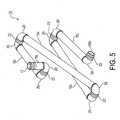
- FIG. 5is an isometric view from above of a foldable drain pipe in accordance with the present invention.
- FIG. 6is a side view of the foldable drain pipe shown in FIG. 5 , fully extended without hobble apparatus constraint, as fabricated and stand-alone prior to being integrated into the system;
- FIG. 7is a top view of the fully extended foldable drain pipe shown in FIG. 6 , fully extended without hobble apparatus constraint, as fabricated and stand-alone prior to being integrated into the system.
- a decanter system 10in accordance with the present invention, comprising a first embodiment of a decanter 12 , a settling tank 14 having a tank outlet 16 , and a foldable drain pipe (FDP) 18 connected therebetween.
- tank outlet 16extending through-the wall of tank 14 , is directly below the vertical operational path of the decanter such that FDP 18 folds and unfolds beneath decanter 12 and above tank outlet 16 .
- FIG. 2in a schematic decanter system 10 ′, an embodiment of a vertical lift decanter 12 ′ and associated FDP 18 are shown in four separate positions: A) flushing and cleaning of the decanter above the tank with FDP 18 partially unfolded; B) maintenance of the decanter above the tank with FDP 18 fully unfolded but hobbled; C) tank empty with the decanter fully lowered and FDP 18 fully folded; and D) the decanter in an intermediate operating position with FDP 18 partially unfolded.
- FIGS. 2 through 7construction of an exemplary FDP 18 in accordance with the present invention is shown in detail.
- FDP 18comprises a plurality of articulated sections of rigid pipe connected end to end.
- a first pipe 18 ais articulated at only one end and is modified at the other end 17 to be fixedly attached to decanter 12 , 12 ′ as shown in FIGS. 1 and 2 .
- a last pipe 18 bis articulated at only one end and is modified at the other end 19 to be rotatably attached to tank outlet 16 as shown in FIGS. 1 and 2 .
- Each of the intermediate pipes 18 c disposed between first and last pipes 18 a , 18 bis articulated at both ends. Articulation is provided by an elbow 20 on each of the articulated adjacent pipe ends, defining an elbow coupling pair, and a rotary seal 22 disposed between adjacent elbows 20 , the assembly defining an articulated coupling.
- An FDP in accordance with the present inventionmay be formed of any convenient material selected from the group consisting of metal and plastic polymer, preferably a plastic polymer comprising PVC.
- an FDP in accordance with the present inventionformed of pipe and elbow elements of constant length and cross-sectional area, has a constant volume over the complete range of positions of folding, from completely folded to completely extended.
- FDP 18will always remain full of liquid at any of positions A-D in FIG. 2 unless or until purposely drained by opening the tank outlet control valve.
- decanter 12 ′is in position B with the FDP. extended and the tank empty, FDP 18 is sufficiently strong to support its filled weight without rupture.
- This featureis an important performance attribute of an FDP in accordance with the present invention and a distinction over prior art soft drain hoses which can collapse and thus have a reduced volume under some operating conditions.
- each articulated couplingis limited to rotation in a common plane 26 , as shown in FIG. 7 (except for the coupling formed at last pipe 18 b which rotates in a parallel plane 26 ′), FDP 18 cannot drift sideways during its travel and therefore cannot make contact with a wall of tank 14 or with any adjacent decanter systems in a multiple-decanter installation.
- Scheme Acomprises discrete lengths of hobbling cable 23 a , 23 b , 23 c attached between the pipe sections and/or elbows as shown.
- Scheme Bcomprises a single cable 25 extending from pipe 18 a to pipe 18 b , passing through guides 27 attached to intermediate pipes 18 c .
- Snubbers 29 attached to cable 25engage guides 27 to limit the opening of the elbow pair angles as shown.
- the three intermediate elbow pairsare each provided with a pair of interfering stops 31 extending across plane of rotation 26 ( FIGS. 3 and 7 ). Stop pairs 31 are shown in operation in FIG. 2 , Positions A, B, and C. As elbow pairs rotate in plane 26 , stop pairs 31 eventually engage each other (e.g., Position B) limiting further unfolding of the elbow pairs.
Landscapes
- Chemical & Material Sciences (AREA)
- Chemical Kinetics & Catalysis (AREA)
- Engineering & Computer Science (AREA)
- General Engineering & Computer Science (AREA)
- Mechanical Engineering (AREA)
- Centrifugal Separators (AREA)
- Life Sciences & Earth Sciences (AREA)
- Hydrology & Water Resources (AREA)
- Environmental & Geological Engineering (AREA)
- Water Supply & Treatment (AREA)
- Organic Chemistry (AREA)
Abstract
Description
Claims (7)
Priority Applications (1)
| Application Number | Priority Date | Filing Date | Title |
|---|---|---|---|
| US14/961,946US10190710B2 (en) | 2013-12-27 | 2015-12-08 | Foldable drain pipe for a decanter in a water treatment system |
Applications Claiming Priority (2)
| Application Number | Priority Date | Filing Date | Title |
|---|---|---|---|
| US14/142,197US9855518B2 (en) | 2013-12-27 | 2013-12-27 | Method and apparatus for a vertical lift decanter system in a water treatment system |
| US14/961,946US10190710B2 (en) | 2013-12-27 | 2015-12-08 | Foldable drain pipe for a decanter in a water treatment system |
Related Parent Applications (1)
| Application Number | Title | Priority Date | Filing Date |
|---|---|---|---|
| US14/142,197Continuation-In-PartUS9855518B2 (en) | 2013-12-27 | 2013-12-27 | Method and apparatus for a vertical lift decanter system in a water treatment system |
Publications (2)
| Publication Number | Publication Date |
|---|---|
| US20160161037A1 US20160161037A1 (en) | 2016-06-09 |
| US10190710B2true US10190710B2 (en) | 2019-01-29 |
Family
ID=56093968
Family Applications (1)
| Application Number | Title | Priority Date | Filing Date |
|---|---|---|---|
| US14/961,946Expired - Fee RelatedUS10190710B2 (en) | 2013-12-27 | 2015-12-08 | Foldable drain pipe for a decanter in a water treatment system |
Country Status (1)
| Country | Link |
|---|---|
| US (1) | US10190710B2 (en) |
Families Citing this family (2)
| Publication number | Priority date | Publication date | Assignee | Title |
|---|---|---|---|---|
| CN107476366B (en)* | 2017-08-04 | 2022-08-02 | 山西临龙船舶修造有限公司 | Multifunctional silt remover |
| MY209309A (en)* | 2021-12-30 | 2025-07-01 | Prestamaju Holdings Sdn Bhd | A telescopic skimming decanter |
Citations (50)
| Publication number | Priority date | Publication date | Assignee | Title |
|---|---|---|---|---|
| US2401745A (en) | 1942-02-23 | 1946-06-11 | B & B Flotation Company | Froth flotation apparatus |
| US2799396A (en) | 1953-08-20 | 1957-07-16 | Cincinnati Butchers Supply Co | Apparatus for treating impure liquids containing suspended solids |
| US3006474A (en) | 1959-02-05 | 1961-10-31 | Dorr Oliver Inc | Method and means for converting the kinetic energy of a fluid stream into random turbulence |
| GB1079809A (en) | 1964-10-27 | 1967-08-16 | Paterson Candy Internat Ltd | Improved liquid clarification tank |
| US3372715A (en) | 1963-10-25 | 1968-03-12 | Youngstown Sheet And Tube Co | Bottom loading arm |
| US3717257A (en) | 1971-12-07 | 1973-02-20 | Rex Chainbelt Inc | Peripheral feed and effluent system for sedimentation tanks |
| US3957655A (en) | 1973-10-31 | 1976-05-18 | Barefoot Bernard B | Sphincter cone assembly for purifying water |
| US3964512A (en) | 1973-09-10 | 1976-06-22 | Odilon Dumas | Self-supporting pipe boom |
| US3997198A (en) | 1975-02-27 | 1976-12-14 | Linder Morris B | Swivel joint construction for pressure containing conduit |
| US4009106A (en) | 1975-06-18 | 1977-02-22 | Envirex Inc. | Clarifier with overflow scum removal |
| US4192746A (en) | 1978-05-24 | 1980-03-11 | Arvanitakis Kostas S | Liquid clarification system |
| EP0010395A1 (en) | 1978-10-10 | 1980-04-30 | Dorr-Oliver Incorporated | Settling tank |
| US4202372A (en)* | 1976-12-01 | 1980-05-13 | Fmc Corporation | Articulated fluid conduit with auxiliary support |
| US4226714A (en) | 1978-12-27 | 1980-10-07 | The Anaconda Company | Thickener control system |
| US4367145A (en) | 1981-01-26 | 1983-01-04 | Simpson Ellis O | Portable water clarifier |
| US4405458A (en) | 1980-04-29 | 1983-09-20 | Mchugh Jr Leo A | Continuous flow, variable capacity self-compensating floating weir |
| US4474213A (en) | 1982-02-08 | 1984-10-02 | Fmc Corporation | Folding service line |
| US4608165A (en) | 1985-04-08 | 1986-08-26 | Samdor Engineering Limited | Liquid surface skimming trough assembly |
| US4715570A (en) | 1986-07-07 | 1987-12-29 | David Mashuda | Foldable drain hose support |
| JPH0365298A (en) | 1989-08-02 | 1991-03-20 | Kubota Corp | Batch activated sludge treatment equipment |
| EP0421265A1 (en) | 1989-10-02 | 1991-04-10 | RITTERSHAUS & BLECHER GMBH | Process and apparatus for admixing of a flocculant solution to sludge liquid before filtration |
| US5205768A (en) | 1991-08-01 | 1993-04-27 | Imodco, Inc. | Multiple fluid swivel arrangement |
| US5290434A (en) | 1993-02-10 | 1994-03-01 | Richard James G | Effluent dosing septic system |
| US5352356A (en) | 1991-09-03 | 1994-10-04 | Murphy D Thomas | Stovepipe decanter apparatus |
| US5411633A (en) | 1991-04-30 | 1995-05-02 | Kamyr, Inc. | Medium consistency pulp ozone bleaching |
| US5754986A (en) | 1996-11-12 | 1998-05-26 | Chien; Chuan-Tai | Water-saving device of water tank for flush toilet |
| US5951878A (en) | 1998-03-20 | 1999-09-14 | Aqua-Aerobic Systems, Inc. | Method and apparatus for cleaning filter material in a filter apparatus utilizing a suction generating nozzle |
| US6213555B1 (en) | 2000-07-20 | 2001-04-10 | Dennis D. Sulpizio | Adjustable angle chaise lounge construction |
| JP2002001310A (en) | 2000-06-23 | 2002-01-08 | Toshiba Plant Kensetsu Co Ltd | Method for removing scum in fermentation tank |
| US20030164341A1 (en) | 2001-12-31 | 2003-09-04 | Use Clark Joseph | Mobile pollution trap and method |
| US7025888B2 (en) | 2001-05-23 | 2006-04-11 | Ashbrook Simon-Hartley Operations, Lp | Floating decanter |
| EP1700963A1 (en) | 2003-11-20 | 2006-09-13 | Kiyoshi Komatsu | Refuse and oil removing device and refuse and oil collection bag for the device |
| US20060218712A1 (en) | 2005-04-01 | 2006-10-05 | David Nichols-Roy | Flush valve with adjustable overflow tube and method for installing a toilet valve |
| US7216373B2 (en) | 2004-06-23 | 2007-05-15 | So-Mel Huang | Toilet tank valve seat structure |
| US20070151916A1 (en) | 2004-05-26 | 2007-07-05 | Trisep Corporation | Network for supporting spiral wound membrane cartridges for submerged operation |
| US20080296228A1 (en) | 2005-11-14 | 2008-12-04 | Otv Sa | Wastewater Treatment Method Comprising Decantation and Fine Screening Stages and Device for Carrying Out Said Method |
| US20090065957A1 (en) | 2005-04-15 | 2009-03-12 | Chien-Pei Mao | Integrated fuel injection and mixing systems for fuel reformers and methods of using the same |
| US20090095672A1 (en) | 2007-10-10 | 2009-04-16 | Wilcher Stephen B | High efficiency grit removal system |
| US20100176054A1 (en) | 2009-01-12 | 2010-07-15 | Koopmans Richard J | Method for remediating solids in waste lifting stations |
| US20100236999A1 (en) | 2007-10-12 | 2010-09-23 | Hideo Utsunomiya | Scum removing apparatus |
| US20110042844A1 (en) | 2009-08-18 | 2011-02-24 | Darrell Ian Brown | Method and apparatus for forming a batt of particulate material for use as a component in an absorbent core assembly |
| US20110073296A1 (en) | 2009-09-25 | 2011-03-31 | Baker Hughes Incorporated | System and apparatus for well screening including a foam layer |
| US7972505B2 (en)* | 2008-07-22 | 2011-07-05 | Trans Terra Corporation | Primary equalization settling tank |
| WO2011087936A2 (en) | 2010-01-12 | 2011-07-21 | Trans Terra Corporation | Self-cleaning influent feed system for a wastewater treatment plant |
| US20110278212A1 (en)* | 2010-05-14 | 2011-11-17 | University Of Tennessee Research Foundation | Sediment and detention basin drainage system and method |
| US20120261337A1 (en) | 2011-04-14 | 2012-10-18 | Global Water Group, Incorporated | System and method for wastewater treatment |
| US8398864B2 (en) | 2008-07-22 | 2013-03-19 | Trans Terra Corporation | Screened decanter assembly for a settling tank |
| US8721889B2 (en) | 2009-07-08 | 2014-05-13 | Saudi Arabian Oil Company | Wastewater treatment process including irradiation of primary solids |
| US8875371B2 (en) | 2009-02-12 | 2014-11-04 | Red Leaf Resources, Inc. | Articulated conduit linkage system |
| EP2889067A1 (en) | 2013-12-27 | 2015-07-01 | ClearCove Systems, Inc. | Method and apparatus for a vertical lift decanter system in a water treatment system |
- 2015
- 2015-12-08USUS14/961,946patent/US10190710B2/ennot_activeExpired - Fee Related
Patent Citations (52)
| Publication number | Priority date | Publication date | Assignee | Title |
|---|---|---|---|---|
| US2401745A (en) | 1942-02-23 | 1946-06-11 | B & B Flotation Company | Froth flotation apparatus |
| US2799396A (en) | 1953-08-20 | 1957-07-16 | Cincinnati Butchers Supply Co | Apparatus for treating impure liquids containing suspended solids |
| US3006474A (en) | 1959-02-05 | 1961-10-31 | Dorr Oliver Inc | Method and means for converting the kinetic energy of a fluid stream into random turbulence |
| US3372715A (en) | 1963-10-25 | 1968-03-12 | Youngstown Sheet And Tube Co | Bottom loading arm |
| GB1079809A (en) | 1964-10-27 | 1967-08-16 | Paterson Candy Internat Ltd | Improved liquid clarification tank |
| US3717257A (en) | 1971-12-07 | 1973-02-20 | Rex Chainbelt Inc | Peripheral feed and effluent system for sedimentation tanks |
| US3964512A (en) | 1973-09-10 | 1976-06-22 | Odilon Dumas | Self-supporting pipe boom |
| US3957655A (en) | 1973-10-31 | 1976-05-18 | Barefoot Bernard B | Sphincter cone assembly for purifying water |
| US3997198A (en) | 1975-02-27 | 1976-12-14 | Linder Morris B | Swivel joint construction for pressure containing conduit |
| US4009106A (en) | 1975-06-18 | 1977-02-22 | Envirex Inc. | Clarifier with overflow scum removal |
| US4202372A (en)* | 1976-12-01 | 1980-05-13 | Fmc Corporation | Articulated fluid conduit with auxiliary support |
| US4192746A (en) | 1978-05-24 | 1980-03-11 | Arvanitakis Kostas S | Liquid clarification system |
| EP0010395A1 (en) | 1978-10-10 | 1980-04-30 | Dorr-Oliver Incorporated | Settling tank |
| US4226714A (en) | 1978-12-27 | 1980-10-07 | The Anaconda Company | Thickener control system |
| US4405458A (en) | 1980-04-29 | 1983-09-20 | Mchugh Jr Leo A | Continuous flow, variable capacity self-compensating floating weir |
| US4367145A (en) | 1981-01-26 | 1983-01-04 | Simpson Ellis O | Portable water clarifier |
| US4474213A (en) | 1982-02-08 | 1984-10-02 | Fmc Corporation | Folding service line |
| US4608165A (en) | 1985-04-08 | 1986-08-26 | Samdor Engineering Limited | Liquid surface skimming trough assembly |
| US4715570A (en) | 1986-07-07 | 1987-12-29 | David Mashuda | Foldable drain hose support |
| JPH0365298A (en) | 1989-08-02 | 1991-03-20 | Kubota Corp | Batch activated sludge treatment equipment |
| EP0421265A1 (en) | 1989-10-02 | 1991-04-10 | RITTERSHAUS & BLECHER GMBH | Process and apparatus for admixing of a flocculant solution to sludge liquid before filtration |
| US5411633A (en) | 1991-04-30 | 1995-05-02 | Kamyr, Inc. | Medium consistency pulp ozone bleaching |
| US5205768A (en) | 1991-08-01 | 1993-04-27 | Imodco, Inc. | Multiple fluid swivel arrangement |
| US5352356A (en) | 1991-09-03 | 1994-10-04 | Murphy D Thomas | Stovepipe decanter apparatus |
| US5290434A (en) | 1993-02-10 | 1994-03-01 | Richard James G | Effluent dosing septic system |
| US5754986A (en) | 1996-11-12 | 1998-05-26 | Chien; Chuan-Tai | Water-saving device of water tank for flush toilet |
| US5951878A (en) | 1998-03-20 | 1999-09-14 | Aqua-Aerobic Systems, Inc. | Method and apparatus for cleaning filter material in a filter apparatus utilizing a suction generating nozzle |
| JP2002001310A (en) | 2000-06-23 | 2002-01-08 | Toshiba Plant Kensetsu Co Ltd | Method for removing scum in fermentation tank |
| US6213555B1 (en) | 2000-07-20 | 2001-04-10 | Dennis D. Sulpizio | Adjustable angle chaise lounge construction |
| US7025888B2 (en) | 2001-05-23 | 2006-04-11 | Ashbrook Simon-Hartley Operations, Lp | Floating decanter |
| US20030164341A1 (en) | 2001-12-31 | 2003-09-04 | Use Clark Joseph | Mobile pollution trap and method |
| EP1700963A1 (en) | 2003-11-20 | 2006-09-13 | Kiyoshi Komatsu | Refuse and oil removing device and refuse and oil collection bag for the device |
| US20070095749A1 (en) | 2003-11-20 | 2007-05-03 | Kiyoshi Komatsu | Refuse/oil removing device and refuse/oil recovery bag |
| US20070151916A1 (en) | 2004-05-26 | 2007-07-05 | Trisep Corporation | Network for supporting spiral wound membrane cartridges for submerged operation |
| US7216373B2 (en) | 2004-06-23 | 2007-05-15 | So-Mel Huang | Toilet tank valve seat structure |
| US20060218712A1 (en) | 2005-04-01 | 2006-10-05 | David Nichols-Roy | Flush valve with adjustable overflow tube and method for installing a toilet valve |
| US20090065957A1 (en) | 2005-04-15 | 2009-03-12 | Chien-Pei Mao | Integrated fuel injection and mixing systems for fuel reformers and methods of using the same |
| US20080296228A1 (en) | 2005-11-14 | 2008-12-04 | Otv Sa | Wastewater Treatment Method Comprising Decantation and Fine Screening Stages and Device for Carrying Out Said Method |
| US20090095672A1 (en) | 2007-10-10 | 2009-04-16 | Wilcher Stephen B | High efficiency grit removal system |
| US20100236999A1 (en) | 2007-10-12 | 2010-09-23 | Hideo Utsunomiya | Scum removing apparatus |
| US7972505B2 (en)* | 2008-07-22 | 2011-07-05 | Trans Terra Corporation | Primary equalization settling tank |
| US8398864B2 (en) | 2008-07-22 | 2013-03-19 | Trans Terra Corporation | Screened decanter assembly for a settling tank |
| US8225942B2 (en) | 2008-07-22 | 2012-07-24 | Trans Terra Corporation | Self-cleaning influent feed system for a wastewater treatment plant |
| US20100176054A1 (en) | 2009-01-12 | 2010-07-15 | Koopmans Richard J | Method for remediating solids in waste lifting stations |
| US8875371B2 (en) | 2009-02-12 | 2014-11-04 | Red Leaf Resources, Inc. | Articulated conduit linkage system |
| US8721889B2 (en) | 2009-07-08 | 2014-05-13 | Saudi Arabian Oil Company | Wastewater treatment process including irradiation of primary solids |
| US20110042844A1 (en) | 2009-08-18 | 2011-02-24 | Darrell Ian Brown | Method and apparatus for forming a batt of particulate material for use as a component in an absorbent core assembly |
| US20110073296A1 (en) | 2009-09-25 | 2011-03-31 | Baker Hughes Incorporated | System and apparatus for well screening including a foam layer |
| WO2011087936A2 (en) | 2010-01-12 | 2011-07-21 | Trans Terra Corporation | Self-cleaning influent feed system for a wastewater treatment plant |
| US20110278212A1 (en)* | 2010-05-14 | 2011-11-17 | University Of Tennessee Research Foundation | Sediment and detention basin drainage system and method |
| US20120261337A1 (en) | 2011-04-14 | 2012-10-18 | Global Water Group, Incorporated | System and method for wastewater treatment |
| EP2889067A1 (en) | 2013-12-27 | 2015-07-01 | ClearCove Systems, Inc. | Method and apparatus for a vertical lift decanter system in a water treatment system |
Non-Patent Citations (6)
| Title |
|---|
| "Vortex Grit Chamber KD 01.5" , Dec. 17, 2013 (Dec. 17, 2013), X P055236807 Retrieved from the Internet: URL: http://www.dwe.dk/files/files/produkter/KD01-5_bro_GB.pdf [retrieved on Dec. 16, 2015] p. 2; figure 1, 2. |
| Communication: Extended EP Search Report for EP 14200235, dated Jan. 3, 2016, 17 Pages. |
| Communication: Partial EP Search Report for EP 15175703, dated Jul. 1, 2016, 10 Pages. |
| Dango & Dienenthal Plate Filter Brochure, 2011, 6 Pages. |
| Freedonia, Water & Wastewater Pipe, Feb. 2012. p. 4 (Year: 2012).* |
| Parker, Rotary Seal Design Guide, Mar. 11, 2010, p. 15-16 (Year: 2010).* |
Also Published As
| Publication number | Publication date |
|---|---|
| US20160161037A1 (en) | 2016-06-09 |
Similar Documents
| Publication | Publication Date | Title |
|---|---|---|
| EP2889067B1 (en) | Method and apparatus for a vertical lift decanter system in a water treatment system | |
| EP2929942B1 (en) | Apparatus for removal of floatables and scum in a waste water treatment system | |
| US6919033B2 (en) | Stormwater treatment system for eliminating solid debris | |
| US4892666A (en) | Skimming apparatus and method | |
| US9908067B2 (en) | Floatables and scum removal apparatus for a waste water treatment system | |
| CA3085711C (en) | Hydrodynamic separators, assemblies, and methods for storm water treatment | |
| US20150183657A1 (en) | Method and apparatus for using air scouring of a screen in a water treatment facility | |
| US10190710B2 (en) | Foldable drain pipe for a decanter in a water treatment system | |
| US9587651B2 (en) | Valveless siphon decanter and methods of use | |
| WO2016163700A1 (en) | Rainwater collecting facility and moving-type rainwater storage tank and method for moving rainwater on water | |
| CN112138434A (en) | A sediment device for oiliness mud | |
| GB2374297A (en) | Dynamic sedimentation system | |
| US3925204A (en) | Liquid separating equipment | |
| CN101332382B (en) | Filtering device of self-controlled liquid surface | |
| KR20160048501A (en) | Floating scum scraper and dissolved air flotation type water treatment apparatus using the same | |
| CN202022770U (en) | Floating water distribution homogenizing oil recovery device | |
| KR101057465B1 (en) | Raw water contaminant separator | |
| US5585006A (en) | Clarifier having sludge pick-up tubes | |
| RU2143517C1 (en) | Device for collecting oil and oil products from water surface | |
| US11787715B2 (en) | Apparatus and method for recycling blackwater and greywater at oil and gas well sites | |
| CN104837537A (en) | Apparatus for clarifying sludge-containing effluent | |
| JP4475896B2 (en) | Combined sewage method | |
| SU821410A1 (en) | Radial settler for removing floating and suspended substances from waste water | |
| JPH0621523Y2 (en) | Clear water discharge device | |
| KR20240012875A (en) | Non-point source contaminant treatment device |
Legal Events
| Date | Code | Title | Description |
|---|---|---|---|
| AS | Assignment | Owner name:CLEARCOVE SYSTEMS, INC., NEW YORK Free format text:ASSIGNMENT OF ASSIGNORS INTEREST;ASSIGNORS:BUTLER, MICHAEL A.;BERTONI, ALFRED;JACOBS, JONATHAN M.;REEL/FRAME:037236/0541 Effective date:20151208 | |
| STCF | Information on status: patent grant | Free format text:PATENTED CASE | |
| AS | Assignment | Owner name:TERRY, DAVID, NEW YORK Free format text:SECURITY INTEREST;ASSIGNOR:CLEARCOVE SYSTEMS, INC.;REEL/FRAME:050854/0852 Effective date:20190816 Owner name:SNYDER, STEVE, PENNSYLVANIA Free format text:SECURITY INTEREST;ASSIGNOR:CLEARCOVE SYSTEMS, INC.;REEL/FRAME:050854/0852 Effective date:20190816 Owner name:WESTBROOK, GREG, NEW YORK Free format text:SECURITY INTEREST;ASSIGNOR:CLEARCOVE SYSTEMS, INC.;REEL/FRAME:050854/0852 Effective date:20190816 | |
| AS | Assignment | Owner name:RIT VENTURE FUND I, LLC, NEW YORK Free format text:CORRECTIVE ASSIGNMENT TO CORRECT THE ADD OMITTED ASSIGNEE PREVIOUSLY RECORDED AT REEL: 050854 FRAME: 0852. ASSIGNOR(S) HEREBY CONFIRMS THE ASSIGNMENT;ASSIGNOR:CLEARCOVE SYSTEMS, INC.;REEL/FRAME:050911/0615 Effective date:20190816 Owner name:TERRY, DAVID, NEW YORK Free format text:CORRECTIVE ASSIGNMENT TO CORRECT THE ADD OMITTED ASSIGNEE PREVIOUSLY RECORDED AT REEL: 050854 FRAME: 0852. ASSIGNOR(S) HEREBY CONFIRMS THE ASSIGNMENT;ASSIGNOR:CLEARCOVE SYSTEMS, INC.;REEL/FRAME:050911/0615 Effective date:20190816 Owner name:WESTBROOK, GREG, NEW YORK Free format text:CORRECTIVE ASSIGNMENT TO CORRECT THE ADD OMITTED ASSIGNEE PREVIOUSLY RECORDED AT REEL: 050854 FRAME: 0852. ASSIGNOR(S) HEREBY CONFIRMS THE ASSIGNMENT;ASSIGNOR:CLEARCOVE SYSTEMS, INC.;REEL/FRAME:050911/0615 Effective date:20190816 Owner name:SNYDER, STEVE, PENNSYLVANIA Free format text:CORRECTIVE ASSIGNMENT TO CORRECT THE ADD OMITTED ASSIGNEE PREVIOUSLY RECORDED AT REEL: 050854 FRAME: 0852. ASSIGNOR(S) HEREBY CONFIRMS THE ASSIGNMENT;ASSIGNOR:CLEARCOVE SYSTEMS, INC.;REEL/FRAME:050911/0615 Effective date:20190816 | |
| FEPP | Fee payment procedure | Free format text:MAINTENANCE FEE REMINDER MAILED (ORIGINAL EVENT CODE: REM.); ENTITY STATUS OF PATENT OWNER: SMALL ENTITY | |
| LAPS | Lapse for failure to pay maintenance fees | Free format text:PATENT EXPIRED FOR FAILURE TO PAY MAINTENANCE FEES (ORIGINAL EVENT CODE: EXP.); ENTITY STATUS OF PATENT OWNER: SMALL ENTITY | |
| STCH | Information on status: patent discontinuation | Free format text:PATENT EXPIRED DUE TO NONPAYMENT OF MAINTENANCE FEES UNDER 37 CFR 1.362 | |
| FP | Lapsed due to failure to pay maintenance fee | Effective date:20230129 |