US10190408B2 - System, apparatus, and method for drilling - Google Patents
System, apparatus, and method for drillingDownload PDFInfo
- Publication number
- US10190408B2 US10190408B2US14/087,637US201314087637AUS10190408B2US 10190408 B2US10190408 B2US 10190408B2US 201314087637 AUS201314087637 AUS 201314087637AUS 10190408 B2US10190408 B2US 10190408B2
- Authority
- US
- United States
- Prior art keywords
- signal
- pair
- electromagnetic
- antenna
- antennas
- Prior art date
- Legal status (The legal status is an assumption and is not a legal conclusion. Google has not performed a legal analysis and makes no representation as to the accuracy of the status listed.)
- Active, expires
Links
Images


Classifications
- E21B47/122—
- E—FIXED CONSTRUCTIONS
- E21—EARTH OR ROCK DRILLING; MINING
- E21B—EARTH OR ROCK DRILLING; OBTAINING OIL, GAS, WATER, SOLUBLE OR MELTABLE MATERIALS OR A SLURRY OF MINERALS FROM WELLS
- E21B47/00—Survey of boreholes or wells
- E21B47/12—Means for transmitting measuring-signals or control signals from the well to the surface, or from the surface to the well, e.g. for logging while drilling
- E21B47/13—Means for transmitting measuring-signals or control signals from the well to the surface, or from the surface to the well, e.g. for logging while drilling by electromagnetic energy, e.g. radio frequency
Definitions
- the present disclosurerelates to a drilling operation, and in particular to a system, apparatus, and method for monitoring a drilling operation.
- Wells drilled for oil, gas and other purposesmay be thousands of feet underground, change direction and extend horizontally.
- Communication systemshave been developed that transmit information regarding the well path, formation properties, and drilling conditions measured with sensors at or near the drill bit. Obtaining and transmitting information is commonly referred to as measurement-while-drilling (MWD) and logging-while-drilling (LWD).
- MWDmeasurement-while-drilling
- LWDlogging-while-drilling
- One transmission techniqueis electromagnetic (EM) telemetry or telemetry.
- Telemetry systemsinclude tools that are configured to transmit an electromagnetic signal to the surface having encoded therein directional, formation and other drilling data obtained during the drilling operation.
- An embodiment of the present disclosureincludes a method for monitoring a drilling operation of a drilling system.
- the drilling systemhas a drill string configured to form a borehole in an earthen formation during the drilling operation.
- the methodincludes the step of receiving a signal via a first pair of antennas positioned on a surface of the earthen formation, the signal being transmitted by a telemetry tool supported by the drill string and being located at a downhole end of the borehole during the drilling operation.
- the signal received by the first pair of antennashas a first signal characteristic.
- the methodincludes receiving the signal via a second pair of antennas positioned on the surface at a different location than that of the first pair of antennas.
- the signal received by the second pair of antennashas a second signal characteristic.
- the methodincludes identifying which of the first signal characteristic and the second signal characteristic of the signal received by the respective first and second pairs of antennas is a preferred signal characteristic.
- the methodcan include decoding the signal received by one of the first and second pairs of antennas that has received the signal with the preferred signal characteristic.
- the methodcan include transmitting a signal from the telemetry tool at a first downhole location in the borehole during a first duration of the drilling operation.
- the methodcan further include receiving the signal via at least two antenna pairs.
- the at least two antenna pairsare positioned on the surface and spaced apart with respect to each other and the borehole.
- the methodcan include receiving, during the first duration of the drilling operation, a surface signal from each of the at least two antenna pairs that received the signal. Further, the method can include decoding the surface signal from one of the at least two antenna pairs that received the signal having a preferred signal characteristic.
- the systemincludes a plurality of antenna pairs, each antenna pair configured to receive a signal that is transmitted by a telemetry tool at a downhole location in the borehole during the drilling operation.
- the systemfurther includes a receiver assembly configured for electronic connection with each of the plurality of antenna pairs.
- the receiver assemblyis configured to receive a plurality of surface signals from each of the respective plurality of antenna pairs when the receiver assembly is electronically connected to the plurality of antenna pairs.
- Each surface signalis indicative of characteristics of the signal received by the respective plurality of antenna pairs.
- the systemincludes a computer processor that is configured for electronic communication with the receiver assembly.
- the computer processoris also configured to determine which among the plurality of surface signals have a preferred signal characteristic. In response to the determination of which surface signal has the preferred signal characteristic, the computer processor decodes the surface signal received by one of the plurality of antenna pairs that received the signal with the preferred signal characteristic.
- the drilling systemincludes a drill string carried by a support member and configured to rotate so as to define the borehole along a drilling direction.
- the drill stringincludes a drill bit positioned at the downhole end of the drill string and one or more sensors carried by the drill string.
- the one or more sensorsare configured to obtain drilling data.
- the drill stringcan include a telemetry tool positioned in an up-hole direction away from the drill bit.
- the telemetry toolis configured to transmit the drilling data via a signal.
- the drilling systemcan include a first pair of antennas configured to receive the signal and a second pair of antennas configured to receive the signal. The first and second pair of antennas are in different locations relative to the support member.
- the drilling systemcan also include a receiver assembly electronically connected to the first and second pair of antennas.
- the receiver assemblyis configured to receive the surface signals from each the first and second pair of antennas.
- the surface signalsare indicative of the signal that has been received by each pair of antennas.
- the drilling systemcan include at least one computer processor configured to decode one of the surface signals received by the receiver assembly based on one or more preferred characteristics of the surface signals obtained from each of the first and second pairs of antennas.
- FIG. 1Ais a schematic plan view of a drilling system forming a borehole in an earthen formation, according to an embodiment of the present disclosure
- FIG. 1Bis a schematic side view of the drilling system forming the borehole in an earthen formation shown in FIG. 1A ;
- FIG. 1Cis a detailed sectional view of a telemetry tool incorporated into the drilling system shown in FIG. 1A ;
- FIG. 1Dis a detailed view of a portion of the drilling system shown in FIG. 1B ;
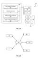
- FIG. 2Ais a block diagram of a computing device and telemetry system of the drilling system shown in FIGS. 1A and 1B ;
- FIG. 2Bis a block diagram illustrating a network of one or more computing devices and the telemetry system shown in FIGS. 1A and 1B ;
- FIGS. 3A and 3Bis process flow diagram illustrating a method for monitoring a drilling operation via the telemetry system shown in FIGS. 1A and 1B ;
- FIG. 4is process flow diagram illustrating a method for monitoring a drilling operation of the drilling system via the telemetry system, according to another embodiment of the present disclosure.
- the drilling system 1is configured to drill a borehole 2 in an earthen formation 3 during a drilling operation.
- the drilling system 1includes a drill string 6 for forming the borehole 2 in the earthen formation 3 , a telemetry system 100 and at least one computing device 200 .
- the telemetry system 100processes and monitors the transmission of drilling data obtained in a downhole location of the borehole 2 to the surface 4 of the earthen formation 3 via an electromagnetic signal 130 .
- the telemetry system 100includes a receiver assembly 110 and two or more antenna pairs 120 .
- the receiver assembly 110can be in electronic communication with the computing device 200 .
- Each antenna pair 120can receive, for instance, detect an electrical field component of an electromagnetic signal 130 transmitted by a downhole telemetry tool 40 as a voltage or surface signal.
- the detected surface signalembodies characteristics of the electric field component of the electromagnetic signal 130 , such as the amplitude and wavelength components of the electric field.
- the receiver assembly 110receives the surface signal from each respective antenna pair 120 .
- the telemetry system 100is configured to decode into drilling data one surface signal among the plurality of surface signals received by the receiver assembly 110 from the antenna pairs 120 .
- the determination of which surface signal to decodeis based in part upon the comparative characteristics of each surface signal detected by respective antenna pairs 120 . For instance, only the surface signal detected by the antenna pair 120 that has preferred signal characteristics is decoded, as will be further detailed below.
- the computing device 200can host one or more applications, for instance software applications, that can initiate desired decoding or signal processing, log parameters that indicate the type of formation being drilled through, the presence of liquids, and run other applications that are configured to perform various methods for monitoring and controlling the drilling operation.
- applicationsfor instance software applications, that can initiate desired decoding or signal processing, log parameters that indicate the type of formation being drilled through, the presence of liquids, and run other applications that are configured to perform various methods for monitoring and controlling the drilling operation.
- the drilling system 1 , telemetry system 100 and methods 300 ( FIGS. 3A, 3B ) and 400 ( FIG. 4 ) as describe hereallow continuous monitoring of signals transmitted from the telemetry tool 40 over the course of the drilling operation. While signal characteristics for each antenna pair 120 change over time as drilling progresses into the formation, the telemetry system 100 can “react” to changing signal transmission conditions by switching, at least for decoding purposes, from an antenna pair with poor signal characteristics to an antenna pair with preferred signal characteristics.
- the ability of monitor and switch among multiple signalshas several advantages. For instance, signal quality from multiple antenna pair locations can be monitored in real-time, simultaneously. This allows the drilling operator to utilize the antenna pairs that have the best or preferred signal reception among the multiple antenna pair locations, based on conditions during drilling.
- Real-time monitoring and signal switchingalso provides greater flexibility to minimize poor signal reception, which improves data reliability, more reliable decoding and fewer decoding errors.
- the ability to monitor, select, a process signals based on detected signal characteristicscan result in better data utilization compared to conventional systems operating in similar marginal transmission conditions.
- Telemetryrefers electromagnetic (EM) telemetry.
- the telemetry system 100can be configured to produce, detect, and process an electromagnetic field signal 130 .
- the telemetry system 110is configured to permit reception and detection of the electrical field component of the electromagnetic field signal 130 .
- the telemetry system 100can also be configured to permit reception and detection of the magnetic field component of the electromagnetic field signal 130 .
- the telemetry tool 40can be configured to produce an electromagnetic field signal 130 , and amplify the electric field component, and alternatively or in addition to, amplify the magnetic field component.
- the antenna pairs 120 and receiver assembly 110can be configured to receive, for instance detect, the electric field component of the electromagnetic signal 130 .
- the antenna pairs 120 and receiver assembly 110can be configured to receive, for instance detect, the magnetic field component of the electromagnetic signal 130 .
- the drilling system 1is configured to drill the borehole 2 in an earthen formation 3 along a borehole axis E such that the borehole axis E extends at least partially along a vertical direction V.
- the vertical direction Vrefers to a direction that is perpendicular to the surface 4 of the earthen formation 3 .
- the drill string 6can be configured for directional drilling, whereby all or a portion of the borehole 2 (and thus axis E) is angularly offset with respect to the vertical direction V along a horizontal direction H.
- the horizontal direction His at least mostly perpendicular to the vertical direction V so as to be aligned with or parallel to the surface 4 .
- the horizontal direction Hcan extend along any direction that is perpendicular to the vertical direction V, for instance north, east, south and west, as well as any incremental direction between north, east, south and west.
- downhole or downhole locationmeans a location closer to the bottom end of the drill string 6 than the top end of the drill string 6 .
- a downhole direction 90FIGS. 1B and 1C ) refers to the direction from the surface 4 toward a bottom end (not numbered) of the borehole 2
- an uphole directionrefers the direction from the bottom end of the borehole 2 toward the surface 4 .
- the downhole and uphole directionscan be curvilinear for directional drilling operations.
- the drilling direction or well pathextends partially along the vertical direction V and the horizontal direction H in any particular geographic direction as noted above.
- An expected drilling directionrefers to the direction along which the borehole will be defined in the earthen formation 3 . While a directional drilling configuration is shown, the telemetry system 100 can be used with vertical drilling operations and is similarly beneficial in vertical drilling.
- the drilling system 1includes a derrick 5 that supports the drill string 6 that extends through and forms the borehole.
- the drill string 6includes several drill string components that define the drill string 6 and the internal passage (not shown).
- Drill string componentsinclude one or more subs, stabilizers, drill pipe sections, and drill collars, a bottomhole assembly (BHA) 7 , and drill bit 14 .
- the drill string 6can include the telemetry tool 40 and one or more sensors 42 as further detailed below.
- the drill string 6is elongate along a central longitudinal axis 32 and includes a top end 8 and a bottom end 10 spaced from the top end 8 along the central longitudinal axis 32 .
- a casing 12Located near the surface and surrounding the top end 8 is a casing 12 .
- the bottom end 10 of the drill string 6includes the drill bit 14 .
- One or more drivessuch as a top drive or rotary table, are configured to rotate the drill string 6 so as to control the rotational speed (RPM) of, and torque on, the drill bit 14 .
- the one or more drivescan rotate the drill string 6 and drill bit 14 to define the borehole 2 .
- a pumpis configured to pump a fluid (not shown), for instance drilling mud, drilling with air, foam (or aerated mud), downward through an internal passage (not shown) in the drill string 6 .
- a mud motormay be disposed at a downhole location of the drill string 6 to rotate the drill bit 14 independent of the rotation of the drill string 6 .
- the drilling systemcan include one or more computing devices 200 in electronic communication with the telemetry system 100 .
- the computing device 200is configured to receive, process, and store various drilling operation information, such as directional, formation information obtained from the downhole sensors described above.
- Any suitable computing device 200may be configured to host a software application for monitoring, controlling and drilling information as described herein.
- the computing device 200can include any appropriate device, examples of which include a desktop computing device, a server computing device, or a portable computing device, such as a laptop, tablet or smart phone. In an exemplary configuration illustrated in FIG.
- the computing device 200includes a processing portion 202 , a memory portion 204 , an input/output portion 206 , and a user interface (UI) portion 208 .
- UIuser interface
- the block diagram depiction of the computing device 200is exemplary and not intended to imply a specific implementation and/or configuration.
- the processing portion 202 , memory portion 204 , input/output portion 206 and user interface portion 208can be coupled together to allow communications therebetween.
- any of the above componentsmay be distributed across one or more separate devices and/or locations.
- the input/output portion 206includes a receiver of the computing device 200 , a transmitter (not to be confused with components of the telemetry tool 40 described below) of the computing device 200 , or an electronic connector for wired connection, or a combination thereof.
- the input/output portion 206is capable of receiving and/or providing information pertaining to communication with a network such as, for example, the Internet.
- transmit and receive functionalitymay also be provided by one or more devices external to the computing device 200 .
- the input/output portion 206can be in electronic communication with the receiver assembly 110 .
- the memory portion 204can be volatile (such as some types of RAM), non-volatile (such as ROM, flash memory, etc.), or a combination thereof.
- the computing device 200can include additional storage (e.g., removable storage and/or non-removable storage) including, but not limited to, tape, flash memory, smart cards, CD-ROM, digital versatile disks (DVD) or other optical storage, magnetic cassettes, magnetic tape, magnetic disk storage or other magnetic storage devices, universal serial bus (USB) compatible memory, or any other medium which can be used to store information and which can be accessed by the computing device 200 .
- the computing device 200can contain the user interface portion 208 , which can include an input device and/or display (input device and display not shown), that allows a user to communicate with the computing device 200 .
- the user interface 208can include inputs that provide the ability to control the computing device 200 , via, for example, buttons, soft keys, a mouse, voice actuated controls, a touch screen, movement of the computing device 200 , visual cues (e.g., moving a hand in front of a camera on the computing device 200 ), or the like.
- the user interface 208can provide outputs, including visual information, such as the visual indication of the plurality of operating ranges for one or more drilling parameters via the display 213 (not shown).
- Other outputscan include audio information (e.g., via speaker), mechanically (e.g., via a vibrating mechanism), or a combination thereof.
- the user interface 208can include a display, a touch screen, a keyboard, a mouse, an accelerometer, a motion detector, a speaker, a microphone, a camera, or any combination thereof.
- the user interface 208can further include any suitable device for inputting biometric information, such as, for example, fingerprint information, retinal information, voice information, and/or facial characteristic information, for instance, so to require specific biometric information for access to the computing device 200 .
- an exemplary and suitable communication architecturecan facilitate monitoring a drilling operation of the drilling system 1 .
- Such an exemplary architecturecan include one or more computing devices 200 , 210 and 220 each of which can be in electronic communication with a database 230 and the telemetry system 100 via common communications network 240 .
- the database 230though schematically represented separate from the computing device 200 could also be a component of the memory portion 204 of the computing device 200 . It should be appreciated that numerous suitable alternative communication architectures are envisioned.
- the drilling control and monitoring applicationOnce the drilling control and monitoring application has been installed onto the computing device 200 , such as described above, it can transfer information between other computing devices on the common network 240 , such as, for example, the Internet.
- a user 24may transmit, or cause the transmission of information via the network 240 regarding one or more drilling parameters to the computing device 210 of a supplier of the telemetry tool 40 , or alternatively to computing device 220 of another third party, e.g., oil company or oil services company, via the network 240 .
- the third partycan view, via a display, the drilling data.
- the computing device 200 and the database 230 depicted in FIG. 2Bmay be operated in whole or in part by, for example, a rig operator at the drill site, a drill site owner, drilling company, and/or any manufacturer or supplier of drilling system components, or other service provider, such as a third party providing drill string design service.
- a rig operator at the drill sitea drill site owner, drilling company, and/or any manufacturer or supplier of drilling system components, or other service provider, such as a third party providing drill string design service.
- each of the parties set forth above and/or other relevant partiesmay operate any number of respective computers and may communicate internally and externally using any number of networks including, for example, wide area networks (WAN's) such as the Internet or local area networks (LAN's).
- WAN'swide area networks
- LAN'slocal area networks
- Database 230may be used, for example, to store data regarding one or more drilling parameters, the plurality of operating ranges from a previous drill run, a current drill run, data concerning the models for the drill string components, models for EM performance, and EM performance data from prior wells in the vicinity of the drill site. Such information can provide an indication of what EM parameters, such as frequency and power requirements at different depths and formations that are suitable for given drilling operation.
- “access” or “accessing” as used hereincan include retrieving information stored in the memory portion of the local computing device, or sending instructions via the network to a remote computing device so as to cause information to be transmitted to the memory portion of the local computing device for access locally. In addition or alternatively, accessing can including accessing information stored in the memory portion of the remote computing device.
- the telemetry tool 40is sometimes referred to herein as a MWD tool, although the telemetry tool 40 can be a LWD tool.
- the telemetry tool 40can also be referred to as an EM transmitter.
- the telemetry tool 40is positioned in a downhole location of the drill string 6 toward the drill bit 14 and can be mounted to the drill string 6 in such a way that it cannot be retrieved, i.e. a fixed mount tool. Alternatively, all or a part of the telemetry tool 40 can be retrievable from the drill string 6 , i.e. a retrievable tool.
- Various means of mountingare possible.
- the telemetry tool 40can hang in a section of the BHA 7 , referred to as a “top mount” configuration, or the telemetry tool 40 can rest on a section of the BHA 7 , referred to as a “bottom mount”. In either case, the telemetry tool 40 is contained in part of the BHA 7 .
- the telemetry tool 40is configured to transmit drilling data to the surface 4 .
- the telemetry tool 40includes an electrode assembly 46 , a transmission assembly 44 and a power source 45 .
- the electrode assembly 46 and transmission assembly 44are electrically connected to the power source 45 .
- the telemetry tool 40includes an electrode insulator 59 , commonly referred to as electrode gap, located where the electrode assembly 46 is attached to the transmission assembly 44 .
- Telemetry tool 40 componentswill be further detailed below.
- the telemetry tool 40is also electrically connected to one or more sensors 42 and various downhole circuitry (not numbered). The sensors 42 obtain drilling data and the telemetry tool 40 transmits the drilling data to the surface via the electromagnetic field signal 130 .
- the telemetry tool 40 illustrated in FIG. 1Ccan be supported by an orienting probe 48 , which may be referred to as a stinger.
- the orienting probe 48is configured to seat in a mule shoe 50 attached to an inner surface (not numbered) of the drill string 6 .
- the orienting probe 48 seated in the mule shoe 50orients, for instance, a directional sensor relative to the drill string 6 , so that the directional sensor can obtain and provide directional measurements, such as the tool face.
- the orienting probe 48supports one or more of the sensors 42 , power source 45 , transmission assembly 44 and electrode assembly 46 in the drill string 6 .
- the telemetry tool 40when the telemetry tool 40 is installed in the drill string 6 or part of the BHA 7 and used during a drill operation, the telemetry tool 40 extends along and with a gap sub 52 , which is a component of the drill string 6 (or BHA 7 ).
- the gap sub 52electrically isolates an uphole portion 54 of the drill string to a downhole portion 56 of the drill string 6 .
- the gap sub 52is located between the uphole portion 54 and the downhole portion 56 .
- the gap sub 52can include an upper gap sub portion 53 a and a lower gap sub portion 53 b . In the embodiment illustrated in FIG.
- the gap sub 52includes an insulator 55 located between the upper gap sub portion 53 a and the lower gap sub portion 53 b . While a single gap sub 52 is shown, the gap sub 52 can include one or more gap subs, e.g. a dual gap sub. Regardless, the mating surfaces of gap sub components can be insulated. Typically, the threads and shoulders are insulated, but any means which electrically isolates a portion 34 of the drill string 6 can be used.
- the electrode assembly 46defines an electrode connection 58 with the drill string 6 .
- the electrode assembly 46includes a shaft component 47 a and a bow spring component 47 b .
- the bow spring component 47 bdirectly contacts the drill string so as to define an electrically conductive connection with the drill string 6 uphole from the insulator 55 .
- the electrode assembly 46can include a shaft component 47 a and a contact ring assembly (not shown) used for fixed mount tools.
- the contact ringdefines an electrical connection between the electrode shaft 47 a and drill string 6 .
- the telemetry tool 40defines the first electrical or electrode connection 58 with the drill string 6 .
- a downhole componentfor instance the stinger 48 as illustrated, can define a second electrical or contact connection 60 with the drill string 6 that is spaced from the first electrical connection 58 along the central longitudinal axis 32 .
- the second electrical connection 60includes conductive electrical contact with the drill string 6 at a location that is spaced from the insulator 55 in the downhole direction 90 .
- the stinger 48can include a conductive element that defines the second electrical connection 60 with the mule shoe 50 and the drill string 6 .
- the gap sub 52thus extends between at least a portion of the first and second electrical connection 58 and 60 .
- the electrode connection 58is typically referred to in the art as a “gap plus” and the contact connection 60 is typically referred to in the art as the “gap minus.”
- the power source 45which can be a battery or turbine alternator, supplies current to the transmission assembly 44 , the electrode assembly 46 , and sensors 42 .
- the power source 45is configured to induce a charge, or voltage across the drill string 6 , between 1) the first electrical connection 58 defined by the electrode assembly 46 in contact with the drill string 6 above the insulator 55 , and 2) the second electrical connection 60 located below the gap sub 52 .
- the electrode shaft 47 aconducts current to the first electrical connection 58 located above the insulator 55 in the gap sub 52 .
- the electrode insulator 59includes a passageway (not shown) that permits the delivery of current to the electrode shaft 47 a .
- the electrode insulator 59is configured to block the current delivered to the electrode shaft 47 a from flowing back into the transmission assembly 44 .
- the chargecreates the electromagnetic field signal 130 .
- the electric field componentbecomes positive or negative by oscillating the charge, which creates and causes an electromagnetic field signal 130 to emanate from the telemetry tool 40 .
- the transmission assembly 44receives drilling data from the one or more sensors 42 and encodes the drilling data into a data packet.
- the transmission assembly 44also includes a power amplifier (not shown) electrically connected to a modulator (not shown).
- the modulatormodulates the data packet into the electromagnetic signal 130 created by the voltage induced across the telemetry tool 40 between the first and second electrical connections 58 and 60 . It can be said that the data packet is embodied in the electromagnetic field signal 130 .
- the power amplifieramplifies the voltage induced across the telemetry tool 40 .
- the power amplifier(not shown) amplifies the electrical field component of the electromagnetic signal 130 such that electric field component of the signal 130 can propagate through the formation 3 to the surface 4 and is received by one or more of the antenna pairs 120 a , 120 b , and 120 c .
- the transmission assembly 44can be configured to amplify the magnetic field component of the electromagnetic field signal 130 as needed.
- the electromagnetic field signal 130can refer to the electrical field component of the signal or the magnetic field component of the signal.
- the telemetry tool 40may be connected to one or more sensors 42 .
- the one or more sensorsmay include directional sensors that are configured to measure the direction and inclination of the well path, and orientation of a tool in the drill string.
- the sensorscan also include formation sensors, e.g. gamma sensors, electrical resistivity, and drilling information sensors, e.g., vibration sensors, torque, weight-on-bit (WOB), temperature, pressures, and sensors to detect operating health of the tool.
- Drilling datacan include: directional data, such as magnetic direction, inclination of the borehole and tool face; formation data, such as gamma radiation, electrical resistivity and other measurements; and drilling dynamics data, including but not limited to, downhole pressures, temperatures, vibration data, WOB, torque.
- the BHA 7may include one or more sensors 42 as noted above, additional downhole sensors may be located along any portion of the drill string 6 for obtaining drilling data.
- the additional downhole sensorscan be in electronic communication with the telemetry tool 40 such that the drill data obtained from the additional downhole sensors can be transmitted to the surface 4 .
- the telemetry toolmay connected to one or more sensors located along the drill string 6 , some sensors may be integral to the tool 40 . Further, one up to all of the sensors can also be electrically connected to a mud pulse telemetry system, as needed.
- One or more telemetry system 100 parametersare adjustable during the drilling operation. Parameter adjustment can improve data acquisition and provide additional flexibility to monitor and adjust transmission settings based on signal characteristics.
- the telemetry tool 40has an operating frequency between 2 Hz and 12 Hz, the operating frequency being adjustable during the drilling operation. It should be appreciated that the operating frequency can exceed 12 Hz in some embodiments, or be less than 1 Hz in other embodiments.
- the telemetry tool 40is configured to have a data rate between 1 to 12 bits per second (bps). The data rate could be up to or exceed 24 bps. However, higher operating frequencies, such as operating frequencies instance well above 12 Hz, do not propagate well through formation strata and data rates are somewhat limited depending on the specific geology of the formation and depth of the transmission point.
- the data ratecan be adjusted during the drilling operation.
- the telemetry toolhas an adjustable power output that could be as low as 1 W and up to or even exceed 50 W.
- the usercan adjust data survey sequences, the data density for higher resolution formation logs, sequence of measurements according to needs of the drilling operation, and encoding methodology employed by the modulation device 114 (discussed below).
- the ability to adjust any one of the aforementioned parametersprovides improves system flexibility for receiving and monitoring signal reception at the surface 4 . Parameter adjustability, and the improved signal reception by decoding a signal from a particular antenna pair 102 with preferred signal reception characteristics enables the use of higher data rates that can be used with stronger signals.
- the telemetry system 100can provide more measurements, more data points for a particular measurement, or an optimum combination of measurements, in real-time, to the drill operator.
- Optimal real time measurements of downhole conditionsenables the drilling operator to execute the drilling operation at hand efficiently.
- by constantly switching and selecting to the preferred signalit is at times possible to drill deeper and still receive a usable signal at the surface.
- utilizing the preferred signalenables transmitting at lower power levels thus reducing the consumption of batteries, typically the highest operating cost of a system. Any of the parameters discussed in this paragraph are exemplary.
- the SureShot EM MWD systemas supplied by APS Technology, Inc.
- the telemetry system 100includes the receiver assembly 110 and a plurality of antenna receiver pairs 120 a , 120 b and 120 c each of which are electronically connected to the receiver assembly 110 through respective wired and/or wireless connections. While three antenna pairs 120 a , 120 b , and 120 c are illustrated. At least two antenna pairs 120 , up to four antenna pairs 120 or more can be used.
- the plurality of antenna pairsinclude a first pair of antennas 120 a positioned at first location A on the surface 4 , a second pair of antennas positioned at second location B on the surface 4 that is different from the first location, and a third pair of antennas 120 c that is positioned on the surface at a third location C that is different than the first and second locations A and B.
- the first, second and third locations A, B, Care shown positioned along the surface 4 along the expected direction of drilling. Further, as detailed below, the first, second and third locations A, B, and C can correspond or are associated with locations of the telemetry tool 40 in the borehole 2 .
- the first antenna pair 120 ais positioned closer to the support structure 5 than second and third locations B and C.
- an operatormay pre-select one of the first, second, and third locations A, B, and C based on the expected drilling direction.
- the telemetry systemcan remove, or limit, the need to move the antenna pairs and the resulting loss of data as drilling progresses through the earthen formation 3 .
- antenna pairscan be relocated. In some cases, obstructions and noise sources may necessitate locating one or more of the antenna pair off of the well path and the telemetry system 100 is beneficial even when the plurality of antenna pairs 120 are not located along an expect well path.
- the antenna pairs 120may be spaced apart around the derrick 5 .
- the antenna pairscan be located at approximately equally spaced distances from the derrick 5 in multiple directions (not shown).
- a first antenna pair 120can be located at a predetermined distance north of the derrick 5
- another antenna paircan be located east of the derrick 5
- a third antenna pair 120can be located south of the derrick 5
- a fourth antenna paircan be located west of the derrick 5 .
- the geographic directionsare exemplary and used for illustrative purposes.
- each antenna pair 120includes a first receiver stake 122 and a second receiver stake 124 .
- a receiver stake 122 and 124can be any conductive element.
- the receiver stakes 122 and 124include terminals 132 and 134 respectively.
- Wires 126 and 128connect the receiver stakes 122 and 124 to the receiver assembly 110 , and to specific respective receivers in the receiver assembly 110 , as discussed below. While wires 126 and 128 are shown, the antenna pairs can be configured to transmit the signals to the receiver assembly 110 wirelessly.
- the pair of terminals 132 and 134receive or detect a first signal 130 a as voltage or surface signal. The surface signal, is then received by the receiver assembly 110 .
- the first EM field signal 130 ais transmitted from the telemetry tool 40 A in a first downhole location 140 A in the borehole 2 through formation strata 66 and 68 to the first antenna pair 120 a positioned at location A along the surface 4 of the formation.
- the voltage signal detected by the antenna pair 120 ais a first surface signal.
- the second antenna pair 120 acan detect the electric field signal as a second surface signal.
- the third antenna pair 120 ccan detect the electric field signal as a third surface signal.
- each antenna pair 120is a conventional antenna pair used in drilling telemetry. It should be noted that the antenna pairs 120 can be defined by other configurations than a pair of receiver stakes 122 and 124 as illustrated.
- the antenna pair 120can be defined by any two electrically conductive components.
- the antenna pair 120can include a single receiver stake 122 and the casing 12 ( FIG. 1B ) or blowout preventer (BOP) (not shown). That is, the receiver assembly 110 can be connected to the first receiver stake 122 via a first wired connection and to the casing 12 via a second wire connection.
- the casing 12becomes a receiver element such that the casing 12 and receiver stake 122 define the antenna pairs 120 .
- the antenna paircan include the casing 12 and any other electrically conductive component.
- the receiver assembly 110receives the first, second and third surface signals from respective antenna pairs 120 a , 120 b , and 120 c .
- the receiver assembly 110thus includes multiple receivers. Each receiver in the receiver assembly 110 may be referred to an amplifier 112 .
- the receiver assembly 110can at least two amplifiers 112 , up to as many amplifiers as there are antenna pairs 120 .
- the receiver assembly 110can include one or more demodulation devices 114 .
- the amplifier 112may be a power amplifier used to detect the minute voltages received by the antenna pair 120 and increase the voltage to usable levels. At useable levels, the surface signal can be separated from background voltage or noise in later signal processing.
- the demodulation device 114is in electronic communication with the computing device 200 . It should be appreciated that the portion of the computing device 200 can be contained in the receiver assembly 110 , such as a processor.
- each antenna pair 120 a - 120 cdetects an electric field component of the EM signal 130 propagated by the telemetry tool 40 as a change in voltage potential across the terminal ends 132 and 134 .
- the voltage potential across the terminal ends 132 and 134 of receiver stakes 122 and 124refers to a surface signal as used herein.
- the respective amplifier 112detects the surface signal and increases the amplitude of the surface signal received from its respective antenna pair 120 .
- the receiver assembly 110can therefor monitor, or detect, a surface signal from each antenna pair 120 .
- the telemetry system 100can monitor multiple surface signals simultaneously in real time as the drilling operation progresses.
- the computing device 200can cause the amplified surface signals to be displayed via the user interface, for instance on a computer display (not shown).
- the demodulation device 114can decode the data packet carried by the surface signals.
- the demodulation device 114 and processorin the computing device 200 can demodulate the surface signal first into binary data. Then, the binary data is sent to the processing portion of the computing device 200 . The binary data is then further processed into drilling information that is then stored in computer memory for access by other software applications, for instance, vibration analysis operations, logging display application, etc.
- the demodulation device 114 and a processor in the receiver assembly 110can decode the signal into binary data and process the binary data into drilling information or data.
- the receiver assembly 110can be configured to detect, amplify and decode the surface signal with the preferred characteristics.
- the receiver assembly 110can be configured to detect and amplify each surface signal, and then transmit the amplified surface signals to the computing device 200 (external to the receiver assembly 110 ) for decoding.
- the computing device 200via the processing portions, carries out instructions stored on the computer memory, to decode only one of the amplified signals which has the preferred signal characteristics. Decoding can occur automatically as discussed above, or in response to a command to do so from a drilling operator.
- the demodulation device 114 and/or processordecodes only the surface signal among the plurality of surface signals based on a determination of the characteristics of electric field component of the EM signal 130 detected by the antenna pairs 120 a , 120 b , and 120 .
- the telemetry system 100While the telemetry system 100 facilities monitoring multiple signals that are indicative of the electric field component of the EM signal 130 detected by multiple respective antenna pairs 120 , the telemetry system 100 decodes, among the plurality of surface signals received by the receiver assembly 110 , only one surface signal into drilling data. Such a system results in real time observations signal quality from multiple locations simultaneously. Further, as noted above, the telemetry system 100 can allow the drilling operator to utilize the best or preferred quality signal detected among the multiple antenna pair locations. Further, monitoring of multiple signals, as well as the ability to adjust one or more telemetry parameters, allows the drilling operator to tailor the transmission needs, frequency, power input, to specific data acquisition requirement given well path, formation characteristics, and noise. For instance, power input can be lowered to reduce conserve power resource. Conserving power utilizes power sources more efficiently which could allow the drilling operator to finish the bit run and avoid a costly trip out of the hole to replace a power source.
- the telemetry tool 40 A and drill bit 14 Aare located at a first downhole location 140 A in the borehole 2 during a first duration of the drilling operation.
- the first downhole location 140 Acan be associated with the first location A of the antenna pairs 102 a on the surface 4 .
- the telemetry tool 40generates the electromagnetic field 130 a (with data packet encoded therein) and travels through formation strata 66 and 68 toward the surface 4 .
- the electric field component of the EM signal 130is received, for instance detected, by the first antenna pair 120 a .
- the electromagnetic signal 130 acan be referred to as a first EM field signal 130 a .
- the electric filed component of the EM signal 130 acould be detected by the second antenna pair 120 b as well, though the signal characteristics detected by the second antenna pair 120 b may be less preferred than the electric field signal detected by the first antenna pair 120 a . It should be appreciated that the downhole location of the telemetry tool 40 during the drill operation is not required to be directly beneath the location A along the vertical direction V. As the first EM field signal 130 a travels through the formation 3 , formation strata, noise from the derrick 5 , motors, metallic components, underground utilities transmission lines, impacts the electric field component and reduces the detectable signal at the surface 4 . Formation strata can be favorable or unfavorable to signal transmission to varying degrees.
- the telemetry tool 40can generate a second EM field signal 130 b that emanates from the telemetry tool 40 located at the second downhole location 140 B in the borehole 2 that is downhole with respect to the first downhole location 140 A.
- the second EM field signal 130 btravels through formation strata 62 , 64 , 66 , and 68 toward the surface 4 .
- the second EM field signal 130 bis detected by the antenna pairs 120 b and 120 c .
- the downhole location 140 Bis located at a greater depth from the surface 4 than the downhole location 140 A.
- the electromagnetic signal 130 battenuates as the electromagnetic 130 b emanates from the telemetry tool 40 and travels to the surface 4 .
- the antenna pair 120 bmay receive and detect the electric field component of the signal 130 b with a lower (worse) signal to noise ratio compared to the signal to noise ratio of the electric field component of the signal 130 b detected by antenna pair 120 c because at 120 c the signal 130 b passes through a thinner part of an unfavorable strata 68 .
- a drilling operatorhas real-time visual indication of the relative strength of the electric field signal detected at each antenna pair.
- the operatorcan cause the computing device 200 to decode, via the demodulation device 114 , only that surface signal that has preferred signal characteristics.
- the computing device 200running software stored on the memory portion, causes the processor to determine signal characteristics for each signal received from each antenna pair 120 a , 120 b , and 120 c .
- the computing device 200causes the demodulation device 114 to automatically decode the surface signal with the preferred signal characteristics into drilling data that can be used with one or more software applications to monitor and control the drilling operation.
- the electric field signal detected by the first and second pair of antennashave respective first and second signal characteristics.
- the system, apparatus and method as described hereincan identify which of the first and second signal characteristics the electric field signal detected by the respective first and second pairs of antennas is a preferred signal characteristic.
- only the surface signal detected or monitored by only one of the pair of antennas 120 a , 120 b , 120 c that detected the electric field signal with the preferred signal characteristicis decoded, as further detailed below.
- an exemplary method 300 for monitoring and controlling a drilling operation via the telemetry system 100 and EM telemetry tool 40is shown.
- the methodincluding monitoring and decoding a surface signal detected by each antenna pair 120 based on one or more preferred signal characteristics.
- the method 300contemplates monitoring the electrical field component of the EM signal 130 based on a signal-to-noise ratio. Other signal characteristics, including but not limited to, frequency variance, presence of harmonics, and frequency stability, and others may be used as well.
- drillingis initiated.
- the operatorcauses the motor to rotate the drill string 6 and initiates mud flow in the drill string 6 , which causes the drill bit 14 to rotate.
- the drill string 6is advanced along the downhole direction.
- the telemetry tool 40via the one or more sensors 42 , obtains drilling data.
- the telemetry tool 40transmits the drilling data to the surface 4 via electromagnetic field signal 130 .
- the telemetry tool 40via the transmission assembly 44 , modulates the drilling data in the signal.
- the transmission assembly 144is configured to carry out modulation of the drill data.
- the modulation selectedshould account for bandwidth efficiency, noise error performance, modulation efficiency, and energy consumption requirements.
- Modulation typesas quadrature phase-shift keying (QPSK), binary phase-shift keying (BPSK) and frequency-shift keying (FSK), can be suitable EM telemetry in drilling operations. Other modulation methods can be used as needed.
- one or more up to all of the plurality of antenna pairs 120 a - 120 cdetect the signal 130 .
- the antenna pairs 120detect the signal as an alternating voltage indicative of a waveform.
- the waveformembodies the data packet encoded into the signal 130 downhole.
- the voltage detected by the antenna pairs 120is referred to as a surface signal, as noted above.
- the receiver assembly 110receives the surface signal from each respective antenna pair 120 a , 120 b , or 120 c .
- Process controlis then transferred to step 324 ( FIG. 3B ), whereby the process determines characteristics for the surface signal detected by each antenna pair 120 .
- process controlcan be transferred to step 348 .
- step 348the signal characteristics for each antenna pair are transmitted to the computing device 200 .
- the computing device 200can access the determined signal characteristics.
- Process controlis then transferred to step 352 .
- step 352the computing device 200 causes the display of the signal characteristics via graphical user interface on a computer display.
- step 356the user can cause the selection of the signal detected by the antenna pair with the preferred signal characteristics, then process control is then transferred to step 332 .
- process controlcan also be transferred to step 328 , whereby the processor determines if automatic signal selection has been overridden. For example, the user may want to select which surface signal should be decoded. The processor determines if the operator has 1) manually selected a surface signal with the preferred signal characteristics, or 2) has indicated that auto signal selection is not needed. If there is an automatic signal override, process control is transferred to step 356 described above. If there has not been an automatic signal override, process control is transferred to step 332 .
- the selected surface signal with the preferred signal characteristicsis decoded into drilling data.
- the processorcan cause the demodulation device 114 to decode the surface signal received from the antenna pair that has detected the signal with the preferred signal characteristics. For instance, if the surface signal from antenna pair 120 b has preferred signal characteristics over the surface signal received from antenna pair 120 c , then the demodulation device 114 will decode the surface signal received from antenna pair 120 c .
- decodingcan include two phases: 1) processing the data packet into binary data, and 2) processing binary data into drilling information. Either decoding phase, or both decoding phases, can be carried out via processor housed in the receiver assembly 110 . Alternatively, either decoding phase, or both decoding phases, can be carried out via processor housed in the computing device 200 .
- step 336the processor will continuously determine which surface signal has the preferred signal characteristics over a period of time (t).
- the period of time (t)can be very short.
- the antenna pair 120 breceives a surface signal with the preferred signal characteristics. Over time, however, antenna pair 120 c detects the signal 130 with preferred signal characteristics over the signal as detected from antenna pair 120 b .
- process controlis transferred to step 340 . If the selected surface signal is no longer the surface signal with the preferred signal characteristics, process control is transferred to step 323 .
- step 340the decoded signal is transmitted to the computing device 200 or portions thereof.
- step 344the computing device 200 , via one or applications hosted thereon, determines drilling operation information from the decoded drilling data.
- the method 400includes monitoring and decoding a surface signal detected by each antenna pair 120 that has the highest signal to noise ratio.
- the method 400contemplates monitoring the electromagnetic signal 130 based on the signal-to-noise ratio as basis to determine which signal to decode.
- the method 400includes initiating drilling (not shown) and obtaining drilling data from the one or more sensors 42 . Further, steps 404 through 412 are similar to the method 300 as described above.
- step 404the telemetry tool 40 transmits drilling data to the surface 4 via electromagnetic field signal 130 .
- step 408each of the plurality of antenna pairs 120 receive the signal.
- step 412the receiver assembly 110 receives the surface signal from each antenna pair 120 .
- step 424the process determines the signal to noise ratio for each signal received from the antenna pairs 120 .
- step 432the surface signal from the antenna pair that detects the signal 130 with the highest signal to noise ratio is selected. Either the user can select the signal with the highest signal to noise ratio or the processor can automatically select the signal with the highest signal to noise ratio.
- the method 400can also include a manual override detection step, similar to step 328 discussed above.
- step 436the selected surface signal is decoded. The processor can cause the demodulation device 114 to decode the surface signal received from the antenna pair that has received the signal with the highest signal to noise ratio.
- step 440the decoded signal is transmitted to the computing device 200 or a processor included in the receiver assembly 110 .
- the computing device 200determines the drilling operation information from the decoded drilling data as discussed above.
- the method 400can also include the step of displaying each surface signal via display (not shown).
- the telemetry system 100can be configured to downlink information from the surface 4 to the tool located downhole, such as the telemetry tool 40 .
- the downlink telemetry system 100when configured for downlinking data to the telemetry tool 40 , can include a receiver assembly 510 (not shown) and plurality of antenna pairs 520 (not shown), similar to the embodiment described above.
- the receiver assembly 110can be housed in a downhole tool telemetry tool 40 or some other tool or drill string component.
- the plurality of antenna pairs 520can be positioned along the drill string 6 .
- the downlink telemetry system 100can include a transmitter 544 (not shown).
- the transmitter 544can be included in the receiver assembly 110 or can be a separate unit.
- the transmittedis configured to encode data received from a source, such as sensors or a computing device, into an electromagnetic field signal that propagates into the formation.
- the receiver assembly 210 and plurality of antenna pairs 520will function in similar manner to receiver assembly 110 and plurality of antenna pairs 520 described above.
Landscapes
- Engineering & Computer Science (AREA)
- Physics & Mathematics (AREA)
- Mining & Mineral Resources (AREA)
- Remote Sensing (AREA)
- Life Sciences & Earth Sciences (AREA)
- Geology (AREA)
- Geophysics (AREA)
- Environmental & Geological Engineering (AREA)
- Fluid Mechanics (AREA)
- Electromagnetism (AREA)
- General Life Sciences & Earth Sciences (AREA)
- Geochemistry & Mineralogy (AREA)
- Geophysics And Detection Of Objects (AREA)
- Earth Drilling (AREA)
- Arrangements For Transmission Of Measured Signals (AREA)
Abstract
Description
Claims (47)
Priority Applications (6)
| Application Number | Priority Date | Filing Date | Title |
|---|---|---|---|
| US14/087,637US10190408B2 (en) | 2013-11-22 | 2013-11-22 | System, apparatus, and method for drilling |
| PCT/US2014/066801WO2015077552A2 (en) | 2013-11-22 | 2014-11-21 | System, apparatus, and method for drilling |
| AU2014352855AAU2014352855A1 (en) | 2013-11-22 | 2014-11-21 | System, apparatus, and method for drilling |
| RU2016124549ARU2016124549A (en) | 2013-11-22 | 2014-11-21 | SYSTEM, DEVICE AND METHOD OF DRILLING |
| CN201480072458.6ACN106030034A (en) | 2013-11-22 | 2014-11-21 | System, apparatus, and method for drilling |
| CA2931314ACA2931314A1 (en) | 2013-11-22 | 2014-11-21 | System, apparatus, and method for drilling |
Applications Claiming Priority (1)
| Application Number | Priority Date | Filing Date | Title |
|---|---|---|---|
| US14/087,637US10190408B2 (en) | 2013-11-22 | 2013-11-22 | System, apparatus, and method for drilling |
Publications (2)
| Publication Number | Publication Date |
|---|---|
| US20150145687A1 US20150145687A1 (en) | 2015-05-28 |
| US10190408B2true US10190408B2 (en) | 2019-01-29 |
Family
ID=52023673
Family Applications (1)
| Application Number | Title | Priority Date | Filing Date |
|---|---|---|---|
| US14/087,637Active2035-06-21US10190408B2 (en) | 2013-11-22 | 2013-11-22 | System, apparatus, and method for drilling |
Country Status (6)
| Country | Link |
|---|---|
| US (1) | US10190408B2 (en) |
| CN (1) | CN106030034A (en) |
| AU (1) | AU2014352855A1 (en) |
| CA (1) | CA2931314A1 (en) |
| RU (1) | RU2016124549A (en) |
| WO (1) | WO2015077552A2 (en) |
Families Citing this family (14)
| Publication number | Priority date | Publication date | Assignee | Title |
|---|---|---|---|---|
| CN104541023B (en)* | 2012-07-20 | 2018-05-08 | 默林科技股份有限公司 | Underground operations, systems, communications, and related apparatus and methods |
| US9359889B2 (en)* | 2013-10-17 | 2016-06-07 | Well Resolutions Technology | System and methods for selective shorting of an electrical insulator section |
| US10190408B2 (en) | 2013-11-22 | 2019-01-29 | Aps Technology, Inc. | System, apparatus, and method for drilling |
| US20150218938A1 (en)* | 2014-01-31 | 2015-08-06 | Weatherford/Lamb, Inc. | Hard-Mounted EM Telemetry System for MWD Tool in Bottom Hole Assembly |
| US9765613B2 (en)* | 2014-03-03 | 2017-09-19 | Aps Technology, Inc. | Drilling system and electromagnetic telemetry tool with an electrical connector assembly and associated methods |
| US9863191B1 (en) | 2014-05-02 | 2018-01-09 | Russell D. Ide | Flexible coupling |
| US9790784B2 (en)* | 2014-05-20 | 2017-10-17 | Aps Technology, Inc. | Telemetry system, current sensor, and related methods for a drilling system |
| US10480289B2 (en)* | 2014-09-26 | 2019-11-19 | Texas Tech University System | Fracturability index maps for fracture placement and design of shale reservoirs |
| US9976413B2 (en)* | 2015-02-20 | 2018-05-22 | Aps Technology, Inc. | Pressure locking device for downhole tools |
| CA2931556C (en)* | 2015-05-27 | 2023-09-26 | Evolution Engineering Inc. | Electromagnetic telemetry system with compensation for drilling fluid characteristics |
| US10598809B2 (en) | 2016-06-30 | 2020-03-24 | Schlumberger Technology Corporation | Downhole electromagnetic sensing techniques |
| WO2018119520A1 (en) | 2016-12-30 | 2018-07-05 | Evolution Engineering Inc. | System and method for data telemetry among adjacent boreholes |
| WO2019112753A1 (en)* | 2017-12-07 | 2019-06-13 | Halliburton Energy Services, Inc. | Resonant receiver for electromagnetic telemetry |
| US10385683B1 (en)* | 2018-02-02 | 2019-08-20 | Nabors Drilling Technologies Usa, Inc. | Deepset receiver for drilling application |
Citations (104)
| Publication number | Priority date | Publication date | Assignee | Title |
|---|---|---|---|---|
| US2225668A (en) | 1936-08-28 | 1940-12-24 | Union Oil Co | Method and apparatus for logging drill holes |
| US3411584A (en) | 1967-01-03 | 1968-11-19 | Otis Eng Co | Well tools |
| US3518609A (en) | 1968-10-28 | 1970-06-30 | Shell Oil Co | Telemetry drill pipe with ring-control electrode means |
| US3765494A (en) | 1972-04-21 | 1973-10-16 | Sperry Sun Well Surveying Co | Circulating sleeve |
| US4066128A (en) | 1975-07-14 | 1978-01-03 | Otis Engineering Corporation | Well flow control apparatus and method |
| US4130162A (en) | 1977-07-01 | 1978-12-19 | Wilson Industries, Inc. | Flow-through mule shoe sub |
| GB2008899A (en) | 1977-11-25 | 1979-06-06 | Sperry Rand Corp | Telemetry system for the transmission of parameters measured down a borehole |
| US4216536A (en) | 1978-10-10 | 1980-08-05 | Exploration Logging, Inc. | Transmitting well logging data |
| US4348682A (en) | 1981-06-19 | 1982-09-07 | Xerox Corporation | Linear ink jet deflection method and apparatus |
| US4416330A (en) | 1982-02-19 | 1983-11-22 | Otis Engineering Corporation | Side pocket mandrel |
| US4630243A (en) | 1983-03-21 | 1986-12-16 | Macleod Laboratories, Inc. | Apparatus and method for logging wells while drilling |
| US4689775A (en) | 1980-01-10 | 1987-08-25 | Scherbatskoy Serge Alexander | Direct radiator system and methods for measuring during drilling operations |
| US4825946A (en) | 1984-09-24 | 1989-05-02 | Otis Engineering Corporation | Apparatus for monitoring a parameter in a well |
| US4980682A (en)* | 1989-07-31 | 1990-12-25 | Atlantic Richfield Company | Method of reducing noise in a borehole electromagnetic telemetry system |
| US5189415A (en) | 1990-11-09 | 1993-02-23 | Japan National Oil Corporation | Receiving apparatus |
| US5328685A (en) | 1993-03-30 | 1994-07-12 | Helene Curtis, Inc. | Clear conditioning composition |
| US5463313A (en) | 1993-09-09 | 1995-10-31 | General Electric Company | Reduced magnetic field line integral current sensor |
| US5782261A (en) | 1995-09-25 | 1998-07-21 | Becker; Billy G. | Coiled tubing sidepocket gas lift mandrel system |
| US5818352A (en) | 1994-09-03 | 1998-10-06 | Integrated Drilling Services Limited | Well data telemetry system |
| EP0911484A2 (en) | 1997-10-24 | 1999-04-28 | Halliburton Energy Services, Inc. | Electromagnetic signal repeater and method for use of same |
| EP0913555A2 (en) | 1997-10-31 | 1999-05-06 | Halliburton Energy Services, Inc. | Electromagnetic signal pickup device |
| EP0922836A1 (en) | 1997-12-10 | 1999-06-16 | Halliburton Energy Services, Inc. | Subsea repeater and method for use of the same |
| US5955884A (en)* | 1994-08-15 | 1999-09-21 | Western Atlas International, Inc. | Method and apparatus for measuring transient electromagnetic and electrical energy components propagated in an earth formation |
| US6018602A (en) | 1997-06-25 | 2000-01-25 | Oerlikon Contraves Ag | Method and arrangement for the space-based operation of quantum-optical amplifiers embodied as optical waveguides |
| US6111409A (en) | 1998-03-02 | 2000-08-29 | Western Atlas International, Inc. | Nuclear magnetic reasonance fluid characterization apparatus and method for using with electric wireline formation testing instruments |
| US6364035B2 (en)* | 1997-04-16 | 2002-04-02 | Digital Control Incorporated | Establishing positions of locating field detectors and path mapping in underground boring tool applications |
| US6367323B1 (en) | 2000-08-17 | 2002-04-09 | Ryan Energy Technologies, Inc. | Dynamic pressure device for oil drill systems |
| US6411078B1 (en) | 1999-01-21 | 2002-06-25 | Tdk Corporation | Current sensor apparatus |
| US6417666B1 (en)* | 1991-03-01 | 2002-07-09 | Digital Control, Inc. | Boring tool tracking system and method using magnetic locating signal and wire-in-pipe data |
| US6470274B1 (en) | 1998-12-30 | 2002-10-22 | Baker Hughes Incorporated | Water saturation and sand fraction determination from borehole resistivity imaging tool, transverse induction logging and a tensorial dual water saturation model |
| US20020170711A1 (en) | 2001-04-23 | 2002-11-21 | David Nuth | Apparatus and methods for conveying instrumentation within a borehole using continuous sucker rod |
| US20030025639A1 (en)* | 2001-08-06 | 2003-02-06 | Rodney Paul F. | Directional signal and noise sensors for borehole electromagnetic telemetry system |
| US6531871B1 (en) | 1999-10-29 | 2003-03-11 | Halliburton Energy Services, Inc. | Extension assembly for an electromagnetic antenna and method of connection |
| US20040004553A1 (en) | 2002-07-05 | 2004-01-08 | Halliburton Energy Services, Inc. | Low frequency electromagnetic telemetry system employing high cardinality phase shift keying |
| US20040035575A1 (en) | 2002-08-22 | 2004-02-26 | Roth Brian A. | Gas lift mandrel |
| US20040104047A1 (en) | 2002-12-02 | 2004-06-03 | Andreas Peter | Insulative gap sub assembly and methods |
| US20040156264A1 (en) | 2003-02-10 | 2004-08-12 | Halliburton Energy Services, Inc. | Downhole telemetry system using discrete multi-tone modulation in a wireless communication medium |
| US20040169367A1 (en) | 2003-02-28 | 2004-09-02 | Sutherland Michael T. | Electrical isolation connector subassembly for use in directional drilling |
| US20040226749A1 (en) | 2003-05-15 | 2004-11-18 | Biglin Denis P. | Latching system for maintaining position of component within a downhole drill string section |
| US20050016771A1 (en) | 2003-07-25 | 2005-01-27 | Schlumberger Technology Corporation | While drilling system and method |
| US20050046587A1 (en) | 2003-08-27 | 2005-03-03 | Wisler Macmillan M. | Electromagnetic borehole telemetry system incorporating a conductive borehole tubular |
| US20050061369A1 (en) | 2003-04-15 | 2005-03-24 | De Almeida Alcino Resende | Mandrel for a gas lift valve |
| US20050140373A1 (en)* | 2003-05-22 | 2005-06-30 | Schlumberger Technology Corporation | Directional electromagnetic wave resistivity apparatus and method |
| US20060035591A1 (en)* | 2004-06-14 | 2006-02-16 | Weatherford/Lamb, Inc. | Methods and apparatus for reducing electromagnetic signal noise |
| US20060041795A1 (en)* | 2004-08-20 | 2006-02-23 | Gabelmann Jeffrey M | Data-fusion receiver |
| US20060062428A1 (en)* | 2004-09-17 | 2006-03-23 | Alattar Osama M | Hierarchical watermark detector |
| US20060118298A1 (en) | 2003-01-15 | 2006-06-08 | Millar Ian A | Wellstring assembly |
| US20060124354A1 (en) | 2004-11-19 | 2006-06-15 | Baker Hughes Incorporated | Modular drilling apparatus with power and/or data transmission |
| US20060202852A1 (en) | 2005-01-31 | 2006-09-14 | Baker Hughes Incorporated | Telemetry system with an insulating connector |
| US7170423B2 (en)* | 2003-08-27 | 2007-01-30 | Weatherford Canada Partnership | Electromagnetic MWD telemetry system incorporating a current sensing transformer |
| US7204309B2 (en) | 2002-05-17 | 2007-04-17 | Halliburton Energy Services, Inc. | MWD formation tester |
| US20070239403A1 (en)* | 2004-06-01 | 2007-10-11 | Scott Hornbostel | Kalman filter approach to processing electormacgnetic data |
| US20070247328A1 (en)* | 2006-04-21 | 2007-10-25 | John Petrovic | System and Method For Downhole Telemetry |
| US20070251729A1 (en) | 2006-05-01 | 2007-11-01 | Halliburton Energy Services, Inc. | Downhole motor with a continuous conductive path |
| US7327144B2 (en)* | 1999-06-01 | 2008-02-05 | Merlin Technology, Inc. | Multi-frequency boring tool locating system and method |
| USRE40321E1 (en)* | 1999-09-15 | 2008-05-20 | Exxonmobil Upstream Research Co. | Remote reservoir resistivity mapping |
| US7480207B2 (en)* | 2006-01-16 | 2009-01-20 | Halliburton Energy Services, Inc. | Filtering and detection of telemetry |
| US7506699B1 (en) | 2008-02-26 | 2009-03-24 | Michael S. Harvey | Directional drilling tool |
| US7506700B1 (en) | 2008-02-26 | 2009-03-24 | Michael S. Harvey | Method for steering mud motors and retrieving measurement while drilling devices |
| US20090261986A1 (en) | 2008-04-17 | 2009-10-22 | Mehta Shyam B | Downlink while pumps are off |
| US7681663B2 (en) | 2005-04-29 | 2010-03-23 | Aps Technology, Inc. | Methods and systems for determining angular orientation of a drill string |
| US7775301B2 (en)* | 2007-08-07 | 2010-08-17 | Martin Technology, Inc. | Advanced steering tool system, method and apparatus |
| US20100262370A1 (en)* | 2008-11-19 | 2010-10-14 | Halliburton Energy Services, Inc. | Data Transmission Systems and Methods for Azimuthally Sensitive Tools with Multiple Depths of Investigation |
| US20100258351A1 (en) | 2009-04-09 | 2010-10-14 | Phoenix Technology Services Lp | System, method and apparatus for downhole system having integrated measurement while operating components |
| US20100305864A1 (en)* | 2007-07-23 | 2010-12-02 | Gies Paul D | Drill bit tracking apparatus and method |
| US20110001633A1 (en)* | 2009-07-06 | 2011-01-06 | Loc Viet Lam | Measurement Device and Associated Method for use in Frequency Selection for Inground Transmission |
| US20110017512A1 (en) | 2009-07-22 | 2011-01-27 | Daniel Codazzi | Instrumentation of appraisal well for telemetry |
| US20110061864A1 (en) | 2009-09-14 | 2011-03-17 | Don Umphries | Wireless pipe recovery and perforating system |
| US20110253382A1 (en) | 2010-04-14 | 2011-10-20 | T-Ram Canada, Inc. | Plunger for performing artificial lift of well fluids |
| US20110304220A1 (en) | 2009-02-26 | 2011-12-15 | Whitehead Lorne A | Systems and methods for dipole enhanced inductive power transfer |
| US20120126992A1 (en) | 2009-07-31 | 2012-05-24 | Halliburton Energy Services, Inc. | Exploitation Of Sea Floor Rig Structures To Enhance Measurement While Drilling Telemetry Data |
| US20120300584A1 (en)* | 2011-05-27 | 2012-11-29 | Conocophillips Company | Two-way wave equation targeted data selection for improved imaging of prospects among complex geologic structures |
| WO2012175658A2 (en) | 2011-06-22 | 2012-12-27 | Vam Drilling France | Tubular device with radiofrequency communication for well head |
| US20130009646A1 (en)* | 2005-02-22 | 2013-01-10 | Matthieu Simon | Electromagnetic Probe |
| US20130014992A1 (en) | 2011-03-01 | 2013-01-17 | The Charles Machine Works, Inc. | Data Transfer In A Two-Pipe Directional Drilling System |
| US20130077440A1 (en)* | 2011-05-27 | 2013-03-28 | Conocophillips Company | Reciprocal method two-way wave equation targeted data selection for improved imaging of complex geologic structures |
| CA2760931A1 (en) | 2011-12-06 | 2013-06-06 | Quentin Pare | Releasably lockable, retrievable, mule shoe assembly |
| US20130140019A1 (en) | 2011-12-06 | 2013-06-06 | Charger Research Ltd. | Releasably lockable, retrievable, mule shoe assembly |
| US8474548B1 (en) | 2005-09-12 | 2013-07-02 | Teledrift Company | Measurement while drilling apparatus and method of using the same |
| US20130169278A1 (en)* | 2010-07-09 | 2013-07-04 | Halliburton Energy Services, Inc. | Imaging and sensing of subterranean reservoirs |
| US20130176139A1 (en) | 2012-01-05 | 2013-07-11 | Merlin Technology, Inc. | Advanced drill string communication system, components and methods |
| CA2786471A1 (en) | 2012-08-16 | 2013-07-26 | Pacesetter Directional Drilling Ltd. | Sealed and hydrostatically lockable retrievable mwd landing system |
| US20130241742A1 (en)* | 2010-09-30 | 2013-09-19 | Schlumberger Canada Limited | Data Retrieval Device for Downhole to Surface Telemetry Systems |
| US20130241561A1 (en)* | 2012-03-19 | 2013-09-19 | Baker Hughes Incorporated | Induction logging signals and antenna systems |
| US20130265171A1 (en) | 2010-12-14 | 2013-10-10 | Halliburton Energy Services, Inc. | Data transmission in drilling operation environments |
| US20140032116A1 (en)* | 2011-04-18 | 2014-01-30 | Halliburton Energy Services, Inc. | Multicomponent borehole radar systems and methods |
| US20140041863A1 (en) | 2012-08-09 | 2014-02-13 | Schlumberger Technology Corporation | Dual barrier side pocket mandrel with gauge |
| US20140048332A1 (en) | 2012-08-16 | 2014-02-20 | Pacesetter Directional Drilling Ltd. | Sealed and hydrostatically lockable retrievable mwd landing system |
| US20140110395A1 (en) | 2012-10-22 | 2014-04-24 | Harris Corporation | System including tunable choke for hydrocarbon resource heating and associated methods |
| US20140240140A1 (en)* | 2013-02-25 | 2014-08-28 | Evolution Engineering Inc. | Downhole electromagnetic and mud pulse telemetry apparatus |
| US8952700B2 (en)* | 2011-01-28 | 2015-02-10 | Precision Energy Services, Inc. | Method for minimizing delays while drilling using a magnetic ranging apparatus |
| US20150053485A1 (en) | 2013-08-23 | 2015-02-26 | Weatherford/Lamb, Inc. | Wired or Ported Transmission Shaft and Universal Joints for Downhole Drilling Motor |
| US20150145687A1 (en) | 2013-11-22 | 2015-05-28 | Aps Technology, Inc. | System, Apparatus, and Method for Drilling |
| US20150218938A1 (en) | 2014-01-31 | 2015-08-06 | Weatherford/Lamb, Inc. | Hard-Mounted EM Telemetry System for MWD Tool in Bottom Hole Assembly |
| US20150247401A1 (en) | 2014-03-03 | 2015-09-03 | Aps Technology, Inc. | Drilling System and Electromagnetic Telemetry Tool With an Electrical Connector Assembly and Associated Methods |
| US20150276970A1 (en)* | 2012-11-21 | 2015-10-01 | Halliburton Energy Services, Inc. | Reducing conductive casing effect in transient cased-hole resistivity logging |
| US20150293254A1 (en) | 2014-04-11 | 2015-10-15 | Well Resolutions Technology | Apparatus and method for downhole resistivity measurements |
| US20150337650A1 (en) | 2014-05-20 | 2015-11-26 | Aps Technology, Inc. | Telemetry system, current sensor, and related methods for a drilling system |
| US20160003035A1 (en)* | 2013-02-25 | 2016-01-07 | Evolution Engineering Inc. | Integrated downhole system with plural telemetry subsystems |
| US9328603B2 (en) | 2013-11-12 | 2016-05-03 | Hunting Energy Services, Inc. | Method and apparatus for protecting downhole components from shock and vibration |
| US20160146000A1 (en) | 2013-06-21 | 2016-05-26 | Evolution Engineering Inc. | Methods and apparatus for generating electromagnetic telemetry signals |
| US20160245068A1 (en) | 2015-02-20 | 2016-08-25 | Aps Technology, Inc. | Pressure locking device for downhole tools |
| US20160290066A1 (en) | 2015-03-30 | 2016-10-06 | Gt Innovations Llc | Shock absorbing ubho/pulser sub assembly with optional mud filter |
| US20160369615A1 (en) | 2014-01-24 | 2016-12-22 | Lord Corporation | Isolating mule shoe |
- 2013
- 2013-11-22USUS14/087,637patent/US10190408B2/enactiveActive
- 2014
- 2014-11-21WOPCT/US2014/066801patent/WO2015077552A2/enactiveApplication Filing
- 2014-11-21AUAU2014352855Apatent/AU2014352855A1/ennot_activeAbandoned
- 2014-11-21CNCN201480072458.6Apatent/CN106030034A/enactivePending
- 2014-11-21RURU2016124549Apatent/RU2016124549A/ennot_activeApplication Discontinuation
- 2014-11-21CACA2931314Apatent/CA2931314A1/ennot_activeAbandoned
Patent Citations (131)
| Publication number | Priority date | Publication date | Assignee | Title |
|---|---|---|---|---|
| US2225668A (en) | 1936-08-28 | 1940-12-24 | Union Oil Co | Method and apparatus for logging drill holes |
| US3411584A (en) | 1967-01-03 | 1968-11-19 | Otis Eng Co | Well tools |
| US3518609A (en) | 1968-10-28 | 1970-06-30 | Shell Oil Co | Telemetry drill pipe with ring-control electrode means |
| US3765494A (en) | 1972-04-21 | 1973-10-16 | Sperry Sun Well Surveying Co | Circulating sleeve |
| US4066128A (en) | 1975-07-14 | 1978-01-03 | Otis Engineering Corporation | Well flow control apparatus and method |
| US4130162A (en) | 1977-07-01 | 1978-12-19 | Wilson Industries, Inc. | Flow-through mule shoe sub |
| GB2008899A (en) | 1977-11-25 | 1979-06-06 | Sperry Rand Corp | Telemetry system for the transmission of parameters measured down a borehole |
| US4160970A (en)* | 1977-11-25 | 1979-07-10 | Sperry Rand Corporation | Electromagnetic wave telemetry system for transmitting downhole parameters to locations thereabove |
| US4216536A (en) | 1978-10-10 | 1980-08-05 | Exploration Logging, Inc. | Transmitting well logging data |
| US4689775A (en) | 1980-01-10 | 1987-08-25 | Scherbatskoy Serge Alexander | Direct radiator system and methods for measuring during drilling operations |
| US4348682A (en) | 1981-06-19 | 1982-09-07 | Xerox Corporation | Linear ink jet deflection method and apparatus |
| US4416330A (en) | 1982-02-19 | 1983-11-22 | Otis Engineering Corporation | Side pocket mandrel |
| US4630243A (en) | 1983-03-21 | 1986-12-16 | Macleod Laboratories, Inc. | Apparatus and method for logging wells while drilling |
| US4825946A (en) | 1984-09-24 | 1989-05-02 | Otis Engineering Corporation | Apparatus for monitoring a parameter in a well |
| US4980682A (en)* | 1989-07-31 | 1990-12-25 | Atlantic Richfield Company | Method of reducing noise in a borehole electromagnetic telemetry system |
| US5189415A (en) | 1990-11-09 | 1993-02-23 | Japan National Oil Corporation | Receiving apparatus |
| US6417666B1 (en)* | 1991-03-01 | 2002-07-09 | Digital Control, Inc. | Boring tool tracking system and method using magnetic locating signal and wire-in-pipe data |
| US5328685A (en) | 1993-03-30 | 1994-07-12 | Helene Curtis, Inc. | Clear conditioning composition |
| US5463313A (en) | 1993-09-09 | 1995-10-31 | General Electric Company | Reduced magnetic field line integral current sensor |
| US5955884A (en)* | 1994-08-15 | 1999-09-21 | Western Atlas International, Inc. | Method and apparatus for measuring transient electromagnetic and electrical energy components propagated in an earth formation |
| US5818352A (en) | 1994-09-03 | 1998-10-06 | Integrated Drilling Services Limited | Well data telemetry system |
| US5782261A (en) | 1995-09-25 | 1998-07-21 | Becker; Billy G. | Coiled tubing sidepocket gas lift mandrel system |
| US6364035B2 (en)* | 1997-04-16 | 2002-04-02 | Digital Control Incorporated | Establishing positions of locating field detectors and path mapping in underground boring tool applications |
| US6018602A (en) | 1997-06-25 | 2000-01-25 | Oerlikon Contraves Ag | Method and arrangement for the space-based operation of quantum-optical amplifiers embodied as optical waveguides |
| EP0911484A2 (en) | 1997-10-24 | 1999-04-28 | Halliburton Energy Services, Inc. | Electromagnetic signal repeater and method for use of same |
| EP0913555A2 (en) | 1997-10-31 | 1999-05-06 | Halliburton Energy Services, Inc. | Electromagnetic signal pickup device |
| US5959548A (en) | 1997-10-31 | 1999-09-28 | Halliburton Energy Services, Inc. | Electromagnetic signal pickup device |
| EP0922836A1 (en) | 1997-12-10 | 1999-06-16 | Halliburton Energy Services, Inc. | Subsea repeater and method for use of the same |
| US6111409A (en) | 1998-03-02 | 2000-08-29 | Western Atlas International, Inc. | Nuclear magnetic reasonance fluid characterization apparatus and method for using with electric wireline formation testing instruments |
| US6470274B1 (en) | 1998-12-30 | 2002-10-22 | Baker Hughes Incorporated | Water saturation and sand fraction determination from borehole resistivity imaging tool, transverse induction logging and a tensorial dual water saturation model |
| US6411078B1 (en) | 1999-01-21 | 2002-06-25 | Tdk Corporation | Current sensor apparatus |
| US7327144B2 (en)* | 1999-06-01 | 2008-02-05 | Merlin Technology, Inc. | Multi-frequency boring tool locating system and method |
| USRE40321E1 (en)* | 1999-09-15 | 2008-05-20 | Exxonmobil Upstream Research Co. | Remote reservoir resistivity mapping |
| US6531871B1 (en) | 1999-10-29 | 2003-03-11 | Halliburton Energy Services, Inc. | Extension assembly for an electromagnetic antenna and method of connection |
| US6367323B1 (en) | 2000-08-17 | 2002-04-09 | Ryan Energy Technologies, Inc. | Dynamic pressure device for oil drill systems |
| US20020170711A1 (en) | 2001-04-23 | 2002-11-21 | David Nuth | Apparatus and methods for conveying instrumentation within a borehole using continuous sucker rod |
| US6915849B2 (en) | 2001-04-23 | 2005-07-12 | Weatherford/Lamb, Inc. | Apparatus and methods for conveying instrumentation within a borehole using continuous sucker rod |
| US20030025639A1 (en)* | 2001-08-06 | 2003-02-06 | Rodney Paul F. | Directional signal and noise sensors for borehole electromagnetic telemetry system |
| US6657597B2 (en) | 2001-08-06 | 2003-12-02 | Halliburton Energy Services, Inc. | Directional signal and noise sensors for borehole electromagnetic telemetry system |
| US7204309B2 (en) | 2002-05-17 | 2007-04-17 | Halliburton Energy Services, Inc. | MWD formation tester |
| US20040004553A1 (en) | 2002-07-05 | 2004-01-08 | Halliburton Energy Services, Inc. | Low frequency electromagnetic telemetry system employing high cardinality phase shift keying |
| US6810955B2 (en) | 2002-08-22 | 2004-11-02 | Baker Hughes Incorporated | Gas lift mandrel |
| US20040035575A1 (en) | 2002-08-22 | 2004-02-26 | Roth Brian A. | Gas lift mandrel |
| US20040104047A1 (en) | 2002-12-02 | 2004-06-03 | Andreas Peter | Insulative gap sub assembly and methods |
| US7296639B2 (en) | 2003-01-15 | 2007-11-20 | Shell Oil Company | Wellstring assembly |
| US20060118298A1 (en) | 2003-01-15 | 2006-06-08 | Millar Ian A | Wellstring assembly |
| US20040156264A1 (en) | 2003-02-10 | 2004-08-12 | Halliburton Energy Services, Inc. | Downhole telemetry system using discrete multi-tone modulation in a wireless communication medium |
| US20040169367A1 (en) | 2003-02-28 | 2004-09-02 | Sutherland Michael T. | Electrical isolation connector subassembly for use in directional drilling |
| US7213607B2 (en) | 2003-04-15 | 2007-05-08 | Petroleo Brasileiro S.A. Petrobras | Mandrel for a gas lift valve |
| US20050061369A1 (en) | 2003-04-15 | 2005-03-24 | De Almeida Alcino Resende | Mandrel for a gas lift valve |
| US20040226749A1 (en) | 2003-05-15 | 2004-11-18 | Biglin Denis P. | Latching system for maintaining position of component within a downhole drill string section |
| US6896050B2 (en) | 2003-05-15 | 2005-05-24 | Ps Technology, Inc. | Latching system for maintaining position of component within a downhole drill string section |
| US20050140373A1 (en)* | 2003-05-22 | 2005-06-30 | Schlumberger Technology Corporation | Directional electromagnetic wave resistivity apparatus and method |
| US20050016771A1 (en) | 2003-07-25 | 2005-01-27 | Schlumberger Technology Corporation | While drilling system and method |
| US7178608B2 (en) | 2003-07-25 | 2007-02-20 | Schlumberger Technology Corporation | While drilling system and method |
| US20050046587A1 (en) | 2003-08-27 | 2005-03-03 | Wisler Macmillan M. | Electromagnetic borehole telemetry system incorporating a conductive borehole tubular |
| US7170423B2 (en)* | 2003-08-27 | 2007-01-30 | Weatherford Canada Partnership | Electromagnetic MWD telemetry system incorporating a current sensing transformer |
| US20070239403A1 (en)* | 2004-06-01 | 2007-10-11 | Scott Hornbostel | Kalman filter approach to processing electormacgnetic data |
| US7243028B2 (en) | 2004-06-14 | 2007-07-10 | Weatherford/Lamb, Inc. | Methods and apparatus for reducing electromagnetic signal noise |
| US20060035591A1 (en)* | 2004-06-14 | 2006-02-16 | Weatherford/Lamb, Inc. | Methods and apparatus for reducing electromagnetic signal noise |
| US7151466B2 (en) | 2004-08-20 | 2006-12-19 | Gabelmann Jeffrey M | Data-fusion receiver |
| WO2006028701A2 (en) | 2004-08-20 | 2006-03-16 | E-Spectrum Technologies, Inc. | Data fusion receiver |
| US20060041795A1 (en)* | 2004-08-20 | 2006-02-23 | Gabelmann Jeffrey M | Data-fusion receiver |
| US20060062428A1 (en)* | 2004-09-17 | 2006-03-23 | Alattar Osama M | Hierarchical watermark detector |
| US20060124354A1 (en) | 2004-11-19 | 2006-06-15 | Baker Hughes Incorporated | Modular drilling apparatus with power and/or data transmission |
| US20060202852A1 (en) | 2005-01-31 | 2006-09-14 | Baker Hughes Incorporated | Telemetry system with an insulating connector |
| US20130009646A1 (en)* | 2005-02-22 | 2013-01-10 | Matthieu Simon | Electromagnetic Probe |
| US7681663B2 (en) | 2005-04-29 | 2010-03-23 | Aps Technology, Inc. | Methods and systems for determining angular orientation of a drill string |
| US8474548B1 (en) | 2005-09-12 | 2013-07-02 | Teledrift Company | Measurement while drilling apparatus and method of using the same |
| US7480207B2 (en)* | 2006-01-16 | 2009-01-20 | Halliburton Energy Services, Inc. | Filtering and detection of telemetry |
| US20070247328A1 (en)* | 2006-04-21 | 2007-10-25 | John Petrovic | System and Method For Downhole Telemetry |
| US8154420B2 (en) | 2006-04-21 | 2012-04-10 | Mostar Directional Technologies Inc. | System and method for downhole telemetry |
| US20070251729A1 (en) | 2006-05-01 | 2007-11-01 | Halliburton Energy Services, Inc. | Downhole motor with a continuous conductive path |
| US7832503B2 (en) | 2006-05-01 | 2010-11-16 | Halliburton Energy Services, Inc. | Downhole motor with a continuous conductive path |
| US20100305864A1 (en)* | 2007-07-23 | 2010-12-02 | Gies Paul D | Drill bit tracking apparatus and method |
| US7775301B2 (en)* | 2007-08-07 | 2010-08-17 | Martin Technology, Inc. | Advanced steering tool system, method and apparatus |
| US7506700B1 (en) | 2008-02-26 | 2009-03-24 | Michael S. Harvey | Method for steering mud motors and retrieving measurement while drilling devices |
| US7506699B1 (en) | 2008-02-26 | 2009-03-24 | Michael S. Harvey | Directional drilling tool |
| US8284073B2 (en) | 2008-04-17 | 2012-10-09 | Schlumberger Technology Corporation | Downlink while pumps are off |
| US20090261986A1 (en) | 2008-04-17 | 2009-10-22 | Mehta Shyam B | Downlink while pumps are off |
| US20100262370A1 (en)* | 2008-11-19 | 2010-10-14 | Halliburton Energy Services, Inc. | Data Transmission Systems and Methods for Azimuthally Sensitive Tools with Multiple Depths of Investigation |
| US20110304220A1 (en) | 2009-02-26 | 2011-12-15 | Whitehead Lorne A | Systems and methods for dipole enhanced inductive power transfer |
| US8069931B2 (en) | 2009-04-09 | 2011-12-06 | Phoenix Technology Services Lp | System, method and apparatus for downhole system having integrated measurement while operating components |
| US20100258351A1 (en) | 2009-04-09 | 2010-10-14 | Phoenix Technology Services Lp | System, method and apparatus for downhole system having integrated measurement while operating components |
| US20110001633A1 (en)* | 2009-07-06 | 2011-01-06 | Loc Viet Lam | Measurement Device and Associated Method for use in Frequency Selection for Inground Transmission |
| US20110017512A1 (en) | 2009-07-22 | 2011-01-27 | Daniel Codazzi | Instrumentation of appraisal well for telemetry |
| US8400326B2 (en) | 2009-07-22 | 2013-03-19 | Schlumberger Technology Corporation | Instrumentation of appraisal well for telemetry |
| US20120126992A1 (en) | 2009-07-31 | 2012-05-24 | Halliburton Energy Services, Inc. | Exploitation Of Sea Floor Rig Structures To Enhance Measurement While Drilling Telemetry Data |
| US9234981B2 (en) | 2009-07-31 | 2016-01-12 | Halliburton Energy Services, Inc. | Exploitation of sea floor rig structures to enhance measurement while drilling telemetry data |
| US20110061864A1 (en) | 2009-09-14 | 2011-03-17 | Don Umphries | Wireless pipe recovery and perforating system |
| US8464798B2 (en) | 2010-04-14 | 2013-06-18 | T-Ram Canada, Inc. | Plunger for performing artificial lift of well fluids |
| US20110253382A1 (en) | 2010-04-14 | 2011-10-20 | T-Ram Canada, Inc. | Plunger for performing artificial lift of well fluids |
| US20130169278A1 (en)* | 2010-07-09 | 2013-07-04 | Halliburton Energy Services, Inc. | Imaging and sensing of subterranean reservoirs |
| US20130241742A1 (en)* | 2010-09-30 | 2013-09-19 | Schlumberger Canada Limited | Data Retrieval Device for Downhole to Surface Telemetry Systems |
| US20130265171A1 (en) | 2010-12-14 | 2013-10-10 | Halliburton Energy Services, Inc. | Data transmission in drilling operation environments |
| US8952700B2 (en)* | 2011-01-28 | 2015-02-10 | Precision Energy Services, Inc. | Method for minimizing delays while drilling using a magnetic ranging apparatus |
| US20130014992A1 (en) | 2011-03-01 | 2013-01-17 | The Charles Machine Works, Inc. | Data Transfer In A Two-Pipe Directional Drilling System |
| US9562987B2 (en) | 2011-04-18 | 2017-02-07 | Halliburton Energy Services, Inc. | Multicomponent borehole radar systems and methods |
| US20140032116A1 (en)* | 2011-04-18 | 2014-01-30 | Halliburton Energy Services, Inc. | Multicomponent borehole radar systems and methods |
| US20130077440A1 (en)* | 2011-05-27 | 2013-03-28 | Conocophillips Company | Reciprocal method two-way wave equation targeted data selection for improved imaging of complex geologic structures |
| US20120300584A1 (en)* | 2011-05-27 | 2012-11-29 | Conocophillips Company | Two-way wave equation targeted data selection for improved imaging of prospects among complex geologic structures |
| WO2012175658A2 (en) | 2011-06-22 | 2012-12-27 | Vam Drilling France | Tubular device with radiofrequency communication for well head |
| CA2760931A1 (en) | 2011-12-06 | 2013-06-06 | Quentin Pare | Releasably lockable, retrievable, mule shoe assembly |
| US20130140019A1 (en) | 2011-12-06 | 2013-06-06 | Charger Research Ltd. | Releasably lockable, retrievable, mule shoe assembly |
| US9303465B2 (en) | 2011-12-06 | 2016-04-05 | Hpc Energy Technologies Ltd. | Releasably lockable, retrievable, mule shoe assembly |
| US20160138388A1 (en) | 2012-01-05 | 2016-05-19 | Merlin Technology, Inc. | Advanced drill string communication system, components and methods |
| US9274243B2 (en) | 2012-01-05 | 2016-03-01 | Merlin Technology, Inc. | Advanced drill string communication system, components and methods |
| US20130176139A1 (en) | 2012-01-05 | 2013-07-11 | Merlin Technology, Inc. | Advanced drill string communication system, components and methods |
| US20130241561A1 (en)* | 2012-03-19 | 2013-09-19 | Baker Hughes Incorporated | Induction logging signals and antenna systems |
| US20140041863A1 (en) | 2012-08-09 | 2014-02-13 | Schlumberger Technology Corporation | Dual barrier side pocket mandrel with gauge |
| US9453397B2 (en) | 2012-08-09 | 2016-09-27 | Schlumberger Technology Corporation | Dual barrier side pocket mandrel with gauge |
| US20140048332A1 (en) | 2012-08-16 | 2014-02-20 | Pacesetter Directional Drilling Ltd. | Sealed and hydrostatically lockable retrievable mwd landing system |
| CA2786471A1 (en) | 2012-08-16 | 2013-07-26 | Pacesetter Directional Drilling Ltd. | Sealed and hydrostatically lockable retrievable mwd landing system |
| US20140110395A1 (en) | 2012-10-22 | 2014-04-24 | Harris Corporation | System including tunable choke for hydrocarbon resource heating and associated methods |
| US9196411B2 (en) | 2012-10-22 | 2015-11-24 | Harris Corporation | System including tunable choke for hydrocarbon resource heating and associated methods |
| US20150276970A1 (en)* | 2012-11-21 | 2015-10-01 | Halliburton Energy Services, Inc. | Reducing conductive casing effect in transient cased-hole resistivity logging |
| US20160003035A1 (en)* | 2013-02-25 | 2016-01-07 | Evolution Engineering Inc. | Integrated downhole system with plural telemetry subsystems |
| US20140240140A1 (en)* | 2013-02-25 | 2014-08-28 | Evolution Engineering Inc. | Downhole electromagnetic and mud pulse telemetry apparatus |
| US9291049B2 (en)* | 2013-02-25 | 2016-03-22 | Evolution Engineering Inc. | Downhole electromagnetic and mud pulse telemetry apparatus |
| US20160146000A1 (en) | 2013-06-21 | 2016-05-26 | Evolution Engineering Inc. | Methods and apparatus for generating electromagnetic telemetry signals |
| US20150053485A1 (en) | 2013-08-23 | 2015-02-26 | Weatherford/Lamb, Inc. | Wired or Ported Transmission Shaft and Universal Joints for Downhole Drilling Motor |
| US9328603B2 (en) | 2013-11-12 | 2016-05-03 | Hunting Energy Services, Inc. | Method and apparatus for protecting downhole components from shock and vibration |
| US20150145687A1 (en) | 2013-11-22 | 2015-05-28 | Aps Technology, Inc. | System, Apparatus, and Method for Drilling |
| US20160369615A1 (en) | 2014-01-24 | 2016-12-22 | Lord Corporation | Isolating mule shoe |
| US20150218938A1 (en) | 2014-01-31 | 2015-08-06 | Weatherford/Lamb, Inc. | Hard-Mounted EM Telemetry System for MWD Tool in Bottom Hole Assembly |
| US20150247401A1 (en) | 2014-03-03 | 2015-09-03 | Aps Technology, Inc. | Drilling System and Electromagnetic Telemetry Tool With an Electrical Connector Assembly and Associated Methods |
| US20150293254A1 (en) | 2014-04-11 | 2015-10-15 | Well Resolutions Technology | Apparatus and method for downhole resistivity measurements |
| US9575201B2 (en) | 2014-04-11 | 2017-02-21 | Well Resolutions Technology | Apparatus and method for downhole resistivity measurements |
| US20150337650A1 (en) | 2014-05-20 | 2015-11-26 | Aps Technology, Inc. | Telemetry system, current sensor, and related methods for a drilling system |
| US20160245068A1 (en) | 2015-02-20 | 2016-08-25 | Aps Technology, Inc. | Pressure locking device for downhole tools |
| US20160290066A1 (en) | 2015-03-30 | 2016-10-06 | Gt Innovations Llc | Shock absorbing ubho/pulser sub assembly with optional mud filter |
Non-Patent Citations (5)
| Title |
|---|
| Gvelasco Quesada, Novel Advances in Microsystems Technologies and Their Applications, CRCPress, Chapter21, Aug. 2013, p. 348, 3 pages. |
| International Patent Application No. PCT/US2014/066801; Notification of Transmittal of the International Search Report and the Written Opinion of the International Searching Authority dated Jul. 21, 2015, 16 pages. |
| International Patent Application No. PCT/US2015/018249; Notification of Transmittal of the International Search Report and the Written Opinion of the International Searching Authority dated May 21, 2015, 10 pages. |
| International Patent Application No. PCT/US2015/031467; Notification of Transmittal of the International Search Report and the Written Opinion of the International Searching Authority dated Aug. 19, 2015, 8 pgs. |
| U.S. Appl. No. 14/627,806, filed Feb. 20, 2015, David David Cramer. |
Also Published As
| Publication number | Publication date |
|---|---|
| RU2016124549A (en) | 2017-12-27 |
| WO2015077552A3 (en) | 2015-09-03 |
| WO2015077552A2 (en) | 2015-05-28 |
| CN106030034A (en) | 2016-10-12 |
| CA2931314A1 (en) | 2015-05-28 |
| AU2014352855A1 (en) | 2016-06-16 |
| US20150145687A1 (en) | 2015-05-28 |
Similar Documents
| Publication | Publication Date | Title |
|---|---|---|
| US10190408B2 (en) | System, apparatus, and method for drilling | |
| US10215021B2 (en) | Downhole electromagnetic and mud pulse telemetry apparatus | |
| US9766362B2 (en) | System and method for using dual telemetry | |
| CN110114551B (en) | System and method for data telemetry between adjacent boreholes | |
| US8917094B2 (en) | Method and apparatus for detecting deep conductive pipe | |
| US10584576B2 (en) | Well ranging apparatus, systems, and methods | |
| US7477161B2 (en) | Bidirectional telemetry apparatus and methods for wellbore operations | |
| US9790784B2 (en) | Telemetry system, current sensor, and related methods for a drilling system | |
| US20110308794A1 (en) | Real Time Determination of Casing Location and Distance with Tilted Antenna Measurement | |
| US20110017512A1 (en) | Instrumentation of appraisal well for telemetry | |
| CA3075297C (en) | Electromagnetic telemetry using active electrodes | |
| US10267142B2 (en) | Downhole electromagnetic communications between two wells |
Legal Events
| Date | Code | Title | Description |
|---|---|---|---|
| AS | Assignment | Owner name:APS TECHNOLOGY, INC., CONNECTICUT Free format text:ASSIGNMENT OF ASSIGNORS INTEREST;ASSIGNOR:ROBERTS, ANDREW;REEL/FRAME:032187/0796 Effective date:20140207 | |
| AS | Assignment | Owner name:BALANCE POINT CAPITAL PARTNERS III, LP, CONNECTICUT Free format text:SECURITY INTEREST;ASSIGNORS:APS TECHNOLOGY, INC.;APS INDUSTRIES, INC.;APST INTERNATIONAL, INC.;REEL/FRAME:044169/0053 Effective date:20171002 Owner name:BALANCE POINT CAPITAL PARTNERS III, LP, CONNECTICU Free format text:SECURITY INTEREST;ASSIGNORS:APS TECHNOLOGY, INC.;APS INDUSTRIES, INC.;APST INTERNATIONAL, INC.;REEL/FRAME:044169/0053 Effective date:20171002 | |
| STCF | Information on status: patent grant | Free format text:PATENTED CASE | |
| AS | Assignment | Owner name:KEYBANK NATIONAL ASSOCIATION, CONNECTICUT Free format text:SECURITY INTEREST;ASSIGNORS:APS TECHNOLOGY, INC.;APS INDUSTRIES, INC.;APST INTERNATIONAL, INC.;REEL/FRAME:048375/0848 Effective date:20190206 Owner name:BALANCE POINT CAPITAL PARTNERS III, LP, CONNECTICU Free format text:AMENDED AND RESTATED INTELLECTUAL PROPERTY SECURITY AGREEMENT;ASSIGNORS:APS TECHNOLOGY, INC.;APS INDUSTRIES, INC.;APST INTERNATIONAL, INC.;REEL/FRAME:049856/0434 Effective date:20190206 Owner name:BALANCE POINT CAPITAL PARTNERS III, LP, CONNECTICUT Free format text:AMENDED AND RESTATED INTELLECTUAL PROPERTY SECURITY AGREEMENT;ASSIGNORS:APS TECHNOLOGY, INC.;APS INDUSTRIES, INC.;APST INTERNATIONAL, INC.;REEL/FRAME:049856/0434 Effective date:20190206 | |
| MAFP | Maintenance fee payment | Free format text:PAYMENT OF MAINTENANCE FEE, 4TH YR, SMALL ENTITY (ORIGINAL EVENT CODE: M2551); ENTITY STATUS OF PATENT OWNER: SMALL ENTITY Year of fee payment:4 | |
| AS | Assignment | Owner name:BALANCE POINT CAPITAL PARTNERS III, LP, AS AGENT, CONNECTICUT Free format text:SECURITY INTEREST;ASSIGNOR:APS TECHNOLOGY LLC;REEL/FRAME:066341/0846 Effective date:20231231 | |
| AS | Assignment | Owner name:APST INTERNATIONAL INC, CONNECTICUT Free format text:RELEASE BY SECURED PARTY;ASSIGNOR:KEYBANK NATIONAL ASSOCIATION;REEL/FRAME:066405/0762 Effective date:20240201 Owner name:APS INDUSTRIES INC, TEXAS Free format text:RELEASE BY SECURED PARTY;ASSIGNOR:KEYBANK NATIONAL ASSOCIATION;REEL/FRAME:066405/0762 Effective date:20240201 Owner name:APS TECHNOLOGY INC, CONNECTICUT Free format text:RELEASE BY SECURED PARTY;ASSIGNOR:KEYBANK NATIONAL ASSOCIATION;REEL/FRAME:066405/0762 Effective date:20240201 |