US10188572B2 - Stirrups devices - Google Patents
Stirrups devicesDownload PDFInfo
- Publication number
- US10188572B2 US10188572B2US14/799,187US201514799187AUS10188572B2US 10188572 B2US10188572 B2US 10188572B2US 201514799187 AUS201514799187 AUS 201514799187AUS 10188572 B2US10188572 B2US 10188572B2
- Authority
- US
- United States
- Prior art keywords
- stanchion
- stirrup
- stirrups
- transverse member
- support
- Prior art date
- Legal status (The legal status is an assumption and is not a legal conclusion. Google has not performed a legal analysis and makes no representation as to the accuracy of the status listed.)
- Active, expires
Links
Images


Classifications
- A—HUMAN NECESSITIES
- A61—MEDICAL OR VETERINARY SCIENCE; HYGIENE
- A61G—TRANSPORT, PERSONAL CONVEYANCES, OR ACCOMMODATION SPECIALLY ADAPTED FOR PATIENTS OR DISABLED PERSONS; OPERATING TABLES OR CHAIRS; CHAIRS FOR DENTISTRY; FUNERAL DEVICES
- A61G13/00—Operating tables; Auxiliary appliances therefor
- A61G13/10—Parts, details or accessories
- A61G13/12—Rests specially adapted therefor; Arrangements of patient-supporting surfaces
- A61G13/1205—Rests specially adapted therefor; Arrangements of patient-supporting surfaces for specific parts of the body
- A61G13/125—Ankles or feet
- A—HUMAN NECESSITIES
- A61—MEDICAL OR VETERINARY SCIENCE; HYGIENE
- A61G—TRANSPORT, PERSONAL CONVEYANCES, OR ACCOMMODATION SPECIALLY ADAPTED FOR PATIENTS OR DISABLED PERSONS; OPERATING TABLES OR CHAIRS; CHAIRS FOR DENTISTRY; FUNERAL DEVICES
- A61G1/00—Stretchers
- A61G1/04—Parts, details or accessories, e.g. head-, foot-, or like rests specially adapted for stretchers
Definitions
- the exemplary embodimentsrelate to medical examination devices and, more particularly, to a collapsible foot and leg stirrups assembly for facilitating a medical examination.
- Movingable bedside medical examination tableshave been developed for facilitating medical examinations of patients that may be bed-bound or are unable to position themselves on stationary medical examination tables.
- moveable tablesare often expensive, and are typically not portable outside a medical facility (e.g., a hospital). Therefore, an inexpensive, portable medical examination device providing support for the feet and legs of a patient who is recumbent on a stretcher or bed outside a medical facility (e.g., a battlefield or other military setting) is desirable.
- a device for facilitating a medical examinationincludes a transverse member having a first end, a second end opposite said first end, and a horizontal axis extending from the first end to the second end.
- the devicealso includes first and second connectors fastened to corresponding ones of the first and second ends of the transverse member.
- Each of the first and second connectorshas a bracket and a hinge affixed thereto.
- the devicealso includes first and second stirrups assemblies pivotally attached to corresponding first and second ones of the hinges.
- Each of the stirrups assembliesincludes a stanchion having a first end, a second end opposite the first end, and a longitudinal axis extending from the first end to the second end.
- the first endis pivotally affixed to the hinge such that the longitudinal axis of the stanchion can be selectively oriented in (i) a first orientation substantially parallel to the horizontal axis of said transverse member, (ii) a second orientation along a vertical axis substantially perpendicular to the horizontal axis of the transverse member, and (iii) a third orientation along a normal axis substantially perpendicular to the horizontal axis of the transverse member and substantially perpendicular to the vertical axis.
- Each of the stirrups assembliesalso includes a stirrup support telescopically extensible from the second end of the stanchion along the longitudinal axis of the stanchion.
- Each of the stirrups assembliesalso includes a multi-positional foot support stirrup slideably positioned along the stanchion.
- the stirrup supportincludes a first portion that is substantially parallel to the longitudinal axis of the stanchion and a second portion that is substantially perpendicular to the longitudinal axis of the stanchion. In an embodiment, the stirrup support includes a curved portion connecting the first portion to the second portion. In an embodiment, the stirrup support includes an eye fixed to the second portion. In an embodiment, the stirrup support includes a chain link removably engaged with the eye. In an embodiment, the stirrup support includes a soft stirrup removably engaged with the chain link.
- the stirrups assemblyalso includes means for securing the stirrup support at a desired extension from the second end of the stanchion.
- the means for securing the stirrup supportincludes a pin adjacent the second end of the stanchion and a plurality of holes within the stirrup support. Each of the holes is adapted to selectively receive the pin.
- the multi-positional foot support stirrupincludes a mounting bracket. In an embodiment, the mounting bracket is operable to retain the multi-positional foot support stirrup in a position along the stanchion.
- the bracketis adapted to engage a pole of a stretcher.
- the bracketincludes a barrier sized and shaped to be complementary to the pole of the stretcher.
- the barrierincludes nylon.
- the transverse memberis U-shaped.
- the transverse memberincludes a central portion disposed between the first end and the second end. The central portion has a longitudinal axis that is substantially parallel to the horizontal axis and offset from the horizontal axis.
- each of the connectorsincludes a plate.
- a methodin an embodiment, relates to examining a patient on a stretcher.
- the patienthas a first foot and a second foot.
- the stretcherhas a first pole and a second pole.
- the methodincludes providing an examination device.
- the examination deviceincludes a transverse member having a first end, a second end opposite the first end, and a horizontal axis extending from the first end to the second end.
- the examination devicealso includes first and second connectors fastened to corresponding ones of the first and second ends of the transverse member.
- Each of the first and second connectorshas a bracket and a hinge affixed thereto.
- the examination devicealso includes first and second stirrups assemblies pivotally attached to corresponding first and second ones of the hinges.
- Each of the stirrups assembliesincludes a stanchion having a first end, a second end opposite the first end, and a longitudinal axis extending from the first end to said second end.
- the first endis pivotally affixed to the hinge such that the longitudinal axis of the stanchion can be selectively oriented in (i) a first orientation substantially parallel to the horizontal axis of the transverse member, (ii) a second orientation along a vertical axis substantially perpendicular to the horizontal axis of the transverse member, and (iii) a third orientation along a normal axis substantially perpendicular to the horizontal axis of the transverse member and substantially perpendicular to the vertical axis.
- Each of the stirrups assembliesalso includes a stirrup support telescopically extensible from the second end of the stanchion along the longitudinal axis of the stanchion.
- Each of the stirrups assembliesalso includes a multi-positional foot support stirrup slideably positioned along the stanchion.
- the methodalso includes attaching the examination device to the stretcher by inserting the first and second poles of the stretcher into corresponding ones of the brackets affixed to the first and second connectors.
- the methodalso includes positioning the stanchions of the first and second stirrups assemblies in a selected one of the second and third orientations.
- the methodalso includes positioning a selected one of (i) the stirrup supports of the first and second stirrups assemblies and (ii) the multi-positional foot support stirrups of the first and second stirrups assemblies in a selected position.
- the methodalso includes placing the first foot of the patient in the selected one of (i) the stirrup support of the first stirrups assembly and (ii) the multi-positional foot support stirrup of said first stirrups assembly.
- the methodalso includes placing the second foot of the patient in the selected one of (i) the stirrup support of the second stirrups assembly and (ii) the multi-positional foot support stirrup of the second stirrups assembly.
- the methodalso includes examining the patient.
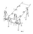
- FIG. 1is a perspective view of a closed (folded) foot support and stirrups assembly constructed in accordance with an embodiment of the present invention, shown in the process of being attached to a stretcher;
- FIG. 2is a perspective view of the foot support and stirrups assembly of FIG. 1 , shown in the vertical open (unfolded) position and attached to the stretcher;
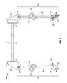
- FIG. 3is a perspective view of the foot support and stirrups assembly of FIG. 1 , shown in the horizontal open (unfolded) position and attached to a stretcher;
- FIG. 4is a perspective view of the foot support and stirrups assembly of FIG. 1 , shown in the vertical open (unfolded) position;
- FIG. 5is a top plan view of the foot support and stirrups assembly shown in FIG. 4 ;
- FIG. 6is a front view of the foot support and stirrups assembly shown in FIG. 4 ;
- FIG. 7is a right side view of the support and stirrups assembly shown in FIG. 4 ;
- FIG. 8is a perspective view of the foot support and stirrups assembly of FIG. 1 , shown in the horizontal open (unfolded) position;
- FIG. 9is top view of the foot support and stirrups assembly of FIG. 1 , shown in the horizontal open (unfolded) position;
- FIG. 10is a front view of the foot support and stirrups assembly shown in FIG. 8 in the horizontal open (unfolded) position;
- FIG. 11is a right side view of the foot support and stirrups assembly shown in FIG. 8 in the horizontal open (unfolded) position;
- FIG. 12is a top perspective view of the closed (folded) foot support and stirrups assembly shown in FIG. 1 in the closed (folded) position;
- FIG. 13is a bottom perspective view of the closed (folded) foot support and stirrups assembly shown in FIG. 1 in the closed (folded) position;
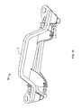
- FIG. 14is a side view of the foot support and stirrups assembly shown in FIG. 8 in the horizontal open (unfolded) position, the stirrup being shown in various positions along the stanchion;
- FIG. 15is a perspective view of a telescoping arm of the foot support and stirrups assembly shown in FIG. 3 , shown both extended out of a stanchion of the foot support and stirrups assembly and retracted into the stanchion;
- FIG. 16is a bottom view of a locking screw inserted through an anchor plate of the foot support and stirrups assembly shown in FIG. 1 so as to lock a stretcher pole in a bracket of the foot support and stirrups assembly;
- FIG. 17is a detailed view of the pole inserted in the bracket of FIG. 16 , the bracket having a barrier installed in a bore therethrough to protect the pole.
- FIGS. 1-13illustrate a foot and leg support and stirrups assembly device 10 (hereinafter “device 10 ” for brevity) constructed in accordance with an embodiment of the present invention. More particularly, as shown in FIG. 1 , the device 10 is removably attachable to a stretcher S.
- the stretcher Smay include a collapsible bed or mat made of fabric such as canvas that is attached to poles P 1 , P 2 . As indicated in FIGS. 1-3 , the stretcher S may be supported on horses H or maneuvered by hand (i.e., by grasping the poles P 1 , P 2 ).
- the device 10includes a U-shaped transverse member 12 that has a transverse rod 14 with first and second ends 16 , 18 .
- the first and second ends 16 , 18are offset from the rod 14 and have the same axial orientation as the rod 14 .
- Attached to the first and second ends 16 , 18are first and second anchor members 20 , 22 .
- the anchor members 20 , 22are plate-like connectors that each support a bracket 24 , 26 and a pivotable hinge 28 , 30 affixed thereto (see FIGS. 4, 8 ).
- Each pivotable hinge 28 , 30connects the corresponding anchor member 20 , 22 , to a stirrups assembly 32 , 34 (see FIG. 8 ).
- the pivotable hinges 28 , 30provide a pivotable connection such that the corresponding stirrups assemblies 32 , 34 can be placed in a vertical open position as shown in FIGS. 2 and 4 , a horizontal open position as shown in FIG. 3 , or a closed position as shown in FIGS. 12 and 13 .
- Each stirrups assembly 32 , 34includes a stanchion 36 , 38 connected to the corresponding pivotable hinge 28 , 30 (see FIGS. 4, 8 ).
- the stirrups assemblies 32 , 34include rigid foot stirrups 40 , 42 slidably positioned along corresponding stanchions 36 , 38 .
- Each rigid foot stirrup 40 , 42includes a mounting bracket 44 , 46 (see FIGS. 4-6 ).
- FIG. 14the stirrups assembly 32 (or 34 ) is shown in the horizontal open position previously described with reference to FIG. 3 .
- FIG. 14will be discussed with reference to the stirrups assembly 32 ; it will be apparent to those of skill in the art that the discussion of FIG. 14 is equally applicable to the stirrups assembly 34 .
- the mounting bracket 44is sized, shaped, and oriented such that, when at rest, the weight of the rigid foot stirrup 40 and the weight of the patient's foot resting therein causes friction between the mounting bracket 44 and the stanchion 36 , preventing the rigid foot stirrup 40 from sliding along the stanchion 36 and retaining the rigid foot stirrup 40 in a first position 48 , a second position 50 , or another desired position along stanchion 36 . Conversely, when the rigid foot stirrup 40 is lifted into an upright position 52 (shown in phantom), the frictional engagement between the mounting bracket 44 and the stanchion 36 is relieved and the rigid foot stirrup 40 may be slid along the stanchion 36 .
- each stirrups assembly 32 , 34includes a telescoping stirrup support 54 , 56 of the type that is known in the art as “candy cane” stirrups.
- Each telescoping stirrup support 54 , 56includes a first portion 58 , 60 that is slidably engaged with the corresponding stanchion 36 , 38 , a second portion 62 , 64 oriented substantially perpendicular to the first portion 58 , 60 , and a curved portion 66 , 68 between the first portion 58 , 60 and the second portion 62 , 64 , respectively.
- the first portion 58 , 60includes two or more holes 70 , 72 , respectively.
- the stanchion 36 , 38includes an arm adjustment pin 74 , 76 , respectively.
- FIG. 15the stirrups assembly 32 (or 34 ) is shown.
- FIG. 15will be discussed with reference to the stirrups assembly 32 ; it will be apparent to those of skill in the art that the discussion of FIG. 15 is equally applicable to the stirrups assembly 34 .
- the arm adjustment pin 74can be selectively engaged with a desired one of the holes 70 to adjust the length of the protruding portion of the first portion 58 of the telescoping stirrup support 54 that protrudes from the stanchion 36 .
- Adjustment optionsmay include a first (e.g., extended) position 78 , a second (e.g., retracted) position 80 , or other positions intermediate between the first and second positions 78 , 80 .
- each of the first portions 58 , 60includes ten holes 70 , 72 .
- the holes 70 , 72are spaced at regular intervals 1.25 inches apart. It will be apparent to those of skill in the art that the specific quantity and spacing of the holes 70 , 72 described above are only exemplary and that variations are possible without departing from the broader concepts of the exemplary embodiments.
- each stirrups assembly 32 , 34includes an eye 82 , 84 connected to the second portion 62 , 64 of the telescoping stirrup support 54 , 56 and positioned such that the eye 82 , 84 is below the second portion 62 , 64 when the stirrups assembly 32 , 34 is in the vertical open position shown in FIGS. 2 and 4 .
- Each eye 82 , 84is connected to a chain link 86 , 88 .
- Each chain link 86 , 88includes a chain link pin 90 , 92 connected to chain link 86 , 88 by a hinge 94 , 96 .
- the hinge 94 , 96is biased to retain the chain link pin 90 , 92 in a closed position, but a force can be applied to the chain link pin 90 , 92 to move the chain link pin 90 , 92 in an open position and thereby allow an object to be threaded onto the chain link 86 , 88 .
- the chain link pin 90 of the chain link 86is shown in an open position, while the chain link pin 92 of the chain link 88 is shown in a closed position; it will be apparent to those of skill in the art that both of the chain link pins 90 , 92 can be selectively moved between the open and closed positions as described above.
- each stirrups assembly 32 , 34also includes a soft stirrup 98 , 100 .
- the soft stirrup 98comprises a strap 102 with eyelets 104 , 106 at either end; the soft stirrup 100 comprises a strap 108 with eyelets 110 , 112 at either end.
- the straps 102 , 108are sized and shaped to support a patient's foot when hung by the eyelets 104 , 106 , 110 , 112 , and are made of cloth having sufficient flexibility and durability for the same purpose, such as canvas.
- the soft stirrups 98 , 100are threaded onto the chain links 82 , 84 and can be removed by applying a force to the chain link pins 90 , 92 , to move the chain link pins 90 , 92 into an open position as described above.
- the soft stirrups 98 , 100hang from the eyes 82 , 84 , and thereby from the second portions 62 , 64 of the telescoping stirrup supports 54 , 56 , in a position such that they may support the feet of a patient who is recumbent on the stretcher S.
- the device 10can be removably attached to the stretcher S, which includes the poles P 1 and P 2 .
- FIG. 16the manner of attachment of the device 10 to the stretcher S is shown; the depiction of FIG. 16 is limited to one side of the device 10 , but the elements depicted therein will be described with reference to both the first and second sides thereof.
- the first and second anchor members 20 , 22are attached to the first and second ends 16 , 18 , respectively, of the U-shaped transverse member 12 .
- the first and second anchor members 20 , 22support the brackets 24 , 26 , respectively.
- the brackets 24 , 26have bores 114 , 116 that are sized and shaped to receive respective ends of the poles P 1 , P 2 of the stretcher S therein.
- the first and second anchor members 20 , 22also include adjustment knobs 118 , 120 , which may be threadedly engaged or disengaged with the first and second anchor members 20 , 22 (e.g., through threaded holes formed within the first and second anchor members 20 , 22 ).
- the adjustment knobs 118 , 120are sized, shaped, and located such that engagement thereof with the first and second anchor members 20 , 22 , secures the poles P 1 , P 2 within the bores 114 , 116 , thereby securely attaching the device 10 to the stretcher S.
- disengagement of the adjustment knobs 118 , 120 from the first and second anchor members 20 , 22enables the poles P 1 , P 2 to be removed from the bores 114 , 116 , and thereby enables the device 10 to be removed from the stretcher S.
- the brackets 24 , 26also enclose barriers 122 , 124 positioned between the first and second anchor members 20 , 22 , and the corresponding poles P 1 , P 2 .
- the barriers 122 , 124are sized and shaped to protect the poles P 1 , P 2 , while facilitating the retention thereof within the brackets 24 , 26 .
- the barriers 122 , 124are made of nylon.
- the barriers 122 , 124have a curvature complementary to the outside diameter of the poles P 1 , P 2 , which may commonly be 1.25 inches.
- adjustable positioning of the barriers 122 , 124may enable the device 10 also to be attached to a stretcher S having poles P 1 , P 2 with outside diameters of 1.5 inches.
- threaded engagement of the adjustment knobs 118 , 120 with the first and second anchor members 20 , 22forces the barriers 122 , 124 toward the poles P 1 , P 2 , thereby securing the poles P 1 , P 2 between the brackets 24 , 26 and the barriers 122 , 124 .
- the pivotable hinges 28 , 30can be operated such that the corresponding stirrups assemblies 32 , 34 are placed in a closed position.
- FIG. 12a closed position is shown.
- the pivotable hinges 28 , 30have been placed in a position such that the stanchions 36 , 38 are substantially parallel to the rod 14 of the transverse member 12 .
- the straps 102 , 108can be removed from the corresponding chain links 86 , 88 at either end, looped around both stanchions 36 , 38 , and re-attached to the corresponding chain links 86 , 88 so as to retain the stanchions 36 , 38 , and thereby the device 10 , in a closed position.
- FIG. 13after being placed in a closed position, the device 10 may be inverted and the rod 14 of the transverse member 12 can be used as a carrying handle for transportation of the device 10 .
Landscapes
- Health & Medical Sciences (AREA)
- Life Sciences & Earth Sciences (AREA)
- Animal Behavior & Ethology (AREA)
- General Health & Medical Sciences (AREA)
- Public Health (AREA)
- Veterinary Medicine (AREA)
- Engineering & Computer Science (AREA)
- Biomedical Technology (AREA)
- Invalid Beds And Related Equipment (AREA)
- Nursing (AREA)
Abstract
Description
Claims (16)
Priority Applications (1)
| Application Number | Priority Date | Filing Date | Title |
|---|---|---|---|
| US14/799,187US10188572B2 (en) | 2015-07-14 | 2015-07-14 | Stirrups devices |
Applications Claiming Priority (1)
| Application Number | Priority Date | Filing Date | Title |
|---|---|---|---|
| US14/799,187US10188572B2 (en) | 2015-07-14 | 2015-07-14 | Stirrups devices |
Publications (2)
| Publication Number | Publication Date |
|---|---|
| US20170014292A1 US20170014292A1 (en) | 2017-01-19 |
| US10188572B2true US10188572B2 (en) | 2019-01-29 |
Family
ID=57775375
Family Applications (1)
| Application Number | Title | Priority Date | Filing Date |
|---|---|---|---|
| US14/799,187Active2037-05-12US10188572B2 (en) | 2015-07-14 | 2015-07-14 | Stirrups devices |
Country Status (1)
| Country | Link |
|---|---|
| US (1) | US10188572B2 (en) |
Cited By (1)
| Publication number | Priority date | Publication date | Assignee | Title |
|---|---|---|---|---|
| US10667974B2 (en) | 2018-05-28 | 2020-06-02 | Donald W. Wright | Sling for use in moving persons with limited mobility |
Families Citing this family (3)
| Publication number | Priority date | Publication date | Assignee | Title |
|---|---|---|---|---|
| US10188572B2 (en)* | 2015-07-14 | 2019-01-29 | Rapid Deployment Stirrups, Llc | Stirrups devices |
| CN112386420B (en)* | 2020-12-05 | 2021-07-09 | 吴长兴 | Convenient postoperative limbs linkage for surgery of adjusting |
| WO2024096906A1 (en)* | 2022-11-03 | 2024-05-10 | Schnell Medical Llc | Lightweight, portable pelvic exam device |
Citations (30)
| Publication number | Priority date | Publication date | Assignee | Title |
|---|---|---|---|---|
| US2067891A (en)* | 1935-12-27 | 1937-01-19 | Hospital Appliances Inc | Leg-supporting means for obstetrical beds |
| US2792266A (en) | 1955-02-17 | 1957-05-14 | Edward G Waters | Leg holders for and in combination with operating table |
| US3104446A (en)* | 1960-07-11 | 1963-09-24 | Jr Frank H Throop | Foot positioner apparatus |
| US3516652A (en)* | 1967-07-31 | 1970-06-23 | Melvin A Roblee | Method and apparatus for alleviating discomfort in the lithotomy position |
| US3907270A (en)* | 1974-12-17 | 1975-09-23 | Philomine A Ezzo | Portable examining unit with stirrups |
| US3982742A (en)* | 1975-11-17 | 1976-09-28 | Ford John L | Medical stirrups |
| US4426071A (en)* | 1981-02-13 | 1984-01-17 | Landstingens Inkopscentral, Lic, Ekonomisk Forening | Leg supporting device for obstetrical tables |
| US4809687A (en)* | 1987-12-30 | 1989-03-07 | Edgewater Medical Systems | Medical stirrup |
| US5226187A (en) | 1991-04-15 | 1993-07-13 | Hill-Rom Company, Inc. | Foot section for birthing bed |
| US5713591A (en) | 1995-09-29 | 1998-02-03 | Zarkhin; Gregory | Multiposition leg and foot, arm and hand supports for wheelchairs |
| US5718011A (en)* | 1997-04-23 | 1998-02-17 | Nogues; Nelson E. | Device for cleaning babies |
| US6108841A (en)* | 1998-07-14 | 2000-08-29 | Diane M. J. Cameron | Ergonomical leg support system for a medical examination table |
| US20030182726A1 (en)* | 2002-03-30 | 2003-10-02 | Greenfield Saul P. | Pediatric stirrup device and method |
| US6907632B2 (en)* | 2002-05-28 | 2005-06-21 | Ferno-Washington, Inc. | Tactical stretcher |
| US7243654B2 (en) | 2005-04-08 | 2007-07-17 | Peter Schuerch | Adjustable position limb support for surgical tables |
| US7367578B2 (en) | 2003-08-29 | 2008-05-06 | Revab Ip B.V. | Wheelchair provided with legrest and calfrest |
| US7461857B2 (en) | 2001-08-24 | 2008-12-09 | Darling Iii Charles W | Multipurpose clamps for utility table/cart/stretcher |
| US20090235457A1 (en) | 2008-03-24 | 2009-09-24 | Harvey William J | Medical Table Foot and Leg Support System |
| US20100242181A1 (en)* | 2009-03-03 | 2010-09-30 | Bochner Ronnie Z | Bedside medical examination device |
| US20110015552A1 (en)* | 2009-07-17 | 2011-01-20 | Rohde Sonja C | Methods and Devices for Assisting Birth |
| US20130318717A1 (en) | 2012-06-01 | 2013-12-05 | Ngozi A Iheoma | Compact and portable gynecological exam device |
| US20140068866A1 (en)* | 2012-09-07 | 2014-03-13 | Allen Medical Systems, Inc. | Carriage for a surgical boot of a hip distractor |
| US20140261099A1 (en)* | 2013-03-14 | 2014-09-18 | Emory University | Surgical support device |
| US8875327B2 (en) | 2010-06-15 | 2014-11-04 | Schnell Medical, Llc | Lightweight portable pelvic exam device |
| US20160022515A1 (en)* | 2014-07-22 | 2016-01-28 | Aero Medical Engineering Pty Ltd | Military Stretcher System |
| US20160287461A1 (en)* | 2015-04-01 | 2016-10-06 | Michael L. Naughton | Surgical table with combination footboard and patient transfer board |
| US20160302987A1 (en)* | 2015-04-17 | 2016-10-20 | Ronnie Z. Bochner | Portable device for facilitating medical examination |
| US20170014292A1 (en)* | 2015-07-14 | 2017-01-19 | Ronnie Z. Bochner | Stirrups devices |
| US20170239118A1 (en)* | 2016-02-22 | 2017-08-24 | Innovative Medical Products, Inc. | Pad assembly, system, method of pre-load positioning of patient for medical procedure and kit |
| US20170246059A1 (en)* | 2014-10-01 | 2017-08-31 | Ferno-Washington, Inc. | Modular stretcher or litter |
- 2015
- 2015-07-14USUS14/799,187patent/US10188572B2/enactiveActive
Patent Citations (31)
| Publication number | Priority date | Publication date | Assignee | Title |
|---|---|---|---|---|
| US2067891A (en)* | 1935-12-27 | 1937-01-19 | Hospital Appliances Inc | Leg-supporting means for obstetrical beds |
| US2792266A (en) | 1955-02-17 | 1957-05-14 | Edward G Waters | Leg holders for and in combination with operating table |
| US3104446A (en)* | 1960-07-11 | 1963-09-24 | Jr Frank H Throop | Foot positioner apparatus |
| US3516652A (en)* | 1967-07-31 | 1970-06-23 | Melvin A Roblee | Method and apparatus for alleviating discomfort in the lithotomy position |
| US3907270A (en)* | 1974-12-17 | 1975-09-23 | Philomine A Ezzo | Portable examining unit with stirrups |
| US3982742A (en)* | 1975-11-17 | 1976-09-28 | Ford John L | Medical stirrups |
| US4426071A (en)* | 1981-02-13 | 1984-01-17 | Landstingens Inkopscentral, Lic, Ekonomisk Forening | Leg supporting device for obstetrical tables |
| US4809687A (en)* | 1987-12-30 | 1989-03-07 | Edgewater Medical Systems | Medical stirrup |
| US5226187A (en) | 1991-04-15 | 1993-07-13 | Hill-Rom Company, Inc. | Foot section for birthing bed |
| US5713591A (en) | 1995-09-29 | 1998-02-03 | Zarkhin; Gregory | Multiposition leg and foot, arm and hand supports for wheelchairs |
| US5718011A (en)* | 1997-04-23 | 1998-02-17 | Nogues; Nelson E. | Device for cleaning babies |
| US6108841A (en)* | 1998-07-14 | 2000-08-29 | Diane M. J. Cameron | Ergonomical leg support system for a medical examination table |
| US7461857B2 (en) | 2001-08-24 | 2008-12-09 | Darling Iii Charles W | Multipurpose clamps for utility table/cart/stretcher |
| US20030182726A1 (en)* | 2002-03-30 | 2003-10-02 | Greenfield Saul P. | Pediatric stirrup device and method |
| US6698044B2 (en)* | 2002-03-30 | 2004-03-02 | Saul P. Greenfield | Pediatric stirrup device and method |
| US6907632B2 (en)* | 2002-05-28 | 2005-06-21 | Ferno-Washington, Inc. | Tactical stretcher |
| US7367578B2 (en) | 2003-08-29 | 2008-05-06 | Revab Ip B.V. | Wheelchair provided with legrest and calfrest |
| US7243654B2 (en) | 2005-04-08 | 2007-07-17 | Peter Schuerch | Adjustable position limb support for surgical tables |
| US20090235457A1 (en) | 2008-03-24 | 2009-09-24 | Harvey William J | Medical Table Foot and Leg Support System |
| US20100242181A1 (en)* | 2009-03-03 | 2010-09-30 | Bochner Ronnie Z | Bedside medical examination device |
| US20110015552A1 (en)* | 2009-07-17 | 2011-01-20 | Rohde Sonja C | Methods and Devices for Assisting Birth |
| US8875327B2 (en) | 2010-06-15 | 2014-11-04 | Schnell Medical, Llc | Lightweight portable pelvic exam device |
| US20130318717A1 (en) | 2012-06-01 | 2013-12-05 | Ngozi A Iheoma | Compact and portable gynecological exam device |
| US20140068866A1 (en)* | 2012-09-07 | 2014-03-13 | Allen Medical Systems, Inc. | Carriage for a surgical boot of a hip distractor |
| US20140261099A1 (en)* | 2013-03-14 | 2014-09-18 | Emory University | Surgical support device |
| US20160022515A1 (en)* | 2014-07-22 | 2016-01-28 | Aero Medical Engineering Pty Ltd | Military Stretcher System |
| US20170246059A1 (en)* | 2014-10-01 | 2017-08-31 | Ferno-Washington, Inc. | Modular stretcher or litter |
| US20160287461A1 (en)* | 2015-04-01 | 2016-10-06 | Michael L. Naughton | Surgical table with combination footboard and patient transfer board |
| US20160302987A1 (en)* | 2015-04-17 | 2016-10-20 | Ronnie Z. Bochner | Portable device for facilitating medical examination |
| US20170014292A1 (en)* | 2015-07-14 | 2017-01-19 | Ronnie Z. Bochner | Stirrups devices |
| US20170239118A1 (en)* | 2016-02-22 | 2017-08-24 | Innovative Medical Products, Inc. | Pad assembly, system, method of pre-load positioning of patient for medical procedure and kit |
Non-Patent Citations (1)
| Title |
|---|
| "Greene Stirrups", product developed by G. Donald Royster and Ronnie Z. Bochner; Prototype presented at 2011 Annual District Meeting, Armed Forces District, American Congress of Obstertricians and Gynecologists, Oct. 23, 2011; 3 pages. |
Cited By (1)
| Publication number | Priority date | Publication date | Assignee | Title |
|---|---|---|---|---|
| US10667974B2 (en) | 2018-05-28 | 2020-06-02 | Donald W. Wright | Sling for use in moving persons with limited mobility |
Also Published As
| Publication number | Publication date |
|---|---|
| US20170014292A1 (en) | 2017-01-19 |
Similar Documents
| Publication | Publication Date | Title |
|---|---|---|
| US10188572B2 (en) | Stirrups devices | |
| US8407831B2 (en) | Patient positioning apparatus | |
| US7287288B2 (en) | Patient lifting device | |
| US20130140781A1 (en) | Walking safety aid apparatus | |
| CA2856883A1 (en) | Physical therapy support device | |
| US12023297B2 (en) | Foot-based massage apparatus | |
| US20170290633A1 (en) | Portable cardiopulmonary support cart systems | |
| US20130328374A1 (en) | Security Restraint Chair | |
| US9308113B2 (en) | Detachable orthopedic sling | |
| US20170239114A1 (en) | Leg support assembly | |
| EP3108866B1 (en) | Patient positioning apparatus and method | |
| US3850165A (en) | Portable traction system | |
| JP5254145B2 (en) | Pet carrier | |
| US20120223109A1 (en) | Dressing Aid | |
| US4181125A (en) | Portable traction device | |
| US9936812B2 (en) | Leg support assembly | |
| KR101872912B1 (en) | Apparatus for supporting pet | |
| US9033854B1 (en) | Forearm exercise apparatus | |
| US20190307105A1 (en) | Invalid dog lift and support device | |
| CA2646024C (en) | Patient position apparatus | |
| CN213249987U (en) | A fixed device for animal administration | |
| US3905359A (en) | Traction device | |
| GB2114880A (en) | Footrest | |
| RU2325891C1 (en) | Stretcher chair | |
| JP2015208405A (en) | Frame of biological information display device |
Legal Events
| Date | Code | Title | Description |
|---|---|---|---|
| AS | Assignment | Owner name:GWENVENTIONS, INC., NEW YORK Free format text:ASSIGNMENT OF ASSIGNORS INTEREST;ASSIGNOR:BOCHNER, RONNIE Z.;REEL/FRAME:042988/0196 Effective date:20160220 | |
| AS | Assignment | Owner name:RAPID DEPLOYMENT STIRRUPS, LLC, DELAWARE Free format text:ASSIGNMENT OF ASSIGNORS INTEREST;ASSIGNORS:ROYSTER, GREENE DONALD, IV;BOCHNER, RONNIE Z.;GWENVENTIONS, LLC;REEL/FRAME:047799/0321 Effective date:20181214 | |
| STCF | Information on status: patent grant | Free format text:PATENTED CASE | |
| AS | Assignment | Owner name:GWENVENTIONS, LLC, NEW YORK Free format text:ASSIGNMENT OF ASSIGNORS INTEREST;ASSIGNOR:RAPID DEPLOYMENT STIRRUPS, LLC;REEL/FRAME:056216/0771 Effective date:20210509 | |
| FEPP | Fee payment procedure | Free format text:MAINTENANCE FEE REMINDER MAILED (ORIGINAL EVENT CODE: REM.); ENTITY STATUS OF PATENT OWNER: SMALL ENTITY | |
| FEPP | Fee payment procedure | Free format text:SURCHARGE FOR LATE PAYMENT, SMALL ENTITY (ORIGINAL EVENT CODE: M2554); ENTITY STATUS OF PATENT OWNER: SMALL ENTITY | |
| MAFP | Maintenance fee payment | Free format text:PAYMENT OF MAINTENANCE FEE, 4TH YR, SMALL ENTITY (ORIGINAL EVENT CODE: M2551); ENTITY STATUS OF PATENT OWNER: SMALL ENTITY Year of fee payment:4 |