US10188397B2 - Torque alleviating intra-airway lung volume reduction compressive implant structures - Google Patents
Torque alleviating intra-airway lung volume reduction compressive implant structuresDownload PDFInfo
- Publication number
- US10188397B2 US10188397B2US15/192,085US201615192085AUS10188397B2US 10188397 B2US10188397 B2US 10188397B2US 201615192085 AUS201615192085 AUS 201615192085AUS 10188397 B2US10188397 B2US 10188397B2
- Authority
- US
- United States
- Prior art keywords
- lung
- implant
- helical
- configuration
- volume reduction
- Prior art date
- Legal status (The legal status is an assumption and is not a legal conclusion. Google has not performed a legal analysis and makes no representation as to the accuracy of the status listed.)
- Expired - Fee Related, expires
Links
- 210000004072lungAnatomy0.000titleclaimsabstractdescription223
- 239000007943implantSubstances0.000titleclaimsabstractdescription209
- 238000011038discontinuous diafiltration by volume reductionMethods0.000titleclaimsdescription68
- 230000007704transitionEffects0.000claimsabstractdescription33
- 230000006835compressionEffects0.000claimsabstractdescription14
- 238000007906compressionMethods0.000claimsabstractdescription14
- 230000029058respiratory gaseous exchangeEffects0.000claimsabstractdescription14
- 230000002708enhancing effectEffects0.000claimsabstractdescription7
- 230000005012migrationEffects0.000claimsabstractdescription4
- 238000013508migrationMethods0.000claimsabstractdescription4
- 238000000034methodMethods0.000claimsdescription37
- 238000002513implantationMethods0.000claimsdescription21
- 238000005452bendingMethods0.000claimsdescription18
- 239000000463materialSubstances0.000abstractdescription35
- 230000000670limiting effectEffects0.000abstractdescription3
- 210000001519tissueAnatomy0.000description88
- 229910052751metalInorganic materials0.000description18
- 239000002184metalSubstances0.000description18
- 210000003281pleural cavityAnatomy0.000description13
- PXHVJJICTQNCMI-UHFFFAOYSA-NNickelChemical compound[Ni]PXHVJJICTQNCMI-UHFFFAOYSA-N0.000description12
- RJURFGZVJUQBHK-UHFFFAOYSA-Nactinomycin DNatural productsCC1OC(=O)C(C(C)C)N(C)C(=O)CN(C)C(=O)C2CCCN2C(=O)C(C(C)C)NC(=O)C1NC(=O)C1=C(N)C(=O)C(C)=C2OC(C(C)=CC=C3C(=O)NC4C(=O)NC(C(N5CCCC5C(=O)N(C)CC(=O)N(C)C(C(C)C)C(=O)OC4C)=O)C(C)C)=C3N=C21RJURFGZVJUQBHK-UHFFFAOYSA-N0.000description11
- 210000000621bronchiAnatomy0.000description10
- 206010014561EmphysemaDiseases0.000description9
- 229910001566austeniteInorganic materials0.000description9
- 238000003384imaging methodMethods0.000description9
- 229910001000nickel titaniumInorganic materials0.000description9
- -1stainless steelChemical class0.000description9
- 210000000115thoracic cavityAnatomy0.000description9
- 239000004696Poly ether ether ketoneSubstances0.000description8
- 229920001692polycarbonate urethanePolymers0.000description8
- 229920002530polyetherether ketonePolymers0.000description8
- RTAQQCXQSZGOHL-UHFFFAOYSA-NTitaniumChemical compound[Ti]RTAQQCXQSZGOHL-UHFFFAOYSA-N0.000description7
- 210000003484anatomyAnatomy0.000description7
- 239000012530fluidSubstances0.000description7
- 230000033001locomotionEffects0.000description7
- 230000007246mechanismEffects0.000description7
- 229920000642polymerPolymers0.000description7
- 229910052719titaniumInorganic materials0.000description7
- 239000010936titaniumSubstances0.000description7
- 230000008901benefitEffects0.000description6
- 238000002591computed tomographyMethods0.000description6
- 229940079593drugDrugs0.000description6
- 239000003814drugSubstances0.000description6
- HLXZNVUGXRDIFK-UHFFFAOYSA-Nnickel titaniumChemical compound[Ti].[Ti].[Ti].[Ti].[Ti].[Ti].[Ti].[Ti].[Ti].[Ti].[Ti].[Ni].[Ni].[Ni].[Ni].[Ni].[Ni].[Ni].[Ni].[Ni].[Ni].[Ni].[Ni].[Ni].[Ni]HLXZNVUGXRDIFK-UHFFFAOYSA-N0.000description6
- BASFCYQUMIYNBI-UHFFFAOYSA-NplatinumChemical compound[Pt]BASFCYQUMIYNBI-UHFFFAOYSA-N0.000description6
- 230000002829reductive effectEffects0.000description6
- 239000012781shape memory materialSubstances0.000description6
- 238000011282treatmentMethods0.000description6
- RJURFGZVJUQBHK-IIXSONLDSA-Nactinomycin DChemical compoundC[C@H]1OC(=O)[C@H](C(C)C)N(C)C(=O)CN(C)C(=O)[C@@H]2CCCN2C(=O)[C@@H](C(C)C)NC(=O)[C@H]1NC(=O)C1=C(N)C(=O)C(C)=C2OC(C(C)=CC=C3C(=O)N[C@@H]4C(=O)N[C@@H](C(N5CCC[C@H]5C(=O)N(C)CC(=O)N(C)[C@@H](C(C)C)C(=O)O[C@@H]4C)=O)C(C)C)=C3N=C21RJURFGZVJUQBHK-IIXSONLDSA-N0.000description5
- 229910045601alloyInorganic materials0.000description5
- 239000000956alloySubstances0.000description5
- 230000009286beneficial effectEffects0.000description5
- 230000036760body temperatureEffects0.000description5
- 210000003123bronchioleAnatomy0.000description5
- 238000013461designMethods0.000description5
- 230000000694effectsEffects0.000description5
- 238000003780insertionMethods0.000description5
- 230000037431insertionEffects0.000description5
- 229910000734martensiteInorganic materials0.000description5
- 229910052759nickelInorganic materials0.000description5
- 229960002930sirolimusDrugs0.000description5
- 206010003598AtelectasisDiseases0.000description4
- 108010092160DactinomycinProteins0.000description4
- 208000007123Pulmonary AtelectasisDiseases0.000description4
- 230000003213activating effectEffects0.000description4
- 230000008878couplingEffects0.000description4
- 238000010168coupling processMethods0.000description4
- 238000005859coupling reactionMethods0.000description4
- 210000003128headAnatomy0.000description4
- 238000011065in-situ storageMethods0.000description4
- 230000004199lung functionEffects0.000description4
- 238000004519manufacturing processMethods0.000description4
- 150000002739metalsChemical class0.000description4
- 230000001936parietal effectEffects0.000description4
- 230000008569processEffects0.000description4
- 238000011084recoveryMethods0.000description4
- 239000000126substanceSubstances0.000description4
- 229920001169thermoplasticPolymers0.000description4
- 239000004416thermosoftening plasticSubstances0.000description4
- 230000009278visceral effectEffects0.000description4
- OKTJSMMVPCPJKN-UHFFFAOYSA-NCarbonChemical compound[C]OKTJSMMVPCPJKN-UHFFFAOYSA-N0.000description3
- 108091006146ChannelsProteins0.000description3
- VYZAMTAEIAYCRO-UHFFFAOYSA-NChromiumChemical compound[Cr]VYZAMTAEIAYCRO-UHFFFAOYSA-N0.000description3
- ZOKXTWBITQBERF-UHFFFAOYSA-NMolybdenumChemical compound[Mo]ZOKXTWBITQBERF-UHFFFAOYSA-N0.000description3
- NWIBSHFKIJFRCO-WUDYKRTCSA-NMytomycinChemical compoundC1N2C(C(C(C)=C(N)C3=O)=O)=C3[C@@H](COC(N)=O)[C@@]2(OC)[C@@H]2[C@H]1N2NWIBSHFKIJFRCO-WUDYKRTCSA-N0.000description3
- 102000010780Platelet-Derived Growth FactorHuman genes0.000description3
- 108010038512Platelet-Derived Growth FactorProteins0.000description3
- 229920004695VICTREX™ PEEKPolymers0.000description3
- 239000000853adhesiveSubstances0.000description3
- 230000001070adhesive effectEffects0.000description3
- 210000004712air sacAnatomy0.000description3
- 239000003146anticoagulant agentSubstances0.000description3
- 239000004019antithrombinSubstances0.000description3
- 210000004204blood vesselAnatomy0.000description3
- 229910052799carbonInorganic materials0.000description3
- 230000008859changeEffects0.000description3
- 239000011651chromiumSubstances0.000description3
- 229910017052cobaltInorganic materials0.000description3
- 239000010941cobaltSubstances0.000description3
- GUTLYIVDDKVIGB-UHFFFAOYSA-Ncobalt atomChemical compound[Co]GUTLYIVDDKVIGB-UHFFFAOYSA-N0.000description3
- 229960000640dactinomycinDrugs0.000description3
- 230000003628erosive effectEffects0.000description3
- 239000011521glassSubstances0.000description3
- 239000011733molybdenumSubstances0.000description3
- 230000003287optical effectEffects0.000description3
- 229910052697platinumInorganic materials0.000description3
- 210000004224pleuraAnatomy0.000description3
- 210000004910pleural fluidAnatomy0.000description3
- 210000002345respiratory systemAnatomy0.000description3
- 230000037390scarringEffects0.000description3
- 229910001285shape-memory alloyInorganic materials0.000description3
- 210000000329smooth muscle myocyteAnatomy0.000description3
- 229910001220stainless steelInorganic materials0.000description3
- 239000010935stainless steelSubstances0.000description3
- 229910052715tantalumInorganic materials0.000description3
- GUVRBAGPIYLISA-UHFFFAOYSA-Ntantalum atomChemical compound[Ta]GUVRBAGPIYLISA-UHFFFAOYSA-N0.000description3
- 230000001225therapeutic effectEffects0.000description3
- 238000009423ventilationMethods0.000description3
- IAKHMKGGTNLKSZ-INIZCTEOSA-N(S)-colchicineChemical compoundC1([C@@H](NC(C)=O)CC2)=CC(=O)C(OC)=CC=C1C1=C2C=C(OC)C(OC)=C1OCIAKHMKGGTNLKSZ-INIZCTEOSA-N0.000description2
- 208000006545Chronic Obstructive Pulmonary DiseaseDiseases0.000description2
- AOJJSUZBOXZQNB-TZSSRYMLSA-NDoxorubicinChemical compoundO([C@H]1C[C@@](O)(CC=2C(O)=C3C(=O)C=4C=CC=C(C=4C(=O)C3=C(O)C=21)OC)C(=O)CO)[C@H]1C[C@H](N)[C@H](O)[C@H](C)O1AOJJSUZBOXZQNB-TZSSRYMLSA-N0.000description2
- OHCQJHSOBUTRHG-KGGHGJDLSA-NFORSKOLINChemical compoundO=C([C@@]12O)C[C@](C)(C=C)O[C@]1(C)[C@@H](OC(=O)C)[C@@H](O)[C@@H]1[C@]2(C)[C@@H](O)CCC1(C)COHCQJHSOBUTRHG-KGGHGJDLSA-N0.000description2
- 102000018233Fibroblast Growth FactorHuman genes0.000description2
- 108050007372Fibroblast Growth FactorProteins0.000description2
- PCZOHLXUXFIOCF-UHFFFAOYSA-NMonacolin XNatural productsC12C(OC(=O)C(C)CC)CC(C)C=C2C=CC(C)C1CCC1CC(O)CC(=O)O1PCZOHLXUXFIOCF-UHFFFAOYSA-N0.000description2
- ZDZOTLJHXYCWBA-VCVYQWHSSA-NN-debenzoyl-N-(tert-butoxycarbonyl)-10-deacetyltaxolChemical compoundO([C@H]1[C@H]2[C@@](C([C@H](O)C3=C(C)[C@@H](OC(=O)[C@H](O)[C@@H](NC(=O)OC(C)(C)C)C=4C=CC=CC=4)C[C@]1(O)C3(C)C)=O)(C)[C@@H](O)C[C@H]1OC[C@]12OC(=O)C)C(=O)C1=CC=CC=C1ZDZOTLJHXYCWBA-VCVYQWHSSA-N0.000description2
- MWUXSHHQAYIFBG-UHFFFAOYSA-NNitric oxideChemical compoundO=[N]MWUXSHHQAYIFBG-UHFFFAOYSA-N0.000description2
- 238000005299abrasionMethods0.000description2
- 239000005557antagonistSubstances0.000description2
- 230000002927anti-mitotic effectEffects0.000description2
- 230000000118anti-neoplastic effectEffects0.000description2
- 230000000702anti-platelet effectEffects0.000description2
- 230000001028anti-proliverative effectEffects0.000description2
- 229940127219anticoagulant drugDrugs0.000description2
- 238000001574biopsyMethods0.000description2
- 239000008280bloodSubstances0.000description2
- 210000004369bloodAnatomy0.000description2
- FAKRSMQSSFJEIM-RQJHMYQMSA-NcaptoprilChemical compoundSC[C@@H](C)C(=O)N1CCC[C@H]1C(O)=OFAKRSMQSSFJEIM-RQJHMYQMSA-N0.000description2
- 239000003795chemical substances by applicationSubstances0.000description2
- 229910052804chromiumInorganic materials0.000description2
- 201000010099diseaseDiseases0.000description2
- 208000037265diseases, disorders, signs and symptomsDiseases0.000description2
- 229940126864fibroblast growth factorDrugs0.000description2
- 238000002594fluoroscopyMethods0.000description2
- PCHJSUWPFVWCPO-UHFFFAOYSA-NgoldChemical compound[Au]PCHJSUWPFVWCPO-UHFFFAOYSA-N0.000description2
- 229910052737goldInorganic materials0.000description2
- 239000010931goldSubstances0.000description2
- 230000012010growthEffects0.000description2
- WQPDUTSPKFMPDP-OUMQNGNKSA-NhirudinChemical compoundC([C@@H](C(=O)N[C@@H](CCC(O)=O)C(=O)N[C@@H](CCC(O)=O)C(=O)N[C@@H]([C@@H](C)CC)C(=O)N1[C@@H](CCC1)C(=O)N[C@@H](CCC(O)=O)C(=O)N[C@@H](CCC(O)=O)C(=O)N[C@@H](CC=1C=CC(OS(O)(=O)=O)=CC=1)C(=O)N[C@@H](CC(C)C)C(=O)N[C@@H](CCC(N)=O)C(O)=O)NC(=O)[C@H](CC(O)=O)NC(=O)CNC(=O)[C@H](CC(O)=O)NC(=O)[C@H](CC(N)=O)NC(=O)[C@H](CC=1NC=NC=1)NC(=O)[C@H](CO)NC(=O)[C@H](CCC(N)=O)NC(=O)[C@H]1N(CCC1)C(=O)[C@H](CCCCN)NC(=O)[C@H]1N(CCC1)C(=O)[C@@H](NC(=O)CNC(=O)[C@H](CCC(O)=O)NC(=O)CNC(=O)[C@@H](NC(=O)[C@@H](NC(=O)[C@H]1NC(=O)[C@H](CCC(N)=O)NC(=O)[C@H](CC(N)=O)NC(=O)[C@H](CCCCN)NC(=O)[C@H](CCC(O)=O)NC(=O)CNC(=O)[C@H](CC(O)=O)NC(=O)[C@H](CO)NC(=O)CNC(=O)[C@H](CC(C)C)NC(=O)[C@H]([C@@H](C)CC)NC(=O)[C@@H]2CSSC[C@@H](C(=O)N[C@@H](CCC(O)=O)C(=O)NCC(=O)N[C@@H](CO)C(=O)N[C@@H](CC(N)=O)C(=O)N[C@H](C(=O)N[C@H](C(NCC(=O)N[C@@H](CCC(N)=O)C(=O)NCC(=O)N[C@@H](CC(N)=O)C(=O)N[C@@H](CCCCN)C(=O)N2)=O)CSSC1)C(C)C)NC(=O)[C@H](CC(C)C)NC(=O)[C@H]1NC(=O)[C@H](CC(C)C)NC(=O)[C@H](CC(N)=O)NC(=O)[C@H](CCC(N)=O)NC(=O)CNC(=O)[C@H](CO)NC(=O)[C@H](CCC(O)=O)NC(=O)[C@H]([C@@H](C)O)NC(=O)[C@@H](NC(=O)[C@H](CC(O)=O)NC(=O)[C@@H](NC(=O)[C@H](CC=2C=CC(O)=CC=2)NC(=O)[C@@H](NC(=O)[C@@H](N)C(C)C)C(C)C)[C@@H](C)O)CSSC1)C(C)C)[C@@H](C)O)[C@@H](C)O)C1=CC=CC=C1WQPDUTSPKFMPDP-OUMQNGNKSA-N0.000description2
- 238000007373indentationMethods0.000description2
- 239000003112inhibitorSubstances0.000description2
- 229910052741iridiumInorganic materials0.000description2
- GKOZUEZYRPOHIO-UHFFFAOYSA-Niridium atomChemical compound[Ir]GKOZUEZYRPOHIO-UHFFFAOYSA-N0.000description2
- 230000007774longtermEffects0.000description2
- PCZOHLXUXFIOCF-BXMDZJJMSA-NlovastatinChemical compoundC([C@H]1[C@@H](C)C=CC2=C[C@H](C)C[C@@H]([C@H]12)OC(=O)[C@@H](C)CC)C[C@@H]1C[C@@H](O)CC(=O)O1PCZOHLXUXFIOCF-BXMDZJJMSA-N0.000description2
- 230000013011matingEffects0.000description2
- 238000002844meltingMethods0.000description2
- 230000008018meltingEffects0.000description2
- 229960004857mitomycinDrugs0.000description2
- 230000004048modificationEffects0.000description2
- 238000012986modificationMethods0.000description2
- 229910052750molybdenumInorganic materials0.000description2
- 229920003023plasticPolymers0.000description2
- 239000004033plasticSubstances0.000description2
- 229920001652poly(etherketoneketone)Polymers0.000description2
- 229920000515polycarbonatePolymers0.000description2
- 239000004417polycarbonateSubstances0.000description2
- 229920001296polysiloxanePolymers0.000description2
- 230000035755proliferationEffects0.000description2
- 230000009467reductionEffects0.000description2
- 239000012858resilient materialSubstances0.000description2
- QZAYGJVTTNCVMB-UHFFFAOYSA-NserotoninChemical compoundC1=C(O)C=C2C(CCN)=CNC2=C1QZAYGJVTTNCVMB-UHFFFAOYSA-N0.000description2
- 230000000391smoking effectEffects0.000description2
- 238000001356surgical procedureMethods0.000description2
- 210000003437tracheaAnatomy0.000description2
- 230000000007visual effectEffects0.000description2
- 238000012800visualizationMethods0.000description2
- KWPACVJPAFGBEQ-IKGGRYGDSA-N(2s)-1-[(2r)-2-amino-3-phenylpropanoyl]-n-[(3s)-1-chloro-6-(diaminomethylideneamino)-2-oxohexan-3-yl]pyrrolidine-2-carboxamideChemical compoundC([C@@H](N)C(=O)N1[C@@H](CCC1)C(=O)N[C@@H](CCCNC(N)=N)C(=O)CCl)C1=CC=CC=C1KWPACVJPAFGBEQ-IKGGRYGDSA-N0.000description1
- PUDHBTGHUJUUFI-SCTWWAJVSA-N(4r,7s,10s,13r,16s,19r)-10-(4-aminobutyl)-n-[(2s,3r)-1-amino-3-hydroxy-1-oxobutan-2-yl]-19-[[(2r)-2-amino-3-naphthalen-2-ylpropanoyl]amino]-16-[(4-hydroxyphenyl)methyl]-13-(1h-indol-3-ylmethyl)-6,9,12,15,18-pentaoxo-7-propan-2-yl-1,2-dithia-5,8,11,14,17-pChemical compoundC([C@H]1C(=O)N[C@H](CC=2C3=CC=CC=C3NC=2)C(=O)N[C@@H](CCCCN)C(=O)N[C@H](C(N[C@@H](CSSC[C@@H](C(=O)N1)NC(=O)[C@H](N)CC=1C=C2C=CC=CC2=CC=1)C(=O)N[C@@H]([C@@H](C)O)C(N)=O)=O)C(C)C)C1=CC=C(O)C=C1PUDHBTGHUJUUFI-SCTWWAJVSA-N0.000description1
- GQGRDYWMOPRROR-ZIFKCHSBSA-N(e)-7-[(1r,2r,3s,5s)-3-hydroxy-5-[(4-phenylphenyl)methoxy]-2-piperidin-1-ylcyclopentyl]hept-4-enoic acidChemical compoundO([C@H]1C[C@@H]([C@@H]([C@H]1CC\C=C\CCC(O)=O)N1CCCCC1)O)CC(C=C1)=CC=C1C1=CC=CC=C1GQGRDYWMOPRROR-ZIFKCHSBSA-N0.000description1
- SFIUYASDNWEYDB-HHQFNNIRSA-N6-chloro-1,1-dioxo-3,4-dihydro-2h-1$l^{6},2,4-benzothiadiazine-7-sulfonamide;(2s)-1-[(2s)-2-methyl-3-sulfanylpropanoyl]pyrrolidine-2-carboxylic acidChemical compoundSC[C@@H](C)C(=O)N1CCC[C@H]1C(O)=O.C1=C(Cl)C(S(=O)(=O)N)=CC2=C1NCNS2(=O)=OSFIUYASDNWEYDB-HHQFNNIRSA-N0.000description1
- 239000005541ACE inhibitorSubstances0.000description1
- 240000005020Acaciella glaucaSpecies0.000description1
- 229940127291Calcium channel antagonistDrugs0.000description1
- JZUFKLXOESDKRF-UHFFFAOYSA-NChlorothiazideChemical compoundC1=C(Cl)C(S(=O)(=O)N)=CC2=C1NCNS2(=O)=OJZUFKLXOESDKRF-UHFFFAOYSA-N0.000description1
- 229910000531Co alloyInorganic materials0.000description1
- 229910000599Cr alloyInorganic materials0.000description1
- SUZLHDUTVMZSEV-UHFFFAOYSA-NDeoxycoleonolNatural productsC12C(=O)CC(C)(C=C)OC2(C)C(OC(=O)C)C(O)C2C1(C)C(O)CCC2(C)CSUZLHDUTVMZSEV-UHFFFAOYSA-N0.000description1
- 229920002307DextranPolymers0.000description1
- MWWSFMDVAYGXBV-RUELKSSGSA-NDoxorubicin hydrochlorideChemical compoundCl.O([C@H]1C[C@@](O)(CC=2C(O)=C3C(=O)C=4C=CC=C(C=4C(=O)C3=C(O)C=21)OC)C(=O)CO)[C@H]1C[C@H](N)[C@H](O)[C@H](C)O1MWWSFMDVAYGXBV-RUELKSSGSA-N0.000description1
- JOYRKODLDBILNP-UHFFFAOYSA-NEthyl urethaneChemical compoundCCOC(N)=OJOYRKODLDBILNP-UHFFFAOYSA-N0.000description1
- HKVAMNSJSFKALM-GKUWKFKPSA-NEverolimusChemical compoundC1C[C@@H](OCCO)[C@H](OC)C[C@@H]1C[C@@H](C)[C@H]1OC(=O)[C@@H]2CCCCN2C(=O)C(=O)[C@](O)(O2)[C@H](C)CC[C@H]2C[C@H](OC)/C(C)=C/C=C/C=C/[C@@H](C)C[C@@H](C)C(=O)[C@H](OC)[C@H](O)/C(C)=C/[C@@H](C)C(=O)C1HKVAMNSJSFKALM-GKUWKFKPSA-N0.000description1
- GHASVSINZRGABV-UHFFFAOYSA-NFluorouracilChemical compoundFC1=CNC(=O)NC1=OGHASVSINZRGABV-UHFFFAOYSA-N0.000description1
- 102000003886GlycoproteinsHuman genes0.000description1
- 108090000288GlycoproteinsProteins0.000description1
- 229920001499HeparinoidPolymers0.000description1
- 102000007625HirudinsHuman genes0.000description1
- 108010007267HirudinsProteins0.000description1
- 102000004286Hydroxymethylglutaryl CoA ReductasesHuman genes0.000description1
- 108090000895Hydroxymethylglutaryl CoA ReductasesProteins0.000description1
- 206010061218InflammationDiseases0.000description1
- FBOZXECLQNJBKD-ZDUSSCGKSA-NL-methotrexateChemical compoundC=1N=C2N=C(N)N=C(N)C2=NC=1CN(C)C1=CC=C(C(=O)N[C@@H](CCC(O)=O)C(O)=O)C=C1FBOZXECLQNJBKD-ZDUSSCGKSA-N0.000description1
- 108010007859LisinoprilProteins0.000description1
- 208000019693Lung diseaseDiseases0.000description1
- FYYHWMGAXLPEAU-UHFFFAOYSA-NMagnesiumChemical compound[Mg]FYYHWMGAXLPEAU-UHFFFAOYSA-N0.000description1
- 229930192392MitomycinNatural products0.000description1
- 229910001182Mo alloyInorganic materials0.000description1
- 229910000990Ni alloyInorganic materials0.000description1
- 229930012538PaclitaxelNatural products0.000description1
- 229910000566Platinum-iridium alloyInorganic materials0.000description1
- 229920008285Poly(ether ketone) PEKPolymers0.000description1
- 239000004698PolyethyleneSubstances0.000description1
- 229910000831SteelInorganic materials0.000description1
- QJJXYPPXXYFBGM-LFZNUXCKSA-NTacrolimusChemical compoundC1C[C@@H](O)[C@H](OC)C[C@@H]1\C=C(/C)[C@@H]1[C@H](C)[C@@H](O)CC(=O)[C@H](CC=C)/C=C(C)/C[C@H](C)C[C@H](OC)[C@H]([C@H](C[C@H]2C)OC)O[C@@]2(O)C(=O)C(=O)N2CCCC[C@H]2C(=O)O1QJJXYPPXXYFBGM-LFZNUXCKSA-N0.000description1
- 229920006362Teflon®Polymers0.000description1
- 229940122388Thrombin inhibitorDrugs0.000description1
- JXLYSJRDGCGARV-WWYNWVTFSA-NVinblastineNatural productsO=C(O[C@H]1[C@](O)(C(=O)OC)[C@@H]2N(C)c3c(cc(c(OC)c3)[C@]3(C(=O)OC)c4[nH]c5c(c4CCN4C[C@](O)(CC)C[C@H](C3)C4)cccc5)[C@@]32[C@H]2[C@@]1(CC)C=CCN2CC3)CJXLYSJRDGCGARV-WWYNWVTFSA-N0.000description1
- QCWXUUIWCKQGHC-UHFFFAOYSA-NZirconiumChemical compound[Zr]QCWXUUIWCKQGHC-UHFFFAOYSA-N0.000description1
- HZEWFHLRYVTOIW-UHFFFAOYSA-N[Ti].[Ni]Chemical compound[Ti].[Ni]HZEWFHLRYVTOIW-UHFFFAOYSA-N0.000description1
- 230000002159abnormal effectEffects0.000description1
- 238000010521absorption reactionMethods0.000description1
- 230000001133accelerationEffects0.000description1
- 230000004913activationEffects0.000description1
- 239000013543active substanceSubstances0.000description1
- 229940009456adriamycinDrugs0.000description1
- 238000003915air pollutionMethods0.000description1
- 208000006682alpha 1-Antitrypsin DeficiencyDiseases0.000description1
- 229940044094angiotensin-converting-enzyme inhibitorDrugs0.000description1
- 239000003242anti bacterial agentSubstances0.000description1
- 230000003266anti-allergic effectEffects0.000description1
- 230000003110anti-inflammatory effectEffects0.000description1
- 239000000043antiallergic agentSubstances0.000description1
- 229940088710antibiotic agentDrugs0.000description1
- 239000003529anticholesteremic agentSubstances0.000description1
- 239000000739antihistaminic agentSubstances0.000description1
- 239000003080antimitotic agentSubstances0.000description1
- 229940034982antineoplastic agentDrugs0.000description1
- 239000002246antineoplastic agentSubstances0.000description1
- 239000003963antioxidant agentSubstances0.000description1
- 230000003078antioxidant effectEffects0.000description1
- 238000013459approachMethods0.000description1
- KXNPVXPOPUZYGB-XYVMCAHJSA-NargatrobanChemical compoundOC(=O)[C@H]1C[C@H](C)CCN1C(=O)[C@H](CCCN=C(N)N)NS(=O)(=O)C1=CC=CC2=C1NC[C@H](C)C2KXNPVXPOPUZYGB-XYVMCAHJSA-N0.000description1
- 229960003856argatrobanDrugs0.000description1
- YEESUBCSWGVPCE-UHFFFAOYSA-Nazanylidyneoxidanium iron(2+) pentacyanideChemical compound[Fe++].[C-]#N.[C-]#N.[C-]#N.[C-]#N.[C-]#N.N#[O+]YEESUBCSWGVPCE-UHFFFAOYSA-N0.000description1
- LMEKQMALGUDUQG-UHFFFAOYSA-NazathioprineChemical compoundCN1C=NC([N+]([O-])=O)=C1SC1=NC=NC2=C1NC=N2LMEKQMALGUDUQG-UHFFFAOYSA-N0.000description1
- 229960002170azathioprineDrugs0.000description1
- 230000001580bacterial effectEffects0.000description1
- 230000003115biocidal effectEffects0.000description1
- 239000000560biocompatible materialSubstances0.000description1
- 229920000249biocompatible polymerPolymers0.000description1
- 230000015572biosynthetic processEffects0.000description1
- 230000000903blocking effectEffects0.000description1
- 210000000988bone and boneAnatomy0.000description1
- 239000000480calcium channel blockerSubstances0.000description1
- 229940097633capotenDrugs0.000description1
- 229960000830captoprilDrugs0.000description1
- 229940082638cardiac stimulant phosphodiesterase inhibitorsDrugs0.000description1
- 238000006243chemical reactionMethods0.000description1
- 210000000038chestAnatomy0.000description1
- 239000000788chromium alloySubstances0.000description1
- 230000001684chronic effectEffects0.000description1
- HHHKFGXWKKUNCY-FHWLQOOXSA-NcilazaprilChemical compoundC([C@@H](C(=O)OCC)N[C@@H]1C(N2[C@@H](CCCN2CCC1)C(O)=O)=O)CC1=CC=CC=C1HHHKFGXWKKUNCY-FHWLQOOXSA-N0.000description1
- 229960005025cilazaprilDrugs0.000description1
- 239000011248coating agentSubstances0.000description1
- 238000000576coating methodMethods0.000description1
- 229960001338colchicineDrugs0.000description1
- OHCQJHSOBUTRHG-UHFFFAOYSA-NcolforsinNatural productsOC12C(=O)CC(C)(C=C)OC1(C)C(OC(=O)C)C(O)C1C2(C)C(O)CCC1(C)COHCQJHSOBUTRHG-UHFFFAOYSA-N0.000description1
- 239000002131composite materialSubstances0.000description1
- 230000008602contractionEffects0.000description1
- 238000001816coolingMethods0.000description1
- 230000007797corrosionEffects0.000description1
- 238000005260corrosionMethods0.000description1
- 229940088547cosmegenDrugs0.000description1
- 239000000824cytostatic agentSubstances0.000description1
- 230000001085cytostatic effectEffects0.000description1
- 230000002939deleterious effectEffects0.000description1
- CYQFCXCEBYINGO-IAGOWNOFSA-Ndelta1-THCChemical compoundC1=C(C)CC[C@H]2C(C)(C)OC3=CC(CCCCC)=CC(O)=C3[C@@H]21CYQFCXCEBYINGO-IAGOWNOFSA-N0.000description1
- 229960003957dexamethasoneDrugs0.000description1
- UREBDLICKHMUKA-CXSFZGCWSA-NdexamethasoneChemical compoundC1CC2=CC(=O)C=C[C@]2(C)[C@]2(F)[C@@H]1[C@@H]1C[C@@H](C)[C@@](C(=O)CO)(O)[C@@]1(C)C[C@@H]2OUREBDLICKHMUKA-CXSFZGCWSA-N0.000description1
- 229960002768dipyridamoleDrugs0.000description1
- IZEKFCXSFNUWAM-UHFFFAOYSA-NdipyridamoleChemical compoundC=12N=C(N(CCO)CCO)N=C(N3CCCCC3)C2=NC(N(CCO)CCO)=NC=1N1CCCCC1IZEKFCXSFNUWAM-UHFFFAOYSA-N0.000description1
- 238000006073displacement reactionMethods0.000description1
- 229960003668docetaxelDrugs0.000description1
- 229960002918doxorubicin hydrochlorideDrugs0.000description1
- 229910000701elgiloys (Co-Cr-Ni Alloy)Inorganic materials0.000description1
- 229920006351engineering plasticPolymers0.000description1
- 238000005516engineering processMethods0.000description1
- 230000007613environmental effectEffects0.000description1
- 210000002919epithelial cellAnatomy0.000description1
- KAQKFAOMNZTLHT-VVUHWYTRSA-NepoprostenolChemical compoundO1C(=CCCCC(O)=O)C[C@@H]2[C@@H](/C=C/[C@@H](O)CCCCC)[C@H](O)C[C@@H]21KAQKFAOMNZTLHT-VVUHWYTRSA-N0.000description1
- 229960001123epoprostenolDrugs0.000description1
- 125000001301ethoxy groupChemical group[H]C([H])([H])C([H])([H])O*0.000description1
- 238000011156evaluationMethods0.000description1
- 229960005167everolimusDrugs0.000description1
- 210000003722extracellular fluidAnatomy0.000description1
- 210000000744eyelidAnatomy0.000description1
- 210000000887faceAnatomy0.000description1
- 235000021323fish oilNutrition0.000description1
- 229920005570flexible polymerPolymers0.000description1
- 238000007667floatingMethods0.000description1
- 229920002313fluoropolymerPolymers0.000description1
- 239000004811fluoropolymerSubstances0.000description1
- 229960002949fluorouracilDrugs0.000description1
- 229910052736halogenInorganic materials0.000description1
- 150000002367halogensChemical class0.000description1
- 229920000669heparinPolymers0.000description1
- ZFGMDIBRIDKWMY-PASTXAENSA-NheparinChemical compoundCC(O)=N[C@@H]1[C@@H](O)[C@H](O)[C@@H](COS(O)(=O)=O)O[C@@H]1O[C@@H]1[C@@H](C(O)=O)O[C@@H](O[C@H]2[C@@H]([C@@H](OS(O)(=O)=O)[C@@H](O[C@@H]3[C@@H](OC(O)[C@H](OS(O)(=O)=O)[C@H]3O)C(O)=O)O[C@@H]2O)CS(O)(=O)=O)[C@H](O)[C@H]1OZFGMDIBRIDKWMY-PASTXAENSA-N0.000description1
- 239000002554heparinoidSubstances0.000description1
- 229940025770heparinoidsDrugs0.000description1
- 229920006158high molecular weight polymerPolymers0.000description1
- 229940006607hirudinDrugs0.000description1
- 206010020718hyperplasiaDiseases0.000description1
- 230000006872improvementEffects0.000description1
- 230000001939inductive effectEffects0.000description1
- 208000015181infectious diseaseDiseases0.000description1
- 230000002757inflammatory effectEffects0.000description1
- 230000004054inflammatory processEffects0.000description1
- 230000002401inhibitory effectEffects0.000description1
- 238000002347injectionMethods0.000description1
- 239000007924injectionSubstances0.000description1
- 238000009114investigational therapyMethods0.000description1
- FZWBNHMXJMCXLU-BLAUPYHCSA-NisomaltotrioseChemical compoundO[C@@H]1[C@@H](O)[C@H](O)[C@@H](CO)O[C@@H]1OC[C@@H]1[C@@H](O)[C@H](O)[C@@H](O)[C@@H](OC[C@@H](O)[C@@H](O)[C@H](O)[C@@H](O)C=O)O1FZWBNHMXJMCXLU-BLAUPYHCSA-N0.000description1
- 108010021336lanreotideProteins0.000description1
- 229960002437lanreotideDrugs0.000description1
- RLAWWYSOJDYHDC-BZSNNMDCSA-NlisinoprilChemical compoundC([C@H](N[C@@H](CCCCN)C(=O)N1[C@@H](CCC1)C(O)=O)C(O)=O)CC1=CC=CC=C1RLAWWYSOJDYHDC-BZSNNMDCSA-N0.000description1
- 229960004844lovastatinDrugs0.000description1
- QLJODMDSTUBWDW-UHFFFAOYSA-Nlovastatin hydroxy acidNatural productsC1=CC(C)C(CCC(O)CC(O)CC(O)=O)C2C(OC(=O)C(C)CC)CC(C)C=C21QLJODMDSTUBWDW-UHFFFAOYSA-N0.000description1
- 229940127215low-molecular weight heparinDrugs0.000description1
- 230000001926lymphatic effectEffects0.000description1
- 210000001365lymphatic vesselAnatomy0.000description1
- 239000011777magnesiumSubstances0.000description1
- 229910052749magnesiumInorganic materials0.000description1
- 238000012423maintenanceMethods0.000description1
- 239000003550markerSubstances0.000description1
- 238000005259measurementMethods0.000description1
- 239000012528membraneSubstances0.000description1
- 102000006240membrane receptorsHuman genes0.000description1
- 108020004084membrane receptorsProteins0.000description1
- 239000007769metal materialSubstances0.000description1
- 229960000485methotrexateDrugs0.000description1
- 229940099246mevacorDrugs0.000description1
- 210000003097mucusAnatomy0.000description1
- 229960001597nifedipineDrugs0.000description1
- HYIMSNHJOBLJNT-UHFFFAOYSA-NnifedipineChemical compoundCOC(=O)C1=C(C)NC(C)=C(C(=O)OC)C1C1=CC=CC=C1[N+]([O-])=OHYIMSNHJOBLJNT-UHFFFAOYSA-N0.000description1
- 229960002460nitroprussideDrugs0.000description1
- 229940012843omega-3 fatty acidDrugs0.000description1
- 235000020660omega-3 fatty acidNutrition0.000description1
- 230000008520organizationEffects0.000description1
- 230000001590oxidative effectEffects0.000description1
- 229960001592paclitaxelDrugs0.000description1
- 230000001575pathological effectEffects0.000description1
- 230000000149penetrating effectEffects0.000description1
- 239000002571phosphodiesterase inhibitorSubstances0.000description1
- 230000035479physiological effects, processes and functionsEffects0.000description1
- HWLDNSXPUQTBOD-UHFFFAOYSA-Nplatinum-iridium alloyChemical class[Ir].[Pt]HWLDNSXPUQTBOD-UHFFFAOYSA-N0.000description1
- 229920002492poly(sulfone)Polymers0.000description1
- 229920000573polyethylenePolymers0.000description1
- 229920001470polyketonePolymers0.000description1
- NMMVKSMGBDRONO-UHFFFAOYSA-Npotassium;9-methyl-3-(1,2,4-triaza-3-azanidacyclopenta-1,4-dien-5-yl)pyrido[1,2-a]pyrimidin-4-oneChemical group[K+].CC1=CC=CN(C2=O)C1=NC=C2C1=NN=N[N-]1NMMVKSMGBDRONO-UHFFFAOYSA-N0.000description1
- 238000005381potential energyMethods0.000description1
- 229940088953prinivilDrugs0.000description1
- 229940117265prinzideDrugs0.000description1
- 102000004196processed proteins & peptidesHuman genes0.000description1
- 108090000765processed proteins & peptidesProteins0.000description1
- 230000000069prophylactic effectEffects0.000description1
- 150000003815prostacyclinsChemical class0.000description1
- 239000002089prostaglandin antagonistSubstances0.000description1
- 102000004169proteins and genesHuman genes0.000description1
- 108090000623proteins and genesProteins0.000description1
- 210000003456pulmonary alveoliAnatomy0.000description1
- 230000002685pulmonary effectEffects0.000description1
- ZAHRKKWIAAJSAO-UHFFFAOYSA-NrapamycinNatural productsCOCC(O)C(=C/C(C)C(=O)CC(OC(=O)C1CCCCN1C(=O)C(=O)C2(O)OC(CC(OC)C(=CC=CC=CC(C)CC(C)C(=O)C)C)CCC2C)C(C)CC3CCC(O)C(C3)OC)CZAHRKKWIAAJSAO-UHFFFAOYSA-N0.000description1
- 239000002464receptor antagonistSubstances0.000description1
- 229940044551receptor antagonistDrugs0.000description1
- 102000005962receptorsHuman genes0.000description1
- 108020003175receptorsProteins0.000description1
- 235000003499redwoodNutrition0.000description1
- 230000001105regulatory effectEffects0.000description1
- 208000023504respiratory system diseaseDiseases0.000description1
- 230000000717retained effectEffects0.000description1
- 238000012552reviewMethods0.000description1
- 231100000241scarToxicity0.000description1
- 238000007790scrapingMethods0.000description1
- 239000000565sealantSubstances0.000description1
- 238000000926separation methodMethods0.000description1
- 229940076279serotoninDrugs0.000description1
- 210000002151serous membraneAnatomy0.000description1
- 238000004904shorteningMethods0.000description1
- QFJCIRLUMZQUOT-HPLJOQBZSA-NsirolimusChemical compoundC1C[C@@H](O)[C@H](OC)C[C@@H]1C[C@@H](C)[C@H]1OC(=O)[C@@H]2CCCCN2C(=O)C(=O)[C@](O)(O2)[C@H](C)CC[C@H]2C[C@H](OC)/C(C)=C/C=C/C=C/[C@@H](C)C[C@@H](C)C(=O)[C@H](OC)[C@H](O)/C(C)=C/[C@@H](C)C(=O)C1QFJCIRLUMZQUOT-HPLJOQBZSA-N0.000description1
- 229940126586small molecule drugDrugs0.000description1
- 239000007787solidSubstances0.000description1
- 239000000243solutionSubstances0.000description1
- 239000002904solventSubstances0.000description1
- 150000003431steroidsChemical class0.000description1
- 230000000638stimulationEffects0.000description1
- 238000006467substitution reactionMethods0.000description1
- 229960005314suraminDrugs0.000description1
- FIAFUQMPZJWCLV-UHFFFAOYSA-NsuraminChemical compoundOS(=O)(=O)C1=CC(S(O)(=O)=O)=C2C(NC(=O)C3=CC=C(C(=C3)NC(=O)C=3C=C(NC(=O)NC=4C=C(C=CC=4)C(=O)NC=4C(=CC=C(C=4)C(=O)NC=4C5=C(C=C(C=C5C(=CC=4)S(O)(=O)=O)S(O)(=O)=O)S(O)(=O)=O)C)C=CC=3)C)=CC=C(S(O)(=O)=O)C2=C1FIAFUQMPZJWCLV-UHFFFAOYSA-N0.000description1
- 229960001967tacrolimusDrugs0.000description1
- QJJXYPPXXYFBGM-SHYZHZOCSA-NtacrolimusNatural productsCO[C@H]1C[C@H](CC[C@@H]1O)C=C(C)[C@H]2OC(=O)[C@H]3CCCCN3C(=O)C(=O)[C@@]4(O)O[C@@H]([C@H](C[C@H]4C)OC)[C@@H](C[C@H](C)CC(=C[C@@H](CC=C)C(=O)C[C@H](O)[C@H]2C)C)OCQJJXYPPXXYFBGM-SHYZHZOCSA-N0.000description1
- RCINICONZNJXQF-MZXODVADSA-NtaxolChemical compoundO([C@@H]1[C@@]2(C[C@@H](C(C)=C(C2(C)C)[C@H](C([C@]2(C)[C@@H](O)C[C@H]3OC[C@]3([C@H]21)OC(C)=O)=O)OC(=O)C)OC(=O)[C@H](O)[C@@H](NC(=O)C=1C=CC=CC=1)C=1C=CC=CC=1)O)C(=O)C1=CC=CC=C1RCINICONZNJXQF-MZXODVADSA-N0.000description1
- RCINICONZNJXQF-XAZOAEDWSA-Ntaxol®Chemical compoundO([C@@H]1[C@@]2(CC(C(C)=C(C2(C)C)[C@H](C([C@]2(C)[C@@H](O)C[C@H]3OC[C@]3(C21)OC(C)=O)=O)OC(=O)C)OC(=O)[C@H](O)[C@@H](NC(=O)C=1C=CC=CC=1)C=1C=CC=CC=1)O)C(=O)C1=CC=CC=C1RCINICONZNJXQF-XAZOAEDWSA-N0.000description1
- 229940063683taxotereDrugs0.000description1
- 238000002560therapeutic procedureMethods0.000description1
- 239000012815thermoplastic materialSubstances0.000description1
- 230000008719thickeningEffects0.000description1
- 210000000779thoracic wallAnatomy0.000description1
- 239000003868thrombin inhibitorSubstances0.000description1
- 230000000451tissue damageEffects0.000description1
- 231100000827tissue damageToxicity0.000description1
- 230000008354tissue degradationEffects0.000description1
- 230000008467tissue growthEffects0.000description1
- 208000037816tissue injuryDiseases0.000description1
- 230000009466transformationEffects0.000description1
- YWBFPKPWMSWWEA-UHFFFAOYSA-OtriazolopyrimidineChemical compoundBrC1=CC=CC(C=2N=C3N=CN[N+]3=C(NCC=3C=CN=CC=3)C=2)=C1YWBFPKPWMSWWEA-UHFFFAOYSA-O0.000description1
- WFKWXMTUELFFGS-UHFFFAOYSA-NtungstenChemical compound[W]WFKWXMTUELFFGS-UHFFFAOYSA-N0.000description1
- 229910052721tungstenInorganic materials0.000description1
- 239000010937tungstenSubstances0.000description1
- 238000012285ultrasound imagingMethods0.000description1
- 229950007952vapiprostDrugs0.000description1
- 230000002792vascularEffects0.000description1
- 210000005166vasculatureAnatomy0.000description1
- 238000012795verificationMethods0.000description1
- 229960003048vinblastineDrugs0.000description1
- JXLYSJRDGCGARV-XQKSVPLYSA-NvincaleukoblastineChemical compoundC([C@@H](C[C@]1(C(=O)OC)C=2C(=CC3=C([C@]45[C@H]([C@@]([C@H](OC(C)=O)[C@]6(CC)C=CCN([C@H]56)CC4)(O)C(=O)OC)N3C)C=2)OC)C[C@@](C2)(O)CC)N2CCC2=C1NC1=CC=CC=C21JXLYSJRDGCGARV-XQKSVPLYSA-N0.000description1
- 229960004528vincristineDrugs0.000description1
- OGWKCGZFUXNPDA-XQKSVPLYSA-NvincristineChemical compoundC([N@]1C[C@@H](C[C@]2(C(=O)OC)C=3C(=CC4=C([C@]56[C@H]([C@@]([C@H](OC(C)=O)[C@]7(CC)C=CCN([C@H]67)CC5)(O)C(=O)OC)N4C=O)C=3)OC)C[C@@](C1)(O)CC)CC1=C2NC2=CC=CC=C12OGWKCGZFUXNPDA-XQKSVPLYSA-N0.000description1
- OGWKCGZFUXNPDA-UHFFFAOYSA-NvincristineNatural productsC1C(CC)(O)CC(CC2(C(=O)OC)C=3C(=CC4=C(C56C(C(C(OC(C)=O)C7(CC)C=CCN(C67)CC5)(O)C(=O)OC)N4C=O)C=3)OC)CN1CCC1=C2NC2=CC=CC=C12OGWKCGZFUXNPDA-UHFFFAOYSA-N0.000description1
- 210000001260vocal cordAnatomy0.000description1
- 229910052726zirconiumInorganic materials0.000description1
Images


Classifications
- A—HUMAN NECESSITIES
- A61—MEDICAL OR VETERINARY SCIENCE; HYGIENE
- A61B—DIAGNOSIS; SURGERY; IDENTIFICATION
- A61B17/00—Surgical instruments, devices or methods
- A61B17/12—Surgical instruments, devices or methods for ligaturing or otherwise compressing tubular parts of the body, e.g. blood vessels or umbilical cord
- A61B17/12022—Occluding by internal devices, e.g. balloons or releasable wires
- A61B17/12099—Occluding by internal devices, e.g. balloons or releasable wires characterised by the location of the occluder
- A61B17/12104—Occluding by internal devices, e.g. balloons or releasable wires characterised by the location of the occluder in an air passage
- A—HUMAN NECESSITIES
- A61—MEDICAL OR VETERINARY SCIENCE; HYGIENE
- A61B—DIAGNOSIS; SURGERY; IDENTIFICATION
- A61B17/00—Surgical instruments, devices or methods
- A61B17/12—Surgical instruments, devices or methods for ligaturing or otherwise compressing tubular parts of the body, e.g. blood vessels or umbilical cord
- A61B17/12022—Occluding by internal devices, e.g. balloons or releasable wires
- A61B17/12027—Type of occlusion
- A61B17/12036—Type of occlusion partial occlusion
- A—HUMAN NECESSITIES
- A61—MEDICAL OR VETERINARY SCIENCE; HYGIENE
- A61B—DIAGNOSIS; SURGERY; IDENTIFICATION
- A61B17/00—Surgical instruments, devices or methods
- A61B17/12—Surgical instruments, devices or methods for ligaturing or otherwise compressing tubular parts of the body, e.g. blood vessels or umbilical cord
- A61B17/12022—Occluding by internal devices, e.g. balloons or releasable wires
- A61B17/12131—Occluding by internal devices, e.g. balloons or releasable wires characterised by the type of occluding device
- A61B17/1214—Coils or wires
- A61B17/12145—Coils or wires having a pre-set deployed three-dimensional shape
- A—HUMAN NECESSITIES
- A61—MEDICAL OR VETERINARY SCIENCE; HYGIENE
- A61B—DIAGNOSIS; SURGERY; IDENTIFICATION
- A61B17/00—Surgical instruments, devices or methods
- A61B17/12—Surgical instruments, devices or methods for ligaturing or otherwise compressing tubular parts of the body, e.g. blood vessels or umbilical cord
- A61B17/12022—Occluding by internal devices, e.g. balloons or releasable wires
- A61B17/12131—Occluding by internal devices, e.g. balloons or releasable wires characterised by the type of occluding device
- A61B17/1214—Coils or wires
- A61B17/1215—Coils or wires comprising additional materials, e.g. thrombogenic, having filaments, having fibers, being coated
- A—HUMAN NECESSITIES
- A61—MEDICAL OR VETERINARY SCIENCE; HYGIENE
- A61B—DIAGNOSIS; SURGERY; IDENTIFICATION
- A61B17/00—Surgical instruments, devices or methods
- A61B17/12—Surgical instruments, devices or methods for ligaturing or otherwise compressing tubular parts of the body, e.g. blood vessels or umbilical cord
- A61B17/12022—Occluding by internal devices, e.g. balloons or releasable wires
- A61B2017/1205—Introduction devices
Definitions
- Embodiments of the systemsmay include an implant and a delivery catheter.
- the implantmay be advanced through tortuous anatomy and actuated to retain a pre-determined shape and rigidity.
- the implantmay comprise a shape-memory material or spring material, which may be constrained to a first configuration during delivery through tortuous anatomy and then allowed to return to a second configuration during deployment.
- the deployed implantmodifies the shape of the airways and locally compresses lung parenchyma to cause volume reduction and thereby tensions the lung parenchyma to restore elastic recoil.
- Systems and devicesare also included that deploy and actuate the implantable devices, as well as systems and devices designed for recapture of the implanted device.
- emphysemaas a chronic (long-term) lung disease that can get worse over time. It's usually caused by smoking. Having emphysema means some of the air sacs in your lungs are damaged, making it hard to breathe. Some reports indicate that emphysema is the fourth largest cause of mortality in the U.S., affecting an estimated 16-30 million U.S. citizens. Each year approximately 100,000 sufferers die of the disease. Smoking has been identified as a major cause, but with ever increasing air pollution and other environmental factors that negatively affect pulmonary patients; the number of people affected by emphysema is on the rise.
- LVRLung Volume Reduction
- the underlying theory behind these devicesis to achieve absorptive atelectasis by preventing air from entering diseased portion of the lung, while allowing air and mucous to pass through the device out of the diseased regions.
- the Watanabe spigotis another mechanical device that can seek to completely occlude the airway, thereby preventing air from entering and exiting the lung.
- Collateral ventilation(interlobar and intralobar—porous flow paths that prevent complete occlusion) may prevent atelectasis for such devices.
- the lack of atelectasis or lung volume reductioncan drastically reduce the effectiveness of such devices.
- Other mechanical devicesinclude means of deploying anchors into airways and physically deforming airways by drawing the anchors together via cables.
- Biological treatmentsutilize tissue engineering aimed at causing scarring at specific locations. Unfortunately, it can be difficult to control the scarring and to prevent uncontrolled proliferation of scarring.
- the present inventiongenerally provides improved medical devices, systems, and methods, particularly for treating one or both lungs of a patient.
- Embodiments of the inventionoften make use of elongate implant structures which can be introduced into an airway system to a target airway axial region.
- the target axial regionmay or may not include branches, and the implants can be deployed within the airway by bending or allowing the implant to bend so that the implant compresses adjacent lung tissue.
- Many embodimentsmay apply lateral bending and/or compression forces against the lung tissue from within the airways for an extended period of time.
- Exemplary embodimentsmay be placed in the lung to increase gas filling resistance in the portion of the lung.
- embodimentsmay be deployed within the lung to uncollapse previously collapsed airways or blood vessels.
- Embodimentsmay comprise a spring or shape memory material which is delivered within a catheter in a delivery configuration to the target airway and then released from the catherter to return to a deployed configuration within the airway.
- Exemplary embodimentsmay have a configuration which provides a more controlled transition from the delivery configuration to the deployed configuration during the release of the device from the catheter.
- a proximal end of the devicemay be configured to facilitate recapture of the device after the device is deployed within the lung. This may be beneficial when the device is deployed in a less than ideal position or orientation or when the implant is no longer deamed necessary.
- Exemplary embodimentsinclude structures or features which may inhibit tissue reactions that might otherwise allow portions of the device to eventually traverse through the wall of the airway.
- Many embodiments of the elongate devicesmay enhance the support area bearing laterally on the tissue of a surrounding airway lumen wall, particularly along a length of the device between a proximal end of the device and a distal end of the device.
- Embodimentsmay have features which increase the device friction with the airway to allow the device to grip the surrounding airway as the device is deployed. This may help prevent the device from longitudinally sliding within the airway and may increase gathering of the damaged lung tissue together in compression.
- Maintaining the device within the airwaymay facilitate recapture of the device (either in the delivery catheter or after full deployment and the device has been implanted, optionally using a separate device to capture the implant with a separate grasper) and successfully pull the device out of the lung.
- the devicemay be recaptured by pulling the device out of the sealant.
- the deviceshould comprise materials that are biocompatible and generally rounded such that micro motion between the device and airway don't cause an acceleration of tissue degradation.
- Contact with the devicemay advantageously induce beneficial tissue thickening. Features which induce some tissue ingrowth (stimulation of tissue growth) so the tissue foundation is thickened and the device is better supported can also be beneficial.
- a lung volume reduction systemfor enhancing a breathing efficiency of a patient with an airway.
- the systemmay include an implantable device configured to impart a compression force on lung tissue.
- the implantable devicemay include a proximal end and a distal end and may further have a first configuration and a second configuration.
- the second configuration of the implantable devicemay correspond to a configuration of the implantable device pre-implantation or post-implantation.
- the second configurationmay comprise at least two helical sections (sometimes referred to herein as coil sections) with a transition section disposed between the at least two helical sections.
- the at least two helical sectionscomprise a right-handed helical section and a left-handed helical section.
- transition section disposed between the at least two helical sectionsmay comprises a switchback transition section when the implantable device is in the second configuration.
- at least one of the at least two helical sectionscomprise a circular helical section when the implantable device is in the second configuration.
- both of the at least two helical sectionscomprise circular helical sections when the implantable device is in the second configuration.
- the implantable devicemay further comprise a jacket which covers a portion of the implantable device.
- the jacketmay be configured to reduce erosion into the airway by a deployed implantable device.
- the jacketmay cover the at least two helical sections and the transition section disposed between the at least two helical sections.
- the jacketmay also cover the distal end of the implantable device.
- the jacketmay comprise a polycarbonate urethane material.
- the polycarbonate materialmay have at least 55D hardness.
- the distal end of the implantable devicemay include an anchor for coupling with the airway.
- the proximal end of the implantable devicemay be atraumatic.
- the proximal end of the implantable devicecomprises a stand-off proximal tail which extends away from each axis of the at least two helical sections when the implant is in the second configuration.
- the at least two helical sectionshave a first and second axis, respectively, and the first and second axes are different when the implantable device is in the second configuration.
- the first and second axesmay form an angle ranging between 190° and 230° when the implantable device is in the second configuration.
- the implantable devicecomprises a spring element.
- the implantable devicemay comprise a metal including nickel and titanium.
- the distal helical sectionmay comprise more loops (i.e., complete helix turns) than the proximal helical section when the implantable device is in the second configuration.
- the proximal helical sectionmay comprise less than two loops when the implantable device is in the second configuration.
- the distal helical sectioncomprises at least one loop when the implantable device is in the second configuration.
- the distal helical sectionmay comprise at least four loops when the implantable device is in the second configuration.
- Some embodiments of the present inventionprovide a lung volume reduction device for enhancing a breathing efficiency of a patient with an airway.
- the devicemay include a proximal end and a distal end; and the device may include a first configuration and a second configuration where the first configuration corresponds to a delivery configuration and the second configuration corresponds to a pre-implantation configuration or a post-implantation configuration.
- the second configuration of the devicemay comprise a first helical section with an axis and the first helical section may be disposed between the proximal end and the distal end of the device.
- the proximal endmay extend away from the axis of the first helical section when the device is in the second configuration.
- the second configurationmay further comprise a second helical section coupled with the first helical section.
- the first helical section and second helical sectionmay comprise a right-handed helical section and a left-handed helical section when the device is in the second configuration.
- the proximal endmay extend away from the axis of the second helical section when the device is in the second configuration.
- the more distal helical sectionmay comprise more loops than the more proximal helical section when the device is in the second configuration.
- the axis of the second helical sectionmay be different than the axis of the first helical section when the device is in the second configuration.
- the devicemay further comprise a jacket covering at least the distal end and the first helical section.
- the jacketmay comprise polycarbonate urethane material having a hardness of at least 55D.
- a method of enhancing a breathing efficiency of a patient with a lung having an airwaymay comprise advancing an implant distally through the airway to a portion of the lung of the patient while the implant is in a delivery configuration; the implant having a proximal end and a distal end. Thereafter, the device may be deployed in the portion of the lung by transitioning the implant from the delivery configuration to a deployed configuration; the deployed configuration of the implant comprising at least two helical sections with a transition section disposed between the at least two helical sections.
- the at least two helical sectionsmay comprise a right-handed helical section and a left-handed helical section and the transition section disposed between the at least two helical sections may comprise a switchback transition section when the implant is in the deployed configuration.
- At least one of the at least two helical sectionsmay comprise a circular helical section when the implantable device is in the deployed configuration.
- both of the at least two helical sectionscomprise circular helical sections when the implant is in the deployed configuration.
- the implantmay further comprise a jacket which covers a portion of the implant. The jacket may be configured to reduce implant erosion into the airway after the implant is deployed within the lung.
- the jacketmay cover the at least two helical sections and the transition section disposed between the at least two helical sections.
- the jacketmay also cover the distal end of the implant.
- the jacketcomprises a polycarbonate urethane material having at least 55D hardness.
- the distal end of the implantmay include an anchor for coupling with the airway.
- the implantmay be deployed in the portion of the lung by coupling the distal end of the implant to the lung tissue with the anchor before or during the transition of the implant from the delivery configuration to the deployed configuration.
- the proximal end of the implantmay be atraumatic.
- the proximal end of the implantmay also comprise a stand-off proximal tail.
- the stand-off proximal tailmay extend away from each axis of the at least two helical sections when the implant is in the deployed configuration.
- the at least two helical sectionsmay have a first and second axis, respectively, and the first and second axes may be different when the implant is in the deployed configuration.
- the first and second axesmay form an angle ranging between 190° and 230° when the implant is in the deployed configuration.
- the implantmay comprise a spring element and the implant may be constrained to the delivery configuration during delivery.
- the implantmay be configured to naturally recover from the constrained delivery configuration to the deployed configuration during deployment.
- the implantmay comprise a metal including nickel and titanium.
- the distal helical sectionmay comprise more loops than the proximal helical section when the implant is in the deployed configuration.
- the proximal helical sectioncomprises less than two loops when the implant is in the deployed configuration.
- the distal helical sectionmay comprise at least one loop when the implant is in the deployed configuration.
- the distal helical sectionmay comprise at least four loops when the implant is in the deployed configuration.
- another method of enhancing a breathing efficiency of a patient with a lung having an airwaymay comprise advancing an implant distally through the airway to a portion of the lung of the patient while the implant is in a delivery configuration; the implant having a proximal end and a distal end.
- the methodmay include deploying the implant in the portion of the lung by transitioning the implant from the delivery configuration to a deployed configuration, the deployed configuration of the implant comprising a first helical section with an axis, the first helical section disposed between the proximal end and the distal end of the device, and wherein the proximal end extends away from the axis of the first helical section when the device is in the deployed configuration.
- the deployed configurationmay further comprise a second helical section with an axis and the second helical section may be coupled with the first helical section.
- the first helical section and second helical sectionmay comprise a right-handed helical section and a left-handed helical section when the implant is in the deployed configuration.
- the proximal endmay extend away from the axis of the second helical section when the implant is in the deployed configuration.
- the more distal helical sectionmay comprise more loops than the more proximal helical section when the implant is in the deployed configuration.
- the axis of the second helical sectionis different than the axis of the first helical section when the device is in the deployed configuration.
- the implantmay further comprise a jacket covering at least the distal end and the first helical section.
- the jacketmay comprise a polycarbonate urethane material having a hardness of at least 55D.
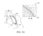
- FIGS. 1A-1Cillustrates the anatomy of the respiratory system
- FIGS. 2A-2Dillustrate a bronchoscope
- FIG. 3illustrates a bronchoscope in combination with a delivery device for a lung volume reduction device according to the invention
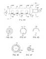
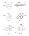
- FIGS. 4A-4Fillustrate a lung volume reduction device according to an aspect of the invention
- FIGS. 5A-5Dillustrate a lung volume reduction device according to another aspect of the invention
- FIG. 6illustrates a lung volume reduction device according to another aspect of the invention
- FIG. 7illustrates a lung volume reduction device encased in a sheath
- FIGS. 8A-8Dillustrate a lung volume reduction device according to another aspect of the invention.
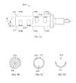
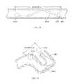
- FIGS. 9A-9Billustrate segments suitable for use in configuring a lung volume reduction device according to an aspect of the invention
- FIG. 10illustrates an exemplary device in a pre-deployed condition according to aspects of the invention
- FIGS. 11A-11Billustrate a lung volume reduction device according to another aspect of the invention
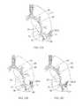
- FIGS. 12A-12Cillustrate a variety of device configurations with atraumatic tips
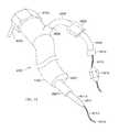
- FIGS. 13A-13Fillustrate a plurality of individual wires formed of shape memory material that can be deployed to form a lung volume reduction device and a delivery device;
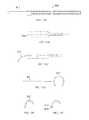
- FIG. 14illustrates a device configuration
- FIG. 15illustrates a device in a loading cartridge
- FIG. 16illustrates a long device configuration
- FIG. 17illustrates a device configuration with a wire support frame
- FIG. 18illustrates a device configuration with a covering
- FIG. 19illustrates a device configuration with a perforated covering
- FIG. 20illustrates a device configuration with an attached wire support frame
- FIG. 21illustrates a device configuration with an attached frame and covering
- FIG. 22illustrates a device configuration that is coupled to a second device
- FIG. 23illustrates a device configuration in a coil shape
- FIGS. 24A-24Eillustrate a device with two helical sections and a transition section
- FIGS. 25A-25Dillustrate the device of FIGS. 24A-E further comprising a jacket
- FIGS. 26A-26Eillustrate another embodiment of the device with two helical sections and a transition section
- FIGS. 27A-27Dillustrate the device of FIGS. 26A-E further comprising a jacket
- FIG. 28illustrates a device in a delivery configuration during delivery within an airway
- FIG. 29illustrates the device of FIG. 28 deployed to the deployed configuration within the airway
- FIGS. 30 and 31are images of human lung tissue before and after a portion of the lung tissue is compressed from within an airway by an embodiment of an implant;
- FIGS. 32A-32Cillustrate a device implanted within the lungs
- FIG. 33Aillustrates a method steps for implanting the device
- FIG. 33Billustrates a method steps for implanting the device
- FIG. 34illustrates a system in an airway with device ready to deliver
- FIG. 35illustrates a system in an airway delivering the device
- FIG. 36illustrates a system in an airway with the device delivered
- FIG. 37illustrates a system with a bronchoscope, catheter, dilator, and guidewire;
- FIGS. 38A-38Billustrate the delivery of the device
- FIG. 39schematically illustrates selection from among a plurality of alternative devices with different lengths, and loading of a device into a cartridge so that the device can be advanced into a delivery catheter;
- FIGS. 40A-40Cillustrate the delivery of a lung volume reduction device according to embodiments of the invention.
- FIG. 1Aillustrates the respiratory system 10 located primarily within a thoracic cavity 11 .
- the respiratory system 10includes the trachea 12 , which brings air from the nose 8 or mouth 9 into the right primary bronchus 14 and the left primary bronchus 16 .
- the right lung 18 and the left lung 20together comprise the lungs 19 .
- the left lung 20is comprised of only two lobes while the right lung 18 is comprised of three lobes, in part to provide space for the heart typically located in the left side of the thoracic cavity 11 , also referred to as the chest cavity.
- the primary bronchuse.g. left primary bronchus 16
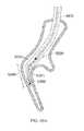
- the pleural cavity 38is the space between the lungs and the chest wall.
- the pleural cavity 38shown in FIG. 1C , protects the lungs 19 and allows the lungs to move during breathing. Also shown in FIG.
- the pleura 40defines the pleural cavity 38 and consists of two layers, the visceral pleurae 42 and the parietal pleurae 44 , with a thin layer of pleural fluid therebetween.
- the space occupied by the pleural fluidis referred to as the pleural space 46 .
- Each of the two pleurae layers 42 , 44are comprised of very porous mesenchymal serous membranes through which small amounts of interstitial fluid transude continually into the pleural space 46 .
- the total amount of fluid in the pleural space 46is typically slight. Under normal conditions, excess fluid is typically pumped out of the pleural space 46 by the lymphatic vessels.
- the lungs 19are described in current literature as an elastic structure that floats within the thoracic cavity 11 .
- the thin layer of pleural fluid that surrounds the lungs 19lubricates the movement of the lungs within the thoracic cavity 11 .
- Suction of excess fluid from the pleural space 46 into the lymphatic channelsmaintains a slight suction between the visceral pleural surface of the lung pleura 42 and the parietal pleural surface of the thoracic cavity 44 . This slight suction creates a negative pressure that keeps the lungs 19 inflated and floating within the thoracic cavity 11 . Without the negative pressure, the lungs 19 collapse like a balloon and expel air through the trachea 12 .
- the lungs 19When fully expanded, the lungs 19 completely fill the pleural cavity 38 and the parietal pleurae 44 and visceral pleurae 42 come into contact. During the process of expansion and contraction with the inhaling and exhaling of air, the lungs 19 slide back and forth within the pleural cavity 38 . The movement within the pleural cavity 38 is facilitated by the thin layer of mucoid fluid that lies in the pleural space 46 between the parietal pleurae 44 and visceral pleurae 42 .
- the air sacs in the lungsare damaged 32 , such as is the case with emphysema, it is hard to breathe. Thus, isolating the damaged air sacs to improve the elastic structure of the lung improves breathing. Similarly, locally compressing regions of the lung tissue while maintaining an overall volume of the lung increases tension in other portions of the lung tissue, which can increase the overall lung function.
- bronchoscope 50can be configured to be of any suitable length, for example, measuring 790 mm in length.
- the bronchoscope 50can further be configured from two main parts, a working head 52 and an insertion tube 54 .
- the working head 52contains an eyepiece 56 ; an ocular lens with a diopter adjusting ring 58 ; attachments for the suction tubing 60 and a suction valve 61 and for the cold halogen light source 62 and 63 ; and an access port or biopsy inlet 64 , through which various devices and fluids can be passed into the working channel 66 and out the distal end of the bronchoscope.
- the working headis attached to the insertion tube, which typically measures 580 mm in length and 6.3 mm in diameter.
- the insertion tubecan be configured to contain fiberoptic bundles (which terminate in the objective lens 30 at the distal tip 68 ), two light guides 70 , 70 ′ and the working channel 66 .
- the distal end of the bronchoscopehas the ability to bend 72 anterior and posterior, with the exact angle of deflection depending on the instrument used.
- a common range of bendingis from 160 degrees forward to 90 degrees backward, for a total of 250 degrees. Bending may be controlled by the operator by adjusting an angle lock lever and angulation lever on the working head. See also, U.S. Patent Pub. US 2005/0288550 A1 to Mathis for Lung Access Device and US 2005/0288549 A1 to Mathis for Guided Access to Lung Tissue, the entirety of which is incorporated herein by reference.
- FIG. 3illustrates the use of a lung volume reduction delivery device 80 for delivering a lung volume reduction device comprising an implantable device with the bronchoscope 50 .
- the lung volume reduction systemas described in further detail below, is adapted and configured to be delivered to a lung airway of a patient in a delivery configuration and then transitioned to a deployed configuration. By deploying the device, tension can be applied to the surrounding tissue which can facilitate restoration of the elastic recoil of the lung.
- the deviceis designed to be used by an interventionalist or surgeon.
- FIGS. 4A-Fillustrate a shaft or tubular member of a lung volume reduction device 110 which may be included in an implant according to an aspect of the invention, with FIGS. 4B-F being cross-sections taken along the lines B-B, C-C, D-D, E-E, and F-F of FIG. 4A , respectively.
- the lung volume reduction device 110includes a member, such as tubular member 112 , which has c-cuts 114 , or notches, along its length to provide flexibility such that the device can be deflected off a longitudinal axis A when deployed.
- the longitudinal axis of the implant shaft or bodymay be changed from a generally straight configuration suitable for distal insertion along axis A to a bent or deployed configuration.
- the bent or deployed implantmay bend or reconfigure a surrounding airway so as to locally compress lung tissue.
- the cutsare oriented parallel to one another along the length of the tubular member and are of the same or similar depth D
- the devicewill tend to uniformly curve around an axis point when deployed.
- the devicepreferentially curls or bends in a direction as determined by the shape of the slots.
- Different types (width, depth, orientation, etc.) of notches or slotscan be used to achieve different operational effects and configurations of the deployed device without departing from the scope of the invention.
- an actuation element 116 or pull-wirePositioned within a lumen 113 of the tubular member 112 , is an actuation element 116 or pull-wire.
- the actuation elementcan have a circular circumference in cross-section, as depicted, or can have any other suitable cross-section.
- the actuation element 116may be anchored at one end of the device 110 , e.g. the distal end, by a cap 119 .
- the cap 119can be bonded to the device and a distal crimp can be provided to crimp the cap 119 into the pull-wire 116 .
- the cap 119may be rounded as depicted to make the dip of the device atraumatic.
- cap 119may be configured to include an anchor configured to grasp the adjacent airway during the device deployment within the airway.
- the anchormay increase the amount of tissue compression by a deployed device and thereby increase the amount of beneficial tension in the lung.
- the opposing ende.g. proximal end, may be adapted and configured to engage a mechanism 120 .
- the mechanism 120may be adapted deploy the device. Further mechanism 120 may be configured to lock the device into a deployed configuration once the device 110 is deployed or to unlock the device to facilitate retrieval of the device from an airway.
- the device 110may be configured to be detachable from a delivery catheter adapted to deliver the lung volume reduction device. The delivery catheter and delivery of the device are discussed further below.
- Mechanism 120at the proximal end of the device may be adapted to include a retainer ring 122 that engages a ratchet 124 that can be used to lock the device in place.
- the coupler 126retains the ratchet 124 such that the ratchet locks the device in place once deployed.
- a retrieval adapter 130is provided, such as a pull-wire eyelid.
- the retrieval adapter 130may be adapted and configured to enable the device to be retrieved at a later point during the procedure or during a subsequent procedure.
- the ratchet devicemay include flanges that extend away from a central axis when deployed to lock the device in place.
- FIGS. 5A-Cillustrate yet another lung volume reduction device according to another aspect of the invention, with FIGS. 5B-C being cross-sections taken along the lines B-B, and C-C of FIG. 5A , respectively.
- the lung volume reduction device 310includes a member, such as tubular member 312 , which has c-cuts 314 , 314 ′, or notches, along its length to provide flexibility such that the device can be deflected in more than one direction off a longitudinal axis A when deployed.
- the notchesare positioned on the member 312 on opposing sides of the member when the member is lying within a plane.
- the devicewill tend to uniformly curve around an axis point when deployed.
- the configuration of the notcheswould result in a deployed configuration that is “s-shaped” when the actuator element 316 is pulled proximally (i.e., toward the user).
- FIG. 6illustrates yet another lung volume reduction device 410 according to another aspect of the invention.
- the tubular member 412has notches 414 , 414 ′, 414 ′′ configured in a spiral pattern along its length.
- FIG. 7illustrates a lung volume reduction device 510 encased in a sheath 535 .
- the sheathcan be a polymeric elastic membrane, such as silicone.
- the sheathcan prevent material from a body cavity from entering the lumen 513 of the tubular member 512 .
- An actuation member 516is provided within the lumen 513 of the tubular member 512 .
- FIGS. 8A-Dillustrate yet another lung volume reduction device 610 according to another aspect of the invention, with FIGS. 8B-D being cross-sections taken along the lines B-B, C-C, and D-D of FIG. 8A , respectively.
- the lung volume reduction device 610 in this embodimentis comprised of individual segments 612 , 612 ′, 612 ′′.
- the segmentscan be configured, for example, to have identical asymmetrical configurations such that a compressible space 614 is between each segment before the device is actuated by activating the actuator element 616 .
- Each of the segmentscan further comprise a detent on a first surface which opposes a mating indentation on a surface of an opposing segment.
- a variety of components of devices disclosed hereincan be configured to provide locking or mating mechanisms to facilitate actuation and operation.
- the actuation element 616When the actuation element 616 is activated, the compressible space is reduced and the opposing surfaces of two adjacent segments come together to reduce or eliminate the space between them, depending upon the desired outcome. Where the segments have identical or nearly identical configurations, the device will evenly arc around an axis point. Where the segments do not have identical configurations, a variety of configurations can be achieved upon deployment depending on the configurations of the segments selected and the organization of the segments in the device.
- the actuator element 616is secured at one end, e.g., the distal end, by a cap 619 .
- the segmentscan be formed as hypotubes or can be formed as injection molded or solid pieces. Use of segments can avoid fatigue on the device because the surfaces come in contact with one another during compression. Material selection can also prevent biometallic corrosion. Further, the segment design is conducive for mass production and maintenance of consistence for final shape and operation.
- FIGS. 9A-Billustrate segments 712 , 712 ′ suitable for use in configuring a lung volume reduction device according to an aspect of the invention.
- the segmentscan be generally cylindrical with a pair of surfaces that are either parallel or non-parallel each other at either end.
- a first surface 713could be perpendicular to the elongated tubular sides 715 of the element, while the opposing surface 717 is not perpendicular to the sides of the element (or parallel to the opposing first surface).
- a detent 721can be provided on one surface that is configured to mate with an indentation 723 the second surface of another.
- Other configurations, such as a key: keyway combinationcan be used without departing from the scope of the invention.
- a central lumen 725is provided through which an actuator element (described above) passes through.
- FIG. 10illustrates devices 2510 according to the invention in a pre-deployed configuration.
- FIG. 10illustrates the device 2510 having a longitudinal configuration, such as the configuration assumed prior to deployment.
- the devicewill preferentially bend.
- the actual preferential bendingwill vary depending upon the configuration of the device. For example, the location, depth, and orientation of the slots depicted in FIGS. 4-7 ; or the orientation of the walls of the segments of FIG. 8 .
- other configurationscan be achieved by, for example, altering the size and location of the c-cuts on the tubular member, or by altering the configuration of the segments illustrated in FIGS. 8-9 .
- the deviceimparts a bending force on the lung tissue which results in a reduction of lung volume.
- the implantonce re-shaped, is shorter in length than the deliverable implant configuration. The shortening occurs when for example, the distance between the proximal end and the distal end is reduced.
- the deliverable shape of the deviceis such that it fits within a cylindrical space that is 18 mm in diameter or smaller.
- the implantcan come into contact with tissue that is larger than 10 ⁇ 6 square inches per linear inch of the implant length.
- the re-shaped or deployed implantcan be configured in a variety of shapes to lie within a single plane, or to adopt any other suitable configuration, such that it does not lie within a single plane. Additionally, the device can have varying rates of curvature along its length.
- FIGS. 11A-Ba lung volume reduction device 210 according to another aspect of the invention is depicted, with FIG. 11B being a cross section taken along the lines B-B of FIG. 11A .
- an actuation element 216Positioned within a lumen 213 of the tubular member 212 is an actuation element 216 or a pull wire.
- the actuation elementcan have a circular circumference in cross-section, as depicted, or can have any other suitable cross-section.
- the actuation element 216may be anchored at one end of the device 210 , e.g. the distal end, by a cap 219 .
- the retainer ring 222is configured to provide anchors 223 , 223 ′ or teeth that are adapted to deploy by retracting the retaining sheath of a delivery catheter.
- the anchors 223contact the airway and affix the device in place.
- the anchor 223can be configured to be self-expanding such that the anchors approach or extend through (e.g., hook) the airway.
- the amount of expansion of the anchorswill be controlled by the design and the materials used. For example, where a shape memory material is used, the anchors can be configured to extend away from the longitudinal wall of the tubular member by a predetermined angle ⁇ , as depicted ⁇ 10 degrees.
- the design of the anchorcan further be driven by the length of the device.
- the anchorscan be configured to catch on the airway when deployed in a manner similar to the way a stent catches within the vasculature, or the anchor can be designed to cause friction. Prior to deployment, the anchors may be retained by a retaining sheath (illustrated below).
- FIGS. 12A-Cillustrates devices 2710 according to the invention implanted within, for example, a bronchiole 26 .
- the device 2710 depicted in FIG. 12Ais configured to provide an atraumatic tip 2711 on either end of the device.
- the device 2710When the device 2710 is activated within the bronchiole 26 the device curves and imparts a bending force on the lung tissue. As a result of the bending pressure, the tissue curves and compresses upon its self to reduce lung volume. Additionally, deployment of the device can result in the airway becoming bent.
- the devicecan also be configured with a single atraumatic tip so that the deployment mechanism 2720 can easily interface with the proximal end of the device.
- atraumatic tip 2711may be comprise a rounded tip similar to the tip illustrated in FIG. 4A .
- the device 810is comprised of a plurality of individual wires formed of shape memory material that resume their shape when implanted.
- the wirescan be heat treated to assume a specific shape, such as a C shape as described above.
- the wiresare then individually implanted through a delivery system 850 such that when the first wire is implanted the diameter of the wire may be small enough that the wire cannot overcome the force applied by the surrounding tissue to assume its pre-configured shape.
- the amount of strength available cumulatively among the wiresdoes overcome the force applied by the tissue and the wires, together, achieve the desired shape (see. FIG. 13F ).
- the strength of a shaped wirecan vary depending on how much material is used. For example, a shaped wire with a larger cross-section will have higher strength than a shaped wire with a smaller cross-section. However, a larger diameter wire may be harder to implant because it would be harder to straighten into a shape suitable for deployment. Where many small wires are used, each wire individually is more flexible and can be deployed easier, but as a larger number of wires are implanted the combined strength increases. In some embodiments, it may be useful to configure the devices 810 such that the use of, for example, 50-100 wires will have the strength to overcome pressure applied by the tissue. The wires 810 can be deployed within a flexible polymer tube to keep the wires in proximity to each other.
- FIG. 14shows an example of an implantable device 3703 made from Nitinol metal wire 3701 .
- Nickel-Titanium, Titanium, stainless steel or other biocompatible metals with memory shape properties or materials with capabilities to recover after being strained 1% or moremay be used to make such an implant. Additionally, plastics, carbon based composites or a combination of these materials would be suitable.
- the deviceis shaped like a French horn and can generally lie in a single plane.
- the endsare formed into a shape that maximizes surface area shown in the form of balls 3702 to minimize scraping or gouging lung tissue.
- the ballsmay be made by melting back a portion of the wire, however, they may be additional components that are welded, pressed or glued onto the ends of wire 3701 .
- a Nitinol metallic implantsuch as the one illustrated in FIG. 14 , may be configured to be elastic to recover to a desired shape in the body as any other type of spring would or it can be made in a configuration that may be thermally actuated to recover to a desired shape.
- Nitinolcan be cooled to a martensite phase or warmed to an austenite phase. In the austenite phase, the metal recovers to its programmed shape. The temperature at which the metal has fully converted to an austenite phase is known as the Af temperature (austenite final). If the metal is tuned so that the Af temperature is at body temperature or lower than body temperature, the material is considered to be elastic in the body and it will perform as a simple spring.
- the devicecan be cooled to induce a martensite phase in the metal that will make the device flexible and very easy to deliver.
- the devicewill naturally recover its shape because the metal is making a transition back to an austenite phase.
- the devicemay be strained enough to induce a martensite phase also. This transformation can take place with as little as 0.1% strain.
- a device that is strain induced into a martensite phasewill still recover to its original shape and convert back to austenite after the constraints are removed.
- the deviceis configured with an Ar temperature that is above body temperature, the device may be heated to convert it to austenite and thermally activate its shape recovery inside the body. All of these configurations will work well to actuate the device in the patient's lung tissue.
- the human body temperatureis considered to be 37 degrees C. in the typical human body.
- FIG. 15illustrates a cutaway view of a delivery cartridge system 3800 that constrains the implant device 3703 in a deliverable shape.
- the device 3801may be shipped to the intended user in such a system or it may be used as a tool to more easily load the implant into a desired shape before being installed into the patient, bronchoscope or a catheter delivery device.
- the cartridgemay be sealed or terminated with open ends or one or more hubs such as the Luer lock hub 3802 that is shown.
- the implantshould be constrained to a diameter that is the same or less than 18 mm diameter because anything larger than that will be difficult to advance past the vocal cord opening.
- FIG. 16illustrates another implant device 3901 that is shaped in a three dimensional shape similar to the seam of a baseball.
- the wireis shaped so that proximal end 3902 extends somewhat straight and slightly longer than the other end. This proximal end will be the end closest to the user and the straight section will make recapture easier. If it were bent, it may be driven into the tissue making it hard to access.
- FIG. 17is an illustration of another implant system 4001 . It is similar to that shown in FIG. 16 with the addition of a wire frame 4002 surrounding the device.
- the wire framemay be used, for example, to increase the bearing area that is applied to the lung tissue. By increasing the bearing area, the pressure born by the tissue is reduced along with a reduction in the propensity for the device to grow through lung structures or cause inflammatory issues. Small wires that apply loads in the body tend to migrate so we believe that the device should be configured to possess more than 0.000001 (1 ⁇ 6 in 2 ) square inches of surface area per linear inch of the length of the device.
- the frameis one of many ways to provide a larger surface area to bear on the tissue.
- FIG. 18shows yet another example of a device 4101 according to the invention.
- the device 4101features a covering to increase bearing area 4102 .
- the main wire 3902is covered by a wire frame and a polymeric covering 4102 .
- the coveringmay be made of any biocompatible plastic, thermoplastic, fluoropolymer, Teflon®, urethane, metal mesh, coating, silicone or other resilient material that will reduce the bearing pressure on the lung tissue.
- the ends of the covering 4103may remain sealed or open as shown to allow the user to flush antibiotics into and out of the covering.
- FIG. 19illustrates another configuration of the implant device 4201 showing a covering 4205 with perforations 4203 adapted and configured to allow the device to be flushed.
- the ends 4202 of the coveringare sealed to the ends of the device to keep the two components fixed and prevent sliding of one or the other during deployment.
- the coveringmay be thermally bonded, glued or shrunk to a tight fit.
- FIG. 20illustrates a device 4301 that has the wire frame 4002 joined to the ball ends 3702 at a junction 4302 .
- the ballsmay be melted from the wire stock and the wire frame may be incorporated into the ball at that time. It may also be glued, pressed together, welded or mechanically locked together.
- FIG. 21illustrates another implant device 4401 with an attached wire frame 4302 , main wire 4103 and a covering 4102 .
- the complete implantmay include additional structures or materials which enhance the ability of the implant to provide therapeutic benefits during long-term implantation, with many of these additional structures or materials providing a bearing surface or interface between the compression-inducing shaft of the device and the surrounding tissue lumen wall of an airway.
- These additional structures or materialsmay be any of the structures or materials which are disclosed in related U.S. patent application Ser. No. 12/782,515 filed on May 18, 2010, entitled Cross-Sectional Modification During Deployment of an Elongate Lung Volume Reduction Device, the application of which is incorporated herein by reference.
- FIG. 22illustrates a system of one or more devices that can be hooked together 4501 .
- the device 3703is configured such that it terminates on both ends, for example, with blunt ball shaped ends 3702 .
- the device 4502is terminated on one end with an open cup and slot shape 4503 that allows the devices to be coupled together. These devices may be delivered together or coupled in-situ. Devices may be installed into a single duct in the lung or in different locations that may be linked together.
- FIG. 23illustrates another three dimensional device 4601 made in the form of a coil with atraumatic ball terminations 3702 .
- FIGS. 24A-24Eillustrate another 100 mm long device 900 in a pre-implantation or a post-implantation configuration.
- device 900includes two helical sections 902 , 904 with a transition/intermediate section 906 disposed between the two helical sections 902 , 904 .
- device 900may have another configuration which corresponds to a delivery configuration in which the device assumes during delivery to a treatment region within an airway.
- Each helical section 902 , 904includes a respective helical axis 906 , 908 .
- helical axis 906is at an angle with helical axis 908 .
- the angle between the helical axis 906 and helical axis 908may be between 190° and 230° in some embodiments.
- helical section 902 , 904may share a helical axis.
- device 900comprises a shape-memory material, however a person of ordinary skill would recognize that many of the methods described above may be used to configure a device such that it may be mechanically actuated and locked into a similar configuration.
- Device 900 as shown in the figuresincludes a right-handed helical section and a left-handed helical section and the transition section 910 between the two helical sections comprises a switchback transition section when the device is in the pre-implantation or post-implantation configuration.
- the switchback transition sectionmay be defined as the intermediate section where the elongate body of the implant transitions between oppositely handed helical configurations. In some embodiments, the switchback transition section may reduce the recoil forces during device 900 deployment thereby providing greater control of device 900 during deployment.
- the switchback transitionmay reduce migration of the implant after deployment and thus maintain the device's tissue compression advantages.
- the helical sectionsdo not have to include the same number of loops or complete helix turns.
- the distal helix 904comprises more loops than the proximal helix 902 .
- device 900may be configured such that the proximal helix 902 includes more loops than distal helix 906 .
- the helical sectionsmay be configured to include a pitch gap of 0.078 ⁇ 0.025 in.
- the two helical sectionsare circular helical sections.
- Other embodiments of the present inventionmay be configured to include spherical or conical helical sections when in a pre-implantation or post-implantation configuration.
- FIGS. 25A-25Dillustrate device 900 further comprising a jacket 916 .
- Jacket 916may increase the diameter of device 900 so as to provide more area per unit force when deployed in the airway.
- the jacketmay increase the device diameter by 3.25 ⁇ to provide more area per unit force. Accordingly, the increase in diameter may reduce erosion into an airway wall once device 900 is deployed.
- Jacket 916may comprise 55D polycarbonate urethane (PCU). PCU may reduce biofilms that promote bacterial growth thereby limiting incidents of infection.
- the jacketmay cover the proximal helix, the distal helix, and the transition section disposed between the helices. Additionally, the jacket may cover the distal portion of the device as shown in FIGS. 25A-25D . In some embodiments, the proximal end is also covered by the jacket. Alternatively, the jacket may cover only certain portions of the device.
- the jacketmay be fastened to device 900 by an adhesive such as Loctite 3311.
- proximal end 912 and distal end 914 of device 900may be configured to be atraumatic.
- proximal end 912 and distal end 914comprises a ball with a diameter of about 0.055 ⁇ 0.005 in which may be made by melting back a portion of the wire or may be additional components that are welded, pressed or glued onto the ends of the wire.
- the atraumatic ballmay have a smaller surface area to allow a low catheter friendly profile or a larger ball which reduces the tissue stress with the larger surface area.
- a tissue penetrating anchormay be used to couple the proximal end or distal end of device 900 to an airway wall during the deployment of the device.
- Proximal end 912is also configured as a stand-off proximal tail which may extend past an outer boundary defined by the proximal coil.
- angle ⁇may be 76° ⁇ 20°.
- the stand-off proximal tailmay extend away from the axis of a helical section when the device is in the pre-implantation or post-implantation configuration as shown in FIG. 24D .
- the stand-off proximal tailmay include a steeper bend 915 at the proximal end which may allow more length to be used in compression.
- the standoff proximal tailprovides for better device retrievability once deployed by reducing the chances that the proximal tail will impinge against or penetrate through the airway wall once the device is deployed. Accordingly, device repositioning and/or removal may be facilitated by a device with a standoff proximal tail configuration.
- the stand-off proximal tailmay be used with other device configurations. In one embodiment, the stand-off proximal tail may be utilized with a device configuration comprising a single helical section.
- FIGS. 26A-26Eillustrate device 1000 which is similar to device 900 .
- Device 1000includes a proximal helical section 1002 and a distal helical section 1004 .
- a transition 1006is disposed between the two helical sections 1002 , 1004 .
- the proximal end 1012 and distal end 1014comprise atraumatic balls.
- Distal helical section 1004includes 4.25 loops but may comprise more.
- FIGS. 27A-27Dillustrate device 1000 further comprising jacket 1016 .
- the distal helical sectionsmay further compress portions of the lungs when device 1000 is deployed within an airway. Similar to device 900 , other configurations of device 1000 are possible.
- device 1000may be configured to include two right handed helical sections or two left handed helical sections.
- the helical sectionsmay share the same helical axis.
- FIGS. 28 and 29illustrate how the device length is reduced when the device is deployed in-situ.
- the device shown in the delivery configuration 4802 in FIG. 28is also shown in the deployed configuration 4803 in FIG. 29 .
- the distance A between the device ends 3702is large while the device is constrained by the constraining cartridge device 3801 .
- Distance Ais similar when the device is constrained by a loading cartridge, catheter or bronchoscope.
- FIG. 29shows the same device in a deployed configuration 4803 in an airway 4801 that has been deformed by the shape recovery of the implant device.
- FIG. 29shows that the distance B between the device ends 3702 is substantially shorter after the device is deployed.
- FIG. 30illustrates the device of FIGS. 26A-E deployed within an airway.
- the airway liningmay be pinched between adjacent helix loops thereby providing beneficial tissue compression.
- a 70% improvement in volume reduction over current LVRCcan be obtained.
- FIGS. 30 and 31show two photos of a human lung in a chest cavity simulator.
- the lungswere explanted from a person who expired due to chronic obstructive pulmonary disease (COPD).
- COPDchronic obstructive pulmonary disease
- the cavityis sealed with the lung's main stem bronchi protruding through a hole in the cavity wall.
- the bronchihas been sealed to the hole so a vacuum can be applied to aspirate the air from the space between the cavity interior and the lung.
- Thisallows the lung to be drawn to a larger expanded condition with vacuum levels that are physiologic (such as 0.1 to 0.3 psi, similar to that of the typical human chest cavity).
- FIG. 30illustrates a 175 mm long implant that has been delivered to a distal end of a delivery catheter as described above.
- the catheteris substantially constraining the implant in a straightened delivery configuration.
- FIG. 31shows the implant after the catheter has been retracted from the implant to allow the implant to return toward its relaxed configuration.
- the implanthas recovered to its original shape by means of elastic recoil and possibly a Nitinol metal compositional phase change substantially back to austenite.
- the delivery grasperhas been unlocked to release the implant in the airway.
- the implantcan be placed in pathologic regions in the lung that provide limited or no exchange of gas to and from the blood stream because the alveolar walls used to do so have been degraded and destroyed by disease. These are typically the most degraded regions that have lost mechanical strength and elasticity. In an inhaling COPD patient these degraded areas fill with air first, at the expense of gas filling in regions that could better help the patient, because the weakened tissue presents little to no resistance to gas filling. By implanting the devices in these areas, resistance is provided so the gas is filled in regions that still can effectively exchange elements to and from the blood stream. Viable regions have structure remaining so resistance to gas filling is present as this is a normal physiologic property.
- the implantadvantageously provides more gas filling resistance in the destroyed regions than the normal physiologic resistance in the viable regions so gas flows to viable tissue. This eliminates or reduces the counterproductive “preferential filling” phenomenon of the most diseased lung tissue prior to treatment.
- the implantable devicemay also delay collapse of airways during a breathing cycle thereby limiting the amount of air trapping in a lung. Accordingly, patients with small airway disease or with alpha 1-antitrypsin deficiency may also be treated with such a device. Additionally, the implantable device may be configured to provide enhanced breathing efficacy immediately after implantation while still allowing gas exchange distal to the deployed implant thereby reducing the chance of atelectasis of lung tissue distal to the implant.
- the embodiments depicted in FIGS. 14-31are adapted and configured to be delivered to a lung airway of a patient in a delivery configuration and to change to a deployed configuration to bend the lung airway.
- the devicesare characterized in that the devices have a delivery configuration that is resiliently bendable into a plurality of shapes, such as the ones depicted in the Figures.
- the design of the devicescan be such that strain relief is facilitated on both ends of the device. Further the ends of the device in either the delivery or deployed state are more resilient.
- the devicescan have any suitable length for treating target tissue. However, the length typically range from, for example, 2 cm to 20 cm, usually 5 cm.
- the diameter of the devicecan range from 1.00 mm to 3.0 mm, preferably 2.4 mm.
- the deviceis used with a catheter which has a working length of 60 cm to 200 cm, preferably 90 cm.
- the devices shown in FIGS. 14-31are adapted and configured to be minimally invasive which facilitates easy use with a bronchoscope procedure. Typically, there is no incision and no violation of the pleural space of the lung during deployment. Furthermore, collateral ventilation in the lung does not affect the effectiveness of the implanted device. As a result, the devices are suitable for use with both homogeneous and heterogeneous emphysema.
- Each of the devices depicted in FIGS. 14-31are adapted and configured to impart bending force on lung tissue.
- a spring elementcan be provided, as illustrated in FIG. 14 that imparts bending force on lung tissue.
- the implantable spring elementthat can be constrained into a shape that can be delivered to a lung airway and unconstrained to allow the element to impart bending force on the airway to cause the airway to be bent.
- Embodiments of the lung volume reduction systemcan be adapted to provide an implant that is constrained in a first configuration to a relatively straighter delivery configuration and allowed to recover in situ to a second configuration that is less straight configuration.
- Devices and implantscan be made, at least partially, of spring material that will fully recover after having been strained at least 1%, suitable material includes a metal, such as metals comprising Nickel and Titanium.
- the implant of the lung volume reduction systemis cooled below body temperature in the delivered configuration.
- the cooling systemcan be controlled by a temperature sensing feedback loop and a feedback signal can be provided by a temperature transducer in the system.
- the devicecan be configured to have an Af temperature adjusted to 37 degrees Celsius or colder. Additionally, at least a portion of the metal of the device can be transformed to the martensite phase in the delivery configuration and/or can be in an austenite phase condition in the deployed configuration.
- Lung volume reduction systemssuch as those depicted in FIGS. 14-31 , comprise an implantable device that is configured to be deliverable into a patient's lung and which is also configured to be reshaped to make the lung tissue that is in contact with the device more curved. Increasing the curvature of the tissue assists in reducing the lung volume of diseased tissue, which in turn increases the lung volume of healthier tissue.
- the devicesare configured to be reshaped to a permanent second configuration.
- the devicescan also be adapted and configured to have a first shape and is configured to be strained elastically to a deliverable shape.
- the devices illustrated in FIGS. 14-31are can be configured to be deliverable into a patient's lung and configured to reshape lung tissue while allowing fluid to flow both directions past the implant.
- a number of additional features described in related U.S. patent application Ser. No. 12/558,206 entitled Enhanced Efficacy Lung Volume Reduction Devices, Methods, and Systems, such as lock features, decoupler systems, activation systems, and retrieval systemsmay be used with aspects of the present invention.
- the full disclosure of U.S. patent application Ser. No. 12/558,206is incorporated herein by reference.
- FIGS. 32A-Cillustrates the process of implanting the device within a lung.
- the device 2810is advanced is a configuration where the device adapts to the anatomy of the lungs through the airways and into, for example, the bronchioles until it reaches a desired location relative to the damaged tissue 32 .
- the deviceis then activated by engaging the actuation device, causing the device to curve and pull the lung tissue toward the activated device (see, FIG. 32B ).
- the devicecontinues to be activated until the lung tissue is withdrawn a desired amount, such as depicted in FIG. 32C .
- withdrawing the tissuecan be achieved by, for example, curving and compressing a target section of lung tissue upon deployment of one of the configurable devices disclosed herein. Once activated sufficiently, the deployment device is withdrawn from the lung cavity.
- FIG. 33Aillustrates the steps including, insertion of the device 3610 , activating the device 3620 , such as by activating an actuator; bending the device into a desired configuration 3630 and locking the device into a deployed condition.
- the step of bending the devicecan be achieved by activating the actuator, as described above, or by the implant being restored into a preconfigured shape.
- the device operationincludes the step of inserting a bronchoscope into a patient's lungs and then inserting an intra-bronchial device or lung volume reduction device into the bronchoscope.
- the intrabronchial deviceis then allowed to exit the distal end of the bronchoscope where it is pushed into the airway.
- a variety of methodscan then be used to verify the positioning of the device to determine if the device is in the desired location. Suitable methods of verification include, for example, visualization via visualization equipment, such as fluoroscopy, CT scanning, etc.
- the deviceis activated by pulling the pull wire proximally (i.e., toward the user and toward the exterior of the patient's body).
- the devicecan be fully actuated and the ratchet can be allowed to lock and hold the device in place. Thereafter, the implant is decoupled from the delivery catheter and the delivery catheter is removed.
- FIG. 33BAnother method of tensioning the lung is shown in FIG. 33B which illustrates steps that include, applying bending loads or force to strain a device from a first shape into a deliverable shape without plastically or permanently bending the device 3640 , delivering the device into the patient using the bronchoscope or other delivery system components to hold the device in a deliverable shape while it is being introduced 3650 and then removing the constraint used to hold the device to allow it to recover back to its first shape 3660 .
- Elastic recovery of the devicewill drive the device to a more bent condition that will apply force to nearby lung tissue.
- the bending forceslocally compress tissue near the implant and apply tension on lung tissue in surrounding regions to restore lung recoil and enhance breathing efficiency.
- the first shapeis adapted to be elastically constrained by a delivery device to a deliverable configuration whereby removal of the delivery device allows the implant to recoil and be reshaped closer to its first shape.
- FIG. 34illustrates a system 4901 that may be used to deliver the implant device.
- the many components of the systemmay be needed to guide the bronchoscope 4902 to a site that is appropriate for implant delivery.
- the airway guide wirehas a distal floppy section 4913 that can be steered into any desired airway by rotating the slight curve at the distal tip to the appropriate trajectory at airway bifurcations.
- devicessuch as a locking proximal handle 4915 may be attached to the proximal end of the wire 4912 .
- the wire tipmay be blunt such as the ball tip shown 4914 .
- the wiremay be adapted and configured to pass through a dilator catheter 4909 that is shaped to provide a smooth diameter transition from the wire diameter to the delivery catheter 4906 diameter.
- the distal tip of the dilator 4910should be tapered 4911 as shown.
- the dilatorprevents the open end of the delivery catheter 4906 to dig into lung tissue in an unintended way.
- the dilator hub 4916may be made as a Y-fitting to allow the user to couple a syringe and inject radiopaque dye through the dilator lumen to increase the visibility of the airways, which facilitates the use of an x-ray guidance system, such as fluoroscopy or computed tomography.
- the delivery cathetermay be used without the wire and dilator.
- the catheter 4906is designed to constrain the device in a deliverable shape while it is advanced through the system and into the patient.
- the distal end 4907may be configured from a floppier polymer or braid than the proximal end 4906 and the distal tip may further include a radiopaque material associated with the tip, either integral or adjacent, to identify the position of the tip relative to other anatomical locations, such as bones. Providing one or more radiopaque markers facilitates using x-ray guidance system to position the distal end of the device in situ relative to a target anatomy.
- the proximal termination of the delivery catheter 4908may further be adapted to incorporate a lockable hub to secure the loading cartridge 3801 with a smooth continuous lumen.
- the delivery catheter 4906is shown introduced into the bronchoscope side port 4905 and out the distal end of the scope 4917 .
- a camera 4903is shown attached to the end of the scope with a cable 4904 , or other delivery mechanism, to transmit the image signal to a processor and monitor.
- the loading cartridge, delivery catheter, dilator, guide wire and wire nutmay be made from any material identified in this specification or materials well known to be used for similar products used in the human vascular tract by radiologists.
- FIG. 35illustrates a delivery system 5001 that has been placed into a human lung.
- the bronchoscope 4902is in an airway 5002 .
- the scope camera 4903is coupled to a video processor 5004 via a cable 4904 .
- the imageis processed and sent through a cable 5005 to a monitor 5006 .
- the monitorshows a typical visual orientation on the screen 5007 of a delivery catheter image 5008 just ahead of the optical element in the scope.
- the distal end of the delivery catheter 4907protrudes out of the scope in an airway 5002 where the user will place an implant device 3703 .
- the implant 3703is loaded into a loading cartridge 3801 that is coupled to the proximal end of the delivery catheter via locking hub connection 3802 .
- a pusher grasper device 5009is coupled to the proximal end of the implant 3703 with a grasper coupler 5010 that is locked to the implant using an actuation plunger 5012 , handle 5011 and pull wire that runs through the central lumen in the pusher catheter.
- the usermay advance the implant to a position in the lung in a deployed configuration.
- the usercan survey the implant placement position and still be able to retrieve the implant back into the delivery catheter, with ease, if the delivery position is less than ideal.
- the devicehas not been delivered and the bottom surface of the lung 5003 is shown as generally flat and the airway is shown as generally straight. These may both be anatomically correct for a lung with no implant devices. If the delivery position is correct, the user may actuate the plunger 5012 to release the implant into the patient.
- FIG. 36illustrates generally the same system after the implant has been deployed into the airway 5103 .
- the implant 5102 and pusher 5101has been advanced through the delivery catheter 4907 to a location distal to the scope 4902 .
- the pusher grasping jaws 5010are still locked onto the proximal end of the implant 5102 but the implant has recovered to a pre-programmed shape that has also bent the airway 5103 into a folded configuration.
- the airway structurehas been effectively shortened within the lung and lung tissue between portions of the implant has been laterally compressed. Since the airways are well anchored into the lung tissue, the airway provides tension on the surrounding lung tissue which is graphically depicted by showing the pulled (curved inward) floor of the lung 5104 .
- the image from the camera 4903is transmitted through the signal processor 5004 to the monitor 5006 to show the distal tip of the delivery catheter 5101 , distal grasper of the pusher 5010 and proximal end of the implant 3703 .
- the graspermay be used to locate, couple to and retrieve devices that have been released in the patient.
- the implantperforms work on the airways and lung tissue without blocking the entire lumen of the airway. This is a benefit in that fluid or air may pass either way through the airway past the implant device.
- FIG. 37illustrates delivery system 5200 as placed into a patient body, and particularly into a human lung.
- Delivery system 5200may be generally similar to system 4901 or 5001 described above.
- the distal end 5240 of bronchoscope 4902extends into an airway system toward an airway portion or axial region 5002 , sometimes referred to as an axial segment.
- the scope camera 4903is coupled to a video processor 5004 via a cable 4904 .
- the imageis processed and sent through a cable 5005 to a monitor 5006 .
- Monitor 5006shows on screen 5007 a portion of a delivery catheter image 5008 just ahead of the optical image capture element in the scope.
- the scopemay be constrained by a relatively large cross-section to advancement only to a “near” region of the lung adjacent the major airways.
- the optical imagehas a viewfield that extends only a limited distance along the airway system, and it will often be desirable to implant some, most, or all of the implant beyond a field of view 5242 of scope 4902 .
- Guidewire 5203is threaded through bronchoscope 4902 and through the airway system to (and through) airway 5002 .
- guidewire 5203may optionally have a cross-section significantly smaller than that of the scope and/or the delivery catheter.
- Alternative embodimentsmay use a relatively large diameter guidewire.
- the guidewiremay instead be large enough to mostly or substantially fill the lumen of the delivery catheter, while still allowing sliding motion of the guidewire through the lumen.
- Suitable guidewiresmay have cross-section in a range from about 5 Fr to about 7 Fr, ideally being about 51 ⁇ 2 Fr, while the delivery catheter may be between about 5 Fr and 9 Fr, ideally being about 7 Fr.
- a distal end 5209 of the guidewire 5203may be angled as described above to facilitate steering. Still further variations are also possible, including delivery of the implant directly thru a working lumen of an endoscope (with use of a separate delivery catheter). In particular, where a cross-sectional size of a bronchoscope allows the scope to be advanced to a distal end of the target airway region, the bronchoscope itself may then be used as a delivery catheter, optionally without remote imaging.
- a fluoroscopic system, an ultrasound imaging system, an MRI system, a computed tomography (CT) system, or some other remote imaging modality having a remote image capture device 5211allows guidance of the guidewire so that the guidewire and/or delivery catheter 5201 can be advanced beyond the viewing field of bronchoscope 4902 .
- the guidewiremay be advanced under remote image guidance without the use of a scope.
- the guidewirecan generally be advanced well beyond the near lung, with the distal end of the guidewire often being advanced to and/or through the mid-lung, optionally toward or to the small airways of the far lung.
- the cross-section of the guidewiremay limit advancement to a region of the airway having a lumen size appropriate for receiving the implants described above.
- the guidewiremay have an atraumatic end, with exemplary embodiments having a guidewire structure which includes a corewire affixed to a surrounding coil with a resilient or low-column strength bumper extending from the coil, the bumper ideally formed by additional loops of the coil with separation between adjacent loops so as to allow the bumper to flex axially and inhibit tissue damage. A rounded surface or ball at the distal end of the bumper also inhibits tissue injury.
- a distal end 5244 of laterally flexible delivery catheter 5201can then be advanced through the lumen within bronchoscope 4902 and over guidewire 5203 under guidance of the imaging system, ideally till the distal end of the delivery catheter is substantially aligned with the distal end of the guidewire.
- the distal portion of guidewire 5203is provided with indicia of length 5206 , the indicia indicating distances along the guidewire from distal end 5209 .
- the indiciamay comprise scale numbers or simple scale markings, and distal end 5244 of catheter 5201 may have one or more corresponding high contrast markers, with the indicia of the guidewire and the marker of the catheter typically visible using the remote imaging system.
- remote imaging camera 5211can identify, track or image indicia 5206 and thus provide the length of the guidewire portion extending between (and the relative position of) the distal end of the bronchoscope and the distal end 5209 of guidewire 5203 .
- Indicia of length 5206may, for example, comprise radiopaque or sonographic markers and the remote imaging modality may comprise, for example, an x-ray or fluoroscopic guidance system, a computed tomography (CT) system, an MRI system, or the like.
- Exemplary indiciacomprise markers in the form of bands of high-contrast metal crimped at regular axial intervals to the corewire with the coil disposed over the bands, the metal typically comprising gold, platinum, tantalum, iridium, tungsten, and/or the like. Note that some of the indicia of the guidewire are schematically shown through the distal portion of the catheter in FIG. 37 . Indicia of length 5206 thus facilitate using a guidance system to measure a length of airway 5002 or other portion of the airway system beyond the field of view of the scope, thereby allowing an implant of appropriate length to be selected.
- Remote imaging modality 5221is coupled to imaging processor 5224 via cable 5215 .
- Imaging processor 5224is coupled to a monitor 5226 which displays an image 5228 on screen 5227 .
- Image 5228shows the indicia of lengths 5205 and 5206 of delivery catheter 5201 and guidewire 5203 , respectively.
- a dilator 5217may be advanced through the lumen of the catheter so that the distal end of the dilator extends from the distal end of delivery catheter 5201 when the catheter is being advanced.
- Dilator 5217atraumatically expands openings of the airway system as delivery catheter 5201 advances distally.
- Dilator 5217tapers radially outwardly proximal of the distal tip of guidewire 5203 , facilitating advancement of the catheter distally to or through the mid-lung toward the far lung.
- FIGS. 38A and 38Bshow an implant 5300 for treating airway 5002 of a lung.
- airway 5002comprises a portion of a branching airway system, and the airway targeted for deployment will typically define an airway axis 5340 .
- Implant 5300comprises an elongate body 5301 , a distal end 5303 , and a proximal end 5305 .
- Elongate body 5301is biased to bend to a bent deployed configuration as described above and as shown in FIG. 38B .
- a pusher grasper device 5009is coupled to the proximal end 5305 with a grasper coupler 5010 that is locked to implant 5300 using an actuation plunder 5012 , handle 5011 , and pull wire that runs through the central lumen in the pusher catheter.
- implant 5300may be loaded into a tubular loading cartridge, for example, cartridge 3801 , and advanced from the loading cartridge into the lumen of catheter 5301 .
- Pusher grasper device 5009can advance implant 5300 through delivery catheter 5201 .
- FIG. 38Awhen restrained within delivery catheter 5201 , elongate body 5301 is maintained in a straightened configuration which defines a long axis between the distal end 5303 and proximal end 5305 .
- FIG. 38Awhen restrained within delivery catheter 5201 , elongate body 5301 is maintained in a straightened configuration which defines a long axis between the distal end 5303 and proximal end 5305 .
- FIG. 38Awhen restrained within delivery catheter 5201
- implant 5300when pusher grasper device 5009 axially restrains implant 5300 and catheter 5201 is pulled proximally from airway axial region 5002 , implant 5300 resiliently returns to a bent deployed configuration to bend the airway 5002 . More specifically, the airway axis 5340 goes from a relatively straight configuration to a highly bent configuration, with lateral movement of the elongate body and surrounding airway structure thereby compressing adjacent tissue.
- catheter 5201Once catheter 5201 has been withdrawn from over elongate body 5301 , the deployment can be evaluated. The user may axially restrain the implant 5300 while catheter 5201 is advanced axially so as to recapture the implant if the deployment does not appear satisfactory, or the user may actuate plunger 5012 to release implant 5300 .
- Implant 5300may be loaded into a tubular loading cartridge, for example, cartridge 3801 , and advanced from the loading cartridge into the lumen of catheter 5301 .
- FIG. 39shows a plurality of implants including implant 5300 A, 5300 B, and 5300 C. Each of these implants may have different sizes, lengths, and shapes from each other.
- guidewire 5203may be advanced to a target region near the distal end of the airway system. Guidewire 5203 may be advanced distally until further distal advancement is limited by the distal end of the guidewire being sufficiently engaged by the surrounding lumen of the airway system. Delivery catheter 5201 can then be advanced so that a distal end of catheter 5201 is adjacent a distal end of the guidewire.
- the distance along the indicia of length 5205 from the bronchoscope to the distal end of guidewire 5203may be used to select an implant having an elongate body 5301 with a desired length.
- the desired lengthmay be lesser, greater or about the same as the distance between the distal end of delivery catheter 5201 and distal end of the bronchoscope as indicated by the indicia 5206 .
- the elongate body 5301 having the selected lengthmay be advanced and deployed into the lung via the airway system and using pusher grasper 5009 as described above.
- the selected implant 5300may be loaded into a loading cartridge 5401 (and subsequently into the lumen of delivery catheter 5201 ) using pusher grasper device 5009 .
- Pusher grasper device 5009may be tensioned proximally and/or loading cartridge 5401 may be pushed distally so that elongate body 5301 straightens axially.
- the loading cartridge 5401 and implant 5300can then be coupled to the other components of the delivery system, and the implant advanced into the airway as described above.
- the pusher grasper 5009moves distally while the catheter 5201 is retracted proximally from over the implant during deployment.
- the selected implantmay have a length greater than the measured distance between the distal end of the guidewire (and hence the end of the delivery catheter) and the distal end of the scope. This can help accommodate recoil or movement of the ends of the implant toward each during delivery so as to avoid imposing excessive axial loads between the implant and tissue. Distal movement of the pusher grasper 5009 and proximal end of the implant during deployment also helps keep the proximal end of the implant within the field of view of the bronchoscope, and enhances the volume of tissue compressed by the implant.
- Exemplary implantsmay be more than 10% longer than the measured target airway axial region length, typically being from 10% to about 30% longer, and ideally being about 20% longer. Suitable implants may, for example, have total arc lengths of 125, 150, 175, and 200 mm.
- the treatment methodmay comprise delivering an implant within the lung and then evaluating the patient's breathing thereafter to determine whether more implants are needed.
- a plurality of implantsmay be delivered within the patient's lungs before an evaluation.
- the patient's lungsmay be evaluated by measuring a forced expiratory volume (FEV) of the patient, measuring/visualizing a change in tissue density at the implantation region, measuring/visualizing displacement of the diaphragm or of the lung fissures, etc.
- FEVforced expiratory volume
- an implantis deployed in a straight configuration with the use of a catheter, e.g., catheter 5201 , to contain it in a generally straight shape.
- a cathetere.g., catheter 5201
- Alternative embodimentsmay use the working lumen of the bronchoscope directly so that the bronchoscope is used as a delivery catheter.
- the implantUpon removal of the constraining catheter, the implant recoils to a deployed shape that can be easily identified by the fact that the distance from one end to the second is reduced.
- the proximal end of the implantmay be grasped, e.g., with pusher grasper device 5009 , and held so that the distal end of the implant remains engaged against the desired airway tissue as the length of the implant is progressively unsheathed (by withdrawing the catheter proximally).
- an implant 5300 having a length longer than that of the target axial region 5505may be selected to be deployed in some cases.
- a guidewiremay be advanced distally from the bronchoscope until the guidewire advancement is inhibited by engagement with the surrounding airway, with the guidewire optionally being relatively large in cross-section (such having a size of between about 5 F and 7 F, ideally having a size of about 51 ⁇ 2 F). This allows the guidewire to be advanced to (but not excessively beyond) a target site for the distal end of the implant (which may have an atraumatic ball surface with a diameter from about 1 to about 3 mm, ideally being about 1.5 mm). As shown in FIG.
- catheter 5201is advanced distally from the distal end of bronchoscope 4902 over the guidewire until the distal end of catheter 5201 is aligned with the distal end of the guidewire or till the distal end of the catheter limits further distal advancement due to the distal end of catheter 5201 being similarly sufficiently engaged by the surrounding lumen of the airway system 5002 .
- a length 5505 of the target axial region of the airwayis measured. Length 5505 may be the distance between the distal end of the advanced catheter 5201 and the distal end of the bronchoscope 4902 , and the guidewire can be withdrawn proximally after the measurement.
- An implant 5300 having a length greater than the measured length 5505is selected and distally advanced through catheter 5201 using pusher grasper 5009 as previously described. Implants having a length of at least 10% more, preferably about 20% more, than the measured target axial region may be selected.
- FIG. 40Bshows the deployment of implant 5300 .
- Implant 5300is advanced through the lumen of catheter 5201 to adjacent its distal end and the catheter 5201 , the distal end of the implant is (at least initially) held axially in place, and the catheter is withdrawn proximally from over a distal portion of the implant.
- catheter 5201As catheter 5201 is withdrawn, implant 5300 bends laterally and compresses a portion of airway 5002 .
- a larger portion airway 5002can be compressed by implant 5300 once catheter 5201 is fully withdrawn such that it no longer restrains implant 5300 .
- the proximal end of the implantmoves distally relative to the surrounding bronchoscope and airway tissue.
- the proximal end of implant 5300may also be released by pusher grasper 5009 after implant 5300 has foreshortened (when measured along the axial center of the airway) gradually throughout its release.
- the proximal end of implant 5300can also be fed into the airway while the potential energy of the implant is being freed to apply work on the lung tissue (while the catheter is being pulled off of the implant).
- the lung airwayscan be distorted so the airway cross section is pushed to a more oval shape.
- Longer implantscan tend to zigzag back and forth across the airway lumen so that implants that are significantly longer than the measured airway length can be introduced.
- a 150 mm long (arc length) implantcan be deployed into a 100 mm long airway. The greater length of the implant may minimize the uncontrolled recoil that may cause the proximal end to be lost in the patient upon release.
- Greater implant lengthcan also allow the user to feed the implant into the patient while the catheter is removed without over stressing the lung tissue. Additionally, should foreshortening of the longer implant occur, the proximal end of the implant can still remain within the viewing field of the bronchoscope and the user can thus retain the ability to retrieve the implant reliably. It should be understood that the length of the implant relative to the diameter of the airway may be much greater than the schematic illustration of FIGS. 40A-40C , that the implant may have more complex three dimensional curvature to effect volumetric compression of the lung tissue, and the like.
- the devicecan be manufactured and deployed such that it is deliverable through a bronchoscope.
- the deviceWhen actuated, the device can be adapted and configured to bend or curl which then distorts lung tissue with which the device comes in contact.
- Lung tissues that may be beneficially distorted by the deviceare airways, blood vessels, faces of tissue that have been dissected for introduction of the device or a combination of any of these.
- the deviceBy compressing the lung tissue, the device can result in an increase in elastic recoil and tension in the lung in at least some cases.
- lung functioncan be at least partially restored regardless of the amount of collateral ventilation.
- the diaphragmmay, in some instances, move up once greater tension is created which enables the lung cavity to operate more effectively.
- Devices according to the inventionhave a small cross-section, typically less than 10 F.
- the flexibility of the device prior to deploymentfacilitates advancement of the device through the tortuous lung anatomy. Once deployed, the device can remain rigid to hold and maintain a tissue deforming effect. Further, the device design facilitates recapture, de-activation and removal as well as adjustment in place.
- biocompatible materialssuch as metals (e.g. stainless steel, shape memory alloys, such a nickel titanium alloy (nitinol), titanium, and cobalt) and engineering plastics (e.g. polycarbonate). See, for example U.S. Pat. No. 5,190,546 to Jervis for Medical Devices Incorporating SIM Memory Alloy Elements and U.S. Pat. No. 5,964,770 to Flomenblit for High Strength Medical Devices of Shape Memory Alloy.
- other materialsmay be appropriate for some or all of the components, such as biocompatible polymers, including polyetheretherketone (PEEK), polyarylamide, polyethylene, and polysulphone.
- Polymers and metals used to make the implant and delivery systemmay be coated with materials to prevent the formation and growth of granular tissue, scar tissue and mucus.
- Many of the drugs used with stent products to arrest hyperplasia of smooth muscle cells in blood vessels after deploying metallic stentswill work very well for these devices.
- Slow release drug eluting polymers or solventsmay be used to regulate the release of drugs that include any substance capable of exerting a therapeutic or prophylactic effect for a patient.
- the drugcould be designed to inhibit the activity of smooth muscle cells. It can be directed at inhibiting abnormal or inappropriate migration and/or proliferation of smooth muscle cells to inhibit tissue mass buildup.
- the drugmay include small molecule drugs, peptides or proteins.
- drugsexamples include antiproliferative substances such as actinomycin D, or derivatives and analogs thereof (manufactured by Sigma-Aldrich of Milwaukee, Wis., or COSMEGEN available from Merck). Synonyms of actinomycin D include dactinomycin, actinomycin IV, actinomycin 1 , actinomycin X 1 , and actinomycin C 1 .
- the active agentcan also fall under the genus of antineoplastic, anti-inflammatory, antiplatelet, anticoagulant, antifibrin, antithrombin, antimitotic, antibiotic, antiallergic and antioxidant substances. Examples of such antineoplastics and/or antimitotics include paclitaxel (e.g.
- TAXOL®by Bristol-Myers Squibb Co. of Stamford, Conn.
- docetaxele.g. Taxotere®, from Aventis S. A. of Frankfurt, Germany
- methotrexatee.g. Taxotere®, from Aventis S. A. of Frankfurt, Germany
- methotrexatee.g. Taxotere®, from Aventis S. A. of Frankfurt, Germany
- methotrexatemethotrexate
- azathioprinemethotrexate
- vincristinevinblastine
- fluorouracile.g. Adriamycin® from Pharmacia & Upjohn of Peapack N.J.
- mitomycine.g. Mutamycin® from Bristol-Myers Squibb
- antiplateletsexamples include sodium heparin, low molecular weight heparins, heparinoids, hirudin, argatroban, forskolin, vapiprost, prostacyclin and prostacyclin analogues, dextran, D-phe-pro-arg-chloromethylketone (synthetic antithrombin), dipyridamole, glycoprotein Hh/IIIa platelet membrane receptor antagonist antibody, recombinant hirudin, and thrombin inhibitors such as AngiomaxTM (Biogen, Inc. of Cambridge, Mass.).
- AngiomaxTMBiogen, Inc. of Cambridge, Mass.
- cytostatic or antiproliferative agentsexamples include angiopeptin, angiotensin converting enzyme inhibitors such as captopril (e.g. Capoten® and Capozide® from Bristol-Myers Squibb), cilazapril or Hsinopril (e.g. Prinivil® and Prinzide® from Merck & Co., Inc.
- calcium channel blockerssuch as nifedipine), colchicine, fibroblast growth factor (FGF) antagonists, fish oil (omega 3-fatty acid), histamine antagonists, lovastatin (an inhibitor of HMG-CoA reductase, a cholesterol lowering drug, brand name Mevacor® from Merck & Co.), monoclonal antibodies (such as those specific for Platelet-Derived Growth Factor (PDGF) receptors), nitroprusside, phosphodiesterase inhibitors, prostaglandin inhibitors, suramin, serotonin blockers, steroids, thioprotease inhibitors, triazolopyrimidine (a PDGF antagonist), and nitric oxide.
- PDGFPlatelet-Derived Growth Factor
- an antiallergic agentis permirolast potassium.
- Other therapeutic substances or agents which jtnay be appropriateinclude alpha-interferon, genetically engineered epithelial cells, tacrolimus, dexamethasone, and rapamycin and structural derivatives or functional analogs thereof, such as 40-O-(2-hydroxy)ethyl-rapamycin (known by the trade name of EVEROLIMUS available from Novartis of New York, N.Y.), 40-O-(3-hydroxy)propyl-rapamycin, 40-O-[2-(2-hydroxy)ethoxy]ethyl-rapamycin, and 40-O-tetrazole-rapamycin.
- polymersthat may be suitable for use in some embodiments, for example other grades of PEEK, such as 30% glass-filled or 30% carbon filled, provided such materials are cleared for use in implantable devices by the FDA, or other regulatory body.
- PEEKpolymers that may be suitable for use in some embodiments, for example other grades of PEEK, such as 30% glass-filled or 30% carbon filled, provided such materials are cleared for use in implantable devices by the FDA, or other regulatory body.
- the use of glass filled PEEKwould be desirable where there was a need to reduce the expansion rate and increase the flexural modulus of PEEK for the instrument
- Glass-filled PEEKis known to be ideal for improved strength, stiffness, or stability while carbon filled PEEK is known to enhance the compressive strength and stiffness of PEEK and lower its expansion rate.
- thermoplastic or thermoplastic polycondensate materialsmay be suitable, including materials that have good memory, are flexible, and/or deflectable have very low moisture absorption, and good wear and/or abrasion resistance, can be used without departing from the scope of the invention.
- materials that have good memory, are flexible, and/or deflectable have very low moisture absorption, and good wear and/or abrasion resistancecan be used without departing from the scope of the invention.
- PEEKKpolyetherketoneketone
- Further other polyketonescan be used as well as other thermoplastics.
- Reference to appropriate polymers that can be used in the tools or tool componentscan be made to the following documents, all of which are incorporated herein by reference.
- the implant described hereincan be made of a metallic material or an alloy such as, but not limited to, cobalt-chromium alloys (e.g., ELGILOY), stainless steel (316L), “MP3SN,” “MP2ON,” ELASTINITE (Nitinol), tantalum, tantalum-based alloys, nickel-titanium alloy, platinum, platinum-based alloys such as, e.g., platinum-iridium alloy, iridium, gold, magnesium, titanium, titanium-based alloys, zirconium-based alloys, or combinations thereof.
- Devices made from bioabsorbable or biostable polymerscan also be used with the embodiments of the present invention.
- MP35N and MP2ONare trade names for alloys of cobalt, nickel, chromium and molybdenum available from Standard Press Steel Co. of Tenkintown, Pa. “MP35N” consists of 35% cobalt, 35% nickel, 20% chromium, and 10% molybdenum. “MP2ON” consists of 50% cobalt, 20% nickel, 20% chromium, and 10% molybdenum.
Landscapes
- Health & Medical Sciences (AREA)
- Surgery (AREA)
- Life Sciences & Earth Sciences (AREA)
- Veterinary Medicine (AREA)
- Vascular Medicine (AREA)
- Public Health (AREA)
- General Health & Medical Sciences (AREA)
- Animal Behavior & Ethology (AREA)
- Heart & Thoracic Surgery (AREA)
- Molecular Biology (AREA)
- Medical Informatics (AREA)
- Biomedical Technology (AREA)
- Engineering & Computer Science (AREA)
- Nuclear Medicine, Radiotherapy & Molecular Imaging (AREA)
- Reproductive Health (AREA)
- Prostheses (AREA)
- Chemical & Material Sciences (AREA)
- Epidemiology (AREA)
- Inorganic Chemistry (AREA)
- Chemical Kinetics & Catalysis (AREA)
Abstract
Description
Claims (20)
Priority Applications (2)
| Application Number | Priority Date | Filing Date | Title |
|---|---|---|---|
| US15/192,085US10188397B2 (en) | 2006-03-13 | 2016-06-24 | Torque alleviating intra-airway lung volume reduction compressive implant structures |
| US16/220,479US20190192163A1 (en) | 2013-03-15 | 2018-12-14 | Torque alleviating intra-airway lung volume reduction compressive implant structures |
Applications Claiming Priority (10)
| Application Number | Priority Date | Filing Date | Title |
|---|---|---|---|
| US74347106P | 2006-03-13 | 2006-03-13 | |
| US11/422,047US8157837B2 (en) | 2006-03-13 | 2006-06-02 | Minimally invasive lung volume reduction device and method |
| US88480407P | 2007-01-12 | 2007-01-12 | |
| US88530507P | 2007-01-17 | 2007-01-17 | |
| US12/167,167US8282660B2 (en) | 2006-03-13 | 2008-07-02 | Minimally invasive lung volume reduction devices, methods, and systems |
| US17930609P | 2009-05-18 | 2009-05-18 | |
| US12/782,515US8721734B2 (en) | 2009-05-18 | 2010-05-18 | Cross-sectional modification during deployment of an elongate lung volume reduction device |
| US201361791517P | 2013-03-15 | 2013-03-15 | |
| US14/209,194US9402633B2 (en) | 2006-03-13 | 2014-03-13 | Torque alleviating intra-airway lung volume reduction compressive implant structures |
| US15/192,085US10188397B2 (en) | 2006-03-13 | 2016-06-24 | Torque alleviating intra-airway lung volume reduction compressive implant structures |
Related Parent Applications (1)
| Application Number | Title | Priority Date | Filing Date |
|---|---|---|---|
| US14/209,194ContinuationUS9402633B2 (en) | 2006-03-13 | 2014-03-13 | Torque alleviating intra-airway lung volume reduction compressive implant structures |
Related Child Applications (1)
| Application Number | Title | Priority Date | Filing Date |
|---|---|---|---|
| US16/220,479ContinuationUS20190192163A1 (en) | 2013-03-15 | 2018-12-14 | Torque alleviating intra-airway lung volume reduction compressive implant structures |
Publications (2)
| Publication Number | Publication Date |
|---|---|
| US20170027584A1 US20170027584A1 (en) | 2017-02-02 |
| US10188397B2true US10188397B2 (en) | 2019-01-29 |
Family
ID=52467374
Family Applications (2)
| Application Number | Title | Priority Date | Filing Date |
|---|---|---|---|
| US14/209,194Expired - Fee RelatedUS9402633B2 (en) | 2006-03-13 | 2014-03-13 | Torque alleviating intra-airway lung volume reduction compressive implant structures |
| US15/192,085Expired - Fee RelatedUS10188397B2 (en) | 2006-03-13 | 2016-06-24 | Torque alleviating intra-airway lung volume reduction compressive implant structures |
Family Applications Before (1)
| Application Number | Title | Priority Date | Filing Date |
|---|---|---|---|
| US14/209,194Expired - Fee RelatedUS9402633B2 (en) | 2006-03-13 | 2014-03-13 | Torque alleviating intra-airway lung volume reduction compressive implant structures |
Country Status (1)
| Country | Link |
|---|---|
| US (2) | US9402633B2 (en) |
Families Citing this family (29)
| Publication number | Priority date | Publication date | Assignee | Title |
|---|---|---|---|---|
| US9801637B2 (en)* | 2006-03-13 | 2017-10-31 | Pneumrx, Inc. | Genetically-associated chronic obstructive pulmonary disease treatment |
| US8157837B2 (en) | 2006-03-13 | 2012-04-17 | Pneumrx, Inc. | Minimally invasive lung volume reduction device and method |
| US9402633B2 (en) | 2006-03-13 | 2016-08-02 | Pneumrx, Inc. | Torque alleviating intra-airway lung volume reduction compressive implant structures |
| US8888800B2 (en) | 2006-03-13 | 2014-11-18 | Pneumrx, Inc. | Lung volume reduction devices, methods, and systems |
| US9173669B2 (en) | 2008-09-12 | 2015-11-03 | Pneumrx, Inc. | Enhanced efficacy lung volume reduction devices, methods, and systems |
| WO2010135352A1 (en) | 2009-05-18 | 2010-11-25 | Pneumrx, Inc. | Cross-sectional modification during deployment of an elongate lung volume reduction device |
| WO2015061790A2 (en) | 2013-10-25 | 2015-04-30 | Pneumrx, Inc. | Genetically-associated chronic obstructive pulmonary disease treatment |
| JP6668325B2 (en)* | 2014-07-18 | 2020-03-18 | エシコン・インコーポレイテッドEthicon, Inc. | Method and apparatus for controlling emphysema cyst size |
| US10390838B1 (en) | 2014-08-20 | 2019-08-27 | Pneumrx, Inc. | Tuned strength chronic obstructive pulmonary disease treatment |
| BR102015011376B1 (en) | 2015-05-18 | 2023-04-04 | Murilo Pundek Rocha | IMPLANTABLE ARTIFICIAL BRONCHI |
| CN106580527B (en)* | 2015-10-15 | 2019-02-12 | 先健科技(深圳)有限公司 | Lung volume reduction elastic implant and lung volume reduction device |
| CN106691626B (en)* | 2015-11-16 | 2019-03-08 | 先健科技(深圳)有限公司 | Lung volume reduction elasticity implant and lung volume reduction instrument |
| US11833034B2 (en) | 2016-01-13 | 2023-12-05 | Shifamed Holdings, Llc | Prosthetic cardiac valve devices, systems, and methods |
| US20210346143A1 (en)* | 2016-09-30 | 2021-11-11 | Pneumrx, Inc. | Containers for Medical Devices |
| WO2018060848A1 (en) | 2016-09-30 | 2018-04-05 | Pneumrx Inc. | Guidewire |
| EP3727195A4 (en)* | 2017-12-22 | 2021-03-10 | Free Flow Medical, Inc. | DEVICES, TREATMENTS AND METHODS FOR RESTORING THE ELASTIC RESILIENCE OF FABRIC |
| AU2019325548B2 (en) | 2018-08-21 | 2025-06-26 | Shifamed Holdings, Llc | Prosthetic cardiac valve devices, systems, and methods |
| CN113260337A (en) | 2018-10-05 | 2021-08-13 | 施菲姆德控股有限责任公司 | Prosthetic heart valve devices, systems, and methods |
| CN113056302B (en) | 2018-10-19 | 2023-03-28 | 施菲姆德控股有限责任公司 | Adjustable medical device |
| EP4252712B1 (en)* | 2018-11-19 | 2025-03-26 | Pulmair Medical, Inc. | Implantable artificial bronchus |
| EP3941391B1 (en) | 2019-03-19 | 2024-12-04 | Shifamed Holdings, LLC | Prosthetic cardiac valve devices, systems |
| USD902407S1 (en) | 2019-11-19 | 2020-11-17 | Pulmair Medical, Inc. | Implantable artificial bronchus |
| CN112869919B (en)* | 2019-11-29 | 2023-06-20 | 深圳市先健呼吸科技有限公司 | Medical measuring device and lung volume reduction system |
| EP4203858A4 (en)* | 2020-08-31 | 2024-10-16 | Shifamed Holdings, LLC | ANCHOR FOR PROSTHETIC HEART VALVE DEVICES |
| CN116456937A (en) | 2020-08-31 | 2023-07-18 | 施菲姆德控股有限责任公司 | Prosthetic Valve Delivery System |
| USD954953S1 (en) | 2020-11-03 | 2022-06-14 | Pulmair Medical, Inc. | Implantable artificial bronchus |
| US12329635B2 (en) | 2020-12-04 | 2025-06-17 | Shifamed Holdings, Llc | Flared prosthetic cardiac valve delivery devices and systems |
| US12201521B2 (en) | 2021-03-22 | 2025-01-21 | Shifamed Holdings, Llc | Anchor position verification for prosthetic cardiac valve devices |
| USD1014758S1 (en) | 2023-04-19 | 2024-02-13 | Pulmair Medical, Inc. | Implantable artificial bronchus |
Citations (356)
| Publication number | Priority date | Publication date | Assignee | Title |
|---|---|---|---|---|
| US3559652A (en) | 1968-08-05 | 1971-02-02 | Minnesota Mining & Mfg | Method of adhesively repairing body tissue with alkoxyalkyl 2-cyanoacrylate |
| US4013080A (en) | 1974-10-03 | 1977-03-22 | Froning Edward C | Cannula connector and direction indicator means for injection system |
| US4153058A (en) | 1977-07-05 | 1979-05-08 | Nehme Alexander E | Pleural decompression catheter |
| US4233984A (en) | 1978-06-30 | 1980-11-18 | Walling Peter T | Respiratory ventilating device |
| US4245624A (en) | 1977-01-20 | 1981-01-20 | Olympus Optical Co., Ltd. | Endoscope with flexible tip control |
| US4479792A (en) | 1980-08-22 | 1984-10-30 | Harrison Lazarus | Peritoneal fluid treatment apparatus, package and method |
| US4494531A (en) | 1982-12-06 | 1985-01-22 | Cook, Incorporated | Expandable blood clot filter |
| US4532935A (en) | 1982-11-01 | 1985-08-06 | Wang Ko P | Bronchoscopic needle assembly |
| US4702260A (en) | 1985-04-16 | 1987-10-27 | Ko Pen Wang | Flexible bronchoscopic needle assembly |
| US4739760A (en) | 1986-06-06 | 1988-04-26 | Thomas J. Fogarty | Vein valve cutter apparatus |
| US4766906A (en) | 1981-05-06 | 1988-08-30 | Ko Pen Wang | Bronchoscopic needle assembly |
| US4769017A (en) | 1985-04-04 | 1988-09-06 | Fath John J | Self-sealing infusion manifold and catheter connector |
| US4821722A (en) | 1987-01-06 | 1989-04-18 | Advanced Cardiovascular Systems, Inc. | Self-venting balloon dilatation catheter and method |
| US4880015A (en) | 1988-06-03 | 1989-11-14 | Nierman David M | Biopsy forceps |
| US5056529A (en) | 1990-04-03 | 1991-10-15 | Groot William J De | Apparatus and method for performing a transbroncheal biopsy |
| JPH0422908A (en) | 1990-05-18 | 1992-01-27 | Fujitsu Ltd | Optical module |
| US5084012A (en) | 1991-03-22 | 1992-01-28 | Kelman Charles D | Apparatus and method for irrigation and aspiration of interior regions of the human eye |
| US5108368A (en) | 1990-01-04 | 1992-04-28 | Pilot Cardiovascular System, Inc. | Steerable medical device |
| US5165420A (en) | 1990-12-21 | 1992-11-24 | Ballard Medical Products | Bronchoalveolar lavage catheter |
| US5186167A (en) | 1990-10-31 | 1993-02-16 | The United States Of America As Represented By The Department Of Health And Human Services | Catheter tip for intratracheal ventilation and intratracheal pulmonary ventilation |
| US5190546A (en) | 1983-10-14 | 1993-03-02 | Raychem Corporation | Medical devices incorporating SIM alloy elements |
| US5219895A (en) | 1991-01-29 | 1993-06-15 | Autogenesis Technologies, Inc. | Collagen-based adhesives and sealants and methods of preparation and use thereof |
| US5240011A (en) | 1991-11-27 | 1993-08-31 | Fischer Imaging Corporation | Motorized biopsy needle positioner |
| US5261889A (en) | 1992-11-24 | 1993-11-16 | Boston Scientific Corporation | Injection therapy catheter |
| WO1994001508A1 (en) | 1992-07-06 | 1994-01-20 | Nicholas Kowanko | Aldehyde-cured proteinaceous adhesive |
| US5303714A (en) | 1990-11-09 | 1994-04-19 | Boston Scientific Corporation | Guidewire for crossing occlusions in blood vessels |
| US5312329A (en) | 1993-04-07 | 1994-05-17 | Valleylab Inc. | Piezo ultrasonic and electrosurgical handpiece |
| US5312331A (en) | 1993-04-15 | 1994-05-17 | Knoepfler Dennis J | Method and apparatus for talc pleurodesis |
| US5315992A (en) | 1993-03-10 | 1994-05-31 | Dalton William J | Triple cuff endobronchial tube with selective multiple outlets served by a single airflow passage |
| US5334183A (en) | 1985-08-28 | 1994-08-02 | Valleylab, Inc. | Endoscopic electrosurgical apparatus |
| US5342387A (en) | 1992-06-18 | 1994-08-30 | American Biomed, Inc. | Artificial support for a blood vessel |
| US5354287A (en) | 1991-01-16 | 1994-10-11 | Senetek Plc | Injector for delivering fluid to internal target tissue |
| US5423830A (en) | 1993-07-07 | 1995-06-13 | Schneebaum; Cary W. | Polyp retrieval method and associated instrument assembly |
| US5472017A (en) | 1992-11-17 | 1995-12-05 | Life Medical Technologies, Inc. | Deflectable catheter |
| US5479938A (en) | 1994-02-07 | 1996-01-02 | Cordis Corporation | Lumen diameter reference guidewire |
| US5484401A (en) | 1992-11-04 | 1996-01-16 | Denver Biomaterials, Inc. | Treatment method for pleural effusion |
| US5514536A (en) | 1993-07-16 | 1996-05-07 | Cryomedical Sciences, Inc. | Solutions for tissue preservation and bloodless surgery and methods using same |
| US5522819A (en) | 1994-05-12 | 1996-06-04 | Target Therapeutics, Inc. | Dual coil medical retrieval device |
| US5526821A (en) | 1993-06-03 | 1996-06-18 | Medical Biopsy, Inc. | Biopsy needle with sample retaining means |
| US5549904A (en) | 1993-06-03 | 1996-08-27 | Orthogene, Inc. | Biological adhesive composition and method of promoting adhesion between tissue surfaces |
| US5549551A (en) | 1994-12-22 | 1996-08-27 | Advanced Cardiovascular Systems, Inc. | Adjustable length balloon catheter |
| US5599294A (en) | 1992-08-12 | 1997-02-04 | Vidamed, Inc. | Microwave probe device and method |
| US5660185A (en) | 1995-04-13 | 1997-08-26 | Neovision Corporation | Image-guided biopsy apparatus with enhanced imaging and methods |
| US5660175A (en) | 1995-08-21 | 1997-08-26 | Dayal; Bimal | Endotracheal device |
| US5697365A (en) | 1996-01-18 | 1997-12-16 | Pell; Donald M. | Endotracheal tube construction and method for intubating a patient |
| JPH105343A (en) | 1996-06-21 | 1998-01-13 | Piolax Inc | Treatment instrument for lumen |
| WO1998001084A1 (en) | 1996-07-04 | 1998-01-15 | Carlo Rebuffat | Surgical appliance for the treatment of pulmonary emphysema |
| US5735264A (en) | 1989-11-21 | 1998-04-07 | Fischer Imaging Corporation | Motorized mammographic biopsy apparatus |
| US5750657A (en) | 1992-10-08 | 1998-05-12 | Bristol-Myers Squibb Company | Methods and compositions using fibrin monomer to make a fibrin sealant |
| WO1998023227A1 (en) | 1996-11-25 | 1998-06-04 | Microdomain Inc | Aneurysm patch apparatus and method for treating an aneurysm |
| US5762070A (en) | 1995-04-28 | 1998-06-09 | Olympus Optical Co., Ltd. | Treatment tool for endoscope, having openable and closable treatment members and guide means therefore |
| US5846235A (en) | 1997-04-14 | 1998-12-08 | Johns Hopkins University | Endoscopic cryospray device |
| US5875692A (en) | 1997-07-23 | 1999-03-02 | Lin; Ching Chou | Ratchet screw driver |
| US5895417A (en) | 1996-03-06 | 1999-04-20 | Cardiac Pathways Corporation | Deflectable loop design for a linear lesion ablation apparatus |
| US5916210A (en) | 1990-01-26 | 1999-06-29 | Intraluminal Therapeutics, Inc. | Catheter for laser treatment of atherosclerotic plaque and other tissue abnormalities |
| US5916212A (en) | 1998-01-23 | 1999-06-29 | Cryomedical Sciences, Inc. | Hand held cyrosurgical probe system |
| US5938635A (en) | 1996-12-30 | 1999-08-17 | Kuhle; William G. | Biopsy needle with flared tip |
| US5954636A (en) | 1997-07-15 | 1999-09-21 | Schwartz; Roy E. | Pediatric endotracheal tube with bronchial blocker and method for selectively blocking respiratory airflow to a pediatric patient's lung |
| US5957919A (en) | 1997-07-02 | 1999-09-28 | Laufer; Michael D. | Bleb reducer |
| US5964770A (en) | 1997-09-30 | 1999-10-12 | Litana Ltd. | High strength medical devices of shape memory alloy |
| US5972026A (en) | 1997-04-07 | 1999-10-26 | Broncus Technologies, Inc. | Bronchial stenter having diametrically adjustable electrodes |
| US5978697A (en) | 1998-01-05 | 1999-11-02 | Galil Medical Ltd. | System and method for MRI-guided cryosurgery |
| WO2000013592A1 (en) | 1998-09-08 | 2000-03-16 | Gip Medizintechnik Gmbh | Device for receiving and actuating a biopsy needle |
| US6063111A (en) | 1998-03-31 | 2000-05-16 | Cordis Corporation | Stent aneurysm treatment system and method |
| US6066090A (en) | 1997-06-19 | 2000-05-23 | Yoon; Inbae | Branched endoscope system |
| US6080113A (en) | 1998-09-11 | 2000-06-27 | Imagyn Medical Technologies California, Inc. | Incisional breast biopsy device |
| US6083255A (en) | 1997-04-07 | 2000-07-04 | Broncus Technologies, Inc. | Bronchial stenter |
| US6123665A (en) | 1997-07-30 | 2000-09-26 | Olympus Optical Co., Ltd. | Endoscope apparatus and surgical instrument therefor |
| US6174323B1 (en) | 1998-06-05 | 2001-01-16 | Broncus Technologies, Inc. | Method and assembly for lung volume reduction |
| US6183498B1 (en) | 1999-09-20 | 2001-02-06 | Devore Dale P. | Methods and products for sealing a fluid leak in a tissue |
| WO2001013839A1 (en) | 1999-08-24 | 2001-03-01 | Spiration, Inc. | Lung reduction device, system, and method |
| US6196966B1 (en) | 1995-10-10 | 2001-03-06 | Conceptus, Inc. | Access catheter and method for maintaining separation between a falloposcope and a tubal wall |
| US6200333B1 (en) | 1997-04-07 | 2001-03-13 | Broncus Technologies, Inc. | Bronchial stenter |
| US6245090B1 (en) | 1997-11-07 | 2001-06-12 | Salviac Limited | Transcatheter occluding implant |
| WO2001054618A1 (en) | 2000-01-31 | 2001-08-02 | Mitralife | Percutaneous mitral annuloplasty and cardiac reinforcement |
| US6273907B1 (en) | 1997-04-07 | 2001-08-14 | Broncus Technologies, Inc. | Bronchial stenter |
| US6283988B1 (en) | 1997-04-07 | 2001-09-04 | Broncus Technologies, Inc. | Bronchial stenter having expandable electrodes |
| US6287290B1 (en) | 1999-07-02 | 2001-09-11 | Pulmonx | Methods, systems, and kits for lung volume reduction |
| US6287304B1 (en) | 1999-10-15 | 2001-09-11 | Neothermia Corporation | Interstitial cauterization of tissue volumes with electrosurgically deployed electrodes |
| US6310166B1 (en) | 1999-08-12 | 2001-10-30 | Closure Medical Corporation | Sterilized cyanoacrylate solutions containing thickeners |
| US6312428B1 (en) | 1995-03-03 | 2001-11-06 | Neothermia Corporation | Methods and apparatus for therapeutic cauterization of predetermined volumes of biological tissue |
| US6315737B1 (en) | 1998-01-02 | 2001-11-13 | Biopsy Needle Limited Partnership | Biopsy needle for a biopsy instrument |
| US6328701B1 (en) | 1998-07-13 | 2001-12-11 | Medical Device Technologies, Inc. | Biopsy needle and surgical instrument |
| US6328689B1 (en) | 2000-03-23 | 2001-12-11 | Spiration, Inc., | Lung constriction apparatus and method |
| US20010051799A1 (en) | 1999-08-23 | 2001-12-13 | Ingenito Edward P. | Tissue volume reduction |
| WO2002000275A1 (en) | 2000-06-24 | 2002-01-03 | Victrex Manufacturing Limited | Bio-compatible polymeric materials |
| WO2002000270A1 (en) | 2000-06-24 | 2002-01-03 | Victrex Manufacturing Limited | Bio-compatible polymeric materials |
| WO2002002158A1 (en) | 2000-06-24 | 2002-01-10 | Victrex Manufacturing Limited | Bio-compatible polymeric materials |
| US20020007831A1 (en) | 2000-07-19 | 2002-01-24 | Davenport Paul W. | Method for treating chronic obstructive pulmonary disorder |
| US20020026188A1 (en) | 2000-03-31 | 2002-02-28 | Balbierz Daniel J. | Tissue biopsy and treatment apparatus and method |
| US6352503B1 (en) | 1998-07-17 | 2002-03-05 | Olympus Optical Co., Ltd. | Endoscopic surgery apparatus |
| US20020042565A1 (en) | 1999-08-05 | 2002-04-11 | Cooper Joel D. | Conduits for maintaining openings in tissue |
| US6379373B1 (en) | 1998-08-14 | 2002-04-30 | Confluent Surgical, Inc. | Methods and apparatus for intraluminal deposition of hydrogels |
| US6387044B1 (en) | 1998-12-02 | 2002-05-14 | J. Morita Manufacturing Corporation | Laparoscope apparatus |
| US6390967B1 (en) | 2000-09-14 | 2002-05-21 | Xoft Microtube, Inc. | Radiation for inhibiting hyperplasia after intravascular intervention |
| US6398775B1 (en) | 1999-10-21 | 2002-06-04 | Pulmonx | Apparatus and method for isolated lung access |
| US6402701B1 (en) | 1999-03-23 | 2002-06-11 | Fna Concepts, Llc | Biopsy needle instrument |
| US6402754B1 (en) | 1999-10-20 | 2002-06-11 | Spiration, Inc. | Apparatus for expanding the thorax |
| US6411852B1 (en) | 1997-04-07 | 2002-06-25 | Broncus Technologies, Inc. | Modification of airways by application of energy |
| WO2002049544A1 (en) | 2000-12-19 | 2002-06-27 | Vascular Architects, Inc. | Biologically active agent delivery apparatus and method |
| WO2002049554A1 (en) | 2000-12-21 | 2002-06-27 | Optrel Ag | Antiglare device for welding protective masks |
| US6416554B1 (en) | 1999-08-24 | 2002-07-09 | Spiration, Inc. | Lung reduction apparatus and method |
| US20020091379A1 (en) | 1998-01-07 | 2002-07-11 | Danek Christopher J. | Method for treating an asthma attack |
| US20020111620A1 (en) | 2001-02-14 | 2002-08-15 | Broncus Technologies, Inc. | Devices and methods for maintaining collateral channels in tissue |
| US20020112729A1 (en) | 2001-02-21 | 2002-08-22 | Spiration, Inc. | Intra-bronchial obstructing device that controls biological interaction with the patient |
| US6443944B1 (en) | 2000-05-19 | 2002-09-03 | Rajiv Doshi | Surgical devices comprising articulated members and methods for using the same |
| US6447534B2 (en) | 1998-05-01 | 2002-09-10 | Sub-Q, Inc. | Device and method for facilitating hemostasis of a biopsy tract |
| US20020128647A1 (en) | 1999-08-05 | 2002-09-12 | Ed Roschak | Devices for applying energy to tissue |
| US20020138074A1 (en) | 1999-08-05 | 2002-09-26 | Thomas Keast | Devices for applying energy to tissue |
| US6464648B1 (en) | 1997-12-26 | 2002-10-15 | Mitaka Kohki Co., Ltd. | Biopsy device and remote control device therefor |
| US20020161399A1 (en) | 1998-11-06 | 2002-10-31 | Neomend, Inc. | Compositions, systems, and methods for creating in situ, chemically cross-linked, mechanical barriers |
| US20020161392A1 (en) | 1998-04-27 | 2002-10-31 | Dubrul William R. | Particle-removing medical device and method |
| US6474340B1 (en) | 1996-10-22 | 2002-11-05 | Epicor, Inc. | Apparatus and method for diagnosis and therapy of electrophysiological disease |
| US6478730B1 (en) | 1998-09-09 | 2002-11-12 | Visionscope, Inc. | Zoom laparoscope |
| US6485436B1 (en) | 2000-08-10 | 2002-11-26 | Csaba Truckai | Pressure-assisted biopsy needle apparatus and technique |
| US20020176893A1 (en) | 2001-02-02 | 2002-11-28 | Wironen John F. | Compositions, implants, methods, and kits for closure of lumen openings, repair of ruptured tissue, and for bulking of tissue |
| US6488673B1 (en) | 1997-04-07 | 2002-12-03 | Broncus Technologies, Inc. | Method of increasing gas exchange of a lung |
| US20020183244A1 (en) | 1999-09-15 | 2002-12-05 | Cryolife, Inc. | Vascular coating composition |
| US20020183838A1 (en) | 2001-03-29 | 2002-12-05 | Liddicoat John R. | Method and apparatus for improving mitral valve function |
| US6491706B1 (en) | 2001-07-10 | 2002-12-10 | Spiration, Inc. | Constriction device including fixation structure |
| US6494844B1 (en) | 2000-06-21 | 2002-12-17 | Sanarus Medical, Inc. | Device for biopsy and treatment of breast tumors |
| US6494897B2 (en) | 1993-02-22 | 2002-12-17 | Heartport, Inc. | Methods and systems for performing thoracoscopic cardiac bypass and other procedures |
| WO2003005709A1 (en) | 2001-07-04 | 2003-01-16 | Siemens Aktiengesellschaft | System for switching, controlling, programming and operating communications devices |
| US6509031B1 (en) | 1999-11-15 | 2003-01-21 | Board Of Regents, Texas A&M University System | System for polymerizing collagen and collagen composites in situ for a tissue compatible wound sealant, delivery vehicle, binding agent and/or chemically modifiable matrix |
| US20030018318A1 (en) | 1999-07-29 | 2003-01-23 | Gerald Melsky | Irrigation and aspiration device |
| US6514290B1 (en) | 2000-03-31 | 2003-02-04 | Broncus Technologies, Inc. | Lung elastic recoil restoring or tissue compressing device and method |
| US6514522B2 (en) | 1998-04-08 | 2003-02-04 | Chondros, Inc. | Polymer constructs |
| US20030029452A1 (en) | 1999-10-14 | 2003-02-13 | The Trustees Of Boston University | Variable peak pressure ventilation method and system |
| US6527761B1 (en) | 2000-10-27 | 2003-03-04 | Pulmonx, Inc. | Methods and devices for obstructing and aspirating lung tissue segments |
| US20030050648A1 (en) | 2001-09-11 | 2003-03-13 | Spiration, Inc. | Removable lung reduction devices, systems, and methods |
| US20030055331A1 (en) | 2001-09-11 | 2003-03-20 | Pulmonx | Methods of endobronchial diagnosis using imaging |
| US20030051733A1 (en) | 2001-09-10 | 2003-03-20 | Pulmonx | Method and apparatus for endobronchial diagnosis |
| US6537195B2 (en) | 2001-05-07 | 2003-03-25 | Xoft, Microtube, Inc. | Combination x-ray radiation and drug delivery devices and methods for inhibiting hyperplasia |
| US6540694B1 (en) | 2000-10-16 | 2003-04-01 | Sanarus Medical, Inc. | Device for biopsy tumors |
| US6540716B1 (en) | 1998-05-06 | 2003-04-01 | Bristol-Myers Squibb Company | Directional endoscopic delivery of material |
| WO2003028522A2 (en) | 2001-03-27 | 2003-04-10 | Neovasc Medical Ltd. | Flow reducing implant |
| US6549800B1 (en) | 1996-04-25 | 2003-04-15 | Johns Hopkins Unversity School Of Medicine | Methods for in vivo magnetic resonance imaging |
| US20030070682A1 (en) | 2001-10-11 | 2003-04-17 | Wilson Peter M. | Bronchial flow control devices and methods of use |
| US20030070676A1 (en) | 1999-08-05 | 2003-04-17 | Cooper Joel D. | Conduits having distal cage structure for maintaining collateral channels in tissue and related methods |
| US20030070683A1 (en) | 2000-03-04 | 2003-04-17 | Deem Mark E. | Methods and devices for use in performing pulmonary procedures |
| US6552172B2 (en) | 2001-08-30 | 2003-04-22 | Habto Biotech, Inc. | Fibrin nanoparticles and uses thereof |
| US6551302B1 (en) | 1997-09-24 | 2003-04-22 | Michael J. Rosinko | Steerable catheter with tip alignment and surface contact detector |
| US20030083692A1 (en) | 2001-10-29 | 2003-05-01 | Scimed Life Systems, Inc. | Distal protection device and method of use thereof |
| US20030083671A1 (en) | 2001-10-25 | 2003-05-01 | Spiration, Inc. | Bronchial obstruction device deployment system and method |
| US6558337B2 (en) | 2001-04-17 | 2003-05-06 | Wisconsin Alumni Research Foundation | Positioner for medical devices such as biopsy needles |
| US20030088195A1 (en) | 2001-11-02 | 2003-05-08 | Vardi Gil M | Guidewire having measurement indicia |
| US20030100921A1 (en) | 1998-11-06 | 2003-05-29 | Neomend, Inc. | Systems, methods, and compositions for achieving closure of vascular puncture sites |
| US6577893B1 (en) | 1993-09-04 | 2003-06-10 | Motorola, Inc. | Wireless medical diagnosis and monitoring equipment |
| US20030109866A1 (en) | 1994-06-24 | 2003-06-12 | Neomend, Inc. | Vascular sealing device with microwave antenna |
| US6585639B1 (en) | 2000-10-27 | 2003-07-01 | Pulmonx | Sheath and method for reconfiguring lung viewing scope |
| US6589161B2 (en) | 2001-10-18 | 2003-07-08 | Spiration, Inc. | Constriction device including tear resistant structures |
| US20030127090A1 (en) | 2001-11-14 | 2003-07-10 | Emphasys Medical, Inc. | Active pump bronchial implant devices and methods of use thereof |
| US20030130657A1 (en) | 1999-08-05 | 2003-07-10 | Tom Curtis P. | Devices for applying energy to tissue |
| US6592559B1 (en) | 1998-12-09 | 2003-07-15 | Cook Incorporated | Hollow, curved, superlastic medical needle |
| WO2003057079A1 (en) | 2002-01-04 | 2003-07-17 | Scimed Life Systems, Inc. | Prosthesis implantable in enteral vessels |
| US6599311B1 (en) | 1998-06-05 | 2003-07-29 | Broncus Technologies, Inc. | Method and assembly for lung volume reduction |
| US20030154988A1 (en) | 2002-02-21 | 2003-08-21 | Spiration, Inc. | Intra-bronchial device that provides a medicant intra-bronchially to the patient |
| US20030158515A1 (en) | 2002-02-21 | 2003-08-21 | Spiration, Inc. | Device and method for intra-bronchial provision of a therapeutic agent |
| US6622731B2 (en) | 2001-01-11 | 2003-09-23 | Rita Medical Systems, Inc. | Bone-treatment instrument and method |
| WO2003077768A1 (en) | 2002-03-19 | 2003-09-25 | Bard Dublin Itc Limited | Biopsy device and biopsy needle module that can be inserted into the biopsy device |
| US20030181922A1 (en) | 2002-03-20 | 2003-09-25 | Spiration, Inc. | Removable anchored lung volume reduction devices and methods |
| US20030181356A1 (en) | 2002-03-11 | 2003-09-25 | Edward Ingenito | Compositions and methods for treating emphysema |
| US20030191496A1 (en) | 1997-03-12 | 2003-10-09 | Neomend, Inc. | Vascular sealing device with microwave antenna |
| US6632243B1 (en) | 1997-09-16 | 2003-10-14 | Emphasys Medical Inc. | Body fluid flow control device |
| US6632239B2 (en) | 2001-10-02 | 2003-10-14 | Spiration, Inc. | Constriction device including reinforced suture holes |
| US6632222B1 (en) | 1993-11-08 | 2003-10-14 | Rita Medical Systems, Inc. | Tissue ablation apparatus |
| US20030192551A1 (en) | 2000-03-04 | 2003-10-16 | Deem Mark E. | Methods and devices for use in performing pulmonary procedures |
| US20030195385A1 (en) | 2002-04-16 | 2003-10-16 | Spiration, Inc. | Removable anchored lung volume reduction devices and methods |
| US20030195511A1 (en) | 2002-04-16 | 2003-10-16 | Spiration, Inc. | Device for and method of removing deleterious body tissue from a site within a patient |
| US6634363B1 (en) | 1997-04-07 | 2003-10-21 | Broncus Technologies, Inc. | Methods of treating lungs having reversible obstructive pulmonary disease |
| US6638275B1 (en) | 2000-10-05 | 2003-10-28 | Medironic, Inc. | Bipolar ablation apparatus and method |
| US6645205B2 (en) | 2001-08-15 | 2003-11-11 | Core Medical, Inc. | Apparatus and methods for reducing lung volume |
| US20030212412A1 (en) | 2002-05-09 | 2003-11-13 | Spiration, Inc. | Intra-bronchial obstructing device that permits mucus transport |
| US20030212450A1 (en) | 2002-05-11 | 2003-11-13 | Tilman Schlick | Stent |
| US20030212337A1 (en) | 2002-05-09 | 2003-11-13 | Spiration, Inc. | Automated provision of information related to air evacuation from a chest cavity |
| US6652516B1 (en) | 1995-08-15 | 2003-11-25 | Rita Medical Systems, Inc. | Cell necrosis apparatus |
| US6652520B2 (en) | 1999-06-17 | 2003-11-25 | Vivant Medical, Inc. | Modular biopsy and microwave ablation needle delivery apparatus adapted to in situ assembly and method of use |
| US6653525B2 (en) | 2001-01-18 | 2003-11-25 | The Brigham And Women's Hospital, Inc. | Prosthetic device for respiratory patients |
| US6663624B2 (en) | 1993-11-08 | 2003-12-16 | Rita Medical Systems, Inc. | RF treatment apparatus |
| US20030233099A1 (en) | 2000-10-17 | 2003-12-18 | Broncus Technologies, Inc. | Modification of airways by application of energy |
| FR2840796A1 (en) | 2002-06-13 | 2003-12-19 | Novatech Inc | Bronchal obturator, e.g. for embolization of part of a lung suffering from seepage of air in a pleura due to a pneumothorax or bronchopleural fistule, includes hollow body with catchment on internal rear face to cooperate with catheter |
| US20040010209A1 (en) | 2002-07-15 | 2004-01-15 | Spiration, Inc. | Device and method for measuring the diameter of an air passageway |
| US20040010289A1 (en) | 2000-10-17 | 2004-01-15 | Broncus Technologies, Inc. | Control system and process for application of energy to airway walls and other mediums |
| US6685626B2 (en) | 2001-02-02 | 2004-02-03 | Regeneration Technologies, Inc. | Compositions, devices, methods, and kits for induction of adhesions |
| US20040024356A1 (en) | 2002-07-31 | 2004-02-05 | Don Tanaka | Long term oxygen therapy system |
| US6690976B2 (en) | 2000-04-13 | 2004-02-10 | Celsion Corporation | Thermotherapy method for treatment and prevention of breast cancer and cancer in other organs |
| US20040030262A1 (en) | 2002-05-03 | 2004-02-12 | Fisher John S. | Biodegradable polymer for marking tissue and sealing tracts |
| US20040034357A1 (en) | 1999-08-03 | 2004-02-19 | University Of Massachusetts, A Massachusetts Corporation | Controlled release implantable devices |
| US6694977B1 (en) | 1999-10-01 | 2004-02-24 | Critical Care Research, Inc. | Mixed-mode liquid ventilation gas and heat exchange |
| US6695791B2 (en) | 2002-01-04 | 2004-02-24 | Spiration, Inc. | System and method for capturing body tissue samples |
| US20040040555A1 (en) | 2002-08-28 | 2004-03-04 | Don Tanaka | Collateral ventilation bypass trap system |
| US20040049264A1 (en) | 2002-09-06 | 2004-03-11 | Scimed Life Systems, Inc. | ePTFE crimped graft |
| US20040049187A1 (en) | 2000-10-23 | 2004-03-11 | Stuart Burnett | Self-adhesive hydratable matrix for topical therapeutic use |
| US20040052850A1 (en) | 2002-09-13 | 2004-03-18 | Kemal Schankereli | Proteinaceous hemostatic tissue sealant |
| US6709408B2 (en) | 2001-08-09 | 2004-03-23 | Biopsy Sciences, Llc | Dual action aspiration biopsy needle |
| US20040055606A1 (en) | 2001-03-02 | 2004-03-25 | Emphasys Medical, Inc. | Bronchial flow control devices with membrane seal |
| US20040059263A1 (en) | 2002-09-24 | 2004-03-25 | Spiration, Inc. | Device and method for measuring the diameter of an air passageway |
| US6712812B2 (en) | 1999-08-05 | 2004-03-30 | Broncus Technologies, Inc. | Devices for creating collateral channels |
| US20040063613A1 (en) | 1998-06-23 | 2004-04-01 | James Rolke | Methods and compositions for sealing tissue leaks |
| US6716180B2 (en) | 1999-09-14 | 2004-04-06 | Mark G. Fontenot | Over the wire breast biopsy system |
| US20040073155A1 (en) | 2000-01-14 | 2004-04-15 | Broncus Technologies, Inc. | Methods and devices for maintaining patency of surgically created channels in tissue |
| US20040073241A1 (en) | 2002-10-11 | 2004-04-15 | Spiration, Inc. | Implantable tissue constriction device and method for suppressing leakage of fluid from resectioned body tissue |
| US6723095B2 (en) | 2001-12-28 | 2004-04-20 | Hemodynamics, Inc. | Method of spinal fixation using adhesive media |
| US20040078054A1 (en) | 1998-06-05 | 2004-04-22 | Broncus Technologies, Inc. | Method for lung volume reduction |
| US20040081676A1 (en) | 2002-08-06 | 2004-04-29 | Kemal Schankereli | Biocompatible phase invertable proteinaceous compositions and methods for making and using the same |
| US6730044B2 (en) | 2000-10-13 | 2004-05-04 | Ethicon Endo-Surgery, Inc. | Firing mechanism for use in a surgical biopsy device |
| US20040087886A1 (en) | 2002-10-30 | 2004-05-06 | Scimed Life Systems, Inc. | Linearly expandable ureteral stent |
| US6736822B2 (en) | 2002-02-20 | 2004-05-18 | Mcclellan Scott B. | Device and method for internal ligation of tubular structures |
| US6749606B2 (en) | 1999-08-05 | 2004-06-15 | Thomas Keast | Devices for creating collateral channels |
| WO2004049970A2 (en) | 2002-12-04 | 2004-06-17 | Lake Region Manufacturing, Inc. | Marked guidewires |
| US6752812B1 (en) | 1997-05-15 | 2004-06-22 | Regent Of The University Of Minnesota | Remote actuation of trajectory guide |
| US6752767B2 (en) | 2002-04-16 | 2004-06-22 | Vivant Medical, Inc. | Localization element with energized tip |
| US20040120849A1 (en) | 2002-12-23 | 2004-06-24 | Closure Medical Corporation | Sterilization of medical adhesive kits |
| US6758824B1 (en) | 2000-11-06 | 2004-07-06 | Suros Surgical Systems, Inc. | Biopsy apparatus |
| US20040133168A1 (en) | 2002-12-23 | 2004-07-08 | Salcudean Septimiu E. | Steerable needle |
| US6768425B2 (en) | 2000-12-21 | 2004-07-27 | Insulet Corporation | Medical apparatus remote control and method |
| WO2004062505A1 (en) | 2003-01-06 | 2004-07-29 | Cook Incorporated | Flexible biopsy needle |
| US6770070B1 (en) | 2000-03-17 | 2004-08-03 | Rita Medical Systems, Inc. | Lung treatment apparatus and method |
| US6770066B1 (en) | 1992-05-11 | 2004-08-03 | Ballard Medical Products | Multi-lumen endoscopic catheter |
| US20040172058A1 (en) | 1997-03-12 | 2004-09-02 | Neomend, Inc. | Universal introducer |
| US20040176833A1 (en) | 2002-11-22 | 2004-09-09 | Cook Incorporated | Stent tissue graft prosthesis |
| US20040176801A1 (en) | 1997-03-12 | 2004-09-09 | Neomend, Inc. | Pretreatment method for enhancing tissue adhesion |
| US6790185B1 (en) | 2002-12-31 | 2004-09-14 | Biopsy Sciences, Llc | Sealant plug delivery methods |
| US6789545B2 (en) | 2002-10-04 | 2004-09-14 | Sanarus Medical, Inc. | Method and system for cryoablating fibroadenomas |
| WO2004080347A2 (en) | 2003-03-12 | 2004-09-23 | Spiration Inc. | Apparatus, method and assembly for delivery of intra-bronchial devices |
| US6797001B2 (en) | 2002-03-11 | 2004-09-28 | Cardiac Dimensions, Inc. | Device, assembly and method for mitral valve repair |
| US6802858B2 (en) | 1998-09-30 | 2004-10-12 | C.R. Bard, Inc. | Vascular inducing implants |
| WO2004086977A1 (en) | 2003-03-29 | 2004-10-14 | C.R. Bard, Inc. | Coaxial cannula provided with a sealing element |
| US6807446B2 (en) | 2002-09-03 | 2004-10-19 | Celsion Corporation | Monopole phased array thermotherapy applicator for deep tumor therapy |
| US6808525B2 (en) | 2001-08-27 | 2004-10-26 | Gyrus Medical, Inc. | Bipolar electrosurgical hook probe for cutting and coagulating tissue |
| US20040211434A1 (en) | 2002-07-05 | 2004-10-28 | Broncus Technologies, Inc. | Extrapleural airway device and method |
| US6814778B1 (en) | 1997-12-12 | 2004-11-09 | Micron Technology, Inc. | Method for continuous mode solder jet apparatus |
| US20040225254A1 (en) | 2003-05-07 | 2004-11-11 | Don Tanaka | Localized pleurodesis chemical delivery |
| US6817973B2 (en) | 2000-03-16 | 2004-11-16 | Immersion Medical, Inc. | Apparatus for controlling force for manipulation of medical instruments |
| US20040234575A1 (en) | 2002-05-09 | 2004-11-25 | Roland Horres | Medical products comprising a haemocompatible coating, production and use thereof |
| US20040231674A1 (en) | 2003-05-20 | 2004-11-25 | Don Tanaka | Intra/extra-thoracic collateral ventilation bypass system |
| US6825091B2 (en) | 2000-01-26 | 2004-11-30 | Samsung Electronics Co., Ltd. | Semiconductor memory device and method of manufacturing same |
| US20040237966A1 (en) | 2003-05-29 | 2004-12-02 | Don Tanaka | Methods and devices to assist pulmonary decompression |
| US6827683B2 (en) | 2001-10-12 | 2004-12-07 | Olympus Corporation | Endoscope system and medical treatment method |
| US6827086B2 (en) | 2002-02-01 | 2004-12-07 | Spiration, Inc. | Device and method of isolating deleterious body tissue located within healthy body tissue |
| US20040244803A1 (en) | 2003-06-05 | 2004-12-09 | Don Tanaka | Intra-thoracic collateral ventilation bypass system |
| US20040244802A1 (en) | 2003-06-03 | 2004-12-09 | Don Tanaka | Lung reduction system |
| US6830756B2 (en) | 1998-11-06 | 2004-12-14 | Neomend, Inc. | Systems, methods, and compositions for achieving closure of vascular puncture sites |
| US20040267277A1 (en) | 2003-06-30 | 2004-12-30 | Zannis Anthony D. | Implant delivery instrument |
| US20050004599A1 (en) | 2003-06-30 | 2005-01-06 | Mcnally-Heintzelman Karen M. | Non-light activated adhesive composite, system, and methods of use thereof |
| US6840948B2 (en) | 2002-06-06 | 2005-01-11 | Ethicon-Endo Surgery, Inc. | Device for removal of tissue lesions |
| US6840952B2 (en) | 2000-12-07 | 2005-01-11 | Mark B. Saker | Tissue tract sealing device |
| US20050016530A1 (en) | 2003-07-09 | 2005-01-27 | Mccutcheon John | Treatment planning with implantable bronchial isolation devices |
| US6852108B2 (en) | 2002-05-14 | 2005-02-08 | Spiration, Inc. | Apparatus and method for resecting and removing selected body tissue from a site inside a patient |
| US20050033344A1 (en) | 2002-05-17 | 2005-02-10 | Dillard David H. | One-way valve devices for anchored implantation in a lung |
| US20050043752A1 (en) | 2001-09-04 | 2005-02-24 | Broncus Technologies, Inc. | Methods and devices for maintaining patency of surgically created channels in a body organ |
| US20050043751A1 (en) | 2001-09-04 | 2005-02-24 | Broncus Technologies, Inc. | Methods and devices for maintaining patency of surgically created channels in a body organ |
| US6860847B2 (en) | 2001-07-10 | 2005-03-01 | Spiration, Inc. | Constriction device viewable under X ray fluoroscopy |
| US6863676B2 (en) | 1998-09-03 | 2005-03-08 | Rubicor Medical, Inc. | Excisional biopsy devices and methods |
| US20050060041A1 (en) | 2001-09-04 | 2005-03-17 | Broncus Technologies, Inc. | Methods and devices for maintaining surgically created channels in a body organ |
| US20050056292A1 (en) | 1999-08-05 | 2005-03-17 | Cooper Joel D. | Devices for maintaining patency of surgically created channels in tissue |
| US20050060042A1 (en) | 2001-09-04 | 2005-03-17 | Broncus Technologies, Inc. | Methods and devices for maintaining surgically created channels in a body organ |
| US20050060044A1 (en) | 1999-08-05 | 2005-03-17 | Ed Roschak | Methods and devices for maintaining patency of surgically created channels in a body organ |
| US20050061322A1 (en) | 2003-01-20 | 2005-03-24 | Pulmonx | Method and arrangement for reducing the volume of a lung |
| US6875209B2 (en) | 2001-09-27 | 2005-04-05 | Galil Medical Ltd. | Cryoplasty apparatus and method |
| US6878106B1 (en) | 1999-02-15 | 2005-04-12 | Ingo F. Herrmann | Deformable fiberscope with a displaceable supplementary device |
| US20050101836A1 (en) | 2000-05-30 | 2005-05-12 | Olympus Optical Co., Ltd. | Medical guide wire |
| US20050103340A1 (en) | 2003-08-20 | 2005-05-19 | Wondka Anthony D. | Methods, systems & devices for endobronchial ventilation and drug delivery |
| US6902536B2 (en) | 2002-02-28 | 2005-06-07 | Milsonix Incorporated | Ultrasonic medical treatment device for RF cauterization and related method |
| US6902526B2 (en) | 2002-10-23 | 2005-06-07 | Orthopaedic Development, Llc | Visualizing ablation device and procedure |
| US20050131339A1 (en) | 2001-06-29 | 2005-06-16 | Makin Inder R.S. | Ultrasonic surgical instrument for intracorporeal sonodynamic therapy |
| US20050137611A1 (en) | 2001-09-04 | 2005-06-23 | Broncus Technologies, Inc. | Methods and devices for maintaining surgically created channels in a body organ |
| US20050137518A1 (en) | 2002-04-19 | 2005-06-23 | Broncus Technologies, Inc. | Devices for maintaining surgically created openings |
| US20050137715A1 (en) | 1999-08-05 | 2005-06-23 | Broncus Technologies, Inc. | Methods and devices for maintaining patency of surgically created channels in a body organ |
| WO2005058206A1 (en) | 2003-12-16 | 2005-06-30 | Edwards Lifesciences Ag | Device for changing the shape of the mitral annulus |
| US6918881B2 (en) | 2002-05-31 | 2005-07-19 | Promex Technologies, Llc | Biopsy needle with integrated guide pin |
| US20050171396A1 (en) | 2003-10-20 | 2005-08-04 | Cyberheart, Inc. | Method for non-invasive lung treatment |
| US20050177144A1 (en) | 1999-08-05 | 2005-08-11 | Broncus Technologies, Inc. | Methods and devices for maintaining patency of surgically created channels in a body organ |
| US20050178389A1 (en) | 2004-01-27 | 2005-08-18 | Shaw David P. | Disease indications for selective endobronchial lung region isolation |
| US6936014B2 (en) | 2002-10-16 | 2005-08-30 | Rubicor Medical, Inc. | Devices and methods for performing procedures on a breast |
| US20050196344A1 (en) | 2004-02-27 | 2005-09-08 | Mccutcheon John | Methods and devices for blocking flow through collateral pathways in the lung |
| US6942627B2 (en) | 2001-07-19 | 2005-09-13 | Ethicon Endo-Surgery, Inc. | Surgical biopsy device having a flexible cutter |
| JP2005287568A (en) | 2004-03-31 | 2005-10-20 | Homuzu Giken:Kk | Stent |
| US20050240277A1 (en) | 2004-04-26 | 2005-10-27 | Peter Aliski | Stent with flexible elements |
| US20050244401A1 (en) | 2002-06-17 | 2005-11-03 | Ingenito Edward P | Compositions and methods for reducing lung volume |
| US6962587B2 (en) | 2000-07-25 | 2005-11-08 | Rita Medical Systems, Inc. | Method for detecting and treating tumors using localized impedance measurement |
| US6964662B2 (en) | 2002-04-09 | 2005-11-15 | Pentax Corporation | Endoscopic forceps instrument |
| US6967673B2 (en) | 2001-06-26 | 2005-11-22 | Pentax Corporation | Electronic endoscope system with color-balance alteration process |
| US20050281802A1 (en) | 2004-06-16 | 2005-12-22 | Glen Gong | Lung volume reduction using glue composition |
| US20050281800A1 (en) | 2004-06-16 | 2005-12-22 | Glen Gong | Targeting sites of damaged lung tissue |
| US20050281740A1 (en) | 2004-06-16 | 2005-12-22 | Glen Gong | Imaging damaged lung tissue |
| US20050281798A1 (en) | 2004-06-16 | 2005-12-22 | Glen Gong | Targeting sites of damaged lung tissue using composition |
| US20050281796A1 (en) | 2004-06-16 | 2005-12-22 | Glen Gong | Targeting damaged lung tissue |
| US20050282748A1 (en) | 2004-06-16 | 2005-12-22 | Glen Gong | Glue compositions for lung volume reduction |
| US20050281739A1 (en) | 2004-06-16 | 2005-12-22 | Glen Gong | Imaging damaged lung tissue using compositions |
| US20050281797A1 (en) | 2004-06-16 | 2005-12-22 | Glen Gong | Lung volume reduction using glue compositions |
| US6979344B2 (en) | 2000-09-18 | 2005-12-27 | Jones Donald K | Foam matrix embolization device |
| US20050288684A1 (en) | 2004-06-16 | 2005-12-29 | Aronson Nathan A | Method of reducing collateral flow in a portion of a lung |
| WO2005122870A2 (en) | 2004-06-14 | 2005-12-29 | Pneumrx, Inc. | Lung access device |
| US20060004388A1 (en) | 2004-06-18 | 2006-01-05 | Ablatrics, Inc. | System for tissue cavity closure |
| US20060004305A1 (en) | 2002-11-27 | 2006-01-05 | George Robert M | Delivery methods and devices for implantable bronchial isolation devices |
| US20060009801A1 (en) | 2004-07-08 | 2006-01-12 | Mcgurk Erin | Pleural effusion treatment device, method and material |
| US6986737B2 (en) | 2000-07-24 | 2006-01-17 | Olympus Optical Co., Ltd. | Endoscopic method for forming an artificial valve |
| US20060020243A1 (en) | 2002-09-20 | 2006-01-26 | Ulrich Speck | Medical device for dispensing medicaments |
| US20060025815A1 (en) | 2004-07-08 | 2006-02-02 | Mcgurk Erin | Lung device with sealing features |
| US20060029548A1 (en) | 2004-07-22 | 2006-02-09 | Amir Pelleg | Methods of diagnosing, monitoring and treating pulmonary diseases |
| US20060030863A1 (en) | 2004-07-21 | 2006-02-09 | Fields Antony J | Implanted bronchial isolation device delivery devices and methods |
| US20060032497A1 (en) | 2000-06-16 | 2006-02-16 | Rajiv Doshi | Methods and devices for improving breathing in patients with pulmonary disease |
| US7011094B2 (en) | 2001-03-02 | 2006-03-14 | Emphasys Medical, Inc. | Bronchial flow control devices and methods of use |
| US7036509B2 (en) | 2003-12-04 | 2006-05-02 | Emphasys Medical, Inc. | Multiple seal port anesthesia adapter |
| US20060100666A1 (en) | 2000-04-20 | 2006-05-11 | Pulmosonix Pty. Ltd. | Apparatus and method for lung analysis |
| US20060116749A1 (en) | 2003-07-18 | 2006-06-01 | Broncus Technologies, Inc. | Devices for maintaining patency of surgically created channels in tissue |
| US20060118126A1 (en) | 2004-11-19 | 2006-06-08 | Don Tanaka | Methods and devices for controlling collateral ventilation |
| US20060124126A1 (en) | 2004-12-10 | 2006-06-15 | Don Tanaka | Collateral ventilation device with chest tube/evacuation features |
| US7063682B1 (en) | 1996-12-19 | 2006-06-20 | Ep Technologies, Inc. | Catheter distal assembly with pull wires |
| US20060135947A1 (en) | 2000-10-27 | 2006-06-22 | Pulmonx | Occlusal stent and methods for its use |
| US20060135984A1 (en) | 2003-07-18 | 2006-06-22 | Broncus Technologies, Inc. | Devices for maintaining patency of surgically created channels in tissue |
| US20060167416A1 (en) | 2004-11-23 | 2006-07-27 | Mark Mathis | Steerable device for accessing a target site and methods |
| US20060162731A1 (en) | 2004-11-16 | 2006-07-27 | Pulmonx | Pulmonary occlusal stent delivery catheter, loading system and methods of use |
| US20060184016A1 (en) | 2005-01-18 | 2006-08-17 | Glossop Neil D | Method and apparatus for guiding an instrument to a target in the lung |
| US7100616B2 (en) | 2003-04-08 | 2006-09-05 | Spiration, Inc. | Bronchoscopic lung volume reduction method |
| US7112225B2 (en) | 2001-08-03 | 2006-09-26 | Gateway Medical, Inc. | Lung assist apparatus and methods for use |
| US20060235432A1 (en) | 2002-02-21 | 2006-10-19 | Devore Lauri J | Intra-bronchial obstructing device that controls biological interaction with the patient |
| US20060264772A1 (en) | 2001-09-10 | 2006-11-23 | Pulmonx | Minimally invasive determination of collateral ventilation in lungs |
| US20060280773A1 (en) | 1999-08-05 | 2006-12-14 | Broncus Technologies, Inc. | Methods and devices for maintaining patency of surgically created channels in a body organ |
| US20060280772A1 (en) | 2001-09-04 | 2006-12-14 | Broncus Technologies, Inc. | Methods and devices for maintaining surgically created channels in a body organ |
| US20060283462A1 (en) | 2002-03-08 | 2006-12-21 | Fields Antony J | Methods and devices for inducing collapse in lung regions fed by collateral pathways |
| US20070005083A1 (en) | 1997-04-30 | 2007-01-04 | Sabaratham Sabanathan | Occlusion device |
| WO2007016409A1 (en) | 2005-08-02 | 2007-02-08 | Reva Medical, Inc. | Axially nested slide and lock expandable device |
| US7175619B2 (en) | 1994-10-07 | 2007-02-13 | Boston Scientific Scimed, Inc. | Loop structures for positioning a diagnostic or therapeutic element on the epicardium or other organ surface |
| US7195017B2 (en) | 2003-07-03 | 2007-03-27 | Cordis Corporation | Collateral ventilation bypass trap system |
| US20070096048A1 (en) | 2005-10-14 | 2007-05-03 | Claude Clerc | Bronchoscopic lung volume reduction valve |
| US20070185572A1 (en) | 2006-02-09 | 2007-08-09 | Jan Otto Solem | Coiled implant for mitral valve repair |
| WO2007106495A2 (en) | 2006-03-13 | 2007-09-20 | Pneumrx, Inc. | Minimally invasive lung volume reduction devices, methods, and systems |
| US20080036763A1 (en) | 2006-08-09 | 2008-02-14 | Mediatek Inc. | Method and system for computer graphics with out-of-band (oob) background |
| US20080063693A1 (en) | 2004-04-29 | 2008-03-13 | Bacterin Inc. | Antimicrobial coating for inhibition of bacterial adhesion and biofilm formation |
| WO2008036763A2 (en) | 2006-09-20 | 2008-03-27 | Pneumrx, Inc. | Tissue adhesive compositions and methods thereof |
| US7351202B2 (en) | 2002-12-05 | 2008-04-01 | Ethicon Endo-Surgery, Inc. | Medical device with track and method of use |
| US20080161865A1 (en) | 2006-12-28 | 2008-07-03 | Cvrx, Inc. | Implantable vessel stimulation device coating |
| US20080183204A1 (en) | 2005-07-14 | 2008-07-31 | Stout Medical Group, L.P. | Expandable support device and method of use |
| US20080262473A1 (en) | 2004-10-19 | 2008-10-23 | Navotek Medical Ltd. | Locating a Catheter Tip Using a Tracked Guide |
| US7445010B2 (en) | 2003-01-29 | 2008-11-04 | Torax Medical, Inc. | Use of magnetic implants to treat issue structures |
| US7451765B2 (en) | 2004-11-18 | 2008-11-18 | Mark Adler | Intra-bronchial apparatus for aspiration and insufflation of lung regions distal to placement or cross communication and deployment and placement system therefor |
| US7503931B2 (en) | 2002-12-26 | 2009-03-17 | Cardiac Dimensions, Inc. | System and method to effect the mitral valve annulus of a heart |
| US20090076526A1 (en) | 2007-09-18 | 2009-03-19 | Alexandra Rousseau | Compression, Banding and Percutaneous Airway Ligation of Emphysematous Lung Tissue |
| US7517320B2 (en) | 2006-06-30 | 2009-04-14 | Broncus Technologies, Inc. | Airway bypass site selection and treatment planning |
| US20090221967A1 (en) | 2005-10-28 | 2009-09-03 | Carag Ag | Intravascular Device |
| US20090306644A1 (en) | 2008-05-09 | 2009-12-10 | Innovative Pulmonary Solutions, Inc. | Systems, assemblies, and methods for treating a bronchial tree |
| WO2010022173A1 (en) | 2008-08-19 | 2010-02-25 | Tissuegen, Inc. | Self-expanding medical device |
| US20100070050A1 (en) | 2008-09-12 | 2010-03-18 | Pneumrx, Inc. | Enhanced Efficacy Lung Volume Reduction Devices, Methods, and Systems |
| US7731651B2 (en) | 2005-03-17 | 2010-06-08 | Spiration, Inc. | Device to deploy a resilient sleeve to constrict on body tissue |
| US7757691B2 (en) | 2003-08-07 | 2010-07-20 | Merit Medical Systems, Inc. | Therapeutic medical appliance delivery and method of use |
| US7811316B2 (en) | 2006-05-25 | 2010-10-12 | Deep Vein Medical, Inc. | Device for regulating blood flow |
| US20120071719A1 (en) | 2010-09-20 | 2012-03-22 | Shanley John F | Method for providing surgical access |
| US20120123514A1 (en) | 2010-05-12 | 2012-05-17 | Medical Device Innovations Inc. | Method and device for treatment of arrhythmias and other maladies |
| US20120172909A1 (en) | 2006-03-13 | 2012-07-05 | Pneumrx, Inc. | Lung Volume Reduction Devices, Methods, and Systems |
| US20120192872A1 (en) | 2010-06-29 | 2012-08-02 | Artventive Medical Group, Inc. | Reversible tubal contraceptive device |
| US8641753B2 (en) | 2009-01-31 | 2014-02-04 | Cook Medical Technologies Llc | Preform for and an endoluminal prosthesis |
| US8721734B2 (en) | 2009-05-18 | 2014-05-13 | Pneumrx, Inc. | Cross-sectional modification during deployment of an elongate lung volume reduction device |
| WO2014151557A2 (en) | 2013-03-15 | 2014-09-25 | Pneumrx, Inc. | Torque alleviating intra-airway lung volume reduction compressive implant structures |
| US20150051709A1 (en) | 2006-03-13 | 2015-02-19 | Pneumrx, Inc. | Torque Alleviating Intra-Airway Lung Volume Reduction Compressive Implant Structures |
Family Cites Families (1)
| Publication number | Priority date | Publication date | Assignee | Title |
|---|---|---|---|---|
| PT71553B (en) | 1979-07-23 | 1981-12-14 | Merck & Co Inc | Process for the preparation of thienamycin and intermediates |
- 2014
- 2014-03-13USUS14/209,194patent/US9402633B2/ennot_activeExpired - Fee Related
- 2016
- 2016-06-24USUS15/192,085patent/US10188397B2/ennot_activeExpired - Fee Related
Patent Citations (485)
| Publication number | Priority date | Publication date | Assignee | Title |
|---|---|---|---|---|
| US3559652A (en) | 1968-08-05 | 1971-02-02 | Minnesota Mining & Mfg | Method of adhesively repairing body tissue with alkoxyalkyl 2-cyanoacrylate |
| US4013080A (en) | 1974-10-03 | 1977-03-22 | Froning Edward C | Cannula connector and direction indicator means for injection system |
| US4245624A (en) | 1977-01-20 | 1981-01-20 | Olympus Optical Co., Ltd. | Endoscope with flexible tip control |
| US4153058A (en) | 1977-07-05 | 1979-05-08 | Nehme Alexander E | Pleural decompression catheter |
| US4233984A (en) | 1978-06-30 | 1980-11-18 | Walling Peter T | Respiratory ventilating device |
| US4479792A (en) | 1980-08-22 | 1984-10-30 | Harrison Lazarus | Peritoneal fluid treatment apparatus, package and method |
| US4766906A (en) | 1981-05-06 | 1988-08-30 | Ko Pen Wang | Bronchoscopic needle assembly |
| US4532935A (en) | 1982-11-01 | 1985-08-06 | Wang Ko P | Bronchoscopic needle assembly |
| US4494531A (en) | 1982-12-06 | 1985-01-22 | Cook, Incorporated | Expandable blood clot filter |
| US5190546A (en) | 1983-10-14 | 1993-03-02 | Raychem Corporation | Medical devices incorporating SIM alloy elements |
| US6306141B1 (en) | 1983-10-14 | 2001-10-23 | Medtronic, Inc. | Medical devices incorporating SIM alloy elements |
| US4769017A (en) | 1985-04-04 | 1988-09-06 | Fath John J | Self-sealing infusion manifold and catheter connector |
| US4702260A (en) | 1985-04-16 | 1987-10-27 | Ko Pen Wang | Flexible bronchoscopic needle assembly |
| US5334183A (en) | 1985-08-28 | 1994-08-02 | Valleylab, Inc. | Endoscopic electrosurgical apparatus |
| US4739760A (en) | 1986-06-06 | 1988-04-26 | Thomas J. Fogarty | Vein valve cutter apparatus |
| US4821722A (en) | 1987-01-06 | 1989-04-18 | Advanced Cardiovascular Systems, Inc. | Self-venting balloon dilatation catheter and method |
| US4880015A (en) | 1988-06-03 | 1989-11-14 | Nierman David M | Biopsy forceps |
| US5735264A (en) | 1989-11-21 | 1998-04-07 | Fischer Imaging Corporation | Motorized mammographic biopsy apparatus |
| US5108368A (en) | 1990-01-04 | 1992-04-28 | Pilot Cardiovascular System, Inc. | Steerable medical device |
| US5916210A (en) | 1990-01-26 | 1999-06-29 | Intraluminal Therapeutics, Inc. | Catheter for laser treatment of atherosclerotic plaque and other tissue abnormalities |
| US5056529A (en) | 1990-04-03 | 1991-10-15 | Groot William J De | Apparatus and method for performing a transbroncheal biopsy |
| JPH0422908A (en) | 1990-05-18 | 1992-01-27 | Fujitsu Ltd | Optical module |
| US5186167A (en) | 1990-10-31 | 1993-02-16 | The United States Of America As Represented By The Department Of Health And Human Services | Catheter tip for intratracheal ventilation and intratracheal pulmonary ventilation |
| US5303714A (en) | 1990-11-09 | 1994-04-19 | Boston Scientific Corporation | Guidewire for crossing occlusions in blood vessels |
| US5165420A (en) | 1990-12-21 | 1992-11-24 | Ballard Medical Products | Bronchoalveolar lavage catheter |
| US5354287A (en) | 1991-01-16 | 1994-10-11 | Senetek Plc | Injector for delivering fluid to internal target tissue |
| US5219895A (en) | 1991-01-29 | 1993-06-15 | Autogenesis Technologies, Inc. | Collagen-based adhesives and sealants and methods of preparation and use thereof |
| US5084012A (en) | 1991-03-22 | 1992-01-28 | Kelman Charles D | Apparatus and method for irrigation and aspiration of interior regions of the human eye |
| US5240011A (en) | 1991-11-27 | 1993-08-31 | Fischer Imaging Corporation | Motorized biopsy needle positioner |
| US6770066B1 (en) | 1992-05-11 | 2004-08-03 | Ballard Medical Products | Multi-lumen endoscopic catheter |
| US5342387A (en) | 1992-06-18 | 1994-08-30 | American Biomed, Inc. | Artificial support for a blood vessel |
| WO1994001508A1 (en) | 1992-07-06 | 1994-01-20 | Nicholas Kowanko | Aldehyde-cured proteinaceous adhesive |
| US5385606A (en) | 1992-07-06 | 1995-01-31 | Kowanko; Nicholas | Adhesive composition and method |
| US5599294A (en) | 1992-08-12 | 1997-02-04 | Vidamed, Inc. | Microwave probe device and method |
| US5750657A (en) | 1992-10-08 | 1998-05-12 | Bristol-Myers Squibb Company | Methods and compositions using fibrin monomer to make a fibrin sealant |
| US5484401A (en) | 1992-11-04 | 1996-01-16 | Denver Biomaterials, Inc. | Treatment method for pleural effusion |
| US5472017A (en) | 1992-11-17 | 1995-12-05 | Life Medical Technologies, Inc. | Deflectable catheter |
| US5261889A (en) | 1992-11-24 | 1993-11-16 | Boston Scientific Corporation | Injection therapy catheter |
| US6494897B2 (en) | 1993-02-22 | 2002-12-17 | Heartport, Inc. | Methods and systems for performing thoracoscopic cardiac bypass and other procedures |
| US5315992A (en) | 1993-03-10 | 1994-05-31 | Dalton William J | Triple cuff endobronchial tube with selective multiple outlets served by a single airflow passage |
| US5312329A (en) | 1993-04-07 | 1994-05-17 | Valleylab Inc. | Piezo ultrasonic and electrosurgical handpiece |
| US5312331A (en) | 1993-04-15 | 1994-05-17 | Knoepfler Dennis J | Method and apparatus for talc pleurodesis |
| US5736132A (en) | 1993-06-03 | 1998-04-07 | Orthogene, Inc. | Method of promoting adhesion between tissue surfaces |
| US5549904A (en) | 1993-06-03 | 1996-08-27 | Orthogene, Inc. | Biological adhesive composition and method of promoting adhesion between tissue surfaces |
| US5526821A (en) | 1993-06-03 | 1996-06-18 | Medical Biopsy, Inc. | Biopsy needle with sample retaining means |
| US5423830A (en) | 1993-07-07 | 1995-06-13 | Schneebaum; Cary W. | Polyp retrieval method and associated instrument assembly |
| US5514536A (en) | 1993-07-16 | 1996-05-07 | Cryomedical Sciences, Inc. | Solutions for tissue preservation and bloodless surgery and methods using same |
| US6577893B1 (en) | 1993-09-04 | 2003-06-10 | Motorola, Inc. | Wireless medical diagnosis and monitoring equipment |
| US6663624B2 (en) | 1993-11-08 | 2003-12-16 | Rita Medical Systems, Inc. | RF treatment apparatus |
| US6632222B1 (en) | 1993-11-08 | 2003-10-14 | Rita Medical Systems, Inc. | Tissue ablation apparatus |
| US5479938A (en) | 1994-02-07 | 1996-01-02 | Cordis Corporation | Lumen diameter reference guidewire |
| US5522819A (en) | 1994-05-12 | 1996-06-04 | Target Therapeutics, Inc. | Dual coil medical retrieval device |
| US20030109866A1 (en) | 1994-06-24 | 2003-06-12 | Neomend, Inc. | Vascular sealing device with microwave antenna |
| US7175619B2 (en) | 1994-10-07 | 2007-02-13 | Boston Scientific Scimed, Inc. | Loop structures for positioning a diagnostic or therapeutic element on the epicardium or other organ surface |
| US5549551A (en) | 1994-12-22 | 1996-08-27 | Advanced Cardiovascular Systems, Inc. | Adjustable length balloon catheter |
| US6312428B1 (en) | 1995-03-03 | 2001-11-06 | Neothermia Corporation | Methods and apparatus for therapeutic cauterization of predetermined volumes of biological tissue |
| US5660185A (en) | 1995-04-13 | 1997-08-26 | Neovision Corporation | Image-guided biopsy apparatus with enhanced imaging and methods |
| US5762070A (en) | 1995-04-28 | 1998-06-09 | Olympus Optical Co., Ltd. | Treatment tool for endoscope, having openable and closable treatment members and guide means therefore |
| US6652516B1 (en) | 1995-08-15 | 2003-11-25 | Rita Medical Systems, Inc. | Cell necrosis apparatus |
| US5660175A (en) | 1995-08-21 | 1997-08-26 | Dayal; Bimal | Endotracheal device |
| US6196966B1 (en) | 1995-10-10 | 2001-03-06 | Conceptus, Inc. | Access catheter and method for maintaining separation between a falloposcope and a tubal wall |
| US5697365A (en) | 1996-01-18 | 1997-12-16 | Pell; Donald M. | Endotracheal tube construction and method for intubating a patient |
| US5895417A (en) | 1996-03-06 | 1999-04-20 | Cardiac Pathways Corporation | Deflectable loop design for a linear lesion ablation apparatus |
| US6549800B1 (en) | 1996-04-25 | 2003-04-15 | Johns Hopkins Unversity School Of Medicine | Methods for in vivo magnetic resonance imaging |
| JPH105343A (en) | 1996-06-21 | 1998-01-13 | Piolax Inc | Treatment instrument for lumen |
| WO1998001084A1 (en) | 1996-07-04 | 1998-01-15 | Carlo Rebuffat | Surgical appliance for the treatment of pulmonary emphysema |
| US5941249A (en) | 1996-09-05 | 1999-08-24 | Maynard; Ronald S. | Distributed activator for a two-dimensional shape memory alloy |
| US6474340B1 (en) | 1996-10-22 | 2002-11-05 | Epicor, Inc. | Apparatus and method for diagnosis and therapy of electrophysiological disease |
| WO1998023227A1 (en) | 1996-11-25 | 1998-06-04 | Microdomain Inc | Aneurysm patch apparatus and method for treating an aneurysm |
| US7063682B1 (en) | 1996-12-19 | 2006-06-20 | Ep Technologies, Inc. | Catheter distal assembly with pull wires |
| US5938635A (en) | 1996-12-30 | 1999-08-17 | Kuhle; William G. | Biopsy needle with flared tip |
| US20040172058A1 (en) | 1997-03-12 | 2004-09-02 | Neomend, Inc. | Universal introducer |
| US20030191496A1 (en) | 1997-03-12 | 2003-10-09 | Neomend, Inc. | Vascular sealing device with microwave antenna |
| US20040176801A1 (en) | 1997-03-12 | 2004-09-09 | Neomend, Inc. | Pretreatment method for enhancing tissue adhesion |
| US6634363B1 (en) | 1997-04-07 | 2003-10-21 | Broncus Technologies, Inc. | Methods of treating lungs having reversible obstructive pulmonary disease |
| US20030159700A1 (en) | 1997-04-07 | 2003-08-28 | Laufer Michael D. | Method of increasing gas exchange of a lung |
| US6411852B1 (en) | 1997-04-07 | 2002-06-25 | Broncus Technologies, Inc. | Modification of airways by application of energy |
| US6488673B1 (en) | 1997-04-07 | 2002-12-03 | Broncus Technologies, Inc. | Method of increasing gas exchange of a lung |
| US5972026A (en) | 1997-04-07 | 1999-10-26 | Broncus Technologies, Inc. | Bronchial stenter having diametrically adjustable electrodes |
| US6083255A (en) | 1997-04-07 | 2000-07-04 | Broncus Technologies, Inc. | Bronchial stenter |
| US6273907B1 (en) | 1997-04-07 | 2001-08-14 | Broncus Technologies, Inc. | Bronchial stenter |
| US6283988B1 (en) | 1997-04-07 | 2001-09-04 | Broncus Technologies, Inc. | Bronchial stenter having expandable electrodes |
| US6283989B1 (en) | 1997-04-07 | 2001-09-04 | Broncus Technolgies, Inc. | Method of treating a bronchial tube with a bronchial stenter having diametrically adjustable electrodes |
| US6200333B1 (en) | 1997-04-07 | 2001-03-13 | Broncus Technologies, Inc. | Bronchial stenter |
| US6299633B1 (en) | 1997-04-07 | 2001-10-09 | Broncus Technologies, Inc. | Bronchial stenter |
| US5846235A (en) | 1997-04-14 | 1998-12-08 | Johns Hopkins University | Endoscopic cryospray device |
| US20070005083A1 (en) | 1997-04-30 | 2007-01-04 | Sabaratham Sabanathan | Occlusion device |
| US7670373B1 (en) | 1997-04-30 | 2010-03-02 | Pulmonx Corporation | Occlusion device |
| US6752812B1 (en) | 1997-05-15 | 2004-06-22 | Regent Of The University Of Minnesota | Remote actuation of trajectory guide |
| US6066090A (en) | 1997-06-19 | 2000-05-23 | Yoon; Inbae | Branched endoscope system |
| US5957919A (en) | 1997-07-02 | 1999-09-28 | Laufer; Michael D. | Bleb reducer |
| US5954636A (en) | 1997-07-15 | 1999-09-21 | Schwartz; Roy E. | Pediatric endotracheal tube with bronchial blocker and method for selectively blocking respiratory airflow to a pediatric patient's lung |
| US5875692A (en) | 1997-07-23 | 1999-03-02 | Lin; Ching Chou | Ratchet screw driver |
| US6123665A (en) | 1997-07-30 | 2000-09-26 | Olympus Optical Co., Ltd. | Endoscope apparatus and surgical instrument therefor |
| US6267732B1 (en) | 1997-09-12 | 2001-07-31 | Imagyn Medical Technologies, Inc. | Incisional breast biopsy device |
| US6632243B1 (en) | 1997-09-16 | 2003-10-14 | Emphasys Medical Inc. | Body fluid flow control device |
| US7033387B2 (en) | 1997-09-16 | 2006-04-25 | Emphasys Medical, Inc. | Body fluid flow control device |
| US6551302B1 (en) | 1997-09-24 | 2003-04-22 | Michael J. Rosinko | Steerable catheter with tip alignment and surface contact detector |
| US5964770A (en) | 1997-09-30 | 1999-10-12 | Litana Ltd. | High strength medical devices of shape memory alloy |
| US6245090B1 (en) | 1997-11-07 | 2001-06-12 | Salviac Limited | Transcatheter occluding implant |
| US6814778B1 (en) | 1997-12-12 | 2004-11-09 | Micron Technology, Inc. | Method for continuous mode solder jet apparatus |
| US6464648B1 (en) | 1997-12-26 | 2002-10-15 | Mitaka Kohki Co., Ltd. | Biopsy device and remote control device therefor |
| US6315737B1 (en) | 1998-01-02 | 2001-11-13 | Biopsy Needle Limited Partnership | Biopsy needle for a biopsy instrument |
| US5978697A (en) | 1998-01-05 | 1999-11-02 | Galil Medical Ltd. | System and method for MRI-guided cryosurgery |
| US20020091379A1 (en) | 1998-01-07 | 2002-07-11 | Danek Christopher J. | Method for treating an asthma attack |
| US5916212A (en) | 1998-01-23 | 1999-06-29 | Cryomedical Sciences, Inc. | Hand held cyrosurgical probe system |
| US6063111A (en) | 1998-03-31 | 2000-05-16 | Cordis Corporation | Stent aneurysm treatment system and method |
| US6514522B2 (en) | 1998-04-08 | 2003-02-04 | Chondros, Inc. | Polymer constructs |
| US20020161392A1 (en) | 1998-04-27 | 2002-10-31 | Dubrul William R. | Particle-removing medical device and method |
| US6447534B2 (en) | 1998-05-01 | 2002-09-10 | Sub-Q, Inc. | Device and method for facilitating hemostasis of a biopsy tract |
| US6540716B1 (en) | 1998-05-06 | 2003-04-01 | Bristol-Myers Squibb Company | Directional endoscopic delivery of material |
| US6997189B2 (en) | 1998-06-05 | 2006-02-14 | Broncus Technologies, Inc. | Method for lung volume reduction |
| US6174323B1 (en) | 1998-06-05 | 2001-01-16 | Broncus Technologies, Inc. | Method and assembly for lung volume reduction |
| US6599311B1 (en) | 1998-06-05 | 2003-07-29 | Broncus Technologies, Inc. | Method and assembly for lung volume reduction |
| US20040078054A1 (en) | 1998-06-05 | 2004-04-22 | Broncus Technologies, Inc. | Method for lung volume reduction |
| US20040031494A1 (en) | 1998-06-10 | 2004-02-19 | Broncus Technologies, Inc. | Methods of treating asthma |
| US20040072756A1 (en) | 1998-06-23 | 2004-04-15 | James Wilkie | Primers for use with tissue sealants and adhesives and methods for using the same |
| US20040063613A1 (en) | 1998-06-23 | 2004-04-01 | James Rolke | Methods and compositions for sealing tissue leaks |
| US6328701B1 (en) | 1998-07-13 | 2001-12-11 | Medical Device Technologies, Inc. | Biopsy needle and surgical instrument |
| US6352503B1 (en) | 1998-07-17 | 2002-03-05 | Olympus Optical Co., Ltd. | Endoscopic surgery apparatus |
| US6379373B1 (en) | 1998-08-14 | 2002-04-30 | Confluent Surgical, Inc. | Methods and apparatus for intraluminal deposition of hydrogels |
| US6863676B2 (en) | 1998-09-03 | 2005-03-08 | Rubicor Medical, Inc. | Excisional biopsy devices and methods |
| WO2000013592A1 (en) | 1998-09-08 | 2000-03-16 | Gip Medizintechnik Gmbh | Device for receiving and actuating a biopsy needle |
| US6478730B1 (en) | 1998-09-09 | 2002-11-12 | Visionscope, Inc. | Zoom laparoscope |
| US6080113A (en) | 1998-09-11 | 2000-06-27 | Imagyn Medical Technologies California, Inc. | Incisional breast biopsy device |
| US6802858B2 (en) | 1998-09-30 | 2004-10-12 | C.R. Bard, Inc. | Vascular inducing implants |
| US20030100921A1 (en) | 1998-11-06 | 2003-05-29 | Neomend, Inc. | Systems, methods, and compositions for achieving closure of vascular puncture sites |
| US20020161399A1 (en) | 1998-11-06 | 2002-10-31 | Neomend, Inc. | Compositions, systems, and methods for creating in situ, chemically cross-linked, mechanical barriers |
| US6830756B2 (en) | 1998-11-06 | 2004-12-14 | Neomend, Inc. | Systems, methods, and compositions for achieving closure of vascular puncture sites |
| US6387044B1 (en) | 1998-12-02 | 2002-05-14 | J. Morita Manufacturing Corporation | Laparoscope apparatus |
| US6592559B1 (en) | 1998-12-09 | 2003-07-15 | Cook Incorporated | Hollow, curved, superlastic medical needle |
| US6878106B1 (en) | 1999-02-15 | 2005-04-12 | Ingo F. Herrmann | Deformable fiberscope with a displaceable supplementary device |
| US6689072B2 (en) | 1999-03-23 | 2004-02-10 | Leopold S. Kaplan | Biopsy needle instrument |
| US6402701B1 (en) | 1999-03-23 | 2002-06-11 | Fna Concepts, Llc | Biopsy needle instrument |
| US6652520B2 (en) | 1999-06-17 | 2003-11-25 | Vivant Medical, Inc. | Modular biopsy and microwave ablation needle delivery apparatus adapted to in situ assembly and method of use |
| US7766895B2 (en) | 1999-07-02 | 2010-08-03 | Pulmonx Corporation | Methods, systems, and kits for lung volume reduction |
| US20050015106A1 (en) | 1999-07-02 | 2005-01-20 | Pulmonx | Methods, systems, and kits for lung volume reduction |
| US6709401B2 (en) | 1999-07-02 | 2004-03-23 | Pulmonx | Methods, systems, and kits for lung volume reduction |
| US20040158228A1 (en) | 1999-07-02 | 2004-08-12 | Pulmonx | Methods, systems, and kits for lung volume reduction |
| US20020062120A1 (en) | 1999-07-02 | 2002-05-23 | Pulmonx | Methods, systems, and kits for lung volume reduction |
| US6287290B1 (en) | 1999-07-02 | 2001-09-11 | Pulmonx | Methods, systems, and kits for lung volume reduction |
| US6878141B1 (en) | 1999-07-02 | 2005-04-12 | Pulmonx | Methods systems and kits for lung volume reduction |
| US7141046B2 (en) | 1999-07-02 | 2006-11-28 | Pulmonx | Methods, systems, and kits for lung volume reduction |
| US20030018318A1 (en) | 1999-07-29 | 2003-01-23 | Gerald Melsky | Irrigation and aspiration device |
| US20050119614A1 (en) | 1999-07-29 | 2005-06-02 | Gerald Melsky | Irrigation and aspiration device |
| US20040034357A1 (en) | 1999-08-03 | 2004-02-19 | University Of Massachusetts, A Massachusetts Corporation | Controlled release implantable devices |
| US20040073201A1 (en) | 1999-08-05 | 2004-04-15 | Broncus Technologies, Inc. | Methods for treating chronic obstructive pulmonary disease |
| US20020042565A1 (en) | 1999-08-05 | 2002-04-11 | Cooper Joel D. | Conduits for maintaining openings in tissue |
| US6712812B2 (en) | 1999-08-05 | 2004-03-30 | Broncus Technologies, Inc. | Devices for creating collateral channels |
| US20050137715A1 (en) | 1999-08-05 | 2005-06-23 | Broncus Technologies, Inc. | Methods and devices for maintaining patency of surgically created channels in a body organ |
| US20040220556A1 (en) | 1999-08-05 | 2004-11-04 | Broncus Technologies, Inc. | Devices and methods for maintaining collateral channels in tissue |
| US20020042564A1 (en) | 1999-08-05 | 2002-04-11 | Cooper Joel D. | Devices for creating collateral channels in the lungs |
| US6692494B1 (en) | 1999-08-05 | 2004-02-17 | Broncus Technologies, Inc. | Methods and devices for creating collateral channels in the lungs |
| US7393330B2 (en) | 1999-08-05 | 2008-07-01 | Broncus Technologies, Inc. | Electrosurgical device having hollow tissue cutting member and transducer assembly |
| US20060276807A1 (en) | 1999-08-05 | 2006-12-07 | Broncus Technologies, Inc. | Methods for treating chronic obstructive pulmonary disease |
| US20030070676A1 (en) | 1999-08-05 | 2003-04-17 | Cooper Joel D. | Conduits having distal cage structure for maintaining collateral channels in tissue and related methods |
| US6749606B2 (en) | 1999-08-05 | 2004-06-15 | Thomas Keast | Devices for creating collateral channels |
| US20060280773A1 (en) | 1999-08-05 | 2006-12-14 | Broncus Technologies, Inc. | Methods and devices for maintaining patency of surgically created channels in a body organ |
| US6629951B2 (en) | 1999-08-05 | 2003-10-07 | Broncus Technologies, Inc. | Devices for creating collateral in the lungs |
| US20050056292A1 (en) | 1999-08-05 | 2005-03-17 | Cooper Joel D. | Devices for maintaining patency of surgically created channels in tissue |
| US7022088B2 (en) | 1999-08-05 | 2006-04-04 | Broncus Technologies, Inc. | Devices for applying energy to tissue |
| US20050060044A1 (en) | 1999-08-05 | 2005-03-17 | Ed Roschak | Methods and devices for maintaining patency of surgically created channels in a body organ |
| US20050049615A1 (en) | 1999-08-05 | 2005-03-03 | Broncus Technologies, Inc. | Methods for treating chronic obstructive pulmonary disease |
| US20050177144A1 (en) | 1999-08-05 | 2005-08-11 | Broncus Technologies, Inc. | Methods and devices for maintaining patency of surgically created channels in a body organ |
| US20030130657A1 (en) | 1999-08-05 | 2003-07-10 | Tom Curtis P. | Devices for applying energy to tissue |
| US20050085801A1 (en) | 1999-08-05 | 2005-04-21 | Broncus Technologies, Inc. | Methods of treating chronic obstructive pulmonary disease |
| US20020128647A1 (en) | 1999-08-05 | 2002-09-12 | Ed Roschak | Devices for applying energy to tissue |
| US20050096529A1 (en) | 1999-08-05 | 2005-05-05 | Broncus Technologies, Inc. | Methods for treating chronic obstructive pulmonary disease |
| US20050107783A1 (en) | 1999-08-05 | 2005-05-19 | Broncus Technologies, Inc. | Devices for applying energy to tissue |
| US20020138074A1 (en) | 1999-08-05 | 2002-09-26 | Thomas Keast | Devices for applying energy to tissue |
| US6310166B1 (en) | 1999-08-12 | 2001-10-30 | Closure Medical Corporation | Sterilized cyanoacrylate solutions containing thickeners |
| US7300428B2 (en) | 1999-08-23 | 2007-11-27 | Aeris Therapeutics, Inc. | Tissue volume reduction |
| US20040038868A1 (en) | 1999-08-23 | 2004-02-26 | Bistech, Inc., A Delaware Corporation | Tissue volume reduction |
| US6682520B2 (en) | 1999-08-23 | 2004-01-27 | Bistech, Inc. | Tissue volume reduction |
| US20010051799A1 (en) | 1999-08-23 | 2001-12-13 | Ingenito Edward P. | Tissue volume reduction |
| US6610043B1 (en) | 1999-08-23 | 2003-08-26 | Bistech, Inc. | Tissue volume reduction |
| US6416554B1 (en) | 1999-08-24 | 2002-07-09 | Spiration, Inc. | Lung reduction apparatus and method |
| WO2001013839A1 (en) | 1999-08-24 | 2001-03-01 | Spiration, Inc. | Lung reduction device, system, and method |
| US6258100B1 (en) | 1999-08-24 | 2001-07-10 | Spiration, Inc. | Method of reducing lung size |
| US6293951B1 (en) | 1999-08-24 | 2001-09-25 | Spiration, Inc. | Lung reduction device, system, and method |
| US20020188171A1 (en) | 1999-08-24 | 2002-12-12 | Spiration, Inc. | Lung reduction apparatus and method |
| US6716180B2 (en) | 1999-09-14 | 2004-04-06 | Mark G. Fontenot | Over the wire breast biopsy system |
| US6849262B2 (en) | 1999-09-15 | 2005-02-01 | Cryolife, Inc. | Vascular coating composition |
| US20020183244A1 (en) | 1999-09-15 | 2002-12-05 | Cryolife, Inc. | Vascular coating composition |
| US6183498B1 (en) | 1999-09-20 | 2001-02-06 | Devore Dale P. | Methods and products for sealing a fluid leak in a tissue |
| US6694977B1 (en) | 1999-10-01 | 2004-02-24 | Critical Care Research, Inc. | Mixed-mode liquid ventilation gas and heat exchange |
| US6907881B2 (en) | 1999-10-14 | 2005-06-21 | The Trustees Of Boston University | Variable peak pressure ventilation method and system |
| US20030029452A1 (en) | 1999-10-14 | 2003-02-13 | The Trustees Of Boston University | Variable peak pressure ventilation method and system |
| US6287304B1 (en) | 1999-10-15 | 2001-09-11 | Neothermia Corporation | Interstitial cauterization of tissue volumes with electrosurgically deployed electrodes |
| US6569166B2 (en) | 1999-10-20 | 2003-05-27 | Spiration, Inc. | Method for expanding the thorax |
| US6402754B1 (en) | 1999-10-20 | 2002-06-11 | Spiration, Inc. | Apparatus for expanding the thorax |
| US20020077593A1 (en) | 1999-10-21 | 2002-06-20 | Pulmonx | Apparatus and method for isolated lung access |
| US6398775B1 (en) | 1999-10-21 | 2002-06-04 | Pulmonx | Apparatus and method for isolated lung access |
| US6509031B1 (en) | 1999-11-15 | 2003-01-21 | Board Of Regents, Texas A&M University System | System for polymerizing collagen and collagen composites in situ for a tissue compatible wound sealant, delivery vehicle, binding agent and/or chemically modifiable matrix |
| US20040073155A1 (en) | 2000-01-14 | 2004-04-15 | Broncus Technologies, Inc. | Methods and devices for maintaining patency of surgically created channels in tissue |
| US6825091B2 (en) | 2000-01-26 | 2004-11-30 | Samsung Electronics Co., Ltd. | Semiconductor memory device and method of manufacturing same |
| US6709456B2 (en) | 2000-01-31 | 2004-03-23 | Ev3 Santa Rosa, Inc. | Percutaneous mitral annuloplasty with hemodynamic monitoring |
| WO2001054618A1 (en) | 2000-01-31 | 2001-08-02 | Mitralife | Percutaneous mitral annuloplasty and cardiac reinforcement |
| US6402781B1 (en) | 2000-01-31 | 2002-06-11 | Mitralife | Percutaneous mitral annuloplasty and cardiac reinforcement |
| US6537314B2 (en) | 2000-01-31 | 2003-03-25 | Ev3 Santa Rosa, Inc. | Percutaneous mitral annuloplasty and cardiac reinforcement |
| US7165548B2 (en) | 2000-03-04 | 2007-01-23 | Emphasys Medical, Inc. | Methods and devices for use in performing pulmonary procedures |
| US6840243B2 (en) | 2000-03-04 | 2005-01-11 | Emphasys Medical, Inc. | Methods and devices for use in performing pulmonary procedures |
| US7662181B2 (en) | 2000-03-04 | 2010-02-16 | Pulmonx Corporation | Methods and devices for use in performing pulmonary procedures |
| US6904909B2 (en) | 2000-03-04 | 2005-06-14 | Emphasys Medical, Inc. | Methods and devices for use in performing pulmonary procedures |
| US6901927B2 (en) | 2000-03-04 | 2005-06-07 | Emphasys Medical, Inc. | Methods and devices for use in performing pulmonary procedures |
| US20050051163A1 (en) | 2000-03-04 | 2005-03-10 | Deem Mark E. | Methods and devices for use in performing pulmonary procedures |
| US20030075170A1 (en) | 2000-03-04 | 2003-04-24 | Deem Mark E. | Methods and devices for use in performing pulmonary procedures |
| US20040154621A1 (en) | 2000-03-04 | 2004-08-12 | Deem Mark E. | Methods and devices for use in performing pulmonary procedures |
| US6694979B2 (en) | 2000-03-04 | 2004-02-24 | Emphasys Medical, Inc. | Methods and devices for use in performing pulmonary procedures |
| US6679264B1 (en) | 2000-03-04 | 2004-01-20 | Emphasys Medical, Inc. | Methods and devices for use in performing pulmonary procedures |
| US20040134487A1 (en) | 2000-03-04 | 2004-07-15 | Deem Mark E. | Methods and devices for use in performing pulmonary procedures |
| US20030192551A1 (en) | 2000-03-04 | 2003-10-16 | Deem Mark E. | Methods and devices for use in performing pulmonary procedures |
| US20030070683A1 (en) | 2000-03-04 | 2003-04-17 | Deem Mark E. | Methods and devices for use in performing pulmonary procedures |
| US6817973B2 (en) | 2000-03-16 | 2004-11-16 | Immersion Medical, Inc. | Apparatus for controlling force for manipulation of medical instruments |
| US6770070B1 (en) | 2000-03-17 | 2004-08-03 | Rita Medical Systems, Inc. | Lung treatment apparatus and method |
| US6485407B2 (en) | 2000-03-23 | 2002-11-26 | Spiration, Inc. | Tissue resection device, system and method |
| US6328689B1 (en) | 2000-03-23 | 2001-12-11 | Spiration, Inc., | Lung constriction apparatus and method |
| US6790172B2 (en) | 2000-03-23 | 2004-09-14 | Spiration, Inc. | Tissue resection device, system and method |
| US8556954B2 (en) | 2000-03-27 | 2013-10-15 | Neovasc Medical Ltd | Methods for treating abnormal growths in the body using a flow reducing implant |
| US20020026188A1 (en) | 2000-03-31 | 2002-02-28 | Balbierz Daniel J. | Tissue biopsy and treatment apparatus and method |
| US6514290B1 (en) | 2000-03-31 | 2003-02-04 | Broncus Technologies, Inc. | Lung elastic recoil restoring or tissue compressing device and method |
| US6690976B2 (en) | 2000-04-13 | 2004-02-10 | Celsion Corporation | Thermotherapy method for treatment and prevention of breast cancer and cancer in other organs |
| US20060100666A1 (en) | 2000-04-20 | 2006-05-11 | Pulmosonix Pty. Ltd. | Apparatus and method for lung analysis |
| US6443944B1 (en) | 2000-05-19 | 2002-09-03 | Rajiv Doshi | Surgical devices comprising articulated members and methods for using the same |
| US20050101836A1 (en) | 2000-05-30 | 2005-05-12 | Olympus Optical Co., Ltd. | Medical guide wire |
| US20060032497A1 (en) | 2000-06-16 | 2006-02-16 | Rajiv Doshi | Methods and devices for improving breathing in patients with pulmonary disease |
| US6494844B1 (en) | 2000-06-21 | 2002-12-17 | Sanarus Medical, Inc. | Device for biopsy and treatment of breast tumors |
| US6945942B2 (en) | 2000-06-21 | 2005-09-20 | Sanarus Medical, Inc. | Device for biopsy and treatment of breast tumors |
| WO2002000275A1 (en) | 2000-06-24 | 2002-01-03 | Victrex Manufacturing Limited | Bio-compatible polymeric materials |
| WO2002000270A1 (en) | 2000-06-24 | 2002-01-03 | Victrex Manufacturing Limited | Bio-compatible polymeric materials |
| WO2002002158A1 (en) | 2000-06-24 | 2002-01-10 | Victrex Manufacturing Limited | Bio-compatible polymeric materials |
| US20020007831A1 (en) | 2000-07-19 | 2002-01-24 | Davenport Paul W. | Method for treating chronic obstructive pulmonary disorder |
| US6568387B2 (en) | 2000-07-19 | 2003-05-27 | University Of Florida | Method for treating chronic obstructive pulmonary disorder |
| US6986737B2 (en) | 2000-07-24 | 2006-01-17 | Olympus Optical Co., Ltd. | Endoscopic method for forming an artificial valve |
| US6962587B2 (en) | 2000-07-25 | 2005-11-08 | Rita Medical Systems, Inc. | Method for detecting and treating tumors using localized impedance measurement |
| US6485436B1 (en) | 2000-08-10 | 2002-11-26 | Csaba Truckai | Pressure-assisted biopsy needle apparatus and technique |
| US6390967B1 (en) | 2000-09-14 | 2002-05-21 | Xoft Microtube, Inc. | Radiation for inhibiting hyperplasia after intravascular intervention |
| US6979344B2 (en) | 2000-09-18 | 2005-12-27 | Jones Donald K | Foam matrix embolization device |
| US6638275B1 (en) | 2000-10-05 | 2003-10-28 | Medironic, Inc. | Bipolar ablation apparatus and method |
| US6730044B2 (en) | 2000-10-13 | 2004-05-04 | Ethicon Endo-Surgery, Inc. | Firing mechanism for use in a surgical biopsy device |
| US6551255B2 (en) | 2000-10-16 | 2003-04-22 | Sanarus Medical, Inc. | Device for biopsy of tumors |
| US6540694B1 (en) | 2000-10-16 | 2003-04-01 | Sanarus Medical, Inc. | Device for biopsy tumors |
| US20030233099A1 (en) | 2000-10-17 | 2003-12-18 | Broncus Technologies, Inc. | Modification of airways by application of energy |
| US7198635B2 (en) | 2000-10-17 | 2007-04-03 | Asthmatx, Inc. | Modification of airways by application of energy |
| US20040010289A1 (en) | 2000-10-17 | 2004-01-15 | Broncus Technologies, Inc. | Control system and process for application of energy to airway walls and other mediums |
| US20040049187A1 (en) | 2000-10-23 | 2004-03-11 | Stuart Burnett | Self-adhesive hydratable matrix for topical therapeutic use |
| US20060095002A1 (en) | 2000-10-27 | 2006-05-04 | Pulmonx | Methods and devices for obstructing and aspirating lung tissue segments |
| US6527761B1 (en) | 2000-10-27 | 2003-03-04 | Pulmonx, Inc. | Methods and devices for obstructing and aspirating lung tissue segments |
| US6997918B2 (en) | 2000-10-27 | 2006-02-14 | Pulmonx | Methods and devices for obstructing and aspirating lung tissue segments |
| US20060135947A1 (en) | 2000-10-27 | 2006-06-22 | Pulmonx | Occlusal stent and methods for its use |
| US20040073191A1 (en) | 2000-10-27 | 2004-04-15 | Pulmonx | Methods and devices for obstructing and aspirating lung tissue segments |
| US6585639B1 (en) | 2000-10-27 | 2003-07-01 | Pulmonx | Sheath and method for reconfiguring lung viewing scope |
| US6758824B1 (en) | 2000-11-06 | 2004-07-06 | Suros Surgical Systems, Inc. | Biopsy apparatus |
| US6840952B2 (en) | 2000-12-07 | 2005-01-11 | Mark B. Saker | Tissue tract sealing device |
| WO2002049544A1 (en) | 2000-12-19 | 2002-06-27 | Vascular Architects, Inc. | Biologically active agent delivery apparatus and method |
| US6768425B2 (en) | 2000-12-21 | 2004-07-27 | Insulet Corporation | Medical apparatus remote control and method |
| WO2002049554A1 (en) | 2000-12-21 | 2002-06-27 | Optrel Ag | Antiglare device for welding protective masks |
| US6622731B2 (en) | 2001-01-11 | 2003-09-23 | Rita Medical Systems, Inc. | Bone-treatment instrument and method |
| US6653525B2 (en) | 2001-01-18 | 2003-11-25 | The Brigham And Women's Hospital, Inc. | Prosthetic device for respiratory patients |
| US6685626B2 (en) | 2001-02-02 | 2004-02-03 | Regeneration Technologies, Inc. | Compositions, devices, methods, and kits for induction of adhesions |
| US20020176893A1 (en) | 2001-02-02 | 2002-11-28 | Wironen John F. | Compositions, implants, methods, and kits for closure of lumen openings, repair of ruptured tissue, and for bulking of tissue |
| US20020111620A1 (en) | 2001-02-14 | 2002-08-15 | Broncus Technologies, Inc. | Devices and methods for maintaining collateral channels in tissue |
| US20020112729A1 (en) | 2001-02-21 | 2002-08-22 | Spiration, Inc. | Intra-bronchial obstructing device that controls biological interaction with the patient |
| US20040055606A1 (en) | 2001-03-02 | 2004-03-25 | Emphasys Medical, Inc. | Bronchial flow control devices with membrane seal |
| US7011094B2 (en) | 2001-03-02 | 2006-03-14 | Emphasys Medical, Inc. | Bronchial flow control devices and methods of use |
| WO2003028522A2 (en) | 2001-03-27 | 2003-04-10 | Neovasc Medical Ltd. | Flow reducing implant |
| US20020183838A1 (en) | 2001-03-29 | 2002-12-05 | Liddicoat John R. | Method and apparatus for improving mitral valve function |
| US6558337B2 (en) | 2001-04-17 | 2003-05-06 | Wisconsin Alumni Research Foundation | Positioner for medical devices such as biopsy needles |
| US6537195B2 (en) | 2001-05-07 | 2003-03-25 | Xoft, Microtube, Inc. | Combination x-ray radiation and drug delivery devices and methods for inhibiting hyperplasia |
| US6967673B2 (en) | 2001-06-26 | 2005-11-22 | Pentax Corporation | Electronic endoscope system with color-balance alteration process |
| US20050131339A1 (en) | 2001-06-29 | 2005-06-16 | Makin Inder R.S. | Ultrasonic surgical instrument for intracorporeal sonodynamic therapy |
| WO2003005709A1 (en) | 2001-07-04 | 2003-01-16 | Siemens Aktiengesellschaft | System for switching, controlling, programming and operating communications devices |
| US20030069488A1 (en) | 2001-07-10 | 2003-04-10 | Spiration, Inc. | Constriction device including fixation structure |
| US6860847B2 (en) | 2001-07-10 | 2005-03-01 | Spiration, Inc. | Constriction device viewable under X ray fluoroscopy |
| US6491706B1 (en) | 2001-07-10 | 2002-12-10 | Spiration, Inc. | Constriction device including fixation structure |
| US6942627B2 (en) | 2001-07-19 | 2005-09-13 | Ethicon Endo-Surgery, Inc. | Surgical biopsy device having a flexible cutter |
| US7112225B2 (en) | 2001-08-03 | 2006-09-26 | Gateway Medical, Inc. | Lung assist apparatus and methods for use |
| US7393363B2 (en) | 2001-08-03 | 2008-07-01 | Gateway Medical, Inc. | Lung assist apparatus and methods for use |
| US6709408B2 (en) | 2001-08-09 | 2004-03-23 | Biopsy Sciences, Llc | Dual action aspiration biopsy needle |
| US6908440B2 (en) | 2001-08-09 | 2005-06-21 | Biopsy Sciences, Llc | Dual action aspiration biopsy needle |
| US7128747B2 (en) | 2001-08-15 | 2006-10-31 | Gateway Medical | Apparatus and methods for reducing lung volume |
| US6645205B2 (en) | 2001-08-15 | 2003-11-11 | Core Medical, Inc. | Apparatus and methods for reducing lung volume |
| US20040073207A1 (en) | 2001-08-15 | 2004-04-15 | Ginn Richard S. | Apparatus and methods for reducing lung volume |
| US6808525B2 (en) | 2001-08-27 | 2004-10-26 | Gyrus Medical, Inc. | Bipolar electrosurgical hook probe for cutting and coagulating tissue |
| US6552172B2 (en) | 2001-08-30 | 2003-04-22 | Habto Biotech, Inc. | Fibrin nanoparticles and uses thereof |
| US20050137611A1 (en) | 2001-09-04 | 2005-06-23 | Broncus Technologies, Inc. | Methods and devices for maintaining surgically created channels in a body organ |
| US20060280772A1 (en) | 2001-09-04 | 2006-12-14 | Broncus Technologies, Inc. | Methods and devices for maintaining surgically created channels in a body organ |
| US20050060042A1 (en) | 2001-09-04 | 2005-03-17 | Broncus Technologies, Inc. | Methods and devices for maintaining surgically created channels in a body organ |
| US20050043752A1 (en) | 2001-09-04 | 2005-02-24 | Broncus Technologies, Inc. | Methods and devices for maintaining patency of surgically created channels in a body organ |
| US20050043751A1 (en) | 2001-09-04 | 2005-02-24 | Broncus Technologies, Inc. | Methods and devices for maintaining patency of surgically created channels in a body organ |
| US20050060041A1 (en) | 2001-09-04 | 2005-03-17 | Broncus Technologies, Inc. | Methods and devices for maintaining surgically created channels in a body organ |
| US20030051733A1 (en) | 2001-09-10 | 2003-03-20 | Pulmonx | Method and apparatus for endobronchial diagnosis |
| US20080200797A1 (en) | 2001-09-10 | 2008-08-21 | Pulmonx | Method and apparatus for endobronchial diagnosis |
| US20060264772A1 (en) | 2001-09-10 | 2006-11-23 | Pulmonx | Minimally invasive determination of collateral ventilation in lungs |
| US20030055331A1 (en) | 2001-09-11 | 2003-03-20 | Pulmonx | Methods of endobronchial diagnosis using imaging |
| US20030050648A1 (en) | 2001-09-11 | 2003-03-13 | Spiration, Inc. | Removable lung reduction devices, systems, and methods |
| US20050033310A1 (en) | 2001-09-11 | 2005-02-10 | Alferness Clifton A. | Intra-bronchial valve devices |
| US6875209B2 (en) | 2001-09-27 | 2005-04-05 | Galil Medical Ltd. | Cryoplasty apparatus and method |
| US6632239B2 (en) | 2001-10-02 | 2003-10-14 | Spiration, Inc. | Constriction device including reinforced suture holes |
| US20050145253A1 (en) | 2001-10-11 | 2005-07-07 | Emphasys Medical, Inc., A Delaware Corporation | Bronchial flow control devices and methods of use |
| US20050166925A1 (en) | 2001-10-11 | 2005-08-04 | Emphasys Medical, Inc., A California Corporation | Bronchial flow control devices and methods of use |
| US6941950B2 (en) | 2001-10-11 | 2005-09-13 | Emphasys Medical, Inc. | Bronchial flow control devices and methods of use |
| US20030070682A1 (en) | 2001-10-11 | 2003-04-17 | Wilson Peter M. | Bronchial flow control devices and methods of use |
| US6827683B2 (en) | 2001-10-12 | 2004-12-07 | Olympus Corporation | Endoscope system and medical treatment method |
| US6589161B2 (en) | 2001-10-18 | 2003-07-08 | Spiration, Inc. | Constriction device including tear resistant structures |
| US6843767B2 (en) | 2001-10-18 | 2005-01-18 | Spiration, Inc. | Constriction device including tear resistant structures |
| US20030083671A1 (en) | 2001-10-25 | 2003-05-01 | Spiration, Inc. | Bronchial obstruction device deployment system and method |
| US6592594B2 (en) | 2001-10-25 | 2003-07-15 | Spiration, Inc. | Bronchial obstruction device deployment system and method |
| US20030183235A1 (en) | 2001-10-25 | 2003-10-02 | Spiration, Inc. | Bronchial obstruction device deployment system and method |
| US20030083692A1 (en) | 2001-10-29 | 2003-05-01 | Scimed Life Systems, Inc. | Distal protection device and method of use thereof |
| US20030088195A1 (en) | 2001-11-02 | 2003-05-08 | Vardi Gil M | Guidewire having measurement indicia |
| US20030127090A1 (en) | 2001-11-14 | 2003-07-10 | Emphasys Medical, Inc. | Active pump bronchial implant devices and methods of use thereof |
| US6723095B2 (en) | 2001-12-28 | 2004-04-20 | Hemodynamics, Inc. | Method of spinal fixation using adhesive media |
| US6695791B2 (en) | 2002-01-04 | 2004-02-24 | Spiration, Inc. | System and method for capturing body tissue samples |
| WO2003057079A1 (en) | 2002-01-04 | 2003-07-17 | Scimed Life Systems, Inc. | Prosthesis implantable in enteral vessels |
| US6827086B2 (en) | 2002-02-01 | 2004-12-07 | Spiration, Inc. | Device and method of isolating deleterious body tissue located within healthy body tissue |
| US6736822B2 (en) | 2002-02-20 | 2004-05-18 | Mcclellan Scott B. | Device and method for internal ligation of tubular structures |
| US20060206147A1 (en) | 2002-02-21 | 2006-09-14 | Devore Lauri J | Intra-bronchial obstruction device that provides a medicant intra-bronchially to the patient |
| US20030158515A1 (en) | 2002-02-21 | 2003-08-21 | Spiration, Inc. | Device and method for intra-bronchial provision of a therapeutic agent |
| US20060235432A1 (en) | 2002-02-21 | 2006-10-19 | Devore Lauri J | Intra-bronchial obstructing device that controls biological interaction with the patient |
| US20060200076A1 (en) | 2002-02-21 | 2006-09-07 | Gonzalez Hugo X | Device and method for intra-bronchial provision of a therapeutic agent |
| US20030154988A1 (en) | 2002-02-21 | 2003-08-21 | Spiration, Inc. | Intra-bronchial device that provides a medicant intra-bronchially to the patient |
| US6929637B2 (en) | 2002-02-21 | 2005-08-16 | Spiration, Inc. | Device and method for intra-bronchial provision of a therapeutic agent |
| US6902536B2 (en) | 2002-02-28 | 2005-06-07 | Milsonix Incorporated | Ultrasonic medical treatment device for RF cauterization and related method |
| US20060283462A1 (en) | 2002-03-08 | 2006-12-21 | Fields Antony J | Methods and devices for inducing collapse in lung regions fed by collateral pathways |
| US6797001B2 (en) | 2002-03-11 | 2004-09-28 | Cardiac Dimensions, Inc. | Device, assembly and method for mitral valve repair |
| US20030181356A1 (en) | 2002-03-11 | 2003-09-25 | Edward Ingenito | Compositions and methods for treating emphysema |
| WO2003077768A1 (en) | 2002-03-19 | 2003-09-25 | Bard Dublin Itc Limited | Biopsy device and biopsy needle module that can be inserted into the biopsy device |
| US20030181922A1 (en) | 2002-03-20 | 2003-09-25 | Spiration, Inc. | Removable anchored lung volume reduction devices and methods |
| US6964662B2 (en) | 2002-04-09 | 2005-11-15 | Pentax Corporation | Endoscopic forceps instrument |
| US20030195385A1 (en) | 2002-04-16 | 2003-10-16 | Spiration, Inc. | Removable anchored lung volume reduction devices and methods |
| US20030195511A1 (en) | 2002-04-16 | 2003-10-16 | Spiration, Inc. | Device for and method of removing deleterious body tissue from a site within a patient |
| US6752767B2 (en) | 2002-04-16 | 2004-06-22 | Vivant Medical, Inc. | Localization element with energized tip |
| US20060235467A1 (en) | 2002-04-16 | 2006-10-19 | Devore Lauri J | Removable anchored lung volume reduction device and methods |
| US20050192526A1 (en) | 2002-04-19 | 2005-09-01 | Michael Biggs | Devices for maintaining surgically created openings |
| US20050137712A1 (en) | 2002-04-19 | 2005-06-23 | Michael Biggs | Devices for maintaining surgically created openings |
| US20050137518A1 (en) | 2002-04-19 | 2005-06-23 | Broncus Technologies, Inc. | Devices for maintaining surgically created openings |
| US20040030262A1 (en) | 2002-05-03 | 2004-02-12 | Fisher John S. | Biodegradable polymer for marking tissue and sealing tracts |
| US20030212337A1 (en) | 2002-05-09 | 2003-11-13 | Spiration, Inc. | Automated provision of information related to air evacuation from a chest cavity |
| US20030212412A1 (en) | 2002-05-09 | 2003-11-13 | Spiration, Inc. | Intra-bronchial obstructing device that permits mucus transport |
| US20040234575A1 (en) | 2002-05-09 | 2004-11-25 | Roland Horres | Medical products comprising a haemocompatible coating, production and use thereof |
| US20030212450A1 (en) | 2002-05-11 | 2003-11-13 | Tilman Schlick | Stent |
| US6852108B2 (en) | 2002-05-14 | 2005-02-08 | Spiration, Inc. | Apparatus and method for resecting and removing selected body tissue from a site inside a patient |
| US20050033344A1 (en) | 2002-05-17 | 2005-02-10 | Dillard David H. | One-way valve devices for anchored implantation in a lung |
| US6918881B2 (en) | 2002-05-31 | 2005-07-19 | Promex Technologies, Llc | Biopsy needle with integrated guide pin |
| US6840948B2 (en) | 2002-06-06 | 2005-01-11 | Ethicon-Endo Surgery, Inc. | Device for removal of tissue lesions |
| FR2840796A1 (en) | 2002-06-13 | 2003-12-19 | Novatech Inc | Bronchal obturator, e.g. for embolization of part of a lung suffering from seepage of air in a pleura due to a pneumothorax or bronchopleural fistule, includes hollow body with catchment on internal rear face to cooperate with catheter |
| US20050244401A1 (en) | 2002-06-17 | 2005-11-03 | Ingenito Edward P | Compositions and methods for reducing lung volume |
| US20040211434A1 (en) | 2002-07-05 | 2004-10-28 | Broncus Technologies, Inc. | Extrapleural airway device and method |
| US20040010209A1 (en) | 2002-07-15 | 2004-01-15 | Spiration, Inc. | Device and method for measuring the diameter of an air passageway |
| US20060076023A1 (en) | 2002-07-26 | 2006-04-13 | Emphasys Medical, Inc., A Delaware Corporation | Bronchial flow control devices and methods of use |
| US20040024356A1 (en) | 2002-07-31 | 2004-02-05 | Don Tanaka | Long term oxygen therapy system |
| US20040081676A1 (en) | 2002-08-06 | 2004-04-29 | Kemal Schankereli | Biocompatible phase invertable proteinaceous compositions and methods for making and using the same |
| US6886558B2 (en) | 2002-08-28 | 2005-05-03 | Cordis Corporation | Collateral ventilation bypass trap system |
| US20040040555A1 (en) | 2002-08-28 | 2004-03-04 | Don Tanaka | Collateral ventilation bypass trap system |
| US6807446B2 (en) | 2002-09-03 | 2004-10-19 | Celsion Corporation | Monopole phased array thermotherapy applicator for deep tumor therapy |
| US20040049264A1 (en) | 2002-09-06 | 2004-03-11 | Scimed Life Systems, Inc. | ePTFE crimped graft |
| US20040052850A1 (en) | 2002-09-13 | 2004-03-18 | Kemal Schankereli | Proteinaceous hemostatic tissue sealant |
| US20060020243A1 (en) | 2002-09-20 | 2006-01-26 | Ulrich Speck | Medical device for dispensing medicaments |
| US20040059263A1 (en) | 2002-09-24 | 2004-03-25 | Spiration, Inc. | Device and method for measuring the diameter of an air passageway |
| US6789545B2 (en) | 2002-10-04 | 2004-09-14 | Sanarus Medical, Inc. | Method and system for cryoablating fibroadenomas |
| US20040073241A1 (en) | 2002-10-11 | 2004-04-15 | Spiration, Inc. | Implantable tissue constriction device and method for suppressing leakage of fluid from resectioned body tissue |
| US6936014B2 (en) | 2002-10-16 | 2005-08-30 | Rubicor Medical, Inc. | Devices and methods for performing procedures on a breast |
| US6902526B2 (en) | 2002-10-23 | 2005-06-07 | Orthopaedic Development, Llc | Visualizing ablation device and procedure |
| US20040087886A1 (en) | 2002-10-30 | 2004-05-06 | Scimed Life Systems, Inc. | Linearly expandable ureteral stent |
| US20040176833A1 (en) | 2002-11-22 | 2004-09-09 | Cook Incorporated | Stent tissue graft prosthesis |
| US20060004305A1 (en) | 2002-11-27 | 2006-01-05 | George Robert M | Delivery methods and devices for implantable bronchial isolation devices |
| WO2004049970A2 (en) | 2002-12-04 | 2004-06-17 | Lake Region Manufacturing, Inc. | Marked guidewires |
| US20050148902A1 (en) | 2002-12-04 | 2005-07-07 | Lake Region Manufacturing, Inc. | Marked guidewires |
| US7351202B2 (en) | 2002-12-05 | 2008-04-01 | Ethicon Endo-Surgery, Inc. | Medical device with track and method of use |
| US20040133168A1 (en) | 2002-12-23 | 2004-07-08 | Salcudean Septimiu E. | Steerable needle |
| US20040120849A1 (en) | 2002-12-23 | 2004-06-24 | Closure Medical Corporation | Sterilization of medical adhesive kits |
| US7503931B2 (en) | 2002-12-26 | 2009-03-17 | Cardiac Dimensions, Inc. | System and method to effect the mitral valve annulus of a heart |
| US6790185B1 (en) | 2002-12-31 | 2004-09-14 | Biopsy Sciences, Llc | Sealant plug delivery methods |
| WO2004062505A1 (en) | 2003-01-06 | 2004-07-29 | Cook Incorporated | Flexible biopsy needle |
| US20050061322A1 (en) | 2003-01-20 | 2005-03-24 | Pulmonx | Method and arrangement for reducing the volume of a lung |
| US7445010B2 (en) | 2003-01-29 | 2008-11-04 | Torax Medical, Inc. | Use of magnetic implants to treat issue structures |
| WO2004080347A2 (en) | 2003-03-12 | 2004-09-23 | Spiration Inc. | Apparatus, method and assembly for delivery of intra-bronchial devices |
| US20040210248A1 (en) | 2003-03-12 | 2004-10-21 | Spiration, Inc. | Apparatus, method and assembly for delivery of intra-bronchial devices |
| WO2004086977A1 (en) | 2003-03-29 | 2004-10-14 | C.R. Bard, Inc. | Coaxial cannula provided with a sealing element |
| US7100616B2 (en) | 2003-04-08 | 2006-09-05 | Spiration, Inc. | Bronchoscopic lung volume reduction method |
| US20060249164A1 (en) | 2003-04-08 | 2006-11-09 | Springmeyer Steven C | Bronchoscopic lung volume reduction method |
| US20040225254A1 (en) | 2003-05-07 | 2004-11-11 | Don Tanaka | Localized pleurodesis chemical delivery |
| US20040231674A1 (en) | 2003-05-20 | 2004-11-25 | Don Tanaka | Intra/extra-thoracic collateral ventilation bypass system |
| US20040237966A1 (en) | 2003-05-29 | 2004-12-02 | Don Tanaka | Methods and devices to assist pulmonary decompression |
| US7896008B2 (en) | 2003-06-03 | 2011-03-01 | Portaero, Inc. | Lung reduction system |
| US20040244802A1 (en) | 2003-06-03 | 2004-12-09 | Don Tanaka | Lung reduction system |
| US20040244803A1 (en) | 2003-06-05 | 2004-12-09 | Don Tanaka | Intra-thoracic collateral ventilation bypass system |
| US20040267277A1 (en) | 2003-06-30 | 2004-12-30 | Zannis Anthony D. | Implant delivery instrument |
| US20050004599A1 (en) | 2003-06-30 | 2005-01-06 | Mcnally-Heintzelman Karen M. | Non-light activated adhesive composite, system, and methods of use thereof |
| US7195017B2 (en) | 2003-07-03 | 2007-03-27 | Cordis Corporation | Collateral ventilation bypass trap system |
| US20050016530A1 (en) | 2003-07-09 | 2005-01-27 | Mccutcheon John | Treatment planning with implantable bronchial isolation devices |
| US20060116749A1 (en) | 2003-07-18 | 2006-06-01 | Broncus Technologies, Inc. | Devices for maintaining patency of surgically created channels in tissue |
| US20060135984A1 (en) | 2003-07-18 | 2006-06-22 | Broncus Technologies, Inc. | Devices for maintaining patency of surgically created channels in tissue |
| US7757691B2 (en) | 2003-08-07 | 2010-07-20 | Merit Medical Systems, Inc. | Therapeutic medical appliance delivery and method of use |
| US20050103340A1 (en) | 2003-08-20 | 2005-05-19 | Wondka Anthony D. | Methods, systems & devices for endobronchial ventilation and drug delivery |
| US20050171396A1 (en) | 2003-10-20 | 2005-08-04 | Cyberheart, Inc. | Method for non-invasive lung treatment |
| US7036509B2 (en) | 2003-12-04 | 2006-05-02 | Emphasys Medical, Inc. | Multiple seal port anesthesia adapter |
| WO2005058206A1 (en) | 2003-12-16 | 2005-06-30 | Edwards Lifesciences Ag | Device for changing the shape of the mitral annulus |
| US20050178389A1 (en) | 2004-01-27 | 2005-08-18 | Shaw David P. | Disease indications for selective endobronchial lung region isolation |
| US20050196344A1 (en) | 2004-02-27 | 2005-09-08 | Mccutcheon John | Methods and devices for blocking flow through collateral pathways in the lung |
| JP2005287568A (en) | 2004-03-31 | 2005-10-20 | Homuzu Giken:Kk | Stent |
| US20050240277A1 (en) | 2004-04-26 | 2005-10-27 | Peter Aliski | Stent with flexible elements |
| US20080063693A1 (en) | 2004-04-29 | 2008-03-13 | Bacterin Inc. | Antimicrobial coating for inhibition of bacterial adhesion and biofilm formation |
| US7670282B2 (en) | 2004-06-14 | 2010-03-02 | Pneumrx, Inc. | Lung access device |
| US7775968B2 (en) | 2004-06-14 | 2010-08-17 | Pneumrx, Inc. | Guided access to lung tissues |
| WO2005122870A2 (en) | 2004-06-14 | 2005-12-29 | Pneumrx, Inc. | Lung access device |
| US20050288549A1 (en) | 2004-06-14 | 2005-12-29 | Pneumrx, Inc. | Guided access to lung tissues |
| US20050288550A1 (en) | 2004-06-14 | 2005-12-29 | Pneumrx, Inc. | Lung access device |
| US20050281798A1 (en) | 2004-06-16 | 2005-12-22 | Glen Gong | Targeting sites of damaged lung tissue using composition |
| US20060009748A1 (en) | 2004-06-16 | 2006-01-12 | Mathis Mark L | Method of compressing a portion of a lung |
| US20050281801A1 (en) | 2004-06-16 | 2005-12-22 | Glen Gong | Glue composition for lung volume reduction |
| US7549984B2 (en) | 2004-06-16 | 2009-06-23 | Pneumrx, Inc. | Method of compressing a portion of a lung |
| US20090104183A1 (en) | 2004-06-16 | 2009-04-23 | Pneumrx, Inc. | Glue composition for lung volume reduction |
| US20050281802A1 (en) | 2004-06-16 | 2005-12-22 | Glen Gong | Lung volume reduction using glue composition |
| US20050281797A1 (en) | 2004-06-16 | 2005-12-22 | Glen Gong | Lung volume reduction using glue compositions |
| US20050281799A1 (en) | 2004-06-16 | 2005-12-22 | Glen Gong | Targeting damaged lung tissue using compositions |
| US7608579B2 (en) | 2004-06-16 | 2009-10-27 | Pneumrx, Inc. | Lung volume reduction using glue compositions |
| US20050281800A1 (en) | 2004-06-16 | 2005-12-22 | Glen Gong | Targeting sites of damaged lung tissue |
| US20050281740A1 (en) | 2004-06-16 | 2005-12-22 | Glen Gong | Imaging damaged lung tissue |
| US20050288702A1 (en) | 2004-06-16 | 2005-12-29 | Mcgurk Erin | Intra-bronchial lung volume reduction system |
| US20050281739A1 (en) | 2004-06-16 | 2005-12-22 | Glen Gong | Imaging damaged lung tissue using compositions |
| US20050281796A1 (en) | 2004-06-16 | 2005-12-22 | Glen Gong | Targeting damaged lung tissue |
| US20050282748A1 (en) | 2004-06-16 | 2005-12-22 | Glen Gong | Glue compositions for lung volume reduction |
| US20060004400A1 (en) | 2004-06-16 | 2006-01-05 | Mcgurk Erin | Method of treating a lung |
| US20050288684A1 (en) | 2004-06-16 | 2005-12-29 | Aronson Nathan A | Method of reducing collateral flow in a portion of a lung |
| US20060004388A1 (en) | 2004-06-18 | 2006-01-05 | Ablatrics, Inc. | System for tissue cavity closure |
| US7766938B2 (en) | 2004-07-08 | 2010-08-03 | Pneumrx, Inc. | Pleural effusion treatment device, method and material |
| US20060009801A1 (en) | 2004-07-08 | 2006-01-12 | Mcgurk Erin | Pleural effusion treatment device, method and material |
| US20060025815A1 (en) | 2004-07-08 | 2006-02-02 | Mcgurk Erin | Lung device with sealing features |
| US7766891B2 (en) | 2004-07-08 | 2010-08-03 | Pneumrx, Inc. | Lung device with sealing features |
| US20060030863A1 (en) | 2004-07-21 | 2006-02-09 | Fields Antony J | Implanted bronchial isolation device delivery devices and methods |
| US20060029548A1 (en) | 2004-07-22 | 2006-02-09 | Amir Pelleg | Methods of diagnosing, monitoring and treating pulmonary diseases |
| US20080262473A1 (en) | 2004-10-19 | 2008-10-23 | Navotek Medical Ltd. | Locating a Catheter Tip Using a Tracked Guide |
| US20060162731A1 (en) | 2004-11-16 | 2006-07-27 | Pulmonx | Pulmonary occlusal stent delivery catheter, loading system and methods of use |
| US7451765B2 (en) | 2004-11-18 | 2008-11-18 | Mark Adler | Intra-bronchial apparatus for aspiration and insufflation of lung regions distal to placement or cross communication and deployment and placement system therefor |
| US20060118126A1 (en) | 2004-11-19 | 2006-06-08 | Don Tanaka | Methods and devices for controlling collateral ventilation |
| US20060167416A1 (en) | 2004-11-23 | 2006-07-27 | Mark Mathis | Steerable device for accessing a target site and methods |
| US20060124126A1 (en) | 2004-12-10 | 2006-06-15 | Don Tanaka | Collateral ventilation device with chest tube/evacuation features |
| US20060184016A1 (en) | 2005-01-18 | 2006-08-17 | Glossop Neil D | Method and apparatus for guiding an instrument to a target in the lung |
| US7731651B2 (en) | 2005-03-17 | 2010-06-08 | Spiration, Inc. | Device to deploy a resilient sleeve to constrict on body tissue |
| US20080183204A1 (en) | 2005-07-14 | 2008-07-31 | Stout Medical Group, L.P. | Expandable support device and method of use |
| US8617235B2 (en) | 2005-08-02 | 2013-12-31 | Reva Medical, Inc. | Axially nested slide and lock expandable device |
| WO2007016409A1 (en) | 2005-08-02 | 2007-02-08 | Reva Medical, Inc. | Axially nested slide and lock expandable device |
| US20070096048A1 (en) | 2005-10-14 | 2007-05-03 | Claude Clerc | Bronchoscopic lung volume reduction valve |
| US20090221967A1 (en) | 2005-10-28 | 2009-09-03 | Carag Ag | Intravascular Device |
| US20070185572A1 (en) | 2006-02-09 | 2007-08-09 | Jan Otto Solem | Coiled implant for mitral valve repair |
| US20120172909A1 (en) | 2006-03-13 | 2012-07-05 | Pneumrx, Inc. | Lung Volume Reduction Devices, Methods, and Systems |
| US20130217956A1 (en) | 2006-03-13 | 2013-08-22 | Pneumrx, Inc. | Minimally Invasive Lung Volume Reduction Devices, Methods, and Systems |
| US8740921B2 (en) | 2006-03-13 | 2014-06-03 | Pneumrx, Inc. | Lung volume reduction devices, methods, and systems |
| US8888800B2 (en) | 2006-03-13 | 2014-11-18 | Pneumrx, Inc. | Lung volume reduction devices, methods, and systems |
| US8668707B2 (en) | 2006-03-13 | 2014-03-11 | Pneumrx, Inc. | Minimally invasive lung volume reduction devices, methods, and systems |
| WO2007106495A2 (en) | 2006-03-13 | 2007-09-20 | Pneumrx, Inc. | Minimally invasive lung volume reduction devices, methods, and systems |
| US9402633B2 (en)* | 2006-03-13 | 2016-08-02 | Pneumrx, Inc. | Torque alleviating intra-airway lung volume reduction compressive implant structures |
| US20140371705A1 (en) | 2006-03-13 | 2014-12-18 | Pneumrx, Inc. | Minimally Invasive Lung Volume Reduction Devices, Methods, and Systems |
| US8932310B2 (en) | 2006-03-13 | 2015-01-13 | Pneumrx, Inc. | Minimally invasive lung volume reduction devices, methods, and systems |
| US20090012626A1 (en) | 2006-03-13 | 2009-01-08 | Pneumrx, Inc. | Minimally invasive lung volume reduction devices, methods, and systems |
| US20150080934A1 (en) | 2006-03-13 | 2015-03-19 | Pneumrx, Inc. | Minimally Invasive Lung Volume Reduction Devices, Methods, and Systems |
| US8142455B2 (en) | 2006-03-13 | 2012-03-27 | Pneumrx, Inc. | Delivery of minimally invasive lung volume reduction devices |
| US8157823B2 (en) | 2006-03-13 | 2012-04-17 | Pneumrx, Inc. | Lung volume reduction devices, methods, and systems |
| US8157837B2 (en) | 2006-03-13 | 2012-04-17 | Pneumrx, Inc. | Minimally invasive lung volume reduction device and method |
| US20150073563A1 (en) | 2006-03-13 | 2015-03-12 | Pneumrx, Inc. | Cross-Sectional Modification During Deployment of an Elongate Lung Volume Reduction Device |
| US20150051709A1 (en) | 2006-03-13 | 2015-02-19 | Pneumrx, Inc. | Torque Alleviating Intra-Airway Lung Volume Reduction Compressive Implant Structures |
| US20150057695A1 (en) | 2006-03-13 | 2015-02-26 | Pneumrx, Inc. | Lung Volume Reduction Devices, Methods, and Systems |
| US8282660B2 (en) | 2006-03-13 | 2012-10-09 | Pneumrx, Inc. | Minimally invasive lung volume reduction devices, methods, and systems |
| US7811316B2 (en) | 2006-05-25 | 2010-10-12 | Deep Vein Medical, Inc. | Device for regulating blood flow |
| US7517320B2 (en) | 2006-06-30 | 2009-04-14 | Broncus Technologies, Inc. | Airway bypass site selection and treatment planning |
| US20080036763A1 (en) | 2006-08-09 | 2008-02-14 | Mediatek Inc. | Method and system for computer graphics with out-of-band (oob) background |
| US20100297218A1 (en) | 2006-09-20 | 2010-11-25 | Pneumrx, Inc. | Tissue adhesive compositions and methods thereof |
| WO2008036763A2 (en) | 2006-09-20 | 2008-03-27 | Pneumrx, Inc. | Tissue adhesive compositions and methods thereof |
| US20080161865A1 (en) | 2006-12-28 | 2008-07-03 | Cvrx, Inc. | Implantable vessel stimulation device coating |
| US20090076526A1 (en) | 2007-09-18 | 2009-03-19 | Alexandra Rousseau | Compression, Banding and Percutaneous Airway Ligation of Emphysematous Lung Tissue |
| US20090306644A1 (en) | 2008-05-09 | 2009-12-10 | Innovative Pulmonary Solutions, Inc. | Systems, assemblies, and methods for treating a bronchial tree |
| WO2010022173A1 (en) | 2008-08-19 | 2010-02-25 | Tissuegen, Inc. | Self-expanding medical device |
| US8672996B2 (en) | 2008-08-19 | 2014-03-18 | Tissuegen, Inc. | Self-expanding medical device |
| US20140188246A1 (en) | 2008-09-12 | 2014-07-03 | Pneumrx, Inc. | Elongated Lung Volume Reduction Devices, Methods, and Systems |
| US8632605B2 (en) | 2008-09-12 | 2014-01-21 | Pneumrx, Inc. | Elongated lung volume reduction devices, methods, and systems |
| US20130103059A1 (en) | 2008-09-12 | 2013-04-25 | Pneumrx, Inc. | Enhanced Efficacy Lung Volume Reduction Devices, Methods, and Systems |
| US20100070050A1 (en) | 2008-09-12 | 2010-03-18 | Pneumrx, Inc. | Enhanced Efficacy Lung Volume Reduction Devices, Methods, and Systems |
| US8641753B2 (en) | 2009-01-31 | 2014-02-04 | Cook Medical Technologies Llc | Preform for and an endoluminal prosthesis |
| US8721734B2 (en) | 2009-05-18 | 2014-05-13 | Pneumrx, Inc. | Cross-sectional modification during deployment of an elongate lung volume reduction device |
| US20120123514A1 (en) | 2010-05-12 | 2012-05-17 | Medical Device Innovations Inc. | Method and device for treatment of arrhythmias and other maladies |
| US20120192872A1 (en) | 2010-06-29 | 2012-08-02 | Artventive Medical Group, Inc. | Reversible tubal contraceptive device |
| US20120071719A1 (en) | 2010-09-20 | 2012-03-22 | Shanley John F | Method for providing surgical access |
| WO2014151557A2 (en) | 2013-03-15 | 2014-09-25 | Pneumrx, Inc. | Torque alleviating intra-airway lung volume reduction compressive implant structures |
Non-Patent Citations (10)
| Title |
|---|
| "Medical ventilator", Wikipedia.Downloaded from <http://en.wikipedia.org/wiki/Medical_ventilator> on Jan. 16, 2015, Jan. 16, 2015. |
| Hermanson , "Bioconjugation Techniques", Academic Press, New York, 1996, 3 pages. |
| Lam et al., "X-Ray Diagnosis: A Physician's Approach", Singapore: Springer, 1998, 6 pages. |
| O'Brien et al., "Improvements in Lung Function, Exercise, and Quality of Life in Hypercapnic COPD Patients After Lung Volume", Chest, vol. 115, 1999, pp. 75-84. |
| Quint et al., "Diaphragmetic Shape Change After Lung Volume Reduction Surgery", Journal of Thoracic Imaging 16, 2001, pp. 149-155. |
| Rowe et al., Handbook of Pharmaceutical Excipients. 4th Edition. London: Pharmaceutical Press, 2003, 6 pages. |
| Slone et al., "Body CT: A Practical Approach", New York: McGraw-Hill, 2000, 4 pages. |
| Stout et al., "X-Ray Structure Determination: A Practical Guide", John Wiley & Sons 2nd Edition, 1989, 9 pages. |
| The United States Pharmacopeia. 29th Revision. The United States Pharmacopeia Convention. Rockville, 2006, 4 pages. |
| Yusen et al., "A Prospective Evaluation of Lung Volume Reduction Surgery in 200 Consecutive Patients", Chest, vol. 123(4), Apr. 2003, pp. 1026-1037. |
Also Published As
| Publication number | Publication date |
|---|---|
| US20150051709A1 (en) | 2015-02-19 |
| US20170027584A1 (en) | 2017-02-02 |
| US9402633B2 (en) | 2016-08-02 |
Similar Documents
| Publication | Publication Date | Title |
|---|---|---|
| US10188397B2 (en) | Torque alleviating intra-airway lung volume reduction compressive implant structures | |
| US20190192163A1 (en) | Torque alleviating intra-airway lung volume reduction compressive implant structures | |
| US10188398B2 (en) | Cross-sectional modification during deployment of an elongate lung volume reduction device | |
| US20190216466A1 (en) | Enhanced Efficacy Lung Volume Reduction Devices, Methods, and Systems | |
| US8142455B2 (en) | Delivery of minimally invasive lung volume reduction devices | |
| HK1204251B (en) | Minimally invasive lung volume reduction devices | |
| HK1217892B (en) | Torque alleviating intra-airway lung volume reduction compressive implant structures |
Legal Events
| Date | Code | Title | Description |
|---|---|---|---|
| AS | Assignment | Owner name:PNEUMRX, INC., CALIFORNIA Free format text:ASSIGNMENT OF ASSIGNORS INTEREST;ASSIGNORS:VASQUEZ, JAIME;MATHIS, MARK L.;MACHOLD, TIMOTHY;AND OTHERS;SIGNING DATES FROM 20120801 TO 20141030;REEL/FRAME:039997/0548 | |
| AS | Assignment | Owner name:PNEUMRX, INC., CALIFORNIA Free format text:ASSIGNMENT OF ASSIGNORS INTEREST;ASSIGNOR:VASQUEZ, JAIME;REEL/FRAME:040690/0381 Effective date:20141201 | |
| STCF | Information on status: patent grant | Free format text:PATENTED CASE | |
| CC | Certificate of correction | ||
| AS | Assignment | Owner name:EKOS LLC, WASHINGTON Free format text:NUNC PRO TUNC ASSIGNMENT;ASSIGNOR:PNEUMRX LLC;REEL/FRAME:051925/0675 Effective date:20191209 Owner name:PNEUMRX LLC, DELAWARE Free format text:CHANGE OF NAME;ASSIGNOR:PNEUMRX, INC.;REEL/FRAME:051925/0350 Effective date:20191203 | |
| FEPP | Fee payment procedure | Free format text:MAINTENANCE FEE REMINDER MAILED (ORIGINAL EVENT CODE: REM.); ENTITY STATUS OF PATENT OWNER: LARGE ENTITY | |
| LAPS | Lapse for failure to pay maintenance fees | Free format text:PATENT EXPIRED FOR FAILURE TO PAY MAINTENANCE FEES (ORIGINAL EVENT CODE: EXP.); ENTITY STATUS OF PATENT OWNER: LARGE ENTITY | |
| STCH | Information on status: patent discontinuation | Free format text:PATENT EXPIRED DUE TO NONPAYMENT OF MAINTENANCE FEES UNDER 37 CFR 1.362 | |
| FP | Lapsed due to failure to pay maintenance fee | Effective date:20230129 |