US10185095B2 - Device for an optical-fiber connection - Google Patents
Device for an optical-fiber connectionDownload PDFInfo
- Publication number
- US10185095B2 US10185095B2US15/676,045US201715676045AUS10185095B2US 10185095 B2US10185095 B2US 10185095B2US 201715676045 AUS201715676045 AUS 201715676045AUS 10185095 B2US10185095 B2US 10185095B2
- Authority
- US
- United States
- Prior art keywords
- fiber optic
- latching
- coupling
- sleeve mount
- coupling housing
- Prior art date
- Legal status (The legal status is an assumption and is not a legal conclusion. Google has not performed a legal analysis and makes no representation as to the accuracy of the status listed.)
- Expired - Fee Related
Links
Images

Classifications
- G—PHYSICS
- G02—OPTICS
- G02B—OPTICAL ELEMENTS, SYSTEMS OR APPARATUS
- G02B6/00—Light guides; Structural details of arrangements comprising light guides and other optical elements, e.g. couplings
- G02B6/24—Coupling light guides
- G02B6/36—Mechanical coupling means
- G02B6/38—Mechanical coupling means having fibre to fibre mating means
- G02B6/3807—Dismountable connectors, i.e. comprising plugs
- G02B6/381—Dismountable connectors, i.e. comprising plugs of the ferrule type, e.g. fibre ends embedded in ferrules, connecting a pair of fibres
- G02B6/3825—Dismountable connectors, i.e. comprising plugs of the ferrule type, e.g. fibre ends embedded in ferrules, connecting a pair of fibres with an intermediate part, e.g. adapter, receptacle, linking two plugs
- G—PHYSICS
- G02—OPTICS
- G02B—OPTICAL ELEMENTS, SYSTEMS OR APPARATUS
- G02B6/00—Light guides; Structural details of arrangements comprising light guides and other optical elements, e.g. couplings
- G02B6/24—Coupling light guides
- G02B6/36—Mechanical coupling means
- G02B6/38—Mechanical coupling means having fibre to fibre mating means
- G02B6/3807—Dismountable connectors, i.e. comprising plugs
- G02B6/381—Dismountable connectors, i.e. comprising plugs of the ferrule type, e.g. fibre ends embedded in ferrules, connecting a pair of fibres
- G02B6/3826—Dismountable connectors, i.e. comprising plugs of the ferrule type, e.g. fibre ends embedded in ferrules, connecting a pair of fibres characterised by form or shape
- G02B6/3831—Dismountable connectors, i.e. comprising plugs of the ferrule type, e.g. fibre ends embedded in ferrules, connecting a pair of fibres characterised by form or shape comprising a keying element on the plug or adapter, e.g. to forbid wrong connection
- G—PHYSICS
- G02—OPTICS
- G02B—OPTICAL ELEMENTS, SYSTEMS OR APPARATUS
- G02B6/00—Light guides; Structural details of arrangements comprising light guides and other optical elements, e.g. couplings
- G02B6/24—Coupling light guides
- G02B6/36—Mechanical coupling means
- G02B6/38—Mechanical coupling means having fibre to fibre mating means
- G02B6/3807—Dismountable connectors, i.e. comprising plugs
- G02B6/3833—Details of mounting fibres in ferrules; Assembly methods; Manufacture
- G02B6/3865—Details of mounting fibres in ferrules; Assembly methods; Manufacture fabricated by using moulding techniques
- G—PHYSICS
- G02—OPTICS
- G02B—OPTICAL ELEMENTS, SYSTEMS OR APPARATUS
- G02B6/00—Light guides; Structural details of arrangements comprising light guides and other optical elements, e.g. couplings
- G02B6/24—Coupling light guides
- G02B6/36—Mechanical coupling means
- G02B6/38—Mechanical coupling means having fibre to fibre mating means
- G02B6/3807—Dismountable connectors, i.e. comprising plugs
- G02B6/3869—Mounting ferrules to connector body, i.e. plugs
- G02B6/387—Connector plugs comprising two complementary members, e.g. shells, caps, covers, locked together
- G—PHYSICS
- G02—OPTICS
- G02B—OPTICAL ELEMENTS, SYSTEMS OR APPARATUS
- G02B6/00—Light guides; Structural details of arrangements comprising light guides and other optical elements, e.g. couplings
- G02B6/24—Coupling light guides
- G02B6/36—Mechanical coupling means
- G02B6/38—Mechanical coupling means having fibre to fibre mating means
- G02B6/3807—Dismountable connectors, i.e. comprising plugs
- G02B6/3873—Connectors using guide surfaces for aligning ferrule ends, e.g. tubes, sleeves, V-grooves, rods, pins, balls
- G02B6/3874—Connectors using guide surfaces for aligning ferrule ends, e.g. tubes, sleeves, V-grooves, rods, pins, balls using tubes, sleeves to align ferrules
- G—PHYSICS
- G02—OPTICS
- G02B—OPTICAL ELEMENTS, SYSTEMS OR APPARATUS
- G02B6/00—Light guides; Structural details of arrangements comprising light guides and other optical elements, e.g. couplings
- G02B6/24—Coupling light guides
- G02B6/36—Mechanical coupling means
- G02B6/38—Mechanical coupling means having fibre to fibre mating means
- G02B6/3807—Dismountable connectors, i.e. comprising plugs
- G02B6/3897—Connectors fixed to housings, casing, frames or circuit boards
- G—PHYSICS
- G02—OPTICS
- G02B—OPTICAL ELEMENTS, SYSTEMS OR APPARATUS
- G02B6/00—Light guides; Structural details of arrangements comprising light guides and other optical elements, e.g. couplings
- G02B6/24—Coupling light guides
- G02B6/36—Mechanical coupling means
- G02B6/38—Mechanical coupling means having fibre to fibre mating means
- G02B6/3807—Dismountable connectors, i.e. comprising plugs
- G02B6/381—Dismountable connectors, i.e. comprising plugs of the ferrule type, e.g. fibre ends embedded in ferrules, connecting a pair of fibres
- G—PHYSICS
- G02—OPTICS
- G02B—OPTICAL ELEMENTS, SYSTEMS OR APPARATUS
- G02B6/00—Light guides; Structural details of arrangements comprising light guides and other optical elements, e.g. couplings
- G02B6/24—Coupling light guides
- G02B6/36—Mechanical coupling means
- G02B6/38—Mechanical coupling means having fibre to fibre mating means
- G02B6/3807—Dismountable connectors, i.e. comprising plugs
- G02B6/3873—Connectors using guide surfaces for aligning ferrule ends, e.g. tubes, sleeves, V-grooves, rods, pins, balls
- G—PHYSICS
- G02—OPTICS
- G02B—OPTICAL ELEMENTS, SYSTEMS OR APPARATUS
- G02B6/00—Light guides; Structural details of arrangements comprising light guides and other optical elements, e.g. couplings
- G02B6/24—Coupling light guides
- G02B6/36—Mechanical coupling means
- G02B6/38—Mechanical coupling means having fibre to fibre mating means
- G02B6/3807—Dismountable connectors, i.e. comprising plugs
- G02B6/389—Dismountable connectors, i.e. comprising plugs characterised by the method of fastening connecting plugs and sockets, e.g. screw- or nut-lock, snap-in, bayonet type
- G02B6/3893—Push-pull type, e.g. snap-in, push-on
- Y—GENERAL TAGGING OF NEW TECHNOLOGICAL DEVELOPMENTS; GENERAL TAGGING OF CROSS-SECTIONAL TECHNOLOGIES SPANNING OVER SEVERAL SECTIONS OF THE IPC; TECHNICAL SUBJECTS COVERED BY FORMER USPC CROSS-REFERENCE ART COLLECTIONS [XRACs] AND DIGESTS
- Y10—TECHNICAL SUBJECTS COVERED BY FORMER USPC
- Y10T—TECHNICAL SUBJECTS COVERED BY FORMER US CLASSIFICATION
- Y10T29/00—Metal working
- Y10T29/49—Method of mechanical manufacture
- Y10T29/49002—Electrical device making
- Y10T29/49117—Conductor or circuit manufacturing
- Y10T29/49204—Contact or terminal manufacturing
- Y10T29/49208—Contact or terminal manufacturing by assembling plural parts
- Y—GENERAL TAGGING OF NEW TECHNOLOGICAL DEVELOPMENTS; GENERAL TAGGING OF CROSS-SECTIONAL TECHNOLOGIES SPANNING OVER SEVERAL SECTIONS OF THE IPC; TECHNICAL SUBJECTS COVERED BY FORMER USPC CROSS-REFERENCE ART COLLECTIONS [XRACs] AND DIGESTS
- Y10—TECHNICAL SUBJECTS COVERED BY FORMER USPC
- Y10T—TECHNICAL SUBJECTS COVERED BY FORMER US CLASSIFICATION
- Y10T29/00—Metal working
- Y10T29/49—Method of mechanical manufacture
- Y10T29/49826—Assembling or joining
Definitions
- the inventionrelates to a device for a coaxial optical-fiber connection, comprising a sleeve mount and a coupling housing for accommodating the sleeve mount.
- optical fibersto be connected coaxially by coupling.
- the optical-fiber ends which are to be connectedare designed with plug-in connectors, which are accommodated by the coupling.
- the plug-in connectorsare designed with ferrules, which are worked in a highly precise manner and are introduced into a sleeve of the corresponding coupling such that their end surfaces come into contact.
- the sleeveis mounted in a sleeve mount.
- the sleeve mountis designed, for example, with latching hooks at the two ends.
- the outer shape of the coupling housingis defined by way of the given geometries of known installation openings. It is known, for easy production and installation, for the coupling housing to be configured in two parts, preferably with two identical housing halves. In order to prevent any possible gap formation between the two housing halves, the latter are, for example, welded.
- U.S. Pat. No. 5,317,663discloses a coupling housing for accommodating a two-part sleeve mount, the coupling housing comprising a basic body and a housing wall designed as a cover. Grooves are made in the basic body of the coupling housing, it being possible for complementary tongues, which are formed on the sleeve mount, to be inserted into said grooves. The displacement of the connecting seam here is favorable for the stability of the coupling.
- the configurationrequires at least two different molds for producing the basic body and the cover.
- the Japanese patent application JP2000266963has disclosed a single-piece coupling housing into which a single-piece sleeve mount can be inserted.
- the sleeve mountis designed with latching noses, which latch into complementary through-passages on the coupling housing.
- the through-passages on the coupling housingcan be produced cost-effectively.
- the weakening of the coupling housing in the contact region of the plug-in connectors as well as the penetration of dustare disadvantageous.
- the inventionis based on the technical problem of providing a device which is intended for a coaxial optical-fiber connection, comprising a coupling housing and a sleeve mount, and, with a small number of parts, has a high level of stability.
- a single-piece sleeve mountcan be latched into a single-piece coupling housing, the latching mount on the coupling housing being designed with at least one latching hook and at least one stop.
- a coupling with the coupling housing and the sleeve mountbeing designed in one piece, in each case, has a higher level of stability in comparison with the couplings of two-part design.
- the single-piece embodiment of the coupling housingprevents any possible gap formation in the contact location of two housing halves. It is possible for the coupling housing to be formed in a single mold. There is no need for any locking elements or similar additional parts for a latching fastening of the sleeve mount in the coupling housing.
- the use of a latching fasteningis suitable for automated installation. It is possible for the latching mount to be formed in the coupling housing without through-passages in the coupling housing.
- the stop and latching hook of the latching mountdo not have any undercut. This allows a cost-effective design of the mold and precise follow-up work on the contact surfaces without any special tools being used.
- the latching hookis designed with a slope, which serves as an installation aid.
- the anglemay be selected in accordance with the required load-bearing force of the latching mount and in order to be suitable for maximum admissible forces during the joining operation.
- the latching mount of each latching nosecomprises two stops and one latching hook, the latching hook being arranged between the stops.
- the arrangementallows the latching nose of the sleeve mount to be accommodated in a stable manner.
- a designcomprising two latching hooks and one centrally located stop is also conceivable in order for the latching nose to be accommodated in a stable, non-tilting manner.
- the embodiment with two stops and one latching hookis preferred.
- the latching fasteningis designed with two latching mounts on mutually opposite housing walls.
- the embodiment with two latching mountsallows stable attachment.
- temporary deformation of the housingis necessary in order to allow passage beyond the projecting latching-hook geometry.
- the housinghas a relatively small accumulation of material at this location.
- the housingis usually designed with flanges on the outsides of two mutually opposite housing walls, for attachment to a front panel, with the result that, in the case of this embodiment, the latching mounts are preferably made on the insides of the other two housing walls.
- connection piecewhich serves, for example, as a protective device against the emission of laser light.
- any possible connection piecemay be attached to the coupling housing by an additional inner latching fastening.
- the formation of the latching sockets for the sleeve mounts on two mutually opposite housing wallsmakes it possible for the additional latching fastening to be formed on the other two housing walls.
- the task of forming the latching fastening for the connection piecedoes not have any adverse effect on the task of forming the latching mounts for the sleeve mount.
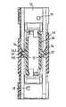
- FIG. 1shows a schematic illustration of a coupling for coaxial optical-fiber connection
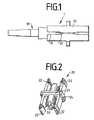
- FIG. 2shows a perspective view of a sleeve mount
- FIG. 3shows a perspective view of a cut-open coupling housing
- FIG. 4shows a sectional illustration of the coupling housing with the sleeve mount installed.
- FIG. 1shows, schematically, a coupling 1 for the coaxial connection of fiber-optic cables.
- the coupling 1comprises a coupling housing 10 , in which a concealed sleeve mount 20 is mounted.
- the end of a fiber-optic cableis designed with a plug-in connector 30 , which can be accommodated in the coupling 1 on both connection sides of the concealed sleeve mount 20 .
- the coupling housing 10is designed with a groove 11 .
- the plug-in connector 30is designed with a complementary tongue 31 .
- FIG. 2shows a perspective illustration of the sleeve mount 20 .
- the sleeve mount 20is designed with a latching nose 21 , latching hooks 22 , an axial bore 23 , and a spacer 24 .
- the latching nose 21is part of a latching fastening for fixing the sleeve mount 20 in the coupling housing 10 , which is illustrated in FIG. 1 .
- the cross section of the latching nose 21is preferably of rectangular design. This provides for a both straightforward production and a high loading capability of the associated latching fastening.
- the latching hooks 22serve for accommodating the plug-in connector 30 , which is illustrated in FIG. 1 .
- the latching hooks 22need to move.
- the sleeve mount 20is thus to be mounted in the coupling housing 10 (not illustrated in FIG. 2 ), such that this movement is not obstructed, and a plug-in connector 30 can be accommodated by the latching hooks 22 .
- good lateral guidance of the sleeve mount 20 in the coupling housing 10is required.
- spacers 24are provided on the sleeve mount 20 .
- the contact location of two plug-in connectors 30 connected by the coupling 1is located in a sleeve which is not illustrated but can be inserted into a bore 23 of the sleeve mount 20 .
- the material of the sleevemay be selected here in accordance with the connection-quality requirements.
- FIG. 3shows a perspective illustration of the cut-open coupling housing 10 .
- the coupling housing 10is designed with flanges 16 on the outsides of two housing walls 12 , it being possible for the coupling housing 10 to be attached to a front panel (not used) by means of said flanges.
- a rectangular through-passage for accommodating the sleeve mount 20which is illustrated in FIG. 2 , is made in the coupling housing 10 .
- one latching mountcomprising a latching hook 14 and two stops 15 , is made on one housing wall 13 and on the opposite housing wall (not illustrated).
- the latching nose 21 of the sleeve mount 20said latching nose being illustrated in FIG.
- the sleeve mount 20can be installed automatically in the latching direction R in the single-piece coupling housing 10 .
- the latching hook 14is designed with a slope 141 for the purpose of assisting the latching-in operation. Easy definition of the coupling housing 10 is necessary in the latching operation in order to allow passage beyond the latching hook 14 .
- the housing walls 12have an accumulation of material in this region on account of the flanges 16 which are usually present.
- the latching mountsare thus preferably formed on the housing walls 13 .
- the contact surfaces 151 of the stops 15can be worked in a precise manner by way of access in the latching direction R.
- a contact surface 142 of the latching hook 14can be worked by way of access counter to the latching direction R. There is thus no need for any special tool for follow-up work on the contact surfaces 142 , 151 .
- FIG. 4shows the coupling housing 10 with a sleeve mount 20 installed.
- the designations herecorrespond to the preceding figures.
- the sleeve mount 20is fixed between the latching hook 14 and the stops 15 via the latching nose 21 .
- the fixing of the sleeve mount 20does not require any further locking elements.
- the contact surfaces 142 , 151 of the latching mountmay be produced in a precise manner, with the result that play is avoidable.
- the outer shape of the coupling 1is determined by way of the given geometry of an installation opening, and it is only the length of the coupling 1 which can be varied within limits.
- the coupling housing 10it is possible for the coupling housing 10 to be extended by a connection piece, which provides protection against the emission of laser radiation.
- dust-protection devicesit is also conceivable for dust-protection devices to be positioned on the coupling housing 10 when the plug-in connector 30 is subjected to pulling.
- the housing walls 12are designed with additional latching noses 17 at terminations of the coupling housing 10 .
- the task of forming the latching noses 17does not adversely affect the task of forming the latching mount for the sleeve mount.
- the latching noses 17are arranged in a diagonally offset manner.
Landscapes
- Physics & Mathematics (AREA)
- General Physics & Mathematics (AREA)
- Optics & Photonics (AREA)
- Mechanical Coupling Of Light Guides (AREA)
- Connector Housings Or Holding Contact Members (AREA)
- Non-Portable Lighting Devices Or Systems Thereof (AREA)
- Laser Surgery Devices (AREA)
- Processing Of Terminals (AREA)
- Details Of Aerials (AREA)
- Input Circuits Of Receivers And Coupling Of Receivers And Audio Equipment (AREA)
- Non-Disconnectible Joints And Screw-Threaded Joints (AREA)
- Yarns And Mechanical Finishing Of Yarns Or Ropes (AREA)
Abstract
Description
Claims (10)
Priority Applications (3)
| Application Number | Priority Date | Filing Date | Title |
|---|---|---|---|
| US15/676,045US10185095B2 (en) | 2002-05-03 | 2017-08-14 | Device for an optical-fiber connection |
| US16/252,251US10948661B2 (en) | 2002-05-03 | 2019-01-18 | Device for an optical-fiber connection |
| US17/173,640US11385413B2 (en) | 2002-05-03 | 2021-02-11 | Device for an optical-fiber connection |
Applications Claiming Priority (13)
| Application Number | Priority Date | Filing Date | Title |
|---|---|---|---|
| DE10219935U | 2002-05-03 | ||
| DE10219935ADE10219935A1 (en) | 2002-05-03 | 2002-05-03 | Device for an optical fiber connection |
| DE10219935.3 | 2002-05-03 | ||
| PCT/EP2003/004292WO2003093883A2 (en) | 2002-05-03 | 2003-04-25 | Device for an optical fibre connection |
| US10/513,207US7377697B2 (en) | 2002-05-03 | 2003-04-25 | Device for an optical fiber connection |
| US12/062,704US7862243B2 (en) | 2002-05-03 | 2008-04-04 | Device for an optical-fiber connection |
| US12/983,699US8123415B2 (en) | 2002-05-03 | 2011-01-03 | Device for an optical-fiber connection |
| US13/367,778US8313248B2 (en) | 2002-05-03 | 2012-02-07 | Device for an optical-fiber connection |
| US13/655,017US8636422B2 (en) | 2002-05-03 | 2012-10-18 | Device for an optical-fiber connection |
| US14/166,495US8985861B2 (en) | 2002-05-03 | 2014-01-28 | Device for an optical-fiber connection |
| US14/638,875US9377590B2 (en) | 2002-05-03 | 2015-03-04 | Device for an optical-fiber connection |
| US15/193,500US9733434B2 (en) | 2002-05-03 | 2016-06-27 | Device for an optical-fiber connection |
| US15/676,045US10185095B2 (en) | 2002-05-03 | 2017-08-14 | Device for an optical-fiber connection |
Related Parent Applications (1)
| Application Number | Title | Priority Date | Filing Date |
|---|---|---|---|
| US15/193,500ContinuationUS9733434B2 (en) | 2002-05-03 | 2016-06-27 | Device for an optical-fiber connection |
Related Child Applications (1)
| Application Number | Title | Priority Date | Filing Date |
|---|---|---|---|
| US16/252,251ContinuationUS10948661B2 (en) | 2002-05-03 | 2019-01-18 | Device for an optical-fiber connection |
Publications (2)
| Publication Number | Publication Date |
|---|---|
| US20180128985A1 US20180128985A1 (en) | 2018-05-10 |
| US10185095B2true US10185095B2 (en) | 2019-01-22 |
Family
ID=29285092
Family Applications (11)
| Application Number | Title | Priority Date | Filing Date |
|---|---|---|---|
| US10/513,207Expired - LifetimeUS7377697B2 (en) | 2002-05-03 | 2003-04-25 | Device for an optical fiber connection |
| US12/062,704Expired - Fee RelatedUS7862243B2 (en) | 2002-05-03 | 2008-04-04 | Device for an optical-fiber connection |
| US12/983,699Expired - Fee RelatedUS8123415B2 (en) | 2002-05-03 | 2011-01-03 | Device for an optical-fiber connection |
| US13/367,778Expired - Fee RelatedUS8313248B2 (en) | 2002-05-03 | 2012-02-07 | Device for an optical-fiber connection |
| US13/655,017Expired - LifetimeUS8636422B2 (en) | 2002-05-03 | 2012-10-18 | Device for an optical-fiber connection |
| US14/166,495Expired - Fee RelatedUS8985861B2 (en) | 2002-05-03 | 2014-01-28 | Device for an optical-fiber connection |
| US14/638,875Expired - Fee RelatedUS9377590B2 (en) | 2002-05-03 | 2015-03-04 | Device for an optical-fiber connection |
| US15/193,500Expired - Fee RelatedUS9733434B2 (en) | 2002-05-03 | 2016-06-27 | Device for an optical-fiber connection |
| US15/676,045Expired - Fee RelatedUS10185095B2 (en) | 2002-05-03 | 2017-08-14 | Device for an optical-fiber connection |
| US16/252,251Expired - Fee RelatedUS10948661B2 (en) | 2002-05-03 | 2019-01-18 | Device for an optical-fiber connection |
| US17/173,640Expired - LifetimeUS11385413B2 (en) | 2002-05-03 | 2021-02-11 | Device for an optical-fiber connection |
Family Applications Before (8)
| Application Number | Title | Priority Date | Filing Date |
|---|---|---|---|
| US10/513,207Expired - LifetimeUS7377697B2 (en) | 2002-05-03 | 2003-04-25 | Device for an optical fiber connection |
| US12/062,704Expired - Fee RelatedUS7862243B2 (en) | 2002-05-03 | 2008-04-04 | Device for an optical-fiber connection |
| US12/983,699Expired - Fee RelatedUS8123415B2 (en) | 2002-05-03 | 2011-01-03 | Device for an optical-fiber connection |
| US13/367,778Expired - Fee RelatedUS8313248B2 (en) | 2002-05-03 | 2012-02-07 | Device for an optical-fiber connection |
| US13/655,017Expired - LifetimeUS8636422B2 (en) | 2002-05-03 | 2012-10-18 | Device for an optical-fiber connection |
| US14/166,495Expired - Fee RelatedUS8985861B2 (en) | 2002-05-03 | 2014-01-28 | Device for an optical-fiber connection |
| US14/638,875Expired - Fee RelatedUS9377590B2 (en) | 2002-05-03 | 2015-03-04 | Device for an optical-fiber connection |
| US15/193,500Expired - Fee RelatedUS9733434B2 (en) | 2002-05-03 | 2016-06-27 | Device for an optical-fiber connection |
Family Applications After (2)
| Application Number | Title | Priority Date | Filing Date |
|---|---|---|---|
| US16/252,251Expired - Fee RelatedUS10948661B2 (en) | 2002-05-03 | 2019-01-18 | Device for an optical-fiber connection |
| US17/173,640Expired - LifetimeUS11385413B2 (en) | 2002-05-03 | 2021-02-11 | Device for an optical-fiber connection |
Country Status (12)
| Country | Link |
|---|---|
| US (11) | US7377697B2 (en) |
| EP (1) | EP1502142B1 (en) |
| KR (1) | KR20040102203A (en) |
| CN (1) | CN100385279C (en) |
| AT (1) | ATE331967T1 (en) |
| AU (1) | AU2003233059A1 (en) |
| DE (2) | DE10219935A1 (en) |
| DK (1) | DK1502142T3 (en) |
| ES (1) | ES2265104T3 (en) |
| PL (1) | PL202127B1 (en) |
| PT (1) | PT1502142E (en) |
| WO (1) | WO2003093883A2 (en) |
Cited By (1)
| Publication number | Priority date | Publication date | Assignee | Title |
|---|---|---|---|---|
| US12164153B2 (en) | 2019-01-09 | 2024-12-10 | Commscope Technologies Llc | Fiber optic adapter with integrally molded structures |
Families Citing this family (41)
| Publication number | Priority date | Publication date | Assignee | Title |
|---|---|---|---|---|
| US5883995A (en) | 1997-05-20 | 1999-03-16 | Adc Telecommunications, Inc. | Fiber connector and adapter |
| DE10219935A1 (en) | 2002-05-03 | 2003-11-27 | Krone Gmbh | Device for an optical fiber connection |
| DE102004013905B4 (en) | 2004-03-17 | 2006-01-26 | Adc Gmbh | Fiber optic connector |
| DE202004020043U1 (en)* | 2004-12-22 | 2006-02-09 | CCS Technology, Inc., Wilmington | Fiber optic connection device, plug and connector for optical fibers |
| US7416349B2 (en)* | 2005-07-27 | 2008-08-26 | Adc Telecommunications, Inc. | Fiber optic adapter module |
| US8270796B2 (en)* | 2008-03-04 | 2012-09-18 | Adc Telecommunications, Inc. | Multi-port adapter block |
| ES2560802T3 (en) | 2008-08-27 | 2016-02-22 | Adc Telecommunications, Inc. | Fiber optic adapter with integrally molded bushing alignment structure |
| WO2010059623A1 (en) | 2008-11-21 | 2010-05-27 | Adc Telecommunications, Inc. | Fiber optic telecommunications module |
| WO2011032050A2 (en) | 2009-09-11 | 2011-03-17 | Trius Therapeutics, Inc. | Gyrase inhibitors |
| CN102870021B (en) | 2010-03-02 | 2015-03-11 | 蒂安电子服务有限责任公司 | Fibre-optic telecommunication module |
| US9417418B2 (en) | 2011-09-12 | 2016-08-16 | Commscope Technologies Llc | Flexible lensed optical interconnect device for signal distribution |
| RU2611105C2 (en) | 2011-10-07 | 2017-02-21 | Адс Телекоммьюникейшнз, Инк. | Fibre-optic cartridge, system and method |
| US8894298B2 (en)* | 2012-07-13 | 2014-11-25 | US Conec, Ltd | Debris reducing multi-fiber connector and adapter and associated methods |
| US9081152B2 (en) | 2012-08-30 | 2015-07-14 | Adc Telecommunications, Inc. | Adapter pack with removable sleeves |
| CN102830468B (en)* | 2012-09-19 | 2015-01-07 | 张钻兴 | Welding-free optical fiber adapter |
| US9146362B2 (en) | 2012-09-21 | 2015-09-29 | Adc Telecommunications, Inc. | Insertion and removal tool for a fiber optic ferrule alignment sleeve |
| US9146374B2 (en) | 2012-09-28 | 2015-09-29 | Adc Telecommunications, Inc. | Rapid deployment packaging for optical fiber |
| NZ706687A (en) | 2012-09-28 | 2017-09-29 | Adc Telecommunications Inc | Fiber optic cassette |
| US9223094B2 (en) | 2012-10-05 | 2015-12-29 | Tyco Electronics Nederland Bv | Flexible optical circuit, cassettes, and methods |
| US9256033B2 (en)* | 2013-01-23 | 2016-02-09 | Commscope, Inc. Of North Carolina | Cylindrical optical ferrule alignment apparatus |
| US10191226B2 (en) | 2013-01-23 | 2019-01-29 | Commscope, Inc. Of North Carolina | Cylindrical optical ferrule alignment apparatus |
| US9435975B2 (en) | 2013-03-15 | 2016-09-06 | Commscope Technologies Llc | Modular high density telecommunications frame and chassis system |
| CN104111498B (en)* | 2013-04-17 | 2016-03-09 | 泰科电子(上海)有限公司 | Adapter, extension fixture, replacing instrument, change assembly and change the method for aligned sleeves |
| US9977198B2 (en)* | 2013-07-16 | 2018-05-22 | 3M Innovative Properties Company | High retention force optical coupling |
| US9201199B2 (en)* | 2014-01-09 | 2015-12-01 | Sung-An LIN | One-piece optical fiber adapter |
| WO2015116672A1 (en) | 2014-01-28 | 2015-08-06 | Adc Telecommunications, Inc. | Slidable fiber optic connection module with cable slack management |
| US9494758B2 (en) | 2014-04-03 | 2016-11-15 | Commscope Technologies Llc | Fiber optic distribution system |
| US9733440B2 (en) | 2014-04-29 | 2017-08-15 | Corning Incorporated | Optical connectors for coupling light sources to optical fibers |
| US9551598B2 (en) | 2014-05-12 | 2017-01-24 | Siemens Energy, Inc. | Fiber optic sensing apparatus with an improved fiber-affixing device |
| JP5805344B1 (en)* | 2014-09-02 | 2015-11-04 | 株式会社精工技研 | Optical connector assembly and optical connector adapter with shutter |
| EP3067774B1 (en)* | 2015-03-13 | 2018-01-17 | Joseph Vögele AG | Operating device for a construction machine |
| MX2017014377A (en) | 2015-05-15 | 2018-08-15 | Adc Telecommunications Shanghai Distrib Co Ltd | Alignment sleeve assembly and optical fibre adapter. |
| CA2988895A1 (en)* | 2016-12-16 | 2018-06-16 | Comcast Cable Communications, Llc | Systems and methods for improved geolocation in a low power wide area network |
| US11409068B2 (en) | 2017-10-02 | 2022-08-09 | Commscope Technologies Llc | Fiber optic circuit and preparation method |
| US11016250B2 (en)* | 2017-12-19 | 2021-05-25 | Us Conec, Ltd. | Mini duplex connector with push-pull polarity mechanism, carrier, and rail-receiving crimp body |
| TW201928429A (en)* | 2017-12-27 | 2019-07-16 | 和碩聯合科技股份有限公司 | Optical fiber connector |
| CN114600018B (en)* | 2019-07-23 | 2024-04-09 | 扇港元器件有限公司 | Ultra-small receptacle for receiving a fiber optic connector opposite a ferrule assembly |
| TWI781413B (en)* | 2020-02-26 | 2022-10-21 | 立佳興業股份有限公司 | Latching structure and optical connector receptacle using the same |
| US12339511B2 (en) | 2020-03-31 | 2025-06-24 | Commscope Technologies Llc | Fiber optic cable management systems and methods |
| TWI766533B (en)* | 2020-11-03 | 2022-06-01 | 立佳興業股份有限公司 | Latch structure and optical receptacle thereof |
| TWM625958U (en)* | 2021-11-29 | 2022-04-21 | 建毅科技股份有限公司 | Fiber Adapter |
Citations (21)
| Publication number | Priority date | Publication date | Assignee | Title |
|---|---|---|---|---|
| US5067783A (en) | 1990-10-16 | 1991-11-26 | At&T Bell Laboratories | Optical fiber connector buildout system |
| US5210810A (en) | 1991-12-19 | 1993-05-11 | At&T Bell Laboratories | Hermaphroditic connector for single fiber optical cable |
| US5317663A (en)* | 1993-05-20 | 1994-05-31 | Adc Telecommunications, Inc. | One-piece SC adapter |
| US5542015A (en) | 1993-04-08 | 1996-07-30 | The Whitaker Corporation | Optical fiber connector latching mechanism |
| EP0731369A2 (en) | 1995-03-08 | 1996-09-11 | Nippon Telegraph And Telephone Corporation | Receptacle for optical fibre connection, housing therefor and method of manufacturing the same |
| US5737464A (en)* | 1995-08-31 | 1998-04-07 | Siecor Corporation | Monolithic optical fiber coupler including sleeve with flexible flap |
| US5838855A (en) | 1997-05-16 | 1998-11-17 | Lucent Technologies Inc. | Sleeve housing for optical coupling buildout |
| US5915058A (en)* | 1998-01-05 | 1999-06-22 | Molex Incorporated | Fiber optic connector assembly |
| US6081647A (en)* | 1998-01-05 | 2000-06-27 | Molex Incorporated | Fiber optic connector receptacle |
| JP2000266963A (en) | 1999-03-16 | 2000-09-29 | Seiko Instruments Inc | Holding construction of light connecting sleeve and light connector adaptor |
| US6154597A (en)* | 1998-01-05 | 2000-11-28 | Molex Incorporated | Fiber optic termination system including a fiber optic connector assembly and method of fabricating same |
| JP2001033658A (en) | 1999-04-09 | 2001-02-09 | Seiko Instruments Inc | Optical connector adaptor |
| US6367984B1 (en) | 1999-11-10 | 2002-04-09 | Lucent Technologies, Inc. | Optical fiber adapter |
| US6508593B1 (en) | 2000-05-09 | 2003-01-21 | Molex Incorporated | Universal panel mount system for fiber optic connecting devices |
| US20030156797A1 (en) | 2002-02-19 | 2003-08-21 | Itt Manufacturing Enterprises, Inc. | Latching fiber optic connector system |
| US6752538B1 (en)* | 2003-02-24 | 2004-06-22 | Itt Manufacturing Enterprises, Inc. | Optic fiber connector secondary latch |
| US6821024B2 (en)* | 2003-04-08 | 2004-11-23 | Itt Manufacturing Enterprises, Inc. | Connector secondary latch |
| US20060093274A1 (en) | 2002-05-03 | 2006-05-04 | Krone Gmbh | Device for an optical fiber connection |
| US20100054668A1 (en)* | 2008-08-27 | 2010-03-04 | Keith Nelson | Fiber optic adapter with integrally molded ferrule alignment structure |
| US20100111484A1 (en) | 2008-10-31 | 2010-05-06 | Tyco Electronics Corporation | Fiber optic connector storage apparatus and methods for using the same |
| US20130183018A1 (en)* | 2012-01-17 | 2013-07-18 | Adc Telecommunications, Inc. | Fiber optic adapter block |
- 2002
- 2002-05-03DEDE10219935Apatent/DE10219935A1/ennot_activeWithdrawn
- 2003
- 2003-04-25KRKR10-2004-7017717Apatent/KR20040102203A/ennot_activeAbandoned
- 2003-04-25PLPL371591Apatent/PL202127B1/ennot_activeIP Right Cessation
- 2003-04-25EPEP03727357Apatent/EP1502142B1/ennot_activeExpired - Lifetime
- 2003-04-25CNCNB038099411Apatent/CN100385279C/ennot_activeExpired - Fee Related
- 2003-04-25ESES03727357Tpatent/ES2265104T3/ennot_activeExpired - Lifetime
- 2003-04-25DKDK03727357Tpatent/DK1502142T3/enactive
- 2003-04-25DEDE50304063Tpatent/DE50304063D1/ennot_activeExpired - Fee Related
- 2003-04-25ATAT03727357Tpatent/ATE331967T1/ennot_activeIP Right Cessation
- 2003-04-25USUS10/513,207patent/US7377697B2/ennot_activeExpired - Lifetime
- 2003-04-25WOPCT/EP2003/004292patent/WO2003093883A2/ennot_activeApplication Discontinuation
- 2003-04-25AUAU2003233059Apatent/AU2003233059A1/ennot_activeAbandoned
- 2003-04-25PTPT03727357Tpatent/PT1502142E/enunknown
- 2008
- 2008-04-04USUS12/062,704patent/US7862243B2/ennot_activeExpired - Fee Related
- 2011
- 2011-01-03USUS12/983,699patent/US8123415B2/ennot_activeExpired - Fee Related
- 2012
- 2012-02-07USUS13/367,778patent/US8313248B2/ennot_activeExpired - Fee Related
- 2012-10-18USUS13/655,017patent/US8636422B2/ennot_activeExpired - Lifetime
- 2014
- 2014-01-28USUS14/166,495patent/US8985861B2/ennot_activeExpired - Fee Related
- 2015
- 2015-03-04USUS14/638,875patent/US9377590B2/ennot_activeExpired - Fee Related
- 2016
- 2016-06-27USUS15/193,500patent/US9733434B2/ennot_activeExpired - Fee Related
- 2017
- 2017-08-14USUS15/676,045patent/US10185095B2/ennot_activeExpired - Fee Related
- 2019
- 2019-01-18USUS16/252,251patent/US10948661B2/ennot_activeExpired - Fee Related
- 2021
- 2021-02-11USUS17/173,640patent/US11385413B2/ennot_activeExpired - Lifetime
Patent Citations (35)
| Publication number | Priority date | Publication date | Assignee | Title |
|---|---|---|---|---|
| US5067783A (en) | 1990-10-16 | 1991-11-26 | At&T Bell Laboratories | Optical fiber connector buildout system |
| US5210810A (en) | 1991-12-19 | 1993-05-11 | At&T Bell Laboratories | Hermaphroditic connector for single fiber optical cable |
| US5542015A (en) | 1993-04-08 | 1996-07-30 | The Whitaker Corporation | Optical fiber connector latching mechanism |
| US5317663A (en)* | 1993-05-20 | 1994-05-31 | Adc Telecommunications, Inc. | One-piece SC adapter |
| EP0731369A2 (en) | 1995-03-08 | 1996-09-11 | Nippon Telegraph And Telephone Corporation | Receptacle for optical fibre connection, housing therefor and method of manufacturing the same |
| US5887095A (en) | 1995-03-08 | 1999-03-23 | Nippon Telegraph & Telephone Corporation | Optical receptacle and housing therefor |
| US5737464A (en)* | 1995-08-31 | 1998-04-07 | Siecor Corporation | Monolithic optical fiber coupler including sleeve with flexible flap |
| US5838855A (en) | 1997-05-16 | 1998-11-17 | Lucent Technologies Inc. | Sleeve housing for optical coupling buildout |
| US5915058A (en)* | 1998-01-05 | 1999-06-22 | Molex Incorporated | Fiber optic connector assembly |
| US6081647A (en)* | 1998-01-05 | 2000-06-27 | Molex Incorporated | Fiber optic connector receptacle |
| US6154597A (en)* | 1998-01-05 | 2000-11-28 | Molex Incorporated | Fiber optic termination system including a fiber optic connector assembly and method of fabricating same |
| JP2000266963A (en) | 1999-03-16 | 2000-09-29 | Seiko Instruments Inc | Holding construction of light connecting sleeve and light connector adaptor |
| JP2001033658A (en) | 1999-04-09 | 2001-02-09 | Seiko Instruments Inc | Optical connector adaptor |
| US6367984B1 (en) | 1999-11-10 | 2002-04-09 | Lucent Technologies, Inc. | Optical fiber adapter |
| US6508593B1 (en) | 2000-05-09 | 2003-01-21 | Molex Incorporated | Universal panel mount system for fiber optic connecting devices |
| US20030156797A1 (en) | 2002-02-19 | 2003-08-21 | Itt Manufacturing Enterprises, Inc. | Latching fiber optic connector system |
| US8123415B2 (en) | 2002-05-03 | 2012-02-28 | Adc Gmbh | Device for an optical-fiber connection |
| US8636422B2 (en) | 2002-05-03 | 2014-01-28 | Adc Gmbh | Device for an optical-fiber connection |
| US20060093274A1 (en) | 2002-05-03 | 2006-05-04 | Krone Gmbh | Device for an optical fiber connection |
| US7377697B2 (en)* | 2002-05-03 | 2008-05-27 | Adc Gmbh | Device for an optical fiber connection |
| US9377590B2 (en) | 2002-05-03 | 2016-06-28 | Commscope Technologies Llc | Device for an optical-fiber connection |
| US8985861B2 (en)* | 2002-05-03 | 2015-03-24 | Adc Gmbh | Device for an optical-fiber connection |
| US7862243B2 (en) | 2002-05-03 | 2011-01-04 | Adc Gmbh | Device for an optical-fiber connection |
| US20110229082A1 (en) | 2002-05-03 | 2011-09-22 | Adc Gmbh | Device for an optical-fiber connection |
| US20140286608A1 (en) | 2002-05-03 | 2014-09-25 | Adc Gmbh | Device for an optical-fiber connection |
| US8313248B2 (en) | 2002-05-03 | 2012-11-20 | Adc Gmbh | Device for an optical-fiber connection |
| US6752538B1 (en)* | 2003-02-24 | 2004-06-22 | Itt Manufacturing Enterprises, Inc. | Optic fiber connector secondary latch |
| US6821024B2 (en)* | 2003-04-08 | 2004-11-23 | Itt Manufacturing Enterprises, Inc. | Connector secondary latch |
| US8382382B2 (en)* | 2008-08-27 | 2013-02-26 | Adc Telecommunications, Inc. | Fiber optic adapter with integrally molded ferrule alignment structure |
| US20130177279A1 (en)* | 2008-08-27 | 2013-07-11 | Adc Telecommunications, Inc. | Fiber optic adapter with integrally molded ferrule alignment structure |
| US8845205B2 (en)* | 2008-08-27 | 2014-09-30 | Adc Telecommunications, Inc. | Fiber optic adapter with integrally molded ferrule alignment structure |
| US20150013889A1 (en) | 2008-08-27 | 2015-01-15 | Adc Telecommunications, Inc. | Fiber optic adapter with integrally molded ferrule alignment structure |
| US20100054668A1 (en)* | 2008-08-27 | 2010-03-04 | Keith Nelson | Fiber optic adapter with integrally molded ferrule alignment structure |
| US20100111484A1 (en) | 2008-10-31 | 2010-05-06 | Tyco Electronics Corporation | Fiber optic connector storage apparatus and methods for using the same |
| US20130183018A1 (en)* | 2012-01-17 | 2013-07-18 | Adc Telecommunications, Inc. | Fiber optic adapter block |
Cited By (1)
| Publication number | Priority date | Publication date | Assignee | Title |
|---|---|---|---|---|
| US12164153B2 (en) | 2019-01-09 | 2024-12-10 | Commscope Technologies Llc | Fiber optic adapter with integrally molded structures |
Also Published As
Similar Documents
| Publication | Publication Date | Title |
|---|---|---|
| US11385413B2 (en) | Device for an optical-fiber connection | |
| US8267595B2 (en) | One-piece LC type optical fiber adapter | |
| US6149313A (en) | Gender selectable fiber optic connector and associated fabrication method | |
| US5719977A (en) | Optical connector with immovable ferrule | |
| US5317663A (en) | One-piece SC adapter | |
| US7985027B2 (en) | Adapter assembly for coupling dissimilar fiber optic connectors | |
| US6461054B1 (en) | Adapter having a light-shielding shutter and optical module receptacle having a light-shielding shutter | |
| EP0788002A1 (en) | Fiber optic connector receptacle with protective shutter | |
| US6130977A (en) | Fiber optic connector sleeve having positioning ribs | |
| US20090060422A1 (en) | One-piece lc type optical fiber adapter | |
| KR20120054627A (en) | Fiber optic adapter with enhanced alignment | |
| EP3330757A1 (en) | Optical fiber connector capable of switching connection polarity | |
| US6741783B2 (en) | Optical cable adapter or connector | |
| US12164153B2 (en) | Fiber optic adapter with integrally molded structures | |
| US20230324625A1 (en) | Multi-fiber reusable splicing systems | |
| US8235600B2 (en) | Method for manufacturing one-piece LC type optical fiber adapter | |
| WO2003076973A2 (en) | Single piece adapter |
Legal Events
| Date | Code | Title | Description |
|---|---|---|---|
| STCF | Information on status: patent grant | Free format text:PATENTED CASE | |
| AS | Assignment | Owner name:JPMORGAN CHASE BANK, N.A., NEW YORK Free format text:ABL SECURITY AGREEMENT;ASSIGNORS:COMMSCOPE, INC. OF NORTH CAROLINA;COMMSCOPE TECHNOLOGIES LLC;ARRIS ENTERPRISES LLC;AND OTHERS;REEL/FRAME:049892/0396 Effective date:20190404 Owner name:WILMINGTON TRUST, NATIONAL ASSOCIATION, AS COLLATE Free format text:PATENT SECURITY AGREEMENT;ASSIGNOR:COMMSCOPE TECHNOLOGIES LLC;REEL/FRAME:049892/0051 Effective date:20190404 Owner name:JPMORGAN CHASE BANK, N.A., NEW YORK Free format text:TERM LOAN SECURITY AGREEMENT;ASSIGNORS:COMMSCOPE, INC. OF NORTH CAROLINA;COMMSCOPE TECHNOLOGIES LLC;ARRIS ENTERPRISES LLC;AND OTHERS;REEL/FRAME:049905/0504 Effective date:20190404 Owner name:WILMINGTON TRUST, NATIONAL ASSOCIATION, AS COLLATERAL AGENT, CONNECTICUT Free format text:PATENT SECURITY AGREEMENT;ASSIGNOR:COMMSCOPE TECHNOLOGIES LLC;REEL/FRAME:049892/0051 Effective date:20190404 | |
| AS | Assignment | Owner name:WILMINGTON TRUST, DELAWARE Free format text:SECURITY INTEREST;ASSIGNORS:ARRIS SOLUTIONS, INC.;ARRIS ENTERPRISES LLC;COMMSCOPE TECHNOLOGIES LLC;AND OTHERS;REEL/FRAME:060752/0001 Effective date:20211115 | |
| FEPP | Fee payment procedure | Free format text:MAINTENANCE FEE REMINDER MAILED (ORIGINAL EVENT CODE: REM.); ENTITY STATUS OF PATENT OWNER: LARGE ENTITY | |
| LAPS | Lapse for failure to pay maintenance fees | Free format text:PATENT EXPIRED FOR FAILURE TO PAY MAINTENANCE FEES (ORIGINAL EVENT CODE: EXP.); ENTITY STATUS OF PATENT OWNER: LARGE ENTITY | |
| STCH | Information on status: patent discontinuation | Free format text:PATENT EXPIRED DUE TO NONPAYMENT OF MAINTENANCE FEES UNDER 37 CFR 1.362 | |
| FP | Lapsed due to failure to pay maintenance fee | Effective date:20230122 | |
| AS | Assignment | Owner name:RUCKUS WIRELESS, LLC (F/K/A RUCKUS WIRELESS, INC.), NORTH CAROLINA Free format text:RELEASE OF SECURITY INTEREST AT REEL/FRAME 049905/0504;ASSIGNOR:JPMORGAN CHASE BANK, N.A., AS COLLATERAL AGENT;REEL/FRAME:071477/0255 Effective date:20241217 Owner name:COMMSCOPE TECHNOLOGIES LLC, NORTH CAROLINA Free format text:RELEASE OF SECURITY INTEREST AT REEL/FRAME 049905/0504;ASSIGNOR:JPMORGAN CHASE BANK, N.A., AS COLLATERAL AGENT;REEL/FRAME:071477/0255 Effective date:20241217 Owner name:COMMSCOPE, INC. OF NORTH CAROLINA, NORTH CAROLINA Free format text:RELEASE OF SECURITY INTEREST AT REEL/FRAME 049905/0504;ASSIGNOR:JPMORGAN CHASE BANK, N.A., AS COLLATERAL AGENT;REEL/FRAME:071477/0255 Effective date:20241217 Owner name:ARRIS SOLUTIONS, INC., NORTH CAROLINA Free format text:RELEASE OF SECURITY INTEREST AT REEL/FRAME 049905/0504;ASSIGNOR:JPMORGAN CHASE BANK, N.A., AS COLLATERAL AGENT;REEL/FRAME:071477/0255 Effective date:20241217 Owner name:ARRIS TECHNOLOGY, INC., NORTH CAROLINA Free format text:RELEASE OF SECURITY INTEREST AT REEL/FRAME 049905/0504;ASSIGNOR:JPMORGAN CHASE BANK, N.A., AS COLLATERAL AGENT;REEL/FRAME:071477/0255 Effective date:20241217 Owner name:ARRIS ENTERPRISES LLC (F/K/A ARRIS ENTERPRISES, INC.), NORTH CAROLINA Free format text:RELEASE OF SECURITY INTEREST AT REEL/FRAME 049905/0504;ASSIGNOR:JPMORGAN CHASE BANK, N.A., AS COLLATERAL AGENT;REEL/FRAME:071477/0255 Effective date:20241217 |