US10182939B2 - Hydraulic injector and methods for intra-ocular lens insertion - Google Patents
Hydraulic injector and methods for intra-ocular lens insertionDownload PDFInfo
- Publication number
- US10182939B2 US10182939B2US14/855,855US201514855855AUS10182939B2US 10182939 B2US10182939 B2US 10182939B2US 201514855855 AUS201514855855 AUS 201514855855AUS 10182939 B2US10182939 B2US 10182939B2
- Authority
- US
- United States
- Prior art keywords
- fluid
- chamber
- piston
- hydraulically
- insertion tool
- Prior art date
- Legal status (The legal status is an assumption and is not a legal conclusion. Google has not performed a legal analysis and makes no representation as to the accuracy of the status listed.)
- Active, expires
Links
- 238000003780insertionMethods0.000titleclaimsabstractdescription82
- 230000037431insertionEffects0.000titleclaimsabstractdescription82
- 238000000034methodMethods0.000titledescription15
- 239000012530fluidSubstances0.000claimsabstractdescription194
- 238000004891communicationMethods0.000claimsabstractdescription23
- 230000004044responseEffects0.000claimsabstractdescription8
- 238000003973irrigationMethods0.000claimsdescription39
- 230000002262irrigationEffects0.000claimsdescription39
- 238000001356surgical procedureMethods0.000claimsdescription8
- FAPWRFPIFSIZLT-UHFFFAOYSA-MSodium chlorideChemical compound[Na+].[Cl-]FAPWRFPIFSIZLT-UHFFFAOYSA-M0.000claimsdescription2
- 230000002572peristaltic effectEffects0.000claimsdescription2
- 239000011780sodium chlorideSubstances0.000claimsdescription2
- 230000007246mechanismEffects0.000description15
- 230000037452primingEffects0.000description9
- 238000010586diagramMethods0.000description8
- 208000002177CataractDiseases0.000description4
- 230000006870functionEffects0.000description3
- 230000008569processEffects0.000description3
- 230000008901benefitEffects0.000description2
- 230000008859changeEffects0.000description2
- 210000004087corneaAnatomy0.000description2
- 238000002347injectionMethods0.000description2
- 239000007924injectionSubstances0.000description2
- 230000004048modificationEffects0.000description2
- 238000012986modificationMethods0.000description2
- 238000005086pumpingMethods0.000description2
- 210000001525retinaAnatomy0.000description2
- 241000699670Mus sp.Species0.000description1
- 230000004075alterationEffects0.000description1
- 230000006835compressionEffects0.000description1
- 238000007906compressionMethods0.000description1
- 230000007812deficiencyEffects0.000description1
- 201000010099diseaseDiseases0.000description1
- 208000037265diseases, disorders, signs and symptomsDiseases0.000description1
- 230000036541healthEffects0.000description1
- 238000002513implantationMethods0.000description1
- 238000001802infusionMethods0.000description1
- 208000014674injuryDiseases0.000description1
- 239000000463materialSubstances0.000description1
- 238000012544monitoring processMethods0.000description1
- 230000001737promoting effectEffects0.000description1
- 230000009467reductionEffects0.000description1
- 239000007787solidSubstances0.000description1
- 238000006467substitution reactionMethods0.000description1
- 230000008733traumaEffects0.000description1
- 230000000007visual effectEffects0.000description1
Images


Classifications
- A—HUMAN NECESSITIES
- A61—MEDICAL OR VETERINARY SCIENCE; HYGIENE
- A61F—FILTERS IMPLANTABLE INTO BLOOD VESSELS; PROSTHESES; DEVICES PROVIDING PATENCY TO, OR PREVENTING COLLAPSING OF, TUBULAR STRUCTURES OF THE BODY, e.g. STENTS; ORTHOPAEDIC, NURSING OR CONTRACEPTIVE DEVICES; FOMENTATION; TREATMENT OR PROTECTION OF EYES OR EARS; BANDAGES, DRESSINGS OR ABSORBENT PADS; FIRST-AID KITS
- A61F9/00—Methods or devices for treatment of the eyes; Devices for putting in contact-lenses; Devices to correct squinting; Apparatus to guide the blind; Protective devices for the eyes, carried on the body or in the hand
- A61F9/007—Methods or devices for eye surgery
- A61F9/00736—Instruments for removal of intra-ocular material or intra-ocular injection, e.g. cataract instruments
- A—HUMAN NECESSITIES
- A61—MEDICAL OR VETERINARY SCIENCE; HYGIENE
- A61F—FILTERS IMPLANTABLE INTO BLOOD VESSELS; PROSTHESES; DEVICES PROVIDING PATENCY TO, OR PREVENTING COLLAPSING OF, TUBULAR STRUCTURES OF THE BODY, e.g. STENTS; ORTHOPAEDIC, NURSING OR CONTRACEPTIVE DEVICES; FOMENTATION; TREATMENT OR PROTECTION OF EYES OR EARS; BANDAGES, DRESSINGS OR ABSORBENT PADS; FIRST-AID KITS
- A61F2/00—Filters implantable into blood vessels; Prostheses, i.e. artificial substitutes or replacements for parts of the body; Appliances for connecting them with the body; Devices providing patency to, or preventing collapsing of, tubular structures of the body, e.g. stents
- A61F2/02—Prostheses implantable into the body
- A61F2/14—Eye parts, e.g. lenses or corneal implants; Artificial eyes
- A61F2/16—Intraocular lenses
- A61F2/1662—Instruments for inserting intraocular lenses into the eye
- A—HUMAN NECESSITIES
- A61—MEDICAL OR VETERINARY SCIENCE; HYGIENE
- A61F—FILTERS IMPLANTABLE INTO BLOOD VESSELS; PROSTHESES; DEVICES PROVIDING PATENCY TO, OR PREVENTING COLLAPSING OF, TUBULAR STRUCTURES OF THE BODY, e.g. STENTS; ORTHOPAEDIC, NURSING OR CONTRACEPTIVE DEVICES; FOMENTATION; TREATMENT OR PROTECTION OF EYES OR EARS; BANDAGES, DRESSINGS OR ABSORBENT PADS; FIRST-AID KITS
- A61F9/00—Methods or devices for treatment of the eyes; Devices for putting in contact-lenses; Devices to correct squinting; Apparatus to guide the blind; Protective devices for the eyes, carried on the body or in the hand
- A61F9/0008—Introducing ophthalmic products into the ocular cavity or retaining products therein
- A61F9/0017—Introducing ophthalmic products into the ocular cavity or retaining products therein implantable in, or in contact with, the eye, e.g. ocular inserts
- A—HUMAN NECESSITIES
- A61—MEDICAL OR VETERINARY SCIENCE; HYGIENE
- A61F—FILTERS IMPLANTABLE INTO BLOOD VESSELS; PROSTHESES; DEVICES PROVIDING PATENCY TO, OR PREVENTING COLLAPSING OF, TUBULAR STRUCTURES OF THE BODY, e.g. STENTS; ORTHOPAEDIC, NURSING OR CONTRACEPTIVE DEVICES; FOMENTATION; TREATMENT OR PROTECTION OF EYES OR EARS; BANDAGES, DRESSINGS OR ABSORBENT PADS; FIRST-AID KITS
- A61F9/00—Methods or devices for treatment of the eyes; Devices for putting in contact-lenses; Devices to correct squinting; Apparatus to guide the blind; Protective devices for the eyes, carried on the body or in the hand
- A61F9/0008—Introducing ophthalmic products into the ocular cavity or retaining products therein
Definitions
- the present disclosureis directed to methods and systems for performing ophthalmic surgical procedures, and more particularly, to methods and systems for treating a patient by inserting an intra-ocular lens into the patient's eye.
- the human eyein simple terms, functions to provide vision by transmitting and refracting light through a clear outer portion called the cornea and focusing the light by way of the lens onto the retina at the back of the eye.
- the quality of the visual image created by the focused lightdepends on many factors including the size, shape, and length of the eye, and the shape and transparency of the cornea and lens.
- IOLIntra-ocular Lens
- An IOL insertion cartridgemay be used to fold and insert an IOL through a relatively small incision into the eye.
- the IOL insertion cartridgemay fold the IOL as it advances therethrough.
- a plunger-like devicemanually pressed by a user, such as a surgeon, advances the lens through the IOL insertion cartridge.
- the forces that the physician exerts on the plunger to advance the lenscan drastically and suddenly decrease, causing the IOL to suddenly shoot into the eye. This can cause improper IOL placement and may cause damage to eye tissue.
- a hydraulically-driven Intra-Ocular Lens (IOL) insertion toolincludes a body, a chamber within the body, a first fluid port providing fluid communication into the chamber, a piston positioned within the chamber and arranged to move within the chamber in response to the introduction or removal of fluid from the chamber, and an elongated member.
- the elongated memberincludes a distal end comprising an intra-ocular lens interface and a proximal end connected to the piston such that movement of the piston within the chamber causes corresponding movement of the elongated member.
- a system for Intra-Ocular Lens (IOL) insertionincludes a surgical console that includes a fluid source and an aspiration pump.
- the systemfurther includes a hydraulically-driven IOL insertion tool having a chamber, a first fluid port in fluid connection with the chamber, and a second fluid port in fluid connection with the chamber, a piston in connection with an elongated member, the elongated member having a distal end comprising an intra-ocular lens interface, a first fluid line providing fluid communication between the fluid source and the first fluid port, and a second fluid line providing fluid communication between the aspiration pump and the second fluid port.
- IOLIntra-Ocular Lens
- a method for inserting an Intra-Ocular Lensincludes connecting a hydraulically-driven IOL insertion hand-piece to a fluid source, the hand-piece comprising a chamber and a piston in connection with an IOL interface. The method further includes priming a hydraulic chamber of the hand-piece, engaging the hand-piece with an IOL insertion cartridge, and hydraulically actuating the piston to move the IOL interface in a distal direction with respect to the IOL lens cartridge.
- IOLIntra-Ocular Lens
- FIG. 1is a diagram showing an illustrative ophthalmic surgical system.
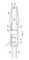
- FIG. 2is a schematic diagram of an illustrative hydraulically-driven IOL insertion tool.
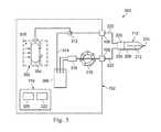
- FIG. 3is a schematic diagram of a surgical console and the hydraulically-driven IOL insertion tool.
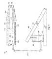
- FIG. 4is a diagram showing a foot pedal with a master chamber in connection with a slave chamber within the hydraulically-driven IOL insertion tool.
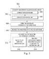
- FIG. 5is an example flowchart showing an illustrative method for using a hydraulically-driven IOL insertion tool to insert an IOL into a patient's eye.
- This disclosureis directed to a hydraulically-driven IOL insertion tool that may provide consistent IOL advancement despite the change or decrease resistance.
- the fluids used to hydraulically drive the IOL insertion toolmay be the same fluids used during other processes of cataract surgical procedures.
- cataract replacement proceduresmay employ a phacoemulsification tool that uses ultrasonic energy to break up or emulsify an existing natural lens.
- the emulsified lens tissuemay then be aspirated by an aspiration tool in communication with an aspiration pump.
- an irrigation toolmay replace aspirated eye fluid with fluid from a fluid.
- some embodimentsuse the aspiration pump and the fluid source to drive the hydraulically-driven IOL insertion tool.
- the IOL insertion toolincludes a body, a chamber within the body, and a fluid port providing fluid communication into the chamber. Fluid pumped into and out of the chamber through the fluid port drives a piston.
- the pistonis secured to a proximal end of an elongated member that has an IOL interface at its distal end. Fluid may be pumped into the chamber to advance the IOL interface forward through the IOL cartridge in a controlled manner. In some embodiments, the fluid is pumped using a foot pedal.
- an IOL insertion tool embodying principles described hereinmay provide a number of advantages not found in conventional IOL insertions tools.
- an IOL insertion tool actuated by hydraulicsadvances the IOL with a smooth, consistent forward motion that may be difficult to achieve with manual insertion systems.
- the IOL insertion toolis a hand-piece controlled by a foot-pedal so that an operator can hold the hand-piece with both hands while controlling the insertion of the IOL by foot.
- the IOL insertion tool hand-piecemay be a low-cost single-use hand-piece.
- FIG. 1is a diagram showing an illustrative ophthalmic surgical system 100 .
- the ophthalmic surgical system 100includes a surgical console 102 and a hydraulically-driven IOL insertion tool 112 .
- the surgical console 102may include a display screen 104 , an irrigation port 106 , an aspiration port 108 , and an input mechanism 114 .
- the input mechanism 114is a foot pedal.
- other input mechanismsmay also be used, such as switches, buttons, triggers, touchscreen elements, keyboards, mice, and others.
- the surgical console 102is designed to be mobile and may be used by a user, such as a health care provider, to perform ophthalmic surgical procedures.
- the surgical console 102may also include a control system 110 that may be configured to process, receive, and store data to perform various functions associated with the IOL insertion tool 112 .
- the display screen 104may communicate information to the user, and in some implementations, may show data relating to system operation and performance during a surgical procedure.
- the display screen 104is a touchscreen that allows the operator to interact with the surgical console 102 through a graphical user interface.
- the surgical console 102may include various fluid handling systems for use during various ophthalmic surgical procedures.
- the surgical console 102may provide irrigation fluid through the irrigation port 106 .
- the surgical console 102may include a pump that can create a vacuum or suction force that may aspirate fluid and tissue through the aspiration port 108 .
- the hydraulically-driven IOL insertion tool 112may use these or other fluid handling systems to drive the hydraulically-driven IOL insertion tool 112 .
- the hydraulically-driven IOL insertion tool 112may be connected to the irrigation port 106 through an irrigation line and may be connected to the aspiration port 108 through an aspiration line.
- FIG. 2is a schematic diagram of the illustrative hydraulically-driven IOL insertion tool 112 , which may be referred to as a hand-piece.
- the hydraulically-driven IOL insertion tool 112includes a body 202 having a hydraulic chamber 204 disposed within. Positioned within the hydraulic chamber 204 is a piston 206 .
- the piston 206is secured to an elongated member 212 that extends outside the hydraulic chamber 204 .
- the proximal end 218 of the elongated member 212is secured to the piston 206 and the distal end 214 of the elongated member 212 includes an IOL interface 216 .
- movement of the piston 206causes corresponding movement of the IOL interface 216 .
- Movement of the piston 206is effected by pumping a fluid into the hydraulic chamber 204 .
- fluidmay be pumped in through an irrigation line 220 connected to the hydraulic chamber 204 through a first fluid port 208 and/or an aspiration line 222 connected to the hydraulic chamber 204 through a second fluid port 210 .
- the body 202 of the hand-piecemay be made of a rigid material.
- the body 202may be shaped for easy grasping by an operator.
- the body 202may include a gripping feature (not shown) on the outer surface of the body 202 .
- the body 202may be hollow and include a number of features therein, such as the hydraulic chamber 204 .
- the hydraulic chamber 204may be formed by the inner surface 207 of the body 202 . In some examples, however, the hydraulic chamber 204 may be formed by a separate element, such as a hollow cylindrical body (not shown), that is supported and housed within the body 202 .
- the piston 206engages the inner surface 207 that forms the hydraulic chamber 204 such that it divides a proximal portion 203 of the hydraulic chamber 204 from a distal portion 205 of the hydraulic chamber 204 .
- the piston 206may form a seal with the inner surface 207 such that it prevents fluid from flowing between the distal portion 205 and the proximal portion 203 .
- the shape of the piston 206may match the shape of the hydraulic chamber 204 .
- the proximal portion 205may be in fluid communication with an environment external to the body 202 .
- the body 202may have one or more through-holes that allow air to flow in and out of the distal portion 205 as the piston 206 moves in either a distal or proximal direction.
- the piston 206may be secured to the elongated member 212 .
- the elongated member 212is directly connected to the piston 206 .
- connector elementsmay be positioned between the piston 206 and the elongated member 212 to provide the desired connection.
- movement of the piston 206 within the hydraulic chamber 204causes corresponding movement of the elongated member 212 .
- the piston 206moves in a distal direction
- the elongated member 212moves in the distal direction.
- the elongated member 212moves in the proximal direction.
- the elongated member 212includes an IOL interface 216 at the distal end 214 of the elongated member 212 .
- the IOL interface 216is designed to hold an IOL (not shown) that is to be inserted into a patient's eye.
- the elongated member 212is sized and shaped to fit within an IOL insertion cartridge 224 .
- the IOL insertion cartridge 224is selectively attachable to the body 202 .
- the IOL insertion cartridge 224is fixed to the body 202 .
- the IOL insertion cartridge 224may be arranged to house an IOL for injection into a surgical site.
- the IOL insertion cartridge 224includes a number of structural features that fold the IOL as it advances so that it can be passed into the eye of the patient.
- the proximal portion 203 of the hydraulic chamber 204includes a first fluid port 208 and a second fluid port 210 .
- the first fluid port 208is connected to a first fluid line, which will be referred to as an irrigation line 220 .
- the irrigation line 220is in fluid communication with a fluid source (not shown) and is arranged to provide fluid communication between the fluid source and the hydraulic chamber 204 .
- the second fluid port 210is connected to a second fluid line, which will be referred to as an aspiration line 222 .
- the aspiration line 222may be in fluid communication with an aspiration pump, as will be described in further detail below.
- Fluid from the irrigation line 220 and/or aspiration line 222is pumped into the proximal portion 203 of the hydraulic chamber 204 , thereby moving the piston 206 , elongated member 212 , and IOL interface 216 in a distal direction. Additionally, fluid is pumped out of the proximal portion 203 of the hydraulic chamber 204 to move the piston 206 , elongated member 212 , and IOL interface 216 in a proximal direction.
- the first fluid port 208includes a check valve (not shown) that allows fluid to flow into the hydraulic chamber 204 while preventing fluid from flowing out of the hydraulic chamber 204 through the first fluid port 208 .
- a check valve(not shown) that allows fluid to flow into the hydraulic chamber 204 while preventing fluid from flowing out of the hydraulic chamber 204 through the first fluid port 208 .
- FIG. 3is a schematic diagram of an IOL insertion system 300 that includes the surgical console 102 and the hydraulically-driven IOL insertion tool 112 .
- the surgical console 102includes a fluid source 302 and an aspiration pump 310 .
- the IOL insertion tool 112may be designed to use the aspiration pump 310 and fluid source 302 that are typically used for phacoemulsification procedures to hydraulically power the IOL insertion tool 200 .
- the irrigation line 220connects the hydraulically-driven IOL insertion tool 112 to the surgical console 102 through the irrigation port 106 to provide irrigation fluid to the hydraulically-driven IOL insertion tool 112 .
- the irrigation port 106is in fluid communication with the fluid source 302 through a switch valve 312 .
- the switch valve 312may be used to selectively direct fluid from the fluid source 302 to either the irrigation port 106 or through a shunt line 314 to a drain chamber 306 such as a drain bag.
- the switch valve 312may also be in an off position and not allow any fluid to pass from the fluid source 302 .
- the switch valve 312may be positioned in the off position.
- the switch valve 312is positioned to direct fluid to the irrigation port 106 and into the irrigation line 220 .
- the switch valve 312can be set to direct fluid through the shunt line 314 into the drain chamber 306 .
- the fluid source 302includes a fluid bag 304 .
- the fluid bag 304is compressed by a compression mechanism 318 that forces the fluid within the fluid bag 304 into the irrigation line 220 .
- the fluidis a saline fluid that is safe for injection into a patient's eye.
- other fluidsalso may be used.
- the aspiration line 222connects the hydraulically-driven IOL insertion tool 112 to the surgical console 102 through the aspiration port 108 to pump fluid into and out of the hydraulically-driven IOL insertion tool 112 .
- the aspiration port 108is in fluid communication with an aspiration pump 310 .
- the aspiration pump 310pumps fluid from the aspiration line 222 and deposits such fluid into a reservoir 316 . Fluid in the reservoir 316 is moved into the drain chamber 306 .
- the aspiration pump 310is configured to be put into reverse and pump fluid back through the aspiration line 222 . The use for such a configuration will be described in further detail below.
- the aspiration pump 310may be one of a variety of pumps, including an elastomeric pump and a peristaltic pump. Other types of pumps are contemplated as well.
- the surgical console 102includes the control system 110 .
- the control system 110may include one or more processors 320 and one or more memory elements 322 .
- the memory element 322may include various types of memory including volatile memory (such as Random Access Memory (RAM)) and non-volatile memory (such as solid state storage).
- RAMRandom Access Memory
- the memory element 322may store computer readable instructions, that when executed by the processor 320 , cause the control system 110 to perform various functions, including managing the fluid source 302 , switch valve 312 , and aspiration pump 310 .
- the control system 110may manage the components of the surgical console 102 to perform various operations associated with the hydraulically-driven IOL insertion tool 112 .
- Such operationsinclude, among others, a priming operation, a distal-direction actuation operation, and a proximal-direction actuation operation.
- a priming operationWhen a user desires to use the hydraulically-driven IOL insertion tool 112 , the user connects the tool to the irrigation line 220 and the aspiration line 222 . The user may then instruct the surgical console 102 to begin the priming operation.
- the priming operationprepares the IOL insertion tool 112 for use. Specifically, when the IOL insertion tool 200 is first connected to the irrigation line 220 and aspiration line 222 , there may still be air in the proximal portion 203 of the hydraulic chamber 204 .
- the control system 110causes the fluid source 302 to inject fluid into the irrigation line 220 and into the hydraulic chamber 204 .
- the irrigation fluidis pumped into the hydraulic chamber 204 through the first fluid port (e.g., 208 , FIG. 2 ), which, as described above, may include a check valve.
- the irrigation fluiddoes not flow back through the irrigation line 220 .
- the control system 110also causes the aspiration pump 310 to operate in a forward manner.
- the aspiration pump 310pumps air out of the aspiration line 222 . This creates a vacuum that is then filled by fluid being pumped into the hydraulic chamber 204 through the irrigation line 220 . After the fluid fills the irrigation line 220 , the hydraulic chamber 204 , and the aspiration line 222 , the priming process is complete.
- the control system 110causes the fluid source 302 to inject fluid into the irrigation line 220 , and thus applies pressure to the fluid within the hydraulic chamber 204 of the hydraulically-driven IOL insertion tool 112 .
- the control system 110causes the aspiration pump 310 to operate in reverse. The aspiration pump 310 thus pumps fluid that is within the aspiration line 222 back into the hydraulic chamber 204 , thus providing additional pressure to move the piston 206 forward in the distal direction.
- Forward (i.e., distal) motion of the piston 206moves the elongated member 212 and the IOL interface 214 forward with respect to the IOL insertion cartridge (e.g., 224 . FIG. 2 ).
- the usermay control the forward movement of the IOL through an input mechanism such as a foot pedal.
- Other input mechanismssuch as buttons, dials, touchscreen elements, and others are contemplated as well.
- the control system 110causes the aspiration pump 310 to operate as usual and pump fluid out of the aspiration line 222 .
- the control system 110may set the switch valve 312 to an off position so that fluid does not flow into the irrigation line 220 .
- a vacuumis created within the hydraulic chamber 204 of the hydraulically-driven IOL insertion tool 112 . This vacuum then pulls the piston 206 in the proximal direction. Such backward motion of the piston 206 may be performed after the IOL has been put into place.
- the usermay wish to cause backward motion of the piston 206 before the IOL has been put into place. For example, if the IOL did not fold properly while passing through the IOL insertion cartridge 224 , then the user may wish to move the IOL backwards and re-insert the IOL through the IOL insertion cartridge 224 .
- FIG. 4is a diagram showing an illustrative foot pedal 402 used to drive the hydraulically-driven IOL insertion tool 112 .
- the hydraulically-driven IOL insertion tool 112is powered by the foot pedal 402 instead of components of the surgical console (e.g., 102 , FIG. 1 ).
- the second fluid port 210is connected to a fluid line 412 .
- the first fluid port 208remains closed and unconnected to a fluid line.
- the fluid line 412provides fluid communication between the hydraulic chamber 204 and a master chamber 406 within the foot pedal 402 .
- the hydraulic chamber 204acts as a slave chamber.
- the foot pedal 402includes a hinged element 404 that is connected to a piston 408 within the master chamber 406 .
- the piston 408is also pressed downward. This presses any fluid within the lower portion 410 of the master chamber 406 through the fluid line 412 and into the proximal portion 203 of the hydraulic chamber 204 . This, in turn, applies pressure to the piston 206 to move the piston 206 in the distal direction.
- the hinged element 404is biased so that it moves back up when the user's foot is no longer pressing down on the hinged element 404 .
- the first fluid port 208may be temporarily connected to a fluid source through the first fluid port 208 .
- first fluid port 208may include a one-way check valve that allows fluid to flow through the fluid port 208 into the hydraulic chamber 204 but does not allow fluid to pass outwardly through the fluid port 208 out of the hydraulic chamber 204 .
- the fluid sourcemay be the fluid source (e.g., 302 , FIG. 3 ) described above.
- the first fluid port 208may be connected to the irrigation port 106 of the surgical console through an irrigation line (e.g., 222 , FIG. 2 ).
- a separate fluid source that is not associated with the surgical console 102may be temporarily connected to the first fluid port 408 for the priming operation.
- FIG. 5is an example flowchart showing an illustrative method 500 for using a hydraulically-driven IOL insertion tool to insert an IOL into a patient's eye.
- a userconnects the hand-piece (i.e., the hydraulically-driven IOL insertion tool) to a driving mechanism.
- the hand-piecei.e., the hydraulically-driven IOL insertion tool
- the driving mechanismTo connect the hand-piece to the driving mechanism, the user connects the hand-piece to an irrigation line at step 504 and connects the hand-piece to an aspiration line at step 506 .
- the driving mechanismis the surgical console (e.g., 102 , FIG. 1 ) described above.
- the irrigation lineis in fluid communication with a fluid source within the surgical console 102 and the aspiration line is in fluid communication with an aspiration pump within the surgical console 102 .
- the driving mechanismis the foot pedal (e.g., 402 , FIG. 4 ) described above.
- the irrigation lineis a temporary connection and provides fluid communication with a fluid source.
- a fluid sourcemay be within the surgical console 102 or may be a separate fluid source.
- the aspiration lineis connected to a master chamber of the foot pedal 402 .
- the hydraulic chamber of the hand-pieceis primed. In some cases, this may be done manually by a user by connecting the hand-piece to a fluid source to fill the hydraulic chamber with fluid.
- the control systeme.g., 110 , FIG. 1
- the priming stepprovides the fluid to prepare the hydraulic chamber for hydraulic operations.
- the userengages the hand-piece with the IOL insertion cartridge.
- the useralso positions the IOL insertion cartridge with respect to the patient's eye so that when the IOL passes through the IOL insertion cartridge, the IOL is properly placed within the patient's eye.
- the usercauses the piston to actuate within the hydraulic chamber to move the IOL forward and into place in the patient's eye.
- the usermay cause the piston to actuate through an input mechanism such as a foot pedal or button.
- an input mechanismsuch as a foot pedal or button.
- Use of the foot pedal or buttonsends a signal to the control system.
- the control systemcauses components within the surgical console to perform as described above to cause actuation of the piston.
- the control systemcauses the fluid source to inject fluid into the irrigation line. This causes pressure within the hydraulic chamber of the hand-piece. This pressure then moves the piston forward. Because the piston is physically connected with an IOL interface, which holds the IOL, the IOL moves forward along with the piston.
- step 514the control system causes the aspiration pump to operate in reverse and pump fluid back into the aspiration line. This also creates pressure within the hydraulic chamber of the hand-piece. This pressure moves the piston forward in the distal direction.
- step 516is performed alone to actuate the piston.
- step 514is performed alone to actuate the piston.
- both steps 514 and 516are performed together to actuate the piston.
- the control systemcan monitor the fluid that goes into and out of the hydraulic chamber 204 . This can allow the control system to provide more precise control over the piston.
- the control systemmay be provided with the dimensions of the hydraulic chamber 204 . The control system may thus calculate the amount of fluid that will move the piston a specific distance.
- the control systemcan stop pumping to stop movement of the piston after it has moved a predetermined distance. Such distance may be controlled by a user through one of the input mechanisms described above.
- step 512includes the user engaging the foot pedal. As described above, this presses fluid out of a master chamber within the foot pedal and into a slave chamber within the hand-piece. This moves the piston forward in the distal direction.
- the hydraulically-driven IOL insertion toolmay be driven by gas forced infusion. This involves injecting a gas into one of the fluid lines to pressurize fluid within the hydraulic chamber and move the piston forward in a distal direction.
- IOL insertioncan be done using a hydraulically-driven IOL insertion tool.
- the hydraulically-driven IOL insertion toolprovides a smooth, controlled, forward movement of the IOL into the patient's eye that is difficult to achieve with a hand-powered IOL insertion tool.
- the hand-piecemay be designed to be a single-use device.
Landscapes
- Health & Medical Sciences (AREA)
- Ophthalmology & Optometry (AREA)
- Engineering & Computer Science (AREA)
- Biomedical Technology (AREA)
- Heart & Thoracic Surgery (AREA)
- Vascular Medicine (AREA)
- Life Sciences & Earth Sciences (AREA)
- Animal Behavior & Ethology (AREA)
- General Health & Medical Sciences (AREA)
- Public Health (AREA)
- Veterinary Medicine (AREA)
- Cardiology (AREA)
- Oral & Maxillofacial Surgery (AREA)
- Transplantation (AREA)
- Nuclear Medicine, Radiotherapy & Molecular Imaging (AREA)
- Surgery (AREA)
- Prostheses (AREA)
Abstract
Description
Claims (15)
Priority Applications (8)
| Application Number | Priority Date | Filing Date | Title |
|---|---|---|---|
| US14/855,855US10182939B2 (en) | 2015-09-16 | 2015-09-16 | Hydraulic injector and methods for intra-ocular lens insertion |
| EP16731980.5AEP3310300B1 (en) | 2015-09-16 | 2016-06-16 | Hydraulic injector for intra-ocular lens insertion |
| CA2992949ACA2992949A1 (en) | 2015-09-16 | 2016-06-16 | Hydraulic injector and methods for intra-ocular lens insertion |
| AU2016322710AAU2016322710B2 (en) | 2015-09-16 | 2016-06-16 | Hydraulic injector and methods for Intra-Ocular lens insertion |
| ES16731980TES2873391T3 (en) | 2015-09-16 | 2016-06-16 | Hydraulic injector for intraocular lens insertion |
| CN201680050107.4ACN107920892B (en) | 2015-09-16 | 2016-06-16 | Hydraulic injector and method for inserting intraocular lenses |
| JP2018509874AJP6791950B2 (en) | 2015-09-16 | 2016-06-16 | Methods for hydraulic injectors and intraocular lens insertion |
| PCT/IB2016/053569WO2017046661A1 (en) | 2015-09-16 | 2016-06-16 | Hydraulic injector and methods for intra-ocular lens insertion |
Applications Claiming Priority (1)
| Application Number | Priority Date | Filing Date | Title |
|---|---|---|---|
| US14/855,855US10182939B2 (en) | 2015-09-16 | 2015-09-16 | Hydraulic injector and methods for intra-ocular lens insertion |
Publications (2)
| Publication Number | Publication Date |
|---|---|
| US20170071787A1 US20170071787A1 (en) | 2017-03-16 |
| US10182939B2true US10182939B2 (en) | 2019-01-22 |
Family
ID=56203442
Family Applications (1)
| Application Number | Title | Priority Date | Filing Date |
|---|---|---|---|
| US14/855,855Active2037-01-17US10182939B2 (en) | 2015-09-16 | 2015-09-16 | Hydraulic injector and methods for intra-ocular lens insertion |
Country Status (8)
| Country | Link |
|---|---|
| US (1) | US10182939B2 (en) |
| EP (1) | EP3310300B1 (en) |
| JP (1) | JP6791950B2 (en) |
| CN (1) | CN107920892B (en) |
| AU (1) | AU2016322710B2 (en) |
| CA (1) | CA2992949A1 (en) |
| ES (1) | ES2873391T3 (en) |
| WO (1) | WO2017046661A1 (en) |
Cited By (2)
| Publication number | Priority date | Publication date | Assignee | Title |
|---|---|---|---|---|
| US20170333253A1 (en)* | 2016-05-17 | 2017-11-23 | Novartis Ag | Automated viscous fluid control in vitreoretinal surgery |
| US11911262B2 (en) | 2021-01-29 | 2024-02-27 | Alcon Inc. | Ratchet drive delivery for surgical implants |
Families Citing this family (6)
| Publication number | Priority date | Publication date | Assignee | Title |
|---|---|---|---|---|
| ES2819150T3 (en)* | 2015-04-19 | 2021-04-15 | Atrion Corp | Spring Operated Hydraulically Operated IOL Inserter |
| JP6763177B2 (en)* | 2016-03-31 | 2020-09-30 | 株式会社ニデック | Intraocular lens insertion device and eye surgery system |
| CA3076901A1 (en)* | 2017-09-26 | 2019-04-04 | William F. Wiley | Self-contained ocular surgery instrument |
| US11266384B2 (en) | 2018-04-20 | 2022-03-08 | Johnson & Johnson Surgical Vision, Inc. | Ergonomic handpiece |
| US10987215B2 (en)* | 2018-04-23 | 2021-04-27 | Johnson & Johnson Surgical Vision, Inc. | Hydraulically assisted lens delivery system and method |
| CN113040977B (en)* | 2021-03-10 | 2023-12-15 | 耿东洋 | Automatic pushing and injecting system for artificial lens |
Citations (78)
| Publication number | Priority date | Publication date | Assignee | Title |
|---|---|---|---|---|
| US3089815A (en) | 1951-10-11 | 1963-05-14 | Lieb Hans | Injectable pharmaceutical preparation, and a method of making same |
| US3301190A (en) | 1964-12-28 | 1967-01-31 | Oil Dyne Inc | Foot operated hydraulic pump |
| US3608549A (en) | 1970-01-15 | 1971-09-28 | Merrill Edward Wilson | Method of administering drugs and capsule therefor |
| US3982537A (en) | 1974-12-30 | 1976-09-28 | Louis Bucalo | Dynamic implants and method for implanting the same |
| US4007742A (en) | 1974-06-03 | 1977-02-15 | Surgical Design Corporation. | Surgical system for controlling the infusion of fluid to and the evacuation of fluid and material from an operating field |
| US4030499A (en) | 1974-12-30 | 1977-06-21 | Louis Bucalo | Method and apparatus for providing living beings with absorbable implants |
| US4054138A (en) | 1974-12-30 | 1977-10-18 | Louis Bucalo | Implants for acting on living beings |
| US4122850A (en) | 1976-06-07 | 1978-10-31 | Louis Bucalo | Apparatus for providing living beings with absorbable implants |
| GB1551767A (en) | 1975-05-27 | 1979-08-30 | Bucalo L | Implantment of living beings or the like subjects |
| US4184510A (en) | 1977-03-15 | 1980-01-22 | Fibra-Sonics, Inc. | Valued device for controlling vacuum in surgery |
| US4246932A (en) | 1979-10-18 | 1981-01-27 | Burron Medical, Inc. | Multiple additive valve assembly |
| US4265618A (en) | 1977-09-09 | 1981-05-05 | Solar Energy Technology, Inc. | Electrically heated endodontic syringe for injecting thermoplastic material into a root canal cavity |
| US4357136A (en) | 1977-09-09 | 1982-11-02 | Solar Energy Technology, Inc. | Method for filling a root canal |
| WO1982003761A1 (en) | 1981-05-04 | 1982-11-11 | Energy Techn Inc Solar | Syringe for obturation of root canal cavities |
| US4392827A (en) | 1981-11-04 | 1983-07-12 | Howard Martin | Self-contained root canal heated condenser dental instrument |
| US4474752A (en) | 1983-05-16 | 1984-10-02 | Merck & Co., Inc. | Drug delivery system utilizing thermosetting gels |
| US4484915A (en) | 1983-03-28 | 1984-11-27 | Tartaglia John A | Medical syringe |
| US4582488A (en) | 1984-04-27 | 1986-04-15 | Newman Martin H | Dental materials dispenser and applicator |
| WO1987000029A1 (en) | 1985-06-26 | 1987-01-15 | Pitz Richard J | Root canal implant-proximity indicative-delivery means |
| US4684344A (en) | 1986-04-11 | 1987-08-04 | Nalge Company | Electrically powered and heated endodontic syringe |
| US4704088A (en) | 1984-04-27 | 1987-11-03 | Newman Martin H | Dental materials dispenser and applicator |
| US4713446A (en) | 1985-09-06 | 1987-12-15 | Minnesota Mining And Manufacturing Company | Viscoelastic collagen solution for ophthalmic use and method of preparation |
| US4795423A (en) | 1980-04-14 | 1989-01-03 | Thomas Jefferson University | Oxygenated perfluorinated perfusion of the ocular globe to treat ischemic retinopathy |
| US4830855A (en) | 1987-11-13 | 1989-05-16 | Landec Labs, Inc. | Temperature-controlled active agent dispenser |
| US4862885A (en) | 1988-05-25 | 1989-09-05 | Cumming J Stuart | Instrument for inserting a deformable intraocular lens into the eye |
| EP0348146A1 (en) | 1988-06-21 | 1989-12-27 | Alcon Laboratories, Inc. | Apparatus for injecting viscous fluid into the eye |
| US4992045A (en) | 1987-04-01 | 1991-02-12 | Dentsply Research & Development Corp. | Battery powered condenser for root canals |
| US5066297A (en) | 1989-01-23 | 1991-11-19 | Cumming J Stuart | Intraocular lens insertion device |
| US5095914A (en) | 1989-09-26 | 1992-03-17 | Walter Sarstedt Geraete Und Verbrauchsmaterial Fuer Medizin & Wissenschaft | Blood extraction device with one-way piston movement |
| US5120307A (en) | 1988-06-21 | 1992-06-09 | Alcon Laboratories, Inc. | Method for injecting viscous fluid into the eye to life retinal membrane |
| US5176502A (en) | 1990-04-25 | 1993-01-05 | Becton, Dickinson And Company | Syringe pump and the like for delivering medication |
| US5336175A (en) | 1992-10-29 | 1994-08-09 | Mames Robert N | Method for the treatment of retinal detachments |
| US5360413A (en) | 1991-12-06 | 1994-11-01 | Filtertek, Inc. | Needleless access device |
| US5370630A (en) | 1993-11-12 | 1994-12-06 | Smidebush; Michael J. | Device for injection of fluidic materials into body tissue |
| US5476511A (en) | 1992-05-04 | 1995-12-19 | Allergan, Inc. | Subconjunctival implants for ocular drug delivery |
| US5487725A (en) | 1994-05-12 | 1996-01-30 | Syntec, Inc. | Pneumatic vitrectomy for retinal attachment |
| WO1996003978A1 (en) | 1994-08-04 | 1996-02-15 | Quadrant Holdings Cambridge Limited | Solid delivery systems for controlled release of molecules incorporated therein and methods of making same |
| US5582595A (en) | 1995-09-28 | 1996-12-10 | Habley Medical Technology Corporation | Aspirating syringe having a plunger guide for a reciprocating plunger assembly |
| US5620700A (en) | 1990-10-30 | 1997-04-15 | Alza Corporation | Injectable drug delivery system and method |
| US5728102A (en) | 1992-09-30 | 1998-03-17 | Staar Surgical Company, Inc. | Disposable intraocular lens insertion system |
| US5743886A (en) | 1994-02-15 | 1998-04-28 | Lawrence A. Lynn | Sequential medical fluid aspiration and injection system and method |
| US5773019A (en) | 1995-09-27 | 1998-06-30 | The University Of Kentucky Research Foundation | Implantable controlled release device to deliver drugs directly to an internal portion of the body |
| US5783205A (en) | 1990-10-30 | 1998-07-21 | Alza Corporation | Injectable drug delivery system and method |
| US5824072A (en) | 1993-11-15 | 1998-10-20 | Oculex Pharmaceuticals, Inc. | Biocompatible ocular implants |
| US5860949A (en) | 1996-12-20 | 1999-01-19 | Chen; Jen-Yie | Volume homeostatic fluid-fluid exchanger |
| WO1999033853A2 (en) | 1997-12-23 | 1999-07-08 | Quadrant Holdings Cambridge Limited | Carbohydrates, useful in solid delivery systems |
| US5928663A (en) | 1997-07-30 | 1999-07-27 | Vitrophage, Inc. | Intraocular perfluorcarbon compositions and surgical methods of using same |
| US5984889A (en) | 1996-02-23 | 1999-11-16 | Allergan Sales, Inc. | Apparatus and method for delivering viscoelastic material to an eye |
| WO2001010482A1 (en) | 1999-08-05 | 2001-02-15 | Biocardia, Inc. | A system and method for delivering thermally sensitive and reverse-thermal gelation matrials |
| US6210357B1 (en) | 1998-07-06 | 2001-04-03 | Robert E Morris | Apparatus for performing surgery inside the human retina using fluidic internal limiting membrane (ILM) separation (films) |
| WO2001039701A1 (en) | 1999-11-30 | 2001-06-07 | Pharmacia Ab | Intraocular lens implanter |
| US6270343B1 (en) | 2000-01-07 | 2001-08-07 | Howard Martin | Endodontic thermal condenser dental instrument |
| US6290690B1 (en) | 1999-06-21 | 2001-09-18 | Alcon Manufacturing, Ltd. | Simultaneous injection and aspiration of viscous fluids in a surgical system |
| US6372246B1 (en) | 1998-12-16 | 2002-04-16 | Ortho-Mcneil Pharmaceutical, Inc. | Polyethylene glycol coating for electrostatic dry deposition of pharmaceuticals |
| US6413245B1 (en) | 1999-10-21 | 2002-07-02 | Alcon Universal Ltd. | Sub-tenon drug delivery |
| US6419656B1 (en) | 1999-03-19 | 2002-07-16 | Arzneimittel Gmbh Apotheker Vetter & Ravensburg | Medical syringe with braked step-advance plunger |
| US6436143B1 (en) | 1999-02-22 | 2002-08-20 | Anthony C. Ross | Method and apparatus for treating intervertebral disks |
| US6585700B1 (en) | 2000-10-05 | 2003-07-01 | Medrad, Inc. | Syringe, syringe plunger and attachment mechanism for front loading medical injector |
| US6635267B1 (en) | 1998-11-10 | 2003-10-21 | Denki Kagaku Kogyo Kabushiki Kaisha | Hyaluronic acid gel, process for the preparation thereof and medical materials containing the same |
| US6645179B1 (en) | 1999-07-06 | 2003-11-11 | Nihon Chemical Research Co., Ltd. | Injection syringe |
| WO2003094992A2 (en) | 2002-05-07 | 2003-11-20 | Primebiotech | Device for liquid micro-injection in confined medium |
| US20040052761A1 (en) | 2002-07-19 | 2004-03-18 | Brent Vernon | Localized delivery system for cancer drugs, phenstatin, using N-isopropylacrylamide |
| US20040176720A1 (en) | 2002-08-31 | 2004-09-09 | Urs Kipfer | Device for administering a liquid solution of an active substance |
| US20050177137A1 (en) | 2002-08-31 | 2005-08-11 | Urs Kipfer | Administering device with temperature sensor |
| US6991457B2 (en) | 2003-05-06 | 2006-01-31 | Aseptico, Inc. | Endodontic obturator with disposable cartridge |
| US20060047250A1 (en) | 2004-08-30 | 2006-03-02 | Hickingbotham Dyson W | Fluid delivery device |
| WO2006050008A1 (en) | 2003-06-20 | 2006-05-11 | Allergan, Inc. | Needleless applicator system and method for application of medicament to the back of an eye |
| US20070038174A1 (en) | 2005-08-09 | 2007-02-15 | Hopkins Mark A | Ophthalmic injector system |
| US20070060887A1 (en) | 2005-08-22 | 2007-03-15 | Marsh David A | Ophthalmic injector |
| US20070270750A1 (en) | 2006-05-17 | 2007-11-22 | Alcon, Inc. | Drug delivery device |
| US7316676B2 (en) | 2002-08-20 | 2008-01-08 | Gholam A. Peyman | Treatment of retinal detachment |
| US7364570B2 (en) | 2003-04-16 | 2008-04-29 | Allergan, Inc. | Controlled volume injection/aspiration device |
| US20090018512A1 (en) | 2007-07-13 | 2009-01-15 | Charles Steven T | Pneumatically-Powered Ophthalmic Injector |
| US20110264102A1 (en) | 2010-04-23 | 2011-10-27 | Abbott Medical Optics Inc. | Insertion mode phacoemulsification employing powered iol delivery |
| US8096972B2 (en) | 2000-08-30 | 2012-01-17 | Johns Hopkins University | Devices for intraocular drug delivery |
| US8617106B2 (en)* | 2007-06-19 | 2013-12-31 | Alcon Research, Ltd. | Post-occlusion chamber collapse canceling system for a surgical apparatus and method of use |
| WO2014089250A1 (en) | 2012-12-05 | 2014-06-12 | Hoya Corporation | Ocular implant insertion apparatus and methods |
| US20140323953A1 (en) | 2013-04-26 | 2014-10-30 | Alcon Research, Ltd. | Partial Venting System for Occlusion Surge Mitigation |
Family Cites Families (8)
| Publication number | Priority date | Publication date | Assignee | Title |
|---|---|---|---|---|
| US5217465A (en)* | 1992-02-28 | 1993-06-08 | Alcon Surgical, Inc. | Flexible and steerable aspiration tip for microsurgery |
| WO2008140546A2 (en)* | 2006-10-16 | 2008-11-20 | Alcon Research, Ltd. | Limited reuse assembly for ophthalmic injection device |
| US20080147023A1 (en)* | 2006-12-18 | 2008-06-19 | Mark Alan Hopkins | System and method for controlling fluid flow in an aspiration chamber |
| SG177630A1 (en)* | 2009-07-14 | 2012-03-29 | Elenza Inc | Folding designs for intraocular lenses |
| US8308799B2 (en)* | 2010-04-20 | 2012-11-13 | Alcon Research, Ltd. | Modular intraocular lens injector device |
| AU2013249153B2 (en)* | 2012-04-19 | 2017-02-02 | Alcon Inc. | Delivery system for ocular implant |
| ES2610198T3 (en)* | 2012-06-04 | 2017-04-26 | Alcon Pharmaceuticals Ltd. | Intraocular lens insertion device and method for unloading an intraocular lens from a cartridge |
| US20140171957A1 (en)* | 2012-12-19 | 2014-06-19 | Alcon Research, Ltd. | Control of Automated Intraocular Lens Injectors |
- 2015
- 2015-09-16USUS14/855,855patent/US10182939B2/enactiveActive
- 2016
- 2016-06-16EPEP16731980.5Apatent/EP3310300B1/enactiveActive
- 2016-06-16CNCN201680050107.4Apatent/CN107920892B/enactiveActive
- 2016-06-16WOPCT/IB2016/053569patent/WO2017046661A1/ennot_activeCeased
- 2016-06-16AUAU2016322710Apatent/AU2016322710B2/enactiveActive
- 2016-06-16ESES16731980Tpatent/ES2873391T3/enactiveActive
- 2016-06-16JPJP2018509874Apatent/JP6791950B2/enactiveActive
- 2016-06-16CACA2992949Apatent/CA2992949A1/enactivePending
Patent Citations (84)
| Publication number | Priority date | Publication date | Assignee | Title |
|---|---|---|---|---|
| US3089815A (en) | 1951-10-11 | 1963-05-14 | Lieb Hans | Injectable pharmaceutical preparation, and a method of making same |
| US3301190A (en) | 1964-12-28 | 1967-01-31 | Oil Dyne Inc | Foot operated hydraulic pump |
| US3608549A (en) | 1970-01-15 | 1971-09-28 | Merrill Edward Wilson | Method of administering drugs and capsule therefor |
| US4007742A (en) | 1974-06-03 | 1977-02-15 | Surgical Design Corporation. | Surgical system for controlling the infusion of fluid to and the evacuation of fluid and material from an operating field |
| US3982537A (en) | 1974-12-30 | 1976-09-28 | Louis Bucalo | Dynamic implants and method for implanting the same |
| US4030499A (en) | 1974-12-30 | 1977-06-21 | Louis Bucalo | Method and apparatus for providing living beings with absorbable implants |
| US4054138A (en) | 1974-12-30 | 1977-10-18 | Louis Bucalo | Implants for acting on living beings |
| GB1551767A (en) | 1975-05-27 | 1979-08-30 | Bucalo L | Implantment of living beings or the like subjects |
| US4122850A (en) | 1976-06-07 | 1978-10-31 | Louis Bucalo | Apparatus for providing living beings with absorbable implants |
| US4184510A (en) | 1977-03-15 | 1980-01-22 | Fibra-Sonics, Inc. | Valued device for controlling vacuum in surgery |
| US4265618A (en) | 1977-09-09 | 1981-05-05 | Solar Energy Technology, Inc. | Electrically heated endodontic syringe for injecting thermoplastic material into a root canal cavity |
| US4357136A (en) | 1977-09-09 | 1982-11-02 | Solar Energy Technology, Inc. | Method for filling a root canal |
| US4246932A (en) | 1979-10-18 | 1981-01-27 | Burron Medical, Inc. | Multiple additive valve assembly |
| US4795423A (en) | 1980-04-14 | 1989-01-03 | Thomas Jefferson University | Oxygenated perfluorinated perfusion of the ocular globe to treat ischemic retinopathy |
| WO1982003761A1 (en) | 1981-05-04 | 1982-11-11 | Energy Techn Inc Solar | Syringe for obturation of root canal cavities |
| US4392827A (en) | 1981-11-04 | 1983-07-12 | Howard Martin | Self-contained root canal heated condenser dental instrument |
| US4484915A (en) | 1983-03-28 | 1984-11-27 | Tartaglia John A | Medical syringe |
| US4474752A (en) | 1983-05-16 | 1984-10-02 | Merck & Co., Inc. | Drug delivery system utilizing thermosetting gels |
| US4704088A (en) | 1984-04-27 | 1987-11-03 | Newman Martin H | Dental materials dispenser and applicator |
| US4582488A (en) | 1984-04-27 | 1986-04-15 | Newman Martin H | Dental materials dispenser and applicator |
| WO1987000029A1 (en) | 1985-06-26 | 1987-01-15 | Pitz Richard J | Root canal implant-proximity indicative-delivery means |
| US4713446A (en) | 1985-09-06 | 1987-12-15 | Minnesota Mining And Manufacturing Company | Viscoelastic collagen solution for ophthalmic use and method of preparation |
| US4684344A (en) | 1986-04-11 | 1987-08-04 | Nalge Company | Electrically powered and heated endodontic syringe |
| US4992045A (en) | 1987-04-01 | 1991-02-12 | Dentsply Research & Development Corp. | Battery powered condenser for root canals |
| US4830855A (en) | 1987-11-13 | 1989-05-16 | Landec Labs, Inc. | Temperature-controlled active agent dispenser |
| US4862885A (en) | 1988-05-25 | 1989-09-05 | Cumming J Stuart | Instrument for inserting a deformable intraocular lens into the eye |
| US5328481A (en) | 1988-06-21 | 1994-07-12 | Alcon Laboratories, Inc. | Method for injecting viscous fluid into the eye to lift retinal membrane |
| EP0348146A1 (en) | 1988-06-21 | 1989-12-27 | Alcon Laboratories, Inc. | Apparatus for injecting viscous fluid into the eye |
| US5066276A (en) | 1988-06-21 | 1991-11-19 | Alcon Laboratories, Inc. | Method and apparatus for injecting viscous fluid into the eye to lift pre-retinal and post-retinal membrane with linear pressure control |
| US5120307A (en) | 1988-06-21 | 1992-06-09 | Alcon Laboratories, Inc. | Method for injecting viscous fluid into the eye to life retinal membrane |
| US5066297A (en) | 1989-01-23 | 1991-11-19 | Cumming J Stuart | Intraocular lens insertion device |
| US5095914A (en) | 1989-09-26 | 1992-03-17 | Walter Sarstedt Geraete Und Verbrauchsmaterial Fuer Medizin & Wissenschaft | Blood extraction device with one-way piston movement |
| US5176502A (en) | 1990-04-25 | 1993-01-05 | Becton, Dickinson And Company | Syringe pump and the like for delivering medication |
| US5783205A (en) | 1990-10-30 | 1998-07-21 | Alza Corporation | Injectable drug delivery system and method |
| US5620700A (en) | 1990-10-30 | 1997-04-15 | Alza Corporation | Injectable drug delivery system and method |
| US5360413A (en) | 1991-12-06 | 1994-11-01 | Filtertek, Inc. | Needleless access device |
| US5476511A (en) | 1992-05-04 | 1995-12-19 | Allergan, Inc. | Subconjunctival implants for ocular drug delivery |
| US5728102A (en) | 1992-09-30 | 1998-03-17 | Staar Surgical Company, Inc. | Disposable intraocular lens insertion system |
| US5336175A (en) | 1992-10-29 | 1994-08-09 | Mames Robert N | Method for the treatment of retinal detachments |
| US5370630A (en) | 1993-11-12 | 1994-12-06 | Smidebush; Michael J. | Device for injection of fluidic materials into body tissue |
| US5824072A (en) | 1993-11-15 | 1998-10-20 | Oculex Pharmaceuticals, Inc. | Biocompatible ocular implants |
| US5743886A (en) | 1994-02-15 | 1998-04-28 | Lawrence A. Lynn | Sequential medical fluid aspiration and injection system and method |
| US5487725A (en) | 1994-05-12 | 1996-01-30 | Syntec, Inc. | Pneumatic vitrectomy for retinal attachment |
| WO1996003978A1 (en) | 1994-08-04 | 1996-02-15 | Quadrant Holdings Cambridge Limited | Solid delivery systems for controlled release of molecules incorporated therein and methods of making same |
| US5773019A (en) | 1995-09-27 | 1998-06-30 | The University Of Kentucky Research Foundation | Implantable controlled release device to deliver drugs directly to an internal portion of the body |
| US5582595A (en) | 1995-09-28 | 1996-12-10 | Habley Medical Technology Corporation | Aspirating syringe having a plunger guide for a reciprocating plunger assembly |
| US5984889A (en) | 1996-02-23 | 1999-11-16 | Allergan Sales, Inc. | Apparatus and method for delivering viscoelastic material to an eye |
| US5860949A (en) | 1996-12-20 | 1999-01-19 | Chen; Jen-Yie | Volume homeostatic fluid-fluid exchanger |
| US5928663A (en) | 1997-07-30 | 1999-07-27 | Vitrophage, Inc. | Intraocular perfluorcarbon compositions and surgical methods of using same |
| WO1999033853A2 (en) | 1997-12-23 | 1999-07-08 | Quadrant Holdings Cambridge Limited | Carbohydrates, useful in solid delivery systems |
| US6210357B1 (en) | 1998-07-06 | 2001-04-03 | Robert E Morris | Apparatus for performing surgery inside the human retina using fluidic internal limiting membrane (ILM) separation (films) |
| US6635267B1 (en) | 1998-11-10 | 2003-10-21 | Denki Kagaku Kogyo Kabushiki Kaisha | Hyaluronic acid gel, process for the preparation thereof and medical materials containing the same |
| US6372246B1 (en) | 1998-12-16 | 2002-04-16 | Ortho-Mcneil Pharmaceutical, Inc. | Polyethylene glycol coating for electrostatic dry deposition of pharmaceuticals |
| US6436143B1 (en) | 1999-02-22 | 2002-08-20 | Anthony C. Ross | Method and apparatus for treating intervertebral disks |
| US6419656B1 (en) | 1999-03-19 | 2002-07-16 | Arzneimittel Gmbh Apotheker Vetter & Ravensburg | Medical syringe with braked step-advance plunger |
| US6290690B1 (en) | 1999-06-21 | 2001-09-18 | Alcon Manufacturing, Ltd. | Simultaneous injection and aspiration of viscous fluids in a surgical system |
| US6645179B1 (en) | 1999-07-06 | 2003-11-11 | Nihon Chemical Research Co., Ltd. | Injection syringe |
| US6726654B2 (en) | 1999-08-05 | 2004-04-27 | Biocardia, Inc. | System and method for delivering thermally sensitive and reverse-thermal gelation materials |
| WO2001010482A1 (en) | 1999-08-05 | 2001-02-15 | Biocardia, Inc. | A system and method for delivering thermally sensitive and reverse-thermal gelation matrials |
| US6488659B1 (en) | 1999-08-05 | 2002-12-03 | Biocardia, Inc. | System and method for delivering thermally sensitive and reverse-thermal gelation materials |
| US6413245B1 (en) | 1999-10-21 | 2002-07-02 | Alcon Universal Ltd. | Sub-tenon drug delivery |
| WO2001039701A1 (en) | 1999-11-30 | 2001-06-07 | Pharmacia Ab | Intraocular lens implanter |
| US6270343B1 (en) | 2000-01-07 | 2001-08-07 | Howard Martin | Endodontic thermal condenser dental instrument |
| US8096972B2 (en) | 2000-08-30 | 2012-01-17 | Johns Hopkins University | Devices for intraocular drug delivery |
| US6585700B1 (en) | 2000-10-05 | 2003-07-01 | Medrad, Inc. | Syringe, syringe plunger and attachment mechanism for front loading medical injector |
| WO2003094992A2 (en) | 2002-05-07 | 2003-11-20 | Primebiotech | Device for liquid micro-injection in confined medium |
| US20040052761A1 (en) | 2002-07-19 | 2004-03-18 | Brent Vernon | Localized delivery system for cancer drugs, phenstatin, using N-isopropylacrylamide |
| US7316676B2 (en) | 2002-08-20 | 2008-01-08 | Gholam A. Peyman | Treatment of retinal detachment |
| US20040176720A1 (en) | 2002-08-31 | 2004-09-09 | Urs Kipfer | Device for administering a liquid solution of an active substance |
| US20050177137A1 (en) | 2002-08-31 | 2005-08-11 | Urs Kipfer | Administering device with temperature sensor |
| US7364570B2 (en) | 2003-04-16 | 2008-04-29 | Allergan, Inc. | Controlled volume injection/aspiration device |
| US6991457B2 (en) | 2003-05-06 | 2006-01-31 | Aseptico, Inc. | Endodontic obturator with disposable cartridge |
| WO2006050008A1 (en) | 2003-06-20 | 2006-05-11 | Allergan, Inc. | Needleless applicator system and method for application of medicament to the back of an eye |
| US20060047250A1 (en) | 2004-08-30 | 2006-03-02 | Hickingbotham Dyson W | Fluid delivery device |
| US20070038174A1 (en) | 2005-08-09 | 2007-02-15 | Hopkins Mark A | Ophthalmic injector system |
| US20070060887A1 (en) | 2005-08-22 | 2007-03-15 | Marsh David A | Ophthalmic injector |
| US20070270750A1 (en) | 2006-05-17 | 2007-11-22 | Alcon, Inc. | Drug delivery device |
| US8617106B2 (en)* | 2007-06-19 | 2013-12-31 | Alcon Research, Ltd. | Post-occlusion chamber collapse canceling system for a surgical apparatus and method of use |
| US20090018512A1 (en) | 2007-07-13 | 2009-01-15 | Charles Steven T | Pneumatically-Powered Ophthalmic Injector |
| US20110264102A1 (en) | 2010-04-23 | 2011-10-27 | Abbott Medical Optics Inc. | Insertion mode phacoemulsification employing powered iol delivery |
| US8758433B2 (en)* | 2010-04-23 | 2014-06-24 | Abbott Medical Optics Inc. | Insertion mode phacoemulsification employing powered IOL delivery |
| WO2014089250A1 (en) | 2012-12-05 | 2014-06-12 | Hoya Corporation | Ocular implant insertion apparatus and methods |
| US20150342726A1 (en)* | 2012-12-05 | 2015-12-03 | Hoya Corporation | Ocular implant insertion apparatus and methods |
| US20140323953A1 (en) | 2013-04-26 | 2014-10-30 | Alcon Research, Ltd. | Partial Venting System for Occlusion Surge Mitigation |
Non-Patent Citations (7)
| Title |
|---|
| International Searching Authority, International Preliminary Report on Patentability, PCT/US2008/067590, dated Jan. 19, 2010, 8 pages. |
| International Searching Authority, International Search Report and Written Opinion, PCT/IB2016/053569, dated Aug. 12, 2016, 21 pages. |
| International Searching Authority, International Search Report, PCT/US2008/067590, dated Oct. 2, 2008, 3 pages. |
| International Searching Authority, Written Opinion, PCT/US2008/067590, dated Oct. 2, 2008, 7 pages. |
| Parker: Your Resource for Motion and Fluid Control Components, Systems and Solutions-System Solutions for Life Sciences; 2003; Aurora Instruments, LLC Brochure; 8 pages. |
| Parker: Your Resource for Motion and Fluid Control Components, Systems and Solutions—System Solutions for Life Sciences; 2003; Aurora Instruments, LLC Brochure; 8 pages. |
| Ultra™ 2800 Positive Displacement Dispenser; 2004; EFD, Inc. Brochure XP 1104 vol. 11.10; 2 pages. |
Cited By (3)
| Publication number | Priority date | Publication date | Assignee | Title |
|---|---|---|---|---|
| US20170333253A1 (en)* | 2016-05-17 | 2017-11-23 | Novartis Ag | Automated viscous fluid control in vitreoretinal surgery |
| US11432961B2 (en)* | 2016-05-17 | 2022-09-06 | Alcon, Inc. | Automated viscous fluid control in vitreoretinal surgery |
| US11911262B2 (en) | 2021-01-29 | 2024-02-27 | Alcon Inc. | Ratchet drive delivery for surgical implants |
Also Published As
| Publication number | Publication date |
|---|---|
| CA2992949A1 (en) | 2017-03-23 |
| AU2016322710B2 (en) | 2021-01-28 |
| EP3310300A1 (en) | 2018-04-25 |
| JP6791950B2 (en) | 2020-11-25 |
| WO2017046661A1 (en) | 2017-03-23 |
| JP2018527078A (en) | 2018-09-20 |
| EP3310300B1 (en) | 2021-04-28 |
| US20170071787A1 (en) | 2017-03-16 |
| AU2016322710A1 (en) | 2018-02-01 |
| CN107920892B (en) | 2021-01-08 |
| ES2873391T3 (en) | 2021-11-03 |
| CN107920892A (en) | 2018-04-17 |
Similar Documents
| Publication | Publication Date | Title |
|---|---|---|
| US10182939B2 (en) | Hydraulic injector and methods for intra-ocular lens insertion | |
| US10799097B2 (en) | Endoscope system including a resilient reservoir | |
| JP6592003B2 (en) | Hydraulic pump for ophthalmic surgery | |
| US4702733A (en) | Foot actuated pinch valve and high vacuum source for irrigation/aspiration handpiece system | |
| RU2687770C2 (en) | Ophthalmologic lubrication system and associated devices, systems and methods | |
| JP6694882B2 (en) | Dual-mode vitrectomy surgery system | |
| JP6995123B2 (en) | System for performing phacoemulsification | |
| KR20230130622A (en) | Systems and methods for viscoelastic delivery | |
| EP2344096B1 (en) | Varying material properties of a single fluidic line in ophthalmology tubing | |
| EP0484050B1 (en) | System and apparatus for controlling fluid flow to and from a surgical site | |
| JP6284939B2 (en) | Tissue removal device, system and method | |
| JP6284939B6 (en) | Tissue removal device, system and method |
Legal Events
| Date | Code | Title | Description |
|---|---|---|---|
| AS | Assignment | Owner name:ALCON RESEARCH, LTD., TEXAS Free format text:ASSIGNMENT OF ASSIGNORS INTEREST;ASSIGNOR:CHANDRAKANT, PARTHA;REEL/FRAME:036680/0410 Effective date:20150922 Owner name:NOVARTIS AG, SWITZERLAND Free format text:ASSIGNMENT OF ASSIGNORS INTEREST;ASSIGNOR:ALCON RESEARCH, LTD.;REEL/FRAME:036680/0873 Effective date:20150929 Owner name:NOVARTIS AG, SWITZERLAND Free format text:ASSIGNMENT OF ASSIGNORS INTEREST;ASSIGNOR:ALCON LABORATORIES, INC.;REEL/FRAME:036680/0830 Effective date:20150929 Owner name:ALCON LABORATORIES, INC., TEXAS Free format text:ASSIGNMENT OF ASSIGNORS INTEREST;ASSIGNOR:CANELLI, HUGH B.;REEL/FRAME:036680/0299 Effective date:20150917 Owner name:ALCON RESEARCH, LTD., TEXAS Free format text:ASSIGNMENT OF ASSIGNORS INTEREST;ASSIGNORS:CHON, JAMES Y.;GORDON, RAPHAEL;SORENSEN, GARY P.;AND OTHERS;REEL/FRAME:036680/0513 Effective date:20150917 | |
| STCF | Information on status: patent grant | Free format text:PATENTED CASE | |
| AS | Assignment | Owner name:ALCON INC., SWITZERLAND Free format text:CONFIRMATORY DEED OF ASSIGNMENT EFFECTIVE APRIL 8, 2019;ASSIGNOR:NOVARTIS AG;REEL/FRAME:051454/0788 Effective date:20191111 | |
| MAFP | Maintenance fee payment | Free format text:PAYMENT OF MAINTENANCE FEE, 4TH YEAR, LARGE ENTITY (ORIGINAL EVENT CODE: M1551); ENTITY STATUS OF PATENT OWNER: LARGE ENTITY Year of fee payment:4 |