US10182919B2 - Surgical implant with guiding rail - Google Patents
Surgical implant with guiding railDownload PDFInfo
- Publication number
- US10182919B2 US10182919B2US15/869,536US201815869536AUS10182919B2US 10182919 B2US10182919 B2US 10182919B2US 201815869536 AUS201815869536 AUS 201815869536AUS 10182919 B2US10182919 B2US 10182919B2
- Authority
- US
- United States
- Prior art keywords
- spacer
- bottom surfaces
- interface
- extending
- teeth
- Prior art date
- Legal status (The legal status is an assumption and is not a legal conclusion. Google has not performed a legal analysis and makes no representation as to the accuracy of the status listed.)
- Active
Links
Images


Classifications
- A—HUMAN NECESSITIES
- A61—MEDICAL OR VETERINARY SCIENCE; HYGIENE
- A61F—FILTERS IMPLANTABLE INTO BLOOD VESSELS; PROSTHESES; DEVICES PROVIDING PATENCY TO, OR PREVENTING COLLAPSING OF, TUBULAR STRUCTURES OF THE BODY, e.g. STENTS; ORTHOPAEDIC, NURSING OR CONTRACEPTIVE DEVICES; FOMENTATION; TREATMENT OR PROTECTION OF EYES OR EARS; BANDAGES, DRESSINGS OR ABSORBENT PADS; FIRST-AID KITS
- A61F2/00—Filters implantable into blood vessels; Prostheses, i.e. artificial substitutes or replacements for parts of the body; Appliances for connecting them with the body; Devices providing patency to, or preventing collapsing of, tubular structures of the body, e.g. stents
- A61F2/02—Prostheses implantable into the body
- A61F2/30—Joints
- A61F2/44—Joints for the spine, e.g. vertebrae, spinal discs
- A61F2/442—Intervertebral or spinal discs, e.g. resilient
- A—HUMAN NECESSITIES
- A61—MEDICAL OR VETERINARY SCIENCE; HYGIENE
- A61F—FILTERS IMPLANTABLE INTO BLOOD VESSELS; PROSTHESES; DEVICES PROVIDING PATENCY TO, OR PREVENTING COLLAPSING OF, TUBULAR STRUCTURES OF THE BODY, e.g. STENTS; ORTHOPAEDIC, NURSING OR CONTRACEPTIVE DEVICES; FOMENTATION; TREATMENT OR PROTECTION OF EYES OR EARS; BANDAGES, DRESSINGS OR ABSORBENT PADS; FIRST-AID KITS
- A61F2/00—Filters implantable into blood vessels; Prostheses, i.e. artificial substitutes or replacements for parts of the body; Appliances for connecting them with the body; Devices providing patency to, or preventing collapsing of, tubular structures of the body, e.g. stents
- A61F2/02—Prostheses implantable into the body
- A61F2/30—Joints
- A61F2/44—Joints for the spine, e.g. vertebrae, spinal discs
- A61F2/4455—Joints for the spine, e.g. vertebrae, spinal discs for the fusion of spinal bodies, e.g. intervertebral fusion of adjacent spinal bodies, e.g. fusion cages
- A61F2/4465—Joints for the spine, e.g. vertebrae, spinal discs for the fusion of spinal bodies, e.g. intervertebral fusion of adjacent spinal bodies, e.g. fusion cages having a circular or kidney shaped cross-section substantially perpendicular to the axis of the spine
- A—HUMAN NECESSITIES
- A61—MEDICAL OR VETERINARY SCIENCE; HYGIENE
- A61F—FILTERS IMPLANTABLE INTO BLOOD VESSELS; PROSTHESES; DEVICES PROVIDING PATENCY TO, OR PREVENTING COLLAPSING OF, TUBULAR STRUCTURES OF THE BODY, e.g. STENTS; ORTHOPAEDIC, NURSING OR CONTRACEPTIVE DEVICES; FOMENTATION; TREATMENT OR PROTECTION OF EYES OR EARS; BANDAGES, DRESSINGS OR ABSORBENT PADS; FIRST-AID KITS
- A61F2/00—Filters implantable into blood vessels; Prostheses, i.e. artificial substitutes or replacements for parts of the body; Appliances for connecting them with the body; Devices providing patency to, or preventing collapsing of, tubular structures of the body, e.g. stents
- A61F2/02—Prostheses implantable into the body
- A61F2/30—Joints
- A61F2/46—Special tools for implanting artificial joints
- A61F2/4603—Special tools for implanting artificial joints for insertion or extraction of endoprosthetic joints or of accessories thereof
- A61F2/4611—Special tools for implanting artificial joints for insertion or extraction of endoprosthetic joints or of accessories thereof of spinal prostheses
- A—HUMAN NECESSITIES
- A61—MEDICAL OR VETERINARY SCIENCE; HYGIENE
- A61F—FILTERS IMPLANTABLE INTO BLOOD VESSELS; PROSTHESES; DEVICES PROVIDING PATENCY TO, OR PREVENTING COLLAPSING OF, TUBULAR STRUCTURES OF THE BODY, e.g. STENTS; ORTHOPAEDIC, NURSING OR CONTRACEPTIVE DEVICES; FOMENTATION; TREATMENT OR PROTECTION OF EYES OR EARS; BANDAGES, DRESSINGS OR ABSORBENT PADS; FIRST-AID KITS
- A61F2/00—Filters implantable into blood vessels; Prostheses, i.e. artificial substitutes or replacements for parts of the body; Appliances for connecting them with the body; Devices providing patency to, or preventing collapsing of, tubular structures of the body, e.g. stents
- A61F2/02—Prostheses implantable into the body
- A61F2/28—Bones
- A61F2002/2817—Bone stimulation by chemical reactions or by osteogenic or biological products for enhancing ossification, e.g. by bone morphogenetic or morphogenic proteins [BMP] or by transforming growth factors [TGF]
- A—HUMAN NECESSITIES
- A61—MEDICAL OR VETERINARY SCIENCE; HYGIENE
- A61F—FILTERS IMPLANTABLE INTO BLOOD VESSELS; PROSTHESES; DEVICES PROVIDING PATENCY TO, OR PREVENTING COLLAPSING OF, TUBULAR STRUCTURES OF THE BODY, e.g. STENTS; ORTHOPAEDIC, NURSING OR CONTRACEPTIVE DEVICES; FOMENTATION; TREATMENT OR PROTECTION OF EYES OR EARS; BANDAGES, DRESSINGS OR ABSORBENT PADS; FIRST-AID KITS
- A61F2/00—Filters implantable into blood vessels; Prostheses, i.e. artificial substitutes or replacements for parts of the body; Appliances for connecting them with the body; Devices providing patency to, or preventing collapsing of, tubular structures of the body, e.g. stents
- A61F2/02—Prostheses implantable into the body
- A61F2/28—Bones
- A61F2002/2835—Bone graft implants for filling a bony defect or an endoprosthesis cavity, e.g. by synthetic material or biological material
- A—HUMAN NECESSITIES
- A61—MEDICAL OR VETERINARY SCIENCE; HYGIENE
- A61F—FILTERS IMPLANTABLE INTO BLOOD VESSELS; PROSTHESES; DEVICES PROVIDING PATENCY TO, OR PREVENTING COLLAPSING OF, TUBULAR STRUCTURES OF THE BODY, e.g. STENTS; ORTHOPAEDIC, NURSING OR CONTRACEPTIVE DEVICES; FOMENTATION; TREATMENT OR PROTECTION OF EYES OR EARS; BANDAGES, DRESSINGS OR ABSORBENT PADS; FIRST-AID KITS
- A61F2/00—Filters implantable into blood vessels; Prostheses, i.e. artificial substitutes or replacements for parts of the body; Appliances for connecting them with the body; Devices providing patency to, or preventing collapsing of, tubular structures of the body, e.g. stents
- A61F2/02—Prostheses implantable into the body
- A61F2/30—Joints
- A61F2002/30001—Additional features of subject-matter classified in A61F2/28, A61F2/30 and subgroups thereof
- A61F2002/30003—Material related properties of the prosthesis or of a coating on the prosthesis
- A61F2002/3006—Properties of materials and coating materials
- A61F2002/3008—Properties of materials and coating materials radio-opaque, e.g. radio-opaque markers
- A—HUMAN NECESSITIES
- A61—MEDICAL OR VETERINARY SCIENCE; HYGIENE
- A61F—FILTERS IMPLANTABLE INTO BLOOD VESSELS; PROSTHESES; DEVICES PROVIDING PATENCY TO, OR PREVENTING COLLAPSING OF, TUBULAR STRUCTURES OF THE BODY, e.g. STENTS; ORTHOPAEDIC, NURSING OR CONTRACEPTIVE DEVICES; FOMENTATION; TREATMENT OR PROTECTION OF EYES OR EARS; BANDAGES, DRESSINGS OR ABSORBENT PADS; FIRST-AID KITS
- A61F2/00—Filters implantable into blood vessels; Prostheses, i.e. artificial substitutes or replacements for parts of the body; Appliances for connecting them with the body; Devices providing patency to, or preventing collapsing of, tubular structures of the body, e.g. stents
- A61F2/02—Prostheses implantable into the body
- A61F2/30—Joints
- A61F2002/30001—Additional features of subject-matter classified in A61F2/28, A61F2/30 and subgroups thereof
- A61F2002/30108—Shapes
- A61F2002/30199—Three-dimensional shapes
- A61F2002/30261—Three-dimensional shapes parallelepipedal
- A61F2002/30266—Three-dimensional shapes parallelepipedal wedge-shaped parallelepipeds
- A—HUMAN NECESSITIES
- A61—MEDICAL OR VETERINARY SCIENCE; HYGIENE
- A61F—FILTERS IMPLANTABLE INTO BLOOD VESSELS; PROSTHESES; DEVICES PROVIDING PATENCY TO, OR PREVENTING COLLAPSING OF, TUBULAR STRUCTURES OF THE BODY, e.g. STENTS; ORTHOPAEDIC, NURSING OR CONTRACEPTIVE DEVICES; FOMENTATION; TREATMENT OR PROTECTION OF EYES OR EARS; BANDAGES, DRESSINGS OR ABSORBENT PADS; FIRST-AID KITS
- A61F2/00—Filters implantable into blood vessels; Prostheses, i.e. artificial substitutes or replacements for parts of the body; Appliances for connecting them with the body; Devices providing patency to, or preventing collapsing of, tubular structures of the body, e.g. stents
- A61F2/02—Prostheses implantable into the body
- A61F2/30—Joints
- A61F2002/30001—Additional features of subject-matter classified in A61F2/28, A61F2/30 and subgroups thereof
- A61F2002/30108—Shapes
- A61F2002/30199—Three-dimensional shapes
- A61F2002/30304—Three-dimensional shapes nose-shaped
- A—HUMAN NECESSITIES
- A61—MEDICAL OR VETERINARY SCIENCE; HYGIENE
- A61F—FILTERS IMPLANTABLE INTO BLOOD VESSELS; PROSTHESES; DEVICES PROVIDING PATENCY TO, OR PREVENTING COLLAPSING OF, TUBULAR STRUCTURES OF THE BODY, e.g. STENTS; ORTHOPAEDIC, NURSING OR CONTRACEPTIVE DEVICES; FOMENTATION; TREATMENT OR PROTECTION OF EYES OR EARS; BANDAGES, DRESSINGS OR ABSORBENT PADS; FIRST-AID KITS
- A61F2/00—Filters implantable into blood vessels; Prostheses, i.e. artificial substitutes or replacements for parts of the body; Appliances for connecting them with the body; Devices providing patency to, or preventing collapsing of, tubular structures of the body, e.g. stents
- A61F2/02—Prostheses implantable into the body
- A61F2/30—Joints
- A61F2002/30001—Additional features of subject-matter classified in A61F2/28, A61F2/30 and subgroups thereof
- A61F2002/30316—The prosthesis having different structural features at different locations within the same prosthesis; Connections between prosthetic parts; Special structural features of bone or joint prostheses not otherwise provided for
- A61F2002/30535—Special structural features of bone or joint prostheses not otherwise provided for
- A61F2002/30537—Special structural features of bone or joint prostheses not otherwise provided for adjustable
- A61F2002/30538—Special structural features of bone or joint prostheses not otherwise provided for adjustable for adjusting angular orientation
- A—HUMAN NECESSITIES
- A61—MEDICAL OR VETERINARY SCIENCE; HYGIENE
- A61F—FILTERS IMPLANTABLE INTO BLOOD VESSELS; PROSTHESES; DEVICES PROVIDING PATENCY TO, OR PREVENTING COLLAPSING OF, TUBULAR STRUCTURES OF THE BODY, e.g. STENTS; ORTHOPAEDIC, NURSING OR CONTRACEPTIVE DEVICES; FOMENTATION; TREATMENT OR PROTECTION OF EYES OR EARS; BANDAGES, DRESSINGS OR ABSORBENT PADS; FIRST-AID KITS
- A61F2/00—Filters implantable into blood vessels; Prostheses, i.e. artificial substitutes or replacements for parts of the body; Appliances for connecting them with the body; Devices providing patency to, or preventing collapsing of, tubular structures of the body, e.g. stents
- A61F2/02—Prostheses implantable into the body
- A61F2/30—Joints
- A61F2002/30001—Additional features of subject-matter classified in A61F2/28, A61F2/30 and subgroups thereof
- A61F2002/30316—The prosthesis having different structural features at different locations within the same prosthesis; Connections between prosthetic parts; Special structural features of bone or joint prostheses not otherwise provided for
- A61F2002/30535—Special structural features of bone or joint prostheses not otherwise provided for
- A61F2002/30593—Special structural features of bone or joint prostheses not otherwise provided for hollow
- A—HUMAN NECESSITIES
- A61—MEDICAL OR VETERINARY SCIENCE; HYGIENE
- A61F—FILTERS IMPLANTABLE INTO BLOOD VESSELS; PROSTHESES; DEVICES PROVIDING PATENCY TO, OR PREVENTING COLLAPSING OF, TUBULAR STRUCTURES OF THE BODY, e.g. STENTS; ORTHOPAEDIC, NURSING OR CONTRACEPTIVE DEVICES; FOMENTATION; TREATMENT OR PROTECTION OF EYES OR EARS; BANDAGES, DRESSINGS OR ABSORBENT PADS; FIRST-AID KITS
- A61F2/00—Filters implantable into blood vessels; Prostheses, i.e. artificial substitutes or replacements for parts of the body; Appliances for connecting them with the body; Devices providing patency to, or preventing collapsing of, tubular structures of the body, e.g. stents
- A61F2/02—Prostheses implantable into the body
- A61F2/30—Joints
- A61F2/30767—Special external or bone-contacting surface, e.g. coating for improving bone ingrowth
- A61F2/30771—Special external or bone-contacting surface, e.g. coating for improving bone ingrowth applied in original prostheses, e.g. holes or grooves
- A61F2002/30772—Apertures or holes, e.g. of circular cross section
- A61F2002/30777—Oblong apertures
- A61F2002/30779—Oblong apertures arcuate
- A—HUMAN NECESSITIES
- A61—MEDICAL OR VETERINARY SCIENCE; HYGIENE
- A61F—FILTERS IMPLANTABLE INTO BLOOD VESSELS; PROSTHESES; DEVICES PROVIDING PATENCY TO, OR PREVENTING COLLAPSING OF, TUBULAR STRUCTURES OF THE BODY, e.g. STENTS; ORTHOPAEDIC, NURSING OR CONTRACEPTIVE DEVICES; FOMENTATION; TREATMENT OR PROTECTION OF EYES OR EARS; BANDAGES, DRESSINGS OR ABSORBENT PADS; FIRST-AID KITS
- A61F2/00—Filters implantable into blood vessels; Prostheses, i.e. artificial substitutes or replacements for parts of the body; Appliances for connecting them with the body; Devices providing patency to, or preventing collapsing of, tubular structures of the body, e.g. stents
- A61F2/02—Prostheses implantable into the body
- A61F2/30—Joints
- A61F2/30767—Special external or bone-contacting surface, e.g. coating for improving bone ingrowth
- A61F2/30771—Special external or bone-contacting surface, e.g. coating for improving bone ingrowth applied in original prostheses, e.g. holes or grooves
- A61F2002/30772—Apertures or holes, e.g. of circular cross section
- A61F2002/30784—Plurality of holes
- A61F2002/30785—Plurality of holes parallel
- A—HUMAN NECESSITIES
- A61—MEDICAL OR VETERINARY SCIENCE; HYGIENE
- A61F—FILTERS IMPLANTABLE INTO BLOOD VESSELS; PROSTHESES; DEVICES PROVIDING PATENCY TO, OR PREVENTING COLLAPSING OF, TUBULAR STRUCTURES OF THE BODY, e.g. STENTS; ORTHOPAEDIC, NURSING OR CONTRACEPTIVE DEVICES; FOMENTATION; TREATMENT OR PROTECTION OF EYES OR EARS; BANDAGES, DRESSINGS OR ABSORBENT PADS; FIRST-AID KITS
- A61F2/00—Filters implantable into blood vessels; Prostheses, i.e. artificial substitutes or replacements for parts of the body; Appliances for connecting them with the body; Devices providing patency to, or preventing collapsing of, tubular structures of the body, e.g. stents
- A61F2/02—Prostheses implantable into the body
- A61F2/30—Joints
- A61F2/30767—Special external or bone-contacting surface, e.g. coating for improving bone ingrowth
- A61F2/30771—Special external or bone-contacting surface, e.g. coating for improving bone ingrowth applied in original prostheses, e.g. holes or grooves
- A61F2002/3082—Grooves
- A—HUMAN NECESSITIES
- A61—MEDICAL OR VETERINARY SCIENCE; HYGIENE
- A61F—FILTERS IMPLANTABLE INTO BLOOD VESSELS; PROSTHESES; DEVICES PROVIDING PATENCY TO, OR PREVENTING COLLAPSING OF, TUBULAR STRUCTURES OF THE BODY, e.g. STENTS; ORTHOPAEDIC, NURSING OR CONTRACEPTIVE DEVICES; FOMENTATION; TREATMENT OR PROTECTION OF EYES OR EARS; BANDAGES, DRESSINGS OR ABSORBENT PADS; FIRST-AID KITS
- A61F2/00—Filters implantable into blood vessels; Prostheses, i.e. artificial substitutes or replacements for parts of the body; Appliances for connecting them with the body; Devices providing patency to, or preventing collapsing of, tubular structures of the body, e.g. stents
- A61F2/02—Prostheses implantable into the body
- A61F2/30—Joints
- A61F2/30767—Special external or bone-contacting surface, e.g. coating for improving bone ingrowth
- A61F2/30771—Special external or bone-contacting surface, e.g. coating for improving bone ingrowth applied in original prostheses, e.g. holes or grooves
- A61F2002/30841—Sharp anchoring protrusions for impaction into the bone, e.g. sharp pins, spikes
- A61F2002/30843—Pyramidally-shaped
- A—HUMAN NECESSITIES
- A61—MEDICAL OR VETERINARY SCIENCE; HYGIENE
- A61F—FILTERS IMPLANTABLE INTO BLOOD VESSELS; PROSTHESES; DEVICES PROVIDING PATENCY TO, OR PREVENTING COLLAPSING OF, TUBULAR STRUCTURES OF THE BODY, e.g. STENTS; ORTHOPAEDIC, NURSING OR CONTRACEPTIVE DEVICES; FOMENTATION; TREATMENT OR PROTECTION OF EYES OR EARS; BANDAGES, DRESSINGS OR ABSORBENT PADS; FIRST-AID KITS
- A61F2/00—Filters implantable into blood vessels; Prostheses, i.e. artificial substitutes or replacements for parts of the body; Appliances for connecting them with the body; Devices providing patency to, or preventing collapsing of, tubular structures of the body, e.g. stents
- A61F2/02—Prostheses implantable into the body
- A61F2/30—Joints
- A61F2/30767—Special external or bone-contacting surface, e.g. coating for improving bone ingrowth
- A61F2/30771—Special external or bone-contacting surface, e.g. coating for improving bone ingrowth applied in original prostheses, e.g. holes or grooves
- A61F2002/30878—Special external or bone-contacting surface, e.g. coating for improving bone ingrowth applied in original prostheses, e.g. holes or grooves with non-sharp protrusions, for instance contacting the bone for anchoring, e.g. keels, pegs, pins, posts, shanks, stems, struts
- A61F2002/30879—Ribs
- A61F2002/30883—Ribs dovetail-shaped
- A61F2002/4475—
- A—HUMAN NECESSITIES
- A61—MEDICAL OR VETERINARY SCIENCE; HYGIENE
- A61F—FILTERS IMPLANTABLE INTO BLOOD VESSELS; PROSTHESES; DEVICES PROVIDING PATENCY TO, OR PREVENTING COLLAPSING OF, TUBULAR STRUCTURES OF THE BODY, e.g. STENTS; ORTHOPAEDIC, NURSING OR CONTRACEPTIVE DEVICES; FOMENTATION; TREATMENT OR PROTECTION OF EYES OR EARS; BANDAGES, DRESSINGS OR ABSORBENT PADS; FIRST-AID KITS
- A61F2/00—Filters implantable into blood vessels; Prostheses, i.e. artificial substitutes or replacements for parts of the body; Appliances for connecting them with the body; Devices providing patency to, or preventing collapsing of, tubular structures of the body, e.g. stents
- A61F2/02—Prostheses implantable into the body
- A61F2/30—Joints
- A61F2/46—Special tools for implanting artificial joints
- A61F2/4603—Special tools for implanting artificial joints for insertion or extraction of endoprosthetic joints or of accessories thereof
- A61F2002/4625—Special tools for implanting artificial joints for insertion or extraction of endoprosthetic joints or of accessories thereof with relative movement between parts of the instrument during use
- A61F2002/4627—Special tools for implanting artificial joints for insertion or extraction of endoprosthetic joints or of accessories thereof with relative movement between parts of the instrument during use with linear motion along or rotating motion about the instrument axis or the implantation direction, e.g. telescopic, along a guiding rod, screwing inside the instrument
Definitions
- the present inventionrelates to spinal implants and methods of implanting such implants. More particularly, the present invention relates to a spinal implant having a guiding rail for cooperating with an insertion instrument, as well as the methods associated with implanting that implant.
- Back paincan be caused by many different things, including any one of several problems that affect the intervertebral discs of the spine.
- These disc problemsinclude, for instance, degeneration, bulging, herniation, thinning of a disc, and abnormal movement, and the pain that is experienced is generally attributable to friction or pressure that inevitably occurs when one adjacent vertebra exerts uneven pressure or when both adjacent vertebrae exert such pressure on the disc.
- disc problemslead to the vertebrae impinging on one of the very many nerves located in the spinal column.
- IFinterbody fusion
- Traditional IF techniquesgenerally involve removing at least a portion of the troublesome disc from the patient, inserting a spinal implant device into the space to hold the graft material in place and to support the vertebrae while solid bone mass forms therebetween, and adding bone graft material into the interbody space between the vertebrae that flank the disc.
- the steps of inserting an implant and bone graft materialinvolve first packing the implant with the bone graft material, and thereafter implanting that construct.
- IFis a long-established technique for correcting the aforementioned disc problems, it is one that is constantly updated. For instance, different implants have been created to suit specific needs, and methods involving the insertion of such implants and the preparation of the vertebrae to receive same are constantly evolving.
- One major issue that has existed and will continue to existis the fact that visibility to the surgical site is often hindered by the patient anatomy. For instance, in the cervical section of the spine, the vertebral bodies are rather small and surrounding patient anatomy, such as the esophagus and other body parts, makes access to and visibility of the surgical site rather difficult. This often hinders the surgeon in properly positioning an implant with respect to the vertebrae.
- the required manipulation of the patient anatomy, distraction of the vertebral bodies, and preparation of the vertebral bodiesoften results in significant scar tissue being formed in the patient. This can be detrimental when performing any subsequently required spinal procedures.
- a first aspect of the present inventionis a prosthetic intervertebral spacer.
- the spacerincludes a body having a front end, a rear end, an anterior side, a posterior side, a top surface, a bottom surface, and an arcuate interface extending away from the body and being connected to the rear end and the posterior side of the body.
- the interfacemay include a rail including a neck portion connected to the body and a lip portion connected to the neck portion.
- the lip portionmay be wider than the neck portion in the direction extending between the top and bottom surfaces.
- the neck and lip portions of the interfacemay form a T shape.
- a notchmay be included in the interface, thereby separating the rail into a first rail segment and a second rail segment.
- the first rail segmentmay be disposed on the rear end of the spacer, and the second rail segment may be disposed on the posterior side of the spacer.
- the notchmay extend in a direction substantially parallel to a longitudinal axis of the spacer.
- the rear end of the spacermay be curved, so that in certain cases, the curves of the rear end and the arcuate interface may lie on concentric circles.
- the front endmay be curved, and may include a steering element configured to mate with an adjacent vertebral body to cause rotation of the spacer during insertion.
- the steering elementmay be a fin or a crease, and may be disposed at an angle with respect to a longitudinal axis of the spacer.
- the spacermay include at least one aperture extending between the upper and lower surfaces. The aperture may allow for bone growth inducing substances to be placed therein.
- a second aspect of the present inventionis another prosthetic intervertebral spacer.
- the spacerincludes a body defined by an outer wall having a convexly curved front end, a convexly curved rear end, a convex anterior side, a concave posterior side, a top surface, and a bottom surface.
- the spacerfurther includes an arcuate interface protruding from the outer wall and being connected to the rear end and the posterior side of the body, where the interface is a rail including a neck portion connected to the body and a lip portion connected to the neck portion.
- the lip portionhas a first dimension greater than a second dimension of the neck portion
- the outer wallhas a third dimension greater than the first dimension, the first and third dimensions extending between the top and bottom surfaces.
- the railmay further include a notch separating the rail into first and second rail segments.
- the notchmay extend in a direction substantially parallel to the longitudinal axis of the spacer.
- the first rail segmentmay be disposed on the rear end of the spacer, and the second rail segment may be disposed on the posterior side of the spacer.
- the neck portion and lip portion of the interfacemay form a T shape.
- the front endmay include a steering element configured to mate with an adjacent vertebral body to cause rotation of the spacer.
- the steering elementmay be a fin or a crease. Additionally, the steering element may be disposed at an angle with respect to the longitudinal axis of the spacer.
- the spacermay include at least one aperture extending between the upper and lower surfaces. The aperture may allow for bone growth inducing substances to be placed therein.
- a third aspect of the present inventionis another prosthetic intervertebral spacer.
- This spacer according to the third aspectmay include a body having a front end, a rear end, an anterior side, a posterior side, and a longitudinal axis.
- the front endpreferably mates with the anterior side at a transition portion that is curved, the transition portion being configured to interact with an annulus fibrosis of an intervertebral disc to cause rotation in the spacer during insertion of the spacer.
- the spacermay further include an arcuate interface extending away from the body and being connected to the rear end and the posterior side of the body.
- the interfacemay be a rail including a neck portion connected to the body and a lip portion connected to the neck portion, the lip portion being wider than the neck portion in the direction extending between the top and bottom surfaces.
- a fourth aspect of the present inventionis a surgical tool for inserting and positioning a prosthetic intervertebral spacer in the intervertebral disc space between two adjacent vertebrae.
- the toolincludes a grasping portion including first and second arms having proximal and distal ends, the distal ends being separated by a first dimensions; a sleeve having an inner surface, the sleeve being slidably disposed about the grasping portion, at least the portion of the inner surface having an inner dimension less than the first dimension; a handle portion connected to the proximal ends in the first and second arms, the handle portion having a rod actuator and a sleeve actuator, the sleeve actuator connected to the sleeve to slide the sleeve with respect to the first and second arms; and a rod having a first end disposed adjacent the distal ends of the first and second arms and a second end, the rod actuator connected to the second end to slide the rod with respect with to the grasping
- the first and second armsmay be flexibly connected to the handle portion such that the distal ends of the first and second arms can move toward and away from another. Further, the first and second arms may also include proximal ends separate by a second distance less than the first distance. Each of the distal ends of the first and second arms may include a projection facing toward the opposite arm for engagement to an interface of the spacer. The distal ends of the first and second arms may be curved to mate with the inner face of the spacer.
- the inner dimensionmay be greater than the second distance.
- the handle portionmay include a grip and a shaft portion, the shaft portion having a proximal end connected to the grip and a distal end connected to the grasping portion.
- the sleeve actuatormay include a rotatable knob disposed on the handle portion.
- the rod actuatormay include a slidable switch disposed on the handle portion and a screw for locking the slidable switch with respect to the handle portion.
- a fifth aspect of the present inventionis a method of using a surgical tool for inserting and positioning a prosthetic intervertebral spacer in the intervertebral disc space between two adjacent vertebrae.
- the methodmay include the steps of providing a surgical tool including a grasping portion having first and second arms having proximal and distal ends, the distal ends being separated by a first dimension; a sleeve having an inner surface, the sleeve being slidably disposed about the grasping portion, at least a portion of the inner surface having an inner dimension less than the first dimension; a handle portion connected to the proximal ends of the first and second arms, the handle portion having a rod actuator and a sleeve actuator, the sleeve actuator connected to the sleeve to slide the sleeve with respect to the first and second arms; and a rod having a first end disposed adjacent the distal ends of the first and second arms and a second end, the rod actuator connected
- the methodmay also include the steps of positioning distal ends of the first and second arms adjacent in interface of an intervertebral spacer, moving the sleeve such that the portion of the inner surface to the sleeve having the inner dimension overlaps the distal ends of the first and second arms, thereby engaging the tool to the interface of the spacer, and engaging the first end of the rod to a notch in the spacer.
- the methodmay further include the steps of inserting the spacer into the intervertebral disc space, disengaging the first end of the rod from the notch, and/or further inserting the spacer into the intervertebral space when the rod is disengaged from the notch.
- the toolmay be configured to slide along the interface of the spacer when engaged with the spacer, where the step of further inserting the spacer includes sliding the tool along the interface of the spacer while the spacer rotates in the intervertebral disc space. Relative rotation of the spacer may be prevented when the rod is engaged to the notch and permitted when the rod is disengaged from the notch.
- the step of disengagingmay be conducted when the spacer contacts a portion of an annulus fibrosis in the anterior portion of the intervertebral disc space.
- the method of the fifth aspectmay further include the step of forming a hole through only a portion of the annulus fibrosis while leaving the remainder of the annulus fibrosis in tact, where the step of inserting includes inserting the spacer through the hole.
- the step of moving the sleevemay include actuating the sleeve actuator.
- the methodmay further include the step of tightening the grip of the tool on the spacer by rotating a rotatable knob of the sleeve actuator.
- the step of engaging the first end of the rodmay include actuating a rod actuator.
- the step of actuatingmay include sliding a slidable switch through the road actuator with respect to the handle portion and locking the slidable switch to the handle portion by tightening the screw of the rod actuator.
- the methodmay further include the step of disengaging the first end of the rod from the notch by loosening the screw and sliding the slidable switch with respect to the handle portion.
- the first and second arms of the toolmay be flexibly connected to the handle portion and the step of moving the sleeve may cause the distal ends of the first and second arms to move toward one another.
- each of the distal ends of the first and second armsmay include a projection facing toward the opposite arm for engagement to an interface of the spacer, and the step of moving the sleeve may cause the distal ends of the first and second arms to engage the projections to mating channels in the interface of the spacer.
- the handle portionmay include a grip and a shaft portion, the shaft portion having a proximal end connected to the grip and a distal end connected to the grasping portion.
- a sixth aspect of the present inventionis another method of using a surgical tool for inserting and positioning a prosthetic intervertebral spacer in the intervertebral disc space between two adjacent vertebrae.
- the method according to the sixth aspectmay include the steps of positioning distal ends of first and second arms with a surgical tool adjacent an interface of intervertebral spacer, the distal ends being separated by a first dimension, moving a sleeve of the tool such that a portion of an inner surface of the sleeve having an inner dimension less than the first dimension overlapped the distal ends of the first and second arms, thereby engaging the tool to the interface of the spacer, and engaging a rod of the tool to a notch in the spacer.
- the methodmay further include the steps of inserting the spacer into the intervertebral space, disengaging the rod from the notch, and/or further inserting the spacer into the intervertebral space when the rod is disengaged from the notch.
- the toolmay be configured to slide along the interface of the spacer when engaged with the spacer, with the step of further inserting the spacer includes sliding the tool along the interface of the spacer while the spacer rotates in the intervertebral disc space. Relative rotation between the spacer and the tool may be prevented when the rod is engaged to the notch and permitted when the rod is disengaged from the notch.
- the step of disengagingmay be conducted when the spacer contacts the annulus fibrosis in the anterior portion of the intervertebral disc space.
- the method of this sixth aspectmay further comprise the step of forming a hole through only a portion of the annulus fibrosis while leaving the remainder of the annulus fibrosis in tact, where the step of inserting includes inserting the spacer through the hole.
- the step of moving the sleevemay include actuating the sleeve actuator of the tool thereby tightening the grip of the tool on the spacer by rotating a rotatable knob of the sleeve aperture.
- the step of engaging the rodmay include actuating the rod actuator of the tool, including sliding the slidable switch of the rod actuator with respect to the handle portion and locking the slidable switch to the handle portion by tightening a screw of the rod actuator.
- the methodmay further comprise the step of disengaging the first end of the rod from the notch by loosening the screw and sliding the slidable switch with respect to the handle portion.
- the first and second arms of the toolmay be flexibly connected to a handle portion of the tool, and the step of moving a sleeve may cause the distal ends of the first and second knobs to move towards one another.
- Each of the distal ends of the first and second armsmay include a projection facing toward the opposite arm for engagement to an interface of the spacer, and the step of moving the sleeve may cause the distal ends of the first and second arms to engage the projections to mating channels in the interface of the spacer.
- a seventh aspect of the present inventionis a method of inserting and positioning a prosthetic intervertebral spacer in an intervertebral disc space between two adjacent vertebrae.
- the methodmay include the steps of providing a spacer including a body having a front end, a rear end, a longitudinal axis, and an interface extending away from the body and being connected to the rear end of the body, engaging a tool to the interface; inserting the spacer at least partially into the intervertebral disc space by moving the tool along an insertion direction; and allowing the spacer to rotate with respect to the insertion direction within in the intervertebral disc space while continuing to move the tool along the insertion direction.
- the toolmay maintain its engagement to the interface during the steps of inserting and allowing.
- the step of allowing the spacer to rotatemay include allowing the front end to interact with an annulus fibrosis of an intervertebral disc to cause rotation in the spacer with respect to the insertion direction.
- the methodmay further include the step of forming a hole through only a portion of the annulus fibrosis while leaving the remainder of the annulus fibrosis in tact, where the step of inserting includes inserting the spacer through the hole.
- the spacermay be inserted such that the spacer is positioned in an anterior aspect of the intervertebral disc space.
- the spacermay be inserted to a final position where the longitudinal axis of the spacer is perpendicular to the insertion direction.
- the longitudinal axis of the spacermay be substantially parallel to a medial lateral axis of the intervertebral disc space.
- the spacermay be inserted such that the longitudinal axis of the spacer is rotated approximately 80 degrees with respect to the insertion direction.
- the allowing stepmay include allowing the tool to slide along the interface during rotation of the spacer.
- the insertion directionmay be substantially parallel to a posterior-anterior axis of the intervertebral disc space.
- the interface of the spacermay include a notch and the tool may include a rod engageable to the notch, where the method further includes the step of engaging the rod to the notch to prevent relative rotation between the spacer and the tool and the step of disengaging the rod from the notch to allow relative rotation between the spacer and the tool.
- the allowing stepmay take place after the rod is disengaged from the notch.
- the spacermay at least be partially inserted with the rod engaged to the notch and at least partially inserted with the rod from the notch.
- the bodymay further include a top surface, a bottom surface, and at least one aperture extending between the top and bottom surfaces, where the method further includes the step of packing bone graft material into the at least one aperture.
- An eighth aspect of the present inventionis another method of inserting and positioning a prosthetic intervertebral spacer in an intervertebral disc space between two adjacent vertebrae.
- the methodmay include the steps of providing a spacer including a body having a front end, a rear end, a longitudinal axis, and an interface extending away from the body and being connected to the rear end of the body, the interface including a notch; engaging a tool to be interface, the tool including a rod; engaging the rod to the notch to prevent relative rotation between the spacer and the tool; inserting the spacer at least partially into the intervertebral disc space by moving the tool along an insertion direction; disengaging the rod from the notch; inserting the spacer further into the intervertebral disc space after the disengaging step by moving the tool substantially along the insertion direction; and allowing the spacer to rotate with respect to the insertion direction within the intervertebral disc space when the rod is disengaged from the notch while continuing
- the methodmay further include the step of forming a hole through only a portion of an annulus fibrosis while leaving the remainder of the annulus fibrosis intact, where the step of inserting includes inserting the spacer through the hole.
- the step of allowing the spacer to rotatemay include allowing the front end to interact with an annulus fibrosis of an intervertebral disc to cause rotation to the spacer with respect to the insertion direction.
- the toolmay maintain its engagement to the interface during the steps of inserting and allowing.
- the spacermay be inserted such that the spacer's position in an anterior aspect of the intervertebral disc space.
- the bodymay include a top surface, a bottom surface, and at least one aperture extending between the top and bottom surfaces, where the method further includes the step of packing bone graft material into the at least one aperture.
- the spacermay further include a front end having frictional properties that are greater than frictional properties of a rear end of the spacer to aid in the rotation of the spacer within the intervertebral disc space.
- the first step of insertingmay include applying a force to the spacer along a first axis substantially parallel to the longitudinal axis of the spacer, and the second step of inserting may include applying a force to the spacer along a second axis forming an angle with the axis of great than zero degrees.
- a ninth aspect of the present inventionis another method of inserting and positioning a prosthetic intervertebral spacer in an intervertebral disc space between two adjacent vertebrae.
- the methodmay include the steps of providing a spacer including a body having a front end, a rear end, a longitudinal axis, and an interface extending away from the body and being connected to the rear end of the body; applying a force to a tool engaged to the interface to move the spacer in the intervertebral disc space, the force being directed along an insertion direction; and allowing the front end to interact with an annulus fibrosis of an intervertebral disc to cause rotation in the spacer with respect to the insertion direction while continuing to move the tool along the insertion direction.
- the methodmay further include the step of forming a hole through only a portion of the annulus fibrosis while leaving the remainder of the annulus fibrosis intact, and the step of inserting the spacer through the hole.
- the engaging between the tool and the interfacemay be maintained during the steps of applying and allowing.
- the allowing stepmay include allowing the tool to slide along the interface during rotation of the spacer.
- the interface of the spacermay include a notch and the tool may include a rod engaged to the notch, where the method further includes the step of engaging the rod to the notch to prevent relative rotation between the spacer and the tool and the step of disengaging the rod from the notch to allow relative rotation between the spacer and the tool.
- the allowing stepmay take place after the rod is disengaged from the notch.
- the spacermay be at least partially inserted with the rod engaged to the notch and at least partially inserted with the rod disengaged from the notch.
- the step of allowingmay include allowing a steering element disposed on the front end of the spacer to meet with an adjacent vertebral body to cause rotation of the spacer with respect to the insertion direction.
- the steering elementmay be disposed at an angle with respect to the longitudinal axis.
- the steering elementmay be a fin or a crease.
- the step of applyingmay include the insertion direction being substantially parallel to the longitudinal axis of the spacer and the method may further include the step of applying a second force to the spacer along the second axis forming an angle with the longitudinal axis of greater than zero degrees.
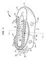
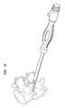
- FIG. 1is a front perspective view of a prosthetic intervertebral spacer in accordance with one embodiment of the present invention.
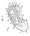
- FIG. 2is a top perspective view of the spacer shown in FIG. 1 .
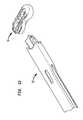
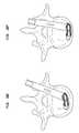
- FIG. 3is a top view of the spacer shown in FIG. 1 , the bottom view being a mirror image thereof.
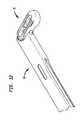
- FIG. 4is a side view of the spacer shown in FIG. 1 .
- FIG. 5is a cross-sectional view of a modified version of the spacer shown in FIG. 1 , the section being taken through the modified version in a similar fashion to line X-X of FIG. 1 .
- FIG. 6is a perspective view of a surgical tool for use in inserting and positioning a prosthetic intervertebral spacer in accordance with one embodiment of the present invention.
- FIG. 7is an exploded view of the insertion tool shown in FIG. 6 .
- FIG. 8is an enlarged exploded view of a portion of the view of FIG. 7 .
- FIG. 9is in illustration depicting an initial connection between the spacer shown in FIG. 1 and the insertion tool shown in FIG. 6 .
- FIG. 10is an illustration depicting the spacer and insertion tool construct shown in FIG. 9 with the insertion tool in a locked position.
- FIG. 11is an illustration depicting the spacer and insertion tool construct shown in FIG. 9 with the spacer rotated with respect to the insertion tool.
- FIG. 12is an illustration of the spacer and insertion tool construct shown in FIG. 9 with the spacer fully rotated with respect to the insertion tool.
- FIG. 13is an illustration depicting the spacer and insertion tool construct shown in FIG. 9 with the spacer released from the insertion tool.
- FIG. 14is an illustration depicting the spacer and insertion tool construct shown in FIG. 9 in relation to an intervertebral space.
- FIG. 15is an illustration depicting the spacer and insertion tool construct shown in FIG. 9 in relation to the intervertebral space, with the spacer in a fully inserted position.
- FIGS. 16 a -16 gare illustrations depicting various stages of insertion of the spacer shown in FIG. 1 in relation to the insertion tool shown in FIG. 6 and a vertebral body.
- FIG. 17is a perspective view of a prosthetic intervertebral spacer in accordance with another embodiment of the present invention.
- proximalmeans closer to the heart and the term “distal” means more distant from the heart.
- distalmeans more distant from the heart.
- anteriormeans towards the feet and the term “superior” means towards the head.
- anteriormeans towards the front part of the body or the face and the term “posterior” means towards the back of the body.
- medialmeans toward the midline of the body and the term “lateral” means away from the midline of the body.
- spacer 10includes a body 12 , which in turn includes a front end 14 , a rear end 16 , an anterior side 18 , a posterior side 20 , a top surface 22 , and a bottom surface 24 .
- Spacer 10further includes an interface 26 , including a neck portion 28 , a lip portion 30 , and a notch 32 .
- Notch 32separates interface 26 into first and second segments 26 a and 26 b (best shown in FIGS. 2 and 3 ), respectively.
- interface 26is arcuate and can best be described as a rail.
- interface 26can vary in shape, size, and configuration, with the only limitation being its cooperation with an insertion tool, such as the one discussed more fully below.
- notch 32is shown as extending in a direction substantially parallel to a longitudinal axis of spacer 10
- neck portion 28 and lip portion 30are shown as forming a T-shape. Again, these elements can vary in other embodiments.
- Spacer 10is preferably constructed of a polymeric material, such as polyetheretherketone (“Peek”). However, spacer 10 may be constructed of practically any materials suitable for implantation in the body of a human. Front end 14 and rear end 16 are shown as being curved, where the curves of the rear end and arcuate interface 26 lie in concentric circles. Again, in other embodiments, this configuration may vary. For instance, it is contemplated to provide a substantially square or rectangular shaped spacer 10 . In the embodiment shown in FIGS. 1-4 , front end 14 defines a tapered nose for spacer 10 .
- front end 14may (additional to or in lieu of the tapered nose structure) include a steering element configured to mate with at least one of the adjacent vertebral bodies spacer 10 is designed to be placed between in order to cause rotation of spacer 10 during insertion.
- a steering elementmay include a fin or crease, and may be disposed at an angle with respect to longitudinal axis of spacer 10 .
- FIG. 17One example spacer 110 of this type is depicted in FIG. 17 , in which a steering element 112 takes the form of a crease.
- FIG. 17depicted in which a steering element 112 takes the form of a crease.
- top and bottom surfaces 22 and 24each include a plurality of bone-engaging features in the form of teeth 34 .
- Other featuresmay be employed for aiding in the fixation of spacer 10 to the adjacent vertebrae.
- Spacer 10also includes apertures 36 a and 36 b formed through top and bottom surfaces 22 and 24 .
- Apertures 36 a and 36 bare separated by a strut 38 , which is recessed with respect to both top and bottom surfaces 22 and 24 .
- strut 38may be formed flush with top and bottom surfaces 22 and 24 , or only recessed with respect to one or the other.
- Apertures 36 a and 36 bare preferably designed to receive bone growth material, as will be discussed more fully below.
- Spacer 10further includes lateral fenestrations 40 a and 40 b , which are preferably designed for allowing fusion that develops between the upper and lower vertebrae (through the spacer) to spread laterally as well, and a plurality of vertical markers 42 a and 42 b , which are preferably constructed of tantalum and press fitted into spacer 10 . Markers 42 a and 42 b make the visual identification of spacer 10 easier through a traditional X-ray technique.
- Spacer 10 shown in FIGS. 1-4preferably includes a length dimension from front end 14 to rear end 16 that is preferably within the range of 15 mm to 40 mm, and more preferably between 26 mm and 31 mm, as well as a length dimension from front end 14 to the end of interface 26 that is preferably within the range of 17 mm to 42 mm, and more preferably between 28 mm and 32 mm.
- a width dimension from anterior side 18 to posterior side 20 of spacer 10 shown in FIGS. 1-4is preferably in the range of 8 mm to 16 mm, and more preferably approximately 12 mm spacer 10 shown in FIGS.
- spacer 10may be of any size.
- spacers 10 designed for use in the cervical area of the spinemay be smaller than spacers 10 designed for use in the thoracic or lumber spine.
- FIG. 5depicts a version of spacer 10 exhibiting top and bottom surfaces 22 and 24 that taper from anterior side 18 to posterior side 20 .
- This tapered constructionpreferably aids in restoring the natural lordotic angle of the adjacent vertebrae.
- the angle of each taperis preferably within the range of zero to ten degrees with respect to the midplane of spacer 10 to comport with the natural lordotic angle, but may be any angle suitable for use in the spine.
- the particular patient anatomywill generally determine whether a spacer like that shown in FIGS. 1-4 or in FIG. 5 will be required. However, a surgeon may employ one design or the other for other reasons.
- FIGS. 6-9depict an insertion tool 50 for use in inserting and positioning a prosthetic intervertebral spacer, for instance, above-described spacer 10 , in the intervertebral disc space between two adjacent vertebra.
- insertion tool 50includes a grasping portion 52 having first and second arms 54 a and 54 b that are preferably capable of moving with respect to one another.
- arms 54 a and 54 bact as spring clips having proximal ends attached to other portions of grasping portion 52 and distal ends between which the dimension can be varied.
- arms 54 a and 54 bmay be movable in other fashions, such as rotatable or the like.
- Tool 50further includes a sleeve 56 having an inner surface 57 that is slidably disposed about grasping portion 52 .
- a portion of inner surface 57 of sleeve 56includes opposing surfaces that are preferably spaced apart by a dimension that is less than a resting dimension between the outer portions of arms 54 a and 54 b . This allows for the distance between arms 54 a and 54 b to be reduced upon sliding of the sleeve distally. This preferably allows for arms 54 a and 54 b to be in an initial position, such as separated by the resting dimension, where they are able to receive spacer 10 , and where sliding of sleeve 56 causes arms 54 a and 54 b to affix to interface 26 .
- arms 54 a and 54 beach preferably include projections 58 a and 58 b , respectively, for positioning adjacent to the shoulder formed between neck portion 28 and lip portion 30 of interface 26 .
- arms 54 a and 54 b and projections 58 a and 58 bare preferably curved to properly mate with the curvature of interface 26 and therefore to allow rotation of spacer 10 with respect to tool 50 .
- the rotational relationship between spacer 10 and tool 50will be discussed more fully below.
- tool 50further includes a handle portion 60 connected to grasping portion 52 .
- Handle portion 60preferably further includes a sleeve actuator 62 for causing sliding movement of sleeve 56 .
- sleeve actuator 62includes a rotatable knob, the rotation of which causes the sliding of sleeve 56 .
- Handle portion 60also preferably includes a rod actuator 63 for causing movement of a rod 64 (best shown in FIGS. 7 and 8 ) that acts as a rotational lock for spacer 10 .
- rod actuator 63takes the form of a switch, the sliding of which causes movement of rod 64 .
- Handle portion 60also preferably includes a grip 66 that may be ergonomically shaped and formed with a material suitable for grasping by a surgeon.
- FIGS. 9-13depict the mating relationship between spacer 10 and insertion tool 50 .
- the initial connection between spacer 10 and tool 50is depicted.
- arms 54 a and 54 bare preferably in an initial state suitable for receiving interface 26 of spacer 10 .
- the inserteris shown with sleeve 56 slid over arms 54 a and 54 b to affix spacer 10 to tool 50 .
- rod 64is shown deployed into notch 32 .
- spacer 10can neither be removed from nor rotated with respect to tool 50 .
- FIG. 11depicts spacer 10 rotated with respect to tool 50 .
- FIG. 11depicts spacer 10 rotated with respect to tool 50 .
- FIG. 12depicts spacer 10 rotated at a maximum amount with respect to tool 50 . This amount is approximately 80 degrees, but may be greater in other embodiments, including approximately 90 degrees.
- FIGS. 9 and 10depicted the majority of tool 50 being connected with first segment 26 a of interface 26
- FIG. 12depicts the majority of tool 50 being connected with second segments 26 b due to the rotation of spacer 10 with respect to tool 50 .
- FIG. 13depicts spacer 10 having been released from tool 50 upon sliding of sleeve 56 in the opposite direction from which it is shown in FIGS. 10-12 .
- FIGS. 14 and 15depict the spacer 10 and tool 50 construct discussed above in relation to two adjacent vertebral bodies in the spine of a human being.
- FIG. 14depicts spacer 10 being inserted from a posterior aspect of the spine
- spacer 10may be inserted from any aspect.
- spacer 10is inserted from an anterior aspect of the spine.
- FIG. 15in a final position located in an anterior portion of the intervertebral disc space
- spacer 10may ultimately be disposed in many different areas of that intervertebral disc space.
- spacer 10may ultimately be implanted so as to be located in a posterior portion of the intervertebral space.
- FIGS. 16 a -16 gdepict in more detail one embodiment method of inserting and positioning spacer 10 in the intervertebral disc space between two adjacent vertebra with the use of tool 50 .
- a surgeonPrior to conducting the method shown in those figures, a surgeon preferably forms a hole through the annulus fibrosis of an intervertebral disc space, leaving a large amount of that anatomical feature untouched. The surgeon may then remove (through the formed hole or otherwise) certain material from the space in order to allow for spacer 10 to be inserted therein. Thereafter, as shown in FIG. 16 a , the locked spacer 10 and tool 50 construct shown in FIG. 10 is inserted through the hole formed through the annulus fibrosis. Again, while this is shown in FIG.
- FIGS. 16 c -16 edepict subsequent and sequential steps in this insertion process.
- FIG. 16 fdepicts spacer 10 fully rotated with respect to insertion tool 50 and disposed in an anterior portion of the disc space where, in this embodiment, it shall remain.
- FIG. 16 fdepicts spacer 10 fully rotated with respect to insertion tool 50 and disposed in an anterior portion of the disc space where, in this embodiment, it shall remain.
- 16 gdepicts tool 50 being removed from spacer 10 . This is due to operation of sleeve actuator 62 to slide sleeve 56 with respect to grasping portion 52 . Spacer 10 is now in its final position and tool 50 can be removed from the space.
- the methods of inserting spacer 10may further include the steps of packing apertures 36 a and 36 b with bone growth inducing substances, such as bone morphogenetic proteins or natural bone materials.
- spacer 10includes a steering element
- the rotation between spacer 10 and tool 50may occur prior to engagement of spacer 10 with the remaining portion of the annulus fibrosis.
- the tapered nose of front end 14 of spacer 10preferably aids in the initial insertion of the spacer within the intervertebral disc space, as well as the cooperation of the spacer with the remaining portion of the annulus fibrosis.
Landscapes
- Health & Medical Sciences (AREA)
- Engineering & Computer Science (AREA)
- Biomedical Technology (AREA)
- Orthopedic Medicine & Surgery (AREA)
- Neurology (AREA)
- Transplantation (AREA)
- Heart & Thoracic Surgery (AREA)
- Oral & Maxillofacial Surgery (AREA)
- Cardiology (AREA)
- Vascular Medicine (AREA)
- Life Sciences & Earth Sciences (AREA)
- Animal Behavior & Ethology (AREA)
- General Health & Medical Sciences (AREA)
- Public Health (AREA)
- Veterinary Medicine (AREA)
- Physical Education & Sports Medicine (AREA)
- Prostheses (AREA)
Abstract
Description
Claims (19)
Priority Applications (3)
| Application Number | Priority Date | Filing Date | Title |
|---|---|---|---|
| US15/869,536US10182919B2 (en) | 2010-09-30 | 2018-01-12 | Surgical implant with guiding rail |
| US16/244,742US11076965B2 (en) | 2010-09-30 | 2019-01-10 | Surgical implant with guiding rail |
| US17/387,501US11850159B2 (en) | 2010-09-30 | 2021-07-28 | Surgical implant with guiding rail |
Applications Claiming Priority (4)
| Application Number | Priority Date | Filing Date | Title |
|---|---|---|---|
| US12/894,796US8858637B2 (en) | 2010-09-30 | 2010-09-30 | Surgical implant with guiding rail |
| US14/475,863US9445914B2 (en) | 2010-09-30 | 2014-09-03 | Surgical implant with guiding rail |
| US15/266,062US9867713B2 (en) | 2010-09-30 | 2016-09-15 | Surgical implant with guiding rail |
| US15/869,536US10182919B2 (en) | 2010-09-30 | 2018-01-12 | Surgical implant with guiding rail |
Related Parent Applications (1)
| Application Number | Title | Priority Date | Filing Date |
|---|---|---|---|
| US15/266,062ContinuationUS9867713B2 (en) | 2010-09-30 | 2016-09-15 | Surgical implant with guiding rail |
Related Child Applications (1)
| Application Number | Title | Priority Date | Filing Date |
|---|---|---|---|
| US16/244,742ContinuationUS11076965B2 (en) | 2010-09-30 | 2019-01-10 | Surgical implant with guiding rail |
Publications (2)
| Publication Number | Publication Date |
|---|---|
| US20180133021A1 US20180133021A1 (en) | 2018-05-17 |
| US10182919B2true US10182919B2 (en) | 2019-01-22 |
Family
ID=45890468
Family Applications (6)
| Application Number | Title | Priority Date | Filing Date |
|---|---|---|---|
| US12/894,796Active2032-02-24US8858637B2 (en) | 2010-09-30 | 2010-09-30 | Surgical implant with guiding rail |
| US14/475,863ActiveUS9445914B2 (en) | 2010-09-30 | 2014-09-03 | Surgical implant with guiding rail |
| US15/266,062ActiveUS9867713B2 (en) | 2010-09-30 | 2016-09-15 | Surgical implant with guiding rail |
| US15/869,536ActiveUS10182919B2 (en) | 2010-09-30 | 2018-01-12 | Surgical implant with guiding rail |
| US16/244,742Active2031-01-19US11076965B2 (en) | 2010-09-30 | 2019-01-10 | Surgical implant with guiding rail |
| US17/387,501Active2031-01-05US11850159B2 (en) | 2010-09-30 | 2021-07-28 | Surgical implant with guiding rail |
Family Applications Before (3)
| Application Number | Title | Priority Date | Filing Date |
|---|---|---|---|
| US12/894,796Active2032-02-24US8858637B2 (en) | 2010-09-30 | 2010-09-30 | Surgical implant with guiding rail |
| US14/475,863ActiveUS9445914B2 (en) | 2010-09-30 | 2014-09-03 | Surgical implant with guiding rail |
| US15/266,062ActiveUS9867713B2 (en) | 2010-09-30 | 2016-09-15 | Surgical implant with guiding rail |
Family Applications After (2)
| Application Number | Title | Priority Date | Filing Date |
|---|---|---|---|
| US16/244,742Active2031-01-19US11076965B2 (en) | 2010-09-30 | 2019-01-10 | Surgical implant with guiding rail |
| US17/387,501Active2031-01-05US11850159B2 (en) | 2010-09-30 | 2021-07-28 | Surgical implant with guiding rail |
Country Status (6)
| Country | Link |
|---|---|
| US (6) | US8858637B2 (en) |
| EP (2) | EP2621412B1 (en) |
| JP (2) | JP5891231B2 (en) |
| AU (1) | AU2011308888B2 (en) |
| CA (2) | CA2935245C (en) |
| WO (1) | WO2012044666A2 (en) |
Cited By (1)
| Publication number | Priority date | Publication date | Assignee | Title |
|---|---|---|---|---|
| US12263091B2 (en)* | 2018-08-09 | 2025-04-01 | Stryker European Operations Holdings Llc | Interbody implants and optimization features thereof |
Families Citing this family (34)
| Publication number | Priority date | Publication date | Assignee | Title |
|---|---|---|---|---|
| US9220547B2 (en) | 2009-03-27 | 2015-12-29 | Spinal Elements, Inc. | Flanged interbody fusion device |
| US20120277866A1 (en)* | 2011-04-28 | 2012-11-01 | Prakasam Kalluri | Angled Bullet-Nose Banana Cage |
| US9220607B2 (en) | 2011-10-28 | 2015-12-29 | Warsaw Oorthopedic, Inc. | Pivotable interbody implant system |
| FR3006170B1 (en)* | 2013-05-31 | 2015-06-26 | Osd Orthopaedic & Spine Dev | INTERSOMATIC PROSTHESIS PRODUCING INDIVIDUALIZED LORDOSE SETTING |
| FR3010628B1 (en) | 2013-09-18 | 2015-10-16 | Medicrea International | METHOD FOR REALIZING THE IDEAL CURVATURE OF A ROD OF A VERTEBRAL OSTEOSYNTHESIS EQUIPMENT FOR STRENGTHENING THE VERTEBRAL COLUMN OF A PATIENT |
| FR3012030B1 (en) | 2013-10-18 | 2015-12-25 | Medicrea International | METHOD FOR REALIZING THE IDEAL CURVATURE OF A ROD OF A VERTEBRAL OSTEOSYNTHESIS EQUIPMENT FOR STRENGTHENING THE VERTEBRAL COLUMN OF A PATIENT |
| US10478313B1 (en) | 2014-01-10 | 2019-11-19 | Nuvasive, Inc. | Spinal fusion implant and related methods |
| US10792168B2 (en) | 2015-02-06 | 2020-10-06 | Alphatec Spine, Inc. | Implant insertion instrument |
| TWI547259B (en)* | 2015-04-28 | 2016-09-01 | 鐿鈦科技股份有限公司 | Spinal fusion surgery instrument for implanting and intervertebral cage thereof |
| US9895235B2 (en)* | 2015-12-18 | 2018-02-20 | Warsaw Orthopedic, Inc. | Spinal implant system and method |
| WO2018109556A1 (en) | 2016-12-12 | 2018-06-21 | Medicrea International | Systems and methods for patient-specific spinal implants |
| WO2018112324A2 (en) | 2016-12-16 | 2018-06-21 | Advance Research System, Llc | Interbody implant with concave profiled nose |
| USD879295S1 (en) | 2017-02-13 | 2020-03-24 | Advance Research System, Llc | Spinal fusion cage |
| EP3612122B1 (en) | 2017-04-21 | 2023-12-20 | Medicrea International | A system for developing one or more patient-specific spinal implants |
| USD847339S1 (en) | 2017-06-26 | 2019-04-30 | Advanced Research System, LLC | Spinal fusion cage |
| EP3663082A4 (en)* | 2017-08-01 | 2021-04-28 | Ishihara Sangyo Kaisha, Ltd. | Three-dimensional structure, method for manufacturing same, and coating device |
| WO2019051260A1 (en) | 2017-09-08 | 2019-03-14 | Pioneer Surgical Technology, Inc. | Intervertebral implants, instruments, and methods |
| USD907771S1 (en) | 2017-10-09 | 2021-01-12 | Pioneer Surgical Technology, Inc. | Intervertebral implant |
| US10918422B2 (en) | 2017-12-01 | 2021-02-16 | Medicrea International | Method and apparatus for inhibiting proximal junctional failure |
| US11311314B2 (en)* | 2018-07-31 | 2022-04-26 | GetSet Surgical SA | Spinal surgery systems and methods |
| AU2019342137A1 (en) | 2018-09-20 | 2021-03-25 | Spinal Elements, Inc. | Spinal implant device |
| US11039931B2 (en)* | 2019-02-01 | 2021-06-22 | Globus Medical, Inc. | Intervertebral spinal implant |
| US11925417B2 (en) | 2019-04-02 | 2024-03-12 | Medicrea International | Systems, methods, and devices for developing patient-specific spinal implants, treatments, operations, and/or procedures |
| US11944385B2 (en) | 2019-04-02 | 2024-04-02 | Medicrea International | Systems and methods for medical image analysis |
| US11877801B2 (en) | 2019-04-02 | 2024-01-23 | Medicrea International | Systems, methods, and devices for developing patient-specific spinal implants, treatments, operations, and/or procedures |
| US11173043B1 (en) | 2019-05-17 | 2021-11-16 | Joseph T. Robbins | Spinal interbody implants |
| JP6700511B1 (en)* | 2019-08-30 | 2020-05-27 | リーガエース株式会社 | System for guiding interbody spacers between bodies |
| US11737888B1 (en) | 2019-09-19 | 2023-08-29 | Advance Research System, Llc | Spinal fusion implant system and method |
| US11769251B2 (en) | 2019-12-26 | 2023-09-26 | Medicrea International | Systems and methods for medical image analysis |
| US11277689B2 (en) | 2020-02-24 | 2022-03-15 | Logitech Europe S.A. | Apparatus and method for optimizing sound quality of a generated audible signal |
| US11911284B2 (en) | 2020-11-19 | 2024-02-27 | Spinal Elements, Inc. | Curved expandable interbody devices and deployment tools |
| WO2022133456A1 (en) | 2020-12-17 | 2022-06-23 | Spinal Elements, Inc. | Spinal implant device |
| US12318144B2 (en) | 2021-06-23 | 2025-06-03 | Medicrea International SA | Systems and methods for planning a patient-specific spinal correction |
| GB202112071D0 (en)* | 2021-08-23 | 2021-10-06 | Invibio Knees Ltd | Surgical implant |
Citations (122)
| Publication number | Priority date | Publication date | Assignee | Title |
|---|---|---|---|---|
| US4714469A (en) | 1987-02-26 | 1987-12-22 | Pfizer Hospital Products Group, Inc. | Spinal implant |
| US5649931A (en) | 1996-01-16 | 1997-07-22 | Zimmer, Inc. | Orthopaedic apparatus for driving and/or removing a bone screw |
| US5782830A (en) | 1995-10-16 | 1998-07-21 | Sdgi Holdings, Inc. | Implant insertion device |
| US6159215A (en) | 1997-12-19 | 2000-12-12 | Depuy Acromed, Inc. | Insertion instruments and method for delivering a vertebral body spacer |
| US6261296B1 (en) | 1998-10-02 | 2001-07-17 | Synthes U.S.A. | Spinal disc space distractor |
| US20020065560A1 (en) | 2000-06-12 | 2002-05-30 | Ortho Development Corporation | Intervertebral spacing implant system |
| US20020165612A1 (en) | 2001-05-03 | 2002-11-07 | David Gerber | Intervertebral implant for transforaminal posterior lumbar interbody fusion procedure |
| US20030040798A1 (en) | 1995-06-07 | 2003-02-27 | Michelson Gary Karlin | Lordotic interbody spinal fusion implants |
| US20030060886A1 (en) | 1995-10-16 | 2003-03-27 | Van Hoeck James E. | Intervertebral spacers |
| US6562072B1 (en) | 1998-01-23 | 2003-05-13 | Aesculap Ag & Co. Kg | Implant for insertion between spinal column vertebrae |
| US6613090B2 (en) | 1998-01-23 | 2003-09-02 | Aesculap Ag & Co. Kg | Intervertebral implant |
| US20040030346A1 (en) | 1999-10-21 | 2004-02-12 | George Frey | Devices and techniques for a posterior lateral disc space approach |
| US6699288B2 (en)* | 2000-03-22 | 2004-03-02 | Scolio Gmbh | Cage-type intervertebral implant |
| US20040127990A1 (en)* | 2002-12-31 | 2004-07-01 | Bartish, Charles M. | Novel banana cage |
| USD493225S1 (en) | 2000-06-12 | 2004-07-20 | Ortho Development Corporation | Implant |
| US6764491B2 (en) | 1999-10-21 | 2004-07-20 | Sdgi Holdings, Inc. | Devices and techniques for a posterior lateral disc space approach |
| US20040153065A1 (en)* | 2003-02-03 | 2004-08-05 | Lim Roy K. | Expanding interbody implant and articulating inserter and method |
| US20040254644A1 (en) | 2002-10-21 | 2004-12-16 | Taylor Brett Allison | Intervertebral disk prosthesis |
| US20050096745A1 (en) | 2003-10-29 | 2005-05-05 | Eurosurgical Sa | Intersomatic cage for lumbar fusion by transforaminal approach and its cage carrying device |
| US20050209698A1 (en) | 2003-08-05 | 2005-09-22 | Gordon Charles R | Expandable intervertebral implant |
| US20050288788A1 (en) | 2004-06-25 | 2005-12-29 | Gretchen Dougherty-Shah | Intervertebral implant and associated method |
| US20060004376A1 (en) | 2004-07-02 | 2006-01-05 | Kenneth Shipp | Device for inserting implants |
| US6984245B2 (en) | 2000-02-22 | 2006-01-10 | Sdgi Holdings, Inc. | Anterior impacted bone graft and driver instruments |
| US6987245B2 (en) | 2001-10-01 | 2006-01-17 | Takao Kawamura | Heat plate, heating element, belt type fixing device and image forming apparatus |
| US7060073B2 (en) | 1999-10-21 | 2006-06-13 | Sdgi Holdings, Inc. | Devices and techniques for a posterior lateral disc space approach |
| US7060096B1 (en) | 1999-11-03 | 2006-06-13 | Tutogen Medical Gmbh | Implant consisting of bone material |
| US20060142858A1 (en)* | 2004-12-16 | 2006-06-29 | Dennis Colleran | Expandable implants for spinal disc replacement |
| US20060178746A1 (en) | 2005-02-10 | 2006-08-10 | Depuy Spine, Inc. | Intervertebral prosthetic disc and method for installing using a guidewire |
| US20060229627A1 (en) | 2004-10-29 | 2006-10-12 | Hunt Margaret M | Variable angle spinal surgery instrument |
| US20060235426A1 (en) | 2005-04-15 | 2006-10-19 | Sdgi Holdings, Inc. | Instruments, implants and methods for positioning implants into a spinal disc space |
| US20060241761A1 (en) | 2005-04-08 | 2006-10-26 | G&L Consulting | Spine implant insertion device and method |
| US7137997B2 (en) | 2003-12-29 | 2006-11-21 | Globus Medical, Inc. | Spinal fusion implant |
| US20060276800A1 (en) | 2005-01-27 | 2006-12-07 | Nexgen Spine, Inc. | Intervertebral disc replacement and surgical instruments therefor |
| EP1752116A1 (en) | 2005-08-11 | 2007-02-14 | Sepitec Foundation | Intervertebral Implant |
| US20070067035A1 (en) | 2005-09-16 | 2007-03-22 | Falahee Mark H | Steerable interbody fusion cage |
| US20070073405A1 (en) | 2005-09-29 | 2007-03-29 | Dominique Verhulst | Motion segment repair system |
| US20070093850A1 (en) | 2005-09-29 | 2007-04-26 | Harris Peter M | Adjustable interbody introducer device and method |
| US20070093897A1 (en)* | 2005-10-21 | 2007-04-26 | Stryker Spine (In France) | System and method for fusion cage implantation |
| US20070118223A1 (en) | 2005-11-23 | 2007-05-24 | Warsaw Orthopedic Inc. | Posterior Articular Disc and Method for Implantation |
| US20070142843A1 (en) | 2005-12-21 | 2007-06-21 | Justin Dye | Articulated delivery instrument |
| US7235082B2 (en) | 2003-08-12 | 2007-06-26 | Depuy Spine, Inc. | Device for insertion of implants |
| US20070162128A1 (en) | 2005-12-16 | 2007-07-12 | Sdgi Holdings, Inc. | Intervertebral spacer and insertion tool |
| US20070208343A1 (en) | 2004-03-10 | 2007-09-06 | Sepitec Foundation | Implant Used in Stabilising Operations on the Thoracic and Lumbar Vertebral Column |
| US20070213826A1 (en) | 2006-03-08 | 2007-09-13 | Seaspine, Inc. | Intervertebral spacer and insertion tool providing multiple angles of insertion |
| US20070213737A1 (en) | 2006-03-08 | 2007-09-13 | Seaspine, Inc. | Insertion tool for an intervertebral spacer providing multiple angles of insertion |
| US20070225808A1 (en) | 2006-03-22 | 2007-09-27 | Warnick David R | Pivotable interbody spacer |
| US20070225726A1 (en) | 2006-03-23 | 2007-09-27 | Justin Dye | Instruments for delivering spinal implants |
| US20070243255A1 (en) | 2004-09-28 | 2007-10-18 | Bing Xu | Multifunctional supramolecular hydrogels as biomaterials |
| US20070255415A1 (en)* | 2006-05-01 | 2007-11-01 | Sdgi Holdings, Inc. | Expandable intervertebral spacers and methods of use |
| US20070276406A1 (en) | 2004-02-09 | 2007-11-29 | Depuy Spine, Inc | Systems and Methods for Spinal Surgery |
| US20070282441A1 (en) | 2006-05-19 | 2007-12-06 | Katie Stream | Spinal Stabilization Device and Methods |
| US20080009880A1 (en) | 2006-03-22 | 2008-01-10 | Warnick David R | Pivotable Vetrebral Spacer |
| US20080058933A1 (en) | 2006-07-31 | 2008-03-06 | Ronald Garner | Spinal fusion implant |
| US20080065082A1 (en) | 2006-09-08 | 2008-03-13 | Narissa Chang | Steerable rasp/trial inserter |
| US20080065219A1 (en) | 2006-09-08 | 2008-03-13 | Justin Dye | Offset radius lordosis |
| US20080077150A1 (en) | 2006-09-22 | 2008-03-27 | Linh Nguyen | Steerable rasp/trial member inserter and method of use |
| US20080077153A1 (en) | 2006-09-22 | 2008-03-27 | Pioneer Surgical Technology, Inc. | System and methods for inserting a spinal disc device into an intervertebral space |
| WO2008039222A1 (en) | 2006-09-25 | 2008-04-03 | Stryker Spine | Rod inserter and rod with reduced diameter end |
| US20080091211A1 (en)* | 2006-10-11 | 2008-04-17 | G & L Consulting | Spine implant insertion device and method |
| US20080097454A1 (en) | 2006-09-19 | 2008-04-24 | Warsaw Orthopedic Inc. | Instruments and methods for spinal implant revision |
| US20080109005A1 (en) | 2006-08-10 | 2008-05-08 | Trudeau Jeffrey L | System and Methods for Inserting a Spinal Disc Device Into an Intervertebral Space |
| US20080119935A1 (en) | 2006-11-17 | 2008-05-22 | Luis Marquez Alvarez | Intersomatic cage, clamp for manipulating it and procedure for inserting the intersomatic cage between vertebrae |
| US20080140085A1 (en) | 2006-12-11 | 2008-06-12 | G&L Consulting, Llc | Steerable spine implant insertion device and method |
| WO2008088777A2 (en) | 2007-01-12 | 2008-07-24 | Synthes Usa, Llc | Modular intervertebral implant |
| US20080221694A1 (en) | 2006-03-22 | 2008-09-11 | Warnick David R | Pivotable Interbody Spacer System and Method |
| US20080224694A1 (en) | 2007-03-12 | 2008-09-18 | Micronas Gmbh | Semiconductor component and method for testing such a component |
| US20080243255A1 (en) | 2007-03-29 | 2008-10-02 | Butler Michael S | Radially expandable spinal interbody device and implantation tool |
| US20080249623A1 (en) | 2006-12-22 | 2008-10-09 | Qi-Bin Bao | Implant Restraint Device and Methods |
| US20080255574A1 (en) | 2007-04-13 | 2008-10-16 | Zimmer Technology, Inc. | Instrument for insertion of prosthetic components |
| US20080262623A1 (en) | 2005-05-06 | 2008-10-23 | Titan Spine, Llc | Composite interbody spinal implant having openings of predetermined size and shape |
| US20080269901A1 (en) | 2007-04-27 | 2008-10-30 | Baynham Bret O | Spinal implant |
| US20080281424A1 (en) | 2006-11-29 | 2008-11-13 | John Parry | Orthopaedic Implants and Prostheses |
| US20080287957A1 (en) | 2007-05-18 | 2008-11-20 | Depuy Spine, Inc. | Insertion blade assembly and method of use |
| US20080306489A1 (en) | 2007-06-07 | 2008-12-11 | Moti Altarac | Inserter for a spinal implant |
| US20080306488A1 (en) | 2007-06-07 | 2008-12-11 | Moti Altarac | Inserter for a spinal implant |
| US7479160B2 (en) | 1998-10-28 | 2009-01-20 | Warsaw Orthopedic, Inc. | Interbody fusion grafts and instrumentation |
| US20090030423A1 (en) | 2007-07-27 | 2009-01-29 | Rolando Puno | Inter-Body Implantation System and Method |
| US20090054991A1 (en) | 2006-05-02 | 2009-02-26 | Ashok Biyani | Transforaminal lumbar interbody fusion cage |
| US20090093883A1 (en) | 2007-10-05 | 2009-04-09 | Mauricio Rodolfo Carrasco | Interspinous implant |
| US20090105832A1 (en) | 2007-06-08 | 2009-04-23 | Ldr Medical | Intersomatic cage, intervertebral prosthesis, anchoring device and implantation instruments |
| US20090112220A1 (en) | 2007-10-30 | 2009-04-30 | Kilian Kraus | Manipulating Tool for a Medical Implant, Medical Implant and Kit of Parts Comprising a Manipulating Tool and Implant |
| US20090112217A1 (en) | 2007-10-31 | 2009-04-30 | Douglas Hester | Implant insertion device |
| US20090138055A1 (en) | 2004-10-20 | 2009-05-28 | Moti Altarac | Spacer insertion instrument |
| US20090143829A1 (en) | 2003-05-16 | 2009-06-04 | Zimmer Spine, Inc. | Access device for minimally invasive surgery |
| US20090143859A1 (en) | 2007-11-30 | 2009-06-04 | Mcclellan Iii John W | Maximum support tlif implant |
| US20090182428A1 (en) | 2008-01-16 | 2009-07-16 | Custom Spine, Inc. | Flanged interbody device |
| US20090187246A1 (en) | 2008-01-22 | 2009-07-23 | Foley Kevin T | Interbody implants for spinal alignment procedures |
| US20090216331A1 (en) | 2008-02-22 | 2009-08-27 | Innvotec Surgicals, Inc. | Spinal Implant with expandable fixation |
| US20090222092A1 (en) | 2006-02-15 | 2009-09-03 | Reginald James Davis | Transforaminal intersomatic cage for an intervertebral fusion graft and an instrument for implanting the cage |
| US20090228110A1 (en)* | 2008-03-07 | 2009-09-10 | K2M, Inc. | Intervertebral instrument, implant, and method |
| US20090234364A1 (en) | 2008-03-03 | 2009-09-17 | David Crook | Surgical positioning assembly and associated spinal implant device and surgical methods |
| US7591852B2 (en) | 2003-12-02 | 2009-09-22 | Alphatec Spine, Inc. | Vertebral body replacement cage assembly |
| US20090248163A1 (en) | 2008-03-31 | 2009-10-01 | King Emily E | Spinal surgery interbody |
| US20090265008A1 (en) | 2008-03-31 | 2009-10-22 | Stryker Spine | Spinal implant apparatus and methods |
| US20090299479A1 (en) | 2007-10-19 | 2009-12-03 | Jones Robert J | Suture guided implant |
| US7632281B2 (en) | 2001-07-16 | 2009-12-15 | Spinecore, Inc. | Instrumentation for manipulating artificial intervertebral disc trials having a cylindrical engagement surface |
| WO2010011849A1 (en) | 2008-07-23 | 2010-01-28 | Malberg Marc I | Modular nucleus pulposus prosthesis |
| US7658766B2 (en) | 2006-05-01 | 2010-02-09 | Warsaw Orthopedic, Inc. | Intervertebral implants with covered inner chamber and methods of use |
| US20100057204A1 (en) | 2008-02-22 | 2010-03-04 | Murali Kadaba | Hydraulically Actuated Expanding Spine Cage With Extendable Locking Anchor |
| US20100094422A1 (en) | 2008-10-13 | 2010-04-15 | Noah Hansell | Intervertebral Spacer |
| US20100100141A1 (en) | 2004-08-06 | 2010-04-22 | Spinalmotion, Inc. | Methods and Apparatus For Intervertebral Disc Prosthesis Insertion |
| US20100114105A1 (en) | 2008-10-31 | 2010-05-06 | Robert Reid,Inc. | System and method for vertebral interbody fusion |
| US7717961B2 (en) | 1999-08-18 | 2010-05-18 | Intrinsic Therapeutics, Inc. | Apparatus delivery in an intervertebral disc |
| US7722674B1 (en) | 2005-08-12 | 2010-05-25 | Innvotec Surgical Inc. | Linearly expanding spine cage for enhanced spinal fusion |
| US7749273B2 (en) | 1999-10-20 | 2010-07-06 | Anulex Technologies, Inc. | Method and apparatus for the treatment of the intervertebral disc annulus |
| US20100191337A1 (en) | 2006-03-08 | 2010-07-29 | Seaspine, Inc. | Interbody device for spinal applications |
| US20100217393A1 (en) | 2009-02-20 | 2010-08-26 | Theofilos Charles S | Interbody fusion system with intervertebral implant retention assembly |
| US7806932B2 (en) | 2003-08-01 | 2010-10-05 | Zimmer Spine, Inc. | Spinal implant |
| US20100256760A1 (en) | 2009-04-02 | 2010-10-07 | Noah Hansell | Method of Installation of Intervertebral Spacers |
| US20100256759A1 (en) | 2009-04-02 | 2010-10-07 | Noah Hansell | Method of Installation of Intervertebral Spacers |
| US20110106258A1 (en) | 2009-10-30 | 2011-05-05 | Warsaw Orthopedic, Inc. | End cap for a vertebral implant |
| US20110106259A1 (en) | 2009-11-05 | 2011-05-05 | Synthes Usa, L.L.C. | Self-Pivoting Spinal Implant and Associated Instrumentation |
| US20110106261A1 (en)* | 2009-10-30 | 2011-05-05 | Spinefrontier, Inc | System and method for an intervertebral implant assembly |
| US7985256B2 (en) | 2005-09-26 | 2011-07-26 | Coalign Innovations, Inc. | Selectively expanding spine cage, hydraulically controllable in three dimensions for enhanced spinal fusion |
| US20110230965A1 (en)* | 2010-03-22 | 2011-09-22 | Gerald Schell | Percutaneous arthrodesis method and system |
| US20110245923A1 (en) | 2009-10-02 | 2011-10-06 | John Cobb | Intervertebral implant device for a posterior interbody fusion surgical procedure |
| US20110276142A1 (en) | 2008-10-13 | 2011-11-10 | Marcin Niemiec | Articulating Spacer |
| US8070813B2 (en) | 2005-09-26 | 2011-12-06 | Coalign Innovations, Inc. | Selectively expanding spine cage, hydraulically controllable in three dimensions for vertebral body replacement |
| US20120059480A1 (en) | 2010-03-22 | 2012-03-08 | Amendia, Inc. | Percutaneous arthrodesis method and system |
| US20130190875A1 (en) | 2005-09-26 | 2013-07-25 | Coalign Innovations, Inc. | Selectively Expanding Spine Cage With Enhanced Bone Graft Infusion |
| US20130253650A1 (en) | 2008-12-10 | 2013-09-26 | Coalign Innovations, Inc. | Adjustable Distraction Cage With Linked Locking Mechanisms |
| US8696751B2 (en) | 2008-12-10 | 2014-04-15 | Coalign Innovations, Inc. | Adjustable distraction cage with linked locking mechanisms |
Family Cites Families (14)
| Publication number | Priority date | Publication date | Assignee | Title |
|---|---|---|---|---|
| US8388684B2 (en)* | 2002-05-23 | 2013-03-05 | Pioneer Signal Technology, Inc. | Artificial disc device |
| US20060014285A1 (en)* | 2004-07-14 | 2006-01-19 | Eldridge Gary R | Methods and compositions for inhibiting biofilms |
| JP2006068086A (en)* | 2004-08-31 | 2006-03-16 | Takiron Co Ltd | Artificial spinal disk insertion tool and tool set |
| US7276424B2 (en)* | 2005-06-29 | 2007-10-02 | Hewlett-Packard Development Company, L.P. | Fabrication of aligned nanowire lattices |
| US7824427B2 (en)* | 2007-01-16 | 2010-11-02 | Perez-Cruet Miquelangelo J | Minimally invasive interbody device |
| US8163026B2 (en)* | 2007-04-05 | 2012-04-24 | Zimmer Spine, Inc. | Interbody implant |
| US8998924B2 (en)* | 2009-04-16 | 2015-04-07 | Coalign Innovations, Inc. | Insertion handle for surgical implants |
| FR2948277B1 (en)* | 2009-07-27 | 2012-11-16 | Medicrea International | ASSEMBLY COMPRISING AN INTERVERTEBRAL IMPLANT FOR IMMOBILIZING A VERTEBRA IN RELATION TO ANOTHER AND A POSITION INSTRUMENT OF THIS IMPLANT |
| US9907560B2 (en)* | 2010-06-24 | 2018-03-06 | DePuy Synthes Products, Inc. | Flexible vertebral body shavers |
| US9724132B2 (en)* | 2011-08-31 | 2017-08-08 | DePuy Synthes Products, Inc. | Devices and methods for cervical lateral fixation |
| US20140172103A1 (en)* | 2012-12-17 | 2014-06-19 | Michael J. O'Neil | Polyaxial Intervertebral Cage |
| US9283091B2 (en)* | 2013-10-07 | 2016-03-15 | Warsaw Orthopedic, Inc. | Spinal implant system and method |
| EP3135254B1 (en)* | 2015-08-26 | 2019-01-02 | Biedermann Technologies GmbH & Co. KG | Intervertebral implant and device for inserting an intervertebral implant |
| US11311314B2 (en)* | 2018-07-31 | 2022-04-26 | GetSet Surgical SA | Spinal surgery systems and methods |
- 2010
- 2010-09-30USUS12/894,796patent/US8858637B2/enactiveActive
- 2011
- 2011-09-28AUAU2011308888Apatent/AU2011308888B2/enactiveActive
- 2011-09-28CACA2935245Apatent/CA2935245C/ennot_activeExpired - Fee Related
- 2011-09-28EPEP11829818.1Apatent/EP2621412B1/enactiveActive
- 2011-09-28WOPCT/US2011/053637patent/WO2012044666A2/enactiveApplication Filing
- 2011-09-28EPEP15187400.5Apatent/EP3023079B1/enactiveActive
- 2011-09-28JPJP2013531760Apatent/JP5891231B2/ennot_activeExpired - Fee Related
- 2011-09-28CACA2813287Apatent/CA2813287C/ennot_activeExpired - Fee Related
- 2014
- 2014-09-03USUS14/475,863patent/US9445914B2/enactiveActive
- 2016
- 2016-02-18JPJP2016028938Apatent/JP6243937B2/ennot_activeExpired - Fee Related
- 2016-09-15USUS15/266,062patent/US9867713B2/enactiveActive
- 2018
- 2018-01-12USUS15/869,536patent/US10182919B2/enactiveActive
- 2019
- 2019-01-10USUS16/244,742patent/US11076965B2/enactiveActive
- 2021
- 2021-07-28USUS17/387,501patent/US11850159B2/enactiveActive
Patent Citations (163)
| Publication number | Priority date | Publication date | Assignee | Title |
|---|---|---|---|---|
| US4714469A (en) | 1987-02-26 | 1987-12-22 | Pfizer Hospital Products Group, Inc. | Spinal implant |
| US20030040798A1 (en) | 1995-06-07 | 2003-02-27 | Michelson Gary Karlin | Lordotic interbody spinal fusion implants |
| US20030060886A1 (en) | 1995-10-16 | 2003-03-27 | Van Hoeck James E. | Intervertebral spacers |
| US5782830A (en) | 1995-10-16 | 1998-07-21 | Sdgi Holdings, Inc. | Implant insertion device |
| US6066174A (en) | 1995-10-16 | 2000-05-23 | Sdgi Holdings, Inc. | Implant insertion device |
| US5649931A (en) | 1996-01-16 | 1997-07-22 | Zimmer, Inc. | Orthopaedic apparatus for driving and/or removing a bone screw |
| US6159215A (en) | 1997-12-19 | 2000-12-12 | Depuy Acromed, Inc. | Insertion instruments and method for delivering a vertebral body spacer |
| US6613090B2 (en) | 1998-01-23 | 2003-09-02 | Aesculap Ag & Co. Kg | Intervertebral implant |
| US6562072B1 (en) | 1998-01-23 | 2003-05-13 | Aesculap Ag & Co. Kg | Implant for insertion between spinal column vertebrae |
| US6261296B1 (en) | 1998-10-02 | 2001-07-17 | Synthes U.S.A. | Spinal disc space distractor |
| US7479160B2 (en) | 1998-10-28 | 2009-01-20 | Warsaw Orthopedic, Inc. | Interbody fusion grafts and instrumentation |
| US7717961B2 (en) | 1999-08-18 | 2010-05-18 | Intrinsic Therapeutics, Inc. | Apparatus delivery in an intervertebral disc |
| US7749273B2 (en) | 1999-10-20 | 2010-07-06 | Anulex Technologies, Inc. | Method and apparatus for the treatment of the intervertebral disc annulus |
| US20040030346A1 (en) | 1999-10-21 | 2004-02-12 | George Frey | Devices and techniques for a posterior lateral disc space approach |
| US7998215B2 (en) | 1999-10-21 | 2011-08-16 | Warsaw Orthopedic, Inc. | Devices and techniques for a posterior lateral disc space approach |
| US7481812B2 (en) | 1999-10-21 | 2009-01-27 | Warsaw Orthopedic, Inc. | Devices and techniques for a posterior lateral disc space approach |
| US6830570B1 (en) | 1999-10-21 | 2004-12-14 | Sdgi Holdings, Inc. | Devices and techniques for a posterior lateral disc space approach |
| US20090105836A1 (en) | 1999-10-21 | 2009-04-23 | George Frey | Devices and techniques for a posterior lateral disc space approach |
| US6764491B2 (en) | 1999-10-21 | 2004-07-20 | Sdgi Holdings, Inc. | Devices and techniques for a posterior lateral disc space approach |
| US7361193B2 (en) | 1999-10-21 | 2008-04-22 | Warsaw Orthopedic, Inc. | Devices and techniques for a posterior lateral disc space approach |
| US20090177285A1 (en) | 1999-10-21 | 2009-07-09 | George Frey | Devices and techniques for a posterior lateral disc space approach |
| US7060073B2 (en) | 1999-10-21 | 2006-06-13 | Sdgi Holdings, Inc. | Devices and techniques for a posterior lateral disc space approach |
| US7060096B1 (en) | 1999-11-03 | 2006-06-13 | Tutogen Medical Gmbh | Implant consisting of bone material |
| US7635371B2 (en) | 2000-02-22 | 2009-12-22 | Warsaw Orthopedic, Inc. | Anterior impacted bone graft and driver instruments |
| US20060212120A1 (en) | 2000-02-22 | 2006-09-21 | Mcgahan Thomas V | Anterior impacted bone graft and driver instruments |
| US6984245B2 (en) | 2000-02-22 | 2006-01-10 | Sdgi Holdings, Inc. | Anterior impacted bone graft and driver instruments |
| US6699288B2 (en)* | 2000-03-22 | 2004-03-02 | Scolio Gmbh | Cage-type intervertebral implant |
| US20040186575A1 (en) | 2000-06-12 | 2004-09-23 | Ortho Development Corporation | Method of implanting an intervertebral spacer |
| USD501555S1 (en) | 2000-06-12 | 2005-02-01 | Ortho Development Corporation | Implant |
| US6852127B2 (en) | 2000-06-12 | 2005-02-08 | Ortho Development Corporation | Method of implanting an intervertebral spacer |
| US20020065560A1 (en) | 2000-06-12 | 2002-05-30 | Ortho Development Corporation | Intervertebral spacing implant system |
| USD494274S1 (en) | 2000-06-12 | 2004-08-10 | Ortho Development Corporation | Implant |
| US6579318B2 (en) | 2000-06-12 | 2003-06-17 | Ortho Development Corporation | Intervertebral spacer |
| US20060212119A1 (en) | 2000-06-12 | 2006-09-21 | Varga Peter P | Intervertebral spacer |
| USD493225S1 (en) | 2000-06-12 | 2004-07-20 | Ortho Development Corporation | Implant |
| US20040186574A1 (en) | 2000-06-12 | 2004-09-23 | Ortho Development Corporation | Intervertebral spacing implant system |
| US20020165612A1 (en) | 2001-05-03 | 2002-11-07 | David Gerber | Intervertebral implant for transforaminal posterior lumbar interbody fusion procedure |
| US7226483B2 (en) | 2001-05-03 | 2007-06-05 | Synthes (U.S.A.) | Method of performing a transforaminal posterior lumber interbody fusion procedure |
| US6719794B2 (en) | 2001-05-03 | 2004-04-13 | Synthes (U.S.A.) | Intervertebral implant for transforaminal posterior lumbar interbody fusion procedure |
| US7632281B2 (en) | 2001-07-16 | 2009-12-15 | Spinecore, Inc. | Instrumentation for manipulating artificial intervertebral disc trials having a cylindrical engagement surface |
| US6987245B2 (en) | 2001-10-01 | 2006-01-17 | Takao Kawamura | Heat plate, heating element, belt type fixing device and image forming apparatus |
| US20040254644A1 (en) | 2002-10-21 | 2004-12-16 | Taylor Brett Allison | Intervertebral disk prosthesis |
| US20040127990A1 (en)* | 2002-12-31 | 2004-07-01 | Bartish, Charles M. | Novel banana cage |
| US7500991B2 (en) | 2002-12-31 | 2009-03-10 | Depuy Acromed, Inc. | Banana cage |
| US7828849B2 (en) | 2003-02-03 | 2010-11-09 | Warsaw Orthopedic, Inc. | Expanding interbody implant and articulating inserter and method |
| US20040153065A1 (en)* | 2003-02-03 | 2004-08-05 | Lim Roy K. | Expanding interbody implant and articulating inserter and method |
| US20090143829A1 (en) | 2003-05-16 | 2009-06-04 | Zimmer Spine, Inc. | Access device for minimally invasive surgery |
| US7806932B2 (en) | 2003-08-01 | 2010-10-05 | Zimmer Spine, Inc. | Spinal implant |
| US20100137922A1 (en) | 2003-08-01 | 2010-06-03 | Hunt Margaret M | Variable angle spinal surgery instrument |
| US20050209698A1 (en) | 2003-08-05 | 2005-09-22 | Gordon Charles R | Expandable intervertebral implant |
| US20050283245A1 (en) | 2003-08-05 | 2005-12-22 | Gordon Charles R | Method of insertion of an expandable intervertebral implant using a tool |
| US20050283244A1 (en) | 2003-08-05 | 2005-12-22 | Gordon Charles R | Method of insertion of an expandable intervertebral implant |
| US7235082B2 (en) | 2003-08-12 | 2007-06-26 | Depuy Spine, Inc. | Device for insertion of implants |
| US20050096745A1 (en) | 2003-10-29 | 2005-05-05 | Eurosurgical Sa | Intersomatic cage for lumbar fusion by transforaminal approach and its cage carrying device |
| US7591852B2 (en) | 2003-12-02 | 2009-09-22 | Alphatec Spine, Inc. | Vertebral body replacement cage assembly |
| US20070073400A1 (en) | 2003-12-29 | 2007-03-29 | Globus Medical, Inc. | Spinal fusion implant |
| US7137997B2 (en) | 2003-12-29 | 2006-11-21 | Globus Medical, Inc. | Spinal fusion implant |
| US20070276406A1 (en) | 2004-02-09 | 2007-11-29 | Depuy Spine, Inc | Systems and Methods for Spinal Surgery |
| US20070208343A1 (en) | 2004-03-10 | 2007-09-06 | Sepitec Foundation | Implant Used in Stabilising Operations on the Thoracic and Lumbar Vertebral Column |
| US20050288788A1 (en) | 2004-06-25 | 2005-12-29 | Gretchen Dougherty-Shah | Intervertebral implant and associated method |
| US7470273B2 (en)* | 2004-06-25 | 2008-12-30 | Ebi, Llc | Tool for intervertebral implant manipulation |
| US20060004376A1 (en) | 2004-07-02 | 2006-01-05 | Kenneth Shipp | Device for inserting implants |
| US20100100141A1 (en) | 2004-08-06 | 2010-04-22 | Spinalmotion, Inc. | Methods and Apparatus For Intervertebral Disc Prosthesis Insertion |
| US20070243255A1 (en) | 2004-09-28 | 2007-10-18 | Bing Xu | Multifunctional supramolecular hydrogels as biomaterials |
| US20090138055A1 (en) | 2004-10-20 | 2009-05-28 | Moti Altarac | Spacer insertion instrument |
| US20060229627A1 (en) | 2004-10-29 | 2006-10-12 | Hunt Margaret M | Variable angle spinal surgery instrument |
| US20060142858A1 (en)* | 2004-12-16 | 2006-06-29 | Dennis Colleran | Expandable implants for spinal disc replacement |
| US20060276800A1 (en) | 2005-01-27 | 2006-12-07 | Nexgen Spine, Inc. | Intervertebral disc replacement and surgical instruments therefor |
| US20060178746A1 (en) | 2005-02-10 | 2006-08-10 | Depuy Spine, Inc. | Intervertebral prosthetic disc and method for installing using a guidewire |
| US20060241761A1 (en) | 2005-04-08 | 2006-10-26 | G&L Consulting | Spine implant insertion device and method |
| JP2008536582A (en) | 2005-04-15 | 2008-09-11 | ウォーソー・オーソペディック・インコーポレーテッド | Instruments, implants, and methods for positioning an implant within a spinal disc space |
| US7575580B2 (en) | 2005-04-15 | 2009-08-18 | Warsaw Orthopedic, Inc. | Instruments, implants and methods for positioning implants into a spinal disc space |
| US20060235426A1 (en) | 2005-04-15 | 2006-10-19 | Sdgi Holdings, Inc. | Instruments, implants and methods for positioning implants into a spinal disc space |
| US20090198246A1 (en) | 2005-04-15 | 2009-08-06 | Roy Lim | Instruments, implants and methods for positioning implants into a spinal disc space |
| US20080262623A1 (en) | 2005-05-06 | 2008-10-23 | Titan Spine, Llc | Composite interbody spinal implant having openings of predetermined size and shape |
| US20090157186A1 (en)* | 2005-08-11 | 2009-06-18 | Sepitec Foundation | Inter-vertebral implant |
| EP1752116A1 (en) | 2005-08-11 | 2007-02-14 | Sepitec Foundation | Intervertebral Implant |
| US7722674B1 (en) | 2005-08-12 | 2010-05-25 | Innvotec Surgical Inc. | Linearly expanding spine cage for enhanced spinal fusion |
| US20070067035A1 (en) | 2005-09-16 | 2007-03-22 | Falahee Mark H | Steerable interbody fusion cage |
| US8070813B2 (en) | 2005-09-26 | 2011-12-06 | Coalign Innovations, Inc. | Selectively expanding spine cage, hydraulically controllable in three dimensions for vertebral body replacement |
| US7985256B2 (en) | 2005-09-26 | 2011-07-26 | Coalign Innovations, Inc. | Selectively expanding spine cage, hydraulically controllable in three dimensions for enhanced spinal fusion |
| US20130190875A1 (en) | 2005-09-26 | 2013-07-25 | Coalign Innovations, Inc. | Selectively Expanding Spine Cage With Enhanced Bone Graft Infusion |
| US20070073405A1 (en) | 2005-09-29 | 2007-03-29 | Dominique Verhulst | Motion segment repair system |
| US20070093850A1 (en) | 2005-09-29 | 2007-04-26 | Harris Peter M | Adjustable interbody introducer device and method |
| WO2007050322A1 (en) | 2005-10-21 | 2007-05-03 | Stryker Spine | System and method for fusion cage implantation |
| US20070093897A1 (en)* | 2005-10-21 | 2007-04-26 | Stryker Spine (In France) | System and method for fusion cage implantation |
| US20070118223A1 (en) | 2005-11-23 | 2007-05-24 | Warsaw Orthopedic Inc. | Posterior Articular Disc and Method for Implantation |
| US20070162128A1 (en) | 2005-12-16 | 2007-07-12 | Sdgi Holdings, Inc. | Intervertebral spacer and insertion tool |
| US20070142843A1 (en) | 2005-12-21 | 2007-06-21 | Justin Dye | Articulated delivery instrument |
| US20090222092A1 (en) | 2006-02-15 | 2009-09-03 | Reginald James Davis | Transforaminal intersomatic cage for an intervertebral fusion graft and an instrument for implanting the cage |
| US20070213737A1 (en) | 2006-03-08 | 2007-09-13 | Seaspine, Inc. | Insertion tool for an intervertebral spacer providing multiple angles of insertion |
| US20100191337A1 (en) | 2006-03-08 | 2010-07-29 | Seaspine, Inc. | Interbody device for spinal applications |
| US20070213826A1 (en) | 2006-03-08 | 2007-09-13 | Seaspine, Inc. | Intervertebral spacer and insertion tool providing multiple angles of insertion |
| US20080009880A1 (en) | 2006-03-22 | 2008-01-10 | Warnick David R | Pivotable Vetrebral Spacer |
| US20080221694A1 (en) | 2006-03-22 | 2008-09-11 | Warnick David R | Pivotable Interbody Spacer System and Method |
| US20070225808A1 (en) | 2006-03-22 | 2007-09-27 | Warnick David R | Pivotable interbody spacer |
| US20070225726A1 (en) | 2006-03-23 | 2007-09-27 | Justin Dye | Instruments for delivering spinal implants |
| US7976549B2 (en) | 2006-03-23 | 2011-07-12 | Theken Spine, Llc | Instruments for delivering spinal implants |
| US20070255415A1 (en)* | 2006-05-01 | 2007-11-01 | Sdgi Holdings, Inc. | Expandable intervertebral spacers and methods of use |
| US7658766B2 (en) | 2006-05-01 | 2010-02-09 | Warsaw Orthopedic, Inc. | Intervertebral implants with covered inner chamber and methods of use |
| US20090054991A1 (en) | 2006-05-02 | 2009-02-26 | Ashok Biyani | Transforaminal lumbar interbody fusion cage |
| US20070282441A1 (en) | 2006-05-19 | 2007-12-06 | Katie Stream | Spinal Stabilization Device and Methods |
| US20080058933A1 (en) | 2006-07-31 | 2008-03-06 | Ronald Garner | Spinal fusion implant |
| US20080109005A1 (en) | 2006-08-10 | 2008-05-08 | Trudeau Jeffrey L | System and Methods for Inserting a Spinal Disc Device Into an Intervertebral Space |
| US20080065082A1 (en) | 2006-09-08 | 2008-03-13 | Narissa Chang | Steerable rasp/trial inserter |
| US20080065219A1 (en) | 2006-09-08 | 2008-03-13 | Justin Dye | Offset radius lordosis |
| US20080097435A1 (en) | 2006-09-19 | 2008-04-24 | Warsaw Orthopedic Inc. | Instruments and methods for spinal implant revision |
| US20080097454A1 (en) | 2006-09-19 | 2008-04-24 | Warsaw Orthopedic Inc. | Instruments and methods for spinal implant revision |
| US20080077150A1 (en) | 2006-09-22 | 2008-03-27 | Linh Nguyen | Steerable rasp/trial member inserter and method of use |
| US20080077241A1 (en) | 2006-09-22 | 2008-03-27 | Linh Nguyen | Removable rasp/trial member insert, kit and method of use |
| US20080077153A1 (en) | 2006-09-22 | 2008-03-27 | Pioneer Surgical Technology, Inc. | System and methods for inserting a spinal disc device into an intervertebral space |
| WO2008039222A1 (en) | 2006-09-25 | 2008-04-03 | Stryker Spine | Rod inserter and rod with reduced diameter end |
| US20080091211A1 (en)* | 2006-10-11 | 2008-04-17 | G & L Consulting | Spine implant insertion device and method |
| US20080119935A1 (en) | 2006-11-17 | 2008-05-22 | Luis Marquez Alvarez | Intersomatic cage, clamp for manipulating it and procedure for inserting the intersomatic cage between vertebrae |
| US20080281424A1 (en) | 2006-11-29 | 2008-11-13 | John Parry | Orthopaedic Implants and Prostheses |
| US20080140085A1 (en) | 2006-12-11 | 2008-06-12 | G&L Consulting, Llc | Steerable spine implant insertion device and method |
| US20080249623A1 (en) | 2006-12-22 | 2008-10-09 | Qi-Bin Bao | Implant Restraint Device and Methods |
| WO2008088777A2 (en) | 2007-01-12 | 2008-07-24 | Synthes Usa, Llc | Modular intervertebral implant |
| US20080224694A1 (en) | 2007-03-12 | 2008-09-18 | Micronas Gmbh | Semiconductor component and method for testing such a component |
| US20080243255A1 (en) | 2007-03-29 | 2008-10-02 | Butler Michael S | Radially expandable spinal interbody device and implantation tool |
| US20080255574A1 (en) | 2007-04-13 | 2008-10-16 | Zimmer Technology, Inc. | Instrument for insertion of prosthetic components |
| US20080269901A1 (en) | 2007-04-27 | 2008-10-30 | Baynham Bret O | Spinal implant |
| US20080287957A1 (en) | 2007-05-18 | 2008-11-20 | Depuy Spine, Inc. | Insertion blade assembly and method of use |
| US20080306488A1 (en) | 2007-06-07 | 2008-12-11 | Moti Altarac | Inserter for a spinal implant |
| US20080306489A1 (en) | 2007-06-07 | 2008-12-11 | Moti Altarac | Inserter for a spinal implant |
| US20090105832A1 (en) | 2007-06-08 | 2009-04-23 | Ldr Medical | Intersomatic cage, intervertebral prosthesis, anchoring device and implantation instruments |
| US20090030423A1 (en) | 2007-07-27 | 2009-01-29 | Rolando Puno | Inter-Body Implantation System and Method |
| US20090093883A1 (en) | 2007-10-05 | 2009-04-09 | Mauricio Rodolfo Carrasco | Interspinous implant |
| US20090299479A1 (en) | 2007-10-19 | 2009-12-03 | Jones Robert J | Suture guided implant |
| US20090112220A1 (en) | 2007-10-30 | 2009-04-30 | Kilian Kraus | Manipulating Tool for a Medical Implant, Medical Implant and Kit of Parts Comprising a Manipulating Tool and Implant |
| US20090112217A1 (en) | 2007-10-31 | 2009-04-30 | Douglas Hester | Implant insertion device |
| US20090143859A1 (en) | 2007-11-30 | 2009-06-04 | Mcclellan Iii John W | Maximum support tlif implant |
| US20090182428A1 (en) | 2008-01-16 | 2009-07-16 | Custom Spine, Inc. | Flanged interbody device |
| US20090187246A1 (en) | 2008-01-22 | 2009-07-23 | Foley Kevin T | Interbody implants for spinal alignment procedures |
| US8435296B2 (en) | 2008-02-22 | 2013-05-07 | Coalign Innovations, Inc. | Hydraulically actuated expanding spine cage with extendable locking anchor |
| US20090216331A1 (en) | 2008-02-22 | 2009-08-27 | Innvotec Surgicals, Inc. | Spinal Implant with expandable fixation |
| US20100057204A1 (en) | 2008-02-22 | 2010-03-04 | Murali Kadaba | Hydraulically Actuated Expanding Spine Cage With Extendable Locking Anchor |
| US20090234364A1 (en) | 2008-03-03 | 2009-09-17 | David Crook | Surgical positioning assembly and associated spinal implant device and surgical methods |
| US20090228110A1 (en)* | 2008-03-07 | 2009-09-10 | K2M, Inc. | Intervertebral instrument, implant, and method |
| US20120245696A1 (en) | 2008-03-31 | 2012-09-27 | Stryker Spine | Spinal implant apparatus and methods |
| US20090265008A1 (en) | 2008-03-31 | 2009-10-22 | Stryker Spine | Spinal implant apparatus and methods |
| US8690926B2 (en) | 2008-03-31 | 2014-04-08 | Stryker Spine | Spinal implant apparatus and methods |
| US20090248163A1 (en) | 2008-03-31 | 2009-10-01 | King Emily E | Spinal surgery interbody |
| WO2010011849A1 (en) | 2008-07-23 | 2010-01-28 | Malberg Marc I | Modular nucleus pulposus prosthesis |
| US8147554B2 (en) | 2008-10-13 | 2012-04-03 | Globus Medical, Inc. | Intervertebral spacer |
| US20120165945A1 (en) | 2008-10-13 | 2012-06-28 | Noah Hansell | Intervertebral Spacer |
| US20100094422A1 (en) | 2008-10-13 | 2010-04-15 | Noah Hansell | Intervertebral Spacer |
| US20110276142A1 (en) | 2008-10-13 | 2011-11-10 | Marcin Niemiec | Articulating Spacer |
| US20100114105A1 (en) | 2008-10-31 | 2010-05-06 | Robert Reid,Inc. | System and method for vertebral interbody fusion |
| US8696751B2 (en) | 2008-12-10 | 2014-04-15 | Coalign Innovations, Inc. | Adjustable distraction cage with linked locking mechanisms |
| US20130253650A1 (en) | 2008-12-10 | 2013-09-26 | Coalign Innovations, Inc. | Adjustable Distraction Cage With Linked Locking Mechanisms |
| US20100145455A1 (en) | 2008-12-10 | 2010-06-10 | Innvotec Surgical, Inc. | Lockable spinal implant |
| US20100217393A1 (en) | 2009-02-20 | 2010-08-26 | Theofilos Charles S | Interbody fusion system with intervertebral implant retention assembly |
| US20100256760A1 (en) | 2009-04-02 | 2010-10-07 | Noah Hansell | Method of Installation of Intervertebral Spacers |
| US8241364B2 (en) | 2009-04-02 | 2012-08-14 | Globus Medical, Inc. | Method of installation of intervertebral spacers |
| US8252060B2 (en) | 2009-04-02 | 2012-08-28 | Globus Medical Inc. | Method of installation of intervertebral spacers |
| US20100256759A1 (en) | 2009-04-02 | 2010-10-07 | Noah Hansell | Method of Installation of Intervertebral Spacers |
| US20110245923A1 (en) | 2009-10-02 | 2011-10-06 | John Cobb | Intervertebral implant device for a posterior interbody fusion surgical procedure |
| US20110106261A1 (en)* | 2009-10-30 | 2011-05-05 | Spinefrontier, Inc | System and method for an intervertebral implant assembly |
| US20110106258A1 (en) | 2009-10-30 | 2011-05-05 | Warsaw Orthopedic, Inc. | End cap for a vertebral implant |
| US20110106259A1 (en) | 2009-11-05 | 2011-05-05 | Synthes Usa, L.L.C. | Self-Pivoting Spinal Implant and Associated Instrumentation |
| US20120059480A1 (en) | 2010-03-22 | 2012-03-08 | Amendia, Inc. | Percutaneous arthrodesis method and system |
| US20110230965A1 (en)* | 2010-03-22 | 2011-09-22 | Gerald Schell | Percutaneous arthrodesis method and system |
Non-Patent Citations (7)
| Title |
|---|
| Australian Search Report from Office Action dated Feb. 9, 2017. |
| AVS Navigator Surgical Technique, Stryker Spine, 2010. |
| European Search Report for Application No. EP15187400 dated Mar. 31, 2016. |
| Extended European Search Report for Application No. 11829818.1 dated Jun. 6, 2014. |
| International Search Report and Written Opinion, PCT/US2011/53637, dated Feb. 23, 2012. |
| International Search Report, PCT/US2011/053633, dated Jan. 27, 2012. |
| International Search Report, PCT/US2011/53629, dated Jan. 18, 2012. |
Cited By (1)
| Publication number | Priority date | Publication date | Assignee | Title |
|---|---|---|---|---|
| US12263091B2 (en)* | 2018-08-09 | 2025-04-01 | Stryker European Operations Holdings Llc | Interbody implants and optimization features thereof |
Also Published As
| Publication number | Publication date |
|---|---|
| US20180133021A1 (en) | 2018-05-17 |
| AU2011308888B2 (en) | 2015-04-02 |
| US20190142599A1 (en) | 2019-05-16 |
| CA2813287A1 (en) | 2012-04-05 |
| US8858637B2 (en) | 2014-10-14 |
| CA2813287C (en) | 2016-07-12 |
| WO2012044666A3 (en) | 2012-06-07 |
| AU2011308888A1 (en) | 2013-05-02 |
| US11076965B2 (en) | 2021-08-03 |
| JP2013542757A (en) | 2013-11-28 |
| EP3023079B1 (en) | 2017-10-25 |
| EP3023079A1 (en) | 2016-05-25 |
| WO2012044666A2 (en) | 2012-04-05 |
| CA2935245C (en) | 2019-04-30 |
| US20120083884A1 (en) | 2012-04-05 |
| CA2935245A1 (en) | 2012-04-05 |
| JP5891231B2 (en) | 2016-03-22 |
| US20140371862A1 (en) | 2014-12-18 |
| US20170000619A1 (en) | 2017-01-05 |
| JP2016120321A (en) | 2016-07-07 |
| JP6243937B2 (en) | 2017-12-06 |
| US20210353426A1 (en) | 2021-11-18 |
| EP2621412A4 (en) | 2014-07-09 |
| EP2621412A2 (en) | 2013-08-07 |
| EP2621412B1 (en) | 2015-11-25 |
| US11850159B2 (en) | 2023-12-26 |
| US9445914B2 (en) | 2016-09-20 |
| US9867713B2 (en) | 2018-01-16 |
Similar Documents
| Publication | Publication Date | Title |
|---|---|---|
| US11850159B2 (en) | Surgical implant with guiding rail | |
| US8603175B2 (en) | Method of inserting surgical implant with guiding rail | |
| US8425529B2 (en) | Instrument for inserting surgical implant with guiding rail | |
| US8545563B2 (en) | Intervertebral implant having extendable bone fixation members | |
| US9814594B2 (en) | Intervertebral disc prosthesis and method | |
| US9211195B2 (en) | Expandable interbody implant and method | |
| US8906099B2 (en) | Expandable interbody implant and method | |
| US10478313B1 (en) | Spinal fusion implant and related methods | |
| AU2015203656B2 (en) | Surgical implant with guiding rail |
Legal Events
| Date | Code | Title | Description |
|---|---|---|---|
| FEPP | Fee payment procedure | Free format text:ENTITY STATUS SET TO UNDISCOUNTED (ORIGINAL EVENT CODE: BIG.); ENTITY STATUS OF PATENT OWNER: LARGE ENTITY | |
| AS | Assignment | Owner name:STRYKER SPINE, FRANCE Free format text:ASSIGNMENT OF ASSIGNORS INTEREST;ASSIGNORS:MILZ, BRYAN D.;HERRMANN, CHRISTINE;ALHEIDT, THOMAS A.;AND OTHERS;SIGNING DATES FROM 20101025 TO 20101028;REEL/FRAME:044629/0933 | |
| AS | Assignment | Owner name:STRYKER EUROPEAN HOLDINGS VI, LLC, MICHIGAN Free format text:NUNC PRO TUNC ASSIGNMENT;ASSIGNOR:STRYKER SPINE;REEL/FRAME:045080/0731 Effective date:20151008 | |
| AS | Assignment | Owner name:STRYKER EUROPEAN HOLDINGS I, LLC, MICHIGAN Free format text:NUNC PRO TUNC ASSIGNMENT;ASSIGNOR:STRYKER EUROPEAN HOLDINGS VI, LLC;REEL/FRAME:045085/0594 Effective date:20151008 | |
| STCF | Information on status: patent grant | Free format text:PATENTED CASE | |
| AS | Assignment | Owner name:STRYKER EUROPEAN OPERATIONS HOLDINGS LLC, MICHIGAN Free format text:CHANGE OF NAME;ASSIGNOR:STRYKER EUROPEAN HOLDINGS III, LLC;REEL/FRAME:052860/0716 Effective date:20190226 Owner name:STRYKER EUROPEAN HOLDINGS III, LLC, DELAWARE Free format text:NUNC PRO TUNC ASSIGNMENT;ASSIGNOR:STRYKER EUROPEAN HOLDINGS I, LLC;REEL/FRAME:052861/0001 Effective date:20200519 | |
| MAFP | Maintenance fee payment | Free format text:PAYMENT OF MAINTENANCE FEE, 4TH YEAR, LARGE ENTITY (ORIGINAL EVENT CODE: M1551); ENTITY STATUS OF PATENT OWNER: LARGE ENTITY Year of fee payment:4 | |
| AS | Assignment | Owner name:STRYKER EUROPEAN OPERATIONS HOLDINGS LLC, MICHIGAN Free format text:CHANGE OF ADDRESS;ASSIGNOR:STRYKER EUROPEAN OPERATIONS HOLDINGS LLC;REEL/FRAME:069730/0754 Effective date:20241217 | |
| AS | Assignment | Owner name:VB SPINE US OPCO LLC, DELAWARE Free format text:ASSIGNMENT OF ASSIGNORS INTEREST;ASSIGNOR:STRYKER EUROPEAN OPERATIONS HOLDINGS LLC;REEL/FRAME:071267/0099 Effective date:20250401 | |
| AS | Assignment | Owner name:ANKURA TRUST COMPANY, LLC, AS COLLATERAL AGENT, CONNECTICUT Free format text:PATENT SECURITY AGREEMENT;ASSIGNORS:K2M, INC.;VB SPINE US OPCO LLC;VB SPINE LLC;REEL/FRAME:071682/0116 Effective date:20250616 | |
| AS | Assignment | Owner name:TEXAS CAPITAL BANK, AS COLLATERAL AGENT, TEXAS Free format text:SECURITY INTEREST;ASSIGNORS:K2M, INC.;VB SPINE US OPCO LLC;REEL/FRAME:072340/0397 Effective date:20250401 |