US10182709B2 - Filter for use with imaging endoscopes - Google Patents
Filter for use with imaging endoscopesDownload PDFInfo
- Publication number
- US10182709B2 US10182709B2US14/975,707US201514975707AUS10182709B2US 10182709 B2US10182709 B2US 10182709B2US 201514975707 AUS201514975707 AUS 201514975707AUS 10182709 B2US10182709 B2US 10182709B2
- Authority
- US
- United States
- Prior art keywords
- fluorescence
- light
- image
- filter
- color
- Prior art date
- Legal status (The legal status is an assumption and is not a legal conclusion. Google has not performed a legal analysis and makes no representation as to the accuracy of the status listed.)
- Expired - Fee Related
Links
Images


Classifications
- A—HUMAN NECESSITIES
- A61—MEDICAL OR VETERINARY SCIENCE; HYGIENE
- A61B—DIAGNOSIS; SURGERY; IDENTIFICATION
- A61B1/00—Instruments for performing medical examinations of the interior of cavities or tubes of the body by visual or photographical inspection, e.g. endoscopes; Illuminating arrangements therefor
- A61B1/04—Instruments for performing medical examinations of the interior of cavities or tubes of the body by visual or photographical inspection, e.g. endoscopes; Illuminating arrangements therefor combined with photographic or television appliances
- A61B1/043—Instruments for performing medical examinations of the interior of cavities or tubes of the body by visual or photographical inspection, e.g. endoscopes; Illuminating arrangements therefor combined with photographic or television appliances for fluorescence imaging
- A—HUMAN NECESSITIES
- A61—MEDICAL OR VETERINARY SCIENCE; HYGIENE
- A61B—DIAGNOSIS; SURGERY; IDENTIFICATION
- A61B1/00—Instruments for performing medical examinations of the interior of cavities or tubes of the body by visual or photographical inspection, e.g. endoscopes; Illuminating arrangements therefor
- A61B1/00002—Operational features of endoscopes
- A61B1/00004—Operational features of endoscopes characterised by electronic signal processing
- A61B1/00006—Operational features of endoscopes characterised by electronic signal processing of control signals
- A—HUMAN NECESSITIES
- A61—MEDICAL OR VETERINARY SCIENCE; HYGIENE
- A61B—DIAGNOSIS; SURGERY; IDENTIFICATION
- A61B1/00—Instruments for performing medical examinations of the interior of cavities or tubes of the body by visual or photographical inspection, e.g. endoscopes; Illuminating arrangements therefor
- A61B1/00002—Operational features of endoscopes
- A61B1/00004—Operational features of endoscopes characterised by electronic signal processing
- A61B1/00009—Operational features of endoscopes characterised by electronic signal processing of image signals during a use of endoscope
- A—HUMAN NECESSITIES
- A61—MEDICAL OR VETERINARY SCIENCE; HYGIENE
- A61B—DIAGNOSIS; SURGERY; IDENTIFICATION
- A61B1/00—Instruments for performing medical examinations of the interior of cavities or tubes of the body by visual or photographical inspection, e.g. endoscopes; Illuminating arrangements therefor
- A61B1/00002—Operational features of endoscopes
- A61B1/00043—Operational features of endoscopes provided with output arrangements
- A61B1/00045—Display arrangement
- A—HUMAN NECESSITIES
- A61—MEDICAL OR VETERINARY SCIENCE; HYGIENE
- A61B—DIAGNOSIS; SURGERY; IDENTIFICATION
- A61B1/00—Instruments for performing medical examinations of the interior of cavities or tubes of the body by visual or photographical inspection, e.g. endoscopes; Illuminating arrangements therefor
- A61B1/00064—Constructional details of the endoscope body
- A61B1/00071—Insertion part of the endoscope body
- A61B1/0008—Insertion part of the endoscope body characterised by distal tip features
- A61B1/00101—Insertion part of the endoscope body characterised by distal tip features the distal tip features being detachable
- A—HUMAN NECESSITIES
- A61—MEDICAL OR VETERINARY SCIENCE; HYGIENE
- A61B—DIAGNOSIS; SURGERY; IDENTIFICATION
- A61B1/00—Instruments for performing medical examinations of the interior of cavities or tubes of the body by visual or photographical inspection, e.g. endoscopes; Illuminating arrangements therefor
- A61B1/00163—Optical arrangements
- A61B1/00186—Optical arrangements with imaging filters
- A—HUMAN NECESSITIES
- A61—MEDICAL OR VETERINARY SCIENCE; HYGIENE
- A61B—DIAGNOSIS; SURGERY; IDENTIFICATION
- A61B1/00—Instruments for performing medical examinations of the interior of cavities or tubes of the body by visual or photographical inspection, e.g. endoscopes; Illuminating arrangements therefor
- A61B1/04—Instruments for performing medical examinations of the interior of cavities or tubes of the body by visual or photographical inspection, e.g. endoscopes; Illuminating arrangements therefor combined with photographic or television appliances
- A61B1/05—Instruments for performing medical examinations of the interior of cavities or tubes of the body by visual or photographical inspection, e.g. endoscopes; Illuminating arrangements therefor combined with photographic or television appliances characterised by the image sensor, e.g. camera, being in the distal end portion
- A—HUMAN NECESSITIES
- A61—MEDICAL OR VETERINARY SCIENCE; HYGIENE
- A61B—DIAGNOSIS; SURGERY; IDENTIFICATION
- A61B1/00—Instruments for performing medical examinations of the interior of cavities or tubes of the body by visual or photographical inspection, e.g. endoscopes; Illuminating arrangements therefor
- A61B1/06—Instruments for performing medical examinations of the interior of cavities or tubes of the body by visual or photographical inspection, e.g. endoscopes; Illuminating arrangements therefor with illuminating arrangements
- A61B1/0638—Instruments for performing medical examinations of the interior of cavities or tubes of the body by visual or photographical inspection, e.g. endoscopes; Illuminating arrangements therefor with illuminating arrangements providing two or more wavelengths
- A—HUMAN NECESSITIES
- A61—MEDICAL OR VETERINARY SCIENCE; HYGIENE
- A61B—DIAGNOSIS; SURGERY; IDENTIFICATION
- A61B1/00—Instruments for performing medical examinations of the interior of cavities or tubes of the body by visual or photographical inspection, e.g. endoscopes; Illuminating arrangements therefor
- A61B1/06—Instruments for performing medical examinations of the interior of cavities or tubes of the body by visual or photographical inspection, e.g. endoscopes; Illuminating arrangements therefor with illuminating arrangements
- A61B1/0646—Instruments for performing medical examinations of the interior of cavities or tubes of the body by visual or photographical inspection, e.g. endoscopes; Illuminating arrangements therefor with illuminating arrangements with illumination filters
- A—HUMAN NECESSITIES
- A61—MEDICAL OR VETERINARY SCIENCE; HYGIENE
- A61B—DIAGNOSIS; SURGERY; IDENTIFICATION
- A61B1/00—Instruments for performing medical examinations of the interior of cavities or tubes of the body by visual or photographical inspection, e.g. endoscopes; Illuminating arrangements therefor
- A61B1/06—Instruments for performing medical examinations of the interior of cavities or tubes of the body by visual or photographical inspection, e.g. endoscopes; Illuminating arrangements therefor with illuminating arrangements
- A61B1/0655—Control therefor
- A—HUMAN NECESSITIES
- A61—MEDICAL OR VETERINARY SCIENCE; HYGIENE
- A61B—DIAGNOSIS; SURGERY; IDENTIFICATION
- A61B1/00—Instruments for performing medical examinations of the interior of cavities or tubes of the body by visual or photographical inspection, e.g. endoscopes; Illuminating arrangements therefor
- A61B1/06—Instruments for performing medical examinations of the interior of cavities or tubes of the body by visual or photographical inspection, e.g. endoscopes; Illuminating arrangements therefor with illuminating arrangements
- A61B1/0661—Endoscope light sources
- G—PHYSICS
- G02—OPTICS
- G02B—OPTICAL ELEMENTS, SYSTEMS OR APPARATUS
- G02B23/00—Telescopes, e.g. binoculars; Periscopes; Instruments for viewing the inside of hollow bodies; Viewfinders; Optical aiming or sighting devices
- G02B23/24—Instruments or systems for viewing the inside of hollow bodies, e.g. fibrescopes
- G02B23/2407—Optical details
- G02B23/2423—Optical details of the distal end
- H—ELECTRICITY
- H04—ELECTRIC COMMUNICATION TECHNIQUE
- H04N—PICTORIAL COMMUNICATION, e.g. TELEVISION
- H04N23/00—Cameras or camera modules comprising electronic image sensors; Control thereof
- H04N23/50—Constructional details
- H04N23/55—Optical parts specially adapted for electronic image sensors; Mounting thereof
- H—ELECTRICITY
- H04—ELECTRIC COMMUNICATION TECHNIQUE
- H04N—PICTORIAL COMMUNICATION, e.g. TELEVISION
- H04N23/00—Cameras or camera modules comprising electronic image sensors; Control thereof
- H04N23/50—Constructional details
- H04N23/555—Constructional details for picking-up images in sites, inaccessible due to their dimensions or hazardous conditions, e.g. endoscopes or borescopes
- H—ELECTRICITY
- H04—ELECTRIC COMMUNICATION TECHNIQUE
- H04N—PICTORIAL COMMUNICATION, e.g. TELEVISION
- H04N23/00—Cameras or camera modules comprising electronic image sensors; Control thereof
- H04N23/56—Cameras or camera modules comprising electronic image sensors; Control thereof provided with illuminating means
- H04N5/2254—
- H04N5/2256—
- H04N2005/2255—
Definitions
- the present inventionrelates to medical imaging systems in general, and in particular to fluorescence endoscopy video systems.
- Fluorescence endoscopyutilizes differences in the fluorescence response of normal tissue and tissue suspicious for early cancer as a tool in the detection and localization of such cancer.
- the fluorescing compounds or fluorophores that are excited during fluorescence endoscopymay be exogenously applied photo-active drugs that accumulate preferentially in suspicious tissues, or they may be the endogenous fluorophores that are present in all tissue. In the latter case, the fluorescence from the tissue is typically referred to as autofluorescence or native fluorescence.
- Tissue autofluorescenceis typically due to fluorophores with absorption bands in the UV and blue portion of the visible spectrum and emission bands in the green to red portions of the visible spectrum. In tissue suspicious for early cancer, the green portion of the autofluorescence spectrum is significantly suppressed. Fluorescence endoscopy that is based on tissue autofluorescence utilizes this spectral difference to distinguish normal from suspicious tissue.
- Fluorescence endoscopyis consequently performed by employing low light image sensors to acquire images of the fluorescing tissue through the endoscope. The images acquired by these sensors are most often encoded as video signals and displayed on a color video monitor.
- Representative fluorescence endoscopy video systems that image tissue autofluorescenceare disclosed in U.S. Pat. No. 5,507,287, issued to Palcic et al.; U.S. Pat. No. 5,590,660, issued to MacAulay et al.; U.S. Pat. No.
- a fluorescence endoscopy video system in accordance with one aspect of the present inventionincludes an endoscopic light source that is capable of operating in multiple modes to produce either white light, reflectance light, fluorescence excitation light, or fluorescence excitation light with reference reflectance light.
- An endoscopeincorporates a light guide for transmitting light to the tissue under observation and includes either an imaging guide or a compact camera disposed in the insertion portion of the endoscope for receiving light from the tissue under observation.
- a compact cameraincludes at least one low light imaging sensor that receives light from the tissue and is capable of operating in multiple imaging modes to acquire color or multi-channel fluorescence and reflectance images.
- the systemfurther includes an image processor and system controller that digitizes, processes and encodes the image signals produced by the image sensor(s) as a color video signal and a color video monitor that displays the processed video images.
- a filteris placed at the distal end of a conventional endoscope in order to produce both autofluorescence and white light images from an image sensor.
- the filterblocks excitation light from reaching an image sensor, but passes some blue light so that both fluorescence images and color/white light images of tissue can be produced.
- a light source that produces excitation lightalso produces a color corrected illumination light such that color images of the tissue can be white balanced.
- FIGS. 1A-1Bare block diagrams of a fluorescence endoscopy video system according to two embodiments of the present invention.
- FIGS. 2A-2Bare block diagrams of a multi-mode light source in accordance with different embodiments of the present invention.
- FIG. 3shows a filter wheel and optical filters for the multi-mode light source
- FIGS. 4A-4Cillustrate a number of alternative embodiments of a camera that can acquire color and/or fluorescence/reflectance images according to one aspect of the present invention with optional placement for collimation and imaging optics;
- FIGS. 5A-5Cillustrate a number of camera beamsplitter configurations
- FIGS. 6A-6Eare graphs illustrating transmission characteristics of filters utilized for color imaging and fluorescence/reflectance imaging with the camera embodiments shown in FIGS. 4A-4C ;
- FIGS. 7A-7Billustrate additional embodiments of a camera according to the present invention that can acquire color, fluorescence/reflectance, and/or fluorescence/fluorescence images according to an embodiment of the present invention with optional placement for collimation and imaging optics;
- FIGS. 8A-8Fare graphs illustrating transmission characteristics of filters for color imaging, fluorescence/fluorescence imaging, and fluorescence/reflectance imaging with the camera embodiment shown in FIGS. 7A-7B ;
- FIG. 9illustrates a distal end filter in accordance with another embodiment of the present invention that allows a conventional endoscope to perform both fluorescence and white light imaging;
- FIGS. 10A and 10Billustrate how the distal end filter allows the endoscope to perform fluorescence and white light imaging in accordance with one embodiment of the present invention
- FIG. 11illustrates one embodiment of a distal end filter that can be secured to a conventional endoscope in accordance with the present invention
- FIG. 12illustrates another embodiment of a distal end filter that is secured to an endoscope in accordance with the present invention.
- FIGS. 13A-13Eare spectral graphs showing the operation of filters in the light source and in front of an image sensor in accordance with an embodiment of the present invention.
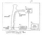
- FIG. 1Ais a block diagram of a fluorescence endoscopy video system 50 in accordance with one embodiment of the present invention.
- the systemincludes a multi-mode light source 52 that generates light for obtaining color and fluorescence images.
- the use of the light source for obtaining different kinds of imageswill be described in further detail below.
- Light from the light source 52is supplied to an illumination guide 54 of an endoscope 60 , which then illuminates a tissue sample 58 that is to be imaged.
- the systemalso includes a multi-mode camera 100 , which is located at the insertion end of the endoscope 60 .
- the light from the tissueis directly captured by the multi-mode camera 100 .
- the resulting endoscope 60can be characterized as a fluorescence video endoscope, similar to video endoscopes currently on the market (such as the Olympus CF-Q180AL/I or CF-240L) in utility, but with the ability to be utilized for fluorescence/reflectance and/or fluorescence/fluorescence imaging, in additional to conventional color imaging. Fluorescence/reflectance and fluorescence/fluorescence imaging will be described in detail below.
- the inherent advantages of a video endoscopecan be obtained; namely, the light available to form an image and the image resolution are improved compared to the case when the image is transmitted outside the body through an endoscope imaging guide or relay lens system.
- a processor/controller 64controls the multi-mode camera 100 and the light source 52 , and produces video signals that are displayed on a video monitor 66 .
- the processor/controller 64communicates with the multi-mode camera 100 with wires or other signal carrying devices that are routed within the endoscope. Alternatively, communication between the processor/controller 64 and the camera 100 can be conducted over a wireless link.
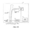
- FIG. 1Bis a block diagram of an alternative fluorescence endoscopy video system 50 , which differs from that shown in FIG. 1A in that endoscope 60 also incorporates an image guide 56 and the multi-mode camera 100 is attached to an external portion of the endoscope that is outside the body. The light that is collected from the tissue by endoscope 60 is transmitted through the image guide 56 and projected into the multi-mode camera 100 .
- the system of FIG. 1Bis identical to that shown in FIG. 1A .
- FIG. 2Ashows the components of the light source 52 in greater detail.
- the light source 52includes an arc lamp 70 that is surrounded by a reflector 72 .
- the arc lamp 70is a high pressure mercury arc lamp (such as the Osram VIP R 150/P24 or HXP R 200W/45).
- arc lampssuch as the Osram VIP R 150/P24 or HXP R 200W/45.
- solid state devicessuch as light emitting diodes or diode lasers
- broadband light sourcesmay be used, but a high pressure mercury lamp is currently preferred for its combination of high blue light output and small arc size.
- the light from the arc lamp 70is coupled to a light guide 54 of the endoscope 60 through appropriate optics 74 , 76 , and 78 for light collection, spectral filtering and focusing respectively.
- the light from the arc lampis spectrally filtered by one of a number of optical filters 76 A, 76 B, 76 C . . . that operate to pass or reject desired wavelengths of light in accordance with the operating mode of the system.
- optical filters 76 A, 76 B, 76 C . . .that operate to pass or reject desired wavelengths of light in accordance with the operating mode of the system.
- wavelengthis to be interpreted broadly to include not only a single wavelength, but a range of wavelengths as well.
- An intensity control 80 that adjusts the amount of light transmitted along the light pathis positioned at an appropriate location between the arc lamp 70 and the endoscope light guide 54 .
- a shutter mechanism 82may be positioned in the same optical path in order to block any of the light from the lamp from reaching the light guide.
- a controller 86operates an actuator 77 that moves the filters 76 A, 76 B or 76 C into and out of the light path. The controller 86 also controls the position of the intensity control 80 and may control the operation of the shutter mechanism 82 .
- the transmission characteristics of filters 76 A, 7613 , 76 C, . . . , the characteristics of the actuator 77 mechanism, and the time available for motion of the filters 76 A, 76 B, 76 C, . . . , into and out of the light pathdepend on the mode of operation required for use with the various camera embodiments. The requirements fall into two classes. If the light source shown in FIG. 2A is of the class wherein only one filter is utilized per imaging mode, the appropriate filter is moved in or out of the light path only when the imaging mode is changed. In that case, the actuator 77 only need change the filter in a time of approximately 1.0 second.
- the optical filter characteristics of filters 76 A, 76 B . . .are tailored for each imaging mode.
- optical filter 76 Aused for color imaging, reduces any spectral peaks and modifies the color temperature of the arc lamp 70 so that the output spectrum simulates sunlight.
- Optical filter 76 Btransmits only fluorescence excitation light for use with the fluorescence/fluorescence imaging mode and optical filter 76 C transmits both fluorescence excitation light and reference reflectance light for use with the fluorescence/reflectance imaging mode.
- a light source 52 A of a second classis illustrated in FIG. 2B ; only the differences from the light source shown in FIG. 2A will be elucidated.
- the light source 52 Auses multiple filters during each imaging mode. For example, light source filters, which provide red, green, and blue illumination sequentially for periods corresponding to a video frame or field, can be used for the acquisition of a color or a multi-spectral image with a monochrome image sensor, with the different wavelength components of the image each acquired at slightly different times. Such rapid filter changing requires a considerably different actuator than necessitated for the light source 52 of FIG. 2A . As shown in FIG.
- the filtersare mounted on a filter wheel 79 that is rotated by a motor, which is synchronized to the video field or frame rate.
- the layout of the blue, red and green filters, 79 A, 79 B, and 79 C, respectively, in filter wheel 79are shown in FIG. 3 .
- each of the various embodiments of the multi-mode camera 100 described belowmay be used both for color (white light) and fluorescence/reflectance and/or fluorescence/fluorescence imaging.
- white light imaging and color imaging of tissueare considered to be synonymous.
- These camera embodimentsparticularly lend themselves to incorporation within a fluorescence video endoscope due to their compactness and their ability to be implemented with no moving parts.
- a camera 100 Areceives light from the tissue 58 , either directly from the tissue in the case of a camera located at the insertion end of an endoscope, as shown in FIG. 1A , or by virtue of an endoscope image guide 56 , which transmits the light from the tissue to the camera, as shown in FIG. 1B .
- the lightis directed towards a monochrome image sensor 102 and a low light image sensor 104 by a fixed optical beamsplitter 106 that splits the incoming light into two beams.
- the light beamis split such that a smaller proportion of the light received from the tissue 58 is directed towards the monochrome image sensor 102 and a larger proportion of the incoming light is directed towards the low light image sensor 104 .
- the beamsplittermay be a standard commercially available single plate 88 , single cube 89 , or single pellicle design 90 , as shown in FIGS. 5A-5C , It should be noted that, if the optical path between the tissue 58 and the image sensors contains an uneven number of reflections (e.g., such as from a single component beamsplitter), the image projected onto the sensor will be left-to-right inverted. The orientation of such images will need to be corrected by image processing.
- light collimating optics 110are positioned in front of the beamsplitter 106
- imaging optics 112 and 114are positioned immediately preceding the monochrome image sensor 102 and the low light image sensor 104 , respectively.
- a spectral filter 118is located in the optical path between the beamsplitter 106 and the low light image sensor 104 .
- the spectral filter 118may be incorporated as an element of the beamsplitter 106 .
- FIG. 4Billustrates another embodiment of the camera 100 .
- a camera 100 Bis the same as the camera 100 A described above except that the light collimating optics 110 and imaging optics 112 and 114 have been eliminated and replaced with a single set of imaging optics 113 located between the tissue and beamsplitter 106 .
- the advantage of this configurationis that all imaging is performed and controlled by the same imaging optics 113 .
- Such a configurationrequires all beam paths to have the same optical path length, however, and this restriction must be considered in the design of the beamsplitter 106 and spectral filter 118 that is located in the path to the low light image sensor 104 .
- the fact that these optical elementsare located in a converging beam path must be considered in specifying these elements and in the design of the imaging optics 113 .
- the low light image sensor 104preferably comprises a charge coupled device with charge carrier multiplication (of the same type as the Texas Instruments TC253 or the Marconi Technologies CCD65), electron beam charge coupled device (EBCCD), intensified charge coupled device (ICCD), charge injection device (CID), charge modulation device (CMD), complementary metal oxide semiconductor image sensor (CMOS) or charge coupled device (CCD) type sensor.
- the monochrome image sensor 102is preferably a CCD or a CMOS image sensor.
- FIG. 4CAn alternative configuration of the camera 100 B is shown in FIG. 4C . All aspects of this embodiment of this camera 100 C are similar to the camera 100 B shown in FIG. 4B except for differences which arise from reducing the width of the camera by mounting both image sensors 102 and 104 perpendicular to the camera front surface.
- the low light image sensor 104 and the monochrome image sensor 102are mounted with their image planes perpendicular to the input image plane of the camera.
- Light received from the tissue 58is projected by imaging optics 113 through beamsplitter 106 onto the image sensors 102 and 104 .
- the beamsplitter 106directs a portion of the incoming light in one beam towards one of the sensors 102 , 104 .
- Another portion of the incoming light in a second light beampasses straight through the beamsplitter 106 and is directed by a mirror 108 towards the other of the sensors 102 , 104 .
- a second set of imaging optics 115is utilized to account for the longer optical path to this second sensor. The images projected onto both sensors will be left-to-right inverted and should be inverted by image processing.
- the processor/controller 64 as shown in FIGS. 1A and 1Breceives the transduced image signals from the camera 100 and digitizes and processes these signals. The processed signals are then encoded in a video format and displayed on a color video monitor 66 .
- the processor/controller 64Based on operator input, the processor/controller 64 also provides control functions for the fluorescence endoscopy video system. These control functions include providing control signals that control the camera gain in all imaging modes, coordinating the imaging modes of the camera and light source, and providing a light level control signal for the light source.
- a second fluorescence image acquired in a band of wavelengths in which the image signal is not significantly affected by tissue pathology, utilized for fluorescence/fluorescence imaging, or a reflected light image acquired in a band of wavelengths in which the image signal is not significantly affected by tissue pathology consisting of light that has undergone scattering within the tissue (known as diffuse reflectance), utilized for fluorescence/reflectance imaging,may be used as a reference signal with which the signal strength of the first fluorescence image can be “normalized.”
- diffuse reflectanceutilized for fluorescence/reflectance imaging
- One technique for performing the normalizationis to assign each of the two image signals a different display color, e.g., by supplying the image signals to different color inputs of a color video monitor.
- the two imagesWhen displayed on a color video monitor, the two images are effectively combined to form a single image, the combined color of which represents the relative strengths of the signals from the two images. Since light originating from fluorescence within tissue and diffuse reflectance light which has undergone scattering within the tissue are both emitted from the tissue with a similar spatial distribution of intensities, the color of a combined image is independent of the absolute strength of the separate image signals, and will not change as a result of changes in the distance or angle of the endoscope 60 to the tissue sample 58 , or changes in other imaging geometry factors.
- Another technique for performing the normalizationis to calculate the ratio of the pixel intensities at each location in the two images. A new image can then be created wherein each pixel has an intensity and color related to the ratio computed. The new image can then be displayed by supplying it to a color video monitor.
- the mixture of colors with which normal tissue and tissue suspicious for early cancer are displayeddepends on the gain applied to each of the two separate image signals. There is an optimal gain ratio for which tissue suspicious for early cancer in a fluorescence image will appear as a distinctly different color than normal tissue. This gain ratio is said to provide the operator with the best combination of sensitivity (ability to detect suspect tissue) and specificity (ability to discriminate correctly). If the gain applied to the reference image signal is too high compared to the gain applied to the fluorescence image signal, the number of tissue areas that appear suspicious, but whose pathology turns out to be normal, increases. Conversely, if the relative gain applied to the reference image signal is too low, sensitivity decreases and suspect tissue will appear like normal tissue.
- In vivo spectroscopyhas been used to determine which differences in tissue autofluorescence and reflectance spectra have a pathological basis.
- the properties of these spectradetermine the particular wavelength bands of autofluorescence and reflected light required for the fluorescence/reflectance imaging mode, or the particular two wavelength bands of autofluorescence required for fluorescence/fluorescence imaging mode. Since the properties of the spectra depend on the tissue type; the wavelengths of the important autofluorescence band(s) may depend on the type of tissue being imaged.
- the specifications of the optical filters described beloware a consequence of these spectral characteristics, and are chosen to be optimal for the tissues to be imaged.
- the filters in the light source and camerashould be optimized for the imaging mode of the camera, the type of tissue to be examined and/or the type of pre-cancerous tissue to be detected.
- all of the filters described belowcan be made to order using standard, commercially available components, the appropriate wavelength range of transmission and degree of blocking outside of the desired transmission range for the described fluorescence endoscopy images are important to the proper operation of the system.
- the importance of other issues in the specification of such filters, such as the fluorescence properties of the filter materials and the proper use of anti-reflection coatings,are taken to be understood.
- FIGS. 6A-6Eillustrate the preferred filter characteristics for use in a fluorescence endoscopy system having a camera of the type shown in FIGS. 4A-4C and light source as shown in FIG. 2B , that operates in a fluorescence/reflectance imaging mode, or a color imaging mode.
- fluorescence endoscopy video systemsoperating in the fluorescence/reflectance imaging mode including green fluorescence with either red or blue reflectance, and red fluorescence with either green or blue reflectance.
- the particular configuration utilizeddepends on the target clinical organ and application. The filter characteristics will now be described for each of these four configurations.
- FIG. 6Aillustrates the composition of the light transmitted by a blue filter, such as filter 79 A, which is used to produce excitation light in the system light source.
- This filtertransmits light in the wavelength range from 370-460 nm or any subset of wavelengths in this range. Of the light transmitted by this filter, less than 0.001% is in the fluorescence imaging band from 480-750 nm (or whatever desired subsets of this range is within the specified transmission range of the primary and reference fluorescence image filters described below).
- FIG. 6Billustrates the composition of the light transmitted by a red filter, such as filter 79 B, which is used to produce red reflectance light in the system light source.
- This filtertransmits light in the wavelength range from 590-750 nm or any subset of wavelengths in this range. Light transmitted outside this range should not exceed 1%.
- FIG. 6Cillustrates the composition of the light transmitted by a green filter, such as filter 79 C, which is used to produce green reflectance light in the system light source.
- This filtertransmits light in the wavelength range from 480-570 nm or any subset of wavelengths in this range. Light transmitted outside this range should not exceed 1%.
- FIG. 6Dshows the composition of the light transmitted by a camera spectral filter, such as filter 118 , for defining the primary fluorescence image in the green spectral band.
- the filterblocks excitation light and red fluorescence light while transmitting green fluorescence light in the wavelength range of 480-570 nm or any subset of wavelengths in this range.
- the filter characteristicsare such that any light outside of the wavelength range of 480-570 nm, or any desired subset of wavelengths in this range, contributes no more than 0.1% to the light transmitted by the filter.
- FIG. 6Eshows the composition of the light transmitted by a camera filter, such as filter 118 , for defining the primary fluorescence image in the red spectral band.
- the filterblocks excitation light and green fluorescence light while transmitting red fluorescence light in the wavelength range of 590-750 nm or any subset of wavelengths in this range.
- the filter characteristicsare such that any light outside of the wavelength range of 590-750 nm, or any desired subset of wavelengths in this range, contributes no more than 0.1% to the light transmitted by the filter.
- the cameras 100 A as shown in FIGS. 4A and 100B as shown in FIG. 4B or 100C as shown in FIG. 4Care capable of operating in color and fluorescence/reflectance imaging modes.
- a light source of the type shown in FIG. 2Bthat provides a different output every video frame or field is required.
- the processor/controller 64provides a control signal to the multi-mode light source 52 that indicates the light source should be operating in the white light mode and provides a synchronizing signal.
- the light source 52sequentially outputs filtered red, green, and blue light, synchronously with the video field or frame of the image sensors 102 and 104 .
- the filtered light from the light source 52is projected into the endoscope light guide 54 and is transmitted to the tip of the endoscope 60 to illuminate the tissue 58 .
- the processor/controller 64also protects the sensitive low light image sensor 104 during color imaging by decreasing the gain of the amplification stage of the sensor.
- the light reflected by the tissue 58is collected and transmitted by the endoscope image guide 56 to the camera where it is projected through beamsplitter 106 onto the monochrome image sensor 102 , or the light is directly projected through the camera beamsplitter 106 onto the monochrome image sensor 102 if the sensor is located within the insertion portion of the endoscope.
- the image projected during each of red, green, and blue illuminationsis transduced by the monochrome image sensor 102 and the resulting image signals are transmitted to the processor/controller 64 .
- the processor/controller 64Based on the brightness of the images captured, the processor/controller 64 provides a control signal to the multi-mode light source 52 to adjust the intensity control 80 and thereby adjust the level of light output by the endoscope light guide 54 .
- the processor/controller 64may also send a control signal to the camera 100 A, 100 B or 100 C to adjust the gain of the monochrome image sensor 102 .
- the processor/controller 64interpolates the images acquired during sequential periods of red, green, and blue illumination to create a complete color image during all time periods, and encodes that color image as video signals.
- the video signalsare connected to color video monitor 66 for display of the color image. All of the imaging operations occur at analog video display rates (30 frames per second for NTSC format and 25 frames per second for PAL format).
- the processor/controller 64When switching to the fluorescence/reflectance imaging mode, the processor/controller 64 provides a control signal to the multi-mode light source 52 to indicate that it should be operating in fluorescence/reflectance mode.
- the light source filter wheel 79stops rotating and the light source 52 selects and positions the appropriate blue optical filter 79 A continuously into the optical path between the arc lamp 70 and the endoscope light guide 54 .
- This change from sequentially changing filters to a static filteroccurs in a period of approximately one second.
- Filter 79 Atransmits only those wavelengths of light that will induce the tissue 58 under examination to fluoresce. All other wavelengths of light are substantially blocked as described above.
- the filtered lightis then projected into the endoscope light guide 54 and transmitted to the tip of the endoscope 60 to illuminate the tissue 58 .
- the processor/controller 64also increases the gain of the amplification stage of the low light image sensor 104 .
- the fluorescence emitted and excitation light reflected by the tissue 58are either collected by the endoscope image guide 56 and projected through the camera beamsplitter 106 onto the low light image sensor 104 and the image sensor 102 , or are collected and directly projected through the camera beamsplitter 106 onto the low light image sensor 104 and the image sensor 102 at the insertion tip of the endoscope 60 .
- Spectral filter 118limits the light transmitted to the low light image sensor 104 to either green or red autofluorescence light only and substantially blocks the light in the excitation wavelength band.
- the autofluorescence imageis transduced by the low light image sensor 104 .
- the reference reflected excitation light imageis transduced by the monochrome image sensor 102 and the resulting image signals are transmitted to the processor/controller 64 .
- the processor/controller 64may provide a control signal to the multi-mode light source 52 to adjust the intensity control 80 and thereby adjust the level of light delivered to the endoscope 60 .
- the processor/controller 64may also send control signals to the cameras 100 A, 100 B or 100 C to adjust the gains of the low light image sensor 104 and the monochrome image sensor 102 , in order to maintain constant image brightness while keeping the relative gain constant.
- the images from the two sensorsare encoded as video signals by processor/controller 64 .
- the fluorescence/reflectance imageis displayed by applying the video signals to different color inputs on the color video monitor 66 .
- the cameras 100 A, 100 B, 100 Ccan be operated in a variation of the fluorescence/reflectance mode to simultaneously obtain fluorescence images and reflectance images with red, green, and blue illumination.
- the operation of the systemis similar to that described previously for color imaging, so only the points of difference from the color imaging mode will be described.
- the multi-mode light source 52instead of changing from sequential red, green, and blue illumination to static blue illumination when switching from color imaging to fluorescence/reflectance imaging, the multi-mode light source 52 provides the same sequential illumination utilized in the color imaging mode, for all imaging modes. Capture and display of the light reflected by the tissue is similar to that described previously for the color imaging mode. However, in addition to the reflectance images captured in that mode, the gain of the amplification stage of the low light image sensor 104 is adjusted to a value that makes it possible to capture autofluorescence images during blue illumination. During red and green illumination, the gain of amplification stage of the low light sensor is decreased to protect the sensor while the image sensor 102 captures reflectance images.
- the cameracaptures both reflectance and fluorescence images during the blue illumination period, in addition to reflected light images during the red and green illumination periods.
- the reflectance imagesare interpolated and displayed on the corresponding red, green and blue channels of a color video monitor to produce a color image.
- a fluorescence/reflectance imageis produced by overlaying the fluorescence image and one or more of the reflectance images displayed in different colors on a color video monitor.
- both a color image and a fluorescence/reflectance imagecan be displayed simultaneously on the color video monitor. In this case, there is no need to utilize a separate color imaging mode.
- only the fluorescence/reflectance imagemay be displayed during fluorescence/reflectance imaging and a color image displayed solely in the color imaging mode.
- a camera 100 D for this embodiment of a systemis as shown in FIG. 7A . It differs from the cameras 100 A, 100 B or 100 C as described above in that all imaging modes utilize a single, low light color image sensor 103 (preferably a color CCD with charge carrier multiplication such as the Texas Instruments TC252) and that no beamsplitter is required.
- the color image sensor 103may be a three-CCD with charge carrier multiplication color image sensor assembly, a color CCD, a three-CCD color image sensor assembly, a color CMOS image sensor, or a three-CMOS color image sensor assembly.
- Each of the pixel elements on the low light color sensor 103is covered by an integrated filter, typically red, green or blue (RGB). These filters define the wavelength bands of fluorescence and reflectance light that reach the individual pixel elements.
- the filter mosaicmay be of the cyan, magenta, yellow, green (CMYG) variety. All mosaic filters typically have considerable overlap between their respective pass bands, which can lead to considerable crosstalk when imaging dim autofluorescence light in the presence of intense reflected excitation light. Therefore, a separate filter 118 is provided to reduce the intensity of reflected excitation light to the same level as that of the autofluorescence light and, at the same time, pass autofluorescence light.
- some conversion and image processingmay be applied to convert CMYG filter responses to responses in RGB space.
- the signals from color image sensors with CMYG filter mosaicsare converted to RGB signals by matrix conversions that are based on the specific layout of the CMYG mosaic pattern and the image sensor read-out architecture. Such conversions are routinely performed in color video systems and are taken to be understood by those of ordinary skill in the art.
- the primary fluorescence and reference imagesare projected onto the same image sensor 103 , but, because of the individual filters placed over each pixel, these different images are detected by separate sensor pixels.
- individual primary fluorescence and reference image signalscan be produced by processor/controller 64 from the single image sensor.
- FIG. 7Alight collimating optics 110 are positioned between the tissue 58 and filter 118 and imaging optics 112 are positioned immediately preceding the color image sensor 103 .
- camera 100 Eas shown in FIG. 7B , eliminates the collimating optics 110 and imaging optics 112 and replaces them with a single imaging optics 113 located between the tissue 58 and filter 118 .
- the advantage of this configurationis that all imaging is performed and controlled by the same imaging optics 113 .
- the fact that filter 118 is located in a converging beam pathmust be considered in specifying that element and in the design of the imaging optics.
- the operation of a system based on camera 100 D of FIG. 7A or 100E of FIG. 7Bwill now be described.
- the cameras 100 D and 100 Eare capable of operation in the color, fluorescence/fluorescence, and fluorescence/reflectance imaging modes.
- a light source of the type shown in FIG. 2Aprovides steady state output in each imaging mode.
- the light transmission specifications of the light source filters 76 A, 76 B, and 76 C, the filter 118 , and the mosaic color filters integrated with the image sensor 103are selected such that the intensity of the reflected light and fluorescence light at the color image sensor's active elements results in transduced image signals with good signal-to-noise characteristics and without significant saturation.
- these filtershave appropriate light transmission specifications for excitation and imaging of the primary fluorescence and for color imaging.
- the filter transmission characteristicsare chosen to provide the desired ratio of relative primary fluorescence to reference light intensity at the image sensor.
- the processor/controller 64provides a control signal to the multimode light source 52 that it should be in white light mode.
- the light sourceselects and positions the appropriate optical filter 76 A into the optical path between the arc lamp 70 and endoscope light guide 54 .
- the light source filter 76 Ashould, in one embodiment, incorporate reduced transmission at red and green wavelengths or a slight peak in the blue (i.e., from 460-480 nm) to obtain a balanced color image at image sensor 103 with the proper proportions of red, green, and blue components.
- Image signals from the color low light sensor 103are processed by processor/controller 64 .
- Standard techniquesare utilized to produce a color image from a single color sensor.
- the image signals from pixels having the same filter characteristicsare interpolated by processor/controller 64 to produce an image signal, related to the pass band of each element of the mosaic filter (e.g., red, green, and blue), at every pixel location.
- the resulting multiple images, which when combined produce a color image,are encoded by processor/controller 64 as video signals.
- the color imageis displayed by connecting the video signals to the appropriate inputs of color video monitor 66 .
- Processor/controller 64also maintains the overall image brightness at a set level by monitoring the brightness of the image signal at each pixel and adjusting the intensity of the light source output and camera amplifier gains according to a programmed algorithm.
- processor/controller 64When switching to the fluorescence/fluorescence imaging mode, processor/controller 64 provides a control signal to the multi-mode light source 52 to indicate that it should be in fluorescence/fluorescence mode.
- the light source 52moves light source filter 76 B into position in the light beam. Filter 76 B transmits excitation light and blocks the transmission of light at the green and red fluorescence detection wavelengths, as described below.
- the characteristics of light source fluorescence excitation filter 76 B and excitation filter 118 , along with the mosaic filter elements on the color sensor 103 ,are such that the intensity of blue light at the color sensor is less than the intensities of red and green autofluorescence at the sensor, and are such that the ratio of the intensity of red autofluorescence to the intensity of green autofluorescence at the color sensor 103 has the appropriate value for optimal differentiation between normal and abnormal tissue.
- the fluorescence imagesare processed, as previously described for color imaging, by processor/controller 64 to produce separate images corresponding to each of the pass bands of the mosaic filter (e.g., RGB or CMYG). These separate images are encoded as video signals by processor/controller 64 .
- a composite fluorescence/fluorescence imageis displayed on the color video monitor 66 by applying the video signals from red and green image signals to different color inputs of the monitor.
- a composite imagecan be created in the image processor/controller 64 based on the relative intensities of the red and green image signals.
- processor/controller 64When switching to the fluorescence/reflectance imaging mode, processor/controller 64 provides a control signal to the multi-mode light source 52 to indicate that it should be in fluorescence/reflectance mode.
- the light source 52moves light source filter 76 C into position in the light beam. Filter 76 C transmits both excitation light and reference light and blocks the transmission of light at fluorescence detection wavelengths, as described below.
- the characteristics of the light source filter 76 C for fluorescence excitation and the reflectance illumination and the camera filter 118 , along with the mosaic filter on the color sensor 103 , as detailed below,are such that the intensity of reflected excitation light at the color sensor is comparable to the intensity of autofluorescence at the sensor, and should be such that the ratio of the intensity of autofluorescence to the intensity of reflected reference light at the color sensor 103 has the appropriate value.
- the fluorescence and reflectance imagesare processed, as previously described for color imaging, by processor/controller 64 to produce separate images corresponding to each of the pass bands of the mosaic filter (e.g., RGB or CMYG). These separate images are encoded as video signals by processor/controller 64 .
- a composite fluorescence/reflectance imageis displayed on color video monitor 66 by applying the video signals from the appropriate spectral bands (as discussed below) to different color inputs of the monitor or creating a composite image in the image processor/controller based on the relative intensities of the image signals received.
- the filters in the light source and camerashould be optimized for the imaging mode of the camera, the type of tissue to be examined and/or the type of pre-cancerous tissue to be detected based on in viva spectroscopy measurements.
- all of the filters described belowcan be made to order using standard, commercially available components, the appropriate wavelength range of transmission and degree of blocking outside of the desired transmission range for the described fluorescence endoscopy images modes are important to the proper operation of the system. The importance of other issues in the specification of such filters such as the fluorescence properties of the filter materials and the proper use of anti-reflection coatings are taken to be understood.
- FIGS. 8A-8FFilter characteristics for use in the fluorescence endoscopy video systems with a camera of the type shown in FIGS. 7A and 7B , operating in a fluorescence/reflectance imaging mode, or a fluorescence/fluorescence imaging mode, are shown in FIGS. 8A-8F .
- fluorescence endoscopy video systemsoperating in the fluorescence/reflectance imaging mode including green fluorescence with red reflectance, and red fluorescence with green reflectance and red or green fluorescence with blue reflectance. The particular configuration utilized depends on the target clinical organ and application. The filter characteristics will now be described for each of these four configurations.
- FIGS. 8A-8Billustrate one composition of the light transmitted by filters for a color imaging mode.
- FIG. 8Aillustrates the composition of the light transmitted by the light source filter, such as filter 76 A, which is used to produce light for color imaging.
- the spectral filter 118remains in place during color imaging since there are no moving parts in the present camera embodiment. Accordingly, to achieve correct color rendition during color imaging it is necessary for the transmission of light source filter 76 A to be modified, compared to the usual white light transmission for color imaging, such that the light received by the high sensitivity color sensor 103 is substantially white when a white reflectance standard is viewed with the camera.
- the transmission of filter 76 A in the red and green spectral handsshould be less than the transmission in the blue in order to balance the effect of spectral filter 118 .
- the transmission of filter 76 A in the blueextends to a long enough wavelength that there is an overlap with the short wavelength region of appreciable transmission of filter 118 .
- Filter 76 Atransmits light in the blue wavelength range from 370-480 nm or any subset of wavelengths in this range at the maximum possible transmission.
- the transmission of Filter 76 A in the green and red wavelength range from 500 -750 nm, or any subsets of wavelengths in this range,is preferably reduced by at least a factor of ten compared to the transmission in the blue, in order to achieve a balanced color image at the high sensitivity color sensor 103 , after taking into account the effect of filter 118 .
- the output spectrumis less flat and a slightly different color correction is generally required in order to achieve a balanced color image at the image sensor.
- FIG. 8Bshows the composition of the light transmitted by the spectral filter 118 , which is used for all imaging modes.
- the filterblocks the blue excitation light in the range 370-450 nm while transmitting red and green light in the wavelength range of 470-750 nm or any subsets of wavelengths in this range.
- the filter characteristicsare such that the intensity of light captured by high sensitivity color sensor 103 in the wavelength bands transmitted by the different regions of the sensor's mosaic filter are comparable, when a white reflectance standard is imaged.
- the filter characteristicsare such that any light outside of the wavelength range of 470-750 nm (or any desired subset of wavelengths in this range) contributes no more than 0.1% to the light transmitted by the filter.
- FIG. 8Cillustrates the composition of the light transmitted by a filter, such as filter 76 B, which is used to produce excitation light in the system light source.
- This filtertransmits light in the wavelength range from 370-450 nm or any subset of wavelengths in this range. Of the light transmitted by this filter, preferably less than 0.001% is in the fluorescence imaging band from 470-750 nm (or whatever desired subsets of this range is within the transmission range of the primary and reference fluorescence wavelength bands defined by the transmission of the mosaic filter incorporated in the high sensitivity color sensor 103 ).
- FIG. 8Dillustrates the composition of the light transmitted by the light, source filter, such as filter 76 C, which is used to produce blue excitation light and red reference light for a green fluorescence and red reflectance imaging mode.
- This filtertransmits light in the blue wavelength range from 370-450 nm, or any subset of wavelengths in this range. It also transmits light in the red wavelength range of 590-750 nm, or any subset of wavelengths in this range.
- the light transmitted in the red wavelength range (or subset of that range)is adjusted, as part of the system design, to be an appropriate fraction of the light transmitted in the blue wavelength range.
- This fractionis selected to meet the need to match the intensity of the reflected reference light projected on the color image sensor to the requirements of the sensor, at the same time as maintaining sufficient fluorescence excitation.
- less than 0.001%is in the green wavelength range of 470-570 nm (or whatever desired subset of this range is specified as the transmission range of the primary fluorescence wavelength band).
- FIG. 8Eillustrates the composition of the light transmitted by a light source filter which is used to produce excitation light such as filter 76 C described above for a red fluorescence and green reflectance imaging mode.
- This filtertransmits light in the blue wavelength range from 370-450 nm or any subset of wavelengths in this range. It also transmits light in the green wavelength range of 470-570 nm or any subset of wavelengths in this range.
- the light transmitted in the green wavelength range (or subset of that range)is adjusted, as part of the system design, to be an appropriate fraction of the light transmitted in the blue wavelength range. This fraction is selected to meet the need to match the intensity of the reflected reference light projected on the color image sensor to the requirements of the sensor, at the same time as maintaining sufficient fluorescence excitation.
- less than 0.001%is in the red fluorescence imaging wavelength range of 590-750 nm (or whatever desired subset of this range is specified as the transmission range of the primary fluorescence wavelength band).
- FIG. 8Fillustrates the composition of the light transmitted by a light source filter which is used to produce excitation light such as filter 76 C described above for a red or green fluorescence and blue reflectance imaging mode.
- This filtertransmits light in the blue wavelength range from 370-470 nm or any subset of wavelengths in this range.
- the light transmitted in the 450-470 nm wavelength range(or subset of that range) is adjusted, as part of the system design, to meet the need to match the intensity of the reflected reference light projected on the color image sensor to the requirements of the sensor and to provide the appropriate ratio of reference reflected light to fluorescence light, at the same time as maintaining sufficient fluorescence excitation.
- the light transmitted by this filterless than 0.001% is in the fluorescence imaging wavelength range of 490-750 nm (or whatever desired subset of this range is specified as the transmission range of the primary fluorescence wavelength band).
- fluorescence imaging with a dedicated fluorescence video endoscopeis enabled by the use of an excitation barrier filter to block the strong excitation light used to excite the tissue fluorescence that these systems are intended to image.
- excitation barrier filterto block the strong excitation light used to excite the tissue fluorescence that these systems are intended to image.
- these barrier filtersare built in to the endoscope distal end (typically between the objective lens and the low light image sensor) and this built-in filter distinguishes these endoscopes from those used for conventional videoendoscopy.
- fluorescence and color/white light imagescan be obtained by placing a barrier or blocking filter on the distal tip of a conventional video endoscope.
- the alternative embodiment of the present inventiondescribes the use of an externally mounted filter in conjunction with a video endoscope that contains a sufficiently sensitive image sensor to image tissue fluorescence.
- This combination of a conventional video endoscope and an externally mounted barrier filtercan be used in conjunction with an appropriate endoscopic light source and video processor/controller to image both in both color, and fluorescence modes.
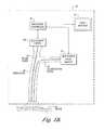
- FIG. 9illustrates one embodiment of a distal filter 202 that can be placed over the distal end of a conventional white light imaging endoscope to allow the endoscope to be used to perform fluorescence and white light examinations.
- the filter 202blocks excess excitation light from reaching the image sensor 103 but allows some blue light to pass in order to obtain white light images.
- FIGS. 10A and 10Billustrate the operation of the distal filter 202 in further detail.
- An endoscope 250includes illumination ports 252 , 254 that supply illumination light to an area of interest.
- a port 256is the distal entrance to a working channel through which endoscopic tools can be passed in order to perform a desired task such as obtaining a biopsy sample, marking tissue with dye or perform some other diagnostic or therapeutic procedures.
- Light that is reflected from the tissue 350is captured by a lens 258 that images the light onto a color image sensor 262 .
- the sensorincludes a mosaic filter 260 that is positioned in front of a CCD, CMOS or equivalent image sensor 262 .
- Image signals produced by the image sensor 262are transmitted to a processor/controller (not shown) that converts the signals into video signals that are displayed on a video monitor.
- the video signalsmay he recorded on a video tape, DVD or other storage media for later review or comparison.
- the endoscope 250may be fitted with the distal end filter 202 .
- the filter 202is included in a filter assembly 300 that does not obscure the illumination ports 252 , 254 in order to allow the illumination light to reach the tissue under examination.
- the filter assembly 300does not interfere with other distal tip features including but not limited to features such as water/air nozzles, electrodes, confocal imaging ports, or the working channel 256 so that tools can still be routed through the endoscope.
- the filter assemblyis made of appropriately inert and non-conductive materials such as plastic or glass or stainless steel, so as also not to interfere with the particular material or electrical characteristics of the endoscope tip that may be required for use in conjunction with endotherapy techniques, such as argon ion plasma coagulation (APC), electrocautery, cryotherapy, or photodynamic therapy (PDT)
- endotherapy techniquessuch as argon ion plasma coagulation (APC), electrocautery, cryotherapy, or photodynamic therapy (PDT)
- the filter 202is positioned in front of the imaging lens 258 and prevents excitation light from reaching the image sensor.
- the filterremoves the excitation light having wavelengths in the range of 370-460 nm or some subset of this range but passes some blue light (e.g., >460 nm), and green and red light for use in white light imaging as described in previous embodiments and as will be in further described below. Because most endoscopes have objective lenses with a wide field of view, the filter should block excitation light over a corresponding wide field of view and over the range of angles of incidence of light collected by the endoscope objective. The filter should also be thin enough not to introduce optical aberrations or interfere with the mechanical properties and maneuverability of the endoscope tip.
- Dye-based absorption filtersthat block the desired range of excitation light and operate over a wide field of view may therefore be preferred for this application.
- Specific examples of such filtersinclude Kodak Wratten gel filters or dyed polycarbonate or other optically clear plastic or glass materials.
- the filteris preferably constructed in a manner similar to optically protective eyewear such as laser goggles.
- the distal filter 202allows fluorescence images to be obtained in at least two modes. In a first mode, excitation light, typically in the blue wavelength spectral band, is provided from a light source such as that described for previous embodiments and through the illumination ports 252 , 254 whereupon it strikes the tissue 350 .
- a portion of the excitation lightis absorbed by the tissue and causes a tissue to produce fluorescence light while a portion of the excitation light is reflected by the tissue 350 .
- Excitation light reflected by the tissue 350is blocked by the filter 202 in the filter assembly 300 , while the tissue fluorescence light and light in other spectral bands passes through the filter 202 .
- the tissueis illuminated with the excitation light and some amount of reflectance light.
- the reflectance lightis in the red spectral band.
- the reflectance lightpasses through the filter 202 and the filter 260 in front of the image sensor 262 .
- Images of the tissue.are obtained by combining for example, the green image signals from the image sensor 262 to obtain a fluorescence image in the green spectral hand and the red image signals from the image sensor 262 to obtain a reflectance image in the red spectral band.
- the reflectance lightmay be provided in the green spectral band and a red fluorescence image obtained.
- blue reflectance light having wavelengths that are not filtered by the filter 202can be used to produce the reflectance image.
- the fluorescence and reflectance imagesmay be combined for display for a viewer.
- the amount of reflectance light supplied from the light sourceis selected to be comparable to the amount of fluorescence light received by the image sensor 262 .
- the endoscope 250can also be used to obtain white light images of the tissue 350 by illuminating the tissue with light including red, green and blue spectral components.
- the illumination lightis reflected by the tissue sample 350 , passes through the filter 202 and is focused onto the mosaic filter 260 of the color image sensor 262 by the endoscopes imaging lens 258 .
- the filter 202removes most of the blue reflectance light, the light received by the image sensor 262 may include proportionally more red and green light.
- the illumination lightshould either contain additional blue light in the band that passes through the filter 202 or proportionally less green and red light so that the resulting image produced from the image sensor signals may be white balanced. Additional fine tuning of the white balance of the images produced by the image sensor 262 can be accomplished by image processing software in the processor/controller (not shown).
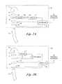
- FIG. 11One embodiment of a filter assembly 200 that is placed on the distal tip of an endoscope is shown in FIG. 11 .
- a filter 202may be mounted in a frame that is snap-fitted over the distal end face of an endoscope.
- the filter and/or frameare secured to the endoscope with a mechanical, adhesive, magnetic force or other means.
- the frameincludes a set, of proximally extending tabs 204 , 206 that are secured to the outer circumference of the endoscope tip.
- the filter 202is positioned in front of the imaging lens of the endoscope. As indicated above, the filter 202 operates to remove a substantial portion of reflected blue excitation light used during the fluorescence imaging mode.
- the framealso includes a hole 210 that is positioned over the working channel of the endoscope in order to allow tools, such as biopsy forceps, snares, cytology brushes, etc., to be passed through the working channel.
- a hole 210Positioned on either side of the frame are holes 212 , 214 that allow light from the illumination guides to pass through the frame.
- FIG. 12shows further detail of a filter 202 secured in front of an imaging lens 258 in order to allow a conventional endoscope to perform both white light and fluorescence imaging.
- the filter 202is formed from a dyed polycarbonate extruded film and bonded to the lens 258 with an optically clear adhesive.
- the filter 202is a 65 ⁇ m thick optical grade polycarbonate film dyed with solvent yellow 33 at a concentration of 0.8% by weight.
- the filmis secured to the lens of the endoscope with a 50 ⁇ m thick layer of an optical adhesive.
- Other dyes, thicknesses and/or concentrationscould he used, depending on the spectral characteristics of the light source used to provide the illumination and excitation light, the response of the imager and the particular fluorescence bands to be viewed.
- the extruded filmcan be die cut and packaged as a kit with an amount of adhesive to allow owners of white light imaging endoscopes to convert their endoscopes into devices that perform both white light imaging and fluorescence imaging when used with a light source that generates excitation light for fluorescence imaging and a color corrected illumination light that compensates for the presence of the filter 202 .
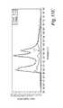
- FIGS. 13A-13Eare spectral graphs showing the spectra of light produced by a light source, a distal blocking filter and a color correction filter in accordance with an embodiment of the present invention.
- the light sourcecontains an Osram HXP R 200W/45 arc lamp described above.
- FIG. 13Ashows a spectrum 300 of the intensity of the light produced by the unfiltered arc lamp. As can be seen the light has significant peaks at in the blue range below 450 nanometers as well as in the green/yellow range from 540-580 nanometers.
- a spectrum 302shows the result when light from the arc lamp is filtered by a conventional ultraviolet (UV) and infrared (IR) filter.
- UVultraviolet
- IRinfrared
- FIG. 13Billustrates the passband characteristics 304 of the filter 202 positioned at the distal end of the endoscope.
- the filtermade of a 65 ⁇ m thick optical grade polycarbonate film dyed with solvent yellow 33 at a concentration of 0.8% by weight.
- the filter 202blocks light having wavelengths below 460 nanometers and passes light having wavelengths above 460 nanometers.
- the spectra of the light when filtered by the UV, IR and distal blocking filter 202are shown in FIG. 13C .
- the lightcontains a spike of blue light at about 480 nanometers that is used for to produce the blue component of a white light image.
- the lightalso contains spikes of green and yellow wavelengths at approximately 550 and 580 nanometers.
- a color correction filtermay be placed to filter the light from the light source during white light imaging.
- FIG. 13Dshows the passband characteristics 310 of one suitable color correction filter.
- the color correction filterpasses the blue light at approximately 470 nanometers but suppresses the green/yellow light from 540-580 nanometers so that the levels of red, green and blue light reaching the image sensor allow the creation of white balanced color images of the tissue.
- Suitable color correction filterscan be obtained commercially from Barr Associates, Inc. of Westford, Ma. As will be appreciated the particular characteristics required of the color correction filter may depend on such factors as the spectral characteristics of the light source, the optics of the endoscope, the image sensor within the endoscope etc. Therefore the filters and light source described are merely exemplary and not limiting of the present invention.
- the spectra 312 of the illumination light when filtered by the UV, IR blocking filter and color correction filterare shown in FIG. 13E . As can be seen, the spectra contains reduced green and yellow components in order to produce color balanced white light images.
- Another embodiment of the present inventionalso utilizes a filter on the distal tip of a video endoscope.
- Some video endoscope systemsdo not employ the use of color image sensors and instead use sequential illumination in various spectral (e.g., blue, green, red) bands and then combine monochrome images to produce full color images.
- An external barrier filter 202can be used in an endoscope of the type shown in FIG. 9 with the high sensitivity color sensor 103 replaced by a monochrome image sensor and sequential illumination of the type discussed in connection with FIG. 2B .
- autofluorescence imagesare obtained by illuminating with an excitation light.
- Color imagesare obtained by sequential illumination with red, green and blue light; wherein the blue light either includes wavelengths or is limited to wavelengths not blocked by the filter 202 .
- the fluorescence endoscopy video systems described in the above embodimentshave been optimized for imaging endogenous tissue fluorescence. They are not limited to this application, however, and may also be used for photo-dynamic diagnosis (PDD) applications.
- PDD applicationsutilize photo-active drugs that preferentially accumulate in tissues suspicious for early cancer. Since effective versions of such drugs are currently in development stages, this invention does not specify the filter characteristics that are optimized for such drugs.
- a fluorescence endoscopy video system operating in either fluorescence/fluorescence or fluorescence/reflectance imaging mode as described hereinmay be used to image the fluorescence from such drugs.
- each of the embodiments of a camera for a fluorescence endoscopy video system described abovedue to their simplicity, naturally lend themselves to miniaturization and implementation in a fluorescence video endoscope, with the camera being incorporated into the insertion portion of the endoscope.
- the camerascan be utilized for both color imaging and fluorescence imaging, and in their most compact form contain no moving parts.
Landscapes
- Health & Medical Sciences (AREA)
- Life Sciences & Earth Sciences (AREA)
- Surgery (AREA)
- Engineering & Computer Science (AREA)
- Physics & Mathematics (AREA)
- Optics & Photonics (AREA)
- Radiology & Medical Imaging (AREA)
- Veterinary Medicine (AREA)
- Biophysics (AREA)
- Pathology (AREA)
- Nuclear Medicine, Radiotherapy & Molecular Imaging (AREA)
- Public Health (AREA)
- Biomedical Technology (AREA)
- Heart & Thoracic Surgery (AREA)
- Medical Informatics (AREA)
- Molecular Biology (AREA)
- Animal Behavior & Ethology (AREA)
- General Health & Medical Sciences (AREA)
- Signal Processing (AREA)
- Multimedia (AREA)
- Astronomy & Astrophysics (AREA)
- General Physics & Mathematics (AREA)
- Endoscopes (AREA)
Abstract
Description
Claims (16)
Priority Applications (2)
| Application Number | Priority Date | Filing Date | Title |
|---|---|---|---|
| US14/975,707US10182709B2 (en) | 2002-01-15 | 2015-12-18 | Filter for use with imaging endoscopes |
| US16/218,256US20190357757A1 (en) | 2002-01-15 | 2018-12-12 | Filter for use with imaging endoscopes |
Applications Claiming Priority (6)
| Application Number | Priority Date | Filing Date | Title |
|---|---|---|---|
| US10/050,601US6899675B2 (en) | 2002-01-15 | 2002-01-15 | Fluorescence endoscopy video systems with no moving parts in the camera |
| US11/009,965US20050154319A1 (en) | 2002-01-15 | 2004-12-10 | Fluorescence endoscopy video systems with no moving parts in the camera |
| US11/122,267US20060241496A1 (en) | 2002-01-15 | 2005-05-04 | Filter for use with imaging endoscopes |
| US11/412,715US8630698B2 (en) | 2005-05-04 | 2006-04-26 | Filter for use with imaging endoscopes |
| US14/154,177US20140194687A1 (en) | 2005-05-04 | 2014-01-13 | Filter for use with imaging endoscopes |
| US14/975,707US10182709B2 (en) | 2002-01-15 | 2015-12-18 | Filter for use with imaging endoscopes |
Related Parent Applications (1)
| Application Number | Title | Priority Date | Filing Date |
|---|---|---|---|
| US14/154,177ContinuationUS20140194687A1 (en) | 2002-01-15 | 2014-01-13 | Filter for use with imaging endoscopes |
Related Child Applications (1)
| Application Number | Title | Priority Date | Filing Date |
|---|---|---|---|
| US16/218,256ContinuationUS20190357757A1 (en) | 2002-01-15 | 2018-12-12 | Filter for use with imaging endoscopes |
Publications (2)
| Publication Number | Publication Date |
|---|---|
| US20160270640A1 US20160270640A1 (en) | 2016-09-22 |
| US10182709B2true US10182709B2 (en) | 2019-01-22 |
Family
ID=37307550
Family Applications (5)
| Application Number | Title | Priority Date | Filing Date |
|---|---|---|---|
| US11/122,267AbandonedUS20060241496A1 (en) | 2002-01-15 | 2005-05-04 | Filter for use with imaging endoscopes |
| US11/412,715Expired - Fee RelatedUS8630698B2 (en) | 2002-01-15 | 2006-04-26 | Filter for use with imaging endoscopes |
| US14/154,177AbandonedUS20140194687A1 (en) | 2002-01-15 | 2014-01-13 | Filter for use with imaging endoscopes |
| US14/975,707Expired - Fee RelatedUS10182709B2 (en) | 2002-01-15 | 2015-12-18 | Filter for use with imaging endoscopes |
| US16/218,256AbandonedUS20190357757A1 (en) | 2002-01-15 | 2018-12-12 | Filter for use with imaging endoscopes |
Family Applications Before (3)
| Application Number | Title | Priority Date | Filing Date |
|---|---|---|---|
| US11/122,267AbandonedUS20060241496A1 (en) | 2002-01-15 | 2005-05-04 | Filter for use with imaging endoscopes |
| US11/412,715Expired - Fee RelatedUS8630698B2 (en) | 2002-01-15 | 2006-04-26 | Filter for use with imaging endoscopes |
| US14/154,177AbandonedUS20140194687A1 (en) | 2002-01-15 | 2014-01-13 | Filter for use with imaging endoscopes |
Family Applications After (1)
| Application Number | Title | Priority Date | Filing Date |
|---|---|---|---|
| US16/218,256AbandonedUS20190357757A1 (en) | 2002-01-15 | 2018-12-12 | Filter for use with imaging endoscopes |
Country Status (4)
| Country | Link |
|---|---|
| US (5) | US20060241496A1 (en) |
| EP (1) | EP1883337A4 (en) |
| JP (2) | JP2008539827A (en) |
| WO (1) | WO2006116847A1 (en) |
Cited By (2)
| Publication number | Priority date | Publication date | Assignee | Title |
|---|---|---|---|---|
| US10902572B1 (en)* | 2019-10-09 | 2021-01-26 | Karl Storz Imaging, Inc. | Enhanced fluorescence imaging for imaging system |
| US11625825B2 (en) | 2019-01-30 | 2023-04-11 | Covidien Lp | Method for displaying tumor location within endoscopic images |
Families Citing this family (82)
| Publication number | Priority date | Publication date | Assignee | Title |
|---|---|---|---|---|
| EP1731087A3 (en) | 2000-07-14 | 2008-08-06 | Novadaq Technologies Inc. | Compact fluorescent endoscopy video system |
| US20060241496A1 (en) | 2002-01-15 | 2006-10-26 | Xillix Technologies Corp. | Filter for use with imaging endoscopes |
| US8634607B2 (en) | 2003-09-23 | 2014-01-21 | Cambridge Research & Instrumentation, Inc. | Spectral imaging of biological samples |
| US7321791B2 (en)* | 2003-09-23 | 2008-01-22 | Cambridge Research And Instrumentation, Inc. | Spectral imaging of deep tissue |
| ATE527619T1 (en) | 2005-01-27 | 2011-10-15 | Cambridge Res & Instrumentation Inc | CLASSIFICATION OF IMAGE PROPERTIES |
| US9204830B2 (en) | 2005-04-15 | 2015-12-08 | Surgisense Corporation | Surgical instruments with sensors for detecting tissue properties, and system using such instruments |
| JP4761899B2 (en)* | 2005-09-12 | 2011-08-31 | Hoya株式会社 | Electronic endoscope system |
| US7420151B2 (en)* | 2005-10-17 | 2008-09-02 | Novadaq Technologies Inc. | Device for short wavelength visible reflectance endoscopy using broadband illumination |
| WO2007106624A2 (en) | 2006-02-07 | 2007-09-20 | Novadaq Technologies Inc. | Near infrared imaging |
| JP4818753B2 (en)* | 2006-02-28 | 2011-11-16 | オリンパス株式会社 | Endoscope system |
| KR100798486B1 (en)* | 2006-03-29 | 2008-01-28 | 한국전기연구원 | Light source device for fluorescence diagnosis and photodynamic therapy |
| US8140141B2 (en)* | 2006-05-17 | 2012-03-20 | University Of Utah Research Foundation | Devices and methods for fluorescent inspection and/or removal of material in a sample |
| EP2051603B1 (en)* | 2006-07-28 | 2019-09-11 | Novadaq Technologies ULC | System and method for deposition and removal of an optical element on an endoscope objective |
| US8248466B2 (en)* | 2006-10-11 | 2012-08-21 | International Business Machines Corporation | Image processing using multiple image devices |
| KR100853655B1 (en)* | 2006-12-15 | 2008-08-25 | 한국전기연구원 | Device, light source system and method of use for optical diagnosis and treatment of skin diseases |
| US8498695B2 (en) | 2006-12-22 | 2013-07-30 | Novadaq Technologies Inc. | Imaging system with a single color image sensor for simultaneous fluorescence and color video endoscopy |
| US20130317295A1 (en)* | 2006-12-29 | 2013-11-28 | GE Inspection Technologies | Light assembly for remote visual inspection apparatus |
| JP5036423B2 (en)* | 2007-06-28 | 2012-09-26 | 株式会社キーエンス | Imaging device |
| US20090048486A1 (en)* | 2007-08-08 | 2009-02-19 | Wilson-Cook Medical Inc. | Distal Tip for an Endoscope |
| JP5372356B2 (en)* | 2007-10-18 | 2013-12-18 | オリンパスメディカルシステムズ株式会社 | Endoscope apparatus and method for operating endoscope apparatus |
| JP5329177B2 (en) | 2007-11-07 | 2013-10-30 | 富士フイルム株式会社 | Imaging system and program |
| KR101517264B1 (en) | 2008-03-18 | 2015-05-04 | 노바다크 테크놀러지즈 인코포레이티드 | Imaging system for combined full-color reflectance and near-infrared imaging |
| CA3194784A1 (en) | 2008-05-20 | 2009-11-26 | University Health Network | Device and method for fluorescence-based imaging and monitoring |
| US8159525B2 (en)* | 2008-06-13 | 2012-04-17 | The United States Of America, As Represented By The Secretary Of Agriculture | Portable multispectral imaging systems |
| EP2165643B1 (en)* | 2008-09-17 | 2012-04-18 | FUJIFILM Corporation | Image obtaining method and image obtaining apparatus |
| US9370324B2 (en)* | 2008-11-05 | 2016-06-21 | Fresenius Medical Care Holdings, Inc. | Hemodialysis patient data acquisition, management and analysis system |
| US8300093B2 (en)* | 2009-01-12 | 2012-10-30 | Fujifilm Corporation | Endoscope image processing method and apparatus, and endoscope system using the same |
| US20100268069A1 (en) | 2009-04-16 | 2010-10-21 | Rongguang Liang | Dental surface imaging using polarized fringe projection |
| DE102009024943A1 (en)* | 2009-06-10 | 2010-12-16 | W.O.M. World Of Medicine Ag | Imaging system and method for fluorescence-optical visualization of an object |
| KR101651521B1 (en)* | 2009-09-25 | 2016-08-29 | 엘지디스플레이 주식회사 | Organic electro-luminescence device for medical |
| JP5371858B2 (en)* | 2009-09-29 | 2013-12-18 | 富士フイルム株式会社 | Electronic endoscope device |
| DE102009060500B4 (en)* | 2009-12-22 | 2015-12-17 | Xion Gmbh | A method for stroboscopically examining repetitive processes and arrangement for operating this method |
| US9211058B2 (en)* | 2010-07-02 | 2015-12-15 | Intuitive Surgical Operations, Inc. | Method and system for fluorescent imaging with background surgical image composed of selective illumination spectra |
| US10682198B2 (en) | 2010-07-02 | 2020-06-16 | Intuitive Surgical Operations, Inc. | Method and system for fluorescent imaging with background surgical image composed of selective illumination spectra |
| JP5507376B2 (en)* | 2010-07-28 | 2014-05-28 | 三洋電機株式会社 | Imaging device |
| DE102010033825B9 (en)* | 2010-08-09 | 2024-04-18 | Carl Zeiss Meditec Ag | Fluorescence observation system and filter set |
| US8743354B2 (en) | 2010-09-07 | 2014-06-03 | Fresenius Medical Care Holdings, Inc. | Shrouded sensor clip assembly and blood chamber for an optical blood monitoring system |
| US9194792B2 (en)* | 2010-09-07 | 2015-11-24 | Fresenius Medical Care Holdings, Inc. | Blood chamber for an optical blood monitoring system |
| JP5604248B2 (en)* | 2010-09-28 | 2014-10-08 | 富士フイルム株式会社 | Endoscopic image display device |
| DE102010050227A1 (en)* | 2010-11-04 | 2012-05-10 | Siemens Aktiengesellschaft | Endoscope with 3D functionality |
| CN107307871B (en) | 2010-11-17 | 2020-04-28 | 弗雷泽纽斯医疗保健控股公司 | Sensor clip assembly for optical monitoring system |
| US9173988B2 (en) | 2010-11-17 | 2015-11-03 | Fresenius Medical Care Holdings, Inc. | Sensor clip assembly for an optical monitoring system |
| CN103765091B (en) | 2011-03-08 | 2017-09-26 | 诺瓦达克技术公司 | Full Spectrum LED Illuminators |
| JP5451802B2 (en)* | 2011-04-01 | 2014-03-26 | 富士フイルム株式会社 | Electronic endoscope system and calibration method for electronic endoscope system |
| US10299773B2 (en)* | 2011-08-21 | 2019-05-28 | Transenterix Europe S.A.R.L. | Device and method for assisting laparoscopic surgery—rule based approach |
| KR101385978B1 (en)* | 2012-08-09 | 2014-04-16 | 한국전기연구원 | Light source system for photo-diagnosis and phototherapy |
| US9420967B2 (en) | 2013-03-19 | 2016-08-23 | Surgisense Corporation | Apparatus, systems and methods for determining tissue oxygenation |
| CN107072505B (en) | 2014-04-05 | 2021-03-12 | 手术感应设备公司 | Devices, systems and methods for mapping of tissue oxygenation |
| JP6769949B2 (en) | 2014-07-24 | 2020-10-14 | ユニバーシティー ヘルス ネットワーク | Data collection and analysis for diagnostic purposes |
| JP5897663B2 (en)* | 2014-08-25 | 2016-03-30 | 富士フイルム株式会社 | Endoscope device |
| DE102015002084B4 (en) | 2015-02-18 | 2022-01-20 | Grintech Gmbh | endoscope |
| JP6019167B1 (en)* | 2015-04-30 | 2016-11-02 | パナソニック株式会社 | Endoscope system and light source control method |
| EP3326019A1 (en)* | 2015-07-17 | 2018-05-30 | Leica Microsystems CMS GmbH | Light sheet microscope for simultaneously imaging a plurality of object planes |
| CN108135460B (en)* | 2015-10-14 | 2019-12-24 | 奥林巴斯株式会社 | Light source device for endoscope and endoscope system |
| AU2016351730B2 (en) | 2015-11-13 | 2019-07-11 | Novadaq Technologies Inc. | Systems and methods for illumination and imaging of a target |
| WO2017127929A1 (en)* | 2016-01-26 | 2017-08-03 | Novadaq Technologies Inc. | Configurable platform |
| JP2017131559A (en)* | 2016-01-29 | 2017-08-03 | ソニー・オリンパスメディカルソリューションズ株式会社 | Medical imaging device, medical image acquisition system, and endoscope apparatus |
| US10293122B2 (en) | 2016-03-17 | 2019-05-21 | Novadaq Technologies ULC | Endoluminal introducer with contamination avoidance |
| USD916294S1 (en) | 2016-04-28 | 2021-04-13 | Stryker European Operations Limited | Illumination and imaging device |
| EP3469420A4 (en) | 2016-06-14 | 2020-02-12 | Novadaq Technologies ULC | METHODS AND SYSTEMS FOR ADAPTIVE IMAGING FOR THE AMPLIFICATION OF A WEAK LIGHT SIGNAL IN A MEDICAL VISUALIZATION |
| EP3580609B1 (en) | 2017-02-10 | 2023-05-24 | Stryker European Operations Limited | Open-field handheld fluorescence imaging systems and methods |
| CN107050657A (en)* | 2017-04-06 | 2017-08-18 | 中国人民解放军总医院 | Photodynamic therapy system with organization chart picture and hot spot boundary visualization function |
| US11653824B2 (en)* | 2017-05-30 | 2023-05-23 | Sony Corporation | Medical observation system and medical observation device |
| JP6798951B2 (en)* | 2017-08-31 | 2020-12-09 | オリンパス株式会社 | Measuring device and operating method of measuring device |
| JPWO2019069414A1 (en)* | 2017-10-04 | 2020-11-05 | オリンパス株式会社 | Endoscope equipment, image processing methods and programs |
| US20190217006A1 (en)* | 2018-01-13 | 2019-07-18 | Ananya ANAND | Fiber optically illuminated medical infusion tubes |
| US12161288B2 (en)* | 2018-07-23 | 2024-12-10 | The Regents Of The University Of California | Oral and oropharyngeal cancer screening system and methods of use |
| EP3860424B1 (en)* | 2018-10-03 | 2024-07-17 | Verily Life Sciences LLC | Dynamic illumination to identify tissue type |
| EP4586628A3 (en) | 2018-11-30 | 2025-09-17 | Intuitive Surgical Operations, Inc. | Medical imaging systems and methods |
| US11457154B2 (en)* | 2019-06-20 | 2022-09-27 | Cilag Gmbh International | Speckle removal in a pulsed hyperspectral, fluorescence, and laser mapping imaging system |
| WO2021067622A1 (en)* | 2019-10-01 | 2021-04-08 | Najdahmadi Avid | Light-based medical device |
| EP3805838B1 (en) | 2019-10-10 | 2023-12-06 | Leica Instruments (Singapore) Pte. Ltd. | Microscope and related apparatuses, methods and computer programs |
| CN114845621A (en)* | 2019-11-01 | 2022-08-02 | 史赛克公司 | System and method for image reorientation for endoscopic imaging |
| US11823433B1 (en)* | 2020-01-21 | 2023-11-21 | Lina M. Paz-Perez | Shadow removal for local feature detector and descriptor learning using a camera sensor sensitivity model |
| GB2597521A (en)* | 2020-07-27 | 2022-02-02 | Sensor Coating Systems Ltd | Detection system and method |
| DE102020124686B9 (en)* | 2020-09-22 | 2023-08-03 | Carl Zeiss Meditec Ag | Filter set, fluorescence observation system and method for simultaneous observation of fluorescent and non-fluorescent areas of an object |
| JP6877705B1 (en) | 2020-10-05 | 2021-05-26 | ニレック株式会社 | Endoscope and imaging unit provided in the endoscope |
| US11839357B2 (en) | 2020-10-12 | 2023-12-12 | Karl Storz Imaging, Inc. | Filter assembly and filter kit for use with an endoscopic system |
| EP4304461A4 (en)* | 2021-03-10 | 2025-01-22 | Kevin Thomas | ALS CAMERA SYSTEM |
| DE102021124010A1 (en)* | 2021-09-16 | 2023-03-16 | Xion Gmbh | Method and device for videoendoscopy with fluorescent light |
| US12337190B2 (en)* | 2022-10-06 | 2025-06-24 | Olympus Medical Systems Corp. | Endoscope system and phototherapy method having a correction operation when an observation mode is set to a thermal suppression mode |
| KR102704299B1 (en)* | 2023-10-04 | 2024-10-04 | 전남대학교산학협력단 | Spectral filter kit |
Citations (318)
| Publication number | Priority date | Publication date | Assignee | Title |
|---|---|---|---|---|
| US3215029A (en) | 1960-11-23 | 1965-11-02 | American Optical Corp | Fiber optical image transfer devices and method of making the same |
| US3257902A (en) | 1959-07-16 | 1966-06-28 | Watson W & Sons Ltd | Optical system having cylindrical rod-like lenses |
| US3971068A (en) | 1975-08-22 | 1976-07-20 | The United States Of America As Represented By The Secretary Of The Navy | Image processing system |
| US4037866A (en) | 1976-07-26 | 1977-07-26 | Price Edward E | Contact lens applicator |
| US4066330A (en) | 1976-06-14 | 1978-01-03 | Karl Storz Endoscopy-America, Inc. | Coupler for joining optical devices |
| US4115812A (en) | 1973-11-26 | 1978-09-19 | Hitachi, Ltd. | Automatic gain control circuit |
| US4149190A (en) | 1977-10-17 | 1979-04-10 | Xerox Corporation | Automatic gain control for video amplifier |
| US4200801A (en) | 1979-03-28 | 1980-04-29 | The United States Of America As Represented By The United States Department Of Energy | Portable spotter for fluorescent contaminants on surfaces |
| US4318395A (en) | 1979-05-23 | 1982-03-09 | Olympus Optical Co., Ltd. | Endoscope ocular accessory mounting device |
| US4355325A (en) | 1980-03-24 | 1982-10-19 | Sony Corporation | White balance control system |
| US4378571A (en) | 1981-07-06 | 1983-03-29 | Xerox Corporation | Serial analog video processor for charge coupled device imagers |
| US4449535A (en) | 1981-03-25 | 1984-05-22 | Compagnie Industrielle Des Lasers Cilas Alcatel | Apparatus for measuring in situ the state of oxidation-reduction of a living organ |
| US4471766A (en) | 1977-11-24 | 1984-09-18 | Inbae Yoon | Ring applicator with an endoscope |
| US4532918A (en) | 1983-10-07 | 1985-08-06 | Welch Allyn Inc. | Endoscope signal level control |
| US4556057A (en) | 1982-08-31 | 1985-12-03 | Hamamatsu Tv Co., Ltd. | Cancer diagnosis device utilizing laser beam pulses |
| JPS60246733A (en) | 1984-05-21 | 1985-12-06 | 熊谷 博彰 | Optical photographing apparatus of organism tissue |
| JPS61159936A (en) | 1985-07-02 | 1986-07-19 | 熊谷 博彰 | Spectral image pick-up apparatus of biological tissue |
| US4611888A (en) | 1983-10-17 | 1986-09-16 | Mp Video, Inc. | Coupler for surgical endoscope and video camera |
| US4638365A (en) | 1984-01-31 | 1987-01-20 | Canon Kabushiki Kaisha | Image sensing device |
| US4655557A (en) | 1983-12-28 | 1987-04-07 | Olympus Optical Co., Ltd. | Oblique viewing optical system for endoscopes |
| US4660982A (en) | 1984-05-09 | 1987-04-28 | Olympus Optical Co., Ltd. | Adaptor for measuring length optically for endoscope |
| US4768513A (en) | 1986-04-21 | 1988-09-06 | Agency Of Industrial Science And Technology | Method and device for measuring and processing light |
| US4786813A (en) | 1984-10-22 | 1988-11-22 | Hightech Network Sci Ab | Fluorescence imaging system |
| US4821117A (en) | 1986-11-12 | 1989-04-11 | Kabushiki Kaisha Toshiba | Endoscopic system for producing fluorescent and visible images |
| JPH01135349A (en) | 1987-11-19 | 1989-05-29 | Maaketsuto Bureinzu:Kk | Contact lens attaching and detaching instrument |
| US4837625A (en) | 1987-02-20 | 1989-06-06 | Sgs-Thomson Microelectronics S.A. | Automatic gain control device for video signals |
| US4856495A (en) | 1986-09-25 | 1989-08-15 | Olympus Optical Co., Ltd. | Endoscope apparatus |
| US4895145A (en) | 1985-05-28 | 1990-01-23 | Surgical Laser Technologies, Inc. | Two-piece disposable laser delivery system |
| US4917457A (en) | 1987-06-08 | 1990-04-17 | Asahi Kogaku Kogyo Kabushiki Kaisha | Beam separating prism |
| US4930516A (en) | 1985-11-13 | 1990-06-05 | Alfano Robert R | Method for detecting cancerous tissue using visible native luminescence |
| US4951135A (en) | 1988-01-11 | 1990-08-21 | Olympus Optical Co., Ltd. | Electronic-type endoscope system having capability of setting AGC variation region |
| US4954897A (en) | 1987-05-22 | 1990-09-04 | Nikon Corporation | Electronic still camera system with automatic gain control of image signal amplifier before image signal recording |
| JPH02272513A (en) | 1989-04-14 | 1990-11-07 | Olympus Optical Co Ltd | Image transmission optical system |
| US4974936A (en) | 1989-03-15 | 1990-12-04 | Richard Wolf Gmbh | Device for supplying light to endoscopes with rotary filter plate and faster rotating runner plate with at least one opaque region |
| US5001556A (en) | 1987-09-30 | 1991-03-19 | Olympus Optical Co., Ltd. | Endoscope apparatus for processing a picture image of an object based on a selected wavelength range |
| US5005960A (en) | 1987-03-19 | 1991-04-09 | Med Inventio Ag | Relay lens system with four optical elements in symmetrical arrangement |
| US5007408A (en) | 1989-03-16 | 1991-04-16 | Olympus Optical Co., Ltd. | Endoscope light source apparatus |
| JPH0397439A (en) | 1989-09-08 | 1991-04-23 | Olympus Optical Co Ltd | Endoscope device for fluorescent observation |
| JPH0397442A (en) | 1989-09-08 | 1991-04-23 | Olympus Optical Co Ltd | Endoscope device for fluorescent observation |
| JPH0397441A (en) | 1989-09-08 | 1991-04-23 | Olympus Optical Co Ltd | Endoscope for fluorescent observation |
| JPH03136630A (en) | 1989-10-24 | 1991-06-11 | Olympus Optical Co Ltd | Endoscope guide tube |
| US5034888A (en) | 1988-02-26 | 1991-07-23 | Olympus Optical Co., Ltd. | Electronic endoscope apparatus having different image processing characteristics for a moving image and a still image |
| FR2671405A1 (en) | 1991-01-04 | 1992-07-10 | Inst Nat Sante Rech Med | DEVICE FOR MEASURING THE PH OF A TARGET, METHOD OF USING SAID DEVICE AND ITS APPLICATIONS. |
| US5134662A (en) | 1985-11-04 | 1992-07-28 | Cell Analysis Systems, Inc. | Dual color camera microscope and methodology for cell staining and analysis |
| US5142410A (en) | 1989-04-14 | 1992-08-25 | Olympus Optical Co., Ltd. | Image relaying optical system |
| EP0512965A1 (en) | 1991-05-08 | 1992-11-11 | Xillix Technologies Corporation | Endoscopic imaging system for diseased tissue |
| US5165079A (en) | 1989-02-02 | 1992-11-17 | Linotype-Hell Ag | Optical color-splitter arrangement |
| JPH055101U (en) | 1991-06-28 | 1993-01-26 | 富士写真光機株式会社 | Laparoscopic trocar |
| WO1993004648A1 (en) | 1991-09-03 | 1993-03-18 | William Frank Clymer | A contact lens applicator |
| US5206759A (en) | 1989-04-14 | 1993-04-27 | Olympus Optical Co., Ltd. | Image relaying optical system |
| US5205280A (en) | 1990-12-21 | 1993-04-27 | Mp Video, Inc. | Quick-release endoscopic coupling assembly |
| JPH05115435A (en) | 1991-10-25 | 1993-05-14 | Olympus Optical Co Ltd | Solid-state image pickup device |
| US5214503A (en) | 1992-01-31 | 1993-05-25 | The United States Of America As Represented By The Secretary Of The Army | Color night vision camera system |
| US5225883A (en) | 1991-06-05 | 1993-07-06 | The Babcock & Wilcox Company | Video temperature monitor |
| US5255087A (en) | 1986-11-29 | 1993-10-19 | Olympus Optical Co., Ltd. | Imaging apparatus and endoscope apparatus using the same |
| US5278642A (en) | 1992-02-26 | 1994-01-11 | Welch Allyn, Inc. | Color imaging system |
| JPH0656894A (en) | 1982-09-27 | 1994-03-01 | Biogen Nv | Polypeptide of pig growth hormone and its production |
| JPH0663164A (en) | 1992-08-14 | 1994-03-08 | Olympus Optical Co Ltd | Laser irradiation device |
| JPH0694989A (en) | 1992-08-22 | 1994-04-08 | Dr Canzek Endoscopie Ag | Optical relay lens system |
| US5305759A (en) | 1990-09-26 | 1994-04-26 | Olympus Optical Co., Ltd. | Examined body interior information observing apparatus by using photo-pulses controlling gains for depths |
| JPH06125911A (en) | 1992-10-15 | 1994-05-10 | Hamamatsu Photonics Kk | Endoscopic device |
| US5334191A (en) | 1992-05-21 | 1994-08-02 | Dix Phillip Poppas | Laser tissue welding control system |
| JPH0668702U (en) | 1993-03-11 | 1994-09-27 | オリンパス光学工業株式会社 | Endoscope with channel cover system |
| US5365057A (en) | 1993-07-02 | 1994-11-15 | Litton Systems, Inc. | Light-weight night vision device |
| US5371355A (en) | 1993-07-30 | 1994-12-06 | Litton Systems, Inc. | Night vision device with separable modular image intensifier assembly |
| US5377686A (en) | 1991-10-11 | 1995-01-03 | The University Of Connecticut | Apparatus for detecting leakage from vascular tissue |
| US5379756A (en) | 1992-09-11 | 1995-01-10 | Welch Allyn, Inc. | Replaceable lens assembly for video laparoscope |
| US5403264A (en) | 1992-09-04 | 1995-04-04 | Ethicon, Inc. | Endoscopic closure inspection device |
| US5408263A (en) | 1992-06-16 | 1995-04-18 | Olympus Optical Co., Ltd. | Electronic endoscope apparatus |
| US5410363A (en) | 1992-12-08 | 1995-04-25 | Lightwave Communications, Inc. | Automatic gain control device for transmitting video signals between two locations by use of a known reference pulse during vertical blanking period so as to control the gain of the video signals at the second location |
| US5419323A (en) | 1988-12-21 | 1995-05-30 | Massachusetts Institute Of Technology | Method for laser induced fluorescence of tissue |
| US5420628A (en) | 1990-01-16 | 1995-05-30 | Research Development Foundation | Video densitometer with determination of color composition |
| US5421337A (en) | 1989-04-14 | 1995-06-06 | Massachusetts Institute Of Technology | Spectral diagnosis of diseased tissue |
| US5424841A (en) | 1993-05-28 | 1995-06-13 | Molecular Dynamics | Apparatus for measuring spatial distribution of fluorescence on a substrate |
| JPH07155290A (en) | 1993-12-03 | 1995-06-20 | Olympus Optical Co Ltd | Endoscope apparatus |
| JPH07155291A (en) | 1993-12-03 | 1995-06-20 | Olympus Optical Co Ltd | Fluorescence observation apparatus |
| JPH07155292A (en) | 1993-12-03 | 1995-06-20 | Olympus Optical Co Ltd | Fluorescence observing apparatus |
| JPH07155286A (en) | 1993-12-03 | 1995-06-20 | Olympus Optical Co Ltd | Fluorescence observing apparatus |
| JPH07155285A (en) | 1993-12-03 | 1995-06-20 | Olympus Optical Co Ltd | Fluorescence observing endoscope apparatus |
| US5430476A (en) | 1992-06-24 | 1995-07-04 | Richard Wolf Gmbh | Device for supplying light to endoscopes |
| JPH07184832A (en) | 1993-12-27 | 1995-07-25 | Olympus Optical Co Ltd | Cover type endoscope |
| JPH07204156A (en) | 1993-12-03 | 1995-08-08 | Olympus Optical Co Ltd | Fluorescence observation device |
| JPH07222712A (en) | 1994-02-10 | 1995-08-22 | Olympus Optical Co Ltd | Fluorescent endoscope system |
| EP0672379A1 (en) | 1994-03-15 | 1995-09-20 | Welch Allyn, Inc. | Dental imaging system |
| JPH07250804A (en) | 1994-03-15 | 1995-10-03 | Olympus Optical Co Ltd | Fluorescence observer |
| JPH07250812A (en) | 1994-03-15 | 1995-10-03 | Olympus Optical Co Ltd | Fluorescence diagnosing apparatus |
| WO1995026673A2 (en) | 1994-03-28 | 1995-10-12 | Xillix Technologies Corporation | Apparatus and method for imaging diseased tissue using integrated autofluorescence |
| US5460166A (en) | 1993-03-11 | 1995-10-24 | Olympus Optical, Ltd. | Endoscope of an endoscope cover system wherein, at the time of the maximum curvature, a fluid tube path will be curved as twisted so as to move to the side on which the radius of curvature will become larger |
| JPH07327913A (en) | 1994-06-13 | 1995-12-19 | Olympus Optical Co Ltd | Cover type endoscope |
| US5485203A (en) | 1991-08-12 | 1996-01-16 | Olympus Optical Co., Ltd. | Color misregistration easing system which corrects on a pixel or block basis only when necessary |
| US5490015A (en) | 1993-03-04 | 1996-02-06 | Olympus Optical Co., Ltd. | Actuator apparatus |
| DE19535114A1 (en) | 1994-09-21 | 1996-03-28 | Asahi Optical Co Ltd | Endoscope with illumination source of multiple wavelengths |
| JPH0894928A (en) | 1994-09-28 | 1996-04-12 | Olympus Optical Co Ltd | Image transmission optical system |
| JPH08126605A (en) | 1994-11-01 | 1996-05-21 | Olympus Optical Co Ltd | Endoscope |
| JPH08140929A (en) | 1994-09-21 | 1996-06-04 | Asahi Optical Co Ltd | Electronic endoscope system for fluorescence diagnosis |
| JPH08140928A (en) | 1994-09-21 | 1996-06-04 | Asahi Optical Co Ltd | Electronic endoscope system for fluorescence diagnosis |
| JPH08168465A (en) | 1994-12-20 | 1996-07-02 | Nissho Corp | Trocar |
| US5536236A (en) | 1993-02-12 | 1996-07-16 | Olympus Optical Co., Ltd. | Covered endoscope system |
| JPH08224210A (en) | 1995-02-23 | 1996-09-03 | Olympus Optical Co Ltd | Fluorescence observing device |
| JPH08224208A (en) | 1995-02-22 | 1996-09-03 | Olympus Optical Co Ltd | Fluorescence observing endoscope device |
| JPH08224240A (en) | 1995-02-22 | 1996-09-03 | Olympus Optical Co Ltd | Fluorescent diagnosing device |
| JPH08224209A (en) | 1995-02-23 | 1996-09-03 | Olympus Optical Co Ltd | Fluorescence observing device |
| DE19608027A1 (en) | 1995-03-03 | 1996-09-05 | Asahi Optical Co Ltd | Biological fluorescence diagnosis device for medical use |
| JPH08228998A (en) | 1995-02-28 | 1996-09-10 | Olympus Optical Co Ltd | Endoscopic device |
| JPH08252218A (en) | 1995-03-16 | 1996-10-01 | Olympus Optical Co Ltd | Fluorescent observing endoscope device |
| US5576882A (en) | 1992-04-08 | 1996-11-19 | Olympus Optical Co., Ltd. | Endoscope |
| US5585846A (en) | 1991-12-05 | 1996-12-17 | Samsung Electronics Co., Ltd. | Image signal processing circuit in a digital camera having gain and gamma control |
| US5596654A (en) | 1987-04-20 | 1997-01-21 | Fuji Photo Film Co., Ltd. | Method of determining desired image signal range based on histogram data |
| JPH0966023A (en) | 1994-09-21 | 1997-03-11 | Asahi Optical Co Ltd | Video processor device of electronic endoscope for fluorescence diagnosis |
| JPH0970384A (en) | 1994-09-21 | 1997-03-18 | Asahi Optical Co Ltd | Electronic endoscope system for fluorescence diagnosis |
| EP0774865A2 (en) | 1995-11-17 | 1997-05-21 | SANYO ELECTRIC Co., Ltd. | Video camera with high speed mode |
| EP0774685A2 (en) | 1995-11-14 | 1997-05-21 | Kodak Limited | Photographic materials for use in redox amplification and process |
| US5646680A (en) | 1994-10-20 | 1997-07-08 | Olympus Optical Co., Ltd. | Endoscope system having a switch forcibly set to display video signals not passed through outer peripheral apparatus |
| US5647368A (en) | 1996-02-28 | 1997-07-15 | Xillix Technologies Corp. | Imaging system for detecting diseased tissue using native fluorsecence in the gastrointestinal and respiratory tract |
| US5647840A (en) | 1994-09-14 | 1997-07-15 | Circon Corporation | Endoscope having a distally heated distal lens |
| US5667472A (en) | 1994-03-18 | 1997-09-16 | Clarus Medical Systems, Inc. | Surgical instrument and method for use with a viewing system |
| US5684629A (en) | 1993-10-05 | 1997-11-04 | Monadnock Optics, Inc. | Optical system for endoscope |
| US5695049A (en) | 1996-10-10 | 1997-12-09 | Johnson & Johnson Vision Products, Inc. | Contact lens package with insertion feature |
| US5697373A (en) | 1995-03-14 | 1997-12-16 | Board Of Regents, The University Of Texas System | Optical method and apparatus for the diagnosis of cervical precancers using raman and fluorescence spectroscopies |
| US5697888A (en) | 1994-04-21 | 1997-12-16 | Olympus Optical Co., Ltd. | Endoscope apparatus having valve device for supplying water and gas |
| US5713364A (en) | 1995-08-01 | 1998-02-03 | Medispectra, Inc. | Spectral volume microprobe analysis of materials |
| US5722962A (en) | 1995-12-29 | 1998-03-03 | Garcia; Joxel | Trocar port filter |
| US5749830A (en) | 1993-12-03 | 1998-05-12 | Olympus Optical Co., Ltd. | Fluorescent endoscope apparatus |
| JPH10127563A (en) | 1996-10-30 | 1998-05-19 | Olympus Optical Co Ltd | Endoscope unit |
| JPH10151104A (en) | 1996-11-25 | 1998-06-09 | Olympus Optical Co Ltd | Fluorescent endoscope device |
| WO1998024360A1 (en) | 1996-12-04 | 1998-06-11 | Harvey Lui | Fluorescence scope system for dermatologic diagnosis |
| US5772355A (en) | 1996-12-19 | 1998-06-30 | Precision Optics Corporation | Quick attach/release adapter mechanism |
| JPH10192297A (en) | 1996-05-09 | 1998-07-28 | Olympus Optical Co Ltd | Securing device of cavity for bone operation |
| JPH10201707A (en) | 1996-11-20 | 1998-08-04 | Olympus Optical Co Ltd | Endoscope apparatus |
| JPH10201700A (en) | 1997-01-20 | 1998-08-04 | Olympus Optical Co Ltd | Fluoroscopic endoscope device |
| JPH10225426A (en) | 1997-02-17 | 1998-08-25 | Olympus Optical Co Ltd | Fluorescence observing device |
| JPH10225427A (en) | 1997-02-13 | 1998-08-25 | Fuji Photo Film Co Ltd | Fluorescent electronic endoscope |
| JPH10243920A (en) | 1997-03-07 | 1998-09-14 | Olympus Optical Co Ltd | Fluorescent observation endoscope device |
| JPH10243915A (en) | 1997-03-04 | 1998-09-14 | Olympus Optical Co Ltd | Fluorescent observation device |
| JPH10262907A (en) | 1997-03-24 | 1998-10-06 | Fuji Photo Optical Co Ltd | Endoscope guiding device |
| US5833617A (en) | 1996-03-06 | 1998-11-10 | Fuji Photo Film Co., Ltd. | Fluorescence detecting apparatus |
| JPH10308114A (en) | 1997-05-06 | 1998-11-17 | Olympus Optical Co Ltd | Light source equipment |
| JPH10309281A (en) | 1997-05-13 | 1998-11-24 | Olympus Optical Co Ltd | Fluorescent diagnostic device |
| JPH10309282A (en) | 1997-05-13 | 1998-11-24 | Olympus Optical Co Ltd | Fluorescent observation device |
| JPH10328129A (en) | 1997-06-02 | 1998-12-15 | Olympus Optical Co Ltd | Fluorescent observing device |
| US5852498A (en) | 1997-04-04 | 1998-12-22 | Kairos Scientific Inc. | Optical instrument having a variable optical filter |
| WO1999001749A1 (en) | 1997-07-03 | 1999-01-14 | Smith & Nephew, Inc. | Fluorescence imaging system |
| JPH1147079A (en) | 1997-08-06 | 1999-02-23 | Olympus Optical Co Ltd | Endoscope system |
| US5891016A (en) | 1995-11-09 | 1999-04-06 | Asahi Kogaku Kogyo Kabushiki Kaisha | Fluorescence endoscope having an exciting light filter and a fluorescence filter |
| US5892625A (en) | 1997-07-09 | 1999-04-06 | Radiant Optics, Inc. | Fluid image transmitting optical system for endoscopes |
| JPH1189789A (en) | 1997-09-24 | 1999-04-06 | Olympus Optical Co Ltd | Fluorescent image device |
| JPH11104070A (en) | 1997-10-02 | 1999-04-20 | Olympus Optical Co Ltd | Endoscope |
| JPH11104059A (en) | 1997-10-02 | 1999-04-20 | Olympus Optical Co Ltd | Fluorescent observation device |
| JPH11104060A (en) | 1997-10-03 | 1999-04-20 | Olympus Optical Co Ltd | Fluorescent observation device |
| JPH11104061A (en) | 1997-10-02 | 1999-04-20 | Olympus Optical Co Ltd | Trans-endoscopic fluorescent observation device |
| JPH11113839A (en) | 1997-10-14 | 1999-04-27 | Olympus Optical Co Ltd | Endoscope device |
| US5910816A (en) | 1995-06-07 | 1999-06-08 | Stryker Corporation | Imaging system with independent processing of visible an infrared light energy |
| JPH11155812A (en) | 1997-12-02 | 1999-06-15 | Olympus Optical Co Ltd | Fluorescent observation device |
| US5941815A (en) | 1996-12-05 | 1999-08-24 | Helix Medical, Inc. | Sigmoid splint device for endoscopy |
| JPH11244220A (en) | 1998-03-03 | 1999-09-14 | Fuji Photo Film Co Ltd | Fluorescent endoscope |
| US5952768A (en) | 1994-10-31 | 1999-09-14 | General Electric Company | Transparent heat conserving coating for metal halide arc tubes |
| US5971918A (en) | 1996-10-02 | 1999-10-26 | Richard Wolf Gmbh | Device for the photodynamic endoscopic diagnosis of tumor tissue |
| WO1999053832A1 (en) | 1998-04-20 | 1999-10-28 | Xillix Technologies Corp. | Imaging system with automatic gain control for reflectance and fluorescence endoscopy |
| US5976146A (en) | 1997-07-11 | 1999-11-02 | Olympus Optical Co., Ltd. | Surgical operation system and method of securing working space for surgical operation in body |
| US5984861A (en) | 1997-09-29 | 1999-11-16 | Boston Scientific Corporation | Endofluorescence imaging module for an endoscope |
| US5986642A (en) | 1995-12-27 | 1999-11-16 | Brother Kogyo Kabushiki Kaisha | Color adjustment device |
| US5990996A (en) | 1996-05-14 | 1999-11-23 | Colorlink, Inc. | Color selective light modulators employing birefringent stacks |
| US5999240A (en) | 1995-05-23 | 1999-12-07 | Colorlink, Inc. | Optical retarder stack pair for transforming input light into polarization states having saturated color spectra |
| JPH11332819A (en) | 1998-05-28 | 1999-12-07 | Olympus Optical Co Ltd | Fluorescent image device |
| US6004263A (en) | 1996-03-13 | 1999-12-21 | Hihon Kohden Corporation | Endoscope with detachable operation unit and insertion unit |
| US6008889A (en) | 1997-04-16 | 1999-12-28 | Zeng; Haishan | Spectrometer system for diagnosis of skin disease |
| WO2000006013A1 (en) | 1998-07-30 | 2000-02-10 | David Lubowski | Sigmoidoscope |
| US6028622A (en)* | 1997-04-25 | 2000-02-22 | Olympus Optical Co., Ltd. | Observation apparatus for endoscopes |
| US6030339A (en) | 1997-03-19 | 2000-02-29 | Olympus Optical Co., Ltd. | Imaging assembly for endoscopes making it possible to detachably attach units thereof, in which electric optical system and imaging device are incorporated respectively, to each other and to autoclave them |
| US6059720A (en) | 1997-03-07 | 2000-05-09 | Asahi Kogaku Kogyo Kabushiki Kaisha | Endoscope system with amplification of fluorescent image |
| US6059719A (en) | 1997-08-06 | 2000-05-09 | Olympus Optical Co., Ltd. | Endoscope system |
| US6061591A (en) | 1996-03-29 | 2000-05-09 | Richard Wolf Gmbh | Arrangement and method for diagnosing malignant tissue by fluorescence observation |
| WO2000042910A1 (en) | 1999-01-26 | 2000-07-27 | Newton Laboratories, Inc. | Autofluorescence imaging system for endoscopy |
| US6110103A (en) | 1993-06-03 | 2000-08-29 | Xomed Surgical Products, Inc. | Disposable endoscope sheath |
| US6110106A (en) | 1998-06-24 | 2000-08-29 | Biomax Technologies, Inc. | Endoscopes and methods relating to direct viewing of a target tissue |
| JP2000245693A (en) | 1999-03-03 | 2000-09-12 | Olympus Optical Co Ltd | Endoscope device |
| US6120435A (en) | 1997-07-16 | 2000-09-19 | Olympus Optical Co., Ltd. | Endoscope system in which operation switch sets designed to function and be handled same way are included in endoscope and image processing apparatus respectively |
| WO2000054652A1 (en) | 1999-03-17 | 2000-09-21 | Ekapot Bhunachet | Method for superimposing fluorescent image on background image by ccd and viewing the images on the same screen simultaneously |
| JP2000287915A (en) | 1999-04-08 | 2000-10-17 | Machida Endscope Co Ltd | Guide tube device for surgery |
| US6148227A (en) | 1998-01-07 | 2000-11-14 | Richard Wolf Gmbh | Diagnosis apparatus for the picture providing recording of fluorescing biological tissue regions |
| US6161035A (en) | 1997-04-30 | 2000-12-12 | Asahi Kogaku Kogyo Kabushiki Kaisha | Fluorescence diagnostic apparatus |
| US6166496A (en) | 1997-08-26 | 2000-12-26 | Color Kinetics Incorporated | Lighting entertainment system |
| JP2000354583A (en) | 1999-06-15 | 2000-12-26 | Olympus Optical Co Ltd | Endoscope fluoroscopic apparatus |
| US6192267B1 (en) | 1994-03-21 | 2001-02-20 | Scherninski Francois | Endoscopic or fiberscopic imaging device using infrared fluorescence |
| US6212425B1 (en) | 1995-09-26 | 2001-04-03 | Karl Storz Gmbh & Co., Kg | Apparatus for photodynamic diagnosis |
| US6258576B1 (en) | 1996-06-19 | 2001-07-10 | Board Of Regents, The University Of Texas System | Diagnostic method and apparatus for cervical squamous intraepithelial lesions in vitro and in vivo using fluorescence spectroscopy |
| JP2001212245A (en) | 1999-11-25 | 2001-08-07 | Sumitomo Bakelite Co Ltd | Guide tube and its usage |
| US20010016679A1 (en) | 2000-02-02 | 2001-08-23 | Olympus Optical Co., Ltd Tokyo Japan | Endoscope apparatus |
| US6280378B1 (en) | 1998-05-29 | 2001-08-28 | Fuji Photo Film Co., Ltd. | Fluorescence endoscope |
| US6293911B1 (en) | 1996-11-20 | 2001-09-25 | Olympus Optical Co., Ltd. | Fluorescent endoscope system enabling simultaneous normal light observation and fluorescence observation in infrared spectrum |
| CA2404600A1 (en) | 2000-03-28 | 2001-10-04 | Board Of Regents, The University Of Texas System | Methods and apparatus for diagnostic multispectral digital imaging |
| US6332092B1 (en) | 1998-07-08 | 2001-12-18 | Lifespex, Incorporated | Optical probe having and methods for uniform light irradiation and/or light collection over a volume |
| US20020001080A1 (en) | 1999-08-06 | 2002-01-03 | Cambridge Research & Instrumentation, Inc., Massachusetts Corporation | Spectral imaging system |
| WO2002007587A2 (en) | 2000-07-14 | 2002-01-31 | Xillix Technologies Corporation | Compact fluorescent endoscopy video system |
| US6347010B1 (en) | 2000-10-10 | 2002-02-12 | Chung-Shan Institute Of Science And Technology | Periscope using common optical path to have stabilized panoramic view |
| US6351663B1 (en) | 1999-09-10 | 2002-02-26 | Akorn, Inc. | Methods for diagnosing and treating conditions associated with abnormal vasculature using fluorescent dye angiography and dye-enhanced photocoagulation |
| US6364829B1 (en) | 1999-01-26 | 2002-04-02 | Newton Laboratories, Inc. | Autofluorescence imaging system for endoscopy |
| US6388702B1 (en) | 1989-01-30 | 2002-05-14 | Olympus Optical Co., Ltd. | Endoscope for recording and displaying time-serial image |
| US20020057501A1 (en) | 1999-03-08 | 2002-05-16 | Fang Lei | Image transmission system for endoscopes and method of producing a rod lens |
| US20020072736A1 (en) | 1996-12-12 | 2002-06-13 | Intuitive Surgical, Inc. | Surgical robotic tools, data architecture, and use |
| US20020087047A1 (en) | 1999-09-13 | 2002-07-04 | Visionscope, Inc. | Miniature endoscope system |
| US6419628B1 (en) | 1997-03-29 | 2002-07-16 | Karl Storz Gmbh & Co. Kg | Endoscope with longitudinal compensation capability in response to thermal stress |
| US6422994B1 (en) | 1997-09-24 | 2002-07-23 | Olympus Optical Co., Ltd. | Fluorescent diagnostic system and method providing color discrimination enhancement |
| US20020103439A1 (en)* | 2000-12-19 | 2002-08-01 | Haishan Zeng | Methods and apparatus for fluorescence and reflectance imaging and spectroscopy and for contemporaneous measurements of electromagnetic radiation with multiple measuring devices |
| US6433102B1 (en) | 1998-12-04 | 2002-08-13 | Nippon Zeon Co., Ltd. | Hydrogenated polymers, resin composition, and process for producing substrate for information-recording medium |
| EP1232764A1 (en) | 1999-11-25 | 2002-08-21 | Sumitomo Bakelite Co., Ltd. | Guide tube and application method therefor |
| JP2002244122A (en) | 2001-02-22 | 2002-08-28 | Sharp Corp | Display device |
| US6443976B1 (en) | 1999-11-30 | 2002-09-03 | Akorn, Inc. | Methods for treating conditions and illnesses associated with abnormal vasculature |
| US20020138008A1 (en)* | 2000-01-13 | 2002-09-26 | Kazuhiro Tsujita | Method and apparatus for displaying fluorescence images and method and apparatus for acquiring endoscope images |
| US20020161284A1 (en) | 2001-04-04 | 2002-10-31 | Olympus Optical Co., Ltd. | Endoscopic optical adapter freely attachable to and detachable from endoscope |
| US20020161283A1 (en) | 2001-04-27 | 2002-10-31 | Fuji Photo Film Co., Ltd. | Image obtaining method and apparatus of an endoscope apparatus |
| US20020177778A1 (en) | 2001-03-16 | 2002-11-28 | Averback Paul A. | Method of detecting amyloid-containing lesions by autofluorescence |
| US20020175993A1 (en)* | 2001-05-16 | 2002-11-28 | Olympus Optical Co., Ltd. | Endoscope system using normal light and fluorescence |
| US6490085B1 (en) | 2001-02-21 | 2002-12-03 | Richard Wolf Gmbh | Symmetric anastigmatic endoscope relay system |
| US20020186478A1 (en) | 2001-06-07 | 2002-12-12 | Fuji Photo Optical Co., Ltd. | Lens assembly for endoscopic lens system |
| US20030002036A1 (en) | 1998-05-13 | 2003-01-02 | Harald Haan | Endoscope for inspection of an observation cavity |
| US6526213B1 (en) | 1998-05-22 | 2003-02-25 | Fiberstars Incorporated | Light pipe composition |
| US6527709B2 (en) | 2001-03-05 | 2003-03-04 | Olympus Optical, Co., Ltd. | Light source device for endoscopes |
| US6529768B1 (en)* | 1999-11-18 | 2003-03-04 | Fuji Photo Film Co., Ltd. | Method and apparatus for acquiring fluorescence images |
| US20030042493A1 (en) | 2001-08-31 | 2003-03-06 | Yuri Kazakevich | Solid-state light source |
| US6537211B1 (en) | 1998-01-26 | 2003-03-25 | Massachusetts Institute Of Technology | Flourescence imaging endoscope |
| US6544102B2 (en) | 2000-02-24 | 2003-04-08 | Loh Optikmaschinen Ag | Device for centering clamping of workpieces, in particular optical lenses, for edge machining thereof |
| US6571119B2 (en) | 1996-03-06 | 2003-05-27 | Fuji Photo Film Co., Ltd. | Fluorescence detecting apparatus |
| WO2003059159A2 (en) | 2002-01-15 | 2003-07-24 | Xillix Technologies Corp. | Fluorescent endoscopy video systems with no moving parts in the camera |
| US6603552B1 (en) | 1999-12-22 | 2003-08-05 | Xillix Technologies Corp. | Portable system for detecting skin abnormalities based on characteristic autofluorescence |
| US20030153811A1 (en) | 2002-02-12 | 2003-08-14 | Olympus Winter & Ibe Gmbh | Fluorescence endoscope with inserted/retracted short-pass filter |
| US20030219383A1 (en) | 1998-05-14 | 2003-11-27 | The General Hospital Corporation, A Massachusetts Corporation | Intramolecularly-quenched near infrared fluorescent probes |
| US20030229270A1 (en)* | 2002-06-05 | 2003-12-11 | Takayuki Suzuki | Endoscope apparatus and diagnosing method using it |
| EP1374755A1 (en) | 2002-06-26 | 2004-01-02 | Olympus Optical Corporation Limited | Image processing device for fluorescence observation |
| US20040010183A1 (en) | 2001-01-17 | 2004-01-15 | Dhindsa Avtar S. | Endoscope valve assembly and method |
| US20040021859A1 (en) | 2002-08-01 | 2004-02-05 | Cunningham David W. | Method for controlling the luminous flux spectrum of a lighting fixture |
| JP2004057520A (en) | 2002-07-30 | 2004-02-26 | Hakko Medical:Kk | Sheath for surgery |
| US20040046865A1 (en)* | 2001-05-16 | 2004-03-11 | Olympus Optical Co., Ltd. | Endoscope device, endoscope and image processing device for endoscope |
| US20040054255A1 (en) | 2000-10-24 | 2004-03-18 | Christian Pilgrim | Endoscopic instrument for use in cavities |
| JP2004094043A (en) | 2002-09-02 | 2004-03-25 | Olympus Corp | Optical unit, its assembling method and optical unit assembly device |
| JP2004163902A (en) | 2002-08-30 | 2004-06-10 | Mitsubishi Chemicals Corp | Color liquid crystal display device and photosensitive color resin composition |
| US20040125445A1 (en) | 1994-12-06 | 2004-07-01 | Jan Hoogland | Integrated optical system for endoscopes and the like |
| US20040133073A1 (en) | 2002-10-31 | 2004-07-08 | George Berci | Camera unit with a coupling for a detachable light and image guide |
| US20040142485A1 (en) | 2002-03-20 | 2004-07-22 | Robert Flower | System and method for visualizing fluid flow through vessels |
| US20040143162A1 (en) | 2001-04-27 | 2004-07-22 | Beat Krattiger | Optical instrument, in particular an endoscope, having an interchangeable head |
| US6772003B2 (en) | 2001-08-03 | 2004-08-03 | Olympus Corporation | Endoscope apparatus |
| US6773392B2 (en) | 2001-03-12 | 2004-08-10 | Olympus Corporation | Endoscope |
| US20040156124A1 (en) | 2003-02-10 | 2004-08-12 | Pentax Corporation | Objective lens unit for endoscope |
| JP2004247156A (en) | 2003-02-13 | 2004-09-02 | Matsushita Electric Works Ltd | Optical filter and lighting equipment using the same |
| US20040186383A1 (en) | 1991-02-26 | 2004-09-23 | Massachusetts Institute Of Technology | Systems and methods of molecular spectroscopy to provide for the diagnosis of tissue |
| US20040204671A1 (en) | 2003-04-08 | 2004-10-14 | Stubbs Jack B. | Continuous gas flow trocar assembly |
| JP2004292722A (en) | 2003-03-28 | 2004-10-21 | Mitsubishi Chemicals Corp | Coating solution for die coater |
| US20040218115A1 (en) | 2002-08-30 | 2004-11-04 | Mitsubishi Chemical Corporation | Color liquid crystal display devices |
| JP2005010315A (en) | 2003-06-17 | 2005-01-13 | Scalar Corp | Optical element filter and optical element filter set |
| US20050027166A1 (en)* | 2003-06-17 | 2005-02-03 | Shinya Matsumoto | Endoscope system for fluorescent observation |
| JP2005058620A (en) | 2003-08-19 | 2005-03-10 | Pentax Corp | Endoscope system and endoscope |
| JP2005058619A (en) | 2003-08-19 | 2005-03-10 | Pentax Corp | Endoscope system |
| JP2005058618A (en) | 2003-08-19 | 2005-03-10 | Pentax Corp | Endoscope and cap |
| JP2005081079A (en) | 2003-09-11 | 2005-03-31 | Pentax Corp | Endoscope system |
| JP2005080819A (en) | 2003-09-08 | 2005-03-31 | Pentax Corp | Endoscope |
| US20050075575A1 (en) | 2003-10-02 | 2005-04-07 | Tuan Vo-Dinh | Advanced synchronous luminescence imaging for chemical and medical diagnostics |
| US20050096505A1 (en)* | 2003-10-30 | 2005-05-05 | Olympus Corporation | Image processing apparatus and endoscope system |
| US6907527B1 (en) | 2000-10-17 | 2005-06-14 | International Business Machines Corporation | Cryptography-based low distortion robust data authentication system and method therefor |
| US6911005B2 (en) | 2001-10-25 | 2005-06-28 | Pentax Corporation | Endoscope with detachable sheath |
| US6915154B1 (en) | 1999-09-24 | 2005-07-05 | National Research Council Of Canada | Method and apparatus for performing intra-operative angiography |
| US20050152027A1 (en) | 2003-02-21 | 2005-07-14 | Armstrong J. J. | Catadioptric imaging system employing immersion liquid for use in broad band microscopy |
| US20050154319A1 (en) | 2002-01-15 | 2005-07-14 | Xillix Technologies Corporation | Fluorescence endoscopy video systems with no moving parts in the camera |
| US20050182291A1 (en) | 2003-12-19 | 2005-08-18 | Olympus Corporation | Endoscope apparatus |
| US6944493B2 (en) | 1999-09-10 | 2005-09-13 | Akora, Inc. | Indocyanine green (ICG) compositions and related methods of use |
| JP2005292404A (en) | 2004-03-31 | 2005-10-20 | Canon Inc | Accessory device |
| US6958035B2 (en) | 2002-10-15 | 2005-10-25 | Dusa Pharmaceuticals, Inc | Medical device sheath apparatus and method of making and using same |
| US20050256373A1 (en) | 2004-05-13 | 2005-11-17 | Sightline Technologies Ltd. | Disposable set for use with an endoscope |
| WO2005110196A1 (en) | 2004-05-14 | 2005-11-24 | Olympus Corporation | Insertion device |
| US20050267331A1 (en) | 2004-05-28 | 2005-12-01 | Secrest Dean J | Overtube assembly |
| US20050275057A1 (en) | 2004-06-15 | 2005-12-15 | Breen Marc L | Schottky diode with dielectric isolation |
| US20050288622A1 (en) | 2004-06-29 | 2005-12-29 | Applied Medical Resources Corporation | Insufflating optical surgical instrument |
| US20060017913A1 (en)* | 2003-06-25 | 2006-01-26 | Olympus Corporation | Flourescence observation equipment |
| US7033314B2 (en) | 2002-01-11 | 2006-04-25 | Fidelitycorp Limited | Endoscopic devices and method of use |
| US20060089554A1 (en) | 2004-10-26 | 2006-04-27 | Olympus Corporation | Image generating device for generating a fluorescence image |
| US7043291B2 (en) | 2001-05-07 | 2006-05-09 | Fuji Photo Film Co., Ltd. | Fluorescence image display apparatus |
| US20060146322A1 (en)* | 2003-03-25 | 2006-07-06 | Riken | Raman probe and Raman spectrum measuring apparatus utilizing the same |
| US20060211915A1 (en) | 2005-03-04 | 2006-09-21 | Fujinon Corporation | Endoscope apparatus |
| US20060217594A1 (en) | 2005-03-24 | 2006-09-28 | Ferguson Gary W | Endoscopy device with removable tip |
| US20060241496A1 (en) | 2002-01-15 | 2006-10-26 | Xillix Technologies Corp. | Filter for use with imaging endoscopes |
| US20060239921A1 (en) | 2005-04-26 | 2006-10-26 | Novadaq Technologies Inc. | Real time vascular imaging during solid organ transplant |
| WO2006116634A2 (en) | 2005-04-26 | 2006-11-02 | Novadaq Technologies, Inc. | Method and apparatus for vasculature visualization with applications in neurosurgery and neurology |
| WO2006119349A2 (en) | 2005-04-29 | 2006-11-09 | Novadaq Technologies, Inc. | Choroid and retinal imaging and treatment system |
| US20060258910A1 (en) | 2005-05-13 | 2006-11-16 | David Stefanchik | Method of positioning a device on an endoscope |
| JP2007143624A (en) | 2005-11-24 | 2007-06-14 | Hamamatsu Photonics Kk | Fluorescence observation apparatus |
| US7236815B2 (en) | 1995-03-14 | 2007-06-26 | The Board Of Regents Of The University Of Texas System | Method for probabilistically classifying tissue in vitro and in vivo using fluorescence spectroscopy |
| CN200987662Y (en) | 2006-12-15 | 2007-12-12 | 天津市企美科技发展有限公司 | Thin diameter medical rigid endoscope |
| US20080021274A1 (en) | 2005-01-05 | 2008-01-24 | Avantis Medical Systems, Inc. | Endoscopic medical device with locking mechanism and method |
| CN101115995A (en) | 2004-07-30 | 2008-01-30 | 普罗美加公司 | Covalent tethering of functional groups to proteins and substrates therefor |
| WO2008011722A1 (en) | 2006-07-28 | 2008-01-31 | Novadaq Technologies Inc. | System and method for deposition and removal of an optical element on an endoscope objective |
| US20080081948A1 (en) | 2006-10-03 | 2008-04-03 | Ethicon Endo-Surgery, Inc. | Apparatus for cleaning a distal scope end of a medical viewing scope |
| CN201048936Y (en) | 2007-07-02 | 2008-04-23 | 李伟 | Ventricle endoscope external sheath |
| US7364574B2 (en) | 2002-07-17 | 2008-04-29 | Novadaq Technologies Inc. | Combined photocoagulation and photodynamic therapy |
| US7385772B2 (en) | 2003-03-25 | 2008-06-10 | Precision Optics Corporation | Optical device with lens positioning and method of making the same |
| CN201085616Y (en) | 2007-08-13 | 2008-07-16 | 广州三友科技有限公司 | Endoscope casing tube |
| US20080239070A1 (en)* | 2006-12-22 | 2008-10-02 | Novadaq Technologies Inc. | Imaging system with a single color image sensor for simultaneous fluorescence and color video endoscopy |
| US20080273247A1 (en) | 2007-05-04 | 2008-11-06 | Yuri Kazakevich | Color-Corrected Optical System |
| US20090012361A1 (en)* | 2003-09-26 | 2009-01-08 | Tidal Photonics, Inc. | Apparatus and methods relating to color imaging endoscope systems |
| EP2028519A2 (en) | 2007-08-22 | 2009-02-25 | Olympus Corporation | Small-diameter objective optical system |
| US20090209813A1 (en) | 2004-11-11 | 2009-08-20 | Daltray Pty. Ltd. | Sigmoidoscope with optical coupling element |
| EP2106739A2 (en) | 2008-04-04 | 2009-10-07 | Olympus Medical Systems Corporation | Endoscope, distal end cap-equipped endoscope and endoscope cleaning sheath |
| US20090290236A1 (en) | 2008-05-22 | 2009-11-26 | General Electric Company | Endoscope objective lens with large entrance pupil diameter and high numerical aperture |
| US20090303317A1 (en) | 2006-02-07 | 2009-12-10 | Novadaq Technologies Inc. | Near infrared imaging |
| US20100081988A1 (en) | 2008-09-29 | 2010-04-01 | Applies Medical Resources Corporation | First-entry trocar system |
| US20100125164A1 (en) | 2008-11-18 | 2010-05-20 | Labombard Denis | Adapter for attaching devices to endoscopes |
| US7724430B2 (en) | 2008-07-17 | 2010-05-25 | Olympus Medical Systems Corp. | Rigid endoscope |
| US20100277817A1 (en) | 2009-04-30 | 2010-11-04 | Durell William E | Lens mounting system for use in lens relay systems |
| RU2412800C2 (en) | 2006-02-03 | 2011-02-27 | ДЗЕ ЮРОПИАН АТОМИК ЭНЕРДЖИ КОММЬЮНИТИ (ЕВРАТОМ) Под представительством Дзе Юропиан Коммишион | Robotised surgical system for minimal invasions |
| CN102004309A (en) | 2010-10-26 | 2011-04-06 | 张阳德 | Non-spherical lens rigid endoscope |
| US20110230719A1 (en) | 2010-03-19 | 2011-09-22 | Fujifilm Corporation | Image capturing method and apparatus |
| US20110249323A1 (en) | 2008-10-06 | 2011-10-13 | Novadaq Technologies Inc. | Compensating optical coupler for visible and nir imaging |
| JP2012050618A (en) | 2010-08-31 | 2012-03-15 | Fujifilm Corp | Image acquiring and displaying method, and image capturing and display device |
| JP5089168B2 (en) | 2003-09-26 | 2012-12-05 | タイダール フォトニクス,インク. | Apparatus and method for extended dynamic range imaging endoscope system |
| US20120316394A1 (en) | 2011-06-09 | 2012-12-13 | Fujifilm Corporation | Rigid-endoscope oversheath |
| WO2013021704A1 (en) | 2011-08-08 | 2013-02-14 | オリンパスメディカルシステムズ株式会社 | Rigid scope optical assembly and rigid endoscope |
| CN103091829A (en) | 2012-11-23 | 2013-05-08 | 中国航天科工集团第三研究院第八三五八研究所 | Optical inversion system of rigid tube endoscope |
| US20140187859A1 (en) | 2012-12-24 | 2014-07-03 | Novadaq Technologies Inc. | Endoluminal introducer |
| US20140343362A1 (en) | 2013-05-15 | 2014-11-20 | Novadaq Technologies Inc. | Highly corrected relay system |
| US20170266398A1 (en) | 2016-03-17 | 2017-09-21 | Novadaq Technologies Inc. | Endoluminal introducer with contamination avoidance |
Family Cites Families (3)
| Publication number | Priority date | Publication date | Assignee | Title |
|---|---|---|---|---|
| US527842A (en)* | 1894-10-23 | forney | ||
| US4424841A (en)* | 1982-09-30 | 1984-01-10 | Smith J Rudy | Modular stacking bag |
| ES2156624T3 (en)* | 1996-11-30 | 2001-07-01 | Scharwaechter Ed Gmbh | DETACHABLE DOOR HINGE FOR CAR DOORS. |
- 2005
- 2005-05-04USUS11/122,267patent/US20060241496A1/ennot_activeAbandoned
- 2006
- 2006-04-26USUS11/412,715patent/US8630698B2/ennot_activeExpired - Fee Related
- 2006-04-27JPJP2008509275Apatent/JP2008539827A/enactivePending
- 2006-04-27WOPCT/CA2006/000669patent/WO2006116847A1/ennot_activeApplication Discontinuation
- 2006-04-27EPEP06721854.5Apatent/EP1883337A4/ennot_activeWithdrawn
- 2013
- 2013-11-28JPJP2013246636Apatent/JP2014087661A/enactivePending
- 2014
- 2014-01-13USUS14/154,177patent/US20140194687A1/ennot_activeAbandoned
- 2015
- 2015-12-18USUS14/975,707patent/US10182709B2/ennot_activeExpired - Fee Related
- 2018
- 2018-12-12USUS16/218,256patent/US20190357757A1/ennot_activeAbandoned
Patent Citations (382)
| Publication number | Priority date | Publication date | Assignee | Title |
|---|---|---|---|---|
| US3257902A (en) | 1959-07-16 | 1966-06-28 | Watson W & Sons Ltd | Optical system having cylindrical rod-like lenses |
| US3215029A (en) | 1960-11-23 | 1965-11-02 | American Optical Corp | Fiber optical image transfer devices and method of making the same |
| US4115812A (en) | 1973-11-26 | 1978-09-19 | Hitachi, Ltd. | Automatic gain control circuit |
| US3971068A (en) | 1975-08-22 | 1976-07-20 | The United States Of America As Represented By The Secretary Of The Navy | Image processing system |
| US4066330A (en) | 1976-06-14 | 1978-01-03 | Karl Storz Endoscopy-America, Inc. | Coupler for joining optical devices |
| US4037866A (en) | 1976-07-26 | 1977-07-26 | Price Edward E | Contact lens applicator |
| US4149190A (en) | 1977-10-17 | 1979-04-10 | Xerox Corporation | Automatic gain control for video amplifier |
| US4471766A (en) | 1977-11-24 | 1984-09-18 | Inbae Yoon | Ring applicator with an endoscope |
| US4200801A (en) | 1979-03-28 | 1980-04-29 | The United States Of America As Represented By The United States Department Of Energy | Portable spotter for fluorescent contaminants on surfaces |
| US4318395A (en) | 1979-05-23 | 1982-03-09 | Olympus Optical Co., Ltd. | Endoscope ocular accessory mounting device |
| US4355325A (en) | 1980-03-24 | 1982-10-19 | Sony Corporation | White balance control system |
| US4449535A (en) | 1981-03-25 | 1984-05-22 | Compagnie Industrielle Des Lasers Cilas Alcatel | Apparatus for measuring in situ the state of oxidation-reduction of a living organ |
| US4378571A (en) | 1981-07-06 | 1983-03-29 | Xerox Corporation | Serial analog video processor for charge coupled device imagers |
| US4556057A (en) | 1982-08-31 | 1985-12-03 | Hamamatsu Tv Co., Ltd. | Cancer diagnosis device utilizing laser beam pulses |
| JPH0656894A (en) | 1982-09-27 | 1994-03-01 | Biogen Nv | Polypeptide of pig growth hormone and its production |
| US4532918A (en) | 1983-10-07 | 1985-08-06 | Welch Allyn Inc. | Endoscope signal level control |
| US4611888A (en) | 1983-10-17 | 1986-09-16 | Mp Video, Inc. | Coupler for surgical endoscope and video camera |
| US4655557A (en) | 1983-12-28 | 1987-04-07 | Olympus Optical Co., Ltd. | Oblique viewing optical system for endoscopes |
| US4638365A (en) | 1984-01-31 | 1987-01-20 | Canon Kabushiki Kaisha | Image sensing device |
| US4660982A (en) | 1984-05-09 | 1987-04-28 | Olympus Optical Co., Ltd. | Adaptor for measuring length optically for endoscope |
| JPS60246733A (en) | 1984-05-21 | 1985-12-06 | 熊谷 博彰 | Optical photographing apparatus of organism tissue |
| US4786813A (en) | 1984-10-22 | 1988-11-22 | Hightech Network Sci Ab | Fluorescence imaging system |
| US4895145A (en) | 1985-05-28 | 1990-01-23 | Surgical Laser Technologies, Inc. | Two-piece disposable laser delivery system |
| JPS61159936A (en) | 1985-07-02 | 1986-07-19 | 熊谷 博彰 | Spectral image pick-up apparatus of biological tissue |
| US5134662A (en) | 1985-11-04 | 1992-07-28 | Cell Analysis Systems, Inc. | Dual color camera microscope and methodology for cell staining and analysis |
| US4930516A (en) | 1985-11-13 | 1990-06-05 | Alfano Robert R | Method for detecting cancerous tissue using visible native luminescence |
| US4930516B1 (en) | 1985-11-13 | 1998-08-04 | Laser Diagnostic Instr Inc | Method for detecting cancerous tissue using visible native luminescence |
| US4768513A (en) | 1986-04-21 | 1988-09-06 | Agency Of Industrial Science And Technology | Method and device for measuring and processing light |
| US4856495A (en) | 1986-09-25 | 1989-08-15 | Olympus Optical Co., Ltd. | Endoscope apparatus |
| US4821117A (en) | 1986-11-12 | 1989-04-11 | Kabushiki Kaisha Toshiba | Endoscopic system for producing fluorescent and visible images |
| US5255087A (en) | 1986-11-29 | 1993-10-19 | Olympus Optical Co., Ltd. | Imaging apparatus and endoscope apparatus using the same |
| US4837625A (en) | 1987-02-20 | 1989-06-06 | Sgs-Thomson Microelectronics S.A. | Automatic gain control device for video signals |
| US5005960A (en) | 1987-03-19 | 1991-04-09 | Med Inventio Ag | Relay lens system with four optical elements in symmetrical arrangement |
| US5596654A (en) | 1987-04-20 | 1997-01-21 | Fuji Photo Film Co., Ltd. | Method of determining desired image signal range based on histogram data |
| US4954897A (en) | 1987-05-22 | 1990-09-04 | Nikon Corporation | Electronic still camera system with automatic gain control of image signal amplifier before image signal recording |
| US4917457A (en) | 1987-06-08 | 1990-04-17 | Asahi Kogaku Kogyo Kabushiki Kaisha | Beam separating prism |
| US5001556A (en) | 1987-09-30 | 1991-03-19 | Olympus Optical Co., Ltd. | Endoscope apparatus for processing a picture image of an object based on a selected wavelength range |
| JPH01135349A (en) | 1987-11-19 | 1989-05-29 | Maaketsuto Bureinzu:Kk | Contact lens attaching and detaching instrument |
| US4951135A (en) | 1988-01-11 | 1990-08-21 | Olympus Optical Co., Ltd. | Electronic-type endoscope system having capability of setting AGC variation region |
| US5034888A (en) | 1988-02-26 | 1991-07-23 | Olympus Optical Co., Ltd. | Electronic endoscope apparatus having different image processing characteristics for a moving image and a still image |
| US5419323A (en) | 1988-12-21 | 1995-05-30 | Massachusetts Institute Of Technology | Method for laser induced fluorescence of tissue |
| US6388702B1 (en) | 1989-01-30 | 2002-05-14 | Olympus Optical Co., Ltd. | Endoscope for recording and displaying time-serial image |
| US5165079A (en) | 1989-02-02 | 1992-11-17 | Linotype-Hell Ag | Optical color-splitter arrangement |
| US4974936A (en) | 1989-03-15 | 1990-12-04 | Richard Wolf Gmbh | Device for supplying light to endoscopes with rotary filter plate and faster rotating runner plate with at least one opaque region |
| US5007408A (en) | 1989-03-16 | 1991-04-16 | Olympus Optical Co., Ltd. | Endoscope light source apparatus |
| US5421337A (en) | 1989-04-14 | 1995-06-06 | Massachusetts Institute Of Technology | Spectral diagnosis of diseased tissue |
| US5142410A (en) | 1989-04-14 | 1992-08-25 | Olympus Optical Co., Ltd. | Image relaying optical system |
| JPH02272513A (en) | 1989-04-14 | 1990-11-07 | Olympus Optical Co Ltd | Image transmission optical system |
| US5206759A (en) | 1989-04-14 | 1993-04-27 | Olympus Optical Co., Ltd. | Image relaying optical system |
| JPH0397441A (en) | 1989-09-08 | 1991-04-23 | Olympus Optical Co Ltd | Endoscope for fluorescent observation |
| JPH0397442A (en) | 1989-09-08 | 1991-04-23 | Olympus Optical Co Ltd | Endoscope device for fluorescent observation |
| JPH0397439A (en) | 1989-09-08 | 1991-04-23 | Olympus Optical Co Ltd | Endoscope device for fluorescent observation |
| JPH03136630A (en) | 1989-10-24 | 1991-06-11 | Olympus Optical Co Ltd | Endoscope guide tube |
| US5420628A (en) | 1990-01-16 | 1995-05-30 | Research Development Foundation | Video densitometer with determination of color composition |
| US5305759A (en) | 1990-09-26 | 1994-04-26 | Olympus Optical Co., Ltd. | Examined body interior information observing apparatus by using photo-pulses controlling gains for depths |
| US5205280A (en) | 1990-12-21 | 1993-04-27 | Mp Video, Inc. | Quick-release endoscopic coupling assembly |
| FR2671405A1 (en) | 1991-01-04 | 1992-07-10 | Inst Nat Sante Rech Med | DEVICE FOR MEASURING THE PH OF A TARGET, METHOD OF USING SAID DEVICE AND ITS APPLICATIONS. |
| US20040186383A1 (en) | 1991-02-26 | 2004-09-23 | Massachusetts Institute Of Technology | Systems and methods of molecular spectroscopy to provide for the diagnosis of tissue |
| EP0512965A1 (en) | 1991-05-08 | 1992-11-11 | Xillix Technologies Corporation | Endoscopic imaging system for diseased tissue |
| US5507287A (en) | 1991-05-08 | 1996-04-16 | Xillix Technologies Corporation | Endoscopic imaging system for diseased tissue |
| US5225883A (en) | 1991-06-05 | 1993-07-06 | The Babcock & Wilcox Company | Video temperature monitor |
| JPH055101U (en) | 1991-06-28 | 1993-01-26 | 富士写真光機株式会社 | Laparoscopic trocar |
| US5485203A (en) | 1991-08-12 | 1996-01-16 | Olympus Optical Co., Ltd. | Color misregistration easing system which corrects on a pixel or block basis only when necessary |
| WO1993004648A1 (en) | 1991-09-03 | 1993-03-18 | William Frank Clymer | A contact lens applicator |
| US5377686A (en) | 1991-10-11 | 1995-01-03 | The University Of Connecticut | Apparatus for detecting leakage from vascular tissue |
| JPH05115435A (en) | 1991-10-25 | 1993-05-14 | Olympus Optical Co Ltd | Solid-state image pickup device |
| US5585846A (en) | 1991-12-05 | 1996-12-17 | Samsung Electronics Co., Ltd. | Image signal processing circuit in a digital camera having gain and gamma control |
| US5214503A (en) | 1992-01-31 | 1993-05-25 | The United States Of America As Represented By The Secretary Of The Army | Color night vision camera system |
| US5278642A (en) | 1992-02-26 | 1994-01-11 | Welch Allyn, Inc. | Color imaging system |
| US5576882A (en) | 1992-04-08 | 1996-11-19 | Olympus Optical Co., Ltd. | Endoscope |
| US5334191A (en) | 1992-05-21 | 1994-08-02 | Dix Phillip Poppas | Laser tissue welding control system |
| US5408263A (en) | 1992-06-16 | 1995-04-18 | Olympus Optical Co., Ltd. | Electronic endoscope apparatus |
| US5430476A (en) | 1992-06-24 | 1995-07-04 | Richard Wolf Gmbh | Device for supplying light to endoscopes |
| JPH0663164A (en) | 1992-08-14 | 1994-03-08 | Olympus Optical Co Ltd | Laser irradiation device |
| JPH0694989A (en) | 1992-08-22 | 1994-04-08 | Dr Canzek Endoscopie Ag | Optical relay lens system |
| US5461509A (en) | 1992-08-22 | 1995-10-24 | Canzek Endoskopie A.G. | Modular optical relay lens system |
| US5403264A (en) | 1992-09-04 | 1995-04-04 | Ethicon, Inc. | Endoscopic closure inspection device |
| US5379756A (en) | 1992-09-11 | 1995-01-10 | Welch Allyn, Inc. | Replaceable lens assembly for video laparoscope |
| JPH06125911A (en) | 1992-10-15 | 1994-05-10 | Hamamatsu Photonics Kk | Endoscopic device |
| US5410363A (en) | 1992-12-08 | 1995-04-25 | Lightwave Communications, Inc. | Automatic gain control device for transmitting video signals between two locations by use of a known reference pulse during vertical blanking period so as to control the gain of the video signals at the second location |
| US5536236A (en) | 1993-02-12 | 1996-07-16 | Olympus Optical Co., Ltd. | Covered endoscope system |
| US5490015A (en) | 1993-03-04 | 1996-02-06 | Olympus Optical Co., Ltd. | Actuator apparatus |
| JPH0668702U (en) | 1993-03-11 | 1994-09-27 | オリンパス光学工業株式会社 | Endoscope with channel cover system |
| US5460166A (en) | 1993-03-11 | 1995-10-24 | Olympus Optical, Ltd. | Endoscope of an endoscope cover system wherein, at the time of the maximum curvature, a fluid tube path will be curved as twisted so as to move to the side on which the radius of curvature will become larger |
| US5424841A (en) | 1993-05-28 | 1995-06-13 | Molecular Dynamics | Apparatus for measuring spatial distribution of fluorescence on a substrate |
| US6110103A (en) | 1993-06-03 | 2000-08-29 | Xomed Surgical Products, Inc. | Disposable endoscope sheath |
| US5365057A (en) | 1993-07-02 | 1994-11-15 | Litton Systems, Inc. | Light-weight night vision device |
| US5371355A (en) | 1993-07-30 | 1994-12-06 | Litton Systems, Inc. | Night vision device with separable modular image intensifier assembly |
| US5684629A (en) | 1993-10-05 | 1997-11-04 | Monadnock Optics, Inc. | Optical system for endoscope |
| JPH07155291A (en) | 1993-12-03 | 1995-06-20 | Olympus Optical Co Ltd | Fluorescence observation apparatus |
| JPH07204156A (en) | 1993-12-03 | 1995-08-08 | Olympus Optical Co Ltd | Fluorescence observation device |
| JPH07155292A (en) | 1993-12-03 | 1995-06-20 | Olympus Optical Co Ltd | Fluorescence observing apparatus |
| JPH07155290A (en) | 1993-12-03 | 1995-06-20 | Olympus Optical Co Ltd | Endoscope apparatus |
| JPH07155286A (en) | 1993-12-03 | 1995-06-20 | Olympus Optical Co Ltd | Fluorescence observing apparatus |
| JPH07155285A (en) | 1993-12-03 | 1995-06-20 | Olympus Optical Co Ltd | Fluorescence observing endoscope apparatus |
| US5749830A (en) | 1993-12-03 | 1998-05-12 | Olympus Optical Co., Ltd. | Fluorescent endoscope apparatus |
| JPH07184832A (en) | 1993-12-27 | 1995-07-25 | Olympus Optical Co Ltd | Cover type endoscope |
| JPH07222712A (en) | 1994-02-10 | 1995-08-22 | Olympus Optical Co Ltd | Fluorescent endoscope system |
| JPH07250812A (en) | 1994-03-15 | 1995-10-03 | Olympus Optical Co Ltd | Fluorescence diagnosing apparatus |
| EP0672379A1 (en) | 1994-03-15 | 1995-09-20 | Welch Allyn, Inc. | Dental imaging system |
| JPH07250804A (en) | 1994-03-15 | 1995-10-03 | Olympus Optical Co Ltd | Fluorescence observer |
| US5667472A (en) | 1994-03-18 | 1997-09-16 | Clarus Medical Systems, Inc. | Surgical instrument and method for use with a viewing system |
| US6192267B1 (en) | 1994-03-21 | 2001-02-20 | Scherninski Francois | Endoscopic or fiberscopic imaging device using infrared fluorescence |
| US5590660A (en) | 1994-03-28 | 1997-01-07 | Xillix Technologies Corp. | Apparatus and method for imaging diseased tissue using integrated autofluorescence |
| US5827190A (en) | 1994-03-28 | 1998-10-27 | Xillix Technologies Corp. | Endoscope having an integrated CCD sensor |
| WO1995026673A2 (en) | 1994-03-28 | 1995-10-12 | Xillix Technologies Corporation | Apparatus and method for imaging diseased tissue using integrated autofluorescence |
| US5697888A (en) | 1994-04-21 | 1997-12-16 | Olympus Optical Co., Ltd. | Endoscope apparatus having valve device for supplying water and gas |
| JPH07327913A (en) | 1994-06-13 | 1995-12-19 | Olympus Optical Co Ltd | Cover type endoscope |
| US5647840A (en) | 1994-09-14 | 1997-07-15 | Circon Corporation | Endoscope having a distally heated distal lens |
| US6099466A (en) | 1994-09-21 | 2000-08-08 | Asahi Kogaku Kogyo Kabushiki Kaisha | Fluorescence diagnosis endoscope system |
| JPH08140928A (en) | 1994-09-21 | 1996-06-04 | Asahi Optical Co Ltd | Electronic endoscope system for fluorescence diagnosis |
| JPH08140929A (en) | 1994-09-21 | 1996-06-04 | Asahi Optical Co Ltd | Electronic endoscope system for fluorescence diagnosis |
| JPH0966023A (en) | 1994-09-21 | 1997-03-11 | Asahi Optical Co Ltd | Video processor device of electronic endoscope for fluorescence diagnosis |
| JPH0970384A (en) | 1994-09-21 | 1997-03-18 | Asahi Optical Co Ltd | Electronic endoscope system for fluorescence diagnosis |
| DE19535114A1 (en) | 1994-09-21 | 1996-03-28 | Asahi Optical Co Ltd | Endoscope with illumination source of multiple wavelengths |
| JPH0894928A (en) | 1994-09-28 | 1996-04-12 | Olympus Optical Co Ltd | Image transmission optical system |
| US5646680A (en) | 1994-10-20 | 1997-07-08 | Olympus Optical Co., Ltd. | Endoscope system having a switch forcibly set to display video signals not passed through outer peripheral apparatus |
| US5952768A (en) | 1994-10-31 | 1999-09-14 | General Electric Company | Transparent heat conserving coating for metal halide arc tubes |
| JPH08126605A (en) | 1994-11-01 | 1996-05-21 | Olympus Optical Co Ltd | Endoscope |
| US6853485B2 (en) | 1994-12-06 | 2005-02-08 | Jan Hoogland | Integrated optical system for endoscopes and the like |
| US20040125445A1 (en) | 1994-12-06 | 2004-07-01 | Jan Hoogland | Integrated optical system for endoscopes and the like |
| JPH08168465A (en) | 1994-12-20 | 1996-07-02 | Nissho Corp | Trocar |
| JPH08224240A (en) | 1995-02-22 | 1996-09-03 | Olympus Optical Co Ltd | Fluorescent diagnosing device |
| JPH08224208A (en) | 1995-02-22 | 1996-09-03 | Olympus Optical Co Ltd | Fluorescence observing endoscope device |
| JPH08224209A (en) | 1995-02-23 | 1996-09-03 | Olympus Optical Co Ltd | Fluorescence observing device |
| JPH08224210A (en) | 1995-02-23 | 1996-09-03 | Olympus Optical Co Ltd | Fluorescence observing device |
| JPH08228998A (en) | 1995-02-28 | 1996-09-10 | Olympus Optical Co Ltd | Endoscopic device |
| US5772580A (en) | 1995-03-03 | 1998-06-30 | Asahi Kogaku Kogyo Kabushiki Kaisha | Biological fluorescence diagnostic apparatus with distinct pickup cameras |
| DE19608027A1 (en) | 1995-03-03 | 1996-09-05 | Asahi Optical Co Ltd | Biological fluorescence diagnosis device for medical use |
| US6095982A (en) | 1995-03-14 | 2000-08-01 | Board Of Regents, The University Of Texas System | Spectroscopic method and apparatus for optically detecting abnormal mammalian epithelial tissue |
| US7236815B2 (en) | 1995-03-14 | 2007-06-26 | The Board Of Regents Of The University Of Texas System | Method for probabilistically classifying tissue in vitro and in vivo using fluorescence spectroscopy |
| US5697373A (en) | 1995-03-14 | 1997-12-16 | Board Of Regents, The University Of Texas System | Optical method and apparatus for the diagnosis of cervical precancers using raman and fluorescence spectroscopies |
| JPH08252218A (en) | 1995-03-16 | 1996-10-01 | Olympus Optical Co Ltd | Fluorescent observing endoscope device |
| US5999240A (en) | 1995-05-23 | 1999-12-07 | Colorlink, Inc. | Optical retarder stack pair for transforming input light into polarization states having saturated color spectra |
| US5910816A (en) | 1995-06-07 | 1999-06-08 | Stryker Corporation | Imaging system with independent processing of visible an infrared light energy |
| US5713364A (en) | 1995-08-01 | 1998-02-03 | Medispectra, Inc. | Spectral volume microprobe analysis of materials |
| US6212425B1 (en) | 1995-09-26 | 2001-04-03 | Karl Storz Gmbh & Co., Kg | Apparatus for photodynamic diagnosis |
| US5891016A (en) | 1995-11-09 | 1999-04-06 | Asahi Kogaku Kogyo Kabushiki Kaisha | Fluorescence endoscope having an exciting light filter and a fluorescence filter |
| EP0774685A2 (en) | 1995-11-14 | 1997-05-21 | Kodak Limited | Photographic materials for use in redox amplification and process |
| EP0774865A2 (en) | 1995-11-17 | 1997-05-21 | SANYO ELECTRIC Co., Ltd. | Video camera with high speed mode |
| US5986642A (en) | 1995-12-27 | 1999-11-16 | Brother Kogyo Kabushiki Kaisha | Color adjustment device |
| US5722962A (en) | 1995-12-29 | 1998-03-03 | Garcia; Joxel | Trocar port filter |
| EP0792618A1 (en) | 1996-02-28 | 1997-09-03 | Xillix Technologies Corporation | Imaging system for detecting diseased tissue using native fluorescence in the gastrointestinal and respiratory tract |
| US5647368A (en) | 1996-02-28 | 1997-07-15 | Xillix Technologies Corp. | Imaging system for detecting diseased tissue using native fluorsecence in the gastrointestinal and respiratory tract |
| US5833617A (en) | 1996-03-06 | 1998-11-10 | Fuji Photo Film Co., Ltd. | Fluorescence detecting apparatus |
| US6070096A (en) | 1996-03-06 | 2000-05-30 | Fuji Photo Film Co., Ltd. | Fluorescence detecting apparatus |
| US6571119B2 (en) | 1996-03-06 | 2003-05-27 | Fuji Photo Film Co., Ltd. | Fluorescence detecting apparatus |
| US6004263A (en) | 1996-03-13 | 1999-12-21 | Hihon Kohden Corporation | Endoscope with detachable operation unit and insertion unit |
| US6061591A (en) | 1996-03-29 | 2000-05-09 | Richard Wolf Gmbh | Arrangement and method for diagnosing malignant tissue by fluorescence observation |
| JPH10192297A (en) | 1996-05-09 | 1998-07-28 | Olympus Optical Co Ltd | Securing device of cavity for bone operation |
| US5990996A (en) | 1996-05-14 | 1999-11-23 | Colorlink, Inc. | Color selective light modulators employing birefringent stacks |
| US6258576B1 (en) | 1996-06-19 | 2001-07-10 | Board Of Regents, The University Of Texas System | Diagnostic method and apparatus for cervical squamous intraepithelial lesions in vitro and in vivo using fluorescence spectroscopy |
| US5971918A (en) | 1996-10-02 | 1999-10-26 | Richard Wolf Gmbh | Device for the photodynamic endoscopic diagnosis of tumor tissue |
| JP2000504968A (en) | 1996-10-10 | 2000-04-25 | ジョンソン アンド ジョンソン ビジョン プロダクツ,インコーポレイテッド | Contact lens container device with insertion means |
| US5695049A (en) | 1996-10-10 | 1997-12-09 | Johnson & Johnson Vision Products, Inc. | Contact lens package with insertion feature |
| JPH10127563A (en) | 1996-10-30 | 1998-05-19 | Olympus Optical Co Ltd | Endoscope unit |
| US6293911B1 (en) | 1996-11-20 | 2001-09-25 | Olympus Optical Co., Ltd. | Fluorescent endoscope system enabling simultaneous normal light observation and fluorescence observation in infrared spectrum |
| JPH10201707A (en) | 1996-11-20 | 1998-08-04 | Olympus Optical Co Ltd | Endoscope apparatus |
| JPH10151104A (en) | 1996-11-25 | 1998-06-09 | Olympus Optical Co Ltd | Fluorescent endoscope device |
| WO1998024360A1 (en) | 1996-12-04 | 1998-06-11 | Harvey Lui | Fluorescence scope system for dermatologic diagnosis |
| US6021344A (en) | 1996-12-04 | 2000-02-01 | Derma Technologies, Inc. | Fluorescence scope system for dermatologic diagnosis |
| US5941815A (en) | 1996-12-05 | 1999-08-24 | Helix Medical, Inc. | Sigmoid splint device for endoscopy |
| US20020072736A1 (en) | 1996-12-12 | 2002-06-13 | Intuitive Surgical, Inc. | Surgical robotic tools, data architecture, and use |
| US5772355A (en) | 1996-12-19 | 1998-06-30 | Precision Optics Corporation | Quick attach/release adapter mechanism |
| US5897269A (en) | 1996-12-19 | 1999-04-27 | Precision Optics Corporation | Quick attach/release adapter mechanism |
| JPH10201700A (en) | 1997-01-20 | 1998-08-04 | Olympus Optical Co Ltd | Fluoroscopic endoscope device |
| JPH10225427A (en) | 1997-02-13 | 1998-08-25 | Fuji Photo Film Co Ltd | Fluorescent electronic endoscope |
| US6002137A (en) | 1997-02-13 | 1999-12-14 | Fuji Photo Film Co., Ltd. | Fluorescence detecting system |
| JPH10225426A (en) | 1997-02-17 | 1998-08-25 | Olympus Optical Co Ltd | Fluorescence observing device |
| JPH10243915A (en) | 1997-03-04 | 1998-09-14 | Olympus Optical Co Ltd | Fluorescent observation device |
| US6059720A (en) | 1997-03-07 | 2000-05-09 | Asahi Kogaku Kogyo Kabushiki Kaisha | Endoscope system with amplification of fluorescent image |
| JPH10243920A (en) | 1997-03-07 | 1998-09-14 | Olympus Optical Co Ltd | Fluorescent observation endoscope device |
| US6030339A (en) | 1997-03-19 | 2000-02-29 | Olympus Optical Co., Ltd. | Imaging assembly for endoscopes making it possible to detachably attach units thereof, in which electric optical system and imaging device are incorporated respectively, to each other and to autoclave them |
| JPH10262907A (en) | 1997-03-24 | 1998-10-06 | Fuji Photo Optical Co Ltd | Endoscope guiding device |
| US6419628B1 (en) | 1997-03-29 | 2002-07-16 | Karl Storz Gmbh & Co. Kg | Endoscope with longitudinal compensation capability in response to thermal stress |
| US5852498A (en) | 1997-04-04 | 1998-12-22 | Kairos Scientific Inc. | Optical instrument having a variable optical filter |
| US6008889A (en) | 1997-04-16 | 1999-12-28 | Zeng; Haishan | Spectrometer system for diagnosis of skin disease |
| US6069689A (en) | 1997-04-16 | 2000-05-30 | Derma Technologies, Inc. | Apparatus and methods relating to optical systems for diagnosis of skin diseases |
| US6028622A (en)* | 1997-04-25 | 2000-02-22 | Olympus Optical Co., Ltd. | Observation apparatus for endoscopes |
| US6161035A (en) | 1997-04-30 | 2000-12-12 | Asahi Kogaku Kogyo Kabushiki Kaisha | Fluorescence diagnostic apparatus |
| JPH10308114A (en) | 1997-05-06 | 1998-11-17 | Olympus Optical Co Ltd | Light source equipment |
| JPH10309281A (en) | 1997-05-13 | 1998-11-24 | Olympus Optical Co Ltd | Fluorescent diagnostic device |
| JPH10309282A (en) | 1997-05-13 | 1998-11-24 | Olympus Optical Co Ltd | Fluorescent observation device |
| JPH10328129A (en) | 1997-06-02 | 1998-12-15 | Olympus Optical Co Ltd | Fluorescent observing device |
| WO1999001749A1 (en) | 1997-07-03 | 1999-01-14 | Smith & Nephew, Inc. | Fluorescence imaging system |
| US5986271A (en) | 1997-07-03 | 1999-11-16 | Lazarev; Victor | Fluorescence imaging system |
| US5892625A (en) | 1997-07-09 | 1999-04-06 | Radiant Optics, Inc. | Fluid image transmitting optical system for endoscopes |
| US5976146A (en) | 1997-07-11 | 1999-11-02 | Olympus Optical Co., Ltd. | Surgical operation system and method of securing working space for surgical operation in body |
| US6120435A (en) | 1997-07-16 | 2000-09-19 | Olympus Optical Co., Ltd. | Endoscope system in which operation switch sets designed to function and be handled same way are included in endoscope and image processing apparatus respectively |
| JPH1147079A (en) | 1997-08-06 | 1999-02-23 | Olympus Optical Co Ltd | Endoscope system |
| US6059719A (en) | 1997-08-06 | 2000-05-09 | Olympus Optical Co., Ltd. | Endoscope system |
| US6166496A (en) | 1997-08-26 | 2000-12-26 | Color Kinetics Incorporated | Lighting entertainment system |
| US6422994B1 (en) | 1997-09-24 | 2002-07-23 | Olympus Optical Co., Ltd. | Fluorescent diagnostic system and method providing color discrimination enhancement |
| JPH1189789A (en) | 1997-09-24 | 1999-04-06 | Olympus Optical Co Ltd | Fluorescent image device |
| US5984861A (en) | 1997-09-29 | 1999-11-16 | Boston Scientific Corporation | Endofluorescence imaging module for an endoscope |
| US6364831B1 (en) | 1997-09-29 | 2002-04-02 | Boston Scientific Corporation | Endofluorescence imaging module for an endoscope |
| JPH11104059A (en) | 1997-10-02 | 1999-04-20 | Olympus Optical Co Ltd | Fluorescent observation device |
| JPH11104061A (en) | 1997-10-02 | 1999-04-20 | Olympus Optical Co Ltd | Trans-endoscopic fluorescent observation device |
| JPH11104070A (en) | 1997-10-02 | 1999-04-20 | Olympus Optical Co Ltd | Endoscope |
| JPH11104060A (en) | 1997-10-03 | 1999-04-20 | Olympus Optical Co Ltd | Fluorescent observation device |
| JPH11113839A (en) | 1997-10-14 | 1999-04-27 | Olympus Optical Co Ltd | Endoscope device |
| JPH11155812A (en) | 1997-12-02 | 1999-06-15 | Olympus Optical Co Ltd | Fluorescent observation device |
| US6148227A (en) | 1998-01-07 | 2000-11-14 | Richard Wolf Gmbh | Diagnosis apparatus for the picture providing recording of fluorescing biological tissue regions |
| US7235045B2 (en) | 1998-01-26 | 2007-06-26 | Massachusetts Institute Of Technology | Fluorescence imaging endoscope |
| US6537211B1 (en) | 1998-01-26 | 2003-03-25 | Massachusetts Institute Of Technology | Flourescence imaging endoscope |
| JPH11244220A (en) | 1998-03-03 | 1999-09-14 | Fuji Photo Film Co Ltd | Fluorescent endoscope |
| WO1999053832A1 (en) | 1998-04-20 | 1999-10-28 | Xillix Technologies Corp. | Imaging system with automatic gain control for reflectance and fluorescence endoscopy |
| US6639664B2 (en) | 1998-05-13 | 2003-10-28 | Storz Endoskop Gmbh | Endoscope for inspection of an observation cavity |
| US20030002036A1 (en) | 1998-05-13 | 2003-01-02 | Harald Haan | Endoscope for inspection of an observation cavity |
| US20030219383A1 (en) | 1998-05-14 | 2003-11-27 | The General Hospital Corporation, A Massachusetts Corporation | Intramolecularly-quenched near infrared fluorescent probes |
| US6526213B1 (en) | 1998-05-22 | 2003-02-25 | Fiberstars Incorporated | Light pipe composition |
| JPH11332819A (en) | 1998-05-28 | 1999-12-07 | Olympus Optical Co Ltd | Fluorescent image device |
| US6280378B1 (en) | 1998-05-29 | 2001-08-28 | Fuji Photo Film Co., Ltd. | Fluorescence endoscope |
| US6110106A (en) | 1998-06-24 | 2000-08-29 | Biomax Technologies, Inc. | Endoscopes and methods relating to direct viewing of a target tissue |
| US6332092B1 (en) | 1998-07-08 | 2001-12-18 | Lifespex, Incorporated | Optical probe having and methods for uniform light irradiation and/or light collection over a volume |
| WO2000006013A1 (en) | 1998-07-30 | 2000-02-10 | David Lubowski | Sigmoidoscope |
| US6433102B1 (en) | 1998-12-04 | 2002-08-13 | Nippon Zeon Co., Ltd. | Hydrogenated polymers, resin composition, and process for producing substrate for information-recording medium |
| WO2000042910A1 (en) | 1999-01-26 | 2000-07-27 | Newton Laboratories, Inc. | Autofluorescence imaging system for endoscopy |
| US6364829B1 (en) | 1999-01-26 | 2002-04-02 | Newton Laboratories, Inc. | Autofluorescence imaging system for endoscopy |
| JP2000245693A (en) | 1999-03-03 | 2000-09-12 | Olympus Optical Co Ltd | Endoscope device |
| US20020057501A1 (en) | 1999-03-08 | 2002-05-16 | Fang Lei | Image transmission system for endoscopes and method of producing a rod lens |
| WO2000054652A1 (en) | 1999-03-17 | 2000-09-21 | Ekapot Bhunachet | Method for superimposing fluorescent image on background image by ccd and viewing the images on the same screen simultaneously |
| JP2000287915A (en) | 1999-04-08 | 2000-10-17 | Machida Endscope Co Ltd | Guide tube device for surgery |
| US6461330B1 (en) | 1999-04-08 | 2002-10-08 | Machida Endoscope Co., Ltd. | Surgical operation guiding apparatus |
| JP2000354583A (en) | 1999-06-15 | 2000-12-26 | Olympus Optical Co Ltd | Endoscope fluoroscopic apparatus |
| US20020001080A1 (en) | 1999-08-06 | 2002-01-03 | Cambridge Research & Instrumentation, Inc., Massachusetts Corporation | Spectral imaging system |
| US6944493B2 (en) | 1999-09-10 | 2005-09-13 | Akora, Inc. | Indocyanine green (ICG) compositions and related methods of use |
| US6351663B1 (en) | 1999-09-10 | 2002-02-26 | Akorn, Inc. | Methods for diagnosing and treating conditions associated with abnormal vasculature using fluorescent dye angiography and dye-enhanced photocoagulation |
| US20020087047A1 (en) | 1999-09-13 | 2002-07-04 | Visionscope, Inc. | Miniature endoscope system |
| US6915154B1 (en) | 1999-09-24 | 2005-07-05 | National Research Council Of Canada | Method and apparatus for performing intra-operative angiography |
| US6529768B1 (en)* | 1999-11-18 | 2003-03-04 | Fuji Photo Film Co., Ltd. | Method and apparatus for acquiring fluorescence images |
| EP1232764A1 (en) | 1999-11-25 | 2002-08-21 | Sumitomo Bakelite Co., Ltd. | Guide tube and application method therefor |
| JP2001212245A (en) | 1999-11-25 | 2001-08-07 | Sumitomo Bakelite Co Ltd | Guide tube and its usage |
| US6443976B1 (en) | 1999-11-30 | 2002-09-03 | Akorn, Inc. | Methods for treating conditions and illnesses associated with abnormal vasculature |
| US6603552B1 (en) | 1999-12-22 | 2003-08-05 | Xillix Technologies Corp. | Portable system for detecting skin abnormalities based on characteristic autofluorescence |
| US20020138008A1 (en)* | 2000-01-13 | 2002-09-26 | Kazuhiro Tsujita | Method and apparatus for displaying fluorescence images and method and apparatus for acquiring endoscope images |
| US20040148141A1 (en) | 2000-01-13 | 2004-07-29 | Fuji Photo Film Co., Ltd. | Method and apparatus for displaying fluorescence images and method and apparatus for acquiring endoscope images |
| US20010016679A1 (en) | 2000-02-02 | 2001-08-23 | Olympus Optical Co., Ltd Tokyo Japan | Endoscope apparatus |
| US6544102B2 (en) | 2000-02-24 | 2003-04-08 | Loh Optikmaschinen Ag | Device for centering clamping of workpieces, in particular optical lenses, for edge machining thereof |
| CA2404600A1 (en) | 2000-03-28 | 2001-10-04 | Board Of Regents, The University Of Texas System | Methods and apparatus for diagnostic multispectral digital imaging |
| US9968244B2 (en) | 2000-07-14 | 2018-05-15 | Novadaq Technologies ULC | Compact fluorescence endoscopy video system |
| US20100198010A1 (en) | 2000-07-14 | 2010-08-05 | Novadaq Technologies Inc. | Compact fluorescence endoscopy video system |
| US8961403B2 (en) | 2000-07-14 | 2015-02-24 | Novadaq Technologies Inc. | Compact fluorescence endoscopy video system |
| US20150230698A1 (en) | 2000-07-14 | 2015-08-20 | Novadaq Technologies Inc. | Compact Fluorescence Endoscopy Video System |
| US6821245B2 (en) | 2000-07-14 | 2004-11-23 | Xillix Technologies Corporation | Compact fluorescence endoscopy video system |
| WO2002007587A2 (en) | 2000-07-14 | 2002-01-31 | Xillix Technologies Corporation | Compact fluorescent endoscopy video system |
| US7341557B2 (en) | 2000-07-14 | 2008-03-11 | Novadaq Technologies Inc. | Compact fluorescence endoscopy video system |
| US7722534B2 (en) | 2000-07-14 | 2010-05-25 | Novadaq Technologies, Inc. | Compact fluorescence endoscopy video system |
| US6347010B1 (en) | 2000-10-10 | 2002-02-12 | Chung-Shan Institute Of Science And Technology | Periscope using common optical path to have stabilized panoramic view |
| US6907527B1 (en) | 2000-10-17 | 2005-06-14 | International Business Machines Corporation | Cryptography-based low distortion robust data authentication system and method therefor |
| US20040054255A1 (en) | 2000-10-24 | 2004-03-18 | Christian Pilgrim | Endoscopic instrument for use in cavities |
| US6898458B2 (en) | 2000-12-19 | 2005-05-24 | Haishan Zeng | Methods and apparatus for fluorescence and reflectance imaging and spectroscopy and for contemporaneous measurements of electromagnetic radiation with multiple measuring devices |
| US20020103439A1 (en)* | 2000-12-19 | 2002-08-01 | Haishan Zeng | Methods and apparatus for fluorescence and reflectance imaging and spectroscopy and for contemporaneous measurements of electromagnetic radiation with multiple measuring devices |
| US6786865B2 (en) | 2001-01-17 | 2004-09-07 | Innon Holdings, Llc | Endoscope valve assembly and method |
| US20040010183A1 (en) | 2001-01-17 | 2004-01-15 | Dhindsa Avtar S. | Endoscope valve assembly and method |
| US6490085B1 (en) | 2001-02-21 | 2002-12-03 | Richard Wolf Gmbh | Symmetric anastigmatic endoscope relay system |
| JP2002244122A (en) | 2001-02-22 | 2002-08-28 | Sharp Corp | Display device |
| US6527709B2 (en) | 2001-03-05 | 2003-03-04 | Olympus Optical, Co., Ltd. | Light source device for endoscopes |
| US6773392B2 (en) | 2001-03-12 | 2004-08-10 | Olympus Corporation | Endoscope |
| US20020177778A1 (en) | 2001-03-16 | 2002-11-28 | Averback Paul A. | Method of detecting amyloid-containing lesions by autofluorescence |
| US20020161284A1 (en) | 2001-04-04 | 2002-10-31 | Olympus Optical Co., Ltd. | Endoscopic optical adapter freely attachable to and detachable from endoscope |
| US20020161283A1 (en) | 2001-04-27 | 2002-10-31 | Fuji Photo Film Co., Ltd. | Image obtaining method and apparatus of an endoscope apparatus |
| US20040143162A1 (en) | 2001-04-27 | 2004-07-22 | Beat Krattiger | Optical instrument, in particular an endoscope, having an interchangeable head |
| US7043291B2 (en) | 2001-05-07 | 2006-05-09 | Fuji Photo Film Co., Ltd. | Fluorescence image display apparatus |
| US20020175993A1 (en)* | 2001-05-16 | 2002-11-28 | Olympus Optical Co., Ltd. | Endoscope system using normal light and fluorescence |
| US20040046865A1 (en)* | 2001-05-16 | 2004-03-11 | Olympus Optical Co., Ltd. | Endoscope device, endoscope and image processing device for endoscope |
| US6960165B2 (en) | 2001-05-16 | 2005-11-01 | Olympus Corporation | Endoscope with a single image pick-up element for fluorescent and normal-light images |
| US20020186478A1 (en) | 2001-06-07 | 2002-12-12 | Fuji Photo Optical Co., Ltd. | Lens assembly for endoscopic lens system |
| US6772003B2 (en) | 2001-08-03 | 2004-08-03 | Olympus Corporation | Endoscope apparatus |
| US20030042493A1 (en) | 2001-08-31 | 2003-03-06 | Yuri Kazakevich | Solid-state light source |
| US6911005B2 (en) | 2001-10-25 | 2005-06-28 | Pentax Corporation | Endoscope with detachable sheath |
| US7033314B2 (en) | 2002-01-11 | 2006-04-25 | Fidelitycorp Limited | Endoscopic devices and method of use |
| US20050143627A1 (en) | 2002-01-15 | 2005-06-30 | Xillix Technologies Corporation | Fluorescence endoscopy video systems with no moving parts in the camera |
| US20050154319A1 (en) | 2002-01-15 | 2005-07-14 | Xillix Technologies Corporation | Fluorescence endoscopy video systems with no moving parts in the camera |
| US20060241496A1 (en) | 2002-01-15 | 2006-10-26 | Xillix Technologies Corp. | Filter for use with imaging endoscopes |
| WO2003059159A2 (en) | 2002-01-15 | 2003-07-24 | Xillix Technologies Corp. | Fluorescent endoscopy video systems with no moving parts in the camera |
| WO2003059159A8 (en) | 2002-01-15 | 2008-05-29 | Xillix Technologies Corp | Fluorescent endoscopy video systems with no moving parts in the camera |
| US6899675B2 (en) | 2002-01-15 | 2005-05-31 | Xillix Technologies Corp. | Fluorescence endoscopy video systems with no moving parts in the camera |
| US20030153811A1 (en) | 2002-02-12 | 2003-08-14 | Olympus Winter & Ibe Gmbh | Fluorescence endoscope with inserted/retracted short-pass filter |
| US20040142485A1 (en) | 2002-03-20 | 2004-07-22 | Robert Flower | System and method for visualizing fluid flow through vessels |
| US7704206B2 (en) | 2002-06-05 | 2010-04-27 | Olympus Corporation | Endoscope that provides selection of each illumination mode of four different illumination modes |
| US20030229270A1 (en)* | 2002-06-05 | 2003-12-11 | Takayuki Suzuki | Endoscope apparatus and diagnosing method using it |
| JP2004024611A (en) | 2002-06-26 | 2004-01-29 | Olympus Corp | Image processor for fluorescent observation |
| US20040037454A1 (en)* | 2002-06-26 | 2004-02-26 | Olympus Optical Co., Ltd. | Image processing device for fluorescence observation |
| US7324674B2 (en) | 2002-06-26 | 2008-01-29 | Olympus Corporation | Image processing device for fluorescence observation |
| EP1374755A1 (en) | 2002-06-26 | 2004-01-02 | Olympus Optical Corporation Limited | Image processing device for fluorescence observation |
| US7364574B2 (en) | 2002-07-17 | 2008-04-29 | Novadaq Technologies Inc. | Combined photocoagulation and photodynamic therapy |
| JP2004057520A (en) | 2002-07-30 | 2004-02-26 | Hakko Medical:Kk | Sheath for surgery |
| US20040021859A1 (en) | 2002-08-01 | 2004-02-05 | Cunningham David W. | Method for controlling the luminous flux spectrum of a lighting fixture |
| JP2004163902A (en) | 2002-08-30 | 2004-06-10 | Mitsubishi Chemicals Corp | Color liquid crystal display device and photosensitive color resin composition |
| US20040218115A1 (en) | 2002-08-30 | 2004-11-04 | Mitsubishi Chemical Corporation | Color liquid crystal display devices |
| JP2004094043A (en) | 2002-09-02 | 2004-03-25 | Olympus Corp | Optical unit, its assembling method and optical unit assembly device |
| US6958035B2 (en) | 2002-10-15 | 2005-10-25 | Dusa Pharmaceuticals, Inc | Medical device sheath apparatus and method of making and using same |
| US20040133073A1 (en) | 2002-10-31 | 2004-07-08 | George Berci | Camera unit with a coupling for a detachable light and image guide |
| US20040156124A1 (en) | 2003-02-10 | 2004-08-12 | Pentax Corporation | Objective lens unit for endoscope |
| JP2004247156A (en) | 2003-02-13 | 2004-09-02 | Matsushita Electric Works Ltd | Optical filter and lighting equipment using the same |
| US20050152027A1 (en) | 2003-02-21 | 2005-07-14 | Armstrong J. J. | Catadioptric imaging system employing immersion liquid for use in broad band microscopy |
| US20060146322A1 (en)* | 2003-03-25 | 2006-07-06 | Riken | Raman probe and Raman spectrum measuring apparatus utilizing the same |
| US7385772B2 (en) | 2003-03-25 | 2008-06-10 | Precision Optics Corporation | Optical device with lens positioning and method of making the same |
| JP2004292722A (en) | 2003-03-28 | 2004-10-21 | Mitsubishi Chemicals Corp | Coating solution for die coater |
| US20040204671A1 (en) | 2003-04-08 | 2004-10-14 | Stubbs Jack B. | Continuous gas flow trocar assembly |
| JP2005010315A (en) | 2003-06-17 | 2005-01-13 | Scalar Corp | Optical element filter and optical element filter set |
| US20100168588A1 (en) | 2003-06-17 | 2010-07-01 | Olympus Corporation | Endoscope system for fluorescent observation |
| US20050027166A1 (en)* | 2003-06-17 | 2005-02-03 | Shinya Matsumoto | Endoscope system for fluorescent observation |
| US20060017913A1 (en)* | 2003-06-25 | 2006-01-26 | Olympus Corporation | Flourescence observation equipment |
| JP2005058620A (en) | 2003-08-19 | 2005-03-10 | Pentax Corp | Endoscope system and endoscope |
| JP2005058619A (en) | 2003-08-19 | 2005-03-10 | Pentax Corp | Endoscope system |
| JP2005058618A (en) | 2003-08-19 | 2005-03-10 | Pentax Corp | Endoscope and cap |
| JP2005080819A (en) | 2003-09-08 | 2005-03-31 | Pentax Corp | Endoscope |
| JP2005081079A (en) | 2003-09-11 | 2005-03-31 | Pentax Corp | Endoscope system |
| JP5089168B2 (en) | 2003-09-26 | 2012-12-05 | タイダール フォトニクス,インク. | Apparatus and method for extended dynamic range imaging endoscope system |
| US20090012361A1 (en)* | 2003-09-26 | 2009-01-08 | Tidal Photonics, Inc. | Apparatus and methods relating to color imaging endoscope systems |
| US20050075575A1 (en) | 2003-10-02 | 2005-04-07 | Tuan Vo-Dinh | Advanced synchronous luminescence imaging for chemical and medical diagnostics |
| US20050096505A1 (en)* | 2003-10-30 | 2005-05-05 | Olympus Corporation | Image processing apparatus and endoscope system |
| US20050182291A1 (en) | 2003-12-19 | 2005-08-18 | Olympus Corporation | Endoscope apparatus |
| JP2005292404A (en) | 2004-03-31 | 2005-10-20 | Canon Inc | Accessory device |
| US20050256373A1 (en) | 2004-05-13 | 2005-11-17 | Sightline Technologies Ltd. | Disposable set for use with an endoscope |
| US7862504B2 (en) | 2004-05-14 | 2011-01-04 | Olympus Corporation | Insertion apparatus |
| WO2005110196A1 (en) | 2004-05-14 | 2005-11-24 | Olympus Corporation | Insertion device |
| US20050267331A1 (en) | 2004-05-28 | 2005-12-01 | Secrest Dean J | Overtube assembly |
| JP2008511341A (en) | 2004-05-28 | 2008-04-17 | ユー.エス. エンドスコピー グループ, インコーポレイテッド | Overtube assembly |
| US20050275057A1 (en) | 2004-06-15 | 2005-12-15 | Breen Marc L | Schottky diode with dielectric isolation |
| US20050288622A1 (en) | 2004-06-29 | 2005-12-29 | Applied Medical Resources Corporation | Insufflating optical surgical instrument |
| CN101115995A (en) | 2004-07-30 | 2008-01-30 | 普罗美加公司 | Covalent tethering of functional groups to proteins and substrates therefor |
| US20060089554A1 (en) | 2004-10-26 | 2006-04-27 | Olympus Corporation | Image generating device for generating a fluorescence image |
| US7798955B2 (en) | 2004-10-26 | 2010-09-21 | Olympus Corporation | Image generating device for generating a fluorescence image |
| US20090209813A1 (en) | 2004-11-11 | 2009-08-20 | Daltray Pty. Ltd. | Sigmoidoscope with optical coupling element |
| US20080021274A1 (en) | 2005-01-05 | 2008-01-24 | Avantis Medical Systems, Inc. | Endoscopic medical device with locking mechanism and method |
| US20060211915A1 (en) | 2005-03-04 | 2006-09-21 | Fujinon Corporation | Endoscope apparatus |
| US20060217594A1 (en) | 2005-03-24 | 2006-09-28 | Ferguson Gary W | Endoscopy device with removable tip |
| US20060239921A1 (en) | 2005-04-26 | 2006-10-26 | Novadaq Technologies Inc. | Real time vascular imaging during solid organ transplant |
| WO2006116634A2 (en) | 2005-04-26 | 2006-11-02 | Novadaq Technologies, Inc. | Method and apparatus for vasculature visualization with applications in neurosurgery and neurology |
| US7918559B2 (en) | 2005-04-29 | 2011-04-05 | Novadaq Technologies Inc. | Choroid and retinal imaging and treatment system |
| WO2006119349A2 (en) | 2005-04-29 | 2006-11-09 | Novadaq Technologies, Inc. | Choroid and retinal imaging and treatment system |
| EP1883337A1 (en) | 2005-05-04 | 2008-02-06 | Novadaq Technologies Inc. | Filter for use with imaging endoscopes |
| US8630698B2 (en) | 2005-05-04 | 2014-01-14 | Novadaq Technologies, Inc. | Filter for use with imaging endoscopes |
| US20140194687A1 (en) | 2005-05-04 | 2014-07-10 | Novadaq Technologies Inc. | Filter for use with imaging endoscopes |
| WO2006116847A1 (en) | 2005-05-04 | 2006-11-09 | Novadaq Technologies Inc. | Filter for use with imaging endoscopes |
| US20060258910A1 (en) | 2005-05-13 | 2006-11-16 | David Stefanchik | Method of positioning a device on an endoscope |
| JP2007143624A (en) | 2005-11-24 | 2007-06-14 | Hamamatsu Photonics Kk | Fluorescence observation apparatus |
| US8506555B2 (en) | 2006-02-03 | 2013-08-13 | The European Atomic Energy Community (Euratom) | Robotic surgical system for performing minimally invasive medical procedures |
| RU2412800C2 (en) | 2006-02-03 | 2011-02-27 | ДЗЕ ЮРОПИАН АТОМИК ЭНЕРДЖИ КОММЬЮНИТИ (ЕВРАТОМ) Под представительством Дзе Юропиан Коммишион | Robotised surgical system for minimal invasions |
| US9877654B2 (en) | 2006-02-07 | 2018-01-30 | Novadaq Technologies Inc. | Near infrared imaging |
| US20090303317A1 (en) | 2006-02-07 | 2009-12-10 | Novadaq Technologies Inc. | Near infrared imaging |
| US20130184591A1 (en) | 2006-02-07 | 2013-07-18 | John C. Tesar | Near Infrared Imaging |
| WO2008011722A1 (en) | 2006-07-28 | 2008-01-31 | Novadaq Technologies Inc. | System and method for deposition and removal of an optical element on an endoscope objective |
| US9386909B2 (en) | 2006-07-28 | 2016-07-12 | Novadaq Technologies Inc. | System and method for deposition and removal of an optical element on an endoscope objective |
| US8408269B2 (en) | 2006-07-28 | 2013-04-02 | Novadaq Technologies, Inc. | System and method for deposition and removal of an optical element on an endoscope objective |
| EP2051603A1 (en) | 2006-07-28 | 2009-04-29 | Novadaq Technologies Inc. | System and method for deposition and removal of an optical element on an endoscope objective |
| US20080081948A1 (en) | 2006-10-03 | 2008-04-03 | Ethicon Endo-Surgery, Inc. | Apparatus for cleaning a distal scope end of a medical viewing scope |
| CN200987662Y (en) | 2006-12-15 | 2007-12-12 | 天津市企美科技发展有限公司 | Thin diameter medical rigid endoscope |
| US20080239070A1 (en)* | 2006-12-22 | 2008-10-02 | Novadaq Technologies Inc. | Imaging system with a single color image sensor for simultaneous fluorescence and color video endoscopy |
| JP2010526342A (en) | 2007-05-04 | 2010-07-29 | スミス アンド ネフュー インコーポレーテッド | Color correction optical system |
| US20080273247A1 (en) | 2007-05-04 | 2008-11-06 | Yuri Kazakevich | Color-Corrected Optical System |
| US7733584B2 (en) | 2007-05-04 | 2010-06-08 | Smith & Nephew, Inc. | Color-corrected optical system |
| CN201048936Y (en) | 2007-07-02 | 2008-04-23 | 李伟 | Ventricle endoscope external sheath |
| CN201085616Y (en) | 2007-08-13 | 2008-07-16 | 广州三友科技有限公司 | Endoscope casing tube |
| EP2028519A2 (en) | 2007-08-22 | 2009-02-25 | Olympus Corporation | Small-diameter objective optical system |
| US7733583B2 (en) | 2007-08-22 | 2010-06-08 | Olympus Corporation | Small-diameter objective optical system |
| JP2009048085A (en) | 2007-08-22 | 2009-03-05 | Olympus Corp | Small-diameter objective optical system |
| EP2106739A2 (en) | 2008-04-04 | 2009-10-07 | Olympus Medical Systems Corporation | Endoscope, distal end cap-equipped endoscope and endoscope cleaning sheath |
| JP2009247566A (en) | 2008-04-04 | 2009-10-29 | Olympus Medical Systems Corp | Endoscope, endoscope with distal end cap, and endoscope washing sheath |
| US20090290236A1 (en) | 2008-05-22 | 2009-11-26 | General Electric Company | Endoscope objective lens with large entrance pupil diameter and high numerical aperture |
| US7724430B2 (en) | 2008-07-17 | 2010-05-25 | Olympus Medical Systems Corp. | Rigid endoscope |
| US20100081988A1 (en) | 2008-09-29 | 2010-04-01 | Applies Medical Resources Corporation | First-entry trocar system |
| US20110249323A1 (en) | 2008-10-06 | 2011-10-13 | Novadaq Technologies Inc. | Compensating optical coupler for visible and nir imaging |
| US20100125164A1 (en) | 2008-11-18 | 2010-05-20 | Labombard Denis | Adapter for attaching devices to endoscopes |
| US20100277817A1 (en) | 2009-04-30 | 2010-11-04 | Durell William E | Lens mounting system for use in lens relay systems |
| US20110230719A1 (en) | 2010-03-19 | 2011-09-22 | Fujifilm Corporation | Image capturing method and apparatus |
| US9241615B2 (en) | 2010-08-31 | 2016-01-26 | Fujifilm Corporation | Image acquisition and display method and image capturing and display apparatus |
| JP2012050618A (en) | 2010-08-31 | 2012-03-15 | Fujifilm Corp | Image acquiring and displaying method, and image capturing and display device |
| CN102004309A (en) | 2010-10-26 | 2011-04-06 | 张阳德 | Non-spherical lens rigid endoscope |
| US20120316394A1 (en) | 2011-06-09 | 2012-12-13 | Fujifilm Corporation | Rigid-endoscope oversheath |
| US8780445B2 (en) | 2011-08-08 | 2014-07-15 | Olympus Medical Systems Corp. | Optical system for rigid scope and rigid endoscope |
| US20130194667A1 (en) | 2011-08-08 | 2013-08-01 | Olympus Medical Systems Corp. | Optical System for Rigid Scope and Rigid Endoscope |
| WO2013021704A1 (en) | 2011-08-08 | 2013-02-14 | オリンパスメディカルシステムズ株式会社 | Rigid scope optical assembly and rigid endoscope |
| CN103091829A (en) | 2012-11-23 | 2013-05-08 | 中国航天科工集团第三研究院第八三五八研究所 | Optical inversion system of rigid tube endoscope |
| US20140187859A1 (en) | 2012-12-24 | 2014-07-03 | Novadaq Technologies Inc. | Endoluminal introducer |
| WO2014199236A2 (en) | 2013-05-15 | 2014-12-18 | Novadaq Technologies Inc. | Highly corrected relay system |
| US20140343362A1 (en) | 2013-05-15 | 2014-11-20 | Novadaq Technologies Inc. | Highly corrected relay system |
| US9918619B2 (en) | 2013-05-15 | 2018-03-20 | Novadaq Technologies, Inc. | Highly corrected relay system |
| US20170266398A1 (en) | 2016-03-17 | 2017-09-21 | Novadaq Technologies Inc. | Endoluminal introducer with contamination avoidance |
Non-Patent Citations (105)
| Title |
|---|
| Alfano, R.R. et al. (Oct. 1987). "Fluorescence Spectra From Cancerous and Normal Human Breast and Lung Tissues," IEEE Journal of Quantum Electronics QE-23(10):1806-1811. |
| Andersson-Engels, S. et al. (1989). "Tissue Diagnostics Using Laser-Induced Fluorescence," Ber. Bunsenges Physical Chemistry 93:335-342. |
| Arregui, M.E. et al. (1996). "Visualization," Chapter 35 in Principles of Lacroscopic Surgery, Springer-Verlag New York, NY, pp. 767-794. |
| Bennett, J.M. et al. (Feb. 1965). "Infrared Reflectance and Emittance of Silver and Gold Evaporated in Ultrahigh Vacuum," Applied Optics 4(2):221-224. |
| Bhunchet, E. et al. (2002). "Fluorescein Electronic Endoscopy: A Novel Method for Detection of Early Stage Gastric Cancer Not Evident to Routine Endoscopy," Gastrointestinal Endoscopy 55(4):562-571. |
| Canadian Office Action dated Dec. 30, 2015, for Canadian Patent Application No. 2,896,267, filed Sep. 22, 2014, four pages. |
| Canadian Office Action dated Feb. 5, 2018 for Canadian Patent Application No. 2911861 filed on Nov. 16, 2015, four pages. |
| Canadian Office Action dated Jan. 4, 2017 for Canadian Application No. 2,911,861, filed on May 15, 2014, four pages. |
| Canadian Office Action dated Nov. 29, 2016, for Canadian Patent Application No. 2,896,267, filed Sep. 22, 2014, four pages. |
| Chinese First Office Action dated Aug. 3, 2016 for Chinese Application No. 201380073686.0 filed Dec. 24, 2013, sixteen pages. |
| Chinese First Office Action dated Nov. 2, 2016 for Chinese Application No. 201480027537.5 filed May 15, 2014, 17 pages. (with English Translation). |
| Chinese Office Action dated Aug. 21, 2017, for Chinese Application No. 201480027537.5, filed on May 15, 2014, seventeen pages. |
| Chinese Second Office Action dated Mar. 9, 2017, for Chinese Application No. 201380073686.0, filed on Dec. 24, 2013, nineteen pages. |
| Chinese Third Office Action dated Mar. 8, 2018 for Chinese Application No. 201480027537.5 filed May 15, 2014, thirteen pages. |
| European Communication pursuant to Rules 70(2) and 70a(2) EPC dated Aug. 4, 2016 for European Application No. 13871081.9 filed on Dec. 24, 2013, one page. |
| European Extended Search Report dated Dec. 16, 2016 for EP Application No. 14810752.7 filed on Sep. 8, 2016, eight pages. |
| European Office Action dated Nov. 19, 2015, for EP Application No. 07 785 001.4, filed on Jul. 30, 2007, four pages. |
| Extended European Search Report dated Jul. 18, 2016 for European Application No. 13871081.9 filed on Dec. 24, 2013, seven pages. |
| Final Office Action dated Aug. 8, 2016 for U.S. Appl. No. 14/278,833, filed May 15, 2014, seven pages. |
| Final Office Action dated Dec. 7, 2015 for U.S. Appl. No. 13/585,824, filed Aug. 14, 2012, ten pages. |
| Final Office Action dated Feb. 14, 2012, for U.S. Appl. No. 12/278,740, filed Dec. 10, 2008, 6 pages. |
| Final Office Action dated Jul. 13, 2014 for U.S. Appl. No. 13/585,824, filed Aug. 14, 2012, nine pages. |
| Final Office Action dated Jul. 23, 2008, for U.S. Appl. No. 11/122,267, filed May 4, 2005, six pages. |
| Final Office Action dated Jun. 18, 2015, for U.S. Appl. No. 14/154,177, filed Jan. 13, 2014, eight pages. |
| Final Office Action dated Jun. 5, 2014, for U.S. Appl. No. 12/761,462, filed Apr. 16, 2010, fourteen pages. |
| Final Office Action dated Mar. 3, 2016 for U.S. Appl. No. 14/140,370, filed Dec. 24, 2013, ten pages. |
| Final Office Action dated May 11, 2011, for U.S. Appl. No. 11/412,715, filed Apr. 26, 2006, eight pages. |
| Final Office Action dated Nov. 24, 2009, for U.S. Appl. No. 11/009,965, filed Dec. 10, 2004, fourteen pages. |
| Final Office Action dated Oct. 6, 2016, for U.S. Appl. No. 14/629,473, filed Feb. 23, 2015, 17 pages. |
| Hung, J. et al. (1991). "Autofluorescence of Normal and Malignant Bronchial Tissue," Lasers in Surgery and Medicine 11:99-105. |
| International Preliminary Report on Patentability dated Feb. 3, 2009, for International Application No. PCT/CA2007/001335 filed Jul. 30, 2007, five pages. |
| International Preliminary Report on Patentability dated Nov. 6, 2007, for International Application No. PCT/CA2006/000669 filed Apr. 27, 2006, nine pages. |
| International Search Report and Written Opinion dated Sep. 22, 2014, for International Application No. PCT/IB2013/003243 filed on Dec. 24, 2013, six pages. |
| International Search Report dated Aug. 3, 2006, for International Application No. PCT/CA2006/000669, three pages. |
| International Search Report dated Dec. 7, 2007, for International Application No. PCT/CA2007/001335, two pages. |
| International Search Report dated Feb. 26, 2008 for International Application No. PCT/US07/061810 filed Feb. 7, 2007, two pages. |
| International Search Report dated Jan. 21, 2002, for International Application No. PCT/US2001/022198, filed on Jul. 13, 2001, three pages. |
| Japanese Final Office Action dated Aug. 2, 2013, for Japanese Patent Application No. 2008-509275, filed on Apr. 27, 2006, four pages. |
| Japanese Notice of Allowance dated Sep. 4, 2017 for Japanese Patent Application No. 2016-513460, filed on May 15, 2014, six pages. |
| Japanese Office Action dated Dec. 5, 2016 for Japanese Patent Application No. 2016-513460, filed on May 15, 2014, nine pages. |
| Japanese Office Action dated Feb. 17, 2012, for Japanese Patent Application No. 2008-509275, filed on Apr. 27, 2006, six pages. |
| Japanese Office Action dated Jul. 4, 2016 for Japanese Patent Application No. 2015-550160 filed Dec. 24, 2013, ten pages. |
| Japanese Office Action dated Mar. 3, 2017 for Japanese Patent Application No. 2015- 550160, filed on Jun. 24, 2015, nine pages. |
| Japanese Office Action dated Nov. 11, 2011, for Japanese Patent Application No. 2009-521077, filed on Jul. 30, 2007, four pages. |
| Japanese Office Action dated Sep. 14, 2012, for Japanese Patent Application No. 2008-509275, filed on Apr. 27, 2006, seven pages. |
| Japanese Office Action dated Sep. 19, 2014, for Japanese Patent Application No. 2013-246636, filed on Apr. 27, 2006, six pages. |
| Korean Final Office Action dated Feb. 13, 2017, for Korean Patent Application No. 2015-7019659, filed on Jul. 20, 2015, twelve pages. |
| Korean Notice of Allowance dated Aug. 14, 2017, for Korean Application No. 10-2015-7035138, filed on Dec. 10, 2015, three pages. |
| Korean Office Action dated Jan. 6, 2017 for Korean Patent Application No. 10-2015-7035138 filed on Dec. 10, 2015, ten pages. |
| Korean Office Action dated Jul. 15, 2016 for Korean Patent Application No. 10-2015-7019659 filed Dec. 24, 2013, twelve pages. |
| Non Final Office Action dated Dec. 31, 2015 for U.S. Appl. No. 14/278,833, filed May 15, 2014, seven pages. |
| Non Final Office Action dated Jan. 29, 2014 for U.S. Appl. No. 13/585,824, filed Aug. 14, 2012, five pages. |
| Non Final Office Action dated Mar. 25, 2015 for U.S. Appl. No. 13/585,824, filed Aug. 14, 2012, ten pages. |
| Non Final Office Action dated Oct. 23, 2015 for U.S. Appl. No. 14/140,370, filed Dec. 24, 2013, eight pages. |
| Non-Final Office Action dated Apr. 2, 2009, for U.S. Appl. No. 11/009,965, filed Dec. 10, 2004, thirteen pages. |
| Non-Final Office Action dated Aug. 16, 2013, for U.S. Appl. No. 12/761,462, filed Apr. 16, 2010, ten pages. |
| Non-Final Office Action dated Aug. 16, 2013, for U.S. Appl. No. 12/761,523, filed Apr. 16, 2010, nine pages. |
| Non-Final Office Action dated Dec. 10, 2010, for U.S. Appl. No. 11/412,715, filed Apr. 26, 2006, ten pages. |
| Non-Final Office Action dated Dec. 14, 2011, for U.S. Appl. No. 11/412,715, filed Apr. 26, 2006, eight pages. |
| Non-Final Office Action dated Jan. 2, 2008, for U.S. Appl. No. 11/122,267, filed May 4, 2005, five pages. |
| Non-Final Office Action dated Jan. 20, 2016, for U.S. Appl. No. 14/629,473, filed Feb. 23, 2015, fourteen pages. |
| Non-Final Office Action dated Jul. 17, 2003, for U.S. Appl. No. 09/905,642, filed Jul. 13, 2001, six pages. |
| Non-Final Office Action dated Jul. 5, 2016, for U.S. Appl. No. 14/975,707, filed Dec. 18, 2015, four pages. |
| Non-Final Office Action dated Jun. 1, 2007, for U.S. Appl. No. 10/899,648, filed Jul. 26, 2004, seven pages. |
| Non-Final Office Action dated Jun. 14, 2011, for U.S. Appl. No. 12/278,740, filed Dec. 10, 2008; 15 pages. |
| Non-Final Office Action dated Jun. 20, 2008, for U.S. Appl. No. 11/009,398, filed Dec. 10, 2004, fifteen pages. |
| Non-Final Office Action dated Jun. 23, 2010, for U.S. Appl. No. 11/009,965, filed Dec. 10, 2004, fourteen pages. |
| Non-Final Office Action dated Jun. 9, 2011, for U.S. Appl. No. 11/830,323, filed Jul. 30, 2007, five pages. |
| Non-Final Office Action dated May 18, 2004, for U.S. Appl. No. 10/050,601, filed Jan. 15, 2002, eight pages. |
| Non-Final Office Action dated Nov. 23, 2009, for U.S. Appl. No. 11/969,974, filed Jan. 7, 2008, seven pages. |
| Non-Final Office Action dated Sep. 12, 2014, for U.S. Appl. No. 14/154,177, filed Jan. 13, 2014, four pages. |
| Non-Final Office Action dated Sep. 27, 2016, for U.S. Appl. No. 14/140,370, filed Dec. 24, 2013, nine pages. |
| Non-Final Office Action with Restriction Requirement dated Mar. 4, 2011, for U.S. Appl. No. 11/830,323, filed Jul. 30, 2007, nine pages. |
| Notice of Allowability dated Jan. 2, 2008, for U.S. Appl. No. 10/899,648, filed Jul. 26, 2004, three pages. |
| Notice of Allowance dated Apr. 7, 2004, for U.S. Appl. No. 09/905,642, filed Jul. 13, 2001, six pages. |
| Notice of Allowance dated Aug. 26, 2004, for U.S. Appl. No. 10/050,601, filed Jan. 15, 2002, four pages. |
| Notice of Allowance dated Aug. 6, 2015, for U.S. Appl. No. 13/853,656, filed Mar. 29, 2013, seven pages. |
| Notice of Allowance dated Feb. 25, 2010, for U.S. Appl. No. 11/969,974, filed Jan. 7, 2008, four pages. |
| Notice of Allowance dated Mar. 28, 2016, for U.S. Appl. No. 13/853,656, filed Mar. 29, 2013, eight pages. |
| Notice of Allowance dated Nov. 23, 2015, for U.S. Appl. No. 13/853,656, filed Mar. 29, 2013, seven pages. |
| Notice of Allowance dated Oct. 10, 2014, for U.S. Appl. No. 12/761,462, filed Apr. 16, 2010, ten pages. |
| Notice of Allowance dated Oct. 5, 2007, for U.S. Appl. No. 10/899,648, filed Jul. 26, 2004, six pages. |
| Notice of Allowance dated Sep. 10, 2013, for U.S. Appl. No. 11/412,715, filed Apr. 26, 2006, eight pages. |
| Notice of Allowance dated Sep. 14, 2012, for U.S. Appl. No. 11/830,323, filed Jul. 30, 2007, eight pages. |
| Orfanidis, S. J. (Jun. 21, 2004) "Multilayer Structures," Chapter 5 in Electromagnetic Waves and Antennas, thirty four pages. |
| O'Shea, D. et al. (1995). "Aberration Curves in Lens Design," Chapter 33 in Handbook of Optics Fundamentals, Techniques and Design, McGraw-Hill, Inc., pp. 33.1-33.6. |
| Russian Office Action dated Dec. 29, 2016, for Russian Application No. 2015124802, filed on Dec. 24, 2013, thirteen pages. |
| Schott AG's Catalog for Optical Glasses. (Feb. 2016). "As the source of the Schott Table." |
| Sherwinter, D.A. (Aug. 2013, e-published on Oct. 11, 2012). "A Novel Adaptor Converts a Laparoscope Into a high-Definition Rigid Sigmoidoscope," Surgical Innovation 20(4):411-413. |
| Supplemental European Search Report dated Oct. 9, 2013, for European Patent Application No. 06721854.5 filed May 4, 2005, six pages. |
| Supplemental Notice of Allowability dated Mar. 10, 2005, for U.S. Appl. No. 10/050,601, filed Jan. 15, 2002, five pages. |
| Supplementary European Search Report dated Jan. 24, 2012 for EP Application No. 07 785 001.4, filed on Jul. 30, 2007, seven pages. |
| Tomkinson, T.H. et al. (Dec. 1, 1996). "Rigid Endoscopic Relay Systems: A Comparative Study," Applied Optics 35:6674-6683. |
| U.S. Appl. No. 15/073,259, filed Mar. 17, 2016, thirty nine pages. |
| U.S. Appl. No. 15/844,206, filed Dec. 15, 2017. |
| U.S. Final Office Action dated Jan. 23, 2017 for U.S. Appl. No. 14/140,370, filed Dec. 24, 2013, twelve pages. |
| U.S. Non Final Office Action dated Dec. 22, 2016, for U.S. Appl. No. 13/585,824, filed Aug. 14, 2012, eight pages. |
| U.S. Non-Final Office Action dated Oct. 3, 2017, for U.S. Appl. No. 15/073,259, filed Mar. 17, 2016, nine pages. |
| U.S. Notice of Allowance dated Aug. 23, 2017, for U.S. Appl. No. 13/585,824, filed Aug. 14, 2012, five pages. |
| U.S. Notice of Allowance dated Jan. 5, 2017, for U.S. Appl. No. 14/278,833, filed May 15, 2014, seven pages. |
| U.S. Notice of Allowance dated Jan. 9, 2018, for U.S. Appl. No. 14/629,473, filed Feb. 23, 2015, nine pages. |
| U.S. Notice of Allowance dated Jul. 28, 2017, for U.S. Appl. No. 14/629,473, filed Feb. 23, 2015, ten pages. |
| U.S. Notice of Allowance datsed Sep. 15, 2017, for U.S. Appl. No. 13/585,824, filed Aug. 14, 2012, five pages. |
| Written Opinion of the International Searching Authority dated Dec. 7, 2007, for International Application No. PCT/CA2007/001335 filed Jul. 30, 2007, four pages. |
| Written Opinion of the International Searching√ Authority dated Aug. 3, 2006, for International Application No. PCT/CA2006/000669 filed Apr. 27, 2006, eight pages. |
Cited By (2)
| Publication number | Priority date | Publication date | Assignee | Title |
|---|---|---|---|---|
| US11625825B2 (en) | 2019-01-30 | 2023-04-11 | Covidien Lp | Method for displaying tumor location within endoscopic images |
| US10902572B1 (en)* | 2019-10-09 | 2021-01-26 | Karl Storz Imaging, Inc. | Enhanced fluorescence imaging for imaging system |
Also Published As
| Publication number | Publication date |
|---|---|
| JP2014087661A (en) | 2014-05-15 |
| EP1883337A4 (en) | 2013-11-06 |
| WO2006116847A1 (en) | 2006-11-09 |
| US20140194687A1 (en) | 2014-07-10 |
| JP2008539827A (en) | 2008-11-20 |
| US20160270640A1 (en) | 2016-09-22 |
| US8630698B2 (en) | 2014-01-14 |
| EP1883337A1 (en) | 2008-02-06 |
| US20190357757A1 (en) | 2019-11-28 |
| US20070015963A1 (en) | 2007-01-18 |
| US20060241496A1 (en) | 2006-10-26 |
Similar Documents
| Publication | Publication Date | Title |
|---|---|---|
| US10182709B2 (en) | Filter for use with imaging endoscopes | |
| US6899675B2 (en) | Fluorescence endoscopy video systems with no moving parts in the camera | |
| EP2122331B1 (en) | System for multi- wavelength fluorescence and reflectance imaging | |
| US20050154319A1 (en) | Fluorescence endoscopy video systems with no moving parts in the camera | |
| JP6724101B2 (en) | Light source device for endoscope | |
| US20190082963A1 (en) | Compact fluorescence endoscopy video system | |
| US7658710B2 (en) | Endoscope system using normal light and fluorescence | |
| US6603552B1 (en) | Portable system for detecting skin abnormalities based on characteristic autofluorescence | |
| JP6827512B2 (en) | Endoscope system | |
| EP1239771B1 (en) | Portable system for detecting skin abnormalities | |
| CN115227187A (en) | Endoscope light source device and endoscope system | |
| KR20250051326A (en) | Fluorescence image system |
Legal Events
| Date | Code | Title | Description |
|---|---|---|---|
| AS | Assignment | Owner name:XILLIX TECHNOLOGIES CORP., CANADA Free format text:ASSIGNMENT OF ASSIGNORS INTEREST;ASSIGNORS:FENGLER, JOHN J.P.;REGAMEY, FRANCIS;REEL/FRAME:040040/0911 Effective date:20060719 Owner name:NOVADAQ TECHNOLOGIES INC., CANADA Free format text:ASSIGNMENT OF ASSIGNORS INTEREST;ASSIGNOR:XILLIX TECHNOLOGIES CORP.;REEL/FRAME:040041/0343 Effective date:20070502 | |
| AS | Assignment | Owner name:MIDCAP FINANCIAL TRUST, AS AGENT, MARYLAND Free format text:SECURITY AGREEMENT (REVOLVING);ASSIGNORS:NOVADAQ TECHNOLOGIES;NOVADAQ CORP.;REEL/FRAME:041306/0172 Effective date:20170106 Owner name:MIDCAP FINANCIAL TRUST, AS AGENT, MARYLAND Free format text:SECURITY AGREEMENT (TERM);ASSIGNORS:NOVADAQ TECHNOLOGIES;NOVADAQ CORP.;REEL/FRAME:041306/0189 Effective date:20170106 | |
| AS | Assignment | Owner name:NOVADAQ CORP., CANADA Free format text:RELEASE BY SECURED PARTY;ASSIGNOR:MIDCAP FUNDING IV TRUST (AS SUCCESSOR AGENT TO MIDCAP FINANCIAL TRUST);REEL/FRAME:043786/0344 Effective date:20170901 Owner name:NOVADAQ TECHNOLOGIES INC., CANADA Free format text:RELEASE BY SECURED PARTY;ASSIGNOR:MIDCAP FUNDING IV TRUST (AS SUCCESSOR AGENT TO MIDCAP FINANCIAL TRUST);REEL/FRAME:043786/0344 Effective date:20170901 Owner name:NOVADAQ CORP., CANADA Free format text:RELEASE BY SECURED PARTY;ASSIGNOR:MIDCAP FINANCIAL TRUST;REEL/FRAME:043788/0799 Effective date:20170901 Owner name:NOVADAQ TECHNOLOGIES INC., CANADA Free format text:RELEASE BY SECURED PARTY;ASSIGNOR:MIDCAP FINANCIAL TRUST;REEL/FRAME:043788/0799 Effective date:20170901 | |
| AS | Assignment | Owner name:NOVADAQ TECHNOLOGIES ULC, CANADA Free format text:MERGER AND CHANGE OF NAME;ASSIGNORS:NOVADAQ TECHNOLOGIES INC.;STRYKER CANADA OPERATIONS ULC;REEL/FRAME:044910/0507 Effective date:20170927 | |
| STCF | Information on status: patent grant | Free format text:PATENTED CASE | |
| AS | Assignment | Owner name:STRYKER EUROPEAN HOLDINGS I, LLC, MICHIGAN Free format text:NUNC PRO TUNC ASSIGNMENT;ASSIGNOR:NOVADAQ TECHNOLOGIES ULC;REEL/FRAME:052873/0548 Effective date:20200520 Owner name:STRYKER EUROPEAN HOLDINGS III, LLC, DELAWARE Free format text:NUNC PRO TUNC ASSIGNMENT;ASSIGNOR:STRYKER EUROPEAN HOLDINGS IV, LLC;REEL/FRAME:052873/0597 Effective date:20200519 Owner name:STRYKER EUROPEAN OPERATIONS LIMITED, IRELAND Free format text:NUNC PRO TUNC ASSIGNMENT;ASSIGNOR:STRYKER EUROPEAN HOLDINGS LLC;REEL/FRAME:052860/0900 Effective date:20200604 Owner name:STRYKER EUROPEAN HOLDINGS IV, LLC, DELAWARE Free format text:NUNC PRO TUNC ASSIGNMENT;ASSIGNOR:STRYKER EUROPEAN HOLDINGS I, LLC;REEL/FRAME:053318/0612 Effective date:20200519 Owner name:STRYKER EUROPEAN HOLDINGS LLC, DELAWARE Free format text:NUNC PRO TUNC ASSIGNMENT;ASSIGNOR:STRYKER EUROPEAN HOLDINGS III, LLC;REEL/FRAME:053823/0445 Effective date:20200604 | |
| AS | Assignment | Owner name:NOVADAQ TECHNOLOGIES ULC, CANADA Free format text:CORRECTIVE ASSIGNMENT TO CORRECT THE ERRONEOUSLY FILED AGAINST APPLICATION NO. 15/570,072 PREVIOUSLY RECORDED AT REEL: 044910 FRAME: 0507. ASSIGNOR(S) HEREBY CONFIRMS THE MERGER AND CHANGE OF NAME;ASSIGNOR:NOVADAQ TECHNOLOGIES INC.;REEL/FRAME:056425/0530 Effective date:20170927 Owner name:STRYKER EUROPEAN HOLDINGS I, LLC, MICHIGAN Free format text:CORRECTIVE ASSIGNMENT TO CORRECT THE ERRONEOUSLY FILED AGAINST APPLICATION NO. 15/570,072 PREVIOUSLY RECORDED AT REEL: 052873 FRAME: 0548. ASSIGNOR(S) HEREBY CONFIRMS THE NUNC PRO TUNC ASSIGNMENT EFFECTIVE 11/30/2017;ASSIGNOR:NOVADAQ TECHNOLOGIES ULC;REEL/FRAME:056425/0616 Effective date:20200520 Owner name:STRYKER EUROPEAN HOLDINGS IV, LLC, DELAWARE Free format text:CORRECTIVE ASSIGNMENT TO CORRECT THE ERRONEOUSLY FILED AGAINST APPLICAITON NO. 15/570,072 PREVIOUSLY RECORDED AT REEL: 053318 FRAME: 0612. ASSIGNOR(S) HEREBY CONFIRMS THE NUNC PRO TUNC ASSIGNMENT EFFECTIVE 09/05/2018;ASSIGNOR:STRYKER EUROPEAN HOLDINGS I, LLC;REEL/FRAME:056425/0731 Effective date:20200519 Owner name:STRYKER EUROPEAN HOLDINGS III, LLC, DELAWARE Free format text:CORRECTIVE ASSIGNMENT TO CORRECT THE ERRONEOUSLY FILED AGAINST APPLICATION NO. 15/570,072 PREVIOUSLY RECORDED AT REEL: 052873 FRAME: 0597. ASSIGNOR(S) HEREBY CONFIRMS THE NUNC PRO TUNC ASSIGNMENT EFFECTIVE 09/05/2018;ASSIGNOR:STRYKER EUROPEAN HOLDINGS IV, LLC;REEL/FRAME:056426/0352 Effective date:20200519 Owner name:STRYKER EUROPEAN HOLDINGS LLC, DELAWARE Free format text:CORRECTIVE ASSIGNMENT TO CORRECT THE ERRONEOUSLY FILED AGAINST APPLICATION NO. 15/570,072 PREVIOUSLY RECORDED AT REEL: 053823 FRAME: 0445. ASSIGNOR(S) HEREBY CONFIRMS THE NUNC PRO TUNC ASSIGNMENT EFFECTIVE 11/29/2018;ASSIGNOR:STRYKER EUROPEAN HOLDINGS III, LLC;REEL/FRAME:056426/0496 Effective date:20200604 Owner name:STRYKER EUROPEAN OPERATIONS LIMITED, IRELAND Free format text:CORRECTIVE ASSIGNMENT TO CORRECT THE ERRONEOUSLY FILED AGAINST APPLICATION NO. 15/570,072 PREVIOUSLY RECORDED AT REEL: 052860 FRAME: 0900. ASSIGNOR(S) HEREBY CONFIRMS THE NUNC PRO TUNC ASSIGNMENT EFFECTIVE 12/31/2018;ASSIGNOR:STRYKER EUROPEAN HOLDINGS LLC;REEL/FRAME:056426/0585 Effective date:20200604 | |
| FEPP | Fee payment procedure | Free format text:MAINTENANCE FEE REMINDER MAILED (ORIGINAL EVENT CODE: REM.); ENTITY STATUS OF PATENT OWNER: LARGE ENTITY | |
| LAPS | Lapse for failure to pay maintenance fees | Free format text:PATENT EXPIRED FOR FAILURE TO PAY MAINTENANCE FEES (ORIGINAL EVENT CODE: EXP.); ENTITY STATUS OF PATENT OWNER: LARGE ENTITY | |
| STCH | Information on status: patent discontinuation | Free format text:PATENT EXPIRED DUE TO NONPAYMENT OF MAINTENANCE FEES UNDER 37 CFR 1.362 | |
| FP | Lapsed due to failure to pay maintenance fee | Effective date:20230122 |