US10182284B2 - Connector assembly for detachable audio system - Google Patents
Connector assembly for detachable audio systemDownload PDFInfo
- Publication number
- US10182284B2 US10182284B2US15/253,474US201615253474AUS10182284B2US 10182284 B2US10182284 B2US 10182284B2US 201615253474 AUS201615253474 AUS 201615253474AUS 10182284 B2US10182284 B2US 10182284B2
- Authority
- US
- United States
- Prior art keywords
- connector
- strap
- insert
- plate structure
- outer plate
- Prior art date
- Legal status (The legal status is an assumption and is not a legal conclusion. Google has not performed a legal analysis and makes no representation as to the accuracy of the status listed.)
- Active, expires
Links
- 230000008878couplingEffects0.000description66
- 238000010168coupling processMethods0.000description66
- 238000005859coupling reactionMethods0.000description66
- 125000006850spacer groupChemical group0.000description32
- 230000007246mechanismEffects0.000description8
- 238000005516engineering processMethods0.000description3
- PXHVJJICTQNCMI-UHFFFAOYSA-NNickelChemical compound[Ni]PXHVJJICTQNCMI-UHFFFAOYSA-N0.000description2
- 210000005069earsAnatomy0.000description2
- 239000000463materialSubstances0.000description2
- 229910052751metalInorganic materials0.000description2
- 239000002184metalSubstances0.000description2
- 238000000034methodMethods0.000description2
- 238000012986modificationMethods0.000description2
- 230000004048modificationEffects0.000description2
- 210000000869occipital lobeAnatomy0.000description2
- 229920001343polytetrafluoroethylenePolymers0.000description2
- 239000004810polytetrafluoroethyleneSubstances0.000description2
- 229910000831SteelInorganic materials0.000description1
- 239000000853adhesiveSubstances0.000description1
- 230000001070adhesive effectEffects0.000description1
- DMFGNRRURHSENX-UHFFFAOYSA-Nberyllium copperChemical compound[Be].[Cu]DMFGNRRURHSENX-UHFFFAOYSA-N0.000description1
- 238000004891communicationMethods0.000description1
- 229920001577copolymerPolymers0.000description1
- PCHJSUWPFVWCPO-UHFFFAOYSA-NgoldChemical compound[Au]PCHJSUWPFVWCPO-UHFFFAOYSA-N0.000description1
- 239000010931goldSubstances0.000description1
- 229910052737goldInorganic materials0.000description1
- 230000002452interceptive effectEffects0.000description1
- 230000013011matingEffects0.000description1
- 150000002739metalsChemical class0.000description1
- 229910052759nickelInorganic materials0.000description1
- 239000004033plasticSubstances0.000description1
- 239000004417polycarbonateSubstances0.000description1
- 229920000515polycarbonatePolymers0.000description1
- 229920000642polymerPolymers0.000description1
- -1polytetrafluoroethylenePolymers0.000description1
- 230000008054signal transmissionEffects0.000description1
- 230000005236sound signalEffects0.000description1
- 229910001220stainless steelInorganic materials0.000description1
- 239000010935stainless steelSubstances0.000description1
- 239000010959steelSubstances0.000description1
- 238000001356surgical procedureMethods0.000description1
- 230000000007visual effectEffects0.000description1
Images


Classifications
- H—ELECTRICITY
- H04—ELECTRIC COMMUNICATION TECHNIQUE
- H04R—LOUDSPEAKERS, MICROPHONES, GRAMOPHONE PICK-UPS OR LIKE ACOUSTIC ELECTROMECHANICAL TRANSDUCERS; DEAF-AID SETS; PUBLIC ADDRESS SYSTEMS
- H04R1/00—Details of transducers, loudspeakers or microphones
- H04R1/10—Earpieces; Attachments therefor ; Earphones; Monophonic headphones
- H04R1/1058—Manufacture or assembly
- H04R1/1066—Constructional aspects of the interconnection between earpiece and earpiece support
- H—ELECTRICITY
- H04—ELECTRIC COMMUNICATION TECHNIQUE
- H04R—LOUDSPEAKERS, MICROPHONES, GRAMOPHONE PICK-UPS OR LIKE ACOUSTIC ELECTROMECHANICAL TRANSDUCERS; DEAF-AID SETS; PUBLIC ADDRESS SYSTEMS
- H04R1/00—Details of transducers, loudspeakers or microphones
- H04R1/02—Casings; Cabinets ; Supports therefor; Mountings therein
- H04R1/028—Casings; Cabinets ; Supports therefor; Mountings therein associated with devices performing functions other than acoustics, e.g. electric candles
- H—ELECTRICITY
- H04—ELECTRIC COMMUNICATION TECHNIQUE
- H04R—LOUDSPEAKERS, MICROPHONES, GRAMOPHONE PICK-UPS OR LIKE ACOUSTIC ELECTROMECHANICAL TRANSDUCERS; DEAF-AID SETS; PUBLIC ADDRESS SYSTEMS
- H04R1/00—Details of transducers, loudspeakers or microphones
- H04R1/10—Earpieces; Attachments therefor ; Earphones; Monophonic headphones
- H04R1/105—Earpiece supports, e.g. ear hooks
Definitions
- This applicationrelates generally to wearable technology and virtual-reality technology, including but not limited to a detachable audio system for a head-mounted strap, such as with a head-mounted display assembly.
- Virtual-reality head-mounted displayshave wide applications in various fields, including engineering design, medical surgery practice, military simulated practice, and video gaming. For example, a user wears a virtual-reality head-mounted display integrated with audio headphones while playing video games so that the user can have an interactive experience in an immersive virtual environment.
- FIG. 1is a perspective view of a head-mounted display system comprising a head-mounted display integrated with a detachable audio subsystem in accordance with an embodiment of the present disclosure.
- FIGS. 2A-2Bare perspective views of an audio subsystem for a head mounted display system in accordance with some embodiments.
- FIG. 3Ais a side view of a strap connector coupled with a coupling subsystem in accordance with some embodiments.
- FIG. 3Bis a side view of a strap connector and a coupling subsystem in accordance with some embodiments.
- FIG. 3Cis a perspective view of a strap connector in accordance with some embodiments.
- FIG. 3Dis a top view of a coupling subsystem coupled with a receiving structure in accordance with some embodiments.
- FIG. 3Eis a side view of a coupling subsystem and a receiving structure in accordance with some embodiments.
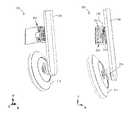
- FIGS. 4A-4Bare perspective views of components of a coupling subsystem and a strap connector in accordance with some embodiments.
- FIG. 4Cshows perspective views of a coupling subsystem in accordance with some embodiments.
- FIGS. 5A-5Dare exploded views illustrating components of a coupling subsystem in accordance with some embodiments.
- FIGS. 6A-6Care side views illustrating decoupling mechanisms between a coupling subsystem and a strap in accordance with some embodiments.
- FIG. 7is a perspective view of a head-mounted display integrated with an audio subsystem in accordance with one or more embodiments.
- FIG. 8is a partially exploded perspective view of the head-mounted display and audio subsystem of FIG. 7 with the connector plate assembly and earbud shown relative to a strap side segment.
- FIG. 9is an enlarged, partial cutaway view of a strap side segment of the head-mounted display of FIG. 8 , with a connector plate in the strap side segment.
- FIG. 10is an enlarged front perspective view of the connector plate assembly of the audio subsystem of FIG. 8 .
- FIG. 11is a cross-sectional view taken substantially along lines 11 - 11 of. FIG. 10 .
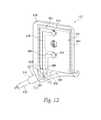
- FIG. 12is a perspective view of the nonconductive insert of the connector plate assembly of. FIG. 10 .
- FIG. 13is a rear perspective view of the connector plate assembly of FIG. 10 , with portions shown as translucent for purposes of discussion.
- a connector plate assembly usable with an earbud assembly or other head-mounted speaker systemis disclosed.
- One embodimentprovides an assembly with a connector plate having a projecting threaded post threadably attachable to a mating interface plate.
- Spring biased pogo pin electrical connectorsproject from hollow cylindrical bosses located on opposing sides of the threaded post, such the mechanical and electrical connection members are independent of each other.
- first, second, etc.are, in some instances, used herein to describe various elements, these elements should not be limited by these terms. These terms are used only to distinguish one element from another. For example, a first segment could be termed a second segment, and, similarly, a second segment could be termed a first segment, without departing from the scope of the various described embodiments. The first segment and the second segment are both segments, but they are not the same segment.
- a connector assembly mountable to a head strapcomprises a connector plate with a substantially planar engagement portion connectable to a head-mounted strap.
- a threaded attachment memberprojects from the engagement portion, and electrically conductive first and second lines are coupled to the engagement portion.
- First and second hollow cylindrical bosses spaced apart from each otherare adjacent to the attachment member and project away from the engagement portion.
- a biased, compressible first pin connectoris connected to the first line and extends through the first boss.
- the first pin connectorhas a retractable first tip portion projecting from the first boss.
- a biased, compressible second pin connectoris connected to the second line and extends through the second boss.
- the second pin connectorhas a retractable second tip portion projecting from the second boss.
- a connector assemblyhas a connector plate mountable to the head strap.
- the connector platehas an outer plate structure with a recessed receiving area, and a non-conductive insert is in the recessed receiving area.
- a threaded attachment memberprojects from the non-conductive insert, and electrically conductive first and second lines are between the outer plate structure and the insert, and are operatively coupleable to an audio module, such as an earbud assembly or the like.
- First and second bosses spaced apart from each otherare adjacent to the attachment member and project away from the engagement portion, wherein the first and second bosses are arranged linearly with the threaded attachment member.
- a compressible first pogo pin connectoris connected to the first line and extends through the first boss.
- the first pogo pin connectorhas a retractable first tip portion projecting from the first boss.
- a compressible second pogo pin connectoris connected to the second line and extends through the second boss.
- the second pogo pin connectorhas a retractable second tip portion projecting from the second boss.
- a connector assemblycomprises an outer plate structure having a first planar portion and a first strap supporting portion.
- the outer plate structurehas an outer rim portion and a recessed receiving area.
- AA threaded attachment memberprojects from the first planar portion.
- a non-conductive insertis in the recessed receiving area with a second planar portion substantially coplanar with the outer rim portion at the first planar portion.
- the inserthas a second strap supporting portion substantially coplanar with the outer rim portion at the first strap supporting portion.
- the second planar portionhas a first aperture with the threaded attachment member extending therethrough and projecting beyond the second planar portion.
- the second planar portionhas first and second hollow cylindrical bosses on opposing sides of the first aperture and that project away from the second planar portion, wherein the first and second bosses and the threaded attachment member are arranged linearly.
- a flex circuitis in the receiving area between the first and second planar portions.
- the flex circuithas a first electrical contact portion aligned with the first boss, and a second electrical contact portion aligned with the second boss.
- First and second spring-biased pogo pin connectorsare connected to the flex circuit.
- the first pogo pin connectorelectrically engages the first electrical contact portion and has a retractable first tip portion projecting from the first boss.
- the second pogo pin connectorelectrically engages the second electrical contact portion and has a retractable second tip portion projecting from the second boss.
- a flexible strain relief member having a first relief portionis connected to the outer plate structure adjacent to the a portion of the flex circuit and the first strap supporting portion.
- AA second relief portionextends away from the outer plate structure.
- the strain relief memberhas an internal channel extending through the first and second relief portions and are configure to receive an electrical wire that can connect to the flex circuit.
- FIG. 1is a perspective view of a head-mounted display system 100 in accordance with some embodiments.
- the head-mounted display system 100comprises a head-mounted display 110 integrated with an audio subsystem 200 .
- the head-mounted system 100may have two audio subsystems located on left and right sides to provide audio signals to the user's left and right ears.
- Each of the left and right audio subsystemsmay use substantially symmetric structures for coupling the speaker to a corresponding rigid segment of the strap 120 .
- the audio subsystem 200will be discussed in detail with reference to the following figures.
- the head-mounted display system 100also comprises a strap 120 for mounting the head-mounted display 110 on a user's head.
- the strap 120comprises a rigid segment 130 , a semi-rigid segment 140 , and a rigid segment 150 that are coupled to each other to adjustably wrap around side and back portions of the user's head.
- the strap 120comprises a single and continuous semi-rigid segment 140 including two arc portions, and each arc portion is to extend from above a user's ears to below the user's occipital lobe to conform to a portion of the user's head.
- the strap 120may comprise two separate and symmetric semi-rigid segments each including an arc portion.
- the rigid segments 130 and 150are coupled to the head-mounted display 110 and positioned on respective sides of the user's head to extend along the lateral dimension (e.g., Z dimension in FIG. 1 ).
- the strap 120may further include flexible segments (not shown) that are stretchable within the rigid segments 130 and 150 respectively to adjust the strap 120 in accordance with the user's head.
- the strap 120comprises a back piece 160 coupled with the semi-rigid segment 140 to rest against the back of the user's head (e.g., around the user's occipital lobe).
- the strap 120comprises a top strap 170 coupled to the back piece 160 and the head-mounted display 110 to adjustably conform to the top of the user's head when the user is wearing the head-mounted display 110 .
- various electrical connection mechanisms 180are used in the head-mounted display system 100 to provide power management and/or other functionalities to the head-mounted display 110 and the audio subsystem 200 .
- the head-mounted display 110is integrated with the audio subsystem 200 using suitable electrical connection mechanisms 180 to provide both visual and audio virtual-reality experiences to the user.
- FIGS. 2A-2Bare perspective views of the audio subsystem 200 for the head-mounted display system 100 in accordance with some embodiments.
- the audio subsystem 200comprises a speaker 210 , an arm 220 coupled to the speaker 210 , a strap connector 230 coupled to the arm 220 , and a coupling subsystem 240 coupled to the strap connector 230 .
- the coupling subsystem 240is releasably coupled to the strap 120 (e.g., the rigid segment 150 ) for the head-mounted display system 100 as illustrated in FIG. 1 .
- the speaker 210may be an on-ear headphone speaker, an around-ear headphone speaker, an over-ear headphone speaker, an in-ear headphone speaker, an earbud speaker, or any other suitable style of speaker.
- the strap connector 230 and the speaker 210are coupled to the arm 220 in respective portions distributed along the length (e.g., Y dimension in FIGS. 2A-2B ) of the arm 220 .
- the arm 220may further comprise a four-bar linkage to provide inward and outward movement of the speaker 210 with respect to the user's ear.
- Various embodiments of the four-bar linkage and other possible structures of the arm 220are described in U.S. patent application Ser. No. 14/627,639, filed on Feb. 20, 2015, the disclosure of which is incorporated herein by reference in its entirety.
- the strap connector 230includes a side 232 coupled to the arm 220 and a side 234 coupled to the coupling subsystem 240 , and the side 232 and the side 234 are opposite to each other along the X dimension as illustrated in FIG. 2B .
- Various embodiments of the strap connector 230are described in U.S. patent application Ser. No. 14/627,639.
- FIG. 3Ais a side view of the strap connector 230 coupled with the coupling subsystem 240 in accordance with some embodiments.
- FIG. 3Aalso illustrates a receiving structure 250 including a side 252 coupled to the coupling subsystem 240 and a side 254 to couple to the strap 120 (e.g., the rigid segment 150 of FIG. 1 ).
- the side 252 and the side 254are opposite to each other along the X dimension as illustrated in FIG. 3A .
- the receiving structure 250is a component of the strap 120 (e.g., the rigid segment 150 ) that is fixedly connected to the strap 120 .
- the receiving structure 250is coupled to the strap 120 using any suitable structure; once coupled, the receiving structure 250 may be considered part of the strap 120 .
- FIG. 3Bis a side view illustrating the strap connector 230 decoupled from the coupling subsystem 240 in accordance with some embodiments.
- the coupling subsystem 240comprises a base 310 , one or more posts 320 (e.g., a pair of posts) extending from the base 310 and through a spacer 340 to couple to the receiving structure 250 , and a spring 330 positioned between the base 310 and the spacer 340 to deform (e.g., to release from a compressed length to a natural length) to detach the coupling subsystem 240 from the receiving structure 250 when the posts 320 decouple from the receiving structure 250 .
- posts 320e.g., a pair of posts
- FIG. 3Cis a perspective view of the strap connector 230 in accordance with some embodiments.
- a side 312 of the base 310is engaged with a recessed portion 236 of the side 234 of the strap connector 230 .
- the side 312 of the base 310is flush to engage with the recessed portion 236 of the side 234 of the strap connector 230 .
- the strap connector 230may further include one or more recessed portions 238 (e.g., circular recessed portions 238 ) on the side 234 and within the recessed portion 236 to receive coupling elements (e.g., screws) extending from the side 312 of the coupling subsystem 240 when the coupling subsystem 240 is engaged with the strap connector 230 .
- recessed portions 238e.g., circular recessed portions 238
- coupling elementse.g., screws
- FIG. 3Dis a top view of the coupling subsystem 240 coupled with the receiving structure 250 in accordance with some embodiments. As shown in FIG. 3D , one or more posts 320 are used to couple the coupling subsystem 240 with the receiving structure 250 . Furthermore, the coupling subsystem 240 may include one or more coupling elements 350 and 352 (e.g., screws).
- FIG. 3Eis a side view of the coupling subsystem 240 decoupled from the receiving structure 250 in accordance with some embodiments.
- the coupling subsystem 240comprises the base 310 , the one or more posts 320 to couple to the receiving structure 250 , the spring 330 located between the spacer 340 and the base 310 , and the one or more coupling elements 352 (e.g., screws) to couple the coupling subsystem 240 to the strap connector 230 .
- Opposite ends of the spring 330contact the spacer 340 and the base 310 .
- FIGS. 4A-4Bare exploded views illustrating a plurality of components of the coupling subsystem 240 in accordance with some embodiments.
- the base 310is a circular boss to locate the coupling subsystem 240 within the recessed portion 236 of the strap connector 230 .
- the circular base 310may have a tapered (e.g., beveled) side portion 317 near the surface on the side 312 of the circular base 310 facing the strap connector 230 as shown in FIG. 4A .
- the side 312 of the circular base 310is configured to engage with the side 234 of the strap connector 230 as shown in FIG. 4B .
- the circular base 310has an opposite side 314 to the side 312 along the X dimension as shown in FIGS. 4A-4B .
- the one or more posts 320extend from the side 314 of the circular base 310 to couple to the strap 120 via the receiving structure 250 as shown in FIG. 3B .
- the strap connector 230is rotatably coupled to the coupling subsystem 240 .
- the circular base 310is rotatably coupled to the strap connector 230 .
- the spring 330contacts the side 314 of the circular base 310 and is positioned between the circular base 310 and the spacer 340 .
- the spring 330changes its length to detach the coupling subsystem 240 (e.g., the spacer 340 and circular base 310 ) from the strap 120 when the plurality of posts 320 decouple from the receiving structure 250 .
- a plurality of coupling elements 352are used to couple the circular base 310 to the strap connector 230 .
- the plurality of coupling elements 352e.g., screws
- the coupling elements 352When the circular coupling subsystem 240 is engaged with the strap connector 230 , the coupling elements 352 respectively insert into the circular recessed portions 238 on the side 234 of the strap connector 230 .
- the coupling elements 352include screws, bolts, or any other suitable fasteners.
- a center coupling element 350is used to couple the spacer 340 to the circular base 310 .
- the spacer 340includes a side 341 facing the circular base 310 and a side 343 opposite to the side 341 along the X dimension.
- the center coupling element 350inserts from the side 343 of the spacer 340 through a center opening 346 of the spacer 340 , into a center opening 368 of the circular base 310 .
- the center coupling element 350includes screws, bolts, or any other suitable fasteners.
- the side 343 of the spacer 340may be flat.
- FIG. 4Cshows perspective views of the coupling subsystem 240 in accordance with some embodiments. As shown in FIG. 4C , the center coupling element 350 may not extend out from the side 312 of the circular base 310 to reach the strap connector 230 .
- one or more spacers 316are used between the coupling elements 352 and the circular base 310 and positioned against the side 314 of the circular base 310 .
- the spacer 316may have a shape that conforms to a portion of the circular base 310 (e.g., as shown in FIG. 4B ), or any other suitable shape (e.g., circular).
- the spacers 316may be used to provide an improved fit and a level surface between the coupling elements 352 and the circular base 310 .
- the spacers 316may also be used to fill gaps between the coupling elements 352 and the circular base 310 subject to wear.
- FIGS. 5A-5Dare exploded views illustrating components of the coupling subsystem 240 in accordance with some embodiments.
- the coupling subsystem 240comprises a pair of posts 320 .
- Each post 320includes an end 326 (e.g., an elongated end) to be inserted into a respective opening 364 of a plurality of openings 364 in the circular base 310 as shown in FIG. 5B .
- a diameter of the end 326is designed to fit tightly in the opening 364 such that the post 320 is fixedly held in the opening 364 of the circular base 310 as shown in FIG. 5D .
- Each post 320also includes an opposite end 322 to be inserted through an opening 342 of the spacer 340 and to couple to the strap 120 .
- the end 322includes a tip 323 to be inserted into a receiving portion on the strap 120 (e.g., an opening in the receiving structure 250 ).
- the end 322also includes a groove 324 to engage with the receiving portion of the strap 120 (e.g., the groove 324 is to engage with concave edges of a latch in the receiving structure 250 ).
- each post 320is circular.
- the groove 324 and the tip 323 of each post 320are also circular. As shown in FIGS. 5A-5B , the diameter of the groove 324 is smaller than the diameter of the mid portion of the post 320 , such that when the post 320 is coupled with the receiving structure 250 , the post 320 is prevented from decoupling from the receiving structure 250 .
- each opening 364 of the plurality of openings 364 of the circular base 310extends through a respective protrusion 362 of a plurality of protrusions 362 that protrude from the side 314 of the circular base 310 .
- the respective protrusion 362may have a shape that conforms to a portion of the circular base 310 or any other suitable shape.
- the circular base 310comprises a center opening 368 extending through a center protrusion 366 that protrudes from the side 314 of the circular base 310 .
- the spring 330has a hollow center 332 , and the center protrusion 366 is inserted into the hollow center 332 of the spring 330 as shown in FIG. 5D .
- the center protrusion 366 of the circular base 310is longer than the respective protrusion 362 of the plurality of protrusions 362 .
- the spacer 340when the spacer 340 is coupled with the circular base 310 (e.g., while the audio subsystem 200 is engaged with the strap 120 ), the spacer 340 rests against the plurality of protrusions 362 of the circular base 310 .
- the spacer 340includes a plurality of openings 342 through which the posts 320 are respectively inserted.
- the spacer 340includes a center protrusion 344 protruding from the side 341 of the spacer 340 and facing the circular base 310 .
- the spacer 340includes a center opening 346 through the center protrusion 344 of the spacer 340 .
- the circular base 310includes a plurality of openings 315 and a center groove 318 on the side 312 .
- the coupling elements 352may insert through the respective openings 315 to couple the circular base 310 to the strap connector 230 .
- the plurality of openings 364are diagonally distributed on a first diagonal of the circular base 310
- the plurality of openings 315are diagonally distributed on a second diagonal of the circular base 310 , in accordance with some embodiments.
- FIGS. 6A-6Care side views illustrating decoupling mechanisms between the coupling subsystem 240 and the strap 120 (e.g., the receiving structure 250 coupled to the strap 120 ) in accordance with some embodiments.
- the coupling element 350e.g., illustrated in FIG. 4C ) may be used to couple the spacer 340 with the circular base 310 while allowing a relative movement along the X dimension between the spacer 340 and the circular base 310 .
- the spring 330has one end contacting the side 314 of the circular base 310 and the opposite end contacting the side 341 of the spacer 340 .
- the spring 330deforms from a first state at a length of d 1 to a second state at a length of d 2 , where d 2 is greater than d 1 , such that the coupling subsystem 240 automatically detaches from the receiving structure 250 .
- a natural length (unstretched and uncompressed) of the spring 330is longer than a length of the center protrusion 344 of the spacer 340 .
- the spring 330has a natural length (i.e., an unstretched and uncompressed length) of d 2 .
- the spring 330is in a compressed state with a length of d 1 .
- the posts 320are released from the receiving structure 250 (e.g., by releasing the grooves 324 from latches in the receiving structure)
- the spring 330automatically changes from the compressed length d 1 to the natural length d 2 .
- the circular base 310moves along the X dimension away from the spacer 340 , and the coupling subsystem 240 detaches from the receiving structure 250 .
- the distance between the side 314 of the circular base 310 and the side 341 of the spacer 340increases from d 1 to d 2 as the spring 330 changes from the compressed state to the natural state.
- the length d 2is not the natural length of the spring 330 , but a length longer than the compressed length d 1 and shorter than the natural length of the spring 330 .
- the detached coupling subsystem 240can couple to the receiving structure 250 by pressing the coupling subsystem 240 toward the receiving structure 250 , such that the posts 320 are coupled with the receiving structure 250 , and the spring 330 is compressed from the length d 2 to the length d 1 .
- the coupling subsystem 240further comprises suitable electrical connection mechanism(s) to provide power management and/or signal transmission between the speaker 210 and the head-mounted display 110 .
- the one or more components of the coupling subsystem 240are made of materials such as beryllium copper, gold, nickel, steel, stainless steel, polytetrafluoroethylene (PTFE), acetyl copolymer, polycarbonate, other polymers and other metals.
- materialssuch as beryllium copper, gold, nickel, steel, stainless steel, polytetrafluoroethylene (PTFE), acetyl copolymer, polycarbonate, other polymers and other metals.
- the coupling subsystem 240as can be used for attaching the speaker 210 to the strap 120 , and detaching the speaker 210 from the strap 120 of the head-mounted display 110 .
- the coupling subsystem 240enables the speaker 210 to be removed from the user's ear without taking off the strap 120 and head-mounted display 110 .
- the audio subsystem 200offers multiple degrees of freedom to adjust the position of the speaker 210 to fit different users.
- the adjustments with multiple degrees of freedominclude, but are not limited to, pivoting inward and outward relative to the user's ear, rotating within a vertical plane, and sliding upward and downward to adjust the height of the speaker 210 .
- Various embodiments of the multiple degrees of freedom and related structuresare described in U.S. patent application Ser. No. 14/627,639.
- FIG. 7is a perspective view of the head-mounted display system 100 integrated with an audio subsystem 400 in accordance with another embodiment.
- the head-mounted display system 100has the strap 120 attached to the head-mounted display 110 at the side segments 130 and 150 .
- Each of the side segments 130 and 150has electrical lines 182 (e.g., wires) or other portions of the electrical connection mechanisms 180 therein that are operatively connected to the head-mounted display 110 .
- the audio subsystem 400is coupled to the electrical connection mechanism 180 at the side segments 130 and 150 via the electrical lines 182 .
- FIG. 8is a partially exploded perspective view of the audio subsystem 400 with a coupling subsystem 405 on each of the side segments 130 and 150 .
- Each coupling subsystem 405has a connection interface plate 407 mounted to the respective side segment 130 / 150 and operatively connected to the electrical lines 182 in the side segment.
- Another portion of the coupling subsystem 405is a connector plate assembly 410 detachably connectable to the connection interface plate 407 .
- the connector plate assembly 410is connected to an earbud assembly 415 or other audio speaker assembly, by a flexible audio line or cable 420 , such as a shielded earbud wire.
- the earbud assembly 415has a contoured housing 425 that contains a speaker unit 430 , which is operatively connected to the flexible audio line 420 , and that carries a soft, flexible tip portion 435 configured to snugly fit into the wearer's ear.
- the connector plate assembly 410 and the earbud assembly 415are detachable from the strap side segment 130 as a unit.
- FIG. 9is an enlarged, partial cutaway view of the strap side segment 130 of the strap 120 .
- the illustrated strap side segment 130contains an interface plate 440 that has a central aperture 442 that receives an internally threaded boss 444 extending partially through the strap side segment 130 .
- the boss 444has a head portion accessible from the inner surface of the strap side segment 130 to allow a user to manually rotate the boss 444 within the aperture relative to the interface plate 440 .
- the interface plate 440also has a pair of electrical contacts 446 on opposing sides of the central aperture 442 , such that the electrical contacts 446 and the boss 444 are arranged linearly.
- the electrical contacts 446are operatively coupled to the electrical lines 182 of the electrical connection mechanisms 180 in the strap side segment 150 .
- the strap side segmenthas a covering portion 448 that substantially covers the interface plate 440 .
- the cover portion 448has a through hole 450 that provides access to the boss 444 , and a pair of access apertures 452 that provide access to the electrical contacts 446 ( FIG. 9 ).
- the connector plate assembly 410 of the audio subsystem 400releasably connects to the interface plate 440 to provide independent electrical and mechanical interface with the side strap segment 130 .
- the illustrated connector plate assembly 410has a threaded attachment member, such as a threaded post 454 , that mates with the threaded boss 444 of the interface plate 440 ( FIG. 9 ). Accordingly, the two plate structures mechanically screw together to capture a portion of the side strap segment 130 therebetween.
- the connector plate assembly 440is removable from the strap side segment 130 by unscrewing the threaded boss 444 from the threaded post 454 .
- the connector plate 410also has a pair of electrical connectors 456 on opposing sides of the threaded post 454 , such that the electrical connectors 456 are independent of the threaded post 454 .
- the electrical connectors 456are sized and positioned to extend through the access apertures 452 and firmly engage the electrical contacts 446 of the interface plate 440 ( FIG. 9 ) to achieve positive electrical engagement with the electrical lines 182 in the side segment 130 .
- the electrical connectors 456 and the threaded post 454are positioned in a linear arrangement, shown as a vertically linear arrangement, that provide for independent mechanical and electrical interconnection with the interface plate 440 .
- the connector plate assembly 410has a generally planar upper portion 458 and a lower portion 460 integrally attached to and projecting away from the planar upper portion 458 , both of which define a contoured support surface 462 shaped and sized to support a bottom edge of the strap side segment 130 when the connector plate assembly 410 is attached to the interface plate 440 .
- the support surface 462works with the linearly aligned electrical connectors 456 and threaded post 454 to resist torsional loads and substantially prevent rotational movement of the connector plate assembly 410 relative to the strap side segment 130 .
- the connector plate assembly 410has an outer plate structure 464 with an outer rim portion 466 that defines a recessed receiving area 468 that receives a nonconductive contoured insert 470 .
- the outer plate structure 464is a die cast metal unit that provides positive stiffness and rigidity to the connector plate assembly 410 and the insert 470 is made of a molded nonconductive plastic material.
- the illustrated threaded post 454is integrally connected to a planar upper portion 472 ( FIG. 11 ) of the outer plate structure 464 .
- FIG. 12is a perspective view of the nonconductive insert 470 of the connector plate assembly 410 shown removed from the outer plate structure 464 .
- the insert 470has a central aperture 474 positioned and sized to extend over the threaded post 454 ( FIG. 10 ), such that the threaded post 454 projects beyond a planar strap-engaging surface 476 of the insert 470 .
- the insert 470also has a pair of hollow, cylindrical bosses 478 integrally connected to and extending from the strap engaging surface 476 .
- the insert 470also has a contoured lower projecting portion 480 that defines a portion of the strap support surface 462 .
- the insert 470is sized to press fit into the receiving area 468 ( FIG.
- the insert 470can also be secured to the outer plate structure 464 with an adhesive to retain the insert 470 in the receiving area 468 , such that the strap engaging surface 476 is substantially coplanar with the outer surface of the outer rim portion 466 .
- FIG. 13is a rear perspective view of the connector plate assembly 410 with portions shown as translucent for purposes of discussion.
- the connector plate assembly 410has a flex circuit 482 captured between the insert 470 and the outer plate structure 464 .
- the flex circuit 482has a pair of electrical contact pads 484 positioned in axial alignment with the hollow bosses 478 of the insert 470 ( FIG. 11 ).
- the contact pads 484are connected to electrical wires or traces 486 that extend to a lower connection portion 488 positioned in the lower portion of the connector plate assembly 410 .
- the connector plate assembly 410has a pair of spring biased pogo pin electrical connectors 490 captured in the bosses 478 and soldered or otherwise electrically fixed to the contact pads 484 of the flex circuit 482 .
- Each pogo pin connector 490has a base 492 attached to a respective one of the contact pads 484 , and a telescoping tip portion 494 slidably disposed in the base 492 and partially projecting out of the bosses 478 .
- a spring 496 or other biasing memberis contained within each pogo pin connector 490 between the base 492 and the tip portion 494 to urge the tip portion 494 axially away from the contact pads 484 so as to protrude through the bosses 478 when the pogo pin connector 490 is in a substantially uncompressed position. Accordingly, when the connector plate assembly 410 is attached to the strap side segment 130 , the tip portion 494 of each pogo pin connector 490 extends through a respective one of the access apertures 452 ( FIG. 8 ) and engages the electrical contacts 446 . The spring 496 cause the tip portion 494 of the pogo pin connector 490 to press against the respective electrical contact 446 of the interface plate 440 to maintain electrical engagement during use of the head-mounted display system 100 .
- the connector plate assembly 410has a flexible strain relief member 500 attached to the lower portion 502 of the outer plate structure 464 .
- the lower portion 502has a chamber area 504 below the insert 470 , and an aperture 506 in communication with the chamber area 504 .
- the flexible strain relief member 500has an upper portion 508 positioned within the chamber 504 , and a lower portion 510 protruding through the aperture 506 and beyond the lower portion 502 of the outer plate structure 464 .
- a wire channel 512extends through the strain relief member 500 between the upper and lower portions 508 and 510 to provide access into the chamber 504 .
- the strain relief member 500has an enlarged contoured upper portion 508 positioned in the chamber 504 adjacent to the lower connection portion 488 of the flex circuit 482 .
- the strain relief member 500securely connects to an upper portion of the audio line 420 , which is securely and electrically connected to the lower connection portion 488 of the flex circuit 482 .
- the audio line 420extends through the wire channel 512 , out of the lower portion of the strain relief member 500 , and connects at its distal end portion to the earbud assembly 415 ( FIG. 8 ).
- the lower portion 510 of the flexible strain relief member 500can flex with the audio line 420 while significantly reducing strain on the audio line 420 within the chamber and at the connection with the flex circuit 482 .
Landscapes
- Engineering & Computer Science (AREA)
- Physics & Mathematics (AREA)
- Acoustics & Sound (AREA)
- Signal Processing (AREA)
- Health & Medical Sciences (AREA)
- Otolaryngology (AREA)
- Manufacturing & Machinery (AREA)
- Details Of Connecting Devices For Male And Female Coupling (AREA)
Abstract
Description
This application claims the benefit of U.S. Provisional Patent Application No. 62/273,352, filed Dec. 30, 2015, titled “Connector Assembly for Detachable Audio System,” which is incorporated herein in its entirety by reference thereto. This application is also related to U.S. Provisional Patent Application Ser. No. 62/174,298, filed Jun. 11, 2015, titled “Detachable Audio System for Head-Mounted Displays,” which is also incorporated herein in its entirety by reference thereto.
This application relates generally to wearable technology and virtual-reality technology, including but not limited to a detachable audio system for a head-mounted strap, such as with a head-mounted display assembly.
Virtual-reality head-mounted displays have wide applications in various fields, including engineering design, medical surgery practice, military simulated practice, and video gaming. For example, a user wears a virtual-reality head-mounted display integrated with audio headphones while playing video games so that the user can have an interactive experience in an immersive virtual environment.
However, it may be difficult for a user to properly adjust and comfortably wear the head-mounted displays and the integrated audio systems using the existing technology, which may negatively affect the user's experience.
For a better understanding of the various described embodiments, reference should be made to the Detailed Description below, in conjunction with the following drawings. Like reference numerals refer to corresponding parts throughout the figures and descriptions.
Overview
A connector plate assembly usable with an earbud assembly or other head-mounted speaker system is disclosed. One embodiment provides an assembly with a connector plate having a projecting threaded post threadably attachable to a mating interface plate. Spring biased pogo pin electrical connectors project from hollow cylindrical bosses located on opposing sides of the threaded post, such the mechanical and electrical connection members are independent of each other.
General Description
Reference will now be made to embodiments, examples of which are illustrated in the accompanying drawings. In the following description, numerous specific details are set forth in order to provide an understanding of the various described embodiments. However, it will be apparent to one of ordinary skill in the art that the various described embodiments may be practiced without these specific details. In other instances, well-known systems, methods, procedures, components, circuits, and networks have not been described in detail so as not to unnecessarily obscure aspects of the embodiments.
It will also be understood that, although the terms first, second, etc. are, in some instances, used herein to describe various elements, these elements should not be limited by these terms. These terms are used only to distinguish one element from another. For example, a first segment could be termed a second segment, and, similarly, a second segment could be termed a first segment, without departing from the scope of the various described embodiments. The first segment and the second segment are both segments, but they are not the same segment.
The terminology used in the description of the various embodiments described herein is for the purpose of describing particular embodiments only and is not intended to be limiting. As used in the description of the various described embodiments and the appended claims, the singular forms “a,” “an,” and “the” are intended to include the plural forms as well, unless the context clearly indicates otherwise. It will also be understood that the term “and/or” as used herein refers to and encompasses any and all possible combinations of one or more of the associated listed items. It will be further understood that the terms “includes,” “including,” “comprises,” and/or “comprising,” when used in this specification, specify the presence of stated features, integers, steps, operations, elements, and/or components, but do not preclude the presence or addition of one or more other features, integers, steps, operations, elements, components, and/or groups thereof.
In at least one embodiment, a connector assembly mountable to a head strap comprises a connector plate with a substantially planar engagement portion connectable to a head-mounted strap. A threaded attachment member projects from the engagement portion, and electrically conductive first and second lines are coupled to the engagement portion. First and second hollow cylindrical bosses spaced apart from each other are adjacent to the attachment member and project away from the engagement portion. A biased, compressible first pin connector is connected to the first line and extends through the first boss. The first pin connector has a retractable first tip portion projecting from the first boss. A biased, compressible second pin connector is connected to the second line and extends through the second boss. The second pin connector has a retractable second tip portion projecting from the second boss.
In another embodiment, a connector assembly has a connector plate mountable to the head strap. The connector plate has an outer plate structure with a recessed receiving area, and a non-conductive insert is in the recessed receiving area. A threaded attachment member projects from the non-conductive insert, and electrically conductive first and second lines are between the outer plate structure and the insert, and are operatively coupleable to an audio module, such as an earbud assembly or the like. First and second bosses spaced apart from each other are adjacent to the attachment member and project away from the engagement portion, wherein the first and second bosses are arranged linearly with the threaded attachment member. A compressible first pogo pin connector is connected to the first line and extends through the first boss. The first pogo pin connector has a retractable first tip portion projecting from the first boss. A compressible second pogo pin connector is connected to the second line and extends through the second boss. The second pogo pin connector has a retractable second tip portion projecting from the second boss.
In another embodiment, a connector assembly comprises an outer plate structure having a first planar portion and a first strap supporting portion. The outer plate structure has an outer rim portion and a recessed receiving area. AA threaded attachment member projects from the first planar portion. A non-conductive insert is in the recessed receiving area with a second planar portion substantially coplanar with the outer rim portion at the first planar portion. The insert has a second strap supporting portion substantially coplanar with the outer rim portion at the first strap supporting portion. The second planar portion has a first aperture with the threaded attachment member extending therethrough and projecting beyond the second planar portion. The second planar portion has first and second hollow cylindrical bosses on opposing sides of the first aperture and that project away from the second planar portion, wherein the first and second bosses and the threaded attachment member are arranged linearly. A flex circuit is in the receiving area between the first and second planar portions. The flex circuit has a first electrical contact portion aligned with the first boss, and a second electrical contact portion aligned with the second boss. First and second spring-biased pogo pin connectors are connected to the flex circuit. The first pogo pin connector electrically engages the first electrical contact portion and has a retractable first tip portion projecting from the first boss. The second pogo pin connector electrically engages the second electrical contact portion and has a retractable second tip portion projecting from the second boss. A flexible strain relief member having a first relief portion is connected to the outer plate structure adjacent to the a portion of the flex circuit and the first strap supporting portion. AA second relief portion extends away from the outer plate structure. The strain relief member has an internal channel extending through the first and second relief portions and are configure to receive an electrical wire that can connect to the flex circuit.
In some embodiments, the head-mounteddisplay system 100 also comprises astrap 120 for mounting the head-mounteddisplay 110 on a user's head. In the example ofFIG. 1 , thestrap 120 comprises arigid segment 130, asemi-rigid segment 140, and arigid segment 150 that are coupled to each other to adjustably wrap around side and back portions of the user's head.
In some embodiments, thestrap 120 comprises a single and continuoussemi-rigid segment 140 including two arc portions, and each arc portion is to extend from above a user's ears to below the user's occipital lobe to conform to a portion of the user's head. Alternatively, thestrap 120 may comprise two separate and symmetric semi-rigid segments each including an arc portion.
In some embodiments, therigid segments display 110 and positioned on respective sides of the user's head to extend along the lateral dimension (e.g., Z dimension inFIG. 1 ). Thestrap 120 may further include flexible segments (not shown) that are stretchable within therigid segments strap 120 in accordance with the user's head.
In some embodiments, thestrap 120 comprises aback piece 160 coupled with thesemi-rigid segment 140 to rest against the back of the user's head (e.g., around the user's occipital lobe).
In some embodiments, thestrap 120 comprises atop strap 170 coupled to theback piece 160 and the head-mounteddisplay 110 to adjustably conform to the top of the user's head when the user is wearing the head-mounteddisplay 110.
In some embodiments, various electrical connection mechanisms180 (e.g., flat flexible circuits and/or electric cables) are used in the head-mounteddisplay system 100 to provide power management and/or other functionalities to the head-mounteddisplay 110 and theaudio subsystem 200. For example, the head-mounteddisplay 110 is integrated with theaudio subsystem 200 using suitableelectrical connection mechanisms 180 to provide both visual and audio virtual-reality experiences to the user.
Various embodiments of thestrap system 120 and the head-mounteddisplay system 100 are described in U.S. patent application Ser. No. 14/603,335, filed on Jan. 22, 2015, and U.S. patent application Ser. No. 14/681,001, filed on Apr. 7, 2015, U.S. patent application Ser. No. 14/749,410 filed on Jun. 24, 2015, which claims priority to 62/174,359 filed on Jun. 11, 2015, all of which are incorporated herein by reference in their entireties.
Thespeaker 210 may be an on-ear headphone speaker, an around-ear headphone speaker, an over-ear headphone speaker, an in-ear headphone speaker, an earbud speaker, or any other suitable style of speaker.
As shown inFIG. 2B , thestrap connector 230 and thespeaker 210 are coupled to thearm 220 in respective portions distributed along the length (e.g., Y dimension inFIGS. 2A-2B ) of thearm 220. Thearm 220 may further comprise a four-bar linkage to provide inward and outward movement of thespeaker 210 with respect to the user's ear. Various embodiments of the four-bar linkage and other possible structures of thearm 220 are described in U.S. patent application Ser. No. 14/627,639, filed on Feb. 20, 2015, the disclosure of which is incorporated herein by reference in its entirety.
Thestrap connector 230 includes aside 232 coupled to thearm 220 and aside 234 coupled to thecoupling subsystem 240, and theside 232 and theside 234 are opposite to each other along the X dimension as illustrated inFIG. 2B . Various embodiments of thestrap connector 230 are described in U.S. patent application Ser. No. 14/627,639.
Thecircular base 310 may have a tapered (e.g., beveled)side portion 317 near the surface on theside 312 of thecircular base 310 facing thestrap connector 230 as shown inFIG. 4A . Theside 312 of thecircular base 310 is configured to engage with theside 234 of thestrap connector 230 as shown inFIG. 4B . Thecircular base 310 has anopposite side 314 to theside 312 along the X dimension as shown inFIGS. 4A-4B . The one ormore posts 320 extend from theside 314 of thecircular base 310 to couple to thestrap 120 via the receivingstructure 250 as shown inFIG. 3B .
In some embodiments, thestrap connector 230 is rotatably coupled to thecoupling subsystem 240. For example, thecircular base 310 is rotatably coupled to thestrap connector 230.
As shown inFIG. 4B , thespring 330 contacts theside 314 of thecircular base 310 and is positioned between thecircular base 310 and thespacer 340. Thespring 330 changes its length to detach the coupling subsystem240 (e.g., thespacer 340 and circular base310) from thestrap 120 when the plurality ofposts 320 decouple from the receivingstructure 250.
As shown inFIGS. 4A-4B , a plurality ofcoupling elements 352 are used to couple thecircular base 310 to thestrap connector 230. For example, the plurality of coupling elements352 (e.g., screws) insert from the side314 (i.e., opposite to theside 312 along X dimension) of thecircular base 310 respectively. Thecoupling elements 352 respectively insert through a plurality ofopenings 315 in thecircular base 310 and out from theside 312 of the circular base310 (e.g., as shown inFIGS. 3E and 4B ). When thecircular coupling subsystem 240 is engaged with thestrap connector 230, thecoupling elements 352 respectively insert into the circular recessedportions 238 on theside 234 of thestrap connector 230. For example, thecoupling elements 352 include screws, bolts, or any other suitable fasteners.
Still referring toFIGS. 4A-4B , acenter coupling element 350 is used to couple thespacer 340 to thecircular base 310. Thespacer 340 includes aside 341 facing thecircular base 310 and aside 343 opposite to theside 341 along the X dimension. In one example, thecenter coupling element 350 inserts from theside 343 of thespacer 340 through acenter opening 346 of thespacer 340, into acenter opening 368 of thecircular base 310. Thecenter coupling element 350 includes screws, bolts, or any other suitable fasteners. Theside 343 of thespacer 340 may be flat.FIG. 4C shows perspective views of thecoupling subsystem 240 in accordance with some embodiments. As shown inFIG. 4C , thecenter coupling element 350 may not extend out from theside 312 of thecircular base 310 to reach thestrap connector 230.
As shown inFIGS. 4A-4B , one ormore spacers 316 are used between thecoupling elements 352 and thecircular base 310 and positioned against theside 314 of thecircular base 310. Thespacer 316 may have a shape that conforms to a portion of the circular base310 (e.g., as shown inFIG. 4B ), or any other suitable shape (e.g., circular). Thespacers 316 may be used to provide an improved fit and a level surface between thecoupling elements 352 and thecircular base 310. Thespacers 316 may also be used to fill gaps between thecoupling elements 352 and thecircular base 310 subject to wear.
Eachpost 320 also includes anopposite end 322 to be inserted through anopening 342 of thespacer 340 and to couple to thestrap 120. Theend 322 includes atip 323 to be inserted into a receiving portion on the strap120 (e.g., an opening in the receiving structure250). Theend 322 also includes agroove 324 to engage with the receiving portion of the strap120 (e.g., thegroove 324 is to engage with concave edges of a latch in the receiving structure250).
In some embodiments, eachpost 320 is circular. Thegroove 324 and thetip 323 of eachpost 320 are also circular. As shown inFIGS. 5A-5B , the diameter of thegroove 324 is smaller than the diameter of the mid portion of thepost 320, such that when thepost 320 is coupled with the receivingstructure 250, thepost 320 is prevented from decoupling from the receivingstructure 250.
In some embodiments as shown inFIG. 5B , each opening364 of the plurality ofopenings 364 of thecircular base 310 extends through arespective protrusion 362 of a plurality ofprotrusions 362 that protrude from theside 314 of thecircular base 310. Therespective protrusion 362 may have a shape that conforms to a portion of thecircular base 310 or any other suitable shape.
In some embodiments as shown inFIG. 5B , thecircular base 310 comprises acenter opening 368 extending through acenter protrusion 366 that protrudes from theside 314 of thecircular base 310. Thespring 330 has ahollow center 332, and thecenter protrusion 366 is inserted into thehollow center 332 of thespring 330 as shown inFIG. 5D . In some embodiments, as illustrated inFIG. 4A , thecenter protrusion 366 of thecircular base 310 is longer than therespective protrusion 362 of the plurality ofprotrusions 362.
In some embodiments, referring back toFIG. 3E , when thespacer 340 is coupled with the circular base310 (e.g., while theaudio subsystem 200 is engaged with the strap120), thespacer 340 rests against the plurality ofprotrusions 362 of thecircular base 310. Thespacer 340 includes a plurality ofopenings 342 through which theposts 320 are respectively inserted.
As shown inFIGS. 5A-5D , thespacer 340 includes acenter protrusion 344 protruding from theside 341 of thespacer 340 and facing thecircular base 310. Thespacer 340 includes acenter opening 346 through thecenter protrusion 344 of thespacer 340. When thespacer 340 is coupled with thecircular base 310, thecenter protrusion 344 of thespacer 340 is inserted into thehollow center 332 of thespring 330, and thecenter protrusion 366 of thecircular base 310 is inserted into the center opening346 of thespacer 340.
In some embodiments, thecircular base 310 includes a plurality ofopenings 315 and acenter groove 318 on theside 312. Thecoupling elements 352 may insert through therespective openings 315 to couple thecircular base 310 to thestrap connector 230. As shown inFIGS. 5A-5B , the plurality ofopenings 364 are diagonally distributed on a first diagonal of thecircular base 310, and the plurality ofopenings 315 are diagonally distributed on a second diagonal of thecircular base 310, in accordance with some embodiments.
In some embodiments, thespring 330 has one end contacting theside 314 of thecircular base 310 and the opposite end contacting theside 341 of thespacer 340. When theposts 320 are released from the receivingstructure 250, thespring 330 deforms from a first state at a length of d1 to a second state at a length of d2, where d2 is greater than d1, such that thecoupling subsystem 240 automatically detaches from the receivingstructure 250. In one example, a natural length (unstretched and uncompressed) of thespring 330 is longer than a length of thecenter protrusion 344 of thespacer 340.
For example, thespring 330 has a natural length (i.e., an unstretched and uncompressed length) of d2. When thecoupling subsystem 240 is coupled with the receivingstructure 250, thespring 330 is in a compressed state with a length of d1. When theposts 320 are released from the receiving structure250 (e.g., by releasing thegrooves 324 from latches in the receiving structure), thespring 330 automatically changes from the compressed length d1 to the natural length d2. Simultaneously, thecircular base 310 moves along the X dimension away from thespacer 340, and thecoupling subsystem 240 detaches from the receivingstructure 250. As illustrated inFIGS. 6A-6C , the distance between theside 314 of thecircular base 310 and theside 341 of thespacer 340 increases from d1 to d2 as thespring 330 changes from the compressed state to the natural state.
In another example, the length d2 is not the natural length of thespring 330, but a length longer than the compressed length d1 and shorter than the natural length of thespring 330.
Reversibly, thedetached coupling subsystem 240 can couple to the receivingstructure 250 by pressing thecoupling subsystem 240 toward the receivingstructure 250, such that theposts 320 are coupled with the receivingstructure 250, and thespring 330 is compressed from the length d2 to the length d1.
In some embodiments, thecoupling subsystem 240 further comprises suitable electrical connection mechanism(s) to provide power management and/or signal transmission between thespeaker 210 and the head-mounteddisplay 110.
In some embodiments, the one or more components of thecoupling subsystem 240 are made of materials such as beryllium copper, gold, nickel, steel, stainless steel, polytetrafluoroethylene (PTFE), acetyl copolymer, polycarbonate, other polymers and other metals.
Thecoupling subsystem 240 as can be used for attaching thespeaker 210 to thestrap 120, and detaching thespeaker 210 from thestrap 120 of the head-mounteddisplay 110. Thecoupling subsystem 240 enables thespeaker 210 to be removed from the user's ear without taking off thestrap 120 and head-mounteddisplay 110.
In some embodiments, theaudio subsystem 200 offers multiple degrees of freedom to adjust the position of thespeaker 210 to fit different users. The adjustments with multiple degrees of freedom include, but are not limited to, pivoting inward and outward relative to the user's ear, rotating within a vertical plane, and sliding upward and downward to adjust the height of thespeaker 210. Various embodiments of the multiple degrees of freedom and related structures are described in U.S. patent application Ser. No. 14/627,639.
While only one side of thecoupling subsystem 405 is referred to below, it is to be understood that the description applies to both sides of thecoupling subsystem 405.FIG. 9 is an enlarged, partial cutaway view of thestrap side segment 130 of thestrap 120. The illustratedstrap side segment 130 contains aninterface plate 440 that has acentral aperture 442 that receives an internally threadedboss 444 extending partially through thestrap side segment 130. In the illustrated embodiment, theboss 444 has a head portion accessible from the inner surface of thestrap side segment 130 to allow a user to manually rotate theboss 444 within the aperture relative to theinterface plate 440.
Theinterface plate 440 also has a pair ofelectrical contacts 446 on opposing sides of thecentral aperture 442, such that theelectrical contacts 446 and theboss 444 are arranged linearly. Theelectrical contacts 446 are operatively coupled to theelectrical lines 182 of theelectrical connection mechanisms 180 in thestrap side segment 150. As seen inFIG. 8 , the strap side segment has a coveringportion 448 that substantially covers theinterface plate 440. Thecover portion 448 has a throughhole 450 that provides access to theboss 444, and a pair ofaccess apertures 452 that provide access to the electrical contacts446 (FIG. 9 ).
Theconnector plate assembly 410 of theaudio subsystem 400 releasably connects to theinterface plate 440 to provide independent electrical and mechanical interface with theside strap segment 130. As seen inFIGS. 10 and 11 , the illustratedconnector plate assembly 410 has a threaded attachment member, such as a threadedpost 454, that mates with the threadedboss 444 of the interface plate440 (FIG. 9 ). Accordingly, the two plate structures mechanically screw together to capture a portion of theside strap segment 130 therebetween. Theconnector plate assembly 440 is removable from thestrap side segment 130 by unscrewing the threadedboss 444 from the threadedpost 454.
Theconnector plate 410 also has a pair ofelectrical connectors 456 on opposing sides of the threadedpost 454, such that theelectrical connectors 456 are independent of the threadedpost 454. Theelectrical connectors 456 are sized and positioned to extend through theaccess apertures 452 and firmly engage theelectrical contacts 446 of the interface plate440 (FIG. 9 ) to achieve positive electrical engagement with theelectrical lines 182 in theside segment 130. In the illustrated embodiment, theelectrical connectors 456 and the threadedpost 454 are positioned in a linear arrangement, shown as a vertically linear arrangement, that provide for independent mechanical and electrical interconnection with theinterface plate 440.
Theconnector plate assembly 410 has a generally planarupper portion 458 and alower portion 460 integrally attached to and projecting away from the planarupper portion 458, both of which define acontoured support surface 462 shaped and sized to support a bottom edge of thestrap side segment 130 when theconnector plate assembly 410 is attached to theinterface plate 440. Thesupport surface 462 works with the linearly alignedelectrical connectors 456 and threadedpost 454 to resist torsional loads and substantially prevent rotational movement of theconnector plate assembly 410 relative to thestrap side segment 130.
As seen inFIGS. 10 and 11 , theconnector plate assembly 410 has anouter plate structure 464 with anouter rim portion 466 that defines a recessedreceiving area 468 that receives a nonconductivecontoured insert 470. In the illustrated embodiment, theouter plate structure 464 is a die cast metal unit that provides positive stiffness and rigidity to theconnector plate assembly 410 and theinsert 470 is made of a molded nonconductive plastic material. The illustrated threadedpost 454 is integrally connected to a planar upper portion472 (FIG. 11 ) of theouter plate structure 464.
As seen inFIG. 11 , theconnector plate assembly 410 has a pair of spring biased pogo pinelectrical connectors 490 captured in thebosses 478 and soldered or otherwise electrically fixed to thecontact pads 484 of theflex circuit 482. Eachpogo pin connector 490 has a base492 attached to a respective one of thecontact pads 484, and atelescoping tip portion 494 slidably disposed in thebase 492 and partially projecting out of thebosses 478. Aspring 496 or other biasing member is contained within eachpogo pin connector 490 between the base492 and thetip portion 494 to urge thetip portion 494 axially away from thecontact pads 484 so as to protrude through thebosses 478 when thepogo pin connector 490 is in a substantially uncompressed position. Accordingly, when theconnector plate assembly 410 is attached to thestrap side segment 130, thetip portion 494 of eachpogo pin connector 490 extends through a respective one of the access apertures452 (FIG. 8 ) and engages theelectrical contacts 446. Thespring 496 cause thetip portion 494 of thepogo pin connector 490 to press against the respectiveelectrical contact 446 of theinterface plate 440 to maintain electrical engagement during use of the head-mounteddisplay system 100.
Referring again toFIG. 13 , theconnector plate assembly 410 has a flexiblestrain relief member 500 attached to thelower portion 502 of theouter plate structure 464. In the illustrated embodiment, thelower portion 502 has achamber area 504 below theinsert 470, and anaperture 506 in communication with thechamber area 504. The flexiblestrain relief member 500 has anupper portion 508 positioned within thechamber 504, and alower portion 510 protruding through theaperture 506 and beyond thelower portion 502 of theouter plate structure 464. Awire channel 512 extends through thestrain relief member 500 between the upper andlower portions chamber 504.
In the illustrated embodiment, thestrain relief member 500 has an enlarged contouredupper portion 508 positioned in thechamber 504 adjacent to thelower connection portion 488 of theflex circuit 482. Thestrain relief member 500 securely connects to an upper portion of theaudio line 420, which is securely and electrically connected to thelower connection portion 488 of theflex circuit 482. Theaudio line 420 extends through thewire channel 512, out of the lower portion of thestrain relief member 500, and connects at its distal end portion to the earbud assembly415 (FIG. 8 ). Thelower portion 510 of the flexiblestrain relief member 500 can flex with theaudio line 420 while significantly reducing strain on theaudio line 420 within the chamber and at the connection with theflex circuit 482.
The foregoing description, for purpose of explanation, has been described with reference to specific embodiments. However, the illustrative discussions above are not intended to be exhaustive or to limit the scope of the claims to the precise forms disclosed. Many modifications and variations are possible in view of the above teachings. The embodiments were chosen in order to best explain the principles underlying the claims and their practical applications, to thereby enable others skilled in the art to best use the embodiments with various modifications as are suited to the particular uses contemplated.
Claims (20)
1. A connector assembly mountable to a head strap, comprising:
a connector plate with a substantially planar engagement portion mountable to the head strap;
a threaded attachment member projecting from the engagement portion;
electrically conductive first and second lines coupled to the engagement portion;
spaced apart first and second hollow cylindrical bosses adjacent to the attachment member and projecting away from the engagement portion;
a biased, compressible first pin connector connected to the first line and extending through the first boss, the first pin connector having a retractable first tip portion projecting from the first boss; and
a biased, compressible second pin connector connected to the second line and extending through the second boss, the second pin connector having a retractable second tip portion projecting from the second boss.
2. The connector assembly ofclaim 1 wherein the connector plate has a contoured strap-supporting portion connected to the engagement portion and configured to support an edge of the strap.
3. The connector assembly ofclaim 1 wherein the connector plate has an outer plate structure with a recessed receiving area, and a non-conductive insert in the recessed receiving area, the first and second bosses are connected to and project from the insert.
4. The connector assembly ofclaim 3 wherein the electrically conductive first and second lines are positioned between the outer plate structure and the insert.
5. The connector assembly ofclaim 1 , further comprising a flexible strain relief member connected to the connector plate and having a first relief portion positioned within the connector plate and adjacent to a portion of the first and second lines, and having a second relief portion extending through and away from the connector plate, the strain relief member having an internal channel extending through the first and second relief portions and configure to receive an electrically conductive that can connect to the first and second lines.
6. The connector assembly ofclaim 1 , further comprising a flex circuit carrying the first and second lines.
7. The connector assembly ofclaim 6 , wherein the connector plate has an outer plate structure with a recessed receiving area, and a non-conductive insert in the recessed receiving area, the flex circuit is captured between the outer plate structure and the insert.
8. The connector assembly ofclaim 1 wherein the connector plate has an outer plate structure with a recessed receiving area, and a non-conductive insert in the recessed receiving area, and wherein the first portion of the strain relief member is captured between the outer plate structure and the insert, and the second portion of the strain relief member extends through an aperture in the outer plate structure.
9. The connector assembly ofclaim 1 wherein the connector plate has an outer plate structure with a recessed receiving area, and a non-conductive insert in the recessed receiving area, wherein the first and second bosses are integrally connected to and project from the insert, and the threaded attachment member is connected to the outer plate structure and extends through an aperture in the insert.
10. The connector assembly ofclaim 1 wherein the first and second bosses and the threaded attachment member are arranged linearly with the threaded attachment member between the first and second bosses.
11. A connector assembly for use with an audio module mountable to a head strap, comprising:
a connector plate mountable to the head strap, the connector plate having an outer plate structure with a recessed receiving area, and a non-conductive insert in the recessed receiving area;
a threaded attachment member projecting from the non-conductive insert;
electrically conductive first and second lines between the outer plate structure and the insert, and being operatively coupleable to the audio module;
spaced apart first and second bosses adjacent to the attachment member and projecting away from the engagement portion, wherein the first and second bosses are on opposing sides of the threaded attachment member;
a compressible first pogo pin connector connected to the first line and extending through the first boss, the first pogo pin connector having a retractable first tip portion projecting from the first boss; and
a compressible second pogo pin connector connected to the second line and extending through the second boss, the second pogo pin connector having a retractable second tip portion projecting from the second boss.
12. The connector assembly ofclaim 11 wherein the connector plate has a planar engagement portion and a contoured strap-supporting portion connected to the engagement portion and configured to support an edge of the strap.
13. The connector assembly ofclaim 11 , further comprising a flexible strain relief member connected to the connector plate and having a first relief portion positioned between the outer plate structure and the insert, and having a second relief portion extending through and away from the outer plate structure, the strain relief member having an internal channel extending through the first and second relief portions and configure to receive an electrically conductive wire that can connect to the first and second lines.
14. The connector assembly ofclaim 11 , further comprising a flex circuit carrying the first and second lines, the flex circuit being captured between the outer plate structure and the insert.
15. The connector assembly ofclaim 11 wherein the first and second bosses are integrally connected to and project from the insert, and the threaded attachment member is connected to the outer plate structure and extends through an aperture in the insert.
16. The connector assembly ofclaim 1 wherein the first and second bosses and the threaded attachment member are arranged linearly with the threaded attachment member between the first and second bosses.
17. A connector assembly for use with an audio module mountable to a head strap, comprising:
an outer plate structure having a first planar portion and a first strap supporting portion, the outer plate structure having an outer rim portion and a recessed receiving area, and a threaded attachment member projecting from the first planar portion;
a non-conductive insert in the recessed receiving area with a second planar portion substantially coplanar with the outer rim portion at the first planar portion, and a second strap supporting portion substantially coplanar with the outer rim portion at the first strap supporting portion, the second planar portion having a first aperture having the threaded attachment member extending through the first aperture and projecting beyond the second planar portion, the second planar portion having a spaced apart first and second hollow cylindrical bosses on opposing sides of the first aperture and projecting away from the second planar portion, wherein the first and second bosses and the threaded attachment member are arranged linearly;
a flex circuit in the receiving area between the first and second planar portions, the flex circuit having a first electrical contact portion aligned with the first boss, and a second electrical contact portion aligned with the second boss;
first and second spring-biased pogo pin connectors connected to the flex circuit, the first pogo pin connector electrically engaging the first electrical contact portion and having a retractable first tip portion projecting from the first boss, and the second pogo pin connector electrically engaging the second electrical contact portion and having a retractable second tip portion projecting from the second boss; and
a flexible strain relief member having a first relief portion connected to the outer plate structure adjacent to the a portion of the flex circuit and the first strap supporting portion, and a second relief portion extending away from the outer plate structure, the strain relief member having an internal channel extending through the first and second relief portions and configure to receive an electrical wire that can connect to the flex circuit.
18. The connector assembly ofclaim 17 wherein the first portion of the strain relief member is captured between the outer plate structure and the insert, and the second portion of the strain relief member extends through an aperture in the outer plate structure adjacent to the first strap support portion.
19. The connector assembly ofclaim 17 wherein the first and second pogo pin connectors are soldered onto the first and second electrical contact portions, respectively, of the flex circuit.
20. The connector assembly ofclaim 17 wherein shaft portions of the first and second pogo pin connectors are press fit into apertures in the first and second bosses, respectively.
Priority Applications (1)
| Application Number | Priority Date | Filing Date | Title |
|---|---|---|---|
| US15/253,474US10182284B2 (en) | 2015-06-11 | 2016-08-31 | Connector assembly for detachable audio system |
Applications Claiming Priority (3)
| Application Number | Priority Date | Filing Date | Title |
|---|---|---|---|
| US201562174298P | 2015-06-11 | 2015-06-11 | |
| US201562273352P | 2015-12-30 | 2015-12-30 | |
| US15/253,474US10182284B2 (en) | 2015-06-11 | 2016-08-31 | Connector assembly for detachable audio system |
Publications (2)
| Publication Number | Publication Date |
|---|---|
| US20170195775A1 US20170195775A1 (en) | 2017-07-06 |
| US10182284B2true US10182284B2 (en) | 2019-01-15 |
Family
ID=59226907
Family Applications (1)
| Application Number | Title | Priority Date | Filing Date |
|---|---|---|---|
| US15/253,474Active2037-02-02US10182284B2 (en) | 2015-06-11 | 2016-08-31 | Connector assembly for detachable audio system |
Country Status (1)
| Country | Link |
|---|---|
| US (1) | US10182284B2 (en) |
Families Citing this family (12)
| Publication number | Priority date | Publication date | Assignee | Title |
|---|---|---|---|---|
| CN111190419B (en) | 2016-05-19 | 2022-08-09 | 科沃斯机器人股份有限公司 | Self-moving robot, combined robot and combined robot map calling method |
| US20180192177A1 (en)* | 2017-01-05 | 2018-07-05 | Muzik, Inc. | Extended reality headsets including removable ear cups and related structures |
| US10178457B1 (en)* | 2017-08-03 | 2019-01-08 | Facebook Technologies, Llc | Audio output assembly for a head-mounted display |
| WO2019075667A1 (en)* | 2017-10-18 | 2019-04-25 | 歌尔科技有限公司 | Head-mounted display |
| CN107635172B (en)* | 2017-10-31 | 2023-10-20 | 歌尔科技有限公司 | Head-mounted equipment |
| WO2019090460A1 (en)* | 2017-11-07 | 2019-05-16 | 深圳市柔宇科技有限公司 | Head-mounted display apparatus |
| CN111201471A (en)* | 2017-11-07 | 2020-05-26 | 深圳市柔宇科技有限公司 | Head-mounted display device |
| CN111201472A (en)* | 2017-11-07 | 2020-05-26 | 深圳市柔宇科技有限公司 | Head-mounted display device |
| US10578875B1 (en)* | 2018-05-30 | 2020-03-03 | Facebook Technologies, Llc | Head-mounted display with integrated speaker enclosure |
| US10816812B2 (en) | 2018-09-13 | 2020-10-27 | Apple Inc. | Display devices with multimodal audio |
| CN113296263B (en)* | 2021-04-27 | 2022-09-20 | 歌尔股份有限公司 | Soundable mirror leg structure and head-mounted display device |
| CN113271511B (en)* | 2021-05-07 | 2024-07-23 | 广州松歌音响设备有限公司 | Detachable combined main body structure of vertical microphone pipe body |
Citations (74)
| Publication number | Priority date | Publication date | Assignee | Title |
|---|---|---|---|---|
| US1356708A (en)* | 1919-03-25 | 1920-10-26 | Goodyear Edward Thomas Parsons | Facial pad adapted for use with field-glasses and other optical instruments and means for supporting the same alone or with other instruments or appliances on the head of the observer |
| US1706601A (en)* | 1924-12-24 | 1929-03-26 | Drager Alexander Bernhard | Harness for respirating appliances such as masks, respirators, and the like |
| US2784713A (en)* | 1954-06-24 | 1957-03-12 | Mine Safety Appliances Co | Breathing apparatus head harness connection |
| US4457461A (en)* | 1981-09-24 | 1984-07-03 | Pilkington P.E. Limited | Head mounting apparatus |
| US4741054A (en)* | 1987-01-22 | 1988-05-03 | Varo, Inc. | Chin cup for use with military headgear |
| US4753378A (en)* | 1985-12-12 | 1988-06-28 | Varo, Inc. | Night vision goggle headgear |
| US4766610A (en)* | 1987-01-22 | 1988-08-30 | Varo, Inc. | Replaceable cushion liner for military headgear |
| US5003300A (en)* | 1987-07-27 | 1991-03-26 | Reflection Technology, Inc. | Head mounted display for miniature video display system |
| US5321416A (en)* | 1992-07-27 | 1994-06-14 | Virtual Research Systems | Head-mounted visual display apparatus |
| US5469578A (en)* | 1993-05-07 | 1995-11-28 | Varo, Inc. | Night vision goggle headgear mount |
| US5551089A (en)* | 1995-01-10 | 1996-09-03 | Whidden; Jenna | Designer earmuff having interchangeable ear muff pieces |
| US6369952B1 (en)* | 1995-07-14 | 2002-04-09 | I-O Display Systems Llc | Head-mounted personal visual display apparatus with image generator and holder |
| US6701535B2 (en)* | 2001-12-21 | 2004-03-09 | Itt Industries | Adjustment mechanism for a headmount apparatus |
| US6912727B2 (en)* | 2003-01-03 | 2005-07-05 | Itt Manufacturing Enterprises, Inc. | Head harness for night vision device |
| US6986162B2 (en)* | 2003-01-03 | 2006-01-17 | Norotos, Inc. | Facemask assembly for night vision goggles |
| US20060196511A1 (en)* | 2005-03-01 | 2006-09-07 | Ventlab Corporation | Headgear for noninvasive ventilation interface |
| US20060225187A1 (en)* | 2005-04-08 | 2006-10-12 | Happy Wu | Sports helmet |
| US20080279409A1 (en)* | 2007-05-11 | 2008-11-13 | Sony Ericsson Mobile Communications Ab | Headset with exchangeable speaker |
| US7484646B1 (en)* | 2004-09-23 | 2009-02-03 | The United States Of America As Represented By The Secretary Of The Navy | Dive mask index bracket |
| US20100087782A1 (en)* | 2008-10-07 | 2010-04-08 | Roozbeh Ghaffari | Catheter balloon having stretchable integrated circuitry and sensor array |
| US20100116526A1 (en)* | 2008-10-07 | 2010-05-13 | Arora William J | Extremely stretchable electronics |
| US20100178722A1 (en)* | 2008-10-07 | 2010-07-15 | De Graff Bassel | Methods and applications of non-planar imaging arrays |
| US20100271191A1 (en)* | 2008-10-07 | 2010-10-28 | De Graff Bassel | Systems, devices, and methods utilizing stretchable electronics to measure tire or road surface conditions |
| US20100298895A1 (en)* | 2008-10-07 | 2010-11-25 | Roozbeh Ghaffari | Systems, methods, and devices using stretchable or flexible electronics for medical applications |
| US20100327028A1 (en)* | 2009-06-26 | 2010-12-30 | Canon Kabushiki Kaisha | Head-mountable apparatus |
| US20110044463A1 (en)* | 2009-08-24 | 2011-02-24 | Dirusso Gregory | Device to enhance an ear bud |
| US20110090135A1 (en)* | 2009-10-21 | 2011-04-21 | Symbol Technologies, Inc. | Interchangeable display device for a head-mounted display system |
| US20110127305A1 (en)* | 2009-11-30 | 2011-06-02 | Matthew Yates | Adjustment device for a head-worn viewing system and method of use thereof |
| US20110197341A1 (en)* | 2008-12-10 | 2011-08-18 | Resmed Limited | Headgear for masks |
| US20110215931A1 (en)* | 2009-10-01 | 2011-09-08 | Mc10, Inc. | Methods and apparatus for assessing head trauma based on conformal sensing of force and/or change in motion of a person's head |
| US20120033142A1 (en)* | 2009-01-27 | 2012-02-09 | Thomson Chip E | User-Wearable Video Displays, Systems and Methods |
| US20120065937A1 (en)* | 2009-10-01 | 2012-03-15 | Mc10, Inc. | Methods and apparatus for measuring technical parameters of equipment, tools and components via conformal electronics |
| US20120105740A1 (en)* | 2000-06-02 | 2012-05-03 | Oakley, Inc. | Eyewear with detachable adjustable electronics module |
| US20120207320A1 (en)* | 2009-10-15 | 2012-08-16 | Elad Avital | earphone with toggle mechanism |
| US20120244848A1 (en)* | 2009-10-01 | 2012-09-27 | Mc10, Inc. | Protective cases with integrated electronics |
| US20120280007A1 (en)* | 2007-10-26 | 2012-11-08 | Canon Kabushiki Kaisha | Head-mounted device |
| US20130099358A1 (en)* | 2011-05-27 | 2013-04-25 | Mc10, Inc. | Electronic, optical and/or mechanical apparatus and systems and methods for fabricating same |
| US8438668B2 (en)* | 2010-05-17 | 2013-05-14 | Louis Garneau Sports Inc. | Occipital stabilization strap for helmets |
| US20130118255A1 (en)* | 2009-12-17 | 2013-05-16 | Gilman Callsen | Methods and apparatus for conformal sensing of force and/or change in motion |
| US20130150693A1 (en)* | 2011-08-05 | 2013-06-13 | Robert D'Angelo | Catheter balloon methods and apparatus employing sensing elements |
| US20130185003A1 (en)* | 2011-07-14 | 2013-07-18 | Mc10, Inc. | Detection of a force on a foot or footwear |
| US20130192356A1 (en)* | 2009-10-01 | 2013-08-01 | Mc10, Inc. | Methods and apparatus for measuring technical parameters of equipment, tools, and components via conformal electronics |
| US20130200268A1 (en)* | 2011-09-28 | 2013-08-08 | Mc10, Inc. | Electronics for detection of a property of a surface |
| US20130199537A1 (en)* | 2010-09-30 | 2013-08-08 | Resmed Limited | Mask system |
| US20130245388A1 (en)* | 2011-09-01 | 2013-09-19 | Mc10, Inc. | Electronics for detection of a condition of tissue |
| US20130274562A1 (en)* | 2011-10-05 | 2013-10-17 | Mc10, Inc. | Cardiac catheter employing conformal electronics for mapping |
| US20130306689A1 (en)* | 2012-05-15 | 2013-11-21 | August A. JOHNSON | Head Mount Apparatus For Hands-Free Video Recording With An Electronic Device |
| US20130316487A1 (en)* | 2008-10-07 | 2013-11-28 | Bassel de Graff | Methods and applications of non-planar imaging arrays |
| US20130327909A1 (en)* | 2012-06-06 | 2013-12-12 | Michael Freelander | Mount for a mobile media device |
| US20140001058A1 (en)* | 2011-03-11 | 2014-01-02 | Mc10, Inc. | Integrated devices to facilitate quantitative assays and diagnostics |
| US20140012242A1 (en)* | 2012-07-05 | 2014-01-09 | Mc10, Inc. | Catheter device including flow sensing |
| US20140012160A1 (en)* | 2011-08-05 | 2014-01-09 | Mc10, Inc. | Catheter balloon employing force sensing elements |
| US20140022746A1 (en)* | 2012-06-11 | 2014-01-23 | MC10 ,Inc. | Strain relief structures for stretachble interconnects |
| US20140036127A1 (en)* | 2012-08-02 | 2014-02-06 | Ronald Pong | Headphones with interactive display |
| US20140097944A1 (en)* | 2012-10-09 | 2014-04-10 | Mc10, Inc. | Conformal electronics integrated with apparel |
| US20140110859A1 (en)* | 2012-10-09 | 2014-04-24 | Mc10, Inc. | Embedding thin chips in polymer |
| US20140188426A1 (en)* | 2012-12-27 | 2014-07-03 | Steven FASTERT | Monitoring hit count for impact events |
| US20140240932A1 (en)* | 2012-06-11 | 2014-08-28 | Mc10, Inc. | Strain isolation structures for stretchable electronics |
| US20140249520A1 (en)* | 2012-07-05 | 2014-09-04 | Mc10, Inc. | Catheter or guidewire device including flow sensing and use thereof |
| US20140263493A1 (en)* | 2013-03-15 | 2014-09-18 | Vocollect, Inc. | Headband variable stiffness |
| US20140303452A1 (en)* | 2008-10-07 | 2014-10-09 | Roozbeh Ghaffari | Systems, Methods, and Devices Having Stretchable Integrated Circuitry for Sensing and Delivering Therapy |
| US20140340857A1 (en)* | 2013-05-14 | 2014-11-20 | Mc10, Inc. | Conformal electronics including nested serpentine interconnects |
| US20140375465A1 (en)* | 2013-06-21 | 2014-12-25 | Mc10, Inc. | Band with conformable electronics |
| US20150019135A1 (en)* | 2013-06-03 | 2015-01-15 | Mc10, Inc. | Motion sensor and analysis |
| US20150035680A1 (en)* | 2013-08-05 | 2015-02-05 | Mc10, Inc. | Flexible temperature sensor including conformable electronics |
| US20150100135A1 (en)* | 2013-10-09 | 2015-04-09 | Mc10, Inc. | Utility gear including conformal sensors |
| US20150122849A1 (en)* | 2013-11-02 | 2015-05-07 | Russell Jones | Aquatic equipment-mounting headgear |
| US20150246198A1 (en)* | 2012-10-17 | 2015-09-03 | Fisher & Paykel Healthcare Limited | Interface comprising a nasal sealing portion and a rolling hinge |
| US20150296285A1 (en)* | 2014-04-15 | 2015-10-15 | Bluewire Audio LLC | Audio System |
| US20150328423A1 (en)* | 2012-11-16 | 2015-11-19 | Fisher & Paykel Healthcare Limited | Nasal seal and respiratory interface |
| US20160044981A1 (en)* | 2014-08-12 | 2016-02-18 | Philip Andrew Frank | Weight-distributing headband for head-worn assembly |
| US20160054570A1 (en)* | 2014-08-20 | 2016-02-25 | Paul Bosveld | Headband comfort and fit adjustment mechanisms |
| US20160054571A1 (en)* | 2014-08-20 | 2016-02-25 | Errol Mark Tazbaz | Headset having versatile eye orientation adjustment system |
| US20160277828A1 (en)* | 2015-03-19 | 2016-09-22 | Axel Electronics Inc. | Headphone With Interchangeable Headband Inserts |
- 2016
- 2016-08-31USUS15/253,474patent/US10182284B2/enactiveActive
Patent Citations (74)
| Publication number | Priority date | Publication date | Assignee | Title |
|---|---|---|---|---|
| US1356708A (en)* | 1919-03-25 | 1920-10-26 | Goodyear Edward Thomas Parsons | Facial pad adapted for use with field-glasses and other optical instruments and means for supporting the same alone or with other instruments or appliances on the head of the observer |
| US1706601A (en)* | 1924-12-24 | 1929-03-26 | Drager Alexander Bernhard | Harness for respirating appliances such as masks, respirators, and the like |
| US2784713A (en)* | 1954-06-24 | 1957-03-12 | Mine Safety Appliances Co | Breathing apparatus head harness connection |
| US4457461A (en)* | 1981-09-24 | 1984-07-03 | Pilkington P.E. Limited | Head mounting apparatus |
| US4753378A (en)* | 1985-12-12 | 1988-06-28 | Varo, Inc. | Night vision goggle headgear |
| US4741054A (en)* | 1987-01-22 | 1988-05-03 | Varo, Inc. | Chin cup for use with military headgear |
| US4766610A (en)* | 1987-01-22 | 1988-08-30 | Varo, Inc. | Replaceable cushion liner for military headgear |
| US5003300A (en)* | 1987-07-27 | 1991-03-26 | Reflection Technology, Inc. | Head mounted display for miniature video display system |
| US5321416A (en)* | 1992-07-27 | 1994-06-14 | Virtual Research Systems | Head-mounted visual display apparatus |
| US5469578A (en)* | 1993-05-07 | 1995-11-28 | Varo, Inc. | Night vision goggle headgear mount |
| US5551089A (en)* | 1995-01-10 | 1996-09-03 | Whidden; Jenna | Designer earmuff having interchangeable ear muff pieces |
| US6369952B1 (en)* | 1995-07-14 | 2002-04-09 | I-O Display Systems Llc | Head-mounted personal visual display apparatus with image generator and holder |
| US20120105740A1 (en)* | 2000-06-02 | 2012-05-03 | Oakley, Inc. | Eyewear with detachable adjustable electronics module |
| US6701535B2 (en)* | 2001-12-21 | 2004-03-09 | Itt Industries | Adjustment mechanism for a headmount apparatus |
| US6912727B2 (en)* | 2003-01-03 | 2005-07-05 | Itt Manufacturing Enterprises, Inc. | Head harness for night vision device |
| US6986162B2 (en)* | 2003-01-03 | 2006-01-17 | Norotos, Inc. | Facemask assembly for night vision goggles |
| US7484646B1 (en)* | 2004-09-23 | 2009-02-03 | The United States Of America As Represented By The Secretary Of The Navy | Dive mask index bracket |
| US20060196511A1 (en)* | 2005-03-01 | 2006-09-07 | Ventlab Corporation | Headgear for noninvasive ventilation interface |
| US20060225187A1 (en)* | 2005-04-08 | 2006-10-12 | Happy Wu | Sports helmet |
| US20080279409A1 (en)* | 2007-05-11 | 2008-11-13 | Sony Ericsson Mobile Communications Ab | Headset with exchangeable speaker |
| US20120280007A1 (en)* | 2007-10-26 | 2012-11-08 | Canon Kabushiki Kaisha | Head-mounted device |
| US20100116526A1 (en)* | 2008-10-07 | 2010-05-13 | Arora William J | Extremely stretchable electronics |
| US20100178722A1 (en)* | 2008-10-07 | 2010-07-15 | De Graff Bassel | Methods and applications of non-planar imaging arrays |
| US20100298895A1 (en)* | 2008-10-07 | 2010-11-25 | Roozbeh Ghaffari | Systems, methods, and devices using stretchable or flexible electronics for medical applications |
| US20130316487A1 (en)* | 2008-10-07 | 2013-11-28 | Bassel de Graff | Methods and applications of non-planar imaging arrays |
| US20100087782A1 (en)* | 2008-10-07 | 2010-04-08 | Roozbeh Ghaffari | Catheter balloon having stretchable integrated circuitry and sensor array |
| US20140303452A1 (en)* | 2008-10-07 | 2014-10-09 | Roozbeh Ghaffari | Systems, Methods, and Devices Having Stretchable Integrated Circuitry for Sensing and Delivering Therapy |
| US20100271191A1 (en)* | 2008-10-07 | 2010-10-28 | De Graff Bassel | Systems, devices, and methods utilizing stretchable electronics to measure tire or road surface conditions |
| US20110197341A1 (en)* | 2008-12-10 | 2011-08-18 | Resmed Limited | Headgear for masks |
| US20120033142A1 (en)* | 2009-01-27 | 2012-02-09 | Thomson Chip E | User-Wearable Video Displays, Systems and Methods |
| US20100327028A1 (en)* | 2009-06-26 | 2010-12-30 | Canon Kabushiki Kaisha | Head-mountable apparatus |
| US20110044463A1 (en)* | 2009-08-24 | 2011-02-24 | Dirusso Gregory | Device to enhance an ear bud |
| US20120244848A1 (en)* | 2009-10-01 | 2012-09-27 | Mc10, Inc. | Protective cases with integrated electronics |
| US20120065937A1 (en)* | 2009-10-01 | 2012-03-15 | Mc10, Inc. | Methods and apparatus for measuring technical parameters of equipment, tools and components via conformal electronics |
| US20130192356A1 (en)* | 2009-10-01 | 2013-08-01 | Mc10, Inc. | Methods and apparatus for measuring technical parameters of equipment, tools, and components via conformal electronics |
| US20110215931A1 (en)* | 2009-10-01 | 2011-09-08 | Mc10, Inc. | Methods and apparatus for assessing head trauma based on conformal sensing of force and/or change in motion of a person's head |
| US20120207320A1 (en)* | 2009-10-15 | 2012-08-16 | Elad Avital | earphone with toggle mechanism |
| US20110090135A1 (en)* | 2009-10-21 | 2011-04-21 | Symbol Technologies, Inc. | Interchangeable display device for a head-mounted display system |
| US20110127305A1 (en)* | 2009-11-30 | 2011-06-02 | Matthew Yates | Adjustment device for a head-worn viewing system and method of use thereof |
| US20130118255A1 (en)* | 2009-12-17 | 2013-05-16 | Gilman Callsen | Methods and apparatus for conformal sensing of force and/or change in motion |
| US8438668B2 (en)* | 2010-05-17 | 2013-05-14 | Louis Garneau Sports Inc. | Occipital stabilization strap for helmets |
| US20130199537A1 (en)* | 2010-09-30 | 2013-08-08 | Resmed Limited | Mask system |
| US20140001058A1 (en)* | 2011-03-11 | 2014-01-02 | Mc10, Inc. | Integrated devices to facilitate quantitative assays and diagnostics |
| US20130099358A1 (en)* | 2011-05-27 | 2013-04-25 | Mc10, Inc. | Electronic, optical and/or mechanical apparatus and systems and methods for fabricating same |
| US20130185003A1 (en)* | 2011-07-14 | 2013-07-18 | Mc10, Inc. | Detection of a force on a foot or footwear |
| US20130150693A1 (en)* | 2011-08-05 | 2013-06-13 | Robert D'Angelo | Catheter balloon methods and apparatus employing sensing elements |
| US20140012160A1 (en)* | 2011-08-05 | 2014-01-09 | Mc10, Inc. | Catheter balloon employing force sensing elements |
| US20130245388A1 (en)* | 2011-09-01 | 2013-09-19 | Mc10, Inc. | Electronics for detection of a condition of tissue |
| US20130200268A1 (en)* | 2011-09-28 | 2013-08-08 | Mc10, Inc. | Electronics for detection of a property of a surface |
| US20130274562A1 (en)* | 2011-10-05 | 2013-10-17 | Mc10, Inc. | Cardiac catheter employing conformal electronics for mapping |
| US20130306689A1 (en)* | 2012-05-15 | 2013-11-21 | August A. JOHNSON | Head Mount Apparatus For Hands-Free Video Recording With An Electronic Device |
| US20130327909A1 (en)* | 2012-06-06 | 2013-12-12 | Michael Freelander | Mount for a mobile media device |
| US20140240932A1 (en)* | 2012-06-11 | 2014-08-28 | Mc10, Inc. | Strain isolation structures for stretchable electronics |
| US20140022746A1 (en)* | 2012-06-11 | 2014-01-23 | MC10 ,Inc. | Strain relief structures for stretachble interconnects |
| US20140249520A1 (en)* | 2012-07-05 | 2014-09-04 | Mc10, Inc. | Catheter or guidewire device including flow sensing and use thereof |
| US20140012242A1 (en)* | 2012-07-05 | 2014-01-09 | Mc10, Inc. | Catheter device including flow sensing |
| US20140036127A1 (en)* | 2012-08-02 | 2014-02-06 | Ronald Pong | Headphones with interactive display |
| US20140097944A1 (en)* | 2012-10-09 | 2014-04-10 | Mc10, Inc. | Conformal electronics integrated with apparel |
| US20140110859A1 (en)* | 2012-10-09 | 2014-04-24 | Mc10, Inc. | Embedding thin chips in polymer |
| US20150246198A1 (en)* | 2012-10-17 | 2015-09-03 | Fisher & Paykel Healthcare Limited | Interface comprising a nasal sealing portion and a rolling hinge |
| US20150328423A1 (en)* | 2012-11-16 | 2015-11-19 | Fisher & Paykel Healthcare Limited | Nasal seal and respiratory interface |
| US20140188426A1 (en)* | 2012-12-27 | 2014-07-03 | Steven FASTERT | Monitoring hit count for impact events |
| US20140263493A1 (en)* | 2013-03-15 | 2014-09-18 | Vocollect, Inc. | Headband variable stiffness |
| US20140340857A1 (en)* | 2013-05-14 | 2014-11-20 | Mc10, Inc. | Conformal electronics including nested serpentine interconnects |
| US20150019135A1 (en)* | 2013-06-03 | 2015-01-15 | Mc10, Inc. | Motion sensor and analysis |
| US20140375465A1 (en)* | 2013-06-21 | 2014-12-25 | Mc10, Inc. | Band with conformable electronics |
| US20150035680A1 (en)* | 2013-08-05 | 2015-02-05 | Mc10, Inc. | Flexible temperature sensor including conformable electronics |
| US20150100135A1 (en)* | 2013-10-09 | 2015-04-09 | Mc10, Inc. | Utility gear including conformal sensors |
| US20150122849A1 (en)* | 2013-11-02 | 2015-05-07 | Russell Jones | Aquatic equipment-mounting headgear |
| US20150296285A1 (en)* | 2014-04-15 | 2015-10-15 | Bluewire Audio LLC | Audio System |
| US20160044981A1 (en)* | 2014-08-12 | 2016-02-18 | Philip Andrew Frank | Weight-distributing headband for head-worn assembly |
| US20160054570A1 (en)* | 2014-08-20 | 2016-02-25 | Paul Bosveld | Headband comfort and fit adjustment mechanisms |
| US20160054571A1 (en)* | 2014-08-20 | 2016-02-25 | Errol Mark Tazbaz | Headset having versatile eye orientation adjustment system |
| US20160277828A1 (en)* | 2015-03-19 | 2016-09-22 | Axel Electronics Inc. | Headphone With Interchangeable Headband Inserts |
Also Published As
| Publication number | Publication date |
|---|---|
| US20170195775A1 (en) | 2017-07-06 |
Similar Documents
| Publication | Publication Date | Title |
|---|---|---|
| US9832561B2 (en) | Detachable audio system for head-mounted displays | |
| US10182284B2 (en) | Connector assembly for detachable audio system | |
| US9854340B2 (en) | Detachable audio system for head-mounted displays | |
| US9864406B2 (en) | Strap system for head-mounted displays | |
| US10149039B2 (en) | Audio headphones for virtual reality head-mounted display | |
| JP6646917B2 (en) | Connection mechanism | |
| US9635448B2 (en) | T-shaped joint in a headphone cord | |
| US20170150769A1 (en) | Earphone and helmet with earphone | |
| US20150189780A1 (en) | Case for a portable electronic device having an interface to provide for transmission of data bewteen the portable electronic device and an external device | |
| US20060239447A1 (en) | Earphone with selectable cable positioning | |
| CN107357042B (en) | Connecting mechanism | |
| US20240103572A1 (en) | Flexible wearable tension member with cable management | |
| US10687134B2 (en) | Disconnectable connector with provisions for motion in two axes | |
| CN206947634U (en) | A kind of bindiny mechanism | |
| CN115250398B (en) | Earphone | |
| WO2024045047A1 (en) | Earpiece | |
| JP2012169067A (en) | Cable connection terminal structure and headphone using the same | |
| CN222674453U (en) | Ear clip headphones | |
| CN222706607U (en) | Earphone | |
| CN222706603U (en) | Earphone | |
| CN222366372U (en) | A headset | |
| CN217335879U (en) | Wearing device of earphone and earphone | |
| CN222706605U (en) | earphone | |
| CN222366376U (en) | A headset | |
| CN222839786U (en) | Detachable OWS earphone |
Legal Events
| Date | Code | Title | Description |
|---|---|---|---|
| AS | Assignment | Owner name:FACEBOOK TECHNOLOGIES, LLC, CALIFORNIA Free format text:CHANGE OF NAME;ASSIGNOR:OCULUS VR, LLC;REEL/FRAME:047112/0836 Effective date:20180904 | |
| STCF | Information on status: patent grant | Free format text:PATENTED CASE | |
| CC | Certificate of correction | ||
| AS | Assignment | Owner name:OCULUS VR, LLC, CALIFORNIA Free format text:ASSIGNMENT OF ASSIGNORS INTEREST;ASSIGNORS:WEBB, JAMES STOCKER;BRISTOL, PETER WESLEY;MORRIS, QUINTIN;AND OTHERS;SIGNING DATES FROM 20161013 TO 20161026;REEL/FRAME:059939/0651 | |
| AS | Assignment | Owner name:META PLATFORMS TECHNOLOGIES, LLC, CALIFORNIA Free format text:CHANGE OF NAME;ASSIGNOR:FACEBOOK TECHNOLOGIES, LLC;REEL/FRAME:060199/0876 Effective date:20220318 | |
| MAFP | Maintenance fee payment | Free format text:PAYMENT OF MAINTENANCE FEE, 4TH YEAR, LARGE ENTITY (ORIGINAL EVENT CODE: M1551); ENTITY STATUS OF PATENT OWNER: LARGE ENTITY Year of fee payment:4 |