US10180038B2 - Force transferring member for use in a tool - Google Patents
Force transferring member for use in a toolDownload PDFInfo
- Publication number
- US10180038B2 US10180038B2US15/147,302US201615147302AUS10180038B2US 10180038 B2US10180038 B2US 10180038B2US 201615147302 AUS201615147302 AUS 201615147302AUS 10180038 B2US10180038 B2US 10180038B2
- Authority
- US
- United States
- Prior art keywords
- seal assembly
- tool
- force transferring
- cone
- cone member
- Prior art date
- Legal status (The legal status is an assumption and is not a legal conclusion. Google has not performed a legal analysis and makes no representation as to the accuracy of the status listed.)
- Active, expires
Links
- 238000000034methodMethods0.000claimsdescription16
- 239000012530fluidSubstances0.000description4
- 238000010008shearingMethods0.000description4
- 230000008878couplingEffects0.000description2
- 238000010168coupling processMethods0.000description2
- 238000005859coupling reactionMethods0.000description2
- 230000007257malfunctionEffects0.000description2
- 239000002002slurrySubstances0.000description2
- 238000009825accumulationMethods0.000description1
- 230000004888barrier functionEffects0.000description1
- 239000004568cementSubstances0.000description1
- 238000006073displacement reactionMethods0.000description1
- 230000000694effectsEffects0.000description1
- 230000002028prematureEffects0.000description1
- 230000000246remedial effectEffects0.000description1
- 238000007789sealingMethods0.000description1
Images


Classifications
- E—FIXED CONSTRUCTIONS
- E21—EARTH OR ROCK DRILLING; MINING
- E21B—EARTH OR ROCK DRILLING; OBTAINING OIL, GAS, WATER, SOLUBLE OR MELTABLE MATERIALS OR A SLURRY OF MINERALS FROM WELLS
- E21B23/00—Apparatus for displacing, setting, locking, releasing or removing tools, packers or the like in boreholes or wells
- E21B23/01—Apparatus for displacing, setting, locking, releasing or removing tools, packers or the like in boreholes or wells for anchoring the tools or the like
- E—FIXED CONSTRUCTIONS
- E21—EARTH OR ROCK DRILLING; MINING
- E21B—EARTH OR ROCK DRILLING; OBTAINING OIL, GAS, WATER, SOLUBLE OR MELTABLE MATERIALS OR A SLURRY OF MINERALS FROM WELLS
- E21B23/00—Apparatus for displacing, setting, locking, releasing or removing tools, packers or the like in boreholes or wells
- E—FIXED CONSTRUCTIONS
- E21—EARTH OR ROCK DRILLING; MINING
- E21B—EARTH OR ROCK DRILLING; OBTAINING OIL, GAS, WATER, SOLUBLE OR MELTABLE MATERIALS OR A SLURRY OF MINERALS FROM WELLS
- E21B33/00—Sealing or packing boreholes or wells
- E21B33/10—Sealing or packing boreholes or wells in the borehole
- E21B33/12—Packers; Plugs
- E21B33/128—Packers; Plugs with a member expanded radially by axial pressure
- E21B33/1285—Packers; Plugs with a member expanded radially by axial pressure by fluid pressure
- E—FIXED CONSTRUCTIONS
- E21—EARTH OR ROCK DRILLING; MINING
- E21B—EARTH OR ROCK DRILLING; OBTAINING OIL, GAS, WATER, SOLUBLE OR MELTABLE MATERIALS OR A SLURRY OF MINERALS FROM WELLS
- E21B33/00—Sealing or packing boreholes or wells
- E21B33/10—Sealing or packing boreholes or wells in the borehole
- E21B33/12—Packers; Plugs
- E21B33/129—Packers; Plugs with mechanical slips for hooking into the casing
- E21B33/1293—Packers; Plugs with mechanical slips for hooking into the casing with means for anchoring against downward and upward movement
Definitions
- Embodiments of this disclosuregenerally relate to controlling the operation of a tool using a force transferring member.
- Controlling the operation of a tool that is located in a wellboreis problematic when different functions of the tool are actuated by different forces and/or pressure levels. For example, large volumes of fluid are pumped from the surface to pressurize the tool to obtain a predetermined pressure level, thereby actuating the tool to perform a specific function. When the tool is actuated, however, an impact force generated by the sudden release of the pressurized fluid can inadvertently cause the actuation of another function of the tool, unknowingly to an operator of the tool. The inadvertent actuation, e.g. the malfunction, of the tool causes confusion and potentially failure of the tool to perform subsequent functions.
- One attempt to address inadvertent actuation of the toolincludes spacing the forces and/or pressure levels that actuate the tool at large differences from each other. Another attempt includes using a choke or a dampening means to absorb the energy release of the pressurized fluid. Additional attempts include running smaller volume inner strings to minimize accumulation effects, or alternating hydraulic functions with mechanical/pneumatic/electrical initiated functions. These prior attempts each have many drawbacks.
- a tool for use in a wellboreincludes a collet member, a cone member, a seal assembly, and a force transferring member.
- the seal assemblyis coupled to the collet member and is in engagement with the core member.
- the force transferring memberis movable from a first state to a second state. The first state prevents relative movement between the seal assembly and the cone member. In the second state, the seal assembly is movable relative to the cone member.
- a method of controlling a tool in a wellboreis disclosed herein.
- a forceis transmitted from a collet member to a cone member, wherein a seal assembly coupled to the collet member engages the cone member.
- a force transferring member positioned in a first stateprevents relative movement between the seal assembly and the cone member.
- the force transferring memberis moved from the first state to a second state to allow movement between the seal assembly and the cone member.
- the seal assemblyis moved relative to the cone member.
- a tool for use in a wellboreincludes a cone member; a seal assembly in engagement with the cone member; and a force transferring member having a first state that prevents relative movement between the seal assembly and the cone member, and having a second state where the seal assembly is movable relative to the cone member.
- a method of controlling a tool in a wellboreincludes coupling a seal assembly to a cone member using a force transferring member positioned in a first state; transmitting a force from the seal assembly to the cone member actuate a feature of the tool; changing the force transferring member from the first state to a second state to allow movement between the seal assembly and the cone member; and moving the seal assembly relative to the cone member.
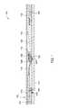
- FIG. 1illustrates a portion of a tool for use in a wellbore, according to one embodiment disclosed herein;
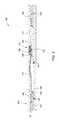
- FIG. 2illustrates the tool when actuated into a correct operational position, according to one embodiment disclosed herein;
- FIG. 3illustrates the tool when inadvertently actuated into an incorrect operational position, according to one embodiment disclosed herein;
- FIG. 4illustrates an enlarged view of a force transferring member of the tool, according to one embodiment disclosed herein;
- FIG. 5A , FIG. 5B , and FIG. 5Cillustrate the tool in run-in, first set, and second set positions, according to one embodiment disclosed herein;
- FIG. 6illustrates an enlarged view of the force transferring member of the tool
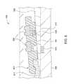
- FIG. 7illustrates a perspective view of a collet, according to one embodiment disclosed herein;
- FIG. 8illustrates a perspective view of a cone member, according to one embodiment disclosed herein;
- FIG. 9illustrates an enlarged view of a portion of a tool in one position, according to one embodiment disclosed herein.
- FIG. 10illustrates an enlarged view of the portion of the tool illustrated in FIG. 9 in another position, according to one embodiment disclosed herein.
- FIG. 1illustrates a portion of a tool 100 for use in a wellbore that provides a seal within a casing 102 , according to one embodiment disclosed herein.
- the tool 100is actuated into different operational positions by applying one or more mechanical, hydraulic, pneumatic, and/or electrical forces to the tool 100 .
- the tool 100may be an anchor, a liner hanger, or any other type of tool used in wellbore operations.
- the tool 100includes an upper mandrel 104 , an outer mandrel 116 , a first releasable member 108 , a collet member 114 , a seal assembly 112 , a cone member 110 , a lower mandrel 120 , a second releasable member 118 , and an inner mandrel 106 .
- the lower end of the upper mandrel 104is coupled to the upper end of the outer mandrel 116 , such as by a threaded connection.
- a seal 125is disposed between the upper mandrel 104 and the inner mandrel 106 .
- the outer mandrel 116is releasably coupled to the inner mandrel 106 by the first releasable member 108 .
- the outer mandrel 116is also coupled to the upper end of the collet member 114 .
- the lower end of the collet member 114is coupled to the seal assembly 112 , which engages a tapered surface 126 of the cone member 110 .
- a seal 145is disposed between the cone member 110 and the inner mandrel 106 .
- the lower end of the cone member 110is coupled to the upper end of the lower mandrel 120 , which is coupled to the inner mandrel 106 by the second releasable member 118 .
- the seal assembly 112is positioned at the base of the tapered surface 126 of the cone member 110 .
- the seal assembly 112includes a seal carrier 128 , two outer seals 130 , and an inner seal 132 , which inner seal 132 sealingly contacts the tapered surface 126 of the cone member 110 .
- the outer seals 130 and the inner seal 132are supported by the seal carrier 128 .
- the seal carrier 128is moved up the tapered surface 126 so that the outer seals 130 seal against the casing 102 during operation of the tool 100 , as further described herein.
- FIG. 2illustrates the tool 100 when correctly actuated into a first operational position, according to one embodiment disclosed herein.
- a force(identified by reference arrow “F”) is applied to the upper mandrel 104 .
- the origin of the forcemay be a mechanical, hydraulic, pneumatic, and/or electrical force applied to the tool 100 .
- the forceis transferred to the outer mandrel 116 to shear the first releasable member 108 .
- the forceis transmitted to the collet member 114 , the seal assembly 112 , the cone member 110 , and the lower mandrel 120 to shear the second releasable member 118 .
- the amount of force required to shear the second releasable member 118is less than the amount of force required to overcome friction between the seal assembly 112 and the tapered surface 126 of the cone member 110 .
- the forceis transmitted from the seal assembly 112 to the cone member 110 without moving the seal assembly 112 relative to the cone member 110 prior to shearing the second releasable member 118 .
- Moving the seal assembly 112 up the tapered surface 126 of the cone member 110 before shearing the second releasable member 118can pre-maturely wedge the seal assembly 112 between the casing 102 and the cone member 110 (as illustrated in FIG. 3 ).
- the upper mandrel 104 , the outer mandrel 116 , the collet member 114 , the seal assembly 112 , the cone member 110 , and the lower mandrel 120are movable relative to the inner mandrel 106 when the second releasable member 118 is sheared.
- the forcemoves the upper mandrel 104 , the outer mandrel 116 , the collet member 114 , the seal assembly 112 , the cone member 110 , and the lower mandrel 120 into a first operational position.
- the tool 100may be actuated into the first operational position to perform a desired function, such as to actuate a slip assembly into engagement with the surrounding wellbore.
- the tool 100may also be actuated into the first operational position to place the tool 100 in a desired condition for actuation into a second operational position. Subsequently, another force can be applied to the upper mandrel 104 , the outer mandrel 116 , and collet member 114 to move the seal assembly 112 up the tapered surface 126 . The seal assembly 112 is then wedged between the casing 102 and the cone member 110 to form a seal.
- FIG. 3illustrates the tool 100 when the seal assembly 112 is pre-maturely wedged between the casing 102 and the cone member 110 before the force is transmitted to shear the second releasable member 118 .
- the failure to shear the second releasable member 118may result in a malfunction of the tool 100 .
- Any subsequent amount of force applied to the upper mandrel 104 in an attempt to shear the second releasable member 118may be transmitted from the seal assembly 112 to the surrounding wellbore via the casing 102 , possibly damaging the seal assembly 112 , the casing 102 , and/or the surrounding wellbore.
- a subsequent actuation of the tool 100is prevented without conducting a remedial operation when the tool 100 is inadvertently actuated into the position shown in FIG. 3 .
- FIG. 4illustrates an enlarged view of a modified portion of the tool 100 that is configured to prevent premature actuation of the seal assembly 112 , according to one embodiment disclosed herein.
- the modified portion of the tool 100includes a seal assembly 400 (with the seals removed for clarity) that has a force transferring member 401 .
- the force transferring member 401engages the upper end of the cone member 110 .
- the force transferring member 401forms a part of an annular body 402 of a seal carrier 403 of the seal assembly 400 .
- the force transferring member 401may be a separate piece that is coupled to the annular body 402 .
- a plurality of grooves 412 a , 412 b , 412 cis formed in the annular body 402 to support a plurality of outer seals 530 and inner seals 532 (as shown in FIGS. 5A-5C and 6 ) similar to the seal assembly 112 illustrated in FIG. 1 .
- the force transferring member 401may be in the form of a deformable tab. As further described below with respect to FIG. 9 , the force transferring member 401 may be in the form of a shearable pin.
- the force transferring member 401may be formed integrally with the annular body 402 , or may be separately coupled to the annular body 402 .
- the force transferring member 401is configured to transmit a force from the seal carrier 403 to the cone member 110 .
- the force transferring member 401aids in preventing relative movement between the seal assembly 400 and the cone member 110 when the force transferring member 401 is in a first state, as shown in FIG. 4 .
- the force transferring member 401may deform to a second state, as shown in FIG. 5C and FIG. 6 , to allow relative movement between the seal assembly 400 and the cone member 110 and allow the seal assembly 400 to be moved up the tapered surface 126 of the cone member 110 and seal against the surrounding casing, similarly as described with respect to FIG. 1 and as further described below with respect to FIGS. 5A-5C .
- FIG. 5Aillustrates a tool 500 , in a run-in position, which is used to seal against a casing 502 at a desired location in a wellbore.
- the tool 500is actuated into different operational positions by applying one or more mechanical, hydraulic, pneumatic, and/or electrical forces to the tool 500 .
- the tool 500may be an anchor, a liner hanger, or any other type of tool used in wellbore operations.
- the tool 500includes a slip assembly 534 having a wedge member 522 and an one or more slips 536 .
- the tool 500also includes an upper mandrel 504 , an outer mandrel 516 , a first releasable member 508 , a collet member 514 , the seal assembly 400 , a cone member 510 , a lower mandrel 520 , a second releasable member 518 , and an inner mandrel 506 .
- the lower end of the upper mandrel 504is coupled to the upper end of the outer mandrel 516 .
- a seal 525is disposed between the upper mandrel 504 and the inner mandrel 506 .
- the outer mandrel 516is releasably coupled to the inner mandrel 506 by the first releasable member 508 .
- the outer mandrel 516is also coupled to the collet member 514 .
- the collet member 514is coupled to the seal assembly 400 , which engages a tapered surface 526 of the cone member 510 .
- a seal 545is disposed between the cone member 510 and the inner mandrel 506 .
- the cone member 510is coupled to the lower mandrel 520 , which is releasably coupled to the inner mandrel 506 by the second releasable member 518 .
- the seal assembly 400is positioned at the base of the tapered surface 526 of the cone member 510 .
- the seal assembly 400further includes two outer seals 530 and an inner seal 532 , which are supported by the seal carrier 403 .
- the seal carrier 403is moved up the tapered surface 526 of the cone member 510 so that the outer seals 530 seal against the casing 502 during operation of the tool 500 .
- the tool 500is actuated into a first set position by a force (identified by reference arrow “F”) applied to the upper mandrel 504 , which shears the first releasable member 508 .
- the force applied to the tool 500may be a mechanical, hydraulic, pneumatic, and/or electrical force.
- the forceis transmitted from the upper mandrel 504 to the outer mandrel 516 , the collet member 514 , the seal carrier 403 , and the force transferring member 401 .
- the force transferring member 401transfers the force to the cone member 510 and the lower mandrel 520 , without forcing the seal assembly 400 up the tapered surface 526 of the cone member 510 .
- the force transferring member 401is positioned adjacent to and engages the upper end of the cone member 510 .
- the force transferring member 401presses against the cone member 510 when the force applied to the upper mandrel 504 is transmitted to the seal carrier 403 .
- the force transferring member 401transfers the force provided to it from the upper mandrel 504 to the cone member 510 to prevent the seal assembly 400 from moving up the cone member 510 prior to shearing the second releasable member 518 and setting of the slips 536 as described below.
- the amount of force required to shear the second releasable member 518is less than the amount of force required to deform the force transferring member 401 to prevent inadvertent movement of the seal assembly 400 relative to the cone member 510 .
- the upper mandrel 504 , the outer mandrel 516 , the collet member 514 , the seal assembly 400 , cone member 510 , and lower mandrel 520then move together relative to the inner mandrel 506 to shear the second releasable member 518 .
- the forcemoves the upper mandrel 504 , the outer mandrel 516 , the collet member 514 , the seal assembly 400 , the cone member 510 , and the lower mandrel 520 until the end surface of the lower mandrel 520 contacts the end surface of the wedge member 522 .
- the wedge member 522is then forced underneath the slips 536 to force the slips 536 radially outward into engagement with the casing 502 .
- Wellbore fluidscan be circulated back up to the surface around the slips 536 and the seal assembly 400 (which has not yet been set) to allow for displacement of a slurry.
- the slurrymay be, for example, cement.
- the tool 500is actuated into a second set position.
- the same or a different forcecan be applied, or continue to be applied, to the upper mandrel 504 .
- the upper mandrel 504 , the outer mandrel 516 , the collet member 514 , the seal assembly 400 , the cone member 510 , and the lower mandrel 520may be prevented from further movement relative to the inner mandrel 506 .
- Continued application of the same or a different force to the upper mandrel 504will then deform the force transferring member 401 from the first position to a second position (illustrated in FIG. 6 ) to allow the seal assembly 400 to move up the tapered surface 526 of the cone member 510 and radially outward into engagement with the casing 502 to form a seal.
- FIG. 6is an enlarged view of the seal assembly 400 , the cone member 510 , and the collet member 514 with the force transferring member 401 deformed or bent into the second position.
- the force transferring member 401forced over the upper end of the cone member 510 and thereby deformed or bent to allow the seal assembly 400 to move up the tapered surface 526 without any significant resistance from the force transferring member 401 .
- the seal assembly 400is movable radially outward into the engagement with the casing 502 when no additional barriers are present. Thus, a tight seal is formed between the seal assembly 400 and the casing 502 .
- FIG. 7illustrates an enlarged view of a collet member 700 for use with the tools 100 , 500 according to one embodiment.
- the collet member 700includes an annular body 702 having a first end 704 opposite a second end 706 , an elongated surface 708 , and a plurality of fingers 710 .
- the elongated surface 708connects the first end 704 to the second end 706 .
- the plurality of fingers 710includes a first end 712 , a second end 714 , and a plurality of holes 716 .
- the first end 712 of each finger 710is coupled to the second end 706 of the annular body 702 .
- the second ends 714are opposite the first ends 712 of each finger 710 , and the plurality of holes 716 are formed in the second ends 714 of the fingers 710 .
- the collet member 700may have, for example, 24 fingers 710 extending from the second end 706 of the annular body 702 .
- Each finger 710may have, for example, two holes 716 , which allow for entry of a force transferring member (illustrated in FIG. 9 ), such as a shear pin.
- the force transferring memberreleasably connects the collet member 700 to a cone member as shown in FIG. 8 .
- FIG. 8illustrates an enlarged view of a cone member 800 for use with the tools 100 , 500 according to one embodiment.
- the cone member 800includes an annular body 802 having a first end 804 opposite a second end 806 , and an elongated surface 808 connecting the first end 804 to the second end 806 .
- the second end 806includes a plurality of holes 810 , which surround the circumference of the annular body 802 at the second end 806 .
- the plurality of holes 810 in the annular body 802 of the cone member 800are configured to mate with the plurality of holes 716 in the collet member 700 .
- a force transferring membershown in FIG. 9 ), such as a shear pin, may be placed through the holes 810 , 716 to temporarily connect the collet member 700 with the cone member 800 .
- FIG. 9illustrates an enlarged view of a portion of a tool 901 , according to one embodiment.
- the tool 901may be the same tool and/or operate the same as the tools 100 , 500 described above. However, instead of the force transferring member 401 as illustrated in FIG. 4 , the tool 901 includes a force transferring member 904 as illustrated in FIG. 9 and further described below. In one embodiment, the tools 100 , 500 , 901 may include a combination of the force transferring members 401 , 904 .
- the tool 901includes the collet member 700 , the cone member 800 , a seal assembly 900 , and the force transferring member 904 .
- the seal assembly 900includes a seal carrier 902 having an annular body 906 that is coupled to the collet member 700 .
- the annular body 906includes a plurality of grooves 908 configured to support one or more seals of the seal assembly 900 , such as the seals 130 of the seal assembly 112 shown in FIG. 1 .
- the force transferring member 904may be, for example, a shear pin, that is disposed in each of a plurality of holes 914 formed in the annular body 906 of the seal carrier 902 .
- the plurality of holes 914 in the annular body 906are configured to align with the plurality of holes 716 in each finger 710 of the collet member 700 , as well as the plurality of holes 810 in the cone member 800 .
- Each force transferring member 904may be placed through the holes 914 , 810 , 716 to temporarily connect the cone member 800 and the collet member 700 with the seal assembly 900 .
- the force transferring member 904is placed through the hole 914 of the annular body 906 and the hole 810 of the cone member.
- the force transferring member 904is placed through the hole 716 of the finger 710 and the hole 810 of the cone member 800 .
- Each force transferring member 904is configured to shear from a first state as shown in FIG. 9 to a second state as shown in FIG. 10 when it is desired for the seal assembly 900 to move up the tapered surface of the cone member 800 .
- the force transferring member 904aids in preventing relative movement between the seal assembly 900 and the cone member 800 to actuate the tool 901 into a first set position, such as the first set position of the tool 500 shown in FIG. 5B .
- the force transferring member 904transmits force from the collet member 700 to the cone member 800 , while preventing inadvertent movement of the seal assembly 900 relative to the cone member 800 .
- the force transferring member 904has been sheared into the second state to allow relative movement between the collet member 700 (and thus the seal assembly 900 ) and the cone member 800 , to allow the seal assembly 900 to move up the tapered surface of the cone member 800 and outward into the engagement with a surrounding casing to form a seal, similarly as described above with respect to tools 100 , 500 .
- the cone member 800may be prevented from further movement, such that a force applied or transmitted to the collet member 700 is directed to each force transferring member 904 .
- each force transferring member 904will shear to allow the tool 901 to actuate into a sealing position, similarly as described above with respect to tools 100 , 500 .
- a tool for use in a wellboreincludes a cone member; a seal assembly in engagement with the cone member; and a force transferring member having a first state that prevents relative movement between the seal assembly and the cone member, and having a second state where the seal assembly is movable relative to the cone member.
- the force transferring memberis a deformable tab.
- the force transferring memberis a shearable pin.
- the force transferring member in the second stateis deformed or sheared to allow relative movement between the seal assembly and the cone member.
- the seal assemblyincludes a seal carrier and one or more seals coupled to the seal carrier, and wherein the force transferring member is coupled to a body of the seal carrier.
- a plurality of outer sealsare coupled to the seal carrier and configured to seal against a surrounding wellbore, and wherein a plurality of inner seals are coupled to the seal carrier and configured to seal against the cone member.
- the force transferring memberincludes a shearable pin disposed in one or more holes formed through the seal assembly and the cone member.
- a collet memberis coupled to the seal assembly.
- the force transferring memberincludes a shearable pin disposed in one or more holes formed through the collet member and the cone member.
- a method of controlling a tool in a wellboreincludes transmitting a force from a collet member to a cone member, wherein a seal assembly coupled to the collet member engages the cone member; preventing relative movement between the seal assembly and the cone member using a force transferring member positioned in a first state; changing the force transferring member from the first state to a second state to allow movement between the seal assembly and the cone member; and moving the seal assembly relative to the cone member.
- changing the force transferring member from the first state to the second stateincludes deforming the force transferring member.
- changing the force transferring member from the first state to the second stateincludes shearing the force transferring member.
- the methodincludes transmitting the force from the collet member to the cone member to set one or more slips of the tool prior to moving the seal assembly relative to the cone member.
- changing the force transferring member from the first state to the second stateincludes transmitting another force from the collet member to the force transferring member to deform or shear the force transferring member.
- the force transferring member in the first stateengages an upper end of the cone member to prevent relative movement between the seal assembly and the cone member.
- moving the seal assembly relative to the cone membercomprises moving the seal assembly up a tapered surface of the cone member.
- the force transferring membercomprises a deformable tab that is coupled to or integral with a body of the seal assembly.
- the force transferring membercomprises a shearable pin disposed through one or more holes formed through at least one of the collet member and the cone member.
- transmitting the force from the seal assembly to the cone membersets one or more slips of the tool prior to moving the seal assembly relative to the cone member.
- changing the force transferring member from the first state to the second statecomprises transmitting another force from the seal assembly to the force transferring member to deform or shear the force transferring member.
Landscapes
- Life Sciences & Earth Sciences (AREA)
- Engineering & Computer Science (AREA)
- Geology (AREA)
- Mining & Mineral Resources (AREA)
- Physics & Mathematics (AREA)
- Environmental & Geological Engineering (AREA)
- Fluid Mechanics (AREA)
- General Life Sciences & Earth Sciences (AREA)
- Geochemistry & Mineralogy (AREA)
- Gripping On Spindles (AREA)
- Gasket Seals (AREA)
Abstract
Description
Claims (18)
Priority Applications (9)
| Application Number | Priority Date | Filing Date | Title |
|---|---|---|---|
| US15/147,302US10180038B2 (en) | 2015-05-06 | 2016-05-05 | Force transferring member for use in a tool |
| GB2102151.4AGB2588742B (en) | 2015-05-06 | 2016-05-06 | Force transferring member for use in a tool |
| CA2984792ACA2984792C (en) | 2015-05-06 | 2016-05-06 | Force transferring member for use in a tool |
| CA3174696ACA3174696C (en) | 2015-05-06 | 2016-05-06 | Force transferring member for use in a tool |
| GB1718952.3AGB2554300B (en) | 2015-05-06 | 2016-05-06 | Force transferring member for use in a tool |
| AU2016258082AAU2016258082B2 (en) | 2015-05-06 | 2016-05-06 | Force transferring member for use in a tool |
| PCT/US2016/031103WO2016179453A1 (en) | 2015-05-06 | 2016-05-06 | Force transferring member for use in a tool |
| NO20171851ANO20171851A1 (en) | 2015-05-06 | 2017-11-21 | Force transferring member for use in a tool |
| AU2020204345AAU2020204345B2 (en) | 2015-05-06 | 2020-06-29 | Force transferring member for use in a tool |
Applications Claiming Priority (2)
| Application Number | Priority Date | Filing Date | Title |
|---|---|---|---|
| US201562157691P | 2015-05-06 | 2015-05-06 | |
| US15/147,302US10180038B2 (en) | 2015-05-06 | 2016-05-05 | Force transferring member for use in a tool |
Publications (2)
| Publication Number | Publication Date |
|---|---|
| US20160326831A1 US20160326831A1 (en) | 2016-11-10 |
| US10180038B2true US10180038B2 (en) | 2019-01-15 |
Family
ID=56098338
Family Applications (1)
| Application Number | Title | Priority Date | Filing Date |
|---|---|---|---|
| US15/147,302Active2036-10-01US10180038B2 (en) | 2015-05-06 | 2016-05-05 | Force transferring member for use in a tool |
Country Status (6)
| Country | Link |
|---|---|
| US (1) | US10180038B2 (en) |
| AU (2) | AU2016258082B2 (en) |
| CA (2) | CA2984792C (en) |
| GB (2) | GB2588742B (en) |
| NO (1) | NO20171851A1 (en) |
| WO (1) | WO2016179453A1 (en) |
Cited By (1)
| Publication number | Priority date | Publication date | Assignee | Title |
|---|---|---|---|---|
| US20200048982A1 (en)* | 2018-08-08 | 2020-02-13 | Baker Hughes, A Ge Company, Llc | System for limiting radial expansion of an expandable seal |
Families Citing this family (5)
| Publication number | Priority date | Publication date | Assignee | Title |
|---|---|---|---|---|
| US9915121B2 (en)* | 2015-06-16 | 2018-03-13 | Baker Hughes, A Ge Company, Llc | Seal pressure relaxation device prior to release of retrievable packer |
| US10214987B2 (en)* | 2016-08-31 | 2019-02-26 | Baker Hughes, A Ge Company, Llc | Downhole tool with integrated scale removal feature |
| US10260310B2 (en) | 2017-07-10 | 2019-04-16 | Baker Hughes, A Ge Company, Llc | High temperature and pressure packer |
| NO20210510A1 (en)* | 2018-11-02 | 2021-04-27 | Dril Quip Inc | Liner hanger with enhanced locking assembly |
| WO2021080934A1 (en)* | 2019-10-20 | 2021-04-29 | Schlumberger Technology Corporation | Combined actuation of slips and packer sealing element |
Citations (85)
| Publication number | Priority date | Publication date | Assignee | Title |
|---|---|---|---|---|
| US2125665A (en) | 1935-07-01 | 1938-08-02 | M O Johnston | Sleeve packer construction |
| US2652894A (en) | 1948-08-09 | 1953-09-22 | Brown | Hold-down slip assembly for well packers |
| US3147016A (en) | 1959-04-06 | 1964-09-01 | Traufler Daniel | Annular gaskets |
| US3215208A (en) | 1961-06-08 | 1965-11-02 | Otis Eng Co | Sealing devices |
| US3227462A (en) | 1964-06-10 | 1966-01-04 | Otis Eng Co | Seal assemblies for tubular conductors |
| US3278192A (en) | 1962-10-08 | 1966-10-11 | Otis Eng Co | Sealing devices |
| US3374838A (en) | 1965-11-08 | 1968-03-26 | Schlumberger Well Surv Corp | Fluid expansible packer and anchor apparatus |
| US3631926A (en) | 1969-12-31 | 1972-01-04 | Schlumberger Technology Corp | Well packer |
| US3784214A (en) | 1971-10-18 | 1974-01-08 | J Tamplen | Seal that is responsive to either mechanical or pressure force |
| US4482086A (en) | 1983-08-04 | 1984-11-13 | Uop Inc. | Expandable packer assembly for sealing a well screen to a casing |
| US4588029A (en) | 1984-09-27 | 1986-05-13 | Camco, Incorporated | Expandable metal seal for a well tool |
| US4752444A (en) | 1985-12-09 | 1988-06-21 | Bowen Ltd. | Method for sterilizing a dental handpiece |
| US4757860A (en) | 1985-05-02 | 1988-07-19 | Dril-Quip, Inc. | Wellhead equipment |
| US4809989A (en) | 1987-06-05 | 1989-03-07 | Otis Engineering Corporation | Coil spring supported sealing element and device |
| US4842061A (en) | 1988-02-05 | 1989-06-27 | Vetco Gray Inc. | Casing hanger packoff with C-shaped metal seal |
| US5052483A (en) | 1990-11-05 | 1991-10-01 | Bestline Liner Systems | Sand control adapter |
| US5076356A (en) | 1989-06-21 | 1991-12-31 | Dril-Quip, Inc. | Wellhead equipment |
| US5311938A (en) | 1992-05-15 | 1994-05-17 | Halliburton Company | Retrievable packer for high temperature, high pressure service |
| US5333692A (en) | 1992-01-29 | 1994-08-02 | Baker Hughes Incorporated | Straight bore metal-to-metal wellbore seal apparatus and method of sealing in a wellbore |
| US5355961A (en) | 1993-04-02 | 1994-10-18 | Abb Vetco Gray Inc. | Metal and elastomer casing hanger seal |
| US5433269A (en) | 1992-05-15 | 1995-07-18 | Halliburton Company | Retrievable packer for high temperature, high pressure service |
| US5462121A (en) | 1994-05-03 | 1995-10-31 | Baker Hughes Incorporated | Failsafe liner installation assembly and method |
| US5467822A (en) | 1991-08-31 | 1995-11-21 | Zwart; Klaas J. | Pack-off tool |
| US5511620A (en) | 1992-01-29 | 1996-04-30 | Baugh; John L. | Straight Bore metal-to-metal wellbore seal apparatus and method of sealing in a wellbore |
| SU1367586A1 (en) | 1986-03-24 | 1996-11-27 | Татарский Государственный Научно-Исследовательский И Проектный Институт Нефтяной Промышленности | Connection of shaped pipes of well shutoff devices |
| US5603511A (en) | 1995-08-11 | 1997-02-18 | Greene, Tweed Of Delaware, Inc. | Expandable seal assembly with anti-extrusion backup |
| US5685369A (en) | 1996-05-01 | 1997-11-11 | Abb Vetco Gray Inc. | Metal seal well packer |
| US5857520A (en) | 1996-11-14 | 1999-01-12 | Halliburton Energy Services, Inc. | Backup shoe for well packer |
| US6123148A (en) | 1997-11-25 | 2000-09-26 | Halliburton Energy Services, Inc. | Compact retrievable well packer |
| US6142227A (en) | 1995-09-08 | 2000-11-07 | Bronnteknologiutvikling As | Expandable retrievable bridge plug |
| US6409175B1 (en) | 1999-07-13 | 2002-06-25 | Grant Prideco, Inc. | Expandable joint connector |
| US20020088616A1 (en) | 2000-07-11 | 2002-07-11 | Swor Loren C. | High temperature high pressure retrievable packer with barrel slip |
| US6425444B1 (en) | 1998-12-22 | 2002-07-30 | Weatherford/Lamb, Inc. | Method and apparatus for downhole sealing |
| US6446717B1 (en) | 2000-06-01 | 2002-09-10 | Weatherford/Lamb, Inc. | Core-containing sealing assembly |
| US20020148612A1 (en) | 1998-11-16 | 2002-10-17 | Shell Oil Co. | Isolation of subterranean zones |
| WO2002097234A1 (en) | 2001-05-18 | 2002-12-05 | Dril-Quip, Inc. | Line hanger, running tool and method |
| US6666276B1 (en) | 2001-10-19 | 2003-12-23 | John M. Yokley | Downhole radial set packer element |
| US6691789B2 (en) | 2001-09-10 | 2004-02-17 | Weatherford/Lamb, Inc. | Expandable hanger and packer |
| US6705615B2 (en) | 2001-10-31 | 2004-03-16 | Dril-Quip, Inc. | Sealing system and method |
| US20040060706A1 (en) | 2002-09-26 | 2004-04-01 | Stephenson David J. | Expandable connection for use with a swelling elastomer |
| US20040123983A1 (en) | 1998-11-16 | 2004-07-01 | Enventure Global Technology L.L.C. | Isolation of subterranean zones |
| US6763893B2 (en) | 2001-11-30 | 2004-07-20 | Tiw Corporation | Downhole tubular patch, tubular expander and method |
| US6769491B2 (en) | 2002-06-07 | 2004-08-03 | Weatherford/Lamb, Inc. | Anchoring and sealing system for a downhole tool |
| US6772844B2 (en) | 2001-10-30 | 2004-08-10 | Smith International, Inc. | High pressure sealing apparatus and method |
| US6789622B1 (en) | 1999-09-06 | 2004-09-14 | Ez Tech Limited | Apparatus for and a method of anchoring an expandable conduit |
| US6814143B2 (en) | 2001-11-30 | 2004-11-09 | Tiw Corporation | Downhole tubular patch, tubular expander and method |
| US6902008B2 (en) | 2001-12-12 | 2005-06-07 | Weatherford/Lamb, Inc. | Bi-directionally boosting and internal pressure trapping packing element system |
| US20050172472A1 (en) | 2002-01-03 | 2005-08-11 | Vallourec Mannesmann Oil & Gas France | Method for making a sealed tubular joint with plastic expansion |
| US20050173110A1 (en) | 2004-02-06 | 2005-08-11 | Trahan Kevin O. | Wellbore seal device |
| US6962206B2 (en) | 2003-05-15 | 2005-11-08 | Weatherford/Lamb, Inc. | Packer with metal sealing element |
| US20060186602A1 (en) | 2003-08-29 | 2006-08-24 | Caledyne Limited | Improved seal |
| US20060272827A1 (en) | 2005-02-11 | 2006-12-07 | Adam Mark K | One trip cemented expandable monobore liner system and method |
| US7213814B2 (en) | 2004-07-28 | 2007-05-08 | Federal-Mogul Worldwide, Inc. | Seal assembly |
| US7225880B2 (en) | 2004-05-27 | 2007-06-05 | Tiw Corporation | Expandable liner hanger system and method |
| US7234533B2 (en) | 2003-10-03 | 2007-06-26 | Schlumberger Technology Corporation | Well packer having an energized sealing element and associated method |
| US20070151725A1 (en) | 1998-12-07 | 2007-07-05 | Shell Oil Company | Expanding a tubular member |
| US7252142B2 (en) | 2002-09-23 | 2007-08-07 | Halliburton Energy Services, Inc. | Annular isolators for expandable tubulars in wellbores |
| US7322422B2 (en) | 2002-04-17 | 2008-01-29 | Schlumberger Technology Corporation | Inflatable packer inside an expandable packer and method |
| WO2008014095A1 (en) | 2006-07-26 | 2008-01-31 | Baker Hughes Incorporated | Swelling packer element with enhanced sealing force |
| US7360592B2 (en) | 2005-04-20 | 2008-04-22 | Baker Hughes Incorporated | Compliant cladding seal/hanger |
| US7367404B2 (en) | 1998-12-22 | 2008-05-06 | Weatherford/Lamb, Inc. | Tubing seal |
| US7370708B2 (en) | 2003-08-02 | 2008-05-13 | Weatherford/Lamb, Inc. | Seal arrangement |
| US7380592B2 (en) | 2003-10-09 | 2008-06-03 | Nicholas Atkins | Pressure control tool for modluating pressure in a portion of a wellbore |
| US7387170B2 (en) | 2002-04-05 | 2008-06-17 | Baker Hughes Incorporated | Expandable packer with mounted exterior slips and seal |
| US7407165B1 (en) | 2000-04-04 | 2008-08-05 | Hutchinson Fts, Inc. | Composite sleeve for sealing a tubular coupling |
| US7441606B2 (en) | 2003-05-01 | 2008-10-28 | Weatherford/Lamb, Inc. | Expandable fluted liner hanger and packer system |
| US7469750B2 (en) | 2004-09-20 | 2008-12-30 | Owen Oil Tools Lp | Expandable seal |
| US20090205843A1 (en) | 2008-02-19 | 2009-08-20 | Varadaraju Gandikota | Expandable packer |
| US7665532B2 (en) | 1998-12-07 | 2010-02-23 | Shell Oil Company | Pipeline |
| US20100089591A1 (en) | 2008-10-13 | 2010-04-15 | Gordon Thomson | Expandable liner hanger and method of use |
| US7703542B2 (en) | 2007-06-05 | 2010-04-27 | Baker Hughes Incorporated | Expandable packer system |
| US7740248B2 (en) | 2003-09-18 | 2010-06-22 | Cameron International Corporation | Annular seal |
| US7748467B2 (en) | 2007-05-31 | 2010-07-06 | Baker Hughes Incorporated | Downhole seal apparatus and method |
| US7766088B2 (en) | 2005-07-07 | 2010-08-03 | Baker Hughes Incorporated | System and method for actuating wellbore tools |
| US7775290B2 (en) | 2003-04-17 | 2010-08-17 | Enventure Global Technology, Llc | Apparatus for radially expanding and plastically deforming a tubular member |
| US7779927B2 (en) | 2001-06-27 | 2010-08-24 | Weatherford/Lamb, Inc. | Non-metallic mandrel and element system |
| US7784797B2 (en) | 2006-05-19 | 2010-08-31 | Baker Hughes Incorporated | Seal and slip assembly for expandable downhole tools |
| US7921921B2 (en) | 2008-09-24 | 2011-04-12 | Baker Hughes Incorporated | Downhole backup system and method |
| US8066065B2 (en) | 2009-08-03 | 2011-11-29 | Halliburton Energy Services Inc. | Expansion device |
| US8109340B2 (en) | 2009-06-27 | 2012-02-07 | Baker Hughes Incorporated | High-pressure/high temperature packer seal |
| US20120205872A1 (en) | 2011-02-16 | 2012-08-16 | Paul Andrew Reinhardt | Extrusion-resistant seals for expandable tubular assembly |
| US8459347B2 (en) | 2008-12-10 | 2013-06-11 | Oiltool Engineering Services, Inc. | Subterranean well ultra-short slip and packing element system |
| US20130269956A1 (en) | 2012-04-17 | 2013-10-17 | Baker Hughes Incorporated | Expandable Annular Isolator |
| US20130292138A1 (en) | 2012-05-03 | 2013-11-07 | Weatherford/Lamb, Inc. | Seal Stem |
| US8997882B2 (en) | 2011-02-16 | 2015-04-07 | Weatherford Technology Holdings, Llc | Stage tool |
- 2016
- 2016-05-05USUS15/147,302patent/US10180038B2/enactiveActive
- 2016-05-06WOPCT/US2016/031103patent/WO2016179453A1/ennot_activeCeased
- 2016-05-06GBGB2102151.4Apatent/GB2588742B/enactiveActive
- 2016-05-06AUAU2016258082Apatent/AU2016258082B2/enactiveActive
- 2016-05-06CACA2984792Apatent/CA2984792C/enactiveActive
- 2016-05-06CACA3174696Apatent/CA3174696C/enactiveActive
- 2016-05-06GBGB1718952.3Apatent/GB2554300B/enactiveActive
- 2017
- 2017-11-21NONO20171851Apatent/NO20171851A1/enunknown
- 2020
- 2020-06-29AUAU2020204345Apatent/AU2020204345B2/enactiveActive
Patent Citations (90)
| Publication number | Priority date | Publication date | Assignee | Title |
|---|---|---|---|---|
| US2125665A (en) | 1935-07-01 | 1938-08-02 | M O Johnston | Sleeve packer construction |
| US2652894A (en) | 1948-08-09 | 1953-09-22 | Brown | Hold-down slip assembly for well packers |
| US3147016A (en) | 1959-04-06 | 1964-09-01 | Traufler Daniel | Annular gaskets |
| US3215208A (en) | 1961-06-08 | 1965-11-02 | Otis Eng Co | Sealing devices |
| US3278192A (en) | 1962-10-08 | 1966-10-11 | Otis Eng Co | Sealing devices |
| US3227462A (en) | 1964-06-10 | 1966-01-04 | Otis Eng Co | Seal assemblies for tubular conductors |
| US3374838A (en) | 1965-11-08 | 1968-03-26 | Schlumberger Well Surv Corp | Fluid expansible packer and anchor apparatus |
| US3631926A (en) | 1969-12-31 | 1972-01-04 | Schlumberger Technology Corp | Well packer |
| US3784214A (en) | 1971-10-18 | 1974-01-08 | J Tamplen | Seal that is responsive to either mechanical or pressure force |
| US4482086A (en) | 1983-08-04 | 1984-11-13 | Uop Inc. | Expandable packer assembly for sealing a well screen to a casing |
| US4588029A (en) | 1984-09-27 | 1986-05-13 | Camco, Incorporated | Expandable metal seal for a well tool |
| US4757860A (en) | 1985-05-02 | 1988-07-19 | Dril-Quip, Inc. | Wellhead equipment |
| US4752444A (en) | 1985-12-09 | 1988-06-21 | Bowen Ltd. | Method for sterilizing a dental handpiece |
| SU1367586A1 (en) | 1986-03-24 | 1996-11-27 | Татарский Государственный Научно-Исследовательский И Проектный Институт Нефтяной Промышленности | Connection of shaped pipes of well shutoff devices |
| US4809989A (en) | 1987-06-05 | 1989-03-07 | Otis Engineering Corporation | Coil spring supported sealing element and device |
| US4842061A (en) | 1988-02-05 | 1989-06-27 | Vetco Gray Inc. | Casing hanger packoff with C-shaped metal seal |
| US5076356A (en) | 1989-06-21 | 1991-12-31 | Dril-Quip, Inc. | Wellhead equipment |
| US5052483A (en) | 1990-11-05 | 1991-10-01 | Bestline Liner Systems | Sand control adapter |
| US5467822A (en) | 1991-08-31 | 1995-11-21 | Zwart; Klaas J. | Pack-off tool |
| US5511620A (en) | 1992-01-29 | 1996-04-30 | Baugh; John L. | Straight Bore metal-to-metal wellbore seal apparatus and method of sealing in a wellbore |
| US5333692A (en) | 1992-01-29 | 1994-08-02 | Baker Hughes Incorporated | Straight bore metal-to-metal wellbore seal apparatus and method of sealing in a wellbore |
| US5433269A (en) | 1992-05-15 | 1995-07-18 | Halliburton Company | Retrievable packer for high temperature, high pressure service |
| US5311938A (en) | 1992-05-15 | 1994-05-17 | Halliburton Company | Retrievable packer for high temperature, high pressure service |
| US5355961A (en) | 1993-04-02 | 1994-10-18 | Abb Vetco Gray Inc. | Metal and elastomer casing hanger seal |
| US5462121A (en) | 1994-05-03 | 1995-10-31 | Baker Hughes Incorporated | Failsafe liner installation assembly and method |
| US5603511A (en) | 1995-08-11 | 1997-02-18 | Greene, Tweed Of Delaware, Inc. | Expandable seal assembly with anti-extrusion backup |
| US6142227A (en) | 1995-09-08 | 2000-11-07 | Bronnteknologiutvikling As | Expandable retrievable bridge plug |
| US5685369A (en) | 1996-05-01 | 1997-11-11 | Abb Vetco Gray Inc. | Metal seal well packer |
| US5857520A (en) | 1996-11-14 | 1999-01-12 | Halliburton Energy Services, Inc. | Backup shoe for well packer |
| US6123148A (en) | 1997-11-25 | 2000-09-26 | Halliburton Energy Services, Inc. | Compact retrievable well packer |
| US20040123983A1 (en) | 1998-11-16 | 2004-07-01 | Enventure Global Technology L.L.C. | Isolation of subterranean zones |
| US20020148612A1 (en) | 1998-11-16 | 2002-10-17 | Shell Oil Co. | Isolation of subterranean zones |
| US20070151725A1 (en) | 1998-12-07 | 2007-07-05 | Shell Oil Company | Expanding a tubular member |
| US7665532B2 (en) | 1998-12-07 | 2010-02-23 | Shell Oil Company | Pipeline |
| US6425444B1 (en) | 1998-12-22 | 2002-07-30 | Weatherford/Lamb, Inc. | Method and apparatus for downhole sealing |
| US7367404B2 (en) | 1998-12-22 | 2008-05-06 | Weatherford/Lamb, Inc. | Tubing seal |
| US6409175B1 (en) | 1999-07-13 | 2002-06-25 | Grant Prideco, Inc. | Expandable joint connector |
| US6789622B1 (en) | 1999-09-06 | 2004-09-14 | Ez Tech Limited | Apparatus for and a method of anchoring an expandable conduit |
| US7407165B1 (en) | 2000-04-04 | 2008-08-05 | Hutchinson Fts, Inc. | Composite sleeve for sealing a tubular coupling |
| US6446717B1 (en) | 2000-06-01 | 2002-09-10 | Weatherford/Lamb, Inc. | Core-containing sealing assembly |
| US20020088616A1 (en) | 2000-07-11 | 2002-07-11 | Swor Loren C. | High temperature high pressure retrievable packer with barrel slip |
| WO2002097234A1 (en) | 2001-05-18 | 2002-12-05 | Dril-Quip, Inc. | Line hanger, running tool and method |
| US7779927B2 (en) | 2001-06-27 | 2010-08-24 | Weatherford/Lamb, Inc. | Non-metallic mandrel and element system |
| US6691789B2 (en) | 2001-09-10 | 2004-02-17 | Weatherford/Lamb, Inc. | Expandable hanger and packer |
| US6666276B1 (en) | 2001-10-19 | 2003-12-23 | John M. Yokley | Downhole radial set packer element |
| US6772844B2 (en) | 2001-10-30 | 2004-08-10 | Smith International, Inc. | High pressure sealing apparatus and method |
| US6705615B2 (en) | 2001-10-31 | 2004-03-16 | Dril-Quip, Inc. | Sealing system and method |
| US6814143B2 (en) | 2001-11-30 | 2004-11-09 | Tiw Corporation | Downhole tubular patch, tubular expander and method |
| US6763893B2 (en) | 2001-11-30 | 2004-07-20 | Tiw Corporation | Downhole tubular patch, tubular expander and method |
| US6902008B2 (en) | 2001-12-12 | 2005-06-07 | Weatherford/Lamb, Inc. | Bi-directionally boosting and internal pressure trapping packing element system |
| US7172029B2 (en) | 2001-12-12 | 2007-02-06 | Weatherford/Lamb, Inc. | Bi-directionally boosting and internal pressure trapping packing element system |
| US20050172472A1 (en) | 2002-01-03 | 2005-08-11 | Vallourec Mannesmann Oil & Gas France | Method for making a sealed tubular joint with plastic expansion |
| US7387170B2 (en) | 2002-04-05 | 2008-06-17 | Baker Hughes Incorporated | Expandable packer with mounted exterior slips and seal |
| US7493945B2 (en) | 2002-04-05 | 2009-02-24 | Baker Hughes Incorporated | Expandable packer with mounted exterior slips and seal |
| US7322422B2 (en) | 2002-04-17 | 2008-01-29 | Schlumberger Technology Corporation | Inflatable packer inside an expandable packer and method |
| US6769491B2 (en) | 2002-06-07 | 2004-08-03 | Weatherford/Lamb, Inc. | Anchoring and sealing system for a downhole tool |
| US7252142B2 (en) | 2002-09-23 | 2007-08-07 | Halliburton Energy Services, Inc. | Annular isolators for expandable tubulars in wellbores |
| US20040060706A1 (en) | 2002-09-26 | 2004-04-01 | Stephenson David J. | Expandable connection for use with a swelling elastomer |
| US7775290B2 (en) | 2003-04-17 | 2010-08-17 | Enventure Global Technology, Llc | Apparatus for radially expanding and plastically deforming a tubular member |
| US7441606B2 (en) | 2003-05-01 | 2008-10-28 | Weatherford/Lamb, Inc. | Expandable fluted liner hanger and packer system |
| US7165622B2 (en) | 2003-05-15 | 2007-01-23 | Weatherford/Lamb, Inc. | Packer with metal sealing element |
| US6962206B2 (en) | 2003-05-15 | 2005-11-08 | Weatherford/Lamb, Inc. | Packer with metal sealing element |
| US7370708B2 (en) | 2003-08-02 | 2008-05-13 | Weatherford/Lamb, Inc. | Seal arrangement |
| US20060186602A1 (en) | 2003-08-29 | 2006-08-24 | Caledyne Limited | Improved seal |
| US7740248B2 (en) | 2003-09-18 | 2010-06-22 | Cameron International Corporation | Annular seal |
| US7234533B2 (en) | 2003-10-03 | 2007-06-26 | Schlumberger Technology Corporation | Well packer having an energized sealing element and associated method |
| US7380592B2 (en) | 2003-10-09 | 2008-06-03 | Nicholas Atkins | Pressure control tool for modluating pressure in a portion of a wellbore |
| US7036581B2 (en) | 2004-02-06 | 2006-05-02 | Allamon Interests | Wellbore seal device |
| US20050173110A1 (en) | 2004-02-06 | 2005-08-11 | Trahan Kevin O. | Wellbore seal device |
| US7225880B2 (en) | 2004-05-27 | 2007-06-05 | Tiw Corporation | Expandable liner hanger system and method |
| US7213814B2 (en) | 2004-07-28 | 2007-05-08 | Federal-Mogul Worldwide, Inc. | Seal assembly |
| US7469750B2 (en) | 2004-09-20 | 2008-12-30 | Owen Oil Tools Lp | Expandable seal |
| US20060272827A1 (en) | 2005-02-11 | 2006-12-07 | Adam Mark K | One trip cemented expandable monobore liner system and method |
| US7360592B2 (en) | 2005-04-20 | 2008-04-22 | Baker Hughes Incorporated | Compliant cladding seal/hanger |
| US7766088B2 (en) | 2005-07-07 | 2010-08-03 | Baker Hughes Incorporated | System and method for actuating wellbore tools |
| US7784797B2 (en) | 2006-05-19 | 2010-08-31 | Baker Hughes Incorporated | Seal and slip assembly for expandable downhole tools |
| WO2008014095A1 (en) | 2006-07-26 | 2008-01-31 | Baker Hughes Incorporated | Swelling packer element with enhanced sealing force |
| US7748467B2 (en) | 2007-05-31 | 2010-07-06 | Baker Hughes Incorporated | Downhole seal apparatus and method |
| US7703542B2 (en) | 2007-06-05 | 2010-04-27 | Baker Hughes Incorporated | Expandable packer system |
| US20110037230A1 (en) | 2007-06-05 | 2011-02-17 | O'connor Keven | Expandable packer system |
| US20090205843A1 (en) | 2008-02-19 | 2009-08-20 | Varadaraju Gandikota | Expandable packer |
| US7921921B2 (en) | 2008-09-24 | 2011-04-12 | Baker Hughes Incorporated | Downhole backup system and method |
| US20100089591A1 (en) | 2008-10-13 | 2010-04-15 | Gordon Thomson | Expandable liner hanger and method of use |
| US8459347B2 (en) | 2008-12-10 | 2013-06-11 | Oiltool Engineering Services, Inc. | Subterranean well ultra-short slip and packing element system |
| US8109340B2 (en) | 2009-06-27 | 2012-02-07 | Baker Hughes Incorporated | High-pressure/high temperature packer seal |
| US8066065B2 (en) | 2009-08-03 | 2011-11-29 | Halliburton Energy Services Inc. | Expansion device |
| US20120205872A1 (en) | 2011-02-16 | 2012-08-16 | Paul Andrew Reinhardt | Extrusion-resistant seals for expandable tubular assembly |
| US8997882B2 (en) | 2011-02-16 | 2015-04-07 | Weatherford Technology Holdings, Llc | Stage tool |
| US20130269956A1 (en) | 2012-04-17 | 2013-10-17 | Baker Hughes Incorporated | Expandable Annular Isolator |
| US20130292138A1 (en) | 2012-05-03 | 2013-11-07 | Weatherford/Lamb, Inc. | Seal Stem |
Non-Patent Citations (1)
| Title |
|---|
| PCT International Search Report and Written Opinion dated Jul. 28, 2016, for International Patent Application No. PCT/2016/031103. |
Cited By (2)
| Publication number | Priority date | Publication date | Assignee | Title |
|---|---|---|---|---|
| US20200048982A1 (en)* | 2018-08-08 | 2020-02-13 | Baker Hughes, A Ge Company, Llc | System for limiting radial expansion of an expandable seal |
| US10760371B2 (en)* | 2018-08-08 | 2020-09-01 | Baker Hughes, A Ge Company, Llc | System for limiting radial expansion of an expandable seal |
Also Published As
| Publication number | Publication date |
|---|---|
| GB202102151D0 (en) | 2021-03-31 |
| GB2588742A (en) | 2021-05-05 |
| GB2554300A (en) | 2018-03-28 |
| GB201718952D0 (en) | 2018-01-03 |
| GB2554300B (en) | 2021-07-14 |
| AU2020204345B2 (en) | 2022-02-10 |
| WO2016179453A1 (en) | 2016-11-10 |
| US20160326831A1 (en) | 2016-11-10 |
| GB2588742B (en) | 2021-09-08 |
| NO20171851A1 (en) | 2017-11-21 |
| AU2016258082B2 (en) | 2020-05-28 |
| CA3174696C (en) | 2024-05-28 |
| CA3174696A1 (en) | 2016-11-10 |
| CA2984792A1 (en) | 2016-11-10 |
| CA2984792C (en) | 2022-12-06 |
| AU2016258082A1 (en) | 2017-12-07 |
| AU2020204345A1 (en) | 2020-07-16 |
Similar Documents
| Publication | Publication Date | Title |
|---|---|---|
| AU2020204345B2 (en) | Force transferring member for use in a tool | |
| US7578353B2 (en) | Apparatus for controlling slip deployment in a downhole device | |
| EP2598711B1 (en) | Expanding elastomer/plug device for sealing bore hole and pipelines | |
| RU2687825C1 (en) | Bidirectional dies | |
| CN109138900B (en) | Plugging device, setting short section and matching equipment | |
| CN102197189B (en) | Downhole tool with load diverting system and method | |
| CN102762813B (en) | Downhole tool releasing mechanism | |
| CN104254663A (en) | Tubular anchoring system and method | |
| US9810037B2 (en) | Shear thickening fluid controlled tool | |
| US10689918B2 (en) | Retrievable re-connecting device with internal seal and slips for connecting to the top of an existing tubing in a well bore | |
| US7971640B2 (en) | Method and device for setting a bottom packer | |
| NO20151531A1 (en) | Seal Assembly | |
| US9534462B2 (en) | Support cone for retrievable packer | |
| US20200003032A1 (en) | Casing Patch | |
| US20150191992A1 (en) | Mandrel for Re-pressurization and Downhole Plugging Apparatus | |
| EP2723973B1 (en) | Plug, and methods for setting and releasing the plug | |
| CN111119786B (en) | Packer, setting tool and drilling and completion integrated method | |
| US3419078A (en) | Pump anchors |
Legal Events
| Date | Code | Title | Description |
|---|---|---|---|
| AS | Assignment | Owner name:WEATHERFORD TECHNOLOGY HOLDINGS, LLC, TEXAS Free format text:ASSIGNMENT OF ASSIGNORS INTEREST;ASSIGNOR:REINHARDT, PAUL ANDREW;REEL/FRAME:038567/0227 Effective date:20160506 | |
| STCF | Information on status: patent grant | Free format text:PATENTED CASE | |
| AS | Assignment | Owner name:WELLS FARGO BANK NATIONAL ASSOCIATION AS AGENT, TEXAS Free format text:SECURITY INTEREST;ASSIGNORS:WEATHERFORD TECHNOLOGY HOLDINGS LLC;WEATHERFORD NETHERLANDS B.V.;WEATHERFORD NORGE AS;AND OTHERS;REEL/FRAME:051891/0089 Effective date:20191213 | |
| AS | Assignment | Owner name:DEUTSCHE BANK TRUST COMPANY AMERICAS, AS ADMINISTR Free format text:SECURITY INTEREST;ASSIGNORS:WEATHERFORD TECHNOLOGY HOLDINGS, LLC;WEATHERFORD NETHERLANDS B.V.;WEATHERFORD NORGE AS;AND OTHERS;REEL/FRAME:051419/0140 Effective date:20191213 Owner name:DEUTSCHE BANK TRUST COMPANY AMERICAS, AS ADMINISTRATIVE AGENT, NEW YORK Free format text:SECURITY INTEREST;ASSIGNORS:WEATHERFORD TECHNOLOGY HOLDINGS, LLC;WEATHERFORD NETHERLANDS B.V.;WEATHERFORD NORGE AS;AND OTHERS;REEL/FRAME:051419/0140 Effective date:20191213 | |
| AS | Assignment | Owner name:WEATHERFORD NORGE AS, TEXAS Free format text:RELEASE BY SECURED PARTY;ASSIGNOR:WELLS FARGO BANK, NATIONAL ASSOCIATION;REEL/FRAME:053838/0323 Effective date:20200828 Owner name:WEATHERFORD CANADA LTD., TEXAS Free format text:RELEASE BY SECURED PARTY;ASSIGNOR:WELLS FARGO BANK, NATIONAL ASSOCIATION;REEL/FRAME:053838/0323 Effective date:20200828 Owner name:HIGH PRESSURE INTEGRITY, INC., TEXAS Free format text:RELEASE BY SECURED PARTY;ASSIGNOR:WELLS FARGO BANK, NATIONAL ASSOCIATION;REEL/FRAME:053838/0323 Effective date:20200828 Owner name:WEATHERFORD TECHNOLOGY HOLDINGS, LLC, TEXAS Free format text:RELEASE BY SECURED PARTY;ASSIGNOR:WELLS FARGO BANK, NATIONAL ASSOCIATION;REEL/FRAME:053838/0323 Effective date:20200828 Owner name:WEATHERFORD U.K. LIMITED, TEXAS Free format text:RELEASE BY SECURED PARTY;ASSIGNOR:WELLS FARGO BANK, NATIONAL ASSOCIATION;REEL/FRAME:053838/0323 Effective date:20200828 Owner name:WEATHERFORD NETHERLANDS B.V., TEXAS Free format text:RELEASE BY SECURED PARTY;ASSIGNOR:WELLS FARGO BANK, NATIONAL ASSOCIATION;REEL/FRAME:053838/0323 Effective date:20200828 Owner name:PRECISION ENERGY SERVICES ULC, TEXAS Free format text:RELEASE BY SECURED PARTY;ASSIGNOR:WELLS FARGO BANK, NATIONAL ASSOCIATION;REEL/FRAME:053838/0323 Effective date:20200828 Owner name:WEATHERFORD SWITZERLAND TRADING AND DEVELOPMENT GMBH, TEXAS Free format text:RELEASE BY SECURED PARTY;ASSIGNOR:WELLS FARGO BANK, NATIONAL ASSOCIATION;REEL/FRAME:053838/0323 Effective date:20200828 Owner name:PRECISION ENERGY SERVICES, INC., TEXAS Free format text:RELEASE BY SECURED PARTY;ASSIGNOR:WELLS FARGO BANK, NATIONAL ASSOCIATION;REEL/FRAME:053838/0323 Effective date:20200828 Owner name:WILMINGTON TRUST, NATIONAL ASSOCIATION, MINNESOTA Free format text:SECURITY INTEREST;ASSIGNORS:WEATHERFORD TECHNOLOGY HOLDINGS, LLC;WEATHERFORD NETHERLANDS B.V.;WEATHERFORD NORGE AS;AND OTHERS;REEL/FRAME:054288/0302 Effective date:20200828 | |
| AS | Assignment | Owner name:WILMINGTON TRUST, NATIONAL ASSOCIATION, MINNESOTA Free format text:SECURITY INTEREST;ASSIGNORS:WEATHERFORD TECHNOLOGY HOLDINGS, LLC;WEATHERFORD NETHERLANDS B.V.;WEATHERFORD NORGE AS;AND OTHERS;REEL/FRAME:057683/0706 Effective date:20210930 Owner name:WEATHERFORD U.K. LIMITED, TEXAS Free format text:RELEASE BY SECURED PARTY;ASSIGNOR:WILMINGTON TRUST, NATIONAL ASSOCIATION;REEL/FRAME:057683/0423 Effective date:20210930 Owner name:PRECISION ENERGY SERVICES ULC, TEXAS Free format text:RELEASE BY SECURED PARTY;ASSIGNOR:WILMINGTON TRUST, NATIONAL ASSOCIATION;REEL/FRAME:057683/0423 Effective date:20210930 Owner name:WEATHERFORD SWITZERLAND TRADING AND DEVELOPMENT GMBH, TEXAS Free format text:RELEASE BY SECURED PARTY;ASSIGNOR:WILMINGTON TRUST, NATIONAL ASSOCIATION;REEL/FRAME:057683/0423 Effective date:20210930 Owner name:WEATHERFORD CANADA LTD, TEXAS Free format text:RELEASE BY SECURED PARTY;ASSIGNOR:WILMINGTON TRUST, NATIONAL ASSOCIATION;REEL/FRAME:057683/0423 Effective date:20210930 Owner name:PRECISION ENERGY SERVICES, INC., TEXAS Free format text:RELEASE BY SECURED PARTY;ASSIGNOR:WILMINGTON TRUST, NATIONAL ASSOCIATION;REEL/FRAME:057683/0423 Effective date:20210930 Owner name:HIGH PRESSURE INTEGRITY, INC., TEXAS Free format text:RELEASE BY SECURED PARTY;ASSIGNOR:WILMINGTON TRUST, NATIONAL ASSOCIATION;REEL/FRAME:057683/0423 Effective date:20210930 Owner name:WEATHERFORD NORGE AS, TEXAS Free format text:RELEASE BY SECURED PARTY;ASSIGNOR:WILMINGTON TRUST, NATIONAL ASSOCIATION;REEL/FRAME:057683/0423 Effective date:20210930 Owner name:WEATHERFORD NETHERLANDS B.V., TEXAS Free format text:RELEASE BY SECURED PARTY;ASSIGNOR:WILMINGTON TRUST, NATIONAL ASSOCIATION;REEL/FRAME:057683/0423 Effective date:20210930 Owner name:WEATHERFORD TECHNOLOGY HOLDINGS, LLC, TEXAS Free format text:RELEASE BY SECURED PARTY;ASSIGNOR:WILMINGTON TRUST, NATIONAL ASSOCIATION;REEL/FRAME:057683/0423 Effective date:20210930 | |
| MAFP | Maintenance fee payment | Free format text:PAYMENT OF MAINTENANCE FEE, 4TH YEAR, LARGE ENTITY (ORIGINAL EVENT CODE: M1551); ENTITY STATUS OF PATENT OWNER: LARGE ENTITY Year of fee payment:4 | |
| AS | Assignment | Owner name:WELLS FARGO BANK, NATIONAL ASSOCIATION, NORTH CAROLINA Free format text:PATENT SECURITY INTEREST ASSIGNMENT AGREEMENT;ASSIGNOR:DEUTSCHE BANK TRUST COMPANY AMERICAS;REEL/FRAME:063470/0629 Effective date:20230131 |