US10175418B2 - Wide angle imaging directional backlights - Google Patents
Wide angle imaging directional backlightsDownload PDFInfo
- Publication number
- US10175418B2 US10175418B2US15/587,366US201715587366AUS10175418B2US 10175418 B2US10175418 B2US 10175418B2US 201715587366 AUS201715587366 AUS 201715587366AUS 10175418 B2US10175418 B2US 10175418B2
- Authority
- US
- United States
- Prior art keywords
- light
- waveguide
- input
- directional
- guide surface
- Prior art date
- Legal status (The legal status is an assumption and is not a legal conclusion. Google has not performed a legal analysis and makes no representation as to the accuracy of the status listed.)
- Active, expires
Links
Images


Classifications
- G—PHYSICS
- G02—OPTICS
- G02B—OPTICAL ELEMENTS, SYSTEMS OR APPARATUS
- G02B6/00—Light guides; Structural details of arrangements comprising light guides and other optical elements, e.g. couplings
- G02B6/0001—Light guides; Structural details of arrangements comprising light guides and other optical elements, e.g. couplings specially adapted for lighting devices or systems
- G02B6/0011—Light guides; Structural details of arrangements comprising light guides and other optical elements, e.g. couplings specially adapted for lighting devices or systems the light guides being planar or of plate-like form
- G02B6/0066—Light guides; Structural details of arrangements comprising light guides and other optical elements, e.g. couplings specially adapted for lighting devices or systems the light guides being planar or of plate-like form characterised by the light source being coupled to the light guide
- G02B6/0068—Arrangements of plural sources, e.g. multi-colour light sources
- G—PHYSICS
- G02—OPTICS
- G02B—OPTICAL ELEMENTS, SYSTEMS OR APPARATUS
- G02B6/00—Light guides; Structural details of arrangements comprising light guides and other optical elements, e.g. couplings
- G02B6/0001—Light guides; Structural details of arrangements comprising light guides and other optical elements, e.g. couplings specially adapted for lighting devices or systems
- G02B6/0011—Light guides; Structural details of arrangements comprising light guides and other optical elements, e.g. couplings specially adapted for lighting devices or systems the light guides being planar or of plate-like form
- G02B6/0033—Means for improving the coupling-out of light from the light guide
- G02B6/0035—Means for improving the coupling-out of light from the light guide provided on the surface of the light guide or in the bulk of it
- G02B6/0045—Means for improving the coupling-out of light from the light guide provided on the surface of the light guide or in the bulk of it by shaping at least a portion of the light guide
- G02B6/0046—Tapered light guide, e.g. wedge-shaped light guide
- G02B6/0048—Tapered light guide, e.g. wedge-shaped light guide with stepwise taper
- G02B27/2264—
- G—PHYSICS
- G02—OPTICS
- G02B—OPTICAL ELEMENTS, SYSTEMS OR APPARATUS
- G02B30/00—Optical systems or apparatus for producing three-dimensional [3D] effects, e.g. stereoscopic images
- G02B30/20—Optical systems or apparatus for producing three-dimensional [3D] effects, e.g. stereoscopic images by providing first and second parallax images to an observer's left and right eyes
- G02B30/22—Optical systems or apparatus for producing three-dimensional [3D] effects, e.g. stereoscopic images by providing first and second parallax images to an observer's left and right eyes of the stereoscopic type
- G02B30/24—Optical systems or apparatus for producing three-dimensional [3D] effects, e.g. stereoscopic images by providing first and second parallax images to an observer's left and right eyes of the stereoscopic type involving temporal multiplexing, e.g. using sequentially activated left and right shutters
- G—PHYSICS
- G02—OPTICS
- G02B—OPTICAL ELEMENTS, SYSTEMS OR APPARATUS
- G02B6/00—Light guides; Structural details of arrangements comprising light guides and other optical elements, e.g. couplings
- G02B6/0001—Light guides; Structural details of arrangements comprising light guides and other optical elements, e.g. couplings specially adapted for lighting devices or systems
- G02B6/0011—Light guides; Structural details of arrangements comprising light guides and other optical elements, e.g. couplings specially adapted for lighting devices or systems the light guides being planar or of plate-like form
- G02B6/0033—Means for improving the coupling-out of light from the light guide
- G02B6/0035—Means for improving the coupling-out of light from the light guide provided on the surface of the light guide or in the bulk of it
- G02B6/004—Scattering dots or dot-like elements, e.g. microbeads, scattering particles, nanoparticles
- G02B6/0043—Scattering dots or dot-like elements, e.g. microbeads, scattering particles, nanoparticles provided on the surface of the light guide
- G—PHYSICS
- G02—OPTICS
- G02B—OPTICAL ELEMENTS, SYSTEMS OR APPARATUS
- G02B6/00—Light guides; Structural details of arrangements comprising light guides and other optical elements, e.g. couplings
- G02B6/0001—Light guides; Structural details of arrangements comprising light guides and other optical elements, e.g. couplings specially adapted for lighting devices or systems
- G02B6/0011—Light guides; Structural details of arrangements comprising light guides and other optical elements, e.g. couplings specially adapted for lighting devices or systems the light guides being planar or of plate-like form
- G02B6/0033—Means for improving the coupling-out of light from the light guide
- G02B6/005—Means for improving the coupling-out of light from the light guide provided by one optical element, or plurality thereof, placed on the light output side of the light guide
- G02B6/0055—Reflecting element, sheet or layer
- G—PHYSICS
- G02—OPTICS
- G02B—OPTICAL ELEMENTS, SYSTEMS OR APPARATUS
- G02B6/00—Light guides; Structural details of arrangements comprising light guides and other optical elements, e.g. couplings
- G02B6/0001—Light guides; Structural details of arrangements comprising light guides and other optical elements, e.g. couplings specially adapted for lighting devices or systems
- G02B6/0011—Light guides; Structural details of arrangements comprising light guides and other optical elements, e.g. couplings specially adapted for lighting devices or systems the light guides being planar or of plate-like form
- G02B6/0075—Arrangements of multiple light guides
- G02B6/0076—Stacked arrangements of multiple light guides of the same or different cross-sectional area
- G—PHYSICS
- G09—EDUCATION; CRYPTOGRAPHY; DISPLAY; ADVERTISING; SEALS
- G09G—ARRANGEMENTS OR CIRCUITS FOR CONTROL OF INDICATING DEVICES USING STATIC MEANS TO PRESENT VARIABLE INFORMATION
- G09G3/00—Control arrangements or circuits, of interest only in connection with visual indicators other than cathode-ray tubes
- G09G3/001—Control arrangements or circuits, of interest only in connection with visual indicators other than cathode-ray tubes using specific devices not provided for in groups G09G3/02 - G09G3/36, e.g. using an intermediate record carrier such as a film slide; Projection systems; Display of non-alphanumerical information, solely or in combination with alphanumerical information, e.g. digital display on projected diapositive as background
- G09G3/003—Control arrangements or circuits, of interest only in connection with visual indicators other than cathode-ray tubes using specific devices not provided for in groups G09G3/02 - G09G3/36, e.g. using an intermediate record carrier such as a film slide; Projection systems; Display of non-alphanumerical information, solely or in combination with alphanumerical information, e.g. digital display on projected diapositive as background to produce spatial visual effects
- G—PHYSICS
- G09—EDUCATION; CRYPTOGRAPHY; DISPLAY; ADVERTISING; SEALS
- G09G—ARRANGEMENTS OR CIRCUITS FOR CONTROL OF INDICATING DEVICES USING STATIC MEANS TO PRESENT VARIABLE INFORMATION
- G09G5/00—Control arrangements or circuits for visual indicators common to cathode-ray tube indicators and other visual indicators
- G09G5/14—Display of multiple viewports
- H—ELECTRICITY
- H04—ELECTRIC COMMUNICATION TECHNIQUE
- H04N—PICTORIAL COMMUNICATION, e.g. TELEVISION
- H04N13/00—Stereoscopic video systems; Multi-view video systems; Details thereof
- H04N13/30—Image reproducers
- H04N13/302—Image reproducers for viewing without the aid of special glasses, i.e. using autostereoscopic displays
- H04N13/31—Image reproducers for viewing without the aid of special glasses, i.e. using autostereoscopic displays using parallax barriers
- H04N13/312—Image reproducers for viewing without the aid of special glasses, i.e. using autostereoscopic displays using parallax barriers the parallax barriers being placed behind the display panel, e.g. between backlight and spatial light modulator [SLM]
- H—ELECTRICITY
- H04—ELECTRIC COMMUNICATION TECHNIQUE
- H04N—PICTORIAL COMMUNICATION, e.g. TELEVISION
- H04N13/00—Stereoscopic video systems; Multi-view video systems; Details thereof
- H04N13/30—Image reproducers
- H04N13/302—Image reproducers for viewing without the aid of special glasses, i.e. using autostereoscopic displays
- H04N13/32—Image reproducers for viewing without the aid of special glasses, i.e. using autostereoscopic displays using arrays of controllable light sources; using moving apertures or moving light sources
- H—ELECTRICITY
- H04—ELECTRIC COMMUNICATION TECHNIQUE
- H04N—PICTORIAL COMMUNICATION, e.g. TELEVISION
- H04N13/00—Stereoscopic video systems; Multi-view video systems; Details thereof
- H04N13/30—Image reproducers
- H04N13/366—Image reproducers using viewer tracking
- H—ELECTRICITY
- H04—ELECTRIC COMMUNICATION TECHNIQUE
- H04N—PICTORIAL COMMUNICATION, e.g. TELEVISION
- H04N13/00—Stereoscopic video systems; Multi-view video systems; Details thereof
- H04N13/30—Image reproducers
- H04N13/366—Image reproducers using viewer tracking
- H04N13/368—Image reproducers using viewer tracking for two or more viewers
- H—ELECTRICITY
- H04—ELECTRIC COMMUNICATION TECHNIQUE
- H04N—PICTORIAL COMMUNICATION, e.g. TELEVISION
- H04N13/00—Stereoscopic video systems; Multi-view video systems; Details thereof
- H04N13/30—Image reproducers
- H04N13/366—Image reproducers using viewer tracking
- H04N13/376—Image reproducers using viewer tracking for tracking left-right translational head movements, i.e. lateral movements
- G—PHYSICS
- G02—OPTICS
- G02B—OPTICAL ELEMENTS, SYSTEMS OR APPARATUS
- G02B6/00—Light guides; Structural details of arrangements comprising light guides and other optical elements, e.g. couplings
- G02B6/0001—Light guides; Structural details of arrangements comprising light guides and other optical elements, e.g. couplings specially adapted for lighting devices or systems
- G02B6/0011—Light guides; Structural details of arrangements comprising light guides and other optical elements, e.g. couplings specially adapted for lighting devices or systems the light guides being planar or of plate-like form
- G02B6/0033—Means for improving the coupling-out of light from the light guide
- G02B6/0035—Means for improving the coupling-out of light from the light guide provided on the surface of the light guide or in the bulk of it
- G02B6/0038—Linear indentations or grooves, e.g. arc-shaped grooves or meandering grooves, extending over the full length or width of the light guide
- G—PHYSICS
- G09—EDUCATION; CRYPTOGRAPHY; DISPLAY; ADVERTISING; SEALS
- G09G—ARRANGEMENTS OR CIRCUITS FOR CONTROL OF INDICATING DEVICES USING STATIC MEANS TO PRESENT VARIABLE INFORMATION
- G09G2354/00—Aspects of interface with display user
- G—PHYSICS
- G09—EDUCATION; CRYPTOGRAPHY; DISPLAY; ADVERTISING; SEALS
- G09G—ARRANGEMENTS OR CIRCUITS FOR CONTROL OF INDICATING DEVICES USING STATIC MEANS TO PRESENT VARIABLE INFORMATION
- G09G3/00—Control arrangements or circuits, of interest only in connection with visual indicators other than cathode-ray tubes
- G09G3/20—Control arrangements or circuits, of interest only in connection with visual indicators other than cathode-ray tubes for presentation of an assembly of a number of characters, e.g. a page, by composing the assembly by combination of individual elements arranged in a matrix no fixed position being assigned to or needed to be assigned to the individual characters or partial characters
- G09G3/34—Control arrangements or circuits, of interest only in connection with visual indicators other than cathode-ray tubes for presentation of an assembly of a number of characters, e.g. a page, by composing the assembly by combination of individual elements arranged in a matrix no fixed position being assigned to or needed to be assigned to the individual characters or partial characters by control of light from an independent source
- G09G3/3406—Control of illumination source
- G09G3/342—Control of illumination source using several illumination sources separately controlled corresponding to different display panel areas, e.g. along one dimension such as lines
- H—ELECTRICITY
- H04—ELECTRIC COMMUNICATION TECHNIQUE
- H04N—PICTORIAL COMMUNICATION, e.g. TELEVISION
- H04N13/00—Stereoscopic video systems; Multi-view video systems; Details thereof
- H04N13/30—Image reproducers
- H04N2013/40—Privacy aspects, i.e. devices showing different images to different viewers, the images not being viewpoints of the same scene
- H04N2013/403—Privacy aspects, i.e. devices showing different images to different viewers, the images not being viewpoints of the same scene the images being monoscopic
- H—ELECTRICITY
- H04—ELECTRIC COMMUNICATION TECHNIQUE
- H04N—PICTORIAL COMMUNICATION, e.g. TELEVISION
- H04N13/00—Stereoscopic video systems; Multi-view video systems; Details thereof
- H04N13/30—Image reproducers
- H04N2013/40—Privacy aspects, i.e. devices showing different images to different viewers, the images not being viewpoints of the same scene
- H04N2013/405—Privacy aspects, i.e. devices showing different images to different viewers, the images not being viewpoints of the same scene the images being stereoscopic or three dimensional
Definitions
- This disclosuregenerally relates to illumination of light modulation devices, and more specifically relates to light guides for providing large area illumination from localized light sources for use in 2D, 3D, and/or autostereoscopic display devices.
- Spatially multiplexed autostereoscopic displaystypically align a parallax component such as a lenticular screen or parallax barrier with an array of images arranged as at least first and second sets of pixels on a spatial light modulator, for example an LCD.
- the parallax componentdirects light from each of the sets of pixels into different respective directions to provide first and second viewing windows in front of the display.
- An observer with an eye placed in the first viewing windowcan see a first image with light from the first set of pixels; and with an eye placed in the second viewing window can see a second image, with light from the second set of pixels.
- Such displayshave reduced spatial resolution compared to the native resolution of the spatial light modulator and further, the structure of the viewing windows is determined by the pixel aperture shape and parallax component imaging function. Gaps between the pixels, for example for electrodes, typically produce non-uniform viewing windows. Undesirably such displays exhibit image flicker as an observer moves laterally with respect to the display and so limit the viewing freedom of the display. Such flicker can be reduced by defocusing the optical elements; however, such defocusing results in increased levels of image cross talk and increases visual strain for an observer. Such flicker can be reduced by adjusting the shape of the pixel aperture, however such changes can reduce display brightness and can comprise addressing electronics in the spatial light modulator.
- a directional illumination apparatusmay include an imaging directional backlight for directing light, an illuminator array for providing light to the imaging directional backlight and an additional optical element that alters the optical system of the imaging directional backlight to provide a substantially uniform 2D illumination mode.
- the imaging directional backlightmay include a waveguide for guiding light.
- the waveguidemay include a first light guiding surface and a second light guiding surface, opposite the first light guiding surface.
- Display backlights in generalemploy waveguides and edge emitting sources. Certain imaging directional backlights have the additional capability of directing the illumination through a display panel into viewing windows.
- An imaging systemmay be formed between multiple sources and the respective window images.
- One example of an imaging directional backlightis an optical valve that may employ a folded optical system and hence may also be an example of a folded imaging directional backlight. Light may propagate substantially without loss in one direction through the optical valve while counter-propagating light may be extracted by reflection off tilted facets as described in U.S. patent application Ser. No. 13/300,293, which is herein incorporated by reference, in its entirety.
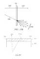
- Directional backlightsprovide illumination through a waveguide with directions within the waveguide imaged to viewing windows. Diverging light from light sources at the input end and propagating within the waveguide is provided with reduced divergence, and typically collimated, by a curved reflecting mirror at a reflecting end of the waveguide and is imaged towards a viewing window by means of curved light extraction features or a lens such as a Fresnel lens.
- the collimated lightis substantially parallel to the edges of a rectangular shaped waveguide and so light is output across the entire area of the waveguide towards the viewing window.
- the direction of the collimated lightis not parallel to the edges of a rectangular waveguide but is inclined at a non-zero angle.
- a non-illuminated (or void) outer portion(that may be triangular) is formed between one edge of the collimated beam and the respective edge of the waveguide. No light is directed to the respective viewing window from within the outer portion and the display will appear dark in this region. It would be desirable to reduce the appearance of the dark outer portions for off-axis viewing positions so that more of the area of the waveguide can be used to illuminate a spatial light modulator, advantageously reducing system size and cost.
- Modification of the systemmay overcome this limitation by introducing light into regions that are void.
- Such modified illumination apparatus embodimentsmay lead to increased brightness, local independent illumination and directional capabilities.
- a directional backlight apparatuscomprising: a waveguide extending between an input end for receiving input light and a reflective end for reflecting the input light back through the waveguide; an array of light sources disposed at different input positions in a lateral direction across the input end of the waveguide, the waveguide having first and second, opposed guide surfaces extending between the input end and the reflective end for guiding light forwards and back along the waveguide, the waveguide being arranged to reflect input light from light sources at the different input positions across the input end after reflection from the reflective end into respective optical windows in output directions distributed in the lateral direction in dependence on the input positions; and a control system arranged to selectively operate the light sources to direct light into a selectable viewing windows, wherein the reflective end converges the reflected light such that reflected light from light sources that are offset from the optical axis of the waveguide fails to illuminate outer portions of the waveguide, the waveguide further comprises sides, extending between the input end and the reflective end and between the guiding surfaces,
- a directional backlightcomprising: a waveguide extending between an input end for receiving input light and a reflective end for reflecting the input light back through the waveguide; and an array of light sources disposed at different input positions in a lateral direction across the input end of the waveguide, the waveguide having first and second, opposed guide surfaces extending between the input end and the reflective end for guiding light forwards and back along the waveguide, the waveguide being arranged to reflect input light from light sources at the different input positions across the input end after reflection from the reflective end into respective optical windows in output directions distributed in the lateral direction in dependence on the input positions, wherein the reflective end converges the reflected light such that reflected light from light sources that are offset from the optical axis of the waveguide fails to illuminate outer portions of the waveguide, and the waveguide further comprises sides, extending between the input end and the reflective end and between the guiding surfaces, that are arranged to reflect the light incident from a light source into the outer portion of the waveguide that fails
- a directional backlight devicecomprising: a waveguide extending between an input end for receiving input light and a reflective end for reflecting the input light back through the waveguide; and an array of light sources disposed at different input positions in a lateral direction across the input end of the waveguide, the waveguide having first and second, opposed guide surfaces extending between the input end and the reflective end for guiding light forwards and back along the waveguide, the waveguide being arranged to reflect input light from light sources at the different input positions across the input end after reflection from the reflective end into respective optical windows in output directions distributed in the lateral direction in dependence on the input positions, wherein the reflective end converges the reflected light such that reflected light from light sources that are offset from the optical axis of the waveguide fails to illuminate outer portions of the waveguide, and the directional backlight device further comprises an array of second light sources disposed along each side of the waveguide that extends between the input end and the reflective end and between the guiding surfaces and arranged to supply light to
- a directional display devicecomprising: a waveguide extending between an input end for receiving input light and a reflective end for reflecting the input light back through the waveguide; an array of light sources disposed at different input positions across the input end of the waveguide, the waveguide having first and second, opposed guide surfaces extending between the input end and the reflective end for guiding light forwards and back along the waveguide, the waveguide being arranged to reflect input light from light sources at the different input positions across the input end after reflection from the reflective end into respective optical windows in output directions distributed in the lateral direction in dependence on the input positions; and a transmissive spatial light modulator extending across the waveguide for modulating the light output therefrom, wherein the spatial light modulator extends across only part of the area of the waveguide.
- a backlight apparatuscomprising: a directional waveguide extending between an input end for receiving input light and a reflective end for reflecting the input light back through the directional waveguide, the directional waveguide having first and second, opposed guide surfaces extending between the input end and the reflective end for guiding light forwards and back along the directional waveguide, wherein the second guide surface has a plurality of light extraction features facing the reflective end and arranged to reflect the light guided back through the directional waveguide from the reflective end from different input positions across the input end in different directions through the first guide surface that are dependent on the input position; and an array of light sources arranged to illuminate the directional waveguide at different input positions across the input end of the directional waveguide, wherein the reflective end converges the reflected light such that reflected light from light sources that are offset from the optical axis of the directional waveguide fails to illuminate outer portions of the directional waveguide; a backlight structure arranged extending across the second guide surface of the directional waveguide and
- each of the first to fifth aspects of the present inventionprovide structures that provide for illumination of the outer portion of the waveguide that otherwise fails to be illuminated by light sources.
- the first to fifth aspects of the present inventionmay be applied together in any combination.
- an autostereoscopic display apparatuscomprising: a display device comprising an array of pixels, the display device being controllable to direct an image displayed on all of the pixels into selectable viewing windows having different positions; and a control system that is operable in a 3D mode of operation and a 2D mode of operation, the control system being arranged in the 3D mode of operation to control the display device to display temporally multiplexed left and right images and synchronously to direct the displayed images into viewing windows in positions in a lateral direction corresponding to the left and right eyes of the observer, and being arranged in the 2D mode of operation to control the display device to display a continuous 2D image, wherein the display device further comprises an angle-dependent diffuser film extending across the display device having a property that light incident at angles in a first range around the normal to the film in the lateral direction is not angularly diffused but light incident at angles in a second range in the lateral direction outside said first range is angularly
- a waveguide structurecomprising: a waveguide extending between an input end for receiving input light and a reflective end for reflecting the input light back through the waveguide, the waveguide having first and second, opposed guide surfaces extending between the input end and the reflective end for guiding light forwards and back along the waveguide, the waveguide being arranged to reflect input light from different input positions in a lateral direction across the input end after reflection from the reflective end in output directions distributed in a lateral direction in dependence on the input position; and an angle-dependent diffuser film extending across the waveguide, having a property that light incident at angles in a first range around the normal to the film in the lateral direction is not angularly diffused but light incident at angles in a second range in the lateral direction outside said range is angularly diffused.
- the diffuser film in accordance with the sixth aspect of the present inventionmay provide increased viewing angle in a 2D mode of operation at a relatively low cost in an apparatus that is also capable of providing a 3D mode of operation using a time division multiplexing technique.
- the sixth aspect of the present inventionmay be applied in combination with any of the first to fifth aspects of the present invention or with any combination thereof.
- a directional illumination apparatuscomprising: an imaging directional backlight for directing light comprising: a waveguide for guiding light, further comprising: a first light guiding surface; and a second light guiding surface, opposite the first light guiding surface; and an illuminator array for providing light to the imaging directional backlight; and an additional optical element that alters the optical system of the imaging directional backlight to provide a substantially uniform 2D illumination mode.
- a stepped imaging directional backlight apparatuscomprising: a stepped waveguide for guiding light, wherein the waveguide comprises: a first light guiding surface; and a second light guiding surface, opposite the first light guiding surface, the second light guiding surface comprising at least one guiding feature and a plurality of extraction features, wherein the extraction features direct light to exit the stepped waveguide; a first illumination input surface located between the first and second light guiding surfaces, the first illumination input surface operable to receive light from a first array of light sources; an illuminator array for providing light to the stepped imaging directional backlight; and an additional optical element that alters the optical system of the stepped imaging directional backlight to provide a substantially uniform 2D illumination mode.
- an imaging directional backlightcomprising: an input side located at a first end of a waveguide; a reflective side located at a second end of the waveguide; a first light directing side and a second light directing side located between the input side and the reflective side of the waveguide, wherein the second light directing side further comprises a plurality of guiding features and a plurality of extraction features; and an additional optical element that alters an optical system of the imaging directional backlight to provide a substantially uniform 2D illumination mode, wherein the additional optical element is at least one of an optical emitter, an imaging facet end, or an alternative light path.
- a folded imaging directional backlight systemthat provides a substantially uniform 2D illumination mode, comprising: a folded imaging directional backlight, comprising: a first waveguide for guiding light operable to receive light from an illuminator array; and a second waveguide optically connected to the first waveguide and operable to receive light from the illuminator array, wherein the first waveguide has a first edge with edge facets and the second waveguide has a second edge with edge facets, further wherein the edge facets provide a substantially uniform 2D illumination mode.
- Embodiments hereinmay provide an autostereoscopic display that provides wide angle viewing which may allow for directional viewing and conventional 2D compatibility.
- the wide angle viewing modemay be for observer tracked autostereoscopic 3D display, observer tracked 2D display (for example for privacy or power saving applications), for wide viewing angle 2D display or for wide viewing angle stereoscopic 3D display.
- embodimentsmay provide a controlled illuminator for the purposes of an efficient autostereoscopic display.
- Such componentscan be used in directional backlights, to provide directional displays including autostereoscopic displays.
- embodimentsmay relate to a directional backlight apparatus and a directional display which may incorporate the directional backlight apparatus.
- Such an apparatusmay be used for autostereoscopic displays, privacy displays, multi-user displays and other directional display applications.
- the optical function of the directional backlightcan be provided by a multiple imaging direction backlight system in which side voided regions of end illuminators may be filled.
- Advantageously such an arrangementmay provide optical functions in addition to the respective optical valve functions while preserving the advantages of high efficiency, large back working distance and thin form factor of the respective optical valve.
- Embodiments hereinmay provide an autostereoscopic display with large area and thin structure. Further, as will be described, the optical valves of the present disclosure may achieve thin optical components with large back working distances. Such components can be used in directional backlights, to provide directional displays including autostereoscopic displays. Further, embodiments may provide a controlled illuminator for the purposes of an efficient auto stereoscopic display.
- Embodiments of the present disclosuremay be used in a variety of optical systems.
- the embodimentmay include or work with a variety of projectors, projection systems, optical components, displays, microdisplays, computer systems, processors, self-contained projector systems, visual and/or audiovisual systems and electrical and/or optical devices.
- aspects of the present disclosuremay be used with practically any apparatus related to optical and electrical devices, optical systems, presentation systems or any apparatus that may contain any type of optical system. Accordingly, embodiments of the present disclosure may be employed in optical systems, devices used in visual and/or optical presentations, visual peripherals and so on and in a number of computing environments.
- Directional backlightsoffer control over the illumination emanating from substantially the entire output surface controlled typically through modulation of independent LED light sources arranged at the input aperture side of an optical waveguide. Controlling the emitted light directional distribution can achieve single person viewing for a security function, where the display can only be seen by a single viewer from a limited range of angles; high electrical efficiency, where illumination is only provided over a small angular directional distribution; alternating left and right eye viewing for time sequential stereoscopic and autostereoscopic display; and low cost.
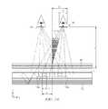
- FIG. 1Ais a schematic diagram illustrating a front view of light propagation in one embodiment of a directional display device, in accordance with the present disclosure
- FIG. 1Bis a schematic diagram illustrating a side view of light propagation in one embodiment of the directional display device of FIG. 1A , in accordance with the present disclosure
- FIG. 2Ais a schematic diagram illustrating in a top view of light propagation in another embodiment of a directional display device, in accordance with the present disclosure
- FIG. 2Bis a schematic diagram illustrating light propagation in a front view of the directional display device of FIG. 2A , in accordance with the present disclosure
- FIG. 2Cis a schematic diagram illustrating light propagation in a side view of the directional display device of FIG. 2A , in accordance with the present disclosure
- FIG. 3is a schematic diagram illustrating in a side view of a directional display device, in accordance with the present disclosure
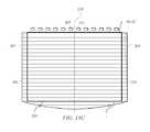
- FIG. 4Ais schematic diagram illustrating in a front view, generation of a viewing window in a directional display device including curved light extraction features, in accordance with the present disclosure
- FIG. 4Bis a schematic diagram illustrating in a front view, generation of a first and a second viewing window in a directional display device including curved light extraction features, in accordance with the present disclosure
- FIG. 5is a schematic diagram illustrating generation of a first viewing window in a directional display device including linear light extraction features, in accordance with the present disclosure
- FIG. 6Ais a schematic diagram illustrating one embodiment of the generation of a first viewing window in a time multiplexed directional display device in a first-time slot, in accordance with the present disclosure
- FIG. 6Bis a schematic diagram illustrating another embodiment of the generation of a second viewing window in a time multiplexed directional display device in a second-time slot, in accordance with the present disclosure
- FIG. 6Cis a schematic diagram illustrating another embodiment of the generation of a first and a second viewing window in a time multiplexed directional display device, in accordance with the present disclosure
- FIG. 7is a schematic diagram illustrating an observer tracking autostereoscopic directional display device, in accordance with the present disclosure.
- FIG. 8is a schematic diagram illustrating a multi-viewer directional display device, in accordance with the present disclosure.
- FIG. 9is a schematic diagram illustrating a privacy directional display device, in accordance with the present disclosure.
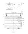
- FIG. 10is a schematic diagram illustrating in side view, the structure of a time multiplexed directional display device, in accordance with the present disclosure
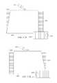
- FIG. 11Ais a schematic diagram illustrating a directional display apparatus comprising a directional display device and a control system, in accordance with the present disclosure
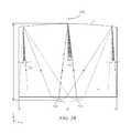
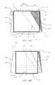
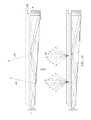
- FIG. 11Bis a schematic diagram illustrating a left side region of insufficient illumination for right sided off-axis viewing of a directional backlight, in accordance with the present disclosure
- FIG. 12Ais a schematic diagram illustrating a right-side region of insufficient illumination for left sided off-axis viewing of a directional backlight, in accordance with the present disclosure
- FIG. 12Bis a schematic diagram illustrating the top view of a directional backlight arranged to reduce the visibility of the void outer portions, in accordance with the present disclosure
- FIG. 12Cis a schematic diagram illustrating a directional display device comprising a directional backlight and spatial light modulator of area outside the outer regions achieved by edge light sources, in accordance with the present disclosure
- FIG. 12Dis a schematic diagram illustrating a directional display device comprising a directional backlight and spatial light modulator of area outside the outer regions achieved by edge light sources wherein the directional backlight is tapered, in accordance with the present disclosure
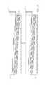
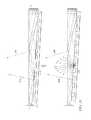
- FIG. 13Ais a schematic diagram illustrating a directional backlight comprising a waveguide that has polished transmitting edges to direct light into voided regions between pairs of sources while allowing unwanted rays to exit the guide, in accordance with the present disclosure
- FIG. 13Bis a schematic diagram illustrating a directional backlight comprising a waveguide that has polished transmitting edges to direct light into voided regions between pairs of sources while allowing unwanted rays to exit the guide, in accordance with the present disclosure
- FIG. 14Ais a schematic diagram illustrating operation of a directional backlight with paired sources for increased illumination areas, in accordance with the present disclosure
- FIG. 14Bis a schematic diagram illustrating operation of a directional backlight with paired sources for increased illumination areas, in accordance with the present disclosure
- FIG. 14Cis a schematic diagram illustrating operation of a directional backlight with paired sources for increased illumination areas, in accordance with the present disclosure
- FIG. 15is a schematic diagram illustrating an embodiment comprising a control system, a light source array and a directional waveguide comprising reflective sides arranged to achieve filling of void outer regions formed by a first light source by illuminating a second light source, in accordance with the present disclosure
- FIG. 16Ais a schematic diagram illustrating a top view of a directional display device comprising a stepped waveguide, in accordance with the present disclosure
- FIG. 16Bis a schematic diagram illustrating a top view of a directional display device comprising a stepped waveguide, in accordance with the present disclosure
- FIG. 16Cis a schematic diagram illustrating a top view of a directional display device comprising a non-collimating reflecting end, in accordance with the present disclosure
- FIG. 16Dis a schematic diagram illustrating a top view of a directional display device comprising a stepped waveguide, in accordance with the present disclosure
- FIG. 16Eis a schematic illustration of the front view of a directional display apparatus comprising outer strings of light sources, in accordance with the present disclosure
- FIG. 17Ais a schematic illustration of two artefacts which may appear at the edge of the viewing region of a directional display apparatus on one side, in accordance with the present disclosure
- FIG. 17Bis a schematic illustration of two artefacts which may appear at the edge of the viewing region of the directional display apparatus on the opposite side to FIG. 17A , in accordance with the present disclosure
- FIG. 17Cis a schematic illustration of one method for compensating the appearance of the void portion of a directional display apparatus, in accordance with the present disclosure.
- FIG. 17Dis a schematic illustration of a further method for compensating the appearance of the void portion of a directional display apparatus, in accordance with the present disclosure.
- FIG. 17Eis a schematic illustration of a further method for compensating the appearance of the void portion of a directional display apparatus, in accordance with the present disclosure.
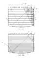
- FIG. 18Ais a schematic diagram illustrating a directional backlight in which side reflecting facets are introduced to redirect light into voided regions of a directional backlight system, in accordance with the present disclosure
- FIG. 18Bis a schematic diagram illustrating a further directional backlight in which side reflecting facets are introduced to redirect light into voided regions of a directional backlight system, in accordance with the present disclosure
- FIG. 18Cis a schematic diagram illustrating yet another further directional backlight in which side reflecting facets are introduced to redirect light into voided regions of a directional backlight system, in accordance with the present disclosure
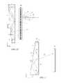
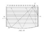
- FIG. 19is a schematic diagram illustrating a further directional backlight in which side holographic films redirect light into voided regions of a directional backlight system, in accordance with the present disclosure
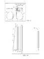
- FIG. 20Ais a schematic diagram illustrating a directional backlight in which additional light sources are used to introduce light into the side of an optical valve, in accordance with the present disclosure
- FIG. 20Bis a schematic diagram illustrating another directional backlight in which additional light sources are used to introduce light into the side of an optical valve, in accordance with the present disclosure
- FIG. 20Cis a schematic diagram illustrating another directional backlight in which additional light sources are used to introduce light into the side of an optical valve, in accordance with the present disclosure
- FIG. 21is a schematic diagram illustrating another directional backlight in which local arrays of sources launch light at controlled angles for wide angle uniform viewing with independent window control, in accordance with the present disclosure
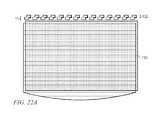
- FIG. 22Ais a schematic diagram illustrating a further directional backlight in which a backlight is placed adjacent an optical valve, in accordance with the present disclosure
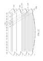
- FIG. 22Bis a schematic diagram illustrating a further directional backlight in which a backlight is placed adjacent an optical valve, in accordance with the present disclosure
- FIG. 22Cis a schematic diagram illustrating a further directional backlight in which a backlight is placed adjacent an optical valve, in accordance with the present disclosure
- FIG. 23is a schematic diagram illustrating a further directional backlight in which a source array is altered in position between adjacent backlights, in accordance with the present disclosure
- FIG. 24is a schematic diagram illustrating a directional backlight in which light is switched between illuminating backlight systems, in accordance with the present disclosure
- FIG. 25Ais a schematic diagram illustrating a directional display device whereby an angle dependent diffuser is used to diffuse high angle rays to a greater extent than those directed normally from the imaging directional backlight, in accordance with the present disclosure
- FIG. 25Bis a schematic diagram illustrating a side view of an angular dependent diffuser, in accordance with the present disclosure.
- FIG. 25Cis a schematic diagram illustrating a side view of an angular dependent diffuser, in accordance with the present disclosure.
- FIG. 25Dis a schematic diagram illustrating an arrangement of an angular dependent diffuser in an autostereoscopic directional display device arranged to provide wide angle viewing, in accordance with the present disclosure
- FIG. 26is a schematic diagram illustrating a directional backlight in which illuminating light is diffused using a switchable diffusing element, in accordance with the present disclosure
- FIG. 27is a schematic diagram illustrating a directional backlight in which guided light may be extracted in a diffuse form by optically contacting the bottom surface of a directional backlight with a diffuse reflecting element, in accordance with the present disclosure
- FIG. 28is a schematic diagram illustrating a directional backlight in which guided light may be extracted in a diffuse form by optically contacting the bottom surface of the directional backlight with a diffuse reflecting element through electroforming material surface material, in accordance with the present disclosure
- FIG. 29is a schematic diagram illustrating a directional backlight in which electro-wetting material is made to move from behind reflecting facets into the guiding region of an imaging directional backlight forcing light to exit and reflect off a diffusing surface, in accordance with the present disclosure
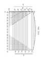
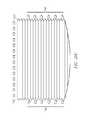
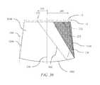
- FIG. 30is a schematic illustration of a top view of a wedge directional backlight arranged to achieve reduced visibility of void portions, in accordance with the present disclosure.
- FIG. 31is a schematic illustration of the side view of a wedge directional backlight, in accordance with the present disclosure.
- Time multiplexed autostereoscopic displayscan advantageously improve the spatial resolution of autostereoscopic display by directing light from all of the pixels of a spatial light modulator to a first viewing window in a first-time slot, and all of the pixels to a second viewing window in a second-time slot.
- an observer with eyes arranged to receive light in first and second viewing windowswill see a full resolution image across the whole of the display over multiple time slots.
- Time multiplexed displayscan advantageously achieve directional illumination by directing an illuminator array through a substantially transparent time multiplexed spatial light modulator using directional optical elements, wherein the directional optical elements substantially form an image of the illuminator array in the window plane.
- the uniformity of the viewing windowsmay be advantageously independent of the arrangement of pixels in the spatial light modulator.
- Such displayscan provide observer tracking displays which have low flicker, with low levels of cross talk for a moving observer.
- the illuminator elements of the time sequential illumination systemmay be provided, for example, by pixels of a spatial light modulator with size approximately 100 micrometers in combination with a lens array.
- pixelssuffer from similar difficulties as for spatially multiplexed displays. Further, such devices may have low efficiency and higher cost, requiring additional display components.
- High window plane uniformitycan be conveniently achieved with macroscopic illuminators, for example, an array of LEDs in combination with homogenizing and diffusing optical elements that are typically of size 1 mm or greater.
- the increased size of the illuminator elementsmeans that the size of the directional optical elements increases proportionately. For example, a 16 mm wide illuminator imaged to a 65 mm wide viewing window may require a 200 mm back working distance.
- the increased thickness of the optical elementscan prevent useful application, for example, to mobile displays, or large area displays.
- optical valves as described in commonly-owned U.S. patent application Ser. No. 13/300,293advantageously can be arranged in combination with fast switching transmissive spatial light modulators to achieve time multiplexed autostereoscopic illumination in a thin package while providing high resolution images with flicker free observer tracking and low levels of cross talk.
- Describedis a one-dimensional array of viewing positions, or windows, that can display different images in a first, typically horizontal, direction, but contain the same images when moving in a second, typically vertical, direction.
- imaging directional backlightsare arranged to direct the illumination from multiple light sources through a display panel to respective multiple viewing windows in at least one axis.
- Each viewing windowis substantially formed as an image in at least one axis of a light source by the imaging system of the imaging directional backlight.
- An imaging systemmay be formed between multiple light sources and the respective window images. In this manner, the light from each of the multiple light sources is substantially not visible for an observer's eye outside of the respective viewing window.
- Non-imaging backlightsare typically arranged to direct the illumination from multiple light sources through a display panel into a substantially common viewing zone for each of the multiple light sources to achieve wide viewing angle and high display uniformity.
- non-imaging backlightsdo not form viewing windows. In this manner, the light from each of the multiple light sources may be visible for an observer's eye at substantially all positions across the viewing zone.
- Such conventional non-imaging backlightsmay have some directionality, for example, to increase screen gain compared to Lambertian illumination, which may be provided by brightness enhancement films such as BEFTM from 3M. However, such directionality may be substantially the same for each of the respective light sources. Thus, for these reasons and others that should be apparent to persons of ordinary skill, conventional non-imaging backlights are different to imaging directional backlights. Edge lit non-imaging backlight illumination structures may be used in liquid crystal display systems such as those seen in 2D Laptops, Monitors and TVs. Light propagates from the edge of a glossy waveguide which may include sparse features; typically, local indentations in the surface of the guide which cause light to be lost regardless of the propagation direction of the light.
- an optical valveis an optical structure that may be a type of light guiding structure or device referred to as, for example, a light valve, an optical valve directional backlight, and a valve directional backlight (“v-DBL”).
- optical valveis different to a spatial light modulator (even though spatial light modulators may be sometimes generally referred to as a “light valve” in the art).
- One example of an imaging directional backlightis an optical valve that may employ a folded optical system. Light may propagate substantially without loss in one direction through the optical valve, may be incident on an imaging reflector, and may counter-propagate such that the light may be extracted by reflection off tilted light extraction features, and directed to viewing windows as described in U.S. patent application Ser. No. 13/300,293, which is herein incorporated by reference in its entirety.
- a stepped waveguide imaging directional backlightmay be at least one of an optical valve.
- a stepped waveguideis a waveguide for an imaging directional backlight comprising a waveguide for guiding light, further comprising: a first light guiding surface; and a second light guiding surface, opposite the first light guiding surface, further comprising a plurality of light guiding features interspersed with a plurality of extraction features arranged as steps.
- lightmay propagate within an exemplary optical valve in a first direction from an input side to a reflective side and may be transmitted substantially without loss.
- Lightmay be reflected at the reflective side and propagates in a second direction substantially opposite the first direction.
- the lightmay be incident on light extraction features, which are operable to redirect the light outside the optical valve.
- the optical valvegenerally allows light to propagate in the first direction and may allow light to be extracted while propagating in the second direction.
- the optical valvemay achieve time sequential directional illumination of large display areas. Additionally, optical elements may be employed that are thinner than the back-working distance of the optical elements to direct light from macroscopic illuminators to a window plane. Such displays may use an array of light extraction features arranged to extract light counter propagating in a substantially parallel waveguide.
- Thin imaging directional backlight implementations for use with LCDshave been proposed and demonstrated by 3M, for example U.S. Pat. No. 7,528,893; by Microsoft, for example U.S. Pat. No. 7,970,246 which may be referred to herein as a “wedge type directional backlight;” by RealD, for example U.S. patent application Ser. No. 13/300,293 which may be referred to herein as an “optical valve” or “optical valve directional backlight,” all of which are herein incorporated by reference in their entirety.
- the present disclosureprovides stepped waveguide imaging directional backlights in which light may reflect back and forth between the internal faces of, for example, a stepped waveguide which may include a first side and a first set of features. As the light travels along the length of the stepped waveguide, the light may not substantially change angle of incidence with respect to the first side and first set of surfaces and so may not reach the critical angle of the medium at these internal faces. Light extraction may be advantageously achieved by a second set of surfaces (the step “risers”) that are inclined to the first set of surfaces (the step “treads”). Note that the second set of surfaces may not be part of the light guiding operation of the stepped waveguide, but may be arranged to provide light extraction from the structure.
- a wedge type imaging directional backlightmay allow light to guide within a wedge profiled waveguide having continuous internal surfaces. The optical valve is thus not a wedge type imaging directional backlight.
- FIG. 1Ais a schematic diagram illustrating a front view of light propagation in one embodiment of a directional display device
- FIG. 1Bis a schematic diagram illustrating a side view of light propagation in the directional display device of FIG. 1A .
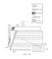
- FIG. 1Aillustrates a front view in the xy plane of a directional backlight of a directional display device, and includes an illuminator array 15 which may be used to illuminate a stepped waveguide 1 .
- Illuminator array 15includes illuminator elements 15 a through illuminator element 15 n (where n is an integer greater than one).
- the stepped waveguide 1 of FIG. 1Amay be a stepped, display sized waveguide 1 .
- Illumination elements 15 a through 15 nare light sources that may be light emitting diodes (LEDs).
- FIG. 1Billustrates a side view in the xz plane, and includes illuminator array 15 , SLM 48 , extraction features 12 , guiding features 10 , and stepped waveguide 1 , arranged as shown.
- the side view provided in FIG. 1Bis an alternative view of the front view shown in FIG. 1A . Accordingly, the illuminator array 15 of FIGS. 1A and 1B corresponds to one another and the stepped waveguide 1 of FIGS. 1A and 1B may correspond to one another.
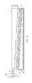
- the stepped waveguide 1may have an input end 2 that is thin and a reflective end 4 that is thick.
- the waveguide 1extends between the input end 2 that receives input light and the reflective end 4 that reflects the input light back through the waveguide 1 .
- the length of the input end 2 in a lateral direction across the waveguideis greater than the height of the input end 2 .
- the illuminator elements 15 a - 15 nare disposed at different input positions in a lateral direction across the input end 2 .
- the waveguide 1has first and second, opposed guide surfaces extending between the input end 2 and the reflective end 4 for guiding light forwards and back along the waveguide 1 .
- the second guide surfacehas a plurality of light extraction features 12 facing the reflective end 4 and arranged to reflect at least some of the light guided back through the waveguide 1 from the reflective end from different input positions across the input end in different directions through the first guide surface that are dependent on the input position.
- the light extraction features 12are reflective facets, although other reflective features could be used.
- the light extraction features 12do not guide light through the waveguide, whereas the intermediate regions of the second guide surface intermediate the light extraction features 12 guide light without extracting it. Those regions of the second guide surface are planar and may extend parallel to the first guide surface, or at a relatively low inclination.
- the light extraction features 12extend laterally to those regions so that the second guide surface has a stepped shape which may include the light extraction features 12 and intermediate regions.
- the light extraction features 12are oriented to reflect light from the light sources, after reflection from the reflective end 4 , through the first guide surface.
- the light extraction features 12are arranged to direct input light from different input positions in the lateral direction across the input end in different directions relative to the first guide surface that are dependent on the input position.
- the illumination elements 15 a - 15 nare arranged at different input positions, the light from respective illumination elements 15 a - 15 n is reflected in those different directions.
- each of the illumination elements 15 a - 15 ndirects light into a respective optical window in output directions distributed in the lateral direction in dependence on the input positions.
- the lateral direction across the input end 2 in which the input positions are distributedcorresponds with regard to the output light to a lateral direction to the normal to the first guide surface.
- the illuminator elements 15 a - 15 nmay be selectively operated to direct light into a selectable optical window.
- the optical windowsmay be used individually or in groups as viewing windows.
- the SLM 48extends across the waveguide and modulates the light output therefrom.
- the SLM 48may a liquid crystal display (LCD), this is merely by way of example and other spatial light modulators or displays may be used including LCOS, DLP devices, and so forth, as this illuminator may work in reflection.
- the SLM 48is disposed across the first guide surface of the waveguide and modulates the light output through the first guide surface after reflection from the light extraction features 12 .
- FIG. 1AThe operation of a directional display device that may provide a one-dimensional array of viewing windows is illustrated in front view in FIG. 1A , with its side profile shown in FIG. 1B .
- the lightmay propagate along +x in a first direction, within the stepped waveguide 1 , while at the same time, the light may fan out in the xy plane and upon reaching the far curved end side 4 , may substantially or entirely fill the curved end side 4 . While propagating, the light may spread out to a set of angles in the xz plane up to, but not exceeding the critical angle of the guide material.
- the extraction features 12 that link the guiding features 10 of the bottom side of the stepped waveguide 1may have a tilt angle greater than the critical angle and hence may be missed by substantially all light propagating along +x in the first direction, ensuring the substantially lossless forward propagation.
- the curved end side 4 of the stepped waveguide 1may be made reflective, typically by being coated with a reflective material such as, for example, silver, although other reflective techniques may be employed.
- Lightmay therefore be redirected in a second direction, back down the guide in the direction of ⁇ x and may be substantially collimated in the xy or display plane.
- the angular spreadmay be substantially preserved in the xz plane about the principal propagation direction, which may allow light to hit the riser edges and reflect out of the guide.
- lightmay be effectively directed approximately normal to the xy display plane with the xz angular spread substantially maintained relative to the propagation direction. This angular spread may be increased when light exits the stepped waveguide 1 through refraction, but may be decreased somewhat dependent on the reflective properties of the extraction features 12 .
- reflectionmay be reduced when total internal reflection (TIR) fails, squeezing the xz angular profile and shifting off normal.
- TIRtotal internal reflection
- the increased angular spread and central normal directionmay be preserved.
- lightmay exit the stepped waveguide 1 approximately collimated and may be directed off normal in proportion to the y-position of the respective illuminator element 15 a - 15 n in illuminator array 15 from the input edge center. Having independent illuminator elements 15 a - 15 n along the input edge 2 then enables light to exit from the entire first light directing side 6 and propagate at different external angles, as illustrated in FIG. 1A .
- Illuminating a spatial light modulator (SLM) 48 such as a fast liquid crystal display (LCD) panel with such a devicemay achieve autostereoscopic 3D as shown in top view or yz-plane viewed from the illuminator array 15 end in FIG. 2A , front view in FIG. 2B and side view in FIG. 2C .
- FIG. 2Ais a schematic diagram illustrating in a top view, propagation of light in a directional display device
- FIG. 2Bis a schematic diagram illustrating in a front view, propagation of light in a directional display device
- FIG. 2Cis a schematic diagram illustrating in side view propagation of light in a directional display device.
- FIGS. 1spatial light modulator
- a stepped waveguide 1may be located behind a fast (e.g., greater than 100 Hz) LCD panel SLM 48 that displays sequential right and left eye images.
- a faste.g., greater than 100 Hz
- specific illuminator elements 15 a through 15 n of illuminator array 15may be selectively turned on and off, providing illuminating light that enters right and left eyes substantially independently by virtue of the system's directionality.
- sets of illuminator elements of illuminator array 15are turned on together, providing a one-dimensional viewing window 26 or an optical pupil with limited width in the horizontal direction, but extended in the vertical direction, in which both eyes horizontally separated may view a left eye image, and another viewing window 44 in which a right eye image may primarily be viewed by both eyes, and a central position in which both the eyes may view different images.
- 3Dmay be viewed when the head of a viewer is approximately centrally aligned. Movement to the side away from the central position may result in the scene collapsing onto a 2D image.
- the reflective end 4may have positive optical power in the lateral direction across the waveguide.
- the optical axismay be defined with reference to the shape of the reflective end 4 , for example being a line that passes through the center of curvature of the reflective end 4 and coincides with the axis of reflective symmetry of the end 4 about the x-axis.
- the optical axismay be similarly defined with respect to other components having optical power, for example the light extraction features 12 if they are curved, or the Fresnel lens 62 described below.
- the optical axis 238is typically coincident with the mechanical axis of the waveguide 1 .
- the optical axis 238is a line that passes through the center of curvature of the surface at end 4 and coincides with the axis of reflective symmetry of the side 4 about the x-axis.
- the optical axis 238is typically coincident with the mechanical axis of the waveguide 1 .
- the cylindrical reflecting surface at end 4may typically comprise a spherical profile to optimize performance for on-axis and off-axis viewing positions. Other profiles may be used.
- FIG. 3is a schematic diagram illustrating in side view a directional display device. Further, FIG. 3 illustrates additional detail of a side view of the operation of a stepped waveguide 1 , which may be a transparent material.
- the stepped waveguide 1may include an illuminator input side 2 , a reflective side 4 , a first light directing side 6 which may be substantially planar, and a second light directing side 8 which includes guiding features 10 and light extraction features 12 .
- light rays 16 from an illuminator element 15 c of an illuminator array 15(not shown in FIG.
- reflective side 4may be a mirrored surface and may reflect light, it may in some embodiments also be possible for light to pass through reflective side 4 .
- light ray 18 reflected by the reflective side 4may be further guided in the stepped waveguide 1 by total internal reflection at the reflective side 4 and may be reflected by extraction features 12 .
- Light rays 18 that are incident on extraction features 12may be substantially deflected away from guiding modes of the stepped waveguide 1 and may be directed, as shown by ray 20 , through the side 6 to an optical pupil that may form a viewing window 26 of an autostereoscopic display.
- the width of the viewing window 26may be determined by at least the size of the illuminator, output design distance and optical power in the side 4 and extraction features 12 .
- each viewing window 26represents a range of separate output directions with respect to the surface normal direction of the spatial light modulator 48 that intersect with a plane at the nominal viewing distance.
- FIG. 4Ais a schematic diagram illustrating in front view a directional display device which may be illuminated by a first illuminator element and including curved light extraction features. Further, FIG. 4A shows in front view further guiding of light rays from illuminator element 15 c of illuminator array 15 , in the stepped waveguide 1 . Each of the output rays are directed towards the same viewing window 26 from the respective illuminator 14 . Thus, light ray 30 may intersect the ray 20 in the window 26 , or may have a different height in the window as shown by ray 32 . Additionally, in various embodiments, sides 22 , 24 of the waveguide 1 may be transparent, mirrored, or blackened surfaces. Continuing the discussion of FIG.
- light extraction features 12may be elongate, and the orientation of light extraction features 12 in a first region 34 of the light directing side 8 (light directing side 8 shown in FIG. 3 , but not shown in FIG. 4A ) may be different to the orientation of light extraction features 12 in a second region 36 of the light directing side 8 .
- FIG. 4Bis a schematic diagram illustrating in front view an optical valve which may illuminated by a second illuminator element. Further, FIG. 4B shows the light rays 40 , 42 from a second illuminator element 15 h of the illuminator array 15 . The curvature of the reflective end on the side 4 and the light extraction features 12 cooperatively produce a second viewing window 44 laterally separated from the viewing window 26 with light rays from the illuminator element 15 h.
- the arrangement illustrated in FIG. 4Bmay provide a real image of the illuminator element 15 c at a viewing window 26 in which the real image may be formed by cooperation of optical power in reflective side 4 and optical power which may arise from different orientations of elongate light extraction features 12 between regions 34 and 36 , as shown in FIG. 4A .
- the arrangement of FIG. 4Bmay achieve improved aberrations of the imaging of illuminator element 15 c to lateral positions in viewing window 26 . Improved aberrations may achieve an extended viewing freedom for an autostereoscopic display while achieving low cross talk levels.
- FIG. 5is a schematic diagram illustrating in front view an embodiment of a directional display device having substantially linear light extraction features. Further, FIG. 5 shows a similar arrangement of components to FIG. 1 (with corresponding elements being similar), with one of the differences being that the light extraction features 12 are substantially linear and parallel to each other. Advantageously, such an arrangement may provide substantially uniform illumination across a display surface and may be more convenient to manufacture than the curved extraction features of FIG. 4A and FIG. 4B .
- FIG. 6Ais a schematic diagram illustrating one embodiment of the generation of a first viewing window in a time multiplexed imaging directional display device in a first time slot
- FIG. 6Bis a schematic diagram illustrating another embodiment of the generation of a second viewing window in a time multiplexed imaging directional backlight apparatus in a second time slot
- FIG. 6Cis a schematic diagram illustrating another embodiment of the generation of a first and a second viewing window in a time multiplexed imaging directional display device.
- FIG. 6Ashows schematically the generation of illumination window 26 from stepped waveguide 1 .
- Illuminator element group 31 in illuminator array 15may provide a light cone 17 directed towards a viewing window 26 .
- Illuminator element group 33 in illuminator array 15may provide a light cone 19 directed towards viewing window 44 .
- windows 26 and 44may be provided in sequence as shown in FIG. 6C . If the image on a spatial light modulator 48 (not shown in FIGS. 6A, 6B, 6C ) is adjusted in correspondence with the light direction output, then an autostereoscopic image may be achieved for a suitably placed viewer. Similar operation can be achieved with all the directional backlights described herein.
- illuminator element groups 31 , 33each include one or more illumination elements from illumination elements 15 a to 15 n , where n is an integer greater than one.
- FIG. 7is a schematic diagram illustrating one embodiment of an observer tracking autostereoscopic directional display device.
- selectively turning on and off illuminator elements 15 a to 15 n along axis 29provides for directional control of viewing windows.
- the head 45 positionmay be monitored with a camera, motion sensor, motion detector, or any other appropriate optical, mechanical or electrical means, and the appropriate illuminator elements of illuminator array 15 may be turned on and off to provide substantially independent images to each eye irrespective of the head 45 position.
- the head tracking system(or a second head tracking system) may provide monitoring of more than one head 45 , 47 (head 47 not shown in FIG. 7 ) and may supply the same left and right eye images to each viewers' left and right eyes providing 3D to all viewers. Again, similar operation can be achieved with all the directional backlights described herein.
- FIG. 8is a schematic diagram illustrating one embodiment of a multi-viewer directional display device as an example including an imaging directional backlight.
- at least two 2D imagesmay be directed towards a pair of viewers 45 , 47 so that each viewer may watch a different image on the spatial light modulator 48 .
- the two 2D images of FIG. 8may be generated in a similar manner as described with respect to FIG. 7 in that the two images would be displayed in sequence and in synchronization with sources whose light is directed toward the two viewers.
- One imageis presented on the spatial light modulator 48 in a first phase
- a second imageis presented on the spatial light modulator 48 in a second phase different from the first phase.
- the output illuminationis adjusted to provide first and second viewing windows 26 , 44 respectively. An observer with both eyes in window 26 will perceive a first image while an observer with both eyes in window 44 will perceive a second image.
- FIG. 9is a schematic diagram illustrating a privacy directional display device which includes an imaging directional backlight.
- 2D display systemsmay also utilize directional backlighting for security and efficiency purposes in which light may be primarily directed at the eyes of a first viewer 45 as shown in FIG. 9 .
- first viewer 45may be able to view an image on device 50
- lightis not directed towards second viewer 47 .
- second viewer 47is prevented from viewing an image on device 50 .
- Each of the embodiments of the present disclosuremay advantageously provide autostereoscopic, dual image or privacy display functions.
- FIG. 10is a schematic diagram illustrating in side view the structure of a time multiplexed directional display device as an example including an imaging directional backlight. Further, FIG. 10 shows in side view an autostereoscopic directional display device, which may include the stepped waveguide 1 and a Fresnel lens 62 arranged to provide the viewing window 26 in a window plane 106 at a nominal viewing distance from the spatial light modulator for a substantially collimated output across the stepped waveguide 1 output surface.
- a vertical diffuser 68may be arranged to extend the height of the window 26 further. The light may then be imaged through the spatial light modulator 48 .
- the illuminator array 15may include light emitting diodes (LEDs) that may, for example, be phosphor converted blue LEDs, or may be separate RGB LEDs.
- the illuminator elements in illuminator array 15may include a uniform light source and spatial light modulator arranged to provide separate illumination regions.
- the illuminator elementsmay include laser light source(s).
- the laser outputmay be directed onto a diffuser by means of scanning, for example, using a galvo or MEMS scanner.
- laser lightmay thus be used to provide the appropriate illuminator elements in illuminator array 15 to provide a substantially uniform light source with the appropriate output angle, and further to provide reduction in speckle.
- the illuminator array 15may be an array of laser light emitting elements.
- the diffusermay be a wavelength converting phosphor, so that illumination may be at a different wavelength to the visible output light.
- a further wedge type directional backlightis generally discussed by U.S. Pat. No. 7,660,047 which is herein incorporated by reference in its entirety.
- the wedge type directional backlight and optical valvefurther process light beams in different ways.
- light input at an appropriate anglewill output at a defined position on a major surface, but light rays will exit at substantially the same angle and substantially parallel to the major surface.
- light input to a stepped waveguide of an optical valve at a certain anglemay output from points across the first side, with output angle determined by input angle.
- the stepped waveguide of the optical valvemay not require further light redirection films to extract light towards an observer and angular non-uniformities of input may not provide non-uniformities across the display surface.
- waveguides, directional backlights and directional display devicesthat are based on and incorporate the structures of FIGS. 1 to 10 above. Except for the modifications and/or additional features which will now be described, the above description applies equally to the following waveguides, directional backlights and display devices, but for brevity will not be repeated.
- the waveguides described belowmay be incorporated into a directional backlight or a directional display device as described above.
- the directional backlights described belowmay be incorporated into a directional display device as described above.
- FIG. 11Ais a schematic diagram illustrating a directional display apparatus comprising a directional display device and a control system.
- the arrangement and operation of the control systemwill now be described and may be applied, with changes as necessary, to each of the display devices disclosed herein.
- the directional backlightcomprises a waveguide 1 and an array 15 of illumination elements 15 a - 15 n arranged as described above.
- the control systemis arranged to selectively operate the illumination elements 15 a - 15 n to direct light into selectable viewing windows.
- Fresnel lens 62may be arranged to cooperate with reflective end 4 to achieve viewing windows at a viewing plane.
- Transmissive spatial light modulator 48may be arranged to receive the light from the directional backlight. The image displayed on the SLM 48 may be presented in synchronisation with the illumination of the light sources of the array 15 .
- the control systemmay comprise a sensor system arranged to detect the position of the observer 99 relative to the display device 100 .
- the sensor systemcomprises a position sensor 406 , such as a camera arranged to determine the position of an observer 408 ; and a head position measurement system 404 that may for example comprise a computer vision image processing system.
- the position sensor 406may comprise known sensors including those comprising cameras and image processing units arranged to detect the position of observer faces.
- Position sensor 406may further comprise a stereo sensor arranged to improve the measure of longitudinal position compared to a monoscopic camera.
- position sensor 406may comprise measurement of eye spacing to give a measure of required placement of respective arrays of viewing windows from tiles of the directional display.
- the control systemmay further comprise an illumination controller and an image controller 403 that are both supplied with the detected position of the observer supplied from the head position measurement system 404 .
- the illumination controllercomprises an LED controller 402 arranged to determine which light sources of array 15 should be switched to direct light to respective eyes of observer 408 in cooperation with waveguide 1 ; and an LED driver 400 arranged to control the operation of light sources of light source array 15 by means of drive lines 407 .
- the illumination controller 74selects the illuminator elements 15 to be operated in dependence on the position of the observer detected by the head position measurement system 72 , so that the viewing windows 26 into which light is directed are in positions corresponding to the left and right eyes of the observer 99 . In this manner, the lateral output directionality of the waveguide 1 corresponds with the observer position.
- the image controller 403is arranged to control the SLM 48 to display images.
- the image controller 403 and the illumination controllermay operate as follows.
- the image controller 403controls the SLM 48 to display temporally multiplexed left and right eye images and the LED controller 402 operates the light sources 15 to direct light into viewing windows in positions corresponding to the left and right eyes of an observer synchronously with the display of left and right eye images.
- an autostereoscopic effectis achieved using a time division multiplexing technique.
- a single viewing windowmay be illuminated by operation of light source 409 (which may comprise one or more LEDs) by means of drive line 410 wherein other drive lines are not driven as described elsewhere.
- the head position measurement system 404detects the position of an observer relative to the display device 100 .
- the LED controller 402selects the light sources 15 to be operated in dependence on the position of the observer detected by the head position measurement system 404 , so that the viewing windows into which light is directed are in positions corresponding to the left and right eyes of the observer. In this manner, the output directionality of the waveguide 1 may be achieved to correspond with the viewer position so that a first image may be directed to the observer's right eye in a first phase and directed to the observer's left eye in a second phase.
- FIG. 11Bis a schematic diagram illustrating a left side region of insufficient illumination for right sided off-axis viewing of a directional backlight.
- the region of insufficient illuminationmay be referred to herein as a void region or outer portion 120 .
- FIG. 12Ais a schematic diagram illustrating a right-side region of insufficient illumination for left sided off-axis viewing of a directional backlight.
- FIGS. 11B and 12Aillustrate the divergence, reflection/refraction and extraction of rays emanating from right and left positioned off-axis sources that propagate away from the guide to form corresponding off-axis viewing windows 26 for the optical valve.
- a directional backlightcomprises a waveguide 1 arranged as described above.
- a light source 243 of the array 15may be arranged on the optical axis 238 of a waveguide 1 that is arranged with a substantially rectangular output area (ignoring the sag of the side 4 ). Diverging light rays from the source 243 are converged by the reflective side 4 to produce a collimated beam within the waveguide with light rays 245 , 247 that are parallel to the sides 244 , 246 of the waveguide 1 . Thus, for light source 243 , light may be output from across the entire width of the waveguide 1 .
- Side 4comprises a reflective end that converges the reflected light such that light sources that are offset from the optical axis of the waveguide fail to illuminate outer portions of the waveguide.
- the convergence of reflective enddefines convergence applied to the incoming light beam from the respective light source. The convergence does not refer to the convergence of the light beam.
- the light beam that is reflected from the reflective endmay be collimated or converging, but may also be diverging with a divergence that is lower than the divergence of the incident light beam on the reflective end.
- the reflective endconverges the reflected light such that reflected light from light sources that are offset from the optical axis of the waveguide fails to illuminate outer portions 120 of the waveguide 1 .
- the effect of the redirection of these rays off the imaging mirror/lens in the two systemsis to create void regions in outer portions 120 within the extraction region that is substantially void of light.
- the triangular voided regionWhen viewed from the left side of the illuminator, the triangular voided region may appear to the right, and the triangular voided region may increase in size the further off-axis the viewer moves.
- a similar triangular portion 120may be seen symmetrically on the left to viewers situated to the right. To the viewer these portions 120 appear dim.
- FIG. 12Bis a schematic diagram illustrating the top view of a directional backlight arranged to reduce the visibility of the void outer portions 120 .
- Reflective end at side 4 for a collimated outputmay be provided by form 251 .
- the radius of curvatureis increased to provide reflective end with form 253 .
- Such a form for side 4produces diverging light beam within the waveguide 1 after reflection, such that the light ray 255 next to side 246 is parallel or close to parallel to side 246 .
- the size of the portion 120is reduced or eliminated.
- the side 4may be planar. Such an arrangement thus advantageously reduces the size of waveguide needed for a given display area and viewing angle.
- the optimum viewing window distancevaries down the length of the waveguide 1 .
- Such a variation in viewing window performancechanges the imaging properties of the waveguide in the vertical direction so that cross talk, image flicker for a moving observer and brightness may vary in the vertical direction.
- FIG. 12Cis a schematic diagram illustrating a directional display device comprising a directional backlight as described above and a spatial light modulator 48 that extends across only part of the area of the waveguide 1 .
- the entirety of the SLM 48is outside the outer portions 120 , 223 not illuminated by the edge light source 14 .
- Advantageously SLM 48 with border 221does not receive light from the portion 120 when directed to viewing window 26 so that a viewer does not have visibility of portions 120 , 223 .
- FIG. 12Dis a schematic diagram illustrating a directional display device comprising a directional backlight as described above and a spatial light modulator 48 that extends across only part of the area of the waveguide 1 .
- the entirety of the SLM 48is outside the outer portions not illuminated by the edge light sources 14 .
- the sides 225 , 227 of the waveguide 1 extending between the input end 2 and the reflective end 4are diverge from the input end 2 to the reflective end 4 , such that the waveguide 1 is tapered.
- the width of the end 4is greater than the width of the end 2 .
- the SLM 48has a border 221 that is inside the waveguide 1 area to avoid the visibility of the non-waveguide regions.
- the size of the waveguide 1is reduced so that additional components 229 such as electronic components may be introduced in the region that would otherwise be void.
- FIGS. 12C and 12Dincrease the size of the directional display device and so it would be desirable to fill the portions in other ways, as will be described in the following embodiments.
- FIG. 13Ais a schematic diagram illustrating an imaging directional backlight including a waveguide 1 as described above, wherein the sides 234 , 236 of the waveguide 1 extending between the input end 2 and the reflective end 4 and between the guiding surfaces, that are planar surfaces arranged to reflect light into voided portions 120 formed by source 14 .
- FIG. 13Ais an embodiment in which the sides 234 and 236 of the waveguide 1 may be polished and optionally coated with a broadband anti-reflection (BBAR) coating.
- BBARbroadband anti-reflection
- the sides 234 and 236may have a reflective coating or may reflect by total internal reflection in which case they need not have a reflective coating.
- Portion 120may be substantially devoid of returning illuminating rays originally from source 14 with position 249 (that may be referred to as the first light source) and reflected at end 4 .
- the sides 234 and 236are parallel to each other and the optical axis of the waveguide.
- light source 14When light source 14 (referred to as the as a first light source is operated, light source 232 (referred to as the second light source) positioned on the opposite side of the optical axis 238 and with position 261 approximately equidistant as position 249 may be simultaneously operated to direct light into the same viewing window as the first light source 14 .
- Light ray 162undergoes reflection at the side 234 closest to the portion 120 . The reflection may be achieved by a metallic coating on side 234 or preferably by total internal reflection.
- light ray 233may be parallel to light ray 235 in the waveguide 1 .
- light rays with the desired directionalitymay be arranged to propagate within the void region formed by the first source 14 .
- first light source 14 and second light source 232are directed into the same viewing window and the waveguide area that directs light to the viewing window for a given off axis position is increased.
- the side 4may be arranged to achieve collimated light within the waveguide, so that the imaging performance of the waveguide is substantially the same for all vertical positions.
- the width of the waveguidemay be reduced, thus reducing bezel size and cost.
- source 14 and 232may be arranged to be illuminated in synchronization with the timing of presentation of one image on an SLM.
- sources 14 and 232may be left eye illumination sources for example.
- the sources of the array 15may each comprise multiple light emitting elements and the gaps between the sources may be substantially reduced or removed.
- Such a displaymay be arranged to achieve autostereoscopic illumination over a wide viewing angle with illumination over the most or all of the waveguide area.
- substantially few to no voided portions 120may then exist and wide angle 2D illumination may be achieved.
- FIG. 13Bis a schematic diagram illustrating a folded imaging directional backlight including a waveguide 1 having polished transmitting edges to direct light substantially into voided regions between pairs of sources 14 , 232 while allowing unwanted rays to exit the guide. Further, FIG. 13B shows that light rays 239 reflected from the side 234 from source 14 may exit the system through side 236 , thus substantially avoiding any stray light contamination of the system and advantageously reducing image cross talk and display uniformity.
- FIG. 14Ais a schematic diagram illustrating operation of a folded imaging directional backlight with paired sources for increased illumination areas. Further, FIG. 14A illustrates the symmetrical in-filling of voided regions 247 and 248 by source pairs 242 and 243 . This paired operation may substantially prevent any voided regions and can be used for directional illumination applications such as an autostereoscopic display. For example, in FIG. 14B sources 2444 may be used to illuminate a left eye image and sources 245 , a right eye image. FIG. 14B is a schematic diagram illustrating operation of a directional backlight with paired sources for increased illumination area on the waveguide 1 . Furthermore, this arrangement may be achieved for most to all situations in which the source pairs 242 , 243 do not substantially overlap.
- FIG. 14Cis a schematic diagram illustrating operation of a directional backlight for on-axis viewing.
- the respective left and right eye light sources 263 , 265are typically arranged either side of the optical axis 238 . It would be desirable to illuminate source 263 to illuminate portion 267 and illuminate source 265 to illuminate portion 269 . However, such sources are in the opposite phase when acting as the first source to the second source, so would create cross talk in a 3D mode. Thus, such an arrangement advantageously achieves 2D infilling of outer portions 267 , 269 but some void regions remain in 3D operation. Therefore, it may be desirable to slightly oversize the waveguide 1 in comparison to the SLM 48 to avoid visibility of the portions 267 , 269 so that the spatial light modulator 48 extends across only part of the area of the waveguide 1 as described above.
- FIG. 15is a schematic diagram illustrating the operation of the control system to further provide driving of the second light source 232 in cooperation with the first light source 14 .
- FIG. 15is a schematic diagram illustrating a directional display apparatus including a control system 406 , 404 , 402 , 400 , and a directional display device including a light source array 15 and a directional waveguide 1 comprising reflective sides 234 , 236 arranged to achieve filling of void outer portions 120 formed by a first light source 14 by illuminating a second light source 232 .
- drive line 411is driven to illuminate light source 14 that creates void outer portion 120 .
- Portion 120may receive illumination from light source 232 driven by line 412 .
- Light ray 233 from source 234is directed towards the converging mirror at side 4 and reflected towards side 234 at which surface it undergoes a reflection and is directed parallel to ray 235 .
- the waveguide 1can be seen to produce light across its entire area for an observer in the respective viewing window 26 .
- the size of the illuminated areais thus increased and waveguide 1 size for a given SLM 48 size may be reduced which reduces bezel size and device cost. Further illumination uniformity is increased and viewing freedom may be extended.
- a directional backlightcomprises a waveguide 1 extending between an input end 2 for receiving input light and a reflective side 4 for reflecting the input light back through the waveguide, the waveguide 1 having first and second, opposed guide surfaces (comprising side 6 and features 10 , 12 respectively) extending between the input end 2 and the reflective side 4 for guiding light forwards and back along the waveguide 1 , wherein the second guide surface has a plurality of light extraction features 12 facing the reflective end 4 and arranged to reflect the light guided back through the waveguide 1 from the reflective side 4 from different input positions across the input end 2 in different directions through the first guide surface 6 that are dependent on the input position; an array of light sources 15 at different input positions across the input end 2 of the waveguide 1 ; and a control system arranged to selectively operate the light sources 14 , 232 to direct light into selectable viewing windows 26 , wherein the reflective end 4 converges the reflected light such that reflected light from light sources 14 that are offset from the optical axis of the waveguide fails to illuminate outer portions 120 of
- the second light source 232may selected to direct light into the same viewing window 26 as the first light source 14 .
- the sides 234 , 236 of the waveguide 1may be parallel.
- the sides 234 , 236 of the waveguide 1may be arranged to reflect light from the light sources by total internal reflection.
- the sides 234 , 236 of the waveguide 1may have a reflective coating.
- a display apparatusmay comprise a directional backlight apparatus and a transmissive spatial light modulator 48 extending across the directional backlight apparatus for modulating the light output therefrom.
- the spatial light modulator 48may extends across the first guide surface 6 of the waveguide 1 .
- the display apparatusmay be an autostereoscopic display apparatus, wherein the control system is arranged to control the spatial light modulator 48 to display temporally multiplexed left and right eye images and synchronously to operate the light sources to direct light into viewing windows 26 in positions corresponding to the left and right eyes of an observer 408 .
- the displaymay further comprise a sensor system arranged to detect the position of an observer 408 relative to the display device, the control system to direct the displayed images into viewing windows 26 in positions corresponding to the left and right eyes of the observer 408 , in dependence on the detected position of the observer.
- a sensor systemarranged to detect the position of an observer 408 relative to the display device, the control system to direct the displayed images into viewing windows 26 in positions corresponding to the left and right eyes of the observer 408 , in dependence on the detected position of the observer.
- Embodiments wherein the sides 244 , 246 of the waveguide 1 are non-parallelcan advantageously achieve desirable differences in the relative positions 249 , 261 of the first light source 14 and second light source 232
- FIG. 16Ais a schematic diagram illustrating a top view of a directional display device comprising a stepped waveguide 1 wherein the sides 244 , 246 of the waveguide diverge with an angle 255 from the input end 2 to the reflective end 4 .
- position 261is a smaller distance from the optical axis 238 than position 249 .
- Light rays 162 from second source 232are thus directed after reflection at side 244 to be within the portion 120 such that reflected ray 233 is parallel to the reflected ray 235 from the first source 14 and is directed to the same viewing window.
- the waveguidehas a taper region so that electronics or other components 229 can be positioned in the taper region, reducing usage by the waveguide 1 of areas outside the display bezel.
- the void portions 120can be filled. Further, as the source 232 is closer to the optical axis 238 , the brightness output of the illumination from second source 232 can be more closely matched to the brightness of the illumination from first source 14 as will be described below.
- FIG. 16Bis a schematic diagram illustrating a top view of a directional display device comprising a stepped waveguide 1 wherein the sides 244 , 246 of the waveguide diverge with an angle 255 from the input end 2 to the reflective end 4 .
- compensating sourcessuch as source 232 in FIG. 16A without generating image cross talk.
- the compensating source for a right eye viewing windowmay be the same source to achieve the respective left eye viewing window.
- the compensationwill create undesirable image cross talk.
- Such sourcesmay be termed non-compensable sources. Light rays 504 from the edge of non-compensable source 500 are thus directed by side 4 to form void region 502 .
- the stepped waveguide 1must have a minimum width that is oversized by a distance 506 at each side in comparison to the width of the spatial light modulator 48 .
- the width of the input side 2may be oversized by distance 506 so that light sources that are off-axis by a small distance are arranged to fill the aperture of the spatial light modulator 48 .
- the small distancemay for example be the distance from the axis 238 that provides viewing windows in the window plane 106 that are offset by 65 mm to 90 mm.
- Advantageously left eye void regionsmay avoid illumination by compensating light sources that are in the right phase and vice versa.
- oversizing the stepped waveguide 1can achieve a uniform illumination for viewing positions close to the optical axis of the display.
- FIG. 16Cis a schematic diagram illustrating a top view of a directional display device comprising a non-collimating reflecting end 4 .
- the form 251(comprising at least a radius and conic constant) of the end 4 that provides collimated output from source 500 after reflection is replaced by a form 253 (comprising a radius that is larger than the radius of form 251 ) that provides diverging output from source 500 after reflection of light rays 504 .
- Further angle 255 for the sides 246is provided to achieve filling of voids for light sources that are more off-axis than source 500 .
- FIG. 12 Bthe form 251 (comprising at least a radius and conic constant) of the end 4 that provides collimated output from source 500 after reflection is replaced by a form 253 (comprising a radius that is larger than the radius of form 251 ) that provides diverging output from source 500 after reflection of light rays 504 .
- Further angle 255 for the sides 246is
- the light source arrayis not required to fill the entire width of the input side 2 to achieve wide angle viewing characteristics.
- Advantageously void regions 502 of FIG. 16Bare eliminated and the oversize distance 506 is reduced or removed.
- light source array 15has a reduced cost in comparison to the parallel sided arrangement of FIG. 12B .
- FIG. 16Dis a schematic diagram illustrating a top view of a directional display device comprising a tapered waveguide 1 wherein the sides 244 , 246 of the waveguide converge with an angle 257 from the input end 2 to the reflective end 4 .
- position 261is a larger distance from the optical axis 238 than position 249 .
- Light rays 162 from second source 232are thus directed after reflection at side 244 to be within the portion 120 such that reflected ray 233 is parallel to the reflected ray 235 from the first source 14 and is directed to the same viewing window.
- the waveguide 1has a taper region so that electronics or other components 229 can be positioned in the taper region, reducing usage by the waveguide 1 of areas outside the display bezel.
- the void portions 120can be filled.
- the size of the zones 267 , 269 as shown in FIG. 14C for viewing positions that are close to the optical axisare reduced, as the second light source 232 can be switched on at smaller off-axis viewing positions without creating undesirable image cross talk.
- the bezel size and waveguide costcan be reduced.
- FIG. 16Eis a schematic illustration of the front view of a directional display apparatus comprising outer strings of light sources.
- LED driver 400is arranged to independently drive array 15 of light sources as described above. It would be desirable to reduce the cost of LED driving for regions at the edge of the viewing freedom, for example in the 2D regions.
- Further light sources 452that may be driven by drive lines 454 and may be arranged as LED strings for example may be arranged at the edges of the array 15 , with multiple LEDs driven by a single driver 450 . Fewer light sources 452 may be used per unit length of input aperture compared to light sources of array 15 .
- wide angle operationmay be achieved, for example in cooperation with diffuser 256 , and light source cost and driver cost may be reduced in comparison to light sources of array 15 that are independently driven.
- FIG. 17Ashows an embodiment of a tracked directional display apparatus in which a camera 5202 and observer position sensing system (not shown) cooperate with light emitting element illuminator array 15 to produce a sub-window array 5204 .
- An observermay be positioned so that right eye 5206 position is arranged near the end of the sub-window array 5204 .
- the illumination from light emitting element illuminator array 15may demonstrate two artefacts when seen on the surface of optical valve 5200 : a dark triangle portion 5210 (primarily due to imaging of the side 4 of the optical valve when directing light to an off-axis position); and a dark band artefact 5208 (primarily due to imaging of the light emitting element arrays when observed from a longitudinal position away from the window plane).
- the dark band artefact 5208may not be visible at the window plane and the portion 5210 may be seen at and away from the window plane.
- the visibility of these artefactswhich primarily depend on the observer's position may be detected by one or both of the camera 5202 and observer position sensing tracking/system. After detection, appropriate action may be taken as described herein to minimize the visibility of the artefacts 5208 , 5210 .
- FIG. 17Billustrates schematically an embodiment of a tracked directional display apparatus when the observer's eye position 5206 is at the other side of the window array 5204 and the portion 5210 and black bar artefact 5208 are reversed with respect to FIG. 17A .
- FIG. 17Cillustrates schematically an embodiment of a directional display apparatus in which the appearance of the black portion 5210 may be compensated by turning on additional sub-windows 5214 by addressing respective light emitting elements 14 , 232 of the illuminator array 15 .
- the respective sub-windows 5214are reflected by the edge 5216 and appear substantially overlayed at position 5218 .
- Such subwindows 5214thus illuminate the portion 5210 .
- the appearance of the dark triangles 5210may be compensated or “filled in” by sub-window illuminators 5214 , which may be primarily or only seen by the observer reflected at position 5218 .
- optical losses that result from the different path travelled following reflection at 5216when compared with direct travel for the rest of sub-window array 5204 , may be primarily compensated for by adjusting the intensity of sub windows 5214 or 5204 . Further, aberration differences such as due to coma may be compensated for by adjustment of the respective subwindow 5214 positions.
- FIG. 17Dillustrates schematically a further embodiment of a directional display apparatus in which the portion 5210 may be compensated by adjusting the illumination of the SLM 5220 in the respective triangle region.
- the position and the shape of the portion 5210can be determined, and thus the image may be updated in correspondence.
- the difference in intensity in the triangle 5210 compared to the rest of illumination 5200may be compensated by adjusting the transmission of the SLM 5220 .
- the image data for the SLM 5220 in region 5222may be slightly attenuated compared to region 5224 so that the effect is to match the intensity seen across the whole SLM 5220 .
- the compensation methods described in FIGS. 17C and 17Dmay be used separately or in combination to improve the viewing region of the display system.
- the viewing freedom of the observercan be extended by compensation for the portion 5210 .
- FIG. 17Eillustrates a further embodiment of a directional display apparatus in which the illumination in sub windows 5214 and illumination at the edge of sub window array 5204 may be adjusted to blend together the transition between regions 5210 and 5200 and advantageously improve the uniformity of the illumination seen by the observer in sub-window 5204 . Also illustrated is blending the transmission either side of the boundary between regions 5222 and 5224 of SLM 5220 . Such blending may include intensity and or colour blending. Advantageously these two methods may be used singly or in combination to improve the uniformity of the display.
- FIG. 18Ais a schematic diagram illustrating a directional backlight in which side reflecting facets 172 are introduced to redirect light into voided regions 120 of a directional backlight system. Further, FIG. 18A shows an embodiment that may employ additional reflecting facets 172 with a directional backlight structure.
- the facets 172may reflect rays 174 from a source 14 that may otherwise be absorbed by the edge and create regions void of illumination light as described previously. Although the angles of the reflected rays 163 do not exactly match the rays 235 reflected from the imaging surface 4 , the combined rays from the entire source illuminator array 15 may fill the portion 120 with an appropriate spread in angle for high angle illumination.
- the shadowed surfaces 176can be made absorbing to substantially suppress unwanted reflection from incident rays 178 .
- FIG. 18Bis a schematic diagram illustrating a further directional backlight in which the sides of the waveguide 1 extending between the input end 2 and the reflective end 4 and between the guiding surfaces are arranged to reflect light incident thereon from a light source into the outer portion of the waveguide that fails to be illuminated by that light source.
- the sideseach comprise an array of reflecting facets that redirect light into voided portions 120 of a directional backlight system.
- FIG. 18Bshows a directional backlight related to that of FIG. 18C in which the bottom facing facet may be substantially transparent which may allow unwanted rays 177 to exit the system. Such rays may be absorbed by an external component (not shown) to reduce stray light in the system.
- FIG. 18Cis a schematic diagram illustrating another directional backlight in which side reflecting facets 173 are introduced to redirect light into voided portions 120 of a directional backlight system. Further, FIG. 18C shows the geometry for designing the side reflecting facet angles.
- sources 1704 and 1706may illuminate for 2D purposes, and the sources 1702 may provide high quality windows for 3D and other direction viewing. Then the facet angles may best be designed to provide the correct reflection from the outermost source of the sources 1702 group.
- the approximate facet angle ⁇ in degrees at the approximate position x along the sidemay be given by:
- ⁇ ⁇ ( x )1 2 ⁇ ( atan ⁇ ( y L ) - atan ⁇ ( x W 2 - y ) - 90 )
- the curved end 4may further comprise a Fresnel mirror, that is a mirror with substantially the same curvature as a single surface, comprising facets to further reduce its thickness.
- a Fresnel mirrorthat is a mirror with substantially the same curvature as a single surface, comprising facets to further reduce its thickness.
- the facet angle ⁇may be arranged so angle 255 is the same as 90- ⁇ .
- the width of the waveguide 1can be reduced, so that the bezel size may be correspondingly reduced.
- the illumination angle around the x-axis within the waveguide 1will be limited to the critical angle, for example +/ ⁇ 42 degrees within the waveguide. Such an arrangement may not achieve adequate illumination uniformity for off-axis points which require higher angles of illumination.
- the cone angle of light within the waveguidecan be increased by attaching the array 15 to the input side by an index matching material, thus providing a substantially Lambertian illumination profile around the x-axis within the waveguide.
- FIG. 19is a schematic diagram illustrating a further directional backlight in which side holographic films 182 redirect light into voided portions 120 of a directional backlight system. Further, FIG. 19 is a related embodiment to that of FIGS. 18A-18C in which the reflecting facets 173 may be replaced with a holographic film 182 which has the same optical function as reflecting facets. Thus, the holographic film 182 may correctly reflect rays 184 that may fill the illumination area and may deflect unwanted rays 188 out of the system.
- FIG. 20Ais a schematic diagram illustrating a directional backlight in which additional light sources 130 are used to introduce light into the side of an imaging directional backlight such as an optical valve comprising a waveguide 1 .
- FIG. 20Aillustrates an embodiment in which a uniform 2D illuminator can be provided through an array of additional light emitting elements 130 that act as second light sources and are disposed along each side of the waveguide 1 that extends between the input end 2 and the reflective end 4 and arranged to supply light to the outer portions 120 of the waveguide 1 at appropriate angles for off-axis viewing.
- Light from light source 14may provide illumination for the extreme right side viewing window in the optical valve system shown.
- the reflected ray 134may define the boundary of the associated right side sub-illuminated portion 120 .
- a defining angle for 138 for the extreme void portion 120 in a 16:9 HD illuminated display systemmay be approximately 42 degrees.
- LEDs within arrays 130may inject light into the guide down with a ray cone of approximately greater than ⁇ 21 degrees.
- An extreme ray 136 injected from source 132 into portion 120may match angle 138 to be extracted at the extreme angles of view.
- the external viewing anglesmay be magnified from the internal propagation angle 138 through refraction when extracted from the high index guiding material.
- Typical backlight aspect ratiosfor example 16:9, may cause the extreme windows illuminated by corner light sources 14 , to be almost 180 degrees off-normal viewing.
- Filling illumination void portions 120 with side injected light from LED arrays 130 in a system with a complete illuminator array 15may then provide for wide-angle illumination.
- FIG. 20Bis a schematic diagram illustrating another directional backlight in which additional light sources 130 are used to introduce light into the side of an optical valve
- FIG. 20Cis a schematic diagram illustrating another embodiment in which additional light sources are used to introduce light into the side of an optical valve waveguide 1
- FIGS. 20B and 20Care related embodiments in which the side surfaces of the guide may be altered to help couple light into the guide from the external source arrays 130 .
- the sidesmay be anti-reflection coated with coating 139
- the sides of the waveguide 1may be serrated so that they comprise an array of facets 1300 facing the second light sources 130 , thereby offering a more normal surface to incoming rays.
- rays incident on the side surfaces from sources within illuminator array 15may be allowed to escape the guide and avoid contamination between viewing windows.
- FIG. 21is a schematic diagram illustrating a directional backlight in which local arrays of sources launch light at controlled angles for wide angle uniform viewing with independent window control.
- the sides of the waveguidecomprise an array of lenses 1302 aligned with respective second light sources 1304 and arranged to control the direction of light supplied from the second light sources 1304 .
- FIG. 21is an embodiment in which the injected light 1308 may be substantially controlled in direction and angular spread from a source 1306 by the lenses 1302 .
- Arrays 1304 of independently addressed sourcescan be turned on and off in a similar fashion to those in the input illuminator array 15 which may allow for precise windows to be formed at extreme viewing angles from which uniform illumination is observed.
- FIG. 22Ais a schematic diagram illustrating a further directional backlight in which a backlight is placed adjacent an optical valve
- FIG. 22Bis a schematic diagram illustrating a side view in which a backlight structure 153 is placed behind the waveguide 1 .
- the backlight structure 153extends across the second guide surface of the directional waveguide 1 and is arranged to provide illumination through the directional waveguide 1 including the outer portions 120 that fail to be illuminated by offset light sources 14 .
- FIGS. 22B and 22Cillustrate in front and side views respectively, another embodiment in which a backlight structure 153 is placed behind the waveguide 1 .
- the transparency of the waveguide 1 of imaging directional backlight structuresadvantageously enables illumination light from additional light sources to be passed through substantially normally with minimal effect.
- Placing a 2D LCD backlight system 153 directly behind with independent sources 152may isolate the illumination from each structure for independent directional and Lambertian illumination.
- FIG. 22Billustrates the backlight structure 153 with the components separated.
- the system componentsmay include a light source array 152 which may shine light into a wedge-shaped backlight waveguide 154 .
- the light from the source array 152may enter the backlight guide 154 by an entrance surface located at the thick end of the wedge-shaped guide 154 .
- Lightmay pass down the guide and may be scattered toward an LCD when rays reflect off structures 155 .
- Light that refracts off the same structures away from the displaymay be back reflected from a Lambertian reflector 156 on the opposite side of the backlight waveguide 154 from the directional waveguide 1 .
- the crossed prism films 157 and 158 together with a diffusing film 159are conditioning films that may condition the light for uniform bright illumination.
- the structure of FIG. 22Bmay only appear similar in some regards to directional systems, the structure of FIG. 22B may not provide independent control of viewing windows through source imaging.
- FIG. 22Cis a schematic diagram illustrating a further directional backlight in which a backlight is placed behind an optical valve.
- FIG. 22Cincludes a backlight system 153 and source array 152 . Additionally, FIG. 22C illustrates an input illuminator array 15 and extraction features 1500 . Further, FIG. 22C shows an embodiment in which the extraction features 1500 of the optical valve may be coated with a reflector to avoid leakage of light into the lower films while substantially maintaining transparency.
- FIG. 23is a schematic diagram illustrating a further directional backlight in which the two separate independent source arrays as shown in FIGS. 22A and 22B , are replaced by a single array 152 as shown in FIG. 23 .
- the single array 152may be physically moved between the entrance of the imaging directional backlight (illustrated in FIG. 23 is an optical valve structure) and the conventional back light unit 153 .
- the array 152 of light sourcesis movable between a position shown in the upper drawing in which they illuminate the input end 2 of the directional waveguide 1 and a position shown in the lower drawing in which they illuminate the backlight waveguide 154 .
- the display apparatusis arranged to illuminate the backlight waveguide 154 using with the same array 152 of light sources that illuminate the directional backlight 1 .
- the physical movementcan be brought about by actuators or by other physical means.
- FIG. 24is a schematic diagram illustrating a directional backlight in which the display apparatus is arranged to illuminate the backlight waveguide 154 using with the same array 152 of light sources that illuminate the directional backlight 1 by the light being switched between illuminating backlight systems.
- the backlight apparatuscomprises an optical structure arranged to direct the light from the array 15 of light sources selectively to the input end of the directional waveguide 1 or to the backlight waveguide 154 .
- the light path from a single source array 152can be altered by means of polarization switching.
- the emitted lightmay be polarized by a polarizing element such as a linear polarizing sheet 164 before being modulated in polarization by liquid crystal (LC) switch 166 .
- LCliquid crystal
- PBSpolarizing beam splitter
- the switch 166may cause the light to be horizontally polarized causing it to be deflected off the PBS 168 and mirror 169 before entering the backlight for 2D illumination.
- Related embodiments to the embodiment of FIG. 24might use other beam deflecting methods and/or devices such as electrically controllable mirrors or those based on electrically deformable deflection elements.
- FIG. 25Ais a schematic diagram illustrating a directional display device including a waveguide structure wherein an angle dependent diffuser film 256 extending across the waveguide 1 is used to diffuse high angle rays to a greater extent than those directed normally from the imaging directional backlight. Further, FIG. 25A shows a waveguide with voided portions 120 which have been substantially filled by any one of the embodiments previously discussed, with an additional angle dependent diffuser film 256 . Diffuser film 256 may have a property that it does not angularly diffuse light incident at angles in a first range around the normal to the film in the lateral direction, but does angularly diffuse incident light at higher angles, that is at angles in a second range in the lateral direction outside the first range.
- the diffuser filmappears clear or non-scattering to near-normally incident light.
- viewing window 26is achieved for on-axis imaging while viewing window 258 of greater lateral extent is achieved for off-axis imaging.
- the viewing angle of the display for 2D viewingcan be increased.
- FIG. 25Bis a schematic diagram illustrating the operation of and a side view of an angular dependent diffuser film 256 perpendicular to the lateral direction.
- this componentmay act to mix high angle rays providing 2D viewing capability while substantially maintaining the accurate imaging of near normal light for purposes such as 3D autostereoscopic viewing.
- FIG. 25Cis a schematic diagram illustrating one example embodiment of a high angle diffuser.
- Film 256comprises a support layer 2510 has a layer 2512 formed thereon comprising a monomeric mixture with inclined regions 2514 of low refractive index alternating with regions 2516 of high refractive index therebetween.
- the regions 2514 and 2516are inclined with respect to the normal of the film 256 .
- this exampleincludes two regions of 2514 and 2516 of differing refractive index, in general there may be additional regions of differing refractive index.
- Light rays 2508 that are incident close to the inclination angle of the regions 2514 , 2516may be scattered that may be due to total internal reflection between layers 2514 , 2516 while light rays 2504 that are incident away from the inclination angle of the regions 2514 , 2516 may be directly transmitted.
- Multiple scattering directionscan be achieved by stacking films arranged at an angle to each other so that a central clear window may be achieved with outer diffusing regions in horizontal directions or horizontal and vertical directions. At very high incident angles, the film may no longer scatter the light.
- the film 256may be substantially transparent in a first range, which in this example is from 0 degrees to 25 degrees, with respect to the normal to the film 256 and may be substantially scattering in a second range, which in this example is from 25 degrees to 55 degrees, with respect to the normal to the film 256 .
- FIG. 25Dis a schematic diagram illustrating an arrangement of an angular dependent diffuser in an autostereoscopic directional display device arranged to provide wide angle viewing.
- Diffuser 256is arranged extending across the display apparatus between Fresnel lens 62 and asymmetric diffuser 68 .
- Diffuser 256may comprise: a first layer 2561 arranged to angularly diffuse light in a sub-range from +25 and +55 degrees in the horizontal direction with respect to the normal to the diffuser 256 and substantially not angularly diffuse light outside this input ray angle cone; and a second layer 2561 arranged to angularly diffuse light in a sub-range from ⁇ 25 and ⁇ 55 degrees in the horizontal direction with respect to the normal to the diffuser 256 .
- the diffuser 256diffuses light in a second range from 25 to 55 degrees with respect to the normal and substantially does not diffuse light outside this viewing cone and in a first range within 25 degrees with respect to the normal. Further layers can be added to provide diffusion in the vertical direction if required.
- control systemis arranged in a 3D mode of operation to selectively operate the light sources to direct light into the viewing windows in positions corresponding to the left and right eyes of the observer, for example, using a time division multiplexing technique.
- the control systemis also arranged to operate in a 2D mode of operation, for example by continuously displaying the same image across the SLM 48 .
- the filmmay provide increased viewing angle for 2D mode of operation in a thin layer at low cost.
- the displayoperates as an autostereoscopic display and film 256 has substantially no effect on output characteristics of the display.
- the observer tracking systemmay determine that autostereoscopic operation is no longer required and switch to 2D operation.
- all the light sources of the array 15may be illuminated.
- the diffusermay provide increased viewing angle for sparsely separated light sources. This may reduce the number and intensity and color matching specification of individually controllable light sources of array 15 and edge light sources 1304 (if present) advantageously reducing cost of light sources and control system.
- the layers 62 , 256 , 68may be arranged into a single structure to reduce light loss and complexity.
- an autostereoscopic display apparatusmay comprise a display device including an SLM 48 comprising an array of pixels, the display device being controllable to direct an image displayed on all of the pixels into selectable viewing windows 26 having different positions; and a control system that is operable in a 3D mode of operation and a 2D mode of operation, the control system being arranged in the 3D mode of operation to control the display device to display temporally multiplexed left and right images and synchronously to direct the displayed images into viewing windows 26 in positions corresponding to the left and right eyes of the observer 408 , and being arranged in the 2D mode of operation to control the display device to display a continuous 2D image, wherein the display device 48 further comprises an angle-dependent diffuser film 256 extending across the display device 48 having a property that light incident at angles in a first range around the normal to the film 256 is not angularly diffused but light incident at angles in a second range outside said first range is angularly diffused.
- FIG. 25Dcan be combined with any of the other wide angle embodiments described herein.
- a diffuser filmmay achieve similar advantages when applied extending across any type of autostereoscopic display apparatus that is operable in a 3D mode of operation using a time division multiplexing technique and also a 2D mode of operation.
- FIG. 26is a schematic diagram illustrating a directional backlight in which illuminating light is diffused using a switchable diffusing element. Further, FIG. 26 shows schematically an embodiment that may redirect imaging rays using a switchable diffuser.
- Light rays 194may be emitted from the imaging directional backlight structure and may form source images within a window plane for directional illumination.
- a switchable diffusersuch as a polymer dispersed liquid crystal device 192 may have minimal effect on the rays in a first state. Electrically altering the first state into a different state that is diffusing may act to break the imaging condition and spread the light 196 substantially uniformly for wide angle 2D viewing.
- FIG. 27is a schematic diagram illustrating a directional backlight in which guided light may be extracted in a diffuse form by optically contacting the bottom surface of a directional backlight with a diffuse reflecting element 202 comprising a structured side with features 203 , 205 and a diffusing side comprising a diffusing surface 209 .
- FIG. 27is a further embodiment in which the imaging condition of an imaging directional backlight may be broken through the introduction of a diffuser.
- a reflecting diffusing element 202may be made to be optically isolated in one state and in optical contact with the light extraction features in another state. In the first state light may not interact with the diffusing element 202 .
- air gaps 207may be provided by inclined sides 203 , 205 , 10 , 12 to achieve guiding for light passing in the first direction through the waveguide 1 .
- the resulting diffuse light 206may provide desired wide angle 2D illumination.
- FIG. 28is a schematic diagram illustrating a directional backlight in which guided light may be extracted in a diffuse form by optically contacting the bottom surface of an imaging directional backlight with a diffuse reflecting element through electroforming material surface material
- FIG. 29is a schematic diagram illustrating of yet another embodiment in which electro-wetting material is made to move from behind reflecting facets into the guiding region of an optical valve forcing light to exit and reflect off a diffusing surface.
- Alternative methods of making optical contact between a lower reflecting diffuser element and an imaging directional backlightcan be considered such as electroforming polymers 214 or electro-wetting materials 218 as illustrated in FIGS. 28 and 29 respectively.
- a full directional backlightmay include additional Fresnel and diffusing elements.
- FIG. 30is a schematic diagram illustrating a front view of an autostereoscopic display device comprising a wedge directional backlight and comprising angled sides 1244 , 1246 .
- FIG. 31is a schematic diagram illustrating a side view of an autostereoscopic display device comprising a wedge directional backlight arranged to achieve landscape and portrait operation. Wedge directional backlights are described in U.S. Pat. No. 7,660,047 incorporated herein by reference.
- the optical wedge 1104is a waveguide having an input end and first and second, opposed guide surfaces 1106 for guiding light along the optical wedge 1104 that are both planar.
- the optical wedge 1104is illuminated by light source array 1101 and light propagates within the medium 1104 of the wedge by total internal reflection at the guide surfaces 1106 .
- the optical wedge 1104has a reflective end 1102 formed by a corrugated mirror facing the input end for reflecting light from the input end back through the optical wedge 1104 .
- the second guide surfaceis inclined at an angle to reflect light in directions that break the total internal reflection of the first guide surface after reflection at the reflective end 1102 , so that light is output at the first guide surface by refraction of light.
- the optical wedge 1104directs input light from the light sources of the light source array 1101 at different input positions across the input end in output directions relative to the normal to the first guide surface that are dependent on those input positions.
- a control system as described above with reference to FIGS. 11A and 11Bis arranged to selectively operate the light sources to direct light into the viewing windows in positions corresponding to the left and right eyes of the observer.
- the optical wedge 1104extends across a transmissive spatial light modulator 1110 to which the output light is supplied.
- the spatial light modulator 1110comprises an array of pixels that modulate light arranged in an aperture with a shape having two perpendicular axes of mirror symmetry. Since light is output from the optical wedge 1104 at high angles of refraction, a prismatic element 1108 extending across first guide surface of the optical wedge 1104 acts as a deflection element to deflect light towards the normal to the spatial light modulator 1110 .
- Sloped sides 1244 , 1246may be arranged in a similar manner to that shown in FIG. 28 to achieve filling of void portion 120 .
- the embodiments related to stepped waveguide directional backlightsmay be applied with changes as necessary to the wedge directional backlight as described herein.
- the terms “substantially” and “approximately”provide an industry-accepted tolerance for its corresponding term and/or relativity between items. Such an industry-accepted tolerance ranges from zero percent to ten percent and corresponds to, but is not limited to, component values, angles, et cetera. Such relativity between items ranges between approximately zero percent to ten percent.
Landscapes
- Physics & Mathematics (AREA)
- Engineering & Computer Science (AREA)
- General Physics & Mathematics (AREA)
- Optics & Photonics (AREA)
- Multimedia (AREA)
- Signal Processing (AREA)
- Computer Hardware Design (AREA)
- Theoretical Computer Science (AREA)
- Planar Illumination Modules (AREA)
- Liquid Crystal (AREA)
- Testing, Inspecting, Measuring Of Stereoscopic Televisions And Televisions (AREA)
- Light Guides In General And Applications Therefor (AREA)
Abstract
Description
Claims (15)
Priority Applications (1)
| Application Number | Priority Date | Filing Date | Title |
|---|---|---|---|
| US15/587,366US10175418B2 (en) | 2012-05-18 | 2017-05-04 | Wide angle imaging directional backlights |
Applications Claiming Priority (6)
| Application Number | Priority Date | Filing Date | Title |
|---|---|---|---|
| US201261649050P | 2012-05-18 | 2012-05-18 | |
| US201261648840P | 2012-05-18 | 2012-05-18 | |
| US201261649054P | 2012-05-18 | 2012-05-18 | |
| US201261727421P | 2012-11-16 | 2012-11-16 | |
| US13/839,552US9678267B2 (en) | 2012-05-18 | 2013-03-15 | Wide angle imaging directional backlights |
| US15/587,366US10175418B2 (en) | 2012-05-18 | 2017-05-04 | Wide angle imaging directional backlights |
Related Parent Applications (1)
| Application Number | Title | Priority Date | Filing Date |
|---|---|---|---|
| US13/839,552ContinuationUS9678267B2 (en) | 2012-05-18 | 2013-03-15 | Wide angle imaging directional backlights |
Publications (2)
| Publication Number | Publication Date |
|---|---|
| US20170235040A1 US20170235040A1 (en) | 2017-08-17 |
| US10175418B2true US10175418B2 (en) | 2019-01-08 |
Family
ID=49580939
Family Applications (2)
| Application Number | Title | Priority Date | Filing Date |
|---|---|---|---|
| US13/839,552Active2033-09-01US9678267B2 (en) | 2012-05-18 | 2013-03-15 | Wide angle imaging directional backlights |
| US15/587,366Active2033-05-18US10175418B2 (en) | 2012-05-18 | 2017-05-04 | Wide angle imaging directional backlights |
Family Applications Before (1)
| Application Number | Title | Priority Date | Filing Date |
|---|---|---|---|
| US13/839,552Active2033-09-01US9678267B2 (en) | 2012-05-18 | 2013-03-15 | Wide angle imaging directional backlights |
Country Status (7)
| Country | Link |
|---|---|
| US (2) | US9678267B2 (en) |
| EP (1) | EP2850472B1 (en) |
| JP (1) | JP6305987B2 (en) |
| KR (1) | KR102269725B1 (en) |
| CN (1) | CN104303085A (en) |
| IN (1) | IN2014DN09298A (en) |
| WO (1) | WO2013173513A1 (en) |
Cited By (1)
| Publication number | Priority date | Publication date | Assignee | Title |
|---|---|---|---|---|
| US11281010B2 (en)* | 2017-12-22 | 2022-03-22 | Dispelix Oy | Curved staircase waveguide element, personal display device and method of producing an image |
Families Citing this family (83)
| Publication number | Priority date | Publication date | Assignee | Title |
|---|---|---|---|---|
| US8684577B2 (en)* | 2005-05-13 | 2014-04-01 | Invuity, Inc. | Body cavity illumination system |
| US9235057B2 (en) | 2012-05-18 | 2016-01-12 | Reald Inc. | Polarization recovery in a directional display device |
| KR102099590B1 (en) | 2012-05-18 | 2020-04-10 | 리얼디 스파크, 엘엘씨 | Controlling light sources of a directional backlight |
| US9188731B2 (en) | 2012-05-18 | 2015-11-17 | Reald Inc. | Directional backlight |
| US9678267B2 (en) | 2012-05-18 | 2017-06-13 | Reald Spark, Llc | Wide angle imaging directional backlights |
| KR101968332B1 (en)* | 2013-05-27 | 2019-04-12 | 한국전자통신연구원 | Method and apparatus for large viewing angle holographic image display |
| KR102254799B1 (en) | 2013-06-17 | 2021-05-24 | 리얼디 스파크, 엘엘씨 | Controlling light sources of a directional backlight |
| EP3058562A4 (en) | 2013-10-14 | 2017-07-26 | RealD Spark, LLC | Control of directional display |
| KR102366346B1 (en) | 2013-10-14 | 2022-02-23 | 리얼디 스파크, 엘엘씨 | Light input for directional backlight |
| US10163403B2 (en)* | 2013-11-18 | 2018-12-25 | Elwha Llc | Systems and methods for producing narrowband images |
| US10134342B2 (en)* | 2013-11-18 | 2018-11-20 | Elwha Llc | Systems and methods for producing narrowband images |
| US9709718B2 (en) | 2013-11-18 | 2017-07-18 | Elwha Llc | Systems and methods for producing narrowband images |
| EP3161550A4 (en)* | 2014-06-26 | 2018-04-18 | RealD Spark, LLC | Directional privacy display |
| WO2016057690A1 (en) | 2014-10-08 | 2016-04-14 | Reald Inc. | Directional backlight |
| US10356383B2 (en) | 2014-12-24 | 2019-07-16 | Reald Spark, Llc | Adjustment of perceived roundness in stereoscopic image of a head |
| KR102244847B1 (en)* | 2014-12-31 | 2021-04-28 | 엘지디스플레이 주식회사 | Super Directional Light Guide Film And Thin Film Type Back Light Unit For Flat Panel Display Using The Same |
| US9690110B2 (en)* | 2015-01-21 | 2017-06-27 | Apple Inc. | Fine-coarse autostereoscopic display |
| US9667928B2 (en)* | 2015-03-06 | 2017-05-30 | Prysm, Inc. | Lambertian servo sensor position and timing |
| RU2596062C1 (en) | 2015-03-20 | 2016-08-27 | Автономная Некоммерческая Образовательная Организация Высшего Профессионального Образования "Сколковский Институт Науки И Технологий" | Method for correction of eye image using machine learning and method of machine learning |
| WO2016168345A1 (en)* | 2015-04-13 | 2016-10-20 | Reald Inc. | Wide angle imaging directional backlights |
| CN107850804B (en)* | 2015-05-27 | 2021-06-11 | 瑞尔D斯帕克有限责任公司 | Wide-angle imaging directional backlight |
| KR102390375B1 (en) | 2015-08-26 | 2022-04-25 | 삼성전자주식회사 | Backlight unit and 3D image display apparatus |
| JP6416408B2 (en)* | 2015-09-28 | 2018-11-07 | 富士フイルム株式会社 | Ranging device, ranging method, and ranging program |
| US10475418B2 (en)* | 2015-10-26 | 2019-11-12 | Reald Spark, Llc | Intelligent privacy system, apparatus, and method thereof |
| US20170131456A1 (en)* | 2015-11-05 | 2017-05-11 | Samsung Electronics Co., Ltd | Light guide plate and backlighting device including the same |
| WO2017083526A1 (en) | 2015-11-10 | 2017-05-18 | Reald Inc. | Distortion matching polarization conversion systems and methods thereof |
| EP3374692B1 (en) | 2015-11-13 | 2021-02-24 | RealD Spark, LLC | Wide angle imaging directional backlights |
| WO2017083583A1 (en)* | 2015-11-13 | 2017-05-18 | Reald Spark, Llc | Surface features for imaging directional backlights |
| CN114143495B (en) | 2016-01-05 | 2025-07-15 | 瑞尔D斯帕克有限责任公司 | Gaze Correction for Multi-View Images |
| KR102458240B1 (en) | 2016-01-06 | 2022-10-24 | 삼성전자주식회사 | Back light unit and desplay device including the same |
| EP3458897B1 (en) | 2016-05-19 | 2025-04-02 | RealD Spark, LLC | Wide angle imaging directional backlights |
| US10425635B2 (en) | 2016-05-23 | 2019-09-24 | Reald Spark, Llc | Wide angle imaging directional backlights |
| CN105891938B (en) | 2016-06-03 | 2018-09-11 | 武汉华星光电技术有限公司 | A kind of backlight module and liquid crystal display |
| CN105911737B (en)* | 2016-06-15 | 2020-03-03 | 京东方科技集团股份有限公司 | Backlight source, display device and control method thereof |
| DE102016113269A1 (en)* | 2016-07-19 | 2018-01-25 | Osram Opto Semiconductors Gmbh | LIGHTING DEVICE FOR A MOBILE TERMINAL |
| KR102646789B1 (en)* | 2016-09-22 | 2024-03-13 | 삼성전자주식회사 | Directional backlight unit and three-dimensional image display apparatus including the same |
| KR102547821B1 (en)* | 2016-11-25 | 2023-06-26 | 삼성전자주식회사 | 3d display apparatus |
| US10684492B2 (en)* | 2016-12-08 | 2020-06-16 | Futurus Technology Co., Ltd. | System for imaging in the air |
| WO2018129059A1 (en) | 2017-01-04 | 2018-07-12 | Reald Spark, Llc | Optical stack for imaging directional backlights |
| JP6778629B2 (en) | 2017-02-09 | 2020-11-04 | ミネベアミツミ株式会社 | Planar lighting device |
| CA3055658C (en)* | 2017-04-02 | 2022-08-16 | Leia Inc. | Dual view zone backlight, dual-mode display, and method |
| EP3607387A4 (en) | 2017-04-03 | 2020-11-25 | RealD Spark, LLC | Segmented imaging directional backlights |
| CN116841075A (en) | 2017-05-08 | 2023-10-03 | 瑞尔D斯帕克有限责任公司 | Optical stack for directional display |
| US10126575B1 (en) | 2017-05-08 | 2018-11-13 | Reald Spark, Llc | Optical stack for privacy display |
| US20210199879A1 (en) | 2017-05-08 | 2021-07-01 | Reald Spark, Llc | Optical stack for imaging directional backlights |
| US10364948B2 (en)* | 2017-05-10 | 2019-07-30 | Ideal Industries Lighting Llc | Optical waveguides and luminaires having a waveguide with extraction features and reflective material having openings disposed thereon |
| CN111183405A (en) | 2017-08-08 | 2020-05-19 | 瑞尔D斯帕克有限责任公司 | Adjust the digital representation of the head area |
| TWI878209B (en) | 2017-09-15 | 2025-04-01 | 美商瑞爾D斯帕克有限責任公司 | Display device and a view angle control optical element for application to a display device |
| US10948648B2 (en) | 2017-09-29 | 2021-03-16 | Reald Spark, Llc | Backlights having stacked waveguide and optical components with different coefficients of friction |
| WO2019067846A1 (en)* | 2017-09-29 | 2019-04-04 | Reald Spark, Llc | Optical stack for directional backlights |
| WO2019090246A1 (en) | 2017-11-06 | 2019-05-09 | Reald Spark, Llc | Privacy display apparatus |
| US10976578B2 (en) | 2018-01-25 | 2021-04-13 | Reald Spark, Llc | Reflective optical stack for privacy display |
| KR102759510B1 (en) | 2018-01-25 | 2025-02-04 | 리얼디 스파크, 엘엘씨 | Touchscreen for privacy display |
| CN110095867B (en)* | 2018-01-31 | 2021-01-22 | 京东方科技集团股份有限公司 | Display device and method, head-up display system, vehicle, and storage medium |
| EP3769516B1 (en) | 2018-03-22 | 2025-06-25 | RealD Spark, LLC | Optical waveguide for directional backlight |
| US11079645B2 (en) | 2018-06-29 | 2021-08-03 | Reald Spark, Llc | Stabilization for privacy display |
| WO2020018552A1 (en) | 2018-07-18 | 2020-01-23 | Reald Spark, Llc | Optical stack for switchable directional display |
| US11106103B2 (en) | 2018-10-03 | 2021-08-31 | Reald Spark, Llc | Privacy display apparatus controlled in response to environment of apparatus |
| US11092852B2 (en) | 2018-11-07 | 2021-08-17 | Reald Spark, Llc | Directional display apparatus |
| US11287677B2 (en) | 2019-01-07 | 2022-03-29 | Reald Spark, Llc | Optical stack for privacy display |
| US11029566B2 (en) | 2019-02-12 | 2021-06-08 | Reald Spark, Llc | Diffuser for privacy display |
| TW202102883A (en) | 2019-07-02 | 2021-01-16 | 美商瑞爾D斯帕克有限責任公司 | Directional display apparatus |
| WO2021026018A1 (en) | 2019-08-02 | 2021-02-11 | Reald Spark, Llc | Optical stack for privacy display |
| EP4038605B1 (en) | 2019-10-02 | 2024-09-25 | RealD Spark, LLC | Privacy display apparatus |
| US11733578B2 (en) | 2019-11-13 | 2023-08-22 | ReaID Spark, LLC | Display device with uniform off-axis luminance reduction |
| CN114761844A (en) | 2019-12-10 | 2022-07-15 | 瑞尔D斯帕克有限责任公司 | Control of reflection of display device |
| WO2021126707A1 (en) | 2019-12-18 | 2021-06-24 | Reald Spark, Llc | Control of ambient light for a privacy display |
| WO2021222606A1 (en) | 2020-04-30 | 2021-11-04 | Reald Spark, Llc | Directional display apparatus |
| WO2021222598A1 (en) | 2020-04-30 | 2021-11-04 | Reald Spark, Llc | Directional display apparatus |
| US11353752B2 (en) | 2020-04-30 | 2022-06-07 | Reald Spark, Llc | Directional display apparatus |
| EP4189285A4 (en) | 2020-07-29 | 2024-07-24 | RealD Spark, LLC | REAR LIGHTING FOR A SWITCHABLE DIRECTION INDICATOR |
| EP4189447A4 (en) | 2020-07-29 | 2024-07-31 | RealD Spark, LLC | Pupillated illumination apparatus |
| CN116194812A (en) | 2020-09-16 | 2023-05-30 | 瑞尔D斯帕克有限责任公司 | Vehicle Exterior Lighting |
| US11892717B2 (en) | 2021-09-30 | 2024-02-06 | Reald Spark, Llc | Marks for privacy display |
| WO2023154217A1 (en) | 2022-02-09 | 2023-08-17 | Reald Spark, Llc | Observer-tracked privacy display |
| EP4505240A1 (en) | 2022-04-07 | 2025-02-12 | RealD Spark, LLC | Directional display apparatus |
| US11966049B2 (en) | 2022-08-02 | 2024-04-23 | Reald Spark, Llc | Pupil tracking near-eye display |
| WO2024035796A1 (en) | 2022-08-11 | 2024-02-15 | Reald Spark, Llc | Anamorphic directional illumination device |
| WO2024226506A1 (en) | 2023-04-25 | 2024-10-31 | Reald Spark, Llc | Switchable privacy display |
| CN116500804B (en)* | 2023-06-29 | 2023-09-15 | 成都工业学院 | Time division multiplexing's three-dimensional display device of retroreflection |
| WO2025030030A2 (en) | 2023-08-03 | 2025-02-06 | Reald Spark, Llc | Privacy displays |
| CN117908295A (en)* | 2024-02-29 | 2024-04-19 | 广州华星光电半导体显示技术有限公司 | Backlight module and display device |
| CN119148283B (en)* | 2024-11-12 | 2025-03-11 | 苏州理湃科技有限公司 | Backlight module and AR equipment |
Citations (347)
| Publication number | Priority date | Publication date | Assignee | Title |
|---|---|---|---|---|
| US1128979A (en) | 1912-06-01 | 1915-02-16 | Walter Hess | Stereoscopic picture. |
| US1970311A (en) | 1931-02-14 | 1934-08-14 | Bell Telephone Labor Inc | Projection of images for viewing in stereoscopic relief |
| US2133121A (en) | 1936-04-02 | 1938-10-11 | Richard I Stearns | Stereoscopic screen and method stereoscopic vision |
| US2247969A (en) | 1937-12-31 | 1941-07-01 | Adlake Co | Edge glow lighting system |
| US2480178A (en) | 1946-05-08 | 1949-08-30 | Ivan H Zinberg | Light conductor |
| US2810905A (en) | 1949-08-23 | 1957-10-22 | Sperry Rand Corp | High frequency directive beam apparatus |
| US3409351A (en) | 1966-02-07 | 1968-11-05 | Douglas F. Winnek | Composite stereography |
| US3715154A (en) | 1970-03-11 | 1973-02-06 | Agfa Gevaert Ag | Three-dimensional picture projection |
| US4057323A (en) | 1974-08-30 | 1977-11-08 | Ward Jr Robertson | Projection screen |
| US4528617A (en) | 1982-02-08 | 1985-07-09 | Sheltered Workshop For The Disabled, Inc. | Light distribution apparatus |
| US4542958A (en) | 1983-01-13 | 1985-09-24 | Vasco, Ltd. | Variable aspect display |
| US4804253A (en) | 1986-05-15 | 1989-02-14 | General Electric Company | Lenticular filter for display devices |
| US4807978A (en) | 1987-09-10 | 1989-02-28 | Hughes Aircraft Company | Color display device and method using holographic lenses |
| US4829365A (en) | 1986-03-07 | 1989-05-09 | Dimension Technologies, Inc. | Autostereoscopic display with illuminating lines, light valve and mask |
| US4914553A (en) | 1984-07-26 | 1990-04-03 | Sharp Kabushiki Kaisha | Lighting device |
| US5278608A (en) | 1992-05-19 | 1994-01-11 | Eastman Kodak Company | Electronically printed depth photography system with improved viewing range |
| WO1994006249A1 (en) | 1992-09-09 | 1994-03-17 | Eichenlaub Jesse B | Stroboscopic illumination system for video displays |
| US5347644A (en) | 1992-06-11 | 1994-09-13 | Sedlmayr Steven R | Three-dimensional image display device and systems and methods for implementation thereof |
| US5349419A (en) | 1992-04-15 | 1994-09-20 | Fuji Photo Film Co., Ltd. | Method and apparatus for recording stereoscopic images |
| EP0653891A1 (en) | 1993-11-12 | 1995-05-17 | Sharp Kabushiki Kaisha | Three-dimensional projection display apparatus |
| WO1995020811A1 (en) | 1994-01-31 | 1995-08-03 | Sdl, Inc. | Laser illuminated display system |
| US5459592A (en) | 1992-04-24 | 1995-10-17 | Sharp Kabushiki Kaisha | Projection display system including a collimating tapered waveguide or lens with the normal to optical axis angle increasing toward the lens center |
| WO1995027915A1 (en) | 1994-04-11 | 1995-10-19 | Minnesota, Mining And Manufacture Company | Tapered multilayer luminaire device |
| US5466926A (en) | 1992-01-27 | 1995-11-14 | Kabushiki Kaisha Toshiba | Colored microlens array and method of manufacturing same |
| JPH0870475A (en) | 1994-06-23 | 1996-03-12 | Sanyo Electric Co Ltd | Method and device for encoding and decoding stereoscopic animation |
| US5510831A (en) | 1994-02-10 | 1996-04-23 | Vision Iii Imaging, Inc. | Autostereoscopic imaging apparatus and method using suit scanning of parallax images |
| US5528720A (en) | 1992-03-23 | 1996-06-18 | Minnesota Mining And Manufacturing Co. | Tapered multilayer luminaire devices |
| EP0721131A2 (en) | 1994-12-29 | 1996-07-10 | Sharp Kabushiki Kaisha | Observer tracking autostereoscopic display and method of tracking an observer |
| JPH08211334A (en) | 1994-10-21 | 1996-08-20 | Sharp Corp | Light sources, 3D displays and directional displays |
| JPH08254617A (en) | 1995-01-30 | 1996-10-01 | Hoshi Seisakusho:Kk | Surface light emitting device |
| US5581402A (en) | 1993-11-22 | 1996-12-03 | Eastman Kodak Company | Method for producing an improved stereoscopic picture and stereoscopic picture obtained according to this method |
| JPH08340556A (en) | 1995-06-14 | 1996-12-24 | Mitsubishi Electric Corp | 3D image display device |
| US5588526A (en) | 1994-04-01 | 1996-12-31 | Insight, Inc. | Flat box system with multiple view optics |
| CN1142869A (en) | 1993-12-21 | 1997-02-12 | 美国3M公司 | Reflective polarizer with brightness enhancement |
| US5697006A (en) | 1992-02-06 | 1997-12-09 | Fuji Photo Film Co., Ltd. | Method and apparatus for recording stereoscopic images and lenticular recording material used therefor |
| US5703667A (en) | 1996-05-31 | 1997-12-30 | Shimada Precision, Co., Ltd. | Light guide plates and light guide plate assembly utilizing diffraction grating |
| US5727107A (en) | 1995-08-03 | 1998-03-10 | Nitto Denko Corporation | Light guide plate, surface light source device, polarized light source device and liquid crystal display |
| EP0830984A2 (en) | 1996-09-19 | 1998-03-25 | Hella KG Hueck & Co. | Vehicle light |
| EP0833183A1 (en) | 1996-09-27 | 1998-04-01 | Sharp Kabushiki Kaisha | LCD spatial light modulator as electronic parallax barrier |
| WO1998021620A1 (en) | 1996-11-14 | 1998-05-22 | Philips Electronics N.V. | Autostereoscopic display apparatus |
| US5771066A (en) | 1997-01-03 | 1998-06-23 | Barnea; Daniel I. | Three dimensional display device |
| US5796451A (en) | 1993-10-23 | 1998-08-18 | Samsung Display Devices Co., Ltd. | Liquid crystal cell with an external color filter |
| EP0860729A2 (en) | 1997-02-20 | 1998-08-26 | Canon Kabushiki Kaisha | Image display system, information processing apparatus, and method of controlling the same |
| US5808792A (en) | 1995-02-09 | 1998-09-15 | Sharp Kabushiki Kaisha | Autostereoscopic display and method of controlling an autostereoscopic display |
| US5875055A (en) | 1995-06-29 | 1999-02-23 | Canon Kabushiki Kaisha | Stereoscopic image display method and stereoscopic image display apparatus using the same |
| WO1999011074A1 (en) | 1997-08-22 | 1999-03-04 | HEINRICH-HERTZ-INSTITUT FüR NACHRICHTENTECHNIK BERLIN GMBH | Device for automatically adjusting an autostereoscopic flat screen |
| US5896225A (en) | 1993-05-24 | 1999-04-20 | Deutsche Thomson Brandt Gmbh | Device for stereoscopic image observation within an increased observation area |
| US5903388A (en) | 1992-06-11 | 1999-05-11 | Sedlmayr Steven R | High efficiency electromagnetic beam projector and systems and method for implementation thereof |
| US5933276A (en) | 1994-04-13 | 1999-08-03 | Board Of Trustees, University Of Arkansas, N.A. | Aberration-free directional image window sheet |
| EP0939273A1 (en) | 1998-02-26 | 1999-09-01 | Nitto Denko Corporation | Light guide plate, planar light source unit and reflection-type liquid-crystal display device |
| US5956001A (en) | 1996-03-15 | 1999-09-21 | Sharp Kabushiki Kaisha | Image display device |
| US5959702A (en) | 1996-10-04 | 1999-09-28 | Goodman; John Mott | Lensless video projector |
| US5971559A (en) | 1994-08-12 | 1999-10-26 | Enplas Corporation | Surface light source device |
| US6008484A (en) | 1996-09-27 | 1999-12-28 | Sharp Kabushiki Kaisha | Observer tracking directional display and observer tracking illumination system |
| US6014164A (en) | 1993-12-01 | 2000-01-11 | Sharp Kabushiki Kaisha | Display for 3D images |
| US6023315A (en) | 1995-07-04 | 2000-02-08 | Sharp Kabushiki Kaisha | Spatial light modulator and directional display |
| JP2000048618A (en) | 1998-07-29 | 2000-02-18 | Casio Comput Co Ltd | Lighting panel and display device using the same |
| US6044196A (en) | 1992-03-23 | 2000-03-28 | Minnesota Mining & Manufacturing, Co. | Luminaire device |
| US6055013A (en) | 1997-02-04 | 2000-04-25 | Sharp Kabushiki Kaisha | Autostereoscopic display |
| US6061179A (en) | 1996-01-23 | 2000-05-09 | Canon Kabushiki Kaisha | Stereoscopic image display apparatus with two-/three-dimensional image display switching function |
| US6064424A (en) | 1996-02-23 | 2000-05-16 | U.S. Philips Corporation | Autostereoscopic display apparatus |
| US6075557A (en) | 1997-04-17 | 2000-06-13 | Sharp Kabushiki Kaisha | Image tracking system and method and observer tracking autostereoscopic display |
| JP2000200049A (en) | 1998-11-02 | 2000-07-18 | Sony Corp | Reflection type display device |
| US6094216A (en) | 1995-05-22 | 2000-07-25 | Canon Kabushiki Kaisha | Stereoscopic image display method, and stereoscopic image display apparatus using the method |
| US6108059A (en) | 1998-03-10 | 2000-08-22 | Sony Corporation | Reflective display having a laminated structure of a polarizer and quarter wave plate being attached to a light guide plate |
| US6118584A (en) | 1995-07-05 | 2000-09-12 | U.S. Philips Corporation | Autostereoscopic display apparatus |
| US6128054A (en) | 1996-09-06 | 2000-10-03 | Central Research Laboratories Limited | Apparatus for displaying an image |
| US6144118A (en) | 1998-09-18 | 2000-11-07 | General Scanning, Inc. | High-speed precision positioning apparatus |
| US6172723B1 (en) | 1997-11-10 | 2001-01-09 | Canon Kabushiki Kaisha | Reflection type LCD pixel having outer low reflectivity region surrounding high reflectivity region upon which microlens light is focussed |
| JP2001093321A (en) | 1999-09-22 | 2001-04-06 | Hitachi Ltd | Illumination device and display device using the same |
| US6219113B1 (en) | 1996-12-17 | 2001-04-17 | Matsushita Electric Industrial Co., Ltd. | Method and apparatus for driving an active matrix display panel |
| WO2001027528A1 (en) | 1999-10-08 | 2001-04-19 | 3M Innovative Properties Company | Display illumination device and method of enhancing brightness in a display illumination device |
| US6224214B1 (en) | 1997-03-27 | 2001-05-01 | Litton Systems, Inc. | Autostereo projection system |
| US6232592B1 (en) | 1998-07-10 | 2001-05-15 | Canon Kabushiki Kaisha | Light guide member, illumination device, and image reading apparatus using them |
| US20010001566A1 (en) | 1996-07-12 | 2001-05-24 | Richard Robert Moseley | Directional display for a directional display having an angular intensity profile compensator |
| US6256447B1 (en) | 1998-12-31 | 2001-07-03 | Physical Optics Corporation | Backlight for correcting diagonal line distortion |
| US6262786B1 (en) | 1996-05-27 | 2001-07-17 | C.R.F. Societa Consortile Per Azioni | Devices with micro-filters and micro-choppers for dynamic selection of colours and images |
| WO2001061241A1 (en) | 2000-02-16 | 2001-08-23 | 3M Innovative Properties Company | Wedge light extractor with risers |
| US6295109B1 (en) | 1997-12-26 | 2001-09-25 | Sharp Kabushiki Kaisha | LCD with plurality of pixels having reflective and transmissive regions |
| JP2001281456A (en) | 2000-03-30 | 2001-10-10 | Enplas Corp | Light transmission plate, surface light source device and display device |
| US6302541B1 (en) | 1998-06-20 | 2001-10-16 | Christoph Grossmann | Method and device for autostereoscopy |
| US6305813B1 (en) | 1999-08-11 | 2001-10-23 | North American Lighting, Inc. | Display device using a light guide for exterior automotive lighting |
| WO2001079923A1 (en) | 2000-04-18 | 2001-10-25 | 3M Innovative Properties Company | Transflective display with non-inverting image |
| US20010050686A1 (en) | 2000-02-15 | 2001-12-13 | U.S. Philips Corporation | Autostereoscopic display driver |
| US20020018299A1 (en) | 2000-03-17 | 2002-02-14 | Stephen Daniell | Optical reproduction system |
| JP2002049004A (en) | 2000-07-31 | 2002-02-15 | Mixed Reality Systems Laboratory Inc | Display controller and method |
| US6373637B1 (en) | 2000-09-13 | 2002-04-16 | Eastman Kodak Company | Diagonal lenticular image system |
| US6377295B1 (en) | 1996-09-12 | 2002-04-23 | Sharp Kabushiki Kaisha | Observer tracking directional display |
| US6422713B1 (en) | 2000-10-17 | 2002-07-23 | Ford Global Technologies, Inc. | Thin-sheet collimation optics for diode laser illumination systems for use in night vision and exterior lighting applications |
| US20020113866A1 (en) | 1996-01-31 | 2002-08-22 | Naosato Taniguchi | Stereoscopic image display apparatus whose observation area is widened |
| US20020113246A1 (en) | 2001-01-25 | 2002-08-22 | Hideo Nagai | Light-emitting unit, light-emitting unit assembly, and lighting apparatus produced using a plurality of light-emitting units |
| US6456340B1 (en) | 1998-08-12 | 2002-09-24 | Pixonics, Llc | Apparatus and method for performing image transforms in a digital display system |
| US6464365B1 (en) | 1999-07-23 | 2002-10-15 | Bae Systems Information And Electronic Systems Integration Inc. | Light collimator for liquid crystal displays |
| US6476850B1 (en) | 1998-10-09 | 2002-11-05 | Kenneth Erbey | Apparatus for the generation of a stereoscopic display |
| US20030046839A1 (en) | 1999-02-10 | 2003-03-13 | Dai Nippon Printing Co., Ltd. | Display apparatus |
| US20030117790A1 (en) | 2001-12-21 | 2003-06-26 | Au Optronics Corp. | Backlight unit of liquid crystal display |
| US20030133191A1 (en) | 2002-01-16 | 2003-07-17 | Kazuo Morita | Three-dimensional observation apparatus |
| US20030137821A1 (en) | 2002-01-23 | 2003-07-24 | Fujitsu Display Technologies Corp. | Light guide plate, light source device equipped therewith and display device |
| US20030137738A1 (en) | 2002-01-18 | 2003-07-24 | Fuji Photo Optical Co., Ltd. | Optical device with barrier layer, optical system, and projector apparatus |
| JP2003215705A (en) | 2001-11-06 | 2003-07-30 | Samsung Electronics Co Ltd | Illumination system and projection system adopting the same |
| US6654156B1 (en) | 1998-12-23 | 2003-11-25 | Holographic Imaging Llc | Image display system |
| CN1466005A (en) | 2002-06-20 | 2004-01-07 | 三星电子株式会社 | Lighting device for flat panel display |
| US20040008877A1 (en) | 2002-02-15 | 2004-01-15 | Ocular Sciences, Inc. | Systems and methods for inspection of ophthalmic lenses |
| US20040021809A1 (en) | 2000-07-11 | 2004-02-05 | Ken Sumiyoshi | Liquid crystal display device |
| EP1394593A1 (en) | 2002-08-27 | 2004-03-03 | Nec Corporation | 3D image / 2D image switching display apparatus and portable terminal device |
| US20040042233A1 (en) | 2002-08-30 | 2004-03-04 | Fujitsu Display Technologies Corporation | Lighting unit and display device |
| US20040046709A1 (en) | 2002-09-05 | 2004-03-11 | Kazutora Yoshino | 3 Dimensional image projector and holodeck |
| CN1487332A (en) | 2002-09-17 | 2004-04-07 | ������������ʽ���� | autostereoscopic display |
| US6724452B1 (en) | 1997-06-12 | 2004-04-20 | Fujitsu Display Technologies Corporation | Vertically aligned (VA) liquid crystal display device |
| US6731355B2 (en) | 2002-03-08 | 2004-05-04 | Citizen Electronics Co., Ltd. | Lighting panel for a display |
| US6736512B2 (en) | 2000-02-21 | 2004-05-18 | Sony International (Europe) Gmbh | Pixel element for a three-dimensional screen |
| US20040105264A1 (en) | 2002-07-12 | 2004-06-03 | Yechezkal Spero | Multiple Light-Source Illuminating System |
| US20040109303A1 (en) | 2002-12-04 | 2004-06-10 | Eugene Olczak | Polarization sensitive optical substrate |
| US20040108971A1 (en) | 1998-04-09 | 2004-06-10 | Digilens, Inc. | Method of and apparatus for viewing an image |
| US20040135741A1 (en) | 2002-10-31 | 2004-07-15 | Pioneer Corporation | Apparatus and method for displaying three-dimensional image |
| US20040170011A1 (en) | 2002-11-04 | 2004-09-02 | Samsung Electronics Co., Ltd. | Backlight unit |
| US6801243B1 (en) | 1997-07-23 | 2004-10-05 | Koninklijke Philips Electronics N.V. | Lenticular screen adaptor |
| US6816158B1 (en) | 1998-10-30 | 2004-11-09 | Lemelson Jerome H | Three-dimensional display system |
| JP2004319364A (en) | 2003-04-18 | 2004-11-11 | Alps Electric Co Ltd | Lighting system and liquid crystal display device |
| US6825985B2 (en) | 2001-07-13 | 2004-11-30 | Mems Optical, Inc. | Autostereoscopic display with rotated microlens and method of displaying multidimensional images, especially color images |
| US20040263968A1 (en) | 2003-04-21 | 2004-12-30 | Masanori Kobayashi | Method and apparatus for displaying three-dimensional stereo image using light deflector |
| US20040263969A1 (en) | 2002-11-25 | 2004-12-30 | Lenny Lipton | Lenticular antireflection display |
| US6847488B2 (en) | 2001-04-07 | 2005-01-25 | Cambridge Flat Projection Displays Limited | Far-field display |
| US6847354B2 (en) | 2000-03-23 | 2005-01-25 | The United States Of America As Represented By The Administrator Of The National Aeronautics And Space Administration | Three dimensional interactive display |
| US6859240B1 (en) | 2000-01-27 | 2005-02-22 | Mems Optical Inc. | Autostereoscopic display |
| GB2405542A (en) | 2003-08-30 | 2005-03-02 | Sharp Kk | Multiple view directional display having display layer and parallax optic sandwiched between substrates. |
| US6867828B2 (en) | 1999-10-08 | 2005-03-15 | International Business Machines Corporation | Light guide apparatus, a backlight apparatus and a liquid crystal display apparatus |
| US6870671B2 (en) | 2000-10-03 | 2005-03-22 | Cambridge 3D Display Limited | Flat-panel display |
| US6883919B2 (en) | 2000-11-25 | 2005-04-26 | Cambridge Flat Projection Displays Limited | Achromatic flat-panel display |
| JP2005116266A (en) | 2003-10-06 | 2005-04-28 | Seiko Epson Corp | Lighting device, display device, and projector |
| US20050094295A1 (en) | 2002-01-31 | 2005-05-05 | Tomoyoshi Yamashita | Light deflection element and light source apparatus using the same |
| JP2005135844A (en) | 2003-10-31 | 2005-05-26 | Sony Corp | Optical element and backlight device |
| US20050110980A1 (en) | 2003-03-14 | 2005-05-26 | Fujitsu Limited | Measurement method by OTDR and terminal station apparatus |
| US20050135116A1 (en) | 2003-12-17 | 2005-06-23 | 3M Innovative Properties Company | Illumination device |
| JP2005183030A (en) | 2003-12-16 | 2005-07-07 | Seiko Epson Corp | Light guide plate and lighting device |
| US20050174768A1 (en) | 2004-02-11 | 2005-08-11 | 3M Innovative Properties Company | Illumination system |
| US20050180167A1 (en) | 2002-03-28 | 2005-08-18 | Hoelen Christoph G.A. | Compact lighting system and display device |
| US20050190345A1 (en) | 2004-02-27 | 2005-09-01 | Dubin Matthew B. | Electro-optical dimming system |
| JP2005259361A (en) | 2004-03-09 | 2005-09-22 | Goyo Paper Working Co Ltd | Surface light source device |
| CN1678943A (en) | 2002-09-19 | 2005-10-05 | 三菱电机株式会社 | Display device and electronic equipment having the display device |
| US20050237488A1 (en) | 2004-04-22 | 2005-10-27 | Futoshi Yamasaki | Image display apparatus |
| CN1696788A (en) | 2004-05-11 | 2005-11-16 | 株式会社日立显示器 | LCD Monitor |
| US20050254127A1 (en) | 2004-05-12 | 2005-11-17 | Allan Evans | Time-sequential colour projection |
| US20050264717A1 (en) | 2004-05-25 | 2005-12-01 | Ko-Wei Chien | Three-dimensional display system and method thereof |
| US20050274956A1 (en) | 2004-05-26 | 2005-12-15 | Bhat Jerome C | LED chip with integrated fast switching diode for ESD protection |
| US20050280637A1 (en) | 2004-06-18 | 2005-12-22 | Nec Corporation | Input and output device and terminal device |
| JP2006004877A (en) | 2004-06-21 | 2006-01-05 | Nippon Leiz Co Ltd | Light guide plate, and flat illumination device |
| US20060012845A1 (en) | 2004-07-13 | 2006-01-19 | Imation Corp. | Spatial light modulator device with diffusive element |
| JP2006031941A (en) | 2004-07-12 | 2006-02-02 | Sharp Corp | Planar light source unit |
| US20060056166A1 (en) | 2004-09-09 | 2006-03-16 | Yeo Terence E | Enhanced LCD backlight |
| US20060114664A1 (en) | 2004-12-01 | 2006-06-01 | Seiko Epson Corporation | Light source device and image display device |
| US7058252B2 (en) | 2001-08-06 | 2006-06-06 | Ocuity Limited | Optical switching apparatus |
| US20060132423A1 (en) | 2003-06-06 | 2006-06-22 | Travis Adrian R L | Scanning backlight for flat-panel display |
| US20060139447A1 (en) | 2004-12-23 | 2006-06-29 | Unkrich Mark A | Eye detection system and method for control of a three-dimensional display |
| US20060158729A1 (en) | 2003-02-21 | 2006-07-20 | Koninklijke Philips Electronics N.V. | Autostereoscopic display |
| US20060176912A1 (en) | 2005-02-07 | 2006-08-10 | Anikitchev Serguei G | Apparatus for projecting a line of light from a diode-laser array |
| US7091931B2 (en) | 2001-08-17 | 2006-08-15 | Geo-Rae Co., Ltd. | Method and system of stereoscopic image display for guiding a viewer's eye motion using a three-dimensional mouse |
| CN1823292A (en) | 2003-07-10 | 2006-08-23 | 奥库提有限公司 | directional display device |
| CN1826553A (en) | 2003-07-23 | 2006-08-30 | 夏普株式会社 | Liquid crystal display device |
| US7101048B2 (en) | 2001-09-25 | 2006-09-05 | Cambridge Flat Protection Displays Limited | Flat-panel projection display |
| US20060203200A1 (en) | 2003-03-07 | 2006-09-14 | Jun Koide | Illumination optical system and projection display optical system |
| US20060215129A1 (en) | 2003-04-16 | 2006-09-28 | Upstream Engineering Oy | 2D/3D data projector |
| US20060221642A1 (en) | 2005-03-31 | 2006-10-05 | Casio Computer Co., Ltd. | Illuminator for emitting at least two lights having directivity and display apparatus using same |
| US20060227427A1 (en) | 2003-09-22 | 2006-10-12 | Gene Dolgoff | Omnidirectional lenticular and barrier-grid image displays and methods for making them |
| US20060244918A1 (en) | 2005-04-27 | 2006-11-02 | Actuality Systems, Inc. | Minimized-thickness angular scanner of electromagnetic radiation |
| US20060250580A1 (en) | 2005-05-03 | 2006-11-09 | Eastman Kodak Company | Display apparatus using LCD panel |
| US7136031B2 (en) | 2000-12-18 | 2006-11-14 | Byoungho Lee | Reflecting three-dimensional display system |
| US20060262376A1 (en) | 2005-05-19 | 2006-11-23 | Jonathan Mather | Display |
| US20060269213A1 (en) | 2005-05-31 | 2006-11-30 | Bright View Electronics Co., Ltd. | Illumination apparatus providing longitudinal illumination |
| US20060284974A1 (en) | 2005-04-08 | 2006-12-21 | Lenny Lipton | Autostereoscopic display with planar pass-through |
| EP1736702A1 (en) | 2004-01-15 | 2006-12-27 | Hitachi Chemical Co., Ltd. | Reflector and backlight device |
| US20060291243A1 (en) | 2005-06-24 | 2006-12-28 | Nec Corporation | Optical member, light source apparatus, display apparatus, and terminal apparatus |
| US20060291053A1 (en) | 2006-01-23 | 2006-12-28 | Colorlink, Inc. | Achromatic Polarization Switches |
| US20070008406A1 (en) | 2005-07-08 | 2007-01-11 | Samsung Electronics Co., Ltd. | High resolution 2D-3D switchable autostereoscopic display apparatus |
| US20070013624A1 (en) | 2005-07-13 | 2007-01-18 | Grant Bourhill | Display |
| US20070035964A1 (en) | 2002-12-06 | 2007-02-15 | General Electric Company | Brightness enhancement film with improved view angle |
| US20070035706A1 (en) | 2005-06-20 | 2007-02-15 | Digital Display Innovations, Llc | Image and light source modulation for a digital display system |
| US20070035829A1 (en) | 2003-09-30 | 2007-02-15 | Ocuity Limited | Directional display apparatus |
| CN2872404Y (en) | 2006-03-06 | 2007-02-21 | 胡国辉 | High-brightness light-conductive board |
| US20070081110A1 (en) | 2005-10-10 | 2007-04-12 | Eastman Kodak Company | Backlight unit with linearly reduced divergence |
| US20070085105A1 (en) | 2005-10-18 | 2007-04-19 | Goldeneye, Inc. | Light emitting diode and side emitting lens |
| US7215475B2 (en) | 2003-07-10 | 2007-05-08 | Ocuity Limited | Lens array structure |
| US7215391B2 (en) | 2004-07-16 | 2007-05-08 | United Microelectronics Corp. | Liquid crystal on silicon display with micro color filters positioned on the top surface of the transparent substrate |
| US20070109401A1 (en) | 2005-11-14 | 2007-05-17 | Real D | Monitor with integral interdigitation |
| US20070115552A1 (en) | 2005-09-02 | 2007-05-24 | Colorlink, Inc. | Polarization beam splitter and combiner |
| US7239293B2 (en) | 1998-01-21 | 2007-07-03 | New York University | Autostereoscopic display |
| US20070153160A1 (en) | 2005-12-29 | 2007-07-05 | Hye-Sun Lee | Liquid crystal display device and method of fabricating the same |
| US20070183466A1 (en) | 2006-02-09 | 2007-08-09 | Samsung Electronics Co., Ltd. | Laser display device |
| US20070189701A1 (en) | 2006-02-10 | 2007-08-16 | Chakmakjian Stephen H | Optical devices for guiding illumination |
| US20070188667A1 (en) | 2003-12-18 | 2007-08-16 | Seereal Technologies Gmbh | Multi-user autostereoscopic display with position tracking |
| CN101029975A (en) | 2006-02-27 | 2007-09-05 | 三星电子株式会社 | High resolution 2d-3d switchable autostereoscopic display apparatus |
| US20070223252A1 (en) | 2006-03-24 | 2007-09-27 | Junwon Lee | Illumination apparatus and film |
| CN101049028A (en) | 2004-09-21 | 2007-10-03 | 夏普株式会社 | multi-view display |
| JP2007273288A (en) | 2006-03-31 | 2007-10-18 | Nippon Leiz Co Ltd | Light guide plate and flat lighting system |
| JP2007286652A (en) | 2003-07-23 | 2007-11-01 | Sharp Corp | Liquid crystal display |
| CN200983052Y (en) | 2006-11-27 | 2007-11-28 | 比亚迪股份有限公司 | A backlight module for 3D LCD |
| US20070279727A1 (en) | 2006-06-05 | 2007-12-06 | Pixtronix, Inc. | Display apparatus with optical cavities |
| CN101114080A (en) | 2006-07-26 | 2008-01-30 | 三星电子株式会社 | Light-emitting device and display device using the light-emitting device |
| CN101142823A (en) | 2005-03-17 | 2008-03-12 | 皇家飞利浦电子股份有限公司 | Autostereoscopic display device and its color filter |
| US20080079662A1 (en) | 2006-10-03 | 2008-04-03 | Kabushiki Kaisha Toshiba. | Stereoscopic display apparatus |
| US20080086289A1 (en) | 2006-10-06 | 2008-04-10 | 3M Innovative Properties Company | Method of designing a matched light guide for a stereoscopic 3d liquid crystal display |
| US7365908B2 (en) | 2001-11-08 | 2008-04-29 | Eugene Dolgoff | Tiling of panels for multiple-image displays |
| US7375886B2 (en) | 2004-04-19 | 2008-05-20 | Stereographics Corporation | Method and apparatus for optimizing the viewing distance of a lenticular stereogram |
| US20080128728A1 (en) | 2004-09-10 | 2008-06-05 | Luminus Devices, Inc. | Polarized light-emitting devices and methods |
| US7410286B2 (en) | 2001-08-02 | 2008-08-12 | Microsoft Corporation | Flat-panel display using tapered waveguide |
| JP2008204874A (en) | 2007-02-21 | 2008-09-04 | Fujifilm Corp | Surface lighting device |
| CN101266338A (en) | 2007-03-15 | 2008-09-17 | 精工爱普生株式会社 | Image display device and optical member therefor |
| US20080225205A1 (en) | 2007-03-13 | 2008-09-18 | Microsoft Corporation | Display With Focussed Illumination |
| US7430358B2 (en) | 2005-04-20 | 2008-09-30 | Wavefront Technology, Inc. | Elliptical diffusers used in displays |
| US20080259012A1 (en) | 1994-10-25 | 2008-10-23 | Fergason James L | Optical display system and method, active and passive dithering using birefringence, color image superpositioning and display enhancement with phase coordinated polarization switching |
| US20080291359A1 (en) | 2007-05-08 | 2008-11-27 | Junji Miyashita | Optical member, backlight unit and display apparatus |
| US20080297431A1 (en) | 2004-02-13 | 2008-12-04 | Mitsubishi Electric Corporation | Liquid Crystal Display Apparatus and Information Device |
| US20080304282A1 (en) | 2007-06-11 | 2008-12-11 | Xiang-Dong Mi | Backlight containing formed birefringence reflective polarizer |
| US20080316768A1 (en) | 2005-02-05 | 2008-12-25 | Cambridge Flat Projection Displays Limited | Flat Panel Lens |
| CN100449353C (en) | 2005-08-04 | 2009-01-07 | 三星电子株式会社 | High-Resolution Autostereoscopic Displays |
| US20090014700A1 (en) | 2005-09-29 | 2009-01-15 | W.P.R.W.M.D.M., L.L.C. | Equipment handling apparatus and method |
| US20090016057A1 (en) | 2006-12-29 | 2009-01-15 | Oy Modines Ltd | Incoupling structure for lighting applications |
| CN101364004A (en) | 2007-08-07 | 2009-02-11 | 碧森科技股份有限公司 | Light guide plate of backlight unit with patterns |
| US20090040426A1 (en) | 2004-01-20 | 2009-02-12 | Jonathan Mather | Directional backlight, a multiple view display and a multi-direction display |
| US7492346B2 (en) | 1999-03-12 | 2009-02-17 | Panasonic Corporation | Surface lighting device and portable terminal using the same |
| US20090067156A1 (en) | 2004-01-17 | 2009-03-12 | Sharp Kabushiki Kaisha | Illumination system and display device |
| KR20090032304A (en) | 2007-09-27 | 2009-04-01 | 삼성전자주식회사 | Nonvolatile Memory Device and Formation Method |
| US20090109705A1 (en) | 2007-10-30 | 2009-04-30 | Edward Pakhchyan | Back-light assembly |
| US7528893B2 (en) | 2007-05-18 | 2009-05-05 | 3M Innovative Properties Company | Backlight for liquid crystal display |
| US20090135623A1 (en) | 2007-11-27 | 2009-05-28 | Minebea Co., Ltd. | Spread illuminating apparatus |
| US20090140656A1 (en) | 2005-08-12 | 2009-06-04 | Seiji Kohashikawa | Light source control device, illuminaton device, and liquid crystal display device |
| US7545429B2 (en) | 2000-11-30 | 2009-06-09 | Microsoft Corporation | Flat-panel camera |
| US20090160757A1 (en) | 2007-12-20 | 2009-06-25 | Real D | Intra-pixel illumination system |
| US20090167651A1 (en) | 2005-07-28 | 2009-07-02 | Light Prescriptions Innovators, Llc | Etendue-conserving illumination-optics for backlights and frontlights |
| US20090168459A1 (en) | 2007-12-27 | 2009-07-02 | Qualcomm Incorporated | Light guide including conjugate film |
| US20090190072A1 (en) | 2008-01-23 | 2009-07-30 | Takayuki Nagata | Wavelength separator, planar illumination device and liquid crystal display device using the wavelength separator |
| US20090190079A1 (en) | 2002-03-19 | 2009-07-30 | Seiko Epson Corporation | Electro-optic device, electronic instrument, and projection display |
| US20090225380A1 (en) | 2005-05-06 | 2009-09-10 | Seereal Technologies S.A. | Device for holographic reconstruction of three-dimensional scenes |
| US7614777B2 (en) | 2006-04-10 | 2009-11-10 | Hitachi Displays, Ltd. | Liquid crystal display device |
| US20090278936A1 (en) | 2004-12-11 | 2009-11-12 | Siegmund Pastoor | Method for autostereoscopically producing three-dimensional image information from scanned sub-pixel extracts and device for carrying out said method |
| US20090290203A1 (en) | 2004-12-23 | 2009-11-26 | Seereal Technologies Gmbh | Method and Device for Computing Computer-Generated Video Holograms |
| US7660047B1 (en) | 2008-09-03 | 2010-02-09 | Microsoft Corporation | Flat panel lens |
| US20100034987A1 (en) | 2006-10-27 | 2010-02-11 | Hideki Fujii | White polyester film for light reflective plate |
| US20100040280A1 (en) | 2008-08-15 | 2010-02-18 | Real D | Enhanced ghost compensation for stereoscopic imagery |
| CN101660689A (en) | 2008-08-25 | 2010-03-03 | 乐金显示有限公司 | Backlight unit and liquid crystal display device having the same |
| US20100091254A1 (en) | 2006-10-02 | 2010-04-15 | Microsoft Corporation | Flat-Panel Optical Projection Apparatus with Reduced Distortion |
| US20100091093A1 (en) | 2008-10-03 | 2010-04-15 | Real D | Optimal depth mapping |
| US20100165598A1 (en) | 2008-12-31 | 2010-07-01 | National Tsing Hua University (Taiwan) | Microstructural polarized light-guide device |
| US7750982B2 (en) | 2008-03-19 | 2010-07-06 | 3M Innovative Properties Company | Autostereoscopic display with fresnel lens element and double sided prism film adjacent a backlight having a light transmission surface with left and right eye light sources at opposing ends modulated at a rate of at least 90 hz |
| US20100177387A1 (en) | 2009-01-15 | 2010-07-15 | Microsoft Corporation | End reflector for a flat panel lens |
| US20100182542A1 (en) | 2009-01-19 | 2010-07-22 | Hitachi Displays, Ltd. | Liquid crystal display device |
| JP2010160527A (en) | 2008-04-03 | 2010-07-22 | Sumitomo Chemical Co Ltd | Liquid crystal display |
| US20100188438A1 (en) | 2007-07-20 | 2010-07-29 | Lg Innotek Co., Ltd. | Backlight and Liquid Crystal Display Device |
| US20100188602A1 (en) | 2009-01-28 | 2010-07-29 | Sharp Laboratories Of America, Inc. | Area active backlight with steerable light source |
| US7771102B2 (en) | 2007-06-07 | 2010-08-10 | Fujifilm Corporation | Planar lighting device |
| US20100214135A1 (en) | 2009-02-26 | 2010-08-26 | Microsoft Corporation | Dynamic rear-projected user interface |
| US20100220260A1 (en) | 2009-03-02 | 2010-09-02 | Hitachi Displays, Ltd. | Liquid crystal display device |
| US20100231498A1 (en) | 2009-03-13 | 2010-09-16 | Microsoft Corporation | Image display via multiple light guide sections |
| US20100277575A1 (en) | 2009-04-30 | 2010-11-04 | Tetracam, Inc. | Method and apparatus for providing a 3d image via a media device |
| US20100278480A1 (en) | 2009-04-21 | 2010-11-04 | Vasylyev Sergiy V | Light collection and illumination systems employing planar waveguide |
| US20100289870A1 (en) | 2009-05-13 | 2010-11-18 | Seereal Technologies S.A. | 3D Display Device with Controllable Device for Tracking Visibility Regions |
| US20100295920A1 (en) | 2009-05-21 | 2010-11-25 | Mcgowan James William | Method and apparatus for enabling improved eye contact in video teleconferencing applications |
| US20100295930A1 (en) | 2007-04-20 | 2010-11-25 | Stunny 3D, Llc | Stereoscopic method and a device for implementation thereof |
| US20100300608A1 (en) | 2009-05-28 | 2010-12-02 | Microsoft Corporation | Making an optic with a cladding |
| US20100302135A1 (en) | 2007-11-19 | 2010-12-02 | Honeywell International Inc. | Backlight systems for liquid crystal displays |
| US20100321953A1 (en) | 2009-05-01 | 2010-12-23 | Zane Coleman | Light emitting devices and applications thereof |
| US20110013417A1 (en) | 2007-03-30 | 2011-01-20 | Honeywell International Inc. | Luminaire having a two-way waveguide |
| KR20110006773A (en) | 2009-07-15 | 2011-01-21 | 삼성전자주식회사 | Display and Television |
| US20110019112A1 (en) | 1991-02-21 | 2011-01-27 | Gene Dolgoff | Projection System with Enhanced Brightness |
| US20110032483A1 (en) | 2009-08-07 | 2011-02-10 | Hruska Curtis R | Multi-segment optical retarder for creating 3d images |
| US20110032724A1 (en) | 2009-08-10 | 2011-02-10 | Harison Toshiba Lighting Corp. | Light emitting device and method for manufacturing same, lighting fixture, and lighting system |
| KR20110017918A (en) | 2008-06-18 | 2011-02-22 | 쓰리엠 이노베이티브 프로퍼티즈 컴파니 | Film that enables autostereoscopic methods |
| US20110043501A1 (en) | 2009-01-15 | 2011-02-24 | Tyler Jon Daniel | Material Simulation Device |
| US20110044579A1 (en) | 2009-08-21 | 2011-02-24 | Microsoft Corporation | Efficient collimation of light with optical wedge |
| WO2011022342A2 (en) | 2009-08-21 | 2011-02-24 | Microsoft Corporation | Scanning collimation of light via flat panel lamp |
| US20110044056A1 (en) | 2009-08-21 | 2011-02-24 | Microsoft Corporation | Light collector for an illumination optic |
| WO2011020962A1 (en) | 2009-08-18 | 2011-02-24 | Screen Research | Method for manufacturing a projection screen, and corresponding screen |
| US20110051237A1 (en) | 2009-08-25 | 2011-03-03 | Sony Corporation | Stereoscopic image displaying device and a method of manufacturing the same |
| WO2011068907A1 (en) | 2009-12-01 | 2011-06-09 | Luminit Llc | Projection screen for displaying two-dimensional and three-dimensional motion pictures and method of use thereof |
| KR20110067534A (en) | 2009-12-14 | 2011-06-22 | 엘지전자 주식회사 | Optical assembly, backlight unit and display device having same |
| US20110188120A1 (en) | 2010-01-29 | 2011-08-04 | Beam Engineering For Advanced Measurement Co. | Broadband optics for manipulating light beams and images |
| US20110187635A1 (en) | 2010-02-04 | 2011-08-04 | Hong Seok Lee | Three-dimensional image display apparatus and method |
| CN102147079A (en) | 2010-01-20 | 2011-08-10 | 三星电子株式会社 | Backlight assembly having a plurality of light guide plates |
| US20110216266A1 (en) | 2010-03-02 | 2011-09-08 | Microsoft Corporation | Wedge backlight with diffraction grating |
| US8016475B2 (en) | 2006-10-10 | 2011-09-13 | Microsoft Corporation | Prismatic film backlight |
| US20110221998A1 (en) | 2010-03-12 | 2011-09-15 | Hitachi Displays, Ltd. | Illuminating device and liquid crystal display device |
| US20110228183A1 (en) | 2010-03-16 | 2011-09-22 | Sony Corporation | Display device and electronic apparatus |
| US20110235359A1 (en) | 2003-05-14 | 2011-09-29 | Jian-Qiang Liu | Waveguide display |
| US20110242277A1 (en) | 2010-03-30 | 2011-10-06 | Do Minh N | Systems and methods for embedding a foreground video into a background feed based on a control input |
| US20110242298A1 (en) | 2009-08-21 | 2011-10-06 | Microsoft Corporation | Private video presentation |
| US20110242150A1 (en) | 2010-03-31 | 2011-10-06 | Samsung Electronics Co., Ltd. | Backlight unit, 3d display having the same, and method of forming 3d image |
| US20110255303A1 (en) | 2010-04-16 | 2011-10-20 | Anthony John Nichol | Illumination device comprising a film-based lightguide |
| JP2011216281A (en) | 2010-03-31 | 2011-10-27 | Shimada Precision Kk | Light guide plate using diffraction grating, and direct backlight device for liquid crystal television |
| US20110285927A1 (en) | 2010-05-24 | 2011-11-24 | Schultz John C | Directional Backlight with Reduced Crosstalk |
| US20110292321A1 (en) | 2010-05-26 | 2011-12-01 | Microsoft Corporation | Shadow elimination in the backlight for a 3-d display |
| US20110310232A1 (en) | 2010-06-21 | 2011-12-22 | Microsoft Corporation | Spatial and temporal multiplexing display |
| US20120002136A1 (en) | 2006-09-26 | 2012-01-05 | Takayuki Nagata | Planar illumination device and liquid crystal display device using the same |
| US20120002295A1 (en) | 2009-02-25 | 2012-01-05 | Carl Zeiss Ag | Display device comprising multifunction glass, production method, and optical element having a fresnel structure |
| US20120008067A1 (en) | 2010-07-09 | 2012-01-12 | Samsung Electronics Co., Ltd. | Backlight unit and display device including the same |
| US20120013720A1 (en) | 2010-07-14 | 2012-01-19 | Shinichi Kadowaki | Display device |
| US20120062991A1 (en) | 2009-05-28 | 2012-03-15 | Koninklijke Philips Electronics N.V. | Autostereoscopic display device |
| US20120063166A1 (en) | 2010-09-13 | 2012-03-15 | Teledyne Lighting And Display Products, Inc. | Collimating waveguide apparatus and method |
| US20120075285A1 (en) | 2010-09-28 | 2012-03-29 | Nintendo Co., Ltd. | Storage medium having stored therein image processing program, image processing apparatus, image processing system, and image processing method |
| US20120081920A1 (en) | 2010-09-30 | 2012-04-05 | Global Lighting Technology Inc. | Backlight module |
| US20120086776A1 (en) | 2010-10-08 | 2012-04-12 | 3Dv Co. Ltd | 3D display system with active shutter plate |
| US20120106193A1 (en) | 2010-10-29 | 2012-05-03 | Kim Guk-Hyun | Backlight assembly and display apparatus having the same |
| EP2451180A2 (en) | 2010-11-05 | 2012-05-09 | Samsung Electronics Co., Ltd. | Display apparatus and method |
| US20120127573A1 (en) | 2010-11-19 | 2012-05-24 | Reald Inc. | Directional flat illuminators |
| US20120154450A1 (en) | 2010-12-16 | 2012-06-21 | 3M Innovative Properties Company | Dual-orientation autostereoscopic backlight and display |
| US20120162966A1 (en) | 2010-12-28 | 2012-06-28 | Lg Electronics Inc. | Display apparatus |
| US20120169838A1 (en) | 2011-01-05 | 2012-07-05 | Hitoshi Sekine | Three-dimensional video conferencing system with eye contact |
| US8223296B2 (en) | 2008-08-25 | 2012-07-17 | Lg Display Co. Ltd. | Backlight unit and liquid crystal display device having the same |
| US20120206050A1 (en) | 2002-07-12 | 2012-08-16 | Yechezkal Evan Spero | Detector Controlled Illuminating System |
| US8251562B2 (en) | 2006-07-21 | 2012-08-28 | Fujifilm Corporation | Unitary light guide plate, light guide plate unit, planar lighting device and liquid crystal display device |
| US20120236484A1 (en) | 2009-12-01 | 2012-09-20 | Hideyuki Miyake | Foldable mobile terminal |
| US20120243204A1 (en) | 2010-11-19 | 2012-09-27 | Reald Inc. | Efficient polarized directional backlight |
| US20120243261A1 (en) | 2011-03-23 | 2012-09-27 | Sony Corporation | Light-source circuit unit, illumination device, and display device |
| CN202486493U (en) | 2012-02-07 | 2012-10-10 | 天津三多水科技有限公司 | Projection curtain |
| US20120257119A1 (en)* | 2009-12-23 | 2012-10-11 | Sharp Kabushiki Kaisha | Lighting device, display device and television receiver |
| US20120257136A1 (en)* | 2011-04-11 | 2012-10-11 | Funai Electric Co., Ltd. | Display and Display Module |
| WO2012158574A1 (en) | 2011-05-13 | 2012-11-22 | Reald Inc. | Efficient polarized directional backlight |
| US20120293721A1 (en) | 2010-02-10 | 2012-11-22 | Sharp Kabushiki Kaisha | Backlight device, liquid crystal display device and television receiver |
| US20120314145A1 (en) | 2010-11-19 | 2012-12-13 | Reald Inc. | Segmented directional backlight and related methods of backlight illumination |
| JP2013015619A (en) | 2011-07-01 | 2013-01-24 | Japan Display West Co Ltd | Display device |
| US20130101253A1 (en) | 2011-10-19 | 2013-04-25 | Milan Momcilo Popovich | Compact wearable display |
| US20130107340A1 (en) | 2011-10-31 | 2013-05-02 | Yoon Kean Wong | Autostereoscopic Steering Light-Guide Three-Dimensional Displays |
| US20130127861A1 (en) | 2011-11-18 | 2013-05-23 | Jacques Gollier | Display apparatuses and methods for simulating an autostereoscopic display device |
| US20130135588A1 (en) | 2011-11-29 | 2013-05-30 | Milan Momcilo Popovich | 3D display apparatus |
| US20130156265A1 (en) | 2010-08-16 | 2013-06-20 | Tandemlaunch Technologies Inc. | System and Method for Analyzing Three-Dimensional (3D) Media Content |
| US20130169701A1 (en) | 2002-03-13 | 2013-07-04 | Dolby Laboratories Licensing Corporation | Display with red, green, and blue light sources |
| US8502253B2 (en) | 2011-04-28 | 2013-08-06 | Lg Innotek Co., Ltd. | Light emitting device package |
| US20130235561A1 (en) | 2012-03-09 | 2013-09-12 | Michael Etienne | Bezel-free display device using directional backlighting |
| JP2013540083A (en) | 2010-10-22 | 2013-10-31 | エス.シー. ジョンソン アンド サン、インコーポレイテッド | Compressible bag with multiple crushable channels across the bottom |
| US20130294684A1 (en) | 2008-10-24 | 2013-11-07 | Reald Inc. | Stereoscopic image format with depth information |
| US20130308339A1 (en) | 2012-05-18 | 2013-11-21 | Reald Inc. | Directional backlight |
| US20130307831A1 (en) | 2012-05-18 | 2013-11-21 | Reald Inc. | Wide angle imaging directional backlights |
| US20130307946A1 (en) | 2012-05-18 | 2013-11-21 | Reald Inc. | Crosstalk suppression in a directional backlight |
| US20130321599A1 (en) | 2012-05-18 | 2013-12-05 | Reald Inc. | Directional display apparatus |
| US20130328866A1 (en) | 2010-11-19 | 2013-12-12 | Reald Inc. | Spatially multiplexed imaging directional backlight displays |
| US20130335821A1 (en) | 2012-05-18 | 2013-12-19 | Reald Inc. | Source conditioning for imaging directional backlights |
| US20140009508A1 (en) | 2012-05-18 | 2014-01-09 | Reald Inc. | Controlling light sources of a directional backlight |
| US20140022619A1 (en) | 2012-07-23 | 2014-01-23 | Reald Inc. | Observer tracking autostereoscopic display |
| US20140036361A1 (en) | 2012-05-18 | 2014-02-06 | Reald Inc. | Directionally illuminated waveguide arrangement |
| US20140043323A1 (en) | 2012-08-13 | 2014-02-13 | Naoki Sumi | Three-dimensional image display apparatus and three-dimensional image processing method |
| US20140041205A1 (en) | 2010-11-19 | 2014-02-13 | Reald Inc. | Method of manufacturing directional backlight apparatus and directional structured optical film |
| US20140126238A1 (en) | 2012-11-07 | 2014-05-08 | Wistron Corporation | Light source module and manufacturing method thereof |
| US8752995B2 (en) | 2011-08-24 | 2014-06-17 | Lg Innotek Co., Ltd. | Light emitting module and backlight unit having the same |
| US8760762B1 (en) | 2011-08-12 | 2014-06-24 | Google Inc. | Image waveguide utilizing two mirrored or polarized surfaces |
| US20140240828A1 (en) | 2013-02-22 | 2014-08-28 | Reald Inc. | Directional Backlight |
| US20140368602A1 (en) | 2013-06-17 | 2014-12-18 | Reald Inc. | Controlling light sources of a directional backlight |
| US20150268479A1 (en) | 2011-11-18 | 2015-09-24 | Reald Inc. | Directional backlight |
| US9197884B2 (en) | 2010-08-09 | 2015-11-24 | Lg Electronics Inc. | System, apparatus, and method for displaying 3-dimensional image and location tracking device |
Family Cites Families (4)
| Publication number | Priority date | Publication date | Assignee | Title |
|---|---|---|---|---|
| WO1999055358A1 (en) | 1998-04-27 | 1999-11-04 | Praecis Pharmaceuticals Incorporated | Methods for treating hot flashes and gynaecomastia |
| JP4256540B2 (en)* | 1999-08-03 | 2009-04-22 | 三菱電機株式会社 | Surface light source device |
| KR100932304B1 (en) | 2007-10-30 | 2009-12-16 | 제일모직주식회사 | Light guide plate for backlight unit having an asymmetric prism on the back and liquid crystal display using the same |
| GB2468519B (en) | 2009-03-12 | 2014-01-15 | Steritrox Ltd | Improvements in and relating to sterilisation and/or decontamination |
- 2013
- 2013-03-15USUS13/839,552patent/US9678267B2/enactiveActive
- 2013-05-15JPJP2015512809Apatent/JP6305987B2/enactiveActive
- 2013-05-15ININ9298DEN2014patent/IN2014DN09298A/enunknown
- 2013-05-15WOPCT/US2013/041235patent/WO2013173513A1/enactiveApplication Filing
- 2013-05-15CNCN201380026053.4Apatent/CN104303085A/enactivePending
- 2013-05-15EPEP13790809.1Apatent/EP2850472B1/enactiveActive
- 2013-05-15KRKR1020147035109Apatent/KR102269725B1/enactiveActive
- 2017
- 2017-05-04USUS15/587,366patent/US10175418B2/enactiveActive
Patent Citations (405)
| Publication number | Priority date | Publication date | Assignee | Title |
|---|---|---|---|---|
| US1128979A (en) | 1912-06-01 | 1915-02-16 | Walter Hess | Stereoscopic picture. |
| US1970311A (en) | 1931-02-14 | 1934-08-14 | Bell Telephone Labor Inc | Projection of images for viewing in stereoscopic relief |
| US2133121A (en) | 1936-04-02 | 1938-10-11 | Richard I Stearns | Stereoscopic screen and method stereoscopic vision |
| US2247969A (en) | 1937-12-31 | 1941-07-01 | Adlake Co | Edge glow lighting system |
| US2480178A (en) | 1946-05-08 | 1949-08-30 | Ivan H Zinberg | Light conductor |
| US2810905A (en) | 1949-08-23 | 1957-10-22 | Sperry Rand Corp | High frequency directive beam apparatus |
| US3409351A (en) | 1966-02-07 | 1968-11-05 | Douglas F. Winnek | Composite stereography |
| US3715154A (en) | 1970-03-11 | 1973-02-06 | Agfa Gevaert Ag | Three-dimensional picture projection |
| US4057323A (en) | 1974-08-30 | 1977-11-08 | Ward Jr Robertson | Projection screen |
| US4528617A (en) | 1982-02-08 | 1985-07-09 | Sheltered Workshop For The Disabled, Inc. | Light distribution apparatus |
| US4542958A (en) | 1983-01-13 | 1985-09-24 | Vasco, Ltd. | Variable aspect display |
| US4914553A (en) | 1984-07-26 | 1990-04-03 | Sharp Kabushiki Kaisha | Lighting device |
| US4829365A (en) | 1986-03-07 | 1989-05-09 | Dimension Technologies, Inc. | Autostereoscopic display with illuminating lines, light valve and mask |
| US4804253A (en) | 1986-05-15 | 1989-02-14 | General Electric Company | Lenticular filter for display devices |
| US4807978A (en) | 1987-09-10 | 1989-02-28 | Hughes Aircraft Company | Color display device and method using holographic lenses |
| US20110019112A1 (en) | 1991-02-21 | 2011-01-27 | Gene Dolgoff | Projection System with Enhanced Brightness |
| US5466926A (en) | 1992-01-27 | 1995-11-14 | Kabushiki Kaisha Toshiba | Colored microlens array and method of manufacturing same |
| US5850580A (en) | 1992-02-06 | 1998-12-15 | Fuji Photo Film Co., Ltd. | Method and apparatus for recording stereoscopic images and lenticular recording material used thereof |
| US5697006A (en) | 1992-02-06 | 1997-12-09 | Fuji Photo Film Co., Ltd. | Method and apparatus for recording stereoscopic images and lenticular recording material used therefor |
| US7587117B2 (en) | 1992-03-23 | 2009-09-08 | 3M Innovative Properties Company | Luminaire device |
| US6044196A (en) | 1992-03-23 | 2000-03-28 | Minnesota Mining & Manufacturing, Co. | Luminaire device |
| US20070025680A1 (en) | 1992-03-23 | 2007-02-01 | 3M Innovative Properties Company | Luminaire device |
| US6335999B1 (en) | 1992-03-23 | 2002-01-01 | Minnesota Mining & Mfg. Co. | Multilayer luminaire device |
| US5528720A (en) | 1992-03-23 | 1996-06-18 | Minnesota Mining And Manufacturing Co. | Tapered multilayer luminaire devices |
| US5349419A (en) | 1992-04-15 | 1994-09-20 | Fuji Photo Film Co., Ltd. | Method and apparatus for recording stereoscopic images |
| US5459592A (en) | 1992-04-24 | 1995-10-17 | Sharp Kabushiki Kaisha | Projection display system including a collimating tapered waveguide or lens with the normal to optical axis angle increasing toward the lens center |
| US5278608A (en) | 1992-05-19 | 1994-01-11 | Eastman Kodak Company | Electronically printed depth photography system with improved viewing range |
| US5903388A (en) | 1992-06-11 | 1999-05-11 | Sedlmayr Steven R | High efficiency electromagnetic beam projector and systems and method for implementation thereof |
| US5347644A (en) | 1992-06-11 | 1994-09-13 | Sedlmayr Steven R | Three-dimensional image display device and systems and methods for implementation thereof |
| WO1994006249A1 (en) | 1992-09-09 | 1994-03-17 | Eichenlaub Jesse B | Stroboscopic illumination system for video displays |
| US5896225A (en) | 1993-05-24 | 1999-04-20 | Deutsche Thomson Brandt Gmbh | Device for stereoscopic image observation within an increased observation area |
| US5796451A (en) | 1993-10-23 | 1998-08-18 | Samsung Display Devices Co., Ltd. | Liquid crystal cell with an external color filter |
| EP0653891A1 (en) | 1993-11-12 | 1995-05-17 | Sharp Kabushiki Kaisha | Three-dimensional projection display apparatus |
| US5581402A (en) | 1993-11-22 | 1996-12-03 | Eastman Kodak Company | Method for producing an improved stereoscopic picture and stereoscopic picture obtained according to this method |
| EP0656555B1 (en) | 1993-12-01 | 2003-03-19 | Sharp Kabushiki Kaisha | Display for 3D images |
| US6014164A (en) | 1993-12-01 | 2000-01-11 | Sharp Kabushiki Kaisha | Display for 3D images |
| CN1142869A (en) | 1993-12-21 | 1997-02-12 | 美国3M公司 | Reflective polarizer with brightness enhancement |
| WO1995020811A1 (en) | 1994-01-31 | 1995-08-03 | Sdl, Inc. | Laser illuminated display system |
| US5510831A (en) | 1994-02-10 | 1996-04-23 | Vision Iii Imaging, Inc. | Autostereoscopic imaging apparatus and method using suit scanning of parallax images |
| US5588526A (en) | 1994-04-01 | 1996-12-31 | Insight, Inc. | Flat box system with multiple view optics |
| WO1995027915A1 (en) | 1994-04-11 | 1995-10-19 | Minnesota, Mining And Manufacture Company | Tapered multilayer luminaire device |
| US5933276A (en) | 1994-04-13 | 1999-08-03 | Board Of Trustees, University Of Arkansas, N.A. | Aberration-free directional image window sheet |
| JPH0870475A (en) | 1994-06-23 | 1996-03-12 | Sanyo Electric Co Ltd | Method and device for encoding and decoding stereoscopic animation |
| US5971559A (en) | 1994-08-12 | 1999-10-26 | Enplas Corporation | Surface light source device |
| US6061489A (en) | 1994-10-12 | 2000-05-09 | Sharp Kabushiki Kaisha | Light source and display |
| JPH08211334A (en) | 1994-10-21 | 1996-08-20 | Sharp Corp | Light sources, 3D displays and directional displays |
| US20080259012A1 (en) | 1994-10-25 | 2008-10-23 | Fergason James L | Optical display system and method, active and passive dithering using birefringence, color image superpositioning and display enhancement with phase coordinated polarization switching |
| JPH08237691A (en) | 1994-12-29 | 1996-09-13 | Sharp Corp | Observer tracking type autostereoscopic display device and observer tracking method |
| US5959664A (en) | 1994-12-29 | 1999-09-28 | Sharp Kabushiki Kaisha | Observer tracking autostereoscopic display and method of tracking an observer |
| EP0721131A2 (en) | 1994-12-29 | 1996-07-10 | Sharp Kabushiki Kaisha | Observer tracking autostereoscopic display and method of tracking an observer |
| JPH08254617A (en) | 1995-01-30 | 1996-10-01 | Hoshi Seisakusho:Kk | Surface light emitting device |
| US5808792A (en) | 1995-02-09 | 1998-09-15 | Sharp Kabushiki Kaisha | Autostereoscopic display and method of controlling an autostereoscopic display |
| US6094216A (en) | 1995-05-22 | 2000-07-25 | Canon Kabushiki Kaisha | Stereoscopic image display method, and stereoscopic image display apparatus using the method |
| JPH08340556A (en) | 1995-06-14 | 1996-12-24 | Mitsubishi Electric Corp | 3D image display device |
| US5875055A (en) | 1995-06-29 | 1999-02-23 | Canon Kabushiki Kaisha | Stereoscopic image display method and stereoscopic image display apparatus using the same |
| US6023315A (en) | 1995-07-04 | 2000-02-08 | Sharp Kabushiki Kaisha | Spatial light modulator and directional display |
| US6118584A (en) | 1995-07-05 | 2000-09-12 | U.S. Philips Corporation | Autostereoscopic display apparatus |
| US5727107A (en) | 1995-08-03 | 1998-03-10 | Nitto Denko Corporation | Light guide plate, surface light source device, polarized light source device and liquid crystal display |
| US6061179A (en) | 1996-01-23 | 2000-05-09 | Canon Kabushiki Kaisha | Stereoscopic image display apparatus with two-/three-dimensional image display switching function |
| US20020113866A1 (en) | 1996-01-31 | 2002-08-22 | Naosato Taniguchi | Stereoscopic image display apparatus whose observation area is widened |
| US6064424A (en) | 1996-02-23 | 2000-05-16 | U.S. Philips Corporation | Autostereoscopic display apparatus |
| US5956001A (en) | 1996-03-15 | 1999-09-21 | Sharp Kabushiki Kaisha | Image display device |
| US6262786B1 (en) | 1996-05-27 | 2001-07-17 | C.R.F. Societa Consortile Per Azioni | Devices with micro-filters and micro-choppers for dynamic selection of colours and images |
| US5703667A (en) | 1996-05-31 | 1997-12-30 | Shimada Precision, Co., Ltd. | Light guide plates and light guide plate assembly utilizing diffraction grating |
| US20010001566A1 (en) | 1996-07-12 | 2001-05-24 | Richard Robert Moseley | Directional display for a directional display having an angular intensity profile compensator |
| US6128054A (en) | 1996-09-06 | 2000-10-03 | Central Research Laboratories Limited | Apparatus for displaying an image |
| US6377295B1 (en) | 1996-09-12 | 2002-04-23 | Sharp Kabushiki Kaisha | Observer tracking directional display |
| EP0830984A2 (en) | 1996-09-19 | 1998-03-25 | Hella KG Hueck & Co. | Vehicle light |
| US5969850A (en) | 1996-09-27 | 1999-10-19 | Sharp Kabushiki Kaisha | Spatial light modulator, directional display and directional light source |
| EP0833183A1 (en) | 1996-09-27 | 1998-04-01 | Sharp Kabushiki Kaisha | LCD spatial light modulator as electronic parallax barrier |
| US6008484A (en) | 1996-09-27 | 1999-12-28 | Sharp Kabushiki Kaisha | Observer tracking directional display and observer tracking illumination system |
| US5959702A (en) | 1996-10-04 | 1999-09-28 | Goodman; John Mott | Lensless video projector |
| WO1998021620A1 (en) | 1996-11-14 | 1998-05-22 | Philips Electronics N.V. | Autostereoscopic display apparatus |
| US6219113B1 (en) | 1996-12-17 | 2001-04-17 | Matsushita Electric Industrial Co., Ltd. | Method and apparatus for driving an active matrix display panel |
| US5771066A (en) | 1997-01-03 | 1998-06-23 | Barnea; Daniel I. | Three dimensional display device |
| US6055013A (en) | 1997-02-04 | 2000-04-25 | Sharp Kabushiki Kaisha | Autostereoscopic display |
| EP0860729A2 (en) | 1997-02-20 | 1998-08-26 | Canon Kabushiki Kaisha | Image display system, information processing apparatus, and method of controlling the same |
| US6481849B2 (en) | 1997-03-27 | 2002-11-19 | .Litton Systems, Inc. | Autostereo projection system |
| US6224214B1 (en) | 1997-03-27 | 2001-05-01 | Litton Systems, Inc. | Autostereo projection system |
| US6075557A (en) | 1997-04-17 | 2000-06-13 | Sharp Kabushiki Kaisha | Image tracking system and method and observer tracking autostereoscopic display |
| US6724452B1 (en) | 1997-06-12 | 2004-04-20 | Fujitsu Display Technologies Corporation | Vertically aligned (VA) liquid crystal display device |
| US6801243B1 (en) | 1997-07-23 | 2004-10-05 | Koninklijke Philips Electronics N.V. | Lenticular screen adaptor |
| WO1999011074A1 (en) | 1997-08-22 | 1999-03-04 | HEINRICH-HERTZ-INSTITUT FüR NACHRICHTENTECHNIK BERLIN GMBH | Device for automatically adjusting an autostereoscopic flat screen |
| US6172723B1 (en) | 1997-11-10 | 2001-01-09 | Canon Kabushiki Kaisha | Reflection type LCD pixel having outer low reflectivity region surrounding high reflectivity region upon which microlens light is focussed |
| US6295109B1 (en) | 1997-12-26 | 2001-09-25 | Sharp Kabushiki Kaisha | LCD with plurality of pixels having reflective and transmissive regions |
| US7239293B2 (en) | 1998-01-21 | 2007-07-03 | New York University | Autostereoscopic display |
| EP0939273A1 (en) | 1998-02-26 | 1999-09-01 | Nitto Denko Corporation | Light guide plate, planar light source unit and reflection-type liquid-crystal display device |
| US6199995B1 (en) | 1998-02-26 | 2001-03-13 | Nitto Denko Corporation | Light guide plate, planer light source unit and reflection-type liquid-crystal display device |
| US6108059A (en) | 1998-03-10 | 2000-08-22 | Sony Corporation | Reflective display having a laminated structure of a polarizer and quarter wave plate being attached to a light guide plate |
| US20040108971A1 (en) | 1998-04-09 | 2004-06-10 | Digilens, Inc. | Method of and apparatus for viewing an image |
| US6302541B1 (en) | 1998-06-20 | 2001-10-16 | Christoph Grossmann | Method and device for autostereoscopy |
| US6232592B1 (en) | 1998-07-10 | 2001-05-15 | Canon Kabushiki Kaisha | Light guide member, illumination device, and image reading apparatus using them |
| JP2000048618A (en) | 1998-07-29 | 2000-02-18 | Casio Comput Co Ltd | Lighting panel and display device using the same |
| US6456340B1 (en) | 1998-08-12 | 2002-09-24 | Pixonics, Llc | Apparatus and method for performing image transforms in a digital display system |
| US6144118A (en) | 1998-09-18 | 2000-11-07 | General Scanning, Inc. | High-speed precision positioning apparatus |
| US6476850B1 (en) | 1998-10-09 | 2002-11-05 | Kenneth Erbey | Apparatus for the generation of a stereoscopic display |
| US6816158B1 (en) | 1998-10-30 | 2004-11-09 | Lemelson Jerome H | Three-dimensional display system |
| JP2000200049A (en) | 1998-11-02 | 2000-07-18 | Sony Corp | Reflection type display device |
| US6654156B1 (en) | 1998-12-23 | 2003-11-25 | Holographic Imaging Llc | Image display system |
| US6256447B1 (en) | 1998-12-31 | 2001-07-03 | Physical Optics Corporation | Backlight for correcting diagonal line distortion |
| US20030046839A1 (en) | 1999-02-10 | 2003-03-13 | Dai Nippon Printing Co., Ltd. | Display apparatus |
| US7492346B2 (en) | 1999-03-12 | 2009-02-17 | Panasonic Corporation | Surface lighting device and portable terminal using the same |
| US6464365B1 (en) | 1999-07-23 | 2002-10-15 | Bae Systems Information And Electronic Systems Integration Inc. | Light collimator for liquid crystal displays |
| US6305813B1 (en) | 1999-08-11 | 2001-10-23 | North American Lighting, Inc. | Display device using a light guide for exterior automotive lighting |
| JP2001093321A (en) | 1999-09-22 | 2001-04-06 | Hitachi Ltd | Illumination device and display device using the same |
| CN1377453A (en) | 1999-10-08 | 2002-10-30 | 3M创新有限公司 | Display illumination device and method of enhancing brightness in a display illumination device |
| US6867828B2 (en) | 1999-10-08 | 2005-03-15 | International Business Machines Corporation | Light guide apparatus, a backlight apparatus and a liquid crystal display apparatus |
| WO2001027528A1 (en) | 1999-10-08 | 2001-04-19 | 3M Innovative Properties Company | Display illumination device and method of enhancing brightness in a display illumination device |
| US6859240B1 (en) | 2000-01-27 | 2005-02-22 | Mems Optical Inc. | Autostereoscopic display |
| US20010050686A1 (en) | 2000-02-15 | 2001-12-13 | U.S. Philips Corporation | Autostereoscopic display driver |
| WO2001061241A1 (en) | 2000-02-16 | 2001-08-23 | 3M Innovative Properties Company | Wedge light extractor with risers |
| US6736512B2 (en) | 2000-02-21 | 2004-05-18 | Sony International (Europe) Gmbh | Pixel element for a three-dimensional screen |
| US20020018299A1 (en) | 2000-03-17 | 2002-02-14 | Stephen Daniell | Optical reproduction system |
| US6847354B2 (en) | 2000-03-23 | 2005-01-25 | The United States Of America As Represented By The Administrator Of The National Aeronautics And Space Administration | Three dimensional interactive display |
| US6663254B2 (en) | 2000-03-30 | 2003-12-16 | Enplas Corporation | Light guide plate, surface light source device and display |
| JP2001281456A (en) | 2000-03-30 | 2001-10-10 | Enplas Corp | Light transmission plate, surface light source device and display device |
| JP3968742B2 (en) | 2000-03-30 | 2007-08-29 | 株式会社エンプラス | Light guide plate, surface light source device and display device |
| WO2001079923A1 (en) | 2000-04-18 | 2001-10-25 | 3M Innovative Properties Company | Transflective display with non-inverting image |
| CN1454329A (en) | 2000-04-18 | 2003-11-05 | 3M创新有限公司 | Transflective display with non-inverting image |
| US20040021809A1 (en) | 2000-07-11 | 2004-02-05 | Ken Sumiyoshi | Liquid crystal display device |
| JP2002049004A (en) | 2000-07-31 | 2002-02-15 | Mixed Reality Systems Laboratory Inc | Display controller and method |
| US6373637B1 (en) | 2000-09-13 | 2002-04-16 | Eastman Kodak Company | Diagonal lenticular image system |
| US6870671B2 (en) | 2000-10-03 | 2005-03-22 | Cambridge 3D Display Limited | Flat-panel display |
| US6422713B1 (en) | 2000-10-17 | 2002-07-23 | Ford Global Technologies, Inc. | Thin-sheet collimation optics for diode laser illumination systems for use in night vision and exterior lighting applications |
| US6883919B2 (en) | 2000-11-25 | 2005-04-26 | Cambridge Flat Projection Displays Limited | Achromatic flat-panel display |
| US7545429B2 (en) | 2000-11-30 | 2009-06-09 | Microsoft Corporation | Flat-panel camera |
| US7136031B2 (en) | 2000-12-18 | 2006-11-14 | Byoungho Lee | Reflecting three-dimensional display system |
| US20020113246A1 (en) | 2001-01-25 | 2002-08-22 | Hideo Nagai | Light-emitting unit, light-emitting unit assembly, and lighting apparatus produced using a plurality of light-emitting units |
| US6847488B2 (en) | 2001-04-07 | 2005-01-25 | Cambridge Flat Projection Displays Limited | Far-field display |
| US6825985B2 (en) | 2001-07-13 | 2004-11-30 | Mems Optical, Inc. | Autostereoscopic display with rotated microlens and method of displaying multidimensional images, especially color images |
| US7410286B2 (en) | 2001-08-02 | 2008-08-12 | Microsoft Corporation | Flat-panel display using tapered waveguide |
| US7058252B2 (en) | 2001-08-06 | 2006-06-06 | Ocuity Limited | Optical switching apparatus |
| CN1307481C (en) | 2001-08-06 | 2007-03-28 | 奥库提有限公司 | Optical switching apparatus |
| US7091931B2 (en) | 2001-08-17 | 2006-08-15 | Geo-Rae Co., Ltd. | Method and system of stereoscopic image display for guiding a viewer's eye motion using a three-dimensional mouse |
| US7101048B2 (en) | 2001-09-25 | 2006-09-05 | Cambridge Flat Protection Displays Limited | Flat-panel projection display |
| JP2003215705A (en) | 2001-11-06 | 2003-07-30 | Samsung Electronics Co Ltd | Illumination system and projection system adopting the same |
| US7365908B2 (en) | 2001-11-08 | 2008-04-29 | Eugene Dolgoff | Tiling of panels for multiple-image displays |
| US20030117790A1 (en) | 2001-12-21 | 2003-06-26 | Au Optronics Corp. | Backlight unit of liquid crystal display |
| US20030133191A1 (en) | 2002-01-16 | 2003-07-17 | Kazuo Morita | Three-dimensional observation apparatus |
| US20030137738A1 (en) | 2002-01-18 | 2003-07-24 | Fuji Photo Optical Co., Ltd. | Optical device with barrier layer, optical system, and projector apparatus |
| JP2003215349A (en) | 2002-01-23 | 2003-07-30 | Fujitsu Display Technologies Corp | Light guide plate, and light source device and display device provided with the same |
| KR20030064258A (en) | 2002-01-23 | 2003-07-31 | 후지쯔 디스플레이 테크놀로지스 코포레이션 | Light guide plate, light source device equipped therewith and display device |
| US20030137821A1 (en) | 2002-01-23 | 2003-07-24 | Fujitsu Display Technologies Corp. | Light guide plate, light source device equipped therewith and display device |
| US7073933B2 (en) | 2002-01-23 | 2006-07-11 | Sharp Kabushiki Kaisha | Light guide plate, light source device equipped therewith and display device |
| US20050094295A1 (en) | 2002-01-31 | 2005-05-05 | Tomoyoshi Yamashita | Light deflection element and light source apparatus using the same |
| US20040008877A1 (en) | 2002-02-15 | 2004-01-15 | Ocular Sciences, Inc. | Systems and methods for inspection of ophthalmic lenses |
| US6731355B2 (en) | 2002-03-08 | 2004-05-04 | Citizen Electronics Co., Ltd. | Lighting panel for a display |
| US20130169701A1 (en) | 2002-03-13 | 2013-07-04 | Dolby Laboratories Licensing Corporation | Display with red, green, and blue light sources |
| US20090190079A1 (en) | 2002-03-19 | 2009-07-30 | Seiko Epson Corporation | Electro-optic device, electronic instrument, and projection display |
| US20050180167A1 (en) | 2002-03-28 | 2005-08-18 | Hoelen Christoph G.A. | Compact lighting system and display device |
| CN1466005A (en) | 2002-06-20 | 2004-01-07 | 三星电子株式会社 | Lighting device for flat panel display |
| US20040105264A1 (en) | 2002-07-12 | 2004-06-03 | Yechezkal Spero | Multiple Light-Source Illuminating System |
| US20120206050A1 (en) | 2002-07-12 | 2012-08-16 | Yechezkal Evan Spero | Detector Controlled Illuminating System |
| EP1394593A1 (en) | 2002-08-27 | 2004-03-03 | Nec Corporation | 3D image / 2D image switching display apparatus and portable terminal device |
| US20040042233A1 (en) | 2002-08-30 | 2004-03-04 | Fujitsu Display Technologies Corporation | Lighting unit and display device |
| US20040046709A1 (en) | 2002-09-05 | 2004-03-11 | Kazutora Yoshino | 3 Dimensional image projector and holodeck |
| CN1487332A (en) | 2002-09-17 | 2004-04-07 | ������������ʽ���� | autostereoscopic display |
| US20050276071A1 (en) | 2002-09-19 | 2005-12-15 | Mitsubishi Denki Kabushiki Kaisha | Display unit and electronic apparatus with display unit |
| CN1678943A (en) | 2002-09-19 | 2005-10-05 | 三菱电机株式会社 | Display device and electronic equipment having the display device |
| US20040135741A1 (en) | 2002-10-31 | 2004-07-15 | Pioneer Corporation | Apparatus and method for displaying three-dimensional image |
| US20040170011A1 (en) | 2002-11-04 | 2004-09-02 | Samsung Electronics Co., Ltd. | Backlight unit |
| US20040263969A1 (en) | 2002-11-25 | 2004-12-30 | Lenny Lipton | Lenticular antireflection display |
| US20040109303A1 (en) | 2002-12-04 | 2004-06-10 | Eugene Olczak | Polarization sensitive optical substrate |
| US20070035964A1 (en) | 2002-12-06 | 2007-02-15 | General Electric Company | Brightness enhancement film with improved view angle |
| US20060158729A1 (en) | 2003-02-21 | 2006-07-20 | Koninklijke Philips Electronics N.V. | Autostereoscopic display |
| US20060203200A1 (en) | 2003-03-07 | 2006-09-14 | Jun Koide | Illumination optical system and projection display optical system |
| US7215415B2 (en) | 2003-03-14 | 2007-05-08 | Fujitsu Limited | Measurement method by OTDR and terminal station apparatus |
| US20050110980A1 (en) | 2003-03-14 | 2005-05-26 | Fujitsu Limited | Measurement method by OTDR and terminal station apparatus |
| US20060215129A1 (en) | 2003-04-16 | 2006-09-28 | Upstream Engineering Oy | 2D/3D data projector |
| JP2004319364A (en) | 2003-04-18 | 2004-11-11 | Alps Electric Co Ltd | Lighting system and liquid crystal display device |
| US20040263968A1 (en) | 2003-04-21 | 2004-12-30 | Masanori Kobayashi | Method and apparatus for displaying three-dimensional stereo image using light deflector |
| US20110235359A1 (en) | 2003-05-14 | 2011-09-29 | Jian-Qiang Liu | Waveguide display |
| US7944428B2 (en) | 2003-06-06 | 2011-05-17 | Microsoft Corporation | Scanning backlight for flat-panel display |
| US20060132423A1 (en) | 2003-06-06 | 2006-06-22 | Travis Adrian R L | Scanning backlight for flat-panel display |
| EP1634119B1 (en) | 2003-06-06 | 2012-08-08 | Cambridge Flat Projection Displays Limited | Flat-panel display comprising a scanning backlight |
| US20110187293A1 (en) | 2003-06-06 | 2011-08-04 | Microsoft Corporation | Scanning backlight for flat-panel display |
| US7215475B2 (en) | 2003-07-10 | 2007-05-08 | Ocuity Limited | Lens array structure |
| CN1823292A (en) | 2003-07-10 | 2006-08-23 | 奥库提有限公司 | directional display device |
| CN100591141C (en) | 2003-07-10 | 2010-02-17 | 友达光电股份有限公司 | Lens array structure and display device |
| US20070109400A1 (en) | 2003-07-10 | 2007-05-17 | Ocuity Limited | Directional display apparatus |
| JP2007286652A (en) | 2003-07-23 | 2007-11-01 | Sharp Corp | Liquid crystal display |
| CN1826553A (en) | 2003-07-23 | 2006-08-30 | 夏普株式会社 | Liquid crystal display device |
| GB2405542A (en) | 2003-08-30 | 2005-03-02 | Sharp Kk | Multiple view directional display having display layer and parallax optic sandwiched between substrates. |
| US20060227427A1 (en) | 2003-09-22 | 2006-10-12 | Gene Dolgoff | Omnidirectional lenticular and barrier-grid image displays and methods for making them |
| US20070035829A1 (en) | 2003-09-30 | 2007-02-15 | Ocuity Limited | Directional display apparatus |
| JP2005116266A (en) | 2003-10-06 | 2005-04-28 | Seiko Epson Corp | Lighting device, display device, and projector |
| JP2005135844A (en) | 2003-10-31 | 2005-05-26 | Sony Corp | Optical element and backlight device |
| JP2005183030A (en) | 2003-12-16 | 2005-07-07 | Seiko Epson Corp | Light guide plate and lighting device |
| US20050135116A1 (en) | 2003-12-17 | 2005-06-23 | 3M Innovative Properties Company | Illumination device |
| US7052168B2 (en) | 2003-12-17 | 2006-05-30 | 3M Innovative Properties Company | Illumination device |
| US20070188667A1 (en) | 2003-12-18 | 2007-08-16 | Seereal Technologies Gmbh | Multi-user autostereoscopic display with position tracking |
| US20080297459A1 (en) | 2004-01-15 | 2008-12-04 | Hitachi Chemical Co., Ltd. | Reflector and Backlight Device |
| CN1910399A (en) | 2004-01-15 | 2007-02-07 | 日立化成工业株式会社 | Reflector and backlight device |
| EP1736702A1 (en) | 2004-01-15 | 2006-12-27 | Hitachi Chemical Co., Ltd. | Reflector and backlight device |
| US8179361B2 (en) | 2004-01-15 | 2012-05-15 | Hitachi Chemical Co., Ltd. | Reflector and backlight device |
| US20090067156A1 (en) | 2004-01-17 | 2009-03-12 | Sharp Kabushiki Kaisha | Illumination system and display device |
| US20090040426A1 (en) | 2004-01-20 | 2009-02-12 | Jonathan Mather | Directional backlight, a multiple view display and a multi-direction display |
| US20050174768A1 (en) | 2004-02-11 | 2005-08-11 | 3M Innovative Properties Company | Illumination system |
| US20080297431A1 (en) | 2004-02-13 | 2008-12-04 | Mitsubishi Electric Corporation | Liquid Crystal Display Apparatus and Information Device |
| US20050190345A1 (en) | 2004-02-27 | 2005-09-01 | Dubin Matthew B. | Electro-optical dimming system |
| JP2005259361A (en) | 2004-03-09 | 2005-09-22 | Goyo Paper Working Co Ltd | Surface light source device |
| US7375886B2 (en) | 2004-04-19 | 2008-05-20 | Stereographics Corporation | Method and apparatus for optimizing the viewing distance of a lenticular stereogram |
| US20050237488A1 (en) | 2004-04-22 | 2005-10-27 | Futoshi Yamasaki | Image display apparatus |
| CN1696788A (en) | 2004-05-11 | 2005-11-16 | 株式会社日立显示器 | LCD Monitor |
| US20050254127A1 (en) | 2004-05-12 | 2005-11-17 | Allan Evans | Time-sequential colour projection |
| US20050264717A1 (en) | 2004-05-25 | 2005-12-01 | Ko-Wei Chien | Three-dimensional display system and method thereof |
| US20050274956A1 (en) | 2004-05-26 | 2005-12-15 | Bhat Jerome C | LED chip with integrated fast switching diode for ESD protection |
| US20050280637A1 (en) | 2004-06-18 | 2005-12-22 | Nec Corporation | Input and output device and terminal device |
| JP2006004877A (en) | 2004-06-21 | 2006-01-05 | Nippon Leiz Co Ltd | Light guide plate, and flat illumination device |
| JP2006031941A (en) | 2004-07-12 | 2006-02-02 | Sharp Corp | Planar light source unit |
| US20060012845A1 (en) | 2004-07-13 | 2006-01-19 | Imation Corp. | Spatial light modulator device with diffusive element |
| US7215391B2 (en) | 2004-07-16 | 2007-05-08 | United Microelectronics Corp. | Liquid crystal on silicon display with micro color filters positioned on the top surface of the transparent substrate |
| US20060056166A1 (en) | 2004-09-09 | 2006-03-16 | Yeo Terence E | Enhanced LCD backlight |
| US20080128728A1 (en) | 2004-09-10 | 2008-06-05 | Luminus Devices, Inc. | Polarized light-emitting devices and methods |
| CN101049028A (en) | 2004-09-21 | 2007-10-03 | 夏普株式会社 | multi-view display |
| US20060114664A1 (en) | 2004-12-01 | 2006-06-01 | Seiko Epson Corporation | Light source device and image display device |
| US20090278936A1 (en) | 2004-12-11 | 2009-11-12 | Siegmund Pastoor | Method for autostereoscopically producing three-dimensional image information from scanned sub-pixel extracts and device for carrying out said method |
| US20090290203A1 (en) | 2004-12-23 | 2009-11-26 | Seereal Technologies Gmbh | Method and Device for Computing Computer-Generated Video Holograms |
| US20060139447A1 (en) | 2004-12-23 | 2006-06-29 | Unkrich Mark A | Eye detection system and method for control of a three-dimensional display |
| US20080316768A1 (en) | 2005-02-05 | 2008-12-25 | Cambridge Flat Projection Displays Limited | Flat Panel Lens |
| US7976208B2 (en) | 2005-02-05 | 2011-07-12 | Microsoft Corporation | Flat panel lens |
| US20060176912A1 (en) | 2005-02-07 | 2006-08-10 | Anikitchev Serguei G | Apparatus for projecting a line of light from a diode-laser array |
| CN101142823A (en) | 2005-03-17 | 2008-03-12 | 皇家飞利浦电子股份有限公司 | Autostereoscopic display device and its color filter |
| CN101598863A (en) | 2005-03-31 | 2009-12-09 | 卡西欧计算机株式会社 | Driving method of display device |
| CN101598863B (en) | 2005-03-31 | 2013-07-17 | 卡西欧计算机株式会社 | Display device |
| US20090174700A1 (en) | 2005-03-31 | 2009-07-09 | Casio Computer Co., Ltd. | Illuminator for emitting at least two lights having directivity and display apparatus using same |
| CN1866112A (en) | 2005-03-31 | 2006-11-22 | 卡西欧计算机株式会社 | Lighting device and display device using the same |
| JP2006310269A (en) | 2005-03-31 | 2006-11-09 | Casio Comput Co Ltd | Illumination device that emits at least two illumination lights having directivity and display device using the same |
| US20060221642A1 (en) | 2005-03-31 | 2006-10-05 | Casio Computer Co., Ltd. | Illuminator for emitting at least two lights having directivity and display apparatus using same |
| US20060284974A1 (en) | 2005-04-08 | 2006-12-21 | Lenny Lipton | Autostereoscopic display with planar pass-through |
| US7430358B2 (en) | 2005-04-20 | 2008-09-30 | Wavefront Technology, Inc. | Elliptical diffusers used in displays |
| US20060244918A1 (en) | 2005-04-27 | 2006-11-02 | Actuality Systems, Inc. | Minimized-thickness angular scanner of electromagnetic radiation |
| US20060250580A1 (en) | 2005-05-03 | 2006-11-09 | Eastman Kodak Company | Display apparatus using LCD panel |
| US20090225380A1 (en) | 2005-05-06 | 2009-09-10 | Seereal Technologies S.A. | Device for holographic reconstruction of three-dimensional scenes |
| US20060262376A1 (en) | 2005-05-19 | 2006-11-23 | Jonathan Mather | Display |
| US20060269213A1 (en) | 2005-05-31 | 2006-11-30 | Bright View Electronics Co., Ltd. | Illumination apparatus providing longitudinal illumination |
| US20070035706A1 (en) | 2005-06-20 | 2007-02-15 | Digital Display Innovations, Llc | Image and light source modulation for a digital display system |
| US20060291243A1 (en) | 2005-06-24 | 2006-12-28 | Nec Corporation | Optical member, light source apparatus, display apparatus, and terminal apparatus |
| US20070008406A1 (en) | 2005-07-08 | 2007-01-11 | Samsung Electronics Co., Ltd. | High resolution 2D-3D switchable autostereoscopic display apparatus |
| US20070013624A1 (en) | 2005-07-13 | 2007-01-18 | Grant Bourhill | Display |
| US20090167651A1 (en) | 2005-07-28 | 2009-07-02 | Light Prescriptions Innovators, Llc | Etendue-conserving illumination-optics for backlights and frontlights |
| CN100449353C (en) | 2005-08-04 | 2009-01-07 | 三星电子株式会社 | High-Resolution Autostereoscopic Displays |
| US7750981B2 (en) | 2005-08-04 | 2010-07-06 | Samsung Electronics Co., Ltd. | High-resolution autostereoscopic display |
| US20090140656A1 (en) | 2005-08-12 | 2009-06-04 | Seiji Kohashikawa | Light source control device, illuminaton device, and liquid crystal display device |
| US20070115552A1 (en) | 2005-09-02 | 2007-05-24 | Colorlink, Inc. | Polarization beam splitter and combiner |
| US20090014700A1 (en) | 2005-09-29 | 2009-01-15 | W.P.R.W.M.D.M., L.L.C. | Equipment handling apparatus and method |
| US20070081110A1 (en) | 2005-10-10 | 2007-04-12 | Eastman Kodak Company | Backlight unit with linearly reduced divergence |
| US20070085105A1 (en) | 2005-10-18 | 2007-04-19 | Goldeneye, Inc. | Light emitting diode and side emitting lens |
| US20070109401A1 (en) | 2005-11-14 | 2007-05-17 | Real D | Monitor with integral interdigitation |
| US20070153160A1 (en) | 2005-12-29 | 2007-07-05 | Hye-Sun Lee | Liquid crystal display device and method of fabricating the same |
| US20060291053A1 (en) | 2006-01-23 | 2006-12-28 | Colorlink, Inc. | Achromatic Polarization Switches |
| US20070183466A1 (en) | 2006-02-09 | 2007-08-09 | Samsung Electronics Co., Ltd. | Laser display device |
| US20070189701A1 (en) | 2006-02-10 | 2007-08-16 | Chakmakjian Stephen H | Optical devices for guiding illumination |
| CN101029975A (en) | 2006-02-27 | 2007-09-05 | 三星电子株式会社 | High resolution 2d-3d switchable autostereoscopic display apparatus |
| CN2872404Y (en) | 2006-03-06 | 2007-02-21 | 胡国辉 | High-brightness light-conductive board |
| US20070223252A1 (en) | 2006-03-24 | 2007-09-27 | Junwon Lee | Illumination apparatus and film |
| JP2007273288A (en) | 2006-03-31 | 2007-10-18 | Nippon Leiz Co Ltd | Light guide plate and flat lighting system |
| US7614777B2 (en) | 2006-04-10 | 2009-11-10 | Hitachi Displays, Ltd. | Liquid crystal display device |
| US20070279727A1 (en) | 2006-06-05 | 2007-12-06 | Pixtronix, Inc. | Display apparatus with optical cavities |
| US8251562B2 (en) | 2006-07-21 | 2012-08-28 | Fujifilm Corporation | Unitary light guide plate, light guide plate unit, planar lighting device and liquid crystal display device |
| CN101114080A (en) | 2006-07-26 | 2008-01-30 | 三星电子株式会社 | Light-emitting device and display device using the light-emitting device |
| US20120002136A1 (en) | 2006-09-26 | 2012-01-05 | Takayuki Nagata | Planar illumination device and liquid crystal display device using the same |
| US20100091254A1 (en) | 2006-10-02 | 2010-04-15 | Microsoft Corporation | Flat-Panel Optical Projection Apparatus with Reduced Distortion |
| US20080079662A1 (en) | 2006-10-03 | 2008-04-03 | Kabushiki Kaisha Toshiba. | Stereoscopic display apparatus |
| US20080084519A1 (en) | 2006-10-06 | 2008-04-10 | 3M Innovative Properties Company | Stereoscopic 3d liquid crystal display apparatus with scanning backlight |
| US20080086289A1 (en) | 2006-10-06 | 2008-04-10 | 3M Innovative Properties Company | Method of designing a matched light guide for a stereoscopic 3d liquid crystal display |
| US8016475B2 (en) | 2006-10-10 | 2011-09-13 | Microsoft Corporation | Prismatic film backlight |
| US20100034987A1 (en) | 2006-10-27 | 2010-02-11 | Hideki Fujii | White polyester film for light reflective plate |
| CN200983052Y (en) | 2006-11-27 | 2007-11-28 | 比亚迪股份有限公司 | A backlight module for 3D LCD |
| US20090016057A1 (en) | 2006-12-29 | 2009-01-15 | Oy Modines Ltd | Incoupling structure for lighting applications |
| JP2008204874A (en) | 2007-02-21 | 2008-09-04 | Fujifilm Corp | Surface lighting device |
| US20080225205A1 (en) | 2007-03-13 | 2008-09-18 | Microsoft Corporation | Display With Focussed Illumination |
| CN101266338A (en) | 2007-03-15 | 2008-09-17 | 精工爱普生株式会社 | Image display device and optical member therefor |
| US20110013417A1 (en) | 2007-03-30 | 2011-01-20 | Honeywell International Inc. | Luminaire having a two-way waveguide |
| US20100295930A1 (en) | 2007-04-20 | 2010-11-25 | Stunny 3D, Llc | Stereoscopic method and a device for implementation thereof |
| US20080291359A1 (en) | 2007-05-08 | 2008-11-27 | Junji Miyashita | Optical member, backlight unit and display apparatus |
| US7528893B2 (en) | 2007-05-18 | 2009-05-05 | 3M Innovative Properties Company | Backlight for liquid crystal display |
| US7771102B2 (en) | 2007-06-07 | 2010-08-10 | Fujifilm Corporation | Planar lighting device |
| EP2003394A2 (en) | 2007-06-11 | 2008-12-17 | Rohm and Haas Denmark Finance A/S | Backlight containing formed birefringence reflective polarizer |
| US20080304282A1 (en) | 2007-06-11 | 2008-12-11 | Xiang-Dong Mi | Backlight containing formed birefringence reflective polarizer |
| US20100188438A1 (en) | 2007-07-20 | 2010-07-29 | Lg Innotek Co., Ltd. | Backlight and Liquid Crystal Display Device |
| CN101364004A (en) | 2007-08-07 | 2009-02-11 | 碧森科技股份有限公司 | Light guide plate of backlight unit with patterns |
| KR20090032304A (en) | 2007-09-27 | 2009-04-01 | 삼성전자주식회사 | Nonvolatile Memory Device and Formation Method |
| US20090109705A1 (en) | 2007-10-30 | 2009-04-30 | Edward Pakhchyan | Back-light assembly |
| US20100302135A1 (en) | 2007-11-19 | 2010-12-02 | Honeywell International Inc. | Backlight systems for liquid crystal displays |
| US20090135623A1 (en) | 2007-11-27 | 2009-05-28 | Minebea Co., Ltd. | Spread illuminating apparatus |
| US20090160757A1 (en) | 2007-12-20 | 2009-06-25 | Real D | Intra-pixel illumination system |
| US20090168459A1 (en) | 2007-12-27 | 2009-07-02 | Qualcomm Incorporated | Light guide including conjugate film |
| US20090190072A1 (en) | 2008-01-23 | 2009-07-30 | Takayuki Nagata | Wavelength separator, planar illumination device and liquid crystal display device using the wavelength separator |
| US7750982B2 (en) | 2008-03-19 | 2010-07-06 | 3M Innovative Properties Company | Autostereoscopic display with fresnel lens element and double sided prism film adjacent a backlight having a light transmission surface with left and right eye light sources at opposing ends modulated at a rate of at least 90 hz |
| JP2010160527A (en) | 2008-04-03 | 2010-07-22 | Sumitomo Chemical Co Ltd | Liquid crystal display |
| KR20110017918A (en) | 2008-06-18 | 2011-02-22 | 쓰리엠 이노베이티브 프로퍼티즈 컴파니 | Film that enables autostereoscopic methods |
| US20100040280A1 (en) | 2008-08-15 | 2010-02-18 | Real D | Enhanced ghost compensation for stereoscopic imagery |
| CN101660689A (en) | 2008-08-25 | 2010-03-03 | 乐金显示有限公司 | Backlight unit and liquid crystal display device having the same |
| US8223296B2 (en) | 2008-08-25 | 2012-07-17 | Lg Display Co. Ltd. | Backlight unit and liquid crystal display device having the same |
| US7660047B1 (en) | 2008-09-03 | 2010-02-09 | Microsoft Corporation | Flat panel lens |
| US20100053771A1 (en) | 2008-09-03 | 2010-03-04 | Microsoft Corporation | Flat panel lens |
| US20100091093A1 (en) | 2008-10-03 | 2010-04-15 | Real D | Optimal depth mapping |
| US20130294684A1 (en) | 2008-10-24 | 2013-11-07 | Reald Inc. | Stereoscopic image format with depth information |
| US20100165598A1 (en) | 2008-12-31 | 2010-07-01 | National Tsing Hua University (Taiwan) | Microstructural polarized light-guide device |
| US20110043501A1 (en) | 2009-01-15 | 2011-02-24 | Tyler Jon Daniel | Material Simulation Device |
| US20100177387A1 (en) | 2009-01-15 | 2010-07-15 | Microsoft Corporation | End reflector for a flat panel lens |
| US20100182542A1 (en) | 2009-01-19 | 2010-07-22 | Hitachi Displays, Ltd. | Liquid crystal display device |
| US20100188602A1 (en) | 2009-01-28 | 2010-07-29 | Sharp Laboratories Of America, Inc. | Area active backlight with steerable light source |
| US20120002295A1 (en) | 2009-02-25 | 2012-01-05 | Carl Zeiss Ag | Display device comprising multifunction glass, production method, and optical element having a fresnel structure |
| US20100214135A1 (en) | 2009-02-26 | 2010-08-26 | Microsoft Corporation | Dynamic rear-projected user interface |
| US20100220260A1 (en) | 2009-03-02 | 2010-09-02 | Hitachi Displays, Ltd. | Liquid crystal display device |
| US8325295B2 (en) | 2009-03-02 | 2012-12-04 | Hitachi Displays, Ltd. | Liquid crystal display device |
| US20100231498A1 (en) | 2009-03-13 | 2010-09-16 | Microsoft Corporation | Image display via multiple light guide sections |
| US20100278480A1 (en) | 2009-04-21 | 2010-11-04 | Vasylyev Sergiy V | Light collection and illumination systems employing planar waveguide |
| US20100277575A1 (en) | 2009-04-30 | 2010-11-04 | Tetracam, Inc. | Method and apparatus for providing a 3d image via a media device |
| US20100321953A1 (en) | 2009-05-01 | 2010-12-23 | Zane Coleman | Light emitting devices and applications thereof |
| US20100289870A1 (en) | 2009-05-13 | 2010-11-18 | Seereal Technologies S.A. | 3D Display Device with Controllable Device for Tracking Visibility Regions |
| US20100295920A1 (en) | 2009-05-21 | 2010-11-25 | Mcgowan James William | Method and apparatus for enabling improved eye contact in video teleconferencing applications |
| US8216405B2 (en) | 2009-05-28 | 2012-07-10 | Microsoft Corporation | Making an optic with a cladding |
| US20100300608A1 (en) | 2009-05-28 | 2010-12-02 | Microsoft Corporation | Making an optic with a cladding |
| US20120062991A1 (en) | 2009-05-28 | 2012-03-15 | Koninklijke Philips Electronics N.V. | Autostereoscopic display device |
| KR20110006773A (en) | 2009-07-15 | 2011-01-21 | 삼성전자주식회사 | Display and Television |
| US20110032483A1 (en) | 2009-08-07 | 2011-02-10 | Hruska Curtis R | Multi-segment optical retarder for creating 3d images |
| US20110032724A1 (en) | 2009-08-10 | 2011-02-10 | Harison Toshiba Lighting Corp. | Light emitting device and method for manufacturing same, lighting fixture, and lighting system |
| WO2011020962A1 (en) | 2009-08-18 | 2011-02-24 | Screen Research | Method for manufacturing a projection screen, and corresponding screen |
| US8354806B2 (en) | 2009-08-21 | 2013-01-15 | Microsoft Corporation | Scanning collimation of light via flat panel lamp |
| US7970246B2 (en) | 2009-08-21 | 2011-06-28 | Microsoft Corporation | Efficient collimation of light with optical wedge |
| US20110242298A1 (en) | 2009-08-21 | 2011-10-06 | Microsoft Corporation | Private video presentation |
| JP2013502693A (en) | 2009-08-21 | 2013-01-24 | マイクロソフト コーポレーション | Scanning collimation of light by flat panel lamp |
| US20110044056A1 (en) | 2009-08-21 | 2011-02-24 | Microsoft Corporation | Light collector for an illumination optic |
| WO2011022342A2 (en) | 2009-08-21 | 2011-02-24 | Microsoft Corporation | Scanning collimation of light via flat panel lamp |
| US20110044579A1 (en) | 2009-08-21 | 2011-02-24 | Microsoft Corporation | Efficient collimation of light with optical wedge |
| KR20120049890A (en) | 2009-08-21 | 2012-05-17 | 마이크로소프트 코포레이션 | Efficient collimation of light with optical wedge |
| US20110228562A1 (en) | 2009-08-21 | 2011-09-22 | Microsoft Corporation | Efficient collimation of light with optical wedge |
| US20110051237A1 (en) | 2009-08-25 | 2011-03-03 | Sony Corporation | Stereoscopic image displaying device and a method of manufacturing the same |
| US20120236484A1 (en) | 2009-12-01 | 2012-09-20 | Hideyuki Miyake | Foldable mobile terminal |
| WO2011068907A1 (en) | 2009-12-01 | 2011-06-09 | Luminit Llc | Projection screen for displaying two-dimensional and three-dimensional motion pictures and method of use thereof |
| KR20110067534A (en) | 2009-12-14 | 2011-06-22 | 엘지전자 주식회사 | Optical assembly, backlight unit and display device having same |
| US20120257119A1 (en)* | 2009-12-23 | 2012-10-11 | Sharp Kabushiki Kaisha | Lighting device, display device and television receiver |
| US8556491B2 (en) | 2010-01-20 | 2013-10-15 | Samsung Display Co., Ltd. | Backlight assembly having a plurality of light guide plates |
| CN102147079A (en) | 2010-01-20 | 2011-08-10 | 三星电子株式会社 | Backlight assembly having a plurality of light guide plates |
| US20110188120A1 (en) | 2010-01-29 | 2011-08-04 | Beam Engineering For Advanced Measurement Co. | Broadband optics for manipulating light beams and images |
| US20110187635A1 (en) | 2010-02-04 | 2011-08-04 | Hong Seok Lee | Three-dimensional image display apparatus and method |
| US20120293721A1 (en) | 2010-02-10 | 2012-11-22 | Sharp Kabushiki Kaisha | Backlight device, liquid crystal display device and television receiver |
| US20110216266A1 (en) | 2010-03-02 | 2011-09-08 | Microsoft Corporation | Wedge backlight with diffraction grating |
| US20110221998A1 (en) | 2010-03-12 | 2011-09-15 | Hitachi Displays, Ltd. | Illuminating device and liquid crystal display device |
| US20110228183A1 (en) | 2010-03-16 | 2011-09-22 | Sony Corporation | Display device and electronic apparatus |
| US20110242277A1 (en) | 2010-03-30 | 2011-10-06 | Do Minh N | Systems and methods for embedding a foreground video into a background feed based on a control input |
| JP2011216281A (en) | 2010-03-31 | 2011-10-27 | Shimada Precision Kk | Light guide plate using diffraction grating, and direct backlight device for liquid crystal television |
| US20110242150A1 (en) | 2010-03-31 | 2011-10-06 | Samsung Electronics Co., Ltd. | Backlight unit, 3d display having the same, and method of forming 3d image |
| US20110255303A1 (en) | 2010-04-16 | 2011-10-20 | Anthony John Nichol | Illumination device comprising a film-based lightguide |
| US20110285927A1 (en) | 2010-05-24 | 2011-11-24 | Schultz John C | Directional Backlight with Reduced Crosstalk |
| US20110292321A1 (en) | 2010-05-26 | 2011-12-01 | Microsoft Corporation | Shadow elimination in the backlight for a 3-d display |
| US8477261B2 (en) | 2010-05-26 | 2013-07-02 | Microsoft Corporation | Shadow elimination in the backlight for a 3-D display |
| WO2011149739A2 (en) | 2010-05-26 | 2011-12-01 | Microsoft Corporation | Shadow elimination in the backlight for a 3-d display |
| US20110310232A1 (en) | 2010-06-21 | 2011-12-22 | Microsoft Corporation | Spatial and temporal multiplexing display |
| US20120008067A1 (en) | 2010-07-09 | 2012-01-12 | Samsung Electronics Co., Ltd. | Backlight unit and display device including the same |
| US20120013720A1 (en) | 2010-07-14 | 2012-01-19 | Shinichi Kadowaki | Display device |
| US9197884B2 (en) | 2010-08-09 | 2015-11-24 | Lg Electronics Inc. | System, apparatus, and method for displaying 3-dimensional image and location tracking device |
| US20130156265A1 (en) | 2010-08-16 | 2013-06-20 | Tandemlaunch Technologies Inc. | System and Method for Analyzing Three-Dimensional (3D) Media Content |
| US20120063166A1 (en) | 2010-09-13 | 2012-03-15 | Teledyne Lighting And Display Products, Inc. | Collimating waveguide apparatus and method |
| US8534901B2 (en) | 2010-09-13 | 2013-09-17 | Teledyne Reynolds, Inc. | Collimating waveguide apparatus and method |
| US20120075285A1 (en) | 2010-09-28 | 2012-03-29 | Nintendo Co., Ltd. | Storage medium having stored therein image processing program, image processing apparatus, image processing system, and image processing method |
| US20120081920A1 (en) | 2010-09-30 | 2012-04-05 | Global Lighting Technology Inc. | Backlight module |
| US8651725B2 (en) | 2010-09-30 | 2014-02-18 | Global Lighting Technology Inc. | Backlight module |
| US20120086776A1 (en) | 2010-10-08 | 2012-04-12 | 3Dv Co. Ltd | 3D display system with active shutter plate |
| JP2013540083A (en) | 2010-10-22 | 2013-10-31 | エス.シー. ジョンソン アンド サン、インコーポレイテッド | Compressible bag with multiple crushable channels across the bottom |
| US8714804B2 (en) | 2010-10-29 | 2014-05-06 | Samsung Display Co., Ltd | Backlight assembly and display apparatus having the same |
| US20120106193A1 (en) | 2010-10-29 | 2012-05-03 | Kim Guk-Hyun | Backlight assembly and display apparatus having the same |
| EP2451180A2 (en) | 2010-11-05 | 2012-05-09 | Samsung Electronics Co., Ltd. | Display apparatus and method |
| KR20120048301A (en) | 2010-11-05 | 2012-05-15 | 삼성전자주식회사 | Display apparatus and method |
| US20120299913A1 (en) | 2010-11-19 | 2012-11-29 | ReaID Inc. | Directional flat illuminators |
| US20120127573A1 (en) | 2010-11-19 | 2012-05-24 | Reald Inc. | Directional flat illuminators |
| US20130328866A1 (en) | 2010-11-19 | 2013-12-12 | Reald Inc. | Spatially multiplexed imaging directional backlight displays |
| US20120243204A1 (en) | 2010-11-19 | 2012-09-27 | Reald Inc. | Efficient polarized directional backlight |
| US20120314145A1 (en) | 2010-11-19 | 2012-12-13 | Reald Inc. | Segmented directional backlight and related methods of backlight illumination |
| US20140041205A1 (en) | 2010-11-19 | 2014-02-13 | Reald Inc. | Method of manufacturing directional backlight apparatus and directional structured optical film |
| US9519153B2 (en) | 2010-11-19 | 2016-12-13 | Reald Inc. | Directional flat illuminators |
| US20120154450A1 (en) | 2010-12-16 | 2012-06-21 | 3M Innovative Properties Company | Dual-orientation autostereoscopic backlight and display |
| US20120162966A1 (en) | 2010-12-28 | 2012-06-28 | Lg Electronics Inc. | Display apparatus |
| US20120169838A1 (en) | 2011-01-05 | 2012-07-05 | Hitoshi Sekine | Three-dimensional video conferencing system with eye contact |
| US20120243261A1 (en) | 2011-03-23 | 2012-09-27 | Sony Corporation | Light-source circuit unit, illumination device, and display device |
| US20120257136A1 (en)* | 2011-04-11 | 2012-10-11 | Funai Electric Co., Ltd. | Display and Display Module |
| US8502253B2 (en) | 2011-04-28 | 2013-08-06 | Lg Innotek Co., Ltd. | Light emitting device package |
| WO2012158574A1 (en) | 2011-05-13 | 2012-11-22 | Reald Inc. | Efficient polarized directional backlight |
| JP2013015619A (en) | 2011-07-01 | 2013-01-24 | Japan Display West Co Ltd | Display device |
| US8760762B1 (en) | 2011-08-12 | 2014-06-24 | Google Inc. | Image waveguide utilizing two mirrored or polarized surfaces |
| US8752995B2 (en) | 2011-08-24 | 2014-06-17 | Lg Innotek Co., Ltd. | Light emitting module and backlight unit having the same |
| US20130101253A1 (en) | 2011-10-19 | 2013-04-25 | Milan Momcilo Popovich | Compact wearable display |
| US20130107340A1 (en) | 2011-10-31 | 2013-05-02 | Yoon Kean Wong | Autostereoscopic Steering Light-Guide Three-Dimensional Displays |
| US20130127861A1 (en) | 2011-11-18 | 2013-05-23 | Jacques Gollier | Display apparatuses and methods for simulating an autostereoscopic display device |
| US20150268479A1 (en) | 2011-11-18 | 2015-09-24 | Reald Inc. | Directional backlight |
| US20130135588A1 (en) | 2011-11-29 | 2013-05-30 | Milan Momcilo Popovich | 3D display apparatus |
| CN202486493U (en) | 2012-02-07 | 2012-10-10 | 天津三多水科技有限公司 | Projection curtain |
| US20130235561A1 (en) | 2012-03-09 | 2013-09-12 | Michael Etienne | Bezel-free display device using directional backlighting |
| US20130321599A1 (en) | 2012-05-18 | 2013-12-05 | Reald Inc. | Directional display apparatus |
| US20130307831A1 (en) | 2012-05-18 | 2013-11-21 | Reald Inc. | Wide angle imaging directional backlights |
| US20140009508A1 (en) | 2012-05-18 | 2014-01-09 | Reald Inc. | Controlling light sources of a directional backlight |
| US20130335821A1 (en) | 2012-05-18 | 2013-12-19 | Reald Inc. | Source conditioning for imaging directional backlights |
| US20140036361A1 (en) | 2012-05-18 | 2014-02-06 | Reald Inc. | Directionally illuminated waveguide arrangement |
| US20130307946A1 (en) | 2012-05-18 | 2013-11-21 | Reald Inc. | Crosstalk suppression in a directional backlight |
| US9350980B2 (en) | 2012-05-18 | 2016-05-24 | Reald Inc. | Crosstalk suppression in a directional backlight |
| US20130308339A1 (en) | 2012-05-18 | 2013-11-21 | Reald Inc. | Directional backlight |
| US20140022619A1 (en) | 2012-07-23 | 2014-01-23 | Reald Inc. | Observer tracking autostereoscopic display |
| US20140043323A1 (en) | 2012-08-13 | 2014-02-13 | Naoki Sumi | Three-dimensional image display apparatus and three-dimensional image processing method |
| US20140126238A1 (en) | 2012-11-07 | 2014-05-08 | Wistron Corporation | Light source module and manufacturing method thereof |
| WO2014130860A1 (en) | 2013-02-22 | 2014-08-28 | Reald Inc. | Directional backlight |
| US20140240828A1 (en) | 2013-02-22 | 2014-08-28 | Reald Inc. | Directional Backlight |
| US20140368602A1 (en) | 2013-06-17 | 2014-12-18 | Reald Inc. | Controlling light sources of a directional backlight |
Non-Patent Citations (105)
| Title |
|---|
| 3M™ ePrivacy Filter software professional version; http://www.cdw.com/shop/products/3M-ePrivacy-Filter-software-professional-version/3239412.aspx?cm_mmc=ShoppingFeeds-_-ChannelIntelligence-_-Software-_-3239412_3MT%20ePrivacy%20Filter%20software%20professional%20version_3MF-EPFPRO&cpncode=37-7582919&srccode=cii_10191459#PO; Copyright 2007-2016. |
| AU-2011329639 Australia Patent Examination Report No. 1 dated Mar. 6, 2014. |
| AU-2013262869 Australian Office Action of Australian Patent Office dated Feb. 22, 2016. |
| AU-2015258258 Australian Office Action of Australian Patent Office dated Jun. 9, 2016. |
| Bahadur, "Liquid crystals applications and uses," World Scientific, vol. 1, pp. 178 (1990). |
| CA-2817044 Canadian office action dated Jul. 14, 2016. |
| CN-201180065590.0 Office first action dated Dec. 31, 2014. |
| CN-201180065590.0 Office fourth action dated Jan. 4, 2017. |
| CN-201180065590.0 Office second action dated Oct. 21, 2015. |
| CN-201180065590.0 Office Third action dated Jun. 6, 2016. |
| CN-201280034488.9 1st Office Action from the State Intellectual Property Office of P.R. China dated Jun. 11, 2015. |
| CN-201280034488.9 2d Office Action from the State Intellectual Property Office of P.R. China dated Mar. 22, 2016. |
| CN-201380026045.X Chinese First Office Action of Chinese Patent Office dated Aug. 29, 2016. |
| CN-201380026046.4 Chinese 1st Office Action of the State Intellectual Property Office of P.R. China dated Oct. 24, 2016. |
| CN-201380026047.9 Chinese 1st Office Action of the State Intellectual Property Office of P.R. dated Dec. 18, 2015. |
| CN-201380026047.9 Chinese 2d Office Action of the State Intellectual Property Office of P.R. dated Jul. 12, 2016. |
| CN-201380026050.0 Chinese 1st Office Action of the State Intellectual Property Office of P.R. dated Jun. 3, 2016. |
| CN-201380026058.7 Chinese 1st Office Action of the State Intellectual Property Office of P.R. China dated Nov. 2, 2016. |
| CN-201380026059.1 Chinese 1st Office Action of the State Intellectual Property Office of P.R. dated Apr. 25, 2016. |
| CN-201380026076.5 Office first action dated May 11, 2016. |
| CN-201380049451.8 Chinese Office Action of the State Intellectual Property Office of P.R. dated Apr. 5, 2016. |
| CN-201380063047.6 Chinese Office Action of the State Intellectual Property Office of P.R. China dated Oct. 9, 2016. |
| CN-201380063055.0 Chinese 1st Office Action of the State Intellectual Property Office of P.R. dated Jun. 23, 2016. |
| CN-201380073381.X Chinese Office Action of the State Intellectual Property Office of P.R. China dated Nov. 16, 2016. |
| CN-201480023023.2 Office first action dated Aug. 12, 2016. |
| EP-07864751.8 European Search Report dated Jun. 1, 2012. |
| EP-07864751.8 Supplementary European Search Report dated May 29, 2015. |
| EP-09817048.3 European Search Report dated Apr. 29, 2016. |
| EP-11842021.5 Office Action dated Dec. 17, 2014. |
| EP-11842021.5 Office Action dated Oct. 2, 2015. |
| EP-11842021.5 Office Action dated Sep. 2, 2016. |
| EP-13758536.0 European Extended Search Report of European Patent Office dated Feb. 4, 2016. |
| EP-13790013.0 European Extended Search Report of European Patent Office dated Jan. 26, 2016. |
| EP-13790141.9 European Extended Search Report of European Patent Office dated Feb. 11, 2016. |
| EP-13790195.5 European Extended Search Report of European Patent Office dated Mar. 2, 2016. |
| EP-13790267.2 European Extended Search Report of European Patent Office dated Feb. 25, 2016. |
| EP-13790274.8 European Extended Search Report of European Patent Office dated Feb. 8, 2016. |
| EP-13790775.4 European Extended Search Report of European Patent Office dated Oct. 9, 2015. |
| EP-13790775.4 Office Action dated Aug. 29, 2016. |
| EP-13790809.1 European Extended Search Report of European Patent Office dated Feb. 16, 2016. |
| EP-13790942.0 European Extended Search Report of European Patent Office dated May 23, 2016. |
| EP-13791332.3 European Extended Search Report of European Patent Office dated Feb. 1, 2016. |
| EP-13791437.0 European Extended Search Report of European Patent Office dated Oct. 14, 2015. |
| EP-13791437.0 European first office action dated Aug. 30, 2016. |
| EP-13822472.0 European Extended Search Report of European Patent Office dated Mar. 2, 2016. |
| EP-13843659.7 European Extended Search Report of European Patent Office dated May 10, 2016. |
| EP-13844510.1 European Extended Search Report of European Patent Office dated May 13, 2016. |
| EP-13865893.5 European Extended Search Report of European Patent Office dated Oct. 6, 2016. |
| EP-14754859.8 European Extended Search Report of European Patent Office dated Oct. 14, 2016. |
| EP-16150248.9 European Extended Search Report of European Patent Office dated Jun. 16, 2016. |
| Ian Sexton et al: "Stereoscopic and autostereoscopic display-systems",—IEEE Signal Processing Magazine, May 1, 1999 (May 1, 1999), pp. 85-99, XP055305471, Retrieved from the Internet: RL:http://ieeexplore.ieee.org/iel5/79/16655/00768575.pdf [retrieved on Sep. 26, 2016]. |
| JP-2015-512809 1st Office Action dated Mar. 28, 2017. |
| Kalantar, et al. "Backlight Unit With Double Surface Light Emission," J. Soc. Inf. Display, vol. 12, Issue 4, pp. 379-387 (Dec. 2004). |
| L. LIPTON: "Stereographics: Developers' Handbook", STEREOGRAPHICS DEVELOPERS HANDBOOK, XX, XX, 1 January 1997 (1997-01-01), XX, pages complete, XP002239311 |
| Languy et al., "Performance comparison of four kinds of flat nonimaging Fresnel lenses made of polycarbonates and polymethyl methacrylate for concentrated photovoltaics", Optics Letters, 36, pp. 2743-2745. |
| Lipton, "Stereographics: Developers' Handbook", Stereographic Developers Handbook, Jan. 1, 1997, XP002239311, p. 42-49. |
| Marjanovic, M.,"Interlace, Interleave, and Field Dominance," http://www.mir.com/DMG/interl.html, pp. 1-5 (2001). |
| PCT/US2007/85475 International preliminary report on patentability dated May 26, 2009. |
| PCT/US2007/85475 International search report and written opinion dated Apr. 10, 2008. |
| PCT/US2009/060686 international preliminary report on patentability dated Apr. 19, 2011. |
| PCT/US2009/060686 international search report and written opinion of international searching authority dated Dec. 10, 2009. |
| PCT/US2011/061511 International Preliminary Report on Patentability dated May 21, 2013. |
| PCT/US2011/061511 International search report and written opinion of international searching authority dated Jun. 29, 2012. |
| PCT/US2012/037677 International search report and written opinion of international searching authority dated Jun. 29, 2012. |
| PCT/US2012/042279 International search report and written opinion of international searching authority dated Feb. 26, 2013. |
| PCT/US2012/052189 International search report and written opinion of the international searching authority dated Jan. 29, 2013. |
| PCT/US2013/041192 International search report and written opinion of international searching authority dated Aug. 28, 2013. |
| PCT/US2013/041228 International search report and written opinion of international searching authority dated Aug. 23, 2013. |
| PCT/US2013/041235 International search report and written opinion of international searching authority dated Aug. 23, 2013. |
| PCT/US2013/041237 International search report and written opinion of international searching authority dated May 15, 2013. |
| PCT/US2013/041548 International search report and written opinion of international searching authority dated Aug. 27, 2013. |
| PCT/US2013/041619 International search report and written opinion of international searching authority dated Aug. 27, 2013. |
| PCT/US2013/041655 International search report and written opinion of international searching authority dated Aug. 27, 2013. |
| PCT/US2013/041683 International search report and written opinion of international searching authority dated Aug. 27, 2013. |
| PCT/US2013/041697 International search report and written opinion of international searching authority dated Aug 23, 2013. |
| PCT/US2013/041703 International search report and written opinion of international searching authority dated Aug. 27, 2013. |
| PCT/US2013/049969 International search report and written opinion of international searching authority dated Oct. 23, 2013. |
| PCT/US2013/063125 International search report and written opinion of international searching authority dated Jan. 20, 2014. |
| PCT/US2013/063133 International search report and written opinion of international searching authority dated Jan. 20, 2014. |
| PCT/US2013/077288 International search report and written opinion of international searching authority dated Apr. 18, 2014. |
| PCT/US2014/017779 International search report and written opinion of international searching authority dated May 28, 2014. |
| PCT/US2014/042721 International search report and written opinion of international searching authority dated Oct. 10, 2014. |
| PCT/US2014/057860 International Preliminary Report on Patentability dated Apr. 5, 2016. |
| PCT/US2014/057860 International search report and written opinion of international searching authority dated Jan. 5, 2015. |
| PCT/US2014/060312 International search report and written opinion of international searching authority dated Jan. 19, 2015. |
| PCT/US2014/060368 International search report and written opinion of international searching authority dated Jan. 14, 2015. |
| PCT/US2014/065020 International search report and written opinion of international searching authority dated May 21, 2015. |
| PCT/US2015/000327 International search report and written opinion of international searching authority dated Apr. 25, 2016. |
| PCT/US2015/021583 International search report and written opinion of international searching authority dated Sep. 10, 2015. |
| PCT/US2015/038024 International search report and written opinion of international searching authority dated Dec. 30, 2015. |
| PCT/US2016/027297 International search report and written opinion of international searching authority dated Jul. 26, 2016. |
| PCT/US2016/027350 International search report and written opinion of the international searching authority dated Jul. 25, 2016. |
| PCT/US2016/034418 International search report and written opinion of the international searching authority dated Sep. 7, 2016. |
| PCT/US2016/056410 International search report and written opinion of the international searching authority dated Jan. 25, 2017. |
| PCT/US2016/061428 International search report and written opinion of international searching authority dated Jan. 20, 2017. |
| Robinson et al., U.S. Appl. No. 14/751,878 entitled "Directional privacy display" filed Jun. 26, 2015. |
| Robinson et al., U.S. Appl. No. 15/097,750 entitled "Wide angle imaging directional backlights" filed Apr. 13, 2016. |
| Robinson et al., U.S. Appl. No. 15/098,084 entitled "Wide angle imaging directional backlights" filed Apr. 13, 2016. |
| Robinson, U.S. Appl. No. 13/300,293 entitled "Directional flat illuminators" filed Nov. 18, 2011. |
| RU-201401264 Office action dated Jan. 18, 2017. |
| Tabiryan et al., "The Promise of Diffractive Waveplates," Optics and Photonics News, vol. 21, Issue 3, pp. 40-45 (Mar. 2010). |
| Travis, et al. "Backlight for view-sequential autostereo 3D", Microsoft E&DD Applied Sciences, (date unknown), 25 pages. |
| Travis, et al. "Collimated light from a waveguide for a display," Optics Express, vol. 17, No. 22, pp. 19714-19719 (2009). |
| Williams S P et al., "New Computational Control Techniques and Increased Understanding for Stereo 3-D Displays", Proceedings of SPIE, SPIE, US, vol. 1256, Jan. 1, 1990, XP000565512, p. 75, 77, 79. |
| WILLIAMS S. P., PARRISH R. V.: "NEW COMPUTATIONAL CONTROL TECHNIQUES AND INCREASED UNDERSTANDING FOR STEREO 3-D DISPLAYS.", VISUAL COMMUNICATIONS AND IMAGE PROCESSING; 20-1-2004 - 20-1-2004; SAN JOSE, vol. 1256., 1 January 1990 (1990-01-01), pages 73 - 82., XP000565512, ISBN: 978-1-62841-730-2, DOI: 10.1117/12.19891 |
Cited By (1)
| Publication number | Priority date | Publication date | Assignee | Title |
|---|---|---|---|---|
| US11281010B2 (en)* | 2017-12-22 | 2022-03-22 | Dispelix Oy | Curved staircase waveguide element, personal display device and method of producing an image |
Also Published As
| Publication number | Publication date |
|---|---|
| CN104303085A (en) | 2015-01-21 |
| JP2015526923A (en) | 2015-09-10 |
| US20170235040A1 (en) | 2017-08-17 |
| EP2850472A1 (en) | 2015-03-25 |
| EP2850472A4 (en) | 2016-03-16 |
| WO2013173513A1 (en) | 2013-11-21 |
| IN2014DN09298A (en) | 2015-07-10 |
| US20130307831A1 (en) | 2013-11-21 |
| JP6305987B2 (en) | 2018-04-04 |
| KR102269725B1 (en) | 2021-06-28 |
| KR20150021937A (en) | 2015-03-03 |
| EP2850472B1 (en) | 2020-03-25 |
| US9678267B2 (en) | 2017-06-13 |
Similar Documents
| Publication | Publication Date | Title |
|---|---|---|
| US10175418B2 (en) | Wide angle imaging directional backlights | |
| US10425635B2 (en) | Wide angle imaging directional backlights | |
| US9225971B2 (en) | Temporally multiplexed display with landscape and portrait operation modes | |
| US10228505B2 (en) | Wide angle imaging directional backlights | |
| US9436015B2 (en) | Superlens component for directional display | |
| US10488578B2 (en) | Light input for directional backlight | |
| US20130328866A1 (en) | Spatially multiplexed imaging directional backlight displays | |
| US9709723B2 (en) | Directional backlight | |
| US10330843B2 (en) | Wide angle imaging directional backlights |
Legal Events
| Date | Code | Title | Description |
|---|---|---|---|
| AS | Assignment | Owner name:REALD INC., CALIFORNIA Free format text:ASSIGNMENT OF ASSIGNORS INTEREST;ASSIGNORS:ROBINSON, MICHAEL G.;SCHUCK, MILLER H.;WOODGATE, GRAHAM J.;AND OTHERS;SIGNING DATES FROM 20130315 TO 20130320;REEL/FRAME:043748/0144 | |
| AS | Assignment | Owner name:REALD SPARK, LLC, CALIFORNIA Free format text:ASSIGNMENT OF ASSIGNORS INTEREST;ASSIGNOR:REALD INC.;REEL/FRAME:043758/0919 Effective date:20170928 | |
| AS | Assignment | Owner name:JEFFERIES FINANCE LLC, AS COLLATERAL AGENT, NEW YORK Free format text:SECURITY INTEREST;ASSIGNORS:REALD INC.;RHOMBUS INTERMEDIATE HOLDINGS, LP;REALD HOLDINGS, INC;AND OTHERS;REEL/FRAME:047723/0767 Effective date:20181130 Owner name:JEFFERIES FINANCE LLC, AS COLLATERAL AGENT, NEW YO Free format text:SECURITY INTEREST;ASSIGNORS:REALD INC.;RHOMBUS INTERMEDIATE HOLDINGS, LP;REALD HOLDINGS, INC;AND OTHERS;REEL/FRAME:047723/0767 Effective date:20181130 | |
| AS | Assignment | Owner name:JEFFERIES FINANCE LLC, AS COLLATERAL AGENT, NEW YORK Free format text:SECURITY INTEREST;ASSIGNORS:REALD INC.;RHOMBUS INTERMEDIATE HOLDINGS, LP;REALD HOLDINGS, INC;AND OTHERS;REEL/FRAME:047740/0085 Effective date:20181130 Owner name:JEFFERIES FINANCE LLC, AS COLLATERAL AGENT, NEW YO Free format text:SECURITY INTEREST;ASSIGNORS:REALD INC.;RHOMBUS INTERMEDIATE HOLDINGS, LP;REALD HOLDINGS, INC;AND OTHERS;REEL/FRAME:047740/0085 Effective date:20181130 | |
| STCF | Information on status: patent grant | Free format text:PATENTED CASE | |
| FEPP | Fee payment procedure | Free format text:ENTITY STATUS SET TO UNDISCOUNTED (ORIGINAL EVENT CODE: BIG.); ENTITY STATUS OF PATENT OWNER: LARGE ENTITY | |
| AS | Assignment | Owner name:HPS INVESTMENT PARTNERS, LLC, AS THE SUCCESSOR-IN-INTEREST, NEW YORK Free format text:SECURITY INTEREST;ASSIGNOR:JEFFERIES FINANCE LLC, AS COLLATERAL AGENT;REEL/FRAME:052622/0104 Effective date:20200506 Owner name:CORTLAND CAPITAL MARKET SERVICES LLC, AS THE SUCCESSOR COLLATERAL AGENT, ILLINOIS Free format text:ASSIGNMENT OF SECURITY INTEREST IN COLLATERAL;ASSIGNOR:JEFFERIES FINANCE LLC, AS COLLATERAL AGENT;REEL/FRAME:052623/0086 Effective date:20200506 | |
| AS | Assignment | Owner name:REALD DDMG ACQUISITION, LLC, CALIFORNIA Free format text:RELEASE OF SECURITY INTEREST RECORDED AT REEL/FRAME 047740/0085;ASSIGNOR:CORTLAND CAPITAL MARKET SERVICES, LLC;REEL/FRAME:054593/0247 Effective date:20201120 Owner name:REALD INC., CALIFORNIA Free format text:RELEASE OF SECURITY INTEREST RECORDED AT REEL/FRAME 047740/0085;ASSIGNOR:CORTLAND CAPITAL MARKET SERVICES, LLC;REEL/FRAME:054593/0247 Effective date:20201120 Owner name:COLORLINK, INC., CALIFORNIA Free format text:RELEASE OF SECURITY INTEREST RECORDED AT REEL/FRAME 047740/0085;ASSIGNOR:CORTLAND CAPITAL MARKET SERVICES, LLC;REEL/FRAME:054593/0247 Effective date:20201120 Owner name:REALD SPARK, LLC, CALIFORNIA Free format text:RELEASE OF SECURITY INTEREST RECORDED AT REEL/FRAME 047740/0085;ASSIGNOR:CORTLAND CAPITAL MARKET SERVICES, LLC;REEL/FRAME:054593/0247 Effective date:20201120 Owner name:RHOMBUS INTERMEDIATE HOLDINGS, LP, CALIFORNIA Free format text:RELEASE OF SECURITY INTEREST RECORDED AT REEL/FRAME 047740/0085;ASSIGNOR:CORTLAND CAPITAL MARKET SERVICES, LLC;REEL/FRAME:054593/0247 Effective date:20201120 | |
| AS | Assignment | Owner name:REALD SPARK, LLC, CALIFORNIA Free format text:PARTIAL RELEASE OF SECURITY INTEREST;ASSIGNOR:HPS INVESTMENT PARTNERS, LLC;REEL/FRAME:055333/0559 Effective date:20210217 | |
| MAFP | Maintenance fee payment | Free format text:PAYMENT OF MAINTENANCE FEE, 4TH YEAR, LARGE ENTITY (ORIGINAL EVENT CODE: M1551); ENTITY STATUS OF PATENT OWNER: LARGE ENTITY Year of fee payment:4 |