US10175307B1 - FM demodulation system for quartz MEMS magnetometer - Google Patents
FM demodulation system for quartz MEMS magnetometerDownload PDFInfo
- Publication number
- US10175307B1 US10175307B1US14/997,203US201614997203AUS10175307B1US 10175307 B1US10175307 B1US 10175307B1US 201614997203 AUS201614997203 AUS 201614997203AUS 10175307 B1US10175307 B1US 10175307B1
- Authority
- US
- United States
- Prior art keywords
- magnetometer
- mode
- frequency
- output
- thickness shear
- Prior art date
- Legal status (The legal status is an assumption and is not a legal conclusion. Google has not performed a legal analysis and makes no representation as to the accuracy of the status listed.)
- Active
Links
- 239000010453quartzSubstances0.000titleclaimsabstractdescription67
- VYPSYNLAJGMNEJ-UHFFFAOYSA-Nsilicon dioxideInorganic materialsO=[Si]=OVYPSYNLAJGMNEJ-UHFFFAOYSA-N0.000titleclaimsabstractdescription67
- 230000010355oscillationEffects0.000claimsdescription21
- 230000004044responseEffects0.000claimsdescription4
- 230000003534oscillatory effectEffects0.000claimsdescription2
- 230000002459sustained effectEffects0.000claimsdescription2
- 239000000284extractSubstances0.000claims1
- 238000000034methodMethods0.000description13
- 238000011896sensitive detectionMethods0.000description9
- 230000035945sensitivityEffects0.000description7
- 239000000758substrateSubstances0.000description7
- 238000001514detection methodMethods0.000description3
- 238000005516engineering processMethods0.000description3
- 238000005404magnetometryMethods0.000description3
- 239000002184metalSubstances0.000description3
- 230000000737periodic effectEffects0.000description3
- 230000008859changeEffects0.000description2
- 238000012986modificationMethods0.000description2
- 230000004048modificationEffects0.000description2
- NJPPVKZQTLUDBO-UHFFFAOYSA-NnovaluronChemical compoundC1=C(Cl)C(OC(F)(F)C(OC(F)(F)F)F)=CC=C1NC(=O)NC(=O)C1=C(F)C=CC=C1FNJPPVKZQTLUDBO-UHFFFAOYSA-N0.000description2
- 101150077194CAP1 geneProteins0.000description1
- 101100245221Mus musculus Prss8 geneProteins0.000description1
- 230000006978adaptationEffects0.000description1
- 230000002411adverseEffects0.000description1
- 230000008901benefitEffects0.000description1
- 230000003750conditioning effectEffects0.000description1
- 230000007423decreaseEffects0.000description1
- 238000011161developmentMethods0.000description1
- 238000010586diagramMethods0.000description1
- 238000001914filtrationMethods0.000description1
- 238000004519manufacturing processMethods0.000description1
- 238000005259measurementMethods0.000description1
- 229920000729poly(L-lysine) polymerPolymers0.000description1
- 230000008569processEffects0.000description1
- 238000012545processingMethods0.000description1
- 238000011160researchMethods0.000description1
- 239000004065semiconductorSubstances0.000description1
- 229910052710siliconInorganic materials0.000description1
- 239000010703siliconSubstances0.000description1
- 239000013598vectorSubstances0.000description1
Images


Classifications
- G—PHYSICS
- G01—MEASURING; TESTING
- G01R—MEASURING ELECTRIC VARIABLES; MEASURING MAGNETIC VARIABLES
- G01R33/00—Arrangements or instruments for measuring magnetic variables
- G01R33/02—Measuring direction or magnitude of magnetic fields or magnetic flux
- G01R33/028—Electrodynamic magnetometers
- G01R33/0286—Electrodynamic magnetometers comprising microelectromechanical systems [MEMS]
- G—PHYSICS
- G01—MEASURING; TESTING
- G01R—MEASURING ELECTRIC VARIABLES; MEASURING MAGNETIC VARIABLES
- G01R33/00—Arrangements or instruments for measuring magnetic variables
- G01R33/0023—Electronic aspects, e.g. circuits for stimulation, evaluation, control; Treating the measured signals; calibration
- G01R33/0041—Electronic aspects, e.g. circuits for stimulation, evaluation, control; Treating the measured signals; calibration using feed-back or modulation techniques
Definitions
- This inventionrelates to magnetometry and more particularly to a FM demodulation System for a quartz magnetometer which may be constructed using Micro-Electro-Mechanical Systems (MEMS) technology.
- MEMSMicro-Electro-Mechanical Systems
- This patentdiscloses an integrated system for demodulating the output of a quartz MEMS magnetometer of the type disclosed by U.S. patent application Ser. No. 14/628,182 filed Feb. 20, 2015 noted above.
- the disclosed quartz MEMS magnetometerutilizes the fact that frequency modulation (FM) of the quartz thickness shear mode oscillator is proportional to the strength of an external magnetic field.
- FMfrequency modulation
- a systemcan provide information regarding the strength of an external magnetic field, and several embodiments of such a system are disclosed herein.
- the object of this inventionis to detect or sense magnetic fields (which is known as magnetometry), especially magnetic fields sensed by a magnetometer of the types disclosed by U.S. patent application Ser. No. 14/628,182 filed Feb. 20, 2015 and entitled “A Micro-scale Piezoelectric Resonating Magnetometer” and U.S. patent application Ser. No. 14/997,160 filed on the same date as this application and entitled “Quartz Magnetometer having a Quartz Resonant Plate with a Broaden Distal End for Enhanced Magnetic Sensitivity”.
- One application of magnetometryis electronic compassing (measuring Earth's magnetic field direction for use in a compass).
- the advantage of the current inventionis that it describes a system which can be implemented using miniature components, preferably manufactured utilizing MEMS technology and ultimately miniaturized into a single compact system integrating a MEMS die and and application-specific integrated circuit (ASIC) die containing the system electronics.
- This disclosed systemis inherently portable with resolution limits around 50 nanoTesla (nT).
- nTnanoTesla
- Embodiments of the system utilizing closed-loop operation and/or phase-sensitive detectionenable even higher detection accuracy, improving the resolution to far below 50 nT are also described herein.
- the present inventionprovides a magnetometer which is connected with an electronic demodulator.
- the electronic demodulatoris coupled to sense electrodes on said magnetometer and performs a frequency demodulation of a thickness shear mode oscillation of the magnetometer at the sense electrodes on said magnetometer sensed by said electronic demodulator.
- the sense electrodes of the magnetometerare coupled to an interface or sustaining circuit which in turn is coupled at an output thereof to the electronic demodulator which preferably includes a phase locked loop circuit.
- the present inventionprovides a FM demodulator circuit for use with a magnetometer and an interface circuit combination, the magnetometer having opposing thickness shear sense electrodes coupled to said sustaining or interface circuit, the sustaining or interface circuit generating a signal having a carrier and two magnetically-sensitive sidebands in response to the a magnetic field interacting with said magnetometer, the FM demodulator circuit comprising a phased locked loop circuit coupled to an output of said sustaining or interface circuit for extracting a pure tone from a signal at the output of said sustaining or interface circuit, the pure tone corresponding to to said carrier at the output of said sustaining or interface circuit; and a down mixer having first and second inputs, the first input of down mixer being coupled to phase locked loop circuit and the second input of said of down mixer being coupled to the output of said interface or sustaining circuit for down converting the magnetically-sensitive sidebands to baseband frequencies without said carrier.
- the present inventionprovides a magnetometer system which includes a magnetometer, an interface circuit and an electronic demodulator.
- the interface circuitis coupled to sense electrodes disposed on the magnetometer and the demodulator being coupled to the interface circuit.
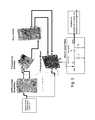
- FIGS. 1 a -1 dshow the general principles of the quartz MEMS-manufacturable magnetometer taught by U.S. patent application Ser. No. 14/628,182 referenced above, with FIG. 1 a being a perspective view of the magnetometer, FIG. 1 b being a section view therethrough taken along line 1 b - 1 b of FIG. 1 a , FIG. 1 c being a schematic diagram of a sustaining or interface circuit coupled to the magnetometer and FIG. 1 d depicting the FM sidebands in the output of the sustaining or interface circuit generated in response to a magnetic field interacting with the magnetometer.
- FIG. 1 eis a graph of the output of the quartz thickness shear oscillator circuit when no AC current is applied to the current loop is 0 dBm (the dashed line) but ⁇ 25 dBm FM sidebands and harmonics (solid lines) are generated when the applied DC magnetic field couples with the AC drive current at 2.77 kHz.
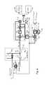
- FIG. 2depicts an open-loop system which is capable of demodulating the FM magnetometer signal.
- FIG. 3depicts a COTS implementation of the FM demodulation system of FIG. 2 .
- FIG. 4depicts one embodiment of a circuit for implementing an analog system for implementing closed-loop phase sensitive detection of magnetic field ⁇ right arrow over (B) ⁇ .
- FIG. 4 adepicts another embodiment of a circuit for implementing an analog system for implementing closed-loop phase sensitive detection of magnetic field ⁇ right arrow over (B) ⁇ .
- FIG. 5depicts an embodiment of a circuit for implementing a digital system for implementing closed-loop phase sensitive detection of magnetic field ⁇ right arrow over (B) ⁇ .
- FIG. 6depicts, on its left hand side a Quartz MEMS magnetometer incorporating capacitive drive electrodes, and also depicts a wafer-level packaged (WLP) Quartz MEMS magnetometer die mounted on a printed-circuit board (PCB) and electrically connected with wire bonds (middle photograph).
- WLPwafer-level packaged Quartz MEMS magnetometer die mounted on a printed-circuit board
- FIG. 7is a side elevation view similar to FIG. 1 b , but FIG. 7 also shows the optional capacitive plates.
- FIGS. 1 a -1 ddepict the general principles of the Quartz MEMS magnetometer 8 taught by U.S. patent application Ser. No. 14/628,182 filed Feb. 20, 2015 and entitled “A Micro-scale Piezoelectric Resonating Magnetometer” which is referenced above.
- the quartz micro-resonatorhas a quartz cantilever 10 which is preferably fixed (thus clamped) at one end of same where it is preferably integrally connected to a wider quartz base portion 50 which in turn may be directly anchored or coupled to a substrate 60 which may be made of silicon, for example, and thus comprise a semiconductor substrate with circuitry formed therein.
- FIG. 7The thickness shear region of the quartz plate is defined by the location of the electrodes 14 a and 14 b in FIG. 7 .
- the flexure mode of oscillationis depicted by the two headed arrow in FIG. 1 b (and also by the two headed arrow in FIG. 1 a adjacent the word “Drive”) while the thickness shear mode of vibration is identified by the two parallel arrows adjacent the word “Sense” in FIG. 1 a .
- the periodic straining in aforementioned regionwhich supports the typical high frequency quartz thickness shear acoustic resonance mode, generates frequency-modulated (FM) sidebands f flex (see the graph of FIG. 1 d ) on either side of the thickness shear resonance frequency f t.s. when the quartz thickness shear mode is driven into oscillation using an interface circuit 18 .
- FMfrequency-modulated
- the firstis formed by the thickness shear mode of the quartz plate 10 in combination with the interface circuit 18 and this oscillator operates at a high frequency ( ⁇ 10 MHz to 10 GHz depending on application requirements).
- the secondis formed by the flexural mode of the quartz plate 10 in combination with feedback provided by a demodulation circuit output at mixer 21 (500 Hz to 1 MHz depending on the flexural mode frequency).
- the current loop 12 or capacitive plates 15need to be driven by some external source 16 near the flexural mode frequency of quartz plate 10 to excite the quartz plate 10 into that mode of oscillation.
- the current loop 12is driven by the output of a demodulation circuit at mixer 21 as shown in the embodiments of FIGS. 4, 4 a and 5 .
- the amplitude of the sidebands (see FIG. 1 d ) at f flexis proportional to the sensed magnetic field component while f t.s. is the fundamental oscillatory frequency in thickness shear mode of the cantilevered beam 10 .
- FIG. 2shows one possible embodiment of a system that can demodulate the magnetometer signal. This system is operates in open loop, because no feedback is provided to the current generator 16 driving the metal loop 12 to hold the loop current at the flexural resonance frequency (f flex ) of the quartz plate 10 .
- the systemshould provide a current to loop 12 having a frequency near the flexural resonance mode of the quartz resonator plate 10 as well as demodulate the thickness-shear oscillation signal to extract the magnetic field signal from the resulting FM sidebands depicted by FIG. 1 d .
- the frequency of the current in the loop 12should preferably fall in the range of f flex ⁇ (1 ⁇ 1/Q) to f flex ⁇ (1+1/Q), where Q is the quality factor of the flexural resonance mode.
- FIG. 2depicts an embodiment of an open-loop system which is capable of demodulating the FM magnetometer signal provided by the quartz magnetometer 8 (at the output of the sustaining or interface circuit 18 ) and bring (demodulate) the magnetically-sensitive sidebands back to their native flexural mode frequency (which is low enough in frequency for a high resolution ADC to accurately capture) by the mixer subtracting the thickness-shear carrier frequency (which is synonymous with the thickness shear resonance frequency) such that the sidebands move from f ts ⁇ f c to simply f c .
- the thickness-shear carrier frequencywhich is synonymous with the thickness shear resonance frequency
- the source 16supplies current to the metal loop 12 .
- the frequency of this currentis not necessarily at the flexural mode resonance frequency f flex although it would be desirable if it were so. Again, that is why it is referred to as an independent frequency f c herein.
- the function of the current source 16is replaced by the output of the demodulation circuit at mixer 21 . This means that f c will always be driven toward f flex by the natural tendency of the flexural oscillation loop to track the flexural mode resonance frequency in a closed loop configuration.
- the quartz magnetometer 8is coupled to an interface circuit 18 which preferably has the input of a transimpedance amplifier (TIA) 18 1 coupled to one of the thickness shear sense electrodes 14 b of the quartz magnetometer 8 .
- the other thickness shear electrode 14 ais coupled in series with an optional varactor 18 3 to an output of TIA 18 1 .
- a tuning voltageis applied across the varactor 18 3 to change its capacitance, resulting in series pulling of the thickness-shear oscillation frequency to a desired target value.
- the output of TIA 18 1is coupled to a buffer amplifier 18 2 , an output of which forms the output of the interface circuit 18 and hence the magnetically-sensitive output of the quartz magnetometer 8 system.
- the output of the interface circuit 18is fed into a phase-locked loop (PLL) 20 , which is preferably formed by a mixer 20 1 , a low-pass filter 20 2 , and a voltage-controlled oscillator (VCO) 20 3 .
- the mixer 20 1acts as a phase detector between its I and Q channels.
- the low pass filter 20 2blocks high order harmonics of the down-mixed signal at its input. In this way, the output of the filter 20 2 is proportional to the phase difference between the I and Q channels.
- the phase differenceis scaled appropriately using, for example, a tunable gain amplifier (not shown) and fed into the tuning port of the VCO 20 3 , which either increases or decreases the frequency of the VCO 20 3 until a lock is achieved between the VCO 20 3 and the incoming signal from the sustaining or interface circuit 18 .
- the frequency of the VCO 20 3tracks the thickness-shear frequency of the magnetometer 8 , but the output of the VCO 20 3 is free of sidebands.
- the single-tone output of the VCO 20 3 and the magnetometer signal output from the sustaining or interface circuit 18are mixed together at a down mixer 21 , which results in frequency subtraction and brings the sidebands to their native frequency near f flex .
- a bandpass filter 22can optionally be used to remove both DC and higher order modulation products from V(f c ) output by the mixer 21 , or the signal V(f c ) can be fed into an analog-digital converter (ADC) 24 and the sideband amplitude can be extracted digitally to obtain a measurement of the strength of the magnetic field sensed by the magnetometer 8 .
- ADCanalog-digital converter
- FIG. 3depicts a COTS implementation of the FM demodulation system of FIG. 2 .
- a differential amplifierLinear Technologies LT6411
- a frequency dividerAnalog Devices ADF4007
- a 600 MHz signalwas divided by 8 to 75 MHz for the PLL reference input—note that the division and subsequent multiplication by 8 is an artifact of the specific PLLs used in this implementation.
- the PLL+VCOis used to lock on to the divided magnetometer output signal and generates an output multiplied up by 8 so that it is back at the native thickness shear frequency (again 600 MHz).
- the VCO outputis a pure tone without the magnetometer side bands.
- the PLL signal and the magnetometer signalare mixed together with a frequency mixer (Analog Devices ADL5801), which is then band-pass filtered and fed to an AC multimeter, or optionally digitized by an ADC.
- the magnetometer 8To maintain maximum sensitivity, it is important for the magnetometer 8 to track the resonance frequency of the flexural mode of the quartz plate 10 . This can be achieved by closing the loop between the FM demodulated output from the down-mixed (and optionally filtered) output of the mixer 21 and the current loop 12 drive signal. See the closed loop embodiments of FIGS. 4 and 5 . Closed-loop operation will be able to maintain maximum sensitivity over a defined temperature range and will also enables phase-sensitive detection of the magnetometer signal, resulting in improved resolution compared to over open-loop amplitude detection utilized in the embodiments of FIGS. 2 and 3 . Hence, a closed-loop quartz magnetometer 8 system will be environmentally robust while maintaining maximum performance.
- FIG. 4depicts a embodiment for implementing an analog system for implementing closed-loop phase sensitive detection of magnetic field ⁇ right arrow over (B) ⁇ .
- the output of the FM demodulated sidebands from mixer 21are buffered by a buffer amplifier 26 and fed back to the capacitive drive plates 15 .
- One of the plates 15 a or 15 bis grounded while the other one of the plates 15 a or 15 b receives the signal from the buffer amp 26 as well as the current loop 12 .
- the current loop 12is connected in parallel with the plates 15 a & 15 b in the embodiment of FIG. 4 , but the current loop 12 could alternatively be connected in series with the plates 15 a & 15 b .
- the buffer amp 26may be understood to also provide a DC offset voltage to the AC demodulated signal in order to drive the capacitive plate actuator 15 .
- FIGS. 4 and 4 ashow a signal V tune output from low pass filter 32 being applied to the Buff Amp. 26 (as signal V tune2 ) which is preferred over applying V tune to varactor 18 3 (as signal V tune1 ).
- the preferred implementationis to route the tuning signal V tune to buffer amp 26 (if optional capacitive plates 15 a/b are utilized with the embodiment of FIG. 4 ) or 26 2 (for the embodiment of FIG. 4 a ) to adjust the DC level provided by buffer amp 26 2 to the capacitive plates 15 a/b which would tune the flexural mode resonance frequency.
- V tuneis routed to the varactor 183 , then the thickness shear resonance frequency is tuned, but that is less preferred, but may still achieve the goal of making the flexural resonance frequency a specific division ratio (N) of the thickness shear resonance frequency. It may be possible to route “V tune ” to both the varactor 18 3 and buffer amp 26 or 26 2 if stability is not adversely impacted thereby. Otherwise, V tune1 or V tune2 , whichever one is not connected to V tune may be connected to a DC voltage when the optional capacitive plates 15 are utilized.
- the thickness shear frequencycan be tuned to a multiple of the flexural frequency by providing a second phase-locked loop (PLL 2 ) formed by a mixer 30 , a low pass filter 32 , and one of the vibration modes of the quartz magnetometer 8 . Which vibration mode depends on where V tune is connected. If V tune is connected to buffer 26 2 , this refers to the flexural mode. If V tune is connected to varactor 18 3 , this would refer to thickness shear mode.
- PLL 2phase-locked loop
- the slowly-varying DC component from low pass filter 32can be used for the phase-lock by controlling either the DC offset of buffer amp 26 (which is the currently preferred embodiment) to tune the flexural resonance frequency of the quartz plate or by controlling the tuning voltage on varactor 18 3 to adjust the thickness shear resonance frequency, while the higher frequency components will be proportional to the magnetic field signal.
- low pass (see element 32 ) and high pass (see element 34 ) filterscan be used to frequency discriminate the desired phase signal proportional to magnetic field strength from the slowly-varying frequency difference between the oscillators required to maintain phase lock.
- FIG. 5depicts a circuit for implementing a digital closed-loop system for implementing closed-loop phase sensitive detection of magnetic field ⁇ right arrow over (B) ⁇ .
- the flexural mode and thickness shear mode oscillatorsare set up in closed loop as described above with reference to FIG. 4 .
- the outputs from the buffer amplifier 26 and optionally the divider 28are directly passed to an ADC 40 and then to a microprocessor 42 , where the desired signal processing is done in the digital domain.
- Feeding the thickness shear resonance to the ADC 32 through a divider 28can be optionally used as a phase reference, or the divider 28 may be eliminated and a system clock can be used as the phase reference if the system clock is sufficiently stable in frequency.
- the divider 28is optional if the system clock is stable enough in frequency to act as a phase reference. If not, then the thickness shear resonance may be used instead (with the divider 28 ) because it is typically quite stable. As such, the divider 28 depicted in the embodiments of FIGS. 4 and 4 a may be omitted and a system clock used instead, if the system clock is sufficiently stable in frequency to act as a phase reference, as the Q input to the mixer 30 in the second phase locked loop PLL 2 .
- FIG. 5can also be modified to utilize two buffer amplifiers 26 1 and 26 2 with separate connections to loop and capacitive electrodes of the magnetometer 8 as done in the embodiment of FIG. 4 a.
- FIG. 6depicts on its left hand side a quartz magnetometer 8 incorporating capacitive drive electrodes 15 a and 15 b (capacitive drive electrode 15 a is on the bottom side of the quartz plate in FIG. 6 —see FIG. 7 —while capacitive drive electrode 15 b is preferably disposed on substrate 60 ), a current loop 12 , and thickness shear electrodes 14 in a single wafer level packaged device.
- the devicemay be subsequently die-attached to a substrate 60 (using a pedestal 52 if needed—see FIG. 7 —to support the device above the substrate 60 ) and electrical connections may be made thereto via wirebonds.
- the external control signalsare made with the indicated connectors.
- the entire electrical systemcan be implemented on a single application-specific integrated circuit (ASIC), eliminating a majority of the PCB boards in the COTS implementation of FIG. 3 .
- ASICapplication-specific integrated circuit
- a second techniquewhich is appropriate for AC magnetic fields, is to take the system output signal proportional to the magnetic field strength as the output of high pass filter 34 . Since the output of mixer 30 is proportional to the phase difference between its I and Q, this technique should allow for very sensitive phase-based detection of the time-varying components of magnetic field.
- a third technique based on FIG. 4is to insert an IQ generator (generating in-phase and quadrature versions of the output of divider 28 ) between divider 28 and mixer 30 . Then an additional mixer can be placed similarly to mixer 30 , but connected to the I channel of theadded IQ generator. In this way, the DC component of the external magnetic field can be measured.
- FIG. 6utilizes a trapezoidally shaped active area quartz magnetometer 8 as that taught by U.S. patent application Ser. No. 14/997,160 filed on the same date as this application and entitled “Quartz Magnetometer having a Quartz Resonant Plate with a Broaden Distal End for Enhanced Magnetic Sensitivity” but modified to also include capacitive drive electrodes 15 a and 15 b disposed preferably interiorly of loop 14 .
- the cantilevered portion of a magnetometer 8according to the above just referenced U.S. Patent Application should have a broadened distal end compared to its point of connection to the quartz base portion 50 , and thus the embodiment of FIG. 6 can assume other shapes including the tee shaped cantilevered arm shown in the above just referenced US Patent Application.
Landscapes
- Physics & Mathematics (AREA)
- Condensed Matter Physics & Semiconductors (AREA)
- General Physics & Mathematics (AREA)
- Measuring Magnetic Variables (AREA)
Abstract
Description
This Application is related to U.S. Provisional Patent Application Ser. No. 61/943,213 filed 21 Feb. 2014 and entitled “A Micro-Scale Piezoelectric Resonating Magnetometer” and to U.S. patent application Ser. No. 14/628,182 filed 20 Feb. 2015 and entitled “A Micro-Scale Piezoelectric Resonating Magnetometer”. The disclosure of these two applications are also hereby incorporated herein by reference.
This Application is also related to U.S. patent application Ser. No. 14/997,423 filed on the same date as this application and entitled A Piezoelectric Magnetometer Capable of Sensing a Magnetic Field in Multiple Vectors”, the disclosure of which is hereby incorporated herein by reference.
This Application is also related to U.S. patent application Ser. No. 14/997,160 filed on the same date as this application and entitled “Quartz Magnetometer having a Quartz Resonant Plate with a Broaden Distal End for Enhanced Magnetic Sensitivity”, the disclosure of which is hereby incorporated herein by reference.
None
This invention relates to magnetometry and more particularly to a FM demodulation System for a quartz magnetometer which may be constructed using Micro-Electro-Mechanical Systems (MEMS) technology.
This patent discloses an integrated system for demodulating the output of a quartz MEMS magnetometer of the type disclosed by U.S. patent application Ser. No. 14/628,182 filed Feb. 20, 2015 noted above. The disclosed quartz MEMS magnetometer utilizes the fact that frequency modulation (FM) of the quartz thickness shear mode oscillator is proportional to the strength of an external magnetic field. As such, a system can provide information regarding the strength of an external magnetic field, and several embodiments of such a system are disclosed herein.
The object of this invention is to detect or sense magnetic fields (which is known as magnetometry), especially magnetic fields sensed by a magnetometer of the types disclosed by U.S. patent application Ser. No. 14/628,182 filed Feb. 20, 2015 and entitled “A Micro-scale Piezoelectric Resonating Magnetometer” and U.S. patent application Ser. No. 14/997,160 filed on the same date as this application and entitled “Quartz Magnetometer having a Quartz Resonant Plate with a Broaden Distal End for Enhanced Magnetic Sensitivity”.
One application of magnetometry is electronic compassing (measuring Earth's magnetic field direction for use in a compass). The advantage of the current invention is that it describes a system which can be implemented using miniature components, preferably manufactured utilizing MEMS technology and ultimately miniaturized into a single compact system integrating a MEMS die and and application-specific integrated circuit (ASIC) die containing the system electronics. This disclosed system is inherently portable with resolution limits around 50 nanoTesla (nT). Embodiments of the system utilizing closed-loop operation and/or phase-sensitive detection enable even higher detection accuracy, improving the resolution to far below 50 nT are also described herein.
In one aspect the present invention provides a magnetometer which is connected with an electronic demodulator. Preferably, the electronic demodulator is coupled to sense electrodes on said magnetometer and performs a frequency demodulation of a thickness shear mode oscillation of the magnetometer at the sense electrodes on said magnetometer sensed by said electronic demodulator. Preferably, the sense electrodes of the magnetometer are coupled to an interface or sustaining circuit which in turn is coupled at an output thereof to the electronic demodulator which preferably includes a phase locked loop circuit.
In another aspect the present invention provides a FM demodulator circuit for use with a magnetometer and an interface circuit combination, the magnetometer having opposing thickness shear sense electrodes coupled to said sustaining or interface circuit, the sustaining or interface circuit generating a signal having a carrier and two magnetically-sensitive sidebands in response to the a magnetic field interacting with said magnetometer, the FM demodulator circuit comprising a phased locked loop circuit coupled to an output of said sustaining or interface circuit for extracting a pure tone from a signal at the output of said sustaining or interface circuit, the pure tone corresponding to to said carrier at the output of said sustaining or interface circuit; and a down mixer having first and second inputs, the first input of down mixer being coupled to phase locked loop circuit and the second input of said of down mixer being coupled to the output of said interface or sustaining circuit for down converting the magnetically-sensitive sidebands to baseband frequencies without said carrier.
In yet another aspect the present invention provides a magnetometer system which includes a magnetometer, an interface circuit and an electronic demodulator. The interface circuit is coupled to sense electrodes disposed on the magnetometer and the demodulator being coupled to the interface circuit.
There are two distinct oscillation loops in this system. The first is formed by the thickness shear mode of thequartz plate 10 in combination with theinterface circuit 18 and this oscillator operates at a high frequency (˜10 MHz to 10 GHz depending on application requirements). The second is formed by the flexural mode of thequartz plate 10 in combination with feedback provided by a demodulation circuit output at mixer21 (500 Hz to 1 MHz depending on the flexural mode frequency). When discussing “open loop” and “closed loop” operation herein, reference is being made to the flexural mode oscillation loop, not the thickness shear oscillation loop, which should preferably be understood to be a closed loop oscillation circuit. In “open loop” operation, thecurrent loop 12 or capacitive plates15 (if used) need to be driven by someexternal source 16 near the flexural mode frequency ofquartz plate 10 to excite thequartz plate 10 into that mode of oscillation. In “closed loop” operation, thecurrent loop 12 is driven by the output of a demodulation circuit atmixer 21 as shown in the embodiments ofFIGS. 4, 4 aand5.
The amplitude of the sidebands (seeFIG. 1d ) at fflexis proportional to the sensed magnetic field component while ft.s.is the fundamental oscillatory frequency in thickness shear mode of the cantileveredbeam 10.
Since the thickness shear frequency is typically in the tens of MHz to several GHz region, recording the amplitude in a portable device of the sidebands calls for FM demodulating above output signal (the interface circuit18) to a frequency at which a high resolution analog-to-digital converter (ADC) can accurately digitize the signal.FIG. 2 shows one possible embodiment of a system that can demodulate the magnetometer signal. This system is operates in open loop, because no feedback is provided to thecurrent generator 16 driving themetal loop 12 to hold the loop current at the flexural resonance frequency (fflex) of thequartz plate 10. How such an open loop system can be constructed from commercial-off-the-shelf (COTS) electronic components will now be described and thereafter closing the loop (that is, convert it to a closed loop system) will be discussed along with phase-sensitive detection, which potentially improves the ultimate resolution of themagnetometer 8 by maintaining a frequency lock onto the flexural resonance of thequartz plate 10.
The system should provide a current toloop 12 having a frequency near the flexural resonance mode of thequartz resonator plate 10 as well as demodulate the thickness-shear oscillation signal to extract the magnetic field signal from the resulting FM sidebands depicted byFIG. 1d . In order to be “near” the flexural resonance mode of thequartz resonator plate 10, the frequency of the current in theloop 12 should preferably fall in the range of fflex·(1−1/Q) to fflex·(1+1/Q), where Q is the quality factor of the flexural resonance mode. Also, modifications to the system are suggested which will enable closed loop operation of the thickness-shear oscillator as well as forming an oscillation loop around the flexural mode of thequartz resonator 8. The closed-loop embodiments of the system (seeFIGS. 4 and 5 ) enable phase-sensitive detection of the magnetic field perturbations, which will greatly enhance the sensitivity and resolution of thequartz magnetometer 8. But before getting to the details of the closed loop embodiments, let us first discuss the open loop embodiment ofFIG. 2 .
As is depicted byFIG. 1e , the sidebands appear at offsets of multiples of fc. They only occur at offsets of fflex, when the flexural mode is driven in closed loop, that is, when fc=fflex(per the discussion above about what “near” means). In the “closed loop” operation of the flexural mode, the function of thecurrent source 16 is replaced by the output of the demodulation circuit atmixer 21. This means that fcwill always be driven toward fflexby the natural tendency of the flexural oscillation loop to track the flexural mode resonance frequency in a closed loop configuration. And this in turn means that the desired condition above that fc=fflexcan be achieved for the closed loop embodiments which will give the maximum possible magnetic sensitivity of the sidebands since it will maximize the periodic straining induced by the flexural mode on the thickness shear mode.
Thequartz magnetometer 8 is coupled to aninterface circuit 18 which preferably has the input of a transimpedance amplifier (TIA)181coupled to one of the thicknessshear sense electrodes 14bof thequartz magnetometer 8. The otherthickness shear electrode 14ais coupled in series with anoptional varactor 183to an output ofTIA 181. A tuning voltage is applied across thevaractor 183to change its capacitance, resulting in series pulling of the thickness-shear oscillation frequency to a desired target value. The output ofTIA 181is coupled to abuffer amplifier 182, an output of which forms the output of theinterface circuit 18 and hence the magnetically-sensitive output of thequartz magnetometer 8 system.
The output of theinterface circuit 18 is fed into a phase-locked loop (PLL)20, which is preferably formed by amixer 201, a low-pass filter 202, and a voltage-controlled oscillator (VCO)203. Themixer 201acts as a phase detector between its I and Q channels. Thelow pass filter 202blocks high order harmonics of the down-mixed signal at its input. In this way, the output of thefilter 202is proportional to the phase difference between the I and Q channels. The phase difference is scaled appropriately using, for example, a tunable gain amplifier (not shown) and fed into the tuning port of theVCO 203, which either increases or decreases the frequency of theVCO 203until a lock is achieved between theVCO 203and the incoming signal from the sustaining orinterface circuit 18. Hence, the frequency of theVCO 203tracks the thickness-shear frequency of themagnetometer 8, but the output of theVCO 203is free of sidebands. Now the single-tone output of theVCO 203and the magnetometer signal output from the sustaining orinterface circuit 18 are mixed together at adown mixer 21, which results in frequency subtraction and brings the sidebands to their native frequency near fflex. Abandpass filter 22 can optionally be used to remove both DC and higher order modulation products from V(fc) output by themixer 21, or the signal V(fc) can be fed into an analog-digital converter (ADC)24 and the sideband amplitude can be extracted digitally to obtain a measurement of the strength of the magnetic field sensed by themagnetometer 8.
To maintain maximum sensitivity, it is important for themagnetometer 8 to track the resonance frequency of the flexural mode of thequartz plate 10. This can be achieved by closing the loop between the FM demodulated output from the down-mixed (and optionally filtered) output of themixer 21 and thecurrent loop 12 drive signal. See the closed loop embodiments ofFIGS. 4 and 5 . Closed-loop operation will be able to maintain maximum sensitivity over a defined temperature range and will also enables phase-sensitive detection of the magnetometer signal, resulting in improved resolution compared to over open-loop amplitude detection utilized in the embodiments ofFIGS. 2 and 3 . Hence, a closed-loop quartz magnetometer 8 system will be environmentally robust while maintaining maximum performance. However, in the event that there is no external magnetic field, no Lorentz force can be generated to drive the flexural mode ofmagnetometer 8 into oscillation. A solution to this problem is to usecapacitive driving plates FIGS. 6 and 7 and in FIG. 3 of U.S. Pat. No. 8,569,937.Plate 15ais disposed on beam10 (preferably interiorly of loop12) whileplate 15bis disposed on adjacent fixed structure (fixed relative to theplate 10 which vibrates) such as substrate60 (see alsoFIG. 1 ). By driving thebeam 10 into flexural oscillation withcapacitive drive plates 15, a force can always be generated, even in the absence of an external magnetic field. Now the external magnetic field {right arrow over (B)} will contribute small perturbations on top of the capacitively-driven flexural mode sidebands seen on the thickness-shear oscillation ofFIG. 1 . These magnetic field perturbations will induce phase variations proportional to the external magnetic field, which can be read out with the systems shown inFIGS. 4 and 5 .
This closes the loop for the flexural mode oscillator and enables sustained oscillation at fc=fflexeven in the absence of an external magnetic field {right arrow over (B)} (using the capacitive driver plates15). Note that there are two oscillators in the system, one at the flexural frequency and one at the thickness shear frequency of themagnetometer 8. A small magnetic field change will perturb the phase of the flexural mode oscillator, which can be read out relative to the stable thickness shear frequency when divided appropriately bydivider 28. To simplify this division, the thickness shear frequency can be tuned to a multiple of the flexural frequency by providing a second phase-locked loop (PLL2) formed by amixer 30, alow pass filter 32, and one of the vibration modes of thequartz magnetometer 8. Which vibration mode depends on where Vtuneis connected. If Vtuneis connected to buffer262, this refers to the flexural mode. If Vtuneis connected tovaractor 183, this would refer to thickness shear mode. The slowly-varying DC component fromlow pass filter 32 can be used for the phase-lock by controlling either the DC offset of buffer amp26 (which is the currently preferred embodiment) to tune the flexural resonance frequency of the quartz plate or by controlling the tuning voltage onvaractor 183to adjust the thickness shear resonance frequency, while the higher frequency components will be proportional to the magnetic field signal. Hence, low pass (see element32) and high pass (see element34) filters (to block the high order demodulation products) can be used to frequency discriminate the desired phase signal proportional to magnetic field strength from the slowly-varying frequency difference between the oscillators required to maintain phase lock.
The embodiment ofFIG. 5 can also be modified to utilize twobuffer amplifiers magnetometer 8 as done in the embodiment ofFIG. 4 a.
Obtaining a signal proportional to the strength of magnetic field will now be discussed with reference primarily the “closed loop” implementation depicted inFIG. 4 . There are several techniques to obtain a signal output proportional to the magnetic field. One technique takes the output V(fflex) ofdown mixer 21 and bandpass filters that signal centered at fflexbyfilter 22 and then measures its AC amplitude or digitizes the signal V(fflex) in an ADC23 and performs the required filtering and/or signal conditioning in the digital domain. This is the same technique used for the closed loop embodiment ofFIG. 2 , except that the output of the mixer is V(fc) instead of V(fflex).
A second technique, which is appropriate for AC magnetic fields, is to take the system output signal proportional to the magnetic field strength as the output ofhigh pass filter 34. Since the output ofmixer 30 is proportional to the phase difference between its I and Q, this technique should allow for very sensitive phase-based detection of the time-varying components of magnetic field.
A third technique based onFIG. 4 , but which would require additional hardware, is to insert an IQ generator (generating in-phase and quadrature versions of the output of divider28) betweendivider 28 andmixer 30. Then an additional mixer can be placed similarly tomixer 30, but connected to the I channel of theadded IQ generator. In this way, the DC component of the external magnetic field can be measured.
The three techniques discussed above with reference toFIG. 4 could alternatively be used with the embodiment ofFIG. 4a . Also, three techniques discussed above with reference toFIG. 4 could alternatively be carried out in the digital domain using the processor ofFIG. 5 as opposed to utilizing the discrete electronics discussed with reference toFIG. 4 .
It will be noted that the embodiment ofFIG. 6 utilizes a trapezoidally shaped activearea quartz magnetometer 8 as that taught by U.S. patent application Ser. No. 14/997,160 filed on the same date as this application and entitled “Quartz Magnetometer having a Quartz Resonant Plate with a Broaden Distal End for Enhanced Magnetic Sensitivity” but modified to also includecapacitive drive electrodes magnetometer 8 according to the above just referenced U.S. Patent Application should have a broadened distal end compared to its point of connection to thequartz base portion 50, and thus the embodiment ofFIG. 6 can assume other shapes including the tee shaped cantilevered arm shown in the above just referenced US Patent Application.
The foregoing Detailed Description of exemplary and possibly preferred embodiments is presented for purposes of illustration and disclosure in accordance with the requirements of the law. It is not intended to be exhaustive nor to limit the invention to the precise form(s) described, but only to enable others skilled in the art to understand how the invention may be suited for a particular use or implementation. The possibility of modifications and variations will be apparent to practitioners skilled in the art. No limitation is intended by the description of exemplary embodiments which may have included tolerances, feature dimensions, specific operating conditions, engineering specifications, or the like, and which may vary between implementations or with changes to the state of the art, and no limitation should be implied therefrom.
Applicant has made this disclosure with respect to the current state of the art, but also contemplates advancements and that adaptations in the future may take into consideration of those advancements, namely in accordance with the then current state of the art. It is intended that the scope of the invention be defined by the Claims as written and equivalents as applicable.
Reference to a claim element in the singular is not intended to mean “one and only one” unless explicitly so stated. Moreover, no element, component, nor method or process step in this disclosure is intended to be dedicated to the public regardless of whether the element, component, or step is explicitly recited in the Claims.
No claim element herein is to be construed under the provisions of 35 U.S.C. § 112(f), unless the element is expressly recited using the phrase “means for . . . ” and no method or process step herein is to be construed under those provisions unless the step, or steps, are expressly recited using the phrase “comprising the step(s) of . . . ”.
Claims (32)
1. A magnetometer in combination with an interface and electronic demodulator circuits and an oscillator circuit, the oscillator circuit driving the magnetometer into a flexure mode of vibration, the magnetometer also entering a thickness shear mode of vibration in response to a sensed magnetic field while in said flexure mode of vibration, the thickness shear mode of vibration being detected by said interface and electronic demodulator circuits, the interface and electronic demodulator circuits detecting sidebands in said thickness shear mode of vibration the amplitudes of which are indicative of an intensity of the magnetic field.
2. A magnetometer in combination with an electronic demodulator wherein the electronic demodulator is coupled to sense electrodes on said magnetometer and performs frequency demodulation of a thickness shear mode of vibration of said magnetometer at said sense electrodes on said magnetometer as sensed by said sense electrodes in combination with said electronic demodulator and detects sidebands in the thickness shear mode of vibration, the sidebands having information indicative of an intensity of a sensed magnetic field.
3. The combination ofclaim 2 wherein said sense electrodes of magnetometer are coupled to an interface or sustaining circuit which in turn is coupled at an output thereof to said electronic demodulator.
4. The combination ofclaim 3 wherein said electronic demodulator includes a phase locked loop circuit.
5. The combination ofclaim 4 wherein said phase locked loop circuit includes a voltage controlled oscillator which is frequency locked to a carrier frequency of the shear mode of vibration of said magnetometer and generates a pure tone corresponding to said carrier frequency free of magnetically-sensitive sidebands in a signal output at the output of said interface or sustaining circuit.
6. The combination ofclaim 5 wherein further including a down mixer having first and second inputs, the first input of down mixer being coupled to the voltage controlled oscillator of said phase locked loop circuit and the second input of said of down mixer being coupled to the output of said interface or sustaining circuit for down converting the magnetically-sensitive sidebands to a near baseband frequency, the down mixer providing a demodulated output of said electronic demodulator.
7. The combination ofclaim 6 wherein said magnetometer includes a loop electrode disposed thereon which surrounds at least one of said sense electrodes on said magnetometer and wherein the demodulated output of said electronic demodulator is coupled to said loop electrode.
8. The combination ofclaim 6 wherein said magnetometer further includes at least one capacitive drive plate disposed thereon and wherein the demodulated output of said electronic demodulator is also coupled to said capacitive drive plate for initializing flexural mode vibrations of said magnetometer in absence of a magnetic field that said magnetometer can sense.
9. The combination ofclaim 3 wherein a flexural mode of vibration of the magnetometer is driven into oscillation via sustained feedback from said electronic demodulator and wherein a thickness shear oscillatory mode of the magnetometer is also driven into oscillation via a sustaining amplifier in said interface or sustaining circuit.
10. The combination ofclaim 3 wherein the thickness shear mode vibration frequency is tuned with a phase locked loop, coupled to interface or sustaining circuit, to a multiple N of the flexural mode vibration frequency.
11. The combination ofclaim 10 wherein an output of the phase lock loop is applied along with an output of the interface or sustaining circuit to a down mixer which extracts magnetically-sensitive sidebands in a signal at the output of the interface or sustaining circuit at baseband frequencies.
12. The combination ofclaim 11 wherein the thickness shear vibration frequency output by the phase locked loop is divided down by an N divider and wherein the N-divided thickness shear oscillation frequency output by the N-divider is applied along with an output generated by the down mixer to a second phase locked loop.
13. A FM demodulator circuit for use with a magnetometer and a sustaining or interface circuit, the magnetometer having opposing thickness shear sense electrodes coupled to said sustaining or interface circuit, the sustaining or interface circuit generating a signal having a carrier and two magnetically-sensitive sidebands generated in response to the a magnetic field interacting with said magnetometer, the FM demodulator circuit comprising:
a. phased locked loop circuit coupled to an output of said sustaining or interface circuit for extracting a pure tone from a signal at the output of said sustaining or interface circuit, the pure tone corresponding to to said carrier at the output of said sustaining or interface circuit; and
b. a down mixer having first and second inputs, the first input of down mixer being coupled to phase locked loop circuit and the second input of said of down mixer being coupled to the output of said interface or sustaining circuit for down converting the magnetically-sensitive sidebands to baseband frequencies without said carrier.
14. A magnetometer system comprising a magnetometer, an interface circuit and an electronic demodulator, the interface circuit being coupled to sense electrodes disposed on a plate of the magnetometer, the plate having flexural and thickness shear vibratory modes, the flexural mode vibratory mode modulating the thickness shear vibratory mode thereby producing sidebands in the thickness shear vibratory mode, the magnetometer and the demodulator being coupled to the interface circuit for detecting said sidebands.
15. The magnetometer system ofclaim 14 wherein the magnetometer has a loop electrode which follows an outline of the shape of an active portion of the magnetometer and wherein the demodulator has an output for driving the loop electrode of the magnetometer.
16. The magnetometer system ofclaim 14 wherein the magnetometer wherein the plate having flexural and thickness shear vibratory modes is a quartz plate and wherein the flexural vibratory mode is driven, in use, into vibration by the demodulator and wherein the thickness shear vibratory mode is driven, in use, into vibration by the interface circuit.
17. The magnetometer system ofclaim 16 wherein a signal corresponding to the frequency of the flexural vibratory mode is electronically mixed in a mixer with a signal corresponding to the frequency of the thickness shear vibratory mode to produce an output signal proportional to the phase of the flexural mode oscillation which is also proportional to the strength of an external magnetic field sensed, in use, by the magnetometer.
18. The magnetometer system ofclaim 17 wherein frequency of the thickness shear vibratory mode frequency is tuned with a phase locked loop to a multiple of the frequency of the flexural vibratory mode.
19. The magnetometer system ofclaim 18 wherein a low pass filter passes a DC component of the output signal to tune the thickness shear vibratory mode frequency while a bandpass filter selects the frequency components of phase perturbations in the output signal which are proportional to the strength of the external magnetic field.
20. The magnetometer system ofclaim 19 wherein the output of the mixer is applied to an analog to digital converter.
21. The magnetometer system ofclaim 20 wherein a microprocessor is coupled to the analog to digital converter.
22. A magnetometer system for measuring the intensity of a magnetic field, the magnetometer system comprising a magnetometer and an interface circuit, the magnetometer having sense electrodes disposed on a dielectric resonator plate, the interface circuit being coupled to said sense electrodes and detecting sidebands in a thickness shear mode of vibration of said dielectric resonator plate, the sidebands having an amplitude indicative of the intensity of said magnetic field.
23. The magnetometer system ofclaim 22 wherein the dielectric resonator plate is a quartz resonator plate.
24. The magnetometer system ofclaim 23 wherein the system further has an oscillator circuit and wherein the quartz resonator plate has at least one loop electrode disposed at or near edges of the quartz resonator plate and spaced from said sense electrodes, the at least one loop electrode being driven by a drive current provided by an oscillator circuit for causing the quartz resonator plate to vibrate in a flexure mode while the quartz resonator plate is also vibrating in said thickness shear mode in the presence of said magnetic field.
25. An apparatus comprising a quartz plate, an interface circuit and an electronic demodulator, the interface circuit being coupled to sense electrodes disposed on the quartz plate, a loop electrode disposed on the quartz plate which surrounds at least one of said sense electrodes, an output of said electronic demodulator being coupled to said loop electrode, the plate having flexural and thickness shear vibratory modes, the flexural mode vibratory mode modulating the thickness shear vibratory mode thereby producing sidebands in the thickness shear vibratory mode, the demodulator being coupled to the interface circuit for detecting said sidebands.
26. The apparatus ofclaim 25 wherein the loop electrode which follows an outline of the shape of an active portion of the quartz plate.
27. The apparatus ofclaim 25 wherein the flexural vibratory mode of the quartz plate is driven, in use, into vibration by the demodulator and wherein the thickness shear vibratory mode is driven, in use, into vibration by the interface circuit.
28. The apparatus ofclaim 27 wherein a signal corresponding to the frequency of the flexural vibratory mode is electronically mixed in a mixer with a signal corresponding to the frequency of the thickness shear vibratory mode to produce an output signal proportional to the phase of the flexural mode oscillation which is also proportional to the strength of an external magnetic field exposed, in use, to the quartz plate.
29. The apparatus ofclaim 28 wherein frequency of the thickness shear vibratory mode frequency is tuned with a phase locked loop to a multiple of the frequency of the flexural vibratory mode.
30. The apparatus ofclaim 29 wherein a low pass filter passes a DC component of the output signal to tune the thickness shear vibratory mode frequency while a bandpass filter selects the frequency components of phase perturbations in the output signal which are proportional to the strength of the external magnetic field.
31. The apparatus ofclaim 30 wherein the output of the mixer is applied to an analog to digital converter.
32. The apparatus ofclaim 31 wherein a microprocessor is coupled to the analog to digital converter.
Priority Applications (1)
| Application Number | Priority Date | Filing Date | Title |
|---|---|---|---|
| US14/997,203US10175307B1 (en) | 2016-01-15 | 2016-01-15 | FM demodulation system for quartz MEMS magnetometer |
Applications Claiming Priority (1)
| Application Number | Priority Date | Filing Date | Title |
|---|---|---|---|
| US14/997,203US10175307B1 (en) | 2016-01-15 | 2016-01-15 | FM demodulation system for quartz MEMS magnetometer |
Publications (1)
| Publication Number | Publication Date |
|---|---|
| US10175307B1true US10175307B1 (en) | 2019-01-08 |
Family
ID=64872538
Family Applications (1)
| Application Number | Title | Priority Date | Filing Date |
|---|---|---|---|
| US14/997,203ActiveUS10175307B1 (en) | 2016-01-15 | 2016-01-15 | FM demodulation system for quartz MEMS magnetometer |
Country Status (1)
| Country | Link |
|---|---|
| US (1) | US10175307B1 (en) |
Cited By (11)
| Publication number | Priority date | Publication date | Assignee | Title |
|---|---|---|---|---|
| US20190250198A1 (en)* | 2018-02-09 | 2019-08-15 | Hrl Laboratories, Llc | Dual Magnetic and Electric Field Quartz Sensor |
| CN111381201A (en)* | 2018-12-25 | 2020-07-07 | Tdk株式会社 | Magnetic field detection device and magnetic field detection method |
| US10819276B1 (en) | 2018-05-31 | 2020-10-27 | Hrl Laboratories, Llc | Broadband integrated RF magnetic antenna |
| US10892931B2 (en)* | 2016-08-31 | 2021-01-12 | Huawei Technologies Duesseldorf Gmbh | Filtered multi-carrier communications |
| US11101786B1 (en) | 2017-06-20 | 2021-08-24 | Hrl Laboratories, Llc | HF-VHF quartz MEMS resonator |
| US11169224B2 (en)* | 2018-12-27 | 2021-11-09 | Tdk Corporation | Magnetic field detection device and method of detecting magnetic field |
| US11239823B1 (en) | 2017-06-16 | 2022-02-01 | Hrl Laboratories, Llc | Quartz MEMS piezoelectric resonator for chipscale RF antennae |
| US11249152B2 (en)* | 2019-03-20 | 2022-02-15 | Tdk Corporation | Magnetic field detection device and method of detecting magnetic field |
| US20220200662A1 (en)* | 2020-12-17 | 2022-06-23 | Electronics And Telecommunications Research Institute | Magnetic field communication method and apparatus using gmi magnetometer |
| US11563420B1 (en) | 2019-03-29 | 2023-01-24 | Hrl Laboratories, Llc | Femto-tesla MEMS RF antenna with integrated flux concentrator |
| US11988727B1 (en) | 2019-07-31 | 2024-05-21 | Hrl Laboratories, Llc | Magnetostrictive MEMS magnetic gradiometer |
Citations (235)
| Publication number | Priority date | Publication date | Assignee | Title |
|---|---|---|---|---|
| US392650A (en) | 1888-11-13 | watrous | ||
| US2487165A (en) | 1946-10-10 | 1949-11-08 | August E Miller | Crystal electrode |
| US3390287A (en) | 1964-12-10 | 1968-06-25 | Kistler Instrumente Ag | Piezo-electric building units |
| US3766616A (en) | 1972-03-22 | 1973-10-23 | Statek Corp | Microresonator packaging and tuning |
| JPS5791017A (en) | 1980-11-27 | 1982-06-07 | Seiko Instr & Electronics Ltd | Gt-cut quartz oscillator |
| US4364016A (en) | 1980-11-03 | 1982-12-14 | Sperry Corporation | Method for post fabrication frequency trimming of surface acoustic wave devices |
| WO1984000082A1 (en) | 1982-06-14 | 1984-01-05 | Gte Prod Corp | Trimming of piezoelectric components |
| US4426769A (en) | 1981-08-14 | 1984-01-24 | Amp Incorporated | Moisture getter for integrated circuit packages |
| US4442574A (en) | 1982-07-26 | 1984-04-17 | General Electric Company | Frequency trimming of saw resonators |
| US4447753A (en) | 1981-03-25 | 1984-05-08 | Seiko Instruments & Electronics Ltd. | Miniature GT-cut quartz resonator |
| US4618262A (en) | 1984-04-13 | 1986-10-21 | Applied Materials, Inc. | Laser interferometer system and method for monitoring and controlling IC processing |
| JPH01129517A (en) | 1987-11-13 | 1989-05-22 | Fujitsu Ltd | Manufacture of surface wave resonance element |
| US4870313A (en) | 1985-04-11 | 1989-09-26 | Toyo Communication Equipment Co., Ltd. | Piezoelectric resonators for overtone oscillations |
| US4898031A (en) | 1987-07-24 | 1990-02-06 | Yazaki Corporation | Vibrational angular velocity sensor |
| US4944836A (en) | 1985-10-28 | 1990-07-31 | International Business Machines Corporation | Chem-mech polishing method for producing coplanar metal/insulator films on a substrate |
| EP0461761A1 (en) | 1990-05-18 | 1991-12-18 | British Aerospace Public Limited Company | Inertial sensors |
| JPH04322507A (en) | 1991-04-22 | 1992-11-12 | Matsushita Electric Ind Co Ltd | How to process crystal resonators |
| EP0531985A1 (en) | 1991-09-12 | 1993-03-17 | Matsushita Electric Industrial Co., Ltd. | Electro-acoustic hybrid integrated circuit and manufacturing method thereof |
| US5203208A (en) | 1991-04-29 | 1993-04-20 | The Charles Stark Draper Laboratory | Symmetrical micromechanical gyroscope |
| JPH05286142A (en) | 1992-04-13 | 1993-11-02 | Fujitsu Ltd | Inkjet head and manufacturing method thereof |
| US5260596A (en) | 1991-04-08 | 1993-11-09 | Motorola, Inc. | Monolithic circuit with integrated bulk structure resonator |
| JPH06232678A (en) | 1993-01-29 | 1994-08-19 | Hitachi Ltd | Surface acoustic wave resonator and method for manufacturing the same |
| JPH06318533A (en) | 1993-02-03 | 1994-11-15 | Tama Electric Co Ltd | Electronic component |
| US5421312A (en) | 1990-11-03 | 1995-06-06 | Dawson Royalties Limited | Electrical circuit |
| US5445008A (en) | 1994-03-24 | 1995-08-29 | Martin Marietta Energy Systems, Inc. | Microbar sensor |
| US5480747A (en) | 1994-11-21 | 1996-01-02 | Sematech, Inc. | Attenuated phase shifting mask with buried absorbers |
| DE4442033A1 (en) | 1994-11-25 | 1996-05-30 | Bosch Gmbh Robert | Yaw rate sensor |
| US5530408A (en) | 1995-05-25 | 1996-06-25 | The United States Of America As Represented By The Secretary Of The Army | Method of making an oven controlled crystal oscillator the frequency of which remains ultrastable under temperature variations |
| US5552016A (en) | 1993-04-28 | 1996-09-03 | Applied Materials, Inc. | Method and apparatus for etchback endpoint detection |
| US5578976A (en) | 1995-06-22 | 1996-11-26 | Rockwell International Corporation | Micro electromechanical RF switch |
| WO1996038710A1 (en) | 1995-05-31 | 1996-12-05 | Litef Gmbh | Micromechanical rotation speed sensor |
| JPH08330878A (en) | 1995-06-02 | 1996-12-13 | Matsushita Electric Ind Co Ltd | Oscillator manufacturing method |
| US5589724A (en) | 1993-01-25 | 1996-12-31 | Matsushita Electric Industrial Co., Ltd. | Piezoelectric device and a package |
| US5605490A (en) | 1994-09-26 | 1997-02-25 | The United States Of America As Represented By The Secretary Of The Army | Method of polishing langasite |
| US5644139A (en) | 1995-03-02 | 1997-07-01 | Allen; Ross R. | Navigation technique for detecting movement of navigation sensors relative to an object |
| US5646346A (en) | 1994-11-10 | 1997-07-08 | Okada; Kazuhiro | Multi-axial angular velocity sensor |
| US5648849A (en) | 1994-04-05 | 1997-07-15 | Sofie | Method of and device for in situ real time quantification of the morphology and thickness of a localized area of a surface layer of a thin layer structure during treatment of the latter |
| US5658418A (en) | 1995-03-31 | 1997-08-19 | International Business Machines Corporation | Apparatus for monitoring the dry etching of a dielectric film to a given thickness in an integrated circuit |
| US5665915A (en) | 1992-03-25 | 1997-09-09 | Fuji Electric Co., Ltd. | Semiconductor capacitive acceleration sensor |
| US5666706A (en) | 1993-06-10 | 1997-09-16 | Matsushita Electric Industrial Co., Ltd. | Method of manufacturing a piezoelectric acoustic wave device |
| US5668057A (en) | 1991-03-13 | 1997-09-16 | Matsushita Electric Industrial Co., Ltd. | Methods of manufacture for electronic components having high-frequency elements |
| JPH09247025A (en) | 1996-03-11 | 1997-09-19 | Murata Mfg Co Ltd | Antenna system |
| US5719324A (en) | 1995-06-16 | 1998-02-17 | Lockheed Martin Energy Systems, Inc. | Microcantilever sensor |
| US5728936A (en) | 1995-08-16 | 1998-03-17 | Robert Bosch Gmbh | Rotary speed sensor |
| WO1998015799A1 (en) | 1996-10-07 | 1998-04-16 | HAHN-SCHICKARD-GESELLSCHAFT FÜR ANGEWANDTE FORSCHUNG E.V. Wilhelm-Schickard-Strasse 10 | Rotation rate sensor with uncoupled mutually perpendicular primary and secondary oscillations |
| US5783749A (en) | 1995-12-07 | 1998-07-21 | Electronics And Telecommunications Research Institute | Vibrating disk type micro-gyroscope |
| DE19719601A1 (en) | 1997-05-09 | 1998-11-12 | Bosch Gmbh Robert | Acceleration sensor with spring-mounted seismic mass |
| US5894090A (en) | 1996-05-31 | 1999-04-13 | California Institute Of Technology | Silicon bulk micromachined, symmetric, degenerate vibratorygyroscope, accelerometer and sensor and method for using the same |
| US5905202A (en) | 1995-09-01 | 1999-05-18 | Hughes Electronics Corporation | Tunneling rotation sensor |
| US5920012A (en) | 1998-06-16 | 1999-07-06 | Boeing North American | Micromechanical inertial sensor |
| US5928532A (en) | 1996-11-11 | 1999-07-27 | Tokyo Electron Limited | Method of detecting end point of plasma processing and apparatus for the same |
| US5942445A (en) | 1996-03-25 | 1999-08-24 | Shin-Etsu Handotai Co., Ltd. | Method of manufacturing semiconductor wafers |
| US5981392A (en) | 1996-03-28 | 1999-11-09 | Shin-Etsu Handotai Co., Ltd. | Method of manufacturing semiconductor monocrystalline mirror-surface wafers which includes a gas phase etching process, and semiconductor monocrystalline mirror-surface wafers manufactured by the method |
| US6009751A (en) | 1998-10-27 | 2000-01-04 | Ljung; Bo Hans Gunnar | Coriolis gyro sensor |
| EP0971208A2 (en) | 1998-07-10 | 2000-01-12 | Murata Manufacturing Co., Ltd. | Angular velocity sensor |
| US6033852A (en) | 1996-09-27 | 2000-03-07 | University Of Maine | Monolithic piezoelectric sensor (MPS) for sensing chemical, biochemical and physical measurands |
| US6044705A (en) | 1993-10-18 | 2000-04-04 | Xros, Inc. | Micromachined members coupled for relative rotation by torsion bars |
| US6049702A (en) | 1997-12-04 | 2000-04-11 | Rockwell Science Center, Llc | Integrated passive transceiver section |
| US6081334A (en) | 1998-04-17 | 2000-06-27 | Applied Materials, Inc | Endpoint detection for semiconductor processes |
| US6089088A (en) | 1997-11-07 | 2000-07-18 | Commissariat A L'energie Atomique | Vibrating microgyrometer |
| US6094985A (en) | 1996-11-22 | 2000-08-01 | Siemens Aktiengesellschaft | Rotation rate sensor |
| US6114801A (en) | 1997-04-14 | 2000-09-05 | Toyo Communication Equipment Co., Ltd. | At-cut crystal resonator |
| US6145380A (en) | 1997-12-18 | 2000-11-14 | Alliedsignal | Silicon micro-machined accelerometer using integrated electrical and mechanical packaging |
| WO2000068640A2 (en) | 1999-04-21 | 2000-11-16 | The Regents Of The University Of California | Micro-machined angle-measuring gyroscope |
| US6151964A (en) | 1998-05-25 | 2000-11-28 | Citizen Watch Co., Ltd. | Angular velocity sensing device |
| EP1055908A1 (en) | 1999-05-27 | 2000-11-29 | Delphi Technologies, Inc. | Angular rate sensor |
| US6155115A (en) | 1991-01-02 | 2000-12-05 | Ljung; Per | Vibratory angular rate sensor |
| US6164134A (en) | 1999-01-29 | 2000-12-26 | Hughes Electronics Corporation | Balanced vibratory gyroscope and amplitude control for same |
| US6182352B1 (en) | 1997-06-02 | 2001-02-06 | Avery Dennison Corporation | Method of manufacturing an EAS marker |
| US6196059B1 (en) | 1997-08-11 | 2001-03-06 | Fraunhofer Gesellschaft Zur Forderung Der Angewandten Forschung E.V. | Piezoelectric resonator, process for the fabrication thereof including its use as a sensor element for the determination of the concentration of a substance contained in a liquid and/or for the determination of the physical properties of the liquid |
| US6204737B1 (en) | 1998-06-02 | 2001-03-20 | Nokia Mobile Phones, Ltd | Piezoelectric resonator structures with a bending element performing a voltage controlled switching function |
| US6207008B1 (en) | 1997-12-15 | 2001-03-27 | Ricoh Company, Ltd. | Dry etching endpoint detection system |
| US6236145B1 (en) | 2000-02-29 | 2001-05-22 | Cts Corporation | High thermal resistivity crystal resonator support structure and oscillator package |
| WO2001044823A1 (en) | 1999-12-16 | 2001-06-21 | Robert Bosch Gmbh | Micromechanical spring structure, especially for a rotational speed sensor |
| US6250157B1 (en) | 1998-06-22 | 2001-06-26 | Aisin Seiki Kabushiki Kaisha | Angular rate sensor |
| US6263552B1 (en) | 1995-12-28 | 2001-07-24 | Ngk Insulators, Ltd. | Method of producing piezoelectric/electrostrictive film-type element |
| US6282958B1 (en) | 1998-08-11 | 2001-09-04 | Bae Systems Plc | Angular rate sensor |
| US6289733B1 (en) | 1999-05-12 | 2001-09-18 | Hughes Electronics Corporation | Planar vibratory gyroscopes |
| US6297064B1 (en) | 1998-02-03 | 2001-10-02 | Tokyo Electron Yamanashi Limited | End point detecting method for semiconductor plasma processing |
| WO2001074708A2 (en) | 2000-04-05 | 2001-10-11 | Interuniversitair Microelektronica Centrum (Imec) | Method for depositing polycrystalline sige suitable for micromachining and devices obtained thereof |
| KR20010110428A (en) | 1999-02-01 | 2001-12-13 | 비르 에이/에스 | A surface plasmon resonance sensor |
| US6335667B1 (en) | 1998-08-28 | 2002-01-01 | Seiko Epson Corporation | Multi-longitudinal mode coupled saw filter |
| US6336366B1 (en) | 1999-09-24 | 2002-01-08 | Ut-Battelle, Llc | Piezoelectrically tunable resonance frequency beam utilizing a stress-sensitive film |
| WO2002012873A2 (en) | 2000-08-08 | 2002-02-14 | Smithkline Beecham P.L.C. | Quartz crystal microbalance |
| US6367326B1 (en) | 1996-07-10 | 2002-04-09 | Wacoh Corporation | Angular velocity sensor |
| US6367786B1 (en) | 1999-06-07 | 2002-04-09 | California Institute Of Technology | Micromachined double resonator |
| US20020066317A1 (en) | 2000-12-06 | 2002-06-06 | Gang Lin | Micro yaw rate sensors |
| US20020072246A1 (en) | 2000-12-11 | 2002-06-13 | Samsung Electronics Co., Ltd. | Method of forming a spin-on-glass insulation layer |
| US20020074947A1 (en) | 2000-09-01 | 2002-06-20 | Takeo Tsukamoto | Electron-emitting device, electron-emitting apparatus, image display apparatus, and light-emitting apparatus |
| US6413682B1 (en) | 1999-05-21 | 2002-07-02 | Shin-Etsu Chemical Co., Ltd. | Synthetic quartz glass substrate for photomask and making method |
| US6417925B1 (en) | 1999-08-26 | 2002-07-09 | Fuji Photo Film Co., Ltd. | Surface plasmon sensor for analyzing liquid sample or humid atmosphere |
| US6424418B2 (en) | 1998-05-29 | 2002-07-23 | Canon Kabushiki Kaisha | Surface plasmon resonance sensor apparatus using surface emitting laser |
| US6426296B1 (en) | 2000-09-08 | 2002-07-30 | The United States Of America As Represented By The Administrator Of The National Aeronautics And Space Administration | Method and apparatus for obtaining a precision thickness in semiconductor and other wafers |
| US6429652B1 (en) | 1999-06-21 | 2002-08-06 | Georgia Tech Research Corporation | System and method of providing a resonant micro-compass |
| US20020107658A1 (en) | 1999-09-20 | 2002-08-08 | Mccall Hiram | Processing method for motion measurement |
| US6432824B2 (en) | 2000-02-25 | 2002-08-13 | Speedfam Co., Ltd. | Method for manufacturing a semiconductor wafer |
| US6481284B2 (en) | 1997-09-02 | 2002-11-19 | Analog Devices, Inc. | Micromachined devices with anti-levitation devices |
| US6492195B2 (en) | 1999-12-24 | 2002-12-10 | Hitachi, Ltd. | Method of thinning a semiconductor substrate using a perforated support substrate |
| US20020185611A1 (en) | 2001-06-04 | 2002-12-12 | The Regents Of The University Of California | Combined advanced finishing and UV laser conditioning process for producing damage resistant optics |
| US20030003608A1 (en) | 2001-03-21 | 2003-01-02 | Tsunetoshi Arikado | Semiconductor wafer with ID mark, equipment for and method of manufacturing semiconductor device from them |
| US20030010123A1 (en) | 2000-01-13 | 2003-01-16 | Malvern Alan R | Accelerometer |
| US6515278B2 (en) | 1999-08-05 | 2003-02-04 | Microvision, Inc. | Frequency tunable resonant scanner and method of making |
| US6514767B1 (en) | 1999-10-06 | 2003-02-04 | Surromed, Inc. | Surface enhanced spectroscopy-active composite nanoparticles |
| US6513380B2 (en) | 2001-06-19 | 2003-02-04 | Microsensors, Inc. | MEMS sensor with single central anchor and motion-limiting connection geometry |
| US20030029238A1 (en) | 2001-08-10 | 2003-02-13 | The Boeing Company | Isolated resonator gyroscope |
| US6584845B1 (en) | 1999-02-10 | 2003-07-01 | California Institute Of Technology | Inertial sensor and method of use |
| US6614529B1 (en) | 1992-12-28 | 2003-09-02 | Applied Materials, Inc. | In-situ real-time monitoring technique and apparatus for endpoint detection of thin films during chemical/mechanical polishing planarization |
| US6621158B2 (en) | 1995-06-06 | 2003-09-16 | Analog Devices, Inc. | Package for sealing an integrated circuit die |
| US6628177B2 (en) | 2000-08-24 | 2003-09-30 | The Regents Of The University Of Michigan | Micromechanical resonator device and micromechanical device utilizing same |
| US6627067B1 (en) | 1999-06-22 | 2003-09-30 | President And Fellows Of Harvard College | Molecular and atomic scale evaluation of biopolymers |
| US20030196490A1 (en) | 2002-04-17 | 2003-10-23 | Donato Cardarelli | MEMS-integrated inertial measurement units on a common substrate |
| US20030205948A1 (en) | 2002-05-03 | 2003-11-06 | Asia Pacific Microsystems, Inc. | Film bulk acoustic device with integrated tunable and trimmable device |
| JP2003318685A (en) | 2002-04-22 | 2003-11-07 | Herutsu Kk | Manufacturing method of quartz resonator |
| US6686807B1 (en) | 1999-11-02 | 2004-02-03 | Eta Sa Fabriques D'ebauches | Time base comprising an integrated micromechanical ring resonator |
| US6710681B2 (en) | 2001-07-13 | 2004-03-23 | Agilent Technologies, Inc. | Thin film bulk acoustic resonator (FBAR) and inductor on a monolithic substrate and method of fabricating the same |
| US20040055381A1 (en) | 2002-08-12 | 2004-03-25 | Shcheglov Kirill V. | Integral resonator gyroscope |
| US20040055380A1 (en) | 2002-08-12 | 2004-03-25 | Shcheglov Kirill V. | Isolated planar gyroscope with internal radial sensing and actuation |
| US6713938B2 (en) | 1999-01-14 | 2004-03-30 | The Regents Of The University Of Michigan | Method and apparatus for filtering signals utilizing a vibrating micromechanical resonator |
| US6715352B2 (en) | 2001-06-26 | 2004-04-06 | Microsensors, Inc. | Method of designing a flexure system for tuning the modal response of a decoupled micromachined gyroscope and a gyroscoped designed according to the method |
| US20040065864A1 (en) | 2000-12-20 | 2004-04-08 | Kristina Vogt | Acidic polishing slurry for the chemical-mechanical polishing of SiO2 isolation layers |
| US6744335B2 (en) | 2000-02-16 | 2004-06-01 | Nokia Mobile Phones Ltd. | Micromechanical tunable capacitor and an integrated tunable resonator |
| US6750728B2 (en) | 2002-03-28 | 2004-06-15 | Humo Laboratory, Ltd. | Quartz oscillator and method for manufacturing the same |
| US6756304B1 (en) | 1999-07-30 | 2004-06-29 | Thales Avionics S.A. | Method for producing via-connections in a substrate and substrate equipped with same |
| US6768396B2 (en) | 1999-12-22 | 2004-07-27 | Koninklijke Philips Electronics N.V. | Filter arrangement |
| US6796179B2 (en) | 2002-05-17 | 2004-09-28 | California Institute Of Technology | Split-resonator integrated-post MEMS gyroscope |
| US20040189311A1 (en) | 2002-12-26 | 2004-09-30 | Glezer Eli N. | Assay cartridges and methods of using the same |
| US6806557B2 (en) | 2002-09-30 | 2004-10-19 | Motorola, Inc. | Hermetically sealed microdevices having a single crystalline silicon getter for maintaining vacuum |
| US20040211052A1 (en) | 2002-04-30 | 2004-10-28 | Kubena Randall L. | Quartz-based nanoresonators and method of fabricating same |
| US6815228B2 (en) | 2000-06-20 | 2004-11-09 | Hitachi, Ltd. | Film thickness measuring method of member to be processed using emission spectroscopy and processing method of the member using the measuring method |
| US20050024165A1 (en) | 2003-07-31 | 2005-02-03 | Wan-Thai Hsu | Apparatus comprising a micromechanical resonator |
| US20050034822A1 (en) | 2003-04-22 | 2005-02-17 | Samsung Electronics Co., Ltd. | Method for fabricating cantilevered type film bulk acoustic resonator and film bulk acoustic resonator fabricated by the same |
| US6862398B2 (en) | 2001-03-30 | 2005-03-01 | Texas Instruments Incorporated | System for directed molecular interaction in surface plasmon resonance analysis |
| US20050056917A1 (en) | 2003-09-15 | 2005-03-17 | Kwon Jong Oh | Wafer level package type FBAR device and manufacturing method thereof |
| US20050062368A1 (en) | 2003-08-19 | 2005-03-24 | Seiko Epson Corporation | Tuning-fork type piezo-oscillator piece and mounting method thereof |
| US6883374B2 (en) | 2001-09-14 | 2005-04-26 | Bae Systems Plc | Vibratory gyroscopic rate sensor |
| US20050093659A1 (en) | 2003-10-30 | 2005-05-05 | Larson John D.Iii | Film acoustically-coupled transformer with increased common mode rejection |
| US6909221B2 (en) | 2002-08-01 | 2005-06-21 | Georgia Tech Research Corporation | Piezoelectric on semiconductor-on-insulator microelectromechanical resonators |
| US6915215B2 (en) | 2002-06-25 | 2005-07-05 | The Boeing Company | Integrated low power digital gyro control electronics |
| JP2005180921A (en) | 2002-04-03 | 2005-07-07 | Japan Science & Technology Agency | Biosensor chip surface carrying polyethylene glycol modified nanoparticles |
| US20050156309A1 (en) | 1999-03-19 | 2005-07-21 | Tetsuo Fujii | Semiconductor sensor |
| US20050172714A1 (en) | 2002-08-12 | 2005-08-11 | California Institute Of Technology | Isolated planar mesogyroscope |
| US6933164B2 (en) | 2001-08-30 | 2005-08-23 | Hrl Laboratories, Llc | Method of fabrication of a micro-channel based integrated sensor for chemical and biological materials |
| US6943484B2 (en) | 2001-12-06 | 2005-09-13 | University Of Pittsburgh | Tunable piezoelectric micro-mechanical resonator |
| US6954020B2 (en) | 2001-06-11 | 2005-10-11 | Intel Corporation | Apparatus for adjusting the resonance frequency of a microelectromechanical (MEMS) resonator using tensile/compressive strain and applications thereof |
| US6953977B2 (en) | 2000-02-08 | 2005-10-11 | Boston Microsystems, Inc. | Micromechanical piezoelectric device |
| US20050260792A1 (en) | 2000-12-07 | 2005-11-24 | Patel Satyadev R | Methods for depositing, releasing and packaging micro-electromechanical devices on wafer substrates |
| WO2005121769A1 (en) | 2004-06-12 | 2005-12-22 | Akubio Limited | Analytical apparatus with array of sensors and calibrating element |
| US6984925B2 (en) | 2002-05-28 | 2006-01-10 | Delaware Capital Formation, Inc | Low acceleration sensitivity mounting structures for crystal resonators |
| US6985051B2 (en) | 2002-12-17 | 2006-01-10 | The Regents Of The University Of Michigan | Micromechanical resonator device and method of making a micromechanical device |
| US20060016065A1 (en) | 2000-07-17 | 2006-01-26 | Yoshiaki Nagaura | Piezoelectric device and acousto-electric transducer and method for manufacturing the same |
| US20060022556A1 (en) | 2004-07-29 | 2006-02-02 | Bail David L | Quartz resonator package having a housing with thermally coupled internal heating element |
| WO2006010206A1 (en) | 2004-07-29 | 2006-02-02 | Mnt Innovations Pty Ltd | Biological saw sensor |
| US7002281B2 (en) | 2003-07-16 | 2006-02-21 | Biode Inc. | Multi-reflective acoustic wave device |
| US20060055479A1 (en) | 2004-09-14 | 2006-03-16 | Masayoshi Okazaki | Surface mount crystal oscillator |
| US20060066419A1 (en) | 2004-09-28 | 2006-03-30 | Fujitsu Media Devices Limited And Fujitsu Limited | Duplexer |
| US7057331B2 (en) | 2003-03-13 | 2006-06-06 | Seiko Epson Corporation | Piezoelectric oscillator, portable telephone unit using piezoelectric oscillator, and electronic equipment using piezoelectric oscillator |
| US20060197619A1 (en) | 2004-07-12 | 2006-09-07 | Epson Toyocom Corporation | Piezoelectric oscillator and manufacturing method thereof |
| US20060213266A1 (en) | 2005-03-22 | 2006-09-28 | Honeywell International Inc. | Use of electrodes to cancel lift effects in inertial sensors |
| WO2006103439A2 (en) | 2005-04-01 | 2006-10-05 | Akubio Limited | Cartridge for a fluid sample analyser |
| US7118657B2 (en) | 1999-06-22 | 2006-10-10 | President And Fellows Of Harvard College | Pulsed ion beam control of solid state features |
| US20060252906A1 (en) | 2003-02-20 | 2006-11-09 | Godschalx James P | Method of synthesis of polyarylenes and the polyarylenes made by such method |
| US20060255691A1 (en) | 2005-03-30 | 2006-11-16 | Takahiro Kuroda | Piezoelectric resonator and manufacturing method thereof |
| US7152290B2 (en) | 2002-03-18 | 2006-12-26 | Seiko Epson Corporation | Methods of manufacturing a piezoelectric actuator and a liquid jetting head |
| JP2006352487A (en) | 2005-06-15 | 2006-12-28 | Epson Toyocom Corp | Piezoelectric oscillator manufacturing method and piezoelectric oscillator |
| US20070017287A1 (en) | 2005-07-20 | 2007-01-25 | The Boeing Company | Disc resonator gyroscopes |
| US20070034005A1 (en) | 2005-08-15 | 2007-02-15 | Cenk Acar | Robust micromachined gyroscopes with two degrees of freedom sense-mode oscillator |
| US20070069605A1 (en) | 2005-06-15 | 2007-03-29 | Interuniversitair Microelektronica Centrum (Imec) | Micro electromechanical device with stress and stress gradient compensation |
| US7211933B2 (en) | 2003-09-19 | 2007-05-01 | Kabushiki Kaisha Toshiba | Voltage controlled oscillator |
| US7224245B2 (en) | 2003-12-22 | 2007-05-29 | Samsung Electronics Co., Ltd. | Duplexer fabricated with monolithic FBAR and isolation part and a method thereof |
| US7232700B1 (en) | 2004-12-08 | 2007-06-19 | Hrl Laboratories, Llc | Integrated all-Si capacitive microgyro with vertical differential sense and control and process for preparing an integrated all-Si capacitive microgyro with vertical differential sense |
| US7234214B2 (en) | 2003-02-25 | 2007-06-26 | Palo Alto Research Center Incorporated | Methods for making thick film elements |
| US20070220971A1 (en) | 2006-03-27 | 2007-09-27 | Georgia Tech Research Corporation | Capacitive bulk acoustic wave disk gyroscopes |
| US20070240508A1 (en) | 2006-04-18 | 2007-10-18 | Watson William S | Vibrating inertial rate sensor utilizing skewed drive or sense elements |
| US7295088B2 (en) | 2004-01-21 | 2007-11-13 | The Regents Of The University Of Michigan | High-Q micromechanical resonator devices and filters utilizing same |
| US7298067B1 (en)* | 2006-09-25 | 2007-11-20 | The United States Of America As Represented By The Secretary Of The Army | Damped package for piezoelectric devices |
| US7317354B2 (en) | 2005-06-16 | 2008-01-08 | Via Technologies, Inc. | Inductor |
| US20080034575A1 (en) | 2006-08-09 | 2008-02-14 | Chang David T | Large area integration of quartz resonators with electronics |
| US20080074661A1 (en) | 2006-09-21 | 2008-03-27 | Jingwu Zhang | Online analyte detection by surface enhanced Raman scattering (SERS) |
| US20080096313A1 (en) | 2000-12-07 | 2008-04-24 | Texas Instruments Incorporated | Methods for Depositing, Releasing and Packaging Micro-Electromechanical Devices on Wafer Substrates |
| US20080100176A1 (en)* | 2006-11-01 | 2008-05-01 | Delaware Capital Formation Incorporated | High sensitivity microsensors based on flexure induced frequency effects |
| US20080148846A1 (en) | 2006-12-22 | 2008-06-26 | The Boeing Company | Vibratory gyroscope with parasitic mode damping |
| US7409851B2 (en) | 2005-03-29 | 2008-08-12 | Cornell Research Foundation, Inc. | Detection of small bound mass |
| US7446628B2 (en) | 2004-12-09 | 2008-11-04 | Wispry, Inc. | Pole-zero elements and related systems and methods |
| US7459992B2 (en) | 2005-05-25 | 2008-12-02 | Fujitsu Media Devices Limited | Acoustic wave filter and acoustic wave duplexer |
| US20080295622A1 (en) | 2007-06-04 | 2008-12-04 | The Boeing Company | Planar resonator gyroscope central die attachment |
| US7479846B2 (en) | 2004-11-02 | 2009-01-20 | Fujitsu Media Devices Limited | Duplexer |
| US20090095077A1 (en) | 2007-10-12 | 2009-04-16 | Denatale Jeffrey F | Disc resonator gyroscope with improved frequency coincidence and method of manufacture |
| US20090140356A1 (en) | 2005-07-21 | 2009-06-04 | Evigia Systems, Inc. | Integrated sensor and circuitry and process therefor |
| US20090146527A1 (en) | 2007-12-07 | 2009-06-11 | Electronics And Telecommunications Research Institute | Piezoelectric microspeaker using microelectromechanical systems and method of manufacturing the same |
| US7551054B2 (en) | 2004-11-30 | 2009-06-23 | Fujitsu Limited | Electronic device and method of manufacturing the same |
| US7557493B2 (en) | 2006-02-10 | 2009-07-07 | Murata Manufacturing Co., Ltd. | Vibrator module |
| US7555938B2 (en) | 2006-09-19 | 2009-07-07 | California Institute Of Technology | Thermoelastic self-actuation in piezoresistive resonators |
| US7564177B2 (en) | 2006-12-26 | 2009-07-21 | Nihon Dempa Kogyo Co., Ltd. | Crystal unit having stacked structure |
| US7579926B2 (en) | 2003-02-22 | 2009-08-25 | Mems Solutions Inc. | FBAR band pass filter, duplexer having the filter and methods for manufacturing the same |
| US7579748B2 (en) | 2006-08-18 | 2009-08-25 | Epson Toyocom Corporation | Piezoelectric device and method for manufacturing thereof |
| US20100020311A1 (en) | 2007-06-14 | 2010-01-28 | Hrl Laboratories, Llc | Integrated quartz biological sensor and method |
| US20100024560A1 (en) | 2006-07-25 | 2010-02-04 | California Institute Of Technology | Disc resonator gyroscope fabrication process requiring no bonding alignment |
| US7663196B2 (en) | 2007-02-09 | 2010-02-16 | Freescale Semiconductor, Inc. | Integrated passive device and method of fabrication |
| US7671427B2 (en) | 2003-05-22 | 2010-03-02 | Samsung Electronics Co., Ltd. | Method of manufacturing film bulk acoustic resonator using internal stress of metallic film and resonator manufactured thereby |
| US7675224B2 (en) | 2005-04-27 | 2010-03-09 | Seiko Epson Corporation | Piezoelectric vibrating reed and piezoelectric device |
| US7690095B2 (en) | 2006-06-29 | 2010-04-06 | Nihon Dempa Kogyo Co., Ltd. | Method for manufacturing quartz piece |
| US20100148803A1 (en) | 2005-05-31 | 2010-06-17 | Ngk Insulators, Ltd. | Passage detection apparatus of object |
| US7757393B2 (en) | 2005-06-03 | 2010-07-20 | Georgia Tech Research Corporation | Capacitive microaccelerometers and fabrication methods |
| US7791431B2 (en) | 2006-12-04 | 2010-09-07 | Electronics And Telecommunications Research Institute | 3-port orthogonal mode transducer and receiver and receiving method using the same |
| US7791432B2 (en) | 2005-06-02 | 2010-09-07 | The Regents Of The University Of California | Contour-mode piezoelectric micromechanical resonators |
| US7802356B1 (en) | 2008-02-21 | 2010-09-28 | Hrl Laboratories, Llc | Method of fabricating an ultra thin quartz resonator component |
| US20100251818A1 (en) | 2009-04-01 | 2010-10-07 | The Boeing Company | Environmentally robust disc resonator gyroscope |
| US20100251817A1 (en) | 2009-04-01 | 2010-10-07 | The Boeing Company | Thermal mechanical isolator for vacuum packaging of a disc resonator gyroscope |
| US7830074B2 (en) | 2006-08-08 | 2010-11-09 | Hrl Laboratories, Llc | Integrated quartz oscillator on an active electronic substrate |
| US7836765B2 (en) | 2007-07-31 | 2010-11-23 | The Boeing Company | Disc resonator integral inertial measurement unit |
| US7872548B2 (en) | 2007-04-20 | 2011-01-18 | Taiyo Yuden Co., Ltd | Antenna duplexer |
| US7884930B2 (en) | 2007-06-14 | 2011-02-08 | Hrl Laboratories, Llc | Integrated quartz biological sensor and method |
| US7895892B2 (en) | 2006-06-30 | 2011-03-01 | Infineon Technologies Ag | Apparatus and method for detecting a rotation |
| US20110107838A1 (en) | 2009-10-07 | 2011-05-12 | Nxp B.V. | Mems pressure sensor |
| US7958781B2 (en) | 2006-12-15 | 2011-06-14 | Atlantic Inertial Systems Limited | Vibrating structure gyroscope |
| US7994877B1 (en) | 2008-11-10 | 2011-08-09 | Hrl Laboratories, Llc | MEMS-based quartz hybrid filters and a method of making the same |
| US20120000288A1 (en) | 2009-03-27 | 2012-01-05 | Panasonic Corporation | Physical quantity sensor |
| US8151640B1 (en) | 2008-02-05 | 2012-04-10 | Hrl Laboratories, Llc | MEMS on-chip inertial navigation system with error correction |
| US8176607B1 (en) | 2009-10-08 | 2012-05-15 | Hrl Laboratories, Llc | Method of fabricating quartz resonators |
| US8205495B2 (en) | 2008-06-10 | 2012-06-26 | The Boeing Company | Systematic disc resonator gyroscope tuning |
| US20120212109A1 (en) | 2008-01-15 | 2012-08-23 | Seiko Epson Corporation | Vibrating piece manufacturing method and vibrator manufacturing method |
| US20120266682A1 (en) | 2011-04-19 | 2012-10-25 | Canon Kabushiki Kaisha | Electromechanical transducer and method of manufacturing the same |
| US20120306321A1 (en) | 2011-06-03 | 2012-12-06 | Seiko Epson Corporation | Piezoelectric vibration element, manufacturing method for piezoelectric vibration element, piezoelectric resonator, electronic device, and electronic apparatus |
| US8381590B2 (en) | 2008-01-29 | 2013-02-26 | Sumitomo Precision Products Co., Ltd. | Vibrating gyroscope using piezoelectric film and method for manufacturing same |
| US8402824B1 (en) | 2009-12-14 | 2013-03-26 | Hrl Laboratories, Llc | Frequency locking of resonators for improved temperature control of gyroscopes |
| JP5286142B2 (en) | 2009-04-10 | 2013-09-11 | 株式会社ディスコ | Processing equipment |
| US8569937B1 (en) | 2010-07-13 | 2013-10-29 | Hrl Laboratories, Llc | Piezoelectric resonator with capacitive sense and/or force rebalance electrodes to control an amplitude of vibration |
| US20130313947A1 (en) | 2009-03-31 | 2013-11-28 | Sand 9, Inc. | Integration of piezoelectric materials with substrates |
| US20140049256A1 (en)* | 2012-07-25 | 2014-02-20 | Silicon Laboratories Inc. | Resonant mems lorentz-force magnetometer using force-feedback and frequency-locked coil excitation |
| US8766745B1 (en) | 2007-07-25 | 2014-07-01 | Hrl Laboratories, Llc | Quartz-based disk resonator gyro with ultra-thin conductive outer electrodes and method of making same |
| US8912711B1 (en) | 2010-06-22 | 2014-12-16 | Hrl Laboratories, Llc | Thermal stress resistant resonator, and a method for fabricating same |
| US8933759B1 (en) | 2012-07-13 | 2015-01-13 | Hrl Laboratories, Llc | Dynamic damping in a quartz oscillator |
| US9061886B1 (en) | 2013-03-15 | 2015-06-23 | Hrl Laboratories, Llc | Doubly-clamped bean quartz micro-resonator |
| US20150188030A1 (en) | 2013-03-13 | 2015-07-02 | Microgen Systems, Inc. | Piezoelectric energy harvester device with curved sidewalls, system, and methods of use and making |
| US20160079884A1 (en) | 2013-05-27 | 2016-03-17 | Fraunhofer-Gesellschaft Zur Foerderung Der Angewandten Forschung E.V. | Electrostatic actuator and method for producing the same |
- 2016
- 2016-01-15USUS14/997,203patent/US10175307B1/enactiveActive
Patent Citations (275)
| Publication number | Priority date | Publication date | Assignee | Title |
|---|---|---|---|---|
| US392650A (en) | 1888-11-13 | watrous | ||
| US2487165A (en) | 1946-10-10 | 1949-11-08 | August E Miller | Crystal electrode |
| US3390287A (en) | 1964-12-10 | 1968-06-25 | Kistler Instrumente Ag | Piezo-electric building units |
| US3766616A (en) | 1972-03-22 | 1973-10-23 | Statek Corp | Microresonator packaging and tuning |
| US4364016A (en) | 1980-11-03 | 1982-12-14 | Sperry Corporation | Method for post fabrication frequency trimming of surface acoustic wave devices |
| JPS5791017A (en) | 1980-11-27 | 1982-06-07 | Seiko Instr & Electronics Ltd | Gt-cut quartz oscillator |
| US4447753A (en) | 1981-03-25 | 1984-05-08 | Seiko Instruments & Electronics Ltd. | Miniature GT-cut quartz resonator |
| US4426769A (en) | 1981-08-14 | 1984-01-24 | Amp Incorporated | Moisture getter for integrated circuit packages |
| WO1984000082A1 (en) | 1982-06-14 | 1984-01-05 | Gte Prod Corp | Trimming of piezoelectric components |
| US4442574A (en) | 1982-07-26 | 1984-04-17 | General Electric Company | Frequency trimming of saw resonators |
| US4618262A (en) | 1984-04-13 | 1986-10-21 | Applied Materials, Inc. | Laser interferometer system and method for monitoring and controlling IC processing |
| US4870313A (en) | 1985-04-11 | 1989-09-26 | Toyo Communication Equipment Co., Ltd. | Piezoelectric resonators for overtone oscillations |
| US4944836A (en) | 1985-10-28 | 1990-07-31 | International Business Machines Corporation | Chem-mech polishing method for producing coplanar metal/insulator films on a substrate |
| US4898031A (en) | 1987-07-24 | 1990-02-06 | Yazaki Corporation | Vibrational angular velocity sensor |
| JPH01129517A (en) | 1987-11-13 | 1989-05-22 | Fujitsu Ltd | Manufacture of surface wave resonance element |
| EP0461761A1 (en) | 1990-05-18 | 1991-12-18 | British Aerospace Public Limited Company | Inertial sensors |
| US5226321A (en) | 1990-05-18 | 1993-07-13 | British Aerospace Public Limited Company | Vibrating planar gyro |
| US5421312A (en) | 1990-11-03 | 1995-06-06 | Dawson Royalties Limited | Electrical circuit |
| US6155115A (en) | 1991-01-02 | 2000-12-05 | Ljung; Per | Vibratory angular rate sensor |
| US5668057A (en) | 1991-03-13 | 1997-09-16 | Matsushita Electric Industrial Co., Ltd. | Methods of manufacture for electronic components having high-frequency elements |
| US5260596A (en) | 1991-04-08 | 1993-11-09 | Motorola, Inc. | Monolithic circuit with integrated bulk structure resonator |
| JPH04322507A (en) | 1991-04-22 | 1992-11-12 | Matsushita Electric Ind Co Ltd | How to process crystal resonators |
| US5203208A (en) | 1991-04-29 | 1993-04-20 | The Charles Stark Draper Laboratory | Symmetrical micromechanical gyroscope |
| EP0531985A1 (en) | 1991-09-12 | 1993-03-17 | Matsushita Electric Industrial Co., Ltd. | Electro-acoustic hybrid integrated circuit and manufacturing method thereof |
| US5665915A (en) | 1992-03-25 | 1997-09-09 | Fuji Electric Co., Ltd. | Semiconductor capacitive acceleration sensor |
| JPH05286142A (en) | 1992-04-13 | 1993-11-02 | Fujitsu Ltd | Inkjet head and manufacturing method thereof |
| US6614529B1 (en) | 1992-12-28 | 2003-09-02 | Applied Materials, Inc. | In-situ real-time monitoring technique and apparatus for endpoint detection of thin films during chemical/mechanical polishing planarization |
| US5589724A (en) | 1993-01-25 | 1996-12-31 | Matsushita Electric Industrial Co., Ltd. | Piezoelectric device and a package |
| JPH06232678A (en) | 1993-01-29 | 1994-08-19 | Hitachi Ltd | Surface acoustic wave resonator and method for manufacturing the same |
| JPH06318533A (en) | 1993-02-03 | 1994-11-15 | Tama Electric Co Ltd | Electronic component |
| US5987985A (en) | 1993-03-30 | 1999-11-23 | Okada; Kazuhiro | Angular velocity sensor |
| US5552016A (en) | 1993-04-28 | 1996-09-03 | Applied Materials, Inc. | Method and apparatus for etchback endpoint detection |
| US5666706A (en) | 1993-06-10 | 1997-09-16 | Matsushita Electric Industrial Co., Ltd. | Method of manufacturing a piezoelectric acoustic wave device |
| US6044705A (en) | 1993-10-18 | 2000-04-04 | Xros, Inc. | Micromachined members coupled for relative rotation by torsion bars |
| US5445008A (en) | 1994-03-24 | 1995-08-29 | Martin Marietta Energy Systems, Inc. | Microbar sensor |
| US5648849A (en) | 1994-04-05 | 1997-07-15 | Sofie | Method of and device for in situ real time quantification of the morphology and thickness of a localized area of a surface layer of a thin layer structure during treatment of the latter |
| US5605490A (en) | 1994-09-26 | 1997-02-25 | The United States Of America As Represented By The Secretary Of The Army | Method of polishing langasite |
| US5646346A (en) | 1994-11-10 | 1997-07-08 | Okada; Kazuhiro | Multi-axial angular velocity sensor |
| US5480747A (en) | 1994-11-21 | 1996-01-02 | Sematech, Inc. | Attenuated phase shifting mask with buried absorbers |
| US5604312A (en) | 1994-11-25 | 1997-02-18 | Robert Bosch Gmbh | Rate-of-rotation sensor |
| DE4442033A1 (en) | 1994-11-25 | 1996-05-30 | Bosch Gmbh Robert | Yaw rate sensor |
| US5644139A (en) | 1995-03-02 | 1997-07-01 | Allen; Ross R. | Navigation technique for detecting movement of navigation sensors relative to an object |
| US5658418A (en) | 1995-03-31 | 1997-08-19 | International Business Machines Corporation | Apparatus for monitoring the dry etching of a dielectric film to a given thickness in an integrated circuit |
| US5530408A (en) | 1995-05-25 | 1996-06-25 | The United States Of America As Represented By The Secretary Of The Army | Method of making an oven controlled crystal oscillator the frequency of which remains ultrastable under temperature variations |
| WO1996038710A1 (en) | 1995-05-31 | 1996-12-05 | Litef Gmbh | Micromechanical rotation speed sensor |
| US5959206A (en) | 1995-05-31 | 1999-09-28 | Litef Gmbh | Micromechanical rotation speed sensor |
| JPH08330878A (en) | 1995-06-02 | 1996-12-13 | Matsushita Electric Ind Co Ltd | Oscillator manufacturing method |
| US6621158B2 (en) | 1995-06-06 | 2003-09-16 | Analog Devices, Inc. | Package for sealing an integrated circuit die |
| US5719324A (en) | 1995-06-16 | 1998-02-17 | Lockheed Martin Energy Systems, Inc. | Microcantilever sensor |
| US5578976A (en) | 1995-06-22 | 1996-11-26 | Rockwell International Corporation | Micro electromechanical RF switch |
| US5728936A (en) | 1995-08-16 | 1998-03-17 | Robert Bosch Gmbh | Rotary speed sensor |
| US5905202A (en) | 1995-09-01 | 1999-05-18 | Hughes Electronics Corporation | Tunneling rotation sensor |
| US5783749A (en) | 1995-12-07 | 1998-07-21 | Electronics And Telecommunications Research Institute | Vibrating disk type micro-gyroscope |
| US6263552B1 (en) | 1995-12-28 | 2001-07-24 | Ngk Insulators, Ltd. | Method of producing piezoelectric/electrostrictive film-type element |
| JPH09247025A (en) | 1996-03-11 | 1997-09-19 | Murata Mfg Co Ltd | Antenna system |
| US5942445A (en) | 1996-03-25 | 1999-08-24 | Shin-Etsu Handotai Co., Ltd. | Method of manufacturing semiconductor wafers |
| US5981392A (en) | 1996-03-28 | 1999-11-09 | Shin-Etsu Handotai Co., Ltd. | Method of manufacturing semiconductor monocrystalline mirror-surface wafers which includes a gas phase etching process, and semiconductor monocrystalline mirror-surface wafers manufactured by the method |
| US5894090A (en) | 1996-05-31 | 1999-04-13 | California Institute Of Technology | Silicon bulk micromachined, symmetric, degenerate vibratorygyroscope, accelerometer and sensor and method for using the same |
| US6367326B1 (en) | 1996-07-10 | 2002-04-09 | Wacoh Corporation | Angular velocity sensor |
| US6033852A (en) | 1996-09-27 | 2000-03-07 | University Of Maine | Monolithic piezoelectric sensor (MPS) for sensing chemical, biochemical and physical measurands |
| WO1998015799A1 (en) | 1996-10-07 | 1998-04-16 | HAHN-SCHICKARD-GESELLSCHAFT FÜR ANGEWANDTE FORSCHUNG E.V. Wilhelm-Schickard-Strasse 10 | Rotation rate sensor with uncoupled mutually perpendicular primary and secondary oscillations |
| US6349597B1 (en) | 1996-10-07 | 2002-02-26 | Hahn-Schickard-Gesellschaft Fur Angewandte Forschung E.V. | Rotation rate sensor with uncoupled mutually perpendicular primary and secondary oscillations |
| US5928532A (en) | 1996-11-11 | 1999-07-27 | Tokyo Electron Limited | Method of detecting end point of plasma processing and apparatus for the same |
| US6094985A (en) | 1996-11-22 | 2000-08-01 | Siemens Aktiengesellschaft | Rotation rate sensor |
| US6114801A (en) | 1997-04-14 | 2000-09-05 | Toyo Communication Equipment Co., Ltd. | At-cut crystal resonator |
| DE19719601A1 (en) | 1997-05-09 | 1998-11-12 | Bosch Gmbh Robert | Acceleration sensor with spring-mounted seismic mass |
| US6182352B1 (en) | 1997-06-02 | 2001-02-06 | Avery Dennison Corporation | Method of manufacturing an EAS marker |
| US6196059B1 (en) | 1997-08-11 | 2001-03-06 | Fraunhofer Gesellschaft Zur Forderung Der Angewandten Forschung E.V. | Piezoelectric resonator, process for the fabrication thereof including its use as a sensor element for the determination of the concentration of a substance contained in a liquid and/or for the determination of the physical properties of the liquid |
| US6481284B2 (en) | 1997-09-02 | 2002-11-19 | Analog Devices, Inc. | Micromachined devices with anti-levitation devices |
| US6089088A (en) | 1997-11-07 | 2000-07-18 | Commissariat A L'energie Atomique | Vibrating microgyrometer |
| US6049702A (en) | 1997-12-04 | 2000-04-11 | Rockwell Science Center, Llc | Integrated passive transceiver section |
| US6207008B1 (en) | 1997-12-15 | 2001-03-27 | Ricoh Company, Ltd. | Dry etching endpoint detection system |
| US6145380A (en) | 1997-12-18 | 2000-11-14 | Alliedsignal | Silicon micro-machined accelerometer using integrated electrical and mechanical packaging |
| US6297064B1 (en) | 1998-02-03 | 2001-10-02 | Tokyo Electron Yamanashi Limited | End point detecting method for semiconductor plasma processing |
| US6081334A (en) | 1998-04-17 | 2000-06-27 | Applied Materials, Inc | Endpoint detection for semiconductor processes |
| US6151964A (en) | 1998-05-25 | 2000-11-28 | Citizen Watch Co., Ltd. | Angular velocity sensing device |
| US6424418B2 (en) | 1998-05-29 | 2002-07-23 | Canon Kabushiki Kaisha | Surface plasmon resonance sensor apparatus using surface emitting laser |
| US6204737B1 (en) | 1998-06-02 | 2001-03-20 | Nokia Mobile Phones, Ltd | Piezoelectric resonator structures with a bending element performing a voltage controlled switching function |
| US5920012A (en) | 1998-06-16 | 1999-07-06 | Boeing North American | Micromechanical inertial sensor |
| US6250157B1 (en) | 1998-06-22 | 2001-06-26 | Aisin Seiki Kabushiki Kaisha | Angular rate sensor |
| EP0971208A2 (en) | 1998-07-10 | 2000-01-12 | Murata Manufacturing Co., Ltd. | Angular velocity sensor |
| US6282958B1 (en) | 1998-08-11 | 2001-09-04 | Bae Systems Plc | Angular rate sensor |
| US6335667B1 (en) | 1998-08-28 | 2002-01-01 | Seiko Epson Corporation | Multi-longitudinal mode coupled saw filter |
| US6009751A (en) | 1998-10-27 | 2000-01-04 | Ljung; Bo Hans Gunnar | Coriolis gyro sensor |
| US6713938B2 (en) | 1999-01-14 | 2004-03-30 | The Regents Of The University Of Michigan | Method and apparatus for filtering signals utilizing a vibrating micromechanical resonator |
| US6164134A (en) | 1999-01-29 | 2000-12-26 | Hughes Electronics Corporation | Balanced vibratory gyroscope and amplitude control for same |
| KR20010110428A (en) | 1999-02-01 | 2001-12-13 | 비르 에이/에스 | A surface plasmon resonance sensor |
| US6584845B1 (en) | 1999-02-10 | 2003-07-01 | California Institute Of Technology | Inertial sensor and method of use |
| US20050156309A1 (en) | 1999-03-19 | 2005-07-21 | Tetsuo Fujii | Semiconductor sensor |
| US6481285B1 (en) | 1999-04-21 | 2002-11-19 | Andrei M. Shkel | Micro-machined angle-measuring gyroscope |
| WO2000068640A2 (en) | 1999-04-21 | 2000-11-16 | The Regents Of The University Of California | Micro-machined angle-measuring gyroscope |
| US6289733B1 (en) | 1999-05-12 | 2001-09-18 | Hughes Electronics Corporation | Planar vibratory gyroscopes |
| US6413682B1 (en) | 1999-05-21 | 2002-07-02 | Shin-Etsu Chemical Co., Ltd. | Synthetic quartz glass substrate for photomask and making method |
| EP1055908A1 (en) | 1999-05-27 | 2000-11-29 | Delphi Technologies, Inc. | Angular rate sensor |
| US6367786B1 (en) | 1999-06-07 | 2002-04-09 | California Institute Of Technology | Micromachined double resonator |
| US6429652B1 (en) | 1999-06-21 | 2002-08-06 | Georgia Tech Research Corporation | System and method of providing a resonant micro-compass |
| US6627067B1 (en) | 1999-06-22 | 2003-09-30 | President And Fellows Of Harvard College | Molecular and atomic scale evaluation of biopolymers |
| US7118657B2 (en) | 1999-06-22 | 2006-10-10 | President And Fellows Of Harvard College | Pulsed ion beam control of solid state features |
| US6756304B1 (en) | 1999-07-30 | 2004-06-29 | Thales Avionics S.A. | Method for producing via-connections in a substrate and substrate equipped with same |
| US6515278B2 (en) | 1999-08-05 | 2003-02-04 | Microvision, Inc. | Frequency tunable resonant scanner and method of making |
| US6417925B1 (en) | 1999-08-26 | 2002-07-09 | Fuji Photo Film Co., Ltd. | Surface plasmon sensor for analyzing liquid sample or humid atmosphere |
| US6651027B2 (en) | 1999-09-20 | 2003-11-18 | American Gnc Corporation | Processing method for motion measurement |
| US20020107658A1 (en) | 1999-09-20 | 2002-08-08 | Mccall Hiram | Processing method for motion measurement |
| US6336366B1 (en) | 1999-09-24 | 2002-01-08 | Ut-Battelle, Llc | Piezoelectrically tunable resonance frequency beam utilizing a stress-sensitive film |
| US6514767B1 (en) | 1999-10-06 | 2003-02-04 | Surromed, Inc. | Surface enhanced spectroscopy-active composite nanoparticles |
| US6686807B1 (en) | 1999-11-02 | 2004-02-03 | Eta Sa Fabriques D'ebauches | Time base comprising an integrated micromechanical ring resonator |
| US6571629B1 (en) | 1999-12-16 | 2003-06-03 | Robert Bosch Gmbh | Micromechanical spring structure, in particular, for a rotation rate sensor |
| WO2001044823A1 (en) | 1999-12-16 | 2001-06-21 | Robert Bosch Gmbh | Micromechanical spring structure, especially for a rotational speed sensor |
| US6768396B2 (en) | 1999-12-22 | 2004-07-27 | Koninklijke Philips Electronics N.V. | Filter arrangement |
| US6492195B2 (en) | 1999-12-24 | 2002-12-10 | Hitachi, Ltd. | Method of thinning a semiconductor substrate using a perforated support substrate |
| US20030010123A1 (en) | 2000-01-13 | 2003-01-16 | Malvern Alan R | Accelerometer |
| US6953977B2 (en) | 2000-02-08 | 2005-10-11 | Boston Microsystems, Inc. | Micromechanical piezoelectric device |
| US6744335B2 (en) | 2000-02-16 | 2004-06-01 | Nokia Mobile Phones Ltd. | Micromechanical tunable capacitor and an integrated tunable resonator |
| US6432824B2 (en) | 2000-02-25 | 2002-08-13 | Speedfam Co., Ltd. | Method for manufacturing a semiconductor wafer |
| US6236145B1 (en) | 2000-02-29 | 2001-05-22 | Cts Corporation | High thermal resistivity crystal resonator support structure and oscillator package |
| WO2001074708A2 (en) | 2000-04-05 | 2001-10-11 | Interuniversitair Microelektronica Centrum (Imec) | Method for depositing polycrystalline sige suitable for micromachining and devices obtained thereof |
| US6815228B2 (en) | 2000-06-20 | 2004-11-09 | Hitachi, Ltd. | Film thickness measuring method of member to be processed using emission spectroscopy and processing method of the member using the measuring method |
| US20060016065A1 (en) | 2000-07-17 | 2006-01-26 | Yoshiaki Nagaura | Piezoelectric device and acousto-electric transducer and method for manufacturing the same |
| WO2002012873A2 (en) | 2000-08-08 | 2002-02-14 | Smithkline Beecham P.L.C. | Quartz crystal microbalance |
| US6628177B2 (en) | 2000-08-24 | 2003-09-30 | The Regents Of The University Of Michigan | Micromechanical resonator device and micromechanical device utilizing same |
| US6856217B1 (en) | 2000-08-24 | 2005-02-15 | The Regents Of The University Of Michigan | Micromechanical resonator device and micromechanical device utilizing same |
| US20020074947A1 (en) | 2000-09-01 | 2002-06-20 | Takeo Tsukamoto | Electron-emitting device, electron-emitting apparatus, image display apparatus, and light-emitting apparatus |
| US6426296B1 (en) | 2000-09-08 | 2002-07-30 | The United States Of America As Represented By The Administrator Of The National Aeronautics And Space Administration | Method and apparatus for obtaining a precision thickness in semiconductor and other wafers |
| US20020066317A1 (en) | 2000-12-06 | 2002-06-06 | Gang Lin | Micro yaw rate sensors |
| US20050260792A1 (en) | 2000-12-07 | 2005-11-24 | Patel Satyadev R | Methods for depositing, releasing and packaging micro-electromechanical devices on wafer substrates |
| US20080096313A1 (en) | 2000-12-07 | 2008-04-24 | Texas Instruments Incorporated | Methods for Depositing, Releasing and Packaging Micro-Electromechanical Devices on Wafer Substrates |
| US20020072246A1 (en) | 2000-12-11 | 2002-06-13 | Samsung Electronics Co., Ltd. | Method of forming a spin-on-glass insulation layer |
| US20040065864A1 (en) | 2000-12-20 | 2004-04-08 | Kristina Vogt | Acidic polishing slurry for the chemical-mechanical polishing of SiO2 isolation layers |
| US20030003608A1 (en) | 2001-03-21 | 2003-01-02 | Tsunetoshi Arikado | Semiconductor wafer with ID mark, equipment for and method of manufacturing semiconductor device from them |
| US6862398B2 (en) | 2001-03-30 | 2005-03-01 | Texas Instruments Incorporated | System for directed molecular interaction in surface plasmon resonance analysis |
| US20020185611A1 (en) | 2001-06-04 | 2002-12-12 | The Regents Of The University Of California | Combined advanced finishing and UV laser conditioning process for producing damage resistant optics |
| US6954020B2 (en) | 2001-06-11 | 2005-10-11 | Intel Corporation | Apparatus for adjusting the resonance frequency of a microelectromechanical (MEMS) resonator using tensile/compressive strain and applications thereof |
| US6513380B2 (en) | 2001-06-19 | 2003-02-04 | Microsensors, Inc. | MEMS sensor with single central anchor and motion-limiting connection geometry |
| US6715352B2 (en) | 2001-06-26 | 2004-04-06 | Microsensors, Inc. | Method of designing a flexure system for tuning the modal response of a decoupled micromachined gyroscope and a gyroscoped designed according to the method |
| US6710681B2 (en) | 2001-07-13 | 2004-03-23 | Agilent Technologies, Inc. | Thin film bulk acoustic resonator (FBAR) and inductor on a monolithic substrate and method of fabricating the same |
| US6629460B2 (en) | 2001-08-10 | 2003-10-07 | The Boeing Company | Isolated resonator gyroscope |
| US20030029238A1 (en) | 2001-08-10 | 2003-02-13 | The Boeing Company | Isolated resonator gyroscope |
| US6933164B2 (en) | 2001-08-30 | 2005-08-23 | Hrl Laboratories, Llc | Method of fabrication of a micro-channel based integrated sensor for chemical and biological materials |
| US6883374B2 (en) | 2001-09-14 | 2005-04-26 | Bae Systems Plc | Vibratory gyroscopic rate sensor |
| US6943484B2 (en) | 2001-12-06 | 2005-09-13 | University Of Pittsburgh | Tunable piezoelectric micro-mechanical resonator |
| US7152290B2 (en) | 2002-03-18 | 2006-12-26 | Seiko Epson Corporation | Methods of manufacturing a piezoelectric actuator and a liquid jetting head |
| US6750728B2 (en) | 2002-03-28 | 2004-06-15 | Humo Laboratory, Ltd. | Quartz oscillator and method for manufacturing the same |
| JP2005180921A (en) | 2002-04-03 | 2005-07-07 | Japan Science & Technology Agency | Biosensor chip surface carrying polyethylene glycol modified nanoparticles |
| US20030196490A1 (en) | 2002-04-17 | 2003-10-23 | Donato Cardarelli | MEMS-integrated inertial measurement units on a common substrate |
| JP2003318685A (en) | 2002-04-22 | 2003-11-07 | Herutsu Kk | Manufacturing method of quartz resonator |
| US20040211052A1 (en) | 2002-04-30 | 2004-10-28 | Kubena Randall L. | Quartz-based nanoresonators and method of fabricating same |
| US20070205839A1 (en) | 2002-04-30 | 2007-09-06 | Hrl Laboratories, Llc | Method for fabricating quartz-based nanoresonators |
| US7237315B2 (en) | 2002-04-30 | 2007-07-03 | Hrl Laboratories, Llc | Method for fabricating a resonator |
| US7459099B2 (en) | 2002-04-30 | 2008-12-02 | Hrl Laboratories, Llc | Quartz-based nanoresonators and method of fabricating same |
| US7750535B2 (en) | 2002-04-30 | 2010-07-06 | Hrl Laboratories, Llc | Quartz-based nanoresonator |
| US7559130B2 (en) | 2002-04-30 | 2009-07-14 | Hrl Laboratories, Llc | Method for fabricating quartz-based nanoresonators |
| US20030205948A1 (en) | 2002-05-03 | 2003-11-06 | Asia Pacific Microsystems, Inc. | Film bulk acoustic device with integrated tunable and trimmable device |
| US6796179B2 (en) | 2002-05-17 | 2004-09-28 | California Institute Of Technology | Split-resonator integrated-post MEMS gyroscope |
| US6984925B2 (en) | 2002-05-28 | 2006-01-10 | Delaware Capital Formation, Inc | Low acceleration sensitivity mounting structures for crystal resonators |
| US6915215B2 (en) | 2002-06-25 | 2005-07-05 | The Boeing Company | Integrated low power digital gyro control electronics |
| US6909221B2 (en) | 2002-08-01 | 2005-06-21 | Georgia Tech Research Corporation | Piezoelectric on semiconductor-on-insulator microelectromechanical resonators |
| US20040055381A1 (en) | 2002-08-12 | 2004-03-25 | Shcheglov Kirill V. | Integral resonator gyroscope |
| US20050274183A1 (en) | 2002-08-12 | 2005-12-15 | The Boeing Company | Integral resonator gyroscope |
| US7401397B2 (en) | 2002-08-12 | 2008-07-22 | The Boeing Company | Method of producing an inertial sensor |
| US6944931B2 (en) | 2002-08-12 | 2005-09-20 | The Boeing Company | Method of producing an integral resonator sensor and case |
| US20040055380A1 (en) | 2002-08-12 | 2004-03-25 | Shcheglov Kirill V. | Isolated planar gyroscope with internal radial sensing and actuation |
| US7168318B2 (en) | 2002-08-12 | 2007-01-30 | California Institute Of Technology | Isolated planar mesogyroscope |
| US7624494B2 (en) | 2002-08-12 | 2009-12-01 | California Institute Of Technology | Method of fabricating a mesoscaled resonator |
| US20060162146A1 (en) | 2002-08-12 | 2006-07-27 | The Boeing Company | Isolated planar gyroscope with internal radial sensing and actuation |
| US20050172714A1 (en) | 2002-08-12 | 2005-08-11 | California Institute Of Technology | Isolated planar mesogyroscope |
| US20070084042A1 (en) | 2002-08-12 | 2007-04-19 | California Institute Of Technology | Isolated planar mesogyroscope |
| US7347095B2 (en) | 2002-08-12 | 2008-03-25 | The Boeing Company | Integral resonator gyroscope |
| US7040163B2 (en) | 2002-08-12 | 2006-05-09 | The Boeing Company | Isolated planar gyroscope with internal radial sensing and actuation |
| US6806557B2 (en) | 2002-09-30 | 2004-10-19 | Motorola, Inc. | Hermetically sealed microdevices having a single crystalline silicon getter for maintaining vacuum |
| US6985051B2 (en) | 2002-12-17 | 2006-01-10 | The Regents Of The University Of Michigan | Micromechanical resonator device and method of making a micromechanical device |
| US20040189311A1 (en) | 2002-12-26 | 2004-09-30 | Glezer Eli N. | Assay cartridges and methods of using the same |
| US20060252906A1 (en) | 2003-02-20 | 2006-11-09 | Godschalx James P | Method of synthesis of polyarylenes and the polyarylenes made by such method |
| US7579926B2 (en) | 2003-02-22 | 2009-08-25 | Mems Solutions Inc. | FBAR band pass filter, duplexer having the filter and methods for manufacturing the same |
| US7234214B2 (en) | 2003-02-25 | 2007-06-26 | Palo Alto Research Center Incorporated | Methods for making thick film elements |
| US7057331B2 (en) | 2003-03-13 | 2006-06-06 | Seiko Epson Corporation | Piezoelectric oscillator, portable telephone unit using piezoelectric oscillator, and electronic equipment using piezoelectric oscillator |
| US20050034822A1 (en) | 2003-04-22 | 2005-02-17 | Samsung Electronics Co., Ltd. | Method for fabricating cantilevered type film bulk acoustic resonator and film bulk acoustic resonator fabricated by the same |
| US9046541B1 (en) | 2003-04-30 | 2015-06-02 | Hrl Laboratories, Llc | Method for producing a disk resonator gyroscope |
| US7671427B2 (en) | 2003-05-22 | 2010-03-02 | Samsung Electronics Co., Ltd. | Method of manufacturing film bulk acoustic resonator using internal stress of metallic film and resonator manufactured thereby |
| US7002281B2 (en) | 2003-07-16 | 2006-02-21 | Biode Inc. | Multi-reflective acoustic wave device |
| US20050024165A1 (en) | 2003-07-31 | 2005-02-03 | Wan-Thai Hsu | Apparatus comprising a micromechanical resonator |
| US20050062368A1 (en) | 2003-08-19 | 2005-03-24 | Seiko Epson Corporation | Tuning-fork type piezo-oscillator piece and mounting method thereof |
| US20050056917A1 (en) | 2003-09-15 | 2005-03-17 | Kwon Jong Oh | Wafer level package type FBAR device and manufacturing method thereof |
| US7490390B2 (en) | 2003-09-19 | 2009-02-17 | Kabushiki Kaisha Toshiba | Method of manufacturing a voltage controlled oscillator |
| US7211933B2 (en) | 2003-09-19 | 2007-05-01 | Kabushiki Kaisha Toshiba | Voltage controlled oscillator |
| US20050093659A1 (en) | 2003-10-30 | 2005-05-05 | Larson John D.Iii | Film acoustically-coupled transformer with increased common mode rejection |
| US7224245B2 (en) | 2003-12-22 | 2007-05-29 | Samsung Electronics Co., Ltd. | Duplexer fabricated with monolithic FBAR and isolation part and a method thereof |
| US7295088B2 (en) | 2004-01-21 | 2007-11-13 | The Regents Of The University Of Michigan | High-Q micromechanical resonator devices and filters utilizing same |
| WO2005121769A1 (en) | 2004-06-12 | 2005-12-22 | Akubio Limited | Analytical apparatus with array of sensors and calibrating element |
| US20060197619A1 (en) | 2004-07-12 | 2006-09-07 | Epson Toyocom Corporation | Piezoelectric oscillator and manufacturing method thereof |
| US20060022556A1 (en) | 2004-07-29 | 2006-02-02 | Bail David L | Quartz resonator package having a housing with thermally coupled internal heating element |
| WO2006010206A1 (en) | 2004-07-29 | 2006-02-02 | Mnt Innovations Pty Ltd | Biological saw sensor |
| US20060055479A1 (en) | 2004-09-14 | 2006-03-16 | Masayoshi Okazaki | Surface mount crystal oscillator |
| US20060066419A1 (en) | 2004-09-28 | 2006-03-30 | Fujitsu Media Devices Limited And Fujitsu Limited | Duplexer |
| US7479846B2 (en) | 2004-11-02 | 2009-01-20 | Fujitsu Media Devices Limited | Duplexer |
| US7551054B2 (en) | 2004-11-30 | 2009-06-23 | Fujitsu Limited | Electronic device and method of manufacturing the same |
| US7232700B1 (en) | 2004-12-08 | 2007-06-19 | Hrl Laboratories, Llc | Integrated all-Si capacitive microgyro with vertical differential sense and control and process for preparing an integrated all-Si capacitive microgyro with vertical differential sense |
| US7446628B2 (en) | 2004-12-09 | 2008-11-04 | Wispry, Inc. | Pole-zero elements and related systems and methods |
| US20060213266A1 (en) | 2005-03-22 | 2006-09-28 | Honeywell International Inc. | Use of electrodes to cancel lift effects in inertial sensors |
| US7409851B2 (en) | 2005-03-29 | 2008-08-12 | Cornell Research Foundation, Inc. | Detection of small bound mass |
| US20060255691A1 (en) | 2005-03-30 | 2006-11-16 | Takahiro Kuroda | Piezoelectric resonator and manufacturing method thereof |
| WO2006103439A2 (en) | 2005-04-01 | 2006-10-05 | Akubio Limited | Cartridge for a fluid sample analyser |
| US7675224B2 (en) | 2005-04-27 | 2010-03-09 | Seiko Epson Corporation | Piezoelectric vibrating reed and piezoelectric device |
| US7459992B2 (en) | 2005-05-25 | 2008-12-02 | Fujitsu Media Devices Limited | Acoustic wave filter and acoustic wave duplexer |
| US20100148803A1 (en) | 2005-05-31 | 2010-06-17 | Ngk Insulators, Ltd. | Passage detection apparatus of object |
| US7791432B2 (en) | 2005-06-02 | 2010-09-07 | The Regents Of The University Of California | Contour-mode piezoelectric micromechanical resonators |
| US7757393B2 (en) | 2005-06-03 | 2010-07-20 | Georgia Tech Research Corporation | Capacitive microaccelerometers and fabrication methods |
| US20070069605A1 (en) | 2005-06-15 | 2007-03-29 | Interuniversitair Microelektronica Centrum (Imec) | Micro electromechanical device with stress and stress gradient compensation |
| JP2006352487A (en) | 2005-06-15 | 2006-12-28 | Epson Toyocom Corp | Piezoelectric oscillator manufacturing method and piezoelectric oscillator |
| US7317354B2 (en) | 2005-06-16 | 2008-01-08 | Via Technologies, Inc. | Inductor |
| US7581443B2 (en) | 2005-07-20 | 2009-09-01 | The Boeing Company | Disc resonator gyroscopes |
| US20070017287A1 (en) | 2005-07-20 | 2007-01-25 | The Boeing Company | Disc resonator gyroscopes |
| US20090140356A1 (en) | 2005-07-21 | 2009-06-04 | Evigia Systems, Inc. | Integrated sensor and circuitry and process therefor |
| US20070034005A1 (en) | 2005-08-15 | 2007-02-15 | Cenk Acar | Robust micromachined gyroscopes with two degrees of freedom sense-mode oscillator |
| US7557493B2 (en) | 2006-02-10 | 2009-07-07 | Murata Manufacturing Co., Ltd. | Vibrator module |
| US7543496B2 (en) | 2006-03-27 | 2009-06-09 | Georgia Tech Research Corporation | Capacitive bulk acoustic wave disk gyroscopes |
| US20070220971A1 (en) | 2006-03-27 | 2007-09-27 | Georgia Tech Research Corporation | Capacitive bulk acoustic wave disk gyroscopes |
| US20070240508A1 (en) | 2006-04-18 | 2007-10-18 | Watson William S | Vibrating inertial rate sensor utilizing skewed drive or sense elements |
| US7690095B2 (en) | 2006-06-29 | 2010-04-06 | Nihon Dempa Kogyo Co., Ltd. | Method for manufacturing quartz piece |
| US7895892B2 (en) | 2006-06-30 | 2011-03-01 | Infineon Technologies Ag | Apparatus and method for detecting a rotation |
| US20100024560A1 (en) | 2006-07-25 | 2010-02-04 | California Institute Of Technology | Disc resonator gyroscope fabrication process requiring no bonding alignment |
| US7830074B2 (en) | 2006-08-08 | 2010-11-09 | Hrl Laboratories, Llc | Integrated quartz oscillator on an active electronic substrate |
| US8138016B2 (en) | 2006-08-09 | 2012-03-20 | Hrl Laboratories, Llc | Large area integration of quartz resonators with electronics |
| US7555824B2 (en) | 2006-08-09 | 2009-07-07 | Hrl Laboratories, Llc | Method for large scale integration of quartz-based devices |
| US20090189294A1 (en) | 2006-08-09 | 2009-07-30 | Hrl Laboratories, Llc | Large area integration of quartz resonators with electronics |
| US20080034575A1 (en) | 2006-08-09 | 2008-02-14 | Chang David T | Large area integration of quartz resonators with electronics |
| US7579748B2 (en) | 2006-08-18 | 2009-08-25 | Epson Toyocom Corporation | Piezoelectric device and method for manufacturing thereof |
| US7555938B2 (en) | 2006-09-19 | 2009-07-07 | California Institute Of Technology | Thermoelastic self-actuation in piezoresistive resonators |
| US20080074661A1 (en) | 2006-09-21 | 2008-03-27 | Jingwu Zhang | Online analyte detection by surface enhanced Raman scattering (SERS) |
| US7298067B1 (en)* | 2006-09-25 | 2007-11-20 | The United States Of America As Represented By The Secretary Of The Army | Damped package for piezoelectric devices |
| US20080100176A1 (en)* | 2006-11-01 | 2008-05-01 | Delaware Capital Formation Incorporated | High sensitivity microsensors based on flexure induced frequency effects |
| US7791431B2 (en) | 2006-12-04 | 2010-09-07 | Electronics And Telecommunications Research Institute | 3-port orthogonal mode transducer and receiver and receiving method using the same |
| US7958781B2 (en) | 2006-12-15 | 2011-06-14 | Atlantic Inertial Systems Limited | Vibrating structure gyroscope |
| US7493814B2 (en) | 2006-12-22 | 2009-02-24 | The Boeing Company | Vibratory gyroscope with parasitic mode damping |
| US20080148846A1 (en) | 2006-12-22 | 2008-06-26 | The Boeing Company | Vibratory gyroscope with parasitic mode damping |
| US7564177B2 (en) | 2006-12-26 | 2009-07-21 | Nihon Dempa Kogyo Co., Ltd. | Crystal unit having stacked structure |
| US7663196B2 (en) | 2007-02-09 | 2010-02-16 | Freescale Semiconductor, Inc. | Integrated passive device and method of fabrication |
| US7872548B2 (en) | 2007-04-20 | 2011-01-18 | Taiyo Yuden Co., Ltd | Antenna duplexer |
| US7793541B2 (en) | 2007-06-04 | 2010-09-14 | The Boeing Company | Planar resonator gyroscope central die attachment |
| US20080295622A1 (en) | 2007-06-04 | 2008-12-04 | The Boeing Company | Planar resonator gyroscope central die attachment |
| US20100020311A1 (en) | 2007-06-14 | 2010-01-28 | Hrl Laboratories, Llc | Integrated quartz biological sensor and method |
| US7884930B2 (en) | 2007-06-14 | 2011-02-08 | Hrl Laboratories, Llc | Integrated quartz biological sensor and method |
| US8766745B1 (en) | 2007-07-25 | 2014-07-01 | Hrl Laboratories, Llc | Quartz-based disk resonator gyro with ultra-thin conductive outer electrodes and method of making same |
| US7836765B2 (en) | 2007-07-31 | 2010-11-23 | The Boeing Company | Disc resonator integral inertial measurement unit |
| US7987714B2 (en) | 2007-10-12 | 2011-08-02 | The Boeing Company | Disc resonator gyroscope with improved frequency coincidence and method of manufacture |
| US20090095077A1 (en) | 2007-10-12 | 2009-04-16 | Denatale Jeffrey F | Disc resonator gyroscope with improved frequency coincidence and method of manufacture |
| US20090146527A1 (en) | 2007-12-07 | 2009-06-11 | Electronics And Telecommunications Research Institute | Piezoelectric microspeaker using microelectromechanical systems and method of manufacturing the same |
| US20120212109A1 (en) | 2008-01-15 | 2012-08-23 | Seiko Epson Corporation | Vibrating piece manufacturing method and vibrator manufacturing method |
| US8381590B2 (en) | 2008-01-29 | 2013-02-26 | Sumitomo Precision Products Co., Ltd. | Vibrating gyroscope using piezoelectric film and method for manufacturing same |
| US8522612B1 (en) | 2008-02-05 | 2013-09-03 | Hrl Laboratories, Llc | MEMS on-chip inertial navigation system with error correction |
| US8151640B1 (en) | 2008-02-05 | 2012-04-10 | Hrl Laboratories, Llc | MEMS on-chip inertial navigation system with error correction |
| US8769802B1 (en) | 2008-02-21 | 2014-07-08 | Hrl Laboratories, Llc | Method of fabrication an ultra-thin quartz resonator |
| US7802356B1 (en) | 2008-02-21 | 2010-09-28 | Hrl Laboratories, Llc | Method of fabricating an ultra thin quartz resonator component |
| US8205495B2 (en) | 2008-06-10 | 2012-06-26 | The Boeing Company | Systematic disc resonator gyroscope tuning |
| US8782876B1 (en) | 2008-11-10 | 2014-07-22 | Hrl Laboratories, Llc | Method of manufacturing MEMS based quartz hybrid filters |
| US7994877B1 (en) | 2008-11-10 | 2011-08-09 | Hrl Laboratories, Llc | MEMS-based quartz hybrid filters and a method of making the same |
| US20120000288A1 (en) | 2009-03-27 | 2012-01-05 | Panasonic Corporation | Physical quantity sensor |
| US20130313947A1 (en) | 2009-03-31 | 2013-11-28 | Sand 9, Inc. | Integration of piezoelectric materials with substrates |
| US8322028B2 (en) | 2009-04-01 | 2012-12-04 | The Boeing Company | Method of producing an isolator for a microelectromechanical system (MEMS) die |
| US8393212B2 (en) | 2009-04-01 | 2013-03-12 | The Boeing Company | Environmentally robust disc resonator gyroscope |
| US20100251818A1 (en) | 2009-04-01 | 2010-10-07 | The Boeing Company | Environmentally robust disc resonator gyroscope |
| US20100251817A1 (en) | 2009-04-01 | 2010-10-07 | The Boeing Company | Thermal mechanical isolator for vacuum packaging of a disc resonator gyroscope |
| JP5286142B2 (en) | 2009-04-10 | 2013-09-11 | 株式会社ディスコ | Processing equipment |
| US20110107838A1 (en) | 2009-10-07 | 2011-05-12 | Nxp B.V. | Mems pressure sensor |
| US8176607B1 (en) | 2009-10-08 | 2012-05-15 | Hrl Laboratories, Llc | Method of fabricating quartz resonators |
| US8593037B1 (en) | 2009-10-08 | 2013-11-26 | Hrl Laboratories, Llc | Resonator with a fluid cavity therein |
| US8402824B1 (en) | 2009-12-14 | 2013-03-26 | Hrl Laboratories, Llc | Frequency locking of resonators for improved temperature control of gyroscopes |
| US8912711B1 (en) | 2010-06-22 | 2014-12-16 | Hrl Laboratories, Llc | Thermal stress resistant resonator, and a method for fabricating same |
| US8569937B1 (en) | 2010-07-13 | 2013-10-29 | Hrl Laboratories, Llc | Piezoelectric resonator with capacitive sense and/or force rebalance electrodes to control an amplitude of vibration |
| US20120266682A1 (en) | 2011-04-19 | 2012-10-25 | Canon Kabushiki Kaisha | Electromechanical transducer and method of manufacturing the same |
| US20120306321A1 (en) | 2011-06-03 | 2012-12-06 | Seiko Epson Corporation | Piezoelectric vibration element, manufacturing method for piezoelectric vibration element, piezoelectric resonator, electronic device, and electronic apparatus |
| US8933759B1 (en) | 2012-07-13 | 2015-01-13 | Hrl Laboratories, Llc | Dynamic damping in a quartz oscillator |
| US20140049256A1 (en)* | 2012-07-25 | 2014-02-20 | Silicon Laboratories Inc. | Resonant mems lorentz-force magnetometer using force-feedback and frequency-locked coil excitation |
| US20150188030A1 (en) | 2013-03-13 | 2015-07-02 | Microgen Systems, Inc. | Piezoelectric energy harvester device with curved sidewalls, system, and methods of use and making |
| US9061886B1 (en) | 2013-03-15 | 2015-06-23 | Hrl Laboratories, Llc | Doubly-clamped bean quartz micro-resonator |
| US20160079884A1 (en) | 2013-05-27 | 2016-03-17 | Fraunhofer-Gesellschaft Zur Foerderung Der Angewandten Forschung E.V. | Electrostatic actuator and method for producing the same |
Non-Patent Citations (135)
| Title |
|---|
| Aaltonen, T. et al., "ALD of Rhodium thin films from Rh (acac) 3 and Oxygen" Electrochemical and Solid State Letters, 8, C99-101 ( 2005). |
| Abe, T., et al., "One-chip Multichannel Quartz Crystal Microbalance (QCM) Fabricated by Deep RIE," Sensors and Actuators, 82 (2000), pp. 139-143. |
| Antonio, D. et al., "Micromechanical magnetometer using an all-silicon nonlinear torsional resonator," Applied Physics Letters 95, 133505 2009 (4 pages). |
| Bahreyni, Behraad, et al.,"A Resonant Micromachined Magnetic Field Sensor," IEEE Sensors Journal, vol. 7, No. 9, Sep. 2007, pp. 1326 to 1334. |
| Barbour et al., "Micromechanical Silicon Instrument and Systems Development at Draper Laboratory," AIAA Guidance Navigation and Control Conference, 1996, Paper No. 96-3709. |
| Burdess et al., "The Theory of a Piezoelectric Disc Gyroscope", Jul. 1986, IEEE Transactions and Aerospace and Electronic Systems, vol. AES 22, No. 4; p. 410-418. |
| Cleland, A.N. et al., "Fabrication of High Frequency Nanometer Scale Mechanical Resonators From Bulk Si Crystals," Applied Physics Letters, Oct. 28, 1996, pp. 2653-2655. |
| Evoy, S., et al. "Temperature-dependent Internal Friction in Silicon Nanoelectromechanical Systems," Applied Physics Letters, vol. 77, No. 15, Oct. 9, 2000, pp. 2397-2399. |
| Friedt, J-M., et al., "Introduction to the quartz tuning fork" , American Journal of Physics 75, 415 (2007), pp. 415-422. |
| From U.S. Appl. No. 10/426,931 (now U.S. Pat. No. 7,237,315), Notice of Allowance dated Feb. 1, 2007 |
| From U.S. Appl. No. 10/426,931 (now U.S. Pat. No. 7,237,315), Office Action dated Aug. 11, 2005. |
| From U.S. Appl. No. 10/426,931 (now U.S. Pat. No. 7,237,315), Office Action dated Aug. 31, 2004. |
| From U.S. Appl. No. 10/426,931 (now U.S. Pat. No. 7,237,315), Office Action dated Dec. 8, 2004. |
| From U.S. Appl. No. 10/426,931 (now U.S. Pat. No. 7,237,315), Office Action dated Jan. 20, 2006. |
| From U.S. Appl. No. 10/426,931 (now U.S. Pat. No. 7,237,315), Office Action dated Jul. 11, 2006. |
| From U.S. Appl. No. 10/426,931 (now U.S. Pat. No. 7,237,315), Office Action dated Jun. 16, 2004. |
| From U.S. Appl. No. 10/426,931 (now U.S. Pat. No. 7,237,315), Office Action dated May 16, 2005. |
| From U.S. Appl. No. 10/426,931 (now U.S. Pat. No. 7,237,315), Office Action dated Oct. 24, 2006. |
| From U.S. Appl. No. 10/426,931 (now U.S. Pat. No. 7,237,315), Office Action dated Sep. 13, 2006. |
| From U.S. Appl. No. 11/043,378 (now U.S. Pat. No. 7,459,099), Notice of Allowance dated Aug. 4, 2008. |
| From U.S. Appl. No. 11/043,378 (now U.S. Pat. No. 7,459,099), Office Action dated Aug. 11, 2006. |
| From U.S. Appl. No. 11/043,378 (now U.S. Pat. No. 7,459,099), Office Action dated Dec. 6, 2006. |
| From U.S. Appl. No. 11/043,378 (now U.S. Pat. No. 7,459,099), Office Action dated Jan. 15, 2008. |
| From U.S. Appl. No. 11/043,378 (now U.S. Pat. No. 7,459,099), Office Action dated May 25, 2007. |
| From U.S. Appl. No. 11/043,378 (now U.S. Pat. No. 7,459,099), Office Action dated Sep. 12, 2007. |
| From U.S. Appl. No. 11/458,911 (now U.S. Pat. No. 7,581,443), Notice of Allowance dated Apr. 23, 2009. |
| From U.S. Appl. No. 11/458,911 (now U.S. Pat. No. 7,581,443), Office Action dated Apr. 17, 2008. |
| From U.S. Appl. No. 11/458,911 (now U.S. Pat. No. 7,581,443), Office Action dated Jul. 2, 2008. |
| From U.S. Appl. No. 11/458,911 (now U.S. Pat. No. 7,581,443), Office Action dated Oct. 12, 2007. |
| From U.S. Appl. No. 11/458,911 (now U.S. Pat. No. 7,581,443), Office Action dated Sep. 17, 2008. |
| From U.S. Appl. No. 11/502,336 (now U.S. Pat. No. 7,555,824), Notice of Allowance dated Mar. 20, 2009. |
| From U.S. Appl. No. 11/502,336 (now U.S. Pat. No. 7,555,824), Office Action dated Jan. 23, 2009. |
| From U.S. Appl. No. 11/502,336 (now U.S. Pat. No. 7,555,824), Office Action dated Nov. 14, 2008. |
| From U.S. Appl. No. 11/800,289 (now U.S. Pat. No. 7,559,130), Notice of Allowance dated Mar. 25, 2009. |
| From U.S. Appl. No. 11/800,289 (now U.S. Pat. No. 7,559,130), Office Action dated Oct. 24, 2008. |
| From U.S. Appl. No. 11/800,294 (now U.S. Pat. No. 7,750,535), Notice of Allowance dated Nov. 30, 2009. |
| From U.S. Appl. No. 11/800,294 (now U.S. Pat. No. 7,750,535), Office Action dated Jul. 29, 2009. |
| From U.S. Appl. No. 11/818,797 (now published as 2010/0020311), Application and Office Actions. |
| From U.S. Appl. No. 11/881,461 (now U.S. Pat. No. 7,830,074), Notice of Allowance dated Jul. 13, 2010. |
| From U.S. Appl. No. 11/881,461 (now U.S. Pat. No. 7,830,074), Notice of Allowance dated Sep. 24, 2010. |
| From U.S. Appl. No. 11/881,461 (now U.S. Pat. No. 7,830,074), Office Action dated Jun. 16, 2009. |
| From U.S. Appl. No. 11/881,461 (now U.S. Pat. No. 7,830,074), Office Action dated Jun. 2, 2010. |
| From U.S. Appl. No. 11/881,461 (now U.S. Pat. No. 7,830,074), Office Action dated Oct. 19, 2009. |
| From U.S. Appl. No. 12/026,486, filed Feb. 5, 2008, unpublished, non publication requested, Application. |
| From U.S. Appl. No. 12/027,247 (now U.S. Pat. No. 8,151,640), Office Action dated Dec. 8, 2011. |
| From U.S. Appl. No. 12/027,247 (now U.S. Pat. No. 8,151,640), Office Action dated Feb. 16, 2011. |
| From U.S. Appl. No. 12/027,247 (now U.S. Pat. No. 8,151,640), Office Action dated Jun. 7, 2011. |
| From U.S. Appl. No. 12/034,852 (now U.S. Pat. No. 7,802,356), Notice of Allowance dated May 19, 2010. |
| From U.S. Appl. No. 12/034,852 (now U.S. Pat. No. 7,802,356), Office Action dated Jan. 28, 2010. |
| From U.S. Appl. No. 12/034,852 (now U.S. Pat. No. 7,802,356), Office Action dated Oct. 2, 2009. |
| From U.S. Appl. No. 12/145,678 (now U.S. Pat. No. 7,884,930), Notice of Allowance dated Jul. 13, 2010. |
| From U.S. Appl. No. 12/145,678 (now U.S. Pat. No. 7,884,930), Office Action dated Jan. 14, 2010. |
| From U.S. Appl. No. 12/145,678 (now U.S. Pat. No. 7,884,930), Office Action dated Jul. 22, 2009. |
| From U.S. Appl. No. 12/145,678 (now U.S. Pat. No. 7,884,930), Office Action dated Mar. 26, 2010. |
| From U.S. Appl. No. 12/268,309 (now U.S. Pat. No. 7,994,877), Notice of Allowance dated Apr. 4, 2011. |
| From U.S. Appl. No. 12/268,309 (now U.S. Pat. No. 7,994,877), Office Action dated Aug. 20, 2010. |
| From U.S. Appl. No. 12/268,309 (now U.S. Pat. No. 7,994,877), Office Action dated Nov. 22, 2010. |
| From U.S. Appl. No. 12/399,680 (now U.S. Pat. No. 8,138,016), Notice of Allowance dated Nov. 14, 2011. |
| From U.S. Appl. No. 12/399,680 (now U.S. Pat. No. 8,138,016), Office Action dated Aug. 4, 2011. |
| From U.S. Appl. No. 12/399,680 (now U.S. Pat. No. 8,138,016), Office Action dated Jun. 7, 2011. |
| From U.S. Appl. No. 12/488,784 (now U.S. Pat. No. 8,766,745), Notice of Allowance dated Feb. 20, 2014. |
| From U.S. Appl. No. 12/488,784 (now U.S. Pat. No. 8,766,745), Office Action dated Apr. 30, 2012. |
| From U.S. Appl. No. 12/488,784 (now U.S. Pat. No. 8,766,745), Office Action dated Aug. 1, 2012. |
| From U.S. Appl. No. 12/488,784 (now U.S. Pat. No. 8,766,745), Office Action dated Jan. 3, 2013. |
| From U.S. Appl. No. 12/488,784 (now U.S. Pat. No. 8,766,745), Office Action dated Jun. 4, 2013. |
| From U.S. Appl. No. 12/488,784 (now U.S. Pat. No. 8,766,745), Office Action dated Oct. 3, 2013. |
| From U.S. Appl. No. 12/575,634 (now U.S. Pat. No. 8,176,607), Notice of Allowance dated Jan. 9, 2012. |
| From U.S. Appl. No. 12/575,634 (now U.S. Pat. No. 8,176,607), Office Action dated Jul. 11, 2011. |
| From U.S. Appl. No. 12/575,634 (now U.S. Pat. No. 8,176,607), Office Action dated Mar. 23, 2011. |
| From U.S. Appl. No. 12/575,634 (now U.S. Pat. No. 8,176,607), Office Action dated Oct. 17, 2011. |
| From U.S. Appl. No. 12/820,761 (now U.S. Pat. No. 8,912,711), Notice of Allowance dated Aug. 15, 2014. |
| From U.S. Appl. No. 12/820,761 (now U.S. Pat. No. 8,912,711), Notice of Allowance dated Oct. 30, 2014. |
| From U.S. Appl. No. 12/820,761 (now U.S. Pat. No. 8,912,711), Office Action dated Feb. 23, 2012. |
| From U.S. Appl. No. 12/820,761 (now U.S. Pat. No. 8,912,711), Office Action dated Jan. 9, 2012. |
| From U.S. Appl. No. 12/820,761 (now U.S. Pat. No. 8,912,711), Office Action dated Jul. 1, 2014. |
| From U.S. Appl. No. 12/820,761 (now U.S. Pat. No. 8,912,711), Office Action dated Jul. 24, 2013. |
| From U.S. Appl. No. 12/820,761 (now U.S. Pat. No. 8,912,711), Office Action dated Jun. 25, 2012. |
| From U.S. Appl. No. 12/820,761 (now U.S. Pat. No. 8,912,711), Office Action dated Mar. 19, 2013. |
| From U.S. Appl. No. 12/820,761 (now U.S. Pat. No. 8,912,711), Office Action dated Mar. 7, 2014. |
| From U.S. Appl. No. 12/820,761 (now U.S. Pat. No. 8,912,711), Office Action dated Nov. 19, 2013. |
| From U.S. Appl. No. 12/820,761 (now U.S. Pat. No. 8,912,711), Office Action dated Nov. 2, 2012. |
| From U.S. Appl. No. 12/820,761 (now U.S. Pat. No. 8,912,711), Office Action dated Sep. 6, 2012. |
| From U.S. Appl. No. 12/831,028 (now U.S. Pat. No. 8,769,802), Notice of Allowance dated Feb. 27, 2014. |
| From U.S. Appl. No. 12/831,028 (now U.S. Pat. No. 8,769,802), Office Action dated Apr. 11, 2012. |
| From U.S. Appl. No. 12/831,028 (now U.S. Pat. No. 8,769,802), Office Action dated Nov. 7, 2013. |
| From U.S. Appl. No. 13/163,357 (now U.S. Pat. No. 8,782,876), Notice of Allowance dated Mar. 13, 2014. |
| From U.S. Appl. No. 13/163,357 (now U.S. Pat. No. 8,782,876), Office Action dated Aug. 19, 2013. |
| From U.S. Appl. No. 13/163,357 (now U.S. Pat. No. 8,782,876), Office Action dated Mar. 1, 2013. |
| From U.S. Appl. No. 13/410,998 (now U.S. Pat. No. 8,522,612), Notice of Allowance dated Apr. 11, 2013. |
| From U.S. Appl. No. 13/434,144 (now U.S. Pat. No. 8,593,037), Notice of Allowance dated Jul. 11, 2013. |
| From U.S. Appl. No. 13/648,041 (now U.S. Pat. No. 9,046,541), Notice of Allowance dated Jan. 16, 2015. |
| From U.S. Appl. No. 13/648,041 (now U.S. Pat. No. 9,046,541), Office Action dated Sep. 15, 2014. |
| From U.S. Appl. No. 13/840,160 (now U.S. Pat. No. 9,061,886), Notice of Allowance dated Feb. 20, 2015. |
| From U.S. Appl. No. 13/840,160 (now U.S. Pat. No. 9,061,886), Office Action dated Dec. 16, 2014. |
| From U.S. Appl. No. 13/840,160 (now U.S. Pat. No. 9,061,886), Office Action dated Jun. 30, 2014. |
| From U.S. Appl. No. 14/628,182 (unpublished, non publication request filed), Notice of Allowance dated Jan. 23, 2018. |
| From U.S. Appl. No. 14/628,182 (unpublished, non publication request filed), office action dated Dec. 9, 2016. |
| From U.S. Appl. No. 14/628,182 (unpublished, non publication request filed), office action dated Jun. 29, 2016. |
| From U.S. Appl. No. 14/628,182 (unpublished, non publication request filed), office action dated Mar. 20, 2017. |
| From U.S. Appl. No. 14/628,182 (unpublished, non publication request filed), office action dated May 31, 2017. |
| From U.S. Appl. No. 14/628,182 (unpublished, non publication request filed), office action dated Nov. 9, 2017. |
| From U.S. Appl. No. 14/680,902, filed Apr. 7, 2015, unpublished, non publication requested, Application. |
| From U.S. Appl. No. 14/997,160 (unpublished; non-publication request filed), Office Action dated Apr. 3, 2017. |
| From U.S. Appl. No. 14/997,423 (unpublished, non publication request filed), Notice of Allowance dated Mar. 29, 2018. |
| From U.S. Appl. No. 14/997,423 (unpublished, non publication request filed), office action dated Apr. 13, 2017. |
| From U.S. Appl. No. 14/997,423 (unpublished, non publication request filed), office action dated Nov. 1, 2017. |
| Fujita et al., "Disk-shaped bulk micromachined gyroscope with vacuum sealing," Sensors and Actuators 82, May 2000, pp. 198-204. |
| Greer, J.A., et al., "Properties of SAW resonators fabricated on quartz substrates of various qualities" Ultrasonics Symposium, 1994 IEEE, vol. 1, Nov. 1-4, 1994, pp. 31-36. |
| Herrera-May, A L, et al."A resonant magnetic field microsensor with high quality factor at atmospheric pressure," J. Micromechanics Microengineering, 19 (2009) 015016 (11pp). |
| Johnson et al., "Surface Micromachined Angular Rate Sensor," 1995 SAE Conference, Paper No. 950538, pp. 77-83. |
| Lin, J.W., et al., "A Robust High-Q Micromachined RF Inductor for RFIC Applications," IEEE Transactions on Electronic Devices, vol. 52, No. 7, pp. 1489-1496 (Jul. 2005). |
| Nguyen, Hung D., et al., "UHF Piezoelectric Quartz MEMS Magnetometers Based on Acoustic Coupling of Flexural and Thickness Shear Modes," MEMS 2015, Estoril, Portugal, Jan. 18-22, 2015, pp. 944-947. |
| Park, K.J. et al., "Selective area atomic layer deposition of rhodium and effective work function characterization in capacitor structures," Applied Physics Letters 89, 043111 (2006), 3 pages. |
| Putty et al., "A Micromachined Vibrating Ring Gyroscope," Solid State Sensor and Actuator Workshop, Transducer Research Foundation, Hilton Head, South Carolina, 1994, pp. 213-220. |
| Sirbuly, Donald J. et al., Multifunctional Nanowire Evanescent Wave Optical Sensors, Advanced Materials, 2007 (published online: Dec. 5, 2006), 19, pp. 61-66. |
| Skulski et al., "Planar resonator sensor for moisture measurements", Microwaves and Radar, 1998, MIKON '98, 12th International Conf., vol. 3, May 20-22, 1998, pp. 692-695. |
| Sunier, R., et al., "Resonant Magnetic Field Sensor With Frequency Output," Journal of Microelectromechanical Systems, vol. 15, No. 5, pp. 1098-1107, Oct. 2006. |
| Tang et al., "A Packaged Silicon MEMS Vibratory Gyroscope for Microspacecraft," Proceedings IEEE, 10th Annual Int. Workshop on MEMS, Japan, 1997, pp. 500-505. |
| Tang et al., "Silicon Bulk Micromachined Vibratory Gyroscope," Jet Propulsion Lab, Jun. 2, 1996 (6 pages). |
| Thompson, M.J. "Low Power 3-axis Lorentz Force Navigation Magnetometer," , MEMS 2011, Cancun, Mexico, Jan. 23-27, 2011. |
| U.S. Appl. No. 12/026,486, filed Feb. 5, 2008, Kubena. |
| U.S. Appl. No. 12/179,579, filed Jul. 24, 2008, Kubena. |
| U.S. Appl. No. 13/363,174, Nguyen, filed Feb. 20, 2015. |
| U.S. Appl. No. 13/910,039, Gregoire, filed Jun. 4, 2013. |
| U.S. Appl. No. 14/628,076, White, filed Feb. 20, 2015. |
| U.S. Appl. No. 14/628,182, Kubena, filed Apr. 7, 2015. |
| U.S. Appl. No. 14/680,902, Kubena, filed Jan. 31, 2012. |
| U.S. Appl. No. 14/997,423, Nguyen, filed Jan. 15, 2016. |
| U.S. Appl. No. 15/083,190, Perahia, filed Mar. 28, 2016. |
| White, Lan M., et al., Increasing the Enhancement of SERS with Dielectric Microsphere Resonators, Spectroscopy-Eugene, Apr. 2006 (5 pages). |
| Wickenden, Dennis, et al. "Development of Miniature Magnetometers," Johns Hopkins APL Technical Digest, vol. 18, No. 2 (1997), pp. 271-278. |
| Wright, et al., "The HRG Applied to a Satellite Attitude Reference System," Guidance and Control, AASAAS, 1994, 86: pp. 55-67. |
| Yan, Fei, et al., "Surface-enhanced Raman scattering (SERS) detection for chemical and biological agents," IEEE Sensors Journal, vol. 5, No. 4, Aug. 2005 (7 pages). |
| Younis, Mohammad I., "Multi-Mode Excitation of a Clamped-clamped Microbeam Resonator," Nonlinear Dynamics, vol. 80, No. 3 (2015), pp. 1531-1541. |
| Zhang, Xuehui; et al., "FPGA-Based Multi-Frequency Excitation and Modulation Technology in EIT System," 2010 3rd International Conference on Biomedical Engineering and Informatics (BMEI 2010), pp. 907-911. |
Cited By (15)
| Publication number | Priority date | Publication date | Assignee | Title |
|---|---|---|---|---|
| US10892931B2 (en)* | 2016-08-31 | 2021-01-12 | Huawei Technologies Duesseldorf Gmbh | Filtered multi-carrier communications |
| US11239823B1 (en) | 2017-06-16 | 2022-02-01 | Hrl Laboratories, Llc | Quartz MEMS piezoelectric resonator for chipscale RF antennae |
| US12166471B2 (en) | 2017-06-16 | 2024-12-10 | Hrl Laboratories, Llc | Quartz MEMS piezoelectric resonator for chipscale RF antennae |
| US11101786B1 (en) | 2017-06-20 | 2021-08-24 | Hrl Laboratories, Llc | HF-VHF quartz MEMS resonator |
| US10921360B2 (en)* | 2018-02-09 | 2021-02-16 | Hrl Laboratories, Llc | Dual magnetic and electric field quartz sensor |
| US20190250198A1 (en)* | 2018-02-09 | 2019-08-15 | Hrl Laboratories, Llc | Dual Magnetic and Electric Field Quartz Sensor |
| US10819276B1 (en) | 2018-05-31 | 2020-10-27 | Hrl Laboratories, Llc | Broadband integrated RF magnetic antenna |
| US11269023B2 (en)* | 2018-12-25 | 2022-03-08 | Tdk Corporation | Magnetic field detection device and method of detecting magnetic field |
| CN111381201A (en)* | 2018-12-25 | 2020-07-07 | Tdk株式会社 | Magnetic field detection device and magnetic field detection method |
| US11169224B2 (en)* | 2018-12-27 | 2021-11-09 | Tdk Corporation | Magnetic field detection device and method of detecting magnetic field |
| US11249152B2 (en)* | 2019-03-20 | 2022-02-15 | Tdk Corporation | Magnetic field detection device and method of detecting magnetic field |
| US11563420B1 (en) | 2019-03-29 | 2023-01-24 | Hrl Laboratories, Llc | Femto-tesla MEMS RF antenna with integrated flux concentrator |
| US11988727B1 (en) | 2019-07-31 | 2024-05-21 | Hrl Laboratories, Llc | Magnetostrictive MEMS magnetic gradiometer |
| US20220200662A1 (en)* | 2020-12-17 | 2022-06-23 | Electronics And Telecommunications Research Institute | Magnetic field communication method and apparatus using gmi magnetometer |
| US11750246B2 (en)* | 2020-12-17 | 2023-09-05 | Electronics And Telecommunications Research Institute | Magnetic field communication method and apparatus using GMI magnetometer |
Similar Documents
| Publication | Publication Date | Title |
|---|---|---|
| US10175307B1 (en) | FM demodulation system for quartz MEMS magnetometer | |
| KR101437190B1 (en) | A device for measuring the turnover rate using a vibration sensor | |
| US7305880B2 (en) | Resonant micro-electro-mechanical system with analog driving | |
| EP0565384B1 (en) | Single axis rate sensor noise reduction | |
| US9588190B2 (en) | Resonant MEMS lorentz-force magnetometer using force-feedback and frequency-locked coil excitation | |
| US9644963B2 (en) | Apparatus and methods for PLL-based gyroscope gain control, quadrature cancellation and demodulation | |
| US8493157B2 (en) | MEMS resonator for filtering and mixing | |
| US10126376B1 (en) | Quartz magnetometer having a quartz resonant plate with a broaden distal end for enhanced magnetic sensitivity | |
| US10031191B1 (en) | Piezoelectric magnetometer capable of sensing a magnetic field in multiple vectors | |
| US9100025B2 (en) | Circuit for measuring the resonant frequency of nanoresonators | |
| EP2572163A1 (en) | Rate sensor with quadrature rejection | |
| EP2769467A1 (en) | Resonator with reduced acceleration sensitivity and phase noise using time domain switch | |
| JP3453724B2 (en) | Angular velocity detector | |
| EP1387152B1 (en) | Coil impedance detection for object detection method and apparatus | |
| JP4536016B2 (en) | Vibrating gyro | |
| WO2010114165A1 (en) | Proximity sensor and radio receiving apparatus | |
| CN102564411B (en) | Oscillating gyro sensor and oscillating gyro circuit | |
| US6374671B1 (en) | Method of stimulating an oscillator control for capacitive measurement of strength, acceleration and/or rotation speed | |
| US12209864B2 (en) | Driving circuit for controlling a MEMS oscillator of resonant type | |
| WO2004105230A1 (en) | Fm signal demodulation method and device thereof | |
| US7064541B2 (en) | Complementary metal-oxide semiconductor xylophone bar magnetometer with automatic resonance control | |
| Zhu et al. | Drive mode control for MEMS gyroscopes with electrostatically tunable structure | |
| Marra et al. | Optimization of low-power oscillator topology for frequency modulated MEMS inertial sensors | |
| JP2002509684A (en) | Phase frequency detector with instantaneous phase difference output | |
| Nguyen et al. | UHF piezoelectric quartz mems magnetometers based on acoustic coupling of flexural and thickness shear modes |
Legal Events
| Date | Code | Title | Description |
|---|---|---|---|
| STCF | Information on status: patent grant | Free format text:PATENTED CASE | |
| MAFP | Maintenance fee payment | Free format text:PAYMENT OF MAINTENANCE FEE, 4TH YEAR, LARGE ENTITY (ORIGINAL EVENT CODE: M1551); ENTITY STATUS OF PATENT OWNER: LARGE ENTITY Year of fee payment:4 |