US10174678B2 - Bowed rotor start using direct temperature measurement - Google Patents
Bowed rotor start using direct temperature measurementDownload PDFInfo
- Publication number
- US10174678B2 US10174678B2US15/042,377US201615042377AUS10174678B2US 10174678 B2US10174678 B2US 10174678B2US 201615042377 AUS201615042377 AUS 201615042377AUS 10174678 B2US10174678 B2US 10174678B2
- Authority
- US
- United States
- Prior art keywords
- gas turbine
- turbine engine
- motoring
- rotor
- temperature
- Prior art date
- Legal status (The legal status is an assumption and is not a legal conclusion. Google has not performed a legal analysis and makes no representation as to the accuracy of the status listed.)
- Active, expires
Links
- 238000009529body temperature measurementMethods0.000titledescription8
- 230000000116mitigating effectEffects0.000claimsabstractdescription66
- 238000000034methodMethods0.000claimsdescription23
- 238000013507mappingMethods0.000claimsdescription4
- 238000010408sweepingMethods0.000claimsdescription4
- 238000012935AveragingMethods0.000claims8
- 239000007789gasSubstances0.000description87
- 239000007858starting materialSubstances0.000description58
- 239000003570airSubstances0.000description23
- 238000012545processingMethods0.000description20
- 238000012423maintenanceMethods0.000description14
- 238000012544monitoring processMethods0.000description13
- 230000009471actionEffects0.000description11
- 238000004891communicationMethods0.000description6
- 230000008569processEffects0.000description6
- 230000004044responseEffects0.000description6
- 238000012360testing methodMethods0.000description6
- 230000007704transitionEffects0.000description5
- 239000000446fuelSubstances0.000description4
- 239000012080ambient airSubstances0.000description3
- 230000006870functionEffects0.000description3
- 230000036541healthEffects0.000description3
- 238000000265homogenisationMethods0.000description3
- 230000001133accelerationEffects0.000description2
- 238000004458analytical methodMethods0.000description2
- 230000003466anti-cipated effectEffects0.000description2
- 238000013459approachMethods0.000description2
- 230000008859changeEffects0.000description2
- 239000000567combustion gasSubstances0.000description2
- 238000013461designMethods0.000description2
- 238000010586diagramMethods0.000description2
- 230000000694effectsEffects0.000description2
- 230000003068static effectEffects0.000description2
- 238000012546transferMethods0.000description2
- 230000001960triggered effectEffects0.000description2
- 230000004075alterationEffects0.000description1
- 230000003321amplificationEffects0.000description1
- 230000005540biological transmissionEffects0.000description1
- 238000009530blood pressure measurementMethods0.000description1
- 238000004364calculation methodMethods0.000description1
- 238000006243chemical reactionMethods0.000description1
- 230000006835compressionEffects0.000description1
- 238000007906compressionMethods0.000description1
- 230000001351cycling effectEffects0.000description1
- 238000013500data storageMethods0.000description1
- 230000003247decreasing effectEffects0.000description1
- 238000001914filtrationMethods0.000description1
- 230000007257malfunctionEffects0.000description1
- 238000002156mixingMethods0.000description1
- 210000003205muscleAnatomy0.000description1
- 238000003199nucleic acid amplification methodMethods0.000description1
- 230000003287optical effectEffects0.000description1
- 230000010355oscillationEffects0.000description1
- 230000003071parasitic effectEffects0.000description1
- 239000011369resultant mixtureSubstances0.000description1
- 238000005070samplingMethods0.000description1
- 238000006467substitution reactionMethods0.000description1
- 238000013024troubleshootingMethods0.000description1
- 238000012795verificationMethods0.000description1
Images


Classifications
- F—MECHANICAL ENGINEERING; LIGHTING; HEATING; WEAPONS; BLASTING
- F02—COMBUSTION ENGINES; HOT-GAS OR COMBUSTION-PRODUCT ENGINE PLANTS
- F02C—GAS-TURBINE PLANTS; AIR INTAKES FOR JET-PROPULSION PLANTS; CONTROLLING FUEL SUPPLY IN AIR-BREATHING JET-PROPULSION PLANTS
- F02C7/00—Features, components parts, details or accessories, not provided for in, or of interest apart form groups F02C1/00 - F02C6/00; Air intakes for jet-propulsion plants
- F02C7/26—Starting; Ignition
- F—MECHANICAL ENGINEERING; LIGHTING; HEATING; WEAPONS; BLASTING
- F01—MACHINES OR ENGINES IN GENERAL; ENGINE PLANTS IN GENERAL; STEAM ENGINES
- F01D—NON-POSITIVE DISPLACEMENT MACHINES OR ENGINES, e.g. STEAM TURBINES
- F01D19/00—Starting of machines or engines; Regulating, controlling, or safety means in connection therewith
- F01D19/02—Starting of machines or engines; Regulating, controlling, or safety means in connection therewith dependent on temperature of component parts, e.g. of turbine-casing
- F—MECHANICAL ENGINEERING; LIGHTING; HEATING; WEAPONS; BLASTING
- F01—MACHINES OR ENGINES IN GENERAL; ENGINE PLANTS IN GENERAL; STEAM ENGINES
- F01D—NON-POSITIVE DISPLACEMENT MACHINES OR ENGINES, e.g. STEAM TURBINES
- F01D25/00—Component parts, details, or accessories, not provided for in, or of interest apart from, other groups
- F01D25/34—Turning or inching gear
- F01D25/36—Turning or inching gear using electric motors
- F—MECHANICAL ENGINEERING; LIGHTING; HEATING; WEAPONS; BLASTING
- F02—COMBUSTION ENGINES; HOT-GAS OR COMBUSTION-PRODUCT ENGINE PLANTS
- F02C—GAS-TURBINE PLANTS; AIR INTAKES FOR JET-PROPULSION PLANTS; CONTROLLING FUEL SUPPLY IN AIR-BREATHING JET-PROPULSION PLANTS
- F02C3/00—Gas-turbine plants characterised by the use of combustion products as the working fluid
- F02C3/04—Gas-turbine plants characterised by the use of combustion products as the working fluid having a turbine driving a compressor
- F—MECHANICAL ENGINEERING; LIGHTING; HEATING; WEAPONS; BLASTING
- F02—COMBUSTION ENGINES; HOT-GAS OR COMBUSTION-PRODUCT ENGINE PLANTS
- F02C—GAS-TURBINE PLANTS; AIR INTAKES FOR JET-PROPULSION PLANTS; CONTROLLING FUEL SUPPLY IN AIR-BREATHING JET-PROPULSION PLANTS
- F02C7/00—Features, components parts, details or accessories, not provided for in, or of interest apart form groups F02C1/00 - F02C6/00; Air intakes for jet-propulsion plants
- F02C7/26—Starting; Ignition
- F02C7/268—Starting drives for the rotor, acting directly on the rotor of the gas turbine to be started
- F—MECHANICAL ENGINEERING; LIGHTING; HEATING; WEAPONS; BLASTING
- F02—COMBUSTION ENGINES; HOT-GAS OR COMBUSTION-PRODUCT ENGINE PLANTS
- F02C—GAS-TURBINE PLANTS; AIR INTAKES FOR JET-PROPULSION PLANTS; CONTROLLING FUEL SUPPLY IN AIR-BREATHING JET-PROPULSION PLANTS
- F02C9/00—Controlling gas-turbine plants; Controlling fuel supply in air- breathing jet-propulsion plants
- G—PHYSICS
- G01—MEASURING; TESTING
- G01H—MEASUREMENT OF MECHANICAL VIBRATIONS OR ULTRASONIC, SONIC OR INFRASONIC WAVES
- G01H1/00—Measuring characteristics of vibrations in solids by using direct conduction to the detector
- G01H1/003—Measuring characteristics of vibrations in solids by using direct conduction to the detector of rotating machines
- F—MECHANICAL ENGINEERING; LIGHTING; HEATING; WEAPONS; BLASTING
- F05—INDEXING SCHEMES RELATING TO ENGINES OR PUMPS IN VARIOUS SUBCLASSES OF CLASSES F01-F04
- F05D—INDEXING SCHEME FOR ASPECTS RELATING TO NON-POSITIVE-DISPLACEMENT MACHINES OR ENGINES, GAS-TURBINES OR JET-PROPULSION PLANTS
- F05D2220/00—Application
- F05D2220/30—Application in turbines
- F05D2220/32—Application in turbines in gas turbines
- F05D2220/323—Application in turbines in gas turbines for aircraft propulsion, e.g. jet engines
- F—MECHANICAL ENGINEERING; LIGHTING; HEATING; WEAPONS; BLASTING
- F05—INDEXING SCHEMES RELATING TO ENGINES OR PUMPS IN VARIOUS SUBCLASSES OF CLASSES F01-F04
- F05D—INDEXING SCHEME FOR ASPECTS RELATING TO NON-POSITIVE-DISPLACEMENT MACHINES OR ENGINES, GAS-TURBINES OR JET-PROPULSION PLANTS
- F05D2260/00—Function
- F05D2260/85—Starting
- F—MECHANICAL ENGINEERING; LIGHTING; HEATING; WEAPONS; BLASTING
- F05—INDEXING SCHEMES RELATING TO ENGINES OR PUMPS IN VARIOUS SUBCLASSES OF CLASSES F01-F04
- F05D—INDEXING SCHEME FOR ASPECTS RELATING TO NON-POSITIVE-DISPLACEMENT MACHINES OR ENGINES, GAS-TURBINES OR JET-PROPULSION PLANTS
- F05D2260/00—Function
- F05D2260/94—Functionality given by mechanical stress related aspects such as low cycle fatigue [LCF] of high cycle fatigue [HCF]
- F05D2260/941—Functionality given by mechanical stress related aspects such as low cycle fatigue [LCF] of high cycle fatigue [HCF] particularly aimed at mechanical or thermal stress reduction
- F—MECHANICAL ENGINEERING; LIGHTING; HEATING; WEAPONS; BLASTING
- F05—INDEXING SCHEMES RELATING TO ENGINES OR PUMPS IN VARIOUS SUBCLASSES OF CLASSES F01-F04
- F05D—INDEXING SCHEME FOR ASPECTS RELATING TO NON-POSITIVE-DISPLACEMENT MACHINES OR ENGINES, GAS-TURBINES OR JET-PROPULSION PLANTS
- F05D2270/00—Control
- F05D2270/50—Control logic embodiments
- F05D2270/54—Control logic embodiments by electronic means, e.g. electronic tubes, transistors or IC's within an electronic circuit
Definitions
- This disclosurerelates to gas turbine engines, and more particularly to an apparatus, system and method for mitigating a bowed rotor start condition using direct temperature measurement in a gas turbine engine.
- Gas turbine enginesare used in numerous applications, one of which is for providing thrust to an airplane.
- the gas turbine engine of an airplanehas been shut off for example, after an airplane has landed at an airport, the engine is hot and due to heat rise, the upper portions of the engine will be hotter than lower portions of the engine. When this occurs thermal expansion may cause deflection of components of the engine which may result in a “bowed rotor” condition. If a gas turbine engine is in such a “bowed rotor” condition it is undesirable to restart or start the engine.
- a bowed rotor start mitigation system for a gas turbine engineincludes a controller operable to receive a speed input indicative of a rotor speed of the gas turbine engine and a measured temperature of the gas turbine engine.
- the controlleris further operable to drive motoring of the gas turbine engine by oscillating the rotor speed within a motoring band for a motoring time based on the measured temperature when a start sequence of the gas turbine engine is initiated.
- further embodimentsmay include where the motoring band includes a range of speeds below a resonance speed of the gas turbine engine.
- further embodimentsmay include where the measured temperature is adjusted with respect to a measured ambient temperature of the gas turbine engine.
- further embodimentsmay include where the motoring time is associated with a bowed rotor risk parameter that is determined based on the measured temperature.
- further embodimentsmay include where the measured temperature is determined based on reading one or more temperature sensors of the gas turbine engine for a predetermined period of time when the start sequence of the gas turbine engine is initiated.
- further embodimentsmay include where based on determining that bowed rotor mitigation is complete, the controller is operable to monitor the vibration level while sweeping through a range of rotor speeds including a critical rotor speed and determine whether bowed rotor mitigation was successful prior to starting the gas turbine engine.
- further embodimentsmay include where the measured temperature is determined based on reading data from one or more temperature sensors at station 3 of the gas turbine engine.
- further embodimentsmay include where the measured temperature is determined based on reading data from one or more temperature sensors at station 4 of the gas turbine engine.
- further embodimentsmay include where the measured temperature is determined based on reading data from one or more temperature sensors at station 4 . 5 of the gas turbine engine.
- a gas turbine engineincludes a motoring system operable to drive rotation of the gas turbine engine, a speed pickup, a temperature sensor, and an electronic engine control operable to receive a speed input from the speed pickup indicative of a rotor speed of the gas turbine engine and a measured temperature from the temperature sensor.
- the electronic engine controlis further operable to drive motoring of the gas turbine engine by controlling the motoring system to oscillate the rotor speed within a motoring band for a motoring time based on the measured temperature when a start sequence of the gas turbine engine is initiated.
- a method of bowed rotor start mitigation for a gas turbine engineincludes receiving, by a controller, a speed input indicative of a rotor speed of the gas turbine engine.
- the controlleralso receives a measured temperature of the gas turbine engine.
- the controllerdrives motoring of the gas turbine engine by oscillating the rotor speed within a motoring band for a motoring time based on the measured temperature when a start sequence of the gas turbine engine is initiated.
- a technical effect of the apparatus, systems and methodsis achieved by using a start sequence for a gas turbine engine as described herein.
- FIG. 1is a cross-sectional view of a gas turbine engine
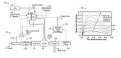
- FIG. 2is a schematic illustration of a starting system for a gas turbine engine in accordance with an embodiment of the disclosure
- FIG. 3is a schematic illustration of a starting system for a gas turbine engine in accordance with another embodiment of the disclosure
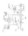
- FIG. 4is a block diagram of a system for bowed rotor start mitigation in accordance with an embodiment of the disclosure
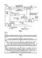
- FIG. 5is a flow chart illustrating a method of bowed rotor start mitigation using direct temperature measurement of a gas turbine engine in accordance with an embodiment of the disclosure
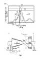
- FIG. 6is a graph illustrating a bowed rotor risk score with respect to time in accordance with an embodiment of the disclosure
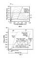
- FIG. 7is a graph illustrating starting profiles of a normal start and a bowed rotor mitigation sequence start in accordance with an embodiment of the disclosure
- FIG. 8is a graph illustrating examples of various vibration level profiles of an engine in accordance with an embodiment of the disclosure.
- FIG. 9is a schematic illustration of a high spool gas path with a straddle-mounted spool in accordance with an embodiment of the disclosure.
- FIG. 10is a schematic illustration of a high spool gas path with an overhung spool in accordance with an embodiment of the disclosure
- FIG. 11is a graph illustrating commanded starter valve opening with respect to time in accordance with an embodiment of the disclosure.
- FIG. 12is a graph illustrating a target rotor speed profile of a dry motoring profile and an actual rotor speed versus time in accordance with an embodiment of the disclosure.
- Embodimentsare related to a bowed rotor start mitigation system in a gas turbine engine.
- Embodimentscan include using a measured temperature value of the gas turbine engine to estimate heat stored in the engine core when a start sequence is initiated and identify a risk of a bowed rotor.
- the measured temperature valuealone or in combination with other values can be used to calculate a bowed rotor risk parameter.
- the measured temperaturecan be adjusted relative to an ambient temperature when calculating the bowed rotor risk parameter.
- the bowed rotor risk parametermay be used to take a control action to mitigate the risk of starting the gas turbine engine with a bowed rotor.
- the control actioncan include dry motoring, which may be performed by running an engine starting system at a lower speed with a longer duration than typically used for engine starting.
- dry motoring speed referred to hereinis a speed below a major resonance speed where, if the temperatures are unhomogenized, the combination of the bowed rotor and similarly bowed casing and the resonance speed would lead to high amplitude oscillation in the rotor and high rubbing of blade tips on one side of the rotor, especially in the high pressure compressor if the rotor is straddle-mounted.
- the engine speed during dry motoringmay oscillate within a motoring band of speed by modulating a starter valve, for example.
- Some embodimentsincrease the rotor speed of the starting spool to approach a critical rotor speed gradually according to a dry motoring profile and as thermal distortion is decreased they then accelerate beyond the critical rotor speed to complete the engine starting process.
- a full authority digital engine control (FADEC) system or other systemmay send a message to the cockpit to inform the crew of an extended time start time due to bowed rotor mitigation actions prior to completing an engine start sequence. If the engine is in a ground test or in a test stand, a message can be sent to the test stand or cockpit based on the control-calculated risk of a bowed rotor.
- a test stand crewcan be alerted regarding a requirement to keep the starting spool of the engine to a speed below the known resonance speed of the rotor in order to homogenize the temperature of the rotor and the casings about the rotor which also are distorted by temperature non-uniformity.
- Monitoring of vibration signatures during the engine starting sequencecan also or separately be used to assess the risk that a bowed rotor start has occurred due to some system malfunction and then direct maintenance, for instance, in the case of suspected outer air seal rub especially in the high compressor.
- Vibration data for the enginecan also be monitored after bowed rotor mitigation is performed during an engine start sequence to confirm success of bowed rotor mitigation. If bowed rotor mitigation is unsuccessful or determined to be incomplete by the FADEC, resulting metrics (e.g., time, date, global positioning satellite (GPS) coordinates, vibration level vs. time, etc.) of the attempted bowed rotor mitigation can be recorded and/or transmitted to direct maintenance
- GPSglobal positioning satellite
- a starter air pressure valvecan be modulated or otherwise dynamically adjusted to limit high rotor speed below high spool resonance speed and prevent rub during dry motoring operation.
- the bowed rotor risk parametercan also be used to limit dry motoring duration to reduce the impact on air starter turbine life.
- the monitoring of vibration signatures during the entire engine starting sequencecan also or separately be used to assess the risk of a bowed rotor start and direct maintenance, for instance, in the case of suspected outer air seal rub especially in the high compressor.
- the gas turbine engine 10has among other components a fan through which ambient air is propelled into the engine housing, a compressor for pressurizing the air received from the fan and a combustor wherein the compressed air is mixed with fuel and ignited for generating combustion gases.
- the gas turbine engine 10further comprises a turbine section for extracting energy from the combustion gases. Fuel is injected into the combustor of the gas turbine engine 10 for mixing with the compressed air from the compressor and ignition of the resultant mixture.
- the fan, compressor, combustor, and turbineare typically all concentric about a central longitudinal axis of the gas turbine engine 10 .
- thermal deflection of the components of the gas turbine engine 10may create the aforementioned bowing or “bowed rotor” condition along the common central longitudinal axis of the gas turbine engine 10 and thus it is desirable to clear or remove the bowed condition prior to the starting or restarting of the gas turbine engine 10 .
- FIG. 1schematically illustrates a gas turbine engine 10 that can be used to power an aircraft, for example.
- the gas turbine engine 10is disclosed herein as a multi-spool turbofan that generally incorporates a fan section 22 , a compressor section 24 , a combustor section 26 and a turbine section 28 .
- the fan section 22drives air along a bypass flowpath while the compressor section 24 drives air along a core flowpath for compression and communication into the combustor section 26 then expansion through the turbine section 28 .
- turbofan gas turbine enginein the disclosed non-limiting embodiment with two turbines and is sometimes referred to as a two spool engine
- the concepts described hereinare not limited to use with turbofans as the teachings may be applied to other types of turbine engines including three-spool architectures.
- the starting spoolis that spool that is located around the combustor, meaning the compressor part of the starting spool is flowing directly into the combustor and the combustor flows directly into the turbine section.
- the engine 10generally includes a low speed spool 30 and a high speed spool 32 mounted for rotation about an engine central longitudinal axis A relative to an engine static structure 36 via several bearing systems 38 . It should be understood that various bearing systems 38 at various locations may alternatively or additionally be provided.
- the low speed spool 30generally includes an inner shaft 40 that interconnects a fan 42 , a low pressure compressor 44 and a low pressure turbine 46 .
- the inner shaft 40is connected to the fan 42 through a geared architecture 48 to drive the fan 42 at a lower speed than the low speed spool 30 in the example of FIG. 1 .
- the high speed spool 32includes an outer shaft 50 that interconnects a high pressure compressor 52 and high pressure turbine 54 .
- a combustor 56is arranged between the high pressure compressor 52 and the high pressure turbine 54 .
- a mid-turbine frame 57 of the engine static structure 36is arranged generally between the high pressure turbine 54 and the low pressure turbine 46 .
- the mid-turbine frame 57further supports bearing systems 38 in the turbine section 28 .
- the inner shaft 40 and the outer shaft 50are concentric and rotate via bearing systems 38 about the engine central longitudinal axis A which is collinear with their longitudinal axes.
- the core airflowis compressed by the low pressure compressor 44 then the high pressure compressor 52 , mixed and burned with fuel in the combustor 56 , then expanded over the high pressure turbine 54 and low pressure turbine 46 .
- the mid-turbine frame 57includes airfoils 59 which are in the core airflow path.
- the turbines 46 , 54rotationally drive the respective low speed spool 30 and high speed spool 32 in response to the expansion.
- Station 2is at an inlet of low pressure compressor 44 having a temperature T 2 and a pressure P 2 .
- Station 2 . 5is at an exit of the low pressure compressor 44 having a temperature T 2 . 5 and a pressure P 2 . 5 .
- Station 3is at an inlet of the combustor 56 having a temperature T 3 and a pressure P 3 .
- Station 4is at an exit of the combustor 56 having a temperature T 4 and a pressure P 4 .
- Station 4 . 5is at an exit of the high pressure turbine 54 having a temperature T 4 . 5 and a pressure P 4 . 5 .
- Station 5is at an exit of the low pressure turbine 46 having a temperature T 5 and a pressure P 5 .
- Measured temperatures in embodimentsmay be acquired at one or more stations 2 - 5 .
- temperature T 3 at station 3can be used to as an engine rotor temperature measurement when there is no engine rotation.
- temperature values at stations 4 (T 4 ), 4 . 5 (T 4 . 5 ), and/or 5 (T 5 )can be used as an engine rotor temperature.
- Temperature measurementscan be normalized to account for hot day/cold day differences.
- temperature T 2can be used as an ambient temperature and a measured temperature (e.g., T 3 ) can be normalized by subtracting temperature T 2 .
- FIG. 1depicts one example configuration
- embodiments as described hereincan cover a wide range of configurations.
- embodimentsmay be implemented in a configuration that is described as a “straddle-mounted” spool 32 A of FIG. 9 .
- This configurationplaces two bearing compartments 37 A and 39 A (which may include a ball bearing and a roller bearing respectively), outside of the plane of most of the compressor disks of high pressure compressor 52 A and at outside at least one of the turbine disks of high pressure turbine 54 A.
- other embodimentsmay be implemented using an over-hung mounted spool 32 B as depicted in FIG. 10 .
- a bearing compartment 37 Bis located forward of the first turbine disk of high pressure turbine 54 B such that the high pressure turbine 54 B is overhung, and it is physically located aft of its main supporting structure.
- the use of straddle-mounted spoolshas advantages and disadvantages in the design of a gas turbine, but one characteristic of the straddle-mounted design is that the span between the bearing compartments 37 A and 39 A is long, making the amplitude of the high spot of a bowed rotor greater and the resonance speed that cannot be transited prior to temperature homogenization is lower.
- the straddle mounted arrangementsuch as straddle-mounted spool 32 A
- the overhung mounted arrangementsuch as overhung spool 32 B
- Lsupportis the distance between bearings (e.g., between bearing compartments 37 A and 39 A or between bearing compartments 37 B and 39 B)
- Dhptis the diameter of the last blade of the high pressure turbine (e.g., high pressure turbine 54 A or high pressure turbine 54 B).
- FIGS. 9 and 10also illustrate a starter 120 interfacing via a tower shaft 55 with the straddle-mounted spool 32 A proximate high compressor 52 A and interfacing via tower shaft 55 with the overhung mounted spool 32 B proximate high compressor 52 B as part of a starting system.
- the starting system 100is also referred to generally as a gas turbine engine system.
- the starting system 100includes a controller 102 which may be an electronic engine control, such as a dual-channel FADEC, and/or engine health monitoring unit.
- the controller 102may include memory to store instructions that are executed by one or more processors.
- the executable instructionsmay be stored or organized in any manner and at any level of abstraction, such as in connection with a controlling and/or monitoring operation of the engine 10 of FIG. 1 .
- the one or more processorscan be any type of central processing unit (CPU), including a general purpose processor, a digital signal processor (DSP), a microcontroller, an application specific integrated circuit (ASIC), a field programmable gate array (FPGA), or the like.
- the memorymay include random access memory (RAM), read only memory (ROM), or other electronic, optical, magnetic, or any other computer readable medium onto which is stored data and control algorithms in a non-transitory form.
- the starting system 100can also include a data storage unit (DSU) 104 that retains data between shutdowns of the gas turbine engine 10 of FIG. 1 .
- the DSU 104includes non-volatile memory and retains data between cycling of power to the controller 102 and DSU 104 .
- a communication link 106can include an aircraft and/or test stand communication bus to interface with aircraft controls, e.g., a cockpit, various onboard computer systems, and/or a test stand.
- a motoring system 108is operable to drive rotation of a starting spool (e.g., high speed spool 32 ) of the gas turbine engine 10 of FIG. 1 .
- Either or both channels of controller 102can alternate on and off commands to an electromechanical device 110 coupled to a discrete starter valve 116 A to achieve a partially open position of the discrete starter valve 116 A to control a flow from a starter air supply 114 (also referred to as air supply 114 ) through a transfer duct 118 to an air turbine starter 120 (also referred to as starter 120 or pneumatic starter motor 120 ) to drive rotation of a starting spool of the gas turbine engine 10 below an engine idle speed.
- the air supply 114(also referred to as starter air supply 114 ) can be provided by any known source of compressed air, such as an auxiliary power unit or ground cart.
- the controller 102can monitor a speed sensor, such as speed pickup 122 that may sense the speed of the engine rotor through its connection to a gearbox 124 which is in turn connected to the high speed spool 32 via tower shaft 55 (e.g., rotational speed of high speed spool 32 ) or any other such sensor for detecting or determining the speed of the gas turbine engine 10 of FIG. 1 .
- the starter 120may be coupled to the gearbox 124 of the gas turbine engine 10 of FIG. 1 directly or through a transmission such as a clutch system (not depicted).
- the controller 102can establish a control loop with respect to rotor speed to adjust positioning of the discrete starter valve 116 A.
- the discrete starter valve 116 Ais an embodiment of a starter valve that is designed as an on/off valve which is typically commanded to either fully opened or fully closed. However, there is a time lag to achieve the fully open position and the fully closed position.
- intermediate positioning statesi.e., partially opened/closed
- the controller 102can modulate the on and off commands (e.g., as a duty cycle using pulse width modulation) to the electromechanical device 110 to further open the discrete starter valve 116 A and increase a rotational speed of the starting spool of the gas turbine engine 10 of FIG. 1 .
- the electromechanical device 110has a cycle time defined between an off-command to an on-command to the off-command that is at most half of a movement time for the discrete starter valve 116 A to transition from fully closed to fully open.
- Pneumatic lines 112 A and 112 B or a mechanical linkagecan be used to drive the discrete starter valve 116 A between the open position and the closed position.
- the electromechanical device 110can be a solenoid that positions the discrete starter valve 116 A based on intermittently supplied electric power as commanded by the controller 102 .
- the electromechanical device 110is an electric valve controlling muscle air to adjust the position of the discrete starter valve 116 A as commanded by the controller 102 .
- the starting system 100also includes a vibration monitoring system 126 .
- the vibration monitoring system 126includes at least one vibration pickup 128 , e.g., an accelerometer, operable to monitor vibration of the gas turbine engine 10 of FIG. 1 .
- Vibration signal processing 130can be performed locally with respect to the vibration pickup 128 , within the controller 102 , or through a separate vibration processing system, which may be part of an engine health monitoring system to acquire vibration data 132 .
- the vibration monitoring system 126can be omitted in some embodiments.
- One or more temperature sensors 134can provide measured temperatures at associated locations of the gas turbine engine 10 to the controller 102 .
- the temperature sensors 134can be located at station 2 (T 2 ), station 2 . 5 (T 2 . 5 ), station 3 (T 3 ), station 4 (T 4 ), station 4 . 5 (T 4 . 5 ), and/or station 5 (T 5 ) as previously described with respect to FIG. 1 .
- FIG. 3is a schematic illustration of a starting system 100 A for the gas turbine engine 10 of FIG. 1 in accordance with another embodiment.
- the starting system 100 Aincludes controller 102 that controls motoring system 108 A, as an alternate embodiment of the motoring system 108 of FIG. 2 .
- the motoring system 108 A of FIG. 3uses a variable position starter valve 116 B.
- FIG. 1In FIG. 1
- either or both channels of controller 102can output a valve control signal 150 operable to dynamically adjust a valve angle of the variable position starter valve 116 A that selectively allows a portion of the air supply 114 to pass through the variable position starter valve 116 B and transfer duct 118 to air turbine starter 120 .
- the variable position starter valve 116 Bis a continuous/infinitely adjustable valve that can hold a commanded valve angle, which may be expressed in terms of a percentage open/closed and/or an angular value (e.g., degrees or radians). Performance parameters of the variable position starter valve 116 B can be selected to meet dynamic response requirements of the starting system 100 A.
- variable position starter valve 116 Bhas a response rate of 0% to 100% open in less than 40 seconds. In other embodiments, the variable position starter valve 116 B has a response rate of 0% to 100% open in less than 30 seconds. In further embodiments, the variable position starter valve 116 B has a response rate of 0% to 100% open in less than 20 seconds.
- the controller 102can monitor a valve angle of the variable position starter valve 116 B using valve angle feedback signals 152 provided to both channels of controller 102 .
- both channels of the controller 102can use the valve angle feedback signals 152 to track a current valve angle, while only one channel designated as an active channel outputs valve control signal 150 .
- the standby channel of controller 102can take over as the active channel to output valve control signal 150 .
- both channels of controller 102output all or a portion of a valve angle command simultaneously on the valve control signals 150 .
- the controller 102can establish an outer control loop with respect to rotor speed and an inner control loop with respect to the valve angle of the variable position starter valve 116 B.
- One or more temperature sensors 134such as thermocouples, can provide measured temperatures at associated locations of the gas turbine engine 10 to the controller 102 .
- the starting system 100 A of FIG. 3also includes vibration monitoring system 126 .
- the vibration monitoring system 126includes at least one vibration pickup 128 , e.g., an accelerometer, operable to monitor vibration of the gas turbine engine 10 of FIG. 1 .
- Vibration signal processing 130can be performed locally with respect to the vibration pickup 128 , within the controller 102 , or through a separate vibration processing system, which may be part of an engine health monitoring system to acquire vibration data 132 .
- the vibration monitoring system 126can be omitted in some embodiments.
- FIG. 4is a block diagram of a system 200 for bowed rotor start mitigation using direct temperature measurement that may control the discrete starter valve 116 A of FIG. 2 or the variable position starter valve 116 B of FIG. 3 via control signals 210 in accordance with an embodiment.
- the system 200may also be referred to as a bowed rotor start mitigation system.
- the system 200includes sensor processing 202 operable to acquire and condition data from a variety of sensors such as the speed pickup 122 , vibration pickup 128 , and temperature sensors 134 of FIG. 2 .
- the sensor processing 202may also provide valve angle 207 to motoring controller 208 based on the valve angle feedback 152 of FIG.
- sensor processing 202provides compressor exit temperature T 3 and ambient temperature T 2 to core temperature processing 204 .
- one or more temperature values from stations 4 (T 4 ), 4 . 5 (T 4 . 5 ), and/or 5 (T 5 )can be provided to core temperature processing 204 .
- Sensor processing 202can provide rotor speed N 2 (i.e., speed of high speed spool 32 ) to a motoring controller 208 and a mitigation monitor 214 .
- Sensor processing 202may also provide vibration data 132 to mitigation monitor 214 .
- the sensor processing 202 , core temperature processing 204 , motoring controller 208 , and/or mitigation monitor 214may be part of controller 102 .
- the heat state of the engine 10 or T coreis determined by the core temperature processing 204 .
- the compressor exit temperature T 3may be substantially equal to T core .
- T coreis set equal to T 3 -T 2 to adjust the temperature with respect to the measured ambient temperature of the gas turbine engine 10 .
- temperature readings from other stations of the gas turbine engine 10can be used to determine T core .
- Communication link 106can provide the core temperature processing 204 with an indication 205 that a start sequence of the gas turbine engine 10 has been initiated. Once rotation of the gas turbine engine 10 begins, temperature readings can be collected for a predetermined period of time, such as ten seconds.
- the temperature readingscan be averaged as core temperature T core before the temperature starts to change due to air flow from engine rotation.
- the core temperature processing 204can determine a bowed rotor risk parameter that is based on the measured temperature using a mapping function or lookup table.
- the bowed rotor risk parametercan have an associated motoring time defining an anticipated amount of time for the motoring controller 208 to send control signals 210 to electromechanical device 110 for controlling discrete starter valve 116 A of FIG. 2 or a dry motoring profile to control valve control signals 150 for controlling variable position starter valve 116 B of FIG. 3 .
- a higher risk of a bowed rotormay result in a longer duration of dry motoring or an extended dry motoring profile to reduce a temperature gradient prior to starting the gas turbine engine 10 of FIG. 1 .
- the bowed rotor risk parametermay be quantified according to a profile curve 402 selected from a family of curves 404 that align with observed aircraft/engine conditions that impact turbine bore temperature (e.g., starting spool temperature) and the resulting bowed rotor risk as depicted in the example graph 400 of FIG. 6 .
- motoring of the engine 10 in a modified start sequencerefers to the turning of a starting spool by the starter 120 at a reduced speed without introduction of fuel and an ignition source in order to cool the engine 10 to a point wherein a normal start sequence can be implemented without starting the engine 10 in a bowed rotor state.
- cool or ambient airis drawn into the engine 10 while motoring the engine 10 at a reduced speed in order to clear the “bowed rotor” condition, which is referred to as a dry motoring mode.
- the motoring controller 208uses a dynamic control calculation in order to determine a required valve position of the starter valve 116 A, 116 B used to supply an air supply or starter air supply 114 to the engine 10 in order to limit the motoring speed of the engine 10 to a target speed N target within a motoring band or following a dry motoring profile due to the position of the starter valve 116 A, 116 B.
- the required valve position of the starter valve 116 A, 116 Bcan be determined based upon an air supply pressure as well as other factors including but not limited to ambient air temperature, parasitic drag on the engine 10 from a variety of engine driven components such as electric generators and hydraulic pumps, and other variables such that the motoring controller 208 closes the loop for an engine motoring speed target N target for the required amount of time based on the output of the bowed rotor start risk model 206 .
- the dynamic control of the valve position(e.g., open state of the valve (e.g., fully open, 1 ⁇ 2 open, 1 ⁇ 4 open, etc.) in order to limit the motoring speed of the engine 10 ) is controlled via duty cycle control (on/off timing using pulse width modulation) of electromechanical device 110 for discrete starter valve 116 A.
- a graph 450 illustrating starting profiles of a normal start 452 and a bowed rotor mitigation sequence start 454is depicted according to an embodiment.
- the controller 102 of FIG. 2opens discrete starter valve 116 A of FIG. 2 (or variable position starter valve 116 B of FIG. 3 ) to enable the air supply 114 to drive rotation of starter 120 to get rotor speed N 2 of the gas turbine engine 10 up to idle speed 456 .
- the controller 102 of FIG. 2opens discrete starter valve 116 A of FIG. 2 (or variable position starter valve 116 B of FIG. 3 ) to enable the air supply 114 to drive rotation of starter 120 to get rotor speed N 2 of the gas turbine engine 10 up to idle speed 456 .
- the controller 102 of FIG. 2opens discrete starter valve 116 A of FIG. 2 (or variable position starter valve 116 B of FIG. 3 ) to enable the air supply 114 to drive rotation of starter 120 to get rotor speed N 2 of the gas turbine engine 10 up to idle speed 456
- controller 102monitors one or more temperature sensors 134 for a predetermined period of time 458 while rotor speed N 2 is at or about zero RPM. If core temperature processing 204 of FIG. 4 determines that bowed rotor mitigation is needed based on measured temperature, then bowed rotor mitigation sequence start 454 is performed instead of normal start 452 .
- bowed rotor mitigation sequence start 454oscillates the rotor speed N 2 within a motoring band 460 for a motoring time.
- the motoring band 460can be defined between a starter valve close limit 462 (i.e., an upper N 2 speed limit) and a starter valve re-open limit 464 (i.e., a lower N 2 limit).
- the starter valve close limit 462is about 3000 RPM and the starter valve re-open limit 464 is about 2000 RPM.
- the actual values used for the starter valve close limit 462 and the starter valve re-open limit 464can be tuned to the specific performance characteristics of the gas turbine engine 10 as further described with respect to FIG. 8 .
- an anticipated amount of dry motoring timecan be used to determine a target rotor speed profile in a dry motoring profile for the currently observed conditions.
- one or more baseline characteristic curves for the target rotor speed profilecan be defined in tables or according to functions that may be rescaled to align with the observed conditions.
- An example of a target rotor speed profile 1002is depicted in graph 1000 of FIG. 12 that includes a steep initial transition portion 1004 , followed by a gradually increasing portion 1006 , and a late acceleration portion 1008 that increases rotor speed above a critical rotor speed, through a fuel-on speed and an engine idle speed.
- the target rotor speed profile 1002can be rescaled with respect to time and/or select portions (e.g., portions 1004 , 1006 , 1008 ) of the target rotor speed profile 1002 can be individually or collectively rescaled (e.g., slope changes) with respect to time to extend or reduce the total motoring time.
- the target rotor speed profile 1002may include all positive slope values such that the actual rotor speed 1010 is driven to essentially increase continuously while bowed rotor start mitigation is active. While the example of FIG. 12 depicts one example of the target rotor speed profile 1002 that can be defined in a dry motoring profile, it will be understood that many variations are possible in embodiments.
- FIG. 11illustrates how a valve angle command 902 can be adjusted between 0 to 100% of a commanded starter valve opening to generate the actual rotor speed 1010 of FIG. 12 .
- the valve angle command 902transitions through points “a” and “b” to fully open the variable position starter valve 116 B.
- the valve angle command 902is reduced between points “b” and “c” to prevent the actual rotor speed 1010 from overshooting the target rotor speed profile 1002 .
- decisions to increase or decrease the commanded starter valve openingis based on monitoring a rate of change of the actual rotor speed 1010 and projecting whether the actual rotor speed 1010 will align with the target rotor speed profile 1002 at a future time. If it is determined that the actual rotor speed 1010 will not align with the target rotor speed profile 1002 at a future time, then the valve angle of the variable position starter valve 116 B is adjusted (e.g., increase or decrease the valve angle command 902 ) at a corresponding time. In the example of FIGS.
- the valve angle command 902oscillates with a gradually reduced amplitude between points “c”, “d”, and “e” as the actual rotor speed 1010 tracks to the target rotor speed profile 1002 through the gradually increasing portion 1006 .
- the valve angle commandtransitions from point “e” to point “f” and beyond to further increase the actual rotor speed 1010 in the late acceleration portion 1008 above the critical rotor speed, through a fuel-on speed and an engine idle speed.
- the mitigation monitor 214 of FIG. 4can operate in response to receiving a complete indicator 212 to run a verification of the bowed rotor mitigation.
- the mitigation monitor 214can provide mitigation results 216 to the motoring controller 208 and may provide result metrics 218 to other systems, such a maintenance request or indicator. Peak vibrations can be checked by the mitigation monitor 214 during the start processes to confirm that bowed rotor mitigation successfully removed the bowed rotor condition.
- the mitigation monitor 214may also run while dry motoring is active to determine whether adjustments to the dry motoring profile are needed.
- the mitigation monitor 214can request that the motoring controller 208 reduce a slope of the target rotor speed profile 1002 of FIG. 12 to extend the dry motoring time before driving the actual rotor speed 1010 of FIG. 12 up to the critical rotor speed.
- the mitigation monitor 214can request that the motoring controller 208 increase a slope of the target rotor speed profile 1002 of FIG. 12 to reduce the dry motoring time before driving the actual rotor speed 1010 of FIG. 12 up to the critical rotor speed.
- FIG. 5is a flow chart illustrating a method 300 of bowed rotor start mitigation using direct temperature measurement of a gas turbine engine in accordance with an embodiment.
- the method 300 of FIG. 5is described in reference to FIGS. 1-12 and may be performed with an alternate order and include additional steps.
- the controller 102receives receive a speed input indicative of a rotor speed (e.g., N 2 ) of the gas turbine engine 10 .
- the speed inputmay be directly or indirectly indicative of the rotational speed of high speed spool 32 , for instance, derived from a rotational speed of gearbox 124 , from speed pickup 122 , or another source (not depicted).
- the controller 102receives a measured temperature from a temperature sensor 134 .
- the measured temperaturecan be determined based on reading one or more temperature sensors 134 of the gas turbine engine 10 for a predetermined period of time when a start sequence of the gas turbine engine is initiated (e.g., based on indication 205 ).
- the measured temperaturemay be adjusted with respect to a measured ambient temperature of the gas turbine engine 10 (e.g., T 3 -T 2 , T 4 -T 2 , etc.).
- bowed rotor start mitigationcan be performed using motoring system 108 , 108 A to rotate a starting spool of the gas turbine engine 10 .
- the controller 102can drive motoring of the gas turbine engine 10 by controlling the motoring system 108 , 108 A to oscillate the rotor speed (e.g., N 2 ) within a motoring band for a motoring time based on the measured temperature when a start sequence of the gas turbine engine 10 is initiated.
- the motoring bandcan include a range of speeds below a resonance speed of the gas turbine engine 10 .
- the motoring timecan be associated with a bowed rotor risk parameter that is determined based on the measured temperature.
- other motoring profilescan be used, such as the target rotor speed profile 1002 for controlling starting spool speed during dry motoring.
- the controller 102can monitor the vibration level of the gas turbine engine 10 while sweeping through a range of rotor speeds including a critical rotor speed and determine whether bowed rotor mitigation was successful prior to starting the gas turbine engine 10 .
- the mitigation monitor 214may receive a complete indicator 212 from the motoring controller 208 when the motoring controller 208 has completed dry motoring, for instance, if the motoring time has elapsed. If the mitigation monitor 214 determines that the bowed rotor condition still exists based on vibration data 132 collected, the motoring controller 208 may restart dry motoring, or a maintenance request or indicator can be triggered along with providing result metrics 218 for further analysis. Metrics of attempted bowed rotor mitigation can be recorded in the DSU 104 based on determining that the attempted bowed rotor mitigation was unsuccessful or incomplete.
- FIG. 8is a graph illustrating examples of various vibration level profiles 502 of an engine, such as gas turbine engine 10 of FIG. 1 .
- the vibration level profiles 502represent a variety of possible vibration levels observed before and/or after performing bowed rotor mitigation.
- a critical speed 510is the speed at which a vibration peak is expected due to amplification effects of a bowed rotor condition along with other contributions to vibration level generally.
- a peak vibration 504 at critical rotor speed 510may be used to trigger different events. For example, if the peak vibration 504 at critical rotor speed 510 is below a maintenance action threshold 506 , then no further actions may be needed.
- a maintenance requestis triggered based on the actual vibration level exceeding maintenance action threshold 506 after completing an attempt of bowed rotor mitigation.
- the lowest rotor vibration vs. speed in FIG. 8is for a fully homogenized rotor, where mitigation is not necessary (engine parked all night long, for example).
- the next higher curveshows a mildly bowed rotor and so on.
- the maintenance action threshold 506is a threshold for setting a maintenance flag such as requiring a troubleshooting routine of one or more system elements.
- the damage risk threshold 508may be a threshold to trigger a more urgent maintenance requirement up to and including an engine check.
- the motoring band 460is defined for a range of N 2 rotor speeds below the critical speed 510 and such that the worst case expected vibration 512 is below the maintenance action threshold 506 within the motoring band 460 .
- Performing motoring at a higher speed (e.g., 2000-3000 RPM) but less than the critical speed 510can reduce the time needed for the temperature homogenization process while also avoiding vibrations reaching potentially harmful levels.
- the controller 102may be programmed to automatically take the necessary measures in order to provide for a modified start sequence without pilot intervention other than the initial start request.
- the controller 102 and/or DSU 104comprises a microprocessor, microcontroller or other equivalent processing device capable of executing commands of computer readable data or program for executing a control algorithm and/or algorithms that control the start sequence of the gas turbine engine.
- the controller 102 and/or DSU 104may include, but not be limited to, a processor(s), computer(s), memory, storage, register(s), timing, interrupt(s), communication interfaces, and input/output signal interfaces, as well as combinations comprising at least one of the foregoing.
- the controller 102 and/or DSU 104may include input signal filtering to enable accurate sampling and conversion or acquisitions of such signals from communications interfaces.
- exemplary embodiments of the disclosurecan be implemented through computer-implemented processes and apparatuses for practicing those processes.
Landscapes
- Engineering & Computer Science (AREA)
- Chemical & Material Sciences (AREA)
- Combustion & Propulsion (AREA)
- Mechanical Engineering (AREA)
- General Engineering & Computer Science (AREA)
- Physics & Mathematics (AREA)
- General Physics & Mathematics (AREA)
- Control Of Turbines (AREA)
Abstract
Description
Claims (20)
Priority Applications (2)
| Application Number | Priority Date | Filing Date | Title |
|---|---|---|---|
| US15/042,377US10174678B2 (en) | 2016-02-12 | 2016-02-12 | Bowed rotor start using direct temperature measurement |
| EP17155683.0AEP3205835B1 (en) | 2016-02-12 | 2017-02-10 | Bowed rotor start using direct temperature measurement |
Applications Claiming Priority (1)
| Application Number | Priority Date | Filing Date | Title |
|---|---|---|---|
| US15/042,377US10174678B2 (en) | 2016-02-12 | 2016-02-12 | Bowed rotor start using direct temperature measurement |
Publications (2)
| Publication Number | Publication Date |
|---|---|
| US20170234230A1 US20170234230A1 (en) | 2017-08-17 |
| US10174678B2true US10174678B2 (en) | 2019-01-08 |
Family
ID=58578802
Family Applications (1)
| Application Number | Title | Priority Date | Filing Date |
|---|---|---|---|
| US15/042,377Active2036-10-15US10174678B2 (en) | 2016-02-12 | 2016-02-12 | Bowed rotor start using direct temperature measurement |
Country Status (2)
| Country | Link |
|---|---|
| US (1) | US10174678B2 (en) |
| EP (1) | EP3205835B1 (en) |
Cited By (10)
| Publication number | Priority date | Publication date | Assignee | Title |
|---|---|---|---|---|
| US20170363012A1 (en)* | 2016-06-20 | 2017-12-21 | United Technologies Corporation | Low-power bowed rotor prevention and monitoring system |
| US20190186368A1 (en)* | 2017-12-18 | 2019-06-20 | General Electric Company | Method of Starting a Gas Turbine Engine |
| US10781754B2 (en) | 2017-12-08 | 2020-09-22 | Pratt & Whitney Canada Corp. | System and method for rotor bow mitigation |
| US11199139B2 (en)* | 2018-12-19 | 2021-12-14 | Raytheon Technologies Corporation | Gas turbine engine system bowed rotor start mitigation and wear reduction |
| US11306654B2 (en) | 2018-12-19 | 2022-04-19 | Raytheon Technologies Corporation | Gas turbine engine system wear reduction |
| US11359546B2 (en) | 2020-04-20 | 2022-06-14 | Honeywell International Inc. | System and method for controlling engine speed with bowed rotor mitigation |
| US11486310B2 (en) | 2020-03-27 | 2022-11-01 | Pratt & Whitney Canada Corp. | System and method for dynamic engine motoring |
| US11668248B2 (en) | 2020-03-27 | 2023-06-06 | Pratt & Whitney Canada Corp. | Start-up system and method for rotor bow mitigation |
| US11702952B2 (en) | 2021-11-11 | 2023-07-18 | General Electric Company | Thermal bias control in turbomachines |
| US12298197B2 (en) | 2023-01-09 | 2025-05-13 | General Electric Company | System and method for reducing motoring time in a turbomachine based on shaft deflection |
Families Citing this family (19)
| Publication number | Priority date | Publication date | Assignee | Title |
|---|---|---|---|---|
| US10125636B2 (en) | 2016-02-12 | 2018-11-13 | United Technologies Corporation | Bowed rotor prevention system using waste heat |
| US10508567B2 (en) | 2016-02-12 | 2019-12-17 | United Technologies Corporation | Auxiliary drive bowed rotor prevention system for a gas turbine engine through an engine accessory |
| US9664070B1 (en) | 2016-02-12 | 2017-05-30 | United Technologies Corporation | Bowed rotor prevention system |
| US10040577B2 (en) | 2016-02-12 | 2018-08-07 | United Technologies Corporation | Modified start sequence of a gas turbine engine |
| US20170234234A1 (en)* | 2016-02-12 | 2017-08-17 | Hamilton Sundstrand Corporation | Gas turbine engine motoring system for bowed rotor engine starts |
| US10125691B2 (en) | 2016-02-12 | 2018-11-13 | United Technologies Corporation | Bowed rotor start using a variable position starter valve |
| US10436064B2 (en) | 2016-02-12 | 2019-10-08 | United Technologies Corporation | Bowed rotor start response damping system |
| US10443505B2 (en) | 2016-02-12 | 2019-10-15 | United Technologies Corporation | Bowed rotor start mitigation in a gas turbine engine |
| US10508601B2 (en) | 2016-02-12 | 2019-12-17 | United Technologies Corporation | Auxiliary drive bowed rotor prevention system for a gas turbine engine |
| US10443507B2 (en) | 2016-02-12 | 2019-10-15 | United Technologies Corporation | Gas turbine engine bowed rotor avoidance system |
| US10539079B2 (en) | 2016-02-12 | 2020-01-21 | United Technologies Corporation | Bowed rotor start mitigation in a gas turbine engine using aircraft-derived parameters |
| FR3047771A1 (en)* | 2016-02-16 | 2017-08-18 | Airbus Operations Sas | SYSTEM AND METHOD FOR STARTING THE ENGINES OF A BIMOTING AIRCRAFT |
| US10358936B2 (en) | 2016-07-05 | 2019-07-23 | United Technologies Corporation | Bowed rotor sensor system |
| US10718231B2 (en) | 2017-12-15 | 2020-07-21 | General Electric Company | Method and system for mitigating bowed rotor operation of gas turbine engine |
| GB201720944D0 (en)* | 2017-12-15 | 2018-01-31 | Rolls Royce Plc | Rotor bow management |
| US11162419B2 (en)* | 2018-02-12 | 2021-11-02 | General Electric Company | Method and structure for operating engine with bowed rotor condition |
| US11155338B2 (en)* | 2018-10-19 | 2021-10-26 | Rolls-Royce North American Technologies Inc. | Encryption and security in a distributed control network |
| US11073086B2 (en) | 2018-11-27 | 2021-07-27 | The Boeing Company | Apparatus, assemblies, and methods for mitigating thermal bow in the rotor of an engine at start-up |
| US20230129383A1 (en)* | 2021-10-21 | 2023-04-27 | Raytheon Technologies Corporation | System and method for gas turbine engine rotor bow mitigation |
Citations (147)
| Publication number | Priority date | Publication date | Assignee | Title |
|---|---|---|---|---|
| US1951875A (en) | 1932-08-06 | 1934-03-20 | Cutler Hammer Inc | Power transmission mechanism |
| US2617253A (en) | 1950-09-23 | 1952-11-11 | Gen Electric | Safety control system for cooling a gas turbine power plant on shutdown |
| US2962597A (en) | 1959-06-09 | 1960-11-29 | Westinghouse Electric Corp | Power plant apparatus |
| US3057155A (en) | 1959-05-15 | 1962-10-09 | English Electric Co Ltd | Starting control arrangements of gas turbines |
| US3151452A (en) | 1962-10-22 | 1964-10-06 | Bendix Corp | Electro-mechanical control for air breathing starter |
| US3290709A (en) | 1964-11-17 | 1966-12-13 | Symington Wayne Corp | Automatic lip for power operated loading platform |
| US3360844A (en) | 1965-09-20 | 1968-01-02 | Theodore S Miller | Applicator closure inserting machine |
| US3764815A (en) | 1971-03-06 | 1973-10-09 | Siemens Ag | Start-up converter |
| US3793905A (en) | 1972-08-14 | 1974-02-26 | Twin Disc Inc | Gas turbine starting and auxiliary turning mechanism |
| GB1374810A (en) | 1970-10-20 | 1974-11-20 | Westinghouse Electric Corp | Gas turbine electric power plant |
| US3898439A (en) | 1970-10-20 | 1975-08-05 | Westinghouse Electric Corp | System for operating industrial gas turbine apparatus and gas turbine electric power plants preferably with a digital computer control system |
| US3951008A (en) | 1975-01-08 | 1976-04-20 | Twin Disc, Incorporated | Power transmitting mechanism for starting a high inertia load and having retarder means for auxiliary starting motor |
| US4044550A (en) | 1975-09-10 | 1977-08-30 | The Boeing Company | Turbine wheel containment shroud for a pneumatically powered turbine engine starter motor |
| US4069424A (en) | 1976-05-10 | 1978-01-17 | Turbodyne Corporation (Gas Turbine Div.) | Shaft turning parking bus for multiple unit installations utilizing a single motorized generator control system |
| US4120159A (en) | 1975-10-22 | 1978-10-17 | Hitachi, Ltd. | Steam turbine control system and method of controlling the ratio of steam flow between under full-arc admission mode and under partial-arc admission mode |
| US4144421A (en) | 1975-12-19 | 1979-03-13 | Hitachi, Ltd. | Hydraulic machine shutdown sensor assembly |
| US4302813A (en) | 1978-02-22 | 1981-11-24 | Hitachi, Ltd. | Method of controlling operation of rotary machines by diagnosing abnormal conditions |
| US4353604A (en) | 1980-12-11 | 1982-10-12 | United Technologies Corporation | Viscous/friction damper |
| US4380146A (en) | 1977-01-12 | 1983-04-19 | Westinghouse Electric Corp. | System and method for accelerating and sequencing industrial gas turbine apparatus and gas turbine electric power plants preferably with a digital computer control system |
| GB2117842A (en) | 1982-03-25 | 1983-10-19 | Rolls Royce | Means for equalising the temperatures within a gas turbine engine |
| US4426641A (en) | 1980-03-31 | 1984-01-17 | Hitachi, Ltd. | Method and apparatus for monitoring the shaft vibration of a rotary machine |
| US4435770A (en) | 1980-03-19 | 1984-03-06 | Hitachi, Ltd. | Vibration diagnosing method and apparatus for a rotary machine |
| US4437163A (en) | 1980-03-31 | 1984-03-13 | Hitachi, Ltd. | Method and apparatus for symptom diagnosis by monitoring vibration of shaft of rotary machine |
| US4453407A (en) | 1980-04-17 | 1984-06-12 | Hitachi, Ltd. | Vibration diagnosis method and apparatus for rotary machines |
| US4485678A (en) | 1982-09-27 | 1984-12-04 | Mechanical Technology Incorporated | Rotor diagnostic and balancing system |
| US4488240A (en) | 1982-02-01 | 1984-12-11 | Becton, Dickinson And Company | Vibration monitoring system for aircraft engines |
| US4496252A (en) | 1982-05-26 | 1985-01-29 | Bbc Brown, Boveri & Company, Limited | Resilient support arrangement for shaft bearings of highspeed rotors, in particular rotors of turbo machines |
| US4598551A (en) | 1985-10-25 | 1986-07-08 | General Electric Company | Apparatus and method for controlling steam turbine operating conditions during starting and loading |
| US4627234A (en) | 1983-06-15 | 1986-12-09 | Sundstrand Corporation | Gas turbine engine/load compressor power plants |
| US4642782A (en) | 1984-07-31 | 1987-02-10 | Westinghouse Electric Corp. | Rule based diagnostic system with dynamic alteration capability |
| US4669893A (en) | 1986-02-18 | 1987-06-02 | United Technologies Corporation | Annular oil damper arrangement |
| US4713985A (en) | 1984-05-31 | 1987-12-22 | Kabushiki Kaisya Advance Kaihatsu Kenkyujo | Transmission apparatus |
| US4733529A (en) | 1986-09-26 | 1988-03-29 | Cef Industries, Inc. | Performance envelope extension device for a gas turbine engine |
| US4747270A (en) | 1986-02-12 | 1988-05-31 | G. Dusterloh Gmbh | Compressed air starting device |
| US4854120A (en) | 1986-09-26 | 1989-08-08 | Cef Industries, Inc. | Performance envelope extension method for a gas turbine engine |
| GB2218751A (en) | 1988-05-12 | 1989-11-22 | United Technologies Corp | Apparatus for supporting a rotating shaft |
| US4979362A (en) | 1989-05-17 | 1990-12-25 | Sundstrand Corporation | Aircraft engine starting and emergency power generating system |
| US5103629A (en) | 1989-11-20 | 1992-04-14 | Westinghouse Electric Corp. | Gas turbine control system having optimized ignition air flow control |
| US5123239A (en) | 1991-02-14 | 1992-06-23 | Sundstrand Corporation | Method of starting a gas turbine engine |
| US5127220A (en) | 1991-02-28 | 1992-07-07 | Allied-Signal Inc. | Method for accelerating a gas turbine engine |
| US5174109A (en) | 1990-10-25 | 1992-12-29 | Sundstrand Corporation | Clutch to disconnect loads during turbine start-up |
| US5184458A (en) | 1989-11-21 | 1993-02-09 | Lampe Steven W | Power unit fuel pressurization system |
| US5201798A (en) | 1990-09-24 | 1993-04-13 | Allied-Signal Inc. | Multifunction integrated power unit and power transfer apparatus therefor |
| US5349814A (en) | 1993-02-03 | 1994-09-27 | General Electric Company | Air-start assembly and method |
| WO1999000585A1 (en) | 1997-06-27 | 1999-01-07 | MTU MOTOREN- UND TURBINEN-UNION MüNCHEN GMBH | Device for the emergency stop of a gas turbine |
| US6146090A (en) | 1998-12-22 | 2000-11-14 | General Electric Co. | Cooling/heating augmentation during turbine startup/shutdown using a seal positioned by thermal response of turbine parts and consequent relative movement thereof |
| US6168377B1 (en) | 1999-01-27 | 2001-01-02 | General Electric Co. | Method and apparatus for eliminating thermal bowing of steam turbine rotors |
| US6190127B1 (en) | 1998-12-22 | 2001-02-20 | General Electric Co. | Tuning thermal mismatch between turbine rotor parts with a thermal medium |
| US6318958B1 (en) | 1998-08-21 | 2001-11-20 | Alliedsignal, Inc. | Air turbine starter with seal assembly |
| US6478534B2 (en) | 1998-08-18 | 2002-11-12 | Siemnes Aktiengesellschaft | Turbine casing |
| US20020173897A1 (en) | 2001-05-18 | 2002-11-21 | Leamy Kevin Richard | System and method for monitoring thermal state to normalize engine trending data |
| JP2002371806A (en) | 2001-06-18 | 2002-12-26 | Mitsubishi Heavy Ind Ltd | Turbine device |
| US6517314B1 (en) | 2001-11-05 | 2003-02-11 | General Electric Company | Method and apparatus for eliminating thermal bowing and axial thrust loads of steam turbine rotors |
| US6558118B1 (en) | 2001-11-01 | 2003-05-06 | General Electric Company | Bucket dovetail bridge member and method for eliminating thermal bowing of steam turbine rotors |
| US20030145603A1 (en) | 2002-02-06 | 2003-08-07 | Reed William H. | Micro volume actuator for an air turbine starter |
| US6681579B2 (en) | 2002-02-07 | 2004-01-27 | Honeywell International, Inc. | Air turbine starter with fluid flow control |
| JP2004036414A (en) | 2002-06-28 | 2004-02-05 | Ebara Corp | Gas turbine device |
| EP1396611A2 (en) | 2002-09-06 | 2004-03-10 | General Electric Company | Method and apparatus for varying the critical speed of a shaft |
| US20040065091A1 (en) | 2001-11-16 | 2004-04-08 | Anderson Stephen Arthur | Off loading clutch for gas turbine engine starting |
| US20040131138A1 (en) | 2001-05-25 | 2004-07-08 | Michael Correia | Brayton cycle nuclear power plant and a method of starting the brayton cycle |
| US6762512B2 (en) | 2002-05-10 | 2004-07-13 | Siemens Westinghourse Power Corporation | Methods for starting a combustion turbine and combustion turbine generator configured to implement same methods |
| EP1533479A2 (en) | 2003-11-24 | 2005-05-25 | General Electric Company | Method and apparatus for detecting rub in a turbomachine |
| US20060032234A1 (en) | 2004-08-16 | 2006-02-16 | Thompson Robert G | Combined power main engine start system |
| US7133801B2 (en) | 2002-06-07 | 2006-11-07 | Exxon Mobil Research And Engineering Company | System and methodology for vibration analysis and condition monitoring |
| US20060260323A1 (en) | 2005-05-19 | 2006-11-23 | Djamal Moulebhar | Aircraft with disengageable engine and auxiliary power unit components |
| US20070031249A1 (en) | 1999-03-27 | 2007-02-08 | Rolls-Royce Plc | Gas turbine engine and a rotor for a gas turbine engine |
| EP1862875A2 (en) | 2006-06-01 | 2007-12-05 | General Electric Company | Methods and apparatus for model predictive control in a real time controller |
| US20080072568A1 (en) | 2006-09-27 | 2008-03-27 | Thomas Ory Moniz | Gas turbine engine assembly and method of assembling same |
| US7428819B2 (en) | 2004-06-22 | 2008-09-30 | Alstom Technology Ltd. | Method for the operation of a compressor of a gas turbine with evaporative cooling of the compressor induction air |
| EP2006496A1 (en) | 2007-06-22 | 2008-12-24 | Siemens Aktiengesellschaft | Gas turbine engine start up method |
| US7543439B2 (en) | 2004-07-22 | 2009-06-09 | Rolls-Royce Plc | Generator assembly |
| US7587133B2 (en) | 2003-09-03 | 2009-09-08 | Siemens Aktiengesellschaft | Method for starting a continuous steam generator and continuous steam generator for carrying out said method |
| US20090246018A1 (en) | 2006-07-12 | 2009-10-01 | Mitsubishi Heavy Industries, Ltd. | Bearing support structure and gas turbine |
| US20090301053A1 (en) | 2006-06-10 | 2009-12-10 | Mtu Aero Engines Gmbh | Gas Turbine and Method of Operating a Gas Turbine |
| US20090314002A1 (en) | 2008-06-11 | 2009-12-24 | Honeywell International Inc. | Bi-modal turbine assembly and starter / drive turbine system employing the same |
| FR2933131A1 (en) | 2008-06-25 | 2010-01-01 | Snecma | Ring fixing support for bypass turbojet engine in airplane, has control system individually controlling heating circuits and homogenizing thermal deformation of support in case of stopping of gas turbine at hot restarting of engine |
| US20100095791A1 (en) | 2008-10-20 | 2010-04-22 | Mactaggart Scott (Holdings) Limited | Apparatus and method for rotating a shaft |
| US20100132365A1 (en) | 2004-04-20 | 2010-06-03 | Gustavo Francisco Labala | Start-Up Control For a Compact Lightweight Turbine |
| US7742881B2 (en) | 2007-08-02 | 2010-06-22 | General Electric Company | System and method for detection of rotor eccentricity baseline shift |
| US7798720B1 (en) | 2006-11-16 | 2010-09-21 | Florida Turbine Technologies, Inc. | Squeeze film damper with highly variable support stiffness |
| US20100293961A1 (en) | 2009-05-19 | 2010-11-25 | Hamilton Sundstrand Corporation | Gas turbine starting with stepping speed control |
| US20100326085A1 (en) | 2009-06-25 | 2010-12-30 | Veilleux Leo J | Lightweight start system for a gas turbine engine |
| US7909566B1 (en) | 2006-04-20 | 2011-03-22 | Florida Turbine Technologies, Inc. | Rotor thrust balance activated tip clearance control system |
| US20110077783A1 (en) | 2008-11-03 | 2011-03-31 | United Technologies Corporation | System and method for design and control of engineering systems utilizing component-level dynamic mathematical model |
| EP2305986A2 (en) | 2009-10-05 | 2011-04-06 | General Electric Company | Methods and systems for mitigating distortion of gas turbine shaft |
| US20110153295A1 (en) | 2009-12-21 | 2011-06-23 | United Technologies Corporation | Method and system for modeling the performance of a gas turbine engine |
| US20110146276A1 (en) | 2009-12-23 | 2011-06-23 | General Electric Company | Method of starting a steam turbine |
| US7972105B2 (en) | 2007-05-10 | 2011-07-05 | General Electric Company | Turbine anti-rotating stall schedule |
| EP2363575A2 (en) | 2010-02-26 | 2011-09-07 | General Electric Company | System and method for inspection of stator vanes |
| US20110296843A1 (en) | 2010-06-04 | 2011-12-08 | Lawson Jr T Towles | Positive displacement power extraction compensation device |
| US20120031067A1 (en) | 2010-08-03 | 2012-02-09 | General Electric Company | Turbulated arrangement of thermoelectric elements for utilizing waste heat generated from turbine engine |
| US20120240591A1 (en) | 2007-12-10 | 2012-09-27 | General Electric Company | Method for shutting down a generator to prepare the generator for restart |
| US20120266601A1 (en) | 2011-04-22 | 2012-10-25 | General Electric Company | System and method for removing heat from a turbomachine |
| US8306776B2 (en) | 2008-06-30 | 2012-11-06 | Mitsubishi Heavy Industries, Ltd. | Method and system for calculating misalignment of rotational body |
| US20120316748A1 (en) | 2011-06-09 | 2012-12-13 | Airbus (Sas) | Method And Device For Monitoring A Turbine Engine Of An Aircraft |
| WO2013007912A1 (en) | 2011-07-12 | 2013-01-17 | Turbomeca | Method for starting a turbomachine that reduces the thermal imbalance |
| US20130031912A1 (en) | 2011-08-01 | 2013-02-07 | Hamilton Sundstrand Corporation | Gas turbine start architecture |
| US20130091850A1 (en) | 2011-10-13 | 2013-04-18 | Hamilton Sundstrand Corporation | Method and system for reducing hot soakback |
| US20130101391A1 (en) | 2011-09-19 | 2013-04-25 | Alstom Technology Ltd. | Self-Adjusting Device for Controlling the Clearance Between Rotating and Stationary Components of a Thermally Loaded Turbo Machine |
| US20130134719A1 (en) | 2010-03-17 | 2013-05-30 | Kawasaki Jukogyo Kabushiki Kaisha | Engine generator |
| US20130251501A1 (en) | 2012-03-26 | 2013-09-26 | Mitsubishi Heavy Industries, Ltd. | Method and purge apparatus for preventing deformation of chamber of gas turbine, and gas turbine providing purge apparatus |
| US20140060076A1 (en) | 2012-08-31 | 2014-03-06 | Todd D. Cortelli | Antirotated piston rack |
| US8770913B1 (en) | 2010-06-17 | 2014-07-08 | Florida Turbine Technologies, Inc. | Apparatus and process for rotor creep monitoring |
| US8776530B2 (en) | 2011-11-23 | 2014-07-15 | General Electric Company | Gas turbine engine lockout reduction |
| US20140199157A1 (en) | 2013-01-16 | 2014-07-17 | Alstom Technology Ltd | Method for barring a rotor of a turbomachine and barring apparatus for conducting such method |
| US20140236451A1 (en) | 2013-02-20 | 2014-08-21 | Snecma | Avionics method and device for monitoring a turbomachine at startup |
| US20140241878A1 (en) | 2013-02-28 | 2014-08-28 | General Electric Company | System and method for controlling a wind turbine based on identified surface conditions of the rotor blades |
| US20140271152A1 (en) | 2013-03-13 | 2014-09-18 | Jose L. Rodriguez | Turbine engine temperature control system with heating element for a gas turbine engine |
| WO2014152701A1 (en) | 2013-03-15 | 2014-09-25 | United Technologies Corporation | Compact aero-thermo model based control system |
| US20140301820A1 (en) | 2013-04-03 | 2014-10-09 | Uwe Lohse | Turbine engine shutdown temperature control system with nozzle injection for a gas turbine engine |
| US20140318144A1 (en) | 2011-11-14 | 2014-10-30 | Nuovo Pignone S.P.A. | Device and method for slow turning of an aeroderivative gas turbine |
| US20140334927A1 (en) | 2011-11-21 | 2014-11-13 | Vestas Wind Systems A/S | Shutdown controller for a wind turbine and a method of shutting down a wind turbine |
| US20140366546A1 (en) | 2013-06-13 | 2014-12-18 | Solar Turbines Incorporated | Variable frequency drive power ride thru |
| US20140373552A1 (en) | 2013-06-25 | 2014-12-25 | Airbus Operations (Sas) | Method and system for starting up an aircraft turbomachine by real-time regulation of air flow |
| US20140373553A1 (en) | 2013-06-25 | 2014-12-25 | Airbus Operations (Sas) | Method and system for starting up an aircraft turbomachine |
| US20140373554A1 (en) | 2013-06-21 | 2014-12-25 | United Technologies Corporation | Air turbine starter pressure monitor system |
| US20140373518A1 (en) | 2013-06-19 | 2014-12-25 | Airbus Operations (Sas) | System and method for spinning up a rotary element of a mechanical device, particularly a turbomachine |
| US20150016949A1 (en) | 2013-07-09 | 2015-01-15 | Rolls-Royce Plc | Tip clearance control method |
| WO2015030946A1 (en) | 2013-08-26 | 2015-03-05 | United Technologies Corporation | Gas turbine engine with fan clearance control |
| US20150115608A1 (en) | 2013-10-31 | 2015-04-30 | General Electric Company | System and method for controlling a wind turbine |
| US20150121874A1 (en) | 2013-11-07 | 2015-05-07 | Mitsubishi Hitachi Power Systems, Ltd. | Activation control device |
| US20150128592A1 (en) | 2012-04-27 | 2015-05-14 | Turbomeca | Method and system for the emergency start-up of an energy generator set |
| US20150159625A1 (en) | 2013-12-11 | 2015-06-11 | General Electric Company | System and method for controlling a wind turbine system |
| US9086018B2 (en) | 2010-04-23 | 2015-07-21 | Hamilton Sundstrand Corporation | Starting a gas turbine engine to maintain a dwelling speed after light-off |
| US20150219121A1 (en) | 2012-10-02 | 2015-08-06 | Borgwarner Inc. | Reduction of turbocharger core unbalance with balance washer |
| US20150377141A1 (en) | 2014-06-26 | 2015-12-31 | Snecma | Method for determining a duration of movement for a starter air valve of a turbine engine |
| WO2016069303A1 (en) | 2014-10-29 | 2016-05-06 | Unison Industries, Llc | Method and system for operating a rotatable machine |
| EP3051074A1 (en) | 2015-01-28 | 2016-08-03 | General Electric Company | Method of starting a gas turbine engine |
| US20160236369A1 (en) | 2013-05-09 | 2016-08-18 | Lawrence E. Baker | Blade sharpening system for a log saw machine |
| US20160245312A1 (en) | 2015-02-20 | 2016-08-25 | Peter G. Morice | Pneumatic actuation system and method |
| US20160265387A1 (en) | 2013-10-15 | 2016-09-15 | United Technologies Corporation | Non-linear bumper bearings |
| US20160288325A1 (en) | 2013-11-19 | 2016-10-06 | Ferrobotics Compliant Robot Technology Gmbh | Robot Arm |
| US20170030265A1 (en) | 2015-07-31 | 2017-02-02 | Ge Aviation Systems Llc | Bleed air valve a turbine engine with anti-ice valve assembly and method of operating |
| US9664070B1 (en) | 2016-02-12 | 2017-05-30 | United Technologies Corporation | Bowed rotor prevention system |
| US9699833B2 (en) | 2011-12-22 | 2017-07-04 | Rolls-Royce Plc | Electronic unit mounting |
| US20170218848A1 (en) | 2016-02-03 | 2017-08-03 | Honeywell International Inc. | Compact accessory systems for a gas turbine engine |
| US20170234158A1 (en) | 2016-02-12 | 2017-08-17 | United Technologies Corporation | Bowed rotor start response damping system |
| US20170234167A1 (en) | 2016-02-12 | 2017-08-17 | United Technologies Corporation | Auxiliary drive bowed rotor prevention system for a gas turbine engine through an engine accessory |
| US20170234166A1 (en) | 2016-02-12 | 2017-08-17 | United Technologies Corporation | Bowed rotor prevention system using waste heat |
| US20170234233A1 (en) | 2016-02-12 | 2017-08-17 | United Technologies Corporation | Bowed rotor start mitigation in a gas turbine engine using aircraft-derived parameters |
| US20170234236A1 (en) | 2016-02-12 | 2017-08-17 | United Technologies Corporation | Bowed rotor start using a variable position starter valve |
| US20170234232A1 (en) | 2016-02-12 | 2017-08-17 | United Technologies Corporation | Auxiliary drive bowed rotor prevention system for a gas turbine engine |
| US20170234231A1 (en) | 2016-02-12 | 2017-08-17 | United Technologies Corporation | Bowed rotor start mitigation in a gas turbine engine |
| US20170233103A1 (en) | 2016-02-12 | 2017-08-17 | United Technologies Corporation | Modified start sequence of a gas turbine engine |
| US20170234235A1 (en) | 2016-02-12 | 2017-08-17 | Hamilton Sundstrand Corporation | Electro-pneumatic gas turbine engine motoring system for bowed rotor engine starts |
| US20170234238A1 (en) | 2016-02-12 | 2017-08-17 | United Technologies Corporation | Gas turbine engine bowed rotor avoidance system |
| US20180010480A1 (en) | 2016-07-05 | 2018-01-11 | United Technologies Corporation | Bowed rotor sensor system |
- 2016
- 2016-02-12USUS15/042,377patent/US10174678B2/enactiveActive
- 2017
- 2017-02-10EPEP17155683.0Apatent/EP3205835B1/enactiveActive
Patent Citations (158)
| Publication number | Priority date | Publication date | Assignee | Title |
|---|---|---|---|---|
| US1951875A (en) | 1932-08-06 | 1934-03-20 | Cutler Hammer Inc | Power transmission mechanism |
| US2617253A (en) | 1950-09-23 | 1952-11-11 | Gen Electric | Safety control system for cooling a gas turbine power plant on shutdown |
| US3057155A (en) | 1959-05-15 | 1962-10-09 | English Electric Co Ltd | Starting control arrangements of gas turbines |
| US2962597A (en) | 1959-06-09 | 1960-11-29 | Westinghouse Electric Corp | Power plant apparatus |
| US3151452A (en) | 1962-10-22 | 1964-10-06 | Bendix Corp | Electro-mechanical control for air breathing starter |
| US3290709A (en) | 1964-11-17 | 1966-12-13 | Symington Wayne Corp | Automatic lip for power operated loading platform |
| US3360844A (en) | 1965-09-20 | 1968-01-02 | Theodore S Miller | Applicator closure inserting machine |
| US3898439A (en) | 1970-10-20 | 1975-08-05 | Westinghouse Electric Corp | System for operating industrial gas turbine apparatus and gas turbine electric power plants preferably with a digital computer control system |
| GB1374810A (en) | 1970-10-20 | 1974-11-20 | Westinghouse Electric Corp | Gas turbine electric power plant |
| US3764815A (en) | 1971-03-06 | 1973-10-09 | Siemens Ag | Start-up converter |
| US3793905A (en) | 1972-08-14 | 1974-02-26 | Twin Disc Inc | Gas turbine starting and auxiliary turning mechanism |
| US3951008A (en) | 1975-01-08 | 1976-04-20 | Twin Disc, Incorporated | Power transmitting mechanism for starting a high inertia load and having retarder means for auxiliary starting motor |
| US4044550A (en) | 1975-09-10 | 1977-08-30 | The Boeing Company | Turbine wheel containment shroud for a pneumatically powered turbine engine starter motor |
| US4120159A (en) | 1975-10-22 | 1978-10-17 | Hitachi, Ltd. | Steam turbine control system and method of controlling the ratio of steam flow between under full-arc admission mode and under partial-arc admission mode |
| US4144421A (en) | 1975-12-19 | 1979-03-13 | Hitachi, Ltd. | Hydraulic machine shutdown sensor assembly |
| US4069424A (en) | 1976-05-10 | 1978-01-17 | Turbodyne Corporation (Gas Turbine Div.) | Shaft turning parking bus for multiple unit installations utilizing a single motorized generator control system |
| US4380146A (en) | 1977-01-12 | 1983-04-19 | Westinghouse Electric Corp. | System and method for accelerating and sequencing industrial gas turbine apparatus and gas turbine electric power plants preferably with a digital computer control system |
| US4302813A (en) | 1978-02-22 | 1981-11-24 | Hitachi, Ltd. | Method of controlling operation of rotary machines by diagnosing abnormal conditions |
| US4435770A (en) | 1980-03-19 | 1984-03-06 | Hitachi, Ltd. | Vibration diagnosing method and apparatus for a rotary machine |
| US4437163A (en) | 1980-03-31 | 1984-03-13 | Hitachi, Ltd. | Method and apparatus for symptom diagnosis by monitoring vibration of shaft of rotary machine |
| US4426641A (en) | 1980-03-31 | 1984-01-17 | Hitachi, Ltd. | Method and apparatus for monitoring the shaft vibration of a rotary machine |
| US4453407A (en) | 1980-04-17 | 1984-06-12 | Hitachi, Ltd. | Vibration diagnosis method and apparatus for rotary machines |
| US4353604A (en) | 1980-12-11 | 1982-10-12 | United Technologies Corporation | Viscous/friction damper |
| US4488240A (en) | 1982-02-01 | 1984-12-11 | Becton, Dickinson And Company | Vibration monitoring system for aircraft engines |
| GB2117842A (en) | 1982-03-25 | 1983-10-19 | Rolls Royce | Means for equalising the temperatures within a gas turbine engine |
| US4496252A (en) | 1982-05-26 | 1985-01-29 | Bbc Brown, Boveri & Company, Limited | Resilient support arrangement for shaft bearings of highspeed rotors, in particular rotors of turbo machines |
| US4485678A (en) | 1982-09-27 | 1984-12-04 | Mechanical Technology Incorporated | Rotor diagnostic and balancing system |
| US4627234A (en) | 1983-06-15 | 1986-12-09 | Sundstrand Corporation | Gas turbine engine/load compressor power plants |
| US4713985A (en) | 1984-05-31 | 1987-12-22 | Kabushiki Kaisya Advance Kaihatsu Kenkyujo | Transmission apparatus |
| US4642782A (en) | 1984-07-31 | 1987-02-10 | Westinghouse Electric Corp. | Rule based diagnostic system with dynamic alteration capability |
| US4598551A (en) | 1985-10-25 | 1986-07-08 | General Electric Company | Apparatus and method for controlling steam turbine operating conditions during starting and loading |
| US4747270A (en) | 1986-02-12 | 1988-05-31 | G. Dusterloh Gmbh | Compressed air starting device |
| US4669893A (en) | 1986-02-18 | 1987-06-02 | United Technologies Corporation | Annular oil damper arrangement |
| US4733529A (en) | 1986-09-26 | 1988-03-29 | Cef Industries, Inc. | Performance envelope extension device for a gas turbine engine |
| US4854120A (en) | 1986-09-26 | 1989-08-08 | Cef Industries, Inc. | Performance envelope extension method for a gas turbine engine |
| GB2218751A (en) | 1988-05-12 | 1989-11-22 | United Technologies Corp | Apparatus for supporting a rotating shaft |
| US4979362A (en) | 1989-05-17 | 1990-12-25 | Sundstrand Corporation | Aircraft engine starting and emergency power generating system |
| US5103629A (en) | 1989-11-20 | 1992-04-14 | Westinghouse Electric Corp. | Gas turbine control system having optimized ignition air flow control |
| US5184458A (en) | 1989-11-21 | 1993-02-09 | Lampe Steven W | Power unit fuel pressurization system |
| US5201798A (en) | 1990-09-24 | 1993-04-13 | Allied-Signal Inc. | Multifunction integrated power unit and power transfer apparatus therefor |
| US5174109A (en) | 1990-10-25 | 1992-12-29 | Sundstrand Corporation | Clutch to disconnect loads during turbine start-up |
| US5123239A (en) | 1991-02-14 | 1992-06-23 | Sundstrand Corporation | Method of starting a gas turbine engine |
| US5127220A (en) | 1991-02-28 | 1992-07-07 | Allied-Signal Inc. | Method for accelerating a gas turbine engine |
| US5349814A (en) | 1993-02-03 | 1994-09-27 | General Electric Company | Air-start assembly and method |
| WO1999000585A1 (en) | 1997-06-27 | 1999-01-07 | MTU MOTOREN- UND TURBINEN-UNION MüNCHEN GMBH | Device for the emergency stop of a gas turbine |
| US6478534B2 (en) | 1998-08-18 | 2002-11-12 | Siemnes Aktiengesellschaft | Turbine casing |
| US6318958B1 (en) | 1998-08-21 | 2001-11-20 | Alliedsignal, Inc. | Air turbine starter with seal assembly |
| US6146090A (en) | 1998-12-22 | 2000-11-14 | General Electric Co. | Cooling/heating augmentation during turbine startup/shutdown using a seal positioned by thermal response of turbine parts and consequent relative movement thereof |
| US6190127B1 (en) | 1998-12-22 | 2001-02-20 | General Electric Co. | Tuning thermal mismatch between turbine rotor parts with a thermal medium |
| US6168377B1 (en) | 1999-01-27 | 2001-01-02 | General Electric Co. | Method and apparatus for eliminating thermal bowing of steam turbine rotors |
| US20070031249A1 (en) | 1999-03-27 | 2007-02-08 | Rolls-Royce Plc | Gas turbine engine and a rotor for a gas turbine engine |
| US7507070B2 (en) | 1999-03-27 | 2009-03-24 | Rolls-Royce Plc | Gas turbine engine and a rotor for a gas turbine engine |
| US6498978B2 (en) | 2001-05-18 | 2002-12-24 | General Electric Company | System and method for monitoring thermal state to normalize engine trending data |
| US20020173897A1 (en) | 2001-05-18 | 2002-11-21 | Leamy Kevin Richard | System and method for monitoring thermal state to normalize engine trending data |
| US20040131138A1 (en) | 2001-05-25 | 2004-07-08 | Michael Correia | Brayton cycle nuclear power plant and a method of starting the brayton cycle |
| JP2002371806A (en) | 2001-06-18 | 2002-12-26 | Mitsubishi Heavy Ind Ltd | Turbine device |
| US6558118B1 (en) | 2001-11-01 | 2003-05-06 | General Electric Company | Bucket dovetail bridge member and method for eliminating thermal bowing of steam turbine rotors |
| US6517314B1 (en) | 2001-11-05 | 2003-02-11 | General Electric Company | Method and apparatus for eliminating thermal bowing and axial thrust loads of steam turbine rotors |
| US20040065091A1 (en) | 2001-11-16 | 2004-04-08 | Anderson Stephen Arthur | Off loading clutch for gas turbine engine starting |
| US20030145603A1 (en) | 2002-02-06 | 2003-08-07 | Reed William H. | Micro volume actuator for an air turbine starter |
| US6681579B2 (en) | 2002-02-07 | 2004-01-27 | Honeywell International, Inc. | Air turbine starter with fluid flow control |
| US6762512B2 (en) | 2002-05-10 | 2004-07-13 | Siemens Westinghourse Power Corporation | Methods for starting a combustion turbine and combustion turbine generator configured to implement same methods |
| US7133801B2 (en) | 2002-06-07 | 2006-11-07 | Exxon Mobil Research And Engineering Company | System and methodology for vibration analysis and condition monitoring |
| JP2004036414A (en) | 2002-06-28 | 2004-02-05 | Ebara Corp | Gas turbine device |
| EP1396611A2 (en) | 2002-09-06 | 2004-03-10 | General Electric Company | Method and apparatus for varying the critical speed of a shaft |
| US7587133B2 (en) | 2003-09-03 | 2009-09-08 | Siemens Aktiengesellschaft | Method for starting a continuous steam generator and continuous steam generator for carrying out said method |
| EP1533479A2 (en) | 2003-11-24 | 2005-05-25 | General Electric Company | Method and apparatus for detecting rub in a turbomachine |
| US7409319B2 (en) | 2003-11-24 | 2008-08-05 | General Electric Company | Method and apparatus for detecting rub in a turbomachine |
| US20100132365A1 (en) | 2004-04-20 | 2010-06-03 | Gustavo Francisco Labala | Start-Up Control For a Compact Lightweight Turbine |
| US7428819B2 (en) | 2004-06-22 | 2008-09-30 | Alstom Technology Ltd. | Method for the operation of a compressor of a gas turbine with evaporative cooling of the compressor induction air |
| US7543439B2 (en) | 2004-07-22 | 2009-06-09 | Rolls-Royce Plc | Generator assembly |
| US20060032234A1 (en) | 2004-08-16 | 2006-02-16 | Thompson Robert G | Combined power main engine start system |
| US7104072B2 (en) | 2004-08-16 | 2006-09-12 | Hamilton Sundstrand Corporation | Combined power main engine start system |
| US20060260323A1 (en) | 2005-05-19 | 2006-11-23 | Djamal Moulebhar | Aircraft with disengageable engine and auxiliary power unit components |
| US7909566B1 (en) | 2006-04-20 | 2011-03-22 | Florida Turbine Technologies, Inc. | Rotor thrust balance activated tip clearance control system |
| EP1862875A2 (en) | 2006-06-01 | 2007-12-05 | General Electric Company | Methods and apparatus for model predictive control in a real time controller |
| US20090301053A1 (en) | 2006-06-10 | 2009-12-10 | Mtu Aero Engines Gmbh | Gas Turbine and Method of Operating a Gas Turbine |
| US9121309B2 (en) | 2006-06-10 | 2015-09-01 | Mtu Aero Engines Gmbh | Gas turbine and method of operating a gas turbine |
| US20090246018A1 (en) | 2006-07-12 | 2009-10-01 | Mitsubishi Heavy Industries, Ltd. | Bearing support structure and gas turbine |
| US20080072568A1 (en) | 2006-09-27 | 2008-03-27 | Thomas Ory Moniz | Gas turbine engine assembly and method of assembling same |
| US7798720B1 (en) | 2006-11-16 | 2010-09-21 | Florida Turbine Technologies, Inc. | Squeeze film damper with highly variable support stiffness |
| US7972105B2 (en) | 2007-05-10 | 2011-07-05 | General Electric Company | Turbine anti-rotating stall schedule |
| EP2006496A1 (en) | 2007-06-22 | 2008-12-24 | Siemens Aktiengesellschaft | Gas turbine engine start up method |
| US7742881B2 (en) | 2007-08-02 | 2010-06-22 | General Electric Company | System and method for detection of rotor eccentricity baseline shift |
| US20120240591A1 (en) | 2007-12-10 | 2012-09-27 | General Electric Company | Method for shutting down a generator to prepare the generator for restart |
| US20090314002A1 (en) | 2008-06-11 | 2009-12-24 | Honeywell International Inc. | Bi-modal turbine assembly and starter / drive turbine system employing the same |
| US8291715B2 (en) | 2008-06-11 | 2012-10-23 | Honeywell International Inc. | Bi-modal turbine assembly and starter / drive turbine system employing the same |
| FR2933131A1 (en) | 2008-06-25 | 2010-01-01 | Snecma | Ring fixing support for bypass turbojet engine in airplane, has control system individually controlling heating circuits and homogenizing thermal deformation of support in case of stopping of gas turbine at hot restarting of engine |
| US8306776B2 (en) | 2008-06-30 | 2012-11-06 | Mitsubishi Heavy Industries, Ltd. | Method and system for calculating misalignment of rotational body |
| US20100095791A1 (en) | 2008-10-20 | 2010-04-22 | Mactaggart Scott (Holdings) Limited | Apparatus and method for rotating a shaft |
| US8090456B2 (en) | 2008-11-03 | 2012-01-03 | United Technologies Corporation | System and method for design and control of engineering systems utilizing component-level dynamic mathematical model |
| US20110077783A1 (en) | 2008-11-03 | 2011-03-31 | United Technologies Corporation | System and method for design and control of engineering systems utilizing component-level dynamic mathematical model |
| US20100293961A1 (en) | 2009-05-19 | 2010-11-25 | Hamilton Sundstrand Corporation | Gas turbine starting with stepping speed control |
| US20100326085A1 (en) | 2009-06-25 | 2010-12-30 | Veilleux Leo J | Lightweight start system for a gas turbine engine |
| EP2305986A2 (en) | 2009-10-05 | 2011-04-06 | General Electric Company | Methods and systems for mitigating distortion of gas turbine shaft |
| US8820046B2 (en) | 2009-10-05 | 2014-09-02 | General Electric Company | Methods and systems for mitigating distortion of gas turbine shaft |
| US20110153295A1 (en) | 2009-12-21 | 2011-06-23 | United Technologies Corporation | Method and system for modeling the performance of a gas turbine engine |
| US20110146276A1 (en) | 2009-12-23 | 2011-06-23 | General Electric Company | Method of starting a steam turbine |
| EP2363575A2 (en) | 2010-02-26 | 2011-09-07 | General Electric Company | System and method for inspection of stator vanes |
| US20130134719A1 (en) | 2010-03-17 | 2013-05-30 | Kawasaki Jukogyo Kabushiki Kaisha | Engine generator |
| US9086018B2 (en) | 2010-04-23 | 2015-07-21 | Hamilton Sundstrand Corporation | Starting a gas turbine engine to maintain a dwelling speed after light-off |
| US20110296843A1 (en) | 2010-06-04 | 2011-12-08 | Lawson Jr T Towles | Positive displacement power extraction compensation device |
| US8770913B1 (en) | 2010-06-17 | 2014-07-08 | Florida Turbine Technologies, Inc. | Apparatus and process for rotor creep monitoring |
| US20120031067A1 (en) | 2010-08-03 | 2012-02-09 | General Electric Company | Turbulated arrangement of thermoelectric elements for utilizing waste heat generated from turbine engine |
| US20120266601A1 (en) | 2011-04-22 | 2012-10-25 | General Electric Company | System and method for removing heat from a turbomachine |
| US20120316748A1 (en) | 2011-06-09 | 2012-12-13 | Airbus (Sas) | Method And Device For Monitoring A Turbine Engine Of An Aircraft |
| US8918264B2 (en) | 2011-06-09 | 2014-12-23 | Airbus Operations (Sas) | Method and device for monitoring a turbine engine of an aircraft |
| US20140123673A1 (en) | 2011-07-12 | 2014-05-08 | Turbomeca | A method of starting a turbomachine while reducing thermal unbalance |
| WO2013007912A1 (en) | 2011-07-12 | 2013-01-17 | Turbomeca | Method for starting a turbomachine that reduces the thermal imbalance |
| US20130031912A1 (en) | 2011-08-01 | 2013-02-07 | Hamilton Sundstrand Corporation | Gas turbine start architecture |
| US20130101391A1 (en) | 2011-09-19 | 2013-04-25 | Alstom Technology Ltd. | Self-Adjusting Device for Controlling the Clearance Between Rotating and Stationary Components of a Thermally Loaded Turbo Machine |
| US20130091850A1 (en) | 2011-10-13 | 2013-04-18 | Hamilton Sundstrand Corporation | Method and system for reducing hot soakback |
| US20140318144A1 (en) | 2011-11-14 | 2014-10-30 | Nuovo Pignone S.P.A. | Device and method for slow turning of an aeroderivative gas turbine |
| US20140334927A1 (en) | 2011-11-21 | 2014-11-13 | Vestas Wind Systems A/S | Shutdown controller for a wind turbine and a method of shutting down a wind turbine |
| US8776530B2 (en) | 2011-11-23 | 2014-07-15 | General Electric Company | Gas turbine engine lockout reduction |
| US9699833B2 (en) | 2011-12-22 | 2017-07-04 | Rolls-Royce Plc | Electronic unit mounting |
| US20130251501A1 (en) | 2012-03-26 | 2013-09-26 | Mitsubishi Heavy Industries, Ltd. | Method and purge apparatus for preventing deformation of chamber of gas turbine, and gas turbine providing purge apparatus |
| US20150128592A1 (en) | 2012-04-27 | 2015-05-14 | Turbomeca | Method and system for the emergency start-up of an energy generator set |
| US20140060076A1 (en) | 2012-08-31 | 2014-03-06 | Todd D. Cortelli | Antirotated piston rack |
| US20150219121A1 (en) | 2012-10-02 | 2015-08-06 | Borgwarner Inc. | Reduction of turbocharger core unbalance with balance washer |
| US20140199157A1 (en) | 2013-01-16 | 2014-07-17 | Alstom Technology Ltd | Method for barring a rotor of a turbomachine and barring apparatus for conducting such method |
| US20140236451A1 (en) | 2013-02-20 | 2014-08-21 | Snecma | Avionics method and device for monitoring a turbomachine at startup |
| US20140241878A1 (en) | 2013-02-28 | 2014-08-28 | General Electric Company | System and method for controlling a wind turbine based on identified surface conditions of the rotor blades |
| US20140271152A1 (en) | 2013-03-13 | 2014-09-18 | Jose L. Rodriguez | Turbine engine temperature control system with heating element for a gas turbine engine |
| WO2014152701A1 (en) | 2013-03-15 | 2014-09-25 | United Technologies Corporation | Compact aero-thermo model based control system |
| US20140301820A1 (en) | 2013-04-03 | 2014-10-09 | Uwe Lohse | Turbine engine shutdown temperature control system with nozzle injection for a gas turbine engine |
| US20160236369A1 (en) | 2013-05-09 | 2016-08-18 | Lawrence E. Baker | Blade sharpening system for a log saw machine |
| US20140366546A1 (en) | 2013-06-13 | 2014-12-18 | Solar Turbines Incorporated | Variable frequency drive power ride thru |
| US20140373518A1 (en) | 2013-06-19 | 2014-12-25 | Airbus Operations (Sas) | System and method for spinning up a rotary element of a mechanical device, particularly a turbomachine |
| US20140373554A1 (en) | 2013-06-21 | 2014-12-25 | United Technologies Corporation | Air turbine starter pressure monitor system |
| US20140373552A1 (en) | 2013-06-25 | 2014-12-25 | Airbus Operations (Sas) | Method and system for starting up an aircraft turbomachine by real-time regulation of air flow |
| US20140373553A1 (en) | 2013-06-25 | 2014-12-25 | Airbus Operations (Sas) | Method and system for starting up an aircraft turbomachine |
| US20150016949A1 (en) | 2013-07-09 | 2015-01-15 | Rolls-Royce Plc | Tip clearance control method |
| WO2015030946A1 (en) | 2013-08-26 | 2015-03-05 | United Technologies Corporation | Gas turbine engine with fan clearance control |
| US20160265387A1 (en) | 2013-10-15 | 2016-09-15 | United Technologies Corporation | Non-linear bumper bearings |
| US20150115608A1 (en) | 2013-10-31 | 2015-04-30 | General Electric Company | System and method for controlling a wind turbine |
| US20150121874A1 (en) | 2013-11-07 | 2015-05-07 | Mitsubishi Hitachi Power Systems, Ltd. | Activation control device |
| EP2871333A1 (en) | 2013-11-07 | 2015-05-13 | Mitsubishi Hitachi Power Systems, Ltd. | Activation control device |
| US20160288325A1 (en) | 2013-11-19 | 2016-10-06 | Ferrobotics Compliant Robot Technology Gmbh | Robot Arm |
| US20150159625A1 (en) | 2013-12-11 | 2015-06-11 | General Electric Company | System and method for controlling a wind turbine system |
| US20150377141A1 (en) | 2014-06-26 | 2015-12-31 | Snecma | Method for determining a duration of movement for a starter air valve of a turbine engine |
| WO2016069303A1 (en) | 2014-10-29 | 2016-05-06 | Unison Industries, Llc | Method and system for operating a rotatable machine |
| EP3051074A1 (en) | 2015-01-28 | 2016-08-03 | General Electric Company | Method of starting a gas turbine engine |
| US20160245312A1 (en) | 2015-02-20 | 2016-08-25 | Peter G. Morice | Pneumatic actuation system and method |
| US20170030265A1 (en) | 2015-07-31 | 2017-02-02 | Ge Aviation Systems Llc | Bleed air valve a turbine engine with anti-ice valve assembly and method of operating |
| US20170218848A1 (en) | 2016-02-03 | 2017-08-03 | Honeywell International Inc. | Compact accessory systems for a gas turbine engine |
| US20170234236A1 (en) | 2016-02-12 | 2017-08-17 | United Technologies Corporation | Bowed rotor start using a variable position starter valve |
| US20170234158A1 (en) | 2016-02-12 | 2017-08-17 | United Technologies Corporation | Bowed rotor start response damping system |
| US20170234167A1 (en) | 2016-02-12 | 2017-08-17 | United Technologies Corporation | Auxiliary drive bowed rotor prevention system for a gas turbine engine through an engine accessory |
| US20170234166A1 (en) | 2016-02-12 | 2017-08-17 | United Technologies Corporation | Bowed rotor prevention system using waste heat |
| US20170234233A1 (en) | 2016-02-12 | 2017-08-17 | United Technologies Corporation | Bowed rotor start mitigation in a gas turbine engine using aircraft-derived parameters |
| US9664070B1 (en) | 2016-02-12 | 2017-05-30 | United Technologies Corporation | Bowed rotor prevention system |
| US20170234232A1 (en) | 2016-02-12 | 2017-08-17 | United Technologies Corporation | Auxiliary drive bowed rotor prevention system for a gas turbine engine |
| US20170234231A1 (en) | 2016-02-12 | 2017-08-17 | United Technologies Corporation | Bowed rotor start mitigation in a gas turbine engine |
| US20170233103A1 (en) | 2016-02-12 | 2017-08-17 | United Technologies Corporation | Modified start sequence of a gas turbine engine |
| US20170234235A1 (en) | 2016-02-12 | 2017-08-17 | Hamilton Sundstrand Corporation | Electro-pneumatic gas turbine engine motoring system for bowed rotor engine starts |
| US20170234238A1 (en) | 2016-02-12 | 2017-08-17 | United Technologies Corporation | Gas turbine engine bowed rotor avoidance system |
| US20180010480A1 (en) | 2016-07-05 | 2018-01-11 | United Technologies Corporation | Bowed rotor sensor system |
Non-Patent Citations (14)
| Title |
|---|
| EP Application No. 17155584 Extended European Search Report dated Jul. 6, 2017, 9 pages. |
| EP Application No. 17155601 Extended European Search Report dated Jun. 30, 2017, 7 pages. |
| EP Application No. 17155612 Extended European Search Report dated Jul. 4, 2017, 8 pages. |
| EP Application No. 17155613 Extended European Search Report dated Jun. 27, 2017, 10 pages. |
| EP Application No. 17155683 Extended European Search Report dated Jun. 30, 2017, 8 pages. |
| EP Application No. 17155683 Office Action dated May 22, 2018, 2 pages. |
| EP Application No. 17155687 Extended European Search Report dated Jun. 16, 2017, 9 pages. |
| EP Application No. 17155698 Extended European Search Report dated Jun. 21, 2017, 9 pages. |
| EP Application No. 17155721 Extended European Search Report dated Jun. 27, 2017, 8 pages. |
| EP Application No. 17155793 Extended European Search Report dated Jun. 30, 2017, 10 pages. |
| EP Application No. 17155798 Extended European Search Report dated Jun. 30, 2017, 9 pages. |
| EP Application No. 17155807 Extended European Search Report dated Jul. 30, 2017, 8 pages. |
| Extended European Search Report for Application No. 17179407.6-1610 dated Dec. 5, 2017 (8 pp.). |
| U.S. Appl. No. 15/042,331 Non-Final Office Action dated Sep. 9, 2016, 37 pages. |
Cited By (14)
| Publication number | Priority date | Publication date | Assignee | Title |
|---|---|---|---|---|
| US20170363012A1 (en)* | 2016-06-20 | 2017-12-21 | United Technologies Corporation | Low-power bowed rotor prevention and monitoring system |
| US10787933B2 (en)* | 2016-06-20 | 2020-09-29 | Raytheon Technologies Corporation | Low-power bowed rotor prevention and monitoring system |
| US10781754B2 (en) | 2017-12-08 | 2020-09-22 | Pratt & Whitney Canada Corp. | System and method for rotor bow mitigation |
| US20190186368A1 (en)* | 2017-12-18 | 2019-06-20 | General Electric Company | Method of Starting a Gas Turbine Engine |
| US11162428B2 (en)* | 2017-12-18 | 2021-11-02 | General Electric Company | Method of starting a gas turbine engine |
| US11306654B2 (en) | 2018-12-19 | 2022-04-19 | Raytheon Technologies Corporation | Gas turbine engine system wear reduction |
| US11199139B2 (en)* | 2018-12-19 | 2021-12-14 | Raytheon Technologies Corporation | Gas turbine engine system bowed rotor start mitigation and wear reduction |
| US11976589B2 (en) | 2018-12-19 | 2024-05-07 | Rtx Corporation | Gas turbine engine system wear reduction |
| US11486310B2 (en) | 2020-03-27 | 2022-11-01 | Pratt & Whitney Canada Corp. | System and method for dynamic engine motoring |
| US11668248B2 (en) | 2020-03-27 | 2023-06-06 | Pratt & Whitney Canada Corp. | Start-up system and method for rotor bow mitigation |
| US11359546B2 (en) | 2020-04-20 | 2022-06-14 | Honeywell International Inc. | System and method for controlling engine speed with bowed rotor mitigation |
| US11702952B2 (en) | 2021-11-11 | 2023-07-18 | General Electric Company | Thermal bias control in turbomachines |
| US12305518B2 (en) | 2021-11-11 | 2025-05-20 | General Electric Company | Thermal bias control in turbomachines |
| US12298197B2 (en) | 2023-01-09 | 2025-05-13 | General Electric Company | System and method for reducing motoring time in a turbomachine based on shaft deflection |
Also Published As
| Publication number | Publication date |
|---|---|
| EP3205835B1 (en) | 2020-09-02 |
| US20170234230A1 (en) | 2017-08-17 |
| EP3205835A1 (en) | 2017-08-16 |
Similar Documents
| Publication | Publication Date | Title |
|---|---|---|
| US10174678B2 (en) | Bowed rotor start using direct temperature measurement | |
| US10625881B2 (en) | Modified start sequence of a gas turbine engine | |
| US11274604B2 (en) | Bowed rotor start mitigation in a gas turbine engine using aircraft-derived parameters | |
| US10125691B2 (en) | Bowed rotor start using a variable position starter valve | |
| US10443507B2 (en) | Gas turbine engine bowed rotor avoidance system | |
| US10443505B2 (en) | Bowed rotor start mitigation in a gas turbine engine | |
| US10508567B2 (en) | Auxiliary drive bowed rotor prevention system for a gas turbine engine through an engine accessory | |
| US10508601B2 (en) | Auxiliary drive bowed rotor prevention system for a gas turbine engine | |
| US11674411B2 (en) | Multi-engine coordination during gas turbine engine motoring | |
| US10443543B2 (en) | High compressor build clearance reduction | |
| US10384791B2 (en) | Cross engine coordination during gas turbine engine motoring | |
| US20180023484A1 (en) | Speed control during motoring of a gas turbine engine | |
| US10823079B2 (en) | Metered orifice for motoring of a gas turbine engine | |
| US20180023479A1 (en) | Air supply control during motoring of a gas turbine engine | |
| US20180112600A1 (en) | Starter air valve system with regulating bleed |
Legal Events
| Date | Code | Title | Description |
|---|---|---|---|
| AS | Assignment | Owner name:UNITED TECHNOLOGIES CORPORATION, CONNECTICUT Free format text:ASSIGNMENT OF ASSIGNORS INTEREST;ASSIGNORS:SCHWARZ, FREDERICK M.;GRACE, AMY R.;SIGNING DATES FROM 20160223 TO 20160229;REEL/FRAME:037858/0239 | |
| STCF | Information on status: patent grant | Free format text:PATENTED CASE | |
| AS | Assignment | Owner name:RAYTHEON TECHNOLOGIES CORPORATION, MASSACHUSETTS Free format text:CHANGE OF NAME;ASSIGNOR:UNITED TECHNOLOGIES CORPORATION;REEL/FRAME:054062/0001 Effective date:20200403 | |
| AS | Assignment | Owner name:RAYTHEON TECHNOLOGIES CORPORATION, CONNECTICUT Free format text:CORRECTIVE ASSIGNMENT TO CORRECT THE AND REMOVE PATENT APPLICATION NUMBER 11886281 AND ADD PATENT APPLICATION NUMBER 14846874. TO CORRECT THE RECEIVING PARTY ADDRESS PREVIOUSLY RECORDED AT REEL: 054062 FRAME: 0001. ASSIGNOR(S) HEREBY CONFIRMS THE CHANGE OF ADDRESS;ASSIGNOR:UNITED TECHNOLOGIES CORPORATION;REEL/FRAME:055659/0001 Effective date:20200403 | |
| MAFP | Maintenance fee payment | Free format text:PAYMENT OF MAINTENANCE FEE, 4TH YEAR, LARGE ENTITY (ORIGINAL EVENT CODE: M1551); ENTITY STATUS OF PATENT OWNER: LARGE ENTITY Year of fee payment:4 | |
| AS | Assignment | Owner name:RTX CORPORATION, CONNECTICUT Free format text:CHANGE OF NAME;ASSIGNOR:RAYTHEON TECHNOLOGIES CORPORATION;REEL/FRAME:064714/0001 Effective date:20230714 |