US10173757B2 - Watersport board fins with fin retention systems and watersport boards containing the same - Google Patents
Watersport board fins with fin retention systems and watersport boards containing the sameDownload PDFInfo
- Publication number
- US10173757B2 US10173757B2US15/593,211US201715593211AUS10173757B2US 10173757 B2US10173757 B2US 10173757B2US 201715593211 AUS201715593211 AUS 201715593211AUS 10173757 B2US10173757 B2US 10173757B2
- Authority
- US
- United States
- Prior art keywords
- fin
- retention system
- locked configuration
- selective retention
- selective
- Prior art date
- Legal status (The legal status is an assumption and is not a legal conclusion. Google has not performed a legal analysis and makes no representation as to the accuracy of the status listed.)
- Active
Links
Images


Classifications
- B63B35/793—
- B—PERFORMING OPERATIONS; TRANSPORTING
- B63—SHIPS OR OTHER WATERBORNE VESSELS; RELATED EQUIPMENT
- B63B—SHIPS OR OTHER WATERBORNE VESSELS; EQUIPMENT FOR SHIPPING
- B63B32/00—Water sports boards; Accessories therefor
- B63B32/60—Board appendages, e.g. fins, hydrofoils or centre boards
- B63B32/66—Arrangements for fixation to the board, e.g. fin boxes or foil boxes
Definitions
- the present disclosurerelates to watersport board fins with fin retention systems, watersport boards containing the same, and associated methods.
- Watersport boardssuch as surfboards and stand-up paddleboards (SUPS) generally are configured to permit a user to stand upon an upper surface of the watersport board while the watersport board floats in a body of water.
- a watersport boardmay include at least one fin extending into the body of water from an underside of the watersport board to stabilize the watersport board and/or to provide the user with directional control as the watersport board traverses the body of water.
- a fin that is integrally formed with the watersport board or permanently coupled to the watersport boardmay be difficult to repair and/or replace in the event of damage, such as may result from a collision with a foreign object.
- a watersport boardmay include a fin box or other structure configured to selectively receive and retain the fin in an operative position on the watersport board.
- Conventional fin boxes and removable finsmay require the use of tools to retain the fin within the fin box and/or to remove the fin from the fin box.
- Other conventional fin boxes and removable finsdo not require the use of tools but may not sufficiently secure the fin in the fin box to prevent unintentional removal of the fin from the fin box during use of the watersport board.
- a fin to be inserted into a fin box of a watersport board for stabilizing the watersport board during use on a body of waterincludes a hydrodynamic blade and a fin base.
- the hydrodynamic bladeis configured to extend into a body of water when the fin is coupled to a watersport board that operates on the body of water.
- the hydrodynamic bladedefines a fin plane and includes a leading edge, a trailing edge, and a foil surface extending between the leading edge and the trailing edge.
- the fin baseextends from the hydrodynamic blade and is configured to be selectively received within a fin box of the watersport board.
- the finfurther includes a fin retention system configured to restrict removal of the fin base from the fin box.
- the fin retention systemincludes a selective retention system configured to selectively transition between an unlocked configuration, in which the selective retention system permits the fin to be inserted into and removed from the fin box, and a locked configuration, in which the selective retention system restricts the fin from being inserted into and removed from the fin box.
- the selective retention systemincludes a retainer configured to extend within a retention channel of the fin box to restrict removal of the fin base from the fin box when the fin base is inserted into the fin box and the selective retention system is in the locked configuration.
- the retainerfurther is configured to pivot about a pivot axis when the selective retention system is transitioned between the unlocked configuration and the locked configuration.
- the selective retention systemfurther includes an actuator coupled to the retainer via a pivot shaft and configured to be actuated by a user to pivot the retainer about the pivot axis to selectively transition the selective retention system between the unlocked configuration and the locked configuration.
- the actuatorforms a portion of the hydrodynamic blade when the selective retention system is in the locked configuration and is configured to rotate away from the fin plane when the selective retention system transitions from the locked configuration to the unlocked configuration.
- the retaineris configured to rotate away from the fin plane when the selective retention system transitions from the unlocked configuration to the locked configuration.
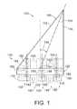
- FIG. 1is a schematic side elevation view representing examples of watersport board fins according to the present disclosure.
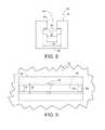
- FIG. 2is a schematic front elevation view representing examples of watersport board fins according to the present disclosure with a selective retention system in the locked configuration.
- FIG. 3is a schematic front elevation view representing examples of watersport board fins according to the present disclosure with the selective retention system in the unlocked configuration.
- FIG. 4is a schematic side elevation view representing examples of watersport board fins according to the present disclosure with the selective retention system in the locked configuration.
- FIG. 5is a schematic front elevation view of the watersport board fins of FIG. 4 .
- FIG. 6is a schematic side elevation view representing examples of watersport board fins according to the present disclosure with the selective retention system in the unlocked configuration.
- FIG. 7is a schematic front elevation view of the watersport board fins of FIG. 6 .
- FIG. 8is an end view of an example of a fin box according to the present disclosure.
- FIG. 9is a fragmentary plan view of an example of a fin box according to the present disclosure.
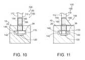
- FIG. 10is a schematic fragmentary partial cross-sectional front elevation view of examples of watersport board fins with a selective retention system in the locked configuration installed in a fin box according to the present disclosure.
- FIG. 11is a schematic fragmentary partial cross-sectional front elevation view of the fins of FIG. 10 with the selective retention system in the unlocked configuration installed in a fin box according to the present disclosure.
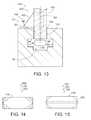
- FIG. 12is a schematic fragmentary partial cross-sectional rear elevation view of examples of watersport board fins with a selective retention system in the locked configuration installed in a fin box according to the present disclosure.
- FIG. 13is a fragmentary partial cross-sectional rear elevation view of the fins of FIG. 12 with the selective retention system in the locked configuration installed in a fin box according to the present disclosure.
- FIG. 14is a schematic plan view of examples of a selective retention system retainer according to the present disclosure.
- FIG. 15is a schematic elevation view of examples of a selective retention system retainer according to the present disclosure.
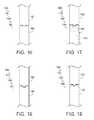
- FIG. 16is a schematic fragmentary elevation view of an example of a retention system lock according to the present disclosure.
- FIG. 17is a schematic fragmentary elevation view of examples of a retention system lock according to the present disclosure.
- FIG. 18is a schematic fragmentary elevation view of an example of a retention system lock according to the present disclosure.
- FIG. 19is a schematic fragmentary elevation view of an example of a retention system lock according to the present disclosure.
- FIG. 20is a bottom perspective view of an example of a watersport board with a watersport board fin installed in a fin box of the watersport board according to the present disclosure.
- FIG. 21is a side elevation view of an example of a watersport board fin according to the present disclosure.
- FIG. 22is a fragmentary side perspective view of the fin of FIG. 21 with a selective retention system in the unlocked configuration that is removed from a fin box according to the present disclosure.
- FIG. 23is a fragmentary partial cross-sectional side perspective view of the fin of FIG. 21 with the selective retention system in the locked configuration that is installed in a fin box according to the present disclosure.
- FIG. 24is a flow chart illustrating methods for installing watersport board fins in fin boxes according to the present disclosure.
- FIGS. 1-24provide examples of watersport board fins 100 according to the present disclosure, of watersport boards 10 including watersport board fins 100 , and/or of methods 200 for forming watersport board fins 100 .
- Elements that serve a similar, or at least substantially similar, purposeare labeled with like numbers in each of FIGS. 1-24 , and these elements may not be discussed in detail herein with reference to each of FIGS. 1-24 .
- all elementsmay not be labeled in each of FIGS. 1-24 , but reference numbers associated therewith may be utilized herein for consistency.
- Elements, components, and/or features that are discussed herein with reference to one or more of FIGS. 1-24may be included in and/or utilized with the subject matter of any of FIGS. 1-24 without departing from the scope of the present disclosure.
- a watersport board fin 100includes a hydrodynamic blade 110 configured to extend into a body of water when the fin is coupled to a watersport board that operates upon the body of water.
- watersport board fin 100also may be referred to as a fin 100 .
- Hydrodynamic blade 110defines a fin plane 102 and includes a leading edge 112 , a trailing edge 114 , and a foil surface 116 extending between the leading edge and the trailing edge.
- Leading edge 112may be described as facing a front side of the watersport board, and trailing edge 114 may be described as facing a rear side of the watersport board, when fin 100 is operatively coupled to the watersport board.
- Foil surface 116may be configured to produce a desired hydrodynamic effect when fin 100 is coupled to a watersport board that operates upon a body of water, such as to stabilize the watersport board upon the body of water and/or to produce a lift force on at least a portion of the watersport board as the watersport board traverses the body of water.
- foil surface 116may be configured such that hydrodynamic blade 110 has a cross-sectional shape that includes and/or defines an airfoil and/or a hydrofoil.
- a shape of fin 100 and/or hydrodynamic blade 110may be characterized by a rake angle 104 , such as may be selected to produce a desired hydrodynamic effect when the fin is coupled to a watersport board that operates upon a body of water.
- Fin 100further includes a fin base 120 extending from hydrodynamic blade 110 and configured to be selectively received and retained within a fin box of a watersport board to operatively couple the fin to the watersport board. More specifically, the fin box may include a retention channel configured to receive fin base 120 .
- a fin 100 that is coupled to a watersport boardalso may be referred to as being installed in, received in, and/or affixed to the watersport board and/or to a fin box thereof.
- a configuration in which fin 100 is coupled to, installed in, received in, and/or affixed to a fin boxalso may be referred to as a configuration in which fin base 110 is coupled to, installed in, received in, and/or affixed to the fin box.
- positional and directional termssuch as “front,” “bottom,” “forward,” “rear,” “backward,” “upper,” “top,” “lower,” “underside,” and the like are considered with respect to a watersport board resting on a body of water with a deck portion thereof facing away from the body of water such that a fin installed in the watersport board is in a downward orientation and extends vertically downward from the watersport board and with leading edge 112 of hydrodynamic blade 110 facing a front end of the watersport board and with trailing edge 114 of the hydrodynamic blade facing a rear end of the watersport board.
- leading edge 112may be described as being positioned in front of trailing edge 114 .
- fin base 120may be described as being positioned above hydrodynamic blade 110 .
- Fin 100includes a fin retention system 130 configured to selectively restrict removal of the fin from a fin box.
- fin retention system 130may include a static retention structure 140 that is configured to restrict removal of fin 100 from a fin box via obstruction of the static retention structure by a portion of the fin box.
- static retention structure 140may include at least one channel pin 142 that is configured to be obstructed by a portion of the fin box when fin base 120 is received in the fin box.
- Fin retention system 130further includes a selective retention system 150 that is configured to selectively transition between an unlocked configuration and a locked configuration.
- Selective retention system 150is configured to permit fin 100 to be inserted into and removed from a fin box while in the unlocked configuration, and is configured to restrict the fin from being inserted into and/or removed from the fin box while in the locked configuration.
- Selective retention system 150may be configured to be selectively transitioned between the locked configuration and the unlocked configuration without the use of tools and without disassembling a portion of fin 100 , thereby enabling a user to readily install and uninstall the fin from a watersport board without additional equipment and without misplacing a component of the fin.
- the selective retention systemis configured to resist unintentional transitioning to the unlocked configuration during use of the watersport board.
- selective retention system 150includes a retainer 170 that is configured to extend within the retention channel of the fin box to restrict removal of fin base 120 from the fin box when fin 100 and/or the fin base is inserted into the fin box and the selective retention system is in the locked configuration.
- Retainer 170is configured to pivot about a pivot axis 152 when selective retention system 150 is transitioned between the unlocked configuration and the locked configuration.
- Selective retention system 150further includes an actuator 160 coupled to retainer 170 via a pivot shaft 154 and configured to be actuated by a user to pivot the retainer about pivot axis 152 to selectively transition the selective retention system between the unlocked configuration and the locked configuration.
- Actuator 160may be configured to be actuated without the use of tools, such as by being rotated by a user's fingers.
- FIG. 2schematically illustrates examples of fins 100 with selective retention system 150 in the locked configuration
- FIG. 3schematically illustrates examples of fins with the selective retention system in the unlocked configuration
- actuator 160forms a portion of hydrodynamic blade 110 when selective retention system 150 is in the locked configuration.
- a surface of actuator 160may be described as being at least substantially aligned and/or coplanar with fin plane 102 , as being at least substantially coplanar and/or coextensive with foil surface 116 , and/or as conforming to the foil surface, when selective retention system 150 is in the locked configuration.
- actuator 160is configured to rotate away from fin plane 102 when selective retention system 150 transitions from the locked configuration to the unlocked configuration, while retainer 170 is configured to rotate away from the fin plane when the selective retention system transitions from the unlocked configuration to the locked configuration.
- selective retention system 150may include one actuator 160 and/or retainer 170 , or more than one actuator 160 and/or retainer 170 . Examples include one actuator and one retainer, two actuators and two retainers, or more than two actuators and/or more than two retainers.
- actuator 160may be positioned at any appropriate location with respect to hydrodynamic blade 110 .
- actuator 160when selective retention system 150 is in the locked configuration, actuator 160 may form a portion of leading edge 112 , may form a portion of trailing edge 114 , may form a portion of foil surface 116 , and/or may be spaced apart from at least one, and optionally both, of the leading edge and the trailing edge.
- fin 100may include at least one retention system lock 180 configured to maintain selective retention system 150 in the locked configuration.
- FIGS. 4-7provide slightly less schematic examples of a fin 100 according to the present disclosure that includes static retention structure 140 and selective retention system 150 .
- FIGS. 4-5illustrate an example of fin 100 with selective retention system 150 in the locked configuration
- FIGS. 6-7illustrate the fin with the selective retention system in the unlocked configuration.
- static retention structure 140includes a pair of channel pins 142 extending from opposed surfaces of fin base 120 and configured to be obstructed by at least a portion of the fin box when the fin base is inserted into the fin box.
- fin 100 schematically illustrated in FIGS. 4-7further includes a selective retention system 150 with an actuator 160 that forms a portion of leading edge 112 of hydrodynamic blade 110 when the selective retention system is in the locked configuration.
- actuator 160may be positioned in any appropriate location with respect to leading edge 112 and/or trailing edge 114 .
- retainer 170may be characterized by a retainer length 172 and/or a retainer width 174
- fin base 120may be characterized by a base width 122 .
- Retainer width 174may be less than or equal to base width 122 , such as to permit fin base 120 to be inserted into the fin box when selective retention system 150 is in the unlocked configuration such that the fin base frictionally engages the fin box without obstruction by retainer 170 .
- FIGS. 8-9illustrate an example of a fin box 20 , such as may be a component of and/or operatively coupled to a watersport board 10 , with which fin 100 is configured to be utilized.
- fin box 20may include a retention channel 30 configured to receive at least a portion of fin base 120 to operatively couple fin 100 to watersport board 10 .
- Retention channel 30may be characterized by a retention channel width 32 , and further may include a neck portion 40 with a neck width 42 that is smaller than the retention channel width.
- Neck portion 40may be configured to permit access to retention channel 30 from exterior fin box 20 .
- fin box 20may be configured to receive fin base 120 via neck portion 40 , and fin box 20 may be configured such that the fin base is in close-fit frictional engagement with the neck portion of the fin box when the fin base is received in the fin box.
- retention channel 30may be described as being at least partially defined by two opposed side walls 34 such that retention channel width 32 is measured between the two opposed side walls.
- the ends of the fin boxmay be closed or otherwise obstructed by the body of the watersport board. Additionally or alternatively, and also when the fin box is not recessed within the bottom surface of the watersport board, the fin box may include end walls, as indicated in dash dot lines in FIG. 9 .
- retention channel 30further may be described as being partially defined by at least one ledge 36 of fin box 20 adjacent to neck portion 40 , and fin retention system 130 may be configured to restrict removal of fin base 120 from fin box 20 via obstruction by at least one ledge.
- static retention structure 140may include the pair of channel pins 142 configured to be positioned under ledges 36 such that the channel pins restrict removal of fin base 120 from fin box 20 via obstruction of the channel pins by the ledges.
- Channel pins 142when present, may be formed of any suitable, typically rigid, material and may be one or more of separate structures, may be part of a unitary bar or rod, may be unitary with the fin base, etc.
- An embodiment of fin 100 that includes at least one channel pin 142may be configured to be utilized with a fin box 20 that includes at least one pin slot 22 , as illustrated in FIG. 9 .
- Each pin slot 22may be defined by ledge 36 , and may be configured to permit channel pin 142 to pass therethrough such that the channel pin is received in retention channel 30 when fin base 120 is received in fin box 20 .
- selective retention system 150may be configured such that retainer 170 restricts removal of fin base 120 from fin box 20 via obstruction by at least one ledge 36 when the selective retention system is in the locked configuration.
- selective retention system 150may be configured such that retainer 170 is at least substantially aligned with fin plane 102 when the selective retention system is in the unlocked configuration, and such that the retainer extends at least substantially transversely across retention channel 30 when the selective retention system is in the locked configuration.
- retainer length 172may be less than retention channel width 32 , such that the retainer may extend entirely transversely across retention channel 30 (i.e., such that the retainer length is aligned with the retention channel width). More specifically, and as illustrated in FIG.
- selective retention system 150may be configured such that retainer 170 is positioned under ledge 36 when the selective retention system is in the locked configuration such that the retainer restricts removal of fin base 120 from fin box 20 via obstruction of the retainer by the ledge.
- retainer 170when selective retention system 150 is in the unlocked configuration, retainer 170 may not be obstructed by ledge 36 , and fin base 120 may be removed from fin box 20 by positioning the fin base along retention channel 30 such that channel pins 142 may pass through pin slots 22 as the fin base is removed from the fin box.
- FIG. 12schematically illustrates fin 100 with fin base 120 received in fin box 20 with selective retention system 150 in the locked configuration
- FIG. 13schematically illustrates the fin and fin box of FIG. 12 with the selective retention system in the unlocked configuration.
- retainer 170may be configured to exhibit any appropriate orientation with respect to and/or engagement with retention channel 30 when selective retention system 150 is in the locked configuration.
- retainer 170may be configured to extend beneath one ledge 36 when selective retention system 150 is in the locked configuration, or (as illustrated in dashed lines in FIG. 12 ) may be configured to extend beneath each of two ledges when the selective retention system is in the locked configuration.
- solid lines in FIG. 12may be configured to extend beneath each of two ledges when the selective retention system is in the locked configuration.
- retainer 170may be configured to be spaced apart from at least one ledge 36 , and/or may be configured to be spaced apart from each of the two opposed side walls 34 , when selective retention system 150 is in the locked configuration. However, this is not required to all retainers 170 , and it is additionally within the scope of the present disclosure that retainer 170 may be configured to engage a portion of fin box 20 and/or of retention channel 30 when selective retention system 150 is in the locked configuration. For example, and as illustrated in dashed lines in FIG. 12 , retainer 170 may be configured to contact and/or engage one or both side walls 34 when selective retention system 150 is in the locked configuration. Additionally or alternatively, and as illustrated in dash-dot lines in FIG.
- retainer 170may be configured to engage at least one ledge 36 when selective retention system 150 is in the locked configuration. Additionally or alternatively, and as illustrated in dash-dot-dot lines in FIG. 12 , retainer 170 may be configured to engage a portion of fin box 20 opposite at least one ledge 36 when selective retention system 150 is in the locked configuration. As further schematically illustrated in FIG. 12 , retainer 170 may be configured to rotate symmetrically, or at least substantially symmetrically, about pivot axis 152 , or may be configured to rotate asymmetrically about the pivot axis.
- Retainer 170may have any appropriate shape adapted for pivoting within retention channel 30 .
- retainer 170may have a shape (as viewed from an underside thereof) that is triangular, quadrilateral, rectangular (as illustrated in solid lines in FIG. 14 ), arcuate (as illustrated in dashed lines in FIG. 14 ), elliptical, ovoid, chamfered (as illustrated in dash-dot lines in FIG. 14 ), and/or hexagonal (as illustrated in dash-dot-dot lines in FIG. 14 ).
- retainer 170may have a non-rectangular shape configured such that the retainer may engage side wall 34 of retention channel 30 when selective retention system 150 is in the locked configuration without the side wall obstructing the retainer from rotating within the retention channel. Additionally, and as illustrated in FIG. 15 , retainer 170 may have any appropriate profile shape (as viewed from a side thereof), such as a profile shape that is quadrilateral, rectangular (as illustrated in solid lines in FIG. 15 ), arcuate (as illustrated in dashed lines in FIG. 15 ), elliptical, ovoid, and/or chamfered.
- selective retention system 150may include at least one retention system lock 180 that is configured to maintain the selective retention system in the locked configuration. That is, retention system lock 180 may be configured to resist unintentional transitioning of selective retention system 150 from the locked configuration to the unlocked configuration. More specifically, and as further schematically illustrated in FIGS. 4-7 , retention system lock 180 may include a first component 182 and a second component 184 that is configured to engage the first component when selective retention system 150 is in the locked configuration. Retention system lock 180 may be configured such that an interaction between first component 182 and second component 184 restricts selective retention system 150 from transitioning from the locked configuration to the unlocked configuration.
- retention system lock 180 and/or the interaction between first component 182 and second component 184may be configured to permit selective retention system 150 to transition from the locked configuration to the unlocked configuration responsive to a force in excess of a threshold unlocking force being applied to the first component and/or to the second component.
- Selective retention system 150may include retention system lock 180 on any appropriate components of fin 100 and/or fin box 20 .
- hydrodynamic blade 110 , fin base 120 , actuator 160 , retainer 170 , and/or fin box 20may include first component 182 and/or second component 184 such that the first component and the second component may move, translate, and/or rotate with respect to one another.
- first component 182 and second component 184 of retention system lock 180may include and/or be any appropriate structures for selectively resisting transitioning of selective retention system 150 from the locked configuration to the unlocked configuration.
- first component 182may include a projection configured to resiliently deform against second component 184 when selective retention system 150 is in the locked configuration.
- first component 182 and second component 184may be configured to produce a static frictional force therebetween when selective retention system 150 is in the locked configuration such that the threshold unlocking force is equal to the maximum static frictional force between the first component and the second component.
- first component 182may include a projection, such as a rigid projection, and second component 184 may be configured to resiliently deform to receive the projection of the first component when selective retention system 150 is in the locked configuration.
- second component 184may include a deformable element 186 that is configured to facilitate the second component resiliently deforming responsive to engagement with first component 182 .
- Deformable element 186may be any appropriate structure configured to facilitate a deformation of second component 184 , such as a cutout in the second component.
- first component 182may include a projection
- second component 184may include a recess configured to receive the projection of the first component when selective retention system 150 is in the locked configuration.
- the projection of first component 182 and the recess of second component 184may be configured to produce a static frictional force therebetween (such as a static frictional force that is less than or equal to the threshold unlocking force), may be configured to abut one another, and/or may be configured to be spaced apart from one another.
- obstruction of the projection of the first component by the recess of the second componentmay restrict relative motion thereof when selective retention system 150 is in the locked configuration.
- first component 182may include at least one first projection
- second component 184may include at least one second projection that is configured to engage the at least one first projection when selective retention system 150 is in the locked configuration.
- the at least one first projection and the at least one second projectionmay be configured to produce a static frictional force therebetween (such as a static frictional force that is less than or equal to the threshold unlocking force), may be configured to abut one another, and/or may be configured to be spaced apart from one another such that obstruction of the first projection(s) by the second projection(s) (and/or vice versa) restricts relative motion thereof when selective retention system 150 is in the locked configuration.
- Fin 100 , watersport board 10 , fin box 20 , and/or any components thereofmay be formed of any appropriate materials, such as may be known and/or conventional in the water sports industry.
- hydrodynamic blade 110 , fin base 120 , actuator 160 , retainer 170 , watersport board 10 , and/or fin box 20may be formed of a plastic, a polymer, polyurethane, a fiberglass, a fiberglass fabric, a composite, carbon fiber, a metal, aluminum, steel, and/or a wood.
- retainer 170may include a resilient peripheral bumper 176 that is positioned around a circumference thereof, such as may be configured to engage at least one side wall 34 of retention channel 30 .
- resilient peripheral bumper 176may be formed of any appropriate material, such as a plastic and/or a rubber, such as may be configured to augment a frictional force between retainer 170 and side wall 34 .
- selective retention system 150may be described as including retention system lock 180 in which first component 182 is the resilient peripheral bumper and second component 184 is the side wall.
- fin 100 and/or hydrodynamic blade 110may be characterized by rake angle 104 . More specifically, rake angle 104 may be measured between a line passing through a midpoint of fin base 120 and extending perpendicular to watersport board 10 when fin 100 is installed in fin box 20 and a line passing through the midpoint of the fin base and a point on hydrodynamic blade 110 distal the watersport board when the fin is installed in the fin box. Rake angle 104 may be any appropriate angle for producing a desired hydrodynamic effect when the fin is coupled to a watersport board that operates upon a body of water.
- rake angle 104may be at least 10 degrees, at least 20 degrees, at least 30 degrees, at least 40 degrees, at least 50 degrees, at least 60 degrees, at most 65 degrees, at most 55 degrees, at most 45 degrees, at most 35 degrees, at most 25 degrees, at most 15 degrees, 10-50 degrees, 20-60 degrees, 30-70 degrees, 10-35 degrees, 20-45 degrees, 30-55 degrees, and/or 40-65 degrees.
- FIGS. 20-23illustrate an example of fin 100 according to the present disclosure.
- FIG. 20illustrates fin 100 installed in fin box 20 of watersport board 10
- FIG. 21illustrates the fin in more detail
- FIGS. 22-23illustrate the fin relative to the fin box.
- FIG. 22illustrates the example of fin 100 with selective retention system 150 in the unlocked configuration
- FIG. 23illustrates the example of fin 100 with fin base 120 received within retention channel 30 of fin base 20 and with the selective retention system in the locked configuration.
- FIG. 21illustrates an example of fin 100 that includes static retention structure 140 in the form of a pair of channel pins 142 extending from fin base 120 and in which actuator 160 forms a portion of leading edge 112 of hydrodynamic blade 110 when selective retention system 150 is in the locked configuration.
- the example fin 100 of FIGS. 21-23further includes retention system lock 180 , in which fin base 120 includes first component 182 and actuator 160 includes second component 184 . More specifically, and as perhaps best seen in FIGS. 22-23 , first component 182 is a projection from a surface of fin base 120 , while second component 184 is a resiliently deformable portion of actuator 160 .
- Second component 184includes deformable element 186 in the form of a cutout in actuator 160 configured to facilitate a resilient deformation of the portion of the actuator in contact with first element 182 when selective retention system 150 is in the locked configuration.
- FIG. 24provides examples of methods 200 for installing fins 100 according to the present disclosure.
- the methods presented in FIG. 24are not intended to be exhaustive or required for production of all fins 100 according to the present disclosure.
- methods 200may include additional steps and/or substeps without departing from the scope of the present disclosure. Unless a particular step must be completed to enable a subsequent step to be performed, the examples of steps shown and/or discussed in connection with FIG. 24 may be performed in any suitable concurrent and/or sequential order.
- reference numerals for the previously discussed fins 100 and components thereofare utilized to provide references to the structures shown and discussed with respect to FIGS. 1-23 even though these reference numerals are not shown in FIG. 24 .
- methods 200 of installing fins 100include providing fin 100 (as indicated at 210 ), inserting fin base 120 of the fin into fin box 20 (as indicated at 220 ), and rotating actuator 160 to transition selective retention system 150 from the unlocked configuration to the locked configuration to restrict removal of the fin base from the fin box (as indicated at 240 ).
- the inserting 220is performed with selective retention system 150 in the unlocked configuration such that neck portion 40 of fin box 20 does not obstruct retainer 170 as fin base 120 is inserted into retention channel 30 .
- the inserting 220may include passing the channel pin through a pin slot 22 of fin box 20 , which may be performed prior to inserting retainer 170 into retention channel 30 of the fin box. Additionally or alternatively, methods 200 further may include positioning fin 100 longitudinally along fin box 20 within retention channel 30 , as indicated at 230 . For example, the positioning 230 may be performed subsequent to the inserting 220 , such as to position channel pin 142 to be misaligned with pin slot 22 (and thereby enabling static retention structure 140 to restrict removal of fin base 120 from retention channel 30 ). As another example, the positioning 230 may include positioning fin 100 along fin box 20 to produce a desired hydrodynamic effect when watersport board 10 operates upon a body of water.
- the term “and/or” placed between a first entity and a second entitymeans one of (1) the first entity, (2) the second entity, and (3) the first entity and the second entity.
- Multiple entities listed with “and/or”should be construed in the same manner, i.e., “one or more” of the entities so conjoined.
- Other entitiesmay optionally be present other than the entities specifically identified by the “and/or” clause, whether related or unrelated to those entities specifically identified.
- a reference to “A and/or B,” when used in conjunction with open-ended language such as “comprising”may refer, in one embodiment, to A only (optionally including entities other than B); in another embodiment, to B only (optionally including entities other than A); in yet another embodiment, to both A and B (optionally including other entities).
- These entitiesmay refer to elements, actions, structures, steps, operations, values, and the like.
- the phrase “at least one,” in reference to a list of one or more entitiesshould be understood to mean at least one entity selected from any one or more of the entity in the list of entities, but not necessarily including at least one of each and every entity specifically listed within the list of entities and not excluding any combinations of entities in the list of entities.
- This definitionalso allows that entities may optionally be present other than the entities specifically identified within the list of entities to which the phrase “at least one” refers, whether related or unrelated to those entities specifically identified.
- “at least one of A and B”may refer, in one embodiment, to at least one, optionally including more than one, A, with no B present (and optionally including entities other than B); in another embodiment, to at least one, optionally including more than one, B, with no A present (and optionally including entities other than A); in yet another embodiment, to at least one, optionally including more than one, A, and at least one, optionally including more than one, B (and optionally including other entities).
- each of the expressions “at least one of A, B and C,” “at least one of A, B, or C,” “one or more of A, B, and C,” “one or more of A, B, or C” and “A, B, and/or C”may mean A alone, B alone, C alone, A and B together, A and C together, B and C together, A, B and C together, and optionally any of the above in combination with at least one other entity.
- the phrase, “for example,” the phrase, “as an example,” and/or simply the term “example,” when used with reference to one or more components, features, details, structures, embodiments, and/or methods according to the present disclosure,are intended to convey that the described component, feature, detail, structure, embodiment, and/or method is an illustrative, non-exclusive example of components, features, details, structures, embodiments, and/or methods according to the present disclosure.
- adaptedand “configured” mean that the element, component, or other subject matter is designed and/or intended to perform a given function.
- the use of the terms “adapted” and “configured”should not be construed to mean that a given element, component, or other subject matter is simply “capable of” performing a given function but that the element, component, and/or other subject matter is specifically selected, created, implemented, utilized, programmed, and/or designed for the purpose of performing the function.
- elements, components, and/or other recited subject matter that is recited as being adapted to perform a particular functionmay additionally or alternatively be described as being configured to perform that function, and vice versa.
- the actuatorforms a portion of the hydrodynamic blade when the selective retention system is in the locked configuration; wherein the actuator is configured to rotate away from the fin plane when the selective retention system transitions from the locked configuration to the unlocked configuration; and wherein the retainer is configured to rotate away from the fin plane when the selective retention system transitions from the unlocked configuration to the locked configuration.
- the retention channel of the fin boxhas a retention channel width
- the fin boxfurther includes a neck portion configured to permit access to the retention channel from exterior the fin box, wherein the neck portion has a neck width that is smaller than the retention channel width; wherein the retention channel is at least partially defined by at least one ledge adjacent to the neck portion; wherein the fin base is configured to be at least partially received in the retention channel; and wherein the retainer is configured to extend transversely across the retention channel when the selective retention system is in the locked configuration.
- A6The fin of any of paragraphs A1-A5, wherein the retention channel is at least partially defined by two opposed side walls, wherein the retention channel width is measured between the two opposed side walls, and wherein the retainer is configured to be spaced apart from each of the two opposed side walls when the fin base is inserted into the fin box and when the selective retention system is in the locked configuration.
- A7The fin of any of paragraphs A1-A5, wherein the retention channel is at least partially defined by a/the two opposed side walls, and wherein the retainer is configured to engage at least one of the two opposed side walls when the fin base is inserted into the fin box and when the selective retention system is in the locked configuration.
- the fin retention systemincludes a static retention structure that is configured to restrict removal of the fin base from the fin box via obstruction of the static retention structure by the at least one ledge.
- the static retention structureincludes at least one channel pin extending from a surface of the fin base, wherein the fin box includes at least one pin slot that is defined by the at least one ledge and is configured to permit the at least one channel pin to pass therethrough, and wherein the at least one channel pin is configured to be received in the retention channel when the fin base is received in the retention channel.
- the selective retention systemfurther includes at least one retention system lock that is configured to maintain the selective retention system in the locked configuration.
- the retention system lockincludes a first component and a second component that is configured to engage the first component when the selective retention structure is in the locked configuration, wherein the retention system lock is configured such that an interaction between the first component and the second component restricts the selective retention structure from transitioning from the locked configuration to the unlocked configuration, and wherein the retention system lock further is configured to permit the selective retention structure to transition from the locked configuration to the unlocked configuration responsive to a force in excess of a threshold unlocking force being applied to at least one of the first component and the second component.
- A22The fin of any of paragraphs A17-A21, wherein the first component of the retention system lock includes a projection, and wherein the second component of the retention system lock is configured to resiliently deform to receive the projection of the first component of the retention system lock when the selective retention structure is in the locked configuration.
- A25The fin of any of paragraphs A17-A24, wherein the first component of the retention system lock includes at least one first projection, and wherein the second component of the retention system lock includes at least one second projection that is configured to engage the at least one first projection when the selective retention structure is in the locked configuration.
- A30The fin of any of paragraphs A1-A29, wherein the hydrodynamic blade is formed of at least one of a plastic, a polymer, polyurethane, a fiberglass, a fiberglass fabric, a composite, carbon fiber, a metal, aluminum, steel, and a wood.
- A31The fin of any of paragraphs A1-A30, wherein the actuator is formed of at least one of a plastic, a polymer, polyurethane, a fiberglass, a fiberglass fabric, a composite, carbon fiber, a metal, aluminum, steel, and a wood.
- the fin baseis formed of at least one of a plastic, a polymer, polyurethane, a fiberglass, a fiberglass fabric, a composite, carbon fiber, a metal, aluminum, steel, and a wood.
- A33The fin of any of paragraphs A1-A32, wherein the retainer is formed of at least one of a plastic, a polymer, polyurethane, a fiberglass, a fiberglass fabric, a composite, carbon fiber, a metal, aluminum, steel, and a wood.
- A35The fin of any of paragraphs A1-A34, wherein the fin box is formed of at least one of a plastic, a polymer, polyurethane, a fiberglass, a fiberglass fabric, a composite, carbon fiber, a metal, aluminum, steel, and a wood.
- A36The fin of any of paragraphs A1-A35, wherein the hydrodynamic blade has a cross-sectional shape that includes at least one of an airfoil and a hydrofoil.
- A37The fin of any of paragraphs A1-A36, wherein the fin has a rake angle, as measured between a line passing through a midpoint of the fin base and extending perpendicular to the watersport board when the fin is installed in the fin box and a line passing through the midpoint of the fin base and a point on the hydrodynamic blade distal the watersport board when the fin is installed in the fin box, and wherein the rake angle is at least one of at least 10 degrees, at least 20 degrees, at least 30 degrees, at least 40 degrees, at least 50 degrees, at least 60 degrees, at most 65 degrees, at most 55 degrees, at most 45 degrees, at most 35 degrees, at most 25 degrees, at most 15 degrees, 10-50 degrees, 20-60 degrees, 30-70 degrees, 10-35 degrees, 20-45 degrees, 30-55 degrees, and 40-65 degrees.
- a watersport board assemblycomprising:
- a watersport boardcomprising:
- a method for coupling a fin to a watersport boardcomprising:
- the finincludes a/the at least one channel pin extending from a surface of the fin base, wherein the fin box includes a/the at least one pin slot that is configured to permit the at least one channel pin to pass therethrough, and wherein the inserting the fin base at least partially into the fin box includes passing the at least one channel pin through the at least one pin slot prior to inserting the retainer into the retention channel of the fin box.
- the watersport board fins, watersport boards, and methods disclosed hereinare applicable to the water sports industry.
Landscapes
- Chemical & Material Sciences (AREA)
- Engineering & Computer Science (AREA)
- Combustion & Propulsion (AREA)
- Mechanical Engineering (AREA)
- Ocean & Marine Engineering (AREA)
- Cooling Or The Like Of Electrical Apparatus (AREA)
- Structures Of Non-Positive Displacement Pumps (AREA)
Abstract
Description
- a hydrodynamic blade that is configured to extend into a body of water when the fin is coupled to a watersport board that operates upon the body of water, wherein the hydrodynamic blade defines a fin plane and includes a leading edge, a trailing edge, and a foil surface extending between the leading edge and the trailing edge;
- a fin base extending from the hydrodynamic blade and configured to be selectively received within a fin box of the watersport board; and
- a fin retention system that is configured to restrict removal of the fin base from the fin box, wherein the fin retention system includes a selective retention system configured to selectively transition between an unlocked configuration, in which the selective retention system permits the fin to be inserted into and removed from the fin box, and a locked configuration, in which the selective retention system restricts the fin from being inserted into and removed from the fin box, wherein the selective retention system includes:
- a retainer that is configured to extend within a retention channel of the fin box to restrict removal of the fin base from the fin box when the fin base is inserted into the fin box and the selective retention system is in the locked configuration and to pivot about a pivot axis when the selective retention system is transitioned between the unlocked configuration and the locked configuration; and
- an actuator that is coupled to the retainer via a pivot shaft and that is configured to be actuated by a user to pivot the retainer about the pivot axis to selectively transition the selective retention system between the unlocked configuration and the locked configuration;
- the fin of any of paragraphs A1-A38; and
- a watersport board with a fin box configured to selectively receive the fin of any of paragraphs A1-A38.
- a watersport board with a fin box; and
- the fin of any of paragraphs A1-A38 operatively coupled to the fin box.
- providing the fin of any of paragraphs A1-A38;
- with the selective retention system in the unlocked configuration, inserting the fin base at least partially into the fin box; and
- rotating the actuator to transition the selective retention system from the unlocked configuration, in which the retainer is aligned with the fin plane, to the locked configuration, in which the retainer extends out of the fin plane to restrict removal of the fin base from the fin box.
Claims (23)
Priority Applications (5)
| Application Number | Priority Date | Filing Date | Title |
|---|---|---|---|
| US15/593,211US10173757B2 (en) | 2017-05-11 | 2017-05-11 | Watersport board fins with fin retention systems and watersport boards containing the same |
| CN201880046154.0ACN110869273B (en) | 2017-05-11 | 2018-05-10 | Aquatic board fins with fin retention system |
| PCT/US2018/031991WO2018209037A1 (en) | 2017-05-11 | 2018-05-10 | Watersport board fins with fin retention systems |
| US16/240,565US10807682B2 (en) | 2017-05-11 | 2019-01-04 | Watersport board fins with fin retention systems and watersport boards containing the same |
| US17/029,467US11685482B2 (en) | 2017-05-11 | 2020-09-23 | Watersport board fins with fin retention systems and watersport boards containing the same |
Applications Claiming Priority (1)
| Application Number | Priority Date | Filing Date | Title |
|---|---|---|---|
| US15/593,211US10173757B2 (en) | 2017-05-11 | 2017-05-11 | Watersport board fins with fin retention systems and watersport boards containing the same |
Related Child Applications (1)
| Application Number | Title | Priority Date | Filing Date |
|---|---|---|---|
| US16/240,565ContinuationUS10807682B2 (en) | 2017-05-11 | 2019-01-04 | Watersport board fins with fin retention systems and watersport boards containing the same |
Publications (2)
| Publication Number | Publication Date |
|---|---|
| US20180327060A1 US20180327060A1 (en) | 2018-11-15 |
| US10173757B2true US10173757B2 (en) | 2019-01-08 |
Family
ID=64097056
Family Applications (3)
| Application Number | Title | Priority Date | Filing Date |
|---|---|---|---|
| US15/593,211ActiveUS10173757B2 (en) | 2017-05-11 | 2017-05-11 | Watersport board fins with fin retention systems and watersport boards containing the same |
| US16/240,565ActiveUS10807682B2 (en) | 2017-05-11 | 2019-01-04 | Watersport board fins with fin retention systems and watersport boards containing the same |
| US17/029,467ActiveUS11685482B2 (en) | 2017-05-11 | 2020-09-23 | Watersport board fins with fin retention systems and watersport boards containing the same |
Family Applications After (2)
| Application Number | Title | Priority Date | Filing Date |
|---|---|---|---|
| US16/240,565ActiveUS10807682B2 (en) | 2017-05-11 | 2019-01-04 | Watersport board fins with fin retention systems and watersport boards containing the same |
| US17/029,467ActiveUS11685482B2 (en) | 2017-05-11 | 2020-09-23 | Watersport board fins with fin retention systems and watersport boards containing the same |
Country Status (3)
| Country | Link |
|---|---|
| US (3) | US10173757B2 (en) |
| CN (1) | CN110869273B (en) |
| WO (1) | WO2018209037A1 (en) |
Cited By (1)
| Publication number | Priority date | Publication date | Assignee | Title |
|---|---|---|---|---|
| US20190135386A1 (en)* | 2017-05-11 | 2019-05-09 | Jimmy Styks Llc | Watersport board fins with fin retention systems and watersport boards containing the same |
Families Citing this family (17)
| Publication number | Priority date | Publication date | Assignee | Title |
|---|---|---|---|---|
| US7011600B2 (en) | 2003-02-28 | 2006-03-14 | Fallbrook Technologies Inc. | Continuously variable transmission |
| PL1954959T3 (en) | 2005-11-22 | 2013-10-31 | Fallbrook Ip Co Llc | Continuously variable transmission |
| CN102221073B (en) | 2005-12-09 | 2013-03-27 | 福博科技术公司 | Continuously variable transmission |
| EP1811202A1 (en) | 2005-12-30 | 2007-07-25 | Fallbrook Technologies, Inc. | A continuously variable gear transmission |
| EP2125469A2 (en) | 2007-02-01 | 2009-12-02 | Fallbrook Technologies Inc. | System and methods for control of transmission and/or prime mover |
| CN103939602B (en) | 2007-11-16 | 2016-12-07 | 福博科知识产权有限责任公司 | Controllers for variable speed drives |
| US8321097B2 (en) | 2007-12-21 | 2012-11-27 | Fallbrook Intellectual Property Company Llc | Automatic transmissions and methods therefor |
| US8469856B2 (en) | 2008-08-26 | 2013-06-25 | Fallbrook Intellectual Property Company Llc | Continuously variable transmission |
| ES2439647T3 (en) | 2009-04-16 | 2014-01-24 | Fallbrook Intellectual Property Company Llc | Stator set and speed change mechanism for a continuously variable transmission |
| CN104302949B (en) | 2012-01-23 | 2017-05-03 | 福博科知识产权有限责任公司 | Infinitely variable continuously variable transmission, continuously variable continuously variable transmission, method, assembly, subassembly, and parts thereof |
| KR102433297B1 (en) | 2013-04-19 | 2022-08-16 | 폴브룩 인텔렉츄얼 프로퍼티 컴퍼니 엘엘씨 | Continuously variable transmission |
| US10047861B2 (en) | 2016-01-15 | 2018-08-14 | Fallbrook Intellectual Property Company Llc | Systems and methods for controlling rollback in continuously variable transmissions |
| KR102364407B1 (en) | 2016-03-18 | 2022-02-16 | 폴브룩 인텔렉츄얼 프로퍼티 컴퍼니 엘엘씨 | continuously variable transmission system and method |
| US10023266B2 (en) | 2016-05-11 | 2018-07-17 | Fallbrook Intellectual Property Company Llc | Systems and methods for automatic configuration and automatic calibration of continuously variable transmissions and bicycles having continuously variable transmissions |
| US11215268B2 (en) | 2018-11-06 | 2022-01-04 | Fallbrook Intellectual Property Company Llc | Continuously variable transmissions, synchronous shifting, twin countershafts and methods for control of same |
| WO2020176392A1 (en) | 2019-02-26 | 2020-09-03 | Fallbrook Intellectual Property Company Llc | Reversible variable drives and systems and methods for control in forward and reverse directions |
| AU2024231643A1 (en)* | 2023-03-03 | 2025-10-02 | D.R. Fin.s. Pty Ltd | Fin |
Citations (25)
| Publication number | Priority date | Publication date | Assignee | Title |
|---|---|---|---|---|
| US1730844A (en) | 1928-07-21 | 1929-10-08 | Perry Richards A | Detachable fin for boats |
| US3659300A (en) | 1969-07-25 | 1972-05-02 | W A V E Corp | Fin attachment structure for surfboards |
| AU491811B1 (en) | 1974-09-03 | 1977-03-10 | Hanimex Pty. Ltd. | Improved surfboard |
| DE2706141A1 (en) | 1977-02-14 | 1978-08-17 | Gerhard Ing Grad Winter | Pivoted centre-board for wind-surfer - has sprung friction hold in box insert with flexible adjusting cord |
| US4379703A (en) | 1981-05-04 | 1983-04-12 | California Fin Systems | Apparatus for securing fins to a surfboard |
| US4398485A (en) | 1980-02-22 | 1983-08-16 | Bernard Diziere | Device for detachably securing a centerboard to a sailboard or the like |
| US4421492A (en) | 1981-06-16 | 1983-12-20 | Leva Donn W | Adjustable fin system |
| DE3248580A1 (en) | 1982-12-30 | 1984-07-05 | Dieter 8242 Bischofswiesen Frank | Fin for a surfboard |
| NL8603222A (en) | 1986-12-18 | 1988-07-18 | Wilhelmus Aloysius Maria Van H | Fin for wind board - has main fin with variable asymmetry and side pieces with passage and return valve on shaft connected to auxiliary fin |
| US4846745A (en) | 1988-01-20 | 1989-07-11 | Lobe Henry J | Sailboard fin retaining member |
| US5215488A (en) | 1992-01-22 | 1993-06-01 | Bailey Steven J | Locking device for releasably retaining fins onto sailboards and like water craft |
| US5464359A (en) | 1992-03-09 | 1995-11-07 | Fin Control Systems Pty. Limited | Surf fin fixing system |
| US5830025A (en) | 1997-09-15 | 1998-11-03 | Fleming; Marc W. | Fin box for a water sports board and method of installation |
| US5934963A (en)* | 1998-08-06 | 1999-08-10 | Frizzell; Marvin Dean | Surfboard fin quick release system |
| US5934962A (en) | 1998-01-20 | 1999-08-10 | Daum; Terry R. | Shallow draft surfboard fin mount |
| US20030092334A1 (en) | 2001-11-13 | 2003-05-15 | Mccausland Bill | Removable and adjustable surf fin system |
| US6764364B1 (en) | 2002-10-21 | 2004-07-20 | Scott Noble Hickman | Surf craft snap-in fin system |
| US6991504B1 (en) | 2004-08-16 | 2006-01-31 | English James A | Surfboard fin mounting system |
| US20080050994A1 (en) | 2006-08-23 | 2008-02-28 | Toshimichi Shibata | Surfboard fin |
| US20080220672A1 (en) | 2006-01-20 | 2008-09-11 | Fred Koelling | Releasable spring-locking mechanism for rapid watercraft fin attachment |
| US20100233921A1 (en) | 2007-07-20 | 2010-09-16 | Katsuyoshi Kumano | Fin attachment structure |
| US20120052755A1 (en) | 2007-08-10 | 2012-03-01 | Fin Control Systems Pty. Limited | Fin plug assembly and method of installation |
| US20130084762A1 (en) | 2011-10-04 | 2013-04-04 | Marine Dynamics, Inc. | Adjustable skeg |
| WO2014008529A1 (en) | 2012-07-09 | 2014-01-16 | Fin Control Systems Pty. Limited | Fin plug for water craft |
| WO2015135034A1 (en) | 2014-03-11 | 2015-09-17 | Fin Control Systems Pty Limited | Securing mechanism for water craft fin |
Family Cites Families (5)
| Publication number | Priority date | Publication date | Assignee | Title |
|---|---|---|---|---|
| US3585663A (en)* | 1969-08-13 | 1971-06-22 | W A V E Corp | Longitudinally adjustable surfboard fin with self-contained locking mechanism |
| US4733496A (en)* | 1986-02-18 | 1988-03-29 | Peter Wallner | Pivoting surfboard fin |
| US8096846B2 (en)* | 2008-11-12 | 2012-01-17 | Scott Posner | Auto-fastening removable fin system |
| CN201419793Y (en)* | 2009-06-03 | 2010-03-10 | 浙江可传工贸有限公司 | Quick-dismounting type tail wing |
| US10173757B2 (en)* | 2017-05-11 | 2019-01-08 | Jimmy Styks Llc | Watersport board fins with fin retention systems and watersport boards containing the same |
- 2017
- 2017-05-11USUS15/593,211patent/US10173757B2/enactiveActive
- 2018
- 2018-05-10WOPCT/US2018/031991patent/WO2018209037A1/ennot_activeCeased
- 2018-05-10CNCN201880046154.0Apatent/CN110869273B/enactiveActive
- 2019
- 2019-01-04USUS16/240,565patent/US10807682B2/enactiveActive
- 2020
- 2020-09-23USUS17/029,467patent/US11685482B2/enactiveActive
Patent Citations (27)
| Publication number | Priority date | Publication date | Assignee | Title |
|---|---|---|---|---|
| US1730844A (en) | 1928-07-21 | 1929-10-08 | Perry Richards A | Detachable fin for boats |
| US3659300A (en) | 1969-07-25 | 1972-05-02 | W A V E Corp | Fin attachment structure for surfboards |
| AU491811B1 (en) | 1974-09-03 | 1977-03-10 | Hanimex Pty. Ltd. | Improved surfboard |
| DE2706141A1 (en) | 1977-02-14 | 1978-08-17 | Gerhard Ing Grad Winter | Pivoted centre-board for wind-surfer - has sprung friction hold in box insert with flexible adjusting cord |
| US4398485A (en) | 1980-02-22 | 1983-08-16 | Bernard Diziere | Device for detachably securing a centerboard to a sailboard or the like |
| US4379703A (en) | 1981-05-04 | 1983-04-12 | California Fin Systems | Apparatus for securing fins to a surfboard |
| US4421492A (en) | 1981-06-16 | 1983-12-20 | Leva Donn W | Adjustable fin system |
| DE3248580A1 (en) | 1982-12-30 | 1984-07-05 | Dieter 8242 Bischofswiesen Frank | Fin for a surfboard |
| NL8603222A (en) | 1986-12-18 | 1988-07-18 | Wilhelmus Aloysius Maria Van H | Fin for wind board - has main fin with variable asymmetry and side pieces with passage and return valve on shaft connected to auxiliary fin |
| US4846745A (en) | 1988-01-20 | 1989-07-11 | Lobe Henry J | Sailboard fin retaining member |
| US5215488A (en) | 1992-01-22 | 1993-06-01 | Bailey Steven J | Locking device for releasably retaining fins onto sailboards and like water craft |
| US5464359A (en) | 1992-03-09 | 1995-11-07 | Fin Control Systems Pty. Limited | Surf fin fixing system |
| US5830025A (en) | 1997-09-15 | 1998-11-03 | Fleming; Marc W. | Fin box for a water sports board and method of installation |
| US5934962A (en) | 1998-01-20 | 1999-08-10 | Daum; Terry R. | Shallow draft surfboard fin mount |
| US5934963A (en)* | 1998-08-06 | 1999-08-10 | Frizzell; Marvin Dean | Surfboard fin quick release system |
| US20030092334A1 (en) | 2001-11-13 | 2003-05-15 | Mccausland Bill | Removable and adjustable surf fin system |
| US6764364B1 (en) | 2002-10-21 | 2004-07-20 | Scott Noble Hickman | Surf craft snap-in fin system |
| US6991504B1 (en) | 2004-08-16 | 2006-01-31 | English James A | Surfboard fin mounting system |
| US20080220672A1 (en) | 2006-01-20 | 2008-09-11 | Fred Koelling | Releasable spring-locking mechanism for rapid watercraft fin attachment |
| US20080050994A1 (en) | 2006-08-23 | 2008-02-28 | Toshimichi Shibata | Surfboard fin |
| US7481690B2 (en) | 2006-08-23 | 2009-01-27 | Toshimichi Shibata | Surfboard fin |
| US20100233921A1 (en) | 2007-07-20 | 2010-09-16 | Katsuyoshi Kumano | Fin attachment structure |
| US20120052755A1 (en) | 2007-08-10 | 2012-03-01 | Fin Control Systems Pty. Limited | Fin plug assembly and method of installation |
| US20130084762A1 (en) | 2011-10-04 | 2013-04-04 | Marine Dynamics, Inc. | Adjustable skeg |
| WO2014008529A1 (en) | 2012-07-09 | 2014-01-16 | Fin Control Systems Pty. Limited | Fin plug for water craft |
| US20160375968A1 (en) | 2012-07-09 | 2016-12-29 | Fin Control Systems Pty Limited | Securing mechanism for water craft fin |
| WO2015135034A1 (en) | 2014-03-11 | 2015-09-17 | Fin Control Systems Pty Limited | Securing mechanism for water craft fin |
Non-Patent Citations (3)
| Title |
|---|
| English-language machine translation of Dutch Patent Application Publication No. 8603222, Jul. 18, 1988. |
| English-language machine translation of German Patent Application Publication No. DE 3248580 A1, Jul. 5, 1984. |
| English-language machine translation of German Patent No. 27 06 141, published Aug. 17, 1978. |
Cited By (2)
| Publication number | Priority date | Publication date | Assignee | Title |
|---|---|---|---|---|
| US20190135386A1 (en)* | 2017-05-11 | 2019-05-09 | Jimmy Styks Llc | Watersport board fins with fin retention systems and watersport boards containing the same |
| US10807682B2 (en)* | 2017-05-11 | 2020-10-20 | Vista Outdoor Operations Llc | Watersport board fins with fin retention systems and watersport boards containing the same |
Also Published As
| Publication number | Publication date |
|---|---|
| US20190135386A1 (en) | 2019-05-09 |
| US20180327060A1 (en) | 2018-11-15 |
| US10807682B2 (en) | 2020-10-20 |
| CN110869273B (en) | 2022-04-12 |
| WO2018209037A1 (en) | 2018-11-15 |
| CN110869273A (en) | 2020-03-06 |
| US11685482B2 (en) | 2023-06-27 |
| US20210139112A1 (en) | 2021-05-13 |
Similar Documents
| Publication | Publication Date | Title |
|---|---|---|
| US10807682B2 (en) | Watersport board fins with fin retention systems and watersport boards containing the same | |
| US6786452B2 (en) | Wing structure of airplane | |
| US7871139B2 (en) | Slide rail assembly | |
| BR112016000485B1 (en) | ZIPPER SLIDER | |
| TWI662883B (en) | Fixing assembly | |
| US11505303B2 (en) | Modular attachment for leading and trailing edge structures | |
| US20140044481A1 (en) | Latch for securing a compute node in a component storage rack | |
| US7661973B2 (en) | Card edge connector positioning apparatus | |
| US20140008939A1 (en) | Striker device for a motor vehicle door lock and a motor vehicle equipped with such striker device | |
| KR102273073B1 (en) | Assembly of an air guide to a structural element of a motor vehicle, and corresponding vehicle | |
| US9669968B2 (en) | Latch for releasably coupling elements together | |
| JP5983324B2 (en) | Cap assembly structure | |
| EP3232296B1 (en) | Hard drive tray | |
| US8217265B2 (en) | Electrical connection parts | |
| US9637061B2 (en) | External down stops for glove box | |
| US12415590B2 (en) | Foldable fin for watersport equipment | |
| CN106028702A (en) | A refrigerator power supply box and its fixing structure | |
| JP2010012731A (en) | Binding fastener for binder | |
| AU2018201157B2 (en) | A Fan | |
| US20150048726A1 (en) | Mounting apparatus for bracket | |
| US20090173457A1 (en) | Device for hanging a curtain in front of a window | |
| JP6356077B2 (en) | Folding container | |
| JP2014126127A (en) | Resin claw structure | |
| US20220030735A1 (en) | Labor-saving mainboard withdrawing stucture for electronic devices | |
| JP5686637B2 (en) | Turnbuckle |
Legal Events
| Date | Code | Title | Description |
|---|---|---|---|
| AS | Assignment | Owner name:JIMMY STYKS LLC, KANSAS Free format text:ASSIGNMENT OF ASSIGNORS INTEREST;ASSIGNORS:DE JAGER, WIM;BREWER, JASON;REEL/FRAME:042347/0430 Effective date:20170511 | |
| AS | Assignment | Owner name:WELLS FARGO BANK, NATIONAL ASSOCIATION, AS ADMINISTRATIVE AGENT, CALIFORNIA Free format text:TERM LOAN INTELLECTUAL PROPERTY SECURITY AGREEMENT;ASSIGNORS:BEE STINGER, LLC;BELL SPORTS, INC.;BUSHNELL HOLDINGS, INC.;AND OTHERS;REEL/FRAME:047602/0001 Effective date:20181119 Owner name:WELLS FARGO BANK, NATIONAL ASSOCIATION, AS ADMINIS Free format text:TERM LOAN INTELLECTUAL PROPERTY SECURITY AGREEMENT;ASSIGNORS:BEE STINGER, LLC;BELL SPORTS, INC.;BUSHNELL HOLDINGS, INC.;AND OTHERS;REEL/FRAME:047602/0001 Effective date:20181119 | |
| AS | Assignment | Owner name:WELLS FARGO BANK, NATIONAL ASSOCIATION, AS ADMINISTRATIVE AGENT, CALIFORNIA Free format text:ABL INTELLECTUAL PROPERTY SECURITY AGREEMENT;ASSIGNORS:BEE STINGER, LLC;BELL SPORTS, INC.;BUSHNELL HOLDINGS, INC.;AND OTHERS;REEL/FRAME:047609/0001 Effective date:20181119 Owner name:WELLS FARGO BANK, NATIONAL ASSOCIATION, AS ADMINIS Free format text:ABL INTELLECTUAL PROPERTY SECURITY AGREEMENT;ASSIGNORS:BEE STINGER, LLC;BELL SPORTS, INC.;BUSHNELL HOLDINGS, INC.;AND OTHERS;REEL/FRAME:047609/0001 Effective date:20181119 | |
| AS | Assignment | Owner name:GACP FINANCE CO., LLC, CALIFORNIA Free format text:SECURITY INTEREST;ASSIGNORS:BEE STINGER LLC;BELL SPORTS, INC.;BUSHNELL HOLDINGS, INC.;AND OTHERS;REEL/FRAME:047688/0306 Effective date:20181119 | |
| STCF | Information on status: patent grant | Free format text:PATENTED CASE | |
| AS | Assignment | Owner name:VISTA OUTDOOR OPERATIONS LLC, MINNESOTA Free format text:ASSIGNMENT OF ASSIGNORS INTEREST;ASSIGNOR:JIMMY STYKS LLC;REEL/FRAME:048120/0702 Effective date:20190116 | |
| AS | Assignment | Owner name:GACP FINANCE CO., LLC, CALIFORNIA Free format text:SECURITY INTEREST;ASSIGNORS:BELL SPORTS, INC.;BUSHNELL HOLDINGS, INC.;BUSHNELL INC.;AND OTHERS;REEL/FRAME:049515/0590 Effective date:20190312 | |
| AS | Assignment | Owner name:MICHAELS OF OREGON CO., KANSAS Free format text:RELEASE BY SECURED PARTY;ASSIGNOR:WELLS FARGO BANK, NATIONAL ASSOCIATION, AS ADMINISTRATIVE AGENT;REEL/FRAME:049725/0096 Effective date:20190710 Owner name:LOGAN OUTDOOR PRODUCTS, LLC, UTAH Free format text:RELEASE BY SECURED PARTY;ASSIGNOR:WELLS FARGO BANK, NATIONAL ASSOCIATION, AS ADMINISTRATIVE AGENT;REEL/FRAME:049725/0096 Effective date:20190710 Owner name:NIGHT OPTICS USA, INC., CALIFORNIA Free format text:RELEASE BY SECURED PARTY;ASSIGNOR:WELLS FARGO BANK, NATIONAL ASSOCIATION, AS ADMINISTRATIVE AGENT;REEL/FRAME:049725/0096 Effective date:20190710 Owner name:BELL SPORTS, INC., CALIFORNIA Free format text:RELEASE BY SECURED PARTY;ASSIGNOR:WELLS FARGO BANK, NATIONAL ASSOCIATION, AS ADMINISTRATIVE AGENT;REEL/FRAME:049725/0096 Effective date:20190710 Owner name:VISTA OUTDOOR INC., MINNESOTA Free format text:RELEASE BY SECURED PARTY;ASSIGNOR:WELLS FARGO BANK, NATIONAL ASSOCIATION, AS ADMINISTRATIVE AGENT;REEL/FRAME:049725/0096 Effective date:20190710 Owner name:STONEY POINT PRODUCTS, INC., KANSAS Free format text:RELEASE BY SECURED PARTY;ASSIGNOR:WELLS FARGO BANK, NATIONAL ASSOCIATION, AS ADMINISTRATIVE AGENT;REEL/FRAME:049725/0096 Effective date:20190710 Owner name:MILLETT INDUSTRIES, KANSAS Free format text:RELEASE BY SECURED PARTY;ASSIGNOR:WELLS FARGO BANK, NATIONAL ASSOCIATION, AS ADMINISTRATIVE AGENT;REEL/FRAME:049725/0096 Effective date:20190710 Owner name:CAMELBAK PRODUCTS, LLC, CALIFORNIA Free format text:RELEASE BY SECURED PARTY;ASSIGNOR:WELLS FARGO BANK, NATIONAL ASSOCIATION, AS ADMINISTRATIVE AGENT;REEL/FRAME:049725/0096 Effective date:20190710 Owner name:GOLD TIP, LLC, UTAH Free format text:RELEASE BY SECURED PARTY;ASSIGNOR:WELLS FARGO BANK, NATIONAL ASSOCIATION, AS ADMINISTRATIVE AGENT;REEL/FRAME:049725/0096 Effective date:20190710 Owner name:NORTHSTAR OUTDOORS, LLC, FORMERLY KNOWN AS JIMMY S Free format text:RELEASE BY SECURED PARTY;ASSIGNOR:WELLS FARGO BANK, NATIONAL ASSOCIATION, AS ADMINISTRATIVE AGENT;REEL/FRAME:049725/0096 Effective date:20190710 Owner name:BEE STINGER, LLC, UTAH Free format text:RELEASE BY SECURED PARTY;ASSIGNOR:WELLS FARGO BANK, NATIONAL ASSOCIATION, AS ADMINISTRATIVE AGENT;REEL/FRAME:049725/0096 Effective date:20190710 Owner name:EAGLE INDUSTRIES UNLIMITED, INC., VIRGINIA Free format text:RELEASE BY SECURED PARTY;ASSIGNOR:WELLS FARGO BANK, NATIONAL ASSOCIATION, AS ADMINISTRATIVE AGENT;REEL/FRAME:049725/0096 Effective date:20190710 Owner name:BUSHNELL INC., KANSAS Free format text:RELEASE BY SECURED PARTY;ASSIGNOR:WELLS FARGO BANK, NATIONAL ASSOCIATION, AS ADMINISTRATIVE AGENT;REEL/FRAME:049725/0096 Effective date:20190710 Owner name:BUSHNELL HOLDINGS, INC., KANSAS Free format text:RELEASE BY SECURED PARTY;ASSIGNOR:WELLS FARGO BANK, NATIONAL ASSOCIATION, AS ADMINISTRATIVE AGENT;REEL/FRAME:049725/0096 Effective date:20190710 Owner name:C PREME LIMITED LLC, CALIFORNIA Free format text:RELEASE BY SECURED PARTY;ASSIGNOR:WELLS FARGO BANK, NATIONAL ASSOCIATION, AS ADMINISTRATIVE AGENT;REEL/FRAME:049725/0096 Effective date:20190710 Owner name:VISTA OUTDOOR OPERATIONS LLC, MINNESOTA Free format text:RELEASE BY SECURED PARTY;ASSIGNOR:WELLS FARGO BANK, NATIONAL ASSOCIATION, AS ADMINISTRATIVE AGENT;REEL/FRAME:049725/0096 Effective date:20190710 Owner name:FEDERAL CARTRIDGE COMPANY, MINNESOTA Free format text:RELEASE BY SECURED PARTY;ASSIGNOR:WELLS FARGO BANK, NATIONAL ASSOCIATION, AS ADMINISTRATIVE AGENT;REEL/FRAME:049725/0096 Effective date:20190710 Owner name:NORTHSTAR OUTDOORS, LLC, FORMERLY KNOWN AS JIMMY STYKS LLC, KANSAS Free format text:RELEASE BY SECURED PARTY;ASSIGNOR:WELLS FARGO BANK, NATIONAL ASSOCIATION, AS ADMINISTRATIVE AGENT;REEL/FRAME:049725/0096 Effective date:20190710 | |
| AS | Assignment | Owner name:GOLD TIP, LLC, UTAH Free format text:RELEASE OF SECURITY AGREEMENT;ASSIGNOR:GACP FINANCE CO., LLC, AS ADMINISTRATIVE AGENT;REEL/FRAME:050827/0778 Effective date:20191023 Owner name:BELL SPORTS, INC., CALIFORNIA Free format text:RELEASE OF SECURITY AGREEMENT;ASSIGNOR:GACP FINANCE CO., LLC, AS ADMINISTRATIVE AGENT;REEL/FRAME:050827/0778 Effective date:20191023 Owner name:BEE STINGER, LLC, UTAH Free format text:RELEASE OF SECURITY AGREEMENT;ASSIGNOR:GACP FINANCE CO., LLC, AS ADMINISTRATIVE AGENT;REEL/FRAME:050827/0778 Effective date:20191023 Owner name:CAMELBAK PRODUCTS, LLC, CALIFORNIA Free format text:RELEASE OF SECURITY AGREEMENT;ASSIGNOR:GACP FINANCE CO., LLC, AS ADMINISTRATIVE AGENT;REEL/FRAME:050827/0778 Effective date:20191023 Owner name:VISTA OUTDOOR INC., MINNESOTA Free format text:RELEASE OF SECURITY AGREEMENT;ASSIGNOR:GACP FINANCE CO., LLC, AS ADMINISTRATIVE AGENT;REEL/FRAME:050827/0778 Effective date:20191023 Owner name:MILLETT INDUSTRIES, KANSAS Free format text:RELEASE OF SECURITY AGREEMENT;ASSIGNOR:GACP FINANCE CO., LLC, AS ADMINISTRATIVE AGENT;REEL/FRAME:050827/0778 Effective date:20191023 Owner name:STONEY POINT PRODUCTS, INC., KANSAS Free format text:RELEASE OF SECURITY AGREEMENT;ASSIGNOR:GACP FINANCE CO., LLC, AS ADMINISTRATIVE AGENT;REEL/FRAME:050827/0778 Effective date:20191023 Owner name:NIGHT OPTICS USA, INC., CALIFORNIA Free format text:RELEASE OF SECURITY AGREEMENT;ASSIGNOR:GACP FINANCE CO., LLC, AS ADMINISTRATIVE AGENT;REEL/FRAME:050827/0778 Effective date:20191023 Owner name:LOGAN OUTDOOR PRODUCTS, LLC, UTAH Free format text:RELEASE OF SECURITY AGREEMENT;ASSIGNOR:GACP FINANCE CO., LLC, AS ADMINISTRATIVE AGENT;REEL/FRAME:050827/0778 Effective date:20191023 Owner name:BUSHNELL HOLDINGS, INC., KANSAS Free format text:RELEASE OF SECURITY AGREEMENT;ASSIGNOR:GACP FINANCE CO., LLC, AS ADMINISTRATIVE AGENT;REEL/FRAME:050827/0778 Effective date:20191023 Owner name:C PREME LIMITED LLC, CALIFORNIA Free format text:RELEASE OF SECURITY AGREEMENT;ASSIGNOR:GACP FINANCE CO., LLC, AS ADMINISTRATIVE AGENT;REEL/FRAME:050827/0778 Effective date:20191023 Owner name:EAGLE INDUSTRIES UNLIMITED, INC., VIRGINIA Free format text:RELEASE OF SECURITY AGREEMENT;ASSIGNOR:GACP FINANCE CO., LLC, AS ADMINISTRATIVE AGENT;REEL/FRAME:050827/0778 Effective date:20191023 Owner name:FEDERAL CARTRIDGE COMPANY, MINNESOTA Free format text:RELEASE OF SECURITY AGREEMENT;ASSIGNOR:GACP FINANCE CO., LLC, AS ADMINISTRATIVE AGENT;REEL/FRAME:050827/0778 Effective date:20191023 Owner name:VISTA OUTDOOR OPERATIONS LLC, MINNESOTA Free format text:RELEASE OF SECURITY AGREEMENT;ASSIGNOR:GACP FINANCE CO., LLC, AS ADMINISTRATIVE AGENT;REEL/FRAME:050827/0778 Effective date:20191023 Owner name:BUSHNELL INC., KANSAS Free format text:RELEASE OF SECURITY AGREEMENT;ASSIGNOR:GACP FINANCE CO., LLC, AS ADMINISTRATIVE AGENT;REEL/FRAME:050827/0778 Effective date:20191023 Owner name:MICHAELS OF OREGON CO., KANSAS Free format text:RELEASE OF SECURITY AGREEMENT;ASSIGNOR:GACP FINANCE CO., LLC, AS ADMINISTRATIVE AGENT;REEL/FRAME:050827/0778 Effective date:20191023 Owner name:NORTHSTAR OUTDOORS, LLC (FKA JIMMY STYKS LLC), KAN Free format text:RELEASE OF SECURITY AGREEMENT;ASSIGNOR:GACP FINANCE CO., LLC, AS ADMINISTRATIVE AGENT;REEL/FRAME:050827/0778 Effective date:20191023 Owner name:EAGLE INDUSTRIES UNLIMITED, INC., VIRGINIA Free format text:RELEASE OF SECURITY AGREEMENT;ASSIGNOR:GACP FINANCE CO., LLC, AS ADMINISTRATIVE AGENT;REEL/FRAME:050829/0344 Effective date:20191023 Owner name:GOLD TIP, LLC, UTAH Free format text:RELEASE OF SECURITY AGREEMENT;ASSIGNOR:GACP FINANCE CO., LLC, AS ADMINISTRATIVE AGENT;REEL/FRAME:050829/0344 Effective date:20191023 Owner name:BUSHNELL HOLDINGS, INC., KANSAS Free format text:RELEASE OF SECURITY AGREEMENT;ASSIGNOR:GACP FINANCE CO., LLC, AS ADMINISTRATIVE AGENT;REEL/FRAME:050829/0344 Effective date:20191023 Owner name:NIGHT OPTICS USA, INC., CALIFORNIA Free format text:RELEASE OF SECURITY AGREEMENT;ASSIGNOR:GACP FINANCE CO., LLC, AS ADMINISTRATIVE AGENT;REEL/FRAME:050829/0344 Effective date:20191023 Owner name:LOGAN OUTDOOR PRODUCTS, LLC, UTAH Free format text:RELEASE OF SECURITY AGREEMENT;ASSIGNOR:GACP FINANCE CO., LLC, AS ADMINISTRATIVE AGENT;REEL/FRAME:050829/0344 Effective date:20191023 Owner name:MILLETT INDUSTRIES, KANSAS Free format text:RELEASE OF SECURITY AGREEMENT;ASSIGNOR:GACP FINANCE CO., LLC, AS ADMINISTRATIVE AGENT;REEL/FRAME:050829/0344 Effective date:20191023 Owner name:C PREME LIMITED LLC, CALIFORNIA Free format text:RELEASE OF SECURITY AGREEMENT;ASSIGNOR:GACP FINANCE CO., LLC, AS ADMINISTRATIVE AGENT;REEL/FRAME:050829/0344 Effective date:20191023 Owner name:CAMELBAK PRODUCTS, LLC, CALIFORNIA Free format text:RELEASE OF SECURITY AGREEMENT;ASSIGNOR:GACP FINANCE CO., LLC, AS ADMINISTRATIVE AGENT;REEL/FRAME:050829/0344 Effective date:20191023 Owner name:VISTA OUTDOOR INC., MINNESOTA Free format text:RELEASE OF SECURITY AGREEMENT;ASSIGNOR:GACP FINANCE CO., LLC, AS ADMINISTRATIVE AGENT;REEL/FRAME:050829/0344 Effective date:20191023 Owner name:NORTHSTAR OUTDOORS, LLC (FKA JIMMY STYKS LLC), KAN Free format text:RELEASE OF SECURITY AGREEMENT;ASSIGNOR:GACP FINANCE CO., LLC, AS ADMINISTRATIVE AGENT;REEL/FRAME:050829/0344 Effective date:20191023 Owner name:VISTA OUTDOOR OPERATIONS LLC, MINNESOTA Free format text:RELEASE OF SECURITY AGREEMENT;ASSIGNOR:GACP FINANCE CO., LLC, AS ADMINISTRATIVE AGENT;REEL/FRAME:050829/0344 Effective date:20191023 Owner name:STONEY POINT PRODUCTS, INC., KANSAS Free format text:RELEASE OF SECURITY AGREEMENT;ASSIGNOR:GACP FINANCE CO., LLC, AS ADMINISTRATIVE AGENT;REEL/FRAME:050829/0344 Effective date:20191023 Owner name:FEDERAL CARTRIDGE COMPANY, MINNESOTA Free format text:RELEASE OF SECURITY AGREEMENT;ASSIGNOR:GACP FINANCE CO., LLC, AS ADMINISTRATIVE AGENT;REEL/FRAME:050829/0344 Effective date:20191023 Owner name:MICHAELS OF OREGON CO., KANSAS Free format text:RELEASE OF SECURITY AGREEMENT;ASSIGNOR:GACP FINANCE CO., LLC, AS ADMINISTRATIVE AGENT;REEL/FRAME:050829/0344 Effective date:20191023 Owner name:BELL SPORTS, INC., CALIFORNIA Free format text:RELEASE OF SECURITY AGREEMENT;ASSIGNOR:GACP FINANCE CO., LLC, AS ADMINISTRATIVE AGENT;REEL/FRAME:050829/0344 Effective date:20191023 Owner name:BUSHNELL INC., KANSAS Free format text:RELEASE OF SECURITY AGREEMENT;ASSIGNOR:GACP FINANCE CO., LLC, AS ADMINISTRATIVE AGENT;REEL/FRAME:050829/0344 Effective date:20191023 Owner name:BEE STINGER, LLC, UTAH Free format text:RELEASE OF SECURITY AGREEMENT;ASSIGNOR:GACP FINANCE CO., LLC, AS ADMINISTRATIVE AGENT;REEL/FRAME:050829/0344 Effective date:20191023 Owner name:NORTHSTAR OUTDOORS, LLC (FKA JIMMY STYKS LLC), KANSAS Free format text:RELEASE OF SECURITY AGREEMENT;ASSIGNOR:GACP FINANCE CO., LLC, AS ADMINISTRATIVE AGENT;REEL/FRAME:050829/0344 Effective date:20191023 Owner name:NORTHSTAR OUTDOORS, LLC (FKA JIMMY STYKS LLC), KANSAS Free format text:RELEASE OF SECURITY AGREEMENT;ASSIGNOR:GACP FINANCE CO., LLC, AS ADMINISTRATIVE AGENT;REEL/FRAME:050827/0778 Effective date:20191023 | |
| AS | Assignment | Owner name:VISTA OUTDOOR OPERATIONS LLC/ARMY/PPI, MINNESOTA Free format text:RELEASE OF ABL INTELLECTUAL PROPERTY SECURITY AGREEMENT;ASSIGNOR:WELLS FARGO BANK, NATIONAL ASSOCIATION, AS ADMINISTRATIVE AGENT;REEL/FRAME:055796/0690 Effective date:20210331 Owner name:EAGLE INDUSTRIES UNLIMITED, INC., VIRGINIA Free format text:RELEASE OF ABL INTELLECTUAL PROPERTY SECURITY AGREEMENT;ASSIGNOR:WELLS FARGO BANK, NATIONAL ASSOCIATION, AS ADMINISTRATIVE AGENT;REEL/FRAME:055796/0690 Effective date:20210331 Owner name:MILLETT INDUSTRIES, KANSAS Free format text:RELEASE OF ABL INTELLECTUAL PROPERTY SECURITY AGREEMENT;ASSIGNOR:WELLS FARGO BANK, NATIONAL ASSOCIATION, AS ADMINISTRATIVE AGENT;REEL/FRAME:055796/0690 Effective date:20210331 Owner name:VISTA OUTDOOR OPERATIONS LLC/SWRI/IRA, MINNESOTA Free format text:RELEASE OF ABL INTELLECTUAL PROPERTY SECURITY AGREEMENT;ASSIGNOR:WELLS FARGO BANK, NATIONAL ASSOCIATION, AS ADMINISTRATIVE AGENT;REEL/FRAME:055796/0690 Effective date:20210331 Owner name:MICHAELS OF OREGON CO., KANSAS Free format text:RELEASE OF ABL INTELLECTUAL PROPERTY SECURITY AGREEMENT;ASSIGNOR:WELLS FARGO BANK, NATIONAL ASSOCIATION, AS ADMINISTRATIVE AGENT;REEL/FRAME:055796/0690 Effective date:20210331 Owner name:C PREME LIMITED LLC, CALIFORNIA Free format text:RELEASE OF ABL INTELLECTUAL PROPERTY SECURITY AGREEMENT;ASSIGNOR:WELLS FARGO BANK, NATIONAL ASSOCIATION, AS ADMINISTRATIVE AGENT;REEL/FRAME:055796/0690 Effective date:20210331 Owner name:BELL SPORTS, INC., CALIFORNIA Free format text:RELEASE OF ABL INTELLECTUAL PROPERTY SECURITY AGREEMENT;ASSIGNOR:WELLS FARGO BANK, NATIONAL ASSOCIATION, AS ADMINISTRATIVE AGENT;REEL/FRAME:055796/0690 Effective date:20210331 Owner name:VISTA OUTDOOR OPERATIONS LLC, MINNESOTA Free format text:RELEASE OF ABL INTELLECTUAL PROPERTY SECURITY AGREEMENT;ASSIGNOR:WELLS FARGO BANK, NATIONAL ASSOCIATION, AS ADMINISTRATIVE AGENT;REEL/FRAME:055796/0690 Effective date:20210331 Owner name:BEE STINGER, LLC, MISSISSIPPI Free format text:RELEASE OF ABL INTELLECTUAL PROPERTY SECURITY AGREEMENT;ASSIGNOR:WELLS FARGO BANK, NATIONAL ASSOCIATION, AS ADMINISTRATIVE AGENT;REEL/FRAME:055796/0690 Effective date:20210331 Owner name:BUSHNELL INC., KANSAS Free format text:RELEASE OF ABL INTELLECTUAL PROPERTY SECURITY AGREEMENT;ASSIGNOR:WELLS FARGO BANK, NATIONAL ASSOCIATION, AS ADMINISTRATIVE AGENT;REEL/FRAME:055796/0690 Effective date:20210331 Owner name:CAMELBAK PRODUCTS, LLC, CALIFORNIA Free format text:RELEASE OF ABL INTELLECTUAL PROPERTY SECURITY AGREEMENT;ASSIGNOR:WELLS FARGO BANK, NATIONAL ASSOCIATION, AS ADMINISTRATIVE AGENT;REEL/FRAME:055796/0690 Effective date:20210331 Owner name:NIGHT OPTICS USA, INC., CALIFORNIA Free format text:RELEASE OF ABL INTELLECTUAL PROPERTY SECURITY AGREEMENT;ASSIGNOR:WELLS FARGO BANK, NATIONAL ASSOCIATION, AS ADMINISTRATIVE AGENT;REEL/FRAME:055796/0690 Effective date:20210331 Owner name:BUSHNELL CORPORATION, KANSAS Free format text:RELEASE OF ABL INTELLECTUAL PROPERTY SECURITY AGREEMENT;ASSIGNOR:WELLS FARGO BANK, NATIONAL ASSOCIATION, AS ADMINISTRATIVE AGENT;REEL/FRAME:055796/0690 Effective date:20210331 Owner name:JIMMY STYKS LLC, KANSAS Free format text:RELEASE OF ABL INTELLECTUAL PROPERTY SECURITY AGREEMENT;ASSIGNOR:WELLS FARGO BANK, NATIONAL ASSOCIATION, AS ADMINISTRATIVE AGENT;REEL/FRAME:055796/0690 Effective date:20210331 Owner name:LOGAN OUTDOOR PRODUCTS, LLC, UTAH Free format text:RELEASE OF ABL INTELLECTUAL PROPERTY SECURITY AGREEMENT;ASSIGNOR:WELLS FARGO BANK, NATIONAL ASSOCIATION, AS ADMINISTRATIVE AGENT;REEL/FRAME:055796/0690 Effective date:20210331 Owner name:BUSHNELL HOLDINGS, INC., KANSAS Free format text:RELEASE OF ABL INTELLECTUAL PROPERTY SECURITY AGREEMENT;ASSIGNOR:WELLS FARGO BANK, NATIONAL ASSOCIATION, AS ADMINISTRATIVE AGENT;REEL/FRAME:055796/0690 Effective date:20210331 Owner name:STONEY POINT PRODUCTS, INC., KANSAS Free format text:RELEASE OF ABL INTELLECTUAL PROPERTY SECURITY AGREEMENT;ASSIGNOR:WELLS FARGO BANK, NATIONAL ASSOCIATION, AS ADMINISTRATIVE AGENT;REEL/FRAME:055796/0690 Effective date:20210331 Owner name:GOLD TIP, LLC, MISSISSIPPI Free format text:RELEASE OF ABL INTELLECTUAL PROPERTY SECURITY AGREEMENT;ASSIGNOR:WELLS FARGO BANK, NATIONAL ASSOCIATION, AS ADMINISTRATIVE AGENT;REEL/FRAME:055796/0690 Effective date:20210331 Owner name:FEDERAL CARTRIDGE COMPANY, MINNESOTA Free format text:RELEASE OF ABL INTELLECTUAL PROPERTY SECURITY AGREEMENT;ASSIGNOR:WELLS FARGO BANK, NATIONAL ASSOCIATION, AS ADMINISTRATIVE AGENT;REEL/FRAME:055796/0690 Effective date:20210331 Owner name:CAPITAL ONE, NATIONAL ASSOCIATION, AS ADMINISTRATIVE AGENT, MARYLAND Free format text:ABL INTELLECTUAL PROPERTY SECURITY AGREEMENT;ASSIGNORS:AMMUNITION OPERATIONS LLC;BEE STINGER, LLC;BELL SPORTS, INC.;AND OTHERS;REEL/FRAME:056033/0349 Effective date:20210331 | |
| MAFP | Maintenance fee payment | Free format text:PAYMENT OF MAINTENANCE FEE, 4TH YEAR, LARGE ENTITY (ORIGINAL EVENT CODE: M1551); ENTITY STATUS OF PATENT OWNER: LARGE ENTITY Year of fee payment:4 | |
| AS | Assignment | Owner name:JPMORGAN CHASE BANK, N.A., AS THE ADMINISTRATIVE AGENT, ILLINOIS Free format text:SECURITY INTEREST;ASSIGNORS:AMMUNITION OPERATIONS LLC;BEE STINGER, LLC;BELL SPORTS, INC.;AND OTHERS;REEL/FRAME:061521/0747 Effective date:20220805 | |
| AS | Assignment | Owner name:SIMMS FISHING PRODUCTS LLC, MONTANA Free format text:TERMINATION AND RELEASE OF TERM LOAN INTELLECTUAL PROPERTY SECURITY AGREEMENT;ASSIGNOR:JPMORGAN CHASE BANK, N.A., AS ADMINISTRATIVE AGENT;REEL/FRAME:066959/0001 Effective date:20240306 Owner name:FOX HEAD, INC., CALIFORNIA Free format text:TERMINATION AND RELEASE OF TERM LOAN INTELLECTUAL PROPERTY SECURITY AGREEMENT;ASSIGNOR:JPMORGAN CHASE BANK, N.A., AS ADMINISTRATIVE AGENT;REEL/FRAME:066959/0001 Effective date:20240306 Owner name:WAWGD NEWCO, LLC, CALIFORNIA Free format text:TERMINATION AND RELEASE OF TERM LOAN INTELLECTUAL PROPERTY SECURITY AGREEMENT;ASSIGNOR:JPMORGAN CHASE BANK, N.A., AS ADMINISTRATIVE AGENT;REEL/FRAME:066959/0001 Effective date:20240306 Owner name:VISTA OUTDOOR OPERATIONS LLC, MINNESOTA Free format text:TERMINATION AND RELEASE OF TERM LOAN INTELLECTUAL PROPERTY SECURITY AGREEMENT;ASSIGNOR:JPMORGAN CHASE BANK, N.A., AS ADMINISTRATIVE AGENT;REEL/FRAME:066959/0001 Effective date:20240306 Owner name:STONE GLACIER, INC., MONTANA Free format text:TERMINATION AND RELEASE OF TERM LOAN INTELLECTUAL PROPERTY SECURITY AGREEMENT;ASSIGNOR:JPMORGAN CHASE BANK, N.A., AS ADMINISTRATIVE AGENT;REEL/FRAME:066959/0001 Effective date:20240306 Owner name:MILLETT INDUSTRIES, INC., KANSAS Free format text:TERMINATION AND RELEASE OF TERM LOAN INTELLECTUAL PROPERTY SECURITY AGREEMENT;ASSIGNOR:JPMORGAN CHASE BANK, N.A., AS ADMINISTRATIVE AGENT;REEL/FRAME:066959/0001 Effective date:20240306 Owner name:MICHAELS OF OREGON CO., KANSAS Free format text:TERMINATION AND RELEASE OF TERM LOAN INTELLECTUAL PROPERTY SECURITY AGREEMENT;ASSIGNOR:JPMORGAN CHASE BANK, N.A., AS ADMINISTRATIVE AGENT;REEL/FRAME:066959/0001 Effective date:20240306 Owner name:LOGAN OUTDOOR PRODUCTS, LLC, UTAH Free format text:TERMINATION AND RELEASE OF TERM LOAN INTELLECTUAL PROPERTY SECURITY AGREEMENT;ASSIGNOR:JPMORGAN CHASE BANK, N.A., AS ADMINISTRATIVE AGENT;REEL/FRAME:066959/0001 Effective date:20240306 Owner name:GOLD TIP, LLC, MISSISSIPPI Free format text:TERMINATION AND RELEASE OF TERM LOAN INTELLECTUAL PROPERTY SECURITY AGREEMENT;ASSIGNOR:JPMORGAN CHASE BANK, N.A., AS ADMINISTRATIVE AGENT;REEL/FRAME:066959/0001 Effective date:20240306 Owner name:FEDERAL CARTRIDGE COMPANY, MINNESOTA Free format text:TERMINATION AND RELEASE OF TERM LOAN INTELLECTUAL PROPERTY SECURITY AGREEMENT;ASSIGNOR:JPMORGAN CHASE BANK, N.A., AS ADMINISTRATIVE AGENT;REEL/FRAME:066959/0001 Effective date:20240306 Owner name:EAGLE INDUSTRIES UNLIMITED, INC., VIRGINIA Free format text:TERMINATION AND RELEASE OF TERM LOAN INTELLECTUAL PROPERTY SECURITY AGREEMENT;ASSIGNOR:JPMORGAN CHASE BANK, N.A., AS ADMINISTRATIVE AGENT;REEL/FRAME:066959/0001 Effective date:20240306 Owner name:CAMELBAK PRODUCTS, LLC, CALIFORNIA Free format text:TERMINATION AND RELEASE OF TERM LOAN INTELLECTUAL PROPERTY SECURITY AGREEMENT;ASSIGNOR:JPMORGAN CHASE BANK, N.A., AS ADMINISTRATIVE AGENT;REEL/FRAME:066959/0001 Effective date:20240306 Owner name:C PREME LIMITED LLC, CALIFORNIA Free format text:TERMINATION AND RELEASE OF TERM LOAN INTELLECTUAL PROPERTY SECURITY AGREEMENT;ASSIGNOR:JPMORGAN CHASE BANK, N.A., AS ADMINISTRATIVE AGENT;REEL/FRAME:066959/0001 Effective date:20240306 Owner name:BUSHNELL INC., KANSAS Free format text:TERMINATION AND RELEASE OF TERM LOAN INTELLECTUAL PROPERTY SECURITY AGREEMENT;ASSIGNOR:JPMORGAN CHASE BANK, N.A., AS ADMINISTRATIVE AGENT;REEL/FRAME:066959/0001 Effective date:20240306 Owner name:BUSHNELL HOLDINGS, INC., KANSAS Free format text:TERMINATION AND RELEASE OF TERM LOAN INTELLECTUAL PROPERTY SECURITY AGREEMENT;ASSIGNOR:JPMORGAN CHASE BANK, N.A., AS ADMINISTRATIVE AGENT;REEL/FRAME:066959/0001 Effective date:20240306 Owner name:BELL SPORTS, INC., CALIFORNIA Free format text:TERMINATION AND RELEASE OF TERM LOAN INTELLECTUAL PROPERTY SECURITY AGREEMENT;ASSIGNOR:JPMORGAN CHASE BANK, N.A., AS ADMINISTRATIVE AGENT;REEL/FRAME:066959/0001 Effective date:20240306 Owner name:AMMUNITION OPERATIONS LLC, MINNESOTA Free format text:TERMINATION AND RELEASE OF TERM LOAN INTELLECTUAL PROPERTY SECURITY AGREEMENT;ASSIGNOR:JPMORGAN CHASE BANK, N.A., AS ADMINISTRATIVE AGENT;REEL/FRAME:066959/0001 Effective date:20240306 | |
| AS | Assignment | Owner name:REVELYST OPERATIONS LLC, MINNESOTA Free format text:ASSIGNMENT OF ASSIGNORS INTEREST;ASSIGNOR:VISTA OUTDOOR OPERATIONS LLC;REEL/FRAME:069272/0579 Effective date:20241021 | |
| AS | Assignment | Owner name:VISTA OUTDOOR OPERATIONS LLC, MINNESOTA Free format text:RELEASE BY SECURED PARTY;ASSIGNOR:CAPITAL ONE, NATIONAL ASSOCIATION;REEL/FRAME:069460/0001 Effective date:20241127 Owner name:STONEY POINT PRODUCTS, INC., MONTANA Free format text:RELEASE BY SECURED PARTY;ASSIGNOR:CAPITAL ONE, NATIONAL ASSOCIATION;REEL/FRAME:069460/0001 Effective date:20241127 Owner name:MILLETT INDUSTRIES, INC., MONTANA Free format text:RELEASE BY SECURED PARTY;ASSIGNOR:CAPITAL ONE, NATIONAL ASSOCIATION;REEL/FRAME:069460/0001 Effective date:20241127 Owner name:MICHAELS OF OREGON CO., MONTANA Free format text:RELEASE BY SECURED PARTY;ASSIGNOR:CAPITAL ONE, NATIONAL ASSOCIATION;REEL/FRAME:069460/0001 Effective date:20241127 Owner name:LOGAN OUTDOOR PRODUCTS, LLC, UTAH Free format text:RELEASE BY SECURED PARTY;ASSIGNOR:CAPITAL ONE, NATIONAL ASSOCIATION;REEL/FRAME:069460/0001 Effective date:20241127 Owner name:GOLD TIP, LLC, MONTANA Free format text:RELEASE BY SECURED PARTY;ASSIGNOR:CAPITAL ONE, NATIONAL ASSOCIATION;REEL/FRAME:069460/0001 Effective date:20241127 Owner name:FEDERAL CARTRIDGE COMPANY, MINNESOTA Free format text:RELEASE BY SECURED PARTY;ASSIGNOR:CAPITAL ONE, NATIONAL ASSOCIATION;REEL/FRAME:069460/0001 Effective date:20241127 Owner name:EAGLE INDUSTRIES UNLIMITED, INC., VIRGINIA Free format text:RELEASE BY SECURED PARTY;ASSIGNOR:CAPITAL ONE, NATIONAL ASSOCIATION;REEL/FRAME:069460/0001 Effective date:20241127 Owner name:CAMELBAK PRODUCTS, LLC, CALIFORNIA Free format text:RELEASE BY SECURED PARTY;ASSIGNOR:CAPITAL ONE, NATIONAL ASSOCIATION;REEL/FRAME:069460/0001 Effective date:20241127 Owner name:C PREME LIMITED LLC, CALIFORNIA Free format text:RELEASE BY SECURED PARTY;ASSIGNOR:CAPITAL ONE, NATIONAL ASSOCIATION;REEL/FRAME:069460/0001 Effective date:20241127 Owner name:BUSHNELL HOLDINGS, INC., MONTANA Free format text:RELEASE BY SECURED PARTY;ASSIGNOR:CAPITAL ONE, NATIONAL ASSOCIATION;REEL/FRAME:069460/0001 Effective date:20241127 Owner name:BUSHNELL INC., MONTANA Free format text:RELEASE BY SECURED PARTY;ASSIGNOR:CAPITAL ONE, NATIONAL ASSOCIATION;REEL/FRAME:069460/0001 Effective date:20241127 Owner name:BELL SPORTS, INC., CALIFORNIA Free format text:RELEASE BY SECURED PARTY;ASSIGNOR:CAPITAL ONE, NATIONAL ASSOCIATION;REEL/FRAME:069460/0001 Effective date:20241127 Owner name:BEE STINGER, LLC, MONTANA Free format text:RELEASE BY SECURED PARTY;ASSIGNOR:CAPITAL ONE, NATIONAL ASSOCIATION;REEL/FRAME:069460/0001 Effective date:20241127 Owner name:AMMUNITION OPERATIONS LLC, MINNESOTA Free format text:RELEASE BY SECURED PARTY;ASSIGNOR:CAPITAL ONE, NATIONAL ASSOCIATION;REEL/FRAME:069460/0001 Effective date:20241127 | |
| AS | Assignment | Owner name:FORTRESS CREDIT CORP., AS COLLATERAL AGENT, NEW YORK Free format text:SECURITY INTEREST;ASSIGNORS:BELL SPORTS, INC.;BUSHNELL HOLDINGS, INC.;BUSHNELL INC.;AND OTHERS;REEL/FRAME:069817/0586 Effective date:20250103 | |
| AS | Assignment | Owner name:CAPITAL ONE, NATIONAL ASSOCIATION, AS THE ADMINISTRATIVE AGENT, CONNECTICUT Free format text:SECURITY INTEREST;ASSIGNORS:BELL SPORTS, INC.;BUSHNELL HOLDINGS, INC.;BUSHNELL INC.;AND OTHERS;REEL/FRAME:072238/0250 Effective date:20250103 |