US10172730B2 - Stents with metallic covers and methods of making same - Google Patents
Stents with metallic covers and methods of making sameDownload PDFInfo
- Publication number
- US10172730B2 US10172730B2US12/210,789US21078908AUS10172730B2US 10172730 B2US10172730 B2US 10172730B2US 21078908 AUS21078908 AUS 21078908AUS 10172730 B2US10172730 B2US 10172730B2
- Authority
- US
- United States
- Prior art keywords
- cover member
- medical device
- tubular
- stent
- fibers
- Prior art date
- Legal status (The legal status is an assumption and is not a legal conclusion. Google has not performed a legal analysis and makes no representation as to the accuracy of the status listed.)
- Expired - Lifetime, expires
Links
Images


Classifications
- A—HUMAN NECESSITIES
- A61—MEDICAL OR VETERINARY SCIENCE; HYGIENE
- A61F—FILTERS IMPLANTABLE INTO BLOOD VESSELS; PROSTHESES; DEVICES PROVIDING PATENCY TO, OR PREVENTING COLLAPSING OF, TUBULAR STRUCTURES OF THE BODY, e.g. STENTS; ORTHOPAEDIC, NURSING OR CONTRACEPTIVE DEVICES; FOMENTATION; TREATMENT OR PROTECTION OF EYES OR EARS; BANDAGES, DRESSINGS OR ABSORBENT PADS; FIRST-AID KITS
- A61F2/00—Filters implantable into blood vessels; Prostheses, i.e. artificial substitutes or replacements for parts of the body; Appliances for connecting them with the body; Devices providing patency to, or preventing collapsing of, tubular structures of the body, e.g. stents
- A61F2/82—Devices providing patency to, or preventing collapsing of, tubular structures of the body, e.g. stents
- A61F2/86—Stents in a form characterised by the wire-like elements; Stents in the form characterised by a net-like or mesh-like structure
- A61F2/90—Stents in a form characterised by the wire-like elements; Stents in the form characterised by a net-like or mesh-like structure characterised by a net-like or mesh-like structure
- A61F2/91—Stents in a form characterised by the wire-like elements; Stents in the form characterised by a net-like or mesh-like structure characterised by a net-like or mesh-like structure made from perforated sheets or tubes, e.g. perforated by laser cuts or etched holes
- A61F2/915—Stents in a form characterised by the wire-like elements; Stents in the form characterised by a net-like or mesh-like structure characterised by a net-like or mesh-like structure made from perforated sheets or tubes, e.g. perforated by laser cuts or etched holes with bands having a meander structure, adjacent bands being connected to each other
- A—HUMAN NECESSITIES
- A61—MEDICAL OR VETERINARY SCIENCE; HYGIENE
- A61F—FILTERS IMPLANTABLE INTO BLOOD VESSELS; PROSTHESES; DEVICES PROVIDING PATENCY TO, OR PREVENTING COLLAPSING OF, TUBULAR STRUCTURES OF THE BODY, e.g. STENTS; ORTHOPAEDIC, NURSING OR CONTRACEPTIVE DEVICES; FOMENTATION; TREATMENT OR PROTECTION OF EYES OR EARS; BANDAGES, DRESSINGS OR ABSORBENT PADS; FIRST-AID KITS
- A61F2/00—Filters implantable into blood vessels; Prostheses, i.e. artificial substitutes or replacements for parts of the body; Appliances for connecting them with the body; Devices providing patency to, or preventing collapsing of, tubular structures of the body, e.g. stents
- A61F2/02—Prostheses implantable into the body
- A61F2/04—Hollow or tubular parts of organs, e.g. bladders, tracheae, bronchi or bile ducts
- A61F2/06—Blood vessels
- A61F2/07—Stent-grafts
- A—HUMAN NECESSITIES
- A61—MEDICAL OR VETERINARY SCIENCE; HYGIENE
- A61F—FILTERS IMPLANTABLE INTO BLOOD VESSELS; PROSTHESES; DEVICES PROVIDING PATENCY TO, OR PREVENTING COLLAPSING OF, TUBULAR STRUCTURES OF THE BODY, e.g. STENTS; ORTHOPAEDIC, NURSING OR CONTRACEPTIVE DEVICES; FOMENTATION; TREATMENT OR PROTECTION OF EYES OR EARS; BANDAGES, DRESSINGS OR ABSORBENT PADS; FIRST-AID KITS
- A61F2/00—Filters implantable into blood vessels; Prostheses, i.e. artificial substitutes or replacements for parts of the body; Appliances for connecting them with the body; Devices providing patency to, or preventing collapsing of, tubular structures of the body, e.g. stents
- A61F2/82—Devices providing patency to, or preventing collapsing of, tubular structures of the body, e.g. stents
- A61F2/86—Stents in a form characterised by the wire-like elements; Stents in the form characterised by a net-like or mesh-like structure
- A61F2/90—Stents in a form characterised by the wire-like elements; Stents in the form characterised by a net-like or mesh-like structure characterised by a net-like or mesh-like structure
- A61F2/91—Stents in a form characterised by the wire-like elements; Stents in the form characterised by a net-like or mesh-like structure characterised by a net-like or mesh-like structure made from perforated sheets or tubes, e.g. perforated by laser cuts or etched holes
- A—HUMAN NECESSITIES
- A61—MEDICAL OR VETERINARY SCIENCE; HYGIENE
- A61F—FILTERS IMPLANTABLE INTO BLOOD VESSELS; PROSTHESES; DEVICES PROVIDING PATENCY TO, OR PREVENTING COLLAPSING OF, TUBULAR STRUCTURES OF THE BODY, e.g. STENTS; ORTHOPAEDIC, NURSING OR CONTRACEPTIVE DEVICES; FOMENTATION; TREATMENT OR PROTECTION OF EYES OR EARS; BANDAGES, DRESSINGS OR ABSORBENT PADS; FIRST-AID KITS
- A61F2/00—Filters implantable into blood vessels; Prostheses, i.e. artificial substitutes or replacements for parts of the body; Appliances for connecting them with the body; Devices providing patency to, or preventing collapsing of, tubular structures of the body, e.g. stents
- A61F2/82—Devices providing patency to, or preventing collapsing of, tubular structures of the body, e.g. stents
- A61F2/86—Stents in a form characterised by the wire-like elements; Stents in the form characterised by a net-like or mesh-like structure
- A61F2/90—Stents in a form characterised by the wire-like elements; Stents in the form characterised by a net-like or mesh-like structure characterised by a net-like or mesh-like structure
- A—HUMAN NECESSITIES
- A61—MEDICAL OR VETERINARY SCIENCE; HYGIENE
- A61F—FILTERS IMPLANTABLE INTO BLOOD VESSELS; PROSTHESES; DEVICES PROVIDING PATENCY TO, OR PREVENTING COLLAPSING OF, TUBULAR STRUCTURES OF THE BODY, e.g. STENTS; ORTHOPAEDIC, NURSING OR CONTRACEPTIVE DEVICES; FOMENTATION; TREATMENT OR PROTECTION OF EYES OR EARS; BANDAGES, DRESSINGS OR ABSORBENT PADS; FIRST-AID KITS
- A61F2/00—Filters implantable into blood vessels; Prostheses, i.e. artificial substitutes or replacements for parts of the body; Appliances for connecting them with the body; Devices providing patency to, or preventing collapsing of, tubular structures of the body, e.g. stents
- A61F2/02—Prostheses implantable into the body
- A61F2/04—Hollow or tubular parts of organs, e.g. bladders, tracheae, bronchi or bile ducts
- A61F2/06—Blood vessels
- A61F2/07—Stent-grafts
- A61F2002/072—Encapsulated stents, e.g. wire or whole stent embedded in lining
- A—HUMAN NECESSITIES
- A61—MEDICAL OR VETERINARY SCIENCE; HYGIENE
- A61F—FILTERS IMPLANTABLE INTO BLOOD VESSELS; PROSTHESES; DEVICES PROVIDING PATENCY TO, OR PREVENTING COLLAPSING OF, TUBULAR STRUCTURES OF THE BODY, e.g. STENTS; ORTHOPAEDIC, NURSING OR CONTRACEPTIVE DEVICES; FOMENTATION; TREATMENT OR PROTECTION OF EYES OR EARS; BANDAGES, DRESSINGS OR ABSORBENT PADS; FIRST-AID KITS
- A61F2/00—Filters implantable into blood vessels; Prostheses, i.e. artificial substitutes or replacements for parts of the body; Appliances for connecting them with the body; Devices providing patency to, or preventing collapsing of, tubular structures of the body, e.g. stents
- A61F2/02—Prostheses implantable into the body
- A61F2/04—Hollow or tubular parts of organs, e.g. bladders, tracheae, bronchi or bile ducts
- A61F2/06—Blood vessels
- A61F2/07—Stent-grafts
- A61F2002/075—Stent-grafts the stent being loosely attached to the graft material, e.g. by stitching
- A—HUMAN NECESSITIES
- A61—MEDICAL OR VETERINARY SCIENCE; HYGIENE
- A61F—FILTERS IMPLANTABLE INTO BLOOD VESSELS; PROSTHESES; DEVICES PROVIDING PATENCY TO, OR PREVENTING COLLAPSING OF, TUBULAR STRUCTURES OF THE BODY, e.g. STENTS; ORTHOPAEDIC, NURSING OR CONTRACEPTIVE DEVICES; FOMENTATION; TREATMENT OR PROTECTION OF EYES OR EARS; BANDAGES, DRESSINGS OR ABSORBENT PADS; FIRST-AID KITS
- A61F2/00—Filters implantable into blood vessels; Prostheses, i.e. artificial substitutes or replacements for parts of the body; Appliances for connecting them with the body; Devices providing patency to, or preventing collapsing of, tubular structures of the body, e.g. stents
- A61F2/82—Devices providing patency to, or preventing collapsing of, tubular structures of the body, e.g. stents
- A61F2/86—Stents in a form characterised by the wire-like elements; Stents in the form characterised by a net-like or mesh-like structure
- A61F2/90—Stents in a form characterised by the wire-like elements; Stents in the form characterised by a net-like or mesh-like structure characterised by a net-like or mesh-like structure
- A61F2/91—Stents in a form characterised by the wire-like elements; Stents in the form characterised by a net-like or mesh-like structure characterised by a net-like or mesh-like structure made from perforated sheets or tubes, e.g. perforated by laser cuts or etched holes
- A61F2/915—Stents in a form characterised by the wire-like elements; Stents in the form characterised by a net-like or mesh-like structure characterised by a net-like or mesh-like structure made from perforated sheets or tubes, e.g. perforated by laser cuts or etched holes with bands having a meander structure, adjacent bands being connected to each other
- A61F2002/91533—Stents in a form characterised by the wire-like elements; Stents in the form characterised by a net-like or mesh-like structure characterised by a net-like or mesh-like structure made from perforated sheets or tubes, e.g. perforated by laser cuts or etched holes with bands having a meander structure, adjacent bands being connected to each other characterised by the phase between adjacent bands
- A61F2002/91541—Adjacent bands are arranged out of phase
- A—HUMAN NECESSITIES
- A61—MEDICAL OR VETERINARY SCIENCE; HYGIENE
- A61F—FILTERS IMPLANTABLE INTO BLOOD VESSELS; PROSTHESES; DEVICES PROVIDING PATENCY TO, OR PREVENTING COLLAPSING OF, TUBULAR STRUCTURES OF THE BODY, e.g. STENTS; ORTHOPAEDIC, NURSING OR CONTRACEPTIVE DEVICES; FOMENTATION; TREATMENT OR PROTECTION OF EYES OR EARS; BANDAGES, DRESSINGS OR ABSORBENT PADS; FIRST-AID KITS
- A61F2/00—Filters implantable into blood vessels; Prostheses, i.e. artificial substitutes or replacements for parts of the body; Appliances for connecting them with the body; Devices providing patency to, or preventing collapsing of, tubular structures of the body, e.g. stents
- A61F2/82—Devices providing patency to, or preventing collapsing of, tubular structures of the body, e.g. stents
- A61F2/86—Stents in a form characterised by the wire-like elements; Stents in the form characterised by a net-like or mesh-like structure
- A61F2/90—Stents in a form characterised by the wire-like elements; Stents in the form characterised by a net-like or mesh-like structure characterised by a net-like or mesh-like structure
- A61F2/91—Stents in a form characterised by the wire-like elements; Stents in the form characterised by a net-like or mesh-like structure characterised by a net-like or mesh-like structure made from perforated sheets or tubes, e.g. perforated by laser cuts or etched holes
- A61F2/915—Stents in a form characterised by the wire-like elements; Stents in the form characterised by a net-like or mesh-like structure characterised by a net-like or mesh-like structure made from perforated sheets or tubes, e.g. perforated by laser cuts or etched holes with bands having a meander structure, adjacent bands being connected to each other
- A61F2002/9155—Adjacent bands being connected to each other
- A61F2002/91558—Adjacent bands being connected to each other connected peak to peak
- A—HUMAN NECESSITIES
- A61—MEDICAL OR VETERINARY SCIENCE; HYGIENE
- A61F—FILTERS IMPLANTABLE INTO BLOOD VESSELS; PROSTHESES; DEVICES PROVIDING PATENCY TO, OR PREVENTING COLLAPSING OF, TUBULAR STRUCTURES OF THE BODY, e.g. STENTS; ORTHOPAEDIC, NURSING OR CONTRACEPTIVE DEVICES; FOMENTATION; TREATMENT OR PROTECTION OF EYES OR EARS; BANDAGES, DRESSINGS OR ABSORBENT PADS; FIRST-AID KITS
- A61F2220/00—Fixations or connections for prostheses classified in groups A61F2/00 - A61F2/26 or A61F2/82 or A61F9/00 or A61F11/00 or subgroups thereof
- A61F2220/0025—Connections or couplings between prosthetic parts, e.g. between modular parts; Connecting elements
- A61F2220/005—Connections or couplings between prosthetic parts, e.g. between modular parts; Connecting elements using adhesives
- A—HUMAN NECESSITIES
- A61—MEDICAL OR VETERINARY SCIENCE; HYGIENE
- A61F—FILTERS IMPLANTABLE INTO BLOOD VESSELS; PROSTHESES; DEVICES PROVIDING PATENCY TO, OR PREVENTING COLLAPSING OF, TUBULAR STRUCTURES OF THE BODY, e.g. STENTS; ORTHOPAEDIC, NURSING OR CONTRACEPTIVE DEVICES; FOMENTATION; TREATMENT OR PROTECTION OF EYES OR EARS; BANDAGES, DRESSINGS OR ABSORBENT PADS; FIRST-AID KITS
- A61F2220/00—Fixations or connections for prostheses classified in groups A61F2/00 - A61F2/26 or A61F2/82 or A61F9/00 or A61F11/00 or subgroups thereof
- A61F2220/0025—Connections or couplings between prosthetic parts, e.g. between modular parts; Connecting elements
- A61F2220/0058—Connections or couplings between prosthetic parts, e.g. between modular parts; Connecting elements soldered or brazed or welded
Definitions
- the present inventionpertains generally to the field of medical devices intended to maintain patency of anatomical passageways, such as those found in the cardiovascular, lymphatic, endocrine, renal, gastrointestinal and/or reproductive systems of mammals. More particularly, the present invention relates to stents, stent-grafts and covered stents that are designed for endoluminal delivery using a delivery catheter and minimally invasive surgical techniques.
- the present inventiongenerally comprises stent-graft or covered stent type devices that are fabricated entirely of biocompatible metals or of biocompatible materials that exhibit biological response and material characteristics substantially the same as biocompatible metals, such as, for example, composite materials.
- the terms “stent-graft” and “covered stent”are used interchangeably.
- endovascular stentswhich are introduced to a site of disease or trauma within the body's vasculature from an introductory location remote from the disease or trauma site using an introductory catheter, passed through the vasculature communicating between the remote introductory location and the disease or trauma site, and released from the introductory catheter at the disease or trauma site to maintain patency of the blood vessel at the site of disease or trauma.
- Stent-graftsare delivered and deployed under similar circumstances and are utilized to maintain patency of an anatomic passageway, for example, by reducing restenosis following angioplasty, or when used to exclude an aneurysm, such as in aortic aneurysm exclusion applications.
- endoluminal stentsWhile the use of endoluminal stents has successfully decreased the rate of restenosis in angioplasty patients, it has been found that a significant restenosis rate continues to exist even with the use of endoluminal stents. It is generally believed that the post-stenting restenosis rate is due, in major part, to the non-regrowth of a healthy endothelial layer over the stent and the incidence of smooth muscle cell-related neointimal growth on the luminal surfaces of the stent. Damage to the endothelium, the natural nonthrombogenic lining of the arterial lumen, is a significant factor contributing to restenosis at the situs of a stent.
- Endothelial lossexposes thrombogenic arterial wall proteins, which, along with the generally thrombogenic nature of many prosthetic materials, such as stainless steel, titanium, tantalum, nitinol, etc., customarily used in manufacturing stents, initiates platelet deposition and activation of the coagulation cascade, which results in thrombus formation, ranging from partial covering of the luminal surface of the stent to an occlusive thrombus. Additionally, endothelial loss at the site of the stent has been implicated in the development of neointimal hyperplasia at the stent situs.
- endoluminal stentsare manufactured of either stainless steel or nickel-titanium alloy, both of which are known to be thrombogenic.
- most stentsminimize the metal surface area that contacts blood in order to minimize thrombus formation after implantation.
- Stent-graftsare essentially endoluminal stents with a discrete covering on either or both of the luminal and abluminal surfaces of the stent that occludes the open spaces, or interstices, between adjacent structural members of the endoluminal stent. It is known in the art to fabricate stent-grafts by covering the stent with endogenous vein or a synthetic material, such as woven polyester known as DACRON®, or with expanded polytetrafluoroethylene. Additionally, it is known in the art to cover the stent with a biological material, such as a xenograft or collagen.
- a primary purpose for covering stentsis to reduce the thrombogenic effect of the stent material and reduce particulate extrusion through interstices of the stent and into the bloodstream.
- Conventional graft materialshave not proven to be a complete solution to enhancing the healing response of conventional stents.
- a stent-graft devicein which a structural component, such as a stent, and a graft component are each fabricated of biocompatible metals or of biocompatible materials which exhibit in vivo biological and mechanical responses substantially the same as biocompatible metals (hereinafter synonymously referred to as “pseudometals” or “pseudometallic materials”).
- the present inventionprovides a stent-graft type device fabricated entirely of biocompatible metals and/or pseudometallic materials. That is, the inventive stent-graft type device comprises generally of a structural component, e.g., a stent, a plurality of stents, or a plurality of support structures, and a covering component, e.g., a graft, each of which is formed of a metal or pseudometal.
- a structural componente.g., a stent, a plurality of stents, or a plurality of support structures
- a covering componente.g., a graft, each of which is formed of a metal or pseudometal.
- the structural componentwill be termed a “stent”, while the covering component will similarly be termed a “graft”.
- the stentmay comprise of any type of structural member and is preferably generally tubular in configuration, and has an inner or luminal wall and an outer or abluminal wall and a central lumen passing along the longitudinal axis of the stent.
- the stentmay be comprised of a wide variety of geometric configurations and constructions, as are known in the art.
- the stentmay assume a balloon expandable slotted configuration of U.S. Pat. No. 4,733,665, 4,739,762, 4,776,337 or 5,102,417, or the stent may be configured as a plurality of self-expanding interwoven wire members, or it may assume any of the wall geometries disclosed in Serruys, P. W., Kutryk, M. J.
- stent designse.g., balloon expandable, self-expanding by spring tension of the material, self-expanding by shape memory properties of the stent material, or self-expanding by superelastic properties of the stent material are well known to one of ordinary skill in the art and may be used with the stent-graft of the present invention.
- the covering component, or the graft of the present inventionmay be employed on either or both of the luminal wall and/or the abluminal wall of the stent, and may cover all or a portion of either or both of the luminal and/or abluminal walls of the stent.
- the graftmay be formed as a planar film of material that is applied to the stent by wrapping about the stent or formed into a tubular structure and coupled to the stent.
- the graftmay be formed as an integral tubular member that is coupled to the stent.
- the graftmay also be fashioned as at least two graft members, with a first graft member covering a luminal wall surface of the stent and a second graft member covering an abluminal wall surface of the stent.
- the graftmay be formed as a single member that covers both a luminal wall surface and an abluminal wall surface of the stent and is everted over either or both ends of the stent.
- the graft membermay be joined to the stent, or where a graft covers both the luminal and abluminal wall surfaces of the stent, the graft may be joined to an opposing graft surface through interstices in the stent.
- the juncture between the graft and the stent or between the graft and the graft through the stentmay be accomplished by chemical, mechanical or thermal means such as by welding, adhesion using biocompatible adhesives, interference fits, interlocking or interfacing couplings, such as an interfacing detent and trough combination, or such other methods of joining or coupling a metallic and pseudometallic material to itself or such materials to one another as are known in the art.
- an interfacing detent-trough combinationmay be a direct interface or it may serve to lock the graft material into a fixed position relative to the structural support members. Further, in order to minimize percent strain resulting from the coupling of a trough and detent, it is desirable that the detent and trough have radiused surfaces.
- the structural support component and the covering componentare preferably fabricated entirely of self-supporting films made of biocompatible metals or biocompatible pseudometals.
- the metal filmsmay either be single layer metal films or plural layer films.
- the terms “metal film,” “thin metallic film” and “metal thin film”are used in this application synonymously to refer to single or plural layer films fabricated of biocompatible metals or biocompatible pseudometals having thicknesses greater than 0 ⁇ m and less than about 125 ⁇ m.
- the thin metallic filmWhen used as the structural support component, the thin metallic film preferably has a thickness greater than about 25 ⁇ m and when used as the covering component, the thin metallic film preferably has a thickness between about 0.11 m and about 25 ⁇ m and most preferably between about 0.1 ⁇ m and about 10 ⁇ m.
- a first embodimentconsists of a stent covered by graft material on each of the luminal and abluminal wall surfaces of the stent.
- a second embodimentconsists of first and second stent members concentrically positioned coaxial with one another, with at least one graft member concentrically positioned intermediate the first and second stent members. In this second embodiment, the at least one graft member may further encapsulate one or both of the first and second stent members.
- At least one discrete graft membermay be conjoined with a plurality of structural members, such as a stent, by joining or coupling the graft member to regions of the structural members.
- the joined regionsmay be at a proximal and/or a distal end of the device, or may be at intermediate regions along the longitudinal and circumferential axes of the device.
- the graft member or membersmay be mechanically joined to one another through interstices formed between adjacent pairs of structural members.
- An alternative method for making the inventive stent-graftincludes employing vacuum deposition methodologies, such as those employed in the microelectronics fabrication arts. For example, sputtering, physical vapor deposition, ion beam-assisted evaporative deposition or the like, may be used to create either or both of the graft and the stent components of the inventive stent-graft device. In ion beam-assisted evaporative deposition, it is preferable to employ dual and simultaneous thermal electron beam evaporation with simultaneous ion bombardment of the material being deposited using an inert gas, such as argon, xenon, nitrogen or neon.
- an inert gassuch as argon, xenon, nitrogen or neon.
- Bombardment with inert gas ions during depositionserves to reduce void content by increasing the atomic packing density in the deposited material.
- the reduced void content in the deposited materialallows the mechanical properties of that deposited material to be similar to the bulk material properties. Deposition rates up to 20 nm/sec are achievable using ion beam-assisted evaporative deposition techniques.
- a 200-micron thick stainless steel filmmay be deposited within about four hours of deposition time. Thinner films may be achieved by using shorter deposition times.
- a cylindrical sputtering targetit is preferable to employ a cylindrical sputtering target, a single circumferential source that concentrically surrounds the substrate that is held in a coaxial position within the source.
- various deposition process parametersincluding, without limitation, target composition, target temperature, chamber pressure, deposition pressure, deposition rate, target configuration, target-to-source distance, bias or partial pressure of the process gases are controlled to optimize deposition of the desired species onto the substrate.
- target compositiontarget temperature, chamber pressure, deposition pressure, deposition rate, target configuration, target-to-source distance, bias or partial pressure of the process gases
- both the reactive and non-reactive gasesare controlled and the inert or non-reactive gaseous species introduced into the deposition chamber is typically argon.
- the substratemay be either stationary or moveable; either rotated about its longitudinal axis, moved in an X-Y plane, planatarily or rotationally moved within the deposition chamber to facilitate deposition or patterning of the deposited material onto the substrate.
- the deposited materialmay be deposited either as a uniform solid film onto the substrate, or patterned by (a) imparting either a positive or negative pattern onto the substrate, such as by etching or photolithography techniques applied to the substrate surface to create a positive or negative image of the desired pattern or (b) using a mask or set of masks which are either stationary or moveable relative to the substrate to define the pattern applied to the substrate. Patterning may be employed to achieve complex finished geometries of the resultant structural supports, web-regions or graft, both in the context of spatial orientation of patterns of regions of relative thickness and thinness, such as by varying the thickness of the film over its length to impart different mechanical characteristics under different delivery, deployment or in vivo environmental conditions.
- the devicemay be removed from the substrate after device formation by any of a variety of methods.
- the substratemay be removed by chemical means, such as etching or dissolution, by ablation, by machining or by ultrasonic energy.
- a sacrificial layer of a materialsuch as carbon, aluminum or organic based materials, such as photoresists, may be deposited intermediate the substrate and the stent and the sacrificial layer removed by melting, chemical means, ablation, machining or other suitable means to free the stent from the substrate.
- the resulting devicemay then be subjected to post-deposition processing to modify the crystalline structure, such as by annealing, or to modify the surface topography, such as by etching to expose a heterogeneous surface of the device.
- Alternate deposition processes which may be employed to form the stent in accordance with the present inventionare cathodic arc, laser ablation, and direct ion beam deposition.
- the crystalline structure of the deposited filmaffects the mechanical properties of the deposited film. These mechanical properties of the deposited film may be modified by post-process treatment, such as by, for example, annealing.
- Materials to make the inventive graft, stent-graft and web-stentare chosen for their biocompatibility, mechanical properties, i.e., tensile strength, yield strength, and their ease of deposition and include, without limitation, the following: elemental titanium, vanadium, aluminum, nickel, tantalum, zirconium, chromium, silver, gold, silicon, magnesium, niobium, scandium, platinum, cobalt, palladium, manganese, molybdenum and alloys thereof, such as zirconium-titanium-tantalum alloys, nitinol, and stainless steel.
- the inventive stent-graft type device of the present inventionis formed entirely of metal or pseudometallic material that exhibits improved endothelialization and healing response as compared to that associated with using conventional synthetic polymeric graft materials.
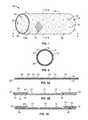
- FIG. 1is a perspective view of a first embodiment of the stent-graft of the present invention.
- FIG. 2is a cross-sectional view taken along line 2 - 2 of FIG. 1 .
- FIG. 3Ais a cross-sectional view taken along line 3 - 3 of FIG. 1 .
- FIG. 3Bis a cross-sectional view of a variation of a first embodiment of the stent-graft of the present invention.
- FIG. 3Cis a cross-sectional view of another variation of a first embodiment of the stent-graft of the present invention.
- FIG. 4Ais a cross-sectional view of a second embodiment of the stent-graft of the present invention.
- FIG. 4Bis a cross-sectional view of a variation of a second embodiment of the stent-graft of the present invention.
- FIG. 4Cis a cross-sectional view of another variation of a second embodiment of the stent-graft of the present invention.
- FIG. 5is a cross-sectional view of a third embodiment of the stent-graft of the present invention.
- FIG. 6is a perspective view of a fourth embodiment of the stent-graft of the present invention.
- FIG. 7is a cross-sectional view taken along line 7 - 7 of FIG. 6 .
- FIG. 8is a cross-sectional view taken along line 8 - 8 of FIG. 6 .
- FIG. 9is a cross-sectional view of a fifth embodiment of the stent-graft of the present invention.
- FIG. 10is a cross-sectional view of a sixth embodiment of the stent-graft of the present invention.
- FIG. 11is a flow diagram illustrating fabrication methodologies for making the inventive stent-graft of the present invention.
- a first embodimentgenerally comprises a structural support member, such as a stent, that has first and second opposing wall surfaces thereof that are bounded by metallic or pseudometallic covers. The covers are positioned adjacent the first and second opposing wall surfaces and are either coupled to the structural support member or are coupled to one another through interstitial openings passing through the structural support member.
- a second embodimentgenerally comprises at least one metallic or pseudometallic cover that is positioned intermediate two adjacent structural support members, e.g., stents.
- pseudometallicand “pseudometallic” are intended to mean a biocompatible material which exhibits biological response and material characteristics substantially the same as biocompatible metals.
- pseudometallic materialsinclude, for example, composite materials, ceramics, quartz, and borosilicate.
- Composite materialsare composed of a matrix material reinforced with any of a variety of fibers made from ceramics, metals, or polymers. The reinforcing fibers are the primary load carriers of the material, with the matrix component transferring the load from fiber to fiber. Reinforcement of the matrix material may be achieved in a variety of ways. Fibers may be either continuous or discontinuous. Reinforcement may also be in the form of particles.
- composite materialsinclude those made of carbon fibers, boron fibers, boron carbide fibers, carbon and graphite fibers, carbon nanotubes, silicon carbide fibers, steel fibers, tungsten fibers, graphite/copper fibers, titanium and silicon carbide/titanium fibers.
- the structural support member and the covering memberare preferably fabricated entirely of self-supporting films made of biocompatible metals or biocompatible pseudometals.
- the metal filmsmay either be single layer metal films or plural layer films.
- the terms “metal film,” “thin metallic film” and “metal thin film”are used in this application synonymously to refer to single or plural layer films fabricated of biocompatible metals or biocompatible pseudometals having thicknesses greater than 0 ⁇ m and less than about 125 ⁇ m.
- FIGS. 1-5illustrate the first embodiment of the present invention and variations thereof.
- FIG. 1illustrates one embodiment of a stent-graft of the present invention.
- FIG. 2is a cross-sectional view taken along line 2 - 2 of FIG. 1
- FIG. 3Ais a cross-sectional view taken along line 3 - 3 of FIG. 1 .
- the inventive stent-graft 10consists generally of at least one structural support member 12 having a first wall surface 12 a and a second wall surface 12 b opposing one another, a first cover member 14 and a second cover member 16 .
- the first cover member 14is positioned adjacent the first wall surface 12 a while the second cover member 16 is positioned adjacent the second wall surface 12 b of the structural support member 12 .
- the first cover member 14 and the second cover 16may be coupled either to the structural support member 12 or to one another through interstitial openings 20 passing through the structural support member 12 .
- Coupling of the first cover member 14 and/or the second cover member 16may be achieved by creating junctions 18 such as by chemical, mechanical or thermal means.
- the junctions 18may be formed by welding, adhering using a biocompatible adhesive, or by forming interlocking or interfacing members on opposing surfaces of the support structure 12 , the first cover member 14 and/or the second cover member 16 depending upon the surfaces to be coupled.
- junction 18may be formed by mechanical interference between the support structure 12 and the first cover member 14 and/or the second cover member 16 .
- first cover member 14 and the second cover member 16may consist of dual discrete members as depicted in FIGS. 4A, 4B, and 4C .
- each of the first cover member 14 and the second cover member 16terminate with opposing proximal 24 and distal 26 ends of the respective first cover member 14 and second cover member 16 .
- Junctions 18may be provided either between the structural support member 12 and the proximal 24 and distal 26 ends of the first 14 and second 16 cover members, between opposing wall surfaces of the first 14 and second 16 cover members and through interstitial spaces in the structural support member 12 , or both. Junctions 18 may also be provided between the structural support member 12 and the first 14 and second 16 cover members.
- FIG. 4Aillustrates an embodiment in which junctions 18 are provided between opposing wall surfaces of the first 14 and second 16 cover members and through interstitial spaces in the structural support member 12 .
- FIG. 4Billustrates an embodiment in which junctions 18 are provided only at the proximal 24 and distal 26 ends of the first 14 and second 16 cover members.
- FIG. 4Cillustrates an embodiment in which junctions 18 are provided directly between the structural support members 12 and the first 14 and second 16 cover members. Thus, the junctions 18 may occur between the cover members 14 , 16 and the structural support member 12 , between the cover members 14 , 16 only, or both.
- the first cover member 14 and the second cover member 16may comprise of a single cover member that is positioned adjacent both the first and second wall surfaces of the structural support member 12 and has an eversion region 22 positioned at either a proximal or distal end of the structural support member, or at both the proximal and distal ends of the structural support member 12 .
- dual cover membersmay be employed with a junction between the first cover member 14 and the second cover member 16 being formed therebetween at the eversion region 22 .
- FIG. 3Aillustrates an embodiment in which the first cover member 14 and the second cover member 16 comprise of a single cover member that is positioned adjacent both the first and second wall surfaces of the structural support member 12 and has an eversion region 22 positioned at either a proximal or distal end of the structural support member.
- FIG. 3Billustrates an embodiment in which the first cover member 14 and the second cover member 16 comprise of a single cover member that is positioned adjacent at least a portion of both the first and second wall surfaces of the structural support member 12 and has an eversion region 22 positioned at both the proximal and distal end of the structural support member 12 .
- FIG. 3Aillustrates an embodiment in which the first cover member 14 and the second cover member 16 comprise of a single cover member that is positioned adjacent both the first and second wall surfaces of the structural support member 12 and has an eversion region 22 positioned at both the proximal and distal end of the structural support member 12 .
- FIG. 3Balso illustrates an embodiment in which junctions 18 are provided between opposing wall surfaces of the first 14 and second 16 cover members and through interstitial spaces in the structural support member 12 .
- FIG. 3Cillustrates an embodiment in which the first cover member 14 and the second cover member 16 comprise of a single cover member that is positioned adjacent at least a portion of both the first and second wall surfaces of the structural support member 12 and has an eversion region 22 positioned at both the proximal and distal end of the structural support member 12 .
- FIG. 3Calso illustrates an embodiment in which junctions 18 are provided directly between the structural support members 12 and the first 14 and second 16 cover members.
- the first cover member 14 and the second cover member 16may consist of a single cover member 14 that is everted over both the distal end 22 of the structural support member 12 and over the proximal end 28 of the structural support member 12 , thereby forming distal and proximal eversion regions 22 , 28 , and opposing ends 30 , 32 of the first cover member 14 are either conjoined to one another, coupled to the structural support member 12 or joined at a junction region 18 to an opposing surface of the first cover member 14 .
- Each of the first 14 and second 16 cover memberspreferably has a plurality of openings 15 passing there through.
- the plurality of openings 15 and 45are shown in one region of the first 14 and second 16 cover members and the metallic cover member 46 for illustrative purposes only. It is contemplated that the plurality of openings 15 and 45 may be present throughout the first 14 and second 16 cover members and the metallic cover member 46 or may be in present in various areas of the first 14 and second 16 cover members and the metallic cover member 46 .
- Each of the plurality of openings 15preferably has a pore size within the range of about 0.1 ⁇ m to about 1000 ⁇ m in at least one of an x or y-axis of the opening, with the total open surface area of the first 14 and second 16 cover being between 0.001 to 90% and which permit cellular and sub-cellular physiological matter, such as proteins, to pass through the openings 15 without permitting fluid seepage there through.
- the term “pore size”is intended to connote a dimension in at least one of an x-axis or a y-axis of the opening 15 .
- the total open surface area of the first 14 or second 16 covermay be calculated by dividing the surface area of each the plurality of openings 15 by the total surface area on either the luminal or abluminal surface of the first 14 or second 16 cover member.
- the plurality of openings 15also impart dimensional flexibility to the first 14 and second 16 cover members and permits flexibility, compressibility and expandability along the longitudinal axis of the stent-graft device 10 , while also permitting compliance, foldabilty and expandability in the radial axis of the stent-graft device 10 .
- the plurality of openings 15are preferably provided in a pattern array in order to maximize the physical properties of the first 14 and second 16 cover members and, hence, the resulting inventive stent-graft 10 .
- the pattern arraymay be provided to selectively enhance longitudinal flexibility while reinforcing against radial compliance.
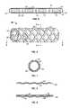
- FIG. 6is a perspective view of one embodiment of the stent-graft of the present invention.
- FIG. 7is a cross-sectional view taken along line 7 - 7 of FIG. 6
- FIG. 8is a cross-sectional view taken along line 8 - 8 of FIG. 6 .
- Stent-graft 40consists generally of at least a first structural support member 42 and a second structural support member 44 , which are, for example, tubular stent members, and a metallic cover member 46 having a plurality of openings 45 .
- the at least two structural support members 42 , 44for ease of reference, will be referred to as stent members 42 , 44 .
- Stent members 42 , 44are preferably generally tubular in configuration, and may be formed as tubular members or initially as planar members that are rolled into a tubular configuration.
- the first and second structural support members 42 , 44may be configured to define alternative geometries suitable for a particular application.
- Such alternative geometriesmay include, for example, planar geometries for use as patches, frustroconical geometries such as for use as anchors for dental implants or other complex geometries such as for osteal implants.
- first structural support member 42 and the second structural support member 44are selected as stents
- the stent members 42 , 44are preferably positioned concentrically relative to one another.
- the metallic cover member 46is then positioned concentrically intermediate the first and second stent members 42 , 44 along at least a portion of a longitudinal axis of the first and second stent members 42 , 44 .
- the first 42 and second 44 structural support membersmay either be joined, as described above, to the metallic cover member 46 or may be joined to one another outside the surface area of the metallic cover member 46 .
- a multilayered constructionmay be formed by extending the metallic cover member 46 and everting the metallic cover member 46 over one or both of the proximal 52 and/or distal 54 ends of the stent-graft.
- the eversion regions 48 , 50may be positioned at the proximal 52 or distal 54 ends of the metallic cover member 46 , or both.
- a plurality of openings 45is provided and passes through the thickness of the cover member 46 .
- each of the plurality of openings 45preferably has an pore size within the range of 0.1 ⁇ m to 1000 ⁇ m, with the total open surface area of the graft being between 0.001 to 90% and which permit cellular and sub-cellular physiological matter, such as proteins, to pass through the openings 45 without permitting fluid seepage there through.
- Both the pore size of the openings 45 and the total open area of the cover member 46may be selected in view of the following non-exclusive factors: the desired flexibility of the cover member 46 , the desired hoop strength of the cover member 46 , the desired degree of geometric enlargement due to deformation of the openings 45 and the desired delivery profile size.
- the inventive cover member 46may be fabricated of pre-existing conventionally produced wrought materials, such as stainless steel or nitinol hypotubes, or may be fabricated by thin film vacuum deposition techniques.
- inventive graftsmay be comprised of a monolayer of biocompatible material or of a plurality of layers of biocompatible materials formed upon one another into a self-supporting laminate structure.
- Laminate structuresare generally known to increase the mechanical strength of sheet materials, such as wood or paper products. Laminates are used in the field of thin film fabrication also to increase the mechanical properties of the thin film, specifically hardness and toughness.
- Laminate metal foilshave not been used or developed because the standard metal forming technologies, such as rolling and extrusion, for example, do not readily lend themselves to producing laminate structures. Vacuum deposition technologies can be developed to yield laminate metal structures with improved mechanical properties. In addition, laminate structures can be designed to provide special qualities by including layers that have special properties such as superelasticity, shape memory, radio-opacity, corrosion resistance etc.
- the graftis fabricated of vacuum deposited metallic and/or pseudometallic films.
- the fabrication method 100 of the present inventionis illustrated.
- a precursor blank of a conventionally fabricated biocompatible metal or pseudometallic materialmay be employed at step 102 .
- a precursor blank of a vacuum deposited metal or pseudometallic filmmay be employed at step 104 .
- a decision 105is made whether to process the precursor blank from step 102 or step 104 by either subtractive or additive processing is made.
- the precursor blank material obtained either from step 102 or step 104may then be masked at step 108 leaving exposed only those regions which will define a plurality of openings and which will be removed to form the openings.
- the exposed regions from step 108are then subjected to removal at step 110 , either by etching, such as by wet or dry chemical etching processing, with the etchant being selected based upon the material of the precursor blank, or by machining, such as by laser ablation or EDM.
- a pattern mask corresponding to the plurality of openings to be formed later and with openings to permit deposition of the graft material through the maskmay be interposed at step 106 between the target and the source and the metal or pseudometal deposited at step 112 through the pattern mask to form the graft material with openings corresponding to the masked regions.
- plural film layersmaybe deposited to form a laminate film structure of the film prior to or concurrently with forming the plurality of openings.
- the width of the interface regionmay be defined as the range within which extensive thermodynamic parameters change. This range can depend on the interface area considered and it may mean the extent of interface microroughness. In other words, adhesion may be promoted by increased interfacial microroughness between adjacent layers within the film.
- the microroughnessmay be imparted by chemical or mechanical means, such as chemical etching or laser ablation, or may be included as a process step during vacuum deposition by selectively depositing a metal or pseudometallic species to form the microroughness.
- the present inventionprovides a new metallic and/or pseudometallic implantable graft that is biocompatible, geometrically changeable either by folding and unfolding or by application of a plastically deforming force, and capable of endoluminal delivery with a suitably small delivery profile.
- Suitable metal materials to fabricate the inventive coversare chosen for their biocompatibility, mechanical properties, i.e., tensile strength, yield strength, and their ease of deposition include, without limitation, the following: titanium, vanadium, aluminum, nickel, tantalum, zirconium, chromium, silver, gold, silicon, magnesium, niobium, scandium, platinum, cobalt, palladium, manganese, molybdenum and alloys thereof, such as chromium-cobalt alloy, zirconium-titanium-tantalum alloys, nickel-titanium, and stainless steel.
- pseudometallic materials potentially useful with the present inventioninclude, for example, composite materials, ceramics, quartz, and borosilicate.
- the present inventionalso provides a method of making the inventive stent-graft devices by vacuum deposition of a graft-forming metal or pseudometal and formation of the openings either by removing sections of deposited material, such as by etching, EDM, ablation, or other similar methods, or by interposing a pattern mask, corresponding to the openings, between the target and the source during deposition processing.
- a pre-existing metal and/or pseudometallic film manufactured by conventional non-vacuum deposition methodologies, such as wrought hypotubemay be obtained, and the openings formed in the pre-existing metal and/or pseudometallic film by removing sections of the film, such as by etching, EDM, ablation, or other similar methods.
- an advantage of employing laminated film structures to form the inventive graftis that differential functionalities may be imparted in the discrete layers.
- a radiopaque materialsuch as tantalum may form one layer of a structure while other layers are chosen to provide the graft with its desired mechanical and structural properties.
Landscapes
- Health & Medical Sciences (AREA)
- Engineering & Computer Science (AREA)
- Biomedical Technology (AREA)
- Heart & Thoracic Surgery (AREA)
- Life Sciences & Earth Sciences (AREA)
- Cardiology (AREA)
- Oral & Maxillofacial Surgery (AREA)
- Transplantation (AREA)
- Veterinary Medicine (AREA)
- Vascular Medicine (AREA)
- Public Health (AREA)
- Animal Behavior & Ethology (AREA)
- General Health & Medical Sciences (AREA)
- Optics & Photonics (AREA)
- Physics & Mathematics (AREA)
- Gastroenterology & Hepatology (AREA)
- Pulmonology (AREA)
- Prostheses (AREA)
Abstract
Description
Claims (33)
Priority Applications (2)
| Application Number | Priority Date | Filing Date | Title |
|---|---|---|---|
| US12/210,789US10172730B2 (en) | 1999-11-19 | 2008-09-15 | Stents with metallic covers and methods of making same |
| US16/222,286US20190125559A1 (en) | 1999-11-19 | 2018-12-17 | Stents with metallic covers and methods of making same |
Applications Claiming Priority (5)
| Application Number | Priority Date | Filing Date | Title |
|---|---|---|---|
| US09/443,929US6379383B1 (en) | 1999-11-19 | 1999-11-19 | Endoluminal device exhibiting improved endothelialization and method of manufacture thereof |
| US09/532,164US6537310B1 (en) | 1999-11-19 | 2000-03-20 | Endoluminal implantable devices and method of making same |
| US10/289,974US7491226B2 (en) | 1999-11-19 | 2002-11-06 | Endoluminal implantable stent-grafts |
| US10/936,883US20060052865A1 (en) | 2004-09-09 | 2004-09-09 | Stents with metallic covers and methods of making same |
| US12/210,789US10172730B2 (en) | 1999-11-19 | 2008-09-15 | Stents with metallic covers and methods of making same |
Related Parent Applications (2)
| Application Number | Title | Priority Date | Filing Date |
|---|---|---|---|
| US10/289,974Continuation-In-PartUS7491226B2 (en) | 1999-11-19 | 2002-11-06 | Endoluminal implantable stent-grafts |
| US10/936,883Continuation-In-PartUS20060052865A1 (en) | 1999-11-19 | 2004-09-09 | Stents with metallic covers and methods of making same |
Related Child Applications (2)
| Application Number | Title | Priority Date | Filing Date |
|---|---|---|---|
| US09/532,164Continuation-In-PartUS6537310B1 (en) | 1999-11-19 | 2000-03-20 | Endoluminal implantable devices and method of making same |
| US16/222,286ContinuationUS20190125559A1 (en) | 1999-11-19 | 2018-12-17 | Stents with metallic covers and methods of making same |
Publications (2)
| Publication Number | Publication Date |
|---|---|
| US20090132022A1 US20090132022A1 (en) | 2009-05-21 |
| US10172730B2true US10172730B2 (en) | 2019-01-08 |
Family
ID=40642793
Family Applications (2)
| Application Number | Title | Priority Date | Filing Date |
|---|---|---|---|
| US12/210,789Expired - LifetimeUS10172730B2 (en) | 1999-11-19 | 2008-09-15 | Stents with metallic covers and methods of making same |
| US16/222,286AbandonedUS20190125559A1 (en) | 1999-11-19 | 2018-12-17 | Stents with metallic covers and methods of making same |
Family Applications After (1)
| Application Number | Title | Priority Date | Filing Date |
|---|---|---|---|
| US16/222,286AbandonedUS20190125559A1 (en) | 1999-11-19 | 2018-12-17 | Stents with metallic covers and methods of making same |
Country Status (1)
| Country | Link |
|---|---|
| US (2) | US10172730B2 (en) |
Cited By (1)
| Publication number | Priority date | Publication date | Assignee | Title |
|---|---|---|---|---|
| US12310846B2 (en)* | 2017-01-23 | 2025-05-27 | Edwards Lifesciences Corporation | Covered prosthetic heart valve |
Families Citing this family (19)
| Publication number | Priority date | Publication date | Assignee | Title |
|---|---|---|---|---|
| US8458879B2 (en)* | 2001-07-03 | 2013-06-11 | Advanced Bio Prosthetic Surfaces, Ltd., A Wholly Owned Subsidiary Of Palmaz Scientific, Inc. | Method of fabricating an implantable medical device |
| US8435285B2 (en)* | 2003-11-25 | 2013-05-07 | Boston Scientific Scimed, Inc. | Composite stent with inner and outer stent elements and method of using the same |
| US8998973B2 (en)* | 2004-03-02 | 2015-04-07 | Boston Scientific Scimed, Inc. | Medical devices including metallic films |
| US8591568B2 (en)* | 2004-03-02 | 2013-11-26 | Boston Scientific Scimed, Inc. | Medical devices including metallic films and methods for making same |
| US8632580B2 (en)* | 2004-12-29 | 2014-01-21 | Boston Scientific Scimed, Inc. | Flexible medical devices including metallic films |
| US7901447B2 (en)* | 2004-12-29 | 2011-03-08 | Boston Scientific Scimed, Inc. | Medical devices including a metallic film and at least one filament |
| US20060142838A1 (en)* | 2004-12-29 | 2006-06-29 | Masoud Molaei | Medical devices including metallic films and methods for loading and deploying same |
| US8992592B2 (en)* | 2004-12-29 | 2015-03-31 | Boston Scientific Scimed, Inc. | Medical devices including metallic films |
| WO2005094725A1 (en)* | 2004-03-31 | 2005-10-13 | Merlin Md Pte Ltd | A method for treating aneurysms |
| US8715340B2 (en)* | 2004-03-31 | 2014-05-06 | Merlin Md Pte Ltd. | Endovascular device with membrane |
| US8500751B2 (en)* | 2004-03-31 | 2013-08-06 | Merlin Md Pte Ltd | Medical device |
| US7854760B2 (en)* | 2005-05-16 | 2010-12-21 | Boston Scientific Scimed, Inc. | Medical devices including metallic films |
| US10987208B2 (en) | 2012-04-06 | 2021-04-27 | Merlin Md Pte Ltd. | Devices and methods for treating an aneurysm |
| US10154918B2 (en) | 2012-12-28 | 2018-12-18 | Cook Medical Technologies Llc | Endoluminal prosthesis with fiber matrix |
| WO2016168765A1 (en)* | 2015-04-16 | 2016-10-20 | Nsvascular, Inc. | Thin-film cuff for endothelialization of endovascular grafts |
| US10869748B2 (en)* | 2016-05-03 | 2020-12-22 | Regents Of The University Of Minnesota | Active monitoring pressure sensitive vascular graft |
| DE102019135453A1 (en)* | 2019-12-20 | 2021-06-24 | Malte Neuss | Multiple stent with membrane |
| CN113288317A (en)* | 2021-07-02 | 2021-08-24 | 苏州舒通医疗科技有限公司 | Medical device |
| CN116250963A (en)* | 2021-12-10 | 2023-06-13 | 深圳市先健呼吸科技有限公司 | an airway stent |
Citations (177)
| Publication number | Priority date | Publication date | Assignee | Title |
|---|---|---|---|---|
| DE1452370A1 (en) | 1965-06-26 | 1969-03-13 | Forrer Hans Georg | Process for the production of thin needles |
| JPS5155724A (en) | 1974-11-12 | 1976-05-17 | Tokuriki Shoten Goshi | Shikayokingokin oyobi sonoseizohoho |
| US4337665A (en)* | 1979-02-26 | 1982-07-06 | Hitachi, Ltd. | Semiconductor pressure detector apparatus with zero-point temperature compensation |
| US4510182A (en) | 1981-08-27 | 1985-04-09 | Ruhrchemie Aktiengesellschaft | Method for the production of homogeneous coatings of two or more metals and/or metal compounds |
| JPS6188135A (en) | 1984-10-05 | 1986-05-06 | Nec Corp | Production of semiconductor biosensor |
| US4733665A (en) | 1985-11-07 | 1988-03-29 | Expandable Grafts Partnership | Expandable intraluminal graft, and method and apparatus for implanting an expandable intraluminal graft |
| US4751099A (en) | 1985-12-28 | 1988-06-14 | National Aerospace Laboratories of Science and Technology Agency | Method of producing a functionally gradient material |
| US4846834A (en) | 1986-05-27 | 1989-07-11 | Clemson University | Method for promoting tissue adhesion to soft tissue implants |
| EP0400947A1 (en) | 1989-05-31 | 1990-12-05 | De Beers Industrial Diamond Division (Proprietary) Limited | Diamond growth |
| EP0442303A1 (en) | 1990-02-13 | 1991-08-21 | General Electric Company | CVD Diamond workpieces and their fabrication |
| US5047031A (en)* | 1988-04-20 | 1991-09-10 | Norian Corporation | In situ calcium phosphate minerals method |
| US5049251A (en) | 1988-06-10 | 1991-09-17 | Fujitsu Limited | Sputtering method for fabricating thin film |
| US5061914A (en) | 1989-06-27 | 1991-10-29 | Tini Alloy Company | Shape-memory alloy micro-actuator |
| US5084151A (en) | 1985-11-26 | 1992-01-28 | Sorin Biomedica S.P.A. | Method and apparatus for forming prosthetic device having a biocompatible carbon film thereon |
| US5102417A (en)* | 1985-11-07 | 1992-04-07 | Expandable Grafts Partnership | Expandable intraluminal graft, and method and apparatus for implanting an expandable intraluminal graft |
| US5133732A (en) | 1987-10-19 | 1992-07-28 | Medtronic, Inc. | Intravascular stent |
| US5133845A (en) | 1986-12-12 | 1992-07-28 | Sorin Biomedica, S.P.A. | Method for making prosthesis of polymeric material coated with biocompatible carbon |
| US5158750A (en) | 1990-06-06 | 1992-10-27 | Praxair S.T. Technology, Inc. | Boron nitride crucible |
| US5207706A (en)* | 1988-10-05 | 1993-05-04 | Menaker M D Gerald | Method and means for gold-coating implantable intravascular devices |
| US5242710A (en) | 1990-06-25 | 1993-09-07 | Lanxide Technology Company, Lp | Methods for making self-supporting composite bodies and articles produced thereby |
| US5277933A (en) | 1990-06-25 | 1994-01-11 | Lanxide Technology Company, Lp | Method for forming a self-supporting body using vapor-phase parent metals and solid oxidants |
| US5329514A (en) | 1991-07-31 | 1994-07-12 | Canon Kabushiki Kaisha | Information processing apparatus, and electrode substrate and information recording medium used in the apparatus |
| US5330500A (en)* | 1990-10-18 | 1994-07-19 | Song Ho Y | Self-expanding endovascular stent with silicone coating |
| US5370684A (en) | 1986-12-12 | 1994-12-06 | Sorin Biomedica S.P.A. | Prosthesis of polymeric material coated with biocompatible carbon |
| US5376463A (en) | 1991-03-26 | 1994-12-27 | Hughes Aircraft Company | Anisometric metal needles with L-shaped cross-section |
| US5387247A (en) | 1983-10-25 | 1995-02-07 | Sorin Biomedia S.P.A. | Prosthetic device having a biocompatible carbon film thereon and a method of and apparatus for forming such device |
| US5421955A (en) | 1991-10-28 | 1995-06-06 | Advanced Cardiovascular Systems, Inc. | Expandable stents and method for making same |
| US5456713A (en) | 1991-10-25 | 1995-10-10 | Cook Incorporated | Expandable transluminal graft prosthesis for repairs of aneurysm and method for implanting |
| US5456712A (en) | 1991-07-03 | 1995-10-10 | Maginot; Thomas J. | Graft and stent assembly |
| US5464419A (en)* | 1993-03-22 | 1995-11-07 | Industrial Research B.V. | Expandable hollow sleeve for the local support and/or reinforcement of a body vessel, and method for the fabrication thereof |
| US5477864A (en) | 1989-12-21 | 1995-12-26 | Smith & Nephew Richards, Inc. | Cardiovascular guidewire of enhanced biocompatibility |
| US5522881A (en)* | 1994-06-28 | 1996-06-04 | Meadox Medicals, Inc. | Implantable tubular prosthesis having integral cuffs |
| US5522882A (en) | 1994-10-21 | 1996-06-04 | Impra, Inc. | Method and apparatus for balloon expandable stent-graft delivery |
| US5540820A (en) | 1990-11-30 | 1996-07-30 | Hitachi, Ltd. | Thin film forming method |
| US5545210A (en) | 1994-09-22 | 1996-08-13 | Advanced Coronary Technology, Inc. | Method of implanting a permanent shape memory alloy stent |
| US5556414A (en) | 1995-03-08 | 1996-09-17 | Wayne State University | Composite intraluminal graft |
| US5569295A (en) | 1993-12-28 | 1996-10-29 | Advanced Cardiovascular Systems, Inc. | Expandable stents and method for making same |
| US5591226A (en) | 1995-01-23 | 1997-01-07 | Schneider (Usa) Inc. | Percutaneous stent-graft and method for delivery thereof |
| US5591227A (en)* | 1992-03-19 | 1997-01-07 | Medtronic, Inc. | Drug eluting stent |
| US5593442A (en) | 1995-06-05 | 1997-01-14 | Localmed, Inc. | Radially expansible and articulated vessel scaffold |
| US5605714A (en) | 1994-03-29 | 1997-02-25 | Southwest Research Institute | Treatments to reduce thrombogeneticity in heart valves made from titanium and its alloys |
| WO1997007257A1 (en) | 1995-08-18 | 1997-02-27 | The Secretary Of State For Defence | Preparation of structural materials by physical vapour deposition process |
| US5607445A (en) | 1992-06-18 | 1997-03-04 | American Biomed, Inc. | Stent for supporting a blood vessel |
| US5607463A (en)* | 1993-03-30 | 1997-03-04 | Medtronic, Inc. | Intravascular medical device |
| US5609629A (en) | 1995-06-07 | 1997-03-11 | Med Institute, Inc. | Coated implantable medical device |
| US5628788A (en) | 1995-11-07 | 1997-05-13 | Corvita Corporation | Self-expanding endoluminal stent-graft |
| US5629077A (en)* | 1994-06-27 | 1997-05-13 | Advanced Cardiovascular Systems, Inc. | Biodegradable mesh and film stent |
| US5630840A (en) | 1993-01-19 | 1997-05-20 | Schneider (Usa) Inc | Clad composite stent |
| US5632779A (en)* | 1989-07-25 | 1997-05-27 | Smith & Nephew, Inc. | Zirconium oxide and zirconium nitride coated vascular grafts |
| US5656036A (en) | 1992-09-01 | 1997-08-12 | Expandable Grafts Partnership | Apparatus for occluding vessels |
| US5665115A (en) | 1992-02-21 | 1997-09-09 | Boston Scientific Technology, Inc. | Intraluminal stent |
| US5667523A (en)* | 1995-04-28 | 1997-09-16 | Impra, Inc. | Dual supported intraluminal graft |
| US5683453A (en) | 1992-01-08 | 1997-11-04 | Expandable Grafts Partnership | Apparatus for bilateral intra-aortic bypass |
| US5685961A (en) | 1992-03-27 | 1997-11-11 | P & D Medical Coatings, Inc. | Method for fabrication of metallized medical devices |
| WO1997044692A2 (en) | 1996-05-09 | 1997-11-27 | President And Fellows Of Harvard College | Fabrication of small-scale coils and bands as photomasks on optical fibers for generation of in-fiber gratings, electromagnets as micro-nmr coils, microtransformers, and intra-vascular stents |
| US5693085A (en) | 1994-04-29 | 1997-12-02 | Scimed Life Systems, Inc. | Stent with collagen |
| US5693084A (en) | 1991-10-25 | 1997-12-02 | Cook Incorporated | Expandable transluminal graft prosthesis for repair of aneurysm |
| US5695517A (en) | 1994-02-10 | 1997-12-09 | Endovascular Systems, Inc. | Method and apparatus for forming an endoluminal bifurcated graft |
| WO1997046268A1 (en) | 1996-06-04 | 1997-12-11 | Cook Incorporated | Implantable medical device |
| US5702419A (en) | 1994-09-21 | 1997-12-30 | Wake Forest University | Expandable, intraluminal stents |
| US5723219A (en) | 1995-12-19 | 1998-03-03 | Talison Research | Plasma deposited film networks |
| US5725573A (en) | 1994-03-29 | 1998-03-10 | Southwest Research Institute | Medical implants made of metal alloys bearing cohesive diamond like carbon coatings |
| WO1998013537A1 (en) | 1996-09-24 | 1998-04-02 | Fotomechanix Limited | Method of producing a hollow structure |
| US5735892A (en) | 1993-08-18 | 1998-04-07 | W. L. Gore & Associates, Inc. | Intraluminal stent graft |
| US5735896A (en) | 1994-08-15 | 1998-04-07 | Biotronik | Biocompatible prosthesis |
| US5744515A (en) | 1995-05-26 | 1998-04-28 | Bsi Corporation | Method and implantable article for promoting endothelialization |
| US5749880A (en)* | 1995-03-10 | 1998-05-12 | Impra, Inc. | Endoluminal encapsulated stent and methods of manufacture and endoluminal delivery |
| US5765418A (en) | 1994-05-16 | 1998-06-16 | Medtronic, Inc. | Method for making an implantable medical device from a refractory metal |
| US5769884A (en)* | 1996-06-27 | 1998-06-23 | Cordis Corporation | Controlled porosity endovascular implant |
| US5772864A (en) | 1996-02-23 | 1998-06-30 | Meadox Medicals, Inc. | Method for manufacturing implantable medical devices |
| US5776161A (en) | 1995-10-16 | 1998-07-07 | Instent, Inc. | Medical stents, apparatus and method for making same |
| US5780807A (en) | 1994-11-28 | 1998-07-14 | Advanced Cardiovascular Systems, Inc. | Method and apparatus for direct laser cutting of metal stents |
| US5782908A (en) | 1995-08-22 | 1998-07-21 | Medtronic, Inc. | Biocompatible medical article and method |
| US5788558A (en) | 1995-11-13 | 1998-08-04 | Localmed, Inc. | Apparatus and method for polishing lumenal prostheses |
| US5798042A (en) | 1994-03-07 | 1998-08-25 | Regents Of The University Of California | Microfabricated filter with specially constructed channel walls, and containment well and capsule constructed with such filters |
| US5811151A (en) | 1996-05-31 | 1998-09-22 | Medtronic, Inc. | Method of modifying the surface of a medical device |
| WO1998045506A1 (en) | 1997-04-08 | 1998-10-15 | Interventional Technologies, Inc. | Method for manufacturing a stent |
| US5824045A (en)* | 1996-10-21 | 1998-10-20 | Inflow Dynamics Inc. | Vascular and endoluminal stents |
| US5824054A (en) | 1997-03-18 | 1998-10-20 | Endotex Interventional Systems, Inc. | Coiled sheet graft stent and methods of making and use |
| US5824049A (en) | 1995-06-07 | 1998-10-20 | Med Institute, Inc. | Coated implantable medical device |
| US5824036A (en) | 1995-09-29 | 1998-10-20 | Datascope Corp | Stent for intraluminal grafts and device and methods for delivering and assembling same |
| US5824058A (en) | 1993-05-20 | 1998-10-20 | Boston Scientific Corporation | Prosthesis delivery |
| US5840009A (en) | 1995-12-05 | 1998-11-24 | Isostent, Inc. | Radioisotope stent with increased radiation field strength at the ends of the stent |
| US5843164A (en)* | 1994-11-15 | 1998-12-01 | Advanced Carrdiovascular Systems, Inc. | Intraluminal stent for attaching a graft |
| US5843117A (en) | 1996-02-14 | 1998-12-01 | Inflow Dynamics Inc. | Implantable vascular and endoluminal stents and process of fabricating the same |
| US5843289A (en) | 1996-01-22 | 1998-12-01 | Etex Corporation | Surface modification of medical implants |
| US5855600A (en) | 1997-08-01 | 1999-01-05 | Inflow Dynamics Inc. | Flexible implantable stent with composite design |
| US5855802A (en) | 1996-05-30 | 1999-01-05 | International Business Machines Corporation | Method and apparatus for forming a tubular article having a perforated annular wall |
| US5855955A (en) | 1995-06-07 | 1999-01-05 | Lanxide Technology Company L.P. | Method for making self-supporting composite bodies |
| US5858556A (en)* | 1997-01-21 | 1999-01-12 | Uti Corporation | Multilayer composite tubular structure and method of making |
| US5868782A (en) | 1996-12-24 | 1999-02-09 | Global Therapeutics, Inc. | Radially expandable axially non-contracting surgical stent |
| US5876432A (en) | 1994-04-01 | 1999-03-02 | Gore Enterprise Holdings, Inc. | Self-expandable helical intravascular stent and stent-graft |
| US5879370A (en) | 1994-02-25 | 1999-03-09 | Fischell; Robert E. | Stent having a multiplicity of undulating longitudinals |
| US5891507A (en) | 1997-07-28 | 1999-04-06 | Iowa-India Investments Company Limited | Process for coating a surface of a metallic stent |
| US5895406A (en) | 1996-01-26 | 1999-04-20 | Cordis Corporation | Axially flexible stent |
| US5897911A (en) | 1997-08-11 | 1999-04-27 | Advanced Cardiovascular Systems, Inc. | Polymer-coated stent structure |
| US5899935A (en) | 1997-08-04 | 1999-05-04 | Schneider (Usa) Inc. | Balloon expandable braided stent with restraint |
| US5902332A (en) | 1988-10-04 | 1999-05-11 | Expandable Grafts Partnership | Expandable intraluminal graft |
| WO1999023977A1 (en) | 1997-11-07 | 1999-05-20 | Expandable Grafts Partnership | Intravascular stent and method for manufacturing an intravascular stent |
| US5907893A (en) | 1996-01-30 | 1999-06-01 | Medtronic, Inc. | Methods for the manufacture of radially expansible stents |
| US5913896A (en) | 1995-11-28 | 1999-06-22 | Medtronic, Inc. | Interwoven dual sinusoidal helix stent |
| US5916264A (en)* | 1997-05-14 | 1999-06-29 | Jomed Implantate Gmbh | Stent graft |
| US5919225A (en) | 1994-09-08 | 1999-07-06 | Gore Enterprise Holdings, Inc. | Procedures for introducing stents and stent-grafts |
| US5925063A (en) | 1997-09-26 | 1999-07-20 | Khosravi; Farhad | Coiled sheet valve, filter or occlusive device and methods of use |
| US5928279A (en) | 1996-07-03 | 1999-07-27 | Baxter International Inc. | Stented, radially expandable, tubular PTFE grafts |
| US5932299A (en) | 1996-04-23 | 1999-08-03 | Katoot; Mohammad W. | Method for modifying the surface of an object |
| US5938697A (en) | 1998-03-04 | 1999-08-17 | Scimed Life Systems, Inc. | Stent having variable properties |
| US5938682A (en) | 1996-01-26 | 1999-08-17 | Cordis Corporation | Axially flexible stent |
| US5945153A (en) | 1994-07-11 | 1999-08-31 | Southwest Research Institute | Non-irritating antimicrobial coating for medical implants and a process for preparing same |
| US5951881A (en) | 1996-07-22 | 1999-09-14 | President And Fellows Of Harvard College | Fabrication of small-scale cylindrical articles |
| US5955588A (en) | 1997-12-22 | 1999-09-21 | Innerdyne, Inc. | Non-thrombogenic coating composition and methods for using same |
| JPH11267462A (en) | 1998-03-20 | 1999-10-05 | Hitachi Ltd | Plasma potential fixing device and plasma potential fixing method |
| US5968091A (en) | 1996-03-26 | 1999-10-19 | Corvita Corp. | Stents and stent grafts having enhanced hoop strength and methods of making the same |
| US5972018A (en) | 1994-03-17 | 1999-10-26 | Medinol Ltd. | Flexible expandable stent |
| US5972027A (en) | 1997-09-30 | 1999-10-26 | Scimed Life Systems, Inc | Porous stent drug delivery system |
| US5972441A (en) | 1993-08-18 | 1999-10-26 | W. L. Gore & Associates, Inc. | Thin-wall polytetrafluoroethylene tube |
| US6001123A (en) | 1994-04-01 | 1999-12-14 | Gore Enterprise Holdings Inc. | Folding self-expandable intravascular stent-graft |
| US6004348A (en) | 1995-03-10 | 1999-12-21 | Impra, Inc. | Endoluminal encapsulated stent and methods of manufacture and endoluminal delivery |
| US6019784A (en) | 1996-04-04 | 2000-02-01 | Electroformed Stents, Inc. | Process for making electroformed stents |
| US6022370A (en) | 1996-10-01 | 2000-02-08 | Numed, Inc. | Expandable stent |
| US6027526A (en) | 1996-04-10 | 2000-02-22 | Advanced Cardiovascular Systems, Inc. | Stent having varied amounts of structural strength along its length |
| US6033433A (en) | 1997-04-25 | 2000-03-07 | Scimed Life Systems, Inc. | Stent configurations including spirals |
| US6036725A (en)* | 1998-06-10 | 2000-03-14 | General Science And Technology | Expandable endovascular support device |
| US6039755A (en) | 1997-02-05 | 2000-03-21 | Impra, Inc., A Division Of C.R. Bard, Inc. | Radially expandable tubular polytetrafluoroethylene grafts and method of making same |
| US6042605A (en) | 1995-12-14 | 2000-03-28 | Gore Enterprose Holdings, Inc. | Kink resistant stent-graft |
| US6042597A (en) | 1998-10-23 | 2000-03-28 | Scimed Life Systems, Inc. | Helical stent design |
| US6059808A (en) | 1996-04-10 | 2000-05-09 | Laboratoires Nycomed Sa | Implantable device and delivery system to reestablish or maintain a bodily canal |
| US6059824A (en)* | 1998-12-23 | 2000-05-09 | Taheri; Syde A. | Mated main and collateral stent and method for treatment of arterial disease |
| US6066169A (en) | 1998-06-02 | 2000-05-23 | Ave Connaught | Expandable stent having articulated connecting rods |
| US6071305A (en) | 1996-11-25 | 2000-06-06 | Alza Corporation | Directional drug delivery stent and method of use |
| US6086773A (en) | 1998-05-22 | 2000-07-11 | Bmc Industries, Inc. | Method and apparatus for etching-manufacture of cylindrical elements |
| US6096175A (en) | 1998-07-17 | 2000-08-01 | Micro Therapeutics, Inc. | Thin film stent |
| US6106642A (en) | 1998-02-19 | 2000-08-22 | Boston Scientific Limited | Process for the improved ductility of nitinol |
| WO2000054704A1 (en) | 1999-03-16 | 2000-09-21 | Advanced Cardiovascular Systems, Inc. | Multilayer stent |
| US6129756A (en) | 1998-03-16 | 2000-10-10 | Teramed, Inc. | Biluminal endovascular graft system |
| US6139573A (en)* | 1997-03-05 | 2000-10-31 | Scimed Life Systems, Inc. | Conformal laminate stent device |
| US6143022A (en) | 1998-08-24 | 2000-11-07 | Medtronic Ave, Inc. | Stent-graft assembly with dual configuration graft component and method of manufacture |
| US6156064A (en) | 1998-08-14 | 2000-12-05 | Schneider (Usa) Inc | Stent-graft-membrane and method of making the same |
| US6159239A (en) | 1998-08-14 | 2000-12-12 | Prodesco, Inc. | Woven stent/graft structure |
| US6162244A (en)* | 1996-03-29 | 2000-12-19 | Willy Ruesch Ag | Layered stent |
| US6165211A (en) | 1995-11-21 | 2000-12-26 | Schneider (Usa) Inc. | Expandable stent-graft covered with expanded polytetrafluoroethylene |
| US6214039B1 (en) | 1995-08-24 | 2001-04-10 | Impra, Inc., A Subsidiary Of C. R. Bard, Inc. | Covered endoluminal stent and method of assembly |
| US6245104B1 (en)* | 1999-02-28 | 2001-06-12 | Inflow Dynamics Inc. | Method of fabricating a biocompatible stent |
| US6264689B1 (en)* | 1998-03-31 | 2001-07-24 | Scimed Life Systems, Incorporated | Low profile medical stent |
| US6264598B1 (en) | 1998-08-06 | 2001-07-24 | Implant Sciences Corporation | Palladium coated implant |
| US6264684B1 (en) | 1995-03-10 | 2001-07-24 | Impra, Inc., A Subsidiary Of C.R. Bard, Inc. | Helically supported graft |
| WO2001053559A1 (en) | 2000-01-24 | 2001-07-26 | Smart Therapeutics, Inc. | Thin-film shape memory alloy device and method |
| WO2001055473A1 (en) | 2000-01-25 | 2001-08-02 | Boston Scientific Limited | Manufacturing medical devices by vapor deposition |
| WO2001056502A1 (en) | 2000-02-01 | 2001-08-09 | Endotex Interventional Systems, Inc. | Micro-porous mesh stent with hybrid structure |
| US6306164B1 (en)* | 1997-09-05 | 2001-10-23 | C. R. Bard, Inc. | Short body endoprosthesis |
| US6322585B1 (en) | 1998-11-16 | 2001-11-27 | Endotex Interventional Systems, Inc. | Coiled-sheet stent-graft with slidable exo-skeleton |
| US6334868B1 (en)* | 1999-10-08 | 2002-01-01 | Advanced Cardiovascular Systems, Inc. | Stent cover |
| WO2002004197A1 (en) | 2000-07-07 | 2002-01-17 | Delphi Technologies, Inc. | Contoured metal structural members and methods for making the same |
| US6344054B1 (en) | 1996-09-20 | 2002-02-05 | Juan Carlos Parodi | Endoluminal prosthesis comprising stent and overlying graft cover, and system and method for deployment thereof |
| US6344053B1 (en) | 1993-12-22 | 2002-02-05 | Medtronic Ave, Inc. | Endovascular support device and method |
| US6346119B1 (en) | 1997-07-25 | 2002-02-12 | Ube Industries, Ltd | Graft equipped with stent |
| US6348066B1 (en) | 1995-11-07 | 2002-02-19 | Corvita Corporation | Modular endoluminal stent-grafts and methods for their use |
| US6352553B1 (en) | 1995-12-14 | 2002-03-05 | Gore Enterprise Holdings, Inc. | Stent-graft deployment apparatus and method |
| US6355058B1 (en) | 1999-12-30 | 2002-03-12 | Advanced Cardiovascular Systems, Inc. | Stent with radiopaque coating consisting of particles in a binder |
| US6377721B1 (en)* | 1998-03-02 | 2002-04-23 | Trustees Of Tufts College | Biosensor array comprising cell populations confined to microcavities |
| US6379383B1 (en) | 1999-11-19 | 2002-04-30 | Advanced Bio Prosthetic Surfaces, Ltd. | Endoluminal device exhibiting improved endothelialization and method of manufacture thereof |
| US6387121B1 (en) | 1996-10-21 | 2002-05-14 | Inflow Dynamics Inc. | Vascular and endoluminal stents with improved coatings |
| US6398802B1 (en) | 1999-06-21 | 2002-06-04 | Scimed Life Systems, Inc. | Low profile delivery system for stent and graft deployment |
| US6416535B1 (en) | 1987-04-06 | 2002-07-09 | Endovascular Technologies, Inc. | Artificial graft and implantation method |
| US6428569B1 (en) | 1999-11-09 | 2002-08-06 | Scimed Life Systems Inc. | Micro structure stent configurations |
| US20020123789A1 (en)* | 1998-12-04 | 2002-09-05 | Francis Ralph T. | Stent cover |
| US6451047B2 (en) | 1995-03-10 | 2002-09-17 | Impra, Inc. | Encapsulated intraluminal stent-graft and methods of making same |
| US6475232B1 (en) | 1996-12-10 | 2002-11-05 | Purdue Research Foundation | Stent with reduced thrombogenicity |
| US6488701B1 (en) | 1998-03-31 | 2002-12-03 | Medtronic Ave, Inc. | Stent-graft assembly with thin-walled graft component and method of manufacture |
| US6500203B1 (en) | 1997-01-23 | 2002-12-31 | Boston Scientific Scimed, Inc. | Process for making stent graft with braided polymeric sleeve |
| US6537310B1 (en) | 1999-11-19 | 2003-03-25 | Advanced Bio Prosthetic Surfaces, Ltd. | Endoluminal implantable devices and method of making same |
| US20030225448A1 (en)* | 2002-05-28 | 2003-12-04 | Scimed Life Systems, Inc. | Polar radiopaque marker for stent |
| US20040054399A1 (en) | 2002-09-17 | 2004-03-18 | Roth Noah M. | Anti-galvanic stent coating |
| US6730119B1 (en)* | 2000-10-06 | 2004-05-04 | Board Of Regents Of The University Of Texas System | Percutaneous implantation of partially covered stents in aneurysmally dilated arterial segments with subsequent embolization and obliteration of the aneurysm cavity |
| US20080034550A1 (en)* | 2006-06-23 | 2008-02-14 | Quanta Computer Inc. | Hinge unit with auto-lock and double-side rotation |
| US7704274B2 (en)* | 2002-09-26 | 2010-04-27 | Advanced Bio Prothestic Surfaces, Ltd. | Implantable graft and methods of making same |
| US7717949B2 (en)* | 2003-09-25 | 2010-05-18 | C. R. Bard, Inc. | Lining for bodily lumen |
Family Cites Families (7)
| Publication number | Priority date | Publication date | Assignee | Title |
|---|---|---|---|---|
| US5422864A (en)* | 1989-09-15 | 1995-06-06 | James Lorello | Minute clocks |
| EP0743089B1 (en)* | 1993-01-25 | 2000-05-17 | Daikin Industries, Limited | Porous polytetrafluoroethylene film |
| DE69507800T2 (en)* | 1994-05-19 | 1999-07-22 | Scimed Life Systems, Inc., Maple Grove, Minn. | IMPROVED TISSUE SUPPORTS |
| US5788556A (en)* | 1997-01-03 | 1998-08-04 | Western Trimming Corporation | Illuminated stacked bead art toy |
| US5980564A (en)* | 1997-08-01 | 1999-11-09 | Schneider (Usa) Inc. | Bioabsorbable implantable endoprosthesis with reservoir |
| US6258121B1 (en)* | 1999-07-02 | 2001-07-10 | Scimed Life Systems, Inc. | Stent coating |
| US6849085B2 (en)* | 1999-11-19 | 2005-02-01 | Advanced Bio Prosthetic Surfaces, Ltd. | Self-supporting laminated films, structural materials and medical devices manufactured therefrom and method of making same |
- 2008
- 2008-09-15USUS12/210,789patent/US10172730B2/ennot_activeExpired - Lifetime
- 2018
- 2018-12-17USUS16/222,286patent/US20190125559A1/ennot_activeAbandoned
Patent Citations (217)
| Publication number | Priority date | Publication date | Assignee | Title |
|---|---|---|---|---|
| DE1452370A1 (en) | 1965-06-26 | 1969-03-13 | Forrer Hans Georg | Process for the production of thin needles |
| JPS5155724A (en) | 1974-11-12 | 1976-05-17 | Tokuriki Shoten Goshi | Shikayokingokin oyobi sonoseizohoho |
| US4337665A (en)* | 1979-02-26 | 1982-07-06 | Hitachi, Ltd. | Semiconductor pressure detector apparatus with zero-point temperature compensation |
| US4510182A (en) | 1981-08-27 | 1985-04-09 | Ruhrchemie Aktiengesellschaft | Method for the production of homogeneous coatings of two or more metals and/or metal compounds |
| US5387247A (en) | 1983-10-25 | 1995-02-07 | Sorin Biomedia S.P.A. | Prosthetic device having a biocompatible carbon film thereon and a method of and apparatus for forming such device |
| JPS6188135A (en) | 1984-10-05 | 1986-05-06 | Nec Corp | Production of semiconductor biosensor |
| US5102417A (en)* | 1985-11-07 | 1992-04-07 | Expandable Grafts Partnership | Expandable intraluminal graft, and method and apparatus for implanting an expandable intraluminal graft |
| US4739762A (en) | 1985-11-07 | 1988-04-26 | Expandable Grafts Partnership | Expandable intraluminal graft, and method and apparatus for implanting an expandable intraluminal graft |
| US4776337A (en)* | 1985-11-07 | 1988-10-11 | Expandable Grafts Partnership | Expandable intraluminal graft, and method and apparatus for implanting an expandable intraluminal graft |
| US4733665B1 (en) | 1985-11-07 | 1994-01-11 | Expandable Grafts Partnership | Expandable intraluminal graft,and method and apparatus for implanting an expandable intraluminal graft |
| US4733665C2 (en) | 1985-11-07 | 2002-01-29 | Expandable Grafts Partnership | Expandable intraluminal graft and method and apparatus for implanting an expandable intraluminal graft |
| US4776337B1 (en)* | 1985-11-07 | 2000-12-05 | Cordis Corp | Expandable intraluminal graft and method and apparatus for implanting an expandable intraluminal graft |
| US4739762B1 (en) | 1985-11-07 | 1998-10-27 | Expandable Grafts Partnership | Expandable intraluminal graft and method and apparatus for implanting an expandable intraluminal graft |
| US4733665A (en) | 1985-11-07 | 1988-03-29 | Expandable Grafts Partnership | Expandable intraluminal graft, and method and apparatus for implanting an expandable intraluminal graft |
| US5084151A (en) | 1985-11-26 | 1992-01-28 | Sorin Biomedica S.P.A. | Method and apparatus for forming prosthetic device having a biocompatible carbon film thereon |
| US4751099A (en) | 1985-12-28 | 1988-06-14 | National Aerospace Laboratories of Science and Technology Agency | Method of producing a functionally gradient material |
| US4846834A (en) | 1986-05-27 | 1989-07-11 | Clemson University | Method for promoting tissue adhesion to soft tissue implants |
| US5370684A (en) | 1986-12-12 | 1994-12-06 | Sorin Biomedica S.P.A. | Prosthesis of polymeric material coated with biocompatible carbon |
| US5133845A (en) | 1986-12-12 | 1992-07-28 | Sorin Biomedica, S.P.A. | Method for making prosthesis of polymeric material coated with biocompatible carbon |
| US6416535B1 (en) | 1987-04-06 | 2002-07-09 | Endovascular Technologies, Inc. | Artificial graft and implantation method |
| US5133732A (en) | 1987-10-19 | 1992-07-28 | Medtronic, Inc. | Intravascular stent |
| US5047031A (en)* | 1988-04-20 | 1991-09-10 | Norian Corporation | In situ calcium phosphate minerals method |
| US5049251A (en) | 1988-06-10 | 1991-09-17 | Fujitsu Limited | Sputtering method for fabricating thin film |
| US5902332A (en) | 1988-10-04 | 1999-05-11 | Expandable Grafts Partnership | Expandable intraluminal graft |
| US5207706A (en)* | 1988-10-05 | 1993-05-04 | Menaker M D Gerald | Method and means for gold-coating implantable intravascular devices |
| EP0400947A1 (en) | 1989-05-31 | 1990-12-05 | De Beers Industrial Diamond Division (Proprietary) Limited | Diamond growth |
| US5061914A (en) | 1989-06-27 | 1991-10-29 | Tini Alloy Company | Shape-memory alloy micro-actuator |
| US5632779A (en)* | 1989-07-25 | 1997-05-27 | Smith & Nephew, Inc. | Zirconium oxide and zirconium nitride coated vascular grafts |
| US5649951A (en) | 1989-07-25 | 1997-07-22 | Smith & Nephew Richards, Inc. | Zirconium oxide and zirconium nitride coated stents |
| US5647858A (en) | 1989-07-25 | 1997-07-15 | Smith & Nephew, Inc. | Zirconium oxide and zirconium nitride coated catheters |
| US5782910A (en) | 1989-12-21 | 1998-07-21 | Smith & Nephew, Inc. | Cardiovascular implants of enhanced biocompatibility |
| US5713947A (en)* | 1989-12-21 | 1998-02-03 | Smith & Nephew, Inc. | Cardiovascular implants of enhanced biocompatibility |
| US5690670A (en) | 1989-12-21 | 1997-11-25 | Davidson; James A. | Stents of enhanced biocompatibility and hemocompatibility |
| US5477864A (en) | 1989-12-21 | 1995-12-26 | Smith & Nephew Richards, Inc. | Cardiovascular guidewire of enhanced biocompatibility |
| EP0442303A1 (en) | 1990-02-13 | 1991-08-21 | General Electric Company | CVD Diamond workpieces and their fabrication |
| US5158750A (en) | 1990-06-06 | 1992-10-27 | Praxair S.T. Technology, Inc. | Boron nitride crucible |
| US5277933A (en) | 1990-06-25 | 1994-01-11 | Lanxide Technology Company, Lp | Method for forming a self-supporting body using vapor-phase parent metals and solid oxidants |
| US5242710A (en) | 1990-06-25 | 1993-09-07 | Lanxide Technology Company, Lp | Methods for making self-supporting composite bodies and articles produced thereby |
| US5330500A (en)* | 1990-10-18 | 1994-07-19 | Song Ho Y | Self-expanding endovascular stent with silicone coating |
| US5540820A (en) | 1990-11-30 | 1996-07-30 | Hitachi, Ltd. | Thin film forming method |
| WO1994025081A1 (en) | 1991-01-07 | 1994-11-10 | Menaker Gerald J | Method and means for limiting thromboses in implantable grafts and the like |
| US5376463A (en) | 1991-03-26 | 1994-12-27 | Hughes Aircraft Company | Anisometric metal needles with L-shaped cross-section |
| US5456712A (en) | 1991-07-03 | 1995-10-10 | Maginot; Thomas J. | Graft and stent assembly |
| US5329514A (en) | 1991-07-31 | 1994-07-12 | Canon Kabushiki Kaisha | Information processing apparatus, and electrode substrate and information recording medium used in the apparatus |
| US5456713A (en) | 1991-10-25 | 1995-10-10 | Cook Incorporated | Expandable transluminal graft prosthesis for repairs of aneurysm and method for implanting |
| US5693084A (en) | 1991-10-25 | 1997-12-02 | Cook Incorporated | Expandable transluminal graft prosthesis for repair of aneurysm |
| US6056776A (en) | 1991-10-28 | 2000-05-02 | Advanced Cardiovascular System, Inc. | Expandable stents and method for making same |
| US5603721A (en) | 1991-10-28 | 1997-02-18 | Advanced Cardiovascular Systems, Inc. | Expandable stents and method for making same |
| US5728158A (en) | 1991-10-28 | 1998-03-17 | Advanced Cardiovascular Systems, Inc. | Expandable stents |
| US5421955B1 (en) | 1991-10-28 | 1998-01-20 | Advanced Cardiovascular System | Expandable stents and method for making same |
| US6066168A (en) | 1991-10-28 | 2000-05-23 | Advanced Cardiovascular Systems, Inc. | Expandable stents and method for making same |
| US5421955A (en) | 1991-10-28 | 1995-06-06 | Advanced Cardiovascular Systems, Inc. | Expandable stents and method for making same |
| US5514154A (en) | 1991-10-28 | 1996-05-07 | Advanced Cardiovascular Systems, Inc. | Expandable stents |
| US6066167A (en) | 1991-10-28 | 2000-05-23 | Advanced Cardiovascular Systems, Inc. | Expandable stents |
| US5683453A (en) | 1992-01-08 | 1997-11-04 | Expandable Grafts Partnership | Apparatus for bilateral intra-aortic bypass |
| US5665115A (en) | 1992-02-21 | 1997-09-09 | Boston Scientific Technology, Inc. | Intraluminal stent |
| US5683448A (en) | 1992-02-21 | 1997-11-04 | Boston Scientific Technology, Inc. | Intraluminal stent and graft |
| US5591227A (en)* | 1992-03-19 | 1997-01-07 | Medtronic, Inc. | Drug eluting stent |
| US5685961A (en) | 1992-03-27 | 1997-11-11 | P & D Medical Coatings, Inc. | Method for fabrication of metallized medical devices |
| US5607445A (en) | 1992-06-18 | 1997-03-04 | American Biomed, Inc. | Stent for supporting a blood vessel |
| US5656036A (en) | 1992-09-01 | 1997-08-12 | Expandable Grafts Partnership | Apparatus for occluding vessels |
| US5630840A (en) | 1993-01-19 | 1997-05-20 | Schneider (Usa) Inc | Clad composite stent |
| US5464419A (en)* | 1993-03-22 | 1995-11-07 | Industrial Research B.V. | Expandable hollow sleeve for the local support and/or reinforcement of a body vessel, and method for the fabrication thereof |
| US5607463A (en)* | 1993-03-30 | 1997-03-04 | Medtronic, Inc. | Intravascular medical device |
| US5824058A (en) | 1993-05-20 | 1998-10-20 | Boston Scientific Corporation | Prosthesis delivery |
| US6251132B1 (en) | 1993-05-20 | 2001-06-26 | Boston Scientific Corporation | Prosthesis delivery |
| US5925075A (en) | 1993-08-18 | 1999-07-20 | W. L. Gore & Associates, Inc. | Intraluminal stent graft |
| US5972441A (en) | 1993-08-18 | 1999-10-26 | W. L. Gore & Associates, Inc. | Thin-wall polytetrafluoroethylene tube |
| US5735892A (en) | 1993-08-18 | 1998-04-07 | W. L. Gore & Associates, Inc. | Intraluminal stent graft |
| US6344053B1 (en) | 1993-12-22 | 2002-02-05 | Medtronic Ave, Inc. | Endovascular support device and method |
| US5569295A (en) | 1993-12-28 | 1996-10-29 | Advanced Cardiovascular Systems, Inc. | Expandable stents and method for making same |
| US5695517A (en) | 1994-02-10 | 1997-12-09 | Endovascular Systems, Inc. | Method and apparatus for forming an endoluminal bifurcated graft |
| US5879370A (en) | 1994-02-25 | 1999-03-09 | Fischell; Robert E. | Stent having a multiplicity of undulating longitudinals |
| US5798042A (en) | 1994-03-07 | 1998-08-25 | Regents Of The University Of California | Microfabricated filter with specially constructed channel walls, and containment well and capsule constructed with such filters |
| US5972018A (en) | 1994-03-17 | 1999-10-26 | Medinol Ltd. | Flexible expandable stent |
| US5725573A (en) | 1994-03-29 | 1998-03-10 | Southwest Research Institute | Medical implants made of metal alloys bearing cohesive diamond like carbon coatings |
| US5605714A (en) | 1994-03-29 | 1997-02-25 | Southwest Research Institute | Treatments to reduce thrombogeneticity in heart valves made from titanium and its alloys |
| US5876432A (en) | 1994-04-01 | 1999-03-02 | Gore Enterprise Holdings, Inc. | Self-expandable helical intravascular stent and stent-graft |
| US6001123A (en) | 1994-04-01 | 1999-12-14 | Gore Enterprise Holdings Inc. | Folding self-expandable intravascular stent-graft |
| US20010034550A1 (en)* | 1994-04-29 | 2001-10-25 | Jonathan Grad | Stent with collagen |
| US6391052B2 (en) | 1994-04-29 | 2002-05-21 | Scimed Life Systems, Inc. | Stent with collagen |
| US5693085A (en) | 1994-04-29 | 1997-12-02 | Scimed Life Systems, Inc. | Stent with collagen |
| US5765418A (en) | 1994-05-16 | 1998-06-16 | Medtronic, Inc. | Method for making an implantable medical device from a refractory metal |
| US5824056A (en) | 1994-05-16 | 1998-10-20 | Medtronic, Inc. | Implantable medical device formed from a refractory metal having a thin coating disposed thereon |
| US5629077A (en)* | 1994-06-27 | 1997-05-13 | Advanced Cardiovascular Systems, Inc. | Biodegradable mesh and film stent |
| US5522881A (en)* | 1994-06-28 | 1996-06-04 | Meadox Medicals, Inc. | Implantable tubular prosthesis having integral cuffs |
| US5945153A (en) | 1994-07-11 | 1999-08-31 | Southwest Research Institute | Non-irritating antimicrobial coating for medical implants and a process for preparing same |
| US5984905A (en) | 1994-07-11 | 1999-11-16 | Southwest Research Institute | Non-irritating antimicrobial coating for medical implants and a process for preparing same |
| US5849206A (en) | 1994-08-15 | 1998-12-15 | Biotronik Mess- Und Therapiegerate Gmbh & Co. Ingenieurburo Berlin | Method of producing a biocompatible prosthesis |
| US5735896A (en) | 1994-08-15 | 1998-04-07 | Biotronik | Biocompatible prosthesis |
| US5919225A (en) | 1994-09-08 | 1999-07-06 | Gore Enterprise Holdings, Inc. | Procedures for introducing stents and stent-grafts |
| US6015429A (en) | 1994-09-08 | 2000-01-18 | Gore Enterprise Holdings, Inc. | Procedures for introducing stents and stent-grafts |
| US5702419A (en) | 1994-09-21 | 1997-12-30 | Wake Forest University | Expandable, intraluminal stents |
| US5545210A (en) | 1994-09-22 | 1996-08-13 | Advanced Coronary Technology, Inc. | Method of implanting a permanent shape memory alloy stent |
| US5522882A (en) | 1994-10-21 | 1996-06-04 | Impra, Inc. | Method and apparatus for balloon expandable stent-graft delivery |
| US5843164A (en)* | 1994-11-15 | 1998-12-01 | Advanced Carrdiovascular Systems, Inc. | Intraluminal stent for attaching a graft |
| US5780807A (en) | 1994-11-28 | 1998-07-14 | Advanced Cardiovascular Systems, Inc. | Method and apparatus for direct laser cutting of metal stents |
| US5591226A (en) | 1995-01-23 | 1997-01-07 | Schneider (Usa) Inc. | Percutaneous stent-graft and method for delivery thereof |
| US5755775A (en) | 1995-01-23 | 1998-05-26 | Schneider (Usa) Inc. | Percutaneous stent-graft and method for delivery thereof |
| US5556414A (en) | 1995-03-08 | 1996-09-17 | Wayne State University | Composite intraluminal graft |
| US5749880A (en)* | 1995-03-10 | 1998-05-12 | Impra, Inc. | Endoluminal encapsulated stent and methods of manufacture and endoluminal delivery |
| US6264684B1 (en) | 1995-03-10 | 2001-07-24 | Impra, Inc., A Subsidiary Of C.R. Bard, Inc. | Helically supported graft |
| US6124523A (en) | 1995-03-10 | 2000-09-26 | Impra, Inc. | Encapsulated stent |
| US6004348A (en) | 1995-03-10 | 1999-12-21 | Impra, Inc. | Endoluminal encapsulated stent and methods of manufacture and endoluminal delivery |
| US6451047B2 (en) | 1995-03-10 | 2002-09-17 | Impra, Inc. | Encapsulated intraluminal stent-graft and methods of making same |
| US6383214B1 (en) | 1995-03-10 | 2002-05-07 | Impra, Inc., A Subsidiary Of C. R. Bard, Inc. | Encapsulated stent |
| US5667523A (en)* | 1995-04-28 | 1997-09-16 | Impra, Inc. | Dual supported intraluminal graft |
| US5744515A (en) | 1995-05-26 | 1998-04-28 | Bsi Corporation | Method and implantable article for promoting endothelialization |
| US5593442A (en) | 1995-06-05 | 1997-01-14 | Localmed, Inc. | Radially expansible and articulated vessel scaffold |
| US5855955A (en) | 1995-06-07 | 1999-01-05 | Lanxide Technology Company L.P. | Method for making self-supporting composite bodies |
| US5824049A (en) | 1995-06-07 | 1998-10-20 | Med Institute, Inc. | Coated implantable medical device |
| US5873904A (en) | 1995-06-07 | 1999-02-23 | Cook Incorporated | Silver implantable medical device |
| US5609629A (en) | 1995-06-07 | 1997-03-11 | Med Institute, Inc. | Coated implantable medical device |
| WO1997007257A1 (en) | 1995-08-18 | 1997-02-27 | The Secretary Of State For Defence | Preparation of structural materials by physical vapour deposition process |
| US5782908A (en) | 1995-08-22 | 1998-07-21 | Medtronic, Inc. | Biocompatible medical article and method |
| US6214039B1 (en) | 1995-08-24 | 2001-04-10 | Impra, Inc., A Subsidiary Of C. R. Bard, Inc. | Covered endoluminal stent and method of assembly |
| US5824036A (en) | 1995-09-29 | 1998-10-20 | Datascope Corp | Stent for intraluminal grafts and device and methods for delivering and assembling same |
| US5776161A (en) | 1995-10-16 | 1998-07-07 | Instent, Inc. | Medical stents, apparatus and method for making same |
| US5628788A (en) | 1995-11-07 | 1997-05-13 | Corvita Corporation | Self-expanding endoluminal stent-graft |
| US6348066B1 (en) | 1995-11-07 | 2002-02-19 | Corvita Corporation | Modular endoluminal stent-grafts and methods for their use |
| US5788558A (en) | 1995-11-13 | 1998-08-04 | Localmed, Inc. | Apparatus and method for polishing lumenal prostheses |
| US6165211A (en) | 1995-11-21 | 2000-12-26 | Schneider (Usa) Inc. | Expandable stent-graft covered with expanded polytetrafluoroethylene |
| US5913896A (en) | 1995-11-28 | 1999-06-22 | Medtronic, Inc. | Interwoven dual sinusoidal helix stent |
| US5840009A (en) | 1995-12-05 | 1998-11-24 | Isostent, Inc. | Radioisotope stent with increased radiation field strength at the ends of the stent |
| US6352553B1 (en) | 1995-12-14 | 2002-03-05 | Gore Enterprise Holdings, Inc. | Stent-graft deployment apparatus and method |
| US6520986B2 (en) | 1995-12-14 | 2003-02-18 | Gore Enterprise Holdings, Inc. | Kink resistant stent-graft |
| US6361637B2 (en) | 1995-12-14 | 2002-03-26 | Gore Enterprise Holdings, Inc. | Method of making a kink resistant stent-graft |
| US6042605A (en) | 1995-12-14 | 2000-03-28 | Gore Enterprose Holdings, Inc. | Kink resistant stent-graft |
| US5723219A (en) | 1995-12-19 | 1998-03-03 | Talison Research | Plasma deposited film networks |
| US5962138A (en) | 1995-12-19 | 1999-10-05 | Talison Research, Inc. | Plasma deposited substrate structure |
| US5843289A (en) | 1996-01-22 | 1998-12-01 | Etex Corporation | Surface modification of medical implants |
| US5895406A (en) | 1996-01-26 | 1999-04-20 | Cordis Corporation | Axially flexible stent |
| US5938682A (en) | 1996-01-26 | 1999-08-17 | Cordis Corporation | Axially flexible stent |
| US5907893A (en) | 1996-01-30 | 1999-06-01 | Medtronic, Inc. | Methods for the manufacture of radially expansible stents |
| US5843117A (en) | 1996-02-14 | 1998-12-01 | Inflow Dynamics Inc. | Implantable vascular and endoluminal stents and process of fabricating the same |
| US5772864A (en) | 1996-02-23 | 1998-06-30 | Meadox Medicals, Inc. | Method for manufacturing implantable medical devices |
| US5968091A (en) | 1996-03-26 | 1999-10-19 | Corvita Corp. | Stents and stent grafts having enhanced hoop strength and methods of making the same |
| US6162244A (en)* | 1996-03-29 | 2000-12-19 | Willy Ruesch Ag | Layered stent |
| US6019784A (en) | 1996-04-04 | 2000-02-01 | Electroformed Stents, Inc. | Process for making electroformed stents |
| US6059808A (en) | 1996-04-10 | 2000-05-09 | Laboratoires Nycomed Sa | Implantable device and delivery system to reestablish or maintain a bodily canal |
| US6027526A (en) | 1996-04-10 | 2000-02-22 | Advanced Cardiovascular Systems, Inc. | Stent having varied amounts of structural strength along its length |
| US5932299A (en) | 1996-04-23 | 1999-08-03 | Katoot; Mohammad W. | Method for modifying the surface of an object |
| WO1997044692A2 (en) | 1996-05-09 | 1997-11-27 | President And Fellows Of Harvard College | Fabrication of small-scale coils and bands as photomasks on optical fibers for generation of in-fiber gratings, electromagnets as micro-nmr coils, microtransformers, and intra-vascular stents |
| US5855802A (en) | 1996-05-30 | 1999-01-05 | International Business Machines Corporation | Method and apparatus for forming a tubular article having a perforated annular wall |
| US5811151A (en) | 1996-05-31 | 1998-09-22 | Medtronic, Inc. | Method of modifying the surface of a medical device |
| US5866113A (en) | 1996-05-31 | 1999-02-02 | Medtronic, Inc. | Medical device with biomolecule-coated surface graft matrix |
| WO1997046268A1 (en) | 1996-06-04 | 1997-12-11 | Cook Incorporated | Implantable medical device |
| US5769884A (en)* | 1996-06-27 | 1998-06-23 | Cordis Corporation | Controlled porosity endovascular implant |
| US5928279A (en) | 1996-07-03 | 1999-07-27 | Baxter International Inc. | Stented, radially expandable, tubular PTFE grafts |
| US5951881A (en) | 1996-07-22 | 1999-09-14 | President And Fellows Of Harvard College | Fabrication of small-scale cylindrical articles |
| US6344054B1 (en) | 1996-09-20 | 2002-02-05 | Juan Carlos Parodi | Endoluminal prosthesis comprising stent and overlying graft cover, and system and method for deployment thereof |
| WO1998013537A1 (en) | 1996-09-24 | 1998-04-02 | Fotomechanix Limited | Method of producing a hollow structure |
| US6022370A (en) | 1996-10-01 | 2000-02-08 | Numed, Inc. | Expandable stent |
| US6387121B1 (en) | 1996-10-21 | 2002-05-14 | Inflow Dynamics Inc. | Vascular and endoluminal stents with improved coatings |
| US5824045A (en)* | 1996-10-21 | 1998-10-20 | Inflow Dynamics Inc. | Vascular and endoluminal stents |
| US6071305A (en) | 1996-11-25 | 2000-06-06 | Alza Corporation | Directional drug delivery stent and method of use |
| US6475232B1 (en) | 1996-12-10 | 2002-11-05 | Purdue Research Foundation | Stent with reduced thrombogenicity |
| US5868782A (en) | 1996-12-24 | 1999-02-09 | Global Therapeutics, Inc. | Radially expandable axially non-contracting surgical stent |
| US5858556A (en)* | 1997-01-21 | 1999-01-12 | Uti Corporation | Multilayer composite tubular structure and method of making |
| US6500203B1 (en) | 1997-01-23 | 2002-12-31 | Boston Scientific Scimed, Inc. | Process for making stent graft with braided polymeric sleeve |
| US6039755A (en) | 1997-02-05 | 2000-03-21 | Impra, Inc., A Division Of C.R. Bard, Inc. | Radially expandable tubular polytetrafluoroethylene grafts and method of making same |
| US6139573A (en)* | 1997-03-05 | 2000-10-31 | Scimed Life Systems, Inc. | Conformal laminate stent device |
| US5824054A (en) | 1997-03-18 | 1998-10-20 | Endotex Interventional Systems, Inc. | Coiled sheet graft stent and methods of making and use |
| WO1998045506A1 (en) | 1997-04-08 | 1998-10-15 | Interventional Technologies, Inc. | Method for manufacturing a stent |
| US6033433A (en) | 1997-04-25 | 2000-03-07 | Scimed Life Systems, Inc. | Stent configurations including spirals |
| US5916264A (en)* | 1997-05-14 | 1999-06-29 | Jomed Implantate Gmbh | Stent graft |
| US6346119B1 (en) | 1997-07-25 | 2002-02-12 | Ube Industries, Ltd | Graft equipped with stent |
| US5891507A (en) | 1997-07-28 | 1999-04-06 | Iowa-India Investments Company Limited | Process for coating a surface of a metallic stent |
| US5855600A (en) | 1997-08-01 | 1999-01-05 | Inflow Dynamics Inc. | Flexible implantable stent with composite design |
| US5899935A (en) | 1997-08-04 | 1999-05-04 | Schneider (Usa) Inc. | Balloon expandable braided stent with restraint |
| US5897911A (en) | 1997-08-11 | 1999-04-27 | Advanced Cardiovascular Systems, Inc. | Polymer-coated stent structure |
| US6306164B1 (en)* | 1997-09-05 | 2001-10-23 | C. R. Bard, Inc. | Short body endoprosthesis |
| US5925063A (en) | 1997-09-26 | 1999-07-20 | Khosravi; Farhad | Coiled sheet valve, filter or occlusive device and methods of use |
| US5972027A (en) | 1997-09-30 | 1999-10-26 | Scimed Life Systems, Inc | Porous stent drug delivery system |
| WO1999023977A1 (en) | 1997-11-07 | 1999-05-20 | Expandable Grafts Partnership | Intravascular stent and method for manufacturing an intravascular stent |
| US5955588A (en) | 1997-12-22 | 1999-09-21 | Innerdyne, Inc. | Non-thrombogenic coating composition and methods for using same |
| US6106642A (en) | 1998-02-19 | 2000-08-22 | Boston Scientific Limited | Process for the improved ductility of nitinol |
| US6377721B1 (en)* | 1998-03-02 | 2002-04-23 | Trustees Of Tufts College | Biosensor array comprising cell populations confined to microcavities |
| US5938697A (en) | 1998-03-04 | 1999-08-17 | Scimed Life Systems, Inc. | Stent having variable properties |
| US6129756A (en) | 1998-03-16 | 2000-10-10 | Teramed, Inc. | Biluminal endovascular graft system |
| JPH11267462A (en) | 1998-03-20 | 1999-10-05 | Hitachi Ltd | Plasma potential fixing device and plasma potential fixing method |
| US6488701B1 (en) | 1998-03-31 | 2002-12-03 | Medtronic Ave, Inc. | Stent-graft assembly with thin-walled graft component and method of manufacture |
| US6264689B1 (en)* | 1998-03-31 | 2001-07-24 | Scimed Life Systems, Incorporated | Low profile medical stent |
| US6086773A (en) | 1998-05-22 | 2000-07-11 | Bmc Industries, Inc. | Method and apparatus for etching-manufacture of cylindrical elements |
| US6066169A (en) | 1998-06-02 | 2000-05-23 | Ave Connaught | Expandable stent having articulated connecting rods |
| US6036725A (en)* | 1998-06-10 | 2000-03-14 | General Science And Technology | Expandable endovascular support device |
| US6096175A (en) | 1998-07-17 | 2000-08-01 | Micro Therapeutics, Inc. | Thin film stent |
| US6264598B1 (en) | 1998-08-06 | 2001-07-24 | Implant Sciences Corporation | Palladium coated implant |
| US6156064A (en) | 1998-08-14 | 2000-12-05 | Schneider (Usa) Inc | Stent-graft-membrane and method of making the same |
| US6159239A (en) | 1998-08-14 | 2000-12-12 | Prodesco, Inc. | Woven stent/graft structure |
| US6143022A (en) | 1998-08-24 | 2000-11-07 | Medtronic Ave, Inc. | Stent-graft assembly with dual configuration graft component and method of manufacture |
| US6042597A (en) | 1998-10-23 | 2000-03-28 | Scimed Life Systems, Inc. | Helical stent design |
| US6322585B1 (en) | 1998-11-16 | 2001-11-27 | Endotex Interventional Systems, Inc. | Coiled-sheet stent-graft with slidable exo-skeleton |
| US20020123789A1 (en)* | 1998-12-04 | 2002-09-05 | Francis Ralph T. | Stent cover |
| US6059824A (en)* | 1998-12-23 | 2000-05-09 | Taheri; Syde A. | Mated main and collateral stent and method for treatment of arterial disease |
| US6245104B1 (en)* | 1999-02-28 | 2001-06-12 | Inflow Dynamics Inc. | Method of fabricating a biocompatible stent |
| WO2000054704A1 (en) | 1999-03-16 | 2000-09-21 | Advanced Cardiovascular Systems, Inc. | Multilayer stent |
| US6398802B1 (en) | 1999-06-21 | 2002-06-04 | Scimed Life Systems, Inc. | Low profile delivery system for stent and graft deployment |
| US6334868B1 (en)* | 1999-10-08 | 2002-01-01 | Advanced Cardiovascular Systems, Inc. | Stent cover |
| US6428569B1 (en) | 1999-11-09 | 2002-08-06 | Scimed Life Systems Inc. | Micro structure stent configurations |
| US6379383B1 (en) | 1999-11-19 | 2002-04-30 | Advanced Bio Prosthetic Surfaces, Ltd. | Endoluminal device exhibiting improved endothelialization and method of manufacture thereof |
| US7491226B2 (en)* | 1999-11-19 | 2009-02-17 | Advanced Bio Prosthetic Surfaces, Ltd. | Endoluminal implantable stent-grafts |
| US7641680B2 (en)* | 1999-11-19 | 2010-01-05 | Advanced Bio Prosthetic Surfaces, Ltd. | Endoluminal implantable stent-grafts |
| US6537310B1 (en) | 1999-11-19 | 2003-03-25 | Advanced Bio Prosthetic Surfaces, Ltd. | Endoluminal implantable devices and method of making same |
| US6355058B1 (en) | 1999-12-30 | 2002-03-12 | Advanced Cardiovascular Systems, Inc. | Stent with radiopaque coating consisting of particles in a binder |
| WO2001053559A1 (en) | 2000-01-24 | 2001-07-26 | Smart Therapeutics, Inc. | Thin-film shape memory alloy device and method |
| US20010039449A1 (en) | 2000-01-24 | 2001-11-08 | A. David Johnson | Thin-film shape memory alloy device and method |
| WO2001055473A1 (en) | 2000-01-25 | 2001-08-02 | Boston Scientific Limited | Manufacturing medical devices by vapor deposition |
| US6312463B1 (en) | 2000-02-01 | 2001-11-06 | Endotex Interventional Systems, Inc. | Micro-porous mesh stent with hybrid structure |
| WO2001056502A1 (en) | 2000-02-01 | 2001-08-09 | Endotex Interventional Systems, Inc. | Micro-porous mesh stent with hybrid structure |
| WO2002004197A1 (en) | 2000-07-07 | 2002-01-17 | Delphi Technologies, Inc. | Contoured metal structural members and methods for making the same |
| US6730119B1 (en)* | 2000-10-06 | 2004-05-04 | Board Of Regents Of The University Of Texas System | Percutaneous implantation of partially covered stents in aneurysmally dilated arterial segments with subsequent embolization and obliteration of the aneurysm cavity |
| US20030225448A1 (en)* | 2002-05-28 | 2003-12-04 | Scimed Life Systems, Inc. | Polar radiopaque marker for stent |
| US20040054399A1 (en) | 2002-09-17 | 2004-03-18 | Roth Noah M. | Anti-galvanic stent coating |
| US7704274B2 (en)* | 2002-09-26 | 2010-04-27 | Advanced Bio Prothestic Surfaces, Ltd. | Implantable graft and methods of making same |
| US7717949B2 (en)* | 2003-09-25 | 2010-05-18 | C. R. Bard, Inc. | Lining for bodily lumen |
| US20080034550A1 (en)* | 2006-06-23 | 2008-02-14 | Quanta Computer Inc. | Hinge unit with auto-lock and double-side rotation |
Non-Patent Citations (69)
| Title |
|---|
| "Adhesion of bovine serus albumin on coated DLC (diamond-like) and uncoated (SiO2 / TiO2) sensor chips," http://wwwphytis.com/stent4.htm, pp. 1-2. |
| "Amorphous carbon and C:N thin films," http://www.glue.umd.edu/˜astan/avs01.htm. |
| "Benefits from diamond-like coated stainless steel stents", http://www.phytis.com/stents0.htm, pp. 1-2. |
| "Directions for use, Diamond AS® stent", www.phytis.com/direcuse.htm, pp. 1-8. |
| "Fabrication of small-scale coils and bands as photomasks on optical fibers for generation of in-fiber gratings, electromagnets as Micro-NMR coils, microtransformers, and intra-vascular stents," www.techtransfer.harvard.edu/cgi-bin/TALSearch.cgi?full_report=1&case=72, Case No. 1263. |
| "Focused ion beam nonafabrication," http://www.glue.umd.edu/˜astan/avs04.htm. |
| "Invulnerability and resistance of DLC-coating," http://www.phytis.com/stent3.htm, pp. 1-3. |
| "Material in use and its biocompatibility," http://www.phytis.com/stent5.htm, pp. 1-2. |
| "Photolithographic fine patterning of difficult-to-etch-metals," http://www.nasatech.com/Briefs/Mar02/LEW17079.html, pp. 1-4. |
| "Pre-clinical and clinical evaluation," http://www.phytis.com/stent2.htm, pp. 1B2. |
| "Risk analysis of stents with a diamond-like coated surface for use in prosthetic implants," http://www.phytis.com/risk.htm, pp. 1-6. |
| "Stents: Literature," http://www.phytis.com/liter.htm, pp. 1-8. |
| "The new Phytis stent," http://www.phytis.com/stent1.htm, pp. 1-2. |
| Ametek Specialty Metal Products Online, "Sputtering targets high-quality thin film materials", www.ametek84.com/fd-sputtering.html, pp. 1-3. |
| AVS 46th International Symposium, Paper BI-FrM10, "Biofilm-titanium chemistry of adhesion using X-ray photoelectron spectroscopy" (Oct. 29, 1999). |
| AVS 46th International Symposium, Paper BI-FrM10, "Nanoscale patterning of gold for attachment of supported lipid bilayers" (Oct. 29, 1999). |
| AVS 46th International Symposium, Paper BI-FrM10, "Biofilm—titanium chemistry of adhesion using X-ray photoelectron spectroscopy" (Oct. 29, 1999). |
| AVS 46th International Symposium, Paper BI-FrM2, "Plasma co-polymer surfaces for the controlled adsorption of common proteins", (Oct. 29, 1999). |
| AVS 46th International Symposium, Paper BI-WeM5, "Biocompatibility of cardiac cells on silane-modified surfaces" (Oct. 27, 1999). |
| AVS 46th International Symposium, Paper BI-WeM7, "Biofunctionalization of surfaces with peptide amphilphiles", (Oct. 27, 1999). |
| AVS 46th International Symposium, Paper BI-WeM9, "Plasma copolymer surfaces for cell culture" (Oct. 27, 1999). |
| Banning, L, et al., "The experimental use of steel mesh tubes for the replacement of arterial segments," Presented at the Third Scientific Meeting of the North American Chapter of the International Society of Angiology, Atlantic City, NJ, pp. 69-75 (Jun. 4, 1955). |
| Buchaillot, L., et al., "Constitutive parts of a shape memory alloy titanium-nickel thin film catheter," Proceedings of the Second International Conference on Shape Memory and Superelastic Technologies Asilomar Conference Center, Pacific Grove, California, USA, pp. 183-188 (1997). |
| Busch, J.D., et al., "Shape memory properties in Ni-Ti sputter-deposited film," J Appl. Phys, 68:12, pp. 6224-6226 (Dec. 15, 1990). |
| Busch, J.D., et al., "Shape memory properties in Ni—Ti sputter-deposited film," J Appl. Phys, 68:12, pp. 6224-6226 (Dec. 15, 1990). |
| Cejna, Manfred, et al., "Primary implantation of polyester-covered stent-grafts for transjugular introhepatic portosystemic stent shunts (TIPSS): A pilot study," Cardiovasc Intervent Radiol, 22: pp. 305-310 (1999). |
| Chu, J.P. et al., (Abstract): "Deposition and characterization of TiNi-base thin films by sputtering" Materials Science and Engineering, vol. A277, pp. 11-17 (2000). |
| Curtis, et al., "Reactions of biological cells to nanostructures," AVS 46th International Symposium, Paper BI-WeM2 (Oct. 27, 1999). |
| Davies, P.F., et al., "Endothelial cell adhesion in real time. Measurements in vitro by tandem scanning confocal image analysis," J. Clin Invest, 91: 6, pp. 2640-2652 (Jun. 1991). |
| Davies, P.F., et al., "Quantitative studies of endothelial cell adhesion. Directional remodeling of focal adhesion sites in response to flow forces," J. Clin Invest., 93: 5, pp. 2031-2038 (May 1994). |
| Daw, R. et al., "Endothelial cell organization on micropatterned protein surfaces," AVS 47th International Symposium, Paper No. BI-WeP21 (Oct. 4, 2000). |
| Edelman, E., et al., "Gold-coated NIR stents in porcine coronary arteries", Circulation, pp. 429-434 (Jan. 23, 2001). |
| Ensinger, W., "The influence of ion irradiation during film growth on the chemical stability of film/substrate systems," Surface and Coatings Technology, 80: pp. 35-48 (1996). |
| Fancey, K.S., et al., (Abstract) "Relative importance of bombardment energy and intensity in ion plating," Journal of VacuumScience & Technology A: Vacuum, Surfaces and Films, 13:2, pp. 428-435 (Abstract view) Mar. 1995. |
| Gisser, K., et al., (Abstract) "Oriented nickel-titanium shape memory alloy films prepared by annealing during deposition", Applied Physics Letters, 61:14, pp. 1632-1634. |
| Goldberg, F., et al., "The effects of ion irradiation on NiTi shape memory alloy thin films," Proceedings of the Second International Conference on Shape Memory and Superelastic Technologies Asilomar Conference Center, Pacific Grove, California, USA, pp. 177-182 (1997). |
| Gordon, et al., (Abstract): "Liquid sources for chemical vapor deposition of group 6 metals and Metal nitrides,", www.techtransfer.harvard.edu/cgi-bin/TALSearch.cgi?full_report=1&case=3, Case No. 1709. |
| Gutensohn, Kai, M.D., "Flow Cytometric Investigation", http://www.phytis.com/stent6.htm, pp. 1-3. |
| Haskal, Z.J., "Improved patency of transjugular intrahepatic portosystemic shunts in humans: Creation and revision with PTFE stent-grafts" Radiology, 213:3, pp. 759-766 (Dec. 1999). |
| Haskal, Z.J., et al., (Abstract): "Porous and nonporous polycarbonate urethane stent-grafts for TIPS formation: biologic responses," J. Vasc. Interv. Radiol, 10:9, pp. 1255-1263 (Oct. 1999). |
| Houston, J.E., "The nanomechanical properties of thin films," AVS 47th International Symposium, Paper No. TF-TuA1 (Oct. 3, 2000). |
| IBM, "Multicomponent film deposition by target biasing," IBM Technical Disclosure Bulletin, pp. 1-2 (Jul. 1980). |
| IEM, "Expertise concerning the implementation of the Phytis Diamond as Stent performed at the Institute for Experimental Medicine (IEM)," http://www.phytis.com/stent9,htm, pp. 1. |
| Inoue, K., et al., "Aortic arch reconstruction by transluminally placed endovascular branched stent graft," Circulation, pp. II316-II321 (Nov. 9, 1999). |
| Ishida, A., et al., "Microstructure of Ti-Rich Ti-Ni thin films," Proceedings of the Second International Conference on Shape Memory and Superelastic Technologies Asilomar Conference Center, Pacific Grove, California, USA, pp. 161-166 (1997). |
| Ishida, A., et al., "Microstructure of Ti-Rich Ti—Ni thin films," Proceedings of the Second International Conference on Shape Memory and Superelastic Technologies Asilomar Conference Center, Pacific Grove, California, USA, pp. 161-166 (1997). |
| Jardine, A. Peter, "Vacuum conditions for sputtering thin film TiNi," (Abstract view), Journal of Vacuum Science and Technology, JVST A Online, pp. 1-2. |
| Johnson, A.D., et al., "Applications of shape-memory alloy thin films," Proceedings of the Second International Conference on Shape Memory and Superelastic Technologies Asilomar Conference Center, Pacific Grove, California, USA, pp. 1-12 (1997). |
| Johnson, A.D., et al., "Recent progress in the application of thin film shape memory alloys," Proceedings of the First International Conference on Shape Memory and Superelastic Technologies Asilomar Conference Center, Pacific Grove, California, USA, pp. 299-310 (1994). |
| Johnson, et al., "Progress in thin film shape memory microactuators," by Johnson, et al., www.sma-mems.com/recent.htm (Overview), pp. 1-5. |
| Kalman, Peter G., M.D. "Stent-graft repair for abdominal aortic aneurysm," CMAJ, 161:9, pp. 1133. |
| Kusano, E., et al., "Anomalous plastic and elastic behaviors of sputter-deposited TiN with 10 or 20 inserted thin A1 layers evaluated by nanoindentation," AVS 47th International Symposium, Paper No. TF-TuA3 (Oct. 3, 2000). |
| Mattox, D., "A concise history of vacuum coating technology, Part 2: 1940 to 1975," www.svc.org/Historyof_Vac2.html, pp. 1-15. |
| Mrksich, M., "Model surfaces for studying and controlling the adhesion of cells," AVS 47th International Symposium, Invited Paper No. BI+EL-TuA1 (Oct. 3, 2000). |
| Nishikawa, T., et al., "Tissue formation of hepatocytes on micro-porous films of polylactide," AVS 47th International Symposium, Paper No. BI+EL-TuA10 (Oct. 3, 2000). |
| Phytis, L.D.A. Home Page Information, http://www.phytis.com/continent/htm, pp. 1-15. |
| Pingshan, Q., et al., The effect of HCD technological factors on the NiTi SMA film thickness, Proceedings of the Second International Conference on Shape Memory and Superelastic Technologies Asilomar Conference Center, Pacific Grove, California, USA, pp. 173-176 (1997). |
| Quandt, E., et al., "Sputter-deposition of TiNi, TiNiPd and TiPd films displaying the two-way shape-memory effect," Sensors and Actuators, A53, pp. 434-439 (1996). |
| Serruys, P.W., et al., "Handbook of coronary stents," Third Ed. (2000). |
| Singh, J., "Multilayer ceramic/metallic coatings by ion beam-assisted, electron beam physical vapor (EB-PVD) deposition", Penn State Appled Research Laboratory, pp. 1-4 (1997). |
| Stolf, N.A., et al., (Abstract): "Self-expanding endovascular stent-graft implant for treatment of descending aortic diseases", J. Card. Surg., 14:1, pp. 9-15 (Jan.-Feb. 1999). |
| Sutherland, D.S., et al., "Cell response to chemically and topographically modified surfaces," AVS 47th International Symposium, Paper No. BI+EL-TuA3 (Oct. 3, 2000). |
| TiNi Alloy Compay (online), "Thin film shape memory alloy microactuators", pp. 1-2. |
| Uhrmeister, P, et al., (Abstract): "Stents for the treatment of aortic aneurysms. Review of devices, technique and results", Thromb Haemost, 82(Suppl):1, pp. 171-175 (Sep. 1999). |
| Vroman, L., "The importance of surfaces in contact phase reactions," Seminars of Thrombosis and Hemostasis, 13:1, pp. 79-85 (1987). |
| Walker, J.A., et al., "Thin-film processing of TiNi shape memory alloy," Sensors and Actuators, A21-A23, pp. 243-246 (1990). |
| Weixin, H., et al., "The characteristics of NiTi HCD-deposited SMA films," Proceedings of the Second International Conference on Shape Memory and Superelastic Technologies Asilomar Conference Center, Pacific Grove, California, USA, pp. 167-172 (1997). |
| Ye, et al., "Bioresorbable microporous stents deliver recombinant adenovirus gene transfer ventors to the arterial wall," Annals of Biomedical Engineering, 26: pp. 298-408 (1998). |
| Zheng, H., et al., (Abstract): "Clinical experience with a new biocompatible phosphorylcholine-coated coronary stent," J. Invasive Cardiol, 11:10, pp. 608-614 (Oct. 1999). |
Cited By (1)
| Publication number | Priority date | Publication date | Assignee | Title |
|---|---|---|---|---|
| US12310846B2 (en)* | 2017-01-23 | 2025-05-27 | Edwards Lifesciences Corporation | Covered prosthetic heart valve |
Also Published As
| Publication number | Publication date |
|---|---|
| US20190125559A1 (en) | 2019-05-02 |
| US20090132022A1 (en) | 2009-05-21 |
Similar Documents
| Publication | Publication Date | Title |
|---|---|---|
| US20190125559A1 (en) | Stents with metallic covers and methods of making same | |
| US20060052865A1 (en) | Stents with metallic covers and methods of making same | |
| US10363125B2 (en) | Method of making implantable medical devices having controlled surface properties | |
| US20200181753A1 (en) | Implantable graft and methods of making same | |
| US9375330B2 (en) | Methods of making medical devices | |
| AU2001245884A1 (en) | Endoluminal implantable devices and method of making same | |
| WO2002038080A9 (en) | Endoluminal stent, self-fupporting endoluminal graft and methods of making same |
Legal Events
| Date | Code | Title | Description |
|---|---|---|---|
| AS | Assignment | Owner name:ADVANCED BIO PROSTHETIC SURFACES, LTD., A WHOLLY O Free format text:ASSIGNMENT OF ASSIGNORS INTEREST;ASSIGNOR:BANAS, CHRISTOPHER E.;REEL/FRAME:029693/0729 Effective date:20040910 | |
| AS | Assignment | Owner name:SPI DALLAS INVESTMENTS, LP, TEXAS Free format text:SECURITY INTEREST;ASSIGNORS:PALMAZ SCIENTIFIC INC.;ADVANCED BIO PROSTHETIC SURFACES, LTD.;ABPS VENTURE ONE, LTD.;REEL/FRAME:036384/0818 Effective date:20150722 | |
| AS | Assignment | Owner name:SPI DALLAS INVESTMENTS, LP, TEXAS Free format text:SECURITY INTEREST;ASSIGNORS:PALMAZ SCIENTIFIC INC.;ADVANCED BIO PROSTHETIC SURFACES, LTD.;ABPS VENTURE ONE, LTD.;REEL/FRAME:036434/0813 Effective date:20150722 Owner name:LENNOX CAPITAL PARTNERS, LP, TEXAS Free format text:CORRECTIVE ASSIGNMENT TO CORRECT THE NAME OF ASSIGNEE PREVIOUSLY RECORDED AT REEL: 036384 FRAME: 0818. ASSIGNOR(S) HEREBY CONFIRMS THE SECURITY INTEREST;ASSIGNORS:PALMAZ SCIENTIFIC INC.;ADVANCED BIO PROSTHETIC SURFACES, LTD.;ABPS VENTURE ONE, LTD.;REEL/FRAME:036465/0091 Effective date:20150722 | |
| AS | Assignment | Owner name:PALMAZ, JULIO, CALIFORNIA Free format text:SECURITY INTEREST;ASSIGNORS:PALMAZ SCIENTIFIC INC.;ADVANCED BIO PROSTHETIC SURFACES, LTD.;ABPS VENTURE ONE, LTD.;REEL/FRAME:037820/0400 Effective date:20150917 | |
| AS | Assignment | Owner name:OAK COURT PARTNERS, LTD., NEVADA Free format text:SECURITY INTEREST;ASSIGNORS:PALMAZ SCIENTIFIC INC.;ADVANCED BIO PROSTHETIC SURFACES, LTD.;ABPS VENTURE ONE, LTD.;REEL/FRAME:037827/0568 Effective date:20150917 Owner name:OAK COURT PARTNERS, LTD., NEVADA Free format text:SECURITY INTEREST;ASSIGNORS:PALMAZ SCIENTIFIC INC.;ADVANCED BIO PROSTHETIC SURFACES, LTD.;ABPS VENTURE ONE, LTD.;REEL/FRAME:037836/0646 Effective date:20150917 | |
| AS | Assignment | Owner name:OAK COURT PARTNERS, LTD., TEXAS Free format text:SECURITY INTEREST;ASSIGNORS:PALMAZ SCIENTIFIC INC.;ADVANCED BIO PROSTHETIC SURFACES, LTD.;ABPS VENTURE ONE, LTD.;REEL/FRAME:037839/0278 Effective date:20151230 | |
| AS | Assignment | Owner name:VACTRONIX SCIENTIFIC, INC., TEXAS Free format text:ASSIGNMENT OF ASSIGNORS INTEREST;ASSIGNOR:ADVANCED BIO PROSTHETIC SURFACES, LTD., A WHOLLY OWNED SUBSIDIARY OF PALMAZ SCIENTIFIC, INC.;REEL/FRAME:045709/0763 Effective date:20180503 | |
| AS | Assignment | Owner name:VACTRONIX SCIENTIFIC, LLC, TEXAS Free format text:ASSIGNMENT OF ASSIGNORS INTEREST;ASSIGNOR:VACTRONIX SCIENTIFIC, INC.;REEL/FRAME:046203/0682 Effective date:20180516 | |
| STCF | Information on status: patent grant | Free format text:PATENTED CASE | |
| MAFP | Maintenance fee payment | Free format text:PAYMENT OF MAINTENANCE FEE, 4TH YR, SMALL ENTITY (ORIGINAL EVENT CODE: M2551); ENTITY STATUS OF PATENT OWNER: SMALL ENTITY Year of fee payment:4 |