US10172020B2 - Systems and methods for networking and wirelessly routing communications - Google Patents
Systems and methods for networking and wirelessly routing communicationsDownload PDFInfo
- Publication number
- US10172020B2 US10172020B2US15/937,707US201815937707AUS10172020B2US 10172020 B2US10172020 B2US 10172020B2US 201815937707 AUS201815937707 AUS 201815937707AUS 10172020 B2US10172020 B2US 10172020B2
- Authority
- US
- United States
- Prior art keywords
- routing
- mesh
- internet
- radio network
- communications
- Prior art date
- Legal status (The legal status is an assumption and is not a legal conclusion. Google has not performed a legal analysis and makes no representation as to the accuracy of the status listed.)
- Active
Links
Images


Classifications
- H—ELECTRICITY
- H04—ELECTRIC COMMUNICATION TECHNIQUE
- H04W—WIRELESS COMMUNICATION NETWORKS
- H04W24/00—Supervisory, monitoring or testing arrangements
- H04W24/02—Arrangements for optimising operational condition
- H—ELECTRICITY
- H04—ELECTRIC COMMUNICATION TECHNIQUE
- H04L—TRANSMISSION OF DIGITAL INFORMATION, e.g. TELEGRAPHIC COMMUNICATION
- H04L45/00—Routing or path finding of packets in data switching networks
- H04L45/42—Centralised routing
- H—ELECTRICITY
- H04—ELECTRIC COMMUNICATION TECHNIQUE
- H04L—TRANSMISSION OF DIGITAL INFORMATION, e.g. TELEGRAPHIC COMMUNICATION
- H04L49/00—Packet switching elements
- H04L49/30—Peripheral units, e.g. input or output ports
- H04L49/3009—Header conversion, routing tables or routing tags
- H—ELECTRICITY
- H04—ELECTRIC COMMUNICATION TECHNIQUE
- H04W—WIRELESS COMMUNICATION NETWORKS
- H04W24/00—Supervisory, monitoring or testing arrangements
- H04W24/04—Arrangements for maintaining operational condition
- H—ELECTRICITY
- H04—ELECTRIC COMMUNICATION TECHNIQUE
- H04W—WIRELESS COMMUNICATION NETWORKS
- H04W24/00—Supervisory, monitoring or testing arrangements
- H04W24/06—Testing, supervising or monitoring using simulated traffic
- H—ELECTRICITY
- H04—ELECTRIC COMMUNICATION TECHNIQUE
- H04W—WIRELESS COMMUNICATION NETWORKS
- H04W24/00—Supervisory, monitoring or testing arrangements
- H04W24/10—Scheduling measurement reports ; Arrangements for measurement reports
- H—ELECTRICITY
- H04—ELECTRIC COMMUNICATION TECHNIQUE
- H04W—WIRELESS COMMUNICATION NETWORKS
- H04W28/00—Network traffic management; Network resource management
- H04W28/16—Central resource management; Negotiation of resources or communication parameters, e.g. negotiating bandwidth or QoS [Quality of Service]
- H—ELECTRICITY
- H04—ELECTRIC COMMUNICATION TECHNIQUE
- H04W—WIRELESS COMMUNICATION NETWORKS
- H04W40/00—Communication routing or communication path finding
- H04W40/02—Communication route or path selection, e.g. power-based or shortest path routing
- H—ELECTRICITY
- H04—ELECTRIC COMMUNICATION TECHNIQUE
- H04W—WIRELESS COMMUNICATION NETWORKS
- H04W40/00—Communication routing or communication path finding
- H04W40/24—Connectivity information management, e.g. connectivity discovery or connectivity update
- H04W40/248—Connectivity information update
Definitions
- the inventions of the present applicationrelate generally to communications routing and computer networking, and more specifically to new and useful systems and method for routing Internet communications via radio frequency transmission.
- Access to the Internetis now a quintessential requirement for many users and businesses.
- access to reliable internet connectivityis not always available to users and businesses, especially those in remote locations.
- Internet infrastructure including fiber optic infrastructure developmentis not always a priority for traditional Internet Service Providers (ISPs) and thus, a remotely located user may not have robust access to the Internet due to limited Internet infrastructure and the like.
- ISPsInternet Service Providers
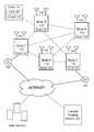
- FIG. 1illustrates a schematic representation of a system 100 for networking and routing communications in accordance with embodiments of the present application
- FIG. 2illustrates a general process flow of a method 200 for networking and routing in accordance with embodiments of the present application
- FIG. 3illustrates a general process flow of a method 300 for optimizing communications routing in a network in accordance with embodiments of the present application
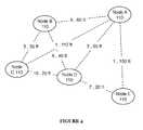
- FIG. 4illustrates a schematic representation of an optimized routing graph in accordance with embodiments of the present application.
- FIG. 5illustrates a general process flow of a method 500 for optimizing communications routing in a network in accordance with embodiments of the present application.
- the system 100includes a plurality of nodes 110 , a central routing server 120 , a plurality of routers 130 , a plurality of antennae 140 , and one or more Internet sources 150 .
- the system 100functions to enable wireless Internet communications between disparate homes (or nodes) using radio frequency-based communications.
- each of the plurality of nodes 110is a home, building, or other structure that is disparate and/or geographically remote from another structure forming one of the plurality of nodes 110 .
- each of the homes forming a nodemay not be geographically remote from another structure (e.g., townhomes, multi-family units, multi-tenant units, etc.), but still may be distinct in terms of the radio-based communication installed at the location of the structure.
- a group of the plurality of homesmay represent a group of townhomes that are generally connected to one another but each of the townhomes in the group may be owned or managed by a disparate entity and similarly, each townhome may maintain its own radio-based communication system.
- Each nodemay be geographically remote in terms of distance between each other.
- the nodesmay be spaced apart in the range of a few feet to possibly a few miles; however, in many instances, the nodes may be 5 feet to 300 feet away from each other, which is typically the distance of homes in a specific neighborhood.
- the plurality of nodes 110may represent all of the homes in a specific neighborhood, which are connected via the system 100 and forming a geographically defined mesh network or the like.
- the plurality of nodes 110may be a combination of different types of entities requiring Internet communications to be routed between them.
- the plurality of nodes 110may be include homes, buildings, vehicles, electronic devices, computing devices, and the like in a specific geographic region. This combination of devices may be connected via the system 100 to network and route Internet communications between them.
- the plurality of nodes 110preferably, form a mesh network with the ability to network with one or more neighboring nodes within the mesh to route or pass communications from an initiating node to a destination node and possibly, onward to a larger communication network (e.g., WAN, Internet, etc.).
- a larger communication networke.g., WAN, Internet, etc.
- the plurality of nodes 110are configured to communicate with each other wirelessly using radio frequency communications.
- the plurality of nodesmay implement a combination of communication schemes or systems to effectively communicate and/or route communication packets between them including any short-range communication system (e.g., Bluetooth) and/or long-range communication systems (e.g., long-range radio chips, Internet, etc.).
- any short-range communication systeme.g., Bluetooth
- long-range communication systemse.g., long-range radio chips, Internet, etc.
- the central routing server 120functions as a central authority for monitoring the network formed by a plurality of nodes 110 and for controlling the operation of each of the plurality of routers 130 and each of the plurality of antennae 140 at each of the plurality of nodes. Additionally, or alternatively, the central routing server 120 may be hosted on a cloud-based system or distributed computing system. Additionally, or alternatively, the central routing server 120 may include several servers operably connected with each other and operably connected to the network formed by the plurality of nodes 110 .
- the central routing server 120is geographically remote from the plurality of nodes 110 ; however, there may be one or more centrally controlled servers at or near one or more of the plurality of nodes 110 and usually, near or at an Internet source 150 for purposes of encrypting and decrypting data being transmitted between each of the plurality of nodes.
- the central routing server 120also functions to collect data from each of the plurality of nodes 110 .
- the central routing server 120may be in operable communication with each of the plurality of routers 130 and each of the plurality of antennae 140 .
- the plurality of routers 130 and antennae 140may periodically record data and/generate data which the routers 130 and the antennae 140 transmit (e.g., via the Internet or the like) back to the central routing server 120 .
- the recorded and/or generated datamay include any data regarding an attribute of the communications being transmitted between the plurality of nodes 110 and, may include, but is not limited to, data regarding operational attributes of each of the nodes (e.g., operations of each router and/or set of antennae at a node), and/or data relating to operational attributes of radio communication links between pairs of linked nodes.
- the central routing server 120may use the communications and operational data collected from the routers 130 and/or antennae 140 to determine routing paths for current and/or future communications. Specifically, the central routing server 120 may generate one or more communications routing tables that include communications routing paths specific to each node of the plurality of nodes 100 that indicates the specific radio links or chain of links that a communication originating at a source node or Internet source will travel to arrive at its destination.
- the routing table generated by the central routing server 120may provide that a communication initiated from node A travels the path A to C to E to Internet source and that a communication initiated at node D travels the path D to A to E to Internet source.
- the routing tabledefines a communications routing path for each of the nodes for transmitting a communication initiating from a specific node to the Internet source and vice versa (e.g., from the Internet source to a specific node) and/or between a source node and a destination node of the mesh radio network.
- the routing tables generated by the central routing server 120may be updated periodically (e.g., every few [2-10 ms] milliseconds to every 10 minutes or so).
- the routing tablesmay be updated as frequently as new data is collected from the nodes, such that a significant data update from the nodes may trigger the central routing server 120 to automatically update the routing tables and transmit the updated routing tables to the nodes, especially when it is recognized by the central routing server 120 that one or more nodes may not be operational or functioning properly or the like (e.g., a node is down).
- a communications routing tablemay be generated and/or updated based on a detection of a new radio node coming online within the mesh radio network of radio nodes and pushed through the mesh radio network by the central routing server 120 or the like.
- the central routing server 120may receive a signal from the new radio and/or a neighboring radio indicating that the new radio is active and seeking a communications routing table and/or seeking establishment as an active radio node for routing communications within the mesh radio network.
- the central routing server 120may function to identifying patenting routing paths involving the new radio including optimal routing paths and optimal radio links involving the new radio node and additionally, generate a new communications routing table that includes communication paths with the new radio node.
- the central routing server 120may transmit the generated routing tables to one or more nodes in a networked set of nodes.
- the nodes receiving the routing tablesmay then propagate the routing tables to each of its neighboring nodes until all or nearly all of the nodes in the networked set of nodes has the most up-to-date routing tables (i.e., a routing table having latest timestamp data).
- the one or more nodes receiving the up-to-date routing tablesmay function to selectively propagate the routing tables to optimally positioned nodes within the mesh radio network that enables the most efficient dissemination of the up-to-date routing tables.
- the one or more optimally positioned nodesmay be identified by the central routing server based on one or more of identifying nodes with connections to a number of nodes exceeding a connection threshold and identifying nodes with communication performance satisfying a performance threshold.
- the central routing server 120may function to augment the routing able with data regarding the identified one or more optimal nodes within the mesh radio network.
- each of the nodes in the networked set of nodesmay continually or periodically ping neighboring nodes to determine whether there are new routing tables available and, in that way, the routing tables may be pulled through the system by the requesting nodes rather than pushed through the system by the receiving nodes or the central routing server.
- the central routing server 120monitors each of the radio links between connected nodes in a networked set of nodes. Specifically, the central routing server 120 may use the data collected from each of the nodes via the routers 130 and antennae 140 to identify attributes of the radio links between connected nodes. For instance, the central routing server 120 is able to monitor and/or identify a signal strength of a radio link, the utilization of a radio link, the capacity of a radio link, the bandwidth of a radio link, the throughput of a radio link, disconnectivity of a radio link, and the like. Based on the monitoring information, the central routing server 120 is able to determine routing instructions and routing tables.
- the central routing server 120may generate a new routing table that avoids making the malfunctioning node a transmitting node (e.g., an intermediary node transmitting communications between an initiating node and a destination node). Additionally, or alternatively, based on the collected radio link data from the identified radio links within the mesh radio network, the central routing server may function to generate and assign performance grades to each of the radio links within the mesh radio network.
- a transmitting nodee.g., an intermediary node transmitting communications between an initiating node and a destination node.
- the plurality of routers 130preferably includes a combination of an internal structure communications router (e.g., Wi-Fi router, transmitter, and receiver, etc.) 131 and a computer 132 .
- the communications router 131is preferably connected to one or more user devices or other routers within a node and functions to route communications between each of the user devices and/or routers and the Internet.
- the computer 132functions to operate communications processing and resident routing software, that when executed by the computer 132 , allows the computer 132 to encrypt out-going communications initiated from the node and decrypt incoming communications received by the node.
- the computer 132functions to generate operational data that is communicated to the central routing server 120 . Additionally, the computer 132 functions to execute all routing functionality for a specific node including identifying and/or requesting new routing tables and the like.
- Each node of the plurality of nodes 110preferably includes a plurality of antennae 140 that may be positioned at an external location of the node. For instance, if the node is a home, the antennae 140 are positioned external to an interior of the home and preferably, are positioned on the home or at a position adjacent or immediately next to the home.
- the antennae 140 at each nodemay include one or more antennae (e.g., 1-4 or 1-n antennae) that may be positioned in various directions to establish multiple connections with one or more antennae of disparate nodes.
- Each of the antennae at a specific nodemay be used to establish active and potential links with other antennae of neighboring nodes.
- An active link between antennae of two disparate nodesmay representative a communications link determined by a routing table generated by the central routing server 120 .
- a potential link between antennae of two disparate nodesmay represent communication links that are not currently in use but may become active links depending on a new routing table.
- the Internet sources 150include media, such as fiber optic cables that are generally fixed in position relatively to a networked set of nodes. Additionally, or alternatively, the Internet sources 150 may include a wireless link (e.g., gigabit+ wireless link) to a datacenter or other intermediary for a backhaul (backbone) connection to the Internet.
- the Internet sources 150may include a plurality of Internet access points positioned proximate to one or more nodes of the networked set of nodes. Each of the plurality of Internet access points may be hardwire connected to the one or more nodes within the mesh radio network.
- each of the Internet access pointsmay be one or more centrally-controlled servers or computers that are able to decrypt communications and/or data received from a node prior to sending the communications through the fiber optic cables to an Internet server. Additionally, the one or more centrally controlled servers or computers may encrypt communications and/or data from the Internet server prior to forwarding the communication to a destination node. In this way, requests and data communications from a node in a networked set of nodes is kept secure and private from other nodes (e.g., transmitting nodes) in the networked set of nodes.
- the method 100includes receiving a request at a user device S 210 , processing the request S 220 , routing the request to an Internet source S 230 , optionally, processing the request at a computing server at the Internet source S 232 , routing a response from an Internet server to the user device S 240 , optionally, processing the response at a server at the Internet source S 242 .
- a user using a wireless networkmay initiate a request using a user device (e.g., any computing device or the like).
- the request initiated by the usergenerally includes an identification of a web page, Internet service, Internet information, or Internet application that the user would like to have access or otherwise, create an ongoing TCP connection with, and the like.
- the identification of the request by the usermay also be used to identify a starting point for calculating latency in processing the request.
- the calculated latencymay be used by a system implementing the method 100 as a measurable metric for improving the response time to a request and generally, the overall performance of the system 100 .
- the requestmay be received at a routing agent (e.g., firmware or the like) operating on a routing computer at the requesting node.
- the routing agentmay first determine a destination of the request (e.g., a destination Internet server) to determine a routing path for the request. Subsequently, the routing agent may check an associated database or an associated memory for a routing table that identifies one or more routing path for requests originating from the requesting node. Depending on when the routing table was updated last, the routing agent may function to use a routing path identified for the node associated with the request or attempt to determine whether there is an updated or new routing table or routing solution available to be used for routing the request to its Internet destination.
- the routing agentmay ping or make a request to each of its direct (e.g., direct radio connection, a single radio link connection, etc.) or its indirect (e.g., indirect radio connection, multiple radio link connections, etc.) neighboring nodes. Additionally, or alternatively, pinging the network of nodes may be performed continuously or near continuously by a routing agent or other node controller and data from each of the nodes may be uploaded to the central routing server in response to the pinging.
- directe.g., direct radio connection, a single radio link connection, etc.
- indirecte.g., indirect radio connection, multiple radio link connections, etc.
- the central routing servermay be able to ingest the uploaded data to determine whether updates to the routing table may be required, update the routing table based on the uploaded information, and push down an updated routing table to the nodes, which in turn is received by routing agents at the nodes.
- the routing table request by the routing agentmay include an indication of a date and/or time (timestamp) of the most recent routing table accessible to the routing agent that was received from a neighboring node or generated by a central routing server.
- the linked or neighboring nodesmay either return an updated routing table or may indicate that there has been no newly updated routing table since the routing table currently accessible to the routing agent.
- the routing agentmay proceed to encrypt data associated with the request and transmit the encrypted request data to a first relay node in the identified routing path. However, if the subject node has a direct path to an Internet source, the routing agent would proceed to transmit the encrypted request data directly to the Internet source S 230 . Additionally, or alternatively, the routing agent may transmit along with the encrypted request data the current routing table and/or a selected routing path for the encrypted requested data. In this way, the next or relaying node can quickly reference the routing table sent with the encrypted request data rather without having to reference a separate memory unit or the like associated with the relay node that stores the routing table.
- the encrypted request data from the initiating nodeis received and processed at the routing agent at each of the relay nodes.
- each of the relaying nodes along the identified routing path for the encrypted request datamay check the routing table sent along with the transmission to identify the next destination node for the encrypted request data package.
- the routing agent at the relaying nodemay also check for any newly available routing tables different from the routing table received with the encrypted request data.
- the routing agent at the relay nodeis able to determine whether a faster route for the encrypted request data has been generated and/or whether any nodes within the original routing path of the encrypted request data have gone offline or malfunctioning such that the nodes are unable to receive or transmit the encrypted data request via the offline and/or malfunctioning node.
- the encrypted request datais decrypted prior to forwarding the request data to the destination Internet server S 232 .
- a response to the requestis received at the Internet source from the destination Internet server. Additionally, or alternatively, at the Internet source, data associated with the response is encrypted prior to transmitting the response to the initiating node that generated the request S 242 . Accordingly, after encrypting the response data, the encrypted response data is transmitted via the reverse routing path of the request data. That is, from the Internet source, the encrypted response data is transmitted via the same nodes, albeit in reverse order, through which the request from the initiating node was transmitted.
- the local routing serveris able to dynamically change the reverse routing path of the encrypted response data to a new routing path back to the initiating node. If the routing table includes a new routing path for the originating node, the routing server would simply reverse the routing path to determine a new reverse routing path for transmitting the encrypted response data back to the initiating node.
- the method 300includes identifying operational attributes of each radio link in a mesh network formed by the plurality of nodes S 310 , generating a normalized routing score for each radio link S 320 , optionally, generating a scored routing graph S 330 , computing optimal routing for each node to the Internet source S 340 .
- the method 300functions to identify one or more optimal routes for routing Internet communications from each node in a mesh network of nodes to an Internet source.
- measurable attributes of each radio link between nodesmay be collected and analyzed, preferably by a central routing server, based on data provided by each of the respective routing agents operating at the respective nodes. Additionally, measurable attributes of the radio links between nodes may be determined by performing one or more tests on the radio links and, based observations of the radio links by a central routing server or the like.
- the central routing serverin a passive observation mode (e.g., a first mode), is able to continually monitor each of the radio links to determine one or more operational attributes (or factors) of the radio links based on usage of the radio links by nodes within a mesh node network.
- the central routing servermay be able to determine attributes, such as a maximum observed bandwidth at each of the radio links, an average maximum bandwidth (based on trailing data), an average latency of communications requests, and the like. Based on these passive observations, the central routing server may provide a weight to each of these passively observed values and calculate a normalized routing score for each radio link.
- S 310may function to apply a first weight to a maximum observed bandwidth value at a radio link, a second weight to an average maximum bandwidth at a radio link, and a third weight to an average latency value at a radio link.
- the normalized routing score for a given radio linkmay be a weighted average value or a weighted summed value of the attributes or factors of a given radio link.
- the central routing servermay implement an active monitoring and measurement process (i.e., an active observation mode) (e.g., a second mode) that involves actively providing loads to the radio links to determine maximum bandwidths, variability, signal strengths, and stability of the radio links, sending test requests from each of the nodes to determine latency from each node to an Internet source, and the like.
- an active monitoring and measurement processi.e., an active observation mode
- a second modee.g., a second mode
- the central routing servermay be able to approximate the total link capacity of a radio link based on a radio link's signal-to-noise ratio.
- a radio link's signal-to-noise ratiocan be used by radios to select an encoding rate and the combination of encoding rate and signal-to-noise ratio can be used by the central routing server to estimate a radio links total capacity; however, this estimation by the central routing server may not take into account varying interference.
- the central routing servermay set various radio frequencies and bandwidths at the nodes, measure a resulting performance of the nodes over one or more periods of time, and utilize the measurement data to determine an optimal frequency and/or bandwidth for each communication link. Additionally, or alternatively, the central routing server may be able to determine an optimal frequency/bandwidth for the entire system of nodes (e.g., specific mesh or family of nodes) rather than only for individual links between the nodes.
- the central routing servermay rank the importance of each of the measured and/or observed attributes of the radio links. For example, in some embodiments, the central routing server may rank total link capacity the highest, such that the total link capacity is weighted more heavily in determining a good radio link for transmitting data. In such example, the central routing server may determine that an average maximum utilized capacity and latency attributes of a radio link should have equal weight, but a lower weight than the total link capacity. Thus, a ranking may be established for several of the attributes of a radio link where the attributes having a greater weight are ranked higher than other attributes with lower weights.
- the observed and/or measured values in the active mode and passive modesmay be used to determine a routing score for each of the radio links.
- each radio link between each of pair of nodesis assigned a routing score where the routing score represents a level of capability (performance) of the radio link to route communications.
- the routing scoremay be based on a scale of 1-10 and the higher the routing score value assigned to a radio link indicates that the associated radio link has a better capability to transmit communications. In such instance, the lower the score on the scale for a radio link, the lesser the capability for the associated radio link to transmit communications.
- the above scaleis only an example of values that can be used for assigning a routing score to a radio link. Any type of values including letter values (e.g., letter grading), numeric values, word values, and the like may be assigned to a radio link to describe a quality or performance of communications transmission of an associated radio link.
- each of the radio linksmay be ranked based on the routing score assigned to each radio link. Thus, radio links having high routing scores may be higher on a ranking list than radio links having low routing scores.
- the ranking of the radio linksmay be used in routing path determinations and the like.
- S 320may function to assign differentiated performance designations to each node within a mesh radio network based on the observed and/or measured values of the mesh radio network.
- S 320may function to identify or label one or more nodes within the mesh radio network having a high performance relative to other nodes within the mesh network (i.e., whitelist).
- a whitelisted nodemay be a node satisfying a whitelist threshold (e.g., a performance score of 90 or better on a scale of 0-100, grade A site on a scale of A-F, etc.).
- S 320may function to greylist one or more nodes within the mesh radio network having low to moderate performance that fails to satisfy a whitelist threshold and that does not fall below a blacklist threshold. While greylisted nodes may still be available in a scored routing graph and/or considered in a computation of a routing table, a greylisted node may be ranked below nodes having a higher performance designation (e.g., whitelisted nodes). Additionally, or alternatively, S 320 may function to identify or label one or more nodes as blacklisted that have a measured or calculated performance below a blacklist threshold. Preferably, blacklisted nodes may be removed (from the scored routing graph) or otherwise eliminated from considering when computing a routing table.
- each radio linkmay be assigned a distance value corresponding to a physical distance between a pair of nodes forming a link.
- the distance valuemay be a measured and/or an approximate physical distance between the nodes and/or the distances between the external antennae of a pair of nodes having a radio link between them. In this way, the distance between two nodes can also be used as a factor in determining optimal routing paths (e.g., shortest routing paths or the like) between a requesting node and a destination node or Internet source.
- a scored routing graphmay be generated which illustrates each of the active and potential links in the mesh network and the routing score assigned to each radio link and/or the distance value assigned to each radio link.
- a single nodemay have varying routing scores associated therewith depending on another node forming a radio link with that single node.
- the scored routing tablemay be dynamically updated by a system implementing the method 300 based on one or more of a detection of a communications routing request from one or more nodes within a mesh radio network, a detection of a communications routing slowdown within the mesh radio network, a detection of a failing or failed node, and the like. Additionally, or alternatively, the scored routing table may be updated on a predetermined schedule (e.g., periodically or continuously at predetermined dates and/or times).
- optimal routing paths for each node in a mesh network of nodesmay be determined.
- the data associated with the scored routing graph, such as the routing scores for each radio linkmay be used as input into a maximum/minimum algorithm or the like (or a shortest-path algorithm where the shortest path algorithm identifies shorter paths as those radio links having higher routing scores).
- the maximum/minimum algorithmpreferably relates to a method for identifying an optimal routing path based on optimizing for maximum available bandwidth along a routing path and optimizing for a minimum total distance from a source of a communication to a destination. Accordingly, the maximum/minimum algorithm functions to balance a need for routing communications through optimally performing (e.g., high available bandwidth, etc.) while minimizing a total distance that communications must travel within a mesh network.
- S 340may function to assign weighting values to each of the maximum and minimum factors of the maximum/minimum algorithm thereby differentiating an importance of the maximum available bandwidth factor and the minimal total distance factor.
- the distance values, alone, between nodesmay be used as input into a shortest-path algorithm to determine routing paths for each node.
- the routing path from a subject node to an Internet source having the lowest additive routing distance valuesmay be identified as a routing path for the subject node.
- a routing pathmay be determined based on a combination of the routing scores assigned to each radio link as well as the distance values assigned to each radio link.
- a combination routing score and distance value routing pathmay be determined for each radio link.
- the routing scores and distance valuesmay be weighted different in the combination, such that the routing score or the distance values have greater weight in the combination routing score and distance value routing path.
- a communications routing table and/or one or more communications routing pathsmay be generated based on one or more simulations of a plurality of communication requests through one or more optimal routing paths within the mesh radio network.
- a system implementing the method 300may function to simulate one or more communication data loads to an optimal communication routing path.
- the one or more communication data loadsmay be based on a projected load of each of the multiple communication routing requests.
- S 340may function to generate a new routing table and/or new communications routing paths for splitting or dispersing the load among multiple communications routing path.
- S 340functions to disperse the multiple communication routing request among, at least, the optimal communications routing path and a sub-optimal communications routing path.
- a technical benefit achieved by the dispersionincludes achieving a combined throughput of the communications routing requests through the combined optimal and sub-optimal routing paths that is greater than the throughput of routing the multiple requests through only the optimal communications routing path.
- the method 400functions to determine communication routing paths and/or optimize communications among a plurality of nodes behaving as a mesh network based on identifying a fastest-time path for routing communications from each of the nodes.
- the method 400employs a software-defined network routing technique from a central governing authority (e.g., a central server).
- a central governing authoritye.g., a central server
- the method 400includes identifying available links between pairs of nodes in a network of nodes S 410 , measuring performance metrics of each link S 420 , ranking each of the available links based on the measured performance metrics S 430 , formulating a fastest routing path for each node in the network of nodes S 440 , generating a routing table based on the fastest routing path for each node in the network of nodes S 450 .
- S 410which includes identifying available links between pairs of nodes in a network of nodes, functions to identify all prospective links between any two nodes in a defined network of nodes (e.g., a defined mesh network or network constrained by a geographic region or encircling). Thus, for each node in a defined network, S 410 functions to identify a target node and every possible link between the target node and another node in the defined network. For instance, in a small network including only four nodes (e.g., A, B, C, and D), each node will have three possible link (e.g., A-B, A-C, and A-D). In such example, S 410 would identify that the small network includes twelve (12) total possible links and specifically, identify each link.
- a defined network of nodese.g., a defined mesh network or network constrained by a geographic region or encircling.
- S 410functions to identify a target node and every possible link between the target node and another node in the defined
- S 420which measuring performance metric of each link, functions to preferably measure attributes of a radio link related speed at which the links transfers data.
- S 420functions to measure the bandwidth for each radio link identified in S 410 , and especially, measure the throughput for each radio link.
- S 420may additionally may other attributes of the radio links, such as latency, jitter, error rate, and similar metric indicating radio link performance. Additionally, S 420 may store these measured performance values in a historical performance metrics database.
- S 420may ignore and/or skip that radio link.
- S 430which includes ranking each of the radio links, functions to rank each of the radio links based on bandwidth and/or throughput. Specifically, S 430 may generate a ranking table or list of all of the available radio links in the defined network based on the measured throughput and/or bandwidth. For instance, each radio link may be ranked from highest throughput to slowest throughput, with the radio links having the highest throughput being at a top of the throughput ranking list. As another example, each radio link may be ranked highest bandwidth to slowest bandwidth, with the radio links having the highest bandwidth being at a top of the bandwidth ranking list. In some embodiments, S 430 may calculate a combined ranking list that takes into account bandwidth and throughput metrics for each link.
- S 430may allocate a heavier weight for the throughput metrics for each radio link as compared to the weight for bandwidth since the throughput metric is a better metric for determining the actual rate that information is transferred. So, for example, a combined ranking list may weight throughput at 60% and bandwidth at 40%, where only 605 of the throughput value for a radio link is added to 40% of the bandwidth rate for a radio link. The combined ranking list would, thus, rank from fastest combined bit speed to lowest bit speed.
- S 440which includes formulating the fastest routing path for each node in a defined network, functions to string together a chain of the fastest radio links for each node to an Internet source. For each node, S 440 may generate multiple proposed fastest routing and once generated, S 440 may compare each of the proposed fastest routing paths to identify the single fastest routing path (e.g., a path taking the shortest time from the node to destination of a communication from the node) for a subject node.
- the single fastest routing pathe.g., a path taking the shortest time from the node to destination of a communication from the node
- S 440may include fast-filtering poor performing radio links from the radio links that may be considered in the formulation of a proposed fastest route path for a node.
- fast-filtering the radio linksmay include setting a performance threshold for route segments or an overall routing path, possibly based on bit rates, and comparing all links available for a possible route segment to the performance threshold.
- any radio link that does not satisfy, exceeds, or falls below the thresholdare immediately filtered from a database or list of radio links that can be considered for a proposed fastest route path. Accordingly, fast-filtering the radio links reduces the amount of processing and time required for generating a fastest route path for a subject node.
- S 440may determine a fastest routing path to route communications from an initiating node to a destination by successively finding a fastest link between pairs of nodes starting from the initiating node through to the destination. While, in some case, this may yield a chain of links, where each link is the fastest available link, the overall time that it takes to transport a communication from the initiating node to the destination may be higher than in which a routing path is optimized to limit the overall time to a smallest value that is required to transport a communication from a node to a destination (e.g., fastest-time path).
- S 450which includes generating a routing table based on the identified fastest routing path for each node in the network of nodes, functions to create a data structure that encapsulates each of the determined fastest routing paths for the nodes.
- S 450may generate the routing table, store a copy of the routing table, and also, transmit or push a copy of the routing table to one or more nodes in the network of nodes.
- the nodesmay actively assist in propagating the routing table to other nodes in the network or passively wait until a neighboring node requests an updated routing table.
- the system and methods of the preferred embodiment and variations thereofcan be embodied and/or implemented at least in part as a machine configured to receive a computer-readable medium storing computer-readable instructions.
- the instructionsare preferably executed by computer-executable components preferably integrated with the system 100 and one or more portions of the computer processors and/or the controllers.
- the computer-readable mediumcan be stored on any suitable computer-readable media such as RAMs, ROMs, flash memory, EEPROMs, optical devices (CD or DVD), hard drives, floppy drives, or any suitable device.
- the computer-executable componentis preferably a general or application specific processor, but any suitable dedicated hardware or hardware/firmware combination device can alternatively or additionally execute the instructions.
- the preferred embodimentsinclude every combination and permutation of the various nodes, routing algorithms (e.g., shortest path, fastest-time path, etc.), and the like.
Landscapes
- Engineering & Computer Science (AREA)
- Computer Networks & Wireless Communication (AREA)
- Signal Processing (AREA)
- Quality & Reliability (AREA)
- Mobile Radio Communication Systems (AREA)
- Data Exchanges In Wide-Area Networks (AREA)
Abstract
Description
Claims (20)
Priority Applications (2)
| Application Number | Priority Date | Filing Date | Title |
|---|---|---|---|
| US15/937,707US10172020B2 (en) | 2017-04-06 | 2018-03-27 | Systems and methods for networking and wirelessly routing communications |
| US16/199,917US10959112B2 (en) | 2017-04-06 | 2018-11-26 | Systems and methods for networking and wirelessly routing communications |
Applications Claiming Priority (3)
| Application Number | Priority Date | Filing Date | Title |
|---|---|---|---|
| US201762482400P | 2017-04-06 | 2017-04-06 | |
| US201862616628P | 2018-01-12 | 2018-01-12 | |
| US15/937,707US10172020B2 (en) | 2017-04-06 | 2018-03-27 | Systems and methods for networking and wirelessly routing communications |
Related Child Applications (1)
| Application Number | Title | Priority Date | Filing Date |
|---|---|---|---|
| US16/199,917ContinuationUS10959112B2 (en) | 2017-04-06 | 2018-11-26 | Systems and methods for networking and wirelessly routing communications |
Publications (2)
| Publication Number | Publication Date |
|---|---|
| US20180295529A1 US20180295529A1 (en) | 2018-10-11 |
| US10172020B2true US10172020B2 (en) | 2019-01-01 |
Family
ID=63711461
Family Applications (2)
| Application Number | Title | Priority Date | Filing Date |
|---|---|---|---|
| US15/937,707ActiveUS10172020B2 (en) | 2017-04-06 | 2018-03-27 | Systems and methods for networking and wirelessly routing communications |
| US16/199,917ActiveUS10959112B2 (en) | 2017-04-06 | 2018-11-26 | Systems and methods for networking and wirelessly routing communications |
Family Applications After (1)
| Application Number | Title | Priority Date | Filing Date |
|---|---|---|---|
| US16/199,917ActiveUS10959112B2 (en) | 2017-04-06 | 2018-11-26 | Systems and methods for networking and wirelessly routing communications |
Country Status (2)
| Country | Link |
|---|---|
| US (2) | US10172020B2 (en) |
| WO (1) | WO2018187094A1 (en) |
Families Citing this family (65)
| Publication number | Priority date | Publication date | Assignee | Title |
|---|---|---|---|---|
| US10749711B2 (en) | 2013-07-10 | 2020-08-18 | Nicira, Inc. | Network-link method useful for a last-mile connectivity in an edge-gateway multipath system |
| US10454714B2 (en) | 2013-07-10 | 2019-10-22 | Nicira, Inc. | Method and system of overlay flow control |
| US10425382B2 (en) | 2015-04-13 | 2019-09-24 | Nicira, Inc. | Method and system of a cloud-based multipath routing protocol |
| US10135789B2 (en) | 2015-04-13 | 2018-11-20 | Nicira, Inc. | Method and system of establishing a virtual private network in a cloud service for branch networking |
| US10498652B2 (en) | 2015-04-13 | 2019-12-03 | Nicira, Inc. | Method and system of application-aware routing with crowdsourcing |
| US20200036624A1 (en) | 2017-01-31 | 2020-01-30 | The Mode Group | High performance software-defined core network |
| US20180219765A1 (en) | 2017-01-31 | 2018-08-02 | Waltz Networks | Method and Apparatus for Network Traffic Control Optimization |
| US10992558B1 (en) | 2017-11-06 | 2021-04-27 | Vmware, Inc. | Method and apparatus for distributed data network traffic optimization |
| US11121962B2 (en) | 2017-01-31 | 2021-09-14 | Vmware, Inc. | High performance software-defined core network |
| US11252079B2 (en) | 2017-01-31 | 2022-02-15 | Vmware, Inc. | High performance software-defined core network |
| US11706127B2 (en) | 2017-01-31 | 2023-07-18 | Vmware, Inc. | High performance software-defined core network |
| US10992568B2 (en) | 2017-01-31 | 2021-04-27 | Vmware, Inc. | High performance software-defined core network |
| US10574528B2 (en) | 2017-02-11 | 2020-02-25 | Nicira, Inc. | Network multi-source inbound quality of service methods and systems |
| US10778528B2 (en) | 2017-02-11 | 2020-09-15 | Nicira, Inc. | Method and system of connecting to a multipath hub in a cluster |
| US10348610B2 (en)* | 2017-05-25 | 2019-07-09 | Alcatel Lucent | Method and apparatus for minimum label bandwidth guaranteed path for segment routing |
| US10523539B2 (en) | 2017-06-22 | 2019-12-31 | Nicira, Inc. | Method and system of resiliency in cloud-delivered SD-WAN |
| US10999165B2 (en) | 2017-10-02 | 2021-05-04 | Vmware, Inc. | Three tiers of SaaS providers for deploying compute and network infrastructure in the public cloud |
| US10999100B2 (en) | 2017-10-02 | 2021-05-04 | Vmware, Inc. | Identifying multiple nodes in a virtual network defined over a set of public clouds to connect to an external SAAS provider |
| US10959098B2 (en) | 2017-10-02 | 2021-03-23 | Vmware, Inc. | Dynamically specifying multiple public cloud edge nodes to connect to an external multi-computer node |
| US10841131B2 (en) | 2017-10-02 | 2020-11-17 | Vmware, Inc. | Distributed WAN security gateway |
| US11089111B2 (en) | 2017-10-02 | 2021-08-10 | Vmware, Inc. | Layer four optimization for a virtual network defined over public cloud |
| US11115480B2 (en) | 2017-10-02 | 2021-09-07 | Vmware, Inc. | Layer four optimization for a virtual network defined over public cloud |
| US11223514B2 (en) | 2017-11-09 | 2022-01-11 | Nicira, Inc. | Method and system of a dynamic high-availability mode based on current wide area network connectivity |
| US10470052B2 (en)* | 2017-11-13 | 2019-11-05 | Common Networks, Inc. | Systems and methods for configuring radio communication devices |
| US11076306B2 (en) | 2018-09-21 | 2021-07-27 | Qualcomm Incorporated | Relay nodes with multi-connected cellular backhaul |
| CN112291725B (en)* | 2019-07-22 | 2021-11-09 | 华为技术有限公司 | Communication method and device |
| CN110581778A (en)* | 2019-08-13 | 2019-12-17 | 中兴通讯股份有限公司 | A routing method, BSR generation method, device and storage medium |
| US11171885B2 (en) | 2019-08-27 | 2021-11-09 | Vmware, Inc. | Providing recommendations for implementing virtual networks |
| US11611507B2 (en) | 2019-10-28 | 2023-03-21 | Vmware, Inc. | Managing forwarding elements at edge nodes connected to a virtual network |
| US11394640B2 (en) | 2019-12-12 | 2022-07-19 | Vmware, Inc. | Collecting and analyzing data regarding flows associated with DPI parameters |
| US11489783B2 (en) | 2019-12-12 | 2022-11-01 | Vmware, Inc. | Performing deep packet inspection in a software defined wide area network |
| US11418997B2 (en) | 2020-01-24 | 2022-08-16 | Vmware, Inc. | Using heart beats to monitor operational state of service classes of a QoS aware network link |
| US11245641B2 (en) | 2020-07-02 | 2022-02-08 | Vmware, Inc. | Methods and apparatus for application aware hub clustering techniques for a hyper scale SD-WAN |
| US11363124B2 (en) | 2020-07-30 | 2022-06-14 | Vmware, Inc. | Zero copy socket splicing |
| US12155547B2 (en)* | 2020-10-14 | 2024-11-26 | Kenneth D. Swinehart | System and method for monitoring network connectivity associated with internet service providers |
| US11444865B2 (en) | 2020-11-17 | 2022-09-13 | Vmware, Inc. | Autonomous distributed forwarding plane traceability based anomaly detection in application traffic for hyper-scale SD-WAN |
| US11575600B2 (en) | 2020-11-24 | 2023-02-07 | Vmware, Inc. | Tunnel-less SD-WAN |
| US11929903B2 (en) | 2020-12-29 | 2024-03-12 | VMware LLC | Emulating packet flows to assess network links for SD-WAN |
| US12218845B2 (en) | 2021-01-18 | 2025-02-04 | VMware LLC | Network-aware load balancing |
| CN116783874A (en) | 2021-01-18 | 2023-09-19 | Vm维尔股份有限公司 | Network aware load balancing |
| US11979325B2 (en) | 2021-01-28 | 2024-05-07 | VMware LLC | Dynamic SD-WAN hub cluster scaling with machine learning |
| US11252535B1 (en)* | 2021-02-08 | 2022-02-15 | Motorola Solutions, Inc. | Device, system and method for transmitting a response command to a radio using a visualization of locations of radios and communication links therebetween |
| US12368676B2 (en) | 2021-04-29 | 2025-07-22 | VMware LLC | Methods for micro-segmentation in SD-WAN for virtual networks |
| US11637768B2 (en) | 2021-05-03 | 2023-04-25 | Vmware, Inc. | On demand routing mesh for routing packets through SD-WAN edge forwarding nodes in an SD-WAN |
| US12009987B2 (en) | 2021-05-03 | 2024-06-11 | VMware LLC | Methods to support dynamic transit paths through hub clustering across branches in SD-WAN |
| US11729065B2 (en) | 2021-05-06 | 2023-08-15 | Vmware, Inc. | Methods for application defined virtual network service among multiple transport in SD-WAN |
| US12250114B2 (en) | 2021-06-18 | 2025-03-11 | VMware LLC | Method and apparatus for deploying tenant deployable elements across public clouds based on harvested performance metrics of sub-types of resource elements in the public clouds |
| US11489720B1 (en) | 2021-06-18 | 2022-11-01 | Vmware, Inc. | Method and apparatus to evaluate resource elements and public clouds for deploying tenant deployable elements based on harvested performance metrics |
| US12015536B2 (en) | 2021-06-18 | 2024-06-18 | VMware LLC | Method and apparatus for deploying tenant deployable elements across public clouds based on harvested performance metrics of types of resource elements in the public clouds |
| US12047282B2 (en) | 2021-07-22 | 2024-07-23 | VMware LLC | Methods for smart bandwidth aggregation based dynamic overlay selection among preferred exits in SD-WAN |
| US11375005B1 (en) | 2021-07-24 | 2022-06-28 | Vmware, Inc. | High availability solutions for a secure access service edge application |
| US12267364B2 (en) | 2021-07-24 | 2025-04-01 | VMware LLC | Network management services in a virtual network |
| US12355656B2 (en)* | 2021-09-24 | 2025-07-08 | Crius Technology Group, Inc. | Methods, systems, and apparatus for routing data in a self-healing network and for self-healing of a network |
| US11943146B2 (en) | 2021-10-01 | 2024-03-26 | VMware LLC | Traffic prioritization in SD-WAN |
| US12015542B2 (en)* | 2021-12-20 | 2024-06-18 | Bae Systems Information And Electronic Systems Integration Inc. | Enhancing route selection of optimized link state routing using a link probing tool |
| US12184557B2 (en) | 2022-01-04 | 2024-12-31 | VMware LLC | Explicit congestion notification in a virtual environment |
| US12425395B2 (en) | 2022-01-15 | 2025-09-23 | VMware LLC | Method and system of securely adding an edge device operating in a public network to an SD-WAN |
| US11909815B2 (en) | 2022-06-06 | 2024-02-20 | VMware LLC | Routing based on geolocation costs |
| US12166661B2 (en) | 2022-07-18 | 2024-12-10 | VMware LLC | DNS-based GSLB-aware SD-WAN for low latency SaaS applications |
| US12316524B2 (en) | 2022-07-20 | 2025-05-27 | VMware LLC | Modifying an SD-wan based on flow metrics |
| US12034587B1 (en) | 2023-03-27 | 2024-07-09 | VMware LLC | Identifying and remediating anomalies in a self-healing network |
| US12057993B1 (en) | 2023-03-27 | 2024-08-06 | VMware LLC | Identifying and remediating anomalies in a self-healing network |
| US12425332B2 (en) | 2023-03-27 | 2025-09-23 | VMware LLC | Remediating anomalies in a self-healing network |
| US12261777B2 (en) | 2023-08-16 | 2025-03-25 | VMware LLC | Forwarding packets in multi-regional large scale deployments with distributed gateways |
| US12355655B2 (en) | 2023-08-16 | 2025-07-08 | VMware LLC | Forwarding packets in multi-regional large scale deployments with distributed gateways |
Citations (14)
| Publication number | Priority date | Publication date | Assignee | Title |
|---|---|---|---|---|
| US5940372A (en) | 1995-07-13 | 1999-08-17 | International Business Machines Corporation | Method and system for selecting path according to reserved and not reserved connections in a high speed packet switching network |
| US6604146B1 (en) | 1999-06-15 | 2003-08-05 | Viasat, Inc. | Efficient internet service implementation for mesh satellite networks using centralized router server for distribution of destination tables |
| US20030156549A1 (en) | 2002-01-09 | 2003-08-21 | Robert Binder | Method and system for evaluating wireless applications |
| US20090285124A1 (en) | 2008-05-13 | 2009-11-19 | Nortel Networks Limited | Wireless mesh network transit link topology optimization method and system |
| US20120307663A1 (en) | 2003-05-14 | 2012-12-06 | Interdigital Technology Corporation | Method and apparatus for network management using periodic measurements of indicators |
| US20140160925A1 (en) | 2012-12-10 | 2014-06-12 | Verizon Patent And Licensing Inc. | Virtual private network to label switched path mapping |
| US20140185454A1 (en) | 2006-03-09 | 2014-07-03 | Firetide, Inc. | Effective Bandwidth Path Metric and Path Computation Method for Wireless Mesh Networks with Wired Links |
| CN102523162B (en) | 2011-12-15 | 2015-02-18 | 西安理工大学 | Ant colony-based QoS (Quality of Service) optimization routing method in ultraviolet wireless Mesh network |
| US20160134468A1 (en)* | 2014-11-07 | 2016-05-12 | Cisco Technology, Inc. | Optimizing inter-pan traffic |
| US20160142252A1 (en)* | 2014-11-19 | 2016-05-19 | Parallel Wireless, Inc. | HealthCheck Access Point |
| WO2016111837A1 (en) | 2015-01-07 | 2016-07-14 | Cisco Technology, Inc. | Selective routing of network traffic for remote inspection in computer networks |
| US20160252355A1 (en)* | 2015-02-27 | 2016-09-01 | Here Global B.V. | Generating routes using navigation meshes |
| US20160366096A1 (en)* | 2015-06-15 | 2016-12-15 | Tempered Networks, Inc. | Overlay network with position independent insertion and tap points |
| US20170142086A1 (en)* | 2015-11-17 | 2017-05-18 | Google Inc. | Wireless network access |
Family Cites Families (48)
| Publication number | Priority date | Publication date | Assignee | Title |
|---|---|---|---|---|
| US6973057B1 (en)* | 1999-01-29 | 2005-12-06 | Telefonaktiebolaget L M Ericsson (Publ) | Public mobile data communications network |
| US7008941B2 (en)* | 2001-05-16 | 2006-03-07 | Myriad Genetics, Inc. | Reverse-turn mimetics and methods relating thereto |
| US7106707B1 (en) | 2001-12-20 | 2006-09-12 | Meshnetworks, Inc. | System and method for performing code and frequency channel selection for combined CDMA/FDMA spread spectrum communication systems |
| US20030137970A1 (en) | 2002-01-22 | 2003-07-24 | Odman Knut T. | System and method for improved synchronization in a wireless network |
| US7350077B2 (en)* | 2002-11-26 | 2008-03-25 | Cisco Technology, Inc. | 802.11 using a compressed reassociation exchange to facilitate fast handoff |
| KR100970725B1 (en) | 2003-09-17 | 2010-07-16 | 삼성전자주식회사 | Frequency subband allocation method and management device |
| EP1699198A1 (en) | 2005-03-01 | 2006-09-06 | Alcatel | Distributing data on an OFDM time-frequency grid by gathering subcarriers in frequency diverse and frequency selective frequency patterns |
| US7602796B2 (en)* | 2005-03-04 | 2009-10-13 | Cisco Technology, Inc. | Method and apparatus for border gateway protocol route management and routing policy modeling |
| US7899027B2 (en) | 2005-03-23 | 2011-03-01 | Cisco Technology, Inc. | Automatic route configuration in hierarchical wireless mesh networks |
| FR2886792B1 (en) | 2005-06-07 | 2007-08-10 | Evolium Sas Soc Par Actions Si | COMMUNICATION NETWORK DIAGNOSTIC TOOL, OPERATING RESULTS OF REAL TESTS AND / OR VALIDATION BY CONTROL DISPLAY MODE |
| US7945658B1 (en) | 2005-12-05 | 2011-05-17 | Narus, Inc. | Method for real-time visualization of BGP analysis and trouble-shooting |
| US7522603B2 (en)* | 2006-03-14 | 2009-04-21 | Cisco Technology, Inc. | Technique for efficiently routing IP traffic on CE-CE paths across a provider network |
| US7948922B2 (en) | 2006-04-18 | 2011-05-24 | Cisco Technology, Inc. | Blocked redundant link-aware spanning tree protocol enhancement |
| WO2008011712A1 (en)* | 2006-07-28 | 2008-01-31 | Michael Tin Yau Chan | Wide-area wireless network topology |
| JP2010519833A (en) | 2007-02-27 | 2010-06-03 | アゼリア ネットワークス | Method and system for radio frequency management in mesh networks with path distance factor |
| KR101498968B1 (en) | 2007-07-05 | 2015-03-12 | 삼성전자주식회사 | Method and apparatus for resource determination for peer-to-peer communication in a communication system |
| US8737267B2 (en)* | 2008-01-30 | 2014-05-27 | Qualcomm Incorporated | Management of wireless relay nodes using routing table |
| US9363745B2 (en)* | 2008-03-26 | 2016-06-07 | Srinivasan Balasubramanian | Device managed access point lists in wireless communications |
| WO2009146132A2 (en) | 2008-04-04 | 2009-12-03 | Powerwave Cognition, Inc. | Methods and systems for a mobile, broadband, routable internet |
| US7961642B2 (en)* | 2008-05-29 | 2011-06-14 | International Business Machines Corporation | System and method for obtaining network link state information from sequential distance vector routing tables |
| US10015141B2 (en)* | 2009-11-25 | 2018-07-03 | International Business Machines Corporation | Dispersed data storage in a VPN group of devices |
| CN102792745B (en) | 2009-12-11 | 2015-05-13 | 诺基亚公司 | Method, device and computer program product for allocating resources in a wireless communication network |
| US8566653B2 (en)* | 2009-12-22 | 2013-10-22 | At&T Intellectual Property I, L.P. | Infrastructure for rapid service deployment |
| US20110225312A1 (en)* | 2010-03-10 | 2011-09-15 | Thomson Licensing | Unified cache and peer-to-peer method and apparatus for streaming media in wireless mesh networks |
| EP2550832B1 (en) | 2010-03-23 | 2017-07-19 | Nokia Solutions and Networks Oy | Resource allocation for direct terminal-to-terminal communication in a cellular system |
| CN102802161A (en) | 2011-05-27 | 2012-11-28 | 国际商业机器公司 | Method and equipment for reducing spectrum interferences among wireless networks |
| US9763272B2 (en) | 2012-02-27 | 2017-09-12 | Futurewei Technologies, Inc. | System and method for time resource allocation for device-to-device communication overlaid on a cellular network |
| US8942173B2 (en) | 2012-04-13 | 2015-01-27 | Intel Corporation | Interference notification in device-to-device communication |
| EP2665326B1 (en) | 2012-05-15 | 2017-12-13 | Telefonaktiebolaget LM Ericsson (publ) | Apparatus and method thereof for setting up device-to-device communication |
| RU2614527C2 (en)* | 2012-05-15 | 2017-03-28 | Телефонактиеболагет Л М Эрикссон (Пабл) | Interferences control for “from device to device” communication using network |
| US8971323B2 (en)* | 2012-06-15 | 2015-03-03 | Citrix Systems, Inc. | Systems and methods for dynamic routing in a cluster |
| US9170971B2 (en)* | 2012-12-26 | 2015-10-27 | Iii Holdings 2, Llc | Fabric discovery for a cluster of nodes |
| TW201511598A (en) | 2013-02-07 | 2015-03-16 | Interdigital Patent Holdings | Apparatus and method for mesh networks |
| EP2797267B1 (en)* | 2013-04-26 | 2016-07-27 | Airbus Defence and Space Limited | Routing data within a communications network |
| US20140355476A1 (en) | 2013-06-03 | 2014-12-04 | Glen J. Anderson | Systems and methods for mesh network deployment |
| CN104284341A (en) | 2013-07-09 | 2015-01-14 | 数码士控股有限公司 | Frequency management system and method in LTED2D communication |
| US9402213B2 (en) | 2014-07-31 | 2016-07-26 | Telekom Malaysia Berhad | Dynamic channel switching for wireless mesh networks |
| US9717067B2 (en)* | 2014-09-09 | 2017-07-25 | Vivint, Inc. | Location-based access point module control |
| US9634928B2 (en)* | 2014-09-29 | 2017-04-25 | Juniper Networks, Inc. | Mesh network of simple nodes with centralized control |
| KR101525978B1 (en) | 2014-10-06 | 2015-06-05 | 숭실대학교산학협력단 | Method of resource allocation based on interference awareness for device-to-device communication and apparatus thereof |
| US10007629B2 (en)* | 2015-01-16 | 2018-06-26 | Oracle International Corporation | Inter-processor bus link and switch chip failure recovery |
| WO2016134541A1 (en) | 2015-02-28 | 2016-09-01 | 华为技术有限公司 | Frequency point configuration method in a microwave network, control device and system |
| US9491764B1 (en) | 2015-06-03 | 2016-11-08 | Vivint, Inc. | Mesh network adjustment |
| DE102015110349B4 (en) | 2015-06-26 | 2020-11-26 | Apple Inc. | COMMUNICATION TERMINAL DEVICE AND METHOD FOR TREATMENT OF UPLOADING TRAFFIC CONGESTION |
| EP3121780A1 (en) | 2015-07-24 | 2017-01-25 | Dieter Fensel | Disseminating content to recipients using multiple distribution channels |
| BR102015032311B1 (en) | 2015-12-22 | 2023-10-17 | Robert Bosch Limitada | PROCESS OF DEPLOYING A MESH NETWORK AND NODE DEVICE OF A MESH NETWORK |
| SI3941106T1 (en)* | 2016-03-18 | 2023-10-30 | Plume Design, Inc. | Wi-Fi network control from the cloud |
| US10264590B2 (en) | 2016-08-31 | 2019-04-16 | Intel Corporation | Channel allocation among multiple radio frequency networks |
- 2018
- 2018-03-27USUS15/937,707patent/US10172020B2/enactiveActive
- 2018-03-27WOPCT/US2018/024656patent/WO2018187094A1/ennot_activeCeased
- 2018-11-26USUS16/199,917patent/US10959112B2/enactiveActive
Patent Citations (14)
| Publication number | Priority date | Publication date | Assignee | Title |
|---|---|---|---|---|
| US5940372A (en) | 1995-07-13 | 1999-08-17 | International Business Machines Corporation | Method and system for selecting path according to reserved and not reserved connections in a high speed packet switching network |
| US6604146B1 (en) | 1999-06-15 | 2003-08-05 | Viasat, Inc. | Efficient internet service implementation for mesh satellite networks using centralized router server for distribution of destination tables |
| US20030156549A1 (en) | 2002-01-09 | 2003-08-21 | Robert Binder | Method and system for evaluating wireless applications |
| US20120307663A1 (en) | 2003-05-14 | 2012-12-06 | Interdigital Technology Corporation | Method and apparatus for network management using periodic measurements of indicators |
| US20140185454A1 (en) | 2006-03-09 | 2014-07-03 | Firetide, Inc. | Effective Bandwidth Path Metric and Path Computation Method for Wireless Mesh Networks with Wired Links |
| US20090285124A1 (en) | 2008-05-13 | 2009-11-19 | Nortel Networks Limited | Wireless mesh network transit link topology optimization method and system |
| CN102523162B (en) | 2011-12-15 | 2015-02-18 | 西安理工大学 | Ant colony-based QoS (Quality of Service) optimization routing method in ultraviolet wireless Mesh network |
| US20140160925A1 (en) | 2012-12-10 | 2014-06-12 | Verizon Patent And Licensing Inc. | Virtual private network to label switched path mapping |
| US20160134468A1 (en)* | 2014-11-07 | 2016-05-12 | Cisco Technology, Inc. | Optimizing inter-pan traffic |
| US20160142252A1 (en)* | 2014-11-19 | 2016-05-19 | Parallel Wireless, Inc. | HealthCheck Access Point |
| WO2016111837A1 (en) | 2015-01-07 | 2016-07-14 | Cisco Technology, Inc. | Selective routing of network traffic for remote inspection in computer networks |
| US20160252355A1 (en)* | 2015-02-27 | 2016-09-01 | Here Global B.V. | Generating routes using navigation meshes |
| US20160366096A1 (en)* | 2015-06-15 | 2016-12-15 | Tempered Networks, Inc. | Overlay network with position independent insertion and tap points |
| US20170142086A1 (en)* | 2015-11-17 | 2017-05-18 | Google Inc. | Wireless network access |
Non-Patent Citations (1)
| Title |
|---|
| International Search Report and Written Opinion for International Application No. PCT/US18/24656 dated Jun. 25, 2018. |
Also Published As
| Publication number | Publication date |
|---|---|
| US10959112B2 (en) | 2021-03-23 |
| US20180295529A1 (en) | 2018-10-11 |
| WO2018187094A1 (en) | 2018-10-11 |
| US20190098517A1 (en) | 2019-03-28 |
Similar Documents
| Publication | Publication Date | Title |
|---|---|---|
| US10959112B2 (en) | Systems and methods for networking and wirelessly routing communications | |
| US10673763B2 (en) | Learning or emulation approach to traffic engineering in information-centric networks | |
| AU2017210584B2 (en) | A framework for traffic engineering in software defined networking | |
| CN107810619B (en) | System and method for inferring network topology and path metrics in wide area networks | |
| US9602406B2 (en) | Data transfer control device and data transfer control method | |
| CN103404219B (en) | For the method and apparatus dispatching equity traffic in cellular networks | |
| US8477601B2 (en) | Network management station, network control system, and network management method | |
| CN102112981A (en) | Distribution of virtual machines in a communication network | |
| Gelenbe et al. | Cognitive packet network for bilateral asymmetric connections | |
| US12231553B2 (en) | Key management device, quantum cryptography communication system, and computer program product | |
| Gopal et al. | Selfish node detection based on evidence by trust authority and selfish replica allocation in DANET | |
| CN112292835B (en) | A heuristic approach for end-to-end digital communications performance measurements | |
| Isravel et al. | Centrality based congestion detection using reinforcement learning approach for traffic engineering in hybrid SDN | |
| CN117979388B (en) | Ad hoc network video communication method and system | |
| JP5212503B2 (en) | COMMUNICATION CONTROL DEVICE, COMMUNICATION CONTROL METHOD, AND COMMUNICATION CONTROL PROGRAM | |
| WO2013046798A1 (en) | Ad-hoc network communication terminal, method for controlling ad-hoc network communication terminal, and ad-hoc network communication system | |
| JP2015154168A (en) | Route control system, route control device, and route control method | |
| Luo et al. | On the throughput and delay in ad hoc networks with human mobility | |
| JP6206105B2 (en) | Communication system, communication method, and communication program | |
| CN117938273A (en) | Communication method, device, equipment, medium and product under quantum network architecture | |
| Janani et al. | Optimizing QoS‐Based Communication Protocol in Wireless Sensor Networks Using Genetic Algorithms With AI/ML Mechanisms for IoT Environment | |
| CN120128540A (en) | Load balancing method, device and equipment for SRv6 network VPN service | |
| Bjurefors | Measurements in opportunistic networks | |
| CN119276772A (en) | Content distribution network routing planning method, device, equipment, medium and product |
Legal Events
| Date | Code | Title | Description |
|---|---|---|---|
| FEPP | Fee payment procedure | Free format text:ENTITY STATUS SET TO UNDISCOUNTED (ORIGINAL EVENT CODE: BIG.); ENTITY STATUS OF PATENT OWNER: LARGE ENTITY Free format text:ENTITY STATUS SET TO UNDISCOUNTED (ORIGINAL EVENT CODE: BIG.); ENTITY STATUS OF PATENT OWNER: SMALL ENTITY | |
| FEPP | Fee payment procedure | Free format text:ENTITY STATUS SET TO SMALL (ORIGINAL EVENT CODE: SMAL); ENTITY STATUS OF PATENT OWNER: LARGE ENTITY Free format text:ENTITY STATUS SET TO SMALL (ORIGINAL EVENT CODE: SMAL); ENTITY STATUS OF PATENT OWNER: SMALL ENTITY | |
| AS | Assignment | Owner name:COMMON NETWORKS, INC., CALIFORNIA Free format text:ASSIGNMENT OF ASSIGNORS INTEREST;ASSIGNORS:JEN, MARK;BROCK, ZACHARY;KOCHHAR, AMRIK;SIGNING DATES FROM 20180424 TO 20180607;REEL/FRAME:046336/0589 | |
| STCF | Information on status: patent grant | Free format text:PATENTED CASE | |
| AS | Assignment | Owner name:INSOLVENCY SERVICES GROUP, INC., CALIFORNIA Free format text:ASSIGNMENT OF ASSIGNORS INTEREST;ASSIGNOR:COMMON NETWORKS, INC.;REEL/FRAME:054650/0646 Effective date:20201203 | |
| AS | Assignment | Owner name:FACEBOOK, INC., CALIFORNIA Free format text:ASSIGNMENT OF ASSIGNORS INTEREST;ASSIGNOR:INSOLVENCY SERVICES GROUP, INC.;REEL/FRAME:054667/0973 Effective date:20201208 | |
| FEPP | Fee payment procedure | Free format text:ENTITY STATUS SET TO UNDISCOUNTED (ORIGINAL EVENT CODE: BIG.); ENTITY STATUS OF PATENT OWNER: LARGE ENTITY | |
| AS | Assignment | Owner name:META PLATFORMS, INC., CALIFORNIA Free format text:CHANGE OF NAME;ASSIGNOR:FACEBOOK, INC.;REEL/FRAME:058495/0763 Effective date:20211028 | |
| MAFP | Maintenance fee payment | Free format text:PAYMENT OF MAINTENANCE FEE, 4TH YEAR, LARGE ENTITY (ORIGINAL EVENT CODE: M1551); ENTITY STATUS OF PATENT OWNER: LARGE ENTITY Year of fee payment:4 |