US10171186B2 - Method and device for detecting notch band - Google Patents
Method and device for detecting notch bandDownload PDFInfo
- Publication number
- US10171186B2 US10171186B2US15/369,940US201615369940AUS10171186B2US 10171186 B2US10171186 B2US 10171186B2US 201615369940 AUS201615369940 AUS 201615369940AUS 10171186 B2US10171186 B2US 10171186B2
- Authority
- US
- United States
- Prior art keywords
- magnitude
- result
- received signal
- ratios
- magnitude value
- Prior art date
- Legal status (The legal status is an assumption and is not a legal conclusion. Google has not performed a legal analysis and makes no representation as to the accuracy of the status listed.)
- Active
Links
- 238000000034methodMethods0.000titleclaimsabstractdescription52
- 238000004891communicationMethods0.000claimsabstractdescription21
- 230000001131transforming effectEffects0.000claimsdescription7
- 238000001228spectrumMethods0.000claims16
- 238000001514detection methodMethods0.000description39
- 238000010586diagramMethods0.000description10
- 238000005516engineering processMethods0.000description4
- 238000012986modificationMethods0.000description3
- 230000004048modificationEffects0.000description3
- 239000000654additiveSubstances0.000description1
- 230000000996additive effectEffects0.000description1
- 230000005540biological transmissionEffects0.000description1
- 230000000593degrading effectEffects0.000description1
- 230000000694effectsEffects0.000description1
- 230000007774longtermEffects0.000description1
- 230000010363phase shiftEffects0.000description1
Images


Classifications
- H—ELECTRICITY
- H04—ELECTRIC COMMUNICATION TECHNIQUE
- H04B—TRANSMISSION
- H04B17/00—Monitoring; Testing
- H04B17/20—Monitoring; Testing of receivers
- H04B17/26—Monitoring; Testing of receivers using historical data, averaging values or statistics
- H—ELECTRICITY
- H04—ELECTRIC COMMUNICATION TECHNIQUE
- H04B—TRANSMISSION
- H04B17/00—Monitoring; Testing
- H04B17/30—Monitoring; Testing of propagation channels
- H04B17/309—Measuring or estimating channel quality parameters
Definitions
- the inventionrelates in general to a method and device for detecting a notch band, and more particularly to a method and device capable of accurately detecting a notch band.
- Multicarrier communication systemsoperable in a wideband and having a high-speed transmission rate, are extensively applied in the daily life.
- a multicarrier communication systemmay include a notch band in the wideband; that is, the multicarrier communication system is capable of transmitting signals in parts of the wideband that are outside the notch band but not in the notch band. If a receiver of the multicarrier communication system cannot accurately detect such notch band, signals transmitted from a transmitter of the multicarrier communication system may not be corrected decoded, hence degrading the overall performance of the multicarrier communication system.
- a notch band detecting methodapplicable to an additive white Gaussian noise (AWGN) channel.
- AWGNadditive white Gaussian noise
- the above notch band detecting methodmay yield a higher false alarm rate, which similarly degrades the overall performance of the multicarrier communication system.
- the present inventiondiscloses a method for detecting a notch band and applied to a multicarrier communication system operating in a wideband.
- the methodincludes: receiving a received signal, and generating a plurality of frequency-domain signals according to the received signal; performing a magnitude operation on the frequency-domain signals to obtain a plurality of magnitude values, wherein the frequency-domain signals correspond to a plurality of frequencies in the wideband; and determining whether the received signal contains a notch band according to a plurality of ratios of a first magnitude set among the magnitude values to a second magnitude set among the magnitude values.
- a first magnitude value in the first magnitude setcorresponds to a second magnitude in the second magnitude set
- a first frequency where the first magnitude value is locatedis spaced from a second frequency where the second magnitude value is located by a fixed interval.
- the present inventionfurther discloses a device applied to a multicarrier communication system operating in a wideband.
- the deviceincludes: a frequency transforming circuit, receiving a received signal, and generating a plurality of frequency-domain signals according to the received signal; a magnitude circuit, performing a magnitude operation on the frequency-domain signals to obtain a plurality of magnitude values; and a determining circuit, determining whether the received signal contains a notch band according to a plurality of ratios of a first magnitude set among the magnitude values to a second magnitude set among the magnitude values.
- a first magnitude value in the first magnitude setcorresponds to a second magnitude in the second magnitude set
- a first frequency where the first magnitude value is locatedis spaced from a second frequency where the second magnitude value is located by a fixed interval.
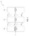
- FIG. 1is a block diagram of a detection device according to an embodiment of the present invention.
- FIG. 2is a flowchart of a detection process according to an embodiment of the present invention.
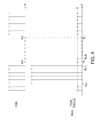
- FIG. 3is a schematic diagram of a plurality of magnitude values and a plurality of ratios when a received signal does not contain a notch band;
- FIG. 4is a schematic diagram of a plurality of magnitude values and a plurality of ratios when a received signal contains a notch band;
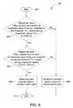
- FIG. 5is a flowchart of a detection process according to an embodiment of the present invention.
- FIG. 6is a flowchart of a detection process according to an embodiment of the present invention.
- FIG. 7is a block diagram of a determining circuit according to an embodiment of the present invention.
- FIG. 8is a flowchart of a detection process according to an embodiment of the present invention.
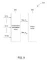
- FIG. 9is a block diagram of a determining circuit according to an embodiment of the present invention.
- FIG. 1shows a block diagram of a detection device 10 according to an embodiment of the present invention.
- the detection device 10may be a receiver of a multicarrier communication system.
- the multicarrier communication systemoperates in a wideband, and may be a communication system such as a Digital Video Broadcast (DVB) or Long-Term Evolution (LTE) system.
- the detection device 10capable of detecting whether a received signal of the detection device 10 contains a notch band in a preamble of the multicarrier communication system, includes a frequency transforming circuit 100 , a magnitude circuit 102 and a determining circuit 104 .
- the frequency transforming circuit 100receives a received signal x in a time domain, and transforms the received signal x to a frequency domain to generate a plurality of frequency-domain signals Y( 1 ) to Y(N).
- the received signal xis an orthogonal frequency-division multiplexing (OFDM) or a discrete multi-tone (DMT) signal.
- the frequency transforming circuit 100may perform a fast Fourier transform (FFT) operation.
- the frequency-domain signal Y(k)represents a frequency-domain signal of the received signal x at a k th frequency
- the plurality of frequency-domain signals Y( 1 ) to Y(N)may include modulated signals modulated by the same amplitude.
- the frequency-domain signals Y( 1 ) to Y(N)may include modulated signals modulated by phase shift key (PSK). That is to say, the frequency-domain signals Y( 1 ) to Y(N) may include modulated signals modulated by BPSK, QPSK, 16PSK and 64PSK modulation schemes. In yet another embodiment, the frequency-domain signals Y( 1 ) to Y(N) may include modulated signals modulated by QPSK(4-QAM), 16QAM, 64QAM, 256QAM and other square QAM modulation schemes.
- PSKphase shift key
- the magnitude circuit 102performs a magnitude operation on the frequency-domain signals Y( 1 ) to Y(N) to obtain a plurality of magnitude values
- the determining circuit 104determines whether the received signal x contains a notch band according to a plurality of ratios R( 1 ) to R(N ⁇ L) of the magnitude values
- corresponds to a magnitude value
- is locatedis spaced from the (k+L) th frequency where the magnitude value
- the integer L(corresponding to the fixed interval) is a positive integer, and may be adjusted based on system requirements or actual conditions.
- the determining circuit 104may sequentially calculate the ratio R(k) as the ratio of the magnitude value
- (i.e., calculating the ratio R(k)
- FIG. 2shows a flowchart of the detection process 20 according to an embodiment of the present invention.
- the detection process 20may be performed by the detection device 10 , and includes following steps.
- step 200a received signal x is received, and a plurality of frequency-domain signals Y( 1 ) to Y(N) are generated according to the received signal x.
- step 202a magnitude operation is performed on the frequency-domain signals Y( 1 ) to Y(N) to obtain a plurality of magnitude values
- step 204a plurality of ratios R( 1 ) to R(N ⁇ L) of the magnitude values
- are obtained, wherein a ratio R(k)
- step 206it is determined whether the received signal x contains a notch band according to the ratios R( 1 ) to R(N ⁇ L).
- in step 202 , and the determining circuit 104 obtaining the ratios R( 1 ) to R(N ⁇ L) in step 204may be referred from the associated description above, and shall be omitted herein.
- the determining circuit 104may determine whether the received signal x contains a notch band according to whether the ratios R( 1 ) to R(N ⁇ L) are greater than a first threshold and whether the ratios R( 1 ) to R(N ⁇ L) are smaller than a second threshold.
- FIG. 3shows a schematic diagram of a plurality of magnitude values
- FIG. 4shows a schematic diagram of a plurality of magnitude values
- FIG. 4illustrates only changes of the magnitude value
- FIG. 4illustrates only changes of the magnitude value
- the notch bandbegins at a K 1 th frequency and ends at a K 2 th frequency (i.e., the notch band has a starting frequency K 1 and an ending frequency K 2 ).
- a bandwidth of the notch bandis 8 frequencies (i.e., the bandwidth occupied by 8 subcarriers), and the integer L is 6.
- the ratio R(k)when k ⁇ K 1 ⁇ L, the ratio R(k) is substantially equal to 1; when K 1 ⁇ L ⁇ k ⁇ K 1 , the ratio R(k) is far greater than 1. More specifically, the ratio R(k) is substantially equal to ⁇ square root over (SNR) ⁇ when K 1 ⁇ L ⁇ k ⁇ K 1 (wherein SNR represents the SNR of the receiver of the multicarrier communication system); the ratio R(k) is smaller than 1 and close to 0 when K 2 ⁇ L ⁇ k ⁇ K 2 .
- SNRrepresents the SNR of the receiver of the multicarrier communication system
- the ratio R(k)is a reciprocal of SNR when K 2 ⁇ L ⁇ k ⁇ K 2 , i.e., the ratio R(k) is substantially ( ⁇ square root over (SNR) ⁇ ) ⁇ 1 (( ⁇ square root over (SNR) ⁇ ) ⁇ 1 gets closer to 0 as SNR becomes larger).
- the determining circuit 104may determine whether the received signal x contains a notch band according to whether the ratios R( 1 ) to R(N ⁇ L) change drastically. More specifically, the determining circuit 104 may determine whether a ratio R(M 1 ) greater than a first threshold TH_ 1 exists among the ratios R( 1 ) to R(N ⁇ L) to accordingly generate a first result Res_ 1 . The determining circuit 104 may further determine whether a ratio R(M 2 ) smaller than a second threshold TH_ 2 exists among the ratios R( 1 ) to R(N ⁇ L) to accordingly generate a first result Res_ 2 .
- the determining circuit 104may determine that the received signal x contains a notch band.
- the first result Res_ 1 being truemeans that a ratio R(M 1 ) greater than the first threshold TH_ 1 exists among the ratios R( 1 ) to R(N ⁇ L);
- the second result Res_ 2 being truemeans that a ratio R(M 2 ) smaller than the second threshold TH_ 2 exists among the ratios R( 1 ) to R(N ⁇ L).
- the first threshold TH_ 1may be greater than 10
- the second threshold TH_ 2may be between 0.5 and 0.75.
- the first threshold TH_ 1 and the second threshold TH_ 2may be adjusted based on the SNR, system requirements and actual conditions of a receiver of a multicarrier communication system.
- TH_ ⁇ 21 2 ⁇ ( 1 + 1 SNR ) .
- FIG. 5shows a flowchart of the detection process 50 according to an embodiment of the present invention.
- the detection process 50may be performed by the determining circuit 104 , and includes following steps.
- step 500the detection process 50 begins.
- step 502it is determined whether a ratio R(M 1 ) greater than a first threshold TH_ 1 exists among the ratios R( 1 ) to R(N ⁇ L). Step 504 is performed if so, otherwise step 508 is performed if not.
- step 504it is determined whether a ratio R(M 2 ) smaller than a second threshold TH_ 2 exists among the ratios R( 1 ) to R(N ⁇ L). Step 506 is performed if so, otherwise step 508 is performed if not.
- step 506it is determined that the received signal x contains a notch band.
- step 508it is determined that the received signal x does not contain a notch band.
- step 510the detection process 50 ends.
- the determining circuit 104may determine whether the received signal x contains a notch band according to the ratios R( 1 ) to R(N ⁇ L). In addition, when the determining circuit 104 determines that the received signal x contains a notch band, the determining circuit 104 may further determine a band position of the notch band (i.e., a starting frequency and an ending frequency of the notch band) according to the ratios R( 1 ) to R(N ⁇ L).
- the determining circuit 104may sequentially compare the ratio R(k) with the first threshold TH_ 1 from the 1 st frequency to the (N ⁇ L) th frequency.
- the determining circuit 104may determine that a ratio R(J 1 ) is greater than the first threshold TH_ 1 and a ratio R(J 1 +1) (the next frequency of the ratio R(J 1 )) is not greater than the first threshold TH_ 1 , the determining circuit 104 may determine that the frequency R(J 1 +1) (i.e., the R(J 1 +1) th frequency) is a starting point of the notch band. Further, the determining circuit 104 may sequentially compare the ratio R(k) with a second threshold TH_ 2 .
- the determining circuit 104may determine that the frequency J 2 (i.e., the J 2 th frequency) is an ending frequency of the notch band.
- the determining circuit 104may obtain the band position of the notch band to further obtain the bandwidth of the wideband as (J 2 ⁇ J 1 ) frequencies (i.e., the bandwidth occupied by the J 2 ⁇ J 1 subcarriers).
- the detection device 10can determine not only whether the received signal x contains a notch band, but also the band position and bandwidth of the notch band when the received signal x contains the notch band.
- the determining circuit 104may transmit information of the band position and the bandwidth of the notch band to a subsequent decoding circuit, which may then reduce an error rate of the receiver of the multicarrier communication system according to the information of the band position and the bandwidth of the notch band.
- the detection device 10reduces a false alarm rate of a multicarrier communication system involving a multipath channel, i.e., a notch band is accurately detected to enhance the system performance of the multicarrier communication system.
- the false alarm rate of a conventional notch band detecting methodis as high as 100%.
- the method for detecting a notch band of the present inventionreduces the false alarm rate to almost 0%.
- the method for detecting a notch band of the present inventionreliably overcomes issues of known technologies.
- the ratio R(k)instead of being
- the determining circuit 104may determine whether L consecutive (or adjacent) ratios R(M 1 ) to R(M 1 +L ⁇ 1) greater than the first threshold TH_ 1 exist among the ratios R( 1 ) to R(N ⁇ L) to accordingly generate a first result Res_ 1 ′.
- the determining circuit 104may further determine whether L consecutive (or adjacent) ratios R(M 2 ) to R(M 2 +L ⁇ 1) smaller than the second threshold TH_ 2 exist among the ratios R( 1 ) to R(N ⁇ L) to accordingly generate a second result Res_ 2 ′.
- the determining circuit 104may determine whether the received signal x contains a notch band. The above operations of the determining circuit 104 may be further concluded into a detection process 60 .
- FIG. 6shows a flowchart of the detection process 60 according to an embodiment of the present invention. The detection process 60 may be performed by the determining circuit 104 , and includes following steps.
- step 600the detection process 60 begins.
- step 602it is determined whether L consecutive ratios R(M 1 ) to R(M 1 +L ⁇ 1) greater than the first threshold TH_ 1 exist among the ratios R( 1 ) to R(N ⁇ L). Step 604 is performed if so, otherwise step 608 is performed if not.
- step 604it is determined whether L consecutive ratios R(M 2 ) to R(M 2 +L ⁇ 1) smaller than the second threshold TH_ 2 exist among the ratios R( 1 ) to R(N ⁇ L) to accordingly generate a second result Res_ 2 ′. Step 606 is performed if so, otherwise step 608 is performed if not.
- step 606it is determined that the received signal x contains a notch band.
- step 608it is determined that the received signal x does not contain a notch band.
- step 610the detection process 60 ends.
- the detection process 60is similar to the detection process 50 .
- One difference between the detection process 60 and the detection process 50is that, in step 502 , the determining circuit 104 generates the first result Res_ 1 when the determining circuit 104 determines that one single ratio R(M 1 ) greater than the first threshold TH_ 1 exists; however, in step 602 , the determining circuit 104 generates the first result Res_ 1 ′ only when determining circuit 104 determines that L consecutive ratios R(M 1 ) to R(M 1 +L ⁇ 1) greater than the first threshold TH_ 1 exist.
- the determining circuit 104generates the first result Res_ 2 when the determining circuit 104 determines that one single ratio R(M 2 ) smaller than the second threshold TH_ 2 exists; however, in step 604 , the determining circuit 104 generates the second result Res_ 2 ′ only when determining circuit 104 determines that L consecutive ratios R(M 2 ) to R(M 2 +L ⁇ 1) smaller than the second threshold TH_ 2 exist.
- FIG. 7shows a block diagram of a determining circuit 704 according to an embodiment of the present invention.
- the determining circuit 704may realize the determining circuit 104 , and includes a ratio calculating circuit 740 and an output circuit 742 .
- the ratio calculating circuit 740receives a plurality of magnitude values
- the ratio calculating circuit 740may include at least one divider (not shown in FIG. 7 ) that calculates the ratios R( 1 ) to R(N ⁇ L).
- the output circuit 742determines whether the received signal x contains a notch band according to changes in the values of the ratios R( 1 ) to R(N ⁇ L).
- the determining circuit 104is not limited to first calculating the ratios R( 1 ) to R(N ⁇ L) and determining whether the received signal x contains a notch band according to the changes in the values of the ratios R( 1 ) to R(N ⁇ L). For example, the determining circuit 104 may determine whether a magnitude
- the determining circuit 104may further determine whether a magnitude
- the third result Res_ 3 being truemeans that the magnitude
- the fourth result Res_ 4 being truemeans that the magnitude
- the third result Res_ 3 and the first result Res_ 1are equivalent (or referred to as if and only if) determination results; the fourth result Res_ 4 and the second result Res_ 2 are equivalent determination results.
- the determining circuit 104may determine that the received signal x contains a notch band.
- FIG. 8shows a flowchart of the detection process 80 according to an embodiment of the present invention.
- the detection process 80may be performed by the determining circuit 104 , and includes following steps.
- step 800the detection process 80 begins.
- step 802it is determined whether a magnitude value
- step 804it is determined whether a magnitude value
- step 806it is determined that the received signal x contains a notch band.
- step 808it is determined that the received signal x does not contain a wide band.
- step 810the detection process 80 ends.
- steps 802 and 804Although the determining circuit 104 does not directly calculate the ratios R( 1 ) to R(N ⁇ 1), steps 802 and 804 are equivalently calculating the ratios R( 1 ) to R(N ⁇ 1) and then accordingly determining whether the received signal x contains a notch band according to the changes in the values of the ratios R( 1 ) to R(N ⁇ 1).
- steps 802 and 804are substantially another embodiment of “determining whether a notch band is contained according to the ratios R( 1 ) to R(N ⁇ L) of the magnitude values
- FIG. 9shows a block diagram of a determining circuit 904 according to another embodiment of the present invention.
- the determining circuit 904may realize the determining circuit 104 , and includes a multiplication comparison circuit 940 and an output circuit 942 .
- the multiplication comparison circuit 940performs step 802 and step 804 , and transmits the third result Res_ 3 and the fourth result Res_ 4 generated in step 802 and step 804 to the output unit 942 , which may then perform step 806 and step 808 according to the third result Res_ 3 and the fourth result Res_ 4 .
- the multiplication comparison circuit 940may include at least one multiplier (not shown in FIG. 9 ) and at least one comparator (not shown in FIG. 9 ).
- the multipliermultiplies the magnitude value
- the comparatordetermines whether the magnitude value
- the frequency transforming circuit 100 , the magnitude circuit 102 and the determining circuits 104 , 704 and 904may be realized or implemented by digital circuits (e.g., register-transfer logic (RTL) circuits) or digital signal processors (DSP), and associated details shall be omitted herein.
- digital circuitse.g., register-transfer logic (RTL) circuits
- DSPdigital signal processors
- the present inventionis capable of accurately determining whether a received signal contains a notch band.
Landscapes
- Engineering & Computer Science (AREA)
- Physics & Mathematics (AREA)
- Computer Networks & Wireless Communication (AREA)
- Signal Processing (AREA)
- Electromagnetism (AREA)
- Quality & Reliability (AREA)
- Probability & Statistics with Applications (AREA)
- Mobile Radio Communication Systems (AREA)
- Circuits Of Receivers In General (AREA)
Abstract
Description
This application claims the benefit of Taiwan application Serial No. 105119400, filed Jun. 21, 2016, the subject matter of which is incorporated herein by reference.
The invention relates in general to a method and device for detecting a notch band, and more particularly to a method and device capable of accurately detecting a notch band.
Multicarrier communication systems, operable in a wideband and having a high-speed transmission rate, are extensively applied in the daily life. However, in certain circumstances, a multicarrier communication system may include a notch band in the wideband; that is, the multicarrier communication system is capable of transmitting signals in parts of the wideband that are outside the notch band but not in the notch band. If a receiver of the multicarrier communication system cannot accurately detect such notch band, signals transmitted from a transmitter of the multicarrier communication system may not be corrected decoded, hence degrading the overall performance of the multicarrier communication system.
There is a known technology of a notch band detecting method applicable to an additive white Gaussian noise (AWGN) channel. However, in the event of severe multipath effects in the channel, the above notch band detecting method may yield a higher false alarm rate, which similarly degrades the overall performance of the multicarrier communication system.
Therefore, there is a need for a solution for accurately detecting a notch band.
It is a primary object of the present invention to provide a method and device for detecting a notch band to improve issues of the known technologies.
The present invention discloses a method for detecting a notch band and applied to a multicarrier communication system operating in a wideband. The method includes: receiving a received signal, and generating a plurality of frequency-domain signals according to the received signal; performing a magnitude operation on the frequency-domain signals to obtain a plurality of magnitude values, wherein the frequency-domain signals correspond to a plurality of frequencies in the wideband; and determining whether the received signal contains a notch band according to a plurality of ratios of a first magnitude set among the magnitude values to a second magnitude set among the magnitude values. Wherein, a first magnitude value in the first magnitude set corresponds to a second magnitude in the second magnitude set, and a first frequency where the first magnitude value is located is spaced from a second frequency where the second magnitude value is located by a fixed interval.
The present invention further discloses a device applied to a multicarrier communication system operating in a wideband. The device includes: a frequency transforming circuit, receiving a received signal, and generating a plurality of frequency-domain signals according to the received signal; a magnitude circuit, performing a magnitude operation on the frequency-domain signals to obtain a plurality of magnitude values; and a determining circuit, determining whether the received signal contains a notch band according to a plurality of ratios of a first magnitude set among the magnitude values to a second magnitude set among the magnitude values. Wherein, a first magnitude value in the first magnitude set corresponds to a second magnitude in the second magnitude set, and a first frequency where the first magnitude value is located is spaced from a second frequency where the second magnitude value is located by a fixed interval.
The above and other aspects of the invention will become better understood with regard to the following detailed description of the preferred but non-limiting embodiments. The following description is made with reference to the accompanying drawings.
In one embodiment, the determiningcircuit 104 may sequentially calculate the ratio R(k) as the ratio of the magnitude value |Y(k)| to the magnitude value |Y(k+L)| (i.e., calculating the ratio R(k)=|Y(k)|/|Y(k+L)|), and determine whether the received signal x contains a notch band according to changes in the values of a plurality of ratios R(1) to R(N−L).
Operations of thedetection device 10 determining whether the received signal x contains a notch band may be concluded into adetection process 20.FIG. 2 shows a flowchart of thedetection process 20 according to an embodiment of the present invention. Thedetection process 20 may be performed by thedetection device 10, and includes following steps.
Instep 200, a received signal x is received, and a plurality of frequency-domain signals Y(1) to Y(N) are generated according to the received signal x.
Instep 202, a magnitude operation is performed on the frequency-domain signals Y(1) to Y(N) to obtain a plurality of magnitude values |Y(1)| to |Y(N−L)|.
Instep 204, a plurality of ratios R(1) to R(N−L) of the magnitude values |Y(1)| to |Y(N−L)| to the magnitude values |Y(1+L)| to |Y(N)| are obtained, wherein a ratio R(k)=|Y(k)|/|Y(k+L)|.
Instep 206, it is determined whether the received signal x contains a notch band according to the ratios R(1) to R(N−L).
Operation details of thefrequency transforming circuit 100 receiving the received signal x and generating the frequency-domain signals Y(1) to Y(N) instep 202, themagnitude circuit 102 obtaining the magnitude values |Y(1)| to |Y(N−L)| instep 202, and the determiningcircuit 104 obtaining the ratios R(1) to R(N−L) instep 204 may be referred from the associated description above, and shall be omitted herein. Instep 206, the determiningcircuit 104 may determine whether the received signal x contains a notch band according to whether the ratios R(1) to R(N−L) are greater than a first threshold and whether the ratios R(1) to R(N−L) are smaller than a second threshold.
Referring toFIG. 3 andFIG. 4 ,FIG. 3 shows a schematic diagram of a plurality of magnitude values |Y(k)| and a plurality of ratios R(k) when the received signal x does not contain a notch band;FIG. 4 shows a schematic diagram of a plurality of magnitude values |Y(k)| and a plurality of ratios R(k) when the received signal x contains a notch band. For simplicity,FIG. 4 illustrates only changes of the magnitude value |Y(k)| and the ratio R(k) near a notch band. In the embodiment shown inFIG. 4 , the notch band begins at a K1thfrequency and ends at a K2thfrequency (i.e., the notch band has a starting frequency K1and an ending frequency K2). A bandwidth of the notch band is 8 frequencies (i.e., the bandwidth occupied by 8 subcarriers), and the integer L is 6.
It is known fromFIG. 3 that, as the received signal x does not contain a notch band, and the magnitude values |Y(1)| to |Y(N−L)| are substantially equal, and so the ratios R(1) to R(N−L) are substantially equal to 1. In comparison, as shown inFIG. 4 , as the received signal x contains a notch band, when the signal-to-noise ratio (SNR) of the multicarrier communication system is large, the magnitude values |Y(K1)| to |Y(K2)| within the notch band are far smaller than the magnitude value |Y(K)| outside the notch band. As a result, the ratios R(1) to R(N−L) change drastically near the notch band. More specifically, when k<K1−L, the ratio R(k) is substantially equal to 1; when K1−L≤k≤K1, the ratio R(k) is far greater than 1. More specifically, the ratio R(k) is substantially equal to √{square root over (SNR)} when K1−L≤k≤K1(wherein SNR represents the SNR of the receiver of the multicarrier communication system); the ratio R(k) is smaller than 1 and close to 0 when K2−L≤k≤K2. More specifically, the ratio R(k) is a reciprocal of SNR when K2−L≤k≤K2, i.e., the ratio R(k) is substantially (√{square root over (SNR)})−1((√{square root over (SNR)})−1gets closer to 0 as SNR becomes larger).
In the above situation, the determiningcircuit 104 may determine whether the received signal x contains a notch band according to whether the ratios R(1) to R(N−L) change drastically. More specifically, the determiningcircuit 104 may determine whether a ratio R(M1) greater than a first threshold TH_1 exists among the ratios R(1) to R(N−L) to accordingly generate a first result Res_1. The determiningcircuit 104 may further determine whether a ratio R(M2) smaller than a second threshold TH_2 exists among the ratios R(1) to R(N−L) to accordingly generate a first result Res_2. When the first result Res_1 is true and the second result Res_2 is also true, the determiningcircuit 104 may determine that the received signal x contains a notch band. Wherein, the first result Res_1 being true means that a ratio R(M1) greater than the first threshold TH_1 exists among the ratios R(1) to R(N−L); the second result Res_2 being true means that a ratio R(M2) smaller than the second threshold TH_2 exists among the ratios R(1) to R(N−L). Preferably, the first threshold TH_1 may be greater than 10, and the second threshold TH_2 may be between 0.5 and 0.75. It should be noted that, the first threshold TH_1 and the second threshold TH_2 may be adjusted based on the SNR, system requirements and actual conditions of a receiver of a multicarrier communication system. In another embodiment, the first threshold TH_1 may be TH_1=½(1+√{square root over (SNR)}), and the second threshold TH_2 may be
Operations of the determiningcircuit 104 determining whether the received signal x contains a notch band according to the ratios R(1) to R(N) may be further concluded into adetection process 50.FIG. 5 shows a flowchart of thedetection process 50 according to an embodiment of the present invention. Thedetection process 50 may be performed by the determiningcircuit 104, and includes following steps.
Instep 500, thedetection process 50 begins.
Instep 502, it is determined whether a ratio R(M1) greater than a first threshold TH_1 exists among the ratios R(1) to R(N−L). Step504 is performed if so, otherwise step508 is performed if not.
Instep 504, it is determined whether a ratio R(M2) smaller than a second threshold TH_2 exists among the ratios R(1) to R(N−L). Step506 is performed if so, otherwise step508 is performed if not.
Instep 506, it is determined that the received signal x contains a notch band.
Instep 508, it is determined that the received signal x does not contain a notch band.
Instep 510, thedetection process 50 ends.
Operation details of thedetection process 50 may be referred from the associated description above, and shall be omitted herein. According to thedetection process 50, the determiningcircuit 104 may determine whether the received signal x contains a notch band according to the ratios R(1) to R(N−L). In addition, when the determiningcircuit 104 determines that the received signal x contains a notch band, the determiningcircuit 104 may further determine a band position of the notch band (i.e., a starting frequency and an ending frequency of the notch band) according to the ratios R(1) to R(N−L). For example, the determiningcircuit 104 may sequentially compare the ratio R(k) with the first threshold TH_1 from the 1stfrequency to the (N−L)thfrequency. When the determiningcircuit 104 determines that a ratio R(J1) is greater than the first threshold TH_1 and a ratio R(J1+1) (the next frequency of the ratio R(J1)) is not greater than the first threshold TH_1, the determiningcircuit 104 may determine that the frequency R(J1+1) (i.e., the R(J1+1)thfrequency) is a starting point of the notch band. Further, the determiningcircuit 104 may sequentially compare the ratio R(k) with a second threshold TH_2. When the determiningcircuit 104 determines that a ratio R(J2) is smaller than the second threshold TH_2 and a ratio R(J2+1) (the next frequency of the ratio R(J2)) is not smaller than the second threshold TH_2, the determiningcircuit 104 may determine that the frequency J2(i.e., the J2thfrequency) is an ending frequency of the notch band. Thus, according to the frequency (J1+1) and the frequency J2, the determiningcircuit 104 may obtain the band position of the notch band to further obtain the bandwidth of the wideband as (J2−J1) frequencies (i.e., the bandwidth occupied by the J2−J1subcarriers).
Known from the above, thedetection device 10 can determine not only whether the received signal x contains a notch band, but also the band position and bandwidth of the notch band when the received signal x contains the notch band. The determiningcircuit 104 may transmit information of the band position and the bandwidth of the notch band to a subsequent decoding circuit, which may then reduce an error rate of the receiver of the multicarrier communication system according to the information of the band position and the bandwidth of the notch band. As opposed to known technologies, thedetection device 10 reduces a false alarm rate of a multicarrier communication system involving a multipath channel, i.e., a notch band is accurately detected to enhance the system performance of the multicarrier communication system.
More specifically, in a multipath channel, the false alarm rate of a conventional notch band detecting method is as high as 100%. In contrast, the method for detecting a notch band of the present invention reduces the false alarm rate to almost 0%. In other words, the method for detecting a notch band of the present invention reliably overcomes issues of known technologies.
It should be noted that, the foregoing embodiments are given to explain the concept of the present invention, and modifications may be made to those embodiments by one person skilled in the art without departing from the spirit of the present invention. For example, the ratio R(k), instead of being |Y(k)|/|Y(k+L)|, may be |Y(k−L)|/|Y(k)|, |Y(k+L)|/|Y(k)| or |Y(k)|/|Y(k−L)|, which are also encompassed within the scope of the present invention.
Further, different from thedetection process 50, the determiningcircuit 104 may determine whether L consecutive (or adjacent) ratios R(M1) to R(M1+L−1) greater than the first threshold TH_1 exist among the ratios R(1) to R(N−L) to accordingly generate a first result Res_1′. The determiningcircuit 104 may further determine whether L consecutive (or adjacent) ratios R(M2) to R(M2+L−1) smaller than the second threshold TH_2 exist among the ratios R(1) to R(N−L) to accordingly generate a second result Res_2′. When the first result Res_1′ is true and the second result Res_2′ is also true, the determiningcircuit 104 may determine whether the received signal x contains a notch band. The above operations of the determiningcircuit 104 may be further concluded into adetection process 60.FIG. 6 shows a flowchart of thedetection process 60 according to an embodiment of the present invention. Thedetection process 60 may be performed by the determiningcircuit 104, and includes following steps.
Instep 600, thedetection process 60 begins.
Instep 602, it is determined whether L consecutive ratios R(M1) to R(M1+L−1) greater than the first threshold TH_1 exist among the ratios R(1) to R(N−L). Step604 is performed if so, otherwise step608 is performed if not.
Instep 604, it is determined whether L consecutive ratios R(M2) to R(M2+L−1) smaller than the second threshold TH_2 exist among the ratios R(1) to R(N−L) to accordingly generate a second result Res_2′. Step606 is performed if so, otherwise step608 is performed if not.
Instep 606, it is determined that the received signal x contains a notch band.
Instep 608, it is determined that the received signal x does not contain a notch band.
Instep 610, thedetection process 60 ends.
Thedetection process 60 is similar to thedetection process 50. One difference between thedetection process 60 and thedetection process 50 is that, instep 502, the determiningcircuit 104 generates the first result Res_1 when the determiningcircuit 104 determines that one single ratio R(M1) greater than the first threshold TH_1 exists; however, instep 602, the determiningcircuit 104 generates the first result Res_1′ only when determiningcircuit 104 determines that L consecutive ratios R(M1) to R(M1+L−1) greater than the first threshold TH_1 exist. Similarly, instep 504, the determiningcircuit 104 generates the first result Res_2 when the determiningcircuit 104 determines that one single ratio R(M2) smaller than the second threshold TH_2 exists; however, instep 604, the determiningcircuit 104 generates the second result Res_2′ only when determiningcircuit 104 determines that L consecutive ratios R(M2) to R(M2+L−1) smaller than the second threshold TH_2 exist.
Further, the determiningcircuit 104 is not limited to first calculating the ratios R(1) to R(N−L) and determining whether the received signal x contains a notch band according to the changes in the values of the ratios R(1) to R(N−L). For example, the determiningcircuit 104 may determine whether a magnitude |Y(M1)| greater than a product of a magnitude value |Y(M1+L)| (corresponding to the magnitude value |Y(M1)|) multiplied by the first threshold TH_1 exists among the magnitude values |Y(1)|˜|Y(N−L)|, and accordingly generates a third result Res_3. The determiningcircuit 104 may further determine whether a magnitude |Y(M2)| smaller than a product of a magnitude value |Y(M2+L)| (corresponding to the magnitude value |Y(M2)|) multiplied by the second threshold TH_2 exists among the magnitude values |Y(1)|˜|Y(N−L)|, and accordingly generates a fourth result Res_4. Wherein, the third result Res_3 being true means that the magnitude |Y(M1)| greater than the product of the magnitude value |Y(M1+L)| multiplied by the first threshold TH_1 exists among the magnitude values |Y(1)|˜|Y(N−L), the fourth result Res_4 being true means that the magnitude |Y(M2)| smaller than the product of the magnitude value |Y(M2+L)| multiplied by the second threshold TH_2 exists among the magnitude values |Y(1)|˜|Y(N−L)|. It should be noted that, the third result Res_3 and the first result Res_1 are equivalent (or referred to as if and only if) determination results; the fourth result Res_4 and the second result Res_2 are equivalent determination results. In other words, when the third result Res_3 is true and the fourth result Res_4 is also true, the determiningcircuit 104 may determine that the received signal x contains a notch band.
The operations of the determiningcircuit 104 determining whether the received signal x contains a notch band may be further concluded into adetection process 80.FIG. 8 shows a flowchart of thedetection process 80 according to an embodiment of the present invention. Thedetection process 80 may be performed by the determiningcircuit 104, and includes following steps.
Instep 800, thedetection process 80 begins.
Instep 802, it is determined whether a magnitude value |Y(M1)| greater than a product of a magnitude value |Y(M1+L)| multiplied by the first threshold TH_1 exists among the magnitude values |Y(1)| to |Y(N−L)|. Step804 is performed if so, otherwise step808 is performed if not.
In step804, it is determined whether a magnitude value |Y(M2)| smaller than a product of a magnitude value |Y(M2+L)| multiplied by the second threshold TH_2 exists among the magnitude values |Y(1)| to |Y(N−L)|. Step806 is performed if so, otherwise step808 is performed if not.
Instep 806, it is determined that the received signal x contains a notch band.
Instep 808, it is determined that the received signal x does not contain a wide band.
Instep 810, thedetection process 80 ends.
Operation details of thedetection process 80 may be referred from associated description above, and shall be omitted herein. It should be noted that, insteps 802 and804, although the determiningcircuit 104 does not directly calculate the ratios R(1) to R(N−1), steps802 and804 are equivalently calculating the ratios R(1) to R(N−1) and then accordingly determining whether the received signal x contains a notch band according to the changes in the values of the ratios R(1) to R(N−1). That is, steps802 and804 are substantially another embodiment of “determining whether a notch band is contained according to the ratios R(1) to R(N−L) of the magnitude values |Y(1)| to |Y(N−L)| (corresponding to a first magnitude set) to the magnitude values |Y(1+L)| to |Y(N)| (corresponding to a second magnitude set)”, which is also encompassed within the scope of the present invention.
Generally known to one person skilled in the art, thefrequency transforming circuit 100, themagnitude circuit 102 and the determiningcircuits
In conclusion, using a plurality of ratios of a first magnitude set to a second magnitude set of a plurality of magnitude values, the present invention is capable of accurately determining whether a received signal contains a notch band.
While the invention has been described by way of example and in terms of the preferred embodiments, it is to be understood that the invention is not limited thereto. On the contrary, it is intended to cover various modifications and similar arrangements and procedures, and the scope of the appended claims therefore should be accorded the broadest interpretation so as to encompass all such modifications and similar arrangements and procedures.
Claims (12)
1. A method for detecting a notch band in a bandwidth of a frequency spectrum of a received signal, applied to a multicarrier system operating in a wideband, the method comprising:
receiving the received signal, and generating a plurality of frequency-domain signals according to the received signal;
performing a magnitude operation on the plurality of frequency-domain signals to obtain a plurality of magnitude values; and
determining whether there is a notch band in the bandwidth of the frequency spectrum of the received signal according to a plurality of ratios of a first magnitude set among the plurality of magnitude values to a second magnitude set among the plurality of magnitude values;
wherein, a first magnitude value in the first magnitude set corresponds to a second magnitude value in the second magnitude set, and a frequency where the first magnitude value is located is spaced from a second frequency where the second magnitude value is located by a fixed interval,
wherein the step of determining whether there is a notch band in the bandwidth of the frequency spectrum of the received signal according to the plurality of ratios of the first magnitude set among the plurality of magnitude values to the second magnitude set among the plurality of magnitude values comprises;
obtaining the plurality of ratios of the first magnitude set among the plurality of magnitude values to the second magnitude set among the plurality of magnitude values; and
determining whether there is a notch band in the bandwidth of the frequency spectrum of the received signal according to the plurality of ratios; and
wherein the step of obtaining the plurality of ratios comprises:
obtaining each of the plurality of ratios as a ratio of a third magnitude value in the first magnitude set to a fourth magnitude value in the second magnitude set corresponding to the third magnitude value.
2. The method according toclaim 1 , wherein the step of determining whether there is a notch band in the bandwidth of the frequency spectrum of the received signal according to the plurality of ratios comprises:
determining whether a first ratio greater than a first threshold exists among the plurality of ratios, and generating a first result;
determining whether a second ratio smaller than a second threshold exists among the plurality of ratios, and generating a second result; and
determining whether there is a notch band in the bandwidth of the frequency spectrum of the received signal according to the first result and the second result.
3. The method according toclaim 2 , wherein the first threshold is greater than 10, and the second threshold is between 0.25 and 0.75.
4. The method according toclaim 2 , wherein the step of determining whether there is a notch band in the bandwidth of the frequency spectrum of the received signal according to the first result and the second result comprises:
determining that there is a notch band in the bandwidth of the frequency spectrum of the received signal when the first result is true and the second result is true;
wherein, the first result being true means that the first ratio greater than the first threshold exists among the plurality of ratios, and the second result being true means that the second ratio smaller than the second threshold exists among the plurality of ratios.
5. The method according toclaim 2 , further comprising:
determining a bandwidth of the notch band in the bandwidth of the frequency spectrum of the received signal according to a third frequency corresponding to the first ratio and a fourth frequency corresponding to the second ratio when the first result is true and the second result is true.
6. The method according toclaim 1 , further comprising:
determining whether a fifth magnitude value greater than a product of a sixth magnitude value in the second magnitude set multiplied by a first threshold exists in the first magnitude set to generate a third result, wherein the fifth magnitude value corresponds to the sixth magnitude value;
determining whether a seventh magnitude value smaller than a product of an eighth magnitude value in the second magnitude set multiplied by a second threshold exists in the first magnitude set to generate a fourth result, wherein the seventh magnitude value corresponds to the eighth magnitude value; and
determining that the received signal contains the notch band in the bandwidth of the frequency spectrum of the received signal when the third result is true and the fourth result is true;
wherein, the third result being true means that the fifth magnitude value is greater than the product of the sixth magnitude value multiplied by the first threshold, and the second result being true means that the seventh magnitude value is smaller than the product of the eighth magnitude value multiplied by the second threshold.
7. A device, applied to a multicarrier communication system operating in a wideband, comprising:
a frequency transforming circuit, receiving a received signal, and generating a plurality of frequency-domain signals according to the received signal;
a magnitude circuit, performing a magnitude operation on the plurality of frequency-domain signals to obtain a plurality of magnitude values; and
a determining circuit, determining whether there is a notch band in a bandwidth of a frequency spectrum of the received signal according to a plurality of ratios of a first magnitude set among the plurality of magnitude values to a second magnitude set among the plurality of magnitude values;
wherein, a first magnitude value in the first magnitude set corresponds to a second magnitude value in the second magnitude set, and a frequency where the first magnitude value is located is spaced from a second frequency where the second magnitude value is located by a fixed interval,
wherein the determining circuit further performs steps below to obtain the plurality of ratios:
obtaining the plurality of ratios of the first magnitude set among the plurality of magnitude values to the second magnitude set among the plurality of magnitude values; and
determining whether there is a notch band in the bandwidth of the frequency spectrum of the received signal according to the plurality of ratios; and
wherein the determining circuit further performs a step below to obtain the plurality of ratios:
obtaining each of the plurality of ratios as a ratio of a third magnitude value in the first magnitude set to a fourth magnitude value in the second magnitude set corresponding to the third magnitude value.
8. The device according toclaim 7 , wherein the determining circuit further performs steps below to determine whether the received signal contains the notch band:
determining whether a first ratio greater than a first threshold exists among the plurality of ratios, and generating a first result;
determining whether a second ratio smaller than a second threshold exists among the plurality of ratios, and generating a second result; and
determining whether there is a notch band in the bandwidth of the frequency spectrum of the received signal according to the first result and the second result.
9. The device according toclaim 8 , wherein the first threshold is greater than 10, and the second threshold is between 0.25 and 0.75.
10. The device according toclaim 8 , wherein the determining circuit further performs a step below to determine whether there is a notch band in the bandwidth of the frequency spectrum of the received signal according to the first result and the second result:
determining that there is a notch band in the bandwidth of the frequency spectrum of the received signal when the first result is true and the second result is true;
wherein, the first result being true means that the first ratio greater than the first threshold exists among the plurality of ratios, and the second result being true means that the second ratio smaller than the second threshold exists among the plurality of ratios.
11. The device according toclaim 8 , wherein the determining circuit further performs a step of:
determining a bandwidth of the notch band according to a third frequency corresponding to the first ratio and a fourth frequency corresponding to the second ratio when the first result is true and the second result is true.
12. The device according toclaim 7 , wherein the determining circuit further performs steps of:
determining whether a fifth magnitude value greater than a product of a sixth magnitude value in the second magnitude set multiplied by a first threshold exists in the first magnitude set to generate a third result, wherein the fifth magnitude value corresponds to the sixth magnitude value;
determining whether a seventh magnitude value smaller than a product of an eighth magnitude value in the second magnitude set multiplied by a second threshold exists in the first magnitude set to generate a fourth result, wherein the seventh magnitude value corresponds to the eighth magnitude value; and
determining that there is a notch band in the bandwidth of the frequency spectrum of the received signal when the third result is true and the fourth result is true;
wherein, the third result being true means that the fifth magnitude value is greater than the product of the sixth magnitude value multiplied by the first threshold, and the second result being true means that the seventh magnitude value is smaller than the product of the eighth magnitude value multiplied by the second threshold.
Applications Claiming Priority (3)
| Application Number | Priority Date | Filing Date | Title |
|---|---|---|---|
| TW105119400 | 2016-06-21 | ||
| TW105119400ATWI610545B (en) | 2016-06-21 | 2016-06-21 | Detecting method and detecting device for detecting notch-band |
| TW105119400A | 2016-06-21 |
Publications (2)
| Publication Number | Publication Date |
|---|---|
| US20170366283A1 US20170366283A1 (en) | 2017-12-21 |
| US10171186B2true US10171186B2 (en) | 2019-01-01 |
Family
ID=60660487
Family Applications (1)
| Application Number | Title | Priority Date | Filing Date |
|---|---|---|---|
| US15/369,940ActiveUS10171186B2 (en) | 2016-06-21 | 2016-12-06 | Method and device for detecting notch band |
Country Status (2)
| Country | Link |
|---|---|
| US (1) | US10171186B2 (en) |
| TW (1) | TWI610545B (en) |
Families Citing this family (1)
| Publication number | Priority date | Publication date | Assignee | Title |
|---|---|---|---|---|
| TWI610545B (en)* | 2016-06-21 | 2018-01-01 | 晨星半導體股份有限公司 | Detecting method and detecting device for detecting notch-band |
Citations (43)
| Publication number | Priority date | Publication date | Assignee | Title |
|---|---|---|---|---|
| US20030210749A1 (en)* | 2002-05-09 | 2003-11-13 | Hosein Asjadi | Receiver |
| US20030216122A1 (en)* | 2002-05-17 | 2003-11-20 | Cordone Sean S. | Multiple carrier adaptive notch filter |
| US20060067381A1 (en)* | 2004-09-23 | 2006-03-30 | Chakravarthy Vasu D | Spectrum re-use employing transfer domain communications systems |
| US20060083325A1 (en)* | 2004-09-30 | 2006-04-20 | Infineon Technologies Ag | Method and receiver circuit for reducing RFI interference |
| US20060114981A1 (en)* | 2002-08-13 | 2006-06-01 | Koninklijke Philips Electronics N.V. | Joint channel and noise variance estimation in a wideband ofdm system |
| US20060146869A1 (en)* | 2004-12-22 | 2006-07-06 | Ning Zhang | Dynamic channel bandwidth management |
| US20070009011A1 (en)* | 2003-06-25 | 2007-01-11 | Coulson Alan J | Narrowband interference suppression for ofdm system |
| US20080292032A1 (en)* | 2007-05-25 | 2008-11-27 | Intel Corporation | Arrangements for interference mitigation utilizing estimation |
| US20090088092A1 (en)* | 2007-09-27 | 2009-04-02 | Kabushiki Kaisha Toshiba | Interference avoidance |
| US20090161804A1 (en)* | 2007-12-21 | 2009-06-25 | Qualcomm Incorporated | Receiver window shaping in OFDM to mitigate narrowband interference |
| US20090207925A1 (en)* | 2008-02-15 | 2009-08-20 | Mediatek Inc. | Wireless communication system, OFDM communication apparatus and method thereof |
| US20100208712A1 (en)* | 2009-02-17 | 2010-08-19 | Wavion Ltd. | Enhancing WLAN performance in the presence of interference |
| US20100329396A1 (en)* | 2009-06-24 | 2010-12-30 | Mstar Semiconductor, Inc. | Interference Detector and Method Thereof |
| US20110116569A1 (en)* | 2009-10-05 | 2011-05-19 | Simon Fraser University | Wireless data communication methods and apparatus |
| US20110124291A1 (en)* | 2009-11-23 | 2011-05-26 | Motorola, Inc. | Method for quieting and sensing in a secondary communications system |
| US20110305306A1 (en)* | 2010-06-12 | 2011-12-15 | Montage Technology (Shanghai) Co. Ltd. | Blind adaptive filter for narrowband interference cancellation |
| US20120231742A1 (en)* | 2009-10-26 | 2012-09-13 | Sergio Barberis | Score-based interference coordination in wireless communication systems |
| US20120238263A1 (en)* | 2009-10-26 | 2012-09-20 | Telecom Italia S.P.A. | Radio resource scheduling for intra-system interference coordination in wireless communication systems |
| US20120243596A1 (en)* | 2011-03-24 | 2012-09-27 | Sony Corporation | Receiver and method |
| US20120250802A1 (en)* | 2011-03-31 | 2012-10-04 | Sony Corporation | Receiver, reception method, program and reception system |
| US20130045705A1 (en)* | 2010-05-31 | 2013-02-21 | St-Ericsson Sa | Filtering Interference Detected at Wireless Receiver |
| US20130084821A1 (en)* | 2010-05-31 | 2013-04-04 | St-Ericsson Sa | Detecting Interference in Wireless Receiver |
| US20130115904A1 (en)* | 2010-07-13 | 2013-05-09 | St-Ericsson Sa | Synchronizing and Detecting Interference in Wireless Receiver |
| US20130315351A1 (en)* | 2011-03-10 | 2013-11-28 | Sony Corporation | Reception device, reception method, and program |
| US20130321707A1 (en)* | 2011-02-28 | 2013-12-05 | Hiroo Takahashi | Transmitter apparatus, information processing method, program, and transmitter system |
| US20130336433A1 (en)* | 2011-04-07 | 2013-12-19 | Sony Corporation | Receiving apparatus, receiving method, and program |
| US20130336431A1 (en)* | 2011-04-06 | 2013-12-19 | Sony Corporation | Receiving apparatus, receiving method, and program |
| US20140009685A1 (en)* | 2011-04-22 | 2014-01-09 | Sony Corporation | Reception device, reception method, program, and reception system |
| US20140010332A1 (en)* | 2011-03-31 | 2014-01-09 | Sony Corporation | Receiving device, receiving method, program, and receiving system |
| US20140079103A1 (en)* | 2012-09-20 | 2014-03-20 | Broadcom Corporation | Interference cancellation within OFDM communications |
| US20140106697A1 (en)* | 2011-05-16 | 2014-04-17 | Furuno Electric Co., Ltd. | Interference wave signal removing device, gnss reception apparatus, mobile terminal, interference wave signal removing program and interference wave removing method |
| US20140273869A1 (en)* | 2013-03-18 | 2014-09-18 | Marvell World Trade Ltd. | Systems and methods for lte interference detection |
| US20140269841A1 (en)* | 2013-03-15 | 2014-09-18 | Joel I. Goodman | Ultra-Wideband Frequency Position Modulation using Nonlinear Compressed Sensing |
| US8891700B1 (en)* | 2013-07-12 | 2014-11-18 | Mitsubishi Electric Research Laboratories, Inc. | Method for detecting, classifying, and reducing interference in wireless networks |
| US20150180690A1 (en)* | 2013-12-23 | 2015-06-25 | Staffan Sahlin | Method, baseband signal generator and computer program for providing a baseband signal |
| US20150222322A1 (en)* | 2014-01-31 | 2015-08-06 | Harris Corporation | Communication system with narrowband interference mitigation and related methods |
| US20150280863A1 (en)* | 2014-03-31 | 2015-10-01 | King Fahd University Of Petroleum And Minerals | Evaluation of compressed sensing in uwb systems with nbi |
| US9214973B1 (en)* | 2012-08-29 | 2015-12-15 | Marvell International Ltd. | Time varying notch filter |
| US9214185B1 (en)* | 2014-06-29 | 2015-12-15 | Avago Technologies General Ip (Singapore) Pte. Ltd. | Adaptive filter-based narrowband interference detection, estimation and cancellation |
| US20160094895A1 (en)* | 2013-06-05 | 2016-03-31 | Sony Corporation | Transmitter and transmission method for transmitting payload data and emergency information |
| US20160164556A1 (en)* | 2014-12-05 | 2016-06-09 | Intel Corporation | Apparatus and method for mitigating loss of signal content |
| US20160285509A1 (en)* | 2015-03-27 | 2016-09-29 | Stmicroelectronics (Rousset) Sas | Method for processing an analog signal coming from a transmission channel, in particular a signal carried by power line communications |
| US20170366283A1 (en)* | 2016-06-21 | 2017-12-21 | Mstar Semiconductor, Inc. | Method and Device for Detecting Notch Band |
Family Cites Families (2)
| Publication number | Priority date | Publication date | Assignee | Title |
|---|---|---|---|---|
| TW200952484A (en)* | 2008-06-05 | 2009-12-16 | Sunplus Technology Co Ltd | Digital Terrestrial Multimedia Broadcasting (DTMB)-based carrier mode detection system |
| EP2840749B1 (en)* | 2013-08-23 | 2020-09-30 | Alcatel Lucent | Receiver and receive method for a filtered multicarrier signal |
- 2016
- 2016-06-21TWTW105119400Apatent/TWI610545B/ennot_activeIP Right Cessation
- 2016-12-06USUS15/369,940patent/US10171186B2/enactiveActive
Patent Citations (44)
| Publication number | Priority date | Publication date | Assignee | Title |
|---|---|---|---|---|
| US20030210749A1 (en)* | 2002-05-09 | 2003-11-13 | Hosein Asjadi | Receiver |
| US20030216122A1 (en)* | 2002-05-17 | 2003-11-20 | Cordone Sean S. | Multiple carrier adaptive notch filter |
| US20060114981A1 (en)* | 2002-08-13 | 2006-06-01 | Koninklijke Philips Electronics N.V. | Joint channel and noise variance estimation in a wideband ofdm system |
| US20070009011A1 (en)* | 2003-06-25 | 2007-01-11 | Coulson Alan J | Narrowband interference suppression for ofdm system |
| US20060067381A1 (en)* | 2004-09-23 | 2006-03-30 | Chakravarthy Vasu D | Spectrum re-use employing transfer domain communications systems |
| US20060083325A1 (en)* | 2004-09-30 | 2006-04-20 | Infineon Technologies Ag | Method and receiver circuit for reducing RFI interference |
| US20060146869A1 (en)* | 2004-12-22 | 2006-07-06 | Ning Zhang | Dynamic channel bandwidth management |
| US20080299932A1 (en)* | 2007-05-25 | 2008-12-04 | Intel Corporation | Arrangements for narrow band interference detection |
| US20080292032A1 (en)* | 2007-05-25 | 2008-11-27 | Intel Corporation | Arrangements for interference mitigation utilizing estimation |
| US20090088092A1 (en)* | 2007-09-27 | 2009-04-02 | Kabushiki Kaisha Toshiba | Interference avoidance |
| US20090161804A1 (en)* | 2007-12-21 | 2009-06-25 | Qualcomm Incorporated | Receiver window shaping in OFDM to mitigate narrowband interference |
| US20090207925A1 (en)* | 2008-02-15 | 2009-08-20 | Mediatek Inc. | Wireless communication system, OFDM communication apparatus and method thereof |
| US20100208712A1 (en)* | 2009-02-17 | 2010-08-19 | Wavion Ltd. | Enhancing WLAN performance in the presence of interference |
| US20100329396A1 (en)* | 2009-06-24 | 2010-12-30 | Mstar Semiconductor, Inc. | Interference Detector and Method Thereof |
| US20110116569A1 (en)* | 2009-10-05 | 2011-05-19 | Simon Fraser University | Wireless data communication methods and apparatus |
| US20120238263A1 (en)* | 2009-10-26 | 2012-09-20 | Telecom Italia S.P.A. | Radio resource scheduling for intra-system interference coordination in wireless communication systems |
| US20120231742A1 (en)* | 2009-10-26 | 2012-09-13 | Sergio Barberis | Score-based interference coordination in wireless communication systems |
| US20110124291A1 (en)* | 2009-11-23 | 2011-05-26 | Motorola, Inc. | Method for quieting and sensing in a secondary communications system |
| US20130084821A1 (en)* | 2010-05-31 | 2013-04-04 | St-Ericsson Sa | Detecting Interference in Wireless Receiver |
| US20130045705A1 (en)* | 2010-05-31 | 2013-02-21 | St-Ericsson Sa | Filtering Interference Detected at Wireless Receiver |
| US20110305306A1 (en)* | 2010-06-12 | 2011-12-15 | Montage Technology (Shanghai) Co. Ltd. | Blind adaptive filter for narrowband interference cancellation |
| US20130115904A1 (en)* | 2010-07-13 | 2013-05-09 | St-Ericsson Sa | Synchronizing and Detecting Interference in Wireless Receiver |
| US20130321707A1 (en)* | 2011-02-28 | 2013-12-05 | Hiroo Takahashi | Transmitter apparatus, information processing method, program, and transmitter system |
| US20130315351A1 (en)* | 2011-03-10 | 2013-11-28 | Sony Corporation | Reception device, reception method, and program |
| US20120243596A1 (en)* | 2011-03-24 | 2012-09-27 | Sony Corporation | Receiver and method |
| US20120250802A1 (en)* | 2011-03-31 | 2012-10-04 | Sony Corporation | Receiver, reception method, program and reception system |
| US20140010332A1 (en)* | 2011-03-31 | 2014-01-09 | Sony Corporation | Receiving device, receiving method, program, and receiving system |
| US20130336431A1 (en)* | 2011-04-06 | 2013-12-19 | Sony Corporation | Receiving apparatus, receiving method, and program |
| US20130336433A1 (en)* | 2011-04-07 | 2013-12-19 | Sony Corporation | Receiving apparatus, receiving method, and program |
| US20140009685A1 (en)* | 2011-04-22 | 2014-01-09 | Sony Corporation | Reception device, reception method, program, and reception system |
| US20140106697A1 (en)* | 2011-05-16 | 2014-04-17 | Furuno Electric Co., Ltd. | Interference wave signal removing device, gnss reception apparatus, mobile terminal, interference wave signal removing program and interference wave removing method |
| US9214973B1 (en)* | 2012-08-29 | 2015-12-15 | Marvell International Ltd. | Time varying notch filter |
| US20140079103A1 (en)* | 2012-09-20 | 2014-03-20 | Broadcom Corporation | Interference cancellation within OFDM communications |
| US20140269841A1 (en)* | 2013-03-15 | 2014-09-18 | Joel I. Goodman | Ultra-Wideband Frequency Position Modulation using Nonlinear Compressed Sensing |
| US20140273869A1 (en)* | 2013-03-18 | 2014-09-18 | Marvell World Trade Ltd. | Systems and methods for lte interference detection |
| US20160094895A1 (en)* | 2013-06-05 | 2016-03-31 | Sony Corporation | Transmitter and transmission method for transmitting payload data and emergency information |
| US8891700B1 (en)* | 2013-07-12 | 2014-11-18 | Mitsubishi Electric Research Laboratories, Inc. | Method for detecting, classifying, and reducing interference in wireless networks |
| US20150180690A1 (en)* | 2013-12-23 | 2015-06-25 | Staffan Sahlin | Method, baseband signal generator and computer program for providing a baseband signal |
| US20150222322A1 (en)* | 2014-01-31 | 2015-08-06 | Harris Corporation | Communication system with narrowband interference mitigation and related methods |
| US20150280863A1 (en)* | 2014-03-31 | 2015-10-01 | King Fahd University Of Petroleum And Minerals | Evaluation of compressed sensing in uwb systems with nbi |
| US9214185B1 (en)* | 2014-06-29 | 2015-12-15 | Avago Technologies General Ip (Singapore) Pte. Ltd. | Adaptive filter-based narrowband interference detection, estimation and cancellation |
| US20160164556A1 (en)* | 2014-12-05 | 2016-06-09 | Intel Corporation | Apparatus and method for mitigating loss of signal content |
| US20160285509A1 (en)* | 2015-03-27 | 2016-09-29 | Stmicroelectronics (Rousset) Sas | Method for processing an analog signal coming from a transmission channel, in particular a signal carried by power line communications |
| US20170366283A1 (en)* | 2016-06-21 | 2017-12-21 | Mstar Semiconductor, Inc. | Method and Device for Detecting Notch Band |
Also Published As
| Publication number | Publication date |
|---|---|
| TWI610545B (en) | 2018-01-01 |
| TW201801488A (en) | 2018-01-01 |
| US20170366283A1 (en) | 2017-12-21 |
Similar Documents
| Publication | Publication Date | Title |
|---|---|---|
| US7944983B2 (en) | Coarse carrier frequency offset estimation for CMMB mobile TV receiver | |
| CN101467412B (en) | Signal detection method and device in multicarrier communication system | |
| Lee et al. | SNR analysis of OFDM systems in the presence of carrier frequency offset for fading channels | |
| US20040228270A1 (en) | Method of processing an OFDM signal and OFDM receiver using the same | |
| EP1460814A2 (en) | Coarse frequency synchronization for multicarrier receivers | |
| JP2008544626A (en) | Receiver for receiving a multicarrier signal | |
| US9059886B1 (en) | Method for transmitting data using variable guard interval and apparatus thereof | |
| US9210002B2 (en) | Transmitter, receiver, and controlling method thereof | |
| US20090185630A1 (en) | Method and apparatus for estimating the channel impulse response of multi-carrier communicating systems | |
| KR20060022687A (en) | Receiver for multicarrier communication system, method for receiving carrier modulated signal of multicarrier, multicarrier communication system and wireless multicarrier communication system | |
| KR20090115232A (en) | Method and apparatus for mitigating interference in multicarrier modulation systems | |
| US8462862B2 (en) | Symbol timing methods and apparatuses using the same in multi-carrier receiving systems | |
| US20080273646A1 (en) | Sampling clock offset tracking and symbol re-timing | |
| US20180034731A1 (en) | Device and method for handling effective path of channel impulse response | |
| CN102265573B (en) | Method and apparatus for estimating phase noise in OFDM transmission system | |
| US8064553B2 (en) | Coarse frequency offset estimation in ISDB receivers | |
| US10171186B2 (en) | Method and device for detecting notch band | |
| US9160591B2 (en) | Signal processing method and associated device, and method for determining whether spectrum of multicarrier signal is reversed | |
| JP2007267307A (en) | Receiving circuit and receiving method | |
| WO2009053150A2 (en) | Method and apparatus for reducing phase noise in orthogonal frequency division multiplexing systems | |
| KR100849811B1 (en) | Spectral Inversion Detection Apparatus and Method | |
| EP2245814B1 (en) | Frame timing and carrier frequency recovery for frequency selective signals | |
| JP3793534B2 (en) | OFDM receiving apparatus and OFDM signal receiving method | |
| US11050593B1 (en) | Synchronization apparatus and method for upstream system | |
| US8411800B2 (en) | TPS decoder for DVB-T television system and receiver using the same |
Legal Events
| Date | Code | Title | Description |
|---|---|---|---|
| AS | Assignment | Owner name:MSTAR SEMICONDUCTOR, INC., TAIWAN Free format text:ASSIGNMENT OF ASSIGNORS INTEREST;ASSIGNORS:WEI, FONG SHIH;WANG, KUN-YU;LIAO, YI-YING;AND OTHERS;SIGNING DATES FROM 20161201 TO 20161202;REEL/FRAME:040533/0486 | |
| STCF | Information on status: patent grant | Free format text:PATENTED CASE | |
| AS | Assignment | Owner name:MEDIATEK INC., TAIWAN Free format text:MERGER;ASSIGNOR:MSTAR SEMICONDUCTOR, INC.;REEL/FRAME:052931/0468 Effective date:20190115 | |
| AS | Assignment | Owner name:XUESHAN TECHNOLOGIES INC., CANADA Free format text:ASSIGNMENT OF ASSIGNORS INTEREST;ASSIGNOR:MEDIATEK INC.;REEL/FRAME:056593/0167 Effective date:20201223 | |
| MAFP | Maintenance fee payment | Free format text:PAYMENT OF MAINTENANCE FEE, 4TH YEAR, LARGE ENTITY (ORIGINAL EVENT CODE: M1551); ENTITY STATUS OF PATENT OWNER: LARGE ENTITY Year of fee payment:4 |