US10166357B2 - Delivery of respiratory therapy with nasal interface - Google Patents
Delivery of respiratory therapy with nasal interfaceDownload PDFInfo
- Publication number
- US10166357B2 US10166357B2US12/448,250US44825007AUS10166357B2US 10166357 B2US10166357 B2US 10166357B2US 44825007 AUS44825007 AUS 44825007AUS 10166357 B2US10166357 B2US 10166357B2
- Authority
- US
- United States
- Prior art keywords
- patient
- foam
- mask
- interface
- nose
- Prior art date
- Legal status (The legal status is an assumption and is not a legal conclusion. Google has not performed a legal analysis and makes no representation as to the accuracy of the status listed.)
- Active, expires
Links
- 0CC12C34*5(CC6)C(C*)C3C4*(*)CCCC[C@@]1C2CC6*5Chemical compoundCC12C34*5(CC6)C(C*)C3C4*(*)CCCC[C@@]1C2CC6*50.000description3
Images


Classifications
- A—HUMAN NECESSITIES
- A61—MEDICAL OR VETERINARY SCIENCE; HYGIENE
- A61M—DEVICES FOR INTRODUCING MEDIA INTO, OR ONTO, THE BODY; DEVICES FOR TRANSDUCING BODY MEDIA OR FOR TAKING MEDIA FROM THE BODY; DEVICES FOR PRODUCING OR ENDING SLEEP OR STUPOR
- A61M16/00—Devices for influencing the respiratory system of patients by gas treatment, e.g. ventilators; Tracheal tubes
- A61M16/06—Respiratory or anaesthetic masks
- A61M16/0683—Holding devices therefor
- A—HUMAN NECESSITIES
- A61—MEDICAL OR VETERINARY SCIENCE; HYGIENE
- A61M—DEVICES FOR INTRODUCING MEDIA INTO, OR ONTO, THE BODY; DEVICES FOR TRANSDUCING BODY MEDIA OR FOR TAKING MEDIA FROM THE BODY; DEVICES FOR PRODUCING OR ENDING SLEEP OR STUPOR
- A61M16/00—Devices for influencing the respiratory system of patients by gas treatment, e.g. ventilators; Tracheal tubes
- A61M16/06—Respiratory or anaesthetic masks
- A61M16/0605—Means for improving the adaptation of the mask to the patient
- A61M16/0616—Means for improving the adaptation of the mask to the patient with face sealing means comprising a flap or membrane projecting inwards, such that sealing increases with increasing inhalation gas pressure
- A61M16/0622—Means for improving the adaptation of the mask to the patient with face sealing means comprising a flap or membrane projecting inwards, such that sealing increases with increasing inhalation gas pressure having an underlying cushion
- A—HUMAN NECESSITIES
- A61—MEDICAL OR VETERINARY SCIENCE; HYGIENE
- A61M—DEVICES FOR INTRODUCING MEDIA INTO, OR ONTO, THE BODY; DEVICES FOR TRANSDUCING BODY MEDIA OR FOR TAKING MEDIA FROM THE BODY; DEVICES FOR PRODUCING OR ENDING SLEEP OR STUPOR
- A61M16/00—Devices for influencing the respiratory system of patients by gas treatment, e.g. ventilators; Tracheal tubes
- A61M16/06—Respiratory or anaesthetic masks
- A61M16/0605—Means for improving the adaptation of the mask to the patient
- A61M16/0633—Means for improving the adaptation of the mask to the patient with forehead support
- A—HUMAN NECESSITIES
- A61—MEDICAL OR VETERINARY SCIENCE; HYGIENE
- A61M—DEVICES FOR INTRODUCING MEDIA INTO, OR ONTO, THE BODY; DEVICES FOR TRANSDUCING BODY MEDIA OR FOR TAKING MEDIA FROM THE BODY; DEVICES FOR PRODUCING OR ENDING SLEEP OR STUPOR
- A61M16/00—Devices for influencing the respiratory system of patients by gas treatment, e.g. ventilators; Tracheal tubes
- A61M16/06—Respiratory or anaesthetic masks
- A61M16/0605—Means for improving the adaptation of the mask to the patient
- A61M16/0611—Means for improving the adaptation of the mask to the patient with a gusset portion
- A—HUMAN NECESSITIES
- A61—MEDICAL OR VETERINARY SCIENCE; HYGIENE
- A61M—DEVICES FOR INTRODUCING MEDIA INTO, OR ONTO, THE BODY; DEVICES FOR TRANSDUCING BODY MEDIA OR FOR TAKING MEDIA FROM THE BODY; DEVICES FOR PRODUCING OR ENDING SLEEP OR STUPOR
- A61M16/00—Devices for influencing the respiratory system of patients by gas treatment, e.g. ventilators; Tracheal tubes
- A61M16/08—Bellows; Connecting tubes ; Water traps; Patient circuits
- A61M16/0816—Joints or connectors
- A61M16/0825—Joints or connectors with ball-sockets
- A—HUMAN NECESSITIES
- A61—MEDICAL OR VETERINARY SCIENCE; HYGIENE
- A61M—DEVICES FOR INTRODUCING MEDIA INTO, OR ONTO, THE BODY; DEVICES FOR TRANSDUCING BODY MEDIA OR FOR TAKING MEDIA FROM THE BODY; DEVICES FOR PRODUCING OR ENDING SLEEP OR STUPOR
- A61M16/00—Devices for influencing the respiratory system of patients by gas treatment, e.g. ventilators; Tracheal tubes
- A61M16/08—Bellows; Connecting tubes ; Water traps; Patient circuits
- A61M16/0816—Joints or connectors
- A61M16/0833—T- or Y-type connectors, e.g. Y-piece
- A—HUMAN NECESSITIES
- A61—MEDICAL OR VETERINARY SCIENCE; HYGIENE
- A61M—DEVICES FOR INTRODUCING MEDIA INTO, OR ONTO, THE BODY; DEVICES FOR TRANSDUCING BODY MEDIA OR FOR TAKING MEDIA FROM THE BODY; DEVICES FOR PRODUCING OR ENDING SLEEP OR STUPOR
- A61M2205/00—General characteristics of the apparatus
- A61M2205/02—General characteristics of the apparatus characterised by a particular materials
- A61M2205/0205—Materials having antiseptic or antimicrobial properties, e.g. silver compounds, rubber with sterilising agent
- A—HUMAN NECESSITIES
- A61—MEDICAL OR VETERINARY SCIENCE; HYGIENE
- A61M—DEVICES FOR INTRODUCING MEDIA INTO, OR ONTO, THE BODY; DEVICES FOR TRANSDUCING BODY MEDIA OR FOR TAKING MEDIA FROM THE BODY; DEVICES FOR PRODUCING OR ENDING SLEEP OR STUPOR
- A61M2205/00—General characteristics of the apparatus
- A61M2205/02—General characteristics of the apparatus characterised by a particular materials
- A61M2205/0216—Materials providing elastic properties, e.g. for facilitating deformation and avoid breaking
- A—HUMAN NECESSITIES
- A61—MEDICAL OR VETERINARY SCIENCE; HYGIENE
- A61M—DEVICES FOR INTRODUCING MEDIA INTO, OR ONTO, THE BODY; DEVICES FOR TRANSDUCING BODY MEDIA OR FOR TAKING MEDIA FROM THE BODY; DEVICES FOR PRODUCING OR ENDING SLEEP OR STUPOR
- A61M2205/00—General characteristics of the apparatus
- A61M2205/02—General characteristics of the apparatus characterised by a particular materials
- A61M2205/0266—Shape memory materials
- A—HUMAN NECESSITIES
- A61—MEDICAL OR VETERINARY SCIENCE; HYGIENE
- A61M—DEVICES FOR INTRODUCING MEDIA INTO, OR ONTO, THE BODY; DEVICES FOR TRANSDUCING BODY MEDIA OR FOR TAKING MEDIA FROM THE BODY; DEVICES FOR PRODUCING OR ENDING SLEEP OR STUPOR
- A61M2210/00—Anatomical parts of the body
- A61M2210/06—Head
- A61M2210/0618—Nose
Definitions
- the inventionrelates to the delivery of respiratory therapy to a patient.
- therapiesare Continuous Positive Airway Pressure (CPAP) treatment, Non-Invasive Positive Pressure Ventilation (NIPPV), and Variable Positive Airway Pressure (VPAP).
- CPAPContinuous Positive Airway Pressure
- NIPPVNon-Invasive Positive Pressure Ventilation
- VPAPVariable Positive Airway Pressure
- SDBSleep Disordered Breathing
- OSAObstructive Sleep Apnea
- respiratory therapyis delivered in the form of a mask system positioned between a patient and apparatus providing a supply of pressurized air or breathing gas.
- Mask systems in the field of the inventiondiffer from mask systems used in other applications such as aviation and safety in particular because of their emphasis on comfort. This high level of comfort is desired because patients must sleep wearing the masks for hours, possibly every night for the rest of their lives.
- therapy compliancecan be improved if the patient's bed partner is not adversely affected by the patient's therapy and wearing of the mask generally.
- Mask systemstypically have a highly clinical aesthetic (as will be described below). This can lead to patients becoming embarrassed about their therapy since the clinical aesthetic serves as a blatant reminder that they are ill and consequently can leave a negative perception of the patient in the mind of an observer.
- Mask systemstypically, although not always, comprise (i) a rigid or semi-rigid portion often referred to as a shell or frame, (ii) a soft, patient contacting portion often referred to as a cushion, and (iii) some form of headgear to hold the frame and cushion in position. If the mask system does in fact include multiple components, at least some assembly and adjustment may be required, which can be difficult for patients who may suffer from lack of dexterity, etc. Further, mask systems often include a mechanism for connecting an air delivery conduit. The air delivery conduit is usually connected to a blower or flow generator.
- Patient contacting portionse.g., cushions
- patient contacting portions including foamare known.
- U.S. Pat. No. 5,429,683discloses a lining for a mask made of a polyurethane foam covered with skin (e.g., latex or silicone).
- skinned foamdoes not allow the portion in contact with the face to breathe, which can lead to skin irritation, and the sealing portion may be subject to creasing which may cause discomfort and lead to leak.
- the skincan also feel too hard for some patients, depending on the thickness and support structure.
- the skinalso does not allow a high degree of local deformation and may be subject to tension transfer across its surface, which can result in shifting of the mask on the face and loss of seal/comfort.
- a range of mask systemsare known including nasal masks, nose & mouth masks, full face masks and nasal prongs, pillows, nozzles & cannulae.
- Maskstypically cover more of the face than nasal prongs, pillows, nozzles and cannulae.
- Nasal prongs, nasal pillows, nozzles and cannulaeall will be collectively referred to as nasal prongs.
- One aspect of the present inventionis to provide a therapy compliance-enhancing patient interface.
- Another aspect of the present inventionis to provide a comfortable patient interface.
- Another aspect of the inventionis to provide a patient interface having a non-medical appearance. In one form, this may be achieved by creating a soft, comfortable, flexible patient interface that has the appearance of an article of clothing.
- Another aspect of the inventionrelates to a comfortable, stable mask to administer a supply of air at positive pressure to the entrance of a patient's airways.
- the maskincludes a gasket-type cushion including a pair of side stabilizing portions.
- Another aspect of the inventionrelates to a cushion constructed from a low permeability foam.
- the cushionmay be constructed from a slow recovery foam.
- the foam cushionmay have a thickness of greater than about 5 mm.
- the cushionmay be die cut from a slab of foam.
- the cushionmay be attached to a structure to impart a curve in the cushion in one or more directions.
- Another aspect of the inventionrelates to a comfortable, unobtrusive, easy to use, stable system for delivering a supply of air at positive pressure to the entrance to the patient's airways such as may be used in nasal CPAP treatment of sleep disordered breathing.
- This systemis compatible with a range of interfaces and/or sealing structures, including nasal masks, nasal cushions, mouth masks, etc.
- the systemhas been particularly designed so that a patient may comfortably sleep in a range of different positions, including rolling onto the side of their face, without experiencing discomfort and while maintaining adequate therapy.
- This systemoffers a number of improvements over the prior art.
- Another aspect of the inventionrelates to an interfacing structure that provides improved comfort, enhanced interfacing performance, and ease of use over prior sealing structures.
- aspects of the improved interfacing structureare that it requires less precise fitting than prior sealing structures and does so with a more comfortable and even pressure distribution on the patient's face.
- the interfacing structurehas a more natural feel against the skin than prior sealing structures and also features controlled air permeability so that the skin is allowed to breathe.
- Another aspect of the improved interfacing structureis that it is less prone to disruption by movement than prior sealing structures.
- the respiratory maskincludes a cushion adapted to be positioned against the face of a patient.
- the cushionis configured in a gasket arrangement around an entrance to the airways of the patient.
- the cushionis constructed from a polyurethane foam and having a thickness of greater than about 5 mm.
- the respiratory maskincludes a cushion.
- the cushionis configured in a gasket arrangement around an entrance to the airways of the patient.
- the cushionis constructed from an unskinned polyurethane foam having a permeability less than about 10 L/s/m 2 .
- the cushionis adapted to be positioned against the face of a patient.
- the respiratory maskincludes a cushioning component constructed from a polyurethane foam having a thickness of greater than about 5 mm, an ILD hardness @40% of less than about 200 N and a density of less than about 200 kg/m 3 .
- the respiratory maskincludes a cushioning component constructed from a polyurethane foam having a thickness of greater than about 5 mm, an ILD hardness @40% of less than about 100 N and a resiliency of less than about 15%.
- the cushioning componentis constructed from a polyurethane foam having an ILD hardness@40% of less than about 200N.
- the cushioning componentis constructed from a polyurethane foam having a density of less than about 200 kg/m 3 .
- the cushioning componentincludes a layer of a polyurethane foam having a thickness in the range of 5 mm to 15 mm, preferably about 10 mm.
- the respiratory maskincludes a cushion.
- the cushionis configured in a gasket arrangement around an entrance to the airways of the patient.
- the cushionis constructed from an unskinned foam having a thickness of greater than about 5 mm, and a hardness of less than about 100 N at 40%.
- the cushionis adapted to be positioned against the face of a patient.
- the respiratory maskincludes a cushion.
- the cushionis configured in a gasket arrangement around an entrance to the airways of the patient.
- the cushionis constructed from an unskinned fine-celled foam with an heterogeneous cell structure having a thickness of greater than about 5 mm and is arranged to be in contact with the skin.
- the respiratory maskincludes a cushioning component constructed from a polyurethane foam having a thickness of greater than about 5 mm, an ILD hardness @40% of less than about 200 N, a resiliency of less than about 40%, density of less than about 200 kg/m 3 , permeability less than about 10 L/s/m 2 , and hysteresis in the range of 5-40%.
- a respiratory mask assemblyincluding an interfacing structure adapted to provide an interface with the patient's face, a pair of tubes adapted to deliver breathable gas to the interfacing structure and support the mask assembly in position on the patient's head, the tubes being arranged to define a generally ring shape, and an adjustment mechanism structured to allow lengthwise adjustment of the ring shape.
- the respiratory maskincludes a cushion adapted to be positioned against the face of a patient.
- the cushionis configured in a gasket arrangement around an entrance to the airways of the patient.
- the cushionis constructed from foam and having a general chevron, delta, boomerang or circumflex shape.
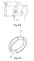
- FIGS. 1-1 to 1-16are various views of a patient interface according to an embodiment of the present invention.
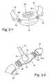
- FIGS. 2-1 to 2-2are schematic views illustrating assembly of a patient interface according to an embodiment of the present invention.
- FIG. 2-3is a schematic view illustrating attachment of a patient interface to a PAP device according to an embodiment of the present invention
- FIGS. 2-4 a to 2 - 4 billustrate attachment of a patient interface to a PAP device according to another embodiment of the present invention
- FIGS. 3-1, 3-2 a , and 3 - 2 billustrate a tube of a patient interface in open and collapsed phases according to an embodiment of the present invention
- FIG. 3-3is a schematic view of a tube and rigidizing element of a patient interface according to an embodiment of the present invention.
- FIGS. 3-4 and 3-4 a to 3 - 4 fillustrate various cross-sections of a tube along its length according to an embodiment of the present invention
- FIGS. 3-5 a to 3 - 5 care schematic views of a tube of a patient interface in open and collapsed or partially collapsed phases according to another embodiment of the present invention.
- FIGS. 3-6 a to 3 - 6 billustrate a tube having a concertina configuration according to another embodiment of the present invention
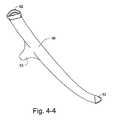
- FIGS. 4-1 to 4-5illustrate tubing for a patient interface according to an embodiment of the present invention
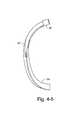
- FIGS. 4-6 to 4-9illustrate tubes and a rigidizing element according to an embodiment of the present invention
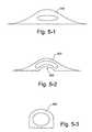
- FIGS. 5-1 to 5-3illustrate tubes of a patient interface according to alternative embodiments of the present invention
- FIGS. 6-1 to 6-4illustrate a back strap of a patient interface according to an embodiment of the present invention
- FIG. 6-5illustrates a back strap of a patient interface according to another embodiment of the present invention
- FIGS. 7-1 to 7-2illustrate manifolds of a patient interface according to alternative embodiments of the present invention
- FIGS. 8-1 to 8-5illustrate a tube configuration according to an embodiment of the present invention
- FIG. 8-6is a schematic view that illustrates a region where tubing may pass according to an embodiment of the present invention.
- FIG. 8-7illustrates an adjustable tube configuration according to another embodiment of the present invention.
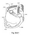
- FIG. 8-8-1illustrates a mask assembly incorporating an adjustment mechanism in accordance with an embodiment of the invention
- FIG. 8-8-2illustrates another view of the mask assembly shown in FIG. 8-8-1 ;
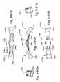
- FIGS. 8-8-3 a to 8 - 8 - 3 eshow various views of the adjustment mechanism shown in FIG. 8-8-1 ;
- FIGS. 8-8-4 a to 8 - 8 - 4 fshow various views of a first rack of the adjustment mechanism shown in FIG. 8-8-1 ;
- FIGS. 8-8-5 a to 8 - 8 - 5 eshow various views of a second rack of the adjustment mechanism shown in FIG. 8-8-1 ;
- FIGS. 8-8-6 a to 8 - 8 - 6 fshow various views of a pinion of the adjustment mechanism shown in FIG. 8-8-1 ;
- FIGS. 8-8-7 a to 8 - 8 - 7 fshow various views of a dial of the adjustment mechanism shown in FIG. 8-8-1 ;
- FIGS. 8-8-8 a to 8 - 8 - 8 fshow various views of a first housing portion of the adjustment mechanism shown in FIG. 8-8-1 ;
- FIGS. 8-8-9 a to 8 - 8 - 9 fshow various views of a second housing portion of the adjustment mechanism shown in FIG. 8-8-1 ;
- FIGS. 9-1 to 9-3illustrate a method for fitting a patient interface according to an embodiment of the present invention
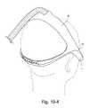
- FIGS. 10-1 to 10-6are various views of a patient interface including a cover according to an embodiment of the present invention.
- FIG. 11-1illustrates a valve of a patient interface according to an embodiment of the present invention
- FIGS. 12-1 to 12-3illustrate clips of a patient interface according to alternative embodiments of the present invention
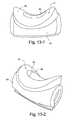
- FIGS. 13-1 to 13-2are various views of a foam interface and support according to an embodiment of the present invention.
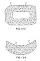
- FIGS. 13-3 and 13-4are top and side views of a foam interface having a cut, unskinned surface according to an embodiment of the present invention
- FIG. 13-5is a top view of a foam interface having a skinned surface according to an embodiment of the present invention.
- FIG. 13-6is an enlarged, schematic cross-section of a portion of the foam interface shown in FIG. 13-5 ;
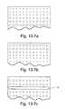
- FIGS. 13-7 a to 13 - 7 cillustrate foams according to alternative embodiments of the present invention
- FIG. 13-8is a schematic cross-section of a portion of a foam interface having a skinned surface and a vent according to an embodiment of the present invention
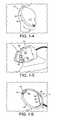
- FIG. 14-1is a table of mechanical properties of a foam interface according to an embodiment of the present invention.
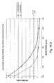
- FIG. 14-2is a graph illustrating properties of a foam interface according to an embodiment of the present invention.
- FIG. 14-3is a schematic view of a dispenser adapted to dispense individual packages containing a foam interface according to an embodiment of the present invention
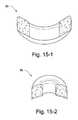
- FIGS. 15-1 to 15-2illustrate front and side cross-sectional views, respectively, of a foam interface according to an embodiment of the present invention
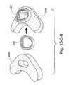
- FIG. 15-3-1shows a front view of a mask assembly in accordance with an embodiment of the invention
- FIG. 15-3-2shows a side view of the mask assembly shown in FIG. 15-3-1 ;
- FIG. 15-3-3shows a top detail view of the mask assembly shown in FIG. 15-3-1 ;
- FIG. 15-3-4shows a front perspective view of the mask assembly shown in FIG. 15-3-1 ;
- FIGS. 15-3-5-1 to 15-3-5-3show three forms of cushions in accordance with an embodiment of the invention including side portions, one of the forms is a flat cushion and the other two forms are curved;
- FIG. 15-3-6shows a flat cushion embodiment that has been adhered to a curved surface
- FIG. 15-3-7shows a perspective view of the cushion embodiment shown in FIG. 15-3-6 ;
- FIG. 15-3-8shows a mounting arrangement for a flat cushion that is configured to provide a curved shape to the flat cushion
- FIGS. 15-3-9-1 to 15-3-9-3show an alternative embodiment of the invention wherein headgear connectors are located close to the nares in between a foam cushion and a decoupling joint;
- FIG. 16-1is a schematic view of a patient interface according to an embodiment of the present invention.
- FIGS. 16-2 to 16-3are schematic views of a frame and force vector according to an embodiment of the present invention.
- FIG. 17-1schematically illustrates layers of an interfacing structure according to an embodiment of the present invention
- FIG. 17-2illustrates a method of joining an interface to a frame according to an embodiment of the present invention
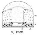
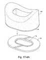
- FIGS. 17-3A to 17-3Cillustrate a mechanical interference type attachment mechanism to removably attach an interfacing structure to a patient interface according to an embodiment of the present invention
- FIGS. 17-4A to 17-4Cillustrate a hook and loop type attachment mechanism to removably attach an interfacing structure to a patient interface according to an embodiment of the present invention
- FIGS. 18-1 to 18-3illustrate a method of joining an under-the-nose interface to a frame according to an embodiment of the present invention
- FIGS. 19-1 to 19-3are sequential views illustrating a manufacturing process for applying a pressure sensitive adhesive to the back of an under-the-nose interface according to an embodiment of the present invention
- FIGS. 20-1 to 20-3illustrate a method of joining an under-the-nose interface to a frame according to an embodiment of the present invention
- FIGS. 20-4 to 20-7are sequential views illustrating a manufacturing process for forming a composite under-the-nose interface according to an embodiment of the present invention
- FIGS. 21-1 to 21-3illustrate a flexible frame according to an embodiment of the present invention
- FIG. 22-1illustrate a flexible frame according to another embodiment of the present invention
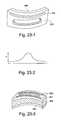
- FIG. 23-1illustrates a flexible frame with a spring element according to an embodiment of the present invention
- FIG. 23-2is a graph for a variable spring element with k values that vary across its length according to an embodiment of the present invention
- FIG. 23-3illustrates a flexible frame with a spring element according to another embodiment of the present invention.
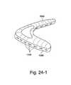
- FIG. 24-1illustrates a foam interface including a rigidizer that provides venting according to an embodiment of the present invention
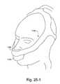
- FIG. 25-1illustrates a patient interface including an under-the-nose interface and a mouth interface according to an embodiment of the present invention
- FIG. 26-1is a perspective view of a known mask commercially sold by Respironics under the name of ComfortCurveTM;
- FIGS. 26-2 to 26-10illustrate improvements and/or alternative arrangements of Respironics' ComfortCurveTM mask according to embodiments of the present invention
- FIG. 27-1is a perspective view of a known mask commercially sold by Respironics under the name of OptiLifeTM;
- FIGS. 27-2 to 27-7illustrate improvements and/or alternative arrangements of Respironics' OptiLifeTM mask according to embodiments of the present invention
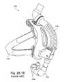
- FIG. 28-1Ais a perspective view of a known mask commercially sold by Respironics' under the name of ComfortLiteTM;
- FIG. 28-2Aillustrates an improvement and/or alternative arrangement of Respironics' ComfortLiteTM mask according to an embodiment of the present invention
- FIG. 28-1Bis a perspective view of a known mask commercially sold by Respironics' under the name of ComfortLiteTM 2;
- FIG. 28-2Billustrates an improvement and/or alternative arrangement of Respironics' ComfortLiteTM 2 mask according to an embodiment of the present invention
- FIGS. 29-1 to 29-2illustrate a known mask commercially sold by Fisher & Paykel under the name of OpusTM;
- FIGS. 29-3 to 29-9illustrate improvements and/or alternative arrangements of Fisher & Paykel's OpusTM mask according to embodiments of the present invention
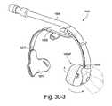
- FIG. 30-1 to 30-2are perspective views of a known mask commercially sold by Puritan Bennett under the name of Breeze® SleepGear® DreamSeal®;
- FIGS. 30-3 to 30-5illustrate improvements and/or alternative arrangements of Puritan Bennett's Breeze® SleepGear® DreamSeal® mask according to embodiments of the present invention
- FIG. 31-1 to 31-2illustrate a known mask commercially sold by InnoMed Technologies under the name of Nasal-AireTM;
- FIGS. 31-3 to 31-4illustrate improvements and/or alternative arrangements of InnoMed Technologies' Nasal-AireTM mask according to embodiments of the present invention.
- the patient interfaces beloware described as including under-the-nose interface types, the patient interfaces may be adapted for use with other suitable interface types. That is, the interface type is merely exemplary, and aspects of the present invention may be adapted to include other interface types, e.g., nasal cushions, nasal prongs, full-face masks, mouth masks, etc.
- Embodiments of the inventionare directed towards moving from uncomfortable, unattractive mask systems to sleek and elegant patient interfaces that are soft, comfortable, lightweight, functional, therapy enhancing, fashionable, easy and intuitive to fit and adjust with little or no adjustment, shape holding, low impact, low profile, continuity of form, individualized or customized, and/or are more appealing and much less objectionable by patients and bed partners alike.
- the subject patient interfacesare less obstructive, less obtrusive, anatomically coherent and appear like an organic extension of and/or blends with the patient, rather than a bulky, mechanical extension affixed to the patient which can appear to be ungainly or unattractive. This can help the patient and the patient's bed partner more readily relax and/or sleep during treatment.
- the patient interfacecan improve the overall perception such that the patient is simply wearing a garment like a night cap or bed clothes, etc. rather than being treated for a respiratory illness.
- This improved perceptioncan help increase the chances that the patient will actually wear the patient interface and comply or better comply with therapy, therefore increasing the likelihood of effective therapy for the user of the device.
- the bed partnerwill more readily accept and participate in the patient's therapy by encouraging the use of a sleep-enhancing device that is easy to use/adjust, more attractive and/or appealing interface.
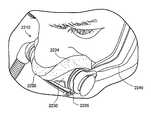
- FIGS. 1-1 to 1-16illustrate a patient interface or mask system 10 according to an embodiment of the present invention.
- the patient interface 10includes an interfacing structure 20 (also referred to as a cushioning structure or conforming structure) adapted to provide an effective interface with the patient's face and an air delivery and stabilizing system 30 (also referred to as conduit headgear or inlet conduit arrangement) adapted to deliver breathable gas to the interfacing structure 20 and support the patient interface 10 in a desired position on the patient's head.
- a coveralso referred to as a sock or covering
- Known patient interfacestypically include separate headgear and air delivery components that are used to locate and supply breathable gas to a mask or the like.
- Known headgeartypically includes an assembly of elastic (or inelastic) straps, buckles, locks, and/or clips.
- Known air delivery componentstypically include 15-22 mm diameter spiral reinforced tubing and swivel connectors. These known arrangements of headgear and air delivery components can be difficult to use for those who are less dexterous and/or unfamiliar with them. These known arrangements of headgear and air delivery components can also be uncomfortable or impractical to lie on.
- the air delivery and stabilizing system 30includes four main components, i.e., tubing 40 , a rigidizer 50 , a back strap 60 , and a manifold 70 (e.g., see FIG. 1-6 ).
- a supply of airis directed to the manifold 70 , e.g., located on or in front of the crown of the patient's head.
- the supply of airpasses from the manifold 70 to the tubing 50 , e.g., at least one and preferably two tubes, towards the patient's nose and/or mouth.
- the tubing 40has the property of being collapsible to lie on, yet sufficiently rigid in other directions so as to maintain sufficient stability of the interface.
- the tubing 40includes two tubes or inlet conduits 42 (also referred to as gas passages or gas conduits) communicated with the interfacing structure 20 to deliver breathable gas to the interfacing structure 20 (e.g., see FIG. 1-6 ).
- a single tubemay be used.
- two tubesbe used, so that a sufficient supply of breathable gas can still be delivered to the interfacing structure 20 when one of the tubes 42 is fully collapsed, e.g., due to the patient lying on his/her side. That is, when two tubes 42 are used, one or both of the tubes 42 may be open in use.
- more than two tubesmay be used, e.g., three or more tubes.
- the tubingmay provide a four tube arrangement including two upper tubes along upper sides of the patient's face and two lower tubes along lower sides of the patient's face.
- Each tube 42includes a first end 42 . 1 adapted to engage a respective end of a frame 22 of the interfacing structure 20 and second end 42 . 2 adapted to engage a respective end of the manifold 70 , as shown in FIGS. 2-1 and 2-2 .
- the frame 22 and manifold 70may each include tube portions 25 adapted to engage respective ends of the tubes 42 , e.g., via friction fit.
- the tubes 42are supplied with pressurized breathable gas from the manifold 70 , and the pressurized breathable gas is delivered into opposing ends of the interfacing structure 20 .
- the tube portions 25 of the frame 22 and manifold 70each have a stepped configuration so that when the respective tube is attached thereto the joint has a smooth, almost seamless form, e.g., no visible step changes in the overall form.
- the boundary between each tube portion 25 and the main body of the frame or manifoldmay have a step height substantially equal to the wall thickness of the respective end 42 . 1 , 42 . 2 of the tube, and mating the tube portion and respective end of the tube will result in a smooth, almost seamless form at the joint.
- the smooth jointimproves aesthetics and may have a functional benefit in reducing drag forces picked up on pillows, bedclothes, etc. as the patient rolls around in bed in use.
- the two tubesmay be independently connected to the supply of gas (e.g., positive airway pressure (PAP) device or flow generator).
- gase.g., positive airway pressure (PAP) device or flow generator.
- one tube 42may extend from one end of the interfacing structure 20 to a first outlet O1 of the PAP device and the other tube 42 may extend from the other end of the interfacing structure 20 to a second outlet O2 of the PAP device.
- the manifoldmay be eliminated or the manifold may be incorporated into the PAP device itself.
- the two tubesmay be joined together at an outlet of the PAP device (e.g., both tubes adapted to be coupled to a single outlet of the PAP device), and then the tubes bifurcate (i.e., split or divide into separated tubes) towards the interfacing structure.
- tube 42 ( 1 )may be coupled to a single outlet O of the PAP device and then split into separate tubes 42 ( 2 ) towards respective ends of the interfacing structure 20 .
- the tube 42 ( 1 )may include an internal dividing wall W to divide the tube into two conduits associated with a respective one of the tubes 42 ( 2 ).
- each tube 42is structured such that it may move between two phases, i.e., a first open phase in which the tube 42 allows the passage of air (e.g., see FIG. 3-1 ) and a second collapsed phase in which the tube 42 is fully collapsed and comfortable to lie on (e.g., see FIG. 3-2 b ).
- Each tube 42is structured such that the weight of any patient's head (e.g., adult or infant/child) resting on the tube 42 is sufficient to collapse the tube 42 so the patient may comfortably lie on his/her side (e.g., see FIGS. 1-3, 1-5, and 1-14 ).
- each tube 42may collapse under much less weight than a typical patient's head.
- the tubeIn the open phase, the tube is open or at least partially open so that the tube allows the passage of air, e.g., without undue resistance to flow, sufficient to provide treatment.
- the tubeIn the collapsed phase, the tube is collapsed to substantially prevent the passage or conductance of air.
- each tubeneed not collapse fully or entirely to provide improved comfort.
- each tubemay be structured such that it may move between a first open phase in which the tube 42 allows the passage of air and a second partially or substantially collapsed phase (e.g., see FIG. 3-2 a ) in which the tube 42 is at least partially or substantially collapsed to restrict and/or at least partially prevent the passage of air.
- opposing inner walls of the tubemay engage one another at one or more points or surfaces along their length such that conductance through the partially or substantially collapsed tube is minimized or even reduced to negligible amounts.
- the tubein the partially or substantially collapsed phase, may be open enough to maintain a small degree of conductance of pressurized gas.
- a small degree of patencycan be accomplished using wall thicknesses of a certain gauge (such that opposed walls will not contact or fully contact one another upon application of loads normally encountered during therapy) and/or one or more short anti-crush ribs provided to an inside surface of the tube.
- Each tube 42is sufficiently air tight and structured to deliver air from the top of the patient's head to the patient's nose without discomfort to the patient, e.g., see FIGS. 1-4 and 4-2 .
- Impedance provided by the tubewill be appropriate for the blower in use, regardless of whether one or both tubes are in the open phase. That is, the tube 42 provides a wide open cross-section with low impedance when in the open phase and provides a low profile when in the collapsed phase.
- the tubesessentially provide a linear tubing system with a parallel line which can be switched on or off (i.e., open phase or collapsed phase), and the switching of either side of the parallel line off will have negligible effect on the total impedance of the tubing system. That is, the impedance “felt” by the PAP device is substantially independent of whether one or both tubes are open.
- the tubesmay also be adapted to control pressure swings, e.g., deep breath by the patient.
- each tube 42may have sufficient strength to maintain patency or an open, unblocked state without being pressurized. That is, the tube 42 may be structured such that it only collapses when it is “actively” compressed, otherwise the tube 42 remains in its open phase.
- the supply of gasmay help to inflate each tube.
- Each tube 42may collapse anywhere along its length and may collapse to a substantially flat configuration so the tube 42 is substantially flat against the patient's face for comfort.
- the tube 42may be structured to collapse along selected portions thereof, e.g., middle only, central only, etc.
- At least one tubemay have at least one laterally ballooning feature.
- a portion of the tubeis collapsed or partially collapsed and a portion of the tube is open, e.g., the tube is “pinched” in the middle to provide a general figure-8 shape.
- at least one tubemay have a relatively wide, flat shape to provide a stretched-out tube adapted to cover more of the patient's cheeks.
- FIG. 3-5 ais a schematic view of a tube 142 in its initial configuration
- FIG. 3-5 billustrates the tube 142 when end portions 144 , 146 are collapsed or partially collapsed into a flat configuration
- 3-5 cillustrates the tube 142 when a middle portion 145 is collapsed or partially collapsed into a flat configuration.
- the tubecould be preformed to have one or more relatively flatter portions 144 , 145 , 146 and one or more rounded conduit portions 147 as shown in FIGS. 3-5 b and 3 - 5 c.
- the patient interfacepreferably does not collapse at the manifold and in an area at the front of the patient's nose, e.g., at the interfacing structure 20 .
- the manifoldmay be constructed of a substantially rigid material and the interfacing structure 20 may include a substantially rigid frame (e.g., frame 22 shown in FIG. 2-1 ) that prevents collapse in use. This arrangement ensures that an air flow path is provided from at least one of the tubes 42 to the patient's nose.
- each tube 42may be molded from a silicone material, e.g., liquid silicone rubber (LSR), having a thin wall thickness of about 0.5 mm.
- each tubemay have a wall thickness in the range of about 0.3 mm to 5 mm.
- the tubesmay have varying colors, and the tubes may be formed in a mold with a polished surface to provide the tubes with smooth exterior surfaces.
- each tubemay be constructed from other soft, flexible materials, e.g., thermoplastic elastomers (e.g., Santoprene), foam, foam laminate, closed cell impermeable foam, dipped and knitted textiles including cotton or silk.
- each tubemay be constructed from two sheets of material, e.g., laminate, that are attached to one another, e.g., heat welded, to form a tube.
- each tubemay be constructed of a plurality of elements, e.g., relatively rigid elements, arranged in a concertina configuration so as to allow the tube to move between open and collapsed phases.
- each tubemay have a concertina configuration that allows each tube to collapse from one volume to another smaller volume.
- FIG. 3-6 aillustrates a cross-section of a concertina-type tube 542 in a first phase that provides a first volume
- FIG. 3-6 billustrates the concertina-type tube 542 in a second phase that provides a second volume smaller than the first volume.
- one side 543 of the tube 542is placed adjacent the patient's face.
- the tube arrangement according to an embodiment of the present inventioncontrasts with prior arrangements such as InnoMed's Nasal Aire and other forms of nasal cannula that are designed to resist crushing (i.e., breathable gas is able to be delivered through both tubes all the time) and thus present an uncomfortable structure for a patient to lie on. Furthermore, unlike prior arrangements, the tube arrangements according to embodiments of the present invention are capable of providing a sufficient supply of pressurized gas when one of the pair of tubes is fully collapsed. Because of the particular arrangement of the pair of tubes in accordance with an embodiment of the present invention, both tubes are not crushed at one time during normal use.
- the tube arrangement according to an embodiment of the present inventionprovides two or more tubes that cooperate to maintain sufficient conductance of gas (e.g., sufficient flow of gas at therapeutic pressure) and comfort to the patient without introducing unnecessarily high impedance.
- each tubehas sufficiently low impedance (e.g., large enough hydraulic diameter) which facilitates the adequate supply of gas when one of the tubes is occluded, e.g., lain on.
- each tube 42has a non-cylindrical cross-sectional shape which provides a blending contour to blend with the patient's face (e.g., see FIGS. 3-1 and 4-1 to 4-5 ). That is, each tube 42 provides a blending contour or free form with few or no sharp edges or straight lines.
- the blending contouris smooth, streamlined, sleek, and blends or tapers the tubes 42 with or into the contours of the patient's head, e.g., anatomically coherent, less obtrusive and more aesthetically appealing.
- the blending contourhas no sharp edges that could cause discomfort, e.g., skin irritations or abrasions.
- each tube 42may vary along its length, e.g., vary non-uniformly with location around the patient's head.
- each tubemay have a cross-sectional area that changes along its length with an approximately constant hydraulic diameter.
- each tube 42may provide flatter regions in certain areas, e.g., where the patient rests on the tube during sleep. In this way, the tubes can be said to be an organic extension of the patient's facial contours.
- FIG. 3-1illustrates an exemplary cross-section of a tube 42 .
- the tube 42has a generally D-shaped cross-section and includes an internal or inwardly facing surface 44 and an external or outwardly facing surface 45 .
- the internal surface 44is relatively flat and adapted to sit substantially flush against the patient's face in use.
- the internal surface 44may have a tapered configuration form an inner edge to an outer edge to provide a comfortable fit for a wide range of patients.
- the internal surface 44provides a relatively large surface area which results in a more even load distribution. This arrangement is less likely to create pressure points in use.
- the internal surface 44may have grip-like material to help stabilize the patient interface on the patient's face.
- a rigidizing elementmay be provided to the internal surface to add rigidity to the tube.
- the external surface 45has a smooth contour that blends with the patient's face. That is, the external surface 45 has a profile or organic form with edges that blend into the patient's face, e.g., in a tangential manner, to prevent any edges from catching on bedclothes, pillows, etc., during sleep (e.g., when the patient rolls over).
- FIGS. 3-4 and 3-4 a to 3 - 4 fillustrate various cross-sections of a tube 42 along its length according to an embodiment of the present invention.
- FIG. 3-4 aillustrates a cross-section of the tube 42 at the end adapted to engage the manifold 70
- FIG. 3-4 billustrates a cross-section of the tube 42 that is 20% of the tube length from the manifold end
- FIG. 3-4 aillustrates a cross-section of the tube 42 at the end adapted to engage the manifold 70
- FIG. 3-4 billustrates a cross-section of the tube 42 that is 20% of the tube length from the manifold end
- FIG. 3-4 cillustrates a cross-section of the tube 42 that is 40% of the tube length from the manifold end
- FIG. 3-4 dillustrates a cross-section of the tube 42 that is 60% of the tube length from the manifold end
- FIG. 3-4 eillustrates a cross-section of the tube 42 that is 80% of the tube length from the manifold end
- FIG. 3-4 fillustrates a cross-section of the tube 42 at the end adapted to engage the interfacing structure 20 .
- the D-shape of the cross-sectionvaries along its length.
- each cross-sectionhas a width w and a height h, and the width and height of the various cross-sections varies along the length of the tube, e.g., a relatively long width and short height at the manifold end and a relatively short width and tall height at the interfacing structure end.
- all of the cross-sectionshave a very similar or common hydraulic diameter, e.g., about 10-15 mm or about 13 mm.
- the shapemay be configured based on aesthetic and/or impedance requirements. In addition, the shape may be configured to provide low profile, comfort, and/or stabilization.
- the tubes 42may have other suitable cross-sectional shapes, e.g., trapezoidal, semi-circular, cylindrical, oval, elliptical, flatter section, etc. Also, the tubes may have a flat configuration with anti-crush ribs. This arrangement is disclosed in U.S. patent Ser. No. 10/385,701, the entirety of which is incorporated herein by reference.
- FIGS. 5-1 to 5-3illustrate alternative cross-sections of the tube.
- FIG. 5-1illustrates a tube 242 that more gradually blends into the patient's face.
- the tube 342may provide a gap 343 in the internal surface, e.g., to allow air flow or breathing. While less preferred than the cross-sections shown in FIGS. 3-1, 5-1, and 5-2 , the cross-section of tube 442 in FIG. 5-3 would be more preferable than a normal cylindrical tube for its blending contour.
- a D-shaped or generally trapezoidal-shaped tubedoes not produce as pronounced pressure regions along bottom edges thereof as a semi-circular-shaped tube would.
- the reason for thisis that the side walls of the D-shaped or generally trapezoidal-shaped tube meet the base at an acute angle ⁇ , i.e., less than 90°, as shown in FIG. 3-1 .
- the side walls of the semi-circular-shaped tubemeet the base at approximately 90°, and if the tube were pressed against the patient's face, the region where the side walls meet the base would be quite rigid and may lead to pressure points.
- a semi-circular-shaped tubemay provide a discontinuity of form when viewed in relation to the patient's facial contours.
- a rigidizing element or rigidizer 50is provided to each tube 42 to add rigidity to the tube 42 (e.g., see FIGS. 1-6, 3-3, and 4-3 to 4-5 ).
- a rigidizing element 50 in accordance with an embodiment of the present inventionis preferably thin and conforming when a patient lies upon it, yet has sufficient stiffness to resist out-of-plane bending. That is, the rigidizing element 50 is structured to allow bending in some planes and resist bending in other planes, e.g., allow bending towards and away from the patient's face.
- the rigidizing element 50also makes the tube 42 inextensible or not stretchy so that the tube 42 is strong in tension and maintains its size.
- the rigidizing element 50may provide structural integrity or self-holding form to the patient interface 10 so that the patient interface 10 can hold its shape and not fall into a heap, e.g., shape memory, whether the patient interface 10 is on or off the patient's head.
- the shape holding arrangementmaintains the tubes in a desired position and may facilitate donning of the patient interface in use.
- the rigidizing element 50may be provided to an interior and/or exterior portion of the tube 42 .
- FIGS. 1-6 and 4-1 to 4-5illustrate a rigidizing element 50 provided to an exterior portion of the tube 42 (e.g., along internal surface 44 ) that is adapted to engage the patient's head in use.
- the rigidizing element 50may include tubular end portions 52 to facilitate connection of the tubes 42 to the manifold 70 and/or interfacing structure 20 .
- the tube/rigidizer sub-assemblymay also provide an extension 53 for supporting the back strap 60 , e.g., see FIGS. 4-1, 4-2, and 4-4 .
- FIGS. 4-6 to 4-9illustrate another embodiment of a rigidizing element 50 with the tubes 42 attached thereto.
- the rigidizing element 50may be structured to extend under the interfacing structure, the manifold, and/or the back strap in use.
- the rigidizing element 50may have a varying thickness along its length, e.g., to vary the stiffness or rigidity of the tube 42 along its length.
- the rigidizing element 50may be thinner at the patient's cheeks and thicker at the top of the patient's head.
- the rigidizing element 50 and/or tube 42may be structured to accommodate a respective arm of patient eyeglasses.
- the rigidizing element 50may be cut and/or formed from thin plastic sheet, e.g., 0.5 mm high impact polystyrene (or EPP foam).
- thin plastic sheete.g., 0.5 mm high impact polystyrene (or EPP foam).
- EPP foamhigh impact polystyrene
- suitable materialse.g., textile, nylon, polypropylene, high duro silicones, elastomers, etc.
- the rigidizing elementmay have other suitable wall thicknesses, e.g., in the range of about 0.3 mm to 5 mm.
- each tubing/rigidizer sub-assemblymay have a total thickness (e.g., thickness of collapsed tubing/rigidizer) of about 1.5 mm, e.g., 0.5 mm rigidizing element, 0.5 mm tube wall on one side, and 0.5 mm tube wall on opposite side.
- the total thicknessmay be more or less depending on application, e.g., 1-10 mm, 1-5 mm, less than 5 mm, about 10 mm, about 5 mm, and/or about 3 mm.
- the wall thickness of the tube and/or rigidizermay be adjusted for comfort and/or robustness, e.g., wall thicknesses thickened.
- the wall thickness of the tube and rigidizeris preferably as thin as possible, but may be thickened so as to be more shape-holding, self-supporting, and/or robust.
- a separate rigidizing element 50may be employed.
- a separate rigidizing element 50may be employed.
- International Patent Application PCT/AU03/00458published as WO 03/090827, which is incorporated herein by reference in its entirety.
- a separate rigidizing element 50may be formed, and then attached to the respective tube 42 , e.g., by an adhesive or by a mechanical interlocking arrangement.
- the rigidizing element 50may be co-molded or co-extruded with the respective tube 42 . That is, the tube 42 and rigidizing element 50 may form an integral, one-piece structure.
- the rigidizing elementmay made of polypropylene and the tube may be made of a thermoplastic elastomer of a grade suitable for welding/co-molding to the polypropylene rigidizing element.
- the rigidizing elementmay include multiple components that are adjustable or movable with respect to one another, e.g., slidable, to adjust the position and/or rigidity provided by the rigidizing element.
- a back strap 60is provided to the tubing/rigidizer sub-assembly (e.g., see FIGS. 1-2, 1-6, and 6-1 to 6-4 ).
- the back strap 60is adapted to be positioned generally on the patient's occipital bone in use to facilitate stabilizing the patient interface on the patient's head.
- the back strap 60may also assist in providing an interfacing force against the interfacing surface, e.g., under the patient's nose.
- the back strap 60(also referred to as an elasto-stabilizer or elastic stabilizer) includes a length of elastic strap 62 .
- the two ends of the elastic strap 62are attached to the tubing/rigidizer sub-assembly, e.g., via eyes 46 provided to respective tubes 42 as shown in FIGS. 6-3 and 6-4 .
- the back strap 60may sit in a range of positions on the patient's head and still effect an adequate interfacing force in both magnitude and direction.
- This arrangementallows some variation in fit size, and aids the patient's comfort in moving the back strap 60 to the most comfortable of locations, e.g., higher or lower positions at the back of the patient's head as shown in FIGS. 6-3 and 6-4 .
- the elasticity of the back strapallows the patient interface to fit a broad range of the population, e.g., 80-90% of the population.
- the back strap 60is primarily used to maintain the patient interface on the patient's head, rather than provide an interfacing force. That is, the interfacing structure 20 does not require high tension for interface (as described below), and therefore the back strap 60 does not need to be relied on for tension for an interfacing force.
- the strap 62may have selected elastic properties, e.g., from zero extension to a relatively small extension, the tension rises and plateaus. The tension may remain generally similar over a relatively large further extension until it reaches the fully extended elastic limit.
- a range of alternative straps 62may be provided with the patient interface for use with different size heads, e.g., different elasticity, thickness, length, etc.
- the back strap 60may have other suitable configurations with selectively adjustable lengths, e.g., baseball cap adjuster (e.g., see FIG. 10-4 ), hook and loop material, ladder lock, adjustable elastic.
- the back strapmay include side rigid portions 65 (e.g., integrally formed with the rigidizing element 50 ) and an elastic strap 62 joining the free ends of the rigid portions 65 .
- the back strapmay be constructed of the same material as the tubes, e.g., tube and back strap co-molded to a rigidizing element.
- the two sides of the patient interfacemay be molded at once, e.g., two rigidizing elements held together by the back strap which blends into both rigidizing elements.
- the tubeswould be engaged with a manifold and an interfacing structure.
- the back strapmay be replaced by ear anchors adapted to engage the patient's ears and support the patient interface on the patient's face.
- the back strapmay only extend across part of the occiput (e.g., the back strap comprises resilient fingers that extend inwards from each side and press against the occiput to provide a rearwardly directed force).
- the manifold 70is provided to interconnect the two tubes 42 and direct air flowing from a suitable source, e.g., a blower, into the two tubes 42 (e.g., see FIGS. 1-2, 1-4 , and 1 - 6 ).
- a suitable sourcee.g., a blower
- the manifold 70is generally T-shaped and includes a base portion 72 and an inlet tube portion 74 that is coupled (e.g., movably coupled via a ball joint, hinge, general flexibility, etc.) to the base portion 72 .
- the manifold 70is designed to be sleek and to have a form continuous with the shape of the patient's head and the patient interface, e.g., unobtrusive.
- the manifoldmay have a relatively flat form or low profile to minimize the height or angle of air delivery.
- the manifoldprovides a transition from the air delivery tubing leading from the PAP device to the inlet tubing leading to the interfacing structure.
- the manifoldtransitions non-crushable tubing of the air delivery tubing to crushable tubing of the inlet tubing.
- the manifoldtransitions tubing profile, e.g., relatively round tubing of the air delivery tubing to relatively flat tubing of the inlet tubing.
- the base portion 72includes opposing tube portions 25 adapted to engage respective tubes 42 , e.g., with a friction fit.
- the cross-sectional shape of the tube portions 25may be non-circular and correspond to the cross-sectional shape of the tubes 42 .
- the base portion 72may be curved to match the shape of the patient's head and is otherwise suitably contoured such that it can rest and sit substantially flush with the top of the patient's head in use.
- the base portionmay include other suitable connections or air holding bonds with the tubes.
- the inlet tube portion 74may be fixed to the base portion 72 , or the inlet tube portion 74 may be movably coupled, e.g., swivel, to the base portion 72 so that the inlet tube portion 74 may be angled with respect to the base portion 72 in use.
- the swivel arrangementmay provide 360° rotation or any other suitable angle range.
- the inlet tube portion 74has an inlet tube 75 , e.g., 15 mm diameter, adapted to connect to an air delivery tube T 1 (e.g., see FIGS. 1-2, 1-7, and 2-2 ) connected to a suitable air delivery source, e.g., a blower.
- manifold 70 and tubes 42may be integrally formed as a one-piece structure, e.g., to reduce the number of parts.
- the manifoldmay be structured to control dynamic flow and/or reduce noise.
- the manifold 70is positioned in a region on the top of the patient's head that does not interfere with a pillow when the patient interface is used (e.g., see FIGS. 1-2, 1-4, and 1-7 ). That is, the manifold 70 directs the air delivery tube T 1 out of the bed so it does not interfere with the pillow and does not pass along the patient's body.
- the manifold 70may be positioned on the crown of the patient's head, e.g., generally in the plane of the patient's ears.
- the manifold 70may be positioned generally in the region of the Bregma in use.
- An advantage of this approachis that tube drag does not directly affect the interface in use. For example, by placing the manifold 70 near the crown of the head, it is positioned furthest from the interfacing structure 20 , so if the air delivery tube is yanked or moved, the movement has less affect on the interface, e.g., by changing the load distribution in the interfacing region, and therefore increases the stability of the interface. Also, the positioning of the manifold enables the tube connection to the mask to be less obtrusive by avoiding the patient's field of vision.
- the manifoldmay provide multiple functions or utilities.
- the manifoldmay provide a point of reference or anchor point for the patient interface. That is, the manifold may act as a head support or stabilizer, an air delivery conduit, and an inlet tubing attachment point.
- the manifoldresists tube drag as described above.
- the manifold 70is generally T-shaped and defines two generally perpendicular axes, i.e., the base portion 72 along a first axis and the inlet tube portion 74 along a second axis that is perpendicular to the first axis.
- the manifold 70may incorporate swiveling features that allow the manifold 70 to swivel or hinge about one or both axes (e.g., see FIG. 7-1 ).
- FIG. 7-2illustrates a manifold 270 having a ball and socket arrangement that allows the inlet tube portion 274 to rotate or swivel with respect to the base portion 272 .
- the base portion and/or inlet tube portionmay incorporate one or more stops to limit swiveling in use.
- the swiveling featureallows the air delivery tube to be suitably angled with respect to the patient interface, e.g., so the air delivery tube does not extend into the wall or bed headboard.
- the manifold 70is positioned at the top of the patient's head, e.g., see FIGS. 1-2, 1-4, and 1-7 .
- the manifold 70may be offset from the top of the patient's head, e.g., positioned at a side of the patient's head. This offset arrangement may provide more comfort as there may be less drag (particularly if the patient sleeps on the opposite side of their head). This arrangement may also facilitate an alternative tube attachment and routing, e.g., a snorkel-like side tube routing.
- the length of the tubes 42may be selected to adjust the manifold 70 to a position where the patient can view and more easily manipulate air delivery tube connections.
- the manifold 70may have an adjustable connection, e.g., sliding or translating coupling, so that two or more positions of the manifold (e.g., along a backstrap of the headgear) may be selected.
- an adjustable connectione.g., sliding or translating coupling
- the air delivery and stabilizing system 30includes two alternative, complementary air delivery pathways located on different parts of the patient's head (e.g., preferably either side of the patient's face) so that a patient may roll through almost a complete circle without occluding both pathways.
- the air delivery and stabilizing system 30has a generally oval or ring-shaped configuration (e.g., see FIGS. 8-1 to 8-4 ).
- each tube 42 of the systemhas one end that passes generally over the crown of the patient's head and the other end passes under the patient's nose, as shown in FIG. 8-5 .
- the air delivery and stabilizing system 30is outside the patient's eyes and does not interfere with the patient's vision or field of view and may be simply donned as one does a cap.
- the ring-shaped configurationmay incorporate a divider to split the ring shape, e.g., ring shape divided at manifold or under nose.
- Each tube 42 of the air delivery and stabilizing system 30passes along a respective side of the patient's face between the patient's eye and ear to provide an arrangement that does not obstruct the patient's vision. That is, each tube 42 is sufficiently spaced from the ear to reduce noise and sufficiently spaced from the eye so it does not affect the field of view. In an embodiment, the tube 42 passes in a direct line from the patient's nose to the crown of the patient's head. However, the tube 42 is not limited to any specific path.
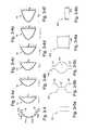
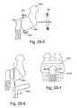
- each tube 42may pass within a region defined between a first boundary curve P 1 and a second boundary curve P 2 .
- the first and second boundary curves P 1 , P 1are represented by two identical curves, one curve rotated with respect to the other curve. The curves are positioned so that they are both on the extremes of the region.
- the first boundary curve P 1is adjacent to the eye at a position where it would impinge upon the patient's field of view
- the second boundary curve P 2is adjacent the patient's ear.
- the second boundary curve P 2may be described as a position adjacent a top forward location on the patient's auricle where the auricle joins the patient's temple.
- Dimension Bshows a head height.
- curve P 2stops on the crown of the patient's head. That is, if the curve represented tubing, it would be substantially snug against the top of the patient's head.
- dimension Ashows the head height of a patient that this would fit.
- a fit range delta ABis achievable using the same non-adjustable tubing.
- the air delivery and stabilizing system 30may pass along the upper jaw bone of the patient, e.g., avoid cheek and follow fleshy areas of the patient's face. Also, in an embodiment, the air delivery and stabilizing system 30 may reside over the mid-point of the patient's temple in use. However, the air delivery and stabilizing system 30 may be sufficiently soft so that sensitive areas do not need to be avoided for comfort.
- the patient interface 10is structured such that little or no adjustment is needed to fit the patient interface to the patient's head.
- the patient interfaceis relatively self-locating, intuitive, auto-adjusting, easy fitting.
- the patient interfacemay be assembled one handed, e.g., slip on like a hat.
- the air delivery and stabilizing system 30has a generally oval or ring-shaped configuration, e.g., a generally truncated elliptical cone or funnel.
- a tapering surface or conical-elliptical ringmay be provided between the inner and outer edges to define a contact surface that engages the patient's head.
- the tapered contact surfacewill engage the patient's head in different positions. For example, if the patient has a larger head, the patient interface may sit higher up on the patient's head. If the patient has a smaller head, the patient interface may sit more towards a rear portion of the patient's head. Once fit, the patient may adjust the back strap 60 as necessary. Thus, the patient may require a single adjustment to fit the patient interface to his/her head. Further details of such an arrangement are disclosed in U.S. Provisional Application No. 60/833,841, filed Jul. 28, 2006, which is incorporated herein by reference in its entirety.
- the oval or ring-shape configuration of the air delivery and stabilizing system 30may be adjustable, e.g., depending on patient fit and/or preference.
- top and/or bottom portions of the “ring”may include an adjustment mechanism 55 to allow adjustment of the ring size, e.g., depending on patient's head size.
- FIGS. 8-8-1 to 8-8-9 fillustrate a mask assembly 2110 including a headgear adjustment mechanism 2155 according to an embodiment of the present invention.
- Such mask assemblyis disclosed in U.S. Provisional Application No. 60/996,485, filed Nov. 20, 2007 and entitled “A Respiratory Mask Headgear Adjustment Apparatus”, which is incorporated herein by reference in its entirety.
- a pair of soft flexible tubes 2142are routed from a foam interface 2120 positioned under the nose to a manifold 2170 located near the crown of the head, as shown in FIGS. 8-8-1 and 8-8-2 .
- Such arrangementforms an oval or ring-shaped “headgear” to support the mask assembly in a desired position on the patient's head.
- a headgear adjustment mechanism 2155 in accordance with an embodiment of the inventionallows lengthwise adjustment of a portion of the headgear, enabling it to be better fitted on a range of different head sizes.
- the headgear adjustment mechanism 2155incorporates a rack and pinion, whereby rotational motion of a dial 2156 is arranged to provide lengthwise adjustment of a headgear configuration. As shown in FIGS. 8-8-1 and 8-8-2 , this allows adjustment of the headgear length so that points A and B may be moved closer together, or farther apart.
- the adjustment mechanism 2155includes a first rack 2157 ( 1 ) ( FIGS. 8-8-4 a to 8 - 8 - 4 f ), a second rack 2157 ( 2 ) ( FIGS. 8-8-5 a to 8 - 8 - 5 e ), a pinion 2158 ( FIGS. 8-8-6 a to 8 - 8 - 6 f ), and a dial 2156 ( FIGS. 8-8-7 a to 8 - 8 - 7 f ) connected to the pinion 2158 .
- a first housing portion 2159FIGS. 8-8-8 a to 8 - 8 - 8 f
- a second housing portion 2161FIGS.
- FIGS. 8-8-9 a to 8 - 8 - 9 fsupport the pinion 2158 and dial 2156 with respect to the racks 2157 ( 1 ), 2157 ( 2 ).
- the racks 2157 ( 1 ), 2157 ( 2 )are connected to or form part of the headgear.
- FIGS. 8-8-3 a to 8 - 8 - 3 eillustrate the adjustment mechanism 2155 isolated from the mask assembly.
- each rack 2157 ( 1 ), 2157 ( 2 )includes a tube connector portion 2163 and a rack portion 2164 that provides a slot 2164 . 1 and a series of teeth 2164 . 2 along one side of the slot.
- Each tube connector portion 2163is connected between a respective tube 2142 and a conduit 2143 provided to the manifold 2170 (see FIGS. 8-8-1 and 8-8-2 ).
- the ends of the tube connector portionmay have different cross-sectional configurations, e.g., to accommodate different cross-sectional configurations of the tube 2142 and conduit 2143 .
- each tube connector portion 2163may be rotatably or otherwise movably mounted to the rack portion 2164 to allow adjustment of the tube connector portion 2163 with respect to the rack portion 2164 , e.g., to adjust routing of the tube 2142 and conduit 2143 .
- each tube connector portionmay be include a bellows-type structure to allow flexibility, slack pick-up, etc.
- the rack portions 2164 of the first and second racks 2157 ( 1 ), 2157 ( 2 )are overlapped with one another to align the slots 2164 . 1 and provide opposed teeth 2164 . 2 (e.g., see FIGS. 8-8-3 b and 8 - 8 - 3 d ).
- the pinion 2158is positioned within the aligned slots and the pinion teeth 2158 . 1 are engaged with opposed teeth 2164 . 2 .
- the first and second housing portions 2159 , 2161are provided on opposing sides of the rack portions 2164 to enclose the pinion 2158 and maintain the pinion 2158 in an operative position.
- the first and second housing portions 2159 , 2161are coupled to one another, e.g., with a snap-fit interlock.
- the dial 2156includes a dial portion 2156 . 1 and a shaft portion 2156 . 2 extending from the dial portion.
- the dial 2156is supported by the first housing portion 2159 and the shaft portion 2156 . 2 extends through an opening 2159 . 1 in the first housing portion 2159 and is interlocked with an correspondingly shaped opening 2158 . 2 provided in the pinion 2158 . Accordingly, rotation of the dial 2156 causes corresponding rotation of the pinion 2158 , which provides lengthening or shortening of the headgear via the pinion's toothed engagement with the first and second racks 2157 ( 1 ), 2157 ( 2 ).
- the adjustment mechanism 2155includes a detent assembly to provide tactile feedback with the motion of the dial 2156 .
- the first housing portion 2159includes spring-biased projections 2159 . 2 that interact with recesses 2156 . 3 provided on the underside of the dial portion 2156 . 1 (see FIG. 8-8-7 d ).
- the spring-biased projections 2159 . 2will move into and out of engagement with the recesses 2156 . 3 .
- the spring-biased projections 2159 . 2will be seated within respective recesses 2156 . 3 to assist in restraining the dial 2156 at the desired position.
- each rackcan simply be coupled with the ends of one or more headgear straps, such that adjustment of the knob changes the length of the headgear.
- each rackcan be associated with another part of the mask, e.g., the conduits 2143 shown in FIGS. 8-8-1 and 8-8-2 .
- each rackis structured to accommodate the end of one of the air delivery conduits 2143 which pass over the top of the user's head.
- the rackse.g., the ends of the tube connector portions
- the adjustment mechanismis configured to be positioned on the crown of the patient's head, although in other configurations, it may be positioned on different parts of the patient's head, or for adjustment of the lengths of different sections of headgear.
- paddingmay be provided to the underside of the adjustment mechanism and adapted to engage the patient's head in use (e.g., exemplary padding 2165 illustrated in FIG. 8-8-3 b ).
- the adjustment mechanismmay include alternative configurations for size adjustment.
- the adjustment mechanismmay include a baseball-cap type adjustment, a belt-loop type adjustment, friction lock type adjustment, etc.
- FIGS. 9-1 to 9-3illustrate an exemplary method for fitting the patient interface to a patient.
- the interfacing structure 20may first be located under the patient's nose.
- the air delivery and stabilizing system 30may be rotated about the interfacing structure 20 onto the patient's head.
- the patient interfaceis rotated, e.g., for X°, until the air delivery and stabilizing system 30 engages the patient's head and prevents further movement.
- the back strap 60may be adjusted as necessary to comfortably secure the patient interface on the patient's head.
- the patient interfacemay be structured to provide “staged fitting” of the patient interface.
- one part of the patient interfacee.g., air delivery and stabilizing system
- another part of the patient interfacee.g., interfacing structure
- This arrangementallows the air delivery and stabilizing system to be engaged with the patient's head, while the interfacing structure is out of engagement.
- an Adam's circuite.g., such as that shown in FIGS.
- the interfacing structuremay be adapted to pivot upwards or laterally into a “standby” position that is out of the patient's field of view and/or not engaged with the patient's face or nose.
- the interfacing structuremay be moved from the “standby” position to a fully operable/engaged position at the last minute just before the patient is ready for therapy (e.g., before sleep).
- the tube or the joint between the tube and the maskmay be pivotable/bendable/movable to move the mask away from the face while still maintaining the headgear in place.
- FIG. 30-3illustrates an exemplary pivot 1915 at the joint between the tube and the mask that allows the mask to move away from the face (e.g., to a position shown in dashed lines).
- the patient interfaceincludes a single adjustment point.
- the adjustment mechanismmay be either passive (e.g., elastic back strap) or require active adjustment (e.g., baseball cap fitting) to provide a one-size fits all arrangement.
- the adjustment pointmay be tailored or modified to fit the patient at the point of sale, and then altered to prevent further adjustment, e.g., tear off.
- the patient interfacemay have a non-adjustable slip-on shape, e.g., like a shoe, with little or no elasticity.
- the patient interfacemay be provided in many different sizes, e.g., up to 20 different sizes, 5, 10, 15, or any other number of sizes (e.g., small, medium, and large). This arrangement may be aided by high mechanical compliance of the sealing interface to provide ample fit-range.
- the patient interfacemay include a method for adjusting the size (e.g., length) of the headgear in either or both of the upper and rear sections of the headgear.
- the air delivery and stabilizing systemmay be textured, colored, foamed, and/or flocked (e.g., lots of little bits of yarn or fluff adhered to it) to give a fabric-like feel or softness for aesthetics and/or comfort.
- the tubing, rigidizing elements, back strap, and/or manifoldmay be textured, colored, foamed, and/or flocked.
- a sock Smay be provided to substantially enclose one or more portions of the tubing, rigidizing elements, back strap, and/or manifold (e.g., see FIGS. 10-1 to 10-6 ).
- a sock Smay be provided to substantially enclose one or more portions of the tubing, rigidizing elements, back strap, and/or manifold (e.g., see FIGS. 10-1 to 10-6 ).
- different materialsmay be co-molded in the same mold to provide a one-piece, integrated structure.
- a fabric or cloth materialmay be co-molded with silicone tubing to provide a one-piece, integrated tube with a fabric/cloth exterior surface and a silicone interior surface.
- the fabric/cloth materialmay be placed in a mold and then silicone may be injected into the same mold so that it bonds with the fabric/cloth material and forms a one-piece, integrated tube.
- multiple portions of the patient interfacemay be co-molded in the same mold with different materials to provide a one-piece, integrated structure.
- a fabric/cloth materialmay be co-molded with tubing constructed of a first material, a manifold constructed of a second material, and a frame constructed of a third material to provide a one-piece, integrated structure.
- the first, second, and third materialsmay include the same material with different durometers or hardnesses, e.g., tubing constructed of relatively soft silicone and manifold and frame constructed of relatively hard silicone.
- the first, second, and third materialsmay include different polymers or materials.
- each portion of the patient interfacemay include regions with different properties, e.g., end portions of the tubing may be harder than an intermediate portion of the tubing.
- the fabric/cloth materialmay be placed in a mold and then the first, second, and third materials may be injected into the same mold so that all the materials bond and form a one-piece, integrated structure, e.g., integrally formed tubing, manifold, frame with fabric/cloth cover.
- the tubing, rigidizing elements, manifold, and/or back strapmay include silicone or other elastic beading for grip.
- This arrangementmay be particularly useful for patient's with bald heads as the beading is adapted to grip the bald head and prevent sliding or movement of the patient interface with respect to the patient's head in use.
- the patient interfacemay be reversible so that the beading may be selectively used, e.g., depending on whether the patient is bald.
- fabricmay be provided on one side and beading may be provided on the opposite side so that the patient may use one or the other depending on preference, e.g., beading oriented towards the patient's head for bald heads and fabric oriented towards the patient's head for hairy heads.
- each tube 42may be manufactured as a bifurcated tube having a co-molded thickened section that forms a rigidizer.
- each tube 42may be constructed of two pieces, i.e., a top half and a bottom half attached to the top half.
- the top halfmay be constructed of textile or foam (e.g., with a sealing layer), and the bottom half may constitute a rigidizer with a skin-contacting portion.
- the patient interfacemay incorporate one or more regions having different colors (color contrast), patterns, and/or surface textures to reduce visual impact or distraction to the user.
- coloring, patterning, and/or surface texturingmay be incorporated into the tubing, rigidizing elements, manifold, back strap, and/or interfacing structure.
- a sock having coloring, patterning, and/or surface texturingmay be provided to the patient interface.
- FIGS. 10-1 to 10-10-6illustrate a patient interface including a cover or sock S having a two-tone color scheme, e.g., a dark color D and a light color L.
- a cover or sock Shaving a two-tone color scheme, e.g., a dark color D and a light color L.
- a dark color Dis positioned adjacent the field of vision.
- This arrangementprovides a low impact, unobtrusive, sleek look that is less visually obtrusive to the patient and others.
- the dark color Dis positioned adjacent the field of vision to minimize visual obstruction or obtrusiveness.
- the patient interfacemay only be visible to the patient at the very outer limits of their field of view, e.g., only the section of the patient interface which rests lower than the patient's eye level may be visible. Further, the dark color D may seem to disappear at the extremities of the field of view resulting in the patient undergoing very little visual obstruction.
- the two-tone textile cover Smay slim the perception of the size of the patient interface on the patient's face. That is, this arrangement has the functional advantage that lighter colors, e.g., white, can be incorporated into the cover that make the relevant region look smaller, slimmer, or less bulky. Thus, the patient interface has a lower visual impact (e.g., less aesthetically obtrusive). In addition, the patient interface may be more fashionable like clothing. In alternative embodiments, one or more light colored lines, e.g., white lines, may be incorporated into the cover. Also, in an embodiment, the interface of the interfacing structure may include a darker color to reduce its visual obstruction.
- the covermay be transparent or selected to blend in with the patient's skin, e.g., camouflaged or skin color. For example, if the patient has relatively darker skin, the cover could be black or dark brown to blend with the patient's skin. In an alternative embodiment, the color and/or texture of the cover may be selected to match the patient's hair.
- a valve Ve.g., mechanical gate
- the valve Vmay remain closed if the interior pressure P int is over 2 cmH 2 O, and the valve may open if the interior pressure P int is less than 2 cmH 2 O thereby allowing the patient to breathe if both tubes 42 are occluded.
- the patient interface 10may be connected to the blower by a pair of air delivery tubes, i.e., a 15 mm tube and a 22 mm tube.
- a 15 mm tube T 1connects the manifold 70 to a 22 mm tube T 2
- the 22 mm tube T 2connects the 15 mm tube T 1 to the blower.
- a quick-release connector 90is provided at the transition between the 15 mm and 22 mm tubes T 1 , T 2 to allow quick release of the 15 mm and 22 mm tubes T 1 , T 2 , and hence quick release of the patient interface 10 from the blower.
- a quick-release connectormay be provided to the manifold 70 positioned adjacent the top of the patient's head.
- the quick-release connectormay have any suitable structure to facilitate tubing assembly/disassembly, e.g., mechanical interlock, friction fit, screw-type arrangement, etc.
- the various connection pointsfacilitates assembly/disassembly of the patient interface system which facilitates cleaning, adjustment, etc.
- the 15 mm tube T 1has a suitable length to allow easy patient access to the quick-release connector 90 , e.g., quick-release connector 90 in patient's field of view. Also, the 15 mm tube T 1 has a suitable length so that the quick-release connector 90 may be positioned sufficiently away from the patient interface so the weight of the quick-release connector may be supported by the bed mattress or other support system.
- the systemis designed such that the hydraulic restriction or bottleneck is provided upstream of the patient interface including the case in which only one of the tubes 42 is open, i.e., the hydraulic bottleneck is provided in the manifold 70 or anywhere upstream of the manifold 70 (e.g., in the 15 mm tube and/or in the 22 mm tube).
- Impedanceis at least partially based on tube length.
- the tubingis designed such that the tubes 42 are shorter than each of the 15 mm tube and the 22 mm tube, e.g., 15 mm and 22 mm tubes at least 40-50 cm long.
- the 22 mm inlet tubemay be about 2 m long and the 15 mm inlet tube may be about 70-75 cm long, with the bottleneck in the 22 mm inlet tube due to its length.
- other suitable lengthsare possible.
- the air delivery tubing that leads to the manifoldmay have a look and feel similar to the inlet tubes 42 .
- the air delivery tubingmay have a smooth, noiseless outer portion, e.g., outer portion constructed of a material that is soft to the touch and provides sound insulation.
- the air delivery tubingmay provide continuity of form from the PAP device or blower to the manifold of the patient interface.
- a clip or clampmay be provided to either air delivery tube T 1 , T 2 and/or quick release connector 90 that is adapted to attach to a bed headboard or other support system.
- the clip or clampsupports the air delivery tube and/or quick release connector on the bed headboard or other support system to isolate tube drag from the patient interface.
- the clip or clampmay be magnetic to allow magnetic attachment.
- FIG. 12-1illustrates the quick release connector 90 magnetically attached to a headboard
- FIG. 12-2illustrates a clip 92 adapted to attach the tube T 1 to a headboard
- FIG. 12-3illustrates the tube T 1 clipped to the patient interface.
- a switchmay be provided along any suitable portion of the patient interface that is adapted to turn the blower providing CPAP therapy on and/or off.
- the switchmay be provided on the air delivery tube or quick release connector.
- the switchmay be wirelessly communicated with the blower.
- inflatable tubesmay be provided around a relatively more rigid air delivery tube to insulate the air delivery tube from the patient's face.
- tubesmay be provided that are adapted to move out of the way when the patient's head is turned.
- Known patient interfacestypically include a silicone seal that is adapted to seal around and/or within the patient's nose and/or mouth. Sealing mechanisms may be categorized as: (1) a flap-type seal, (2) a bulk compression or gasket-type seal, or (3) a combination of (1) & (2).
- a flap-type sealmay utilize the mechanics of a flexible membrane to achieve a reliably sealing interface. Compared to a flap-type seal that works by deflection of the flap, a bulk material seal works by compression of the material.
- a preferred interfacing structure of the present inventionutilizes foam in the form of a bulk compression type seal although the foam may take other forms. The foam interface may be formed by die cutting from a block of foam. Preferably, the cut piece of foam is configured into a gasket or compression-type seal.
- an interfacing structure 20in the form of an under-the-nose interface 80 made of foam (e.g., see FIGS. 1-6, 1-8, 1-10, 13-1, 13-2 ) that provides an effective and superiorly comfortable engagement with the underside of the patient's nose in use.
- the under-the-nose interfacemay be in the form of a cupping portion, prongs, or pillows.
- the foam interface 80may be supported by a support and/or frame or shell adapted to communicate with respective tubes 42 of the air delivery and stabilizing system 30 described above.
- the foam interface 80may be provided to a relatively stiff shell or frame 22 , e.g., formed of silicone, including tube portions 25 adapted to engage respective ends of the tubes 42 , e.g., via friction fit.
- the foam interface 80may be provided to a cylindrical support or base 82 , e.g., constructed of silicone, and the cylindrical support 82 is adapted to be attached to a relatively rigid frame (not shown) adapted to engage respective ends of the tubes 42 .
- the cylindrical support 82may have a substantially similar structure to the base portion of a nozzle assembly (with the nozzles removed) as disclosed in U.S. patent application Ser. No. 10/781,929, the entirety of which is incorporated herein by reference.
- the flexibility of the cylindrical support 82adds compliance to the interface.
- the cylindrical support 82may have a split base to be connected with a channel in the frame.
- the interface, cylindrical support, and/or framemay be adapted to rotate to add further compliance and/or adjustment to the interface.
- the rotational adjustment and positioningmay be maintained through the use of friction, indexing, and locking mechanisms.
- the foam interface 80is constructed of a very soft foam that is compliant enough to gently cradle the patient's nose and provide an unobtrusive and comfortable nasal interface, e.g., under-the-nose foam interface.
- the under-the-nose foam interfaceprovides the visual freedom and unobtrusiveness of nasal prongs, without the intrusiveness and potential discomfort of silicone prongs inside the patient' nose.
- the exit of the foam interface remaining entirely or predominantly outside of the noseallows for the impedance of the orifice to be matched to, or lower than, the nostril openings so that flow is not restricted and formed into a jet stream inside the nose.
- the foamalso has a diffusing effect at the boundary of the flow as it enters the nose.
- the irregular surface of the foammay add turbulence to the boundary layer of the flow entering the nostrils and as such navigates the nostril cavity with less concentrated force on the sensitive anatomy inside the nose. This diffusing effect also allows for the alignment of the interface with the nostril to be less critical with respect to the generation of the jetting effect.
- the foam being slightly air permeablealso has the advantage of minimizing the aspects of the jetting effect that are attributable to humidity and temperature.
- Cold air and temperature variable air entering and exiting the nosecan cause an irritating sensation inside the nose with known interfaces.
- the foammay be infused with warm exhaled air, and upon subsequent inhalation this small amount of warm air may reenter and/or heat the air stream that enters the nose therefore reducing the jetting effect.
- Yet another advantage of the foam in relation to the jetting effectis its ability to retain moisture (e.g., moist air), again due to the permeable nature of the foam. Upon inhalation, the stored moisture may add to the humidity of the inhaled air and reduce the jetting effect.
- the under-the-nose interfacemay have a central portion that divides the singular orifice into two.
- the two resulting orificesmay be size-matched, smaller than, or larger than the nostrils.
- both of the aforementioned embodimentssingle and double orifice
- alignment of the orifices with the nostrilscan be relaxed compared to nasal prong designs. This is a result of not having positively intruding features inside the nostrils.
- the interfaceallows for greater movement along the surface of the skin without compromising the interface and/or seal.
- the foammay intrude slightly inside the nostrils as it takes the shape of the anatomy it is interfacing with.
- the interfacemay be made from a very soft, viscoelastic polyurethane foam grade.
- One method of quantifying the viscoelastic nature of foamis to measure the rate of deformation or recovery of the foam after it has been compressed.
- the rate of recoveryis designed so that the interface remains comfortably and sealingly engaged with the user's face while wearing the mask.
- the viscoelastic naturehas particular benefits for maintaining comfort and seal during movement while wearing the mask.
- the range of viscoelasticitymay range from a foam that has a very slow rate of recovery to a very fast rate of recovery.
- an interfacing structure in accordance with a preferred embodiment of the present inventionis its relatively slow rate of return compared to known interfacing structures.
- a silicone or other rigid elastomer cushionhas a relatively fast rate of return in the order of 5 to 10 cm/sec or higher.
- the interfacing structurehas a rate of return of less than about 5 cm/sec. In a preferred embodiment, the rate of return is about 1 cm/sec.
- Rate of returncan be measured by sandwiching a sample of bulk material between a bottom flat, rigid plate and a top flat, rigid, light plate. The top plate is moved downwards by a predetermined distance, compressing the bulk material and then is released. The time it takes the bulk material to raise the top plate to the original position is measured. The measure will be relative only, because the time taken to return to the original position will be dependant on the weight of the plate. The rate of return is equal to the thickness of the foam divided by the time to return. A relatively fast rate of return will take place in under a second.
- the preferred type of foamwas measured using the above mentioned rate of return test and a very light top plate (of rigid foam) was used such that the weight of the top plate was negligible.
- the block of foam sandwiched between the two plateswas 5 cm thick and was manually sandwiched down until it was about 1 cm thick. It took 3.5 sec to return. This corresponds to a rate of return of about 1 cm/sec.
- a typical prior art silicone membranewould return in under half a second.
- a related material propertyis hysteresis.
- another aspect of a preferred embodiment of the inventionis a material exhibiting hysteresis in the range of 25 to 35 percent.
- hysteresis of the foammay include other exemplary ranges.
- the foammay exhibit hysteresis in the range of approximately 2 to 50%.
- the foammay exhibit hysteresis in the range of approximately 5 to 40%.
- the foammay exhibit hysteresis in the range of approximately 10 to 35%.
- the foammay exhibit hysteresis in the range of approximately 15 to 35%.
- the foam interfacehas a permanent low resilience.
- the foamhas a resilience of less than about 40%.
- the foamhas a resilience of less than about 15%.
- Resilienceis one measure of visco-elasticity.
- Low resilience foamhas a high visco-elasticity, giving the foam a characteristic of slow deformation (slow recovery). The foam deforming at a slow rate enables the foam to conform gently to the wearer's face and gives a unique perception of comfort.
- the cushionincludes an antimicrobial agent.
- under-the-nose interfacemay be constructed of other materials that form a cellular polymeric structure, e.g., polyethylene, polypropylene, silicone, latex rubber.
- under-the-nose interfacemay be constructed of other suitable material types and configurations, e.g., textile covered foam, textile, textile strata, silicone (e.g., dual wall silicone under-the-nose interface with membrane and undercushion), silicone foam.
- suitable material types and configurationse.g., textile covered foam, textile, textile strata, silicone (e.g., dual wall silicone under-the-nose interface with membrane and undercushion), silicone foam.
- the foam interfacefeatures the foam acting as a HCH (Hygroscopic Condenser Humidifier) or HME (Heat and Moisture Exchanger). This allows heat and moisture to be captured and returned to the user's airway to increase breathing comfort as described above in relation to the jetting effect.
- HCHHydrophilic Condenser Humidifier
- HMEHeat and Moisture Exchanger
- the foam interfacemay be structured to provide acoustical properties, e.g., dampen noise, vibrations.
- the porous moisture absorbing and moisture retaining properties of the foamallow for the addition of scented vaporous liquids to the interface before or during the wearing of the interface. Such scents may or may not be therapeutic in nature.
- the mechanical properties of the foammay be modified (e.g., pore size, surface tension) to adjust the rate of evaporation of the scented liquid. Similarly, the drying performance of the foam may be adjusted.
- the foam interface 80is a very soft, flexible, visco-elastic foam (e.g., converted slabstock) that has a soft, comfortable feel against the patient's skin and a hardness or stiffness that resembles the soft fleshy anatomy of the patient's face with properties as defined in FIG. 14-1 . If sufficient stability and sealing reaction force is afforded by the patient interface design, the hardness will ideally be softer than the fleshy anatomy of the face.
- converted slabstocke.g., converted slabstock
- the hardness of the interfacebeing softer than the anatomy it is interfacing with maximizes comfort by allowing for minimal pressure to be applied to the face to achieve an interface or pressure increase to the user's airway (i.e., low hardness and high visco-elasticity allows low contact pressure and maximal conformance to the contours of the patient's face (shape forming ability)).
- the interfacing dynamicsare also improved whereby the interface conforms around the facial anatomy more so than the interface deforming the face, e.g., interface can accommodate relatively small features on the patient's face (e.g., facial creases and features which are the size of dimples on a golf ball, undulations, etc.).
- the foam interfaceprovides a static seal that may allow lower strap tension from headgear to create a sealing force and a dynamic seal that allows the interface to withstand macro-movement from a patient rolling around in bed and maintain an interface.
- a static sealmay allow lower strap tension from headgear to create a sealing force
- a dynamic sealthat allows the interface to withstand macro-movement from a patient rolling around in bed and maintain an interface.
- the visco-elastic foamhas a much more natural feeling against the patient's skin compared to conventional silicone interfaces, which may have a sweaty, plastic feel.
- the foammay include a moisture content, e.g., slightly moist or damp after usage or washing, which may provide a cooling effect or a refreshing feel when air flows through the foam in use.
- a preferred form of interface in accordance with an embodiment of the inventionis cut from a block of polyurethane foam.
- the foam interface 80may be an unskinned, low hardness, low density, low porosity, soft, low odor, low air-permeability, low resiliency, low isocyanate index polyether polyurethane foam with a very fine heterogeneous cell structure and visco-elastic behavior.
- the foamalso features color and colorfastness to a pantone reference.
- the foammay provide moisture wicking ability to wick moisture or sweat from the patient's skin.
- properties of the foam interfacemay vary along its thickness, e.g., density, porosity, or hardness of the foam may vary in different layers, and/or properties of the foam interface may vary along its perimeter, e.g., breathability may vary in different regions of the interface's perimeter. Visco-elasticity is the range of recovery of the foam interface from compression. While it is preferable that a foam have all of these properties, in different forms of the invention, the foam may not have all of these properties, or may have various subcombinations of them. Also, the foam cushion may be constructed of another suitable material (e.g., non-foam material) that mimics one or more of the foam properties/characteristics as described above, e.g., micro cellular polyurethane.
- another suitable materiale.g., non-foam material
- FIGS. 13-3 to 13-4illustrate foam with a mixed heterogeneous cell structure
- FIGS. 13-7 a and 13 - 7 billustrate foam with a layered heterogeneous cell structure.
- FIGS. 13-7 a and 13 - 7 balso illustrate how properties of foam may vary in different layers.
- the foammay include three layers, i.e., small, medium, and large cell layers.
- small cell layersare near the surface and the cell layers get gradually larger towards the interior
- FIG. 13-7 blarge cell layers are near the surface and the cell layers get gradually smaller towards the interior.
- the layersmay have any suitable arrangement, e.g., medium layer near surface, then small and large layers towards interior. Such cell structure arrangements may be achieved depending on the choice of manufacturing methods.
- FIG. 13-7 cillustrates a foam including a reinforcement element R, e.g., constructed of a laminate of stiffer foam, plastic, or metal, at an interior portion thereof.
- the reinforcement element Ris structured to add rigidity to the foam in use.
- the foam portions on each side of the reinforcement elementmay include a homogeneous structure (as shown in FIG. 13-7 c ) and/or a heterogeneous structure (layered or mixed).
- the reinforcement element Rmay be situated on one side of the foam interface, e.g., the bottom/non-facial contacting surface. In this way, the reinforcement may provide dual functionality, i.e., providing both reinforcement and a method for attachment to the mask (e.g., mechanical interference fit, Velcro, pressure-sensitive adhesive).
- FIG. 14-1illustrates a table of mechanical properties of a foam interface according to an embodiment of the present invention.
- One aspect of a preferred embodiment of the present inventionis the low hardness of the foam (or other soft material) of the sealing structure.
- Hardnesscan be defined in terms of both indentation and compression hardness.
- An exemplary ILD hardness @ 40%is in the range of 25 to 80 N while an exemplary CLD hardness @ 40% is in the range of 0.4 to 1.5 kPa.
- the foam hardnessmay include other exemplary ranges.
- a preferred ILD hardness @ 40%may be in the range of 50-200N.
- the foammay have an ILD hardness @ 40% generally less than about 100 N.
- the foammay have an ILD hardness in the range of less than about 80 N.
- the foammay have an ILD hardness in the range of about 20 N to about 80 N.
- the foammay have an ILD hardness in the range of about 25 to 80 N.
- the foammay have an ILD hardness of approximately 40 N to 60 N. If the foam is too hard, it will not conform to the wearer's face and seal.
- a thinner layer of foam(e.g. 5 mm to 10 mm) may be constructed using a harder foam (e.g. ILD hardness at 40% between 100 N to 200N)
- the foamhas a density of less than about 60 kg/m 3 . In another embodiment, the foam has a density of about 55 kg/m 3 . In another embodiment, the foam has a density in the range of about 30-60 kg/m 3 . In another embodiment, the foam has a density in the range of about 30-200 kg/m 3 , or 50-150 kg/m 3 , or 75-125 kg/m 3 . In another embodiment, the foam has a density in the range of about 50-60 kg/m 3 , or 60-100 kg/m 3 .
- a suitable foam densitybalances stability, comfort and ease of use. If the density is too low, a foam interface may lack stability.
- the foamhas an internal cell structure that is permeable. Having the foam permeable has the advantage of allowing transport of air and moisture through the foam, which can also moderate the temperature at the foam-skin interface, all of which improves the comfort for the wearer.
- the foammay have a low permeability. This strikes a balance between having sufficient air flow to be comfortable, but low enough air flow so as to not be disturbing to the wearer, as well as maintaining sufficient therapeutic positive pressure at the airway (if the foam is too permeable pressure is lost at the airway).
- the foamhas a permeability in the range of 10 to 50 L/s/m 2 , although in some forms, an impermeable foam may be used. Hence, it may not be necessary for the foam to form a complete seal provided an adequate supply of air can be provided at appropriate pressures and flow rates for effective therapy.
- the foamhas a preferred permeability of less than about 10 L/min @ 125 Pa, more preferably less than about 5 L/min @ 125 Pa.
- the foam permeabilitymay include other exemplary ranges.
- the different layers of foammay have different permeabilities.
- the foam interfaceincludes four generic surfaces. As illustrated, the interface includes an air path (inside) surface 2221 . 1 , a skin contact (sealing) surface 2221 . 2 , an atmospheric (outside) surface 2221 . 3 , and an attachment (mask attachment) surface 2221 . 4 . Each of these surfaces may be permeable, impermeable, or a combination thereof. Accordingly, it should be appreciated that the interface may have multiple degrees or ranges of permeability.
- Cellular foam typeflexible polyurethane
- Cell structurecontrol of the cell structure of the foam is desirable to control the feel (also known as the “hand”) and look of the foam.
- the cell structuremay be controlled to have a more heterogeneous or more homogeneous distribution of cell sizes, and this can affect the feel and look of the foam in various ways.
- the foamcan also be produced to have a cell structure with varying degrees of open and closed cell content, which can affect several aspects of the foam's properties, e.g., air and moisture permeability.
- the foam with a high closed cell contentmay have sufficiently low permeability so that a positive pressure seal may be created inside the interface upon compression against the skin.
- the foammay include significantly more closed cells than open cells, e.g., 90% closed and 10% open.
- the compressive force provided by the foam to sealis therefore a function of the mechanical stiffness of the foam, and also the compressive stiffness added by having pressurized air inside the foam's cellular structure (e.g., air spring/air pressure stiffness). In this manner, the sealing function is provided while still allowing a small deliberate flow of air to escape along the surface and through the body of the foam structure.
- the foamhas a cut, open cellular structure against the skin, however other embodiments may include foam that has a permeable skin. Another embodiment may have foam that is skinned (both permeable and impermeable skin) only on the skin contacting surfaces of the interface, leaving flow to pass through the body of the foam structure rather than along the skin-contacting surface.
- Air permeabilitythe foam can be produced to have a controlled range of air permeability.
- foamwould be produced to have the highest closed cell content possible to prevent air or moisture from passing through the foam.
- itmay be desirable that there is allowed a relatively small amount of air permeability. This has several distinct advantages in relation to both the comfort and sealing performance of the interface when it is worn, e.g., allowing a small, diffuse flow to pass through the foam gives the skin in contact with the interface the ability to breathe, and for excess moisture to be removed from the interface during use;
- Air permeability durabilitymaintenance of the desired level of air permeability throughout the component usage life is desirable because the flow through all elements of the mask system may be required to meet a given specification. Changes in air permeability can occur with cyclic mechanical compression loading therefore measures that are taken to improve the durability of the foam structure in relation to its permeability are an advantage.
- a polyurethane formulation that uses an MDI (Methylene-Bis-Di-Isocyanate) type isocyanatemay be chosen to give the foam a durable closed cell content;
- Odor/VolatilesAs the foam is intended to be used in close proximity to a person's nose, any measure that can be taken to minimize or preferentially modify the odor is an advantage.
- a polyurethane formulation that uses an MDI (Methylene-Bis-Di-Isocyanate) type isocyanate (e.g., a refined MDI)is a preferred choice to minimize odor.
- MDIMethylene-Bis-Di-Isocyanate
- TDItoluene di-isocyanate
- the foam cushionmay be structured to provide an aromatic scent
- ParticulatesThe chemistry and processing of the foam is chosen such that the foam component will not produce small particles that may be inhaled during use;
- the foamis produced to have a fine cell heterogeneous cell structure to maximize the smooth feel of the foam, and this can also aid in minimizing the potential for skin abrasion and irritation.
- Another aspect of the foam's mechanical properties that may aid its aesthetic appealis for it to be produced with a high level of visco-elasticity, which gives the foam an interesting interactive property;
- the foam chemistrymay be chosen so that it maintains its desired mechanical properties for the required shelf life and usage life of the component (e.g., foam structure may be manipulated to have predetermined life span, ranging from single use to long term use). This affords the advantage of providing a renewable product to the user on suitable replacement frequencies whereby the foam component may be replaced on a daily, weekly, monthly or other basis. Components that are packaged in predetermined multiples may then be supplied to the user, e.g., on a 3, 6, or 12 monthly or other suitable basis;
- the foammay be designed to withstand the thermal conditions of storage and transportation. It may also be designed to withstand the temperatures of disinfection and sterilization processes (e.g., autoclaving temperatures and potentially temperatures up to 180 degrees);
- UV stability/Light fastnessthe foam material will not breakdown easily with light exposure
- the foam componentmay be designed to have given swelling characteristics when saturated with water or other liquids. It may be designed to minimize or maximize its change in geometry depending on the desired characteristics of the foam under saturated conditions (e.g., swelling may be desirable to open the pores of the foam for cleaning, swelling may be undesirable to preserve the functional geometry under saturated conditions);
- the foam componentmay be designed to become dry under specific time constraints and environmental conditions, e.g., the component may be moist after usage or cleaning procedures so it may be desirable for the component to dry as quickly as possible prior to further usage, e.g., moisture in the interface may be desirable under certain usage conditions (cool feeling against the skin in hot conditions), so it may be advantageous for the component to retain moisture for longer periods of time, e.g., the component may be designed to dry during use by the air flowing through the material under the pressurized conditions during CPAP therapy (self drying);
- Hydrolytic stabilitythe chemical formulation of the polyurethane foam may be chosen to give the foam a desired level of hydrolytic stability.
- the choice of a polyether type polyol over a polyester type polyolmay give the foam improved resistance to hydrolysis (mechanical breakdown in the presence of moisture);
- the foam componentmay be colored to a defined Pantone reference (e.g. PC287);
- Color fastnessA key challenge with respect to the use of foams is discoloration, both from natural aging and environmental factors during use. This is particularly an issue with natural and light colored foams.
- One method of countering discolorationis to deliberately color the foam with colors that change less obviously with age and usage (e.g., darker and more intense colors may discolor less). That is to say that the coloring of the foam has a functional attribute in preserving the perceived utility and cleanliness of the component during its usage life.
- Another issue that may occuris the running of any dye or pigment that is removably included in the foam structure.
- a reactive colorantis incorporated so that color reacts into the foam chemical structure so that it becomes part of the polyurethane chemical background, e.g., ReactintTM Colorants from Milliken Chemical.
- ReactintTM Colorantsfrom Milliken Chemical.
- Slabstock packagingslabstock foam may be wrapped and sealed in plastic for shipment and storage;
- the foam interface componentsmay be designed to have a predetermined usage life. In this case, the component may need to be replaced on a more frequent basis than that which is currently known in the industry.
- the componentmay be packaged to include multiple components in one package (e.g., box or carton).
- one box or carton of componentsmay include 50 components, 100 components, monthly supply of components, yearly supply of components, or other suitable basis.
- Componentsmay be individually packaged and manufactured as part of a continuous perforated strip and provided in one package (e.g., single foam interface in one package similar to a condom wrapper having two side walls sealed about their perimeter).
- the componentsmay be in grouped or solitary component cells.
- vacuum packagingoffers protection against aging from environmental factors (e.g., oxygen, humidity), as well as the ability to provide the component in a customized micro-environment (e.g., inert gases to prevent aging, scented gases for therapeutic and non-therapeutic purposes, color, flavor).
- Vacuum packagingalso offers a significant advantage in reducing the physical volume of the product for shipping efficiency and logistical convenience. The foam can be compressed for extended periods of time—weeks or months—and still return to its uncompressed shape when the package is opened.
- 14-3is a schematic view of a rotatable dispenser or reel D adapted to dispense individual packages P containing a foam interface, e.g., continuous stream of individual packages separated by perforations to allow perforated tear-off.
- a foam interfacee.g., continuous stream of individual packages separated by perforations to allow perforated tear-off.
- the componentsmay be separated by other suitable frangible or breakable connections.
- Machinabilitymay be produced to be sufficiently dense and hard so that it can be machined into intricate 3D geometries
- BiocompatibilityBiocompatibility
- BiocompatibilityBiocompatibility
- the chemistry and processing of foamis chosen to produce a foam that is in compliance with ISO 10993 biocompatibility standards;
- the foam structuremay provide an environment that houses potential microbial (e.g., bacterial, fungal) growth, particularly in the presence of warmth and humidity and in close proximity to the nose. Any measures that can be inhibitory to the growth of fungus and bacteria may be desirable to preserve the cleanliness and/or prolong the usage life of the component. Typically, this is achieved by using non-porous materials or skinned porous materials that are minimally absorbent and easily cleanable for components that are in intimate contact with the user.
- a revealed, cut or open cellular structuree.g., cut foam
- other methodsmust be pursued to address cleanliness and longevity of the component.
- the foam interface componentis configured to be replaced at suitable frequencies (e.g., daily, weekly, monthly or other suitable regime). Suitable cleaning and maintenance regimes may also be recommended for the component (e.g., washing, drying, cleaning solutions (e.g., isopropyl alcohol), steaming, microwave sterilization).
- suitable frequenciese.g., daily, weekly, monthly or other suitable regime.
- cleaning and maintenance regimesmay also be recommended for the component (e.g., washing, drying, cleaning solutions (e.g., isopropyl alcohol), steaming, microwave sterilization).
- Another method to inhibit microbial growthis to include an antibacterial or antimicrobial agent (e.g., AEGIS brand antimicrobial for polyurethane foams) into the foam chemistry; and
- the foam interfacemay be a frequently replaced component
- the foam grademay be selected to be degradable within a chosen timeframe for minimal environmental impact. This may be expressed as a half life for the material to break down in landfill.
- the foamis designed to break down in a time frame that is much less than materials known in the industry (e.g., silicone, skinned porous structures, gels). This may be achieved by augmenting the chemistry of the foam and porous structure of the foam to allow the ingress of landfill and microorganisms that aid the breakdown of the foam.
- materials known in the industrye.g., silicone, skinned porous structures, gels.
- Another significant advantage of the foam that minimizes environmental impactis that the material is much softer and of much lower densities than typical materials known in the industry, meaning that the material may be easily compressed and take up far less space in landfill.
- the foam interface componentsmay be available individually and/or in box sets or cartons. This arrangement provides the possibility of a broad range of distribution channels, e.g., available via home-healthcare dealer, chemist, internet, etc.
- the patientwhen the interface component wears out or needs replacement, the patient may order a box when needed or a replacement box (e.g., including daily-use interface components) may be periodically sent out to a patient, e.g., patient signs up for 1 year supply with monthly delivery.
- a replacement boxe.g., including daily-use interface components
- This arrangementprovides repeat business for a home-healthcare dealer. Also, this arrangement creates assembly line efficiencies because an assembly step (i.e., attachment of interface component to frame) is transferred to the patient. This arrangement may be adapted to reduce shipping by setting up manufacturing locally. In addition, this arrangement may provide an advantage to sleep labs because they do not need to sterilize, but just use disposable interface components.
- the packaging of the componentmay reflect replacement or reordering requirements.
- the last items in a boxmay be packaged differently to indicate “end of supply”.
- the packagingmay include different colors to indicate different days, weeks, months, etc.
- the foam structuremay have a certain usage life or life span.
- the foam structuremay include an end-of-life indicator to indicate that this usage life has been reached.
- the end-of-life indicatormay include one or more of the following: pH based color change (microbes produce acid to cause color change at replacement frequency); dirt/color changes; environmental aging (take environmental gases out of packaging); adhesive deteriorates with time (provides single assembly so patient cannot remove component without destroying it—cohesive strength of glue greater than adhesive); and/or packaging include color guides that you match the component to see whether it needs replacement.
- the foam interface 80may be manufactured (e.g., from free rise slab stock) to have a skinned surface or a cut, unskinned surface. Because foam has a cellular internal structure, when the foam is cut (e.g., die cut), an open cellular structure is exposed. The cut, open cellular structure on the surface of the interface in contact with the skin has different performance characteristics compared to a skinned foam, particularly when used as a patient interface.
- FIGS. 13-3 and 13-4illustrate a foam interface 80 having a cut, unskinned surface CS
- FIGS. 13-5 and 13-6illustrates a foam interface 80 having a skinned surface SS. As illustrated, the cut surface CS in FIGS.
- FIGS. 13-3 and 13-4exposes the cellular structure of the foam, e.g., air bubbles and pin holes exposed.
- the skinned surface SS in FIGS. 13-5 and 13-6conceals the cellular structure of the foam, e.g., smooth exterior surface with no air bubbles or pin-holes exposed.
- the foamis unskinned.
- a skinned foammay be used.
- a partially skinned foammay also be used, e.g., to control air permeability.
- An unskinned foamhas the advantage of allowing the air permeability of the foam (so-called “breathability” of the foam) to be utilized, improving the comfort for the wearer by controlling moisture buildup and temperature gradients at the cushion-skin interface.
- the airflow through the foambenefits the sealing characteristics at the cushion-skin interface.
- the foam cushionprovides “a leaky” interface that helps to create air circulation to keep the contact surfaces relatively dry and comfortable (e.g., about 5-10% leak).
- the foam cushionis arranged to be skin contacting.
- the foam cushiondoes not have a layer of silicone between it and the patient's skin.
- a foam including a cut cellular structuree.g., see FIGS. 13-3 and 13-4
- the foammay be designed to have a very pleasing, comfortable tactile property that is not sticky or plastic in feel as with silicone.
- Foamcan be produced to have a coarse to very fine-celled structure, and a homogeneous or heterogeneous distribution of cell sizes. These properties may be controlled through the manufacturing process.
- a heterogeneous cell structure with a high content of fine sized cellsmay be preferred.
- the cut cellular surface (e.g., see FIGS. 13-3 and 13-4 ) of the foamprovides seal and/or grip.
- the foammay mechanically deform and engage the patient's face, e.g., to provide seal, and may also grip the skin sufficiently so as to not dislodge (e.g., and lose seal) under micro-movement (i.e., less than 1 mm).
- a cut cellular surfaceprovides this grip (e.g., friction grip) and may be improved in combination with a “wetter” feeling foam grade and a high degree of softness and visco-elasticity in the foam grade.
- a preferred foammay be a very soft, low (isocyanate) index foam having a wet, sticky, and/or moist feeling to touch.
- the “stickiness” or “wetness” of the foammay allow sliding movement of the foam along the patient's face without substantially breaking the seal, e.g., “crawling” seal. That is, the location of the seal may be shifted without losing contact with the patient's face and without losing substantial therapeutic pressure.
- the degree of grip or stickinessmay be determined at least in part by surface tension (e.g., coefficient of static friction) and/or the geometry of the cut surface (e.g., roughness).
- the foam interface 80may have a geometry that is generally cradle shaped (i.e., curvature in one direction) or saddle shaped (i.e., curvature in two directions).
- the interfacemay also have more than two directions of curvature and complex curvature arrangements to address, match, or deliberately mismatch certain anatomical regions, depending on the intended function of the geometry.
- the top surface of the foam interface 80provides a saddle shape that includes curvature in two directions that aids engagement of the patient's nose and its orifices.
- curvature in a first directione.g., see front view of FIG. 15-1
- curvature in a second directione.g., see side view of FIG. 15-2
- curvature in a second directionis structured to accommodate the anatomy that forms the naso-labial angle of the patient's nose.
- the degree of curvature in both first and second directionsmay be traded for extra compliance in the interface mechanical properties in combination with extra interface thickness (pile), e.g., the first and second curvature directions may be omitted for an interface that has sufficient softness and thickness to comfortably and effectively hug engage and seal against the interfacing (e.g., nasal and facial) anatomy.
- pileextra interface thickness
- the mechanical properties of the foammay be adjusted (e.g., softer) so that the interface will seal effectively using a geometry that has a flat top surface (without curvature in the first and second directions described above).
- the curvature and shape of the foammay be provided by the frame, backing, or other support structure that the foam is attached to.
- the under-the-nose interface according to an aspect of the present inventionis not a membrane and does not behave as such.
- Its cross sectional shapehas a low aspect ratio and may be approximately square, rhomboid, rectangular or diamond in shape, as illustrated in FIGS. 15-1 to 15-2 .
- the cross-sectionmay be round, elliptical, or other more organic shapes depending on the possibilities afforded by the manufacturing process. Because the interface cross-section is not long and thin, it does not behave as a membrane, but as a compression seal.
- the interfacemay deform outwardly by the positive air pressure inside the mask chamber, but this deformation is a feature that may encourage the interface to engage the anatomy that it is interfacing with, e.g., the shape of the interface may change under pressure to more closely approximate the shape of the patient's face.
- FIGS. 15-3-1 to 15-3-4illustrate a patient interface 2210 including a foam interface 2220 according to an embodiment of the present invention.
- the foam interface 2220is incorporated into an existing nasal assembly such as that disclosed in U.S. patent application Ser. No. 10/781,929, the entirety of which is incorporated herein by reference.
- the nozzlesmay be removed from the existing assembly, and the remaining base portion or cylindrical support (e.g., constructed of silicone) may be modified to incorporate the foam cushion.
- FIGS. 15-3-1 to 15-3-4illustrate the foam interface 2220 on base portion 2230 , and the base portion 2230 is provided to a relatively rigid frame 2235 and maintained on the patient's face by headgear 2240 .
- the foam interface cut from the block of foammay have a general chevron, delta, boomerang or circumflex shape.
- the overall width w (from left to right as viewed in FIG. 15-3-5-1 ) of the chevronmay be approximately 6 cm to 9 cm, preferably 8 cm.
- the height h (from top to bottom as viewed in FIG. 15-3-5-1 ) of the chevronmay be approximately 3 cm to 5 cm.
- the thickness t (as viewed in FIG. 15-3-5-1 ) of the interfacemay be approximately 15 mm.
- the foam interfacemay include lateral portions or “wings” to provide stability, particularly lateral stability of the interface in use.
- FIGS. 15-3-5-1 to 15-3-5-3illustrate three foam interfaces 2220 . 1 , 2220 . 2 , 2220 . 3 including wings in accordance with an embodiment of the invention. As illustrated, each interface 2220 . 1 , 2220 . 2 , 2220 . 3 includes a main body 2222 with an orifice 2223 and wings 2224 extending from the main body 2222 .
- the interface 2220 . 1is relatively flat
- FIGS. 15-3-5-2 and 15-3-5-3the interfaces 2220 . 2 , 2220 . 3 are curved or contoured, e.g., wings 2224 curved or contoured with respect to the main body 2222 .
- the wings 2224are sufficiently wide (e.g., 8 cm) so that the wings are wider than nose widths for a large range of patients. Moreover, in use, the wings 2224 are adapted to provide a wrapping or hugging effect around the patient's nose, e.g., see FIGS. 15-3-1 to 15-3-4 . For example, the wings may extend laterally beyond lateral flanks of the patient's nose and/or vertically above the lateral flanks, possibly including the tip of the patient's nose.
- the wingsmay be constructed and arranged to engage the facial groove on each side of the patient's nose-crease formed between lower cheek and upper lip area.
- FIG. 15-3-4illustrates the wings 2224 engaged with such facial groove or crease on each side of the patient's nose.
- side stabilizing portionsmay be separate from a main interface.
- cheek padsmay be formed of a foam in accordance with an embodiment of the invention.
- the interfacemay be cut into a flat shape, preferably it is either cut or held so as to impart curvature in one or two directions.
- the interfacehas curvature in two direction, it has a geometric “saddle” shape.
- the foammay be cut to have the desired curvature.
- the desired curvaturemay be achieved by cutting an interface into a flat shape, and then gluing (or otherwise adhering) the interface to a support structure, such as a surface having the desired curvature. Because the foam is so conforming, it readily takes up the shape of the surface to which it is adhered.
- FIGS. 15-3-6 and 15-3-7illustrate the foam interface 2220 on base portion 2230 , such as described in reference to FIGS. 15-3-1 to 15-3-4 .
- the upper surface of the base portion 2230provides a contoured surface which shapes the desired curvature of the foam interface 2220 .
- FIG. 15-3-8illustrates a foam interface 2220 provided to a support ring 2231 .
- One side of the support ring 2231provides a contoured surface which shapes the desired curvature of the foam interface 2220 , and the opposite side of the support ring 2231 provides structure to mount the foam interface to the mask frame.
- An advantage of having a generally flat shapeis that it facilitates automated manufacture.
- the widthcan be supported at the back of the foam (i.e., non patient-contacting side) by some rigid or semi-rigid material or laminate material.
- the surface to which the foam is adheredcan be used to mount the foam into the mask frame.
- a ResMed SWIFT maskis adapted and a foam interface is adhered directly to the silicone barrel of the cushion, such as described above in reference to FIGS. 15-3-1 to 15-3-4 .
- the projecting end portions or wingsmay remain unattached or floppy to facilitate conformance to the patient's face in use.
- FIGS. 15-3-9-1 to 15-3-9-3show an alternative patient interface 2310 in accordance with an embodiment of the invention.
- the mask assembly of this configurationis generally described in Australian Provisional Patent application 2007905737, filed 22 Oct. 2007, the entire contents of which are hereby expressly incorporated by cross-reference.
- the mask assembly 2310includes a support structure or frame 2335 , a foam interface 2320 provided to one side of the frame 2335 , and an elbow 2350 including a plurality of vents 2352 provided to the other side of the frame 2335 .
- Each lateral side of the frame 2335includes a headgear connector 2337 in the form of a slot adapted to attach a headgear strap.
- the frame 2335includes a decoupling joint 2339 to removably couple the foam cushion 2320 .
- the lateral sides of the frame 2335are curved to shape the desired curvature of the foam interface 2320 .
- the foammay have a thickness of about 5-20 mm, e.g., 15 mm, depending on the hardness and visco-elasticity of the foam, so that the foam can deform with a hugging or wrapping effect under and around the bottom of the patient's nose.
- the thicknessesmay vary accordingly, e.g., 5-50 mm, 10-30 mm, 14-20 mm.
- the thickness of the skin-contacting layer of foammay be very soft and very thin (e.g., 1-3 mm), and the conforming layer harder and thicker (5-20 mm).
- a harder and similarly thin or thinner (e.g., ⁇ 1 mm) layer of foammay serve as a layer acting as an attachment mechanism.
- the thickness of the foammay determine the mechanical compliance of the interface in combination with the hardness of the foam.
- a softer foam in combination with a greater thicknesscan provide additional mechanical compliance and fit range, specifically when compared to silicone seals known in the art.
- the density, hardness, and thickness of the foamcan be controlled to achieve an interface that delivers a therapeutic pressure and a comfortable fit without fully compressing the provided foam thickness. Due to the forgiving and compliant nature of the foam, a distinct advantage over other interfaces known in the art is that of sizing consolidation, and even the possibility of providing a one-size-fits-all interface. That is, the softness and compliance of the material used in the interface may allow the interface component to fit a much broader percentage of the population with the same or a reduced number of sizes.
- a suitable thickness for foam in accordance with an embodiment of the inventionis greater than about 5 mm, e.g., preferably about 10-15 mm. If the cushion is too thin, it may not provide adequate cushioning effect in use and may compress flat when subject to the forces used in stabilizing and retaining a mask on a face. In other forms, it may have a thickness of approximately 5 mm, approximately 10 mm, approximately 20 mm, approximately 25 mm, or approximately 30 mm, or greater, depending on the combination of other features. In another embodiment, the thickness may be greater than about 10 mm. For example, a softer cushion might require a greater thickness. In use, the cushion is adapted to compress and form a seal with the patient's face without high headgear strap forces, i.e., less reliant on strap tension from headgear to create a sealing force.
- the foam interface 80includes a single orifice 84 adapted to interface with both of the patient's nostrils (e.g., see FIGS. 13-1 to 13-2 ). Specifically, the interface compresses around the openings of both left and right nostrils, e.g., either surrounding or partially occluding the nostrils, such that the orifice 84 is in airpath communication with the nasal airways. In alternative embodiments, the airpath communication may be via two or more orifices (e.g., two orifices with one for use with each nostril). In embodiments, the profile of the orifice 84 may have a generally round, rectangular, rounded rectangular, triangular, elliptical, or oval shape.
- the orificematches the shape of the external profile of the component, however the orifice profile and external profile may differ in shape considerably (e.g., the external profile may be elliptical and the internal profile may be triangular).
- the foam interfacemay include a block of foam with no orifice and the permeability of the foam adjacent the airway openings may be sufficiently high so as to allow sufficient airflow to the patient's nose.
- an external upper perimeter of the foam interface 80forms an interfacing path P (e.g., see FIGS. 13-1 to 13-2 ) that encompasses the inferior width of the nose, e.g., interfaces outside of nose or external nares.
- the foam interfacemay be designed to engage the underside of the nose.
- the geometry of the interfacemay be described generically as annular, having an inner and outer perimeter when observed in top view.
- the inner perimeter of the interface(which defines the orifice) may encompass the nostrils or partially occlude the nostrils making alignment of the interface with the nostrils less critical.
- the area between the inner and outer perimetermay engage a broader area of the face in comparison to other interfaces known in the art (e.g., nasal prongs) to provide a more evenly distributed pressure and low force on the face.
- the outer perimetermay sit within the inferior outline of the nose or give a close geometrical match to the width of the nose itself.
- the outer perimeterlies outside of the inferior outline of the nose to enhance the stability and snugness of fit by allowing the interface to have a wrapping or cradling effect around the width of the nose. This can aid the unobtrusive visual perception of the product when viewed from other than a first person perspective.
- the outer perimeter of the interfacecan be designed to lie outside the inferior outline of the nose, having a hugging or wrapping effect around the width of the nose. In the case where the outer perimeter of the interface is wider than the nose, this arrangement may provide enhanced stability and snugness of the interface. It may also allow for increased intuitiveness of fitting the interface, especially in combination with a first direction curvature or V-shape (looking front-on at the face). The interface then features a self-alignment mechanism and intuitive location for the nose to be snuggly received.
- the foam interfaceis structured to sit under the nostrils and the angle of the interface or interfacing vector is more diagonally upward towards the crown of the head as opposed to directly backwards and into the plane of the face, as is typical of the conventional over-the-nose interfaces.
- the patient interfacemay include a first loop LP 1 (e.g., air delivery tubes) and a second loop LP 2 (e.g., back strap) connected to the first loop LP 1 in use.
- first loop LP 1passes along an underside of the patient's nose, along the cheek region, above the ears, and over the crown of the patient's head to define a sealing force against the underside of the patient's nose.
- the second loop LP 2passes generally over the occipital bone to define a headgear vector at an angle ⁇ between 40°-80° (e.g., 60°) with the first loop LP 1 .
- FIGS. 16-2 to 16-3schematically illustrate a frame 222 for supporting the foam interface that is adapted to angle the interfacing vector more backwards.
- thisallows the separation of sealing forces and forces that stabilize the patient interface on the head. More distinct control and adjustment of these forces is therefore provided as more of the stabilizing forces are supported above the top lip and on the cheek region of the patient.
- the interfacing vectoris less forcibly directed into the patient's nose, improving the comfort for the patient.
- the stabilizing forcesmay be relieved off the top lip and born more on the cheek region by providing load-bearing features on the headgear adjacent to the interface.
- the load bearing featuresmay form an integral part of the foam interface component and extend along the (e.g., inner) facial contacting surfaces of the headgear. They may also be permanently or removably fixed to the headgear separate to the interface.
- the surface area provided by the framemay be smaller (e.g., narrower width across the face, narrower diameter), which may provide a smaller reaction force into the patient's face to achieve an effective interface.
- the foam interfacemay include a breathable or permeable foam (e.g., based on a cut surface and/or the elimination of skin) that allows a deliberate amount of airflow both through the interface material (e.g., foam bulk structure) and between the interface and the patient's skin (e.g., cut surface of foam).
- a breathable or permeable foame.g., based on a cut surface and/or the elimination of skin
- the interface materiale.g., foam bulk structure
- the airflowis designed to be less than an amount that causes excessive drying of the skin and cooling of the anatomy around the interface when worn on the face.
- the foam's constructionprovides a breathable interface such that condensation buildup and associated irritation can be avoided at the contact interface between the patient and interface.
- the foamprovides “a leaky” interface (e.g., measured by a percentage of vent flow) with intentional/controllable leak through the foam structure/matrix that helps to create air circulation to keep the contact surfaces relatively dry and comfortable (e.g., about 10% of vent flow, 30-40% of vent flow).
- the amount of leak provided by the foammay depend on comfort, drying skin, and/or annoyance, for example.
- the foam interfacemay be constructed to leak within predictable and predetermined limits and physical locations, e.g., vary air flow permeability or breathability around the outer perimeter of the interface.
- the material of the foammay be selected to manage moisture, e.g., avoid moisture buildup in some regions and encourage moisture in other regions, e.g., near nose for humidification. Hydrophobic and hydrophilic (e.g., moisture wicking) materials (or treatments resulting in similar properties) are some options.
- Moisture wicking foam adapted to “pull” moisture or sweat from the patient's skinmay decrease skin breakdown, pressure sores, and/or ulceration.
- the foammay be designed to feature different degrees of air permeability through the bulk of the foam and through the surface of the foam.
- the foammay be impermeable through its body and permeable just at its interfacing surface.
- the foammay be permeable through its body and impermeable at its interfacing surface, though resulting in different sealing characteristics. For example, this could allow breathability to be achieved while achieving alternative interfacing and/or sealing characteristics to the cut-cellular structured foam interface described herein.
- the foammay also be structured to be impermeable throughout, or impermeable in specific locations where airflow permeability is to be avoided, e.g., into the eyes.
- the breathable interfacemay improve the dynamic interfacing performance (i.e., the ability to withstand macro-movement from a patient rolling around in bed and maintain an interface) over conventional interfacing materials. This is achieved because a small amount of airflow is already flowing between the interface surface and the patient's skin and there is less consequence to the interfacing mechanism when it is subjected to macro-movement compared to a conventional silicone seal. Silicone relies partially on its ability to “stick” to the patient's skin to provide a stable dynamic seal. Thus, when the silicone seal is moved tangentially along the skin surface, it is forced to buckle and completely detach from the skin and be reseated normally to the face to regain its geometrical form that it was designed to sit in to seal.
- the silicone sealwill provide an abrupt leak upon shifting or macro-movement that requires reseating of the interface, whereas the breathable foam interface provides an interface that can regain its interfacing properties easily without the need to reseat the foam interface on the patient's face to recover from its buckled geometry (e.g., from movement of the face relative to the interface).
- Thisis also an effect of having an interface that does not rely on membrane mechanics to interface and/or seal.
- the width of the cross-section of the interfacemay typically be an order of magnitude larger than a membrane thickness (preferably 5-12 mm and even more preferably 8-10 mm, as compared to 0.35-1.0 mm).
- the larger widthmay allow for the interface to engage with the patient's face over a larger area, and as such may not be as sensitive to a local disruption in the interfacing mechanism due to movement or surface irregularity on the patient's face.
- the cut surface of the foam interfaceprovides lower tension transfer across the surface when it is compressed into the face, which is an improvement in dynamic sealing performance over silicone membrane seals which are susceptible to leakage due to creasing when they move on the face.
- the foam interfacemay have a skinned surface, and the skinned surface may be permeable to provide similar effects as a foam interface having a cut, unskinned surface.
- the skinned surfacemay be in the form of a breathable polyurethane skin, a membrane that allows permeability, a textured surface, a spray-on porous coating, a perforated skin, and/or a textile.
- the foam interface 80may have a skinned surface SS, and a vent 81 may extend from the foam interior to atmosphere to allow permeability.
- FIG. 14-2is a graph that illustrates properties of a foam interface according to an embodiment of the present invention.
- the foam interfacemay be structured such that leak decreases as force applied to the interface (both in compression and extension) is increased. Also, the disruption to leak flow with movement away from the patient's face is minimal.
- the foam interfacehas a (mechanically) compliant nature that allows it to accommodate a much larger range of facial geometry compared to interfaces made of silicone and other materials known in the art. This arrangement allows for the possibility of consolidating the number of sizes required to fit a patient population, e.g., potentially a one-size-fits-all interface.
- the foam sealconforms readily to a larger range of facial shapes as compared to a non-foam seal.
- One way that compliance can be quantifiedis by measuring to what extent the bulk material wraps around a cylinder of a given diameter. More specifically, the angle the bulk material wraps around the cylinder can be measured with respect to the longitudinal axis of the cylinder.
- a preferred foam according to an embodiment of the present inventionhas a cut or unskinned patient contacting surface and a thickness of between 8 and 14 mm and has a density of between 40 and 70 kg/cubic meter.
- the foam interfacemay provide superior mechanical compliance, and this combined with the fact that the region of interfacing is less complex and has less magnitude of anthropometric variation (e.g., compared to conventional nasal and full face interfaces) gives the interface superior fitting qualities.
- the foamcan deform to the appropriate size and shape (e.g., localized deformation) without compromising the interface (e.g., buckling, creasing) and without adding discomfort to the patient (e.g., lower and more even pressure on the face).
- the highly compliant foamfits and interfaces with a broader range of population for a given geometry (e.g., size), especially compared to silicone interfaces.
- the mechanical compliance of the foam interfacecan make the patient interface design less reliant on strap tension from headgear.
- the patient interfacemay be fitted to the patient's face by fitting the air delivery and stabilizing system (e.g., headgear) and then allowing the interface to find its way to the patient's nose without the need for refined adjustments. That is, the foam interface better accommodates imprecise fitting.
- the air delivery and stabilizing systeme.g., headgear
- the compliant nature of the foamalso allows the foam to quickly adapt to the patient's face, (e.g., upon initial fitting or when the patient moves or rolls around during sleep), without compromising the interface and without adding discomfort to the patient. That is, the foam provides greater tolerance to misalignment.
- the foam interfacemay provide a warming sensation to the patient's nares upon exhalation, e.g., similar to breathing into a blanket on a cold night. This arrangement reduces the “frozen nose” effect experienced by some users of nasal prong or nasal pillow interfaces.
- the foam interfacemay include extended side portions that extend along sides of the patient's face, e.g., along upper cheek regions between the air delivery tubes and the patient's cheeks near or extending from the mouth, to provide the warming sensation to other areas of the patient's face.
- the interfacing structuremay include a soft foam attached to a stiffer structure, e.g., 40 Shore A silicone shell with a wall thickness of approximately 1.5 mm such as the cylindrical support described in U.S. patent application Ser. No. 10/781,929, the entirety of which is incorporated herein by reference.
- the interfacing structuremay include multiple layers with each layer providing a certain function.
- FIG. 17-1schematically illustrates an interfacing structure including four functional layers.
- the first layer L 1represents a skin-contacting layer that is structured to provide a comfortable seal against the skin of the patient's face and/or nose.
- the second layer L 2represents a conforming layer that is structured to easily conform to the patient's nasal anatomy.
- the third layer L 3represents a form holding layer that is structured to support the interface to hold its overall form (since the softness of the L 1 and L 2 layers may not be sufficiently self-supporting under loading conditions).
- the fourth layer L 4represents a retention/attachment layer that is structured to retain/attach the interfacing structure to the patient interface, e.g., frame, shell.
- the functionality of the skin contacting layer L 1 and the conforming layer L 2may be provided by one material that includes both a comfortable feel on the skin and suitable plush compressive properties to conform around the underside of the nose.
- the reinforcing functionality of the L 3 layer and the attachment functionality of the L 4 layermay be provided by the (L 4 ) attachment mechanism, and/or by the substrate (e.g., adhesive) used to join the functional layers together.
- the foam interface 80 with a cut cellular structuremay provide the functionality of the first and second layers L 1 , L 2
- the cylindrical support 82e.g., made of silicone
- the third layer L 3may provide the functionality of the fourth layer L 4
- a loop material for attachment to a framemay provide the functionality of the fourth layer L 4 (described below).
- the L 3 form holding layermay include a material that is malleable (e.g., aluminum wire) so that the interface may be manually deformed into a more effective and comfortable geometry.
- a material that is malleablee.g., aluminum wire
- the first or skin contacting layer L 1may be flocked or covered with a textile (or other suitable breathable materials), e.g., for comfort, grip, alternative wicking properties, and/or alternative air permeability.
- a textileor other suitable breathable materials
- the interfacing structure 20is a separate component from the air delivery and stabilizing system 30 . Therefore, an attachment mechanism is provided to secure (e.g., removably secure) the interfacing structure to the air delivery and stabilizing system. As noted above, a portion of the attachment mechanism may form a retention layer L 4 of the interfacing structure.
- the interface componentis typically a separate component to the rest of the patient interface. This is due to many reasons including: the interface geometry is usually complex and difficult to manufacture in combination with other components of the patient interface; interfaces usually need to accommodate a large anthropometric variation and as such several interchangeable interface sizes exist to cover the full range of variation; the interface may require washing many times during its life and having it removable allows for a more thorough wash and makes cleaning an easier task; and/or interface has a replacement frequency greater than that of the rest of the patient interface and needs to be removable to be replaced.
- the attachment mechanismis structured such that all assembly and disassembly tasks performed by the patient should be as easy as possible, particularly considering the potentially varied ages and intellectual and physical competencies of the patient.
- the interfaceincludes as little asymmetry as possible (e.g., allowing functionally correct attachment in as many different (e.g., two) orientations as possible), intuitive cues as to the method of attachment (e.g., self-aligning or self-orienting), a size, shape, and texture that is not difficult to handle (e.g., requiring minimal dexterity), tolerance to misalignment, as little force as possible to assemble, and/or as little force as possible to disassemble.
- a force feedback from a mechanismusually can indicate to a user that assembly has occurred and is correct. While requiring as little force as possible to assemble, a correct assembly should be evident to the patient.
- disassembly forceshould be higher than the assembly force to ensure that disassembly does not occur inadvertently. Disassembly force should not be too high as to risk damage to the interface component or other components of the patient interface.
- the attachment of the interface to the frame of the patient interfaceshould have no air leak (e.g., sealed) or a small, known amount of air leak over the treatment pressure range.
- the foam interface 80may be provided to a base B adapted to retain the foam interface to a frame F.
- the base Bis sufficiently longer than an inlet to the frame (e.g., length D of base is longer than length d of frame inlet) such that the base B is resiliently squeezed and/or simply manipulated through the inlet and into a slot S provided in the frame F where it is retained in an operative position.
- a mechanical interference type attachment mechanismmay removably attach the interfacing structure to the patient interface.
- a base Be.g. stiff laminate
- an attachment structure ATmay be provided to the frame of the patient interface.
- a hook portion HPextends from the inner edge of the attachment structure AT.
- the base Bis resiliently stretched and/or simply manipulated over the hook portion HP where it is retained in an operative position, e.g., with a mechanical interference fit.
- the free end 185 of the hook portion HPoverhangs the inner edge of the base B to prevent inadvertent removal.
- the free end 185 of the hook portion HPprovides an internal lip that is pressed against the foam interface 180 to provide a seal.
- the base B and attachment structure ATprovide both attachment and a circumferential seal between the interfacing structure and the frame.
- the base B and attachment structure ATeach have a generally planar configuration and the profile of the base B and attachment structure AT is substantially similar to the profile of the under side of the interfacing structure, e.g., elongated or elliptical ring shape.
- the outer edges of the base B and attachment structure ATsubstantially align with outer edges of the under side of the foam interface 180 .
- the inner edges of the attachment structure ATmay be slightly external to inner edges of the under side of the foam interface 180 , e.g., due to the hook portion HP.
- the coverage of the base B and attachment structure AT on the under side of the interfacing structuremay be matched, internal, or external to the inner and outer edges of the under side geometry profile.
- the base and attachment structuremay be internal to the outer edge of the under side to prevent contact of the base and attachment structure with the patient's top lip in use.
- the mechanical interference type attachment mechanismmay have other suitable arrangements.
- the mechanical interference type attachment mechanismmay include: an internal lip with a sleeve section; an internal lip with angle section; an external lip with a single reinforcement layer; an external lip with a double reinforcement layer; a push-in fit with a single foam layer; or a push-in fit with a double foam layer.
- an adhesive type attachment mechanismmay removably attach the interfacing structure to the patient interface.
- an adhesivee.g. pressure sensitive adhesive (PSA)
- PSApressure sensitive adhesive
- a foam interfacemay be provided on the under side of the interfacing structure (e.g., in the form of a foam interface) that allows the interfacing structure to be removably attached to the frame of the patient interface.
- the under side and adhesive(e.g., PSA) provide thereto may have a generally planar configuration.
- the under side and adhesivemay provide a curvature along a first direction.
- the base and adhesivemay provide curvature along two or more directions, e.g., saddle shape over centering action.
- the coverage of the adhesive on the under side of the interfacing structuremay be matched, internal, or external to the inner and outer edges of the under side geometry profile.
- the adhesivemay be matched to the edges of the profile for ease of manufacture.
- the adhesivemay be internal to the outer edge of the under side to prevent contact of the adhesive with the patient's top lip in use.
- the attachment mechanismmay be structured to manipulate the life span of the interface, e.g., attachment mechanism fails at a predetermined time and therefore requires replacement of the interface.
- an injection molded componentmay be provided to the foam interface which includes a biased flap portion.
- the flap portionis adapted to attach or grip around an opening in the frame.
- the foam interfacemay include a circumferential groove with the frame edge acting as a tongue. Heat and/or pressure may be applied to the foam interface to harden the foam at the connection point.
- no significant attachment mechanismmay be provided as the interface is sandwiched between the frame and the patient's face in use.
- the attachment mechanismmay be in the form of a hook and loop material, e.g., VelcroTM.
- the hook materialmay be provided on the frame and the loop material, e.g., UnBroken Loop (UBL), may be provided on the under side or base of the interfacing structure.
- the loop materialmay be provided on the underside of the cylindrical support 82 , e.g., by an adhesive.
- hook and loop materialmay be reversed, but in the context of an interface that has a high replacement frequency, it is preferred that the less durable side of the hook and loop material is attached to the interfacing structure, i.e., the loop material.
- a hook and loop style attachment mechanismallows for an intuitive assembly that requires very little force for assembly/disassembly.
- a hook and loop interfacetypically is not airtight. Therefore, a hook and loop interface according to an embodiment of the present invention may include a small, known amount of leak that is repeatable within a defined range between assembly actions.
- attachment and interface-to-frame sealing functionsmay be performed separately.
- a hook and loop interfacemay be used to provide the attachment
- a soft deformable closed loop linear interfacemay be used to provide the sealing.
- the hook and loop interfaceprovides attachment between the interfacing structure and the frame and in doing so provides a normal force that presses the loop material onto a soft circumferential seal on the opposing side of the interface-to-frame arrangement.
- the interfacing structuremay lie either on or adjacent to the hook material provided to the frame.
- the loop materialmay have a matching smooth rubber/plastic surface for the interfacing or sealing to work against.
- the interfacing structuremay be formed by providing a sheet of foam material (e.g., slabstock or block of foam material (e.g., 1 m ⁇ 0.5 m ⁇ 2 m block)), laminating or otherwise attaching hook material to the foam sheet, and die cutting the foam sheet to form the desired shape of the interfacing structure.
- foam materiale.g., slabstock or block of foam material (e.g., 1 m ⁇ 0.5 m ⁇ 2 m block)
- laminating or otherwise attaching hook materialto the foam sheet
- die cutting the foam sheetto form the desired shape of the interfacing structure.
- FIGS. 17-4A to 17-4Cillustrate another embodiment of a hook and loop type attachment mechanism (e.g., VelcroTM) structured to removably attach the interfacing structure to the patient interface.
- a loop material LPmay be provided on the under side of the interfacing structure (e.g., in the form of a foam interface 180 ) and a hook material HK may be provided to the frame of the patient interface. It should be appreciated that the arrangement of the hook and loop material may be reversed.
- a sealing lip SLextends from the inner edge of the hook material HK.
- the hook and loop materialsare removably engaged with one another, which presses the loop material LP against the sealing lip SL to provide a seal.
- the hook and loop type attachment mechanismprovides attachment between the interfacing structure and the frame, and the sealing lip SL is deformable to provide a circumferential seal between the interfacing structure and the frame.
- the hook and loop material HK, LPeach have a generally planar configuration and the profile of the hook and loop material HK, LP is substantially similar to the profile of the under side of the interfacing structure, e.g., elongated or elliptical ring shape.
- the inner and outer edges of the hook and loop materialsubstantially align with inner and outer edges of the under side of the foam interface 180 . That is, the perimeter boundaries of the hook and loop material may be matched to the edges of the under side geometry profile of the interface, e.g., for ease of manufacture.
- the coverage of the hook and loop material on the under side of the interfacing structuremay be matched, internal, or external to the inner and outer edges of the under side geometry profile.
- the hook and loop materialmay be internal to the outer edge of the under side to prevent contact of the hook and loop material with the patient's top lip in use.
- the hook and loop type attachment mechanismmay have other suitable arrangements.
- the hook and loop materialsmay provide a planar configuration such as that described above, but without a sealing lip.
- the hook and loop materialsmay provide a curvature along a first direction.
- the hook and loop materialsmay provide a curvature along a first direction and a sealing lip such as that described above.
- the hook and loop materialsmay provide curvature along two or more directions, e.g., saddle shape over centering action.
- FIGS. 18-1 to 18-3illustrate a method of joining an under-the-nose foam interface 380 to a frame 322 according to another embodiment of the present invention.
- the under-the-nose interface 380includes structure that allows it to be attached to the frame 322 with a snap-over fit, and the connection relies on the friction and/or mechanical interlock between the under-the-nose interface 380 and frame 322 for its strength.
- the resultant jointwould have limited strength, however the location of the joint allows the force between the patient and the frame to assist in strengthening the joint.
- the frame 322includes a generally tubular structure that is curved along its length so that it can follow the contours and/or conform to the shape of the patient's face in use.
- the under-the-nose interface 380is structured so that it can be attached to the frame 322 with a snap-over fit.
- the back side of the under-the-nose interface 380includes a groove 387 along its longitudinal axis that is adapted to receive a portion of the tubular frame 322 therein.
- One or more surfaces and/or edges of the groove 387are adapted to engage the frame 322 with a friction and/or mechanical interlock fit.
- each end of the under-the-nose interface 380includes an arcuate cutout 389 that is adapted to receive a respective end portion of the frame 322 as it curves along its length.
- an under-the-nose interface or foam interfacemay be joined to a frame by a pressure sensitive adhesive (PSA).
- FIGS. 19-1 to 19-3are sequential views illustrating a manufacturing process for applying PSA to the back of an under-the-nose interface according to an embodiment of the present invention.
- FIG. 19-1illustrates an untreated under-the-nose interface 480
- FIG. 19-2illustrates an under-the-nose interface 480 after a PSA 485 has been applied
- FIG. 19-3illustrates the finished sub-assembly after a removable backing 486 has been applied to the PSA 485 on the under-the-nose interface 480 .
- the under-the-nose interface 480would be assembled in a similar manner as that shown in FIGS. 18-1 to 18-3 , e.g., snap-over fit.
- the backing 486is removed from the under-the-nose interface 480 before assembly in order to reveal the PSA 485 .
- the resultant jointwill have increased joint strength with the PSA 485 .
- the PSAshould be configured such that it adheres better to the under-the-nose interface than to the frame. That is, the cohesive strength of the PSA is preferably higher than the adhesive strength. This arrangement allows the PSA to remain on the under-the-nose interface and not on the frame when the under-the-nose interface is pulled off from the frame, e.g., for cleaning or replacement.
- FIGS. 20-1 to 20-3illustrate a method of joining an under-the-nose interface or foam interface 580 to a frame 522 according to another embodiment of the present invention.
- the under-the-nose interface 580includes a groove or undercut 595 on opposing sides thereof that is adapted to mate or interlock with respective protrusions 596 provided on the frame 522 , e.g., with a snap-fit.
- the resultant jointwill have increased joint strength with respect to that shown in FIGS. 18-1 to 18-3 for example.
- FIGS. 20-4 to 20-7are sequential views illustrating a manufacturing process for forming a composite under-the-nose interface according to an embodiment of the present invention.
- a visco-elastic foam portion 1291is formed having a first side that provides a patient interface and a second side that provides spaced apart platforms 1293 .
- connecting portions 1297are formed each having a groove or undercut 1295 .
- the connecting portions 1297are constructed from a material having a lot more resilience and structure than the visco-elastic foam portion 1291 , e.g., high density foam, TPE, TP.
- TPEhigh density foam
- an adhesive 1285e.g., hot melt glue
- the connecting portions 1297are attached to respective platforms 1293 of the foam portion 1291 via the adhesive 1285 to assemble the composite under-the-nose interface 1280 .
- the composite under-the-nose interface 1280may be attached to a frame such as that described in FIGS. 20-1 to 20-3 , e.g., groove or undercut 1295 interlocks with respective protrusions provided on the frame.
- the composite under-the-nose interface 1280provides connecting portions 1297 that are structured to provide a higher joint strength than visco-elastic foam alone. It should be appreciated that other suitable manufacturing processes may be used to create a composite under-the-nose interface.
- the attachment mechanismmay be structured to allow the foam of the interface to be received into a receiving channel in the frame or shell.
- the seal and retentionin this case relies upon the interference fit between the foam and the channel in the frame or shell.
- the very soft interfacing foamis preferably laminated or otherwise joined to a harder and more dense foam (or other structure) that results in a greater interference force when engaged with the channel.
- the attachment mechanismcan be achieved through a rigid or semi-rigid component adhered to the underside of the soft interfacing foam.
- the rigid/semi-rigid componentmay be configured to provide a number of mechanical interference fits, e.g., clipped into/onto frame.
- the attachment mechanismmay include a magnetic arrangement to magnetically couple the frame and the interfacing structure.
- topography around the nosehas steep gradients with sharp transitions between these gradients.
- a low resilience structurewould allow the greatest comfort while still achieving an interface, e.g., textile interface.
- textile interfacesare typically very thin (e.g., less then 2 mm thick) and cannot in themselves offer the required properties to add compliance.
- a support structureis required.
- a support structureis not limited to textile interfaces, i.e., foam and silicone interfaces to name a few could benefit from a support structure as well.
- the interfacemay be mounted on a frame made from a flexible material, e.g., injection molded silicone frame.
- a framemade from a flexible material, e.g., injection molded silicone frame.
- Each end of the framewould be attached to a respective tube 42 .
- the flexible frameWhen pulled against the patient's face, the flexible frame can conform to the patient's face, e.g., wrap around the patient's nose without pinching.
- the framemay be constructed of materials having different stiffnesses. If the frame is constructed of silicone, this arrangement may be achieved by simply using silicones with different Shore Hardnesses.
- FIGS. 21-1 to 21-3illustrate a frame 622 for supporting an under-the-nose interface 680 and vent 627 according to an embodiment of the present invention.
- the central portion C of the frame 622(shown in darker shading) is stiffer than the side portions S of the frame 622 .
- This arrangementresults in side portions S having more flexibility than the center portion C of the frame 622 .
- the deflection of the side portions Sis more substantial than that in the center portion C.
- the frame 622will not pinch the patient's nose and the center portion C will remain relatively straight to prevent the interface from occluding the nostrils.
- the stiffer center portion Censures that the conduit in front on the patient's nose is maintained open in use.
- FIG. 22-1illustrates a flexible frame 722 according to another embodiment of the present invention.
- the frame 722may be a molded foam conduit including openings 722 . 1 and 722 . 2 adapted to engage an under-the-nose interface, e.g., replaceable foam under-the-nose interface, and vent.
- the ends of the frame 722may attach to respective tubes 42 in any suitable manner.
- a flexible framesuch as those described above may include a spring element to increase comfort.
- FIG. 23-1illustrates a flexible frame 822 including a spring element 828 and an interface 880 provided to the frame 822 .
- the spring element 828may be a thermoplastic elastomer (TPE) or a metal (e.g., Polycarb, Nitinol, etc.).
- TPEthermoplastic elastomer
- metale.g., Polycarb, Nitinol, etc.
- the spring element 828is attached horizontally along the frame 822 .
- the spring element 828is structured to counteract the force provided by the air delivery and stabilizing system 30 , e.g., tubes 42 .
- the spring elementwill effectively increase the radius of the frame 822 when attached to the patient.
- the spring elementmay be a variable spring element that varies its k values across its length, e.g., see graph of FIG. 23-2 .
- the spring elementmay have a k that resembles a general bell curve arrangement such that the middle of the spring element is relatively stiff and the ends of the spring element are relatively loose. This arrangement may be advantageous as the curvature of the patient could be better matched. For example, if the interface was an under the nose type interface, a relatively stiff spring may be provided in the middle of the frame and then a loosening spring may be provided as the frame moves away from the center of the nares.
- FIG. 23-3illustrates an interface 980 provided to a frame having a low resilience foam 956 , a medium density foam 957 , and spring elements 929 , e.g., constructed of Nitinol.
- a breathable foam interfacemay provide the necessary volume of CO 2 washout or venting, which may obviate the need for separate CO 2 washout vents.
- the breathable foam interfacemay provide a vent silencing or diffusing feature.
- the breathable foam interfacemay provide a single component with dual purposes, e.g., sealing and venting.
- CO 2 vent holesmay be used in conjunction with a foam interface, e.g., because condensation may block one or more breathable portions of the breathable foam interface. The air venting from the CO 2 vent holes may pass through the foam as a means of diffusing and reducing noise from the stream of venting air.
- the frame or support that supports the foam interfacemay include one or more vent holes for CO 2 washout, e.g., see FIGS. 1-8, 2-1, and 18-1 .
- FIG. 24-1illustrates a foam interface 1080 including a rigidizer 1098 that provides venting.
- the rigidizer 1098may be in the form of a rigid/semi-rigid backing piece including holes 1099 for venting.
- the foam interface 1080includes a “boomerang” shape. The semi-porous nature of the foam and the extended arms of the “boomerang” shape allows the patient's skin to breathe under the foam, as the foam has a very small and diffuse flow of air constantly coming out of the foam from the orifice outwards.
- the frame or support that supports the foam interfacemay include one or more supplemental ports, e.g., to provide supplemental oxygen and/or collect pressure/humidity data.
- FIG. 25-1illustrates an embodiment of a patient interface 1110 including an under-the-nose interface 1180 and a mouth interface 1181 , e.g., constructed of foam, to interface or seal with the patient's mouth in use.
- various components of the patient interfacemay be constructed at least in part from a silicone that is foamed, i.e. foamed silicone. That is, one or more portions of a component may be constructed from foamed silicone or an entire component may be constructed from foamed silicone.
- a forehead pad for a forehead support of a patient interfaceincludes a stalk or connector adapted to connect the forehead pad to a frame and a patient-contacting pad portion adapted to contact the patient's forehead.
- the stalkmay be constructed from a non-foamed silicone (e.g., LSR) and the patient-contacting pad portion may be constructed from a foamed silicone.
- the cushion of the patient interface and/or conduits connected to the patient interfacemay be partly or wholly constructed from foamed silicone.
- the foamed siliconecan provide respective components with different “feels” and/or different connection properties.
- foamed siliconemay provide one or more of the following properties: lighter; appealing texture, comfort; uses less material; opaque or translucent; cleanable (e.g., if there are a sufficiently high percentage of closed cells) to make the component longer lasting and with a lower replacement frequency; softer at a given thickness or durometer; lower extensibility and tear resistance; surface properties may be altered (e.g., with a skin); impermeable to air/biological matter; permanence of sealing properties with age (e.g., oil/grease absorbance); and/or surface breathable but body impermeable.
- One or more aspects or features of the present inventionmay be adapted for use and/or incorporated into embodiments and/or components of known masks, as would be apparent to those of ordinary skill in the art.
- FIG. 26-1illustrates a known mask 1500 commercially sold by Respironics Inc. under the name of ComfortCurveTM and one or more portions of the mask are described in Australian Application No. AU 2005100738, published Nov. 24, 2005.
- the mask 1500includes a frame 1502 , a cushion 1504 provided to the frame 1502 and adapted to form a seal with the patient's nose in use, cheek pads 1506 provided to the frame 1502 to support the cushion 1504 in use, inlet tubes 1508 provided to the frame 1502 and adapted to deliver breathable gas to the patient, and headgear 1505 removably attached to the frame 1502 to maintain the mask 1500 in a desired position on the patient's face.
- the ComfortCurveTM maskincludes a cushion constructed of a silicone material.
- the cushionmay be a foam cushion 1504 F constructed of a foam material F.
- the foam material Fmay include one or more of the foam properties described above, e.g., visco-elastic, un-skinned, etc.
- the frame attachment mechanism or clip 1507may be maintained as a base substrate and the foam material F may be attached to the clip 1507 .
- This arrangementallows removable attachment of the foam cushion to the existing frame of the ComfortCurveTM mask.
- the foam cushion 1504 Fmay extend along side portions of the frame 1502 (e.g., in place of the cheek pads 1506 ) so that the foam material F may wrap around the patient's nose and/or conform to the patient's face when the frame 1502 is pulled against the patient's face in use.
- the foam cushion 1504 Fmay include multiple layers, e.g., a first layer constructed of a high density foam and a second layer constructed of a more compliant foam adapted to engage the patient's face.
- the ComfortCurveTM cushion 1504may be provided with a foam or fabric layer FL on a contact surface adapted to engage the patient's face.
- the foam or fabric layer FLmay be provided to the cushion in any suitable manner, e.g., spray-on foam like flocking, fabric adhered to cushion, etc.
- the foam or fabric layer FLmay improve comfort, feel, and/or softness, and may provide a moisture wicking feature.
- the ComfortCurveTM maskincludes headgear constructed of a fabric-type material to maintain the mask in a desired position on the patient's face.
- the headgearmay be replaced or combined with collapsible conduits 1540 adapted to deliver breathable gas and stabilize the cushion interface on the patient's face.
- the conduits 1540may include one or more of the tube properties described above, e.g., partially or fully collapsible, cross-sectional contour that blends into the patient's face, etc., and/or the conduits 1540 may include a rigidizer.
- the inlet tubes 1508may be routed through the headgear 1505 , e.g., up towards the top of the patient's head, rather than hang downwardly from the frame.
- a support membermay be provided to the headgear to improve stability.
- a wire membere.g., magnesium wire
- the headgear strapsthat extend from the frame to top of the patient's head.
- one or more straps of the headgear 1505may include a relatively soft cover, sock, or pad 1509 , e.g., constructed of foam or gel, to improve comfort.
- the cheek pads 1506may be inflatable and the inlet tubes 1508 may be attached or otherwise communicated to the cheek pads 1506 to inflate the cheek pads 1506 in use.
- Such an arrangementmay be adapted for use with the conduit headgear described above.
- the cheek padsmay be in fluid communication with the cushion such that air may pass from the inlet tubes and into both the cushion cavity and cheek pads.
- the inlet tubesmay extend along an inner side of the frame (e.g., adjacent the patient's face) and/or the headgear, rather than along the outer side of the patient's face.
- the cushionmay be structured to accommodate the alar and naso-labial angle of the patient's nose.
- the cheek padsmay be eliminated.
- a yoke or rigidizer 1511may be provided one or more straps of the headgear 1505 to improve stability.
- the rigidizermay be structured similar to that provided on ResMed's VISTATM and SWIFTTM masks, e.g., see U.S. Pat. No. 6,907,882 and U.S. patent application Ser. No. 10/781,929, filed Feb. 20, 2004, each of which is incorporated herein by reference in its entirety.
- the rigidizer 1511 , frame 1502 , and inlet ports 1514 associated with inlet tubes 1508may be integrally formed as a one-piece structure.
- the cheek padsmay be eliminated and the frame may be extended to improve stability.
- the framemay include extended side portions 1513 that extend along the sides of the patient's head and taper/thin out towards the patient's temple. Ends of the side portions 1513 may include suitable structure for attachment to respective headgear straps.
- FIG. 27-1illustrates another known mask 1600 commercially sold by Respironics under the name of OptiLifeTM.
- the mask 1600includes a frame 1602 , nasal pillows 1604 provided to the frame 1602 and adapted to form a seal with the patient's nasal passages in use, an inlet tube 1608 provided to the frame 1602 and adapted to deliver breathable gas to the patient, and headgear 1605 including a chin strap 1606 removably attached to the frame 1602 to maintain the mask 1600 in a desired position on the patient's face.
- the OptiLifeTM maskincludes nasal pillows.
- the nasal pillowsmay be replaced with a foam interface F constructed of a foam material F.
- the foam interface Fmay include one or more of the foam properties described above, e.g., visco-elastic, de-skinned, etc.
- the foam interface Fmay be provided with an adaptor having a base that supports the foam interface F and couples the foam interface F to the existing frame 1602 of the OptiLifeTM mask.
- each side strap of the headgear 1605may include a foam cheek pad 1607 to improve comfort and/or stability.
- the frame 1602may include side inlet ports 1614 adapted to engage respective inlet tubes 1608 .
- the framemay be structured similar to that provided on Respironics' ComfortCurveTM mask.
- the frame 1602may include side inlet ports 1614 adapted to engage collapsible inlet tubes 1640 including one or more of the collapsible tube properties described above.
- the collapsible inlet tubes 1640may be routed through the headgear 1605 , e.g., up towards the top of the patient's head.
- a rigidizer 1611may be provided one or more straps of the headgear 1605 to improve rigidity and/or stability.
- the maskmay include structure (e.g., provided to the headgear, frame, etc.) that is adapted to fill gaps or spaces provided between the patient's face and the mask/headgear.
- the gap-filling structuremay improve comfort and/or stability in use.
- the maskmay include structure to fill gaps or spaces S provided between the patient's face and the mask/headgear.
- FIG. 28-1Aillustrates a known mask commercially sold by Respironics' under the name of ComfortLiteTM
- FIG. 28-1Billustrates a known mask commercially sold by Respironics' under the name of ComfortLiteTM 2
- the ComfortLiteTM and ComfortLiteTM 2 masks 1700each include a frame 1702 , nasal pillows 1704 provided to the frame 1702 and adapted to form a seal with the patient's nasal passages in use, an inlet tube 1708 provided to the frame 1702 and adapted to deliver breathable gas to the patient, and headgear 1705 to maintain the mask 1700 in a desired position on the patient's face.
- each maskmay include two inlet tubes rather than a single inlet tube that extends over the patient's nose to the top of the patient's head.
- the frame 1702may include side inlet ports 1714 adapted to engage respective inlet tubes 1708 routed towards the top of the patient's head.
- one or more portions of the headgearmay be eliminated such as the forehead support.
- FIG. 29-1illustrates another known mask 1800 commercially sold by Fisher & Paykel under the name of OpusTM.
- the mask 1800includes a frame 1802 , nasal pillows 1804 provided to the frame 1802 and adapted to form a seal with the patient's nasal passages in use, an elbow 1807 provided to the frame 1802 and connected to an inlet tube 1808 adapted to deliver breathable gas to the patient, and headgear 1805 including a support structure or rigidizer 1809 to maintain the mask 1800 in a desired position on the patient's face.
- the frame 1802 , nasal pillows 1804 , and elbow 1807 of the OpusTM maskform a sub-assembly that is coupled to the support structure 1809 via a clip arrangement.
- quick release arrangementsmay be provided to releasably connect the sub-assembly to the support structure.
- the sub-assemblymay be coupled to the support structure via a magnet arrangement.
- the sub-assemblymay be coupled to the support structure in a manner that allows removal of the sub-assembly while the headgear is maintained on the patient's head.
- the joint between the elbow and the framecan be structured in a quick-release design, e.g., where the ball joint of the elbow can be resiliently attached/detached from the frame. This arrangement allows the frame/nasal pillows to be maintained along with the headgear on the patient's head.
- the clip arrangement of the OpusTM maskincludes a clip 1817 on the bottom portion of the frame 1802 that is adapted to engage a clip receptacle 1819 provided to the support structure 1809 .
- the clip arrangementmay have a reverse position, e.g., clip 1817 provided to a top portion of the frame 1802 . This arrangement may allow a more continuous form across the front of the mask.
- the clip arrangementmay be arranged to allow the sub-assembly to engage the support structure 1809 from the front of the support structure, rather than from the rear of the support structure (e.g. see FIG. 29-2 ).
- the support structuremay provide an annular ring 1821 that is adapted to engage a resilient mating portion or snap-fit connector 1823 provided to the frame 1802 .
- the snap-fit arrangementmay be similar to the elbow connection arrangement of ResMed's VISTATM mask, e.g., see U.S. Pat. No. 6,907,882 which is incorporated herein by reference in its entirety.
- one of the frame 1802 and support structure 1809may include a flange (e.g., flange F on frame as shown in FIG. 29-6 ) and the other of the frame 1802 and support structure 1809 may include a recess (e.g., recess R on support structure as shown in FIG. 29-6 ) adapted to receive the flange to retain the frame to the support structure.
- a flangee.g., flange F on frame as shown in FIG. 29-6
- a recesse.g., recess R on support structure as shown in FIG. 29-6
- an adjustment mechanismmay be provided to the frame and/or nasal pillows to allow adjustment of the nasal pillows to accommodate the alar and naso-labial angle of the patient's nose.
- the elbow and/or tubemay be arranged for sliding movement relative to the frame to isolate the seal from tube drag.
- FIG. 29-7illustrates a slidable elbow 1807 S that is slidable with respect to the frame 1802 into multiple operative positions, e.g., 2 or more operative positions.
- a portion of the elbowmay have a substantially oval-shaped cross-section (rather than a round cross-section) to provide the elbow with a lower profile.
- the maskmay include two inlet tubes rather than a single inlet tube.
- the frame 1802may include side inlet ports 1814 adapted to engage respective inlet tubes 1808 routed towards the top of the patient's head.
- the headgearmay be eliminated or integrated with the tubes, e.g., two inlet tubes adapted to deliver breathable gas and stabilize the nasal pillows on the patient's face.
- the inlet tubesmay be collapsible and may include one or more of the collapsible tube properties described above.
- the silicone nasal pillows of the OpusTM maskmay be replaced with a foam interface 1815 constructed of foam F and including one or more of the foam properties described above.
- the foam interfacemay be a block of foam (e.g., reticulated foam) wherein the perimeter of the interface is sealed or relatively less permeable and the center of the interface is breathable to act as diffusing mechanism.
- the center of the interfacemay have two discrete areas for each nostril.
- foam alternativesinclude edible packaging foams, fibrous filter material, and foam prongs.
- the foam prongsmay have a bell shape with a cylindrical outlet hole, and optional reinforcement may be provided to one or more portions of the foam prongs, e.g., inner walls, outer walls, etc.
- the silicone nasal pillowsmay be provided with a foam layer on a contact surface adapted to engage the patient's nose.
- the foam layermay be provided to the nasal pillows in any suitable manner, e.g., spray-on micro diffuse layer (e.g., HC405).
- the foam layermay improve comfort, feel, and/or softness, and may provide a moisture wicking feature.
- FIGS. 30-1 and 30-2illustrate another known mask 1900 commercially sold by Puritan Bennett under the name of Breeze® SleepGear® DreamSeal®.
- the mask 1900includes a frame 1902 , a cushion 1904 provided to the frame 1902 and adapted to form a seal with the patient's nose in use, an inlet tube 1908 provided to the frame 1902 and adapted to deliver breathable gas to the patient, and a head support 1905 provided to the frame 1902 to maintain the mask 1900 in a desired position on the patient's face.
- the Breeze® SleepGear® DreamSeal® maskincludes a cushion constructed of a silicone material.
- the cushionmay be a foam cushion 1904 F constructed of a foam material F.
- the foam material Fmay include one or more of the foam properties described above, e.g., visco-elastic, un-skinned, etc.
- the head support 1905 of the Breeze® SleepGear® DreamSeal® maskincludes a metal spring 1911 that supports a cradle 1913 adapted to engage the rear the patient's head (e.g., see FIG. 30-1 ).
- the metal spring 1911may be replaced with a plastic component that may be molded in one-piece with the remainder of the head support.
- the one-piece head supportmay be overmolded with the inlet tube 1908 , e.g., to reduce the number of parts, facilitate assembly, etc.
- the Breeze® SleepGear® DreamSeal® maskincludes a gap G between the inlet tube 1908 and the nose/forehead of the patient's face.
- the gap Gmay be reduced by changing the contour and/or routing of the inlet tube 1908 .
- the inlet tube 1908may be flatter towards the top of the patient's head (e.g., more oval-shaped cross-section 1917 as opposed to round-shaped cross-section 1919 ) and have a configuration such that it provides narrower portion 1921 as it passes between the patient's eyes (e.g., hourglass-shaped).
- the maskmay include two inlet tubes rather than a single inlet tube.
- the frame 1902may include side inlet ports 1914 adapted to engage respective inlet tubes 1908 routed towards the top of the patient's head.
- a manifold 1916may be provided at the top of the patient's head to interconnect the tubes 1908 .
- one or more portions of the frame, inlet tube, and/or head supportmay include a cover or sock to improve aesthetics and/or comfort.
- FIGS. 31-1 and 31-2illustrate another known mask 2000 commercially sold by InnoMed Technologies under the name of Nasal-AireTM.
- the mask 2000includes a nasal interface 2004 provided to the patient's nose in use, inlet tubes 2008 provided to the respective sides of the nasal interface 2004 to deliver breathable gas to the patient, a manifold 2006 to interconnect the inlet tubes 2008 , and a head strap 2005 to maintain the mask 2000 in a desired position on the patient's face.
- the inlet tubes of the Nasal-AireTM maskare substantially non-collapsible and/or crush-resistant.
- the inlet tubesmay be replaced with collapsible conduits adapted to deliver breathable gas and stabilize the nasal interface on the patient's face.
- the collapsible conduitsmay include one or more of the collapsible tube properties described above.
- each conduitmay be provided with a rigidizer and/or each conduit may have a general D-shaped cross-section.
- the maskmay include a back strap 2009 rather than a full head strap to maintain the mask in a desired position on the patient's face.
- the back strap 209may include one or more of the back strap properties described above.
- the Nasal-AireTM maskincludes a nasal interface constructed of a silicone material.
- the nasal interfacemay be a foam nasal interface 2004 F constructed of a foam material F.
- the foam material Fmay include one or more of the foam properties described above, e.g., visco-elastic, un-skinned, etc.
- the manifold of the Nasal-AireTM maskincludes a relatively rigid, one-piece, plastic structure.
- the manifoldmay be constructed of more than one material, e.g., rigid portion and semi-rigid portion, to improve comfort and/or aesthetics.
- the manifoldmay be positioned on the patient's head, rather than hang downwardly from the patient's head.
- a preferred interfacing structureutilizes foam having properties as set forth in FIG. 14-1 .
- Known sealing interfaceshave quite different bulk properties, for example, a typical silicone has a density in the range of 1050 to 1150 kg/m ⁇ 3, a tear strength of 20 to 40 N/mm, a tensile strength of approximately 10 Mpa, an elongation at break of 600%, a 40 Shore A hardness, hysteresis of less than about 5%, a resilience of approximately 40 to 50%, and an air permeability of 0.
- the interfacing structuremay be made from one of more of TPE foam, silicone foam, latex foam and polyolefin foam.
- the interfacing structureis configured to form a gasket or compression-type seal, it may be configured alternatively or additionally as a flap-type seal. In another form, the interfacing structure may be configured as an adhesive seal.
- an unskinned foamis used, however, a partially skinned, or pierced skinned foam may be used. Furthermore, a porous skinned foam may also be used. An integral, or a non-integral skin may also be used for part or all of the foam.
- foamWhilst a foam is preferably used in the interfacing structure, possible alternative materials include high pile textiles, rubber, chamois, non-woven textiles or fibre arrangements and spacer fabric.
- foammay be combined with flaps, bladders, or rigid backing material.
- a layer of foammay be arranged over a gusset configuration.
- a layer of foammay be used over a flap, or a solid section.
- foammay be reinforced with other materials, for example a wire.
- the interfacing structure described in the present applicationmay have other applications.
- headphones, headgear and other equipment where a soft, conforming layer against the skin or bodymay be advantageous.
- Headphonesmay use the foam described in the present application to surround or cover the ear, to insert into the ear, to lie on the head or other parts of the face or body.
- Helmets or masks used in other respiratory or non-respiratory applicationsmay also benefit from an interfacing structure as described.
- Other devices, such as devices to deliver drugs transdermally, or prosthesesmay also benefit from the present interfacing structure
Landscapes
- Health & Medical Sciences (AREA)
- Emergency Medicine (AREA)
- Pulmonology (AREA)
- Engineering & Computer Science (AREA)
- Anesthesiology (AREA)
- Biomedical Technology (AREA)
- Heart & Thoracic Surgery (AREA)
- Hematology (AREA)
- Life Sciences & Earth Sciences (AREA)
- Animal Behavior & Ethology (AREA)
- General Health & Medical Sciences (AREA)
- Public Health (AREA)
- Veterinary Medicine (AREA)
- Respiratory Apparatuses And Protective Means (AREA)
- Orthopedics, Nursing, And Contraception (AREA)
Abstract
Description
Claims (34)
Priority Applications (2)
| Application Number | Priority Date | Filing Date | Title |
|---|---|---|---|
| US12/448,250US10166357B2 (en) | 2006-12-15 | 2007-12-14 | Delivery of respiratory therapy with nasal interface |
| US16/193,383US11446461B2 (en) | 2006-12-15 | 2018-11-16 | Delivery of respiratory therapy |
Applications Claiming Priority (18)
| Application Number | Priority Date | Filing Date | Title |
|---|---|---|---|
| US87496806P | 2006-12-15 | 2006-12-15 | |
| US92424107P | 2007-05-04 | 2007-05-04 | |
| US92939307P | 2007-06-25 | 2007-06-25 | |
| AU001052 | 2007-07-27 | ||
| PCT/AU2007/001052WO2008011683A1 (en) | 2006-07-28 | 2007-07-27 | Delivery of respiratory therapy |
| WOPCT/AU2007/001052 | 2007-07-27 | ||
| PCT/AU2007/001051WO2008011682A1 (en) | 2006-07-28 | 2007-07-27 | Delivery of respiratory therapy |
| AU001051 | 2007-07-27 | ||
| WOPCT/AU2007/001051 | 2007-07-27 | ||
| AU2007905737AAU2007905737A0 (en) | 2007-10-22 | A Nasal Mask System | |
| AU2007905737 | 2007-10-22 | ||
| AU2007906102AAU2007906102A0 (en) | 2007-11-06 | A Mask For Respiratory Therapy | |
| AU2007906102 | 2007-11-06 | ||
| AU2007906276AAU2007906276A0 (en) | 2007-11-16 | A respiratory mask system | |
| AU2007906276 | 2007-11-16 | ||
| US99648507P | 2007-11-20 | 2007-11-20 | |
| US12/448,250US10166357B2 (en) | 2006-12-15 | 2007-12-14 | Delivery of respiratory therapy with nasal interface |
| PCT/AU2007/001936WO2008070929A1 (en) | 2006-12-15 | 2007-12-14 | Delivery of respiratory therapy |
Related Parent Applications (1)
| Application Number | Title | Priority Date | Filing Date |
|---|---|---|---|
| PCT/AU2007/001936A-371-Of-InternationalWO2008070929A1 (en) | 2006-12-15 | 2007-12-14 | Delivery of respiratory therapy |
Related Child Applications (1)
| Application Number | Title | Priority Date | Filing Date |
|---|---|---|---|
| US16/193,383ContinuationUS11446461B2 (en) | 2006-12-15 | 2018-11-16 | Delivery of respiratory therapy |
Publications (2)
| Publication Number | Publication Date |
|---|---|
| US20100018534A1 US20100018534A1 (en) | 2010-01-28 |
| US10166357B2true US10166357B2 (en) | 2019-01-01 |
Family
ID=39511165
Family Applications (3)
| Application Number | Title | Priority Date | Filing Date |
|---|---|---|---|
| US12/448,250Active2028-07-21US10166357B2 (en) | 2006-12-15 | 2007-12-14 | Delivery of respiratory therapy with nasal interface |
| US16/193,383Active2030-07-02US11446461B2 (en) | 2006-12-15 | 2018-11-16 | Delivery of respiratory therapy |
| US17/886,635PendingUS20220379063A1 (en) | 2006-12-15 | 2022-08-12 | Delivery of respiratory therapy |
Family Applications After (2)
| Application Number | Title | Priority Date | Filing Date |
|---|---|---|---|
| US16/193,383Active2030-07-02US11446461B2 (en) | 2006-12-15 | 2018-11-16 | Delivery of respiratory therapy |
| US17/886,635PendingUS20220379063A1 (en) | 2006-12-15 | 2022-08-12 | Delivery of respiratory therapy |
Country Status (5)
| Country | Link |
|---|---|
| US (3) | US10166357B2 (en) |
| EP (3) | EP2481434B1 (en) |
| JP (3) | JP5911189B2 (en) |
| CN (1) | CN101687085B (en) |
| WO (1) | WO2008070929A1 (en) |
Cited By (8)
| Publication number | Priority date | Publication date | Assignee | Title |
|---|---|---|---|---|
| US10953180B2 (en) | 2018-03-29 | 2021-03-23 | ResMed Pty Ltd | Conduit with magnetic connector |
| US20210275769A1 (en)* | 2020-03-04 | 2021-09-09 | 3B Medical, Inc. | Nasal cannula without nostril prongs |
| US11376384B2 (en) | 2006-07-28 | 2022-07-05 | ResMed Pty Ltd | Delivery of respiratory therapy using conduits with varying wall thicknesses |
| US11446461B2 (en)* | 2006-12-15 | 2022-09-20 | ResMed Pty Ltd | Delivery of respiratory therapy |
| US12043424B2 (en) | 2019-09-09 | 2024-07-23 | Pavestone, LLC | Vented packaging arrangement and method |
| US12239789B2 (en) | 2020-06-24 | 2025-03-04 | 3B Medical, Inc. | Nasal cannula without nostril prongs |
| US12268815B2 (en) | 2019-06-28 | 2025-04-08 | ResMed Pty Ltd | Patient interface with headgear tubing having outer textile portion and inner impermeable layer |
| USD1098412S1 (en) | 2023-08-21 | 2025-10-14 | Theresa Carr | Cannula cover |
Families Citing this family (184)
| Publication number | Priority date | Publication date | Assignee | Title |
|---|---|---|---|---|
| JP4570966B2 (en)* | 2002-09-06 | 2010-10-27 | レスメド・リミテッド | Cushion for breathing mask assembly |
| AU2003244171B2 (en) | 2002-09-09 | 2007-11-15 | Fisher & Paykel Healthcare Limited | Limb for Breathing Circuit |
| AU2003275762A1 (en) | 2002-11-06 | 2004-06-07 | Resmed Limited | Mask and components thereof |
| WO2004052438A1 (en) | 2002-12-06 | 2004-06-24 | Fisher & Paykel Healthcare Limited | Mouthpiece |
| US7588033B2 (en) | 2003-06-18 | 2009-09-15 | Breathe Technologies, Inc. | Methods, systems and devices for improving ventilation in a lung area |
| EP2510968B1 (en) | 2003-12-31 | 2017-02-08 | ResMed Limited | Compact oronasal patient interface |
| WO2005079726A1 (en) | 2004-02-23 | 2005-09-01 | Fisher & Paykel Healthcare Limited | Breathing assistance apparatus |
| US9072852B2 (en) | 2004-04-02 | 2015-07-07 | Fisher & Paykel Healthcare Limited | Breathing assistance apparatus |
| EP3936180B1 (en) | 2004-04-02 | 2023-11-29 | Fisher & Paykel Healthcare Limited | Breathing assistance apparatus |
| US8807135B2 (en)* | 2004-06-03 | 2014-08-19 | Resmed Limited | Cushion for a patient interface |
| EP2471566B1 (en) | 2005-01-12 | 2016-04-27 | ResMed Limited | Cushion for patient interface |
| US8397728B2 (en) | 2005-10-14 | 2013-03-19 | Resmed Limited | Cushion to frame assembly mechanism |
| US20090126739A1 (en) | 2005-10-25 | 2009-05-21 | Resmed Limited | Interchangeable Mask Assembly |
| WO2007109837A1 (en) | 2006-03-24 | 2007-10-04 | Resmed Ltd | Air delivery conduit |
| BRPI0709500A2 (en) | 2006-04-10 | 2011-07-26 | Aeiomed Inc | apparatus for providing positive airway pressure for the treatment of sleep apnea, chronic pulmonary obstruction and snoring, and method for providing positive air pressure for the treatment of sleep apnea, chronic pulmonary obstruction and snoring |
| JP5191005B2 (en) | 2006-05-18 | 2013-04-24 | ブリーズ テクノロジーズ, インコーポレイテッド | Method and device for tracheostomy |
| DE202007019687U1 (en) | 2006-07-14 | 2015-07-14 | Fisher & Paykel Healthcare Ltd. | Respiratory support device |
| NZ701722A (en) | 2006-07-28 | 2016-07-29 | Resmed Ltd | Delivery of respiratory therapy |
| US8517023B2 (en) | 2007-01-30 | 2013-08-27 | Resmed Limited | Mask system with interchangeable headgear connectors |
| NZ578334A (en) | 2007-04-19 | 2011-01-28 | Resmed Ltd | Mask frame connected to face cushion via intervening clip |
| EP2452716B1 (en) | 2007-07-30 | 2017-06-21 | ResMed Ltd. | Patient interface |
| EP2420281B1 (en)* | 2007-08-24 | 2020-12-09 | ResMed Pty Ltd | Mask vent |
| US8573201B2 (en) | 2007-10-22 | 2013-11-05 | Resmed Limited | Patient interface systems |
| WO2011014931A1 (en) | 2009-08-07 | 2011-02-10 | Resmed Ltd | Patient interface systems |
| USD656231S1 (en) | 2009-04-20 | 2012-03-20 | Resmed Limited | Respiratory mask |
| EP2219719B1 (en)* | 2007-11-15 | 2017-12-27 | ResMed Limited | A cushioning structure |
| US20090199856A1 (en)* | 2008-02-07 | 2009-08-13 | Marcell Berlin | Protective garment for masks |
| AU2015200781B2 (en)* | 2008-03-04 | 2017-03-09 | ResMed Pty Ltd | An Interface Including a Foam Cushioning Element |
| NZ783425A (en) | 2008-03-04 | 2022-12-23 | ResMed Pty Ltd | Mask system |
| US11331447B2 (en) | 2008-03-04 | 2022-05-17 | ResMed Pty Ltd | Mask system with snap-fit shroud |
| CN101965209A (en)* | 2008-03-04 | 2011-02-02 | 雷斯梅德有限公司 | Interfaces including foam padding elements |
| US20110000492A1 (en)* | 2008-03-04 | 2011-01-06 | Resmed Ltd | Foam respiratory mask |
| US10258757B2 (en) | 2008-05-12 | 2019-04-16 | Fisher & Paykel Healthcare Limited | Patient interface and aspects thereof |
| US10792451B2 (en) | 2008-05-12 | 2020-10-06 | Fisher & Paykel Healthcare Limited | Patient interface and aspects thereof |
| NZ589845A (en) | 2008-05-29 | 2013-05-31 | Resmed Ltd | Flexible structure for mask having a flexible gel filled structure including two gells of diferent hardness |
| US8905031B2 (en) | 2008-06-04 | 2014-12-09 | Resmed Limited | Patient interface systems |
| US8291906B2 (en) | 2008-06-04 | 2012-10-23 | Resmed Limited | Patient interface systems |
| US11660413B2 (en) | 2008-07-18 | 2023-05-30 | Fisher & Paykel Healthcare Limited | Breathing assistance apparatus |
| WO2010020874A2 (en)* | 2008-08-05 | 2010-02-25 | Stewart Ruth | Respiratory mask interface |
| NZ615630A (en)* | 2008-09-12 | 2015-05-29 | Resmed Ltd | A foam-based interfacing structure method and apparatus |
| EP2349428B1 (en)* | 2008-10-10 | 2017-09-20 | Fisher & Paykel Healthcare Limited | Nasal pillows for a patient interface |
| GB2478504B (en)* | 2008-12-17 | 2013-06-12 | Fisher & Paykel Healthcare Ltd | Respiratory mask sealing interface |
| EP2213324B1 (en) | 2009-01-30 | 2016-07-27 | ResMed R&D Germany GmbH | Patient interface structure and method/tool for manufacturing same |
| US20120097156A1 (en)* | 2009-02-17 | 2012-04-26 | Somnetics Global Pte. Ltd. | Positive airway pressure therapy mask humidification systems and methods |
| USD653748S1 (en)* | 2009-04-21 | 2012-02-07 | Resmed Limited | Headgear for a respiratory mask |
| CN108310580B (en)* | 2009-06-02 | 2023-06-13 | 瑞思迈私人有限公司 | Non-highlighting nasal mask |
| EP2445563A4 (en) | 2009-06-24 | 2016-03-23 | Resmed Ltd | ADJUSTABLE MASK SYSTEM AND CORRESPONDING METHODS |
| EP2501423A4 (en) | 2009-11-18 | 2014-10-29 | Fisher & Paykel Healthcare Ltd | Nasal interface |
| US10532177B2 (en)* | 2009-12-22 | 2020-01-14 | Fisher & Paykel Healthcare Limited | Components for medical circuits |
| GB2489379B (en) | 2009-12-23 | 2016-01-13 | Fisher & Paykel Healthcare Ltd | Patient interface and headgear |
| US9339626B2 (en)* | 2010-03-16 | 2016-05-17 | Carefusion 207, Inc. | Seal for variable compression interfaces |
| NZ701943A (en)* | 2010-09-01 | 2016-05-27 | Resmed Ltd | Mask system |
| CA2811423C (en)* | 2010-09-30 | 2019-03-12 | Breathe Technologies, Inc. | Methods, systems and devices for humidifying a respiratory tract |
| WO2012040791A1 (en) | 2010-09-30 | 2012-04-05 | Resmed Limited | Patient interface systems |
| EP2621573B1 (en) | 2010-09-30 | 2016-12-21 | ResMed Limited | Mask system |
| EP3470102B1 (en) | 2010-10-08 | 2021-05-05 | ResMed Pty Ltd | Unobstrusive nasal mask |
| EP2624903B1 (en) | 2010-10-08 | 2018-05-16 | Fisher & Paykel Healthcare Limited | Breathing assistance apparatus |
| AU2011323148B2 (en)* | 2010-11-04 | 2016-05-26 | Insleep Technologies, Llc | Breathing apparatus |
| US9308339B2 (en) | 2010-12-20 | 2016-04-12 | Koninklijke Philips N.V. | Patient interface having wrap around fabric headgear |
| US8979823B2 (en)* | 2011-02-09 | 2015-03-17 | Apnicure, Inc. | Saliva management system with continuous flow through oral device |
| EP2686052B1 (en) | 2011-03-15 | 2021-12-15 | ResMed Pty Ltd | Air delivery conduit |
| GB2529079B (en) | 2011-04-15 | 2016-06-22 | Fisher & Paykel Healthcare Ltd | An elbow assembly for a mask |
| US10603456B2 (en) | 2011-04-15 | 2020-03-31 | Fisher & Paykel Healthcare Limited | Interface comprising a nasal sealing portion |
| US8915250B2 (en) | 2011-05-11 | 2014-12-23 | Carefusion 207, Inc. | Tube placement in non-invasive ventilation |
| US8695602B2 (en)* | 2011-05-11 | 2014-04-15 | Carefusion 207, Inc. | Corrugated flexible seal of a ventilation mask |
| US8905028B2 (en)* | 2011-05-11 | 2014-12-09 | Carefusion 207, Inc. | Non-invasive ventilation facial skin protection |
| US9022029B2 (en) | 2011-05-11 | 2015-05-05 | Carefusion 207, Inc. | Carbon-dioxide sampling system for accurately monitoring carbon dioxide in exhaled breath |
| US8944059B2 (en) | 2011-05-11 | 2015-02-03 | Carefusion 207, Inc. | Non-invasive ventilation exhaust gas venting |
| EP3827864A1 (en)* | 2011-06-08 | 2021-06-02 | ResMed Pty Ltd | Air delivery conduit |
| EP4169558A1 (en) | 2011-06-21 | 2023-04-26 | ResMed Pty Ltd | Pap system |
| US9038634B2 (en) | 2011-06-22 | 2015-05-26 | Breathe Technologies, Inc. | Ventilation mask with integrated piloted exhalation valve |
| US8844533B2 (en) | 2011-06-22 | 2014-09-30 | Breathe Technologies, Inc. | Ventilation mask with integrated piloted exhalation valve |
| US9616194B2 (en) | 2011-06-22 | 2017-04-11 | Breathe Technologies, Inc. | Ventilation mask with integrated piloted exhalation valve and method of ventilating a patient using the same |
| US20140123981A1 (en) | 2011-06-30 | 2014-05-08 | Koninklijke Philips N.V. | Skin-contact product having moisture and microclimate control |
| MX2013014550A (en)* | 2011-06-30 | 2014-02-19 | Koninkl Philips Nv | User interface device providing improved load distribution functionality. |
| CN103648568B (en)* | 2011-06-30 | 2017-09-19 | 皇家飞利浦有限公司 | The user interface device of improved load distribution function is provided |
| JP6030645B2 (en) | 2011-06-30 | 2016-11-24 | コーニンクレッカ フィリップス エヌ ヴェKoninklijke Philips N.V. | Medical and non-medical devices made from hydrophilic rubber materials |
| RU2635350C2 (en) | 2011-06-30 | 2017-11-13 | Конинклейке Филипс Н.В. | Hydrophilic rubber materials and methods for their manufacture |
| EP3851146B1 (en) | 2011-08-22 | 2025-04-30 | ResMed Pty Ltd | Manufactured to shape headgear and masks |
| US9333314B2 (en) | 2011-09-20 | 2016-05-10 | Koninklijke Philips N.V. | Patient interface with torque-resistant connection |
| CN107261287B (en) | 2011-11-15 | 2020-09-11 | 瑞思迈私人有限公司 | Nasal mask system |
| CN104053531B (en) | 2012-01-16 | 2017-05-03 | 皇家飞利浦有限公司 | Surfaces on a device that come into contact with a user's skin or other external tissue to provide low friction and enhanced comfort engineered |
| EP2804653B1 (en) | 2012-01-16 | 2021-03-24 | Koninklijke Philips N.V. | Patient interface device having an engineered surface for providing low friction and improved comfort to the user |
| WO2013144797A1 (en) | 2012-03-27 | 2013-10-03 | Koninklijke Philips N.V. | Facial mask with custom - manufactured cushion element, and associated method |
| CN104245027B (en) | 2012-04-17 | 2017-05-17 | 皇家飞利浦有限公司 | Gas Delivery Catheters for Respiratory Therapy Systems |
| WO2013171624A1 (en) | 2012-05-16 | 2013-11-21 | Koninklijke Philips N.V. | Patient interface devices |
| EP2854921A1 (en)* | 2012-06-01 | 2015-04-08 | Koninklijke Philips N.V. | Respiratory interface device for delivering gas to a user |
| US9750915B2 (en)* | 2012-06-19 | 2017-09-05 | David A. Opperman | Nasal cannula comfort tip |
| EP2863979B1 (en) | 2012-06-20 | 2020-12-02 | Koninklijke Philips N.V. | Reversible frame for a patient interface assembly |
| EP2869878B1 (en) | 2012-07-16 | 2015-12-23 | Koninklijke Philips N.V. | Cradle cushion having side stabilizers |
| WO2014020494A1 (en)* | 2012-08-01 | 2014-02-06 | Koninklijke Philips N.V. | Pivoting quick release for a patient interface device |
| WO2014021722A1 (en) | 2012-08-03 | 2014-02-06 | Fisher & Paykel Healthcare Limited | Deformable insert for low pressure patient interface |
| GB2553475B8 (en) | 2012-08-08 | 2019-01-02 | Fisher & Paykel Healthcare Ltd | Headgear for patient interface |
| EP4279106A3 (en) | 2012-09-04 | 2024-01-17 | Fisher & Paykel Healthcare Limited | Valsalva mask |
| EP2897676B1 (en) | 2012-09-21 | 2016-05-25 | Koninklijke Philips N.V. | Respiratory mask having a magnetically supported cushion |
| US9591875B2 (en)* | 2012-09-21 | 2017-03-14 | R. J. Reynolds Tobacco Company | Fibrous composite tobacco-containing materials |
| US10821250B2 (en) | 2012-11-16 | 2020-11-03 | Fisher & Paykel Healthcare Limited | Nasal seal and respiratory interface |
| US20150314095A1 (en)* | 2012-12-13 | 2015-11-05 | Koninklijke Philips N.V. | Patient interface cushion with integral straps |
| US10413692B2 (en) | 2013-02-04 | 2019-09-17 | ResMed Pty Ltd | Cushion assembly |
| US10004867B2 (en) | 2013-02-04 | 2018-06-26 | Resmed Limited | Respiratory apparatus |
| AU2014213016B2 (en) | 2013-02-04 | 2017-03-16 | ResMed Pty Ltd | Respiratory apparatus |
| US10987477B2 (en) | 2013-02-04 | 2021-04-27 | ResMed Pty Ltd | Respiratory apparatus |
| USD809131S1 (en) | 2014-08-04 | 2018-01-30 | Resmed Limited | Respiratory mask assembly |
| WO2014132057A2 (en)* | 2013-03-01 | 2014-09-04 | Draeger Safety Uk Limited | Valve assembly |
| JP6502862B2 (en)* | 2013-03-07 | 2019-04-17 | コーニンクレッカ フィリップス エヌ ヴェKoninklijke Philips N.V. | Manifold assembly for breathing interface device |
| USD749205S1 (en)* | 2013-03-08 | 2016-02-09 | Fresca Medical, Inc. | Sleep apnea device |
| US9878121B2 (en) | 2013-03-13 | 2018-01-30 | Breathe Technologies, Inc. | Ventilation mask with heat and moisture exchange device |
| CN116899065A (en)* | 2013-03-15 | 2023-10-20 | 费雪派克医疗保健有限公司 | Nasal cannula assemblies and related components |
| NZ732754A (en)* | 2013-05-14 | 2018-12-21 | ResMed Pty Ltd | Oro-nasal patient interface |
| CN112439116B (en) | 2013-05-14 | 2024-10-01 | 瑞思迈私人有限公司 | Patient interface and pad assembly for patient interface |
| CN107961427B (en) | 2013-07-17 | 2020-10-16 | 费雪派克医疗保健有限公司 | Patient interface and aspects thereof |
| US11013858B2 (en)* | 2016-01-12 | 2021-05-25 | David S. Goldsmith | Nonjacketing side-entry connectors and prosthetic disorder response systems |
| EP3057638B9 (en)* | 2013-10-16 | 2021-05-26 | Fisher&Paykel Healthcare Limited | A patient interface |
| NZ720335A (en)* | 2013-11-15 | 2021-07-30 | ResMed Pty Ltd | Patient interface and method for making same |
| US10751495B2 (en) | 2013-12-20 | 2020-08-25 | Koninklijke Philips N.V. | Patient interface |
| EP3125982B1 (en)* | 2014-03-31 | 2019-07-24 | Fisher & Paykel Healthcare Limited | Headgear for respiratory interfaces |
| WO2016005473A1 (en)* | 2014-07-10 | 2016-01-14 | Koninklijke Philips N.V. | Wear-out indicator for a patient interface |
| CN106714887B (en)* | 2014-07-16 | 2020-01-17 | 人类设计医疗有限公司 | Facial interface and headgear system for use with ventilation and positive air pressure systems |
| SG11201700351VA (en) | 2014-07-18 | 2017-02-27 | Fisher & Paykel Healthcare Ltd | Headgear clip arrangement |
| WO2016032343A1 (en) | 2014-08-25 | 2016-03-03 | Fisher & Paykel Healthcare Limited | Respiratory mask and related portions, components or sub-assemblies |
| JP6931326B2 (en) | 2014-09-16 | 2021-09-01 | フィッシャー アンド ペイケル ヘルスケア リミテッド | Headgear assembly and interface assembly with headgear |
| US10828452B2 (en) | 2014-09-16 | 2020-11-10 | Fisher & Paykel Healthcare Limited | Intramold headgear |
| SG10201902309XA (en)* | 2014-09-16 | 2019-04-29 | Fisher & Paykel Healthcare Ltd | Headgear for a respiratory mask |
| US10646680B2 (en) | 2014-09-19 | 2020-05-12 | Fisher & Paykel Healthcare Limited | Headgear assemblies and interface assemblies with headgear |
| CN113181494B (en)* | 2014-09-19 | 2025-03-11 | 费雪派克医疗保健有限公司 | Patient Interface |
| WO2016049534A1 (en)* | 2014-09-26 | 2016-03-31 | Neurosave, Inc. | Brain cooling devices and methods |
| WO2016054692A2 (en)* | 2014-10-10 | 2016-04-14 | Resmed Limited | Foam cushion respiratory apparatus |
| EP3223894B1 (en)* | 2014-11-26 | 2020-12-23 | ResMed Pty Ltd | Textile patient interface |
| CA2977729A1 (en) | 2015-03-04 | 2016-09-09 | Fisher & Paykel Healthcare Limited | Mask system headgear |
| USD757930S1 (en) | 2015-03-19 | 2016-05-31 | Insleep Technologies, Llc | Nasal pillow |
| KR102662489B1 (en) | 2015-03-31 | 2024-05-02 | 피셔 앤 페이켈 핼스케어 리미티드 | User interface and system for gassing the airway |
| USD768287S1 (en) | 2015-04-03 | 2016-10-04 | Insleep Technologies, Llc | Nasal interface base |
| CN105381530A (en)* | 2015-12-09 | 2016-03-09 | 东莞市毅达电子有限公司 | a flexible mask |
| WO2017120643A1 (en)* | 2016-01-14 | 2017-07-20 | Resmed Limited | Oro-nasal patient interface |
| WO2017124152A1 (en) | 2016-01-21 | 2017-07-27 | Resmed Limited | Adjustable headgear tubing for a patient interface |
| AU2017234345B2 (en) | 2016-03-16 | 2022-03-03 | Fisher & Paykel Healthcare Limited | Intra-mould substrate |
| SG11201807699TA (en) | 2016-03-16 | 2018-10-30 | Fisher & Paykel Healthcare Ltd | Strap assembly, strap connector, headgear, headgear assembly, method of forming headgear, tubular connector, patient interface and method of joining straps |
| EP3430284B1 (en) | 2016-03-16 | 2021-07-14 | Fisher & Paykel Healthcare Limited | Directional lock for interface headgear arrangement |
| US11357943B2 (en) | 2016-04-28 | 2022-06-14 | ResMed Pty Ltd | Patient interface |
| USD882066S1 (en) | 2016-05-13 | 2020-04-21 | Fisher & Paykel Healthcare Limited | Frame for a breathing mask |
| JP2019517286A (en)* | 2016-06-03 | 2019-06-24 | コーニンクレッカ フィリップス エヌ ヴェKoninklijke Philips N.V. | Cushion member and method of manufacturing the cushion member |
| US20180036503A1 (en)* | 2016-08-08 | 2018-02-08 | Mohamed Aly-Helmy MOHAMED | Cpap cannula device |
| EP3995168B8 (en) | 2016-08-11 | 2025-09-03 | Fisher & Paykel Healthcare Limited | A collapsible conduit, patient interface and headgear connector |
| US11213648B2 (en) | 2016-12-13 | 2022-01-04 | Koninklijke Philips N.V. | Cushion member with engaging element |
| USD823455S1 (en) | 2017-02-23 | 2018-07-17 | Fisher & Paykel Healthcare Limited | Cushion assembly for breathing mask assembly |
| USD823454S1 (en) | 2017-02-23 | 2018-07-17 | Fisher & Paykel Healthcare Limited | Cushion assembly for breathing mask assembly |
| USD824020S1 (en) | 2017-02-23 | 2018-07-24 | Fisher & Paykel Healthcare Limited | Cushion assembly for breathing mask assembly |
| CN106860988B (en)* | 2017-03-09 | 2023-05-26 | 南昌大学第二附属医院 | An intelligently regulated artificial nose airbag control system |
| USD901673S1 (en) | 2017-03-09 | 2020-11-10 | Fisher & Paykel Healthcare Limited | Frame and breathing tube assembly for a nasal mask |
| USD874646S1 (en) | 2017-03-09 | 2020-02-04 | Fisher & Paykel Healthcare Limited | Headgear component for a nasal mask assembly |
| CN107007918A (en)* | 2017-05-09 | 2017-08-04 | 王小玉 | One kind uses lung ventilator patient with respiratory surface hood pad and breathing mask |
| US12102764B2 (en) | 2017-06-26 | 2024-10-01 | Fisher & Paykel Healthcare Limited | Respiratory mask system |
| CN118267536A (en)* | 2017-09-12 | 2024-07-02 | Isl有限责任公司 | Viscoelastic foam |
| USD855793S1 (en) | 2017-09-20 | 2019-08-06 | Fisher & Paykel Healthcare Limited | Frame for a nasal mask |
| USD875242S1 (en) | 2017-09-20 | 2020-02-11 | Fisher & Paykel Healthcare Limited | Nasal mask and breathing tube set |
| WO2019063339A1 (en) | 2017-09-28 | 2019-04-04 | Koninklijke Philips N.V. | Cushion with protrusion and patient interface device including same |
| USD878549S1 (en) | 2017-11-21 | 2020-03-17 | Fisher & Paykel Healthcare Limited | Connector for nasal cannula assembly |
| USD849242S1 (en) | 2017-11-21 | 2019-05-21 | Fisher & Paykel Healthcare Limited | Nasal cannula assembly |
| USD849243S1 (en) | 2017-11-21 | 2019-05-21 | Fisher & Paykel Healthcare Limited | Nasal cannula |
| USD848614S1 (en) | 2017-11-21 | 2019-05-14 | Fisher & Paykel Healthcare Limited | Pad for nasal cannula assembly |
| WO2019123348A1 (en) | 2017-12-21 | 2019-06-27 | Fisher & Paykel Healthcare Limited | Respiratory mask system |
| MX2020006669A (en) | 2017-12-22 | 2020-08-31 | ResMed Pty Ltd | Conduit headgear connector for patient interface. |
| EP3765135B1 (en) | 2018-03-16 | 2024-11-27 | Fisher & Paykel Healthcare Limited | Headgear with lock disengagement mechanism |
| US20190298954A1 (en)* | 2018-03-30 | 2019-10-03 | Koninklijke Philips N.V. | Adjustable frame for an interface device |
| US11590310B2 (en) | 2018-06-26 | 2023-02-28 | ResMed Pty Ltd | Headgear tubing for a patient interface |
| USD924388S1 (en) | 2018-07-10 | 2021-07-06 | ResMed Pty Ltd | Patient interface |
| USD942614S1 (en) | 2018-07-10 | 2022-02-01 | ResMed Pty Ltd | Combined cushion and frame module for patient interface |
| USD862686S1 (en)* | 2018-07-16 | 2019-10-08 | Mohamed Aly Helmy Mohamed | CPAP cannula device |
| AU2019323224B2 (en) | 2018-08-20 | 2021-10-21 | ResMed Pty Ltd | Headgear for a patient interface |
| USD942615S1 (en) | 2018-09-12 | 2022-02-01 | ResMed Pty Ltd | Patient interface |
| US12115314B2 (en) | 2018-10-16 | 2024-10-15 | ResMed Pty Ltd | Textile seal-forming structure with multiple curvatures |
| US20200197646A1 (en)* | 2018-12-21 | 2020-06-25 | Koninklijke Philips N.V. | Bi-material sealing arrangement and patient interface device including same |
| US11554236B2 (en)* | 2018-12-24 | 2023-01-17 | Koninklijke Philips N.V. | Patient interface device having magnetic coupling features |
| US11464932B2 (en)* | 2019-01-29 | 2022-10-11 | ResMed Pty Ltd | Headgear tubing for a patient interface |
| WO2020165760A1 (en) | 2019-02-13 | 2020-08-20 | ResMed Pty Ltd | Textile tube for a therapy device |
| US20220379061A1 (en)* | 2019-09-10 | 2022-12-01 | ResMed Pty Ltd | A therapy system for respiratory-related disorders, and patient interface and headgear for use in same |
| US11666724B2 (en) | 2019-11-29 | 2023-06-06 | ResMed Pty Ltd | Adjustable headgear tubing for a patient interface |
| EP4135812B1 (en)* | 2020-04-16 | 2025-08-27 | ResMed Pty Ltd | Elastomeric seal-forming structure with multiple curvatures |
| JP6811450B1 (en)* | 2020-06-10 | 2021-01-13 | 浜口ウレタン株式会社 | mask |
| WO2022005402A1 (en)* | 2020-06-30 | 2022-01-06 | ResMed Asia Pte. Ltd. | Inflatable headgear and patient interface |
| WO2022016220A1 (en)* | 2020-07-22 | 2022-01-27 | ResMed Pty Ltd | Adjustable positioning and stabilising structure |
| USD1060658S1 (en) | 2020-12-28 | 2025-02-04 | ResMed Asia Pte. Ltd. | Patient interface |
| WO2023144717A1 (en)* | 2022-01-25 | 2023-08-03 | Tallon Eric | Continuous positive pressure ventilation mask |
| CN116952303B (en)* | 2023-07-27 | 2024-04-30 | 浙江卓诗尼鞋业有限公司 | Comprehensive detection equipment for multiple functions of shoes |
Citations (446)
| Publication number | Priority date | Publication date | Assignee | Title |
|---|---|---|---|---|
| DE185017C (en) | ||||
| US443191A (en) | 1890-12-23 | Karl illing | ||
| US781516A (en) | 1904-02-03 | 1905-01-31 | George N Guthrie Jr | Respirator and inhaler. |
| US1081745A (en) | 1912-05-03 | 1913-12-16 | White S Dental Mfg Co | Nasal inhaler. |
| US1125542A (en) | 1914-03-11 | 1915-01-19 | Aubrey Humphries | Apparatus for use in administering anesthetics. |
| US1192186A (en) | 1910-09-20 | 1916-07-25 | Samuel Ward Greene | Respirator. |
| US1229050A (en) | 1917-03-29 | 1917-06-05 | Robert Donald | Respirator. |
| US1282527A (en) | 1918-04-13 | 1918-10-22 | Gratien Bidonde | Life-preserver. |
| US1362766A (en) | 1919-11-07 | 1920-12-21 | Mcgargill James Martin | Gas-mask |
| US1445010A (en) | 1920-11-15 | 1923-02-13 | William S Feinberg | Breathing apparatus for swimmers |
| US1610793A (en) | 1926-04-30 | 1926-12-14 | Kaufman Leo | Respirator |
| US1873160A (en) | 1929-02-08 | 1932-08-23 | Harold V Sturtevant | Breathing apparatus |
| GB532214A (en) | 1939-08-22 | 1941-01-20 | Hayden Thomas Cattanach | Improvements in and relating to nasal douches |
| US2353643A (en) | 1942-07-29 | 1944-07-18 | Arthur H Bulbulian | Head harness for masks |
| US2415846A (en) | 1944-10-23 | 1947-02-18 | Randall Francis Eugene | Oronasal mask |
| US2433565A (en) | 1946-06-21 | 1947-12-30 | Korman Alexander | Nose filter |
| US2625155A (en) | 1950-12-11 | 1953-01-13 | Arthur E Engelder | Face mask |
| US2706983A (en) | 1951-09-15 | 1955-04-26 | Willson Products Inc | Flexible construction in respirator mask facepiece |
| US2931356A (en) | 1958-08-25 | 1960-04-05 | Puritan Compressed Gas Corp | Oxygen mask having detachable face seal cushion |
| US3013556A (en) | 1959-08-07 | 1961-12-19 | Jr Ellis A Galleher | Head strap for respiratory masks |
| US3090046A (en) | 1961-05-17 | 1963-05-21 | Fibre Metal Products Company | Adjustable headband |
| US3552778A (en) | 1969-05-05 | 1971-01-05 | J G Franklin & Sons Ltd | Swivel couplings for use in breathing or anaesthetic or other medical apparatus |
| US3670726A (en) | 1969-09-23 | 1972-06-20 | Becton Dickinson Co | Breathing circuit |
| US3682171A (en) | 1971-03-31 | 1972-08-08 | Baxter Laboratories Inc | Nasal cannula |
| US3739774A (en) | 1970-05-21 | 1973-06-19 | Ml Aviation Co Ltd | Respirators |
| US3754552A (en) | 1971-06-08 | 1973-08-28 | Sandoz Ag | Flexible nasal cannula |
| US3799164A (en) | 1971-08-12 | 1974-03-26 | Du Pont | Analgesic apparatus |
| US3861385A (en) | 1972-08-25 | 1975-01-21 | Edward Carden | Anaesthetist{3 s ventilation |
| US3902486A (en) | 1972-08-29 | 1975-09-02 | Jacquet Felicien | Portable respiratory apparatus |
| US3905361A (en) | 1974-04-24 | 1975-09-16 | Brunswick Mfg Co Inc | Apparatus for sealing the esophagus and providing artificial respiration and evacuating the stomach |
| US3938614A (en) | 1972-06-20 | 1976-02-17 | Aktiebolaget Lennartsfors Mekaniska Verkstad | Cushion member for sound-proof sealing |
| US3972321A (en) | 1975-02-20 | 1976-08-03 | Proctor John S | Upper lip mounted retaining means for medical-surgical tubes |
| US4006744A (en) | 1974-06-24 | 1977-02-08 | Abbott Laboratories | Locking cannula mount |
| US4142527A (en) | 1977-02-07 | 1979-03-06 | Garcia Nelson C | Endotracheal tube holder |
| US4153051A (en) | 1977-07-08 | 1979-05-08 | Shippert Ronald D | Compound splint and kit |
| US4156426A (en) | 1977-08-11 | 1979-05-29 | Gold Lawrence W | Head-mounted oxygen-administration device |
| DE3011900A1 (en) | 1979-04-03 | 1980-10-23 | Warne Surgical Products Ltd | UPHOLSTERY FOR A FACE MASK AND METHOD FOR THE PRODUCTION THEREOF |
| US4248218A (en) | 1978-09-22 | 1981-02-03 | Fischer Charles M | Gas administration scavenging mask |
| DD146688A1 (en) | 1979-10-19 | 1981-02-25 | Gerhard Gruner | DEVICE FOR INFLUENCING THE BREATHING SYSTEM IN NEWBORNS |
| US4263908A (en) | 1979-07-25 | 1981-04-28 | Mizerak Vladimir S | Nasal cannula mask |
| US4264743A (en) | 1979-04-23 | 1981-04-28 | Nhk Spring Co., Ltd. | Polyurethane foam sealing material and process for producing the same |
| US4267845A (en) | 1978-10-05 | 1981-05-19 | Robertson Jr Charles H | Method and apparatus for measuring pulmonary ventilation |
| US4273124A (en) | 1979-06-01 | 1981-06-16 | Zimmerman J Earl | Nasal cannula |
| US4312359A (en) | 1980-02-19 | 1982-01-26 | Life Care Systems, Inc. | Noninvasive blood pressure measuring system |
| WO1982003548A1 (en) | 1981-04-24 | 1982-10-28 | Sullivan Colin Edward | Device for treating snoring sickness |
| US4367816A (en) | 1981-06-10 | 1983-01-11 | Wilkes Kenneth R | Tear strip for gas sterilizable package and package |
| US4367735A (en) | 1979-12-31 | 1983-01-11 | Novametrix Medical Systems, Inc. | Nasal cannula |
| US4406283A (en) | 1982-02-04 | 1983-09-27 | Phillip Bir | Oxygen cannulae for continuous administration of oxygen, and its associated mounting structure and method for mounting same onto the head of a patient |
| US4414973A (en) | 1981-03-10 | 1983-11-15 | U.S.D. Corp. | Respirator face mask |
| US4422456A (en) | 1981-09-08 | 1983-12-27 | City Of Hope National Medical Center | Nasal cannula structure |
| US4449526A (en) | 1981-11-27 | 1984-05-22 | Elam James O | Mask breathing system |
| US4454880A (en) | 1982-05-12 | 1984-06-19 | Rudolph Muto | Nasal hood with open-bottom mixing chamber |
| US4455675A (en) | 1982-04-28 | 1984-06-19 | Bose Corporation | Headphoning |
| US4493614A (en) | 1982-10-08 | 1985-01-15 | Lifecare Services, Inc. | Pump for a portable ventilator |
| US4548200A (en) | 1983-04-18 | 1985-10-22 | Baka Manufacturing Company, Inc. | Endotracheal tube holder |
| US4549542A (en) | 1983-07-25 | 1985-10-29 | Chien Chao Huei | Multiple-effect respirator |
| US4572323A (en) | 1983-03-28 | 1986-02-25 | Racal Safety Limited | Hearing protectors |
| US4579113A (en) | 1984-04-23 | 1986-04-01 | Parmelee Industries, Inc. | Disposable covers for respirators |
| US4587967A (en) | 1985-07-09 | 1986-05-13 | Lifecare Services, Inc. | Oxygen enriched reciprocating piston respirator |
| US4601465A (en) | 1984-03-22 | 1986-07-22 | Roy Jean Yves | Device for stimulating the human respiratory system |
| US4617637A (en) | 1985-07-09 | 1986-10-14 | Lifecare Services, Inc. | Servo control system for a reciprocating piston respirator |
| US4630604A (en) | 1985-04-09 | 1986-12-23 | Siebe North, Inc. | Valve assembly for a replaceable filter respirator |
| GB2176404A (en) | 1985-06-13 | 1986-12-31 | Od G Univ Im I I Mechnikova | Respirator |
| US4641647A (en) | 1985-02-08 | 1987-02-10 | Sheryl L. Taylor | Device for securing respiratory appliance during respiratory therapy |
| US4648398A (en) | 1984-10-31 | 1987-03-10 | Sherwood Medical Company | Nasal cannula |
| WO1987001950A1 (en) | 1985-09-26 | 1987-04-09 | Protector Safety Limited | Respirator |
| US4660555A (en) | 1984-09-21 | 1987-04-28 | Payton Hugh W | Oxygen delivery and administration system |
| US4671271A (en) | 1985-11-27 | 1987-06-09 | Dolores Bishop | Protective facial mask |
| US4676241A (en) | 1984-01-16 | 1987-06-30 | W.L.G. Technology | Ventilation tube swivel |
| US4699139A (en) | 1985-09-30 | 1987-10-13 | Marshall Marie F | Nasal cannula assembly with patient comfort pad |
| US4706664A (en) | 1986-04-11 | 1987-11-17 | Puritan-Bennett Corporation | Inspiration oxygen saver |
| US4711636A (en) | 1985-11-08 | 1987-12-08 | Bierman Steven F | Catheterization system |
| US4713844A (en) | 1986-07-16 | 1987-12-22 | Gentex Corporation | Protective helmet with face mask sealing means |
| USD293613S (en) | 1985-11-18 | 1988-01-05 | Anesthesia Respiratory Technology, Inc. | Anesthesia and respiratory face mask |
| US4753233A (en) | 1987-02-10 | 1988-06-28 | Advantage Medical | Nasal cannula |
| US4767411A (en) | 1987-07-14 | 1988-08-30 | Edmunds L Henry | Protective catheter sleeve |
| US4774946A (en)* | 1983-11-28 | 1988-10-04 | Ackrad Laboratories, Inc. | Nasal and endotracheal tube apparatus |
| EP0288937A2 (en) | 1987-04-30 | 1988-11-02 | Cavan Corporation | Disposable breathing mask |
| US4782832A (en)* | 1987-07-30 | 1988-11-08 | Puritan-Bennett Corporation | Nasal puff with adjustable sealing means |
| US4790829A (en) | 1983-08-24 | 1988-12-13 | Russell Bowden | Reusable injection catheter |
| DE3719009A1 (en) | 1987-06-06 | 1988-12-22 | Ernst Dipl Ing Hoermann | Ventilation mask with adjustable mouthpiece and nose moulding |
| US4802857A (en) | 1987-11-23 | 1989-02-07 | Laughlin Patrick E | CPR mask |
| US4803981A (en) | 1981-09-22 | 1989-02-14 | Vickery Ian M | Anaesthesia mask |
| US4809692A (en) | 1986-01-31 | 1989-03-07 | Trudell Medical | Pediatric asthmatic medication inhaler |
| US4811730A (en) | 1988-07-18 | 1989-03-14 | Seitz Corporation | CPR face mask and method of using same |
| US4830138A (en) | 1986-10-06 | 1989-05-16 | Finnveden Holding Ab | Pressure ring for ear cover |
| US4838878A (en) | 1985-05-03 | 1989-06-13 | Glenda G. Kalt | Universal clamp |
| US4878491A (en) | 1988-09-23 | 1989-11-07 | Mcgilvray Iii Donald A | Exercise snorkel apparatus |
| US4899740A (en) | 1989-01-17 | 1990-02-13 | E. D. Bullard Company | Respirator system for use with a hood or face mask |
| US4907584A (en) | 1988-03-03 | 1990-03-13 | Mcginnis Gerald E | Respiratory mask |
| US4915105A (en) | 1988-10-28 | 1990-04-10 | Lee Tien Chu | Miniature respiratory apparatus |
| US4919128A (en) | 1988-08-26 | 1990-04-24 | University Technologies International Inc. | Nasal adaptor device and seal |
| US4919654A (en) | 1988-08-03 | 1990-04-24 | Kalt Medical Corporation | IV clamp with membrane |
| US4945907A (en) | 1987-04-13 | 1990-08-07 | New England Thermoplastics, Inc. | Face mask |
| US4949733A (en)* | 1988-07-21 | 1990-08-21 | Sampson Robert D | Nasal oxygen cannula pad |
| US4960121A (en) | 1987-03-18 | 1990-10-02 | Figgie International, Inc. | Half-face mask assembly |
| JPH02249558A (en) | 1989-03-24 | 1990-10-05 | Teijin Ltd | Gas feeding device for respiration |
| US4966590A (en) | 1988-12-13 | 1990-10-30 | Kalt Medical Corporation | IV Clamp with membrane dressing |
| US4969880A (en) | 1989-04-03 | 1990-11-13 | Zamierowski David S | Wound dressing and treatment method |
| US4971051A (en) | 1987-07-13 | 1990-11-20 | Toffolon Norman R | Pneumatic cushion and seal |
| US4976698A (en) | 1987-10-23 | 1990-12-11 | Stokley Manuel H | Intravenous catheter and tubing stabilization device |
| US4989599A (en) | 1989-01-26 | 1991-02-05 | Puritan-Bennett Corporation | Dual lumen cannula |
| DE3927038A1 (en) | 1989-08-16 | 1991-02-21 | Juergen Hoefer | Oxygen mask measuring blood oxygen level - has sensor on lever arm for placing on forehead of wearer |
| US4996983A (en) | 1989-01-31 | 1991-03-05 | Amrhein Floyd E | Inhaler filtration device with housing supportable by spectacle temple |
| US5000173A (en) | 1987-11-19 | 1991-03-19 | Daniel Zalkin | Respiratory aid device |
| US5005571A (en) | 1988-11-25 | 1991-04-09 | Dietz Henry G | Mouth nose mask for use with an inhalation therapy and/or breathing monitoring apparatus |
| EP0427474A2 (en) | 1989-11-09 | 1991-05-15 | Smiths Industries Medical Systems Inc. | Face masks and face masks components |
| US5020163A (en) | 1989-06-29 | 1991-06-04 | Gentex Corporation | Earseal for sound-attenuating earcup assembly |
| US5022900A (en) | 1988-07-20 | 1991-06-11 | Eagle, Military Gear Overseas Ltd. | Forced ventilation filtration device |
| US5023955A (en) | 1989-04-13 | 1991-06-18 | Gentex Corporation | Impact-absorbing sound-attenuating earcup |
| US5025805A (en) | 1990-07-11 | 1991-06-25 | Betty Nutter | Nasal cannula assembly |
| US5038772A (en) | 1988-07-09 | 1991-08-13 | Dragerwerk Aktiengessellschaft | Closed-cycle breathing equipment |
| US5042478A (en) | 1988-08-26 | 1991-08-27 | University Technologies International, Inc. | Method of ventilation using nares seal |
| US5046491A (en) | 1990-03-27 | 1991-09-10 | Derrick Steven J | Apparatus and method for respired gas collection and analysis |
| US5074297A (en) | 1989-12-19 | 1991-12-24 | The General Hospital Corporation | Self-sealing mask for delivering intermittent positive pressure ventilation |
| EP0466960A1 (en) | 1987-03-10 | 1992-01-22 | Ignatius E. Theodorou | Portable breathing device |
| EP0303090B1 (en) | 1987-08-04 | 1992-04-22 | SGE SOCIETA' GENERALE ELASTOMERI S.p.A. | Seal for protective masks |
| US5113857A (en) | 1990-08-27 | 1992-05-19 | Stair Dickerman | Breathing gas delivery system and holding clip member therefor |
| US5117818A (en) | 1988-03-23 | 1992-06-02 | Palfy Christa Ursula | Nasal tube holder |
| US5121745A (en) | 1990-07-23 | 1992-06-16 | Israel Michael B | Self-inflatable rescue mask |
| US5127397A (en) | 1989-09-04 | 1992-07-07 | Ambu International A/S | Protective device kit for use in pulmonary ventilation treatment by the mouth-to-mouth or mouth-to-nose methods |
| US5137017A (en) | 1989-04-13 | 1992-08-11 | Salter Labs | Demand oxygen system |
| US5138722A (en) | 1991-07-02 | 1992-08-18 | David Clark Company Inc. | Headset ear seal |
| US5155863A (en) | 1991-05-23 | 1992-10-20 | Roberts Johniece T | Removable protective cover for breathing mask |
| WO1992020395A1 (en) | 1991-05-22 | 1992-11-26 | Anne Le Mitouard | Facial breathing mask |
| WO1992020392A1 (en) | 1991-05-24 | 1992-11-26 | Calor Air Separation Limited | Nasal cannula |
| USD333015S (en) | 1991-12-02 | 1993-02-02 | Lifecare International, Inc. | Nasal mask |
| US5188101A (en) | 1991-11-15 | 1993-02-23 | Tumolo Jean S | Premature baby headband for supporting nasal cannulas and oxygen feed tubes |
| US5207665A (en) | 1990-07-06 | 1993-05-04 | Mcneil-Ppc, Inc. | Absorbent product having mechanical attachment mechanism |
| US5220699A (en) | 1992-07-27 | 1993-06-22 | Farris R David | Surgical face mask support apparatus and method |
| US5243709A (en) | 1991-09-04 | 1993-09-14 | Natus Medical, Inc. | Acoustically sealing earmuff for an infant |
| US5243971A (en) | 1990-05-21 | 1993-09-14 | The University Of Sydney | Nasal mask for CPAP having ballooning/moulding seal with wearer's nose and facial contours |
| US5245995A (en) | 1987-06-26 | 1993-09-21 | Rescare Limited | Device and method for monitoring breathing during sleep, control of CPAP treatment, and preventing of apnea |
| US5261893A (en) | 1989-04-03 | 1993-11-16 | Zamierowski David S | Fastening system and method |
| US5263939A (en) | 1992-10-09 | 1993-11-23 | Surgin Surgical Instrumentation, Inc. | Retainer for laparoscopic cannula |
| US5265592A (en) | 1991-02-28 | 1993-11-30 | Intertechnique | Individual protective breathing equipment |
| US5265595A (en) | 1989-06-19 | 1993-11-30 | Hans Rudolph, Inc. | Mask for breath analysis |
| US5267557A (en) | 1992-08-17 | 1993-12-07 | Her Mou Lin | Nose mask with a filtering device |
| US5269296A (en) | 1991-10-29 | 1993-12-14 | Landis Robert M | Nasal continuous positive airway pressure apparatus and method |
| US5271391A (en) | 1991-12-20 | 1993-12-21 | Linda Graves | Apparatus for delivering a continuous positive airway pressure to an infant |
| US5299599A (en) | 1992-09-17 | 1994-04-05 | Lifecare International, Inc. | Valving arrangement for a negative pressure ventilator |
| US5304146A (en) | 1992-10-23 | 1994-04-19 | Johnson Melissa C | Medical appliance securing device |
| US5335656A (en) | 1988-04-15 | 1994-08-09 | Salter Laboratories | Method and apparatus for inhalation of treating gas and sampling of exhaled gas for quantitative analysis |
| US5349949A (en) | 1991-10-03 | 1994-09-27 | Intertechnique | Face mask with lip, fold, and resilient spring means to improve seal |
| US5355878A (en) | 1990-06-26 | 1994-10-18 | Cam Lock (Uk) Ltd. | Breathing equipment for aircrew |
| US5355893A (en) | 1992-04-06 | 1994-10-18 | Mick Peter R | Vital signs monitor |
| US5364367A (en) | 1993-04-30 | 1994-11-15 | Minnesota Mining And Manufacturing Company | Cannula anchor |
| US5372391A (en) | 1993-02-22 | 1994-12-13 | The United States Of America As Represented By The United States Department Of Energy | Internal pipe attachment mechanism |
| US5372390A (en) | 1993-02-24 | 1994-12-13 | Senior Engineering Investments, B.V. | Coupling system for relatively thick-walled tubes |
| US5372389A (en) | 1993-06-22 | 1994-12-13 | Graco Inc. | Nozzle swivel joint |
| US5372130A (en) | 1992-02-26 | 1994-12-13 | Djs&T Limited Partnership | Face mask assembly and method having a fan and replaceable filter |
| US5372388A (en) | 1993-04-30 | 1994-12-13 | American Pipe & Plastics, Inc. | Integral multi-duct conduit section |
| US5375593A (en) | 1994-02-10 | 1994-12-27 | Press; John R. | Oxygenating pacifier |
| US5385141A (en) | 1992-04-16 | 1995-01-31 | Siebe North, Inc. | Speech diaphragm and exhalation valve |
| US5394568A (en) | 1993-01-28 | 1995-03-07 | Minnesota Mining And Manufacturing Company | Molded head harness |
| US5396885A (en) | 1992-07-31 | 1995-03-14 | Nelson; Joseph M. | Mobile air supply cart having dual tanks and connections allowing simultaneous filling of tank and delivery of air to a user |
| US5398676A (en) | 1993-09-30 | 1995-03-21 | Press; Roman J. | Portable emergency respirator |
| US5400776A (en) | 1993-07-09 | 1995-03-28 | Proprietary Technology, Inc. | Apparatus for maintaining a bend in a medical insufflation tube |
| US5419318A (en) | 1991-05-21 | 1995-05-30 | Better Breathing, Inc. | Breathing mask |
| US5425359A (en) | 1994-08-29 | 1995-06-20 | Liou; Nan-Tien | Nose plug structure with filter |
| EP0658356A2 (en) | 1993-11-19 | 1995-06-21 | Airways Ltd., Inc. | Nasal ventilation cannula |
| US5437267A (en) | 1993-08-03 | 1995-08-01 | Weinstein; Allan | Device for delivering aerosol to the nasal membranes and method of use |
| US5441046A (en) | 1993-09-29 | 1995-08-15 | Respironics, Inc. | Quick release mechanism for nasal and/or oral gas delivery mask |
| US5462528A (en) | 1988-07-01 | 1995-10-31 | Roewer; Norbert | Stomach tube |
| FR2720280A1 (en) | 1994-05-27 | 1995-12-01 | Mitouard Anne Le | Respiratory mask for assisted ventilation |
| US5488948A (en) | 1993-09-23 | 1996-02-06 | Intertechnique | Fast donning respiratory protection equipment |
| US5509409A (en) | 1994-09-12 | 1996-04-23 | The Living Trust Of Marjorie F. Weatherholt | Nasal cannula assembly |
| US5513634A (en) | 1994-05-06 | 1996-05-07 | Chek-Med Systems, Inc. | Combination integral bite block airway and nasal cannula |
| US5513635A (en) | 1995-02-02 | 1996-05-07 | Bedi; Shan | Nasal cannula anchoring apparatus |
| US5526806A (en)* | 1995-04-04 | 1996-06-18 | Sansoni; Jean | Non-invasive nasal cannula |
| US5533506A (en) | 1995-01-13 | 1996-07-09 | Medlife, Inc. | Nasal tube assembly |
| US5538000A (en) | 1995-02-06 | 1996-07-23 | Hans Rudolph, Inc. | Airflow delivery system |
| US5538001A (en) | 1992-06-12 | 1996-07-23 | The Secretary Of State For Defence In Her Britannic Majesty's Government Of The United Kingdom Of Northern Ireland And Great Britain | Oxygen masks |
| WO1996028207A1 (en) | 1995-03-16 | 1996-09-19 | Assistance Publique - Hopitaux De Paris | Facial respirator mask, part and method for the manufacture thereof |
| US5560354A (en) | 1993-06-18 | 1996-10-01 | Rescare Limited | Facial masks for assisted respiration or CPAP |
| US5570684A (en) | 1995-12-29 | 1996-11-05 | Behr; R. Douglas | Heating and humidifying respiratory mask |
| EP0747078A2 (en) | 1995-06-06 | 1996-12-11 | RESPIRONICS Inc. | Nasal mask |
| US5592938A (en) | 1992-06-08 | 1997-01-14 | Respironics Inc. | Mask apparatus |
| US5623923A (en) | 1993-06-09 | 1997-04-29 | Intertechnique | Respiratory equipment with comfort adjustment |
| EP0776679A1 (en) | 1995-12-01 | 1997-06-04 | Cleantec Co., Ltd. | Mask maintaining warmth in nasal area |
| US5647357A (en) | 1995-09-08 | 1997-07-15 | Respironics, Inc. | Respiratory mask facial seal |
| US5653228A (en) | 1994-10-25 | 1997-08-05 | Byrd; Timothy N. | Medical tube holding device and associated securing strap |
| US5655527A (en) | 1994-06-03 | 1997-08-12 | Respironics Inc. | Respiratory mask with floating seal responsive to pressurized gas |
| US5662101A (en) | 1995-12-07 | 1997-09-02 | Respironics, Inc. | Respiratory facial mask |
| US5682881A (en) | 1996-10-21 | 1997-11-04 | Winthrop; Neil | Nasal CPAP/Cannula and securement apparatus |
| US5704345A (en) | 1993-11-05 | 1998-01-06 | Resmed Limited | Detection of apnea and obstruction of the airway in the respiratory system |
| US5707342A (en) | 1995-11-24 | 1998-01-13 | Fuji Photo Optical Co., Ltd. | Protector girdle for endoscopic insertion instrument |
| WO1998004310A1 (en) | 1996-07-26 | 1998-02-05 | Resmed Limited | A nasal mask and mask cushion therefor |
| WO1998012965A1 (en) | 1996-09-23 | 1998-04-02 | Resmed Limited | Assisted ventilation to match patient respiratory need |
| US5735272A (en) | 1997-01-22 | 1998-04-07 | Dillon; Michael M. | Nasal tube holder having a nasal dilator attached thereto |
| US5740799A (en) | 1993-12-21 | 1998-04-21 | Maersk Medical A/S | Device for the supply of oxygen and/or other gases to a patient |
| US5752511A (en) | 1996-11-22 | 1998-05-19 | Simmons; Carl J. | Universal medical tube retainer and nasal wall tissue dilator |
| US5752510A (en)* | 1996-11-14 | 1998-05-19 | Goldstein; Joseph | Nasal and oral air passageway delivery management apparatus |
| DE29723101U1 (en) | 1997-04-05 | 1998-05-28 | Gottlieb Weinmann Geräte für Medizin und Arbeitsschutz GmbH + Co. KG, 22525 Hamburg | Device for coupling to ventilation masks |
| WO1998023305A1 (en) | 1996-11-25 | 1998-06-04 | Kimberly-Clark Worldwide, Inc. | Adhesive composition comprising a polysiloxane |
| DE19703526A1 (en) | 1997-01-31 | 1998-08-06 | Rainer Berger | Appliance for delivery of a substance into inhaled air |
| US5794619A (en) | 1997-02-18 | 1998-08-18 | Edelman; Robert | Nasal cannula mounted solely by frictional engagement with the columella |
| US5807341A (en) | 1996-12-11 | 1998-09-15 | Team Medical Llc | Medical catheter dressing device |
| US5842469A (en) | 1997-07-03 | 1998-12-01 | Rapp; John D. | Method for extending the useful life of a nasal dilator |
| WO1999016327A1 (en) | 1997-09-29 | 1999-04-08 | Alpine Partners | Skin mounted device holder |
| US5906203A (en) | 1994-08-01 | 1999-05-25 | Safety Equipment Sweden Ab | Breathing apparatus |
| WO1999025410A1 (en) | 1997-11-14 | 1999-05-27 | Medisolve Limited | A seal for a respiratory mask, and a respiratory mask |
| US5918598A (en) | 1998-04-10 | 1999-07-06 | Belfer; William A. | Strapless respiratory facial mask for customizing to the wearer's face |
| US5921239A (en) | 1997-01-07 | 1999-07-13 | Sunrise Medical Hhg Inc. | Face mask for patient breathing |
| WO1999043375A1 (en) | 1998-02-25 | 1999-09-02 | MAP Medizintechnik für Arzt und Patient GmbH & Co. KG | Respirator mask |
| US5954049A (en) | 1991-10-15 | 1999-09-21 | Trudell Medical Limited | Equine mask with MDI adapter |
| US5966745A (en) | 1995-01-23 | 1999-10-19 | Schwartz; Alan N. | Goggles with pliable and resilient sealing pad |
| US5975079A (en) | 1994-07-25 | 1999-11-02 | Hellings; Deborah | Anesthesia and respiratory face mask |
| WO1999061088A1 (en) | 1998-05-22 | 1999-12-02 | Resmed Limited | Ventilatory assistance for treatment of cardiac failure and cheyne-stokes breathing |
| JPH11332391A (en) | 1998-05-21 | 1999-12-07 | Inoac Corporation:Kk | Seedling raising pot |
| US6012455A (en)* | 1996-11-14 | 2000-01-11 | Goldstein; Joseph | Nasal air delivery apparatus |
| US6019101A (en)* | 1996-10-31 | 2000-02-01 | Sleepnet Corporation | Nasal air mask |
| US6026811A (en) | 1998-03-12 | 2000-02-22 | Settle; Romaine A. | Protective cover for nasal air supply hose |
| US6044844A (en) | 1996-12-02 | 2000-04-04 | Resmed Limited | Mask and harness assembly |
| WO2000018457A1 (en) | 1998-09-26 | 2000-04-06 | Glaxo Group Limited | Inhalation device |
| WO2000020072A1 (en) | 1998-10-05 | 2000-04-13 | Respironics, Inc. | Customizable seal, mask with customizable seal and method of using such a seal |
| US6082360A (en) | 1995-05-04 | 2000-07-04 | Hans Rudolph, Inc. | Mask with gel seal |
| WO2000038772A1 (en) | 1998-12-24 | 2000-07-06 | Resmed Limited | An anti-asphyxia valve |
| US6086118A (en) | 1991-09-10 | 2000-07-11 | Bundy Corporation | Quick connect tubing connector |
| US6095996A (en) | 1997-05-30 | 2000-08-01 | Bristol-Myers Squibb Company | Adhesive composition or structure |
| US6109263A (en) | 1995-08-09 | 2000-08-29 | Feuchtgruber; Gottfried | Packaged respiratory mask |
| WO2000050121A1 (en) | 1999-02-25 | 2000-08-31 | Respironics, Inc. | Adhesive nasal mask assembly, system and method of using same |
| US6119693A (en) | 1998-01-16 | 2000-09-19 | Resmed Limited | Forehead support for facial mask |
| US6119694A (en) | 1997-07-24 | 2000-09-19 | Respironics Georgia, Inc. | Nasal mask and headgear |
| US6123082A (en) | 1996-12-18 | 2000-09-26 | Resmed Limited | Device for preventing or reducing the passage of air through the mouth |
| US6139787A (en) | 1996-10-24 | 2000-10-31 | Ubertech Texas, Inc. | Method for applying molded silicone design elements onto substrates |
| WO2000069521A1 (en) | 1999-05-12 | 2000-11-23 | Respironics, Inc. | Low contact nasal mask and system using same |
| US6152137A (en) | 1995-01-23 | 2000-11-28 | Schwartz; Alan N. | Pliable and resilient sealing pad |
| WO2000072905A1 (en) | 1999-05-28 | 2000-12-07 | Euromedico Ltd. | Gas-supplying device |
| WO2000074758A1 (en) | 1999-06-08 | 2000-12-14 | Sleepnet Corporation | Nose mask |
| WO2000076568A1 (en) | 1999-06-16 | 2000-12-21 | Mallinckrodt Inc. | Pliable respiratory mask |
| WO2000078384A1 (en) | 1999-06-18 | 2000-12-28 | Resmed Limited | Forehead support for facial mask |
| US6193914B1 (en) | 1995-11-30 | 2001-02-27 | Ubertech Texas, Inc. | Molding thermosetting polymers onto substrates |
| US6196223B1 (en)* | 1998-04-10 | 2001-03-06 | William A. Belfer | Strapless respiratory facial mask for customizing to the wearer's face |
| DE19944242A1 (en) | 1999-09-15 | 2001-03-22 | Dentallabor Negurescu Gmbh | Medical breathing mask with nose and mouth pieces joins these via orifice and flexible connector tube to breathing apparatus. |
| US6211263B1 (en) | 1996-12-23 | 2001-04-03 | The Procter & Gamble Company | Adhesive for secure topical attachment to the skin and comfortable removal |
| US6231548B1 (en) | 1999-08-26 | 2001-05-15 | Alfred Ernest Bassett | Securing device for intravenous cannula or catheter |
| EP1099452A2 (en) | 1999-11-12 | 2001-05-16 | MAP Medizintechnik für Arzt und Patient GmbH & Co. KG | Respiratory mask and method for making the same |
| US6241930B1 (en) | 1995-11-30 | 2001-06-05 | Ubertech Texas, Inc. | Method of constructing a garment with a graphical design thereon |
| US6247470B1 (en) | 1999-07-07 | 2001-06-19 | Armen G. Ketchedjian | Oxygen delivery, oxygen detection, carbon dioxide monitoring (ODODAC) apparatus and method |
| US6258066B1 (en) | 1999-03-08 | 2001-07-10 | Rex W. Urich | Intravenous catheter stabilizing device |
| DE10002571A1 (en) | 2000-01-21 | 2001-07-26 | Mpv Truma Ges Fuer Medizintech | Breathing mask is of a flexible material with a spaced sealing lip at the inner support wall to give a comfortable and sealed fit at the face when in place around the nose |
| US20010015204A1 (en) | 1999-03-26 | 2001-08-23 | Mallinckrodt Inc. | Method and combination for treating sleep apnea using a cantilever mask attachment device |
| WO2001062326A1 (en) | 2000-02-25 | 2001-08-30 | MAP Medizintechnik für Arzt und Patient GmbH & Co. KG | Sealing lip device for a respiratory mask, respiratory mask and a method and a mould for producing the same |
| US20010020474A1 (en) | 2000-01-21 | 2001-09-13 | Hecker Karl Heinz | Nasal breathing mask and mask cushion for a nasal breathing mask |
| US6295366B1 (en) | 1999-03-24 | 2001-09-25 | Flightcom Corporation | Aircraft headset |
| US20010042547A1 (en) | 2000-05-17 | 2001-11-22 | Southmedic Incorporated | Lightweight patient oxygen delivery system |
| JP2001327615A (en) | 2000-05-22 | 2001-11-27 | Shizuko Miura | Inner napkin for absorbing and accumulating tear and keeping mask sanitary |
| US6328038B1 (en) | 1998-07-14 | 2001-12-11 | Fred Bruce Kessler | Nasal cannula retainer |
| WO2001095965A1 (en) | 2000-06-14 | 2001-12-20 | Fisher & Paykel Healthcare Limited | Breathing assistance apparatus |
| WO2001097892A1 (en) | 2000-06-19 | 2001-12-27 | Australian Centre For Advanced Medical Technology Ltd | Mask |
| WO2001097893A1 (en) | 2000-06-22 | 2001-12-27 | Resmed Ltd. | Mask with gusset |
| US20020005198A1 (en) | 1996-07-26 | 2002-01-17 | Philip Rodney Kwok | Full-face mask and mask cushion therefor |
| US6341606B1 (en) | 1999-05-19 | 2002-01-29 | Mallinckrodt, Inc. | Disposable respiratory mask with adhesive skin interface |
| US6347631B1 (en) | 1999-11-09 | 2002-02-19 | Mallinckrodt, Inc. | Cantilever device and method for breathing devices and the like |
| WO2002013884A2 (en) | 2000-08-11 | 2002-02-21 | Namey David Jr | Two-shot injection molded nasal/oral mask |
| US6358279B1 (en) | 1999-02-22 | 2002-03-19 | University Of Miami | Minicapsulorhexis valve |
| JP2002102352A (en) | 2000-09-21 | 2002-04-09 | Smiths Group Plc | Ventilator for patient |
| US6374826B1 (en) | 1999-03-18 | 2002-04-23 | Resmed Limited | Mask and headgear connector |
| GB2368533A (en) | 2000-08-12 | 2002-05-08 | Smiths Group Plc | Nose ventilation device |
| US20020053347A1 (en) | 1999-06-18 | 2002-05-09 | Saeed Ziaee | Nasal Mask |
| WO2002038221A1 (en) | 2000-11-10 | 2002-05-16 | Lee Keun Woo | Anti-fogging mask |
| US20020069872A1 (en) | 2000-09-22 | 2002-06-13 | Gradon Lewis George | Mouthpiece |
| WO2002045784A1 (en) | 2000-12-07 | 2002-06-13 | Resmed Ltd | Mask brace and mask assembly |
| US6412593B1 (en) | 1998-03-18 | 2002-07-02 | Nct Group, Inc. | Cushioned earphones |
| US6412487B1 (en) | 1997-01-31 | 2002-07-02 | Resmed Limited | Mask cushion and frame assembly |
| US6419660B1 (en) | 1998-05-29 | 2002-07-16 | Ronald D. Russo | Medical tube holder |
| US6423036B1 (en) | 1999-06-07 | 2002-07-23 | Gibbons Surgical Corporation | Cannula anchoring port |
| US6422238B1 (en) | 1999-01-12 | 2002-07-23 | Resmed Limited | Headgear |
| US20020096178A1 (en) | 1999-06-18 | 2002-07-25 | Saeed Ziaee | Nasal mask with balloon exhalation valve |
| US6431172B1 (en) | 2000-10-20 | 2002-08-13 | Mallinckrodt Inc. | Nasal cannula with inflatable plenum chamber |
| US6434796B1 (en) | 1999-10-20 | 2002-08-20 | Kathryn M. Speirs | Oxygen delivery cannula retainer, cannula with retainers assembly, and method for retaining cannulas |
| US6439234B1 (en) | 1998-04-03 | 2002-08-27 | Salter Labs | Nasal cannula |
| JP2002527155A (en) | 1998-10-13 | 2002-08-27 | テーマ | Nasal respiratory mask for treating breathing disorders, especially sleep apnea |
| US20020117177A1 (en) | 1996-12-02 | 2002-08-29 | Kwok Philip Rodney | Harness assembly for a nasal mask |
| US6448303B1 (en) | 2000-12-29 | 2002-09-10 | National Starch And Chemical Investment Holding Corporation | Hot melt adhesives for dermal application |
| US20020124849A1 (en) | 2000-05-26 | 2002-09-12 | Taema | Nasal breathing mask with adjustable thermistor for treating respiratory disorders of sleep |
| US20020143296A1 (en) | 2001-03-29 | 2002-10-03 | Russo Ronald D. | Medical tube holder |
| DE10213905A1 (en) | 2001-03-30 | 2002-10-10 | Fred G Goebel | Breathing air flow control in a breathing apparatus for a patient, comprises determining the air pressure in a cuff, and then controlling the air flow accordingly |
| US6467482B1 (en) | 2000-02-01 | 2002-10-22 | Georges Boussignac | Respiratory assistance apparatus |
| US6467483B1 (en) | 1999-07-28 | 2002-10-22 | Respironics, Inc. | Respiratory mask |
| US6470887B1 (en) | 1998-05-12 | 2002-10-29 | Intertechnique | Protective breathing equipment with fast positioning |
| US20020157673A1 (en) | 1998-07-14 | 2002-10-31 | Kessler Fred B. | Nasal cannula retainer |
| US20020162556A1 (en) | 2001-05-07 | 2002-11-07 | Medical Graphics Corporation | Face mask incorporating respiratory flow sensor |
| US6478026B1 (en) | 1999-03-13 | 2002-11-12 | Thomas J. Wood | Nasal ventilation interface |
| US6482178B1 (en) | 1999-05-21 | 2002-11-19 | Cook Urological Incorporated | Localization device with anchoring barbs |
| EP1258266A1 (en) | 2001-05-18 | 2002-11-20 | Tiara Medical Systems, Inc. | Mask cushion and method of using same |
| JP2002540859A (en) | 1999-04-01 | 2002-12-03 | ブレアーズ メディカル エービー | Respiratory mask and manufacturing method thereof |
| US6491034B1 (en) | 1999-02-09 | 2002-12-10 | Resmed Limited | Gas delivery connection assembly |
| US20020185134A1 (en) | 2001-06-07 | 2002-12-12 | Bishop Giles Andrew | Face masks |
| US6530373B1 (en) | 2000-08-04 | 2003-03-11 | Mallinckrodt Inc. | Respirator mask |
| US6536435B1 (en) | 1999-02-22 | 2003-03-25 | Cabot Safety Intermediate Corporation | Respirator headpiece and release mechanism |
| US20030079749A1 (en) | 2001-10-25 | 2003-05-01 | Roger Strickland | Nasal cannula |
| US6558247B1 (en)* | 1997-07-29 | 2003-05-06 | Titon Hardware Limited | Ventilator |
| US6561188B1 (en) | 2000-08-21 | 2003-05-13 | Ellis Alan D | Nasal breathing apparatus and methods |
| JP2003135600A (en) | 2001-11-02 | 2003-05-13 | Hiroshi Toshioka | Cannula holder |
| US6561190B1 (en) | 1997-02-10 | 2003-05-13 | Resmed Limited | Mask and a vent assembly therefor |
| US6561193B1 (en) | 1998-10-30 | 2003-05-13 | Linda J. Noble | Nasal gas delivery apparatus and a nasal vestibular airway |
| US6561192B2 (en) | 2000-03-03 | 2003-05-13 | The Penn State Research Foundation | Nasal oral respiratory interface |
| US20030089373A1 (en) | 2001-06-14 | 2003-05-15 | Gradon Lewis George | Breathing assistance apparatus |
| US6571798B1 (en) | 2000-04-05 | 2003-06-03 | W. Keith Thornton | Device for improving breathing and method of constructing same |
| US6579267B2 (en) | 2001-01-05 | 2003-06-17 | Applied Diabetes Research, Inc. | Pivoting joint infusion assembly |
| US20030111080A1 (en) | 2000-06-14 | 2003-06-19 | Olsen Gregory James | Breathing assistance apparatus |
| JP2003175121A (en) | 2001-12-10 | 2003-06-24 | Isao Shimada | Mask |
| US6584975B1 (en) | 2000-08-28 | 2003-07-01 | Eldridge Taylor | Respirator mask for filtering breathed air |
| US6595214B1 (en) | 2000-11-22 | 2003-07-22 | Mpv-Truma Gesellschaft Fur | Nasal respiration mask |
| US6595215B2 (en) | 2000-03-13 | 2003-07-22 | Innomed Technologies, Inc. | Ventilation interface for sleep apnea therapy |
| US6607516B2 (en) | 1999-02-02 | 2003-08-19 | The Procter & Gamble Company | Disposable human waste management devices with improved adhesive flange to facilitate adhesion in oily conditions |
| US20030154980A1 (en) | 1991-12-20 | 2003-08-21 | Michael Berthon-Jones | Patient interface for respiratory apparatus |
| GB2385533A (en) | 2002-02-22 | 2003-08-27 | Smiths Group Plc | Face mask with seal around nose |
| US20030168063A1 (en) | 2002-03-08 | 2003-09-11 | Gambone Anthony Joseph | Pressure face mask and nasal mask |
| US6627289B1 (en) | 1988-12-20 | 2003-09-30 | Kimberly-Clark Worldwide, Inc. | Mechanical fastening tapes and method for their construction |
| US6631718B1 (en) | 1999-06-08 | 2003-10-14 | Sleepnet Corporation | Air mask with seal |
| US20030196656A1 (en) | 2002-04-23 | 2003-10-23 | Moore Rachael E. | Ergonomic and adjustable respiratory mask assembly with cushion |
| US20030196658A1 (en) | 2002-04-23 | 2003-10-23 | Ging Anthony M. | Ergonomic and adjustable respiratory mask assembly with frame |
| US6637434B2 (en) | 1998-10-30 | 2003-10-28 | Linda J. Noble | Nasal gas delivery system and method for use thereof |
| JP2003325629A (en) | 2002-05-08 | 2003-11-18 | Senko Medical Instr Mfg Co Ltd | Manual breathing apparatus for resuscitation |
| US6663600B2 (en) | 2000-08-03 | 2003-12-16 | Venetech International, Inc. | Dialysis catheter anchoring system |
| WO2003105921A2 (en) | 2002-06-14 | 2003-12-24 | Map Medizin-Technologie Gmbh | Mask cushioning and forehead pad for a respiratory mask, respiratory mask in addition to a mould and method for their production |
| US6669712B1 (en) | 2000-06-30 | 2003-12-30 | Norman Cardoso | Nasal oxygen cannula with supply tube management |
| JP2004000570A (en) | 2002-04-23 | 2004-01-08 | Resmed Ltd | Adjustable respirator mask assembly having vent cover based on ergonomics |
| US6679257B1 (en) | 1998-08-13 | 2004-01-20 | Fisher & Paykel Limited | Breathing assistance apparatus |
| USD485905S1 (en) | 2002-08-09 | 2004-01-27 | Resmed Limited | Nasal mask |
| US20040025885A1 (en) | 2002-08-09 | 2004-02-12 | Payne, Charles E. | Headwear for use by a sleep apnea patient |
| US20040025882A1 (en) | 2000-07-21 | 2004-02-12 | Stefan Madaus | Holding device for a respiratory mask |
| US6698427B1 (en) | 2002-08-20 | 2004-03-02 | Liselle K. Clowers | Comfort ring for patient medical mask |
| US20040045551A1 (en) | 2002-09-06 | 2004-03-11 | Ric Investments, Inc. | Patient interface with forehead support system |
| WO2004022146A1 (en) | 2002-09-06 | 2004-03-18 | Resmed Limited | Cushion for a respiratory mask assembly |
| US6710099B2 (en) | 1999-02-02 | 2004-03-23 | The Procter & Gamble Company | Disposable absorbent articles with improved adhesive for attachment to the skin to facilitate water adhesion stability with low pain level removal |
| US20040079374A1 (en) | 2002-10-24 | 2004-04-29 | Thornton W. Keith | Custom fitted mask and method of forming same |
| WO2004041342A1 (en) | 2002-11-06 | 2004-05-21 | Resmed Limited | Mask and components thereof |
| US20040106891A1 (en) | 2002-08-30 | 2004-06-03 | Inrad, Inc. | Localizing needle with fluid delivery |
| US20040111104A1 (en) | 2002-08-23 | 2004-06-10 | Organ Recovery Systems | Cannulas, cannula mount assemblies, and clamping methods using such cannulas and cannula mount assemblies |
| US20040112384A1 (en) | 2001-09-07 | 2004-06-17 | Resmed Limited | Headgear connection assembly for a respiratory mask assembly |
| US20040127856A1 (en) | 2002-12-27 | 2004-07-01 | Carolyn Johnson | Catheter and delivery end |
| JP3102973U (en) | 2004-01-23 | 2004-07-22 | 嘉清 天木 | Medical inhalation mask |
| US6766800B2 (en) | 2002-08-30 | 2004-07-27 | Sensormedics Corporation | Pressure regulating valve for use in continuous positive airway pressure devices |
| US6766817B2 (en) | 2001-07-25 | 2004-07-27 | Tubarc Technologies, Llc | Fluid conduction utilizing a reversible unsaturated siphon with tubarc porosity action |
| US20040149280A1 (en) | 2002-12-23 | 2004-08-05 | Lisa Semeniuk | Method and apparatus for preventing ear abrasion |
| US6776163B2 (en) | 2002-03-06 | 2004-08-17 | The Boc Group, Plc | Nasal cannulae |
| US6776162B2 (en) | 2000-03-13 | 2004-08-17 | Innomed Technologies, Inc. | Ventilation interface for sleep apnea therapy |
| WO2004073778A1 (en) | 2003-02-21 | 2004-09-02 | Resmed Limited | Nasal assembly |
| US6789543B2 (en) | 2002-07-02 | 2004-09-14 | James L. Cannon | Assisted breathing device and method of wearing same |
| WO2004078230A2 (en) | 2003-02-28 | 2004-09-16 | Sunrise Medical Hhg Inc. | Method for securing a nasal mask |
| US6805117B1 (en) | 2001-11-07 | 2004-10-19 | Ric Investments, Llc | Universal fitting headgear |
| US20040211428A1 (en) | 2003-02-28 | 2004-10-28 | Sunrise Medical Hhg Inc. | Nasal mask cushion |
| US20040221850A1 (en)* | 2003-02-21 | 2004-11-11 | Resmed Limited | Nasal mask assembly |
| US6817362B2 (en) | 2001-08-10 | 2004-11-16 | North Safety Products Inc. | Respirator |
| US20040226564A1 (en) | 2003-05-14 | 2004-11-18 | Jan-Ove Persson | Device for holding a tracheal cannula |
| US6820617B2 (en) | 1998-08-13 | 2004-11-23 | Fisher & Paykel Limited | Breathing assistance apparatus |
| US6823865B2 (en) | 2000-05-15 | 2004-11-30 | Resmed Limited | Respiratory mask having gas washout vent and gas washout vent assembly for respiratory mask |
| US6823869B2 (en) | 2001-09-07 | 2004-11-30 | Resmed Limited | Mask assembly |
| EP1481702A2 (en) | 2003-05-30 | 2004-12-01 | Fisher & Paykel Healthcare Limited | Breathing assistance apparatus |
| US6834650B1 (en) | 1999-03-12 | 2004-12-28 | Mallinckrodt, Inc. | Face or nose mask for non-invasive ventilation of patients in general |
| US20050011524A1 (en) | 2003-07-17 | 2005-01-20 | Marguerite Thomlinson | Nasal interface apparatus |
| US20050011523A1 (en) | 2003-07-18 | 2005-01-20 | Acoba, Llc | Method and system of Individually controlling airway pressure of a patient's nares |
| US20050033247A1 (en) | 2003-08-06 | 2005-02-10 | Thompson Paul S. | Nasal cannula assembly |
| US20050028822A1 (en) | 2003-08-08 | 2005-02-10 | Tiara Medical Systems, Inc. | Sealing nasal cannula |
| US6860270B2 (en) | 2001-08-02 | 2005-03-01 | Joseph A. Sniadach | Double barrel ventilation mask for a patient |
| WO2005018524A2 (en) | 2003-08-18 | 2005-03-03 | Wondka Anthony D | Method and device for non-invasive ventilation with nasal interface |
| WO2005018523A2 (en) | 2003-08-18 | 2005-03-03 | Ric Investments, Llc | Patient interface assembly and system using same |
| US20050051176A1 (en) | 2001-06-18 | 2005-03-10 | Riggins Michael Allen | Nasal and oral cannula apnea detection device |
| US20050051171A1 (en) | 2003-09-10 | 2005-03-10 | Booth Jamie Lee | Nose breathing mask for a medical patient; and method |
| US20050056286A1 (en) | 2003-09-17 | 2005-03-17 | Huddart Brett John | Breathable respiratory mask |
| US20050061326A1 (en) | 2002-08-09 | 2005-03-24 | Payne Charles E. | Headwear for use by a sleep apnea patient |
| EP1529505A1 (en) | 2003-11-04 | 2005-05-11 | Bacou-Dalloz Eye & Face Protection, Inc. | Face shield assembly |
| US20050101933A1 (en) | 2003-11-10 | 2005-05-12 | James Marrs | Subcutaneous infusion device and method |
| US20050121030A1 (en) | 2002-03-08 | 2005-06-09 | Timothy Bateman | Mask apparatus |
| WO2005053781A1 (en) | 2003-12-08 | 2005-06-16 | Fisher & Paykel Healthcare Limited | Breathing assistance apparatus |
| AU2004308536A1 (en) | 2003-12-31 | 2005-07-14 | ResMed Pty Ltd | Compact oronasal patient interface |
| US20050150495A1 (en) | 2004-01-10 | 2005-07-14 | Wolfgang Rittner | Passenger oxygen mask |
| US20050150498A1 (en) | 2004-01-14 | 2005-07-14 | Southmedic Incorporated | Oxygen diffuser support |
| US20050155604A1 (en) | 2002-04-23 | 2005-07-21 | Resmed Limited | Respiratory mask assembly with magnetic coupling to headgear assembly |
| US6926004B2 (en) | 2003-08-20 | 2005-08-09 | Weinmann Geräte für Medizin GmbH & Co. KG | Breathing mask with a head fastening device |
| WO2005076874A2 (en) | 2004-02-06 | 2005-08-25 | Ric Investments, Llc | Patient interface assembly supported under the mandible |
| US20050199242A1 (en) | 2004-03-11 | 2005-09-15 | Ric Investments, Llc | Patient interface device |
| US20050211252A1 (en) | 2002-01-17 | 2005-09-29 | Map Medizin-Technologie Gmbh | Breathing mask arrangement and a forehead support device for same |
| CN1688269A (en) | 2002-07-11 | 2005-10-26 | 生命恢复系统Hd责任有限公司 | Apparatus for altering the body temperature of a patient |
| WO2005099801A1 (en) | 2004-04-15 | 2005-10-27 | Resmed Limited | Positive-air-pressure machine conduit |
| US20050235999A1 (en) | 2004-04-23 | 2005-10-27 | Wood Thomas J | Nasal ventilation interface and system |
| US20050241644A1 (en) | 2004-04-09 | 2005-11-03 | Resmed Limited | Nasal assembly |
| DE102004055433B3 (en) | 2004-11-17 | 2005-11-17 | Drägerwerk AG | Breathing mask with integrated suction area |
| AU2005100738A4 (en) | 2005-09-08 | 2005-11-24 | Respironics, Inc. | Patient interface device |
| US6968844B2 (en) | 2002-06-10 | 2005-11-29 | Laerdal Medical As | Mask cover |
| US6972003B2 (en) | 2000-03-10 | 2005-12-06 | Venetec International, Inc. | Medical anchoring system |
| WO2005118040A1 (en) | 2004-06-03 | 2005-12-15 | Resmed Limited | Cushion for a patient interface |
| US20050284481A1 (en) | 2004-06-23 | 2005-12-29 | Dragerwerk Aktiengesellschaft | Breathing mask with breathing gas supply through the strap |
| US6981503B1 (en) | 2004-11-16 | 2006-01-03 | Leon Shapiro | Hands free-anesthesia mask |
| US7011090B2 (en) | 2001-09-07 | 2006-03-14 | Resmed Limited | Elbow for mask assembly |
| EP1637175A1 (en) | 1999-06-18 | 2006-03-22 | Resmed Ltd. | Mask and headgear with connector |
| CN1750854A (en) | 2003-02-21 | 2006-03-22 | 雷斯梅德有限公司 | nasal assembly |
| US20060060200A1 (en) | 2004-09-21 | 2006-03-23 | Ric Investments, Llc | Cheek-mounted patient interface |
| US20060081250A1 (en) | 2004-10-15 | 2006-04-20 | Bordewick Steven S | Nares seal |
| US20060095008A1 (en) | 2004-10-29 | 2006-05-04 | Lampropoulos Fred P | Self-suturing anchor device for a catheter |
| US20060095009A1 (en) | 2004-10-29 | 2006-05-04 | Lampropoulos Fred P | Self-suturing anchor device for a catheter |
| US7052127B2 (en) | 2002-01-23 | 2006-05-30 | Warnaco Swimwear Products Inc. | One-piece integrally-formed goggle |
| US20060122285A1 (en)* | 2004-12-02 | 2006-06-08 | Falloon Stephen B | Non-scorch flame retarded polyurethane foam |
| US20060124131A1 (en) | 2004-12-10 | 2006-06-15 | Respcare, Inc. | Hybrid ventilation mask with nasal interface and method for configuring such a mask |
| US7076282B2 (en) | 1998-07-31 | 2006-07-11 | First Water Limited | Bioadhesive compositions and biomedical electrodes containing them |
| WO2006074517A1 (en) | 2005-01-12 | 2006-07-20 | Resmed Limited | Forehead supports for facial masks |
| WO2006074513A1 (en) | 2005-01-12 | 2006-07-20 | Resmed Limited | Cushion for patient interface |
| WO2006074516A1 (en) | 2005-01-12 | 2006-07-20 | Resmed Limited | Respiratory mask having gas washout vent and method for making the mask |
| US7080645B2 (en) | 2001-02-06 | 2006-07-25 | Seleon Gmbh | Anti-snoring device, method for reducing snoring, and a nasal air cannula |
| US20060174887A1 (en) | 2004-12-10 | 2006-08-10 | Sanjay Chandran | Ventilation interface |
| US20060180151A1 (en) | 2005-02-12 | 2006-08-17 | Rinaldi Tracey L | Adjustable nasal cannula apparatus and method of use |
| US7101359B2 (en) | 1997-09-04 | 2006-09-05 | The Procter & Gamble Company | Absorbent article fastening device |
| EP1696989A1 (en) | 2003-11-11 | 2006-09-06 | MAP Medizin-Technologie GmbH | Headband device for an oxygen mask, and method for the production thereof |
| US20060207597A1 (en) | 2005-03-15 | 2006-09-21 | Wright Clifford A | Adjustable bite block for respirator |
| US7146976B2 (en) | 2002-08-06 | 2006-12-12 | Mckown Joseph R | Nasal cannula retainer |
| WO2006130903A1 (en) | 2005-06-06 | 2006-12-14 | Resmed Limited | Mask system |
| US7152601B2 (en) | 2000-12-18 | 2006-12-26 | Mohamed Ali Barakat | Strapless respiratory face mask |
| US7152599B2 (en) | 2005-05-20 | 2006-12-26 | Thomas Wendell A | Nasal mask for delivering gas |
| WO2007009182A1 (en) | 2005-07-19 | 2007-01-25 | Map Medizin-Technologie Gmbh | Respiratory mask and method for manufacturing a respiratory mask |
| US7191781B2 (en) | 2003-08-05 | 2007-03-20 | Innomed Technologies, Inc. | Nasal ventilation interface and system |
| WO2007041751A1 (en) | 2005-10-14 | 2007-04-19 | Resmed Limited | Cushion to frame assembly mechanism |
| WO2007041786A1 (en) | 2005-10-14 | 2007-04-19 | Resmed Ltd | Nasal assembly |
| US7207328B1 (en) | 2003-07-29 | 2007-04-24 | Armin Altemus | Emergency air delivery system for patients |
| WO2007048174A1 (en) | 2005-10-25 | 2007-05-03 | Resmed Ltd | Interchangeable mask assembly |
| WO2007053878A1 (en) | 2005-11-08 | 2007-05-18 | Resmed Ltd | Nasal assembly |
| US20070125387A1 (en) | 2005-12-02 | 2007-06-07 | Chris Zollinger | Infant nasal interface prong device |
| US7237551B2 (en) | 2004-12-22 | 2007-07-03 | Ric Investments, Llc. | Cushion for a patient interface |
| US7243723B2 (en) | 2004-06-18 | 2007-07-17 | Halliburton Energy Services, Inc. | System and method for fracturing and gravel packing a borehole |
| USD550836S1 (en) | 2005-07-06 | 2007-09-11 | Respcare, Inc. | Ventilation interface |
| USD552733S1 (en) | 2003-10-06 | 2007-10-09 | Tyco Healthcare Group Lp | Balloon anchored cannula |
| US7285255B2 (en) | 2002-12-10 | 2007-10-23 | Ecolab Inc. | Deodorizing and sanitizing employing a wicking device |
| US20070272249A1 (en) | 2006-05-10 | 2007-11-29 | Sanjay Chandran | Ventilation interface |
| US20070282272A1 (en) | 2006-05-30 | 2007-12-06 | Bannon Chad D | Device for guiding medical tubing |
| WO2007143772A2 (en) | 2006-06-16 | 2007-12-21 | Johann Stadler | Holder for an indwelling venous cannula |
| WO2007145534A1 (en) | 2006-06-16 | 2007-12-21 | Fisher & Paykel Healthcare Limited | Breathing assistance apparatus |
| US20080004573A1 (en) | 2006-05-19 | 2008-01-03 | Heiner Kaufmann | Adapter for Affixing a Medical Appliance |
| WO2008011683A1 (en) | 2006-07-28 | 2008-01-31 | Resmed Ltd | Delivery of respiratory therapy |
| WO2008011682A1 (en) | 2006-07-28 | 2008-01-31 | Resmed Ltd | Delivery of respiratory therapy |
| US20080065022A1 (en) | 2006-09-08 | 2008-03-13 | Kurt Kyvik | Catheter anchor |
| WO2008040050A1 (en) | 2006-10-02 | 2008-04-10 | Resmed Ltd | Cushion for mask system |
| US20080110469A1 (en) | 2006-11-13 | 2008-05-15 | Stanley Weinberg | Strapless flexible tribo-charged respiratory facial mask and method |
| JP2008136826A (en) | 2006-12-01 | 2008-06-19 | Nao Tanaka | Putting gauze and mask with valve curtain at nose and lip parts |
| US20080200880A1 (en) | 2007-02-15 | 2008-08-21 | Kurt Kyvik | Catheter anchor |
| US20080257354A1 (en) | 2007-04-19 | 2008-10-23 | Resmed Limited | Cushion and cushion to frame assembly mechanism for patient interface |
| US20090014007A1 (en) | 2007-07-13 | 2009-01-15 | Resmed Limited | Patient interface and non-invasive positive pressure ventilating method |
| US20090044808A1 (en) | 2007-07-30 | 2009-02-19 | Resmed Limited | Patient interface |
| WO2009108994A1 (en) | 2008-03-04 | 2009-09-11 | Resmed Ltd | A foam respiratory mask |
| WO2009109004A1 (en) | 2008-03-04 | 2009-09-11 | Resmed Ltd | An interface including a foam cushioning element |
| US20100000534A1 (en) | 2008-06-04 | 2010-01-07 | Resmed Limited | Patient interface systems |
| WO2010028425A1 (en) | 2008-09-12 | 2010-03-18 | Resmed Ltd | A foam-based interfacing structure method and apparatus |
| JP2013225629A (en) | 2012-04-23 | 2013-10-31 | Panasonic Corp | Lighting circuit and switch |
| US8701667B1 (en) | 2006-05-05 | 2014-04-22 | Ric Investments, Llc | Patient interface device with limited support area on the face |
Family Cites Families (131)
| Publication number | Priority date | Publication date | Assignee | Title |
|---|---|---|---|---|
| DE146688C (en) | ||||
| US1596754A (en) | 1923-10-30 | 1926-08-17 | Judson D Moschelle | Reenforced tubing |
| US1632449A (en) | 1924-07-17 | 1927-06-14 | Elmer I Mckessson | Mask |
| US1710160A (en) | 1925-02-04 | 1929-04-23 | Gibbs Wahlert Mask Co Inc | Respirator |
| US2126755A (en) | 1934-08-04 | 1938-08-16 | Dreyfus Camille | Method of making a composite fabric |
| US2073335A (en) | 1935-10-05 | 1937-03-09 | Connell Karl | Breathing tube |
| US2130555A (en) | 1936-04-06 | 1938-09-20 | Malcom Robert | Respirator filter |
| US2228218A (en) | 1936-11-25 | 1941-01-07 | Hygeia Filtering Corp | Respirator |
| US2376871A (en) | 1941-05-24 | 1945-05-29 | Fink Rudolph | Respirator mask |
| US2578621A (en) | 1945-12-29 | 1951-12-11 | Mine Safety Appliances Co | Respirator mask |
| US3037251A (en) | 1959-04-08 | 1962-06-05 | Robert L Landis | Sealing gaskets |
| US3181532A (en) | 1963-04-22 | 1965-05-04 | Artell L Harris | Sand blaster's helmet |
| US3291127A (en) | 1963-10-30 | 1966-12-13 | Lee R Eimer | Audio exhalation valve for anesthetic nose mask |
| US3424633A (en) | 1964-07-10 | 1969-01-28 | Vanderbilt Co R T | Method of making strap material |
| US3330273A (en) | 1964-10-15 | 1967-07-11 | Puritan Compressed Gas Corp | Oro-nasal face mask with improved sealing cuff |
| US3508587A (en) | 1966-09-29 | 1970-04-28 | Hans A Mauch | Tubular structural member |
| US3831583A (en) | 1971-03-05 | 1974-08-27 | Univ California | Implantable bulb for inflation of surgical implements |
| US3850171A (en) | 1973-05-16 | 1974-11-26 | Vickers Ltd | Medical face masks |
| US3865106A (en) | 1974-03-18 | 1975-02-11 | Bernard P Palush | Positive pressure breathing circuit |
| US3980311A (en) | 1974-03-20 | 1976-09-14 | A-Lok Corporation | Joint assembly for vertically aligned sectionalized manhole structures incorporating D-shaped gaskets |
| FR2317526A1 (en) | 1975-07-08 | 1977-02-04 | Rhone Poulenc Ind | PERISTALTIC PUMP |
| JPS5247455A (en) | 1975-10-13 | 1977-04-15 | Riyuuji Akiyama | Fungus bed cultivation of edible fungus |
| US4258710A (en) | 1978-08-16 | 1981-03-31 | Reber Fred L | Mask-type respirator |
| US4266540A (en) | 1978-10-13 | 1981-05-12 | Donald Panzik | Nasal oxygen therapy mask |
| US4245924A (en) | 1978-12-07 | 1981-01-20 | Hancor, Inc. | Arch conduit |
| US4463755A (en) | 1981-05-18 | 1984-08-07 | Terumo Corporation | Breathing circuit |
| US4437463A (en) | 1981-11-16 | 1984-03-20 | Ackrad Laboratories, Inc. | Securing device for tube insertable in body cavity |
| US4659869A (en) | 1983-06-20 | 1987-04-21 | Pawling Rubber Corporation | Clip-on strip for RFT/EMI shielding |
| US4677977A (en) | 1984-08-03 | 1987-07-07 | Gentex Corporation | Mask for pressure breathing |
| SE450337B (en) | 1985-03-25 | 1987-06-22 | Bilsom Ab | ORONKAPA INCLUDING SEALING RINGS WITH LIQUID LAYERS |
| US5160325A (en) | 1986-10-06 | 1992-11-03 | C. R. Bard, Inc. | Catheter with novel lumens shapes |
| JPH0649301Y2 (en) | 1988-02-10 | 1994-12-14 | 日本酸素株式会社 | Breathing apparatus |
| US5062421A (en) | 1987-11-16 | 1991-11-05 | Minnesota Mining And Manufacturing Company | Respiratory mask having a soft, compliant facepiece and a thin, rigid insert and method of making |
| US5065756A (en) | 1987-12-22 | 1991-11-19 | New York University | Method and apparatus for the treatment of obstructive sleep apnea |
| AU108058S (en) | 1988-09-30 | 1990-06-28 | Resmed Ltd | A nasal manifold |
| US5148802B1 (en) | 1989-09-22 | 1997-08-12 | Respironics Inc | Method and apparatus for maintaining airway patency to treat sleep apnea and other disorders |
| US5018519B1 (en) | 1990-08-03 | 2000-11-28 | Porter Instr Company Inc | Mask for administering an anesthetic gas to a patient |
| US5117819A (en) | 1990-09-10 | 1992-06-02 | Healthdyne, Inc. | Nasal positive pressure device |
| US5233978A (en) | 1992-04-03 | 1993-08-10 | Medway | Nasal oxygen mask |
| US5217391A (en) | 1992-06-29 | 1993-06-08 | Amp Incorporated | Matable coaxial connector assembly having impedance compensation |
| JP3102973B2 (en) | 1993-09-01 | 2000-10-23 | シャープ株式会社 | Liquid crystal display device and method of manufacturing the same |
| DE9411933U1 (en) | 1994-07-22 | 1994-10-27 | Gottlieb Weinmann Geräte für Medizin und Arbeitsschutz GmbH + Co, 22525 Hamburg | Gas supply line |
| US5556390A (en) | 1995-03-07 | 1996-09-17 | Quinton Instrument Company | Catheter with oval or elliptical lumens |
| US5605149A (en) | 1995-03-17 | 1997-02-25 | Board Of Regents, The University Of Texas System | Method and apparatus for directing air flow within an intubated patient |
| US5647358A (en) | 1996-03-20 | 1997-07-15 | Vilasi; Joseph | Expandable inter vivos tube |
| US5657752A (en) | 1996-03-28 | 1997-08-19 | Airways Associates | Nasal positive airway pressure mask and method |
| US5842470A (en) | 1996-05-03 | 1998-12-01 | Ruben; Philip H. | Facial surgical mask with easier breathing device |
| US6192886B1 (en) | 1996-10-17 | 2001-02-27 | Hans Rudolph, Inc. | Nasal mask |
| US5746201A (en) | 1997-01-23 | 1998-05-05 | Nellcor Puritan-Bennett | CPAP nose mask |
| US6561191B1 (en) | 1997-02-10 | 2003-05-13 | Resmed Limited | Mask and a vent assembly therefor |
| US5937851A (en) | 1997-02-27 | 1999-08-17 | Respironics, Inc. | Swivel device utilizing bearing clearance to allow carbon dioxide laden exhaust |
| US6062221A (en) | 1997-10-03 | 2000-05-16 | 3M Innovative Properties Company | Drop-down face mask assembly |
| US6016804A (en) | 1997-10-24 | 2000-01-25 | Scott Technologies, Inc. | Respiratory mask and method of making thereof |
| US6584976B2 (en) | 1998-07-24 | 2003-07-01 | 3M Innovative Properties Company | Face mask that has a filtered exhalation valve |
| US6796308B2 (en) | 1998-12-09 | 2004-09-28 | Resmed Limited | Mask cushion and frame assembly |
| AUPQ102999A0 (en) | 1999-06-18 | 1999-07-08 | Resmed Limited | A connector for a respiratory mask and a respiratory mask |
| US6354293B1 (en) | 1999-03-16 | 2002-03-12 | Foster E. Madison | Breathing humidifier |
| US6615832B1 (en) | 1999-06-22 | 2003-09-09 | Bragel International, Inc. | Wear article with detachable interface assembly |
| SE514555C2 (en) | 1999-07-08 | 2001-03-12 | Peltor Ab | Method of making cover and cover made according to the procedure |
| US6435181B1 (en) | 1999-08-30 | 2002-08-20 | Sunrise Medical Hhg Inc. | Respiratory mask with adjustable exhaust vent |
| AUPQ382299A0 (en) | 1999-11-03 | 1999-11-25 | Australian Centre For Advanced Medical Technology Ltd | Mask |
| DE10007506B4 (en) | 2000-02-18 | 2006-02-02 | Map Medizin-Technologie Gmbh | Breathing gas hose assembly for supplying a breathing gas |
| WO2006069415A1 (en) | 2004-12-30 | 2006-07-06 | Resmed Limited | Respiratory mask having gas washout vent and gas washout vent assembly for respiratory mask |
| US6710927B2 (en)* | 2000-06-26 | 2004-03-23 | Angus Duncan Richards | Multi-mode display device |
| AUPQ880800A0 (en) | 2000-07-17 | 2000-08-10 | Australian Centre For Advanced Medical Technology Ltd | Mask |
| US7096865B1 (en) | 2000-10-18 | 2006-08-29 | Oxygen Lifeline, Llc | Personal gas supply delivery system |
| US7188620B2 (en) | 2000-12-12 | 2007-03-13 | Resmed Limited | Headgear |
| US20020096172A1 (en) | 2001-01-25 | 2002-07-25 | Gell Harold A. | Method and apparatus for adjusting the internal pressure of a waterproof case |
| WO2002081957A1 (en) | 2001-04-04 | 2002-10-17 | Hancor, Inc. | Corrugation structure for pipe |
| US6851425B2 (en) | 2001-05-25 | 2005-02-08 | Respironics, Inc. | Exhaust port assembly for a pressure support system |
| WO2003026721A2 (en) | 2001-09-24 | 2003-04-03 | Fukunaga Atsuo F | Breathing circuits having unconventional respiratory conduits and systems and methods for optimising utilisation of fresh gases |
| US7320323B2 (en) | 2001-10-22 | 2008-01-22 | Map Medizin-Technologie Gmbh | Breathing mask device and application device and frontal support device thereof |
| EP1582230B1 (en) | 2001-11-22 | 2008-05-14 | Resmed Limited | Respiratory mask with gas washout vent |
| US7104491B2 (en) | 2002-02-07 | 2006-09-12 | Vinding Donald R | Retractable reel for flexible tubing |
| US7155133B2 (en) | 2002-02-12 | 2006-12-26 | Finisar Corporation | Avalanche photodiode controller circuit for fiber optics transceiver |
| JP2003320041A (en) | 2002-05-02 | 2003-11-11 | Shigematsu Works Co Ltd | Mask |
| US6668882B1 (en) | 2002-06-14 | 2003-12-30 | Catherine Cazes | Handbag with removable purse |
| US7089941B2 (en) | 2002-08-20 | 2006-08-15 | Bordewick Steven S | Face mask support |
| US6786485B2 (en) | 2002-08-30 | 2004-09-07 | Shlomo Ruvane Frieman | Dice game apparatus and methods for using same |
| US7291240B2 (en) | 2002-09-09 | 2007-11-06 | Fisher & Paykel Healthcare Limited | Method of forming a conduit using a wound sacrificial layer |
| NZ622333A (en) | 2002-11-08 | 2016-01-29 | Resmed Ltd | Headgear assembly for a respiratory mask assembly |
| JP4288066B2 (en) | 2002-12-27 | 2009-07-01 | エヌエックスピー ビー ヴィ | Circuit equipment |
| US7621274B2 (en) | 2003-03-22 | 2009-11-24 | Invacare Corporation | Nasal mask |
| CN101987221B (en) | 2003-05-02 | 2013-09-04 | 雷斯梅德有限公司 | A mask system |
| JP2005013492A (en) | 2003-06-26 | 2005-01-20 | Nippon Medical Products Co Ltd | mask |
| US7682332B2 (en) | 2003-07-15 | 2010-03-23 | Portaero, Inc. | Methods to accelerate wound healing in thoracic anastomosis applications |
| US8714157B2 (en) | 2003-09-03 | 2014-05-06 | Fisher & Paykel Healthcare Limited | Mask |
| AU2004277844C1 (en) | 2003-10-08 | 2011-01-20 | Fisher & Paykel Healthcare Limited | Breathing assistance apparatus |
| USD505489S1 (en) | 2003-10-28 | 2005-05-24 | Tiara Medical Systems, Inc. | Headgear for a respirator mask |
| US20050092329A1 (en) | 2003-10-29 | 2005-05-05 | Sta-Maria Rosalinda C. | Nasal continuous positive airway pressure cannula device and securement for infants |
| AU2004292336B2 (en) | 2003-11-25 | 2011-07-07 | ResMed Pty Ltd | Vent system for CPAP patient interface used in treatment of sleep disordered breathing |
| WO2005079377A2 (en) | 2004-02-12 | 2005-09-01 | Fukunaga Atsuo F | Multifunctional integrated filter and breathing conduit |
| WO2005079726A1 (en) | 2004-02-23 | 2005-09-01 | Fisher & Paykel Healthcare Limited | Breathing assistance apparatus |
| AU2005232337B2 (en) | 2004-04-15 | 2011-02-10 | Resmed Limited | Positive-air-pressure machine conduit |
| NZ608551A (en) | 2004-06-16 | 2014-10-31 | Resmed Ltd | Cushion for a respiratory mask assembly |
| WO2006000046A1 (en) | 2004-06-25 | 2006-01-05 | Resmed Limited | Forehead support for a patient interface |
| US7353827B2 (en) | 2004-09-01 | 2008-04-08 | Vitol Signs, Inc. | Mask, mask shell and seal with improved mounting, mask seal, method of mask manufacture and mask with reduced exhalation noise |
| US7178528B2 (en) | 2005-03-01 | 2007-02-20 | Lau Greg Y | Headgear for noninvasive ventilation interface |
| US7287528B2 (en) | 2005-04-13 | 2007-10-30 | Ric Investments, Llc | Cushion inside a cushion patient interface |
| KR101277926B1 (en) | 2005-05-19 | 2013-06-27 | 파커-한니핀 코포레이션 | Strip Gasket for EMI Shielding |
| US7513255B2 (en) | 2005-06-03 | 2009-04-07 | Ric Investments, Llc | Patient interface device with universal headgear mounting member |
| US7600514B2 (en) | 2005-06-17 | 2009-10-13 | Nellcor Puritan Bennett Llc | System and method for securing a gas delivery mask onto a subject's head |
| WO2007006089A1 (en) | 2005-07-08 | 2007-01-18 | Resmed Limited | Headgear for mask assembly |
| WO2007014088A2 (en) | 2005-07-25 | 2007-02-01 | Cook Incorporated | Intraluminal prosthesis and stent |
| US7798144B2 (en)* | 2005-07-29 | 2010-09-21 | Resmed Limited | Life style flow generator and mask system |
| US20070045152A1 (en) | 2005-08-01 | 2007-03-01 | Resmed Limited | Storage system for an apparatus that delivers breathable gas to a patient |
| WO2007019624A1 (en) | 2005-08-15 | 2007-02-22 | Resmed Ltd | Cpap systems |
| US8245711B2 (en) | 2005-08-15 | 2012-08-21 | Ric Investments, Llc | Patient interface with adjustable cushion |
| WO2007045008A1 (en) | 2005-10-17 | 2007-04-26 | Resmed Limited | Anti-asphyxia valve assembly for respiratory mask |
| US8051855B2 (en) | 2005-11-15 | 2011-11-08 | Ric Investments, Llc | Respiratory mask |
| US9320865B2 (en) | 2006-03-09 | 2016-04-26 | Ric Investments, Llc | Super-soft gel seal and mask using same |
| US8460223B2 (en) | 2006-03-15 | 2013-06-11 | Hill-Rom Services Pte. Ltd. | High frequency chest wall oscillation system |
| US20070251527A1 (en) | 2006-04-21 | 2007-11-01 | Tiara Medical Systems, Inc. | Self-contained respiratory therapy apparatus for enhanced patient compliance and therapeutic efficacy |
| US7500480B2 (en) | 2006-06-16 | 2009-03-10 | Koninklijke Philips Electronics N.V. | Chin pivot patient interface device |
| US8025058B2 (en) | 2006-07-05 | 2011-09-27 | Mergenet Solutions, Inc. | Variable CPAP respiratory interface |
| DE202007019687U1 (en) | 2006-07-14 | 2015-07-14 | Fisher & Paykel Healthcare Ltd. | Respiratory support device |
| US20110072553A1 (en) | 2006-09-07 | 2011-03-31 | Peter Chi Fai Ho | Headgear Assembly |
| US8225553B1 (en) | 2006-09-28 | 2012-07-24 | The United States Of America As Represented By The Secretary Of The Navy | Firezone fumetight seal |
| US20080106056A1 (en) | 2006-11-07 | 2008-05-08 | Meritor Suspension Systems Company, U.S. | Heat shrunken low-friction stabilizer bar sleeve |
| MY149663A (en) | 2006-12-08 | 2013-09-30 | Teijin Pharma Ltd | Headgear and its manufacturing method |
| CN103418070B (en) | 2006-12-15 | 2017-03-01 | 瑞思迈有限公司 | Delivery Systems for Respiratory Therapy |
| EP2481434B1 (en) | 2006-12-15 | 2016-04-13 | ResMed Ltd. | Delivery of respiratory therapy |
| US8517023B2 (en) | 2007-01-30 | 2013-08-27 | Resmed Limited | Mask system with interchangeable headgear connectors |
| WO2009026627A1 (en) | 2007-08-31 | 2009-03-05 | Resmed Ltd | Respiratory mask with textile features |
| US8800563B2 (en) | 2007-11-05 | 2014-08-12 | Resmed Limited | Headgear for a respiratory mask and a method for donning a respiratory mask |
| NZ783425A (en) | 2008-03-04 | 2022-12-23 | ResMed Pty Ltd | Mask system |
| TWM349271U (en)* | 2008-07-02 | 2009-01-21 | Galemed Corp | Auxiliary device for breathing |
| CN108744216B (en) | 2008-12-10 | 2024-07-19 | 瑞思迈私人有限公司 | Headgear for a mask |
| EP4279106A3 (en) | 2012-09-04 | 2024-01-17 | Fisher & Paykel Healthcare Limited | Valsalva mask |
| WO2017124152A1 (en)* | 2016-01-21 | 2017-07-27 | Resmed Limited | Adjustable headgear tubing for a patient interface |
| US11666724B2 (en)* | 2019-11-29 | 2023-06-06 | ResMed Pty Ltd | Adjustable headgear tubing for a patient interface |
- 2007
- 2007-12-14EPEP12165188.9Apatent/EP2481434B1/ennot_activeNot-in-force
- 2007-12-14EPEP07845378.4Apatent/EP2101855B1/ennot_activeNot-in-force
- 2007-12-14USUS12/448,250patent/US10166357B2/enactiveActive
- 2007-12-14WOPCT/AU2007/001936patent/WO2008070929A1/enactiveApplication Filing
- 2007-12-14JPJP2009540550Apatent/JP5911189B2/ennot_activeExpired - Fee Related
- 2007-12-14CNCN2007800463853Apatent/CN101687085B/ennot_activeExpired - Fee Related
- 2007-12-14EPEP12165191.3Apatent/EP2481435B1/ennot_activeNot-in-force
- 2013
- 2013-08-09JPJP2013166104Apatent/JP5922625B2/ennot_activeExpired - Fee Related
- 2014
- 2014-07-03JPJP2014137593Apatent/JP5905930B2/ennot_activeExpired - Fee Related
- 2018
- 2018-11-16USUS16/193,383patent/US11446461B2/enactiveActive
- 2022
- 2022-08-12USUS17/886,635patent/US20220379063A1/enactivePending
Patent Citations (515)
| Publication number | Priority date | Publication date | Assignee | Title |
|---|---|---|---|---|
| DE185017C (en) | ||||
| US443191A (en) | 1890-12-23 | Karl illing | ||
| US781516A (en) | 1904-02-03 | 1905-01-31 | George N Guthrie Jr | Respirator and inhaler. |
| US1192186A (en) | 1910-09-20 | 1916-07-25 | Samuel Ward Greene | Respirator. |
| US1081745A (en) | 1912-05-03 | 1913-12-16 | White S Dental Mfg Co | Nasal inhaler. |
| US1125542A (en) | 1914-03-11 | 1915-01-19 | Aubrey Humphries | Apparatus for use in administering anesthetics. |
| US1229050A (en) | 1917-03-29 | 1917-06-05 | Robert Donald | Respirator. |
| US1282527A (en) | 1918-04-13 | 1918-10-22 | Gratien Bidonde | Life-preserver. |
| US1362766A (en) | 1919-11-07 | 1920-12-21 | Mcgargill James Martin | Gas-mask |
| US1445010A (en) | 1920-11-15 | 1923-02-13 | William S Feinberg | Breathing apparatus for swimmers |
| US1610793A (en) | 1926-04-30 | 1926-12-14 | Kaufman Leo | Respirator |
| US1873160A (en) | 1929-02-08 | 1932-08-23 | Harold V Sturtevant | Breathing apparatus |
| GB532214A (en) | 1939-08-22 | 1941-01-20 | Hayden Thomas Cattanach | Improvements in and relating to nasal douches |
| US2353643A (en) | 1942-07-29 | 1944-07-18 | Arthur H Bulbulian | Head harness for masks |
| US2415846A (en) | 1944-10-23 | 1947-02-18 | Randall Francis Eugene | Oronasal mask |
| US2433565A (en) | 1946-06-21 | 1947-12-30 | Korman Alexander | Nose filter |
| US2625155A (en) | 1950-12-11 | 1953-01-13 | Arthur E Engelder | Face mask |
| US2706983A (en) | 1951-09-15 | 1955-04-26 | Willson Products Inc | Flexible construction in respirator mask facepiece |
| US2931356A (en) | 1958-08-25 | 1960-04-05 | Puritan Compressed Gas Corp | Oxygen mask having detachable face seal cushion |
| US3013556A (en) | 1959-08-07 | 1961-12-19 | Jr Ellis A Galleher | Head strap for respiratory masks |
| US3090046A (en) | 1961-05-17 | 1963-05-21 | Fibre Metal Products Company | Adjustable headband |
| US3552778A (en) | 1969-05-05 | 1971-01-05 | J G Franklin & Sons Ltd | Swivel couplings for use in breathing or anaesthetic or other medical apparatus |
| US3670726A (en) | 1969-09-23 | 1972-06-20 | Becton Dickinson Co | Breathing circuit |
| US3739774A (en) | 1970-05-21 | 1973-06-19 | Ml Aviation Co Ltd | Respirators |
| US3682171A (en) | 1971-03-31 | 1972-08-08 | Baxter Laboratories Inc | Nasal cannula |
| US3754552A (en) | 1971-06-08 | 1973-08-28 | Sandoz Ag | Flexible nasal cannula |
| US3799164A (en) | 1971-08-12 | 1974-03-26 | Du Pont | Analgesic apparatus |
| US3938614A (en) | 1972-06-20 | 1976-02-17 | Aktiebolaget Lennartsfors Mekaniska Verkstad | Cushion member for sound-proof sealing |
| US3861385A (en) | 1972-08-25 | 1975-01-21 | Edward Carden | Anaesthetist{3 s ventilation |
| US3902486A (en) | 1972-08-29 | 1975-09-02 | Jacquet Felicien | Portable respiratory apparatus |
| US3905361A (en) | 1974-04-24 | 1975-09-16 | Brunswick Mfg Co Inc | Apparatus for sealing the esophagus and providing artificial respiration and evacuating the stomach |
| US4006744A (en) | 1974-06-24 | 1977-02-08 | Abbott Laboratories | Locking cannula mount |
| US3972321A (en) | 1975-02-20 | 1976-08-03 | Proctor John S | Upper lip mounted retaining means for medical-surgical tubes |
| US4142527A (en) | 1977-02-07 | 1979-03-06 | Garcia Nelson C | Endotracheal tube holder |
| US4153051A (en) | 1977-07-08 | 1979-05-08 | Shippert Ronald D | Compound splint and kit |
| US4156426A (en) | 1977-08-11 | 1979-05-29 | Gold Lawrence W | Head-mounted oxygen-administration device |
| US4248218A (en) | 1978-09-22 | 1981-02-03 | Fischer Charles M | Gas administration scavenging mask |
| US4267845A (en) | 1978-10-05 | 1981-05-19 | Robertson Jr Charles H | Method and apparatus for measuring pulmonary ventilation |
| DE3011900A1 (en) | 1979-04-03 | 1980-10-23 | Warne Surgical Products Ltd | UPHOLSTERY FOR A FACE MASK AND METHOD FOR THE PRODUCTION THEREOF |
| US4264743A (en) | 1979-04-23 | 1981-04-28 | Nhk Spring Co., Ltd. | Polyurethane foam sealing material and process for producing the same |
| US4273124A (en) | 1979-06-01 | 1981-06-16 | Zimmerman J Earl | Nasal cannula |
| US4263908A (en) | 1979-07-25 | 1981-04-28 | Mizerak Vladimir S | Nasal cannula mask |
| DD146688A1 (en) | 1979-10-19 | 1981-02-25 | Gerhard Gruner | DEVICE FOR INFLUENCING THE BREATHING SYSTEM IN NEWBORNS |
| US4367735A (en) | 1979-12-31 | 1983-01-11 | Novametrix Medical Systems, Inc. | Nasal cannula |
| US4312359A (en) | 1980-02-19 | 1982-01-26 | Life Care Systems, Inc. | Noninvasive blood pressure measuring system |
| US4414973A (en) | 1981-03-10 | 1983-11-15 | U.S.D. Corp. | Respirator face mask |
| WO1982003548A1 (en) | 1981-04-24 | 1982-10-28 | Sullivan Colin Edward | Device for treating snoring sickness |
| US4944310A (en) | 1981-04-24 | 1990-07-31 | Somed Pty. Ltd. | Device for treating snoring sickness |
| US4367816A (en) | 1981-06-10 | 1983-01-11 | Wilkes Kenneth R | Tear strip for gas sterilizable package and package |
| US4422456A (en) | 1981-09-08 | 1983-12-27 | City Of Hope National Medical Center | Nasal cannula structure |
| US4803981A (en) | 1981-09-22 | 1989-02-14 | Vickery Ian M | Anaesthesia mask |
| US4449526A (en) | 1981-11-27 | 1984-05-22 | Elam James O | Mask breathing system |
| US4406283A (en) | 1982-02-04 | 1983-09-27 | Phillip Bir | Oxygen cannulae for continuous administration of oxygen, and its associated mounting structure and method for mounting same onto the head of a patient |
| US4455675A (en) | 1982-04-28 | 1984-06-19 | Bose Corporation | Headphoning |
| US4454880A (en) | 1982-05-12 | 1984-06-19 | Rudolph Muto | Nasal hood with open-bottom mixing chamber |
| US4493614A (en) | 1982-10-08 | 1985-01-15 | Lifecare Services, Inc. | Pump for a portable ventilator |
| US4572323A (en) | 1983-03-28 | 1986-02-25 | Racal Safety Limited | Hearing protectors |
| US4548200A (en) | 1983-04-18 | 1985-10-22 | Baka Manufacturing Company, Inc. | Endotracheal tube holder |
| US4549542A (en) | 1983-07-25 | 1985-10-29 | Chien Chao Huei | Multiple-effect respirator |
| US4790829A (en) | 1983-08-24 | 1988-12-13 | Russell Bowden | Reusable injection catheter |
| US4774946A (en)* | 1983-11-28 | 1988-10-04 | Ackrad Laboratories, Inc. | Nasal and endotracheal tube apparatus |
| US4676241A (en) | 1984-01-16 | 1987-06-30 | W.L.G. Technology | Ventilation tube swivel |
| US4601465A (en) | 1984-03-22 | 1986-07-22 | Roy Jean Yves | Device for stimulating the human respiratory system |
| US4579113A (en) | 1984-04-23 | 1986-04-01 | Parmelee Industries, Inc. | Disposable covers for respirators |
| US4660555A (en) | 1984-09-21 | 1987-04-28 | Payton Hugh W | Oxygen delivery and administration system |
| US4648398A (en) | 1984-10-31 | 1987-03-10 | Sherwood Medical Company | Nasal cannula |
| US4641647A (en) | 1985-02-08 | 1987-02-10 | Sheryl L. Taylor | Device for securing respiratory appliance during respiratory therapy |
| US4630604A (en) | 1985-04-09 | 1986-12-23 | Siebe North, Inc. | Valve assembly for a replaceable filter respirator |
| US4838878A (en) | 1985-05-03 | 1989-06-13 | Glenda G. Kalt | Universal clamp |
| GB2176404A (en) | 1985-06-13 | 1986-12-31 | Od G Univ Im I I Mechnikova | Respirator |
| US4617637A (en) | 1985-07-09 | 1986-10-14 | Lifecare Services, Inc. | Servo control system for a reciprocating piston respirator |
| US4587967A (en) | 1985-07-09 | 1986-05-13 | Lifecare Services, Inc. | Oxygen enriched reciprocating piston respirator |
| WO1987001950A1 (en) | 1985-09-26 | 1987-04-09 | Protector Safety Limited | Respirator |
| US4699139A (en) | 1985-09-30 | 1987-10-13 | Marshall Marie F | Nasal cannula assembly with patient comfort pad |
| US4711636A (en) | 1985-11-08 | 1987-12-08 | Bierman Steven F | Catheterization system |
| USD293613S (en) | 1985-11-18 | 1988-01-05 | Anesthesia Respiratory Technology, Inc. | Anesthesia and respiratory face mask |
| US4671271A (en) | 1985-11-27 | 1987-06-09 | Dolores Bishop | Protective facial mask |
| US4809692A (en) | 1986-01-31 | 1989-03-07 | Trudell Medical | Pediatric asthmatic medication inhaler |
| US4706664A (en) | 1986-04-11 | 1987-11-17 | Puritan-Bennett Corporation | Inspiration oxygen saver |
| US4713844A (en) | 1986-07-16 | 1987-12-22 | Gentex Corporation | Protective helmet with face mask sealing means |
| US4830138A (en) | 1986-10-06 | 1989-05-16 | Finnveden Holding Ab | Pressure ring for ear cover |
| US4753233A (en) | 1987-02-10 | 1988-06-28 | Advantage Medical | Nasal cannula |
| EP0466960A1 (en) | 1987-03-10 | 1992-01-22 | Ignatius E. Theodorou | Portable breathing device |
| US4960121A (en) | 1987-03-18 | 1990-10-02 | Figgie International, Inc. | Half-face mask assembly |
| US4945907A (en) | 1987-04-13 | 1990-08-07 | New England Thermoplastics, Inc. | Face mask |
| EP0288937A2 (en) | 1987-04-30 | 1988-11-02 | Cavan Corporation | Disposable breathing mask |
| DE3719009A1 (en) | 1987-06-06 | 1988-12-22 | Ernst Dipl Ing Hoermann | Ventilation mask with adjustable mouthpiece and nose moulding |
| US5245995A (en) | 1987-06-26 | 1993-09-21 | Rescare Limited | Device and method for monitoring breathing during sleep, control of CPAP treatment, and preventing of apnea |
| US4971051A (en) | 1987-07-13 | 1990-11-20 | Toffolon Norman R | Pneumatic cushion and seal |
| US4767411A (en) | 1987-07-14 | 1988-08-30 | Edmunds L Henry | Protective catheter sleeve |
| US4782832A (en)* | 1987-07-30 | 1988-11-08 | Puritan-Bennett Corporation | Nasal puff with adjustable sealing means |
| EP0303090B1 (en) | 1987-08-04 | 1992-04-22 | SGE SOCIETA' GENERALE ELASTOMERI S.p.A. | Seal for protective masks |
| US4976698A (en) | 1987-10-23 | 1990-12-11 | Stokley Manuel H | Intravenous catheter and tubing stabilization device |
| US5000173A (en) | 1987-11-19 | 1991-03-19 | Daniel Zalkin | Respiratory aid device |
| US4802857A (en) | 1987-11-23 | 1989-02-07 | Laughlin Patrick E | CPR mask |
| US4907584A (en) | 1988-03-03 | 1990-03-13 | Mcginnis Gerald E | Respiratory mask |
| US5117818A (en) | 1988-03-23 | 1992-06-02 | Palfy Christa Ursula | Nasal tube holder |
| US5335656A (en) | 1988-04-15 | 1994-08-09 | Salter Laboratories | Method and apparatus for inhalation of treating gas and sampling of exhaled gas for quantitative analysis |
| US5462528A (en) | 1988-07-01 | 1995-10-31 | Roewer; Norbert | Stomach tube |
| US5038772A (en) | 1988-07-09 | 1991-08-13 | Dragerwerk Aktiengessellschaft | Closed-cycle breathing equipment |
| US4811730A (en) | 1988-07-18 | 1989-03-14 | Seitz Corporation | CPR face mask and method of using same |
| US5022900A (en) | 1988-07-20 | 1991-06-11 | Eagle, Military Gear Overseas Ltd. | Forced ventilation filtration device |
| US4949733A (en)* | 1988-07-21 | 1990-08-21 | Sampson Robert D | Nasal oxygen cannula pad |
| US4919654A (en) | 1988-08-03 | 1990-04-24 | Kalt Medical Corporation | IV clamp with membrane |
| US4919128A (en) | 1988-08-26 | 1990-04-24 | University Technologies International Inc. | Nasal adaptor device and seal |
| US5042478A (en) | 1988-08-26 | 1991-08-27 | University Technologies International, Inc. | Method of ventilation using nares seal |
| US4878491A (en) | 1988-09-23 | 1989-11-07 | Mcgilvray Iii Donald A | Exercise snorkel apparatus |
| US4915105A (en) | 1988-10-28 | 1990-04-10 | Lee Tien Chu | Miniature respiratory apparatus |
| US5005571A (en) | 1988-11-25 | 1991-04-09 | Dietz Henry G | Mouth nose mask for use with an inhalation therapy and/or breathing monitoring apparatus |
| US4966590A (en) | 1988-12-13 | 1990-10-30 | Kalt Medical Corporation | IV Clamp with membrane dressing |
| US6627289B1 (en) | 1988-12-20 | 2003-09-30 | Kimberly-Clark Worldwide, Inc. | Mechanical fastening tapes and method for their construction |
| US4899740A (en) | 1989-01-17 | 1990-02-13 | E. D. Bullard Company | Respirator system for use with a hood or face mask |
| US4989599A (en) | 1989-01-26 | 1991-02-05 | Puritan-Bennett Corporation | Dual lumen cannula |
| US4996983A (en) | 1989-01-31 | 1991-03-05 | Amrhein Floyd E | Inhaler filtration device with housing supportable by spectacle temple |
| JPH02249558A (en) | 1989-03-24 | 1990-10-05 | Teijin Ltd | Gas feeding device for respiration |
| US5261893A (en) | 1989-04-03 | 1993-11-16 | Zamierowski David S | Fastening system and method |
| US4969880A (en) | 1989-04-03 | 1990-11-13 | Zamierowski David S | Wound dressing and treatment method |
| US5023955A (en) | 1989-04-13 | 1991-06-18 | Gentex Corporation | Impact-absorbing sound-attenuating earcup |
| US5137017A (en) | 1989-04-13 | 1992-08-11 | Salter Labs | Demand oxygen system |
| US5265595A (en) | 1989-06-19 | 1993-11-30 | Hans Rudolph, Inc. | Mask for breath analysis |
| US5020163A (en) | 1989-06-29 | 1991-06-04 | Gentex Corporation | Earseal for sound-attenuating earcup assembly |
| DE3927038A1 (en) | 1989-08-16 | 1991-02-21 | Juergen Hoefer | Oxygen mask measuring blood oxygen level - has sensor on lever arm for placing on forehead of wearer |
| US5127397A (en) | 1989-09-04 | 1992-07-07 | Ambu International A/S | Protective device kit for use in pulmonary ventilation treatment by the mouth-to-mouth or mouth-to-nose methods |
| EP0427474A2 (en) | 1989-11-09 | 1991-05-15 | Smiths Industries Medical Systems Inc. | Face masks and face masks components |
| US5074297A (en) | 1989-12-19 | 1991-12-24 | The General Hospital Corporation | Self-sealing mask for delivering intermittent positive pressure ventilation |
| US5046491A (en) | 1990-03-27 | 1991-09-10 | Derrick Steven J | Apparatus and method for respired gas collection and analysis |
| US5243971A (en) | 1990-05-21 | 1993-09-14 | The University Of Sydney | Nasal mask for CPAP having ballooning/moulding seal with wearer's nose and facial contours |
| US5355878A (en) | 1990-06-26 | 1994-10-18 | Cam Lock (Uk) Ltd. | Breathing equipment for aircrew |
| US5207665A (en) | 1990-07-06 | 1993-05-04 | Mcneil-Ppc, Inc. | Absorbent product having mechanical attachment mechanism |
| US5025805A (en) | 1990-07-11 | 1991-06-25 | Betty Nutter | Nasal cannula assembly |
| US5121745A (en) | 1990-07-23 | 1992-06-16 | Israel Michael B | Self-inflatable rescue mask |
| US5113857A (en) | 1990-08-27 | 1992-05-19 | Stair Dickerman | Breathing gas delivery system and holding clip member therefor |
| US5265592A (en) | 1991-02-28 | 1993-11-30 | Intertechnique | Individual protective breathing equipment |
| US5419318A (en) | 1991-05-21 | 1995-05-30 | Better Breathing, Inc. | Breathing mask |
| WO1992020395A1 (en) | 1991-05-22 | 1992-11-26 | Anne Le Mitouard | Facial breathing mask |
| US5429683A (en) | 1991-05-22 | 1995-07-04 | Le Mitouard; Anne | Face mask for breathing |
| US5155863A (en) | 1991-05-23 | 1992-10-20 | Roberts Johniece T | Removable protective cover for breathing mask |
| WO1992020392A1 (en) | 1991-05-24 | 1992-11-26 | Calor Air Separation Limited | Nasal cannula |
| US5138722A (en) | 1991-07-02 | 1992-08-18 | David Clark Company Inc. | Headset ear seal |
| US5243709A (en) | 1991-09-04 | 1993-09-14 | Natus Medical, Inc. | Acoustically sealing earmuff for an infant |
| US6086118A (en) | 1991-09-10 | 2000-07-11 | Bundy Corporation | Quick connect tubing connector |
| US5349949A (en) | 1991-10-03 | 1994-09-27 | Intertechnique | Face mask with lip, fold, and resilient spring means to improve seal |
| US5954049A (en) | 1991-10-15 | 1999-09-21 | Trudell Medical Limited | Equine mask with MDI adapter |
| US5269296A (en) | 1991-10-29 | 1993-12-14 | Landis Robert M | Nasal continuous positive airway pressure apparatus and method |
| US5477852A (en) | 1991-10-29 | 1995-12-26 | Airways Ltd., Inc. | Nasal positive airway pressure apparatus and method |
| US5188101A (en) | 1991-11-15 | 1993-02-23 | Tumolo Jean S | Premature baby headband for supporting nasal cannulas and oxygen feed tubes |
| USD333015S (en) | 1991-12-02 | 1993-02-02 | Lifecare International, Inc. | Nasal mask |
| US5271391A (en) | 1991-12-20 | 1993-12-21 | Linda Graves | Apparatus for delivering a continuous positive airway pressure to an infant |
| US20030154980A1 (en) | 1991-12-20 | 2003-08-21 | Michael Berthon-Jones | Patient interface for respiratory apparatus |
| US5372130A (en) | 1992-02-26 | 1994-12-13 | Djs&T Limited Partnership | Face mask assembly and method having a fan and replaceable filter |
| US5355893A (en) | 1992-04-06 | 1994-10-18 | Mick Peter R | Vital signs monitor |
| US5385141A (en) | 1992-04-16 | 1995-01-31 | Siebe North, Inc. | Speech diaphragm and exhalation valve |
| US5592938A (en) | 1992-06-08 | 1997-01-14 | Respironics Inc. | Mask apparatus |
| US5538001A (en) | 1992-06-12 | 1996-07-23 | The Secretary Of State For Defence In Her Britannic Majesty's Government Of The United Kingdom Of Northern Ireland And Great Britain | Oxygen masks |
| US5220699A (en) | 1992-07-27 | 1993-06-22 | Farris R David | Surgical face mask support apparatus and method |
| US5396885A (en) | 1992-07-31 | 1995-03-14 | Nelson; Joseph M. | Mobile air supply cart having dual tanks and connections allowing simultaneous filling of tank and delivery of air to a user |
| US5267557A (en) | 1992-08-17 | 1993-12-07 | Her Mou Lin | Nose mask with a filtering device |
| US5299599A (en) | 1992-09-17 | 1994-04-05 | Lifecare International, Inc. | Valving arrangement for a negative pressure ventilator |
| US5263939A (en) | 1992-10-09 | 1993-11-23 | Surgin Surgical Instrumentation, Inc. | Retainer for laparoscopic cannula |
| US5304146A (en) | 1992-10-23 | 1994-04-19 | Johnson Melissa C | Medical appliance securing device |
| US5394568A (en) | 1993-01-28 | 1995-03-07 | Minnesota Mining And Manufacturing Company | Molded head harness |
| US5372391A (en) | 1993-02-22 | 1994-12-13 | The United States Of America As Represented By The United States Department Of Energy | Internal pipe attachment mechanism |
| US5372390A (en) | 1993-02-24 | 1994-12-13 | Senior Engineering Investments, B.V. | Coupling system for relatively thick-walled tubes |
| US5372388A (en) | 1993-04-30 | 1994-12-13 | American Pipe & Plastics, Inc. | Integral multi-duct conduit section |
| US5364367A (en) | 1993-04-30 | 1994-11-15 | Minnesota Mining And Manufacturing Company | Cannula anchor |
| US5623923A (en) | 1993-06-09 | 1997-04-29 | Intertechnique | Respiratory equipment with comfort adjustment |
| US5560354A (en) | 1993-06-18 | 1996-10-01 | Rescare Limited | Facial masks for assisted respiration or CPAP |
| US6123071A (en) | 1993-06-18 | 2000-09-26 | Resmed Limited | Facial masks for assisted respiration or CPAP |
| US5372389A (en) | 1993-06-22 | 1994-12-13 | Graco Inc. | Nozzle swivel joint |
| US5400776A (en) | 1993-07-09 | 1995-03-28 | Proprietary Technology, Inc. | Apparatus for maintaining a bend in a medical insufflation tube |
| US5437267A (en) | 1993-08-03 | 1995-08-01 | Weinstein; Allan | Device for delivering aerosol to the nasal membranes and method of use |
| US5488948A (en) | 1993-09-23 | 1996-02-06 | Intertechnique | Fast donning respiratory protection equipment |
| US5441046A (en) | 1993-09-29 | 1995-08-15 | Respironics, Inc. | Quick release mechanism for nasal and/or oral gas delivery mask |
| US5398676A (en) | 1993-09-30 | 1995-03-21 | Press; Roman J. | Portable emergency respirator |
| US5704345A (en) | 1993-11-05 | 1998-01-06 | Resmed Limited | Detection of apnea and obstruction of the airway in the respiratory system |
| EP0658356A2 (en) | 1993-11-19 | 1995-06-21 | Airways Ltd., Inc. | Nasal ventilation cannula |
| US5740799A (en) | 1993-12-21 | 1998-04-21 | Maersk Medical A/S | Device for the supply of oxygen and/or other gases to a patient |
| US5375593A (en) | 1994-02-10 | 1994-12-27 | Press; John R. | Oxygenating pacifier |
| US5513634A (en) | 1994-05-06 | 1996-05-07 | Chek-Med Systems, Inc. | Combination integral bite block airway and nasal cannula |
| FR2720280A1 (en) | 1994-05-27 | 1995-12-01 | Mitouard Anne Le | Respiratory mask for assisted ventilation |
| US5655527A (en) | 1994-06-03 | 1997-08-12 | Respironics Inc. | Respiratory mask with floating seal responsive to pressurized gas |
| US5975079A (en) | 1994-07-25 | 1999-11-02 | Hellings; Deborah | Anesthesia and respiratory face mask |
| US5906203A (en) | 1994-08-01 | 1999-05-25 | Safety Equipment Sweden Ab | Breathing apparatus |
| US5425359A (en) | 1994-08-29 | 1995-06-20 | Liou; Nan-Tien | Nose plug structure with filter |
| US5509409A (en) | 1994-09-12 | 1996-04-23 | The Living Trust Of Marjorie F. Weatherholt | Nasal cannula assembly |
| US5653228A (en) | 1994-10-25 | 1997-08-05 | Byrd; Timothy N. | Medical tube holding device and associated securing strap |
| US5533506A (en) | 1995-01-13 | 1996-07-09 | Medlife, Inc. | Nasal tube assembly |
| US5966745A (en) | 1995-01-23 | 1999-10-19 | Schwartz; Alan N. | Goggles with pliable and resilient sealing pad |
| US6152137A (en) | 1995-01-23 | 2000-11-28 | Schwartz; Alan N. | Pliable and resilient sealing pad |
| US6098205A (en) | 1995-01-23 | 2000-08-08 | Schwartz; Alan N. | Goggles with pliable and resilient sealing pad |
| US5513635A (en) | 1995-02-02 | 1996-05-07 | Bedi; Shan | Nasal cannula anchoring apparatus |
| US5538000A (en) | 1995-02-06 | 1996-07-23 | Hans Rudolph, Inc. | Airflow delivery system |
| WO1996028207A1 (en) | 1995-03-16 | 1996-09-19 | Assistance Publique - Hopitaux De Paris | Facial respirator mask, part and method for the manufacture thereof |
| AU5113096A (en) | 1995-03-16 | 1996-10-02 | Assistance Publique - Hopitaux De Paris | Facial ventilation mask, and a piece and a method for its manufacture |
| US5526806A (en)* | 1995-04-04 | 1996-06-18 | Sansoni; Jean | Non-invasive nasal cannula |
| US6082360A (en) | 1995-05-04 | 2000-07-04 | Hans Rudolph, Inc. | Mask with gel seal |
| US5724965A (en) | 1995-06-06 | 1998-03-10 | Respironics Inc. | Nasal mask |
| EP0747078A2 (en) | 1995-06-06 | 1996-12-11 | RESPIRONICS Inc. | Nasal mask |
| US6109263A (en) | 1995-08-09 | 2000-08-29 | Feuchtgruber; Gottfried | Packaged respiratory mask |
| US5647357A (en) | 1995-09-08 | 1997-07-15 | Respironics, Inc. | Respiratory mask facial seal |
| US6895965B2 (en) | 1995-09-08 | 2005-05-24 | Respironics, Inc. | Customizable seal, mask with customizable seal and method of using such a seal |
| US5707342A (en) | 1995-11-24 | 1998-01-13 | Fuji Photo Optical Co., Ltd. | Protector girdle for endoscopic insertion instrument |
| US6193914B1 (en) | 1995-11-30 | 2001-02-27 | Ubertech Texas, Inc. | Molding thermosetting polymers onto substrates |
| US6241930B1 (en) | 1995-11-30 | 2001-06-05 | Ubertech Texas, Inc. | Method of constructing a garment with a graphical design thereon |
| EP0776679A1 (en) | 1995-12-01 | 1997-06-04 | Cleantec Co., Ltd. | Mask maintaining warmth in nasal area |
| US5662101A (en) | 1995-12-07 | 1997-09-02 | Respironics, Inc. | Respiratory facial mask |
| US5570684A (en) | 1995-12-29 | 1996-11-05 | Behr; R. Douglas | Heating and humidifying respiratory mask |
| US6581602B2 (en) | 1996-07-26 | 2003-06-24 | Resmed Limited | Nasal mask and mask cushion therefor |
| US20020005198A1 (en) | 1996-07-26 | 2002-01-17 | Philip Rodney Kwok | Full-face mask and mask cushion therefor |
| WO1998004310A1 (en) | 1996-07-26 | 1998-02-05 | Resmed Limited | A nasal mask and mask cushion therefor |
| US6634358B2 (en) | 1996-07-26 | 2003-10-21 | Resmed Limited | Nasal mask cushion assembly |
| US6701927B2 (en) | 1996-07-26 | 2004-03-09 | Resmed Limited | Full-face mask and mask cushion therefor |
| US6112746A (en) | 1996-07-26 | 2000-09-05 | Resmed Limited | Nasal mask and mask cushion therefor |
| US6513526B2 (en) | 1996-07-26 | 2003-02-04 | Resmed Limited | Full-face mask and mask cushion therefor |
| US20020174868A1 (en) | 1996-07-26 | 2002-11-28 | Kwok Philip Rodney | Full-face mask and mask cushion therefor |
| US6357441B1 (en) | 1996-07-26 | 2002-03-19 | Resmed Limited | Nasal mask and mask cushion therefor |
| WO1998012965A1 (en) | 1996-09-23 | 1998-04-02 | Resmed Limited | Assisted ventilation to match patient respiratory need |
| US5682881A (en) | 1996-10-21 | 1997-11-04 | Winthrop; Neil | Nasal CPAP/Cannula and securement apparatus |
| US6139787A (en) | 1996-10-24 | 2000-10-31 | Ubertech Texas, Inc. | Method for applying molded silicone design elements onto substrates |
| US6019101A (en)* | 1996-10-31 | 2000-02-01 | Sleepnet Corporation | Nasal air mask |
| US5752510A (en)* | 1996-11-14 | 1998-05-19 | Goldstein; Joseph | Nasal and oral air passageway delivery management apparatus |
| US6012455A (en)* | 1996-11-14 | 2000-01-11 | Goldstein; Joseph | Nasal air delivery apparatus |
| US5752511A (en) | 1996-11-22 | 1998-05-19 | Simmons; Carl J. | Universal medical tube retainer and nasal wall tissue dilator |
| WO1998023305A1 (en) | 1996-11-25 | 1998-06-04 | Kimberly-Clark Worldwide, Inc. | Adhesive composition comprising a polysiloxane |
| US6044844A (en) | 1996-12-02 | 2000-04-04 | Resmed Limited | Mask and harness assembly |
| US20020117177A1 (en) | 1996-12-02 | 2002-08-29 | Kwok Philip Rodney | Harness assembly for a nasal mask |
| US5807341A (en) | 1996-12-11 | 1998-09-15 | Team Medical Llc | Medical catheter dressing device |
| US6123082A (en) | 1996-12-18 | 2000-09-26 | Resmed Limited | Device for preventing or reducing the passage of air through the mouth |
| US6211263B1 (en) | 1996-12-23 | 2001-04-03 | The Procter & Gamble Company | Adhesive for secure topical attachment to the skin and comfortable removal |
| US5921239A (en) | 1997-01-07 | 1999-07-13 | Sunrise Medical Hhg Inc. | Face mask for patient breathing |
| US5735272A (en) | 1997-01-22 | 1998-04-07 | Dillon; Michael M. | Nasal tube holder having a nasal dilator attached thereto |
| DE19703526A1 (en) | 1997-01-31 | 1998-08-06 | Rainer Berger | Appliance for delivery of a substance into inhaled air |
| US6412487B1 (en) | 1997-01-31 | 2002-07-02 | Resmed Limited | Mask cushion and frame assembly |
| US6561190B1 (en) | 1997-02-10 | 2003-05-13 | Resmed Limited | Mask and a vent assembly therefor |
| US5794619A (en) | 1997-02-18 | 1998-08-18 | Edelman; Robert | Nasal cannula mounted solely by frictional engagement with the columella |
| DE29723101U1 (en) | 1997-04-05 | 1998-05-28 | Gottlieb Weinmann Geräte für Medizin und Arbeitsschutz GmbH + Co. KG, 22525 Hamburg | Device for coupling to ventilation masks |
| US6095996A (en) | 1997-05-30 | 2000-08-01 | Bristol-Myers Squibb Company | Adhesive composition or structure |
| US5842469A (en) | 1997-07-03 | 1998-12-01 | Rapp; John D. | Method for extending the useful life of a nasal dilator |
| US6119694A (en) | 1997-07-24 | 2000-09-19 | Respironics Georgia, Inc. | Nasal mask and headgear |
| US6558247B1 (en)* | 1997-07-29 | 2003-05-06 | Titon Hardware Limited | Ventilator |
| US7101359B2 (en) | 1997-09-04 | 2006-09-05 | The Procter & Gamble Company | Absorbent article fastening device |
| WO1999016327A1 (en) | 1997-09-29 | 1999-04-08 | Alpine Partners | Skin mounted device holder |
| WO1999025410A1 (en) | 1997-11-14 | 1999-05-27 | Medisolve Limited | A seal for a respiratory mask, and a respiratory mask |
| US6119693A (en) | 1998-01-16 | 2000-09-19 | Resmed Limited | Forehead support for facial mask |
| WO1999043375A1 (en) | 1998-02-25 | 1999-09-02 | MAP Medizintechnik für Arzt und Patient GmbH & Co. KG | Respirator mask |
| US6026811A (en) | 1998-03-12 | 2000-02-22 | Settle; Romaine A. | Protective cover for nasal air supply hose |
| US6412593B1 (en) | 1998-03-18 | 2002-07-02 | Nct Group, Inc. | Cushioned earphones |
| US6439234B1 (en) | 1998-04-03 | 2002-08-27 | Salter Labs | Nasal cannula |
| US6655385B1 (en) | 1998-04-03 | 2003-12-02 | Salter Labs | Nasal cannula |
| US6196223B1 (en)* | 1998-04-10 | 2001-03-06 | William A. Belfer | Strapless respiratory facial mask for customizing to the wearer's face |
| US5918598A (en) | 1998-04-10 | 1999-07-06 | Belfer; William A. | Strapless respiratory facial mask for customizing to the wearer's face |
| US6470887B1 (en) | 1998-05-12 | 2002-10-29 | Intertechnique | Protective breathing equipment with fast positioning |
| JPH11332391A (en) | 1998-05-21 | 1999-12-07 | Inoac Corporation:Kk | Seedling raising pot |
| WO1999061088A1 (en) | 1998-05-22 | 1999-12-02 | Resmed Limited | Ventilatory assistance for treatment of cardiac failure and cheyne-stokes breathing |
| US6419660B1 (en) | 1998-05-29 | 2002-07-16 | Ronald D. Russo | Medical tube holder |
| US20020157673A1 (en) | 1998-07-14 | 2002-10-31 | Kessler Fred B. | Nasal cannula retainer |
| US6328038B1 (en) | 1998-07-14 | 2001-12-11 | Fred Bruce Kessler | Nasal cannula retainer |
| US20020066452A1 (en) | 1998-07-14 | 2002-06-06 | Kessler Fred Bruce | Nasal cannula retainer |
| US7076282B2 (en) | 1998-07-31 | 2006-07-11 | First Water Limited | Bioadhesive compositions and biomedical electrodes containing them |
| US6679257B1 (en) | 1998-08-13 | 2004-01-20 | Fisher & Paykel Limited | Breathing assistance apparatus |
| US6820617B2 (en) | 1998-08-13 | 2004-11-23 | Fisher & Paykel Limited | Breathing assistance apparatus |
| JP2002525179A (en) | 1998-09-26 | 2002-08-13 | グラクソ グループ リミテッド | Inhalation device |
| WO2000018457A1 (en) | 1998-09-26 | 2000-04-06 | Glaxo Group Limited | Inhalation device |
| WO2000020072A1 (en) | 1998-10-05 | 2000-04-13 | Respironics, Inc. | Customizable seal, mask with customizable seal and method of using such a seal |
| JP2002527155A (en) | 1998-10-13 | 2002-08-27 | テーマ | Nasal respiratory mask for treating breathing disorders, especially sleep apnea |
| US6637434B2 (en) | 1998-10-30 | 2003-10-28 | Linda J. Noble | Nasal gas delivery system and method for use thereof |
| US6561193B1 (en) | 1998-10-30 | 2003-05-13 | Linda J. Noble | Nasal gas delivery apparatus and a nasal vestibular airway |
| WO2000038772A1 (en) | 1998-12-24 | 2000-07-06 | Resmed Limited | An anti-asphyxia valve |
| US6422238B1 (en) | 1999-01-12 | 2002-07-23 | Resmed Limited | Headgear |
| US6710099B2 (en) | 1999-02-02 | 2004-03-23 | The Procter & Gamble Company | Disposable absorbent articles with improved adhesive for attachment to the skin to facilitate water adhesion stability with low pain level removal |
| US6607516B2 (en) | 1999-02-02 | 2003-08-19 | The Procter & Gamble Company | Disposable human waste management devices with improved adhesive flange to facilitate adhesion in oily conditions |
| US6491034B1 (en) | 1999-02-09 | 2002-12-10 | Resmed Limited | Gas delivery connection assembly |
| US6358279B1 (en) | 1999-02-22 | 2002-03-19 | University Of Miami | Minicapsulorhexis valve |
| US6536435B1 (en) | 1999-02-22 | 2003-03-25 | Cabot Safety Intermediate Corporation | Respirator headpiece and release mechanism |
| WO2000050121A1 (en) | 1999-02-25 | 2000-08-31 | Respironics, Inc. | Adhesive nasal mask assembly, system and method of using same |
| US6258066B1 (en) | 1999-03-08 | 2001-07-10 | Rex W. Urich | Intravenous catheter stabilizing device |
| US6834650B1 (en) | 1999-03-12 | 2004-12-28 | Mallinckrodt, Inc. | Face or nose mask for non-invasive ventilation of patients in general |
| US20050039757A1 (en) | 1999-03-13 | 2005-02-24 | Wood Thomas J. | Ventilation interface for sleep apnea therapy |
| US6997177B2 (en) | 1999-03-13 | 2006-02-14 | Inno Med Technologies, Inc. | Ventilation interface for sleep apnea therapy |
| US6478026B1 (en) | 1999-03-13 | 2002-11-12 | Thomas J. Wood | Nasal ventilation interface |
| US6374826B1 (en) | 1999-03-18 | 2002-04-23 | Resmed Limited | Mask and headgear connector |
| US6295366B1 (en) | 1999-03-24 | 2001-09-25 | Flightcom Corporation | Aircraft headset |
| US20010015204A1 (en) | 1999-03-26 | 2001-08-23 | Mallinckrodt Inc. | Method and combination for treating sleep apnea using a cantilever mask attachment device |
| JP2002540859A (en) | 1999-04-01 | 2002-12-03 | ブレアーズ メディカル エービー | Respiratory mask and manufacturing method thereof |
| US6412488B1 (en) | 1999-05-12 | 2002-07-02 | Respironics, Inc. | Low contact nasal mask and system using same |
| WO2000069521A1 (en) | 1999-05-12 | 2000-11-23 | Respironics, Inc. | Low contact nasal mask and system using same |
| US6341606B1 (en) | 1999-05-19 | 2002-01-29 | Mallinckrodt, Inc. | Disposable respiratory mask with adhesive skin interface |
| US6482178B1 (en) | 1999-05-21 | 2002-11-19 | Cook Urological Incorporated | Localization device with anchoring barbs |
| US20020046755A1 (en) | 1999-05-28 | 2002-04-25 | Torsten De Voss | Gas-supplying device |
| WO2000072905A1 (en) | 1999-05-28 | 2000-12-07 | Euromedico Ltd. | Gas-supplying device |
| US6423036B1 (en) | 1999-06-07 | 2002-07-23 | Gibbons Surgical Corporation | Cannula anchoring port |
| US6631718B1 (en) | 1999-06-08 | 2003-10-14 | Sleepnet Corporation | Air mask with seal |
| US7210481B1 (en) | 1999-06-08 | 2007-05-01 | Sleepnet Corporation | Nose mask |
| WO2000074758A1 (en) | 1999-06-08 | 2000-12-14 | Sleepnet Corporation | Nose mask |
| US20020023647A1 (en) | 1999-06-16 | 2002-02-28 | Gary L. Hansen | Pliable respiratory mask |
| WO2000076568A1 (en) | 1999-06-16 | 2000-12-21 | Mallinckrodt Inc. | Pliable respiratory mask |
| WO2000078384A1 (en) | 1999-06-18 | 2000-12-28 | Resmed Limited | Forehead support for facial mask |
| US20020053347A1 (en) | 1999-06-18 | 2002-05-09 | Saeed Ziaee | Nasal Mask |
| EP1637175A1 (en) | 1999-06-18 | 2006-03-22 | Resmed Ltd. | Mask and headgear with connector |
| US6581601B2 (en) | 1999-06-18 | 2003-06-24 | Saeed Ziaee | Nasal mask with balloon exhalation valve |
| US6532961B1 (en) | 1999-06-18 | 2003-03-18 | Resmed Limited | Forehead support for facial mask |
| JP2003502119A (en) | 1999-06-18 | 2003-01-21 | レスメッド・リミテッド | Forehead support for facial mask |
| US6644315B2 (en) | 1999-06-18 | 2003-11-11 | Saeed Ziaee | Nasal mask |
| US20020096178A1 (en) | 1999-06-18 | 2002-07-25 | Saeed Ziaee | Nasal mask with balloon exhalation valve |
| US6247470B1 (en) | 1999-07-07 | 2001-06-19 | Armen G. Ketchedjian | Oxygen delivery, oxygen detection, carbon dioxide monitoring (ODODAC) apparatus and method |
| US6467483B1 (en) | 1999-07-28 | 2002-10-22 | Respironics, Inc. | Respiratory mask |
| US6231548B1 (en) | 1999-08-26 | 2001-05-15 | Alfred Ernest Bassett | Securing device for intravenous cannula or catheter |
| DE19944242A1 (en) | 1999-09-15 | 2001-03-22 | Dentallabor Negurescu Gmbh | Medical breathing mask with nose and mouth pieces joins these via orifice and flexible connector tube to breathing apparatus. |
| US6434796B1 (en) | 1999-10-20 | 2002-08-20 | Kathryn M. Speirs | Oxygen delivery cannula retainer, cannula with retainers assembly, and method for retaining cannulas |
| US6347631B1 (en) | 1999-11-09 | 2002-02-19 | Mallinckrodt, Inc. | Cantilever device and method for breathing devices and the like |
| EP1099452A2 (en) | 1999-11-12 | 2001-05-16 | MAP Medizintechnik für Arzt und Patient GmbH & Co. KG | Respiratory mask and method for making the same |
| DE10002571A1 (en) | 2000-01-21 | 2001-07-26 | Mpv Truma Ges Fuer Medizintech | Breathing mask is of a flexible material with a spaced sealing lip at the inner support wall to give a comfortable and sealed fit at the face when in place around the nose |
| US20010020474A1 (en) | 2000-01-21 | 2001-09-13 | Hecker Karl Heinz | Nasal breathing mask and mask cushion for a nasal breathing mask |
| US6467482B1 (en) | 2000-02-01 | 2002-10-22 | Georges Boussignac | Respiratory assistance apparatus |
| WO2001062326A1 (en) | 2000-02-25 | 2001-08-30 | MAP Medizintechnik für Arzt und Patient GmbH & Co. KG | Sealing lip device for a respiratory mask, respiratory mask and a method and a mould for producing the same |
| US6561192B2 (en) | 2000-03-03 | 2003-05-13 | The Penn State Research Foundation | Nasal oral respiratory interface |
| US6972003B2 (en) | 2000-03-10 | 2005-12-06 | Venetec International, Inc. | Medical anchoring system |
| US6776162B2 (en) | 2000-03-13 | 2004-08-17 | Innomed Technologies, Inc. | Ventilation interface for sleep apnea therapy |
| US6807967B2 (en) | 2000-03-13 | 2004-10-26 | Innomed Technologies, Inc. | Ventilation interface for sleep apnea therapy |
| US6595215B2 (en) | 2000-03-13 | 2003-07-22 | Innomed Technologies, Inc. | Ventilation interface for sleep apnea therapy |
| US6571798B1 (en) | 2000-04-05 | 2003-06-03 | W. Keith Thornton | Device for improving breathing and method of constructing same |
| US6823865B2 (en) | 2000-05-15 | 2004-11-30 | Resmed Limited | Respiratory mask having gas washout vent and gas washout vent assembly for respiratory mask |
| US20010042547A1 (en) | 2000-05-17 | 2001-11-22 | Southmedic Incorporated | Lightweight patient oxygen delivery system |
| JP2001327615A (en) | 2000-05-22 | 2001-11-27 | Shizuko Miura | Inner napkin for absorbing and accumulating tear and keeping mask sanitary |
| US20020124849A1 (en) | 2000-05-26 | 2002-09-12 | Taema | Nasal breathing mask with adjustable thermistor for treating respiratory disorders of sleep |
| US20030111080A1 (en) | 2000-06-14 | 2003-06-19 | Olsen Gregory James | Breathing assistance apparatus |
| WO2001095965A1 (en) | 2000-06-14 | 2001-12-20 | Fisher & Paykel Healthcare Limited | Breathing assistance apparatus |
| WO2001097892A1 (en) | 2000-06-19 | 2001-12-27 | Australian Centre For Advanced Medical Technology Ltd | Mask |
| WO2001097893A1 (en) | 2000-06-22 | 2001-12-27 | Resmed Ltd. | Mask with gusset |
| US6986352B2 (en) | 2000-06-22 | 2006-01-17 | Resmed Limited | Mask with gusset |
| US20020029780A1 (en) | 2000-06-22 | 2002-03-14 | Frater Robert H. | Mask with gusset |
| US7107989B2 (en) | 2000-06-22 | 2006-09-19 | Resmed Limited | Mask with gusset |
| US6669712B1 (en) | 2000-06-30 | 2003-12-30 | Norman Cardoso | Nasal oxygen cannula with supply tube management |
| US20040025882A1 (en) | 2000-07-21 | 2004-02-12 | Stefan Madaus | Holding device for a respiratory mask |
| US7018362B2 (en) | 2000-08-03 | 2006-03-28 | Venetec International, Inc. | Dialysis catheter anchoring system |
| US6663600B2 (en) | 2000-08-03 | 2003-12-16 | Venetech International, Inc. | Dialysis catheter anchoring system |
| US6530373B1 (en) | 2000-08-04 | 2003-03-11 | Mallinckrodt Inc. | Respirator mask |
| WO2002013884A2 (en) | 2000-08-11 | 2002-02-21 | Namey David Jr | Two-shot injection molded nasal/oral mask |
| GB2368533A (en) | 2000-08-12 | 2002-05-08 | Smiths Group Plc | Nose ventilation device |
| US6561188B1 (en) | 2000-08-21 | 2003-05-13 | Ellis Alan D | Nasal breathing apparatus and methods |
| US6584975B1 (en) | 2000-08-28 | 2003-07-01 | Eldridge Taylor | Respirator mask for filtering breathed air |
| JP2002102352A (en) | 2000-09-21 | 2002-04-09 | Smiths Group Plc | Ventilator for patient |
| US20020069872A1 (en) | 2000-09-22 | 2002-06-13 | Gradon Lewis George | Mouthpiece |
| US6431172B1 (en) | 2000-10-20 | 2002-08-13 | Mallinckrodt Inc. | Nasal cannula with inflatable plenum chamber |
| WO2002038221A1 (en) | 2000-11-10 | 2002-05-16 | Lee Keun Woo | Anti-fogging mask |
| US6595214B1 (en) | 2000-11-22 | 2003-07-22 | Mpv-Truma Gesellschaft Fur | Nasal respiration mask |
| US20040065328A1 (en) | 2000-12-07 | 2004-04-08 | Amarasinghe Amal Shirley | Mask brace and mask assembly |
| WO2002045784A1 (en) | 2000-12-07 | 2002-06-13 | Resmed Ltd | Mask brace and mask assembly |
| US7152601B2 (en) | 2000-12-18 | 2006-12-26 | Mohamed Ali Barakat | Strapless respiratory face mask |
| US6448303B1 (en) | 2000-12-29 | 2002-09-10 | National Starch And Chemical Investment Holding Corporation | Hot melt adhesives for dermal application |
| US6579267B2 (en) | 2001-01-05 | 2003-06-17 | Applied Diabetes Research, Inc. | Pivoting joint infusion assembly |
| US7080645B2 (en) | 2001-02-06 | 2006-07-25 | Seleon Gmbh | Anti-snoring device, method for reducing snoring, and a nasal air cannula |
| US20020143296A1 (en) | 2001-03-29 | 2002-10-03 | Russo Ronald D. | Medical tube holder |
| US20030000526A1 (en) | 2001-03-30 | 2003-01-02 | Fred Gobel | Method for controlling a ventilator, and system therefor |
| DE10213905A1 (en) | 2001-03-30 | 2002-10-10 | Fred G Goebel | Breathing air flow control in a breathing apparatus for a patient, comprises determining the air pressure in a cuff, and then controlling the air flow accordingly |
| US20020162556A1 (en) | 2001-05-07 | 2002-11-07 | Medical Graphics Corporation | Face mask incorporating respiratory flow sensor |
| US20030019495A1 (en) | 2001-05-18 | 2003-01-30 | Palkon David J. | Mask cushion and method of using same |
| EP1258266A1 (en) | 2001-05-18 | 2002-11-20 | Tiara Medical Systems, Inc. | Mask cushion and method of using same |
| US20020185134A1 (en) | 2001-06-07 | 2002-12-12 | Bishop Giles Andrew | Face masks |
| US20030089373A1 (en) | 2001-06-14 | 2003-05-15 | Gradon Lewis George | Breathing assistance apparatus |
| US20050051176A1 (en) | 2001-06-18 | 2005-03-10 | Riggins Michael Allen | Nasal and oral cannula apnea detection device |
| US6918404B2 (en) | 2001-07-25 | 2005-07-19 | Tubarc Technologies, Llc | Irrigation and drainage based on hydrodynamic unsaturated fluid flow |
| US7066586B2 (en) | 2001-07-25 | 2006-06-27 | Tubarc Technologies, Llc | Ink refill and recharging system |
| US6766817B2 (en) | 2001-07-25 | 2004-07-27 | Tubarc Technologies, Llc | Fluid conduction utilizing a reversible unsaturated siphon with tubarc porosity action |
| US6860270B2 (en) | 2001-08-02 | 2005-03-01 | Joseph A. Sniadach | Double barrel ventilation mask for a patient |
| US6817362B2 (en) | 2001-08-10 | 2004-11-16 | North Safety Products Inc. | Respirator |
| US20040118406A1 (en) | 2001-09-07 | 2004-06-24 | Lithgow Perry David | Cushion for a respiratory mask assembly |
| US7523754B2 (en) | 2001-09-07 | 2009-04-28 | Resmed Limited | Cushion for a respiratory mask assembly |
| US7011090B2 (en) | 2001-09-07 | 2006-03-14 | Resmed Limited | Elbow for mask assembly |
| US6823869B2 (en) | 2001-09-07 | 2004-11-30 | Resmed Limited | Mask assembly |
| US20040112384A1 (en) | 2001-09-07 | 2004-06-17 | Resmed Limited | Headgear connection assembly for a respiratory mask assembly |
| US7958893B2 (en)* | 2001-09-07 | 2011-06-14 | Resmed Limited | Cushion for a respiratory mask assembly |
| US6679265B2 (en) | 2001-10-25 | 2004-01-20 | Worldwide Medical Technologies | Nasal cannula |
| US20030079749A1 (en) | 2001-10-25 | 2003-05-01 | Roger Strickland | Nasal cannula |
| JP2003135600A (en) | 2001-11-02 | 2003-05-13 | Hiroshi Toshioka | Cannula holder |
| US6805117B1 (en) | 2001-11-07 | 2004-10-19 | Ric Investments, Llc | Universal fitting headgear |
| JP2003175121A (en) | 2001-12-10 | 2003-06-24 | Isao Shimada | Mask |
| US20050211252A1 (en) | 2002-01-17 | 2005-09-29 | Map Medizin-Technologie Gmbh | Breathing mask arrangement and a forehead support device for same |
| US7052127B2 (en) | 2002-01-23 | 2006-05-30 | Warnaco Swimwear Products Inc. | One-piece integrally-formed goggle |
| GB2385533A (en) | 2002-02-22 | 2003-08-27 | Smiths Group Plc | Face mask with seal around nose |
| US6776163B2 (en) | 2002-03-06 | 2004-08-17 | The Boc Group, Plc | Nasal cannulae |
| US20030168063A1 (en) | 2002-03-08 | 2003-09-11 | Gambone Anthony Joseph | Pressure face mask and nasal mask |
| US20050121030A1 (en) | 2002-03-08 | 2005-06-09 | Timothy Bateman | Mask apparatus |
| US7152602B2 (en) | 2002-03-08 | 2006-12-26 | Smiths Group Plc | Mask apparatus |
| US20050155604A1 (en) | 2002-04-23 | 2005-07-21 | Resmed Limited | Respiratory mask assembly with magnetic coupling to headgear assembly |
| US20030196656A1 (en) | 2002-04-23 | 2003-10-23 | Moore Rachael E. | Ergonomic and adjustable respiratory mask assembly with cushion |
| US20030196658A1 (en) | 2002-04-23 | 2003-10-23 | Ging Anthony M. | Ergonomic and adjustable respiratory mask assembly with frame |
| US6907882B2 (en) | 2002-04-23 | 2005-06-21 | Resmed Limited | Ergonomic and adjustable respiratory mask assembly with headgear assembly |
| JP2004000570A (en) | 2002-04-23 | 2004-01-08 | Resmed Ltd | Adjustable respirator mask assembly having vent cover based on ergonomics |
| JP2003325629A (en) | 2002-05-08 | 2003-11-18 | Senko Medical Instr Mfg Co Ltd | Manual breathing apparatus for resuscitation |
| US6968844B2 (en) | 2002-06-10 | 2005-11-29 | Laerdal Medical As | Mask cover |
| JP2005529687A (en) | 2002-06-14 | 2005-10-06 | エムアーペー メディツィンテクノロジー ゲゼルシャフト・ミット・ベシュレンクテル・ハフツング | Respirator mask pad and forehead pad, respiratory mask, and mold and method for manufacturing the mask |
| WO2003105921A2 (en) | 2002-06-14 | 2003-12-24 | Map Medizin-Technologie Gmbh | Mask cushioning and forehead pad for a respiratory mask, respiratory mask in addition to a mould and method for their production |
| US6789543B2 (en) | 2002-07-02 | 2004-09-14 | James L. Cannon | Assisted breathing device and method of wearing same |
| CN1688269A (en) | 2002-07-11 | 2005-10-26 | 生命恢复系统Hd责任有限公司 | Apparatus for altering the body temperature of a patient |
| US7146976B2 (en) | 2002-08-06 | 2006-12-12 | Mckown Joseph R | Nasal cannula retainer |
| US20040025885A1 (en) | 2002-08-09 | 2004-02-12 | Payne, Charles E. | Headwear for use by a sleep apnea patient |
| US20050061326A1 (en) | 2002-08-09 | 2005-03-24 | Payne Charles E. | Headwear for use by a sleep apnea patient |
| US6938620B2 (en) | 2002-08-09 | 2005-09-06 | Charles E. Payne, Jr. | Headwear for use by a sleep apnea patient |
| USD485905S1 (en) | 2002-08-09 | 2004-01-27 | Resmed Limited | Nasal mask |
| US6698427B1 (en) | 2002-08-20 | 2004-03-02 | Liselle K. Clowers | Comfort ring for patient medical mask |
| US20040111104A1 (en) | 2002-08-23 | 2004-06-10 | Organ Recovery Systems | Cannulas, cannula mount assemblies, and clamping methods using such cannulas and cannula mount assemblies |
| US20040106891A1 (en) | 2002-08-30 | 2004-06-03 | Inrad, Inc. | Localizing needle with fluid delivery |
| US6766800B2 (en) | 2002-08-30 | 2004-07-27 | Sensormedics Corporation | Pressure regulating valve for use in continuous positive airway pressure devices |
| WO2004022146A1 (en) | 2002-09-06 | 2004-03-18 | Resmed Limited | Cushion for a respiratory mask assembly |
| US20040045551A1 (en) | 2002-09-06 | 2004-03-11 | Ric Investments, Inc. | Patient interface with forehead support system |
| US20040079374A1 (en) | 2002-10-24 | 2004-04-29 | Thornton W. Keith | Custom fitted mask and method of forming same |
| JP2006505373A (en) | 2002-11-06 | 2006-02-16 | レスメド リミテッド | Mask and its components |
| WO2004041342A1 (en) | 2002-11-06 | 2004-05-21 | Resmed Limited | Mask and components thereof |
| US7285255B2 (en) | 2002-12-10 | 2007-10-23 | Ecolab Inc. | Deodorizing and sanitizing employing a wicking device |
| US20040149280A1 (en) | 2002-12-23 | 2004-08-05 | Lisa Semeniuk | Method and apparatus for preventing ear abrasion |
| US20040127856A1 (en) | 2002-12-27 | 2004-07-01 | Carolyn Johnson | Catheter and delivery end |
| US20040221850A1 (en)* | 2003-02-21 | 2004-11-11 | Resmed Limited | Nasal mask assembly |
| JP2006518231A (en) | 2003-02-21 | 2006-08-10 | レスメド リミテッド | Nasal assembly |
| US20060137690A1 (en) | 2003-02-21 | 2006-06-29 | Gunaratnam Michael K | Nasal assembly |
| WO2004073778A1 (en) | 2003-02-21 | 2004-09-02 | Resmed Limited | Nasal assembly |
| CN1750854A (en) | 2003-02-21 | 2006-03-22 | 雷斯梅德有限公司 | nasal assembly |
| US20040226566A1 (en) | 2003-02-21 | 2004-11-18 | Resmed Limited | Nasal assembly |
| WO2004078230A2 (en) | 2003-02-28 | 2004-09-16 | Sunrise Medical Hhg Inc. | Method for securing a nasal mask |
| US20040211428A1 (en) | 2003-02-28 | 2004-10-28 | Sunrise Medical Hhg Inc. | Nasal mask cushion |
| US20040226564A1 (en) | 2003-05-14 | 2004-11-18 | Jan-Ove Persson | Device for holding a tracheal cannula |
| JP2005040589A (en) | 2003-05-30 | 2005-02-17 | Fisher & Paykel Healthcare Ltd | Nasal cannula assembly |
| EP1481702A2 (en) | 2003-05-30 | 2004-12-01 | Fisher & Paykel Healthcare Limited | Breathing assistance apparatus |
| US20050011524A1 (en) | 2003-07-17 | 2005-01-20 | Marguerite Thomlinson | Nasal interface apparatus |
| US20050011523A1 (en) | 2003-07-18 | 2005-01-20 | Acoba, Llc | Method and system of Individually controlling airway pressure of a patient's nares |
| US7207328B1 (en) | 2003-07-29 | 2007-04-24 | Armin Altemus | Emergency air delivery system for patients |
| US7191781B2 (en) | 2003-08-05 | 2007-03-20 | Innomed Technologies, Inc. | Nasal ventilation interface and system |
| US20050033247A1 (en) | 2003-08-06 | 2005-02-10 | Thompson Paul S. | Nasal cannula assembly |
| US20050028822A1 (en) | 2003-08-08 | 2005-02-10 | Tiara Medical Systems, Inc. | Sealing nasal cannula |
| US20050066976A1 (en)* | 2003-08-18 | 2005-03-31 | Wondka Anthony D. | Method and device for non-invasive ventilation with nasal interface |
| WO2005018523A2 (en) | 2003-08-18 | 2005-03-03 | Ric Investments, Llc | Patient interface assembly and system using same |
| WO2005018524A2 (en) | 2003-08-18 | 2005-03-03 | Wondka Anthony D | Method and device for non-invasive ventilation with nasal interface |
| US6926004B2 (en) | 2003-08-20 | 2005-08-09 | Weinmann Geräte für Medizin GmbH & Co. KG | Breathing mask with a head fastening device |
| US20050051171A1 (en) | 2003-09-10 | 2005-03-10 | Booth Jamie Lee | Nose breathing mask for a medical patient; and method |
| US20050056286A1 (en) | 2003-09-17 | 2005-03-17 | Huddart Brett John | Breathable respiratory mask |
| USD552733S1 (en) | 2003-10-06 | 2007-10-09 | Tyco Healthcare Group Lp | Balloon anchored cannula |
| EP1529505A1 (en) | 2003-11-04 | 2005-05-11 | Bacou-Dalloz Eye & Face Protection, Inc. | Face shield assembly |
| US20050101933A1 (en) | 2003-11-10 | 2005-05-12 | James Marrs | Subcutaneous infusion device and method |
| EP1696989A1 (en) | 2003-11-11 | 2006-09-06 | MAP Medizin-Technologie GmbH | Headband device for an oxygen mask, and method for the production thereof |
| WO2005053781A1 (en) | 2003-12-08 | 2005-06-16 | Fisher & Paykel Healthcare Limited | Breathing assistance apparatus |
| US7942148B2 (en)* | 2003-12-31 | 2011-05-17 | Resmed Limited | Compact oronasal patient interface |
| AU2004308536A1 (en) | 2003-12-31 | 2005-07-14 | ResMed Pty Ltd | Compact oronasal patient interface |
| US20070186930A1 (en) | 2003-12-31 | 2007-08-16 | Resmed Limited | Compact oronasal patient interface |
| US20070144525A1 (en) | 2003-12-31 | 2007-06-28 | Resmed Limited | Compact oronasal patient interface |
| US7658189B2 (en) | 2003-12-31 | 2010-02-09 | Resmed Limited | Compact oronasal patient interface |
| WO2005063328A1 (en) | 2003-12-31 | 2005-07-14 | Resmed Ltd | Compact oronasal patient interface |
| US20060237017A1 (en) | 2003-12-31 | 2006-10-26 | Resmed Limited | Compact oronasal patient interface |
| US20050150495A1 (en) | 2004-01-10 | 2005-07-14 | Wolfgang Rittner | Passenger oxygen mask |
| US20050150498A1 (en) | 2004-01-14 | 2005-07-14 | Southmedic Incorporated | Oxygen diffuser support |
| JP3102973U (en) | 2004-01-23 | 2004-07-22 | 嘉清 天木 | Medical inhalation mask |
| US7178525B2 (en) | 2004-02-06 | 2007-02-20 | Ric Investments, Llc | Patient interface assembly supported under the mandible |
| WO2005076874A2 (en) | 2004-02-06 | 2005-08-25 | Ric Investments, Llc | Patient interface assembly supported under the mandible |
| US20050205096A1 (en)* | 2004-02-06 | 2005-09-22 | Ric Investments, Llc | Patient intreface assembly supported under the mandible |
| US20060231103A1 (en) | 2004-03-11 | 2006-10-19 | Matula Jerome Jr | Patient interface device |
| US20050199242A1 (en) | 2004-03-11 | 2005-09-15 | Ric Investments, Llc | Patient interface device |
| WO2005086943A2 (en) | 2004-03-11 | 2005-09-22 | Ric Investments, Llc | Patient interface device |
| US20050241644A1 (en) | 2004-04-09 | 2005-11-03 | Resmed Limited | Nasal assembly |
| WO2005099801A1 (en) | 2004-04-15 | 2005-10-27 | Resmed Limited | Positive-air-pressure machine conduit |
| US20050235999A1 (en) | 2004-04-23 | 2005-10-27 | Wood Thomas J | Nasal ventilation interface and system |
| US20080006277A1 (en) | 2004-06-03 | 2008-01-10 | Resmed Limited | Cushion for a Patient Interface |
| WO2005118040A1 (en) | 2004-06-03 | 2005-12-15 | Resmed Limited | Cushion for a patient interface |
| US7243723B2 (en) | 2004-06-18 | 2007-07-17 | Halliburton Energy Services, Inc. | System and method for fracturing and gravel packing a borehole |
| US20050284481A1 (en) | 2004-06-23 | 2005-12-29 | Dragerwerk Aktiengesellschaft | Breathing mask with breathing gas supply through the strap |
| US20060060200A1 (en) | 2004-09-21 | 2006-03-23 | Ric Investments, Llc | Cheek-mounted patient interface |
| US20060081250A1 (en) | 2004-10-15 | 2006-04-20 | Bordewick Steven S | Nares seal |
| US20060095009A1 (en) | 2004-10-29 | 2006-05-04 | Lampropoulos Fred P | Self-suturing anchor device for a catheter |
| US20060095008A1 (en) | 2004-10-29 | 2006-05-04 | Lampropoulos Fred P | Self-suturing anchor device for a catheter |
| US6981503B1 (en) | 2004-11-16 | 2006-01-03 | Leon Shapiro | Hands free-anesthesia mask |
| DE102004055433B3 (en) | 2004-11-17 | 2005-11-17 | Drägerwerk AG | Breathing mask with integrated suction area |
| US20060122285A1 (en)* | 2004-12-02 | 2006-06-08 | Falloon Stephen B | Non-scorch flame retarded polyurethane foam |
| US20060124131A1 (en) | 2004-12-10 | 2006-06-15 | Respcare, Inc. | Hybrid ventilation mask with nasal interface and method for configuring such a mask |
| US20060174887A1 (en) | 2004-12-10 | 2006-08-10 | Sanjay Chandran | Ventilation interface |
| US7237551B2 (en) | 2004-12-22 | 2007-07-03 | Ric Investments, Llc. | Cushion for a patient interface |
| US20060283461A1 (en) | 2004-12-24 | 2006-12-21 | Resmed Limited | Mask system |
| WO2006074517A1 (en) | 2005-01-12 | 2006-07-20 | Resmed Limited | Forehead supports for facial masks |
| WO2006074513A1 (en) | 2005-01-12 | 2006-07-20 | Resmed Limited | Cushion for patient interface |
| WO2006074516A1 (en) | 2005-01-12 | 2006-07-20 | Resmed Limited | Respiratory mask having gas washout vent and method for making the mask |
| US20060180151A1 (en) | 2005-02-12 | 2006-08-17 | Rinaldi Tracey L | Adjustable nasal cannula apparatus and method of use |
| US20060207597A1 (en) | 2005-03-15 | 2006-09-21 | Wright Clifford A | Adjustable bite block for respirator |
| US7152599B2 (en) | 2005-05-20 | 2006-12-26 | Thomas Wendell A | Nasal mask for delivering gas |
| WO2006130903A1 (en) | 2005-06-06 | 2006-12-14 | Resmed Limited | Mask system |
| USD550836S1 (en) | 2005-07-06 | 2007-09-11 | Respcare, Inc. | Ventilation interface |
| WO2007009182A1 (en) | 2005-07-19 | 2007-01-25 | Map Medizin-Technologie Gmbh | Respiratory mask and method for manufacturing a respiratory mask |
| AU2005100738A4 (en) | 2005-09-08 | 2005-11-24 | Respironics, Inc. | Patient interface device |
| WO2007041786A1 (en) | 2005-10-14 | 2007-04-19 | Resmed Ltd | Nasal assembly |
| WO2007041751A1 (en) | 2005-10-14 | 2007-04-19 | Resmed Limited | Cushion to frame assembly mechanism |
| WO2007048174A1 (en) | 2005-10-25 | 2007-05-03 | Resmed Ltd | Interchangeable mask assembly |
| WO2007053878A1 (en) | 2005-11-08 | 2007-05-18 | Resmed Ltd | Nasal assembly |
| US20070125387A1 (en) | 2005-12-02 | 2007-06-07 | Chris Zollinger | Infant nasal interface prong device |
| US8701667B1 (en) | 2006-05-05 | 2014-04-22 | Ric Investments, Llc | Patient interface device with limited support area on the face |
| US20070272249A1 (en) | 2006-05-10 | 2007-11-29 | Sanjay Chandran | Ventilation interface |
| US20080004573A1 (en) | 2006-05-19 | 2008-01-03 | Heiner Kaufmann | Adapter for Affixing a Medical Appliance |
| US20070282272A1 (en) | 2006-05-30 | 2007-12-06 | Bannon Chad D | Device for guiding medical tubing |
| WO2007145534A1 (en) | 2006-06-16 | 2007-12-21 | Fisher & Paykel Healthcare Limited | Breathing assistance apparatus |
| WO2007143772A2 (en) | 2006-06-16 | 2007-12-21 | Johann Stadler | Holder for an indwelling venous cannula |
| US20080047560A1 (en) | 2006-07-28 | 2008-02-28 | Resmed Limited | Delivery of respiratory therapy |
| US20080060649A1 (en) | 2006-07-28 | 2008-03-13 | Resmed Limited | Delivery of respiratory therapy |
| US20090217929A1 (en)* | 2006-07-28 | 2009-09-03 | Resmed Limited | Delivery of Respiratory Therapy |
| US8297285B2 (en)* | 2006-07-28 | 2012-10-30 | Resmed Limited | Delivery of respiratory therapy |
| WO2008011682A1 (en) | 2006-07-28 | 2008-01-31 | Resmed Ltd | Delivery of respiratory therapy |
| WO2008011683A1 (en) | 2006-07-28 | 2008-01-31 | Resmed Ltd | Delivery of respiratory therapy |
| US20080065022A1 (en) | 2006-09-08 | 2008-03-13 | Kurt Kyvik | Catheter anchor |
| WO2008040050A1 (en) | 2006-10-02 | 2008-04-10 | Resmed Ltd | Cushion for mask system |
| US20080110469A1 (en) | 2006-11-13 | 2008-05-15 | Stanley Weinberg | Strapless flexible tribo-charged respiratory facial mask and method |
| JP2008136826A (en) | 2006-12-01 | 2008-06-19 | Nao Tanaka | Putting gauze and mask with valve curtain at nose and lip parts |
| US20080200880A1 (en) | 2007-02-15 | 2008-08-21 | Kurt Kyvik | Catheter anchor |
| US20080257354A1 (en) | 2007-04-19 | 2008-10-23 | Resmed Limited | Cushion and cushion to frame assembly mechanism for patient interface |
| US20090014007A1 (en) | 2007-07-13 | 2009-01-15 | Resmed Limited | Patient interface and non-invasive positive pressure ventilating method |
| US20090044808A1 (en) | 2007-07-30 | 2009-02-19 | Resmed Limited | Patient interface |
| WO2009109004A1 (en) | 2008-03-04 | 2009-09-11 | Resmed Ltd | An interface including a foam cushioning element |
| WO2009108994A1 (en) | 2008-03-04 | 2009-09-11 | Resmed Ltd | A foam respiratory mask |
| US20100000534A1 (en) | 2008-06-04 | 2010-01-07 | Resmed Limited | Patient interface systems |
| US8291906B2 (en)* | 2008-06-04 | 2012-10-23 | Resmed Limited | Patient interface systems |
| WO2010028425A1 (en) | 2008-09-12 | 2010-03-18 | Resmed Ltd | A foam-based interfacing structure method and apparatus |
| JP2013225629A (en) | 2012-04-23 | 2013-10-31 | Panasonic Corp | Lighting circuit and switch |
Non-Patent Citations (154)
| Title |
|---|
| "Ear Loop Face Mask". |
| "If You Hate CPAP! You Need CPAP Pro®," www.cpappro.com. |
| A Final Office Action dated Jun. 12, 2017, in a related U.S. Appl. No. 12/085,191 (38 pages). |
| A Final Office Action dated Mar. 30, 2018, in a related U.S. Appl. No. 15/650,577 (34 pages). |
| A First Examination Report dated Dec. 4, 2017, in a related New Zealand Patent Application No. 736962 (4 pages). |
| A Non-Final Office Action dated Sep. 19, 2017, in a related U.S. Appl. No. 12/085,191, citing U.S. Pat. No. 3,552,778 (Muller), U.S. Pat. No. 3,799,164 (Rollins) and U.S. Pat. No. 4,878,491 (McGilvray ) (45 pages). |
| A Second Office Action dated Dec. 5, 2016 in a related Japanese Application No. 2013-157403 (4 pages), and an English translation thereof (6 pages). |
| A Second Office Action dated Sep. 21, 2015 in a related Chinese Application No. 201310138927.7 (9 pages), and an English translation thereof (12 pages). |
| A Third Office Action dated Jul. 4, 2016, in a corresponding Chinese Application No. 201310308838.2 (3 pages), and an English translation thereof (6 pages). |
| A Third Office Action dated Mar. 27, 2017, in a related Japanese Application No. 2013-157403 (2 pages), and an English translation thereof (2 pages). |
| Adam J. Singer MD et al. "The Cyanoacrylate Topical Skin Adhesives," American Journal of Emergency Medicine, vol. 26, 2008, pp. 490-496. |
| ComfortLite™ 2, Respironics, http://comfortlite2.respironics.com. |
| ComfortLite™, Respironics, http://comfortlite.respironics.com |
| Communication dated Nov. 12, 2014 issued in corresponding European Application No. 12 165 188.9 (7 pages). |
| Communication dated Nov. 4, 2014 issued in corresponding European Application No. 12 165 191.3 (5 pages). |
| Communication enclosing an Extended European Search Report dated Jun. 28, 2016 in a related European Application No. 16155760.8-1662 (10 pages), citing U.S. Pat. Nos. 6,698,427, 4,579,113 and 5,155,863, and U.S. Patent Publication No. US 2002/0162556. |
| Communication enclosing an Extended European Search Report dated Jun. 28, 2016, in a related European Application No. 16155760.8 (10 pages). |
| Communication enclosing the Extended European Search Report dated Jan. 17, 2017 in a related European Application No. EP 161659008 (7 pages). |
| Communication issued in a related European Application No. 11 191 107.9, dated Feb. 28, 2013. |
| Communication issued in a related European Application No. 11 191 110.3, dated Feb. 15, 2013. |
| Communication pursuant to Article 94(3) EPC issued in a related European Patent Application No. 07 784 696.2-1662 dated Jul. 17, 2013. |
| Deadline for Counterstatement dated Feb. 1, 2017 in a related New Zealand Application No. 702644 (2 pages), forwarding an Amended Notice of Opposition to Grant of Patent (Section 21) (2 pages) and a Statement of Case (13 pages). |
| Decision of Rejection dated Apr. 27, 2015 in corresponding Japanese Patent Application No. 2013-166104, with English Translation thereof (8 pages). |
| Decision of Rejection dated Aug. 10, 2015 in a related Japanese Application No. 2013-218972 (4 pages) and English translation thereof (3 pages). |
| Decision of Rejection dated Mar. 2, 2015 issued in related Japanese Application No. 2013-157403 with English translation (4 pages). |
| Decision of Rejection dated Mar. 3, 2014 in corresponding Japanese Patent Application No. 2009-540550 (English language version only). |
| Decision of Rejection issued in a related Japanese Appl. No. 2009-521069 with English translation thereof (dated Apr. 2, 2013). |
| EP Supplementary Search Report issued in EP Application 03793493, dated Dec. 2, 2009. |
| European Examination Report issued in EP 07845378.4 (dated Sep. 16, 2010). |
| European Search Report filed on Jul. 27, 2009 in EP Application No. 07784697.0. |
| European Search Report issued in EP 07845378.4, dated Dec. 1, 2009. |
| Examination Report filed in New Zealand Application 539836, dated Aug. 25, 2005. |
| Examination Report issued in a related New Zealand Patent Appl. No. 575405 (dated May 7, 2012). |
| Examination Report issued in European Appln. No. 07845378.4 (dated Jul. 21, 2011). |
| Examiner's Report No. 3 dated Nov. 18, 2009 in New Zealand Application No. 2003275762. |
| Extended European Search Report dated Mar. 19, 2009 in European Application No. EP 08161249. |
| Extended European Search Report dated Sep. 3, 2009 in corresponding EP Application No. 09161984.1. |
| Extended European Search Report issued in a corresponding Patent Appl. No. 12 16 5191.3, dated Aug. 2, 2012. |
| Extended European Search Report. Application No. EP 08154854, dated Nov. 27, 2008. |
| Extended European Search Repot issued in a corresponding Patent Appl. No. 12 16 5188.9, dated Aug. 3, 2012. |
| Final Office Action dated Dec. 14, 2014, in a related U.S. Appl. No. 12/085,191 (44 pages), citing U.S. Pat. No. 8,701,667, U.S Patent Publication No. 2006/0231103 and U.S. Patent Publication No. 2005/0066976. |
| Final Office Action issued in a related U.S. Appl. No. 12/085,191, dated Feb. 12, 2013. |
| Final Office Action issued in related U.S. Appl. No. 12/085,191 dated Jan. 3, 2014, including PTO-892 listing US 2006/0042629 (Geist) and U.S. Pat. No. 6,615,832, (Chen). |
| First Examination Report dated Dec. 19, 2014 in related New Zealand Patent Application No. 702644. |
| First Examination Report dated Jun. 30, 2016, in a related New Zealand Application No. 721025 (2 pages). |
| First Examination Report issued in corresponding New Zealand Patent Application No. 615330 dated Sep. 30, 2013. |
| First Office Action dated May 18, 2015 in a corresponding Japanese application No. 2014-13753, and English translation thereof (11 pages). |
| Fisher and Paykel Col.—Product Family—http://www.fphcare.com/osa/products.asp/. |
| Fourth Office Action dated Nov. 18, 2015, in a related Chinese Application No. 201210210669.4 (8 pages) and an English translation thereof (13 pages). |
| Further Examination Report dated Dec. 18, 2014 in related New Zealand Application No. 610755. |
| Further Examination Report dated Jun. 30, 2017, in a related New Zealand Application No. 721025 (3 pages). |
| Further Examination Report dated Sep. 23, 2014 issued in corresponding New Zealand Application No. 610755 (2 pages). |
| Hans Rudolph, Inc.—Mask Products—http://www.rudolphkc.com/products.php?category=MASKS. |
| International Preliminary Report on Patentability for PCT/AU2004/001832, dated Jul. 3, 2006. |
| International Search Report filed in PCT/AU2006/000770, dated Aug. 3, 2006. |
| International Search Report for PCT/AU2004/001832, dated Mar. 24, 2005. |
| International Search Report for PCT/AU2005/000803, dated Jun. 30. 2005. |
| International Search Report for PCT/AU2007/001051, dated Nov. 5, 2007. |
| International Search Report for PCT/AU2007/001052, dated Oct. 9, 2007. |
| International Search Report for PCT/AU2007/001936, dated Mar. 4, 2008. |
| International Search Report PCT/AU2003/001163, dated Nov. 4, 2003. |
| International Search Report PCT/AU2003/001471, dated Feb. 12, 2004. |
| International Search Report PCT/AU2009/000240, dated May 21, 2009. |
| International Search Report PCT/AU2009/000262, dated Jun. 9, 2009. |
| International Search Report PCT/AU2009/001144, dated Dec. 18, 2009. |
| Joel W. Beam, "Tissue Adhesives for Simple Traumatic Lacerations," Journal of Athletic Training, 2008, vol. 43, No. 2, pp. 222-224. |
| JP Office Action and English translation issued in a related Japanese Appl. No. 2009-540550, dated May 29, 2012. |
| Merriam-Webster Online Dictionary definition of moveable from the 14th century. |
| New Zealand Examination Report issued in NZ Appln. No. 575405 (dated Jan. 17, 2011). |
| Non-Final Office Action dated Dec. 14, 2016 in a related U.S. Appl. No. 12/085,191 (38 pages), citing U.S. Pat. Nos. 4,809,692, 5,966,745, 6,012,455 and 7,152,602, and U.S. Patent Publication No. 2005/012030. |
| Non-Final Office Action dated Dec. 14, 2016, in a related U.S. Appl. No. 12/085,191 (38 pages). |
| Non-final Office Action dated Jun. 6, 2014 in related U.S. Appl. No. 12/085,191, including PTO-892 listing US 2005/0205096 A1 (Matula, Jr. et al.), WO 2005/053781 A1 (McAuley et al.) and WO 2007/104042 A2 (Ho). |
| Non-final Office Action issued in related U.S. Appl. No. 12/085,191 dated Jul. 2, 2013. |
| Non-Final Office Action issued in related U.S. Appl. No. 12/085,191 dated Jun. 3, 2015, including PTO-892 listing WO 2004/041342 (19 pages). |
| Non-Final Office Action issued in U.S. Appl. No. 15/650,577, dated Aug. 9, 2018 (33 pages), citing U.S. Pat. No. 6,684,882 (Morine) and US 2006/0174889 (Noble). |
| Notice of Opposition filed Oct. 25, 2016 in a related New Zealand Application No. 702644 (3 pages), citing U.S. Patent Publication No. 2004/0149280. |
| Notice of Opposition filed Oct. 25, 2016, in a related New Zealand Application No. 702644 (3 pages). |
| Notification of the First Office Action dated Apr. 20, 2015 issued in a corresponding Chinese application No. 2013103088382 with English translation (14 pages). |
| Notification of the First Office Action dated Jan. 12, 2015 issued in a related Chinese Application No. 201310138927.7 with English translation (20 pages). |
| NZ Examination Report issued in a related New Zealand Appl. No. 599372, dated Apr. 20, 2012. |
| Office Action dated Dec. 22, 2009 in European Appln. No. 04802133.1 |
| Office Action dated Jan. 13, 2015 issued in related U.S. Appl. No. 12/085,191 (30 pages). |
| Office Action dated Jun. 30, 2014 in corresponding Japanese Application No. 2013-166104 with English-language translation thereof. |
| Office Action dated Jun. 30, 2014 in related Japanese Application No. 2013-157403 with English-language translation thereof, listing JP 2003-502119 (of which WO 00/78384 is a corresponding English language document). |
| Office Action dated Sep. 14, 2015 in a related Japanese Application No. 2014-198231 (4 pages) and English translation thereof (5 pages). |
| Office Action issued in a corresponding Chinese Application No. 200780046385.3 (dated Jan. 4, 2013) with English translation thereof. |
| Office Action issued in a corresponding Japanese Application No. 2009-540550 with English translation thereof (dated Feb. 12, 2013). |
| Office Action issued in Chinese Application No. 200780046385.3 (dated Mar. 22, 2012) with English translation. |
| Office Action issued in Chinese Appln. No. 200780046385.3 (dated Jun. 30, 2011) w/English translation. |
| Patent Examination Report No. 1 dated Dec. 22, 2014 issued in related Australian Application No. 2014201200 (6 pages). |
| ResMed Co.—Mask Products—http://resmed.com/portal/site/RedMedUS/index.jsp? . . . . |
| Respironics Co.—Mask Family—http://masksfamily.respironics.com/. |
| Second Office Action dated Aug. 17, 2015 in a related Japanese Application No. 2013-118615 (3 pages) and English translation thereof (4 pages). |
| Second Office Action dated Jan. 7, 2016 in a corresponding Chinese Application No. 201310308838.2 (6 pages) and an English translation thereof (8 pages). |
| Second Office Action dated Nov. 28, 2016 in a related Japanese Application No. 2013-218972 (4 pages), and an English translation thereof (7 pages). |
| Second Office Action dated Nov. 30, 2015 in a corresponding Japanese Application No. 2013-166104 (2 pages) and an English translation thereof (2 pages). |
| Snapp Nasal Interface, Tiara Medical Systems, Inc.—http://www.tiaramed.com/asp_shops/shopdisplayproducts.asp?id=109&cat=SNAPP%2A+Nasal+Interface. |
| Subbu Venkatraman et al., "Review Skin Adhesives and Skin Adhesion 1. Transdermal Drug Delivery Systems," Biomaterials, vol. 19, 1998, pp. 1119-1136. |
| Summons to Attend Oral Proceedings pursuant to Rule 115(1) EPC issued Dec. 9, 2014 in related European Patent Application Publication No. 11 191 110.3. |
| Supplementary European Search Report dated Dec. 18, 2009 in European Application No. 03810331.3. |
| Supplementary European Search Report dated Sep. 8, 2009 in European Appln. No. 04802133.1. |
| Supplementary Search Report issued in European Appln. 05746824.1, dated Dec. 17, 2009. |
| Third Office Action dated Mar. 25, 2016 in a related Chinese Application No. 201310138927.7 (10 pages), and an English translation thereof (12 pages). |
| Third office Action dated Oct. 5, 2015 in a corresponding Japanese Patent Application No. 2009-540550 (4 pages), and an English Translation thereof (4 pages). |
| U.S. Appl. No. 10/385,701, filed Mar. 2003, Berthon-Jones et al, U.S. Pat. No. 7,302,950, Dec. 2007. |
| U.S. Appl. No. 10/533,928, filed Jun. 2006, Berthon-Jones et al, 2006-0118117. |
| U.S. Appl. No. 10/584,711, filed Dec. 2004, Davidson. |
| U.S. Appl. No. 10/655,622, filed Sep. 2003, Lithgow. |
| U.S. Appl. No. 10/781,929, filed Feb. 2004, Gunaratnam et al, U.S. Pat. No. 7,318,437, Jan. 2008. |
| U.S. Appl. No. 10/871,929, filed Feb. 2004, Surjaatmadja. |
| U.S. Appl. No. 11/080,446, filed Jul. 2005, Ging et al, 2005-0155604. |
| U.S. Appl. No. 11/447,295, filed Jun. 2006, Lubke et al. |
| U.S. Appl. No. 11/474,415, filed Jun. 2006, Davidson et al. |
| U.S. Appl. No. 11/491,016, filed Feb. 2007, Kwok et al, 2007-0023044. |
| U.S. Appl. No. 11/597,909, filed Jul. 2007, Worboys. |
| U.S. Appl. No. 11/703,082, filed Feb. 2007, Davidson. |
| U.S. Appl. No. 11/878,932, filed Jul. 2007, Veliss et al. |
| U.S. Appl. No. 11/878,933, filed Jul. 2007, Veliss et al. |
| U.S. Appl. No. 12/081,696, filed Apr. 2008, Davidson et al. |
| U.S. Appl. No. 12/085,191, filed Apr. 16, 2009. |
| U.S. Appl. No. 12/219,852, filed Jul. 2008, Guney et al. |
| U.S. Appl. No. 12/309,696, filed Jan. 2009, Kwok et al. |
| U.S. Appl. No. 12/382,517, filed Mar. 2009, Lithgow. |
| U.S. Appl. No. 12/461,448, filed Aug. 2009, Berthon-Jones. |
| U.S. Appl. No. 12/478,537, filed Jun. 2009, Kooij et al. |
| U.S. Appl. No. 12/656,466, filed Jan. 2010, Biener et al. |
| U.S. Appl. No. 12/700,878, filed Feb. 2010, Davidson et al. |
| U.S. Appl. No. 60,833,841, filed Jul. 2006, Veliss et al. |
| U.S. Appl. No. 60/424,686, filed Nov. 2002, Lithgow. |
| U.S. Appl. No. 60/483,622, filed Jul. 2003, Kwok et al. |
| U.S. Appl. No. 60/533,214, filed Dec. 2003, Drew. |
| U.S. Appl. No. 60/634,802, filed Dec. 2004, Chandran. |
| U.S. Appl. No. 60/645,672, filed Jan. 2005, Chandran. |
| U.S. Appl. No. 60/795,615, filed Apr. 2006, Judson et al. |
| U.S. Appl. No. 60/835,442, filed Aug. 2006, Selvarajan et al. |
| U.S. Appl. No. 60/852,649, filed Oct. 2006, Selvarajan et al. |
| U.S. Appl. No. 60/874,968, filed Dec. 2006, Kwok et al. |
| U.S. Appl. No. 60/907,856, filed Apr. 2007, Davidson et al. |
| U.S. Appl. No. 60/924,241, filed May 2007, Kwok et al. |
| U.S. Appl. No. 60/929,393, filed Jun. 2007, Kwok et al. |
| U.S. Appl. No. 60/935,179, filed Jul. 2007, Guney et al. |
| U.S. Appl. No. 60/935,336, filed Aug. 2007, Davidson et al. |
| U.S. Appl. No. 60/996,160, filed Nov. 2007, Guney et al. |
| U.S. Appl. No. 61/006,409, filed Jan. 2008, Guney et al. |
| U.S. Appl. No. 61/064,818, filed Mar. 2008, Guney et al. |
| U.S. Appl. No. 61/071,512, filed May 2008, Guney et al. |
| U.S. Appl. No. 61/213,326, filed May 2009, Dravitzki et al. |
| U.S. Appl. No. 61/222,711, filed Jul. 2009, Dravitzki et al. |
| U.S. Appl. No. 61/263,175, filed Nov. 2009, Dravitzki et al. |
| U.S. Appl. No. 61/272,162, filed Aug. 2009, Dravitzki et al. |
| U.S. Appl. No. 61/272,250, filed Sep. 2009, Dravitzki et al. |
| Unsolicited email from Elson Silva, PhD, dated Mar. 28, 2008, "Requesting IDS of U.S. Pat. No. 6,766,817 for patents on fluids moving on porosity by Unsaturated Hydraulic Flow," (email provided in both HTML and plain text format). |
| Webster's New World Dictionary, Third College Edition 1988, definition for engaged and flexible. |
| Webster's Third New International Dictionary, 1993, Dictionary definition for adjustable, bendable, and mild steel. |
Cited By (11)
| Publication number | Priority date | Publication date | Assignee | Title |
|---|---|---|---|---|
| US11376384B2 (en) | 2006-07-28 | 2022-07-05 | ResMed Pty Ltd | Delivery of respiratory therapy using conduits with varying wall thicknesses |
| US11497873B2 (en) | 2006-07-28 | 2022-11-15 | ResMed Pty Ltd | Delivery of respiratory therapy using a detachable manifold |
| US11446461B2 (en)* | 2006-12-15 | 2022-09-20 | ResMed Pty Ltd | Delivery of respiratory therapy |
| US10953180B2 (en) | 2018-03-29 | 2021-03-23 | ResMed Pty Ltd | Conduit with magnetic connector |
| US12263305B2 (en) | 2018-03-29 | 2025-04-01 | ResMed Pty Ltd | Conduit with magnetic connector |
| US12268815B2 (en) | 2019-06-28 | 2025-04-08 | ResMed Pty Ltd | Patient interface with headgear tubing having outer textile portion and inner impermeable layer |
| US12043424B2 (en) | 2019-09-09 | 2024-07-23 | Pavestone, LLC | Vented packaging arrangement and method |
| US20210275769A1 (en)* | 2020-03-04 | 2021-09-09 | 3B Medical, Inc. | Nasal cannula without nostril prongs |
| US11666722B2 (en)* | 2020-03-04 | 2023-06-06 | 3B Medical, Inc. | Nasal cannula without nostril prongs |
| US12239789B2 (en) | 2020-06-24 | 2025-03-04 | 3B Medical, Inc. | Nasal cannula without nostril prongs |
| USD1098412S1 (en) | 2023-08-21 | 2025-10-14 | Theresa Carr | Cannula cover |
Also Published As
| Publication number | Publication date |
|---|---|
| EP2481434A2 (en) | 2012-08-01 |
| EP2101855A4 (en) | 2009-12-30 |
| JP5922625B2 (en) | 2016-05-24 |
| JP5911189B2 (en) | 2016-04-27 |
| JP5905930B2 (en) | 2016-04-20 |
| JP2013230397A (en) | 2013-11-14 |
| US20190111227A1 (en) | 2019-04-18 |
| EP2481435B1 (en) | 2016-02-24 |
| EP2481434B1 (en) | 2016-04-13 |
| EP2481435A3 (en) | 2012-09-05 |
| EP2481435A2 (en) | 2012-08-01 |
| WO2008070929A1 (en) | 2008-06-19 |
| US20100018534A1 (en) | 2010-01-28 |
| JP2010512193A (en) | 2010-04-22 |
| US11446461B2 (en) | 2022-09-20 |
| EP2101855B1 (en) | 2013-08-21 |
| CN101687085A (en) | 2010-03-31 |
| EP2101855A1 (en) | 2009-09-23 |
| EP2481434A3 (en) | 2012-09-05 |
| CN101687085B (en) | 2013-08-21 |
| US20220379063A1 (en) | 2022-12-01 |
| JP2014205066A (en) | 2014-10-30 |
Similar Documents
| Publication | Publication Date | Title |
|---|---|---|
| US11135386B2 (en) | Multicomponent respiratory therapy interface | |
| US11446461B2 (en) | Delivery of respiratory therapy | |
| AU2014201200B2 (en) | Delivery of Respiratory Therapy | |
| NZ753520B2 (en) | Delivery of Respiratory Therapy | |
| NZ753520A (en) | Delivery of Respiratory Therapy | |
| NZ702644B2 (en) | Delivery of Respiratory Therapy |
Legal Events
| Date | Code | Title | Description |
|---|---|---|---|
| AS | Assignment | Owner name:RESMED LIMITED, AUSTRALIA Free format text:ASSIGNMENT OF ASSIGNORS INTEREST;ASSIGNORS:VELISS, LEE JAMES;CARROLL, FIONA CATHERINE;GREGORY, BRUCE DAVID;AND OTHERS;SIGNING DATES FROM 20081201 TO 20081208;REEL/FRAME:034505/0848 Owner name:RESMED LIMITED, AUSTRALIA Free format text:ASSIGNMENT OF ASSIGNORS INTEREST;ASSIGNOR:SELVARAJAN, KARTHIKEYAN;REEL/FRAME:034505/0865 Effective date:20081203 Owner name:RESMED LIMITED, AUSTRALIA Free format text:ASSIGNMENT OF ASSIGNORS INTEREST;ASSIGNOR:PRECISION FOAM MANUFACTURING PTY LTD;REEL/FRAME:034506/0001 Effective date:20140221 Owner name:PRECISION FOAM MANUFACTURING PTY LTD, AUSTRALIA Free format text:ASSIGNMENT OF ASSIGNORS INTEREST;ASSIGNOR:GILLIVER, DAVID MARK;REEL/FRAME:034505/0962 Effective date:20140221 Owner name:RESMED LIMITED, AUSTRALIA Free format text:ASSIGNMENT OF ASSIGNORS INTEREST;ASSIGNOR:D3 DESIGN PTY LTD;REEL/FRAME:034505/0933 Effective date:20090514 Owner name:D3 DESIGN PTY LTD, AUSTRALIA Free format text:ASSIGNMENT OF ASSIGNORS INTEREST;ASSIGNORS:SOLARI, CLIVE;BRACKENREG, SCOTT DOUGLAS;REEL/FRAME:034631/0163 Effective date:20090422 | |
| STCF | Information on status: patent grant | Free format text:PATENTED CASE | |
| AS | Assignment | Owner name:RESMED PTY LTD, AUSTRALIA Free format text:CHANGE OF NAME;ASSIGNOR:RESMED LIMITED;REEL/FRAME:050005/0461 Effective date:20190301 | |
| MAFP | Maintenance fee payment | Free format text:PAYMENT OF MAINTENANCE FEE, 4TH YEAR, LARGE ENTITY (ORIGINAL EVENT CODE: M1551); ENTITY STATUS OF PATENT OWNER: LARGE ENTITY Year of fee payment:4 |