US10163548B2 - Power/fiber hybrid cable - Google Patents
Power/fiber hybrid cableDownload PDFInfo
- Publication number
- US10163548B2 US10163548B2US15/803,442US201715803442AUS10163548B2US 10163548 B2US10163548 B2US 10163548B2US 201715803442 AUS201715803442 AUS 201715803442AUS 10163548 B2US10163548 B2US 10163548B2
- Authority
- US
- United States
- Prior art keywords
- outer jacket
- hybrid cable
- defined tear
- major axis
- central opening
- Prior art date
- Legal status (The legal status is an assumption and is not a legal conclusion. Google has not performed a legal analysis and makes no representation as to the accuracy of the status listed.)
- Expired - Fee Related
Links
Images


Classifications
- H—ELECTRICITY
- H01—ELECTRIC ELEMENTS
- H01B—CABLES; CONDUCTORS; INSULATORS; SELECTION OF MATERIALS FOR THEIR CONDUCTIVE, INSULATING OR DIELECTRIC PROPERTIES
- H01B9/00—Power cables
- H01B9/005—Power cables including optical transmission elements
- G—PHYSICS
- G02—OPTICS
- G02B—OPTICAL ELEMENTS, SYSTEMS OR APPARATUS
- G02B6/00—Light guides; Structural details of arrangements comprising light guides and other optical elements, e.g. couplings
- G02B6/44—Mechanical structures for providing tensile strength and external protection for fibres, e.g. optical transmission cables
- G02B6/4401—Optical cables
- G02B6/4415—Cables for special applications
- G02B6/4416—Heterogeneous cables
- G02B6/44265—Fibre-to-antenna cables; Auxiliary devices thereof
- G—PHYSICS
- G02—OPTICS
- G02B—OPTICAL ELEMENTS, SYSTEMS OR APPARATUS
- G02B6/00—Light guides; Structural details of arrangements comprising light guides and other optical elements, e.g. couplings
- G02B6/44—Mechanical structures for providing tensile strength and external protection for fibres, e.g. optical transmission cables
- G02B6/4401—Optical cables
- G02B6/4429—Means specially adapted for strengthening or protecting the cables
- G02B6/443—Protective covering
- G02B6/4431—Protective covering with provision in the protective covering, e.g. weak line, for gaining access to one or more fibres, e.g. for branching or tapping
- G—PHYSICS
- G02—OPTICS
- G02B—OPTICAL ELEMENTS, SYSTEMS OR APPARATUS
- G02B6/00—Light guides; Structural details of arrangements comprising light guides and other optical elements, e.g. couplings
- G02B6/44—Mechanical structures for providing tensile strength and external protection for fibres, e.g. optical transmission cables
- G02B6/4401—Optical cables
- G02B6/4429—Means specially adapted for strengthening or protecting the cables
- G02B6/4434—Central member to take up tensile loads
- G—PHYSICS
- G02—OPTICS
- G02B—OPTICAL ELEMENTS, SYSTEMS OR APPARATUS
- G02B6/00—Light guides; Structural details of arrangements comprising light guides and other optical elements, e.g. couplings
- G02B6/44—Mechanical structures for providing tensile strength and external protection for fibres, e.g. optical transmission cables
- G02B6/4479—Manufacturing methods of optical cables
- G02B6/4495—
- H—ELECTRICITY
- H01—ELECTRIC ELEMENTS
- H01B—CABLES; CONDUCTORS; INSULATORS; SELECTION OF MATERIALS FOR THEIR CONDUCTIVE, INSULATING OR DIELECTRIC PROPERTIES
- H01B1/00—Conductors or conductive bodies characterised by the conductive materials; Selection of materials as conductors
- H01B1/02—Conductors or conductive bodies characterised by the conductive materials; Selection of materials as conductors mainly consisting of metals or alloys
- H01B1/026—Alloys based on copper
- H—ELECTRICITY
- H01—ELECTRIC ELEMENTS
- H01B—CABLES; CONDUCTORS; INSULATORS; SELECTION OF MATERIALS FOR THEIR CONDUCTIVE, INSULATING OR DIELECTRIC PROPERTIES
- H01B13/00—Apparatus or processes specially adapted for manufacturing conductors or cables
- H01B13/06—Insulating conductors or cables
- H01B13/14—Insulating conductors or cables by extrusion
- H—ELECTRICITY
- H01—ELECTRIC ELEMENTS
- H01B—CABLES; CONDUCTORS; INSULATORS; SELECTION OF MATERIALS FOR THEIR CONDUCTIVE, INSULATING OR DIELECTRIC PROPERTIES
- H01B7/00—Insulated conductors or cables characterised by their form
- H01B7/009—Cables with built-in connecting points or with predetermined areas for making deviations
Definitions
- the present disclosurerelates generally to hybrid communication systems. More particularly, the present disclosure relates to telecommunications cables capable of transmitting both optical signals and electrical power.
- a cablecarries both electrical power and optical communications.
- the electrical power and optical communicationscan be directed to a device for generating a cellular coverage area (e.g., a macrocell, a microcell, a metrocell, a picocell, a femtocell, etc.)
- a cellular coverage areae.g., a macrocell, a microcell, a metrocell, a picocell, a femtocell, etc.
- Another aspect of the present disclosurerelates to telecommunications cables that facilitate the fast, low cost and simple deployment of optical fiber and power to interface with active devices such as devices for generating wireless communication coverage areas (e.g., wireless transceivers) and other active devices (e.g., cameras).
- active devicessuch as devices for generating wireless communication coverage areas (e.g., wireless transceivers) and other active devices (e.g., cameras).
- Still other aspects of the present disclosurerelate to hybrid power/optical fiber cables that facilitate the deployment of wireless communication coverage areas at various locations such as stadiums, shopping areas, hotel, high rise office buildings, multi-dwelling units, suburban environments, corporate and university campuses, in-building areas, near-building areas, tunnels, canyons, roadside areas and coastal areas. Still further aspects of the present disclosure relate to power/optical fiber hybrid cables that enhance the coverage areas provided by cellular technologies (e.g., GSM, CDMA, UMTS, LTE, IiMax, WiFi, etc.).
- cellular technologiese.g., GSM, CDMA, UMTS, LTE, IiMax, WiFi, etc.
- a further aspect of the present disclosurerelates to a hybrid cable having an outer jacket including a transverse cross-sectional profile that defines a major axis and a minor axis.
- the outer jackethas a height measured along the minor axis and a width measured along the major axis. The width is greater than the height such that the transverse cross-sectional profile of the outer jacket is elongated along the major axis.
- the outer jacketincludes a left portion, a right portion and a central portion. The left, right and central portions are positioned along the major axis with the central portion being disposed between the left and right portions. The left portion defines a left passage, the right portion defines a right passage and the central portion defines a central passage.
- the hybrid cablealso includes a left electrical conductor positioned within the left passage, a right electrical conductor positioned within the right passage and at least one optical fiber positioned within the central passage.
- the hybrid cableincludes a left pre-defined tear location positioned between the central portion and the left portion of the outer jacket and a right pre-defined tear location positioned between the central portion and the right portion of the outer jacket.
- the left pre-defined tear locationis weakened such that the left portion of the outer jacket can be manually torn from the central portion of the outer jacket.
- the left pre-defined tear locationis configured such that the left portion of the outer jacket fully surrounds the left passage and the central portion of the outer jacket fully surrounds the central passage after the left portion of the outer jacket has been torn from the central portion of the outer jacket.
- the right pre-defined tear locationis weakened such that the right portion of the outer jacket can be manually torn from the central portion of the outer jacket.
- the right pre-defined tear locationis configured such that the right portion of the outer jacket fully surrounds the right passage and the central portion of the outer jacket fully surrounds the central passage after the right portion of the outer jacket has been torn from the central portion of the outer jacket.
- inventive aspectscan relate to individual features and to combinations of features. It is to be understood that both the forgoing general description and the following detailed description are exemplary and explanatory only and are not restrictive of the broad inventive concepts upon which the examples disclosed herein are based.
- FIG. 1is a system diagram showing an example distribution of wireless coverage areas deployed using a hybrid cable system in accordance with the principles of the present disclosure
- FIG. 2is a transverse cross-sectional view of a power/optical fiber hybrid cable in accordance with the principles of the present disclosure, the cross-section taken along section line 2 - 2 of FIG.;
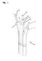
- FIG. 3is a perspective view of a portion of the hybrid cable of FIG. 2 with electrically conductive portions of the cable showing separated from a central optical fiber portion of the cable;
- FIG. 4is a plan view of the hybrid cable of FIGS. 2 and 3 with the electrically conductive portions of the hybrid cable trimmed relative to the central fiber optic portion of the hybrid cable;
- FIG. 5is a transverse cross-sectional view of another power/optical fiber hybrid cable in accordance with the principles of the present disclosure
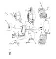
- FIG. 6is a schematic representation of a system for manufacturing the hybrid cables in accordance with the principles of the present disclosure.
- FIG. 7is a cross-sectional view taken along section line 7 - 7 of FIG. 6 .
- FIG. 1shows a system 10 in accordance with the principles of the present disclosure for enhancing the coverage areas provided by cellular technologies (e.g., GSM, CDMA, UMTS, LTE, WiMax, WiFi, etc.).
- the system 10includes a base location 11 (i.e., a hub) and a plurality of wireless coverage area defining equipment 12 a , 12 b , 12 c , 12 d , 12 e and 12 f distributed about the base location 11 .
- the base location 11can include a structure 14 (e.g., a closet, hut, building, housing, enclosure, cabinet, etc.) protecting telecommunications equipment such as racks, fiber optic adapter panels, passive optical splitters, wavelength division multi-plexers, fiber splice locations, optical fiber patching and/or fiber interconnect structures and other active and/or passive equipment.
- a structure 14e.g., a closet, hut, building, housing, enclosure, cabinet, etc.
- telecommunications equipmentsuch as racks, fiber optic adapter panels, passive optical splitters, wavelength division multi-plexers, fiber splice locations, optical fiber patching and/or fiber interconnect structures and other active and/or passive equipment.
- the base location 11is connected to a central office 16 or other remote location by a fiber optic cable such as a multi-fiber optical trunk cable 18 that provides high band-width two-way optical communication between the base location 11 and the central office 16 or other remote location.
- the base location 11is connected to the wireless coverage area defining equipment 12 a , 12 b , 12 c , 12 d , 12 e and 12 f by hybrid cables 20 .
- the hybrid cables 20are each capable of transmitting both power and communications between the base location 11 and the wireless coverage area defining equipment 12 a , 12 b , 12 c , 12 d , 12 e and 12 f.
- the wireless coverage area defining equipment 12 a , 12 b , 12 c , 12 d , 12 e and 12 fcan each include one or more wireless transceiver 22 .
- the transceivers 22can include single transceivers 22 or distributed arrays of transceivers 22 .
- a “wireless transceiver”is a device or arrangement of devices capable of transmitting and receiving wireless signals.
- a wireless transceivertypically includes an antenna for enhancing receiving and transmitting the wireless signals.
- Wireless coverage areasare defined around each of the wireless coverage area defining equipment 12 a , 12 b , 12 c , 12 d , 12 e and 12 f Wireless coverage areas can also be referred to as cells, cellular coverage areas, wireless coverage zones, or like terms. Examples of and/or alternative terms for wireless transceivers include radio-heads, wireless routers, cell sites, wireless nodes, etc.
- the base location 11is shown as a base transceiver station (BTS) located adjacent to a radio tower 24 supporting and elevating a plurality the wireless coverage area defining equipment 12 a .
- the equipment 12 acan define wireless coverage areas such as a macrocells or microcells (i.e., cells each having a coverage area less than or equal to about 2 kilometers wide).
- the wireless coverage area defining equipment 12 bis shown deployed at a suburban environment (e.g., on a light pole in a residential neighborhood) and the equipment 12 c is shown deployed at a roadside area (e.g., on a roadside power pole).
- the equipment 12 ccould also be installed at other locations such as tunnels, canyons, coastal areas, etc.
- the equipment 12 b , 12 ccan define wireless coverage areas such as microcells or picocells (i.e., cells each having a coverage area equal to or less than about 200 meters wide).
- the equipment 12 dis shown deployed at a campus location (e.g., a university or corporate campus), the equipment 12 e is shown deployed at a large public venue location (e.g., a stadium), and the equipment 12 f is shown installed at an in-building or near-building environment (e.g., multi-dwelling unit, high rise, school, etc.).
- the equipment 12 d , 12 e , and 12 fcan define wireless coverage areas such as microcells, picocells, or femtocells (i.e., cells each having a coverage area equal to or less than about 10 meters wide).
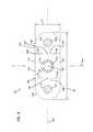
- FIG. 2is a transverse cross-sectional view taken through one of the hybrid cables 20 of FIG. 1 .
- Hybrid cable 20includes an outer jacket 100 having a transverse cross-sectional profile that defines a major axis 102 and a minor axis 104 .
- the outer jackethas a height H measured along the minor axis 104 and a width W measured along the major axis 102 .
- the width Wis greater than the height H such that the transverse cross-sectional profile of the outer jacket 100 is elongated along the major axis 102 .
- the outer jacket 100can include a left portion 106 , a right portion 108 and a central portion 110 .
- the left portion 106 , the right portion 108 and the central portion 110can be positioned along the major axis 102 with the central portion 110 being disposed between the left portion 106 and the right portion 108 .
- the left portion 106can define a left passage 112
- the right portion 108can define a right passage 114
- the central portion 110can define a central passage 116 .
- the passages 112 , 114 and 116can have lengths that extend along a central longitudinal axis 118 of the cable 20 for the length of the cable.
- a left electrical conductor 120is shown positioned within the left passage 112
- a right electrical conductor 122is shown positioned within the right passage 114
- at least one optical fiber 124is shown positioned within the central passage 116 .
- the left electrical conductor 120 , the right electrical conductor 122 and the optical fiber 124have lengths that extend along the central longitudinal axis 118 of the cable 20 .
- the hybrid cable 20includes a left pre-defined tear location 126 positioned between the central portion 110 and the left portion 106 of the outer jacket 100 , and a right pre-defined tear location 128 positioned between the central portion 110 and the right portion 108 of the outer jacket 100 .
- the left pre-defined tear location 126is weakened such that the left portion 106 of the outer jacket 100 can be manually torn from the central portion 110 of the outer jacket 100 .
- the right pre-defined tear location 128is weakened such that the right portion 108 of the outer jacket 100 can be manually torn from the central portion 110 of the outer jacket 100 .
- the left pre-defined tear location 126is configured such that the left portion 106 of the outer jacket 100 fully surrounds the left passage 112 and the central portion 110 of the outer jacket 100 fully surrounds the central passage 116 after the left portion 106 of the outer jacket 100 has been torn from the central portion 110 of the outer jacket 100 .
- the left electrical conductor 120remains fully insulated and the optical fiber 120 remains fully protected after the left portion 106 has been torn from the central portion 110 .
- the right pre-defined tear location 128is configured such that the right portion 108 of the outer jacket 100 fully surrounds the right passage 114 and the central portion 110 of the outer jacket 100 fully surrounds the central passage 119 after the right portion 108 of the outer jacket 100 has been torn from the central portion 110 of the outer jacket 100 .
- the right electrical conductor 122remains fully insulated and the optical fiber 124 remains fully protected after the right portion 108 has been torn from the central portion 110 .
- FIG. 3shows the hybrid cable 20 with both the left portion 106 and the right portion 108 torn away from the central portion 110 .
- both the left electrical conductor 120 and the right electrical conductor 122are fully insulated by their corresponding left and right portions 106 , 108 .
- the central portion 110has a rectangular transverse cross-sectional shape that fully surrounds the central passage 116 so as to protect the optical fiber or fibers 124 .
- left and right electrical conductors 120 , 122have a construction suitable for carrying electricity. It will be appreciated that the electrical conductors can have a solid or stranded construction. Example sizes of the electrical conductors include 12 gauge, 16 gauge, or other sizes.
- the outer jacket 100is preferably constructed of a polymeric material.
- the hybrid cable 20 and the outer jacket 100are plenum rated.
- the outer jacket 100can be manufactured of a fire-retardant plastic material.
- the outer jacket 100can be manufactured of a low smoke zero halogen material.
- Example materials for the outer jacketinclude polyvinyl chloride (PVC), fluorinated ethylene polymer (FEP), polyolefin formulations including, for example, polyethylene, and other materials.
- the central passage 116can contain one or more optical fibers 124 .
- the optical fibers 124can be coated optical fibers having cores less than 12 microns in diameter, cladding layers less than 140 microns in diameter, and coating layers less than 300 microns in diameter.
- the core and cladding layerstypically include a silica based material.
- the cladding layercan have an index of a refraction that is less than the index of refraction of the core to allow optical signals that are transmitted through the optical fibers to be confined generally to the core.
- multiple cladding layerscan be provided.
- optical fiberscan include bend insensitive optical fibers having multiple cladding layers separated by trench layers.
- protective coatingscan form coating layers around the cladding layers.
- the coating layerscan have diameters less than 300 microns, or less than 260 microns, or in the range of 240 to 260 microns.
- the optical fibers 124can be unbuffered.
- the optical fiberscan include a tight buffer layer, a loose buffer layer, or a semi-tight buffer layer.
- the buffer layerscan have an outer diameter of about 800 to 1,000 microns.
- the optical fiberscan include single mode optical fibers, multi-mode optical fibers, bend insensitive fibers or other fibers.
- the optical fibers 124can be ribbonized.
- the left and right portions 106 , 108can be trimmed relative to the central portion 110 after the left and right portions 106 , 104 have been torn away from the central portion 110 .
- the central portion 110extends distally beyond the ends of the left and right portions 106 , 108 .
- insulation displacement connectorscan be used to pierce through the jacket materials of the left and right portions 106 , 108 to electrically connect the left and right electrical connectors 120 , 122 to an electrical power source, ground, active components or other structures.
- the optical fibers 124can be directly terminated with optical connectors.
- connectorized pigtailscan be spliced to the ends of the optical fibers 124 .
- the outer jacket 100includes a top side 130 and a bottom side 132 separated by the height H. As depicted, the top and bottom sides 130 , 132 are generally parallel to one another.
- Each of the left and right pre-defined tear locations 126 , 128includes an upper slit 134 that extends downwardly from the top side 130 , a lower slit 136 that extends upwardly from the bottom side 132 and a non-slitted portion 138 positioned between the upper and lower slits 134 , 136 .
- the upper and lower slits 134 , 136are partially re-closed slits.
- the left and right pre-defined tear locations 126 , 128also include jacket weakening members 140 that are imbedded in the non-slitted portions 138 .
- the jacket weakening members 140can include strands, monofilaments, threads, filaments or other members.
- the jacket weakening members 140extend along the central longitudinal axis 118 of the cable 20 for the length of the cable 20 .
- the jacket weakening members 140are aligned along the major axis 102 .
- the upper and lower slits 130 , 136 as well as the jacket weakening member 140 of the left pre-defined tear location 126are aligned along a left tearing plane P L that is oriented generally perpendicular relative to the major axis 102 .
- the upper and lower slits 134 , 136 as well as the jacket weakening member 140 of the right pre-defined tear location 128are aligned along a right tearing plane P R that is oriented generally perpendicular with respect to the major axis 102 .
- the hybrid cable 20can include a tensile strength structure 142 that provides tensile enforcement to the hybrid cable 20 so as to prevent tensile loads from being applied to the optical fibers 124 .
- the tensile strength structure 142can include reinforcing structures such as Aramid yarns or other reinforcing fibers.
- the tensile strength structure 142can have an oriented polymeric construction.
- a tensile strength structure 142can include a reinforcing tape.
- the reinforcing tapecan be bonded to the outer jacket 100 so as to line the central passage 116 .
- the tensile strength structure 142can include a reinforcing tape that extends along the length of the hybrid cable 20 and has longitudinal edges/ends 144 that are separated so as to define a gap 144 therein between.
- the tensile strength member 142can be anchored to a structure such as a fiber optic connector, housing or other structure so as to limit the transfer of tensile load to the optical fibers 124 . It will be appreciated that the tensile strength structure 142 can be anchored by techniques such as crimping, adhesives, fasteners, bands or other structures.
- FIG. 5shows an alternative hybrid cable 20 ′ having the same construction as the hybrid cable 20 except two tensile strength structures 142 A, 142 B have been provided within the central passage 116 .
- Tensile strength members 142 A, 142 Beach include a tensile reinforcing tape that is bonded to the central portion 110 of the outer jacket 100 .
- the tensile strength members 142 A, 142 Bcan include portions that circumferentially overlap one another within the central passage 116 . In certain examples, by stripping away an end portion of the central portion 110 , the tensile strength structures 142 A, 142 B can be exposed and readily secured to a structure such as a fiber optic connector, a panel, a housing or other structure.
- the tensile strength structures 142 A, 142 Bcan be crimped, adhesively secured or otherwise attached to rods (e.g., epoxy rods reinforced with fibers) that are in turn secured within a ruggedized fiber optic connector such as the fiber optic connector disclosed at U.S. Pat. No. 7,744,288 which is hereby incorporated by reference in its entirety, or the fiber optic connector disclosed at U.S. Pat. No. 7,918,609, which is hereby incorporated by reference in its entirety.
- cables in accordance with the principles of the present disclosurecan be manufactured using a one-pass manufacturing process.
- the same one-pass manufacturing processcan be used to manufacture different types of cables by substituting in different types of electrical conductors (e.g., stranded or non-stranded) and by using different types of optical fibers (e.g., buffered optical fibers, non-buffered optical fibers, ribbonized fibers, multi-mode fibers, single-mode fibers, bend insensitive fibers, etc.).
- electrical conductorse.g., stranded or non-stranded
- optical fiberse.g., buffered optical fibers, non-buffered optical fibers, ribbonized fibers, multi-mode fibers, single-mode fibers, bend insensitive fibers, etc.
- the system 200includes a cross head, generally designated 202 , that receives polymeric (e.g., thermoplastic) material from an extruder 204 .
- a hopper 206is used to feed material into the extruder 204 .
- a conveyor 208can be used to convey material (e.g., base material and possibly additives) to the hopper 206 . In other embodiments, additional conveyors can be used to convey additional materials to the hopper 206 .
- the extruder 204is heated by a heating system 212 that may include one or more heating elements for heating zones of the extruder as well as the cross head 202 to desired processing temperatures.
- the system 200can also include one or more supply rolls 218 for feeding the tensile strength structure 142 or structures to the cross-head 202 and a longitudinal shaping tool 220 .
- the tensile strength structure 142is disposed on the supply roll 218 .
- the shaping tool 220is used to form/shape the tensile strength structure 142 (e.g., one or more pieces of reinforcing tape) into a generally cylindrical shape that surrounds the one or more fibers 124 prior to entering the cross-head 202 .
- the system 200further includes feed rolls 250 , 251 for feeding the electrical conductors 120 , 122 into the cross-head 202 , and feed rolls 254 , 255 for feeding the jacket weakening members 140 into the cross-head 202 .
- a water trough 222is located downstream from the cross head 202 for cooling the extruded product that exits the cross head 202 .
- the cooled final productis stored on a take-up roll 224 rotated by a drive mechanism 226 .
- a controller 228can coordinate the operation of the various components of the system 200 .
- the cross-head 202can be configured to provide the jacket 100 with the desired transverse cross-sectional shape of FIG. 2 .
- the system 200further includes a slitting module 230 located immediately downstream from the cross head 202 .
- the slitting module 230includes blade slitting blades 232 that form slits in the outer jacket 100 corresponding to the upper and lower slits 134 , 136 .
- the slitting blades 232slit the outer jacket 100 while the material of the outer jacket is still at least partially molten. In this way, in certain examples, the slits at least partially reclose after slitting. In this way, the slits form weakened portions in the jacket. In other embodiments, the slits may remain fully open.
- the optical fibers 124 , the left and right electrical conductors 120 , 122 , the tensile reinforcing structure 142 and the jacket weakening members 140are all fed through the cross head 202 .
- the shaping tool 220can shape the tensile strength structure 142 around the optical fibers 120 such that the tensile strength member 142 surrounds the optical fibers as the optical fibers and the tensile strength structure 142 pass through the cross-head 202 .
- the material of the outer jacket 100is extruded about the cylindrical tensile strength structure 142 as well as about the left and right electrical conductors 120 , 122 and the jacket weakening members 140 .
- the material forming the outer jacket 100 of the cable 20leaves the cross-head 202 having a shape/profile of the type shown at FIG. 2 . Thereafter, the cutting blades 232 of the slitting module 230 slit the upper and lower slits 134 , 136 into the jacket. The cable is then cooled at the trough 222 and is collected on the take-up spool 224 .
Landscapes
- Physics & Mathematics (AREA)
- General Physics & Mathematics (AREA)
- Optics & Photonics (AREA)
- Engineering & Computer Science (AREA)
- Manufacturing & Machinery (AREA)
- Communication Cables (AREA)
- Insulated Conductors (AREA)
Abstract
Description
Claims (18)
Priority Applications (2)
| Application Number | Priority Date | Filing Date | Title |
|---|---|---|---|
| US15/803,442US10163548B2 (en) | 2013-05-14 | 2017-11-03 | Power/fiber hybrid cable |
| US16/183,119US10892068B2 (en) | 2013-05-14 | 2018-11-07 | Power/fiber hybrid cable |
Applications Claiming Priority (4)
| Application Number | Priority Date | Filing Date | Title |
|---|---|---|---|
| US201361823125P | 2013-05-14 | 2013-05-14 | |
| US14/277,347US9472314B2 (en) | 2013-05-14 | 2014-05-14 | Power/fiber hybrid cable |
| US15/097,756US9837186B2 (en) | 2013-05-14 | 2016-04-13 | Power/fiber hybrid cable |
| US15/803,442US10163548B2 (en) | 2013-05-14 | 2017-11-03 | Power/fiber hybrid cable |
Related Parent Applications (1)
| Application Number | Title | Priority Date | Filing Date |
|---|---|---|---|
| US15/097,756ContinuationUS9837186B2 (en) | 2013-05-14 | 2016-04-13 | Power/fiber hybrid cable |
Related Child Applications (1)
| Application Number | Title | Priority Date | Filing Date |
|---|---|---|---|
| US16/183,119ContinuationUS10892068B2 (en) | 2013-05-14 | 2018-11-07 | Power/fiber hybrid cable |
Publications (2)
| Publication Number | Publication Date |
|---|---|
| US20180061529A1 US20180061529A1 (en) | 2018-03-01 |
| US10163548B2true US10163548B2 (en) | 2018-12-25 |
Family
ID=51894877
Family Applications (4)
| Application Number | Title | Priority Date | Filing Date |
|---|---|---|---|
| US14/277,347ActiveUS9472314B2 (en) | 2013-05-14 | 2014-05-14 | Power/fiber hybrid cable |
| US15/097,756ActiveUS9837186B2 (en) | 2013-05-14 | 2016-04-13 | Power/fiber hybrid cable |
| US15/803,442Expired - Fee RelatedUS10163548B2 (en) | 2013-05-14 | 2017-11-03 | Power/fiber hybrid cable |
| US16/183,119ActiveUS10892068B2 (en) | 2013-05-14 | 2018-11-07 | Power/fiber hybrid cable |
Family Applications Before (2)
| Application Number | Title | Priority Date | Filing Date |
|---|---|---|---|
| US14/277,347ActiveUS9472314B2 (en) | 2013-05-14 | 2014-05-14 | Power/fiber hybrid cable |
| US15/097,756ActiveUS9837186B2 (en) | 2013-05-14 | 2016-04-13 | Power/fiber hybrid cable |
Family Applications After (1)
| Application Number | Title | Priority Date | Filing Date |
|---|---|---|---|
| US16/183,119ActiveUS10892068B2 (en) | 2013-05-14 | 2018-11-07 | Power/fiber hybrid cable |
Country Status (10)
| Country | Link |
|---|---|
| US (4) | US9472314B2 (en) |
| EP (1) | EP2997582B1 (en) |
| KR (1) | KR20160010496A (en) |
| CN (1) | CN105247627B (en) |
| AU (1) | AU2014265983B2 (en) |
| CA (1) | CA2912515C (en) |
| CL (1) | CL2015003348A1 (en) |
| MX (1) | MX359326B (en) |
| SA (1) | SA515370137B1 (en) |
| WO (1) | WO2014185978A1 (en) |
Cited By (4)
| Publication number | Priority date | Publication date | Assignee | Title |
|---|---|---|---|---|
| US20190139679A1 (en)* | 2013-05-14 | 2019-05-09 | Commscope Technologies Llc | Power/fiber hybrid cable |
| WO2023055498A1 (en) | 2021-09-29 | 2023-04-06 | Commscope Technologies Llc | Hybrid pull apart cable with conforming overjacket |
| WO2023191985A1 (en) | 2022-03-30 | 2023-10-05 | Commscope Technologies Llc | Bonded pair hybrid cable |
| WO2024211139A1 (en) | 2023-04-03 | 2024-10-10 | Commscope Technologies Llc | Round hybrid cable with sub-jacketed conductors |
Families Citing this family (20)
| Publication number | Priority date | Publication date | Assignee | Title |
|---|---|---|---|---|
| WO2013188973A1 (en)* | 2012-06-18 | 2013-12-27 | Universite Laval | Optogenetic probe |
| CN105247805B (en) | 2013-03-18 | 2017-12-08 | 阿德斯电信公司 | Framework for wireless network |
| US9557505B2 (en) | 2013-03-18 | 2017-01-31 | Commscope Technologies Llc | Power and optical fiber interface |
| CA2937453C (en) | 2014-01-22 | 2021-05-04 | Adc Telecommunications, Inc. | Flat drop cable with features for enhancing stripability |
| CN109343178A (en) | 2014-02-07 | 2019-02-15 | 泰科电子公司 | Hardened optical power connection system |
| WO2016106152A1 (en) | 2014-12-22 | 2016-06-30 | Tyco Electronics Raychem Bvba | Power/fiber hybrid cable for indoor use |
| KR102431912B1 (en)* | 2015-02-13 | 2022-08-11 | 엘에스전선 주식회사 | Traveling cable for elevator |
| WO2018089623A1 (en) | 2016-11-09 | 2018-05-17 | Commscope, Inc. Of North Carolina | Exchangeable powered infrastructure module |
| MX2019009050A (en)* | 2017-01-31 | 2019-11-21 | Sandvik Materials Tech Llc | FLAT PACKAGE THAT HAS A SPACER BETWEEN TUBES. |
| AU2018250693B2 (en) | 2017-04-13 | 2022-03-10 | Commscope Technologies Llc | Flat drop cable with features for enhanced stripability |
| KR102534067B1 (en)* | 2017-11-03 | 2023-05-17 | 엘에스전선 주식회사 | Flat Optical And Power Composite Cable |
| USD860264S1 (en)* | 2018-01-16 | 2019-09-17 | Mid-South Control Line, Llc | Encapsulated conduits having jacket with sections of reduced material |
| USD860263S1 (en)* | 2018-01-16 | 2019-09-17 | Mid-South Control Line, Llc | Encapsulated conduit having jacket with sections of reduced material |
| EP3879661B1 (en) | 2020-03-10 | 2022-12-07 | CE+T Power Luxembourg SA | Safe and resilient energy distribution system for a highly efficient microgrid |
| US11588327B2 (en) | 2020-03-10 | 2023-02-21 | Ce+T Power Luxembourg Sa | Safe and resilient energy distribution for a highly efficient microgrid |
| WO2021180638A1 (en) | 2020-03-10 | 2021-09-16 | Ce+T Power Luxembourg Sa | Safe and resilient energy distribution system for a highly efficient microgrid |
| BR102020022101A2 (en)* | 2020-10-28 | 2022-05-10 | Furukawa Electric Latam S.A. | Telecommunications hybrid cable |
| CN113284665B (en)* | 2021-04-19 | 2022-07-12 | 华为技术有限公司 | A kind of photoelectric composite cable and photoelectric system |
| CN114034407B (en)* | 2021-10-29 | 2023-07-14 | 中国联合网络通信集团有限公司 | Monitoring method, device and computer-readable storage medium for optical cable tube well |
| CA3198944A1 (en) | 2022-05-09 | 2023-11-09 | Prysmian S.P.A. | Hybrid drop cable |
Citations (165)
| Publication number | Priority date | Publication date | Assignee | Title |
|---|---|---|---|---|
| US4089585A (en) | 1974-12-18 | 1978-05-16 | Bicc Limited | Optical guides |
| US4199225A (en) | 1978-04-07 | 1980-04-22 | Bicc Limited | Optical guides |
| US4220812A (en) | 1977-06-17 | 1980-09-02 | Lynenwerk Gmbh & Co. Kommanditgesellschaft | Electric cable for communication purposes |
| US4359598A (en) | 1977-05-13 | 1982-11-16 | Bicc Limited | Overhead electric transmission systems |
| US4365865A (en) | 1981-01-30 | 1982-12-28 | Sea-Log Corporation | Hybrid cable construction |
| US4401361A (en) | 1972-06-06 | 1983-08-30 | Bicc Limited | Optical guides |
| US4420220A (en) | 1979-06-25 | 1983-12-13 | Bicc Public Limited Company | Optical guides |
| US4467138A (en)* | 1983-01-17 | 1984-08-21 | Gk Technologies, Inc. | Plural conductor communication wire |
| US4497537A (en) | 1983-06-09 | 1985-02-05 | Bicc Public Limited Company | Electric and/or optical cable |
| US4552432A (en) | 1983-04-21 | 1985-11-12 | Cooper Industries, Inc. | Hybrid cable |
| US4695127A (en) | 1985-03-27 | 1987-09-22 | Cooper Industries, Inc. | Hybrid coaxial-optical cable and method of use |
| US4723832A (en) | 1985-06-28 | 1988-02-09 | Fujikura Limited | Composite overhead cable structure for electric and optical transmission |
| US4729628A (en) | 1986-11-14 | 1988-03-08 | Siecor Corporation | Fiber optic dropwire |
| US4761053A (en) | 1985-08-28 | 1988-08-02 | American Telephone And Telegraph Company, At&T Bell Laboratories | Communications transmission media |
| US4787705A (en) | 1986-09-05 | 1988-11-29 | Fujikura Ltd. | Composite optical fiber and power cable |
| US4844575A (en) | 1987-04-10 | 1989-07-04 | American Telephone And Telegraph Company, At&T Bell Laboratories | Optical fiber cable |
| US4852965A (en) | 1987-02-27 | 1989-08-01 | American Telephone And Telegraph Company At&T Bell Laboratories | Composite service and distribution communications media |
| US4867527A (en) | 1987-03-31 | 1989-09-19 | Societa' Cavi Pirelli S.P.A. | Combined electrical power and optical fiber cable |
| US4895426A (en) | 1988-09-20 | 1990-01-23 | The Boeing Company | Electrically conducting reinforced optical fiber |
| US5109457A (en) | 1988-12-14 | 1992-04-28 | At&T Bell Laboratories | All-dielectric optical fiber cable having enhanced fiber access |
| US5138685A (en) | 1990-01-23 | 1992-08-11 | At&T Bell Laboratories | Communications cable having microbial resistant water blocking provisions |
| US5155304A (en) | 1990-07-25 | 1992-10-13 | At&T Bell Laboratories | Aerial service wire |
| US5268971A (en) | 1991-11-07 | 1993-12-07 | Alcatel Na Cable Systems, Inc. | Optical fiber/metallic conductor composite cable |
| EP0629889A1 (en) | 1993-06-17 | 1994-12-21 | Telia Ab | Optical cable design |
| US5448670A (en) | 1994-06-10 | 1995-09-05 | Commscope, Inc. | Elliptical aerial self-supporting fiber optic cable and associated apparatus and methods |
| US5469523A (en) | 1994-06-10 | 1995-11-21 | Commscope, Inc. | Composite fiber optic and electrical cable and associated fabrication method |
| US5494461A (en) | 1993-07-27 | 1996-02-27 | Krone Aktiengesellschaft | Terminal block for high transmission rates in the telecommunication and data technique |
| US5539851A (en) | 1995-04-17 | 1996-07-23 | Taylor; John A. | Hybrid optical fiber/copper coaxial data transmission cable |
| US5555336A (en) | 1994-12-27 | 1996-09-10 | Hughes Aircraft Company | Fiber optic ower distribution |
| US5555338A (en) | 1994-07-19 | 1996-09-10 | Alcatel Kabel Ag & Co. | Self-supporting electrical and optical overhead cable |
| US5557698A (en) | 1994-08-19 | 1996-09-17 | Belden Wire & Cable Company | Coaxial fiber optical cable |
| US5677974A (en) | 1995-08-28 | 1997-10-14 | Southern New England Telephone Company | Hybrid communications and power cable and distribution method and network using the same |
| KR970060748U (en) | 1997-09-10 | 1997-12-10 | 박익교 | Folding pyramid structure for easy carrying and storage |
| US5737470A (en) | 1996-03-12 | 1998-04-07 | Nippon Telegraph And Telephone Corporation | Flat optical fiber cable |
| US5745627A (en) | 1995-12-28 | 1998-04-28 | Lucent Technologies Inc. | Composite cable for fiber-to-the-curb architecture using centralized power |
| US5778116A (en) | 1997-01-23 | 1998-07-07 | Tomich; John L. | Photonic home area network fiber/power insertion apparatus |
| US5778652A (en) | 1995-07-12 | 1998-07-14 | Siemens Aktiengesellschaft | Cable with a sheath made of steel, and a method and apparatus for forming the cable |
| US5838858A (en) | 1996-05-14 | 1998-11-17 | Molex Incorporated | Fiber optic connection unit |
| US5896480A (en) | 1996-10-22 | 1999-04-20 | Stewart Connector Systems, Inc. | Optical interconnection system |
| US5913003A (en) | 1997-01-10 | 1999-06-15 | Lucent Technologies Inc. | Composite fiber optic distribution cable |
| US5982966A (en) | 1996-12-19 | 1999-11-09 | Alcatel | Asymmetric structure fiber optic cable |
| US6088499A (en) | 1997-09-30 | 2000-07-11 | Siecor Corporation | Fiber optic cable with ripcord |
| US6101305A (en) | 1997-12-15 | 2000-08-08 | Siecor Corporation | Fiber optic cable |
| US6142802A (en) | 1998-12-18 | 2000-11-07 | International Business Machines Corporation | Guide rail and cam system with integrated connector for removable transceiver |
| US6169834B1 (en) | 1998-05-13 | 2001-01-02 | Alcatel | Slotted composite cable having a cable housing with a tubular opening for copper pairs and a slot for an optical fiber |
| US6195487B1 (en) | 1998-06-30 | 2001-02-27 | Pirelli Cable Corporation | Composite cable for access networks |
| US6236789B1 (en) | 1999-12-22 | 2001-05-22 | Pirelli Cables And Systems Llc | Composite cable for access networks |
| US6343172B1 (en) | 1999-08-24 | 2002-01-29 | Corning Cable System Llc | Composite fiber optic/coaxial electrical cables |
| US6347172B1 (en) | 2000-06-28 | 2002-02-12 | Alcatel | Cable having side-emitting fiber under transparent or translucent cable jacket |
| US6363192B1 (en) | 1998-12-23 | 2002-03-26 | Corning Cable Systems Llc | Composite cable units |
| US6370303B1 (en) | 2000-10-20 | 2002-04-09 | Pirelli Cables And Systems Llc | Optical fiber cable with support member for indoor and outdoor use |
| KR200273482Y1 (en) | 2002-01-15 | 2002-04-26 | 대한전선 주식회사 | Unified cable |
| US20020126967A1 (en) | 1996-03-29 | 2002-09-12 | Dominion Lasercom, Inc. | Hybrid electro-optic cable |
| US20020136510A1 (en) | 2001-03-23 | 2002-09-26 | Edgar Heinz | Hybrid cable with optical and electrical cores and hybrid cable arrangement |
| US6463198B1 (en) | 2000-03-30 | 2002-10-08 | Corning Cable Systems Llc | Micro composite fiber optic/electrical cables |
| US20020147978A1 (en) | 2001-04-04 | 2002-10-10 | Alex Dolgonos | Hybrid cable/wireless communications system |
| US6493491B1 (en) | 1999-09-28 | 2002-12-10 | Alcatel | Optical drop cable for aerial installation |
| US6501888B2 (en) | 1999-09-16 | 2002-12-31 | Corning Cable Systems Llc | Fiber optic cables with strength members and an apparatus for making the same |
| US6542674B1 (en) | 2000-08-25 | 2003-04-01 | Corning Cable Systems Llc | Fiber optic cables with strength members |
| US6563990B1 (en)* | 1998-06-22 | 2003-05-13 | Corning Cable Systems, Llc | Self-supporting cables and an apparatus and methods for making the same |
| US6567592B1 (en) | 2000-09-29 | 2003-05-20 | Corning Cable Systems Llc | Optical cables with flexible strength sections |
| US20030108351A1 (en) | 2001-09-24 | 2003-06-12 | Feinberg Lee Daniel | Methods for ultra long-haul optical communications |
| US6599025B1 (en) | 1998-03-11 | 2003-07-29 | Ccs Technology, Inc. | Hybrid data plug |
| US6621964B2 (en) | 2001-05-21 | 2003-09-16 | Corning Cable Systems Llc | Non-stranded high strength fiber optic cable |
| US20030215197A1 (en) | 2002-05-14 | 2003-11-20 | Simon Jonathan N. | Combined optical and electrical transmission line |
| US6687437B1 (en) | 2000-06-05 | 2004-02-03 | Essex Group, Inc. | Hybrid data communications cable |
| US6719461B2 (en) | 2002-02-19 | 2004-04-13 | Fiber Systems International | Hybrid fiber optic and power connector |
| US6744954B1 (en) | 1998-11-20 | 2004-06-01 | Sumitomo Electric Industries, Ltd. | Submarine optical cable, optical fiber unit employed in the submarine optical cable, and method of making optical fiber unit |
| US6755575B2 (en) | 2000-07-12 | 2004-06-29 | Zarlink Semiconductor Ab | Self powered data communication optical fiber cable extender |
| US6758693B2 (en) | 2000-11-02 | 2004-07-06 | Ntt Advanced Technology Corporation | Optical active connector plug for LAN and its connector port |
| US6792184B2 (en) | 2002-05-31 | 2004-09-14 | Corning Cable Systems Llc | Optical fiber ribbons having a preferential separation sequence |
| US20040258165A1 (en) | 2001-11-29 | 2004-12-23 | Pentti Peltonen | Transmission system for transmiting data via current conducting branches |
| US6836603B1 (en) | 2003-08-14 | 2004-12-28 | Furukawa Electric North America, Inc. | Optical fiber cables |
| US20050002622A1 (en) | 2001-11-19 | 2005-01-06 | Ralph Sutehall | Optical fibre drop cables |
| US6845200B1 (en) | 2003-10-24 | 2005-01-18 | Corning Cable Systems Llc | Fiber optic assemblies, cable, and manufacturing methods therefor |
| US20050185903A1 (en) | 2004-02-20 | 2005-08-25 | Koertel Andreas H. | Apparatus and method for supplying power over an optical link |
| US7006740B1 (en) | 1999-05-28 | 2006-02-28 | Corning Cable Systems, Llc | Communication cable having a soft housing |
| US20060045443A1 (en) | 2004-08-30 | 2006-03-02 | Blazer Bradley J | Fiber optic ribbons having one or more preferential tear portions and method of making the same |
| US20060153516A1 (en) | 2005-01-13 | 2006-07-13 | Napiorkowski John J | Network interface device having integral slack storage compartment |
| US20060165355A1 (en) | 2002-12-19 | 2006-07-27 | Greenwood Jody L | Fiber optic cable having a dry insert and methods of making the same |
| US20060291787A1 (en) | 2005-06-27 | 2006-12-28 | Seddon David A | Fiber optic cable having strength component |
| US7158703B2 (en) | 2005-02-11 | 2007-01-02 | Nexans | Power umbilical for deep water |
| US7184634B2 (en) | 2004-03-25 | 2007-02-27 | Corning Cable Systems, Llc. | Fiber optic drop cables suitable for outdoor fiber to the subscriber applications |
| US7218821B2 (en) | 2004-08-20 | 2007-05-15 | Furukawa Electric North America Inc. | Optical fiber cables |
| US7225534B2 (en) | 2005-02-11 | 2007-06-05 | Adc Telecommunications, Inc. | Telecommunications cable jacket adapted for post-extrusion insertion of optical fiber and methods for manufacturing the same |
| US7272281B2 (en) | 2006-02-01 | 2007-09-18 | Sbc Knowledge Ventures, L.P. | Powered fiber cable |
| US20070269170A1 (en) | 2006-05-19 | 2007-11-22 | Easton Martyn N | Fiber optic cable and fiber optic cable assembly for wireless access |
| US7310430B1 (en) | 2006-06-02 | 2007-12-18 | Sbc Knowledge Ventures | Hybrid cables for communication networks |
| US7362936B2 (en) | 2006-03-01 | 2008-04-22 | Defense Photonics Group, Inc. | Optical harness assembly and method |
| US7371014B2 (en) | 2006-08-21 | 2008-05-13 | Intel Corporation | Monolithic active optical cable assembly for data device applications and various connector types |
| US20080131132A1 (en) | 2006-12-01 | 2008-06-05 | Solheid James J | Network interface device |
| US7387517B2 (en) | 2006-09-20 | 2008-06-17 | Fujitsu Limited | Connector mounting structure |
| US7401985B2 (en) | 2006-04-10 | 2008-07-22 | Finisar Corporation | Electrical-optical active optical cable |
| US20080219621A1 (en) | 2004-12-06 | 2008-09-11 | Pirelli & C. S.P.A. | Point-To-Point Optical Fibre Link |
| US7445389B2 (en) | 2006-04-10 | 2008-11-04 | Finisar Corporation | Active optical cable with integrated eye safety |
| US7454107B2 (en) | 2005-11-01 | 2008-11-18 | Corning Cable Systems Llc | Fiber optic cables suitable for automated preconnectorization |
| US7467896B2 (en) | 2000-05-26 | 2008-12-23 | Corning Cable Systems Llc | Fiber optic drop cables and preconnectorized assemblies |
| US20090041413A1 (en) | 2007-08-08 | 2009-02-12 | Hurley William C | Retractable optical fiber tether assembly and associated fiber optic cable |
| US7494287B2 (en) | 2004-10-15 | 2009-02-24 | Emcore Corporation | Integrated optical fiber and electro-optical converter |
| US7499616B2 (en) | 2006-04-10 | 2009-03-03 | Finisar Corporation | Active optical cable with electrical connector |
| US7532796B2 (en) | 2006-09-29 | 2009-05-12 | Corning Cable Systems Llc | Fiber optic ribbons having one or more predetermined fracture regions |
| US7539380B1 (en) | 2007-11-26 | 2009-05-26 | Corning Cable Systems Llc | Fiber optic cables and assemblies for fiber toward the subscriber applications |
| AU2008309134A1 (en) | 2007-11-26 | 2009-06-11 | Corning Cable Systems Llc | Fiber optic cables and assemlies for fiber toward the subscriber applications |
| US20090297104A1 (en) | 2008-05-28 | 2009-12-03 | Kachmar Wayne M | Fiber optic cable |
| US7643631B2 (en) | 2005-08-26 | 2010-01-05 | Adc Telecommunications, Inc. | Enclosure for broadband service delivery system |
| US7643713B2 (en) | 2005-08-31 | 2010-01-05 | Nexans | Composite cable |
| US7692098B2 (en) | 2002-07-10 | 2010-04-06 | Commscope Properties, Llc | Coaxial cable having wide continuous usable bandwidth |
| US7693375B2 (en) | 2002-12-19 | 2010-04-06 | Corning Cable Systems Llc | Fiber optic cable having a dry insert |
| US7712976B2 (en) | 2006-04-10 | 2010-05-11 | Finisar Corporation | Active optical cable with integrated retiming |
| US7744288B2 (en) | 2007-12-11 | 2010-06-29 | Adc Telecommunications, Inc. | Hardened fiber optic connector compatible with hardened and non-hardened fiber optic adapters |
| US20100200270A1 (en) | 2009-02-12 | 2010-08-12 | Commscope, Inc. Of North Carolina | Communications cables having outer surface with reduced coefficient of friction and methods of making same |
| US7778510B2 (en) | 2006-04-10 | 2010-08-17 | Finisar Corporation | Active optical cable electrical connector |
| WO2010102201A2 (en) | 2009-03-05 | 2010-09-10 | Adc Telecommunications, Inc. | Methods, systems and devices for integrating wireless technology into a fiber optic network |
| US20100290787A1 (en) | 2009-05-15 | 2010-11-18 | Cox Terry D | Power Distribution Devices, Systems, and Methods for Radio-Over-Fiber (RoF) Distributed Communication |
| US20100321591A1 (en) | 2009-06-17 | 2010-12-23 | Funai Electric Co., Ltd. | Cable for Display and Television System |
| US7876989B2 (en) | 2006-04-10 | 2011-01-25 | Finisar Corporation | Active optical cable with integrated power |
| US20110021069A1 (en) | 2009-07-21 | 2011-01-27 | Yiping Hu | Thin format crush resistant electrical cable |
| US20110038582A1 (en) | 2008-09-30 | 2011-02-17 | Apple Inc. | Magnetic connector with optical signal path |
| US7918609B2 (en) | 2000-05-26 | 2011-04-05 | Corning Cable Systems Llc | Fiber optic drop cables and preconnectorized assemblies |
| US20110091174A1 (en) | 2009-10-21 | 2011-04-21 | Adc Telecommunications, Inc. | Flat Drop Cable with Center Strength Member |
| US20110188815A1 (en) | 2010-02-04 | 2011-08-04 | Blackwell Jr Chois A | Optical interface cards, assemblies, and related methods, suited for installation and use in antenna system equipment |
| US20110217010A1 (en)* | 2010-03-02 | 2011-09-08 | Adc Telecommunications, Inc. | Fiber optic cable assembly |
| US8041166B2 (en) | 2008-10-28 | 2011-10-18 | Adc Telecommunications, Inc. | Flat drop cable |
| US20110268452A1 (en) | 2010-05-02 | 2011-11-03 | Beamon Hubert B | Digital data services and/or power distribution in optical fiber-based distributed communications systems providing digital data and radio frequency (rf) communications services, and related components and methods |
| US8059929B2 (en) | 2006-05-11 | 2011-11-15 | Corning Cable Systems Llc | Tools and methods for manufacturing fiber optic distribution cables |
| US20110280527A1 (en) | 2010-05-14 | 2011-11-17 | Sumitomo Electric Industries, Ltd. | Composite optical fiber cable and composite optical fiber cable assembly |
| WO2011146720A2 (en) | 2010-05-19 | 2011-11-24 | Adc Telecommunications, Inc. | Flat drop cable with medial bump |
| US20110293227A1 (en) | 2010-05-31 | 2011-12-01 | Hon Hai Precision Industry Co., Ltd. | Cable assembly with elecrical and optical transmitting |
| EP2393222A1 (en) | 2010-06-03 | 2011-12-07 | Alcatel Lucent | System and method for transporting electric power and providing optical fiber communications under sea water |
| US20110311191A1 (en) | 2010-06-22 | 2011-12-22 | Sumitomo Electric Industries, Ltd. | Opto-electro hybrid cable |
| US8083417B2 (en) | 2006-04-10 | 2011-12-27 | Finisar Corporation | Active optical cable electrical adaptor |
| US20120008905A1 (en) | 2010-07-06 | 2012-01-12 | Hon Hai Precision Industry Co., Ltd. | Optical-electrical hybrid transmission cable |
| US20120008904A1 (en) | 2010-07-06 | 2012-01-12 | Hon Hai Precision Industry Co., Ltd. | Optical-electrical hybrid transmission cable |
| US20120008906A1 (en) | 2010-07-06 | 2012-01-12 | Hon Hai Precision Industry Co., Ltd. | Optical-electrical hybrid transmission cable |
| US20120080225A1 (en) | 2010-09-30 | 2012-04-05 | Apple Inc. | Cable for electrical and optical transmission |
| US8175433B2 (en) | 2007-07-31 | 2012-05-08 | Corning Cable Systems Llc | Fiber optic cables coupling and methods therefor |
| US20120114288A1 (en) | 2010-11-05 | 2012-05-10 | Hon Hai Precision Industry Co., Ltd. | Cable assembly transmitting with electrical and optical signals |
| US8204348B2 (en) | 2009-06-30 | 2012-06-19 | Nexans | Composite, optical fiber, power and signal tactical cable |
| US8224141B2 (en) | 2008-05-27 | 2012-07-17 | Adc Telecommunications, Inc. | Multi-jacketed fiber optic cable |
| US20120191997A1 (en) | 2011-01-25 | 2012-07-26 | Avago Technologies Fiber Ip (Singapore) Pte. Ltd. | Active optical cable (aoc) and a method and apparatus for performing power management in the aoc |
| US8244087B2 (en) | 2007-10-18 | 2012-08-14 | Prysmian Cables Y Sistemas S.L. | Hybrid cable |
| US8249410B2 (en) | 2008-04-25 | 2012-08-21 | Corning Cable Systems Llc | Connector housing for a communication network |
| WO2012112532A2 (en) | 2011-02-14 | 2012-08-23 | Adc Telecommunications, Inc. | Fiber optic cable with electrical conductors |
| US8301003B2 (en) | 2010-05-14 | 2012-10-30 | Corning Cable Systems Llc | Cable network interconnection system with connector package and cable package |
| US8297854B2 (en) | 2009-02-14 | 2012-10-30 | Corning Cable Systems Llc | Multimode fiber optic assemblies |
| US20120281952A1 (en) | 2011-05-03 | 2012-11-08 | Avago Technologies Fiber Ip (Singapore) Pte. Ltd. | Active optical cable (aoc) having a molded plastic leadframe that obviates the need for an optical connector, an aoc that incorporates the aoc connector, and a method of using the aoc |
| US20120281953A1 (en) | 2011-05-03 | 2012-11-08 | Sehf-Korea Co., Ltd. | Optical electrical hybrid cable |
| US20120288245A1 (en) | 2008-12-02 | 2012-11-15 | Hurley William C | Optical fiber array cables and associated fiber optic cables and systems |
| US20120295486A1 (en) | 2011-05-17 | 2012-11-22 | 3M Innovative Properties Company | Remote socket apparatus |
| US8328433B2 (en) | 2008-12-12 | 2012-12-11 | Kabushiki Kaisha Toshiba | Optical/electrical composite cable |
| US20120315004A1 (en) | 2011-06-10 | 2012-12-13 | Register Iii James A | Fiber optic cables allowing fiber translation to reduce bend attenuation |
| US20130011106A1 (en) | 2011-07-06 | 2013-01-10 | Tyco Electronics Corporation | Electrical cable with optical fiber |
| US20130022318A1 (en) | 2011-07-18 | 2013-01-24 | Fiber Connections Inc. | Field terminated fiber optic and electrical connection device |
| US20130058613A1 (en) | 2011-09-06 | 2013-03-07 | Stefan Jost | Compact, low-cost outside plant or indoor/outdoor cables |
| US20130094821A1 (en)* | 2011-10-13 | 2013-04-18 | Eric R. Logan | Access features of armored flat fiber optic cable |
| US20130094823A1 (en)* | 2011-10-13 | 2013-04-18 | Michael John Gimblet | Fiber optic cables with extruded access features for access to a cable cavity |
| US8480312B2 (en) | 2010-02-04 | 2013-07-09 | Adc Telecommunications, Inc. | Ruggedized fiber optic/electrical connection system |
| WO2013117598A2 (en) | 2012-02-07 | 2013-08-15 | Tyco Electronics Corporation | Optical fiber connection system including optical fiber alignment device |
| US8538216B2 (en) | 2008-09-23 | 2013-09-17 | Corning Cable Systems Llc | Fiber optic cables and assemblies for fiber toward the subscriber applications |
| US20130287349A1 (en) | 2012-04-27 | 2013-10-31 | Michael Todd Faulkner | Hybrid cable including fiber-optic and electrical-conductor elements |
| US20140072264A1 (en) | 2012-09-10 | 2014-03-13 | Tellabs Bedford, Inc. | Delivery of gpon technology |
| US20140258742A1 (en) | 2013-03-05 | 2014-09-11 | Ching-Yun CHIEN | Hybrid fiber optic and power over ethernet |
| US20150125146A1 (en) | 2012-04-20 | 2015-05-07 | Tyco Electronics Raychem Bvba | Wireless drop in a fiber-to-the-home network |
| US20150309271A1 (en) | 2013-03-18 | 2015-10-29 | Adc Telecommunications, Inc. | Power and optical fiber interface |
| US20150378118A1 (en) | 2013-02-18 | 2015-12-31 | Thomas P. Huegerich | Hybrid power and optical fiber cable with conductive buffer tube |
Family Cites Families (13)
| Publication number | Priority date | Publication date | Assignee | Title |
|---|---|---|---|---|
| US2204782A (en)* | 1936-04-13 | 1940-06-18 | Belden Mfg Co | Method and apparatus for making electric conductor cord |
| US2628998A (en)* | 1945-11-08 | 1953-02-17 | Gilbert Co A C | Splittable cable with visible conductors |
| US2581472A (en)* | 1948-03-30 | 1952-01-08 | Whitney Blake Co | Multiple conductor insulated wire |
| KR970060748A (en) | 1996-01-29 | 1997-08-12 | 이준 | Base station power supply method in a mobile communication system |
| JP3505640B2 (en)* | 1999-11-25 | 2004-03-08 | 日本航空電子工業株式会社 | Flexible transmission line integrated connector |
| JP2003311658A (en) | 2002-04-24 | 2003-11-05 | Nec Kagoshima Ltd | Work bench |
| US7471862B2 (en) | 2002-12-19 | 2008-12-30 | Corning Cable Systems, Llc | Dry fiber optic cables and assemblies |
| US7391943B2 (en)* | 2005-05-31 | 2008-06-24 | Corning Cable Systems Llc | Fiber optic cables that are separable for optical fiber access |
| US7808205B2 (en) | 2007-05-29 | 2010-10-05 | Motorola, Inc | Battery charger and method for communicating battery pack charging status information |
| CN201359882Y (en)* | 2009-02-20 | 2009-12-09 | 南京烽火藤仓光通信有限公司 | Non-metallic central tube-type optic/electric composite cable |
| CN201868149U (en)* | 2010-07-19 | 2011-06-15 | 江苏中天科技股份有限公司 | Photoelectric composite cable for Fiber To The Home (FTTT) |
| JP5041450B2 (en)* | 2010-11-24 | 2012-10-03 | 古河電気工業株式会社 | Optical fiber colored core |
| CN105247627B (en)* | 2013-05-14 | 2018-08-10 | 阿德斯电信公司 | Power/Fiber Optic Hybrid Cable |
- 2014
- 2014-05-14CNCN201480031046.8Apatent/CN105247627B/enactiveActive
- 2014-05-14EPEP14797917.3Apatent/EP2997582B1/enactiveActive
- 2014-05-14WOPCT/US2014/000115patent/WO2014185978A1/enactiveIP Right Grant
- 2014-05-14AUAU2014265983Apatent/AU2014265983B2/enactiveActive
- 2014-05-14MXMX2015015839Apatent/MX359326B/enactiveIP Right Grant
- 2014-05-14USUS14/277,347patent/US9472314B2/enactiveActive
- 2014-05-14CACA2912515Apatent/CA2912515C/enactiveActive
- 2014-05-14KRKR1020157034931Apatent/KR20160010496A/ennot_activeCeased
- 2015
- 2015-11-12SASA515370137Apatent/SA515370137B1/enunknown
- 2015-11-13CLCL2015003348Apatent/CL2015003348A1/enunknown
- 2016
- 2016-04-13USUS15/097,756patent/US9837186B2/enactiveActive
- 2017
- 2017-11-03USUS15/803,442patent/US10163548B2/ennot_activeExpired - Fee Related
- 2018
- 2018-11-07USUS16/183,119patent/US10892068B2/enactiveActive
Patent Citations (192)
| Publication number | Priority date | Publication date | Assignee | Title |
|---|---|---|---|---|
| US4401361A (en) | 1972-06-06 | 1983-08-30 | Bicc Limited | Optical guides |
| US4089585A (en) | 1974-12-18 | 1978-05-16 | Bicc Limited | Optical guides |
| US4359598A (en) | 1977-05-13 | 1982-11-16 | Bicc Limited | Overhead electric transmission systems |
| US4220812A (en) | 1977-06-17 | 1980-09-02 | Lynenwerk Gmbh & Co. Kommanditgesellschaft | Electric cable for communication purposes |
| US4199225A (en) | 1978-04-07 | 1980-04-22 | Bicc Limited | Optical guides |
| US4420220A (en) | 1979-06-25 | 1983-12-13 | Bicc Public Limited Company | Optical guides |
| US4365865A (en) | 1981-01-30 | 1982-12-28 | Sea-Log Corporation | Hybrid cable construction |
| US4467138A (en)* | 1983-01-17 | 1984-08-21 | Gk Technologies, Inc. | Plural conductor communication wire |
| US4552432A (en) | 1983-04-21 | 1985-11-12 | Cooper Industries, Inc. | Hybrid cable |
| US4497537A (en) | 1983-06-09 | 1985-02-05 | Bicc Public Limited Company | Electric and/or optical cable |
| US4695127A (en) | 1985-03-27 | 1987-09-22 | Cooper Industries, Inc. | Hybrid coaxial-optical cable and method of use |
| US4723832A (en) | 1985-06-28 | 1988-02-09 | Fujikura Limited | Composite overhead cable structure for electric and optical transmission |
| US4761053A (en) | 1985-08-28 | 1988-08-02 | American Telephone And Telegraph Company, At&T Bell Laboratories | Communications transmission media |
| US4787705A (en) | 1986-09-05 | 1988-11-29 | Fujikura Ltd. | Composite optical fiber and power cable |
| US4729628A (en) | 1986-11-14 | 1988-03-08 | Siecor Corporation | Fiber optic dropwire |
| US4852965A (en) | 1987-02-27 | 1989-08-01 | American Telephone And Telegraph Company At&T Bell Laboratories | Composite service and distribution communications media |
| US4867527A (en) | 1987-03-31 | 1989-09-19 | Societa' Cavi Pirelli S.P.A. | Combined electrical power and optical fiber cable |
| US4844575A (en) | 1987-04-10 | 1989-07-04 | American Telephone And Telegraph Company, At&T Bell Laboratories | Optical fiber cable |
| US4895426A (en) | 1988-09-20 | 1990-01-23 | The Boeing Company | Electrically conducting reinforced optical fiber |
| US5109457A (en) | 1988-12-14 | 1992-04-28 | At&T Bell Laboratories | All-dielectric optical fiber cable having enhanced fiber access |
| US5138685A (en) | 1990-01-23 | 1992-08-11 | At&T Bell Laboratories | Communications cable having microbial resistant water blocking provisions |
| US5155304A (en) | 1990-07-25 | 1992-10-13 | At&T Bell Laboratories | Aerial service wire |
| US5268971A (en) | 1991-11-07 | 1993-12-07 | Alcatel Na Cable Systems, Inc. | Optical fiber/metallic conductor composite cable |
| EP0629889A1 (en) | 1993-06-17 | 1994-12-21 | Telia Ab | Optical cable design |
| US5494461A (en) | 1993-07-27 | 1996-02-27 | Krone Aktiengesellschaft | Terminal block for high transmission rates in the telecommunication and data technique |
| US5448670A (en) | 1994-06-10 | 1995-09-05 | Commscope, Inc. | Elliptical aerial self-supporting fiber optic cable and associated apparatus and methods |
| US5469523A (en) | 1994-06-10 | 1995-11-21 | Commscope, Inc. | Composite fiber optic and electrical cable and associated fabrication method |
| US5651081A (en)* | 1994-06-10 | 1997-07-22 | Commscope, Inc. | Composite fiber optic and electrical cable and associated fabrication method |
| US5555338A (en) | 1994-07-19 | 1996-09-10 | Alcatel Kabel Ag & Co. | Self-supporting electrical and optical overhead cable |
| US5557698A (en) | 1994-08-19 | 1996-09-17 | Belden Wire & Cable Company | Coaxial fiber optical cable |
| US5555336A (en) | 1994-12-27 | 1996-09-10 | Hughes Aircraft Company | Fiber optic ower distribution |
| US5539851A (en) | 1995-04-17 | 1996-07-23 | Taylor; John A. | Hybrid optical fiber/copper coaxial data transmission cable |
| US5778652A (en) | 1995-07-12 | 1998-07-14 | Siemens Aktiengesellschaft | Cable with a sheath made of steel, and a method and apparatus for forming the cable |
| US5677974A (en) | 1995-08-28 | 1997-10-14 | Southern New England Telephone Company | Hybrid communications and power cable and distribution method and network using the same |
| US5745627A (en) | 1995-12-28 | 1998-04-28 | Lucent Technologies Inc. | Composite cable for fiber-to-the-curb architecture using centralized power |
| US5737470A (en) | 1996-03-12 | 1998-04-07 | Nippon Telegraph And Telephone Corporation | Flat optical fiber cable |
| US20020126967A1 (en) | 1996-03-29 | 2002-09-12 | Dominion Lasercom, Inc. | Hybrid electro-optic cable |
| US6931183B2 (en) | 1996-03-29 | 2005-08-16 | Dominion Lasercom, Inc. | Hybrid electro-optic cable for free space laser antennas |
| US5838858A (en) | 1996-05-14 | 1998-11-17 | Molex Incorporated | Fiber optic connection unit |
| US5896480A (en) | 1996-10-22 | 1999-04-20 | Stewart Connector Systems, Inc. | Optical interconnection system |
| US5982966A (en) | 1996-12-19 | 1999-11-09 | Alcatel | Asymmetric structure fiber optic cable |
| US5913003A (en) | 1997-01-10 | 1999-06-15 | Lucent Technologies Inc. | Composite fiber optic distribution cable |
| US5778116A (en) | 1997-01-23 | 1998-07-07 | Tomich; John L. | Photonic home area network fiber/power insertion apparatus |
| KR970060748U (en) | 1997-09-10 | 1997-12-10 | 박익교 | Folding pyramid structure for easy carrying and storage |
| US6088499A (en) | 1997-09-30 | 2000-07-11 | Siecor Corporation | Fiber optic cable with ripcord |
| US6101305A (en) | 1997-12-15 | 2000-08-08 | Siecor Corporation | Fiber optic cable |
| US6599025B1 (en) | 1998-03-11 | 2003-07-29 | Ccs Technology, Inc. | Hybrid data plug |
| US6169834B1 (en) | 1998-05-13 | 2001-01-02 | Alcatel | Slotted composite cable having a cable housing with a tubular opening for copper pairs and a slot for an optical fiber |
| US6563990B1 (en)* | 1998-06-22 | 2003-05-13 | Corning Cable Systems, Llc | Self-supporting cables and an apparatus and methods for making the same |
| US20030202756A1 (en) | 1998-06-22 | 2003-10-30 | Hurley William C. | Self-supporting cables and an apparatus and methods for making the same |
| US6847767B2 (en) | 1998-06-22 | 2005-01-25 | Corning Cable Systems Llc | Self-supporting cables and an apparatus and methods for making the same |
| US6195487B1 (en) | 1998-06-30 | 2001-02-27 | Pirelli Cable Corporation | Composite cable for access networks |
| US6744954B1 (en) | 1998-11-20 | 2004-06-01 | Sumitomo Electric Industries, Ltd. | Submarine optical cable, optical fiber unit employed in the submarine optical cable, and method of making optical fiber unit |
| US6142802A (en) | 1998-12-18 | 2000-11-07 | International Business Machines Corporation | Guide rail and cam system with integrated connector for removable transceiver |
| US6363192B1 (en) | 1998-12-23 | 2002-03-26 | Corning Cable Systems Llc | Composite cable units |
| US6738547B2 (en) | 1998-12-23 | 2004-05-18 | Corning Cable Systems Llc | Composite cable units |
| US7006740B1 (en) | 1999-05-28 | 2006-02-28 | Corning Cable Systems, Llc | Communication cable having a soft housing |
| US6343172B1 (en) | 1999-08-24 | 2002-01-29 | Corning Cable System Llc | Composite fiber optic/coaxial electrical cables |
| US6501888B2 (en) | 1999-09-16 | 2002-12-31 | Corning Cable Systems Llc | Fiber optic cables with strength members and an apparatus for making the same |
| US6493491B1 (en) | 1999-09-28 | 2002-12-10 | Alcatel | Optical drop cable for aerial installation |
| US6236789B1 (en) | 1999-12-22 | 2001-05-22 | Pirelli Cables And Systems Llc | Composite cable for access networks |
| US6463198B1 (en) | 2000-03-30 | 2002-10-08 | Corning Cable Systems Llc | Micro composite fiber optic/electrical cables |
| US7467896B2 (en) | 2000-05-26 | 2008-12-23 | Corning Cable Systems Llc | Fiber optic drop cables and preconnectorized assemblies |
| US7918609B2 (en) | 2000-05-26 | 2011-04-05 | Corning Cable Systems Llc | Fiber optic drop cables and preconnectorized assemblies |
| US6687437B1 (en) | 2000-06-05 | 2004-02-03 | Essex Group, Inc. | Hybrid data communications cable |
| US6347172B1 (en) | 2000-06-28 | 2002-02-12 | Alcatel | Cable having side-emitting fiber under transparent or translucent cable jacket |
| US6755575B2 (en) | 2000-07-12 | 2004-06-29 | Zarlink Semiconductor Ab | Self powered data communication optical fiber cable extender |
| US6714710B2 (en) | 2000-08-25 | 2004-03-30 | Corning Cable Systems, Llc | Fiber optic cables with strength members |
| US6542674B1 (en) | 2000-08-25 | 2003-04-01 | Corning Cable Systems Llc | Fiber optic cables with strength members |
| US6567592B1 (en) | 2000-09-29 | 2003-05-20 | Corning Cable Systems Llc | Optical cables with flexible strength sections |
| US6370303B1 (en) | 2000-10-20 | 2002-04-09 | Pirelli Cables And Systems Llc | Optical fiber cable with support member for indoor and outdoor use |
| US6758693B2 (en) | 2000-11-02 | 2004-07-06 | Ntt Advanced Technology Corporation | Optical active connector plug for LAN and its connector port |
| US20020136510A1 (en) | 2001-03-23 | 2002-09-26 | Edgar Heinz | Hybrid cable with optical and electrical cores and hybrid cable arrangement |
| US20020147978A1 (en) | 2001-04-04 | 2002-10-10 | Alex Dolgonos | Hybrid cable/wireless communications system |
| US6621964B2 (en) | 2001-05-21 | 2003-09-16 | Corning Cable Systems Llc | Non-stranded high strength fiber optic cable |
| US20030108351A1 (en) | 2001-09-24 | 2003-06-12 | Feinberg Lee Daniel | Methods for ultra long-haul optical communications |
| US20050002622A1 (en) | 2001-11-19 | 2005-01-06 | Ralph Sutehall | Optical fibre drop cables |
| US20040258165A1 (en) | 2001-11-29 | 2004-12-23 | Pentti Peltonen | Transmission system for transmiting data via current conducting branches |
| KR200273482Y1 (en) | 2002-01-15 | 2002-04-26 | 대한전선 주식회사 | Unified cable |
| US6719461B2 (en) | 2002-02-19 | 2004-04-13 | Fiber Systems International | Hybrid fiber optic and power connector |
| US20030215197A1 (en) | 2002-05-14 | 2003-11-20 | Simon Jonathan N. | Combined optical and electrical transmission line |
| US6792184B2 (en) | 2002-05-31 | 2004-09-14 | Corning Cable Systems Llc | Optical fiber ribbons having a preferential separation sequence |
| US7692098B2 (en) | 2002-07-10 | 2010-04-06 | Commscope Properties, Llc | Coaxial cable having wide continuous usable bandwidth |
| US20060165355A1 (en) | 2002-12-19 | 2006-07-27 | Greenwood Jody L | Fiber optic cable having a dry insert and methods of making the same |
| US7693375B2 (en) | 2002-12-19 | 2010-04-06 | Corning Cable Systems Llc | Fiber optic cable having a dry insert |
| US6836603B1 (en) | 2003-08-14 | 2004-12-28 | Furukawa Electric North America, Inc. | Optical fiber cables |
| US6845200B1 (en) | 2003-10-24 | 2005-01-18 | Corning Cable Systems Llc | Fiber optic assemblies, cable, and manufacturing methods therefor |
| US6965718B2 (en) | 2004-02-20 | 2005-11-15 | Hewlett-Packard Development Company, L.P. | Apparatus and method for supplying power over an optical link |
| US20050185903A1 (en) | 2004-02-20 | 2005-08-25 | Koertel Andreas H. | Apparatus and method for supplying power over an optical link |
| US7184634B2 (en) | 2004-03-25 | 2007-02-27 | Corning Cable Systems, Llc. | Fiber optic drop cables suitable for outdoor fiber to the subscriber applications |
| US7218821B2 (en) | 2004-08-20 | 2007-05-15 | Furukawa Electric North America Inc. | Optical fiber cables |
| US20060045443A1 (en) | 2004-08-30 | 2006-03-02 | Blazer Bradley J | Fiber optic ribbons having one or more preferential tear portions and method of making the same |
| US7494287B2 (en) | 2004-10-15 | 2009-02-24 | Emcore Corporation | Integrated optical fiber and electro-optical converter |
| US20080219621A1 (en) | 2004-12-06 | 2008-09-11 | Pirelli & C. S.P.A. | Point-To-Point Optical Fibre Link |
| US20060153516A1 (en) | 2005-01-13 | 2006-07-13 | Napiorkowski John J | Network interface device having integral slack storage compartment |
| US7158703B2 (en) | 2005-02-11 | 2007-01-02 | Nexans | Power umbilical for deep water |
| US7225534B2 (en) | 2005-02-11 | 2007-06-05 | Adc Telecommunications, Inc. | Telecommunications cable jacket adapted for post-extrusion insertion of optical fiber and methods for manufacturing the same |
| US20060291787A1 (en) | 2005-06-27 | 2006-12-28 | Seddon David A | Fiber optic cable having strength component |
| US7643631B2 (en) | 2005-08-26 | 2010-01-05 | Adc Telecommunications, Inc. | Enclosure for broadband service delivery system |
| US7643713B2 (en) | 2005-08-31 | 2010-01-05 | Nexans | Composite cable |
| US7454107B2 (en) | 2005-11-01 | 2008-11-18 | Corning Cable Systems Llc | Fiber optic cables suitable for automated preconnectorization |
| US7272281B2 (en) | 2006-02-01 | 2007-09-18 | Sbc Knowledge Ventures, L.P. | Powered fiber cable |
| US7362936B2 (en) | 2006-03-01 | 2008-04-22 | Defense Photonics Group, Inc. | Optical harness assembly and method |
| US7401985B2 (en) | 2006-04-10 | 2008-07-22 | Finisar Corporation | Electrical-optical active optical cable |
| US7445389B2 (en) | 2006-04-10 | 2008-11-04 | Finisar Corporation | Active optical cable with integrated eye safety |
| US7876989B2 (en) | 2006-04-10 | 2011-01-25 | Finisar Corporation | Active optical cable with integrated power |
| US7499616B2 (en) | 2006-04-10 | 2009-03-03 | Finisar Corporation | Active optical cable with electrical connector |
| US7778510B2 (en) | 2006-04-10 | 2010-08-17 | Finisar Corporation | Active optical cable electrical connector |
| US7762727B2 (en) | 2006-04-10 | 2010-07-27 | Finisar Corporation | Active optical cable with integrated control features |
| US7712976B2 (en) | 2006-04-10 | 2010-05-11 | Finisar Corporation | Active optical cable with integrated retiming |
| US20120057821A1 (en) | 2006-04-10 | 2012-03-08 | Finisar Corporation | Active optical cable |
| US8083417B2 (en) | 2006-04-10 | 2011-12-27 | Finisar Corporation | Active optical cable electrical adaptor |
| US8059929B2 (en) | 2006-05-11 | 2011-11-15 | Corning Cable Systems Llc | Tools and methods for manufacturing fiber optic distribution cables |
| US20070269170A1 (en) | 2006-05-19 | 2007-11-22 | Easton Martyn N | Fiber optic cable and fiber optic cable assembly for wireless access |
| US20080037941A1 (en) | 2006-06-02 | 2008-02-14 | Mallya Arvind R | Hybrid cables for communication networks |
| US7310430B1 (en) | 2006-06-02 | 2007-12-18 | Sbc Knowledge Ventures | Hybrid cables for communication networks |
| US7371014B2 (en) | 2006-08-21 | 2008-05-13 | Intel Corporation | Monolithic active optical cable assembly for data device applications and various connector types |
| US7387517B2 (en) | 2006-09-20 | 2008-06-17 | Fujitsu Limited | Connector mounting structure |
| US7532796B2 (en) | 2006-09-29 | 2009-05-12 | Corning Cable Systems Llc | Fiber optic ribbons having one or more predetermined fracture regions |
| US20080131132A1 (en) | 2006-12-01 | 2008-06-05 | Solheid James J | Network interface device |
| US8175433B2 (en) | 2007-07-31 | 2012-05-08 | Corning Cable Systems Llc | Fiber optic cables coupling and methods therefor |
| US20090041413A1 (en) | 2007-08-08 | 2009-02-12 | Hurley William C | Retractable optical fiber tether assembly and associated fiber optic cable |
| US8244087B2 (en) | 2007-10-18 | 2012-08-14 | Prysmian Cables Y Sistemas S.L. | Hybrid cable |
| US7796853B2 (en) | 2007-11-26 | 2010-09-14 | Corning Cable Systems Llc | Fiber optic cables and assemblies for fiber toward the subscriber applications |
| AU2008309134A1 (en) | 2007-11-26 | 2009-06-11 | Corning Cable Systems Llc | Fiber optic cables and assemlies for fiber toward the subscriber applications |
| AU2010235866A1 (en) | 2007-11-26 | 2010-11-11 | Corning Cable Systems Llc | Fiber optic cables and assemblies for fiber toward the subscriber applications |
| US7567741B2 (en) | 2007-11-26 | 2009-07-28 | Corning Cable Systems Llc | Fiber optic cables and assemblies for fiber toward the subscriber applications |
| CN101925841A (en) | 2007-11-26 | 2010-12-22 | 康宁光缆系统有限公司 | Optical cable and assembly for fiber to the subscriber applications |
| AU2010201456A1 (en) | 2007-11-26 | 2010-05-06 | Corning Cable Systems Llc | Fiber optic cables and assemblies for fiber toward the subscriber applications |
| US7539380B1 (en) | 2007-11-26 | 2009-05-26 | Corning Cable Systems Llc | Fiber optic cables and assemblies for fiber toward the subscriber applications |
| US7744288B2 (en) | 2007-12-11 | 2010-06-29 | Adc Telecommunications, Inc. | Hardened fiber optic connector compatible with hardened and non-hardened fiber optic adapters |
| US8249410B2 (en) | 2008-04-25 | 2012-08-21 | Corning Cable Systems Llc | Connector housing for a communication network |
| US8224141B2 (en) | 2008-05-27 | 2012-07-17 | Adc Telecommunications, Inc. | Multi-jacketed fiber optic cable |
| US20090297104A1 (en) | 2008-05-28 | 2009-12-03 | Kachmar Wayne M | Fiber optic cable |
| US8712200B1 (en) | 2008-09-23 | 2014-04-29 | Corning Cable Systems Llc | Fiber optic cables and assemblies for fiber toward the subscriber applications |
| US8538216B2 (en) | 2008-09-23 | 2013-09-17 | Corning Cable Systems Llc | Fiber optic cables and assemblies for fiber toward the subscriber applications |
| US20110038582A1 (en) | 2008-09-30 | 2011-02-17 | Apple Inc. | Magnetic connector with optical signal path |
| US8041166B2 (en) | 2008-10-28 | 2011-10-18 | Adc Telecommunications, Inc. | Flat drop cable |
| US8290320B2 (en) | 2008-10-28 | 2012-10-16 | Adc Telecommunications, Inc. | Flat drop cable |
| US20120288245A1 (en) | 2008-12-02 | 2012-11-15 | Hurley William C | Optical fiber array cables and associated fiber optic cables and systems |
| US8328433B2 (en) | 2008-12-12 | 2012-12-11 | Kabushiki Kaisha Toshiba | Optical/electrical composite cable |
| US20100200270A1 (en) | 2009-02-12 | 2010-08-12 | Commscope, Inc. Of North Carolina | Communications cables having outer surface with reduced coefficient of friction and methods of making same |
| US7897873B2 (en) | 2009-02-12 | 2011-03-01 | Commscope Inc. Of North Carolina | Communications cables having outer surface with reduced coefficient of friction and methods of making same |
| US8297854B2 (en) | 2009-02-14 | 2012-10-30 | Corning Cable Systems Llc | Multimode fiber optic assemblies |
| WO2010102201A2 (en) | 2009-03-05 | 2010-09-10 | Adc Telecommunications, Inc. | Methods, systems and devices for integrating wireless technology into a fiber optic network |
| US8270838B2 (en) | 2009-05-15 | 2012-09-18 | Corning Cable Systems Llc | Power distribution devices, systems, and methods for Radio-over-Fiber (RoF) distributed communication |
| US8155525B2 (en) | 2009-05-15 | 2012-04-10 | Corning Cable Systems Llc | Power distribution devices, systems, and methods for radio-over-fiber (RoF) distributed communication |
| US20100290787A1 (en) | 2009-05-15 | 2010-11-18 | Cox Terry D | Power Distribution Devices, Systems, and Methods for Radio-Over-Fiber (RoF) Distributed Communication |
| US20100321591A1 (en) | 2009-06-17 | 2010-12-23 | Funai Electric Co., Ltd. | Cable for Display and Television System |
| US8204348B2 (en) | 2009-06-30 | 2012-06-19 | Nexans | Composite, optical fiber, power and signal tactical cable |
| US20110021069A1 (en) | 2009-07-21 | 2011-01-27 | Yiping Hu | Thin format crush resistant electrical cable |
| US8184935B2 (en) | 2009-10-21 | 2012-05-22 | Adc Telecommunications, Inc. | Flat drop cable with center strength member |
| US20110091174A1 (en) | 2009-10-21 | 2011-04-21 | Adc Telecommunications, Inc. | Flat Drop Cable with Center Strength Member |
| US8480312B2 (en) | 2010-02-04 | 2013-07-09 | Adc Telecommunications, Inc. | Ruggedized fiber optic/electrical connection system |
| US20110188815A1 (en) | 2010-02-04 | 2011-08-04 | Blackwell Jr Chois A | Optical interface cards, assemblies, and related methods, suited for installation and use in antenna system equipment |
| US8363994B2 (en) | 2010-03-02 | 2013-01-29 | Adc Telecommunications, Inc. | Fiber optic cable assembly |
| US20110217010A1 (en)* | 2010-03-02 | 2011-09-08 | Adc Telecommunications, Inc. | Fiber optic cable assembly |
| US20110268452A1 (en) | 2010-05-02 | 2011-11-03 | Beamon Hubert B | Digital data services and/or power distribution in optical fiber-based distributed communications systems providing digital data and radio frequency (rf) communications services, and related components and methods |
| US20110280527A1 (en) | 2010-05-14 | 2011-11-17 | Sumitomo Electric Industries, Ltd. | Composite optical fiber cable and composite optical fiber cable assembly |
| US8301003B2 (en) | 2010-05-14 | 2012-10-30 | Corning Cable Systems Llc | Cable network interconnection system with connector package and cable package |
| WO2011146720A2 (en) | 2010-05-19 | 2011-11-24 | Adc Telecommunications, Inc. | Flat drop cable with medial bump |
| US8238706B2 (en) | 2010-05-19 | 2012-08-07 | Adc Telecommunications, Inc. | Flat drop cable with medial bump |
| US20110293227A1 (en) | 2010-05-31 | 2011-12-01 | Hon Hai Precision Industry Co., Ltd. | Cable assembly with elecrical and optical transmitting |
| EP2393222A1 (en) | 2010-06-03 | 2011-12-07 | Alcatel Lucent | System and method for transporting electric power and providing optical fiber communications under sea water |
| US20110311191A1 (en) | 2010-06-22 | 2011-12-22 | Sumitomo Electric Industries, Ltd. | Opto-electro hybrid cable |
| US20120008904A1 (en) | 2010-07-06 | 2012-01-12 | Hon Hai Precision Industry Co., Ltd. | Optical-electrical hybrid transmission cable |
| US20120008905A1 (en) | 2010-07-06 | 2012-01-12 | Hon Hai Precision Industry Co., Ltd. | Optical-electrical hybrid transmission cable |
| US20120008906A1 (en) | 2010-07-06 | 2012-01-12 | Hon Hai Precision Industry Co., Ltd. | Optical-electrical hybrid transmission cable |
| US20120080225A1 (en) | 2010-09-30 | 2012-04-05 | Apple Inc. | Cable for electrical and optical transmission |
| US20120114288A1 (en) | 2010-11-05 | 2012-05-10 | Hon Hai Precision Industry Co., Ltd. | Cable assembly transmitting with electrical and optical signals |
| US20120191997A1 (en) | 2011-01-25 | 2012-07-26 | Avago Technologies Fiber Ip (Singapore) Pte. Ltd. | Active optical cable (aoc) and a method and apparatus for performing power management in the aoc |
| US20120230637A1 (en) | 2011-02-14 | 2012-09-13 | Adc Telecommunications, Inc. | Fiber optic cable with electrical conductors |
| WO2012112532A2 (en) | 2011-02-14 | 2012-08-23 | Adc Telecommunications, Inc. | Fiber optic cable with electrical conductors |
| EP2676161A2 (en) | 2011-02-14 | 2013-12-25 | ADC Telecommunications, INC. | Fiber optic cable with electrical conductors |
| US20120281952A1 (en) | 2011-05-03 | 2012-11-08 | Avago Technologies Fiber Ip (Singapore) Pte. Ltd. | Active optical cable (aoc) having a molded plastic leadframe that obviates the need for an optical connector, an aoc that incorporates the aoc connector, and a method of using the aoc |
| US20120281953A1 (en) | 2011-05-03 | 2012-11-08 | Sehf-Korea Co., Ltd. | Optical electrical hybrid cable |
| US20120295486A1 (en) | 2011-05-17 | 2012-11-22 | 3M Innovative Properties Company | Remote socket apparatus |
| US20120315004A1 (en) | 2011-06-10 | 2012-12-13 | Register Iii James A | Fiber optic cables allowing fiber translation to reduce bend attenuation |
| US20130011106A1 (en) | 2011-07-06 | 2013-01-10 | Tyco Electronics Corporation | Electrical cable with optical fiber |
| US20130022318A1 (en) | 2011-07-18 | 2013-01-24 | Fiber Connections Inc. | Field terminated fiber optic and electrical connection device |
| US20130058613A1 (en) | 2011-09-06 | 2013-03-07 | Stefan Jost | Compact, low-cost outside plant or indoor/outdoor cables |
| US20130094821A1 (en)* | 2011-10-13 | 2013-04-18 | Eric R. Logan | Access features of armored flat fiber optic cable |
| US20130094823A1 (en)* | 2011-10-13 | 2013-04-18 | Michael John Gimblet | Fiber optic cables with extruded access features for access to a cable cavity |
| US8682124B2 (en) | 2011-10-13 | 2014-03-25 | Corning Cable Systems Llc | Access features of armored flat fiber optic cable |
| US9274302B2 (en)* | 2011-10-13 | 2016-03-01 | Corning Cable Systems Llc | Fiber optic cables with extruded access features for access to a cable cavity |
| WO2013117598A2 (en) | 2012-02-07 | 2013-08-15 | Tyco Electronics Corporation | Optical fiber connection system including optical fiber alignment device |
| US20150125146A1 (en) | 2012-04-20 | 2015-05-07 | Tyco Electronics Raychem Bvba | Wireless drop in a fiber-to-the-home network |
| US20130287349A1 (en) | 2012-04-27 | 2013-10-31 | Michael Todd Faulkner | Hybrid cable including fiber-optic and electrical-conductor elements |
| US20140072264A1 (en) | 2012-09-10 | 2014-03-13 | Tellabs Bedford, Inc. | Delivery of gpon technology |
| US20150378118A1 (en) | 2013-02-18 | 2015-12-31 | Thomas P. Huegerich | Hybrid power and optical fiber cable with conductive buffer tube |
| US20140258742A1 (en) | 2013-03-05 | 2014-09-11 | Ching-Yun CHIEN | Hybrid fiber optic and power over ethernet |
| US20150309271A1 (en) | 2013-03-18 | 2015-10-29 | Adc Telecommunications, Inc. | Power and optical fiber interface |
Non-Patent Citations (8)
| Title |
|---|
| "GE-Critical Power, DAS and Small Cell Powering Architectures," DAS and Small Cell Congress, May 1, 2013; 22 pages. |
| "GE—Critical Power, DAS and Small Cell Powering Architectures," DAS and Small Cell Congress, May 1, 2013; 22 pages. |
| European Search Report for Application No. 14797917.3 dated Dec. 6, 2016. |
| International Search Report and Written Opinion for PCT/US2014/000115 dated Sep. 24, 2014. |
| International Search Report and Written Opinion for PCT/US2014/015969 dated Jul. 21, 2014. |
| International Search Report and Written Opinion for PCT/US2014/030969 dated Nov. 26, 2014. |
| International Search Report and Written Opinion for PCT/US2014/046678 dated Nov. 6, 2014. |
| OneReach PoE Extender System brochure from Berk-Tek, 8 pages (Jan. 2011). |
Cited By (5)
| Publication number | Priority date | Publication date | Assignee | Title |
|---|---|---|---|---|
| US20190139679A1 (en)* | 2013-05-14 | 2019-05-09 | Commscope Technologies Llc | Power/fiber hybrid cable |
| US10892068B2 (en)* | 2013-05-14 | 2021-01-12 | Commscope Technologies Llc | Power/fiber hybrid cable |
| WO2023055498A1 (en) | 2021-09-29 | 2023-04-06 | Commscope Technologies Llc | Hybrid pull apart cable with conforming overjacket |
| WO2023191985A1 (en) | 2022-03-30 | 2023-10-05 | Commscope Technologies Llc | Bonded pair hybrid cable |
| WO2024211139A1 (en) | 2023-04-03 | 2024-10-10 | Commscope Technologies Llc | Round hybrid cable with sub-jacketed conductors |
Also Published As
| Publication number | Publication date |
|---|---|
| KR20160010496A (en) | 2016-01-27 |
| US9837186B2 (en) | 2017-12-05 |
| AU2014265983B2 (en) | 2017-09-14 |
| EP2997582B1 (en) | 2025-07-30 |
| CN105247627B (en) | 2018-08-10 |
| AU2014265983A1 (en) | 2015-12-03 |
| EP2997582A1 (en) | 2016-03-23 |
| US9472314B2 (en) | 2016-10-18 |
| CA2912515C (en) | 2021-08-03 |
| CL2015003348A1 (en) | 2016-07-15 |
| US10892068B2 (en) | 2021-01-12 |
| US20190139679A1 (en) | 2019-05-09 |
| MX359326B (en) | 2018-09-25 |
| US20180061529A1 (en) | 2018-03-01 |
| EP2997582A4 (en) | 2017-01-04 |
| CA2912515A1 (en) | 2014-11-20 |
| WO2014185978A1 (en) | 2014-11-20 |
| MX2015015839A (en) | 2016-07-15 |
| CN105247627A (en) | 2016-01-13 |
| US20160300643A1 (en) | 2016-10-13 |
| US20140338968A1 (en) | 2014-11-20 |
| SA515370137B1 (en) | 2018-06-27 |
Similar Documents
| Publication | Publication Date | Title |
|---|---|---|
| US10892068B2 (en) | Power/fiber hybrid cable | |
| US12405435B2 (en) | Power and optical fiber interface | |
| CN106133571A (en) | Hardened optical power connection system | |
| EP3022595B1 (en) | Power and optical fiber interface | |
| US10008309B2 (en) | Power/fiber hybrid cable for indoor use | |
| US12431262B2 (en) | Hybrid drop cable | |
| EP4020047A1 (en) | Photoelectric fast-connection optical cable for 5g outdoor micro base station and method using the same | |
| AU2016317828A1 (en) | Device for distributing hybrid trunk cable |
Legal Events
| Date | Code | Title | Description |
|---|---|---|---|
| FEPP | Fee payment procedure | Free format text:ENTITY STATUS SET TO UNDISCOUNTED (ORIGINAL EVENT CODE: BIG.); ENTITY STATUS OF PATENT OWNER: LARGE ENTITY | |
| STCF | Information on status: patent grant | Free format text:PATENTED CASE | |
| AS | Assignment | Owner name:JPMORGAN CHASE BANK, N.A., NEW YORK Free format text:ABL SECURITY AGREEMENT;ASSIGNORS:COMMSCOPE, INC. OF NORTH CAROLINA;COMMSCOPE TECHNOLOGIES LLC;ARRIS ENTERPRISES LLC;AND OTHERS;REEL/FRAME:049892/0396 Effective date:20190404 Owner name:JPMORGAN CHASE BANK, N.A., NEW YORK Free format text:TERM LOAN SECURITY AGREEMENT;ASSIGNORS:COMMSCOPE, INC. OF NORTH CAROLINA;COMMSCOPE TECHNOLOGIES LLC;ARRIS ENTERPRISES LLC;AND OTHERS;REEL/FRAME:049905/0504 Effective date:20190404 Owner name:WILMINGTON TRUST, NATIONAL ASSOCIATION, AS COLLATE Free format text:PATENT SECURITY AGREEMENT;ASSIGNOR:COMMSCOPE TECHNOLOGIES LLC;REEL/FRAME:049892/0051 Effective date:20190404 Owner name:WILMINGTON TRUST, NATIONAL ASSOCIATION, AS COLLATERAL AGENT, CONNECTICUT Free format text:PATENT SECURITY AGREEMENT;ASSIGNOR:COMMSCOPE TECHNOLOGIES LLC;REEL/FRAME:049892/0051 Effective date:20190404 | |
| AS | Assignment | Owner name:WILMINGTON TRUST, DELAWARE Free format text:SECURITY INTEREST;ASSIGNORS:ARRIS SOLUTIONS, INC.;ARRIS ENTERPRISES LLC;COMMSCOPE TECHNOLOGIES LLC;AND OTHERS;REEL/FRAME:060752/0001 Effective date:20211115 | |
| FEPP | Fee payment procedure | Free format text:MAINTENANCE FEE REMINDER MAILED (ORIGINAL EVENT CODE: REM.); ENTITY STATUS OF PATENT OWNER: LARGE ENTITY | |
| LAPS | Lapse for failure to pay maintenance fees | Free format text:PATENT EXPIRED FOR FAILURE TO PAY MAINTENANCE FEES (ORIGINAL EVENT CODE: EXP.); ENTITY STATUS OF PATENT OWNER: LARGE ENTITY | |
| STCH | Information on status: patent discontinuation | Free format text:PATENT EXPIRED DUE TO NONPAYMENT OF MAINTENANCE FEES UNDER 37 CFR 1.362 | |
| FP | Lapsed due to failure to pay maintenance fee | Effective date:20221225 | |
| AS | Assignment | Owner name:RUCKUS WIRELESS, LLC (F/K/A RUCKUS WIRELESS, INC.), NORTH CAROLINA Free format text:RELEASE OF SECURITY INTEREST AT REEL/FRAME 049905/0504;ASSIGNOR:JPMORGAN CHASE BANK, N.A., AS COLLATERAL AGENT;REEL/FRAME:071477/0255 Effective date:20241217 Owner name:COMMSCOPE TECHNOLOGIES LLC, NORTH CAROLINA Free format text:RELEASE OF SECURITY INTEREST AT REEL/FRAME 049905/0504;ASSIGNOR:JPMORGAN CHASE BANK, N.A., AS COLLATERAL AGENT;REEL/FRAME:071477/0255 Effective date:20241217 Owner name:COMMSCOPE, INC. OF NORTH CAROLINA, NORTH CAROLINA Free format text:RELEASE OF SECURITY INTEREST AT REEL/FRAME 049905/0504;ASSIGNOR:JPMORGAN CHASE BANK, N.A., AS COLLATERAL AGENT;REEL/FRAME:071477/0255 Effective date:20241217 Owner name:ARRIS SOLUTIONS, INC., NORTH CAROLINA Free format text:RELEASE OF SECURITY INTEREST AT REEL/FRAME 049905/0504;ASSIGNOR:JPMORGAN CHASE BANK, N.A., AS COLLATERAL AGENT;REEL/FRAME:071477/0255 Effective date:20241217 Owner name:ARRIS TECHNOLOGY, INC., NORTH CAROLINA Free format text:RELEASE OF SECURITY INTEREST AT REEL/FRAME 049905/0504;ASSIGNOR:JPMORGAN CHASE BANK, N.A., AS COLLATERAL AGENT;REEL/FRAME:071477/0255 Effective date:20241217 Owner name:ARRIS ENTERPRISES LLC (F/K/A ARRIS ENTERPRISES, INC.), NORTH CAROLINA Free format text:RELEASE OF SECURITY INTEREST AT REEL/FRAME 049905/0504;ASSIGNOR:JPMORGAN CHASE BANK, N.A., AS COLLATERAL AGENT;REEL/FRAME:071477/0255 Effective date:20241217 |