US10162142B2 - Fiber optic closure - Google Patents
Fiber optic closureDownload PDFInfo
- Publication number
- US10162142B2 US10162142B2US15/854,140US201715854140AUS10162142B2US 10162142 B2US10162142 B2US 10162142B2US 201715854140 AUS201715854140 AUS 201715854140AUS 10162142 B2US10162142 B2US 10162142B2
- Authority
- US
- United States
- Prior art keywords
- component
- fiber optic
- tray
- closure
- fiber
- Prior art date
- Legal status (The legal status is an assumption and is not a legal conclusion. Google has not performed a legal analysis and makes no representation as to the accuracy of the status listed.)
- Active
Links
Images


Classifications
- G—PHYSICS
- G02—OPTICS
- G02B—OPTICAL ELEMENTS, SYSTEMS OR APPARATUS
- G02B6/00—Light guides; Structural details of arrangements comprising light guides and other optical elements, e.g. couplings
- G02B6/44—Mechanical structures for providing tensile strength and external protection for fibres, e.g. optical transmission cables
- G02B6/4439—Auxiliary devices
- G02B6/444—Systems or boxes with surplus lengths
- G02B6/4441—Boxes
- G02B6/4442—Cap coupling boxes
- G—PHYSICS
- G02—OPTICS
- G02B—OPTICAL ELEMENTS, SYSTEMS OR APPARATUS
- G02B6/00—Light guides; Structural details of arrangements comprising light guides and other optical elements, e.g. couplings
- G02B6/24—Coupling light guides
- G02B6/255—Splicing of light guides, e.g. by fusion or bonding
- G02B6/2555—Alignment or adjustment devices for aligning prior to splicing
- G—PHYSICS
- G02—OPTICS
- G02B—OPTICAL ELEMENTS, SYSTEMS OR APPARATUS
- G02B6/00—Light guides; Structural details of arrangements comprising light guides and other optical elements, e.g. couplings
- G02B6/24—Coupling light guides
- G02B6/255—Splicing of light guides, e.g. by fusion or bonding
- G02B6/2558—Reinforcement of splice joint
- G—PHYSICS
- G02—OPTICS
- G02B—OPTICAL ELEMENTS, SYSTEMS OR APPARATUS
- G02B6/00—Light guides; Structural details of arrangements comprising light guides and other optical elements, e.g. couplings
- G02B6/24—Coupling light guides
- G02B6/26—Optical coupling means
- G02B6/28—Optical coupling means having data bus means, i.e. plural waveguides interconnected and providing an inherently bidirectional system by mixing and splitting signals
- G02B6/2804—Optical coupling means having data bus means, i.e. plural waveguides interconnected and providing an inherently bidirectional system by mixing and splitting signals forming multipart couplers without wavelength selective elements, e.g. "T" couplers, star couplers
- G—PHYSICS
- G02—OPTICS
- G02B—OPTICAL ELEMENTS, SYSTEMS OR APPARATUS
- G02B6/00—Light guides; Structural details of arrangements comprising light guides and other optical elements, e.g. couplings
- G02B6/24—Coupling light guides
- G02B6/36—Mechanical coupling means
- G02B6/38—Mechanical coupling means having fibre to fibre mating means
- G02B6/3807—Dismountable connectors, i.e. comprising plugs
- G02B6/3873—Connectors using guide surfaces for aligning ferrule ends, e.g. tubes, sleeves, V-grooves, rods, pins, balls
- G02B6/3874—Connectors using guide surfaces for aligning ferrule ends, e.g. tubes, sleeves, V-grooves, rods, pins, balls using tubes, sleeves to align ferrules
- G—PHYSICS
- G02—OPTICS
- G02B—OPTICAL ELEMENTS, SYSTEMS OR APPARATUS
- G02B6/00—Light guides; Structural details of arrangements comprising light guides and other optical elements, e.g. couplings
- G02B6/24—Coupling light guides
- G02B6/36—Mechanical coupling means
- G02B6/38—Mechanical coupling means having fibre to fibre mating means
- G02B6/3807—Dismountable connectors, i.e. comprising plugs
- G02B6/3897—Connectors fixed to housings, casing, frames or circuit boards
- G—PHYSICS
- G02—OPTICS
- G02B—OPTICAL ELEMENTS, SYSTEMS OR APPARATUS
- G02B6/00—Light guides; Structural details of arrangements comprising light guides and other optical elements, e.g. couplings
- G02B6/44—Mechanical structures for providing tensile strength and external protection for fibres, e.g. optical transmission cables
- G02B6/4439—Auxiliary devices
- G02B6/444—Systems or boxes with surplus lengths
- G02B6/4441—Boxes
- G02B6/4442—Cap coupling boxes
- G02B6/4444—Seals
- G—PHYSICS
- G02—OPTICS
- G02B—OPTICAL ELEMENTS, SYSTEMS OR APPARATUS
- G02B6/00—Light guides; Structural details of arrangements comprising light guides and other optical elements, e.g. couplings
- G02B6/44—Mechanical structures for providing tensile strength and external protection for fibres, e.g. optical transmission cables
- G02B6/4439—Auxiliary devices
- G02B6/444—Systems or boxes with surplus lengths
- G02B6/4452—Distribution frames
- G02B6/44524—Distribution frames with frame parts or auxiliary devices mounted on the frame and collectively not covering a whole width of the frame or rack
- G—PHYSICS
- G02—OPTICS
- G02B—OPTICAL ELEMENTS, SYSTEMS OR APPARATUS
- G02B6/00—Light guides; Structural details of arrangements comprising light guides and other optical elements, e.g. couplings
- G02B6/44—Mechanical structures for providing tensile strength and external protection for fibres, e.g. optical transmission cables
- G02B6/4439—Auxiliary devices
- G02B6/444—Systems or boxes with surplus lengths
- G02B6/44528—Patch-cords; Connector arrangements in the system or in the box
- G—PHYSICS
- G02—OPTICS
- G02B—OPTICAL ELEMENTS, SYSTEMS OR APPARATUS
- G02B6/00—Light guides; Structural details of arrangements comprising light guides and other optical elements, e.g. couplings
- G02B6/44—Mechanical structures for providing tensile strength and external protection for fibres, e.g. optical transmission cables
- G02B6/4439—Auxiliary devices
- G02B6/444—Systems or boxes with surplus lengths
- G02B6/4453—Cassettes
- G02B6/4454—Cassettes with splices
- G—PHYSICS
- G02—OPTICS
- G02B—OPTICAL ELEMENTS, SYSTEMS OR APPARATUS
- G02B6/00—Light guides; Structural details of arrangements comprising light guides and other optical elements, e.g. couplings
- G02B6/44—Mechanical structures for providing tensile strength and external protection for fibres, e.g. optical transmission cables
- G02B6/4439—Auxiliary devices
- G02B6/4471—Terminating devices ; Cable clamps
- G02B6/44775—Cable seals e.g. feed-through
- Y—GENERAL TAGGING OF NEW TECHNOLOGICAL DEVELOPMENTS; GENERAL TAGGING OF CROSS-SECTIONAL TECHNOLOGIES SPANNING OVER SEVERAL SECTIONS OF THE IPC; TECHNICAL SUBJECTS COVERED BY FORMER USPC CROSS-REFERENCE ART COLLECTIONS [XRACs] AND DIGESTS
- Y10—TECHNICAL SUBJECTS COVERED BY FORMER USPC
- Y10T—TECHNICAL SUBJECTS COVERED BY FORMER US CLASSIFICATION
- Y10T29/00—Metal working
- Y10T29/49—Method of mechanical manufacture
- Y10T29/49002—Electrical device making
- Y—GENERAL TAGGING OF NEW TECHNOLOGICAL DEVELOPMENTS; GENERAL TAGGING OF CROSS-SECTIONAL TECHNOLOGIES SPANNING OVER SEVERAL SECTIONS OF THE IPC; TECHNICAL SUBJECTS COVERED BY FORMER USPC CROSS-REFERENCE ART COLLECTIONS [XRACs] AND DIGESTS
- Y10—TECHNICAL SUBJECTS COVERED BY FORMER USPC
- Y10T—TECHNICAL SUBJECTS COVERED BY FORMER US CLASSIFICATION
- Y10T29/00—Metal working
- Y10T29/49—Method of mechanical manufacture
- Y10T29/49716—Converting
Definitions
- the present disclosurerelates generally to components for fiber optic communications networks. More particularly, the present disclosure relates to sealed closures used in fiber optic networks.
- Fiber optic communications systemsare becoming prevalent in part because service providers want to deliver high band width communication capabilities to customers.
- Fiber optic communications systemsemploy a network of fiber optic cables to transmit large volumes of data and voice signals over relatively long distances.
- a typical fiber optic networkincludes a system of trunk fiber optic cables each including a relatively large number of optical fibers.
- Fiber optic networksalso include drop cables that interconnect to fibers of the trunk cables at various locations along the lengths of the trunk cables. The drop cables can be routed from the trunk cables to subscriber locations or to intermediate structures such as drop terminals.
- Drop cablesare often connected to the optical fibers of trunk cables via splices (e.g., fusion splices).
- Splicesare typically supported within splice trays that are often protected from the environment by sealed, re-enterable closures.
- Such closurestypically include sealed ports through which the trunk cables and drop cables enter the closures.
- Example dome-style splice closuresare disclosed in U.S. Pat. Nos. 7,780,173; 5,446,823; and 5,323,480; which patents are hereby incorporated by reference in their entireties.
- Drop cablescan also be connected to trunk cables through the use of fiber optic connectors (e.g., non-ruggedized connectors or ruggedized connectors).
- Non-ruggedized connectorsare generally less robust that ruggedized connectors.
- ruggedized connectorsare typically equipped with seals. Because of their non-robust and unsealed structure, non-ruggedized connectors are generally used for inside applications or within sealed closures. In contrast, because of their robust and sealed structure, ruggedized connectors can be used in outside applications where they are exposed to the environment.
- the use of ruggedized fiber optic connection systemsallows pre-connectorized drop cables to be connected to fibers of a trunk cable without accessing the inside of a splice closure.
- the drop cablescan include ruggedized connectors that plug into ruggedized adapters mounted on the outside wall of a splice closure.
- An example splice enclosure including ruggedized adaptersis disclosed in U.S. Pat. No. 7,013,074.
- Drop cablescan often be routed from a trunk cable to an intermediate structure such as a drop terminal.
- Drop terminals equipped with ruggedized adaptersare disclosed in U.S. Pat. Nos. 7,292,763; 7,120,347; and 7,266,244.
- Certain aspects of the present disclosurerelate to devices and methods for upgrading/retrofitting splice closures that have already been installed in the field.
- the splice closurescan be upgraded/retrofitted to include ruggedized fiber optic adapters configured for receiving ruggedized fiber optic connectors mounted at the ends of drop cables.
- Another aspect of the present disclosurerelates to a dome-style splice closure configured to accommodate the internal splicing of drop cables and also being configured to interconnect with drop cables terminated with ruggedized connectors.
- a further aspect of the present disclosurerelates to structures and methods for providing closures that have splicing capabilities and are also compatible with pre-connectorized drop cables.
- Still another aspect of the present disclosurerelates to component trays/cassettes adapted for use in upgrading/retrofitting splice closures.
- inventive aspectscan relate to individual features and to combinations of features. It is to be understood that both the foregoing general description and the following detailed description are exemplary and explanatory only and are not restrictive of the broad inventive concepts upon which the embodiments disclosure herein are based.
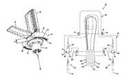
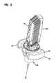
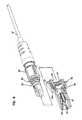
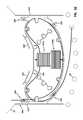
- FIG. 1is a perspective view of a dome-style closure in accordance with the principles of the present disclosure
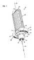
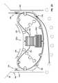
- FIG. 2is a perspective view of the closure of FIG. 1 with the dome removed to expose a stack of splice trays;
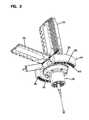
- FIG. 3shows the closure of FIG. 1 with the dome removed and one of the splice trays of the stack of splice trays pivoted downwardly;
- FIG. 4is a bottom view of the closure of FIG. 1 ;
- FIG. 5is a top view of the closure of FIG. 1 ;
- FIG. 6is a schematic view showing various components of the closure of FIG. 1 ;
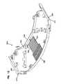
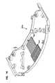
- FIG. 7is a top, perspective view of an expansion component of the closure of FIG. 1 ;
- FIG. 8is a bottom, perspective view of the expansion component of the closure of FIG. 1 ;
- FIG. 9shows a ruggedized adapter and ruggedized connector suitable for use with the closure of FIG. 1 ;
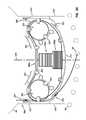
- FIG. 10shows the closure of FIG. 1 equipped with components (e.g., optical power splitters, optical wavelength dividing components, etc.) for increasing the service capacity of the closure;
- componentse.g., optical power splitters, optical wavelength dividing components, etc.
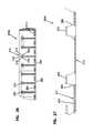
- FIG. 11is a plan view of a first component tray adapted for use with the closure of FIG. 1 ;
- FIG. 12is a perspective view of the component tray of FIG. 11 ;
- FIG. 13is a cross-sectional view taken along section line 13 - 13 of FIG. 11 ;
- FIG. 14is a cross-sectional view taken along section line 14 - 14 of FIG. 11 ;
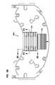
- FIG. 15is a plan view of the component tray of FIG. 11 with wavelength splitting components and splicing components secured thereto;
- FIG. 16is a perspective view of the component tray of FIG. 11 with wavelength splitting components and splicing components secured thereto;
- FIG. 17is a cross-sectional view taken along section line 17 - 17 of FIG. 15 ;
- FIG. 18is a cross-sectional view taken along section line 18 - 18 of FIG. 15 ;
- FIG. 19shows an inner passage of a radial extension of the closure of FIG. 1 , component trays are shown mounted within the inner passage;
- FIG. 20is a diagrammatic cross-sectional view showing the component tray of FIG. 11 mounted in one of the radial extensions of the closure of FIG. 1 , a first fiber routing path of the component tray is also shown;
- FIG. 21is the same view as FIG. 20 showing a second fiber routing path
- FIG. 22is the same view as FIG. 20 showing a third fiber routing path
- FIG. 23is the same view as FIG. 20 showing a fourth fiber routing path;
- FIG. 11is a plan view of a first component tray adapted for use with the closure of FIG. 1 ;
- FIG. 24is a plan view of a second component tray adapted for use with the closure of FIG. 1 ;
- FIG. 25is a perspective view of the component tray of FIG. 24 ;
- FIG. 26is a cross-sectional view taken along section line 26 - 26 of FIG. 24 ;
- FIG. 27is a cross-sectional view taken along section line 27 - 27 of FIG. 24 ;
- FIG. 28is a plan view of the component tray of FIG. 24 with power splitting components and splicing components secured thereto;
- FIG. 29is a perspective view of the component tray of FIG. 24 with power splitting components and splicing components secured thereto;
- FIG. 30is a cross-sectional view taken along section line 30 - 30 of FIG. 28 ;
- FIG. 31is a cross-sectional view taken along section line 31 - 31 of FIG. 28 .
- the present disclosurerelates generally to closures adapted for use in fiber optic communications networks.
- the closurescan be environmentally sealed and can be re-enterable.
- the closurescan be configured to provide optical connections in the form of optical splices or connectorized connections.
- FIGS. 1-6show a closure 20 in accordance with the principles of the present disclosure.
- the closure 20defines a central longitudinal axis 22 that extends along a length of the closure 20 from a bottom end 24 and a top end 26 .
- a base 28defines the bottom end 24 of the closure 20 while a dome 30 defines the top end 26 of the closure 20 .
- the base 28defines a plurality of cable through-ports 32 for allowing cables (e.g., trunk cables, drop cables or other cables) to enter the closure 20 .
- the base 28supports a frame 33 (see FIG. 2 ) to which a stack of pivotal splice trays 35 are mounted.
- An expansion component 34mounts between the dome 30 and the base 28 .
- the frame 33extends through the expansion component 34 .
- the expansion component 34includes expansion housings 36 having interior regions adapted to be in communication with the interior of the dome 30 and the interior of the base 28 .
- the expansion housings 36are positioned on opposite sides of the axis 22 and have dimensions d (see FIG. 5 ) that project radially outwardly from the axis 22 .
- expansion housings 36are positioned radially/laterally outside a main cylindrical outer boundary 37 defined by the dome 30 .
- a plurality of ruggedized fiber optic adapters 38are mounted to the expansion housings 36 .
- the ruggedized fiber optic adapters 38include connector ports 84 (see FIG. 9 ) for receiving ruggedized fiber optic connectors.
- the connector ports 84 and the cable through-ports 32face in a downward direction and have axes that are generally parallel with respect to the axis 22 .
- dust caps 93are shown mounted in the ports 84 .
- the dome 30 of the closure 20includes a closed top end 42 and an open bottom end 44 .
- the closed top end 42defines the top end 26 of the closure 20 and the open bottom end 44 is configured for a connection to the expansion component 34 .
- a circumferential flange 46is provided at the open bottom end 44 for facilitating coupling the dome 30 to the expansion component 34 with a clamp.
- the base 28 of the closure 20includes a top end 48 positioned opposite from a bottom end 50 .
- the bottom end 50defines the bottom end 24 of the closure 20
- the top end 48is adapted to be connected to the expansion component 34 .
- the top end 48includes a circumferential flange 52 for facilitating coupling the base 28 to the expansion component 34 with a clamp.
- a cable sealing arrangementis provided within the base 28 .
- the sealing arrangementcan be actuated by an actuator 54 which causes sealing material within the base 28 to be compressed in a direction along the axis 22 . When the sealing material is axially compressed, the material deforms radially inwardly about the cables within the through-ports 32 thereby forming circumferential seals around cables.
- the expansion component 34 of the closure 20includes a central collar 55 that mounts between the open bottom end 44 of the dome 30 and the top end 48 of the base 28 .
- the collar 55can also be referred to as a spacer or a sleeve.
- An upper end of the collar 55includes a circumferential flange 56 adapted to be clamped to the circumferential flange 46 at the bottom of the dome 30 .
- a lower end of the collar 55includes a circumferential flange 58 adapted to be clamped to the circumferential flange 52 at the top end 48 of the base 28 .
- FIG. 6shows a first channel clamp 61 being used to clamp the flanges 46 , 56 together and a second the channel clamp 63 being used to clamp the flanges 52 , 58 together.
- the collar 55is generally coaxially aligned with the dome 30 and the base 28 .
- the central collar 55includes an axial dimension A 1 that is selected to insure that the collar 55 does not interfere with the ability of the splice trays 35 to pivot relative to the frame 33 .
- a 1axial dimension selected to insure that the collar 55 does not interfere with the ability of the splice trays 35 to pivot relative to the frame 33 .
- the top end of the collar 55coincides with a location where the splice trays 35 are pivoted to an open position.
- the splice trays 35are pivoted about 90 degrees relative to the frame 33 when the splice trays are 35 in the open position.
- the expansion housings 36 of the expansion component 34include main housings 36 a and radial extensions 36 b that connect the main housings 36 a to the collar 55 .
- the main housings 36 ahave enlarged internal volumes as compared to the radial extensions 36 b .
- the radial extensions 36 bdefine radial fiber passages 71 that provide communication between interior regions of the main housings 36 a and an exterior region of the collar 55 .
- the interior region of the collar 55is also in communication with an interior region of the dome 30 and an interior region of the base 28 .
- Reinforcing wall portions 222e.g., webs
- the wall portions 222are located at the ends of the passages 74 that are positioned adjacent the collar 55 .
- the wall portions 222have curvatures that extend about the central axis 22 and also have heights that extend along the axial dimension A 1 .
- the wall portions 222provide crush resistance in the axial orientation.
- the radial extensions 36 bcan also include tray guide rails 223 provided at side walls 225 of the radial extensions 36 b.
- the main housings 36 a of the expansion component 34are shaped to curve generally about the axis 22 of the closure 20 .
- Bottom sides of the main housings 36 aare defined by adapter mounting walls 72 having outer surfaces 74 that face in a downward direction.
- Adapter mounting openings 76extend through the adapter mounting walls 72 .
- the ruggedized fiber optic adapters 38are mounted within the adapter mounting openings 76 .
- the adapter mounting openings 76 of each of the main housings 36 aare positioned along a curve located radially outside the main cylindrical boundary 37 defined by the dome 30 .
- the fiber optic adapters 38are axially offset (e.g., upwardly offset) from the through-ports 32 of the base 28 and are also radially outwardly offset from the through-ports 32 of the base 28 .
- FIG. 9shows one of the ruggedized fiber optic adapters 38 and a corresponding ruggedized fiber optic connector 80 adapted to be received within the fiber optic adapter 38 .
- the fiber optic connector 80is shown mounted at the end of a drop cable 81 .
- the fiber optic adapter 38includes an inner port 82 adapted for receiving a connector such as an SC connector 83 (see FIG. 6 ), and an outer port 84 adapted for receiving one of the ruggedized fiber optic connectors 80 .
- an optical connectionis provided between the connectors 80 , 83 .
- the fiber optic adapter 38can include a latch 85 for retaining the fiber optic connector 83 within the inner port 82 .
- Internal threads 87can be provided in the outer port 84 .
- the threads 87cooperate with external threads 89 of a threaded nut 95 provided on the ruggedized fiber optic connector 80 to retain the ruggedized fiber optic connector 80 within the outer port 84 .
- An alignment sleeve 91is provided within the fiber optic adapter 38 for aligning ferrules of the connectors 80 , 83 .
- the adapter mounting wall 72is captured between a flange 86 of the adapter 38 and a retention nut 88 .
- a sealing member 97 in the form of an o-ringcan be used to provide a seal between the housing of the fiber optic adapter 38 and the outer surface 74 of the adapter mounting wall 72 .
- the main housings 36 ahave axial dimensions A 2 that are larger than corresponding axial dimensions A 3 of the radial extensions 36 b .
- the axial dimensions A 2are larger than the axial dimensions A 3 at least in part because of axial extension portions 99 that project downwardly from the radial extensions 36 b .
- the axial extension portions 99function to downwardly offset the adapter mounting walls 72 from the radial extensions 36 b .
- the enlarged axial dimensions A 2provide more axial space within the main housings 36 a (i.e., between the upper and lower walls of the main housings 36 a ) for routing fibers. For example, sufficient space is provided for bending optical fibers corresponding to the connectors 83 without violating minimum bend radius requirements for the optical fibers. As shown at FIG.
- the optical fibers coupled to the connectors 83are bent about 90 degrees as the optical fibers are routed from the connectors 83 within the fiber optic adapters 38 to the fiber passages 71 of the radial extensions 36 b . Furthermore, as shown at FIG. 6 , a gap/open space 220 defined radially between the axial extension portions 99 and the central collar 55 provides clearance for mounting and accessing the clamp 63 .
- the closure 20is adapted to accommodate both splice connections and connectorized connections (e.g., connections using ruggedized connectors).
- FIG. 6shows a trunk cable 100 routed through the interior of the closure 20 .
- the trunk cable 100extends through the through-ports 32 provided at the base 28 .
- one or more of the fibers of the trunk cable 100can be spliced to corresponding fibers of a drop cable 102 that is also routed through a cable through-port 32 of the base 28 .
- the closure 20accommodates a spliced connection with a drop cable.
- the pre-connectorized drop cablecan be plugged into the outer port 84 of one of the fiber optic adapters 38 .
- the connector of the pre-connectorized drop cableWhen the connector of the pre-connectorized drop cable is inserted within the outer port 84 , it optically connects to a corresponding connector 83 that has been pre-mounted within the inner port of the adapter 38 .
- the connector 83can be mounted directly to one of the optical fibers of the trunk cable 100 .
- the connector 83can be field terminated on the fiber.
- the connector 83can be mounted at the end of a pigtail fiber that is spliced to a corresponding one of the fibers of the trunk cable 100 at the splice location.
- the main housings 36 acan include outer end covers 73 that are removable from main bodies of the main housings 36 a . By removing the end covers 73 , interior regions of the main housings 36 a can be easily accessed for loading trays into the radial extensions 36 b , for routing connectors 83 to the inner ports of the adapters 38 , or for service operations or maintenance activities.
- the configuration of the expansion component 34is ideally suited for use in retrofitting/upgrading existing splice closures that are already in operation in the field.
- the dome 30 of the closurecan be removed and the expansion component 34 can be mounted to the base of the closure.
- the connectors 83 mounted within the inner ports 82 of the fiber optic adapters 38can then be optically connected to optical fibers of one or more trunk/feeder cables routed into and/or through the closure.
- the connectors 83can be field terminated at ends of selected fibers of the trunk cables.
- the connectors 83can be mounted at the end of pigtails which are spliced to fibers of the trunk cables.
- the expansion component 34For the purpose of providing a closure design suitable for retrofitting existing splice closures, it is desirable for the expansion component 34 to be a separate piece from the dome 30 and the base 28 . However, in alternative embodiments, the expansion component 34 can be integrally formed with either the dome 30 or the base 28 .
- the expansion component 34can include additional structures for increasing the service capacity of the closure.
- Example structurescan include passive components such as optical power splitters and structures for providing optical wavelength splitter/dividing/filtering.
- Optical power splittersare capable of splitting an entire optical signal carried by one optical fiber to two or more optical fibers (e.g., 1 by 2 splitters; 1 by 4 splitters; 1 by 8 splitters, 1 by 16 splitters; 1 by 32 splitters, etc.), and are also capable of combining optical signals from multiple fibers back to one optical fiber.
- Wavelength splitting/dividing structuresare capable dividing an optical signal carried by one optical fiber into separate wavelength ranges with each range then being directed to and carried by a separate optical fiber, and are also capable of combining separate wavelength ranges carried by separate optical fibers back to one optical fiber.
- FIG. 10shows the expansion component 34 equipped with service capacity increasing components 200 a , 200 b of the type described in the previous paragraph (e.g., optical power splitters, optical wavelength splitters, etc.).
- the components 200 a , 200 bare shown mounted in the passages 71 defined by the radial extensions 36 b .
- An input fiber 202 to the component 200 ais shown spliced to a corresponding optical fiber of the trunk cable 100 and output fibers 204 of the component 200 a are coupled to the fiber optic connectors 83 inserted within the inner ports of the fiber optic adapters 38 .
- An input fiber 206 of the component 200 bis provided by one of the optical fibers of the trunk cable 100 .
- the input fiber 206has a connectorized end 208 that connects to the component 200 b in a plug-and-play type configuration. Further details about example plug-and-play type connections for optical splitters are disclosed at U.S. Pat. Nos. 7,376,322; 7,400,813; 7,376,323; and 7,346,254; which are hereby incorporated by reference in their entireties.
- Output fibers 210 of the component 200 bare coupled to the fiber optic connectors 83 inserted within the inner ports of the fiber optic adapters 38 .
- FIGS. 11-18show a component tray 300 a (i.e., cassette) adapted to be mounted within the passage 71 of one of the radial extensions 36 b .
- the component tray 300 ais configured to securely retain optical components such as splice sleeves 302 and wavelength splitting components 304 .
- the splice sleevesare structures for reinforcing a slice (e.g., a fusion splice) between two optical fibers.
- a splice sleevetypically includes an inner adhesive layer surrounded by a heat shrink layer. Splice sleeves also typically include axial reinforcing members attached to the heat shrink layer.
- the splice sleeves 302 and the components 304are generally cylindrical. The components 304 have larger diameters as compared to the splice sleeves 302 .
- the first component tray 300 ais sized and shaped to fit within one of the radial extensions 36 b without projecting substantially into the collar 55 or the main housings 36 a . As shown at FIG. 19 , the component tray 300 a is mounted at a lower mounting location of one of the radial extensions 36 b , and another component tray 300 b (see FIGS. 24-31 ) is mounted at an upper mounting location of the radial extension 36 b . In certain embodiments, each of the radial extensions 36 b can be loaded with component trays 300 a , 300 b so as to maximize the circuit density provided by the expansion component 34 .
- the component tray 300 ahas a generally kidney-shaped perimeter when viewed in plan view.
- the perimeteris defined in part by a concave side 306 of the tray 300 a and an opposite convex outer side 308 of the tray 300 a .
- the perimeteris also defined by opposite ends 310 , 312 of the tray 300 a that extend between the concave and convex sides 306 , 308 .
- the ends 310 , 312are substantially parallel to one another.
- the tray 300 aincludes a base 314 and a perimeter wall arrangement 316 that projects upwardly from the base 314 .
- the perimeter wall arrangement 316extends around the perimeter of the tray 300 a and cooperates with the base 314 to define a protected fiber management volume/space 318 above the base 314 .
- Fiber retention tabs 320project inwardly from the perimeter wall arrangement 316 .
- the tabs 320are spaced above the base 314 and overhang the fiber management space 318 .
- the tabs 320function to retain optical fibers routed on the tray 300 a within the fiber management space 318 .
- Some of the tabs 320include receptacles 322 for receiving fasteners (e.g., snap-fit fasteners) used to secure a cover over the top of the space 318 .
- the tray 300 ais symmetric about a central axis 324 .
- the tray 300 aincludes two fiber entrance/exit locations 326 , 328 positioned at the concave side 306 of the tray and two fiber entrance/exit locations 330 , 332 positioned at the convex side 308 of the tray.
- the locations 326 , 330are at one end 310 of the tray and the locations 328 , 332 are located at the other end 312 of the tray.
- the locations 326 , 328define fiber routing paths P 1 , P 2 that are substantially parallel to the central axis 324 , while the locations 330 , 332 define fiber routing paths P 3 , P 4 that converge toward and intersect at the central axis 324 .
- Tie down structures 333are provided at each of the exit/entrance locations for allowing tubing protecting the optical fibers to be tied down (e.g., with cable ties) to the tray.
- the tray 300 aincludes structures for facilitating securing the tray within the bottom mounting location of one of the radial extensions 36 b .
- the tray 300 aincludes flanges 336 that project outwardly from the opposite ends 310 , 312 at locations adjacent the top of the tray 300 a .
- the flanges 336slide beneath the side rails 223 of the extension 36 b .
- the tray 300 aalso includes resilient retention latches 338 positioned at the concave side 306 of the tray 300 a .
- the latches 338are positioned between the central axis 324 and the fiber entrance/exit locations 326 , 328 and are adapted to latch (e.g., by a snap fit connection) over the edges the walls 222 of the radial extension 36 b when the tray 300 a is fully inserted therein.
- the latches 338include a flexible cantilever portion 340 , a cam portion 342 and a catch 344 .
- the cantilever portion 340is substantially parallel to the central axis 324 and the cam portions 342 define cam surfaces aligned along planes P 5 , P 6 that are angled relative to the central axis 324 .
- the planes P 5 , P 6converge as the planes extend toward the concave side 306 of the tray 300 a .
- the concave shape of the trayprovides a recess 346 between the latches 338 .
- the recess 346provides clearance for the walls 222 when the tray 300 a is latched within one of the radial extensions 36 b.
- the cover 73is removed from the corresponding main housing 36 a .
- the tray 300 ais then inserted though the open side of the main housing 36 a in a radial direction directed toward the central axis 22 of the expansion component 34 .
- the insertion directionis parallel to the central axis 324 of the tray 300 a .
- the flanges 336ride beneath the rails 223 in close proximity to the side walls 225 .
- the cam surfaces of the cam portions 342into contact with the walls 222 .
- component mounting locations 350 a , 350 bare positioned at a central region of the tray 300 a and excess fiber storage locations 352 are positioned adjacent the ends of the tray 300 a .
- the excess fiber storage locations 352are adapted for storing optical fiber 354 in a looped/coiled configuration.
- the locations 352are defined in part by inner surfaces of the perimeter wall arrangement 316 and in part by curved cable management walls 353 positioned within the fiber management space 318 .
- the coilscan be positioned inside or outside the walls 353 based on user preference.
- FIG. 20-23show various optical fiber routing schemes/paths in which optical fibers are routed from one of the fiber entrance/exit locations 326 , 328 through one of the component mounting locations 350 a , 350 b to one of the fiber entrance/exit locations 330 , 332 .
- splitsare not shown at the wavelength splitting components 304 .
- multiple output fiberscan be provided from each component 304 for each input fiber as shown at FIG. 10 .
- All of the depicted routing schemesinvolve routing the fibers 354 around the inside of the perimeter of the tray 300 a . Only FIG. 20 shows excess fiber being coiled at the locations 352 .
- fibercan be similarly coiled in any of the routing schemes to accommodate excess fiber length.
- the angling of the fiber entrance/exit locations 330 , 332 along orientations P 3 and P 4facilitates routing fibers to adapters 38 located on opposite sides of the central axis 324 from the respective locations 330 , 332 without violating minimum bend radius requirements of the optical fibers
- the component mounting locations 350 a , 350 bhave a compact configuration adapted for securely attaching optical components to the tray 300 a .
- the component mounting location 350 ais adapted for mounting wavelength splitting components 304 to the tray 300 a and the component mounting location 350 b is adapted for mounting splice sleeves 302 to the tray 300 a .
- the retention structures provided at the locations 350 a , 350 bare the same, except that the components provided at location 350 a are larger than those provided at location 350 b.
- the retention structures provided at the component mounting locations 350 a , 350 bdefine a plurality of elongated pockets 392 (i.e., cavities, receptacles, component receiving locations, receptacles) having lengths aligned substantially perpendicular relative to the central axis 324 .
- the pockets 392 of each location 350 a , 350 bare arranged in a row of pockets with the lengths of the pockets being substantially parallel to one another.
- Each of the pockets 392is defined between two resilient retention members 394 that are substantially parallel to one another and that extend at least a majority of the length of the pocket 392 .
- the resilient retention members 394have cantilevered configurations with base ends 396 integrally formed (e.g., molded as one seamless piece) with the base 314 .
- the resilient retention membershave elastic/spring-like characteristics when bent about their base ends 396 in an orientation transverse to their lengths (e.g., orientation 395 ).
- the retention members 394include concave sides 397 that face at least partially toward the base 314 (e.g., downwardly) and that overhang the pockets 392 .
- the retention members 394also include convex sides 398 that face away from the base 314 (e.g., upwardly).
- the concave sides 397at least partially oppose the convex sides 398 of adjacent retention members 394 such that the sides 397 , 398 cooperate to define lateral boundaries of the pockets 392 .
- Through-slots 399are defined through the base 314 at locations directly beneath the overhanging portions of the concave sides 397 of the retention members 394 .
- the base 314defines pocket beds 400 between the slots 399 and the convex sides 398 of the retention members 394 .
- the pocket beds 400include component support surfaces that are recessed relative to a main level 402 of the base 314 . End shoulders 403 are defined at the interface between the component support surface and the main level 402 .
- the componentis pressed between the concave side 397 and the convex side 398 of two adjacent retention members 394 .
- the retention members 394elastically flex/deflect apart providing clearance for the component to enter the pocket.
- the retention positionis a neutral position where the retention members 394 are not deflected.
- the retention members 394can be deflected when in the retention position to apply an elastic retention force to the component.
- FIGS. 24-31show the tray 300 b that is adapted to be mounted at the upper mounting positions of the radial extensions 36 b .
- the tray 300 bhas the same basic configuration as the tray 300 a except flanges 336 are located at a bottom side of the tray 300 b such that the flanges can ride on top sides of the rails 223 when the tray is inserted into the upper position of one of the radial extensions 36 b .
- the tray 300 bincludes a component mounting location 350 c adapted for securing rectangular components such as optical power splitters 303 to the tray 300 b.
- the retention structures provided at the component mounting location 350 cdefine a plurality of elongated pockets having lengths aligned substantially perpendicular relative to the central axis 324 .
- the pocketsare arranged in a row of pockets with the lengths of the pockets being substantially parallel to one another.
- Each of the pocketsis defined between two pairs of resilient retention members 370 .
- the resilient retention members 370have cantilevered configurations with base ends integrally formed (e.g., molded as one seamless piece) with the base 314 .
- the resilient retention membershave elastic/spring-like characteristics when bent about their base ends in an orientation transverse to their lengths.
- the retention members 370include retention heads 372 each having two cam surfaces 374 that meet at an apex 376 .
- Each retention headalso includes a retention surface 378 positioned beneath each cam surface 374 .
- the retention surfaces 378face toward the base 314 (e.g., downwardly) and overhang pockets separated by the main cantilever body of each retention member 370 .
- Through-slots 380are defined through the base 314 at locations directly beneath the retention surfaces 378 .
- the base 314defines pocket beds 382 between the slots 380 .
- the pocket beds 382include component support surfaces (see FIG. 27 ) that are recessed relative to the main level 402 of the base 314 . End shoulders 385 are defined at the interface between the component support surface and the main level 364 .
- the componentis pressed between two of the retention members 370 .
- the componentengages the cam surfaces 374 positioned at opposite sides of the pocket causing the retention members 370 to deflect apart providing clearance for the component to enter the pocket.
- the componentseats on the pocket bed 382 and the retention members 370 elastically move back toward a retaining configuration (see FIG. 30 ) where the component is captured within the pocket beneath the retention surfaces 378 .
- the shoulders 385limit axial movement of the component within the pocket (see FIG. 31 ).
- dome-style splice closureVarious aspects of the disclosure are shown with respect to a dome-style splice closure. In alternative embodiments, it will be appreciated that aspects of the present disclosure can be used with other types of closures such as in-line closures, or other types of closures.
- the various embodiments disclosed hereinhave been described using directional terms (e.g., upper, lower, top, bottom, etc.) merely for ease of describing the relative positioning of the various parts.
- the embodiments disclosed hereincan be used in any orientation.
- the enclosures described hereinmight typically be oriented horizontally (i.e., with the central axes extending horizontally).
- the enclosures described hereinmight typically be oriented vertically (i.e., with the central axes extending vertically).
- the phrase “generally parallel”means parallel or almost parallel. Also, the phrase “generally perpendicular” means perpendicular or almost perpendicular.
Landscapes
- Physics & Mathematics (AREA)
- General Physics & Mathematics (AREA)
- Optics & Photonics (AREA)
- Engineering & Computer Science (AREA)
- Plasma & Fusion (AREA)
- Light Guides In General And Applications Therefor (AREA)
- Mechanical Coupling Of Light Guides (AREA)
Abstract
Description
Claims (5)
Priority Applications (4)
| Application Number | Priority Date | Filing Date | Title |
|---|---|---|---|
| US15/854,140US10162142B2 (en) | 2011-02-16 | 2017-12-26 | Fiber optic closure |
| US16/229,989US20190129114A1 (en) | 2011-02-16 | 2018-12-21 | Fiber optic closure |
| US16/404,259US20190361186A1 (en) | 2011-02-16 | 2019-05-06 | Fiber optic closure |
| US16/949,447US20210041652A1 (en) | 2011-02-16 | 2020-10-29 | Fiber optic closure |
Applications Claiming Priority (8)
| Application Number | Priority Date | Filing Date | Title |
|---|---|---|---|
| US201161443501P | 2011-02-16 | 2011-02-16 | |
| US201161468405P | 2011-03-28 | 2011-03-28 | |
| US13/397,884US8861919B2 (en) | 2011-02-16 | 2012-02-16 | Fiber optic closure |
| US14/495,110US9057858B2 (en) | 2011-02-16 | 2014-09-24 | Fiber optic closure |
| US14/716,347US20150253530A1 (en) | 2011-02-16 | 2015-05-19 | Fiber optic closure |
| US15/289,459US20170023759A1 (en) | 2011-02-16 | 2016-10-10 | Fiber optic closure |
| US15/582,894US9864157B2 (en) | 2011-02-16 | 2017-05-01 | Fiber optic closure |
| US15/854,140US10162142B2 (en) | 2011-02-16 | 2017-12-26 | Fiber optic closure |
Related Parent Applications (1)
| Application Number | Title | Priority Date | Filing Date |
|---|---|---|---|
| US15/582,894ContinuationUS9864157B2 (en) | 2011-02-16 | 2017-05-01 | Fiber optic closure |
Related Child Applications (1)
| Application Number | Title | Priority Date | Filing Date |
|---|---|---|---|
| US16/229,989ContinuationUS20190129114A1 (en) | 2011-02-16 | 2018-12-21 | Fiber optic closure |
Publications (2)
| Publication Number | Publication Date |
|---|---|
| US20180203200A1 US20180203200A1 (en) | 2018-07-19 |
| US10162142B2true US10162142B2 (en) | 2018-12-25 |
Family
ID=46828519
Family Applications (9)
| Application Number | Title | Priority Date | Filing Date |
|---|---|---|---|
| US13/397,884Active2032-12-22US8861919B2 (en) | 2011-02-16 | 2012-02-16 | Fiber optic closure |
| US14/495,110ActiveUS9057858B2 (en) | 2011-02-16 | 2014-09-24 | Fiber optic closure |
| US14/716,347AbandonedUS20150253530A1 (en) | 2011-02-16 | 2015-05-19 | Fiber optic closure |
| US15/289,459AbandonedUS20170023759A1 (en) | 2011-02-16 | 2016-10-10 | Fiber optic closure |
| US15/582,894ActiveUS9864157B2 (en) | 2011-02-16 | 2017-05-01 | Fiber optic closure |
| US15/854,140ActiveUS10162142B2 (en) | 2011-02-16 | 2017-12-26 | Fiber optic closure |
| US16/229,989AbandonedUS20190129114A1 (en) | 2011-02-16 | 2018-12-21 | Fiber optic closure |
| US16/404,259AbandonedUS20190361186A1 (en) | 2011-02-16 | 2019-05-06 | Fiber optic closure |
| US16/949,447AbandonedUS20210041652A1 (en) | 2011-02-16 | 2020-10-29 | Fiber optic closure |
Family Applications Before (5)
| Application Number | Title | Priority Date | Filing Date |
|---|---|---|---|
| US13/397,884Active2032-12-22US8861919B2 (en) | 2011-02-16 | 2012-02-16 | Fiber optic closure |
| US14/495,110ActiveUS9057858B2 (en) | 2011-02-16 | 2014-09-24 | Fiber optic closure |
| US14/716,347AbandonedUS20150253530A1 (en) | 2011-02-16 | 2015-05-19 | Fiber optic closure |
| US15/289,459AbandonedUS20170023759A1 (en) | 2011-02-16 | 2016-10-10 | Fiber optic closure |
| US15/582,894ActiveUS9864157B2 (en) | 2011-02-16 | 2017-05-01 | Fiber optic closure |
Family Applications After (3)
| Application Number | Title | Priority Date | Filing Date |
|---|---|---|---|
| US16/229,989AbandonedUS20190129114A1 (en) | 2011-02-16 | 2018-12-21 | Fiber optic closure |
| US16/404,259AbandonedUS20190361186A1 (en) | 2011-02-16 | 2019-05-06 | Fiber optic closure |
| US16/949,447AbandonedUS20210041652A1 (en) | 2011-02-16 | 2020-10-29 | Fiber optic closure |
Country Status (2)
| Country | Link |
|---|---|
| US (9) | US8861919B2 (en) |
| WO (1) | WO2013105998A2 (en) |
Cited By (2)
| Publication number | Priority date | Publication date | Assignee | Title |
|---|---|---|---|---|
| RU197413U1 (en)* | 2020-01-14 | 2020-04-23 | Закрытое Акционерное Общество "Связьстройдеталь" | Optical Coupler Terminal Module |
| US11733465B2 (en) | 2020-06-09 | 2023-08-22 | Senko Advanced Components. Inc. | Multiport assembly and associated components |
Families Citing this family (48)
| Publication number | Priority date | Publication date | Assignee | Title |
|---|---|---|---|---|
| US8861919B2 (en)* | 2011-02-16 | 2014-10-14 | Tyco Electronics Corporation | Fiber optic closure |
| US9106981B2 (en) | 2011-10-03 | 2015-08-11 | Tyco Electronics Uk Ltd | Aggregation enclosure for elevated, outdoor locations |
| CN103975264B (en)* | 2011-10-07 | 2015-09-16 | Adc电信公司 | Slidable fiber optic connection module with cable slack management |
| US10379308B2 (en) | 2012-03-19 | 2019-08-13 | Brian D. Coate | Apparatus and method for splicing all-dielectric self-supporting fiber optic cable |
| US9195021B2 (en)* | 2012-09-21 | 2015-11-24 | Adc Telecommunications, Inc. | Slidable fiber optic connection module with cable slack management |
| US10082636B2 (en)* | 2012-09-21 | 2018-09-25 | Commscope Technologies Llc | Slidable fiber optic connection module with cable slack management |
| CN105074525A (en) | 2013-01-29 | 2015-11-18 | 泰科电子瑞侃有限公司 | Fiber Distribution System |
| US9829668B2 (en) | 2013-08-23 | 2017-11-28 | CommScope Connectivity Belgium BVBA | Pass-through assembly having an anchor member and a cover |
| CN105683795A (en) | 2013-08-24 | 2016-06-15 | 康普连通比利时有限责任公司 | Rugged Fiber Optic Connectors and Connection Systems |
| WO2015066185A1 (en)* | 2013-10-29 | 2015-05-07 | 3M Innovative Properties Company | Fiber optic splice closure |
| CN204013952U (en)* | 2014-06-26 | 2014-12-10 | 中兴通讯股份有限公司 | intelligent controlling device, intelligent optical distribution network equipment and system |
| WO2016007488A1 (en)* | 2014-07-10 | 2016-01-14 | Corning Optical Communications LLC | Optical fiber distribution hub with fiber routing structures |
| WO2016094331A1 (en) | 2014-12-10 | 2016-06-16 | Commscope Technologies Llc | Fiber optic cable slack management module |
| US10054741B2 (en)* | 2015-10-14 | 2018-08-21 | Commscope Technologies Llc | Fiber optic enclosure assembly |
| GB2547681A (en)* | 2016-02-25 | 2017-08-30 | British Telecomm | Apparatus |
| ES2851948T3 (en) | 2016-04-19 | 2021-09-09 | Commscope Inc North Carolina | Telecom rack with slide out trays |
| WO2017184501A1 (en) | 2016-04-19 | 2017-10-26 | Commscope, Inc. Of North Carolina | Door assembly for a telecommunications chassis with a combination hinge structure |
| EP3583455A1 (en) | 2017-02-15 | 2019-12-25 | CommScope Connectivity Belgium BVBA | Interchangeable telecommunications enclosure components |
| WO2018149917A1 (en) | 2017-02-15 | 2018-08-23 | CommScope Connectivity Belgium BVBA | Modular telecommunications enclosures |
| US9829665B1 (en)* | 2017-04-27 | 2017-11-28 | Afl Telecommunications Llc | Fiber optic splice enclosures |
| CN107121728B (en)* | 2017-06-29 | 2020-04-17 | 常州太平通讯科技有限公司 | General optical fiber fusion splice tray |
| US11002935B2 (en) | 2017-08-18 | 2021-05-11 | Commscope Technologies Llc | MST expansion closures; and methods |
| EP3673308B1 (en) | 2017-08-23 | 2024-04-03 | Commscope Technologies LLC | Drop terminal |
| US11385429B2 (en)* | 2017-10-18 | 2022-07-12 | Commscope Technologies Llc | Fiber optic connection cassette |
| CN109696732B (en) | 2017-10-24 | 2022-12-09 | 康普技术有限责任公司 | Fiber Management Device |
| CN110156674A (en)* | 2018-02-13 | 2019-08-23 | 中国科学院上海有机化学研究所 | A spiro compound as indoleamine-2,3-dioxygenase inhibitor |
| US11852882B2 (en) | 2018-02-28 | 2023-12-26 | Commscope Technologies Llc | Packaging assembly for telecommunications equipment |
| RU2683815C1 (en)* | 2018-03-01 | 2019-04-02 | Закрытое Акционерное Общество "Связьстройдеталь" | Optical coupling and coupling hermetic seal |
| WO2019204317A1 (en) | 2018-04-16 | 2019-10-24 | Commscope Technologies Llc | Adapter structure |
| PL3844973T3 (en) | 2018-08-31 | 2025-03-03 | CommScope Connectivity Belgium BVBA | Frame assemblies for optical fiber distribution elements |
| WO2020043914A1 (en) | 2018-08-31 | 2020-03-05 | CommScope Connectivity Belgium BVBA | Frame assemblies for optical fiber distribution elements |
| EP3844546A1 (en) | 2018-08-31 | 2021-07-07 | CommScope Connectivity Belgium BVBA | Frame assemblies for optical fiber distribution elements |
| EP3844547A1 (en) | 2018-08-31 | 2021-07-07 | CommScope Connectivity Belgium BVBA | Frame assemblies for optical fiber distribution elements |
| EP3845044B1 (en) | 2018-08-31 | 2023-02-15 | CommScope Connectivity Belgium BVBA | Frame assemblies for optical fiber distribution elements |
| CN109856732B (en)* | 2019-01-31 | 2024-04-16 | 广东瑞谷光网通信股份有限公司 | High-efficient tool of reprocessing of general type optical device |
| US11899262B2 (en) | 2019-03-29 | 2024-02-13 | Commscope Technologies Llc | Fiber management components for telelcommunications closures |
| BR112021022985A2 (en) | 2019-05-18 | 2022-01-04 | Commscope Technologies Llc | Telecommunications Cabinet System |
| EP3742213B1 (en)* | 2019-05-22 | 2024-11-06 | Prysmian S.p.A. | High density splice holder tray |
| CN110501794B (en)* | 2019-07-01 | 2020-06-05 | 国网浙江省电力有限公司衢州供电公司 | Fiber Optic Splice Box with Humidity Detection |
| PH12022551068A1 (en)* | 2019-11-01 | 2023-10-16 | Commscope Technologies Llc | Telecommunication enclosure |
| CN211402854U (en)* | 2019-12-20 | 2020-09-01 | 宁波广瑞通信技术有限公司 | Branching joint box |
| RU2723915C1 (en)* | 2020-01-14 | 2020-06-18 | Закрытое Акционерное Общество "Связьстройдеталь" | Optical coupling and terminal module for optical coupling (versions) |
| RU196705U1 (en)* | 2020-01-14 | 2020-03-12 | Закрытое Акционерное Общество "Связьстройдеталь" | Optical coupler |
| EP4097527B1 (en)* | 2020-01-31 | 2024-11-27 | CommScope Connectivity Belgium BV | Cable sealing unit with multiple configurations |
| US11953750B2 (en) | 2020-04-30 | 2024-04-09 | Commscope Technologies Llc | Interlocking fiber optic connector holder |
| WO2022036219A1 (en)* | 2020-08-14 | 2022-02-17 | Commscope Technologies Llc | Fiber optic enclosure with a side cable entrance |
| US11604320B2 (en)* | 2020-09-30 | 2023-03-14 | Corning Research & Development Corporation | Connector assemblies for telecommunication enclosures |
| CN112415667B (en)* | 2020-11-30 | 2022-04-01 | 四川天邑康和通信股份有限公司 | MPO fiber connector |
Citations (41)
| Publication number | Priority date | Publication date | Assignee | Title |
|---|---|---|---|---|
| EP0267028A2 (en) | 1986-11-05 | 1988-05-11 | N.V. Raychem S.A. | Closure assembly |
| US5059748A (en) | 1990-04-26 | 1991-10-22 | Raychem Corporation | Cable splice enclosure |
| US5185845A (en) | 1990-12-13 | 1993-02-09 | At&T Bell Laboratories | Optical fiber closure having enhanced storage capability |
| US5323480A (en) | 1992-11-25 | 1994-06-21 | Raychem Corporation | Fiber optic splice closure |
| US5446823A (en) | 1994-01-26 | 1995-08-29 | Raychem Corporation | Aerial, pedestal, below grade, or buried optical fiber closure |
| US5495549A (en)* | 1994-02-18 | 1996-02-27 | Keptel, Inc. | Optical fiber splice closure |
| US5572617A (en) | 1994-04-26 | 1996-11-05 | Krone Aktiengesellschaft | Housing for optical components |
| US5602954A (en) | 1984-04-11 | 1997-02-11 | Raychem Sv | Electrofit fiber optics butt splice |
| US5758004A (en) | 1995-03-31 | 1998-05-26 | Minnesota Mining And Manufacturing Company | Closure with cable strain relief |
| US5777268A (en) | 1995-10-06 | 1998-07-07 | Raychem Corporation | Splice closure for buried telecommunications cables |
| US6304707B1 (en) | 1996-02-29 | 2001-10-16 | Daniel Daems | Optical fiber organizer |
| KR100367752B1 (en) | 1995-11-03 | 2003-03-15 | 사노피-신델라보 | Stable freeze-dried pharmaceutical formulation |
| US6539160B2 (en) | 2000-10-27 | 2003-03-25 | Corning Cable Systems Llc | Optical fiber splicing and connecting assembly with coupler cassette |
| US6579014B2 (en) | 2001-09-28 | 2003-06-17 | Corning Cable Systems Llc | Fiber optic receptacle |
| US20030169566A1 (en)* | 2001-12-21 | 2003-09-11 | Owens Mark J. | WDM add/drop multiplexer module |
| US6899467B2 (en) | 2001-09-28 | 2005-05-31 | Corning Cable Systems Llc | Fiber optic plug and receptacle assembly |
| US6934457B2 (en) | 2002-02-25 | 2005-08-23 | Nexans | Cassette for coiling optical fibers |
| US7013074B2 (en) | 2004-02-06 | 2006-03-14 | Corning Cable Systems Llc | Optical connection closure having at least one connector port |
| US7090406B2 (en) | 2000-05-26 | 2006-08-15 | Corning Cable Systems Llc | Preconnectorized fiber optic drop cables and assemblies |
| US7120347B2 (en) | 2004-01-27 | 2006-10-10 | Corning Cable Systems Llc | Multi-port optical connection terminal |
| US20070047895A1 (en) | 2005-08-31 | 2007-03-01 | 3M Innovative Properties Company | Enclosure and organizer for telecommunication lines and splices |
| US7266244B2 (en) | 2001-04-24 | 2007-09-04 | Microsoft Corporation | Robust recognizer of perceptually similar content |
| US7264402B2 (en) | 2005-03-10 | 2007-09-04 | Corning Cable Systems Llc | Multi-fiber optic receptacle and plug assembly |
| US7292763B2 (en) | 2004-03-08 | 2007-11-06 | Adc Telecommunications, Inc. | Fiber access terminal |
| US7346254B2 (en) | 2005-08-29 | 2008-03-18 | Adc Telecommunications, Inc. | Fiber optic splitter module with connector access |
| US7376323B2 (en) | 2005-05-25 | 2008-05-20 | Adc Telecommunications, Inc. | Fiber optic adapter module |
| US7376322B2 (en) | 2004-11-03 | 2008-05-20 | Adc Telecommunications, Inc. | Fiber optic module and system including rear connectors |
| US20080124038A1 (en) | 2006-11-28 | 2008-05-29 | Kowalczyk Scott C | Fiber distribution enclosure |
| US7400813B2 (en)* | 2005-05-25 | 2008-07-15 | Adc Telecommunications, Inc. | Fiber optic splitter module |
| US7418183B2 (en) | 2006-02-08 | 2008-08-26 | Charles Industries, Ltd. | Fiber optic splice enclosure |
| US7744288B2 (en) | 2007-12-11 | 2010-06-29 | Adc Telecommunications, Inc. | Hardened fiber optic connector compatible with hardened and non-hardened fiber optic adapters |
| US7780173B2 (en) | 2007-03-12 | 2010-08-24 | Tyco Electronics Corporation | Sealing assemblies and methods for sealing an elongate member |
| US7785016B2 (en) | 2007-03-12 | 2010-08-31 | Corning Cable Systems Llc | Fiber optic adapter and connector assemblies |
| US8009954B2 (en) | 2008-04-21 | 2011-08-30 | Adc Telecommunications, Inc. | Fiber optic splice tray |
| US20110317974A1 (en) | 2010-06-23 | 2011-12-29 | Adc Telecommunications, Inc. | Telecommunications Assembly |
| US8189983B2 (en) | 2006-09-13 | 2012-05-29 | 3M Innovative Properties Company | Fiber circuit management system with splice tray |
| US20130039623A1 (en)* | 2010-04-27 | 2013-02-14 | Yuanzhe Zhang | Fiber optic module and chassis |
| US8385711B2 (en) | 2010-04-30 | 2013-02-26 | Corning Cable Systems Llc | Multi-configurable splice holder |
| US8660397B2 (en) | 2010-04-30 | 2014-02-25 | Corning Cable Systems Llc | Multi-layer module |
| USD707630S1 (en) | 2012-11-29 | 2014-06-24 | Multilink, Inc. | Base plate of optical fiber splice cassette |
| US8861919B2 (en) | 2011-02-16 | 2014-10-14 | Tyco Electronics Corporation | Fiber optic closure |
Family Cites Families (12)
| Publication number | Priority date | Publication date | Assignee | Title |
|---|---|---|---|---|
| DE3825756C1 (en) | 1988-07-29 | 1989-09-21 | Walter Rose Gmbh & Co Kg, 5800 Hagen, De | |
| TR24079A (en) | 1988-11-09 | 1991-03-01 | Raychem Sa Nv | CLOSING LUGGAGE |
| GB9513364D0 (en) | 1995-06-30 | 1995-09-06 | Raychem Sa Nv | Cable seal |
| ES2151171T3 (en) | 1995-06-30 | 2000-12-16 | Raychem Sa Nv | CABLE SEAL INSERT. |
| US5896486A (en)* | 1997-05-01 | 1999-04-20 | Lucent Technologies Inc. | Mass splice tray for optical fibers |
| US6931174B2 (en)* | 2002-08-29 | 2005-08-16 | Luminent Incorporated | Optical add/drop module |
| US7130519B2 (en) | 2004-05-11 | 2006-10-31 | Preformed Line Products Company | Convertible fiber closure platform |
| US7418181B2 (en)* | 2006-02-13 | 2008-08-26 | Adc Telecommunications, Inc. | Fiber optic splitter module |
| EP2182601B1 (en) | 2008-10-30 | 2012-01-11 | 3M Innovative Properties Company | Sealing enclosure |
| US8837940B2 (en)* | 2010-04-14 | 2014-09-16 | Adc Telecommunications, Inc. | Methods and systems for distributing fiber optic telecommunication services to local areas and for supporting distributed antenna systems |
| WO2015028428A1 (en) | 2013-08-24 | 2015-03-05 | Tyco Electronics Raychem Bvba | Sealing structures for optical cable closure |
| KR102403823B1 (en) | 2019-12-13 | 2022-05-30 | 두산에너빌리티 주식회사 | Strut structure with strip for exhaust diffuser and gas turbine having the same |
- 2012
- 2012-02-16USUS13/397,884patent/US8861919B2/enactiveActive
- 2012-02-16WOPCT/US2012/025429patent/WO2013105998A2/enactiveApplication Filing
- 2014
- 2014-09-24USUS14/495,110patent/US9057858B2/enactiveActive
- 2015
- 2015-05-19USUS14/716,347patent/US20150253530A1/ennot_activeAbandoned
- 2016
- 2016-10-10USUS15/289,459patent/US20170023759A1/ennot_activeAbandoned
- 2017
- 2017-05-01USUS15/582,894patent/US9864157B2/enactiveActive
- 2017-12-26USUS15/854,140patent/US10162142B2/enactiveActive
- 2018
- 2018-12-21USUS16/229,989patent/US20190129114A1/ennot_activeAbandoned
- 2019
- 2019-05-06USUS16/404,259patent/US20190361186A1/ennot_activeAbandoned
- 2020
- 2020-10-29USUS16/949,447patent/US20210041652A1/ennot_activeAbandoned
Patent Citations (44)
| Publication number | Priority date | Publication date | Assignee | Title |
|---|---|---|---|---|
| US5602954A (en) | 1984-04-11 | 1997-02-11 | Raychem Sv | Electrofit fiber optics butt splice |
| EP0267028A2 (en) | 1986-11-05 | 1988-05-11 | N.V. Raychem S.A. | Closure assembly |
| US5059748A (en) | 1990-04-26 | 1991-10-22 | Raychem Corporation | Cable splice enclosure |
| US5185845A (en) | 1990-12-13 | 1993-02-09 | At&T Bell Laboratories | Optical fiber closure having enhanced storage capability |
| US5323480A (en) | 1992-11-25 | 1994-06-21 | Raychem Corporation | Fiber optic splice closure |
| US5446823A (en) | 1994-01-26 | 1995-08-29 | Raychem Corporation | Aerial, pedestal, below grade, or buried optical fiber closure |
| US5495549A (en)* | 1994-02-18 | 1996-02-27 | Keptel, Inc. | Optical fiber splice closure |
| US5572617A (en) | 1994-04-26 | 1996-11-05 | Krone Aktiengesellschaft | Housing for optical components |
| US5758004A (en) | 1995-03-31 | 1998-05-26 | Minnesota Mining And Manufacturing Company | Closure with cable strain relief |
| US5777268A (en) | 1995-10-06 | 1998-07-07 | Raychem Corporation | Splice closure for buried telecommunications cables |
| KR100367752B1 (en) | 1995-11-03 | 2003-03-15 | 사노피-신델라보 | Stable freeze-dried pharmaceutical formulation |
| US6304707B1 (en) | 1996-02-29 | 2001-10-16 | Daniel Daems | Optical fiber organizer |
| US7090406B2 (en) | 2000-05-26 | 2006-08-15 | Corning Cable Systems Llc | Preconnectorized fiber optic drop cables and assemblies |
| US6539160B2 (en) | 2000-10-27 | 2003-03-25 | Corning Cable Systems Llc | Optical fiber splicing and connecting assembly with coupler cassette |
| US7266244B2 (en) | 2001-04-24 | 2007-09-04 | Microsoft Corporation | Robust recognizer of perceptually similar content |
| US6579014B2 (en) | 2001-09-28 | 2003-06-17 | Corning Cable Systems Llc | Fiber optic receptacle |
| US6899467B2 (en) | 2001-09-28 | 2005-05-31 | Corning Cable Systems Llc | Fiber optic plug and receptacle assembly |
| US20030169566A1 (en)* | 2001-12-21 | 2003-09-11 | Owens Mark J. | WDM add/drop multiplexer module |
| US6934457B2 (en) | 2002-02-25 | 2005-08-23 | Nexans | Cassette for coiling optical fibers |
| US7120347B2 (en) | 2004-01-27 | 2006-10-10 | Corning Cable Systems Llc | Multi-port optical connection terminal |
| US7013074B2 (en) | 2004-02-06 | 2006-03-14 | Corning Cable Systems Llc | Optical connection closure having at least one connector port |
| US20080226252A1 (en) | 2004-03-08 | 2008-09-18 | Adc Telecommunications, Inc. | Fiber Access Terminal |
| US7292763B2 (en) | 2004-03-08 | 2007-11-06 | Adc Telecommunications, Inc. | Fiber access terminal |
| US7376322B2 (en) | 2004-11-03 | 2008-05-20 | Adc Telecommunications, Inc. | Fiber optic module and system including rear connectors |
| US7264402B2 (en) | 2005-03-10 | 2007-09-04 | Corning Cable Systems Llc | Multi-fiber optic receptacle and plug assembly |
| US7376323B2 (en) | 2005-05-25 | 2008-05-20 | Adc Telecommunications, Inc. | Fiber optic adapter module |
| US7400813B2 (en)* | 2005-05-25 | 2008-07-15 | Adc Telecommunications, Inc. | Fiber optic splitter module |
| US7346254B2 (en) | 2005-08-29 | 2008-03-18 | Adc Telecommunications, Inc. | Fiber optic splitter module with connector access |
| US20070047895A1 (en) | 2005-08-31 | 2007-03-01 | 3M Innovative Properties Company | Enclosure and organizer for telecommunication lines and splices |
| US7418183B2 (en) | 2006-02-08 | 2008-08-26 | Charles Industries, Ltd. | Fiber optic splice enclosure |
| US8189983B2 (en) | 2006-09-13 | 2012-05-29 | 3M Innovative Properties Company | Fiber circuit management system with splice tray |
| US20080124038A1 (en) | 2006-11-28 | 2008-05-29 | Kowalczyk Scott C | Fiber distribution enclosure |
| US7785016B2 (en) | 2007-03-12 | 2010-08-31 | Corning Cable Systems Llc | Fiber optic adapter and connector assemblies |
| US7780173B2 (en) | 2007-03-12 | 2010-08-24 | Tyco Electronics Corporation | Sealing assemblies and methods for sealing an elongate member |
| US7744288B2 (en) | 2007-12-11 | 2010-06-29 | Adc Telecommunications, Inc. | Hardened fiber optic connector compatible with hardened and non-hardened fiber optic adapters |
| US8009954B2 (en) | 2008-04-21 | 2011-08-30 | Adc Telecommunications, Inc. | Fiber optic splice tray |
| US20130039623A1 (en)* | 2010-04-27 | 2013-02-14 | Yuanzhe Zhang | Fiber optic module and chassis |
| US8385711B2 (en) | 2010-04-30 | 2013-02-26 | Corning Cable Systems Llc | Multi-configurable splice holder |
| US8660397B2 (en) | 2010-04-30 | 2014-02-25 | Corning Cable Systems Llc | Multi-layer module |
| US20110317974A1 (en) | 2010-06-23 | 2011-12-29 | Adc Telecommunications, Inc. | Telecommunications Assembly |
| US8861919B2 (en) | 2011-02-16 | 2014-10-14 | Tyco Electronics Corporation | Fiber optic closure |
| US9057858B2 (en)* | 2011-02-16 | 2015-06-16 | Tyco Electronics Corporation | Fiber optic closure |
| US9864157B2 (en)* | 2011-02-16 | 2018-01-09 | Commscope Technologies Llc | Fiber optic closure |
| USD707630S1 (en) | 2012-11-29 | 2014-06-24 | Multilink, Inc. | Base plate of optical fiber splice cassette |
Non-Patent Citations (1)
| Title |
|---|
| International Search Report and Written Opinion for PCT/US2012/05429 dated Aug. 27, 2013. |
Cited By (4)
| Publication number | Priority date | Publication date | Assignee | Title |
|---|---|---|---|---|
| RU197413U1 (en)* | 2020-01-14 | 2020-04-23 | Закрытое Акционерное Общество "Связьстройдеталь" | Optical Coupler Terminal Module |
| US11733465B2 (en) | 2020-06-09 | 2023-08-22 | Senko Advanced Components. Inc. | Multiport assembly and associated components |
| US11774682B2 (en) | 2020-06-09 | 2023-10-03 | Senko Advanced Components, Inc | Multiport assembly and associated components |
| US11934015B2 (en) | 2020-06-09 | 2024-03-19 | Senko Advanced Components, Inc. | Multiport assembly and associated components |
Also Published As
| Publication number | Publication date |
|---|---|
| US20150253530A1 (en) | 2015-09-10 |
| US9864157B2 (en) | 2018-01-09 |
| US20180203200A1 (en) | 2018-07-19 |
| US8861919B2 (en) | 2014-10-14 |
| US20190361186A1 (en) | 2019-11-28 |
| US20120237173A1 (en) | 2012-09-20 |
| US20170235075A1 (en) | 2017-08-17 |
| US9057858B2 (en) | 2015-06-16 |
| US20190129114A1 (en) | 2019-05-02 |
| US20170023759A1 (en) | 2017-01-26 |
| WO2013105998A3 (en) | 2013-10-17 |
| WO2013105998A2 (en) | 2013-07-18 |
| US20210041652A1 (en) | 2021-02-11 |
| US20150010278A1 (en) | 2015-01-08 |
Similar Documents
| Publication | Publication Date | Title |
|---|---|---|
| US10162142B2 (en) | Fiber optic closure | |
| US20220011530A1 (en) | Wall box adapted to be mounted at a mid-span access location of a telecommunications cable | |
| US10473873B2 (en) | Fiber optic enclosure with cable management drawer | |
| US12379559B2 (en) | Telecommunications terminal | |
| EP3435130A1 (en) | Splitter module and enclosure for use therein | |
| EP3673308A1 (en) | Fiber management tray for drop terminal | |
| US11899262B2 (en) | Fiber management components for telelcommunications closures | |
| US10942318B2 (en) | Sealed connection terminal | |
| US12353040B2 (en) | Adapter configured to permit a heat shrink splice holder portion of a fiber splice cassette to hold a mechanical crimp splice protector | |
| US20220057589A1 (en) | Common Module Storage within a Fiber Distribution Hub | |
| US20230314728A1 (en) | Fiber optic enclosure with a side cable entrance |
Legal Events
| Date | Code | Title | Description |
|---|---|---|---|
| FEPP | Fee payment procedure | Free format text:ENTITY STATUS SET TO UNDISCOUNTED (ORIGINAL EVENT CODE: BIG.); ENTITY STATUS OF PATENT OWNER: LARGE ENTITY | |
| STCF | Information on status: patent grant | Free format text:PATENTED CASE | |
| AS | Assignment | Owner name:JPMORGAN CHASE BANK, N.A., NEW YORK Free format text:ABL SECURITY AGREEMENT;ASSIGNORS:COMMSCOPE, INC. OF NORTH CAROLINA;COMMSCOPE TECHNOLOGIES LLC;ARRIS ENTERPRISES LLC;AND OTHERS;REEL/FRAME:049892/0396 Effective date:20190404 Owner name:WILMINGTON TRUST, NATIONAL ASSOCIATION, AS COLLATE Free format text:PATENT SECURITY AGREEMENT;ASSIGNOR:COMMSCOPE TECHNOLOGIES LLC;REEL/FRAME:049892/0051 Effective date:20190404 Owner name:JPMORGAN CHASE BANK, N.A., NEW YORK Free format text:TERM LOAN SECURITY AGREEMENT;ASSIGNORS:COMMSCOPE, INC. OF NORTH CAROLINA;COMMSCOPE TECHNOLOGIES LLC;ARRIS ENTERPRISES LLC;AND OTHERS;REEL/FRAME:049905/0504 Effective date:20190404 Owner name:WILMINGTON TRUST, NATIONAL ASSOCIATION, AS COLLATERAL AGENT, CONNECTICUT Free format text:PATENT SECURITY AGREEMENT;ASSIGNOR:COMMSCOPE TECHNOLOGIES LLC;REEL/FRAME:049892/0051 Effective date:20190404 | |
| AS | Assignment | Owner name:WILMINGTON TRUST, DELAWARE Free format text:SECURITY INTEREST;ASSIGNORS:ARRIS SOLUTIONS, INC.;ARRIS ENTERPRISES LLC;COMMSCOPE TECHNOLOGIES LLC;AND OTHERS;REEL/FRAME:060752/0001 Effective date:20211115 | |
| MAFP | Maintenance fee payment | Free format text:PAYMENT OF MAINTENANCE FEE, 4TH YEAR, LARGE ENTITY (ORIGINAL EVENT CODE: M1551); ENTITY STATUS OF PATENT OWNER: LARGE ENTITY Year of fee payment:4 | |
| AS | Assignment | Owner name:APOLLO ADMINISTRATIVE AGENCY LLC, NEW YORK Free format text:SECURITY INTEREST;ASSIGNORS:ARRIS ENTERPRISES LLC;COMMSCOPE TECHNOLOGIES LLC;COMMSCOPE INC., OF NORTH CAROLINA;AND OTHERS;REEL/FRAME:069889/0114 Effective date:20241217 | |
| AS | Assignment | Owner name:RUCKUS WIRELESS, LLC (F/K/A RUCKUS WIRELESS, INC.), NORTH CAROLINA Free format text:RELEASE OF SECURITY INTEREST AT REEL/FRAME 049905/0504;ASSIGNOR:JPMORGAN CHASE BANK, N.A., AS COLLATERAL AGENT;REEL/FRAME:071477/0255 Effective date:20241217 Owner name:COMMSCOPE TECHNOLOGIES LLC, NORTH CAROLINA Free format text:RELEASE OF SECURITY INTEREST AT REEL/FRAME 049905/0504;ASSIGNOR:JPMORGAN CHASE BANK, N.A., AS COLLATERAL AGENT;REEL/FRAME:071477/0255 Effective date:20241217 Owner name:COMMSCOPE, INC. OF NORTH CAROLINA, NORTH CAROLINA Free format text:RELEASE OF SECURITY INTEREST AT REEL/FRAME 049905/0504;ASSIGNOR:JPMORGAN CHASE BANK, N.A., AS COLLATERAL AGENT;REEL/FRAME:071477/0255 Effective date:20241217 Owner name:ARRIS SOLUTIONS, INC., NORTH CAROLINA Free format text:RELEASE OF SECURITY INTEREST AT REEL/FRAME 049905/0504;ASSIGNOR:JPMORGAN CHASE BANK, N.A., AS COLLATERAL AGENT;REEL/FRAME:071477/0255 Effective date:20241217 Owner name:ARRIS TECHNOLOGY, INC., NORTH CAROLINA Free format text:RELEASE OF SECURITY INTEREST AT REEL/FRAME 049905/0504;ASSIGNOR:JPMORGAN CHASE BANK, N.A., AS COLLATERAL AGENT;REEL/FRAME:071477/0255 Effective date:20241217 Owner name:ARRIS ENTERPRISES LLC (F/K/A ARRIS ENTERPRISES, INC.), NORTH CAROLINA Free format text:RELEASE OF SECURITY INTEREST AT REEL/FRAME 049905/0504;ASSIGNOR:JPMORGAN CHASE BANK, N.A., AS COLLATERAL AGENT;REEL/FRAME:071477/0255 Effective date:20241217 |