US10158299B1 - Common voltage reduction for active front end drives - Google Patents
Common voltage reduction for active front end drivesDownload PDFInfo
- Publication number
- US10158299B1 US10158299B1US15/956,008US201815956008AUS10158299B1US 10158299 B1US10158299 B1US 10158299B1US 201815956008 AUS201815956008 AUS 201815956008AUS 10158299 B1US10158299 B1US 10158299B1
- Authority
- US
- United States
- Prior art keywords
- inverter
- rectifier
- mode
- modulation signals
- signals
- Prior art date
- Legal status (The legal status is an assumption and is not a legal conclusion. Google has not performed a legal analysis and makes no representation as to the accuracy of the status listed.)
- Active
Links
Images


Classifications
- H—ELECTRICITY
- H02—GENERATION; CONVERSION OR DISTRIBUTION OF ELECTRIC POWER
- H02M—APPARATUS FOR CONVERSION BETWEEN AC AND AC, BETWEEN AC AND DC, OR BETWEEN DC AND DC, AND FOR USE WITH MAINS OR SIMILAR POWER SUPPLY SYSTEMS; CONVERSION OF DC OR AC INPUT POWER INTO SURGE OUTPUT POWER; CONTROL OR REGULATION THEREOF
- H02M5/00—Conversion of AC power input into AC power output, e.g. for change of voltage, for change of frequency, for change of number of phases
- H02M5/40—Conversion of AC power input into AC power output, e.g. for change of voltage, for change of frequency, for change of number of phases with intermediate conversion into DC
- H02M5/42—Conversion of AC power input into AC power output, e.g. for change of voltage, for change of frequency, for change of number of phases with intermediate conversion into DC by static converters
- H02M5/44—Conversion of AC power input into AC power output, e.g. for change of voltage, for change of frequency, for change of number of phases with intermediate conversion into DC by static converters using discharge tubes or semiconductor devices to convert the intermediate DC into AC
- H02M5/453—Conversion of AC power input into AC power output, e.g. for change of voltage, for change of frequency, for change of number of phases with intermediate conversion into DC by static converters using discharge tubes or semiconductor devices to convert the intermediate DC into AC using devices of a triode or transistor type requiring continuous application of a control signal
- H02M5/458—Conversion of AC power input into AC power output, e.g. for change of voltage, for change of frequency, for change of number of phases with intermediate conversion into DC by static converters using discharge tubes or semiconductor devices to convert the intermediate DC into AC using devices of a triode or transistor type requiring continuous application of a control signal using semiconductor devices only
- H02M5/4585—Conversion of AC power input into AC power output, e.g. for change of voltage, for change of frequency, for change of number of phases with intermediate conversion into DC by static converters using discharge tubes or semiconductor devices to convert the intermediate DC into AC using devices of a triode or transistor type requiring continuous application of a control signal using semiconductor devices only having a rectifier with controlled elements
- H—ELECTRICITY
- H02—GENERATION; CONVERSION OR DISTRIBUTION OF ELECTRIC POWER
- H02M—APPARATUS FOR CONVERSION BETWEEN AC AND AC, BETWEEN AC AND DC, OR BETWEEN DC AND DC, AND FOR USE WITH MAINS OR SIMILAR POWER SUPPLY SYSTEMS; CONVERSION OF DC OR AC INPUT POWER INTO SURGE OUTPUT POWER; CONTROL OR REGULATION THEREOF
- H02M1/00—Details of apparatus for conversion
- H02M1/12—Arrangements for reducing harmonics from AC input or output
- H02M1/123—Suppression of common mode voltage or current
- H02M2001/123—
Definitions
- the subject matter disclosed hereinrelates to power conversion systems.
- Disclosed examplesinclude power conversion system, non-transitory computer readable mediums, and methods of operating a power conversion system, in which inverter switching control signals are generated in a first mode according to an inverter carrier signal having an inverter switching frequency, and according to inverter modulation signals, to operate inverter switches to provide an AC output signal, and the inverter modulation signals are shifted in a second mode for low modulation index values to reduce common mode voltage.
- FIG. 1is a schematic diagram.
- FIG. 2is a signal diagram.
- FIG. 3is a flow diagram.
- FIG. 4is a signal diagram.
- FIG. 5is a signal diagram.
- FIG. 6is a signal diagram.
- FIG. 7is a signal diagram.
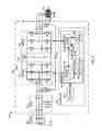
- a system 100is shown in FIG. 1 , which includes an AC power source 102 , a motor load 104 , and a power conversion system 106 (e.g., motor drive).
- the power conversion system 106converts AC input power from the source 102 into AC output power to drive a motor load 104 .
- the source 102 and the load 104are multiphase components (e.g., three phase).
- the power conversion system 106includes a three phase filter circuit 110 , a three phase active front end (AFE) rectifier 112 , a DC bus circuit 114 , and a three phase inverter circuit 116 .
- the filter circuit 110includes an AC input to receive an AC signal from the output of the power source 102 .
- the rectifier 112includes a rectifier input to receive an AC input signal from an output of the filter circuit 110 .
- the rectifier 112has an output to provide a DC bus voltage signal (e.g., DC bus voltage signal VDC) across a DC bus capacitor CDC the DC bus circuit 114 during a normal operating mode.
- the inverter 116converts the DC bus voltage signal VDC to an AC output signal to deliver output power to the motor load 104 .
- the power conversion system 106includes a controller 118 with at least one processor 120 and a memory 122 .
- the controller 118 and the components thereofmay be any suitable hardware, processor-executed software, processor-executed firmware, logic, or combinations thereof that are adapted, programmed, or otherwise configured to implement the functions illustrated and described herein.
- the controller 118in certain embodiments may be implemented, in whole or in part, as software components executed using one or more processing elements, such as one or more processors 120 , and may be implemented as a set of sub-components or objects including computer executable instructions stored in the non-transitory computer readable electronic memory 122 for operation using computer readable data executing on one or more hardware platforms such as one or more computers including one or more processors, data stores, memory, etc.
- the components of the controller 118may be executed on the same computer processor or in distributed fashion in two or more processing components that are operatively coupled with one another to provide the functionality and operation described herein.
- the controller 118 in one exampleincludes multiple processors to individually implement rectifier and inverter control functions.
- the processor 120executes computer executable instructions stored in the memory 122 to implement various motor control functions.
- the memory 122 in this exampleincludes executable instructions to implement a rectifier control component 124 and an inverter control component 126 .
- the controller 118provides switching control signals to operate the rectifier 112 and the inverter 116 during normal operation.
- the controller 118operates the drive 106 in a first mode (e.g., a NORMAL mode) and a second mode (e.g., CMR mode) for reducing common mode voltages (e.g., Vcm between an internal ground node “g” and an internal neutral node “n” in FIG. 1 ).
- a neutral of the AC input source 102is connected to a ground node or connection (e.g., labeled GND), and the motor load 104 is also connected to the ground node.
- GNDground node or connection
- the controller 118selects the current operating mode according to an inverter modulation index (MI), where the modulation index value represents the amount of output power used to drive the motor load 104 .
- the controller 118stores and updates a modulation index threshold value 130 (MITH) in the memory 122 .
- the modulation index threshold value 130 (MITH)is one third of a span of the inverter modulation index value MI. In other examples, a different inverter modulation index value can be used.
- the controller 118in one example provides the rectifier and inverter switching control signals using rectifier and inverter carrier signals, such as triangle carriers with an active rectifier switching frequency higher than the inverter switching frequency.
- the individual switching control signalsare generated in one example as pulse width modulated signals based on comparison of phase-specific modulation signals with the carrier signal. In one example, when a given modulation signal is above a triangular carrier signal, the associated switch is turned on, and the switch is turned off when the modulation signal is less than or equal to the carrier signal. Similar pulse width modulation signal generation techniques can be used for both the rectifier 112 and the inverter 116 in one example.
- the carrier signal modulation conceptcan be implemented in analog circuits, and/or in digital form, for example, by computing modulation signal values and a carrier signal value, and performing the comparison and resulting PWM switching signal generation in firmware or software.
- the present conceptscan advantageously facilitate operation at a rectifier switching frequency to increase the drive rating and reduce the drive size and/or cost.
- the rectifier PWM switching frequencyis at least twice the inverter PWM switching frequency.
- the controller 118is configured to operate the rectifier 112 in a discontinuous pulse width modulated mode (DPWM) in both the first and second modes.
- DPWMdiscontinuous pulse width modulated mode
- This discontinuous PWM operationinhibits switching of one of the switching rectifier phases (e.g., A, B or C) during a given time interval, for example, 1 ⁇ 6 of the rectifier switching cycle or switching period.
- Using rectifier side DPWMfacilitates increasing the rectifier switching frequency due to lower switching losses, which in turn allows reduced LCL filter size/cost, and reduced rectifier IGBT switching losses.
- the controller 118implements the DPWM on rectifier operation by generating the switching control signals to operate switches of the switching rectifier 112 using a zero vector (e.g., 111 or 000 ) during a given switching interval.
- the controller 118stores and updates a flag or value 132 (e.g., DPWM FLAG) in the memory 122 .
- the flag or value 132has one of two possible states, including a first state (e.g., +1) that indicates the rectifier controller 124 is currently using a first zero vector (e.g., 111 that turns all the upper rectifier switches on and turns all the lower rectifier switches off) for DPWM operation of the rectifier 112 , and a second state (e.g., ⁇ 1 ) that indicates the rectifier controller 124 is currently using a second zero vector (e.g., 000 that turns all the lower rectifier switches on and turns all the upper rectifier switches off) for DPWM operation of the rectifier 112 .
- a first statee.g., +1
- a second statee.g., ⁇ 1
- the rectifier 112 and the inverter 116include isolated gate bipolar transistors (IGBTs), and the same IGBTs size and type can be used in both the rectifier 112 and the inverter 116 .
- IGBTsisolated gate bipolar transistors
- the disclosed conceptscan also be employed for common mode reduction when the rectifier side switches operated according to normal three phase PWM switching control techniques.
- the processor 120maintains first and second inverter threshold values 134 (INVTH 1 ) and 136 (INVTH 2 ) in the memory 122 .
- inverter modulation signalshave a span of ⁇ 1 to +1
- the first inverter threshold value 134is +1 ⁇ 3
- the second inverter threshold value 136is ⁇ 1 ⁇ 3.
- the controller 118includes driver circuitry (not shown) to deliver switching control signals to switches of the active rectifier 112 and the inverter 116 according to pulse width modulated switching signals generated by the rectifier control component 124 and the inverter control component 126 .
- the rectifier control component 124generates pulse width modulated rectifier switching control signals to operate switches of the rectifier 112 to convert an AC input signal to control the DC bus voltage signal VDC according to a feedback signal or value by converting a multiphase AC input signal (e.g., voltages Va, Vb and Vc at input phases A, B and C, respectively) to provide the DC bus voltage signal VDC to the DC bus circuit 114 .
- a multiphase AC input signale.g., voltages Va, Vb and Vc at input phases A, B and C, respectively
- the inverter control component 126generates pulse width modulated inverter switching control signals to operate switches of the inverter 116 to provide a multiphase AC output signal (e.g., voltages Vu, Vv and Vw at output phases U, V, and W, respectively) to the load 104 according to one or more feedback signals or values by converting the DC bus voltage signal VDC to implement one or more load control operating parameters, such as motor speed, torque, etc.
- a multiphase AC output signale.g., voltages Vu, Vv and Vw at output phases U, V, and W, respectively
- FIG. 2shows a graph 200 with an example triangle carrier signal curve 202 and an example triangular inverter carrier signal curve 204 with a frequency of one third of the rectifier switching frequency.
- the graph 200shows example times T 0 , T 2 and T 4 corresponding to valleys in the inverter carrier curve 204 , as well as times T 1 , T 3 and T 5 corresponding to inverter carrier peaks.
- the ratio of the inverter switching frequency (i.e., the inverter carrier signal frequency) to the rectifier switching frequency (i.e., the rectifier carrier signal frequency)is an integer fraction, e.g., 2 ⁇ 3, 1 ⁇ 4, 3 ⁇ 5, etc.
- individual peaks and valleys of the inverter carrier signalare aligned with peaks or valleys of the rectifier carrier signal, as shown in FIG. 2 and in FIG. 4 below.
- certain benefitsare achieved by increasing the rectifier PWM switching frequency, for example, to reduce input current total Harmonic distortion (THD), to improve control performance, and to reduce the size and/or cost of the LCL filter.
- TDDinput current total Harmonic distortion
- the graph 200also shows time windows or intervals 211 , 212 and 213 where the rectifier carrier curve 202 has peaks that correspond to a 000 rectifier DPWM zero vector while the inverter carrier signal 204 is below the center of the inverter carrier signal span. Further time windows 214 , 215 and 216 correspond to the rectifier carrier curve 202 having valleys that correspond to a 111 rectifier DPWM zero vector while the inverter carrier signal 204 is above the center of its span.
- FIG. 2also shows a graph 220 with three phase-specific rectifier modulation curves 222 (phase A), 224 (phase B) and 226 (phase C) within a rectifier modulation/carrier span that ranges from ⁇ 1 to +1.
- the graph 220also shows a common mode voltage curve 228 resulting from the PWM converter operation of the rectifier 112 .
- the common mode signalis used to generate the DPWM switching signals, which are used to control the rectifier gates switching. If the rectifier switching is not well controlled, higher common mode voltage (+/ ⁇ VDC) will be generated which may induce premature bearing degradation in the motor load 104 .
- Common mode voltage in the systemis a result of not well coordinated control of rectifier/inverter, and in particular, because of the control of inverter.
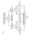
- FIG. 3shows a method 300 of operating a power conversion system
- FIG. 4shows graphs 400 and 410 with signal waveforms during operation of the example system 106 according to the example method 300
- the method 300is implemented as computer executable instructions stored in the memory 122 of the controller 118 in FIG. 1 or in another non-transitory computer readable medium, with the control processor 120 executing the program instructions to cause the processor 120 to operate the rectifier 112 and the inverter 116 by generating pulse width modulated switching control signals.
- the graph 400 in FIG. 4shows an example inverter carrier signal 401 along with example inverter modulation signals 402 (inverter output phase U), 404 (phase V) and 406 (phase W), each within a corresponding span that ranges from ⁇ 1 to +1.
- a graph 410shows an example curve 412 of the value of the DPWM FLAG (e.g., flag 132 in the memory 122 of FIG. 1 ).
- the controller 118stores and maintains the value of the flag 132 at one of two possible states. In this example, the flag 132 (curve 412 in FIG.
- the flag 132has a second state (e.g., value of ⁇ 1) that indicates the rectifier controller 124 is currently using a second zero vector (e.g., zero vector 000 from T 2 to T 3 and from T 4 to T 5 for DPWM operation of the rectifier 112 .
- the example method 300 in FIG. 3includes generating rectifier switching control signals to operate the rectifier switches according to a rectifier carrier signal (e.g., 202 ) having a rectifier switching frequency to provide a DC bus voltage signal (e.g., VDC).
- the method 300includes generating inverter switching control signals in a first mode (e.g., NORMAL), according to the inverter carrier signal (e.g., 204 , 401 ) and according to a plurality of inverter modulation signals (e.g., 402 , 404 and 406 in FIG. 4 ), to operate the inverter switches to provide the AC output signal to drive the connected load (e.g., motor load 104 ).
- NORMALinverter switching control signals in a first mode
- the inverter carrier signale.g., 204 , 401
- a plurality of inverter modulation signalse.g., 402 , 404 and 406 in FIG. 4
- the method 300also include, in a second mode (e.g., CMR), selectively shifting the plurality of inverter modulation signals (e.g., 402 , 404 and 406 ) by a non-zero first amount to generate corresponding shifted inverter modulation signal signals (e.g., 402 A, 404 A and 406 A in FIG. 4 ), and generating the inverter switching control signals according to the inverter carrier signal (e.g., 204 , 401 ), and according to the shifted inverter modulation signals (e.g., 402 A, 404 A, 406 A), to operate the switches of the inverter (e.g., 116 ) at the inverter switching frequency to provide the AC output signal.
- a second modee.g., CMR
- the method 300includes operating in the first mode (e.g., NORMAL) when an inverter modulation index is greater than a modulation index threshold value (e.g., 130, MITH in the memory 122 of FIG. 1 ), and operating in the second mode when the inverter modulation index is less than or equal to the modulation index threshold value.
- a modulation index threshold valuee.g. 130, MITH in the memory 122 of FIG. 1
- the example method 300can be implemented by the drive controller 118 to reduce the common mode voltage Vcm in the motor drive 106 . This provides enhanced motor drive bearing protection without LCL filter de-rating of the LCL filter due to selection of different zero vectors.
- the method 300provides a common mode reduction method for active front end (AFE) drives with different PWM frequencies for the rectifier 112 and inverter 116 .
- AFEactive front end
- the method 300 and operation of the controller 118can reduce the common mode voltage Vcm down to +/ ⁇ 2 VDC/3 without any additional filter inductor losses or inverter side du/dt filter inductors or motor windings.
- the span of the inverter modulation signals 402 , 404 and 406ranges from ⁇ 1 to +1, the first inverter threshold value 134 (INVTH 1 is +1 ⁇ 3), and the second inverter threshold value 136 (INVTH 2 ) is ⁇ 1 ⁇ 3.
- the second modee.g., CMR
- controller 118in the second mode, increases or shifts the modulation signals up when the DPWM flag 132 is +1 (curve 412 , e.g., in response to the rectifier switching control signals using a first zero vector 111) and decreases or shifts the modulation signals down when the DPWM flag 132 is ⁇ 1 (e.g., in response to the rectifier switching control signals using a first zero vector 000).
- controller 118switches between selectively increasing and selectively decreasing the plurality of inverter modulation signals 402 , 404 , 406 only at peaks and valleys of the inverter carrier signal 204 , 401 .
- the example method 300 in FIG. 3uses DPWM control for operating the rectifier 112 and uses space vector pulse width modulation (SVPWM) for inverter control in the NORMAL first mode.
- SVPWMspace vector pulse width modulation
- the controller 118modifies the inverter control by selectively shifting the inverter modulation signals.
- DPWM( ⁇ 1, 1) is the flag variable (e.g., 132 in FIG. 1 ) to indicate the rectifier zero vector.
- the inverter modulationswitches between SVPWM (first mode for high modulation index) and the modified (e.g., shifted) PWM scheme (second mode for low modulation index).
- the switching threshold for these two modes in one implementationis a constant, e.g., 1 ⁇ 3, although other values can be used, and the threshold 130 (MITH) can be adjustable in some examples.
- the maximum signalis shifted up to 2 ⁇ 3 or the minimal signal is shifted down to ⁇ 2 ⁇ 3 in one example, depending on which zero vector is used on the rectifier side.
- the example method 300 in FIG. 3begins at 302 , where the controller 118 calculates the rectifier and inverter duty ratios based on DC bus voltage and inverter output control loops as da, db, dc and du, dv, dw.
- the controller 118also computes or otherwise determines the maximum and minimum rectifier and inverter modulation signal values at 302 .
- the controller 118determines the value of the flag value 132 according to whether the rectifier zero vector is 000 or 111 according to the rectifier modulation signals. Based on rectifier side zero vector, the controller 118 determines the zero vector duty ratio of the inverter 116 and shift one zero vector duty ratio to be 1 ⁇ 6 of the span (e.g., span of ⁇ 1 to +1), depending on the DPWM zero status flag 132 . The controller 118 updates the rectifier and inverter duty ratios da, db, dc and du, dv, dw, and transitions the value of the flag 132 only with the inverter triangle carrier waveform at peaks/valleys.
- the controller 118then selectively shifts the inverter modulation values at 314 , as described above. Once the modulation signal values have been selectively adjusted, these are used to generate the PWM switching control signals to operate the power conversion system 106 .
- FIG. 5illustrates comparative modulation and common mode signals for an example (graph 500 ) with no selective inverter modulation signal adjustment, and an implementation (graph 510 ) of the selective modulation signal shifting by the controller 118 according to the example method 300 .
- the graph 500shows a rectifier carrier curve 501 , an inverter carrier curve 502 , and a common mode voltage curve 503 (Vcm).
- the graph 500also shows example PWM inverter switching control pulse signals 504 U (Phase U), 504 V (phase V) and 504 W (phase W), and example PWM rectifier switching control pulse signals 506 A (Phase A), 506 B (phase B) and 506 C (phase C).
- the common mode voltage curve 503transitions to +VDC at points 508 in the graph 500 and transitions to ⁇ VDC at points 509 .
- the graph 510shows corresponding curves 501 - 504 and 506 for the example controller 118 operating according to the method 300 of FIG. 3 .
- the selective shifting of the inverter modulation signalse.g., shifted signals 402 A, 404 A and 406 A in FIG. 4 ) limits the maximum and minimum values of the common mode voltage Vcm to +/ ⁇ 2 VDC/3.
- a graph 600 in FIG. 6shows a common mode voltage curve 602 for an example motor drive implementation at an inverter output frequency of 10 Hz and an inverter carrier switching frequency of 1.33 kHz with no selective inverter modulation signal adjustment, which exhibits common mode voltages Vcm with peaks in excess of 700 volts (e.g., approximately +/ ⁇ VDC).
- FIG. 6also provides a graph 610 with a common mode voltage curve 612 for an example motor drive implementation at an inverter output frequency of 10 Hz and an inverter carrier switching frequency of 1.33 kHz using selective inverter modulation signal adjustment as described above. This example limits the common mode voltages Vcm with peaks less than 500 volts (e.g., approximately +/ ⁇ 2 VDC/3).
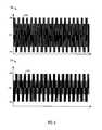
- FIG. 7provides a graph 700 with inverter output current curves 702 (phase U), 704 (phase V), and 706 (phase W) at an inverter output frequency of 10 Hz and an inverter carrier switching frequency of 1.33 kHz for an example motor drive implementation with no selective inverter modulation signal adjustment.
- a graph 710 in FIG. 7shows inverter output current curves 712 (phase U), 714 (phase V), and 716 (phase W) at an inverter output frequency of 10 Hz and an inverter carrier switching frequency of 1.33 kHz an example motor drive implementation that uses the above-described selective inverter modulation signal adjustment in FIG. 3 .
- the example currents 712 , 714 and 716 from the modified PWM schemeinclude higher ripple, as expected due to the duty ratio redistribution on zero vectors.
- the original output currents in the graph 700have an average total harmonic distortion (THD) of 2.82%, while the calculated THD in the currents 712 , 714 and 716 in the graph 710 is 3.52%.
- THDtotal harmonic distortion
- the calculated THD levels of the total harmonics from both casesare both very low compared to the fundamental current, and the tradeoff in THD associated with the presently described examples is small compared with the significant common mode voltage improvements.
Landscapes
- Engineering & Computer Science (AREA)
- Power Engineering (AREA)
- Inverter Devices (AREA)
Abstract
Description
The subject matter disclosed herein relates to power conversion systems.
Various aspects of the present disclosure are now summarized to facilitate a basic understanding of the disclosure, wherein this summary is not an extensive overview of the disclosure, and is intended neither to identify certain elements of the disclosure, nor to delineate the scope thereof. Rather, the primary purpose of this summary is to present various concepts of the disclosure in a simplified form prior to the more detailed description that is presented hereinafter. Disclosed examples include power conversion system, non-transitory computer readable mediums, and methods of operating a power conversion system, in which inverter switching control signals are generated in a first mode according to an inverter carrier signal having an inverter switching frequency, and according to inverter modulation signals, to operate inverter switches to provide an AC output signal, and the inverter modulation signals are shifted in a second mode for low modulation index values to reduce common mode voltage.
The following description and drawings set forth certain illustrative implementations of the disclosure in detail, which are indicative of one or more exemplary ways in which the various principles of the disclosure may be carried out. The illustrated examples are not exhaustive of the many possible embodiments of the disclosure. Various objects, advantages and novel features of the disclosure will be set forth in the following detailed description when considered in conjunction with the drawings.
Referring now to the figures, several embodiments or implementations are hereinafter described in conjunction with the drawings, wherein like reference numerals are used to refer to like elements throughout, and wherein the various features are not necessarily drawn to scale.
Asystem 100 is shown inFIG. 1 , which includes anAC power source 102, amotor load 104, and a power conversion system106 (e.g., motor drive). The power conversion system106 converts AC input power from thesource 102 into AC output power to drive amotor load 104. In the illustrated example, thesource 102 and theload 104 are multiphase components (e.g., three phase). The power conversion system106 includes a threephase filter circuit 110, a three phase active front end (AFE)rectifier 112, aDC bus circuit 114, and a threephase inverter circuit 116. Thefilter circuit 110 includes an AC input to receive an AC signal from the output of thepower source 102. Therectifier 112 includes a rectifier input to receive an AC input signal from an output of thefilter circuit 110. Therectifier 112 has an output to provide a DC bus voltage signal (e.g., DC bus voltage signal VDC) across a DC bus capacitor CDC theDC bus circuit 114 during a normal operating mode. Theinverter 116 converts the DC bus voltage signal VDC to an AC output signal to deliver output power to themotor load 104.
The power conversion system106 includes acontroller 118 with at least oneprocessor 120 and amemory 122. Thecontroller 118 and the components thereof may be any suitable hardware, processor-executed software, processor-executed firmware, logic, or combinations thereof that are adapted, programmed, or otherwise configured to implement the functions illustrated and described herein. Thecontroller 118 in certain embodiments may be implemented, in whole or in part, as software components executed using one or more processing elements, such as one ormore processors 120, and may be implemented as a set of sub-components or objects including computer executable instructions stored in the non-transitory computer readableelectronic memory 122 for operation using computer readable data executing on one or more hardware platforms such as one or more computers including one or more processors, data stores, memory, etc. The components of thecontroller 118 may be executed on the same computer processor or in distributed fashion in two or more processing components that are operatively coupled with one another to provide the functionality and operation described herein.
Thecontroller 118 in one example includes multiple processors to individually implement rectifier and inverter control functions. In the example ofFIG. 1 , theprocessor 120 executes computer executable instructions stored in thememory 122 to implement various motor control functions. Thememory 122 in this example includes executable instructions to implement arectifier control component 124 and aninverter control component 126. Thecontroller 118 provides switching control signals to operate therectifier 112 and theinverter 116 during normal operation. In one example, thecontroller 118 operates the drive106 in a first mode (e.g., a NORMAL mode) and a second mode (e.g., CMR mode) for reducing common mode voltages (e.g., Vcm between an internal ground node “g” and an internal neutral node “n” inFIG. 1 ). In the system configuration ofFIG. 1 , a neutral of theAC input source 102 is connected to a ground node or connection (e.g., labeled GND), and themotor load 104 is also connected to the ground node. Other grounding configurations are possible in other implementations.
In one implementation, thecontroller 118 selects the current operating mode according to an inverter modulation index (MI), where the modulation index value represents the amount of output power used to drive themotor load 104. In one possible implementation, thecontroller 118 stores and updates a modulation index threshold value130 (MITH) in thememory 122. In one example, thecontroller 118 operates in the first mode (NORMAL) when the inverter modulation index is greater than or equal to the modulation index threshold value130 (e.g., when MI>=MITH), and thecontroller 118 operates in the second mode (CMR) to facilitate common mode voltage reduction when the inverter modulation index is less than the modulation index threshold value130 (e.g., when MI<MITH). In one example, the modulation index threshold value130 (MITH) is one third of a span of the inverter modulation index value MI. In other examples, a different inverter modulation index value can be used.
Thecontroller 118 in one example provides the rectifier and inverter switching control signals using rectifier and inverter carrier signals, such as triangle carriers with an active rectifier switching frequency higher than the inverter switching frequency. The individual switching control signals are generated in one example as pulse width modulated signals based on comparison of phase-specific modulation signals with the carrier signal. In one example, when a given modulation signal is above a triangular carrier signal, the associated switch is turned on, and the switch is turned off when the modulation signal is less than or equal to the carrier signal. Similar pulse width modulation signal generation techniques can be used for both therectifier 112 and theinverter 116 in one example. The carrier signal modulation concept can be implemented in analog circuits, and/or in digital form, for example, by computing modulation signal values and a carrier signal value, and performing the comparison and resulting PWM switching signal generation in firmware or software.
The present concepts can advantageously facilitate operation at a rectifier switching frequency to increase the drive rating and reduce the drive size and/or cost. In one example, the rectifier PWM switching frequency is at least twice the inverter PWM switching frequency. In one implementation, moreover, thecontroller 118 is configured to operate therectifier 112 in a discontinuous pulse width modulated mode (DPWM) in both the first and second modes. This discontinuous PWM operation inhibits switching of one of the switching rectifier phases (e.g., A, B or C) during a given time interval, for example, ⅙ of the rectifier switching cycle or switching period. Using rectifier side DPWM facilitates increasing the rectifier switching frequency due to lower switching losses, which in turn allows reduced LCL filter size/cost, and reduced rectifier IGBT switching losses.
In one example, thecontroller 118 implements the DPWM on rectifier operation by generating the switching control signals to operate switches of theswitching rectifier 112 using a zero vector (e.g.,111 or000) during a given switching interval. In the example ofFIG. 1 , thecontroller 118 stores and updates a flag or value132 (e.g., DPWM FLAG) in thememory 122. In this example, the flag orvalue 132 has one of two possible states, including a first state (e.g., +1) that indicates therectifier controller 124 is currently using a first zero vector (e.g.,111 that turns all the upper rectifier switches on and turns all the lower rectifier switches off) for DPWM operation of therectifier 112, and a second state (e.g., −1) that indicates therectifier controller 124 is currently using a second zero vector (e.g.,000 that turns all the lower rectifier switches on and turns all the upper rectifier switches off) for DPWM operation of therectifier 112. In certain examples, therectifier 112 and theinverter 116 include isolated gate bipolar transistors (IGBTs), and the same IGBTs size and type can be used in both therectifier 112 and theinverter 116. The disclosed concepts can also be employed for common mode reduction when the rectifier side switches operated according to normal three phase PWM switching control techniques.
In addition, theprocessor 120 maintains first and second inverter threshold values134 (INVTH1) and136 (INVTH2) in thememory 122. In one example, inverter modulation signals have a span of −1 to +1, the firstinverter threshold value 134 is +⅓, and the secondinverter threshold value 136 is −⅓. Thecontroller 118 includes driver circuitry (not shown) to deliver switching control signals to switches of theactive rectifier 112 and theinverter 116 according to pulse width modulated switching signals generated by therectifier control component 124 and theinverter control component 126. In one example, therectifier control component 124 generates pulse width modulated rectifier switching control signals to operate switches of therectifier 112 to convert an AC input signal to control the DC bus voltage signal VDC according to a feedback signal or value by converting a multiphase AC input signal (e.g., voltages Va, Vb and Vc at input phases A, B and C, respectively) to provide the DC bus voltage signal VDC to theDC bus circuit 114. In one example, theinverter control component 126 generates pulse width modulated inverter switching control signals to operate switches of theinverter 116 to provide a multiphase AC output signal (e.g., voltages Vu, Vv and Vw at output phases U, V, and W, respectively) to theload 104 according to one or more feedback signals or values by converting the DC bus voltage signal VDC to implement one or more load control operating parameters, such as motor speed, torque, etc.
Thegraph 200 also shows time windows orintervals rectifier carrier curve 202 has peaks that correspond to a 000 rectifier DPWM zero vector while theinverter carrier signal 204 is below the center of the inverter carrier signal span.Further time windows rectifier carrier curve 202 having valleys that correspond to a 111 rectifier DPWM zero vector while theinverter carrier signal 204 is above the center of its span.FIG. 2 also shows agraph 220 with three phase-specific rectifier modulation curves222 (phase A),224 (phase B) and226 (phase C) within a rectifier modulation/carrier span that ranges from −1 to +1. Thegraph 220 also shows a commonmode voltage curve 228 resulting from the PWM converter operation of therectifier 112. The common mode signal is used to generate the DPWM switching signals, which are used to control the rectifier gates switching. If the rectifier switching is not well controlled, higher common mode voltage (+/−VDC) will be generated which may induce premature bearing degradation in themotor load 104. Common mode voltage in the system is a result of not well coordinated control of rectifier/inverter, and in particular, because of the control of inverter.
Referring also toFIGS. 3 and 4 ,FIG. 3 shows amethod 300 of operating a power conversion system, andFIG. 4 showsgraphs example method 300. In one example, themethod 300 is implemented as computer executable instructions stored in thememory 122 of thecontroller 118 inFIG. 1 or in another non-transitory computer readable medium, with thecontrol processor 120 executing the program instructions to cause theprocessor 120 to operate therectifier 112 and theinverter 116 by generating pulse width modulated switching control signals.
Thegraph 400 inFIG. 4 shows an example inverter carrier signal401 along with example inverter modulation signals402 (inverter output phase U),404 (phase V) and406 (phase W), each within a corresponding span that ranges from −1 to +1. Agraph 410 shows anexample curve 412 of the value of the DPWM FLAG (e.g.,flag 132 in thememory 122 ofFIG. 1 ). Thecontroller 118 stores and maintains the value of theflag 132 at one of two possible states. In this example, the flag132 (curve 412 inFIG. 4 ) has a first state (e.g., value of +1) that indicates therectifier controller 124 is currently using a first zero vector (e.g., rectifier zerovector 111 from T1 to T2 and from T3 to T4 inFIG. 4 ). Theflag 132 has a second state (e.g., value of −1) that indicates therectifier controller 124 is currently using a second zero vector (e.g., zerovector 000 from T2 to T3 and from T4 to T5 for DPWM operation of therectifier 112.
Theexample method 300 inFIG. 3 includes generating rectifier switching control signals to operate the rectifier switches according to a rectifier carrier signal (e.g.,202) having a rectifier switching frequency to provide a DC bus voltage signal (e.g., VDC). Themethod 300 includes generating inverter switching control signals in a first mode (e.g., NORMAL), according to the inverter carrier signal (e.g.,204,401) and according to a plurality of inverter modulation signals (e.g.,402,404 and406 inFIG. 4 ), to operate the inverter switches to provide the AC output signal to drive the connected load (e.g., motor load104). Themethod 300 also include, in a second mode (e.g., CMR), selectively shifting the plurality of inverter modulation signals (e.g.,402,404 and406) by a non-zero first amount to generate corresponding shifted inverter modulation signal signals (e.g.,402A,404A and406A inFIG. 4 ), and generating the inverter switching control signals according to the inverter carrier signal (e.g.,204,401), and according to the shifted inverter modulation signals (e.g.,402A,404A,406A), to operate the switches of the inverter (e.g.,116) at the inverter switching frequency to provide the AC output signal. In one example, themethod 300 includes operating in the first mode (e.g., NORMAL) when an inverter modulation index is greater than a modulation index threshold value (e.g., 130, MITH in thememory 122 ofFIG. 1 ), and operating in the second mode when the inverter modulation index is less than or equal to the modulation index threshold value.
Theexample method 300 can be implemented by thedrive controller 118 to reduce the common mode voltage Vcm in the motor drive106. This provides enhanced motor drive bearing protection without LCL filter de-rating of the LCL filter due to selection of different zero vectors. Themethod 300 provides a common mode reduction method for active front end (AFE) drives with different PWM frequencies for therectifier 112 andinverter 116. In one example, themethod 300 and operation of thecontroller 118 can reduce the common mode voltage Vcm down to +/−2 VDC/3 without any additional filter inductor losses or inverter side du/dt filter inductors or motor windings. This common mode voltage reduction, in turn, facilitates the use of different rectifier and inverter switching frequencies and enhanced power density in the motor drive power conversion system106. In one implementation, the span of the inverter modulation signals402,404 and406 ranges from −1 to +1, the first inverter threshold value134 (INVTH1 is +⅓), and the second inverter threshold value136 (INVTH2) is −⅓.
In the example ofFIG. 3 , thecontroller 118 is configured, in the second mode (e.g., CMR), to selectively increase the inverter modulation signals402,404 and406 by a non-zero first amount when DPWM=+1. Thecontroller 118 in one example determines the first amount such that the maximum one of the shifted inverter modulation signal signals402A,404A,406A is shifted to be equal to the maximum span value minus the first inverter threshold value134 (e.g., 1⅓=+⅔ in this example); or to selectively decrease the inverter modulation signals402,404 and406 by the first amount such that the minimum one of the shifted inverter modulation signal signals402A,404A and406A is equal to the minimum span minus the second inverter threshold value136 (e.g., (−1)−(−⅓)=−⅔ in this example). In the example ofFIG. 4 , in the second mode, thecontroller 118 increases or shifts the modulation signals up when theDPWM flag 132 is +1 (curve 412, e.g., in response to the rectifier switching control signals using a first zero vector 111) and decreases or shifts the modulation signals down when theDPWM flag 132 is −1 (e.g., in response to the rectifier switching control signals using a first zero vector 000). In one implementation, as shown inFIG. 3 ,controller 118 switches between selectively increasing and selectively decreasing the plurality of inverter modulation signals402,404,406 only at peaks and valleys of theinverter carrier signal 204,401.
Theexample method 300 inFIG. 3 uses DPWM control for operating therectifier 112 and uses space vector pulse width modulation (SVPWM) for inverter control in the NORMAL first mode. For reducing common mode voltages in the second mode (CMR), thecontroller 118 modifies the inverter control by selectively shifting the inverter modulation signals. In the example ofFIG. 3 , the initial modulation signals for therectifier 112 and theinverter 116 are di (i=a, b, c, u, v, w), and dcm_j (j=r, i) are the common mode components injected into original modulation signals. In this example, moreover, di′ (i=a, b, c, u, v, w) are the modified modulation signals for the rectifier/inverter, and dmax_j/dmin_j (j=r, i) is the maximum/minimum value of the rectifier/inverter original modulation signals. Also, DPWM (−1, 1) is the flag variable (e.g.,132 inFIG. 1 ) to indicate the rectifier zero vector. The inverter modulation switches between SVPWM (first mode for high modulation index) and the modified (e.g., shifted) PWM scheme (second mode for low modulation index). The switching threshold for these two modes in one implementation is a constant, e.g., ⅓, although other values can be used, and the threshold130 (MITH) can be adjustable in some examples. When a modulation signal shift happens in the second mode, the maximum signal is shifted up to ⅔ or the minimal signal is shifted down to −⅔ in one example, depending on which zero vector is used on the rectifier side. After shifting, thecontroller 118 uses the adjusted modulation signals di′ (i=a, b, c, u, v, w) to generate switching states for therectifier 112 and theinverter 116.
Theexample method 300 inFIG. 3 begins at302, where thecontroller 118 calculates the rectifier and inverter duty ratios based on DC bus voltage and inverter output control loops as da, db, dc and du, dv, dw. Thecontroller 118 also computes or otherwise determines the maximum and minimum rectifier and inverter modulation signal values at302. In one example, the calculated rectifier side values are dmax_r=max(da,db,dc), dmin_r=min(da,db,dc), and the calculated inverter side values are computed as dmax_i=max(du,dv,dw), dmin_i=min(du,dv,dw).
At304, thecontroller 118 determines the value of theflag value 132 according to whether the rectifier zero vector is 000 or 111 according to the rectifier modulation signals. Based on rectifier side zero vector, thecontroller 118 determines the zero vector duty ratio of theinverter 116 and shift one zero vector duty ratio to be ⅙ of the span (e.g., span of −1 to +1), depending on the DPWM zerostatus flag 132. Thecontroller 118 updates the rectifier and inverter duty ratios da, db, dc and du, dv, dw, and transitions the value of theflag 132 only with the inverter triangle carrier waveform at peaks/valleys.
In the example ofFIG. 3 , thecontroller 118 checks the rectifier zero vector by determining whether dmax_r+dmin_r>=0. If so (YES at304), thecontroller 118 sets theflag 132 DPWM=1 and sets dcm_r=1-dmax_r at316, and otherwise (NO at304) thecontroller 118 sets theflag 132 DPWM=−1 and sets dcm_r=−1-dmin_r at306. If DPWM=−1 (e.g., between T2 and T3 inFIG. 4 ), theprocess 300 proceeds to308, where thecontroller 118 determines whether 1+dmin_i>⅓. If so, (YES at308), thecontroller 118 sets dcm_i=−⅔-dmin_i at312. This decreases the inverter modulation signals402,404 and406 by the first amount such that the minimum one of the shifted inverter modulation signal signals402A,404A and406A is equal to the minimum span minus the second inverter threshold value136 (e.g., (−1)−(−⅓)=−⅔ in this example). Otherwise (NO at308), thecontroller 118 sets dcm_i=−(dmax_i+dmin_i)/2 at310. Thecontroller 118 then selectively shifts the inverter modulation values at314, including updating the rectifier duty ratios as da′=da+dcm_r, db′=db+dcm_r and dc′=dc+dcm_r, and updating the inverter side duty ratios updated as du′=du+dcm_i, dv′=dv+dcm_i and dw′=dw+dcm_i.
If DPWM=+1 (YES at304, between T1 and T2 inFIG. 4 ), thecontroller 118 sets dcm_r=1−dmax_r at316, and determines whether 1−dmax_i>⅓ at318. If so, (YES at318), thecontroller 118 sets dcm_i=⅔-dmax_i at320. This shifts the inverter modulation signals up such that the maximum one of the shifted inverter modulation signal signals402A,404A,406A is shifted to be equal to the maximum span value minus the first inverter threshold value134 (e.g., 1⅓=+⅔ in this example). Otherwise (NO at318), thecontroller 118 sets dcm_i=−(dmax_i+dmin_i)/2 at322. Thecontroller 118 then selectively shifts the inverter modulation values at314, as described above. Once the modulation signal values have been selectively adjusted, these are used to generate the PWM switching control signals to operate the power conversion system106.
Referring also toFIGS. 5-7 ,FIG. 5 illustrates comparative modulation and common mode signals for an example (graph500) with no selective inverter modulation signal adjustment, and an implementation (graph510) of the selective modulation signal shifting by thecontroller 118 according to theexample method 300. Thegraph 500 shows arectifier carrier curve 501, aninverter carrier curve 502, and a common mode voltage curve503 (Vcm). Thegraph 500 also shows example PWM inverter switching control pulse signals504 U (Phase U),504 V (phase V) and504 W (phase W), and example PWM rectifier switching control pulse signals506 A (Phase A),506 B (phase B) and506 C (phase C). In the case without modulation signal shifting, the commonmode voltage curve 503 transitions to +VDC atpoints 508 in thegraph 500 and transitions to −VDC at points509. Thegraph 510 shows corresponding curves501-504 and506 for theexample controller 118 operating according to themethod 300 ofFIG. 3 . The selective shifting of the inverter modulation signals (e.g., shifted signals402A,404A and406A inFIG. 4 ) limits the maximum and minimum values of the common mode voltage Vcm to +/−2 VDC/3.
Agraph 600 inFIG. 6 shows a commonmode voltage curve 602 for an example motor drive implementation at an inverter output frequency of 10 Hz and an inverter carrier switching frequency of 1.33 kHz with no selective inverter modulation signal adjustment, which exhibits common mode voltages Vcm with peaks in excess of 700 volts (e.g., approximately +/−VDC).FIG. 6 also provides agraph 610 with a commonmode voltage curve 612 for an example motor drive implementation at an inverter output frequency of 10 Hz and an inverter carrier switching frequency of 1.33 kHz using selective inverter modulation signal adjustment as described above. This example limits the common mode voltages Vcm with peaks less than 500 volts (e.g., approximately +/−2 VDC/3).
The above examples are merely illustrative of several possible embodiments of various aspects of the present disclosure, wherein equivalent alterations and/or modifications will occur to others skilled in the art upon reading and understanding this specification and the annexed drawings. In particular regard to the various functions performed by the above described components (assemblies, devices, systems, circuits, and the like), the terms (including a reference to a “means”) used to describe such components are intended to correspond, unless otherwise indicated, to any component, such as hardware, processor-executed software, or combinations thereof, which performs the specified function of the described component (i.e., that is functionally equivalent), even though not structurally equivalent to the disclosed structure which performs the function in the illustrated implementations of the disclosure. In addition, although a particular feature of the disclosure may have been disclosed with respect to only one of several implementations, such feature may be combined with one or more other features of the other implementations as may be desired and advantageous for any given or particular application. Also, to the extent that the terms “including”, “includes”, “having”, “has”, “with”, or variants thereof are used in the detailed description and/or in the claims, such terms are intended to be inclusive in a manner similar to the term “comprising”. This description uses examples to disclose various embodiments and also to enable any person skilled in the art to practice the disclosed subject matter, including making and using any devices or systems and performing any incorporated methods. It will be evident that various modifications and changes may be made, and additional embodiments may be implemented, without departing from the broader scope of the present disclosure as set forth in the following claims, wherein the specification and drawings are to be regarded in an illustrative rather than restrictive sense.
Claims (19)
1. A power conversion system, comprising:
a switching rectifier, including a rectifier input to receive an AC input signal, and a rectifier output to provide a DC bus voltage signal;
a DC bus circuit, including a DC bus capacitor coupled to receive the DC bus voltage signal from the rectifier output;
an inverter to convert the DC bus voltage signal to an AC output signal to deliver output power to a load; and
a controller configured to:
generate rectifier switching control signals to operate switches of the switching rectifier according to a rectifier carrier signal having a rectifier switching frequency to provide the DC bus voltage signal to the DC bus circuit;
in a first mode, generate the inverter switching control signals according to an inverter carrier signal having an inverter switching frequency and according to a plurality of inverter modulation signals to operate switches of the inverter to provide the AC output signal; and
in a second mode, selectively shift the plurality of inverter modulation signals by a non-zero first amount to generate a corresponding plurality of shifted inverter modulation signals, and generate the inverter switching control signals according to the inverter carrier signal and according to the plurality of shifted inverter modulation signals to operate the switches of the inverter at the inverter switching frequency to provide the AC output signal;
wherein the controller is configured to operate in the first mode when an inverter modulation index is greater than a modulation index threshold value; and wherein the controller is configured to operate in the second mode when the inverter modulation index is less than or equal to the modulation index threshold value; and
wherein the controller is configured, in the second mode, to: (i) selectively increase the plurality of inverter modulation signals by the non-zero first amount such that a maximum one of the shifted inverter modulation signals is equal to a difference between a maximum span of the inverter modulation signals and a first inverter threshold value; or (ii) selectively decrease the plurality of inverter modulation signals by the non-zero first amount such that a minimum one of the shifted inverter modulation signals is equal to a difference between a minimum span of the inverter modulation signals and a second inverter threshold value.
2. The power conversion system ofclaim 1 , wherein the modulation index threshold value is one third of a span of an inverter modulation index value.
3. The power conversion system ofclaim 1 , wherein the controller is configured, in the second mode, to: (i) selectively increase the plurality of inverter modulation signals by the non-zero first amount in response to the rectifier switching control signals using a first zero vector that turns all upper switches of the rectifier on and turns all lower switches of the rectifier off, and (ii) selectively decrease the plurality of inverter modulation signals by the non-zero first amount in response to the rectifier switching control signals using a second zero vector that turns all the upper switches of the rectifier off and turns all the lower switches of the rectifier on.
4. The power conversion system ofclaim 1 , wherein a span of the inverter modulation signals ranges from −1 to +1, wherein the first inverter threshold value is +⅓, and wherein the second inverter threshold value is −⅓.
5. The power conversion system ofclaim 1 , wherein the rectifier switching frequency is higher than the inverter switching frequency.
6. The power conversion system ofclaim 5 , wherein individual peaks and valleys of the inverter carrier signal are aligned with peaks or valleys of the rectifier carrier signal.
7. The power conversion system ofclaim 6 , wherein the controller is configured, in the second mode, to switch between selectively increasing and selectively decreasing the plurality of inverter modulation signals only at peaks and valleys of the inverter carrier signal.
8. The power conversion system ofclaim 1 , wherein the controller is configured, in the first and second modes, to generate the rectifier switching control signals to operate switches of the switching rectifier using a zero vector that turns all switches of a single rectifier phase on or turns all switches of the single rectifier phase off.
9. The power conversion system ofclaim 1 , wherein the controller is configured, in the second mode, to switch should between selectively increasing and selectively decreasing the plurality of inverter modulation signals only at peaks and valleys of the inverter carrier signal.
10. A power conversion system, comprising:
a switching rectifier, including a rectifier input to receive an AC input signal, and a rectifier output to provide a DC bus voltage signal;
a DC bus circuit, including a DC bus capacitor coupled to receive the DC bus voltage signal from the rectifier output;
an inverter to convert the DC bus voltage signal to an AC output signal to deliver output power to a load; and
a controller configured to:
generate rectifier switching control signals to operate switches of the switching rectifier according to a rectifier carrier signal having a rectifier switching frequency to provide the DC bus voltage signal to the DC bus circuit;
in a first mode, generate the inverter switching control signals according to an inverter carrier signal having an inverter switching frequency and according to a plurality of inverter modulation signals to operate switches of the inverter to provide the AC output signal; and
in a second mode, selectively shift the plurality of inverter modulation signals by a non-zero first amount to generate a corresponding plurality of shifted inverter modulation signals, and generate the inverter switching control signals according to the inverter carrier signal and according to the plurality of shifted inverter modulation signals to operate the switches of the inverter at the inverter switching frequency to provide the AC output signal; and
operate in the first mode when an inverter modulation index is greater than a modulation index threshold value; and wherein the controller is configured to operate in the second mode when the inverter modulation index is less than or equal to the modulation index threshold value;
wherein the controller is configured, in the second mode, to: (i) selectively increase the plurality of inverter modulation signals by the non-zero first amount in response to the rectifier switching control signals using a first zero vector that turns all upper switches of the rectifier on and turns all lower switches of the rectifier off, and (ii) selectively decrease the plurality of inverter modulation signals by the non-zero first amount in response to the rectifier switching control signals using a second zero vector that turns all the upper switches of the rectifier off and turns all the lower switches of the rectifier on.
11. The power conversion system ofclaim 10 , wherein the modulation index threshold value is one third of a span of an inverter modulation index value.
12. The power conversion system ofclaim 10 , wherein the rectifier switching frequency is higher than the inverter switching frequency.
13. The power conversion system ofclaim 12 , wherein individual peaks and valleys of the inverter carrier signal are aligned with peaks or valleys of the rectifier carrier signal.
14. The power conversion system ofclaim 13 , wherein the controller is configured, in the second mode, to switch between selectively increasing and selectively decreasing the plurality of inverter modulation signals only at peaks and valleys of the inverter carrier signal.
15. The power conversion system ofclaim 10 , wherein the controller is configured, in the second mode, to switch between selectively increasing and selectively decreasing the plurality of inverter modulation signals only at peaks and valleys of the inverter carrier signal.
16. A method of operating a power conversion system, the method comprising:
generating rectifier switching control signals to operate switches of a switching rectifier according to a rectifier carrier signal having a rectifier switching frequency to provide a DC bus voltage signal;
in a first mode, generating inverter switching control signals according to an inverter carrier signal having an inverter switching frequency, and according to a plurality of inverter modulation signals, to operate switches of an inverter to provide an AC output signal;
in a second mode, selectively shifting the plurality of inverter modulation signals by a non-zero first amount to generate a corresponding plurality of shifted inverter modulation signals, and generating the inverter switching control signals according to the inverter carrier signal, and according to the plurality of shifted inverter modulation signals, to operate the switches of the inverter at the inverter switching frequency to provide the AC output signal;
operating in the first mode when an inverter modulation index is greater than a modulation index threshold value; and
operating in the second mode when the inverter modulation index is less than or equal to the modulation index threshold value; and
in the second mode, (i) selectively increasing the plurality of inverter modulation signals by the non-zero first amount such that a maximum one of the shifted inverter modulation signals is equal to a difference between a maximum span of the inverter modulation signals and a first inverter threshold value; or (ii) selectively decreasing the plurality of inverter modulation signals by the non-zero first amount such that a minimum one of the shifted inverter modulation signals is equal to a difference between a minimum span of the inverter modulation signals and a second inverter threshold value.
17. A non-transitory computer readable medium, comprising computer executable instructions that, when executed by at least one processor, cause the at least one processor to:
generate rectifier switching control signals to operate switches of a switching rectifier according to a rectifier carrier signal having a rectifier switching frequency to provide a DC bus voltage signal;
in a first mode, generate inverter switching control signals according to an inverter carrier signal having an inverter switching frequency, and according to a plurality of inverter modulation signals, to operate switches of an inverter to provide an AC output signal;
in a second mode, selectively shift the plurality of inverter modulation signals by a non-zero first amount to generate a corresponding plurality of shifted inverter modulation signals, and generate the inverter switching control signals according to the inverter carrier signal, and according to the plurality of shifted inverter modulation signals, to operate the switches of the inverter at the inverter switching frequency to provide the AC output signal;
operate in the first mode when an inverter modulation index is greater than a modulation index threshold value; and
operate in the second mode when the inverter modulation index is less than or equal to the modulation index threshold value; and
in the second mode, (i) selectively increase the plurality of inverter modulation signals by the non-zero first amount such that a maximum one of the shifted inverter modulation signals is equal to a difference between a maximum span of the inverter modulation signals and a first inverter threshold value; or (ii) selectively decrease the plurality of inverter modulation signals by the non-zero first amount such that a minimum one of the shifted inverter modulation signals is equal to a difference between a minimum span of the inverter modulation signals and a second inverter threshold value.
18. A method of operating a power conversion system, the method comprising:
generating rectifier switching control signals to operate switches of a switching rectifier according to a rectifier carrier signal having a rectifier switching frequency to provide a DC bus voltage signal;
in a first mode, generating inverter switching control signals according to an inverter carrier signal having an inverter switching frequency, and according to a plurality of inverter modulation signals, to operate switches of an inverter to provide an AC output signal;
in a second mode, selectively shifting the plurality of inverter modulation signals by a non-zero first amount to generate a corresponding plurality of shifted inverter modulation signals, and generating the inverter switching control signals according to the inverter carrier signal, and according to the plurality of shifted inverter modulation signals, to operate the switches of the inverter at the inverter switching frequency to provide the AC output signal;
operating in the first mode when an inverter modulation index is greater than a modulation index threshold value;
operating in the second mode when the inverter modulation index is less than or equal to the modulation index threshold value; and
in the second mode, (i) selectively increasing the plurality of inverter modulation signals by the non-zero first amount in response to the rectifier switching control signals using a first zero vector that turns all upper switches of the rectifier on and turns all lower switches of the rectifier off, and (ii) selectively decreasing the plurality of inverter modulation signals by the non-zero first amount in response to the rectifier switching control signals using a second zero vector that turns all the upper switches of the rectifier off and turns all the lower switches of the rectifier on.
19. A non-transitory computer readable medium, comprising computer executable instructions that, when executed by at least one processor, cause the at least one processor to:
generate rectifier switching control signals to operate switches of a switching rectifier according to a rectifier carrier signal having a rectifier switching frequency to provide a DC bus voltage signal;
in a first mode, generate inverter switching control signals according to an inverter carrier signal having an inverter switching frequency, and according to a plurality of inverter modulation signals, to operate switches of an inverter to provide an AC output signal;
in a second mode, selectively shift the plurality of inverter modulation signals by a non-zero first amount to generate a corresponding plurality of shifted inverter modulation signals, and generate the inverter switching control signals according to the inverter carrier signal, and according to the plurality of shifted inverter modulation signals, to operate the switches of the inverter at the inverter switching frequency to provide the AC output signal;
operate in the first mode when an inverter modulation index is greater than a modulation index threshold value; and
operate in the second mode when the inverter modulation index is less than or equal to the modulation index threshold value; and
in the second mode, (i) selectively increase the plurality of inverter modulation signals by the non-zero first amount in response to the rectifier switching control signals using a first zero vector that turns all upper switches of the rectifier on and turns all lower switches of the rectifier off, and (ii) selectively decrease the plurality of inverter modulation signals by the non-zero first amount in response to the rectifier switching control signals using a second zero vector that turns all the upper switches of the rectifier off and turns all the lower switches of the rectifier on.
Priority Applications (1)
| Application Number | Priority Date | Filing Date | Title |
|---|---|---|---|
| US15/956,008US10158299B1 (en) | 2018-04-18 | 2018-04-18 | Common voltage reduction for active front end drives |
Applications Claiming Priority (1)
| Application Number | Priority Date | Filing Date | Title |
|---|---|---|---|
| US15/956,008US10158299B1 (en) | 2018-04-18 | 2018-04-18 | Common voltage reduction for active front end drives |
Publications (1)
| Publication Number | Publication Date |
|---|---|
| US10158299B1true US10158299B1 (en) | 2018-12-18 |
Family
ID=64604844
Family Applications (1)
| Application Number | Title | Priority Date | Filing Date |
|---|---|---|---|
| US15/956,008ActiveUS10158299B1 (en) | 2018-04-18 | 2018-04-18 | Common voltage reduction for active front end drives |
Country Status (1)
| Country | Link |
|---|---|
| US (1) | US10158299B1 (en) |
Cited By (13)
| Publication number | Priority date | Publication date | Assignee | Title |
|---|---|---|---|---|
| US20180175627A1 (en)* | 2016-12-16 | 2018-06-21 | Ge Aviation Systems Llc | Space vector modulation in aerospace applications |
| US20190097527A1 (en)* | 2017-09-28 | 2019-03-28 | Texas Instruments Incorporated | Methods and apparatus to compensate for power factor loss using a phasor cancellation based compensation scheme |
| CN110401355A (en)* | 2019-07-31 | 2019-11-01 | 河北工业大学 | A Modulation Method of Indirect Matrix Converter to Suppress Common Mode Voltage |
| US10541626B1 (en)* | 2019-01-15 | 2020-01-21 | Rockwell Automation Technologies, Inc. | Power conversion system with PWM carrier emulation |
| CN111049465A (en)* | 2020-01-06 | 2020-04-21 | 深圳市蓝海华腾技术股份有限公司 | DPWM control method and device |
| CN111884523A (en)* | 2020-08-07 | 2020-11-03 | 浙江鲲悟科技有限公司 | Power conversion system |
| CN113691157A (en)* | 2021-08-30 | 2021-11-23 | 燕山大学 | A Modular Multilevel Converter Rotation Discontinuous Control Method |
| US11336206B2 (en) | 2020-09-23 | 2022-05-17 | Rockwell Automation Technoligies, Inc. | Switching frequency and PWM control to extend power converter lifetime |
| CN114944750A (en)* | 2022-07-21 | 2022-08-26 | 深圳市首航新能源股份有限公司 | Inverter circuit, driving method of switching tube and inverter |
| TWI783569B (en)* | 2020-08-03 | 2022-11-11 | 日商日立產機系統股份有限公司 | Power conversion equipment and metal processing equipment |
| US11533013B1 (en)* | 2021-07-29 | 2022-12-20 | Rivian Ip Holdings, Llc | Pulse width modulation clock synchronization |
| US20230099313A1 (en)* | 2021-09-24 | 2023-03-30 | Zeng Hsing Industrial Co., Ltd. | Motor drive system and motor drive method |
| US20240258903A1 (en)* | 2023-01-31 | 2024-08-01 | Cummins Power Generation Inc. | Rebalancing pulse width modulation signals for power systems |
Citations (187)
| Publication number | Priority date | Publication date | Assignee | Title |
|---|---|---|---|---|
| GB1295261A (en) | 1969-01-24 | 1972-11-08 | ||
| US4443841A (en) | 1980-02-15 | 1984-04-17 | Wataru Mikami | Neutral-point-clamped PWM inverter |
| US4783728A (en) | 1986-04-29 | 1988-11-08 | Modular Power Corp. | Modular power supply with PLL control |
| US4894621A (en) | 1988-06-13 | 1990-01-16 | Westinghouse Electric Corp. | Circuit for five level waveform synthesis |
| US4978894A (en)* | 1988-09-08 | 1990-12-18 | Kabushiki Kaisha Toshiba | Single phase to three phase rectifier/inverter with DC ripple compensation |
| US5298848A (en) | 1990-11-28 | 1994-03-29 | Hitachi, Ltd. | Large capacity variable speed PWM spatial vector type sub-harmonic system for driving AC electric motor |
| US5361196A (en) | 1992-04-24 | 1994-11-01 | Hitachi, Ltd. | Power converter for converting DC voltage into AC phase voltage having three levels of positive, zero and negative voltage |
| US5502633A (en) | 1992-01-24 | 1996-03-26 | Kabushiki Kaisha Toshiba | Method and apparatus for controlling an inverter |
| US5625545A (en) | 1994-03-01 | 1997-04-29 | Halmar Robicon Group | Medium voltage PWM drive and method |
| US5638263A (en) | 1994-03-01 | 1997-06-10 | Halmar Robicon Group | Low and medium voltage PWM AC/DC power conversion method and apparatus |
| US5642275A (en) | 1995-09-14 | 1997-06-24 | Lockheed Martin Energy System, Inc. | Multilevel cascade voltage source inverter with seperate DC sources |
| US5790396A (en) | 1995-12-19 | 1998-08-04 | Kabushiki Kaisha Toshiba | Neutral point clamped (NPC) inverter control system |
| CN1190278A (en) | 1997-02-03 | 1998-08-12 | 北京凯奇新技术开发总公司 | High-voltage large-power frequency convertor without power network pollution |
| EP0874448A1 (en) | 1996-01-10 | 1998-10-28 | Hitachi, Ltd. | Multilevel power converting apparatus |
| US5933339A (en) | 1998-03-23 | 1999-08-03 | Electric Boat Corporation | Modular static power converter connected in a multi-level, multi-phase, multi-circuit configuration |
| US5986909A (en) | 1998-05-21 | 1999-11-16 | Robicon Corporation | Multiphase power supply with plural series connected cells and failed cell bypass |
| US6005788A (en) | 1998-02-13 | 1999-12-21 | Wisconsin Alumni Research Foundation | Hybrid topology for multilevel power conversion |
| US6031738A (en) | 1998-06-16 | 2000-02-29 | Wisconsin Alumni Research Foundation | DC bus voltage balancing and control in multilevel inverters |
| US6058031A (en) | 1997-10-23 | 2000-05-02 | General Electric Company | Five level high power motor drive converter and control system |
| CN1253999A (en) | 1998-11-13 | 2000-05-24 | 李海仁 | Metal cutting and welding gas |
| US6075350A (en) | 1998-04-24 | 2000-06-13 | Lockheed Martin Energy Research Corporation | Power line conditioner using cascade multilevel inverters for voltage regulation, reactive power correction, and harmonic filtering |
| US6075717A (en) | 1996-05-01 | 2000-06-13 | General Electric Company | PWM rectifier control with switching losses equally distributed among multiple switching devices |
| GB2345594A (en) | 1997-10-09 | 2000-07-12 | Toshiba Kk | Multiple inverter system with protection circuit |
| US6166929A (en) | 2000-02-29 | 2000-12-26 | Rockwell Technologies, Llc | CSI based drive having active damping control |
| US6229722B1 (en) | 1997-10-09 | 2001-05-08 | Kabushiki Kaisha Toshiba | Multiple inverter system |
| US6236580B1 (en) | 1999-04-09 | 2001-05-22 | Robicon Corporation | Modular multi-level adjustable supply with series connected active inputs |
| TW439350B (en) | 1999-07-20 | 2001-06-07 | Lai Yan Sheng | Pulse-width modulation control apparatus and methods for common mode voltage reduction of voltage-controlled inverters/converters |
| US6269010B1 (en) | 2000-02-29 | 2001-07-31 | Rockwell Technologies, Llc | CSI based drive having feedforward control of inverter input voltage |
| US6295215B1 (en) | 2000-04-06 | 2001-09-25 | Powerware Corporation | AC power supply apparatus with economy mode and methods of operation thereof |
| US6320767B1 (en) | 1998-12-18 | 2001-11-20 | Kabushiki Kaisha Toshiba | Inverter apparatus |
| US20010048290A1 (en) | 1998-08-26 | 2001-12-06 | Underwood Thomas C. | Integrated control system and method for controlling mode, synchronization, power factor, and utility outage ride-through for micropower generation systems |
| US6359416B1 (en) | 2000-09-29 | 2002-03-19 | Rockwell Automation Technologies, Inc. | Adaptive predictive synchronous current frame regulator method and apparatus |
| US6366483B1 (en) | 2000-07-24 | 2002-04-02 | Rockwell Automation Technologies, Inc. | PWM rectifier having de-coupled power factor and output current control loops |
| US6411530B2 (en) | 2000-04-06 | 2002-06-25 | Robicon Corporation | Drive and power supply with phase shifted carriers |
| US6469916B1 (en) | 2001-10-01 | 2002-10-22 | Rockwell Automation Technologies, Inc. | Method and apparatus for compensating for device dynamics and voltage drop in inverter based control systems |
| US6477067B1 (en) | 2001-10-02 | 2002-11-05 | Rockwell Automation Technologies, Inc. | Method and apparatus for compensating for device dynamics in inverter based control systems |
| CN1400731A (en) | 2001-08-07 | 2003-03-05 | 任少康 | Waveform generation method and power conversion device |
| US6541933B1 (en) | 2001-11-20 | 2003-04-01 | Rockwell Automation Technologies, Inc. | Angle control of modulating wave to reduce reflected wave overvoltage transients |
| US6556461B1 (en) | 2001-11-19 | 2003-04-29 | Power Paragon, Inc. | Step switched PWM sine generator |
| CN1414692A (en) | 2002-03-08 | 2003-04-30 | 北京利德华福技术有限公司 | No-harmonic wave pollution high voltage large power frequency converter |
| US6617821B2 (en) | 2001-09-20 | 2003-09-09 | Rockwell Automation Technologies, Inc. | Method and apparatus for compensating for device dynamics by adjusting inverter carrier frequency |
| CN2577503Y (en) | 2002-03-25 | 2003-10-01 | 天津电气传动设计研究所 | Over voltage protection device of single-phase bridge inverter for medium voltage frequency transformer |
| US6636012B2 (en) | 2001-09-28 | 2003-10-21 | Rockwell Automation Technologies, Inc. | Stator and rotor resistance identifier using high frequency injection |
| USRE38439E1 (en) | 1999-05-12 | 2004-02-24 | Otis Elevator Company | Control of a DC matrix converter |
| US6697274B2 (en) | 2000-09-13 | 2004-02-24 | Abb Research Ltd. | Open-loop and closed-loop control method for a three-point converter with active clamped switches, and apparatus for this purpose |
| US6697271B2 (en) | 2000-08-16 | 2004-02-24 | Northrop Grumman Corporation | Cascaded multi-level H-bridge drive |
| US6703809B2 (en) | 2002-03-05 | 2004-03-09 | Rockwell Automation Technologies, Inc. | Flux position identifier using high frequency injection with the presence of a rich harmonic spectrum in a responding signal |
| US6720748B1 (en) | 2003-02-12 | 2004-04-13 | Rockwell Automation Technologies, Inc. | Static commissioning method and apparatus to identify rated flux current |
| US6795323B2 (en) | 2000-12-07 | 2004-09-21 | Kabushiki Kaisha Yaskawa Denki | Three-level neutral point clamping pwn inverter and neutral point voltage controller |
| US6819070B2 (en) | 2003-02-12 | 2004-11-16 | Rockwell Automation Technologies, Inc. | Method and apparatus for controlling reflected voltage using a motor controller |
| US6819077B1 (en) | 2003-05-21 | 2004-11-16 | Rockwell Automation Technologies, Inc. | Method and apparatus for reducing sampling related errors in a modulating waveform generator used with a PWM controller |
| US6842354B1 (en) | 2003-08-08 | 2005-01-11 | Rockwell Automation Technologies, Inc. | Capacitor charge balancing technique for a three-level PWM power converter |
| US6859374B2 (en) | 2002-06-13 | 2005-02-22 | Abb Oy | Method in connection with converter bridges |
| US20050128777A1 (en)* | 2002-03-20 | 2005-06-16 | Katsutoshi Yamanaka | Pwm inverter device |
| CN2737060Y (en) | 2003-12-26 | 2005-10-26 | 哈尔滨九洲电气股份有限公司 | Control signal transmission installation in high voltage frequency converter |
| US6982533B2 (en) | 2003-09-17 | 2006-01-03 | Rockwell Automation Technologies, Inc. | Method and apparatus to regulate loads |
| EP1641111A2 (en) | 2004-09-28 | 2006-03-29 | Rockwell Automation Technologies, Inc. | Method and apparatus to reduce common mode voltages applied to a load by a drive |
| US7034501B1 (en) | 2005-02-28 | 2006-04-25 | Rockwell Automation Technologies, Inc. | Adjusting gate pulse time intervals for reflected wave mitigation |
| US7057905B2 (en) | 2003-08-05 | 2006-06-06 | Jl Audio, Inc | Method and apparatus for power conversion having a four-quadrant output |
| JP2006223009A (en) | 2005-02-08 | 2006-08-24 | Fuji Electric Holdings Co Ltd | 5-level inverter and driving method thereof |
| US7106025B1 (en) | 2005-02-28 | 2006-09-12 | Rockwell Automation Technologies, Inc. | Cancellation of dead time effects for reducing common mode voltages |
| WO2006107548A1 (en) | 2005-03-30 | 2006-10-12 | General Electric Company | Power converter system and method |
| EP1713168A2 (en) | 2005-04-15 | 2006-10-18 | Rockwell Automation Technologies, Inc. | DC voltage balance control for three-level NPC power converters with even-order harmonic elimination scheme |
| US20060267542A1 (en)* | 2005-05-27 | 2006-11-30 | Lixiang Wei | Pulse width modulation (PWM) rectifier with variable switching frequency |
| US7164254B2 (en) | 2005-02-28 | 2007-01-16 | Rockwell Automation Technologies, Inc. | Modulation methods and apparatus for reducing common mode voltages |
| US7170767B2 (en) | 2001-01-02 | 2007-01-30 | Bixel Paul S | System and method for regenerative PWM AC power conversion |
| US7180270B2 (en) | 2003-07-05 | 2007-02-20 | Alstom Technology Ltd. | Frequency converter for high-speed generators |
| CN1925289A (en) | 2006-09-15 | 2007-03-07 | 哈尔滨九洲电气股份有限公司 | High-voltage frequency changing standard transducing power unit |
| US20070211501A1 (en) | 2006-03-01 | 2007-09-13 | Rockwell Automation Technologies, Inc. | Power converter with reduced common mode voltage |
| US20070297202A1 (en) | 2006-06-27 | 2007-12-27 | Rockwell Automation Technologies, Inc. | Self powered supply for power converter switch driver |
| US20080019157A1 (en)* | 2006-01-23 | 2008-01-24 | Abb Oy | Method for starting pulse width modulation |
| US7336509B2 (en) | 2005-09-28 | 2008-02-26 | Rockwell Automation Technologies, Inc. | Method and apparatus for estimating line inductance for PWM rectifier control |
| US7342380B1 (en) | 2006-08-31 | 2008-03-11 | Rockwell Automation Technologies, Inc. | System and method for adjustable carrier waveform generator |
| US20080079314A1 (en) | 2006-09-28 | 2008-04-03 | Siemens Energy And Automation, Inc. | System for bypassing a power cell of a power supply |
| US20080081244A1 (en) | 2006-09-28 | 2008-04-03 | Siemens Energy And Automation, Inc. | Method for bypassing a power cell of a power supply |
| US7356441B2 (en) | 2005-09-28 | 2008-04-08 | Rockwell Automation Technologies, Inc. | Junction temperature prediction method and apparatus for use in a power conversion module |
| US20080088186A1 (en) | 2006-09-28 | 2008-04-17 | Siemens Energy And Automation, Inc. | Integrated power cell bypass assembly and power supply including same |
| US20080151583A1 (en)* | 2006-12-11 | 2008-06-26 | Fuji Electric Fa Components & Systems Co., Ltd. | Inverter apparatus |
| KR20080061641A (en) | 2006-12-28 | 2008-07-03 | 현대중공업 주식회사 | H-Bridge Multilevel Inverter Continuous Operation Device and Method |
| US7400518B2 (en) | 2006-05-22 | 2008-07-15 | Rockwell Automation Technologies, Inc. | Modulation methods and apparatus for reducing common mode noise |
| US20080174182A1 (en) | 2006-09-28 | 2008-07-24 | Siemens Energy And Automation, Inc. | Method for operating a multi-cell power supply having an integrated power cell bypass assembly |
| US20080180055A1 (en) | 2007-01-30 | 2008-07-31 | Rockwell Automation Technologies, Inc. | Systems and methods for improved motor drive power factor control |
| US7428158B2 (en) | 2005-09-09 | 2008-09-23 | Siemens Energy & Automation, Inc. | System and method for reducing harmonic effects on a power delivery system |
| US20080278109A1 (en)* | 2007-05-08 | 2008-11-13 | Wei Qian | System and Method for Controlling Input Line Harmonics in a Motor Drive |
| US7471525B2 (en) | 2004-08-30 | 2008-12-30 | Hitachi Appliances, Inc. | Converter and power converter that becomes it with the converter |
| US20090058350A1 (en)* | 2007-08-28 | 2009-03-05 | Rockwell Automation Technologies, Inc. | Junction temperature reduction for three phase inverters modules |
| US20090073622A1 (en) | 2007-09-13 | 2009-03-19 | Siemens Energy & Automation, Inc. | Method and system for bypassing a power cell of a power supply |
| US20090085510A1 (en) | 2007-09-28 | 2009-04-02 | Manish Pande | Motor Drive Using Flux Adjustment to Control Power Factor |
| US20090128083A1 (en) | 2007-11-21 | 2009-05-21 | Rockwell Automation Technologies, Inc. | Motor drive with var compensation |
| US20090175059A1 (en)* | 2006-04-20 | 2009-07-09 | Daikin Industries, Ltd. | Power converter apparatus and power converter apparatus control method |
| US20090184681A1 (en) | 2006-06-23 | 2009-07-23 | Toyota Jidosha Kubishiki Kaisha | Electrically Powered Vehicle |
| US7649281B2 (en) | 2006-04-17 | 2010-01-19 | Delta Electronics, Inc. | Low power loss uninterruptible power supply |
| US20100025995A1 (en) | 2008-07-31 | 2010-02-04 | Rockwell Automation Technologies, Inc. | Current source converter-based wind energy system |
| US20100080028A1 (en) | 2008-09-29 | 2010-04-01 | Rockwell Automation Technologies, Inc. | Power conversion system and method for active damping of common mode resonance |
| US20100078998A1 (en) | 2008-09-30 | 2010-04-01 | Rockwell Automation Technologies, Inc. | Power electronic module pre-charge system and method |
| US20100085789A1 (en) | 2008-10-07 | 2010-04-08 | Drs Power & Control Technologies, Inc. | Voltage Drive System With Hysteretic Current Control And Method Of Operating The Same |
| US20100091534A1 (en) | 2007-03-14 | 2010-04-15 | Meidensha Corporation | Matrix converter space vector modulation method |
| US20100109585A1 (en) | 2008-10-30 | 2010-05-06 | Fuji Electric Systems Co., Ltd. | AC motor driving circuit and electric car driving circuit |
| US20100141041A1 (en) | 2009-05-29 | 2010-06-10 | General Electric Company | Dc-to-ac power conversion system and method |
| US7738267B1 (en)* | 2009-01-07 | 2010-06-15 | Rockwell Automation Technologies, Inc. | Systems and methods for common-mode voltage reduction in AC drives |
| CN101795057A (en) | 2010-04-07 | 2010-08-04 | 浙江大学 | Method for starting three-phase modular multilevel inverter without auxiliary DC power supply |
| US7830681B2 (en) | 2008-09-24 | 2010-11-09 | Teco-Westinghouse Motor Company | Modular multi-pulse transformer rectifier for use in asymmetric multi-level power converter |
| US20100301975A1 (en) | 2006-09-28 | 2010-12-02 | Siemens Industry, Inc. | Device and system for bypassing a power cell of a power supply |
| US20110019449A1 (en) | 2009-07-21 | 2011-01-27 | Shuji Katoh | Power converter apparatus |
| CN102005960A (en) | 2010-11-30 | 2011-04-06 | 中国汽车技术研究中心 | Inverter with three bridge arms and nine switches for dual-alternating-current motor drive and control method thereof |
| US20110095603A1 (en) | 2009-10-27 | 2011-04-28 | Hyundai Motor Company | Emergency control apparatus and method for use |
| US20110141777A1 (en)* | 2008-08-21 | 2011-06-16 | Kenichi Sakakibara | Direct converting apparatus, method for controlling the same, and control signal generation device |
| US7978488B2 (en) | 2005-06-01 | 2011-07-12 | Mitsubishi Electric Corporation | Three-level power converting apparatus |
| US20110176340A1 (en)* | 2008-09-22 | 2011-07-21 | Kenichi Sakakibara | Power converter, control method thereof, and direct matrix converter |
| US20110249479A1 (en) | 2010-04-07 | 2011-10-13 | Schneider Toshiba Inverter Europe Sas | Method of controlling an inverter of npc type |
| US8040101B2 (en) | 2008-01-11 | 2011-10-18 | National University Corporation Nagaoka University Of Technology | Alternating current motor drive circuit and electric vehicle drive circuit |
| US8130501B2 (en) | 2009-06-30 | 2012-03-06 | Teco-Westinghouse Motor Company | Pluggable power cell for an inverter |
| US20120057380A1 (en) | 2010-09-07 | 2012-03-08 | Kazuya Abe | Multilevel inverter |
| US20120057384A1 (en) | 2009-05-07 | 2012-03-08 | Rodney Jones | Method of adapting a configuration of a voltage converting device and voltage converting unit for a voltage converting device |
| US8138697B2 (en) | 2007-04-27 | 2012-03-20 | International Rectifier Corporation | Sensorless speed detection during zero vector |
| US8144491B2 (en) | 2008-12-31 | 2012-03-27 | Drs Power & Control Technologies, Inc. | Cascaded flying capacitor modular high voltage inverters |
| US8159840B2 (en) | 2008-03-20 | 2012-04-17 | Ls Industrial Systems Co., Ltd. | Multilevel inverter |
| ES2378865A1 (en) | 2009-11-23 | 2012-04-18 | Universitat Politècnica De Catalunya | CONVERTER OF ELECTRICAL ENERGY OF INTERLOCKING OF FOUR OR MORE LEVELS AND CONTROL METHOD. |
| US20120113698A1 (en) | 2009-07-21 | 2012-05-10 | Shigenori Inoue | Power conversion device |
| US20120140532A1 (en)* | 2010-12-01 | 2012-06-07 | Rockwell Automation Technologies, Inc. | Pulse width modulation control method and system for mitigating reflected wave effects in over-modulation region |
| CN102522913A (en) | 2011-12-04 | 2012-06-27 | 中国科学院电工研究所 | Hybrid multi-level current transformation topology based on H full-bridge subunit and control method of hybrid multi-level current transformation topology |
| US20120163046A1 (en)* | 2009-09-28 | 2012-06-28 | Hiroshi Hibino | Phase current detection device and power conversion device using the same |
| CN102624025A (en) | 2012-03-20 | 2012-08-01 | 武汉大学 | A composite unit cascaded multi-level inverter circuit energy feedback device and its control method |
| US20120195079A1 (en) | 2011-01-31 | 2012-08-02 | Tesla Motors, Inc. | Fast switching for power inverter |
| US20120195078A1 (en) | 2011-02-01 | 2012-08-02 | Michael Levin | Prevention of safety hazards due to leakage current |
| US20120201056A1 (en)* | 2011-02-09 | 2012-08-09 | Rockwell Automation Technologies, Inc. | Power converter with common mode voltage reduction |
| WO2012105737A1 (en) | 2011-02-04 | 2012-08-09 | Hyundai Heavy Industries Co., Ltd. | Method and circuits for common mode current depression in 3 phase transformerless pv inverter |
| US20120212982A1 (en)* | 2011-02-17 | 2012-08-23 | Rockwell Automation Technologies, Inc. | Cmv reduction under bus transient condition |
| US20120218795A1 (en) | 2011-02-28 | 2012-08-30 | Siemens Corporation | Pulse width modulated control for hybrid inverters |
| US20120229061A1 (en)* | 2011-03-11 | 2012-09-13 | Denso Corporation | Voltage converter and voltage converter system including voltage converter |
| US8279641B2 (en)* | 2007-05-31 | 2012-10-02 | Mitsubishi Electric Corporation | Electric power conversion apparatus having frequency fixing unit to control beat phenomenon |
| US8279640B2 (en) | 2008-09-24 | 2012-10-02 | Teco-Westinghouse Motor Company | Modular multi-pulse transformer rectifier for use in symmetric multi-level power converter |
| CN102739030A (en) | 2012-07-04 | 2012-10-17 | 浙江省电力试验研究院技术服务中心 | Starting method of full-bridge type MMC-HVDC (modular multilevel converter-high voltage direct current) |
| US20130010504A1 (en) | 2011-07-06 | 2013-01-10 | Rockwell Automation Technologies, Inc. | Power converter and integrated dc choke therefor |
| JP2013012674A (en) | 2011-06-30 | 2013-01-17 | Casio Comput Co Ltd | Semiconductor chip manufacturing method, circuit assembly and manufacturing method of the same |
| EP2568591A1 (en) | 2011-09-12 | 2013-03-13 | Green Power Technologies, S.L. | Multilevel-clamped multilevel converters (MLC2) |
| US8400793B2 (en) | 2009-02-11 | 2013-03-19 | Abb Research Ltd. | Method in a cascaded two-level converter, control device and computer program products |
| CN102983568A (en) | 2012-11-12 | 2013-03-20 | 华北电力大学 | Modular multilevel converter high voltage direct current (MMC-HVDC) converter station starting method used for power network black start |
| CN103051167A (en) | 2012-12-12 | 2013-04-17 | 广东电网公司电力科学研究院 | MMC-based (modular multilevel converter-based) UPQC (unified power quality conditioner) charge-starting method |
| CN103051236A (en) | 2012-12-29 | 2013-04-17 | 深圳航天科技创新研究院 | CHB cascaded photovoltaic inverter circuit based on three-phase multi-split transformer |
| CN103078539A (en) | 2013-01-15 | 2013-05-01 | 南京南瑞继保电气有限公司 | Charging method of modular multilevel converter |
| US20130121041A1 (en) | 2011-11-15 | 2013-05-16 | General Electric Company | Power converter based on h-bridges |
| US20130121042A1 (en) | 2011-11-11 | 2013-05-16 | Delta Electronics (Shanghai) Co., Ltd | Cascaded h-bridge medium voltage drive, power cell and bypass module thereof |
| WO2013091675A1 (en) | 2011-12-19 | 2013-06-27 | Abb Technology Ltd | Black start of a modular multilevel voltage source converter |
| US20130180273A1 (en)* | 2010-10-15 | 2013-07-18 | Mitsubishi Electric Corporation | Heat pump device, heat pump system, and method for controlling three-phase inverter |
| WO2013104418A1 (en) | 2012-01-11 | 2013-07-18 | Bombardier Transportation Gmbh | Generation of switching sequence for a cascaded multilevel converter |
| US20130223651A1 (en) | 2010-10-27 | 2013-08-29 | Merus Audio Aps | Audio amplifier using multi-level pulse width modulation |
| CN103312257A (en) | 2012-03-13 | 2013-09-18 | 洛克威尔自动控制技术股份有限公司 | Apparatus and method for energy efficient motor drive standby operation |
| US20130249501A1 (en)* | 2012-03-26 | 2013-09-26 | Rockwell Automation Technologies, Inc. | Double fed induction generator (dfig) converter and method for improved grid fault ridethrough |
| US20130272045A1 (en) | 2011-11-04 | 2013-10-17 | Alstom Technology Ltd | Voltage source converter (vsc) with neutral-point-clamped (npc) topology and method for operating such voltage source converter |
| US20130291578A1 (en)* | 2010-12-21 | 2013-11-07 | Mitsubishi Electric Corporation | Heat pump device, heat pump system, and method for controlling three-phase inverter |
| US20130300380A1 (en) | 2010-06-08 | 2013-11-14 | Siemens Aktiengesellschaft | Shaft-driven generator system |
| US8619446B2 (en) | 2012-04-27 | 2013-12-31 | Rockwell Automation Technologies, Inc. | Cascaded H-bridge (CHB) inverter level shift PWM with rotation |
| US20140003099A1 (en) | 2012-06-29 | 2014-01-02 | Siemens Aktiengesellschaft | Frequency converter with dc link capacitor and method for pre-charging the dc link capacitor |
| US20140036557A1 (en)* | 2012-04-27 | 2014-02-06 | Rockwell Automation Technologies, Inc. | Cascaded h-bridge (chb) inverter level shift pwm with rotation |
| US20140042817A1 (en) | 2012-08-13 | 2014-02-13 | Rockwell Automation Technologies, Inc. | Method and apparatus for bypassing cascaded h-bridge (chb) power cells and power sub cell for multilevel inverter |
| US20140056038A1 (en)* | 2011-11-22 | 2014-02-27 | Panasonic Corporation | Ac conversion circuit |
| US20140063870A1 (en) | 2012-08-30 | 2014-03-06 | Siemens Industry, Inc. | Apparatus and methods for restoring power cell functionality in multi-cell power supplies |
| US20140146586A1 (en) | 2011-04-15 | 2014-05-29 | Siemens Aktiengesellschaft | Multilevel converter and method of starting up a multilevel converter |
| US20140204632A1 (en) | 2013-01-24 | 2014-07-24 | Det International Holding Limited | Bypassed cascaded cell converter |
| US8817499B2 (en) | 2010-10-04 | 2014-08-26 | Schneider Toshiba Inverter Europe Sas | Control method and system for reducing the common-mode current in a power converter |
| US20140268928A1 (en) | 2013-03-18 | 2014-09-18 | Rockwell Automation Technologies, Inc. | Power cell bypass method and apparatus for multilevel inverter |
| US20140268954A1 (en)* | 2013-03-15 | 2014-09-18 | Rockwell Automation Technologies, Inc. | Methods and apparatus for continuous and discontinuous active rectifier boost operation to increase power converter rating |
| US20140268953A1 (en)* | 2013-03-15 | 2014-09-18 | Rockwell Automation Technologies, Inc. | Active front end power converter with boost mode derating to protect filter inductor |
| US20140300298A1 (en) | 2013-04-08 | 2014-10-09 | Rockwell Automation Technologies, Inc. | Power stage precharging and dynamic braking apparatus for multilevel inverter |
| US8860380B2 (en) | 2011-06-10 | 2014-10-14 | Abb Technology Ag | Method for energizing a chain-link converter, controller, computer programs and computer program products |
| US20140369089A1 (en)* | 2011-11-28 | 2014-12-18 | Daikin Industries, Ltd. | Power conversion control device |
| US20140376287A1 (en) | 2013-06-20 | 2014-12-25 | Rockwell Automation Technologies, Inc. | Multilevel voltage source converters and systems |
| US8929111B2 (en) | 2012-10-22 | 2015-01-06 | Hamilton Sundstrand Corporation | System and method for common-mode elimination in a multi-level converter |
| US20150009731A1 (en) | 2013-07-03 | 2015-01-08 | Lsis Co., Ltd. | Multilevel inverter |
| EP2838189A2 (en) | 2013-08-15 | 2015-02-18 | General Electric Company | Power converter with a multi-level bridge topology and control method |
| US20150146462A1 (en)* | 2013-11-28 | 2015-05-28 | Kabushiki Kaisha Yaskawa Denki | Current source power conversion apparatus and current source power conversion method |
| US20150171733A1 (en) | 2012-08-13 | 2015-06-18 | Rockwell Automation Technologies, Inc. | Method and apparatus for bypassing cascaded h-bridge (chb) power cells and power sub cell for multilevel inverter |
| US20150280608A1 (en) | 2014-03-26 | 2015-10-01 | Solaredge Technologies, Ltd | Multi-level inverter |
| US20150318791A1 (en)* | 2014-05-05 | 2015-11-05 | Rockwell Automation Technologies, Inc. | Motor drive with silicon carbide mosfet switches |
| US20150355262A1 (en)* | 2014-06-05 | 2015-12-10 | Rockwell Automation Technologies, Inc. | Apparatus and method for automatic ground fault location determination in high resistance grounded motor drive system |
| US20150355259A1 (en)* | 2014-06-05 | 2015-12-10 | Rockwell Automation Technologies, Inc. | Filter capacitor degradation identification using measured and expected voltage |
| US20160006367A1 (en)* | 2014-07-03 | 2016-01-07 | Rockwell Automation Technologies, Inc. | Methods and power conversion system control apparatus to control igbt junction temperature at low speed |
| US20160013715A1 (en)* | 2014-07-08 | 2016-01-14 | Rockwell Automation Technologies, Inc. | Lcl filter resonance mitigation technique for voltage source converters |
| US9318976B1 (en)* | 2014-10-30 | 2016-04-19 | Rockwell Automation Technologies, Inc. | Adjustable PWM method to increase low speed starting torque and inverter voltage measurement accuracy |
| US9325252B2 (en) | 2014-01-13 | 2016-04-26 | Rockwell Automation Technologies, Inc. | Multilevel converter systems and sinusoidal pulse width modulation methods |
| US20160248334A1 (en)* | 2015-02-25 | 2016-08-25 | Rockwell Automation Technologies, Inc. | Motor drive with lcl filter inductor with built-in passive damping resistor for afe rectifier |
| US20160268948A1 (en) | 2015-03-10 | 2016-09-15 | Lsis Co., Ltd. | Inverter system |
| US9520800B2 (en) | 2014-01-09 | 2016-12-13 | Rockwell Automation Technologies, Inc. | Multilevel converter systems and methods with reduced common mode voltage |
| US9559541B2 (en) | 2015-01-15 | 2017-01-31 | Rockwell Automation Technologies, Inc. | Modular multilevel converter and charging circuit therefor |
| US20170353138A1 (en)* | 2016-06-06 | 2017-12-07 | Rockwell Automation Technologies, Inc. | Motor drive with resonance detection and impedance computation |
| US20180145602A1 (en)* | 2014-05-05 | 2018-05-24 | Rockwell Automation Technologies, Inc. | Motor drive with silicon carbide mosfet switches |
- 2018
- 2018-04-18USUS15/956,008patent/US10158299B1/enactiveActive
Patent Citations (207)
| Publication number | Priority date | Publication date | Assignee | Title |
|---|---|---|---|---|
| GB1295261A (en) | 1969-01-24 | 1972-11-08 | ||
| US4443841A (en) | 1980-02-15 | 1984-04-17 | Wataru Mikami | Neutral-point-clamped PWM inverter |
| US4783728A (en) | 1986-04-29 | 1988-11-08 | Modular Power Corp. | Modular power supply with PLL control |
| US4894621A (en) | 1988-06-13 | 1990-01-16 | Westinghouse Electric Corp. | Circuit for five level waveform synthesis |
| US4978894A (en)* | 1988-09-08 | 1990-12-18 | Kabushiki Kaisha Toshiba | Single phase to three phase rectifier/inverter with DC ripple compensation |
| US5298848A (en) | 1990-11-28 | 1994-03-29 | Hitachi, Ltd. | Large capacity variable speed PWM spatial vector type sub-harmonic system for driving AC electric motor |
| US5502633A (en) | 1992-01-24 | 1996-03-26 | Kabushiki Kaisha Toshiba | Method and apparatus for controlling an inverter |
| US5361196A (en) | 1992-04-24 | 1994-11-01 | Hitachi, Ltd. | Power converter for converting DC voltage into AC phase voltage having three levels of positive, zero and negative voltage |
| US5625545A (en) | 1994-03-01 | 1997-04-29 | Halmar Robicon Group | Medium voltage PWM drive and method |
| US5638263A (en) | 1994-03-01 | 1997-06-10 | Halmar Robicon Group | Low and medium voltage PWM AC/DC power conversion method and apparatus |
| US5642275A (en) | 1995-09-14 | 1997-06-24 | Lockheed Martin Energy System, Inc. | Multilevel cascade voltage source inverter with seperate DC sources |
| US5790396A (en) | 1995-12-19 | 1998-08-04 | Kabushiki Kaisha Toshiba | Neutral point clamped (NPC) inverter control system |
| EP0874448A1 (en) | 1996-01-10 | 1998-10-28 | Hitachi, Ltd. | Multilevel power converting apparatus |
| US6075717A (en) | 1996-05-01 | 2000-06-13 | General Electric Company | PWM rectifier control with switching losses equally distributed among multiple switching devices |
| CN1190278A (en) | 1997-02-03 | 1998-08-12 | 北京凯奇新技术开发总公司 | High-voltage large-power frequency convertor without power network pollution |
| GB2345594A (en) | 1997-10-09 | 2000-07-12 | Toshiba Kk | Multiple inverter system with protection circuit |
| US6229722B1 (en) | 1997-10-09 | 2001-05-08 | Kabushiki Kaisha Toshiba | Multiple inverter system |
| US6058031A (en) | 1997-10-23 | 2000-05-02 | General Electric Company | Five level high power motor drive converter and control system |
| US6005788A (en) | 1998-02-13 | 1999-12-21 | Wisconsin Alumni Research Foundation | Hybrid topology for multilevel power conversion |
| US5933339A (en) | 1998-03-23 | 1999-08-03 | Electric Boat Corporation | Modular static power converter connected in a multi-level, multi-phase, multi-circuit configuration |
| US6075350A (en) | 1998-04-24 | 2000-06-13 | Lockheed Martin Energy Research Corporation | Power line conditioner using cascade multilevel inverters for voltage regulation, reactive power correction, and harmonic filtering |
| US6222284B1 (en) | 1998-05-21 | 2001-04-24 | Robicon Corporation | Multiphase power supply with series connected power cells with failed cell bypass |
| US5986909A (en) | 1998-05-21 | 1999-11-16 | Robicon Corporation | Multiphase power supply with plural series connected cells and failed cell bypass |
| US6031738A (en) | 1998-06-16 | 2000-02-29 | Wisconsin Alumni Research Foundation | DC bus voltage balancing and control in multilevel inverters |
| US20010048290A1 (en) | 1998-08-26 | 2001-12-06 | Underwood Thomas C. | Integrated control system and method for controlling mode, synchronization, power factor, and utility outage ride-through for micropower generation systems |
| CN1253999A (en) | 1998-11-13 | 2000-05-24 | 李海仁 | Metal cutting and welding gas |
| US6320767B1 (en) | 1998-12-18 | 2001-11-20 | Kabushiki Kaisha Toshiba | Inverter apparatus |
| US6236580B1 (en) | 1999-04-09 | 2001-05-22 | Robicon Corporation | Modular multi-level adjustable supply with series connected active inputs |
| USRE38439E1 (en) | 1999-05-12 | 2004-02-24 | Otis Elevator Company | Control of a DC matrix converter |
| TW439350B (en) | 1999-07-20 | 2001-06-07 | Lai Yan Sheng | Pulse-width modulation control apparatus and methods for common mode voltage reduction of voltage-controlled inverters/converters |
| US6269010B1 (en) | 2000-02-29 | 2001-07-31 | Rockwell Technologies, Llc | CSI based drive having feedforward control of inverter input voltage |
| US6166929A (en) | 2000-02-29 | 2000-12-26 | Rockwell Technologies, Llc | CSI based drive having active damping control |
| US6411530B2 (en) | 2000-04-06 | 2002-06-25 | Robicon Corporation | Drive and power supply with phase shifted carriers |
| US6295215B1 (en) | 2000-04-06 | 2001-09-25 | Powerware Corporation | AC power supply apparatus with economy mode and methods of operation thereof |
| US6366483B1 (en) | 2000-07-24 | 2002-04-02 | Rockwell Automation Technologies, Inc. | PWM rectifier having de-coupled power factor and output current control loops |
| US6697271B2 (en) | 2000-08-16 | 2004-02-24 | Northrop Grumman Corporation | Cascaded multi-level H-bridge drive |
| US6697274B2 (en) | 2000-09-13 | 2004-02-24 | Abb Research Ltd. | Open-loop and closed-loop control method for a three-point converter with active clamped switches, and apparatus for this purpose |
| US6359416B1 (en) | 2000-09-29 | 2002-03-19 | Rockwell Automation Technologies, Inc. | Adaptive predictive synchronous current frame regulator method and apparatus |
| US6795323B2 (en) | 2000-12-07 | 2004-09-21 | Kabushiki Kaisha Yaskawa Denki | Three-level neutral point clamping pwn inverter and neutral point voltage controller |
| US7170767B2 (en) | 2001-01-02 | 2007-01-30 | Bixel Paul S | System and method for regenerative PWM AC power conversion |
| CN1400731A (en) | 2001-08-07 | 2003-03-05 | 任少康 | Waveform generation method and power conversion device |
| US6617821B2 (en) | 2001-09-20 | 2003-09-09 | Rockwell Automation Technologies, Inc. | Method and apparatus for compensating for device dynamics by adjusting inverter carrier frequency |
| US6636012B2 (en) | 2001-09-28 | 2003-10-21 | Rockwell Automation Technologies, Inc. | Stator and rotor resistance identifier using high frequency injection |
| US6469916B1 (en) | 2001-10-01 | 2002-10-22 | Rockwell Automation Technologies, Inc. | Method and apparatus for compensating for device dynamics and voltage drop in inverter based control systems |
| US6477067B1 (en) | 2001-10-02 | 2002-11-05 | Rockwell Automation Technologies, Inc. | Method and apparatus for compensating for device dynamics in inverter based control systems |
| US6556461B1 (en) | 2001-11-19 | 2003-04-29 | Power Paragon, Inc. | Step switched PWM sine generator |
| US6541933B1 (en) | 2001-11-20 | 2003-04-01 | Rockwell Automation Technologies, Inc. | Angle control of modulating wave to reduce reflected wave overvoltage transients |
| US6703809B2 (en) | 2002-03-05 | 2004-03-09 | Rockwell Automation Technologies, Inc. | Flux position identifier using high frequency injection with the presence of a rich harmonic spectrum in a responding signal |
| CN1414692A (en) | 2002-03-08 | 2003-04-30 | 北京利德华福技术有限公司 | No-harmonic wave pollution high voltage large power frequency converter |
| US20050128777A1 (en)* | 2002-03-20 | 2005-06-16 | Katsutoshi Yamanaka | Pwm inverter device |
| US7068526B2 (en) | 2002-03-20 | 2006-06-27 | Kabushiki Kaisha Yaskawa Denki | PWM inverter device |
| CN2577503Y (en) | 2002-03-25 | 2003-10-01 | 天津电气传动设计研究所 | Over voltage protection device of single-phase bridge inverter for medium voltage frequency transformer |
| US6859374B2 (en) | 2002-06-13 | 2005-02-22 | Abb Oy | Method in connection with converter bridges |
| US6819070B2 (en) | 2003-02-12 | 2004-11-16 | Rockwell Automation Technologies, Inc. | Method and apparatus for controlling reflected voltage using a motor controller |
| US6720748B1 (en) | 2003-02-12 | 2004-04-13 | Rockwell Automation Technologies, Inc. | Static commissioning method and apparatus to identify rated flux current |
| US6819077B1 (en) | 2003-05-21 | 2004-11-16 | Rockwell Automation Technologies, Inc. | Method and apparatus for reducing sampling related errors in a modulating waveform generator used with a PWM controller |
| US7180270B2 (en) | 2003-07-05 | 2007-02-20 | Alstom Technology Ltd. | Frequency converter for high-speed generators |
| US7057905B2 (en) | 2003-08-05 | 2006-06-06 | Jl Audio, Inc | Method and apparatus for power conversion having a four-quadrant output |
| US6842354B1 (en) | 2003-08-08 | 2005-01-11 | Rockwell Automation Technologies, Inc. | Capacitor charge balancing technique for a three-level PWM power converter |
| US6982533B2 (en) | 2003-09-17 | 2006-01-03 | Rockwell Automation Technologies, Inc. | Method and apparatus to regulate loads |
| CN2737060Y (en) | 2003-12-26 | 2005-10-26 | 哈尔滨九洲电气股份有限公司 | Control signal transmission installation in high voltage frequency converter |
| US7471525B2 (en) | 2004-08-30 | 2008-12-30 | Hitachi Appliances, Inc. | Converter and power converter that becomes it with the converter |
| EP1641111A2 (en) | 2004-09-28 | 2006-03-29 | Rockwell Automation Technologies, Inc. | Method and apparatus to reduce common mode voltages applied to a load by a drive |
| US7215559B2 (en) | 2004-09-28 | 2007-05-08 | Rockwell Automation Technologies, Inc. | Method and apparatus to reduce common mode voltages applied to a load by a drive |
| JP2006223009A (en) | 2005-02-08 | 2006-08-24 | Fuji Electric Holdings Co Ltd | 5-level inverter and driving method thereof |
| US7106025B1 (en) | 2005-02-28 | 2006-09-12 | Rockwell Automation Technologies, Inc. | Cancellation of dead time effects for reducing common mode voltages |
| US7164254B2 (en) | 2005-02-28 | 2007-01-16 | Rockwell Automation Technologies, Inc. | Modulation methods and apparatus for reducing common mode voltages |
| US7034501B1 (en) | 2005-02-28 | 2006-04-25 | Rockwell Automation Technologies, Inc. | Adjusting gate pulse time intervals for reflected wave mitigation |
| WO2006107548A1 (en) | 2005-03-30 | 2006-10-12 | General Electric Company | Power converter system and method |
| US7495938B2 (en) | 2005-04-15 | 2009-02-24 | Rockwell Automation Technologies, Inc. | DC voltage balance control for three-level NPC power converters with even-order harmonic elimination scheme |
| EP1713168A2 (en) | 2005-04-15 | 2006-10-18 | Rockwell Automation Technologies, Inc. | DC voltage balance control for three-level NPC power converters with even-order harmonic elimination scheme |
| EP1713168A3 (en) | 2005-04-15 | 2009-12-16 | Rockwell Automation Technologies, Inc. | DC voltage balance control for three-level NPC power converters with even-order harmonic elimination scheme |
| US20060267542A1 (en)* | 2005-05-27 | 2006-11-30 | Lixiang Wei | Pulse width modulation (PWM) rectifier with variable switching frequency |
| US7978488B2 (en) | 2005-06-01 | 2011-07-12 | Mitsubishi Electric Corporation | Three-level power converting apparatus |
| US7428158B2 (en) | 2005-09-09 | 2008-09-23 | Siemens Energy & Automation, Inc. | System and method for reducing harmonic effects on a power delivery system |
| US7356441B2 (en) | 2005-09-28 | 2008-04-08 | Rockwell Automation Technologies, Inc. | Junction temperature prediction method and apparatus for use in a power conversion module |
| US7336509B2 (en) | 2005-09-28 | 2008-02-26 | Rockwell Automation Technologies, Inc. | Method and apparatus for estimating line inductance for PWM rectifier control |
| US20080019157A1 (en)* | 2006-01-23 | 2008-01-24 | Abb Oy | Method for starting pulse width modulation |
| US7589984B2 (en) | 2006-01-23 | 2009-09-15 | Abb Oy | Method for starting pulse width modulation |
| US7274576B1 (en) | 2006-03-01 | 2007-09-25 | Rockwell Automation Technologies, Inc. | Power converter with reduced common mode voltage |
| US20070211501A1 (en) | 2006-03-01 | 2007-09-13 | Rockwell Automation Technologies, Inc. | Power converter with reduced common mode voltage |
| US7649281B2 (en) | 2006-04-17 | 2010-01-19 | Delta Electronics, Inc. | Low power loss uninterruptible power supply |
| US20090175059A1 (en)* | 2006-04-20 | 2009-07-09 | Daikin Industries, Ltd. | Power converter apparatus and power converter apparatus control method |
| US7400518B2 (en) | 2006-05-22 | 2008-07-15 | Rockwell Automation Technologies, Inc. | Modulation methods and apparatus for reducing common mode noise |
| US20090184681A1 (en) | 2006-06-23 | 2009-07-23 | Toyota Jidosha Kubishiki Kaisha | Electrically Powered Vehicle |
| US7511976B2 (en) | 2006-06-27 | 2009-03-31 | Rockwell Automation Technologies, Inc. | Self powered supply for power converter switch driver |
| US20070297202A1 (en) | 2006-06-27 | 2007-12-27 | Rockwell Automation Technologies, Inc. | Self powered supply for power converter switch driver |
| US7342380B1 (en) | 2006-08-31 | 2008-03-11 | Rockwell Automation Technologies, Inc. | System and method for adjustable carrier waveform generator |
| CN1925289A (en) | 2006-09-15 | 2007-03-07 | 哈尔滨九洲电气股份有限公司 | High-voltage frequency changing standard transducing power unit |
| US20100301975A1 (en) | 2006-09-28 | 2010-12-02 | Siemens Industry, Inc. | Device and system for bypassing a power cell of a power supply |
| US7568931B2 (en) | 2006-09-28 | 2009-08-04 | Siemens Energy & Automation, Inc. | Integrated power cell bypass assembly and power supply including same |
| US7800254B2 (en) | 2006-09-28 | 2010-09-21 | Siemens Industry, Inc. | System for bypassing a power cell of a power supply |
| US20080079314A1 (en) | 2006-09-28 | 2008-04-03 | Siemens Energy And Automation, Inc. | System for bypassing a power cell of a power supply |
| US8441147B2 (en) | 2006-09-28 | 2013-05-14 | Siemens Industry, Inc. | Device and system for bypassing a power cell of a power supply |
| US20080081244A1 (en) | 2006-09-28 | 2008-04-03 | Siemens Energy And Automation, Inc. | Method for bypassing a power cell of a power supply |
| US20080088186A1 (en) | 2006-09-28 | 2008-04-17 | Siemens Energy And Automation, Inc. | Integrated power cell bypass assembly and power supply including same |
| US8008923B2 (en) | 2006-09-28 | 2011-08-30 | Siemens Industry, Inc. | Method for bypassing a power cell of a power supply |
| US20080174182A1 (en) | 2006-09-28 | 2008-07-24 | Siemens Energy And Automation, Inc. | Method for operating a multi-cell power supply having an integrated power cell bypass assembly |
| US20080151583A1 (en)* | 2006-12-11 | 2008-06-26 | Fuji Electric Fa Components & Systems Co., Ltd. | Inverter apparatus |
| KR20080061641A (en) | 2006-12-28 | 2008-07-03 | 현대중공업 주식회사 | H-Bridge Multilevel Inverter Continuous Operation Device and Method |
| US20080180055A1 (en) | 2007-01-30 | 2008-07-31 | Rockwell Automation Technologies, Inc. | Systems and methods for improved motor drive power factor control |
| US7495410B2 (en) | 2007-01-30 | 2009-02-24 | Rockwell Automation Technologies, Inc. | Systems and methods for improved motor drive power factor control |
| US20100091534A1 (en) | 2007-03-14 | 2010-04-15 | Meidensha Corporation | Matrix converter space vector modulation method |
| US8138697B2 (en) | 2007-04-27 | 2012-03-20 | International Rectifier Corporation | Sensorless speed detection during zero vector |
| US20080278109A1 (en)* | 2007-05-08 | 2008-11-13 | Wei Qian | System and Method for Controlling Input Line Harmonics in a Motor Drive |
| US8279641B2 (en)* | 2007-05-31 | 2012-10-02 | Mitsubishi Electric Corporation | Electric power conversion apparatus having frequency fixing unit to control beat phenomenon |
| US20090058350A1 (en)* | 2007-08-28 | 2009-03-05 | Rockwell Automation Technologies, Inc. | Junction temperature reduction for three phase inverters modules |
| US20090073622A1 (en) | 2007-09-13 | 2009-03-19 | Siemens Energy & Automation, Inc. | Method and system for bypassing a power cell of a power supply |
| US8093764B2 (en) | 2007-09-13 | 2012-01-10 | Siemens Industry, Inc. | Method and system for bypassing a power cell of a power supply |
| US20090085510A1 (en) | 2007-09-28 | 2009-04-02 | Manish Pande | Motor Drive Using Flux Adjustment to Control Power Factor |
| US20090128083A1 (en) | 2007-11-21 | 2009-05-21 | Rockwell Automation Technologies, Inc. | Motor drive with var compensation |
| US8040101B2 (en) | 2008-01-11 | 2011-10-18 | National University Corporation Nagaoka University Of Technology | Alternating current motor drive circuit and electric vehicle drive circuit |
| US8159840B2 (en) | 2008-03-20 | 2012-04-17 | Ls Industrial Systems Co., Ltd. | Multilevel inverter |
| US20100025995A1 (en) | 2008-07-31 | 2010-02-04 | Rockwell Automation Technologies, Inc. | Current source converter-based wind energy system |
| US20110141777A1 (en)* | 2008-08-21 | 2011-06-16 | Kenichi Sakakibara | Direct converting apparatus, method for controlling the same, and control signal generation device |
| US20110176340A1 (en)* | 2008-09-22 | 2011-07-21 | Kenichi Sakakibara | Power converter, control method thereof, and direct matrix converter |
| US8279640B2 (en) | 2008-09-24 | 2012-10-02 | Teco-Westinghouse Motor Company | Modular multi-pulse transformer rectifier for use in symmetric multi-level power converter |
| US7830681B2 (en) | 2008-09-24 | 2010-11-09 | Teco-Westinghouse Motor Company | Modular multi-pulse transformer rectifier for use in asymmetric multi-level power converter |
| US20100080028A1 (en) | 2008-09-29 | 2010-04-01 | Rockwell Automation Technologies, Inc. | Power conversion system and method for active damping of common mode resonance |
| US20100078998A1 (en) | 2008-09-30 | 2010-04-01 | Rockwell Automation Technologies, Inc. | Power electronic module pre-charge system and method |
| US7894224B2 (en) | 2008-10-07 | 2011-02-22 | DRS Power & Technologies, Inc. | Voltage drive system with hysteretic current control and method of operating the same |
| US20100085789A1 (en) | 2008-10-07 | 2010-04-08 | Drs Power & Control Technologies, Inc. | Voltage Drive System With Hysteretic Current Control And Method Of Operating The Same |
| US20100109585A1 (en) | 2008-10-30 | 2010-05-06 | Fuji Electric Systems Co., Ltd. | AC motor driving circuit and electric car driving circuit |
| US8144491B2 (en) | 2008-12-31 | 2012-03-27 | Drs Power & Control Technologies, Inc. | Cascaded flying capacitor modular high voltage inverters |
| US8107267B2 (en) | 2009-01-07 | 2012-01-31 | Rockwell Automation Technologies, Inc. | Systems and methods for common-mode voltage reduction in fully regenerative AC drives |
| US7738267B1 (en)* | 2009-01-07 | 2010-06-15 | Rockwell Automation Technologies, Inc. | Systems and methods for common-mode voltage reduction in AC drives |
| US8400793B2 (en) | 2009-02-11 | 2013-03-19 | Abb Research Ltd. | Method in a cascaded two-level converter, control device and computer program products |
| US20120057384A1 (en) | 2009-05-07 | 2012-03-08 | Rodney Jones | Method of adapting a configuration of a voltage converting device and voltage converting unit for a voltage converting device |
| US20100141041A1 (en) | 2009-05-29 | 2010-06-10 | General Electric Company | Dc-to-ac power conversion system and method |
| US8130501B2 (en) | 2009-06-30 | 2012-03-06 | Teco-Westinghouse Motor Company | Pluggable power cell for an inverter |
| US20120113698A1 (en) | 2009-07-21 | 2012-05-10 | Shigenori Inoue | Power conversion device |
| US20110019449A1 (en) | 2009-07-21 | 2011-01-27 | Shuji Katoh | Power converter apparatus |
| US20120163046A1 (en)* | 2009-09-28 | 2012-06-28 | Hiroshi Hibino | Phase current detection device and power conversion device using the same |
| US20110095603A1 (en) | 2009-10-27 | 2011-04-28 | Hyundai Motor Company | Emergency control apparatus and method for use |
| US8508066B2 (en) | 2009-10-27 | 2013-08-13 | Hyundai Motor Company | Emergency control apparatus and method for use |
| ES2378865A1 (en) | 2009-11-23 | 2012-04-18 | Universitat Politècnica De Catalunya | CONVERTER OF ELECTRICAL ENERGY OF INTERLOCKING OF FOUR OR MORE LEVELS AND CONTROL METHOD. |
| US20110249479A1 (en) | 2010-04-07 | 2011-10-13 | Schneider Toshiba Inverter Europe Sas | Method of controlling an inverter of npc type |
| CN101795057A (en) | 2010-04-07 | 2010-08-04 | 浙江大学 | Method for starting three-phase modular multilevel inverter without auxiliary DC power supply |
| US20130300380A1 (en) | 2010-06-08 | 2013-11-14 | Siemens Aktiengesellschaft | Shaft-driven generator system |
| US20120057380A1 (en) | 2010-09-07 | 2012-03-08 | Kazuya Abe | Multilevel inverter |
| US8817499B2 (en) | 2010-10-04 | 2014-08-26 | Schneider Toshiba Inverter Europe Sas | Control method and system for reducing the common-mode current in a power converter |
| US20130180273A1 (en)* | 2010-10-15 | 2013-07-18 | Mitsubishi Electric Corporation | Heat pump device, heat pump system, and method for controlling three-phase inverter |
| US20130223651A1 (en) | 2010-10-27 | 2013-08-29 | Merus Audio Aps | Audio amplifier using multi-level pulse width modulation |
| CN102005960A (en) | 2010-11-30 | 2011-04-06 | 中国汽车技术研究中心 | Inverter with three bridge arms and nine switches for dual-alternating-current motor drive and control method thereof |
| US20120140532A1 (en)* | 2010-12-01 | 2012-06-07 | Rockwell Automation Technologies, Inc. | Pulse width modulation control method and system for mitigating reflected wave effects in over-modulation region |
| US20130291578A1 (en)* | 2010-12-21 | 2013-11-07 | Mitsubishi Electric Corporation | Heat pump device, heat pump system, and method for controlling three-phase inverter |
| US20120195079A1 (en) | 2011-01-31 | 2012-08-02 | Tesla Motors, Inc. | Fast switching for power inverter |
| US20120195078A1 (en) | 2011-02-01 | 2012-08-02 | Michael Levin | Prevention of safety hazards due to leakage current |
| WO2012105737A1 (en) | 2011-02-04 | 2012-08-09 | Hyundai Heavy Industries Co., Ltd. | Method and circuits for common mode current depression in 3 phase transformerless pv inverter |
| US20120201056A1 (en)* | 2011-02-09 | 2012-08-09 | Rockwell Automation Technologies, Inc. | Power converter with common mode voltage reduction |
| US20120212982A1 (en)* | 2011-02-17 | 2012-08-23 | Rockwell Automation Technologies, Inc. | Cmv reduction under bus transient condition |
| US20120218795A1 (en) | 2011-02-28 | 2012-08-30 | Siemens Corporation | Pulse width modulated control for hybrid inverters |
| US20120229061A1 (en)* | 2011-03-11 | 2012-09-13 | Denso Corporation | Voltage converter and voltage converter system including voltage converter |
| US20140146586A1 (en) | 2011-04-15 | 2014-05-29 | Siemens Aktiengesellschaft | Multilevel converter and method of starting up a multilevel converter |
| US8860380B2 (en) | 2011-06-10 | 2014-10-14 | Abb Technology Ag | Method for energizing a chain-link converter, controller, computer programs and computer program products |
| JP2013012674A (en) | 2011-06-30 | 2013-01-17 | Casio Comput Co Ltd | Semiconductor chip manufacturing method, circuit assembly and manufacturing method of the same |
| US20130010504A1 (en) | 2011-07-06 | 2013-01-10 | Rockwell Automation Technologies, Inc. | Power converter and integrated dc choke therefor |
| EP2568591A1 (en) | 2011-09-12 | 2013-03-13 | Green Power Technologies, S.L. | Multilevel-clamped multilevel converters (MLC2) |
| US20130272045A1 (en) | 2011-11-04 | 2013-10-17 | Alstom Technology Ltd | Voltage source converter (vsc) with neutral-point-clamped (npc) topology and method for operating such voltage source converter |
| US20130121042A1 (en) | 2011-11-11 | 2013-05-16 | Delta Electronics (Shanghai) Co., Ltd | Cascaded h-bridge medium voltage drive, power cell and bypass module thereof |
| US20130121041A1 (en) | 2011-11-15 | 2013-05-16 | General Electric Company | Power converter based on h-bridges |
| US9036379B2 (en) | 2011-11-15 | 2015-05-19 | General Electric Company | Power converter based on H-bridges |
| US20140056038A1 (en)* | 2011-11-22 | 2014-02-27 | Panasonic Corporation | Ac conversion circuit |
| US20140369089A1 (en)* | 2011-11-28 | 2014-12-18 | Daikin Industries, Ltd. | Power conversion control device |
| CN102522913A (en) | 2011-12-04 | 2012-06-27 | 中国科学院电工研究所 | Hybrid multi-level current transformation topology based on H full-bridge subunit and control method of hybrid multi-level current transformation topology |
| WO2013091675A1 (en) | 2011-12-19 | 2013-06-27 | Abb Technology Ltd | Black start of a modular multilevel voltage source converter |
| WO2013104418A1 (en) | 2012-01-11 | 2013-07-18 | Bombardier Transportation Gmbh | Generation of switching sequence for a cascaded multilevel converter |
| CN103312257A (en) | 2012-03-13 | 2013-09-18 | 洛克威尔自动控制技术股份有限公司 | Apparatus and method for energy efficient motor drive standby operation |
| CN102624025A (en) | 2012-03-20 | 2012-08-01 | 武汉大学 | A composite unit cascaded multi-level inverter circuit energy feedback device and its control method |
| US20130249501A1 (en)* | 2012-03-26 | 2013-09-26 | Rockwell Automation Technologies, Inc. | Double fed induction generator (dfig) converter and method for improved grid fault ridethrough |
| US8619446B2 (en) | 2012-04-27 | 2013-12-31 | Rockwell Automation Technologies, Inc. | Cascaded H-bridge (CHB) inverter level shift PWM with rotation |
| US20140036557A1 (en)* | 2012-04-27 | 2014-02-06 | Rockwell Automation Technologies, Inc. | Cascaded h-bridge (chb) inverter level shift pwm with rotation |
| US20140003099A1 (en) | 2012-06-29 | 2014-01-02 | Siemens Aktiengesellschaft | Frequency converter with dc link capacitor and method for pre-charging the dc link capacitor |
| CN102739030A (en) | 2012-07-04 | 2012-10-17 | 浙江省电力试验研究院技术服务中心 | Starting method of full-bridge type MMC-HVDC (modular multilevel converter-high voltage direct current) |
| US20140042817A1 (en) | 2012-08-13 | 2014-02-13 | Rockwell Automation Technologies, Inc. | Method and apparatus for bypassing cascaded h-bridge (chb) power cells and power sub cell for multilevel inverter |
| EP2698912A2 (en) | 2012-08-13 | 2014-02-19 | Rockwell Automation Technologies, Inc. | Method and apparatus for bypassing cascaded H-Bridge (CHB) power cells and power sub cell for multilevel inverter |
| US20150171733A1 (en) | 2012-08-13 | 2015-06-18 | Rockwell Automation Technologies, Inc. | Method and apparatus for bypassing cascaded h-bridge (chb) power cells and power sub cell for multilevel inverter |
| US20140063870A1 (en) | 2012-08-30 | 2014-03-06 | Siemens Industry, Inc. | Apparatus and methods for restoring power cell functionality in multi-cell power supplies |
| US8929111B2 (en) | 2012-10-22 | 2015-01-06 | Hamilton Sundstrand Corporation | System and method for common-mode elimination in a multi-level converter |
| CN102983568A (en) | 2012-11-12 | 2013-03-20 | 华北电力大学 | Modular multilevel converter high voltage direct current (MMC-HVDC) converter station starting method used for power network black start |
| CN103051167A (en) | 2012-12-12 | 2013-04-17 | 广东电网公司电力科学研究院 | MMC-based (modular multilevel converter-based) UPQC (unified power quality conditioner) charge-starting method |
| CN103051236A (en) | 2012-12-29 | 2013-04-17 | 深圳航天科技创新研究院 | CHB cascaded photovoltaic inverter circuit based on three-phase multi-split transformer |
| CN103078539A (en) | 2013-01-15 | 2013-05-01 | 南京南瑞继保电气有限公司 | Charging method of modular multilevel converter |
| US20140204632A1 (en) | 2013-01-24 | 2014-07-24 | Det International Holding Limited | Bypassed cascaded cell converter |
| US20140268953A1 (en)* | 2013-03-15 | 2014-09-18 | Rockwell Automation Technologies, Inc. | Active front end power converter with boost mode derating to protect filter inductor |
| US20140268954A1 (en)* | 2013-03-15 | 2014-09-18 | Rockwell Automation Technologies, Inc. | Methods and apparatus for continuous and discontinuous active rectifier boost operation to increase power converter rating |
| US20140268928A1 (en) | 2013-03-18 | 2014-09-18 | Rockwell Automation Technologies, Inc. | Power cell bypass method and apparatus for multilevel inverter |
| US20140300298A1 (en) | 2013-04-08 | 2014-10-09 | Rockwell Automation Technologies, Inc. | Power stage precharging and dynamic braking apparatus for multilevel inverter |
| US20140376287A1 (en) | 2013-06-20 | 2014-12-25 | Rockwell Automation Technologies, Inc. | Multilevel voltage source converters and systems |
| US20150009731A1 (en) | 2013-07-03 | 2015-01-08 | Lsis Co., Ltd. | Multilevel inverter |
| EP2838189A2 (en) | 2013-08-15 | 2015-02-18 | General Electric Company | Power converter with a multi-level bridge topology and control method |
| US20150146462A1 (en)* | 2013-11-28 | 2015-05-28 | Kabushiki Kaisha Yaskawa Denki | Current source power conversion apparatus and current source power conversion method |
| US9520800B2 (en) | 2014-01-09 | 2016-12-13 | Rockwell Automation Technologies, Inc. | Multilevel converter systems and methods with reduced common mode voltage |
| US9325252B2 (en) | 2014-01-13 | 2016-04-26 | Rockwell Automation Technologies, Inc. | Multilevel converter systems and sinusoidal pulse width modulation methods |
| US20150280608A1 (en) | 2014-03-26 | 2015-10-01 | Solaredge Technologies, Ltd | Multi-level inverter |
| US20150318791A1 (en)* | 2014-05-05 | 2015-11-05 | Rockwell Automation Technologies, Inc. | Motor drive with silicon carbide mosfet switches |
| US20180145602A1 (en)* | 2014-05-05 | 2018-05-24 | Rockwell Automation Technologies, Inc. | Motor drive with silicon carbide mosfet switches |
| US20150355262A1 (en)* | 2014-06-05 | 2015-12-10 | Rockwell Automation Technologies, Inc. | Apparatus and method for automatic ground fault location determination in high resistance grounded motor drive system |
| US20150355259A1 (en)* | 2014-06-05 | 2015-12-10 | Rockwell Automation Technologies, Inc. | Filter capacitor degradation identification using measured and expected voltage |
| US20160006367A1 (en)* | 2014-07-03 | 2016-01-07 | Rockwell Automation Technologies, Inc. | Methods and power conversion system control apparatus to control igbt junction temperature at low speed |
| US20160013715A1 (en)* | 2014-07-08 | 2016-01-14 | Rockwell Automation Technologies, Inc. | Lcl filter resonance mitigation technique for voltage source converters |
| US9318976B1 (en)* | 2014-10-30 | 2016-04-19 | Rockwell Automation Technologies, Inc. | Adjustable PWM method to increase low speed starting torque and inverter voltage measurement accuracy |
| US20160126861A1 (en)* | 2014-10-30 | 2016-05-05 | Rockwell Automation Technologies, Inc. | Adjustable pwm method to increase low speed starting torque and inverter voltage measurement accuracy |
| US9559541B2 (en) | 2015-01-15 | 2017-01-31 | Rockwell Automation Technologies, Inc. | Modular multilevel converter and charging circuit therefor |
| US20160248334A1 (en)* | 2015-02-25 | 2016-08-25 | Rockwell Automation Technologies, Inc. | Motor drive with lcl filter inductor with built-in passive damping resistor for afe rectifier |
| US20160268948A1 (en) | 2015-03-10 | 2016-09-15 | Lsis Co., Ltd. | Inverter system |
| US20170353138A1 (en)* | 2016-06-06 | 2017-12-07 | Rockwell Automation Technologies, Inc. | Motor drive with resonance detection and impedance computation |
Non-Patent Citations (83)
| Title |
|---|
| Abu-Rub et al.,"Medium-Voltage Multilevel Converters—State of the Art, Chellenges, and Requirements in Industrial Applications", IEEE Transactions on Industrial Electronics, vol. 57, No. 8, Aug. 2010, pp. 2581-2596. |
| Akagi et al., "A Passive EMI Filter for Eliminating Both Bearing Current and Ground Leakage Current From an Inverter-Driven Motor", IEEE Transactions on Power Electronics, 2006 , pp. 1459-1469. |
| Akagi et al., "An Approach to Eliminating High-Frequency Shaft Voltage and Ground Leakage Current From an Inverter-Driven Motor", IEEE Transactions on Industry Applications, 2004 , pp. 1162-1169. |
| Altivar 1000, "The new range of medium-voltage variable speed drives", Hi-performance compact designs from 0.5 to 10MW, Schneider Electric-Automation—Motion & Drives, Jul. 2008, 34 pgs, obtained from the World Wide Web Apr. 2013. |
| Angulo, Mauricio, et al., "Level-shifted PMW for Cascaded Multilevel Inverters with Even Power Distribution", IEEE Power Electronics Specialists Conference (PESC), pp. 2373-2378, Jun. 2007. |
| Apeldoorn et al., "A 16 MVA ANPC-PEBB with 6 ka IGCTs," in Conf. Rec. 40th IEEE IAS Annu. Meeting, Oct. 2-6, 2005, vol. 2, pp. 818-824. |
| Barbosa et al., "Active neutral-point-clamped multilevel converters," in Proc. IEEE 36th Power Electron. Spec. Conf., Jun. 16, 2005, pp. 2296-2301. |
| Bruckner et al., "The active NPC converter and its loss-balancing control," IEEE Trans. Ind. Electron., vol. 52, No. 3, pp. 855-868, Jun. 2005. |
| Cacciato et al., "Modified space-vector-modulation technique for common mode currents reduction and full utilization of the DC bus", in Proc. IEEE APEC Conf. Rec., 2009, pp. 109-115. |
| Cacciato et al., "Reduction of common mode currents in PWM inverter motor drives", IEEE Trans. Ind. Appl., vol. 35, No. 2, pp. 469-476, Mar./Apr. 1999. |
| Cavalcanti et al., "Modulation Techniques to Eliminate Leakage Currents in Transformerless Three-Phase Photovoltaic Systems", IEEE Transactions on Industrial Electronics, 2010 , pp. 1360-1368. |
| Celanovic et al., "A Comprehensive Study of Neutral-Point Voltage Balancing Problem in Three-Level Neutral-Point-Clamped Voltage Source PWM Inverters", IEEE Transactions on Power Electronics, vol. 15, No. 2, Mar. 2000, pp. 242-249. |
| Cengelci, E., et al., A New Medium Voltage PWM Inverter Topology for Adjustable Speed Drives, IEEE, 0-7803-4943-1, 1998, pp. 1416-1423. |
| Cha, Han Ju et al. An Approach to Reduce Common-Mode Voltage in Matrix Converter, Jul./Aug. 2003, IEEE, vol. 39, pp. 1151-1159. |
| Cha, Han Ju, "Analysis and Design of Matrix Converter for Adjustable Speed Drive and Distributed Power Sources", Aug. 2004, Texas A&M Univ., Doctor of Philosophy Dissertation Paper. |
| Chaudhuri, Toufann, et al., Introducing the Common Cross Connected Stage (C3S) for the 5L ANPC Multilevel Inverter, IEEE, 978-1-4244-1668-4, 2008, pp. 167-173. |
| Cheng et al., "A novel switching sequence design for five-level NPC/H-bridge inverters with improved output voltage spectrum and minimized device switching frequency," IEEE Trans. Power Electron., vol. 22, No. 6, pp. 2138-2145, Nov. 2007. |
| Choi et al., "A General Circuit Topology of Multilevel Inverter", Dept. of Electrical Engineering, Korea Advanced Institute of Science and Technology (KAIST), 1991 IEEE, 8 pgs. |
| De Broe, et al., "Neutral-To-Ground Voltage Minimization in a PWM-Rectifier/Inverter Configuration", Power Electronics and Variable Speed Drives, Sep. 23-25, 1996, Conference Publication No. 429, IEEE, 1996. |
| Erdman, Russel J. Kerkman, David W. Schlegel, and Gary L. Skibinski, "Effect of PWM Inverters on AC Motor Bearing Currents and Shaft Voltages", 1996 IEEE. |
| Etxeberria-Otadui et al., Gaztaaga, U. Viscarret, and M. Caballero, "Analysis of a H-NPC topology for an AC traction front-end converter," in Proc. 13th EPE-PEMC, Sep. 1-3, 2008, pp. 1555-1561. |
| Floricau, Dan et al., A new stacked NPC converter: 3L-topology and control, Proceedings of the 12th European Conf. on Power Electronics and Applications, EPE 2007, EPE Association, 2007, 10 pgs. |
| Glinka, M., Prototype of Multiphase Modular-Multilevel-Converter with 2 MW power rating and 17-level-output-voltage, IEEE, 0-7803-8399-0, 2004, pp. 2572-2576. |
| Guennegues et al., "Selective harmonic elimination PWM applied to H-bridge topology in high speed applications," in Proc. Int. Conf. Powereng, Mar. 18-20, 2009, pp. 152-156. |
| Guennegues, V., et al., A Converter Topology for High Speed Motor Drive Applications, IEEE Xplore, 2009, 8 pgs. |
| Gupta et al., "A Space Vector Modulation Scheme to Reduce Common Mode Voltage for Cascaded Multilevel Inverters", IEEE Transactions on Power Electronics, vol. 22, No. 5, Sep. 2007, pp. 1672-1681. |
| Hava et al., "A high-performance PWM algorithm for common-mode voltage reduction in three-phase voltage source inverters," IEEE Trans. Power Electron., vol. 26, No. 7, pp. 1998-2008, Jul. 2011. |
| Hiller, Mark et al., Medium-Voltage Drives; An overview of the common converter topologies and power semiconductor devices, IEEE Industry Applications Magazine, Mar.-Apr. 2010, pp. 22-30. |
| Horvath, "How isolation transformers in MV drives protect motor insulation", TM GE Automation Systems, Roanoke, VA, 2004. |
| Hua, Lin, "A Modulation Strategy to Reduce Common-Mode Voltage for Current-Controlled Matrix Converters", Nov. 2006, IEEE Xplore, pp. 2775-2780. |
| Iman-Eini, Hossein et al., "A Fault-Tolerant Control Strategy for Cascaded H-Bridge Multilevel Rectifiers", Journal of Power Electronics, vol. 1, Jan. 2010. |
| Kerkman, et al., "PWM Inverters and Their Influence on Motor Over-Voltage," 1997 IEEE. |
| Khomfoi, Surin et al., "Fault Detection and Reconfiguration Technique for Cascaded H-bridge 11-level Inverter Drives Operating under Faulty Condition", 2007 IEEE, PEDS 2007, pp. 1035-1042. |
| Kieferndorf et al., "A new medium voltage drive system based on anpc-5l technology," in Proc. IEEE-ICIT, Viña del Mar, Chile, Mar. 2010,pp. 605-611. |
| Kim et al., "A New PWM Strategy for Common-Mode Voltage Reduction in Neutral-Point-Clamped Inverter-Fed AC Motor Drives", IEEE Translations on Industry Applications, vol. 37, No. 6, Nov. 2001, pp. 1480-1845. |
| Kouro et al., "Recent advances and industrial applications of multilevel converters," IEEE Trans. Ind. Electron., vol. 57, No. 8, pp. 2553-2580, Aug. 2010. |
| Lai et al., "Optimal common-mode voltage reduction PWM technique for inverter control with consideration of the dead-time effects—part I: basic development," IEEE Trans. Ind. Appl., vol. 40, No. 6, pp. 1605-1612, Nov./Dec. 2004. |
| Lee, Hyeoun-Dong et al., "A Common Mode Voltage Reduction in Boost Rectifier/Inverter System by Shifting Active Voltage Vector in a Control Period", IEEE Transactions on Power Electronics, vol. 15, No. 6, Nov. 2000. |
| Lesnicar et al., "An Innovative Modular Multilevel Converter Topology Suitable for a Wide Power Range", 2003 IEEE Bologna PowerTech Conference, Jun. 23-26, Bologna Italy, 6 pgs. |
| Lesnicar, A., et al., A new modular voltage source inverter topology, Inst. of Power Electronics and Control, Muenchen, DE, Oct. 10, 2007, pp. 1-10. |
| Lezana, Pablo et al., "Survey on Fault Operation on Multilevel Inverters", IEEE Transactions on Industrial Electronics, vol. 57, No. 7, Jul. 2010, pp. 2207-2217. |
| Li, Jun, et al., A New Nine-Level Active NPC (ANPC) Converter for Grid Connection of Large Wind Turboines for Distributed Generation, IEEE Transactions on Power Electronics, vol. 26, No. 3, Mar. 2011, pp. 961-972. |
| Loh et al., "Reduced Common-Mode Modulation Strategies for Cascaded Multilevel Inverters", IEEE Transaction on Industry Applications, vol. 39, No. 5, Sep. 2003, pp. 1386-1395. |
| McGrath, Brendan Peter et al., "Multicarrier PMW Strategies for Multilevel Inverters," IEEE Transactions on Industrial Electronics, vol. 49, No. 4, pp. 858-867, Aug. 2002. |
| Meili et al., "Optimized pulse patterns for the 5-level ANPC converter for high speed high power applications," in Proc. 32nd IEEE IECON, Nov. 6-10, 2006, pp. 2587-2592. |
| Muetze, & A. Binder, "Don't lose Your Bearings", Mitigation techniques for bearing currents in inverter-supplied drive systems, 2006 IEEE. |
| Naik et al., "Circuit model for shaft voltage prediction in induction motors fed by PWMbased AC drives", IEEE Trans. Ind. Appl., vol. 39, No. 5, pp. 1294-1299, Nov./Dec. 1996. |
| O-Harvest, product information, Beijing Leader & Harvest Electric Technologies Co., Ltd., http:/www.ld-harvest.com/en/3-1-2.htm, retrieved from the Internet Apr. 11, 2013, 3 pgs. |
| Park, Young-Min, "A Simple and Reliable PWM Synchronization & Phase-Shift Method for Cascaded H-Bridge Multilevel Inverters based on a Standard Serial Communication Protocol", IEEE 41st IAS Annual Meeting, pp. 988-994, Oct. 2006. |
| Peng, "A Generalized Multilevel Inverter Topology with Self Voltage Balancing", IEEE Transactions on Industry Applications, vol. 37, No. 2, Mar./Apr. 2001, pp. 611-618. |
| Rashidi-Rad et al., "Reduction of Common-Mode Voltage in an Even Level Inverter by a New SVM Method", Int'l Journal of Advanced Computer Science, vol. 2, No. 9, pp. 343-347, Sep. 2012. |
| Rendusara, et al., "Analysis of common mode voltage-‘neutral shift’ in medium voltage PWM adjustable speed drive (MV-ASD) systems", IEEE Trans. Power Electron., vol. 15, No. 6, pp. 1124-1133, Nov. 2000. |
| Robicon Perfect Harmony, "Medium-Voltage Liquid-Cooled Drives", Siemens, Catalog D 15.1, 2012, USA Edition, obtained from the World Wide Web Apr. 2013, 91 pgs. (Downloaded to EFS Web as Part 1, pp. 1-49; and Part 2, pp. 50-91). |
| Robicon Perfect Harmony, "The Drive of Choice for Highest Demands", Siemens, Copyright Siemens AG 2008, 16 pgs, .obtained from the World Wide Web Apr. 2013. |
| Robicon, "Perfect Harmony MV Drive Product Overview", 18 pgs . . . obtained from the World Wide Web Apr. 2013. |
| Rodriguez et al., "A New Modulation Method to Reduce Common-Mode Voltages in Multilevel Inverters", IEEE Transactions on Industrial Electronics, vol. 51, No. 4, Aug. 2004, 834-939. |
| Rodriguez et al., "Multilevel inverters: A survey of topologies, controls, and applications," IEEE Trans. Ind. Electron., vol. 49, No. 4, pp. 724-738, Aug. 2002. |
| Rodriguez et al., "Operation of a Medium-Voltage Drive Under Faulty Conditions", IEEE Transactions on Industrial Electronics, vol. 52, No. 4, Aug. 2005, pp. 1080-1085. |
| Rodriguez, et al., "Multilevel voltage source- converter topologies for industrial medium-voltage drives," IEEE Trans. Ind. Electron., vol. 54, no. 6, pp. 2930-2945, Dec. 2007. |
| Saeedifard, et al., "Operation and control of a hybrid seven-level converter," IEEE Trans. Power Electron., vol. 27, No. 2, pp. 652-660, Feb. 2012. |
| Saeedifard, Maryann et al., Analysis and Control of DC-Capacitor-Voltage-Drift Phenomenon of a Passive Front-End Five-Level Converter, IEEE Transactions on Industrial Electronics, vol. 54, No. 6, Dec. 2007, pp. 3255-3266. |
| Sedghi, S. et al., "A New Multilevel Carrier Based Pulse Width Modulation Method for Modular Multilevel Inverter", IEEE, 8th International Conference on Power Electronics—ECCE Asia (ICPE & ECCE), pp. 1432-1439, May 30-Jun. 3, 2011. |
| Sepahvand, Hossein et al., "Fault Recovery Strategy for Hybrid Cascaded H-Bridge Multi-Level Inverters", 2011 IEEE, pp. 1629-1633. |
| Serpa et al., "Fivelevel virtual-flux direct power control for the active neutral-point clamped multilevel inverter," in Proc. IEEE Power Electron. Spec. Conf. |
| Silva, Cesar et al., Control of an Hybrid Multilevel Inverter for Current Waveform Improvement, IEEE, 978-1-4244-1666-0, 2008, pp. 2329-2335. |
| Song, Wenchao et al., "Control Strategy for Fault-Tolerant Cascaded Multilevel Converter based STATCOM", 2007 IEEE, pp. 1073-1076. |
| Ulrich, James A., et al., Floating Capacitor Voltage Regulation in Diode Clamped Hybrid Multilevel Converters, IEEE, 978-1-4244-3439-8, 2009, pp. 197-202. |
| Un et al., "A near-state PWM method with reduced switching losses and reduced common-mode voltage for three-phase voltage source inverters," IEEE Trans. Ind. Appl., vol. 45, No. 2, pp. 782-793, Mar./Apr. 2009. |
| Wang, "Motor shaft voltages and bearing currents and their reduction in multilevel medium-voltage PWM voltage-source-inverter drive applications", IEEE Trans. Ind. Appl., vol. 36, No. 5, pp. 1336-1341, Sep./Oct. 2000. |
| Wei, Sanmin et al., "Control Method for Cascaded H-Bridge Multilevel Inverter with Faulty Power Cells", 2003 IEEE, pp. 261-267. |
| Wen, Jun et al., Synthesis of Multilevel Converters Based on Single-and/or Three-Phase Converter Building Blocks, IEEE Transactions on Power Electronics, vol. 23, No. 3, May 2008, pp. 1247-1256. |
| Wu et al., "A five-level neutral-point-clamped H-bridge PWM inverter with superior harmonics suppression: A theoretical analysis," in Proc. IEEE Int. Symp. Circuits Syst., Orlando, FL, May 30-Jun. 2, 1999, vol. 5, pp. 198-201. |
| Wu, Bin, "EE8407 Power Converter Systems", Topic 6, Multilevel Cascaded H-Bridge (CHB) Inverters, pp. 1-14, 2006. |
| Wu, Bin, "High-Power Converters and AC Drives", Wiley-IEEE Press, 2006, Chapter 7, pp. 119-142. |
| Wu, Bin, "High-Power Converters and AC Drives", Wiley-IEEE Press, 2006, Chapter 9, pp. 179-186. |
| Wu, High-Power Converters and AC Drives. New York/Piscataway, NJ: Wiley/IEEE Press, 2006, Ch. 1. |
| Yantra Harvest Energy Pvt. Ltd., "Medium Voltage Drives", www.yantraharvest.com, obtained from the World Wide Web Apr. 2013. |
| Yin, et al., "Analytical Investigation of the Switching Frequency Harmonic Characteristic for Common Mode Reduction Modulator", 2005 IEEE. |
| Zhang et al., "A Multilevel Converter Topology with Common Flying Capacitors", IEEE 978-1-4799-0336, 2013, pp. 1274-1280. |
| Zhang et al., "Multilevel Inverter Modulation Schemes to Eliminate Common-Mode Voltages", IEEE Transactions on Industry Applications, vol. 36, No. 6, Nov./Dec. 2000, pp. 1645-1653. |
| Zhao, et al., "Hybrid Selective Harmonic Elimination PWM for Common-Mode Voltage Reduction in Three-Level Neutral-Point-Clamped Inverters for Variable Speed Induction Drives", IEEE Transactions on Power Electronics, 2012 , pp. 1152-1158. |
| Zhao, Jing et al., "A Novel PWM Control Method for Hybrid-Clamped Multilevel Inverters", IEEE Transactions on Industrial Electronics, vol. 57, No. 7, pp. 2365-2373, Jul. 2010. |
| Zhu et al., An Integrated AC Choke Design for Common-Mode Current Suppression in Neutral-Connected Power Converter Systems. IEEE Transactions on Power Electronics, 2012 , pp. 1228-1236. |
Cited By (27)
| Publication number | Priority date | Publication date | Assignee | Title |
|---|---|---|---|---|
| US10833605B2 (en)* | 2016-12-16 | 2020-11-10 | Ge Aviation Systems Llc | Space vector modulation in aerospace applications |
| US20180175627A1 (en)* | 2016-12-16 | 2018-06-21 | Ge Aviation Systems Llc | Space vector modulation in aerospace applications |
| US11050344B2 (en) | 2017-09-28 | 2021-06-29 | Texas Instruments Incorporated | Methods and apparatus to compensate for power factor loss using a phasor cancellation based compensation scheme |
| US10797589B2 (en)* | 2017-09-28 | 2020-10-06 | Texas Instruments Incorporated | Methods and apparatus to compensate for power factor loss using a phasor cancellation based compensation scheme |
| US12301101B2 (en) | 2017-09-28 | 2025-05-13 | Texas Instruments Incorporated | Methods and apparatus to compensate for power factor loss using a phasor cancellation based compensation scheme |
| US12051969B2 (en) | 2017-09-28 | 2024-07-30 | Texas Instruments Incorporated | Methods and apparatus to compensate for power factor loss using a phasor cancellation based compensation scheme |
| US20190097527A1 (en)* | 2017-09-28 | 2019-03-28 | Texas Instruments Incorporated | Methods and apparatus to compensate for power factor loss using a phasor cancellation based compensation scheme |
| US11658564B2 (en) | 2017-09-28 | 2023-05-23 | Texas Instruments Incorporated | Methods and apparatus to compensate for power factor loss using a phasor cancellation based compensation scheme |
| US10541626B1 (en)* | 2019-01-15 | 2020-01-21 | Rockwell Automation Technologies, Inc. | Power conversion system with PWM carrier emulation |
| CN110401355A (en)* | 2019-07-31 | 2019-11-01 | 河北工业大学 | A Modulation Method of Indirect Matrix Converter to Suppress Common Mode Voltage |
| CN110401355B (en)* | 2019-07-31 | 2020-12-22 | 河北工业大学 | Indirect matrix converter modulation method for inhibiting common-mode voltage |
| CN111049465A (en)* | 2020-01-06 | 2020-04-21 | 深圳市蓝海华腾技术股份有限公司 | DPWM control method and device |
| TWI783569B (en)* | 2020-08-03 | 2022-11-11 | 日商日立產機系統股份有限公司 | Power conversion equipment and metal processing equipment |
| US12255551B2 (en) | 2020-08-03 | 2025-03-18 | Hitachi Industrial Equipment Systems Co., Ltd. | Power conversion device and metal processing device |
| WO2022028238A1 (en)* | 2020-08-07 | 2022-02-10 | 浙江鲲悟科技有限公司 | Power conversion system |
| CN111884523B (en)* | 2020-08-07 | 2021-11-19 | 浙江鲲悟科技有限公司 | Power conversion system |
| CN111884523A (en)* | 2020-08-07 | 2020-11-03 | 浙江鲲悟科技有限公司 | Power conversion system |
| US11336206B2 (en) | 2020-09-23 | 2022-05-17 | Rockwell Automation Technoligies, Inc. | Switching frequency and PWM control to extend power converter lifetime |
| US11533013B1 (en)* | 2021-07-29 | 2022-12-20 | Rivian Ip Holdings, Llc | Pulse width modulation clock synchronization |
| US20230070157A1 (en)* | 2021-07-29 | 2023-03-09 | Rivian Ip Holdings, Llc | Pulse width modulation clock synchronization |
| US11722089B2 (en)* | 2021-07-29 | 2023-08-08 | Rivian Ip Holdings, Llc | Pulse width modulation clock synchronization |
| CN113691157A (en)* | 2021-08-30 | 2021-11-23 | 燕山大学 | A Modular Multilevel Converter Rotation Discontinuous Control Method |
| US20230099313A1 (en)* | 2021-09-24 | 2023-03-30 | Zeng Hsing Industrial Co., Ltd. | Motor drive system and motor drive method |
| US11942834B2 (en)* | 2021-09-24 | 2024-03-26 | Zeng Hsing Industrial Co., Ltd. | Motor drive system and motor drive method |
| CN114944750B (en)* | 2022-07-21 | 2022-11-01 | 深圳市首航新能源股份有限公司 | Inverter circuit, driving method of switching tube and inverter |
| CN114944750A (en)* | 2022-07-21 | 2022-08-26 | 深圳市首航新能源股份有限公司 | Inverter circuit, driving method of switching tube and inverter |
| US20240258903A1 (en)* | 2023-01-31 | 2024-08-01 | Cummins Power Generation Inc. | Rebalancing pulse width modulation signals for power systems |
Similar Documents
| Publication | Publication Date | Title |
|---|---|---|
| US10158299B1 (en) | Common voltage reduction for active front end drives | |
| Bode et al. | Implementation of three level hysteresis current control for a single phase voltage source inverter | |
| US9236828B1 (en) | Methods and power conversion system control apparatus to control IGBT junction temperature at low speed | |
| KR100655917B1 (en) | PWM pulse control method | |
| US8223511B2 (en) | Common mode voltage reduction apparatus and method for current source converter based drive | |
| US9584043B2 (en) | Inverter phase current reconstruction apparatus and methods | |
| US8488345B2 (en) | Pulse width modulation control method and system for mitigating reflected wave effects in over-modulation region | |
| US6411530B2 (en) | Drive and power supply with phase shifted carriers | |
| US8817499B2 (en) | Control method and system for reducing the common-mode current in a power converter | |
| JP6453526B1 (en) | Power converter | |
| US10784797B1 (en) | Bootstrap charging by PWM control | |
| KR20180020941A (en) | Power-conversion method and device and vehicle comprising such a device | |
| CN112740526B (en) | Multi-level inverter | |
| JP4929863B2 (en) | Power converter | |
| JP2016042772A (en) | 3-level inverter control method and control apparatus | |
| US11848600B2 (en) | Power conversion device with control circuit to adjust a common mode voltage of combined output voltages | |
| CN109412442B (en) | Zero common mode modulation method suitable for MMC | |
| US20180205371A1 (en) | Voltage supply circuits and controlling methods therefor | |
| JP7494321B2 (en) | Three-phase three-level inverter drive control device and drive control method | |
| JP6469493B2 (en) | Voltage converter and control method of voltage converter | |
| JP7202244B2 (en) | power converter | |
| von Zimmermann et al. | Z-source drive inverter using modified SVPWM for low output voltage and regenerating operation | |
| JP3747259B2 (en) | Electric vehicle control device | |
| Chen et al. | Three-Phase Scalar PWM with Zero Averaged Common-Mode Voltage | |
| JP6546131B2 (en) | Controller of current source power converter |
Legal Events
| Date | Code | Title | Description |
|---|---|---|---|
| FEPP | Fee payment procedure | Free format text:ENTITY STATUS SET TO UNDISCOUNTED (ORIGINAL EVENT CODE: BIG.); ENTITY STATUS OF PATENT OWNER: LARGE ENTITY | |
| STCF | Information on status: patent grant | Free format text:PATENTED CASE | |
| MAFP | Maintenance fee payment | Free format text:PAYMENT OF MAINTENANCE FEE, 4TH YEAR, LARGE ENTITY (ORIGINAL EVENT CODE: M1551); ENTITY STATUS OF PATENT OWNER: LARGE ENTITY Year of fee payment:4 |