US10158257B2 - System and methods for using sound waves to wirelessly deliver power to electronic devices - Google Patents
System and methods for using sound waves to wirelessly deliver power to electronic devicesDownload PDFInfo
- Publication number
- US10158257B2 US10158257B2US15/397,723US201715397723AUS10158257B2US 10158257 B2US10158257 B2US 10158257B2US 201715397723 AUS201715397723 AUS 201715397723AUS 10158257 B2US10158257 B2US 10158257B2
- Authority
- US
- United States
- Prior art keywords
- transmitter
- computer
- receiver
- power
- sound waves
- Prior art date
- Legal status (The legal status is an assumption and is not a legal conclusion. Google has not performed a legal analysis and makes no representation as to the accuracy of the status listed.)
- Active
Links
Images


Classifications
- H—ELECTRICITY
- H02—GENERATION; CONVERSION OR DISTRIBUTION OF ELECTRIC POWER
- H02J—CIRCUIT ARRANGEMENTS OR SYSTEMS FOR SUPPLYING OR DISTRIBUTING ELECTRIC POWER; SYSTEMS FOR STORING ELECTRIC ENERGY
- H02J50/00—Circuit arrangements or systems for wireless supply or distribution of electric power
- H02J50/15—Circuit arrangements or systems for wireless supply or distribution of electric power using ultrasonic waves
- H—ELECTRICITY
- H02—GENERATION; CONVERSION OR DISTRIBUTION OF ELECTRIC POWER
- H02J—CIRCUIT ARRANGEMENTS OR SYSTEMS FOR SUPPLYING OR DISTRIBUTING ELECTRIC POWER; SYSTEMS FOR STORING ELECTRIC ENERGY
- H02J50/00—Circuit arrangements or systems for wireless supply or distribution of electric power
- H02J50/20—Circuit arrangements or systems for wireless supply or distribution of electric power using microwaves or radio frequency waves
- H—ELECTRICITY
- H02—GENERATION; CONVERSION OR DISTRIBUTION OF ELECTRIC POWER
- H02J—CIRCUIT ARRANGEMENTS OR SYSTEMS FOR SUPPLYING OR DISTRIBUTING ELECTRIC POWER; SYSTEMS FOR STORING ELECTRIC ENERGY
- H02J50/00—Circuit arrangements or systems for wireless supply or distribution of electric power
- H02J50/30—Circuit arrangements or systems for wireless supply or distribution of electric power using light, e.g. lasers
- H—ELECTRICITY
- H02—GENERATION; CONVERSION OR DISTRIBUTION OF ELECTRIC POWER
- H02J—CIRCUIT ARRANGEMENTS OR SYSTEMS FOR SUPPLYING OR DISTRIBUTING ELECTRIC POWER; SYSTEMS FOR STORING ELECTRIC ENERGY
- H02J50/00—Circuit arrangements or systems for wireless supply or distribution of electric power
- H02J50/40—Circuit arrangements or systems for wireless supply or distribution of electric power using two or more transmitting or receiving devices
- H02J50/402—Circuit arrangements or systems for wireless supply or distribution of electric power using two or more transmitting or receiving devices the two or more transmitting or the two or more receiving devices being integrated in the same unit, e.g. power mats with several coils or antennas with several sub-antennas
- H—ELECTRICITY
- H02—GENERATION; CONVERSION OR DISTRIBUTION OF ELECTRIC POWER
- H02J—CIRCUIT ARRANGEMENTS OR SYSTEMS FOR SUPPLYING OR DISTRIBUTING ELECTRIC POWER; SYSTEMS FOR STORING ELECTRIC ENERGY
- H02J50/00—Circuit arrangements or systems for wireless supply or distribution of electric power
- H02J50/60—Circuit arrangements or systems for wireless supply or distribution of electric power responsive to the presence of foreign objects, e.g. detection of living beings
- H—ELECTRICITY
- H02—GENERATION; CONVERSION OR DISTRIBUTION OF ELECTRIC POWER
- H02J—CIRCUIT ARRANGEMENTS OR SYSTEMS FOR SUPPLYING OR DISTRIBUTING ELECTRIC POWER; SYSTEMS FOR STORING ELECTRIC ENERGY
- H02J50/00—Circuit arrangements or systems for wireless supply or distribution of electric power
- H02J50/80—Circuit arrangements or systems for wireless supply or distribution of electric power involving the exchange of data, concerning supply or distribution of electric power, between transmitting devices and receiving devices
- H—ELECTRICITY
- H02—GENERATION; CONVERSION OR DISTRIBUTION OF ELECTRIC POWER
- H02J—CIRCUIT ARRANGEMENTS OR SYSTEMS FOR SUPPLYING OR DISTRIBUTING ELECTRIC POWER; SYSTEMS FOR STORING ELECTRIC ENERGY
- H02J7/00—Circuit arrangements for charging or depolarising batteries or for supplying loads from batteries
- H02J7/00032—Circuit arrangements for charging or depolarising batteries or for supplying loads from batteries characterised by data exchange
- H02J7/00034—Charger exchanging data with an electronic device, i.e. telephone, whose internal battery is under charge
- H02J7/025—
Definitions
- the disclosed embodimentsrelate generally to wireless power transmission systems and, in particular, to wirelessly transmitting sound waves that are used to provide power to an electronic device.
- Portable electronic devicessuch as laptop computers, mobile phones, tablets, and other electronic devices, require frequent charging of a power-storing component (e.g., a battery) to operate.
- a power-storing componente.g., a battery
- Many electronic devicesrequire charging one or more times per day.
- charging an electronic devicerequires manually connecting an electronic device to an outlet or other power source using a wired charging cable.
- the power-storing componentis removed from an electronic device and inserted into charging equipment. Accordingly, charging is time consuming, burdensome, and inefficient because users must carry around multiple charging cables and/or other charging devices, and frequently must locate appropriate power sources to charge their electronic devices.
- conventional charging techniquespotentially deprive a user of the ability to use the device while it is charging, and/or require the user to remain next to a wall outlet or other power source to which their electronic device or other charging equipment is connected.
- Some other conventional charging systemsutilize inductive coils to generate a magnetic field that is used to charge a device.
- inductive couplinghas a limited short range, such as a few inches or less. Users typically must place the device at a specific position on a charging pad and are unable to move the device to different positions on the pad, without interrupting or terminating the charging of the device. This results in a frustrating experience for many users as they may be unable to locate the device at the exact right position on the pad to start charging their device.
- a method of wirelessly transmitting power using sound wavesincludes: receiving, at a computer system, information identifying a location of a receiver device that requires charging, wherein the location is within a predetermined range of the computer system; transmitting a first set of sound waves, via one or more transducer elements of a first pocket-forming transmitter that is coupled with the computer system, that converge in three-dimensional space proximate to the predetermined location of the receiver device to form a pocket of energy at the location; while transmitting the first set of sound waves that converge in three-dimensional space proximate to the location of the receiver device to form the pocket of energy at the location: (i) receiving a second set of sound waves from a second pocket-forming transmitter, distinct from the first pocket-forming transmitter; and (ii) charging the computer system by converting energy from the second set of sound waves into usable power.
- FIG. 1is a block diagram showing components of a wireless power transmission system, in accordance with some embodiments.
- FIG. 2Ais a block diagram showing components of a transmitter used in some wireless power transmission systems, in accordance with some embodiments.
- FIG. 2Bis a block diagram showing multiple transmitters controlled by a single microcontroller, in accordance with some embodiments.
- FIG. 2Cis a block diagram of a flat panel transducer array that may be used in a transmitter, in accordance with some embodiments.
- FIGS. 2D-2Fshow arrangements of transducer arrays that may be used in a transmitter, in accordance with some embodiments.
- FIG. 3Ais a block diagram showing components of a receiver used in some wireless power transmission systems, in accordance with some embodiments.
- FIG. 3Bis a block diagram of an electronic device including at least one embedded receiver and at least one auxiliary power supply for improving the life of the electronic device's main power supply, in accordance with some embodiments.
- FIG. 4Ais a flow diagram of an example routine that may be utilized by a microcontroller of a transmitter to authenticate devices requiring wireless power transmission, in accordance with some embodiments.
- FIG. 4Bis a flow diagram of an example routine that may be utilized by a microcontroller of a transmitter to deliver power to devices that have been previously authenticated, in accordance with some embodiments.
- FIG. 4Cis a flow diagram of an example routine that may be utilized by a microcontroller of a transmitter (e.g., a transmitter that is associated with a base station, such as that described below in reference to FIG. 10 ) to deliver power to a receiver, in accordance with some embodiments.
- a transmittere.g., a transmitter that is associated with a base station, such as that described below in reference to FIG. 10
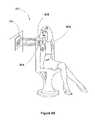
- FIG. 5Ais an illustration including an electronic device associated with a user, in the form of a Bluetooth headset worn by the user, including at least one embedded receiver for receiving wireless power transmissions from a transmitter, in accordance with some embodiments.
- FIG. 5Bis an illustration including an electronic device, in the form of a wearable computing device such as a wristwatch, including at least one embedded receiver, for receiving wireless power transmissions from a transmitter, in accordance with some embodiments.
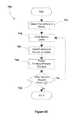
- FIG. 5Cis a flow diagram of an algorithm that may be used to manage power loads on an electronic device, in accordance with some embodiments.
- FIG. 6Ais an illustration showing a wireless power transmission system used for charging one or more peripheral devices via a transmitter associated with a laptop computer, in accordance with some embodiments.
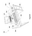
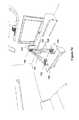
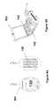
- FIG. 6Bis an exploded view of a laptop screen, showing components including an embedded wireless power transmitter, in accordance with some embodiments.
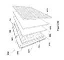
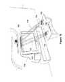
- FIG. 6Cis an exploded view of a laptop screen, showing components including an embedded wireless power transmitter and an embedded wireless power receiver, in accordance with some embodiments.
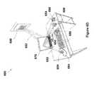
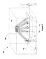
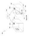
- FIG. 6Dis an illustration showing a wireless power transmission system in which a laptop computer may receive and transmit sound waves in a substantially simultaneous fashion, in accordance with some embodiments.
- FIG. 6Eis a flow diagram of a wireless power transmission process that may be implemented for charging one or more peripheral devices using a laptop computer, in accordance with some embodiments.
- FIGS. 7A-7Bare illustrations of game controllers that are coupled with wireless power receivers, in accordance with some embodiments.
- FIGS. 7C-7Gillustrate various wireless power transmission systems in which power is wirelessly delivered to electronic devices using sound waves, in accordance with some embodiments.
- FIG. 7Hillustrates an improved rollable electronic paper display used to explain certain advantages of wireless power transmission systems, in accordance with some embodiments.
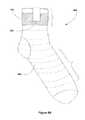
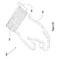
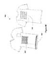
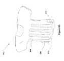
- FIGS. 8A-8Gillustrate various articles (e.g., heating blanket, heating sock, heating glove, warming jacket, shirt, cap, and cooling shirt) with embedded wireless power receivers, in accordance with some embodiments.
- FIGS. 9A-9Bare illustrations of medical devices with wireless power receivers coupled thereto, in accordance with some embodiments.
- FIGS. 9C-9Eare illustrations of wireless power transmission systems for wirelessly delivering power to medical devices, in accordance with some embodiments.
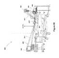
- FIG. 10is an illustration of a house configured with a number of wireless power transmitters and receivers, in accordance with some embodiments.
- FIG. 11Aillustrates a law enforcement officer wearing a uniform with an integrated wireless power receiver, in accordance with some embodiments.
- FIGS. 11B-11Dillustrate wireless power transmitters integrated with various types of mobile law enforcement equipment (e.g., a police squad car and a SWAT team vehicle) for use in conjunction with law enforcement operations, in accordance with some embodiments.
- mobile law enforcement equipmente.g., a police squad car and a SWAT team vehicle
- FIGS. 12A-12Dillustrate tracking systems that upload to a cloud-based service for use in conjunction with wireless power transmission systems, in accordance with some embodiments.
- one or more transmittersgenerate power waves to form pockets of energy at target locations and adjust power wave generation based on sensed data to provide safe, reliable, and efficient wirelessly-delivered power to receivers (and devices associated therewith).
- the power wavesare sound waves that are transmitted in frequencies between 10 kHz and 50 kHz.
- a controlled “pocket of energy”e.g., a region in which available power is high due to constructive interference of power waves
- null spacese.g., a region in which available power is low or nonexistent due to destructive interference of power waves
- pockets of energyform at one or more locations in a two- or three-dimensional field due to patterns of constructive interference caused by convergences of transmitted power waves.
- Energy from the transmitted power wavesmay be harvested by receivers (i.e., received and converted into usable power) at the one or more locations.
- adaptive pocket-formingis performed, e.g., by adjusting power wave transmission to achieve a target power level for at least some of the power waves transmitted by the one or more transmitters.
- a system for adaptive pocket-formingincludes a sensor.
- the sensordetects an object, such as a sensitive object (e.g., a person, an animal, equipment sensitive to the power waves, and the like) within a predetermined distance (e.g., a distance within a range of 1-5 feet) of a pocket of energy, of one or more of the power waves, or of a transmitter, then a respective transmitter of the one or more transmitters adjusts one or more characteristics of transmitted power waves.
- a sensitive objecte.g., a person, an animal, equipment sensitive to the power waves, and the like
- a predetermined distancee.g., a distance within a range of 1-5 feet
- Non-limiting examples of the one or more characteristicsinclude: frequency, amplitude, trajectory, phase, and other characteristics used by one or more antennas of the one or more transmitters to transmit the power waves.
- the adaptive pocket-forming processadjusts the one or more characteristics accordingly.
- adjusting the one or more characteristicsincludes reducing a currently generated power level at a location by adjusting one or more transmitted power waves that converge at the target location.
- reducing a currently generated power levelincludes transmitting a power wave that causes destructive interference with at least one other transmitted power wave. For example, a power wave is transmitted with a first phase that is shifted relative to a second phase of at least one other power wave to destructively interfere with the at least one other power wave in order to diminish or eliminate the currently generated power level at the target location.
- adjusting the one or more characteristicsincludes increasing a power level for some of the transmitted power waves to ensure that the receiver receives adequate energy sufficient to quickly charge a power-storing component of an electronic device that is associated with the receiver.
- an objectis “tagged” (e.g., an identifier of the object is stored in memory in association with a flag) to indicate that the detected object is a sensitive object.
- a determinationis made as to whether the particular object is a sensitive object. In some embodiments, this determination includes performing a lookup in the memory to check whether the particular object has been previously tagged and is therefore known as a sensitive object. In response to determining that the particular object is a sensitive object, the one or more characteristics used to transmit the power waves are adjusted accordingly.
- sensing a sensitive objectincludes using a series of sensor readings from one or more sensors to determine motion of an object within a transmission field of the one or more transmitters.
- sensor output from one or more sensorsis used to detect motion of the object approaching within a predetermined distance of a pocket of energy or of power waves used to form the pocket of energy.
- the currently generated power level at the location of the pocket of energyis reduced.
- the one or more sensorsinclude sensors that are internal to the one or more transmitters, the receiver, and/or sensors that are external to the one or more transmitters and the receiver and may include thermal imaging, optical, radar, and other types of sensors capable to detecting objects within a transmission field.
- wireless charging techniquesthat might be employed are not be limited to such technologies and transmission techniques. Rather, it should be appreciated that additional or alternative wireless charging techniques may be utilized, including any suitable technology and technique for wirelessly transmitting energy so that a receiver is capable of converting the transmitted energy to electrical power. Such technologies or techniques may transmit various forms of wirelessly transmitted energy including the following non-limiting examples: microwave, laser light, infrared, or other forms of electromagnetic energy.
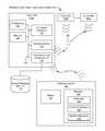
- FIG. 1illustrates components of an example wireless power transmission environment 100 , in accordance with some embodiments.
- Wireless power transmission environment 100includes, e.g., transmitters 102 (e.g., transmitters 102 a , 102 b . . . 102 n ) and a receiver 120 .
- the wireless power transmission environment 100includes a number of receivers 120 , each of which is associated with a respective electronic device 122 .
- An example transmitter 102(e.g., transmitter 102 a ) includes, e.g., one or more processor(s) 104 , a memory 106 , one or more antenna arrays 110 , one or more communications components 112 , and/or one or more transmitter sensors 114 . In some embodiments, these components are, interconnected via a communications bus 108 . References to these components of transmitters 102 cover embodiments in which one or more than one of each of these components (and combinations thereof) are included.
- memory 106stores one or more programs (e.g., sets of instructions) and/or data structures, collectively referred to as “modules” herein.
- memory 106or the non-transitory computer readable storage medium of memory 106 stores the following programs, modules, and data structures, or a subset or superset thereof:
- memory 106stores a subset of the modules identified above.
- an external mapping memory 132that is communicatively connected to communications component 112 stores one or more modules identified above.
- the memory 106 and/or external mapping memory 132may store additional modules not described above.
- the modules stored in memory 106 , or a non-transitory computer readable storage medium of memory 106provide instructions for implementing respective operations in the methods described below.
- some or all of these modulesmay be implemented with specialized hardware circuits that subsume part or all of the module functionality.
- One or more of the above-identified elementsmay be executed by one or more of processor(s) 104 .
- one or more of the modules described with regard to memory 106is implemented on memory 104 of a server (not shown) that is communicatively coupled to one or more transmitters 102 and/or by a memory of electronic device 122 and/or receiver 120 .
- a single processor 104executes software modules for controlling multiple transmitters 102 (e.g., transmitters 102 b . . . 102 n ).
- a single transmitter 102includes multiple processors 104 , such as one or more transmitter processors (configured to, e.g., control transmission of signals 116 by antenna array 110 ), one or more communications component processors (configured to, e.g., control communications transmitted by communications component 112 and/or receive communications via communications component 112 ) and/or one or more sensor processors (configured to, e.g., control operation of transmitter sensor 114 and/or receive output from transmitter sensor 114 ).
- Receiver 120receives power signals 116 and/or communications 118 transmitted by transmitters 102 .
- receiver 120includes one or more antennas 124 (e.g., antenna array including multiple antenna elements), power converter 126 , receiver sensor 128 and/or other components or circuitry. References to these components of receiver 120 cover embodiments in which one or more than one of each of these components (and combinations thereof) are included.
- Receiver 120converts energy from received signals 116 (e.g., power waves) into electrical energy to power and/or charge electronic device 122 .
- receiver 120uses power converter 126 to convert captured energy from power waves 116 to alternating current (AC) electricity or direct current (DC) electricity usable to power and/or charge electronic device 122 .
- power converter 126include rectifiers, rectifying circuits, voltage conditioners, among suitable circuitry and devices.
- receiver 120receives one or more power waves 116 directly from transmitter 102 . In some embodiments, receiver 120 harvests power waves from one or more pockets of energy created by one or more power waves 116 transmitted by transmitter 102 .
- circuitrye.g., integrated circuits, amplifiers, rectifiers, and/or voltage conditioner
- the receiver 120converts the energy of the power waves (e.g., radio frequency electromagnetic radiation) to usable power (i.e., electricity), which powers electronic device 122 and/or is stored to battery 130 of electronic device 122 .
- a rectifying circuit of the receiver 120translates the electrical energy from AC to DC for use by electronic device 122 .
- a voltage conditioning circuitincreases or decreases the voltage of the electrical energy as required by the electronic device 122 .
- an electrical relayconveys electrical energy from the receiver 120 to the electronic device 122 .
- receiver 120is a component of an electronic device 122 .
- a receiver 120is coupled (e.g., detachably coupled) to an electronic device 122 .
- electronic device 122is a peripheral device of receiver 120 .
- electronic device 122obtains power from multiple transmitters 102 and/or using multiple receivers 120 .
- the wireless power transmission environment 100includes a plurality of electronic devices 122 , each having at least one respective receiver 120 that is used to harvest power waves from the transmitters 102 into usable power for charging the electronic devices 122 .
- the one or more transmitters 102adjust one or more characteristics (e.g., phase, gain, direction, and/or frequency) of power waves 116 .
- a transmitter 102e.g., transmitter 102 a
- the one or more transmitters 102adjust power waves 116 such that trajectories of power waves 116 converge at a predetermined location within a transmission field (e.g., a location or region in space), resulting in controlled constructive or destructive interference patterns.
- respective antenna arrays 110 of the one or more transmitters 102may include a set of one or more antennas configured to transmit the power waves 116 into respective transmission fields of the one or more transmitters 102 .
- Integrated circuits (not shown) of the respective transmitter 102such as a controller circuit and/or waveform generator, may control the behavior of the antennas. For example, based on the information received from the receiver via the communications signal 118 , a controller circuit may determine a set of one or more characteristics or waveform characteristics (e.g., amplitude, frequency, trajectory, phase, among other characteristics) used for transmitting the power waves 116 that would effectively provide power to the receiver 120 and electronic device 122 .
- the controller circuitmay also identify a subset of antennas from the antenna arrays 110 that would be effective in transmitting the power waves 116 .
- a waveform generator circuit of the respective transmitter 102 coupled to the processor 104may convert energy and generate the power waves 116 having the waveform characteristics identified by the controller, and then provide the power waves to the antenna arrays 110 for transmission.
- constructive interference of power wavesoccurs when two or more power waves 116 are in phase with each other and converge into a combined wave such that an amplitude of the combined wave is greater than amplitude of a single one of the power waves.
- the positive and negative peaks of sinusoidal waveforms arriving at a location from multiple antennas“add together” to create larger positive and negative peaks.
- a pocket of energyis formed at a location in a transmission field where constructive interference of power waves occurs.
- destructive interference of power wavesoccurs when two or more power waves are out of phase and converge into a combined wave such that the amplitude of the combined wave is less than the amplitude of a single one of the power waves. For example, the power waves “cancel each other out,” thereby diminishing the amount of energy concentrated at a location in the transmission field. In some embodiments, destructive interference is used to generate a negligible amount of energy or “null” at a location within the transmission field where the power waves converge.
- the one or more transmitters 102transmit power waves 116 that create two or more discrete transmission fields (e.g., overlapping and/or non-overlapping discrete transmission fields).
- a first transmission fieldis managed by a first processor 104 of a first transmitter (e.g. transmitter 102 a ) and a second transmission field is managed by a second processor 104 of a second transmitter (e.g., transmitter 102 b ).
- the two or more discrete transmission fieldsare managed by the transmitter processors 104 as a single transmission field.
- communications component 112transmits communication signals 118 via a wired and/or wireless communication connection to receiver 120 .
- communications component 112generates communications signals 118 used for triangulation of receiver 120 .
- communication signals 118are used to convey information between transmitter 102 and receiver 120 for adjusting one or more characteristics used to transmit the power waves 116 .
- communications signals 118include information related to status, efficiency, user data, power consumption, billing, geo-location, and other types of information.
- receiver 120includes a transmitter (not shown), or is a part of a transceiver, that transmits communications signals 118 to communications component 112 of transmitter 102 .
- communications component 112(e.g., communications component 112 of transmitter 102 a ) includes a communications component antenna for communicating with receiver 120 and/or other transmitters 102 (e.g., transmitters 102 b through 102 n ).
- these communications signals 118represent a distinct channel of signals transmitted by transmitter 102 , independent from a channel of signals used for transmission of the power waves 116 .
- the receiver 120includes a receiver-side communications component (not shown) configured to communicate various types of data with one or more of the transmitters 102 , through a respective communications signal 118 generated by the receiver-side communications component.
- the datamay include location indicators for the receiver 120 and/or electronic device 122 , a power status of the device 122 , status information for the receiver 120 , status information for the electronic device 122 , status information about the power waves 116 , and/or status information for pockets of energy.
- the receiver 120may provide data to the transmitter 101 , via the communications signal 118 , regarding the current operation of the system 100 , including: information identifying a present location of the receiver 120 or the device 122 , an amount of energy received by the receiver 120 , and an amount of power received and/or used by the electronic device 122 , among other possible data points containing other types of information.
- the data contained within communications signals 118is used by electronic device 122 , receiver 120 , and/or transmitters 102 for determining adjustments of the one or more characteristics used by the antenna array 110 to transmit the power waves 106 .
- the transmitter 102uses a communications signal 118 to communicate data that is used, e.g., to identify receivers 120 within a transmission field, identify electronic devices 122 , determine safe and effective waveform characteristics for power waves, and/or hone the placement of pockets of energy.
- receiver 120uses a communications signal 118 to communicate data for, e.g., alerting transmitters 102 that the receiver 120 has entered or is about to enter a transmission field, provide information about electronic device 122 , provide user information that corresponds to electronic device 122 , indicate the effectiveness of received power waves 116 , and/or provide updated characteristics or transmission parameters that the one or more transmitters 102 use to adjust transmission of the power waves 116 .
- the communications component 112 of the transmitter 102communicates (e.g., transmits and/or receives) one or more types of data (including, e.g., authentication data and/or transmission parameters) including various information such as a beacon message, a transmitter identifier, a device identifier for an electronic device 122 , a user identifier, a charge level for electronic device 122 , a location of receiver 120 in a transmission field, and/or a location of electronic device 122 in a transmission field.
- dataincluding, e.g., authentication data and/or transmission parameters
- various informationsuch as a beacon message, a transmitter identifier, a device identifier for an electronic device 122 , a user identifier, a charge level for electronic device 122 , a location of receiver 120 in a transmission field, and/or a location of electronic device 122 in a transmission field.
- transmitter sensor 114 and/or receiver sensor 128detect and/or identify conditions of electronic device 122 , receiver 120 , transmitter 102 , and/or a transmission field.
- data generated by transmitter sensor 114 and/or receiver sensor 128is used by transmitter 102 to determine appropriate adjustments to the one or more characteristics used to transmit the power waves 106 .
- Data from transmitter sensor 114 and/or receiver sensor 128 received by transmitter 102includes, e.g., raw sensor data and/or sensor data processed by a processor 104 , such as a sensor processor. Processed sensor data includes, e.g., determinations based upon sensor data output.
- sensor data received from sensors that are external to the receiver 120 and the transmitters 102is also used (such as thermal imaging data, information from optical sensors, and others).
- receiver sensor 128is a gyroscope that provides raw data such as orientation data (e.g., tri-axial orientation data), and processing this raw data may include determining a location of receiver 120 and/or or a location of receiver antenna 124 using the orientation data.
- orientation datae.g., tri-axial orientation data
- receiver sensor 128includes one or more infrared sensors (e.g., that output thermal imaging information), and processing this infrared sensor data includes identifying a person (e.g., indicating presence of the person and/or indicating an identification of the person) or other sensitive object based upon the thermal imaging information.
- infrared sensorse.g., that output thermal imaging information
- processing this infrared sensor dataincludes identifying a person (e.g., indicating presence of the person and/or indicating an identification of the person) or other sensitive object based upon the thermal imaging information.
- receiver sensor 128includes a gyroscope and/or an accelerometer that indicates an orientation of receiver 120 and/or electronic device 122 .
- transmitters 102receive orientation information from receiver sensor 128 and the transmitters 102 (or a component thereof, such as the processor 104 ) use the received orientation information to determine whether electronic device 122 is flat on a table, in motion, and/or in use (e.g., next to a user's head).
- receiver sensor 128is a sensor of electronic device 122 (e.g., an electronic device 122 that is remote from receiver 120 ).
- receiver 120 and/or electronic device 122includes a communication system for transmitting signals (e.g., sensor signals output by receiver sensor 128 ) to transmitter 102 .
- Non-limiting examples of transmitter sensor 114 and/or receiver sensor 128include, e.g., infrared, pyroelectric, ultrasonic, laser, optical, Doppler, gyro, accelerometer, microwave, millimeter, RF standing-wave sensors, resonant LC sensors, capacitive sensors, and/or inductive sensors.
- technologies for transmitter sensor 114 and/or receiver sensor 128include binary sensors that acquire stereoscopic sensor data, such as the location of a human or other sensitive object.
- transmitter sensor 114 and/or receiver sensor 128is configured for human recognition (e.g., capable of distinguishing between a person and other objects, such as furniture).
- human recognition-enabled sensorsinclude: body temperature data, infrared range-finder data, motion data, activity recognition data, silhouette detection and recognition data, gesture data, heart rate data, portable devices data, and wearable device data (e.g., biometric readings and output, accelerometer data).
- transmitters 102adjust one or more characteristics used to transmit the power waves 116 to ensure compliance with electromagnetic field (EMF) exposure protection standards for human subjects.
- EMFelectromagnetic field
- Maximum exposure limitsare defined by US and European standards in terms of power density limits and electric field limits (as well as magnetic field limits). These include, for example, limits established by the Federal Communications Commission (FCC) for maximum permissible exposure (MPE), and limits established by European regulators for radiation exposure. Limits established by the FCC for MPE are codified at 47 CFR ⁇ 1.1310.
- FCCFederal Communications Commission
- MPEmaximum permissible exposure
- Limits established by the FCC for MPEare codified at 47 CFR ⁇ 1.1310.
- power densitycan be used to express an intensity of exposure. Power density is defined as power per unit area.
- power densitycan be commonly expressed in terms of watts per square meter (W/m 2 ), milliwatts per square centimeter (mW/cm 2 ), or microwatts per square centimeter ( ⁇ W/cm 2 ).
- output from transmitter sensor 114 and/or receiver sensor 128is used by transmitter 102 to detect whether a person or other sensitive object enters a power transmission region (e.g., a location within a predetermined distance of a transmitter 102 , power waves generated by transmitter 102 , and/or a pocket of energy).
- the transmitter 102in response to detecting that a person or other sensitive object has entered the power transmission region, the transmitter 102 adjusts one or more power waves 116 (e.g., by ceasing power wave transmission, reducing power wave transmission, and/or adjusting the one or more characteristics of the power waves). In some embodiments, in response to detecting that a person or other sensitive object has entered the power transmission region, the transmitter 102 activates an alarm (e.g., by transmitting a signal to a loudspeaker that is a component of transmitter 102 or to an alarm device that is remote from transmitter 102 ). In some embodiments, in response to detecting that a person or other sensitive object has entered a power transmission region, the transmitter 102 transmits a digital message to a system log or administrative computing device.
- antenna array 110includes multiple antenna elements (e.g., configurable “tiles”) collectively forming an antenna array.
- Antenna array 110generates, e.g., RF power waves, ultrasonic power waves, infrared power waves, and/or magnetic resonance power waves.
- the antennas of an antenna array 110e.g., of a single transmitter, such as transmitter 102 a , and/or of multiple transmitters, such as transmitters 102 a , 102 b , . . . , 102 n
- transmit two or more power waves that intersect at a defined locatione.g., a location corresponding to a detected location of a receiver 120 , thereby forming a pocket of energy at the defined location.
- transmitter 102assigns a first task to a first subset of antenna elements of antenna array 110 , a second task to a second subset of antenna elements of antenna array 110 , and so on, such that the constituent antennas of antenna array 110 perform different tasks (e.g., determining locations of previously undetected receivers 120 and/or transmitting power waves 116 to one or more receivers 120 ).
- the constituent antennas of antenna array 110perform different tasks (e.g., determining locations of previously undetected receivers 120 and/or transmitting power waves 116 to one or more receivers 120 ).
- nine antennastransmit power waves 116 that form a pocket of energy and the tenth antenna operates in conjunction with communications component 112 to identify new receivers in the transmission field.
- an antenna array 110 having ten antenna elementsis split into two groups of five antenna elements, each of which transmits power waves 116 to two different receivers 120 in the transmission field.
- a respective transmitter 200may include a housing 202 with at least two or more transducer elements 204 , at least one sound wave integrated circuit (SWIC) 206 , at least one microcontroller 208 (e.g., one or the processors 104 , FIG. 1 ), and one or more communications components 112 (also shown in FIG. 1 ).
- housing 202is made of any suitable material which may allow for signal or wave transmission and/or reception, for example plastic or hard rubber.
- the at least two transducer elements 204may include suitable transducer types for operating in frequency bands such as 10 KHz to 50 KHz, or other suitable frequency bands for ultrasound waves.
- the at least two transducer elements 204are arranged in suitable combinations to transmit sound waves required to activate a receiver (e.g., receiver 120 , FIG. 1 ), so that the receiver is able to harness energy from the sound waves for powering an electronic device associated with the receiver (e.g., electronic device 122 , FIG. 1 ).
- transducersinclude, for example, piezoelectric devices, piezo transducers of ceramic or other suitable materials, among others.
- the transducer elements 204are arranged in a pattern (e.g., as described below in reference to FIG. 2C ).
- shape and orientation of transducer elements 204varies to match desired features of a respective transmitter 102 , e.g., orientation of transducer elements 204 may be flat in X, Y, and Z axes, or may be otherwise oriented in three-dimensional space.
- respective transducer elements 204 of a respective transmitter 102may operate in independent frequencies, allowing a multichannel operation of transmitting sound waves and producing pockets of energy at desired locations within a transmission field of the transmitter.
- the at least one SWIC 206includes a proprietary chip for adjusting phases and/or relative magnitudes of sound wave signals which may serve as inputs for the at least two transducer elements 204 for transmitting sound waves that converge constructively to generate pockets of energy at desired locations with a transmission field of the transmitter 102 .
- these sound wave signalsare produced using a power source 212 (e.g., an external or internal power source) and a local oscillator chip (not shown) using a suitable piezoelectric material.
- the power sourcemay include a battery of a device in which a transmitter 102 is embedded (e.g., a battery of laptop 602 which may have an embedded transmitter 102 , FIG. 6A ).
- microcontroller 208determines optimal times and locations for forming pockets of energy by processor at least in part by processing information sent by a receiver 120 to the communications component 112 .
- communications component 112utilizes standard wireless communication protocols to communicate with the receiver, which may include Bluetooth, Wi-Fi or ZigBee communication protocols.
- communications component 112may be used to receive other information from the receiver such as an identifier for the device or user, battery level of an electronic device associated with the receiver, and/or location information about the electronic device.
- Non-limiting examples of communications components 112include Bluetooth transceivers, radar, infrared cameras or sound devices for sonic triangulation for determining the device's position.
- the transducer elements 204are arranged in many different arrays, as shown in FIGS. 2C-2F , and explained in more detail below.
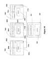
- FIG. 2Bis a block diagram showing multiple transmitters controlled by a single microcontroller, in accordance with some embodiments.
- a base station 240may be utilized to help coordinate transmissions of sound waves by a plurality of transmitters 102 a through 102 n (additional details regarding transmitters 102 are provided above in reference to FIG. 2A ).
- the base station 240may include one or more micro-controller 241 , a power source 243 , and a housing.
- the base station 240may include connections to each of the transmitters 102 .
- Such connectionsmay include a variety of types of connections, such as coaxial cable, phone cable, LAN cable, wireless connection via Wi-Fi or BLUETOOTH among others.
- a respective connection between a transmitter 102 and the base station 240may be used to link a respective SWIC 206 with the microcontroller 241 and the power source 243 , to facilitate controlled transmission of sound waves for wirelessly delivering power to receivers and devices connected therewith.
- the microcontroller 241may control a variety of features of a respective SWIC 206 , including timing for transmitting sound waves, direction of transmitted sound waves, bounce angles for transmitted sound waves, power intensity for transmitted sound waves, and the like, to allow for controlled creation of pockets of energy that form based on constructive interference of sound waves transmitted by the various transmitters 102 .
- the microcontroller 241may control multiple transmitters 102 in near simultaneous fashion in order to facilitate creation of multiple pockets of energy.
- the microcontroller 241may also use manage and control communications between respective transmitters and between respective transmitters by controlling respective communication components 112 . In this way, the base station 240 is configured to control various features of a single or multiple transmitters.
- base station 240is coupled with a power source 243 , which in turn may be used to provide power to transmitters 102 .
- power source 243includes an AC or DC power supply. Voltage, power, and current intensity provided by power source 243 may vary based in dependency with the required sound waves to be transmitted. Use of the power to create sound waves may be managed by microcontroller 241 and carried out by SWIC 206 , which may utilize a plurality of methods and components to produce sound wave signals in a wide variety of frequencies, wavelengths, intensities, and other features. As an example, oscillators and piezoelectric crystals may be used to create and change sound frequencies in different transducer elements 204 . In some embodiments, a variety of filters may be used for smoothing signals as well as amplifiers for increasing power to be transmitted.
- each respective transmitter 102transmits sound waves at different or at the same frequencies, power intensities, amplitudes, etc.
- FIG. 2Cis a block diagram of a flat panel transducer array 300 that may be used in a transmitter (e.g., a transmitter 102 , such as those discussed above in reference to FIGS. 1, 2A, and 2B ), in accordance with some embodiments.
- a transmittere.g., a transmitter 102 , such as those discussed above in reference to FIGS. 1, 2A, and 2B .
- the flat panel transducer array 300includes N number of transducer elements 204 , where gain requirements for transmitting sound waves are distributed across the N number of transducer elements 204 .
- the transducer elements 204are distributed in an equally spaced grid (e.g., an 8 ⁇ 8 grid with a total of 64 transducer elements 204 or a 16 ⁇ 16 grid with a total of 256 transducer elements 204 ).
- the number of transducer elements 204 in a particular transducer arraymay vary in relation with desired range and power transmission capabilities for a respective transmitter 102 (i.e., the more transducer elements 204 , the wider range and higher power transmission capability available for the respective transmitter 102 ).
- the transducer array 300may have a circular pattern or polygon arrangement of transducer elements 204 . In some embodiments, the array 300 may also be divided into sets of transducer elements, and each set may then be distributed across multiple surfaces (multi-faceted).
- a transducer arraymay operate as a single array, a pair array, a quad array, or any other suitable arrangement (as described below in reference to FIGS. 2D-2F ), which may be designed to create a transmitter with desired sound wave transmission capabilities.
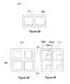
- FIGS. 2D-2Fshow arrangements of example transducer arrays 400 a that may be used in a respective transmitter 102 , in accordance with some embodiments.
- FIG. 2Dshows a single array 402 where all transducer elements 204 may operate at 50 KHz.
- the single array 402may be used for transmitting sound waves to a single receiver for charging or powering a single electronic device.
- FIG. 2Eshows an example pair array 404 , including a top half 406 of transducer elements 204 , and a bottom half 408 of transducer elements 204 .
- portions of the example pair array 404may operate at different frequencies (e.g., each transducer element within the top half 406 may operate at 10 kHz and each transducer element in the bottom half 408 may operate at a frequency of 20 kHz).
- transducer elements in each half of the example pair array 404may vary in size (e.g., those in the top half are slightly smaller than those in the bottom half).
- FIG. 2Fshows an example quad array 410 where one or more transducer elements 204 may be virtually divided to avoid power losses during wireless power transmission.
- a respective transducer element 204 cmay be virtually divided into two transducer elements, transducer element 204 c 1 and transducer element 204 c 2 .
- Transducer element 204 c 1may be used for transmitting at a frequency of 50 kHz and transducer element 204 c 2 may be used for transmitting at a frequency of 10 kHz.
- the quad array 410 arrangement of transducer elementsmay be used in situations where multiple receivers 120 operating at different frequency bands require power.
- FIG. 3Ais a block diagram showing components of a receiver (e.g., receiver 120 , FIG. 1 ) used in some wireless power transmission systems, in accordance with some embodiments.
- a receivere.g., receiver 120 , FIG. 1
- receiver 120includes a housing 302 with at least one sensor element 128 (also shown in FIG. 1 ), at least one rectifier 306 , at least one power converter 308 , and an optional communications component 310 .
- housing 302is made of any suitable material which may allow for signal or wave transmission and/or reception, e.g., plastic or hard rubber.
- housing 302may be light, resistant to heat, water, corrosion resistant, durable, and adaptable to different types of environments (e.g., resistant to climate changes).
- housing 302may be part of an external hardware component that is added to different electronic equipment, e.g., in the form of a case, or may be embedded within electronic equipment.
- housing 302provides isolation for components of the receiver 120 to protect it from external factors, such as water and sweat (e.g., for embodiments in which a receiver is embedded in an article of clothing, such as those discussed below).
- sensor element 128may include suitable sensor types for operating in frequency bands similar to the bands described for transmitter 102 with reference to FIGS. 1 and 2A-2F .
- sensor element 128is any device capable of receiving sound waves or any combination of sounds or signals from a respective transmitter 102 .
- Suitable sensor elements 128include various types of microphones.
- the sensor element 128is a sound transducer (i.e., a sound sensor) that produces an electrical analog output signal which is proportional to an acoustic sound wave acting upon its flexible diaphragm. In some embodiments, this electrical analog output signal is an electrical image representing characteristics of a waveform representing the acoustic sound wave.
- the output signal from a microphoneproduces an analog signal either in the form of a voltage or current which is proportional to the actual sound wave.
- types of microphones available as sound transducersinclude dynamic, electret condenser, ribbon, and piezo-electric crystal types.
- the sensor element 128is a dynamic moving-coil microphone sound transducer that is configured to optimize wireless power reception from sound waves transmitted by a transmitter 102 .
- multiple different types of sensor elements 128are included in a single receiver 120 . Using multiple sensor elements 128 may be beneficial for a respective receiver 120 that is coupled with an electronic device that does not have a preferred orientation during usage or whose orientation may vary continuously through time, e.g., a smartphone or portable gaming system.
- flexible, piezo transducers, distributed in specific patternsmay be used as the sensor elements 128 . Different sensor, rectifier, or power converter arrangements are possible for a receiver 120 , as will be evident to one skilled in the art.
- rectifier 306may be configured to convert the signal (e.g., a sound signal) received by sensor element 128 into a voltage (e.g., DC).
- Rectifier 306may include diodes or resistors, inductors or capacitors to rectify alternating current (AC) voltage generated by sensor element 304 to direct current (DC) voltage.
- ACalternating current
- DCdirect current
- rectifier 306is placed close to sensor element 128 to minimize any potential loss of energy.
- DC voltagemay be regulated using power converter 126 .
- power converter 126is used for regulating voltage obtained from rectifier 306 to obtain an appropriate output voltage for charging or powering an electronic device.
- power converter 126is a DC-DC converter which may help provide a constant voltage output, regardless of input, to an electronic device, or as in the embodiment to a battery that may be associated with an electronic device. Typical voltage outputs may be from about 5 volts to about 10 volts.
- initial high currentswhich may break-down operation of an electronic switched mode DC-DC converter may be required.
- a capacitor(not shown) may be added at the output of receiver 300 to provide the extra energy required.
- lower powermay be provided, e.g., 1/80th of the total initial power while having the clothing or blanket (or circuits associated therewith which are powered by the receiver 120 ) still build up charge.
- communications component 310which may be a similar device to the communications component 112 of transmitter 112 ( FIGS. 1 and 2A ), may be included in receiver 120 to communicate with a transmitter or with other equipment.
- Such a communications component 310may communicate using standard wireless communication protocols, including Bluetooth, Wi-Fi, or ZigBee communications protocols.
- an embedded receiver 120may be used to power up one or more capacitors within a given electronic device, e.g. a smartphone, which upon discharging may provide sufficient power to the smartphone. Such a configuration may diminish the size and power capabilities of batteries required for these electronic devices. In some embodiments, depending on the capacitors' size and efficiency, batteries may not even be required in these electronic devices at all.
- a respective receiver 120may be used in conjunction with tracking systems for observing, following, and recording movements of people, animals, or objects during certain periods of time.
- the respective receiver 120may be coupled with any of a number of devices, e.g., bracelets, necklaces, belts, rings, ear chips, and watches, among others.
- a transmitter 102may be employed for locating the respective receiver 120 through sound wave transmissions (and/or communications between respective communications components of the receiver and the transmitter) between the respective receiver 120 and the transmitter 102 .
- such a setuphelps to ensure continuous monitoring/tracking, as the respective receiver 120 is constantly charged by the transmitter 102 , thus helping to avoid interruptions such as when the respective receiver 120 runs out of power.
- this tracking setupalso uses data from global positioning systems, real-time location systems, or other tracking systems to help find and monitor the location of living beings such as animals or humans, and/or the location of objects such as cars, electronic devices, and commodities, among others.
- FIG. 3Bis a block diagram of an electronic device 300 including at least one embedded receiver 320 (which may be an instance of the receiver 120 described above) and at least one auxiliary power supply 304 for improving the life of the electronic device's main power supply 324 , in accordance with some embodiments.
- the embedded receiver 320may include at least one sensor element 308 that is configured to convert accumulated energy from sound waves in pockets of energy, produced through pocket-forming transmissions by one or more transmitters 102 , into AC voltage.
- the embedded receiver 320also includes at least one rectifier 322 where AC voltage may be converted to direct current (DC) voltage.
- the embedded receiver 320also includes at least one power converter 312 for providing constant DC voltage output to auxiliary power supply 304 .
- auxiliary power supply 304is a suitable charge storing device, e.g., a capacitor (which may easily and cheaply be manufactured to have a small size).
- Auxiliary power supply 304may fully or partially power electronic device 300 , and thus may fully or partially decrease the power demand on power supply 324 to satisfy the power requirements of electronic device 300 . In this way, the life of the main power supply 324 may be extended.
- the electronic device 300may include an existing microcontroller or microprocessor 316 that is configured to manage power loads on auxiliary power supply 304 and/or power supply 324 .
- the microcontroller 316is a part of the embedded receiver 320 , and is separate and distinct from a microcontroller or processor of the device 300 .
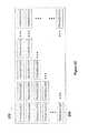
- FIG. 4Ais a flow diagram of an example routine/method 400 a that may be utilized by a microcontroller of a transmitter (e.g., microcontroller 208 of transmitter 102 , FIG. 2A ) to authenticate devices requiring wireless power transmissions, in accordance with some embodiments.
- the method 400 amay begin when transmitter 102 receives a power delivery request 402 from a respective receiver (e.g., receiver 120 , FIGS. 1 and 3A ).
- the receivermay send a signature signal which may be coded using suitable techniques such as delay encoding, orthogonal frequency-division multiplexing (OFDM), code division multiplexing (UM), or other suitable binary coding for identifying a given electronic device that includes the receiver.
- suitable techniquessuch as delay encoding, orthogonal frequency-division multiplexing (OFDM), code division multiplexing (UM), or other suitable binary coding for identifying a given electronic device that includes the receiver.
- microcontroller 208may proceed to authentication step 404 where it may evaluate the signature signal sent by the receiver. The microcontroller 208 may then proceed to a determination step 406 , at which it is determined whether the electronic device associated with the receiver 120 is authorized to receive wireless power transmissions from the transmitter. If the receiver is not authorized, microcontroller 208 may decide, at decision 406 , not to deliver power at step 408 , and thus may end routine 400 a at end 410 (in some embodiments, the method 400 a loops back to step 402 to continue receiving additional power delivery requests). On the other hand, if the receiver is authorized, the microcontroller 208 may then proceed to determine a type of electronic device that is associated with the receiver, at step 412 .
- the microcontroller 208may obtain information from the receiver that identifies the type of electronic device that is associated with the microcontroller 208 , including information identifying a manufacturer, a serial number, total power required, battery level among other such information (in some embodiments, this information is included with the initial power delivery request, while, in other embodiments, this information is sent via a separate communication). Afterwards, the microcontroller 208 may proceed to run a device module at step 414 , in which a routine suited to the authenticated device is executed (e.g., a routine that causes the transmitter to transmit sound waves towards the receiver and with a desired frequency, so that the transmitted sound waves form a constructive interference pattern proximate to the receiver). In some embodiments, method 400 b ( FIG. 4B ) is executed at step 414 (method 400 b is described in more detail below).
- a routine suited to the authenticated devicee.g., a routine that causes the transmitter to transmit sound waves towards the receiver and with a desired frequency, so that the transmitted sound waves
- the microcontroller 208may deliver power to each authorized receiver (i.e., as determined after executing the method 400 a ) or may utilize a priority status for each respective receiver to determine which receiver should receive the wireless power transmissions in which order.
- the priority statusmay be a predefined priority status that is provided by a user. For example, the user may choose to prioritize wireless power transmissions to its smartphone, rather than to its gaming device, and/or may choose to deliver more wireless power transmissions to its smartphone rather than the gaming device.
- devicessuch as smoke detectors, digital door locks, and CCTV cameras may also have a high priority order for receipt of wirelessly delivered powered (as discussed below in reference to FIG. 10 ).
- FIG. 4Bis a flow diagram of an example routine/method 400 b that may be utilized by a microcontroller of a transmitter (e.g., microcontroller 208 of transmitter 102 , FIG. 2A ) to wirelessly deliver power to devices that have been previously authenticated, in accordance with some embodiments.
- the method 400 bis executed in conjunction with step 414 of method 400 a , to determine how to wirelessly deliver power to an authenticated device.
- the method 400 bstarts at determine power delivery profile step 422 , in which the microcontroller 208 decides to wirelessly transmit power using either a default power profile or a user-customized profile.
- the microcontroller 208determines that the default power profile will be utilized, the microcontroller 208 then proceeds to verify a battery level of the electronic device, at step 424 .
- the microcontroller 208determines power needs of the electronic device that is coupled with the receiver. Afterwards, microcontroller 208 may proceed to a decision at step 426 regarding whether a battery of the electronic device is fully charged or not.
- the microcontroller 208proceeds to not deliver power to the device at step 428 , and may also end method 400 b at step 430 (in other embodiments, the method 400 b may return to either step 402 of method 400 a ). If it is determined that the battery of the electronic device is not fully charged, then the microcontroller 208 proceeds to verify if the electronic device meets specific wireless power delivery criteria at decision step 432 . These criteria may depend on characteristics of the electronic device that has been authenticated to receiver power.
- the criteriamay include that smartphones may only receive power if they are not currently being used, or during usage but only if the user is not currently using the device for certain purposes (such as placing a phone call or video call), or maybe during usage as long as a Wi-Fi signal is not interrupted during the transmission of the wireless power signals, among other such criteria.
- the usermay then specify a minimum battery level for the electronic device to have before it should receive wirelessly delivered power, or the user may specify the power delivery criteria (used in conjunction with step 432 ), among other customizable options associated with the delivery of wireless power.
- the method 400 bcauses the customizable options to be presented to the user on a graphical user interface of the user's electronic device and the user interacts with that graphical user interface to input their selections.
- microcontroller 208may also record data on a memory that is in communication with the microcontroller 208 .
- datamay include powering statistics related to how frequently particular devices require wireless power transmissions, at what times respective electronic devices are requesting power, how long it takes to wirelessly deliver enough power to fully charge respective electronic devices, how much power was delivered to a respective device at a particular point in time, a priority status or order that is used to determine how and when to wirelessly deliver power to various electronic devices, a location at which respective electronic devices are located while they are receiving wirelessly delivered power (for example at home or in the workplace).
- these statisticsmay be uploaded to a cloud-based server or other suitable centralized storage location, so that the user may review the statistics.
- stores, coffee shops and the like providing wireless power as a secondary servicemay use the aforementioned statistics for allocating monetary charges to a user based on how much total power they have received/consumed via their respective devices.
- usersmay buy powering time, for example, a user may pay for an hour of wirelessly delivered power.
- the aforementioned statisticsmay also be used to help the microcontroller 108 decide when to stop delivering power to devices associated with such a user (e.g., after the purchased hour expires).
- FIG. 4Cis a flow diagram of an example routine/method 470 that may be utilized by a microcontroller of a transmitter (e.g., microcontroller 208 of transmitter 102 , FIG. 2A ) (e.g., a transmitter that is associated with a base station, such as that described in reference to FIGS. 2B and 10 ) to deliver power to a receiver, in accordance with some embodiments.
- a microcontroller of a transmittere.g., microcontroller 208 of transmitter 102 , FIG. 2A
- a transmittere.g., a transmitter that is associated with a base station, such as that described in reference to FIGS. 2B and 10
- some of the operations of the method 470may be interchanged with the operations described above in reference to FIGS. 4A-4B .
- the method 470begins when any transmitter 102 in a wireless powered house (e.g., such as that discussed below in reference to FIG. 10 ) receives a power delivery request at step 472 from a respective receiver (e.g., receiver 120 , FIG. 1 ). Subsequently, the microcontroller 208 determines device locations at step 474 based on information received from the respective receiver, such as information included in a signal sent via Bluetooth, sound waves, infrared, among others.
- a wireless powered housee.g., such as that discussed below in reference to FIG. 10
- the microcontroller 208determines device locations at step 474 based on information received from the respective receiver, such as information included in a signal sent via Bluetooth, sound waves, infrared, among others.
- devicesare identified and based on the information sent by the respective receiver (in some embodiments, this information is sent with the information used to determine device locations but, in other embodiments, the respective receiver sends a signature signal to the closest transmitter 102 , and such signal may be coded using suitable techniques such as delay encoding, orthogonal frequency-division multiplexing (OFDM), code division multiplexing (CDM) or other suitable binary coding for identifying a given electronic device).
- OFDMorthogonal frequency-division multiplexing
- CDMcode division multiplexing
- the microcontroller 208obtains information (from the signals discussed above) such as type of device, manufacturer, serial number, and/or total power required.
- microcontroller 208may proceed to authenticate whether a device associated with the respective receiver is authorized to receive power (as explained above in conjunction with methods 400 a and 400 b ).
- authorized devicesmay receive wirelessly delivered power from the transmitter in accordance with an assigned priority order, as determined at a step 478 (priority order is also discussed above in reference to methods 400 a and 400 b ).
- the microcontroller 208also determines whether a device associated with the respective receiver requires charge 480 (e.g., is a battery of the device below a threshold charge level). If the device does not require charge, the transmitter may not charge it at do not deliver power step 482 (and the method 470 may then return to step 478 ).
- the microcontroller 208determines whether a device meets certain delivery criteria 484 .
- delivery criteriaare provided above in reference to methods 400 a and 400 b .
- the criteriamay also include that certain devices may only receive power when located in specific rooms. Such certain devices may include drillers, electric knives, lighters, electric screwdrivers, saws, among other to which operational restrictions may be desirable for safety reasons.
- the delivery criteriamay also include requiring user authentication (e.g., via password verification or biometric authentication) to wirelessly deliver power to these certain devices.
- the criteria of limiting certain devices to a particular operational area and requiring user authenticationmay both be utilized for the certain devices.
- certain data and statisticsare collected, as discussed above in reference to FIGS. 4A-4B .
- the microcontroller 208may determine (at step 486 ) if the respective receiver is within an optimal range (e.g., 5-10 feet) from a closest transmitter 102 . If the respective receiver is within the optimal range, then transmitter 102 may start to wirelessly deliver power at step 490 . If the respective receiver is outside of the optimal range, then the microcontroller 208 may use reflectors and wireless repeaters (e.g., described below in reference to FIG. 10 ) for increasing the optimal range, and such operation may be performed at a wireless power delivery range-enhancing step 488 .
- an optimal rangee.g., 5-10 feet
- FIGS. 5A-5Billustrate devices that are coupled with receivers (e.g., a respective receiver 120 , FIG. 1 ), so that respective devices are able to wirelessly receive sound wave transmissions from a transmitter (e.g., transmitter 102 , or an instance thereof such as transmitter 506 ) and then convert energy from those transmission into usable power.
- a transmittere.g., transmitter 102 , or an instance thereof such as transmitter 506
- FIG. 5Ashows a wireless power delivery system 500 that includes an electronic device associated with a user, in the form of a Bluetooth headset worn by the user, including at least one embedded receiver (e.g., a receiver 120 , FIG. 1 ) for receiving wireless power transmissions from a transmitter as the user moves around, in accordance with some embodiments.
- an individual 502 wearing a Bluetooth-enabled headset 504that is wirelessly receiving power through pocket-forming techniques (e.g., from sound waves that have accumulated in the form of a pocket of energy 508 near the headset and energy from the sound waves is converted to usable power at the headset using the receiver 120 ).
- transmitter 506may be located within a house or on other such buildings that individual 502 may frequent. In other embodiments, transmitter 506 may be placed inside the car of individual 502 for wirelessly delivering power to the headset 504 while the user is driving.
- FIG. 5Bis an illustration of wireless power delivery system 500 including an electronic device, in the form of a wearable computing device such as a wristwatch 514 worn by a user 512 , including at least one embedded receiver (e.g., receiver 120 , FIG. 1 ), for receiving wireless power transmissions from a transmitter (e.g., transmitter 102 , or an instance thereof such as transmitter 506 ), in accordance with some embodiments.
- a transmittere.g., transmitter 102 , or an instance thereof such as transmitter 506
- the embedded receiverincludes these components to allow communications with the transmitter and to have the microcontroller perform certain power management functions (as described above). As shown in FIG.
- an individual 512is wearing a wristwatch 514 that is wirelessly receiving power through pocket-forming techniques (e.g., from sound waves that have accumulated in the form of a pocket of energy 518 near the wristwatch 514 and energy from the sound waves is converted to usable power at the wristwatch 514 using the receiver 120 ).
- pocket-forming techniquese.g., from sound waves that have accumulated in the form of a pocket of energy 518 near the wristwatch 514 and energy from the sound waves is converted to usable power at the wristwatch 514 using the receiver 120 ).
- FIG. 5Cis a flow diagram of an algorithm/method 600 that may be used to manage power loads on an electronic device (such as the electronic devices of FIGS. 5A-5B ), in accordance with some embodiments.
- the method 600may be used by a controller, for example a microcontroller of a receiver, for managing power loads on an auxiliary power supply, of an electronic device that is coupled with the receiver, in the form of a capacitor and/or power supply 306 in the form of battery.
- the method 600may begin at a verify power step 602 where the microcontroller may determine whether power is being delivered to the receiver. Afterwards, the micro-controller may continue to a power decision step 604 where it may determine whether to proceed either to a deep sleep mode at step 606 or to a deep sleep mode decision step 608 depending on the power delivery status.
- the microcontrollermay proceed to deep sleep mode at step 606 where power saving may be prioritized for the electronic device and the receiver.
- the microcontrollermay proceed to a deep sleep mode decision at step 608 , where it may determine whether the electronic device is in a deep sleep mode or not. If the electronic device is in the deep sleep mode, then the microcontroller may proceed to turn deep sleep mode off at step 610 . Afterwards, the microcontroller may proceed to conduct a determination as to whether a capacitor (or other auxiliary power supply of the electronic device) is fully charged or not at step 612 .
- the microcontrollermay proceed directly to the determination at step 612 .
- the microcontrollermay determine whether to proceed either to a run on capacitor step 614 or run on battery step 616 . If the auxiliary power supply in the form of a capacitor is fully charged, then the microcontroller may proceed to run on capacitor step 614 where the capacitor may be used to provide power to the electronic device. On the other hand, if the capacitor is not fully charged, then the microcontroller may proceed to run on the electronic device's battery at step 616 .
- a sub-routinemay be added where the microcontroller may proceed to a voltage verification step 618 , where it may, continuously or on predefined time intervals, verify the voltage across the capacitor to ensure that the electronic device may not turn off. If the voltage level across the capacitor is not sufficient for powering the electronic device, then the microcontroller may proceed to run on the battery at step 616 . Otherwise, it may remain at run on capacitor step 614 . In any circumstance where the micro-controller reaches run on battery step 616 , the method 600 may begin again to verify power delivery status at step 602 and thereby minimize the power load on the main power supply (e.g., the electronic device's battery).
- the main power supplye.g., the electronic device's battery
- the microcontrollermay also proceed to capacitor charge decision step 612 to decide whether to run deep sleep mode using either the power supply or the capacitor.
- the micro-controllermay decide to provide power to the electronic device using the main power supply and the capacitor at the same time.
- a plurality of capacitorsmay all be used as the auxiliary power supply to compensate for power surges or high power demands.
- FIG. 6Ais an illustration showing a wireless power transmission system 650 used for charging one or more peripheral devices via a transmitter (e.g., a transmitter 102 , FIG. 1 ) associated with a laptop computer (e.g., a laptop with an embedded transmitter and which may also include an embedded receiver 120 ), in accordance with some embodiments.
- the peripheral devicesmay include a headset 684 , a keyboard 686 , a mouse 688 , and a smartphone 690 , among others.
- these peripheral devicesmay operate wirelessly with laptop computer 102 through Bluetooth communication, and may include rechargeable batteries that are charged using wirelessly delivery power, as described below.
- a transmitter(which may be embedded within the laptop 670 ) may transmit controlled sound waves 652 which may converge in 3-D space to form a pocket of energy near one or more of the peripheral devices. These sound waves 652 may be controlled through phase and/or relative amplitude adjustments to form constructive and destructive interference patterns (pocket-forming). Pockets of energy 654 may be formed as constructive interference patterns and may be 3-dimensional in shape, while null-spaces may be generated using destructive interference of sound waves. As explained above, respective receivers 120 embedded in the peripheral devices convert energy from the sound waves that have accumulated in the pockets of energy 654 to usable power for charging or powering batteries in the peripheral devices.
- the laptop computer 670may be connected to a conventional wall outlet for charging its battery to suitable levels, while providing wireless power transmission to the peripheral devices.
- FIG. 6Bis an exploded view of a laptop screen 620 , showing components including an embedded wireless power transmitter 102 with transducer elements 204 , in accordance with some embodiments.
- the laptop screen 620may be formed of different layers, including a front transparent screen layer 623 , a polarized film layer 624 , a LED/LCD back-light layer 622 , and a frame 621 .
- transmitter 102may be integrated in the screen, specifically between LED/LCD back-light layer 622 and frame 621 .
- the transmitter 102may include a plurality of transducer elements 204 facing out of the screen. This configuration of transducer elements 204 may allow suitable transmission of sound waves towards the peripheral devices discussed above in reference to FIG. 6A .
- the transmitter 102may be embedded in circuitry elements or metal mesh (touchscreen versions) of the screen.
- FIG. 6Cis an exploded view of a laptop screen 630 , showing components including an embedded wireless power transmitter 102 with transducer elements 204 and an embedded wireless power receiver 640 (e.g., an instance of receiver 120 , FIG. 1 ), in accordance with some embodiments.
- the laptop screen 630may be formed of different layers, as described above in reference to FIG. 6B .
- the transmitter 102may be integrated between LED/LCD back-light layer 624 and frame 621
- receiver 640may be integrated along frame 621 . As shown in FIG.
- transducer elements 204 of transmitter 102may pointing out of the screen 630
- sensor elements 641 of receiver 640may be embedded around the edges of frame 621 for allowing reception of sound waves from sources or transmitters at different locations.
- the location and configuration of transmitter 102 and receiver 640 in laptop computer screen 630may vary according to the application.
- the receiver 640may be configured in a middle of the back of frame 621 and may include high directional sensor elements 641 that can be oriented towards a transmitter in proximity to the laptop computer 670 for receiving suitable wirelessly power transmission that may be used to power the laptop 670 .
- laptop computer screen 630may include a single transmitter 102 that may also operate as a receiver 640 , in which case, transmitter 102 may use same transducer elements 204 for transmitting and receiving sound waves.
- the transmitter embedded in laptop computer screen 630may switch between those transducer elements 204 receiving sound waves for charging a battery of the laptop or transmitting sound waves for charging batteries in peripheral devices.
- An algorithm executed by a microcontroller of the laptopmay be used to control the switching between transmitting and receiving sound waves.
- FIG. 6Dis an illustration showing the wireless power transmission system 650 of FIG. 6A , in which the laptop computer 670 is also configured with an embedded receiver 120 , so that the laptop 670 may receive and transmit sound waves in a substantially simultaneous fashion, in accordance with some embodiments.
- one or more separate transmitters 698may direct sound waves 652 towards edges of the laptop computer's screen where sensor elements of the embedded receiver may be integrated (not shown). In this way, pockets of energy may be captured by the sensor elements and utilized by the embedded receiver to charge a battery of the laptop 670 .
- an embedded transmitter 102(not shown), may direct sound waves towards one or more peripheral devices.
- transmitter 698may include a higher amperage power source such as a standard 120/220 volts AC house connection compared to transmitter 102 embedded in the laptop, which may obtain power from only from a battery of the laptop. This may allow the transmitter 698 to have a wider wireless charging range as compared to the embedded transmitter of the laptop.
- the various peripheral devices 684 , 686 , 688 , and 690may receive wirelessly delivered power from either or both of the transmitter 698 and the embedded transmitter of the laptop.
- an algorithm processed by a microcontroller of the laptop and/or the transmitter 698may coordinate wirelessly power delivery operations between the transmitters. For example, this algorithm may decide which transmitter should send sound waves to wirelessly charge peripheral devices, depending on proximity and/or energy levels of a battery in the laptop computer.
- FIG. 6Eis a flow diagram of a method of wireless power transmission that may be implemented for charging one or more peripheral devices using a laptop computer (e.g., the laptop discussed above in reference to FIGS. 6A-6D ), in accordance with some embodiments.
- a laptop computere.g., the laptop discussed above in reference to FIGS. 6A-6D
- Wireless power transmission process 700may begin by selecting one or more transmitters in range, at block 702 .
- One or more peripheral devicesmay require wireless charging, in which case, one or more transmitters in a room, or an embedded transmitter 102 of the laptop may be selected if they are within a suitable range. For example, if a smartphone is not within a suitable charging distance from the laptop (e.g., not in the table, or within 3-4 feet of the laptop), then a higher power transmitter 698 may be selected for delivering wireless power.
- a wireless charging distance for the embedded transmitter of the laptopmay be within a range of about 1 to 3 meters, and if peripheral devices are outside this range, then they instead will be wirelessly charged by transmitter 698 .
- the laptopmay also include a software application that may provide information about distance, charging levels, efficiency, location, and optimum positioning of the laptop computer with respect to peripheral devices and transmitter 698 .
- wireless power transmission process 700may continue by checking charge levels of the battery in the laptop, at block 704 . This check may be performed by a control module included in the laptop (not shown) or by a microcontroller included with the transmitted embedded in the laptop.
- a charge level of the laptopmust be above a certain threshold to allow the laptop to transmit wireless power. For example, minimum and maximum charging thresholds may be established at about 25% and 99% of total charge, respectively. That is, if battery charge is below the minimum threshold or 25%, then the laptop must be connected to a power outlet or it may receive wireless charging from transmitter 698 . When battery charge is at 99% or at least above 25%, the laptop 102 may transmit sound waves for charging peripheral devices that are within range.
- Wireless power transmission process 700may continue at block 706 , where a communications component of the embedded transmitter or transmitter 698 may identify one or more peripheral devices that may require wireless charging.
- a communications component of the embedded transmitter or transmitter 698may identify one or more peripheral devices that may require wireless charging.
- priority charging ordersare established and utilized to ensure that the one or more peripheral devices are charged in a particular order.
- transmission of sound waves towards designated peripheral devicescan begin, at block 708 , where these sound waves may constructively interfere to generate pockets of energy proximate to the peripheral devices, which pockets of energy may be converted by respective embedded receivers to usable power for powering or charging the one or more peripheral devices, sequentially or simultaneously.
- the embedded transmitter of the laptop or transmitter 698 on the wallmay continuously check if there are other peripheral devices that may require wireless charging or powering, at block 710 . If new or additional peripheral devices are identified, then either transmitter may wirelessly charge the newly identified peripheral devices according to the established charging priorities, optimum ranges, battery levels and/or other parameters. If no further peripheral devices are recognized or need wireless charging, then wireless power transmission process 700 may end.
- FIGS. 7A-7Bare illustrations of game controllers 720 and 722 that are coupled with wireless power receivers 120 , in accordance with some embodiments.
- a receiver 120may be integrated on a front side of the game controller 720 , and the receiver 120 may include an array of sensor elements strategically distributed to match the game controller's design.
- FIG. 7Banother game controller 722 is shown and that controller includes a receiver 120 that is integrated with an additional case 726 to provide wireless power receiver capabilities to the game controller 724 .
- Case 726may be made out of plastic rubber or any other suitable material for cases, and it may include an array of sensor elements located on the back side of the case, which number and type may be calculated according to the game controller design. Case may also be connected to game controller 724 through a cable 728 , or in other embodiments, the case 726 may be attached to a surface of the game controller 726 .
- FIGS. 7C-7Gillustrate various wireless power transmission systems in which power is wirelessly delivered to electronic devices using sound waves, in accordance with some embodiments.
- FIG. 7Cillustrates a wireless power delivery system 730 that wirelessly transmits power to game controllers 722 , using pocket-forming.
- transmitter 102may be located at the ceiling of a living room pointing downwards, and may transmit controlled sound waves 731 which may converge in 3-D space.
- the amplitude of the sound waves 731may be controlled through phase and/or relative amplitude adjustments to form constructive and destructive interference patterns (pocket-forming), and produce controlled pockets of energy 732 .
- Receiver 120embedded or attached to game controllers 722 , may then utilize energy from the pockets of energy for charging or powering an electronic device.
- the transmitter 102is coupled with a game console 733 , and the receivers embedded within respective game controllers 732 wirelessly receive sound waves from the transmitter 102 and then convert energy from the sound waves that has accumulated in pockets of energy 732 into usable power.
- the transmitter 102is coupled with a game console 733 via a cable 735 (such as a USB cable), and the receivers embedded within respective game controllers 732 wirelessly receive sound waves from the transmitter 102 and then convert energy from the sound waves that has accumulated in pockets of energy 732 into usable power.
- the game console 733produces power along the cable 735 , and the transmitter uses that power to generate sound waves that are then transmitted to the game controllers 722 for charging and powering purposes, as described above.
- FIG. 7Fillustrates a wireless power delivery system 740 where various electronic devices, for example a smartphone 741 , a tablet 742 , and a laptop 743 may receive power, through pocket-forming techniques (as described throughout this detailed description), utilizing a transmitter 102 at a predefined range 744 .
- these devicesmay include embedded receivers 120 (or be otherwise operatively coupled to receivers) and capacitors for obtaining necessary power for performing their intended functions.
- the system 740may be utilized in retail stores where interaction between electronic devices (used for showcase) and potential buyers may be limited due to the presence of wired connections.
- a potential buyer 745may be interested in acquiring a tablet 746 and, because the system 740 has been implemented, the buyer 745 may interact freely with the tablet 746 before purchasing, but subject to certain restrictions. For example, were buyer 745 to step out of the range at which transmitter 102 wirelessly delivers power, tablet 746 may no longer operate (as can be seen in the rightmost part of FIG. 7F for another buyer). In some embodiments, the transmitter 102 may also detect when a tablet or other device travels outside of its range, and may then issue an alarm.
- the wireless power delivery system of FIG. 7Fmay be applied to other settings, such as educational environments, as shown in FIG. 7G .
- educational environmentssuch as educational environments, as shown in FIG. 7G .
- teachers and studentsmay be provided with tablets, electronic readers, laptops or even virtual glasses for imparting and taking notes during lectures.
- such equipmentmay be expensive. Therefore, measures for preventing unauthorized usage of such devices may be employed.
- devicesmay be wired to school chairs so that they may not be taken outside classrooms.
- utilizing electronic devices with embedded wireless power receiversmay improve the foregoing situation.
- a transmitter 102 inside a classroommay provide wireless power, through pocket-forming techniques, to various electronic devices with embedded receivers and capacitors (not shown), for example an e-reader 747 , a laptop 748 , and virtual glasses 749 which may be used by different users in the educational setting.
- the foregoing electronic devicesmay become inoperable outside the range of transmitter 102 , as can be seen in the rightmost part of FIG. 7G .
- FIG. 7Hillustrates an improved rollable electronic paper display 750 used to explain certain advantages of wireless power transmission systems, in accordance with some embodiments.
- the display 750is produced using flexible organic light emitting diodes (FOLED).
- the display 750may include at least one embedded receiver 751 (e.g., an instance of the receiver 120 described herein) with a capacitor in one of its corners.
- the circuitry for providing power to rollable electronic paper display 750may be confined to only a fraction of its surface area. This may improve transparency of the rollable electronic paper display 750 .
- an e-reader including the aforementioned receivers and capacitorsmay diminish its weight considerably, as well as improve its display brightness.
- the weight of e-readersmay be driven by their batteries, e.g. up to about 60% to about 80% of the total weight.
- batteriesmay not be required to be as powerful, thereby reducing overall size and weight of the batteries, and in turn diminishing weight of e-readers.
- e-readerscan be made thinner.
- previous volume used up for battery allocationcan be distributed to increase display capacity.
- FIGS. 8A-8Gillustrate various articles (e.g., heating blanket, heating sock, heating glove, warming jacket, shirt, cap, and cooling shirt) with embedded wireless power receivers, in accordance with some embodiments.
- FIG. 8Ashows a heating blanket 800 , according to an embodiment, which includes a heating circuit 801 , receivers 120 and flexible batteries 802 ;
- FIG. 8Billustrates a heating sock 804 with a heating circuit 801 , a receiver 120 and flexible rechargeable batteries 802 ;
- FIG. 8Cshows a heating glove 805 with a heating circuit 801 , a receiver 120 and batteries 802 ;
- FIG. 8Dillustrates a heating jacket 806 that includes heating patches 807 , a receiver 120 and flexible batteries 802 ;
- FIG. 8 Eshows a shirt 808 with a display 802 a receiver 120 and flexible batteries 802 ;
- FIG. 8Fillustrates a cap 811 with a display a receiver and flexible batteries;
- FIG. 8Gshows a cooling shirt 812 with a cooling liquid reservoir 813 , cooling tubes 814 , sensor wiring 815 and case 816 (in some embodiments, case 816 may include a battery, a receiver and a pump for controlling the flow of cooling liquid through cooling tubes 814 ).
- the articles of clothing with embedded receiversmay operate at 7.4V and may be powered or charged wirelessly (as described herein).
- FIGS. 9A-9Bare illustrations of medical devices with wireless power receivers coupled thereto, in accordance with some embodiments.
- FIG. 9Ashows a blood glucose meter 901 that includes a receiver 120 .
- FIG. 9Bshows a portable medical electronic device such as a portable ultrasound machine 902 that includes multiple receivers 120 , coupled to both a front and side portion of the device 902 .
- Receiver 120may also be included in a plurality of medical electronic devices such as infrared electronic thermometer, electronic pads like tablets, blood pressure monitor, blood glucose meter, pulse oximeter, and ECG among others. The number and type of sensor elements are calculated according the medical electronic device's design.
- FIGS. 9C-9Eare illustrations of wireless power transmission systems for wirelessly delivering power to medical devices, in accordance with some embodiments.
- FIGS. 9C-9Dshow wireless power delivery system 910 , in accordance with some embodiments.
- Transmitter 102may be located at the ceiling of a room pointing downwards, and may transmit controlled sound waves 911 which may converge in 3-D space to form pockets of energy.
- a receiver 120embedded or attached to portable electronic medical device 913 , may then convert energy that has accumulated by constructively interfering sound waves at pockets of energy 912 for charging or powering these devices.
- FIG. 9Eillustrates a wireless power delivery system 950 for wirelessly providing power to wireless sensors 951 , which may be used for measuring physiological parameters of a patient.
- multiple transmitters 102 attached or embedded to medical devices 952may provide controlled sound waves 911 to wireless sensors 951 .
- the wireless power delivery techniques for health care environmentsmay even be utilized in rooms in which a patient has a pacemaker, as the sound waves will not interfere or damage functioning of those types of devices because electromagnetic fields are not generated when using sound waves to wirelessly deliver power.
- FIG. 10is an illustration of a house configured with a number of wireless power transmitters and receivers, in accordance with some embodiments.
- FIG. 10depicts a wireless powered house 1000 , which may include a plurality of transmitters 102 connected to a single base station 1002 , which may also include a main transmitter.
- base station 1002manages wireless power delivery to mobile and non-mobile devices in wireless powered house 1000 (additional details regarding base stations are provided above).
- transmitters 102may be embedded into a plurality of electronic devices and objects in wireless powered house 1000 .
- Base station 1002may enable communication between every transmitter 102 and receivers 120 in wireless powered house 1000 .
- wireless powered house 1000may include a variety of range enhancers, which may increase range of wireless power transmission, such range enhancers may include: reflectors 1004 and wireless repeaters 1006 .
- Reflectors 1004may be included in several places of the wireless powered house 1000 , such as curtains, walls, floor, and ceiling among others.
- Wireless repeaters 1006may include a receiver 120 and a transmitter 102 for re-transmitting power.
- FIG. 10illustrates an example for using reflectors 1004 and wireless repeaters 1006 , where a CCTV camera 1010 requires charge, but it is too far for receiving power at an optimal efficiency.
- base station 1002may trace a trajectory for SW waves 1008 which may imply less loses and includes the use of reflectors 1004 that may be embedded in the walls and a wireless repeater 1006 , which may receive the reflected sound waves 1008 and re-transmits these to the CCTV camera 1010 with higher power than the received.
- base station 1002may send sound waves 1008 to any device in wireless powered house 1000 , these devices may include static devices such as: Smoke detectors 1026 , digital door locks 1028 , CCTV cameras 1010 , wall clocks 1032 among others devices that requires wired powered connections.
- static devicessuch as: Smoke detectors 1026 , digital door locks 1028 , CCTV cameras 1010 , wall clocks 1032 among others devices that requires wired powered connections.
- the lack of cables for powering such devicesmay reduce work time for installing and maintaining those devices. Furthermore, walls, ceilings and floors need not be drilled for installing cables.
- Device locationsmay be updated automatically by base station 1002 , which may set a communication channel between each device, regardless if it is a mobile or non-mobile device.
- Some devicessuch as mirrors 1034 may allow a transmitter 102 to be embedded therein in order to charge small devices and disposable devices in the bathroom and/or in the bedroom.
- Such devicesmay include: Electric razors, electric toothbrushes, lamps, massagers, UV-Sterilizers among others. Therefore, mirror 1034 may significantly reduce wired chargers for each electric device in bathrooms and bedrooms.
- televisions 1036may include transmitters 102 for powering and charging mobile and non-mobile devices.
- Base station 1002may establish areas where wireless power transmission may have specialized protocols, these areas may include infirmary, children rooms, room for pregnant and other regions where devices may be sensitive to radio frequency waves but not to sound waves 1008 . Some areas may represent a permanent null space, where no pockets of energy are generated. Furthermore, some receivers 120 may possess the same specialized protocols regardless their location in wireless powered house 1000 . Such devices may include electric knives, drills, and lighters among others. Therefore, each device may be restricted to a specific area and to a specific user, thus, safety in wireless powered house 1000 may be higher. Hence, children may not be exposed or in proximity to harmful hardware and thieves may not be able to use stolen equipment outside the wireless powered house 1000 .
- FIG. 11Aillustrates a law enforcement officer wearing a uniform with an integrated wireless power receiver, in accordance with some embodiments.
- a law enforcement officeris wearing a uniform with an integrated receiver 1104 .
- Uniform with an integrated receiver 1104may include electrical devices 1102 such as radios, night vision goggles, and wearable cameras among others. Electrical devices 1102 may be coupled to receiver 1104 through wires strategically distributed in the uniform. Receiver 1104 may then have an array of sensor elements 128 distributed thereon.
- FIG. 11B-11Dillustrates wireless power transmitters integrated with various types of mobile law enforcement equipment (e.g., a police squad car and a SWAT team vehicle) for use in conjunction with law enforcement operations, in accordance with some embodiments.
- mobile law enforcement equipmente.g., a police squad car and a SWAT team vehicle
- FIG. 11Billustrates a mobile power source 1110 for police officers wearing uniforms with an integrated receiver 1104 .
- Mobile power source 1100may also serve electrical devices 1102 coupled with receivers 1104 independently.
- a police car 1112may include a transmitter 1103 which may be placed on top of siren 1114 .
- Transmitter 1103may be coupled to any suitable battery management system in police car 1112 to get the power necessary to enable wireless power transmission.
- Transmitter 1103may include an array of transducer elements 204 (e.g., 1105 ) which may be distributed along the edge of the structure located on top of siren 1114 .
- Transmitter 1103may then transmit controlled sound waves (SW) 1116 which may converge in 3-D space. These SW 1116 may be controlled through phase and/or relative amplitude adjustments to form constructive and destructive interference patterns (pocket-forming).
- Uniforms with an integrated receiver 1104may then utilize pockets of energy produced by pocket-forming for charging or powering electrical devices 1102 .
- SWcontrolled sound waves
- FIG. 11Cillustrates a mobile power source 1120 for specialized police officers wearing uniforms with an integrated receiver 1104 .
- Mobile power source 1120may also serve electrical devices 1102 coupled with receivers 1104 independently.
- a SWAT Mobile Command Truck 1122may include a transmitter 1103 which may be placed on top of siren 1126 .
- Transmitter 1103may be coupled to any suitable battery management system in SWAT Mobile Command Truck 1122 to get the power necessary to enable wireless power transmission.
- Transmitter 1103may include an array of transducer elements 204 which may be distributed along the edge of the structure located on top of siren 1126 .
- Transmitter 1103may then transmit controlled sound waves 1116 which may converge in 3-D space. These sound waves 1116 may be controlled through phase and/or relative amplitude adjustments to form constructive and destructive interference patterns (pocket-forming).
- Uniforms with an integrated receiver 1104may then utilize pockets of energy produced by pocket-forming for charging or powering electrical devices 1102 .
- FIG. 11Dillustrates a mobile power source 1130 for remote controlled vehicles 1132 designed for espionage, detecting mines or disabling bombs may be powered wirelessly.
- remote control and powermay be critical factors to prevent exposure or harm to police officers 1134 .
- a police car 1136may include a transmitter 1103 which may be placed on top of siren 1140 .
- Transmitter 1103may be coupled to any suitable battery management system in police car 1136 to get the power necessary to enable wireless power transmission.
- Transmitter 1103may include an array of transducer elements 204 which may be distributed along the edge of the structure located on top of siren 1140 . Transmitter 1103 may then transmit controlled SW 1116 which may converge in 3-D space.
- SW 1116may be controlled through phase and/or relative amplitude adjustments to form constructive and destructive interference patterns (pocket-forming).
- Remote controlled vehicle 1132may be coupled with the receiver 1104 .
- the receiver 1104may then utilize pockets of energy produced by pocket-forming for charging or powering remote controlled vehicle 1132 .
- FIGS. 12A-12Dillustrate tracking systems that upload data to a cloud-based service for use in conjunction with wireless power transmission systems, in accordance with some embodiments.
- FIG. 12Ashows a wireless tracking system 1200 for determining the location of objects or living beings.
- wireless tracking system 1200may be applied in a wireless power transmission system using pocket-forming techniques.
- Transmitter 1202may be in house 1204 placed on a suitable location, such on a wall, for an effective wireless power transmission to electronic device 1206 .
- Objects or living beingsmay use an electronic device 1206 with embedded or adapted receiver 1208 .
- Receiver 1208may include components described in FIG. 1 and transmitter 1202 may also include components described in FIG. 1 .
- transmitter 1202may charge or power receiver 1208
- micro-controller 208(from transmitter 1202 ) may be able to process information provided by communications component from receiver 1208 , as described above. This information may be repeatedly uploaded to a cloud-based service 1210 to be stored in a database in determined intervals of time. Through data stored in database, the information may be read through a suitable interface such as computer software from any suitable computing device and from any suitable location. Transmitter 1202 may use a unique identifier of receiver 1208 for identifying and tracking electronic device 1206 from other devices. The unique identifier of receiver 1208 may be according to the type of communications component that may be used in receiver 1208 ; for example, if a protocol is used, the MAC address may be the unique identifier.
- This unique identifiermay allow the information of electronic device 1206 with receiver 1208 to be mapped and stored in the database stored in cloud-based service 1210 .
- Other unique identifiersmay include International Mobile Equipment Identity (IMEI) numbers, which usually comprise a 15-digit unique identifier associated with all GSM, UNITS and LTE network mobile users; Unique Device ID (UDID) from iPhones, iPads and Mods, comprising a combination of 40 numbers and letters set by Apple; Android ID, which is set by Google and created when a user first boots up the device; or International Mobile Subscriber Identity (IMSI), which is a unique identification associated with the subscriber identity module (SIM).
- IMEIInternational Mobile Equipment Identity
- UIDUnique Device ID
- Android IDwhich is set by Google and created when a user first boots up the device
- IMSIInternational Mobile Subscriber Identity
- cloud-based service 1210may be public when the service, provided by the same transmitter 1202 or wireless manufacturer, is utilized in the public network by using only the user credentials for obtaining the desired information.
- cloud-based service 1210may be private when transmitter 1202 may be adapted to a private network that has more restrictions besides user credentials.
- a cloud-based service 1210may be suitable for finding the location of receiver 1208 .
- a usermay be able to access with user credentials a suitable interface such as an Internet explorer, to visually depict the places where receiver 1208 was located, using information uploaded in database from the cloud-based service 1210 .
- a suitable interfacesuch as an Internet explorer
- the informationmay be uploaded to cloud-based service 1210 , where user may also be able to depict the information stored in the cloud-based service 1210 .
- wireless tracking system 1200may be programmed to send notifications when living beings or objects are not in the place where it/she/he has to be. For example, if a cat is not at owner's home, a notification such as an interactive message may be sent to a cellphone notifying that the cat is not at home.
- This interactive message servicemay be adapted to cloud-based service 1210 as an extra service.
- the interactive messagemay be optionally sent to an e-mail or to computer software as it may be desired.
- additional informationmay be included in the interactive message such as current location, time, battery level of receiver 1208 , among other types of data.
- wireless tracking system 1200may operate when receiver 1208 includes at least one audio component, such as a speaker or microphone, which may enable location determination via sonic triangulation or other such methods.
- receiver 1208includes at least one audio component, such as a speaker or microphone, which may enable location determination via sonic triangulation or other such methods.
- transmitter 1202may be connected to an alarm system which may be activated when receiver 1208 is not located in the place where it has to be.
- FIG. 12Bshows a wireless tracking system 1200 for tracking the location of a dog 1212 .
- dog 1212is wearing a necklace collar 1214 that may include an integrated chip 1216 with an embedded receiver 1208 .
- Dog 1212may be outside first room 1220 and inside second room 1222 .
- First room 1220may be the place where dog 1212 lives; however dog 1212 escaped and arrived at second room 1222 (e.g., a coffee shop).
- a first transmitter 1202 ais hanging on a wall
- second transmitter 1202 bis hanging on a wall.
- First transmitter 1202 adetects that dog 1212 is not at home, here the interruption of sound waves 104 transmission to receiver 1208 from necklace collar 1214 allows first transmitter 1202 a to detect the absence of dog 1212 in first room 1220 .
- the type of communication component to communicate first transmitter 1202 a or second transmitter 1202 b with receiver 1208is a Wi-Fi protocol.
- the owner of dog 1212receives a message notification informing that his/her dog 1212 is outside first room 1220 .
- receiver 1208received sound waves 104 from second transmitter 1202 b , while this second transmitter 1202 b detects the presence of a new receiver 1208 and uploads the location and time to database stored in the public cloud-based service 1228 .
- the owner of dog 1212accesses public cloud-based service 1228 through a smartphone application for tracking the location of dog 1212 .
- the ownermay have his/her credentials to access cloud-based service 1228 , where the user account is mapped with MAC address of first transmitter 1202 a and receiver 1208 .
- a displayis provided with the locations with determined times where dog 1212 has been during its absence from first room 1220 , using the MAC address of receiver 1208 . Finally, the owner is now capable to rescue his/her dog 1212 by knowing the current location where dog 1212 is.
- FIG. 12Cshows a wireless tracking system 1200 for tracking and controlling the location of a woman 1230 that has conditional liberty in her house 1238 , in this example, woman 1230 is wearing an ankle monitor 1232 that may include a GPS chip 1216 with an adapted receiver 1208 to charge its battery.
- Ankle monitor 1232receives sound waves 104 from transmitter 1202 that is hanging on a wall from house 1238 .
- Receiver 1208communicates with transmitter 1202 through a ZigBee protocol.
- the unique identifier which is used to identify receiver 1208is Personal Area Network Identifier (PAN ID).
- PAN IDPersonal Area Network Identifier
- Receiver 1208sends information to transmitter 1202 about the battery status, how many times battery has been charged, battery age indicator, and cycle efficiency.
- transmitter 1202may include an alarm system which may be activated when receiver 1208 is not receiving sound waves 104 or/and woman 1230 is not in house 1238 . This alarm system provides an audio sound alert, while transmitter 1202 sends a notification to computer software of police office.
- receiver 1208may upload information and location of woman 1230 to public cloud-based service 1240 which may be transferred to private cloud cloud-based service 1240 ; this operation is used as a back-up tracking system in case GPS does not work appropriately.
- the woman 1230may be found and handcuffed by police officer due to location was provided by GPS and/or private-cloud based service.
- FIG. 12Dshows a wireless tracking system 1200 for tracking and controlling commodities of generators 1242 stored inside a warehouse 1243 .
- one transmitter 1202is used, which is hanging on a wall of warehouse 1243 .
- Each generator 1242has an electronic tag 1244 with an adapted receiver 1208 .
- Transmitter 1202may transfer sound waves 104 to each receiver 1208 for powering and tracking each electronic tag 1244 .
- the communication component used in these receivers 1208is a Bluetooth protocol.
- the unique identifieris U LIII for the Bluetooth protocol. If one or more generators are illegally removed from warehouse 1243 , transmitter 1202 activates an alarm and notifies a security guard through an interactive message informing that one or more generators 1242 are being stolen.
- Security guardaccesses a cloud-based service 1250 through an application and identifies generators 1242 that were stolen through UUID of each electronic tag 1244 .
- Security guardreceives another interactive message informing the current location of the stolen generators 1242 , in which this information was obtained when receivers 1208 from electronic tags 1244 receive sound waves 104 from other transmitter 1202 .
- This other transmitter 1202may upload the information of the current location of the stolen generators, allowing the guard to find these generators 1242 .
- some embodimentsinclude a laptop with an embedded wireless power transmitter and/or receiver.
- a transmittermay be embedded in the laptop computer screen for transmitting sound waves (SW) towards one or more peripheral devices, where these SW waves may generate pockets of energy that may allow the wireless charging of one or more peripheral devices.
- These peripheral devicesmay include a receiver for collecting and using the transmitted SW waves. Examples of peripheral devices may include headsets, computer keyboards and mice, smartphones, and the like.
- the disclosed systems and methods for wireless power transmission using a laptop computermay allow seamless operation and wireless charging between one or more peripheral devices and the laptop computer, without the need of using physical cables or connections.
- the laptop computermay include both, a transmitter and a receiver, for simultaneously transmitting and receiving SW.
- laptop computermay be wirelessly charged by a separate transmitter in proximity, while the laptop computer may also wirelessly charge one or more peripheral devices within range.
- the laptop computermay include a single transmitter that can also be used as a receiver.
- a software algorithmmay be used to control the switching using same transducer elements for transmitting or receiving SW waves.
- a method for wireless power transmission to an electronic device from a computer systemincludes: embedding a pocket-forming transmitter in a screen display of the computer system; transmitting power SW waves from the pocket-forming transmitter having a radio frequency integrated circuit, transducer elements, a microprocessor and communication circuitry; generating pockets of energy from the transmitter to converge in 3-D space at predetermined locations; integrating a receiver having sensor elements and communication circuitry within the electronic device; converting the pockets of energy from the transmitter to the integrated receiver to power the electronic device.
- the computer systemis a laptop, notebook or nano-notebook.
- the computer systemis a desktop computer, a tablet, iPad, iPhone, smartphone or other peripheral portable electronic devices.
- the computer systemincludes an embedded receiver whereby a separate transmitter in proximity to the computer system powers the computer system while the transmitter of the computer system wirelessly charges the electronic device.
- the methodincludes switching between the transmitter and the receiver in the computer system.
- the methodincludes controlling the switching by a software algorithm.
- the methodincludes using the same transducer elements for transmitting and receiving the power SW waves.
- the methodincludes synchronizing wirelessly with at least one peripheral electronic device used with the computer system and the step of powering the at least one peripheral electronic device.
- the at least one peripheral electronic deviceincludes computer mice, keyboards, smartphones, audio or visual headsets and other peripherals used with a computer system.
- the transmitteris integrated between a LED/LCD back-light layer and a frame of the screen display.
- the methodincludes selecting the separate transmitter within a predetermined charging range of the computer system; verifying a battery charge level of the computer system; charging the computer system; and identifying peripheral devices within a predetermined range of the computer system transmitter for wirelessly charging the peripheral devices.
- the wireless power transmission from the computer systemallows seamless operation and wireless charging between at least one peripheral device and the computer system.
- the computer system transmitterincludes adaptive pocket-forming for dynamically adjusting pocket-forming to regulate power on the receiver of at least one peripheral electronic device within predetermined range of the transmitter through communication signals between the transmitter and receiver communication circuitry.
- the electronic deviceincludes peripheral devices used in conjunction with the computer system that include a receiver with sensor elements for collecting the power SW waves for charging the peripheral devices.
- the sensor elements of the transmitter and receiveroperate in frequency bands of 10 kHz to 50 kHz.
- peripheral devicesoperate wirelessly with the computer system through Bluetooth communication between the communication circuitry of the transmitter and receiver.
- the transducer elementsare facing out of the computer system screen display to allow suitable transmission of power SW waves to the electronic device.
- the screen displayincludes both the transmitter and a receiver for providing charging to the computer system and charging to the electronic device by switching between the transmitter and receiver over the transducer elements of the computer system.
- a method of control protocols for a wireless sound power transmission systemincludes: generating two or more sound waves from a transmitter having a micro-controller for digital signal processing in response to receiving a signature signal from a receiver requesting a power delivery; forming controlled constructive patterns from the generated sound waves controlled by the micro-controller; accumulating energy or power in the form of constructive interference patterns from the sound waves to form pockets of energy; converging the pockets of energy in 3-D space to a targeted electronic device connected to the receiver sending the signature signal; evaluating the signature signal sent by the receiver to authenticate the identification of the targeted electronic device for reception of the pockets of energy to charge the electronic device; and determining the power delivery profile of the targeted and authenticated electronic device to meet the request for power delivery by the receiver for charging or operating the electronic device.
- a control protocol for a wireless sound power transmission systemincludes: a transmitter for generating pockets of energy to a receiver electrically connected to at least one electronic device; and a micro-controller for receiving coded signature signals from the receiver and connected to a communication network between the transmitter and receiver for controlling an authentication and a power profile of each electronic device receiving the pockets of energy.
- the transmittergenerates two or more sound waves from at least two sound transmit transducers to create constructive interference patterns from the sound waves to form the pockets of energy.
- the receivergenerates the coded signature signals requesting power delivery from the transmitter to the receiver of the electronic device.
- Wireless sound power systemis used in a house to provide power and charge to a plurality of mobile and non-mobile devices therein.
- the wireless powered houseoften includes a single base station that is connected to several transmitters.
- the base stationmanages operation of every transmitter in an independently manner or operates several transmitters as a single transmitter. Connection between base station and transmitters may be achieved through a plurality of techniques including wired connections and wireless connections.
- transmittersinclude one or more transducers connected to at least one sound wave integrated circuit with a micro-controller and a power source.
- Wireless power systemmay include several transmitters located in different locations for enabling multiple room coverage.
- a single base stationmay manage each transmitter in different location with different and independent operation modes.
- base stationsmay enable the use of all transmitters as a single transmitter.
- Base stationsmay reduce the cost of a wireless power system, because specific circuitry may only be placed in base stations rather than on each transmitter.
- the use of a base station for controlling several transmittersmay improve the managing and charging of several receivers.
- Base stationmay use a CPU, computer, micro-controller among others components for processing information from receivers and transmitters.
- a variety of protocolsmay be executed by base station in order to charge and power a plurality of mobile and non-mobile devices, such protocols may include priorities, restricted locations, and authentication among others. Protocols may be customized by the user.
- a method for wireless power transmission for electronic devicesincludes: emitting SW waves from a plurality of pocket-forming transmitters each having a radio frequency integrated circuit, antenna elements, communication circuitry and a predetermined number of the plurality of pocket-forming transmitters connected to at least one base station having a digital processing unit and a power source connected to the digital processing unit and each of the predetermined number of transmitters; generating pockets of energy from each transmitter to converge in 3-D space at predetermined locations within a building or rooms within a predefined structure; incorporating receivers within the electronic devices; and converting the pockets of energy in 3-D space from each transmitter within the receivers located within range of each transmitter within the predefined structure to charge or power the electronic devices.
- a method for wireless power transmission for electronic devicesincludes: connecting a plurality of pocket-forming transmitters to at least one base station having a digital processor or a microcontroller or ASIC for controlling the transmitters; connecting a power source to the digital processor and to the transmitters; generating SW waves from a SW circuit embedded within each of the transmitters; controlling the generated SW waves with the digital signal processor in each transmitter; transmitting the SW waves through antenna elements connected to the transmitters within a predefined structure or building; incorporating receivers within the electronic devices; and capturing the SW waves forming pockets of energy converging in 3-D Space at receivers located at predetermined locations within the structure to convert the pockets of energy into a DC voltage for charging or powering the electronic devices.
- the base stationis connected to the transmitters through a coaxial cable, a phone cable, a LAN cable or a wireless connection.
- the methodincludes: communicating information between the transmitter and receiver through communication circuitry and communication protocols in both the transmitter and receiver to identify the location of the electronic devices within the structure or rooms within the building.
- transducer elements in the transmitter and receiveroperate in the frequency hands of 10 KHz to 50 KHz.
- the methodincludes: enhancing the range of wireless power transmission with a range enhancer, reflectors and repeaters located on the curtains, walls, floor, ceiling and furniture in predetermined positions around rooms of the structure.
- the electronic devicesare restricted to a specific area and to a specific user to ensure safety and security in wireless power transmission within a structure of electronic devices.
- a method for wireless power transmission for an electronic deviceincludes: delivering a power request from the electronic device to a plurality of pocket-forming transmitters for emitting SW waves to form pockets of energy converging in 3-D space connected to a power source; determining the requesting electronic device location; identifying the electronic device to be charged; prioritizing the electronic device to receive a charge; checking the battery level of the electronic device to confirm the need for a charge; meeting delivery criteria by the electronic device to be charged; confirming the electronic device is within range of at least one transmitter for charging; and delivering power to the electronic device to be charged or using a range enhancer to deliver the power to the electronic device.
- a method for improving battery life of electronic devices running on small batteries, for example coin batteriesmay include wireless sound power transmission through suitable techniques such as pocket-forming, while including receivers and capacitors in the aforementioned devices.
- the methodmay provide wireless power to electronic devices such as headsets, smart-watches and the like.
- such devicesmay include a capacitor or other suitable charge-storing devices, which upon discharge may power fully and/or partially the aforementioned devices.
- the foregoing methodmay decrease fully and/or partially power loads on a device's battery. Thus, battery life in such devices may be enhanced.
- a method for wireless power transmission to improve battery life in a portable electronic deviceincludes: transmitting pockets of energy consisting of SW waves from a transmitter with at least two transducers and a transmitter communication device; receiving the pockets of energy through a sensor in a receiver with a receiver communication device and a controller connected to the portable electronic device; and converting the pockets of energy for charging an auxiliary power supply of the electronic device responsive to communication signals between the transmitter and receiver communication devices related to the power requirements of the portable electronic device.
- the methodincludes: rectifying the SW waves from the pockets of energy and converting the rectified SW waves into a constant DC voltage for charging the auxiliary power supply.
- the auxiliary power supplyis a capacitor.
- the methodincludes: communicating between transmitter and receiver communication devices with short radio frequency (RF) waves or pilot signals through the respective RF antennas and utilizing communication protocols of Bluetooth, Wi-Fi or ZigBee to carry information related to the power requirements of the portable electronic device.
- RFradio frequency
- a method for wireless charging of a game controllerincludes: connecting a pocket-forming transmitter to a power source; generating sound waves from a sound circuit embedded within the transmitter; controlling the generated sound waves with a digital signal processor in the transmitter; transmitting the sound waves through antenna elements connected to the transmitter; and capturing the sound waves forming pockets of energy in 3-D space at a receiver with antenna elements connected to the game controller to convert the pockets of energy into a DC voltage for charging or powering a battery of the garner controller.
- the transmitteris mounted in a central location within a gaming room and the receiver is mounted on or connected to the game controller.
- the methodincludes: communicating a power level of the battery and communicating a location of the game controller within a gaming room.
- a method for wireless power transmission to an electronic deviceincludes: connecting a pocket-forming transmitter to a power source; generating SW waves from a SW circuit embedded within the transmitter; controlling the generated SW waves with a digital signal processor in the transmitter; transmitting the SW waves through transducer elements connected to the transmitter within a predefined range; and capturing the SW waves forming pockets of energy converging in 3-D space at a receiver with sensor elements connected to the electronic device within the predefined range to convert the pockets of energy into a DC voltage for charging or powering the electronic device.
- the transmitter and receiverinclude communication circuitry for transferring information between the transmitter and receiver.
- the methodincludes: communicating information between the transmitter and receiver through the communication circuitry to identify the device, a user, a battery level, a location or other such information of each electronic device within the predefined range.
- the receiver or the electronic deviceincludes a capacitor having a storage capacity for powering the electronic device whenever the electronic device is within the predefined range of the transmitter and for powering the electronic device only for a limited predetermined period of time whenever the electronic device is out of the predefined range of the transmitter.
- the transmitteridentifies each electronic device within the predefined range and delivers power to each approved electronic device through pocket-forming hut disables, locks out and removes power from each electronic device when the approved electronic device is moved out of the range of the transmitter for security reasons.
- the transmitteridentifies each receiver requesting power and then only powers approved electronic devices within the predefined range of the transmitter. In some embodiments, the receiver and the capacitor providing an operating voltage to the electronic device eliminates the need for a battery to power the electronic device within the predefined range of the transmitter.
- a method for wireless sound power transmission to a temperature regulation circuit embedded in clothing or smart fabricsincludes: emitting power SW waves from a pocket-forming transmitter having a SW integrated circuit, transducer elements, a microprocessor and communication circuitry; generating pockets of energy from the transmitter to converge in 3-D space at predetermined locations within a predefined range; integrating a receiver having sensor elements and communication circuitry within the clothing or smart fabric; attaching the temperature regulation circuit to the receiver; converting the pockets of energy in 3-D space from the transmitter to the receiver integrated with the clothing or smart fabric to power and to regulate the temperature within the temperature regulation circuit.
- a method for wireless transmission of power to an electronic medical device or a sensorincludes: connecting a transmitter to a power source within a medical facility or patient room; generating pocket forming power SW signals from a SW circuit embedded within the transmitter; generating communication signals from a communication circuit embedded within the transmitter; controlling the generated power SW signals and the communication signals with a digital signal processor; transmitting the power SW and communication signals through at least two transducers and one antenna, respectively, electrically connected to the SW circuitry and communication circuits within the transmitter; capturing pockets of energy produced by the pocket-forming power SW signals in converging in 3-D space at a receiver with an antenna connected to the medical device or sensor for converting the pockets of energy into a DC voltage for charging or powering the medical device or sensor; and receiving the communication signals at the receiver to generate location, power requirements or other information between the transmitter and receiver of the electronic medical device or sensor.
- a method for wireless power transmission in an electronic medical device or a sensorincludes: emitting power sound waves from a transmitter generating pockets of energy in 3D space through pocket-forming in a medical facility or a patient room; coupling receivers to the electronic medical device or sensor; capturing the pockets of energy in 3-D space at the receivers; and powering or charging the electronic medical device or sensor from the captured pockets of energy.
- the pocket-forming transmitteris centrally located in a recovery room, operating room, patient room, emergency room or common area of a hospital for charging the electronic medical device or the sensor.
- the electronic medical device or sensoris a portable blood glucose meter, portable ultrasound machine, infrared electronic thermometer, electronic pads with electronic medical records, blood pressure monitor, pulse oximeter, portable EKG or any other electronic device used by a medical professional or a hospital administrator.
- the wireless power distribution system disclosed heremay charge or power the electrical devices wirelessly.
- the wireless power distribution systemmay include at least one transmitter coupled with any suitable battery management system in a Law Enforcement vehicle, in other embodiments, a Law Enforcement uniform may be coupled with wireless receiver components that may use the pockets of energy to charge or power the electrical devices.
- a method for wireless power transmission for electrical devices used by law enforcement equipmentincludes: emitting SW waves from a pocket-forming transmitter each having a sound wave; integrated circuit, transducer elements, and communication circuitry; generating pockets of energy from the transmitter to converge in 3-D space at predetermined locations within a predefined range; incorporating a receiver within a law enforcement uniform; attaching the electrical devices to the receiver; and convening the pockets of energy in 3-D space from the transmitter to the receiver located within the law enforcement uniform to charge or power the electrical devices.
- the electrical devicesare radios, night vision goggles, wearable cameras, flashlights, sensors and other portable law enforcement electrical devices for use in law enforcement.
- the electrical devicesare coupled to the receiver through wires strategically distributed in the uniform.
- the transmitter and receiverinclude transducer and sensor elements, respectively.
- a method for wireless power transmission to a portable electronic deviceincludes: connecting a receiver to the electronic device; receiving sound wave pockets of energy at the receiver from a pocket-forming transmitter; charging and powering the portable electronic device from the wirelessly transmitted sound wave pockets of energy accumulated at the receiver for charging and powering the electronic device; and tracking a living being or an object from signals communicated between the receiver and the transmitter.
- the storage mediumcan include, but is not limited to, high-speed random access memory, such as DRAM, SRAM, DDR RAM or other random access solid state memory devices, and may include non-volatile memory, such as one or more magnetic disk storage devices, optical disk storage devices, flash memory devices, or other non-volatile solid state storage devices.
- Memory 106optionally includes one or more storage devices remotely located from the CPU(s) 104 .
- Memory 106or alternatively the non-volatile memory device(s) within memory 106 , comprises a non-transitory computer readable storage medium.
- features of the present inventioncan be incorporated in software and/or firmware for controlling the hardware of a processing system (such as the components associated with the transmitters 102 and/or receivers 120 ), and for enabling a processing system to interact with other mechanisms utilizing the results of the present invention.
- software or firmwaremay include, but is not limited to, application code, device drivers, operating systems, and execution environments/containers.
- Communication systems as referred to hereinoptionally communicate via wired and/or wireless communication connections.
- Communication systemsoptionally communicate with networks, such as the Internet, also referred to as the World Wide Web (WWW), an intranet and/or a wireless network, such as a cellular telephone network, a wireless local area network (LAN) and/or a metropolitan area network (MAN), and other devices by wireless communication.
- networkssuch as the Internet, also referred to as the World Wide Web (WWW), an intranet and/or a wireless network, such as a cellular telephone network, a wireless local area network (LAN) and/or a metropolitan area network (MAN), and other devices by wireless communication.
- WLANwireless local area network
- MANmetropolitan area network
- Wireless communication connectionsoptionally use any of a plurality of communications standards, protocols and technologies, including but not limited to radio-frequency (RF), radio-frequency identification (RFID), infrared, radar, sound, Global System for Mobile Communications (GSM), Enhanced Data GSM Environment (EDGE), high-speed downlink packet access (HSDPA), high-speed uplink packet access (HSUPA), Evolution, Data-Only (EV-DO), HSPA, HSPA+, Dual-Cell HSPA (DC-HSPDA), long term evolution (LTE), near field communication (NFC), ZigBee, wideband code division multiple access (W-CDMA), code division multiple access (CDMA), time division multiple access (TDMA), Bluetooth, Wireless Fidelity (Wi-Fi) (e.g., IEEE 102.11a, IEEE 102.11ac, IEEE 102.11ax, IEEE 102.11b, IEEE 102.11g and/or IEEE 102.11n), voice over Internet Protocol (VoIP), Wi-MAX, a protocol for e
- the term “if”may be construed to mean “when” or “upon” or “in response to determining” or “in accordance with a determination” or “in response to detecting,” that a stated condition precedent is true, depending on the context.
- the phrase “if it is determined [that a stated condition precedent is true]” or “if [a stated condition precedent is true]” or “when [a stated condition precedent is true]”may be construed to mean “upon determining” or “in response to determining” or “in accordance with a determination” or “upon detecting” or “in response to detecting” that the stated condition precedent is true, depending on the context.
Landscapes
- Engineering & Computer Science (AREA)
- Power Engineering (AREA)
- Computer Networks & Wireless Communication (AREA)
- Physics & Mathematics (AREA)
- Optics & Photonics (AREA)
- Charge And Discharge Circuits For Batteries Or The Like (AREA)
Abstract
Description
This application is a continuation-in-part of the following applications: U.S. patent application Ser. No. 14/276,811, filed May 13, 2014; U.S. patent application Ser. No. 14/276,786, filed May 13, 2014; U.S. patent application Ser. No. 14/276,606, filed May 13, 2014; U.S. patent application Ser. No. 14/273,843, filed May 9, 2014; U.S. patent application Ser. No. 14/273,271, filed May 8, 2014; U.S. patent application Ser. No. 14/273,253, filed May 8, 2014; U.S. patent application Ser. No. 14/295,003, filed Jun. 3, 2014; U.S. patent application Ser. No. 14/266,991, filed May 1, 2014; U.S. patent application Ser. No. 14/622,451, filed Feb. 13, 2015; U.S. patent application Ser. No. 15/237,478, filed Aug. 15, 2016; and U.S. patent application Ser. No. 14/295,032, filed Jun. 3, 2014. Each of these applications is hereby incorporated by reference in its entirety.
The disclosed embodiments relate generally to wireless power transmission systems and, in particular, to wirelessly transmitting sound waves that are used to provide power to an electronic device.
Portable electronic devices, such as laptop computers, mobile phones, tablets, and other electronic devices, require frequent charging of a power-storing component (e.g., a battery) to operate. Many electronic devices require charging one or more times per day. Often, charging an electronic device requires manually connecting an electronic device to an outlet or other power source using a wired charging cable. In some cases, the power-storing component is removed from an electronic device and inserted into charging equipment. Accordingly, charging is time consuming, burdensome, and inefficient because users must carry around multiple charging cables and/or other charging devices, and frequently must locate appropriate power sources to charge their electronic devices. Additionally, conventional charging techniques potentially deprive a user of the ability to use the device while it is charging, and/or require the user to remain next to a wall outlet or other power source to which their electronic device or other charging equipment is connected.
Some other conventional charging systems utilize inductive coils to generate a magnetic field that is used to charge a device. However, such inductive coupling has a limited short range, such as a few inches or less. Users typically must place the device at a specific position on a charging pad and are unable to move the device to different positions on the pad, without interrupting or terminating the charging of the device. This results in a frustrating experience for many users as they may be unable to locate the device at the exact right position on the pad to start charging their device.
There is a need for systems and methods for wirelessly delivering power to electronic devices using sound waves.
In some embodiments, a method of wirelessly transmitting power using sound waves is provided. The method includes: receiving, at a computer system, information identifying a location of a receiver device that requires charging, wherein the location is within a predetermined range of the computer system; transmitting a first set of sound waves, via one or more transducer elements of a first pocket-forming transmitter that is coupled with the computer system, that converge in three-dimensional space proximate to the predetermined location of the receiver device to form a pocket of energy at the location; while transmitting the first set of sound waves that converge in three-dimensional space proximate to the location of the receiver device to form the pocket of energy at the location: (i) receiving a second set of sound waves from a second pocket-forming transmitter, distinct from the first pocket-forming transmitter; and (ii) charging the computer system by converting energy from the second set of sound waves into usable power.
Note that the various embodiments described above can be combined with any other embodiments described herein. The features and advantages described in the specification are not all inclusive and, in particular, many additional features and advantages will be apparent to one of ordinary skill in the art in view of the drawings, specification, and claims. Moreover, it should be noted that the language used in the specification has been principally selected for readability and instructional purposes, and may not have been selected to delineate or circumscribe the inventive subject matter.
So that the present disclosure can be understood in greater detail, a more particular description may be had by reference to the features of various embodiments, some of which are illustrated in the appended drawings. The appended drawings, however, merely illustrate pertinent features of the present disclosure and are therefore not to be considered limiting, for the description may admit to other effective features.
In accordance with common practice, the various features illustrated in the drawings may not be drawn to scale. Accordingly, the dimensions of the various features may be arbitrarily expanded or reduced for clarity. In addition, some of the drawings may not depict all of the components of a given system, method or device. Finally, like reference numerals may be used to denote like features throughout the specification and figures.
Numerous details are described herein in order to provide a thorough understanding of the example embodiments illustrated in the accompanying drawings. However, some embodiments may be practiced without many of the specific details, and the scope of the claims is only limited by those features and aspects specifically recited in the claims. Furthermore, well-known processes, components, and materials have not been described in exhaustive detail so as not to unnecessarily obscure pertinent aspects of the embodiments described herein.
In some embodiments, one or more transmitters generate power waves to form pockets of energy at target locations and adjust power wave generation based on sensed data to provide safe, reliable, and efficient wirelessly-delivered power to receivers (and devices associated therewith). In some embodiments, the power waves are sound waves that are transmitted in frequencies between 10 kHz and 50 kHz. In some embodiments, a controlled “pocket of energy” (e.g., a region in which available power is high due to constructive interference of power waves) and/or null spaces (e.g., a region in which available power is low or nonexistent due to destructive interference of power waves) may be formed by convergence of the power waves transmitted into a transmission field of the one or more transmitters.
In some embodiments, pockets of energy form at one or more locations in a two- or three-dimensional field due to patterns of constructive interference caused by convergences of transmitted power waves. Energy from the transmitted power waves may be harvested by receivers (i.e., received and converted into usable power) at the one or more locations.
In some embodiments, adaptive pocket-forming is performed, e.g., by adjusting power wave transmission to achieve a target power level for at least some of the power waves transmitted by the one or more transmitters. For example, a system for adaptive pocket-forming includes a sensor. In some embodiments, when the sensor detects an object, such as a sensitive object (e.g., a person, an animal, equipment sensitive to the power waves, and the like) within a predetermined distance (e.g., a distance within a range of 1-5 feet) of a pocket of energy, of one or more of the power waves, or of a transmitter, then a respective transmitter of the one or more transmitters adjusts one or more characteristics of transmitted power waves. Non-limiting examples of the one or more characteristics include: frequency, amplitude, trajectory, phase, and other characteristics used by one or more antennas of the one or more transmitters to transmit the power waves. As one example, in response to receiving information indicating that transmission of power waves by a respective transmitter of the one or more transmitters should be adjusted (e.g., a sensor senses a sensitive object within a predetermined distance of a respective target location), the adaptive pocket-forming process adjusts the one or more characteristics accordingly.
In some embodiments, adjusting the one or more characteristics includes reducing a currently generated power level at a location by adjusting one or more transmitted power waves that converge at the target location. In some embodiments, reducing a currently generated power level includes transmitting a power wave that causes destructive interference with at least one other transmitted power wave. For example, a power wave is transmitted with a first phase that is shifted relative to a second phase of at least one other power wave to destructively interfere with the at least one other power wave in order to diminish or eliminate the currently generated power level at the target location.
In some embodiments, adjusting the one or more characteristics includes increasing a power level for some of the transmitted power waves to ensure that the receiver receives adequate energy sufficient to quickly charge a power-storing component of an electronic device that is associated with the receiver.
In some embodiments, an object is “tagged” (e.g., an identifier of the object is stored in memory in association with a flag) to indicate that the detected object is a sensitive object. In response to detection of a particular object within a predetermined distance of a target location, a determination is made as to whether the particular object is a sensitive object. In some embodiments, this determination includes performing a lookup in the memory to check whether the particular object has been previously tagged and is therefore known as a sensitive object. In response to determining that the particular object is a sensitive object, the one or more characteristics used to transmit the power waves are adjusted accordingly.
In some embodiments, sensing a sensitive object includes using a series of sensor readings from one or more sensors to determine motion of an object within a transmission field of the one or more transmitters. In some embodiments, sensor output from one or more sensors is used to detect motion of the object approaching within a predetermined distance of a pocket of energy or of power waves used to form the pocket of energy. In response to a determination that a sensitive object is approaching (e.g., moving toward and/or within a predefined distance of a pocket of energy), the currently generated power level at the location of the pocket of energy is reduced. In some embodiments, the one or more sensors include sensors that are internal to the one or more transmitters, the receiver, and/or sensors that are external to the one or more transmitters and the receiver and may include thermal imaging, optical, radar, and other types of sensors capable to detecting objects within a transmission field.
Although some embodiments herein include the use of sound-wave-based (or RF-based wave) transmission technologies as a primary example, it should be appreciated that the wireless charging techniques that might be employed are not be limited to such technologies and transmission techniques. Rather, it should be appreciated that additional or alternative wireless charging techniques may be utilized, including any suitable technology and technique for wirelessly transmitting energy so that a receiver is capable of converting the transmitted energy to electrical power. Such technologies or techniques may transmit various forms of wirelessly transmitted energy including the following non-limiting examples: microwave, laser light, infrared, or other forms of electromagnetic energy.
An example transmitter102 (e.g.,transmitter 102a) includes, e.g., one or more processor(s)104, amemory 106, one ormore antenna arrays 110, one ormore communications components 112, and/or one ormore transmitter sensors 114. In some embodiments, these components are, interconnected via acommunications bus 108. References to these components oftransmitters 102 cover embodiments in which one or more than one of each of these components (and combinations thereof) are included.
In some embodiments,memory 106 stores one or more programs (e.g., sets of instructions) and/or data structures, collectively referred to as “modules” herein. In some embodiments,memory 106, or the non-transitory computer readable storage medium ofmemory 106 stores the following programs, modules, and data structures, or a subset or superset thereof:
- information received from receiver120 (e.g., generated by
receiver sensor 128 and then transmitted to thetransmitter 102a); - information received from
transmitter sensor 114; - an adaptive pocket-forming module that adjusts one or more power waves transmitted by one or
more transmitters 102; and/or - a beacon transmitting module that transmits a
communication signal 118 for detecting a receiver120 (e.g., within a transmission field of the one or more transmitters102).
- information received from receiver120 (e.g., generated by
The above-identified modules (e.g., data structures and/or programs including sets of instructions) need not be implemented as separate software programs, procedures, or modules, and thus various subsets of these modules may be combined or otherwise re-arranged in various embodiments. In some embodiments,memory 106 stores a subset of the modules identified above. In some embodiments, anexternal mapping memory 132 that is communicatively connected tocommunications component 112 stores one or more modules identified above. Furthermore, thememory 106 and/orexternal mapping memory 132 may store additional modules not described above. In some embodiments, the modules stored inmemory 106, or a non-transitory computer readable storage medium ofmemory 106, provide instructions for implementing respective operations in the methods described below. In some embodiments, some or all of these modules may be implemented with specialized hardware circuits that subsume part or all of the module functionality. One or more of the above-identified elements may be executed by one or more of processor(s)104. In some embodiments, one or more of the modules described with regard tomemory 106 is implemented onmemory 104 of a server (not shown) that is communicatively coupled to one ormore transmitters 102 and/or by a memory ofelectronic device 122 and/orreceiver 120.
In some embodiments, a single processor104 (e.g.,processor 104 oftransmitter 102a) executes software modules for controlling multiple transmitters102 (e.g.,transmitters 102b. . .102n). In some embodiments, a single transmitter102 (e.g.,transmitter 102a) includesmultiple processors 104, such as one or more transmitter processors (configured to, e.g., control transmission ofsignals 116 by antenna array110), one or more communications component processors (configured to, e.g., control communications transmitted bycommunications component 112 and/or receive communications via communications component112) and/or one or more sensor processors (configured to, e.g., control operation oftransmitter sensor 114 and/or receive output from transmitter sensor114).
Receiver120 (e.g., a receiver of electronic device122) receives power signals116 and/orcommunications 118 transmitted bytransmitters 102. In some embodiments,receiver 120 includes one or more antennas124 (e.g., antenna array including multiple antenna elements),power converter 126,receiver sensor 128 and/or other components or circuitry. References to these components ofreceiver 120 cover embodiments in which one or more than one of each of these components (and combinations thereof) are included.Receiver 120 converts energy from received signals116 (e.g., power waves) into electrical energy to power and/or chargeelectronic device 122. For example,receiver 120 usespower converter 126 to convert captured energy frompower waves 116 to alternating current (AC) electricity or direct current (DC) electricity usable to power and/or chargeelectronic device 122. Non-limiting examples ofpower converter 126 include rectifiers, rectifying circuits, voltage conditioners, among suitable circuitry and devices.
In some embodiments,receiver 120 receives one ormore power waves 116 directly fromtransmitter 102. In some embodiments,receiver 120 harvests power waves from one or more pockets of energy created by one ormore power waves 116 transmitted bytransmitter 102.
In some embodiments, after the power waves116 are received and/or energy is harvested from a pocket of energy, circuitry (e.g., integrated circuits, amplifiers, rectifiers, and/or voltage conditioner) of thereceiver 120 converts the energy of the power waves (e.g., radio frequency electromagnetic radiation) to usable power (i.e., electricity), which powerselectronic device 122 and/or is stored tobattery 130 ofelectronic device 122. In some embodiments, a rectifying circuit of thereceiver 120 translates the electrical energy from AC to DC for use byelectronic device 122. In some embodiments, a voltage conditioning circuit increases or decreases the voltage of the electrical energy as required by theelectronic device 122. In some embodiments, an electrical relay conveys electrical energy from thereceiver 120 to theelectronic device 122.
In some embodiments,receiver 120 is a component of anelectronic device 122. In some embodiments, areceiver 120 is coupled (e.g., detachably coupled) to anelectronic device 122. In some embodiments,electronic device 122 is a peripheral device ofreceiver 120. In some embodiments,electronic device 122 obtains power frommultiple transmitters 102 and/or usingmultiple receivers 120. In some embodiments, the wirelesspower transmission environment 100 includes a plurality ofelectronic devices 122, each having at least onerespective receiver 120 that is used to harvest power waves from thetransmitters 102 into usable power for charging theelectronic devices 122.
In some embodiments, the one ormore transmitters 102 adjust one or more characteristics (e.g., phase, gain, direction, and/or frequency) of power waves116. For example, a transmitter102 (e.g.,transmitter 102a) selects a subset of one or more antenna elements ofantenna array 110 to initiate transmission of power waves116, cease transmission of power waves116, and/or adjust one or more characteristics used to transmit power waves116. In some implementations, the one ormore transmitters 102 adjustpower waves 116 such that trajectories ofpower waves 116 converge at a predetermined location within a transmission field (e.g., a location or region in space), resulting in controlled constructive or destructive interference patterns.
In some embodiments,respective antenna arrays 110 of the one ormore transmitters 102 may include a set of one or more antennas configured to transmit the power waves116 into respective transmission fields of the one ormore transmitters 102. Integrated circuits (not shown) of therespective transmitter 102, such as a controller circuit and/or waveform generator, may control the behavior of the antennas. For example, based on the information received from the receiver via the communications signal118, a controller circuit may determine a set of one or more characteristics or waveform characteristics (e.g., amplitude, frequency, trajectory, phase, among other characteristics) used for transmitting the power waves116 that would effectively provide power to thereceiver 120 andelectronic device 122. The controller circuit may also identify a subset of antennas from theantenna arrays 110 that would be effective in transmitting the power waves116. As another example, a waveform generator circuit of therespective transmitter 102 coupled to theprocessor 104 may convert energy and generate the power waves116 having the waveform characteristics identified by the controller, and then provide the power waves to theantenna arrays 110 for transmission.
In some instances, constructive interference of power waves occurs when two ormore power waves 116 are in phase with each other and converge into a combined wave such that an amplitude of the combined wave is greater than amplitude of a single one of the power waves. For example, the positive and negative peaks of sinusoidal waveforms arriving at a location from multiple antennas “add together” to create larger positive and negative peaks. In some embodiments, a pocket of energy is formed at a location in a transmission field where constructive interference of power waves occurs.
In some instances, destructive interference of power waves occurs when two or more power waves are out of phase and converge into a combined wave such that the amplitude of the combined wave is less than the amplitude of a single one of the power waves. For example, the power waves “cancel each other out,” thereby diminishing the amount of energy concentrated at a location in the transmission field. In some embodiments, destructive interference is used to generate a negligible amount of energy or “null” at a location within the transmission field where the power waves converge.
In some embodiments, the one ormore transmitters 102 transmitpower waves 116 that create two or more discrete transmission fields (e.g., overlapping and/or non-overlapping discrete transmission fields). In some embodiments, a first transmission field is managed by afirst processor 104 of a first transmitter (e.g. transmitter 102a) and a second transmission field is managed by asecond processor 104 of a second transmitter (e.g.,transmitter 102b). In some embodiments, the two or more discrete transmission fields (e.g., overlapping and/or non-overlapping) are managed by thetransmitter processors 104 as a single transmission field.
In some embodiments,communications component 112 transmits communication signals118 via a wired and/or wireless communication connection toreceiver 120. In some embodiments,communications component 112 generates communications signals118 used for triangulation ofreceiver 120. In some embodiments, communication signals118 are used to convey information betweentransmitter 102 andreceiver 120 for adjusting one or more characteristics used to transmit the power waves116. In some embodiments, communications signals118 include information related to status, efficiency, user data, power consumption, billing, geo-location, and other types of information.
In some embodiments,receiver 120 includes a transmitter (not shown), or is a part of a transceiver, that transmits communications signals118 tocommunications component 112 oftransmitter 102.
In some embodiments, communications component112 (e.g.,communications component 112 oftransmitter 102a) includes a communications component antenna for communicating withreceiver 120 and/or other transmitters102 (e.g.,transmitters 102bthrough102n). In some embodiments, thesecommunications signals 118 represent a distinct channel of signals transmitted bytransmitter 102, independent from a channel of signals used for transmission of the power waves116.
In some embodiments, thereceiver 120 includes a receiver-side communications component (not shown) configured to communicate various types of data with one or more of thetransmitters 102, through a respective communications signal118 generated by the receiver-side communications component. The data may include location indicators for thereceiver 120 and/orelectronic device 122, a power status of thedevice 122, status information for thereceiver 120, status information for theelectronic device 122, status information about the power waves116, and/or status information for pockets of energy. In other words, thereceiver 120 may provide data to the transmitter101, via the communications signal118, regarding the current operation of thesystem 100, including: information identifying a present location of thereceiver 120 or thedevice 122, an amount of energy received by thereceiver 120, and an amount of power received and/or used by theelectronic device 122, among other possible data points containing other types of information.
In some embodiments, the data contained within communications signals118 is used byelectronic device 122,receiver 120, and/ortransmitters 102 for determining adjustments of the one or more characteristics used by theantenna array 110 to transmit the power waves106. Using acommunications signal 118, thetransmitter 102 communicates data that is used, e.g., to identifyreceivers 120 within a transmission field, identifyelectronic devices 122, determine safe and effective waveform characteristics for power waves, and/or hone the placement of pockets of energy. In some embodiments,receiver 120 uses acommunications signal 118 to communicate data for, e.g., alertingtransmitters 102 that thereceiver 120 has entered or is about to enter a transmission field, provide information aboutelectronic device 122, provide user information that corresponds toelectronic device 122, indicate the effectiveness of receivedpower waves 116, and/or provide updated characteristics or transmission parameters that the one ormore transmitters 102 use to adjust transmission of the power waves116.
As an example, thecommunications component 112 of thetransmitter 102 communicates (e.g., transmits and/or receives) one or more types of data (including, e.g., authentication data and/or transmission parameters) including various information such as a beacon message, a transmitter identifier, a device identifier for anelectronic device 122, a user identifier, a charge level forelectronic device 122, a location ofreceiver 120 in a transmission field, and/or a location ofelectronic device 122 in a transmission field.
In some embodiments,transmitter sensor 114 and/orreceiver sensor 128 detect and/or identify conditions ofelectronic device 122,receiver 120,transmitter 102, and/or a transmission field. In some embodiments, data generated bytransmitter sensor 114 and/orreceiver sensor 128 is used bytransmitter 102 to determine appropriate adjustments to the one or more characteristics used to transmit the power waves106. Data fromtransmitter sensor 114 and/orreceiver sensor 128 received bytransmitter 102 includes, e.g., raw sensor data and/or sensor data processed by aprocessor 104, such as a sensor processor. Processed sensor data includes, e.g., determinations based upon sensor data output. In some embodiments, sensor data received from sensors that are external to thereceiver 120 and thetransmitters 102 is also used (such as thermal imaging data, information from optical sensors, and others).
In some embodiments,receiver sensor 128 is a gyroscope that provides raw data such as orientation data (e.g., tri-axial orientation data), and processing this raw data may include determining a location ofreceiver 120 and/or or a location ofreceiver antenna 124 using the orientation data.
In some embodiments,receiver sensor 128 includes one or more infrared sensors (e.g., that output thermal imaging information), and processing this infrared sensor data includes identifying a person (e.g., indicating presence of the person and/or indicating an identification of the person) or other sensitive object based upon the thermal imaging information.
In some embodiments,receiver sensor 128 includes a gyroscope and/or an accelerometer that indicates an orientation ofreceiver 120 and/orelectronic device 122. As one example,transmitters 102 receive orientation information fromreceiver sensor 128 and the transmitters102 (or a component thereof, such as the processor104) use the received orientation information to determine whetherelectronic device 122 is flat on a table, in motion, and/or in use (e.g., next to a user's head).
In some embodiments,receiver sensor 128 is a sensor of electronic device122 (e.g., anelectronic device 122 that is remote from receiver120). In some embodiments,receiver 120 and/orelectronic device 122 includes a communication system for transmitting signals (e.g., sensor signals output by receiver sensor128) totransmitter 102.
Non-limiting examples oftransmitter sensor 114 and/orreceiver sensor 128 include, e.g., infrared, pyroelectric, ultrasonic, laser, optical, Doppler, gyro, accelerometer, microwave, millimeter, RF standing-wave sensors, resonant LC sensors, capacitive sensors, and/or inductive sensors. In some embodiments, technologies fortransmitter sensor 114 and/orreceiver sensor 128 include binary sensors that acquire stereoscopic sensor data, such as the location of a human or other sensitive object.
In some embodiments,transmitter sensor 114 and/orreceiver sensor 128 is configured for human recognition (e.g., capable of distinguishing between a person and other objects, such as furniture). Examples of sensor data output by human recognition-enabled sensors include: body temperature data, infrared range-finder data, motion data, activity recognition data, silhouette detection and recognition data, gesture data, heart rate data, portable devices data, and wearable device data (e.g., biometric readings and output, accelerometer data).
In some embodiments,transmitters 102 adjust one or more characteristics used to transmit the power waves116 to ensure compliance with electromagnetic field (EMF) exposure protection standards for human subjects. Maximum exposure limits are defined by US and European standards in terms of power density limits and electric field limits (as well as magnetic field limits). These include, for example, limits established by the Federal Communications Commission (FCC) for maximum permissible exposure (MPE), and limits established by European regulators for radiation exposure. Limits established by the FCC for MPE are codified at 47 CFR § 1.1310. For electromagnetic field (EMF) frequencies in the microwave range, power density can be used to express an intensity of exposure. Power density is defined as power per unit area. For example, power density can be commonly expressed in terms of watts per square meter (W/m2), milliwatts per square centimeter (mW/cm2), or microwatts per square centimeter (μW/cm2). In some embodiments, output fromtransmitter sensor 114 and/orreceiver sensor 128 is used bytransmitter 102 to detect whether a person or other sensitive object enters a power transmission region (e.g., a location within a predetermined distance of atransmitter 102, power waves generated bytransmitter 102, and/or a pocket of energy). In some embodiments, in response to detecting that a person or other sensitive object has entered the power transmission region, thetransmitter 102 adjusts one or more power waves116 (e.g., by ceasing power wave transmission, reducing power wave transmission, and/or adjusting the one or more characteristics of the power waves). In some embodiments, in response to detecting that a person or other sensitive object has entered the power transmission region, thetransmitter 102 activates an alarm (e.g., by transmitting a signal to a loudspeaker that is a component oftransmitter 102 or to an alarm device that is remote from transmitter102). In some embodiments, in response to detecting that a person or other sensitive object has entered a power transmission region, thetransmitter 102 transmits a digital message to a system log or administrative computing device.
In some embodiments,antenna array 110 includes multiple antenna elements (e.g., configurable “tiles”) collectively forming an antenna array.Antenna array 110 generates, e.g., RF power waves, ultrasonic power waves, infrared power waves, and/or magnetic resonance power waves. In some embodiments, the antennas of an antenna array110 (e.g., of a single transmitter, such astransmitter 102a, and/or of multiple transmitters, such astransmitters
In some embodiments,transmitter 102 assigns a first task to a first subset of antenna elements ofantenna array 110, a second task to a second subset of antenna elements ofantenna array 110, and so on, such that the constituent antennas ofantenna array 110 perform different tasks (e.g., determining locations of previouslyundetected receivers 120 and/or transmittingpower waves 116 to one or more receivers120). As one example, in anantenna array 110 with ten antennas, nine antennas transmitpower waves 116 that form a pocket of energy and the tenth antenna operates in conjunction withcommunications component 112 to identify new receivers in the transmission field. In another example, anantenna array 110 having ten antenna elements is split into two groups of five antenna elements, each of which transmits power waves116 to twodifferent receivers 120 in the transmission field.
Turning now toFIG. 2A , a block diagram is shown that includes certain components of a transmitter used in some wireless power transmission systems, in accordance with some embodiments. As shown inFIG. 2A , in some embodiments, a respective transmitter200 (e.g., one of thetransmitters 102 shown inFIG. 1 and described above) may include ahousing 202 with at least two ormore transducer elements 204, at least one sound wave integrated circuit (SWIC)206, at least one microcontroller208 (e.g., one or theprocessors 104,FIG. 1 ), and one or more communications components112 (also shown inFIG. 1 ). In some embodiments,housing 202 is made of any suitable material which may allow for signal or wave transmission and/or reception, for example plastic or hard rubber.
In some embodiments, the at least twotransducer elements 204 may include suitable transducer types for operating in frequency bands such as 10 KHz to 50 KHz, or other suitable frequency bands for ultrasound waves. In some embodiments, the at least twotransducer elements 204 are arranged in suitable combinations to transmit sound waves required to activate a receiver (e.g.,receiver 120,FIG. 1 ), so that the receiver is able to harness energy from the sound waves for powering an electronic device associated with the receiver (e.g.,electronic device 122,FIG. 1 ). Non-limiting examples of transducers include, for example, piezoelectric devices, piezo transducers of ceramic or other suitable materials, among others. In some embodiments, thetransducer elements 204 are arranged in a pattern (e.g., as described below in reference toFIG. 2C ). In some embodiments, shape and orientation oftransducer elements 204 varies to match desired features of arespective transmitter 102, e.g., orientation oftransducer elements 204 may be flat in X, Y, and Z axes, or may be otherwise oriented in three-dimensional space. In some embodiments,respective transducer elements 204 of arespective transmitter 102 may operate in independent frequencies, allowing a multichannel operation of transmitting sound waves and producing pockets of energy at desired locations within a transmission field of the transmitter.
In some embodiments, the at least oneSWIC 206 includes a proprietary chip for adjusting phases and/or relative magnitudes of sound wave signals which may serve as inputs for the at least twotransducer elements 204 for transmitting sound waves that converge constructively to generate pockets of energy at desired locations with a transmission field of thetransmitter 102. In some embodiments, these sound wave signals are produced using a power source212 (e.g., an external or internal power source) and a local oscillator chip (not shown) using a suitable piezoelectric material. In some embodiments, the power source may include a battery of a device in which atransmitter 102 is embedded (e.g., a battery of laptop602 which may have an embeddedtransmitter 102,FIG. 6A ).
In some embodiments,microcontroller 208 determines optimal times and locations for forming pockets of energy by processor at least in part by processing information sent by areceiver 120 to thecommunications component 112. In some embodiments,communications component 112 utilizes standard wireless communication protocols to communicate with the receiver, which may include Bluetooth, Wi-Fi or ZigBee communication protocols. In some embodiments,communications component 112 may be used to receive other information from the receiver such as an identifier for the device or user, battery level of an electronic device associated with the receiver, and/or location information about the electronic device. Non-limiting examples ofcommunications components 112 include Bluetooth transceivers, radar, infrared cameras or sound devices for sonic triangulation for determining the device's position.
In some embodiments, thetransducer elements 204 are arranged in many different arrays, as shown inFIGS. 2C-2F , and explained in more detail below.
In some embodiments, thebase station 240 may include one ormore micro-controller 241, apower source 243, and a housing. In some embodiments, thebase station 240 may include connections to each of thetransmitters 102. Such connections may include a variety of types of connections, such as coaxial cable, phone cable, LAN cable, wireless connection via Wi-Fi or BLUETOOTH among others. In some embodiments, a respective connection between atransmitter 102 and thebase station 240 may be used to link arespective SWIC 206 with themicrocontroller 241 and thepower source 243, to facilitate controlled transmission of sound waves for wirelessly delivering power to receivers and devices connected therewith.
In some embodiments, themicrocontroller 241 may control a variety of features of arespective SWIC 206, including timing for transmitting sound waves, direction of transmitted sound waves, bounce angles for transmitted sound waves, power intensity for transmitted sound waves, and the like, to allow for controlled creation of pockets of energy that form based on constructive interference of sound waves transmitted by thevarious transmitters 102. In some embodiments, themicrocontroller 241 may controlmultiple transmitters 102 in near simultaneous fashion in order to facilitate creation of multiple pockets of energy. In some embodiments, themicrocontroller 241 may also use manage and control communications between respective transmitters and between respective transmitters by controllingrespective communication components 112. In this way, thebase station 240 is configured to control various features of a single or multiple transmitters.
In some embodiments,base station 240 is coupled with apower source 243, which in turn may be used to provide power totransmitters 102. In some embodiments,power source 243 includes an AC or DC power supply. Voltage, power, and current intensity provided bypower source 243 may vary based in dependency with the required sound waves to be transmitted. Use of the power to create sound waves may be managed bymicrocontroller 241 and carried out bySWIC 206, which may utilize a plurality of methods and components to produce sound wave signals in a wide variety of frequencies, wavelengths, intensities, and other features. As an example, oscillators and piezoelectric crystals may be used to create and change sound frequencies indifferent transducer elements 204. In some embodiments, a variety of filters may be used for smoothing signals as well as amplifiers for increasing power to be transmitted.
In some embodiments, having thebase station 240 manage operations of one ormany transmitters 102 allows a single point of control for transmitters located in various rooms or locations within a physical building (e.g., a user's house, as discussed below in reference toFIG. 10 ). In some embodiments, eachrespective transmitter 102 transmits sound waves at different or at the same frequencies, power intensities, amplitudes, etc.
In some embodiments, the flatpanel transducer array 300 includes N number oftransducer elements 204, where gain requirements for transmitting sound waves are distributed across the N number oftransducer elements 204. In some embodiments, thetransducer elements 204 are distributed in an equally spaced grid (e.g., an 8×8 grid with a total of 64transducer elements 204 or a 16×16 grid with a total of 256 transducer elements204). The number oftransducer elements 204 in a particular transducer array may vary in relation with desired range and power transmission capabilities for a respective transmitter102 (i.e., the moretransducer elements 204, the wider range and higher power transmission capability available for the respective transmitter102). In some embodiments, thetransducer array 300 may have a circular pattern or polygon arrangement oftransducer elements 204. In some embodiments, thearray 300 may also be divided into sets of transducer elements, and each set may then be distributed across multiple surfaces (multi-faceted).
In some embodiments, a transducer array may operate as a single array, a pair array, a quad array, or any other suitable arrangement (as described below in reference toFIGS. 2D-2F ), which may be designed to create a transmitter with desired sound wave transmission capabilities.
In some embodiments,receiver 120 includes ahousing 302 with at least one sensor element128 (also shown inFIG. 1 ), at least onerectifier 306, at least one power converter308, and anoptional communications component 310. In some embodiments,housing 302 is made of any suitable material which may allow for signal or wave transmission and/or reception, e.g., plastic or hard rubber. In some embodiments,housing 302 may be light, resistant to heat, water, corrosion resistant, durable, and adaptable to different types of environments (e.g., resistant to climate changes). In some embodiments,housing 302 may be part of an external hardware component that is added to different electronic equipment, e.g., in the form of a case, or may be embedded within electronic equipment. In some embodiments,housing 302 provides isolation for components of thereceiver 120 to protect it from external factors, such as water and sweat (e.g., for embodiments in which a receiver is embedded in an article of clothing, such as those discussed below).
In some embodiments,sensor element 128 may include suitable sensor types for operating in frequency bands similar to the bands described fortransmitter 102 with reference toFIGS. 1 and 2A-2F . In some embodiments,sensor element 128 is any device capable of receiving sound waves or any combination of sounds or signals from arespective transmitter 102.Suitable sensor elements 128 include various types of microphones. In some embodiments, thesensor element 128 is a sound transducer (i.e., a sound sensor) that produces an electrical analog output signal which is proportional to an acoustic sound wave acting upon its flexible diaphragm. In some embodiments, this electrical analog output signal is an electrical image representing characteristics of a waveform representing the acoustic sound wave. In some embodiments, the output signal from a microphone produces an analog signal either in the form of a voltage or current which is proportional to the actual sound wave. Non-limiting examples of types of microphones available as sound transducers include dynamic, electret condenser, ribbon, and piezo-electric crystal types.
In some embodiments, thesensor element 128 is a dynamic moving-coil microphone sound transducer that is configured to optimize wireless power reception from sound waves transmitted by atransmitter 102. In some embodiments, multiple different types ofsensor elements 128 are included in asingle receiver 120. Usingmultiple sensor elements 128 may be beneficial for arespective receiver 120 that is coupled with an electronic device that does not have a preferred orientation during usage or whose orientation may vary continuously through time, e.g., a smartphone or portable gaming system. In some embodiments, flexible, piezo transducers, distributed in specific patterns, may be used as thesensor elements 128. Different sensor, rectifier, or power converter arrangements are possible for areceiver 120, as will be evident to one skilled in the art.
In some embodiments,rectifier 306 may be configured to convert the signal (e.g., a sound signal) received bysensor element 128 into a voltage (e.g., DC).Rectifier 306 may include diodes or resistors, inductors or capacitors to rectify alternating current (AC) voltage generated by sensor element304 to direct current (DC) voltage. In some embodiments,rectifier 306 is placed close tosensor element 128 to minimize any potential loss of energy. In some embodiments, after rectifying AC voltage, DC voltage may be regulated usingpower converter 126.
In some embodiments,power converter 126 is used for regulating voltage obtained fromrectifier 306 to obtain an appropriate output voltage for charging or powering an electronic device. In some embodiments,power converter 126 is a DC-DC converter which may help provide a constant voltage output, regardless of input, to an electronic device, or as in the embodiment to a battery that may be associated with an electronic device. Typical voltage outputs may be from about 5 volts to about 10 volts. In some embodiments in which thereceiver 120 is coupled with an article of clothing or blanket (as described below), initial high currents which may break-down operation of an electronic switched mode DC-DC converter may be required. In such a case, a capacitor (not shown) may be added at the output ofreceiver 300 to provide the extra energy required. Afterwards, lower power may be provided, e.g., 1/80th of the total initial power while having the clothing or blanket (or circuits associated therewith which are powered by the receiver120) still build up charge.
In some embodiments,communications component 310, which may be a similar device to thecommunications component 112 of transmitter112 (FIGS. 1 and 2A ), may be included inreceiver 120 to communicate with a transmitter or with other equipment. Such acommunications component 310 may communicate using standard wireless communication protocols, including Bluetooth, Wi-Fi, or ZigBee communications protocols.
In some embodiments, an embeddedreceiver 120 may be used to power up one or more capacitors within a given electronic device, e.g. a smartphone, which upon discharging may provide sufficient power to the smartphone. Such a configuration may diminish the size and power capabilities of batteries required for these electronic devices. In some embodiments, depending on the capacitors' size and efficiency, batteries may not even be required in these electronic devices at all.
In some embodiments, arespective receiver 120 may be used in conjunction with tracking systems for observing, following, and recording movements of people, animals, or objects during certain periods of time. In some embodiments, therespective receiver 120 may be coupled with any of a number of devices, e.g., bracelets, necklaces, belts, rings, ear chips, and watches, among others. In some embodiments, atransmitter 102 may be employed for locating therespective receiver 120 through sound wave transmissions (and/or communications between respective communications components of the receiver and the transmitter) between therespective receiver 120 and thetransmitter 102. In some instances, such a setup helps to ensure continuous monitoring/tracking, as therespective receiver 120 is constantly charged by thetransmitter 102, thus helping to avoid interruptions such as when therespective receiver 120 runs out of power. In some embodiments, this tracking setup also uses data from global positioning systems, real-time location systems, or other tracking systems to help find and monitor the location of living beings such as animals or humans, and/or the location of objects such as cars, electronic devices, and commodities, among others.
In some embodiments, the embeddedreceiver 320, as described above in reference toFIG. 3A , may include at least one sensor element308 that is configured to convert accumulated energy from sound waves in pockets of energy, produced through pocket-forming transmissions by one ormore transmitters 102, into AC voltage. In some embodiments, the embeddedreceiver 320 also includes at least onerectifier 322 where AC voltage may be converted to direct current (DC) voltage. In some embodiments, the embeddedreceiver 320 also includes at least onepower converter 312 for providing constant DC voltage output to auxiliary power supply304. In some embodiments, auxiliary power supply304 is a suitable charge storing device, e.g., a capacitor (which may easily and cheaply be manufactured to have a small size).
Auxiliary power supply304 may fully or partially powerelectronic device 300, and thus may fully or partially decrease the power demand onpower supply 324 to satisfy the power requirements ofelectronic device 300. In this way, the life of themain power supply 324 may be extended. In some embodiments, theelectronic device 300 may include an existing microcontroller ormicroprocessor 316 that is configured to manage power loads on auxiliary power supply304 and/orpower supply 324. In some embodiments, themicrocontroller 316 is a part of the embeddedreceiver 320, and is separate and distinct from a microcontroller or processor of thedevice 300.
In some embodiments,microcontroller 208 may proceed toauthentication step 404 where it may evaluate the signature signal sent by the receiver. Themicrocontroller 208 may then proceed to adetermination step 406, at which it is determined whether the electronic device associated with thereceiver 120 is authorized to receive wireless power transmissions from the transmitter. If the receiver is not authorized,microcontroller 208 may decide, atdecision 406, not to deliver power atstep 408, and thus may end routine400aat end410 (in some embodiments, themethod 400aloops back to step402 to continue receiving additional power delivery requests). On the other hand, if the receiver is authorized, themicrocontroller 208 may then proceed to determine a type of electronic device that is associated with the receiver, atstep 412.
Atstep 412, themicrocontroller 208 may obtain information from the receiver that identifies the type of electronic device that is associated with themicrocontroller 208, including information identifying a manufacturer, a serial number, total power required, battery level among other such information (in some embodiments, this information is included with the initial power delivery request, while, in other embodiments, this information is sent via a separate communication). Afterwards, themicrocontroller 208 may proceed to run a device module atstep 414, in which a routine suited to the authenticated device is executed (e.g., a routine that causes the transmitter to transmit sound waves towards the receiver and with a desired frequency, so that the transmitted sound waves form a constructive interference pattern proximate to the receiver). In some embodiments,method 400b(FIG. 4B ) is executed at step414 (method 400bis described in more detail below).
In some embodiments, if multiple receivers require power, themicrocontroller 208 may deliver power to each authorized receiver (i.e., as determined after executing themethod 400a) or may utilize a priority status for each respective receiver to determine which receiver should receive the wireless power transmissions in which order. In some embodiments, the priority status may be a predefined priority status that is provided by a user. For example, the user may choose to prioritize wireless power transmissions to its smartphone, rather than to its gaming device, and/or may choose to deliver more wireless power transmissions to its smartphone rather than the gaming device. In some embodiments, devices such as smoke detectors, digital door locks, and CCTV cameras may also have a high priority order for receipt of wirelessly delivered powered (as discussed below in reference toFIG. 10 ).
In some embodiments, themethod 400bstarts at determine powerdelivery profile step 422, in which themicrocontroller 208 decides to wirelessly transmit power using either a default power profile or a user-customized profile. When themicrocontroller 208 determines that the default power profile will be utilized, themicrocontroller 208 then proceeds to verify a battery level of the electronic device, atstep 424. Atstep 424, themicrocontroller 208 determines power needs of the electronic device that is coupled with the receiver. Afterwards,microcontroller 208 may proceed to a decision atstep 426 regarding whether a battery of the electronic device is fully charged or not. If the battery is fully charged, then themicrocontroller 208 proceeds to not deliver power to the device atstep 428, and may also endmethod 400bat step430 (in other embodiments, themethod 400bmay return to either step402 ofmethod 400a). If it is determined that the battery of the electronic device is not fully charged, then themicrocontroller 208 proceeds to verify if the electronic device meets specific wireless power delivery criteria atdecision step 432. These criteria may depend on characteristics of the electronic device that has been authenticated to receiver power. For example, the criteria may include that smartphones may only receive power if they are not currently being used, or during usage but only if the user is not currently using the device for certain purposes (such as placing a phone call or video call), or maybe during usage as long as a Wi-Fi signal is not interrupted during the transmission of the wireless power signals, among other such criteria.
If it is determined atstep 422 that a user-customized profile will be utilized, the user may then specify a minimum battery level for the electronic device to have before it should receive wirelessly delivered power, or the user may specify the power delivery criteria (used in conjunction with step432), among other customizable options associated with the delivery of wireless power. In some embodiments, themethod 400bcauses the customizable options to be presented to the user on a graphical user interface of the user's electronic device and the user interacts with that graphical user interface to input their selections.
In some embodiments,microcontroller 208 may also record data on a memory that is in communication with themicrocontroller 208. Such data may include powering statistics related to how frequently particular devices require wireless power transmissions, at what times respective electronic devices are requesting power, how long it takes to wirelessly deliver enough power to fully charge respective electronic devices, how much power was delivered to a respective device at a particular point in time, a priority status or order that is used to determine how and when to wirelessly deliver power to various electronic devices, a location at which respective electronic devices are located while they are receiving wirelessly delivered power (for example at home or in the workplace). In some embodiments, these statistics may be uploaded to a cloud-based server or other suitable centralized storage location, so that the user may review the statistics. In some embodiments, stores, coffee shops and the like providing wireless power as a secondary service may use the aforementioned statistics for allocating monetary charges to a user based on how much total power they have received/consumed via their respective devices. In some cases, users may buy powering time, for example, a user may pay for an hour of wirelessly delivered power. Thus, the aforementioned statistics may also be used to help themicrocontroller 108 decide when to stop delivering power to devices associated with such a user (e.g., after the purchased hour expires).
In some embodiments, themethod 470 begins when anytransmitter 102 in a wireless powered house (e.g., such as that discussed below in reference toFIG. 10 ) receives a power delivery request atstep 472 from a respective receiver (e.g.,receiver 120,FIG. 1 ). Subsequently, themicrocontroller 208 determines device locations atstep 474 based on information received from the respective receiver, such as information included in a signal sent via Bluetooth, sound waves, infrared, among others.
Atstep 476, devices are identified and based on the information sent by the respective receiver (in some embodiments, this information is sent with the information used to determine device locations but, in other embodiments, the respective receiver sends a signature signal to theclosest transmitter 102, and such signal may be coded using suitable techniques such as delay encoding, orthogonal frequency-division multiplexing (OFDM), code division multiplexing (CDM) or other suitable binary coding for identifying a given electronic device). Atstep 476, themicrocontroller 208 obtains information (from the signals discussed above) such as type of device, manufacturer, serial number, and/or total power required. Then,microcontroller 208 may proceed to authenticate whether a device associated with the respective receiver is authorized to receive power (as explained above in conjunction withmethods methods microcontroller 208 also determines whether a device associated with the respective receiver requires charge480 (e.g., is a battery of the device below a threshold charge level). If the device does not require charge, the transmitter may not charge it at do not deliver power step482 (and themethod 470 may then return to step478).
In some embodiments, themicrocontroller 208 then determines whether a device meetscertain delivery criteria 484. Examples of delivery criteria are provided above in reference tomethods
In some embodiments, certain data and statistics are collected, as discussed above in reference toFIGS. 4A-4B .
In some embodiments, afterstep 484, themicrocontroller 208 may determine (at step486) if the respective receiver is within an optimal range (e.g., 5-10 feet) from aclosest transmitter 102. If the respective receiver is within the optimal range, thentransmitter 102 may start to wirelessly deliver power atstep 490. If the respective receiver is outside of the optimal range, then themicrocontroller 208 may use reflectors and wireless repeaters (e.g., described below in reference toFIG. 10 ) for increasing the optimal range, and such operation may be performed at a wireless power delivery range-enhancingstep 488.
In particular,FIG. 5A shows a wirelesspower delivery system 500 that includes an electronic device associated with a user, in the form of a Bluetooth headset worn by the user, including at least one embedded receiver (e.g., areceiver 120,FIG. 1 ) for receiving wireless power transmissions from a transmitter as the user moves around, in accordance with some embodiments. As shown inFIG. 5A an individual502 wearing a Bluetooth-enabledheadset 504 that is wirelessly receiving power through pocket-forming techniques (e.g., from sound waves that have accumulated in the form of a pocket ofenergy 508 near the headset and energy from the sound waves is converted to usable power at the headset using the receiver120). In some embodiments,transmitter 506 may be located within a house or on other such buildings that individual502 may frequent. In other embodiments,transmitter 506 may be placed inside the car ofindividual 502 for wirelessly delivering power to theheadset 504 while the user is driving.
In some embodiments, themethod 600 may be used by a controller, for example a microcontroller of a receiver, for managing power loads on an auxiliary power supply, of an electronic device that is coupled with the receiver, in the form of a capacitor and/orpower supply 306 in the form of battery. Themethod 600 may begin at a verify power step602 where the microcontroller may determine whether power is being delivered to the receiver. Afterwards, the micro-controller may continue to a power decision step604 where it may determine whether to proceed either to a deep sleep mode atstep 606 or to a deep sleepmode decision step 608 depending on the power delivery status. For example, if power is not being delivered, the microcontroller may proceed to deep sleep mode atstep 606 where power saving may be prioritized for the electronic device and the receiver. On the other hand, if power is being delivered, the microcontroller may proceed to a deep sleep mode decision atstep 608, where it may determine whether the electronic device is in a deep sleep mode or not. If the electronic device is in the deep sleep mode, then the microcontroller may proceed to turn deep sleep mode off at step610. Afterwards, the microcontroller may proceed to conduct a determination as to whether a capacitor (or other auxiliary power supply of the electronic device) is fully charged or not atstep 612.
On the other hand, if the electronic device is not in the deep sleep mode, the microcontroller may proceed directly to the determination atstep 612. Atstep 612, the microcontroller may determine whether to proceed either to a run oncapacitor step 614 or run onbattery step 616. If the auxiliary power supply in the form of a capacitor is fully charged, then the microcontroller may proceed to run oncapacitor step 614 where the capacitor may be used to provide power to the electronic device. On the other hand, if the capacitor is not fully charged, then the microcontroller may proceed to run on the electronic device's battery atstep 616.
Referring back to run oncapacitor step 614, a sub-routine may be added where the microcontroller may proceed to avoltage verification step 618, where it may, continuously or on predefined time intervals, verify the voltage across the capacitor to ensure that the electronic device may not turn off. If the voltage level across the capacitor is not sufficient for powering the electronic device, then the microcontroller may proceed to run on the battery atstep 616. Otherwise, it may remain at run oncapacitor step 614. In any circumstance where the micro-controller reaches run onbattery step 616, themethod 600 may begin again to verify power delivery status at step602 and thereby minimize the power load on the main power supply (e.g., the electronic device's battery).
In some embodiments, when deep sleep mode is entered atstep 606, the microcontroller may also proceed to capacitorcharge decision step 612 to decide whether to run deep sleep mode using either the power supply or the capacitor.
In other embodiments of themethod 600, the micro-controller may decide to provide power to the electronic device using the main power supply and the capacitor at the same time. In some embodiments, a plurality of capacitors may all be used as the auxiliary power supply to compensate for power surges or high power demands.
A transmitter (which may be embedded within the laptop670) may transmit controlledsound waves 652 which may converge in 3-D space to form a pocket of energy near one or more of the peripheral devices. Thesesound waves 652 may be controlled through phase and/or relative amplitude adjustments to form constructive and destructive interference patterns (pocket-forming). Pockets ofenergy 654 may be formed as constructive interference patterns and may be 3-dimensional in shape, while null-spaces may be generated using destructive interference of sound waves. As explained above,respective receivers 120 embedded in the peripheral devices convert energy from the sound waves that have accumulated in the pockets ofenergy 654 to usable power for charging or powering batteries in the peripheral devices.
In some embodiments, thelaptop computer 670 may be connected to a conventional wall outlet for charging its battery to suitable levels, while providing wireless power transmission to the peripheral devices.
The location and configuration oftransmitter 102 andreceiver 640 inlaptop computer screen 630 may vary according to the application. In some embodiments, thereceiver 640 may be configured in a middle of the back offrame 621 and may include highdirectional sensor elements 641 that can be oriented towards a transmitter in proximity to thelaptop computer 670 for receiving suitable wirelessly power transmission that may be used to power thelaptop 670. In other embodiments,laptop computer screen 630 may include asingle transmitter 102 that may also operate as areceiver 640, in which case,transmitter 102 may usesame transducer elements 204 for transmitting and receiving sound waves. That is, the transmitter embedded inlaptop computer screen 630 may switch between thosetransducer elements 204 receiving sound waves for charging a battery of the laptop or transmitting sound waves for charging batteries in peripheral devices. An algorithm executed by a microcontroller of the laptop may be used to control the switching between transmitting and receiving sound waves.
In some embodiments,transmitter 698 may include a higher amperage power source such as a standard 120/220 volts AC house connection compared totransmitter 102 embedded in the laptop, which may obtain power from only from a battery of the laptop. This may allow thetransmitter 698 to have a wider wireless charging range as compared to the embedded transmitter of the laptop. In some embodiments, the variousperipheral devices transmitter 698 and the embedded transmitter of the laptop. In some embodiments, an algorithm processed by a microcontroller of the laptop and/or thetransmitter 698 may coordinate wirelessly power delivery operations between the transmitters. For example, this algorithm may decide which transmitter should send sound waves to wirelessly charge peripheral devices, depending on proximity and/or energy levels of a battery in the laptop computer.
Wirelesspower transmission process 700 may begin by selecting one or more transmitters in range, atblock 702. One or more peripheral devices may require wireless charging, in which case, one or more transmitters in a room, or an embeddedtransmitter 102 of the laptop may be selected if they are within a suitable range. For example, if a smartphone is not within a suitable charging distance from the laptop (e.g., not in the table, or within 3-4 feet of the laptop), then ahigher power transmitter 698 may be selected for delivering wireless power. In some embodiments, a wireless charging distance for the embedded transmitter of the laptop may be within a range of about 1 to 3 meters, and if peripheral devices are outside this range, then they instead will be wirelessly charged bytransmitter 698.
The laptop may also include a software application that may provide information about distance, charging levels, efficiency, location, and optimum positioning of the laptop computer with respect to peripheral devices andtransmitter 698.
After selecting the transmitter within the optimal charging range, wirelesspower transmission process 700 may continue by checking charge levels of the battery in the laptop, at block704. This check may be performed by a control module included in the laptop (not shown) or by a microcontroller included with the transmitted embedded in the laptop. In some embodiments, a charge level of the laptop must be above a certain threshold to allow the laptop to transmit wireless power. For example, minimum and maximum charging thresholds may be established at about 25% and 99% of total charge, respectively. That is, if battery charge is below the minimum threshold or 25%, then the laptop must be connected to a power outlet or it may receive wireless charging fromtransmitter 698. When battery charge is at 99% or at least above 25%, thelaptop 102 may transmit sound waves for charging peripheral devices that are within range.
Wirelesspower transmission process 700 may continue atblock 706, where a communications component of the embedded transmitter ortransmitter 698 may identify one or more peripheral devices that may require wireless charging. In some embodiments, priority charging orders are established and utilized to ensure that the one or more peripheral devices are charged in a particular order.
After the one or more peripheral devices are identified and charging priorities/parameters in the embedded transmitter ortransmitter 698 are set, transmission of sound waves towards designated peripheral devices can begin, atblock 708, where these sound waves may constructively interfere to generate pockets of energy proximate to the peripheral devices, which pockets of energy may be converted by respective embedded receivers to usable power for powering or charging the one or more peripheral devices, sequentially or simultaneously.
Using a communications component, the embedded transmitter of the laptop ortransmitter 698 on the wall may continuously check if there are other peripheral devices that may require wireless charging or powering, atblock 710. If new or additional peripheral devices are identified, then either transmitter may wirelessly charge the newly identified peripheral devices according to the established charging priorities, optimum ranges, battery levels and/or other parameters. If no further peripheral devices are recognized or need wireless charging, then wirelesspower transmission process 700 may end.
InFIG. 7B , anothergame controller 722 is shown and that controller includes areceiver 120 that is integrated with anadditional case 726 to provide wireless power receiver capabilities to thegame controller 724.Case 726 may be made out of plastic rubber or any other suitable material for cases, and it may include an array of sensor elements located on the back side of the case, which number and type may be calculated according to the game controller design. Case may also be connected togame controller 724 through acable 728, or in other embodiments, thecase 726 may be attached to a surface of thegame controller 726.
InFIG. 7D , thetransmitter 102 is coupled with agame console 733, and the receivers embedded withinrespective game controllers 732 wirelessly receive sound waves from thetransmitter 102 and then convert energy from the sound waves that has accumulated in pockets ofenergy 732 into usable power.
InFIG. 7E , thetransmitter 102 is coupled with agame console 733 via a cable735 (such as a USB cable), and the receivers embedded withinrespective game controllers 732 wirelessly receive sound waves from thetransmitter 102 and then convert energy from the sound waves that has accumulated in pockets ofenergy 732 into usable power. In some embodiments, thegame console 733 produces power along thecable 735, and the transmitter uses that power to generate sound waves that are then transmitted to thegame controllers 722 for charging and powering purposes, as described above.
The wireless power delivery system ofFIG. 7F may be applied to other settings, such as educational environments, as shown inFIG. 7G . For example, in educational programs for developing or unprivileged cities, regions and countries, teachers and students may be provided with tablets, electronic readers, laptops or even virtual glasses for imparting and taking notes during lectures. However, such equipment may be expensive. Therefore, measures for preventing unauthorized usage of such devices may be employed. For example, devices may be wired to school chairs so that they may not be taken outside classrooms. However, utilizing electronic devices with embedded wireless power receivers may improve the foregoing situation. In some embodiments, atransmitter 102 inside a classroom may provide wireless power, through pocket-forming techniques, to various electronic devices with embedded receivers and capacitors (not shown), for example ane-reader 747, alaptop 748, andvirtual glasses 749 which may be used by different users in the educational setting. The foregoing electronic devices may become inoperable outside the range oftransmitter 102, as can be seen in the rightmost part ofFIG. 7G .
In some embodiments the articles of clothing with embedded receivers may operate at 7.4V and may be powered or charged wirelessly (as described herein).
The above described may not be limited to portable electronic medical devices shown inFIGS. 9A-9B .Receiver 120 may also be included in a plurality of medical electronic devices such as infrared electronic thermometer, electronic pads like tablets, blood pressure monitor, blood glucose meter, pulse oximeter, and ECG among others. The number and type of sensor elements are calculated according the medical electronic device's design.
In some embodiments, the wireless power delivery techniques for health care environments may even be utilized in rooms in which a patient has a pacemaker, as the sound waves will not interfere or damage functioning of those types of devices because electromagnetic fields are not generated when using sound waves to wirelessly deliver power.
In some embodiments,base station 1002 may sendsound waves 1008 to any device in wireless poweredhouse 1000, these devices may include static devices such as:Smoke detectors 1026,digital door locks 1028,CCTV cameras 1010,wall clocks 1032 among others devices that requires wired powered connections. The lack of cables for powering such devices may reduce work time for installing and maintaining those devices. Furthermore, walls, ceilings and floors need not be drilled for installing cables.
Device locations may be updated automatically bybase station 1002, which may set a communication channel between each device, regardless if it is a mobile or non-mobile device. Some devices such asmirrors 1034 may allow atransmitter 102 to be embedded therein in order to charge small devices and disposable devices in the bathroom and/or in the bedroom. Such devices may include: Electric razors, electric toothbrushes, lamps, massagers, UV-Sterilizers among others. Therefore,mirror 1034 may significantly reduce wired chargers for each electric device in bathrooms and bedrooms.
Similarly tomirror 1034,televisions 1036 may includetransmitters 102 for powering and charging mobile and non-mobile devices.
InFIG. 11A , a law enforcement officer is wearing a uniform with anintegrated receiver 1104. Uniform with anintegrated receiver 1104 may includeelectrical devices 1102 such as radios, night vision goggles, and wearable cameras among others.Electrical devices 1102 may be coupled toreceiver 1104 through wires strategically distributed in the uniform.Receiver 1104 may then have an array ofsensor elements 128 distributed thereon.
Whiletransmitter 1202 may charge orpower receiver 1208, micro-controller208 (from transmitter1202) may be able to process information provided by communications component fromreceiver 1208, as described above. This information may be repeatedly uploaded to a cloud-basedservice 1210 to be stored in a database in determined intervals of time. Through data stored in database, the information may be read through a suitable interface such as computer software from any suitable computing device and from any suitable location.Transmitter 1202 may use a unique identifier ofreceiver 1208 for identifying and trackingelectronic device 1206 from other devices. The unique identifier ofreceiver 1208 may be according to the type of communications component that may be used inreceiver 1208; for example, if a protocol is used, the MAC address may be the unique identifier. This unique identifier may allow the information ofelectronic device 1206 withreceiver 1208 to be mapped and stored in the database stored in cloud-basedservice 1210. Other unique identifiers may include International Mobile Equipment Identity (IMEI) numbers, which usually comprise a 15-digit unique identifier associated with all GSM, UNITS and LTE network mobile users; Unique Device ID (UDID) from iPhones, iPads and Mods, comprising a combination of 40 numbers and letters set by Apple; Android ID, which is set by Google and created when a user first boots up the device; or International Mobile Subscriber Identity (IMSI), which is a unique identification associated with the subscriber identity module (SIM). Furthermore, user may be able to obtain user credentials to access the database stored in a private or public cloud-basedservice 1210 to obtain the information ofreceiver 1208. In some embodiments, cloud-basedservice 1210 may be public when the service, provided by thesame transmitter 1202 or wireless manufacturer, is utilized in the public network by using only the user credentials for obtaining the desired information. And, cloud-basedservice 1210 may be private whentransmitter 1202 may be adapted to a private network that has more restrictions besides user credentials.
In some embodiments, in order to track the location of a determined living being or object, a cloud-basedservice 1210 may be suitable for finding the location ofreceiver 1208. For example, whenreceiver 1208 may not be inhouse 1204, a user may be able to access with user credentials a suitable interface such as an Internet explorer, to visually depict the places wherereceiver 1208 was located, using information uploaded in database from the cloud-basedservice 1210. Also, ifreceiver 1208 may reach power or charge from anothertransmitter 1202 located in public establishments such as stores, coffee shops, and libraries, among others, the information may be uploaded to cloud-basedservice 1210, where user may also be able to depict the information stored in the cloud-basedservice 1210.
In some embodiments,wireless tracking system 1200 may be programmed to send notifications when living beings or objects are not in the place where it/she/he has to be. For example, if a cat is not at owner's home, a notification such as an interactive message may be sent to a cellphone notifying that the cat is not at home. This interactive message service may be adapted to cloud-basedservice 1210 as an extra service. The interactive message may be optionally sent to an e-mail or to computer software as it may be desired. Furthermore, additional information may be included in the interactive message such as current location, time, battery level ofreceiver 1208, among other types of data.
In some embodiments,wireless tracking system 1200, may operate whenreceiver 1208 includes at least one audio component, such as a speaker or microphone, which may enable location determination via sonic triangulation or other such methods.
In some embodiments,transmitter 1202 may be connected to an alarm system which may be activated whenreceiver 1208 is not located in the place where it has to be.
In one example,FIG. 12B shows awireless tracking system 1200 for tracking the location of adog 1212. In some embodiments,dog 1212 is wearing anecklace collar 1214 that may include anintegrated chip 1216 with an embeddedreceiver 1208.Dog 1212 may be outsidefirst room 1220 and insidesecond room 1222.First room 1220 may be the place wheredog 1212 lives; howeverdog 1212 escaped and arrived at second room1222 (e.g., a coffee shop). Infirst room 1220, afirst transmitter 1202ais hanging on a wall, and insecond room 1222, asecond transmitter 1202bis hanging on a wall.First transmitter 1202adetects thatdog 1212 is not at home, here the interruption ofsound waves 104 transmission toreceiver 1208 fromnecklace collar 1214 allowsfirst transmitter 1202ato detect the absence ofdog 1212 infirst room 1220. In some embodiments, the type of communication component to communicatefirst transmitter 1202aorsecond transmitter 1202bwithreceiver 1208, is a Wi-Fi protocol.
Subsequently, the owner ofdog 1212 receives a message notification informing that his/herdog 1212 is outsidefirst room 1220. Whendog 1212 arrived atsecond room 1222,receiver 1208 receivedsound waves 104 fromsecond transmitter 1202b, while thissecond transmitter 1202bdetects the presence of anew receiver 1208 and uploads the location and time to database stored in the public cloud-basedservice 1228. Afterwards, the owner ofdog 1212 accesses public cloud-basedservice 1228 through a smartphone application for tracking the location ofdog 1212. The owner may have his/her credentials to access cloud-basedservice 1228, where the user account is mapped with MAC address offirst transmitter 1202aandreceiver 1208. In the cloud-basedservice 1228, a display is provided with the locations with determined times wheredog 1212 has been during its absence fromfirst room 1220, using the MAC address ofreceiver 1208. Finally, the owner is now capable to rescue his/herdog 1212 by knowing the current location wheredog 1212 is.
In another example,FIG. 12C shows awireless tracking system 1200 for tracking and controlling the location of awoman 1230 that has conditional liberty in herhouse 1238, in this example,woman 1230 is wearing anankle monitor 1232 that may include aGPS chip 1216 with an adaptedreceiver 1208 to charge its battery.Ankle monitor 1232 receivessound waves 104 fromtransmitter 1202 that is hanging on a wall fromhouse 1238.Receiver 1208 communicates withtransmitter 1202 through a ZigBee protocol. In this case, the unique identifier which is used to identifyreceiver 1208 is Personal Area Network Identifier (PAN ID).Receiver 1208 sends information totransmitter 1202 about the battery status, how many times battery has been charged, battery age indicator, and cycle efficiency. This information may be uploaded to a private cloud-basedservice 1240 which is monitored by a police station that superviseswoman 1230. Further,transmitter 1202 may include an alarm system which may be activated whenreceiver 1208 is not receivingsound waves 104 or/andwoman 1230 is not inhouse 1238. This alarm system provides an audio sound alert, whiletransmitter 1202 sends a notification to computer software of police office.
As shown inFIG. 12C ,woman 1230 escapedhouse 1238; therefore the alarm system is activated providing audio sound alert and a police office receives a message notification informing thatwoman 1230 is outsidehouse 1238. Then, police officer detects the location ofwoman 1230 in a map using theGPS chip 1216 fromankle monitor 1232. Further, police officer accesses private cloud-based network to monitor the battery life and the last time whenreceiver 1208 receivedsound waves 104. Police officer may also have his/her credentials to access private cloud-basedservice 1240, where the user account is mapped with PAN ID oftransmitter 1202. In addition, ifwoman 1230 arrived to a public place such as coffee shop,receiver 1208 may upload information and location ofwoman 1230 to public cloud-basedservice 1240 which may be transferred to private cloud cloud-basedservice 1240; this operation is used as a back-up tracking system in case GPS does not work appropriately. Finally, thewoman 1230 may be found and handcuffed by police officer due to location was provided by GPS and/or private-cloud based service.
In one more example,FIG. 12D shows awireless tracking system 1200 for tracking and controlling commodities ofgenerators 1242 stored inside awarehouse 1243. Here, onetransmitter 1202 is used, which is hanging on a wall ofwarehouse 1243. Eachgenerator 1242 has anelectronic tag 1244 with an adaptedreceiver 1208.Transmitter 1202 may transfersound waves 104 to eachreceiver 1208 for powering and tracking eachelectronic tag 1244. The communication component used in thesereceivers 1208 is a Bluetooth protocol. In this embodiment, the unique identifier is U LIII for the Bluetooth protocol. If one or more generators are illegally removed fromwarehouse 1243,transmitter 1202 activates an alarm and notifies a security guard through an interactive message informing that one ormore generators 1242 are being stolen. Security guard accesses a cloud-basedservice 1250 through an application and identifiesgenerators 1242 that were stolen through UUID of eachelectronic tag 1244. Security guard receives another interactive message informing the current location of the stolengenerators 1242, in which this information was obtained whenreceivers 1208 fromelectronic tags 1244 receivesound waves 104 fromother transmitter 1202. Thisother transmitter 1202 may upload the information of the current location of the stolen generators, allowing the guard to find thesegenerators 1242.
Example Systems and Methods with Embedded Receivers in Laptop Screens
As discussed above, some embodiments include a laptop with an embedded wireless power transmitter and/or receiver. In some embodiments, a transmitter may be embedded in the laptop computer screen for transmitting sound waves (SW) towards one or more peripheral devices, where these SW waves may generate pockets of energy that may allow the wireless charging of one or more peripheral devices. These peripheral devices may include a receiver for collecting and using the transmitted SW waves. Examples of peripheral devices may include headsets, computer keyboards and mice, smartphones, and the like. The disclosed systems and methods for wireless power transmission using a laptop computer may allow seamless operation and wireless charging between one or more peripheral devices and the laptop computer, without the need of using physical cables or connections. According to another embodiment, the laptop computer may include both, a transmitter and a receiver, for simultaneously transmitting and receiving SW. In this case, laptop computer may be wirelessly charged by a separate transmitter in proximity, while the laptop computer may also wirelessly charge one or more peripheral devices within range. Yet in another embodiment, the laptop computer may include a single transmitter that can also be used as a receiver. In this case, a software algorithm may be used to control the switching using same transducer elements for transmitting or receiving SW waves.
In some embodiments, a method for wireless power transmission to an electronic device from a computer system is provided. The method includes: embedding a pocket-forming transmitter in a screen display of the computer system; transmitting power SW waves from the pocket-forming transmitter having a radio frequency integrated circuit, transducer elements, a microprocessor and communication circuitry; generating pockets of energy from the transmitter to converge in 3-D space at predetermined locations; integrating a receiver having sensor elements and communication circuitry within the electronic device; converting the pockets of energy from the transmitter to the integrated receiver to power the electronic device. In some embodiments, the computer system is a laptop, notebook or nano-notebook. In some embodiments, the computer system is a desktop computer, a tablet, iPad, iPhone, smartphone or other peripheral portable electronic devices. In some embodiments, the computer system includes an embedded receiver whereby a separate transmitter in proximity to the computer system powers the computer system while the transmitter of the computer system wirelessly charges the electronic device. In some embodiments, the method includes switching between the transmitter and the receiver in the computer system. In some embodiments, the method includes controlling the switching by a software algorithm. In some embodiments, the method includes using the same transducer elements for transmitting and receiving the power SW waves. In some embodiments, the method includes synchronizing wirelessly with at least one peripheral electronic device used with the computer system and the step of powering the at least one peripheral electronic device. In some embodiments, the at least one peripheral electronic device includes computer mice, keyboards, smartphones, audio or visual headsets and other peripherals used with a computer system. In some embodiments, the transmitter is integrated between a LED/LCD back-light layer and a frame of the screen display. In some embodiments, the method includes selecting the separate transmitter within a predetermined charging range of the computer system; verifying a battery charge level of the computer system; charging the computer system; and identifying peripheral devices within a predetermined range of the computer system transmitter for wirelessly charging the peripheral devices. In some embodiments, the wireless power transmission from the computer system allows seamless operation and wireless charging between at least one peripheral device and the computer system. In some embodiments, the computer system transmitter includes adaptive pocket-forming for dynamically adjusting pocket-forming to regulate power on the receiver of at least one peripheral electronic device within predetermined range of the transmitter through communication signals between the transmitter and receiver communication circuitry. In some embodiments, the electronic device includes peripheral devices used in conjunction with the computer system that include a receiver with sensor elements for collecting the power SW waves for charging the peripheral devices. In some embodiments, the sensor elements of the transmitter and receiver operate in frequency bands of 10 kHz to 50 kHz. In some embodiments, peripheral devices operate wirelessly with the computer system through Bluetooth communication between the communication circuitry of the transmitter and receiver. In some embodiments, the transducer elements are facing out of the computer system screen display to allow suitable transmission of power SW waves to the electronic device. In some embodiments, the screen display includes both the transmitter and a receiver for providing charging to the computer system and charging to the electronic device by switching between the transmitter and receiver over the transducer elements of the computer system.
Example Control Protocols for Wireless Power Transmissions using Sound Waves
In some embodiments, a method of control protocols for a wireless sound power transmission system is provided. The method includes: generating two or more sound waves from a transmitter having a micro-controller for digital signal processing in response to receiving a signature signal from a receiver requesting a power delivery; forming controlled constructive patterns from the generated sound waves controlled by the micro-controller; accumulating energy or power in the form of constructive interference patterns from the sound waves to form pockets of energy; converging the pockets of energy in 3-D space to a targeted electronic device connected to the receiver sending the signature signal; evaluating the signature signal sent by the receiver to authenticate the identification of the targeted electronic device for reception of the pockets of energy to charge the electronic device; and determining the power delivery profile of the targeted and authenticated electronic device to meet the request for power delivery by the receiver for charging or operating the electronic device.
In some embodiments, a control protocol for a wireless sound power transmission system is provided. The method includes: a transmitter for generating pockets of energy to a receiver electrically connected to at least one electronic device; and a micro-controller for receiving coded signature signals from the receiver and connected to a communication network between the transmitter and receiver for controlling an authentication and a power profile of each electronic device receiving the pockets of energy. In some embodiments, the transmitter generates two or more sound waves from at least two sound transmit transducers to create constructive interference patterns from the sound waves to form the pockets of energy. In some embodiments, the receiver generates the coded signature signals requesting power delivery from the transmitter to the receiver of the electronic device.
Example Systems and Methods for use in Houses Configured with Wireless Transmission Systems
Wireless sound power system is used in a house to provide power and charge to a plurality of mobile and non-mobile devices therein. The wireless powered house often includes a single base station that is connected to several transmitters. The base station manages operation of every transmitter in an independently manner or operates several transmitters as a single transmitter. Connection between base station and transmitters may be achieved through a plurality of techniques including wired connections and wireless connections. In some embodiments, transmitters include one or more transducers connected to at least one sound wave integrated circuit with a micro-controller and a power source. Wireless power system may include several transmitters located in different locations for enabling multiple room coverage. In order to improve this feature, a single base station may manage each transmitter in different location with different and independent operation modes. Furthermore, base stations may enable the use of all transmitters as a single transmitter.
Base stations may reduce the cost of a wireless power system, because specific circuitry may only be placed in base stations rather than on each transmitter. In addition, the use of a base station for controlling several transmitters may improve the managing and charging of several receivers.
Base station may use a CPU, computer, micro-controller among others components for processing information from receivers and transmitters. Furthermore, a variety of protocols may be executed by base station in order to charge and power a plurality of mobile and non-mobile devices, such protocols may include priorities, restricted locations, and authentication among others. Protocols may be customized by the user.
In some embodiments, a method for wireless power transmission for electronic devices is provided. The method includes: emitting SW waves from a plurality of pocket-forming transmitters each having a radio frequency integrated circuit, antenna elements, communication circuitry and a predetermined number of the plurality of pocket-forming transmitters connected to at least one base station having a digital processing unit and a power source connected to the digital processing unit and each of the predetermined number of transmitters; generating pockets of energy from each transmitter to converge in 3-D space at predetermined locations within a building or rooms within a predefined structure; incorporating receivers within the electronic devices; and converting the pockets of energy in 3-D space from each transmitter within the receivers located within range of each transmitter within the predefined structure to charge or power the electronic devices.
In some embodiments, a method for wireless power transmission for electronic devices is provided. The method includes: connecting a plurality of pocket-forming transmitters to at least one base station having a digital processor or a microcontroller or ASIC for controlling the transmitters; connecting a power source to the digital processor and to the transmitters; generating SW waves from a SW circuit embedded within each of the transmitters; controlling the generated SW waves with the digital signal processor in each transmitter; transmitting the SW waves through antenna elements connected to the transmitters within a predefined structure or building; incorporating receivers within the electronic devices; and capturing the SW waves forming pockets of energy converging in 3-D Space at receivers located at predetermined locations within the structure to convert the pockets of energy into a DC voltage for charging or powering the electronic devices. In some embodiments, the base station is connected to the transmitters through a coaxial cable, a phone cable, a LAN cable or a wireless connection. In some embodiments, the method includes: communicating information between the transmitter and receiver through communication circuitry and communication protocols in both the transmitter and receiver to identify the location of the electronic devices within the structure or rooms within the building. In some embodiments, transducer elements in the transmitter and receiver operate in the frequency hands of 10 KHz to 50 KHz. In some embodiments, the method includes: enhancing the range of wireless power transmission with a range enhancer, reflectors and repeaters located on the curtains, walls, floor, ceiling and furniture in predetermined positions around rooms of the structure. In some embodiments, the electronic devices are restricted to a specific area and to a specific user to ensure safety and security in wireless power transmission within a structure of electronic devices.
In some embodiments, a method for wireless power transmission for an electronic device is provided. The method includes: delivering a power request from the electronic device to a plurality of pocket-forming transmitters for emitting SW waves to form pockets of energy converging in 3-D space connected to a power source; determining the requesting electronic device location; identifying the electronic device to be charged; prioritizing the electronic device to receive a charge; checking the battery level of the electronic device to confirm the need for a charge; meeting delivery criteria by the electronic device to be charged; confirming the electronic device is within range of at least one transmitter for charging; and delivering power to the electronic device to be charged or using a range enhancer to deliver the power to the electronic device.
Example Systems and Methods for Harnessing Energy from Sound Waves to Improve Battery Life of Electronic Devices
In some embodiments, a method for improving battery life of electronic devices running on small batteries, for example coin batteries, is provided. The method may include wireless sound power transmission through suitable techniques such as pocket-forming, while including receivers and capacitors in the aforementioned devices. The method may provide wireless power to electronic devices such as headsets, smart-watches and the like. As described in embodiments above, such devices may include a capacitor or other suitable charge-storing devices, which upon discharge may power fully and/or partially the aforementioned devices. The foregoing method may decrease fully and/or partially power loads on a device's battery. Thus, battery life in such devices may be enhanced.
In some embodiments, a method for wireless power transmission to improve battery life in a portable electronic device is provided. The method includes: transmitting pockets of energy consisting of SW waves from a transmitter with at least two transducers and a transmitter communication device; receiving the pockets of energy through a sensor in a receiver with a receiver communication device and a controller connected to the portable electronic device; and converting the pockets of energy for charging an auxiliary power supply of the electronic device responsive to communication signals between the transmitter and receiver communication devices related to the power requirements of the portable electronic device. In some embodiments, the method includes: rectifying the SW waves from the pockets of energy and converting the rectified SW waves into a constant DC voltage for charging the auxiliary power supply. In some embodiments, the auxiliary power supply is a capacitor. In some embodiments, the method includes: communicating between transmitter and receiver communication devices with short radio frequency (RF) waves or pilot signals through the respective RF antennas and utilizing communication protocols of Bluetooth, Wi-Fi or ZigBee to carry information related to the power requirements of the portable electronic device.
Example Systems and Methods for using Sound Waves to Provide Wirelessly Delivered Power to Game Controllers
In some embodiments, sound charging methods and systems for powering or charging game controllers are provided. A method for wireless charging of a game controller includes: connecting a pocket-forming transmitter to a power source; generating sound waves from a sound circuit embedded within the transmitter; controlling the generated sound waves with a digital signal processor in the transmitter; transmitting the sound waves through antenna elements connected to the transmitter; and capturing the sound waves forming pockets of energy in 3-D space at a receiver with antenna elements connected to the game controller to convert the pockets of energy into a DC voltage for charging or powering a battery of the garner controller. In some embodiments, the transmitter is mounted in a central location within a gaming room and the receiver is mounted on or connected to the game controller. In some embodiments, the method includes: communicating a power level of the battery and communicating a location of the game controller within a gaming room.
Example Systems and Methods for Employing a Selective Delivery Range Wirelessly Delivering Power to Electronic Devices using Sound Waves
In some embodiments, a method for wireless power transmission to an electronic device is provided. The method includes: connecting a pocket-forming transmitter to a power source; generating SW waves from a SW circuit embedded within the transmitter; controlling the generated SW waves with a digital signal processor in the transmitter; transmitting the SW waves through transducer elements connected to the transmitter within a predefined range; and capturing the SW waves forming pockets of energy converging in 3-D space at a receiver with sensor elements connected to the electronic device within the predefined range to convert the pockets of energy into a DC voltage for charging or powering the electronic device. In some embodiments, the transmitter and receiver include communication circuitry for transferring information between the transmitter and receiver. In some embodiments, the method includes: communicating information between the transmitter and receiver through the communication circuitry to identify the device, a user, a battery level, a location or other such information of each electronic device within the predefined range. In some embodiments, the receiver or the electronic device includes a capacitor having a storage capacity for powering the electronic device whenever the electronic device is within the predefined range of the transmitter and for powering the electronic device only for a limited predetermined period of time whenever the electronic device is out of the predefined range of the transmitter. In some embodiments, the transmitter identifies each electronic device within the predefined range and delivers power to each approved electronic device through pocket-forming hut disables, locks out and removes power from each electronic device when the approved electronic device is moved out of the range of the transmitter for security reasons. In some embodiments, the transmitter identifies each receiver requesting power and then only powers approved electronic devices within the predefined range of the transmitter. In some embodiments, the receiver and the capacitor providing an operating voltage to the electronic device eliminates the need for a battery to power the electronic device within the predefined range of the transmitter.
Example Systems and Methods for using Sound Waves to Wirelessly Deliver Power to Articles of Clothing with Embedded Wireless Power Receivers
In some embodiments, various electric receiver arrangements included in clothing pieces that require electric current perform tasks, such as warming, cooling and displaying. In some embodiments, a method for wireless sound power transmission to a temperature regulation circuit embedded in clothing or smart fabrics is provided. The method includes: emitting power SW waves from a pocket-forming transmitter having a SW integrated circuit, transducer elements, a microprocessor and communication circuitry; generating pockets of energy from the transmitter to converge in 3-D space at predetermined locations within a predefined range; integrating a receiver having sensor elements and communication circuitry within the clothing or smart fabric; attaching the temperature regulation circuit to the receiver; converting the pockets of energy in 3-D space from the transmitter to the receiver integrated with the clothing or smart fabric to power and to regulate the temperature within the temperature regulation circuit.
Example Systems and Methods for using Sound Waves to Wirelessly Deliver Power to Healthcare Gadgets and Sensors
The often large and cumbersome medical devices such as the ones used for measurement (e.g., infrared electronic thermometer, blood pressure monitor, blood glucose meter, pulse oximeter and ECG monitor) and others such as ultrasound machines have become smaller in terms of dimensions, remain durable for a longer period of time, and are less expensive as the electronic technology evolves to maturity. However, in order for these devices to become portable they need to use batteries to get the power they need to work. The constant use of these devices demands charging their batteries more often. In hospitals or healthcare centers this may be troublesome and inconvenient for the staff since they may not have enough time to fully charge their healthcare gadgets.
In some embodiments, a method for wireless transmission of power to an electronic medical device or a sensor is provided. The method includes: connecting a transmitter to a power source within a medical facility or patient room; generating pocket forming power SW signals from a SW circuit embedded within the transmitter; generating communication signals from a communication circuit embedded within the transmitter; controlling the generated power SW signals and the communication signals with a digital signal processor; transmitting the power SW and communication signals through at least two transducers and one antenna, respectively, electrically connected to the SW circuitry and communication circuits within the transmitter; capturing pockets of energy produced by the pocket-forming power SW signals in converging in 3-D space at a receiver with an antenna connected to the medical device or sensor for converting the pockets of energy into a DC voltage for charging or powering the medical device or sensor; and receiving the communication signals at the receiver to generate location, power requirements or other information between the transmitter and receiver of the electronic medical device or sensor.
In some embodiments, a method for wireless power transmission in an electronic medical device or a sensor is provided. The method includes: emitting power sound waves from a transmitter generating pockets of energy in 3D space through pocket-forming in a medical facility or a patient room; coupling receivers to the electronic medical device or sensor; capturing the pockets of energy in 3-D space at the receivers; and powering or charging the electronic medical device or sensor from the captured pockets of energy. In some embodiments, the pocket-forming transmitter is centrally located in a recovery room, operating room, patient room, emergency room or common area of a hospital for charging the electronic medical device or the sensor. In some embodiments, the electronic medical device or sensor is a portable blood glucose meter, portable ultrasound machine, infrared electronic thermometer, electronic pads with electronic medical records, blood pressure monitor, pulse oximeter, portable EKG or any other electronic device used by a medical professional or a hospital administrator.
Example Systems and Methods for using Sound Waves to Wirelessly Deliver Power to Electronic Devices used by Law Enforcement Personnel
Law Enforcement officers may be required to carry a great deal of equipment which in most cases are electrical devices, the wireless power distribution system disclosed here may charge or power the electrical devices wirelessly. In some embodiments, the wireless power distribution system may include at least one transmitter coupled with any suitable battery management system in a Law Enforcement vehicle, in other embodiments, a Law Enforcement uniform may be coupled with wireless receiver components that may use the pockets of energy to charge or power the electrical devices.
In some embodiments, a method for wireless power transmission for electrical devices used by law enforcement equipment is provided. The method includes: emitting SW waves from a pocket-forming transmitter each having a sound wave; integrated circuit, transducer elements, and communication circuitry; generating pockets of energy from the transmitter to converge in 3-D space at predetermined locations within a predefined range; incorporating a receiver within a law enforcement uniform; attaching the electrical devices to the receiver; and convening the pockets of energy in 3-D space from the transmitter to the receiver located within the law enforcement uniform to charge or power the electrical devices. In some embodiments, the electrical devices are radios, night vision goggles, wearable cameras, flashlights, sensors and other portable law enforcement electrical devices for use in law enforcement. In some embodiments, the electrical devices are coupled to the receiver through wires strategically distributed in the uniform. In some embodiments, the transmitter and receiver include transducer and sensor elements, respectively.
Example Systems and Methods for Configuring Tracing Systems for use in Conjunction with Wireless Power Transmission Systems
In some embodiments, a method for wireless power transmission to a portable electronic device is provided. The method includes: connecting a receiver to the electronic device; receiving sound wave pockets of energy at the receiver from a pocket-forming transmitter; charging and powering the portable electronic device from the wirelessly transmitted sound wave pockets of energy accumulated at the receiver for charging and powering the electronic device; and tracking a living being or an object from signals communicated between the receiver and the transmitter.
Features of the present invention can be implemented in, using, or with the assistance of a computer program product, such as a storage medium (media) or computer readable storage medium (media) having instructions stored thereon/in which can be used to program a processing system to perform any of the features presented herein. The storage medium (e.g., memory106) can include, but is not limited to, high-speed random access memory, such as DRAM, SRAM, DDR RAM or other random access solid state memory devices, and may include non-volatile memory, such as one or more magnetic disk storage devices, optical disk storage devices, flash memory devices, or other non-volatile solid state storage devices.Memory 106 optionally includes one or more storage devices remotely located from the CPU(s)104.Memory 106, or alternatively the non-volatile memory device(s) withinmemory 106, comprises a non-transitory computer readable storage medium.
Stored on any one of the machine readable medium (media), features of the present invention can be incorporated in software and/or firmware for controlling the hardware of a processing system (such as the components associated with thetransmitters 102 and/or receivers120), and for enabling a processing system to interact with other mechanisms utilizing the results of the present invention. Such software or firmware may include, but is not limited to, application code, device drivers, operating systems, and execution environments/containers.
Communication systems as referred to herein (e.g.,communications component 112,FIG. 1 ) optionally communicate via wired and/or wireless communication connections. Communication systems optionally communicate with networks, such as the Internet, also referred to as the World Wide Web (WWW), an intranet and/or a wireless network, such as a cellular telephone network, a wireless local area network (LAN) and/or a metropolitan area network (MAN), and other devices by wireless communication. Wireless communication connections optionally use any of a plurality of communications standards, protocols and technologies, including but not limited to radio-frequency (RF), radio-frequency identification (RFID), infrared, radar, sound, Global System for Mobile Communications (GSM), Enhanced Data GSM Environment (EDGE), high-speed downlink packet access (HSDPA), high-speed uplink packet access (HSUPA), Evolution, Data-Only (EV-DO), HSPA, HSPA+, Dual-Cell HSPA (DC-HSPDA), long term evolution (LTE), near field communication (NFC), ZigBee, wideband code division multiple access (W-CDMA), code division multiple access (CDMA), time division multiple access (TDMA), Bluetooth, Wireless Fidelity (Wi-Fi) (e.g., IEEE 102.11a, IEEE 102.11ac, IEEE 102.11ax, IEEE 102.11b, IEEE 102.11g and/or IEEE 102.11n), voice over Internet Protocol (VoIP), Wi-MAX, a protocol for e-mail (e.g., Internet message access protocol (IMAP) and/or post office protocol (POP)), instant messaging (e.g., extensible messaging and presence protocol (XMPP), Session Initiation Protocol for Instant Messaging and Presence Leveraging Extensions (SIMPLE), Instant Messaging and Presence Service (IMPS)), and/or Short Message Service (SMS), or any other suitable communication protocol, including communication protocols not yet developed as of the filing date of this document.
It will be understood that, although the terms “first,” “second,” etc. may be used herein to describe various elements, these elements should not be limited by these terms. These terms are only used to distinguish one element from another.
The terminology used herein is for the purpose of describing particular embodiments only and is not intended to be limiting of the claims. As used in the description of the embodiments and the appended claims, the singular forms “a,” “an” and “the” are intended to include the plural forms as well, unless the context clearly indicates otherwise. It will also be understood that the term “and/or” as used herein refers to and encompasses any and all possible combinations of one or more of the associated listed items. It will be further understood that the terms “comprises” and/or “comprising,” when used in this specification, specify the presence of stated features, integers, steps, operations, elements, and/or components, but do not preclude the presence or addition of one or more other features, integers, steps, operations, elements, components, and/or groups thereof.
As used herein, the term “if” may be construed to mean “when” or “upon” or “in response to determining” or “in accordance with a determination” or “in response to detecting,” that a stated condition precedent is true, depending on the context. Similarly, the phrase “if it is determined [that a stated condition precedent is true]” or “if [a stated condition precedent is true]” or “when [a stated condition precedent is true]” may be construed to mean “upon determining” or “in response to determining” or “in accordance with a determination” or “upon detecting” or “in response to detecting” that the stated condition precedent is true, depending on the context.
The foregoing description, for purpose of explanation, has been described with reference to specific embodiments. However, the illustrative discussions above are not intended to be exhaustive or to limit the claims to the precise forms disclosed. Many modifications and variations are possible in view of the above teachings. The embodiments were chosen and described in order to best explain principles of operation and practical applications, to thereby enable others skilled in the art.
Claims (20)
1. A method of wirelessly transmitting power using sound waves, comprising:
receiving, at a computer, information identifying a location of a receiver device that requires charging, wherein the location is within a predetermined range of the computer;
transmitting a first set of sound waves, via one or more transducer elements of a first transmitter that is mechanically coupled with the computer, that converge proximate to the location of the receiver device to form a pocket of energy at the location, wherein the receiver device is distinct from the computer; and
while transmitting the first set of sound waves that converge proximate to the location of the receiver device to form the pocket of energy at the location:
receiving, at the computer, a second set of sound waves from a second transmitter, distinct from the first transmitter, and
charging the computer by converting energy from the second set of sound waves into usable electricity.
2. The method ofclaim 1 , wherein receiving the second set of sound waves includes, determining that the computer requires charging,
wherein the second set of sound waves is transmitted by the second transmitter in accordance with the determining that the computer requires charging.
3. The method ofclaim 2 , wherein transmitting the first set of sound waves to the receiver device is performed in accordance with a determination that a charge level of the computer is sufficient to allow the computer to provide wireless power to the receiver device.
4. The method ofclaim 2 , wherein the determining that the computer requires charging is performed by the computer.
5. The method ofclaim 1 , wherein the receiver device is a first peripheral device of a plurality of peripheral devices associated with the computer, and the method further comprises:
determining that a second peripheral device of the plurality of peripheral devices is not within the predetermined range of the computer; and
in accordance with determining that the second peripheral device of the plurality of peripheral devices is not within the predetermined range of the computer, selecting the second transmitter to deliver wireless power to the second peripheral device.
6. The method ofclaim 1 , further comprising:
while transmitting the first set of sound waves, determining whether an additional receiver device is located within the predetermined range of the computer; and
in accordance with determining that the additional receiver device is located with the predetermined range of the computer, transmitting by the first transmitter additional sound waves that converge proximate to a location of the additional receiver device to form an additional pocket of energy at the location of the additional receiver device.
7. The method ofclaim 1 , wherein the computer uses the one or more transducer elements to receive the second set of sound waves from the second transmitter.
8. The method ofclaim 7 , wherein the computer is a laptop computer, and the one or more transducer elements are embedded in the laptop computer.
9. The method ofclaim 8 , wherein the one or more transducer elements are embedded in a screen of the laptop computer.
10. The method ofclaim 1 , wherein the predetermined range is a range between one and three meters away from the computer.
11. The method ofclaim 1 , wherein the computer is a laptop, a desktop computer, or a tablet.
12. The method ofclaim 1 , wherein the receiver device comprises an electronic device that is coupled with a plurality of antenna elements for receiving the first set of sound waves.
13. The method ofclaim 12 , wherein the electronic device is a peripheral device associated with the computer.
14. The method ofclaim 13 , wherein the peripheral device is selected from the group consisting of: a mouse, a keyboard, a headset, and a smartphone.
15. The method ofclaim 1 , wherein the receiver device is a first receiver device of a plurality of receiver devices, and the method further comprises:
receiving, at the computer, additional information identifying a location of a second receiver device of the plurality of receiver devices that requires charging, wherein the location of the second receiver device is within the predetermined range of the computer.
16. The method ofclaim 15 , further comprising:
establishing a charging order for the first and second receiver devices; and
transmitting one or more sets of sound waves to the first and second receiver devices in accordance with the established charging order.
17. The method ofclaim 1 , wherein transmitting the first set of sound waves includes:
receiving, at the computer, instructions from the second transmitter to transmit the first set of sound waves to the receiver device.
18. The method ofclaim 1 , wherein the second transmitter is a higher power transmitter than the first transmitter.
19. A computer, comprising:
a first transmitter having one or more transducer elements;
one or more processors; and
memory storing one or more programs, which when executed by the one or more processors, cause the computer to:
receive, at the computer, information identifying a location of a receiver device that requires charging, wherein the location is within a predetermined range of the computer;
transmit a first set of sound waves, via the one or more transducer elements, that converge proximate to the location of the receiver device to form a pocket of energy at the location, wherein the receiver device is distinct from the computer; and
while transmitting the first set of sound waves that converge proximate to the location of the receiver device to form the pocket of energy at the location:
receive, at the computer, a second set of sound waves from a second transmitter, distinct from the first transmitter, and
charge the computer by converting energy from the second set of sound waves into usable electricity.
20. A non-transitory computer-readable storage medium, storing one or more programs configured for execution by one or more processors of a computer, the one or more programs including instructions, which when executed by the one or more processors cause the computer to:
receive, at the computer, information identifying a location of a receiver device that requires charging, wherein the location is within a predetermined range of the computer;
transmit a first set of sound waves, via one or more transducer elements of a first transmitter that is mechanically coupled with the computer, that converge proximate to the location of the receiver device to form a pocket of energy at the location, wherein the receiver device is distinct from the computer; and
while transmitting the first set of sound waves that converge proximate to the location of the receiver device to form the pocket of energy at the location:
receive, at the computer, a second set of sound waves from a second transmitter, distinct from the first transmitter, and
charge the computer by converting energy from the second set of sound waves into usable electricity.
Priority Applications (3)
| Application Number | Priority Date | Filing Date | Title |
|---|---|---|---|
| US15/397,723US10158257B2 (en) | 2014-05-01 | 2017-01-03 | System and methods for using sound waves to wirelessly deliver power to electronic devices |
| US16/224,682US10516301B2 (en) | 2014-05-01 | 2018-12-18 | System and methods for using sound waves to wirelessly deliver power to electronic devices |
| US16/726,751US20200403452A1 (en) | 2014-05-01 | 2019-12-24 | System and methods for using sound waves to wirelessly deliver power to electronic devices |
Applications Claiming Priority (12)
| Application Number | Priority Date | Filing Date | Title |
|---|---|---|---|
| US14/266,991US20150318729A1 (en) | 2013-05-10 | 2014-05-01 | Wireless sound tracking pocket-forming |
| US14/273,253US20150326026A1 (en) | 2013-05-10 | 2014-05-08 | Wireless sound powering of electronic devices with selective delivery range |
| US14/273,271US9537357B2 (en) | 2013-05-10 | 2014-05-08 | Wireless sound charging methods and systems for game controllers, based on pocket-forming |
| US14/273,843US9843229B2 (en) | 2013-05-10 | 2014-05-09 | Wireless sound charging and powering of healthcare gadgets and sensors |
| US14/276,606US20150333528A1 (en) | 2013-06-12 | 2014-05-13 | Wireless sound powered house |
| US14/276,786US9941705B2 (en) | 2013-05-10 | 2014-05-13 | Wireless sound charging of clothing and smart fabrics |
| US14/276,811US20150333573A1 (en) | 2013-05-10 | 2014-05-13 | Wireless sound power distribution system for law enforcement equipment |
| US14/295,003US9966784B2 (en) | 2014-06-03 | 2014-06-03 | Systems and methods for extending battery life of portable electronic devices charged by sound |
| US14/295,032US9537358B2 (en) | 2013-05-10 | 2014-06-03 | Laptop computer as a transmitter for wireless sound charging |
| US14/622,451US20160241045A1 (en) | 2013-05-10 | 2015-02-13 | Protocols for wireless sound power transmission |
| US15/237,478US9859758B1 (en) | 2014-05-14 | 2016-08-15 | Transducer sound arrangement for pocket-forming |
| US15/397,723US10158257B2 (en) | 2014-05-01 | 2017-01-03 | System and methods for using sound waves to wirelessly deliver power to electronic devices |
Related Parent Applications (2)
| Application Number | Title | Priority Date | Filing Date |
|---|---|---|---|
| US14/276,811Continuation-In-PartUS20150333573A1 (en) | 2013-05-10 | 2014-05-13 | Wireless sound power distribution system for law enforcement equipment |
| US15/237,478Continuation-In-PartUS9859758B1 (en) | 2014-05-01 | 2016-08-15 | Transducer sound arrangement for pocket-forming |
Related Child Applications (1)
| Application Number | Title | Priority Date | Filing Date |
|---|---|---|---|
| US16/224,682ContinuationUS10516301B2 (en) | 2014-05-01 | 2018-12-18 | System and methods for using sound waves to wirelessly deliver power to electronic devices |
Publications (2)
| Publication Number | Publication Date |
|---|---|
| US20170179771A1 US20170179771A1 (en) | 2017-06-22 |
| US10158257B2true US10158257B2 (en) | 2018-12-18 |
Family
ID=59066505
Family Applications (3)
| Application Number | Title | Priority Date | Filing Date |
|---|---|---|---|
| US15/397,723ActiveUS10158257B2 (en) | 2014-05-01 | 2017-01-03 | System and methods for using sound waves to wirelessly deliver power to electronic devices |
| US16/224,682Expired - Fee RelatedUS10516301B2 (en) | 2014-05-01 | 2018-12-18 | System and methods for using sound waves to wirelessly deliver power to electronic devices |
| US16/726,751AbandonedUS20200403452A1 (en) | 2014-05-01 | 2019-12-24 | System and methods for using sound waves to wirelessly deliver power to electronic devices |
Family Applications After (2)
| Application Number | Title | Priority Date | Filing Date |
|---|---|---|---|
| US16/224,682Expired - Fee RelatedUS10516301B2 (en) | 2014-05-01 | 2018-12-18 | System and methods for using sound waves to wirelessly deliver power to electronic devices |
| US16/726,751AbandonedUS20200403452A1 (en) | 2014-05-01 | 2019-12-24 | System and methods for using sound waves to wirelessly deliver power to electronic devices |
Country Status (1)
| Country | Link |
|---|---|
| US (3) | US10158257B2 (en) |
Cited By (51)
| Publication number | Priority date | Publication date | Assignee | Title |
|---|---|---|---|---|
| US20190222070A1 (en)* | 2014-05-01 | 2019-07-18 | Energous Corporation | System and methods for using sound waves to wirelessly deliver power to electronic devices |
| US10498144B2 (en) | 2013-08-06 | 2019-12-03 | Energous Corporation | Systems and methods for wirelessly delivering power to electronic devices in response to commands received at a wireless power transmitter |
| US10516289B2 (en) | 2015-12-24 | 2019-12-24 | Energous Corportion | Unit cell of a wireless power transmitter for wireless power charging |
| US10523058B2 (en) | 2013-07-11 | 2019-12-31 | Energous Corporation | Wireless charging transmitters that use sensor data to adjust transmission of power waves |
| US10554052B2 (en) | 2014-07-14 | 2020-02-04 | Energous Corporation | Systems and methods for determining when to transmit power waves to a wireless power receiver |
| US10594165B2 (en) | 2015-11-02 | 2020-03-17 | Energous Corporation | Stamped three-dimensional antenna |
| US10615647B2 (en) | 2018-02-02 | 2020-04-07 | Energous Corporation | Systems and methods for detecting wireless power receivers and other objects at a near-field charging pad |
| US10680319B2 (en) | 2017-01-06 | 2020-06-09 | Energous Corporation | Devices and methods for reducing mutual coupling effects in wireless power transmission systems |
| US10734717B2 (en) | 2015-10-13 | 2020-08-04 | Energous Corporation | 3D ceramic mold antenna |
| US10778041B2 (en) | 2015-09-16 | 2020-09-15 | Energous Corporation | Systems and methods for generating power waves in a wireless power transmission system |
| US10840743B2 (en) | 2016-12-12 | 2020-11-17 | Energous Corporation | Circuit for managing wireless power transmitting devices |
| US10848853B2 (en) | 2017-06-23 | 2020-11-24 | Energous Corporation | Systems, methods, and devices for utilizing a wire of a sound-producing device as an antenna for receipt of wirelessly delivered power |
| US10923954B2 (en) | 2016-11-03 | 2021-02-16 | Energous Corporation | Wireless power receiver with a synchronous rectifier |
| US10965164B2 (en) | 2012-07-06 | 2021-03-30 | Energous Corporation | Systems and methods of wirelessly delivering power to a receiver device |
| US10985617B1 (en) | 2019-12-31 | 2021-04-20 | Energous Corporation | System for wirelessly transmitting energy at a near-field distance without using beam-forming control |
| US10992187B2 (en) | 2012-07-06 | 2021-04-27 | Energous Corporation | System and methods of using electromagnetic waves to wirelessly deliver power to electronic devices |
| US10992185B2 (en) | 2012-07-06 | 2021-04-27 | Energous Corporation | Systems and methods of using electromagnetic waves to wirelessly deliver power to game controllers |
| US11011942B2 (en) | 2017-03-30 | 2021-05-18 | Energous Corporation | Flat antennas having two or more resonant frequencies for use in wireless power transmission systems |
| US11018779B2 (en) | 2019-02-06 | 2021-05-25 | Energous Corporation | Systems and methods of estimating optimal phases to use for individual antennas in an antenna array |
| US11056929B2 (en) | 2015-09-16 | 2021-07-06 | Energous Corporation | Systems and methods of object detection in wireless power charging systems |
| US11063476B2 (en) | 2017-01-24 | 2021-07-13 | Energous Corporation | Microstrip antennas for wireless power transmitters |
| US11114885B2 (en) | 2015-12-24 | 2021-09-07 | Energous Corporation | Transmitter and receiver structures for near-field wireless power charging |
| US11139699B2 (en) | 2019-09-20 | 2021-10-05 | Energous Corporation | Classifying and detecting foreign objects using a power amplifier controller integrated circuit in wireless power transmission systems |
| US11159057B2 (en) | 2018-03-14 | 2021-10-26 | Energous Corporation | Loop antennas with selectively-activated feeds to control propagation patterns of wireless power signals |
| US11233425B2 (en) | 2014-05-07 | 2022-01-25 | Energous Corporation | Wireless power receiver having an antenna assembly and charger for enhanced power delivery |
| US11245289B2 (en) | 2016-12-12 | 2022-02-08 | Energous Corporation | Circuit for managing wireless power transmitting devices |
| US11342798B2 (en) | 2017-10-30 | 2022-05-24 | Energous Corporation | Systems and methods for managing coexistence of wireless-power signals and data signals operating in a same frequency band |
| US11355966B2 (en) | 2019-12-13 | 2022-06-07 | Energous Corporation | Charging pad with guiding contours to align an electronic device on the charging pad and efficiently transfer near-field radio-frequency energy to the electronic device |
| US11381118B2 (en) | 2019-09-20 | 2022-07-05 | Energous Corporation | Systems and methods for machine learning based foreign object detection for wireless power transmission |
| US11411441B2 (en) | 2019-09-20 | 2022-08-09 | Energous Corporation | Systems and methods of protecting wireless power receivers using multiple rectifiers and establishing in-band communications using multiple rectifiers |
| US11437735B2 (en) | 2018-11-14 | 2022-09-06 | Energous Corporation | Systems for receiving electromagnetic energy using antennas that are minimally affected by the presence of the human body |
| US11462949B2 (en) | 2017-05-16 | 2022-10-04 | Wireless electrical Grid LAN, WiGL Inc | Wireless charging method and system |
| US11502551B2 (en) | 2012-07-06 | 2022-11-15 | Energous Corporation | Wirelessly charging multiple wireless-power receivers using different subsets of an antenna array to focus energy at different locations |
| US11515732B2 (en) | 2018-06-25 | 2022-11-29 | Energous Corporation | Power wave transmission techniques to focus wirelessly delivered power at a receiving device |
| US11539243B2 (en) | 2019-01-28 | 2022-12-27 | Energous Corporation | Systems and methods for miniaturized antenna for wireless power transmissions |
| US11637456B2 (en) | 2017-05-12 | 2023-04-25 | Energous Corporation | Near-field antennas for accumulating radio frequency energy at different respective segments included in one or more channels of a conductive plate |
| US11670970B2 (en) | 2015-09-15 | 2023-06-06 | Energous Corporation | Detection of object location and displacement to cause wireless-power transmission adjustments within a transmission field |
| US11710321B2 (en) | 2015-09-16 | 2023-07-25 | Energous Corporation | Systems and methods of object detection in wireless power charging systems |
| US11722177B2 (en) | 2013-06-03 | 2023-08-08 | Energous Corporation | Wireless power receivers that are externally attachable to electronic devices |
| US11799324B2 (en) | 2020-04-13 | 2023-10-24 | Energous Corporation | Wireless-power transmitting device for creating a uniform near-field charging area |
| US11831361B2 (en) | 2019-09-20 | 2023-11-28 | Energous Corporation | Systems and methods for machine learning based foreign object detection for wireless power transmission |
| US11863001B2 (en) | 2015-12-24 | 2024-01-02 | Energous Corporation | Near-field antenna for wireless power transmission with antenna elements that follow meandering patterns |
| US11916398B2 (en) | 2021-12-29 | 2024-02-27 | Energous Corporation | Small form-factor devices with integrated and modular harvesting receivers, and shelving-mounted wireless-power transmitters for use therewith |
| US12057715B2 (en) | 2012-07-06 | 2024-08-06 | Energous Corporation | Systems and methods of wirelessly delivering power to a wireless-power receiver device in response to a change of orientation of the wireless-power receiver device |
| US12074452B2 (en) | 2017-05-16 | 2024-08-27 | Wireless Electrical Grid Lan, Wigl Inc. | Networked wireless charging system |
| US12074460B2 (en) | 2017-05-16 | 2024-08-27 | Wireless Electrical Grid Lan, Wigl Inc. | Rechargeable wireless power bank and method of using |
| US12142939B2 (en) | 2022-05-13 | 2024-11-12 | Energous Corporation | Integrated wireless-power-transmission platform designed to operate in multiple bands, and multi-band antennas for use therewith |
| US12155231B2 (en) | 2019-04-09 | 2024-11-26 | Energous Corporation | Asymmetric spiral antennas for wireless power transmission and reception |
| US12224599B2 (en) | 2020-08-12 | 2025-02-11 | Energous Corporation | Systems and methods for secure wireless transmission of power using unidirectional communication signals from a wireless-power-receiving device |
| US12306285B2 (en) | 2020-12-01 | 2025-05-20 | Energous Corporation | Systems and methods for using one or more sensors to detect and classify objects in a keep-out zone of a wireless-power transmission field, and antennas with integrated sensor arrangements |
| US12431735B2 (en) | 2019-09-20 | 2025-09-30 | Energous Corporation | Asymmetric spiral antennas with parasitic elements for wireless power transmission |
Families Citing this family (38)
| Publication number | Priority date | Publication date | Assignee | Title |
|---|---|---|---|---|
| CN101489478B (en)* | 2006-06-01 | 2012-07-04 | 必安康医疗有限公司 | Devices, systems and methods for monitoring physiological symptoms |
| US9526429B2 (en) | 2009-02-06 | 2016-12-27 | Resmed Sensor Technologies Limited | Apparatus, system and method for chronic disease monitoring |
| US10439448B2 (en) | 2014-08-21 | 2019-10-08 | Energous Corporation | Systems and methods for automatically testing the communication between wireless power transmitter and wireless power receiver |
| US10381880B2 (en) | 2014-07-21 | 2019-08-13 | Energous Corporation | Integrated antenna structure arrays for wireless power transmission |
| US10068703B1 (en) | 2014-07-21 | 2018-09-04 | Energous Corporation | Integrated miniature PIFA with artificial magnetic conductor metamaterials |
| US10559971B2 (en) | 2015-04-10 | 2020-02-11 | Ossia Inc. | Wirelessly chargeable battery apparatus |
| US12283828B2 (en) | 2015-09-15 | 2025-04-22 | Energous Corporation | Receiver devices configured to determine location within a transmission field |
| US10027180B1 (en) | 2015-11-02 | 2018-07-17 | Energous Corporation | 3D triple linear antenna that acts as heat sink |
| US10027159B2 (en) | 2015-12-24 | 2018-07-17 | Energous Corporation | Antenna for transmitting wireless power signals |
| US10283975B1 (en)* | 2016-03-28 | 2019-05-07 | Amazon Technologies, Inc. | Smart diagnostics for hot-pluggable battery systems |
| WO2017189511A1 (en)* | 2016-04-25 | 2017-11-02 | University Of Maryland, College Park | System and method for wireless power transfer using time reversed electromagnetic wave propagation |
| US20180083474A1 (en)* | 2016-09-19 | 2018-03-22 | Microsoft Technology Licensing, Llc | Wireless powering for electronic auxiliary devices |
| US10389161B2 (en) | 2017-03-15 | 2019-08-20 | Energous Corporation | Surface mount dielectric antennas for wireless power transmitters |
| US11146093B2 (en) | 2017-03-31 | 2021-10-12 | Ossia Inc. | Actively modifying output voltage of a wirelessly chargeable energy storage apparatus |
| US11096429B2 (en)* | 2017-06-13 | 2021-08-24 | Analog Devices, Inc. | System and method for wireless charging of smart garments |
| WO2019006204A1 (en)* | 2017-06-30 | 2019-01-03 | Tesla, Inc. | Multi-channel and bi-directional battery management system |
| KR20190020614A (en)* | 2017-08-21 | 2019-03-04 | 현대자동차주식회사 | Charge controlling method, electrical vehicle and charger using the method |
| US10122219B1 (en) | 2017-10-10 | 2018-11-06 | Energous Corporation | Systems, methods, and devices for using a battery as a antenna for receiving wirelessly delivered power from radio frequency power waves |
| US11172322B2 (en)* | 2017-11-29 | 2021-11-09 | GuRu Wireless, Inc. | Wireless access authentication based on user location |
| CN108135004B (en)* | 2017-12-20 | 2021-09-28 | 深圳大学 | Charging network energy efficiency optimization method and system based on beam forming and time distribution |
| US10708782B1 (en)* | 2018-01-05 | 2020-07-07 | Joseph S. Noonan | Wireless communication managed access system |
| US10678335B2 (en)* | 2018-01-08 | 2020-06-09 | Facebook Technologies, Llc | Methods, devices, and systems for creating haptic stimulations and tracking motion of a user |
| US11121583B2 (en)* | 2018-01-23 | 2021-09-14 | Stryker Corporation | Operating room wireless power transfer |
| US10903677B2 (en)* | 2018-07-31 | 2021-01-26 | International Business Machines Corporation | Prioritizing an inductive charging of each device of multiple devices based on power preferences |
| JP6906488B2 (en) | 2018-09-05 | 2021-07-21 | 株式会社東芝 | Electronic devices and methods |
| US10925007B2 (en) | 2018-11-02 | 2021-02-16 | Apple Inc. | Dynamic power reduction requests for wireless communications |
| AU2019376002B2 (en) | 2018-11-08 | 2022-11-17 | Schlage Lock Company Llc | Wirelessly-powered electronic devices |
| US20200161889A1 (en)* | 2018-11-16 | 2020-05-21 | T-Mobile Usa, Inc. | Over-the-air wireless charging |
| FR3091089B1 (en)* | 2018-12-19 | 2022-03-11 | Commissariat Energie Atomique | Acoustic transmission device |
| US10812125B1 (en)* | 2019-05-31 | 2020-10-20 | Intel Corporation | Radiation exposure control for beamforming technologies |
| US11594807B2 (en)* | 2019-06-26 | 2023-02-28 | Samsung Electronics Co., Ltd. | Methods of RF compliance for terminal |
| US11517120B1 (en)* | 2019-07-30 | 2022-12-06 | Cynthia Gonzalez | Wirelessly-controlled electric blanket |
| US20210226710A1 (en)* | 2020-01-17 | 2021-07-22 | Lisnr | Audio transmitter/receiver array |
| US11361774B2 (en) | 2020-01-17 | 2022-06-14 | Lisnr | Multi-signal detection and combination of audio-based data transmissions |
| US11418876B2 (en) | 2020-01-17 | 2022-08-16 | Lisnr | Directional detection and acknowledgment of audio-based data transmissions |
| US12046910B2 (en) | 2020-02-24 | 2024-07-23 | Ossia Inc. | Devices and systems for providing wirelessly chargeable batteries with improved charge capacities |
| CN114189267A (en)* | 2021-11-22 | 2022-03-15 | 上海影创信息科技有限公司 | Air-spaced charging system and method based on 5G base station millimeter wave beam forming |
| US12301022B2 (en)* | 2022-10-31 | 2025-05-13 | Adeia Guides Inc. | Laser-based system for providing wireless power |
Citations (889)
| Publication number | Priority date | Publication date | Assignee | Title |
|---|---|---|---|---|
| US787412A (en) | 1900-05-16 | 1905-04-18 | Nikola Tesla | Art of transmitting electrical energy through the natural mediums. |
| US3167775A (en) | 1959-10-07 | 1965-01-26 | Rudolf Guertler | Multi-band antenna formed of closely spaced folded dipoles of increasing length |
| US3434678A (en) | 1965-05-05 | 1969-03-25 | Raytheon Co | Microwave to dc converter |
| US3696384A (en) | 1971-07-08 | 1972-10-03 | Recognition Devices | Ultrasonic tracking and locating system |
| US3754269A (en) | 1972-03-07 | 1973-08-21 | Vorta Systems Inc | Omni-directional antenna mounted in circular radome |
| US4101895A (en) | 1977-02-14 | 1978-07-18 | The United States Of America As Represented By The Secretary Of The Army | Multifrequency antenna system integrated into a radome |
| US4360741A (en) | 1980-10-06 | 1982-11-23 | The Boeing Company | Combined antenna-rectifier arrays for power distribution systems |
| US4944036A (en) | 1970-12-28 | 1990-07-24 | Hyatt Gilbert P | Signature filter system |
| US4995010A (en) | 1989-07-21 | 1991-02-19 | Johnson Fishing, Inc. | Depth finding-trolling system |
| US5200759A (en) | 1991-06-03 | 1993-04-06 | Mcginnis Henry J | Telecommunications tower equipment housing |
| US5211471A (en) | 1990-12-28 | 1993-05-18 | The Brinkmann Corporation | Flashlight with tailcap switch boot |
| US5548292A (en) | 1993-05-07 | 1996-08-20 | Space Systems/Loral | Mobile communication satellite payload |
| US5556749A (en) | 1992-11-12 | 1996-09-17 | Hitachi Chemical Research Center, Inc. | Oligoprobe designstation: a computerized method for designing optimal DNA probes |
| US5568088A (en) | 1994-01-11 | 1996-10-22 | Ericsson Ge Mobile Communications Inc. | Waste energy control and management in power amplifier |
| US5646633A (en) | 1995-04-05 | 1997-07-08 | Mcdonnell Douglas Corporation | Microstrip antenna having a plurality of broken loops |
| US5697063A (en) | 1995-05-30 | 1997-12-09 | Matsushita Electric Industrial Co., Ltd. | Indoor radio communication system |
| US5712642A (en) | 1994-09-27 | 1998-01-27 | Hughes Missile Systems Company | Spatial power combiner using subharmonic beam position control |
| US5936527A (en) | 1998-02-10 | 1999-08-10 | E-Tag Systems, Inc. | Method and apparatus for locating and tracking documents and other objects |
| WO1999052173A2 (en) | 1998-03-16 | 1999-10-14 | Raytheon Company | Phased array antenna calibration system and method |
| US5982139A (en) | 1997-05-09 | 1999-11-09 | Parise; Ronald J. | Remote charging system for a vehicle |
| US6046708A (en) | 1998-02-03 | 2000-04-04 | Telefonaktiebolaget Lm Ericsson | Termination contact for an antenna with a nickel-titanium radiating element |
| EP1028482A2 (en) | 1999-02-11 | 2000-08-16 | Patria Vehicles Oy | Telescopic mast system |
| US6127942A (en) | 1998-10-27 | 2000-10-03 | The Aerospace Corporation | Ultrasonic power sensory system |
| US6127799A (en) | 1999-05-14 | 2000-10-03 | Gte Internetworking Incorporated | Method and apparatus for wireless powering and recharging |
| US6163296A (en) | 1999-07-12 | 2000-12-19 | Lockheed Martin Corp. | Calibration and integrated beam control/conditioning system for phased-array antennas |
| WO2001011716A1 (en) | 1999-08-09 | 2001-02-15 | Franco Toninato | Antenna for mobile radiocommunications equipment |
| EP1081506A1 (en) | 1999-08-10 | 2001-03-07 | Armstrong World Industries, Inc. | Ceiling tile transmitter and receiver system |
| US6289237B1 (en) | 1998-12-22 | 2001-09-11 | University Of Pittsburgh Of The Commonwealth System Of Higher Education | Apparatus for energizing a remote station and related method |
| US20010027876A1 (en) | 2000-03-24 | 2001-10-11 | Matsushita Electric Industrial Co., Ltd. | Fixture, circuit board with fixture, and electronic-component mounted body and method of manufacturing the same |
| US6329908B1 (en) | 2000-06-23 | 2001-12-11 | Armstrong World Industries, Inc. | Addressable speaker system |
| US20020001307A1 (en) | 2000-05-20 | 2002-01-03 | Equipe Communications Corporation | VPI/VCI availability index |
| US20020024471A1 (en) | 1999-02-12 | 2002-02-28 | Tdk Corporation | Lens antenna and lens antenna array |
| US20020028655A1 (en) | 2000-07-14 | 2002-03-07 | Rosener Douglas K. | Repeater system |
| US20020034958A1 (en) | 2000-06-05 | 2002-03-21 | Gerald Oberschmidt | Indoor wireless system using active reflector |
| US20020054330A1 (en) | 2000-07-11 | 2002-05-09 | Noriyuki Jinbo | Image forming system and image forming apparatus |
| US20020065052A1 (en) | 2000-02-01 | 2002-05-30 | Krishna Pande | Complete outdoor radio unit for LMDS |
| US20020072784A1 (en) | 2000-10-10 | 2002-06-13 | Sheppard Norman F. | Microchip reservoir devices using wireless transmission of power and data |
| US6421235B2 (en) | 1997-04-04 | 2002-07-16 | Richarad J. Ditzik | Portable electronic units including notebook computers, PDAs and battery operated units |
| US20020095980A1 (en) | 2000-09-08 | 2002-07-25 | Breed David S. | Method and apparatus for monitoring tires |
| US20020103447A1 (en) | 2000-09-12 | 2002-08-01 | Koninklijke Philips Electronic N.V. | Data transmission system |
| US6437685B2 (en) | 2000-06-30 | 2002-08-20 | Mitsubishi Denki Kabushiki Kaisha | Cordless power transmission system, power transmission terminal and electrical appliance |
| US20020133592A1 (en) | 1998-01-23 | 2002-09-19 | Sony Corporation | Information processing apparatus and method, information processing system and program providing medium |
| US6456253B1 (en) | 1999-11-02 | 2002-09-24 | RR Elektronische Geräte GmbH & Co. KG | Reflector antenna and method of producing a sub-reflector |
| US6476795B1 (en) | 2000-01-20 | 2002-11-05 | Hewlett-Packard Company | Mouse recharging module |
| US20020172223A1 (en) | 1999-01-08 | 2002-11-21 | Stilp Louis A. | Calibration for wireless location system |
| US6501414B2 (en) | 2001-04-02 | 2002-12-31 | The United States Of America As Represented By The United States National Aeronautics And Space Administration | Method for locating a concealed object |
| US20030005759A1 (en) | 2001-07-09 | 2003-01-09 | Breed David S. | Wireless sensing and communication system of roadways |
| US20030058187A1 (en) | 2001-09-24 | 2003-03-27 | Billiet Romain Louis | Ceramic-embedded micro-electromagnetic device and method of fabrication thereof |
| US20030076274A1 (en) | 2001-07-23 | 2003-04-24 | Phelan Harry Richard | Antenna arrays formed of spiral sub-array lattices |
| US6583723B2 (en) | 2001-02-23 | 2003-06-24 | Fujitsu Limited | Human interface system using a plurality of sensors |
| US6597897B2 (en) | 1998-12-14 | 2003-07-22 | Lear Automotive Dearborn, Inc. | Low power radio frequency transmitter with controllable gain |
| US6615074B2 (en) | 1998-12-22 | 2003-09-02 | University Of Pittsburgh Of The Commonwealth System Of Higher Education | Apparatus for energizing a remote station and related method |
| US20030179152A1 (en) | 2002-03-14 | 2003-09-25 | Kyocera Corporation | Herical antenna and communication apparatus |
| US20030179573A1 (en) | 2002-03-22 | 2003-09-25 | Chun James K. | Watertight, low power L.E.D. flashlight |
| US20030192053A1 (en) | 1997-02-19 | 2003-10-09 | Next Level Communications, Inc. | Method and apparatus for transmitting wireless signals over media |
| WO2003091943A1 (en) | 2002-04-24 | 2003-11-06 | Marconi Intellectual Property (Us) Inc | Energy source recharging device and method |
| US6650376B1 (en) | 1998-02-17 | 2003-11-18 | Fujitsu Limited | Controller of tuner apparatus and method for controlling power supply to tuner of tuner apparatus |
| US6664920B1 (en) | 1993-11-18 | 2003-12-16 | Raytheon Company | Near-range microwave detection for frequency-modulation continuous-wave and stepped frequency radar systems |
| US20040019624A1 (en) | 2002-07-23 | 2004-01-29 | Hitachi, Ltd. | Computing system and control method |
| US20040020100A1 (en) | 2002-08-05 | 2004-02-05 | O'brien Denis Michael | Apparatus for a wireless animal trap detection system |
| US20040036657A1 (en) | 2002-04-24 | 2004-02-26 | Forster Ian J. | Energy source communication employing slot antenna |
| US20040066251A1 (en) | 2002-05-31 | 2004-04-08 | Eleftheriades George V. | Planar metamaterials for control of electromagnetic wave guidance and radiation |
| US20040107641A1 (en) | 2002-12-04 | 2004-06-10 | The Ohio State University Ppg Industries Inc. | Sidelobe controlled radio transmission region in metallic panel |
| US20040113543A1 (en) | 2002-11-19 | 2004-06-17 | Daniels John James | Organic light active devices and methods for fabricating the same |
| US20040119675A1 (en) | 2002-12-13 | 2004-06-24 | Sharp Kabushiki Kaisha | Display device |
| US20040130442A1 (en) | 1995-06-07 | 2004-07-08 | Breed David S. | Wireless and powerless sensor and interrogator |
| US20040130425A1 (en) | 2002-08-12 | 2004-07-08 | Tal Dayan | Enhanced RF wireless adaptive power provisioning system for small devices |
| US20040142733A1 (en) | 1997-05-09 | 2004-07-22 | Parise Ronald J. | Remote power recharge for electronic equipment |
| US20040145342A1 (en) | 2003-01-28 | 2004-07-29 | Lyon Geoff M. | Adaptive charger system and method |
| WO2004077550A1 (en) | 2003-02-28 | 2004-09-10 | Innotron Co., Ltd. | Wireless battery charging system using rectenna |
| US6798716B1 (en) | 2003-06-19 | 2004-09-28 | Bc Systems, Inc. | System and method for wireless electrical power transmission |
| US20040196190A1 (en) | 2003-04-02 | 2004-10-07 | Mendolia Gregory S. | Method for fabrication of miniature lightweight antennas |
| US6803744B1 (en) | 1999-11-01 | 2004-10-12 | Anthony Sabo | Alignment independent and self aligning inductive power transfer system |
| US20040203979A1 (en) | 2002-04-01 | 2004-10-14 | Attar Rashid A. | Method and apparatus for transmit power modulation in a wireless communications system |
| US20040207559A1 (en) | 2003-04-15 | 2004-10-21 | Filtronic Lk Oy | Adjustable multi-band antenna |
| US20040218759A1 (en) | 1999-10-20 | 2004-11-04 | Microsoft Corporation | Methods and apparatus for protecting information content |
| US20040259604A1 (en) | 2003-05-20 | 2004-12-23 | Mickle Marlin H. | Recharging method and associated apparatus |
| US20040263124A1 (en) | 2003-06-30 | 2004-12-30 | Sony Electronics Inc. | System and method for reducing external battery capacity requirement for a wireless card |
| US20050007276A1 (en) | 2003-07-10 | 2005-01-13 | Barrick Donald E. | Circular superdirective receive antenna arrays |
| GB2404497A (en) | 2003-07-30 | 2005-02-02 | Peter Bryan Webster | PCB mounted antenna |
| US6853197B1 (en) | 2001-12-03 | 2005-02-08 | Atheros Communications, Inc. | Method and apparatus for insuring integrity of a connectorized antenna |
| US20050030118A1 (en) | 2001-11-30 | 2005-02-10 | Deging Wang | Broadband access transmission network integrating the functions of electric power network, telecommunication network, tv network and internet |
| US6856291B2 (en) | 2002-08-15 | 2005-02-15 | University Of Pittsburgh- Of The Commonwealth System Of Higher Education | Energy harvesting circuits and associated methods |
| US20050046584A1 (en) | 1992-05-05 | 2005-03-03 | Breed David S. | Asset system control arrangement and method |
| US20050055316A1 (en) | 2003-09-04 | 2005-03-10 | Sun Microsystems, Inc. | Method and apparatus having multiple identifiers for use in making transactions |
| US20050093766A1 (en) | 2003-10-30 | 2005-05-05 | Deere & Company, A Delaware Corporation | Controlling a telescopic antenna mast |
| US20050117660A1 (en) | 2002-04-30 | 2005-06-02 | Sandrine Vialle | Wireless transmission using an adaptive transmit antenna array |
| US20050116683A1 (en) | 2002-05-13 | 2005-06-02 | Splashpower Limited | Contact-less power transfer |
| US20050134517A1 (en) | 2003-12-18 | 2005-06-23 | Kathrein-Werke Kg | Antenna having at least one dipole or an antenna element arrangement similar to a dipole |
| US6911945B2 (en) | 2003-02-27 | 2005-06-28 | Filtronic Lk Oy | Multi-band planar antenna |
| US20050171411A1 (en) | 1999-06-03 | 2005-08-04 | Kenknight Bruce | System and method for transacting an automated patient communications session |
| US20050198673A1 (en) | 2003-11-03 | 2005-09-08 | John Kit | Satellite TV security system |
| US20050227619A1 (en) | 2002-02-21 | 2005-10-13 | Lee Jong H | Broadband wireless repeater for mobile communication system |
| US20050232469A1 (en) | 2004-04-15 | 2005-10-20 | Kenneth Schofield | Imaging system for vehicle |
| US20050237258A1 (en) | 2002-03-27 | 2005-10-27 | Abramov Oleg Y | Switched multi-beam antenna |
| US20050237249A1 (en) | 2004-04-08 | 2005-10-27 | Hirschmann Electronics Gmbh & Co. Kg | Motor-vehicle antenna mount |
| US6960968B2 (en) | 2002-06-26 | 2005-11-01 | Koninklijke Philips Electronics N.V. | Planar resonator for wireless power transfer |
| US6967462B1 (en) | 2003-06-05 | 2005-11-22 | Nasa Glenn Research Center | Charging of devices by microwave power beaming |
| US20050282591A1 (en) | 2004-06-22 | 2005-12-22 | Mari Shaff | Solar-Powered Mobile Telephone |
| US20060013335A1 (en) | 2004-07-19 | 2006-01-19 | Michael Leabman | Multi-connection, non-simultaneous frequency diversity in radio communication systems |
| US20060019712A1 (en) | 2001-11-14 | 2006-01-26 | Seung-Won Choi | Calibration apparatus for smart antenna and method thereof |
| US20060030279A1 (en) | 2004-07-19 | 2006-02-09 | Michael Leabman | Non-simultaneous frequency diversity in radio communication systems |
| US20060033674A1 (en) | 2002-05-30 | 2006-02-16 | Essig John R Jr | Multi-function field-deployable resource harnessing apparatus and methods of manufacture |
| US7003350B2 (en) | 2003-11-03 | 2006-02-21 | Kenergy, Inc. | Intravenous cardiac pacing system with wireless power supply |
| US20060071308A1 (en) | 2004-10-05 | 2006-04-06 | Chia-Lun Tang | Apparatus of antenna with heat slug and its fabricating process |
| US7027311B2 (en) | 2003-10-17 | 2006-04-11 | Firefly Power Technologies, Inc. | Method and apparatus for a wireless power supply |
| US20060094425A1 (en) | 2004-10-28 | 2006-05-04 | Mickle Marlin H | Recharging apparatus |
| US20060092079A1 (en) | 2004-10-01 | 2006-05-04 | De Rochemont L P | Ceramic antenna module and methods of manufacture thereof |
| US20060113955A1 (en) | 2004-11-29 | 2006-06-01 | Patrick Nunally | Remote power charging of electronic devices |
| US20060119532A1 (en) | 2004-12-07 | 2006-06-08 | Jae-Seung Yun | Circular polarized helical radiation element and its array antenna operable in TX/RX band |
| KR20060061776A (en) | 2006-05-12 | 2006-06-08 | 순천대학교 산학협력단 | Receiver integrated antenna power supply IC chip for power energy wireless transmission using radio waves |
| JP2006157586A (en) | 2004-11-30 | 2006-06-15 | Keakomu:Kk | Portable radio equipment |
| US20060136004A1 (en) | 2004-12-21 | 2006-06-22 | Ebr Systems, Inc. | Leadless tissue stimulation systems and methods |
| US7068234B2 (en) | 2003-05-12 | 2006-06-27 | Hrl Laboratories, Llc | Meta-element antenna and array |
| US20060160517A1 (en) | 2005-01-19 | 2006-07-20 | Samsung Electronics Co., Ltd. | Apparatus and method for using ambient RF power in a portable terminal |
| US20060183473A1 (en) | 2005-01-28 | 2006-08-17 | Brother Kogyo Kabushiki Kaisha | Cordless apparatus |
| US20060190063A1 (en) | 2004-05-07 | 2006-08-24 | John Kanzius | Enhanced systems and methods for RF-induced hyperthermia |
| US20060192913A1 (en) | 2003-02-03 | 2006-08-31 | Shunsuke Shutou | Phase difference film and production method therefor |
| US20060199620A1 (en) | 2005-02-24 | 2006-09-07 | Firefly Power Technologies, Inc. | Method, apparatus and system for power transmission |
| US20060238365A1 (en) | 2005-04-24 | 2006-10-26 | Elio Vecchione | Short-range wireless power transmission and reception |
| WO2006122783A2 (en) | 2005-05-18 | 2006-11-23 | Electrolux Home Products Corporation N.V. | Food temperature setting using rfid technology |
| US20060266564A1 (en) | 2005-05-24 | 2006-11-30 | Perlman Stephen G | System and method for powering a vehicle using radio frequency generators |
| US20060266917A1 (en) | 2005-05-23 | 2006-11-30 | Baldis Sisinio F | Wireless Power Transmission System |
| US20060278706A1 (en) | 2005-06-10 | 2006-12-14 | Nec Corporation | Radio communication system |
| US20060284593A1 (en) | 2005-06-21 | 2006-12-21 | Nagy Louis L | Wireless battery charging system and method |
| US20060287094A1 (en) | 2005-06-01 | 2006-12-21 | Clay Mahaffey | Methods and systems for betting with pari-mutuel payouts |
| US20070007821A1 (en) | 2005-07-06 | 2007-01-11 | Nazzareno Rossetti | Untethered power supply of electronic devices |
| US20070019693A1 (en) | 2005-03-07 | 2007-01-25 | Graham David S | Wireless power beaming to common electronic devices |
| US20070021140A1 (en) | 2005-07-22 | 2007-01-25 | Keyes Marion A Iv | Wireless power transmission systems and methods |
| JP2007043432A (en) | 2005-08-02 | 2007-02-15 | Mitsubishi Materials Corp | Surface-mounted antenna |
| US7183748B1 (en) | 2000-02-07 | 2007-02-27 | Fujitsu Limited | Electric charger and power supply device for portable terminal |
| US7191013B1 (en) | 2004-11-08 | 2007-03-13 | The United States Of America As Represented By The Administrator Of The National Aeronautics And Space Administration | Hand held device for wireless powering and interrogation of biomems sensors and actuators |
| US20070060185A1 (en) | 2003-09-25 | 2007-03-15 | Gwendal Simon | Method for adjusting a transmitting power in a wireless communications network |
| US7196663B2 (en) | 2002-09-09 | 2007-03-27 | Thomson Licensing | Dielectric resonator type antennas |
| US20070070490A1 (en) | 2005-09-28 | 2007-03-29 | Fujitsu Limited | Optical communication device provided with a reflector and method for forming a reflector in an optical communication device |
| US7205749B2 (en) | 2005-02-28 | 2007-04-17 | Texas Instruments Incorporated | Power line communication using power factor correction circuits |
| US20070093269A1 (en) | 2005-08-03 | 2007-04-26 | Michael Leabman | Beamforming using subset of antenna array |
| US20070090997A1 (en) | 2005-10-20 | 2007-04-26 | Raytheon Company | Reflect array antennas having monolithic sub-arrays with improved DC bias current paths |
| KR20070044302A (en) | 2005-10-24 | 2007-04-27 | 삼성전자주식회사 | Apparatus and method for sharing power wirelessly by induction |
| US20070097653A1 (en) | 2005-11-03 | 2007-05-03 | International Business Machines Corporation | Method and apparatus for grounding a heat sink in thermal contact with an electronic component using a grounding spring having multiple-jointed spring fingers |
| US20070106894A1 (en) | 2004-04-15 | 2007-05-10 | Yibo Zhang | Communication device, communication system and authentication method |
| US20070109121A1 (en) | 2005-08-04 | 2007-05-17 | Cohen Marc H | Harvesting ambient radio frequency electromagnetic energy for powering wireless electronic devices, sensors and sensor networks and applications thereof |
| US7222356B1 (en) | 1999-01-14 | 2007-05-22 | Canon Kabushiki Kaisha | Communication apparatus, storage medium, camera and processing method |
| US20070139000A1 (en) | 2005-03-03 | 2007-06-21 | Yosuke Kozuma | System, apparatus and method for supplying electric power, apparatus and method for receiving electric power, storage medium and program |
| US20070149162A1 (en) | 2005-02-24 | 2007-06-28 | Powercast, Llc | Pulse transmission method |
| US20070164868A1 (en) | 2005-12-14 | 2007-07-19 | Deavours Daniel D | Microstrip antenna for rfid device |
| US20070173196A1 (en) | 2006-01-24 | 2007-07-26 | Daniel Gallic | Built-In Low Power FM/VHF Transmitter for use of transmitting stored or streamed voice, music of video signals to entertainment systems wirelessly |
| US20070173214A1 (en) | 2006-01-05 | 2007-07-26 | University Of Pittsburgh-Of The Commonwealth System Of Higher Education | Wireless autonomous device system |
| US20070178945A1 (en) | 2006-01-18 | 2007-08-02 | Cook Nigel P | Method and system for powering an electronic device via a wireless link |
| US20070178857A1 (en) | 2005-10-24 | 2007-08-02 | Firefly Power Technologies, Inc. | Method and apparatus for high efficiency rectification for various loads |
| US20070182367A1 (en) | 2006-01-31 | 2007-08-09 | Afshin Partovi | Inductive power source and charging system |
| US20070191075A1 (en) | 2006-02-13 | 2007-08-16 | Powercast, Llc | Implementation of an RF power transmitter and network |
| US20070191074A1 (en) | 2005-05-24 | 2007-08-16 | Powercast, Llc | Power transmission network and method |
| US20070197281A1 (en) | 2005-09-13 | 2007-08-23 | Frank Stronach | Methods And Systems For Conducting Pari-Mutuel Wagers |
| KR100755144B1 (en) | 2006-06-02 | 2007-09-04 | 엘지전자 주식회사 | Refrigerator to communicate data wirelessly with sensors for detecting food storage conditions |
| US20070210960A1 (en) | 2006-03-10 | 2007-09-13 | Ahmadreza Rofougaran | Beamforming RF circuit and applications thereof |
| US7274336B2 (en) | 2002-01-25 | 2007-09-25 | The Boeing Company | Aircraft phased array antenna structure including adjacently supported equipment |
| US7274334B2 (en) | 2005-03-24 | 2007-09-25 | Tdk Corporation | Stacked multi-resonator antenna |
| US20070222681A1 (en) | 2006-03-22 | 2007-09-27 | Firefly Power Technologies, Inc. | Method and apparatus for implementation of a wireless power supply |
| US20070257634A1 (en) | 2006-05-05 | 2007-11-08 | Leschin Stephen J | Self-powered portable electronic device |
| US20070273486A1 (en) | 2005-01-13 | 2007-11-29 | Fujitsu Limited | Information access system for accessing information in contactless information storage device, and method therefor |
| US20070296639A1 (en) | 2004-08-18 | 2007-12-27 | Anders Hook | Wave-Guide-Notch Antenna |
| US20070298846A1 (en) | 2006-06-14 | 2007-12-27 | Powercast, Llc | Wireless power transmission |
| US20080014897A1 (en) | 2006-01-18 | 2008-01-17 | Cook Nigel P | Method and apparatus for delivering energy to an electrical or electronic device via a wireless link |
| US20080024376A1 (en) | 2006-07-28 | 2008-01-31 | Iti Scotland Limited | Antenna arrangement |
| US20080048917A1 (en) | 2006-08-25 | 2008-02-28 | Rayspan Corporation | Antennas Based on Metamaterial Structures |
| US20080062062A1 (en) | 2004-08-31 | 2008-03-13 | Borau Carmen M B | Slim Multi-Band Antenna Array For Cellular Base Stations |
| US20080062255A1 (en) | 2006-09-10 | 2008-03-13 | Wave Group Ltd. And O.D.F. Optronics Ltd. | Self contained compact & portable omni-directional monitoring and automatic alarm video device |
| US20080067874A1 (en) | 2006-09-14 | 2008-03-20 | Ryan Tseng | Method and apparatus for wireless power transmission |
| US20080074324A1 (en) | 2006-09-21 | 2008-03-27 | Puzella Angelo M | Tile sub-array and related circuits and techniques |
| US7351975B2 (en) | 2005-03-29 | 2008-04-01 | Duke University | Sensor system for identifying and tracking movements of multiple sources |
| US7359730B2 (en) | 2005-04-29 | 2008-04-15 | Telecordia Technologies, Inc. | Method and apparatus for reducing interference associated with wireless communication |
| US20080089277A1 (en) | 2006-10-16 | 2008-04-17 | Assa Abloy Hospitality, Inc. | Centralized wireless network for multi-room large properties |
| US20080113816A1 (en) | 2006-03-02 | 2008-05-15 | Mahaffey Clayton R | Methods and systems for betting with pari-mutuel payouts |
| US20080110263A1 (en) | 2006-11-10 | 2008-05-15 | Penrith Corporation | Transducer array imaging system |
| US20080123383A1 (en) | 2006-11-29 | 2008-05-29 | Semiconductor Energy Laboratory Co., Ltd. | Rectifier circuit, power supply circuit, and semiconductor device |
| US20080122297A1 (en) | 2006-11-24 | 2008-05-29 | Semiconductor Energy Laboratory Co., Ltd. | Wireless Power Supply System and Wireless Power Supply Method |
| US20080129536A1 (en) | 2006-11-03 | 2008-06-05 | Smartsynch, Inc. | Forward throw antenna utility meter |
| US20080140278A1 (en) | 1995-06-07 | 2008-06-12 | Automotive Technologies International, Inc. | Vehicle Software Upgrade Techniques |
| US7392068B2 (en) | 2002-03-01 | 2008-06-24 | Mobilewise | Alternative wirefree mobile device power supply method and system with free positioning |
| US20080169910A1 (en) | 2007-01-05 | 2008-07-17 | Powercast Corporation | Implementation of a wireless power transmitter and method |
| JP2008167017A (en) | 2006-12-27 | 2008-07-17 | Renesas Technology Corp | Power amplification and detection circuit, and transmitter and transceiver each using the same, |
| US20080197802A1 (en) | 2007-02-16 | 2008-08-21 | Seiko Epson Corporation | Power transmission control device, power reception control device, non-contact power transmission system, power transmission device, power reception device, and electronic instrument |
| US20080204350A1 (en) | 2007-02-23 | 2008-08-28 | Northrop Grumman Systems Corporation | Modular active phased array |
| US20080204342A1 (en) | 2005-03-18 | 2008-08-28 | The University Of British Columbia | Reflector Antenna |
| US20080210762A1 (en) | 2006-08-31 | 2008-09-04 | Semiconductor Energy Laboratory Co., Ltd. | Semiconductor device and power receiving device |
| US20080211458A1 (en) | 2007-03-01 | 2008-09-04 | Lawther Joel S | Charging display system |
| US20080233890A1 (en) | 2007-03-19 | 2008-09-25 | Thomas Baker | Method and system for auto detecting and auto switching antennas in a multi-antenna fm transmit/receive system |
| US20080248758A1 (en) | 2007-04-04 | 2008-10-09 | Infineon Technologies Ag | Data Transmission And Retransmission |
| US20080248846A1 (en) | 2007-04-06 | 2008-10-09 | Magna Entertainment Corporation | Method and system for conducting multi-race lottery or pari-mutuel wagers |
| US20080258993A1 (en) | 2007-03-16 | 2008-10-23 | Rayspan Corporation | Metamaterial Antenna Arrays with Radiation Pattern Shaping and Beam Switching |
| US20080266191A1 (en) | 2005-11-10 | 2008-10-30 | Nxp B.V. | Broadband Antenna For a Transponder of a Radio Frequency Identification System |
| US20080278378A1 (en) | 2007-05-07 | 2008-11-13 | National Taiwan University | Wideband dielectric resonator antenna |
| US7463201B2 (en) | 2002-02-01 | 2008-12-09 | Interdigital Corporation | Aperiodic array antenna |
| US20080309452A1 (en) | 2007-06-14 | 2008-12-18 | Hatem Zeine | Wireless power transmission system |
| US7471247B2 (en) | 2006-06-13 | 2008-12-30 | Nokia Siemens Networks, Oy | Antenna array and unit cell using an artificial magnetic layer |
| US20090002493A1 (en) | 2005-03-22 | 2009-01-01 | Lawrence Kates | System and method for pest detection |
| US20090019183A1 (en) | 2007-07-10 | 2009-01-15 | Qualcomm Incorporated | Methods and apparatus for data exchange in peer to peer communications |
| US20090036065A1 (en) | 2007-08-01 | 2009-02-05 | Crystalmedia Technology, Inc. | Transmit/receive switch |
| US20090047998A1 (en) | 2007-08-16 | 2009-02-19 | Motorola, Inc. | Method and apparatus for controlling power transmission levels for a mobile station having transmit diversity |
| US20090058731A1 (en) | 2007-08-30 | 2009-03-05 | Gm Global Technology Operations, Inc. | Dual Band Stacked Patch Antenna |
| US20090058354A1 (en) | 2007-09-04 | 2009-03-05 | Soren David Harrison | Solar-powered media system and apparatus |
| US20090058361A1 (en) | 2007-06-01 | 2009-03-05 | Michael Sasha John | Systems and Methods for Wireless Power |
| US20090067208A1 (en) | 2007-09-11 | 2009-03-12 | Donald Corey Martin | Method and apparatus for providing power |
| US20090096412A1 (en) | 2007-10-10 | 2009-04-16 | Chuan-Pan Huang | Inductive charging device |
| US20090096413A1 (en) | 2006-01-31 | 2009-04-16 | Mojo Mobility, Inc. | System and method for inductive charging of portable devices |
| US20090102296A1 (en) | 2007-01-05 | 2009-04-23 | Powercast Corporation | Powering cell phones and similar devices using RF energy harvesting |
| US20090102292A1 (en) | 2007-09-19 | 2009-04-23 | Nigel Power, Llc | Biological Effects of Magnetic Power Transfer |
| US20090108679A1 (en) | 2007-10-30 | 2009-04-30 | Ati Technologies Ulc | Wireless energy transfer |
| US20090122847A1 (en) | 2007-09-04 | 2009-05-14 | Sierra Wireless, Inc. | Antenna Configurations for Compact Device Wireless Communication |
| US7535195B1 (en) | 2005-08-25 | 2009-05-19 | National Semiconductor Corporation | Battery charger that employs current sharing to simultaneously power an application and charge a battery |
| US20090128262A1 (en) | 2007-11-15 | 2009-05-21 | Samsung Electronics Co., Ltd. | Apparatus and system for transmitting power wirelessly |
| US20090157911A1 (en) | 2007-12-17 | 2009-06-18 | Takashi Aihara | Recording control apparatus, recording control method, and computer program product |
| US20090200985A1 (en) | 2005-10-21 | 2009-08-13 | Regan Zane | Systems and Methods for Receiving and Managing Power in Wireless Devices |
| US20090206791A1 (en) | 2008-02-20 | 2009-08-20 | Chun-Kil Jung | Non-Contact Power Charging System and Control Method Thereof |
| US20090207090A1 (en) | 2007-06-22 | 2009-08-20 | Vubiq Incorporated | Integrated antenna and chip package and method of manufacturing thereof |
| US20090207092A1 (en) | 2008-02-15 | 2009-08-20 | Paul Nysen | Compact diversity antenna system |
| US20090219903A1 (en) | 2006-05-23 | 2009-09-03 | Alamouti Siavash M | Millimeter-wave reflector antenna system and methods for communicating using millimeter-wave signals |
| US20090218891A1 (en) | 2008-02-29 | 2009-09-03 | Mccollough Jr Norman D | Method and apparatus for rfid based smart sensors |
| US20090218884A1 (en) | 2005-06-28 | 2009-09-03 | Soar Roger J | Contactless Battery Charging Apparel |
| US20090243397A1 (en) | 2008-03-05 | 2009-10-01 | Nigel Power, Llc | Packaging and Details of a Wireless Power device |
| US20090264069A1 (en) | 2008-04-17 | 2009-10-22 | Hiroyuki Yamasuge | Wireless communication apparatus, power supply method, program, and wireless communication system |
| US7614556B2 (en) | 2004-11-05 | 2009-11-10 | Goliath Solutions, Llc | Distributed RFID antenna array utilizing circular polarized helical antennas |
| US20090281678A1 (en) | 2008-05-12 | 2009-11-12 | Masataka Wakamatsu | Power Transmission Device, Power Transmission Method, Program, Power Receiving Device and Power Transfer System |
| US20090280866A1 (en) | 2005-11-14 | 2009-11-12 | Neocific, Inc. | Multiple-antenna system for cellular communication and broadcasting |
| US20090284227A1 (en) | 2008-05-13 | 2009-11-19 | Qualcomm Incorporated | Receive antenna for wireless power transfer |
| US20090284083A1 (en) | 2008-05-14 | 2009-11-19 | Aristeidis Karalis | Wireless energy transfer, including interference enhancement |
| US20090284325A1 (en) | 2008-04-21 | 2009-11-19 | Spx Corporation | Phased-Array Antenna Filter and Diplexer for a Super Economical Broadcast System |
| US20090291634A1 (en) | 2006-04-24 | 2009-11-26 | Mikko Saarisalo | System and method for manage and control near field communication for a mobile multifunctional device when the device is uncharged or only partially charged |
| US20090299175A1 (en) | 2008-05-27 | 2009-12-03 | Kyma Medical Technologies | Location tracking of a metallic object in a living body |
| US20090312046A1 (en) | 2008-06-11 | 2009-12-17 | International Business Machines Corporation | Intelligent wireless power charging system |
| US20090315412A1 (en) | 2008-06-20 | 2009-12-24 | Mitsubishi Electric Corporation | Wireless power transfer system, power transmitter, and rectenna base station |
| US7639994B2 (en) | 2006-07-29 | 2009-12-29 | Powercast Corporation | RF power transmission network and method |
| US20090322281A1 (en) | 2008-06-25 | 2009-12-31 | Seiko Epson Corporation | Power transmission control device, power transmission device, power receiving control device, power receiving device, electronic apparatus, method for controlling power transmission, and method for controlling power receiving |
| US20100001683A1 (en) | 2008-07-03 | 2010-01-07 | Chi Mei Communication Systems, Inc. | Charging apparatus, portable electronic device using the apparatus, and charging method thereof |
| US20100007307A1 (en) | 2008-07-09 | 2010-01-14 | Access Business Group International Llc | Wireless charging system |
| US20100007569A1 (en) | 2006-12-04 | 2010-01-14 | Dong-Uk Sim | Dipole tag antenna structure mountable on metallic objects using artificial magnetic conductor for wireless identification and wireless identification system using the dipole tag antenna structure |
| US7652577B1 (en) | 2006-02-04 | 2010-01-26 | Checkpoint Systems, Inc. | Systems and methods of beamforming in radio frequency identification applications |
| US20100019686A1 (en) | 2008-02-13 | 2010-01-28 | Gutierrez Jr Enrique | Devices and methods for generating beam patterns with controllable intensity, color, or information content |
| US20100019908A1 (en) | 2008-07-24 | 2010-01-28 | International Business Machines Corporation | Circuit structure and method of fabrication for facilitating radio frequency identification (rfid) |
| US20100026605A1 (en) | 2008-05-23 | 2010-02-04 | University Of Maryland | F-inverted compact antenna for wireless sensor networks and manufacturing method |
| US20100027379A1 (en) | 2006-10-02 | 2010-02-04 | Gary Saulnier | Ultrasonic Through-Wall Communication (UTWC) System |
| US20100029383A1 (en) | 2008-07-31 | 2010-02-04 | Hon Hai Precision Industry Co., Ltd. | Remote control and television and method for playing a game |
| US20100034238A1 (en) | 2008-08-05 | 2010-02-11 | Broadcom Corporation | Spread spectrum wireless resonant power delivery |
| US20100033021A1 (en) | 2008-08-05 | 2010-02-11 | Broadcom Corporation | Phased array wireless resonant power delivery system |
| US20100033390A1 (en) | 2006-05-23 | 2010-02-11 | Alamouti Siavash M | Millimeter-wave communication system with directional antenna and one or more millimeter-wave reflectors |
| US20100041453A1 (en) | 2006-10-20 | 2010-02-18 | Grimm Jr Robert Dean | Method for playing casino-style games of chance with pari-mutuel race outcomes |
| US20100044123A1 (en) | 2005-05-24 | 2010-02-25 | Rearden, Llc | System and method for powering vehicle using radio frequency signals and feedback |
| WO2010022181A1 (en) | 2008-08-19 | 2010-02-25 | Qualcomm Incorporated | Wireless power transmission for portable wireless power charging |
| US20100054200A1 (en) | 2008-08-26 | 2010-03-04 | Samsung Electronics Co., Ltd. | Method and apparatus for beamforming in OFDM wireless system |
| US20100060534A1 (en) | 2008-09-09 | 2010-03-11 | Kabushiki Kaisha Toshiba | Antenna device |
| US7679576B2 (en) | 2006-08-10 | 2010-03-16 | Kathrein-Werke Kg | Antenna arrangement, in particular for a mobile radio base station |
| US20100066631A1 (en) | 2006-09-21 | 2010-03-18 | Raytheon Company | Panel Array |
| US20100075607A1 (en) | 2008-09-19 | 2010-03-25 | Kenichi Hosoya | Method of controlling wireless communication system and wireless communication system |
| US20100079005A1 (en) | 2008-09-30 | 2010-04-01 | Searete Llc, A Limited Liability Corporation Of The State Of Delaware | Beam power with multiple power zones |
| US20100082193A1 (en) | 2004-07-07 | 2010-04-01 | Mark Joseph Chiappetta | Celestial navigation system for an autonomous vehicle |
| WO2010039246A1 (en) | 2008-09-30 | 2010-04-08 | Searete, Llc | Beam power for local receivers |
| US20100087227A1 (en) | 2008-10-02 | 2010-04-08 | Alvarion Ltd. | Wireless base station design |
| US20100090524A1 (en) | 2007-05-17 | 2010-04-15 | Kazuyoshi Obayashi | Electric power supply system and vehicle |
| US20100090656A1 (en) | 2005-06-08 | 2010-04-15 | Shearer John G | Powering devices using rf energy harvesting |
| US7702771B2 (en) | 1996-07-23 | 2010-04-20 | Server Technology, Inc. | Electrical power distribution device having a current display |
| US20100109443A1 (en) | 2008-07-28 | 2010-05-06 | Qualcomm Incorporated | Wireless power transmission for electronic devices |
| US20100117926A1 (en) | 2008-11-13 | 2010-05-13 | Microsoft Corporation | Wireless antenna for emitting conical radiation |
| US20100119234A1 (en) | 2008-11-12 | 2010-05-13 | Eiji Suematsu | Millimeter wave transceiving system and reflecting plate |
| US20100123618A1 (en) | 2008-11-19 | 2010-05-20 | Harris Corporation | Closed loop phase control between distant points |
| US20100123624A1 (en) | 2008-11-19 | 2010-05-20 | Harris Corporation | Systems and methods for determining element phase center locations for an array of antenna elements |
| US20100142509A1 (en) | 2008-12-08 | 2010-06-10 | Samsung Electronics Co., Ltd. | Method and system for integrated wireless power and data communication |
| US20100142418A1 (en) | 2008-06-02 | 2010-06-10 | Shinichiro Nishioka | Data communication system, data communication request device, and data communication response device |
| US20100151808A1 (en) | 2008-11-21 | 2010-06-17 | Qualcomm Incorporated | Reduced jamming between receivers and wireless power transmitters |
| US20100148723A1 (en) | 2008-09-02 | 2010-06-17 | Qualcomm Incorporated | Bidirectional wireless power transmission |
| US20100156741A1 (en) | 2008-12-19 | 2010-06-24 | Enrique Ayala Vazquez | Electronic device with isolated antennas |
| US20100164433A1 (en) | 2008-12-30 | 2010-07-01 | Motorola, Inc. | Wireless Battery Charging Systems, Battery Systems and Charging Apparatus |
| US20100164296A1 (en) | 2008-09-27 | 2010-07-01 | Kurs Andre B | Wireless energy transfer using variable size resonators and system monitoring |
| US20100174629A1 (en) | 2009-01-06 | 2010-07-08 | Taylor Joshua B | Metered Delivery of Wireless Power |
| US20100171461A1 (en) | 2009-01-06 | 2010-07-08 | Access Business Group International Llc | Wireless charging system with device power compliance |
| US20100176934A1 (en) | 2009-01-14 | 2010-07-15 | Mstar Semiconductor, Inc. | Radio frequency charging system |
| US20100181961A1 (en) | 2009-01-22 | 2010-07-22 | Qualcomm Incorporated | Adaptive power control for wireless charging |
| US20100181964A1 (en) | 2009-01-22 | 2010-07-22 | Mark Huggins | Wireless power distribution system and method for power tools |
| US20100194206A1 (en) | 2009-02-05 | 2010-08-05 | Qualcomm Incorporated | Wireless power for charging devices |
| US20100201201A1 (en) | 2009-02-10 | 2010-08-12 | Qualcomm Incorporated | Wireless power transfer in public places |
| US20100201314A1 (en) | 2009-02-12 | 2010-08-12 | Qualcomm Incorporated | Wireless power transfer for low power devices |
| US20100201189A1 (en) | 2008-05-13 | 2010-08-12 | Qualcomm Incorporated | Wireless power transfer for vehicles |
| US20100210233A1 (en) | 2008-09-08 | 2010-08-19 | Qualcomm Incorporated | Receive antenna arrangement for wireless power |
| US20100207572A1 (en) | 2009-02-13 | 2010-08-19 | Qualcomm Incorporated | Wireless power from renewable energy |
| US20100214177A1 (en) | 2009-02-26 | 2010-08-26 | Harris Corporation, Corporation of the State of Delawre | Wireless communications including an antenna for wireless power transmission and data communication and associated methods |
| US20100213895A1 (en) | 2009-02-24 | 2010-08-26 | Qualcomm Incorporated | Wireless power charging timing and charging control |
| US7786419B2 (en) | 2008-09-30 | 2010-08-31 | The Invention Science Fund I, Llc | Beam power with beam redirection |
| US20100225270A1 (en) | 2009-03-08 | 2010-09-09 | Qualcomm Incorporated | Wireless power transfer for chargeable devices |
| US20100227570A1 (en) | 2009-03-09 | 2010-09-09 | Palm, Inc. | Isolation techniques for multiple co-located radio modules |
| US20100231470A1 (en) | 2009-03-12 | 2010-09-16 | Rayspan Corporation | Multiband composite right and left handed (crlh) slot antenna |
| US20100237709A1 (en) | 2008-09-27 | 2010-09-23 | Hall Katherine L | Resonator arrays for wireless energy transfer |
| US20100244576A1 (en) | 2009-03-25 | 2010-09-30 | Qualcomm Incorporated | Optimization of wireless power devices |
| US20100256831A1 (en) | 2009-04-03 | 2010-10-07 | Keith Abramo | Wireless power infrastructure |
| US20100259110A1 (en) | 2008-09-27 | 2010-10-14 | Kurs Andre B | Resonator optimizations for wireless energy transfer |
| US20100259447A1 (en) | 2009-04-10 | 2010-10-14 | Raytheon Company | Wireless power transmission system and method |
| US20100264747A1 (en) | 2008-09-27 | 2010-10-21 | Hall Katherine L | Wireless energy transfer converters |
| US20100277121A1 (en) | 2008-09-27 | 2010-11-04 | Hall Katherine L | Wireless energy transfer between a source and a vehicle |
| US20100277003A1 (en) | 2009-03-20 | 2010-11-04 | Qualcomm Incorporated | Adaptive impedance tuning in wireless power transmission |
| US20100279606A1 (en) | 2009-02-13 | 2010-11-04 | Qualcomm Incorporated | Wireless power and wireless communication for electronic devices |
| US7830312B2 (en) | 2008-03-11 | 2010-11-09 | Intel Corporation | Wireless antenna array system architecture and methods to achieve 3D beam coverage |
| US20100289341A1 (en) | 2009-02-10 | 2010-11-18 | Qualcomm Incorporated | Systems and methods relating to multi-dimensional wireless charging |
| US20100295372A1 (en) | 2008-09-15 | 2010-11-25 | Searete Llc | Methods, devices and systems for transmission between an implanted device and an external device |
| US7844306B2 (en) | 2005-05-24 | 2010-11-30 | Powercast Corporation | Power transmission network |
| US20100309079A1 (en) | 2009-06-09 | 2010-12-09 | Ahmadreza Rofougaran | Method and system for a smart antenna utilizing leaky wave antennas |
| WO2010138994A1 (en) | 2009-06-02 | 2010-12-09 | Commonwealth Scientific Industrial Research Organisation | Power transmission to mobile devices on animals |
| US20100309088A1 (en) | 2009-06-05 | 2010-12-09 | Nokia Corporation | Near Field Communication |
| US20100315045A1 (en) | 2007-06-14 | 2010-12-16 | Omnilectric, Inc. | Wireless power transmission system |
| US20100316163A1 (en) | 2004-04-02 | 2010-12-16 | Antonio Forenza | System and method for DIDO precoding interpolation in multicarrier systems |
| US20100328044A1 (en) | 2006-10-26 | 2010-12-30 | Koninklijke Philips Electronics N.V. | Inductive power system and method of operation |
| US20100332401A1 (en) | 2009-06-30 | 2010-12-30 | Anand Prahlad | Performing data storage operations with a cloud storage environment, including automatically selecting among multiple cloud storage sites |
| US20100327766A1 (en) | 2006-03-28 | 2010-12-30 | Recker Michael V | Wireless emergency lighting system |
| US20110013198A1 (en) | 2008-03-22 | 2011-01-20 | Shirley Lyle G | Dimensional probe and methods of use |
| US20110018360A1 (en) | 2009-07-24 | 2011-01-27 | Access Business Group International Llc | Power supply |
| US20110028114A1 (en) | 2008-03-21 | 2011-02-03 | Nxp B.V. | Apparatus comprising a broadcast receiver circuit and provided with an antenna |
| US20110032149A1 (en) | 2009-08-06 | 2011-02-10 | Leabman Michael A | System and Methods for Antenna Optimization for Wireless Broadband Communication |
| US20110031928A1 (en) | 2007-12-21 | 2011-02-10 | Soar Roger J | Soldier system wireless power and data transmission |
| US20110043047A1 (en) | 2008-09-27 | 2011-02-24 | Aristeidis Karalis | Wireless energy transfer using field shaping to reduce loss |
| US20110043163A1 (en) | 2009-08-24 | 2011-02-24 | Access Business Group International Llc | Wireless power distribution and control system |
| US7898105B2 (en) | 2006-09-01 | 2011-03-01 | Powercast Corporation | RF powered specialty lighting, motion, sound |
| US20110055037A1 (en) | 2009-08-11 | 2011-03-03 | Larry Hayashigawa | Stored energy and charging appliance |
| US7904117B2 (en) | 2005-08-12 | 2011-03-08 | Sibeam | Wireless communication device using adaptive beamforming |
| US20110056215A1 (en) | 2009-09-10 | 2011-03-10 | Qualcomm Incorporated | Wireless power for heating or cooling |
| US20110057607A1 (en) | 2009-09-10 | 2011-03-10 | Qualcomm Incorporated | Variable wireless power transmission |
| US20110062788A1 (en) | 2009-09-17 | 2011-03-17 | Yung-Hsiang Chen | Wirless power supply device |
| US7911386B1 (en) | 2006-05-23 | 2011-03-22 | The Regents Of The University Of California | Multi-band radiating elements with composite right/left-handed meta-material transmission line |
| US20110074620A1 (en) | 2008-07-02 | 2011-03-31 | Adc Automotive Distance Control Systems Gmbh | Radar System With Elevation Measuring Capability |
| US20110074342A1 (en) | 2009-09-30 | 2011-03-31 | Nellcor Puritan Bennett Llc | Wireless electricity for electronic devices |
| US20110074349A1 (en) | 2008-05-28 | 2011-03-31 | Georgia Tech Research Corporation | Systems and methods for providing wireless power to a portable unit |
| US20110078092A1 (en) | 2009-09-25 | 2011-03-31 | Lg Electronics Inc. | Apparatus and method for controlling a battery |
| US7925308B2 (en) | 2005-11-21 | 2011-04-12 | Powercast Corporation | Radio-frequency (RF) power portal |
| US20110090126A1 (en) | 2009-10-21 | 2011-04-21 | Motorola, Inc. | Active reduction of electric field generated by a transmit antenna via an auxillary antenna structure |
| US20110109167A1 (en) | 2009-11-09 | 2011-05-12 | Samsung Electronics Co., Ltd. | Load impedance decision device, wireless power transmission device, and wireless power transmission method |
| US20110115605A1 (en) | 2009-11-17 | 2011-05-19 | Strattec Security Corporation | Energy harvesting system |
| US20110115432A1 (en) | 2009-11-17 | 2011-05-19 | Qualcomm Incorporated | Power management for electronic devices |
| US20110115303A1 (en) | 2009-11-19 | 2011-05-19 | Access Business Group International Llc | Multiple use wireless power systems |
| US20110114401A1 (en) | 2009-11-13 | 2011-05-19 | Hiroshi Kanno | Electric power supply system for vehicle |
| US7948208B2 (en) | 2006-06-01 | 2011-05-24 | Mojo Mobility, Inc. | Power source, charging system, and inductive receiver for mobile devices |
| US20110122026A1 (en) | 2009-11-24 | 2011-05-26 | Delaquil Matthew P | Scalable and/or reconfigurable beamformer systems |
| US20110121660A1 (en) | 2008-06-02 | 2011-05-26 | Powermat Ltd. | Appliance mounted power outlets |
| US20110122018A1 (en) | 2009-11-24 | 2011-05-26 | Industrial Technology Research Institute | Electromagnetic conductor reflecting plate and antenna array thereof and radar thereof and communication apparatus thereof |
| US20110127845A1 (en) | 2009-11-30 | 2011-06-02 | Broadcom Corporation | Wireless power circuit board and assembly |
| US20110127952A1 (en) | 2009-11-30 | 2011-06-02 | Broadcom Corporation | Ic controlled wireless power operation and applications thereof |
| US20110133655A1 (en) | 2006-03-28 | 2011-06-09 | Recker Michael V | Autonomous grid shifting lighting device |
| US20110133691A1 (en) | 2007-11-20 | 2011-06-09 | Nokia Corporation | Wireless Galvanic Charging Device,Method of Operation Thereof and Mobile Electric Device to be Charged |
| US20110154429A1 (en) | 2009-12-17 | 2011-06-23 | Winegard Company | Internal television antenna and method for a portable entertainment module |
| US20110151789A1 (en) | 2009-12-23 | 2011-06-23 | Louis Viglione | Wireless power transmission using phased array antennae |
| US20110148578A1 (en) | 2009-12-09 | 2011-06-23 | Oakland University | Automotive direction finding system based on received power levels |
| US20110156494A1 (en) | 2008-08-25 | 2011-06-30 | Governing Dynamics Llc | Wireless Energy Transfer System |
| US20110156640A1 (en) | 2009-12-25 | 2011-06-30 | Mehran Moshfeghi | Method and apparatus for wirelessly transferring power and communicating with one or more slave devices |
| US20110163128A1 (en) | 2007-08-09 | 2011-07-07 | Asahi Breweries, Ltd. | Beverage container and cooling system for the same |
| EP2346136A1 (en) | 2010-01-13 | 2011-07-20 | Universität Duisburg-Essen | Apparatus for generating an alternating magnetic field and apparatus for providing an effective power from an alternating magnetic field |
| US20110175455A1 (en) | 2010-01-15 | 2011-07-21 | Sony Corporation | Wireless power supplying system |
| US20110175461A1 (en) | 2010-01-07 | 2011-07-21 | Audiovox Corporation | Method and apparatus for harvesting energy |
| US20110182245A1 (en) | 2008-03-20 | 2011-07-28 | Nokia Corporation | Data indicator for persistently allocated packets in a communications system |
| US20110184842A1 (en) | 2010-01-28 | 2011-07-28 | Roger D Melen | Energy transfer systems and methods for mobile vehicles |
| US20110181120A1 (en) | 2010-01-27 | 2011-07-28 | Honeywell International Inc. | Wireless energy transfer |
| US20110188207A1 (en) | 2010-01-29 | 2011-08-04 | Lg Electronics Inc. | Mobile terminal |
| US20110194543A1 (en) | 2010-02-11 | 2011-08-11 | Yang Zhao | Routing device and signal transmitting method for wireless local area network |
| US20110195722A1 (en) | 2010-02-09 | 2011-08-11 | Jerold Michael Walter | Method and system for tracking, monitoring and/or charging tracking devices including wireless energy transfer features |
| US20110199046A1 (en) | 2010-02-12 | 2011-08-18 | Fu Da Tong Technology Co., Ltd. | Frequency modulation type wirelss power supply and charger system |
| US20110215086A1 (en) | 2010-03-02 | 2011-09-08 | Winharbor Technology Co., Ltd. | Wirelessly-chargeable stretch-resistant light-emitting or heat-emitting structure |
| US20110217923A1 (en) | 2010-03-05 | 2011-09-08 | Tyco Healthcare Group Lp | System and method for transferring power to intrabody instruments |
| US20110220634A1 (en) | 2010-03-12 | 2011-09-15 | Winharbor Technology Co., Ltd. | Wirelessly-chargeable heating pad |
| WO2011112022A2 (en) | 2010-03-12 | 2011-09-15 | Samsung Electronics Co., Ltd. | Wireless power charging method and apparatus for electronic device |
| US20110222272A1 (en) | 2010-03-09 | 2011-09-15 | Winharbor Technology Co., Ltd. | Removable wirelessly-chargeable light-emitting device |
| US20110244913A1 (en) | 2010-04-02 | 2011-10-06 | Samsung Electronics Co., Ltd. | Method and apparatus for controlling wireless power transmission |
| US20110243050A1 (en) | 2004-10-14 | 2011-10-06 | Alvarion Ltd. | Method and apparatus for power saving in wireless systems |
| US20110243040A1 (en) | 2010-04-06 | 2011-10-06 | Samsung Electronics Co. Ltd. | Apparatus and method for spatial division duplex (sdd) for millimeter wave communication system |
| US20110249678A1 (en) | 2010-04-08 | 2011-10-13 | Hunt Technologies, Llc | Dynamic modulation selection |
| US20110248575A1 (en) | 2010-04-08 | 2011-10-13 | Samsung Electronics Co., Ltd. | Television system with wireless power transmission function, television set, and set-top box |
| US20110248573A1 (en) | 2010-04-07 | 2011-10-13 | Panasonic Corporation | Wireless power transmission system |
| US20110254503A1 (en) | 2010-04-08 | 2011-10-20 | Qualcomm Incorporated | Wireless power antenna alignment adjustment system for vehicles |
| US20110254377A1 (en) | 2010-04-08 | 2011-10-20 | Qualcomm Incorporated | Wireless power transmission in electric vehicles |
| US20110259953A1 (en) | 2010-04-08 | 2011-10-27 | Access Business Group International Llc | Point of sale inductive systems and methods |
| US8055003B2 (en) | 2008-04-01 | 2011-11-08 | Apple Inc. | Acoustic systems for electronic devices |
| US20110273977A1 (en) | 2010-05-04 | 2011-11-10 | Nir Shapira | System and method for channel state related feedback in multi-user multiple-input-multiple-output systems |
| US20110278941A1 (en) | 2010-05-12 | 2011-11-17 | General Electric Company | Dielectric materials for power transfer system |
| US20110279226A1 (en) | 2010-05-14 | 2011-11-17 | Topco Scientific Co.,Ltd. | Charging system and charging method thereof |
| US20110282415A1 (en) | 2010-05-11 | 2011-11-17 | Searete Llc, A Limited Liability Corporation Of The State Of Delaware | Wearable wireless power transmitter |
| US20110281535A1 (en) | 2010-05-14 | 2011-11-17 | Qualcomm Incorporated | Controlling field distribution of a wireless power transmitter |
| US20110286374A1 (en) | 2010-05-20 | 2011-11-24 | Samsung Electronics Co., Ltd. | Method and system for wireless charging using radio wave |
| US20110285213A1 (en) | 2009-02-04 | 2011-11-24 | Intel Mobile Communications Technology GmbH | Determining device, method for determining of transmitting parameter, energy transmitting device and method for wirelessly transmitting energy |
| US20110291489A1 (en) | 2010-05-31 | 2011-12-01 | Tsai Ming-Chiu | Power transmission method of high-power wireless induction power supply system |
| US8070595B2 (en) | 2009-02-10 | 2011-12-06 | Cfph, Llc | Amusement devices and games including means for processing electronic data where ultimate outcome of the game is dependent on relative odds of a card combination and/or where chance is a factor: the monty hall paradox |
| KR20110132059A (en) | 2010-06-01 | 2011-12-07 | 심현섭 | LED lighting using contactless power supply |
| US20110302078A1 (en) | 2010-06-02 | 2011-12-08 | Bryan Marc Failing | Managing an energy transfer between a vehicle and an energy transfer system |
| US20110304521A1 (en) | 2009-03-06 | 2011-12-15 | Nec Corporation | Resonator antenna and communication apparatus |
| US20110304437A1 (en) | 2010-06-09 | 2011-12-15 | Plus Location Systems USA LLC | Antenna and Sensor System for Sharply Defined Active Sensing Zones |
| US20110304216A1 (en) | 2010-06-10 | 2011-12-15 | Access Business Group International Llc | Coil configurations for inductive power transer |
| EP2397973A1 (en) | 2010-06-18 | 2011-12-21 | Research In Motion Limited | Shared coil for inductive charging and hearing-aid-compliance requirements in mobile phones |
| US8092301B2 (en) | 2008-07-14 | 2012-01-10 | Cfph, Llc | Information aggregation games |
| US20120013296A1 (en) | 2010-07-15 | 2012-01-19 | Soudeh Heydari | Method and system for harvesting rf signals and wirelessly charging a device |
| US20120013198A1 (en) | 2010-07-15 | 2012-01-19 | Sony Corporation | Power relaying apparatus, power transmission system and method for manufacturing power relaying apparatus |
| US20120013196A1 (en) | 2010-07-16 | 2012-01-19 | Young-Jae Kim | Fuel cell system and power managing method of the same |
| US20120019419A1 (en) | 2009-01-07 | 2012-01-26 | Christophe Prat | Flat Screen With Integrated Antenna |
| KR20120009843A (en) | 2010-07-21 | 2012-02-02 | 엘지전자 주식회사 | Mobile terminal and its application sharing method |
| US20120043887A1 (en) | 2010-08-18 | 2012-02-23 | Steven Mesibov | Wireless power transmission system and associated devices |
| US20120051109A1 (en) | 2010-08-27 | 2012-03-01 | Dong Zo Kim | Active rectifier with delay locked loop, wireless power receiving apparatus including active rectifier |
| US20120051294A1 (en) | 2007-12-21 | 2012-03-01 | Thomson Licensing | Method of transmission of at least a data packet by several antennas and corresponding reception method |
| US20120056486A1 (en) | 2010-09-02 | 2012-03-08 | Advantest Corporation | Wireless power receiving apparatus |
| US20120056741A1 (en) | 2010-09-07 | 2012-03-08 | Liping Julia Zhu | System to track one or more indoor persons, outdoor persons and vehicles |
| US20120068906A1 (en) | 2009-04-05 | 2012-03-22 | Elta Systems Ltd. | Phased array antenna and method for producing thereof |
| US20120074891A1 (en) | 2010-09-27 | 2012-03-29 | Noel Wayne Anderson | Robot power source charging station |
| US20120080957A1 (en) | 2008-08-20 | 2012-04-05 | Cooper Emily B | Wireless power transfer apparatus and method thereof |
| US20120086284A1 (en) | 2008-09-27 | 2012-04-12 | Capanella Andrew J | Wireless transmission of solar generated power |
| US8159090B2 (en) | 2006-09-01 | 2012-04-17 | Powercast Corporation | Hybrid power harvesting and method |
| US20120095617A1 (en) | 2011-10-06 | 2012-04-19 | Ford Global Technologies, Llc | Vehicle guidance system |
| US20120098485A1 (en) | 2010-10-21 | 2012-04-26 | Samsung Electronics Co., Ltd. | Wireless charging method and apparatus |
| US20120099675A1 (en) | 2009-07-02 | 2012-04-26 | Panasonic Corporation | Transmission circuit and communication device |
| US20120098350A1 (en) | 2008-09-27 | 2012-04-26 | Campanella Andrew J | Wireless energy transfer for photovoltaic panels |
| US20120104849A1 (en) | 2010-02-17 | 2012-05-03 | Stewart John Robert Jackson | Electrical Supply Apparatus |
| US20120105252A1 (en) | 2010-10-28 | 2012-05-03 | Tongqing Wang | Wireless traffic sensor system |
| US20120103562A1 (en) | 2010-11-02 | 2012-05-03 | Clayton Alexander | Heated or cooled dishwasher safe dishware and drinkware |
| US20120112532A1 (en) | 2008-09-27 | 2012-05-10 | Kesler Morris P | Tunable wireless energy transfer for in-vehicle applications |
| US20120119914A1 (en) | 2009-07-23 | 2012-05-17 | Fujitsu Limited | Power transmission device, wireless power supply system, and wireless power supply device |
| US20120126743A1 (en) | 2011-10-21 | 2012-05-24 | Rivers Jr Cecil | System, charging device, and method of charging a power storage device |
| US20120132647A1 (en) | 2010-11-30 | 2012-05-31 | Bose Corporation | Induction Cooking |
| US20120133214A1 (en) | 2010-11-26 | 2012-05-31 | Electronics And Telecommunications Research Institute | Direct feeding apparatus for impedance matching of wireless power transmission device, and transmitter and receiver using the same |
| US20120147802A1 (en) | 2010-06-18 | 2012-06-14 | Yosuke Ukita | Communication apparatus and communication method |
| US20120146426A1 (en) | 1999-11-01 | 2012-06-14 | Anthony Sabo | Alignment independent and self-aligning inductive power transfer system |
| US20120146577A1 (en) | 2010-12-10 | 2012-06-14 | Canon Kabushiki Kaisha | Power supply apparatus, battery pack, method, and storage medium |
| US20120146576A1 (en) | 2010-06-11 | 2012-06-14 | Mojo Mobility, Inc. | System for wireless power transfer that supports interoperability, and multi-pole magnets for use therewith |
| US20120149307A1 (en) | 2010-12-10 | 2012-06-14 | Hitachi, Ltd | Wireless Power Transmission System, Transmitter, and Receiver |
| US20120150670A1 (en) | 2009-01-06 | 2012-06-14 | Access Business Group International Llc | Wireless power delivery during payment |
| US20120153894A1 (en) | 2010-12-16 | 2012-06-21 | Qualcomm Incorporated | Wireless energy transfer and continuous radio station signal coexistence |
| US20120157019A1 (en) | 2010-12-16 | 2012-06-21 | Pai-Chi Li | Wireless power transmission system, wireless power transmitting apparatus and wireless power receiving apparatus |
| US20120161544A1 (en) | 2009-12-25 | 2012-06-28 | Kabushiki Kaisha Toshiba | Wireless power transmission device and power receiving device |
| US20120161531A1 (en) | 2010-12-23 | 2012-06-28 | Sang Joon Kim | Wireless power and data transmission and reception system |
| US20120169276A1 (en) | 2011-01-04 | 2012-07-05 | Primax Electronics Ltd. | Wireless charging transmitter for portable electronic device |
| US20120173418A1 (en) | 2010-12-30 | 2012-07-05 | International Business Machines Corporation | Managing power distribution |
| US20120169278A1 (en) | 2011-01-03 | 2012-07-05 | Samsung Electronics Co., Ltd. | Wireless power transmission apparatus and system for wireless power transmission thereof |
| US20120179004A1 (en) | 2009-01-14 | 2012-07-12 | Bernd Roesicke | Medical monitoring network |
| US20120182427A1 (en) | 2011-06-06 | 2012-07-19 | Aaron Marshall | System and method for providing thermal gender recognition |
| US20120181973A1 (en) | 2003-08-29 | 2012-07-19 | Robert Lyden | Solar array resembling natural foliage including means for wireless transmission of electric power |
| US20120187851A1 (en) | 2009-01-22 | 2012-07-26 | Mark Huggins | Wireless power distribution system and method |
| US8234509B2 (en) | 2008-09-26 | 2012-07-31 | Hewlett-Packard Development Company, L.P. | Portable power supply device for mobile computing devices |
| US20120200399A1 (en) | 2009-09-02 | 2012-08-09 | Kwang Muk Chae | Transmission apparatus for remotely indicating position and reception apparatus |
| US20120201173A1 (en) | 2011-02-03 | 2012-08-09 | Mayank Jain | Single channel full duplex wireless communications |
| US20120206299A1 (en) | 2011-02-10 | 2012-08-16 | International Business Machines Corporation | Millimeter-wave communications using a reflector |
| US20120214462A1 (en) | 2011-02-18 | 2012-08-23 | Chu Inchang | Wireless charging method and apparatus |
| US20120212072A1 (en) | 2011-02-21 | 2012-08-23 | Sony Corporation | Power transmission device, power transmission method, and power transmission system |
| US20120214536A1 (en) | 2009-08-27 | 2012-08-23 | Lg Electronics Inc. | Cooperative wireless power signal transmission method and device |
| US8264291B2 (en) | 2009-06-19 | 2012-09-11 | Sony Corporation | Resonator and a method of manufacturing the same, and oscillator and electronic apparatus including the same |
| US20120228956A1 (en) | 2011-03-10 | 2012-09-13 | Semiconductor Energy Laboratory Co., Ltd. | Power-receiving device, wireless power-feeding system including power-receiving device, and wireless communication system including power-receiving device |
| US20120231856A1 (en) | 2011-03-08 | 2012-09-13 | Jae-Cheol Lee | Mobile terminal, method of controlling wireless charging thereof, and wireless charging system thereof |
| US20120235636A1 (en) | 2011-01-18 | 2012-09-20 | Afshin Partovi | Systems and methods for providing positioning freedom, and support of different voltages, protocols, and power levels in a wireless power system |
| US20120242283A1 (en) | 2011-03-25 | 2012-09-27 | Nam Yun Kim | Portable device and wireless power charging system for portable device |
| US8276325B2 (en) | 2009-12-31 | 2012-10-02 | The United States Of America As Represented By The Secretary Of The Navy | Vehicle and mast mounting assembly therefor |
| US20120249051A1 (en) | 2011-03-30 | 2012-10-04 | Samsung Electronics Co., Ltd. | Method and system for wireless charging in a portable terminal |
| US20120248891A1 (en) | 2011-03-31 | 2012-10-04 | Qualcomm Incorporated | Systems and methods for detecting and protecting a wireless power communication device in a wireless power system |
| US20120248886A1 (en) | 2008-09-27 | 2012-10-04 | Kesler Morris P | Multi-resonator wireless energy transfer to mobile devices |
| US20120248888A1 (en) | 2008-09-27 | 2012-10-04 | Kesler Morris P | Wireless energy transfer with resonator arrays for medical applications |
| US8284101B2 (en) | 2008-05-02 | 2012-10-09 | The Queen's University Of Belfast | Retrodirective antenna systems |
| US20120265272A1 (en) | 2011-04-13 | 2012-10-18 | Spinal Modulation, Inc. | Telemetry antennas for medical devices and medical devices including telemetry antennas |
| US20120262002A1 (en) | 2011-04-13 | 2012-10-18 | Qualcomm Incorporated | Antenna alignment and vehicle guidance for wireless charging of electric vehicles |
| US20120267900A1 (en) | 2011-04-19 | 2012-10-25 | Huffman James D | Energy harvesting device including mems composite transducer |
| US20120268238A1 (en) | 2011-04-25 | 2012-10-25 | Park Jinmoo | Apparatus and system for providing wireless charging service |
| US20120274154A1 (en) | 2011-04-27 | 2012-11-01 | Research In Motion Limited | Methods and apparatuses for wireless power transfer |
| US20120280650A1 (en) | 2011-05-05 | 2012-11-08 | Samsung Electro-Mechanics Company, Ltd. | Wireless Power Transfer System and Methods |
| US8310201B1 (en) | 2003-05-06 | 2012-11-13 | Cypress Semiconductor Corporation | Battery with electronic compartment |
| US20120286582A1 (en) | 2011-05-11 | 2012-11-15 | Samsung Electronics Co., Ltd. | Wireless power transmission system, and method of controlling resonance impedance and resonance frequency of wireless power transmission system |
| US20120292993A1 (en) | 2011-05-20 | 2012-11-22 | American Science And Technology Corporation | Energy Scavenging Power Supply |
| US20120293119A1 (en) | 2011-05-17 | 2012-11-22 | Samsung Electronics Co., Ltd. | Wireless charging apparatus and method |
| US20120293021A1 (en) | 2011-03-22 | 2012-11-22 | Triune Ip Llc | Variable Power Energy Harvesting System |
| US20120299542A1 (en) | 2011-05-27 | 2012-11-29 | uBeam Inc. | Receiver controller for wireless power transfer |
| US20120299389A1 (en) | 2011-05-27 | 2012-11-29 | Jaesung Lee | Establishing data communication connection using wireless power transmission |
| US20120309332A1 (en) | 2011-05-30 | 2012-12-06 | Shen-Yi Liao | RF Processing Circuit and Wireless Communication Device Using the Same |
| US20120309308A1 (en) | 2011-06-01 | 2012-12-06 | Samsung Electronics Co., Ltd. | Wireless power transmission system, and method and apparatus for allocating communication channel and transmitting power in wireless power transmission system |
| US20120306720A1 (en) | 2011-06-06 | 2012-12-06 | Kabushiki Kaisha Toshiba | Antenna unit and panel array antenna device |
| US20120306707A1 (en) | 2011-06-01 | 2012-12-06 | Guangli Yang | Low-Profile Multiband Antenna For a Wireless Communication Device |
| US20120306705A1 (en) | 2010-03-31 | 2012-12-06 | Nec Corporation | Radio communication apparatus and current reducing method |
| US20120309295A1 (en) | 2011-05-31 | 2012-12-06 | Yael Maguire | Passively powering a wireless communications device |
| US20120313449A1 (en) | 2008-09-27 | 2012-12-13 | Witricity Corporation | Resonator optimizations for wireless energy transfer |
| US20120326660A1 (en)* | 2011-06-27 | 2012-12-27 | Board Of Regents, The University Of Texas System | Wireless Power Transmission |
| WO2012177283A1 (en) | 2011-06-21 | 2012-12-27 | Intel Corporation | Apparatus, systems and methods for wireless charging for pc platforms and peripherals |
| US20130002550A1 (en) | 2008-05-30 | 2013-01-03 | Sony Computer Entertainment America Llc. | Determination of controller three-dimensional location using image analysis and ultrasonic communication |
| US20130024059A1 (en) | 2011-07-21 | 2013-01-24 | Ut-Battelle, Llc | Wireless power transfer electric vehicle supply equipment installation and validation tool |
| US20130026981A1 (en) | 2011-07-28 | 2013-01-31 | Broadcom Corporation | Dual mode wireless power |
| US20130026982A1 (en) | 2011-07-29 | 2013-01-31 | Perry Rothenbaum | Wireless battery charging device, method and system |
| US20130033571A1 (en) | 2011-08-03 | 2013-02-07 | General Electric Company | Method and system for cropping a 3-dimensional medical dataset |
| US20130032589A1 (en) | 2010-04-26 | 2013-02-07 | Korea Institute Of Industrial Technology | Contactlessly chargeable heater |
| US20130038124A1 (en) | 2007-03-27 | 2013-02-14 | Ronald M. Newdoll | Pole-mounted power generation systems, structures and processes |
| US20130038402A1 (en) | 2011-07-21 | 2013-02-14 | Witricity Corporation | Wireless power component selection |
| US20130044035A1 (en) | 2010-09-07 | 2013-02-21 | Kunjie Zhuang | Dual-Polarized Microstrip Antenna |
| US20130043738A1 (en) | 2011-08-18 | 2013-02-21 | Samsung Electronics Co., Ltd. | Apparatus and method for sharing energy in wireless device |
| US20130049484A1 (en) | 2010-04-30 | 2013-02-28 | Powermat Technologies Ltd. | System and method for transferring power inductively over an extended region |
| US20130049475A1 (en) | 2011-08-31 | 2013-02-28 | Samsung Electronics Co., Ltd. | Wireless power transmission system using solar cell module |
| US20130049471A1 (en) | 2011-08-24 | 2013-02-28 | Vladislav Oleynik | Multipurpose, universal Converter with battery control and real-time Power Factor Correction. |
| US20130057078A1 (en) | 2011-06-29 | 2013-03-07 | Jaesung Lee | Wireless power transmitter and wireless power transfer method thereof in many-to-one communication |
| US20130057364A1 (en) | 2008-09-27 | 2013-03-07 | Witricity Corporation | Resonator enclosure |
| US20130057210A1 (en) | 2011-09-02 | 2013-03-07 | Tesla Motors, Inc. | Method of Operating a Multiport Vehicle Charging System |
| US20130057205A1 (en) | 2011-09-05 | 2013-03-07 | Ls Cable & System Ltd. | Apparatus for wireless power transmission using multi antenna and method for controlling the same |
| WO2013031988A1 (en) | 2011-09-02 | 2013-03-07 | 富士通株式会社 | Power relay |
| KR20130026977A (en) | 2011-09-06 | 2013-03-14 | 삼성전자주식회사 | Communication method and apparatus in wireless charge system |
| US20130063143A1 (en) | 2011-09-01 | 2013-03-14 | Siemens Aktiengesellschaft | Local SAR Constrained Parallel Transmission RF Pulse in Magnetic Resonance Imaging |
| US20130063082A1 (en) | 2011-09-08 | 2013-03-14 | Samsung Electronics Co., Ltd. | Wireless power receiver and control method thereof |
| WO2013035190A1 (en) | 2011-09-09 | 2013-03-14 | 中国電力株式会社 | Non-contact power supply system and non-contact power supply method |
| US20130069444A1 (en) | 2010-05-28 | 2013-03-21 | Koninklijke Philips Electronics N.V. | Transmitter module for use in a modular power transmitting system |
| WO2013038074A2 (en) | 2011-09-12 | 2013-03-21 | Valeo Systemes Thermiques | Inductive power transmission device |
| US20130077650A1 (en) | 2010-04-08 | 2013-03-28 | Gerhard Traxler | Thermographic Test Method and Testing Device for Carrying Out the Test Method |
| WO2013042399A1 (en) | 2011-09-21 | 2013-03-28 | パナソニック 株式会社 | Non-contact power supply system |
| US20130078918A1 (en) | 1996-02-20 | 2013-03-28 | Robert J. Crowley | Mobile wifi arrangement |
| US8411963B2 (en) | 2008-08-08 | 2013-04-02 | The Nielsen Company (U.S.), Llc | Methods and apparatus to count persons in a monitored environment |
| US20130082651A1 (en) | 2011-09-30 | 2013-04-04 | Samsung Electronics Co., Ltd. | Apparatus and method for wireless charging |
| US20130082653A1 (en) | 2011-10-04 | 2013-04-04 | Samsung Electronics Co., Ltd. | Wireless power multi-charging method and power transmitter |
| US20130083774A1 (en) | 2011-09-29 | 2013-04-04 | Samsung Electronics Co., Ltd | Method and apparatus for short handover latency in wireless communication system using beam forming |
| US20130088192A1 (en) | 2011-10-05 | 2013-04-11 | Research In Motion Limited | Wireless charging and communication with power source devices and power charge devices in a communication system |
| US20130088331A1 (en) | 2011-10-10 | 2013-04-11 | Electronics And Telecommunications Reasearch Institute | Apparatus and method for recognizing location of object in location recognition system |
| US20130088090A1 (en) | 2011-10-07 | 2013-04-11 | Utah State University Research Foundation | Wireless power transfer magnetic couplers |
| WO2013052950A1 (en) | 2011-10-06 | 2013-04-11 | Rolls-Royce Corporation | Wireless battery charging system |
| US20130088082A1 (en) | 2011-10-11 | 2013-04-11 | Electronics And Telecommunications Research Institute | Wireless power transferring device, wireless power receiving device and wireless power transferring and receiving device |
| US20130093388A1 (en) | 2008-05-07 | 2013-04-18 | Mojo Mobility, Inc. | Inductive charging including use of after-market accessories |
| US20130099389A1 (en) | 2011-10-19 | 2013-04-25 | Samsung Electronics Co., Ltd. | Multilayered circuit type antenna package |
| US20130099586A1 (en) | 2011-10-19 | 2013-04-25 | Toshiba Tec Kabushiki Kaisha | Power transmission apparatus, power transmission device, power reception device, and power transmission method |
| US8432071B2 (en) | 2010-08-05 | 2013-04-30 | Taiwan Semiconductor Manufacturing Company, Ltd. | Method and apparatus for energy harvest from ambient sources |
| US20130107023A1 (en) | 2011-10-28 | 2013-05-02 | Mayuko Tanaka | Contact-less Power Transmitter and Contact-less Power Transmission System |
| US20130106197A1 (en) | 2011-11-02 | 2013-05-02 | Lg Innotek Co., Ltd. | Wireless power transmitter and power transmission method thereof |
| US20130120217A1 (en) | 2010-07-28 | 2013-05-16 | Tetsuya Ueda | Microwave resonator configured by composite right/left-handed meta-material and antenna apparatus provided with the microwave resonator |
| US20130119777A1 (en) | 2011-11-03 | 2013-05-16 | Shaw Industries Group | Wireless energy transfer systems |
| US20130132010A1 (en) | 2011-11-21 | 2013-05-23 | Research In Motion Limited | Method and apparatus for battery charge level estimation |
| US8452235B2 (en) | 2009-03-28 | 2013-05-28 | Qualcomm, Incorporated | Tracking receiver devices with wireless power systems, apparatuses, and methods |
| US8451189B1 (en) | 2009-04-15 | 2013-05-28 | Herbert U. Fluhler | Ultra-wide band (UWB) artificial magnetic conductor (AMC) metamaterials for electrically thin antennas and arrays |
| US20130134923A1 (en) | 2011-11-25 | 2013-05-30 | Research In Motion Limited | Apparatus, and associated method, for providing charging energy to recharge a portable power supply |
| US20130137455A1 (en) | 2011-11-28 | 2013-05-30 | Sony Corporation | Wireless energy transfer system |
| US8457656B2 (en) | 2010-09-27 | 2013-06-04 | Awarepoint Corporation | Wireless tracking system and method utilizing multiple location algorithms |
| US20130141037A1 (en) | 2011-12-05 | 2013-06-06 | Jatupum Jenwatanavet | Apparatus for wireless device charging using radio frequency (rf) energy and device to be wirelessly charged |
| US20130149975A1 (en) | 2011-12-08 | 2013-06-13 | Apple Inc. | System and methods for performing antenna transmit diversity |
| US20130148341A1 (en) | 2010-08-23 | 2013-06-13 | Litonics Limited | Heatsink for lighting device |
| US20130155748A1 (en) | 2010-06-15 | 2013-06-20 | Telefonaktiebolaget L M Ericsson (Publ) | Conversion Circuit |
| US20130154387A1 (en) | 2011-12-15 | 2013-06-20 | Samsung Electronics Co., Ltd. | Apparatus and method for transmitting wireless power |
| US20130157729A1 (en) | 2011-12-16 | 2013-06-20 | Joseph Akwo Tabe | Energy harvesting computer device in association with a communication device configured with apparatus for boosting signal reception |
| US20130169348A1 (en) | 2012-01-04 | 2013-07-04 | Futurewei Technologies, Inc. | SAR Control Using Capacitive Sensor and Transmission Duty Cycle Control in a Wireless Device |
| US20130171939A1 (en) | 2011-12-30 | 2013-07-04 | Robert Bosch Gmbh | Low cost proximity pairing mechanism in wireless personal area networks |
| US20130169219A1 (en) | 2011-12-29 | 2013-07-04 | Research In Motion Corporation | Power supply management for portable electronic devices |
| US20130169061A1 (en) | 2010-09-02 | 2013-07-04 | Vladimir Vitalievich Miroshnichenko | Appliance with a wireless electrical energy transmission device |
| US20130178253A1 (en) | 2002-09-12 | 2013-07-11 | Broadcom Corporation | Using location information to control transmission signal levels of wireless devices |
| US20130175877A1 (en) | 2011-01-28 | 2013-07-11 | Panasonic Corporation | Power supplying module for contactless power supplying device, method for using power supplying module of contactless power supplying device, and method for manufacturing power supplying module of contactless power supplying device |
| US20130181881A1 (en) | 2012-01-13 | 2013-07-18 | Sarantel Limited | Antenna assembly |
| WO2013105920A2 (en) | 2011-12-09 | 2013-07-18 | Intel Corporation | Implementing wireless power transfer with 60 ghz mmwave communication |
| US20130190031A1 (en) | 2010-10-04 | 2013-07-25 | Håkan Persson | Minimizing drive test logged data reporting |
| US20130197320A1 (en) | 2012-01-26 | 2013-08-01 | David E. Albert | Ultrasonic digital communication of biological parameters |
| US20130193769A1 (en) | 2012-01-27 | 2013-08-01 | Vinay Mehta | Solar Roof Shingles and Underlayment with Wireless Power Transfer |
| US20130207477A1 (en) | 2012-02-15 | 2013-08-15 | Snu R&Db Foundation | Method, system and computer-readable recording medium for transferring wireless power by using antennas with high orders of spherical modes |
| US20130210357A1 (en) | 2012-02-10 | 2013-08-15 | Huawei Device Co., Ltd. | Method, device and system for radio frequency device pairing |
| US20130207879A1 (en) | 2010-04-26 | 2013-08-15 | Tyco Electronics Services Gmbh | Pcb antenna layout |
| US20130221757A1 (en) | 2012-02-29 | 2013-08-29 | Electronics And Telecommunications Research Institute | Wireless power transmission apparatus |
| US20130234536A1 (en) | 2012-03-08 | 2013-09-12 | Sergey Chemishkian | Method and system to control ambient rf energy for wireless devices |
| US20130234658A1 (en) | 2012-03-12 | 2013-09-12 | Renesas Electronics Corporation | Wireless charging circuit, wireless charging system and semiconductor device |
| US20130234530A1 (en) | 2012-03-07 | 2013-09-12 | Hitachi Maxell, Ltd. | Wireless power transfer system and wireless power transfer method |
| US20130241474A1 (en) | 2012-03-15 | 2013-09-19 | Mehran Moshfeghi | Method and system for a battery charging station utilizing multiple types of power transmitters for wireless battery charging |
| US20130241468A1 (en)* | 2010-12-27 | 2013-09-19 | Mehran Moshfeghi | Method and system for wireless battery charging utilizing ultrasonic transducer array based beamforming |
| US20130241306A1 (en) | 2010-12-10 | 2013-09-19 | Everheart Systems Inc. | Mobile wireless power system |
| US20130254578A1 (en) | 2012-03-23 | 2013-09-26 | Hon Hai Precision Industry Co., Ltd. | Computing device and method for managing servers in data center |
| US20130249478A1 (en) | 2012-03-21 | 2013-09-26 | Kabushiki Kaisha Tokai Rika Denki Seisakusho | In-vehicle wireless charging system |
| US20130249479A1 (en) | 2011-01-18 | 2013-09-26 | Mojo Mobility, Inc. | Systems and methods for wireless power transfer |
| US8552597B2 (en) | 2006-03-31 | 2013-10-08 | Siemens Corporation | Passive RF energy harvesting scheme for wireless sensor |
| US20130268782A1 (en) | 2012-04-06 | 2013-10-10 | Broadcom Corporation | System and Method for Power Control in a Physical Layer Device |
| US20130264997A1 (en) | 2012-04-09 | 2013-10-10 | Samsung Electronics Co., Ltd. | Wireless charging apparatus and method |
| US8560026B2 (en) | 2010-11-23 | 2013-10-15 | Motorola Mobility Llc | Methods and devices for power-aware data synchronization in wireless devices |
| US20130270923A1 (en) | 2008-04-21 | 2013-10-17 | Qualcomm Incorporated | System and method for efficient wireless power transfer to devices located on and outside a charging base |
| US20130285606A1 (en) | 2011-01-10 | 2013-10-31 | Powermat Technologies Ltd. | System for transferring power inductively to items within a container |
| US20130285477A1 (en) | 2010-11-09 | 2013-10-31 | The Regents Of The University Of California | Wireless power mechanisms for lab-on-a-chip devices |
| US20130288600A1 (en) | 2012-04-25 | 2013-10-31 | Nokia Corporation | Method, apparatus, and computer program product for wireless charging detection |
| US20130293423A1 (en) | 2008-03-31 | 2013-11-07 | Golba Llc | Method and system for determining the location of an electronic device using multi-tone frequeny signals |
| US20130307751A1 (en) | 2012-05-18 | 2013-11-21 | Research In Motion Limited | Compact Multi-Band Antenna for Worldwide Mobile Handset Applications |
| US20130311798A1 (en) | 2012-05-18 | 2013-11-21 | Dell Products, Lp | System and Method for Providing Wireless Power Feedback in a Wireless Power Delivery System |
| US20130310020A1 (en) | 2010-10-25 | 2013-11-21 | Yamamoto Kazuhiro | Communication device |
| US8604746B2 (en) | 2010-05-31 | 2013-12-10 | Samsung Sdi Co., Ltd. | Contactless power charging system and energy storage system including the same |
| US20130328417A1 (en) | 2011-02-17 | 2013-12-12 | Panasonic Corporation | Power transmitting apparatus, power receiving apparatus, and power transmitting method |
| US20130334883A1 (en) | 2012-06-19 | 2013-12-19 | Samsung Electronics Co., Ltd. | Battery charging method and electronic device |
| US20130339108A1 (en) | 2012-06-14 | 2013-12-19 | Sap Ag | Managing demand charge tariffs for electric power |
| US20130343251A1 (en) | 2012-06-25 | 2013-12-26 | Huawei Device Co., Ltd. | Method and wi-fi device for setting communications mode |
| US20140001876A1 (en) | 2012-06-29 | 2014-01-02 | Ihi Aerospace Co., Ltd. | Rectenna |
| US20140001846A1 (en) | 2011-12-28 | 2014-01-02 | Lutron Electronics Co., Inc. | Load Control System Having A Broadcast Controller With A Diverse Wireless Communication System |
| US20140006017A1 (en) | 2012-06-29 | 2014-01-02 | Qualcomm Incorporated | Systems, methods, apparatus, and computer-readable media for generating obfuscated speech signal |
| US20140001875A1 (en) | 2012-06-29 | 2014-01-02 | Broadcom Corporation | Portable device capable of wireless power reception and transmission |
| US8626249B2 (en) | 2008-08-12 | 2014-01-07 | T-Mobile Usa, Inc. | Charging station that operates as an intermediary device between mobile devices and other devices |
| US20140011531A1 (en) | 2011-03-22 | 2014-01-09 | Telefonaktiebolaget L M Ericsson (Publ) | Performing Coordinated Multipoint Transmission and Reception (CoMP) in a Wireless Communication Network |
| US20140009110A1 (en) | 2012-07-09 | 2014-01-09 | Samsung Electronics Co., Ltd. | Method and apparatus for providing wireless charging power to a wireless power receiver |
| US20140009108A1 (en) | 2012-07-06 | 2014-01-09 | DvineWave Inc. | Transmitters for wireless power transmission |
| US20140008993A1 (en) | 2012-07-06 | 2014-01-09 | DvineWave Inc. | Methodology for pocket-forming |
| US20140008992A1 (en) | 2012-07-06 | 2014-01-09 | DvineWave Inc. | Receivers for wireless power transmission |
| US8629576B2 (en) | 2008-03-28 | 2014-01-14 | Qualcomm Incorporated | Tuning and gain control in electro-magnetic power systems |
| US20140015344A1 (en) | 2012-07-10 | 2014-01-16 | Farrokh Mohamadi | Flat panel, stationary or mobile, spatially beam-formed wireless energy delivery system |
| US20140015336A1 (en) | 2012-07-15 | 2014-01-16 | Access Business Group International Llc | Variable mode wireless power supply systems |
| US20140021908A1 (en) | 2012-03-23 | 2014-01-23 | Hevo Inc. | Systems and mobile application for electric wireless charging stations |
| US20140021907A1 (en) | 2011-10-03 | 2014-01-23 | The Board Of Trustees Of The Leland Stanford Junior University | Wireless energy transfer |
| US20140035786A1 (en) | 2012-07-31 | 2014-02-06 | Cambium Networks Limited | Patch antenna |
| US20140035526A1 (en) | 2012-07-31 | 2014-02-06 | Qualcomm Incorporated | Selective communication based on distance from a plurality of electric vehicle wireless charging stations in a facility |
| US20140043248A1 (en) | 2012-08-13 | 2014-02-13 | Chih-Shan Yeh | Touch panel structure, touch and display panel structure, and integrated touch display panel structure having antenna pattern and method of forming touch panel having antenna pattern |
| US8653966B2 (en) | 2007-05-23 | 2014-02-18 | Ip Holdings, Inc. | System for seamless and secure networking of implantable medical devices, electronic patch devices and wearable devices |
| US20140049422A1 (en) | 2012-08-17 | 2014-02-20 | Qualcomm Incorporated | Wireless power system with capacitive proximity sensing |
| US20140054971A1 (en) | 2012-08-24 | 2014-02-27 | Qualcomm Incorporated | Power supply control in wireless power transfer systems |
| US20140055098A1 (en) | 2012-08-23 | 2014-02-27 | Samsung Electronics Co., Ltd. | Method and apparatus for wireless charging an electronic device |
| US20140057618A1 (en) | 2011-02-24 | 2014-02-27 | Nokia Siemens Networks Oy | Configuring Power Distribution Within Cooperation Areas of Cellular Communication Networks |
| US20140062395A1 (en) | 2012-09-05 | 2014-03-06 | Samsung Electronics Co., Ltd. | Wireless power transmitter for excluding cross-connected wireless power receiver and method for controlling the same |
| US8674551B2 (en) | 2008-06-06 | 2014-03-18 | University Of Florida Research Foundation, Inc. | Method and apparatus for contactless power transfer |
| US20140082435A1 (en) | 2012-09-19 | 2014-03-20 | Anritsu Coporation | Test system, test method, and test device |
| US20140086125A1 (en) | 2012-09-24 | 2014-03-27 | Broadcom Corporation | Enhanced rate physical layer for bluetooth™ low energy |
| US20140086592A1 (en) | 2012-09-26 | 2014-03-27 | Rohm Co., Ltd. | Wireless power supply receiver-transmitter device, wireless power supply receiver and wireless power supply transmitter |
| US20140091756A1 (en) | 2012-10-02 | 2014-04-03 | Witricity Corporation | Wireless power transfer |
| US20140091968A1 (en) | 2009-09-08 | 2014-04-03 | Google Inc. | System and method for adaptive beamforming for specific absorption rate control |
| US20140103869A1 (en) | 2012-09-07 | 2014-04-17 | Qualcomm Incorporated | Protection device and method for power transmitter |
| US20140111147A1 (en) | 2007-12-21 | 2014-04-24 | Cynetic Designs Ltd. | Modular pocket with inductive power and data |
| US20140113689A1 (en) | 2012-10-19 | 2014-04-24 | Samsung Electronics Co., Ltd. | Wireless power receiver and method for setting sleep mode in wireless power receiver |
| US8712485B2 (en) | 2010-11-19 | 2014-04-29 | Apple Inc. | Proximity sensor arrangement in a mobile device |
| US8712355B2 (en) | 2011-08-30 | 2014-04-29 | Motorola Mobility Llc | Antenna tuning on an impedance trajectory |
| US20140118140A1 (en) | 2012-10-25 | 2014-05-01 | David Amis | Methods and systems for requesting the aid of security volunteers using a security network |
| US20140117946A1 (en) | 2012-10-31 | 2014-05-01 | GM Global Technology Operations LLC | Method and system for charging a plug-in electric vehicle |
| US8718773B2 (en) | 2007-05-23 | 2014-05-06 | Ebr Systems, Inc. | Optimizing energy transmission in a leadless tissue stimulation system |
| US20140128107A1 (en) | 2012-11-08 | 2014-05-08 | Samsung Electronics Co., Ltd. | Apparatus and method for outputting location of wireless charging device in portable terminal |
| US20140132210A1 (en) | 2012-03-21 | 2014-05-15 | Mojo Mobility, Inc. | System and method for charging or powering devices, such as robots, electric vehicles, or other mobile devices or equipment |
| WO2014075103A1 (en) | 2012-11-09 | 2014-05-15 | California Institute Of Technology | Smart rf lensing: efficient, dynamic and mobile wireless power transfer |
| US20140133279A1 (en) | 2012-11-13 | 2014-05-15 | The Board Of Trustees Of The Leland Stanford Junior University | Energy Harvesting |
| US8729737B2 (en) | 2008-09-27 | 2014-05-20 | Witricity Corporation | Wireless energy transfer using repeater resonators |
| US20140139180A1 (en) | 2012-11-20 | 2014-05-22 | Samsung Electronics Co., Ltd. | Wireless power receiver for increased charging efficiency |
| US20140142876A1 (en) | 2012-11-16 | 2014-05-22 | Witricity Corporation | Systems And Methods For Wireless Power System With Improved Performance and/or Ease of Use |
| US20140141838A1 (en) | 2012-11-16 | 2014-05-22 | UNU Electronics Inc. | Mobile device case with interchangeable display |
| US20140139034A1 (en) | 2012-09-07 | 2014-05-22 | Ganapathy Sankar | Multi-mode Multi-coupling Multi-protocol Ubiquitous Wireless Power Transmitter |
| US8736228B1 (en) | 2010-12-20 | 2014-05-27 | Amazon Technologies, Inc. | Charging an electronic device including traversing at least a portion of a path with an apparatus |
| US20140145879A1 (en) | 2011-03-15 | 2014-05-29 | Helen K. Pan | Mm-wave phased array antenna with beam tilting radiation pattern |
| US20140145884A1 (en) | 2012-11-27 | 2014-05-29 | International Business Machines Corporation | Package structures to improve on-chip antenna performance |
| US20140143933A1 (en) | 2012-11-27 | 2014-05-29 | Qualcomm Incorporated | Wireless charging systems and methods |
| US20140152117A1 (en) | 2012-12-03 | 2014-06-05 | WIPQTUS Inc. | Wireless Power System With A Self-regulating Wireless Power Receiver |
| US20140159667A1 (en) | 2012-12-10 | 2014-06-12 | Electronics & Telecommunications Research Institute | Energy conversion apparatus |
| US20140159651A1 (en) | 2012-12-12 | 2014-06-12 | Qualcomm Incorporated | Resolving communcations in a wireless power system with co-located transmitters |
| US20140159662A1 (en) | 2011-07-24 | 2014-06-12 | Makita Corporation | Portable battery pack charging system, method for recharging a battery pack, and adapter therefor |
| US20140169385A1 (en) | 2011-05-26 | 2014-06-19 | Cohere Technologies, Inc. | Modulation and equalization in an orthonormal time-frequency shifting communications system |
| US20140176061A1 (en) | 2012-12-26 | 2014-06-26 | Elwha Llc | Ad-hoc Wireless Sensor Package |
| US20140177399A1 (en) | 2012-12-24 | 2014-06-26 | Hon Hai Precision Industry Co., Ltd. | Electronic wrist watch having wireless charging function |
| US20140176054A1 (en) | 2012-12-20 | 2014-06-26 | Shahar Porat | Wireless charging optimization |
| US20140184155A1 (en) | 2012-12-27 | 2014-07-03 | Korea Electronics Technology Institute | Transmitting antenna and transmitter for wireless power charging |
| US20140184163A1 (en) | 2012-12-28 | 2014-07-03 | Ripan Das | Battery charge management for electronic device |
| US20140184148A1 (en) | 2012-12-28 | 2014-07-03 | Broadcom Corporation | Power Transfer Architecture With Charging History |
| US20140184170A1 (en) | 2013-01-02 | 2014-07-03 | Kt Corporation | Management of electric power demand in electric vehicle charging stations |
| US8772960B2 (en) | 2011-05-23 | 2014-07-08 | Denso Corporation | Power transmitting and receiving system for vehicle |
| US8770482B2 (en) | 2006-04-26 | 2014-07-08 | Roche Diagnostics Operations, Inc. | Apparatus and method to administer and manage an intelligent base unit for a handheld medical device |
| US20140194092A1 (en) | 2011-08-25 | 2014-07-10 | Telefonaktiebolaget L M Ericsson (Publ) | Charging of Battery-Operated Devices Over Wireless Connections |
| US20140194095A1 (en) | 2013-01-06 | 2014-07-10 | Wavemarket, Inc. | System and method for message identification and notification |
| US20140191568A1 (en) | 2013-01-04 | 2014-07-10 | Mojo Mobility, Inc. | System and method for powering or charging multiple receivers wirelessly with a power transmitter |
| US20140206384A1 (en) | 2013-01-24 | 2014-07-24 | Electronics And Telecommunications Research Institute | Wireless power charging apparatus and method of charging the apparatus |
| US20140210281A1 (en) | 2013-01-29 | 2014-07-31 | Canon Kabushiki Kaisha | Power supply system, power transmission device, power receiving device, method for controlling power transmission device, method for controlling power receiving device, and program |
| US20140217955A1 (en) | 2010-07-09 | 2014-08-07 | Industrial Technology Research Institute | Charge apparatus |
| US20140217967A1 (en) | 2013-02-04 | 2014-08-07 | Ossia, Inc. | Systems and methods for optimally delivering pulsed wireless power |
| US20140232610A1 (en) | 2011-02-02 | 2014-08-21 | Mitsubishi Steel Mfg. Co., Ltd. | Antenna device |
| US20140232320A1 (en) | 2013-02-18 | 2014-08-21 | Maurice Ento July | Unit |
| US20140239733A1 (en) | 2012-01-08 | 2014-08-28 | Powermat Technologies, Ltd. | System and method for providing and controlling inductive power charging |
| US20140245036A1 (en) | 2011-11-18 | 2014-08-28 | Sony Corporation | Electronic apparatus, charging control method, charging system, and data transmission system |
| US20140241231A1 (en) | 2013-02-22 | 2014-08-28 | Ossia, Inc. | Method and apparatus for focused data communications |
| WO2014132258A1 (en) | 2013-02-28 | 2014-09-04 | Powermat Technologies Ltd. | Systems and methods for managing a distributed wireless power transfer network for electrical devices |
| US20140247152A1 (en) | 2013-03-04 | 2014-09-04 | Hello Inc. | Telemetry system with tracking receiver devices |
| US20140246416A1 (en) | 2013-03-04 | 2014-09-04 | Black & Decker Inc. | Electrically heated garment |
| US8832646B1 (en) | 2005-01-18 | 2014-09-09 | The Mathworks, Inc. | Obfuscation of automatically generated code |
| CN203826555U (en) | 2014-05-15 | 2014-09-10 | 重庆大学 | Dual-band micro strip antenna based on split resonance ring |
| US20140252813A1 (en) | 2013-03-11 | 2014-09-11 | Robert Bosch Gmbh | Contactless Power Transfer System |
| US20140252866A1 (en) | 2011-11-03 | 2014-09-11 | Jim Walsh | Presence and range detection of wireless power receiving devices and method thereof |
| US20140265943A1 (en) | 2013-03-15 | 2014-09-18 | uBeam Inc. | Ultrasonic Transducer Control |
| US20140273892A1 (en) | 2013-03-14 | 2014-09-18 | Farhad Nourbakhsh | Integrated networking equipment and diversity antenna in light bulb |
| US20140281655A1 (en) | 2013-03-15 | 2014-09-18 | uBeam Inc. | Transducer Clock Signal Distribution |
| US20140266025A1 (en) | 2013-03-15 | 2014-09-18 | Daniel B. Jakubowski | Wireless interrogation and wireless charging of electronic devices |
| US20140265727A1 (en) | 2013-03-15 | 2014-09-18 | uBeam Inc. | Ultrasonic Transducer |
| US20140265725A1 (en) | 2013-03-15 | 2014-09-18 | uBeam Inc. | Ultrasonic Driver |
| CN104090265A (en) | 2014-07-04 | 2014-10-08 | 北京智谷睿拓技术服务有限公司 | Positioning method and device |
| US20140300452A1 (en) | 2013-04-05 | 2014-10-09 | Powermat Technologies, Ltd. | System and method for determining proximity |
| US8860364B2 (en) | 2010-04-23 | 2014-10-14 | Qualcomm Incorporated | Wireless power distribution among a plurality of receivers |
| US20140312706A1 (en) | 2008-09-27 | 2014-10-23 | Witricity Corporation | Temperature compensation in a wireless transfer system |
| US20140325218A1 (en) | 2013-04-26 | 2014-10-30 | Toyota Jidosha Kabushiki Kaisha | Wireless Charging System Using Secure Wireless Charging Protocols |
| US20140327390A1 (en) | 2013-05-02 | 2014-11-06 | Electronics And Telecommunications Research Institute | Apparatus and method for wireless charging |
| US20140327320A1 (en) | 2013-05-01 | 2014-11-06 | Witricity Corporation | Wireless energy transfer |
| US8897770B1 (en) | 2014-08-18 | 2014-11-25 | Sunlight Photonics Inc. | Apparatus for distributed airborne wireless communications |
| US20140355718A1 (en) | 2011-09-12 | 2014-12-04 | Rwth Aachen | Device for modifying trajectories |
| US20140357309A1 (en) | 2013-05-10 | 2014-12-04 | DvineWave Inc. | Protocols for wireless power transmission |
| US20140354221A1 (en) | 2013-05-10 | 2014-12-04 | DvineWave Inc. | Antenna arrangement for pocket-forming |
| US20140354063A1 (en) | 2013-05-10 | 2014-12-04 | DvineWave Inc. | Tracking surface for determining optimal charging position |
| US20140368405A1 (en) | 2013-06-18 | 2014-12-18 | Telefonaktiebolaget L M Ericsson (Publ) | Inverted F-Antennas at a Wireless Communication Node |
| US20140368161A1 (en) | 2013-06-17 | 2014-12-18 | DvineWave Inc. | Battery life of portable electronic devices |
| US20140368048A1 (en) | 2013-05-10 | 2014-12-18 | DvineWave Inc. | Wireless charging with reflectors |
| US8917057B2 (en) | 2002-06-10 | 2014-12-23 | City University Of Hong Kong | Battery charging system |
| US20140375255A1 (en) | 2013-05-10 | 2014-12-25 | DvineWave Inc. | Wireless power transmission with selective range |
| US20140375261A1 (en) | 2012-02-05 | 2014-12-25 | Humavox Ltd. | Remote charging system |
| US20140375258A1 (en) | 2013-06-19 | 2014-12-25 | Samsung Electronics Co., Ltd. | Wireless charger for electronic device |
| US20140375139A1 (en) | 2012-10-05 | 2014-12-25 | Canon Kabushiki Kaisha | Power supply apparatus, power supply method, and computer program |
| US20140375253A1 (en) | 2013-06-24 | 2014-12-25 | DvineWave Inc. | Methodology for multiple pocket-forming |
| US20150003207A1 (en) | 2013-06-27 | 2015-01-01 | Electronics And Telecommunications Research Institute | Wireless power transmission apparatus using ultrasound |
| US20150001949A1 (en) | 2013-07-01 | 2015-01-01 | DvineWave Inc. | Hybrid charging method for wireless power transmission based on pocket-forming |
| US8928544B2 (en) | 2011-02-21 | 2015-01-06 | Her Majesty The Queen In Right Of Canada As Represented By The Minister Of National Defence | Wideband circularly polarized hybrid dielectric resonator antenna |
| US20150008980A1 (en) | 2013-07-05 | 2015-01-08 | Samsung Electronics Co., Ltd. | Apparatus and method for matching harmonics |
| US20150011160A1 (en) | 2013-07-08 | 2015-01-08 | Research In Motion Limited | Docking station connectivity monitor/controller |
| US20150015182A1 (en) | 2012-02-07 | 2015-01-15 | Puck Charger Systems Pty Ltd | System and method for charging mobile devices at a venue |
| US20150015194A1 (en) | 2013-05-10 | 2015-01-15 | DvineWave Inc. | Wireless charging and powering of electronic devices in a vehicle |
| US20150015180A1 (en) | 2013-03-20 | 2015-01-15 | Garold C. Miller | Portable Power Charger with Wireless and Direct Charging Connectivity |
| US20150015192A1 (en) | 2013-07-11 | 2015-01-15 | DvineWave Inc. | Wireless tracking pocket-forming |
| US20150015195A1 (en) | 2012-07-06 | 2015-01-15 | DvineWave Inc. | Portable wireless charging pad |
| US8937408B2 (en) | 2008-09-27 | 2015-01-20 | Witricity Corporation | Wireless energy transfer for medical applications |
| US20150022010A1 (en) | 2013-05-10 | 2015-01-22 | DvineWave Inc. | Wireless charging and powering of electronic sensors in a vehicle |
| US20150022008A1 (en) | 2013-05-10 | 2015-01-22 | DvineWave Inc. | Home base station for multiple room coverage with multiple transmitters |
| US20150022009A1 (en) | 2013-07-19 | 2015-01-22 | DvineWave Inc. | Method for 3 dimensional pocket-forming |
| US20150021990A1 (en) | 2007-02-02 | 2015-01-22 | Inovus Solar, Inc. | Energy-efficient solar-powered outdoor lighting |
| US20150023204A1 (en) | 2013-07-19 | 2015-01-22 | General Electric Company | Systems and methods for combined wireless power charging and network pairing |
| US20150028688A1 (en) | 2012-02-29 | 2015-01-29 | The Chugoku Electric Power Co., Inc. | Wireless power transfer system, power transmission device, power receiving device, and control method of wireless power transfer system |
| US20150029397A1 (en) | 2013-07-25 | 2015-01-29 | DvineWave Inc. | Tv with integrated wireless power transmitter |
| US20150028694A1 (en) | 2013-07-25 | 2015-01-29 | DvineWave Inc. | Power couplings in transmitters for wireless power transmission |
| US20150028875A1 (en) | 2012-03-09 | 2015-01-29 | Panasonic Corporation | Metal detection method, metal detection device, metal detection method for wireless power supply device, and wireless power supply device |
| US20150028697A1 (en) | 2013-07-29 | 2015-01-29 | Kabushiki Kaisha Yaskawa Denki | Linear motor |
| US8946940B2 (en) | 2011-03-23 | 2015-02-03 | Samsung Electronics Co., Ltd. | Wireless power transmission system, and method for controlling wireless power transmission and wireless power reception |
| US20150035715A1 (en) | 2013-08-01 | 2015-02-05 | Samsung Electronics Co., Ltd. | Antenna device and electronic apparatus having the same |
| US20150035378A1 (en) | 2012-02-17 | 2015-02-05 | University Of Virginia Patent Foundation | Energy harvesting and control for sensor node |
| US20150046526A1 (en) | 2013-08-01 | 2015-02-12 | Google Inc. | Magnetic Induction Network Device |
| US20150042265A1 (en) | 2013-05-10 | 2015-02-12 | DvineWave Inc. | Wireless powering of electronic devices |
| US20150042264A1 (en) | 2013-08-06 | 2015-02-12 | DvineWave Inc. | Social power sharing for mobile devices based on pocket-forming |
| US20150044977A1 (en) | 2013-08-06 | 2015-02-12 | Motorola Mobility Llc | Method and wireless communication device for using an antenna as a sensor device in guiding selection of optimized tuning networks |
| US20150041459A1 (en) | 2013-08-06 | 2015-02-12 | DvineWave Inc. | Wireless electrical temperature regulator for food and beverages |
| US8970070B2 (en) | 2010-07-02 | 2015-03-03 | Panasonic Intellectual Property Management Co., Ltd. | Wireless power transmission system |
| US20150061404A1 (en) | 2010-08-31 | 2015-03-05 | Witricity Corporation | Communication in wireless energy transfer systems |
| US20150077036A1 (en) | 2013-05-10 | 2015-03-19 | DvineWave Inc. | Wireless power distribution system for military applications |
| US20150077037A1 (en) | 2013-05-10 | 2015-03-19 | DvineWave Inc. | Wireless power transmission utilizing alternate energy sources |
| US20150076917A1 (en) | 2013-05-10 | 2015-03-19 | DvineWave Inc. | Wireless power supply for logistic services |
| US20150076927A1 (en) | 2013-05-10 | 2015-03-19 | DvineWave Inc. | Wireless power supply for rescue devices |
| US8989053B1 (en) | 2013-11-29 | 2015-03-24 | Fedex Corporate Services, Inc. | Association management in a wireless node network |
| US20150091706A1 (en) | 2013-09-30 | 2015-04-02 | Sergey Chemishkian | Real-time wireless power transfer control for passive backscattering devices |
| US20150091520A1 (en) | 2013-09-27 | 2015-04-02 | Siemens Aktiengesellschaft | Electrically powered vehicle and method of charging an electrical energy storage device of an electrically powered vehicle |
| US20150097663A1 (en) | 2013-10-07 | 2015-04-09 | Google Inc. | Smart-home multi-functional hazard detector providing location-specific feature configuration |
| US9006934B2 (en) | 2010-04-09 | 2015-04-14 | Sony Corporation | Power feeding apparatus, power receiving apparatus, wireless power feeding system and method for wireless transfer of power |
| US20150102769A1 (en) | 2013-05-10 | 2015-04-16 | DvineWave Inc. | Wireless charging of tools using a toolbox transmitter |
| US20150102764A1 (en) | 2013-05-10 | 2015-04-16 | DvineWave Inc. | Wireless charging methods and systems for game controllers, based on pocket-forming |
| US20150102681A1 (en) | 2013-05-10 | 2015-04-16 | DvineWave Inc. | Wireless charging and powering of healthcare gadgets and sensors |
| US20150102973A1 (en) | 2013-10-15 | 2015-04-16 | Northrop Grumman Systems Corporation | Reflectarray antenna system |
| US20150109181A1 (en) | 2013-10-21 | 2015-04-23 | Elwha LLC, a limited liability company of the State of Delaware | Antenna system facilitating reduction of interfering signals |
| US20150108848A1 (en) | 2013-10-22 | 2015-04-23 | Nxp B.V. | Antenna resonance frequency control driver |
| US20150115878A1 (en) | 2013-10-31 | 2015-04-30 | Samsung Electro-Mechanics Co., Ltd. | Wireless charging device and control method thereof |
| US20150115877A1 (en) | 2013-10-31 | 2015-04-30 | Honda Motor Co., Ltd. | Method and system to mount a portable electronic device to wirelessly charge |
| US20150123496A1 (en) | 2013-05-10 | 2015-05-07 | DvineWave Inc. | Wireless powered house |
| US20150123483A1 (en) | 2013-05-10 | 2015-05-07 | DvineWave Inc. | Wireless powering of electronic devices with selective delivery range |
| US20150130285A1 (en) | 2013-05-10 | 2015-05-14 | DvineWave Inc. | Portable transmitter for wireless power transmission |
| US20150128733A1 (en) | 2013-11-12 | 2015-05-14 | Qualcomm Incorporated | Methods, devices and systems for self charging sensors |
| US20150148664A1 (en) | 2013-11-27 | 2015-05-28 | Clear Guide Medical | Ultrasound system with stereo image guidance or tracking |
| US20150155738A1 (en) | 2013-05-10 | 2015-06-04 | DvineWave Inc. | Wireless power distribution system for law enforcement equipment |
| US20150155737A1 (en) | 2013-12-02 | 2015-06-04 | Qualcomm Incorporated | Wireless power orthogonal polarization antenna array |
| US20150162751A1 (en) | 2013-05-10 | 2015-06-11 | DvineWave Inc. | Wireless charging of clothing and smart fabrics |
| US20150162779A1 (en) | 2011-12-15 | 2015-06-11 | Samsung Electronics Co., Ltd. | Method and apparatus for transmitting wireless power |
| US9059599B2 (en) | 2012-04-20 | 2015-06-16 | Korea Electronics Technology Institute | Method and system for multi wireless charging |
| US20150171658A1 (en) | 2012-05-29 | 2015-06-18 | Humavox Ltd. | Wireless charging device |
| US20150171656A1 (en) | 2013-05-10 | 2015-06-18 | DvineWave Inc. | Laptop computer as a transmitter for wireless charging |
| US20150171931A1 (en) | 2012-07-31 | 2015-06-18 | Intellectual Discovery Co., Ltd. | Wireless power transmission network and wireless power transmission method |
| US20150171513A1 (en) | 2013-12-17 | 2015-06-18 | Elwha Llc | System wirelessly transferring power to a target device over a tested transmission pathway |
| US20150177326A1 (en) | 2013-12-20 | 2015-06-25 | Texas Instruments Deutschland Gmbh | Waveform Calibration Using Built In Self Test Mechanism |
| US20150180133A1 (en) | 2008-08-22 | 2015-06-25 | Duke University | Metamaterial waveguide lens |
| US20150188352A1 (en) | 2013-12-28 | 2015-07-02 | Gregory A. Peek | Wireless charging device for wearable electronic device |
| WO2015097809A1 (en) | 2013-12-26 | 2015-07-02 | 三菱電機エンジニアリング株式会社 | Resonant transmitting power-supply device and resonant transmitting power-supply system |
| US9083595B2 (en) | 2010-05-28 | 2015-07-14 | Cohere Technologies, Inc. | Signal modulation method resistant to echo reflections and frequency offsets |
| US20150199665A1 (en) | 2014-01-10 | 2015-07-16 | Htc Corporation | Method of Payment for Wireless Charging Service |
| US9088216B2 (en) | 2009-01-19 | 2015-07-21 | Power Systems Technologies, Ltd. | Controller for a synchronous rectifier switch |
| US20150207333A1 (en) | 2012-09-11 | 2015-07-23 | Access Business Group International Llc | Wireless power control |
| US20150207542A1 (en) | 2014-01-21 | 2015-07-23 | Ossia, Inc. | Systems and methods for wireless power and communication |
| US20150222126A1 (en) | 2013-05-10 | 2015-08-06 | Energous | External or internal receiver for smart mobile devices |
| US20150244070A1 (en) | 2013-04-27 | 2015-08-27 | Commsky Technologies, Inc. | Switchable Antennas for Wireless Applications |
| US20150244201A1 (en) | 2014-02-26 | 2015-08-27 | Htc Corporation | Method of Handling Wireless Charging Authentication |
| US20150244187A1 (en) | 2014-02-26 | 2015-08-27 | Kabushiki Kaisha Toshiba | Electronic device |
| US20150244341A1 (en) | 2014-02-23 | 2015-08-27 | Apple Inc. | Impedance Matching for Inductive Power Transfer Systems |
| US20150249484A1 (en) | 2012-10-11 | 2015-09-03 | Powermat Technologies, Ltd. | Inductive power transmission system and method for concurrently transmitting digital messages |
| US20150255989A1 (en) | 2014-03-04 | 2015-09-10 | Broadcom Corporation | Resonant Tuning Through Rectifier Time Shifting |
| US20150263534A1 (en) | 2014-03-14 | 2015-09-17 | Research & Business Foundation Sungkyunkwan University | Active rectifier and wireless power receiving apparatus using the same that can reduce reverse current leakage |
| US20150263548A1 (en) | 2014-03-14 | 2015-09-17 | Emily Cooper | Systems and methods for wireless power distribution allocation |
| US9143010B2 (en) | 2010-12-28 | 2015-09-22 | Tdk Corporation | Wireless power transmission system for selectively powering one or more of a plurality of receivers |
| US20150280484A1 (en) | 2014-03-27 | 2015-10-01 | Piezo Energy Technologies, LLC | Electro-Acoustic Device Charging and Power Supply |
| US20150288438A1 (en) | 2012-12-10 | 2015-10-08 | Intel Corporation | Modular antenna array with rf and baseband beamforming |
| WO2015161323A1 (en) | 2014-04-18 | 2015-10-22 | Transsip, Inc. | Metamaterial substrate for circuit design |
| US20150311585A1 (en) | 2012-06-12 | 2015-10-29 | United States Government As Represented By The Secretary Of The Navy | Near Field Tunable Parasitic Antenna |
| US20150312721A1 (en) | 2014-04-25 | 2015-10-29 | Aruba Networks, Inc. | Determining location based on both a detected location and a predicted location |
| US9178389B2 (en) | 2011-08-29 | 2015-11-03 | Samsung Electro-Mechanics Co., Ltd. | Wireless power transmission system and method of controlling the same |
| US20150318729A1 (en) | 2013-05-10 | 2015-11-05 | Energous Corporation | Wireless sound tracking pocket-forming |
| US20150326068A1 (en) | 2014-05-07 | 2015-11-12 | Energous Corporation | Systems and methods for wireless transmission of power |
| US20150326142A1 (en) | 2014-05-07 | 2015-11-12 | Energous Corporation | Integrated Rectifier and Boost Converter for Wireless Power Transmission |
| US20150326143A1 (en) | 2014-05-07 | 2015-11-12 | Energous Corporation | Synchronous Rectifier Design for Wireless Power Receiver |
| US20150326069A1 (en) | 2014-05-07 | 2015-11-12 | Energous Corporation | Enhanced Receiver for Wireless Power Transmission |
| US20150326025A1 (en) | 2014-05-07 | 2015-11-12 | Energous Corporation | System and Method for Controlling Communication Between Wireless Power Transmitter Managers |
| US20150327085A1 (en) | 2010-05-28 | 2015-11-12 | Cohere Technologies, Inc. | Otfs methods of data channel characterization and uses thereof |
| US20150326024A1 (en) | 2014-05-07 | 2015-11-12 | Energous Corporation | Systems and Methods for Device and Power Receiver Pairing |
| US20150326072A1 (en) | 2014-05-07 | 2015-11-12 | Energous Corporation | Boost-Charger-Boost System for Enhanced Power Delivery |
| US20150326070A1 (en) | 2014-05-07 | 2015-11-12 | Energous Corporation | Methods and Systems for Maximum Power Point Transfer in Receivers |
| US20150333528A1 (en) | 2013-06-12 | 2015-11-19 | Energous Corporation | Wireless sound powered house |
| US20150333800A1 (en) | 2011-05-27 | 2015-11-19 | uBeam Inc. | Motion prediction for wireless power transfer |
| US20150333529A1 (en) | 2013-05-10 | 2015-11-19 | Energous Corporation | Transducer sound arrangement for pocket-forming |
| US20150333573A1 (en) | 2013-05-10 | 2015-11-19 | Energous Corporation | Wireless sound power distribution system for law enforcement equipment |
| US20150340910A1 (en) | 2014-05-23 | 2015-11-26 | Energous Corporation | Enhanced Transmitter for Wireless Power Transmission |
| US20150341087A1 (en) | 2011-01-20 | 2015-11-26 | Triune Ip, Llc | Multi-use wireless power and data system |
| US20150340911A1 (en) | 2014-05-23 | 2015-11-26 | Energous Corporation | System and Method for Generating a Power Receiver Identifier in a Wireless Power Network |
| US20150340909A1 (en) | 2014-05-23 | 2015-11-26 | Energous Corporation | System and Method for a Self-system Analysis in a Wireless Power Transmission Network |
| US20150340903A1 (en) | 2014-05-23 | 2015-11-26 | Energous Corporation | Systems and Methods for Power Payment Based on Proximity |
| US20150340759A1 (en) | 2014-05-20 | 2015-11-26 | University Of North Dakota | Conformal antennas for unmanned and piloted vehicles and method of antenna operation |
| US20150349574A1 (en) | 2014-06-03 | 2015-12-03 | Energous | Battery life of portable electronic devices charged by sound |
| US20150358222A1 (en) | 2012-05-01 | 2015-12-10 | Time Warner Cable Enterprises Llc | Power fluctuation detection and analysis |
| US20150365137A1 (en) | 2014-06-11 | 2015-12-17 | Enovate Medical, Llc | Variable wireless transfer |
| US9225196B2 (en) | 2013-05-14 | 2015-12-29 | Richtek Technology Corp. | Rectifying-and-modulating circuit and wireless power receiver incorporating the same |
| US20160005068A1 (en) | 2014-07-02 | 2016-01-07 | Sk Planet Co., Ltd. | Service providing device, terminal, wireless charging system comprising the same, control method thereof and computer readable medium having computer program recorded therefor |
| US20160013678A1 (en) | 2014-07-14 | 2016-01-14 | Energous Corporation | System and Method for Manually Selecting and Deselecting Devices to Charge in a Wireless Power Network |
| US20160013656A1 (en) | 2014-07-14 | 2016-01-14 | Energous Corporation | System and Method for Providing Health Safety in a Wireless Power Transmission System |
| US20160013855A1 (en) | 2013-02-16 | 2016-01-14 | Cable Television Laboratories, Inc. | Multiple-input multiple-output (mimo) communication system |
| US20160012695A1 (en) | 2014-07-14 | 2016-01-14 | Energous Corporation | Off-Premises Alert System and Method for Wireless Power Receivers in a Wireless Power Network |
| US20160013677A1 (en) | 2014-07-14 | 2016-01-14 | Energous Corporation | System and Method for Enabling Automatic Charging Schedules in a Wireless Power Network to One or More Devices |
| US9240469B2 (en) | 2012-11-07 | 2016-01-19 | Southeast University | Transverse ultra-thin insulated gate bipolar transistor having high current density |
| US20160020649A1 (en) | 2013-05-10 | 2016-01-21 | Energous Corporation | System and Method for Smart Registration of Wireless Power Receivers in a Wireless Power Network |
| US20160020636A1 (en) | 2014-07-15 | 2016-01-21 | Rf Micro Devices, Inc. | Radio frequency (rf) power harvesting circuit |
| US20160020830A1 (en) | 2014-07-21 | 2016-01-21 | Energous Corporation | Systems and Methods for Communication with Remote Management Systems |
| US9242411B2 (en) | 2009-01-06 | 2016-01-26 | Stratasys Ltd. | Method and apparatus for monitoring electro-magnetic radiation power in solid freeform fabrication systems |
| US9244500B2 (en) | 2011-05-23 | 2016-01-26 | Intel Corporation | System integration supporting completely wireless peripheral applications |
| US20160042206A1 (en) | 2013-03-14 | 2016-02-11 | Alberto Pesavento | Powering rfid tags using multiple synthesized-beam rfid readers |
| WO2016024869A1 (en) | 2014-08-12 | 2016-02-18 | Powerbyproxi Limited | System and method for power transfer |
| US9270344B2 (en) | 2013-02-01 | 2016-02-23 | Creating Revolutions, LLC | Combination process interaction |
| US20160054395A1 (en) | 2014-08-21 | 2016-02-25 | Energous Corporation | Systems and Methods for Automatically Testing the Communication Between Wireless Power Transmitter and Wireless Power Receiver |
| US20160054440A1 (en) | 2014-08-25 | 2016-02-25 | Younis Technologies, Inc. | Indoor position location using delayed scanned directional reflectors |
| US20160054396A1 (en) | 2014-08-21 | 2016-02-25 | Energous Corporation | Method for Automatically Testing the Operational Status of a Wireless Power Receiver in a Wireless Power Transmission System |
| US20160056635A1 (en) | 2014-08-21 | 2016-02-25 | Energous Corporation | Systems and Methods for Tracking the Status and Usage Information of a Wireless Power Transmission System |
| US20160056966A1 (en) | 2014-08-21 | 2016-02-25 | Energous Corporation | System and Method to Control a Wireless Power Transmission System by Configuration of Wireless Power Transmission Control Parameters |
| US20160056640A1 (en) | 2014-08-25 | 2016-02-25 | NuVolta Technologies | Zero Voltage Switching Half-Bridge Converters |
| US20160056669A1 (en) | 2014-08-21 | 2016-02-25 | Energous Corporation | Systems and Methods for a Configuration Web Service to Provide Configuration of a Wireless Power Transmitter within a Wireless Power Transmission System |
| US20160065005A1 (en) | 2013-04-17 | 2016-03-03 | Intellectual Discovery Co., Ltd. | Wireless power transmission apparatus and method therefor |
| US9282582B1 (en) | 2014-10-31 | 2016-03-08 | Aruba Networks, Inc. | Sleep control for network of bluetooth low energy devices |
| US20160079799A1 (en) | 2014-09-16 | 2016-03-17 | Rf Micro Devices, Inc. | Method for wireless charging power control |
| US9294840B1 (en) | 2010-12-17 | 2016-03-22 | Logitech Europe S. A. | Ease-of-use wireless speakers |
| US9297896B1 (en) | 2011-05-24 | 2016-03-29 | Garmin International, Inc. | Electronically steered weather radar |
| US20160094092A1 (en) | 2014-09-25 | 2016-03-31 | Supply, Inc. | Wireless Power Transmission |
| US20160094091A1 (en) | 2014-09-25 | 2016-03-31 | Agency For Defense Development | Wideband rectenna and rectifying apparatus for rectenna |
| WO2016048512A1 (en) | 2014-09-24 | 2016-03-31 | Intel IP Corporation | Methods and systems for optimizing location-based wireless charging |
| US20160099602A1 (en) | 2013-06-03 | 2016-04-07 | Energous Corporation | Tracking Surface for Determining Optimal Charging Position |
| US20160099756A1 (en) | 2012-07-06 | 2016-04-07 | Energous Corporation | Systems and methods for wireless power transmission |
| US20160099758A1 (en) | 2013-05-10 | 2016-04-07 | Energous Corporation | System and Method for Controlling Communication Between Wireless Power Transmitter Managers |
| US20160099609A1 (en) | 2012-07-06 | 2016-04-07 | Energous Corporation | Methodology for pocket-forming |
| US20160099611A1 (en) | 2012-07-06 | 2016-04-07 | Energous Corporation | Wireless power transmission with selective range |
| US20160099613A1 (en) | 2014-07-14 | 2016-04-07 | Energous Corporation | System and method for providing health safety in a wireless power transmission system |
| US20160099601A1 (en) | 2012-07-06 | 2016-04-07 | Energous Corporation | Receivers for Wireless Power Transmission |
| US20160099610A1 (en) | 2012-07-06 | 2016-04-07 | Energous Corporation | Transmitters for wireless power transmission |
| US20160099755A1 (en) | 2012-07-06 | 2016-04-07 | Energous Corporation | Methodology for multiple pocket-forming |
| US20160100124A1 (en) | 2013-05-10 | 2016-04-07 | Energous Corporation | Tv system with wireless power transmitter |
| US20160099757A1 (en) | 2012-07-06 | 2016-04-07 | Energous Corporation | Systems and methods for wireless power transmission |
| US20160100312A1 (en) | 2013-05-10 | 2016-04-07 | Energous Corporation | System and method for smart registration of wireless power receivers in a wireless power network |
| US20160099614A1 (en) | 2014-02-06 | 2016-04-07 | Energous Corporation | External or Internal Receiver for Smart Mobile Devices |
| US20160099612A1 (en) | 2012-07-06 | 2016-04-07 | Energous Corporation | Method for 3 dimensional pocket-forming |
| US20160126752A1 (en) | 2013-06-17 | 2016-05-05 | Nokia Technologies Oy | Method and apparatus for wireless power transfer |
| US20160126776A1 (en) | 2014-01-29 | 2016-05-05 | Sk Planet Co., Ltd. | Wireless charging equipment, terminal, wireless charging system comprising the same, control method thereof and non-transitory computer readable storage medium having computer program recorded thereon |
| US20160141908A1 (en) | 2014-11-14 | 2016-05-19 | Motorola Solutions, Inc | Method and apparatus for efficiency compliance in wireless charging systems |
| US20160164563A1 (en) | 2014-12-05 | 2016-06-09 | Microsoft Technology Licensing, Llc | Selective specific absorption rate adjustment |
| US9368020B1 (en) | 2013-05-10 | 2016-06-14 | Energous Corporation | Off-premises alert system and method for wireless power receivers in a wireless power network |
| US20160181873A1 (en) | 2013-08-09 | 2016-06-23 | Drayson Wireless Limited | RF Energy Harvester |
| US20160181849A1 (en) | 2014-12-22 | 2016-06-23 | Qualcomm Incorporated | System and method for thermal management in wireless charging devices |
| US20160181867A1 (en) | 2014-12-23 | 2016-06-23 | Palo Alto Research Center Incorporated | Rectifying Circuit For Multiband Radio Frequency (RF) Energy Harvesting |
| US20160181854A1 (en) | 2013-07-11 | 2016-06-23 | Energous Corporation | Proximity transmitters for wireless power charging systems |
| US20160191121A1 (en) | 2014-12-27 | 2016-06-30 | Energous Corporation | Systems and methods for wireless power transmission |
| US20160204622A1 (en) | 2014-07-14 | 2016-07-14 | Energous Corporation | Systems and methods of providing wireless power using receiver device sensor inputs |
| US20160204642A1 (en) | 2013-08-13 | 2016-07-14 | Samsung Electronics Co., Ltd. | Wireless charging control method and apparatus in wireless power transmission system |
| US9401977B1 (en) | 2013-10-28 | 2016-07-26 | David Curtis Gaw | Remote sensing device, system, and method utilizing smartphone hardware components |
| US9409490B2 (en) | 2013-09-27 | 2016-08-09 | Qualcomm Incorporated | Device alignment in inductive power transfer systems |
| US20160238365A1 (en) | 2015-01-14 | 2016-08-18 | Barry Douglas Wixey | Crown Molding Protractor |
| US9438045B1 (en) | 2013-05-10 | 2016-09-06 | Energous Corporation | Methods and systems for maximum power point transfer in receivers |
| US9444283B2 (en) | 2012-02-28 | 2016-09-13 | Samsung Electronics Co., Ltd | Method and apparatus for wirelessly charging multiple wireless power receivers |
| US9450449B1 (en) | 2012-07-06 | 2016-09-20 | Energous Corporation | Antenna arrangement for pocket-forming |
| US9461502B2 (en) | 2013-05-03 | 2016-10-04 | Samsung Electronics Co., Ltd | Control method for wireless charging |
| US20160299210A1 (en) | 2015-04-10 | 2016-10-13 | Ossia Inc. | Techniques for imaging wireless power delivery environments and tracking objects therein |
| US20160323000A1 (en) | 2013-12-16 | 2016-11-03 | The Regents Of The University Of California | Wireless wearable big data brain machine interface |
| US20160336804A1 (en) | 2014-01-03 | 2016-11-17 | Wilus Institute Of Standards And Technology Inc. | Wireless power transmission apparatus and wireless power transmission method |
| WO2016187357A1 (en) | 2015-05-18 | 2016-11-24 | Lasermotive, Inc. | Locating power receivers |
| US20160339258A1 (en) | 2014-05-12 | 2016-11-24 | Micron Devices Llc | Remote rf power system with low profile transmitting antenna |
| US20160359367A1 (en) | 2011-09-03 | 2016-12-08 | Ariel Inventions, Llc | Transferring power to a mobile device |
| US9520748B2 (en) | 2013-04-17 | 2016-12-13 | El Wha Llc | Systems and methods for providing wireless power to a power-receiving device, and related power-receiving devices |
| US9520725B2 (en) | 2011-12-27 | 2016-12-13 | The Chugoku Electric Power Co., Inc. | Wireless power transfer system, transmission device, and controlling method of wireless power transfer system |
| US20170005530A1 (en) | 2015-06-30 | 2017-01-05 | Ossia Inc. | Energy delivery modulation in wireless power delivery environments |
| US20170005481A1 (en) | 2015-07-02 | 2017-01-05 | Qualcomm Incorporated | Controlling field distribution of a wireless power transmitter |
| US9544640B2 (en) | 2010-03-02 | 2017-01-10 | Harman International Industries, Incorporated | Wireless theater system |
| US20170025903A1 (en) | 2014-02-20 | 2017-01-26 | Samsung Electronics Co., Ltd. | Wireless power transmitter and method for controlling wireless power transmitter |
| US20170026087A1 (en) | 2015-07-22 | 2017-01-26 | Canon Kabushiki Kaisha | Electronic device capable of performing wireless communication, method of controlling the electronic device, and program |
| US9559553B2 (en) | 2015-02-16 | 2017-01-31 | Lg Innotek Co., Ltd. | Wireless power transmission apparatus and wireless power transmission method |
| US9571974B2 (en) | 2014-10-20 | 2017-02-14 | Samsung Electronics Co., Ltd. | Device searching method and electronic device supporting the same |
| US20170043675A1 (en) | 2015-08-14 | 2017-02-16 | Jaguar Land Rover Limited | System and method for charging portable electronic devices within a vehicle |
| US20170047784A1 (en) | 2015-08-12 | 2017-02-16 | Samsung Electronics Co., Ltd. | Electronic device and method for controlling fan of electronic device |
| US9590317B2 (en) | 2009-08-31 | 2017-03-07 | Commscope Technologies Llc | Modular type cellular antenna assembly |
| US9590444B2 (en) | 2009-11-30 | 2017-03-07 | Broadcom Corporation | Device with integrated wireless power receiver configured to make a charging determination based on a level of battery life and charging efficiency |
| US20170077736A1 (en) | 2015-09-16 | 2017-03-16 | Energous Corporation | Systems and methods for wireless power charging |
| US20170077995A1 (en) | 2015-09-15 | 2017-03-16 | Energous Corporation | Identifying receivers in a wireless charging transmission field |
| US20170077735A1 (en) | 2015-09-16 | 2017-03-16 | Energous Corporation | Systems and methods for transmitting power to receivers |
| US20170077765A1 (en) | 2015-09-16 | 2017-03-16 | Energous Corporation | Systems and methods of object detection in wireless power charging systems |
| US20170085120A1 (en) | 2015-09-22 | 2017-03-23 | Energous Corporation | Systems and methods for identifying sensitive objects in a wireless charging transmission field |
| US20170085437A1 (en) | 2015-09-22 | 2017-03-23 | Veniam, Inc. | Systems and methods for monitoring a network of moving things |
| US9620996B2 (en) | 2015-04-10 | 2017-04-11 | Ossia Inc. | Wireless charging with multiple power receiving facilities on a wireless device |
| US20170110887A1 (en) | 2015-09-16 | 2017-04-20 | Energous Corporation | Systems and methods of object detection in wireless power charging systems |
| US20170110914A1 (en) | 2015-09-16 | 2017-04-20 | Energous Corporation | Systems and methods for real time or near real time wireless communications between electronic devices |
| US9647328B2 (en) | 2011-11-04 | 2017-05-09 | Kathrein-Werke Kg | Patch radiator |
| US20170163076A1 (en) | 2015-12-03 | 2017-06-08 | Samsung Electronics Co. Ltd. | Device for performing wireless charging and method thereof |
| US9711999B2 (en) | 2014-09-19 | 2017-07-18 | Qorvo Us, Inc. | Antenna array calibration for wireless charging |
| US9723635B2 (en) | 2014-02-21 | 2017-08-01 | Sony Corporation | NFC collision avoidance with controllable NFC transmission delay timing |
Family Cites Families (147)
| Publication number | Priority date | Publication date | Assignee | Title |
|---|---|---|---|---|
| US6069412A (en) | 1993-03-29 | 2000-05-30 | Powerware Corporation | Power factor corrected UPS with improved connection of battery to neutral |
| US6271799B1 (en) | 2000-02-15 | 2001-08-07 | Harris Corporation | Antenna horn and associated methods |
| DE20016655U1 (en) | 2000-09-25 | 2002-02-14 | iC-Haus GmbH, 55294 Bodenheim | System for wireless energy and data transmission |
| DE10049844A1 (en) | 2000-10-09 | 2002-04-11 | Philips Corp Intellectual Pty | Miniaturized microwave antenna |
| US6708065B2 (en) | 2001-03-02 | 2004-03-16 | Cardiac Pacemakers, Inc. | Antenna for an implantable medical device |
| JP2002319816A (en) | 2001-04-24 | 2002-10-31 | Ee C Ii Tec Kk | Antenna device |
| TW535329B (en) | 2001-05-17 | 2003-06-01 | Acer Neweb Corp | Dual-band slot antenna |
| US9153074B2 (en) | 2011-07-18 | 2015-10-06 | Dylan T X Zhou | Wearable augmented reality eyeglass communication device including mobile phone and mobile computing via virtual touch screen gesture control and neuron command |
| US7193644B2 (en) | 2002-10-15 | 2007-03-20 | Revolutionary Concepts, Inc. | Automated audio video messaging and answering system |
| GB2414121B (en) | 2004-05-11 | 2008-04-02 | Splashpower Ltd | Controlling inductive power transfer systems |
| US7079079B2 (en) | 2004-06-30 | 2006-07-18 | Skycross, Inc. | Low profile compact multi-band meanderline loaded antenna |
| US7893882B2 (en) | 2007-01-08 | 2011-02-22 | Ruckus Wireless, Inc. | Pattern shaping of RF emission patterns |
| US7372408B2 (en) | 2006-01-13 | 2008-05-13 | International Business Machines Corporation | Apparatus and methods for packaging integrated circuit chips with antenna modules providing closed electromagnetic environment for integrated antennas |
| US8994276B2 (en) | 2006-03-28 | 2015-03-31 | Wireless Environment, Llc | Grid shifting system for a lighting circuit |
| US20070291165A1 (en) | 2006-06-20 | 2007-12-20 | Ming-Yan Wang | Hands-free portable digital video camera device |
| US8064533B2 (en) | 2006-12-29 | 2011-11-22 | Broadcom Corporation | Reconfigurable MIMO transceiver and method for use therewith |
| US8193764B2 (en) | 2007-08-08 | 2012-06-05 | Jay Marketing Associates, Inc. | Wireless charging of electronic devices |
| US20090067198A1 (en) | 2007-08-29 | 2009-03-12 | David Jeffrey Graham | Contactless power supply |
| EP2031785A1 (en) | 2007-09-02 | 2009-03-04 | Mitsubishi Electric Information Technology Centre Europe B.V. | System for transmitting information data from a transmitter to a receiver over a nested block channel |
| US20090073066A1 (en) | 2007-09-14 | 2009-03-19 | M/A-Com, Inc. | Grid Antenna |
| US9431700B2 (en) | 2008-03-05 | 2016-08-30 | Ethertronics, Inc. | Modal antenna-integrated battery assembly |
| JP4544339B2 (en) | 2008-04-28 | 2010-09-15 | ソニー株式会社 | Power transmission device, power transmission method, program, and power transmission system |
| EP2349079B1 (en) | 2008-10-10 | 2023-06-07 | Implantica Patent Ltd. | Charger for implant |
| US7782610B2 (en) | 2008-11-17 | 2010-08-24 | Incase Designs Corp. | Portable electronic device case with battery |
| US20100167664A1 (en) | 2008-12-31 | 2010-07-01 | Motorola, Inc. | Apparatus and Method for Providing Antenna Beamforming |
| US8922347B1 (en) | 2009-06-17 | 2014-12-30 | L. Pierre de Rochemont | R.F. energy collection circuit for wireless devices |
| KR101256556B1 (en) | 2009-09-08 | 2013-04-19 | 한국전자통신연구원 | Patch Antenna with Wide Bandwidth at Millimeter Wave Band |
| US8618915B2 (en) | 2009-12-23 | 2013-12-31 | At&T Intellectual Property I, L.P. | Apparatus and method for integrating a transmitting device and a battery pack |
| US20130076308A1 (en) | 2010-06-03 | 2013-03-28 | Powerkiss Oy | Arrangement for a charger |
| KR20110135540A (en) | 2010-06-11 | 2011-12-19 | 삼성전자주식회사 | Receiver for wireless power reception and method of receiving wireless power thereof |
| US20120086615A1 (en) | 2010-10-12 | 2012-04-12 | John Peter Norair | Method and Apparatus for an Integrated Antenna |
| US8811918B2 (en) | 2010-11-26 | 2014-08-19 | Broadcom Corporation | Distribution of transmit signal to multiple transmit antennas for reduction of measured specific absorption rate |
| CN107015673B (en) | 2011-01-14 | 2020-11-24 | 三星电子株式会社 | Method and apparatus for sending user input from a sink device to a source device |
| JP5703823B2 (en) | 2011-02-21 | 2015-04-22 | ソニー株式会社 | Power transmission device, power transmission method, and power transmission system |
| US9391461B2 (en) | 2011-05-31 | 2016-07-12 | Samsung Electronics Co., Ltd. | Wireless power transmission and charging system, and power control method of wireless power transmission and charging system |
| KR101338732B1 (en) | 2011-11-10 | 2013-12-06 | 엘지이노텍 주식회사 | Apparatus for transmmiting wireless power and apparatus for receiving wireless power and method for transmitting wireless power, method for receiving wireless power, method for transmitting information and method for receiving information |
| JP2013162624A (en) | 2012-02-03 | 2013-08-19 | Sharp Corp | Power supply system |
| US9391674B2 (en) | 2012-04-26 | 2016-07-12 | Semiconductor Energy Laboratory Co., Ltd. | Power feeding system and power feeding method |
| JP2013243431A (en) | 2012-05-17 | 2013-12-05 | Equos Research Co Ltd | Antenna coil |
| US10063064B1 (en) | 2014-05-23 | 2018-08-28 | Energous Corporation | System and method for generating a power receiver identifier in a wireless power network |
| US10090699B1 (en) | 2013-11-01 | 2018-10-02 | Energous Corporation | Wireless powered house |
| US9887584B1 (en) | 2014-08-21 | 2018-02-06 | Energous Corporation | Systems and methods for a configuration web service to provide configuration of a wireless power transmitter within a wireless power transmission system |
| US10243414B1 (en) | 2014-05-07 | 2019-03-26 | Energous Corporation | Wearable device with wireless power and payload receiver |
| US10291055B1 (en) | 2014-12-29 | 2019-05-14 | Energous Corporation | Systems and methods for controlling far-field wireless power transmission based on battery power levels of a receiving device |
| US10256657B2 (en) | 2015-12-24 | 2019-04-09 | Energous Corporation | Antenna having coaxial structure for near field wireless power charging |
| US9966765B1 (en) | 2013-06-25 | 2018-05-08 | Energous Corporation | Multi-mode transmitter |
| US10090886B1 (en) | 2014-07-14 | 2018-10-02 | Energous Corporation | System and method for enabling automatic charging schedules in a wireless power network to one or more devices |
| US9923386B1 (en) | 2012-07-06 | 2018-03-20 | Energous Corporation | Systems and methods for wireless power transmission by modifying a number of antenna elements used to transmit power waves to a receiver |
| US10205239B1 (en) | 2014-05-07 | 2019-02-12 | Energous Corporation | Compact PIFA antenna |
| US10075008B1 (en) | 2014-07-14 | 2018-09-11 | Energous Corporation | Systems and methods for manually adjusting when receiving electronic devices are scheduled to receive wirelessly delivered power from a wireless power transmitter in a wireless power network |
| US9853458B1 (en) | 2014-05-07 | 2017-12-26 | Energous Corporation | Systems and methods for device and power receiver pairing |
| US9825674B1 (en) | 2014-05-23 | 2017-11-21 | Energous Corporation | Enhanced transmitter that selects configurations of antenna elements for performing wireless power transmission and receiving functions |
| US9787103B1 (en) | 2013-08-06 | 2017-10-10 | Energous Corporation | Systems and methods for wirelessly delivering power to electronic devices that are unable to communicate with a transmitter |
| US10199849B1 (en) | 2014-08-21 | 2019-02-05 | Energous Corporation | Method for automatically testing the operational status of a wireless power receiver in a wireless power transmission system |
| US10992187B2 (en) | 2012-07-06 | 2021-04-27 | Energous Corporation | System and methods of using electromagnetic waves to wirelessly deliver power to electronic devices |
| US10124754B1 (en) | 2013-07-19 | 2018-11-13 | Energous Corporation | Wireless charging and powering of electronic sensors in a vehicle |
| US10263432B1 (en) | 2013-06-25 | 2019-04-16 | Energous Corporation | Multi-mode transmitter with an antenna array for delivering wireless power and providing Wi-Fi access |
| US10291066B1 (en) | 2014-05-07 | 2019-05-14 | Energous Corporation | Power transmission control systems and methods |
| US10038337B1 (en) | 2013-09-16 | 2018-07-31 | Energous Corporation | Wireless power supply for rescue devices |
| US10211674B1 (en) | 2013-06-12 | 2019-02-19 | Energous Corporation | Wireless charging using selected reflectors |
| US9812890B1 (en) | 2013-07-11 | 2017-11-07 | Energous Corporation | Portable wireless charging pad |
| US10193396B1 (en) | 2014-05-07 | 2019-01-29 | Energous Corporation | Cluster management of transmitters in a wireless power transmission system |
| US9893555B1 (en) | 2013-10-10 | 2018-02-13 | Energous Corporation | Wireless charging of tools using a toolbox transmitter |
| US9843201B1 (en) | 2012-07-06 | 2017-12-12 | Energous Corporation | Wireless power transmitter that selects antenna sets for transmitting wireless power to a receiver based on location of the receiver, and methods of use thereof |
| US10218227B2 (en) | 2014-05-07 | 2019-02-26 | Energous Corporation | Compact PIFA antenna |
| US10199835B2 (en) | 2015-12-29 | 2019-02-05 | Energous Corporation | Radar motion detection using stepped frequency in wireless power transmission system |
| US9899861B1 (en) | 2013-10-10 | 2018-02-20 | Energous Corporation | Wireless charging methods and systems for game controllers, based on pocket-forming |
| US9867062B1 (en) | 2014-07-21 | 2018-01-09 | Energous Corporation | System and methods for using a remote server to authorize a receiving device that has requested wireless power and to determine whether another receiving device should request wireless power in a wireless power transmission system |
| US10211682B2 (en) | 2014-05-07 | 2019-02-19 | Energous Corporation | Systems and methods for controlling operation of a transmitter of a wireless power network based on user instructions received from an authenticated computing device powered or charged by a receiver of the wireless power network |
| US9876380B1 (en) | 2013-09-13 | 2018-01-23 | Energous Corporation | Secured wireless power distribution system |
| US9876394B1 (en) | 2014-05-07 | 2018-01-23 | Energous Corporation | Boost-charger-boost system for enhanced power delivery |
| US10050462B1 (en) | 2013-08-06 | 2018-08-14 | Energous Corporation | Social power sharing for mobile devices based on pocket-forming |
| US9939864B1 (en) | 2014-08-21 | 2018-04-10 | Energous Corporation | System and method to control a wireless power transmission system by configuration of wireless power transmission control parameters |
| US9859797B1 (en) | 2014-05-07 | 2018-01-02 | Energous Corporation | Synchronous rectifier design for wireless power receiver |
| US9853692B1 (en) | 2014-05-23 | 2017-12-26 | Energous Corporation | Systems and methods for wireless power transmission |
| US20180048178A1 (en) | 2013-06-25 | 2018-02-15 | Energous Corporation | System and methods of using electromagnetic waves to wirelessly deliver power to electronic devices |
| US10965164B2 (en) | 2012-07-06 | 2021-03-30 | Energous Corporation | Systems and methods of wirelessly delivering power to a receiver device |
| US10148097B1 (en) | 2013-11-08 | 2018-12-04 | Energous Corporation | Systems and methods for using a predetermined number of communication channels of a wireless power transmitter to communicate with different wireless power receivers |
| US9847677B1 (en) | 2013-10-10 | 2017-12-19 | Energous Corporation | Wireless charging and powering of healthcare gadgets and sensors |
| US10230266B1 (en) | 2014-02-06 | 2019-03-12 | Energous Corporation | Wireless power receivers that communicate status data indicating wireless power transmission effectiveness with a transmitter using a built-in communications component of a mobile device, and methods of use thereof |
| US10223717B1 (en) | 2014-05-23 | 2019-03-05 | Energous Corporation | Systems and methods for payment-based authorization of wireless power transmission service |
| US10224982B1 (en) | 2013-07-11 | 2019-03-05 | Energous Corporation | Wireless power transmitters for transmitting wireless power and tracking whether wireless power receivers are within authorized locations |
| US20140104157A1 (en) | 2012-10-15 | 2014-04-17 | Qualcomm Mems Technologies, Inc. | Transparent antennas on a display device |
| US9276329B2 (en) | 2012-11-22 | 2016-03-01 | Commscope Technologies Llc | Ultra-wideband dual-band cellular basestation antenna |
| EP2747195B1 (en) | 2012-12-21 | 2017-02-08 | Stichting IMEC Nederland | Antenna arrangement for wireless powering |
| US20140197691A1 (en) | 2013-01-14 | 2014-07-17 | Mitsubishi Electric Research Laboratories, Inc | Wireless Energy Transfer for Misaligned Resonators |
| US20130290427A1 (en) | 2013-03-04 | 2013-10-31 | Hello Inc. | Wearable device with unique user ID and telemetry system in communication with one or more social networks |
| US10103552B1 (en) | 2013-06-03 | 2018-10-16 | Energous Corporation | Protocols for authenticated wireless power transmission |
| US10003211B1 (en) | 2013-06-17 | 2018-06-19 | Energous Corporation | Battery life of portable electronic devices |
| US20150022194A1 (en) | 2013-07-18 | 2015-01-22 | Blackberry Limited | Magnetometer for aligning a portable device on a planar charging surface of an inductive charging unit |
| GB2519079B (en) | 2013-10-08 | 2020-11-04 | Nokia Technologies Oy | Method and apparatus for wireless power transfer |
| KR102280579B1 (en) | 2013-12-19 | 2021-07-22 | 삼성전자주식회사 | Charge circuit, Charge system and wireless power receiver |
| US9813997B2 (en) | 2014-01-10 | 2017-11-07 | Microsoft Technology Licensing, Llc | Antenna coupling for sensing and dynamic transmission |
| US9583838B2 (en) | 2014-03-20 | 2017-02-28 | Apple Inc. | Electronic device with indirectly fed slot antennas |
| JP2015185946A (en) | 2014-03-20 | 2015-10-22 | キヤノン株式会社 | antenna device |
| US10158257B2 (en) | 2014-05-01 | 2018-12-18 | Energous Corporation | System and methods for using sound waves to wirelessly deliver power to electronic devices |
| US9973008B1 (en) | 2014-05-07 | 2018-05-15 | Energous Corporation | Wireless power receiver with boost converters directly coupled to a storage element |
| US10170917B1 (en) | 2014-05-07 | 2019-01-01 | Energous Corporation | Systems and methods for managing and controlling a wireless power network by establishing time intervals during which receivers communicate with a transmitter |
| US10153645B1 (en) | 2014-05-07 | 2018-12-11 | Energous Corporation | Systems and methods for designating a master power transmitter in a cluster of wireless power transmitters |
| US10153653B1 (en) | 2014-05-07 | 2018-12-11 | Energous Corporation | Systems and methods for using application programming interfaces to control communications between a transmitter and a receiver |
| KR101891426B1 (en) | 2014-05-20 | 2018-08-24 | 후지쯔 가부시끼가이샤 | Wireless power transmission control method and wireless power transmission system |
| US9876536B1 (en) | 2014-05-23 | 2018-01-23 | Energous Corporation | Systems and methods for assigning groups of antennas to transmit wireless power to different wireless power receivers |
| US9522270B2 (en) | 2014-07-10 | 2016-12-20 | Micron Devices, LLC | Circuit for an implantable device |
| US9871301B2 (en) | 2014-07-21 | 2018-01-16 | Energous Corporation | Integrated miniature PIFA with artificial magnetic conductor metamaterials |
| US10068703B1 (en) | 2014-07-21 | 2018-09-04 | Energous Corporation | Integrated miniature PIFA with artificial magnetic conductor metamaterials |
| US9965009B1 (en) | 2014-08-21 | 2018-05-08 | Energous Corporation | Systems and methods for assigning a power receiver to individual power transmitters based on location of the power receiver |
| US9917477B1 (en) | 2014-08-21 | 2018-03-13 | Energous Corporation | Systems and methods for automatically testing the communication between power transmitter and wireless receiver |
| US10141755B2 (en) | 2014-09-09 | 2018-11-27 | Halo International SEZC Ltd. | Multi-functional portable power charger |
| US9407981B2 (en) | 2014-10-17 | 2016-08-02 | Apple Inc. | Audio class-compliant charging accessories for wireless headphones and headsets |
| CN107636931B (en) | 2014-11-05 | 2020-12-18 | 苹果公司 | Inductive power receiver |
| JP2016128765A (en) | 2015-01-09 | 2016-07-14 | 富士通株式会社 | Location information identification system |
| US20160380466A1 (en) | 2015-02-03 | 2016-12-29 | Intel Corporation | Device dependent maximum coil current |
| US9819069B2 (en) | 2015-02-11 | 2017-11-14 | Google Inc. | Multi-band antenna with a battery resonator |
| KR20160102779A (en) | 2015-02-23 | 2016-08-31 | 한국전자통신연구원 | Wireless power transmission device, wireless power transmission system including thereof and wireless power transmission method thereof |
| US9634402B2 (en) | 2015-03-09 | 2017-04-25 | Trimble Inc. | Polarization diversity in array antennas |
| US10559971B2 (en) | 2015-04-10 | 2020-02-11 | Ossia Inc. | Wirelessly chargeable battery apparatus |
| US9793611B2 (en) | 2015-08-03 | 2017-10-17 | City University Of Hong Kong | Antenna |
| US10523033B2 (en) | 2015-09-15 | 2019-12-31 | Energous Corporation | Receiver devices configured to determine location within a transmission field |
| US10778041B2 (en) | 2015-09-16 | 2020-09-15 | Energous Corporation | Systems and methods for generating power waves in a wireless power transmission system |
| US10158259B1 (en) | 2015-09-16 | 2018-12-18 | Energous Corporation | Systems and methods for identifying receivers in a transmission field by transmitting exploratory power waves towards different segments of a transmission field |
| US9871387B1 (en) | 2015-09-16 | 2018-01-16 | Energous Corporation | Systems and methods of object detection using one or more video cameras in wireless power charging systems |
| US10186893B2 (en) | 2015-09-16 | 2019-01-22 | Energous Corporation | Systems and methods for real time or near real time wireless communications between a wireless power transmitter and a wireless power receiver |
| US10135294B1 (en) | 2015-09-22 | 2018-11-20 | Energous Corporation | Systems and methods for preconfiguring transmission devices for power wave transmissions based on location data of one or more receivers |
| US10153660B1 (en) | 2015-09-22 | 2018-12-11 | Energous Corporation | Systems and methods for preconfiguring sensor data for wireless charging systems |
| US10128686B1 (en) | 2015-09-22 | 2018-11-13 | Energous Corporation | Systems and methods for identifying receiver locations using sensor technologies |
| US10135295B2 (en) | 2015-09-22 | 2018-11-20 | Energous Corporation | Systems and methods for nullifying energy levels for wireless power transmission waves |
| US10734717B2 (en) | 2015-10-13 | 2020-08-04 | Energous Corporation | 3D ceramic mold antenna |
| US9853485B2 (en) | 2015-10-28 | 2017-12-26 | Energous Corporation | Antenna for wireless charging systems |
| TW201729610A (en) | 2015-10-29 | 2017-08-16 | 帕戈技術股份有限公司 | Hearing aid adapted for wireless power reception |
| US10135112B1 (en) | 2015-11-02 | 2018-11-20 | Energous Corporation | 3D antenna mount |
| US10256677B2 (en) | 2016-12-12 | 2019-04-09 | Energous Corporation | Near-field RF charging pad with adaptive loading to efficiently charge an electronic device at any position on the pad |
| US10038332B1 (en) | 2015-12-24 | 2018-07-31 | Energous Corporation | Systems and methods of wireless power charging through multiple receiving devices |
| US10116162B2 (en) | 2015-12-24 | 2018-10-30 | Energous Corporation | Near field transmitters with harmonic filters for wireless power charging |
| US10079515B2 (en) | 2016-12-12 | 2018-09-18 | Energous Corporation | Near-field RF charging pad with multi-band antenna element with adaptive loading to efficiently charge an electronic device at any position on the pad |
| US10320446B2 (en) | 2015-12-24 | 2019-06-11 | Energous Corporation | Miniaturized highly-efficient designs for near-field power transfer system |
| US10027159B2 (en) | 2015-12-24 | 2018-07-17 | Energous Corporation | Antenna for transmitting wireless power signals |
| US10008886B2 (en) | 2015-12-29 | 2018-06-26 | Energous Corporation | Modular antennas with heat sinks in wireless power transmission systems |
| KR20170089668A (en) | 2016-01-27 | 2017-08-04 | 엘지전자 주식회사 | A watch-type mobile terminal comprising an antenna |
| US10923954B2 (en) | 2016-11-03 | 2021-02-16 | Energous Corporation | Wireless power receiver with a synchronous rectifier |
| US10389161B2 (en) | 2017-03-15 | 2019-08-20 | Energous Corporation | Surface mount dielectric antennas for wireless power transmitters |
| US10680319B2 (en) | 2017-01-06 | 2020-06-09 | Energous Corporation | Devices and methods for reducing mutual coupling effects in wireless power transmission systems |
| US10439442B2 (en) | 2017-01-24 | 2019-10-08 | Energous Corporation | Microstrip antennas for wireless power transmitters |
| US11011942B2 (en) | 2017-03-30 | 2021-05-18 | Energous Corporation | Flat antennas having two or more resonant frequencies for use in wireless power transmission systems |
| US10511097B2 (en) | 2017-05-12 | 2019-12-17 | Energous Corporation | Near-field antennas for accumulating energy at a near-field distance with minimal far-field gain |
| US10848853B2 (en) | 2017-06-23 | 2020-11-24 | Energous Corporation | Systems, methods, and devices for utilizing a wire of a sound-producing device as an antenna for receipt of wirelessly delivered power |
| US10122219B1 (en) | 2017-10-10 | 2018-11-06 | Energous Corporation | Systems, methods, and devices for using a battery as a antenna for receiving wirelessly delivered power from radio frequency power waves |
| US11342798B2 (en) | 2017-10-30 | 2022-05-24 | Energous Corporation | Systems and methods for managing coexistence of wireless-power signals and data signals operating in a same frequency band |
- 2017
- 2017-01-03USUS15/397,723patent/US10158257B2/enactiveActive
- 2018
- 2018-12-18USUS16/224,682patent/US10516301B2/ennot_activeExpired - Fee Related
- 2019
- 2019-12-24USUS16/726,751patent/US20200403452A1/ennot_activeAbandoned
Patent Citations (1002)
| Publication number | Priority date | Publication date | Assignee | Title |
|---|---|---|---|---|
| US787412A (en) | 1900-05-16 | 1905-04-18 | Nikola Tesla | Art of transmitting electrical energy through the natural mediums. |
| US3167775A (en) | 1959-10-07 | 1965-01-26 | Rudolf Guertler | Multi-band antenna formed of closely spaced folded dipoles of increasing length |
| US3434678A (en) | 1965-05-05 | 1969-03-25 | Raytheon Co | Microwave to dc converter |
| US4944036A (en) | 1970-12-28 | 1990-07-24 | Hyatt Gilbert P | Signature filter system |
| US3696384A (en) | 1971-07-08 | 1972-10-03 | Recognition Devices | Ultrasonic tracking and locating system |
| US3754269A (en) | 1972-03-07 | 1973-08-21 | Vorta Systems Inc | Omni-directional antenna mounted in circular radome |
| US4101895A (en) | 1977-02-14 | 1978-07-18 | The United States Of America As Represented By The Secretary Of The Army | Multifrequency antenna system integrated into a radome |
| US4360741A (en) | 1980-10-06 | 1982-11-23 | The Boeing Company | Combined antenna-rectifier arrays for power distribution systems |
| US4995010A (en) | 1989-07-21 | 1991-02-19 | Johnson Fishing, Inc. | Depth finding-trolling system |
| US5211471A (en) | 1990-12-28 | 1993-05-18 | The Brinkmann Corporation | Flashlight with tailcap switch boot |
| US5200759A (en) | 1991-06-03 | 1993-04-06 | Mcginnis Henry J | Telecommunications tower equipment housing |
| US20050046584A1 (en) | 1992-05-05 | 2005-03-03 | Breed David S. | Asset system control arrangement and method |
| US5556749A (en) | 1992-11-12 | 1996-09-17 | Hitachi Chemical Research Center, Inc. | Oligoprobe designstation: a computerized method for designing optimal DNA probes |
| US5548292A (en) | 1993-05-07 | 1996-08-20 | Space Systems/Loral | Mobile communication satellite payload |
| US6664920B1 (en) | 1993-11-18 | 2003-12-16 | Raytheon Company | Near-range microwave detection for frequency-modulation continuous-wave and stepped frequency radar systems |
| US5568088A (en) | 1994-01-11 | 1996-10-22 | Ericsson Ge Mobile Communications Inc. | Waste energy control and management in power amplifier |
| US5712642A (en) | 1994-09-27 | 1998-01-27 | Hughes Missile Systems Company | Spatial power combiner using subharmonic beam position control |
| US5646633A (en) | 1995-04-05 | 1997-07-08 | Mcdonnell Douglas Corporation | Microstrip antenna having a plurality of broken loops |
| US5697063A (en) | 1995-05-30 | 1997-12-09 | Matsushita Electric Industrial Co., Ltd. | Indoor radio communication system |
| US6988026B2 (en) | 1995-06-07 | 2006-01-17 | Automotive Technologies International Inc. | Wireless and powerless sensor and interrogator |
| US20080140278A1 (en) | 1995-06-07 | 2008-06-12 | Automotive Technologies International, Inc. | Vehicle Software Upgrade Techniques |
| US20040130442A1 (en) | 1995-06-07 | 2004-07-08 | Breed David S. | Wireless and powerless sensor and interrogator |
| US20130078918A1 (en) | 1996-02-20 | 2013-03-28 | Robert J. Crowley | Mobile wifi arrangement |
| US7702771B2 (en) | 1996-07-23 | 2010-04-20 | Server Technology, Inc. | Electrical power distribution device having a current display |
| US20030192053A1 (en) | 1997-02-19 | 2003-10-09 | Next Level Communications, Inc. | Method and apparatus for transmitting wireless signals over media |
| US6421235B2 (en) | 1997-04-04 | 2002-07-16 | Richarad J. Ditzik | Portable electronic units including notebook computers, PDAs and battery operated units |
| US5982139A (en) | 1997-05-09 | 1999-11-09 | Parise; Ronald J. | Remote charging system for a vehicle |
| US20040142733A1 (en) | 1997-05-09 | 2004-07-22 | Parise Ronald J. | Remote power recharge for electronic equipment |
| US7068991B2 (en) | 1997-05-09 | 2006-06-27 | Parise Ronald J | Remote power recharge for electronic equipment |
| US20020133592A1 (en) | 1998-01-23 | 2002-09-19 | Sony Corporation | Information processing apparatus and method, information processing system and program providing medium |
| US6046708A (en) | 1998-02-03 | 2000-04-04 | Telefonaktiebolaget Lm Ericsson | Termination contact for an antenna with a nickel-titanium radiating element |
| US5936527A (en) | 1998-02-10 | 1999-08-10 | E-Tag Systems, Inc. | Method and apparatus for locating and tracking documents and other objects |
| US6650376B1 (en) | 1998-02-17 | 2003-11-18 | Fujitsu Limited | Controller of tuner apparatus and method for controlling power supply to tuner of tuner apparatus |
| WO1999052173A2 (en) | 1998-03-16 | 1999-10-14 | Raytheon Company | Phased array antenna calibration system and method |
| US6127942A (en) | 1998-10-27 | 2000-10-03 | The Aerospace Corporation | Ultrasonic power sensory system |
| US6597897B2 (en) | 1998-12-14 | 2003-07-22 | Lear Automotive Dearborn, Inc. | Low power radio frequency transmitter with controllable gain |
| US6615074B2 (en) | 1998-12-22 | 2003-09-02 | University Of Pittsburgh Of The Commonwealth System Of Higher Education | Apparatus for energizing a remote station and related method |
| US6289237B1 (en) | 1998-12-22 | 2001-09-11 | University Of Pittsburgh Of The Commonwealth System Of Higher Education | Apparatus for energizing a remote station and related method |
| US20020172223A1 (en) | 1999-01-08 | 2002-11-21 | Stilp Louis A. | Calibration for wireless location system |
| US7222356B1 (en) | 1999-01-14 | 2007-05-22 | Canon Kabushiki Kaisha | Communication apparatus, storage medium, camera and processing method |
| EP1028482A2 (en) | 1999-02-11 | 2000-08-16 | Patria Vehicles Oy | Telescopic mast system |
| US20020024471A1 (en) | 1999-02-12 | 2002-02-28 | Tdk Corporation | Lens antenna and lens antenna array |
| US6127799A (en) | 1999-05-14 | 2000-10-03 | Gte Internetworking Incorporated | Method and apparatus for wireless powering and recharging |
| US20050171411A1 (en) | 1999-06-03 | 2005-08-04 | Kenknight Bruce | System and method for transacting an automated patient communications session |
| US6163296A (en) | 1999-07-12 | 2000-12-19 | Lockheed Martin Corp. | Calibration and integrated beam control/conditioning system for phased-array antennas |
| WO2001011716A1 (en) | 1999-08-09 | 2001-02-15 | Franco Toninato | Antenna for mobile radiocommunications equipment |
| EP1081506A1 (en) | 1999-08-10 | 2001-03-07 | Armstrong World Industries, Inc. | Ceiling tile transmitter and receiver system |
| US20040218759A1 (en) | 1999-10-20 | 2004-11-04 | Microsoft Corporation | Methods and apparatus for protecting information content |
| US20120146426A1 (en) | 1999-11-01 | 2012-06-14 | Anthony Sabo | Alignment independent and self-aligning inductive power transfer system |
| US6803744B1 (en) | 1999-11-01 | 2004-10-12 | Anthony Sabo | Alignment independent and self aligning inductive power transfer system |
| US6456253B1 (en) | 1999-11-02 | 2002-09-24 | RR Elektronische Geräte GmbH & Co. KG | Reflector antenna and method of producing a sub-reflector |
| US6476795B1 (en) | 2000-01-20 | 2002-11-05 | Hewlett-Packard Company | Mouse recharging module |
| US20020065052A1 (en) | 2000-02-01 | 2002-05-30 | Krishna Pande | Complete outdoor radio unit for LMDS |
| US7183748B1 (en) | 2000-02-07 | 2007-02-27 | Fujitsu Limited | Electric charger and power supply device for portable terminal |
| US20010027876A1 (en) | 2000-03-24 | 2001-10-11 | Matsushita Electric Industrial Co., Ltd. | Fixture, circuit board with fixture, and electronic-component mounted body and method of manufacturing the same |
| US20020001307A1 (en) | 2000-05-20 | 2002-01-03 | Equipe Communications Corporation | VPI/VCI availability index |
| US20020034958A1 (en) | 2000-06-05 | 2002-03-21 | Gerald Oberschmidt | Indoor wireless system using active reflector |
| US6329908B1 (en) | 2000-06-23 | 2001-12-11 | Armstrong World Industries, Inc. | Addressable speaker system |
| US6437685B2 (en) | 2000-06-30 | 2002-08-20 | Mitsubishi Denki Kabushiki Kaisha | Cordless power transmission system, power transmission terminal and electrical appliance |
| US20020054330A1 (en) | 2000-07-11 | 2002-05-09 | Noriyuki Jinbo | Image forming system and image forming apparatus |
| US20020028655A1 (en) | 2000-07-14 | 2002-03-07 | Rosener Douglas K. | Repeater system |
| US20020095980A1 (en) | 2000-09-08 | 2002-07-25 | Breed David S. | Method and apparatus for monitoring tires |
| US20020103447A1 (en) | 2000-09-12 | 2002-08-01 | Koninklijke Philips Electronic N.V. | Data transmission system |
| US20020072784A1 (en) | 2000-10-10 | 2002-06-13 | Sheppard Norman F. | Microchip reservoir devices using wireless transmission of power and data |
| US6583723B2 (en) | 2001-02-23 | 2003-06-24 | Fujitsu Limited | Human interface system using a plurality of sensors |
| US6501414B2 (en) | 2001-04-02 | 2002-12-31 | The United States Of America As Represented By The United States National Aeronautics And Space Administration | Method for locating a concealed object |
| US20030005759A1 (en) | 2001-07-09 | 2003-01-09 | Breed David S. | Wireless sensing and communication system of roadways |
| US20030076274A1 (en) | 2001-07-23 | 2003-04-24 | Phelan Harry Richard | Antenna arrays formed of spiral sub-array lattices |
| US20030058187A1 (en) | 2001-09-24 | 2003-03-27 | Billiet Romain Louis | Ceramic-embedded micro-electromagnetic device and method of fabrication thereof |
| US20060019712A1 (en) | 2001-11-14 | 2006-01-26 | Seung-Won Choi | Calibration apparatus for smart antenna and method thereof |
| US20050030118A1 (en) | 2001-11-30 | 2005-02-10 | Deging Wang | Broadband access transmission network integrating the functions of electric power network, telecommunication network, tv network and internet |
| US6853197B1 (en) | 2001-12-03 | 2005-02-08 | Atheros Communications, Inc. | Method and apparatus for insuring integrity of a connectorized antenna |
| US7274336B2 (en) | 2002-01-25 | 2007-09-25 | The Boeing Company | Aircraft phased array antenna structure including adjacently supported equipment |
| US7463201B2 (en) | 2002-02-01 | 2008-12-09 | Interdigital Corporation | Aperiodic array antenna |
| US20050227619A1 (en) | 2002-02-21 | 2005-10-13 | Lee Jong H | Broadband wireless repeater for mobile communication system |
| US7392068B2 (en) | 2002-03-01 | 2008-06-24 | Mobilewise | Alternative wirefree mobile device power supply method and system with free positioning |
| US20030179152A1 (en) | 2002-03-14 | 2003-09-25 | Kyocera Corporation | Herical antenna and communication apparatus |
| US20030179573A1 (en) | 2002-03-22 | 2003-09-25 | Chun James K. | Watertight, low power L.E.D. flashlight |
| US20050237258A1 (en) | 2002-03-27 | 2005-10-27 | Abramov Oleg Y | Switched multi-beam antenna |
| US20040203979A1 (en) | 2002-04-01 | 2004-10-14 | Attar Rashid A. | Method and apparatus for transmit power modulation in a wireless communications system |
| WO2003091943A1 (en) | 2002-04-24 | 2003-11-06 | Marconi Intellectual Property (Us) Inc | Energy source recharging device and method |
| US20040036657A1 (en) | 2002-04-24 | 2004-02-26 | Forster Ian J. | Energy source communication employing slot antenna |
| US20050117660A1 (en) | 2002-04-30 | 2005-06-02 | Sandrine Vialle | Wireless transmission using an adaptive transmit antenna array |
| US20050116683A1 (en) | 2002-05-13 | 2005-06-02 | Splashpower Limited | Contact-less power transfer |
| US20060033674A1 (en) | 2002-05-30 | 2006-02-16 | Essig John R Jr | Multi-function field-deployable resource harnessing apparatus and methods of manufacture |
| US20040066251A1 (en) | 2002-05-31 | 2004-04-08 | Eleftheriades George V. | Planar metamaterials for control of electromagnetic wave guidance and radiation |
| US8917057B2 (en) | 2002-06-10 | 2014-12-23 | City University Of Hong Kong | Battery charging system |
| US6960968B2 (en) | 2002-06-26 | 2005-11-01 | Koninklijke Philips Electronics N.V. | Planar resonator for wireless power transfer |
| US20040019624A1 (en) | 2002-07-23 | 2004-01-29 | Hitachi, Ltd. | Computing system and control method |
| US20040020100A1 (en) | 2002-08-05 | 2004-02-05 | O'brien Denis Michael | Apparatus for a wireless animal trap detection system |
| US20040130425A1 (en) | 2002-08-12 | 2004-07-08 | Tal Dayan | Enhanced RF wireless adaptive power provisioning system for small devices |
| US6856291B2 (en) | 2002-08-15 | 2005-02-15 | University Of Pittsburgh- Of The Commonwealth System Of Higher Education | Energy harvesting circuits and associated methods |
| US7196663B2 (en) | 2002-09-09 | 2007-03-27 | Thomson Licensing | Dielectric resonator type antennas |
| US20130178253A1 (en) | 2002-09-12 | 2013-07-11 | Broadcom Corporation | Using location information to control transmission signal levels of wireless devices |
| US20040113543A1 (en) | 2002-11-19 | 2004-06-17 | Daniels John James | Organic light active devices and methods for fabricating the same |
| US20040107641A1 (en) | 2002-12-04 | 2004-06-10 | The Ohio State University Ppg Industries Inc. | Sidelobe controlled radio transmission region in metallic panel |
| US20040119675A1 (en) | 2002-12-13 | 2004-06-24 | Sharp Kabushiki Kaisha | Display device |
| US20040145342A1 (en) | 2003-01-28 | 2004-07-29 | Lyon Geoff M. | Adaptive charger system and method |
| US20060192913A1 (en) | 2003-02-03 | 2006-08-31 | Shunsuke Shutou | Phase difference film and production method therefor |
| US6911945B2 (en) | 2003-02-27 | 2005-06-28 | Filtronic Lk Oy | Multi-band planar antenna |
| WO2004077550A1 (en) | 2003-02-28 | 2004-09-10 | Innotron Co., Ltd. | Wireless battery charging system using rectenna |
| US20040196190A1 (en) | 2003-04-02 | 2004-10-07 | Mendolia Gregory S. | Method for fabrication of miniature lightweight antennas |
| US20040207559A1 (en) | 2003-04-15 | 2004-10-21 | Filtronic Lk Oy | Adjustable multi-band antenna |
| US8310201B1 (en) | 2003-05-06 | 2012-11-13 | Cypress Semiconductor Corporation | Battery with electronic compartment |
| US7068234B2 (en) | 2003-05-12 | 2006-06-27 | Hrl Laboratories, Llc | Meta-element antenna and array |
| US7403803B2 (en) | 2003-05-20 | 2008-07-22 | University Of Pittsburgh - Of The Commonwealth System Of Higher Education | Recharging method and associated apparatus |
| US20040259604A1 (en) | 2003-05-20 | 2004-12-23 | Mickle Marlin H. | Recharging method and associated apparatus |
| US6967462B1 (en) | 2003-06-05 | 2005-11-22 | Nasa Glenn Research Center | Charging of devices by microwave power beaming |
| US6798716B1 (en) | 2003-06-19 | 2004-09-28 | Bc Systems, Inc. | System and method for wireless electrical power transmission |
| US20040263124A1 (en) | 2003-06-30 | 2004-12-30 | Sony Electronics Inc. | System and method for reducing external battery capacity requirement for a wireless card |
| US20050007276A1 (en) | 2003-07-10 | 2005-01-13 | Barrick Donald E. | Circular superdirective receive antenna arrays |
| GB2404497A (en) | 2003-07-30 | 2005-02-02 | Peter Bryan Webster | PCB mounted antenna |
| US20120181973A1 (en) | 2003-08-29 | 2012-07-19 | Robert Lyden | Solar array resembling natural foliage including means for wireless transmission of electric power |
| US20050055316A1 (en) | 2003-09-04 | 2005-03-10 | Sun Microsystems, Inc. | Method and apparatus having multiple identifiers for use in making transactions |
| US20070060185A1 (en) | 2003-09-25 | 2007-03-15 | Gwendal Simon | Method for adjusting a transmitting power in a wireless communications network |
| US7643312B2 (en) | 2003-10-17 | 2010-01-05 | Powercast Corporation | Method and apparatus for a wireless power supply |
| US7027311B2 (en) | 2003-10-17 | 2006-04-11 | Firefly Power Technologies, Inc. | Method and apparatus for a wireless power supply |
| US20050093766A1 (en) | 2003-10-30 | 2005-05-05 | Deere & Company, A Delaware Corporation | Controlling a telescopic antenna mast |
| US20050198673A1 (en) | 2003-11-03 | 2005-09-08 | John Kit | Satellite TV security system |
| US7003350B2 (en) | 2003-11-03 | 2006-02-21 | Kenergy, Inc. | Intravenous cardiac pacing system with wireless power supply |
| US20050134517A1 (en) | 2003-12-18 | 2005-06-23 | Kathrein-Werke Kg | Antenna having at least one dipole or an antenna element arrangement similar to a dipole |
| US20100316163A1 (en) | 2004-04-02 | 2010-12-16 | Antonio Forenza | System and method for DIDO precoding interpolation in multicarrier systems |
| US20050237249A1 (en) | 2004-04-08 | 2005-10-27 | Hirschmann Electronics Gmbh & Co. Kg | Motor-vehicle antenna mount |
| US20050232469A1 (en) | 2004-04-15 | 2005-10-20 | Kenneth Schofield | Imaging system for vehicle |
| US20070106894A1 (en) | 2004-04-15 | 2007-05-10 | Yibo Zhang | Communication device, communication system and authentication method |
| US20060190063A1 (en) | 2004-05-07 | 2006-08-24 | John Kanzius | Enhanced systems and methods for RF-induced hyperthermia |
| US20050282591A1 (en) | 2004-06-22 | 2005-12-22 | Mari Shaff | Solar-Powered Mobile Telephone |
| US20100082193A1 (en) | 2004-07-07 | 2010-04-01 | Mark Joseph Chiappetta | Celestial navigation system for an autonomous vehicle |
| US20060013335A1 (en) | 2004-07-19 | 2006-01-19 | Michael Leabman | Multi-connection, non-simultaneous frequency diversity in radio communication systems |
| US20060030279A1 (en) | 2004-07-19 | 2006-02-09 | Michael Leabman | Non-simultaneous frequency diversity in radio communication systems |
| US20070296639A1 (en) | 2004-08-18 | 2007-12-27 | Anders Hook | Wave-Guide-Notch Antenna |
| US20080062062A1 (en) | 2004-08-31 | 2008-03-13 | Borau Carmen M B | Slim Multi-Band Antenna Array For Cellular Base Stations |
| US20060092079A1 (en) | 2004-10-01 | 2006-05-04 | De Rochemont L P | Ceramic antenna module and methods of manufacture thereof |
| US20060071308A1 (en) | 2004-10-05 | 2006-04-06 | Chia-Lun Tang | Apparatus of antenna with heat slug and its fabricating process |
| US20110243050A1 (en) | 2004-10-14 | 2011-10-06 | Alvarion Ltd. | Method and apparatus for power saving in wireless systems |
| US20060094425A1 (en) | 2004-10-28 | 2006-05-04 | Mickle Marlin H | Recharging apparatus |
| US8228194B2 (en) | 2004-10-28 | 2012-07-24 | University Of Pittsburgh - Of The Commonwealth System Of Higher Education | Recharging apparatus |
| US7614556B2 (en) | 2004-11-05 | 2009-11-10 | Goliath Solutions, Llc | Distributed RFID antenna array utilizing circular polarized helical antennas |
| US7191013B1 (en) | 2004-11-08 | 2007-03-13 | The United States Of America As Represented By The Administrator Of The National Aeronautics And Space Administration | Hand held device for wireless powering and interrogation of biomems sensors and actuators |
| US20060113955A1 (en) | 2004-11-29 | 2006-06-01 | Patrick Nunally | Remote power charging of electronic devices |
| US7443057B2 (en) | 2004-11-29 | 2008-10-28 | Patrick Nunally | Remote power charging of electronic devices |
| JP2006157586A (en) | 2004-11-30 | 2006-06-15 | Keakomu:Kk | Portable radio equipment |
| US20060119532A1 (en) | 2004-12-07 | 2006-06-08 | Jae-Seung Yun | Circular polarized helical radiation element and its array antenna operable in TX/RX band |
| US20060136004A1 (en) | 2004-12-21 | 2006-06-22 | Ebr Systems, Inc. | Leadless tissue stimulation systems and methods |
| US20070273486A1 (en) | 2005-01-13 | 2007-11-29 | Fujitsu Limited | Information access system for accessing information in contactless information storage device, and method therefor |
| US8832646B1 (en) | 2005-01-18 | 2014-09-09 | The Mathworks, Inc. | Obfuscation of automatically generated code |
| US20060160517A1 (en) | 2005-01-19 | 2006-07-20 | Samsung Electronics Co., Ltd. | Apparatus and method for using ambient RF power in a portable terminal |
| US20060183473A1 (en) | 2005-01-28 | 2006-08-17 | Brother Kogyo Kabushiki Kaisha | Cordless apparatus |
| US20060199620A1 (en) | 2005-02-24 | 2006-09-07 | Firefly Power Technologies, Inc. | Method, apparatus and system for power transmission |
| US20070149162A1 (en) | 2005-02-24 | 2007-06-28 | Powercast, Llc | Pulse transmission method |
| US7205749B2 (en) | 2005-02-28 | 2007-04-17 | Texas Instruments Incorporated | Power line communication using power factor correction circuits |
| US20070139000A1 (en) | 2005-03-03 | 2007-06-21 | Yosuke Kozuma | System, apparatus and method for supplying electric power, apparatus and method for receiving electric power, storage medium and program |
| US20070019693A1 (en) | 2005-03-07 | 2007-01-25 | Graham David S | Wireless power beaming to common electronic devices |
| US20080204342A1 (en) | 2005-03-18 | 2008-08-28 | The University Of British Columbia | Reflector Antenna |
| US20090002493A1 (en) | 2005-03-22 | 2009-01-01 | Lawrence Kates | System and method for pest detection |
| US7274334B2 (en) | 2005-03-24 | 2007-09-25 | Tdk Corporation | Stacked multi-resonator antenna |
| US7351975B2 (en) | 2005-03-29 | 2008-04-01 | Duke University | Sensor system for identifying and tracking movements of multiple sources |
| US20060238365A1 (en) | 2005-04-24 | 2006-10-26 | Elio Vecchione | Short-range wireless power transmission and reception |
| US7359730B2 (en) | 2005-04-29 | 2008-04-15 | Telecordia Technologies, Inc. | Method and apparatus for reducing interference associated with wireless communication |
| WO2006122783A2 (en) | 2005-05-18 | 2006-11-23 | Electrolux Home Products Corporation N.V. | Food temperature setting using rfid technology |
| US20060266917A1 (en) | 2005-05-23 | 2006-11-30 | Baldis Sisinio F | Wireless Power Transmission System |
| US20100044123A1 (en) | 2005-05-24 | 2010-02-25 | Rearden, Llc | System and method for powering vehicle using radio frequency signals and feedback |
| US8380255B2 (en) | 2005-05-24 | 2013-02-19 | Powercast Corporation | Power transmission network |
| US20060266564A1 (en) | 2005-05-24 | 2006-11-30 | Perlman Stephen G | System and method for powering a vehicle using radio frequency generators |
| US7451839B2 (en) | 2005-05-24 | 2008-11-18 | Rearden, Llc | System and method for powering a vehicle using radio frequency generators |
| US20070191074A1 (en) | 2005-05-24 | 2007-08-16 | Powercast, Llc | Power transmission network and method |
| US7844306B2 (en) | 2005-05-24 | 2010-11-30 | Powercast Corporation | Power transmission network |
| US20060287094A1 (en) | 2005-06-01 | 2006-12-21 | Clay Mahaffey | Methods and systems for betting with pari-mutuel payouts |
| US9021277B2 (en) | 2005-06-08 | 2015-04-28 | Powercast Corporation | Powering devices using RF energy harvesting |
| US20100090656A1 (en) | 2005-06-08 | 2010-04-15 | Shearer John G | Powering devices using rf energy harvesting |
| US8621245B2 (en) | 2005-06-08 | 2013-12-31 | Powercast Corporation | Powering devices using RF energy harvesting |
| US20060278706A1 (en) | 2005-06-10 | 2006-12-14 | Nec Corporation | Radio communication system |
| US20060284593A1 (en) | 2005-06-21 | 2006-12-21 | Nagy Louis L | Wireless battery charging system and method |
| US20090218884A1 (en) | 2005-06-28 | 2009-09-03 | Soar Roger J | Contactless Battery Charging Apparel |
| US20070007821A1 (en) | 2005-07-06 | 2007-01-11 | Nazzareno Rossetti | Untethered power supply of electronic devices |
| US20070021140A1 (en) | 2005-07-22 | 2007-01-25 | Keyes Marion A Iv | Wireless power transmission systems and methods |
| JP2007043432A (en) | 2005-08-02 | 2007-02-15 | Mitsubishi Materials Corp | Surface-mounted antenna |
| US20070093269A1 (en) | 2005-08-03 | 2007-04-26 | Michael Leabman | Beamforming using subset of antenna array |
| US20070109121A1 (en) | 2005-08-04 | 2007-05-17 | Cohen Marc H | Harvesting ambient radio frequency electromagnetic energy for powering wireless electronic devices, sensors and sensor networks and applications thereof |
| US7904117B2 (en) | 2005-08-12 | 2011-03-08 | Sibeam | Wireless communication device using adaptive beamforming |
| US7535195B1 (en) | 2005-08-25 | 2009-05-19 | National Semiconductor Corporation | Battery charger that employs current sharing to simultaneously power an application and charge a battery |
| US20070197281A1 (en) | 2005-09-13 | 2007-08-23 | Frank Stronach | Methods And Systems For Conducting Pari-Mutuel Wagers |
| US20070070490A1 (en) | 2005-09-28 | 2007-03-29 | Fujitsu Limited | Optical communication device provided with a reflector and method for forming a reflector in an optical communication device |
| US20070090997A1 (en) | 2005-10-20 | 2007-04-26 | Raytheon Company | Reflect array antennas having monolithic sub-arrays with improved DC bias current paths |
| US20090200985A1 (en) | 2005-10-21 | 2009-08-13 | Regan Zane | Systems and Methods for Receiving and Managing Power in Wireless Devices |
| KR20070044302A (en) | 2005-10-24 | 2007-04-27 | 삼성전자주식회사 | Apparatus and method for sharing power wirelessly by induction |
| US20070178857A1 (en) | 2005-10-24 | 2007-08-02 | Firefly Power Technologies, Inc. | Method and apparatus for high efficiency rectification for various loads |
| US20070103110A1 (en) | 2005-10-24 | 2007-05-10 | Samsung Electronics Co., Ltd. | Apparatus and method of wirelessly sharing power by inductive method |
| US7868482B2 (en) | 2005-10-24 | 2011-01-11 | Powercast Corporation | Method and apparatus for high efficiency rectification for various loads |
| US9000616B2 (en) | 2005-10-24 | 2015-04-07 | Powercast Corporation | Method and apparatus for high efficiency rectification for various loads |
| US20070097653A1 (en) | 2005-11-03 | 2007-05-03 | International Business Machines Corporation | Method and apparatus for grounding a heat sink in thermal contact with an electronic component using a grounding spring having multiple-jointed spring fingers |
| US20080266191A1 (en) | 2005-11-10 | 2008-10-30 | Nxp B.V. | Broadband Antenna For a Transponder of a Radio Frequency Identification System |
| US20090280866A1 (en) | 2005-11-14 | 2009-11-12 | Neocific, Inc. | Multiple-antenna system for cellular communication and broadcasting |
| US7925308B2 (en) | 2005-11-21 | 2011-04-12 | Powercast Corporation | Radio-frequency (RF) power portal |
| US20070164868A1 (en) | 2005-12-14 | 2007-07-19 | Deavours Daniel D | Microstrip antenna for rfid device |
| US20070173214A1 (en) | 2006-01-05 | 2007-07-26 | University Of Pittsburgh-Of The Commonwealth System Of Higher Education | Wireless autonomous device system |
| US9130602B2 (en) | 2006-01-18 | 2015-09-08 | Qualcomm Incorporated | Method and apparatus for delivering energy to an electrical or electronic device via a wireless link |
| US8447234B2 (en) | 2006-01-18 | 2013-05-21 | Qualcomm Incorporated | Method and system for powering an electronic device via a wireless link |
| US20110050166A1 (en) | 2006-01-18 | 2011-03-03 | Qualcomm Incorporated | Method and system for powering an electronic device via a wireless link |
| US20080014897A1 (en) | 2006-01-18 | 2008-01-17 | Cook Nigel P | Method and apparatus for delivering energy to an electrical or electronic device via a wireless link |
| US20070178945A1 (en) | 2006-01-18 | 2007-08-02 | Cook Nigel P | Method and system for powering an electronic device via a wireless link |
| US20070173196A1 (en) | 2006-01-24 | 2007-07-26 | Daniel Gallic | Built-In Low Power FM/VHF Transmitter for use of transmitting stored or streamed voice, music of video signals to entertainment systems wirelessly |
| US20070182367A1 (en) | 2006-01-31 | 2007-08-09 | Afshin Partovi | Inductive power source and charging system |
| US20090096413A1 (en) | 2006-01-31 | 2009-04-16 | Mojo Mobility, Inc. | System and method for inductive charging of portable devices |
| US7652577B1 (en) | 2006-02-04 | 2010-01-26 | Checkpoint Systems, Inc. | Systems and methods of beamforming in radio frequency identification applications |
| US20070191075A1 (en) | 2006-02-13 | 2007-08-16 | Powercast, Llc | Implementation of an RF power transmitter and network |
| US20080113816A1 (en) | 2006-03-02 | 2008-05-15 | Mahaffey Clayton R | Methods and systems for betting with pari-mutuel payouts |
| US20070210960A1 (en) | 2006-03-10 | 2007-09-13 | Ahmadreza Rofougaran | Beamforming RF circuit and applications thereof |
| US20070222681A1 (en) | 2006-03-22 | 2007-09-27 | Firefly Power Technologies, Inc. | Method and apparatus for implementation of a wireless power supply |
| US7812771B2 (en) | 2006-03-22 | 2010-10-12 | Powercast, Llc | Method and apparatus for implementation of a wireless power supply |
| US20100327766A1 (en) | 2006-03-28 | 2010-12-30 | Recker Michael V | Wireless emergency lighting system |
| US20110133655A1 (en) | 2006-03-28 | 2011-06-09 | Recker Michael V | Autonomous grid shifting lighting device |
| US8552597B2 (en) | 2006-03-31 | 2013-10-08 | Siemens Corporation | Passive RF energy harvesting scheme for wireless sensor |
| US20090291634A1 (en) | 2006-04-24 | 2009-11-26 | Mikko Saarisalo | System and method for manage and control near field communication for a mobile multifunctional device when the device is uncharged or only partially charged |
| US8770482B2 (en) | 2006-04-26 | 2014-07-08 | Roche Diagnostics Operations, Inc. | Apparatus and method to administer and manage an intelligent base unit for a handheld medical device |
| US20070257634A1 (en) | 2006-05-05 | 2007-11-08 | Leschin Stephen J | Self-powered portable electronic device |
| KR20060061776A (en) | 2006-05-12 | 2006-06-08 | 순천대학교 산학협력단 | Receiver integrated antenna power supply IC chip for power energy wireless transmission using radio waves |
| US20100033390A1 (en) | 2006-05-23 | 2010-02-11 | Alamouti Siavash M | Millimeter-wave communication system with directional antenna and one or more millimeter-wave reflectors |
| US20100156721A1 (en) | 2006-05-23 | 2010-06-24 | Alamouti Siavash M | Millimeter-wave indoor wireless personal area network with ceiling reflector and methods for communicating using millimeter-waves |
| US7911386B1 (en) | 2006-05-23 | 2011-03-22 | The Regents Of The University Of California | Multi-band radiating elements with composite right/left-handed meta-material transmission line |
| US20090219903A1 (en) | 2006-05-23 | 2009-09-03 | Alamouti Siavash M | Millimeter-wave reflector antenna system and methods for communicating using millimeter-wave signals |
| US7948208B2 (en) | 2006-06-01 | 2011-05-24 | Mojo Mobility, Inc. | Power source, charging system, and inductive receiver for mobile devices |
| KR100755144B1 (en) | 2006-06-02 | 2007-09-04 | 엘지전자 주식회사 | Refrigerator to communicate data wirelessly with sensors for detecting food storage conditions |
| US7471247B2 (en) | 2006-06-13 | 2008-12-30 | Nokia Siemens Networks, Oy | Antenna array and unit cell using an artificial magnetic layer |
| US20070298846A1 (en) | 2006-06-14 | 2007-12-27 | Powercast, Llc | Wireless power transmission |
| US20080024376A1 (en) | 2006-07-28 | 2008-01-31 | Iti Scotland Limited | Antenna arrangement |
| US7639994B2 (en) | 2006-07-29 | 2009-12-29 | Powercast Corporation | RF power transmission network and method |
| US7679576B2 (en) | 2006-08-10 | 2010-03-16 | Kathrein-Werke Kg | Antenna arrangement, in particular for a mobile radio base station |
| US20080048917A1 (en) | 2006-08-25 | 2008-02-28 | Rayspan Corporation | Antennas Based on Metamaterial Structures |
| US20080210762A1 (en) | 2006-08-31 | 2008-09-04 | Semiconductor Energy Laboratory Co., Ltd. | Semiconductor device and power receiving device |
| US8432062B2 (en) | 2006-09-01 | 2013-04-30 | Powercast Corporation | RF powered specialty lighting, motion, sound |
| US8159090B2 (en) | 2006-09-01 | 2012-04-17 | Powercast Corporation | Hybrid power harvesting and method |
| US7898105B2 (en) | 2006-09-01 | 2011-03-01 | Powercast Corporation | RF powered specialty lighting, motion, sound |
| US20080062255A1 (en) | 2006-09-10 | 2008-03-13 | Wave Group Ltd. And O.D.F. Optronics Ltd. | Self contained compact & portable omni-directional monitoring and automatic alarm video device |
| US20080067874A1 (en) | 2006-09-14 | 2008-03-20 | Ryan Tseng | Method and apparatus for wireless power transmission |
| US20080074324A1 (en) | 2006-09-21 | 2008-03-27 | Puzella Angelo M | Tile sub-array and related circuits and techniques |
| US20100066631A1 (en) | 2006-09-21 | 2010-03-18 | Raytheon Company | Panel Array |
| US20100027379A1 (en) | 2006-10-02 | 2010-02-04 | Gary Saulnier | Ultrasonic Through-Wall Communication (UTWC) System |
| US20080089277A1 (en) | 2006-10-16 | 2008-04-17 | Assa Abloy Hospitality, Inc. | Centralized wireless network for multi-room large properties |
| US20100041453A1 (en) | 2006-10-20 | 2010-02-18 | Grimm Jr Robert Dean | Method for playing casino-style games of chance with pari-mutuel race outcomes |
| US20100328044A1 (en) | 2006-10-26 | 2010-12-30 | Koninklijke Philips Electronics N.V. | Inductive power system and method of operation |
| US20080129536A1 (en) | 2006-11-03 | 2008-06-05 | Smartsynch, Inc. | Forward throw antenna utility meter |
| US20080110263A1 (en) | 2006-11-10 | 2008-05-15 | Penrith Corporation | Transducer array imaging system |
| US8099140B2 (en) | 2006-11-24 | 2012-01-17 | Semiconductor Energy Laboratory Co., Ltd. | Wireless power supply system and wireless power supply method |
| US20080122297A1 (en) | 2006-11-24 | 2008-05-29 | Semiconductor Energy Laboratory Co., Ltd. | Wireless Power Supply System and Wireless Power Supply Method |
| US20080123383A1 (en) | 2006-11-29 | 2008-05-29 | Semiconductor Energy Laboratory Co., Ltd. | Rectifier circuit, power supply circuit, and semiconductor device |
| US20100007569A1 (en) | 2006-12-04 | 2010-01-14 | Dong-Uk Sim | Dipole tag antenna structure mountable on metallic objects using artificial magnetic conductor for wireless identification and wireless identification system using the dipole tag antenna structure |
| JP2008167017A (en) | 2006-12-27 | 2008-07-17 | Renesas Technology Corp | Power amplification and detection circuit, and transmitter and transceiver each using the same, |
| US20080169910A1 (en) | 2007-01-05 | 2008-07-17 | Powercast Corporation | Implementation of a wireless power transmitter and method |
| US20090102296A1 (en) | 2007-01-05 | 2009-04-23 | Powercast Corporation | Powering cell phones and similar devices using RF energy harvesting |
| US20150021990A1 (en) | 2007-02-02 | 2015-01-22 | Inovus Solar, Inc. | Energy-efficient solar-powered outdoor lighting |
| US20080197802A1 (en) | 2007-02-16 | 2008-08-21 | Seiko Epson Corporation | Power transmission control device, power reception control device, non-contact power transmission system, power transmission device, power reception device, and electronic instrument |
| US20080204350A1 (en) | 2007-02-23 | 2008-08-28 | Northrop Grumman Systems Corporation | Modular active phased array |
| US20080211458A1 (en) | 2007-03-01 | 2008-09-04 | Lawther Joel S | Charging display system |
| US20080258993A1 (en) | 2007-03-16 | 2008-10-23 | Rayspan Corporation | Metamaterial Antenna Arrays with Radiation Pattern Shaping and Beam Switching |
| US20080233890A1 (en) | 2007-03-19 | 2008-09-25 | Thomas Baker | Method and system for auto detecting and auto switching antennas in a multi-antenna fm transmit/receive system |
| US20130038124A1 (en) | 2007-03-27 | 2013-02-14 | Ronald M. Newdoll | Pole-mounted power generation systems, structures and processes |
| US20080248758A1 (en) | 2007-04-04 | 2008-10-09 | Infineon Technologies Ag | Data Transmission And Retransmission |
| US20080248846A1 (en) | 2007-04-06 | 2008-10-09 | Magna Entertainment Corporation | Method and system for conducting multi-race lottery or pari-mutuel wagers |
| US20080278378A1 (en) | 2007-05-07 | 2008-11-13 | National Taiwan University | Wideband dielectric resonator antenna |
| US20100090524A1 (en) | 2007-05-17 | 2010-04-15 | Kazuyoshi Obayashi | Electric power supply system and vehicle |
| US8718773B2 (en) | 2007-05-23 | 2014-05-06 | Ebr Systems, Inc. | Optimizing energy transmission in a leadless tissue stimulation system |
| US8653966B2 (en) | 2007-05-23 | 2014-02-18 | Ip Holdings, Inc. | System for seamless and secure networking of implantable medical devices, electronic patch devices and wearable devices |
| US9318898B2 (en) | 2007-06-01 | 2016-04-19 | Witricity Corporation | Wireless power harvesting and transmission with heterogeneous signals |
| US20090058361A1 (en) | 2007-06-01 | 2009-03-05 | Michael Sasha John | Systems and Methods for Wireless Power |
| US8115448B2 (en) | 2007-06-01 | 2012-02-14 | Michael Sasha John | Systems and methods for wireless power |
| US20140035524A1 (en) | 2007-06-14 | 2014-02-06 | Omnilectric, Inc. | Wireless power transmission system |
| US8159364B2 (en) | 2007-06-14 | 2012-04-17 | Omnilectric, Inc. | Wireless power transmission system |
| US8854176B2 (en) | 2007-06-14 | 2014-10-07 | Ossia, Inc. | Wireless power transmission system |
| US8558661B2 (en) | 2007-06-14 | 2013-10-15 | Omnilectric, Inc. | Wireless power transmission system |
| WO2008156571A2 (en) | 2007-06-14 | 2008-12-24 | Hatem Zeine | Wireless power transmission system |
| US20080309452A1 (en) | 2007-06-14 | 2008-12-18 | Hatem Zeine | Wireless power transmission system |
| US8410953B2 (en) | 2007-06-14 | 2013-04-02 | Omnilectric, Inc. | Wireless power transmission system |
| US8446248B2 (en) | 2007-06-14 | 2013-05-21 | Omnilectric, Inc. | Wireless power transmission system |
| US20120193999A1 (en) | 2007-06-14 | 2012-08-02 | Omnilectric, Inc. | Wireless power transmission system |
| US20100315045A1 (en) | 2007-06-14 | 2010-12-16 | Omnilectric, Inc. | Wireless power transmission system |
| US20130207604A1 (en) | 2007-06-14 | 2013-08-15 | Omnilectric, Inc. | Wireless power transmission system |
| US20090207090A1 (en) | 2007-06-22 | 2009-08-20 | Vubiq Incorporated | Integrated antenna and chip package and method of manufacturing thereof |
| US20090019183A1 (en) | 2007-07-10 | 2009-01-15 | Qualcomm Incorporated | Methods and apparatus for data exchange in peer to peer communications |
| US20090036065A1 (en) | 2007-08-01 | 2009-02-05 | Crystalmedia Technology, Inc. | Transmit/receive switch |
| US20110163128A1 (en) | 2007-08-09 | 2011-07-07 | Asahi Breweries, Ltd. | Beverage container and cooling system for the same |
| US20090047998A1 (en) | 2007-08-16 | 2009-02-19 | Motorola, Inc. | Method and apparatus for controlling power transmission levels for a mobile station having transmit diversity |
| US20090058731A1 (en) | 2007-08-30 | 2009-03-05 | Gm Global Technology Operations, Inc. | Dual Band Stacked Patch Antenna |
| US20090122847A1 (en) | 2007-09-04 | 2009-05-14 | Sierra Wireless, Inc. | Antenna Configurations for Compact Device Wireless Communication |
| US20090058354A1 (en) | 2007-09-04 | 2009-03-05 | Soren David Harrison | Solar-powered media system and apparatus |
| US8461817B2 (en) | 2007-09-11 | 2013-06-11 | Powercast Corporation | Method and apparatus for providing wireless power to a load device |
| US20090067208A1 (en) | 2007-09-11 | 2009-03-12 | Donald Corey Martin | Method and apparatus for providing power |
| US20090102292A1 (en) | 2007-09-19 | 2009-04-23 | Nigel Power, Llc | Biological Effects of Magnetic Power Transfer |
| US20090096412A1 (en) | 2007-10-10 | 2009-04-16 | Chuan-Pan Huang | Inductive charging device |
| US20090108679A1 (en) | 2007-10-30 | 2009-04-30 | Ati Technologies Ulc | Wireless energy transfer |
| US20090128262A1 (en) | 2007-11-15 | 2009-05-21 | Samsung Electronics Co., Ltd. | Apparatus and system for transmitting power wirelessly |
| US20110133691A1 (en) | 2007-11-20 | 2011-06-09 | Nokia Corporation | Wireless Galvanic Charging Device,Method of Operation Thereof and Mobile Electric Device to be Charged |
| US20090157911A1 (en) | 2007-12-17 | 2009-06-18 | Takashi Aihara | Recording control apparatus, recording control method, and computer program product |
| US20110031928A1 (en) | 2007-12-21 | 2011-02-10 | Soar Roger J | Soldier system wireless power and data transmission |
| US20140111147A1 (en) | 2007-12-21 | 2014-04-24 | Cynetic Designs Ltd. | Modular pocket with inductive power and data |
| US20120051294A1 (en) | 2007-12-21 | 2012-03-01 | Thomson Licensing | Method of transmission of at least a data packet by several antennas and corresponding reception method |
| US20100019686A1 (en) | 2008-02-13 | 2010-01-28 | Gutierrez Jr Enrique | Devices and methods for generating beam patterns with controllable intensity, color, or information content |
| US20090207092A1 (en) | 2008-02-15 | 2009-08-20 | Paul Nysen | Compact diversity antenna system |
| US20090206791A1 (en) | 2008-02-20 | 2009-08-20 | Chun-Kil Jung | Non-Contact Power Charging System and Control Method Thereof |
| US20090218891A1 (en) | 2008-02-29 | 2009-09-03 | Mccollough Jr Norman D | Method and apparatus for rfid based smart sensors |
| US20090243397A1 (en) | 2008-03-05 | 2009-10-01 | Nigel Power, Llc | Packaging and Details of a Wireless Power device |
| US7830312B2 (en) | 2008-03-11 | 2010-11-09 | Intel Corporation | Wireless antenna array system architecture and methods to achieve 3D beam coverage |
| US20110182245A1 (en) | 2008-03-20 | 2011-07-28 | Nokia Corporation | Data indicator for persistently allocated packets in a communications system |
| US20110028114A1 (en) | 2008-03-21 | 2011-02-03 | Nxp B.V. | Apparatus comprising a broadcast receiver circuit and provided with an antenna |
| US20110013198A1 (en) | 2008-03-22 | 2011-01-20 | Shirley Lyle G | Dimensional probe and methods of use |
| US8629576B2 (en) | 2008-03-28 | 2014-01-14 | Qualcomm Incorporated | Tuning and gain control in electro-magnetic power systems |
| US20130293423A1 (en) | 2008-03-31 | 2013-11-07 | Golba Llc | Method and system for determining the location of an electronic device using multi-tone frequeny signals |
| US8055003B2 (en) | 2008-04-01 | 2011-11-08 | Apple Inc. | Acoustic systems for electronic devices |
| US20090264069A1 (en) | 2008-04-17 | 2009-10-22 | Hiroyuki Yamasuge | Wireless communication apparatus, power supply method, program, and wireless communication system |
| US8180286B2 (en) | 2008-04-17 | 2012-05-15 | Sony Corporation | Wireless power and communication system |
| US20090284325A1 (en) | 2008-04-21 | 2009-11-19 | Spx Corporation | Phased-Array Antenna Filter and Diplexer for a Super Economical Broadcast System |
| US20130270923A1 (en) | 2008-04-21 | 2013-10-17 | Qualcomm Incorporated | System and method for efficient wireless power transfer to devices located on and outside a charging base |
| US20140139039A1 (en) | 2008-04-21 | 2014-05-22 | Qualcomm Incorporated | Short range efficient wireless power transfer |
| US8284101B2 (en) | 2008-05-02 | 2012-10-09 | The Queen's University Of Belfast | Retrodirective antenna systems |
| US20130093388A1 (en) | 2008-05-07 | 2013-04-18 | Mojo Mobility, Inc. | Inductive charging including use of after-market accessories |
| US20090281678A1 (en) | 2008-05-12 | 2009-11-12 | Masataka Wakamatsu | Power Transmission Device, Power Transmission Method, Program, Power Receiving Device and Power Transfer System |
| US20090284082A1 (en) | 2008-05-13 | 2009-11-19 | Qualcomm Incorporated | Method and apparatus with negative resistance in wireless power transfers |
| US20090284220A1 (en) | 2008-05-13 | 2009-11-19 | Qualcomm Incorporated | Method and apparatus for adaptive tuning of wireless power transfer |
| US20090284227A1 (en) | 2008-05-13 | 2009-11-19 | Qualcomm Incorporated | Receive antenna for wireless power transfer |
| US20090286475A1 (en) | 2008-05-13 | 2009-11-19 | Qualcomm Incorporated | Signaling charging in wireless power environment |
| US20100201189A1 (en) | 2008-05-13 | 2010-08-12 | Qualcomm Incorporated | Wireless power transfer for vehicles |
| US20090284083A1 (en) | 2008-05-14 | 2009-11-19 | Aristeidis Karalis | Wireless energy transfer, including interference enhancement |
| US20100026605A1 (en) | 2008-05-23 | 2010-02-04 | University Of Maryland | F-inverted compact antenna for wireless sensor networks and manufacturing method |
| US20090299175A1 (en) | 2008-05-27 | 2009-12-03 | Kyma Medical Technologies | Location tracking of a metallic object in a living body |
| US20110074349A1 (en) | 2008-05-28 | 2011-03-31 | Georgia Tech Research Corporation | Systems and methods for providing wireless power to a portable unit |
| US20130002550A1 (en) | 2008-05-30 | 2013-01-03 | Sony Computer Entertainment America Llc. | Determination of controller three-dimensional location using image analysis and ultrasonic communication |
| US20110121660A1 (en) | 2008-06-02 | 2011-05-26 | Powermat Ltd. | Appliance mounted power outlets |
| US20100142418A1 (en) | 2008-06-02 | 2010-06-10 | Shinichiro Nishioka | Data communication system, data communication request device, and data communication response device |
| US8674551B2 (en) | 2008-06-06 | 2014-03-18 | University Of Florida Research Foundation, Inc. | Method and apparatus for contactless power transfer |
| US20090312046A1 (en) | 2008-06-11 | 2009-12-17 | International Business Machines Corporation | Intelligent wireless power charging system |
| US20090315412A1 (en) | 2008-06-20 | 2009-12-24 | Mitsubishi Electric Corporation | Wireless power transfer system, power transmitter, and rectenna base station |
| US20090322281A1 (en) | 2008-06-25 | 2009-12-31 | Seiko Epson Corporation | Power transmission control device, power transmission device, power receiving control device, power receiving device, electronic apparatus, method for controlling power transmission, and method for controlling power receiving |
| US20110074620A1 (en) | 2008-07-02 | 2011-03-31 | Adc Automotive Distance Control Systems Gmbh | Radar System With Elevation Measuring Capability |
| US20100001683A1 (en) | 2008-07-03 | 2010-01-07 | Chi Mei Communication Systems, Inc. | Charging apparatus, portable electronic device using the apparatus, and charging method thereof |
| US20100007307A1 (en) | 2008-07-09 | 2010-01-14 | Access Business Group International Llc | Wireless charging system |
| US8092301B2 (en) | 2008-07-14 | 2012-01-10 | Cfph, Llc | Information aggregation games |
| US20100019908A1 (en) | 2008-07-24 | 2010-01-28 | International Business Machines Corporation | Circuit structure and method of fabrication for facilitating radio frequency identification (rfid) |
| US20100109443A1 (en) | 2008-07-28 | 2010-05-06 | Qualcomm Incorporated | Wireless power transmission for electronic devices |
| US8278784B2 (en) | 2008-07-28 | 2012-10-02 | Qualcomm Incorporated | Wireless power transmission for electronic devices |
| US20100029383A1 (en) | 2008-07-31 | 2010-02-04 | Hon Hai Precision Industry Co., Ltd. | Remote control and television and method for playing a game |
| US20100034238A1 (en) | 2008-08-05 | 2010-02-11 | Broadcom Corporation | Spread spectrum wireless resonant power delivery |
| US20100033021A1 (en) | 2008-08-05 | 2010-02-11 | Broadcom Corporation | Phased array wireless resonant power delivery system |
| US8411963B2 (en) | 2008-08-08 | 2013-04-02 | The Nielsen Company (U.S.), Llc | Methods and apparatus to count persons in a monitored environment |
| US8626249B2 (en) | 2008-08-12 | 2014-01-07 | T-Mobile Usa, Inc. | Charging station that operates as an intermediary device between mobile devices and other devices |
| US20100127660A1 (en) | 2008-08-19 | 2010-05-27 | Qualcomm Incorporated | Wireless power transmission for portable wireless power charging |
| WO2010022181A1 (en) | 2008-08-19 | 2010-02-25 | Qualcomm Incorporated | Wireless power transmission for portable wireless power charging |
| US20120080957A1 (en) | 2008-08-20 | 2012-04-05 | Cooper Emily B | Wireless power transfer apparatus and method thereof |
| US20150180133A1 (en) | 2008-08-22 | 2015-06-25 | Duke University | Metamaterial waveguide lens |
| US20110156494A1 (en) | 2008-08-25 | 2011-06-30 | Governing Dynamics Llc | Wireless Energy Transfer System |
| US20100054200A1 (en) | 2008-08-26 | 2010-03-04 | Samsung Electronics Co., Ltd. | Method and apparatus for beamforming in OFDM wireless system |
| US20100148723A1 (en) | 2008-09-02 | 2010-06-17 | Qualcomm Incorporated | Bidirectional wireless power transmission |
| US20100210233A1 (en) | 2008-09-08 | 2010-08-19 | Qualcomm Incorporated | Receive antenna arrangement for wireless power |
| US20100060534A1 (en) | 2008-09-09 | 2010-03-11 | Kabushiki Kaisha Toshiba | Antenna device |
| US20100295372A1 (en) | 2008-09-15 | 2010-11-25 | Searete Llc | Methods, devices and systems for transmission between an implanted device and an external device |
| US20100075607A1 (en) | 2008-09-19 | 2010-03-25 | Kenichi Hosoya | Method of controlling wireless communication system and wireless communication system |
| US8234509B2 (en) | 2008-09-26 | 2012-07-31 | Hewlett-Packard Development Company, L.P. | Portable power supply device for mobile computing devices |
| US20100259110A1 (en) | 2008-09-27 | 2010-10-14 | Kurs Andre B | Resonator optimizations for wireless energy transfer |
| US20120248888A1 (en) | 2008-09-27 | 2012-10-04 | Kesler Morris P | Wireless energy transfer with resonator arrays for medical applications |
| US8729737B2 (en) | 2008-09-27 | 2014-05-20 | Witricity Corporation | Wireless energy transfer using repeater resonators |
| US20110043047A1 (en) | 2008-09-27 | 2011-02-24 | Aristeidis Karalis | Wireless energy transfer using field shaping to reduce loss |
| US20120313449A1 (en) | 2008-09-27 | 2012-12-13 | Witricity Corporation | Resonator optimizations for wireless energy transfer |
| US20100164296A1 (en) | 2008-09-27 | 2010-07-01 | Kurs Andre B | Wireless energy transfer using variable size resonators and system monitoring |
| US20120086284A1 (en) | 2008-09-27 | 2012-04-12 | Capanella Andrew J | Wireless transmission of solar generated power |
| US8497601B2 (en) | 2008-09-27 | 2013-07-30 | Witricity Corporation | Wireless energy transfer converters |
| US20120098350A1 (en) | 2008-09-27 | 2012-04-26 | Campanella Andrew J | Wireless energy transfer for photovoltaic panels |
| US20120112532A1 (en) | 2008-09-27 | 2012-05-10 | Kesler Morris P | Tunable wireless energy transfer for in-vehicle applications |
| US20100237709A1 (en) | 2008-09-27 | 2010-09-23 | Hall Katherine L | Resonator arrays for wireless energy transfer |
| US20140312706A1 (en) | 2008-09-27 | 2014-10-23 | Witricity Corporation | Temperature compensation in a wireless transfer system |
| US20100264747A1 (en) | 2008-09-27 | 2010-10-21 | Hall Katherine L | Wireless energy transfer converters |
| US20140159652A1 (en) | 2008-09-27 | 2014-06-12 | Witricity Corporation | Wireless energy transfer converters |
| US20120248886A1 (en) | 2008-09-27 | 2012-10-04 | Kesler Morris P | Multi-resonator wireless energy transfer to mobile devices |
| US8937408B2 (en) | 2008-09-27 | 2015-01-20 | Witricity Corporation | Wireless energy transfer for medical applications |
| US20130057364A1 (en) | 2008-09-27 | 2013-03-07 | Witricity Corporation | Resonator enclosure |
| US20100277121A1 (en) | 2008-09-27 | 2010-11-04 | Hall Katherine L | Wireless energy transfer between a source and a vehicle |
| US8264101B2 (en) | 2008-09-30 | 2012-09-11 | The Invention Science Fund I, Llc | Beam power with multiple power zones |
| US7786419B2 (en) | 2008-09-30 | 2010-08-31 | The Invention Science Fund I, Llc | Beam power with beam redirection |
| WO2010039246A1 (en) | 2008-09-30 | 2010-04-08 | Searete, Llc | Beam power for local receivers |
| US20100079005A1 (en) | 2008-09-30 | 2010-04-01 | Searete Llc, A Limited Liability Corporation Of The State Of Delaware | Beam power with multiple power zones |
| US20100087227A1 (en) | 2008-10-02 | 2010-04-08 | Alvarion Ltd. | Wireless base station design |
| US20100119234A1 (en) | 2008-11-12 | 2010-05-13 | Eiji Suematsu | Millimeter wave transceiving system and reflecting plate |
| US20100117926A1 (en) | 2008-11-13 | 2010-05-13 | Microsoft Corporation | Wireless antenna for emitting conical radiation |
| US20100123624A1 (en) | 2008-11-19 | 2010-05-20 | Harris Corporation | Systems and methods for determining element phase center locations for an array of antenna elements |
| US20100123618A1 (en) | 2008-11-19 | 2010-05-20 | Harris Corporation | Closed loop phase control between distant points |
| US20100151808A1 (en) | 2008-11-21 | 2010-06-17 | Qualcomm Incorporated | Reduced jamming between receivers and wireless power transmitters |
| US20100142509A1 (en) | 2008-12-08 | 2010-06-10 | Samsung Electronics Co., Ltd. | Method and system for integrated wireless power and data communication |
| US20100156741A1 (en) | 2008-12-19 | 2010-06-24 | Enrique Ayala Vazquez | Electronic device with isolated antennas |
| US20100164433A1 (en) | 2008-12-30 | 2010-07-01 | Motorola, Inc. | Wireless Battery Charging Systems, Battery Systems and Charging Apparatus |
| US20100174629A1 (en) | 2009-01-06 | 2010-07-08 | Taylor Joshua B | Metered Delivery of Wireless Power |
| US9242411B2 (en) | 2009-01-06 | 2016-01-26 | Stratasys Ltd. | Method and apparatus for monitoring electro-magnetic radiation power in solid freeform fabrication systems |
| US20120150670A1 (en) | 2009-01-06 | 2012-06-14 | Access Business Group International Llc | Wireless power delivery during payment |
| US20100171461A1 (en) | 2009-01-06 | 2010-07-08 | Access Business Group International Llc | Wireless charging system with device power compliance |
| US20120019419A1 (en) | 2009-01-07 | 2012-01-26 | Christophe Prat | Flat Screen With Integrated Antenna |
| US20120179004A1 (en) | 2009-01-14 | 2012-07-12 | Bernd Roesicke | Medical monitoring network |
| US20100176934A1 (en) | 2009-01-14 | 2010-07-15 | Mstar Semiconductor, Inc. | Radio frequency charging system |
| US9088216B2 (en) | 2009-01-19 | 2015-07-21 | Power Systems Technologies, Ltd. | Controller for a synchronous rectifier switch |
| US8497658B2 (en) | 2009-01-22 | 2013-07-30 | Qualcomm Incorporated | Adaptive power control for wireless charging of devices |
| US8823319B2 (en) | 2009-01-22 | 2014-09-02 | Qualcomm Incorporated | Adaptive power control for wireless charging of devices |
| US20100181964A1 (en) | 2009-01-22 | 2010-07-22 | Mark Huggins | Wireless power distribution system and method for power tools |
| US20130278209A1 (en) | 2009-01-22 | 2013-10-24 | Qualcomm Incorporated | Adaptive power control for wireless charging of devices |
| US20120187851A1 (en) | 2009-01-22 | 2012-07-26 | Mark Huggins | Wireless power distribution system and method |
| US20100181961A1 (en) | 2009-01-22 | 2010-07-22 | Qualcomm Incorporated | Adaptive power control for wireless charging |
| US20110285213A1 (en) | 2009-02-04 | 2011-11-24 | Intel Mobile Communications Technology GmbH | Determining device, method for determining of transmitting parameter, energy transmitting device and method for wirelessly transmitting energy |
| US20100194206A1 (en) | 2009-02-05 | 2010-08-05 | Qualcomm Incorporated | Wireless power for charging devices |
| US20100201201A1 (en) | 2009-02-10 | 2010-08-12 | Qualcomm Incorporated | Wireless power transfer in public places |
| US20100289341A1 (en) | 2009-02-10 | 2010-11-18 | Qualcomm Incorporated | Systems and methods relating to multi-dimensional wireless charging |
| US8070595B2 (en) | 2009-02-10 | 2011-12-06 | Cfph, Llc | Amusement devices and games including means for processing electronic data where ultimate outcome of the game is dependent on relative odds of a card combination and/or where chance is a factor: the monty hall paradox |
| US20100201314A1 (en) | 2009-02-12 | 2010-08-12 | Qualcomm Incorporated | Wireless power transfer for low power devices |
| US20100279606A1 (en) | 2009-02-13 | 2010-11-04 | Qualcomm Incorporated | Wireless power and wireless communication for electronic devices |
| US8963486B2 (en) | 2009-02-13 | 2015-02-24 | Qualcomm Incorporated | Wireless power from renewable energy |
| US20100207572A1 (en) | 2009-02-13 | 2010-08-19 | Qualcomm Incorporated | Wireless power from renewable energy |
| US20100213895A1 (en) | 2009-02-24 | 2010-08-26 | Qualcomm Incorporated | Wireless power charging timing and charging control |
| US8760113B2 (en) | 2009-02-24 | 2014-06-24 | Qualcomm Incorporated | Wireless power charging timing and charging control |
| US20100214177A1 (en) | 2009-02-26 | 2010-08-26 | Harris Corporation, Corporation of the State of Delawre | Wireless communications including an antenna for wireless power transmission and data communication and associated methods |
| US20110304521A1 (en) | 2009-03-06 | 2011-12-15 | Nec Corporation | Resonator antenna and communication apparatus |
| US20100225270A1 (en) | 2009-03-08 | 2010-09-09 | Qualcomm Incorporated | Wireless power transfer for chargeable devices |
| US20100227570A1 (en) | 2009-03-09 | 2010-09-09 | Palm, Inc. | Isolation techniques for multiple co-located radio modules |
| US20100231470A1 (en) | 2009-03-12 | 2010-09-16 | Rayspan Corporation | Multiband composite right and left handed (crlh) slot antenna |
| US20100277003A1 (en) | 2009-03-20 | 2010-11-04 | Qualcomm Incorporated | Adaptive impedance tuning in wireless power transmission |
| US8338991B2 (en) | 2009-03-20 | 2012-12-25 | Qualcomm Incorporated | Adaptive impedance tuning in wireless power transmission |
| US20100244576A1 (en) | 2009-03-25 | 2010-09-30 | Qualcomm Incorporated | Optimization of wireless power devices |
| US8452235B2 (en) | 2009-03-28 | 2013-05-28 | Qualcomm, Incorporated | Tracking receiver devices with wireless power systems, apparatuses, and methods |
| US20100256831A1 (en) | 2009-04-03 | 2010-10-07 | Keith Abramo | Wireless power infrastructure |
| US20120068906A1 (en) | 2009-04-05 | 2012-03-22 | Elta Systems Ltd. | Phased array antenna and method for producing thereof |
| US20100259447A1 (en) | 2009-04-10 | 2010-10-14 | Raytheon Company | Wireless power transmission system and method |
| US8072380B2 (en) | 2009-04-10 | 2011-12-06 | Raytheon Company | Wireless power transmission system and method |
| US8451189B1 (en) | 2009-04-15 | 2013-05-28 | Herbert U. Fluhler | Ultra-wide band (UWB) artificial magnetic conductor (AMC) metamaterials for electrically thin antennas and arrays |
| WO2010138994A1 (en) | 2009-06-02 | 2010-12-09 | Commonwealth Scientific Industrial Research Organisation | Power transmission to mobile devices on animals |
| US20100309088A1 (en) | 2009-06-05 | 2010-12-09 | Nokia Corporation | Near Field Communication |
| US20100308767A1 (en) | 2009-06-09 | 2010-12-09 | Ahmadreza Rofougaran | Method and system for distributed battery charging utilizing leaky wave antennas |
| US20100309079A1 (en) | 2009-06-09 | 2010-12-09 | Ahmadreza Rofougaran | Method and system for a smart antenna utilizing leaky wave antennas |
| US8264291B2 (en) | 2009-06-19 | 2012-09-11 | Sony Corporation | Resonator and a method of manufacturing the same, and oscillator and electronic apparatus including the same |
| US20100332401A1 (en) | 2009-06-30 | 2010-12-30 | Anand Prahlad | Performing data storage operations with a cloud storage environment, including automatically selecting among multiple cloud storage sites |
| US20120099675A1 (en) | 2009-07-02 | 2012-04-26 | Panasonic Corporation | Transmission circuit and communication device |
| US20120119914A1 (en) | 2009-07-23 | 2012-05-17 | Fujitsu Limited | Power transmission device, wireless power supply system, and wireless power supply device |
| US20110018360A1 (en) | 2009-07-24 | 2011-01-27 | Access Business Group International Llc | Power supply |
| US20110034191A1 (en) | 2009-08-06 | 2011-02-10 | Leabman Michael A | System and Methods for Wireless Broadband Delivery of Data |
| US20110034190A1 (en) | 2009-08-06 | 2011-02-10 | Leabman Michael A | System and Methods for Simultaneous Wireless Broadband Communication Between Multiple Base Stations |
| US8614643B2 (en) | 2009-08-06 | 2013-12-24 | Truepath Holdings Llc | System and methods for antenna optimization for wireless broadband communication |
| US20110032149A1 (en) | 2009-08-06 | 2011-02-10 | Leabman Michael A | System and Methods for Antenna Optimization for Wireless Broadband Communication |
| US20110032866A1 (en) | 2009-08-06 | 2011-02-10 | Leabman Michael A | System and Methods for Scalable Processing of Received Radio Frequency Beamform Signal |
| US8467733B2 (en) | 2009-08-06 | 2013-06-18 | Truepath Holdings Llc | System and methods for wireless broadband delivery of data |
| US8923189B2 (en) | 2009-08-06 | 2014-12-30 | Truepath Technologies, Llc | System and methods for scalable processing of received radio frequency beamform signal |
| US20110055037A1 (en) | 2009-08-11 | 2011-03-03 | Larry Hayashigawa | Stored energy and charging appliance |
| US20110043163A1 (en) | 2009-08-24 | 2011-02-24 | Access Business Group International Llc | Wireless power distribution and control system |
| US20110043327A1 (en) | 2009-08-24 | 2011-02-24 | Baarman David W | Physical and virtual identification in a wireless power network |
| US20120214536A1 (en) | 2009-08-27 | 2012-08-23 | Lg Electronics Inc. | Cooperative wireless power signal transmission method and device |
| US9590317B2 (en) | 2009-08-31 | 2017-03-07 | Commscope Technologies Llc | Modular type cellular antenna assembly |
| US20120200399A1 (en) | 2009-09-02 | 2012-08-09 | Kwang Muk Chae | Transmission apparatus for remotely indicating position and reception apparatus |
| US20140091968A1 (en) | 2009-09-08 | 2014-04-03 | Google Inc. | System and method for adaptive beamforming for specific absorption rate control |
| US20110057607A1 (en) | 2009-09-10 | 2011-03-10 | Qualcomm Incorporated | Variable wireless power transmission |
| US20110056215A1 (en) | 2009-09-10 | 2011-03-10 | Qualcomm Incorporated | Wireless power for heating or cooling |
| US20110062788A1 (en) | 2009-09-17 | 2011-03-17 | Yung-Hsiang Chen | Wirless power supply device |
| US20110078092A1 (en) | 2009-09-25 | 2011-03-31 | Lg Electronics Inc. | Apparatus and method for controlling a battery |
| US20110074342A1 (en) | 2009-09-30 | 2011-03-31 | Nellcor Puritan Bennett Llc | Wireless electricity for electronic devices |
| US20110090126A1 (en) | 2009-10-21 | 2011-04-21 | Motorola, Inc. | Active reduction of electric field generated by a transmit antenna via an auxillary antenna structure |
| US20110109167A1 (en) | 2009-11-09 | 2011-05-12 | Samsung Electronics Co., Ltd. | Load impedance decision device, wireless power transmission device, and wireless power transmission method |
| US20110114401A1 (en) | 2009-11-13 | 2011-05-19 | Hiroshi Kanno | Electric power supply system for vehicle |
| US20110115605A1 (en) | 2009-11-17 | 2011-05-19 | Strattec Security Corporation | Energy harvesting system |
| US20110115432A1 (en) | 2009-11-17 | 2011-05-19 | Qualcomm Incorporated | Power management for electronic devices |
| US20110115303A1 (en) | 2009-11-19 | 2011-05-19 | Access Business Group International Llc | Multiple use wireless power systems |
| US20110122026A1 (en) | 2009-11-24 | 2011-05-26 | Delaquil Matthew P | Scalable and/or reconfigurable beamformer systems |
| US20110122018A1 (en) | 2009-11-24 | 2011-05-26 | Industrial Technology Research Institute | Electromagnetic conductor reflecting plate and antenna array thereof and radar thereof and communication apparatus thereof |
| US9590444B2 (en) | 2009-11-30 | 2017-03-07 | Broadcom Corporation | Device with integrated wireless power receiver configured to make a charging determination based on a level of battery life and charging efficiency |
| US20110127845A1 (en) | 2009-11-30 | 2011-06-02 | Broadcom Corporation | Wireless power circuit board and assembly |
| US20110127952A1 (en) | 2009-11-30 | 2011-06-02 | Broadcom Corporation | Ic controlled wireless power operation and applications thereof |
| US20110148578A1 (en) | 2009-12-09 | 2011-06-23 | Oakland University | Automotive direction finding system based on received power levels |
| US20110154429A1 (en) | 2009-12-17 | 2011-06-23 | Winegard Company | Internal television antenna and method for a portable entertainment module |
| US20110151789A1 (en) | 2009-12-23 | 2011-06-23 | Louis Viglione | Wireless power transmission using phased array antennae |
| US8686685B2 (en) | 2009-12-25 | 2014-04-01 | Golba, Llc | Secure apparatus for wirelessly transferring power and communicating with one or more slave devices |
| US20120161544A1 (en) | 2009-12-25 | 2012-06-28 | Kabushiki Kaisha Toshiba | Wireless power transmission device and power receiving device |
| US20110156640A1 (en) | 2009-12-25 | 2011-06-30 | Mehran Moshfeghi | Method and apparatus for wirelessly transferring power and communicating with one or more slave devices |
| US8276325B2 (en) | 2009-12-31 | 2012-10-02 | The United States Of America As Represented By The Secretary Of The Navy | Vehicle and mast mounting assembly therefor |
| US8362745B2 (en) | 2010-01-07 | 2013-01-29 | Audiovox Corporation | Method and apparatus for harvesting energy |
| US20110175461A1 (en) | 2010-01-07 | 2011-07-21 | Audiovox Corporation | Method and apparatus for harvesting energy |
| EP2346136A1 (en) | 2010-01-13 | 2011-07-20 | Universität Duisburg-Essen | Apparatus for generating an alternating magnetic field and apparatus for providing an effective power from an alternating magnetic field |
| US20110175455A1 (en) | 2010-01-15 | 2011-07-21 | Sony Corporation | Wireless power supplying system |
| US20110181120A1 (en) | 2010-01-27 | 2011-07-28 | Honeywell International Inc. | Wireless energy transfer |
| US20110184842A1 (en) | 2010-01-28 | 2011-07-28 | Roger D Melen | Energy transfer systems and methods for mobile vehicles |
| US20110188207A1 (en) | 2010-01-29 | 2011-08-04 | Lg Electronics Inc. | Mobile terminal |
| US20110195722A1 (en) | 2010-02-09 | 2011-08-11 | Jerold Michael Walter | Method and system for tracking, monitoring and/or charging tracking devices including wireless energy transfer features |
| US20110194543A1 (en) | 2010-02-11 | 2011-08-11 | Yang Zhao | Routing device and signal transmitting method for wireless local area network |
| US20110199046A1 (en) | 2010-02-12 | 2011-08-18 | Fu Da Tong Technology Co., Ltd. | Frequency modulation type wirelss power supply and charger system |
| US20120104849A1 (en) | 2010-02-17 | 2012-05-03 | Stewart John Robert Jackson | Electrical Supply Apparatus |
| US9544640B2 (en) | 2010-03-02 | 2017-01-10 | Harman International Industries, Incorporated | Wireless theater system |
| US20110215086A1 (en) | 2010-03-02 | 2011-09-08 | Winharbor Technology Co., Ltd. | Wirelessly-chargeable stretch-resistant light-emitting or heat-emitting structure |
| US20110217923A1 (en) | 2010-03-05 | 2011-09-08 | Tyco Healthcare Group Lp | System and method for transferring power to intrabody instruments |
| US20110222272A1 (en) | 2010-03-09 | 2011-09-15 | Winharbor Technology Co., Ltd. | Removable wirelessly-chargeable light-emitting device |
| WO2011112022A2 (en) | 2010-03-12 | 2011-09-15 | Samsung Electronics Co., Ltd. | Wireless power charging method and apparatus for electronic device |
| EP2545635A2 (en) | 2010-03-12 | 2013-01-16 | Samsung Electronics Co., Ltd. | Wireless power charging method and apparatus for electronic device |
| US20110220634A1 (en) | 2010-03-12 | 2011-09-15 | Winharbor Technology Co., Ltd. | Wirelessly-chargeable heating pad |
| US20110221389A1 (en) | 2010-03-12 | 2011-09-15 | Samsung Electronics Co., Ltd. | Wireless power charging method and apparatus for electronic device |
| US20120306705A1 (en) | 2010-03-31 | 2012-12-06 | Nec Corporation | Radio communication apparatus and current reducing method |
| US20110244913A1 (en) | 2010-04-02 | 2011-10-06 | Samsung Electronics Co., Ltd. | Method and apparatus for controlling wireless power transmission |
| US20110243040A1 (en) | 2010-04-06 | 2011-10-06 | Samsung Electronics Co. Ltd. | Apparatus and method for spatial division duplex (sdd) for millimeter wave communication system |
| US20110248573A1 (en) | 2010-04-07 | 2011-10-13 | Panasonic Corporation | Wireless power transmission system |
| US20110259953A1 (en) | 2010-04-08 | 2011-10-27 | Access Business Group International Llc | Point of sale inductive systems and methods |
| US20110249678A1 (en) | 2010-04-08 | 2011-10-13 | Hunt Technologies, Llc | Dynamic modulation selection |
| US20110254503A1 (en) | 2010-04-08 | 2011-10-20 | Qualcomm Incorporated | Wireless power antenna alignment adjustment system for vehicles |
| US20130077650A1 (en) | 2010-04-08 | 2013-03-28 | Gerhard Traxler | Thermographic Test Method and Testing Device for Carrying Out the Test Method |
| US20110248575A1 (en) | 2010-04-08 | 2011-10-13 | Samsung Electronics Co., Ltd. | Television system with wireless power transmission function, television set, and set-top box |
| US20110254377A1 (en) | 2010-04-08 | 2011-10-20 | Qualcomm Incorporated | Wireless power transmission in electric vehicles |
| US9006934B2 (en) | 2010-04-09 | 2015-04-14 | Sony Corporation | Power feeding apparatus, power receiving apparatus, wireless power feeding system and method for wireless transfer of power |
| US8860364B2 (en) | 2010-04-23 | 2014-10-14 | Qualcomm Incorporated | Wireless power distribution among a plurality of receivers |
| US20130032589A1 (en) | 2010-04-26 | 2013-02-07 | Korea Institute Of Industrial Technology | Contactlessly chargeable heater |
| US20130207879A1 (en) | 2010-04-26 | 2013-08-15 | Tyco Electronics Services Gmbh | Pcb antenna layout |
| US20130049484A1 (en) | 2010-04-30 | 2013-02-28 | Powermat Technologies Ltd. | System and method for transferring power inductively over an extended region |
| US20110273977A1 (en) | 2010-05-04 | 2011-11-10 | Nir Shapira | System and method for channel state related feedback in multi-user multiple-input-multiple-output systems |
| US20110282415A1 (en) | 2010-05-11 | 2011-11-17 | Searete Llc, A Limited Liability Corporation Of The State Of Delaware | Wearable wireless power transmitter |
| US20110278941A1 (en) | 2010-05-12 | 2011-11-17 | General Electric Company | Dielectric materials for power transfer system |
| US20110281535A1 (en) | 2010-05-14 | 2011-11-17 | Qualcomm Incorporated | Controlling field distribution of a wireless power transmitter |
| US20110279226A1 (en) | 2010-05-14 | 2011-11-17 | Topco Scientific Co.,Ltd. | Charging system and charging method thereof |
| US20110286374A1 (en) | 2010-05-20 | 2011-11-24 | Samsung Electronics Co., Ltd. | Method and system for wireless charging using radio wave |
| US20130069444A1 (en) | 2010-05-28 | 2013-03-21 | Koninklijke Philips Electronics N.V. | Transmitter module for use in a modular power transmitting system |
| US20150327085A1 (en) | 2010-05-28 | 2015-11-12 | Cohere Technologies, Inc. | Otfs methods of data channel characterization and uses thereof |
| US9083595B2 (en) | 2010-05-28 | 2015-07-14 | Cohere Technologies, Inc. | Signal modulation method resistant to echo reflections and frequency offsets |
| US20110291489A1 (en) | 2010-05-31 | 2011-12-01 | Tsai Ming-Chiu | Power transmission method of high-power wireless induction power supply system |
| US8604746B2 (en) | 2010-05-31 | 2013-12-10 | Samsung Sdi Co., Ltd. | Contactless power charging system and energy storage system including the same |
| KR20110132059A (en) | 2010-06-01 | 2011-12-07 | 심현섭 | LED lighting using contactless power supply |
| US20110302078A1 (en) | 2010-06-02 | 2011-12-08 | Bryan Marc Failing | Managing an energy transfer between a vehicle and an energy transfer system |
| US20110304437A1 (en) | 2010-06-09 | 2011-12-15 | Plus Location Systems USA LLC | Antenna and Sensor System for Sharply Defined Active Sensing Zones |
| US20150236520A1 (en) | 2010-06-10 | 2015-08-20 | Access Business Group International Llc | Coil configurations for inductive power transfer |
| US20110304216A1 (en) | 2010-06-10 | 2011-12-15 | Access Business Group International Llc | Coil configurations for inductive power transer |
| US20120146576A1 (en) | 2010-06-11 | 2012-06-14 | Mojo Mobility, Inc. | System for wireless power transfer that supports interoperability, and multi-pole magnets for use therewith |
| US20130155748A1 (en) | 2010-06-15 | 2013-06-20 | Telefonaktiebolaget L M Ericsson (Publ) | Conversion Circuit |
| EP2397973A1 (en) | 2010-06-18 | 2011-12-21 | Research In Motion Limited | Shared coil for inductive charging and hearing-aid-compliance requirements in mobile phones |
| US20120147802A1 (en) | 2010-06-18 | 2012-06-14 | Yosuke Ukita | Communication apparatus and communication method |
| US8970070B2 (en) | 2010-07-02 | 2015-03-03 | Panasonic Intellectual Property Management Co., Ltd. | Wireless power transmission system |
| US20140217955A1 (en) | 2010-07-09 | 2014-08-07 | Industrial Technology Research Institute | Charge apparatus |
| US20120013198A1 (en) | 2010-07-15 | 2012-01-19 | Sony Corporation | Power relaying apparatus, power transmission system and method for manufacturing power relaying apparatus |
| US20120013296A1 (en) | 2010-07-15 | 2012-01-19 | Soudeh Heydari | Method and system for harvesting rf signals and wirelessly charging a device |
| US20120013196A1 (en) | 2010-07-16 | 2012-01-19 | Young-Jae Kim | Fuel cell system and power managing method of the same |
| KR20120009843A (en) | 2010-07-21 | 2012-02-02 | 엘지전자 주식회사 | Mobile terminal and its application sharing method |
| US20130120217A1 (en) | 2010-07-28 | 2013-05-16 | Tetsuya Ueda | Microwave resonator configured by composite right/left-handed meta-material and antenna apparatus provided with the microwave resonator |
| US8432071B2 (en) | 2010-08-05 | 2013-04-30 | Taiwan Semiconductor Manufacturing Company, Ltd. | Method and apparatus for energy harvest from ambient sources |
| US20120043887A1 (en) | 2010-08-18 | 2012-02-23 | Steven Mesibov | Wireless power transmission system and associated devices |
| US20130148341A1 (en) | 2010-08-23 | 2013-06-13 | Litonics Limited | Heatsink for lighting device |
| US20120051109A1 (en) | 2010-08-27 | 2012-03-01 | Dong Zo Kim | Active rectifier with delay locked loop, wireless power receiving apparatus including active rectifier |
| US20150061404A1 (en) | 2010-08-31 | 2015-03-05 | Witricity Corporation | Communication in wireless energy transfer systems |
| US20120056486A1 (en) | 2010-09-02 | 2012-03-08 | Advantest Corporation | Wireless power receiving apparatus |
| US20130169061A1 (en) | 2010-09-02 | 2013-07-04 | Vladimir Vitalievich Miroshnichenko | Appliance with a wireless electrical energy transmission device |
| US20130044035A1 (en) | 2010-09-07 | 2013-02-21 | Kunjie Zhuang | Dual-Polarized Microstrip Antenna |
| US20120056741A1 (en) | 2010-09-07 | 2012-03-08 | Liping Julia Zhu | System to track one or more indoor persons, outdoor persons and vehicles |
| US20120074891A1 (en) | 2010-09-27 | 2012-03-29 | Noel Wayne Anderson | Robot power source charging station |
| US8457656B2 (en) | 2010-09-27 | 2013-06-04 | Awarepoint Corporation | Wireless tracking system and method utilizing multiple location algorithms |
| US20130190031A1 (en) | 2010-10-04 | 2013-07-25 | Håkan Persson | Minimizing drive test logged data reporting |
| US9059598B2 (en) | 2010-10-21 | 2015-06-16 | Samsung Electronics Co., Ltd | Wireless charging method and apparatus |
| US20120098485A1 (en) | 2010-10-21 | 2012-04-26 | Samsung Electronics Co., Ltd. | Wireless charging method and apparatus |
| US20130310020A1 (en) | 2010-10-25 | 2013-11-21 | Yamamoto Kazuhiro | Communication device |
| US20120105252A1 (en) | 2010-10-28 | 2012-05-03 | Tongqing Wang | Wireless traffic sensor system |
| US20120103562A1 (en) | 2010-11-02 | 2012-05-03 | Clayton Alexander | Heated or cooled dishwasher safe dishware and drinkware |
| US20130200064A1 (en) | 2010-11-02 | 2013-08-08 | Piatto Technologies, Inc. | Heated or cooled dishwasher safe dishware and drinkware |
| US20130285477A1 (en) | 2010-11-09 | 2013-10-31 | The Regents Of The University Of California | Wireless power mechanisms for lab-on-a-chip devices |
| US8712485B2 (en) | 2010-11-19 | 2014-04-29 | Apple Inc. | Proximity sensor arrangement in a mobile device |
| US8560026B2 (en) | 2010-11-23 | 2013-10-15 | Motorola Mobility Llc | Methods and devices for power-aware data synchronization in wireless devices |
| US20120133214A1 (en) | 2010-11-26 | 2012-05-31 | Electronics And Telecommunications Research Institute | Direct feeding apparatus for impedance matching of wireless power transmission device, and transmitter and receiver using the same |
| US20120132647A1 (en) | 2010-11-30 | 2012-05-31 | Bose Corporation | Induction Cooking |
| US20120149307A1 (en) | 2010-12-10 | 2012-06-14 | Hitachi, Ltd | Wireless Power Transmission System, Transmitter, and Receiver |
| US20120146577A1 (en) | 2010-12-10 | 2012-06-14 | Canon Kabushiki Kaisha | Power supply apparatus, battery pack, method, and storage medium |
| US20130241306A1 (en) | 2010-12-10 | 2013-09-19 | Everheart Systems Inc. | Mobile wireless power system |
| US20120157019A1 (en) | 2010-12-16 | 2012-06-21 | Pai-Chi Li | Wireless power transmission system, wireless power transmitting apparatus and wireless power receiving apparatus |
| US20120153894A1 (en) | 2010-12-16 | 2012-06-21 | Qualcomm Incorporated | Wireless energy transfer and continuous radio station signal coexistence |
| US9294840B1 (en) | 2010-12-17 | 2016-03-22 | Logitech Europe S. A. | Ease-of-use wireless speakers |
| US8736228B1 (en) | 2010-12-20 | 2014-05-27 | Amazon Technologies, Inc. | Charging an electronic device including traversing at least a portion of a path with an apparatus |
| US20120161531A1 (en) | 2010-12-23 | 2012-06-28 | Sang Joon Kim | Wireless power and data transmission and reception system |
| US20130241468A1 (en)* | 2010-12-27 | 2013-09-19 | Mehran Moshfeghi | Method and system for wireless battery charging utilizing ultrasonic transducer array based beamforming |
| US9143010B2 (en) | 2010-12-28 | 2015-09-22 | Tdk Corporation | Wireless power transmission system for selectively powering one or more of a plurality of receivers |
| US20120173418A1 (en) | 2010-12-30 | 2012-07-05 | International Business Machines Corporation | Managing power distribution |
| US20120169278A1 (en) | 2011-01-03 | 2012-07-05 | Samsung Electronics Co., Ltd. | Wireless power transmission apparatus and system for wireless power transmission thereof |
| US20120169276A1 (en) | 2011-01-04 | 2012-07-05 | Primax Electronics Ltd. | Wireless charging transmitter for portable electronic device |
| US20130285606A1 (en) | 2011-01-10 | 2013-10-31 | Powermat Technologies Ltd. | System for transferring power inductively to items within a container |
| US20120235636A1 (en) | 2011-01-18 | 2012-09-20 | Afshin Partovi | Systems and methods for providing positioning freedom, and support of different voltages, protocols, and power levels in a wireless power system |
| US20130119929A1 (en) | 2011-01-18 | 2013-05-16 | Mojo Mobility, Inc. | Multi-dimensional inductive charger and applications thereof |
| US20130249479A1 (en) | 2011-01-18 | 2013-09-26 | Mojo Mobility, Inc. | Systems and methods for wireless power transfer |
| US20150341087A1 (en) | 2011-01-20 | 2015-11-26 | Triune Ip, Llc | Multi-use wireless power and data system |
| US20130175877A1 (en) | 2011-01-28 | 2013-07-11 | Panasonic Corporation | Power supplying module for contactless power supplying device, method for using power supplying module of contactless power supplying device, and method for manufacturing power supplying module of contactless power supplying device |
| US20140232610A1 (en) | 2011-02-02 | 2014-08-21 | Mitsubishi Steel Mfg. Co., Ltd. | Antenna device |
| US20120201153A1 (en) | 2011-02-03 | 2012-08-09 | Dinesh Bharadia | Adaptive techniques for full duplex communications |
| US20120201173A1 (en) | 2011-02-03 | 2012-08-09 | Mayank Jain | Single channel full duplex wireless communications |
| US20120206299A1 (en) | 2011-02-10 | 2012-08-16 | International Business Machines Corporation | Millimeter-wave communications using a reflector |
| US20130328417A1 (en) | 2011-02-17 | 2013-12-12 | Panasonic Corporation | Power transmitting apparatus, power receiving apparatus, and power transmitting method |
| US20120214462A1 (en) | 2011-02-18 | 2012-08-23 | Chu Inchang | Wireless charging method and apparatus |
| US8903456B2 (en) | 2011-02-18 | 2014-12-02 | Lg Electronics Inc. | Wireless charging method and apparatus |
| US8928544B2 (en) | 2011-02-21 | 2015-01-06 | Her Majesty The Queen In Right Of Canada As Represented By The Minister Of National Defence | Wideband circularly polarized hybrid dielectric resonator antenna |
| US20120212072A1 (en) | 2011-02-21 | 2012-08-23 | Sony Corporation | Power transmission device, power transmission method, and power transmission system |
| US20140057618A1 (en) | 2011-02-24 | 2014-02-27 | Nokia Siemens Networks Oy | Configuring Power Distribution Within Cooperation Areas of Cellular Communication Networks |
| US20120231856A1 (en) | 2011-03-08 | 2012-09-13 | Jae-Cheol Lee | Mobile terminal, method of controlling wireless charging thereof, and wireless charging system thereof |
| US20120228956A1 (en) | 2011-03-10 | 2012-09-13 | Semiconductor Energy Laboratory Co., Ltd. | Power-receiving device, wireless power-feeding system including power-receiving device, and wireless communication system including power-receiving device |
| US20140145879A1 (en) | 2011-03-15 | 2014-05-29 | Helen K. Pan | Mm-wave phased array antenna with beam tilting radiation pattern |
| US20140225805A1 (en) | 2011-03-15 | 2014-08-14 | Helen K. Pan | Conformal phased array antenna with integrated transceiver |
| US20140011531A1 (en) | 2011-03-22 | 2014-01-09 | Telefonaktiebolaget L M Ericsson (Publ) | Performing Coordinated Multipoint Transmission and Reception (CoMP) in a Wireless Communication Network |
| US20120293021A1 (en) | 2011-03-22 | 2012-11-22 | Triune Ip Llc | Variable Power Energy Harvesting System |
| US8946940B2 (en) | 2011-03-23 | 2015-02-03 | Samsung Electronics Co., Ltd. | Wireless power transmission system, and method for controlling wireless power transmission and wireless power reception |
| KR20120108759A (en) | 2011-03-25 | 2012-10-05 | 삼성전자주식회사 | Portable device and wireless power charging system |
| US20120242283A1 (en) | 2011-03-25 | 2012-09-27 | Nam Yun Kim | Portable device and wireless power charging system for portable device |
| US20120249051A1 (en) | 2011-03-30 | 2012-10-04 | Samsung Electronics Co., Ltd. | Method and system for wireless charging in a portable terminal |
| US20120248891A1 (en) | 2011-03-31 | 2012-10-04 | Qualcomm Incorporated | Systems and methods for detecting and protecting a wireless power communication device in a wireless power system |
| US20120265272A1 (en) | 2011-04-13 | 2012-10-18 | Spinal Modulation, Inc. | Telemetry antennas for medical devices and medical devices including telemetry antennas |
| US20120262002A1 (en) | 2011-04-13 | 2012-10-18 | Qualcomm Incorporated | Antenna alignment and vehicle guidance for wireless charging of electric vehicles |
| US20120267900A1 (en) | 2011-04-19 | 2012-10-25 | Huffman James D | Energy harvesting device including mems composite transducer |
| US20120268238A1 (en) | 2011-04-25 | 2012-10-25 | Park Jinmoo | Apparatus and system for providing wireless charging service |
| US20120274154A1 (en) | 2011-04-27 | 2012-11-01 | Research In Motion Limited | Methods and apparatuses for wireless power transfer |
| US20120280650A1 (en) | 2011-05-05 | 2012-11-08 | Samsung Electro-Mechanics Company, Ltd. | Wireless Power Transfer System and Methods |
| US20120286582A1 (en) | 2011-05-11 | 2012-11-15 | Samsung Electronics Co., Ltd. | Wireless power transmission system, and method of controlling resonance impedance and resonance frequency of wireless power transmission system |
| US20120293119A1 (en) | 2011-05-17 | 2012-11-22 | Samsung Electronics Co., Ltd. | Wireless charging apparatus and method |
| US20120292993A1 (en) | 2011-05-20 | 2012-11-22 | American Science And Technology Corporation | Energy Scavenging Power Supply |
| US8772960B2 (en) | 2011-05-23 | 2014-07-08 | Denso Corporation | Power transmitting and receiving system for vehicle |
| US9244500B2 (en) | 2011-05-23 | 2016-01-26 | Intel Corporation | System integration supporting completely wireless peripheral applications |
| US9297896B1 (en) | 2011-05-24 | 2016-03-29 | Garmin International, Inc. | Electronically steered weather radar |
| US20140169385A1 (en) | 2011-05-26 | 2014-06-19 | Cohere Technologies, Inc. | Modulation and equalization in an orthonormal time-frequency shifting communications system |
| US20120300592A1 (en) | 2011-05-27 | 2012-11-29 | uBeam Inc. | Sender transducer for wireless power transfer |
| US20120299540A1 (en) | 2011-05-27 | 2012-11-29 | uBeam Inc. | Sender communications for wireless power transfer |
| US20120299541A1 (en) | 2011-05-27 | 2012-11-29 | uBeam Inc. | Sender controller for wireless power transfer |
| US9001622B2 (en) | 2011-05-27 | 2015-04-07 | uBeam Inc. | Receiver communications for wireless power transfer |
| US20120300588A1 (en) | 2011-05-27 | 2012-11-29 | uBeam Inc. | Receiver communications for wireless power transfer |
| US9793764B2 (en) | 2011-05-27 | 2017-10-17 | uBeam Inc. | Sender transducer for wireless power transfer |
| US20120299542A1 (en) | 2011-05-27 | 2012-11-29 | uBeam Inc. | Receiver controller for wireless power transfer |
| US20150333800A1 (en) | 2011-05-27 | 2015-11-19 | uBeam Inc. | Motion prediction for wireless power transfer |
| US20120299389A1 (en) | 2011-05-27 | 2012-11-29 | Jaesung Lee | Establishing data communication connection using wireless power transmission |
| US20120300593A1 (en) | 2011-05-27 | 2012-11-29 | uBeam Inc. | Receiver transducer for wireless power transfer |
| US20120309332A1 (en) | 2011-05-30 | 2012-12-06 | Shen-Yi Liao | RF Processing Circuit and Wireless Communication Device Using the Same |
| US20120309295A1 (en) | 2011-05-31 | 2012-12-06 | Yael Maguire | Passively powering a wireless communications device |
| US20120309308A1 (en) | 2011-06-01 | 2012-12-06 | Samsung Electronics Co., Ltd. | Wireless power transmission system, and method and apparatus for allocating communication channel and transmitting power in wireless power transmission system |
| US20120306707A1 (en) | 2011-06-01 | 2012-12-06 | Guangli Yang | Low-Profile Multiband Antenna For a Wireless Communication Device |
| US20120182427A1 (en) | 2011-06-06 | 2012-07-19 | Aaron Marshall | System and method for providing thermal gender recognition |
| US20120306720A1 (en) | 2011-06-06 | 2012-12-06 | Kabushiki Kaisha Toshiba | Antenna unit and panel array antenna device |
| WO2012177283A1 (en) | 2011-06-21 | 2012-12-27 | Intel Corporation | Apparatus, systems and methods for wireless charging for pc platforms and peripherals |
| US20150002086A1 (en) | 2011-06-21 | 2015-01-01 | Gary N. Matos | Apparatus, systems and methods for wireless charging for pc platforms and peripherals |
| US9030161B2 (en) | 2011-06-27 | 2015-05-12 | Board Of Regents, The University Of Texas System | Wireless power transmission |
| US20120326660A1 (en)* | 2011-06-27 | 2012-12-27 | Board Of Regents, The University Of Texas System | Wireless Power Transmission |
| US20130057078A1 (en) | 2011-06-29 | 2013-03-07 | Jaesung Lee | Wireless power transmitter and wireless power transfer method thereof in many-to-one communication |
| US20130024059A1 (en) | 2011-07-21 | 2013-01-24 | Ut-Battelle, Llc | Wireless power transfer electric vehicle supply equipment installation and validation tool |
| US20130038402A1 (en) | 2011-07-21 | 2013-02-14 | Witricity Corporation | Wireless power component selection |
| US20140159662A1 (en) | 2011-07-24 | 2014-06-12 | Makita Corporation | Portable battery pack charging system, method for recharging a battery pack, and adapter therefor |
| US20130026981A1 (en) | 2011-07-28 | 2013-01-31 | Broadcom Corporation | Dual mode wireless power |
| US20130026982A1 (en) | 2011-07-29 | 2013-01-31 | Perry Rothenbaum | Wireless battery charging device, method and system |
| US20130033571A1 (en) | 2011-08-03 | 2013-02-07 | General Electric Company | Method and system for cropping a 3-dimensional medical dataset |
| US20130043738A1 (en) | 2011-08-18 | 2013-02-21 | Samsung Electronics Co., Ltd. | Apparatus and method for sharing energy in wireless device |
| US20130049471A1 (en) | 2011-08-24 | 2013-02-28 | Vladislav Oleynik | Multipurpose, universal Converter with battery control and real-time Power Factor Correction. |
| US20140194092A1 (en) | 2011-08-25 | 2014-07-10 | Telefonaktiebolaget L M Ericsson (Publ) | Charging of Battery-Operated Devices Over Wireless Connections |
| US9178389B2 (en) | 2011-08-29 | 2015-11-03 | Samsung Electro-Mechanics Co., Ltd. | Wireless power transmission system and method of controlling the same |
| US8712355B2 (en) | 2011-08-30 | 2014-04-29 | Motorola Mobility Llc | Antenna tuning on an impedance trajectory |
| US20130049475A1 (en) | 2011-08-31 | 2013-02-28 | Samsung Electronics Co., Ltd. | Wireless power transmission system using solar cell module |
| US20130063143A1 (en) | 2011-09-01 | 2013-03-14 | Siemens Aktiengesellschaft | Local SAR Constrained Parallel Transmission RF Pulse in Magnetic Resonance Imaging |
| US20130057210A1 (en) | 2011-09-02 | 2013-03-07 | Tesla Motors, Inc. | Method of Operating a Multiport Vehicle Charging System |
| WO2013031988A1 (en) | 2011-09-02 | 2013-03-07 | 富士通株式会社 | Power relay |
| US20160359367A1 (en) | 2011-09-03 | 2016-12-08 | Ariel Inventions, Llc | Transferring power to a mobile device |
| US20130057205A1 (en) | 2011-09-05 | 2013-03-07 | Ls Cable & System Ltd. | Apparatus for wireless power transmission using multi antenna and method for controlling the same |
| KR20130026977A (en) | 2011-09-06 | 2013-03-14 | 삼성전자주식회사 | Communication method and apparatus in wireless charge system |
| US20130063082A1 (en) | 2011-09-08 | 2013-03-14 | Samsung Electronics Co., Ltd. | Wireless power receiver and control method thereof |
| WO2013035190A1 (en) | 2011-09-09 | 2013-03-14 | 中国電力株式会社 | Non-contact power supply system and non-contact power supply method |
| US20140346860A1 (en) | 2011-09-12 | 2014-11-27 | Valeo Systemes Thermiques | Inductive power transmission device |
| US20140355718A1 (en) | 2011-09-12 | 2014-12-04 | Rwth Aachen | Device for modifying trajectories |
| WO2013038074A2 (en) | 2011-09-12 | 2013-03-21 | Valeo Systemes Thermiques | Inductive power transmission device |
| WO2013042399A1 (en) | 2011-09-21 | 2013-03-28 | パナソニック 株式会社 | Non-contact power supply system |
| US20130083774A1 (en) | 2011-09-29 | 2013-04-04 | Samsung Electronics Co., Ltd | Method and apparatus for short handover latency in wireless communication system using beam forming |
| US20130082651A1 (en) | 2011-09-30 | 2013-04-04 | Samsung Electronics Co., Ltd. | Apparatus and method for wireless charging |
| US9142998B2 (en) | 2011-10-03 | 2015-09-22 | The Board Of Trustees Of The Leland Stanford Junior University | Wireless energy transfer |
| US20140021907A1 (en) | 2011-10-03 | 2014-01-23 | The Board Of Trustees Of The Leland Stanford Junior University | Wireless energy transfer |
| US20130082653A1 (en) | 2011-10-04 | 2013-04-04 | Samsung Electronics Co., Ltd. | Wireless power multi-charging method and power transmitter |
| US20130088192A1 (en) | 2011-10-05 | 2013-04-11 | Research In Motion Limited | Wireless charging and communication with power source devices and power charge devices in a communication system |
| US20120095617A1 (en) | 2011-10-06 | 2012-04-19 | Ford Global Technologies, Llc | Vehicle guidance system |
| WO2013052950A1 (en) | 2011-10-06 | 2013-04-11 | Rolls-Royce Corporation | Wireless battery charging system |
| US20130088090A1 (en) | 2011-10-07 | 2013-04-11 | Utah State University Research Foundation | Wireless power transfer magnetic couplers |
| US20130088331A1 (en) | 2011-10-10 | 2013-04-11 | Electronics And Telecommunications Reasearch Institute | Apparatus and method for recognizing location of object in location recognition system |
| US20130088082A1 (en) | 2011-10-11 | 2013-04-11 | Electronics And Telecommunications Research Institute | Wireless power transferring device, wireless power receiving device and wireless power transferring and receiving device |
| US20130099586A1 (en) | 2011-10-19 | 2013-04-25 | Toshiba Tec Kabushiki Kaisha | Power transmission apparatus, power transmission device, power reception device, and power transmission method |
| US20130099389A1 (en) | 2011-10-19 | 2013-04-25 | Samsung Electronics Co., Ltd. | Multilayered circuit type antenna package |
| US20120126743A1 (en) | 2011-10-21 | 2012-05-24 | Rivers Jr Cecil | System, charging device, and method of charging a power storage device |
| US20130107023A1 (en) | 2011-10-28 | 2013-05-02 | Mayuko Tanaka | Contact-less Power Transmitter and Contact-less Power Transmission System |
| US20130106197A1 (en) | 2011-11-02 | 2013-05-02 | Lg Innotek Co., Ltd. | Wireless power transmitter and power transmission method thereof |
| US20140252866A1 (en) | 2011-11-03 | 2014-09-11 | Jim Walsh | Presence and range detection of wireless power receiving devices and method thereof |
| US20130119777A1 (en) | 2011-11-03 | 2013-05-16 | Shaw Industries Group | Wireless energy transfer systems |
| US9647328B2 (en) | 2011-11-04 | 2017-05-09 | Kathrein-Werke Kg | Patch radiator |
| US20140245036A1 (en) | 2011-11-18 | 2014-08-28 | Sony Corporation | Electronic apparatus, charging control method, charging system, and data transmission system |
| US20130132010A1 (en) | 2011-11-21 | 2013-05-23 | Research In Motion Limited | Method and apparatus for battery charge level estimation |
| US20130134923A1 (en) | 2011-11-25 | 2013-05-30 | Research In Motion Limited | Apparatus, and associated method, for providing charging energy to recharge a portable power supply |
| US20130137455A1 (en) | 2011-11-28 | 2013-05-30 | Sony Corporation | Wireless energy transfer system |
| US20130141037A1 (en) | 2011-12-05 | 2013-06-06 | Jatupum Jenwatanavet | Apparatus for wireless device charging using radio frequency (rf) energy and device to be wirelessly charged |
| US20130149975A1 (en) | 2011-12-08 | 2013-06-13 | Apple Inc. | System and methods for performing antenna transmit diversity |
| US20140292090A1 (en) | 2011-12-09 | 2014-10-02 | Carlos Cordeiro | Implementing wireless power transfer with 60 ghz mmwave communication |
| WO2013105920A2 (en) | 2011-12-09 | 2013-07-18 | Intel Corporation | Implementing wireless power transfer with 60 ghz mmwave communication |
| US20150162779A1 (en) | 2011-12-15 | 2015-06-11 | Samsung Electronics Co., Ltd. | Method and apparatus for transmitting wireless power |
| US20130154387A1 (en) | 2011-12-15 | 2013-06-20 | Samsung Electronics Co., Ltd. | Apparatus and method for transmitting wireless power |
| US20130157729A1 (en) | 2011-12-16 | 2013-06-20 | Joseph Akwo Tabe | Energy harvesting computer device in association with a communication device configured with apparatus for boosting signal reception |
| US9520725B2 (en) | 2011-12-27 | 2016-12-13 | The Chugoku Electric Power Co., Inc. | Wireless power transfer system, transmission device, and controlling method of wireless power transfer system |
| US20140001846A1 (en) | 2011-12-28 | 2014-01-02 | Lutron Electronics Co., Inc. | Load Control System Having A Broadcast Controller With A Diverse Wireless Communication System |
| US20130169219A1 (en) | 2011-12-29 | 2013-07-04 | Research In Motion Corporation | Power supply management for portable electronic devices |
| US20130171939A1 (en) | 2011-12-30 | 2013-07-04 | Robert Bosch Gmbh | Low cost proximity pairing mechanism in wireless personal area networks |
| US20130169348A1 (en) | 2012-01-04 | 2013-07-04 | Futurewei Technologies, Inc. | SAR Control Using Capacitive Sensor and Transmission Duty Cycle Control in a Wireless Device |
| US20140239733A1 (en) | 2012-01-08 | 2014-08-28 | Powermat Technologies, Ltd. | System and method for providing and controlling inductive power charging |
| US20130181881A1 (en) | 2012-01-13 | 2013-07-18 | Sarantel Limited | Antenna assembly |
| US20130197320A1 (en) | 2012-01-26 | 2013-08-01 | David E. Albert | Ultrasonic digital communication of biological parameters |
| US20130193769A1 (en) | 2012-01-27 | 2013-08-01 | Vinay Mehta | Solar Roof Shingles and Underlayment with Wireless Power Transfer |
| US20140375261A1 (en) | 2012-02-05 | 2014-12-25 | Humavox Ltd. | Remote charging system |
| US20150015182A1 (en) | 2012-02-07 | 2015-01-15 | Puck Charger Systems Pty Ltd | System and method for charging mobile devices at a venue |
| US20130210357A1 (en) | 2012-02-10 | 2013-08-15 | Huawei Device Co., Ltd. | Method, device and system for radio frequency device pairing |
| US20130207477A1 (en) | 2012-02-15 | 2013-08-15 | Snu R&Db Foundation | Method, system and computer-readable recording medium for transferring wireless power by using antennas with high orders of spherical modes |
| US20150035378A1 (en) | 2012-02-17 | 2015-02-05 | University Of Virginia Patent Foundation | Energy harvesting and control for sensor node |
| US9444283B2 (en) | 2012-02-28 | 2016-09-13 | Samsung Electronics Co., Ltd | Method and apparatus for wirelessly charging multiple wireless power receivers |
| US20150028688A1 (en) | 2012-02-29 | 2015-01-29 | The Chugoku Electric Power Co., Inc. | Wireless power transfer system, power transmission device, power receiving device, and control method of wireless power transfer system |
| US20130221757A1 (en) | 2012-02-29 | 2013-08-29 | Electronics And Telecommunications Research Institute | Wireless power transmission apparatus |
| US20130234530A1 (en) | 2012-03-07 | 2013-09-12 | Hitachi Maxell, Ltd. | Wireless power transfer system and wireless power transfer method |
| US20130234536A1 (en) | 2012-03-08 | 2013-09-12 | Sergey Chemishkian | Method and system to control ambient rf energy for wireless devices |
| US20150028875A1 (en) | 2012-03-09 | 2015-01-29 | Panasonic Corporation | Metal detection method, metal detection device, metal detection method for wireless power supply device, and wireless power supply device |
| US20130234658A1 (en) | 2012-03-12 | 2013-09-12 | Renesas Electronics Corporation | Wireless charging circuit, wireless charging system and semiconductor device |
| US20130241474A1 (en) | 2012-03-15 | 2013-09-19 | Mehran Moshfeghi | Method and system for a battery charging station utilizing multiple types of power transmitters for wireless battery charging |
| US9077188B2 (en) | 2012-03-15 | 2015-07-07 | Golba Llc | Method and system for a battery charging station utilizing multiple types of power transmitters for wireless battery charging |
| US20140132210A1 (en) | 2012-03-21 | 2014-05-15 | Mojo Mobility, Inc. | System and method for charging or powering devices, such as robots, electric vehicles, or other mobile devices or equipment |
| US20130249478A1 (en) | 2012-03-21 | 2013-09-26 | Kabushiki Kaisha Tokai Rika Denki Seisakusho | In-vehicle wireless charging system |
| US20140021908A1 (en) | 2012-03-23 | 2014-01-23 | Hevo Inc. | Systems and mobile application for electric wireless charging stations |
| US20130254578A1 (en) | 2012-03-23 | 2013-09-26 | Hon Hai Precision Industry Co., Ltd. | Computing device and method for managing servers in data center |
| US20130268782A1 (en) | 2012-04-06 | 2013-10-10 | Broadcom Corporation | System and Method for Power Control in a Physical Layer Device |
| US20130264997A1 (en) | 2012-04-09 | 2013-10-10 | Samsung Electronics Co., Ltd. | Wireless charging apparatus and method |
| US9059599B2 (en) | 2012-04-20 | 2015-06-16 | Korea Electronics Technology Institute | Method and system for multi wireless charging |
| US20130288600A1 (en) | 2012-04-25 | 2013-10-31 | Nokia Corporation | Method, apparatus, and computer program product for wireless charging detection |
| US20150358222A1 (en) | 2012-05-01 | 2015-12-10 | Time Warner Cable Enterprises Llc | Power fluctuation detection and analysis |
| US20130311798A1 (en) | 2012-05-18 | 2013-11-21 | Dell Products, Lp | System and Method for Providing Wireless Power Feedback in a Wireless Power Delivery System |
| US20130307751A1 (en) | 2012-05-18 | 2013-11-21 | Research In Motion Limited | Compact Multi-Band Antenna for Worldwide Mobile Handset Applications |
| US20150171658A1 (en) | 2012-05-29 | 2015-06-18 | Humavox Ltd. | Wireless charging device |
| US20150311585A1 (en) | 2012-06-12 | 2015-10-29 | United States Government As Represented By The Secretary Of The Navy | Near Field Tunable Parasitic Antenna |
| US20130339108A1 (en) | 2012-06-14 | 2013-12-19 | Sap Ag | Managing demand charge tariffs for electric power |
| US20130334883A1 (en) | 2012-06-19 | 2013-12-19 | Samsung Electronics Co., Ltd. | Battery charging method and electronic device |
| US20130343251A1 (en) | 2012-06-25 | 2013-12-26 | Huawei Device Co., Ltd. | Method and wi-fi device for setting communications mode |
| US20140001876A1 (en) | 2012-06-29 | 2014-01-02 | Ihi Aerospace Co., Ltd. | Rectenna |
| US20140006017A1 (en) | 2012-06-29 | 2014-01-02 | Qualcomm Incorporated | Systems, methods, apparatus, and computer-readable media for generating obfuscated speech signal |
| US20140001875A1 (en) | 2012-06-29 | 2014-01-02 | Broadcom Corporation | Portable device capable of wireless power reception and transmission |
| US20160099609A1 (en) | 2012-07-06 | 2016-04-07 | Energous Corporation | Methodology for pocket-forming |
| US20140008992A1 (en) | 2012-07-06 | 2014-01-09 | DvineWave Inc. | Receivers for wireless power transmission |
| US9450449B1 (en) | 2012-07-06 | 2016-09-20 | Energous Corporation | Antenna arrangement for pocket-forming |
| US20150015195A1 (en) | 2012-07-06 | 2015-01-15 | DvineWave Inc. | Portable wireless charging pad |
| US9143000B2 (en) | 2012-07-06 | 2015-09-22 | Energous Corporation | Portable wireless charging pad |
| US20160099612A1 (en) | 2012-07-06 | 2016-04-07 | Energous Corporation | Method for 3 dimensional pocket-forming |
| US20160099757A1 (en) | 2012-07-06 | 2016-04-07 | Energous Corporation | Systems and methods for wireless power transmission |
| US20160099755A1 (en) | 2012-07-06 | 2016-04-07 | Energous Corporation | Methodology for multiple pocket-forming |
| US20160099610A1 (en) | 2012-07-06 | 2016-04-07 | Energous Corporation | Transmitters for wireless power transmission |
| US20160099601A1 (en) | 2012-07-06 | 2016-04-07 | Energous Corporation | Receivers for Wireless Power Transmission |
| US20160099611A1 (en) | 2012-07-06 | 2016-04-07 | Energous Corporation | Wireless power transmission with selective range |
| US20170179763A9 (en) | 2012-07-06 | 2017-06-22 | Energous Corporation | Methodology for pocket-forming |
| US20170005516A9 (en) | 2012-07-06 | 2017-01-05 | Energous Corporation | Method for 3 dimensional pocket-forming |
| US20160099756A1 (en) | 2012-07-06 | 2016-04-07 | Energous Corporation | Systems and methods for wireless power transmission |
| US20140008993A1 (en) | 2012-07-06 | 2014-01-09 | DvineWave Inc. | Methodology for pocket-forming |
| US20140009108A1 (en) | 2012-07-06 | 2014-01-09 | DvineWave Inc. | Transmitters for wireless power transmission |
| US20140009110A1 (en) | 2012-07-09 | 2014-01-09 | Samsung Electronics Co., Ltd. | Method and apparatus for providing wireless charging power to a wireless power receiver |
| US20140015344A1 (en) | 2012-07-10 | 2014-01-16 | Farrokh Mohamadi | Flat panel, stationary or mobile, spatially beam-formed wireless energy delivery system |
| US20140015336A1 (en) | 2012-07-15 | 2014-01-16 | Access Business Group International Llc | Variable mode wireless power supply systems |
| US20150171931A1 (en) | 2012-07-31 | 2015-06-18 | Intellectual Discovery Co., Ltd. | Wireless power transmission network and wireless power transmission method |
| US20140035526A1 (en) | 2012-07-31 | 2014-02-06 | Qualcomm Incorporated | Selective communication based on distance from a plurality of electric vehicle wireless charging stations in a facility |
| US20140035786A1 (en) | 2012-07-31 | 2014-02-06 | Cambium Networks Limited | Patch antenna |
| US20140043248A1 (en) | 2012-08-13 | 2014-02-13 | Chih-Shan Yeh | Touch panel structure, touch and display panel structure, and integrated touch display panel structure having antenna pattern and method of forming touch panel having antenna pattern |
| US20140049422A1 (en) | 2012-08-17 | 2014-02-20 | Qualcomm Incorporated | Wireless power system with capacitive proximity sensing |
| US20140055098A1 (en) | 2012-08-23 | 2014-02-27 | Samsung Electronics Co., Ltd. | Method and apparatus for wireless charging an electronic device |
| US20140054971A1 (en) | 2012-08-24 | 2014-02-27 | Qualcomm Incorporated | Power supply control in wireless power transfer systems |
| US20140062395A1 (en) | 2012-09-05 | 2014-03-06 | Samsung Electronics Co., Ltd. | Wireless power transmitter for excluding cross-connected wireless power receiver and method for controlling the same |
| US20140103869A1 (en) | 2012-09-07 | 2014-04-17 | Qualcomm Incorporated | Protection device and method for power transmitter |
| US20140139034A1 (en) | 2012-09-07 | 2014-05-22 | Ganapathy Sankar | Multi-mode Multi-coupling Multi-protocol Ubiquitous Wireless Power Transmitter |
| US20150207333A1 (en) | 2012-09-11 | 2015-07-23 | Access Business Group International Llc | Wireless power control |
| US20140082435A1 (en) | 2012-09-19 | 2014-03-20 | Anritsu Coporation | Test system, test method, and test device |
| US20140086125A1 (en) | 2012-09-24 | 2014-03-27 | Broadcom Corporation | Enhanced rate physical layer for bluetooth™ low energy |
| US20140086592A1 (en) | 2012-09-26 | 2014-03-27 | Rohm Co., Ltd. | Wireless power supply receiver-transmitter device, wireless power supply receiver and wireless power supply transmitter |
| US20140091756A1 (en) | 2012-10-02 | 2014-04-03 | Witricity Corporation | Wireless power transfer |
| US20140375139A1 (en) | 2012-10-05 | 2014-12-25 | Canon Kabushiki Kaisha | Power supply apparatus, power supply method, and computer program |
| US20150249484A1 (en) | 2012-10-11 | 2015-09-03 | Powermat Technologies, Ltd. | Inductive power transmission system and method for concurrently transmitting digital messages |
| US20140113689A1 (en) | 2012-10-19 | 2014-04-24 | Samsung Electronics Co., Ltd. | Wireless power receiver and method for setting sleep mode in wireless power receiver |
| US20140118140A1 (en) | 2012-10-25 | 2014-05-01 | David Amis | Methods and systems for requesting the aid of security volunteers using a security network |
| US20140117946A1 (en) | 2012-10-31 | 2014-05-01 | GM Global Technology Operations LLC | Method and system for charging a plug-in electric vehicle |
| US9240469B2 (en) | 2012-11-07 | 2016-01-19 | Southeast University | Transverse ultra-thin insulated gate bipolar transistor having high current density |
| US20140128107A1 (en) | 2012-11-08 | 2014-05-08 | Samsung Electronics Co., Ltd. | Apparatus and method for outputting location of wireless charging device in portable terminal |
| US20150130293A1 (en) | 2012-11-09 | 2015-05-14 | California Institute Of Technology | Generator unit for wireless power transfer |
| WO2014075103A1 (en) | 2012-11-09 | 2014-05-15 | California Institute Of Technology | Smart rf lensing: efficient, dynamic and mobile wireless power transfer |
| US20140175893A1 (en) | 2012-11-09 | 2014-06-26 | California Institute Of Technology | Smart rf lensing: efficient, dynamic and mobile wireless power transfer |
| US20140133279A1 (en) | 2012-11-13 | 2014-05-15 | The Board Of Trustees Of The Leland Stanford Junior University | Energy Harvesting |
| US20140142876A1 (en) | 2012-11-16 | 2014-05-22 | Witricity Corporation | Systems And Methods For Wireless Power System With Improved Performance and/or Ease of Use |
| US20140141838A1 (en) | 2012-11-16 | 2014-05-22 | UNU Electronics Inc. | Mobile device case with interchangeable display |
| US20140139180A1 (en) | 2012-11-20 | 2014-05-22 | Samsung Electronics Co., Ltd. | Wireless power receiver for increased charging efficiency |
| US20140143933A1 (en) | 2012-11-27 | 2014-05-29 | Qualcomm Incorporated | Wireless charging systems and methods |
| US20140145884A1 (en) | 2012-11-27 | 2014-05-29 | International Business Machines Corporation | Package structures to improve on-chip antenna performance |
| US20140152117A1 (en) | 2012-12-03 | 2014-06-05 | WIPQTUS Inc. | Wireless Power System With A Self-regulating Wireless Power Receiver |
| US20140159667A1 (en) | 2012-12-10 | 2014-06-12 | Electronics & Telecommunications Research Institute | Energy conversion apparatus |
| US20150288438A1 (en) | 2012-12-10 | 2015-10-08 | Intel Corporation | Modular antenna array with rf and baseband beamforming |
| US20140159651A1 (en) | 2012-12-12 | 2014-06-12 | Qualcomm Incorporated | Resolving communcations in a wireless power system with co-located transmitters |
| US20140176054A1 (en) | 2012-12-20 | 2014-06-26 | Shahar Porat | Wireless charging optimization |
| US20140177399A1 (en) | 2012-12-24 | 2014-06-26 | Hon Hai Precision Industry Co., Ltd. | Electronic wrist watch having wireless charging function |
| US20140176061A1 (en) | 2012-12-26 | 2014-06-26 | Elwha Llc | Ad-hoc Wireless Sensor Package |
| US20140184155A1 (en) | 2012-12-27 | 2014-07-03 | Korea Electronics Technology Institute | Transmitting antenna and transmitter for wireless power charging |
| US20140184148A1 (en) | 2012-12-28 | 2014-07-03 | Broadcom Corporation | Power Transfer Architecture With Charging History |
| US20140184163A1 (en) | 2012-12-28 | 2014-07-03 | Ripan Das | Battery charge management for electronic device |
| US20140184170A1 (en) | 2013-01-02 | 2014-07-03 | Kt Corporation | Management of electric power demand in electric vehicle charging stations |
| US20140191568A1 (en) | 2013-01-04 | 2014-07-10 | Mojo Mobility, Inc. | System and method for powering or charging multiple receivers wirelessly with a power transmitter |
| US20140194095A1 (en) | 2013-01-06 | 2014-07-10 | Wavemarket, Inc. | System and method for message identification and notification |
| US20140206384A1 (en) | 2013-01-24 | 2014-07-24 | Electronics And Telecommunications Research Institute | Wireless power charging apparatus and method of charging the apparatus |
| US20140210281A1 (en) | 2013-01-29 | 2014-07-31 | Canon Kabushiki Kaisha | Power supply system, power transmission device, power receiving device, method for controlling power transmission device, method for controlling power receiving device, and program |
| US9270344B2 (en) | 2013-02-01 | 2016-02-23 | Creating Revolutions, LLC | Combination process interaction |
| US20140217967A1 (en) | 2013-02-04 | 2014-08-07 | Ossia, Inc. | Systems and methods for optimally delivering pulsed wireless power |
| US20160013855A1 (en) | 2013-02-16 | 2016-01-14 | Cable Television Laboratories, Inc. | Multiple-input multiple-output (mimo) communication system |
| US20140232320A1 (en) | 2013-02-18 | 2014-08-21 | Maurice Ento July | Unit |
| US20140241231A1 (en) | 2013-02-22 | 2014-08-28 | Ossia, Inc. | Method and apparatus for focused data communications |
| WO2014132258A1 (en) | 2013-02-28 | 2014-09-04 | Powermat Technologies Ltd. | Systems and methods for managing a distributed wireless power transfer network for electrical devices |
| US20140246416A1 (en) | 2013-03-04 | 2014-09-04 | Black & Decker Inc. | Electrically heated garment |
| US20140247152A1 (en) | 2013-03-04 | 2014-09-04 | Hello Inc. | Telemetry system with tracking receiver devices |
| US20140252813A1 (en) | 2013-03-11 | 2014-09-11 | Robert Bosch Gmbh | Contactless Power Transfer System |
| US20140273892A1 (en) | 2013-03-14 | 2014-09-18 | Farhad Nourbakhsh | Integrated networking equipment and diversity antenna in light bulb |
| US20160042206A1 (en) | 2013-03-14 | 2016-02-11 | Alberto Pesavento | Powering rfid tags using multiple synthesized-beam rfid readers |
| US20140266025A1 (en) | 2013-03-15 | 2014-09-18 | Daniel B. Jakubowski | Wireless interrogation and wireless charging of electronic devices |
| US20140265725A1 (en) | 2013-03-15 | 2014-09-18 | uBeam Inc. | Ultrasonic Driver |
| US20140265943A1 (en) | 2013-03-15 | 2014-09-18 | uBeam Inc. | Ultrasonic Transducer Control |
| US20140265727A1 (en) | 2013-03-15 | 2014-09-18 | uBeam Inc. | Ultrasonic Transducer |
| US20140281655A1 (en) | 2013-03-15 | 2014-09-18 | uBeam Inc. | Transducer Clock Signal Distribution |
| US20150015180A1 (en) | 2013-03-20 | 2015-01-15 | Garold C. Miller | Portable Power Charger with Wireless and Direct Charging Connectivity |
| US20140300452A1 (en) | 2013-04-05 | 2014-10-09 | Powermat Technologies, Ltd. | System and method for determining proximity |
| US20160065005A1 (en) | 2013-04-17 | 2016-03-03 | Intellectual Discovery Co., Ltd. | Wireless power transmission apparatus and method therefor |
| US9520748B2 (en) | 2013-04-17 | 2016-12-13 | El Wha Llc | Systems and methods for providing wireless power to a power-receiving device, and related power-receiving devices |
| US20140325218A1 (en) | 2013-04-26 | 2014-10-30 | Toyota Jidosha Kabushiki Kaisha | Wireless Charging System Using Secure Wireless Charging Protocols |
| US20150244070A1 (en) | 2013-04-27 | 2015-08-27 | Commsky Technologies, Inc. | Switchable Antennas for Wireless Applications |
| US20140327320A1 (en) | 2013-05-01 | 2014-11-06 | Witricity Corporation | Wireless energy transfer |
| US20140327390A1 (en) | 2013-05-02 | 2014-11-06 | Electronics And Telecommunications Research Institute | Apparatus and method for wireless charging |
| US9461502B2 (en) | 2013-05-03 | 2016-10-04 | Samsung Electronics Co., Ltd | Control method for wireless charging |
| WO2014182788A3 (en) | 2013-05-10 | 2016-05-06 | Energous Corporation | Methodology for pocket-forming |
| US20150076917A1 (en) | 2013-05-10 | 2015-03-19 | DvineWave Inc. | Wireless power supply for logistic services |
| US20150155738A1 (en) | 2013-05-10 | 2015-06-04 | DvineWave Inc. | Wireless power distribution system for law enforcement equipment |
| US9252628B2 (en)* | 2013-05-10 | 2016-02-02 | Energous Corporation | Laptop computer as a transmitter for wireless charging |
| US20150162751A1 (en) | 2013-05-10 | 2015-06-11 | DvineWave Inc. | Wireless charging of clothing and smart fabrics |
| US20160020649A1 (en) | 2013-05-10 | 2016-01-21 | Energous Corporation | System and Method for Smart Registration of Wireless Power Receivers in a Wireless Power Network |
| US20150022008A1 (en) | 2013-05-10 | 2015-01-22 | DvineWave Inc. | Home base station for multiple room coverage with multiple transmitters |
| US20140354063A1 (en) | 2013-05-10 | 2014-12-04 | DvineWave Inc. | Tracking surface for determining optimal charging position |
| US20140354221A1 (en) | 2013-05-10 | 2014-12-04 | DvineWave Inc. | Antenna arrangement for pocket-forming |
| US20150171656A1 (en) | 2013-05-10 | 2015-06-18 | DvineWave Inc. | Laptop computer as a transmitter for wireless charging |
| US20140357309A1 (en) | 2013-05-10 | 2014-12-04 | DvineWave Inc. | Protocols for wireless power transmission |
| US9537358B2 (en) | 2013-05-10 | 2017-01-03 | Energous Corporation | Laptop computer as a transmitter for wireless sound charging |
| US9537354B2 (en) | 2013-05-10 | 2017-01-03 | Energous Corporation | System and method for smart registration of wireless power receivers in a wireless power network |
| WO2014182788A2 (en) | 2013-05-10 | 2014-11-13 | Energous Corporation | Methodology for pocket-forming |
| US9538382B2 (en) | 2013-05-10 | 2017-01-03 | Energous Corporation | System and method for smart registration of wireless power receivers in a wireless power network |
| US9537357B2 (en) | 2013-05-10 | 2017-01-03 | Energous Corporation | Wireless sound charging methods and systems for game controllers, based on pocket-forming |
| US20140375255A1 (en) | 2013-05-10 | 2014-12-25 | DvineWave Inc. | Wireless power transmission with selective range |
| US20150042265A1 (en) | 2013-05-10 | 2015-02-12 | DvineWave Inc. | Wireless powering of electronic devices |
| US20150130285A1 (en) | 2013-05-10 | 2015-05-14 | DvineWave Inc. | Portable transmitter for wireless power transmission |
| US20140376646A1 (en) | 2013-05-10 | 2014-12-25 | DvineWave Inc. | Hybrid wi-fi and power router transmitter |
| US20150123483A1 (en) | 2013-05-10 | 2015-05-07 | DvineWave Inc. | Wireless powering of electronic devices with selective delivery range |
| US20150123496A1 (en) | 2013-05-10 | 2015-05-07 | DvineWave Inc. | Wireless powered house |
| US20150222126A1 (en) | 2013-05-10 | 2015-08-06 | Energous | External or internal receiver for smart mobile devices |
| US20160099758A1 (en) | 2013-05-10 | 2016-04-07 | Energous Corporation | System and Method for Controlling Communication Between Wireless Power Transmitter Managers |
| US20150022010A1 (en) | 2013-05-10 | 2015-01-22 | DvineWave Inc. | Wireless charging and powering of electronic sensors in a vehicle |
| US20150077036A1 (en) | 2013-05-10 | 2015-03-19 | DvineWave Inc. | Wireless power distribution system for military applications |
| US20150077037A1 (en) | 2013-05-10 | 2015-03-19 | DvineWave Inc. | Wireless power transmission utilizing alternate energy sources |
| US20140368048A1 (en) | 2013-05-10 | 2014-12-18 | DvineWave Inc. | Wireless charging with reflectors |
| US9124125B2 (en) | 2013-05-10 | 2015-09-01 | Energous Corporation | Wireless power transmission with selective range |
| US20160100124A1 (en) | 2013-05-10 | 2016-04-07 | Energous Corporation | Tv system with wireless power transmitter |
| US9130397B2 (en) | 2013-05-10 | 2015-09-08 | Energous Corporation | Wireless charging and powering of electronic devices in a vehicle |
| US20150102681A1 (en) | 2013-05-10 | 2015-04-16 | DvineWave Inc. | Wireless charging and powering of healthcare gadgets and sensors |
| US20150102764A1 (en) | 2013-05-10 | 2015-04-16 | DvineWave Inc. | Wireless charging methods and systems for game controllers, based on pocket-forming |
| US9438046B1 (en) | 2013-05-10 | 2016-09-06 | Energous Corporation | Methods and systems for maximum power point transfer in receivers |
| US9438045B1 (en) | 2013-05-10 | 2016-09-06 | Energous Corporation | Methods and systems for maximum power point transfer in receivers |
| US9866279B2 (en) | 2013-05-10 | 2018-01-09 | Energous Corporation | Systems and methods for selecting which power transmitter should deliver wireless power to a receiving device in a wireless power delivery network |
| US20150102769A1 (en) | 2013-05-10 | 2015-04-16 | DvineWave Inc. | Wireless charging of tools using a toolbox transmitter |
| US20150333573A1 (en) | 2013-05-10 | 2015-11-19 | Energous Corporation | Wireless sound power distribution system for law enforcement equipment |
| US20150270741A1 (en) | 2013-05-10 | 2015-09-24 | Energous Corporation | Wireless charging and powering of electronic devices in a vehicle |
| US20150333529A1 (en) | 2013-05-10 | 2015-11-19 | Energous Corporation | Transducer sound arrangement for pocket-forming |
| US20150076927A1 (en) | 2013-05-10 | 2015-03-19 | DvineWave Inc. | Wireless power supply for rescue devices |
| US20160100312A1 (en) | 2013-05-10 | 2016-04-07 | Energous Corporation | System and method for smart registration of wireless power receivers in a wireless power network |
| US20170134686A9 (en) | 2013-05-10 | 2017-05-11 | Energous Corporation | Tv system with wireless power transmitter |
| US20150326063A1 (en) | 2013-05-10 | 2015-11-12 | Energous Corporation | Portable wireless charging pad |
| US20150015194A1 (en) | 2013-05-10 | 2015-01-15 | DvineWave Inc. | Wireless charging and powering of electronic devices in a vehicle |
| US20150318729A1 (en) | 2013-05-10 | 2015-11-05 | Energous Corporation | Wireless sound tracking pocket-forming |
| US9368020B1 (en) | 2013-05-10 | 2016-06-14 | Energous Corporation | Off-premises alert system and method for wireless power receivers in a wireless power network |
| US9225196B2 (en) | 2013-05-14 | 2015-12-29 | Richtek Technology Corp. | Rectifying-and-modulating circuit and wireless power receiver incorporating the same |
| WO2014197472A1 (en) | 2013-06-03 | 2014-12-11 | Energous Corporation | Tracking surface for determining optimal charging position |
| US20160099602A1 (en) | 2013-06-03 | 2016-04-07 | Energous Corporation | Tracking Surface for Determining Optimal Charging Position |
| US20150333528A1 (en) | 2013-06-12 | 2015-11-19 | Energous Corporation | Wireless sound powered house |
| US20140368161A1 (en) | 2013-06-17 | 2014-12-18 | DvineWave Inc. | Battery life of portable electronic devices |
| US20160126752A1 (en) | 2013-06-17 | 2016-05-05 | Nokia Technologies Oy | Method and apparatus for wireless power transfer |
| US20140368405A1 (en) | 2013-06-18 | 2014-12-18 | Telefonaktiebolaget L M Ericsson (Publ) | Inverted F-Antennas at a Wireless Communication Node |
| US20140375258A1 (en) | 2013-06-19 | 2014-12-25 | Samsung Electronics Co., Ltd. | Wireless charger for electronic device |
| WO2014209587A1 (en) | 2013-06-24 | 2014-12-31 | Energous Corporation | Methodology for multiple pocket-forming |
| US20140375253A1 (en) | 2013-06-24 | 2014-12-25 | DvineWave Inc. | Methodology for multiple pocket-forming |
| US20150003207A1 (en) | 2013-06-27 | 2015-01-01 | Electronics And Telecommunications Research Institute | Wireless power transmission apparatus using ultrasound |
| US20150001949A1 (en) | 2013-07-01 | 2015-01-01 | DvineWave Inc. | Hybrid charging method for wireless power transmission based on pocket-forming |
| US20150008980A1 (en) | 2013-07-05 | 2015-01-08 | Samsung Electronics Co., Ltd. | Apparatus and method for matching harmonics |
| US20150011160A1 (en) | 2013-07-08 | 2015-01-08 | Research In Motion Limited | Docking station connectivity monitor/controller |
| US20150015192A1 (en) | 2013-07-11 | 2015-01-15 | DvineWave Inc. | Wireless tracking pocket-forming |
| US20160181854A1 (en) | 2013-07-11 | 2016-06-23 | Energous Corporation | Proximity transmitters for wireless power charging systems |
| US20150022009A1 (en) | 2013-07-19 | 2015-01-22 | DvineWave Inc. | Method for 3 dimensional pocket-forming |
| US20150023204A1 (en) | 2013-07-19 | 2015-01-22 | General Electric Company | Systems and methods for combined wireless power charging and network pairing |
| US20150028694A1 (en) | 2013-07-25 | 2015-01-29 | DvineWave Inc. | Power couplings in transmitters for wireless power transmission |
| US20150029397A1 (en) | 2013-07-25 | 2015-01-29 | DvineWave Inc. | Tv with integrated wireless power transmitter |
| US20150028697A1 (en) | 2013-07-29 | 2015-01-29 | Kabushiki Kaisha Yaskawa Denki | Linear motor |
| US20150046526A1 (en) | 2013-08-01 | 2015-02-12 | Google Inc. | Magnetic Induction Network Device |
| US20150035715A1 (en) | 2013-08-01 | 2015-02-05 | Samsung Electronics Co., Ltd. | Antenna device and electronic apparatus having the same |
| US20150044977A1 (en) | 2013-08-06 | 2015-02-12 | Motorola Mobility Llc | Method and wireless communication device for using an antenna as a sensor device in guiding selection of optimized tuning networks |
| US20150042264A1 (en) | 2013-08-06 | 2015-02-12 | DvineWave Inc. | Social power sharing for mobile devices based on pocket-forming |
| US20150041459A1 (en) | 2013-08-06 | 2015-02-12 | DvineWave Inc. | Wireless electrical temperature regulator for food and beverages |
| US20160181873A1 (en) | 2013-08-09 | 2016-06-23 | Drayson Wireless Limited | RF Energy Harvester |
| US20160204642A1 (en) | 2013-08-13 | 2016-07-14 | Samsung Electronics Co., Ltd. | Wireless charging control method and apparatus in wireless power transmission system |
| WO2015038773A1 (en) | 2013-09-16 | 2015-03-19 | Energous Corporation | Wireless power supply for logistic services |
| US20150091520A1 (en) | 2013-09-27 | 2015-04-02 | Siemens Aktiengesellschaft | Electrically powered vehicle and method of charging an electrical energy storage device of an electrically powered vehicle |
| US9409490B2 (en) | 2013-09-27 | 2016-08-09 | Qualcomm Incorporated | Device alignment in inductive power transfer systems |
| US20150091706A1 (en) | 2013-09-30 | 2015-04-02 | Sergey Chemishkian | Real-time wireless power transfer control for passive backscattering devices |
| US20150097663A1 (en) | 2013-10-07 | 2015-04-09 | Google Inc. | Smart-home multi-functional hazard detector providing location-specific feature configuration |
| US20170092115A1 (en) | 2013-10-07 | 2017-03-30 | Google Inc. | Smart-home multi-functional device with guided installation |
| US20150102973A1 (en) | 2013-10-15 | 2015-04-16 | Northrop Grumman Systems Corporation | Reflectarray antenna system |
| US20150109181A1 (en) | 2013-10-21 | 2015-04-23 | Elwha LLC, a limited liability company of the State of Delaware | Antenna system facilitating reduction of interfering signals |
| US20150108848A1 (en) | 2013-10-22 | 2015-04-23 | Nxp B.V. | Antenna resonance frequency control driver |
| US9401977B1 (en) | 2013-10-28 | 2016-07-26 | David Curtis Gaw | Remote sensing device, system, and method utilizing smartphone hardware components |
| US20150115878A1 (en) | 2013-10-31 | 2015-04-30 | Samsung Electro-Mechanics Co., Ltd. | Wireless charging device and control method thereof |
| US20150115877A1 (en) | 2013-10-31 | 2015-04-30 | Honda Motor Co., Ltd. | Method and system to mount a portable electronic device to wirelessly charge |
| US20150128733A1 (en) | 2013-11-12 | 2015-05-14 | Qualcomm Incorporated | Methods, devices and systems for self charging sensors |
| US20150148664A1 (en) | 2013-11-27 | 2015-05-28 | Clear Guide Medical | Ultrasound system with stereo image guidance or tracking |
| US8989053B1 (en) | 2013-11-29 | 2015-03-24 | Fedex Corporate Services, Inc. | Association management in a wireless node network |
| US20150155737A1 (en) | 2013-12-02 | 2015-06-04 | Qualcomm Incorporated | Wireless power orthogonal polarization antenna array |
| US20160323000A1 (en) | 2013-12-16 | 2016-11-03 | The Regents Of The University Of California | Wireless wearable big data brain machine interface |
| US20150171513A1 (en) | 2013-12-17 | 2015-06-18 | Elwha Llc | System wirelessly transferring power to a target device over a tested transmission pathway |
| US20150177326A1 (en) | 2013-12-20 | 2015-06-25 | Texas Instruments Deutschland Gmbh | Waveform Calibration Using Built In Self Test Mechanism |
| US20170005524A1 (en) | 2013-12-26 | 2017-01-05 | Mitsubishi Electric Engineering Company, Limited | Resonant type transmission power supply device and resonant type transmission power supply system |
| WO2015097809A1 (en) | 2013-12-26 | 2015-07-02 | 三菱電機エンジニアリング株式会社 | Resonant transmitting power-supply device and resonant transmitting power-supply system |
| US20150188352A1 (en) | 2013-12-28 | 2015-07-02 | Gregory A. Peek | Wireless charging device for wearable electronic device |
| US20160336804A1 (en) | 2014-01-03 | 2016-11-17 | Wilus Institute Of Standards And Technology Inc. | Wireless power transmission apparatus and wireless power transmission method |
| US20150199665A1 (en) | 2014-01-10 | 2015-07-16 | Htc Corporation | Method of Payment for Wireless Charging Service |
| US20150207542A1 (en) | 2014-01-21 | 2015-07-23 | Ossia, Inc. | Systems and methods for wireless power and communication |
| US20160126776A1 (en) | 2014-01-29 | 2016-05-05 | Sk Planet Co., Ltd. | Wireless charging equipment, terminal, wireless charging system comprising the same, control method thereof and non-transitory computer readable storage medium having computer program recorded thereon |
| US20160099614A1 (en) | 2014-02-06 | 2016-04-07 | Energous Corporation | External or Internal Receiver for Smart Mobile Devices |
| US20170025903A1 (en) | 2014-02-20 | 2017-01-26 | Samsung Electronics Co., Ltd. | Wireless power transmitter and method for controlling wireless power transmitter |
| US9723635B2 (en) | 2014-02-21 | 2017-08-01 | Sony Corporation | NFC collision avoidance with controllable NFC transmission delay timing |
| US20150244341A1 (en) | 2014-02-23 | 2015-08-27 | Apple Inc. | Impedance Matching for Inductive Power Transfer Systems |
| US20150244201A1 (en) | 2014-02-26 | 2015-08-27 | Htc Corporation | Method of Handling Wireless Charging Authentication |
| US20150244187A1 (en) | 2014-02-26 | 2015-08-27 | Kabushiki Kaisha Toshiba | Electronic device |
| US20150255989A1 (en) | 2014-03-04 | 2015-09-10 | Broadcom Corporation | Resonant Tuning Through Rectifier Time Shifting |
| US20150263548A1 (en) | 2014-03-14 | 2015-09-17 | Emily Cooper | Systems and methods for wireless power distribution allocation |
| US20150263534A1 (en) | 2014-03-14 | 2015-09-17 | Research & Business Foundation Sungkyunkwan University | Active rectifier and wireless power receiving apparatus using the same that can reduce reverse current leakage |
| US20150280484A1 (en) | 2014-03-27 | 2015-10-01 | Piezo Energy Technologies, LLC | Electro-Acoustic Device Charging and Power Supply |
| WO2015161323A1 (en) | 2014-04-18 | 2015-10-22 | Transsip, Inc. | Metamaterial substrate for circuit design |
| US20150312721A1 (en) | 2014-04-25 | 2015-10-29 | Aruba Networks, Inc. | Determining location based on both a detected location and a predicted location |
| US20150326069A1 (en) | 2014-05-07 | 2015-11-12 | Energous Corporation | Enhanced Receiver for Wireless Power Transmission |
| US9806564B2 (en) | 2014-05-07 | 2017-10-31 | Energous Corporation | Integrated rectifier and boost converter for wireless power transmission |
| US20150326024A1 (en) | 2014-05-07 | 2015-11-12 | Energous Corporation | Systems and Methods for Device and Power Receiver Pairing |
| US20150326025A1 (en) | 2014-05-07 | 2015-11-12 | Energous Corporation | System and Method for Controlling Communication Between Wireless Power Transmitter Managers |
| US20150326072A1 (en) | 2014-05-07 | 2015-11-12 | Energous Corporation | Boost-Charger-Boost System for Enhanced Power Delivery |
| US9819230B2 (en) | 2014-05-07 | 2017-11-14 | Energous Corporation | Enhanced receiver for wireless power transmission |
| US20150326143A1 (en) | 2014-05-07 | 2015-11-12 | Energous Corporation | Synchronous Rectifier Design for Wireless Power Receiver |
| US20150326142A1 (en) | 2014-05-07 | 2015-11-12 | Energous Corporation | Integrated Rectifier and Boost Converter for Wireless Power Transmission |
| US20150326068A1 (en) | 2014-05-07 | 2015-11-12 | Energous Corporation | Systems and methods for wireless transmission of power |
| US20150326070A1 (en) | 2014-05-07 | 2015-11-12 | Energous Corporation | Methods and Systems for Maximum Power Point Transfer in Receivers |
| US20160339258A1 (en) | 2014-05-12 | 2016-11-24 | Micron Devices Llc | Remote rf power system with low profile transmitting antenna |
| CN203826555U (en) | 2014-05-15 | 2014-09-10 | 重庆大学 | Dual-band micro strip antenna based on split resonance ring |
| US20150340759A1 (en) | 2014-05-20 | 2015-11-26 | University Of North Dakota | Conformal antennas for unmanned and piloted vehicles and method of antenna operation |
| US20150340909A1 (en) | 2014-05-23 | 2015-11-26 | Energous Corporation | System and Method for a Self-system Analysis in a Wireless Power Transmission Network |
| US20150340903A1 (en) | 2014-05-23 | 2015-11-26 | Energous Corporation | Systems and Methods for Power Payment Based on Proximity |
| US9793758B2 (en) | 2014-05-23 | 2017-10-17 | Energous Corporation | Enhanced transmitter using frequency control for wireless power transmission |
| US20150340910A1 (en) | 2014-05-23 | 2015-11-26 | Energous Corporation | Enhanced Transmitter for Wireless Power Transmission |
| US20150340911A1 (en) | 2014-05-23 | 2015-11-26 | Energous Corporation | System and Method for Generating a Power Receiver Identifier in a Wireless Power Network |
| US20150349574A1 (en) | 2014-06-03 | 2015-12-03 | Energous | Battery life of portable electronic devices charged by sound |
| US20150365138A1 (en) | 2014-06-11 | 2015-12-17 | Enovate Medical, Llc | Interference Detection for a Wireless Transfer Station |
| US20150365137A1 (en) | 2014-06-11 | 2015-12-17 | Enovate Medical, Llc | Variable wireless transfer |
| US20160005068A1 (en) | 2014-07-02 | 2016-01-07 | Sk Planet Co., Ltd. | Service providing device, terminal, wireless charging system comprising the same, control method thereof and computer readable medium having computer program recorded therefor |
| CN104090265A (en) | 2014-07-04 | 2014-10-08 | 北京智谷睿拓技术服务有限公司 | Positioning method and device |
| US20160013677A1 (en) | 2014-07-14 | 2016-01-14 | Energous Corporation | System and Method for Enabling Automatic Charging Schedules in a Wireless Power Network to One or More Devices |
| US20160099613A1 (en) | 2014-07-14 | 2016-04-07 | Energous Corporation | System and method for providing health safety in a wireless power transmission system |
| US20160013678A1 (en) | 2014-07-14 | 2016-01-14 | Energous Corporation | System and Method for Manually Selecting and Deselecting Devices to Charge in a Wireless Power Network |
| US20160012695A1 (en) | 2014-07-14 | 2016-01-14 | Energous Corporation | Off-Premises Alert System and Method for Wireless Power Receivers in a Wireless Power Network |
| US20160204622A1 (en) | 2014-07-14 | 2016-07-14 | Energous Corporation | Systems and methods of providing wireless power using receiver device sensor inputs |
| US20160013656A1 (en) | 2014-07-14 | 2016-01-14 | Energous Corporation | System and Method for Providing Health Safety in a Wireless Power Transmission System |
| US20160020636A1 (en) | 2014-07-15 | 2016-01-21 | Rf Micro Devices, Inc. | Radio frequency (rf) power harvesting circuit |
| US20160020830A1 (en) | 2014-07-21 | 2016-01-21 | Energous Corporation | Systems and Methods for Communication with Remote Management Systems |
| WO2016024869A1 (en) | 2014-08-12 | 2016-02-18 | Powerbyproxi Limited | System and method for power transfer |
| US8897770B1 (en) | 2014-08-18 | 2014-11-25 | Sunlight Photonics Inc. | Apparatus for distributed airborne wireless communications |
| US20160056669A1 (en) | 2014-08-21 | 2016-02-25 | Energous Corporation | Systems and Methods for a Configuration Web Service to Provide Configuration of a Wireless Power Transmitter within a Wireless Power Transmission System |
| US20160054395A1 (en) | 2014-08-21 | 2016-02-25 | Energous Corporation | Systems and Methods for Automatically Testing the Communication Between Wireless Power Transmitter and Wireless Power Receiver |
| US20160056635A1 (en) | 2014-08-21 | 2016-02-25 | Energous Corporation | Systems and Methods for Tracking the Status and Usage Information of a Wireless Power Transmission System |
| US20160056966A1 (en) | 2014-08-21 | 2016-02-25 | Energous Corporation | System and Method to Control a Wireless Power Transmission System by Configuration of Wireless Power Transmission Control Parameters |
| US20160054396A1 (en) | 2014-08-21 | 2016-02-25 | Energous Corporation | Method for Automatically Testing the Operational Status of a Wireless Power Receiver in a Wireless Power Transmission System |
| US20160054440A1 (en) | 2014-08-25 | 2016-02-25 | Younis Technologies, Inc. | Indoor position location using delayed scanned directional reflectors |
| US20160056640A1 (en) | 2014-08-25 | 2016-02-25 | NuVolta Technologies | Zero Voltage Switching Half-Bridge Converters |
| US20160079799A1 (en) | 2014-09-16 | 2016-03-17 | Rf Micro Devices, Inc. | Method for wireless charging power control |
| US9711999B2 (en) | 2014-09-19 | 2017-07-18 | Qorvo Us, Inc. | Antenna array calibration for wireless charging |
| US9564773B2 (en) | 2014-09-24 | 2017-02-07 | Intel IP Corportation | Methods and systems for optimizing location-based wireless charging |
| WO2016048512A1 (en) | 2014-09-24 | 2016-03-31 | Intel IP Corporation | Methods and systems for optimizing location-based wireless charging |
| US20160094091A1 (en) | 2014-09-25 | 2016-03-31 | Agency For Defense Development | Wideband rectenna and rectifying apparatus for rectenna |
| US20160094092A1 (en) | 2014-09-25 | 2016-03-31 | Supply, Inc. | Wireless Power Transmission |
| US9571974B2 (en) | 2014-10-20 | 2017-02-14 | Samsung Electronics Co., Ltd. | Device searching method and electronic device supporting the same |
| US9282582B1 (en) | 2014-10-31 | 2016-03-08 | Aruba Networks, Inc. | Sleep control for network of bluetooth low energy devices |
| US20160141908A1 (en) | 2014-11-14 | 2016-05-19 | Motorola Solutions, Inc | Method and apparatus for efficiency compliance in wireless charging systems |
| US20160164563A1 (en) | 2014-12-05 | 2016-06-09 | Microsoft Technology Licensing, Llc | Selective specific absorption rate adjustment |
| US20160181849A1 (en) | 2014-12-22 | 2016-06-23 | Qualcomm Incorporated | System and method for thermal management in wireless charging devices |
| US20160181867A1 (en) | 2014-12-23 | 2016-06-23 | Palo Alto Research Center Incorporated | Rectifying Circuit For Multiband Radio Frequency (RF) Energy Harvesting |
| US20160191121A1 (en) | 2014-12-27 | 2016-06-30 | Energous Corporation | Systems and methods for wireless power transmission |
| US20160238365A1 (en) | 2015-01-14 | 2016-08-18 | Barry Douglas Wixey | Crown Molding Protractor |
| US9559553B2 (en) | 2015-02-16 | 2017-01-31 | Lg Innotek Co., Ltd. | Wireless power transmission apparatus and wireless power transmission method |
| US9620996B2 (en) | 2015-04-10 | 2017-04-11 | Ossia Inc. | Wireless charging with multiple power receiving facilities on a wireless device |
| US20160299210A1 (en) | 2015-04-10 | 2016-10-13 | Ossia Inc. | Techniques for imaging wireless power delivery environments and tracking objects therein |
| WO2016187357A1 (en) | 2015-05-18 | 2016-11-24 | Lasermotive, Inc. | Locating power receivers |
| US20170005530A1 (en) | 2015-06-30 | 2017-01-05 | Ossia Inc. | Energy delivery modulation in wireless power delivery environments |
| US20170005481A1 (en) | 2015-07-02 | 2017-01-05 | Qualcomm Incorporated | Controlling field distribution of a wireless power transmitter |
| US20170026087A1 (en) | 2015-07-22 | 2017-01-26 | Canon Kabushiki Kaisha | Electronic device capable of performing wireless communication, method of controlling the electronic device, and program |
| US20170047784A1 (en) | 2015-08-12 | 2017-02-16 | Samsung Electronics Co., Ltd. | Electronic device and method for controlling fan of electronic device |
| US20170043675A1 (en) | 2015-08-14 | 2017-02-16 | Jaguar Land Rover Limited | System and method for charging portable electronic devices within a vehicle |
| US20170077995A1 (en) | 2015-09-15 | 2017-03-16 | Energous Corporation | Identifying receivers in a wireless charging transmission field |
| US20170077764A1 (en) | 2015-09-16 | 2017-03-16 | Energous Corporation | Systems and methods of object detection in wireless power charging systems |
| US20170110914A1 (en) | 2015-09-16 | 2017-04-20 | Energous Corporation | Systems and methods for real time or near real time wireless communications between electronic devices |
| US20170110887A1 (en) | 2015-09-16 | 2017-04-20 | Energous Corporation | Systems and methods of object detection in wireless power charging systems |
| US20170077765A1 (en) | 2015-09-16 | 2017-03-16 | Energous Corporation | Systems and methods of object detection in wireless power charging systems |
| US20170077735A1 (en) | 2015-09-16 | 2017-03-16 | Energous Corporation | Systems and methods for transmitting power to receivers |
| US20170077736A1 (en) | 2015-09-16 | 2017-03-16 | Energous Corporation | Systems and methods for wireless power charging |
| US20170085437A1 (en) | 2015-09-22 | 2017-03-23 | Veniam, Inc. | Systems and methods for monitoring a network of moving things |
| US20170085120A1 (en) | 2015-09-22 | 2017-03-23 | Energous Corporation | Systems and methods for identifying sensitive objects in a wireless charging transmission field |
| US20170163076A1 (en) | 2015-12-03 | 2017-06-08 | Samsung Electronics Co. Ltd. | Device for performing wireless charging and method thereof |
Non-Patent Citations (150)
| Title |
|---|
| Adamiuk G et al; "Compact, Dual-Polarized UWB-Antanna, Embedded in a Dielectric" IEEE Transactions on Antenna and Propagation, IEEE Service Center, Piscataway, NJ, US vol. 56, No. 2, ISSN: 0018-926X, abstract; Figure 1, Feb. 1, 2010, 8 pgs. |
| B.D. Van Veen et al., Beamforming: A Versatile Approach to Spatial Filtering, IEEE, ASSP Magazine, Apr. 1988, pp. 4-24. |
| Energous Corp., IPRP , PCT/US2014/040648, dated Dec. 8, 2015, 8 pgs. |
| Energous Corp., IPRP , PCT/US2014/044810, dated Jan. 5, 2016, 10 pgs. |
| Energous Corp., IPRP , PCT/US2014/045237, dated Jan. 12, 2016, 12 pgs. |
| Energous Corp., IPRP , PCT/US2014/047963, dated Jan. 26, 2016, 10 pgs. |
| Energous Corp., IPRP , PCT/US2014/049673, dated Feb. 9, 2016, 6 pgs. |
| Energous Corp., IPRP , PCT/US2014/054897, dated Mar. 15, 2016, 8 pgs. |
| Energous Corp., IPRP , PCT/US2014/054953, dated Mar. 22, 2016, 5 pgs. |
| Energous Corp., IPRP , PCT/US2014/062672 dated May 10, 2016, 8 pgs. |
| Energous Corp., IPRP , PCT/US2015/067271, dated Jul. 4, 2017, 5 pgs. |
| Energous Corp., IPRP , PCT/US2015/067294, dated Jul. 4, 2017, 6 pgs. |
| Energous Corp., IPRP , PCT/US2015/067334, dated Jul. 4, 2017, 5 pgs. |
| Energous Corp., IPRP, PCT/US2014/037072, dated Nov. 10, 2015, 6 pgs. |
| Energous Corp., IPRP, PCT/US2014/037170, dated Nov. 10, 2015, 8 pgs. |
| Energous Corp., IPRP, PCT/US2014/040697, dated Dec. 8, 2015, 9 pgs. |
| Energous Corp., IPRP, PCT/US2014/040705, dated Dec. 8, 2015, 6 pgs. |
| Energous Corp., IPRP, PCT/US2014/041323, dated Dec. 22, 2015, 8 pgs. |
| Energous Corp., IPRP, PCT/US2014/041342, dated Dec. 15, 2015, 8 pgs. |
| Energous Corp., IPRP, PCT/US2014/041534, dated Dec. 29, 2015, 7 pgs. |
| Energous Corp., IPRP, PCT/US2014/041546, dated Dec. 29, 2015, 9 pgs. |
| Energous Corp., IPRP, PCT/US2014/041558, dated Dec. 29, 2015, 6 pgs. |
| Energous Corp., IPRP, PCT/US2014/045102, dated Jan. 12, 2016, 11 pgs. |
| Energous Corp., IPRP, PCT/US2014/045119, dated Jan. 12, 2016, 9 pgs. |
| Energous Corp., IPRP, PCT/US2014/046941, dated Jan. 19, 2016, 9 pgs. |
| Energous Corp., IPRP, PCT/US2014/046956, dated Jan. 19, 2016, 7 pgs. |
| Energous Corp., IPRP, PCT/US2014/046961, dated Jan. 19, 2016, 8 pgs. |
| Energous Corp., IPRP, PCT/US2014/048002, dated Feb. 12, 2015 8 pgs. |
| Energous Corp., IPRP, PCT/US2014/049666, dated Feb. 9, 2016, 5 pgs. |
| Energous Corp., IPRP, PCT/US2014/049669, dated Feb. 9, 2016, 8 pgs. |
| Energous Corp., IPRP, PCT/US2014/055195, dated Mar. 22, 2016, 9 pgs. |
| Energous Corp., IPRP, PCT/US2014/059317, dated Apr. 12, 2016, 10 pgs. |
| Energous Corp., IPRP, PCT/US2014/059340, dated Apr. 12, 2016, 11 pgs. |
| Energous Corp., IPRP, PCT/US2014/059871, dated Apr. 12, 2016, 9 pgs. |
| Energous Corp., IPRP, PCT/US2014/062661, dated May 3, 2016, 10 pgs. |
| Energous Corp., IPRP, PCT/US2014/062682, dated May 3, 2016, 8 pgs. |
| Energous Corp., IPRP, PCT/US2014/068282, dated Jun. 7, 2016, 10 pgs. |
| Energous Corp., IPRP, PCT/US2014/068568, dated Jun. 14, 2016, 8 pgs. |
| Energous Corp., IPRP, PCT/US2014/068586, dated Jun. 14, 2016, 8 pgs. |
| Energous Corp., IPRP, PCT/US2015/067242, dated Jun. 27, 2017, 7 pgs. |
| Energous Corp., IPRP, PCT/US2015/067243, dated Jun. 27, 2017, 7 pgs. |
| Energous Corp., IPRP, PCT/US2015/067245, dated Jun. 27, 2017, 7 pgs. |
| Energous Corp., IPRP, PCT/US2015/067246, dated Jun. 27, 2017, 9 pgs. |
| Energous Corp., IPRP, PCT/US2015/067249, dated Jun. 27, 2017, 7 pgs. |
| Energous Corp., IPRP, PCT/US2015/067275, dated Jul. 4, 2017, 7 pgs. |
| Energous Corp., IPRP, PCT/US2015/067279, dated Jul. 4, 2017, 7 pgs. |
| Energous Corp., IPRP, PCT/US2015/067282, dated Jul. 4, 2017, 6 pgs. |
| Energous Corp., IPRP, PCT/US2015/067287, dated Jul. 4, 2017, 6 pgs. |
| Energous Corp., IPRP, PCT/US2015/067291, dated Jul. 4, 2017, 4 pgs. |
| Energous Corp., IPRP, PCT/US2015/067325, dated Jul. 4, 2017, 8 pgs. |
| Energous Corp., IPRP, PCT/US2015/67250, dated Mar. 30, 2016, 10 pgs. |
| Energous Corp., ISRWO , PCT/US2014/040648, dated Oct. 10, 2014, 11 pgs. |
| Energous Corp., ISRWO , PCT/US2014/044810 dated Oct. 21, 2014, 12 pgs. |
| Energous Corp., ISRWO , PCT/US2014/047963, dated Nov. 7, 2014, 13 pgs. |
| Energous Corp., ISRWO , PCT/US2014/049673, dated Nov. 18, 2014, 10 pgs. |
| Energous Corp., ISRWO , PCT/US2014/054891, dated Dec. 18, 2014, 12 pgs. |
| Energous Corp., ISRWO , PCT/US2014/054897, dated Feb. 17, 2015 10 pgs. |
| Energous Corp., ISRWO , PCT/US2014/054953, dated Dec. 4, 2014, 7 pgs. |
| Energous Corp., ISRWO , PCT/US2014/062672 dated Jan. 26, 2015, 11 pgs. |
| Energous Corp., ISRWO , PCT/US2014/068282, dated Mar. 19, 2015, 13 pgs. |
| Energous Corp., ISRWO , PCT/US2015/067271, dated Mar. 11, 2016, 6 pgs. |
| Energous Corp., ISRWO , PCT/US2015/067294, dated Mar. 29, 2016, 7 pgs. |
| Energous Corp., ISRWO , PCT/US2015/067334, dated Mar. 3, 2016, 6 pgs. |
| Energous Corp., ISRWO PCT/US2014/045237, dated Oct. 13, 2014, 16 pgs. |
| Energous Corp., ISRWO, PCT/US2014/037072, dated Sep. 12, 2014, 8 pgs. |
| Energous Corp., ISRWO, PCT/US2014/037109, dated Apr. 8, 2016, 12 pgs. |
| Energous Corp., ISRWO, PCT/US2014/037170, dated Sep. 15, 2014, 11 pgs. |
| Energous Corp., ISRWO, PCT/US2014/040697, dated Oct. 1, 2014, 12 pgs. |
| Energous Corp., ISRWO, PCT/US2014/040705, dated Sep. 23, 2014, 8 pgs. |
| Energous Corp., ISRWO, PCT/US2014/041323, dated Oct. 1, 2014, 10 pgs. |
| Energous Corp., ISRWO, PCT/US2014/041342, dated Jan. 27, 2015, 10 pgs. |
| Energous Corp., ISRWO, PCT/US2014/041534, dated Oct. 13, 2014,10 pgs. |
| Energous Corp., ISRWO, PCT/US2014/041546, dated Oct. 16, 2014, 12 pgs. |
| Energous Corp., ISRWO, PCT/US2014/041558, dated Oct. 10, 2014, 8 pgs. |
| Energous Corp., ISRWO, PCT/US2014/045102, dated Oct. 28, 2014, 14 pgs. |
| Energous Corp., ISRWO, PCT/US2014/045119, dated Oct. 13, 2014, 11 pgs. |
| Energous Corp., ISRWO, PCT/US2014/046941, dated Nov. 6, 2014, 11 pgs. |
| Energous Corp., ISRWO, PCT/US2014/046956, dated Nov. 12, 2014, 10 pgs. |
| Energous Corp., ISRWO, PCT/US2014/046961, dated Nov. 24, 2014, 16 pgs. |
| Energous Corp., ISRWO, PCT/US2014/048002, dated Nov. 13, 2014, 11 pgs. |
| Energous Corp., ISRWO, PCT/US2014/049666, dated Nov. 10, 2014, 7 pgs. |
| Energous Corp., ISRWO, PCT/US2014/049669, dated Nov. 13, 2014, 10 pgs. |
| Energous Corp., ISRWO, PCT/US2014/055195, dated Dec. 22, 2014, 11 pgs. |
| Energous Corp., ISRWO, PCT/US2014/059317, dated Feb. 24, 2015, 13 pgs. |
| Energous Corp., ISRWO, PCT/US2014/059340, dated Jan. 15, 2015, 13 pgs. |
| Energous Corp., ISRWO, PCT/US2014/059871, dated Jan. 23, 2015, 12 pgs. |
| Energous Corp., ISRWO, PCT/US2014/062661, dated Jan. 27, 2015, 12 pgs. |
| Energous Corp., ISRWO, PCT/US2014/062682, dated Feb. 12, 2015, 10 pgs. |
| Energous Corp., ISRWO, PCT/US2014/068568, dated Mar. 20, 2015, 10 pgs. |
| Energous Corp., ISRWO, PCT/US2014/068586, dated Mar. 20, 2015, 11 pgs. |
| Energous Corp., ISRWO, PCT/US2015/067242, dated Mar. 16, 2016, 9 pgs. |
| Energous Corp., ISRWO, PCT/US2015/067243, dated Mar. 10, 2016, 11 pgs. |
| Energous Corp., ISRWO, PCT/US2015/067245, dated Mar. 17, 2016, 8 pgs. |
| Energous Corp., ISRWO, PCT/US2015/067246, dated May 11, 2016, 18 pgs. |
| Energous Corp., ISRWO, PCT/US2015/067249, dated Mar. 29, 2016, 8 pgs. |
| Energous Corp., ISRWO, PCT/US2015/067275, dated Mar. 3, 2016, 8 pgs. |
| Energous Corp., ISRWO, PCT/US2015/067279, dated Mar. 11, 2015, 13 pgs. |
| Energous Corp., ISRWO, PCT/US2015/067282, dated Jul. 5, 2016, 7 pgs. |
| Energous Corp., ISRWO, PCT/US2015/067287, dated Feb. 2, 2016, 8 pgs. |
| Energous Corp., ISRWO, PCT/US2015/067291, dated Mar. 4, 2016, 10 pgs. |
| Energous Corp., ISRWO, PCT/US2015/067325, dated Mar. 10, 2016, 9 pgs. |
| Energous Corp., ISRWO, PCT/US2015/67250, dated Mar. 30, 2016, 11 pgs. |
| Energous Corp., ISRWO, PCT/US2016/068495, dated Mar. 30, 2017, 9 pgs. |
| Energous Corp., ISRWO, PCT/US2016/068498, dated May 17, 2017, 8 pgs. |
| Energous Corp., ISRWO, PCT/US2016/068504, dated Mar. 30, 2017, 8 pgs. |
| Energous Corp., ISRWO, PCT/US2016/068551, dated Mar. 17, 2017, 8 pgs. |
| Energous Corp., ISRWO, PCT/US2016/068565, dated Mar. 8, 2017, 11 pgs. |
| Energous Corp., ISRWO, PCT/US2016/068987, dated May 8, 2017, 10 pgs. |
| Energous Corp., ISRWO, PCT/US2016/068993, dated Mar. 13, 2017, 12 pgs. |
| Energous Corp., ISRWO, PCT/US2016/069316 , dated Mar. 16, 2017, 15 pgs. |
| Energous Corp., ISRWO, PCT/US2017/046800 , dated Sep. 11, 2017, 13 pgs. |
| Energous Corp., ISRWO, PCT/US2017/065886, dated Apr. 6, 2018, 13 pgs. |
| Energous Corp., ISRWO, PCT/US2018/012806 , dated Mar. 23, 2018, 9 pgs. |
| Energous Corp.. IPRP, PCT/US2014/037109, dated Apr. 12, 2016, 9 pgs. |
| Enertous Corp., IPRP , PCT/US2014/054891, dated Mar. 15, 2016, 10 pgs. |
| European Search Report, EP Patent Application No. 14868901.1, dated Jul. 7, 2017, 5 pgs. |
| European Search Report, EP Patent Application No. 16189300, dated Feb. 28, 2017, 4 pgs. |
| European Search Report, EP Patent Application No. 16189974, dated Mar. 2, 2017, 5 pgs. |
| European Search Report, EP Patent Application No. 16189982.8, dated Jan. 27, 2017, 9 pgs. |
| European Search Report, EP Patent Application No. 16189988.5, dated Mar. 1, 2017, 4 pgs. |
| European Search Report, EP Patent Application No. 16193743, dated Feb. 2, 2017, 5 pgs. |
| European Search Report, EP Patent Application No. 16196205.5, dated Mar. 28, 2017, 7 pgs. |
| European Search Report, EP Patent Application No. EP14822971, dated Feb. 1, 2017, 9 pgs. |
| European Search Report, EP Patent Application No. EP16189052.0, dated Jan. 31, 2017, 11 pgs. |
| European Search Report, EP Patent Application No. EP16189319-3, dated Feb. 1, 2017, 9 pgs. |
| European Search Report, EP Patent Application No. EP16189987, dated Feb. 1, 2017, 8 pgs. |
| European Search Report. EP15876036, dated May 3, 2018, 8 pgs. |
| J. Han et al. Enhanced Computer Vision with Microsoft Kinect Sensor: A Review, IEEE Transactions on Cybernetics vol. 43, No. 5. pp. 1318-1334, Oct. 3, 2013. |
| L.H. Hsieh et al. Development of a Retrodirective Wireless Microwave Power Transmission System, IEEE, 2003 pp. 393-396. |
| Leabman, Adaptive Band-partitioning for Interference Cancellation in Communication System, Thesis Massachusetts Institute of Technology, Feb. 1997, pp. 1-70. |
| Li et al. High-Efficiency Switching-Mode Charger System Design Conisderations with Dynamnic Power Path Management, Mar./Apr. 2012 Issue, 8 pgs. |
| Mao: BeamStar: An Edge-Based Approach to Routing in Wireless Sensors Networks, IEEE Transactions on Mobile Computing, IEEE Service Center, Los Alamitos, CA US, vol. 6, No. 11, Nov. 1, 2007, 13 pgs. |
| Mascarenas et al.; "Experimental Studies of Using Wireless Energy Transmission for Powering Embedded Sensor Nodes." Nov. 28, 2009, Journal of Sound and Vibration, pp. 2421-2433. |
| Order Granting Reexamination Request Control No. 90013793 Aug. 31, 2016, 23 pgs. |
| Ossia Inc. vs Energous Corp., Declaration of Stephen B. Heppe in Support of Petition for Post-Grant Review of U.S. Pat. No. 9124125, PGR2016-00023, dated May 31, 2016, 144 pgs. |
| Ossia Inc. vs Energous Corp., Declaration of Stephen B. Heppe in Support of Petition for Post-Grant Review of U.S. Pat. No. 9124125, PGR2016-00024, dated May. 31, 2016, 122 pgs. |
| Ossia Inc. vs Energous Corp., Patent Owner Preliminary Response, Sep. 8, 2016, 95 pgs. |
| Ossia Inc. vs Energous Corp., Petition for Post Grant Review of U.S. Pat. No. 9124125, dated May 31, 2016, 86 pgs. |
| Ossia Inc. vs Energous Corp., Petition for Post-Grant Review of U.S. Pat. No. 9124125, dated May 31, 2016, 92 pgs. |
| Ossia Inc. vs Energous Corp., PGR2016-00023-Institution Decision, Nov. 29, 2016, 29 pgs. |
| Ossia Inc. vs Energous Corp., PGR2016-00024-Institution Decision, Nov. 29, 2016, 50 pgs. |
| Ossia Inc. vs Energous Corp., PGR2016-00024-Judgement-Adverse, Jan. 20, 2017, 3 pgs. |
| Panda, SIW based Slot Array Antenna and Power Management Circuit for Wireless Energy Harvesting Applications, IEEE APSURSI, Jul. 2012, 2 pgs. |
| Paolo Nenzi et al; "U-Helix: On-chip short conical antenna", 2013 7th European Conference on Antennas and Propagation (EUCAP), ISBN:978-1-4673-2187-7, IEEE, Apr. 8, 2013, 5 pgs. |
| ReExam Ordered Control No. 90013793 Feb. 2, 2017, 8 pgs. |
| Singh, Wireless Power Transfer Using Metamaterial Bonded Microstrip Antenna for Smart Grid WSN: In Fourth International Conference on Advances in Computing and Communications (ICACC), Aug. 27-29, 2014, Abstract 299. |
| Smolders-Institute of Electrical 1-15 and Electronics Engineers: "Broadband microstrip array antennas" Digest of the Antennas and Propagation Society International Symposium. Seattle, WA Jun. 19-24, 1994. Abstract 3 pgs. |
| Supplementary European Search Report, EP Patent Application No. EP14818136-5, dated Jul. 21, 2016, 9 pgs. |
| T. Gill et al. "A System for Change Detection and Human Recognition in Voxel Space using the Microsoft Kinect Sensor," 2011 IEEE Applied Imagery Pattern Recognition Workshop. 8 pgs. |
| Zhai, "A Practical wireless charging system based on ultra-wideband retro-reflective beamforming" 2010 IEEE Antennas and Propagation Society International Symposium, Toronto, ON 2010, pp. 1-4. |
Cited By (84)
| Publication number | Priority date | Publication date | Assignee | Title |
|---|---|---|---|---|
| US11502551B2 (en) | 2012-07-06 | 2022-11-15 | Energous Corporation | Wirelessly charging multiple wireless-power receivers using different subsets of an antenna array to focus energy at different locations |
| US11652369B2 (en) | 2012-07-06 | 2023-05-16 | Energous Corporation | Systems and methods of determining a location of a receiver device and wirelessly delivering power to a focus region associated with the receiver device |
| US10992185B2 (en) | 2012-07-06 | 2021-04-27 | Energous Corporation | Systems and methods of using electromagnetic waves to wirelessly deliver power to game controllers |
| US10992187B2 (en) | 2012-07-06 | 2021-04-27 | Energous Corporation | System and methods of using electromagnetic waves to wirelessly deliver power to electronic devices |
| US10965164B2 (en) | 2012-07-06 | 2021-03-30 | Energous Corporation | Systems and methods of wirelessly delivering power to a receiver device |
| US12057715B2 (en) | 2012-07-06 | 2024-08-06 | Energous Corporation | Systems and methods of wirelessly delivering power to a wireless-power receiver device in response to a change of orientation of the wireless-power receiver device |
| US12166363B2 (en) | 2012-07-06 | 2024-12-10 | Energous Corporation | System and methods of using electromagnetic waves to wirelessly deliver power to security cameras and adjusting wireless delivery of power to the security cameras as they move |
| US11722177B2 (en) | 2013-06-03 | 2023-08-08 | Energous Corporation | Wireless power receivers that are externally attachable to electronic devices |
| US10523058B2 (en) | 2013-07-11 | 2019-12-31 | Energous Corporation | Wireless charging transmitters that use sensor data to adjust transmission of power waves |
| US10498144B2 (en) | 2013-08-06 | 2019-12-03 | Energous Corporation | Systems and methods for wirelessly delivering power to electronic devices in response to commands received at a wireless power transmitter |
| US10516301B2 (en)* | 2014-05-01 | 2019-12-24 | Energous Corporation | System and methods for using sound waves to wirelessly deliver power to electronic devices |
| US20190222070A1 (en)* | 2014-05-01 | 2019-07-18 | Energous Corporation | System and methods for using sound waves to wirelessly deliver power to electronic devices |
| US11233425B2 (en) | 2014-05-07 | 2022-01-25 | Energous Corporation | Wireless power receiver having an antenna assembly and charger for enhanced power delivery |
| US10554052B2 (en) | 2014-07-14 | 2020-02-04 | Energous Corporation | Systems and methods for determining when to transmit power waves to a wireless power receiver |
| US11670970B2 (en) | 2015-09-15 | 2023-06-06 | Energous Corporation | Detection of object location and displacement to cause wireless-power transmission adjustments within a transmission field |
| US11056929B2 (en) | 2015-09-16 | 2021-07-06 | Energous Corporation | Systems and methods of object detection in wireless power charging systems |
| US11777328B2 (en) | 2015-09-16 | 2023-10-03 | Energous Corporation | Systems and methods for determining when to wirelessly transmit power to a location within a transmission field based on predicted specific absorption rate values at the location |
| US10778041B2 (en) | 2015-09-16 | 2020-09-15 | Energous Corporation | Systems and methods for generating power waves in a wireless power transmission system |
| US12131546B2 (en) | 2015-09-16 | 2024-10-29 | Energous Corporation | Systems and methods of object detection in wireless power charging systems |
| US11710321B2 (en) | 2015-09-16 | 2023-07-25 | Energous Corporation | Systems and methods of object detection in wireless power charging systems |
| US10734717B2 (en) | 2015-10-13 | 2020-08-04 | Energous Corporation | 3D ceramic mold antenna |
| US10594165B2 (en) | 2015-11-02 | 2020-03-17 | Energous Corporation | Stamped three-dimensional antenna |
| US12272986B2 (en) | 2015-12-24 | 2025-04-08 | Energous Corporation | Near-field wireless power transmission techniques |
| US11451096B2 (en) | 2015-12-24 | 2022-09-20 | Energous Corporation | Near-field wireless-power-transmission system that includes first and second dipole antenna elements that are switchably coupled to a power amplifier and an impedance-adjusting component |
| US11114885B2 (en) | 2015-12-24 | 2021-09-07 | Energous Corporation | Transmitter and receiver structures for near-field wireless power charging |
| US10958095B2 (en) | 2015-12-24 | 2021-03-23 | Energous Corporation | Near-field wireless power transmission techniques for a wireless-power receiver |
| US11863001B2 (en) | 2015-12-24 | 2024-01-02 | Energous Corporation | Near-field antenna for wireless power transmission with antenna elements that follow meandering patterns |
| US10879740B2 (en) | 2015-12-24 | 2020-12-29 | Energous Corporation | Electronic device with antenna elements that follow meandering patterns for receiving wireless power from a near-field antenna |
| US10516289B2 (en) | 2015-12-24 | 2019-12-24 | Energous Corportion | Unit cell of a wireless power transmitter for wireless power charging |
| US11689045B2 (en) | 2015-12-24 | 2023-06-27 | Energous Corporation | Near-held wireless power transmission techniques |
| US10923954B2 (en) | 2016-11-03 | 2021-02-16 | Energous Corporation | Wireless power receiver with a synchronous rectifier |
| US11777342B2 (en) | 2016-11-03 | 2023-10-03 | Energous Corporation | Wireless power receiver with a transistor rectifier |
| US12027899B2 (en) | 2016-12-12 | 2024-07-02 | Energous Corporation | Circuit for managing wireless power transmitting devices |
| US10840743B2 (en) | 2016-12-12 | 2020-11-17 | Energous Corporation | Circuit for managing wireless power transmitting devices |
| US11245289B2 (en) | 2016-12-12 | 2022-02-08 | Energous Corporation | Circuit for managing wireless power transmitting devices |
| US11594902B2 (en) | 2016-12-12 | 2023-02-28 | Energous Corporation | Circuit for managing multi-band operations of a wireless power transmitting device |
| US10680319B2 (en) | 2017-01-06 | 2020-06-09 | Energous Corporation | Devices and methods for reducing mutual coupling effects in wireless power transmission systems |
| US11063476B2 (en) | 2017-01-24 | 2021-07-13 | Energous Corporation | Microstrip antennas for wireless power transmitters |
| US11011942B2 (en) | 2017-03-30 | 2021-05-18 | Energous Corporation | Flat antennas having two or more resonant frequencies for use in wireless power transmission systems |
| US11637456B2 (en) | 2017-05-12 | 2023-04-25 | Energous Corporation | Near-field antennas for accumulating radio frequency energy at different respective segments included in one or more channels of a conductive plate |
| US12074460B2 (en) | 2017-05-16 | 2024-08-27 | Wireless Electrical Grid Lan, Wigl Inc. | Rechargeable wireless power bank and method of using |
| US12074452B2 (en) | 2017-05-16 | 2024-08-27 | Wireless Electrical Grid Lan, Wigl Inc. | Networked wireless charging system |
| US11462949B2 (en) | 2017-05-16 | 2022-10-04 | Wireless electrical Grid LAN, WiGL Inc | Wireless charging method and system |
| US10848853B2 (en) | 2017-06-23 | 2020-11-24 | Energous Corporation | Systems, methods, and devices for utilizing a wire of a sound-producing device as an antenna for receipt of wirelessly delivered power |
| US11218795B2 (en) | 2017-06-23 | 2022-01-04 | Energous Corporation | Systems, methods, and devices for utilizing a wire of a sound-producing device as an antenna for receipt of wirelessly delivered power |
| US11342798B2 (en) | 2017-10-30 | 2022-05-24 | Energous Corporation | Systems and methods for managing coexistence of wireless-power signals and data signals operating in a same frequency band |
| US11817721B2 (en) | 2017-10-30 | 2023-11-14 | Energous Corporation | Systems and methods for managing coexistence of wireless-power signals and data signals operating in a same frequency band |
| US10615647B2 (en) | 2018-02-02 | 2020-04-07 | Energous Corporation | Systems and methods for detecting wireless power receivers and other objects at a near-field charging pad |
| US12107441B2 (en) | 2018-02-02 | 2024-10-01 | Energous Corporation | Systems and methods for detecting wireless power receivers and other objects at a near-field charging pad |
| US11710987B2 (en) | 2018-02-02 | 2023-07-25 | Energous Corporation | Systems and methods for detecting wireless power receivers and other objects at a near-field charging pad |
| US11159057B2 (en) | 2018-03-14 | 2021-10-26 | Energous Corporation | Loop antennas with selectively-activated feeds to control propagation patterns of wireless power signals |
| US11967760B2 (en) | 2018-06-25 | 2024-04-23 | Energous Corporation | Power wave transmission techniques to focus wirelessly delivered power at a location to provide usable energy to a receiving device |
| US11515732B2 (en) | 2018-06-25 | 2022-11-29 | Energous Corporation | Power wave transmission techniques to focus wirelessly delivered power at a receiving device |
| US11699847B2 (en) | 2018-06-25 | 2023-07-11 | Energous Corporation | Power wave transmission techniques to focus wirelessly delivered power at a receiving device |
| US12132261B2 (en) | 2018-11-14 | 2024-10-29 | Energous Corporation | Systems for receiving electromagnetic energy using antennas that are minimally affected by the presence of the human body |
| US11437735B2 (en) | 2018-11-14 | 2022-09-06 | Energous Corporation | Systems for receiving electromagnetic energy using antennas that are minimally affected by the presence of the human body |
| US11539243B2 (en) | 2019-01-28 | 2022-12-27 | Energous Corporation | Systems and methods for miniaturized antenna for wireless power transmissions |
| US11784726B2 (en) | 2019-02-06 | 2023-10-10 | Energous Corporation | Systems and methods of estimating optimal phases to use for individual antennas in an antenna array |
| US11463179B2 (en) | 2019-02-06 | 2022-10-04 | Energous Corporation | Systems and methods of estimating optimal phases to use for individual antennas in an antenna array |
| US11018779B2 (en) | 2019-02-06 | 2021-05-25 | Energous Corporation | Systems and methods of estimating optimal phases to use for individual antennas in an antenna array |
| US12155231B2 (en) | 2019-04-09 | 2024-11-26 | Energous Corporation | Asymmetric spiral antennas for wireless power transmission and reception |
| US11411441B2 (en) | 2019-09-20 | 2022-08-09 | Energous Corporation | Systems and methods of protecting wireless power receivers using multiple rectifiers and establishing in-band communications using multiple rectifiers |
| US11381118B2 (en) | 2019-09-20 | 2022-07-05 | Energous Corporation | Systems and methods for machine learning based foreign object detection for wireless power transmission |
| US11139699B2 (en) | 2019-09-20 | 2021-10-05 | Energous Corporation | Classifying and detecting foreign objects using a power amplifier controller integrated circuit in wireless power transmission systems |
| US11799328B2 (en) | 2019-09-20 | 2023-10-24 | Energous Corporation | Systems and methods of protecting wireless power receivers using surge protection provided by a rectifier, a depletion mode switch, and a coupling mechanism having multiple coupling locations |
| US12301020B2 (en) | 2019-09-20 | 2025-05-13 | Energous Corporation | Systems and methods of establishing in-band communications using a communication criterion |
| US12418327B2 (en) | 2019-09-20 | 2025-09-16 | Energous Corporation | Systems and methods for machine learning zone-based foreign object detection for wireless power transmission |
| US12074459B2 (en) | 2019-09-20 | 2024-08-27 | Energous Corporation | Classifying and detecting foreign objects using a power amplifier controller integrated circuit in wireless power transmission systems |
| US11715980B2 (en) | 2019-09-20 | 2023-08-01 | Energous Corporation | Classifying and detecting foreign objects using a power amplifier controller integrated circuit in wireless power transmission systems |
| US11831361B2 (en) | 2019-09-20 | 2023-11-28 | Energous Corporation | Systems and methods for machine learning based foreign object detection for wireless power transmission |
| US12431735B2 (en) | 2019-09-20 | 2025-09-30 | Energous Corporation | Asymmetric spiral antennas with parasitic elements for wireless power transmission |
| US12218519B2 (en) | 2019-12-13 | 2025-02-04 | Energous Corporation | Charging pad with guiding contours to align an electronic device on the charging pad |
| US11355966B2 (en) | 2019-12-13 | 2022-06-07 | Energous Corporation | Charging pad with guiding contours to align an electronic device on the charging pad and efficiently transfer near-field radio-frequency energy to the electronic device |
| US10985617B1 (en) | 2019-12-31 | 2021-04-20 | Energous Corporation | System for wirelessly transmitting energy at a near-field distance without using beam-forming control |
| US11817719B2 (en) | 2019-12-31 | 2023-11-14 | Energous Corporation | Systems and methods for controlling and managing operation of one or more power amplifiers to optimize the performance of one or more antennas |
| US11411437B2 (en) | 2019-12-31 | 2022-08-09 | Energous Corporation | System for wirelessly transmitting energy without using beam-forming control |
| US12100971B2 (en) | 2019-12-31 | 2024-09-24 | Energous Corporation | Systems and methods for determining a keep-out zone of a wireless power transmitter |
| US11799324B2 (en) | 2020-04-13 | 2023-10-24 | Energous Corporation | Wireless-power transmitting device for creating a uniform near-field charging area |
| US12348055B2 (en) | 2020-04-13 | 2025-07-01 | Energous Corporation | Wireless-power transmitting device for creating a uniform near-field charging area |
| US12224599B2 (en) | 2020-08-12 | 2025-02-11 | Energous Corporation | Systems and methods for secure wireless transmission of power using unidirectional communication signals from a wireless-power-receiving device |
| US12306285B2 (en) | 2020-12-01 | 2025-05-20 | Energous Corporation | Systems and methods for using one or more sensors to detect and classify objects in a keep-out zone of a wireless-power transmission field, and antennas with integrated sensor arrangements |
| US11916398B2 (en) | 2021-12-29 | 2024-02-27 | Energous Corporation | Small form-factor devices with integrated and modular harvesting receivers, and shelving-mounted wireless-power transmitters for use therewith |
| US12413097B2 (en) | 2021-12-29 | 2025-09-09 | Energous Corporation | Small form-factor devices with integrated and modular harvesting receivers, and shelving-mounted wireless-power transmitters for use therewith |
| US12142939B2 (en) | 2022-05-13 | 2024-11-12 | Energous Corporation | Integrated wireless-power-transmission platform designed to operate in multiple bands, and multi-band antennas for use therewith |
Also Published As
| Publication number | Publication date |
|---|---|
| US10516301B2 (en) | 2019-12-24 |
| US20190222070A1 (en) | 2019-07-18 |
| US20200403452A1 (en) | 2020-12-24 |
| US20170179771A1 (en) | 2017-06-22 |
Similar Documents
| Publication | Publication Date | Title |
|---|---|---|
| US10516301B2 (en) | System and methods for using sound waves to wirelessly deliver power to electronic devices | |
| US20180048178A1 (en) | System and methods of using electromagnetic waves to wirelessly deliver power to electronic devices | |
| US10992187B2 (en) | System and methods of using electromagnetic waves to wirelessly deliver power to electronic devices | |
| US12166363B2 (en) | System and methods of using electromagnetic waves to wirelessly deliver power to security cameras and adjusting wireless delivery of power to the security cameras as they move | |
| JP7274533B2 (en) | System and method for wireless power transfer | |
| US10992185B2 (en) | Systems and methods of using electromagnetic waves to wirelessly deliver power to game controllers | |
| US20160204622A1 (en) | Systems and methods of providing wireless power using receiver device sensor inputs | |
| US10224982B1 (en) | Wireless power transmitters for transmitting wireless power and tracking whether wireless power receivers are within authorized locations | |
| US20150318729A1 (en) | Wireless sound tracking pocket-forming | |
| CN111527708B (en) | System and method for managing coexistence of wireless power and data signals operating in the same frequency band | |
| US11011942B2 (en) | Flat antennas having two or more resonant frequencies for use in wireless power transmission systems | |
| US10396604B2 (en) | Systems and methods for operating a plurality of antennas of a wireless power transmitter | |
| US10224758B2 (en) | Wireless powering of electronic devices with selective delivery range | |
| US10075017B2 (en) | External or internal wireless power receiver with spaced-apart antenna elements for charging or powering mobile devices using wirelessly delivered power | |
| US10103552B1 (en) | Protocols for authenticated wireless power transmission | |
| US10090886B1 (en) | System and method for enabling automatic charging schedules in a wireless power network to one or more devices | |
| US9893554B2 (en) | System and method for providing health safety in a wireless power transmission system | |
| US10075008B1 (en) | Systems and methods for manually adjusting when receiving electronic devices are scheduled to receive wirelessly delivered power from a wireless power transmitter in a wireless power network | |
| US9853692B1 (en) | Systems and methods for wireless power transmission | |
| US9825674B1 (en) | Enhanced transmitter that selects configurations of antenna elements for performing wireless power transmission and receiving functions | |
| US9876536B1 (en) | Systems and methods for assigning groups of antennas to transmit wireless power to different wireless power receivers | |
| US9787103B1 (en) | Systems and methods for wirelessly delivering power to electronic devices that are unable to communicate with a transmitter | |
| WO2015006106A1 (en) | Wireless tracking pocket-forming | |
| CN110999022A (en) | System, method and device using wire of sound generating device as antenna for receiving wirelessly transferred power | |
| US20160099602A1 (en) | Tracking Surface for Determining Optimal Charging Position |
Legal Events
| Date | Code | Title | Description |
|---|---|---|---|
| AS | Assignment | Owner name:ENERGOUS CORPORATION, CALIFORNIA Free format text:ASSIGNMENT OF ASSIGNORS INTEREST;ASSIGNOR:LEABMAN, MICHAEL A.;REEL/FRAME:045466/0779 Effective date:20180313 | |
| AS | Assignment | Owner name:ENERGOUS CORPORATION, CALIFORNIA Free format text:ASSIGNMENT OF ASSIGNORS INTEREST;ASSIGNOR:BELL, DOUGLAS;REEL/FRAME:046207/0723 Effective date:20180623 | |
| FEPP | Fee payment procedure | Free format text:ENTITY STATUS SET TO UNDISCOUNTED (ORIGINAL EVENT CODE: BIG.); ENTITY STATUS OF PATENT OWNER: LARGE ENTITY | |
| STCF | Information on status: patent grant | Free format text:PATENTED CASE | |
| MAFP | Maintenance fee payment | Free format text:PAYMENT OF MAINTENANCE FEE, 4TH YEAR, LARGE ENTITY (ORIGINAL EVENT CODE: M1551); ENTITY STATUS OF PATENT OWNER: LARGE ENTITY Year of fee payment:4 |