US10156873B2 - Information handling system having fluid manifold with embedded heat exchanger system - Google Patents
Information handling system having fluid manifold with embedded heat exchanger systemDownload PDFInfo
- Publication number
- US10156873B2 US10156873B2US15/016,234US201615016234AUS10156873B2US 10156873 B2US10156873 B2US 10156873B2US 201615016234 AUS201615016234 AUS 201615016234AUS 10156873 B2US10156873 B2US 10156873B2
- Authority
- US
- United States
- Prior art keywords
- liquid
- node
- supply
- cooling
- return
- Prior art date
- Legal status (The legal status is an assumption and is not a legal conclusion. Google has not performed a legal analysis and makes no representation as to the accuracy of the status listed.)
- Active, expires
Links
Images


Classifications
- G—PHYSICS
- G06—COMPUTING OR CALCULATING; COUNTING
- G06F—ELECTRIC DIGITAL DATA PROCESSING
- G06F1/00—Details not covered by groups G06F3/00 - G06F13/00 and G06F21/00
- G06F1/16—Constructional details or arrangements
- G06F1/20—Cooling means
- G—PHYSICS
- G05—CONTROLLING; REGULATING
- G05B—CONTROL OR REGULATING SYSTEMS IN GENERAL; FUNCTIONAL ELEMENTS OF SUCH SYSTEMS; MONITORING OR TESTING ARRANGEMENTS FOR SUCH SYSTEMS OR ELEMENTS
- G05B19/00—Programme-control systems
- G05B19/02—Programme-control systems electric
- G05B19/18—Numerical control [NC], i.e. automatically operating machines, in particular machine tools, e.g. in a manufacturing environment, so as to execute positioning, movement or co-ordinated operations by means of programme data in numerical form
- G05B19/404—Numerical control [NC], i.e. automatically operating machines, in particular machine tools, e.g. in a manufacturing environment, so as to execute positioning, movement or co-ordinated operations by means of programme data in numerical form characterised by control arrangements for compensation, e.g. for backlash, overshoot, tool offset, tool wear, temperature, machine construction errors, load, inertia
- G—PHYSICS
- G05—CONTROLLING; REGULATING
- G05B—CONTROL OR REGULATING SYSTEMS IN GENERAL; FUNCTIONAL ELEMENTS OF SUCH SYSTEMS; MONITORING OR TESTING ARRANGEMENTS FOR SUCH SYSTEMS OR ELEMENTS
- G05B19/00—Programme-control systems
- G05B19/02—Programme-control systems electric
- G05B19/18—Numerical control [NC], i.e. automatically operating machines, in particular machine tools, e.g. in a manufacturing environment, so as to execute positioning, movement or co-ordinated operations by means of programme data in numerical form
- G05B19/416—Numerical control [NC], i.e. automatically operating machines, in particular machine tools, e.g. in a manufacturing environment, so as to execute positioning, movement or co-ordinated operations by means of programme data in numerical form characterised by control of velocity, acceleration or deceleration
- H—ELECTRICITY
- H05—ELECTRIC TECHNIQUES NOT OTHERWISE PROVIDED FOR
- H05K—PRINTED CIRCUITS; CASINGS OR CONSTRUCTIONAL DETAILS OF ELECTRIC APPARATUS; MANUFACTURE OF ASSEMBLAGES OF ELECTRICAL COMPONENTS
- H05K7/00—Constructional details common to different types of electric apparatus
- H05K7/20—Modifications to facilitate cooling, ventilating, or heating
- H05K7/2029—Modifications to facilitate cooling, ventilating, or heating using a liquid coolant with phase change in electronic enclosures
- H05K7/203—Modifications to facilitate cooling, ventilating, or heating using a liquid coolant with phase change in electronic enclosures by immersion
- H—ELECTRICITY
- H05—ELECTRIC TECHNIQUES NOT OTHERWISE PROVIDED FOR
- H05K—PRINTED CIRCUITS; CASINGS OR CONSTRUCTIONAL DETAILS OF ELECTRIC APPARATUS; MANUFACTURE OF ASSEMBLAGES OF ELECTRICAL COMPONENTS
- H05K7/00—Constructional details common to different types of electric apparatus
- H05K7/20—Modifications to facilitate cooling, ventilating, or heating
- H05K7/20709—Modifications to facilitate cooling, ventilating, or heating for server racks or cabinets; for data centers, e.g. 19-inch computer racks
- H05K7/208—Liquid cooling with phase change
- H05K7/20809—Liquid cooling with phase change within server blades for removing heat from heat source
- G—PHYSICS
- G05—CONTROLLING; REGULATING
- G05B—CONTROL OR REGULATING SYSTEMS IN GENERAL; FUNCTIONAL ELEMENTS OF SUCH SYSTEMS; MONITORING OR TESTING ARRANGEMENTS FOR SUCH SYSTEMS OR ELEMENTS
- G05B2219/00—Program-control systems
- G05B2219/30—Nc systems
- G05B2219/50—Machine tool, machine tool null till machine tool work handling
- G05B2219/50324—As function of coolant
- G—PHYSICS
- G06—COMPUTING OR CALCULATING; COUNTING
- G06F—ELECTRIC DIGITAL DATA PROCESSING
- G06F2200/00—Indexing scheme relating to G06F1/04 - G06F1/32
- G06F2200/20—Indexing scheme relating to G06F1/20
- G06F2200/201—Cooling arrangements using cooling fluid
Definitions
- the present disclosuregenerally relates to information handling systems (IHS), and more particular to removing heat from a direct-interface liquid cooled (DL) rack-configured IHS (RIHS) using a liquid-to-liquid heat exchanger.
- IHSinformation handling systems
- RIHSliquid-to-liquid heat exchanger
- IHSInformation Handling System
- An IHSgenerally processes, compiles, stores, and/or communicates information or data for business, personal, or other purposes, thereby allowing users to take advantage of the value of the information.
- Technology and information handling needs and requirementsvary between different users or applications. IHSs may vary regarding what information is handled, how the information is handled, how much information is processed, stored, or communicated, as well as how quickly and efficiently the information is processed, stored, or communicated.
- the variations in IHSsallow for IHSs to be general or configured for a specific user or specific use such as financial transaction processing, airline reservations, enterprise data storage, or global communications.
- IHSsmay include a variety of hardware and software components that may be configured to process, store, and communicate information and may include one or more computer systems, data storage systems, and networking systems.
- a rack-configured (or rack) IHScan be provided.
- the RIHSincludes a physical rack, within which is inserted a plurality of functional nodes, such as server (or processing) nodes/modules, storage nodes, and power supply nodes.
- These nodes, and particularly the server nodestypically include processors and other functional components that dissipate heat when operating and/or when connected to a power supply. Efficient removal of the heat being generated by these components is required to maintain the operational integrity of the RIHS.
- Traditional heat removal systemsinclude use of air movers, such as fans, to convectionally transfer the heat from inside of the RIHS to outside the RIHS. More recently, some RIHS have been designed to enable submersion of the server modules and/or the heat generating components in a tank of cooling liquid to effect cooling via absorption of the heat by the surrounding immersion liquid.
- the amount of processing capacity and storage capacity per node and/or per rackcontinues to increase, providing greater heat dissipation per node and requiring more directed cooling solutions.
- Extreme variationscan exist in server/power/network topology configurations within an IT rack.
- the thermal requirements for heat-generating functional components for power, control, storage and server nodescan be very different between types or vary according to usage. These variations drive corresponding extreme diversity in port placement, fitting size requirements, mounting locations, and manifold capacity for a liquid cooling subsystem.
- a chassis of each nodeis typically densely provisioned. Lack of space thus exists to mount a discrete water distribution manifold in high-power IT racks.
- the illustrative embodiments of the present disclosureprovides an Information Handling System (IHS) including a node-receiving chassis having a front access side and an opposing rear side. At least one liquid cooled (LC) node inserted into a bay of the node-receiving chassis.
- the LC nodeincludes a node enclosure provisioned with at least one heat-generating component.
- the node enclosureis provisioned with an internal node-level liquid cooling system of conduits.
- the systemincludes at least one node supply conduit connected for fluid transfer to at least one supply conduit intake port.
- the systemincludes at least one node return conduit connected for fluid transfer to at least one return conduit output port.
- the at least one supply conduit intake and return conduit output portsare located at an inserted end of the node enclosure.
- the at least one supply conduit intake and return conduit output portsare oriented toward the opposing rear side of the node-receiving chassis respectively enabling receipt of a first cooling liquid at a first temperature and return of the first cooling liquid at an increased temperature due to heat absorption within the node enclosure.
- a liquid-to-liquid heat exchanger(LTLHE) is positioned towards the rear side of the node-receiving chassis.
- LTLHEincludes at least one node-receiving supply port and at least one node-receiving return port oriented facing the opposing rear side of the chassis.
- the node-receiving supply and return portsenable sealed engagement, for first cooling liquid transfer, to the at least one supply conduit intake port and from the at least one return conduit output port of the at least one LC node.
- LTLHEincludes a first liquid manifold extending between the at least one node-receiving supply port and the at least one node-receiving return port.
- the first liquid manifoldis in sealed fluid connection to the intake and output ports of the node-level liquid cooling system of conduits.
- the first liquid manifoldprovides a first liquid cooling loop for continuous flow of the first liquid through the at least one LC node and through the first liquid manifold.
- a second liquid manifoldis capable of being in sealed fluid connection to a supply conduit and a return conduit of a liquid cooling supply for fluid transfer of a second cooling liquid.
- a transfer plate formed of thermally conductive materialseparates the first and second liquid manifolds for transferring heat from the first cooling liquid to the second cooling liquid.
- the present disclosureprovides a Rack Information Handling System (RIHS) that includes a rack having one or node-receiving bays.
- An LTLHEis received in a rear section of the rack.
- the LTLHEincludes at least one node-receiving supply port and at least one node-receiving return port.
- the LTLHEincludes a first liquid manifold extending between the at least one node-receiving supply port and the at least one node-receiving return port.
- the LTLHEincludes a second liquid manifold capable of being in sealed fluid connection to a supply conduit and a return conduit of a liquid cooling supply for fluid transfer of a second cooling liquid.
- the LTLHEincludes a transfer plate formed of thermally conductive material and separating the first and second liquid manifolds for transferring heat from the first cooling liquid to the second cooling liquid.
- a node-receiving chassishas a front access side and an opposing rear side and having a bay configured to receive an inserted at least one LC node.
- LC nodeincludes a node enclosure provisioned with at least one heat-generating component.
- An internal node-level liquid cooling system of conduitsincludes at least one node supply conduit connected for fluid transfer to at least one supply conduit intake port and at least one node return conduit connected for fluid transfer to at least one return conduit output port.
- the at least one supply conduit intake and return conduit output portsare located at an inserted end of the node enclosure and oriented toward the opposing rear side of the node-receiving chassis.
- the supply conduit intake and return conduit output portssealingly engage for fluid transfer respectively at least one node-receiving supply port and at least one node-receiving return port.
- the supply conduit intake and return conduit output portsenable receipt of a first cooling liquid at a first temperature and return of the first cooling liquid at an increased temperature due to heat absorption within the first liquid manifold.
- the present disclosureprovides a power node including a power node enclosure receivable in a power node-receiving bay of a rack.
- the power node enclosureis sealed to contain immersion cooling liquid.
- the power node enclosureis provisioned with at least one heat generating component that receives, converts, and/or distributes electrical power for use by other nodes within the RIHS.
- a power node inlet port and at least one power distribution outlet portrespectively receives facility power and distributes power to the internal RIHS components.
- At least one liquid to liquid heat transfer mechanismhas a first surface that is impinged upon by a volume of at least one of the immersion cooling liquid and immersion cooling liquid vapor.
- the at least one liquid to liquid heat transfer mechanismhas a second surface that receives a flow of a second cooling liquid via a liquid manifold providing a system of conduits.
- the system of conduitsis sealably engaged to the supply and return conduits of the liquid cooling supply to enable a flow of the second cooling liquid manifold to absorb heat from the power node enclosure.
- the present disclosureprovides a method of assembling an RIHS.
- the methodincludes mounting in a rack a node-receiving chassis having a front access side and an opposing rear side.
- the methodincludes attaching in a rear section of the rack the LTLHE.
- the methodincludes inserting the at least one LC node into a bay of the node-receiving chassis.
- the present disclosureprovides a method of assembling an RIHS.
- the methodincludes inserting one or more nodes containing electrical power consuming components into one or node-receiving bays of a rack.
- the methodincludes inserting into the rack a power node having a power node enclosure sealed to contain immersion cooling liquid and provisioned with at least one heat generating component.
- the methodincludes electrically connecting a power node inlet port and at least one power distribution outlet port of the power node to rack electrical power distribution components.
- the power node inlet port and at least one power distribution outlet portrespectively receives facility power and distributes power to the internal IHS components.
- the methodincludes sealingly engaging for fluid transfer at least one liquid to liquid heat transfer mechanism.
- the liquid to liquid heat transfer mechanismhas a first surface that is impinged upon by a volume of at least one of the immersion cooling liquid and immersion cooling liquid vapor.
- the liquid to liquid heat transfer mechanismhas a second surface that receives a flow of a second cooling liquid via a liquid manifold.
- the liquid manifoldprovides a system of conduits that is sealably engaged to the supply and return conduits of the liquid cooling supply. The sealing engagement enables a flow of the second cooling liquid manifold to absorb heat from the power node enclosure.
- FIG. 1illustrates a side perspective view of an internal layout/configuration of an example Liquid-Cooled (LC) Information Handling System (IHS) that utilizes an embedded Liquid-to-Liquid Heat Exchanger (LTLHE), according to one or more embodiments;
- LCLiquid-Cooled
- IHSInformation Handling System
- LTLHEembedded Liquid-to-Liquid Heat Exchanger
- FIG. 2illustrates a side perspective view of an internal layout/configuration of another example LC IHS that utilizes an embedded LTLHE, according to one or more embodiments;
- FIG. 3illustrates a detailed block diagram of a Direct-Interface Liquid-Cooled (DL) Rack Information Handling System (RIHS) configured with LC nodes arranged in blocks and which are cooled in part by a liquid cooling system having a liquid rail comprised of Modular Liquid Distribution (MLD) conduits, and in part by block liquid manifolds for some LC nodes and in part by liquid-to-liquid heat exchangers (LTLHEs), according to multiple embodiments;
- MLDModular Liquid Distribution
- FIG. 4illustrates a front perspective view of an example DL RIHS, according to one or more embodiments
- FIG. 5illustrates a rear perspective view of the example DL RIHS of FIG. 4 with a louvered rear door in an open position to expose an example liquid rail, according to one or more embodiments;
- FIG. 6illustrates a right side perspective view of the example block of LC nodes and a corresponding LTLHE configured for open-loop cooling liquid distribution, according to one or more embodiments
- FIG. 7illustrates a perspective detail view of the LTLHE of FIG. 6 , according to one or more embodiments
- FIG. 8illustrates a right side perspective view of the assembled LTLHE of FIG. 6 , according to one or more embodiments
- FIG. 9illustrates a right side perspective view of a disassembled LTLHE of FIG. 6 , according to one or more embodiments.
- FIG. 10illustrates a right side view of the disassembled LTLHE of FIG. 9 , according to one or more embodiments
- FIG. 11illustrates a flow diagram of a method of assembling a DL RIHS that utilizes LTLHEs for cooling LC nodes, according to one or more embodiments
- FIG. 12illustrates a flow diagram of a method of assembling a DL RIHS that utilizes an immersion-cooled power node, according to one or more embodiments
- FIG. 13illustrates a front-angled perspective view of an immersion Power Distribution Unit (PDU), according to one or more embodiments
- FIG. 14illustrates a rear perspective view of the immersion PDU of FIG. 13 , according to one or more embodiments
- FIG. 15illustrates a rear perspective view of the immersion PDU of FIG. 13 with a top panel removed to expose a liquid-to-liquid heat exchanger and supply piping, according to one or more embodiments;
- FIG. 16illustrates a top perspective view of the immersion PDU of FIG. 15 , with a top panel and heat exchanger removed to expose the internal power devices, according to one or more embodiments;
- FIG. 17provides a second internal view of the power devices and supply piping of the immersion PDU of FIG. 16 , with a rear panel having a main power supply connector and power distribution outlets, and supply and return connectors embedded therein, according to one or more embodiments;
- FIG. 18is a side cross-sectional view of the immersion PDU of FIG. 13 , with cooling fluid convection loops illustrated by arrows, according to one or more embodiments.
- a Rack Information Handling Systemhas a liquid-to-liquid heat exchanger (LTLHE) that is received in a rear section of a rack and includes node-receiving supply port/s and return port/s.
- LTLHEincludes a first liquid manifold extending between the node-receiving supply port/s and the node-receiving return port/s.
- LTLHEincludes a second liquid manifold capable of being in sealed fluid connection to a supply conduit and a return conduit of a liquid cooling supply for fluid transfer of a second cooling liquid.
- LTLHEincludes a transfer plate formed of thermally conductive material separating the first and second liquid manifolds for transferring heat from the first cooling liquid to the second cooling liquid.
- RIHSincludes a node-receiving chassis configured to receive inserted liquid cooled nodes that sealingly engage for fluid transfer of the first liquid to LTLHE embedded in the rack for heat absorption and transfer by the second liquid.
- references within the specification to “one embodiment,” “an embodiment,” “embodiments”, or “one or more embodiments”are intended to indicate that a particular feature, structure, or characteristic described in connection with the embodiment is included in at least one embodiment of the present disclosure.
- the appearance of such phrases in various places within the specificationare not necessarily all referring to the same embodiment, nor are separate or alternative embodiments mutually exclusive of other embodiments.
- various featuresare described which may be exhibited by some embodiments and not by others.
- various requirementsare described which may be requirements for some embodiments but not other embodiments.
- rack-configured(as in RIHS) generally refers to the configuration of a large scale sever system within a physical rack having multiple chassis receiving rails for receiving specific sizes of information technology (IT) nodes, such as server modules, storage modules, and power modules.
- ITinformation technology
- the term nodegenerally refers to each separate unit inserted into a 1 U or other height rack space within the rack.
- operational characteristics of the various IT nodescan be collectively controlled by a single rack-level controller.
- multiple nodescan be arranged into blocks, with each block having a separate block-level controller that is communicatively connected to the rack-level controller.
- an information handling systemmay include any instrumentality or aggregate of instrumentalities operable to compute, classify, process, transmit, receive, retrieve, originate, switch, store, display, manifest, detect, record, reproduce, handle, or utilize any form of information, intelligence, or data for business, scientific, control, or other purposes.
- an information handling systemmay be a personal computer, a network storage device, or any other suitable device and may vary in size, shape, performance, functionality, and price.
- the information handling systemmay include random access memory (RAM), one or more processing resources such as a central processing unit (CPU) or hardware or software control logic, ROM, and/or other types of nonvolatile memory.
- Additional components of the information handling systemmay include one or more disk drives, one or more network ports for communication with external devices as well as various input and output (I/O) devices, such as a keyboard, a mouse, and a video display.
- the information handling systemmay also include one or more buses operable to transmit communications between the various hardware components.
- server nodesmultiple processing servers or server IHSs (referred to herein as server nodes) can be included within the single RIHS. Certain aspects of the disclosure then relate to the specific LC (sever or other) nodes and the functionality associated with these individual nodes or block-level groupings of nodes, while other aspects more generally relate to the overall DL RIHS containing all of the LC nodes.
- the present disclosurealso includes additional consideration for cooling of secondary equipment and auxiliary components within the rack utilizing fluid-to-fluid heat exchanger methodology. Additionally, the present disclosure provides a modular approach to utilizing an air-to-liquid heat exchanger with quick connection and scalability to allow the solution to be scalable in both 1 U and 2 U increments.
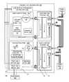
- FIG. 1illustrates an Information Handling System (IHS) 100 that includes liquid cooled (LC) nodes 102 a - 102 b and an immersion-cooled power node 102 c (collectively “nodes” 102 ).
- the LC nodes 102 a - 102 bare respectively received in node-receiving chasses 104 a - 104 b each having a front access side and an opposing rear side.
- a node enclosure 110 of each LC node 102 a - 102 bis provisioned with heat-generating component/s 112 and an internal node-level LC system 114 of conduits.
- the LC system 114includes node supply conduit/s 116 connected for fluid transfer to supply conduit intake port/s 118 .
- the LC system 114includes node return conduit/s 120 connected for fluid transfer to return conduit output port/s 122 .
- the supply conduit intake and return conduit output ports 118 , 122are located at an inserted end of the node enclosure 110 and are oriented toward the opposing rear side of the node-receiving chassis 104 a - 104 b respectively.
- the supply conduit intake and return conduit output ports 118 , 122respectively enable receipt of a first cooling liquid 123 at a first temperature and return of the first cooling liquid 123 at an increased temperature due to heat absorption within the node enclosure 110 .
- a liquid-to-liquid heat exchanger (LTLHE) 120is positioned towards the rear side of each node-receiving chassis 104 a - 104 b.
- Each LTLHE 120includes node-receiving supply port/s 124 and node-receiving return port/s 125 that are oriented facing the opposing rear side of the chassis 104 a - 104 b to enable sealed engagement, for first cooling liquid transfer, to the supply conduit intake port/s 116 and from the return conduit output port/s 118 of the respective LC node 102 a - 102 b .
- a first liquid manifold 126extends between the node-receiving supply port/s 124 and the node-receiving return port/s 118 .
- the first liquid manifold 126is engageably in sealed fluid connection to the intake and output ports 118 , 122 of the node-level LC system 114 of conduits to provide a first liquid cooling loop for continuous flow of the first liquid through the at least one LC node 102 a - 102 b and through the first liquid manifold 126 .
- a second liquid manifold 128is capable of being in sealed fluid connection to a supply conduit 130 and a return conduit 132 of a liquid cooling supply, such as a facility liquid supply 134 and a facility liquid return 136 , for fluid transfer of a second cooling liquid 137 .
- a transfer plate 138is formed of thermally conductive material. The transfer plate 138 separates the first and second liquid manifolds 126 , 128 for transferring heat from the first cooling liquid to the second cooling liquid 137 .
- nodes 102are received in a block chasses 104 a - 104 b that are mounted to, or that is integral to, a rack 139 .
- a dynamic control valve 140can dynamically regulate liquid flow through the second liquid manifold 128 of the LTLHE 120 .
- a fluid mover 142such as a pump on a cold plate, can dynamically regulate liquid flow through the first liquid manifold 126 .
- Sensor/s 144that detect intake, internal or exhausted temperatures, moisture levels, or liquid pressure are positioned to detect a temperature within the nodes 102 .
- a liquid infrastructure management controller (LIMC) 146is in communication with the sensor/s 144 and the dynamic control valve 140 to control an amount of liquid flow in response to the temperature detected by the sensor/s 144 .
- a check valve 148can prevent backflow into the second liquid manifold 128 .
- the power node 102 chas a power node enclosure 150 sealed to contain immersion cooling liquid/s 152 , such as a dielectric liquid, and immersion cooling liquid vapor 154 .
- the power node enclosure 150is provisioned with heat generating component/s 112 that include redundant AC-to-DC power supply modules 156 .
- the redundant AC-to-DC power supply modules 156has a power node inlet port 158 that receives AC electrical power from a power source 160 , such as a facility electrical circuit.
- the redundant AC-to-DC power supply modules 156has power distribution outlet port/s 161 that distributes DC electrical power for use by other nodes 102 a - 102 b within the IHS 100 .
- the power node 102 cincludes a liquid-to-liquid heat transfer mechanism 162 that has a first surface 164 that is impinged upon by a volume of the immersion cooling liquid/s 152 and immersion cooling liquid vapor 154 and a second surface 166 that receives a flow of a second cooling liquid 137 , such as facility water, via a liquid manifold 170 .
- the liquid manifold 170provides a system 171 of conduits that is sealably engaged to the supply and return conduits 130 , 132 of the liquid cooling supply provided by facility liquid supply and return 134 , 136 .
- the liquid manifold 170enables a flow of the second cooling liquid 137 to absorb heat from the power node enclosure 150 .
- the second liquid manifold 128 of the LTLHE 120 and the liquid manifold 170 of the liquid-to-liquid heat transfer mechanism 162 of the power node 102 ceach include a supply bypass tube 172 terminating in the two supply connections 174 and a return bypass tube 176 terminating in two return connections 178 .
- the dynamic control valve 140directs a portion of the second cooling liquid 137 from the supply bypass tube 172 to the node-receiving input port/s 125 .
- the check valve 148allows forward flow only of the cooling liquid that has absorbed heat from the heat-generating component/s 112 from the node 102 back to return bypass tube 176 .
- the supply and return conduits 130 , 132can be Modular Liquid Distribution (MLD) conduits 180 to connect in succession respectively the supply bypass tubes 172 , 176 to form a liquid rail 182 .
- MLDModular Liquid Distribution
- a liquid railcan include a series of secondary conduits, such as supply divert conduit and return divert conduit that provides a by-pass fluid path for each of MLD conduits 180 .
- divert conduit/sallow for the removal of corresponding MLD conduit 180 , thus removing the flow of cooling liquid to the particular block of nodes, without interrupting the flow of cooling liquid to the other surrounding blocks of computer gear.
- a particular MLD conduit 180can be replaced due to a leak.
- a block liquid manifold 128can be replaced. The inclusion of divert conduits thus enables rapid servicing and maintenance of block liquid manifold 128 and/or nodes within block chassis without having to reconfigure the MLD conduits 180 .
- the IHS 100can continue operating as cooling liquid continues to be provided to the remainder of the blocks that are plugged into the liquid rail.
- Re-insertion of the MLD conduit 180then reconnects the flow of cooling liquid to the block for normal cooling operations, and shuts off the diverted flow of cooling liquid.
- the MLD conduits 180provide a quick disconnect feature that interrupts flow when not fully engaged to a respective ports. Disconnection of an MLD conduit 180 interrupts flow in a primary portion of the liquid rail for either supply or return, shifting flow through one or more divert conduits to provide cooling liquid to the other block liquid manifolds 120 .
- a manual or active shutoff valvecan interrupt flow on either or both of the primary or divert portions of the liquid rail.
- FIG. 2depicts an example IHS 200 having components an LC power node 202 b inserted into the node-receiving chassis 104 b .
- Liquid coolingis provided by an LTLHE 120 rather than being integral to a power node enclosure 250 .
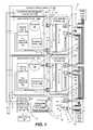
- FIG. 3depicts an example RIHS 300 having illustrative example of LC nodes 302 a - 302 j (collectively refer to as nodes 302 ), with each nodes 302 a - 302 i having a node enclosure 304 provisioned with heat-generating components 306 .
- RIHS 300includes a power node 302 i that is also liquid cooled. Additionally, RIHS 300 also includes an infrastructure node 302 j and liquid filtration node 302 k , which do not necessarily include heat-generating components 306 that require liquid cooling, as the other LC nodes 302 a - 302 i .
- a Direct-Interface Liquid Cooling (DL) subsystem(generally shown as being within the RIHS 300 and labelled herein as 308 ) can be utilized for cooling the nodes 302 via an internal node-level system 309 of conduits.
- nodes 302 a - 302 dreceive cooling liquid from a DL subsystem 308 via block liquid manifolds (BLM) 310 that are received in a rear section of a rack 312 .
- BLMblock liquid manifolds
- LC nodes 302 a - 302 dinclude other components 314 that are not necessarily heat generating, but which are exposed to the same ambient heat conditions as the heat-generating components 306 by virtue of their location within the node enclosure 304 .
- these other components 314can be sufficiently cooled by the direct-interface liquid cooling methodology applied to the node 302 a - 302 d and/or using forced or convective air movement, as described later herein.
- Each node 302is supported and protected by a respective node enclosure 304 .
- Nodes 302 a - 302 dare further received in node receiving bays 316 of a first block chassis 319 a of a first block 320 a .
- Nodes 302 e - 302 hare received in a second block chassis 319 b of a second block 320 b .
- Blocks 320 a - 320 bare collectively referred to as blocks 320 .
- the nodes 302are vertically arranged. In one or more alternate embodiments, at least portions of the nodes 302 (and potentially all of the nodes) may also be arranged horizontally while benefiting from aspects of the present innovation.
- LC nodes 302 e - 302 ireceive secondary cooling liquid from the DL subsystem 308 via a corresponding LTLHE 318 according to aspects of the present disclosure.
- LC nodes 302 e - 302 hare connected to a liquid rail 324 of the RIHS 300 by MLD conduits 328 .
- LC nodes 302 e - 302 iinclude a fluid mover 330 to recirculate the first cooling liquid through the respective LTLHE 318 .
- the power node 302 ihas heat-generating components such as redundant AC-DC power supply modules 306 a that are immersed for cooling in a dielectric liquid.
- the AC-DC power supply modules 306 areceive AC power via a power node inlet port 334 from a power source 336 .
- the AC-DC power supply modules 306 adistributes DC power via a power node outlet port 338 over rack electrical distribution components 340 to other nodes 302 a - 302 i , 302 j - 302 k .
- the dielectric liquidis liquid cooled by cooling liquid from the DL subsystem 308 via a liquid-to-liquid heat exchanger (LTLHE) 342 .
- LTLHEliquid-to-liquid heat exchanger
- nodes 302can be of different physical heights of form factors (e.g., 3U, 3.5U, 2U), and the described features can also be applied to nodes 302 having different widths and depths (into the rack), with some extensions made and/or lateral modifications to the placement of cooling subsystem conduits, as needed to accommodate the different physical dimensions.
- form factorse.g., 3U, 3.5U, 2U
- power node 302 iis depicted as having a larger node enclosure 304 a (with corresponding different dimensions of AC-DC power supply modules 306 a ) of a different number of rack units in physical height (e.g., 2U) that differs from the heights (e.g., 3U) of the other nodes 302 a - 102 h and 302 j - 302 k .
- RIHS 300can include blocks 320 or nodes 302 selectably of a range of discrete rack units.
- different types of Information Technology (IT) componentscan be provided within each node 302 , with each node possibly performing different functions within RIHS 300 .
- ITInformation Technology
- a given node 302may include one of a server module, a power module, a control module, or a storage module.
- the nodes 302can be individual nodes operating independent of each other, with the RIHS 300 including at least one rack-level controller (RC) 342 for controlling operational conditions within the RIHS 300 , such as temperature, power consumption, communication, and the like.
- RCrack-level controller
- Each node 302is then equipped with a node-level controller (NC) 344 that communicates with the rack-level controller 342 to provide localized control of the operational conditions of the node 302 .
- NCnode-level controller
- RIHS 300also includes block-level controllers (BCs) 346 , communicatively coupled to the rack-level controller 342 and performing block-level control functions for the LC nodes 302 within the specific block 320 .
- the nodes 302are arranged into blocks 320 , with each block 320 having one or more nodes 302 and a corresponding block-level controller 346 .
- the blocks 320do not necessarily include the same number of nodes 302 , and a block 320 can include a single node 302 , in some implementations.
- DL subsystem 308provides direct-interface liquid cooling to heat-generating components 306 via a liquid rail 324 under the control of the rack-level controller 342 , block-level controllers 346 , and/or node-level controllers 344 , in some embodiments.
- Rack-level controller 342controls a supply valve 350 , such as a solenoid valve, to allow cooling liquid, such as water, to be received from a facility liquid supply 352 .
- the cooling liquidis received from facility liquid supply 352 and is passed through liquid filtration node 302 k before being passed through supply conduit 354 of liquid rail 324 .
- Each block 320 a , 320 breceives a dynamically controlled amount of the cooling liquid via block-level dynamic control valve 356 , such as a proportional valve. Return flow from each block 320 a , 320 b can be protected from backflow by block-level check valve 333 .
- the individual needs of the respective nodes 302 a - 302 d of block 320 acan be dynamically provided by respective node-level dynamic control valves 358 , controlled by the block-level controller 346 , which control can, in some embodiments, be facilitated by the node-level controllers 344 .
- each of the supply valve 350 and/or dynamic control valves 356 , 358can be individually closed to mitigate a leak.
- a check valve 360is provided between each node 302 a - 302 h and 302 j and a return conduit 362 of the liquid rail 324 to prevent a backflow into the nodes 302 a - 302 h and 302 j .
- the return conduit 362returns the cooling liquid to a facility liquid return 364 .
- RIHS 300includes temperature sensors 366 that are each located within or proximate to each node 302 a - 302 k , with each temperature sensor 366 connected to the node-level controller 344 and/or the corresponding block-level controller 346 . Temperature sensors 366 operate in a feedback control loop of the DL subsystem 308 to control the amount of liquid flow required to cool the nodes 302 a - 302 h and 302 j .
- the rack-level controller 342can coordinate performance constraints to block-level controllers 346 and/or node-level controllers 344 that limit an amount of heat generated by the heat-generating components 306 to match a heat capacity of the flow of cooling liquid in DL subsystem 308 .
- the rack-level controller 342can coordinate cooling levels to block-level controllers 346 and/or node-level controllers 344 that in turn control the dynamic control valves 356 , 358 for absorption and transfer of the heat generated by the heat-generating components 306 by the DL subsystem 308 .
- support controllerssuch as an LIMC 368 can perform management and operational testing of DL subsystem 308 .
- LIMC 368can monitor pressure sensors 370 and liquid sensors 373 to detect a leak, to validate operation of a dynamic control valves 356 , 358 or shutoff valves such as supply valve 350 . LIMC 368 can perform close-loop control of specific flow rates within the RIHS 300 .
- Temperature monitoring controlsare provided to ensure that sufficient volume and flow rate of cooling liquid are provided to properly cool any exhaust air and maintain node 302 at a desired operating temperature (or within a desired operating temperature range).
- the temperature and volume of cooling liquid from the facility liquid supply 350is determined based on measurements and testing and/or empirical calculations to provide adequate cooling for the operational requirements of the RIHS 300 .
- at least the volume of the cooling liquidis dynamically controlled to more closely approximate the cooling requirements of RIHS 300 and/or at least any air-cooled node 302 j at a given time.
- a first temperature sensor 366 ais positioned to detect an air temperature of a selected one of an air intake and air exhaust of a node 302 .
- Second temperature sensor 366 bis positioned to detect an air temperature within the node 302 .
- LIMC 368is in communication with first and second temperature sensors 366 a , 366 b and with dynamic control valve 356 and LIMC 368 can dynamically adjust a volume of cooling liquid based at least in part on a difference between the detected air temperatures.
- LIMC 368is coupled to and receives the detected temperature readings from a node controller and/or a block controller that in turn is coupled to first temperature sensor 366 a and second temperature sensor 366 b .
- LIMC 368 and/or one of the other controllersgenerates a control signal that is sent to a pulse width modulation (PWM) circuit (not shown), which is coupled to dynamic control valve 356 .
- PWMpulse width modulation
- PWM circuitIn response to receipt of the control signal, PWM circuit in turn generates a PWM signal that can control the open position of dynamic control valve 356 .
- the PWM signaladjusts the open position of dynamic control valve 356 , and the open position of the valve determines (and can be used to regulate) the amount (or rate) of cooling liquid that flows through dynamic control valve 356 .
- LIMC 368triggers a specific value of the PWM signal based on a rack level determination that can include consideration of available (un-allocated or reclaimed) volume of liquid flow across the RIHS 300 and other factors.
- LTLHE 318can be configured as a single node LTLHE or a block level LTLHE supporting multiple adjacent nodes within a block chassis 319 of RIHS 300 , and the flow control aspects described as being provided by LIMC 368 can also be provided by a block level controller, in one or more embodiments. Additional control features associated with the allocation of liquid flow to LTLHE 318 are provided in related patent applications No. 15/017,604, filed Feb. 6, 2016 and No. 15/017,451, filed Feb. 5, 2016, whose content are incorporated herein by reference.
- FIGS. 4-5illustrate a DL RIHS 400 that receives LC nodes 402 ( FIG. 4 ) from a front side 404 of a rack 406 having a rack enclosure 408 formed in part by a top panel 410 ( FIG. 5 ), side panels 412 , and a bottom panel (not shown).
- FIG. 5illustrates a rear section 414 of the rack enclosure 408 that is accessible via a louvered door 416 .
- LTLHE 418 and block liquid manifolds 420support respective node-receiving bays 422 .
- Modular Liquid Distribution (MLD) conduits 424form a supply conduit 426 and a return conduit 428 of a liquid rail 430 .
- MLDModular Liquid Distribution
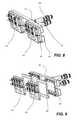
- FIGS. 6-7illustrate an example block 600 of LC nodes 602 that are sealingly engaged to a LTLHE 604 .
- FIGS. 6-10illustrate that the LTLHE 604 includes a first liquid manifold 606 , a transfer plate 608 , and a second liquid manifold 610
- a liquid rail 612include supply and return conduits 614 , 616 that linearly attach to each other. Centerline supply and return hose connections 618 , 620 of the supply and return conduits 614 , 616 attach to supply and return connections 622 , 624 of the LTLHE 604 .
- FIG. 11illustrates a method 1100 of assembling an RIHS that utilizes LTLHEs to cool LC nodes.
- the method 1100includes assembling the LTLHE that includes at least one node-receiving supply port and at least one node-receiving return port.
- the LTLHEincludes a first liquid manifold extending between the at least one node-receiving supply port and the at least one node-receiving return port.
- the LTLHEincludes a second liquid manifold capable of being in sealed fluid connection to a supply conduit and a return conduit of a liquid cooling supply for fluid transfer of a second cooling liquid.
- the LTLHEincludes a transfer plate formed of thermally conductive material separating the first and second liquid manifolds for transferring heat from the first cooling liquid to the second cooling liquid (block 1102 ).
- the methoda flow diagram of a method of assembling a DL RIHS, according to one or more embodiments 1100 includes mounting in a rack a node-receiving chassis having a front access side and an opposing rear side (block 1104 ).
- the method 1100includes attaching in a rear section of the rack the LTLHE (block 1106 ).
- the method 1100includes provisioning a node enclosure of at least one LC node with at least one heat-generating component (block 1108 ).
- the method 1100includes attaching an internal node-level liquid cooling system of conduits to the node enclosure.
- the systemincludes at least one node supply conduit connected for fluid transfer to at least one supply conduit intake port and at least one node return conduit connected for fluid transfer to at least one return conduit output port (block 1110 ).
- the method 1100includes inserting the at least one LC node into a bay of the node-receiving chassis (block 1112 ).
- the method 1100includes sealingly engaging at least one supply conduit intake and return conduit output ports located at an inserted end of the node enclosure and oriented toward the opposing rear side of the node-receiving chassis to the LTLHE (block 1114 ). The sealing engagement enables receipt of a first cooling liquid at a first temperature and return of the first cooling liquid at an increased temperature due to heat absorption within the node enclosure. Then method 1100 ends.
- FIG. 12illustrates method 1200 of assembling an RIHS that utilized an immersion-cooled power node.
- the method 1200includes inserting one or more nodes containing electrical power consuming components into one or node-receiving bays of a rack (block 1202 ).
- the method 1200includes inserting into the rack a power node having a power node enclosure sealed to contain immersion cooling liquid and provisioned with at least one heat generating component (block 1204 ).
- the method 1200includes electrically connecting to rack electrical power distribution components a power node inlet port and at least one power distribution outlet port of the power node that respectively receives facility power and distributes power to the internal IHS components (block 1206 ).
- the method 1200includes sealingly engaging for fluid transfer at least one liquid to liquid heat transfer mechanism having a first surface that is impinged upon by a volume of at least one of the immersion cooling liquid and immersion cooling liquid vapor.
- the at least one liquid to liquid heat transfer mechanismhaving a second surface that receives a flow of a second cooling liquid via a liquid manifold.
- the liquid manifoldprovides a system of conduits that is sealably engaged to the supply and return conduits of the liquid cooling supply to enable a flow of the second cooling liquid manifold to absorb heat from the power node enclosure (block 1208 ). Then method 1200 ends.
- the methodsmay be embodied in an automated manufacturing system that performs a series of functional processes. In some implementations, certain steps of the method are combined, performed simultaneously or in a different order, or perhaps omitted, without deviating from the scope of the disclosure.
- the method blocksare described and illustrated in a particular sequence, use of a specific sequence of functional processes represented by the blocks is not meant to imply any limitations on the disclosure. Changes may be made with regards to the sequence of processes without departing from the scope of the present disclosure. Use of a particular sequence is therefore, not to be taken in a limiting sense, and the scope of the present disclosure is defined only by the appended claims.
- RIHSreceives high voltage AC (VAC) that is power converted down to a 12 volt DC (VDC) power by Power Supply Units (PSUs) within a Power Distribution Unit (PDU).
- the PSUsbridges the data center supply power to the type of power required by IT equipment within the RIHS. This power conversion creates a tremendous amount of heat.
- the amount of power that can be supplied by a Power Supply Unit (PSU)is limited by its ability to be cooled.
- Today, Direct Current Supply (DCS)is limited to 2000 W maximum power from each PSU.
- RIHSesinclude PSUs that are mounted to a rack in a server bay.
- a generally-known RIHScan include 400V/240 VAC 3-phase data center input power strip. A particular outlet of the power strip provides 240 VAC 1-phase Power Distribution Unit (PDU) power output via electrical power cables to one server PSU of three server PSUs inserted in PSU bays of a server-sized PSU chassis.
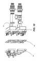
- FIG. 13illustrates an immersion PDU 1300 having a PDU chassis 1302 that is rack-unit dimensioned to be received in a server slot or bay of the RIHS 400 ( FIG. 4 ).
- FIG. 14illustrates immersion PDU 1300 having liquid cooling and electrical interfaces on a back side 1304 of PDU chassis 1302 .
- Liquid cooling interfacesinclude left and right liquid supply connections 1306 , 1308 with a bypass feature.
- Liquid cooling interfacesinclude left and right liquid return connections 1310 , 1312 with a bypass feature.
- Electrical interfacesinclude three-phase (x, y, z) circuit breakers 1314 , an electrical cable 1316 that provides data center input power (e.g., 480 VAC), and positive and negative direct current (DC) bus bars 1318 , 1320 that provide server output power (e.g., 12 VDC) that can be distributed to multiple servers (i.e., functional nodes requiring power) of the RIHS 400 ( FIG. 4 ).
- FIG. 15illustrates that the PDU chassis 1302 forms a sealed enclosure that contains a dielectric liquid 1322 .
- the dielectric liquidcan be water and/or can be oil or some other liquid that is able to absorb a large amount of heat and quickly release that heat to a cooling source, such as a condenser or radiator.
- the cooling liquid received from the liquid supply connections 1306 , 1308is kept separate from the dielectric liquid.
- the cooling liquidis directed through supply conduits 1323 to pass through a radiator 1324 that absorbs and removes heat from the dielectric liquid 1322 .
- the warmed cooling liquidis directed from the radiator 1324 through return conduits 1326 to the liquid return connections 1310 , 1312 .
- FIGS. 16-18illustrate examples in which immersion PDU 1300 supports eighteen ( 18 ) server PSUs 1328 that are immersed in the dielectric liquid 1322 within the PDU chassis 1302 .
- the dielectric liquid 1322is electrically non-conductive and can have roughly one thousand times the cooling capacity per unit of volume than air.
- each server PSU 1328converts 240 VAC to 12 VDC used by functional computing components in the RIHS. With the cooling benefit of the immersion PDU 1300 , each server PSU 1328 can operate at 3000 W for a total of 54,000 Watts maximum DC power output in the same volumetric footprint as generally-known PSUs without immersion cooling.
- FIG. 18illustrates thermal flow within the immersive PDU 1300 .
- the process of heat removalcan involve single phase heat transfer (i.e., dielectric liquid to cooling liquid) or dual phase heat transfer (i.e., liquid to gas and back to liquid).
- single phase heat transferi.e., dielectric liquid to cooling liquid
- dual phase heat transferi.e., liquid to gas and back to liquid
- the enclosureis passive, requiring no pumps or fans.
- One or more of the embodiments of the disclosure describedcan be implementable, at least in part, using a software-controlled programmable processing device, such as a microprocessor, digital signal processor or other processing device, data processing apparatus or system.
- a computer program for configuring a programmable device, apparatus or system to implement the foregoing described methodsis envisaged as an aspect of the present disclosure.
- the computer programmay be embodied as source code or undergo compilation for implementation on a processing device, apparatus, or system.
- the computer programis stored on a carrier device in machine or device readable form, for example in solid-state memory, magnetic memory such as disk or tape, optically or magneto-optically readable memory such as compact disk or digital versatile disk, flash memory, etc.
- the processing device, apparatus or systemutilizes the program or a part thereof to configure the processing device, apparatus, or system for operation.
Landscapes
- Engineering & Computer Science (AREA)
- Physics & Mathematics (AREA)
- Theoretical Computer Science (AREA)
- Human Computer Interaction (AREA)
- General Physics & Mathematics (AREA)
- General Engineering & Computer Science (AREA)
- Microelectronics & Electronic Packaging (AREA)
- Thermal Sciences (AREA)
- Manufacturing & Machinery (AREA)
- Automation & Control Theory (AREA)
- Computer Hardware Design (AREA)
- Cooling Or The Like Of Electrical Apparatus (AREA)
Abstract
Description
Claims (19)
Priority Applications (2)
| Application Number | Priority Date | Filing Date | Title |
|---|---|---|---|
| US15/016,234US10156873B2 (en) | 2015-12-21 | 2016-02-04 | Information handling system having fluid manifold with embedded heat exchanger system |
| PCT/US2016/043077WO2017135992A1 (en) | 2015-12-21 | 2016-07-20 | Information handling system having fluid manifold with embedded heat exchanger system |
Applications Claiming Priority (3)
| Application Number | Priority Date | Filing Date | Title |
|---|---|---|---|
| US201562270563P | 2015-12-21 | 2015-12-21 | |
| US201562270564P | 2015-12-21 | 2015-12-21 | |
| US15/016,234US10156873B2 (en) | 2015-12-21 | 2016-02-04 | Information handling system having fluid manifold with embedded heat exchanger system |
Publications (2)
| Publication Number | Publication Date |
|---|---|
| US20170177041A1 US20170177041A1 (en) | 2017-06-22 |
| US10156873B2true US10156873B2 (en) | 2018-12-18 |
Family
ID=59066071
Family Applications (1)
| Application Number | Title | Priority Date | Filing Date |
|---|---|---|---|
| US15/016,234Active2036-12-29US10156873B2 (en) | 2015-12-21 | 2016-02-04 | Information handling system having fluid manifold with embedded heat exchanger system |
Country Status (2)
| Country | Link |
|---|---|
| US (1) | US10156873B2 (en) |
| WO (1) | WO2017135992A1 (en) |
Cited By (14)
| Publication number | Priority date | Publication date | Assignee | Title |
|---|---|---|---|---|
| US11212942B2 (en) | 2019-08-26 | 2021-12-28 | Ovh | Cooling arrangement for autonomous cooling of a rack |
| US20220361365A1 (en)* | 2021-05-06 | 2022-11-10 | Tyco Fire & Security Gmbh | Electrical power distribution optimized liquid immersion cooling tank with variable flow for high density computer server equipment |
| US20230041910A1 (en)* | 2019-12-05 | 2023-02-09 | Provides Metalmeccanica S.R.L. | Cooling system of electronic systems, in particular for data centre |
| US11729950B2 (en) | 2021-04-01 | 2023-08-15 | Ovh | Immersion cooling system with dual dielectric cooling liquid circulation |
| US11800683B2 (en) | 2021-02-17 | 2023-10-24 | Sunonwealth Electric Machine Industry Co., Ltd. | Immersion cooling system |
| US11877428B2 (en) | 2021-04-20 | 2024-01-16 | Dell Products L.P. | Modular horizontal rack manifold for liquid cooling |
| US20240023276A1 (en)* | 2022-07-13 | 2024-01-18 | Dell Products, L.P. | Rack-based management of leaks in liquid cooled information handling systems |
| US20240032241A1 (en)* | 2022-07-20 | 2024-01-25 | Dell Products, L.P. | Liquid Cooling Manifold for Information Technology Equipment |
| US11924998B2 (en) | 2021-04-01 | 2024-03-05 | Ovh | Hybrid immersion cooling system for rack-mounted electronic assemblies |
| US20240334646A1 (en)* | 2023-03-29 | 2024-10-03 | Fulian Precision Electronics (Tianjin) Co., Ltd. | Immersed cooling system and immersed cooling cabinet |
| US12120846B2 (en) | 2021-04-01 | 2024-10-15 | Ovh | Immersion cooling systems for electronic components |
| US12137536B2 (en) | 2021-04-01 | 2024-11-05 | Ovh | Systems and methods for autonomously activable redundant cooling of a heat generating component |
| US12144145B2 (en) | 2021-04-01 | 2024-11-12 | Ovh | Data center rack system with integrated liquid and dielectric immersion cooling |
| US12363865B2 (en) | 2022-01-28 | 2025-07-15 | The Research Foundation For The State University Of New York | Regenerative preheater for phase change cooling applications |
Families Citing this family (34)
| Publication number | Priority date | Publication date | Assignee | Title |
|---|---|---|---|---|
| US10448543B2 (en)* | 2015-05-04 | 2019-10-15 | Google Llc | Cooling electronic devices in a data center |
| GB201619987D0 (en) | 2016-11-25 | 2017-01-11 | Iceotope Ltd | Fluid cooling system |
| US10299413B2 (en)* | 2017-02-21 | 2019-05-21 | Baidu Usa Llc | Modular self-aligning liquid heat removal coupling system for electronic racks |
| CN111095541B (en) | 2017-09-06 | 2021-12-17 | 爱思欧托普集团有限公司 | Heat sink, heat sink device and module for liquid immersion cooling |
| CN107979955B (en)* | 2017-11-24 | 2020-06-30 | 北京百度网讯科技有限公司 | A modular liquid-cooled server chassis |
| US10765036B2 (en)* | 2017-12-22 | 2020-09-01 | Facebook, Inc. | Systems and devices for low-vibration cooling of storage drives |
| GB201804875D0 (en)* | 2018-03-27 | 2018-05-09 | Sec Dep For Foreign And Commonwealth Affairs | A power distribution assembly |
| US10667437B2 (en)* | 2018-04-12 | 2020-05-26 | Baidu Usa Llc | Liquid distribution unit design for liquid cooling of electronic racks of a data center |
| US10225958B1 (en)* | 2018-05-03 | 2019-03-05 | Baidu Usa Llc | Liquid cooling system for a data center |
| US10736240B2 (en)* | 2018-05-24 | 2020-08-04 | Baidu Usa Llc | High reliability cooling module design for IT and data center liquid cooling |
| US10925190B2 (en)* | 2018-06-04 | 2021-02-16 | Baidu Usa Llc | Leak detection and response system for liquid cooling of electronic racks of a data center |
| DK3588043T3 (en) | 2018-06-28 | 2020-08-31 | Ovh | FLUID CIRCUIT MONITORING SYSTEM |
| US11191185B2 (en)* | 2018-09-14 | 2021-11-30 | Cisco Technology, Inc. | Liquid cooling distribution in a modular electronic system |
| US10609839B1 (en)* | 2018-09-28 | 2020-03-31 | Liquidcool Solutions, Inc. | Liquid submersion cooled electronic systems and devices |
| CN109743869B (en)* | 2019-01-30 | 2020-04-14 | 全亿大科技(佛山)有限公司 | Liquid cooling radiator and server system |
| CN114667033A (en)* | 2019-03-14 | 2022-06-24 | 华为技术有限公司 | Heat dissipation method, heat dissipation device and cabinet |
| US11032949B2 (en)* | 2019-09-30 | 2021-06-08 | Baidu Usa Llc | Method for deploying liquid cooling solution in an air-cooled data center room |
| US11212943B2 (en) | 2020-02-21 | 2021-12-28 | Nvidia Corporation | Universal pluggable datacenter cooling system |
| EP4165309B1 (en) | 2020-06-10 | 2024-10-02 | General Electric Renovables España, S.L. | Multisiphon passive cooling system with liquid bridge |
| CN112051798B (en)* | 2020-08-17 | 2021-07-20 | 扬州大学 | A Computable and Reconfigurable Machine Tool Geometric Pose Error Definition Method |
| CN114138082A (en)* | 2020-09-03 | 2022-03-04 | 北京图森智途科技有限公司 | Cooling system and server system |
| TWI756925B (en)* | 2020-11-18 | 2022-03-01 | 緯創資通股份有限公司 | Coolant distribution device and electronic apparatus having the same |
| US20220236779A1 (en)* | 2021-01-22 | 2022-07-28 | Nvidia Corporation | Intelligent rear door heat exchanger for local cooling loops in a datacenter cooling system |
| CN214592559U (en)* | 2021-02-17 | 2021-11-02 | 建准电机工业股份有限公司 | Immersion Cooling System |
| US11895809B2 (en)* | 2021-05-12 | 2024-02-06 | Nvidia Corporation | Intelligent leak sensor system for datacenter cooling systems |
| US11849564B2 (en)* | 2021-06-22 | 2023-12-19 | Baidu Usa Llc | Server rack component for advanced fluid arrangement |
| US11729949B2 (en)* | 2021-06-23 | 2023-08-15 | Baidu Usa Llc | Disaggregated system architecture for immersion cooling |
| US11930617B2 (en)* | 2021-07-20 | 2024-03-12 | Dell Products, L.P. | Enhanced information handling system component immersion cooling via pump return connection |
| CN115877926A (en)* | 2021-09-23 | 2023-03-31 | 戴尔产品有限公司 | Serial Fluid Flow Loops in Liquid Assisted Air Cooling Thermal Control Systems |
| US12178020B2 (en)* | 2022-04-28 | 2024-12-24 | Baidu Usa Llc | Side fluid cooling apparatus for server racks |
| US12302541B2 (en)* | 2022-09-14 | 2025-05-13 | Hamilton Sundstrand Corporation | Stable pumped two-phase cooling |
| US20240237277A9 (en)* | 2022-10-24 | 2024-07-11 | Strategic Thermal Labs, Llc | Stacked-fin cold plate with a 3d vapor chamber |
| US12200912B2 (en)* | 2023-01-23 | 2025-01-14 | ZT Group Int'l, Inc. | Hybrid liquid cooling system for a computing rack |
| US20240284639A1 (en)* | 2023-02-22 | 2024-08-22 | Vertiv Corporation | Zero-U Coolant Distribution Unit |
Citations (69)
| Publication number | Priority date | Publication date | Assignee | Title |
|---|---|---|---|---|
| US5758607A (en) | 1995-05-26 | 1998-06-02 | Bayerische Motoren Werke Aktiengesellschaft | Cooling system having an electrically adjustable control element |
| US6462949B1 (en) | 2000-08-07 | 2002-10-08 | Thermotek, Inc. | Electronic enclosure cooling system |
| US6574104B2 (en) | 2001-10-05 | 2003-06-03 | Hewlett-Packard Development Company L.P. | Smart cooling of data centers |
| US6775137B2 (en) | 2002-11-25 | 2004-08-10 | International Business Machines Corporation | Method and apparatus for combined air and liquid cooling of stacked electronics components |
| US20040221604A1 (en) | 2003-02-14 | 2004-11-11 | Shigemi Ota | Liquid cooling system for a rack-mount server system |
| US20050122685A1 (en) | 2003-12-03 | 2005-06-09 | International Business Machines Corporation | Cooling system and method employing multiple dedicated coolant conditioning units for cooling multiple electronics subsystems |
| US20050248922A1 (en) | 2004-05-07 | 2005-11-10 | International Business Machines Corporation | Cooling assembly for electronics drawer using passive fluid loop and air-cooled cover |
| US7013955B2 (en) | 2003-07-28 | 2006-03-21 | Thermal Corp. | Flexible loop thermosyphon |
| US20080067805A1 (en) | 2004-06-01 | 2008-03-20 | Nissan Motor Co., Ltd. | Fluid coupling |
| US7403384B2 (en) | 2006-07-26 | 2008-07-22 | Dell Products L.P. | Thermal docking station for electronics |
| US20080232064A1 (en) | 2007-03-22 | 2008-09-25 | Fujitsu Limited | Cooling system for information device |
| US20080276639A1 (en) | 2007-05-10 | 2008-11-13 | Stoddard Robert J | Computer cooling system |
| US20090086432A1 (en) | 2007-09-27 | 2009-04-02 | International Business Machines Corporation | Docking station with closed loop airlfow path for facilitating cooling of an electronics rack |
| US20090086428A1 (en) | 2007-09-27 | 2009-04-02 | International Business Machines Corporation | Docking station with hybrid air and liquid cooling of an electronics rack |
| US20090126909A1 (en) | 2007-11-19 | 2009-05-21 | International Business Machines Corporation | System and method for facilitating cooling of a liquid-cooled electronics rack |
| US20090126910A1 (en) | 2007-11-19 | 2009-05-21 | International Businiess Machines Corporation | Apparatus and method for facilitating servicing of a liquid-cooled electronics rack |
| US20090154096A1 (en) | 2007-12-17 | 2009-06-18 | International Business Machines Corporation | Apparatus and method for facilitating cooling of an electronics system |
| US20090165868A1 (en) | 2007-12-31 | 2009-07-02 | Pearson Steven L | Automated condensate drain line cleaning system, method, and kit |
| US20090259343A1 (en) | 2006-01-19 | 2009-10-15 | American Power Conversion Corporation | Cooling system and method |
| US20090262501A1 (en) | 2008-04-21 | 2009-10-22 | International Business Machines Corporation | Rack With Integrated Rear-Door Heat Exchanger |
| US7657347B2 (en) | 2008-02-15 | 2010-02-02 | International Business Machines Corporation | Temperature-based monitoring method and system for determining first and second fluid flow rates through a heat exchanger |
| US20100032142A1 (en) | 2008-08-11 | 2010-02-11 | Sun Microsystems, Inc. | Liquid cooled rack with optimized air flow rate and liquid coolant flow |
| US20100103618A1 (en) | 2008-10-23 | 2010-04-29 | International Business Machines Corporation | Apparatus and method for facilitating pumped immersion-cooling of an electronic subsystem |
| US20100103614A1 (en) | 2008-10-23 | 2010-04-29 | International Business Machines Corporation | Apparatus and method for immersion-cooling of an electronic system utilizing coolant jet impingement and coolant wash flow |
| US20110060470A1 (en) | 2009-09-09 | 2011-03-10 | International Business Machines Corporation | Cooling system and method minimizing power consumption in cooling liquid-cooled electronics racks |
| US20110075373A1 (en) | 2009-09-28 | 2011-03-31 | International Business Machines Corporation | System and method for standby mode cooling of a liquid-cooled electronics rack |
| US20110083621A1 (en) | 2009-06-18 | 2011-04-14 | Cummins Ip, Inc. | Apparatus, System, and Method for Reductant Line Heating Control |
| US20110112694A1 (en) | 2008-06-30 | 2011-05-12 | Bash Cullen E | Cooling Medium Distribution Over A Network Of Passages |
| US7944694B2 (en)* | 2008-10-23 | 2011-05-17 | International Business Machines Corporation | Liquid cooling apparatus and method for cooling blades of an electronic system chassis |
| US7963119B2 (en) | 2007-11-26 | 2011-06-21 | International Business Machines Corporation | Hybrid air and liquid coolant conditioning unit for facilitating cooling of one or more electronics racks of a data center |
| US7990709B2 (en) | 2009-09-23 | 2011-08-02 | International Business Machines Corporation | Apparatus and method for facilitating cooling of an electronics rack |
| US20110313576A1 (en) | 2010-06-17 | 2011-12-22 | Mark Randal Nicewonger | System and method for flowing fluids through electronic chassis modules |
| US20120180979A1 (en) | 2010-04-19 | 2012-07-19 | Steve Harrington | Computer Cooling System And Method of Use |
| US8405975B2 (en) | 2011-01-11 | 2013-03-26 | Dell Products L.P. | Dual mode portable information handling system cooling |
| US8422218B2 (en) | 2007-04-16 | 2013-04-16 | Stephen Samuel Fried | Liquid cooled condensers for loop heat pipe like enclosure cooling |
| US20130098085A1 (en) | 2011-04-19 | 2013-04-25 | Liebert Corporation | High efficiency cooling system |
| US20130106265A1 (en) | 2011-10-28 | 2013-05-02 | Dell Products L.P. | System and Method for Cooling Information Handling Resources |
| US20130112378A1 (en) | 2011-11-04 | 2013-05-09 | Dell Products L.P. | System and Method for Cooling Information Handling Resources |
| US20130128455A1 (en) | 2011-11-17 | 2013-05-23 | Cisco Technology, Inc. | Environmental control for module housing electronic equipment racks |
| US8516284B2 (en) | 2010-11-04 | 2013-08-20 | International Business Machines Corporation | Saving power by placing inactive computing devices in optimized configuration corresponding to a specific constraint |
| US20130229769A1 (en) | 2012-03-05 | 2013-09-05 | Xu Yang | Data center container with draining mechanism |
| US20130264046A1 (en) | 2012-04-04 | 2013-10-10 | International Business Machines Corporation | Coolant and ambient temperature control for chillerless liquid cooled data centers |
| US8564951B1 (en) | 2012-09-07 | 2013-10-22 | Fujitsu Limited | Electronic apparatus and cooling module mounted in that electronic apparatus |
| US20130312854A1 (en) | 2012-05-25 | 2013-11-28 | Asetek A/S | Fluid connector for a cooling system |
| US20130312839A1 (en) | 2012-05-22 | 2013-11-28 | Dell Products L.P. | System and method for cooling information handling resources |
| US20130312846A1 (en) | 2012-05-25 | 2013-11-28 | André Sloth Eriksen | Fluid connector for a cooling system |
| US8749968B1 (en)* | 2010-08-26 | 2014-06-10 | Asetek A/S | Liquid cooling system for a server |
| US20140203550A1 (en) | 2013-01-18 | 2014-07-24 | Pfeiffer Vacuum Gmbh | Connection apparatus |
| US20140202678A1 (en) | 2013-01-21 | 2014-07-24 | International Business Machines Corporation | Multi-level redundant cooling system for continuous cooling of an electronic system(s) |
| US8797740B2 (en) | 2011-10-31 | 2014-08-05 | International Business Machines Corporation | Multi-rack assembly method with shared cooling unit |
| US20140218859A1 (en) | 2013-02-01 | 2014-08-07 | Dell Products L.P. | System for Cooling Hard Disk Drives Using Vapor Momentum Driven By Boiling of Dielectric Liquid |
| US8824143B2 (en) | 2011-10-12 | 2014-09-02 | International Business Machines Corporation | Combined power and cooling rack supporting an electronics rack(S) |
| US20140321056A1 (en) | 2011-12-01 | 2014-10-30 | Nec Corporation | Electronic substrate housing equipment and electric apparatus |
| US20140328562A1 (en) | 2013-05-02 | 2014-11-06 | Xyratex Technology Limited | Storage device, a storage or test system and a method of mounting a storage device |
| US8978401B2 (en) | 2012-07-18 | 2015-03-17 | International Business Machines Corporation | Data center cooling system |
| US20150109735A1 (en) | 2013-10-21 | 2015-04-23 | International Business Machines Corporation | Pump-enhanced, immersion-cooling of electronic component(s) |
| US9045995B2 (en) | 2011-05-09 | 2015-06-02 | International Business Machines Corporation | Electronics rack with liquid-coolant-driven, electricity-generating system |
| US9069532B2 (en) | 2011-07-25 | 2015-06-30 | International Business Machines Corporation | Valve controlled, node-level vapor condensation for two-phase heat sink(s) |
| US20150233597A1 (en) | 2013-12-17 | 2015-08-20 | Optimum Energy Llc | Systems and methods for fault detection using smart valves |
| US20150334878A1 (en) | 2012-12-18 | 2015-11-19 | Schneider Electric It Corporation | Cooling unit and method |
| US20160066480A1 (en) | 2014-08-29 | 2016-03-03 | International Business Machines Corporation | Blind docking apparatus to enable liquid cooling in compute nodes |
| US9386727B2 (en) | 2009-09-09 | 2016-07-05 | International Business Machines Corporation | Apparatus for adjusting coolant flow resistance through liquid-cooled electronics racks |
| US20160242326A1 (en) | 2015-02-12 | 2016-08-18 | International Business Machines Corporation | Cooling system with integrated fill and drain pump |
| US9451726B2 (en)* | 2012-09-25 | 2016-09-20 | Liquidcool Solutions, Inc. | Method and apparatus to manage coolant pressure and flow for an array of liquid submerged electronic devices |
| US9496200B2 (en) | 2011-07-27 | 2016-11-15 | Coolit Systems, Inc. | Modular heat-transfer systems |
| US20160366792A1 (en) | 2014-05-28 | 2016-12-15 | Hewlett Packard Enterprise Development Lp | Multiple tank cooling system |
| US20170049009A1 (en) | 2015-08-11 | 2017-02-16 | Lenovo Enterprise Solutions (Singapore) Pte. Ltd. | Coolant distribution unit for a multi-node chassis |
| US20170181323A1 (en) | 2015-12-21 | 2017-06-22 | Dell Products, L.P. | Rack information handling system having modular liquid distribution (mld) conduits |
| US20170181322A1 (en) | 2015-12-21 | 2017-06-22 | Dell Products, L.P. | Scalable rack-mount air-to-liquid heat exchanger |
Family Cites Families (5)
| Publication number | Priority date | Publication date | Assignee | Title |
|---|---|---|---|---|
| KR100447204B1 (en)* | 2002-08-22 | 2004-09-04 | 엘지전자 주식회사 | Multi-type air conditioner for cooling/heating the same time and method for controlling the same |
| US8351206B2 (en)* | 2010-06-29 | 2013-01-08 | International Business Machines Corporation | Liquid-cooled electronics rack with immersion-cooled electronic subsystems and vertically-mounted, vapor-condensing unit |
| US9043035B2 (en)* | 2011-11-29 | 2015-05-26 | International Business Machines Corporation | Dynamically limiting energy consumed by cooling apparatus |
| US9606588B2 (en)* | 2012-11-08 | 2017-03-28 | Silicon Graphics International Corp. | Closed-loop cooling system for high-density clustered computer system |
| US8964390B2 (en)* | 2012-11-08 | 2015-02-24 | International Business Machines Corporation | Sectioned manifolds facilitating pumped immersion-cooling of electronic components |
- 2016
- 2016-02-04USUS15/016,234patent/US10156873B2/enactiveActive
- 2016-07-20WOPCT/US2016/043077patent/WO2017135992A1/ennot_activeCeased
Patent Citations (78)
| Publication number | Priority date | Publication date | Assignee | Title |
|---|---|---|---|---|
| US5758607A (en) | 1995-05-26 | 1998-06-02 | Bayerische Motoren Werke Aktiengesellschaft | Cooling system having an electrically adjustable control element |
| US6462949B1 (en) | 2000-08-07 | 2002-10-08 | Thermotek, Inc. | Electronic enclosure cooling system |
| US6574104B2 (en) | 2001-10-05 | 2003-06-03 | Hewlett-Packard Development Company L.P. | Smart cooling of data centers |
| US6775137B2 (en) | 2002-11-25 | 2004-08-10 | International Business Machines Corporation | Method and apparatus for combined air and liquid cooling of stacked electronics components |
| US20040190247A1 (en) | 2002-11-25 | 2004-09-30 | International Business Machines Corporation | Method for combined air and liquid cooling of stacked electronics components |
| US20040221604A1 (en) | 2003-02-14 | 2004-11-11 | Shigemi Ota | Liquid cooling system for a rack-mount server system |
| US7013955B2 (en) | 2003-07-28 | 2006-03-21 | Thermal Corp. | Flexible loop thermosyphon |
| US20050122685A1 (en) | 2003-12-03 | 2005-06-09 | International Business Machines Corporation | Cooling system and method employing multiple dedicated coolant conditioning units for cooling multiple electronics subsystems |
| US7106590B2 (en) | 2003-12-03 | 2006-09-12 | International Business Machines Corporation | Cooling system and method employing multiple dedicated coolant conditioning units for cooling multiple electronics subsystems |
| US20050248922A1 (en) | 2004-05-07 | 2005-11-10 | International Business Machines Corporation | Cooling assembly for electronics drawer using passive fluid loop and air-cooled cover |
| US20080067805A1 (en) | 2004-06-01 | 2008-03-20 | Nissan Motor Co., Ltd. | Fluid coupling |
| US20090259343A1 (en) | 2006-01-19 | 2009-10-15 | American Power Conversion Corporation | Cooling system and method |
| US7403384B2 (en) | 2006-07-26 | 2008-07-22 | Dell Products L.P. | Thermal docking station for electronics |
| US20080232064A1 (en) | 2007-03-22 | 2008-09-25 | Fujitsu Limited | Cooling system for information device |
| US8422218B2 (en) | 2007-04-16 | 2013-04-16 | Stephen Samuel Fried | Liquid cooled condensers for loop heat pipe like enclosure cooling |
| US20080276639A1 (en) | 2007-05-10 | 2008-11-13 | Stoddard Robert J | Computer cooling system |
| US20090086432A1 (en) | 2007-09-27 | 2009-04-02 | International Business Machines Corporation | Docking station with closed loop airlfow path for facilitating cooling of an electronics rack |
| US20090086428A1 (en) | 2007-09-27 | 2009-04-02 | International Business Machines Corporation | Docking station with hybrid air and liquid cooling of an electronics rack |
| US20090126910A1 (en) | 2007-11-19 | 2009-05-21 | International Businiess Machines Corporation | Apparatus and method for facilitating servicing of a liquid-cooled electronics rack |
| US8387249B2 (en) | 2007-11-19 | 2013-03-05 | International Business Machines Corporation | Apparatus and method for facilitating servicing of a liquid-cooled electronics rack |
| US20090126909A1 (en) | 2007-11-19 | 2009-05-21 | International Business Machines Corporation | System and method for facilitating cooling of a liquid-cooled electronics rack |
| US7963119B2 (en) | 2007-11-26 | 2011-06-21 | International Business Machines Corporation | Hybrid air and liquid coolant conditioning unit for facilitating cooling of one or more electronics racks of a data center |
| US20090154096A1 (en) | 2007-12-17 | 2009-06-18 | International Business Machines Corporation | Apparatus and method for facilitating cooling of an electronics system |
| US20090165868A1 (en) | 2007-12-31 | 2009-07-02 | Pearson Steven L | Automated condensate drain line cleaning system, method, and kit |
| US7657347B2 (en) | 2008-02-15 | 2010-02-02 | International Business Machines Corporation | Temperature-based monitoring method and system for determining first and second fluid flow rates through a heat exchanger |
| US20090262501A1 (en) | 2008-04-21 | 2009-10-22 | International Business Machines Corporation | Rack With Integrated Rear-Door Heat Exchanger |
| US20110112694A1 (en) | 2008-06-30 | 2011-05-12 | Bash Cullen E | Cooling Medium Distribution Over A Network Of Passages |
| US20100032142A1 (en) | 2008-08-11 | 2010-02-11 | Sun Microsystems, Inc. | Liquid cooled rack with optimized air flow rate and liquid coolant flow |
| US20100103614A1 (en) | 2008-10-23 | 2010-04-29 | International Business Machines Corporation | Apparatus and method for immersion-cooling of an electronic system utilizing coolant jet impingement and coolant wash flow |
| US7944694B2 (en)* | 2008-10-23 | 2011-05-17 | International Business Machines Corporation | Liquid cooling apparatus and method for cooling blades of an electronic system chassis |
| US20100103618A1 (en) | 2008-10-23 | 2010-04-29 | International Business Machines Corporation | Apparatus and method for facilitating pumped immersion-cooling of an electronic subsystem |
| US20110083621A1 (en) | 2009-06-18 | 2011-04-14 | Cummins Ip, Inc. | Apparatus, System, and Method for Reductant Line Heating Control |
| US20110060470A1 (en) | 2009-09-09 | 2011-03-10 | International Business Machines Corporation | Cooling system and method minimizing power consumption in cooling liquid-cooled electronics racks |
| US9386727B2 (en) | 2009-09-09 | 2016-07-05 | International Business Machines Corporation | Apparatus for adjusting coolant flow resistance through liquid-cooled electronics racks |
| US8583290B2 (en) | 2009-09-09 | 2013-11-12 | International Business Machines Corporation | Cooling system and method minimizing power consumption in cooling liquid-cooled electronics racks |
| US7990709B2 (en) | 2009-09-23 | 2011-08-02 | International Business Machines Corporation | Apparatus and method for facilitating cooling of an electronics rack |
| US20110075373A1 (en) | 2009-09-28 | 2011-03-31 | International Business Machines Corporation | System and method for standby mode cooling of a liquid-cooled electronics rack |
| US20120180979A1 (en) | 2010-04-19 | 2012-07-19 | Steve Harrington | Computer Cooling System And Method of Use |
| US20110313576A1 (en) | 2010-06-17 | 2011-12-22 | Mark Randal Nicewonger | System and method for flowing fluids through electronic chassis modules |
| US8749968B1 (en)* | 2010-08-26 | 2014-06-10 | Asetek A/S | Liquid cooling system for a server |
| US8516284B2 (en) | 2010-11-04 | 2013-08-20 | International Business Machines Corporation | Saving power by placing inactive computing devices in optimized configuration corresponding to a specific constraint |
| US8405975B2 (en) | 2011-01-11 | 2013-03-26 | Dell Products L.P. | Dual mode portable information handling system cooling |
| US20130098085A1 (en) | 2011-04-19 | 2013-04-25 | Liebert Corporation | High efficiency cooling system |
| US9045995B2 (en) | 2011-05-09 | 2015-06-02 | International Business Machines Corporation | Electronics rack with liquid-coolant-driven, electricity-generating system |
| US9069532B2 (en) | 2011-07-25 | 2015-06-30 | International Business Machines Corporation | Valve controlled, node-level vapor condensation for two-phase heat sink(s) |
| US9496200B2 (en) | 2011-07-27 | 2016-11-15 | Coolit Systems, Inc. | Modular heat-transfer systems |
| US8824143B2 (en) | 2011-10-12 | 2014-09-02 | International Business Machines Corporation | Combined power and cooling rack supporting an electronics rack(S) |
| US8934244B2 (en) | 2011-10-28 | 2015-01-13 | Dell Products L.P. | System and method for cooling information handling resources |
| US20130106265A1 (en) | 2011-10-28 | 2013-05-02 | Dell Products L.P. | System and Method for Cooling Information Handling Resources |
| US8797740B2 (en) | 2011-10-31 | 2014-08-05 | International Business Machines Corporation | Multi-rack assembly method with shared cooling unit |
| US20130112378A1 (en) | 2011-11-04 | 2013-05-09 | Dell Products L.P. | System and Method for Cooling Information Handling Resources |
| US20130128455A1 (en) | 2011-11-17 | 2013-05-23 | Cisco Technology, Inc. | Environmental control for module housing electronic equipment racks |
| US8842433B2 (en) | 2011-11-17 | 2014-09-23 | Cisco Technology, Inc. | Environmental control for module housing electronic equipment racks |
| US20140321056A1 (en) | 2011-12-01 | 2014-10-30 | Nec Corporation | Electronic substrate housing equipment and electric apparatus |
| US20130229769A1 (en) | 2012-03-05 | 2013-09-05 | Xu Yang | Data center container with draining mechanism |
| US9250636B2 (en) | 2012-04-04 | 2016-02-02 | International Business Machines Corporation | Coolant and ambient temperature control for chillerless liquid cooled data centers |
| US20130264046A1 (en) | 2012-04-04 | 2013-10-10 | International Business Machines Corporation | Coolant and ambient temperature control for chillerless liquid cooled data centers |
| US20130312839A1 (en) | 2012-05-22 | 2013-11-28 | Dell Products L.P. | System and method for cooling information handling resources |
| US20130312846A1 (en) | 2012-05-25 | 2013-11-28 | André Sloth Eriksen | Fluid connector for a cooling system |
| US20130312854A1 (en) | 2012-05-25 | 2013-11-28 | Asetek A/S | Fluid connector for a cooling system |
| US8978401B2 (en) | 2012-07-18 | 2015-03-17 | International Business Machines Corporation | Data center cooling system |
| US8564951B1 (en) | 2012-09-07 | 2013-10-22 | Fujitsu Limited | Electronic apparatus and cooling module mounted in that electronic apparatus |
| US9451726B2 (en)* | 2012-09-25 | 2016-09-20 | Liquidcool Solutions, Inc. | Method and apparatus to manage coolant pressure and flow for an array of liquid submerged electronic devices |
| US20150334878A1 (en) | 2012-12-18 | 2015-11-19 | Schneider Electric It Corporation | Cooling unit and method |
| US20140203550A1 (en) | 2013-01-18 | 2014-07-24 | Pfeiffer Vacuum Gmbh | Connection apparatus |
| US20140202678A1 (en) | 2013-01-21 | 2014-07-24 | International Business Machines Corporation | Multi-level redundant cooling system for continuous cooling of an electronic system(s) |
| US20140218859A1 (en) | 2013-02-01 | 2014-08-07 | Dell Products L.P. | System for Cooling Hard Disk Drives Using Vapor Momentum Driven By Boiling of Dielectric Liquid |
| US20140328562A1 (en) | 2013-05-02 | 2014-11-06 | Xyratex Technology Limited | Storage device, a storage or test system and a method of mounting a storage device |
| US20150109735A1 (en) | 2013-10-21 | 2015-04-23 | International Business Machines Corporation | Pump-enhanced, immersion-cooling of electronic component(s) |
| US20150233597A1 (en) | 2013-12-17 | 2015-08-20 | Optimum Energy Llc | Systems and methods for fault detection using smart valves |
| US20160366792A1 (en) | 2014-05-28 | 2016-12-15 | Hewlett Packard Enterprise Development Lp | Multiple tank cooling system |
| US20160066480A1 (en) | 2014-08-29 | 2016-03-03 | International Business Machines Corporation | Blind docking apparatus to enable liquid cooling in compute nodes |
| US20160242326A1 (en) | 2015-02-12 | 2016-08-18 | International Business Machines Corporation | Cooling system with integrated fill and drain pump |
| US20160242319A1 (en) | 2015-02-12 | 2016-08-18 | International Business Machines Corporation | Cooling system with integrated fill and drain pump |
| US20170049009A1 (en) | 2015-08-11 | 2017-02-16 | Lenovo Enterprise Solutions (Singapore) Pte. Ltd. | Coolant distribution unit for a multi-node chassis |
| US20170181323A1 (en) | 2015-12-21 | 2017-06-22 | Dell Products, L.P. | Rack information handling system having modular liquid distribution (mld) conduits |
| US20170181322A1 (en) | 2015-12-21 | 2017-06-22 | Dell Products, L.P. | Scalable rack-mount air-to-liquid heat exchanger |
| US10010013B2 (en) | 2015-12-21 | 2018-06-26 | Dell Products, L.P. | Scalable rack-mount air-to-liquid heat exchanger |
Non-Patent Citations (15)
| Title |
|---|
| Ahmad, Yahya A., Non-Final Office Action, U.S. Appl. No. 15/016,226, The United States Patent and Trademark Office, dated Apr. 7, 2017. |
| Brown, Robert D., Non-Final Office Action, U.S. Appl. No. 15/698,642, The United States Patent and Trademark Office, dated May 24, 2018. |
| Brown, Robert D., Notice of Allowance, U.S. Appl. No. 15/017,582, The United States Patent and Trademark Office, dated Jun. 13, 2017. |
| Dravinikas, Adam, Final Office Action, U.S. Appl. No. 15/049,074, The United States Patent and Trademark Office, dated Apr. 27, 2018. |
| Dravininkas, Adam B., Non-Final Office Action, U.S. Appl. No. 15/016,249, The United States Patent and Trademark Office, dated Jun. 20, 2017. |
| Dravininkas, Adam B., Notice of Allowance, U.S. Appl. No. 15/016,249, The United States Patent and Trademark Office, dated Feb. 26, 2018. |
| Dravininkas, Adam B., Restriction Requirement, U.S. Appl. No. 15/049,074, The United States Patent and Trademark Office, dated Jul. 13, 2017. |
| Dravininkas, Adam, Ex Parte Quayle Action, U.S. Appl. No. 15/016,249, The United States Patent and Trademark Office, Oct. 24, 2017. |
| Dravininkas, Adam, Non-Final Office Action, U.S. Appl. No. 15/049,074, The United States Patent and Trademark Office, dated Nov. 14, 2017. |
| Patent Cooperation Treaty (PCT), International Preliminary Report on Patentability, International Application No. PCT/US2016/031379, dated Jun. 26, 2018. |
| Suryawanshi, Suresh, Non-Final Office Action, U.S. Appl. No. 15/017,451, The United States Patent and Trademark Office, dated Dec. 14, 2017. |
| Suryawanshi, Suresh, Non-Final Office Action, U.S. Appl. No. 15/017,492, The United States Patent and Trademark Office, dated Nov. 3, 2017. |
| Suryawanshi, Suresh, Non-Final Office Action, U.S. Appl. No. 15/017,604, The United States Patent and Trademark Office, dated Dec. 22, 2017. |
| Suryawanshi, Suresh, Notice of Allowance, U.S. Appl. No. 15/017,492, The United States Patent and Trademark Office, dated May 2, 2018. |
| Suryawanshi, Suresh, Notice of Allowance, U.S. Appl. No. 15/017,604, The United States Patent and Trademark Office, dated Jun. 6, 2018. |
Cited By (24)
| Publication number | Priority date | Publication date | Assignee | Title |
|---|---|---|---|---|
| US11212942B2 (en) | 2019-08-26 | 2021-12-28 | Ovh | Cooling arrangement for autonomous cooling of a rack |
| US20230041910A1 (en)* | 2019-12-05 | 2023-02-09 | Provides Metalmeccanica S.R.L. | Cooling system of electronic systems, in particular for data centre |
| US11871546B2 (en)* | 2019-12-05 | 2024-01-09 | Wieland Provides SRL | Cooling system of electronic systems, in particular for data centre |
| US11800683B2 (en) | 2021-02-17 | 2023-10-24 | Sunonwealth Electric Machine Industry Co., Ltd. | Immersion cooling system |
| US12120846B2 (en) | 2021-04-01 | 2024-10-15 | Ovh | Immersion cooling systems for electronic components |
| US12137536B2 (en) | 2021-04-01 | 2024-11-05 | Ovh | Systems and methods for autonomously activable redundant cooling of a heat generating component |
| US12167568B2 (en) | 2021-04-01 | 2024-12-10 | Ovh | Rack system for housing at least one immersion case |
| US12156370B2 (en) | 2021-04-01 | 2024-11-26 | Ovh | Rack system for housing an electronic device |
| US12144145B2 (en) | 2021-04-01 | 2024-11-12 | Ovh | Data center rack system with integrated liquid and dielectric immersion cooling |
| US12200901B2 (en) | 2021-04-01 | 2025-01-14 | Ovh | Method and extraction system for extracting an electronic device from an immersive cooling container |
| US11924998B2 (en) | 2021-04-01 | 2024-03-05 | Ovh | Hybrid immersion cooling system for rack-mounted electronic assemblies |
| US12309965B2 (en) | 2021-04-01 | 2025-05-20 | Ovh | Liquid cooling device mounted on a heat generating electronic component |
| US11729950B2 (en) | 2021-04-01 | 2023-08-15 | Ovh | Immersion cooling system with dual dielectric cooling liquid circulation |
| US11877428B2 (en) | 2021-04-20 | 2024-01-16 | Dell Products L.P. | Modular horizontal rack manifold for liquid cooling |
| US20220361365A1 (en)* | 2021-05-06 | 2022-11-10 | Tyco Fire & Security Gmbh | Electrical power distribution optimized liquid immersion cooling tank with variable flow for high density computer server equipment |
| US12336137B2 (en) | 2021-05-06 | 2025-06-17 | Tyco Fire & Security Gmbh | Electrical power distribution optimized liquid immersion cooling tank with variable flow for high density computer server equipment |
| US11678462B2 (en)* | 2021-05-06 | 2023-06-13 | Tyco Fire & Security Gmbh | Electrical power distribution optimized liquid immersion cooling tank with variable flow for high density computer server equipment |
| US12363865B2 (en) | 2022-01-28 | 2025-07-15 | The Research Foundation For The State University Of New York | Regenerative preheater for phase change cooling applications |
| US12133361B2 (en)* | 2022-07-13 | 2024-10-29 | Dell Products, L.P. | Rack-based management of leaks in liquid cooled information handling systems |
| US20240023276A1 (en)* | 2022-07-13 | 2024-01-18 | Dell Products, L.P. | Rack-based management of leaks in liquid cooled information handling systems |
| US12185496B2 (en)* | 2022-07-20 | 2024-12-31 | Dell Products, L.P. | Liquid cooling manifold for information technology equipment |
| US20240032241A1 (en)* | 2022-07-20 | 2024-01-25 | Dell Products, L.P. | Liquid Cooling Manifold for Information Technology Equipment |
| US20240334646A1 (en)* | 2023-03-29 | 2024-10-03 | Fulian Precision Electronics (Tianjin) Co., Ltd. | Immersed cooling system and immersed cooling cabinet |
| US12356588B2 (en)* | 2023-03-29 | 2025-07-08 | Fulian Precision Electronics (Tianjin) Co., Ltd. | Immersed cooling system and immersed cooling cabinet |
Also Published As
| Publication number | Publication date |
|---|---|
| US20170177041A1 (en) | 2017-06-22 |
| WO2017135992A1 (en) | 2017-08-10 |
Similar Documents
| Publication | Publication Date | Title |
|---|---|---|
| US10156873B2 (en) | Information handling system having fluid manifold with embedded heat exchanger system | |
| US10729039B2 (en) | Liquid cooled rack information handling system having storage drive carrier for leak containment and vibration mitigation | |
| US9968010B2 (en) | Information handling system having flexible chassis block radiators | |
| US10010013B2 (en) | Scalable rack-mount air-to-liquid heat exchanger | |
| US10917998B2 (en) | Rack information handling system having modular liquid distribution (MLD) conduits | |
| US10172262B2 (en) | Integrated air-spring for hydraulic force damping of a rigid liquid cooling subsystem | |
| US10146231B2 (en) | Liquid flow control based upon energy balance and fan speed for controlling exhaust air temperature | |
| US8514575B2 (en) | Multimodal cooling apparatus for an electronic system | |
| US11252844B2 (en) | Liquid distribution for electronic racks | |
| US10070560B2 (en) | Drawer-level immersion-cooling with hinged, liquid-cooled heat sink | |
| CN104054407B (en) | Cooling system for server | |
| US9295181B2 (en) | Coolant-conditioning unit with automated control of coolant flow valves | |
| US8208258B2 (en) | System and method for facilitating parallel cooling of liquid-cooled electronics racks | |
| US8830672B2 (en) | Computer system cooling using an externally-applied fluid conduit | |
| JP4903295B2 (en) | Case and rack system for liquid immersion cooling of arrayed electronic devices | |
| CN107209538B (en) | System for liquid cooling | |
| CN116017951A (en) | Liquid Cooled Cabinets and Liquid Cooling Systems | |
| HK1202212B (en) | Cooling system for a server |
Legal Events
| Date | Code | Title | Description |
|---|---|---|---|
| AS | Assignment | Owner name:DELL PRODUCTS, L.P., TEXAS Free format text:ASSIGNMENT OF ASSIGNORS INTEREST;ASSIGNORS:SHELNUTT, AUSTIN MICHAEL;NORTH, TRAVIS C.;HELBERG, CHRISTOPHER M.;AND OTHERS;SIGNING DATES FROM 20160328 TO 20160406;REEL/FRAME:038211/0133 | |
| AS | Assignment | Owner name:BANK OF AMERICA, N.A., AS ADMINISTRATIVE AGENT, NORTH CAROLINA Free format text:SUPPLEMENT TO PATENT SECURITY AGREEMENT (ABL);ASSIGNORS:DELL PRODUCTS L.P.;DELL SOFTWARE INC.;WYSE TECHNOLOGY, L.L.C.;REEL/FRAME:038665/0001 Effective date:20160511 Owner name:THE BANK OF NEW YORK MELLON TRUST COMPANY, N.A., AS FIRST LIEN COLLATERAL AGENT, TEXAS Free format text:SUPPLEMENT TO PATENT SECURITY AGREEMENT (NOTES);ASSIGNORS:DELL SOFTWARE INC.;WYSE TECHNOLOGY, L.L.C.;DELL PRODUCTS L.P.;REEL/FRAME:038664/0908 Effective date:20160511 Owner name:BANK OF AMERICA, N.A., AS COLLATERAL AGENT, NORTH CAROLINA Free format text:SUPPLEMENT TO PATENT SECURITY AGREEMENT (TERM LOAN);ASSIGNORS:DELL PRODUCTS L.P.;DELL SOFTWARE INC.;WYSE TECHNOLOGY, L.L.C.;REEL/FRAME:038665/0041 Effective date:20160511 Owner name:BANK OF AMERICA, N.A., AS COLLATERAL AGENT, NORTH Free format text:SUPPLEMENT TO PATENT SECURITY AGREEMENT (TERM LOAN);ASSIGNORS:DELL PRODUCTS L.P.;DELL SOFTWARE INC.;WYSE TECHNOLOGY, L.L.C.;REEL/FRAME:038665/0041 Effective date:20160511 Owner name:THE BANK OF NEW YORK MELLON TRUST COMPANY, N.A., A Free format text:SUPPLEMENT TO PATENT SECURITY AGREEMENT (NOTES);ASSIGNORS:DELL SOFTWARE INC.;WYSE TECHNOLOGY, L.L.C.;DELL PRODUCTS L.P.;REEL/FRAME:038664/0908 Effective date:20160511 Owner name:BANK OF AMERICA, N.A., AS ADMINISTRATIVE AGENT, NO Free format text:SUPPLEMENT TO PATENT SECURITY AGREEMENT (ABL);ASSIGNORS:DELL PRODUCTS L.P.;DELL SOFTWARE INC.;WYSE TECHNOLOGY, L.L.C.;REEL/FRAME:038665/0001 Effective date:20160511 | |
| AS | Assignment | Owner name:WYSE TECHNOLOGY L.L.C., CALIFORNIA Free format text:RELEASE OF REEL 038665 FRAME 0001 (ABL);ASSIGNOR:BANK OF AMERICA, N.A., AS ADMINISTRATIVE AGENT;REEL/FRAME:040021/0348 Effective date:20160907 Owner name:DELL SOFTWARE INC., CALIFORNIA Free format text:RELEASE OF REEL 038665 FRAME 0001 (ABL);ASSIGNOR:BANK OF AMERICA, N.A., AS ADMINISTRATIVE AGENT;REEL/FRAME:040021/0348 Effective date:20160907 Owner name:SECUREWORKS, CORP., GEORGIA Free format text:RELEASE OF REEL 038665 FRAME 0001 (ABL);ASSIGNOR:BANK OF AMERICA, N.A., AS ADMINISTRATIVE AGENT;REEL/FRAME:040021/0348 Effective date:20160907 Owner name:DELL PRODUCTS L.P., TEXAS Free format text:RELEASE OF REEL 038665 FRAME 0001 (ABL);ASSIGNOR:BANK OF AMERICA, N.A., AS ADMINISTRATIVE AGENT;REEL/FRAME:040021/0348 Effective date:20160907 | |
| AS | Assignment | Owner name:DELL SOFTWARE INC., CALIFORNIA Free format text:RELEASE OF REEL 038665 FRAME 0041 (TL);ASSIGNOR:BANK OF AMERICA, N.A., AS COLLATERAL AGENT;REEL/FRAME:040028/0375 Effective date:20160907 Owner name:DELL SOFTWARE INC., CALIFORNIA Free format text:RELEASE OF REEL 038664 FRAME 0908 (NOTE);ASSIGNOR:BANK OF NEW YORK MELLON TRUST COMPANY, N.A., AS COLLATERAL AGENT;REEL/FRAME:040027/0390 Effective date:20160907 Owner name:DELL PRODUCTS L.P., TEXAS Free format text:RELEASE OF REEL 038664 FRAME 0908 (NOTE);ASSIGNOR:BANK OF NEW YORK MELLON TRUST COMPANY, N.A., AS COLLATERAL AGENT;REEL/FRAME:040027/0390 Effective date:20160907 Owner name:WYSE TECHNOLOGY L.L.C., CALIFORNIA Free format text:RELEASE OF REEL 038665 FRAME 0041 (TL);ASSIGNOR:BANK OF AMERICA, N.A., AS COLLATERAL AGENT;REEL/FRAME:040028/0375 Effective date:20160907 Owner name:SECUREWORKS, CORP., GEORGIA Free format text:RELEASE OF REEL 038665 FRAME 0041 (TL);ASSIGNOR:BANK OF AMERICA, N.A., AS COLLATERAL AGENT;REEL/FRAME:040028/0375 Effective date:20160907 Owner name:WYSE TECHNOLOGY L.L.C., CALIFORNIA Free format text:RELEASE OF REEL 038664 FRAME 0908 (NOTE);ASSIGNOR:BANK OF NEW YORK MELLON TRUST COMPANY, N.A., AS COLLATERAL AGENT;REEL/FRAME:040027/0390 Effective date:20160907 Owner name:DELL PRODUCTS L.P., TEXAS Free format text:RELEASE OF REEL 038665 FRAME 0041 (TL);ASSIGNOR:BANK OF AMERICA, N.A., AS COLLATERAL AGENT;REEL/FRAME:040028/0375 Effective date:20160907 Owner name:SECUREWORKS, CORP., GEORGIA Free format text:RELEASE OF REEL 038664 FRAME 0908 (NOTE);ASSIGNOR:BANK OF NEW YORK MELLON TRUST COMPANY, N.A., AS COLLATERAL AGENT;REEL/FRAME:040027/0390 Effective date:20160907 | |
| AS | Assignment | Owner name:THE BANK OF NEW YORK MELLON TRUST COMPANY, N.A., AS NOTES COLLATERAL AGENT, TEXAS Free format text:SECURITY AGREEMENT;ASSIGNORS:ASAP SOFTWARE EXPRESS, INC.;AVENTAIL LLC;CREDANT TECHNOLOGIES, INC.;AND OTHERS;REEL/FRAME:040136/0001 Effective date:20160907 Owner name:CREDIT SUISSE AG, CAYMAN ISLANDS BRANCH, AS COLLATERAL AGENT, NORTH CAROLINA Free format text:SECURITY AGREEMENT;ASSIGNORS:ASAP SOFTWARE EXPRESS, INC.;AVENTAIL LLC;CREDANT TECHNOLOGIES, INC.;AND OTHERS;REEL/FRAME:040134/0001 Effective date:20160907 Owner name:CREDIT SUISSE AG, CAYMAN ISLANDS BRANCH, AS COLLAT Free format text:SECURITY AGREEMENT;ASSIGNORS:ASAP SOFTWARE EXPRESS, INC.;AVENTAIL LLC;CREDANT TECHNOLOGIES, INC.;AND OTHERS;REEL/FRAME:040134/0001 Effective date:20160907 Owner name:THE BANK OF NEW YORK MELLON TRUST COMPANY, N.A., A Free format text:SECURITY AGREEMENT;ASSIGNORS:ASAP SOFTWARE EXPRESS, INC.;AVENTAIL LLC;CREDANT TECHNOLOGIES, INC.;AND OTHERS;REEL/FRAME:040136/0001 Effective date:20160907 | |
| STCF | Information on status: patent grant | Free format text:PATENTED CASE | |
| AS | Assignment | Owner name:THE BANK OF NEW YORK MELLON TRUST COMPANY, N.A., T Free format text:SECURITY AGREEMENT;ASSIGNORS:CREDANT TECHNOLOGIES, INC.;DELL INTERNATIONAL L.L.C.;DELL MARKETING L.P.;AND OTHERS;REEL/FRAME:049452/0223 Effective date:20190320 Owner name:THE BANK OF NEW YORK MELLON TRUST COMPANY, N.A., TEXAS Free format text:SECURITY AGREEMENT;ASSIGNORS:CREDANT TECHNOLOGIES, INC.;DELL INTERNATIONAL L.L.C.;DELL MARKETING L.P.;AND OTHERS;REEL/FRAME:049452/0223 Effective date:20190320 | |
| AS | Assignment | Owner name:THE BANK OF NEW YORK MELLON TRUST COMPANY, N.A., TEXAS Free format text:SECURITY AGREEMENT;ASSIGNORS:CREDANT TECHNOLOGIES INC.;DELL INTERNATIONAL L.L.C.;DELL MARKETING L.P.;AND OTHERS;REEL/FRAME:053546/0001 Effective date:20200409 | |
| AS | Assignment | Owner name:WYSE TECHNOLOGY L.L.C., CALIFORNIA Free format text:RELEASE BY SECURED PARTY;ASSIGNOR:CREDIT SUISSE AG, CAYMAN ISLANDS BRANCH;REEL/FRAME:058216/0001 Effective date:20211101 Owner name:SCALEIO LLC, MASSACHUSETTS Free format text:RELEASE BY SECURED PARTY;ASSIGNOR:CREDIT SUISSE AG, CAYMAN ISLANDS BRANCH;REEL/FRAME:058216/0001 Effective date:20211101 Owner name:MOZY, INC., WASHINGTON Free format text:RELEASE BY SECURED PARTY;ASSIGNOR:CREDIT SUISSE AG, CAYMAN ISLANDS BRANCH;REEL/FRAME:058216/0001 Effective date:20211101 Owner name:MAGINATICS LLC, CALIFORNIA Free format text:RELEASE BY SECURED PARTY;ASSIGNOR:CREDIT SUISSE AG, CAYMAN ISLANDS BRANCH;REEL/FRAME:058216/0001 Effective date:20211101 Owner name:FORCE10 NETWORKS, INC., CALIFORNIA Free format text:RELEASE BY SECURED PARTY;ASSIGNOR:CREDIT SUISSE AG, CAYMAN ISLANDS BRANCH;REEL/FRAME:058216/0001 Effective date:20211101 Owner name:EMC IP HOLDING COMPANY LLC, TEXAS Free format text:RELEASE BY SECURED PARTY;ASSIGNOR:CREDIT SUISSE AG, CAYMAN ISLANDS BRANCH;REEL/FRAME:058216/0001 Effective date:20211101 Owner name:EMC CORPORATION, MASSACHUSETTS Free format text:RELEASE BY SECURED PARTY;ASSIGNOR:CREDIT SUISSE AG, CAYMAN ISLANDS BRANCH;REEL/FRAME:058216/0001 Effective date:20211101 Owner name:DELL SYSTEMS CORPORATION, TEXAS Free format text:RELEASE BY SECURED PARTY;ASSIGNOR:CREDIT SUISSE AG, CAYMAN ISLANDS BRANCH;REEL/FRAME:058216/0001 Effective date:20211101 Owner name:DELL SOFTWARE INC., CALIFORNIA Free format text:RELEASE BY SECURED PARTY;ASSIGNOR:CREDIT SUISSE AG, CAYMAN ISLANDS BRANCH;REEL/FRAME:058216/0001 Effective date:20211101 Owner name:DELL PRODUCTS L.P., TEXAS Free format text:RELEASE BY SECURED PARTY;ASSIGNOR:CREDIT SUISSE AG, CAYMAN ISLANDS BRANCH;REEL/FRAME:058216/0001 Effective date:20211101 Owner name:DELL MARKETING L.P., TEXAS Free format text:RELEASE BY SECURED PARTY;ASSIGNOR:CREDIT SUISSE AG, CAYMAN ISLANDS BRANCH;REEL/FRAME:058216/0001 Effective date:20211101 Owner name:DELL INTERNATIONAL, L.L.C., TEXAS Free format text:RELEASE BY SECURED PARTY;ASSIGNOR:CREDIT SUISSE AG, CAYMAN ISLANDS BRANCH;REEL/FRAME:058216/0001 Effective date:20211101 Owner name:DELL USA L.P., TEXAS Free format text:RELEASE BY SECURED PARTY;ASSIGNOR:CREDIT SUISSE AG, CAYMAN ISLANDS BRANCH;REEL/FRAME:058216/0001 Effective date:20211101 Owner name:CREDANT TECHNOLOGIES, INC., TEXAS Free format text:RELEASE BY SECURED PARTY;ASSIGNOR:CREDIT SUISSE AG, CAYMAN ISLANDS BRANCH;REEL/FRAME:058216/0001 Effective date:20211101 Owner name:AVENTAIL LLC, CALIFORNIA Free format text:RELEASE BY SECURED PARTY;ASSIGNOR:CREDIT SUISSE AG, CAYMAN ISLANDS BRANCH;REEL/FRAME:058216/0001 Effective date:20211101 Owner name:ASAP SOFTWARE EXPRESS, INC., ILLINOIS Free format text:RELEASE BY SECURED PARTY;ASSIGNOR:CREDIT SUISSE AG, CAYMAN ISLANDS BRANCH;REEL/FRAME:058216/0001 Effective date:20211101 | |
| AS | Assignment | Owner name:SCALEIO LLC, MASSACHUSETTS Free format text:RELEASE OF SECURITY INTEREST IN PATENTS PREVIOUSLY RECORDED AT REEL/FRAME (040136/0001);ASSIGNOR:THE BANK OF NEW YORK MELLON TRUST COMPANY, N.A., AS NOTES COLLATERAL AGENT;REEL/FRAME:061324/0001 Effective date:20220329 Owner name:EMC IP HOLDING COMPANY LLC (ON BEHALF OF ITSELF AND AS SUCCESSOR-IN-INTEREST TO MOZY, INC.), TEXAS Free format text:RELEASE OF SECURITY INTEREST IN PATENTS PREVIOUSLY RECORDED AT REEL/FRAME (040136/0001);ASSIGNOR:THE BANK OF NEW YORK MELLON TRUST COMPANY, N.A., AS NOTES COLLATERAL AGENT;REEL/FRAME:061324/0001 Effective date:20220329 Owner name:EMC CORPORATION (ON BEHALF OF ITSELF AND AS SUCCESSOR-IN-INTEREST TO MAGINATICS LLC), MASSACHUSETTS Free format text:RELEASE OF SECURITY INTEREST IN PATENTS PREVIOUSLY RECORDED AT REEL/FRAME (040136/0001);ASSIGNOR:THE BANK OF NEW YORK MELLON TRUST COMPANY, N.A., AS NOTES COLLATERAL AGENT;REEL/FRAME:061324/0001 Effective date:20220329 Owner name:DELL MARKETING CORPORATION (SUCCESSOR-IN-INTEREST TO FORCE10 NETWORKS, INC. AND WYSE TECHNOLOGY L.L.C.), TEXAS Free format text:RELEASE OF SECURITY INTEREST IN PATENTS PREVIOUSLY RECORDED AT REEL/FRAME (040136/0001);ASSIGNOR:THE BANK OF NEW YORK MELLON TRUST COMPANY, N.A., AS NOTES COLLATERAL AGENT;REEL/FRAME:061324/0001 Effective date:20220329 Owner name:DELL PRODUCTS L.P., TEXAS Free format text:RELEASE OF SECURITY INTEREST IN PATENTS PREVIOUSLY RECORDED AT REEL/FRAME (040136/0001);ASSIGNOR:THE BANK OF NEW YORK MELLON TRUST COMPANY, N.A., AS NOTES COLLATERAL AGENT;REEL/FRAME:061324/0001 Effective date:20220329 Owner name:DELL INTERNATIONAL L.L.C., TEXAS Free format text:RELEASE OF SECURITY INTEREST IN PATENTS PREVIOUSLY RECORDED AT REEL/FRAME (040136/0001);ASSIGNOR:THE BANK OF NEW YORK MELLON TRUST COMPANY, N.A., AS NOTES COLLATERAL AGENT;REEL/FRAME:061324/0001 Effective date:20220329 Owner name:DELL USA L.P., TEXAS Free format text:RELEASE OF SECURITY INTEREST IN PATENTS PREVIOUSLY RECORDED AT REEL/FRAME (040136/0001);ASSIGNOR:THE BANK OF NEW YORK MELLON TRUST COMPANY, N.A., AS NOTES COLLATERAL AGENT;REEL/FRAME:061324/0001 Effective date:20220329 Owner name:DELL MARKETING L.P. (ON BEHALF OF ITSELF AND AS SUCCESSOR-IN-INTEREST TO CREDANT TECHNOLOGIES, INC.), TEXAS Free format text:RELEASE OF SECURITY INTEREST IN PATENTS PREVIOUSLY RECORDED AT REEL/FRAME (040136/0001);ASSIGNOR:THE BANK OF NEW YORK MELLON TRUST COMPANY, N.A., AS NOTES COLLATERAL AGENT;REEL/FRAME:061324/0001 Effective date:20220329 Owner name:DELL MARKETING CORPORATION (SUCCESSOR-IN-INTEREST TO ASAP SOFTWARE EXPRESS, INC.), TEXAS Free format text:RELEASE OF SECURITY INTEREST IN PATENTS PREVIOUSLY RECORDED AT REEL/FRAME (040136/0001);ASSIGNOR:THE BANK OF NEW YORK MELLON TRUST COMPANY, N.A., AS NOTES COLLATERAL AGENT;REEL/FRAME:061324/0001 Effective date:20220329 | |
| MAFP | Maintenance fee payment | Free format text:PAYMENT OF MAINTENANCE FEE, 4TH YEAR, LARGE ENTITY (ORIGINAL EVENT CODE: M1551); ENTITY STATUS OF PATENT OWNER: LARGE ENTITY Year of fee payment:4 | |
| AS | Assignment | Owner name:SCALEIO LLC, MASSACHUSETTS Free format text:RELEASE OF SECURITY INTEREST IN PATENTS PREVIOUSLY RECORDED AT REEL/FRAME (045455/0001);ASSIGNOR:THE BANK OF NEW YORK MELLON TRUST COMPANY, N.A., AS NOTES COLLATERAL AGENT;REEL/FRAME:061753/0001 Effective date:20220329 Owner name:EMC IP HOLDING COMPANY LLC (ON BEHALF OF ITSELF AND AS SUCCESSOR-IN-INTEREST TO MOZY, INC.), TEXAS Free format text:RELEASE OF SECURITY INTEREST IN PATENTS PREVIOUSLY RECORDED AT REEL/FRAME (045455/0001);ASSIGNOR:THE BANK OF NEW YORK MELLON TRUST COMPANY, N.A., AS NOTES COLLATERAL AGENT;REEL/FRAME:061753/0001 Effective date:20220329 Owner name:EMC CORPORATION (ON BEHALF OF ITSELF AND AS SUCCESSOR-IN-INTEREST TO MAGINATICS LLC), MASSACHUSETTS Free format text:RELEASE OF SECURITY INTEREST IN PATENTS PREVIOUSLY RECORDED AT REEL/FRAME (045455/0001);ASSIGNOR:THE BANK OF NEW YORK MELLON TRUST COMPANY, N.A., AS NOTES COLLATERAL AGENT;REEL/FRAME:061753/0001 Effective date:20220329 Owner name:DELL MARKETING CORPORATION (SUCCESSOR-IN-INTEREST TO FORCE10 NETWORKS, INC. AND WYSE TECHNOLOGY L.L.C.), TEXAS Free format text:RELEASE OF SECURITY INTEREST IN PATENTS PREVIOUSLY RECORDED AT REEL/FRAME (045455/0001);ASSIGNOR:THE BANK OF NEW YORK MELLON TRUST COMPANY, N.A., AS NOTES COLLATERAL AGENT;REEL/FRAME:061753/0001 Effective date:20220329 Owner name:DELL PRODUCTS L.P., TEXAS Free format text:RELEASE OF SECURITY INTEREST IN PATENTS PREVIOUSLY RECORDED AT REEL/FRAME (045455/0001);ASSIGNOR:THE BANK OF NEW YORK MELLON TRUST COMPANY, N.A., AS NOTES COLLATERAL AGENT;REEL/FRAME:061753/0001 Effective date:20220329 Owner name:DELL INTERNATIONAL L.L.C., TEXAS Free format text:RELEASE OF SECURITY INTEREST IN PATENTS PREVIOUSLY RECORDED AT REEL/FRAME (045455/0001);ASSIGNOR:THE BANK OF NEW YORK MELLON TRUST COMPANY, N.A., AS NOTES COLLATERAL AGENT;REEL/FRAME:061753/0001 Effective date:20220329 Owner name:DELL USA L.P., TEXAS Free format text:RELEASE OF SECURITY INTEREST IN PATENTS PREVIOUSLY RECORDED AT REEL/FRAME (045455/0001);ASSIGNOR:THE BANK OF NEW YORK MELLON TRUST COMPANY, N.A., AS NOTES COLLATERAL AGENT;REEL/FRAME:061753/0001 Effective date:20220329 Owner name:DELL MARKETING L.P. (ON BEHALF OF ITSELF AND AS SUCCESSOR-IN-INTEREST TO CREDANT TECHNOLOGIES, INC.), TEXAS Free format text:RELEASE OF SECURITY INTEREST IN PATENTS PREVIOUSLY RECORDED AT REEL/FRAME (045455/0001);ASSIGNOR:THE BANK OF NEW YORK MELLON TRUST COMPANY, N.A., AS NOTES COLLATERAL AGENT;REEL/FRAME:061753/0001 Effective date:20220329 Owner name:DELL MARKETING CORPORATION (SUCCESSOR-IN-INTEREST TO ASAP SOFTWARE EXPRESS, INC.), TEXAS Free format text:RELEASE OF SECURITY INTEREST IN PATENTS PREVIOUSLY RECORDED AT REEL/FRAME (045455/0001);ASSIGNOR:THE BANK OF NEW YORK MELLON TRUST COMPANY, N.A., AS NOTES COLLATERAL AGENT;REEL/FRAME:061753/0001 Effective date:20220329 | |
| AS | Assignment | Owner name:DELL MARKETING L.P. (ON BEHALF OF ITSELF AND AS SUCCESSOR-IN-INTEREST TO CREDANT TECHNOLOGIES, INC.), TEXAS Free format text:RELEASE OF SECURITY INTEREST IN PATENTS PREVIOUSLY RECORDED AT REEL/FRAME (053546/0001);ASSIGNOR:THE BANK OF NEW YORK MELLON TRUST COMPANY, N.A., AS NOTES COLLATERAL AGENT;REEL/FRAME:071642/0001 Effective date:20220329 Owner name:DELL INTERNATIONAL L.L.C., TEXAS Free format text:RELEASE OF SECURITY INTEREST IN PATENTS PREVIOUSLY RECORDED AT REEL/FRAME (053546/0001);ASSIGNOR:THE BANK OF NEW YORK MELLON TRUST COMPANY, N.A., AS NOTES COLLATERAL AGENT;REEL/FRAME:071642/0001 Effective date:20220329 Owner name:DELL PRODUCTS L.P., TEXAS Free format text:RELEASE OF SECURITY INTEREST IN PATENTS PREVIOUSLY RECORDED AT REEL/FRAME (053546/0001);ASSIGNOR:THE BANK OF NEW YORK MELLON TRUST COMPANY, N.A., AS NOTES COLLATERAL AGENT;REEL/FRAME:071642/0001 Effective date:20220329 Owner name:DELL USA L.P., TEXAS Free format text:RELEASE OF SECURITY INTEREST IN PATENTS PREVIOUSLY RECORDED AT REEL/FRAME (053546/0001);ASSIGNOR:THE BANK OF NEW YORK MELLON TRUST COMPANY, N.A., AS NOTES COLLATERAL AGENT;REEL/FRAME:071642/0001 Effective date:20220329 Owner name:EMC CORPORATION, MASSACHUSETTS Free format text:RELEASE OF SECURITY INTEREST IN PATENTS PREVIOUSLY RECORDED AT REEL/FRAME (053546/0001);ASSIGNOR:THE BANK OF NEW YORK MELLON TRUST COMPANY, N.A., AS NOTES COLLATERAL AGENT;REEL/FRAME:071642/0001 Effective date:20220329 Owner name:DELL MARKETING CORPORATION (SUCCESSOR-IN-INTEREST TO FORCE10 NETWORKS, INC. AND WYSE TECHNOLOGY L.L.C.), TEXAS Free format text:RELEASE OF SECURITY INTEREST IN PATENTS PREVIOUSLY RECORDED AT REEL/FRAME (053546/0001);ASSIGNOR:THE BANK OF NEW YORK MELLON TRUST COMPANY, N.A., AS NOTES COLLATERAL AGENT;REEL/FRAME:071642/0001 Effective date:20220329 Owner name:EMC IP HOLDING COMPANY LLC, TEXAS Free format text:RELEASE OF SECURITY INTEREST IN PATENTS PREVIOUSLY RECORDED AT REEL/FRAME (053546/0001);ASSIGNOR:THE BANK OF NEW YORK MELLON TRUST COMPANY, N.A., AS NOTES COLLATERAL AGENT;REEL/FRAME:071642/0001 Effective date:20220329 |