US10155609B2 - Tamper evident tub - Google Patents
Tamper evident tubDownload PDFInfo
- Publication number
- US10155609B2 US10155609B2US15/467,710US201715467710AUS10155609B2US 10155609 B2US10155609 B2US 10155609B2US 201715467710 AUS201715467710 AUS 201715467710AUS 10155609 B2US10155609 B2US 10155609B2
- Authority
- US
- United States
- Prior art keywords
- lid
- latch
- tab
- container
- container body
- Prior art date
- Legal status (The legal status is an assumption and is not a legal conclusion. Google has not performed a legal analysis and makes no representation as to the accuracy of the status listed.)
- Active
Links
Images


Classifications
- B—PERFORMING OPERATIONS; TRANSPORTING
- B65—CONVEYING; PACKING; STORING; HANDLING THIN OR FILAMENTARY MATERIAL
- B65D—CONTAINERS FOR STORAGE OR TRANSPORT OF ARTICLES OR MATERIALS, e.g. BAGS, BARRELS, BOTTLES, BOXES, CANS, CARTONS, CRATES, DRUMS, JARS, TANKS, HOPPERS, FORWARDING CONTAINERS; ACCESSORIES, CLOSURES, OR FITTINGS THEREFOR; PACKAGING ELEMENTS; PACKAGES
- B65D50/00—Closures with means for discouraging unauthorised opening or removal thereof, with or without indicating means, e.g. child-proof closures
- B65D50/02—Closures with means for discouraging unauthorised opening or removal thereof, with or without indicating means, e.g. child-proof closures openable or removable by the combination of plural actions
- B65D50/06—Closures with means for discouraging unauthorised opening or removal thereof, with or without indicating means, e.g. child-proof closures openable or removable by the combination of plural actions requiring the combination of different actions in succession
- B—PERFORMING OPERATIONS; TRANSPORTING
- B65—CONVEYING; PACKING; STORING; HANDLING THIN OR FILAMENTARY MATERIAL
- B65D—CONTAINERS FOR STORAGE OR TRANSPORT OF ARTICLES OR MATERIALS, e.g. BAGS, BARRELS, BOTTLES, BOXES, CANS, CARTONS, CRATES, DRUMS, JARS, TANKS, HOPPERS, FORWARDING CONTAINERS; ACCESSORIES, CLOSURES, OR FITTINGS THEREFOR; PACKAGING ELEMENTS; PACKAGES
- B65D1/00—Rigid or semi-rigid containers having bodies formed in one piece, e.g. by casting metallic material, by moulding plastics, by blowing vitreous material, by throwing ceramic material, by moulding pulped fibrous material or by deep-drawing operations performed on sheet material
- B65D1/22—Boxes or like containers with side walls of substantial depth for enclosing contents
- B—PERFORMING OPERATIONS; TRANSPORTING
- B65—CONVEYING; PACKING; STORING; HANDLING THIN OR FILAMENTARY MATERIAL
- B65D—CONTAINERS FOR STORAGE OR TRANSPORT OF ARTICLES OR MATERIALS, e.g. BAGS, BARRELS, BOTTLES, BOXES, CANS, CARTONS, CRATES, DRUMS, JARS, TANKS, HOPPERS, FORWARDING CONTAINERS; ACCESSORIES, CLOSURES, OR FITTINGS THEREFOR; PACKAGING ELEMENTS; PACKAGES
- B65D25/00—Details of other kinds or types of rigid or semi-rigid containers
- B65D25/28—Handles
- B65D25/2882—Integral handles
- B65D25/2885—Integral handles provided on the side wall
- B—PERFORMING OPERATIONS; TRANSPORTING
- B65—CONVEYING; PACKING; STORING; HANDLING THIN OR FILAMENTARY MATERIAL
- B65D—CONTAINERS FOR STORAGE OR TRANSPORT OF ARTICLES OR MATERIALS, e.g. BAGS, BARRELS, BOTTLES, BOXES, CANS, CARTONS, CRATES, DRUMS, JARS, TANKS, HOPPERS, FORWARDING CONTAINERS; ACCESSORIES, CLOSURES, OR FITTINGS THEREFOR; PACKAGING ELEMENTS; PACKAGES
- B65D43/00—Lids or covers for rigid or semi-rigid containers
- B65D43/14—Non-removable lids or covers
- B65D43/16—Non-removable lids or covers hinged for upward or downward movement
- B65D43/163—Non-removable lids or covers hinged for upward or downward movement the container and the lid being made separately
- B—PERFORMING OPERATIONS; TRANSPORTING
- B65—CONVEYING; PACKING; STORING; HANDLING THIN OR FILAMENTARY MATERIAL
- B65D—CONTAINERS FOR STORAGE OR TRANSPORT OF ARTICLES OR MATERIALS, e.g. BAGS, BARRELS, BOTTLES, BOXES, CANS, CARTONS, CRATES, DRUMS, JARS, TANKS, HOPPERS, FORWARDING CONTAINERS; ACCESSORIES, CLOSURES, OR FITTINGS THEREFOR; PACKAGING ELEMENTS; PACKAGES
- B65D43/00—Lids or covers for rigid or semi-rigid containers
- B65D43/14—Non-removable lids or covers
- B65D43/22—Devices for holding in closed position, e.g. clips
- B—PERFORMING OPERATIONS; TRANSPORTING
- B65—CONVEYING; PACKING; STORING; HANDLING THIN OR FILAMENTARY MATERIAL
- B65D—CONTAINERS FOR STORAGE OR TRANSPORT OF ARTICLES OR MATERIALS, e.g. BAGS, BARRELS, BOTTLES, BOXES, CANS, CARTONS, CRATES, DRUMS, JARS, TANKS, HOPPERS, FORWARDING CONTAINERS; ACCESSORIES, CLOSURES, OR FITTINGS THEREFOR; PACKAGING ELEMENTS; PACKAGES
- B65D55/00—Accessories for container closures not otherwise provided for
- B65D55/02—Locking devices; Means for discouraging or indicating unauthorised opening or removal of closure
- B65D55/06—Deformable or tearable wires, strings or strips; Use of seals
- B65D2101/0007—
- B65D2101/0023—
- B—PERFORMING OPERATIONS; TRANSPORTING
- B65—CONVEYING; PACKING; STORING; HANDLING THIN OR FILAMENTARY MATERIAL
- B65D—CONTAINERS FOR STORAGE OR TRANSPORT OF ARTICLES OR MATERIALS, e.g. BAGS, BARRELS, BOTTLES, BOXES, CANS, CARTONS, CRATES, DRUMS, JARS, TANKS, HOPPERS, FORWARDING CONTAINERS; ACCESSORIES, CLOSURES, OR FITTINGS THEREFOR; PACKAGING ELEMENTS; PACKAGES
- B65D2401/00—Tamper-indicating means
- B65D2401/05—Tearable non-integral strips
- B—PERFORMING OPERATIONS; TRANSPORTING
- B65—CONVEYING; PACKING; STORING; HANDLING THIN OR FILAMENTARY MATERIAL
- B65D—CONTAINERS FOR STORAGE OR TRANSPORT OF ARTICLES OR MATERIALS, e.g. BAGS, BARRELS, BOTTLES, BOXES, CANS, CARTONS, CRATES, DRUMS, JARS, TANKS, HOPPERS, FORWARDING CONTAINERS; ACCESSORIES, CLOSURES, OR FITTINGS THEREFOR; PACKAGING ELEMENTS; PACKAGES
- B65D2401/00—Tamper-indicating means
- B65D2401/10—Tearable part of the container
- B—PERFORMING OPERATIONS; TRANSPORTING
- B65—CONVEYING; PACKING; STORING; HANDLING THIN OR FILAMENTARY MATERIAL
- B65D—CONTAINERS FOR STORAGE OR TRANSPORT OF ARTICLES OR MATERIALS, e.g. BAGS, BARRELS, BOTTLES, BOXES, CANS, CARTONS, CRATES, DRUMS, JARS, TANKS, HOPPERS, FORWARDING CONTAINERS; ACCESSORIES, CLOSURES, OR FITTINGS THEREFOR; PACKAGING ELEMENTS; PACKAGES
- B65D2401/00—Tamper-indicating means
- B65D2401/15—Tearable part of the closure
- B—PERFORMING OPERATIONS; TRANSPORTING
- B65—CONVEYING; PACKING; STORING; HANDLING THIN OR FILAMENTARY MATERIAL
- B65D—CONTAINERS FOR STORAGE OR TRANSPORT OF ARTICLES OR MATERIALS, e.g. BAGS, BARRELS, BOTTLES, BOXES, CANS, CARTONS, CRATES, DRUMS, JARS, TANKS, HOPPERS, FORWARDING CONTAINERS; ACCESSORIES, CLOSURES, OR FITTINGS THEREFOR; PACKAGING ELEMENTS; PACKAGES
- B65D2525/00—Details of other kinds or types of rigid or semi-rigid containers
- B65D2525/28—Handles
- B65D2525/281—Details relating to handles
Definitions
- This disclosurerelates generally to tubs, and more specifically to tamper evident tubs and containers.
- aspects of the present disclosuregenerally relate to tubs, and more specifically tamper evident tubs and containers.
- a tamper evident tuballows for particular components of a container lid to engage and latch onto particular components of a latch assembly, in one embodiment.
- the container lid in a closed positionmay be engaged with the latch assembly, thereby securing the lid in a closed position.
- the lidmay be opened by removing one or more breakable tabs.
- removing the one or more breakable tabsallows for a user or handler of the container to access the particular lid components and latch assembly components maintaining the lid in a closed position.
- the user or handler of the containermay push inward, and then upward, on the lid components to allow for the lid components to unlatch with the latch assembly.
- the present tamper evident tubincludes a container body defining an interior cavity, the container body comprising a bottom and a top edge, wherein the top edge is opposite the bottom and defines an opening to the cavity. Additionally, the tamper evident tub includes a latch disposed on an exterior surface of the container body proximate the top edge, the latch comprising an inwardly-extending portion that extends towards the container body. In particular embodiments, the tamper evident tub includes a lid hingedly-coupled to the container body proximate the opening and disposable in an opened or closed position, the lid comprising a lid tab with at least one outwardly-extending ridge for engaging with the inwardly-extending portion of the latch when the lid is in the closed position.
- the tamper evident tubfurther comprises a chamber disposed on the exterior surface of the container body, wherein the latch is defined within the chamber and wherein the lid tab is received within the chamber through a chamber opening when the lid is in the closed position.
- the chambercomprises a front surface that faces away from the container body, at least a portion of the front surface comprising a removable tab that blocks access to the chamber. In some embodiments, wherein upon removal of the removable tab, the chamber and the lid tab received therein are accessible when the lid is in the closed position.
- the lid tabis deformable from a first position to a second position.
- the lid tabupon positioning the lid in the closed position, the lid tab is disposed in the first position wherein the at least one outwardly-extending ridge engages the inwardly-extending portion of the latch securing the lid in the closed position.
- the at least one outwardly-extending ridgeupon deformably displacing the lid tab from the first position inwardly toward the container body to the second position, the at least one outwardly-extending ridge disengages with the inwardly-extending portion of the latch, whereby the lid can be moved from the closed position towards the open position.
- the lid tabcomprises a downwardly-extending portion that extends downwardly beyond the at least one outwardly-extending ridge when the lid is in the closed position, the downwardly-extending portion for receiving a disengagement force to disengage the lid tab from the first position to the second position.
- the lidfurther comprises at least one lid support tab.
- at least a portion of the lid support tabextends beyond the top edge of the container body and into the cavity when the lid is in the closed position.
- the lid support tabfurther comprises a substantially flat surface for engaging the top edge of the container when the lid is in the closed position.
- the tamper evident tubincludes at least one additional latch disposed on the exterior surface of the container body proximate the top edge, the latch comprising an inwardly-extending portion that extends towards the container body. Additionally, and in one embodiment, the tamper evident tub includes at least one additional lid tab with at least one outwardly-extending ridge for engaging with the inwardly-extending portion of the at least one additional latch when the lid is in the closed position.
- the tamper evident tubincludes a container assembly comprising a container body defining an interior cavity, the container body comprising a bottom and a top edge, wherein the top edge is opposite the bottom and defines an opening to the cavity.
- the tamper evident tubincludes a latch assembly proximate the top edge of the container body and extending from a face of the container body, the latch assembly comprising a top surface substantially perpendicular to the face of the container body and a front surface substantially parallel to the face of the container body, wherein the latch assembly defines a chamber comprising a latch, an opening through the top surface and into the chamber, and an opening through the front surface and into the chamber.
- the tamper evident tubfurther includes a lid comprising a tab with a ridge, wherein the tab extends through the opening in the top surface of the latch assembly such that at least a portion of the tab is disposed within the chamber and the ridge is engaged with the latch.
- the tamper evident tubincludes a tear strip removably coupled to the latch assembly at least partially occluding the opening through the front face of the latch assembly, thereby blocking access to the chamber.
- the container assemblyfurther comprises a hinge integrally formed with the container body and the lid.
- the hingeis integrally formed on a side of the container body opposite the latch assembly.
- the container assemblyfurther comprises a satellite ring circumscribing the container body and comprising a top surface substantially perpendicular to the face of the container body.
- the satellite ringis integrally formed with the latch assembly.
- the top surface of the satellite ringis co-planer and integrally formed with the top surface of the latch assembly.
- the satellite ringis integrally formed with a hinge integrally formed with the container body and the lid.
- the ridge included on the container assemblyis a major ridge and the tab further comprises at least one minor ridge.
- the latchcomprises a substantially flat surface substantially parallel to the top surface of the latch assembly, the substantially flat surface engaged with a substantially flat surface of the ridge.
- the container assemblyincludes a tab, wherein the tab is disposed in a first position with the ridge engaged with the latch, the tab is deformable to disengage the ridge, and upon disengaging the ridge, the tab is moveable in an upward direction, thereby opening the lid.
- the lidfurther comprises one or more support structures, wherein at least one portion of each support structure extends below the top edge of the container body into the cavity for preventing the lid from being forced open.
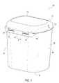
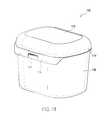
- FIG. 1is an isometric view of an exemplary tub, according to one embodiment of the present disclosure
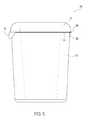
- FIG. 2is a an isometric view of the exemplary tub of FIG. 1 with the lid in an open position prior to being closed, according to one embodiment of the present disclosure
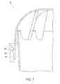
- FIG. 3is a rear view of the exemplary tub of FIG. 1 , according to one embodiment of the present disclosure
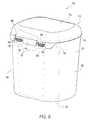
- FIG. 4is a top view of the exemplary tub of FIG. 1 , according to one embodiment of the present disclosure
- FIG. 5is a side view of the exemplary tub of FIG. 1 , according to one embodiment of the present disclosure
- FIG. 6is a first cross sectional view of the closure mechanism of the exemplary tub of FIG. 1 , according to one embodiment of the present disclosure
- FIG. 7is a second cross sectional view of the closure mechanism of the exemplary tub of FIG. 1 , according to one embodiment of the present disclosure
- FIG. 8is a third cross sectional view of the closure mechanism of the exemplary tub of FIG. 1 , according to one embodiment of the present disclosure
- FIG. 9is an isometric view of the exemplary tub of FIG. 1 with the lift tabs removed, according to one embodiment of the present disclosure
- FIG. 10is an isometric view of the exemplary tub of FIG. 2 with the lift tabs removed, according to one embodiment of the present disclosure
- FIG. 11is an isometric view of a first alternate exemplary tub, according to one embodiment of the present disclosure.
- FIG. 12is an isometric view of a second alternate exemplary tub, according to one embodiment of the present disclosure.
- FIG. 13is a bottom view of the second alternate exemplary tub of FIG. 12 , according to one embodiment of the present disclosure.
- a tamper evident tub with a lidis disclosed.
- the tubincludes a latching mechanism operative to secure the lid in a closed position.
- the tubincludes one or more breakable tabs located in front of the latching mechanism such that the latching mechanism is accessible by breaking the breakable tabs.
- the containeris substantially rectangular in shape. In one or more embodiments, the container may be shaped to include one or more handles integrated into the tub body.
- the tub discussed hereinmay be formed in any suitable way.
- the tubis formed by injection molding.
- the tubis 3D printed or created via other additive manufacturing means.
- various components of the tubare formed or created separately and the various components of the tub are joined or otherwise suitably connected to form the tub.
- the tubmay be a one piece and unitary tub.
- the tub discussed hereinmay be used for storing or transporting any variety of materials, including, but not limited to: food, paints, oils, consumer goods, construction materials, inks, chemicals, lubricants, adhesives, coatings, roofing mastics, driveway sealers, flavorings, sanitation supplies, building products, ice melt compounds, powders, pet food, and other such materials.
- the tubmay be formed from any suitable material or materials for storing or transporting such materials.
- the tubis manufactured from plastic (e.g., polyethylene, high-density polyethylene, etc.).
- the tubis manufactured from a metal or composite material.
- FIG. 1depicts an isometric view of an exemplary tub 100 with a lid 112 in a closed position, according to one embodiment of the present disclosure.
- the exemplary tub 100includes a tub body 102 with a first side 104 , second 106 , bottom 108 , top 110 , and the lid 112 .
- the exemplary tub 100has a substantially rectangular shape with rounded edges.
- the top of the lid 112is flat and the edges of the lid may slope downward in a convex manner.
- the lid 112encloses and seals the interior of the tub 100 .
- the exemplary tub 100includes various features proximate the top 110 of the exemplary tub 100 .
- the exemplary tub 100includes a satellite ring 114 .
- the satellite ring 114is a protruding ridge that extends outward from the tub bodyl 02 .
- the satellite ring 114has a flat upper surface and round lower surface.
- the satellite ring 114has a round upper surface (convex) and an inwardly round bottom surface (concave), whereby one satellite ring 114 may accept a satellite ring of a separate tub in a stacked configuration (e.g., if the lids are in an open position).
- the satellite ring 114extends fully or partially around the body 102 of the exemplary tub 100 .
- the satellite ring 114may provide a surface or location for the lid 112 to meet and seal when in a closed position.
- the satellite ring 114acts as a base or starting point from which other tub features extend.
- the satellite ring 114extends downward at location 116 in order to partially form or integrate with the latch assembly 118 .
- the latch assembly 118is entirely separate from the satellite ring 114 .
- the latch assembly 118begins to linearly and gradually increase in width at starting at the location 116 .
- the linear increase in width of the latch assembly 118forms about a 45 degree downward angle between the satellite ring 114 and the location 116 .
- the latch assembly 118extends about 1.5 inches (3.81 cm) downward from the satellite ring 114 .
- the latch assembly 118extends downward in order to provide a surface to include one or more breakable tabs 120 .
- the one or more breakable tabs 120are removable portions of the latch assembly 118 .
- the breakable tabs 120may be connected to the latch assembly 118 by means of perforated seams, fused corners, or other appropriate means of attachment, and may operate similarly to typical tear strips.
- the one or more breakable tabs 120may be removed to reveal additional features of the exemplary tub 100 .
- a gap 122may be located between the upper portion of the one or more breakable tabs 120 and the upper portion of the latch assembly 118 .
- the gap 122may allow for a user or handler of the exemplary tub 100 to achieve better leverage to pull away the breakable tab 120 .
- additional exemplary tub 100 featuresmay be visible through the gap 122 .
- the exemplary tub 100is shown with the lid 112 in an open position prior to being closed, according to one embodiment of the present disclosure.
- the exemplary tub 100may be manufactured and distributed with the lid 112 in an open position.
- manufacturing the exemplary tub 100 with the lid 112 in an open positionmay allow for a user to later fill the exemplary tub 100 with various materials or objects, and then close the lid 112 , thereby securing the lid 112 in a closed position.
- the lid 112is positioned behind the exemplary tub 100 and is facing upward.
- the lid 112includes one or more lift tabs 202 .
- the lift tabs 202 included on the lid 112may align with and enter the lift tab holes 204 .
- the latch assembly 118includes an upper surface 119 .
- the satellite ring 114may be integrally formed with the latch assembly 118 .
- the upper surface 119is wider than the other portion(s) of the satellite ring 114 in order to include the lift tab holes 204 .
- the lift tab holes 204allow for the lift tabs 202 to enter an area behind the breakable tabs 120 .
- the tub interior 210is shown, according to one embodiment of the present disclosure.
- the tub interior 210may be operable to store objects and elements ranging from household cleaning supplies, liquids, chemicals, etc.
- the lid 112includes a plurality of lid support ribs 206 .
- the plurality of lid support ribs 206are located along the inner curved portion 112 A of the lid 112 .
- the lid support ribs 206may be molded onto the curved portion 112 A of the lid 112 during the manufacturing process. As mentioned briefly above, the lid 112 may transition from an opened position to a closed position.
- the lid support ribs 206may accept an upper rim 208 of the exemplary tub 100 at the rib location 206 A.
- the rib location 206 Ais a substantially flat portion of the lid support rib 206 .
- each rib location 206 A of the plurality of support ribs 206may accept the tub upper rim 208 .
- the plurality of support ribs 206may include rounded ends 206 B. In one embodiment, the rounded ends 206 B may extend past the tub upper rim 208 and into the tub interior 210 when in a closed position.
- the lid 112may not close entirely if the elements stored within the tub interior 210 prevent the rounded edges 206 B of the plurality of support rubs 206 from extending downward into the tub interior 210 .
- the lid 112is attached to the tub body 102 by one or more hinges 302 .
- two hinges 302attach the tub lid 112 to the satellite ring 114 .
- the upper portion of the hinge 302is integrally attached to the lid 112
- the lower portion of the hinge 302is integrally attached to the tub body 102 .
- the satellite ring 114may not be included in attaching the lid 112 to the tub body 102 by one or more hinges 302 .
- the satellite ring 114may discontinue circumscribing the tub body 102 in near proximity to the one or more hinges 302 .
- the one or more hinges 302may directly attach the lid 112 and the tub body 102 without integrally forming with the satellite ring 114 .
- a hinge support 304is included in near proximity to each hinge 302 .
- the hinge supports 304are located below the hinges 302 .
- the hinge supports 304are oriented perpendicular to the each hinge 302 and also provide structural support to the hinge 302 .
- the hinge supports 304are integrally formed with the one or more hinges 302 to form one unitary piece.
- the hinge supports 304are integrally formed onto the tub body 102 and one side portion of the hinge supports 304 are integrally formed onto the lower portion of the satellite ring 114 .
- the lid 112can be seen positioned with a bottom surface in contact, and creating a seal with, the satellite ring 114 .
- the lid 112 and satellite ring 114create a flush outer surface at and along the location 306 where it continues around the tub body 102 .
- both the lid 112 and satellite ring 114are shown protruding outward from the tub body 102 , similar to an umbrella shape.
- the container body 102may taper in dimensions, beginning at the satellite ring 114 and continuing downward towards the tub bottom 108 (e.g., the circumference of the tub 100 at the top 110 is greater than the circumference of the bottom 108 ).
- the tapered shape of the exemplary tub 100may allow for the tub 100 to be stacked or placed into another separate tub for storage, transportation, etc.
- the tub interior 210is shown.
- the tub bottom 108includes a dimple 402 .
- the dimple 402is a spherical indentation that may protrude upward into the tub interior 210 , thereby slightly reducing the volume of the tub interior 210 .
- the lift tab holes 204are shown from an upper perspective, according to one embodiment of the present disclosure.
- the exemplary tub 100includes a latch 404 as well as one or more latch support ribs 406 .
- the latch 404may include an inwardly extending portion of the latch assembly 118 that secures a lift tab 202 , thereby maintaining the lid 112 in a closed position when closed.
- the latch support ribs 406protect the integrity of the latch 404 .
- the hinges 302are shown connecting the lid 112 with the rest of the exemplary tub 100 .
- the exemplary tub 100includes two hinges 302 .
- the exemplary tub 100may be manufactured (e.g., molded, 3D printed, etc.) to integrally include the one or more hinges 302 .
- the lid 112 and the tub body 102may be manufactured individually and may be joined or fused at the one or more hinges 302 .
- the exemplary container 100includes more or less hinges 302 than shown, depending on certain design configurations and constraints.
- the exemplary tub 100is manufactured as one unitary member.
- FIG. 5a side view of the exemplary tub 100 is shown according to one embodiment of the present disclosure.
- the hinge 302is shown protruding outward slightly beyond where the lid 112 meets the satellite ring 114 .
- the hinge support 304is also shown in the present embodiment.
- the hinge support 304may be molded to or otherwise attached to both the hinge 302 and the tub body 102 .
- the hinge support 304may extend downward along the tub body 102 about 1.0 inches (2.54 cm) from the bottom of the hinge 302 .
- the attachment of the hinge support 304 to both the hinge 302 and the tub body 102provides structural support to the hinge 302 as well as the lid 112 .
- FIGS. 6, 7, and 8show cross sectional views taken through the lid 112 and latch assembly 118 (indicated by the dashed line A-A in FIG. 1 ), according to various aspects of the present disclosure.
- the cross sectional viewsshow how the lift tab 202 (and individual portions thereof) engages with the latch assembly 118 (and individual portions thereof) throughout the transition of opening and closing the lid 112 .
- FIG. 6shows a cross section taken through the latch assembly 118 and a breakable tab 120 of the exemplary tub 100 with the lid 112 in a closed position.
- the cross sectionreveals a lift tab chamber 602 with a lift tab 202 occupying the space therein.
- the lift tab 202is shown in a latched position within the lift tab chamber 602 .
- the lift tab 202includes a latch tooth 604 .
- the latch tooth 604may have a substantially triangular shape. As seen in the present embodiment, the latch tooth 604 resembles a right-angled triangle.
- the latch tooth 604may be any outwardly extending ridge of the lift tab 202 and may resemble any shape that allows for one directional movement when engaged with another object (e.g., a hook).
- the object the latch tooth 604 is engaged withis the latch 404 .
- the angled side of the latch tooth 604may allow for the latch tooth 604 to pass over the latch 404 .
- the right-angled side of the latch tooth 604may prevent the latch tooth 604 , and thus the lift tab 202 , from retreating backward.
- the latch tooth 604 and latch 404may behave similarly to a latch bolt on a door.
- the latch bolt on a dooris angled and allows for the door to be easily closed; however, once the door is closed it will not reopen by simply pulling the door back outward.
- the lift tab 202includes a downwardly-extending portion below the latch tooth 604 .
- included on the downwardly-extending portion of the lift tab 202are one or more press ridges 606 .
- three press ridges 606are shown as rounded protrusions protruding from the lift tab 202 .
- a usermay inwardly (towards the tub body), and then upwardly (out of the lift tab chamber), push the lift tab 202 via the press ridges 606 in order to unlatch or release the lift tab 202 from the closed position within the lift tab chamber 602 .
- the press ridges 606may allow a user to better grip the region of the lift tab 202 for a user to press.
- the lift tab 202may include more or less press ridges 606 as shown (e.g., two press ridges, one press ridge, many press ridges, no press ridges, etc.).
- a lift tab chamber wall 608is seen behind the lift tab 202 .
- at least two lift tab chamber walls 608define the space of the lift tab chamber 602 .
- the lift tab chamber walls 608are substantially perpendicularly aligned with the tub body 102 , thereby defining a space outward from the tub body 102 .
- the lift tab chamber walls 608extend downward from the upper surface 119 of the latch assembly 118 to below the lowest portion of the lift tab 202 .
- the lift tab chamber walls 608extend below the lowest portion of the lift tab 202 to prevent access to the lift tab 202 while the breakable tab 120 is still attached to the latch assembly 118 .
- the lift tab chamber walls 608may be integrally formed with the latch assembly 118 and the tub body 102 . In other embodiments, only one side of the lift tab chamber walls 608 are integrally formed or connected to an adjacent portion of the exemplary tub 100 . In various embodiments, the lift tab chamber walls 608 not only define the space of the lift tab chambers 602 , but also provide structural support to the latch assembly 118 . In certain embodiments, the lift tab chamber walls 608 may be triangular shaped, rectangular shaped, quadrant shaped, etc.
- a cross section of the breakable tab 120is shown, according to one embodiment of the present disclosure.
- the breakable tab 120is positioned slightly below the latch 404 , thus creating the gap 122 seen from the front of the exemplary tub 100 in FIG. 1 .
- the gap 122 between the breakable tab 120 and the latch 404may allow for a user or handler of the exemplary tub 100 to see the latch tooth 604 but not access the press ridges 606 .
- the breakable tab 120may be flush with the latch 404 , (or any portion of the latch assembly 118 ) thereby eliminating the presence of the gap 122 .
- the breakable tab 120may prevent children, or any user with under-developed dexterity skills, from opening the exemplary tub 100 until the breakable tab 120 is removed. In certain embodiments, even when a breakable tab 120 is removed and the lift tab 202 is exposed, a user with under-developed dexterity skills may still struggle to open the lid 112 .
- the latch support rib 406has a substantially triangular shape and is attached to or integrally formed with the latch 404 as well as the latch assembly 118 .
- the latch support rib 406may have rectangular shape, a quadrant shape, etc.
- the latch support rib 406provides structural support to the latch 404 .
- a scenariomay arise where an upward force is being exerted on the lid 112 in an attempt to open the exemplary tub 100 .
- the latch support rib 406may distribute the force between the latch 404 and the latch assembly 118 .
- distributing the force between the latch 404 and the latch assembly 118may prevent the latch 404 from either becoming deformed or breaking under the force, thereby keeping the lid 112 in a closed position.
- the lid 112includes a natural bend and flex. As seen in the present embodiment, the lift tab 120 in its natural state extends away from the exemplary tub 100 . In particular embodiments, the natural bend and flex of the lid 112 allows for the lift tab 202 to remain in a latched position. According to various aspects of the present disclosure, the initial form of the lid 112 , as developed during manufacturing, may be the source of the outward force allowing the lift tab 202 to remain in a latched position. Moreover, the natural bend and flex of the lid 112 allows for the lift tab 202 to extend back outward after being pressed inward by a user or handler of the exemplary tub 100 , according to one embodiment of the present disclosure.
- the support ribs 206are shown accepting the upper rim 208 of the exemplary tub 100 .
- the support ribs 206may provide support to the exemplary tub 100 and prevent the exemplary tub 100 from being compressed or deformed under extreme conditions. For example, consider a scenario where the exemplary tub 100 is exposed to forces pushing inward on the sides of the exemplary tub 100 . In this scenario, the support ribs 206 may prevent the upper rim 208 from bending inward, and thus preventing the exemplary tub 100 from becoming deformed and thus preventing unintended access to the contents of the exemplary tub 100 .
- FIG. 7an embodiment similar to FIG. 6 is shown with the breakable tab 120 removed.
- removing the breakable tab 120allows for a user to access the lift tab 202 .
- the breakable tab 120may be connected to the latch assembly 118 by means of perforated seams, fused corners, or other appropriate means of attachment.
- removing the breakable tab 120may require a user or handler to exert a force, thereby ripping or tearing away the breakable tab 120 .
- the usermay pop the breakable tab 120 inward or outward to dislocate the breakable tab 120 from its initial position.
- a user or handler of the exemplary tub 100may push the lift tab 202 inward and then upward to open the lid.
- pushing the lift tab 202 inwardpositions the right-angled side of the latch tooth 604 away from the latch 404 . Further, pushing the lift tab 202 upward after it has been pushed inward allows for the latch tooth 604 to avoid being prohibited by the latch 404 . In one embodiment, the result of this action may be seen at FIG. 8 .
- the latch tooth 604is shown in an intermediate removal position and is mostly removed from the lift tab chamber 602 and partially removed from the lift tab hole 204 .
- the edge of the latch 404is in contact with the space between two of the press ridges 606 .
- the press ridges 606 on the lift tab 202may further prevent the lid 112 from opening or closing.
- pushing inward on the lift tab 202and then either upward or downward, may allow for the lift tab 202 to further exit the lift tab chamber 602 or reenter the lift tab chamber 602 .
- the exemplary tub 100is shown without the breakable tabs 120 , according to one embodiment.
- the breakable tabs 120may have been removed from the latch assembly 118 .
- the exemplary tub 100may be manufactured and distributed with the lid 112 in an opened position and the breakable tabs 120 included on the latch assembly 118 .
- closing the lid 112may result in the lift tabs 202 being secured in the latch assembly 118 behind the breakable tabs 120 , as seen in FIG. 1 .
- removing the one or more breakable tabs 120allows access to the lift tab chamber 602 .
- the latch tooth 604 of the lift tab 202may be secured below the latch 404 when the lid 112 is in a closed position.
- the latch 404is concealed behind the front face of the latch assembly 118 .
- the one or more press ridges 606protrude outward from the lift tab 202 .
- pushing inward and then upward on each lift tab 202 via the press ridges 606allows for the latch tooth 604 to disengage the latch 404 , thereby allowing the lid 112 to be lifted into the open position.
- pushing inward and then upward on each lift tab 202may be difficult for users that have under-developed dexterity skills (i.e., children), thereby preventing certain users from opening the lid 112 .
- FIG. 10shows the exemplary tub 100 with the lid 112 in an open position and without the breakable tabs 120 .
- pushing inward and then upward on each lift tab 202 via the press ridges 606allows for the latch tooth 604 to disengage the latch 404 , thereby allowing the lid 112 to be lifted into an open position.
- the present embodimentshows the result of the above described action.
- the one or more lift tabs 202are lifted upward through the lift tab chamber 602 and further through the lift tab holes 204 .
- the exemplary tub 1100is an alternate embodiment of the exemplary tub 100 .
- the exemplary tub 1100includes features substantially similar to the exemplary tub 100 such as the tub body 1102 , lid 1112 , satellite ring 1114 , latch assembly 1118 , and breakable tab 1120 .
- the lift tab 202 , latch tooth 604 , and latch 404 included on the exemplary tub 100are also substantially similar to the same features on the exemplary tub 1100 .
- the exemplary tub 1100may have different dimensions than the exemplary tub 100 ; however, the functionality of the two tubs is substantially similar.
- the exemplary tub 1100includes only one breakable tab 1120 .
- the exemplary tub 1100(and other alternate embodiments) may include a plurality of breakable tabs 1120 .
- FIG. 12shows an isometric view of an exemplary tub 1200 , according to one embodiment of the present disclosure.
- the exemplary tub 1200is an alternate embodiment of the exemplary tub 100 .
- the exemplary tub 1200includes features substantially similar to the exemplary tub 100 such as the lid 1212 , satellite ring 1214 , latch assembly 1218 , and breakable tab 1220 .
- the lift tab 202 , latch tooth 604 , and latch 404 included on the exemplary tub 100are also substantially similar to the same features on the exemplary tub 1200 .
- the first side 1202 of the exemplary tub 1200includes a handle 1204 .
- the handle 1204is integrated or molded into the shape of the first side 1202 of the exemplary tub 1200 .
- the handle 1204is formed by a recess 1206 in the first side 1202 , the front 1215 , and the rear 1216 of the exemplary tub 1200 .
- the recess 1206allows for a user or handler of the exemplary tub 1200 to easily grab the tub 1200 with a single hand.
- a handle 1204may be present on both the first side 1202 and the second side 1208 of the exemplary tub 1200 .
- the general curvature of the first side 1202 and second side 1208 of the exemplary tub 1200are substantially similar. As shown in the present embodiment, both the first side 1202 and second side 1208 of the exemplary tub 1200 extend straight downward from the satellite ring 1214 and then proceed to curve inward towards the bottom 1213 of the tub 1200 , thereby reducing the volume of the exemplary tub 1200 .
- the handle 1204includes a plurality of grip ridges 1210 .
- the plurality of grip ridges 1210allows for a user or handler of the exemplary tub 1200 to better grasp the tub 1200 .
- the plurality of grip ridges 1210protrudes slightly outward from the handle inner surface 1212 (as seen in FIG. 13 ).
- the plurality of grip ridges 1210may extend inward into the exemplary tub 1200 interior.
- the grip ridges 1210are vertically aligned along the handle inner surface 1211 .
- the grip ridges 1210may be horizontally aligned, diagonally aligned, crossed, or another appropriate pattern.
- the handle 1204may not include any grip ridges 1210 at all.
- the handle inner surface 1211may be bare or may include another surface that promotes an enhanced grip such as sandpaper, a tacky substance, etc.
- exemplary tub 1200may include various types of handles (e.g., jug handles, etc.).
- the present embodimentshows a bottom view of the exemplary container 1200 .
- the bottom 1213 of the exemplary tub 1200includes a shape that is substantially different from the lid 1212 .
- the bottom 108 of the exemplary tub 100includes a shape and proportions that are substantially similar to the lid 112 .
- the bottom 1213 of the exemplary tub 1200includes the curvature of the first side 1202 and second side 1208 , and the handle recess 1206 .
- the bottom 1213resembles two disproportionate semi-circular halves, wherein the smaller semi-circular half is in near proximity to the handle 1204 .
- each handle recess 1206reduces the surface area of the tub bottom 1213 , thereby creating the smaller semi-circular half.
- the handle 1204tapers inward as the handle 1204 extends downward and bends inward from the satellite ring 1214 to the tub bottom 1213 .
- the curvature of the handle recess 1206resembles a valley shape.
- the handle recess 1206begins to curve inward at location 1321 into the exemplary tub 1200 interior.
- the handle recess 1206then forms a rounded bottom at location 1322 .
- the rounded bottom at location 1322represents the inner most portion of the handle recess 1206 and therefore the inner most grab-able portion of the handle 1204 .
- the handle recess 1206then begins to curve outward to location 1323 .
- the location 1323is similar to location 1321 in that both locations are above or outside the inner most portion of the handle recess 1206 , which is 1322 in the present embodiment.
Landscapes
- Engineering & Computer Science (AREA)
- Mechanical Engineering (AREA)
- Ceramic Engineering (AREA)
- Closures For Containers (AREA)
- Containers Opened By Tearing Frangible Portions (AREA)
- Confectionery (AREA)
- Manufacturing Of Micro-Capsules (AREA)
- Acyclic And Carbocyclic Compounds In Medicinal Compositions (AREA)
Abstract
Description
Claims (18)
Priority Applications (16)
| Application Number | Priority Date | Filing Date | Title |
|---|---|---|---|
| US15/467,710US10155609B2 (en) | 2017-03-23 | 2017-03-23 | Tamper evident tub |
| CA2965061ACA2965061A1 (en) | 2017-03-23 | 2017-04-24 | Tamper evident tub |
| BR112019019681-1ABR112019019681B1 (en) | 2017-03-23 | 2017-12-14 | CONTAINER AND CONTAINER ASSEMBLY |
| CN201780088840.XACN110573432B (en) | 2017-03-23 | 2017-12-14 | Tamper-resistant bucket |
| MX2019011222AMX2019011222A (en) | 2017-03-23 | 2017-12-14 | Tamper evident tub. |
| ES17901772TES2954310T3 (en) | 2017-03-23 | 2017-12-14 | Tamper Proof Cube |
| NZ757385ANZ757385B2 (en) | 2017-12-14 | Tamper evident tub | |
| EP17901772.8AEP3601085B1 (en) | 2017-03-23 | 2017-12-14 | Tamper evident tub |
| PCT/US2017/066310WO2018174975A1 (en) | 2017-03-23 | 2017-12-14 | Tamper evident tub |
| AU2017405076AAU2017405076B2 (en) | 2017-03-23 | 2017-12-14 | Tamper evident tub |
| US16/188,729US10974879B2 (en) | 2017-03-23 | 2018-11-13 | Tamper evident tub |
| MX2023010291AMX2023010291A (en) | 2017-03-23 | 2019-09-20 | Tamper evident tub. |
| MX2024008367AMX2024008367A (en) | 2017-03-23 | 2019-09-20 | Tamper evident tub. |
| US17/201,281US11453534B2 (en) | 2017-03-23 | 2021-03-15 | Tamper evident tub |
| US17/894,599US12098004B2 (en) | 2017-03-23 | 2022-08-24 | Tamper evident tub |
| US18/658,578US20240286805A1 (en) | 2017-03-23 | 2024-05-08 | Tamper evident tub |
Applications Claiming Priority (1)
| Application Number | Priority Date | Filing Date | Title |
|---|---|---|---|
| US15/467,710US10155609B2 (en) | 2017-03-23 | 2017-03-23 | Tamper evident tub |
Related Child Applications (1)
| Application Number | Title | Priority Date | Filing Date |
|---|---|---|---|
| US16/188,729ContinuationUS10974879B2 (en) | 2017-03-23 | 2018-11-13 | Tamper evident tub |
Publications (2)
| Publication Number | Publication Date |
|---|---|
| US20180273258A1 US20180273258A1 (en) | 2018-09-27 |
| US10155609B2true US10155609B2 (en) | 2018-12-18 |
Family
ID=63582111
Family Applications (2)
| Application Number | Title | Priority Date | Filing Date |
|---|---|---|---|
| US15/467,710ActiveUS10155609B2 (en) | 2017-03-23 | 2017-03-23 | Tamper evident tub |
| US16/188,729Active2037-08-30US10974879B2 (en) | 2017-03-23 | 2018-11-13 | Tamper evident tub |
Family Applications After (1)
| Application Number | Title | Priority Date | Filing Date |
|---|---|---|---|
| US16/188,729Active2037-08-30US10974879B2 (en) | 2017-03-23 | 2018-11-13 | Tamper evident tub |
Country Status (8)
| Country | Link |
|---|---|
| US (2) | US10155609B2 (en) |
| EP (1) | EP3601085B1 (en) |
| CN (1) | CN110573432B (en) |
| AU (1) | AU2017405076B2 (en) |
| CA (1) | CA2965061A1 (en) |
| ES (1) | ES2954310T3 (en) |
| MX (3) | MX2019011222A (en) |
| WO (1) | WO2018174975A1 (en) |
Cited By (4)
| Publication number | Priority date | Publication date | Assignee | Title |
|---|---|---|---|---|
| US20180155099A1 (en)* | 2015-12-08 | 2018-06-07 | Inline Plastics Corp. | Child-resistant containers |
| USD876949S1 (en)* | 2018-04-20 | 2020-03-03 | Reckitt Benckiser Finish B.V. | Storage box |
| USD876948S1 (en)* | 2018-04-20 | 2020-03-03 | Reckitt Benckiser Finish B.V. | Storage box |
| USD876950S1 (en)* | 2018-04-20 | 2020-03-03 | Reckitt Benckiser Finish B.V. | Storage box |
Families Citing this family (28)
| Publication number | Priority date | Publication date | Assignee | Title |
|---|---|---|---|---|
| CA3035052A1 (en) | 2016-08-26 | 2018-03-01 | Berry Plastics Corporation | Container |
| WO2018053342A1 (en)* | 2016-09-16 | 2018-03-22 | Csp Technologies, Inc. | Container having internal thumb tab and related assemblies |
| USD933449S1 (en) | 2016-11-22 | 2021-10-19 | Dometic Sweden Ab | Latch |
| US11535425B2 (en) | 2016-11-22 | 2022-12-27 | Dometic Sweden Ab | Cooler |
| US10155609B2 (en) | 2017-03-23 | 2018-12-18 | Bway Corporation | Tamper evident tub |
| US11453534B2 (en) | 2017-03-23 | 2022-09-27 | Bway Corporation | Tamper evident tub |
| USD876216S1 (en) | 2017-12-04 | 2020-02-25 | Å&R Carton Lund Aktiebolag | Package |
| AU201813953S (en)* | 2018-01-08 | 2018-07-31 | Wrigley W M Jun Co | Bottle |
| AU201813949S (en)* | 2018-01-08 | 2018-07-26 | Wrigley W M Jun Co | Bottle |
| JP1627131S (en)* | 2018-02-28 | 2019-03-18 | ||
| CA3036042A1 (en)* | 2018-03-07 | 2019-09-07 | Berry Global, Inc. | Package |
| CA3036024A1 (en) | 2018-03-07 | 2019-09-07 | Berry Global, Inc. | Package |
| MX2020008865A (en)* | 2018-03-09 | 2020-10-14 | M & M Ind Inc | Child resistant pail. |
| USD976102S1 (en)* | 2019-03-22 | 2023-01-24 | The Procter & Gamble Company | Messaging structure |
| CA3080678A1 (en)* | 2019-06-27 | 2020-12-27 | Dongguan Lk Tin Packaging Co.,Ltd. | Container with security lock |
| BE1027590B1 (en)* | 2019-09-23 | 2021-04-22 | Deca Packaging Group Verkort Deca Nv | Tamper resistant packaging |
| CA3151231A1 (en)* | 2021-03-15 | 2022-09-15 | Bway Corporation | Tamper evident tub |
| USD1011876S1 (en) | 2021-05-14 | 2024-01-23 | Altria Client Services Llc | Combined container with push-and-slide locking mechanism |
| US12371234B2 (en) | 2021-05-14 | 2025-07-29 | Altria Client Services Llc | Package with locking mechanism including flexible member having first segment and second segment, and container with flexible tab |
| US20220363453A1 (en)* | 2021-05-14 | 2022-11-17 | Altria Client Services Llc | Container with push-and-slide locking mechanism |
| USD1091252S1 (en) | 2021-05-20 | 2025-09-02 | Thermos, L.L.C. | Food jar |
| USD1090248S1 (en) | 2021-07-30 | 2025-08-26 | Altria Client Services Llc | Container with push-and-slide locking mechanism |
| USD1089822S1 (en) | 2021-07-30 | 2025-08-19 | Altria Client Services Llc | Container including locking mechanism with pair of tabs |
| CN217893826U (en)* | 2021-10-22 | 2022-11-25 | 酷仕客有限公司 | Rotary die cooler |
| CN116115135A (en)* | 2021-11-13 | 2023-05-16 | 深圳银星智能集团股份有限公司 | Container and cleaning base station |
| USD996059S1 (en)* | 2022-02-24 | 2023-08-22 | Otter Products, Llc | Container |
| US20230322450A1 (en)* | 2022-04-06 | 2023-10-12 | Crativ Solutions, Inc. | Latch Mechanism For A Child-Resistant Storage Case |
| EP4417535A1 (en)* | 2023-02-16 | 2024-08-21 | Craemer GmbH | Small container for hazardous material |
Citations (50)
| Publication number | Priority date | Publication date | Assignee | Title |
|---|---|---|---|---|
| US3759415A (en)* | 1972-06-13 | 1973-09-18 | Nosco Plastics | Pail |
| US4170315A (en) | 1977-02-10 | 1979-10-09 | Createchnic Patent Ag | Closure for rigid and deformable containers |
| US4705172A (en) | 1986-06-27 | 1987-11-10 | Gage Industries, Inc. | Lid with orientation device |
| US5100015A (en)* | 1991-07-05 | 1992-03-31 | Electro-Wire Products, Inc. | Latch unit for container and mating lid |
| USD350876S (en) | 1993-03-22 | 1994-09-27 | Plastics, Inc. | Dry food storage container |
| US5353946A (en) | 1993-07-26 | 1994-10-11 | Church & Dwight Co., Inc. | Container with reclosable lid latch |
| USD363669S (en) | 1994-05-13 | 1995-10-31 | Pennoyer Jr Raymond P | Container |
| US5577779A (en) | 1994-12-22 | 1996-11-26 | Yazaki Corporation | Snap fit lock with release feature |
| USD377902S (en) | 1994-02-17 | 1997-02-11 | Kimberly-Clark Tissue Company | Wet wipe container |
| USD442438S1 (en) | 1999-11-22 | 2001-05-22 | Nicholas G. Schankowski | Combined cooler and stereo |
| USD449782S1 (en) | 2000-08-22 | 2001-10-30 | Cindy L. Diaz | Chewing gum box |
| USD457038S1 (en) | 2000-11-29 | 2002-05-14 | Polyconcept Usa, Inc. | Cooler |
| USD464791S1 (en) | 2000-08-25 | 2002-10-29 | Lemoine S.A. | Container for cotton sticks |
| USD473789S1 (en) | 2002-06-19 | 2003-04-29 | Colgate-Palmolive Company | Container |
| USD484797S1 (en) | 2002-11-25 | 2004-01-06 | Bristol-Myers Squibb Company | Stackable container |
| US20040084464A1 (en) | 2002-10-29 | 2004-05-06 | Koo Cha-Ii | Airtight container |
| USD489530S1 (en) | 2002-12-23 | 2004-05-11 | Brendan Jon Lindsay | Container with removable lid |
| US6772902B1 (en) | 2003-06-20 | 2004-08-10 | Colin White | One-piece molded child-proof container |
| USD513122S1 (en) | 2004-04-23 | 2005-12-27 | Thinking Outside, L.L.C. | Tool box |
| USD513451S1 (en) | 2004-03-08 | 2006-01-10 | Otter Products, Llc | Box |
| US20060076260A1 (en) | 2004-10-07 | 2006-04-13 | Ropak Corporation | Container and lid with multiple chambers and related methods |
| USD524119S1 (en) | 2004-10-11 | 2006-07-04 | Hana Cobi Co., Ltd. | Tea container having a filtering net |
| USD530616S1 (en) | 2005-02-02 | 2006-10-24 | Bristol-Myers Squibb Company | Container |
| US20070007297A1 (en) | 2005-05-16 | 2007-01-11 | Li Kwong F | Sealable container |
| USD544798S1 (en) | 2005-12-22 | 2007-06-19 | Plastipak Packaging, Inc. | Plastic container |
| US20070187277A1 (en) | 2006-02-09 | 2007-08-16 | Rubbermaid Incorporated | Storage container and container system |
| USD556041S1 (en) | 2007-01-09 | 2007-11-27 | Silgan Plastics Corporation | Canister with handle |
| USD560489S1 (en) | 2005-09-06 | 2008-01-29 | Satnick Lane D | Container |
| USD562160S1 (en) | 2007-03-12 | 2008-02-19 | Wki Holding Company, Inc. | Measuring container |
| USD569720S1 (en) | 2007-03-12 | 2008-05-27 | Cadbury Schweppes Plc | Container |
| USD573844S1 (en) | 2007-07-25 | 2008-07-29 | Textron Inc. | Sand bucket/cooler |
| USD581793S1 (en) | 2006-09-11 | 2008-12-02 | Consolidated Container Company Lp | Container |
| US20090289066A1 (en) | 2008-05-21 | 2009-11-26 | Helen Of Troy Limited | Container with sealing lid |
| US20100308066A1 (en) | 2009-06-05 | 2010-12-09 | Abbott Laboratories | Container |
| US20110031246A1 (en) | 2009-08-07 | 2011-02-10 | Massey Jr Raymond C | Tamper-Resistant Storage Container |
| USD641164S1 (en) | 2010-07-16 | 2011-07-12 | Dart Industries Inc. | Hinged Container |
| USD644437S1 (en) | 2009-12-22 | 2011-09-06 | Nammo Lapua Oy | Packaging container |
| USD663111S1 (en) | 2011-10-03 | 2012-07-10 | Positive Outcomes, Inc. | Pill box |
| US20120205375A1 (en) | 2011-02-10 | 2012-08-16 | Wells' Dairy, Inc. | Personal size container |
| USD673453S1 (en) | 2004-10-07 | 2013-01-01 | Ropak Corporation | Container with lid |
| US20130233753A1 (en) | 2012-03-09 | 2013-09-12 | Travis S. Harvey | Nesting Container Lids with Snap On Wings |
| US8733566B2 (en) | 2004-09-01 | 2014-05-27 | Creanova Universal Closures, Ltd. | Tamper evidence means for a closure and a tamper evident closure |
| US20140144867A1 (en) | 2006-03-17 | 2014-05-29 | Csp Technologies, Inc. | Tab release child safety feature |
| US20140190969A1 (en) | 2013-01-07 | 2014-07-10 | Wei Mon Industry Co., Ltd. | Tamper-evident container |
| US8839975B2 (en) | 2009-08-03 | 2014-09-23 | Ropak Corporation | Container and lid |
| USD731329S1 (en) | 2013-03-28 | 2015-06-09 | Joseph Joseph Ltd. | Measuring jug |
| US20160101908A1 (en) | 2014-10-14 | 2016-04-14 | Berry Plastics Corporation | Container closure |
| USD760073S1 (en) | 2014-03-13 | 2016-06-28 | S.C. Johnson & Son, Inc. | Container |
| USD784089S1 (en) | 2015-06-30 | 2017-04-18 | Sovaro Coolers, LLC | Cooler |
| USD807170S1 (en) | 2015-07-28 | 2018-01-09 | Wells Enterprises, Inc. | Container |
Family Cites Families (33)
| Publication number | Priority date | Publication date | Assignee | Title |
|---|---|---|---|---|
| US3240375A (en)* | 1963-11-20 | 1966-03-15 | Burrows Allen | Shipping and display container |
| US3840152A (en)* | 1973-06-18 | 1974-10-08 | None Such Enterprises Inc | Sealable and resealable container |
| US4512493A (en)* | 1981-11-10 | 1985-04-23 | Holdt J W Von | Molded bucket and lid having high stack strength |
| US4746008A (en)* | 1987-07-01 | 1988-05-24 | Heverly Karen H | Child-resistant box for storage of hazardous materials |
| CA2114805C (en)* | 1993-09-22 | 2006-12-12 | Frano Luburic | Container cover having primary and secondary detent means |
| US5979691A (en)* | 1998-04-10 | 1999-11-09 | Von Holdt; John W. | Container and locking lid |
| US6401968B1 (en)* | 2000-05-05 | 2002-06-11 | Kimberly-Clark Worldwide, Inc. | Wet wipes container having an improved opening mechanism |
| DE20006093U1 (en)* | 2000-04-01 | 2000-09-14 | Jokey Plastik Gummersbach GmbH, 51645 Gummersbach | Plastic container with snap-on lid |
| US6405885B1 (en)* | 2000-12-22 | 2002-06-18 | Seaquist Closures Foreign, Inc. | Locking tamper-evident dispensing closure |
| FR2820120A1 (en)* | 2001-01-30 | 2002-08-02 | Crown Cork & Seal Tech Corp | CAP WITH POURING ORIFICE CLOSED BY A LID AND LID INVIOLABILITY SYSTEM |
| US6712233B2 (en)* | 2001-03-13 | 2004-03-30 | Stephen H. Arshinoff | Lid with hinge for plastic pail |
| DE10140255A1 (en)* | 2001-08-07 | 2003-02-27 | Huber Westform Gmbh & Co | Container with a lid |
| DE10210486A1 (en)* | 2002-03-11 | 2003-10-09 | Jokey Plastik Gummersbach Gmbh | Container with a lid |
| DE10246086B4 (en)* | 2002-10-02 | 2005-11-03 | Mars, Incorporated | container |
| KR200336235Y1 (en)* | 2003-08-30 | 2003-12-18 | 김상훈 | Bottle cap and bottle having it |
| US7654411B2 (en)* | 2004-06-08 | 2010-02-02 | Berry Plastics Corporation | Container with lockable lid |
| AU2005274936B8 (en)* | 2004-07-16 | 2011-04-21 | Closure Systems International, Inc | Tamper-indicating dispensing closure |
| US7735665B2 (en)* | 2005-02-18 | 2010-06-15 | Rexam Closure Systems Inc. | Child-resistant flip-top dispensing closure, package and method of manufacture |
| ITMO20050099A1 (en)* | 2005-04-27 | 2006-10-28 | Sacmi | CAPSULES, CONTAINERS AND METHODS. |
| BRPI0600882A (en)* | 2006-03-10 | 2007-11-20 | Brasilata Embalagens Metalicas | container closure arrangement |
| US8292101B1 (en)* | 2007-05-29 | 2012-10-23 | Remax Healthcare Packaging Inc. | Flip-top dispensing system with a child resistant latch mechanism |
| CA2602398A1 (en)* | 2007-10-16 | 2009-04-16 | Gaetan Milante | Medication vial |
| CN201186779Y (en)* | 2008-04-11 | 2009-01-28 | 天津海河乳业有限公司 | Yoghurt packaging cup |
| CN201276258Y (en)* | 2008-08-14 | 2009-07-22 | 蔡沧洋 | Novel anti-counterfeiting sealing packing box |
| BRPI0904284A2 (en)* | 2009-10-30 | 2011-06-28 | Fechamentos Inteligentes Desenvolvimento De Embalagens Ltda | safety lock with lock, and safety lock fastening system |
| US8459486B2 (en)* | 2010-04-19 | 2013-06-11 | Ropak Corporation | Container and lid |
| CN202038495U (en)* | 2010-12-01 | 2011-11-16 | 深圳市通产丽星股份有限公司 | Packing container |
| PL2588384T3 (en)* | 2011-03-03 | 2014-10-31 | Aptargroup Inc | Closure with tamper-evident feature |
| CN203877128U (en)* | 2014-04-14 | 2014-10-15 | 浙江海洋学院 | Portable preservation box |
| US9669959B2 (en)* | 2015-03-26 | 2017-06-06 | Bway Corporation | Container with integrated handles |
| US10676258B2 (en)* | 2017-02-13 | 2020-06-09 | Rieke Llc | Child-resistant, flip-top closure |
| US10155609B2 (en) | 2017-03-23 | 2018-12-18 | Bway Corporation | Tamper evident tub |
| CN108861027A (en)* | 2017-05-08 | 2018-11-23 | 内蒙古伊利实业集团股份有限公司 | Packaging cover, the open method of packaging cover and the packing container including the packaging cover |
- 2017
- 2017-03-23USUS15/467,710patent/US10155609B2/enactiveActive
- 2017-04-24CACA2965061Apatent/CA2965061A1/enactivePending
- 2017-12-14MXMX2019011222Apatent/MX2019011222A/enunknown
- 2017-12-14ESES17901772Tpatent/ES2954310T3/enactiveActive
- 2017-12-14WOPCT/US2017/066310patent/WO2018174975A1/ennot_activeCeased
- 2017-12-14AUAU2017405076Apatent/AU2017405076B2/enactiveActive
- 2017-12-14CNCN201780088840.XApatent/CN110573432B/enactiveActive
- 2017-12-14EPEP17901772.8Apatent/EP3601085B1/enactiveActive
- 2018
- 2018-11-13USUS16/188,729patent/US10974879B2/enactiveActive
- 2019
- 2019-09-20MXMX2023010291Apatent/MX2023010291A/enunknown
- 2019-09-20MXMX2024008367Apatent/MX2024008367A/enunknown
Patent Citations (53)
| Publication number | Priority date | Publication date | Assignee | Title |
|---|---|---|---|---|
| US3759415A (en)* | 1972-06-13 | 1973-09-18 | Nosco Plastics | Pail |
| US4170315A (en) | 1977-02-10 | 1979-10-09 | Createchnic Patent Ag | Closure for rigid and deformable containers |
| US4705172A (en) | 1986-06-27 | 1987-11-10 | Gage Industries, Inc. | Lid with orientation device |
| US5100015A (en)* | 1991-07-05 | 1992-03-31 | Electro-Wire Products, Inc. | Latch unit for container and mating lid |
| USD350876S (en) | 1993-03-22 | 1994-09-27 | Plastics, Inc. | Dry food storage container |
| US5353946A (en) | 1993-07-26 | 1994-10-11 | Church & Dwight Co., Inc. | Container with reclosable lid latch |
| USD377902S (en) | 1994-02-17 | 1997-02-11 | Kimberly-Clark Tissue Company | Wet wipe container |
| USD363669S (en) | 1994-05-13 | 1995-10-31 | Pennoyer Jr Raymond P | Container |
| US5577779A (en) | 1994-12-22 | 1996-11-26 | Yazaki Corporation | Snap fit lock with release feature |
| USD442438S1 (en) | 1999-11-22 | 2001-05-22 | Nicholas G. Schankowski | Combined cooler and stereo |
| USD449782S1 (en) | 2000-08-22 | 2001-10-30 | Cindy L. Diaz | Chewing gum box |
| USD464791S1 (en) | 2000-08-25 | 2002-10-29 | Lemoine S.A. | Container for cotton sticks |
| USD457038S1 (en) | 2000-11-29 | 2002-05-14 | Polyconcept Usa, Inc. | Cooler |
| USD473789S1 (en) | 2002-06-19 | 2003-04-29 | Colgate-Palmolive Company | Container |
| US20040084464A1 (en) | 2002-10-29 | 2004-05-06 | Koo Cha-Ii | Airtight container |
| USD484797S1 (en) | 2002-11-25 | 2004-01-06 | Bristol-Myers Squibb Company | Stackable container |
| USD489530S1 (en) | 2002-12-23 | 2004-05-11 | Brendan Jon Lindsay | Container with removable lid |
| US6772902B1 (en) | 2003-06-20 | 2004-08-10 | Colin White | One-piece molded child-proof container |
| USD513451S1 (en) | 2004-03-08 | 2006-01-10 | Otter Products, Llc | Box |
| USD513122S1 (en) | 2004-04-23 | 2005-12-27 | Thinking Outside, L.L.C. | Tool box |
| US8733566B2 (en) | 2004-09-01 | 2014-05-27 | Creanova Universal Closures, Ltd. | Tamper evidence means for a closure and a tamper evident closure |
| US7784635B2 (en) | 2004-10-07 | 2010-08-31 | Ropak Corporation | Container and lid with multiple chambers |
| US20060076260A1 (en) | 2004-10-07 | 2006-04-13 | Ropak Corporation | Container and lid with multiple chambers and related methods |
| USD673453S1 (en) | 2004-10-07 | 2013-01-01 | Ropak Corporation | Container with lid |
| US20110024942A1 (en) | 2004-10-07 | 2011-02-03 | Frano Luburic | Container and lid with multiple chambers and related methods |
| USD524119S1 (en) | 2004-10-11 | 2006-07-04 | Hana Cobi Co., Ltd. | Tea container having a filtering net |
| USD530616S1 (en) | 2005-02-02 | 2006-10-24 | Bristol-Myers Squibb Company | Container |
| US20070007297A1 (en) | 2005-05-16 | 2007-01-11 | Li Kwong F | Sealable container |
| USD560489S1 (en) | 2005-09-06 | 2008-01-29 | Satnick Lane D | Container |
| USD544798S1 (en) | 2005-12-22 | 2007-06-19 | Plastipak Packaging, Inc. | Plastic container |
| US20070187277A1 (en) | 2006-02-09 | 2007-08-16 | Rubbermaid Incorporated | Storage container and container system |
| US20140144867A1 (en) | 2006-03-17 | 2014-05-29 | Csp Technologies, Inc. | Tab release child safety feature |
| USD581793S1 (en) | 2006-09-11 | 2008-12-02 | Consolidated Container Company Lp | Container |
| USD556041S1 (en) | 2007-01-09 | 2007-11-27 | Silgan Plastics Corporation | Canister with handle |
| USD562160S1 (en) | 2007-03-12 | 2008-02-19 | Wki Holding Company, Inc. | Measuring container |
| USD569720S1 (en) | 2007-03-12 | 2008-05-27 | Cadbury Schweppes Plc | Container |
| USD573844S1 (en) | 2007-07-25 | 2008-07-29 | Textron Inc. | Sand bucket/cooler |
| US20090289066A1 (en) | 2008-05-21 | 2009-11-26 | Helen Of Troy Limited | Container with sealing lid |
| US20100308066A1 (en) | 2009-06-05 | 2010-12-09 | Abbott Laboratories | Container |
| US8839975B2 (en) | 2009-08-03 | 2014-09-23 | Ropak Corporation | Container and lid |
| US20110031246A1 (en) | 2009-08-07 | 2011-02-10 | Massey Jr Raymond C | Tamper-Resistant Storage Container |
| USD644437S1 (en) | 2009-12-22 | 2011-09-06 | Nammo Lapua Oy | Packaging container |
| USD641164S1 (en) | 2010-07-16 | 2011-07-12 | Dart Industries Inc. | Hinged Container |
| US20120205375A1 (en) | 2011-02-10 | 2012-08-16 | Wells' Dairy, Inc. | Personal size container |
| USD663111S1 (en) | 2011-10-03 | 2012-07-10 | Positive Outcomes, Inc. | Pill box |
| US20130233753A1 (en) | 2012-03-09 | 2013-09-12 | Travis S. Harvey | Nesting Container Lids with Snap On Wings |
| US8733550B2 (en) | 2012-03-09 | 2014-05-27 | Wki Holding Company, Inc. | Nesting container lids with snap on wings |
| US20140190969A1 (en) | 2013-01-07 | 2014-07-10 | Wei Mon Industry Co., Ltd. | Tamper-evident container |
| USD731329S1 (en) | 2013-03-28 | 2015-06-09 | Joseph Joseph Ltd. | Measuring jug |
| USD760073S1 (en) | 2014-03-13 | 2016-06-28 | S.C. Johnson & Son, Inc. | Container |
| US20160101908A1 (en) | 2014-10-14 | 2016-04-14 | Berry Plastics Corporation | Container closure |
| USD784089S1 (en) | 2015-06-30 | 2017-04-18 | Sovaro Coolers, LLC | Cooler |
| USD807170S1 (en) | 2015-07-28 | 2018-01-09 | Wells Enterprises, Inc. | Container |
Non-Patent Citations (4)
| Title |
|---|
| Alibaba, "Guangzhou factory wholesale high quality clothes cleaning laundry detergent", Accessed Feb. 20, 2018 https://www.alibaba.com/product-detail/Guangzhou-factory-wholesale-high-quality-clothes_60594202908.html. |
| Bed Bath & Beyond, announced Apr. 17, 2011, accessed on Jan. 17, 2018: https://www.bedbathandbeyond.com/1/1/46493-pyrex-8-cup-measuring-cup-lid.htmi#BVRRWidgetiD. |
| International Search Report and Written Opinion dated Feb. 22, 2018, mailed in International Application No. PCT/US17/66310. |
| Webstaurantstore, announced Dec. 11, 2013, accessed on Jan. 17, 2018 https://www.webstaurantstore.com/kitchenaid-k5gb-5-qt-glass-mixing-bowl-with-handle-and-lid-for-stand-mixers/519K5GB.html. |
Cited By (5)
| Publication number | Priority date | Publication date | Assignee | Title |
|---|---|---|---|---|
| US20180155099A1 (en)* | 2015-12-08 | 2018-06-07 | Inline Plastics Corp. | Child-resistant containers |
| US10543967B2 (en)* | 2015-12-08 | 2020-01-28 | Inline Plastics Corp. | Child-resistant containers |
| USD876949S1 (en)* | 2018-04-20 | 2020-03-03 | Reckitt Benckiser Finish B.V. | Storage box |
| USD876948S1 (en)* | 2018-04-20 | 2020-03-03 | Reckitt Benckiser Finish B.V. | Storage box |
| USD876950S1 (en)* | 2018-04-20 | 2020-03-03 | Reckitt Benckiser Finish B.V. | Storage box |
Also Published As
| Publication number | Publication date |
|---|---|
| MX2024008367A (en) | 2024-07-22 |
| AU2017405076A1 (en) | 2019-10-10 |
| EP3601085A4 (en) | 2021-06-09 |
| CA2965061A1 (en) | 2018-09-23 |
| ES2954310T3 (en) | 2023-11-21 |
| BR112019019681A2 (en) | 2020-04-14 |
| AU2017405076B2 (en) | 2024-04-04 |
| US10974879B2 (en) | 2021-04-13 |
| WO2018174975A1 (en) | 2018-09-27 |
| CN110573432A (en) | 2019-12-13 |
| MX2019011222A (en) | 2019-12-19 |
| CN110573432B (en) | 2022-04-08 |
| US20180273258A1 (en) | 2018-09-27 |
| MX2023010291A (en) | 2023-09-12 |
| EP3601085B1 (en) | 2023-04-19 |
| NZ757385A (en) | 2024-08-30 |
| US20190077556A1 (en) | 2019-03-14 |
| EP3601085A1 (en) | 2020-02-05 |
Similar Documents
| Publication | Publication Date | Title |
|---|---|---|
| US10974879B2 (en) | Tamper evident tub | |
| US8146763B2 (en) | Collapsible storage device | |
| US7284673B2 (en) | Locking structure for hinged container | |
| US8146773B2 (en) | Collapsible storage device | |
| EP2738115A1 (en) | Child deterrent package | |
| US4917261A (en) | Vacuum-formed container with u-shaped lock | |
| US11401086B2 (en) | Container | |
| CA2241709A1 (en) | Container with corner latch closure | |
| US20240286805A1 (en) | Tamper evident tub | |
| US8033411B2 (en) | Collapsible storage device | |
| US8066136B2 (en) | Collapsible storage device | |
| US3568916A (en) | Locking mechanisms for egg cartons | |
| US3414159A (en) | Handled container with sliding cover | |
| US7854370B2 (en) | Collapsible storage device | |
| EP4308475A1 (en) | Tamper evident tub | |
| JP5814656B2 (en) | Foamed resin container | |
| BR112019019681B1 (en) | CONTAINER AND CONTAINER ASSEMBLY | |
| CN206880282U (en) | Disposable lunch-box | |
| JP6957114B2 (en) | Container with closure | |
| JPH10338258A (en) | Cap with hinge |
Legal Events
| Date | Code | Title | Description |
|---|---|---|---|
| AS | Assignment | Owner name:BWAY CORPORATION, GEORGIA Free format text:ASSIGNMENT OF ASSIGNORS INTEREST;ASSIGNOR:LUBURIC, FRANO;REEL/FRAME:041760/0831 Effective date:20170324 | |
| STCF | Information on status: patent grant | Free format text:PATENTED CASE | |
| AS | Assignment | Owner name:THE BANK OF NEW YORK MELLON TRUST COMPANY, N.A., FLORIDA Free format text:SECURITY AGREEMENT;ASSIGNORS:BWAY CORPORATION;NORTH AMERICA PACKAGING CORPORATION;ROPAK CORPORATION;AND OTHERS;REEL/FRAME:052596/0952 Effective date:20200507 | |
| MAFP | Maintenance fee payment | Free format text:PAYMENT OF MAINTENANCE FEE, 4TH YEAR, LARGE ENTITY (ORIGINAL EVENT CODE: M1551); ENTITY STATUS OF PATENT OWNER: LARGE ENTITY Year of fee payment:4 | |
| AS | Assignment | Owner name:BANK OF AMERICA, N.A., AS AGENT, GEORGIA Free format text:SECURITY INTEREST;ASSIGNOR:BWAY CORPORATION;REEL/FRAME:061248/0598 Effective date:20220928 | |
| AS | Assignment | Owner name:BANK OF AMERICA, N.A., AS COLLATERAL AGENT, NEW YORK Free format text:SECURITY AGREEMENT;ASSIGNORS:BWAY CORPORATION;ROPAK CORPORATION;MAUSER USA, LLC;REEL/FRAME:062700/0852 Effective date:20230210 Owner name:MAUSER USA, LLC, ILLINOIS Free format text:RELEASE BY SECURED PARTY;ASSIGNOR:THE BANK OF NEW YORK MELLON TRUST COMPANY, N.A.;REEL/FRAME:062702/0556 Effective date:20230210 Owner name:ROPAK CORPORATION, ILLINOIS Free format text:RELEASE BY SECURED PARTY;ASSIGNOR:THE BANK OF NEW YORK MELLON TRUST COMPANY, N.A.;REEL/FRAME:062702/0556 Effective date:20230210 Owner name:PLASTICAN, INC., ILLINOIS Free format text:RELEASE BY SECURED PARTY;ASSIGNOR:THE BANK OF NEW YORK MELLON TRUST COMPANY, N.A.;REEL/FRAME:062702/0556 Effective date:20230210 Owner name:NORTH AMERICA PACKAGING CORPORATION, ILLINOIS Free format text:RELEASE BY SECURED PARTY;ASSIGNOR:THE BANK OF NEW YORK MELLON TRUST COMPANY, N.A.;REEL/FRAME:062702/0556 Effective date:20230210 Owner name:BWAY CORPORATION, ILLINOIS Free format text:RELEASE BY SECURED PARTY;ASSIGNOR:THE BANK OF NEW YORK MELLON TRUST COMPANY, N.A.;REEL/FRAME:062702/0556 Effective date:20230210 | |
| AS | Assignment | Owner name:THE BANK OF NEW YORK MELLON TRUST COMPANY, N.A., AS COLLATERAL AGENT, FLORIDA Free format text:SECURITY AGREEMENT (NOTES);ASSIGNORS:BWAY CORPORATION;ROPAK CORPORATION;MAUSER USA, LLC;REEL/FRAME:062714/0705 Effective date:20230210 | |
| AS | Assignment | Owner name:THE BANK OF NEW YORK MELLON TRUST COMPANY, N.A., AS COLLATERAL AGENT, FLORIDA Free format text:SECURITY AGREEMENT;ASSIGNORS:BWAY CORPORATION;ROPAK CORPORATION;MAUSER USA, LLC;REEL/FRAME:062746/0937 Effective date:20230210 | |
| AS | Assignment | Owner name:THE BANK OF NEW YORK MELLON TRUST COMPANY, N.A., AS COLLATERAL AGENT, FLORIDA Free format text:SECURITY INTEREST;ASSIGNORS:BWAY CORPORATION;MAUSER USA, LLC;ROPAK CORPORATION;REEL/FRAME:067177/0922 Effective date:20240416 |