US10155071B2 - Reduced-pressure systems, methods, and devices for simultaneously treating a plurality of tissue sites - Google Patents
Reduced-pressure systems, methods, and devices for simultaneously treating a plurality of tissue sitesDownload PDFInfo
- Publication number
- US10155071B2 US10155071B2US13/681,731US201213681731AUS10155071B2US 10155071 B2US10155071 B2US 10155071B2US 201213681731 AUS201213681731 AUS 201213681731AUS 10155071 B2US10155071 B2US 10155071B2
- Authority
- US
- United States
- Prior art keywords
- pressure
- reduced
- port
- therapy unit
- patient
- Prior art date
- Legal status (The legal status is an assumption and is not a legal conclusion. Google has not performed a legal analysis and makes no representation as to the accuracy of the status listed.)
- Active, expires
Links
- XDTMQSROBMDMFD-UHFFFAOYSA-NC1CCCCC1Chemical compoundC1CCCCC1XDTMQSROBMDMFD-UHFFFAOYSA-N0.000description1
Images


Classifications
- A61M1/0031—
- A—HUMAN NECESSITIES
- A61—MEDICAL OR VETERINARY SCIENCE; HYGIENE
- A61M—DEVICES FOR INTRODUCING MEDIA INTO, OR ONTO, THE BODY; DEVICES FOR TRANSDUCING BODY MEDIA OR FOR TAKING MEDIA FROM THE BODY; DEVICES FOR PRODUCING OR ENDING SLEEP OR STUPOR
- A61M1/00—Suction or pumping devices for medical purposes; Devices for carrying-off, for treatment of, or for carrying-over, body-liquids; Drainage systems
- A61M1/60—Containers for suction drainage, adapted to be used with an external suction source
- A61M1/602—Mechanical means for preventing flexible containers from collapsing when vacuum is applied inside, e.g. stents
- A61M1/0015—
- A61M1/0035—
- A—HUMAN NECESSITIES
- A61—MEDICAL OR VETERINARY SCIENCE; HYGIENE
- A61M—DEVICES FOR INTRODUCING MEDIA INTO, OR ONTO, THE BODY; DEVICES FOR TRANSDUCING BODY MEDIA OR FOR TAKING MEDIA FROM THE BODY; DEVICES FOR PRODUCING OR ENDING SLEEP OR STUPOR
- A61M1/00—Suction or pumping devices for medical purposes; Devices for carrying-off, for treatment of, or for carrying-over, body-liquids; Drainage systems
- A61M1/71—Suction drainage systems
- A61M1/74—Suction control
- A61M1/743—Suction control by changing the cross-section of the line, e.g. flow regulating valves
- A—HUMAN NECESSITIES
- A61—MEDICAL OR VETERINARY SCIENCE; HYGIENE
- A61M—DEVICES FOR INTRODUCING MEDIA INTO, OR ONTO, THE BODY; DEVICES FOR TRANSDUCING BODY MEDIA OR FOR TAKING MEDIA FROM THE BODY; DEVICES FOR PRODUCING OR ENDING SLEEP OR STUPOR
- A61M1/00—Suction or pumping devices for medical purposes; Devices for carrying-off, for treatment of, or for carrying-over, body-liquids; Drainage systems
- A61M1/90—Negative pressure wound therapy devices, i.e. devices for applying suction to a wound to promote healing, e.g. including a vacuum dressing
- A61M1/91—Suction aspects of the dressing
- A61M1/918—Suction aspects of the dressing for multiple suction locations
- A—HUMAN NECESSITIES
- A61—MEDICAL OR VETERINARY SCIENCE; HYGIENE
- A61M—DEVICES FOR INTRODUCING MEDIA INTO, OR ONTO, THE BODY; DEVICES FOR TRANSDUCING BODY MEDIA OR FOR TAKING MEDIA FROM THE BODY; DEVICES FOR PRODUCING OR ENDING SLEEP OR STUPOR
- A61M1/00—Suction or pumping devices for medical purposes; Devices for carrying-off, for treatment of, or for carrying-over, body-liquids; Drainage systems
- A61M1/90—Negative pressure wound therapy devices, i.e. devices for applying suction to a wound to promote healing, e.g. including a vacuum dressing
- A61M1/96—Suction control thereof
- A61M1/966—Suction control thereof having a pressure sensor on or near the dressing
- A—HUMAN NECESSITIES
- A61—MEDICAL OR VETERINARY SCIENCE; HYGIENE
- A61M—DEVICES FOR INTRODUCING MEDIA INTO, OR ONTO, THE BODY; DEVICES FOR TRANSDUCING BODY MEDIA OR FOR TAKING MEDIA FROM THE BODY; DEVICES FOR PRODUCING OR ENDING SLEEP OR STUPOR
- A61M1/00—Suction or pumping devices for medical purposes; Devices for carrying-off, for treatment of, or for carrying-over, body-liquids; Drainage systems
- A61M1/90—Negative pressure wound therapy devices, i.e. devices for applying suction to a wound to promote healing, e.g. including a vacuum dressing
- A61M1/98—Containers specifically adapted for negative pressure wound therapy
- A61M1/982—Containers specifically adapted for negative pressure wound therapy with means for detecting level of collected exudate
- A61F13/00068—
- A—HUMAN NECESSITIES
- A61—MEDICAL OR VETERINARY SCIENCE; HYGIENE
- A61F—FILTERS IMPLANTABLE INTO BLOOD VESSELS; PROSTHESES; DEVICES PROVIDING PATENCY TO, OR PREVENTING COLLAPSING OF, TUBULAR STRUCTURES OF THE BODY, e.g. STENTS; ORTHOPAEDIC, NURSING OR CONTRACEPTIVE DEVICES; FOMENTATION; TREATMENT OR PROTECTION OF EYES OR EARS; BANDAGES, DRESSINGS OR ABSORBENT PADS; FIRST-AID KITS
- A61F13/00—Bandages or dressings; Absorbent pads
- A61F13/05—Bandages or dressings; Absorbent pads specially adapted for use with sub-pressure or over-pressure therapy, wound drainage or wound irrigation, e.g. for use with negative-pressure wound therapy [NPWT]
- A—HUMAN NECESSITIES
- A61—MEDICAL OR VETERINARY SCIENCE; HYGIENE
- A61F—FILTERS IMPLANTABLE INTO BLOOD VESSELS; PROSTHESES; DEVICES PROVIDING PATENCY TO, OR PREVENTING COLLAPSING OF, TUBULAR STRUCTURES OF THE BODY, e.g. STENTS; ORTHOPAEDIC, NURSING OR CONTRACEPTIVE DEVICES; FOMENTATION; TREATMENT OR PROTECTION OF EYES OR EARS; BANDAGES, DRESSINGS OR ABSORBENT PADS; FIRST-AID KITS
- A61F13/00—Bandages or dressings; Absorbent pads
- A61F2013/00361—Plasters
- A61F2013/00365—Plasters use
- A61F2013/00536—Plasters use for draining or irrigating wounds
- A—HUMAN NECESSITIES
- A61—MEDICAL OR VETERINARY SCIENCE; HYGIENE
- A61F—FILTERS IMPLANTABLE INTO BLOOD VESSELS; PROSTHESES; DEVICES PROVIDING PATENCY TO, OR PREVENTING COLLAPSING OF, TUBULAR STRUCTURES OF THE BODY, e.g. STENTS; ORTHOPAEDIC, NURSING OR CONTRACEPTIVE DEVICES; FOMENTATION; TREATMENT OR PROTECTION OF EYES OR EARS; BANDAGES, DRESSINGS OR ABSORBENT PADS; FIRST-AID KITS
- A61F13/00—Bandages or dressings; Absorbent pads
- A61F2013/00361—Plasters
- A61F2013/00365—Plasters use
- A61F2013/0054—Plasters use for deep wounds
- A61M1/0009—
- A61M1/0023—
- A61M1/0025—
- A61M1/0027—
- A61M1/0088—
- A—HUMAN NECESSITIES
- A61—MEDICAL OR VETERINARY SCIENCE; HYGIENE
- A61M—DEVICES FOR INTRODUCING MEDIA INTO, OR ONTO, THE BODY; DEVICES FOR TRANSDUCING BODY MEDIA OR FOR TAKING MEDIA FROM THE BODY; DEVICES FOR PRODUCING OR ENDING SLEEP OR STUPOR
- A61M1/00—Suction or pumping devices for medical purposes; Devices for carrying-off, for treatment of, or for carrying-over, body-liquids; Drainage systems
- A61M1/64—Containers with integrated suction means
- A61M1/67—Containers incorporating a piston-type member to create suction, e.g. syringes
- A—HUMAN NECESSITIES
- A61—MEDICAL OR VETERINARY SCIENCE; HYGIENE
- A61M—DEVICES FOR INTRODUCING MEDIA INTO, OR ONTO, THE BODY; DEVICES FOR TRANSDUCING BODY MEDIA OR FOR TAKING MEDIA FROM THE BODY; DEVICES FOR PRODUCING OR ENDING SLEEP OR STUPOR
- A61M1/00—Suction or pumping devices for medical purposes; Devices for carrying-off, for treatment of, or for carrying-over, body-liquids; Drainage systems
- A61M1/71—Suction drainage systems
- A61M1/73—Suction drainage systems comprising sensors or indicators for physical values
- A61M1/732—Visual indicating means for vacuum pressure
- A—HUMAN NECESSITIES
- A61—MEDICAL OR VETERINARY SCIENCE; HYGIENE
- A61M—DEVICES FOR INTRODUCING MEDIA INTO, OR ONTO, THE BODY; DEVICES FOR TRANSDUCING BODY MEDIA OR FOR TAKING MEDIA FROM THE BODY; DEVICES FOR PRODUCING OR ENDING SLEEP OR STUPOR
- A61M1/00—Suction or pumping devices for medical purposes; Devices for carrying-off, for treatment of, or for carrying-over, body-liquids; Drainage systems
- A61M1/90—Negative pressure wound therapy devices, i.e. devices for applying suction to a wound to promote healing, e.g. including a vacuum dressing
- A61M1/98—Containers specifically adapted for negative pressure wound therapy
- A61M1/984—Containers specifically adapted for negative pressure wound therapy portable on the body
- A61M1/985—Containers specifically adapted for negative pressure wound therapy portable on the body the dressing itself forming the collection container
- A—HUMAN NECESSITIES
- A61—MEDICAL OR VETERINARY SCIENCE; HYGIENE
- A61M—DEVICES FOR INTRODUCING MEDIA INTO, OR ONTO, THE BODY; DEVICES FOR TRANSDUCING BODY MEDIA OR FOR TAKING MEDIA FROM THE BODY; DEVICES FOR PRODUCING OR ENDING SLEEP OR STUPOR
- A61M2205/00—General characteristics of the apparatus
- A61M2205/15—Detection of leaks
- A—HUMAN NECESSITIES
- A61—MEDICAL OR VETERINARY SCIENCE; HYGIENE
- A61M—DEVICES FOR INTRODUCING MEDIA INTO, OR ONTO, THE BODY; DEVICES FOR TRANSDUCING BODY MEDIA OR FOR TAKING MEDIA FROM THE BODY; DEVICES FOR PRODUCING OR ENDING SLEEP OR STUPOR
- A61M2205/00—General characteristics of the apparatus
- A61M2205/18—General characteristics of the apparatus with alarm
- A—HUMAN NECESSITIES
- A61—MEDICAL OR VETERINARY SCIENCE; HYGIENE
- A61M—DEVICES FOR INTRODUCING MEDIA INTO, OR ONTO, THE BODY; DEVICES FOR TRANSDUCING BODY MEDIA OR FOR TAKING MEDIA FROM THE BODY; DEVICES FOR PRODUCING OR ENDING SLEEP OR STUPOR
- A61M2205/00—General characteristics of the apparatus
- A61M2205/21—General characteristics of the apparatus insensitive to tilting or inclination, e.g. spill-over prevention
- A—HUMAN NECESSITIES
- A61—MEDICAL OR VETERINARY SCIENCE; HYGIENE
- A61M—DEVICES FOR INTRODUCING MEDIA INTO, OR ONTO, THE BODY; DEVICES FOR TRANSDUCING BODY MEDIA OR FOR TAKING MEDIA FROM THE BODY; DEVICES FOR PRODUCING OR ENDING SLEEP OR STUPOR
- A61M2205/00—General characteristics of the apparatus
- A61M2205/33—Controlling, regulating or measuring
- A61M2205/3331—Pressure; Flow
- A61M2205/3344—Measuring or controlling pressure at the body treatment site
- A—HUMAN NECESSITIES
- A61—MEDICAL OR VETERINARY SCIENCE; HYGIENE
- A61M—DEVICES FOR INTRODUCING MEDIA INTO, OR ONTO, THE BODY; DEVICES FOR TRANSDUCING BODY MEDIA OR FOR TAKING MEDIA FROM THE BODY; DEVICES FOR PRODUCING OR ENDING SLEEP OR STUPOR
- A61M2205/00—General characteristics of the apparatus
- A61M2205/58—Means for facilitating use, e.g. by people with impaired vision
- A61M2205/583—Means for facilitating use, e.g. by people with impaired vision by visual feedback
- A61M2205/584—Means for facilitating use, e.g. by people with impaired vision by visual feedback having a color code
- A—HUMAN NECESSITIES
- A61—MEDICAL OR VETERINARY SCIENCE; HYGIENE
- A61M—DEVICES FOR INTRODUCING MEDIA INTO, OR ONTO, THE BODY; DEVICES FOR TRANSDUCING BODY MEDIA OR FOR TAKING MEDIA FROM THE BODY; DEVICES FOR PRODUCING OR ENDING SLEEP OR STUPOR
- A61M2205/00—General characteristics of the apparatus
- A61M2205/84—General characteristics of the apparatus for treating several patients simultaneously
- A—HUMAN NECESSITIES
- A61—MEDICAL OR VETERINARY SCIENCE; HYGIENE
- A61M—DEVICES FOR INTRODUCING MEDIA INTO, OR ONTO, THE BODY; DEVICES FOR TRANSDUCING BODY MEDIA OR FOR TAKING MEDIA FROM THE BODY; DEVICES FOR PRODUCING OR ENDING SLEEP OR STUPOR
- A61M27/00—Drainage appliance for wounds or the like, i.e. wound drains, implanted drains
Definitions
- the present disclosurerelates generally to medical systems, devices, and methods for treating a patient with reduced pressure, and more particularly, but not by way of limitation, to medical systems, devices, and methods for simultaneously treating a plurality of tissue sites.
- Systems, methods, and devicesare presented that facilitate the simultaneous treatment of a plurality of tissue sites with reduced pressure.
- a system for simultaneously treating a plurality of tissue sites on a patientincludes a plurality of reduced-pressure dressings, and a plurality of multi-lumen reduced-pressure delivery conduits.
- Each multi-lumen reduced-pressure delivery conduitincludes at least one pressure-sampling lumen and at least one reduced-pressure supply lumen.
- the systemalso includes a multi-port therapy unit.
- the multi-port therapy unitincludes a plurality of patient-side ports. Each of the plurality of patient-side ports is configured to fluidly couple with one of the plurality of multi-lumen reduced-pressure delivery conduits and with at least one of the pressure-sampling lumens and one of the reduced-pressure supply lumens therein.
- the multi-port therapy unitalso includes a fluid reservoir fluidly coupled to the plurality of patient-side ports, and a plurality of pressure sensors.
- the plurality of pressure sensorsare associated with the plurality of patient-side ports for determining a pressure associated with each of the plurality of pressure-sampling lumens.
- the multi-port therapy unitfurther includes a controller operatively coupled to the plurality of pressure sensors for receiving treatment pressure data from the plurality of pressure sensors.
- the controllerincludes a microprocessor and memory configured to monitor pressure for each of the plurality of pressure sensors and to signal an alarm condition if the pressure is outside of a pre-selected range.
- the multi-port therapy unitalso includes an electrical source operatively coupled to the controller, and a supply-side port for receiving reduced pressure.
- the supply-side portis fluidly coupled to the fluid reservoir.
- the multi-port therapy unitalso includes an alarm indicator operatively coupled to the controller for indicating when the controller signals an alarm condition.
- the systemfurther includes a reduced-pressure source fluidly coupled
- a method for treating a plurality of tissue sites on a patientdeploys a plurality of reduced-pressure dressings proximate to the plurality of tissue sites and fluidly couples the plurality of reduced-pressure dressings to a multi-port therapy unit.
- the multi-port therapy unitincludes a plurality of patient-side ports. Each of the plurality of patient-side ports is configured to fluidly couple with one of the plurality of multi-lumen reduced-pressure delivery conduits and with at least one of the pressure-sampling lumens and one of the reduced-pressure supply lumens therein.
- the multi port therapy unitfurther includes a fluid reservoir fluidly coupled to the plurality of patient-side ports and a plurality of pressure sensors.
- the plurality of pressure sensorsare associated with the plurality of patient-side ports for determining a pressure associated with each of the plurality of pressure-sampling lumens.
- the multi-port therapy unitfurther includes a controller operatively coupled to the plurality of pressure sensors for receiving treatment pressure data from the plurality of pressure sensors.
- the controllerincludes a microprocessor and memory configured to monitor pressure for, each of the plurality of pressure sensors and to signal an alarm condition if the pressure is outside of a pre-selected range.
- An electrical sourceis operatively coupled to the controller.
- the multi-port therapy unitfurther includes a supply-side port for receiving reduced pressure.
- the supply-side portis fluidly coupled to the fluid reservoir, and an alarm indicator is operatively coupled to the controller for indicating when the controller signals an alarm condition.
- the methodactivates the multi-port therapy unit to deliver reduced pressure simultaneously to the plurality of reduced-pressure dressings and to monitor pressure for each of the plurality of reduced-pressure dressings.
- a system for simultaneously treating a plurality of tissue sites on a patientincludes a plurality of reduced pressure dressings and a plurality of multi-lumen reduced-pressure delivery conduits.
- Each multi-lumen reduced-pressure delivery conduitincludes at least a pressure-sampling lumen and at least a reduced-pressure supply lumen.
- the systemfurther includes a fluid storage device fluidly coupled to the plurality of reduced-pressure dressings for receiving and at least temporarily storing fluids, and a multi-port therapy unit.
- the multi-port therapy unitincludes a controller and a plurality of patient-side ports.
- Each of the plurality of patient-side portsis configured to fluidly couple with one of the plurality of multi-lumen reduced-pressure delivery conduits and with at least one of the pressure-sampling lumens and one of the reduced-pressure supply lumens therein.
- the multi-port therapy unitalso includes a plurality of reduced-pressure plenums, each of the plurality of reduced-pressure plenums associated with one of the plurality of patient-side ports.
- the multi-port therapy unitfurther includes a plurality of treatment pressure sensors. Each of the plurality of treatment pressure sensors is associated with one of the plurality of patient-side ports for determining a pressure associated with the at least one pressure-sampling lumen in the multi-lumen reduced-pressure delivery conduit associated with the patient-side port.
- Each treatment pressure sensoris operatively coupled to the controller to provide a treatment pressure signal to the controller.
- the multi-port therapy unitalso includes a plurality of plenum pressure sensors. Each of the plurality of plenum pressure sensors is associated with one of the plurality of reduced-pressure plenums and is operatively coupled to the controller for supplying a plenum pressure signal.
- the multi-port therapy unitfurther includes a first plurality of control valves fluidly coupled between each of the plurality of reduced-pressure plenums and an associated patient-side port. Each of the first plurality of control valves is operatively coupled to the controller so that each of the first plurality of control valves may be controlled by the controller.
- the multi-port therapy unitalso includes a main vacuum source fluidly coupled to each of the plurality of plenums for supplying reduced pressure to each of the plurality of reduced-pressure plenums, and a second plurality of control valves fluidly coupled between each of the plurality of reduced-pressure plenums and the main vacuum source.
- the controlleris operative to regulate the reduced pressure supplied from the plurality of reduced-pressure plenums to the plurality of patient-side ports by controlling the first plurality of control valves and to regulate the reduced pressure supplied to the plurality of reduced-pressure plenums using the second plurality of control valves.
- a system for simultaneously treating a plurality of tissue sites on a patientincludes a plurality of reduced-pressure dressings and a plurality of multi-lumen reduced-pressure delivery conduits.
- Each multi-lumen reduced-pressure delivery conduitincludes at least a pressure-sampling lumen and at least a reduced-pressure supply lumen.
- the systemalso includes a fluid storage device fluidly coupled to the plurality of reduced-pressure dressings for receiving fluids therefrom and a multi-port therapy unit.
- the multi-port therapy unitincludes a plurality of pressure ports. Each of the plurality of pressure ports is configured to fluidly couple with at least one of the pressure-sampling lumens of the plurality of multi-lumen reduced-pressure delivery conduits.
- the multi-port therapy unitalso includes a treatment pressure sensor fluidly coupled to the plurality of pressure sampling lumens associated with the plurality of multi-lumen reduced-pressure delivery conduits by a plurality of delivery conduits.
- the multi-port therapy unitfurther includes a valve means fluidly coupled to the treatment pressure sensor and the plurality of pressure ports for selectively controlling the flow from each of the plurality of pressure ports to the treatment pressure sensor.
- the multi-port therapy unitincludes a reduced-pressure source fluidly coupled to the plurality of reduced-pressure dressings, and a controller operatively coupled to the treatment pressure sensor, the plurality of valves, and the reduced-pressure source.
- the controlleris configured to monitor the reduced pressure of each of the plurality of pressure-sampling lumens associated with the plurality of multi-lumen reduced-pressure delivery conduits and in response to control the reduced pressure delivered by the reduced-pressure source.
- a system for simultaneously treating a plurality of tissue sites on a patientincludes a plurality of reduced-pressure dressings and a plurality of multi-lumen reduced-pressure delivery conduits.
- Each multi-lumen reduced-pressure delivery conduitincludes at least a pressure-sampling lumen and reduced-pressure supply lumen.
- the systemalso includes a fluid storage device fluidly coupled to the plurality of reduced-pressure dressings for receiving fluids therefrom and a multi-port therapy unit.
- the multi-port therapy unitincludes a controller and a plurality of pressure ports. Each of the plurality of pressure ports is configured to fluidly couple with at least one of the pressure-sampling lumens of the plurality of multi-lumen reduced-pressure delivery conduits.
- the multi-port therapy unitfurther includes a plurality of treatment pressure sensors fluidly coupled to the plurality of pressure ports and operatively coupled to the controller, and a reduced-pressure source fluidly coupled to the plurality of reduced-pressure dressings.
- the controlleris operatively coupled to the plurality of treatment pressure sensors and the reduced-pressure source.
- the controlleris configured to monitor the reduced pressure of each of the plurality of pressure-sampling lumens associated with the plurality of multi-lumen reduced-pressure delivery conduits and to control the reduced pressure delivered by the reduced-pressure source.
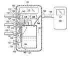
- FIG. 1is a cross-sectional view (with a portion shown in elevation view) of an illustrative embodiment of a system for simultaneously treating a plurality of tissue sites on a patient;
- FIG. 2is an elevation view of an illustrative embodiment of a multi-port therapy unit and an illustrative reduced-pressure source from FIG. 1 ;
- FIG. 3is a cross-sectional view (with a portion shown as a schematic diagram) of an illustrative embodiment of a system for simultaneously treating a plurality of tissue sites on a patient;
- FIG. 4is a cross-sectional view of an illustrative embodiment of a reduced-pressure plenum for use as an aspect of the system of FIG. 3 ;
- FIG. 5is a cross-sectional view (with a portion shown as a schematic diagram) of an illustrative embodiment of a system for simultaneously treating a plurality of tissue sites on a patient;
- FIG. 6is a schematic diagram of a portion of an illustrative embodiment of a system for simultaneously treating a plurality of tissue sites on a patient;
- FIG. 7is a schematic pressure-time graph for illustrating a method for identifying a leak in system for simultaneously treating a plurality of tissue sites on a patient;
- FIG. 8is a schematic pressure-time graph for illustrating a method for identifying a leak in a system for simultaneously treating a plurality of tissue sites on a patient;
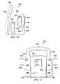
- FIG. 9is a perspective view of an illustrative embodiment of a multi-port therapy unit.
- FIG. 10is a side elevation view of the multi-port therapy unit of FIG. 9 ;
- FIG. 11is a rear elevation view of the multi-port therapy unit of FIG. 9 ;
- FIG. 12is a perspective view of an illustrative embodiment of a multi-port therapy unit
- FIG. 13is a front elevation view of the multi-port therapy unit of FIG. 12 ;
- FIG. 14is a rear elevation view of the multi-port therapy unit of FIG. 12 ;
- FIG. 15is a side elevation view of the multi-port therapy unit of FIG. 12 ;
- FIG. 16is a perspective view of an illustrative embodiment of a multi-port therapy unit
- FIG. 17is a side elevation view of the multi-port therapy unit of FIG. 16 ;
- FIG. 18is a rear elevation view of the illustrative multi-port therapy unit of FIG. 16 ;
- FIG. 19is a perspective view of an illustrative embodiment of a multi-port therapy unit
- FIG. 20is a side elevation view of the multi-port therapy unit of FIG. 19 ;
- FIG. 21is a rear elevation view of the multi-port therapy unit of FIG. 19 .
- tissue site 102may be the bodily tissue of any human, animal, or other organism, including bone tissue, adipose tissue, muscle tissue, dermal tissue, vascular tissue, connective tissue, cartilage, tendons, ligaments, or any other tissue.
- Treatment of tissue sites 102may include removal of fluids, e.g., exudate or ascites. While numerous tissue sites, sizes, and depths may be treated with the system 100 , the system 100 is shown treating tissue sites 102 in the form of wounds.
- tissue sites 102are shown for illustration purposes, it should be understood that any number of tissue sites—typically two or greater—may be treated with the system 100 .
- the system 100includes a plurality of reduced-pressure dressings 114 deployed on the plurality of tissue sites 102 .
- Each of the plurality of reduced-pressure dressings 114may be any kind of dressing that allows reduced pressure to be delivered to the tissue site 102 associated with the reduced-pressure dressing 114 and that is operable to remove fluids from the tissue site 102 .
- each reduced-pressure dressing 114includes a manifold 116 , a sealing member 118 , and a reduced-pressure interface 120 .
- the sealing member 118is releasably coupled to the tissue site 102 using an attachment device 122 .
- the attachment device 122may take numerous forms.
- the attachment device 122may be a medically acceptable, pressure-sensitive adhesive that extends about a periphery, a portion, or the entire sealing member 118 ; a double-sided drape tape; paste; hydrocolloid; hydro-gel; silicone gel, oraganogel, or other sealing devices or elements.
- the sealing member 118creates a sealed space 124 containing the manifold 116 and the tissue site 102 to be treated.
- the manifold 116is a substance or structure that is provided to assist in applying reduced pressure to, delivering fluids to, or removing fluids from the associated tissue site 102 .
- the manifold 116includes a plurality of flow channels or pathways that distribute fluids provided to and removed from the tissue site 102 around the manifold 116 .
- the flow channels or pathwaysare interconnected to improve distribution of fluids provided to or removed from the tissue site 102 .
- the manifold 116may comprise, for example, one or more of the following: a biocompatible material that is capable of being placed in contact with the tissue site 102 and distributing reduced pressure to the tissue site 102 ; devices that have structural elements arranged to form flow channels, such as, for example, cellular foam, open-cell foam, porous tissue collections, liquids, gels, and foams that include, or cure to include, flow channels; porous materials, such as foam, gauze, felted mat, or any other material suited to a particular biological application; or porous foam that includes a plurality of interconnected cells or pores that act as flow channels, e.g., a polyurethane, open-cell, reticulated foam such as GranuFoam® material manufactured by Kinetic Concepts, Incorporated of San Antonio, Tex.; a bioresorbable material; or a scaffold material.
- a biocompatible materialthat is capable of being placed in contact with the tissue site 102 and distributing reduced pressure to the tissue site 102 ; devices that have structural
- the manifold 116may also be used to distribute fluids such as medications, antibacterials, growth factors, and various solutions to the tissue site 102 .
- Other layersmay be included in or on the manifold 116 , such as absorptive materials, wicking materials, hydrophobic materials, and hydrophilic materials.
- the manifold 116may be constructed from a bioresorbable material that can remain in a patient's body following use of the reduced-pressure dressing 114 .
- Suitable bioresorbable materialsmay include, without limitation, a polymeric blend of polylactic acid (PLA) and polyglycolic acid (PGA).
- the polymeric blendmay also include without limitation polycarbonates, polyfumarates, and capralactones.
- the manifold 116may further serve as a scaffold for new cell-growth, or a scaffold material may be used in conjunction with the manifold 116 to promote cell-growth.
- a scaffoldis a substance or structure used to enhance or promote the growth of cells or formation of tissue, such as a three-dimensional porous structure that provides a template for cell growth.
- Illustrative examples of scaffold materialsinclude calcium phosphate, collagen, PLA/PGA, coral hydroxy apatites, carbonates, or processed allograft materials.
- the sealing member 118may be any material that provides a fluid seal.
- a fluid sealis a seal adequate to maintain reduced pressure at a desired site given the particular reduced-pressure source or subsystem involved.
- the sealing member 118may be, for example, an impermeable or semi-permeable, elastomeric material. For semi-permeable materials, the permeability must be low enough that for a given reduced-pressure source, the desired reduced pressure may be maintained.
- the sealing member 118may be discrete pieces for each reduced-pressure dressing 114 or may be one continuous sheet used for all the plurality of reduced-pressure dressings 114 .
- Each of the plurality of reduced-pressure interfaces 120is fluidly coupled to the associated sealed space 124 for the tissue site 102 .
- the reduced-pressure interfaces 120may each be any device for delivering reduced pressure to the associated sealed space 124 .
- each of the reduced-pressure interfaces 120may comprise one of the following: a T.R.A.C.® Pad or Sensa T.R.A.C.® Pad available from KCI of San Antonio, Tex.; or another device or tubing.
- a plurality of multi-lumen reduced-pressure delivery conduits 126are fluidly coupled to the plurality of reduced-pressure interfaces 120 in a one-to-one fashion.
- Each of the plurality of multi-lumen reduced-pressure delivery conduits 126has a first end 127 and a second end 129 . Each first end 127 of the multi-lumen reduced-pressure delivery conduits 126 is fluidly coupled to a multi-port therapy unit 128 .
- Each of the plurality of multi-lumen reduced-pressure delivery conduits 126may include at least one pressure-sampling lumen and at least one reduced-pressure supply lumen.
- the pressure-sampling lumenprovides a pressure for determining the pressure or approximate pressure at the associated reduced-pressure dressing 114 .
- the reduced-pressure supply lumendelivers the reduced pressure to the reduced-pressure dressing 114 and receives fluids therefrom.
- the second end 129 of each multi-lumen reduced-pressure delivery conduit 126is fluidly coupled to a respective reduced-pressure interface 120 .
- the multi-port therapy unit 128provides reduced pressure through the multi-lumen reduced-pressure delivery conduits 126 and reduced-pressure interfaces 120 to the sealed spaces 124 .
- the multi-port therapy unit 128receives pressure from the at least one pressure-sampling lumen of each of the plurality of multi-lumen reduced-pressure delivery conduits 126 and determines the pressure thereof.
- Reduced pressureincludes a pressure less than the ambient pressure at a tissue site that is being subjected to treatment. In most cases, this reduced pressure will be less than the atmospheric pressure at which the patient is located. Alternatively, the reduced pressure may be less than a hydrostatic pressure at the tissue site. Unless otherwise indicated, quantitative values of pressure stated herein are gauge pressures.
- the reduced pressure deliveredmay be constant or varied (patterned or random) and may be delivered continuously or intermittently. Although the terms “vacuum” and “negative pressure” may be used to describe the pressure applied to the tissue site, the actual pressure applied to the tissue site may be more than the pressure normally associated with a complete vacuum. Consistent with the use herein, unless otherwise indicated, an increase in reduced pressure or vacuum pressure typically refers to a reduction in absolute pressure.
- the multi-port therapy unit 128includes a plurality of patient-side ports 130 .
- Each of the plurality of patient-side ports 130is configured to fluidly couple to one of the multi-lumen reduced-pressure delivery conduits 126 and in particular with at least one of the pressure-sampling lumens and one of the reduced-pressure supply lumens of the plurality of multi-lumen reduced-pressure delivery conduits 126 .
- Patient-side ports 130 not in usemay be sealed by a cap 131 .
- a fluid reservoir 134is fluidly coupled to the plurality of patient-side ports 130 to provide reduced pressure thereto and receive fluids therefrom.
- a drain conduit 135may fluidly couple the fluid reservoir 134 to an exterior for draining the fluid reservoir 134 .
- a valve 137 associated with the drain conduit 135selectively controls fluid exiting the drain conduit 135 .
- the valve 137may be manual or may be automated and coupled to a controller 136 . Unless otherwise indicated, as used throughout this document, “or” does not require mutual exclusivity.
- the multi-port therapy unit 128also includes a plurality of pressure sensors 132 , or pressure transducers, that provide a treatment pressure signal to the controller 136 .
- the controller 136may be a printed wire assembly (PWA) or an application specific integrated circuit (ASIC) with a microprocessor and memory or other control device.
- the plurality of pressure sensors 132are associated with the plurality of patient-side ports 130 for determining a pressure associated with each of the plurality of patient-side ports 130 and typically with the pressure-sampling lumen therein that carries the approximate pressure at the reduced-pressure dressing 114 .
- Pressure associated with each of the plurality of patient-side ports 130may include the pressure at the port itself or proximate the port in an internal conduit. In any event, each pressure sensor 132 measures pressure a respective pressure-sampling lumen.
- the controller 136is operatively coupled to the plurality of pressure sensors 132 for receiving treatment pressure data from the plurality of pressure sensors 132 .
- the controller 136includes a microprocessor and memory configured to monitor pressure for each of the plurality of pressure sensors 132 and to signal an alarm condition if the pressure leaves a desired range or goes below a minimum reduced pressure threshold (i.e., the absolute pressure rises above a threshold).
- the controller 136is electrically coupled to an electrical power source 138 , which may be a battery or fixed power line, for example.
- a user interface 140is operatively coupled to the controller 136 for providing information readouts or for receiving user inputs.
- the multi-port therapy unit 128may include a plurality of visual indicators 142 .
- the visual indicators 142visually alert users when a pressure below a first threshold exists (i.e., above an absolute pressure threshold) at one of the plurality of patient-side ports 130 .
- the multi-port therapy unit 128also includes a supply-side port 144 for receiving reduced pressure.
- the supply-side port 144is fluidly coupled to the fluid reservoir 134 such as by an internal conduit 146 .
- the supply-side port 144is also fluidly coupled by a conduit 148 to a reduced-pressure source 150 .
- the reduced-pressure source 150may be any device for supplying a reduced pressure, such as a vacuum pump, wall suction, or other source. While the amount and nature of reduced pressure applied to a tissue site will typically vary according to the application, the reduced pressure will typically be between ⁇ 5 mm Hg ( ⁇ 667 Pa) and ⁇ 500 mm Hg ( ⁇ 66.7 kPa) and more typically between ⁇ 75 mm Hg ( ⁇ 9.9 kPa) and ⁇ 300 mm Hg ( ⁇ 39.9 kPa). In some embodiments, the reduced-pressure source 150 may be a V.A.C. Freedom, V.A.C. ATS, InfoVAC, ActiVAC, ABThera, or V.A.C. Ulta therapy units available from KCI of San Antonio, Tex.
- the reduced-pressure source 150is fluidly coupled to the supply-side port 144 of the multi-port therapy unit 128 .
- the caps 131or sealing caps, are removed from the plurality of patient-side ports 130 in a number corresponding to the number of tissue sites 102 that are to be treated.
- the first ends 127 of the plurality of multi-lumen reduced-pressure delivery conduits 126are coupled to the uncapped members of the plurality of patient-side ports 130 .
- the plurality of reduced-pressure dressings 114are deployed on the plurality of tissue sites 102 .
- the second ends 129 of the plurality of multi-lumen reduced-pressure delivery conduits 126are fluidly coupled to the plurality of reduced-pressure dressings 114 .
- the reduced-pressure source 150is activated to supply reduced pressure to the fluid reservoir 134 and to the tissue sites 102 . As liquids are removed from the tissue sites 102 , the liquids begin to fill the fluid reservoir 134 . Optionally, after fluid reservoir 134 is full, the fluid may continue into a fluid reservoir contained within the reduced-pressure source 150 . Alternatively, a hydrophobic or oleophobic filter may be included as part of the supply-side port 144 to prevent liquids from reaching the reduced-pressure source 150 .
- the multi-port therapy unit 128monitors pressure at the tissue sites 102 for each of the connected reduced-pressure dressings 114 .
- Each pressure sensor 132develops a treatment pressure signal that is delivered to the controller 136 for monitoring.
- the microprocessor and memory or other aspects of controller 136are used to monitor the treatment pressure signals to confirm compliance with the desired pressure range.
- the pressure in each tissue site 102may be displayed on the user interface 140 constantly or with a cycled pattern.
- separate multi-colored LED indicatorsmay be included to provide a quick color indication of pressure and status at each of the plurality of patient-side ports 130 .
- the multi-colored LED indicatorsmay be able to assume the colors green, yellow, and red.
- the controller 136may be programmed to produce a green light when the pressure is between ⁇ 75 mm Hg and ⁇ 150 mm Hg.
- a yellow lightmay be signaled if the wound pressure declines (i.e., loses reduced pressure so that pressure is greater on an absolute pressure scale) indicating a dressing leak.
- a red lightmay be used to indicate the wound pressure is below a reduced pressure threshold (e.g., ⁇ 40 mm Hg) and is not providing adequate therapy.
- a flashing red lightmay mean that an over pressure (e.g., more negative than ⁇ 200 mm Hg) has been applied.
- a relief valvemay also be included.
- the caregivermay find and address a leak that is in the associated reduced-pressure dressing 114 , disconnect the multi-lumen reduced-pressure delivery conduit 126 associated with that particular reduced-pressure dressing 114 and reattach the cap 131 to avoid compromising the reduced pressure available for other tissue sites 102 .
- the caregivermay connect a separate therapy unit (reduced pressure source and fluid reservoir) to the apparently leaking reduced-pressure dressing 114 so that reduced pressure may continue to be supplied until a more convenient time is available for addressing the situation.
- the controller 136may also optionally activate an audible alarm 152 , but given tight quarters for many transportation operations, this feature may be turned off or not included. Typically, if it is a desire to purge the plurality of multi-lumen reduced-pressure delivery conduits 126 , they will be purged together. If the red light is indicated, the caregiver checks the multi-lumen reduced-pressure delivery conduits 126 for blockage and replaces any blocked conduits if necessary.
- the fluid reservoir 134 in the multi-port therapy unit 128is an off-the-shelf canister.
- the fluid reservoir 134may have a minimal size, and the plurality of reduced-pressure dressings 114 may include absorbents to hold liquids at the dressing.
- the multi-port therapy unit 128may be a collapsible unit to minimize space requirements.
- the multi-port therapy unit 128may expand as it fills with liquids.
- each reduced-pressure dressing 114includes an absorbent layer for storing liquids in the reduced-pressure dressing 114 .
- the absorbent layermay be made from super absorbent fibers.
- the super absorbent fibersmay retain or bond to the liquid in conjunction with a physical or chemical change to the fibers.
- the super absorbent fibermay include the Super Absorbent Fiber (SAF) material from Technical Absorbents, Ltd. of Grimsby, United Kingdom, or the like.
- SAFSuper Absorbent Fiber
- the absorbent layermay be a sheet or mat of fibrous material in which the fibers absorb liquid from the tissue site 102 .
- the structure of the absorbent layer that contains the fibersmay be either woven or non-woven.
- the fibers in the absorbent layermay gel upon contact with the liquid, thereby trapping the liquid. Spaces or voids between the fibers may allow reduced pressure that is applied to the absorbent layer to be transferred within and through the absorbent layer.
- the fiber density of the fibers in the absorbent layermay be approximately 1.4 grams per millimeter.
- a positive pressure exhaust from a vacuum pump in the reduced-pressure source 150may be routed into channels that are pressurized at a greater pressure than the reduced pressure gradient within the fluid reservoir 134 such that the fluid reservoir 134 has a structure that inflates around it.
- the chambersmay be sealed at ambient pressure, so when an aircraft transporting a patient using the system 100 reaches altitude, the reduced pressure at altitude may cause a pressure differential that fills the channels with higher pressure air.
- the fluid reservoir 134 of the multi-port therapy unit 128may include a tortuous path such that fluid may not easily reflux from channel to channel. This may take the form of an opening from a pathway of a second baffle, or series of baffles within a rigid section of the fluid reservoir 134 .
- the tortuous pathsmay take the form of small pieces of absorbent, non-woven looking material, or a small-pore open-celled foam acting as a barrier to low pressure reflux or fluids.
- valvesthat allow fluid and air to flow in one direction into the fluid reservoir 134 but prevents these same fluids from reverse flow.
- valvescommonly known as check-valves, include flat/flap valves and duck-bill valves.
- the fluid reservoir 134may be an absorbent pouch.
- the fluid reservoirmay be a pouch containing an absorbent layer such as the one previously mentioned.
- the supply-side port 144may include a hydrophobic or oleophobic filter.
- the hydrophobic filterprevents fluids from being passed to the reduced-pressure source 150 .
- the hydrophobic filteris periodically changed.
- the hydrophobic filtermay be included as part of a fluid reservoir 134 and replaced when the fluid reservoir 134 is replaced. If the fluid reservoir 134 becomes full, at times it may be desirable to drain some of the liquids therein. For this reason, the valve 137 may be opened and fluids removed through the drain conduit 135 . If reduced pressure therapy is occurring during the draining process, a valve that prevents reduced pressure from entering the supply-side port 144 may be incorporated and used to prevent the bleeding of reduced pressure.
- an osmotic membranemay be used to have a fluid gathering section that allows easy draining of that portion. In other words, water is separated from the exudate such that the water may be discarded.
- the ports 130 , 144may be configured to be “connector-less” connections.
- Shut-off valvesmay be incorporated into the connectors to minimize loss of vacuum during connecting and disconnecting.
- the pressure sensors 132may be removed from the multi-port therapy unit 128 and placed on the plurality of reduced-pressure dressings 114 . This may be more desirable with inexpensive pressure sensors. Such an approach would, eliminate the need for blockage detectors and allow specific tissue site pressure monitoring with more accuracy.
- the fluid reservoir 134may be removed from the multi-port therapy unit 128 for disposal. This leaves the remaining components for refurbishing and reuse according to one illustrative embodiment.
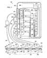
- FIG. 3another illustrative embodiment of a system 200 for simultaneously treating a plurality of tissue sites 202 is presented.
- the plurality of tissue sites 202 , plurality of reduced-pressure dressings 214 , and many other aspects of the system 200are analogous to those in FIG. 1 .
- the system 200is shown treating tissue sites 202 in the form of wounds.
- the woundsare shown for illustrative purposes extending through epidermis 208 , dermis 210 , and into subcutaneous tissue 212 . Other depths or types of wounds or, more generally, tissue sites may be treated.
- five tissue sites 202are shown for illustration purposes, it should be understood that any number of tissue sites—typically two and greater—may be treated with the system 200 .
- the system 200includes the plurality of reduced-pressure dressings 214 deployed on the plurality of tissue sites 202 .
- Each of the plurality of reduced-pressure dressings 214may be any kind of dressing that allows reduced pressure to be delivered to the tissue site 202 associated with the reduced-pressure dressing 214 and that is operable to remove fluids from the tissue site 202 .
- each reduced-pressure dressing 214includes a manifold 216 , a sealing member 218 , and a reduced-pressure interface 220 .
- the sealing member 218is releasably coupled to the tissue site 202 using an attachment device 222 .
- the attachment device 222may take numerous forms, such as those previously mentioned.
- the sealing member 218creates a sealed space 224 containing the manifold 216 and the tissue site 202 to be treated. These components are analogous to those in FIG. 1 .
- the reduced-pressure dressings 214are fluidly coupled to a multi-port therapy unit 228 by a plurality of multi-lumen reduced-pressure delivery conduits 226 .
- Each multi-lumen reduced-pressure delivery conduit 226may include at least one pressure-sampling lumen and at least one reduced-pressure supply lumen.
- Each multi-lumen reduced-pressure delivery conduit 226has a first end 227 and a second end 229 .
- the first ends 227are fluidly coupled to the multi-port therapy unit 228 at a plurality of patient-side ports 230 .
- each patient-side port 230 that is not usedmay have a cap (see 131 in FIG. 1 ) covering the patient-side port.
- Each of the plurality of patient-side ports 230is configured to fluidly couple with one of the plurality of multi-lumen reduced-pressure delivery conduits 226 and have at least one of the pressure-sampling lumens and one of the reduced-pressure supply lumens fluidly coupled.
- the pressure-sampling lumenis fluidly coupled to one of a plurality of treatment pressure sensors 232 .
- a fluid storage deviceis fluidly coupled to each of the plurality of multi-lumen reduced-pressure delivery conduits 226 .
- the fluid storage deviceis fluidly coupled to the plurality of reduced-pressure dressings 214 for receiving and at least temporarily storing fluids therefrom.
- the fluid storage devicemay be one or more of the following: a single reservoir (not explicitly shown but analogous to 134 in FIGS.
- each the multi-lumen reduced-pressure delivery conduits 226fluidly coupled to each the multi-lumen reduced-pressure delivery conduits 226 , a plurality of fluid reservoirs 234 (only one is shown for illustration purposes) associated with the multi-port therapy unit 228 , a plurality of in-line canisters 235 (only one is shown for illustration purposes), a plurality of sections within one large canister which are specific to each wound, or a plurality of absorbent layers associated with or forming part of the plurality of reduced-pressure dressings 214 .
- the multi-port therapy unit 228includes a controller 236 , the plurality of patient-side ports 230 , and a plurality of reduced-pressure plenums 256 .
- Each of the plurality of reduced-pressure plenums 256is associated with one of the plurality of patient-side ports 230 .
- Each plenum of the plurality of reduced-pressure plenums 256is a pressure vessel for holding reduced pressure.
- Each plenummay have a fixed volume or a variable volume. With respect to the latter, as shown in FIG.
- each plenum of the plurality of reduced-pressure plenums 256may be formed with a moveable wall 258 that is biased outward by biasing devices 260 to help maintain reduced pressure in the interior of the reduced-pressure plenum 256 .
- the biasing device 260may be a spring compressed shorter than its free length, a positively charged cylinder, or other biasing device.
- Each plenummay have a fixed volume between about 50 cc and about 400 cc, for example.
- the multi-port therapy unit 228also includes the plurality of treatment pressure sensors 232 .
- Each of the plurality of treatment pressure sensors 232is associated with one of the plurality of patient-side ports 230 for determining a pressure associated with at least one pressure-sampling lumen in the multi-lumen reduced-pressure delivery conduit 226 associated with the patient-side port 230 .
- Each treatment pressure sensor 232is operatively coupled to the controller 236 to provide a treatment pressure signal to the controller 236 .
- the multi-port therapy unit 228also includes a plurality of plenum pressure sensors 262 .
- Each of the plurality of plenum pressure sensors 262is associated with one of the plurality of reduced-pressure plenums 256 and is operatively coupled to the controller 236 for supplying a plenum pressure signal.
- the multi-port therapy unit 228also includes a first plurality of control valves 264 fluidly coupled between each of the plurality of reduced-pressure plenums 256 and an associated patient-side port 230 .
- the plurality of first control valves 264may comprise a plurality of proportional valves.
- Each of the first plurality of control valves 264is operatively coupled to the controller 236 so that each of the first plurality of control valves 264 may be controlled by the controller 236 .
- the first plurality of control valves 264controls the delivery of reduced pressure from the reduced-pressure plenums 256 into the plurality of multi-lumen reduced-pressure delivery conduits 226 .
- a bacteria filtermay be associated with each of the first plurality of control valves 264 . Alternatively or in addition, a bacteria filter may be placed at the ports 230 or if an in-line canister is used as part of that structure.
- the multi-port therapy unit 228also includes a main vacuum source 266 fluidly coupled to each of the plurality of reduced-pressure plenums 256 for charging the reduced-pressure plenums 256 , i.e., supplying reduced pressure to each of the plurality of reduced pressure plenums 256 .
- the main vacuum source 266is typically a single vacuum pump but could also be a wall supply of reduced pressure or a multi-pump subsystem. If a vacuum pump, the main vacuum source 266 may receive electrical power from an electrical power source 238 .
- the main vacuum source 266can charge each of the plurality of reduced-pressure plenums 256 with reduced pressure.
- the stored reduced pressureis used to deliver regulated reduced pressure to the tissue sites 202 .
- the reduced pressure in each reduced-pressure plenum 256is greater (more negative on a pressure scale) than ⁇ 400 mm Hg.
- the multi-port therapy unit 228also includes a second plurality of control valves 268 fluidly coupled between each of the plurality of reduced-pressure plenums 256 and the main vacuum source 266 .
- the plurality of second control valves 268may comprise proportional valves.
- the second plurality of control valves 268controls the introduction of reduced pressure into the reduced-pressure plenums 256 .
- the second plurality of control valves 268may have a hydrophobic filter associated with each to prevent liquids from reaching the main vacuum source 266 .
- Each of the plurality of first control valves 264is controlled to regulate the reduced pressure down to the pressure selected by the caregiver for a respective channel and tissue site 202 .
- the multi-lumen reduced-pressure delivery conduits 226 or connectormay include an automatic shut-off valve to isolate an individual line for a dressing change without interacting with the user interface associated with the controller 236 .
- An indicatorcould be provided on each line to help isolate leaks—one implementation may be a green/yellow/red indicator that is based on the controller's calculation of recharge rate for a given plenum module, in conjunction with information about the proportional valve set point required to maintain the selected therapy reduced pressure.
- Multi-lumen reduced-pressure delivery conduits 226may be color-coded to aid in therapy management.
- the controller 236may be a printed wire assembly (PWA), for example, or an application specific integrated circuit (ASIC) with a microprocessor and memory or other control device.
- the controller 236is operative to regulate the reduced pressure supplied from the plurality of reduced-pressure plenums 256 to the plurality of patient-side ports 230 by controlling the first plurality of control valves 264 and to regulate the reduced pressure supplied to the plurality of reduced-pressure plenums 256 using the second plurality of control valves 268 .
- the controller 236is electrically coupled to the electrical power source 238 .
- the controller 236is configured to receive the plenum pressure signal for each plenum of the plurality of reduced-pressure plenums 256 , and if a plenum pressure signal is less than a plenum threshold (for example, without limitation, if ⁇ 290 mm Hg is less reduced pressure than an illustrative plenum threshold of ⁇ 300 mm Hg) to at least partially open the associated valve of the second plurality of control valves to deliver additional reduced pressure to the plenum associated with the plenum pressure signal that is less than the plenum threshold.
- a plenum thresholdfor example, without limitation, if ⁇ 290 mm Hg is less reduced pressure than an illustrative plenum threshold of ⁇ 300 mm Hg
- the controller 236is also configured to receive the treatment pressure signal for each of the plurality of treatment pressure sensors 232 and if a treatment pressure signal is less than a minimum treatment pressure threshold (e.g., without limitation, the pressure is ⁇ 90 mm Hg which is less than the minimum treatment pressure of ⁇ 100 mm Hg) to at least partially open the associated valve of the first plurality of control valves 264 and if the treatment pressure signal is greater than a high treatment pressure threshold to at least partially close the associated valve of the first plurality of control valves 264 .
- a minimum treatment pressure thresholde.g., without limitation, the pressure is ⁇ 90 mm Hg which is less than the minimum treatment pressure of ⁇ 100 mm Hg
- Each of the plurality of patient-side ports 230may also include a relief valve to limit the maximum reduced pressure that may be applied to a reduced-pressure dressing 214 .
- the controller 236may also be operative to prioritize the filling of the plenums of the plurality of reduced-pressure plenums 256 such that a plenum having a plenum pressure signal that over time continues below a plenum threshold will be filled only after other plenums of the plurality of reduced-pressure plenums 256 .
- the controller 236determines that a leak may be occurring with a reduced-pressure dressing 214 or other aspect associated with a particular plenum, that plenum will be filled last to avoid devoting all or a substantial amount of the system's reduced pressure to trying to compensate for a leak.
- a plurality of indicators 270may be associated with each of the patient-side ports 230 .
- the indicators 270may be LED lights or other visual indicators. If the controller 236 determines that a leak may exist as referenced above, the controller 236 may cause the indicator 270 associated with the channel or particular reduced-pressure dressing 214 to be activated. In this way, the user may be able to address the leak for that particular channel or reduced-pressure dressing 214 .
- system 200may be used with a different arrangement of reduced-pressure plenums 256 such that perhaps two channels are operated on one plenum or the system has one larger plenum upon which each channel is fed.
- the volume of a reduced-pressure plenum 256may vary (depending upon the capacity one wishes to provide and the likely leak tolerance one needs the system to manage) from about 50 cc at the low end to about 400 cc. Other volumes are possible.
- the reduced-pressure plenum 256is adjusted to use mechanical pressure/energy storage.
- a sealed bellow plastic structure of sufficient strength that it is able to vertically or in some form collapse under a vacuum that is also capable of exerting force to return to its previous shapemay be used. In this case, the force is essentially multiplied. If one considers such a structure with a spring structure incorporated (see FIG. 4 ), under high reduced pressure the air is removed and the structure is charged. When connected to the wound via the regulating valves, the spring attempts to extend and the structure will expand to ‘pump’ negative pressure to the wound. The pressure in the structure or the mechanical position of the structure may be monitored in order to determine when a re-charge is required.
- Thismay be a molded bellows structure or a piston type assembly with a central spring, or alternatively a combination of the aforementioned structures with constant force springs such that the pressure delivered is predictable.
- the main vacuum source 266may be used in conjunction with or replaced with a connection to another pump such as wall-suction or another integrated vacuum source which would be available at the place of treatment.
- another pumpsuch as wall-suction or another integrated vacuum source which would be available at the place of treatment.
- the proportional valvesmay be replaced with a simple mechanical regulating valve which controls the wound pressure. This arrangement would still provide for pressure feedback and alarms. With an absorbent based dressing system, there will be no tube blockages so the system may merely determine and confirm the appropriate delivery of pressure and also notify the caregiver when the dressing is full.
- the valvemay be manufactured and produced such that it is capable of selecting from a range of pressures.
- a designmight include a rotational collar on the regulating valve, which would adjust the spring force on the regulating diaphragm such that with less force, a lower pressure is regulated to the wound, and with a greater force on the diaphragm, a higher pressure is regulated to the wound.
- the electronic systemmay be configured to recognize that this pressure has been manually adjusted to either pre-set levels (e.g., ⁇ 75/ ⁇ 125/ ⁇ 200 mm Hg) or to a user selected variable pressure ( ⁇ 143 mm Hg for example) by a pressure sensor connected to the immediate orifice of the regulator and thus provide pressure feedback in the knowledge that this pressure is the pressure which should be manifolded to the reduced-pressure interface through the absorbent structure.
- pre-set levelse.g., ⁇ 75/ ⁇ 125/ ⁇ 200 mm Hg
- a user selected variable pressure⁇ 143 mm Hg for example
- the higher-vacuum plenum volumecould include the multi-lumen reduced-pressure delivery conduit 226 going to the wound site, with final pressure regulation and wound pressure sensing hardware placed at or near each tissue site 202 .
- Regulationwould be implemented with a piezo-proportional valve (e.g., from Festo) which requires relatively little battery power (small currents are required only to change the valve opening, not to maintain a setting).
- Disposable medical grade pressure sensorse.g., from Measurement Specialties
- Wireless communication back to the controller 236is possible, and this would provide additional options for using y-connectors to reduce the number of tube sets running back to the main control unit, and thus reduce the number of plenums required.
- lightmay be used to identify channels with issues. It has been shown that clear extruded tubing makes a good conduit for light transmission. This can be utilized to highlight individual conduits by applying a light source to one end, which has the effect of illuminating the length of conduit much like a fiber optic tube, but in this instance the light diffuses along its length. This may also be helpful in instructing the user of the location of a fluid or exudate blockage, as one would expect that the transmitted light would be refracted less after such a mass. This would be useful to indicate which one of multiple conduits is at issue during a fault condition or when setting up the system.
- the devicemay be used in noisy environments such as field hospitals and military aircraft, this feature may augment the audio feedback that is often relied upon during modes such as seal check.
- the use of multi-color LEDswould allow for the color to be altered depending on the information that was being communicated.
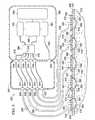
- tissue sites 302for simultaneously treating a plurality of tissue sites 302 on a patient 304 are presented.
- the plurality of tissue sites 302 , plurality of reduced-pressure dressings 314 , and many other aspects of the system 300are analogous to those in FIGS. 1 and 4 .
- the system 300is shown treating tissue sites 302 in the form of wounds.
- the woundsare shown for illustrative purposes extending through epidermis 308 , dermis 310 , and into subcutaneous tissue 312 . Other depths or types of wounds or, more generally, tissue sites may be treated.
- five tissue sites 302are shown for illustration purposes, it should be understood that any number of tissue sites—typically two or greater—may be treated with the system 300 .
- the system 300includes the plurality of reduced-pressure dressings 314 deployed on the plurality of tissue sites 302 .
- Each of the plurality of reduced-pressure dressings 314may be any kind of dressing that allows reduced pressure to be delivered to the tissue site 302 associated with the reduced-pressure dressing 314 and that is operable to remove fluids from the tissue site 302 .
- each reduced-pressure dressing 314includes a manifold 316 , a sealing member 318 , and a reduced-pressure interface 320 .
- the sealing member 318is releasably coupled to the tissue site 302 using an attachment device 322 .
- the attachment device 322may take numerous forms, such as those previously mentioned in other embodiments.
- the sealing member 318creates a sealed space 324 containing the manifold 316 and the tissue site 302 to be treated. These components are analogous to those in FIGS. 1 and 4 .
- the reduced-pressure dressings 314are fluidly coupled to a fluid reservoir 334 .
- the fluid reservoir 334has a plurality of patient-side ports 330 that are fluidly coupled to a plurality of multi-lumen reduced-pressure delivery conduits 326 .
- the fluid reservoir 334is fluidly coupled to a reduced-pressure source 350 through a reduced-pressure port 351 .
- An internal conduit 353is fluidly coupled between the reduced-pressure port 351 and the reduced-pressure source 350 .
- a plurality of by-pass conduits 374fluidly coupled the pressure-sampling lumens of the multi-lumen reduced-pressure delivery conduits 326 to a plurality of pressure ports 376 .
- a plurality of internal conduits 378fluidly couples the plurality of pressure ports 376 to a multiplexing valve 380 .
- a plurality of control valvesmay be used on a plurality of internal conduits fluidly coupling the plurality of pressure ports 376 and treatment pressure sensor 332 .
- a controller 336can close all the valves except one at a time to use the treatment pressure sensor 332 on each valve.
- the treatment pressure sensor 332is operatively coupled to the controller 336 to deliver treatment pressure signals.
- a fluid storage deviceis fluidly coupled to each of the plurality of multi-lumen reduced-pressure delivery conduits 326 .
- the fluid storage deviceis fluidly coupled to the plurality of reduced-pressure dressings 314 for receiving and at least temporarily storing fluids therefrom.
- the fluid storage devicemay be one or more of the following: the fluid reservoir 334 fluidly coupled to each the multi-lumen reduced-pressure delivery conduits 326 as shown, or a plurality of in-line canisters (not shown but analogous to in-line canister 235 in FIG. 4 )), or a plurality of absorbent layers associated with or forming part of the plurality of reduced-pressure dressings 314 .
- the multi-port therapy unit 328includes the controller 336 and the plurality of pressure ports 376 .
- Each of the plurality of pressure ports 376is configured to fluidly couple with at least one of the pressure-sampling lumens of the plurality of multi-lumen reduced pressure delivery conduits 326 .
- the multi-port therapy unit 328further includes the treatment pressure sensor 332 that is fluidly coupled to the plurality of pressure-sampling lumens associated with the plurality multi-lumen reduced-pressure delivery conduits 326 .
- a valve meansmay be used to couple one of the plurality of pressure ports 376 to the treatment pressure sensor 332 at a time.
- the valve meansmay be the multiplexing valve 380 or plurality of valves as described elsewhere herein.
- the multi-port therapy unit 328also includes the reduced-pressure source 350 that is fluidly coupled to the plurality of reduced-pressure dressings 314 .
- the reduced-pressure source 350is operatively coupled to the controller 336 .
- the reduced-pressure source 350charges the fluid reservoir 334 with reduced pressure that is delivered by the plurality of multi-lumen reduced-pressure delivery conduits 326 to the plurality of reduced-pressure dressings 314 .
- the multi-port therapy unit 328also includes the controller 336 .
- the controller 336is operatively coupled to the treatment pressure sensor 332 , the valve means (e.g., multiplexing valve 380 ), and the reduced-pressure source 350 .
- the controller 336is configured to monitor the treatment reduced pressure signals of each of the plurality of pressure-sampling lumens associated with the plurality of multi-lumen reduced-pressure delivery conduits 326 as measured by the treatment pressure sensor 332 . In response, the controller 336 controls the reduced pressure delivered by the reduced-pressure source 350 to the plurality of reduced-pressure dressings 314 .
- the controller 336may be configured to determine a number of pressure ports 376 in use and to look up a gross-flow-rate limit for the number and compare the gross-flow-rate limit to the actual flow rate of the reduced-pressure source 350 and if the actual flow rate is greater than the gross-flow-rate limit, to activate an alert (audible alarm, visual indicator, or other alert). As described further below, the controller 336 may be configured to use various steps to determine if one or more of the reduced-pressure dressings 314 is leaking.
- a user interface 340may be used to receive information from or to input commands or data into the controller 336 .
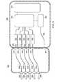
- FIG. 6another illustrative embodiment of a portion of a system 300 for simultaneously treating a plurality of tissue sites 302 on a patient is presented.
- the system 300 of FIG. 6is analogous to the system 300 of FIG. 5 and accordingly some components are labeled with reference numerals but not further described here.
- FIG. 6differs mainly in that instead of a single treatment pressure sensor 332 , a plurality of treatment pressure sensors 332 are used.
- the plurality of pressure ports 376are fluidly coupled to the plurality of treatment pressure sensors 332 , which each develop a treatment pressure signal.
- the plurality of treatment pressure sensors 332are operatively coupled to the controller 336 for delivering the treatment pressure signals to the controller 336 .
- Other aspects of the system 300are analogous to FIG. 5 .
- the controller 336may be used in configuring the controller 336 to determine when a leak likely exists. Two prominent approaches are readily used. With reference to FIG. 7 , the first includes stopping the reduced pressure to the reduced-pressure dressings 314 and then comparing its decay pattern 400 to a set standard or a median decay pattern 402 . If the variation is greater than a desired threshold, the controller 336 activates an alert. With references to FIG. 8 , the second approach is to stop the reduced pressure supplied to the reduced-pressure dressing 314 for a time period and then to activate the reduced pressure and capture the ramp-up pattern 500 for a particular reduced-pressure dressing 314 . This approach may be combined with the initial pressure decay test to provide dual confirmation of the leaking channel. The ramp-up pattern 500 may then be compared to a standard or median pattern 502 .
- a simple blocking featuremay be added, such as a piece of open-celled foam, across the entry ports 330 so that fluid splashes do not have the opportunity of reaching the opening but fluids can be drawn into the fluid reservoir 334 .
- a pressure gradient through the system 300with the greater reduced pressure in the fluid reservoir 334 and reducing down towards the dressing 314 , it is not anticipated that flow will naturally occur towards the dressing 314 .
- a simple flap valvecould be constructed at the port 330 from a material that is permeable to fluids so that therapy is not compromised but will resist an instantaneous burst of fluid as could happen if the fluid reservoir 334 was agitated or knocked over.
- a single pressure sensor 332is controlled and multiplexed to measure pressure in a pressure-sampling lumen of each multi-lumen reduced-pressure conduit in sequence.
- the controller 336will automatically assign a percentage of sensor time to each wound, and via a directional control valve (such as an electronically actuated piston or spool valve) will pneumatically connect the sensor to each wound every 2 seconds (sample time may vary).
- the pneumatic volume between the valve and the sensormay be minimized to reduce the potential for the channels to be influenced by each other at switching. Initially this may be on a purely sequential basis (i.e.
- wound 1 , wound 2 , etc)may determine that some wounds are struggling to maintain pressure more than others, which are remaining consistent. At this time the controller may choose to prioritize these low performing wounds for more regular checks (i.e. wound 1 , wound 2 , wound 3 , wound 2 , wound 4 , wound 2 . . . wound 2 has a lower pressure). Having one pressure sensor does mean that any sensor-to-sensor variances will not be a factor when the system is trying to balance the wound pressure control.
- the control valve switching sequencemay be coordinated with a purge function in order to avoid concerns of possible cross-contamination during switching, but also to reduce the total number of valves required.
- a plurality of treatment pressure sensors 332are multiplexed into one sensor port on the controller 336 which are electronically scanned by the controller in a manner similar to those previously discussed.
- Sensor to sensor variancesmay be a factor in the reporting of channel pressures, but there is a benefit here in that a failure of any one pressure sensor can be reported and that channel indicated as off to the user.
- the controller 336may monitor each signal continuously.
- the system 300which has a reduced-pressure source 350 that is a vacuum pump and fixed fluid reservoir volume, is capable of detecting a leak in one or more reduced-pressure dressings 314 .
- the leakis determined by measuring the fluid reservoir pressure and estimating air flow based on pump duty, and comparing the estimated air flow based on pump duty to pre-determined air flow levels within the software of the air flow level that should be required for a set number of wounds.
- the system 300may have a leak tolerance of 1 l/min with one or possibly 2 wound dressings.
- the system 300 with up to 5 woundsmay have a proportionately higher leak threshold as each dressing presents its own sealing challenge, e.g., a leak tolerance of 2 l/min.
- the controller 336is capable of providing an alarm to tell the caregiver if the net average pressure in the system is low, and that a leak likely exists due to the pump having to operate at a level consistent with there being a flow of air into the system that is above its pre-determined threshold.
- the system 300is pneumatically capable of delivering therapy with up to 5 dressings or another desired number with consideration given not only due to the possibility of air leak, but also because pneumatically a high flow of fluid in the system imposes the same duty on the pump. A situation may exist where all 5 wounds are moderately exudating and there are small leaks which in themselves would not trigger a leak alarm, but combined with the fluid pressure drop results in the leak alarm threshold being triggered. Therefore, the trigger level may be varied by user input.
- the pump control and the multi-channel wound pressure measurementsare used to determine which dressings have the most significant leak.
- this systemmonitors the wound pressure during deliberate dynamic changes in pump pressure to look for differences in the ways in which wound pressure changes between dressings, to seek ways to identify which one possesses an air leak, for example, as described with respect to FIGS. 7 and 8 .
- a two-cavity (or two-chamber) canisterwhere the cavity acts as a plenum to allow the user to have two groups of wounds at different pressures, may be used Valves are used to allow the single pump to control pressure in these two chambers.
- each conduitmay have its own electronically actuated valve which is driven by the controller 336 .
- the valvesWhen the valves are closed, they seal the line to prevent leaks.
- These valvesmay be driven directly from the main controller 336 or by a secondary PWA which has an encoder circuit driven by a serial connection from the controller PWA. This would then allow a leaking dressing to be isolated while therapy is maintained to the others until the user has corrected the fault.
- FIGS. 5 and 6feature collection of fluids in a centralized fluid reservoir 334 .
- the use of a wound-site or an in-line absorbent componentmay be used to replace or augment the capacity provided by the fluid reservoir 334 . This may be used where there are multiple highly exudating wounds.
- the systems 300may use evaporation to further process fluids.
- the evaporationcould be used to enhance the volume of fluids that can be accepted.
- a high moisture-vapor-transfer-rate (MVTR) materialis used in the reduced pressure dressings 314 or at other locations.
- An aspect of the fluid reservoir 334may be formed from the high MVTR material. In a pressurized cabin, it is normal for the humidity levels to be lower than 50% and for the actual pressure to be considerably lower than that experienced at sea level—both these factors will aid in the process of evaporation.
- each portmay be fitted with a clear plastic ring that is illuminated from a light source such as a LED, which may be white or color coded for each port (i.e., a different color for each port).
- the light source illuminating the ringis controlled by the controller 336 .
- the ringwill either be in close proximity or touching the multi-lumen reduced-pressure delivery conduit such that a light connection is made with the conduit and that when the ring becomes illuminated light is also fed down the conduit.
- the ring on that portilluminates and flashes to indicate which port is impacted, and the light will also travel down the conduit to assist in highlighting to the user which wound is involved.
- the systems 100 , 200 , 300 or aspects of the systems for simultaneously treating a plurality of tissue sites on a patientmay be structured in numerous ways. A few illustrative examples follow. Referring for example primarily to FIGS. 9-11 , a multi-port therapy unit 600 is presented.
- the multi-port therapy unit 600has a carrying handle 602 and a body 604 .
- the body 604is configured to receive a plurality of canisters 606 on a backside 608 .
- Each canister 606includes a fluid reservoir and a port 607 for receiving a multi-port reduced-pressure delivery conduit.
- the canisters 606may include seals for interfacing with the body 604 and may clip to a support or attachment prong (not explicitly shown) or otherwise releasably attached to the body 604 .
- a front face 610includes a user panel 612 , or user interface.
- the user panel 612may have segments 614 devoted to each of the plurality of canisters 606 .
- the back side 608may include a pole-attachment device 616 for releasably attaching the multi-port therapy unit 600 to a pole or other securing member.
- the pole-attachment device 616may include a pole channel 617 and a knob 618 to screw a clamp onto the pole in the pole channel 617 or other securing member.
- FIGS. 12-15another multi-port therapy unit 600 is presented.
- the multi-port therapy unit 600is analogous in most respects to the multi-port therapy unit 600 of FIGS. 9-11 , and accordingly, some parts are labeled but not further described here.
- a main difference between the multi-port therapy unit 600 of FIGS. 12-15 and the multi-port therapy unit 600 of FIGS. 9-11is that the plurality of canisters has been moved to the front face 610 .
- an illustrative multi-lumen reduced-pressure delivery conduit 620is shown coupled to the port 607 associated with one canister 606 .
- FIGS. 16-18another multi-port therapy unit 600 is presented.
- the multi-port therapy unit 600is analogous in most respects to the multi-port therapy unit 600 of FIGS. 9-11 , and accordingly, some parts are labeled but not further described here.
- a main difference between the multi-port therapy unit 600 of FIGS. 16-18 and the multi-port therapy unit 600 of FIGS. 9-11is that the canisters 606 are coupled to the body 604 on a first side 622 .
- one multi-lumen reduced-pressure delivery conduit 620is shown coupled to a port 607 of one canister 606 .
- a power cord connection 624Also shown is a power cord connection 624 .
- FIGS. 19-21another multi-port therapy unit 600 is presented.
- the multi-port therapy unit 600is analogous in most respects to the multi-port therapy unit 600 of FIGS. 9-11 , and accordingly, some parts are labeled but not further described here.
- a main difference between the multi-port therapy unit 600 of FIGS. 19-21 and the multi-port therapy unit 600 of FIGS. 9-11is that the canisters 606 are coupled on a first side 622 and a second side 626 .
- the canisters 606 on each side 622 , 626are staggered vertically (for orientation shown).
- the canisters 606have a kidney shape that may be oriented differently on each side 622 , 626 .
- FIG. 21shows four multi-lumen reduced-pressure delivery conduits 620 coupled to the multi-port therapy unit 600 .
- a canister channel 628 to receive an attachment prongis shown in FIG. 19 .
Landscapes
- Health & Medical Sciences (AREA)
- Heart & Thoracic Surgery (AREA)
- Vascular Medicine (AREA)
- Engineering & Computer Science (AREA)
- Anesthesiology (AREA)
- Biomedical Technology (AREA)
- Hematology (AREA)
- Life Sciences & Earth Sciences (AREA)
- Animal Behavior & Ethology (AREA)
- General Health & Medical Sciences (AREA)
- Public Health (AREA)
- Veterinary Medicine (AREA)
- Media Introduction/Drainage Providing Device (AREA)
- External Artificial Organs (AREA)
- Surgical Instruments (AREA)
Abstract
Description
Claims (10)
Priority Applications (3)
| Application Number | Priority Date | Filing Date | Title |
|---|---|---|---|
| US13/681,731US10155071B2 (en) | 2011-11-23 | 2012-11-20 | Reduced-pressure systems, methods, and devices for simultaneously treating a plurality of tissue sites |
| US16/128,252US11813392B2 (en) | 2011-11-23 | 2018-09-11 | Reduced-pressure systems, methods, and devices for simultaneously treating a plurality of tissue sites |
| US18/377,108US20240024561A1 (en) | 2011-11-23 | 2023-10-05 | Reduced-pressure systems, methods, and devices for simultaneously treating a plurality of tissue sites |
Applications Claiming Priority (2)
| Application Number | Priority Date | Filing Date | Title |
|---|---|---|---|
| US201161563284P | 2011-11-23 | 2011-11-23 | |
| US13/681,731US10155071B2 (en) | 2011-11-23 | 2012-11-20 | Reduced-pressure systems, methods, and devices for simultaneously treating a plurality of tissue sites |
Related Child Applications (1)
| Application Number | Title | Priority Date | Filing Date |
|---|---|---|---|
| US16/128,252DivisionUS11813392B2 (en) | 2011-11-23 | 2018-09-11 | Reduced-pressure systems, methods, and devices for simultaneously treating a plurality of tissue sites |
Publications (2)
| Publication Number | Publication Date |
|---|---|
| US20130144227A1 US20130144227A1 (en) | 2013-06-06 |
| US10155071B2true US10155071B2 (en) | 2018-12-18 |
Family
ID=47279139
Family Applications (3)
| Application Number | Title | Priority Date | Filing Date |
|---|---|---|---|
| US13/681,731Active2034-05-15US10155071B2 (en) | 2011-11-23 | 2012-11-20 | Reduced-pressure systems, methods, and devices for simultaneously treating a plurality of tissue sites |
| US16/128,252Active2036-08-21US11813392B2 (en) | 2011-11-23 | 2018-09-11 | Reduced-pressure systems, methods, and devices for simultaneously treating a plurality of tissue sites |
| US18/377,108PendingUS20240024561A1 (en) | 2011-11-23 | 2023-10-05 | Reduced-pressure systems, methods, and devices for simultaneously treating a plurality of tissue sites |
Family Applications After (2)
| Application Number | Title | Priority Date | Filing Date |
|---|---|---|---|
| US16/128,252Active2036-08-21US11813392B2 (en) | 2011-11-23 | 2018-09-11 | Reduced-pressure systems, methods, and devices for simultaneously treating a plurality of tissue sites |
| US18/377,108PendingUS20240024561A1 (en) | 2011-11-23 | 2023-10-05 | Reduced-pressure systems, methods, and devices for simultaneously treating a plurality of tissue sites |
Country Status (7)
| Country | Link |
|---|---|
| US (3) | US10155071B2 (en) |
| EP (2) | EP2782615B1 (en) |
| JP (1) | JP6189316B2 (en) |
| CN (1) | CN103930138B (en) |
| AU (1) | AU2012340789B2 (en) |
| CA (1) | CA2854478C (en) |
| WO (1) | WO2013078214A1 (en) |
Cited By (1)
| Publication number | Priority date | Publication date | Assignee | Title |
|---|---|---|---|---|
| WO2022114967A1 (en) | 2020-11-24 | 2022-06-02 | Aroa Biosurgery Limited | Fluid drainage and delivery device for wound treatment |
Families Citing this family (124)
| Publication number | Priority date | Publication date | Assignee | Title |
|---|---|---|---|---|
| JP5113522B2 (en) | 2004-10-07 | 2013-01-09 | トランスメディクス, インク. | System and method for organ management ex-vivo |
| US12010987B2 (en) | 2004-10-07 | 2024-06-18 | Transmedics, Inc. | Systems and methods for ex-vivo organ care and for using lactate as an indication of donor organ status |
| US9078428B2 (en) | 2005-06-28 | 2015-07-14 | Transmedics, Inc. | Systems, methods, compositions and solutions for perfusing an organ |
| EP2129409B2 (en) | 2007-03-14 | 2021-11-24 | The Board of Trustees of the Leland Stanford Junior University | Devices for application of reduced pressure therapy |
| US9457179B2 (en) | 2007-03-20 | 2016-10-04 | Transmedics, Inc. | Systems for monitoring and applying electrical currents in an organ perfusion system |
| US9408954B2 (en) | 2007-07-02 | 2016-08-09 | Smith & Nephew Plc | Systems and methods for controlling operation of negative pressure wound therapy apparatus |
| GB0715259D0 (en) | 2007-08-06 | 2007-09-12 | Smith & Nephew | Canister status determination |
| US12121648B2 (en) | 2007-08-06 | 2024-10-22 | Smith & Nephew Plc | Canister status determination |
| EP2203137B1 (en) | 2007-10-11 | 2016-02-24 | Spiracur, Inc. | Closed incision negative pressure wound therapy device |
| US10226610B2 (en) | 2007-10-26 | 2019-03-12 | Electrochemical Oxygen Concepts, Inc. | Apparatus and methods for controlling tissue oxygenation for wound healing and promoting tissue viability |
| US8287506B2 (en) | 2007-10-26 | 2012-10-16 | Electrochemical Oxygen Concepts, Inc. | Apparatus and methods for controlling tissue oxygenation for wound healing and promoting tissue viability |
| US10750738B2 (en) | 2008-01-31 | 2020-08-25 | Transmedics, Inc. | Systems and methods for ex vivo lung care |
| AU2009214439B2 (en) | 2008-02-14 | 2014-09-25 | Solventum Intellectual Properties Company | Devices and methods for treatment of damaged tissue |
| CA2744548C (en) | 2008-11-25 | 2017-06-13 | Spiracur Inc. | Device for delivery of reduced pressure to body surfaces |
| US8361043B2 (en) | 2009-01-07 | 2013-01-29 | Spiracur Inc. | Reduced pressure therapy of the sacral region |
| US8444614B2 (en) | 2009-04-10 | 2013-05-21 | Spiracur, Inc. | Methods and devices for applying closed incision negative pressure wound therapy |
| US8795246B2 (en) | 2010-08-10 | 2014-08-05 | Spiracur Inc. | Alarm system |
| US8753322B2 (en) | 2010-08-10 | 2014-06-17 | Spiracur Inc. | Controlled negative pressure apparatus and alarm mechanism |
| US11291760B2 (en) | 2010-08-10 | 2022-04-05 | Kci Licensing, Inc. | Controlled negative pressure apparatus and alarm mechanism |
| US9526920B2 (en) | 2010-10-12 | 2016-12-27 | Smith & Nephew, Inc. | Medical device |
| CA2819032C (en) | 2010-11-25 | 2020-06-23 | Smith & Nephew Plc | Composition i-ii and products and uses thereof |
| GB201020005D0 (en) | 2010-11-25 | 2011-01-12 | Smith & Nephew | Composition 1-1 |
| JP6029650B2 (en) | 2011-04-14 | 2016-11-24 | トランスメディクス,インコーポレイテッド | Organ protection solution for mechanical perfusion in ex-vivo of donor lung |
| WO2013066426A2 (en) | 2011-06-24 | 2013-05-10 | Kci Licensing, Inc. | Reduced-pressure dressings employing tissue-fixation elements |
| US20150159066A1 (en) | 2011-11-25 | 2015-06-11 | Smith & Nephew Plc | Composition, apparatus, kit and method and uses thereof |
| AU2013237095B2 (en) | 2012-03-20 | 2017-10-05 | Smith & Nephew Plc | Controlling operation of a reduced pressure therapy system based on dynamic duty cycle threshold determination |
| EP2852333B1 (en) | 2012-05-22 | 2021-12-15 | Smith & Nephew plc | Apparatuses for wound therapy |
| JP6400570B2 (en) | 2012-05-23 | 2018-10-10 | スミス アンド ネフュー ピーエルシーSmith & Nephew Public Limited Company | Apparatus and method for local negative pressure closure therapy |
| WO2014020440A1 (en) | 2012-08-01 | 2014-02-06 | Smith & Nephew Plc | Wound dressing |
| CN108186200B (en) | 2012-08-01 | 2021-08-10 | 史密夫及内修公开有限公司 | Wound dressing |
| JP2016517318A (en) | 2013-03-14 | 2016-06-16 | スミス アンド ネフュー インコーポレーテッド | System and method for administering decompression therapy |
| US9737649B2 (en) | 2013-03-14 | 2017-08-22 | Smith & Nephew, Inc. | Systems and methods for applying reduced pressure therapy |
| EP2968647B1 (en) | 2013-03-15 | 2022-06-29 | Smith & Nephew plc | Wound dressing sealant and use thereof |
| US10695226B2 (en) | 2013-03-15 | 2020-06-30 | Smith & Nephew Plc | Wound dressing and method of treatment |
| US10758648B2 (en) | 2013-03-15 | 2020-09-01 | Kci Licensing, Inc. | Vacuum cartridge with integrated valve |
| US20160120706A1 (en) | 2013-03-15 | 2016-05-05 | Smith & Nephew Plc | Wound dressing sealant and use thereof |
| CN105407932A (en) | 2013-03-15 | 2016-03-16 | 史密夫及内修公开有限公司 | Wound dressing and method of treatment |
| WO2015023515A1 (en)* | 2013-08-13 | 2015-02-19 | Smith & Nephew, Inc. | Systems and methods for applying reduced pressure therapy |
| BR112016007156B1 (en)* | 2013-10-02 | 2022-12-13 | 3M Innovative Properties Company | REDUCED PRESSURE SYSTEM |
| US10016543B2 (en)* | 2013-10-02 | 2018-07-10 | Kci Licensing, Inc. | Disposable reduced-pressure therapy system with electronic feedback |
| JP6634661B2 (en)* | 2014-01-07 | 2020-01-22 | ポトレロ メディカル,インコーポレイテッド | Systems, instruments and methods for draining and analyzing body fluids |
| EP3939554A1 (en) | 2014-02-11 | 2022-01-19 | 3M Innovative Properties Company | Devices for applying closed incision negative pressure wound therapy |
| CN106163583B (en)* | 2014-02-20 | 2019-03-19 | 凯希特许有限公司 | For using vacuum pump to empty the method and system of deposited part |
| CN103800993A (en)* | 2014-02-28 | 2014-05-21 | 昆山韦睿医疗科技有限公司 | Negative-pressure wound treatment equipment and system |
| WO2015134749A2 (en) | 2014-03-06 | 2015-09-11 | Stryker Corporation | Medical/surgical waste collection unit with a light assembly separate from the primary display, the light assembly presenting informatin about the operation of the system by selectively outputting light |
| CA3185937A1 (en) | 2014-06-02 | 2015-12-10 | Transmedics, Inc. | Ex vivo organ care system |
| US10610414B2 (en) | 2014-06-18 | 2020-04-07 | Smith & Nephew Plc | Wound dressing and method of treatment |
| US20160177250A1 (en)* | 2014-06-25 | 2016-06-23 | Cytori Therapeutics, Inc. | Tissue transfer system |
| DE102014214045A1 (en)* | 2014-07-18 | 2016-01-21 | Asskea Gmbh | Apparatus for aspirating body fluid and filter module therefor |
| CA3179001A1 (en)* | 2014-07-31 | 2016-02-04 | Smith & Nephew, Inc. | Systems and methods for applying reduced pressure therapy |
| US12133789B2 (en)* | 2014-07-31 | 2024-11-05 | Smith & Nephew, Inc. | Reduced pressure therapy apparatus construction and control |
| CN104225770A (en)* | 2014-09-30 | 2014-12-24 | 昆山韦睿医疗科技有限公司 | Method for cooperation of multiple negative-pressure treatment devices and negative-pressure treatment system |
| EP3229588B1 (en) | 2014-12-12 | 2025-04-23 | TransMedics, Inc. | Apparatus and method for organ perfusion |
| EP3237032B1 (en)* | 2014-12-22 | 2024-08-07 | Smith & Nephew plc | Negative pressure wound therapy apparatus |
| AU2015373537B2 (en)* | 2014-12-29 | 2020-09-03 | Smith & Nephew Plc | Negative pressure wound therapy apparatus and method of operating the apparatus |
| CA2972701A1 (en) | 2014-12-30 | 2016-07-07 | Smith & Nephew, Inc. | Systems and methods for applying reduced pressure therapy |
| EP3240587B1 (en) | 2014-12-30 | 2020-05-27 | Smith & Nephew, Inc | Systems for applying reduced pressure therapy |
| EP3597228B1 (en)* | 2015-04-06 | 2023-05-03 | 3M Innovative Properties Company | Apparatus for controlling negative-pressure treatment |
| EP3297697B1 (en) | 2015-05-18 | 2022-05-11 | Smith & Nephew plc | Negative pressure wound therapy apparatus |
| AU2016305091B2 (en) | 2015-08-13 | 2021-06-10 | Smith & Nephew, Inc. | Systems and methods for applying reduced pressure therapy |
| DK3347084T3 (en) | 2015-09-09 | 2021-02-15 | Transmedics Inc | AORTIC NEEDLE FOR EX VIVO ORGAN CARE SYSTEM |
| CN119280635A (en)* | 2015-12-07 | 2025-01-10 | 电化学氧概念公司 | Devices and methods for controlling tissue oxygenation and promoting tissue vitality in wound healing |
| US11364150B2 (en) | 2015-12-30 | 2022-06-21 | Smith & Nephew Plc | Negative pressure wound therapy apparatus |
| US11090196B2 (en) | 2015-12-30 | 2021-08-17 | Smith & Nephew Plc | Absorbent negative pressure wound therapy dressing |
| US11141513B2 (en) | 2016-01-28 | 2021-10-12 | Kci Licensing, Inc. | Fluid container with pressure regulation |
| WO2017139394A1 (en)* | 2016-02-09 | 2017-08-17 | Kci Licensing, Inc. | A negative-pressure therapy apparatus with push-to-release actuator |
| EP4393526A3 (en) | 2016-02-12 | 2024-08-14 | Smith & Nephew, Inc | Systems and methods for detecting operational conditions of reduced pressure therapy |
| WO2017146986A1 (en)* | 2016-02-22 | 2017-08-31 | Kci Licensing, Inc. | Manually activated negative pressure therapy system with integrated audible feedback |
| JP1586116S (en) | 2016-02-29 | 2017-09-19 | ||
| WO2017148824A1 (en) | 2016-03-04 | 2017-09-08 | Smith & Nephew Plc | Negative pressure wound therapy apparatus for post breast surgery wounds |
| WO2017192810A1 (en)* | 2016-05-04 | 2017-11-09 | Parasol Medical LLC | Portable pump for negative pressure wound therapy |
| CN109069713A (en) | 2016-05-13 | 2018-12-21 | 史密夫和内修有限公司 | Automatic wound in negative pressure wound treating system couples detection |
| US10987091B2 (en) | 2016-05-17 | 2021-04-27 | Biosense Webster (Israel) Ltd. | System and method for catheter connections |
| US11413388B2 (en)* | 2016-05-24 | 2022-08-16 | Somavac Medical Solutions, Inc. | Portable device with disposable reservoir for collection of internal fluid after surgery from a plurality of sites simultaneously |
| WO2017205967A1 (en)* | 2016-05-30 | 2017-12-07 | Freed Darren | Apparatus and method for ex vivo lung ventilation with a varying exterior pressure |
| SE541236C2 (en) | 2016-06-23 | 2019-05-14 | Resaroe Event Ab | Body drainage system comprising a peristaltic pump device |
| EP3481348A4 (en) | 2016-07-08 | 2020-02-26 | ConvaTec Technologies Inc. | Fluid collection apparatus |
| EP3528861A4 (en)* | 2016-10-19 | 2020-06-17 | Medtec Medical, Inc. | Electronic vacuum regulator device |
| CN106581789B (en)* | 2016-12-12 | 2023-05-26 | 武汉维斯第医用科技股份有限公司 | External multi-pipeline converter for negative pressure closed drainage system |
| EP3551147B1 (en) | 2016-12-12 | 2023-08-09 | Smith & Nephew PLC | Wound dressing |
| US11395870B2 (en) | 2017-02-15 | 2022-07-26 | Smith & Nephew Asia Pacific Pte. Limited | Negative pressure wound therapy apparatuses and methods for using the same |
| EP3589250A1 (en) | 2017-02-28 | 2020-01-08 | T J Smith & Nephew Limited | Multiple dressing negative pressure wound therapy system |
| GB2560365B (en) | 2017-03-09 | 2021-10-20 | Brightwake Ltd | Improvements relating to apparatus negative pressure wound therapy |
| EP3372257A1 (en)* | 2017-03-09 | 2018-09-12 | Mölnlycke Health Care AB | Negative pressure wound therapy assembly |
| AU2018234981B2 (en)* | 2017-03-15 | 2023-09-28 | Smith & Nephew Plc | Multiple dressing negative pressure wound therapy system with calibrated leak paths |
| WO2018195101A1 (en) | 2017-04-19 | 2018-10-25 | Smith & Nephew, Inc. | Negative pressure wound therapy canisters |
| USD881202S1 (en)* | 2017-05-08 | 2020-04-14 | Kci Licensing, Inc. | Display screen with graphical user interface for negative pressure unit |
| WO2018212849A1 (en)* | 2017-05-16 | 2018-11-22 | Kci Licensing, Inc. | An absorbent negative-pressure dressing system for use with post-surgical breast wounds |
| JP7155162B2 (en) | 2017-06-14 | 2022-10-18 | ティージェイ スミス アンド ネフュー リミテッド | Negative pressure wound therapy unit |
| US10702686B2 (en) | 2017-06-30 | 2020-07-07 | Electrochemical Oxygen Concepts, Inc. | Wound oxygen supply system |
| EP3687592B1 (en) | 2017-09-29 | 2025-09-03 | T.J. Smith & Nephew, Limited | Negative pressure wound therapy apparatus with removable panels |
| WO2019089266A1 (en)* | 2017-11-03 | 2019-05-09 | Kci Licensing, Inc. | Extended wear-time dressing |
| CN111836655A (en) | 2017-11-16 | 2020-10-27 | 康沃特克有限公司 | fluid collection equipment |
| US11160910B2 (en)* | 2017-12-18 | 2021-11-02 | Alcon Inc. | Cassette annunciation |
| GB201813282D0 (en) | 2018-08-15 | 2018-09-26 | Smith & Nephew | System for medical device activation and opertion |
| GB201804347D0 (en) | 2018-03-19 | 2018-05-02 | Smith & Nephew Inc | Securing control of settings of negative pressure wound therapy apparatuses and methods for using the same |
| WO2019190753A1 (en)* | 2018-03-29 | 2019-10-03 | Kci Licensing, Inc. | A system for managing instillation therapy on multiple wounds with a single fluid source |
| US20210008259A1 (en)* | 2018-04-04 | 2021-01-14 | Kci Licensing, Inc. | Systems and methods for controlling negative pressure therapy with fluid instillation therapy and cleansing |
| GB201806988D0 (en) | 2018-04-30 | 2018-06-13 | Quintanar Felix Clarence | Power source charging for negative pressure wound therapy apparatus |
| WO2019211731A1 (en) | 2018-04-30 | 2019-11-07 | Smith & Nephew Pte. Limited | Systems and methods for controlling dual mode negative pressure wound therapy apparatus |
| GB201808438D0 (en) | 2018-05-23 | 2018-07-11 | Smith & Nephew | Systems and methods for determining blockages in a negative pressure wound therapy system |
| WO2020018328A1 (en)* | 2018-07-16 | 2020-01-23 | Kci Licensing, Inc. | Wound therapy system with conduit blockage detection |
| GB201813565D0 (en)* | 2018-08-21 | 2018-10-03 | Smith & Nephew | Negative pressure wound therapy device status indication using a canister |
| GB201814158D0 (en) | 2018-08-31 | 2018-10-17 | Smith & Nephew | Blockage and leak detection in multiple dressing reduced pressure wound therapy systems |
| WO2020061264A1 (en) | 2018-09-19 | 2020-03-26 | Deroyal Industries, Inc. | Multiple-wound negative pressure wound therapy using multiple fluid collection volumes |
| US20220001096A1 (en)* | 2018-10-03 | 2022-01-06 | Kci Licensing, Inc. | Low-profile fluid conductors with treatment indicators |
| EP3880268B1 (en)* | 2018-11-14 | 2024-09-11 | Solventum Intellectual Properties Company | Wound therapy system with blockage and leak detection |
| WO2020110626A1 (en)* | 2018-11-27 | 2020-06-04 | 株式会社村田製作所 | Npwt module |
| GB2588482B (en) | 2019-07-03 | 2022-01-05 | Smith & Nephew | Negative pressure wound therapy dressing recognition, wound status detection, and therapy adjustment |
| GB201911693D0 (en) | 2019-08-15 | 2019-10-02 | Smith & Nephew | Systems and methods for monitoring essential performance of wound therapy |
| GB201914283D0 (en) | 2019-10-03 | 2019-11-20 | Smith & Nephew | Apparatuses and methods for negative pressure wound therapy |
| GB201918593D0 (en)* | 2019-12-17 | 2020-01-29 | Smith & Nephew | Systems and methods for operating a wound therapy device in stealth mode |
| GB202001212D0 (en) | 2020-01-29 | 2020-03-11 | Smith & Nephew | Systems and methods for measuring and tracking wound volume |
| WO2021161119A1 (en)* | 2020-02-10 | 2021-08-19 | Kci Licensing, Inc. | System and method for coordinating negative pressure and instillation therapy |
| GB202002338D0 (en)* | 2020-02-20 | 2020-04-08 | Convatec Ltd | A method and control system for a wound therapy apparatus |
| WO2021194479A1 (en)* | 2020-03-24 | 2021-09-30 | Hewlett-Packard Development Company, L.P. | Processing systems with a plurality of supply reservoirs |
| CN111420132A (en)* | 2020-03-31 | 2020-07-17 | 振德医疗用品股份有限公司 | Miniature negative pressure drainage instrument and operation method thereof |
| US11291758B2 (en)* | 2020-08-05 | 2022-04-05 | Covidien Lp | Collection system for managing outflow from a surgical procedure |
| EP4192539B1 (en)* | 2020-08-05 | 2025-08-27 | KCI Manufacturing Unlimited Company | Multi-canister module for negative-pressure therapy |
| EP4237027A1 (en)* | 2020-12-07 | 2023-09-06 | KCI Manufacturing Unlimited Company | Systems, methods, and apparatuses to overcome pump-induced pressure excursions and control aliasing with reduced volume, absorbent negative-pressure therapy systems |
| US12208197B2 (en)* | 2020-12-11 | 2025-01-28 | Hisham Alshaer | Manually operated negative pressure wound treatment apparatus coupled with smart feedback system |
| WO2023012551A1 (en)* | 2021-08-04 | 2023-02-09 | Kci Manufacturing Unlimited Company | Negative pressure accumulator to control fluid flow through filter |
| GB2625770A (en)* | 2022-12-22 | 2024-07-03 | Brightwake Ltd | Apparatus for negative pressure wound therapy |
| DE102023117305A1 (en)* | 2023-06-30 | 2025-01-02 | Paul Hartmann Ag | Array comprising at least two aggregate parts and at least two container parts for forming a device for negative pressure treatment of wounds |
Citations (142)
| Publication number | Priority date | Publication date | Assignee | Title |
|---|---|---|---|---|
| US1355846A (en) | 1920-02-06 | 1920-10-19 | David A Rannells | Medical appliance |
| US2547758A (en) | 1949-01-05 | 1951-04-03 | Wilmer B Keeling | Instrument for treating the male urethra |
| US2632443A (en) | 1949-04-18 | 1953-03-24 | Eleanor P Lesher | Surgical dressing |
| GB692578A (en) | 1949-09-13 | 1953-06-10 | Minnesota Mining & Mfg | Improvements in or relating to drape sheets for surgical use |
| US2682873A (en) | 1952-07-30 | 1954-07-06 | Johnson & Johnson | General purpose protective dressing |
| US2910763A (en) | 1955-08-17 | 1959-11-03 | Du Pont | Felt-like products |
| US2969057A (en) | 1957-11-04 | 1961-01-24 | Brady Co W H | Nematodic swab |
| US3066672A (en) | 1960-09-27 | 1962-12-04 | Jr William H Crosby | Method and apparatus for serial sampling of intestinal juice |
| US3367332A (en) | 1965-08-27 | 1968-02-06 | Gen Electric | Product and process for establishing a sterile area of skin |
| US3520300A (en) | 1967-03-15 | 1970-07-14 | Amp Inc | Surgical sponge and suction device |
| US3568675A (en) | 1968-08-30 | 1971-03-09 | Clyde B Harvey | Fistula and penetrating wound dressing |
| US3648692A (en) | 1970-12-07 | 1972-03-14 | Parke Davis & Co | Medical-surgical dressing for burns and the like |
| US3682180A (en) | 1970-06-08 | 1972-08-08 | Coilform Co Inc | Drain clip for surgical drain |
| US3826254A (en) | 1973-02-26 | 1974-07-30 | Verco Ind | Needle or catheter retaining appliance |
| DE2640413A1 (en) | 1976-09-08 | 1978-03-09 | Wolf Gmbh Richard | CATHETER MONITORING DEVICE |
| US4080970A (en) | 1976-11-17 | 1978-03-28 | Miller Thomas J | Post-operative combination dressing and internal drain tube with external shield and tube connector |
| US4096853A (en) | 1975-06-21 | 1978-06-27 | Hoechst Aktiengesellschaft | Device for the introduction of contrast medium into an anus praeter |
| US4139004A (en) | 1977-02-17 | 1979-02-13 | Gonzalez Jr Harry | Bandage apparatus for treating burns |
| US4165748A (en) | 1977-11-07 | 1979-08-28 | Johnson Melissa C | Catheter tube holder |
| US4184510A (en) | 1977-03-15 | 1980-01-22 | Fibra-Sonics, Inc. | Valued device for controlling vacuum in surgery |
| WO1980002182A1 (en) | 1979-04-06 | 1980-10-16 | J Moss | Portable suction device for collecting fluids from a closed wound |
| US4233969A (en) | 1976-11-11 | 1980-11-18 | Lock Peter M | Wound dressing materials |
| US4245630A (en) | 1976-10-08 | 1981-01-20 | T. J. Smith & Nephew, Ltd. | Tearable composite strip of materials |
| US4256109A (en) | 1978-07-10 | 1981-03-17 | Nichols Robert L | Shut off valve for medical suction apparatus |
| US4261363A (en) | 1979-11-09 | 1981-04-14 | C. R. Bard, Inc. | Retention clips for body fluid drains |
| US4275721A (en) | 1978-11-28 | 1981-06-30 | Landstingens Inkopscentral Lic, Ekonomisk Forening | Vein catheter bandage |
| US4284079A (en) | 1979-06-28 | 1981-08-18 | Adair Edwin Lloyd | Method for applying a male incontinence device |
| US4297995A (en) | 1980-06-03 | 1981-11-03 | Key Pharmaceuticals, Inc. | Bandage containing attachment post |
| US4333468A (en) | 1980-08-18 | 1982-06-08 | Geist Robert W | Mesentery tube holder apparatus |
| US4373519A (en) | 1981-06-26 | 1983-02-15 | Minnesota Mining And Manufacturing Company | Composite wound dressing |
| US4382441A (en) | 1978-12-06 | 1983-05-10 | Svedman Paul | Device for treating tissues, for example skin |
| US4392853A (en) | 1981-03-16 | 1983-07-12 | Rudolph Muto | Sterile assembly for protecting and fastening an indwelling device |
| US4392858A (en) | 1981-07-16 | 1983-07-12 | Sherwood Medical Company | Wound drainage device |
| US4419097A (en) | 1981-07-31 | 1983-12-06 | Rexar Industries, Inc. | Attachment for catheter tube |
| EP0100148A1 (en) | 1982-07-06 | 1984-02-08 | Dow Corning Limited | Medical-surgical dressing and a process for the production thereof |
| US4465485A (en) | 1981-03-06 | 1984-08-14 | Becton, Dickinson And Company | Suction canister with unitary shut-off valve and filter features |
| EP0117632A2 (en) | 1983-01-27 | 1984-09-05 | Johnson & Johnson Products Inc. | Adhesive film dressing |
| US4475909A (en) | 1982-05-06 | 1984-10-09 | Eisenberg Melvin I | Male urinary device and method for applying the device |
| US4480638A (en) | 1980-03-11 | 1984-11-06 | Eduard Schmid | Cushion for holding an element of grafted skin |
| US4525374A (en) | 1984-02-27 | 1985-06-25 | Manresa, Inc. | Treating hydrophobic filters to render them hydrophilic |
| US4525166A (en) | 1981-11-21 | 1985-06-25 | Intermedicat Gmbh | Rolled flexible medical suction drainage device |
| US4540412A (en) | 1983-07-14 | 1985-09-10 | The Kendall Company | Device for moist heat therapy |
| US4543100A (en) | 1983-11-01 | 1985-09-24 | Brodsky Stuart A | Catheter and drain tube retainer |
| US4548202A (en) | 1983-06-20 | 1985-10-22 | Ethicon, Inc. | Mesh tissue fasteners |
| US4551139A (en) | 1982-02-08 | 1985-11-05 | Marion Laboratories, Inc. | Method and apparatus for burn wound treatment |
| EP0161865A2 (en) | 1984-05-03 | 1985-11-21 | Smith and Nephew Associated Companies p.l.c. | Adhesive wound dressing |
| US4569348A (en) | 1980-02-22 | 1986-02-11 | Velcro Usa Inc. | Catheter tube holder strap |
| AU550575B2 (en) | 1981-08-07 | 1986-03-27 | Richard Christian Wright | Wound drainage device |
| US4605399A (en) | 1984-12-04 | 1986-08-12 | Complex, Inc. | Transdermal infusion device |
| US4608041A (en) | 1981-10-14 | 1986-08-26 | Frese Nielsen | Device for treatment of wounds in body tissue of patients by exposure to jets of gas |
| US4640688A (en) | 1985-08-23 | 1987-02-03 | Mentor Corporation | Urine collection catheter |
| US4655754A (en) | 1984-11-09 | 1987-04-07 | Stryker Corporation | Vacuum wound drainage system and lipids baffle therefor |
| US4664662A (en) | 1984-08-02 | 1987-05-12 | Smith And Nephew Associated Companies Plc | Wound dressing |
| WO1987004626A1 (en) | 1986-01-31 | 1987-08-13 | Osmond, Roger, L., W. | Suction system for wound and gastro-intestinal drainage |
| US4710165A (en) | 1985-09-16 | 1987-12-01 | Mcneil Charles B | Wearable, variable rate suction/collection device |
| US4733659A (en) | 1986-01-17 | 1988-03-29 | Seton Company | Foam bandage |
| GB2195255A (en) | 1986-09-30 | 1988-04-07 | Vacutec Uk Limited | Method and apparatus for vacuum treatment of an epidermal surface |
| US4743232A (en) | 1986-10-06 | 1988-05-10 | The Clinipad Corporation | Package assembly for plastic film bandage |
| GB2197789A (en) | 1986-11-28 | 1988-06-02 | Smiths Industries Plc | Anti-foaming disinfectants used in surgical suction apparatus |
| US4758220A (en) | 1985-09-26 | 1988-07-19 | Alcon Laboratories, Inc. | Surgical cassette proximity sensing and latching apparatus |
| US4787888A (en) | 1987-06-01 | 1988-11-29 | University Of Connecticut | Disposable piezoelectric polymer bandage for percutaneous delivery of drugs and method for such percutaneous delivery (a) |
| US4826494A (en) | 1984-11-09 | 1989-05-02 | Stryker Corporation | Vacuum wound drainage system |
| US4838883A (en) | 1986-03-07 | 1989-06-13 | Nissho Corporation | Urine-collecting device |
| US4840187A (en) | 1986-09-11 | 1989-06-20 | Bard Limited | Sheath applicator |
| US4863449A (en) | 1987-07-06 | 1989-09-05 | Hollister Incorporated | Adhesive-lined elastic condom cathether |
| US4872450A (en) | 1984-08-17 | 1989-10-10 | Austad Eric D | Wound dressing and method of forming same |
| US4878901A (en) | 1986-10-10 | 1989-11-07 | Sachse Hans Ernst | Condom catheter, a urethral catheter for the prevention of ascending infections |
| GB2220357A (en) | 1988-05-28 | 1990-01-10 | Smiths Industries Plc | Medico-surgical containers |
| US4897081A (en) | 1984-05-25 | 1990-01-30 | Thermedics Inc. | Percutaneous access device |
| US4906233A (en) | 1986-05-29 | 1990-03-06 | Terumo Kabushiki Kaisha | Method of securing a catheter body to a human skin surface |
| US4906240A (en) | 1988-02-01 | 1990-03-06 | Matrix Medica, Inc. | Adhesive-faced porous absorbent sheet and method of making same |
| US4919654A (en) | 1988-08-03 | 1990-04-24 | Kalt Medical Corporation | IV clamp with membrane |
| CA2005436A1 (en) | 1988-12-13 | 1990-06-13 | Glenda G. Kalt | Transparent tracheostomy tube dressing |
| US4941882A (en) | 1987-03-14 | 1990-07-17 | Smith And Nephew Associated Companies, P.L.C. | Adhesive dressing for retaining a cannula on the skin |
| US4953565A (en) | 1986-11-26 | 1990-09-04 | Shunro Tachibana | Endermic application kits for external medicines |
| WO1990010424A1 (en) | 1989-03-16 | 1990-09-20 | Smith & Nephew Plc | Absorbent devices and precursors therefor |
| US4969880A (en) | 1989-04-03 | 1990-11-13 | Zamierowski David S | Wound dressing and treatment method |
| US4985019A (en) | 1988-03-11 | 1991-01-15 | Michelson Gary K | X-ray marker |
| GB2235877A (en) | 1989-09-18 | 1991-03-20 | Antonio Talluri | Closed wound suction apparatus |
| US5037397A (en) | 1985-05-03 | 1991-08-06 | Medical Distributors, Inc. | Universal clamp |
| US5086170A (en) | 1989-01-16 | 1992-02-04 | Roussel Uclaf | Process for the preparation of azabicyclo compounds |
| US5092858A (en) | 1990-03-20 | 1992-03-03 | Becton, Dickinson And Company | Liquid gelling agent distributor device |
| US5100396A (en) | 1989-04-03 | 1992-03-31 | Zamierowski David S | Fluidic connection system and method |
| JPH04129536A (en) | 1990-09-19 | 1992-04-30 | Terumo Corp | Balance device |
| US5134994A (en) | 1990-02-12 | 1992-08-04 | Say Sam L | Field aspirator in a soft pack with externally mounted container |
| US5149331A (en) | 1991-05-03 | 1992-09-22 | Ariel Ferdman | Method and device for wound closure |
| US5167613A (en) | 1992-03-23 | 1992-12-01 | The Kendall Company | Composite vented wound dressing |
| US5176663A (en) | 1987-12-02 | 1993-01-05 | Pal Svedman | Dressing having pad with compressibility limiting elements |
| WO1993009727A1 (en) | 1991-11-14 | 1993-05-27 | Wake Forest University | Method and apparatus for treating tissue damage |
| US5215522A (en) | 1984-07-23 | 1993-06-01 | Ballard Medical Products | Single use medical aspirating device and method |
| US5232453A (en) | 1989-07-14 | 1993-08-03 | E. R. Squibb & Sons, Inc. | Catheter holder |
| US5261893A (en)* | 1989-04-03 | 1993-11-16 | Zamierowski David S | Fastening system and method |
| US5278100A (en) | 1991-11-08 | 1994-01-11 | Micron Technology, Inc. | Chemical vapor deposition technique for depositing titanium silicide on semiconductor wafers |
| US5279550A (en) | 1991-12-19 | 1994-01-18 | Gish Biomedical, Inc. | Orthopedic autotransfusion system |
| US5298015A (en) | 1989-07-11 | 1994-03-29 | Nippon Zeon Co., Ltd. | Wound dressing having a porous structure |
| US5342376A (en) | 1993-05-03 | 1994-08-30 | Dermagraphics, Inc. | Inserting device for a barbed tissue connector |
| US5344415A (en) | 1993-06-15 | 1994-09-06 | Deroyal Industries, Inc. | Sterile system for dressing vascular access site |
| DE4306478A1 (en) | 1993-03-02 | 1994-09-08 | Wolfgang Dr Wagner | Drainage device, in particular pleural drainage device, and drainage method |
| WO1994020041A1 (en) | 1993-03-09 | 1994-09-15 | Wake Forest University | Wound treatment employing reduced pressure |
| US5358494A (en) | 1989-07-11 | 1994-10-25 | Svedman Paul | Irrigation dressing |
| US5437622A (en) | 1992-04-29 | 1995-08-01 | Laboratoire Hydrex (Sa) | Transparent adhesive dressing with reinforced starter cuts |
| US5437651A (en) | 1993-09-01 | 1995-08-01 | Research Medical, Inc. | Medical suction apparatus |
| DE29504378U1 (en) | 1995-03-15 | 1995-09-14 | MTG Medizinisch, technische Gerätebau GmbH, 66299 Friedrichsthal | Electronically controlled low-vacuum pump for chest and wound drainage |
| WO1996005873A1 (en) | 1994-08-22 | 1996-02-29 | Kinetic Concepts Inc. | Wound drainage equipment |
| US5527293A (en) | 1989-04-03 | 1996-06-18 | Kinetic Concepts, Inc. | Fastening system and method |
| US5549584A (en) | 1994-02-14 | 1996-08-27 | The Kendall Company | Apparatus for removing fluid from a wound |
| US5556375A (en) | 1994-06-16 | 1996-09-17 | Hercules Incorporated | Wound dressing having a fenestrated base layer |
| US5607388A (en) | 1994-06-16 | 1997-03-04 | Hercules Incorporated | Multi-purpose wound dressing |
| WO1997018007A1 (en) | 1995-11-14 | 1997-05-22 | Kci Medical Limited | Portable wound treatment apparatus |
| WO1999013793A1 (en) | 1997-09-12 | 1999-03-25 | Kci Medical Limited | Surgical drape and suction head for wound treatment |
| US6071267A (en) | 1998-02-06 | 2000-06-06 | Kinetic Concepts, Inc. | Medical patient fluid management interface system and method |
| US6135116A (en) | 1997-07-28 | 2000-10-24 | Kci Licensing, Inc. | Therapeutic method for treating ulcers |
| US6241747B1 (en) | 1993-05-03 | 2001-06-05 | Quill Medical, Inc. | Barbed Bodily tissue connector |
| US6287316B1 (en) | 1999-03-26 | 2001-09-11 | Ethicon, Inc. | Knitted surgical mesh |
| US20020077661A1 (en) | 2000-12-20 | 2002-06-20 | Vahid Saadat | Multi-barbed device for retaining tissue in apposition and methods of use |
| US20020115951A1 (en) | 2001-02-22 | 2002-08-22 | Core Products International, Inc. | Ankle brace providing upper and lower ankle adjustment |
| US20020120185A1 (en) | 2000-05-26 | 2002-08-29 | Kci Licensing, Inc. | System for combined transcutaneous blood gas monitoring and vacuum assisted wound closure |
| US20020143286A1 (en) | 2001-03-05 | 2002-10-03 | Kci Licensing, Inc. | Vacuum assisted wound treatment apparatus and infection identification system and method |
| US6488643B1 (en) | 1998-10-08 | 2002-12-03 | Kci Licensing, Inc. | Wound healing foot wrap |
| US6493568B1 (en) | 1994-07-19 | 2002-12-10 | Kci Licensing, Inc. | Patient interface system |
| AU755496B2 (en) | 1997-09-12 | 2002-12-12 | Kci Licensing, Inc. | Surgical drape and suction head for wound treatment |
| US20020198504A1 (en)* | 2000-11-29 | 2002-12-26 | Risk James R. | Wound treatment apparatus |
| US20060025727A1 (en)* | 2003-09-16 | 2006-02-02 | Boehringer Laboratories, Inc. | Apparatus and method for suction-assisted wound healing |
| DE102006051223A1 (en) | 2006-04-25 | 2007-11-08 | Erdmann, Alfons, Dr. med. | Device for treating patients suffering from skin lesions comprises body covering having at least one cover element and gas-impenetrable layer, and connectable to device for producing vacuum |
| WO2008027449A2 (en) | 2006-08-30 | 2008-03-06 | Southeastern Medical Technologies | Methods, compositions and apparatuses to treat wounds with pressures altered from atmospheric |
| JP4129536B2 (en) | 2000-02-24 | 2008-08-06 | ヴェネテック インターナショナル,インコーポレイテッド | Highly compatible catheter anchoring system |
| WO2008098207A2 (en) | 2007-02-09 | 2008-08-14 | Twin Star Medical, Inc. | Method and system for the use of hollow fiber catheters in topical applications |
| US20090281509A1 (en) | 2008-05-12 | 2009-11-12 | Gellis Michael B | Apparatus to collect body fluids following liposuction surgery |
| WO2009141820A1 (en) | 2008-05-21 | 2009-11-26 | Morris Topaz | Wound healing device |
| US7846141B2 (en) | 2002-09-03 | 2010-12-07 | Bluesky Medical Group Incorporated | Reduced pressure treatment system |
| US20110071484A1 (en) | 2009-09-22 | 2011-03-24 | Song Jiuhong | Vacuum sealing drainage device for bleeding wound tissue |
| US20110178481A1 (en)* | 2010-01-20 | 2011-07-21 | Kci Licensing, Inc. | Wound-Connection Pads For Fluid Instillation and Negative Pressure Wound Therapy, and Systems and Methods |
| WO2012067916A1 (en) | 2010-11-17 | 2012-05-24 | Kci Licensing, Inc. | Systems and methods for managing reduced pressure at a plurality of wound sites |
| US8216198B2 (en) | 2009-01-09 | 2012-07-10 | Tyco Healthcare Group Lp | Canister for receiving wound exudate in a negative pressure therapy system |
| US8251979B2 (en) | 2009-05-11 | 2012-08-28 | Tyco Healthcare Group Lp | Orientation independent canister for a negative pressure wound therapy device |
| US8257327B2 (en) | 2003-10-28 | 2012-09-04 | Smith & Nephew Plc | Wound cleansing apparatus with actives |
| US8398614B2 (en) | 2002-10-28 | 2013-03-19 | Smith & Nephew Plc | Apparatus for aspirating, irrigating and cleansing wounds |
| US8449509B2 (en) | 2004-04-05 | 2013-05-28 | Bluesky Medical Group Incorporated | Flexible reduced pressure treatment appliance |
| US8529548B2 (en) | 2004-04-27 | 2013-09-10 | Smith & Nephew Plc | Wound treatment apparatus and method |
| US8551060B2 (en) | 2008-07-17 | 2013-10-08 | Smith & Nephew, Inc. | Subatmospheric pressure mechanism for wound therapy system and related methods therefor |
| US8926592B2 (en) | 2003-10-28 | 2015-01-06 | Smith & Nephew Plc | Wound cleansing apparatus with heat |
| US9017302B2 (en) | 2008-07-21 | 2015-04-28 | Smith & Nephew, Inc. | Thin film wound dressing |
Family Cites Families (5)
| Publication number | Priority date | Publication date | Assignee | Title |
|---|---|---|---|---|
| JPS6281120A (en) | 1985-10-03 | 1987-04-14 | Fujitsu Ltd | semiconductor equipment |
| US7857806B2 (en)* | 2005-07-14 | 2010-12-28 | Boehringer Technologies, L.P. | Pump system for negative pressure wound therapy |
| AU2009221772B2 (en)* | 2008-03-05 | 2015-01-22 | Solventum Intellectual Properties Company | Dressing and method for applying reduced pressure to and collecting and storing fluid from a tissue site |
| TW200950824A (en)* | 2008-04-30 | 2009-12-16 | Kci Licensing Inc | Use of nucleic acids with reduced pressure therapy |
| CN102068750B (en)* | 2011-01-26 | 2013-05-15 | 惠州市华阳医疗电子有限公司 | System equipment management-based negative pressure wound therapy system |
- 2012
- 2012-11-20AUAU2012340789Apatent/AU2012340789B2/enactiveActive
- 2012-11-20USUS13/681,731patent/US10155071B2/enactiveActive
- 2012-11-20CACA2854478Apatent/CA2854478C/enactiveActive
- 2012-11-20EPEP12795284.4Apatent/EP2782615B1/enactiveActive
- 2012-11-20JPJP2014543540Apatent/JP6189316B2/enactiveActive
- 2012-11-20CNCN201280054579.9Apatent/CN103930138B/enactiveActive
- 2012-11-20EPEP16189729.3Apatent/EP3124062B1/enactiveActive
- 2012-11-20WOPCT/US2012/066081patent/WO2013078214A1/enactiveApplication Filing
- 2018
- 2018-09-11USUS16/128,252patent/US11813392B2/enactiveActive
- 2023
- 2023-10-05USUS18/377,108patent/US20240024561A1/enactivePending
Patent Citations (163)
| Publication number | Priority date | Publication date | Assignee | Title |
|---|---|---|---|---|
| US1355846A (en) | 1920-02-06 | 1920-10-19 | David A Rannells | Medical appliance |
| US2547758A (en) | 1949-01-05 | 1951-04-03 | Wilmer B Keeling | Instrument for treating the male urethra |
| US2632443A (en) | 1949-04-18 | 1953-03-24 | Eleanor P Lesher | Surgical dressing |
| GB692578A (en) | 1949-09-13 | 1953-06-10 | Minnesota Mining & Mfg | Improvements in or relating to drape sheets for surgical use |
| US2682873A (en) | 1952-07-30 | 1954-07-06 | Johnson & Johnson | General purpose protective dressing |
| US2910763A (en) | 1955-08-17 | 1959-11-03 | Du Pont | Felt-like products |
| US2969057A (en) | 1957-11-04 | 1961-01-24 | Brady Co W H | Nematodic swab |
| US3066672A (en) | 1960-09-27 | 1962-12-04 | Jr William H Crosby | Method and apparatus for serial sampling of intestinal juice |
| US3367332A (en) | 1965-08-27 | 1968-02-06 | Gen Electric | Product and process for establishing a sterile area of skin |
| US3520300A (en) | 1967-03-15 | 1970-07-14 | Amp Inc | Surgical sponge and suction device |
| US3568675A (en) | 1968-08-30 | 1971-03-09 | Clyde B Harvey | Fistula and penetrating wound dressing |
| US3682180A (en) | 1970-06-08 | 1972-08-08 | Coilform Co Inc | Drain clip for surgical drain |
| US3648692A (en) | 1970-12-07 | 1972-03-14 | Parke Davis & Co | Medical-surgical dressing for burns and the like |
| US3826254A (en) | 1973-02-26 | 1974-07-30 | Verco Ind | Needle or catheter retaining appliance |
| US4096853A (en) | 1975-06-21 | 1978-06-27 | Hoechst Aktiengesellschaft | Device for the introduction of contrast medium into an anus praeter |
| DE2640413A1 (en) | 1976-09-08 | 1978-03-09 | Wolf Gmbh Richard | CATHETER MONITORING DEVICE |
| US4245630A (en) | 1976-10-08 | 1981-01-20 | T. J. Smith & Nephew, Ltd. | Tearable composite strip of materials |
| US4233969A (en) | 1976-11-11 | 1980-11-18 | Lock Peter M | Wound dressing materials |
| US4080970A (en) | 1976-11-17 | 1978-03-28 | Miller Thomas J | Post-operative combination dressing and internal drain tube with external shield and tube connector |
| US4139004A (en) | 1977-02-17 | 1979-02-13 | Gonzalez Jr Harry | Bandage apparatus for treating burns |
| US4184510A (en) | 1977-03-15 | 1980-01-22 | Fibra-Sonics, Inc. | Valued device for controlling vacuum in surgery |
| US4165748A (en) | 1977-11-07 | 1979-08-28 | Johnson Melissa C | Catheter tube holder |
| US4256109A (en) | 1978-07-10 | 1981-03-17 | Nichols Robert L | Shut off valve for medical suction apparatus |
| US4275721A (en) | 1978-11-28 | 1981-06-30 | Landstingens Inkopscentral Lic, Ekonomisk Forening | Vein catheter bandage |
| US4382441A (en) | 1978-12-06 | 1983-05-10 | Svedman Paul | Device for treating tissues, for example skin |
| WO1980002182A1 (en) | 1979-04-06 | 1980-10-16 | J Moss | Portable suction device for collecting fluids from a closed wound |
| US4284079A (en) | 1979-06-28 | 1981-08-18 | Adair Edwin Lloyd | Method for applying a male incontinence device |
| US4261363A (en) | 1979-11-09 | 1981-04-14 | C. R. Bard, Inc. | Retention clips for body fluid drains |
| US4569348A (en) | 1980-02-22 | 1986-02-11 | Velcro Usa Inc. | Catheter tube holder strap |
| US4480638A (en) | 1980-03-11 | 1984-11-06 | Eduard Schmid | Cushion for holding an element of grafted skin |
| US4297995A (en) | 1980-06-03 | 1981-11-03 | Key Pharmaceuticals, Inc. | Bandage containing attachment post |
| US4333468A (en) | 1980-08-18 | 1982-06-08 | Geist Robert W | Mesentery tube holder apparatus |
| US4465485A (en) | 1981-03-06 | 1984-08-14 | Becton, Dickinson And Company | Suction canister with unitary shut-off valve and filter features |
| US4392853A (en) | 1981-03-16 | 1983-07-12 | Rudolph Muto | Sterile assembly for protecting and fastening an indwelling device |
| US4373519A (en) | 1981-06-26 | 1983-02-15 | Minnesota Mining And Manufacturing Company | Composite wound dressing |
| US4392858A (en) | 1981-07-16 | 1983-07-12 | Sherwood Medical Company | Wound drainage device |
| US4419097A (en) | 1981-07-31 | 1983-12-06 | Rexar Industries, Inc. | Attachment for catheter tube |
| AU550575B2 (en) | 1981-08-07 | 1986-03-27 | Richard Christian Wright | Wound drainage device |
| US4608041A (en) | 1981-10-14 | 1986-08-26 | Frese Nielsen | Device for treatment of wounds in body tissue of patients by exposure to jets of gas |
| US4525166A (en) | 1981-11-21 | 1985-06-25 | Intermedicat Gmbh | Rolled flexible medical suction drainage device |
| US4551139A (en) | 1982-02-08 | 1985-11-05 | Marion Laboratories, Inc. | Method and apparatus for burn wound treatment |
| US4475909A (en) | 1982-05-06 | 1984-10-09 | Eisenberg Melvin I | Male urinary device and method for applying the device |
| EP0100148A1 (en) | 1982-07-06 | 1984-02-08 | Dow Corning Limited | Medical-surgical dressing and a process for the production thereof |
| EP0117632A2 (en) | 1983-01-27 | 1984-09-05 | Johnson & Johnson Products Inc. | Adhesive film dressing |
| US4548202A (en) | 1983-06-20 | 1985-10-22 | Ethicon, Inc. | Mesh tissue fasteners |
| US4540412A (en) | 1983-07-14 | 1985-09-10 | The Kendall Company | Device for moist heat therapy |
| US4543100A (en) | 1983-11-01 | 1985-09-24 | Brodsky Stuart A | Catheter and drain tube retainer |
| US4525374A (en) | 1984-02-27 | 1985-06-25 | Manresa, Inc. | Treating hydrophobic filters to render them hydrophilic |
| EP0161865A2 (en) | 1984-05-03 | 1985-11-21 | Smith and Nephew Associated Companies p.l.c. | Adhesive wound dressing |
| US4897081A (en) | 1984-05-25 | 1990-01-30 | Thermedics Inc. | Percutaneous access device |
| US5215522A (en) | 1984-07-23 | 1993-06-01 | Ballard Medical Products | Single use medical aspirating device and method |
| US4664662A (en) | 1984-08-02 | 1987-05-12 | Smith And Nephew Associated Companies Plc | Wound dressing |
| US4872450A (en) | 1984-08-17 | 1989-10-10 | Austad Eric D | Wound dressing and method of forming same |
| US4655754A (en) | 1984-11-09 | 1987-04-07 | Stryker Corporation | Vacuum wound drainage system and lipids baffle therefor |
| US4826494A (en) | 1984-11-09 | 1989-05-02 | Stryker Corporation | Vacuum wound drainage system |
| US4605399A (en) | 1984-12-04 | 1986-08-12 | Complex, Inc. | Transdermal infusion device |
| US5037397A (en) | 1985-05-03 | 1991-08-06 | Medical Distributors, Inc. | Universal clamp |
| US4640688A (en) | 1985-08-23 | 1987-02-03 | Mentor Corporation | Urine collection catheter |
| US4710165A (en) | 1985-09-16 | 1987-12-01 | Mcneil Charles B | Wearable, variable rate suction/collection device |
| US4758220A (en) | 1985-09-26 | 1988-07-19 | Alcon Laboratories, Inc. | Surgical cassette proximity sensing and latching apparatus |
| US4733659A (en) | 1986-01-17 | 1988-03-29 | Seton Company | Foam bandage |
| WO1987004626A1 (en) | 1986-01-31 | 1987-08-13 | Osmond, Roger, L., W. | Suction system for wound and gastro-intestinal drainage |
| US4838883A (en) | 1986-03-07 | 1989-06-13 | Nissho Corporation | Urine-collecting device |
| US4906233A (en) | 1986-05-29 | 1990-03-06 | Terumo Kabushiki Kaisha | Method of securing a catheter body to a human skin surface |
| US4840187A (en) | 1986-09-11 | 1989-06-20 | Bard Limited | Sheath applicator |
| GB2195255A (en) | 1986-09-30 | 1988-04-07 | Vacutec Uk Limited | Method and apparatus for vacuum treatment of an epidermal surface |
| US4743232A (en) | 1986-10-06 | 1988-05-10 | The Clinipad Corporation | Package assembly for plastic film bandage |
| US4878901A (en) | 1986-10-10 | 1989-11-07 | Sachse Hans Ernst | Condom catheter, a urethral catheter for the prevention of ascending infections |
| US4953565A (en) | 1986-11-26 | 1990-09-04 | Shunro Tachibana | Endermic application kits for external medicines |
| GB2197789A (en) | 1986-11-28 | 1988-06-02 | Smiths Industries Plc | Anti-foaming disinfectants used in surgical suction apparatus |
| US4941882A (en) | 1987-03-14 | 1990-07-17 | Smith And Nephew Associated Companies, P.L.C. | Adhesive dressing for retaining a cannula on the skin |
| US4787888A (en) | 1987-06-01 | 1988-11-29 | University Of Connecticut | Disposable piezoelectric polymer bandage for percutaneous delivery of drugs and method for such percutaneous delivery (a) |
| US4863449A (en) | 1987-07-06 | 1989-09-05 | Hollister Incorporated | Adhesive-lined elastic condom cathether |
| US5176663A (en) | 1987-12-02 | 1993-01-05 | Pal Svedman | Dressing having pad with compressibility limiting elements |
| US4906240A (en) | 1988-02-01 | 1990-03-06 | Matrix Medica, Inc. | Adhesive-faced porous absorbent sheet and method of making same |
| US4985019A (en) | 1988-03-11 | 1991-01-15 | Michelson Gary K | X-ray marker |
| GB2220357A (en) | 1988-05-28 | 1990-01-10 | Smiths Industries Plc | Medico-surgical containers |
| EP0358302A2 (en) | 1988-05-28 | 1990-03-14 | Smiths Industries Public Limited Company | Medico-surgical suction container |
| US4919654A (en) | 1988-08-03 | 1990-04-24 | Kalt Medical Corporation | IV clamp with membrane |
| CA2005436A1 (en) | 1988-12-13 | 1990-06-13 | Glenda G. Kalt | Transparent tracheostomy tube dressing |
| US5086170A (en) | 1989-01-16 | 1992-02-04 | Roussel Uclaf | Process for the preparation of azabicyclo compounds |
| WO1990010424A1 (en) | 1989-03-16 | 1990-09-20 | Smith & Nephew Plc | Absorbent devices and precursors therefor |
| US5527293A (en) | 1989-04-03 | 1996-06-18 | Kinetic Concepts, Inc. | Fastening system and method |
| US5100396A (en) | 1989-04-03 | 1992-03-31 | Zamierowski David S | Fluidic connection system and method |
| US5261893A (en)* | 1989-04-03 | 1993-11-16 | Zamierowski David S | Fastening system and method |
| US4969880A (en) | 1989-04-03 | 1990-11-13 | Zamierowski David S | Wound dressing and treatment method |
| US5358494A (en) | 1989-07-11 | 1994-10-25 | Svedman Paul | Irrigation dressing |
| US5298015A (en) | 1989-07-11 | 1994-03-29 | Nippon Zeon Co., Ltd. | Wound dressing having a porous structure |
| US5232453A (en) | 1989-07-14 | 1993-08-03 | E. R. Squibb & Sons, Inc. | Catheter holder |
| GB2235877A (en) | 1989-09-18 | 1991-03-20 | Antonio Talluri | Closed wound suction apparatus |
| US5134994A (en) | 1990-02-12 | 1992-08-04 | Say Sam L | Field aspirator in a soft pack with externally mounted container |
| US5092858A (en) | 1990-03-20 | 1992-03-03 | Becton, Dickinson And Company | Liquid gelling agent distributor device |
| JPH04129536A (en) | 1990-09-19 | 1992-04-30 | Terumo Corp | Balance device |
| US5149331A (en) | 1991-05-03 | 1992-09-22 | Ariel Ferdman | Method and device for wound closure |
| US5278100A (en) | 1991-11-08 | 1994-01-11 | Micron Technology, Inc. | Chemical vapor deposition technique for depositing titanium silicide on semiconductor wafers |
| US5645081A (en) | 1991-11-14 | 1997-07-08 | Wake Forest University | Method of treating tissue damage and apparatus for same |
| US5636643A (en) | 1991-11-14 | 1997-06-10 | Wake Forest University | Wound treatment employing reduced pressure |
| WO1993009727A1 (en) | 1991-11-14 | 1993-05-27 | Wake Forest University | Method and apparatus for treating tissue damage |
| US5279550A (en) | 1991-12-19 | 1994-01-18 | Gish Biomedical, Inc. | Orthopedic autotransfusion system |
| US5167613A (en) | 1992-03-23 | 1992-12-01 | The Kendall Company | Composite vented wound dressing |
| US5437622A (en) | 1992-04-29 | 1995-08-01 | Laboratoire Hydrex (Sa) | Transparent adhesive dressing with reinforced starter cuts |
| DE4306478A1 (en) | 1993-03-02 | 1994-09-08 | Wolfgang Dr Wagner | Drainage device, in particular pleural drainage device, and drainage method |
| WO1994020041A1 (en) | 1993-03-09 | 1994-09-15 | Wake Forest University | Wound treatment employing reduced pressure |
| US6241747B1 (en) | 1993-05-03 | 2001-06-05 | Quill Medical, Inc. | Barbed Bodily tissue connector |
| US5342376A (en) | 1993-05-03 | 1994-08-30 | Dermagraphics, Inc. | Inserting device for a barbed tissue connector |
| US5344415A (en) | 1993-06-15 | 1994-09-06 | Deroyal Industries, Inc. | Sterile system for dressing vascular access site |
| US5437651A (en) | 1993-09-01 | 1995-08-01 | Research Medical, Inc. | Medical suction apparatus |
| US5549584A (en) | 1994-02-14 | 1996-08-27 | The Kendall Company | Apparatus for removing fluid from a wound |
| US5556375A (en) | 1994-06-16 | 1996-09-17 | Hercules Incorporated | Wound dressing having a fenestrated base layer |
| US5607388A (en) | 1994-06-16 | 1997-03-04 | Hercules Incorporated | Multi-purpose wound dressing |
| US6493568B1 (en) | 1994-07-19 | 2002-12-10 | Kci Licensing, Inc. | Patient interface system |
| WO1996005873A1 (en) | 1994-08-22 | 1996-02-29 | Kinetic Concepts Inc. | Wound drainage equipment |
| DE29504378U1 (en) | 1995-03-15 | 1995-09-14 | MTG Medizinisch, technische Gerätebau GmbH, 66299 Friedrichsthal | Electronically controlled low-vacuum pump for chest and wound drainage |
| WO1997018007A1 (en) | 1995-11-14 | 1997-05-22 | Kci Medical Limited | Portable wound treatment apparatus |
| US6135116A (en) | 1997-07-28 | 2000-10-24 | Kci Licensing, Inc. | Therapeutic method for treating ulcers |
| WO1999013793A1 (en) | 1997-09-12 | 1999-03-25 | Kci Medical Limited | Surgical drape and suction head for wound treatment |
| GB2329127B (en) | 1997-09-12 | 2000-08-16 | Kci Medical Ltd | Surgical drape and suction head for wound treatment |
| GB2333965A (en) | 1997-09-12 | 1999-08-11 | Kci Medical Ltd | Surgical drape |
| US6553998B2 (en) | 1997-09-12 | 2003-04-29 | Kci Licensing, Inc. | Surgical drape and suction head for wound treatment |
| US6345623B1 (en) | 1997-09-12 | 2002-02-12 | Keith Patrick Heaton | Surgical drape and suction head for wound treatment |
| AU745271B2 (en) | 1997-09-12 | 2002-03-14 | Kci Licensing, Inc. | Surgical drape and suction head for wound treatment |
| AU755496B2 (en) | 1997-09-12 | 2002-12-12 | Kci Licensing, Inc. | Surgical drape and suction head for wound treatment |
| EP1018967B1 (en) | 1997-09-12 | 2004-08-18 | KCI Licensing, Inc. | Suction head for wound treatment and combination with a surgical drape |
| US6814079B2 (en) | 1997-09-12 | 2004-11-09 | Kci Licensing, Inc. | Surgical drape and suction head for wound treatment |
| US6071267A (en) | 1998-02-06 | 2000-06-06 | Kinetic Concepts, Inc. | Medical patient fluid management interface system and method |
| US6488643B1 (en) | 1998-10-08 | 2002-12-03 | Kci Licensing, Inc. | Wound healing foot wrap |
| US6287316B1 (en) | 1999-03-26 | 2001-09-11 | Ethicon, Inc. | Knitted surgical mesh |
| JP4129536B2 (en) | 2000-02-24 | 2008-08-06 | ヴェネテック インターナショナル,インコーポレイテッド | Highly compatible catheter anchoring system |
| US20020120185A1 (en) | 2000-05-26 | 2002-08-29 | Kci Licensing, Inc. | System for combined transcutaneous blood gas monitoring and vacuum assisted wound closure |
| US20020198504A1 (en)* | 2000-11-29 | 2002-12-26 | Risk James R. | Wound treatment apparatus |
| US20020077661A1 (en) | 2000-12-20 | 2002-06-20 | Vahid Saadat | Multi-barbed device for retaining tissue in apposition and methods of use |
| US20020115951A1 (en) | 2001-02-22 | 2002-08-22 | Core Products International, Inc. | Ankle brace providing upper and lower ankle adjustment |
| US20020143286A1 (en) | 2001-03-05 | 2002-10-03 | Kci Licensing, Inc. | Vacuum assisted wound treatment apparatus and infection identification system and method |
| US8062273B2 (en) | 2002-09-03 | 2011-11-22 | Bluesky Medical Group Incorporated | Reduced pressure treatment system |
| US9211365B2 (en) | 2002-09-03 | 2015-12-15 | Bluesky Medical Group, Inc. | Reduced pressure treatment system |
| US7846141B2 (en) | 2002-09-03 | 2010-12-07 | Bluesky Medical Group Incorporated | Reduced pressure treatment system |
| US8834451B2 (en) | 2002-10-28 | 2014-09-16 | Smith & Nephew Plc | In-situ wound cleansing apparatus |
| US8535296B2 (en) | 2002-10-28 | 2013-09-17 | Smith & Nephew Plc | Apparatus for aspirating, irrigating and cleansing wounds |
| US8398614B2 (en) | 2002-10-28 | 2013-03-19 | Smith & Nephew Plc | Apparatus for aspirating, irrigating and cleansing wounds |
| US20060025727A1 (en)* | 2003-09-16 | 2006-02-02 | Boehringer Laboratories, Inc. | Apparatus and method for suction-assisted wound healing |
| US8257327B2 (en) | 2003-10-28 | 2012-09-04 | Smith & Nephew Plc | Wound cleansing apparatus with actives |
| US9289542B2 (en) | 2003-10-28 | 2016-03-22 | Smith & Nephew Plc | Wound cleansing apparatus |
| US8926592B2 (en) | 2003-10-28 | 2015-01-06 | Smith & Nephew Plc | Wound cleansing apparatus with heat |
| US8449509B2 (en) | 2004-04-05 | 2013-05-28 | Bluesky Medical Group Incorporated | Flexible reduced pressure treatment appliance |
| US9198801B2 (en) | 2004-04-05 | 2015-12-01 | Bluesky Medical Group, Inc. | Flexible reduced pressure treatment appliance |
| US20150080788A1 (en) | 2004-04-27 | 2015-03-19 | Smith & Nephew Plc | Wound treatment apparatus and method |
| US8529548B2 (en) | 2004-04-27 | 2013-09-10 | Smith & Nephew Plc | Wound treatment apparatus and method |
| DE102006051223A1 (en) | 2006-04-25 | 2007-11-08 | Erdmann, Alfons, Dr. med. | Device for treating patients suffering from skin lesions comprises body covering having at least one cover element and gas-impenetrable layer, and connectable to device for producing vacuum |
| WO2008027449A2 (en) | 2006-08-30 | 2008-03-06 | Southeastern Medical Technologies | Methods, compositions and apparatuses to treat wounds with pressures altered from atmospheric |
| WO2008098207A2 (en) | 2007-02-09 | 2008-08-14 | Twin Star Medical, Inc. | Method and system for the use of hollow fiber catheters in topical applications |
| US20090281509A1 (en) | 2008-05-12 | 2009-11-12 | Gellis Michael B | Apparatus to collect body fluids following liposuction surgery |
| US20110130712A1 (en)* | 2008-05-21 | 2011-06-02 | Moris Topaz | Wound healing device |
| WO2009141820A1 (en) | 2008-05-21 | 2009-11-26 | Morris Topaz | Wound healing device |
| US20140163491A1 (en) | 2008-07-17 | 2014-06-12 | Smith & Nephew, Inc. | Subatmospheric pressure mechanism for wound therapy system and related methods therefor |
| US8551060B2 (en) | 2008-07-17 | 2013-10-08 | Smith & Nephew, Inc. | Subatmospheric pressure mechanism for wound therapy system and related methods therefor |
| US9017302B2 (en) | 2008-07-21 | 2015-04-28 | Smith & Nephew, Inc. | Thin film wound dressing |
| US8679081B2 (en) | 2009-01-09 | 2014-03-25 | Smith & Nephew, Inc. | Canister for receiving wound exudate in a negative pressure therapy system |
| US8216198B2 (en) | 2009-01-09 | 2012-07-10 | Tyco Healthcare Group Lp | Canister for receiving wound exudate in a negative pressure therapy system |
| US8251979B2 (en) | 2009-05-11 | 2012-08-28 | Tyco Healthcare Group Lp | Orientation independent canister for a negative pressure wound therapy device |
| US8568386B2 (en) | 2009-05-11 | 2013-10-29 | Smith & Nephew, Inc. | Orientation independent canister for a negative pressure wound therapy device |
| US20110071484A1 (en) | 2009-09-22 | 2011-03-24 | Song Jiuhong | Vacuum sealing drainage device for bleeding wound tissue |
| US20110178481A1 (en)* | 2010-01-20 | 2011-07-21 | Kci Licensing, Inc. | Wound-Connection Pads For Fluid Instillation and Negative Pressure Wound Therapy, and Systems and Methods |
| WO2012067916A1 (en) | 2010-11-17 | 2012-05-24 | Kci Licensing, Inc. | Systems and methods for managing reduced pressure at a plurality of wound sites |
Non-Patent Citations (43)
| Title |
|---|
| A.A. Safronov, Dissertation Abstract, Vacuum Therapy of Trophic Ulcers of the Lower Leg with Simultaneous Autoplasty of the Skin (Central Scientific Research Institute of Traumatology and Orthopedics, Moscow, U.S.S.R. 1967) (certified translation). |
| Arnljots, Björn et al.: "Irrigation Treatment in Split-Thickness Skin Grafting of Intractable Leg Ulcers", Scand J. Plast Reconstr. Surg., No. 19, 1985, pp. 211-213. |
| C.E. Tennants, "The Use of Hypermia in the Postoperative Treatment of Lesions of the Extremities and Thorax," Journal of the American Medical Association 64 (1915), pp. 1548-1549. |
| Chariker, Mark E., M.D., et al; "Effective Management of incisional and cutaneous fistulae with closed suction wound drainage"; Contemporary Surgery, vol. 34, Jun. 1989, pp. 59-63. |
| Chinn, Steven D. et al.: "Closed Wound Suction Drainage", The Journal of Foot Surgery, vol. 24, No. 1, 1985, pp. 76-81. |
| D.E. Tribble, An Improved Sump Drain-Irrigation Device of Simple Construction, Archives of Surgery 105 (1972) pp. 511-513. |
| Dattilo, Philip P., Jr., et al; "Medical Textiles: Application of an Absorbable Barbed Bi-directional Surgical Suture"; Journal of Textile and Apparel, Technology and Management, vol. 2, Issue 2, Spring 2002, pp. 1-5. |
| Davydov, YU. A., et al; "Bacteriological and Cytological Assessment of Vacuum Therapy for Purulent Wounds"; Vestnik Khirurgi, Oct. 1988, pp. 48-52, and 8 page English translation thereof. |
| Davydov, YU. A., et al; "Concepts for the Clinical-Biological Management of the Wound Process in the Treatment of Purulent Wounds by Means of Vacuum Therapy"; Vestnik Khirurgi, Jul. 7, 1980, pp. 132-136, and 8 page English translation thereof. |
| Davydov, YU. A., et al; "Vacuum Therapy in the Treatment of Purulent Lactation Mastitis"; Vestnik Khirurgi, May 14, 1986, pp. 66-70, and 9 page English translation thereof. |
| Egnell Minor Addition to the Users Manual Concerning Overflow Protection—Concerns all Egnell Pumps, Feb. 3, 1983, pp. 2. |
| Egnell Minor, Instruction Book, First Edition, 300 7502, Feb. 1975, pp. 24. |
| European Examination Report for corresponding Application No. 161897293, dated Apr. 26, 2018. |
| European Search Report for EP 12795284.4 dated Apr. 9, 2015. |
| F.E. Johnson, "An Improved Technique for Skin Graft Placement Using a Suction Drain," Surgery, Gynecology, and Obstetrics 159 (1984), pp. 584-585. |
| G. {hacek over (Z)}ivadinović, V. Ðukić, {hacek over (Z)}. Maksimović, Ð. Radak, and P. Pe{hacek over (s)}ka, "Vacuum Therapy in the Treatment of Peripheral Blood Vessels," Timok Medical Journal 11 (1986), pp. 161-164 (certified translation). |
| George V. Letsou, MD., et al; "Stimulation of Adenylate Cyclase Activity in Cultured Endothelial Cells Subjected to Cyclic Stretch"; Journal of Cardiovascular Surgery, 31, 1990, pp. 634-639. |
| International Search Report and Written Opinion for corresponding PCT/US2012/066081, dated Feb. 15, 2013. |
| International Search Report for PCT International Application PCT/GB95/01983; dated Nov. 23, 1995. |
| James H. Blackburn, II, MD, et al; "Negative-Pressure Dressings as a Bolster for Skin Grafts"; Annals of Plastic Surgery, vol. 40, No. 5, May 1998, pp. 453-457. |
| John Masters; "Reliable, Inexpensive and Simple Suction Dressings"; Letter to the Editor, British Journal of Plastic Surgery, 1998, vol. 51 (3), p. 267; Elsevier Science/The British Association of Plastic Surgeons, UK. |
| K.F. Jeter, T.E. Tintle, and M. Chariker, "Managing Draining Wounds and Fistulae: New and Established Methods," Chronic Wound Care, edited by D. Krasner (Health Management Publications, Inc., King of Prussia, PA 1990), pp. 240-246. |
| Kostyuchenok, B.M., et al; "Vacuum Treatment in the Surgical Management of Purulent Wounds"; Vestnik Khirurgi, Sep. 1986, pp. 18-21 and 6 page English translation thereof. |
| Louis C. Argenta, MD and Michael J. Morykwas, PhD; "Vacuum-Assisted Closure: A New Method for Wound Control and Treatment: Clinical Experience"; Annals of Plastic Surgery, vol. 38, No. 6, Jun. 1997; pp. 563-576. |
| M. Schein, R. Saadia, J.R. Jamieson, and G.A.G. Decker, "The ‘Sandwich Technique’ in the Management of the Open Abdomen," British Journal of Surgery 73 (1986), pp. 369-370. |
| M.J. Morykwas, L.C. Argenta, E.I. Shelton-Brown, and W. McGuirt, "Vacuum-Assisted Closure: A New Method for Wound Control and Treatment: Animal Studies and Basic Foundation," Annals of Plastic Surgery 38 (1997), pp. 553-562 (Morykwas I). |
| N.A. Bagautdinov, "Variant of External Vacuum Aspiration in the Treatment of Purulent Diseases of the Soft Tissues," Current Problems in Modern Clinical Surgery: Interdepartmental Collection, edited by V. Ye Volkov et al. (Chuvashia State University, Cheboksary, U.S.S.R. 1986);pp. 94-96 (certified translation). |
| Orringer, Jay, et al; "Management of Wounds in Patients with Complex Enterocutaneous Fistulas"; Surgery, Gynecology & Obstetrics, Jul. 1987, vol. 165, pp. 79-80. |
| PCT International Examination and Search Report, PCT International Application PCT/GB96/02802; dated Jan. 15, 1998 & dated Apr. 29, 1997. |
| PCT International Search Report for PCT International Application PCT/GB98/02713; dated Jan. 8, 1999. |
| PCT Written Opinion, PCT International Application PCT/GB96/02802; dated Sep. 3, 1997. |
| PCT Written Opinion; PCT International Application PCT/GB98/02713; dated Jun. 8, 1999. |
| S.E. Greer, et al "The Use of Subatmospheric Pressure Dressing Therapy to Close Lymphocutaneous Fistulas of the Groin" British Journal of Plastic Surgery (2000), 53, pp. 484-487. |
| Selections from W. Meyer and V. Schmieden, Bier's Hyperemic Treatment in Surgery, Medicine, and the Specialties: A Manual of Its Practical Application, (W.B. Saunders Co., Philadelphia, PA 1909), pp. 17-25, 44-64, 90-96, 167-170, and 210-211. |
| Susan Mendez-Eastmen, RN; "When Wounds Won't Heal" RN Jan. 1998, vol. 61 (1); Medical Economics Company, Inc., Montvale, NJ, USA; pp. 20-24. |
| Svedman, P. et al.: "A Dressing System Providing Fluid Supply and Suction Drainage Used for Continuous or Intermittent Irrigation", Annals of Plastic Surgery, vol. 17, No. 2, Aug. 1986, pp. 125-133. |
| Svedman, P.: "A Dressing Allowing Continuous Treatment of a Biosurface", IRCS Medical Science: Biomedical Technology, Clinical Medicine, Surgery and Transplantation, vol. 7, 1979, p. 221. |
| Svedman, P.: "Irrigation Treatment of Leg Ulcers", The Lancet, Sep. 3, 1983, pp. 532-534. |
| V.A. Kuznetsov & N.A. Bagautdinov, "Vacuum and Vacuum-Sorption Treatment of Open Septic Wounds," in II All-Union Conference on Wounds and Wound Infections: Presentation Abstracts, edited by B.M. Kostyuchenok et al. (Moscow, U.S.S.R. Oct. 28-29, 1986) pp. 91-92 ("Bagautdinov II"). |
| V.A. Solovev et al., Guidelines, The Method of Treatment of Immature External Fistulas in the Upper Gastrointestinal Tract, editor-in-chief Prov. V.I. Parahonyak (S.M. Kirov Gorky State Medical Institute, Gorky, U.S.S.R. 1987) ("Solovev Guidelines"). |
| V.A. Solovev, Dissertation Abstract, Treatment and Prevention of Suture Failures after Gastric Resection (S.M. Kirov Gorky State Medical Institute, Gorky, U.S.S.R. 1988) ("Solovev Abstract"). |
| V.A.C.® Therapy Clinical Guidelines: A Reference Source for Clinicians (Jul. 2007). |
| Yusupov. YU. N., et al; "Active Wound Drainage", Vestnik Khirurgi, vol. 138, Issue 4, 1987, and 7 page English translation thereof. |
Cited By (2)
| Publication number | Priority date | Publication date | Assignee | Title |
|---|---|---|---|---|
| WO2022114967A1 (en) | 2020-11-24 | 2022-06-02 | Aroa Biosurgery Limited | Fluid drainage and delivery device for wound treatment |
| EP4251067A4 (en)* | 2020-11-24 | 2024-11-27 | Aroa Biosurgery Limited | FLUID DRAINAGE AND DELIVERY DEVICE FOR WOUND TREATMENT |
Also Published As
| Publication number | Publication date |
|---|---|
| US11813392B2 (en) | 2023-11-14 |
| US20190046697A1 (en) | 2019-02-14 |
| EP2782615A1 (en) | 2014-10-01 |
| WO2013078214A1 (en) | 2013-05-30 |
| CN103930138B (en) | 2016-06-22 |
| EP3124062A1 (en) | 2017-02-01 |
| JP6189316B2 (en) | 2017-08-30 |
| AU2012340789A1 (en) | 2014-04-24 |
| EP3124062B1 (en) | 2022-02-09 |
| AU2012340789B2 (en) | 2017-05-04 |
| US20240024561A1 (en) | 2024-01-25 |
| JP2014533583A (en) | 2014-12-15 |
| CA2854478C (en) | 2020-07-28 |
| CA2854478A1 (en) | 2013-05-30 |
| US20130144227A1 (en) | 2013-06-06 |
| EP2782615B1 (en) | 2016-10-19 |
| CN103930138A (en) | 2014-07-16 |
Similar Documents
| Publication | Publication Date | Title |
|---|---|---|
| US20240024561A1 (en) | Reduced-pressure systems, methods, and devices for simultaneously treating a plurality of tissue sites | |
| US10780203B2 (en) | Fluid pouch, system, and method for storing fluid from a tissue site | |
| US12226290B2 (en) | Apparatuses and methods for negative pressure wound therapy | |
| EP2976113B1 (en) | System and method for multiple direction flexible inline canister | |
| EP3419686B1 (en) | Manually activated negative pressure therapy system with integrated audible feedback | |
| US10004880B2 (en) | System and apparatus for treating a tissue site having an in-line canister | |
| AU2017202683B2 (en) | Fluid pouch, system, and method for storing fluid from a tissue site |
Legal Events
| Date | Code | Title | Description |
|---|---|---|---|
| AS | Assignment | Owner name:KCI LICENSING, INC., TEXAS Free format text:ASSIGNMENT OF ASSIGNORS INTEREST;ASSIGNORS:LOCKE, CHRISTOPHER BRIAN;COULTHARD, RICHARD DANIEL JOHN;LUCKEMEYER, JAMES;AND OTHERS;SIGNING DATES FROM 20140205 TO 20140207;REEL/FRAME:032303/0763 | |
| AS | Assignment | Owner name:WILMINGTON TRUST, NATIONAL ASSOCIATION, AS COLLATERAL AGENT, MINNESOTA Free format text:SECOND LIEN SECURITY AGREEMENT;ASSIGNORS:KCI USA, INC.;LIFECELL CORPORATION;KCI LICENSING, INC.;REEL/FRAME:040098/0268 Effective date:20160920 Owner name:WILMINGTON TRUST, NATIONAL ASSOCIATION, AS COLLATE Free format text:SECOND LIEN SECURITY AGREEMENT;ASSIGNORS:KCI USA, INC.;LIFECELL CORPORATION;KCI LICENSING, INC.;REEL/FRAME:040098/0268 Effective date:20160920 | |
| AS | Assignment | Owner name:WILMINGTON TRUST, NATIONAL ASSOCIATION, AS COLLATERAL AGENT, MINNESOTA Free format text:LIMITED THIRD LIEN INTELLECTUAL PROPERTY SECURITY AGREEMENT;ASSIGNORS:KCI USA, INC.;LIFECELL CORPORATION;KCI LICENSING, INC.;REEL/FRAME:040291/0237 Effective date:20161006 Owner name:WILMINGTON TRUST, NATIONAL ASSOCIATION, AS COLLATE Free format text:LIMITED THIRD LIEN INTELLECTUAL PROPERTY SECURITY AGREEMENT;ASSIGNORS:KCI USA, INC.;LIFECELL CORPORATION;KCI LICENSING, INC.;REEL/FRAME:040291/0237 Effective date:20161006 | |
| AS | Assignment | Owner name:KCI USA, INC., TEXAS Free format text:RELEASE OF SECURITY INTEREST REEL/FRAME 040098/0268;ASSIGNOR:WILMINGTON TRUST;REEL/FRAME:041666/0320 Effective date:20170203 | |
| STCF | Information on status: patent grant | Free format text:PATENTED CASE | |
| AS | Assignment | Owner name:KCI USA, INC., TEXAS Free format text:RELEASE OF SECURITY INTEREST IN PATENTS;ASSIGNOR:WILMINGTON TRUST, NATIONAL ASSOCIATION;REEL/FRAME:050966/0547 Effective date:20191011 Owner name:KCI LICENSING, INC., TEXAS Free format text:RELEASE OF SECURITY INTEREST IN PATENTS;ASSIGNOR:WILMINGTON TRUST, NATIONAL ASSOCIATION;REEL/FRAME:050966/0547 Effective date:20191011 | |
| MAFP | Maintenance fee payment | Free format text:PAYMENT OF MAINTENANCE FEE, 4TH YEAR, LARGE ENTITY (ORIGINAL EVENT CODE: M1551); ENTITY STATUS OF PATENT OWNER: LARGE ENTITY Year of fee payment:4 | |
| AS | Assignment | Owner name:3M INNOVATIVE PROPERTIES COMPANY, MINNESOTA Free format text:ASSIGNMENT OF ASSIGNORS INTEREST;ASSIGNOR:KCI LICENSING, INC.;REEL/FRAME:064718/0544 Effective date:20230824 | |
| AS | Assignment | Owner name:SOLVENTUM INTELLECTUAL PROPERTIES COMPANY, MINNESOTA Free format text:ASSIGNMENT OF ASSIGNORS INTEREST;ASSIGNOR:3M INNOVATIVE PROPERTIES COMPANY;REEL/FRAME:066443/0513 Effective date:20240201 |