US10154862B2 - System and method for performing vertebral reduction using a sleeve - Google Patents
System and method for performing vertebral reduction using a sleeveDownload PDFInfo
- Publication number
- US10154862B2 US10154862B2US15/618,499US201715618499AUS10154862B2US 10154862 B2US10154862 B2US 10154862B2US 201715618499 AUS201715618499 AUS 201715618499AUS 10154862 B2US10154862 B2US 10154862B2
- Authority
- US
- United States
- Prior art keywords
- sleeve
- threads
- collar
- closure member
- spinal stabilization
- Prior art date
- Legal status (The legal status is an assumption and is not a legal conclusion. Google has not performed a legal analysis and makes no representation as to the accuracy of the status listed.)
- Active
Links
Images


Classifications
- A—HUMAN NECESSITIES
- A61—MEDICAL OR VETERINARY SCIENCE; HYGIENE
- A61B—DIAGNOSIS; SURGERY; IDENTIFICATION
- A61B17/00—Surgical instruments, devices or methods
- A61B17/56—Surgical instruments or methods for treatment of bones or joints; Devices specially adapted therefor
- A61B17/58—Surgical instruments or methods for treatment of bones or joints; Devices specially adapted therefor for osteosynthesis, e.g. bone plates, screws or setting implements
- A61B17/68—Internal fixation devices, including fasteners and spinal fixators, even if a part thereof projects from the skin
- A61B17/70—Spinal positioners or stabilisers, e.g. stabilisers comprising fluid filler in an implant
- A61B17/7074—Tools specially adapted for spinal fixation operations other than for bone removal or filler handling
- A61B17/7091—Tools specially adapted for spinal fixation operations other than for bone removal or filler handling for applying, tightening or removing longitudinal element-to-bone anchor locking elements, e.g. caps, set screws, nuts or wedges
Definitions
- Bonemay be subject to degeneration caused by trauma, disease, and/or aging. Degeneration may destabilize bone and affect surrounding structures. For example, destabilization of a spine may result in alteration of a natural spacing between adjacent vertebrae. Alteration of a natural spacing between adjacent vertebrae may subject nerves that pass between vertebral bodies to pressure. Pressure applied to the nerves may cause pain and/or nerve damage. Maintaining the natural spacing between vertebrae may reduce pressure applied to nerves that pass between vertebral bodies. A spinal stabilization procedure may be used to maintain the natural spacing between vertebrae and promote spinal stability.
- a rodis attached to multiple vertebrae using bone screws.
- the rodprovides stabilization for the vertebrae.
- the offset between vertebraemay have to be lessened in a process called reduction.
- a toolis used to press down on a spinal stabilization rod while another tool is used to pull up on the collar of a bone screw (or sleeve attached to the collar) causing the rod and collar to move toward each other and, hence, the vertebra to which the collar is attached to move.
- the reducer toolsoften require additional space at the surgical site.
- Embodiments described hereinprovide systems and methods for using a sleeve to perform vertebral reduction procedures.
- a reduction systemcomprising a bone fastener assembly and a sleeve adapted for use in minimally invasive procedures.
- the bone fastener assemblycan comprise collar having a first set of threads internal to the collar a slot sized to fit a spinal stabilization rod.
- the sleevecan comprise a body detachably coupled to the collar.
- the body of the sleevecan define at least one channel sized to allow a portion of the spinal stabilization rod to move along said channel and a passage extending from a first end of said sleeve to a second end of said sleeve sized to fit a closure member.
- the bodycan comprise a second set of threads internal to the passage matching the first set of threads on the collar and positioned to form a continuous set of threads with the first set threads.
- a closure membercan be sized to fit the passage and comprise an external set of the threads complimentary to the first set of threads and the second set of thread.
- the closure membercan be adapted to secure the spinal stabilization rod in the collar.
- the continuous set of threadscan be continuous in the sense that a closure member can thread from the sleeve to the collar using the set of threads.
- the continuous set of threadsmay have gaps in the threads, such as where openings occur in the collar or sleeve or where the threads transition from the sleeve and the collar.
- One embodiment of a method of performing a spinal reduction procedurecan comprise providing a bone screw coupled to vertebrae, the bone screw and a sleeve.
- the bone screwcan comprise a collar having a first set of threads internal to the collar and define a slot sized to fit a spinal stabilization rod.
- the sleevecan be detachably coupled to the collar.
- the sleevecan comprise a body having at least one channel sized to allow a portion of the spinal stabilization rod to move along said channel.
- the bodycan also define a passage extending from a first end of the sleeve to a second end of the sleeve. The passage can be sized to fit a closure member.
- the bodycan comprise a second set of threads internal to the passage matching the first set of threads on the collar and positioned to form a continuous set of threads with the first set threads.
- the methodcan further comprise inserting a portion of a spinal stabilization rod into the channel of the sleeve, inserting a closure member in the passage of the sleeve, fully engaging threads on the closure member with the second set of threads before the closure member contacts the spinal stabilization rod and turning the closure member with a tool to cause the closure member move the rod and collar relative to each other to cause the rod to seat in the collar and the vertebrae to which the bone screw is coupled to translate.
- Another embodimentcan comprise a spinal implantation system, comprising a spinal stabilization rod, a first bone fastener assembly, a second bone fastener assembly, a first quick connect sleeve, a second quick connect sleeve and a spinal stabilization rod.
- At least one of the quick connect sleevescan comprise a body defining a passage sized to fit a closure member from a first end of the sleeve to a second end of the sleeve, a channel sized to fit at least a portion of the spinal stabilization rod and at least one or more additional channels to fit a portion of a coupling member.
- the first sleevecan also include a coupling member having a head portion and a body portion.
- the sleevecan include a set of threads disposed internal to the passage.
- the body portion of the coupling membercan be at least partially disposed in the one or more additional channels and be adapted to engage with a collar portion of the first bone fastener assembly to prevent translation of the collar portion of the first bone fastener assembly relative to the first sleeve.
- the set of threadscan be adapted to form a continuous set of threads on a collar portion of the first bone fastener assembly and engage complementary threads of a closure member.
- the second sleevemay also include threads for reduction or be a sleeve without internal threads for reduction.
- FIG. 1depicts one example of spinal stabilization system 100 that may be implanted using a minimally invasive surgical procedure.
- FIGS. 2A-2Bdepict an embodiment of a sleeve that can be used for reduction
- FIG. 3depicts and embodiment of a quick release mechanism
- FIGS. 4A-4Care diagrammatic representations of performing reduction with a sleeve.
- FIG. 5is a diagrammatic representation of inhibiting rotation of a sleeve.
- the instrumentsmay include, but are not limited to, positioning needles, guide wires, sleeves, bone fastener driver, mallets, tissue wedges, tissue retractors, tissue dilators, bone awls, taps, and an rod length estimator.
- An instrumentation kitmay provide instruments and spinal stabilization system components necessary for forming a spinal stabilization system in a patient.
- An exemplary instrumentation kitmay include, but is not limited to, two or more detachable members (e.g., extender sleeves), a tissue wedge, a rod inserter, a counter torque wrench, an estimating tool, a seater, closure member driver, and/or combinations thereof.
- detachable membersmay include quick-connect sleeve assemblies that can allow for quick connection to a bone fastener (e.g., a lumbar fixation screw) during a spinal surgical procedure.
- An exemplary method for inserting a stabilization system in a spinemay involve determining one or more vertebrae of the spine to be targeted for stabilization, making an incision in the skin, inserting a spinal stabilization system utilizing quick-connect sleeve assemblies, and closing the incision in the skin.
- images of a patientmay be taken to assist in determining target locations for insertion of bone fastener assemblies in vertebrae to be stabilized.
- a marking or markingsmay be made on the patient to indicate the target locations.
- An incisionmay be made in the patient's skin between the target locations. In some cases, the incision may be enlarged after insertion of a first bone fastener assembly.
- the targeting needlemay be inserted into a first pedicle.
- a guide wiremay be inserted through a hollow shaft of the targeting needle into the first pedicle.
- the targeting needlemay be removed from the patient.
- a first bone fastener assembly coupled to a first extender sleevemay be inserted into the first pedicle.
- a similar procedurecan be followed to couple a bone fastener with extender sleeve to a second pedicle.
- a rod(e.g., a rigid or dynamic stabilization rod) may be to the bone fasteners using a rod insertion tool that allows the rod to be inserted into the body in a first orientation with a reduced profile.
- the rod insertion toolcan rotate the rod to span the bone fasteners.
- the rodmay be seated in the collars of the bone fastener assemblies.
- a position of the rod in the collarsmay be confirmed using fluoroscopic imaging.
- a first closure member coupled to a drivermay be advanced down the first quick-connect sleeve assembly.
- the first closure membermay be coupled to the first collar.
- a counter torque wrenchmay be coupled to the first quick-connect sleeve assembly.
- the drivermay be removed from the first closure member after coupling the first closure member to the first collar.
- the drivercan be used to couple a second closure member to the second collar.
- the bone fastener assembliesmay be offset relative to each other due to positioning of the vertebrae such that one of the vertebrae must be moved to allow the rod to seat in the first or second collar.
- Embodiments described hereinprovide systems and methods for using the closure member to perform reduction to reduce the offset between the vertebrae. This reduces the need for a separate reduction tool during minimally invasive surgical procedures.
- a small openingmay need to be made in a patient.
- the surgical proceduremay be performed through a 2 cm to 4 cm incision formed in the skin of the patient.
- the incisionmay be above and substantially between the vertebrae to be stabilized.
- the incisionmay be above and substantially halfway between the vertebrae to be stabilized.
- Dilators, a targeting needle, and/or a tissue wedgemay be used to provide access to the vertebrae to be stabilized without the need to form an incision with a scalpel through muscle and other tissue between the vertebrae to be stabilized.
- a minimally invasive proceduremay reduce an amount of post-operative pain felt by a patient as compared to invasive spinal stabilization procedures and reduce recovery time for the patient as compared to invasive spinal procedures.
- FIG. 1depicts one example of spinal stabilization system 100 that may be implanted using a minimally invasive surgical procedure.
- Spinal stabilization system 100may include bone fastener assemblies 102 , stabilization rod 104 , and/or closure members 106 .
- Other spinal stabilization system embodimentsmay include, but are not limited to, plates, dumbbell-shaped members, and/or transverse connectors.
- FIG. 1depicts a spinal stabilization system for one vertebral level.
- the spinal stabilization system of FIG. 1may be used as a multi-level spinal stabilization system if one or more vertebrae are located between the vertebrae in which bone fastener assemblies 102 are placed.
- multi-level spinal stabilization systemsmay include additional bone fastener assemblies to couple to one or more other vertebrae.
- Spinal stabilization system 100can be inserted using sleeves that are designed for use in minimally invasive procedures. Such sleeves attach to the collar of a bone fastener assembly and provide a working passage to the collar.
- sleevesfor minimally invasive surgery are known in the art. Examples of sleeves are described in U.S. patent application Ser. No. 11/779,406 entitled “SPINAL STABILIZATION SYSTEMS WITH QUICK-CONNECT SLEEVE ASSEMBLIES FOR USE IN SURGICAL PROCEDURES” by Landry et al., which is a continuation-in-part application of U.S. patent application Ser. No. 10/697,793, entitled “SPINAL STABILIZATION SYSTEMS AND METHODS,” filed Oct.
- a sleevecan attach to the collar of a bone fastener assembly and provide a passage for tools to access the bone fastener assembly.
- a distal end of a sleevemay be tapered or angled to reduce bulk at a surgical site. Instruments may be inserted into the detachable member to manipulate the bone fastener assembly. Movement of the sleeve may alter an orientation of a collar relative to a bone fastener of the bone fastener assembly.
- a sleevemay be used as a reducer during a spinal stabilization procedure.
- a sleeve for a single-level vertebral stabilization systemmay include one or more channels in a wall of the detachable member to allow access to an adjacent vertebra.
- one or more single or multi-channel sleevesmay be used. Channels may provide flexibility to or enhance flexibility of a multi-channel sleeve.
- a proximal portion of a multi-channel sleevemay have a solid circumference. A region of solid circumference in a multi-channel sleeve may enhance stability of the multi-channel detachable member.
- Instrumentsmay access a bone fastener assembly through a passage in a sleeve.
- a channel in a wall of a sleevemay extend a full length of the sleeve.
- a channel in a wall of a sleevemay extend only a portion of the length of the sleeve.
- a channel in a wall of a sleevemay extend 25%, 50%, 75%, 80%, 90%, 95% or more of the length of the sleeve.
- a channelcan extend to a distal end of a sleeve such that a rod inserted in the channel may pass from the sleeve into a slot of a collar of a bone fastener assembly coupled to the sleeve.
- a channel in a sleevemay be any of a variety of shapes.
- a channelmay have a width that exceeds a width (e.g., a diameter) of the rod that is to be inserted in the channel.
- a channelmay be a linear opening parallel to a longitudinal axis of the sleeve.
- a channelmay have a non-linear shape including, but not limited to, a helical pattern, an arc, an “L” shape, or an “S” shape.
- a non-linear channelmay allow a stabilization rod to travel along a predetermined path.
- adjacent sleevesmay include channels with matching profiles, allowing ends of a stabilization rod to follow similar paths down the detachable member channels.
- Coupling membersmay extend through portions of a sleeve to engage a collar to establish a radial orientation of the sleeve on the collar and/or to inhibit rotation of the collar relative to the sleeve.
- a distal end of a coupling membermay be flat, curved, or angled.
- a distal end of a coupling membermay be threaded.
- a distal end of a coupling membermay be a projection that engages an opening in a collar.
- an upper surface of a collar and/or a surface of a distal end of a coupling membermay be textured to inhibit rotation of the collar relative to the sleeve.
- a proximal end of a coupling membermay include a tool engaging portion.
- a tool engaging portionmay include, but is not limited to, a hex section, a hexalobular section, a tapered section, a bead, a knot, a keyed opening, a coating, a threading, and/or a roughened surface for engaging a drive that rotates or otherwise displaces the coupling member.
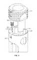
- FIGS. 2A-2Bare diagrammatic representations of a sleeve 1000 that can be used for reduction.
- Sleeve 1000can be any single or multi-channel sleeve suitable for minimally invasive surgery that detachably connects to collar 112 .
- Sleeve 1000can include body 1002 defining one or more channels 1004 through the walls of body 1002 that are sized to fit a spinal stabilization rod 104 .
- a passage 1006 from a proximal end to a distal end of body 1002provides a workspace for various tools to reach collar 112 and allows a closure member to be engaged with collar 112 .
- Body 1002can include flange 1008 for coupling with a collar 112 and internal female threads 1012 .
- Collar 112can also include internal threads 148 .
- FIG. 2Billustrates sleeve 1000 connected to collar 112 and FIG. 2B illustrates that threads 1012 and threads 148 of collar 112 form a continuous set of threads 1014 . While threads 1012 and threads 148 do not necessarily have to abut or contact each other when they form continuous set of threads 1014 , they are selected so that continuous set of threads 1014 allows the closure member to transition from threads 1012 to threads 148 .
- the threads 1012 or 148can include any suitable standard threads or nonstandard threads such as modified threads described in U.S. patent application Ser. No. 11/779,406. According to one embodiment, threads 1012 and 148 can be selected so that the threads will not strip unless undue torque is used on a closure member. Threads 1012 and 148 have identical or different thread configurations (types, angles, sizes or other properties) as long as a closure member can safely transition from threads 1012 to 148 during a reduction procedure.
- Threads 1012can be disposed any length along sleeve 1000 including the entire length of sleeve 1000 . In one embodiment, threads 1012 are at least long enough to allow a closure member to fully engage threads 1012 prior to contacting the stabilization rod for a desired level of reduction. For a 30 mm reduction, for example, threads 1012 can be disposed along at least 35-40 mm of body 1002 .
- the threads 1012 and 148can be timed. That is the angular orientation and position of the threads can be controlled to form a continuous set of threads down which a closure member can move. Even if the threads are properly timed, however, sleeve 1000 , in some embodiments, can be attached to collar 112 in various orientations. One or more of the orientations may result in threads 1012 and 148 being misaligned such that the end of threads 1012 does not match up with the beginning of threads 148 . To alleviate this problem, sleeve 1000 can include alignment features to ensure that the threads are properly oriented. For example, sleeve 1000 may include visible indicia for alignment or a coupling mechanism between sleeve 1000 and collar 112 that only allows sleeve 1000 and collar 112 to couple together with the threads properly aligned.
- FIG. 3is a diagrammatic representation of a coupling member that aligns sleeve 1000 and collar 112 .
- head member 1010connects to a body portion comprising two prongs 1016 and 1018 .
- Prongs 1016 and 1018can have different sizes, shapes, orientations or other characteristics so that the prongs 1016 and 1018 can only fit in corresponding recesses in collar 112 when sleeve threads 1012 are properly aligned with the threads of collar 112 .
- Prongs 1016 and 1018can be partially disposed in channels 1020 and 1022 along the walls of body 1002 . In other embodiments, the channels for prongs 1016 and 1018 may form passages running internal to walls of body 1002 .
- a locking member 1024can be used to securely couple head member 1010 to body 1002 .
- locking member 1024is a screw.
- locking member 1020can be a locking feature such as described for quick release mechanisms in U.S. patent application Ser. No. 11/779,406 that use a push motion, a twist motion, or a combination thereof or other locking mechanism as needed or desired.
- the coupling membercan be adapted to couple to collar 112 in one click as described, for example, in U.S. patent application Ser. No. 11/779,406.
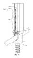
- FIGS. 4A-4Care diagrammatic representations of an embodiment of reduction using a sleeve 1050 .
- sleeve 1050is a multi-channel sleeve suitable for use in minimally invasive surgeries. However, reduction can also be performed using a single channel sleeve.
- Sleeve 1050includes a body 1052 defining a passage 1054 and channels 1056 . Threads 1062 are disposed along the walls of passage 1054 .
- Sleeve 1050is aligned so that threads 1062 form a continuous set of threads with threads 148 of collar 112 .
- a tool 1070can be used to turn closure member 1060 .
- Tool 1070can include any suitable tool to turn closure member 1060 including, but not limited, hex, flat head, Philips head, star, socket or other type of driver known in the art.
- Tool 1070can be a torque driver that will allow a user to apply up to a select amount of torque to closure member 1060 .
- the maximum amount of torquecan be selected to prevent the threads of closure member 1060 from stripping or, in the case of a shear off closure member, prevent a portion of closure member 106 from shearing.
- tool 1070can allow a maximum of 90 lbs/ft to be applied to closure member 1060 .
- threads 1012 and 148 and the threads on closure member 1060can be selected so that they will not strip based on a safety factor over the amount of torque allowed by tool 1070 .
- Sleeve 1050can be selected to have threads 1062 that extend from collar 112 past rod 104 a distance sufficient to allow the threads of closure member 1060 to fully engage threads 1062 prior to contacting rod 104 . This reduces the likelihood that the threads of closure member 106 will strip due to insufficient engagement with threads 1062 when closure member 106 asserts a force on rod 104 .
- a closure member 1060can be placed in passage 1054 and engaged with threads 1062 using tool 1070 .
- Closure member 1060can be brought in contact with rod 104 and continually turned to force rod 104 into collar 112 . If the torque required is greater than the amount set by tool 1070 , a separate reduction device can be used to finish reduction. Reduction is complete when rod 104 is fully seated in collar 112 . If a shear off closure member is used such as closure member 106 described above, tool 1070 can be reconfigured or another tool used to apply sufficient force to closure member 1060 to cause shear off.
- FIG. 5illustrates one embodiment of inhibiting rotation of sleeve 1050 .
- tool 1070is inserted in sleeve 1050 to turn closure member 106 .
- a counter torque wrench 1072can be used to prevent sleeve 1050 from rotating as force is applied to tool 1070 .
- Counter torque wrench 1072can be shaped to slip over sleeve 1050 on a portion of sleeve 1050 that extends outside of the patient's body. Force can be applied to counter torque wrench 1072 in a direction opposite to rotational force applied to tool 1070 .
- Embodiments described hereinprovide systems and methods to perform reduction using sleeves adapted for use in minimally invasive surgery.
- the sleevecan include internal threads that match those of a bone fastener assembly to provide a continuously threaded section.
- a closure member having complementary threads to the sleeve and collarcan be screwed down the continuous set of threads move the rod into the collar. When the rod is fully seated in the collar the sleeve can be removed.
Landscapes
- Health & Medical Sciences (AREA)
- Orthopedic Medicine & Surgery (AREA)
- Neurology (AREA)
- Life Sciences & Earth Sciences (AREA)
- Surgery (AREA)
- Heart & Thoracic Surgery (AREA)
- Engineering & Computer Science (AREA)
- Biomedical Technology (AREA)
- Nuclear Medicine, Radiotherapy & Molecular Imaging (AREA)
- Medical Informatics (AREA)
- Molecular Biology (AREA)
- Animal Behavior & Ethology (AREA)
- General Health & Medical Sciences (AREA)
- Public Health (AREA)
- Veterinary Medicine (AREA)
- Surgical Instruments (AREA)
Abstract
Description
Claims (14)
Priority Applications (1)
| Application Number | Priority Date | Filing Date | Title |
|---|---|---|---|
| US15/618,499US10154862B2 (en) | 2009-08-11 | 2017-06-09 | System and method for performing vertebral reduction using a sleeve |
Applications Claiming Priority (2)
| Application Number | Priority Date | Filing Date | Title |
|---|---|---|---|
| US12/539,468US9707019B2 (en) | 2009-08-11 | 2009-08-11 | System and method for performing vertebral reduction using a sleeve |
| US15/618,499US10154862B2 (en) | 2009-08-11 | 2017-06-09 | System and method for performing vertebral reduction using a sleeve |
Related Parent Applications (1)
| Application Number | Title | Priority Date | Filing Date |
|---|---|---|---|
| US12/539,468ContinuationUS9707019B2 (en) | 2009-08-11 | 2009-08-11 | System and method for performing vertebral reduction using a sleeve |
Publications (2)
| Publication Number | Publication Date |
|---|---|
| US20170273725A1 US20170273725A1 (en) | 2017-09-28 |
| US10154862B2true US10154862B2 (en) | 2018-12-18 |
Family
ID=43012705
Family Applications (2)
| Application Number | Title | Priority Date | Filing Date |
|---|---|---|---|
| US12/539,468Active2031-11-11US9707019B2 (en) | 2009-08-11 | 2009-08-11 | System and method for performing vertebral reduction using a sleeve |
| US15/618,499ActiveUS10154862B2 (en) | 2009-08-11 | 2017-06-09 | System and method for performing vertebral reduction using a sleeve |
Family Applications Before (1)
| Application Number | Title | Priority Date | Filing Date |
|---|---|---|---|
| US12/539,468Active2031-11-11US9707019B2 (en) | 2009-08-11 | 2009-08-11 | System and method for performing vertebral reduction using a sleeve |
Country Status (2)
| Country | Link |
|---|---|
| US (2) | US9707019B2 (en) |
| EP (2) | EP2283787B1 (en) |
Cited By (4)
| Publication number | Priority date | Publication date | Assignee | Title |
|---|---|---|---|---|
| US11191574B2 (en) | 2020-03-17 | 2021-12-07 | Warsaw Orthopedic, Inc. | Set screw reducer for modular reduction screws |
| US11439441B2 (en) | 2017-09-05 | 2022-09-13 | Medos International Sarl | Modular surgical instruments and related methods |
| US11553947B2 (en) | 2019-07-16 | 2023-01-17 | Aesculap Implant Systems, Llc | Spinal deformity sequential persuader |
| US12053214B2 (en) | 2021-03-05 | 2024-08-06 | Medos International Sårl | Sequential reducer |
Families Citing this family (28)
| Publication number | Priority date | Publication date | Assignee | Title |
|---|---|---|---|---|
| US8439922B1 (en) | 2008-02-06 | 2013-05-14 | NiVasive, Inc. | Systems and methods for holding and implanting bone anchors |
| US9707019B2 (en) | 2009-08-11 | 2017-07-18 | Zimmer Spine, Inc. | System and method for performing vertebral reduction using a sleeve |
| US8512383B2 (en) | 2010-06-18 | 2013-08-20 | Spine Wave, Inc. | Method of percutaneously fixing a connecting rod to a spine |
| US8206395B2 (en)* | 2010-06-18 | 2012-06-26 | Spine Wave, Inc. | Surgical instrument and method for the distraction or compression of bones |
| US9198698B1 (en) | 2011-02-10 | 2015-12-01 | Nuvasive, Inc. | Minimally invasive spinal fixation system and related methods |
| US9060818B2 (en) | 2011-09-01 | 2015-06-23 | DePuy Synthes Products, Inc. | Bone implants |
| US9289250B2 (en) | 2011-10-17 | 2016-03-22 | Warsaw Orthopedic, Inc. | Extender collar system |
| CN103120598B (en)* | 2011-11-18 | 2015-07-29 | 北京纳通科技集团有限公司 | Spinal orthopedic bar apparatus for placing |
| EP2762095B1 (en) | 2013-01-31 | 2016-05-25 | Zimmer Spine | Device for fixing a bony structure to a support member |
| US9005205B2 (en) | 2013-03-04 | 2015-04-14 | Degen Medical, Inc. | Rod insertion tools, rods and methods |
| US10136927B1 (en) | 2013-03-15 | 2018-11-27 | Nuvasive, Inc. | Rod reduction assemblies and related methods |
| US9486256B1 (en) | 2013-03-15 | 2016-11-08 | Nuvasive, Inc. | Rod reduction assemblies and related methods |
| US9655659B2 (en) | 2013-04-20 | 2017-05-23 | Degen Medical, Inc. | Anchor tower |
| US9453526B2 (en) | 2013-04-30 | 2016-09-27 | Degen Medical, Inc. | Bottom-loading anchor assembly |
| US9125694B2 (en)* | 2013-05-06 | 2015-09-08 | Life Spine, Inc. | Systems and methods for spinal rod insertion and reduction |
| CN114983546A (en)* | 2013-05-13 | 2022-09-02 | 尼奥医疗公司 | Orthopedic implant kit |
| US20150313647A1 (en)* | 2014-04-30 | 2015-11-05 | Ignacio Sanpera Trigueros | System for correction of the spine curvatures |
| US9974577B1 (en) | 2015-05-21 | 2018-05-22 | Nuvasive, Inc. | Methods and instruments for performing leveraged reduction during single position spine surgery |
| JP2017038871A (en)* | 2015-08-21 | 2017-02-23 | 賢 石井 | Spinal implant surgical instrument |
| US20170112551A1 (en)* | 2015-10-27 | 2017-04-27 | Ctl Medical Corporation | Modular rod reduction tower and related methods |
| US20190336182A1 (en) | 2015-10-27 | 2019-11-07 | Ctl Medical Corporation | Modular rod reduction tower and related methods |
| US10335205B2 (en)* | 2015-11-09 | 2019-07-02 | Globus Medical, Inc. | MIS cross-connector |
| US10398454B2 (en)* | 2015-11-09 | 2019-09-03 | Globus Medical, Inc. | MIS cross-connector |
| US10398481B2 (en) | 2016-10-03 | 2019-09-03 | Nuvasive, Inc. | Spinal fixation system |
| US11051861B2 (en) | 2018-06-13 | 2021-07-06 | Nuvasive, Inc. | Rod reduction assemblies and related methods |
| CN113795211B (en) | 2019-03-26 | 2024-11-29 | 尼奥医疗公司 | System for tightening an orthopedic set screw at two different torque levels |
| ES2988747T3 (en) | 2019-07-02 | 2024-11-21 | Neo Medical Sa | System to prevent lateral tension on bone structures resulting from off-axis forces caused by the screwdriver and screw extender |
| US11134994B2 (en)* | 2020-01-30 | 2021-10-05 | Warsaw Orthopedic, Inc. | Spinal-correction system having threaded extender tabs and reduction tab extenders |
Citations (40)
| Publication number | Priority date | Publication date | Assignee | Title |
|---|---|---|---|---|
| US5586984A (en) | 1995-07-13 | 1996-12-24 | Fastenetix, L.L.C. | Polyaxial locking screw and coupling element assembly for use with rod fixation apparatus |
| US6648888B1 (en) | 2002-09-06 | 2003-11-18 | Endius Incorporated | Surgical instrument for moving a vertebra |
| US20040215190A1 (en) | 2003-04-25 | 2004-10-28 | Nguyen Thanh V. | System and method for minimally invasive posterior fixation |
| US20040249378A1 (en) | 2001-10-04 | 2004-12-09 | Saint Martin Pierre Henri | Spinal osteosynthesis assembly comprising the head of an anchoring member and a tool for fixing said head |
| US20050065517A1 (en) | 2003-09-24 | 2005-03-24 | Chin Kingsley Richard | Methods and devices for improving percutaneous access in minimally invasive surgeries |
| US20050119667A1 (en) | 2003-12-02 | 2005-06-02 | Eurosurgical Sa | Clip-type surgical instrument for spinal implant |
| US20050131408A1 (en) | 2003-12-16 | 2005-06-16 | Sicvol Christopher W. | Percutaneous access devices and bone anchor assemblies |
| US20050131421A1 (en) | 2003-12-16 | 2005-06-16 | Anderson David G. | Methods and devices for minimally invasive spinal fixation element placement |
| US20050149053A1 (en) | 2003-12-17 | 2005-07-07 | Varieur Michael S. | Instruments and methods for bone anchor engagement and spinal rod reduction |
| US20050182410A1 (en) | 2002-09-06 | 2005-08-18 | Jackson Roger P. | Helical guide and advancement flange with radially loaded lip |
| US20050192570A1 (en) | 2004-02-27 | 2005-09-01 | Jackson Roger P. | Orthopedic implant rod reduction tool set and method |
| US20050192579A1 (en) | 2004-02-27 | 2005-09-01 | Jackson Roger P. | Orthopedic implant rod reduction tool set and method |
| US20050273101A1 (en) | 2004-05-28 | 2005-12-08 | Aesculap Ag & Co. Kg | Bone screw and osteosynthesis device |
| US20060036244A1 (en) | 2003-10-21 | 2006-02-16 | Innovative Spinal Technologies | Implant assembly and method for use in an internal structure stabilization system |
| US20060036252A1 (en) | 2004-08-12 | 2006-02-16 | Baynham Bret O | Polyaxial screw |
| US20060036254A1 (en) | 2004-08-10 | 2006-02-16 | Roy Lim | Reducing instrument for spinal surgery |
| US20060074418A1 (en) | 2004-09-24 | 2006-04-06 | Jackson Roger P | Spinal fixation tool set and method for rod reduction and fastener insertion |
| US20060111713A1 (en) | 2004-11-23 | 2006-05-25 | Jackson Roger P | Spinal fixation tool set and method |
| US20060142761A1 (en) | 2002-10-30 | 2006-06-29 | Landry Michael E | Spinal stabilization systems and methods |
| US20060184178A1 (en) | 2004-02-27 | 2006-08-17 | Jackson Roger P | Orthopedic implant rod reduction tool set and method |
| US20070073294A1 (en) | 2003-09-24 | 2007-03-29 | Spinefrontier Lls | System and method for implanting spinal stabilization devices |
| US20070100352A1 (en) | 2005-10-31 | 2007-05-03 | Deffenbaugh Daren L | Cartridge suture anchor delivery device, suture anchor delivery device and associated method |
| US20070162010A1 (en) | 2005-03-04 | 2007-07-12 | Chao Nam T | Instruments and methods for manipulating vertebra |
| US20070179502A1 (en) | 2003-02-19 | 2007-08-02 | Aesculap, Inc. | Implant device including threaded locking mechanism |
| US20070191840A1 (en) | 2006-01-26 | 2007-08-16 | Sdgi Holdings, Inc. | Spinal anchor assemblies having extended receivers |
| US20070233079A1 (en) | 2006-02-06 | 2007-10-04 | Stryker Spine | Rod contouring apparatus and method for percutaneous pedicle screw extension |
| US7278995B2 (en) | 2002-06-04 | 2007-10-09 | Howmedica Osteonics Corp. | Apparatus for securing a spinal rod system |
| US20070288026A1 (en) | 2006-06-09 | 2007-12-13 | Endius, Inc. | Methods and apparatus for access to and/or treatment of the spine |
| US20080009862A1 (en) | 2006-06-16 | 2008-01-10 | Zimmer Spine, Inc. | Removable polyaxial housing for a pedicle screw |
| US20080077139A1 (en) | 2002-10-30 | 2008-03-27 | Landry Michael E | Spinal stabilization systems with quick-connect sleeve assemblies for use in surgical procedures |
| US20080082103A1 (en) | 2006-06-16 | 2008-04-03 | Alphatec Spine, Inc. | Systems and methods for manipulating and/or installing a pedicle screw |
| US20080091213A1 (en) | 2004-02-27 | 2008-04-17 | Jackson Roger P | Tool system for dynamic spinal implants |
| US20080114403A1 (en) | 2006-11-09 | 2008-05-15 | Zimmer Spine, Inc. | Minimally invasive pedicle screw access system and associated method |
| US20080119849A1 (en) | 2006-11-20 | 2008-05-22 | Depuy Spine Inc. | Break-off screw extensions |
| US20080132957A1 (en) | 2006-11-22 | 2008-06-05 | Wilfried Matthis | Bone anchoring device |
| US20090005814A1 (en) | 2007-06-28 | 2009-01-01 | Peter Thomas Miller | Stabilization system and method |
| US7520879B2 (en) | 2006-02-07 | 2009-04-21 | Warsaw Orthopedic, Inc. | Surgical instruments and techniques for percutaneous placement of spinal stabilization elements |
| US20090234392A1 (en) | 2008-03-13 | 2009-09-17 | Depuy Spine, Inc. | Method for inserting a spinal fixation element using implants having guide tabs |
| US7591836B2 (en) | 2004-07-30 | 2009-09-22 | Zimmer Spine, Inc. | Surgical devices and methods for vertebral shifting utilizing spinal fixation systems |
| US20110040328A1 (en) | 2009-08-11 | 2011-02-17 | Zimmer Spine Austin, Inc. | System and method for performing vertebral reduction using a sleeve |
- 2009
- 2009-08-11USUS12/539,468patent/US9707019B2/enactiveActive
- 2010
- 2010-08-02EPEP10008069Apatent/EP2283787B1/ennot_activeNot-in-force
- 2010-08-02EPEP12180027Apatent/EP2522287A1/ennot_activeWithdrawn
- 2017
- 2017-06-09USUS15/618,499patent/US10154862B2/enactiveActive
Patent Citations (50)
| Publication number | Priority date | Publication date | Assignee | Title |
|---|---|---|---|---|
| US5586984A (en) | 1995-07-13 | 1996-12-24 | Fastenetix, L.L.C. | Polyaxial locking screw and coupling element assembly for use with rod fixation apparatus |
| US20040249378A1 (en) | 2001-10-04 | 2004-12-09 | Saint Martin Pierre Henri | Spinal osteosynthesis assembly comprising the head of an anchoring member and a tool for fixing said head |
| US7278995B2 (en) | 2002-06-04 | 2007-10-09 | Howmedica Osteonics Corp. | Apparatus for securing a spinal rod system |
| US20050182410A1 (en) | 2002-09-06 | 2005-08-18 | Jackson Roger P. | Helical guide and advancement flange with radially loaded lip |
| US6648888B1 (en) | 2002-09-06 | 2003-11-18 | Endius Incorporated | Surgical instrument for moving a vertebra |
| US7491218B2 (en) | 2002-10-30 | 2009-02-17 | Abbott Spine, Inc. | Spinal stabilization systems and methods using minimally invasive surgical procedures |
| US20060142761A1 (en) | 2002-10-30 | 2006-06-29 | Landry Michael E | Spinal stabilization systems and methods |
| US20080077139A1 (en) | 2002-10-30 | 2008-03-27 | Landry Michael E | Spinal stabilization systems with quick-connect sleeve assemblies for use in surgical procedures |
| US20070179502A1 (en) | 2003-02-19 | 2007-08-02 | Aesculap, Inc. | Implant device including threaded locking mechanism |
| US20040215190A1 (en) | 2003-04-25 | 2004-10-28 | Nguyen Thanh V. | System and method for minimally invasive posterior fixation |
| US20070016194A1 (en) | 2003-04-25 | 2007-01-18 | Shaolian Samuel M | Articulating spinal fixation rod and system |
| US20050065517A1 (en) | 2003-09-24 | 2005-03-24 | Chin Kingsley Richard | Methods and devices for improving percutaneous access in minimally invasive surgeries |
| US20070073294A1 (en) | 2003-09-24 | 2007-03-29 | Spinefrontier Lls | System and method for implanting spinal stabilization devices |
| US20060036244A1 (en) | 2003-10-21 | 2006-02-16 | Innovative Spinal Technologies | Implant assembly and method for use in an internal structure stabilization system |
| US20050119667A1 (en) | 2003-12-02 | 2005-06-02 | Eurosurgical Sa | Clip-type surgical instrument for spinal implant |
| US20050154389A1 (en) | 2003-12-16 | 2005-07-14 | Depuy Spine, Inc. | Methods and devices for minimally invasive spinal fixation element placement |
| US20050131421A1 (en) | 2003-12-16 | 2005-06-16 | Anderson David G. | Methods and devices for minimally invasive spinal fixation element placement |
| US20050131408A1 (en) | 2003-12-16 | 2005-06-16 | Sicvol Christopher W. | Percutaneous access devices and bone anchor assemblies |
| US7179261B2 (en) | 2003-12-16 | 2007-02-20 | Depuy Spine, Inc. | Percutaneous access devices and bone anchor assemblies |
| US20050149053A1 (en) | 2003-12-17 | 2005-07-07 | Varieur Michael S. | Instruments and methods for bone anchor engagement and spinal rod reduction |
| US20050192579A1 (en) | 2004-02-27 | 2005-09-01 | Jackson Roger P. | Orthopedic implant rod reduction tool set and method |
| US20060184178A1 (en) | 2004-02-27 | 2006-08-17 | Jackson Roger P | Orthopedic implant rod reduction tool set and method |
| US7160300B2 (en) | 2004-02-27 | 2007-01-09 | Jackson Roger P | Orthopedic implant rod reduction tool set and method |
| US20050192570A1 (en) | 2004-02-27 | 2005-09-01 | Jackson Roger P. | Orthopedic implant rod reduction tool set and method |
| US20080091213A1 (en) | 2004-02-27 | 2008-04-17 | Jackson Roger P | Tool system for dynamic spinal implants |
| US20050273101A1 (en) | 2004-05-28 | 2005-12-08 | Aesculap Ag & Co. Kg | Bone screw and osteosynthesis device |
| US7591836B2 (en) | 2004-07-30 | 2009-09-22 | Zimmer Spine, Inc. | Surgical devices and methods for vertebral shifting utilizing spinal fixation systems |
| US20060036254A1 (en) | 2004-08-10 | 2006-02-16 | Roy Lim | Reducing instrument for spinal surgery |
| US20060036252A1 (en) | 2004-08-12 | 2006-02-16 | Baynham Bret O | Polyaxial screw |
| US20060074418A1 (en) | 2004-09-24 | 2006-04-06 | Jackson Roger P | Spinal fixation tool set and method for rod reduction and fastener insertion |
| US20060111713A1 (en) | 2004-11-23 | 2006-05-25 | Jackson Roger P | Spinal fixation tool set and method |
| US20070162010A1 (en) | 2005-03-04 | 2007-07-12 | Chao Nam T | Instruments and methods for manipulating vertebra |
| US20070100352A1 (en) | 2005-10-31 | 2007-05-03 | Deffenbaugh Daren L | Cartridge suture anchor delivery device, suture anchor delivery device and associated method |
| US20070191840A1 (en) | 2006-01-26 | 2007-08-16 | Sdgi Holdings, Inc. | Spinal anchor assemblies having extended receivers |
| US20070233079A1 (en) | 2006-02-06 | 2007-10-04 | Stryker Spine | Rod contouring apparatus and method for percutaneous pedicle screw extension |
| US20090099605A1 (en) | 2006-02-06 | 2009-04-16 | Stryker Spine | Rod contouring apparatus for percutaneous pedicle screw extension |
| US7520879B2 (en) | 2006-02-07 | 2009-04-21 | Warsaw Orthopedic, Inc. | Surgical instruments and techniques for percutaneous placement of spinal stabilization elements |
| US20070288026A1 (en) | 2006-06-09 | 2007-12-13 | Endius, Inc. | Methods and apparatus for access to and/or treatment of the spine |
| US20080009862A1 (en) | 2006-06-16 | 2008-01-10 | Zimmer Spine, Inc. | Removable polyaxial housing for a pedicle screw |
| US20080082103A1 (en) | 2006-06-16 | 2008-04-03 | Alphatec Spine, Inc. | Systems and methods for manipulating and/or installing a pedicle screw |
| US20080114403A1 (en) | 2006-11-09 | 2008-05-15 | Zimmer Spine, Inc. | Minimally invasive pedicle screw access system and associated method |
| US20080119849A1 (en) | 2006-11-20 | 2008-05-22 | Depuy Spine Inc. | Break-off screw extensions |
| US20080300638A1 (en) | 2006-11-20 | 2008-12-04 | Depuy Spine, Inc. | Break-off screw extensions |
| US20080132957A1 (en) | 2006-11-22 | 2008-06-05 | Wilfried Matthis | Bone anchoring device |
| US20090005814A1 (en) | 2007-06-28 | 2009-01-01 | Peter Thomas Miller | Stabilization system and method |
| US20090234392A1 (en) | 2008-03-13 | 2009-09-17 | Depuy Spine, Inc. | Method for inserting a spinal fixation element using implants having guide tabs |
| US20110040328A1 (en) | 2009-08-11 | 2011-02-17 | Zimmer Spine Austin, Inc. | System and method for performing vertebral reduction using a sleeve |
| EP2283787B1 (en) | 2009-08-11 | 2012-09-19 | Zimmer Spine, Inc. | System for performing vertebral reduction using a sleeve |
| EP2522287A1 (en) | 2009-08-11 | 2012-11-14 | Zimmer Spine, Inc. | System for performing vertebral reduction using a sleeve |
| US9707019B2 (en) | 2009-08-11 | 2017-07-18 | Zimmer Spine, Inc. | System and method for performing vertebral reduction using a sleeve |
Non-Patent Citations (37)
Cited By (5)
| Publication number | Priority date | Publication date | Assignee | Title |
|---|---|---|---|---|
| US11439441B2 (en) | 2017-09-05 | 2022-09-13 | Medos International Sarl | Modular surgical instruments and related methods |
| US12053213B2 (en) | 2017-09-05 | 2024-08-06 | Medos International Sárl | Modular surgical instruments and related methods |
| US11553947B2 (en) | 2019-07-16 | 2023-01-17 | Aesculap Implant Systems, Llc | Spinal deformity sequential persuader |
| US11191574B2 (en) | 2020-03-17 | 2021-12-07 | Warsaw Orthopedic, Inc. | Set screw reducer for modular reduction screws |
| US12053214B2 (en) | 2021-03-05 | 2024-08-06 | Medos International Sårl | Sequential reducer |
Also Published As
| Publication number | Publication date |
|---|---|
| US9707019B2 (en) | 2017-07-18 |
| US20110040328A1 (en) | 2011-02-17 |
| EP2283787A1 (en) | 2011-02-16 |
| EP2283787B1 (en) | 2012-09-19 |
| US20170273725A1 (en) | 2017-09-28 |
| EP2522287A1 (en) | 2012-11-14 |
Similar Documents
| Publication | Publication Date | Title |
|---|---|---|
| US10154862B2 (en) | System and method for performing vertebral reduction using a sleeve | |
| US12343049B2 (en) | Spinal stabilization systems with quick-connect sleeve assemblies for use in surgical procedures | |
| US10426538B2 (en) | Instruments and methods for adjusting separation distance of vertebral bodies with a minimally invasive spinal stabilization procedure | |
| US7985242B2 (en) | Instruments and methods for reduction of vertebral bodies | |
| US8048129B2 (en) | MIS crosslink apparatus and methods for spinal implant | |
| US7947064B2 (en) | Stabilization system and method | |
| EP2198793B1 (en) | Coaxially lockable poly-axial bone fastener assemblies | |
| US8262662B2 (en) | Break-off screw extensions | |
| US20090005787A1 (en) | Device and system for implanting polyaxial bone fasteners |
Legal Events
| Date | Code | Title | Description |
|---|---|---|---|
| STCF | Information on status: patent grant | Free format text:PATENTED CASE | |
| AS | Assignment | Owner name:ZIMMER BIOMET SPINE, INC., INDIANA Free format text:MERGER;ASSIGNOR:ZIMMER SPINE, INC.;REEL/FRAME:059232/0356 Effective date:20160930 | |
| AS | Assignment | Owner name:JPMORGAN CHASE BANK, N.A., AS ADMINISTRATIVE AGENT, NEW YORK Free format text:SECURITY INTEREST;ASSIGNORS:BIOMET 3I, LLC;EBI, LLC;ZIMMER BIOMET SPINE, INC.;AND OTHERS;REEL/FRAME:059293/0213 Effective date:20220228 | |
| MAFP | Maintenance fee payment | Free format text:PAYMENT OF MAINTENANCE FEE, 4TH YEAR, LARGE ENTITY (ORIGINAL EVENT CODE: M1551); ENTITY STATUS OF PATENT OWNER: LARGE ENTITY Year of fee payment:4 | |
| AS | Assignment | Owner name:ZIMMER BIOMET SPINE, INC., COLORADO Free format text:MERGER;ASSIGNOR:ZIMMER SPINE, INC.;REEL/FRAME:066894/0402 Effective date:20160927 Owner name:ZIMMER SPINE, INC., MINNESOTA Free format text:ASSIGNMENT OF ASSIGNORS INTEREST;ASSIGNORS:MILLER, PETER THOMAS;FORTON, CHARLES R.;RICEMAN, BRUCE A.;SIGNING DATES FROM 20100608 TO 20100610;REEL/FRAME:066884/0125 | |
| AS | Assignment | Owner name:CERBERUS BUSINESS FINANCE AGENCY, LLC, NEW YORK Free format text:GRANT OF A SECURITY INTEREST -- PATENTS;ASSIGNORS:ZIMMER BIOMET SPINE, LLC;EBI, LLC;REEL/FRAME:066970/0806 Effective date:20240401 | |
| AS | Assignment | Owner name:ZIMMER BIOMET SPINE, LLC (F/K/A ZIMMER BIOMET SPINE, INC.), COLORADO Free format text:RELEASE BY SECURED PARTY;ASSIGNOR:JPMORGAN CHASE BANK, N.A.;REEL/FRAME:066973/0833 Effective date:20240401 Owner name:EBI, LLC, NEW JERSEY Free format text:RELEASE BY SECURED PARTY;ASSIGNOR:JPMORGAN CHASE BANK, N.A.;REEL/FRAME:066973/0833 Effective date:20240401 | |
| AS | Assignment | Owner name:ZIMMER BIOMET SPINE, LLC, COLORADO Free format text:CHANGE OF NAME;ASSIGNOR:ZIMMER BIOMET SPINE, INC.;REEL/FRAME:069772/0121 Effective date:20240220 Owner name:HIGHRIDGE MEDICAL, LLC, COLORADO Free format text:CHANGE OF NAME;ASSIGNOR:ZIMMER BIOMET SPINE, LLC;REEL/FRAME:069772/0248 Effective date:20240405 |